
SECTION 1A7 - SEATS
Service Precaution
Front Seat Assembly
Front Seat Assembly and Associated
Parts
Removal
Installation
Rear Seat Assembly
Rear Seat Cushion Assembly and
Associated Parts
Removal
Installation
Rear Seat Back Assembly and
Associated Parts
Removal
Installation
Main Data and Specifications
Torque Specifications
SERVICE PRECAUTION
WARNING: THIS VEHICLE HAS A SUPPLEMENTAL
RESTRAINT SYSTEM (SRS). REFER TO THE SRS
COMPONENT AND WIRING LOCATION VIEW IN
ORDER TO DETERMINE WHETHER YOU ARE
PERFORMING SERVICE ON OR NEAR THE SRS
COMPONENTS OR THE SRS WIRING. WHEN YOU
ARE PERFORMING SERVICE ON OR NEAR THE
SRS COMPONENTS OR THE SRS WIRING, REFER
TO THE SRS SERVICE INFORMATION. FAILURE TO
FOLLOW WARNINGS COULD RESULT IN POSSIBLE
AIR BAG DEPLOYMENT, PERSONAL INJURY, OR
OTHERWISE UNNEEDED SRS SYSTEM REPAIRS.
CAUTION: Always use the correct fastener in the
proper location. When you replace a fastener, use
ONLY the exact part number for that application.
ISUZU will call out those fasteners that require a
replacement after removal. ISUZU will also call out
the fasteners that require thread lockers or thread
sealant. UNLESS OTHERWISE SPECIFIED, do not
use supplemental coatings (Paints, greases, or
other corros ion inhibitors) on threa ded fasteners or
fastener joint interfaces. Generally, such coatings
adversely affect the fastener torque and the joint
clamping force, and may damage the fastener.
When you install fasteners, use the correct
tightening sequence and specifications. Following
these instructions can help you avoid damage to
parts and systems.
FRONT SEAT ASSEMBLY
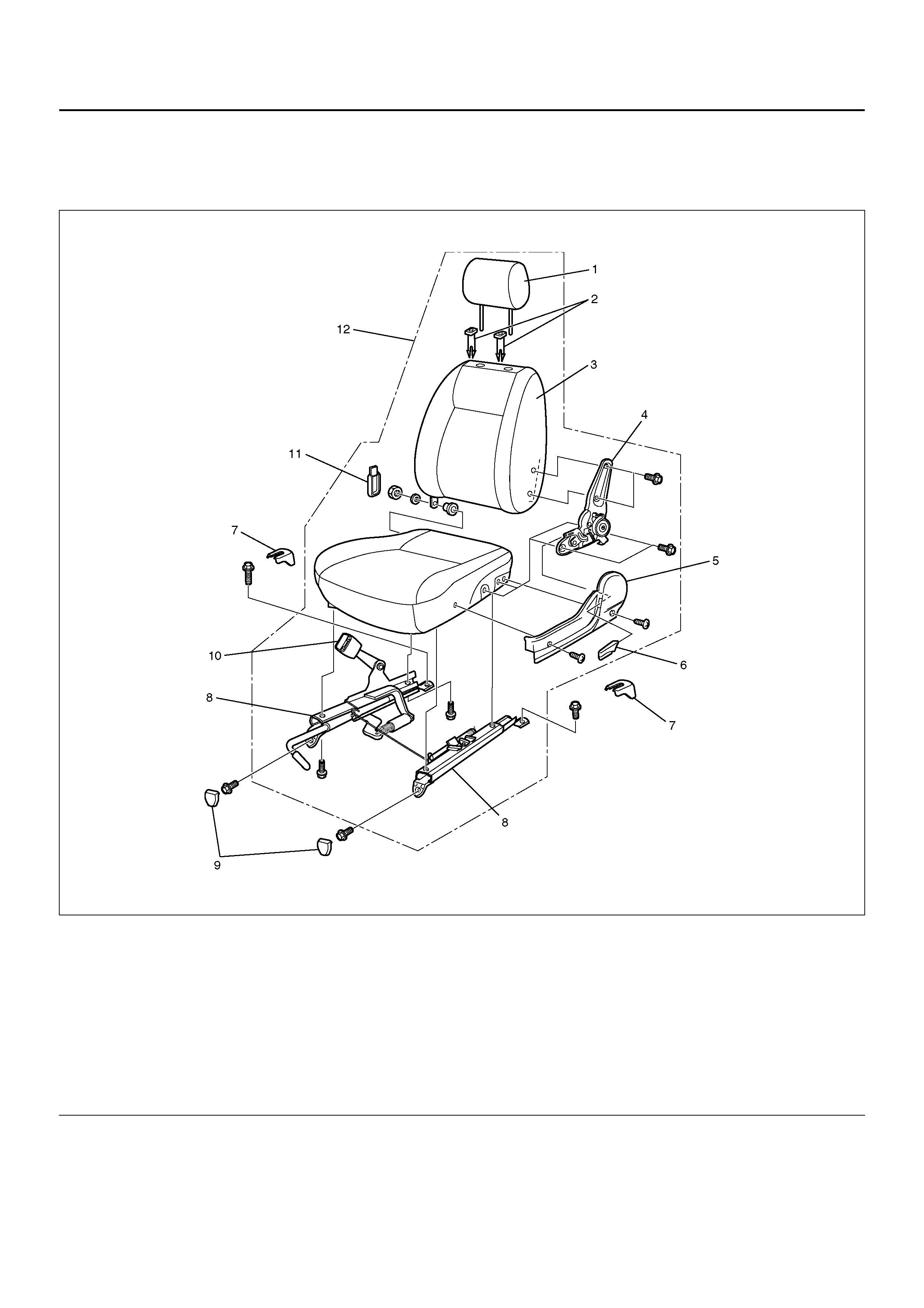
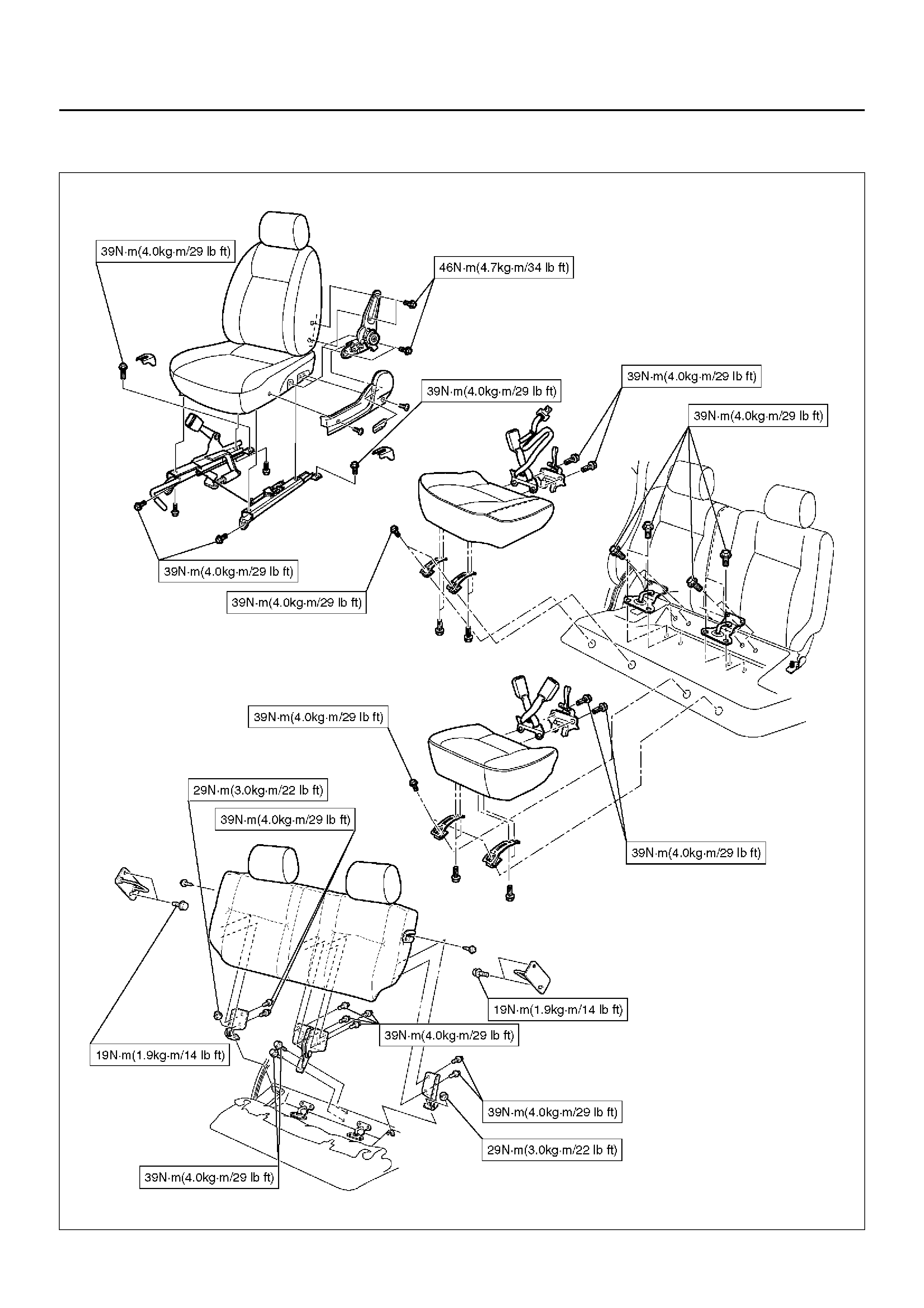
FRONT SEAT ASSEMBLY AND ASSOCIATED PARTS
750R100011
Legend
EndOFCallout
REMOVAL
1. Disconnect the battery ground cable.
2. Remove the front and rear leg covers.
3. Remove the front seat assembly.
• Remove the four fixing bolts.
• Disconnect the seat belt warning connector
(Driver’s side only).
(1) Headrest
(2) G uide Hol der
(3) Seat Back Assembly
(4) Reclining Device
(5) Side Cover
(6) Reclining Knob
(7) Rear Leg Cover
(8) Seat Adj uster
(9) Front Leg Cover
(10) Front Seat Belt Buckle Assembly
(11) Hinge Cover
(12) Front Seat Assembly

4. Pull out the reclining knob.
5. Remove the side cover.
• Remove the two screws.
6. Remove the headrest.
7. Remove the reclining device.
• Turn up the seat back trim cover in order to
remove the reclining device fixing bolts.
750RS006
8. Remove the seat back assembly.
• Remove the seat back assembly fixing nut on the
opposite side of the reclining device.
750RS007
9. Remove the trim cover (Seat back side).
10. Remove the guide holder.
• Pull the guide holder out by holding the bottom
end of it from the seat back assembly.
11. Remove the seat adjuster.
• Disconnect the release wire (4) and remove the
fixing bolts.
750RW006
12. Remove the seat belt buckle assembly.
13. Remove the trim cover (Seat cushion side).
INSTALLATION
To install, follow the removal steps in the reverse order,
noting the foll owi ng poi nts:
1. Tighten the reclining device fixing bolts to the
specified torque.
Torque: 46 N·m (4.7 kg·m/34 lbft)
2. Tighten the front seat assembly fixing bolts to the
specified torque.
Torque: 39 N·m (4.0 kg·m/29 lbft)
REAR SEAT ASSEMBLY
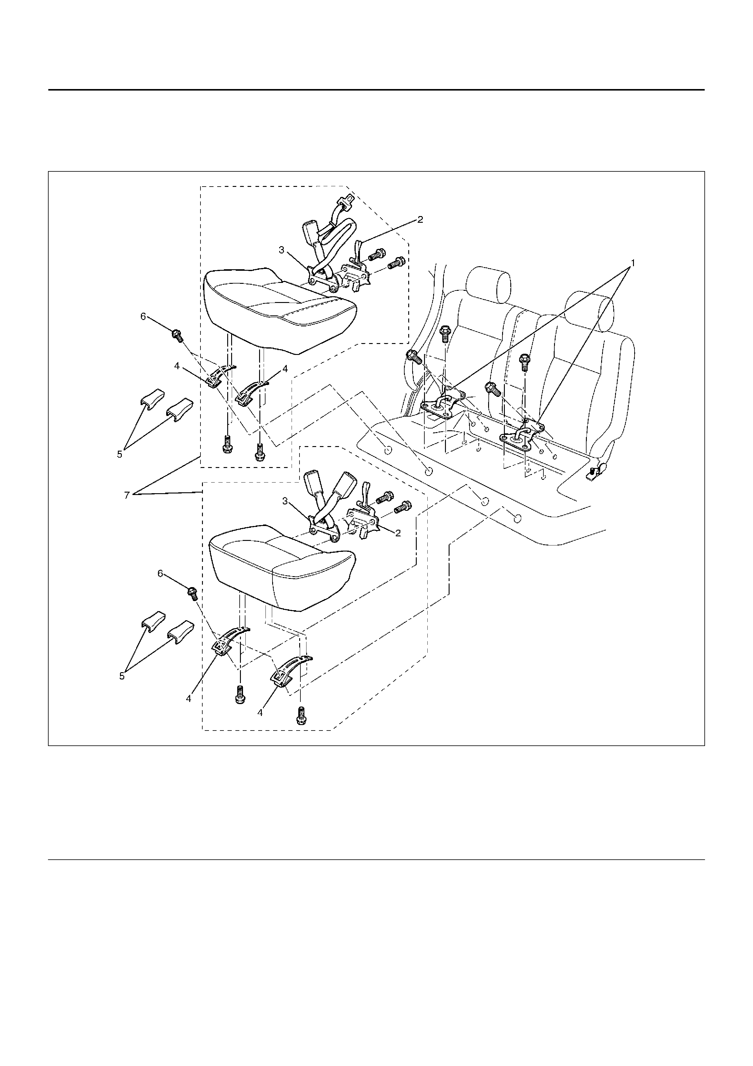
REAR SEAT CUSHION ASSEMBLY AND ASSOCIATED PARTS
755RY00009
Legend
EndOFCallout
REMOVAL
1. Remo ve the hin ge cover s .
2. Remove the seat cushion fixing bolts.
(1) Rear Seat Lock Striker
(2) Rear Seat Lock Assembly
(3) Rear Seat Belt Buckle Assembly
(4) Seat Cushion Hinge
(5) Hinge Cover
(6) Seat Cushion Fixing Bolt
(7) Rear Seat Cushion Assembly
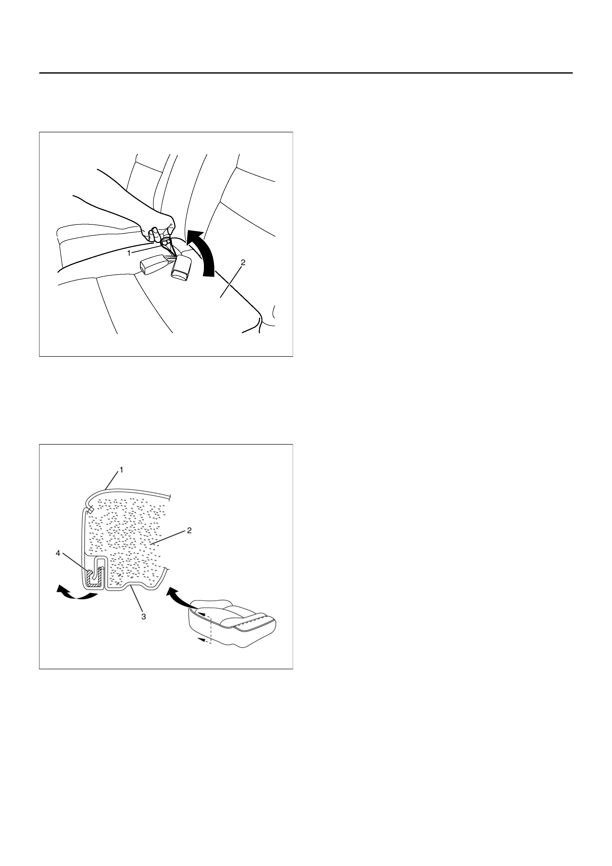
3. Remove the seat cushion assembly (2).
• Pull on the strap (1) of the rear seat lock
assembly to release the seat lock.
755R100006
4. Remove the seat cushion hinges.
5. Remove the rear cushion trim cover (1) and rear
seat cushion pad (2).
• Remove cushion trim cover from rear cushion
frame (3) with prying the plastic retainers (4).
755RX028
6. Remove the rear seat lock assembly and rear seat
belt buckle assembly.
7. Remove the rear seat lock strikers.
• Remove the four bolts at each striker.
INSTALLATION
To install, follow the removal steps in the reverse order,
noting the foll owi ng poi nts:
1. Tighten the rear seat lock assembly and rear seat
belt buckle assembly fixing bolts to the specified
torque.
Torque: 39 N·m (4.0 kg·m/29 lbft)
2. Tighten the rear seat lock striker fixing bolts to the
specified torque.
Torque: 39 N·m (4.0 kg·m/29 lbft)
3. Tighten the seat cushion hinge fixing bolts to the
specified torque.
Torque: 39 N·m (4.0 kg·m/29 lbft)
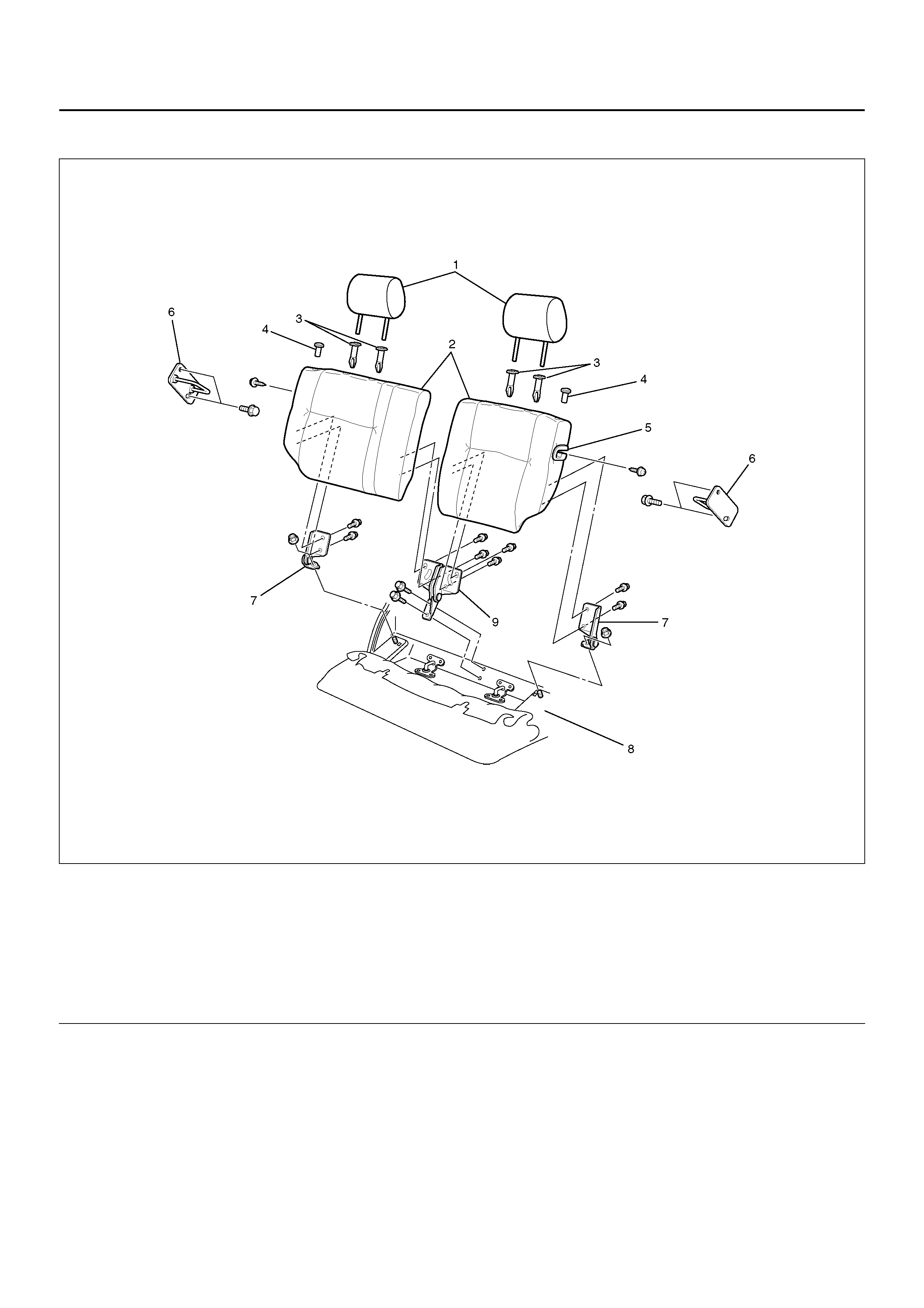
REAR SEAT BACK ASSEMBLY AND ASSOCIATED PARTS
755R100005
Legend
EndOFCallout
REMOVAL
1. Pull on the release knob and fold the seat back
assembly forward.
2. Remo ve the lug gag e floor car pe ts.
• Remove the carpet fixing nine clips at each from
the backside of the seat back assembly.
3. Remo ve the se at back ass em bly.
• Remove the four fixing bolts at each seat back.
4. Remove the seat lock covers.
5. Remove the headrests.
6. Remove the release knobs.
• Turn the knob counterclockwise to remove it.
7. Rem ove the trim covers.
8. Remove the guide holders.
(1) Headrest
(2) Seat Back Assembly
(3) G uide Hol der
(4) Release Knob
(5) Seat Lock Cover
(6) Seat Loc k Stri ker
(7) Side Hinge
(8) Body Floor Panel
(9) Center Hinge

9. Remove the side hinges.
• Remove the one fixing nut at each side hinge.
10. Remove the center hinge.
• Remove the two fixing bolts.
INSTALLATION
To install, follow the removal steps in the reverse order,
noting the following points:
1. Tighten the center hinge fiixng bolts to the sp ecified
torque.
Torque: 39 N·m (4.0 kg·m/29 lbft)
2. Tighten the side hinge fixing nuts to the specified
torque.
Torque: 29 N·m (3.0 kg·m/22 lbft)
3. Tighten the side lock striker fixing bolts to the
specified torque.
Torque: 19 N·m (1.9 kg·m/14 lbft)
MAIN DATA AND SPECIFICATIONS
TORQUE SPECIFICATIONS
750R100009