
SECTION 1A8 - EXTERIOR / INTERIOR TRIM
Service Precaution
Consoles
Consoles and Associated Parts
Removal
Installation
Front Door Trim Panel
Front Door Trim Panel and Associated
Parts
Removal
Installation
Rear Door Trim Panel
Rear Door Trim Panel and Associated
Parts
Removal
Installation
Door Mirror Assembly
Removal
Installation
Mirror Replacement
Interior Mirror Assembly
Removal
Installation
Interior Trim Panels
Interior Trim Panels and Associated Parts
Removal
Installation
Overhead Console
Parts Location
Removal
Installation
Headlining
Parts Location
Removal
Installation
Wheel Arch Protector
Wheel Arch Protector and Associated
Parts
Removal
Installation
Wheel Arch Moulding
Wheel Arch Moulding and Associated
Parts
Removal
Installation
Fuel Filler Door
Parts Location
Removal
Installation
Roof Rail
Parts Location
Removal
Installation
Power Door Mirror System
General Description
Door Mirror Switch
Power Window System
General Description
Power Window Switch Driver Seat Side
Power Window Motor
Main Data and Specifications
Techline

SERVICE PRECAUTION
WARNING: THIS VEHICLE HAS A SUPPLEMENTAL
RESTRAINT SYSTEM (SRS). REFER TO THE SRS
COMPONENT AND WIRING LOCATION VIEW IN
ORDER TO DETERMINE WHETHER YOU ARE
PERFORMING SERVICE ON OR NEAR THE SRS
COMPONENTS OR THE SRS WIRING. WHEN YOU
ARE PERFORMING SERVICE ON OR NEAR THE
SRS COMPONENTS OR THE SRS WIRING, REFER
TO THE SRS SERVICE INFORMATION. FAILURE TO
FOLLOW WARNINGS COULD RESULT IN POSSIBLE
AIR BAG DEPLOYMENT, PERSONAL INJURY, OR
OTHERWISE UNNEEDED SRS SYSTEM REPAIRS.
CAUTION: Always use the correct fastener in the
proper location. When you replace a fastener, use
ONLY the exact part number for that application.
ISUZU will call out those fasteners that require a
replacement after removal. ISUZU will also call out
the fasteners that require thread lockers or thread
sealant. UNLESS OTHERWISE SPECIFIED, do not
use supplemental coatings (Paints, greases, or
other corros ion inhibitors) on threa ded fasteners or
fastener joint interfaces. Generally, such coatings
adversely affect the fastener torque and the joint
clamping force, and may damage the fastener.
When you install fasteners, use the correct
tightening sequence and specifications. Following
these instructions can help you avoid damage to
parts and systems.
CONSOLES
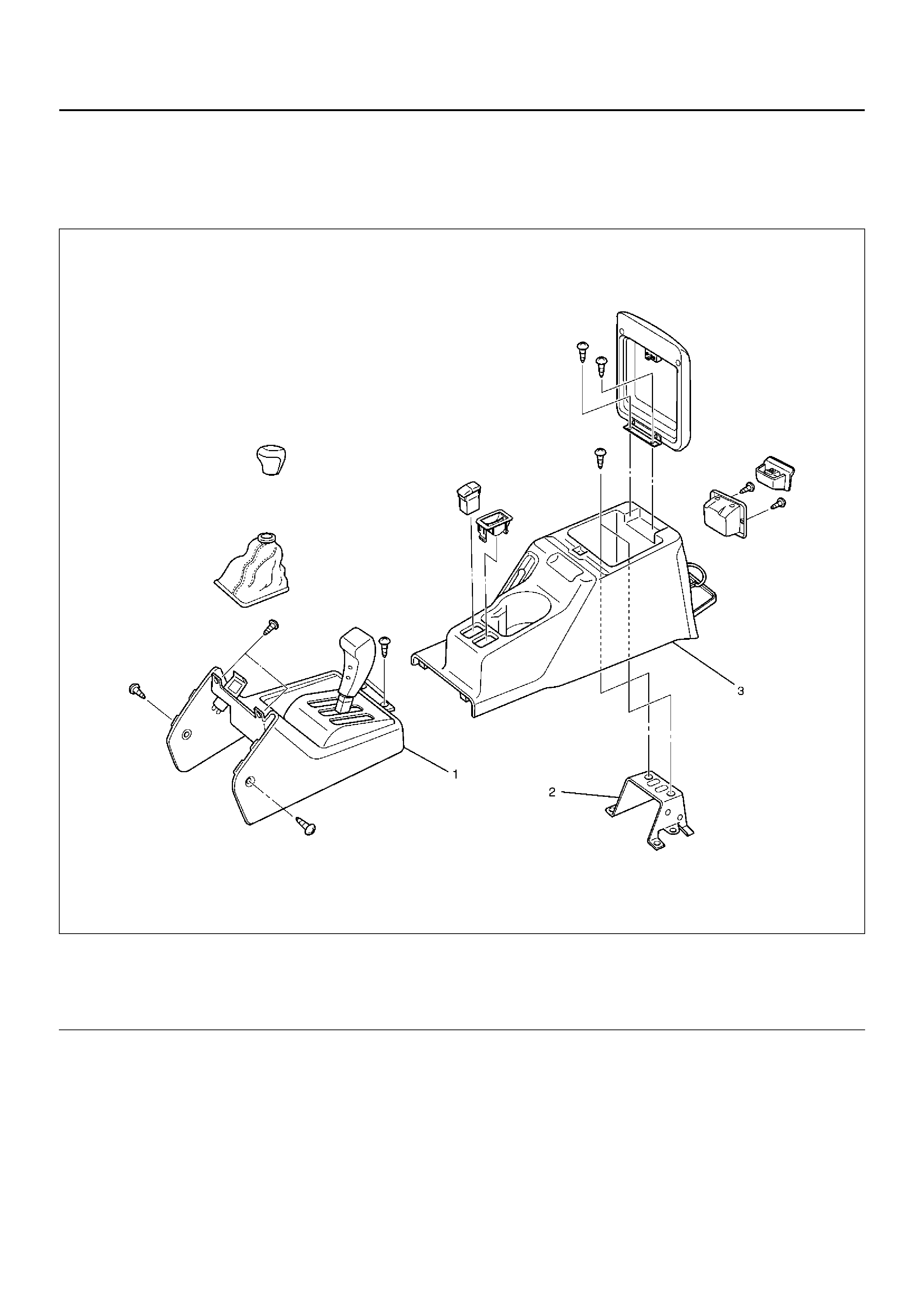
CONSOLES AND ASSOCIATED PARTS
745RX004
Legend
EndOFCallout
REMOVAL
1. Disconnect the battery ground cable.
2. Remove the shift knob (M/T) / transfer knob (W/O
TOD).
3. Remove the rear console assembly.
• Open the rear console lid and remove two
screws.
• Disconnect the switch connector.
4. Remove the front console assembly.
• Remove six fixing screws and disconnect the
accessory socket connector.
INSTALLATION
To install, follow the removal steps in the reverse order.
(1) Front Console
(2) Console Brackets (3) Rear Console Assembly
FRONT DOOR TRIM PANEL
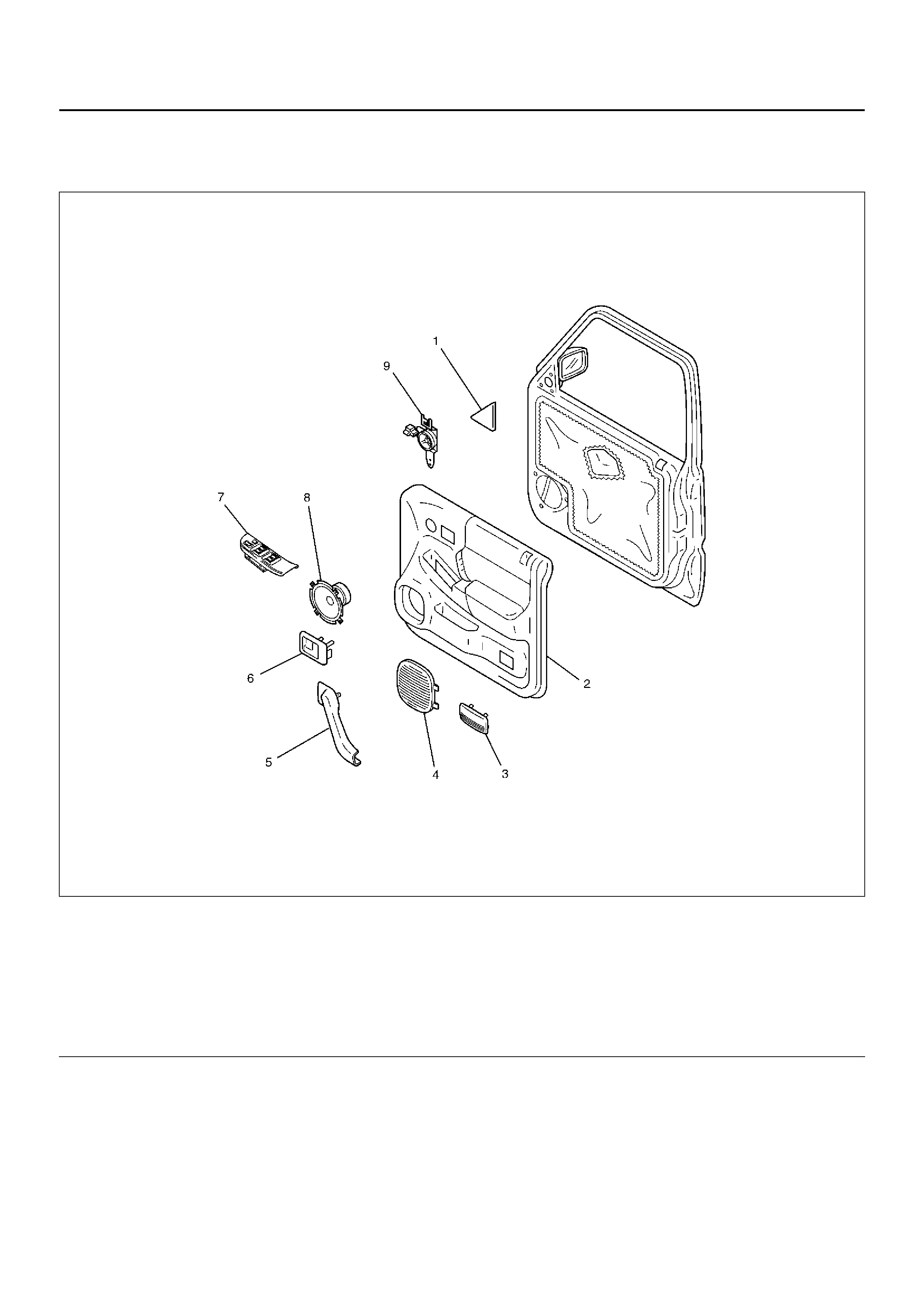
FRONT DOOR TRIM PANEL AND ASSOCIATED PARTS
635RY00012
Legend
EndOFCallout
(1) Door Mirror Cover
(2) Door Trim Panel
(3) Cour tes y Lig ht Lens
(4) Spea ker Gri ll
(5) Grip Cover
(6) Inside Handle
(7) Power Window Switch
(8) Speaker Assembly
(9) Tweeter
REMOVAL
1. Disconnect the battery ground cable.
2. Remove the door mirror cover (2).
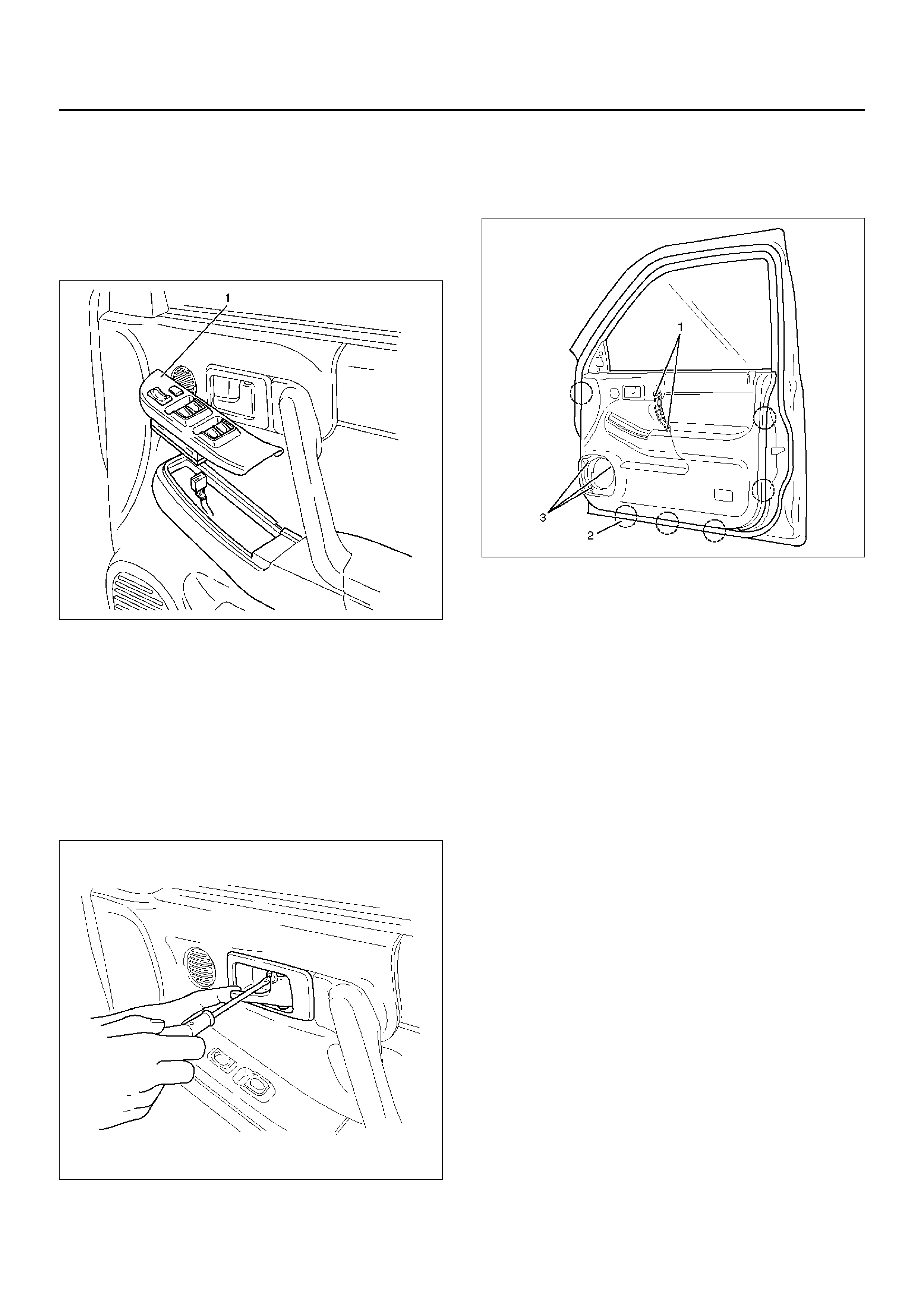
3. Remove the power window switch (1).
• Pry the power window switch out and disconnect
the switch connector.
635RW016
4. Remove the speaker cover.
5. Remove the front speaker.
• Remove the front speaker fixing screws in order
to disconnect the speaker connector.
6. Remove the inside handle fixing screw.
CAUTION: Take care not to apply excessive force
on the inside handle link, lest this link is elongated,
which could make it impossible to operate the door
with the inside handle.
632RW003
7. Remove the door trim panel.
• Remove the five fixing screws (1), (3) in order to
pull out the six clip positions (2) from the door
panel.
635RW007
• Disconnect the tweeter and courtesy light
connectors to lift the door trim panel and unlock
the engagement of the waist seal section. Then,
pass the inside handle through the mounting hole
of the trim panel, and detach the trim panel.
8. Remove the inside handle.
9. Remove the tweeter.
INSTALLATION
To install, follow the removal steps in the reverse order.
REAR DOOR TRIM PANEL
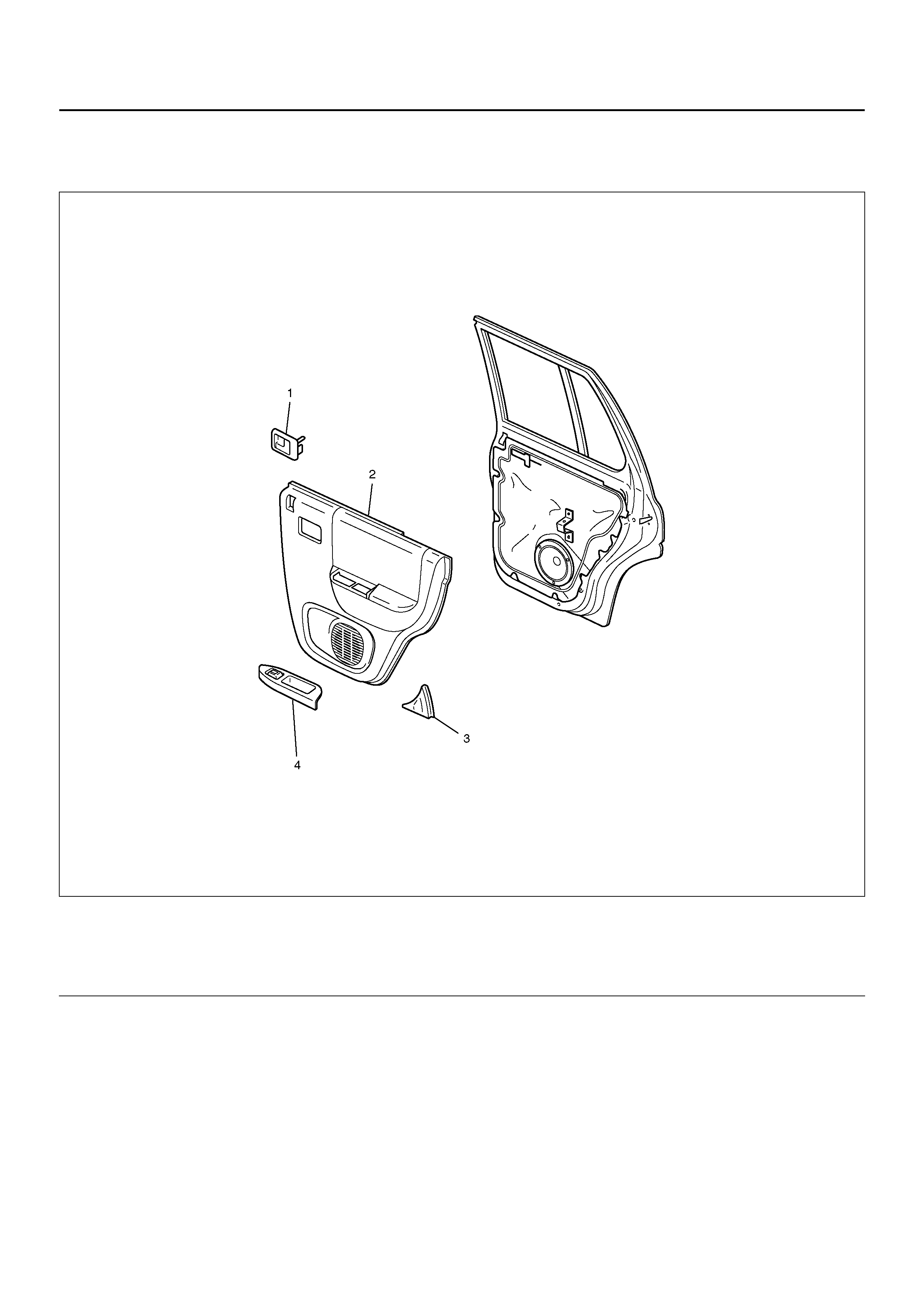
REAR DOOR TRIM PANEL AND ASSOCIATED PARTS
655R100007
Legend
EndOFCallout
(1) Inside Hand le
(2) Door Trim Panel (3) Rear Door Corner Garnish
(4) Power Window Switch
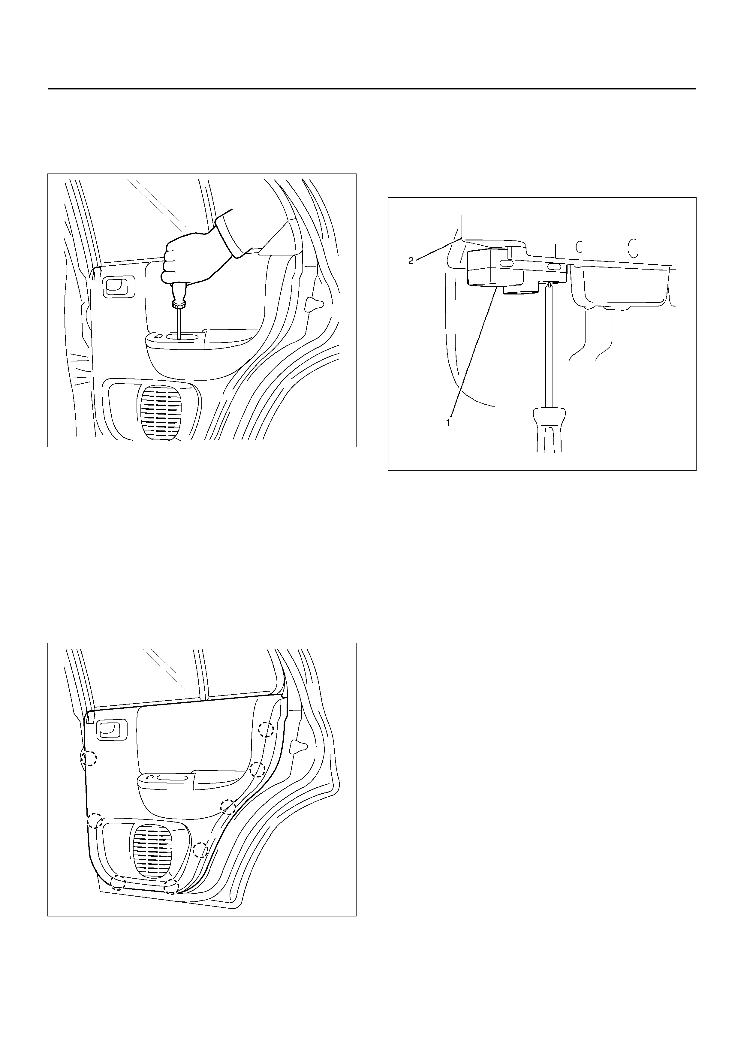
REMOVAL
1. Disconnect the battery ground cable.
2. Remove the one screw from the pull case.
655R100002
3. Remove the inside handle fixing screw.
CAUTION: Take care not to apply excessive force
on the inside handle link, lest this link be elongated,
which could make it impossible to operate the door
with the inside handle.
4. Remove the rear door corner garnish.
• Pull the garnish to disconnect the retaining clip.
5. Remove the door trim panel.
• Pull the trim panel at the eight clip positions from
the door panel.
655R100003
• Disconnect the power window switch connector
to lift the trim panel and unlock the engagement
of the waist seal section, then pass the inside
lever through the mounting hole of the trim panel,
and detach the trim panel.
6. Remove the inside handle.
7. Remove the power window switch (1) and pull case.
• Remove the fixing screws of switch from back
side of the rear door trim (2).
825RW079
INSTALLATION
To install, follow the removal steps in the reverse order.
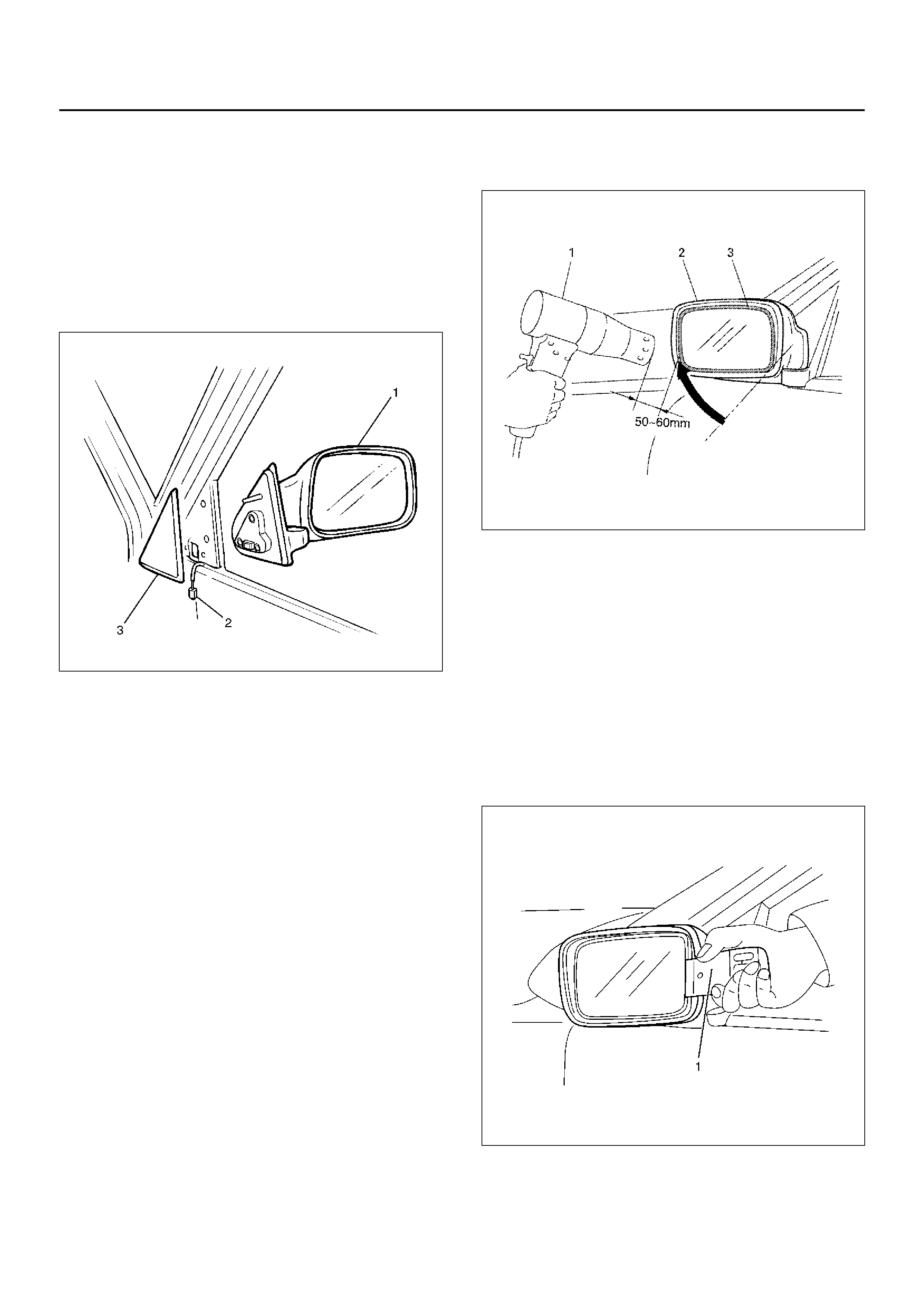
DOOR MIRROR ASSEMBLY
REMOVAL
1. Disconnect the battery ground cable.
2. Remove the door mirror cover (3).
3. Remove the door mirror assembly (1).
• Remove the three bolts and disconnect the
connector (2).
635RX011
INSTALLATION
To install, follow the removal steps in the reverse order.
MIRROR REPLACEMENT
1. Disconnect the battery ground cable.
2. Push down the door mirror (2) to ward the front of
vehicle.
3. Heat the periphery (3) of the mirror with a dryer (1).
• As the dryer keeps the specific distance of 50 mm
to 60 mm from the mirror, heat uniformly.
• Touch the heating part by hand to check if the
mirror base becomes soft.
720RY00006
4. Remove the mirror from the mirror base.
• Prepare a scraper (1) or metal scale, which
thickness is less than 1 mm.
• Insert the scraper or metal scale from the inside
as shown in figure and lift up the back side of the
mirror in approx. 10 mm.
• Peel the periphery part off little by little with
fingers.
CAUTION: As pressing excessively and peeling off
may damage it, handle it with care. When replacing
the mirror which is broken, take care to avoid the
injury.
720RY00003
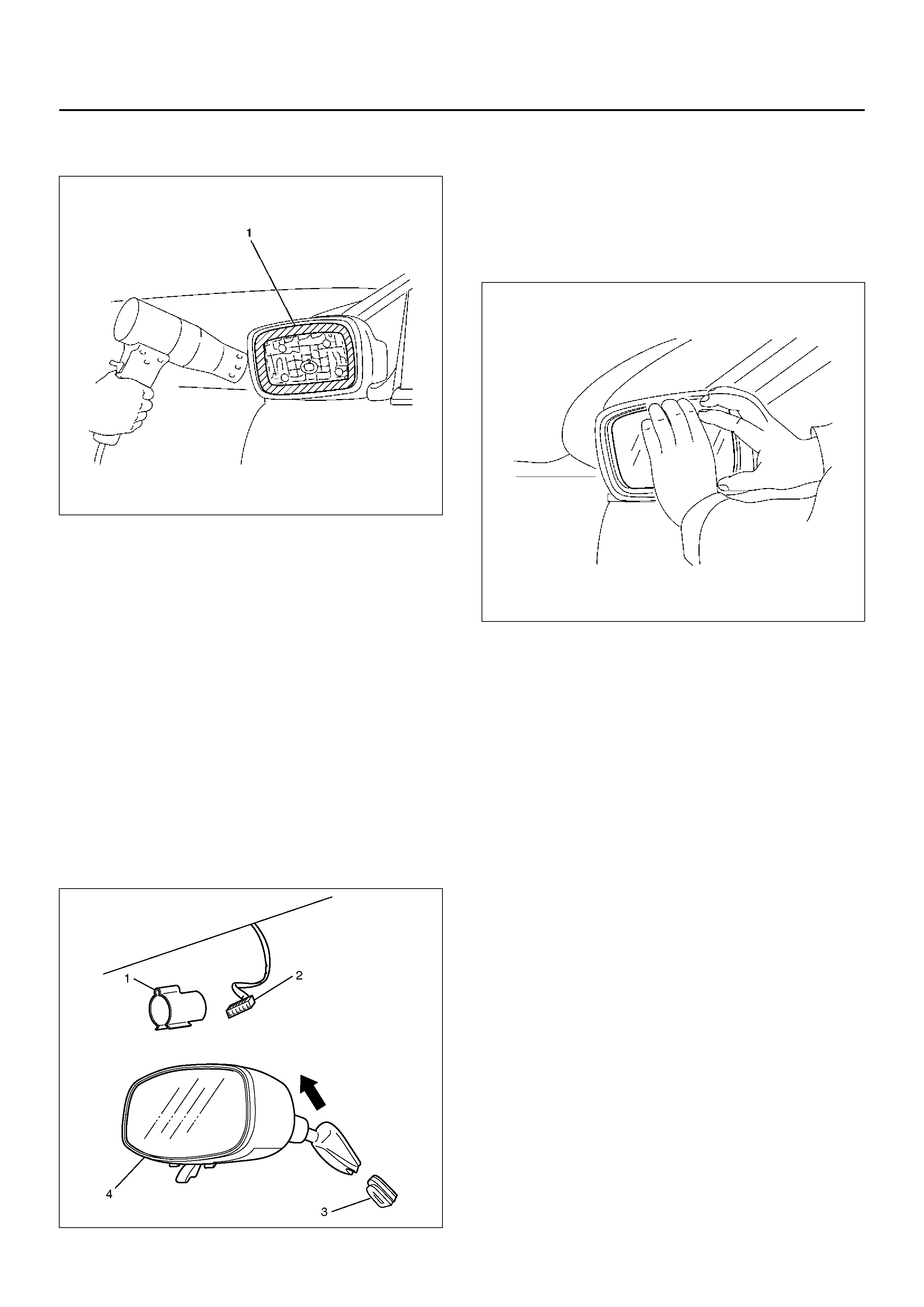
5. When installing the mirror, heat the periphery (1) of
the mirror base in same order to remove it.
720RY00004
6. Peeling off the protection sheet of butyl tape, put it
on the mirror base.
• Check the direction of the upper and lower to put
it on.
• Put the mirror on the mirror base little by little
from the outside of the mirror.
• After checking that the lip of periphery of the
mirror base covers the mirror uniformly, push the
butyl tape to put it on by palm of hand.
CAUTION: When replacing the mirror, check the
part number and change the mirror of the same part
number.
720RY00005
INTERIOR MIRROR ASSEMBLY
REMOVAL
1. Disconnect the battery ground cable.
2. Remove the harness clip (1).
3. Remove the interior mirror assembly (4).
• Pull the interior mirror up with the stay and
remove the interior mirror from the base (3).
• Disconnect the connector (2).
825R100021
INSTALLATION
To install, follow the removal steps in the reverse order.
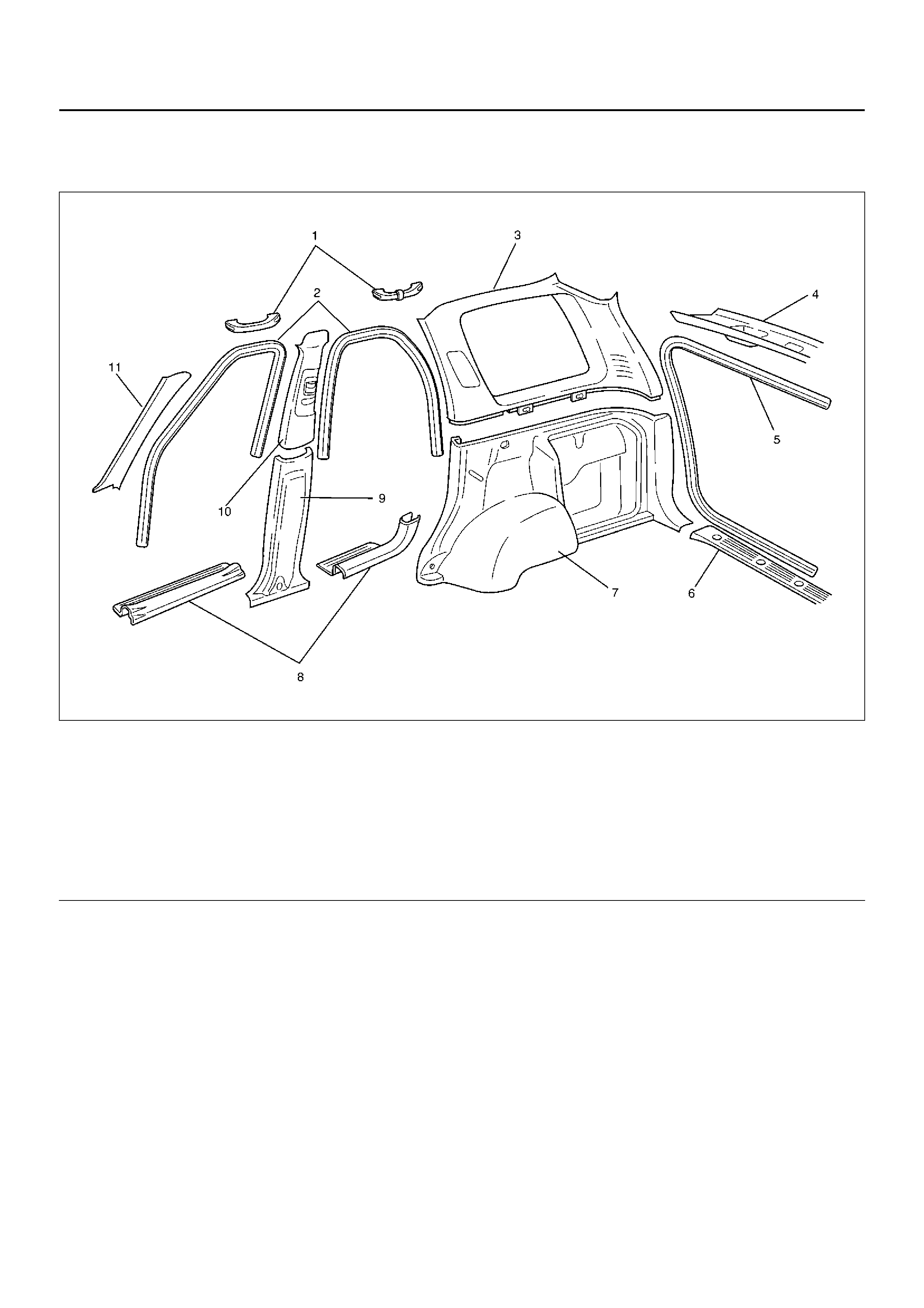
INTERIOR TRIM PANELS
INTERIOR TRIM PANELS AND ASSOCIATED PARTS
643RY00001
Legend
EndOFCallout
REMOVAL
1. Disconnect the battery ground cable.
2. Remo ve the si ll plates (Front & Rear ).
3. Remove the dash side trim cover.
4. Remove the lower center pillar trim cover.
• Remove the lower anchor bolt cover and lower
anchor bolt from the front seat belt.
• Pry the trim cover clips free from the body panel.
5. Remove the door finishers (Front & Rear).
6. Remove the upper center pillar trim cover.
• Pry the trim cover clips free from the body panel.
7. Remove the front pillar trim cover.
• Ply the trim cover clips free from the body panel.
8. Remove the tailgate weather strip.
9. Remove the rear end floor trim cover.
• Remove the five fixing screws.
(1) Assist Grip (Front & Rear)
(2) Door Finisher (Front & Rear)
(3) Upper Quarter Trim Cover
(4) Rear Roof Trim Cover
(5) Tailgate Weather Strip
(6) Rear End Floor Trim Cover
(7) Lower Quater Trim Cover
(8) Sill Plate (Front & Rear)
(9) Lower Center Pillar Trim Cover
(10) Upper Center Pillar Trim Cover
(11) Front Pillar Trim Cover
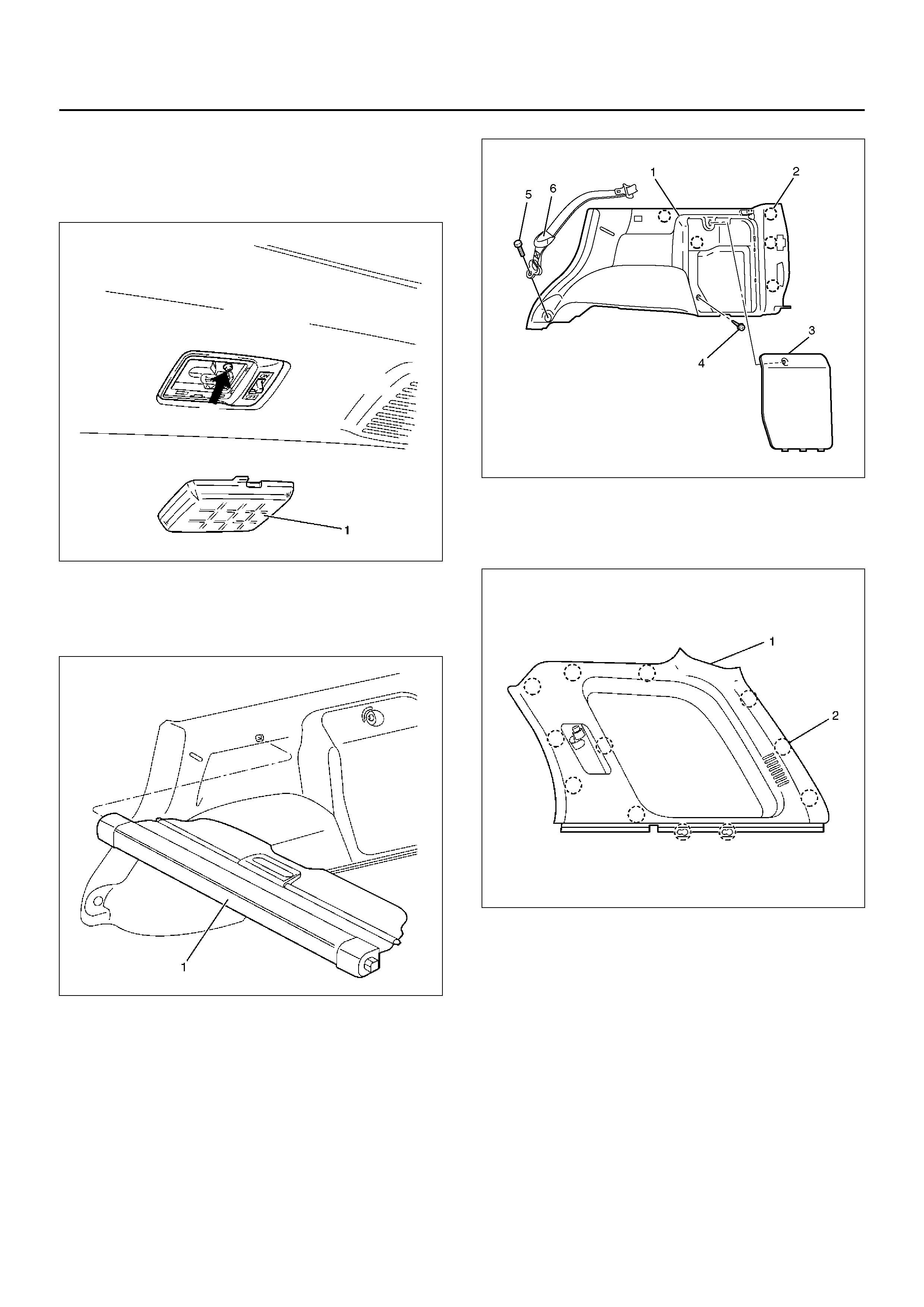
10. Remo ve the luggag e room ligh t.
• Remove the luggage room light lens (1) and the
fixing screw.
• Disconnect the luggage room light connector.
825RW100
11. Remo ve the rear roof trim co ver.
• Pry the trim cover clips free from the body panel.
12. Remo ve the tonn eau cove r assem bl y (1).
643RY00002
13. Remove the lower anchor bolt cover (6) and the
lower anchor bolt (5) from the rear seat belt.
14. Remo ve the low er quarter trim co ve r (1).
• Remove the tool box lid (3) and fixing screw (4).
Pry the fi ve ( RH) o r six ( LH) cl ip posi t io ns ( 2) f re e
from the body panel.
• Disconnect the accessory socket connector (LH
side).
643R100001
15. Remove the upper quarter trim cover (1).
• Pry the twelve clip positions (2) free from the
body panel.
643RY00004
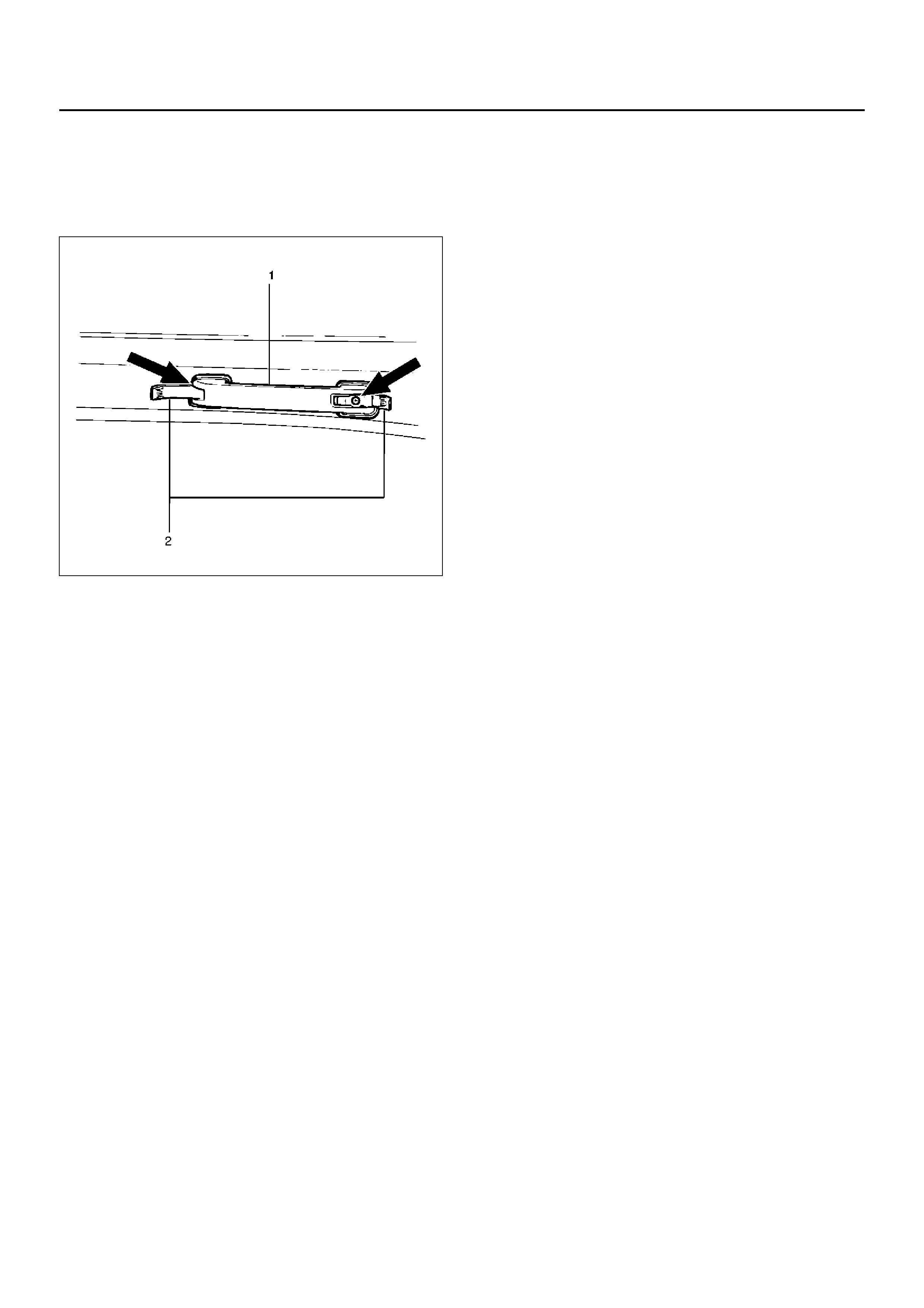
16. Remove the front pillar assist grip (1) (Front &
Rear).
• Open the both sides of the assist grip cover (2)
and remove the fixing screws and the front pillar
assist grip.
743RW003
INSTALLATION
To install, follow the removal steps in the reverse order,
noting the following point:
1. Tighten the seat belt anchor bolt to the specified
torque.
Torque: 39N·m (4.0kg·m/29lbft)
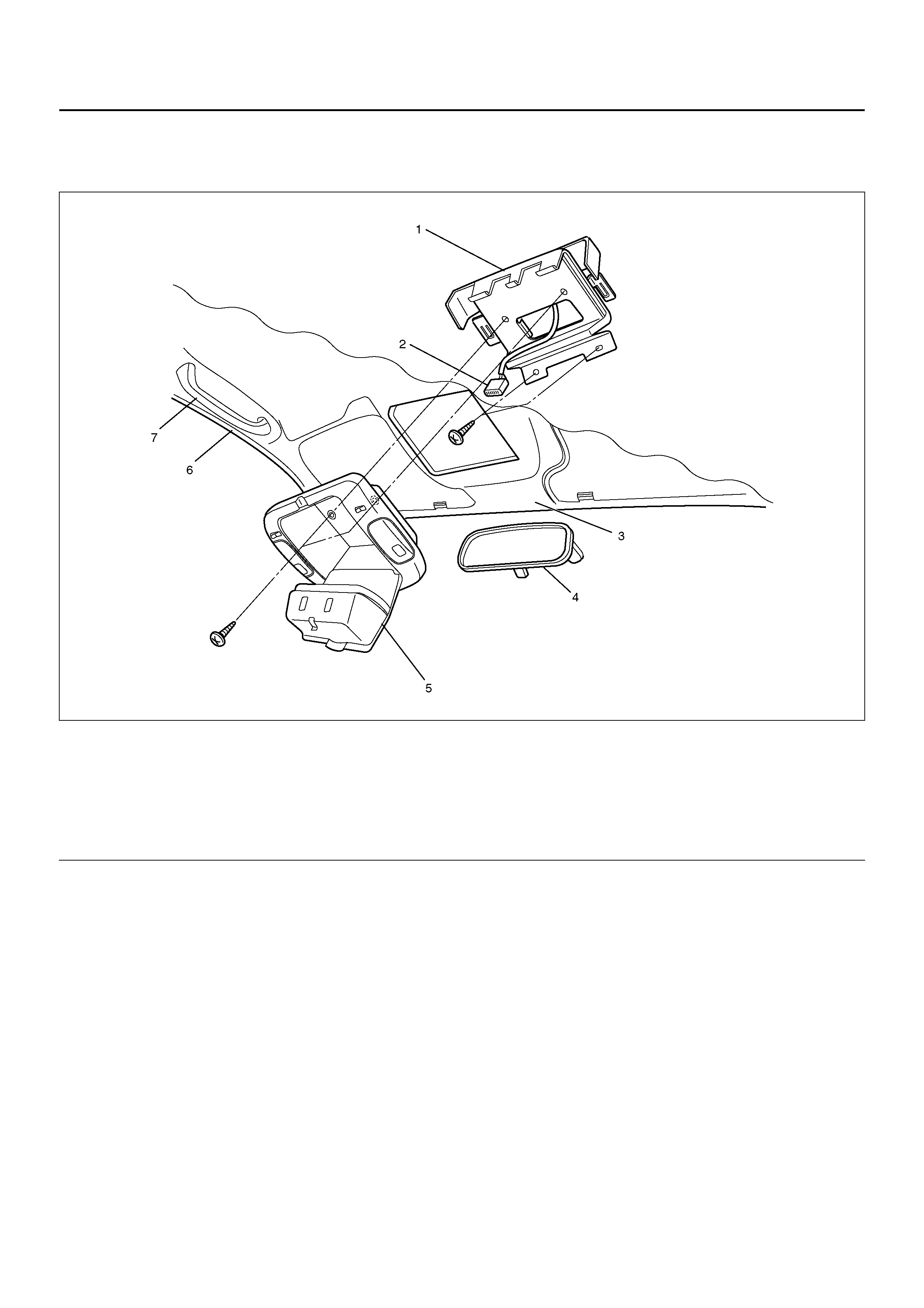
OVERHEAD CONSOLE
PARTS LOCATION
743R100002
Legend
EndOFCallout
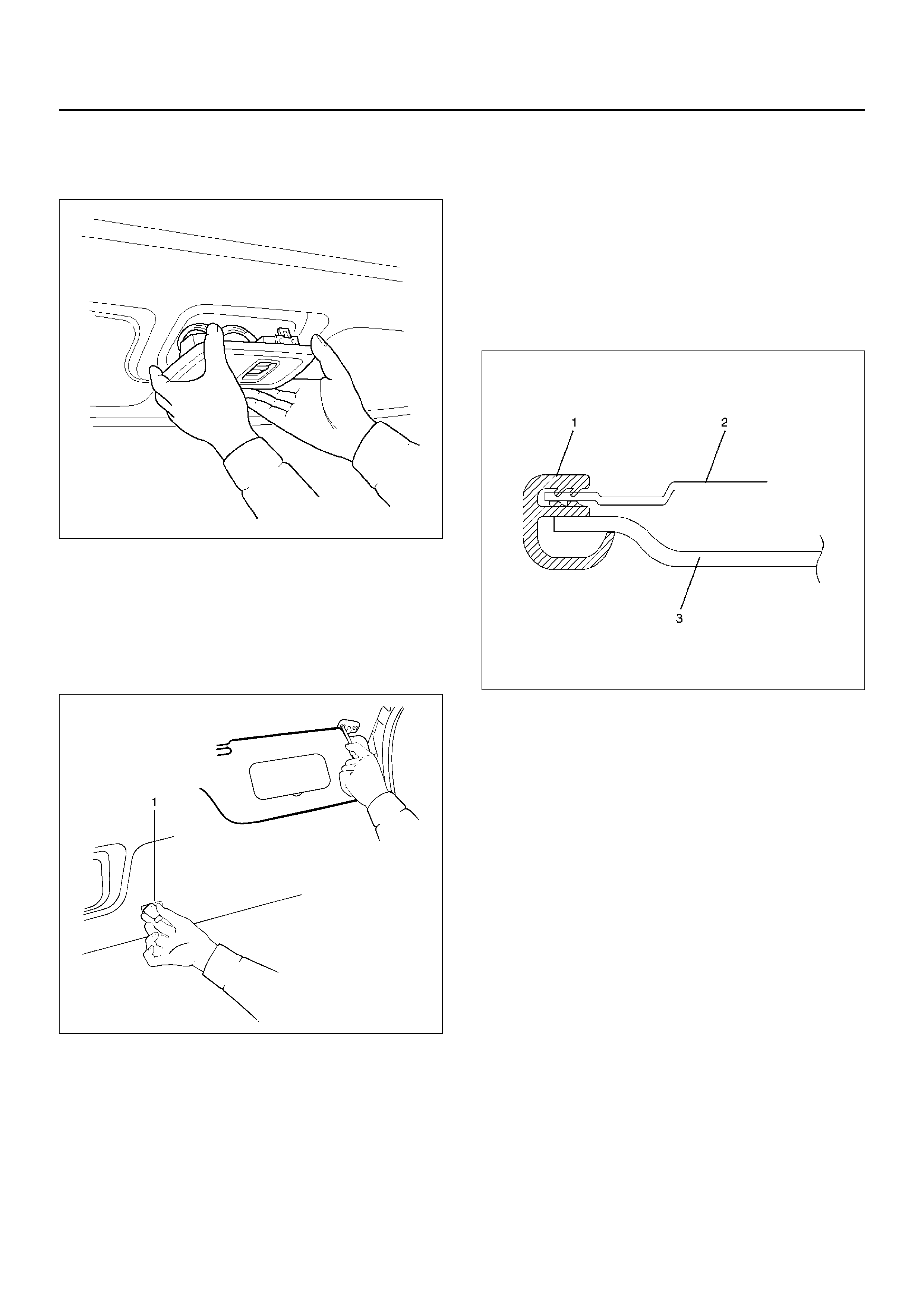
REMOVAL
1. Disconnect the battery ground cable.
2. Remove the overhead console assembly.
• Open the lid and remove the two screws.
• Disconnect the harness connector.
3. Remove the sunvisor and sunvisor holder. (right and
left)
4. Remove the front assist grip. (right and left)
5. Remove the front piller trim cover.
6. Remove the front door finisher.
• Remove the upper side of door finisher.
7. Remove the interior mirror.
8. Remove the overhead console bracket.
• Remove the two screws.
INSTALLATION
To install, follow the removal steps in the reverse order.
(1) Overhead Console Bracket
(2) Harness Connector
(3) Head Lining
(4) Interior Mirror
(5) Overhead Console Assembly
(6) Front Door Finis he r
(7) Fr ont As si s t Grip
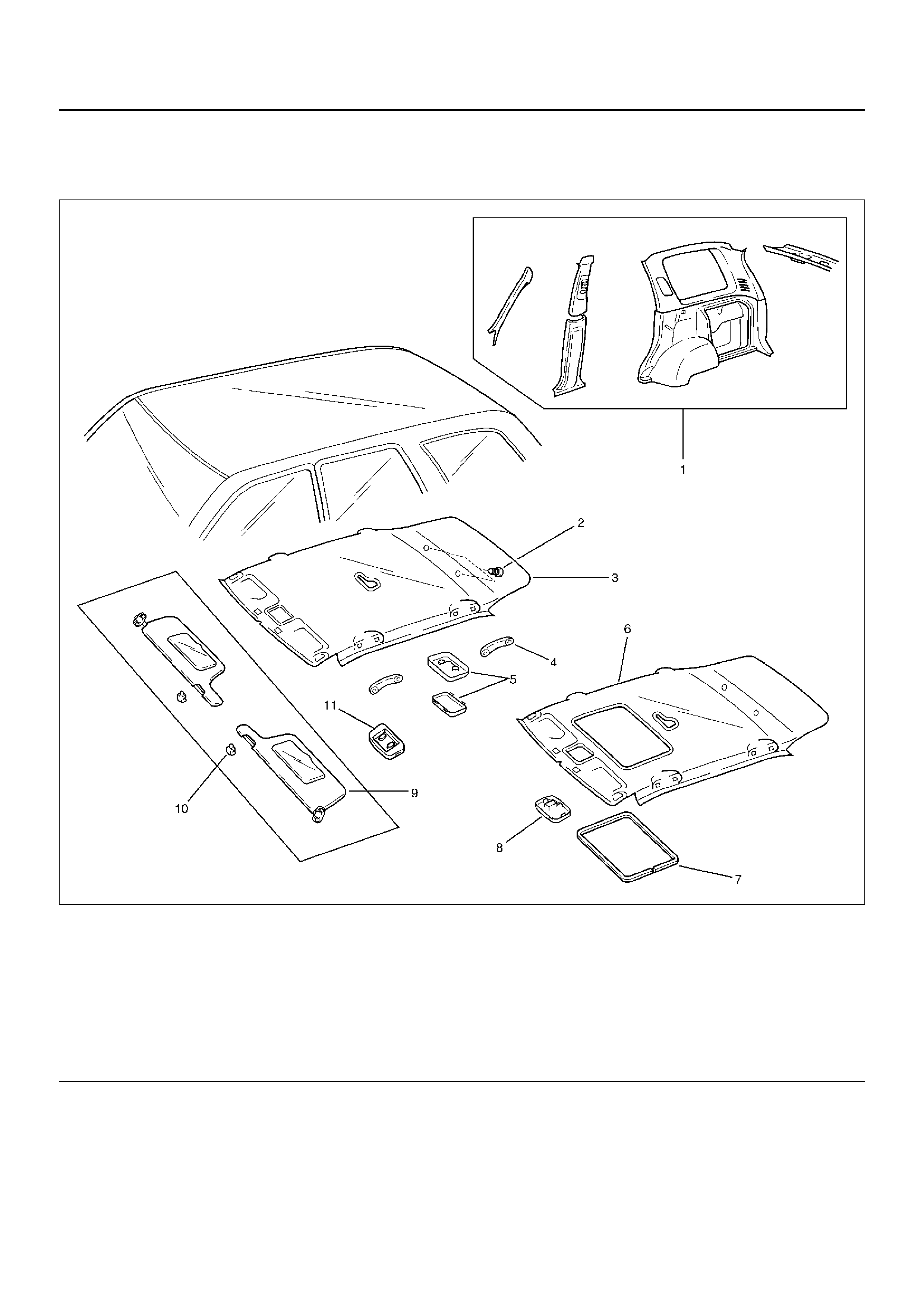
HEADLINING
PARTS LOCATION
666RY00003
Legend
EndOFCallout
REMOVAL
1. Disconnect the battery ground cable.
2. Remove the interior trim panels.
• Refer to Interior Trim Panels in this section.
3. Remove the dome light.
• Remove the dome light lens and the fixing
screws.
• Disconnect the dome light connectors.
(1) Inter io r Trim Panels
(2) Clip
(3) Headlining (Without Sunroof)
(4) Assist Grip
(5) Dome Lig ht
(6) Headlinng (With Sun Roof)
(7) Sunroof Finisher (With Sunroof)
(8) Sunroof Switch (With Sunroof)
(9) Sunvisors
(10) Sunvisor Holder
(11) Overhead Consol (Without Sunroof)
4. Remove the sunroof switch (With sunroof).
• Pry the clip positions free from the sunroof switch
bracket and disconnect the connector.
665RW002
5. Remove the overhead consol (Without sunroof).
• Refer to Overhead Consol Assembly in Exterior/
Interior section.
6. Remove the sunvisors.
• Remove the fixing screws and pull out the
sunvisor holder (1) to remove it.
743R200003
7. Remove the sunroof finisher (With sunroof).
8. Remove the headlining.
• Remove the headlining fixing clips.
INSTALLATION
To install, follow the removal steps in the reverse order,
noting the foll owi ng poi nts.
1. Install the headlining so that the fixing clips will not
come off.
2. To install the sunroof finisher (1), first fit it in at one
place with the headlining (3) close to the sunroof
frame complete (2), then install the entire finisher
tightly by hitting it with a plastic hammer, not
allowing it to move up.
665RW003
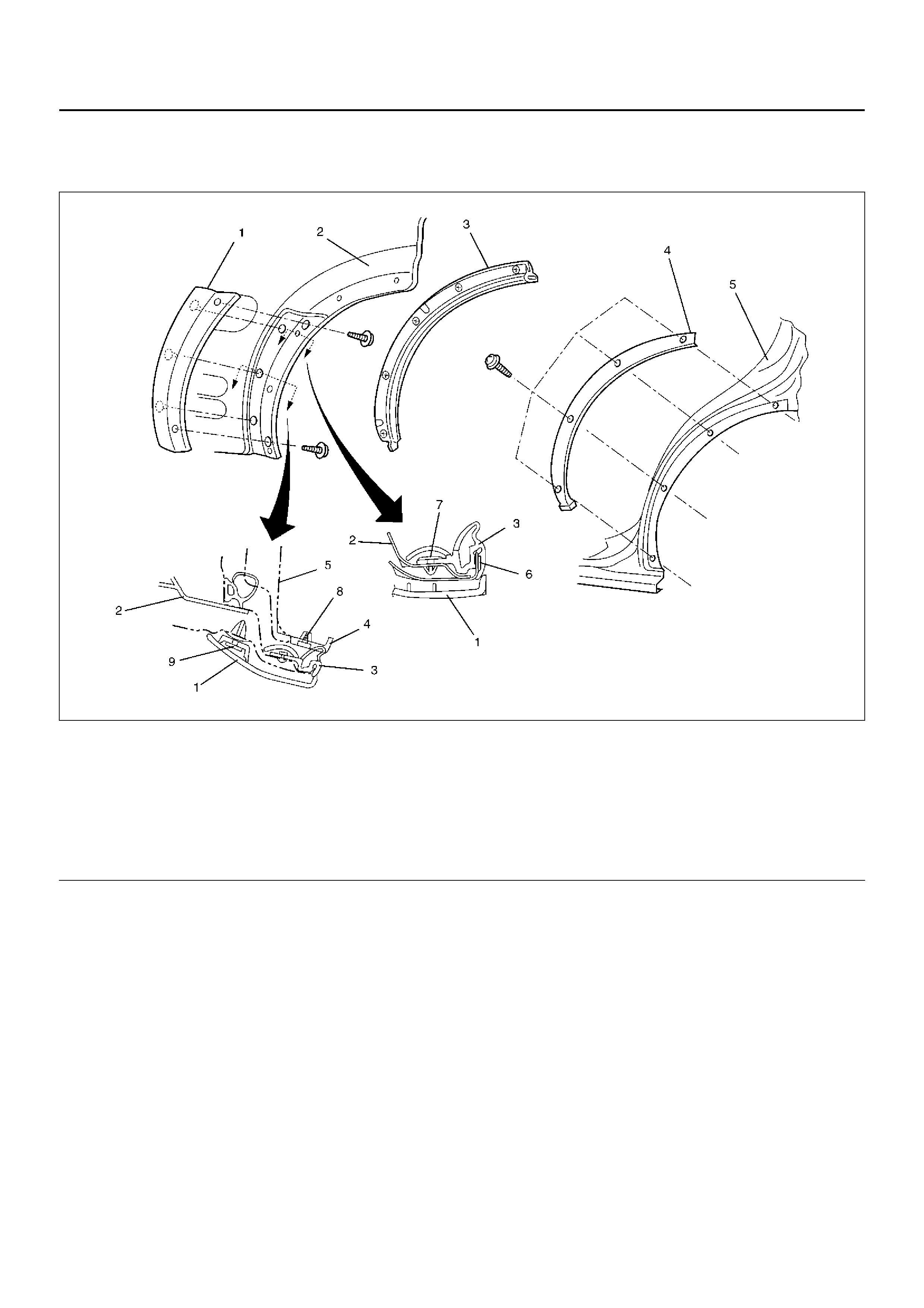
WHEEL ARCH PROTECTOR
WHEEL ARCH PROTECTOR AND ASSOCIATED PARTS
620RW019
Legend
EndOFCallout
REMOVAL
1. Remove the wheel arch cover.
• Remove the four fixing screws.
2. Remove the wheel arch protector.
• Remove the two fixing screws from the back side
of the rear door panel and pull out the clips at
three positions.
3. Remove the rear door wheel arch seal.
• After disengaging five clips, peel off the double
sided adhesive tape.
INSTALLATION
To install, follow the removal steps in the reverse order,
noting the foll owi ng poi nt.
1. Use a new double sided adhesive tape whenever
installing the rear door wheel arch seal.
Using a white gasoline, clean the places in advance
where a double sided adhesive tape is affixed.
(1) Wheel Arch Protector
(2) Rear Door Panel
(3) Rear Door Wheel Arch Seal
(4) Wheel Arch Cover
(5) Body Panel
(6) Double Sided Adhesive Tape
(7) Clip
(8) S cr ew Grom met
(9) Clip
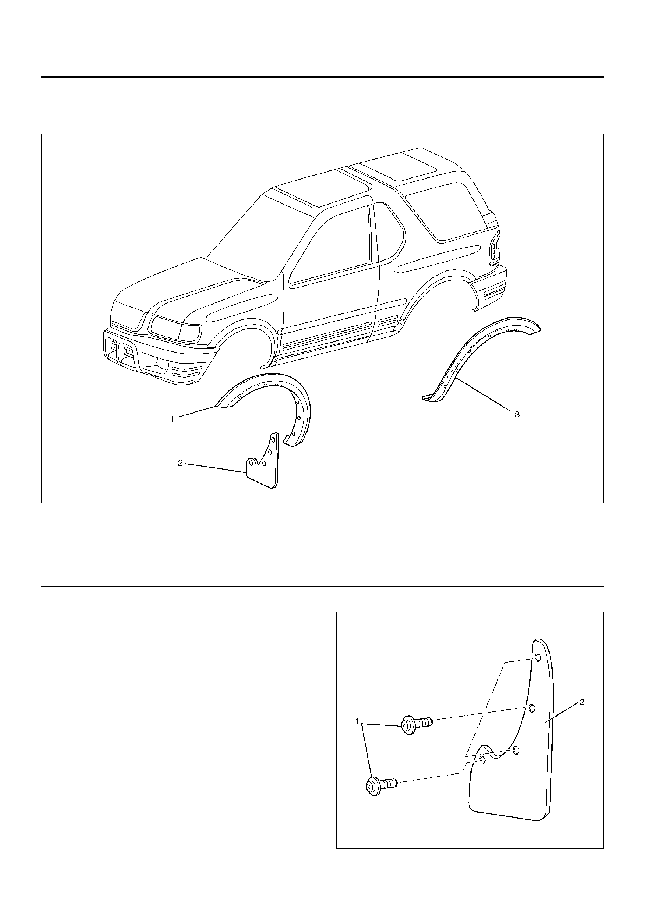
WHEEL ARCH MOULDING
WHEEL ARCH MOULDING AND ASSOCIATED PARTS
620RY00007
Legend
EndOFCallout
REMOVAL
1. Remove the front mud fla p (2).
• Remove the four fixing screws (1).
(Three of four screws are fixed together with
moulding.)
647RW002
(1) Front Wheel Arch Moulding
(2) Front Mud Flap
(3) Rocker Wheel Arch Extension
(4) Rear Wheel Arch Moulding
(5) Quarter Panel Wheel Arch Moulding
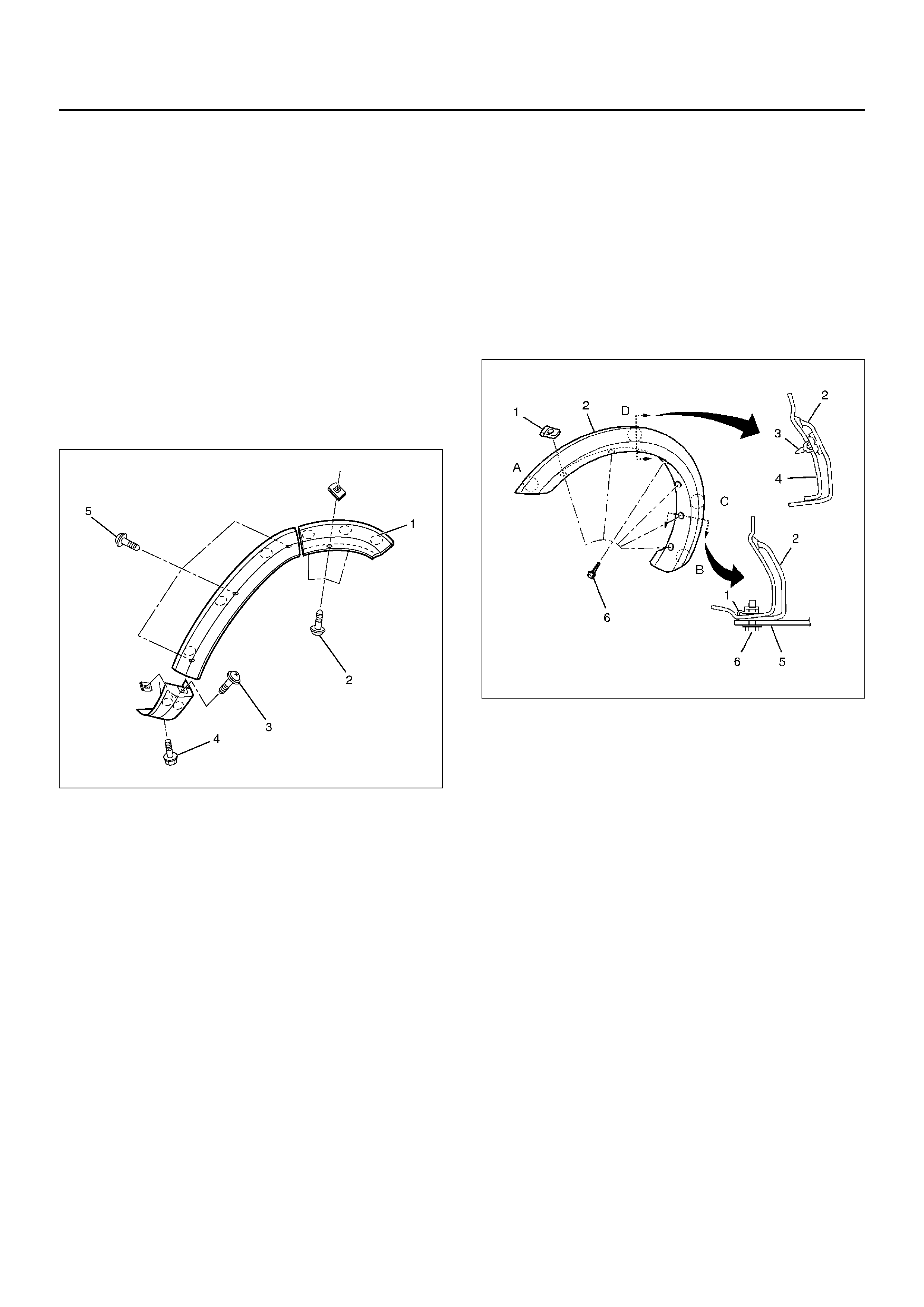
2. Remove the front wheel arch molding.
• Remove the three fixing screws and pull out the
clips at three positions from the fender panel.
3. Remove the rocker wheel arch extension.
• Remove the fixing bolt (4) and screw (3). Pull out
the extension with the two clips (1) from the
rocker outer panel.
4. Remove the quater panel wheel arch moulding.
• Remove the three fixing screws (2) and pull out
the moulding with the three clips (1) from the
quarter outer panel.
5. Remove the rear wheel arch moulding.
• Remove the three fixing screws (5) of the back of
the door panel and pull out the moulding with the
three clips (1) from the door outer panel.
620RY00003
INSTALLATION
To install, follow the removal steps in the reverse order,
noting the foll owi ng poi nts.
1. Install the front wheel arch molding (2).
• Install the six nuts (1) to the body panel (4).
• Put the four clips (3) of the front wheel arch
molding into the body in order of A, B, C and D.
2. Install the six fixing screws (6).
(Three of six screws are fixed together with the front
mud flap.)
620RW015
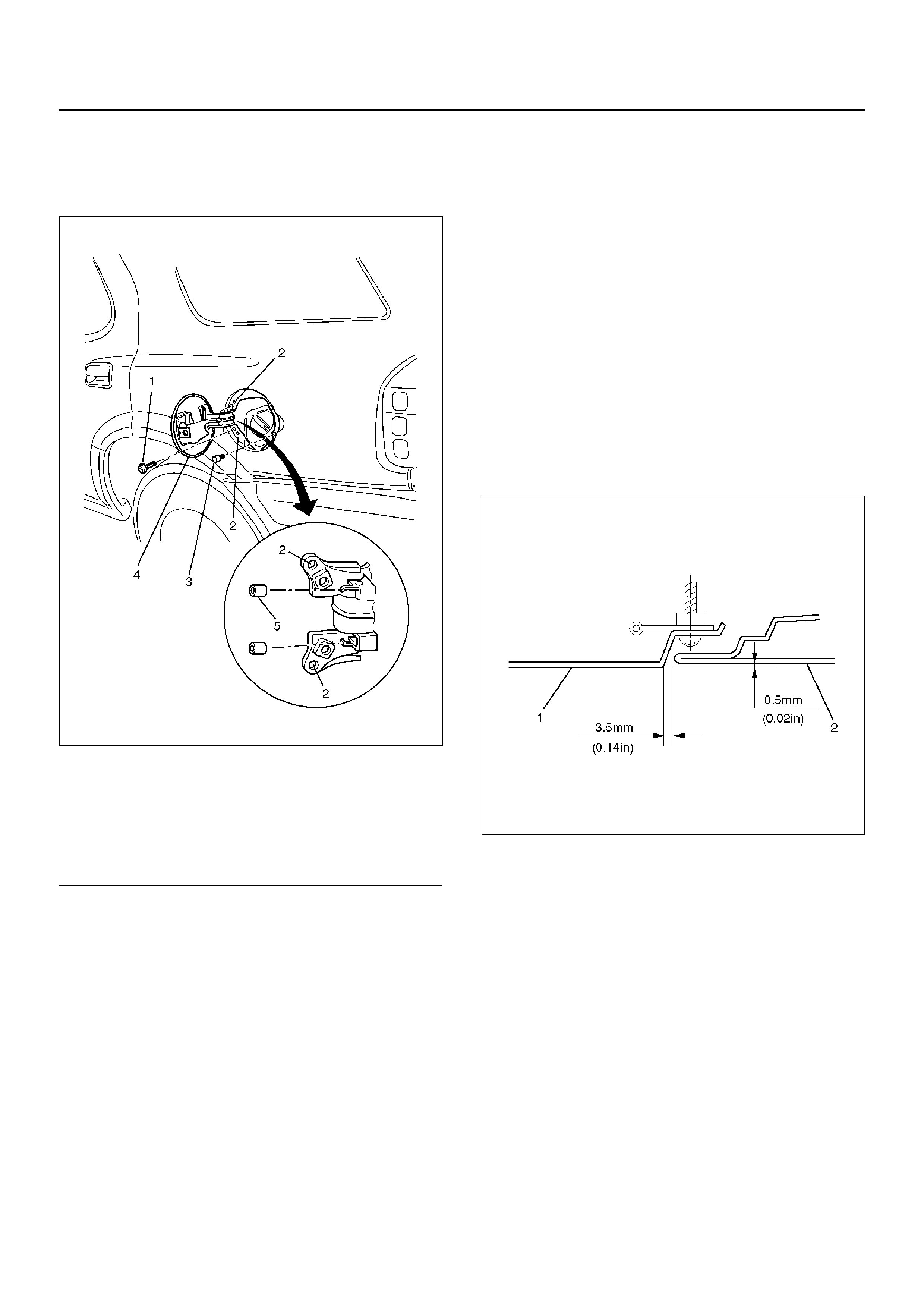
FUEL FILLER DOOR
PARTS LOCATION
686RW010
Legend
EndOFCallout
REMOVAL
1. Open the fuel filler door.
2. Remove the fuel filler door.
• Remove the two fixing screws.
3. Pull out the fuel filler door buffer.
4. Pull out the fuel filler hinge buffer.
INSTALLATION
To install, follow the removal steps in the reverse order,
noting the foll owi ng poi nts.
1. Install the fuel filler door to match the basic hole.
2. Adjust the clearance between quarter outer panel
(1) and fuel filler door (2).
686RX003
(1) Fuel Filler Door Fixing Screw
(2) Basic Hole
(3) Fuel Filler Door Buffer
(4) Fuel Filler Door
(5) Fuel Filler Door Hinge Buffer
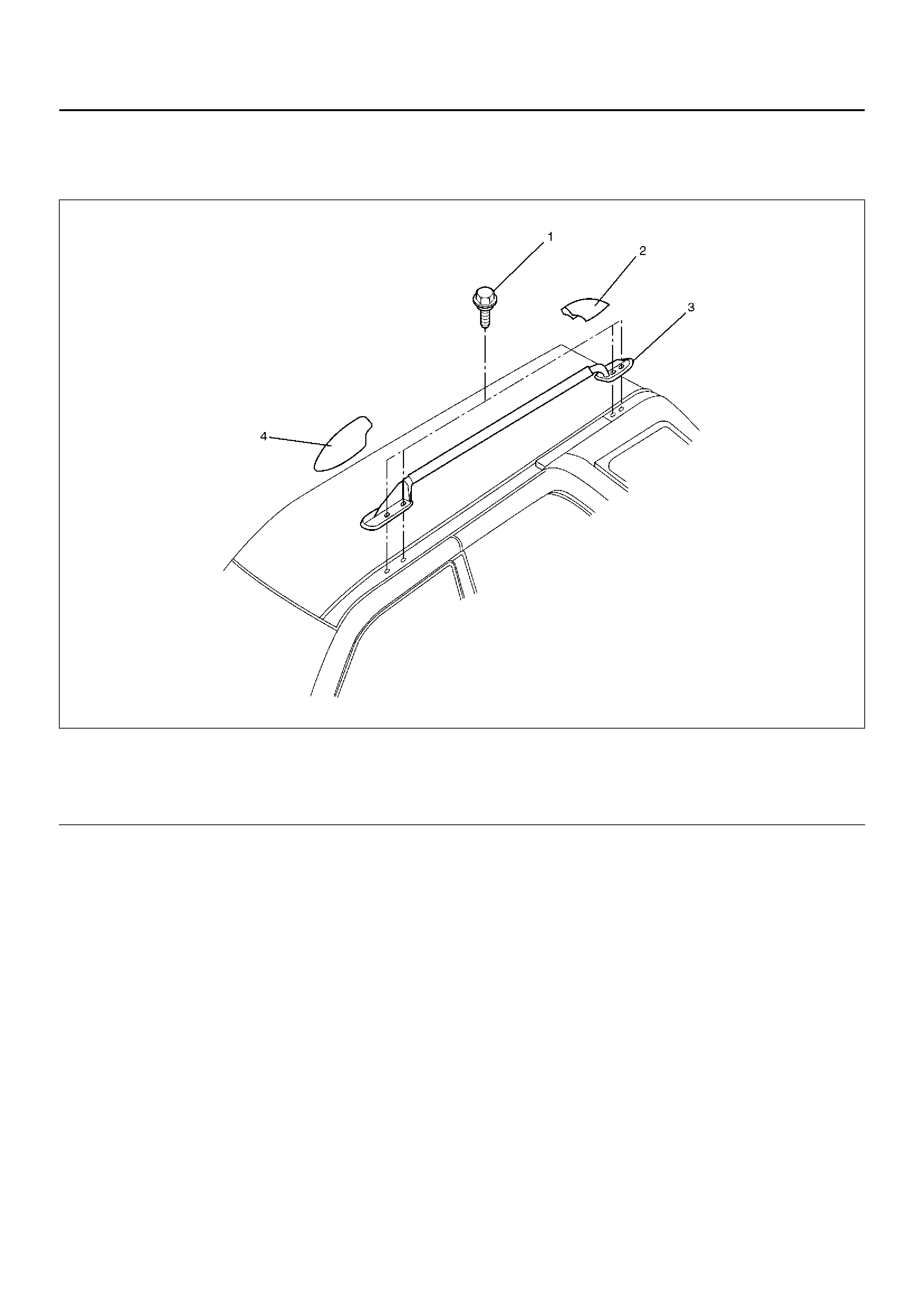
ROOF RAIL
PARTS LOCATION
660RY00016
Legend
EndOFCallout
REMOVAL
1. Remove the front and rear of roof rail cover.
• Pry the roof rail covers.
2. Remove the roof rail sub assembly.
• Remove the four fixing bolts at each roof rail.
INSTALLATION
To install, follow the removal steps in the reverse order,
noting the following points.
1. Tighten the roof rail sub assembly fixing bolts to the
specified torque.
Torque 8N·m (0.8kg·m/69lbin)
(1) Roof Rail Fixing Bolt
(2) Rear Roof Rail Cover (3) Roof Rail Sub Assembly
(4) Front Roof Rai l Cove r
POWER DOOR MIRROR SYSTEM
GENERAL DESCRIPTION
The system consists of the starter switch, door mirror
switch, rear defogger/mirror defogger switch and door
mirrors on both sides.
When the door mirror switch is operated with the starter
switch at either “ACC" or “ON" position, the motor in the
door mirror (on either side) rotates to allow the
horizontal and vertical adjustment of mirror angles.
When the rear defogger/mirror defogger switch is turned
“ON" (with the starter switch at “ON" position), the
heaters in both left and right mirrors and the rear
hatchgate glass are activated to defog both mirrors and
rear hatchgate glass at the same time.
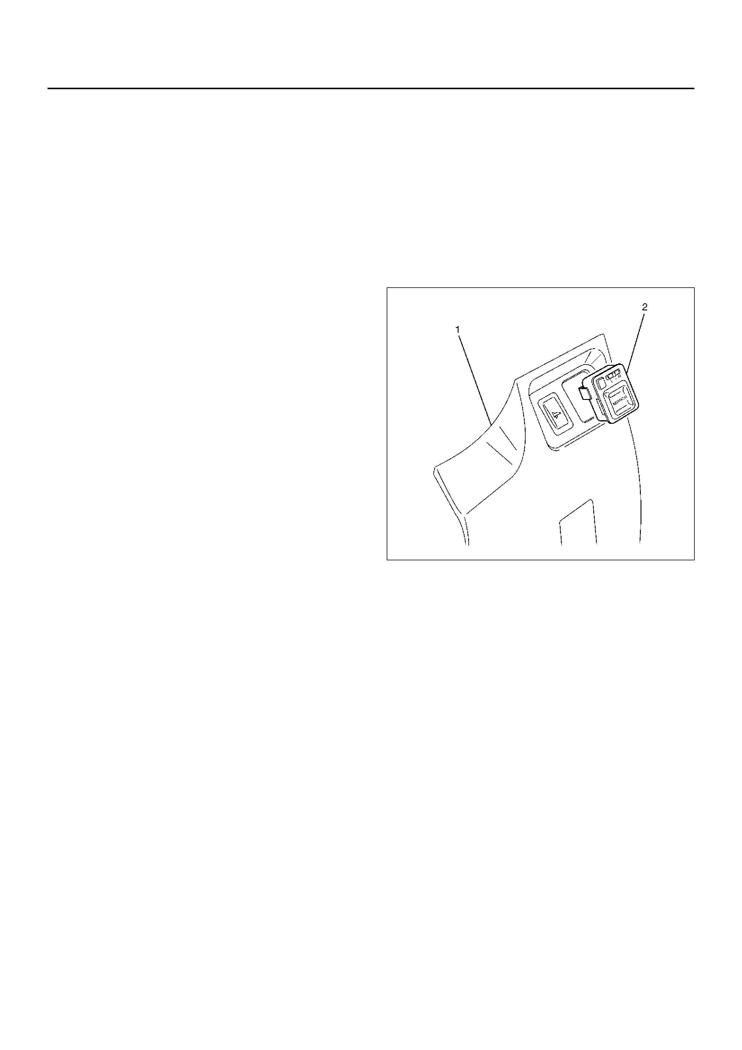
DOOR MIRROR SWITCH
REMOVAL
1. Disconnect the battery ground cable.
2. Remove the instrument panel lower cover (1).
Refer to the instrument panel assembly in Body
Structure section.
3. Remove the door mirror switch (2).
825RW266
Installation
To install, follow the removal steps in the reverse order.
Rear Defogger/Mirror Defogger Switch
Refer to Rear Defogger/Mirror Switch in Lighting
System section.
Door Mirrors
Refer to Door Mirror Assembly in this section.
POWER WINDOW SYSTEM
GENERAL DESCRIPTION
The power window system consists of power window
switches and power window motors on driver and
passenger sides and power window relay. With the
starter switch in “ON" position, the battery voltage is
supplied through power window relay to the power
window switches on driver and passenger sides.
Selection of up or down switch changes the motor
rotating direction to open or close the window.
When the lock switch on the switch panel on the driver
side is pressed, the power window switch is in open
state. As a result, the power source to the other
switches are cut off, and the power window motors do
not run.
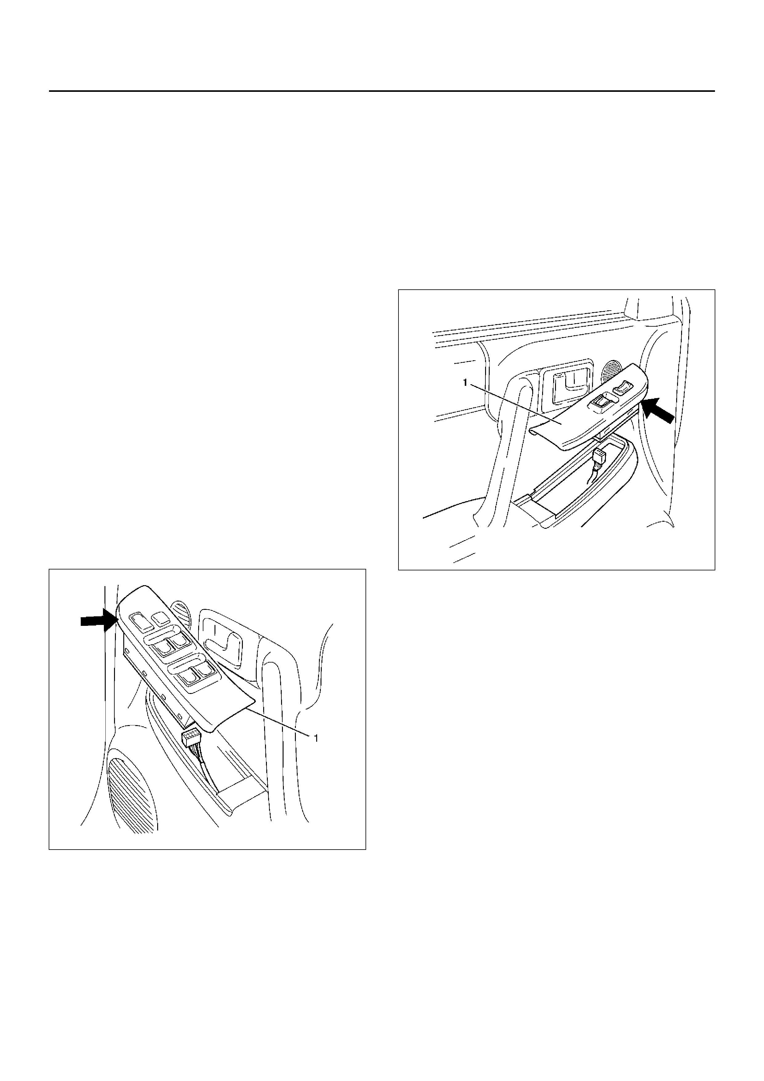
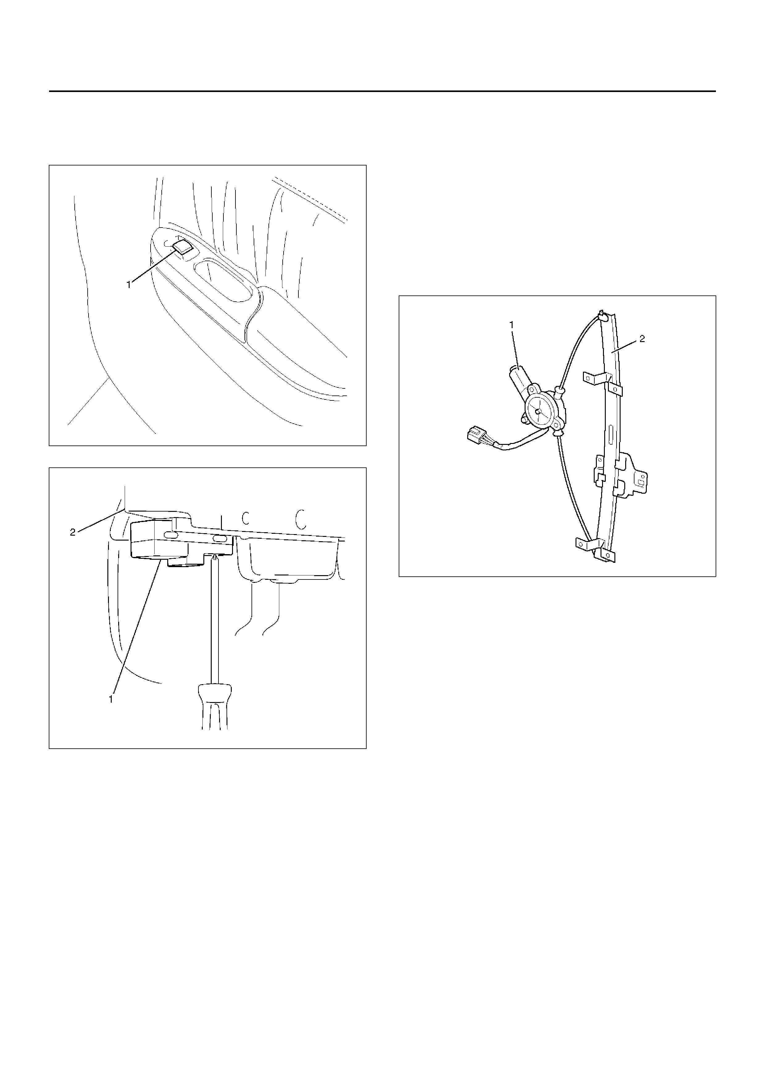
POWER WINDOW SWITCH DRIVER
SEAT SIDE
REMOVAL
1. Disconnect the battery ground cable.
2. Remove the switch (1).
• Pull out the switch by pushing the spring with the
tip of a screwdriver.
• Disconnect the connector.
825RY00073
Installation
To install, follow the removal steps in the reverse order.
Front Passenger Seat Side
Removal
1. Disconnect the battery ground cable.
2. Remove the switch (1).
• Pull out the switch by pushing the spring with the
tip of a screwdriver.
• Disconnect the connector.
825RW264
Installation
To install, follow the removal steps in the reverse order.
Rear-Left and Right Sides
Removal
1. Disconnect the battery ground cable.
2. Remove the rear door trim panel (2).
• Refer to Rear Door Trim Panel in this section.
• Disconnect the rear power window switch (1)
connector.
3. Remove the rear power window switch (1).
• Remove the switch fixing screw from the back
side of the rear door trim (2).
825RW081
825RW079
Installation
To install, follow the removal steps in the reverse order.
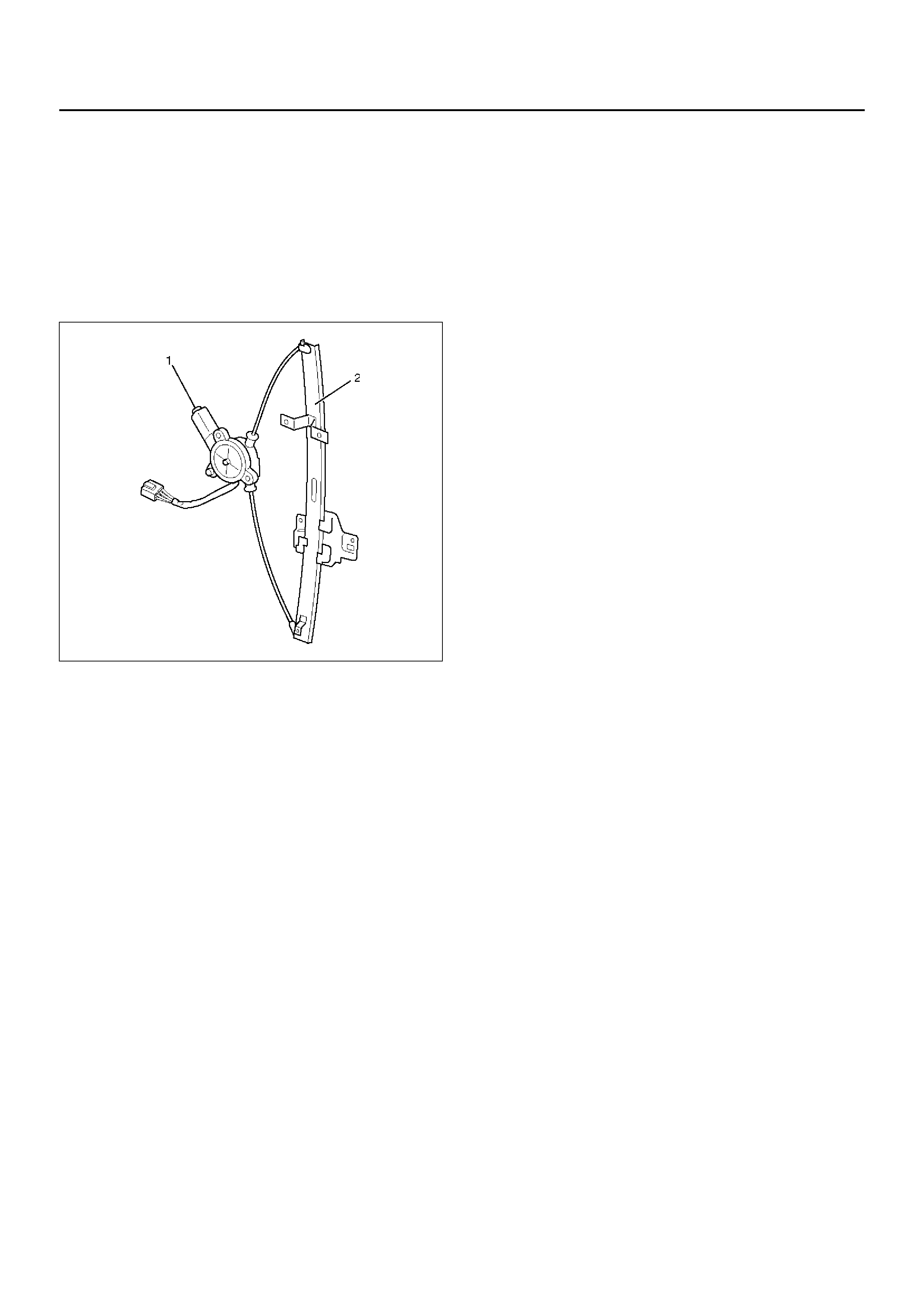
POWER WINDOW MOTOR
DRIVER SEAT SIDE
Removal
1. Disconnect the battery ground cable.
2. Remove the window regulator assembly (2).
• Refer to Window Regulator and Glass in Body
Structure section.
3. Remove the power window motor (1).
• Remove three screws.
825RW096
Installation
To install, follow the removal steps in the reverse order.
Front Passenger Seat Side
Removal and Installation
Refer to Front Window Motor — Driver Seat Side in this
section.
Rear-Left Side
Removal
1. Disconnect the battery ground cable.
2. Remove the rear window regulator assembly (2).
• Refer to Rear Window Regulator and Glass in
Body Structure section.
3. Remove the power window motor (1).
• Remove three screws.
825RW095
Installation
To install, follow the removal steps in the reverse order.
Rear-Right Side
Removal and Installation
Refer to Rear Power Window Motor — Left Side in this
section.

MAIN DATA AND SPECIFICATIONS
Torque Specifications
Application N·m kg·m lb ft lb in
Front & Rear Seat Belt Anchor Bolts 39 4.0 29 —
Roof Rail Fixing Bolts 8 0.8 — 69