
SECTION 11 - ENGINE IMMOBILISER SYSTEM
General Information
System Components
Engine Start Sequence
System Programming
TECH 2 Operation
Transponder-Key Programming
Erasing Transponder Keys
Programming The Immobiliser Control Unit (ICU)
Programming The PCM/ECM
Programming The PCM/ECM & ICU
Enable Programming - T IS 20 00
Diagnostic Trouble Codes
Engine Will Not Crank - No DTC Set
DTC B0001 - Immobiliser Fault
DTC B0002 - Immobiliser Not Programmed
DTC B0003 - Transponder Key Problem
DTC B0004 - Antenna Coil Open
DTC B0005 - Vehicle Speed Signal Voltage Low
DTC B0006 - Vehicle Speed Signal Voltage High
DTC B0007 - No Engine Request
DTC B0008 - Incorrect Transponder key Response
DTC B0009 - No Transponder Key Programmed
DTC B0010 - Unkown Transponder Key
Immobiliser Control Unit Harness Connectors
General Information
The Engine Immobiliser System is designed to provide ‘Drive-away’ protection by electronically disabling the fuel
system, ign iti on sy st em a nd th e s tarter mo tor rela y. It is a passiv e sy st em, r eq ui ring n o ac tion on the part of the d riv er
other than removing the ignition key from the switch.
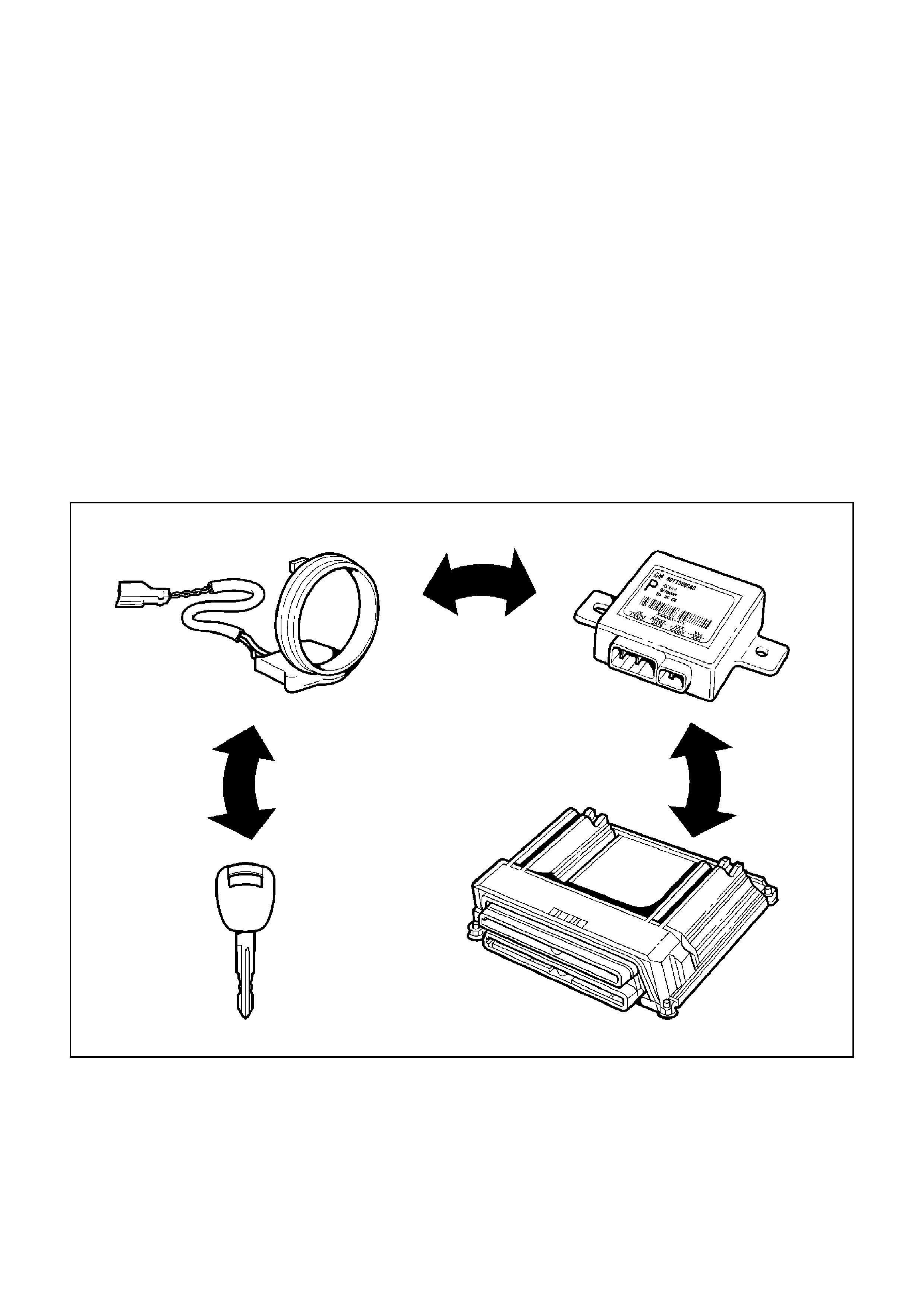
When the ignition is turned ‘ON’, a complex process of data transfer takes place between the transponder type ignition
key, the Immobiliser Control Unit (ICU) and the Powertrain Control Module (PCM).
If any transmitted data is incorrect or missing, the ICU prevents starter motor relay operation and the PCM will prevent
the engine from runni ng.
When the engine has been shut down for more than twelve seconds, both the request and the immobiliser signal
change on the next ignition cycle, the complex data exchange taking place again.
If there is a malfunction - either an incorrect transponder signal or no communication between the components, engine
is disab led, the ‘C HECK ENG INE’ l amp in the instrume nt clus ter will bl ink rapi dly an d the rele vant Diagno st ic Trou ble
Code (DTC) is stored in both the ICU and the PCM.
System Components
The main system components are:
• Transponder Key
• Coil Antenna
• Immobiliser Control Unit (ICU)
• Coil Antenna
•Starter Relay
• Powertrain Control Module
• Associated wiring harnesses, connectors and fuses
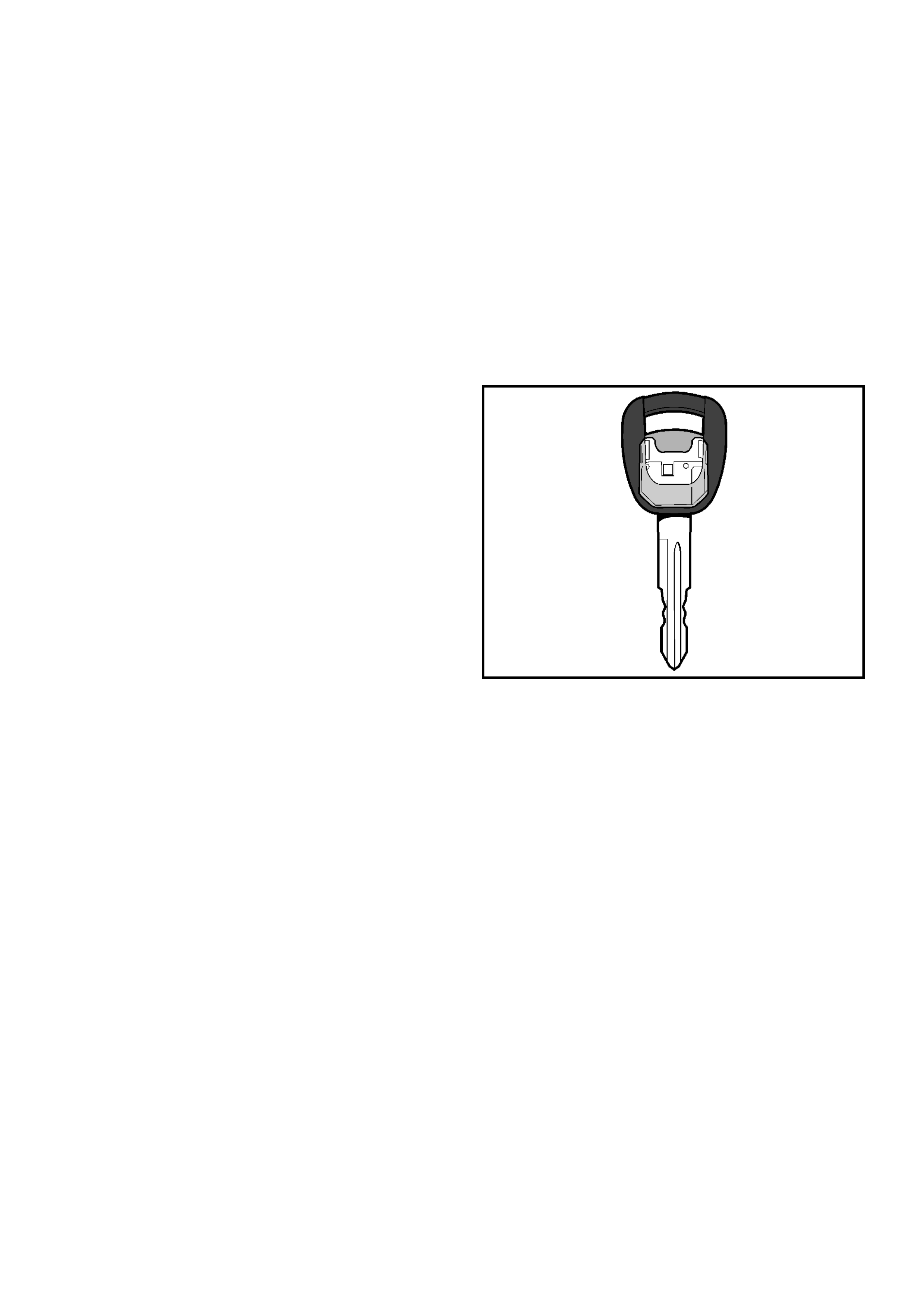
Transponder Key
The system uses a conventional mechanical-cut ignition
key containing a minature transponder (transmitter/
responder) embedded in the plastic handle.
Each transponder is programmed with it’s own specific
ID code during manufacture. Up to 10
18
codes are
available with this system, making code duplication
almost impossible.
The transponder circuit in the key does not require
batteries - the opera tin g si gna l is prov id ed c or dle ss l y by
the ICU supplying a high frequency (133 kHz) AC
voltage signal to the coil antenna.
Encapsulated by the hard plastic of the key head, the
transponder is the most durable part of the ignition key.
The module is initially programmed with two
transponder codes, corresponding to the two keys
supplied with the vehicle. Should a key be lost, or an
additional key required, uncoded keys may be
programmed into the sy stem with the a id of TECH 2. A
maximum of 5 transponder codes can be stored in the
ICU.
Due to the complex nature of the coded signals
transmitted between the it is recommended to replace
existing ignition keys when the ICU is replaced.

Coil Antenna
A non-contact radio frequency is used to transfer
information between the transponder key and the
Immobiliser Control Unit. Surrounding the ignition lock is
a dipole antenna, which is connected to the ICU by a
wiring harness.
The antenna is designed to have a very limited range,
ensuring that only the key in the ignition lock can
communicate with the ICU. This excludes the possible
interference from other transponder keys in the vehicle.
The antenna is accessed by removing the steering
column shroud. Apart from a continuity test on the coil
windin g, substitu tion with a known g ood part is the only
applicable diagnostic procedure.
Immobiliser Control Unit (ICU)
The Immobiliser Control Unit (ICU) is located behind the
RH lower instrument panel. The ICU is powered at all
times from Fuse C-23 (Immo) and receives an ignition
‘ON’ signal from Fuse C-12 (Engine).
Communication from the ICU to the PCM is on the
Vehicl e Speed Sensor (VSS) signal wi re (ICU pin B8 to
PCM pin S27).
Communication from the PCM to the ICU takes place on
the ‘CHECK ENGINE ’ Lamp (CEL) contr ol circuit (PCM
pin S11 to ICU pin B7).
NOTE: If th e ICU and PCM are re placed at the same
time, the ICU MUST be programmed BEFORE the
Immobiliser function of the PCM can be activated.
Powertrain Control Module (PCM)
The PCM is located on the passenger side of the engine
compartment, immediately behind the aircleaner
assembly.
Should the transponder key rolling code not match the
PCM’s calculated code, the PCM immobilises the
engine by disabling the fuel and ignition systems.
While visually siCELar , the MY2002 Frontera V6 PCM is
not interchangeable with the Holden GEN III V8 PCM.
When installing a new PCM, ensure that the correct
PCM is fitted to the vehicle. Refer to the latest parts
listing for PCM part number identification.
Note: A repl ac em ent PCM m ust b e p rogrammed. Re fer
to Section 0C-1 - Service Programming System. Once
programmed, the ICU and the PCM must be linked for
correct ope ratio n. Refer to System Prog ramming in this
section.
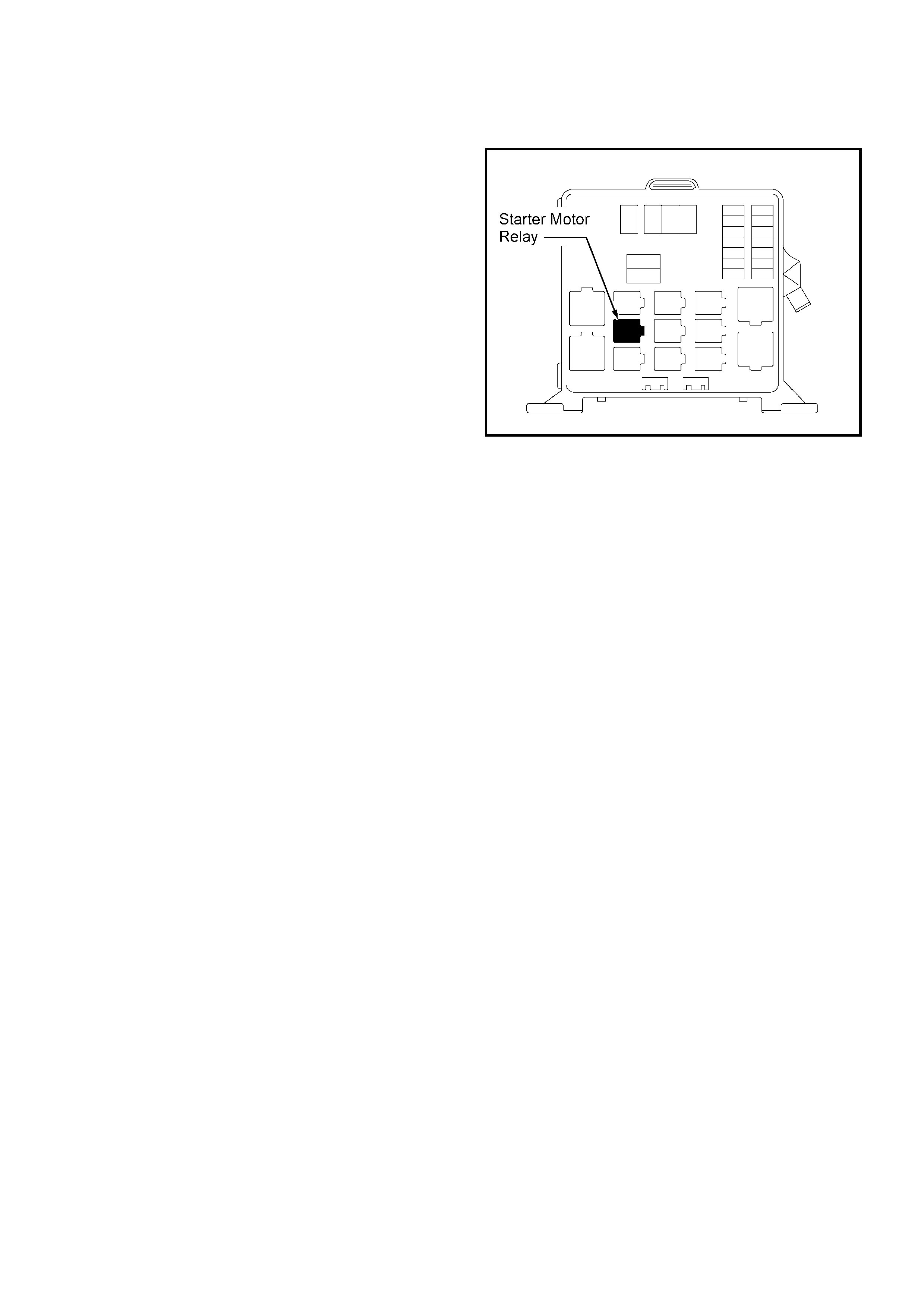
Starter Motor Relay
The starter motor relay is located in the engine
compartment Main Fuse & Relay Box. One side of the
relay solenoid windings are connected ICU pin B1. Pin
B2 of the ICU is connected to ground.
When the ignition key is in the crank position, and the
correct si gn als have been rece ived by the both ICU an d
the PCM, the ICU will provide the path to ground
energising the relay windings.
Engine Start Sequence
Before the syst em will all ow engi ne oper ation, the foll owing sequ ence of d ata transfe r and code evalu ation mu st take
place:
1. When the ignition is turned ON, ICU supplies a high frequency (133kHz) AC voltage signal to the key via the
antenna.
2. The transponder code is transmitted to the ICU.
3. The ICU checks the transponder code and enables the Immobiliser Relay.
4. The PCM generates and transmits a RANDOM code to the ICU.
5. The ICU receives the RANDOM code from the PCM and transmits the code to the transponder.
6. The transponder calculates a ROLLING code based on the RANDOM code.
7. The transponder transmits the ROLLING code to the PCM via the ICU
8. The PCM compares the transferred rolling code with its calculated rolling code.
9. If both the calculated and transferred codes match, the PCM enable the fuel and ignition systems.
10. The en gine cann ot be s tarted durin g the data tr ansfer an d code ev aluation proc ess. If any of the a bove s teps are
unsuccessful, all relevant engine functions remain disabled.

System Pr ogramming
Programming of the Immobiliser system is performed with TECH-2 when:
• The Immobiliser Control Unit is replaced.
• The Immobiliser Control Unit is reset.
• The PCM is replaced.
• Addit ion al ign iti on ke ys are requi re d.
• An ignition key has been lost.
Prior to commencing the programming sequence, the technician will require:
• The Vehicle Identification Number.
• The vehicle security code from Holden TAS
• The mechanical key number.
To enable the completion of the programming sequence, the technician will require:
• Permission from TIS 2000
Security Data
The following codes/data are stored in the ICU reference memory during vehicle production:
• The Vehicle Identification Number.
• The vehicle security code.
• The mechanical key number.
• Engine type
• Transponder code/s
The secur ity c od e c an not b e d ele ted or al tered with TECH -2. T he trans po nder c od e/s an d en gin e ty pe are p ro cess ed
internal ly only and are n ot displ ayed on T ECH-2. T he Vehic le Identi fication Nu mber and m echanic al key n umber are
stored as further information for vehicle identification and can be displayed on TECH-2.
Security Code
The 4-digit security code prevents unauthorised programming and access to the data in the ICU via TECH-2. The
security code is programmed into the ICU.
Programming the Security Code
New Immobiliser Control Units do not contain a programmed security code. If the ICU is replaced, the security code for
that vehicle must be obtained, and then programmed into the ICU with TECH-2.
Replacement of the Immobiliser Control Unit (ICU)
Due to the comple x nature of the coded signals transmitted between the key and the ICU, it is necessary to replace
both existing ignition keys when the ICU is replaced.
Resetting of the Immobiliser Control Unit (ICU)
Resetting of the ICU m ay nece ssitate repla cemen t of e ither or both exi sting ignitio n key s. Th is s ituati on is most like ly
to occur if the ICU is swapped from one vehicle to another.

System Pr ogramming
Replacement of the PCM
Once programmed to the vehicle Immobiliser system, the PCM cannot be removed and used in another vehicle. The
is no PCM reset procedure available at this point in time - the Service Programming System (SPS) required for
resetting a PCM does not apply to current Jackaroo and Monterey.
Loss of a Transponder Key
If a transponder key is lost, all transponder codes in the Immobiliser Control Unit must be erased to prevent
unauthori sed use. Thi s will ens ure that, whi lst the 'lost' key will allow acc ess to the v ehicle, i t cannot b e used to star t
the vehicle .
After erasing all existing codes, the transponder codes of the remaining keys and the new transponder key can be
programmed.
NOTE:
• Programming Approval must be obtained from TIS, using the `Enable Programming" option, before either
control unit or transponder key programming is performed.
• Once Pr og ra mming Approval h as been obtain ed, T E CH-2 wi ll all ow f ive pr og ra mm ing ope ra tio ns. On ce al l five
programming operations have been used, Programming Approval will then have to be obtained again.
• If the five programming operations are not used within 24hrs, they will be cleared from TECH-2, requiring
further Programming Approval to be obtained.
TECH 2 Operation
With the lates t software loade d, connect TECH 2 to the
vehicle, turn on TECH 2.
When the TECH 2 introduction screen appears, press
ENTER.
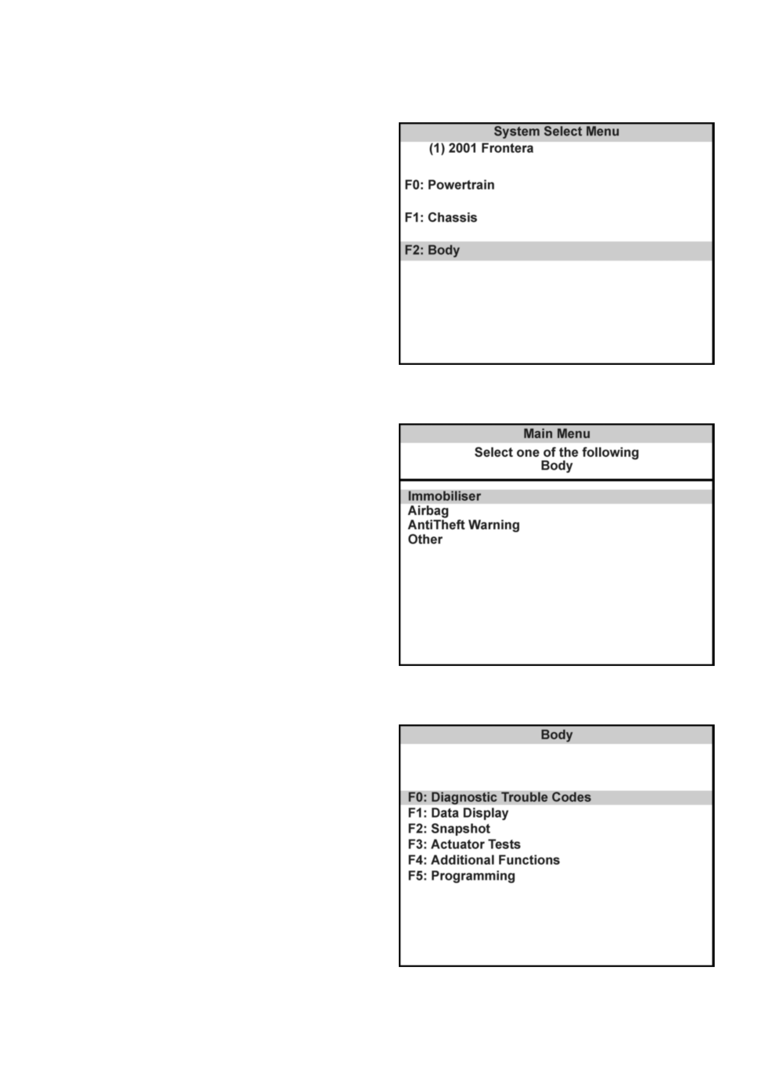
Select: Diagnostics / MY2001 / Frontera / F2: Body /
Immobiliser
The following modes and sub-modes are now available:
F0: Diagnostic Trouble Codes
• F0: Read DTC Info Ordered By Priority
• F1: Read DTC Info As Stored By ECU
• F2: Clear DTC Information
F1: Data Display
F2: Snapshot
F3: Actuator Test
• F0: Starter Relay Output Test
F4: Additional Functions
• F0: Read ECU Identification
• F1: Reset Immobiliser
• F2: Reset Engine Control Module
• F3: Erase Transponder - Keys
F5: Programming
• F0: Program Immobiliser Function
• F1: Program Transponder - Keys
• F2: Program Mechanical key Number
Transponder-Key Program ming
Programming Approval must be obtained from TIS 2000, using the "Enable Programming" option, during the
transponder key program sequence.
TECH 2 will request the Vehicle Security Num ber during the program sequence - this must be obtained from
Holden TAS prior to commencing this operation.
Connect TECH 2 to the vehicle:
1. Select Diagnostics / MY2001 / Frontera / F2:
Body.
2. Select Immobiliser.
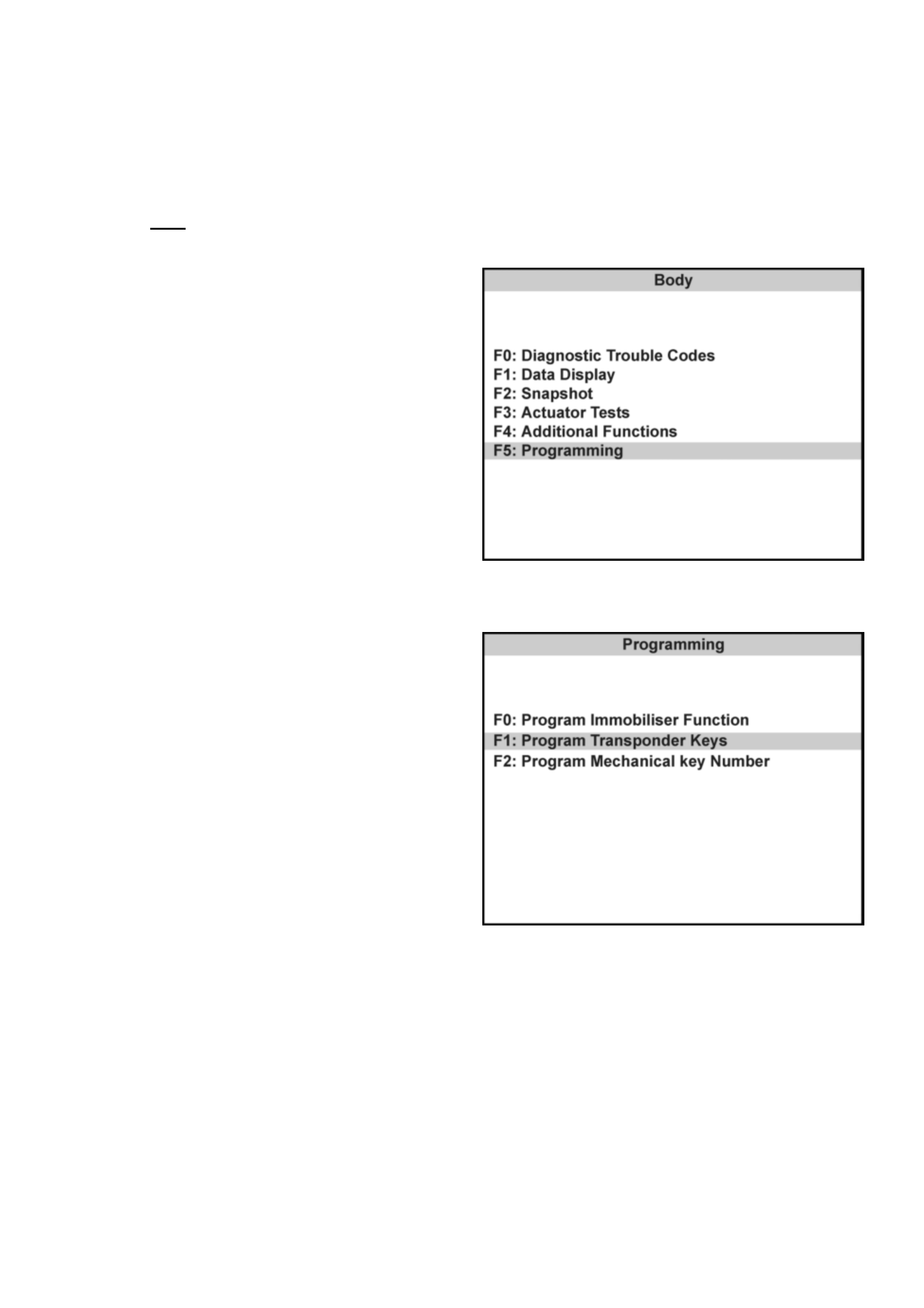
3. Select F5: Programming.
4. Select F1: Program Transponder - Keys.
5. Obtain programming approval from TIS 2000.
6. Return to F1: Program Transponder - Keys.
7. When the SECURITY CODE is requested, enter
the security code and press ENTER.
8. Insert a non-programmed Transponder key and
press CONFIRM.
9. 'Turn On Ignition Key' will be displayed if the
ignition is OFF.
10. The Transponder status will be displayed if the
status does not allow programming.
11. When Programming starts, 'Programming
Transponder - key' is displayed.
12. Cycle the ignition key as instructed by the
display.
13. If the programming was successful, the screen
will display'Program More Keys?'
Erasing Transponder Keys
If a transponder key is lost, all transponder codes in the Immobiliser Control Unit must be erased to prevent
unauthori sed use. Thi s will ens ure that, whi lst the 'lost' key will allow acc ess to the v ehicle, i t cannot b e used to star t
the vehicle .
CAUTION: This sequ ence erases ALL transponder-keys. Transponder-Key programming will be required before the
vehicle can be restarted.
TECH 2 will request the Vehicle Security Num ber during the program sequence - this must be obtained from
Holden TAS prior to commencing this operation.
Connect TECH 2 to the vehicle:
1. Select Diagnostics / MY2001 / Frontera / F2:
Body.
2. Select Immobiliser.
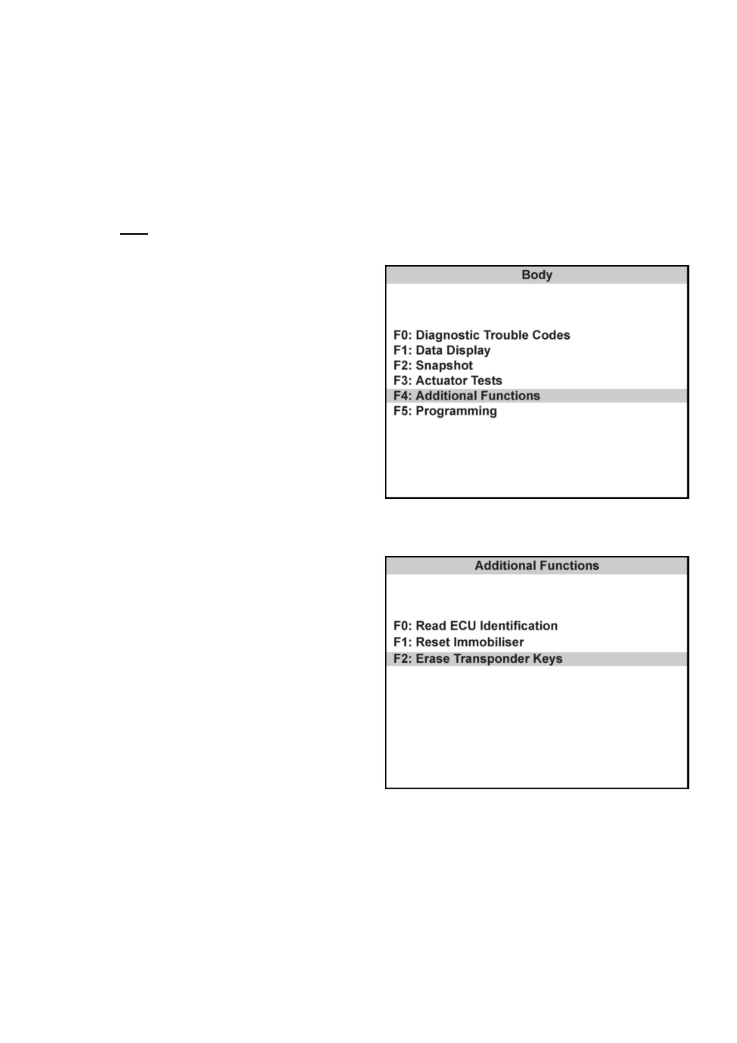
3. Select F4: Additional Functions.
4. Select F2: Erase Transponder - Keys.
5. The screen will display 'See Checking
Procedur e Bef or e Progr amm in g'.
6. Select CONFIRM to cont inu e.
7. The screen will display 'CAUTION - All
Transponder keys will be erased'
8. Select CONFIRM to cont inu e.
9. All transponder-keys are now erased.
10. Program the new transponder key and any
remaining keys to the vehicle using the
'Transpon der- Ke y Programming' sequen ce
Programming The Immobiliser Control Unit (ICU)
TECH 2 will request the Vehicle Security Num ber during the program sequence - this must be obtained from
Holden TAS prior to commencing this operation.
Connect TECH 2 to the vehicle:
1. Select Diagnostics / MY2001 / Frontera / F2:
Body.
2. Select Immobiliser.
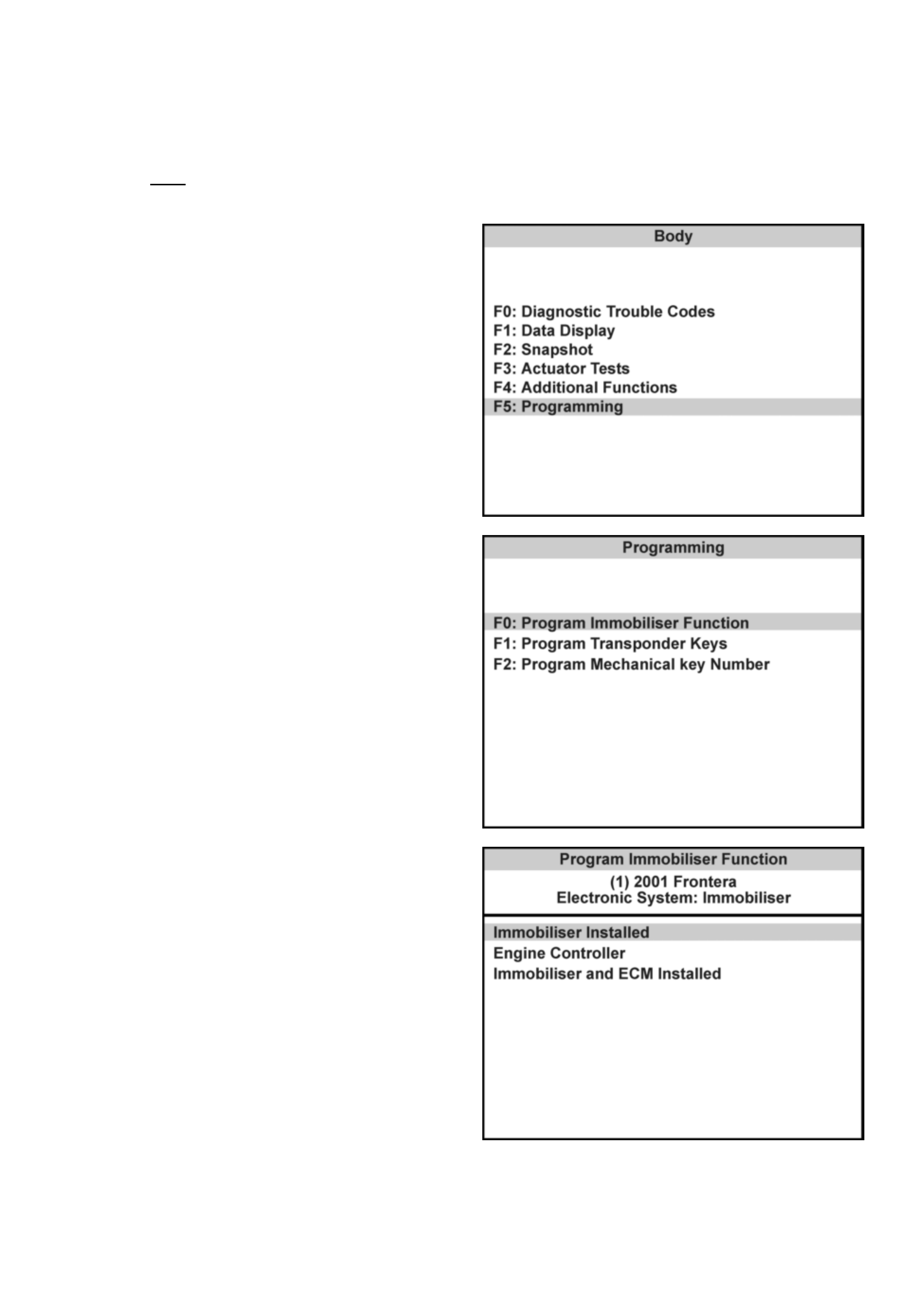
3. Select F5: Programming.
4. Select F0: Program Immobiliser Function.
5. Select Immobiliser Installed
6. Obtain programming approval from TIS 2000.
7. Return to F0: Program Immobiliser Function.
8. When the SECURITY CODE is requested, enter
the security code and press ENTER.
9. When the VIN is requested, enter the vehicle
identification number and press ENTER.
10. When the MECHANICAL KEY number is
requested, enter the key number and press
ENTER.
11. Turn the ignition ON.
12. Select the engine type
13. Check the programming result
14. Program the transponder-keys to the ICU.

Programming The PCM/ECM
TECH 2 will request the Vehicle Security Num ber during the program sequence - this must be obtained from
Holden TAS prior to commencing this operation.
Connect TECH 2 to the vehicle:
1. Select Diagnostics / MY2001 / Frontera / F2:
Body.
2. Select Immobiliser.
3. Select F5: Programming.
4. Select F0: Program Immobiliser Function.
5. Select Engine Controller
6. Obtain programming approval from TIS 2000.
7. Return to F0: Program Immobiliser Function.
8. When the SECURITY CODE is requested, enter
the security code and press ENTER.
9. When the VIN is requested, enter the vehicle
identification number and press ENTER.
10. When the MECHANICAL KEY number is
requested, enter the key number and press
ENTER.
11. Turn the ignition ON.
12. Select the engine type
13. Check the programming result
Programming The PCM/ECM & ICU
TECH 2 will request the Vehicle Security Num ber during the program sequence - this must be obtained from
Holden TAS prior to commencing this operation.
When the PCCM and ICU are replaced at the same time, the ICU MUST be programmed BEFORE the
Immobiliser function of the PCM can be activated.
Connect TECH-2 to the vehicle:
Connect TECH 2 to the vehicle:
1. Select Diagnostics / MY2001 / Frontera / F2:
Body.
2. Select Immobiliser.
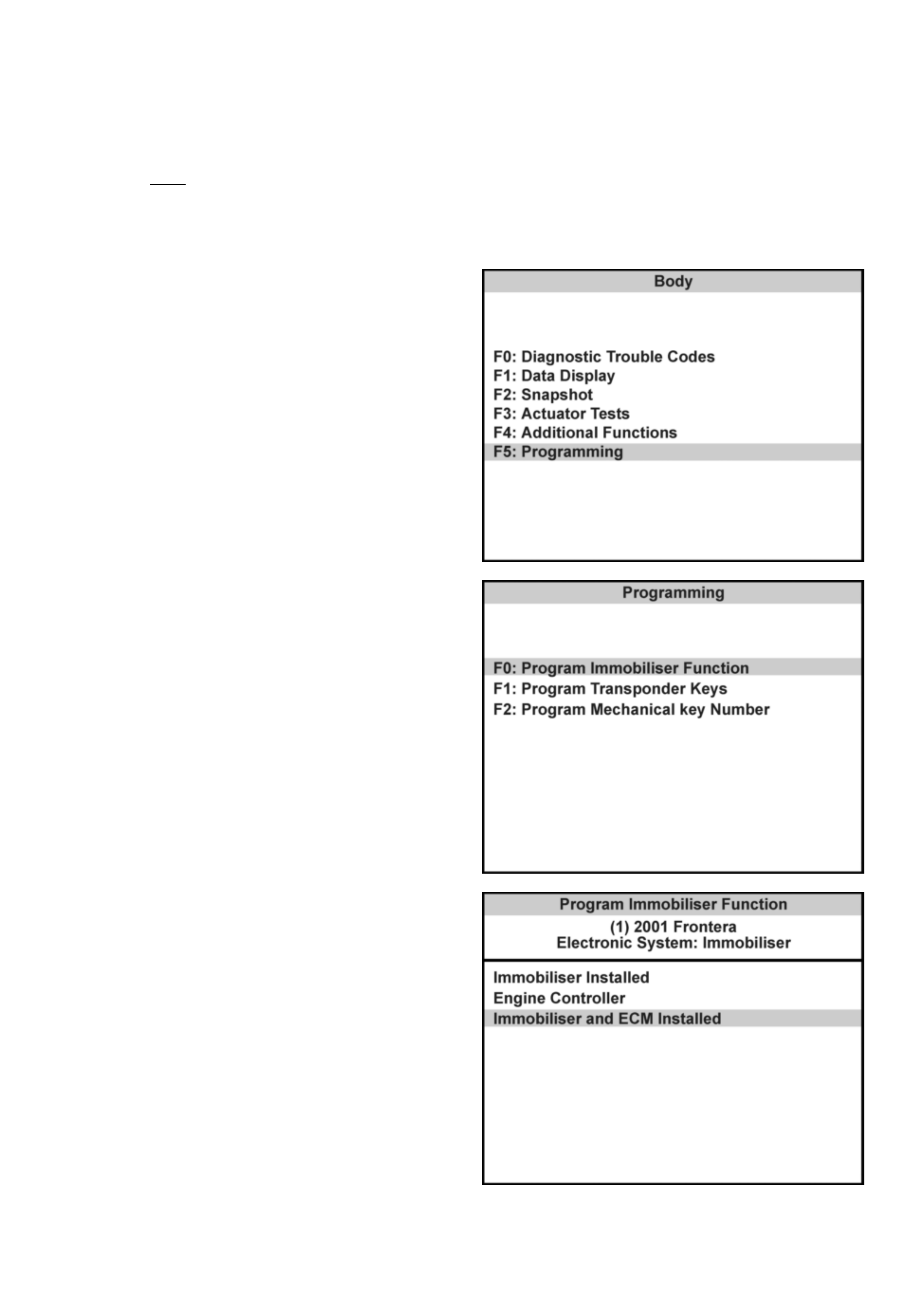
3. Select F5: Programming.
4. Select F0: Program Immobiliser Function.
5. Select Immobiliser and ECM Installed
6. Obtain programming approval from TIS 2000.
7. Return to F0: Program Immobiliser Function.
8. When the SECURITY CODE is requested, enter
the security code and press ENTER.
9. When the VIN is requested, enter the vehicle
identification number and press ENTER.
10. When the MECHANICAL KEY number is
requested, enter the key number and press
ENTER.
11. Turn the ignition ON.
12. Select the engine type
13. Check the programming result
14. Program the transponder-keys to the ICU.
Enable Programming - TIS 2000
'Enable Programming' (TIS Approval) is used in order to
prevent the unauthorised programming of the system
security functions.
TIS Approval is required to perform the following
functions on the UBS Immobiliser System:
• Programming the Immobiliser Control Unit
• Programming the transponder keys
• Programming the PCM/ECM
After the TECH 2 security programming function has
been selected, TECH 2 will display - "Please get
programming approval from TIS'.
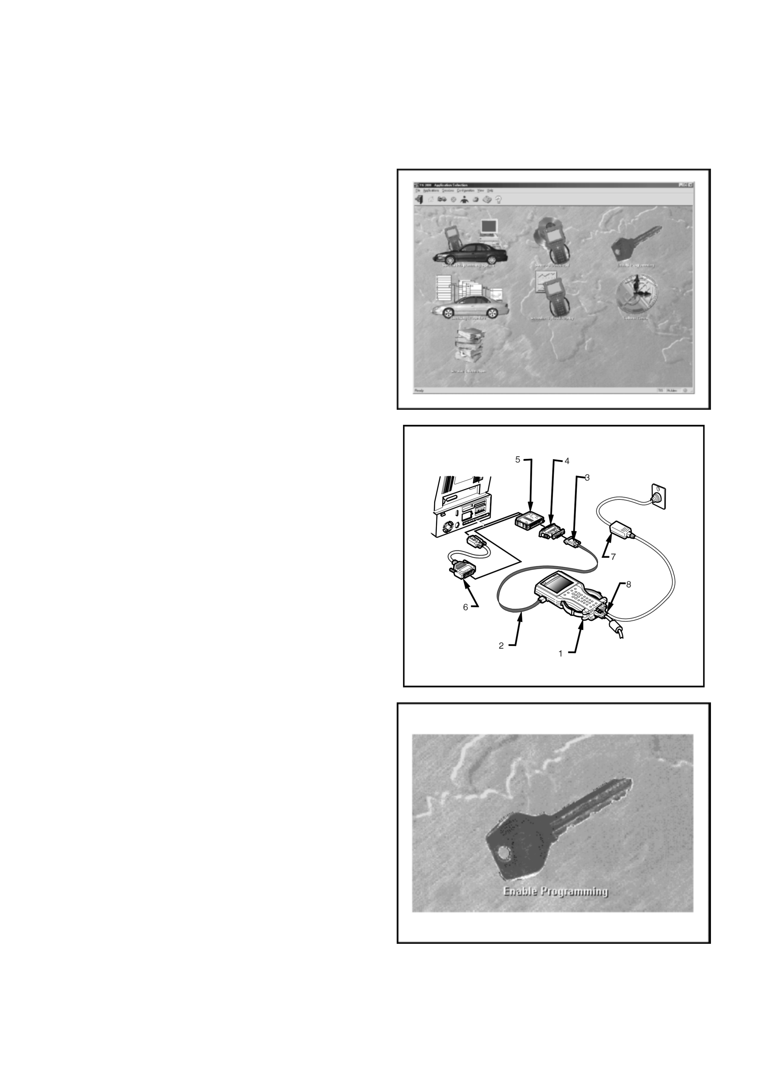
Enable Programming Procedure
1. Connect the RS232C interface cable to the
TECH2 communication port.
2. Connect the other end of the RS232C cable to
the hardware key using the 9 pin and 25 pin
adaptors.
3. Connect the hardware key to the serial port of
the TIS 2000 PC.
4. Connect t he p ower sup ply to the TECH 2 po wer
jack.
5. Press the PWR button and allow TECH 2 to
boot to the start-up screen.
6. Click on the Enable Programming icon of the
TIS 2000 main screen.
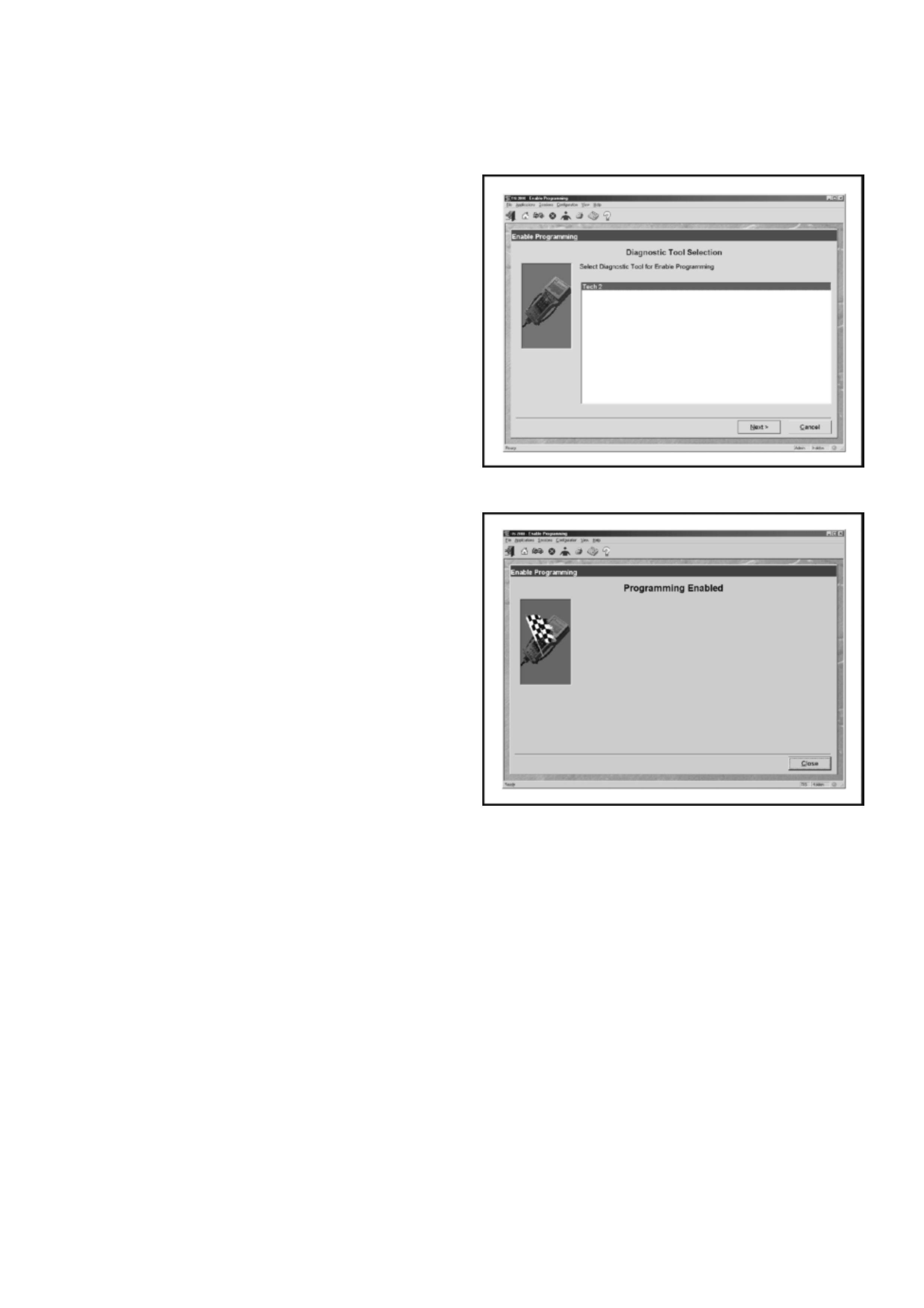
Enable Programmi ng - TIS 2000
7. Select diagnostic tool (TECH 2) for Enable
Programming
8. Select Next to continue
9. When the process is completed, the
Programming Enabled screen will be displayed.
10. Click on the Close button to close the
application.
11. Reconnect TECH-2 to the vehicle DLC and
complete the programming function.

Diagnostic Trouble Codes
Current DTC's
The engine will not run when any current DTC is lo gged.
• The PCM disables the fuel and ignition systems
• The ICU inhibits starter motor operation by
disabling the starter motor relay for DTCs B0003
and B0004.
History DTC's
When the fault has been repaired, or an intermittent
failure has occured, the engine will operate normally
and the current DTC becomes a History DTC. History
DTC’s are displayed as “Not Present” when reading
stored DTCs with TECH 2.
History DTC's are stored in an EEPROM. This type of
memory storage means the codes are not cleared when
the battery is disconnected.
• History codes may be cleared from the system
memory by TECH 2.
• A History DTC will self- clear a fter 25 cons ec utiv e
ignition cycles without the fault recurring.
Multiple DTC's
Multple DTC’s will be set in the ICU under the followin g
conditions:
1. ICU Not Programmed
• DTC’s B0002, B0009 & B0010
2. Immobiliser Antenna or Antenna Harness failure
• DTC’s B0003 & B0004
DTC Description
B0001 Immobiliser Fault
B8002 Immobiliser Not Programmed
B0003 Transponder Key Problem
B0004 Immobiliser Coil Circuit
B0005 Vehicle Speed Signal Voltage Low/High or Open Circuit
B0006 Vehicle Speed Signal-Out High
B0007 No ECM Request (CEL Disconnected)
B0008 Incorrect Transponder Response
B0009 No Transponder Key Programmed
B0010 Unknown Transponder Key

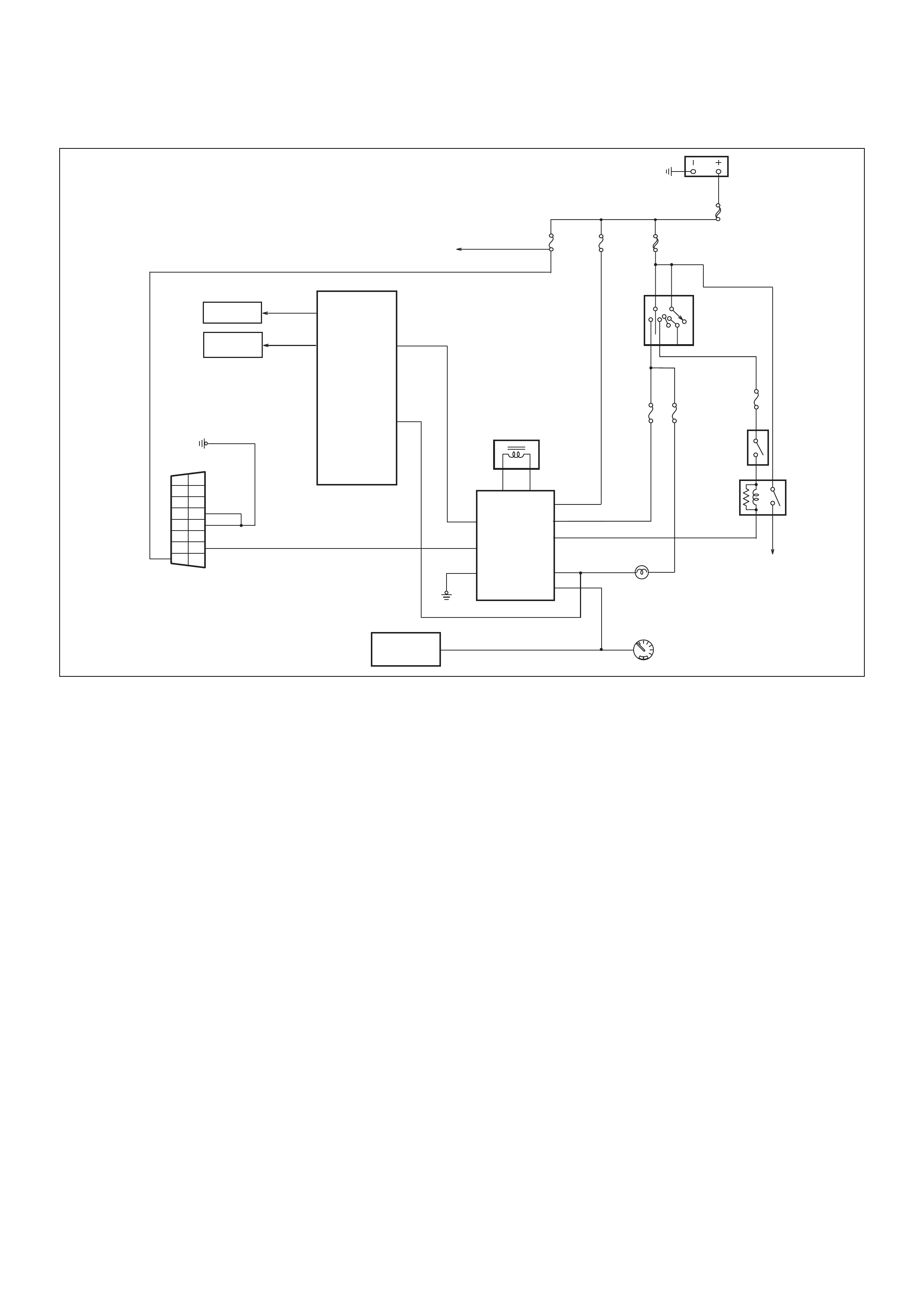
Engine Will Not Crank - No DTC Set
060RA00003
Circuit Description
The Immobiliser Control Unit provdes the ground path
for the starter motor relay solenoid windings. A no-crank
condition will occur due to failure in either the Engine
Immobili se r Sy st em or starter moto r cir cuit oper ati on .
Condition for Setting the DTC
Not Applicable
Acti on Taken Wh en the DTC sets
Not Applicable
Condition for Clearing the CEL/DTC
Not Applicable
Diagnostic Aids
Check for the following conditions:
• Poor connection at PCM and Immobiliser Control
Unit. Inspect harness connectors for backed out
terminals, improper mating, broken locks,
improperly formed or damaged terminals, and poor
terminal to wire connection.
• Damaged harness-Inspect the wiring harness for
damage, If the harness appears to be OK, disconnect
the PCM and Immobiliser, turn the ignition “ON" and
observe a voltmeter connected to the suspect driver
circuit at the PCM and Immobiliser harness connector
while moving connectors and wiring harnesses
relates to the CEL. A change in voltage will indicate
the location of the fault.
ACC
B2
B1
OFF
IG2
ST
IG1
IGNITION
SWITCH
BATT
MAIN
80A
IGN. B2
50A
IMMO.
C-23
10A
ENGINE
C-12
15A
METER
C-11
15A
S11
STOP
C-6
15A
SPEEDOMETER
CHECK ENG.
A1
S27
PCM
1
9
2
10
3
11
4
12
5
13
6
14
7
15
8
16
B6
B5
B7
B2
B1
B3
B4
A3
ANTENNA COIL
STARTER
C-3
10A
STARTER
MOTOR
ICU
STARTER
RELAY
MODE SW.
(AUTO)
B8
VEHICLE SPEED
SENSOR
STOP
LAMPS
INJECTORS
ION SENSING
MODULE

Engine Will Not Crank - No DTC Set
Step Action Value(s) Yes No
1 Was the “On-Board Diagnostic (OBD) system Check"
performed?
— Go to Step 2
Go to OBD
system ch ec k
Refer to Section
6C1
2 Check the PCM and ICU harness and connectors for:
1. Backed out terminals, improper mating, broken
locks, improperly formed or damaged terminals,
and poor terminal to wire connection.
2. Damaged ha rn es s - Ins pec t the wiring har ne ss for
damage.
If a problem found, repair as necessary.
Was a problem found? Verify repair Go to Step 3
3 Turn the ignition ON, does the ‘CHECK ENGINE’
Lamp flash at 2Hz?
— Go to Step 4
Check starter
motor circuit.
Refer Section
6E
4 With the ignition ON, check the voltage at ICU pin B3.
Is the voltage in specified range? 11.6v - 12.7v Go to Step 6 Go to Step 5
5 Check for continuity between Fuse C-12 & ICU pin B3.
If a problem found, repair as necessary.
Was a problem found? Verify repair Go to Step 6
6 Measure the resistance between ICU pin B2 and
ground.
Is the resistance less than the specified value? 5 ohms Go to Step 8 Go to Step 7
7 Repair the ground circuit from ICU pin B2 to ground
Is the action complete? — Verify repair —
8. Replace the ICU and the existing ignition keys
Reprogram the system Verify repair

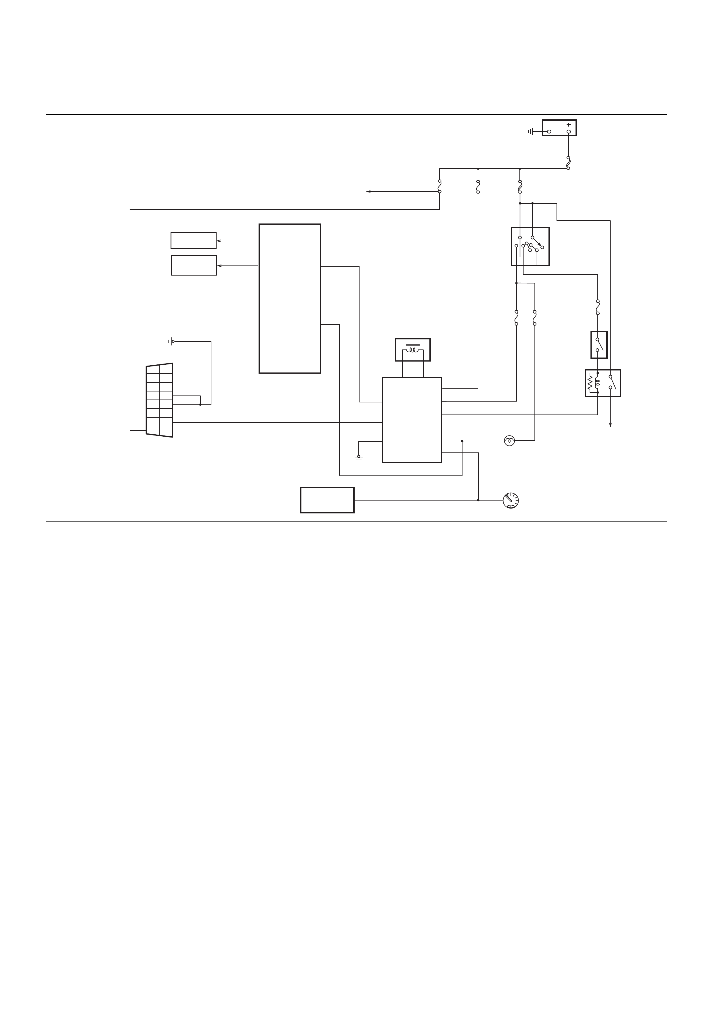
DTC B0001 - Immobiliser Fault
060RA00003
Circuit Description
The Immobiliser Control Unit generates signals based
on information received from the transponder key and
the PCM.
Condition for Setting the DTC
A DTC B8001 will set within 0.5 secs. of turning the
ignition ON if:
• The ICU’s EEPROM fails to produce a valid
signal. This is an internal ICU failure and cannot
be repaired.
Acti on Taken Wh en the DTC sets
• The engine will not crank
• The CHECK ENGINE Lamp will flash at 4Hz
Condition for Clearing the CEL/DTC
• Using TECH 2, select Clear DTC Information
• A History DTC B8001 will self-clear after 25
consecutive ignition cycles without the fault
recurring.
Diagnostic Aids
Not Applicable
ACC
B2
B1
OFF
IG2
ST
IG1
IGNITION
SWITCH
BATT
MAIN
80A
IGN. B2
50A
IMMO.
C-23
10A
ENGINE
C-12
15A
METER
C-11
15A
S11
STOP
C-6
15A
SPEEDOMETER
CHECK ENG.
A1
S27
PCM
1
9
2
10
3
11
4
12
5
13
6
14
7
15
8
16
B6
B5
B7
B2
B1
B3
B4
A3
ANTENNA COIL
STARTER
C-3
10A
STARTER
MOTOR
ICU
STARTER
RELAY
MODE SW.
(AUTO)
B8
VEHICLE SPEED
SENSOR
STOP
LAMPS
INJECTORS
ION SENSING
MODULE

DTC B0001 - Immobiliser Fault
Step Action Value(s) Yes No
1 Replace the ICU and the existing ignition keys
Reprogram the system — Verify repair —

DTC B0002 - Immobiliser Not Programmed
060RA00003
Circuit Description
The Immobiliser Control Unit is programmed with
vehicle security information (Security Code, VIN &
mechanical key number), during initial installation.
Condition for Setting the DTC
A DTC B0002 will set immediately upon recognition If :
• The vehicle security code is not programmed into
the system.
Acti on Taken Wh en the DTC sets
• The engine will not crank
• The CHECK ENGINE Lamp will flash at 4Hz
Condition for Clearing the CEL/DTC
• Using TECH 2, select Clear DTC Information
• A History DTC B0002 will self-clear after 25
consecutive ignition cycles without the fault
recurring.
Diagnostic Aids
Check for the following conditions:
• Poor connection at PCM and Immobiliser Control
Unit. Inspect harness connectors for backed out
terminals, improper mating, broken locks,
improperly formed or damaged terminals, and poor
terminal to wire connection.
ACC
B2
B1
OFF
IG2
ST
IG1
IGNITION
SWITCH
BATT
MAIN
80A
IGN. B2
50A
IMMO.
C-23
10A
ENGINE
C-12
15A
METER
C-11
15A
S11
STOP
C-6
15A
SPEEDOMETER
CHECK ENG.
A1
S27
PCM
1
9
2
10
3
11
4
12
5
13
6
14
7
15
8
16
B6
B5
B7
B2
B1
B3
B4
A3
ANTENNA COIL
STARTER
C-3
10A
STARTER
MOTOR
ICU
STARTER
RELAY
MODE SW.
(AUTO)
B8
VEHICLE SPEED
SENSOR
STOP
LAMPS
INJECTORS
ION SENSING
MODULE

DTC B8002 - Security Code Not Programmed
Step Action Value(s) Yes No
1 Attempt to reprogram the security information
W as the programming successful? — Verify repair Go to Step 2
2 Was the “On-Board Diagnostic (OBD) system Check"
performed?
— Go to Step 3
Go to OBD
system ch ec k
Refer to Section
6C1
3 Check the PCM and ICU harness and connectors for:
1. Backed out terminals, improper mating, broken
locks, improperly formed or damaged terminals,
and poor terminal to wire connection.
2. Damaged ha rn es s - Ins pec t the wiring har ne ss for
damage.
If a problem found, repair as necessary.
Was a problem found? — Verify repair Go to Step 4
4 Replace the ICU and the existing ignition keys
Reprogram the system — Verify repair —

DTC B0003 - Transponder Key Problem
060RA00003
Circuit Description
The Immobiliser Control Unit expects to receive a valid
transponder key signal when the ignition is turned ON.
Condition for Setting the DTC
A DTC B0003 will set if any of the following conditions
are present for at least 0.84 seconds during an
attempted start:
• No transponder-key signal is present.
• The transponder-key is defective.
• The key is not a transponder key.
Acti on Taken Wh en the DTC sets
• The engine will not crank
• The CHECK ENGINE Lamp will flash at 4Hz
Condition for Clearing the CEL/DTC
• Using TECH 2, select Clear DTC Information
• A History DTC B0003 will self-clear after 25
consecutive ignition cycles without the fault
recurring.
ACC
B2
B1
OFF
IG2
ST
IG1
IGNITION
SWITCH
BATT
MAIN
80A
IGN. B2
50A
IMMO.
C-23
10A
ENGINE
C-12
15A
METER
C-11
15A
S11
STOP
C-6
15A
SPEEDOMETER
CHECK ENG.
A1
S27
PCM
1
9
2
10
3
11
4
12
5
13
6
14
7
15
8
16
B6
B5
B7
B2
B1
B3
B4
A3
ANTENNA COIL
STARTER
C-3
10A
STARTER
MOTOR
ICU
STARTER
RELAY
MODE SW.
(AUTO)
B8
VEHICLE SPEED
SENSOR
STOP
LAMPS
INJECTORS
ION SENSING
MODULE

DTC B8003- Transponder Key Problem
Step Action Value(s) Yes No
1 Was the “On-Board Diagnostic (OBD) system Check"
performed?
— Go to Step 2
Go to OBD
system ch ec k
Refer to Section
6C1
2 Check the PCM and ICU harness and connectors for:
1. Backed out terminals, improper mating, broken
locks, improperly formed or damaged terminals,
and poor terminal to wire connection.
2. Damaged ha rn es s - Ins pec t the wiring har ne ss for
damage.
If a problem found, repair as necessary.
Was a problem found? Verify repair Go to Step 3
3 Turn the ignition ON, does the ‘CHECK ENGINE’
Lamp flash at 4Hz? — Go to Step 4 —
4 Check for correct operation with the other transponder
key/s
Does the system operate correctly? — Go to Step 5 Go to Step 5
5 Reprogram the transponder key.
Was the programming successful? Verify repair Go to Step 6
6 Is a DTC B0004 set after the program attempt? Go to
Diagnostic
Chart
DTC B0004 -
Antenna Coil
Open Go to Step 7
7 Replace the ICU and the existing ignition keys
Reprogram the system — Verify repair —

DTC B0004 - Antenna Coil Open
060RA00003
Circuit Description
The Immobiliser Control Unit expects to receive a valid
transponder key signal when the ignition is turned ON.
The ICU and transponder key communicate via the
antenna coil circuit.
Condition for Setting the DTC
A DTC B0004 will set immendiately upon recognition If :
• The antenna coil is not connected or there is an
open in the antenna coil circuit.
Acti on Taken Wh en the DTC sets
• The engine will not crank.
• The CHECK ENGINE Lamp will flash at 4Hz.
• A DTC B0003 - “TRANSPONDER KEY
PROBLEM” also will be set
Condition for Clearing the CEL/DTC
• Using TECH 2, select Clear DTC Information
• A History DTC B0004 will self-clear after 25
consecutive ignition cycles without the fault
recurring.
Diagnostic Aids
Check for the following conditions:
• Poor connection of the antenna circuit at the
Immobili s er Co ntr ol Unit. In sp ec t h ar ness c on nector s
for backed out terminals, improper mating, broken
locks, improperly formed or damaged terminals, and
poor terminal to wire connection.
ACC
B2
B1
OFF
IG2
ST
IG1
IGNITION
SWITCH
BATT
MAIN
80A
IGN. B2
50A
IMMO.
C-23
10A
ENGINE
C-12
15A
METER
C-11
15A
S11
STOP
C-6
15A
SPEEDOMETER
CHECK ENG.
A1
S27
PCM
1
9
2
10
3
11
4
12
5
13
6
14
7
15
8
16
B6
B5
B7
B2
B1
B3
B4
A3
ANTENNA COIL
STARTER
C-3
10A
STARTER
MOTOR
ICU
STARTER
RELAY
MODE SW.
(AUTO)
B8
VEHICLE SPEED
SENSOR
STOP
LAMPS
INJECTORS
ION SENSING
MODULE

DTC B0004 - Antenna Coil Open
Step Action Value(s) Yes No
1 Was the “On-Board Diagnostic (OBD) system Check"
performed?
— Go to Step 2
Go to OBD
system ch ec k
Refer to Section
6C1
2 Check for continuity between ICU harness connector
‘A’ pin 1 and pin 3.
Was a problem found? — Go to Step 3 Go to Step 3
3 Check for continuity between ICU harness connector
‘A’ pin 1and antenna coil pin 1.
If a problem found, repair as necessary.
W as a problem found? — Verify repair Go to Step 4
4 Check for continuity between ICU harness connector
‘A’ pin 3 and antenna coil pin 2.
If a problem found, repair as necessary.
W as a problem found? — Verify repair Go to Step 3
5 Replace the antenna coil assembly
Is the action complete? — Verify repair —
DTC B0005 - Vehicle Speed Signal Voltage Low
060RA00003
Circuit Description
When the i gniti on is tur ned ON wi th a v alid t ranspon der
key, the PC M transmits a 10 -volt signal to the ICU. Th e
ICU’s code generator will pulse the 10-volt signal to
ground. The PCM’s Signal Comparator compares the
coded signal generated by the ICU to that pre-
programmed into it’s memory. If both codes are
identica l, the PCM ’s fuel control an d ignition circuits will
be enabled.
Condition for Setting the DTC
A DTC B0005 will set if:
• There is a short to ground or an open in the
circuit between ICU wiring harness connector B
terminal 8 & PCM wiring harness 80-way red
conne cto r termi nal S27.
Acti on Taken Wh en the DTC sets
• The engine will crank but not start.
• The CHECK ENGINE Lamp will flash at 4Hz
Condition for Clearing the CEL/DTC
• Using TECH 2, select Clear DTC Information
• A History DTC B0005 will self-clear after 25
consecutive ignition cycles without the fault
recurring.
Diagnostic Aids
Check for the following conditions:
• Poor connection at PCM and Immobiliser Control
Unit. Inspect harness connectors for backed out
terminals, improper mating, broken locks,
improperly formed or damaged terminals, and poor
terminal to wire connection.
• Damaged harness-Inspect the wiring harness for
damage, If the harness appears to be OK, disconnect
the PCM and Immobiliser, turn the ignition “ON" and
observe a voltmeter connected to the suspect driver
circuit at the PCM and Immobiliser harness connector
while moving connectors and wiring harnesses
relates to the CEL. A change in voltage will indicate
the location of the fault.
ACC
B2
B1
OFF
IG2
ST
IG1
IGNITION
SWITCH
BATT
MAIN
80A
IGN. B2
50A
IMMO.
C-23
10A
ENGINE
C-12
15A
METER
C-11
15A
S11
STOP
C-6
15A
SPEEDOMETER
CHECK ENG.
A1
S27
PCM
1
9
2
10
3
11
4
12
5
13
6
14
7
15
8
16
B6
B5
B7
B2
B1
B3
B4
A3
ANTENNA COIL
STARTER
C-3
10A
STARTER
MOTOR
ICU
STARTER
RELAY
MODE SW.
(AUTO)
B8
VEHICLE SPEED
SENSOR
STOP
LAMPS
INJECTORS
ION SENSING
MODULE

DTC B0005 - Vehicle Speed Signal Voltage Low
Step Action Value(s) Yes No
1 Was the “On-Board Diagnostic (OBD) system Check"
performed?
— Go to Step 2
Go to OBD
system ch ec k
Refer to Section
6C1
2 Check for continuity between ICU wiring harness
connec tor B te rmina l 8 & PC M wir ing ha rness 8 0-way
red connector terminal S27
If a problem found, repair as necessary.
W as a problem found? — Verify repair Go to Step 3
3 Check for continuity between ICU wiring harness
connector B terminal 8 and ground
If a problem found, repair as necessary.
Was a problem found? — Verify repair Go to Step 4
4 Clear the DTC using TECH 2
Did the DTC Clear? — Verify repair Go to Step 2

DTC B0006 - Vehicle Speed Signal Voltage High
060RA00003
Circuit Description
When the i gniti on is tur ned ON wi th a v alid t ranspon der
key, the PC M transmits a 10 -volt signal to the ICU. Th e
ICU’s code generator will pulse the 10-volt signal to
ground. The PCM’s Signal Comparator compares the
coded signal generated by the ICU to that pre-
programmed into it’s memory. If both codes are
identica l, the PCM ’s fuel control an d ignition circuits will
be enabled.
Condition for Setting the DTC
A DTC B0006 will set if:
• There is a short to power (B+) in the circuit
between ICU wiring harness connector B
terminal 8 & PCM wiring harness 80-way red
conne cto r termi nal S27.
Acti on Taken Wh en the DTC sets
• The engine will crank but not start.
• The CHECK ENGINE Lamp will flash at 4Hz
Condition for Clearing the CEL/DTC
• Using TECH 2, select Clear DTC Information
• A History DTC B0006 will self-clear after 25
consecutive ignition cycles without the fault
recurring.
Diagnostic Aids
Check for the following conditions:
• Poor connection at PCM and Immobiliser Control
Unit. Inspect harness connectors for backed out
terminals, improper mating, broken locks, improperly
formed or damaged terminals, and poor terminal to
wire connection.
• Damaged harness-Inspect the wiring harness for
damage, If the harness appears to be OK, disconnect
the PCM and Immobiliser, turn the ignition “ON" and
observe a voltmeter connected to the suspect driver
circuit at the PCM and Immobiliser harness connector
while moving connectors and wiring harnesses
relates to the CEL. A change in voltage will indicate
the location of the fault.
ACC
B2
B1
OFF
IG2
ST
IG1
IGNITION
SWITCH
BATT
MAIN
80A
IGN. B2
50A
IMMO.
C-23
10A
ENGINE
C-12
15A
METER
C-11
15A
S11
STOP
C-6
15A
SPEEDOMETER
CHECK ENG.
A1
S27
PCM
1
9
2
10
3
11
4
12
5
13
6
14
7
15
8
16
B6
B5
B7
B2
B1
B3
B4
A3
ANTENNA COIL
STARTER
C-3
10A
STARTER
MOTOR
ICU
STARTER
RELAY
MODE SW.
(AUTO)
B8
VEHICLE SPEED
SENSOR
STOP
LAMPS
INJECTORS
ION SENSING
MODULE

DTC B0006 - Vehicle Speed Signal Voltage High
Step Action Value(s) Yes No
1 Was the “On-Board Diagnostic (OBD) system Check"
performed?
— Go to Step 2
Go to OBD
system ch ec k
Refer to Section
6C1
2 1. Disconnect the ICU and PCM harness
connectors.
2. Turn the ignition ON and check for voltage at ICU
harness connector B pin 8
If a voltage signal is found, repair as necessary.
Was a problem found? Approx 12v. Verify repair Go to Step 3
3 Clear the DTC using TECH 2
Did the DTC Clear? — Verify repair Go to Step 2
DTC B0007 - No Engine Request
060RA00003
Circuit Description
The PCM transmits an ‘ENGINE REQUEST’ signal to
the ICU when the ignition is turned ON, using the
‘CHECK ENGINE’ Lamp (CEL) circuit.
Condition for Setting the DTC
A DTC B0007 will set within 0.5 secs. of turning the
ignition ON if:
• The ICU does not receive an ‘ENGINE
REQUEST’ signal from PCM.
This condition may be caused by:
• Cicuit interruption between ICU wiring harness
connector B terminal 7 & PCM wiring harness 80-
way red connector terminal S11.
or
• A defective ICU.
NOTE:
1. A DTC B0007 which has been set due to a wiring
harness fault or ICU failure will, in most cases, be
accompanied by a DTC P1626 ‘IMMOBILISER NO
SIGNAL ’ set in the PCM.
2. A DTC B0007 will be set if the ignition switch is
returned to the ‘ON’ or ‘START’ position within 10
seconds of switching the ignition ‘OFF’. A DTC set
in this manner WILL NOT have any effect on the
starting performance of the engine.
3. Should a DTC B0007 be set under condition (2),
when the ignition switch is returned to the OFF
posittion for more than 10 seconds before
restarting, the DTC will be viewed as ‘NOT
PRESENT’. Again, a DTC set under this condition
WILL NOT have any effect on the starting
performance of the engine.
Action Taken When the DTC sets
• The engine will crank, but will not run.
• The CHECK ENGINE Lamp will flash at 4Hz
Condition for Clearing the CEL/DTC
• Using TECH 2, select Clear DTC Information
• A History DTC B0007 will self-clear after 25
consecutive ignition cycles without the fault
recurring.
ACC
B2
B1
OFF
IG2
ST
IG1
IGNITION
SWITCH
BATT
MAIN
80A
IGN. B2
50A
IMMO.
C-23
10A
ENGINE
C-12
15A
METER
C-11
15A
S11
STOP
C-6
15A
SPEEDOMETER
CHECK ENG.
A1
S27
PCM
1
9
2
10
3
11
4
12
5
13
6
14
7
15
8
16
B6
B5
B7
B2
B1
B3
B4
A3
ANTENNA COIL
STARTER
C-3
10A
STARTER
MOTOR
ICU
STARTER
RELAY
MODE SW.
(AUTO)
B8
VEHICLE SPEED
SENSOR
STOP
LAMPS
INJECTORS
ION SENSING
MODULE

DTC B0007 - No Engine Request
Step Action Value(s) Yes No
1 Was the “On-Board Diagnostic (OBD) system Check"
performed?
— Go to Step 2
Go to OBD
system ch ec k
Refer to Section
6C1
2 Inspec t ICU and PCM harness c onnectors for backed
out terminals, improper mating, broken locks,
improperly formed or damaged terminals, and poor
terminal to wire connection.
If a problem found, repair as necessary.
W as a problem found? — Verify repair Go to Step 3
3 1. Disconnect the PCM connectors
2. Check for continuity between:
ICU pin B terminal 7 & PCM wiring harness 80-
way red conne cto r termi nal S11.
If an open circuit is found, repair as necessary.
W as an open circuit found? — Verify repair Go to Step 4
4 Disconnect the PCM connectors
Check for continuity between:
ICU pin B terminal 7 and ground
If a continuity is found, repair as necessary.
W as continuity found? — Verify repair Go to Step 5
5 Reset the ICU - refer to the initial menu selection
procedure detailed in “TECH 2 Operation” in this
section, then follow the TECH 2 ‘on-screen’
instructions.
TECH 2 will request the vehicle security code
during this proce dure. This must be obtained from
Holden TAS prior to commencing this operation.
Does the engine start and run after the ICU Reset
Procedure has been performed? Verify repair Go to Step 6
6 Replace the ICU (Internal circuit failure).
Important: The replacement ICU must be
programmed. refer to this Section for the correct
procedure.
Important: The PCM and ICU must be linked, refer to
this Section for the correct procedure.
Is the action complete? — Verify repair —

DTC B0008 - Incorrect Transponder key Response
060RA00003
Circuit Description
The Immobiliser Control Unit expects to receive a valid
transponder key signal when the ignition is turned ON.
Condition for Setting the DTC
A DTC B0008 will set immendiately upon recognition If :
• The transponder key reponse to the ICU signal is
incorrect.
Acti on Taken Wh en the DTC sets
• The engine will not crank
• The CHECK ENGINE Lamp will flash at 4Hz
Condition for Clearing the CEL/DTC
• Using TECH 2, select Clear DTC Information
• A History DTC B0008 will self-clear after 25
consecutive ignition cycles without the fault
recurring.
Diagnostic Aids
Check for the following conditions:
• Poor connection at PCM and Immobiliser Control
Unit. Inspect harness connectors for backed out
terminals, improper mating, broken locks,
improperly formed or damaged terminals, and poor
terminal to wire connection.
• Damaged harness-Inspect the wiring harness for
damage, If the harness appears to be OK, disconnect
the PCM and Immobiliser, turn the ignition “ON" and
observe a voltmeter connected to the suspect driver
circuit at the PCM and Immobiliser harness connector
while moving connectors and wiring harnesses
relates to the CEL. A change in voltage will indicate
the location of the fault.
ACC
B2
B1
OFF
IG2
ST
IG1
IGNITION
SWITCH
BATT
MAIN
80A
IGN. B2
50A
IMMO.
C-23
10A
ENGINE
C-12
15A
METER
C-11
15A
S11
STOP
C-6
15A
SPEEDOMETER
CHECK ENG.
A1
S27
PCM
1
9
2
10
3
11
4
12
5
13
6
14
7
15
8
16
B6
B5
B7
B2
B1
B3
B4
A3
ANTENNA COIL
STARTER
C-3
10A
STARTER
MOTOR
ICU
STARTER
RELAY
MODE SW.
(AUTO)
B8
VEHICLE SPEED
SENSOR
STOP
LAMPS
INJECTORS
ION SENSING
MODULE

DTC B0008 - Incorrect Transponder key Response
Step Action Value(s) Yes No
1 Check for correct operation with the other transponder
key/s
Does the system operate correctly? — Go to Step 2 Go to Step 4
2 Reprogram the transponder key.
Was the programming successful? Verify repair Go to Step 3
3 Replace the transponder key
Reprogram the system — Verify repair —
4 Replace the ICU and the existing ignition keys
Reprogram the system — Verify repair —

DTC B0009 - No Transponder Key Programmed
060RA00003
Circuit Description
The Immobiliser Control Unit expects to receive a valid
transponder key signal when the ignition is turned ON.
Condition for Setting the DTC
A DTC B0009 will set immendiately upon recognition If :
• No transponder keys are programmed into the
system.
Acti on Taken Wh en the DTC sets
• The engine will not crank.
• The CHECK ENGINE Lamp will flash at 4Hz
Condition for Clearing the CEL/DTC
• Using TECH 2, select Clear DTC Information
• A History DTC B0009 will self-clear after 25
consecutive ignition cycles without the fault
recurring.
Diagnostic Aids
Check for the following conditions:
• Poor connection at PCM and Immobiliser Control
Unit. Inspect harness connectors for backed out
terminals, improper mating, broken locks,
improperly formed or damaged terminals, and poor
terminal to wire connection.
• Damaged harness-Inspect the wiring harness for
damage, If the harness appears to be OK, disconnect
the PCM and Immobiliser, turn the ignition “ON" and
observe a voltmeter connected to the suspect driver
circuit at the PCM and Immobiliser harness connector
while moving connectors and wiring harnesses
relates to the CEL. A change in voltage will indicate
the location of the fault.
ACC
B2
B1
OFF
IG2
ST
IG1
IGNITION
SWITCH
BATT
MAIN
80A
IGN. B2
50A
IMMO.
C-23
10A
ENGINE
C-12
15A
METER
C-11
15A
S11
STOP
C-6
15A
SPEEDOMETER
CHECK ENG.
A1
S27
PCM
1
9
2
10
3
11
4
12
5
13
6
14
7
15
8
16
B6
B5
B7
B2
B1
B3
B4
A3
ANTENNA COIL
STARTER
C-3
10A
STARTER
MOTOR
ICU
STARTER
RELAY
MODE SW.
(AUTO)
B8
VEHICLE SPEED
SENSOR
STOP
LAMPS
INJECTORS
ION SENSING
MODULE

DTC B0009 - Transponder ID Table Empty
Step Action Value(s) Yes No
1 Attempt to reprogram the transponder keys
W as the programming successful? — Verify repair Go to Step 2
2 Was the “On-Board Diagnostic (OBD) system Check"
performed?
— Go to Step 3
Go to OBD
system ch ec k
Refer to Section
6C1
3 Check the PCM and ICU harness and connectors for:
1. Backed out terminals, improper mating, broken
locks, improperly formed or damaged terminals,
and poor terminal to wire connection.
2. Damaged ha rn es s - Ins pec t the wiring har ne ss for
damage.
If a problem found, repair as necessary.
Was a problem found? — Verify repair Go to Step 4
4 Replace the ICU and the existing ignition keys
Reprogram the system — Verify repair —

DTC B0010 - Unkown Transponder Key
060RA00003
Circuit Description
The Immobiliser Control Unit expects to receive a valid
transponder key signal when the ignition is turned ON.
Condition for Setting the DTC
A DTC B0010 will set if any of the following conditions
are present for at least 0.84 seconds during an
attempted start:
• The transponder-key signal is not programmed to
the ECU
• The transponder read-out is interrupted
Acti on Taken Wh en the DTC sets
• The engine will not crank.
• The CHECK ENGINE Lamp will flash at 4Hz
Condition for Clearing the CEL/DTC
• Using TECH 2, select Clear DTC Information
• A History DTC B0010 will self-clear after 25
consecutive ignition cycles without the fault
recurring.
Diagnostic Aids
Check for the following conditions:
• Poor connection at PCM and Immobiliser Control
Unit. Inspect harness connectors for backed out
terminals, improper mating, broken locks,
improperly formed or damaged terminals, and poor
terminal to wire connection.
• Damaged harness-Inspect the wiring harness for
damage, If the harness appears to be OK, disconnect
the PCM and Immobiliser, turn the ignition “ON" and
observe a voltmeter connected to the suspect driver
circuit at the PCM and Immobiliser harness connector
while moving connectors and wiring harnesses
relates to the CEL. A change in voltage will indicate
the location of the fault.
ACC
B2
B1
OFF
IG2
ST
IG1
IGNITION
SWITCH
BATT
MAIN
80A
IGN. B2
50A
IMMO.
C-23
10A
ENGINE
C-12
15A
METER
C-11
15A
S11
STOP
C-6
15A
SPEEDOMETER
CHECK ENG.
A1
S27
PCM
1
9
2
10
3
11
4
12
5
13
6
14
7
15
8
16
B6
B5
B7
B2
B1
B3
B4
A3
ANTENNA COIL
STARTER
C-3
10A
STARTER
MOTOR
ICU
STARTER
RELAY
MODE SW.
(AUTO)
B8
VEHICLE SPEED
SENSOR
STOP
LAMPS
INJECTORS
ION SENSING
MODULE

DTC B0010 - Transponder ID Invalid
Step Action Value(s) Yes No
1 Check for correct operation with the other transponder
key/s
Does the system operate correctly? — Go to Step 2 Go to Step 4
2 Reprogram the transponder key.
Was the programming successful? Verify repair Go to Step 3
3 Replace the transponder key
Reprogram the system — Verify repair —
4 Replace the ICU and the existing ignition keys
Reprogram the system — Verify repair —
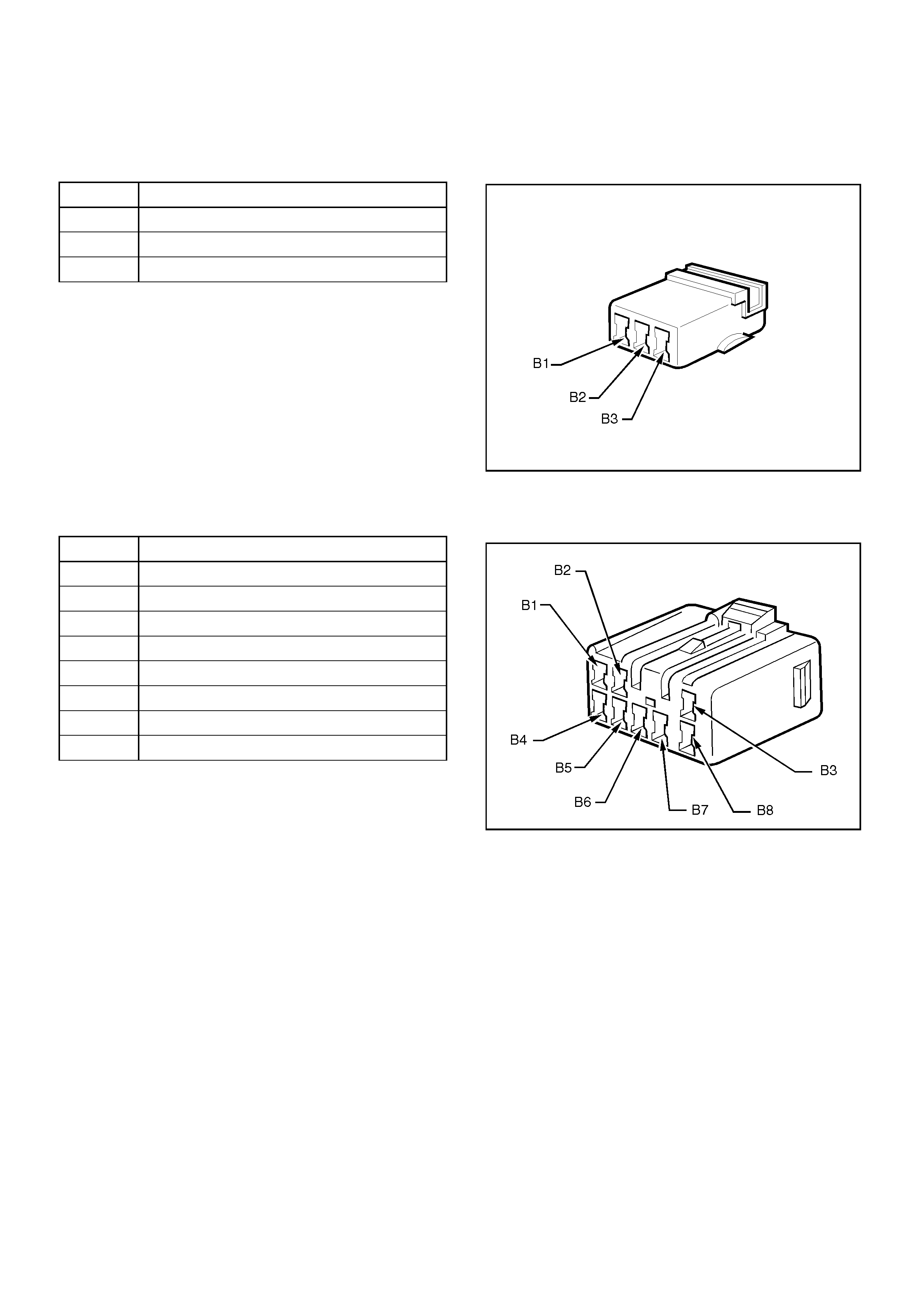
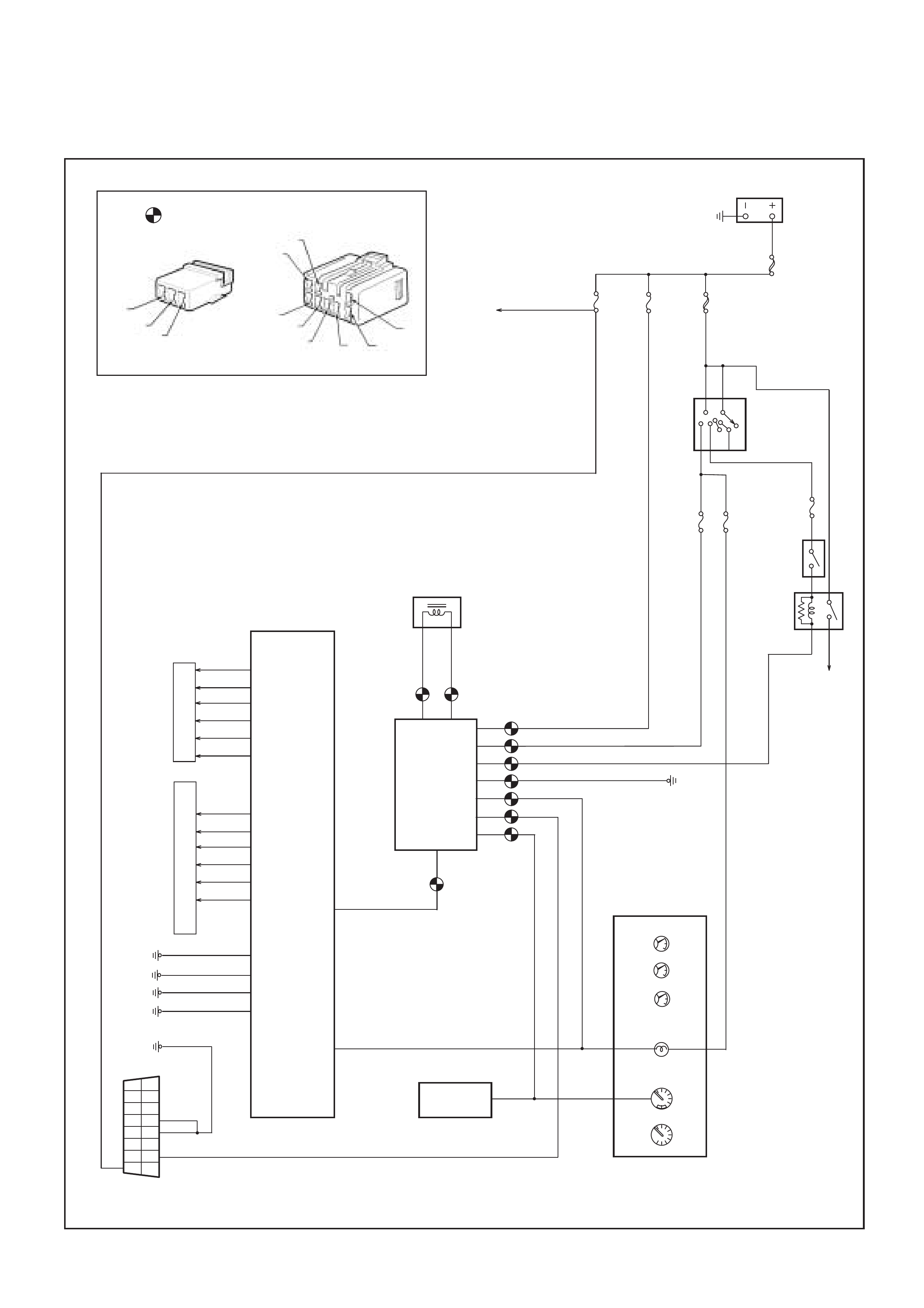
Immobiliser Control Unit Harness Connectors
Connector A
Connector B
Pin Circuit
A1 Antenna Coil Positive
A2 Not Used
A3 Antenna Coil Negative
Pin Circuit
B1 Starter Relay
B2 Ground
B3 Ignition from Fuse C-12
B4 Battery Power from Fuse C-23
B5 Diagnostic Link Connector Pin 7
B6 Vehicle Speed Sensor Signal Input
B7 PCM/ECM to ICU Communication
B8 ICU to PCM/ECM Communication
ACC
B2
B1
OFF
IG2
ST
IG1
IGNITION
SWITCH
BATT
MAIN
80A
IGN. B2
50A
IMMO.
C-23
10A
ENGINE
C-12
15A
METER
C-11
15A
F62
F64
F66
F69
0.5B/L
S11
STOP
C-6
15A
SPEEDOMETER
INSTRUMENTS
TACHOMETER
OIL PRESSURE
ENG TEMPERATURE
CHECK ENG.
0.5B
A1
0.5B
S40
S27
PCM
1
9
2
10
3
11
4
12
5
13
6
14
7
15
8
16
B6
B5
B7
B2
B1
B3
B4
A3
ANTENNA COIL
0.5O
0.5B
0.85Y/B
0.5R/B
0.5W/L
0.5O/B
0.5Y/R
STARTER
C-3
10A
STARTER
MOTOR
IMMOBILISER
CONTROL
UNIT
STARTER
RELAY
FUEL LEVEL
MODE SW.
(AUTO)
B8
VEHICLE SPEED
SENSOR
STOP
LAMPS
S1
Immobiliser Control Unit Harness Connectors
0.5L/B
S28
F56
S25
S62
F25
F26
S13
S19
A1
B1
A3
B2
A2
B4
B5
B6 B7 B8
B3
F1
F40
I
N
J
E
C
T
O
R
S
I
O
N
S
E
N
S
I
N
G
M
O
D
U
L
E