
SECTION 12A - BATTERY
Service Precaution
Battery
General Description
Diagnosis
Battery Charging
Jump Starting
Battery Removal
Battery Installation
Main Data and Specifications
SERVICE PRECAUTION
WARNING: THIS VEHICLE HAS A SUPPLEMENTAL
RESTRAINT SYSTEM (SRS), REFER TO THE SRS
COMPONENT AND WIRING LOCATION VIEW IN
ORDER TO DETERMINE WHETHER YOU ARE
PERFORMING SERVICE ON OR NEAR THE SRS
COMPONENTS OR THE SRS WIRING. WHEN YOU
ARE PERFORMING SERVICE ON OR NEAR THE
SRS COMPONENTS OR THE SRS WIRING, REFER
TO THE SRS SERVICE INFORMATION. FAILURE TO
FOLLOW WARNINGS COULD RESULT IN
POSSIBLE AIR BAG DEPLOYMENT, PERSONAL
INJURY, OR OTHERWISE UNNEEDED SRS SYSTEM
REPAIRS.
CAUTION: Always use the correct fastener in the
proper location. When you replace a fastener, use
ONLY the exact part number for that application.
HOLDEN will call out those fasteners that require a
replacement after removal. HOLDEN will also call
out the fasteners that require thread lockers or
thread sealant. UNLESS OTHERWISE SPECIFIED,
do not use supplemental coatings (Paints, greases,
or other corrosion inhibitors) on threaded fasteners
or fastener joint interfaces. Generally, such
coatings adversely affect the fastener torque and
the joint clamping force, and may damage the
fastener. When you install fasteners, use the
correct tightening sequence and specifications.
Following these instructions can help you avoid
damage to parts and systems.
BATTERY
GENERAL DESCRIPTION
There are six battery fluid caps on top of the battery.
These are covered by a paper label.
The battery is completely sealed except for the six small
vent holes on the side. These vent holes permit the
escape of small amounts of gas generated by the
battery.
This type of battery has the following advantages over
conventional batteries:
1. There is no need to add water during the entire
service life of the battery.
2. The battery protects itself against overcharging.
The battery will refuse to accept an extensive
charge.
(A conventional battery will accept an excessive
charge, resulting in gassing and loss of battery
fluid.)
3. The battery is much less vulnerable to self
discharge than a conventional type battery.
DIAGNOSIS
1. Visual Inspection
Inspect the battery for obvious physical damage, such
as a cracked or broken case, which would permit
electrolyte loss.
Replace the battery if obvious physical damage is
discov ered dur in g inspec ti on.
Check for any other physical damage and correct it as
necessary.
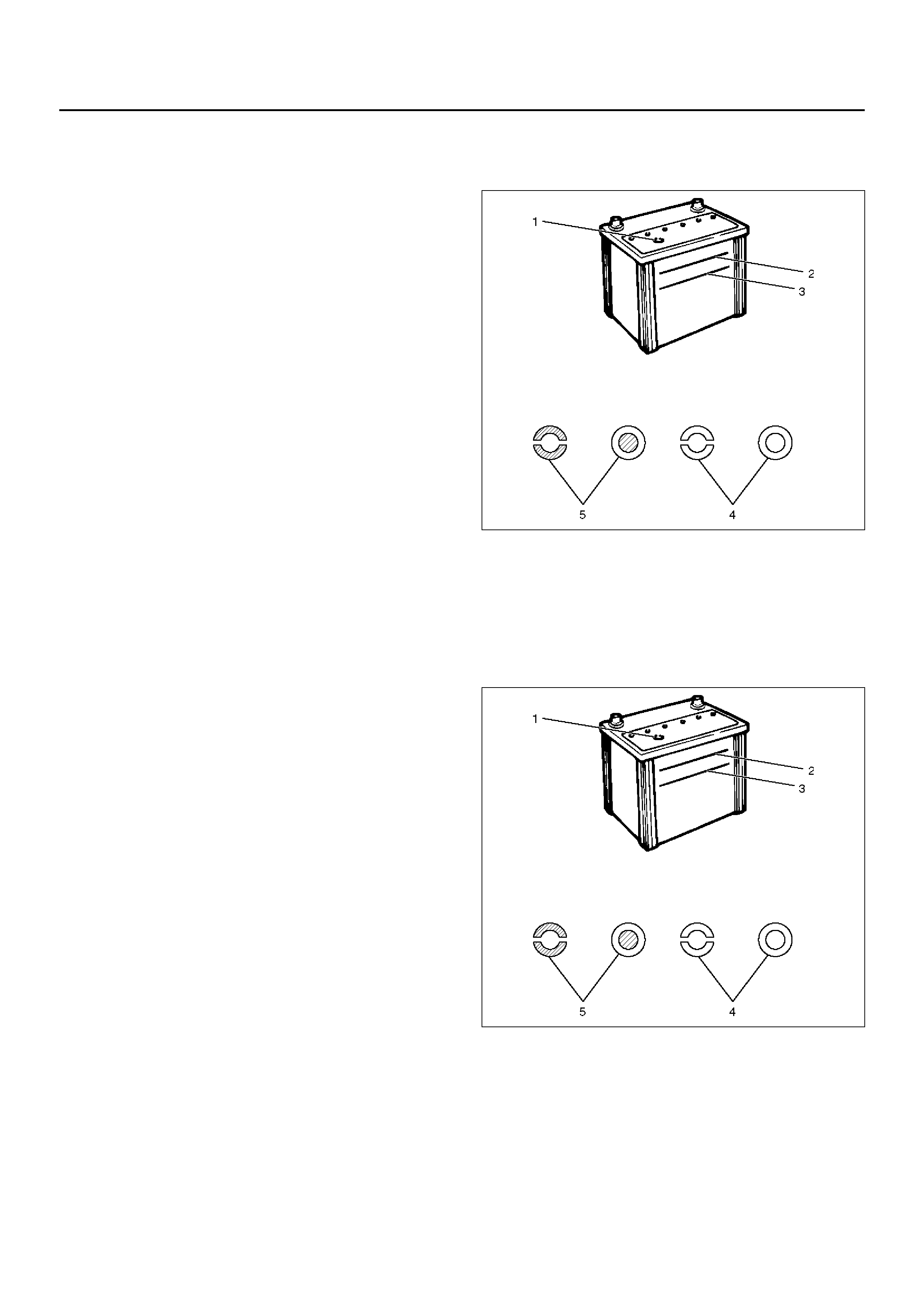
2. Hydrometer Check
There is a bu il t–in hy dr om eter ( Char ge test ind icato r(1) )
at the top of the battery. It is designed to be used during
diagnostic procedures.
Before tr ying to rea d the hy drom ete r, carefull y clean th e
upper battery surface.
If your work area is poorly lit, additional light may be
necessary to read the hydrometer.
a BLUE RING OR DOT VISIBLE(5) – Go to Step 4.
b BLUE R ING OR DOT N OT VIS I BLE(4 ) – Go t o Step
3.
061RW001
3. Fluid Level Check
The fluid level should be between the upper level line(2)
and lower level line(3) on side of battery.
a CORRECT FLUID LEVEL – Charge the battery.
b BELOW LOWER LEVEL – Replace battery.
061RW001
4. Voltage Check
1. Put voltmeter test leads to battery terminals.
a VOLTAGE IS 12.4V OR A BOV E – Go t o Ste p 5.
b VOLTAGE IS UNDER 12.4V – Go to procedure
(2) below.

2. Determine fast charge amperage from specification.
(See Main Data and Specifications in this section).
Fast charge battery for 30 minutes at amperage rate
no higher than specified value.
Take voltage and amperage readings after charge.
a VOLTAGE IS ABOVE 16V AT BELOW 1/3 OF
AMPERAGE RATE – Replace battery.
b VOLTAGE IS ABOVE 16V AT ABOVE 1/3 OF
AMPERAGE RATE – Drop charging voltage to
15V and charge for 10 – 15 hours. Then go to
Step 5.
c VOLTAGE IS BETWEEN 12V AND 16V –
Continue charging at the same rate for an
additional 3–1/2 hours. Then go to Step 5.
d VOLTAGE BELOW 12V – Replace Battery.
5. Load Test
1. Connect a voltmeter and a battery load tester
across the battery terminals.
2. Apply 300 ampere load for 15 seconds to remove
surface charge from the battery. Remove load.
3. Wait 15 seconds to let battery recover. Then apply
specified load from specifications (See Main Data
and Specifications in this section).
Read voltage after 15 seconds, then remove load.
a VOLTAGE DOES NOT DROP BELOW THE
MINIMUM LISTED IN THE TABLE – The battery
is good and should be returned to service.
b VOLTAGE IS LESS THAN MINIMUM LISTED –
Replace battery.
BATTERY CHARGING
Observe the following safety precautions when charging
the battery:
1. Never attempt to charge the battery when the fluid
level is below the lower level line on the side of the
battery. In this case, the battery must be replaced.
2. Pay close attention to the battery during charging
procedure.
Battery charging shou ld be disc ontinued or the rate
of charge reduced if the battery feels hot to the
touch.
Battery charging shou ld be disc ontinued or the rate
of charge reduced if the battery begins to gas or
spew electrolyte from the vent holes.
3. In order to more easily view the hydrometer blue dot
or ring, it may be necessary to jiggle or tilt the
battery.
4. Battery temperature can have a great effect on
battery charging capacity.
5. The sealed battery used on this vehicle may be
either quick charged or slow charged in the same
manner as other batteries.
Whichever method you decide to use, be sure that
you completely charge the battery. Never partially
charge the battery.
ESTIMATED TEMPERATURE MINIMUM
VOLTAGE
°F°CV
70 21 9.6
60 16 9.5
50 10 9.4
40 4 9.3
30 –1 9.1
20 –7 8.9
10 –12 8.7
0 –18 8.5
The battery temperature must be estimated by feel
and by the temperature the battery has been exposed
to for the preceding few hours.
JUMP STARTING
Jump Starting with an Auxiliary (Booster)
Battery
CAUTION: Never push or tow the vehicle in an
attempt to start it. Serious damage to the emission
system as well as other vehicle parts will result.
Treat both the discharged battery and the booster
battery with great care when using jumper cables.
Carefully follow the jump starting procedure, being
careful at all times to avoid sparking.
WARNING: FAILURE TO CAREFULLY FOLLOW THE
JUMP STARTING PROCEDURE COULD RESULT IN
THE FOLLOWING:
1. Serous personal injury, particularly to your eyes.
2. Property damage from a battery explosion,
battery acid, or an electrical fire.
3. Damage to the electronic components of one or
both vehicles particularly.
Never expose the battery to an open flame or electrical
spark. Gas generated by the battery may catch fire or
explode.
Remove any rings, watches, or other jewelry before
working around the battery. Protect your eyes by
wearing an approved set of goggles.
Never allow battery fluid to come in contact with your
eyes or skin.
Never allow battery fluid to come in contact with fabrics
or painted surfaces.
Battery fluid is a highly corrosive acid.
Should battery fluid come in contact with your eyes,
skin, fabric, or a painted surface, immediately and
thoroughly rinse the affected area with clean tap water.
Never allow metal tools or jumper cables to come in
contact with the positive battery terminal, or any other
metal surface of the vehicle. This will protect against a
short circuit.
Always keep batteries out of reach of young children.
Jump Starting Procedure
1. Set the vehicle parking brake.
If the vehicle is equipped with an automatic
transmission, place the selector level in the “PARK"
position.
If the vehicle is equipped with a manual
transmission, place the shift lever in the “NEUTRAL"
position.
Turn “OFF" the ignition.
Turn “OFF" all lights and any other accessory
requiring electrical power.
2. Look at the built–in hydrometer.
If the indication area of the built–in hydrometer is
completely clear, do not try to jump start.
3. Attach the end of one jumper cable to the positive
terminal of the booster battery.
Attach the other end of the same cable to the
positive terminal of the discharged battery.
Do not allow the vehicles to touch each other. This
will cause a ground connection, effectively
neutralizing the charging procedure.
Be sure that the booster battery has a 12 volt rating.
4. Attach one end of the remaining cable to the
negative terminal of the booster battery.
Attach the other end of the same cable to a solid
engine ground (such as the air conditioning
compressor bracket or the generator mounting
bracket) of the vehicle with the discharged battery.
The ground connection must be at least 450 mm (18
in.) from the battery of the vehicle whose battery is
being charged.
WARNING: NEVER ATTACH THE END OF THE
JUMPER CABLE DIRECTLY TO THE NEGATIVE
TERMINAL OF THE DEAD BATTERY.
5. Start the engine of the vehicle with the good battery.
Make sure that all unnecessary electrical
accessories have been turned “OFF".
6. Start the engine of the vehicle with the dead battery.
7. To remove the jumper cables, follow the above
directions in reverse order.
Be sure to first disconnect the negative cable from
the vehicle with the discharged battery.
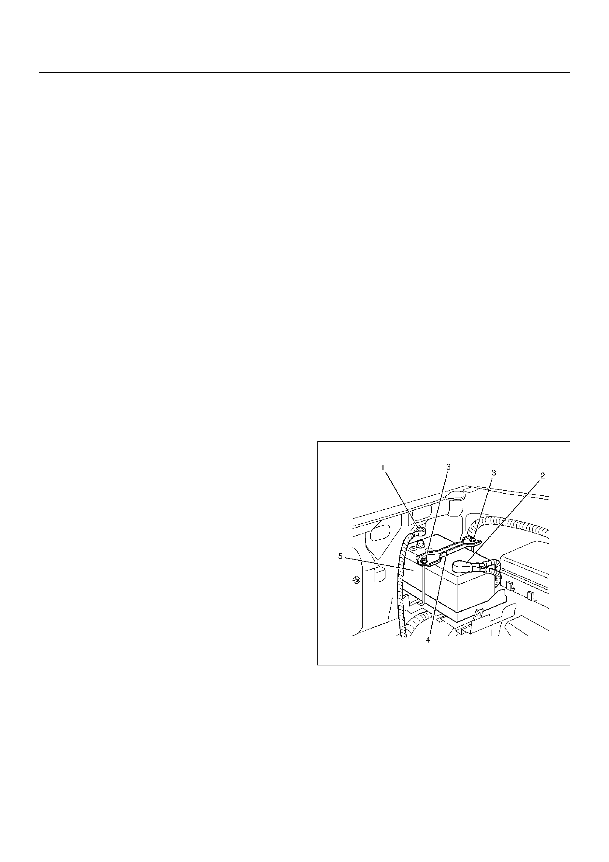
BATTERY REMOVAL
061RX002
1. R emove negative cable (1).
2. Remove positive cable (2).
3. Remove retainer screw and rods (3).
4. Remove retainer (4).
5. Remove battery (5).

BATTERY INSTALLATION
1. Install battery (5).
2. Install retainer (4).
3. Instal retainer screw and rods (3).
Make sure that the rod is hooked on the body side.
4. Install positive cable (2).
5. Install negative cable (1).

MAIN DATA AND SPECIFICATIONS
General Specifications
Model (JIS) 24R–600
Voltage (V) 12
Cold Cranking Performance (Amp) 600
Reserve Capacity (Min) 118
Load Test (Amp) 300
BCI Group No. 24