
SECTION 12B - LIGHTING SYSTEM
Service Precaution
Headlamp Bulb
Removal
Installation
Headlamp Assembly
Removal
Installation
Headlamp Adjustment
Fog Lamp Bulb
Removal
Installation
Fog Lamp Assembly
Removal
Installation
Fog Lamp Adjustment
Park Lamp Bulb
Removal
Installation
Front Combination Lamp Assembly
Removal
Installation
Tail Lamp Bulb
Removal
Installation
License Plate Lamp Bulb
Removal
Installation
Stop Lamp Bulb
Removal and Installation
High Mounted Stop Lamp Assembly
Removal
Installation
High Mounted Stop Lamp Bulb
Removal
Installation
Backup Lamp Bulb
Removal
Installation
Front Turn Signal Lamp Bulb
Removal
Installation
Side Turn Signal Lamp Bulb
Removal
Installation
Rear Turn Signal Lamp Bulb
Removal
Installation
Dome Lamp Bulb
Removal
Installation
Courtesy Lamp Bulb
Removal
Installation
Map Lamp Bulb
Removal
Installation
Map Lamp Bulb (with Overhead Console)
Removal
Installation
Load Compartment Lamp Bulb
Removal
Installation
HVAC Bezel Illumination Lamp Bulb
Removal and Installation
Shift Lever Illumination Lamp Bulb (A/T)
Removal
Installation
Ashtray Illumination Bulb
Removal
Installation
Starter Switch
Removal and Installation
Lighting Switch (Combination Switch)
Removal and Installation
Dimmer·Passing Switch
(Combination Switch)
Removal and Installation
Door Switch
Removal
Installation
Rear Demister Switch
Removal
Installation
Key Remind Switch (Starter Switch)
Removal and Installation
Hazard Warning Lamp Switch
Removal
Installation
Stop Lamp Switch
Removal and Installation
4WD Switch
Removal
Installation
Fog Lamp Switch
Removal
Installation
TOD Switch
Removal
Installation

Cruise Main Switch
Removal
Installation
Power/Winter Switch
Removal
Installation
Illumination Controller
Removal
Installation
Backup Lamp Switch (M/T)
Removal
Installation
Turn Signal Lamp Switch
(Combination Switch)
Removal and Installation
Lamp and Bulb Specifications
SERVICE PRECAUTION
WARNING: THIS VEHICLE HAS A SUPPLEMENTAL
RESTRAINT SYSTEM (SRS). REFER TO THE SRS
COMPONENT AND WIRING LOCATION VIEW IN
ORDER TO DETERMINE WHETHER YOU ARE
PERFORMING SERVICE ON OR NEAR THE SRS
COMPONENTS OR THE SRS WIRING. WHEN YOU
ARE PERFORMING SERVICE ON OR NEAR THE
SRS COMPONENTS OR THE SRS WIRING, REFER
TO THE SRS SERVICE INFORMATION. FAILURE TOFOLLOW WARNINGS COULD RESULT IN POSSIBLEAIR BAG DEPLOYMENT, PERSONAL INJURY, OROTHERWISE UNNEEDED SRS SYSTEM REPAIRS.
CAUTION: Always use the correct fastener in the
proper location. When you replace a fastener, use
ONLY the exact part number for that application.
HOLDEN will call out those fasteners that require a
replacement after removal. HOLDEN will also call
out the fasteners that require thread lockers or
thread sealant. UNLESS OTHERWISE SPECIFIED,
do not use supplemental coatings (Paints, greases,
or other corrosion inhibitors) on threaded fasteners
or fastener joint interfaces. Generally, such
coatings adversely affect the fastener torque and
the joint clamping force, and may damage the
fastener. When you install fasteners, use the correct
tightening sequence and specifications. Following
these instructions can help you avoid damage to
parts and systems.
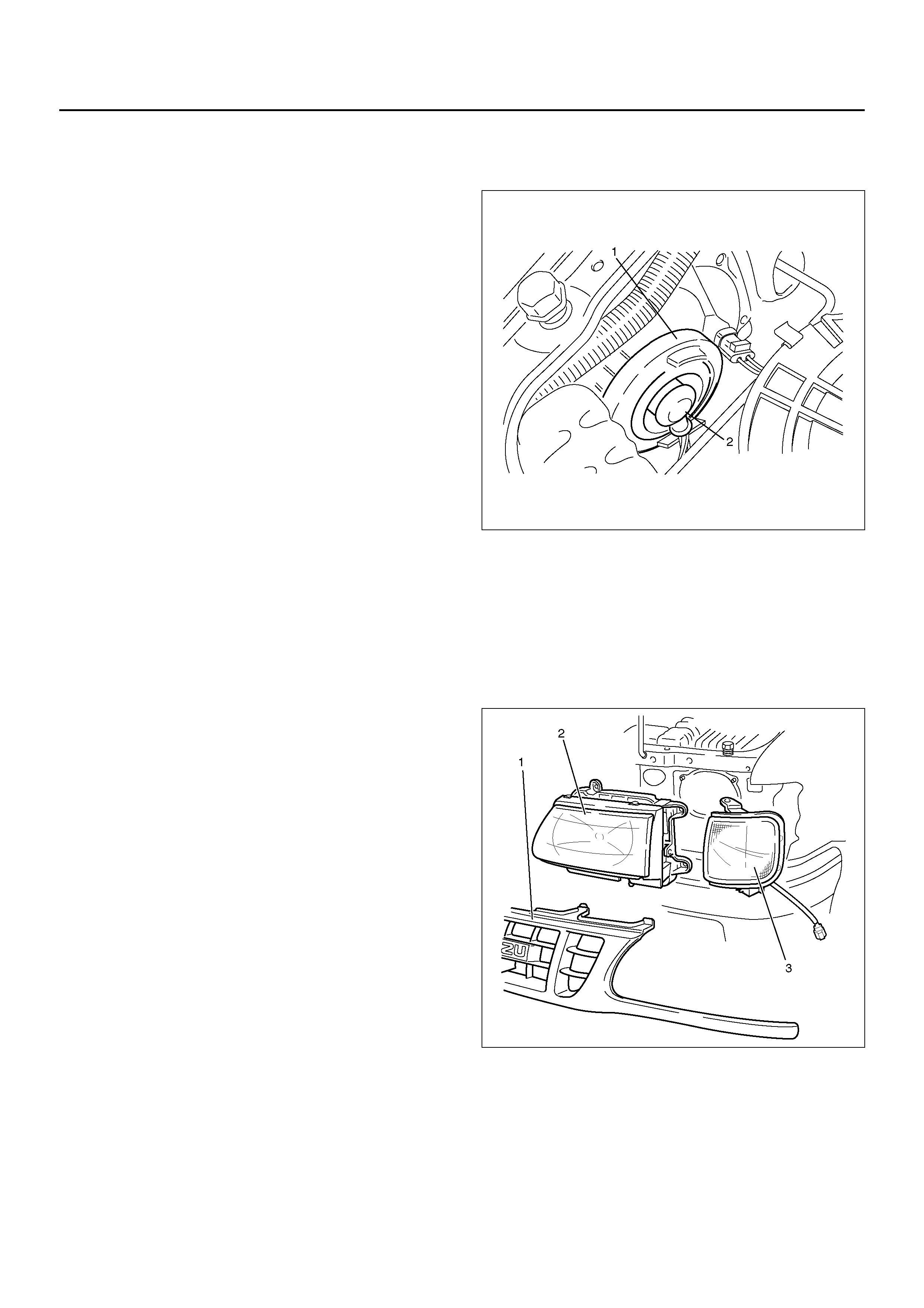
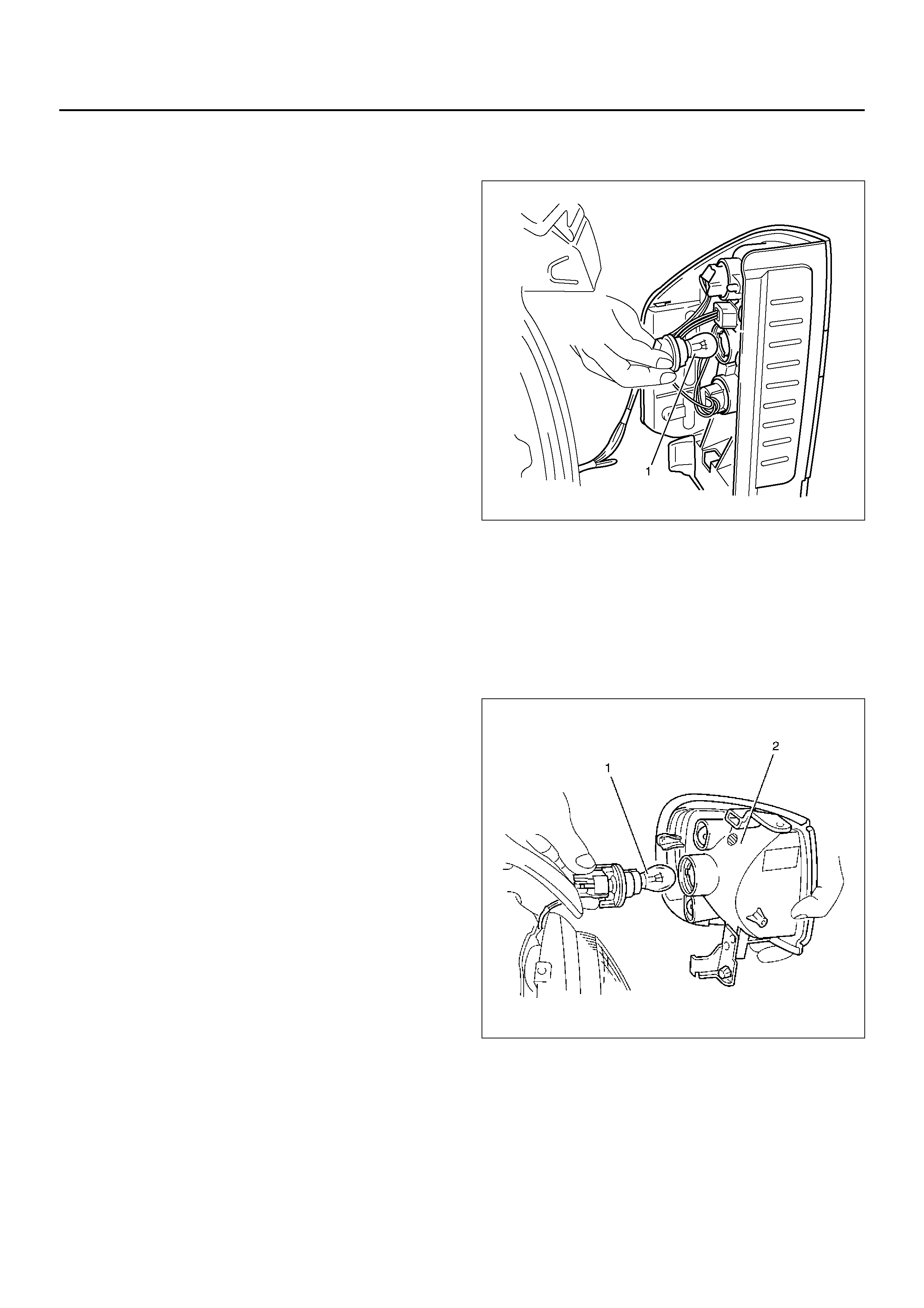
HEADLAMP BULB
REMOVAL
1. Disconnect the battery ground cable.
2. Remove the headlamp bulb.
• Disconnect the connector (2).
• Remove the rubber cap (1).
• Remove the spring.
CAUTION: The halogen lamp bulb produces heat
and temperature rises high, therefore, if the glass
surface is contaminated it will be burnt by heat
leaving stains which will not come out. This may
reduce the illuminating power or damage the bulb
due to thermal deformation during evaporation. In
order to prevent this problem, do not touch the
glass surface with your fingers.
801RY00010
INSTALLATION
To install, follow the removal steps in the reverse order.
HEADLAMP ASSEMBLY
REMOVAL
1. Disconnect the battery ground cable.
2. Remove the radiator grille (1).
• Remove eight clips and a screw.
3. Remove the side marker lamp (3).
• Remove three screws.
• Disconnect the connector.
4. Remove the headlamp assembly (2).
• Disconnect the connector.
• Remove four screws.
801RY00017
INSTALLATION
To install, follow the removal steps in the reverse order.
CAUTION: After installing the headlamp, be sure to
adjust the headlamp aim.
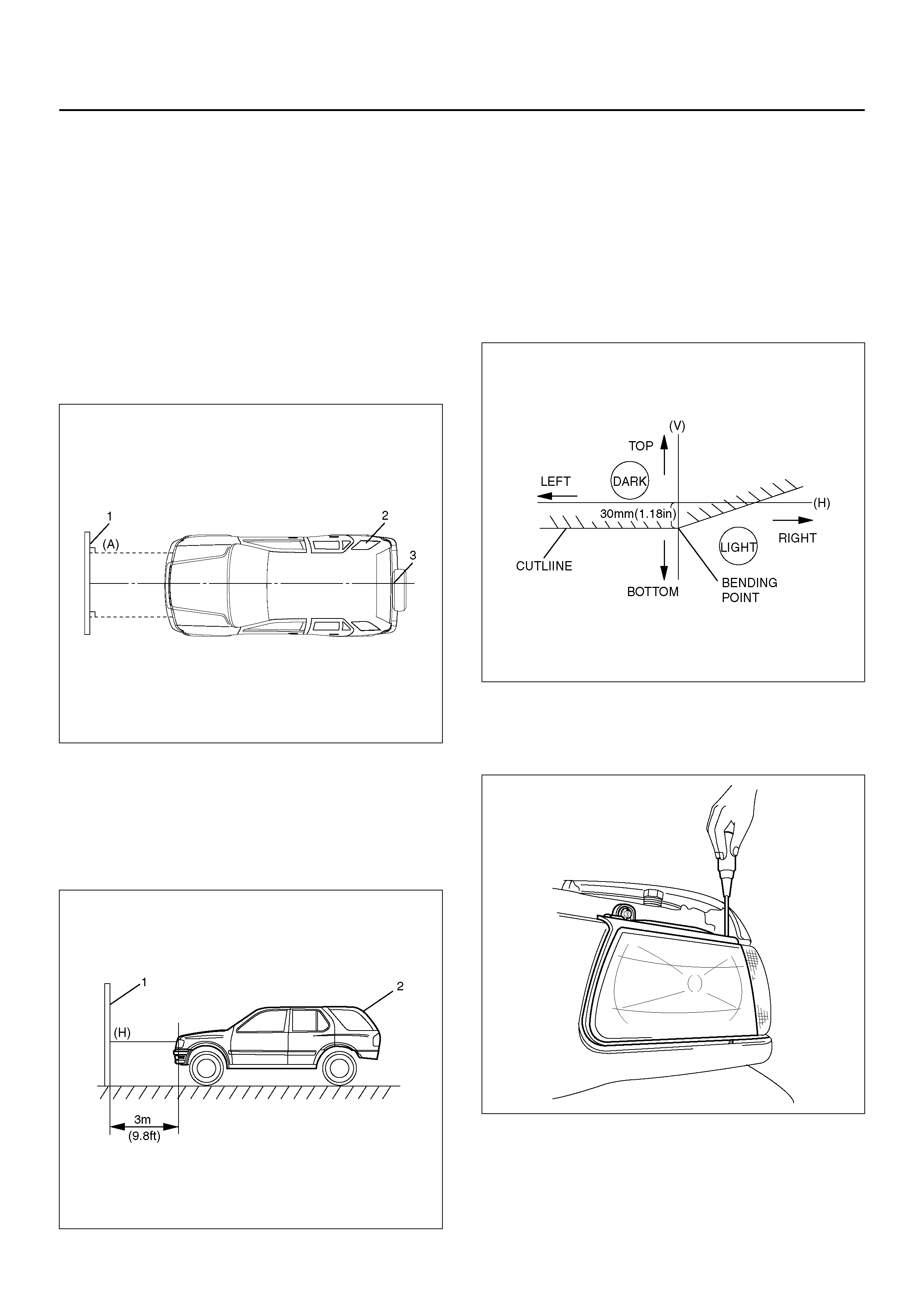
HEADLAMP ADJUSTMENT
Preparation
Place the vehicle with 1 – person in driver seat, on a
level surface and check to see if the inflation pressure of
the tyres is correct, the linses are clean, the battery is
sufficiently charged, and adjust to place vehicle by using
the screen .
1. Set up the screen (1) on a level surface.
2. Put on the screen at right angles to the center line
(3).
3. Adjust the center of the vehicle (2) to the center line
on floor.
801R100007
4. Keep the vehicle (2) 3m (9.8 ft) apart from the
sc re e n (1).
5. Toward the screen from the bulb center mark of
headlamp, extend a parallel line (A) to the floor and
draw a vertical line (V) at an intersection point of
screen and a parallel line (A).
801R100006
6. Measure a height (H) from the bulb mark of
headlamp to the floor and draw a horizontal line on
the screen.
7. Turn on the low beam of headlamp.
8. Adjust the bending point to the vertical line (V) by
horizontal adjustment and adjust cut line 30mm
(1.18in) below from horizontal line (H) by vertical
adjustment.
NOTE: While adjusting the headlamp, cover the other
one so as not to light the screen.
801R100013
Vertical Adjustment
Use a screwdriver for vertical adjustment.
801RY00018
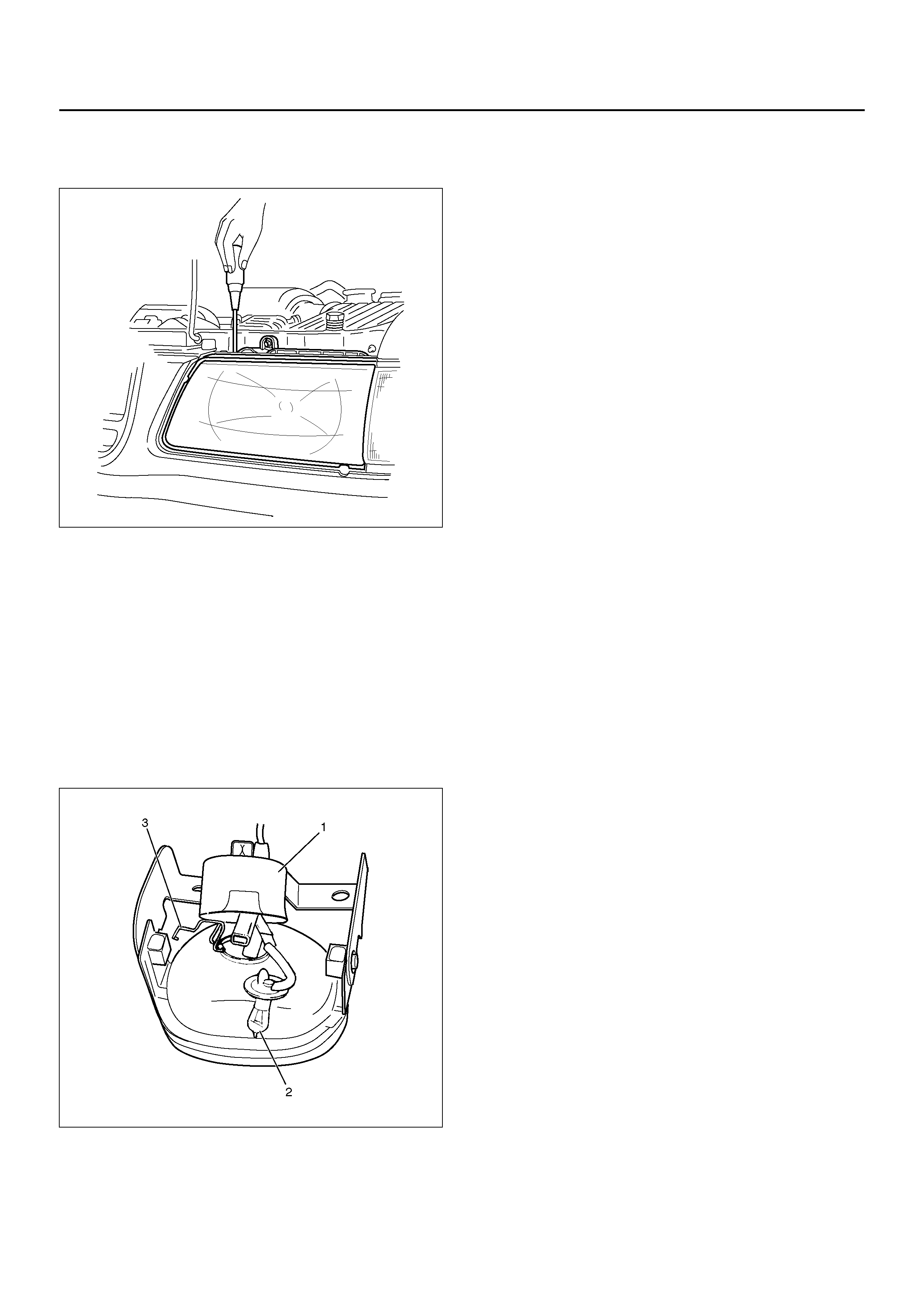
Horizontal Adjustment
Use a screwdriver for horizontal adjustment.
801R100004
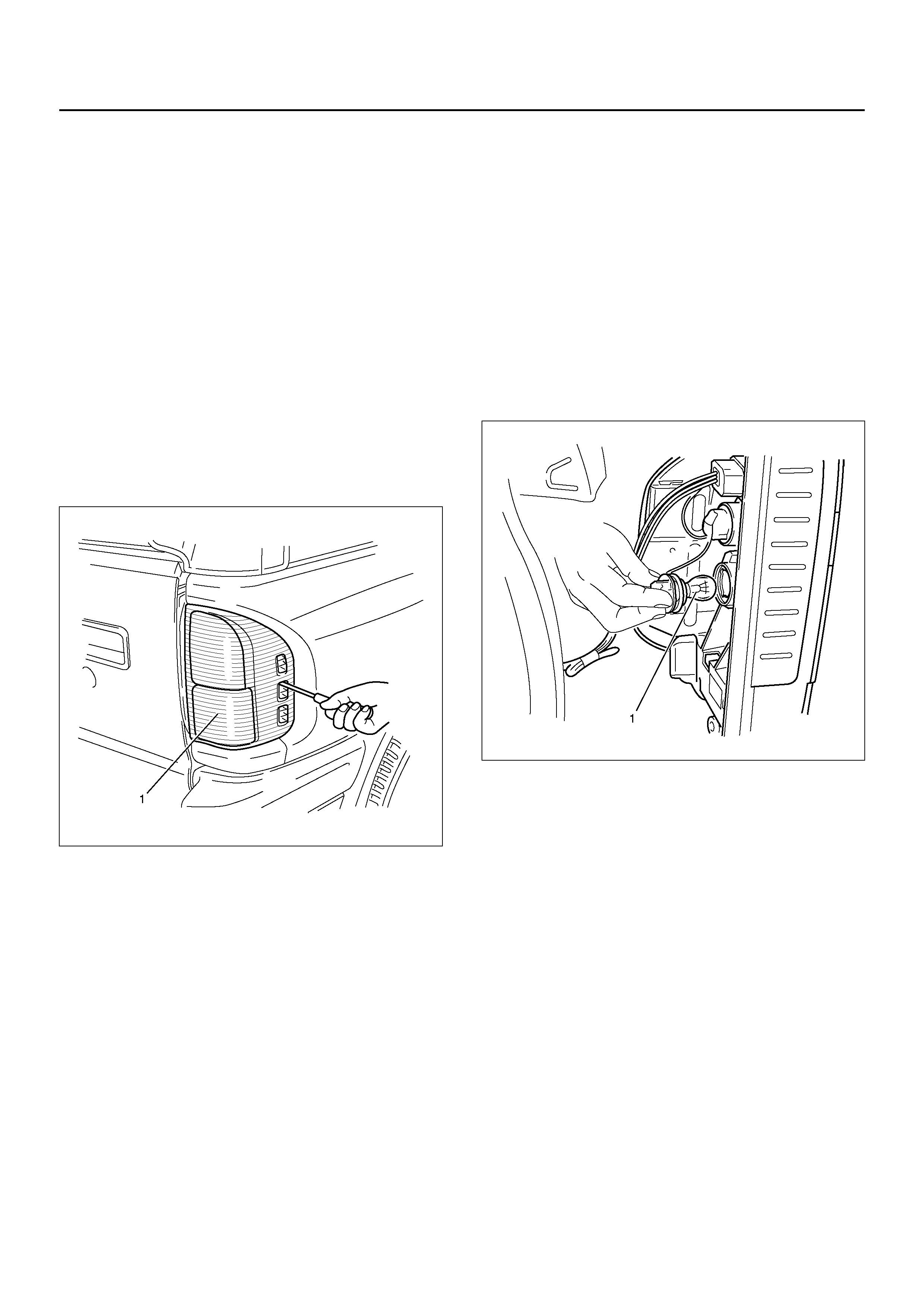
FOG LAMP BULB
REMOVAL
1. Disconnect the battery ground cable.
2. Remove the fog lamp bulb (2).
• Open the rear cover (1).
• Remove the dust cover.
• Disconnect the bulb connector.
• Remove the clip (3).
801RY00011
INSTALLATION
To install, follow the removal steps in the reverse order.
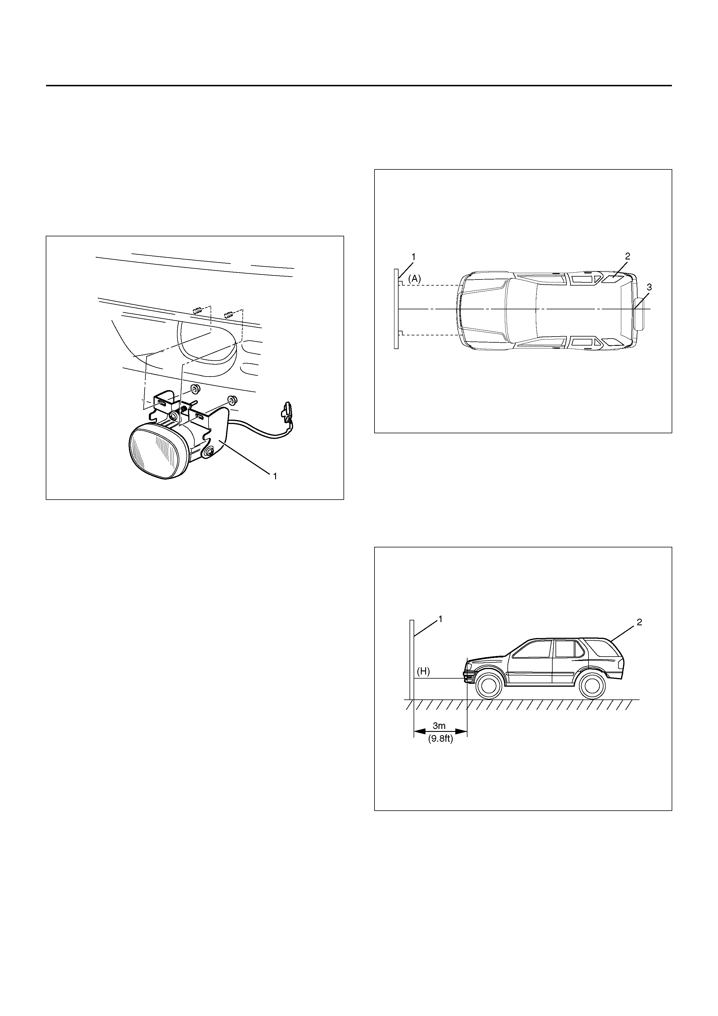
FOG LAMP ASSEMBLY
REMOVAL
1. Disconnect the battery ground cable.
2. Remove the fog lamp assembly (1).
• Disconnect the connector.
• Remove two nuts from the bracket.
801RY00012
INSTALLATION
To install, follow the removal steps in the reverse order.
CAUTION: After installing the fog lamp, be sure to
adjust the fog lamp aim.
FOG LAMP ADJUSTMENT
Preparation
Place the vehicle with 1 – person in driver seat, on a
level surface and check to see if the inflation pressure of
the tires iscorrect, the linses are clean, the battery is
sufficiently charged, and adjust to place vehicle by using
the screen .
1. Set up the screen (1) on a leve surface.
2. Put on the screen at right angles to the center line
(3).
3. Adjust the center of the vehicle (2) to the center line
on floor.
801R100007
4. Keep the vehicle (2) 3m (9.8 ft) apart from the
screen (1).
5. Toward the screen from the bulb center mark of fog
lamp, extend a parallel line (A) to the floor and draw
a vertical line (V) at an intersection point of screen
and a pa rallel line (A).
801R100015
6. Measure a hight (H) from the bulb mark of fog lamp
to the floor and draw a horizontal line on the screen.
7. Turn on the fog lamp.
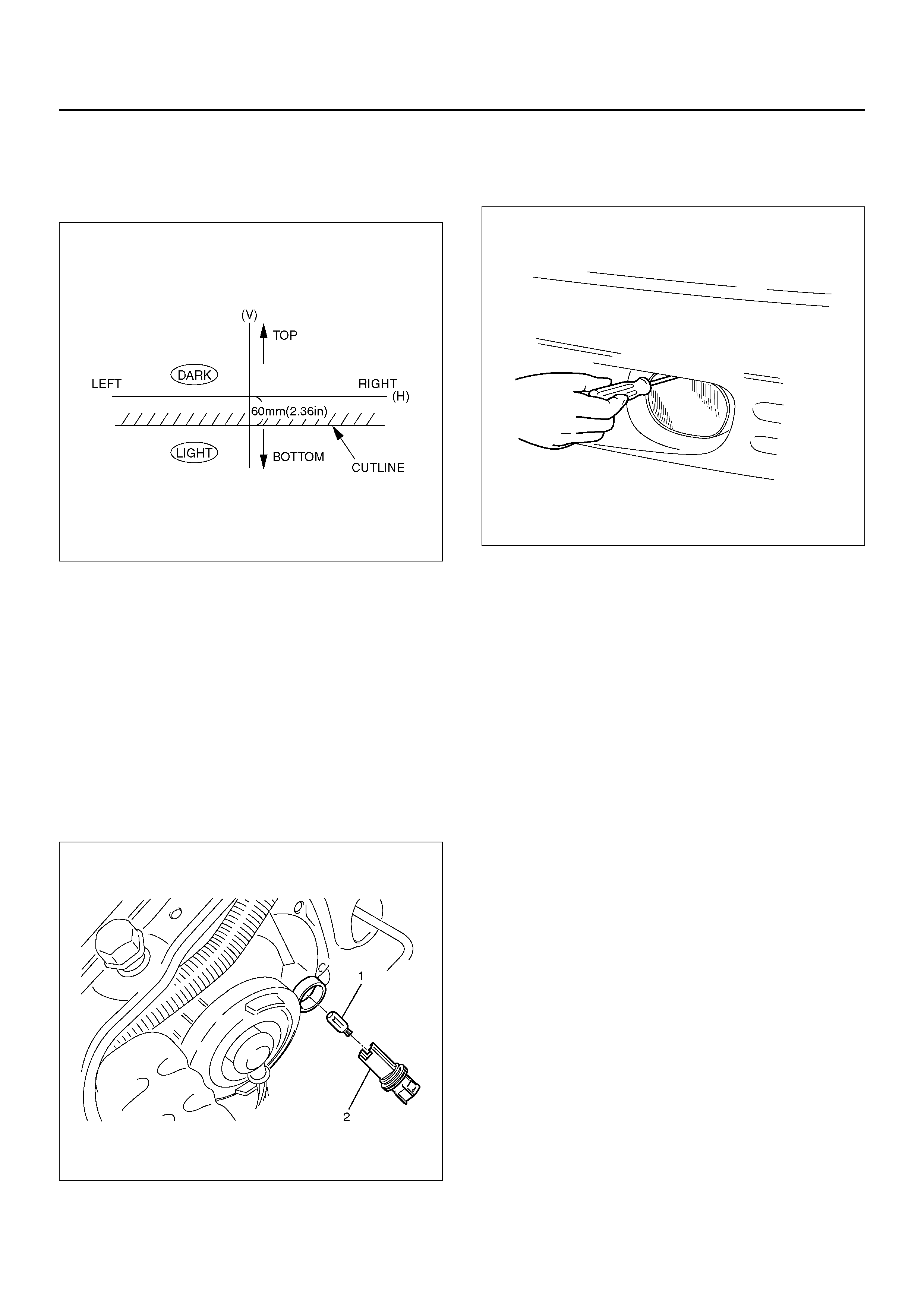
8. Adjust cut line 60mm (2.36in) below from horizontal
line (H) by vertical adjustment.
NOTE: While adjusting the fog lamp, cover the other
one not to lamp the screen.
801R100014
Vertical Adjustment
Turn the adjusting screw with a screwdriver to adjust the
aim of the fog lamp vertically.
801RY00013
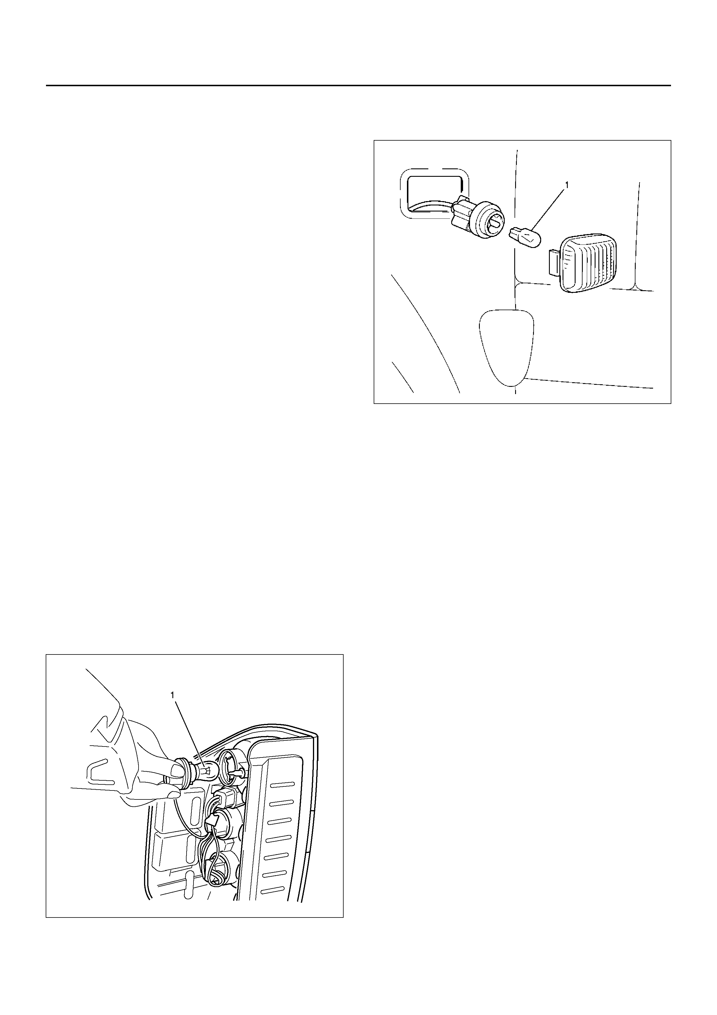
PARK LAMP BULB
REMOVAL
1. Disconnect the battery ground cable.
2. Disconnect the connector.
3. Remove the socket retaining ring by turning it
counterclockwise.
4. Remove the clearance lamp bulb (2).
• Remove the rubber cap.
• Pull out the bulb socket (1).
801RY00014
INSTALLATION
To install, follow the removal steps in the reverse order.
FRONT COMBINATION LAMP ASSEMBLY
REMOVAL
1. Disconnect the battery ground cable.
2. Remove the side combination lamp.
• Refer to Side Marker lamp Bulb in this section.
3. Disconnect the connector.
INSTALLATION
To install, follow the removal steps in the reverse order.
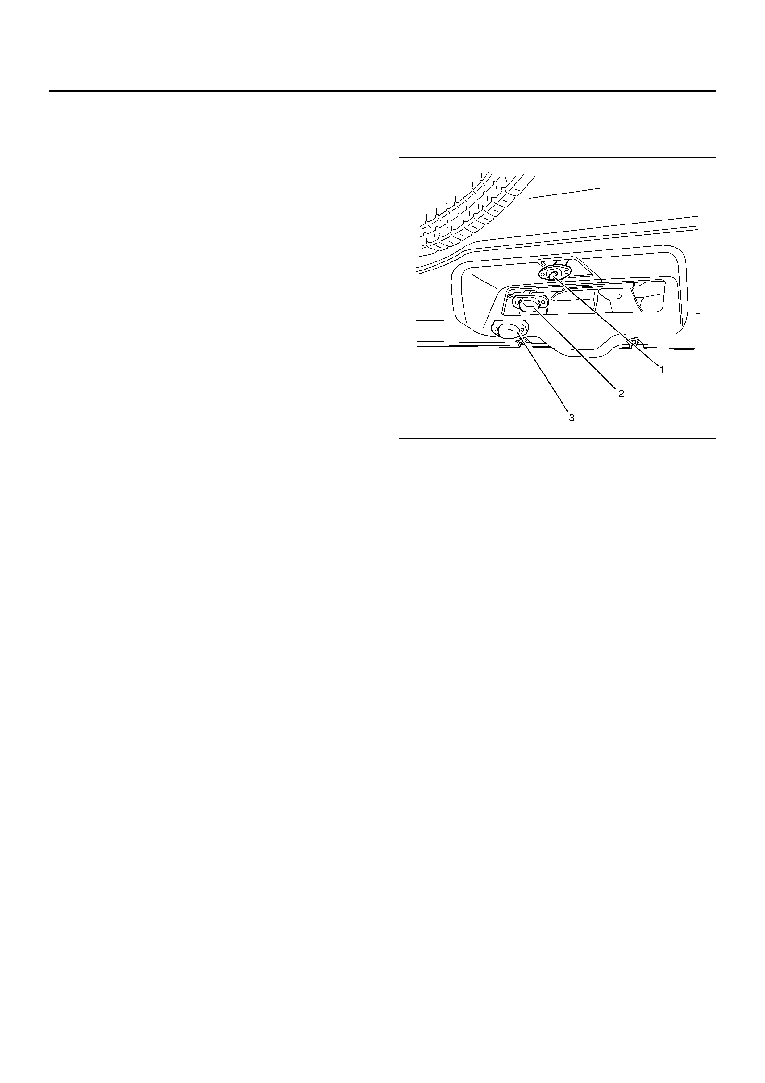
TAIL LAMP BULB
REMOVAL
1. Disconnect the battery ground cable.
2. Remove the rear combination lamp assembly (1).
• Remove three screws.
3. Pull out the rear combination lamp assembly to
ward you.
803RY00005
• Remove the bulb (1) by turning it
counterclockwise while pushing it at the same
time.
825RW069
INSTALLATION
To install, follow the removal steps in the reverse order.
LICENSE PLATE LAMP BULB
REMOVAL
1. Disconnect the battery ground cable.
2. Remove the lens cover (3).
• Remove two screws.
3. Remove the lens (2).
4. Remove the bulb (1).
• Pull out the bulb from the socket.
825RW070
INSTALLATION
To install, follow the removal steps in the reverse order.
STOP LAMP BULB
REMOVAL AND INSTALLATION
Refer to Tail lamp Bulb in this section.
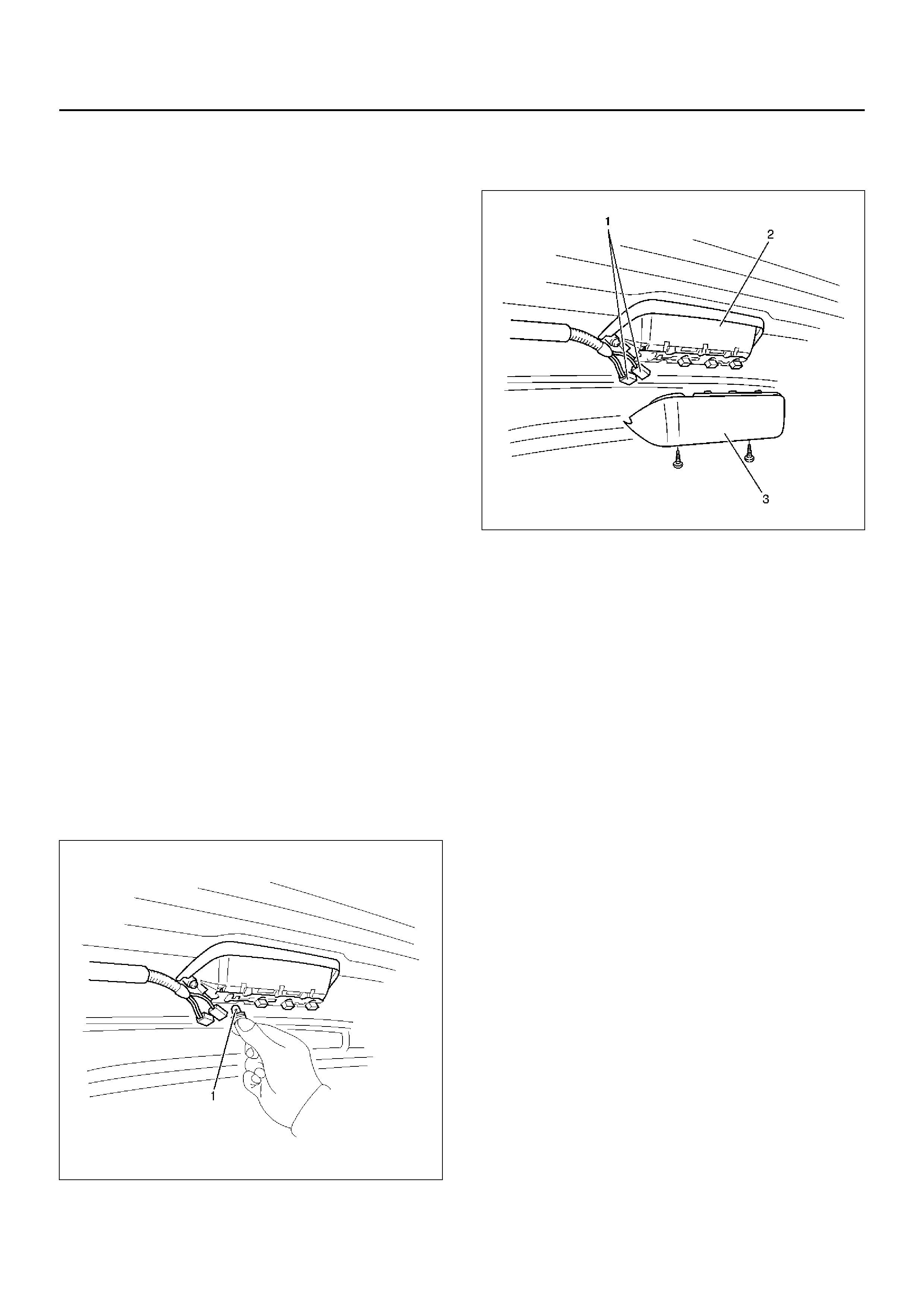
HIGH MOUNTED STOP LAMP ASSEMBLY
REMOVAL
1. Disconnect the battery ground cable.
2. Remove the high mount stop lamp assembly (2).
• Remove the cover (3).
• Disconnect the connectors (1).
• Remove two screws.
803RX001
INSTALLATION
To install, follow the removal steps in the reverse order.
HIGH MOUNTED STOP LAMP BULB
REMOVAL
1. Disconnect the battery ground cable.
2. Remove the cover.
3. Remove the bulb (1).
• Remove the socket by turning it
counterclockwise.
825RW071-1
INSTALLATION
To install, follow the removal steps in the reverse order.
BACKUP LAMP BULB
REMOVAL
1. Disconnect the battery ground cable.
2. Remove the rear combination lamp assembly.
• Refer to the Tail lamp Bulb removal step 2 in this
section.
• Remove the bulb (1) by turning it
counterclockwise while pushing it at the same
time.
825RW073
INSTALLATION
To install, follow the removal steps in the reverse order.
FRONT TURN SIGNAL LAMP BULB
REMOVAL
1. Disconnect the battery ground cable.
2. Remove the radiator grille.
• Refer to Engine Hood and Fender.
3. Remove the front turn signal lamp (2).
• Remove three screws.
4. Remove the bulb (1).
• Remove the front turn signal lamp socket by
turning it counterclockwise.
• Remove the bulb by turning it counterclockwise
while pushing it at the same time.
825RW067
INSTALLATION
To install, follow the removal steps in the reverse order.
SIDE TURN SIGNAL LAMP BULB
REMOVAL
1. Disconnect the battery ground cable.
2. Remove the side turn signal lamp assembly.
• Pushing in the rear direction of vehicle, pull out it
toward you.
3. Remove the bulb (1) by turning it counterclockwise.
801RW024
INSTALLATION
To install, follow the removal steps in the reverse order.
REAR TURN SIGNAL LAMP BULB
REMOVAL
1. Disconnect the battery ground cable.
2. Remove the rear combination lamp assembly.
• Refer to the Tail lamp Bulb in this section.
• Remove the bulb (1) by turning it
counterclockwise while pushing it at the same
time.
825RW074
INSTALLATION
To install, follow the removal steps in the reverse order.

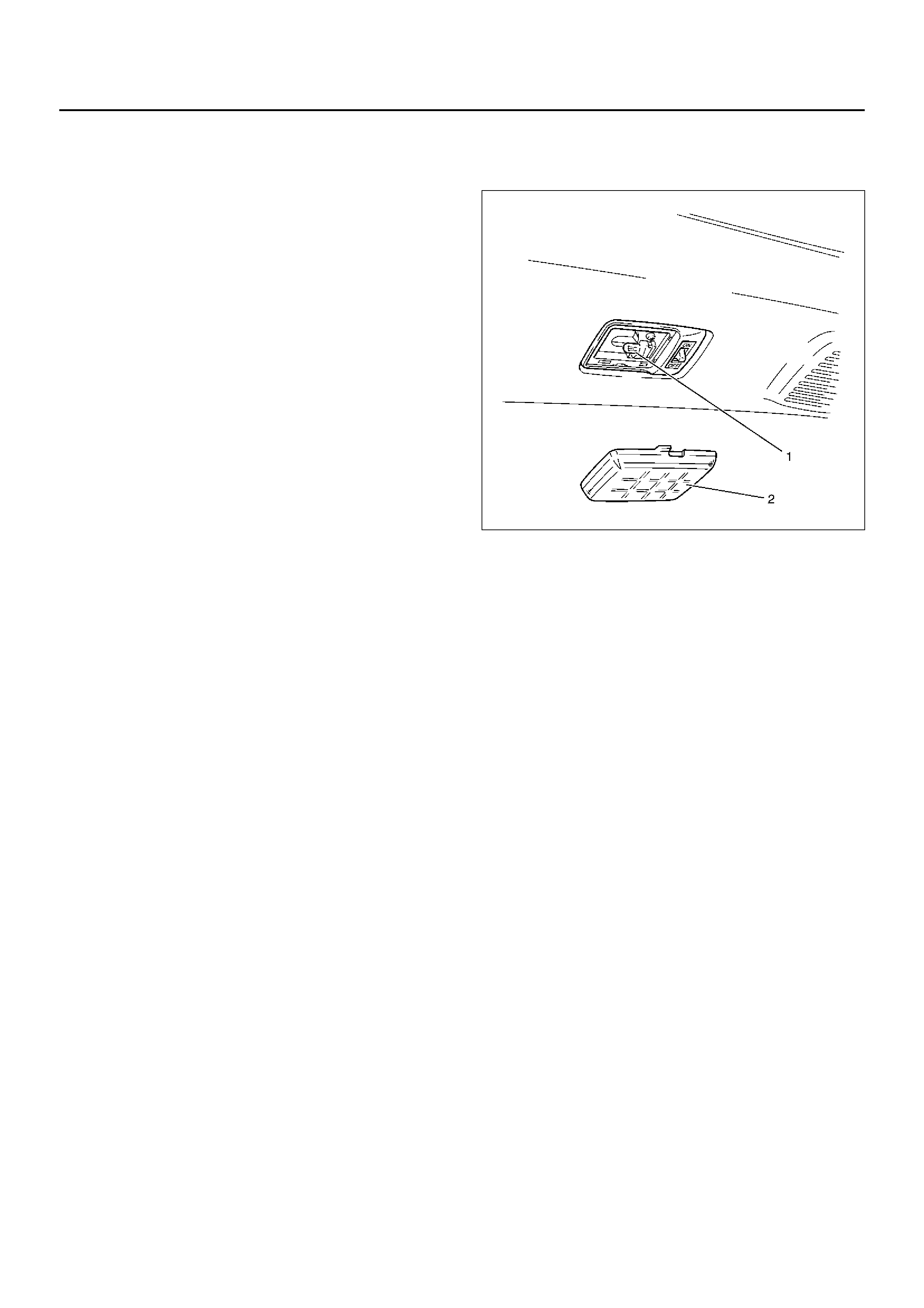
DOME LAMP BULB
REMOVAL
1. Disconnect the battery ground cable.
2. Remove the lens (2).
3. Remove the bulb (1).
• Pull out the bulb.
825RW075
INSTALLATION
To install, follow the removal steps in the reverse order.
COURTESY LAMP BULB
REMOVAL
1. Disconnect the battery ground cable.
2. Remove the lens (2).
3. Remove the bulb (1).
• Pull out the bulb.
825RW076
INSTALLATION
To install, follow the removal steps in the reverse order.
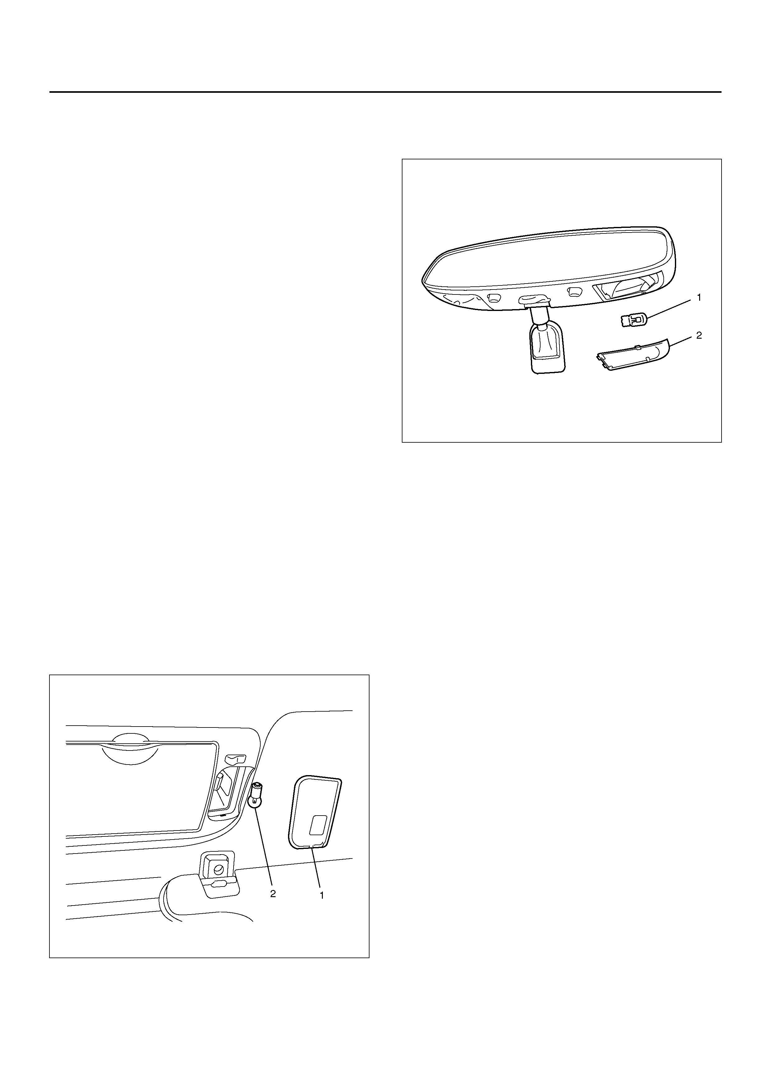
MAP LAMP BULB
REMOVAL
1. Disconnect the battery ground cable.
2. Remove the lens (2).
3. Remove the bulb (1).
• Pull out the bulb.
805R100001
INSTALLATION
To install, follow the removal steps in the reverse order.
MAP LAMP BULB (WITH OVERHEAD CONSOLE)
REMOVAL
1. Disconnect the battery ground cable.
2. Remove the lens (1).
3. Remove the bulb (2).
825RX059
INSTALLATION
To install, follow the removal steps in the reverse order.
LOAD COMPARTMENT LAMP BULB (4DOOR MODEL)
REMOVAL
1. Disconnect the battery ground cable.
2. Remove the lens (2).
3. Remove the bulb (1).
• Pull out the bulb.
825RW077
INSTALLATION
To install, follow the removal steps in the reverse order.
HVAC BEZEL ILLUMINATION LAMP BULB
REMOVAL AND INSTALLATION
Refer to Control Panel Illumination bulb in Heating,
Ventilation and Air Conditioning (HVAC) section.
SHIFT LEVER ILLUMINATION LAMP BULB (A/T)
REMOVAL
1. Disconnect the battery ground cable.
2. Remove the console assembly.
• Remove four screws.
3. Remove the bulb (1).
• Turn the bulb socket counterclockwise.
• Pull out the bulb from the socket.
825RW287
ASHTRAY ILLUMINATION BULB
REMOVAL
1. Disconnect the battery ground cable.
2. Remove the lower cluster panel(1).
• Refer to Instrument Panel Assembly in Body
Structure section.
3. Disconnector the connector (2).
4. Turn the socket counterclockwise to remove it then
pull out the bulb(3).
45RW013
INSTALLATION
To install, follow the removal steps in the reverse order.
STARTER SWITCH
REMOVAL AND INSTALLATION
Refer to Lock cylinder in steering section.
LIGHTING SWITCH (COMBINATION SWITCH)
REMOVAL AND INSTALLATION
Refer to Combination Switch in Steering section.
DIMMER·PASSING SWITCH (COMBINATION SWITCH)
REMOVAL AND INSTALLATION
Refer to Combination Switch in Steering section.
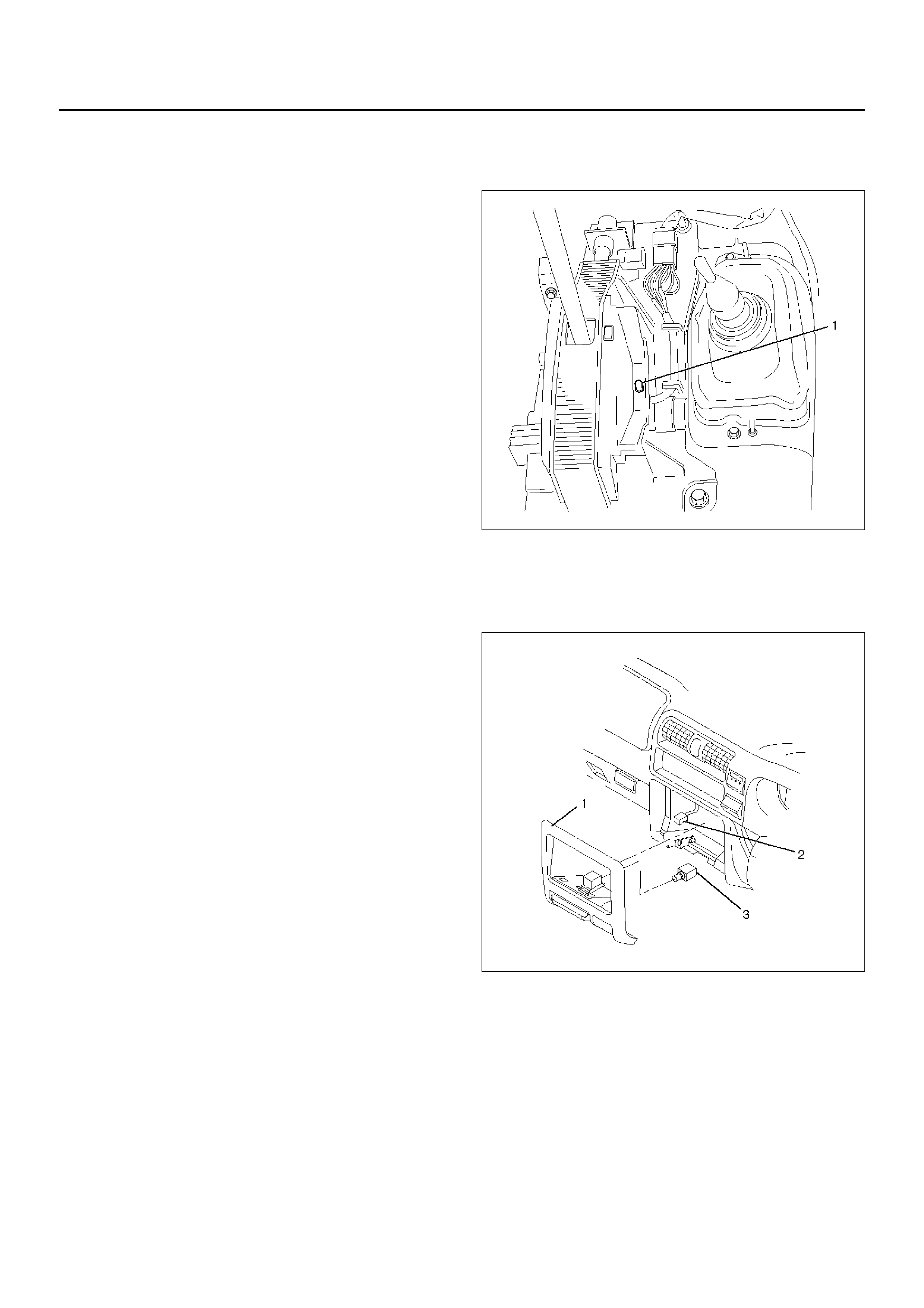
DOOR SWITCH
REMOVAL
1. Disconnect the battery ground cable.
2. Remove the door switch (2).
• Remove the screw (1).
• Disconnect the connector (3).
825RW289
INSTALLATION
To install, follow the removal steps in the reverse order.
REAR DEMISTER SWITCH
REMOVAL
1. Disconnect the battery ground cable.
2. Remove the meter cluster assembly (1).
• Refer to Instrument Panel Assembly in Body
Structure section.
3. Remove the rear Demister switch (2).
• Disconnect the switch connector.
• Push the lock from the back side of the meter
cluster assembly.
825RW280
INSTALLATION
To install, follow the removal steps in the reverse order.
KEY REMIND SWITCH (STARTER SWITCH)
REMOVAL AND INSTALLATION
Refer to Lock Cylinder in Steering section.
HAZARD WARNING LAMP SWITCH
REMOVAL
1. Disconnect the battery ground cable.
2. Remove the meter cluster assembly (1).
• Refer to Instrument Panel Assembly in Body
Structure section.
3. Remove the hazard warning switch (2).
• Disconnect the switch connector.
• Push the lock from the back side of the meter
cluster assembly.
825RW279
INSTALLATION
To install, follow the removal steps in the reverse order.

STOP LAMP SWITCH
REMOVAL AND INSTALLATION
Refer to Stop lamp Switch in Brake section.
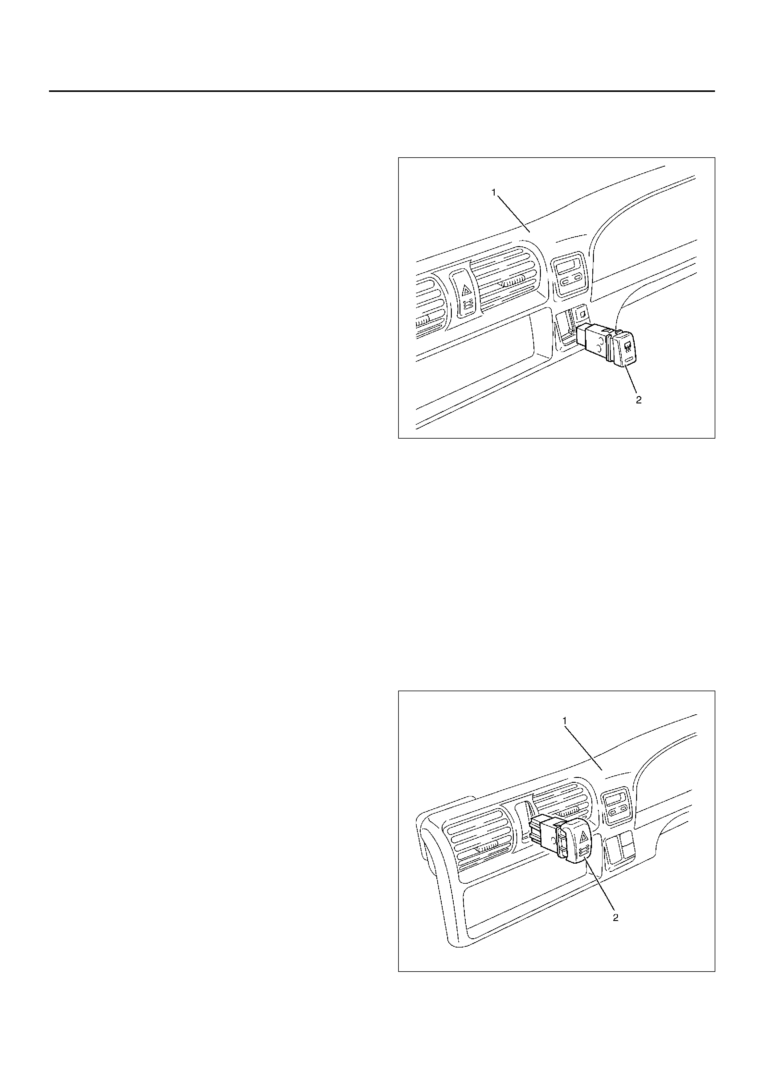
4WD SWITCH
REMOVAL
1. Disconnect the battery ground cable.
2. Remove the meter cluster assembly (1).
• Refer to Instrument Panel Assembly in Body
Structure section.
3. Remove the 4WD switch (2).
• Disconnect the switch connector.
• Push the lock from the back side of the meter
cluster assembly.
825RW275-1
INSTALLATION
To install, follow the removal steps in the reverse order.
FOG LAMP SWITCH
REMOVAL
1. Disconnect the battery ground cable.
2. Remove the meter cluster assembly (1).
• Refer to Instrument Panel Assembly in Body
Structure section.
3. Remove the fog lamp switch (2).
• Disconnect the switch connector.
• Push the lock from the back side of the meter
cluster assembly.
825RW274
INSTALLATION
To install, follow the removal steps in the reverse order.
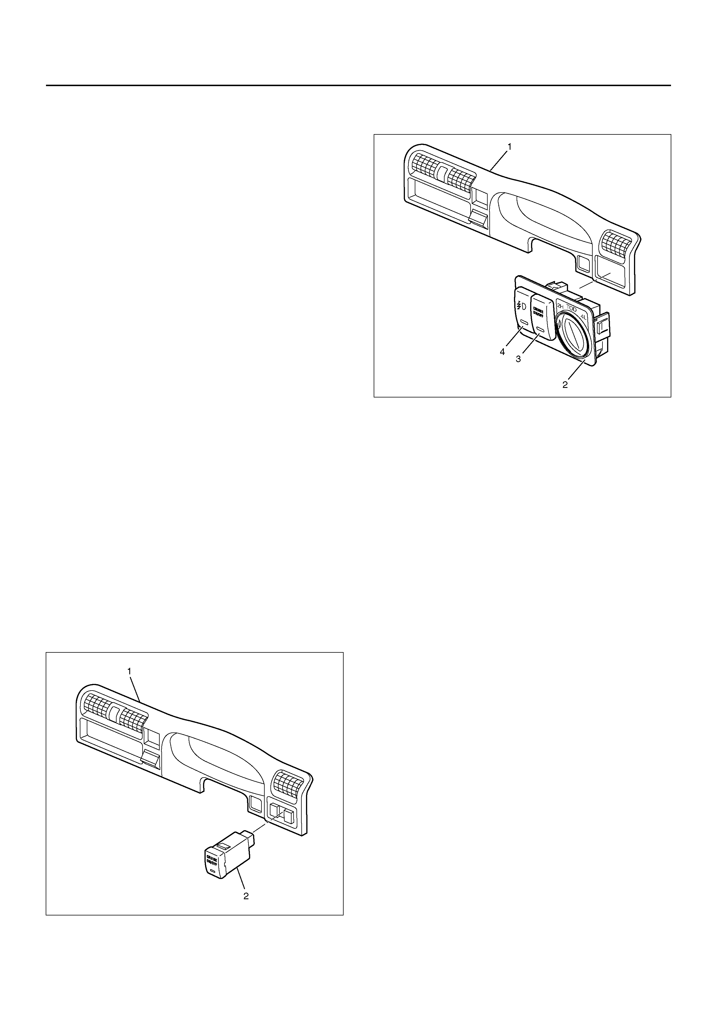
TOD SWITCH
REMOVAL
1. Disconnect the battery ground cable.
2. Remove the meter cluster Assembly (1).
• Refer to Instrument Panel Assembly in Body
Structure section.
3. Remove the TOD switch (2).
• Disconnect the switchs (2) (3) (4) connectors.
• Push the lock from the back side of the meter
cluster assembly.
825R100031
INSTALLATION
To install, follow the removal steps in the reverse order.
CRUISE MAIN SWITCH
REMOVAL
1. Disconnect the battery ground cable.
2. Remove the meter cluster assembly (1).
• Refer to Instrument Panel Assembly in Body
Structure section.
3. Remove the cruise main switch (2).
• Disconnect the switch connector.
• Push the lock from the back side of the meter
cluster assembly.
825R100032
INSTALLATION
To install, follow the removal steps in the reverse order.
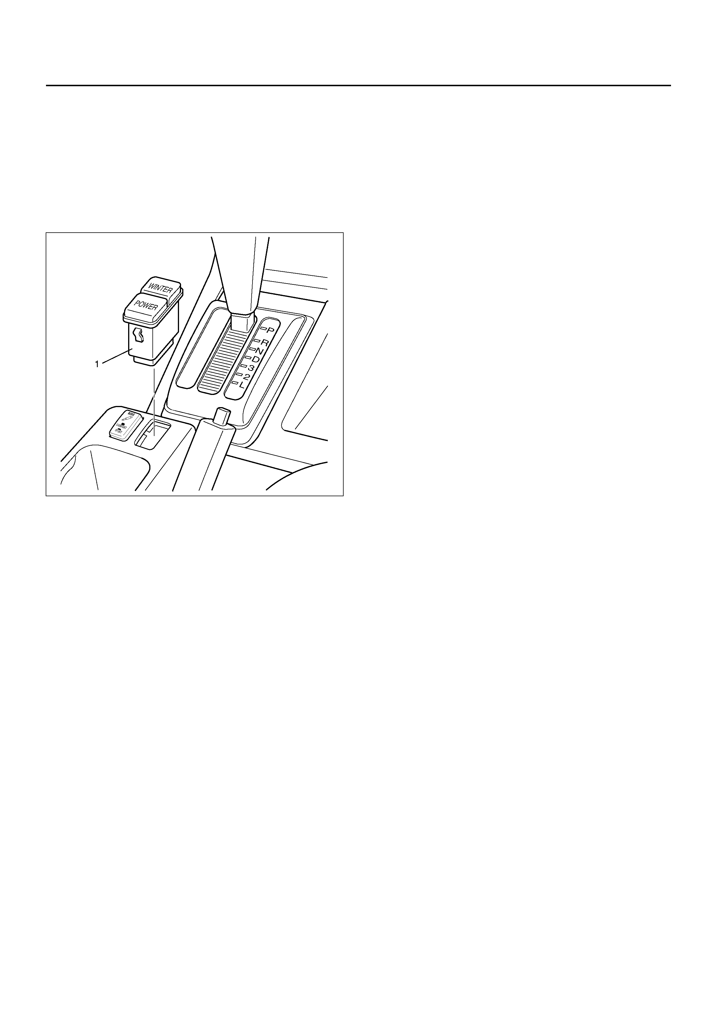
POWER/WINTER SWITCH
REMOVAL
1. Disconnect the battery ground cable.
2. Remove the power/winter switch (1).
• Pull out the power/winter switch.
• Disconnect the switch connector.
825RY00076
INSTALLATION
To install, follow the removal steps in the reverse order.
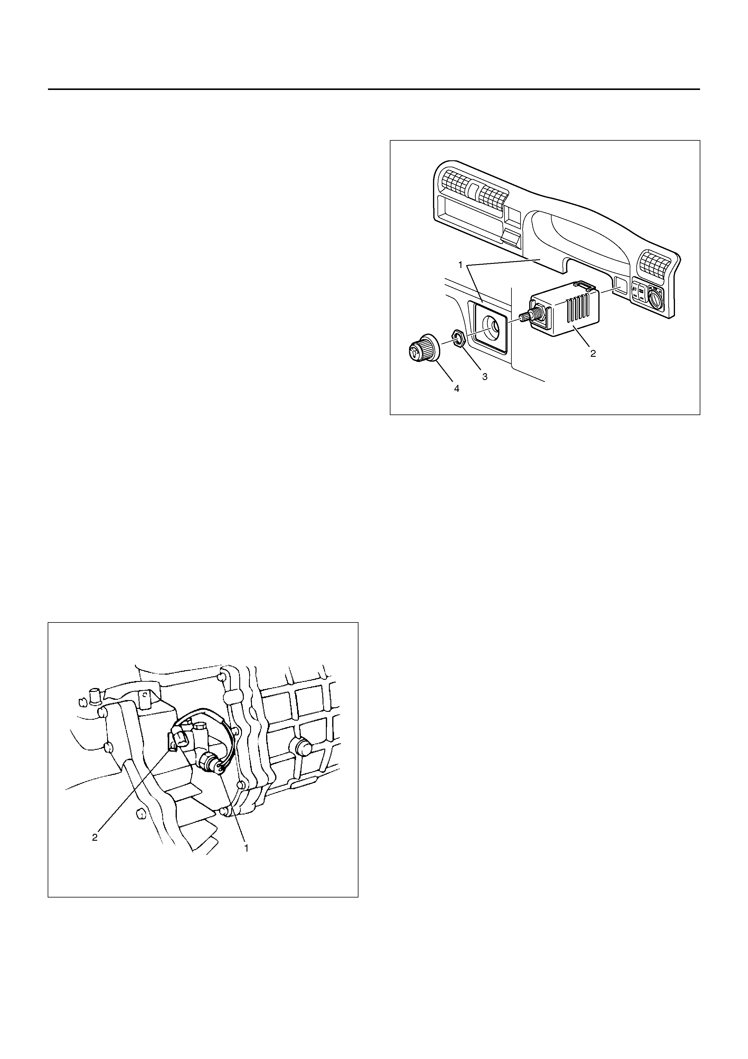
ILLUMINATION CONTROLLER
REMOVAL
1. Disconnect the battery ground cable.
2. Remove the meter cluster assembly (1).
• Refer to Instrument Panel Assembly in Body
Structure section.
3. Remove the illumination controller (2).
• Disconnect the controller connector.
• Remove the controller knob (4).
• Remove the nut (3).
• Remove the controller from the back side of the
meter cluster assembly.
825R100033
INSTALLATION
To install, follow the removal steps in the reverse order.
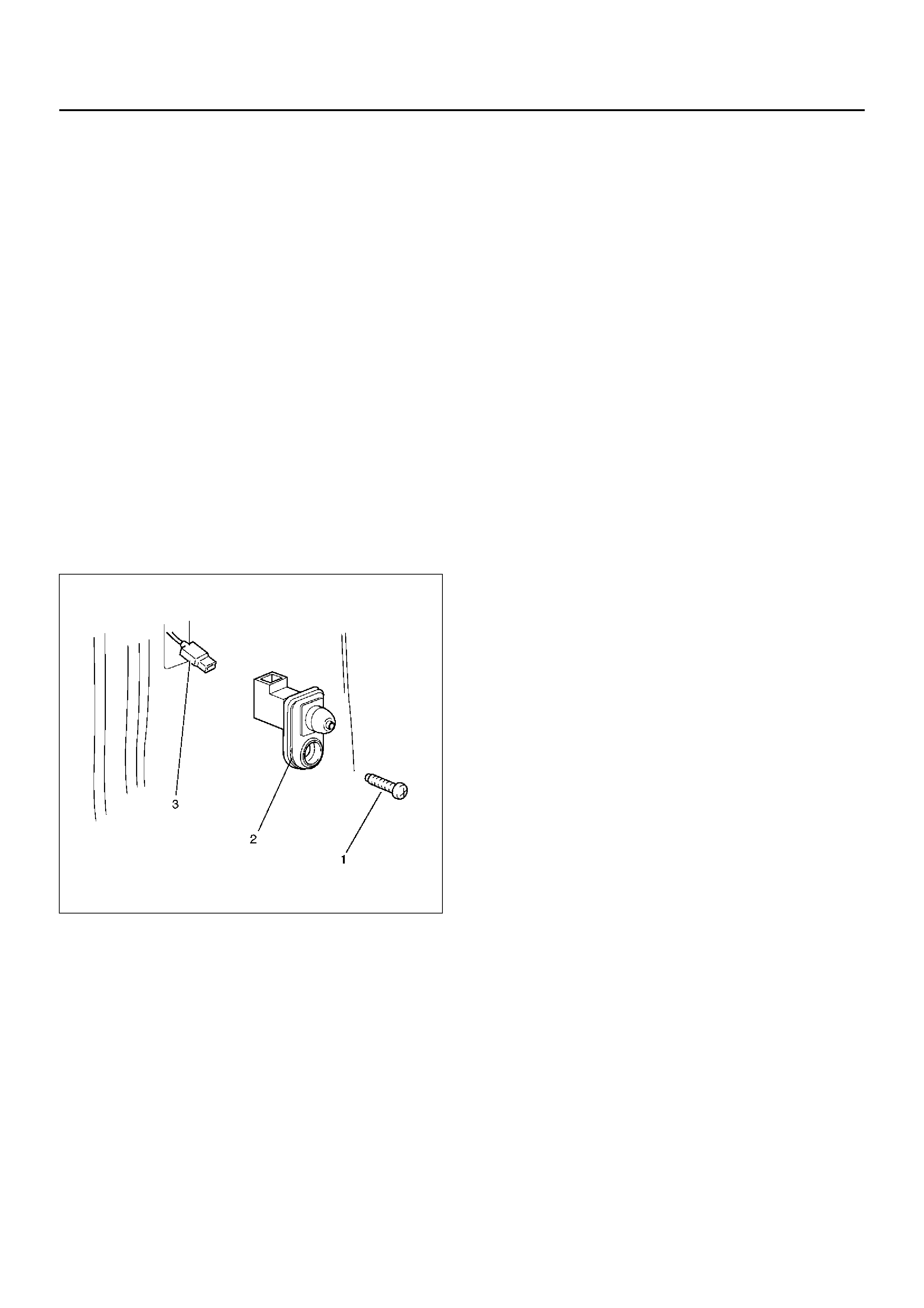
BACKUP LAMP SWITCH (M/T)
REMOVAL
1. Disconnect the battery ground cable.
2. Remove the backup lamp switch (1).
• Disconnect the connector (2).
230RW010
INSTALLATION
To install, follow the removal steps in the reverse order,
noting the following point.
1. Apply liquid gasket to the screw portion of the switch
to prevent oil leak.
TURN SIGNAL LAMP SWITCH (COMBINATION SWITCH)
REMOVAL AND INSTALLATION
Refer to Combination Switch in Steering section.
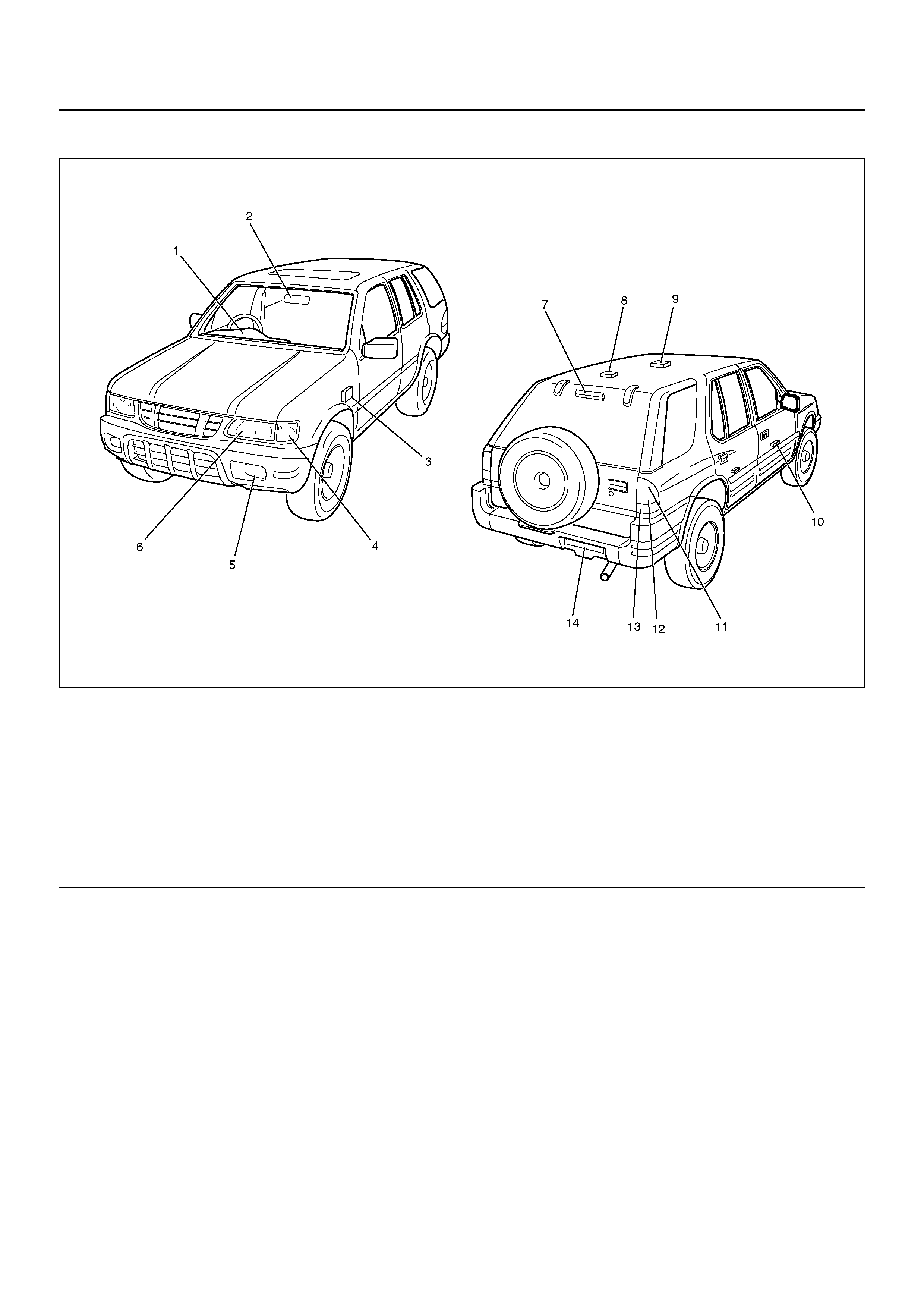
LAMP AND BULB SPECIFICATIONS
810R100011
Legend
EndOFCallout
(1) Meter
(2) Map Lamp
(3) Side Turn Signal Lamp
(4) Front Turn Signal Lamp
(5) Fog Lamp
(6) HeadLamp/Clearance Lamp
(7) High Mounted Stop Lamp
(8) Load Compartment Lamp
(9) Dome Lamp
(10) Courtesy Lamp
(11) Rear Turn Signal Lamp
(12) Backup Lamp
(13) Tail Lamp/Stop Lamp
(14) License Plate Lamp

Lamp and Bulb Specifications
Lamp Name Bulb No. Rated
Power Number of
Bulbs Lens Color Remarks
HeadLamp/Clearance Lamp — 60w/55w,
5w 2 White Halogen
Front Turn signal Lam p — 21w 2 Amber
Side Turn Signal Lamp — 5w 2 Amber
Fog Lamp — 55w 2 White Halogen
Rear Turn Sign al Lam p — 21w 2 Amber
Backup Lamp — 18w 2 White
Tail Lamp — 5w 2 Red
Stop Lamp — 21w 2 Red
High Mounted Stop Lamp — 5w 4 Red
License Plate Lamp — 5w 1 White RR Bumper
Map Lamp — 5w 2 White RR View
Mirror
Map Lamp — 8w 2 White Overhead
Consol
Dome Lamp — 7w 1 White
Load Compartment Lamp — 5w 1
Courtesy Lamp — 3.4w 2 White
Indicator/Warning
Lamp
Check Trans — 1.4w 1 Red Meter
A/T Oil Temp — 3w 1 Red Meter
Cruise Set — 1.4w 1 Green Meter
Power Drive — 1.4w 1 Amber Meter
Wint er Drive — 1.4w 1 Green Meter
Turn Signal — 1.4w 2 Green Meter
High Beam — 1.4 w 1 Blue Meter
ABS — 1.4w 1 Amber Meter
Seat Belt — 2w 1 Red Meter
Malfunction Indicator
(Check Engine) — 1.4w 1 Amber Meter
Low F uel — 1.4w 1 Amber Meter
4WD — 1.4w 1 Green Meter
Oil Pressure — 1.4w 1 Red Meter
Brake System — 1.4w 1 Red Meter
Charge — 1.4w 1 Red Meter
A/T Shift Position — 1.4w 7 P,N,D,3,2,L
:Green
R: Amber
Meter
Air Bag — 2w 1 Red Meter
Check TOD — 1.4w 1 Red Meter
Reduced Power — 1.4w 1 Amber Meter
Sports Mode — 1.4w 1 Green Meter
Illumination Lamp Meter — 3.4w 4 Meter
Shift lever — 1.4w 1 White Shift lever