
SECTION 12E - CRUISE CONTROL SYSTEMS
Service Precaution
General Description
Brake Switch
Removal and Installation
Adjustment
Clutch Switch
Removal and Installation
Adjustment
Powertrain Control Module (PCM)
Removal and Installation
Mode Switch
Removal and Installation
Cruise Control Main Switch
Removal
Installation
Cruise Control Switch (Combination Switch)
Removal and Installation
Diagnosis
SERVICE PRECAUTION
WARNING: THIS VEHICLE HAS A SUPPLEMENTAL
RESTRAINT SYSTEM (SRS). REFER TO THE SRS
COMPONENT AND WIRING LOCATION VIEW IN
ORDER TO DETERMINE WHETHER YOU ARE
PERFORMING SERVICE ON OR NEAR THE SRS
COMPONENTS OR THE SRS WIRING. WHEN YOU
ARE PERFORMING SERVICE ON OR NEAR THE
SRS COMPONENTS OR THE SRS WIRING, REFER
TO THE SRS SERVICE INFORMATION. FAILURE TO
FOLLOW WARNINGS COULD RESULT IN POSSIBLE
AIR BAG DEPLOYMENT, PERSONAL INJURY, OR
OTHERWISE UNNEEDED SRS SYSTEM REPAIRS.
CAUTION: Always use the correct fastener in the
proper location. When you replace a fastener, use
ONLY the exact part number for that application.
HOLDEN will call out those fasteners that require a
replacement after removal. HOLDEN will also call
out the fasteners that require thread lockers or
thread sealant. UNLESS OTHERWISE SPECIFIED,
do not use supplemental coatings (Paints, greases,
or other corrosion inhibitors) on threaded fasteners
or fastener joint interfaces. Generally, such
coatings adversely affect the fastener torque and
the joint clamping force, and may damage the
fastener. When you install fasteners, use the
correct tightening sequence and specifications.
Following these instructions can help you avoid
damage to parts and systems.
GENERAL DESCRIPTION
When enabled, the cruise control maintains a constant
cruising speed without manual control of the accelerator
pedal. The vehicle speed will remain constant until a
cancelling signal is received.
When the cruise main switch is turned on and vehicle
speed is above 40 km/h, battery voltage is applied to
Powertrain Control Module (PCM). When a signal from
the Cruise Control switch is input to PCM while the
vehicle is in this state, the cruise control system is
activated. While the cruise system is active, the
“CRUISE MAIN" indicator light is illuminated.
1 . SET/COAST Switch Function
1. Set Function: When the SET/COAST switch is
pressed and released with the Cruise Main switch
on, th e speed at which the ve hicle is run ning at that
moment is stored in the memory, and the vehicle will
maintain the stored speed.
2. Coast-Down Function: When the SET/COAST
switch is rotated for more than one second while the
vehicle is running, the vehicle will decelerates. The
speed at whi ch vehicle is trav elling when the switch
is released will be stored in the memory, and the
vehicle maintains the stored speed.
3. Tap-Down Function: When the SET/COAST
switch is turned on and then off for less than one
second, the vehicle decelerates 1.6km/h for each
on/off operation. The speed at which vehicle is
travelling when the switch is last released will be
stored in the mem ory, and the ve hicl e maintains the
stored speed.
2 . RESUME/ACCEL Switch Function
1. Resume Function: When the RESUME, ACCEL
switch is turned on/off after the system is
temporarily deactivated by pressing the brake or
clutch pedal, the vehicle resumes the speed stored
before the system was released.
2. Accelerate Function: When the RESUME/ACCEL
switch is rotated for more than one second with the
system activated, the vehicle speed will increase
until the switch is released. The system will now
maintain the current vehicle speed.
3. Tap-Up Function: When the RESUME/ACCEL
switch is rotated for less than one second while the
vehicle while the vehicle speed is above 40 km/h,
the vehicle accelerates 1.6 km/h for each on/off
operation.
3 . CANCEL Function
1. Temporary Cancellation:
• When the cancel switch is turned on.
• When the brake pedal is pressed.
• When the clutch pedal is pressed. (M/T)
• When the select lever is shifted to any position
other than “D", “3", “2" or “L". (A/T)
• When the vehicle speed has decreased about
20 km/h or more than the stored speed.
• When the vehicle speed gets lower than 36 km/h.
2. Complete Cancellation:
• When the starter switch or the Cruise Main switch
is turned off.
• When the failsafe function is activated.
BRAKE SWITCH
REMOVAL AND INSTALLATION
Refer to Brake Pedal Replacement in Brake section.
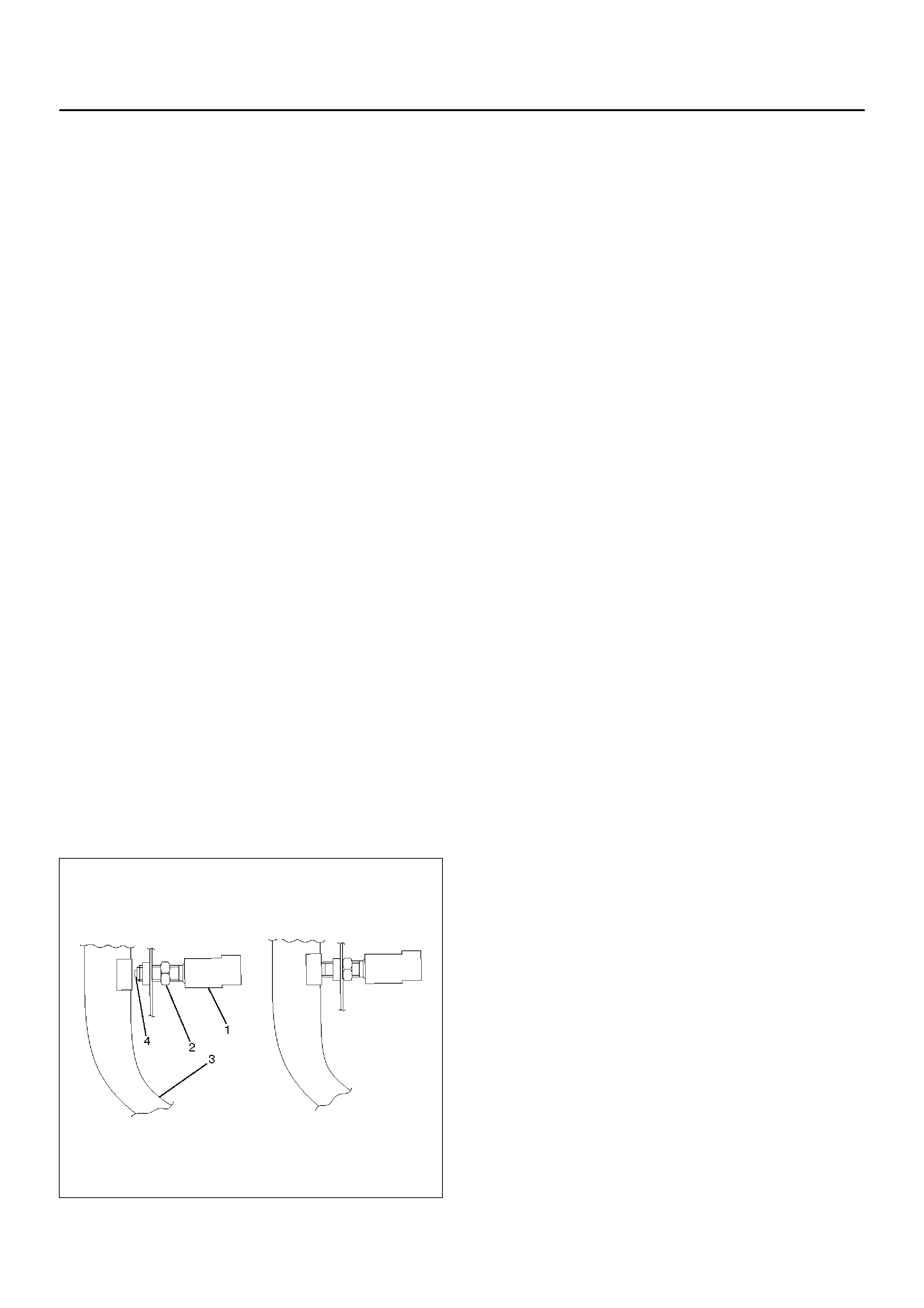
ADJUSTMENT
1. Check that the brake pedal (3) is fully returned by
pedal return spring.
2. Disconnect the brake switch connector.
3. Loosen the lock nut (2).
4. Rotate the brake switch (1) clockwise until plunger
(4) retracts fully into the brake switch threaded
housing.
5. Rotate the brake switch a half turn anti-clockwise.
6. Tighten the lock nut.
7. Connect the switch connector.
310RS028
CLUTCH SWITCH
REMOVAL AND INSTALLATION
Refer to the Clutch Control removal and installation
steps in Clutch section.
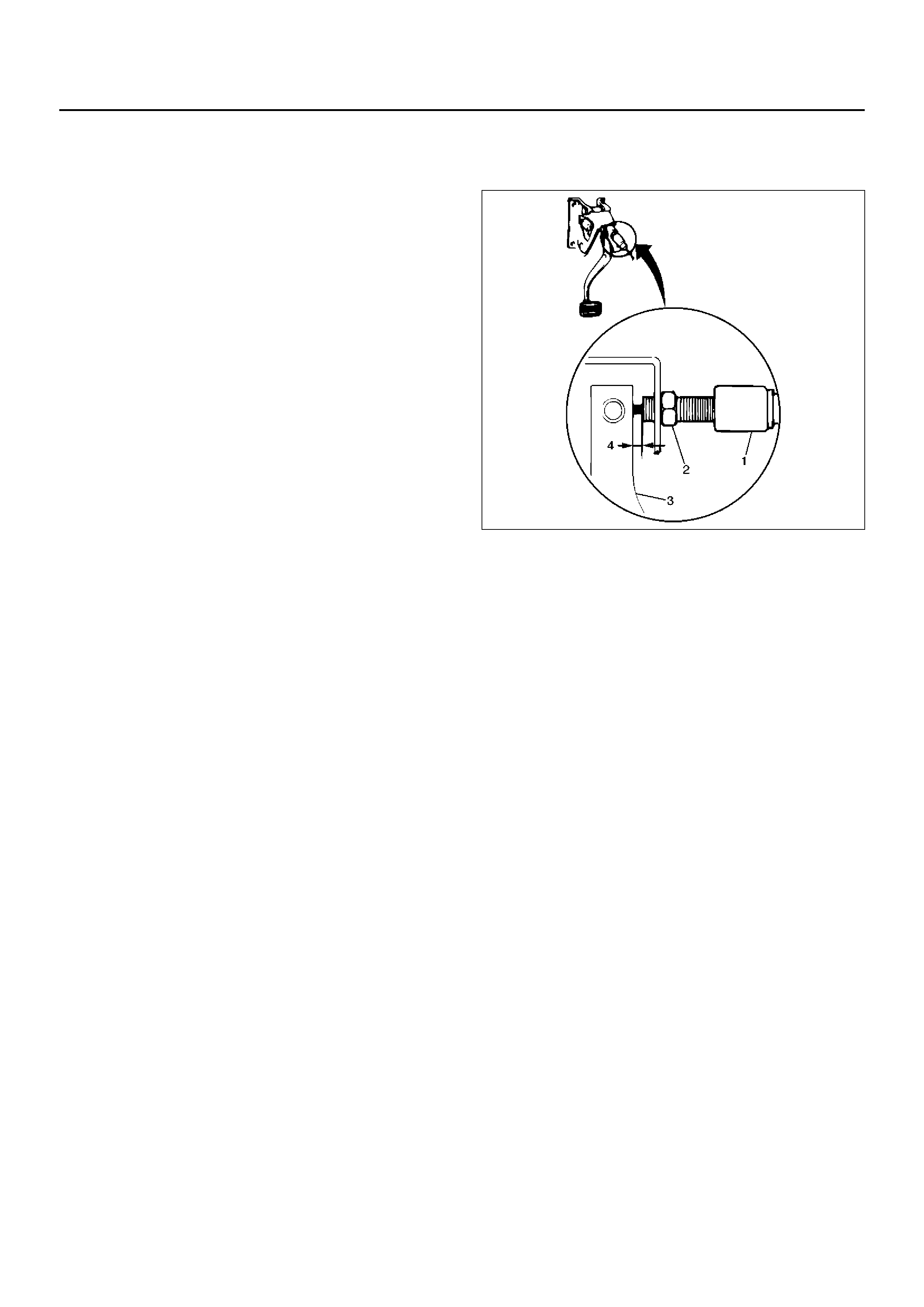
ADJUSTMENT
1. Remove the clutch switch connector and loosen the
locknut (2).
2. Turn the clutch switch (1) clockwise until the switch
plunger contacts the clutch pedal arm (3).
3. Rotate the clutch switch anti-clockwise until the
specified clearance (4) is achieved between the
clutch switch plunger and the clutch pedal arm(3).
4. Lock the lock nut(2).
5. Connect clutch switch connector.
Clutch Switch Plunger to Clutch Pedal Clearance
0.5 – 1.5 mm (0.020 – 0.059 in) 203RS016-1
POWERTRAIN CONTROL MODULE (PCM)
REMOVAL AND INSTALLATION
Refer to Powertrain Control Module (PCM) in Engine
section.
MODE SWITCH
REMOVAL AND INSTALLATION
Refer to Mode Switch in Automatic Transmission
section.
CRUISE CONTROL MAIN SWITCH
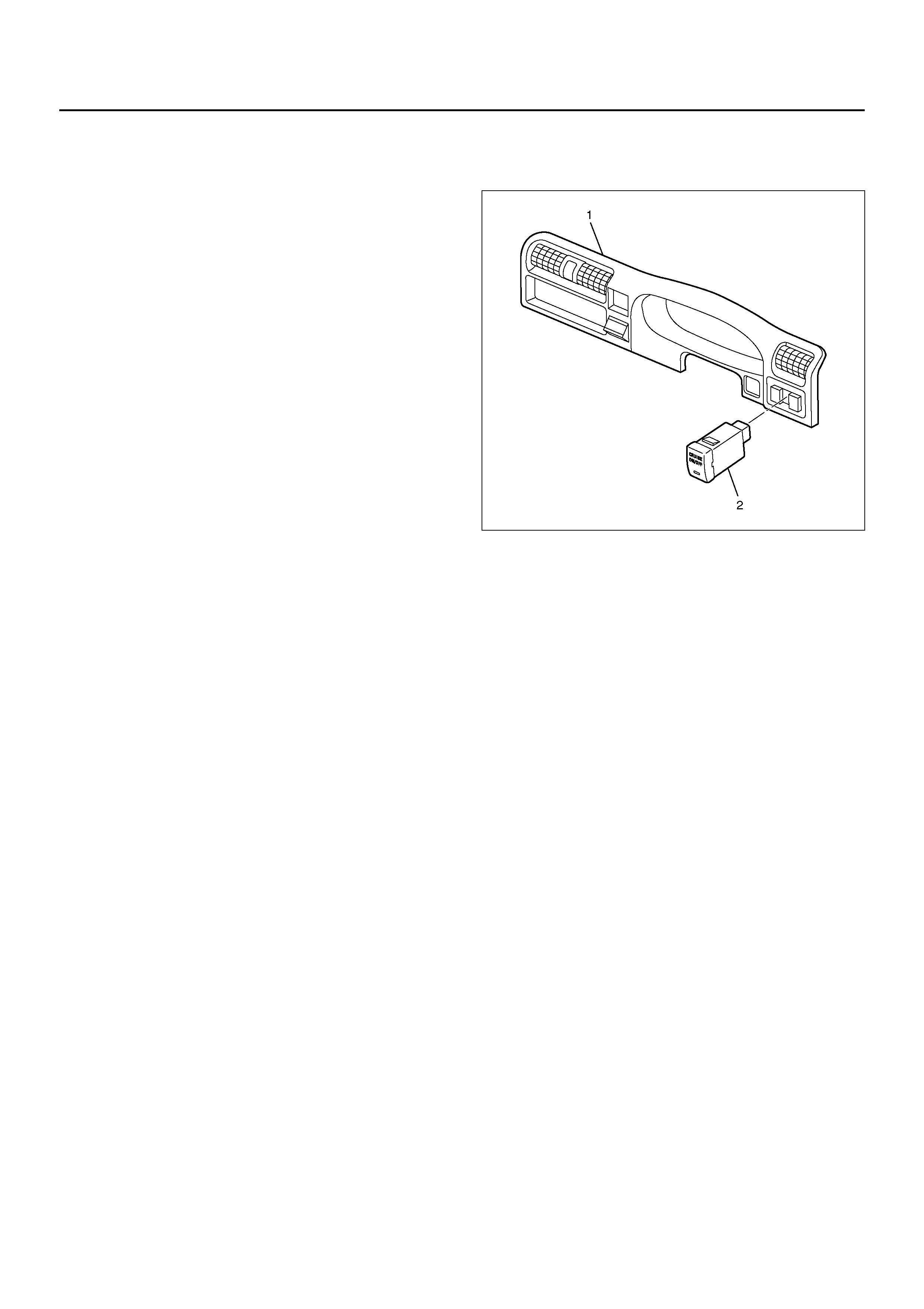
REMOVAL
1. Disconnect the battery ground cable.
2. Remove the meter cluster assembly (1).
• Refer to Instrument Panel Assembly in Body
Structure section.
3. Remove the cruise control main switch (2).
• Disconnect the switch connector.
• Push the lock from the back side of the meter
cluster assembly.
825R100032
INSTALLATION
To install, follow the removal steps in the reverse order.
CRUISE CONTROL SWITCH (COMBINATION SWITCH)
REMOVAL AND INSTALLATION
Refer to Lighting Switch (Combination Switch) in
Lighting System section.

DIAGNOSIS
Cruise control system is controlled by the PCM as well
as 6VD1 engine and automatic transmission. DTCs are
stored in the PCM if troubles occur in the circuit. DTCs
categorized “type D" are shown only by using the Tech 2
scan tool. The following chart only shows some typical
DTCs for cruise control system. Refer to PCM
Diagnostic Trouble Codes in Driveability and Emissions
for entire DTC diagnosis.
DTC: Diagnostic Trouble Code
NOTE: The DTCs are onl y de tec ted whil e the en gin e is
running
DTC TROUBLE
PART DTC
TYPE MAJOR CONDITION OF
TROUBLE DIAGNOSIS PERIOD
P0565 CRUISE MAIN
CIRCUIT D • THE SWITCH CONTACT
REMAINS ON FOR 15
SECONDS OR MORE.
• NOISES ARE GENERA TED BY
THE POOR SWITCH
CONT ACT 60 TIMES WITHIN 1
SECOND.
DIAGNOSIS IS ENABLED 130
SECONDS AFTER THE SWITCH
OPERATED.
P0566 CRUISE
CANCEL
CIRCUIT
D • THE SWITCH CONTACT
REMAINS ON FOR 40
SECONDS OR MORE.
• NOISES ARE GENERA TED BY
THE POOR SWITCH
CONTACT 100 TIMES WITHIN
1.6 SECONDS.
DIAGNOSIS IS ENABLED IN 120
SECONDS AFTER THE SWITCH
OPERATED.
P0567 CRUISE
RESUME
CIRCUIT
D • THE SWITCH CONTACT
REMAINS ON FOR 50
SECONDS OR MORE.
• NOISES ARE GENERA TED BY
THE POOR SWITCH
CONTACT 100 TIMES WITHIN
1.6 SECONDS.
DIAGNOSIS IS ENABLED IN 110
SECONDS AFTER THE SWITCH
OPERATED.