
SECTION 12M3 - SRS CONTROL SYSTEM
Service Precaution
Diagnostic Information
Electrical Circuit Identification
System Schematic
SRS Diagnostic System Check
Chart A SDM Integrity Check
Chart B “AIR BAG" Warning Lamp Comes
“ON" Steady
Chart C “AIR BAG" Warning Lamp Does
Not Comes “ON" Steady
DTC 15 Passenger Deployment Loop
Resistance High
DTC 16 Passenger Deployment Loop
Resistance Low
DTC 17 Passenger Deployment Loop
Open
DTC 18 Passenger Deployment Loop
Short To Ground
DTC 19 Passenger Deployment Loop
Short To Voltage
DTC 21 Driver Deployment Loop
Resistance High
DTC 22 Driver Deployment Loop
Resistance Low
DTC 24 Driver Deployment Loop
Short To Ground
DTC 25 Driver Deployment Loop
Short To Voltage
DTC 26 Driver Deployment Loop Open
DTC 51 Deployment Event Commanded
DTC 53 Deployment Commanded With
Deployment Loop Fault Or Energy Reserves
Out Of Range
DTC 61 Warning Lamp Circuit Failure
DTC 71 Internal SDM Fault
SERVICE PRECAUTION
WARNING: THIS VEHICLE HAS A SUPPLEMENTAL
RESTRAINT SYSTEM (SRS). REFER TO THE SRS
COMPONENT AND WIRING LOCATION VIEW IN
ORDER TO DETERMINE WHETHER YOU ARE
PERFORMING SERVICE ON OR NEAR THE SRS
COMPONENTS OR THE SRS WIRING. WHEN YOU
ARE PERFORMING SERVICE ON OR NEAR THE
SRS COMPONENTS OR THE SRS WIRING, REFER
TO THE SRS SERVICE INFORMATION. FAILURE TO
FOLLOW WARNINGS COULD RESULT IN POSSIBLE
AIR BAG DEPLOYMENT, PERSONAL INJURY, OR
OTHERWISE UNNEEDED SRS SYSTEM REPAIRS.
CAUTION: Always use the correct fastener in the
proper location. When you replace a fastener, use
ONLY the exact part number for that application.
HOLDEN will call out those fasteners that require a
replacement after removal. HOLDEN will also call
out the fasteners that require thread lockers or
thread sealant. UNLESS OTHERWISE SPECIFIED,
do not use supplemental coatings (Paints, greases,
or other corrosion inhibitors) on threaded fasteners
or fastener joint interfaces. Generally, such
coatings adversely affect the fastener torque and
the joint clamping force, and may damage the
fastener. When you install fasteners, use the correct
tightening sequence and specifications. Following
these instructions can help you avoid damage to
parts and systems.

DIAGNOSTIC INFORMATION
Diagnostic Procedures
WARNING: WHEN FASTENERS ARE REMOVED,
ALWAYS REINSTALL THEM IN THE SAME
LOCATION FROM WHICH THEY WERE REMOVED.
IF A FASTENER NEEDS TO BE REPLACED, USE
THE CORRECT PART NUMBER FASTENER FOR
THAT APPLICATION. IF THE CORRECT PART
NUMBER FASTENER IS NOT AVAILABLE, A
FASTENER OF EQUAL SIZE AND STRENGTH (OR
STRONGER) MAY BE USED. FASTENERS THAT
ARE NOT REUSED, AND THOSE REQUIRING
THREAD LOCKING COMPOUND WILL BE CALLED
OUT. THE CORRECT TORQUE VALUE MUST BE
USED WHEN INSTALLING FASTENERS THAT
REQUIRE IT. IF THE ABOVE CONDITIONS ARE NOT
FOLLOWED, PARTS OR SYSTEM DAMAGE COULD
RESULT.
WARNING: TO AVOID DEPLOYMENT WHEN
TROUBLESHOOTING THE SRS, DO NOT USE
ELECTRICAL TEST EQUIPMENT SUCH AS A
BATTERY–POWERED OR AC–POWERED
VOLTMETER, OHMMETER, ETC., OR ANY TYPE OF
ELECTRICAL EQUIPMENT OTHER THAN THAT
SPECIFIED IN THIS MANUAL. DO NOT USE A
NONPOWERED, PROBE–TYPE TESTER.
INSTRUCTIONS IN THIS MANUAL MUST BE
FOLLOWED CAREFULLY, OTHERWISE PERSONAL
INJURY MAY RESULT.
The diagnostic procedures used in this section are
designed to aid in finding and repairing SRS problems.
Outlined below are the steps to find and repair SRS
problems quickly and effectively. Failure to carefully
follow these procedures may result in extended
diagnostic time, incorrect diagnosis and incorrect parts
Replacement.
1. Perform The “SRS Diagnostic System Check."
The “Supplemental Restraint System (SRS)
Diagnostic System Check" should always be the
starting point of any SRS diagnostics. The “SRS
Diagnostic System Check" checks for proper “AIR
BAG" warning lamp operation and checks for SRS
trouble codes using both “Flash Code" and “Scan
Tool" Methods.
2. Refer To The Proper Diagnostic Chart As
Directed By The “SRS Diagnostic System
Check."
The “SRS Diagnostic System Check" will lead you
to the correct chart to diagnose any SRS problems.
Bypassing these procedures may result in
extended diagnostic time, incorrect diagnosis and
incorrect parts Replacement.
3. Repeat the “SRS Diagnostic System Check"
After Any Repair Or Diagnostic Procedures
Have Been Perfor med .
Performing the “SRS Diagnostic System Check"
after all repair or diagnostic procedures will assure
that the repair has been made correctly and that no
other conditions exist.
Diagnostic Codes
The Sensing and Diagnostic Module (SDM) maintains a
history record of all diagnostic codes that have been
detected since the SRS codes were last cleared during
service.
1. Active Codes—Faults that are presently detected
this ignition cycle. Active codes are stored in
Random Access Memory (RAM).
2. History Codes—All faults detected since the last
time the history fault memory was cleared. History
codes are stored in Electronically Erasable
Program m ab le Read only Mem ory (EEP RO M).
How To Read Trouble Codes
All codes (Active and history) can be read (or cleared)
by using a scan tool or equivalent.
How To Clear Trouble Codes
T rouble codes can only be cleared by using a scan tool.
If a scan tool is not available then inform the owner of
the stored codes and suggest that the codes are
cleared upon the next visit to a dealership.
Scan Tool Diagnostics
A scan tool can be used to read current and history
codes and to clear all history codes after a repair is
complete. The scan tool must be updated to
communicate with the SRS through a replaceable
cartridge for SRS diagnostics. To use the scan tool,
connect it to the Data Link Connector (DLC) and turn
the ignition switch “ON". Then follow the manufacturer's
directions for communication with the SRS. The scan
tool reads serial data from the Sensing and Diagnostic
Module (SDM) “Serial Data" output (terminal 24) to the
DLC.
Basic Knowledge Required
Before using this section of the Service Manual, there is
some basic knowledge which will be required. Without
this knowledge, you will have trouble using the
diagnostic procedures in this section. Use care to
prevent harm or unwanted deployment. Read all
cautions in the service manual and on warning labels
attached to SRS components.
Basic Electrical Circuits
You should understand the basic theory of electricity
including series and parallel circuits, and understand the
volt age dr ops ac ross se ri es re sist o rs. You s hou ld k now
the meaning of voltage (volts), current (amps), and
resistance (ohms). You should understand what
happens in a circuit with an open or a shorted wire. You
should be able to read and understand a wiring
diagram.

“Flash Code" Diagnostics
Flash code diagnostics can be used to read current
codes and to determine if history codes are present but
cannot be used to clear codes or read history codes.
Flash code diagnostics is enabled by grounding by
terminal 13 shorting to terminal 4 of the DLC with the
ignition switch “ON". Grounding terminal 13 of the DLC
pulls the “Diagnostics Request" input (Terminal 1) of the
SDM low and signals the SDM to enter the flash code
diagnostic display mode.
The SDM displays the trouble codes by flashing the
warning lamp. Each code that is displayed will consist of
a number of flashes which represents the tens digit, a
1.2 second pause, following by a number of flashes
which represents the ones digit of the code. Each code
is displayed one time before moving on to the next
code. After all of the codes have been displayed, the
entyre code sequence will continually by repeated until
ground is removed from terminal 13 of the DLC.
Two special codes exist when reading in the flash code
mode (Flash Code 12 and Flash Code 13). “Flash
Code 12" will always be the first code displayed when
the flash code mode is enabled Code 12 is not an
indication of a SRS problem but an indication that the
flash code mode has been enabled. If there are no
current or history codes present, the SDM will display
code 12 until ground is removed from the DLC at
terminal 13. “Flash Code 13" will be displayed if there
are history codes. To read the history codes, a scan
tool must be used.
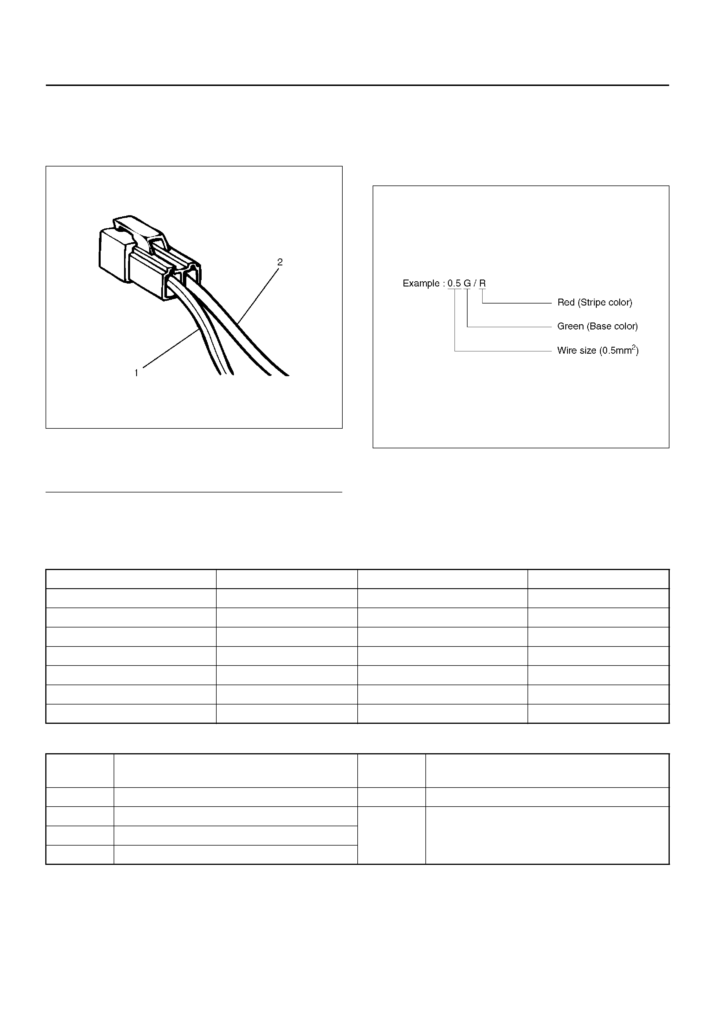
ELECTRICAL CIRCUIT IDENTIFICATION
Wiring
Wire Color
D08RX174
Legend
EndOFCallout
All wires have color-coded insulation.
Wires belonging to a system’s main harness wil have a
single color. Wires belonging to a system’s sub-circuits
will have a colored stripe. Striped wires use the
following code to show wire size and colors.
D08RX175
Abbreviations are used to indicate wire colour within a
circuit diagram.
Refer to the following table.
Wire Color Coding
Distinction of Circuit by Wi re Base Colour
(1) Coloured Stripe
(2) Single Color
Colour-coding Colour Colour-coding Colour
BBlackBRBrown
W White LG Light green
R Red GR Grey
G Green P Pink
Y Yello w LB Light blue
LBlueVViolet
O Orange
Base
color Circuits Base
color Circuits
B Starter circuit and grounding circuit Y Instrument circuit
W Chargi ng ci rcui t L, O, BR,
LG, GR, P,
SB, V Other circuitsR Lighting circuit
G Signal circuits

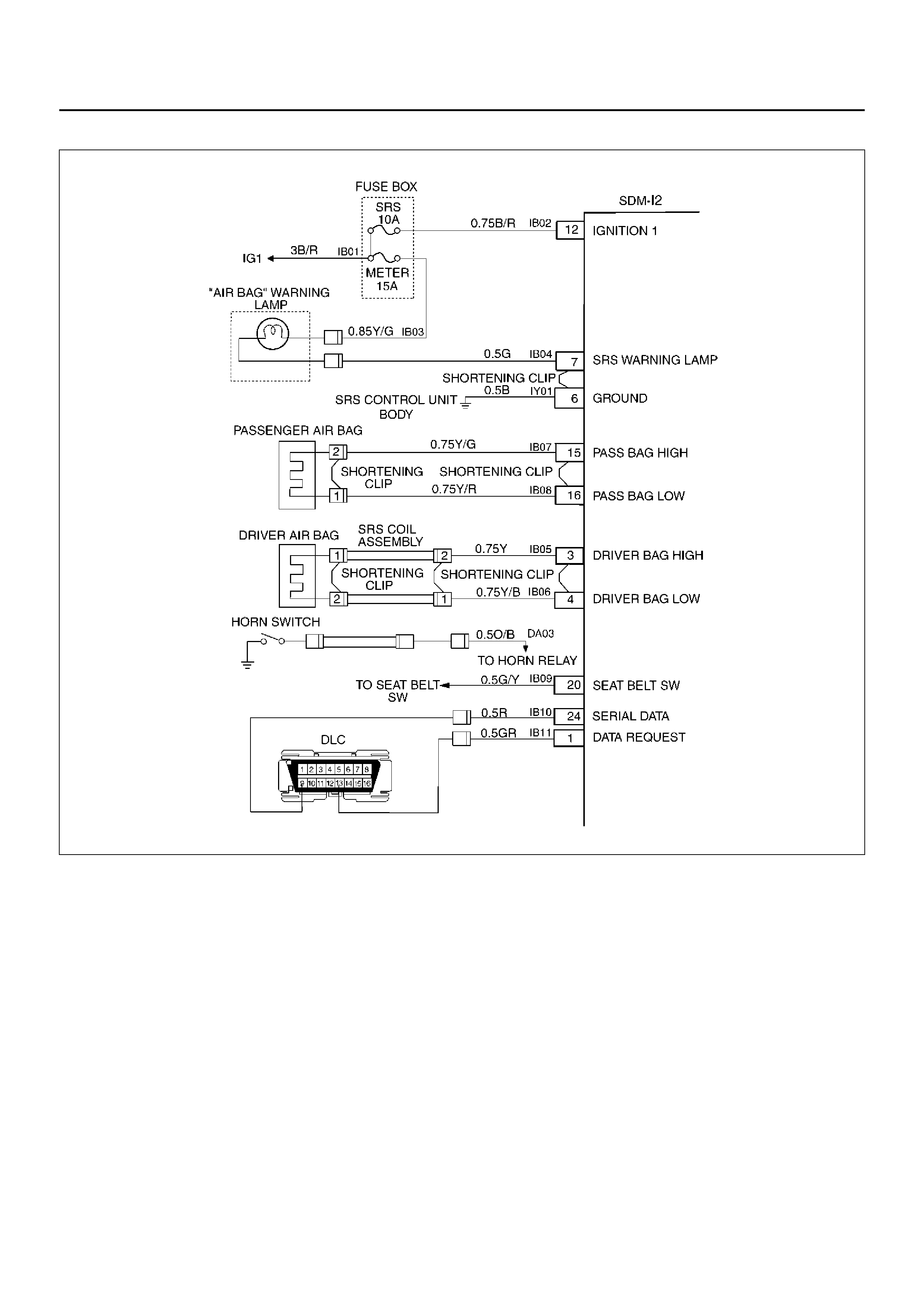
SYSTEM SCHEMATIC
D09RX002
SRS DIAGNOSTIC SYSTEM CHECK
The diagnostic procedures used in this section are
designed to find and repair Supplemental Restraint
System (SRS) malfunctions. To get the best results, it
is important to use the diagnostic charts and follow the
sequence listed below:
A Perform the “SRS Diagnostic System Check."
The “SRS Diagnostic System Check" must be the
starting point of any SRS diagnostics. The “SRS
Diagnostic System Check" checks for proper “AIR
BAG" warning lamp operation, the ability of the
Sensing and Diagnostic Module (SDM) to
communicate through the “Serial Data" line and
whether SRS diagnostic trouble codes exist.
B Refer to the proper diagnostic chart as directed by
the “SRS Diagnostic System Check."
The “SRS Diagnostic System Check" will lead you
to the correct chart to diagnose any SRS
malfunctions. Bypassing these procedures may
result in extended diagnostic time, incorrect
diagnosis and incorrect parts replacement.
C Repeat the “SRS Diagnostic System Check" after
any repair or diagno st ic proc edu res hav e been
performed.
Performi ng the “SRS Diagno sti c System Chec k"
after all repair or diagnostic procedures will ensure
that the repair has been made correctly and that no
other malfunctions exist
Circuit Description
When the ignition switch is first turned “ON", “ignition 1"
voltage is applied from the “SRS" fuse to the SDM at the
“ignition 1" input terminals “12". The SDM responds by
flashing the “AIR BAG" warning lamp seven times while
performing tests on the SRS.

Notes On System Check Chart:
The number(s) below refer to step number(s) on the
“Supplemental Restraint System Diagnostic System
Check" chart.
1. The “AIR BAG" warning lamp should flash seven
times after ignition is first turned “ON."
2. After the “AIR BAG" warning lamp flashes seven
times, it should turn “OFF."
3. Improper operation of the “AIR BAG" warning lamp is
indicated. This test differentiates a warning lamp
stays “ON" condition from a warning lamp does not
come “ON" cond iti on.
4. This test checks for the proper operation of the
“Serial Data" line. This test will also determine
whether history diagnostic trouble codes are stored
and, if so, identify them.
5. This test checks for proper operation of the “Serial
Data" line. This test will also identify the stored
diagnostic trouble codes and whether they are
current or history.
Diagnostic Aids:
The order in which diagnostic trouble codes are
diagnosed is very important. Failure to diagnose the
diagnostic trouble codes in the order specified may
result in extended diagnostic time, incorrect diagnosis
and incorrect parts Replacement.

SRS Diagnostic System Check
Step Action Yes No
1 Note the “AIR BAG" warning lamp when ignition switch is turned
“ON."
Does the “AIR BAG" warning lamp flash seven (7) times? Go to Step 2 Go to Step 3
2 Note the “AIR BAG" warning lamp after it flashed 7 times.
Does the “AIR BAG" warning lamp go “OFF"? Go to Step 4 Go to Step 5
3 Note the “AIR BAG" warning lamp when ignition switch is turned
“ON."
Does the “AIR BAG" warning lamp come “ON" steady? Go to Chart B. Go to Chart C.
4 1. Ignition swi tc h “OFF."
2. Connect a scan tool to data link connector.
3. Follow direction given in the scan tool instruction manual.
4. Ignition switc h “ON."
5. Request the SRS diagnostic trouble code display recode all
history diagnostic trouble code(s) specify as such, on repair
order.
Are any diagnostic trouble codes displayed?
Ignition switc h
“OFF."
When DTC 71
is set, go to
DTC 71 chart.
For all other
history codes
refer to
“Diagnostics
Aids" for that
specific DTC.
A history DTC
indicates the
malfunction has
been repaired
or is
intermittent.
SRS is
functional and
free of
malfunctions,
no further
diagnosis is
required.
If scan tool
indicates “No
Data
Received," refer
to ch assis
electrical
section.

5 1. Ignition swi tc h “OFF."
2. Connect a scan tool to data link connector.
3. Follow directions as given in the scan tool instruction manual.
4. Ignition switc h “ON."
5. Request the SRS diagnostic trouble code display, recode all
diagnostic trouble code(s), specifying as current or history on
repair order.
Are any diagnostic trouble codes displayed?
Ignition switc h
“OFF."
When DTC 53
is set, go to
DTC 53 chart.
When DTC 51
is set, go to
DTC 51 chart.
When DTC 19
is set, go to
DTC 19 chart.
When DTC 25
is set, go to
DTC 25 chart.
Diagnose
remaining
current DTCs
from lowest to
highest.
When only
history DTCs
exist, Refer to
“Diagnostics
Aids" for that
specific DTC.
A history DTC
indicates the
malfunction has
been repaired
or is
intermittent.
If scan tool
indicates “No Data
Received," refer to
chassis electrical
section.
Step Action Yes No

CHART A SDM INTEGRITY CHECK
D09RX002
Circuit Description:
When the Sensing and Diagnostic Module (SDM)
recognizes “ignition 1" voltage, applied to terminals
“12", is greater than 9 volts, the “AIR BAG" warning
lamp is flashed 7 times to verify operation. At this time
the SDM performs “Turn–ON" tests followed by
“Continuous Monitoring" tests. When a malfunction is
detected, the SDM sets a current diagnostic trouble
code and illuminates the “AIR BAG" warning lamp. The
SDM will clear current diagnostic trouble codes and
move them to a history file when the malfunction is no
longer detected and/or the ignition switch is cycled,
except for Diagnostic T rouble Codes (DTCs) 51, 53 and
71. DTC 71 can only be cleared using a scan tool
“Clear Codes" command in case that the malfunction
on DTC 71 has been solved and no DTCs 51 and 53
were remained. DTCs 51, 53 and 71 can not be cleared
after a “Clear Codes" command is issued.
Chart Test Description:
The number(s) below refer to step number(s) on the
diagno sti c ch ar t:
1. This test confirms a current malfunction. If no current
malfunction is occurring (history DTC set) the
“Diagnostic Aids" for the appropriate diagnostic
trouble code should be referenced. The SDM should
not be replaced for a history diagnostic trouble
code.
2. This test checks for a malfunction introduced into the
SRS during the diagnostic process. It is extremely
unlikely that a malfunctioning SDM would cause a
new malfunction to occur during the diagnostic
process.
3. When all circuitry outside the SDM has been found to
operate properly, as indicated by the appropriate
diagnostic chart, then and only then should the SDM
be replaced.

Chart A SDM Integrity Check
WARNING: DURING SERVICE PROCEDURES. BE
VERY CAREFUL WHEN HANDLING A SENSING
AND DIAGNOSTIC MODULE (SDM). NEVER STRIKE
OR JAR THE SDM. NEVER POWER UP THE SRS
WHEN THE SDM IS NOT RIGIDLY ATTACHED TO
THE VEHICLE. ALL SDM AND MOUNTING
BRACKET FASTENERS MUST BE CAREFULLY
TORQUED AND THE ARROW MUST BE POINTING
TOWARD THE FRONT OF THE VEHICLE TO
ENSURE PROPER OPERATION OF THE SRS. THE
SDM COULD BE ACTIVATED WHEN POWERED
WHILE NOT RIGIDLY ATTACHED TO THE VEHICLE
WHICH COULD CAUSE DEPLOYMENT AND
RESULT IN PERSONAL INJURY.
Step Action Yes No
1 1. This chart assumes that the “SRS Diagnostic System Check"
and either a symptom chart or a diagnostic trouble code chart
diagnosis have been performed When all circuitry outside the
SDM has been found to operate properly, as indicated by the
appropriate diagnostic chart, and the symptom or DTC
remains current, the following diagnostic procedures must be
performed to verify the need for SDM Replacement.
2. Ignition switch “OFF."
3. Reconnect all SRS components, ensure all components are
properly mounted.
4. Ensure the ignition switch has been “OFF" for at least 15
seconds.
5. Note “AIR BAG" warning lamp as ignition switch is turned
“ON."
Does warning lamp flash 7 times then go “OFF"?
The symptom
or DTC is no
longer
occurring.
Clear SRS
diagnostic
trouble co des .
Repeat the
“SRS
Diagnostic
System Check." Go to Step 2
2 Using a scan tool, request diagnostic trouble code display.
Is the same symptom or DTC occurring as was when the “SRS
Diagnostic System Check " was first performed?
Ignition switc h
“OFF."
Go to the
appropriate
chart for the
indicated
malfunction. Go to Step 3
3 1. Clear “SRS Diagnostic Trouble Codes."
2. Ignition switch “OFF" for at least two minutes.
3. Note “AIR BAG" warning lamp as ignition switch is turned
“ON."
Does warning lamp flash 7 times then go “OFF"?
SRS is
functional and
free of
malfunctions.
No further
diagnosis is
required.
Go to Step 4
Ignition switch
“OFF."
Replace SDM.
Go to Step 4
4 Reconnect all SRS components, ensure all components are
properly mounted.
Was this step finished?
Repeat the “SRS
Diagnostic System
Check." Go to Step 4

CHART B “AIR BAG" WARNING LAMP COMES “ON" STEADY
D09RX002
Circuit Description:
When the ignition switch is first turned “ON", “ignition 1"
voltage is applied from the “METER” fuse to “AIR BAG",
warning lamp which is connected to “Supplemental
Restraint System (SRS) warning lamp", terminal “7".
The “SRS" fuses apply system voltage to the “ignition
1" inputs, terminals “12". The Sensing and Diagnostic
Module (SDM) responds by flashing the “AIR BAG"
warning lamp 7 times. If “ignition 1" voltage is less than
9 volts, the “AIR BAG" warning lamp will come “ON"
solid with no DTCs set.
Chart Test Description:
The number(s) below refer to step number(s) on the
diagnostic chart:
2. This test checks for an open in the “ignition 1" circuit
to the SDM.
3. This test checks for the voltage of “ignition 1."
4. This test determines whether the malfunction is a
short to ground in Circuit IB04 – GREEN.

Chart B “AIR BAG" Warning Lamp Comes “ON" Steady
Step Action Yes No
1 1. When measurements are requested in this chart use 5–
8840–0285–0 DVM with correct terminal adapter from 5–
8840–0385–0.
2. Ignition switch “OFF."
3. Connect scan tool to data link connector , Follow directions as
given in the scan tool instruction manual.
4. Ignition switc h “ON."
5. Request SRS diagnostic trouble code display.
Does scan tool indicate “No Data Received"? Go to Step 2 Go to Step 3
2 1. Ignition swi tc h “OFF."
2. Inspect SDM harness connector connection to SDM.
Is it securely connected to the SDM? Ignition switc h
“OFF."
Replace SDM .
Go to Step 5
Connect SDM
securely to de–
activate
shorting clip in
SDM harness
connector.
Go to Step 5
3 Using scan tool, request SRS data list.
Is “ignition" more than 9 volts?
Go to Step 4
Ignition switch
“OFF."
Replace SDM.
Go to Step 5
4 1. Ignition swi tc h “OFF."
2. Disconnect SRS coil and passenger air bag assemblies.
Yellow 2–pin connectors located at base of steering column
and behind the glove box assembly.
3. Disconnect SDM.
4. Measure resistance from SDM harness connector terminal
“6" to ground.
Does DVM display “0L" (infinite)? Go to Chart A.
Replace SRS
harness.
Go to Step 5
5 Reconnect all SRS components, ensure all components are
properly mounted.
Was this step finished?
Repeat the
“SRS
Diagnostic
System Check." Go to Step 5

CHART C “AIR BAG" WARNING LAMP DOES NOT COMES “ON" STEADY
D09RX002
Circuit Description:
When the ignition switch is first turned “ON", “ignition 1"
voltage is applied from the “METER" fuse to the “AIR
BAG" warning lamp which is connected to
“Supplemental Restraint System (SRS) warning lamp",
terminal “7". The “SRS" fuse apply system voltage to
the “ignition 1" inputs, terminals “12". The Sensing and
Diagnostic Module (SDM) responds by flashing the “AIR
BAG" warning lamp seven times. If “ignition 1" voltage
is more than 16 volts, the “AIR BAG" warning lamp will
be still “OFF" solid with no DTCs set.
Chart Test Description:
The number(s) below refer to step number(s) on the
diagnostic chart:
1. This test decides whether power is available to SDM
warning lamp power feed circuit.
2. This test determines whether the voltage is present in
the warning lamp circuit.
3. This test determines if the malfunction is in the
instrum ent clus ter.
4. This test checks for open in the warning lamp
circuitry.
5. This test isolates the IB04–GREEN circuit and
checks for a short in the IB04–GREEN circuit to B+.
8. This test checks for a short from the SDM warning
lamp power feed circuit to ground.
9. This test determines whether the short to ground is
due to a short in the wiring.

Chart C “AIR BAG" Warning Lamp Does Not Comes “ON" Steady
Step Action Yes No
1 1. When measurements are requested in this chart use 5–
8840–0285–0 DVM with correct terminal adapter from 5–
8840–0385–0.
2. Ignition switch “OFF."
3. Remove and inspect “METER" fuse to the “AIR BAG"
warning lam p.
Is fuse good? Go to Step 2 Go to Step 7
2 1. Ignition swi tc h “OFF."
2. Disconnect SRS coil and passenger air bag assemblies.
Yellow 2–pin connectors located at base of steering column
and behind the glove box assembly.
3. Disconnect SDM.
4. Ignition switc h “ON."
5. Measure voltage on SDM harness connector from terminal
“7" to terminal “6" (ground).
Is system voltage present on terminal “7"? Go to Step 4 Go to Step 3
3 1. Ignition swi tc h “OFF."
2. R emove instrument meter cl uster.
3. Check for proper connection to instrument cluster at IB04–
GRN terminal.
4. If OK, then remove and inspect “AIR BAG" bulb.
Is bulb good? Go to Step 5 Replace bulb.
Go to Step 6
4 1. Ignition swi tc h “OFF."
2. Disconnect instrument meter cluster harness connector.
3. Ignition switc h “ON."
4. Measure voltage on SDM harness connector from terminal
“7" to terminal “6" (ground).
Is voltage 1 volt or less? Go to Chart A.
Replace SRS
harness.
Go to Step 6
51.Install bulb.
2. Measure resistance from instrument meter cluster harness
connector IB04–GRN terminal to SDM harness connector
terminal “7 ".
Is resistance 5.0 ohm s or less ?
Service
instrument
meter cluster.
Go to Step 6
Replace SRS
harness.
Go to Step 6
6 Reconnect all SRS components, ensure all components are
properly mounted.
Was this step finished?
Repeat the “SRS
Diagnostic System
Check." Go to Step 6
7 Were you sent here from chart C? Go to Step 8 Go to Step 1
8 1. Replace “METER" fuse.
2. Ignition switch “ON" wait 10 seconds then ignition switch
“OFF."
3. Remove and inspect “METER" fuse.
Is fuse good?
Install “METER"
fuse.
Go to Step 10 Go to Step 9

9 1. Disconnect SRS coil and passenger air bag assemblies.
Yellow 2–pin connectors located at base of steering column
and behind the glove box assembly.
2. Disconnect SDM.
3. Replace “METER" fuse.
4. Ignition switch “ON" wait to 10 seconds.
5. Ignition swit ch “OFF" .
6. Remove and inspection “METER" fuse.
Is fuse good?
Install “METER"
fuse.
Go to Chart A.
Replace SRS
harness.
Replace
“MET E R" f us e .
Go to Step 10
10 Reconnect all SRS components, ensure all components are
properly mounted.
Was this step finished?
Repeat the
“SRS
Diagnostic
System Check." Go to Step 10
Step Action Yes No

DTC 15 PASSENGER DEPLOYMENT LOOP RESISTANCE HIGH
D09RX002
Circuit Description:
When the ignition switch is turned “ON", the Sensing
and Diagnostic Module (SDM) will perform tests to
diagnose critical malfunctions within itself. Upon
passing these tests “ignition 1", and deployment loop
voltages are measured to ensure they are within their
respective normal voltage ranges. The SDM then
proceed s with the “Resi s tance Measur em ent Test".
“Passenger Bag Low" terminal “16" is grounded
through a resister and the passenger current source
connected to “Passenger Bag High" terminal “15" allows
a known amount of current to flow. By monitoring the
voltage difference betwe en “Pas se nge r Bag High" and
“Passenger Bag Low" the SDM calculates the
combined resistance of the passenger air bag
assembly, harness wiring Circuits(CKTs) IB07–
YELLOW/GREEN and IB08–YELLOW/RED connector
terminal contact.
DTC Will Set When:
The combined resistance of the passenger air bag
assembly , harness wiring CKTs IB07–YELLOW/GREEN
and IB08–Y EL LO W/ RED, and connector termi nal
contact is above a specified value. This test is run once
each ignition cycle during the “Resistance Measurement
Test" when:
1. No “higher priority faults" are detected during “Turn–
ON."
2. “Ignition 1" voltage is in the specified value.
Action Taken:
SDM turns “ON" the “AIR BAG" warning lamp and sets
a diagnostic trouble code.

DTC Will Clear When:
The ignition switch is turned “OFF."
DTC Chart Test Des cription:
The number(s) below refer to step number(s) on the
diagnostic chart:
2. This test determines whether the malfunction is in the
Sensing and Diagnostic Module (SDM).
3. This test verifies proper connection of the yellow 2–
pin connector.
4. This test checks for proper contact and/or corrosion
of the yellow 2–pin connector terminals.
5. The test checks for a malfunctioning passenger air
bag assembly.
6. This test determines whether the malfunction is due
to high resistance in the wiring.
Diagnostic Aids:
An intermittent condition is likely to be caused by a poor
connection at the passenger air bag assembly harness
connector terminals “1" and “2", SDM terminal “15" and
“16", or a poor wire to terminal connection in
Circuits(CKTs) IB07–YELLOW/GREEN and IB08–
YELLOW/RED. This test for this diagnostic trouble
code is only run while the “AIR BAG" warning lamp is
performing the bulb check, unless Diagnostic Trouble
Code (DTC) 17 or DTC 26 is detected. When a scan
tool “Clear Codes" command is issued and the
malfunction is still present, the DTC will not r eappear
until the next ignition cycle.

DTC 15 Passenger Deployment Loop Resistance High
Step Action Yes No
1 Was the “SRS Diagnostic System Check" performed?
Go to Step 2
Go to the “SRS
Diagnostic System
Check."
2 1. When measurements are requested in this chart use 5–
8840–0285–0 DVM with correct terminal adapter from 5–
8840–0385–0.
2. Use scan tool data list function, read and record the
passenger deployment loop resistance.
Is passenger resist more than 2.9 ohms? Go to Step 3 Go to Chart A.
3 1. Ignition swi tc h “OFF."
2. Make sure the passenger air bag assembly yellow 2–pin
connector located behind the glove box assembly is seated
properly.
Is the yellow 2–pin connector connected properly?
Go to Step 4
Seat passenger
air bag
assembly
yellow 2–pin
connector
properly.
Go to Step 7
4 1. Disconnect and inspect the passenger air bag assembly
yellow 2–pin connector located behind the glove box
assembly.
2. If OK, reconnect the passenger air bag assembly 2–pin
connector.
3. Ignition switc h “ON."
Is DTC 15 current? Go to St ep 5
Ignition switch
“OFF."
Go to Step 7
5 1. Ignition swi tc h “OFF."
2. Disconnect SRS coil and passenger air bag 2–pin connectors
located at the base of the steering column and behind the
glove box assembly.
3. Connect 5–8840–2421–0 SRS driver / passenger load tool
and appropriate adapters to SRS coil and passenger air bag
assembly harness connectors.
4. Ignition switc h “ON."
Is DTC 15 current? Go to St ep 6
Ignition switch
“OFF."
Replace the
passenger air
bag assembl y.
Go to Step 7
6 1. Ignition swi tc h “OFF."
2. There has been an increase in the total circuit resistance of
the passenger inflator deployment loop.
3. Use the high resolution ohmmeter mode of the DVM while
checking CKTs IB07–YEL/GRN and IB08–YEL/RED, and
SDM connector terminal “15" and “16" to locate the root
cause.
Was a fault found?
Replace SRS
harness.
Go to Step 7 Go to Chart A.
7 1. Reconnect all components ensure all component are
properly mounted.
2. Clear diagnostic trouble codes.
Was this step finished?
Repeat the “SRS
Diagnostic System
Check." Go to Step 7

DTC 16 PASSENGER DEPLOYMENT LOOP RESISTANCE LOW
D09RX002
Circuit Description:
When the ignition switch is turned “ON", the Sensing
and Diagnostic Module (SDM) will perform tests to
diagnose critical malfunctions within itself. Upon
passing these tests “ignition 1", and deployment loop
voltages are measured to ensure they are within their
respective normal voltage ranges. The SDM then
proceeds with the “Resistance Measurement Test".
“Passenger Bag Low" terminal “16" is grounded through
a resistor and the passenger current source connected
to “Passenger Bag High" terminal “15" allows a known
amount of current to flow. By monitoring the voltage
difference between “Passenger Bag High" and
“Passenger Bag Low", the SDM calculates the
combined resistance of the passenger air bag
assembly, harness wiring Circuits(CKTs) IB07–
YELLOW/GREEN and IB08–YELLOW/RED connector
terminal contact.
DTC Will Set When:
The combined resistance of the passenger air bag
assembly, harness wiring CKTs IB07–YELLOW/
GREEN and IB08–YELLOW/RED, and connector
terminal contact is above a specified value. This test is
run once each ignition cycle during the “Resistance
Measurement Test" when:
1. No “higher priority faults" are detected during “Turn–
ON",
2. “Ignition 1" voltage is in the specified value.
Action Taken:
SDM turns “ON" the “AIR BAG" warning lamp and sets
a diagnostic trouble code.

DTC Will Clear When:
The ignition switch is turned “OFF."
DTC Chart Test Des cription:
The number(s)) below refer to step number(s) on the
diagnostic chart:
2. This test determines whether the malfunction is in the
Sensing and Diagnostic Module (SDM).
3. This test verifies connection of the yellow 2–pin
connector.
4. This test cheeks for proper operation of the shorting
clip in the yellow 2–pin connector.
5. The test checks for a malfunction passenger air bag
assembly.
6. This test determines whether the malfunctioning is
due to shorting in the wiring.
Diagnostic Aids:
An int ermitt ent condi tion is li kely to be c aused by a shor t
between Circuits(CKTs) IB07–YELLOW/GREEN and
IB08–YELLOW/RED, or a malfunctioning shorting clip
on the passenger air bag assembly which would
require replacement of the air bag assembly. The test
for this diagnostic trouble code is only run while “AIR
BAG" warning lamp is performing the bulb check,
unless Diagnostic T rouble Code (DTC) 17 or DTC 26 is
detected. When a scan tool “Clear Codes" command is
issued and the malfunction is still present, the DTC will
not reappear until the next ignition cycle.

DTC 16 Passenger Deployment Loop Resistance Low
Step Action Yes No
1 Was the “SRS Diagnostic System Check" performed?
Go to Step 2
Go to the “SRS
Diagnostic System
Check."
2 1. When measurements are requested in this chart use 5–
8840–0285–0 DVM with correct terminal adapter from 5–
8840–0385–0.
2. Using scan tool data list function, read and record the
passenger deployment loop resistance.
Is passenger resist. less than 1.4 ohms? Go to Step 3 Go to Chart A.
3 1. Ignition swi tc h “OFF."
2. Make sure the passenger air bag assembly yellow 2–pin
connector located behind the glove box assembly is seated
properly.
Is the yellow 2–pin connector connected properly?
Go to Step 4
Seat passenger
air bag
assembly
yellow 2–pin
connector
properly.
Go to Step 7
4 1. Disconnect and inspect the passenger air bag assembly
yellow 2–pin connector located behind the glove box
assembly.
2. If OK, reconnect the passenger air bag assembly 2–pin
connector.
3. Ignition switc h “ON."
Is DTC 16 current? Go to St ep 5
Ignition switch
“OFF."
Go to Step 7
5 1. Ignition swi tc h “OFF."
2. Disconnect SRS coil and passenger air bag 2–pin connectors
located at the base of the steering column and behind the
glove box assembly.
3. Connect 5–8840–2421–0 SRS driver / passenger load tool
and appropriate adapters to SRS coil and passenger air bag
assembly harness connectors.
4. Ignition switc h “ON."
Is DTC 16 current? Go to Step 6.
Ignition switch
“OFF."
Replace the
passenger air
bag assembl y.
Go to Step 7
6 1. Ignition swi tc h “OFF."
2. There has been a decrease in the total circuit resistance of
the passenger inflator deployment loop.
3. Use the high resolution ohmmeter mode of the DVM while
checking CKTs IB07–YEL/GRN and IB08–YEL/RED, and
SDM connector terminal “15" and “16" to locate the root
cause.
Was a fault found?
Replace SRS
harness.
Go to Step 7 Go to Chart A.
7 1. Reconnect all components, ensure all component are
properly mounted.
2. Clear diagnostic trouble codes.
Was this step finished?
Repeat the “SRS
Diagnostic System
Check." Go to Step 7

DTC 17 PASSENGER DEPLOYMENT LOOP OPEN
D09RX002
Circuit Description:
When the ignition switch is turned “ON", the Sensing
and Diagnostic Module (SDM) will perform tests to
diagnose critical malfunctions within itself. Upon
passing these tests, “ignition 1", and deployment loop
voltages are measured to ensure they are within their
respective normal voltage ranges. During “Continuous
Monitoring" diag nos tics , a fixed amo unt of curr ent is
flowing in the deployment loop. This produces
proportional voltage drops in the loop. By monitoring
the voltage difference between “Passenger Bag High"
and “Passenger Bag Low", the SDM calculates the
combined resistance of the passenger air bag
assembl y, harne ss wiring Cir cuits( CKTs) IB0 7–
YELLOW/GREEN and IB08– YELLOW/RED, and
connector terminal contact.
DTC Will Set When:
The voltage difference between “Passenger Bag High"
terminal “15" and “Passenger Bag Low" terminal “16" is
above or equal to a specified value for 500 milliseconds
during “Continuous Monitoring".
Action Taken:
SDM turns “ON" the “AIR BAG" warning lamp and sets
a diagnostic trouble code.
DTC Will Clear When:
The voltage difference between “Passenger Bag High"
terminal “15" and “Passenger Bag Low" terminal “16" is
below a specified value for 500 milliseconds during
“Conti nuo us Mon ito ring" .

DTC Chart Test Des cription:
The number(s) below refer to step number(s) on the
diagnostic chart:
2. This test determines whether the malfunction is in the
Sensing and Diagnostic Module (SDM).
3. This test verifies proper connection of the yellow 2–
pin connector.
4. This test cheeks for proper contact and/or corrosion
of the shorting clip in the yellow 2–pin connector
terminals.
5. The test checks for a malfunctioning passenger air
bag assembly.
6. This test determines whether there is an open in the
wiring.
Diagnostic Aids:
An intermittent condition is likely to be caused by a poor
connection at the passenger air bag assembly harness
connector terminals “1" and “2," SDM terminals “15" and
“16," or an open in Circuits IB07–YELLOW/GREEN
and IB08–YELLOW/RED.

DTC 17 Passenger Deployment Loop Open
Step Action Yes No
1 Was the “SRS Diagnostic System Check" performed?
Go to Step 2
Go to the “SRS
Diagnostic System
Check."
2 1. When measurements are requested in this chart use 5–
8840–0285–0 DVM with correct terminal adapter from 5–
8840–0385–0.
2. Using scan tool data list function, read and record the
passenger differential voltage.
Is passenger differential voltage. more than 4.25 volts? Go to Step 3 Go to Chart A.
3 1. Ignition swi tc h “OFF."
2. Make sure the passenger air bag assembly yellow 2–pin
connector located behind the glove box assembly is seated
properly.
Is the yellow 2–pin connector connected properly?
Go to Step 4
Seat passenger
air bag
assembly
yellow 2–pin
connector
properly.
Go to Step 7
4 1. Disconnect and inspect the passenger air bag assembly
yellow 2–pin connector located behind the glove box
assembly.
2. If OK, reconnected the passenger air bag assembly yellow 2–
pin connector.
3. Ignition switc h “ON."
Is DTC 17 current? Go to St ep 5
Ignition switch
“OFF."
Go to Step 7
5 1. Ignition swi tc h “OFF."
2. Disconnect SRS coil and passenger air bag assembly yellow
2–pin connectors located at the base of the steering column
and behind the glove box assembly.
3. Connect 5–8840–2421–0 SRS driver / passenger load tool
and appropriate adapters to SRS coil and passenger air bag
assembly harness connectors.
4. Ignition switc h “ON."
Is DTC 17 current? Go to St ep 6
Ignition switch
“OFF."
Replace the
passenger air
bag assembl y.
Go to Step 7
6 1. Ignition swi tc h “OFF."
2. There has been an open circuit in the passenger inflator
deplo ym ent loo p.
3. Use the high resolution ohmmeter mode of the DVM while
checking CKTs IB07–YEL/GRN and IB08–YEL/RED, and
SDM connector terminal “15" and “16" to locate the root
cause.
Was a fault found?
Replace SRS
harness.
Go to Step 7 Go to Chart A.
7 1. Reconnect all components ensure all component are
properly mounted.
2. Clear diagnostic trouble codes.
Was this step finished?
Repeat the “SRS
Diagnostic System
Check." Go to Step 7

DTC 18 PASSENGER DEPLOYMENT LOOP SHORT TO GROUND
D09RX002
Circuit Description:
When the ignition switch is turned “ON", the Sensing
and Diagnostic Module (SDM) will perform tests to
diagnose critical malfunctions within itself. Upon
passing these tests, “ignition 1", and deployment loop
voltages are measured to ensure they are within their
respective normal voltage ranges.
The SDM monitors the voltages at “Driver Bag Low"
terminal “4" and “Passenger Bag Low" terminal “16" to
detect short to ground in the air bag assembly circuits.
DTC Will Set When:
Neither of the two air bag assemblies is open.
“Ignition 1" is within the normal operating voltage range.
Once these conditions are met and the voltage at
“Passenger Bag Low" is below a specified value,
Diagnostic Trouble Code (DTC) 18 will set. This test is
run once each ign iti on cyc le and “Co nti nuo us
Monitoring".
Action Taken:
SDM turns “ON" the “AIR BAG" warning lamp and sets
a diagnostic trouble code.
DTC Will Clear When:
This malfunction is no longer occurring and the ignition
switch is turned “OFF".
DTC Chart Test Description:
The number(s) below refer to circled number(s) on the
diagno sti c ch ar t:
2. This test determines whether the SDM is
malfunctioning.
3. This test isolates the malfunction to one side of the
passenger air bag assembly yellow 2–pin connector
behind glove box compartment.
4. This test determines whether the malfunction is in
Circuit(CKT) IB07–YELLOW/GREEN.

5. This test determines whether the malfunction is in
CKT IB08–Y EL LOW/RED.
Diagnostic Aids:
An int ermitt ent condi tion is li kely to be c aused by a shor t
to ground in the passenger air bag assembly circuit.
Inspect CKTs IB07–YELLOW/GREEN and IB08–
YELLOW/RED carefully for cutting or chafing. If the
wiring pigtail of the passenger air bag assembly is
damaged, the component must be replaced.

DTC 18 Passenger Deployment Loop Short To Ground
Step Action Yes No
1 Was the “SRS Diagnostic System Check" performed?
Go to Step 2
Go to the “SRS
Diagnostic System
Check."
2 1. When measurements are requested in this chart use 5–
8840–0285–0 DVM with correct terminal adapter from 5–
8840–0385–0.
2. Ign iti on switch “OFF."
3. Connect scan tool data link connector. Follow directions as
given in the scan tool operator's manual.
4. Ignition switc h “ON."
5. Read passenger sense LO.
Is passenger sense LO less than 1.5 volts? Go to Step 3 Go to Chart A.
3 1. Ignition swi tc h “OFF."
2. Disconnect passenger air bag assembly yellow 2–pin
connector behind the glove box assembly..
3. Leave driver air bag assembly connected.
Connect SRS driver / passenger load tool 5–8840–2421–0
and appropriate adapter to passenger air bag assembly
harness connector.
4. Ignition switc h “ON."
Is DTC 18 current? Go to St ep 4
Ignition switch
“OFF."
Replace
passenger air
bag assembl y.
Go to Step 6
4 1. Ignition swi tc h “OFF."
2. Disconnect SRS driver / passenger load tool.
3. Measure resistance on SDM harness connector from
terminal “15" to terminal “6" (ground).
Does DVM display “0L" (infinite)? Go to Step 5
Replace SRS
harness.
Go to Step 6
5 Measure resistance on SDM harness connector from terminal “6"
“16" to terminal (ground).
Does DVM display “0L" (infinite)? Go to Chart A.
Replace SRS
harness.
Go to Step 6
6 1. Reconnect all components, ensure all component are
properly mounted.
2. Clear diagnostic trouble codes.
Was this step finished?
Repeat the “SRS
Diagnostic System
Check." Go to Step 6

DTC 19 PASSENGER DEPLOYMENT LOOP SHORT TO VOLTAGE
D09RX002
Circuit Description:
When the ignition switch is turned “ON", the Sensing
and Diagnostic Module (SDM) will perform tests to
diagnose critical malfunctions within itself. Upon
passing these tests, “ignition 1", and dep loy me nt loop
voltages are measured to ensure they are within their
respective normal voltage ranges.
The SDM monitors the voltages at “Driver Bag Low"
terminal “4" and “Passenger Bag Low" terminal “16" to
detect short to B+ in the air bag assembly circuits.
DTC Will Set When:
“Ignition 1" is within the normal operating voltage range.
Once these conditions are met and the voltage at
“Passenger Bag Low" is above a specified value,
Diagnostic Trouble Code (DTC) 19 will set. This test is
run once each ign iti on cyc le and “Co nti nuo us
Monitoring".
Action Taken:
SDM turns “ON" the “AIR BAG" warning lamp and sets
DTC 19 and also DTC 71.
DTC Will Clear When:
The SDM is replaced.
DTC Chart Test Description:
The number(s) below refer to step number(s) on the
diagno sti c ch ar t:
2. This test determines whether the malfunction is in the
SDM.
3. This test isolates the malfunction to one side of the
passenger air bag assembly yellow 2–pin connector
behind glove box compartment.
4. This test determines whether the malfunction is in
Circuit(CKT) IB07–YELLOW/GREEN.

5. This test determines whether the malfunction is in
CKT IB08–Y EL LOW/RED.
Diagnostic Aids:
An int ermitt ent condi tion is li kely to be c aused by a shor t
to B+ in the passenger air bag assembly circuit.
Inspect CKTs IB07–YELLOW/GREEN and IB08–
YELLOW/RED carefully for cutting or chafing. If the
wiring pigtail of the passenger air bag assembly is
damaged, the component must be replaced. A careful
inspection of CKT IB07–YELLOW/GREEN and IB08–
YELLOW/RED, including the passenger air bag
assembly pigtail is essential to ensure that the
replacement Sensing and Diagnostic Module (SDM) will
not be damaged.

DTC 19 Passenger Deployment Loop Short To Voltage
CAUTION: When DTC 19 has been set, it is
necessary to replace the Sensing and Diagnostic
Module (SDM). Setting Diagnostic Trouble Code
(DTC) 19 and 25 or 51 or 53 will also cause DTC 71
to set. When a scan tool “CLEAR CODES"
command is issued and the malfunction is no
longer present, DTC 71 will remain current. Ensure
that the short to voltage condition is repaired prior
to installing a replacement SDM to avoid damaging
the SDM.
Step Action Yes No
1 Was the “SRS Diagnostic System Check" performed?
Go to Step 2
Go to the “SRS
Diagnostic System
Check."
2 1. When measurements are requested in this chart use 5–
8840–0285–0 DVM with correct terminal adapter from 5–
8840–0385–0.
2. Ign iti on switch “OFF."
3. Connect scan tool data link connector. Follow directions as
given in the scan tool operator's manual.
4. Ignition switc h “ON."
5. Read passenger sense LO.
Is passenger sense LO more than 3.5 volts? Go to Step 3 Go to Chart A.
3 1. Ignition swi tc h “OFF."
2. Disconnect passenger air bag assembly yellow 2–pin
connector behind the glove box assembly.
3. Leave driver air bag assembly connected.
4. Connect SRS driver / passenger load tool 5–8840–2421–0
and appropriate adapter to passenger air bag assembly
harness connector.
5. Ignition switc h “ON."
Is passenger sense LO more than 3.5 volts? Go to Step 4
Ignition switch
“OFF."
Replace
passenger air
bag assembl y.
Go to Step 6
4 1. Ignition swi tc h “OFF."
2. Disconnect SDM.
3. Disconnect SRS driver / passenger load tool.
4. Measure resistance on SDM harness connector from
terminal “15" to terminal “12" (IGNITION 1).
Does DVM display “0L" (infinite)? Go to Step 5
Replace SRS
harness.
Go to Step 6
5 Measure resistance on SDM harness connector from terminal
“16" to terminal “12" (IGNITION 1).
Does DVM display “0L" (infinite)? Go to Chart A.
Replace SRS
harness.
Go to Step 6
6 1. Reconnect all components, ensure all component are
properly mounted.
2. Ignition switc h “ON."
Is passenger sense LO less than 3.5 volts?
Ignition switc h
“OFF."
Replace SDM .
Go to Step 7 Go to Chart A.
7 1. Reconnect all components, ensure all component are
properly mounted.
2. Clear diagnostic trouble codes.
Was this step finished?
Repeat the “SRS
Diagnostic System
Check." Go to Step 7

DTC 21 DRIVER DEPLOYMENT LOOP RESISTANCE HIGH
D09RX002
Circuit Description:
When the ignition switch is turned “ON", the Sensing
and Diagnostic Module (SDM) will perform tests to
diagnose critical malfunctions within itself. Upon
passing these tests, “ignition 1", and deployment loop
voltages are measured to ensure they are within their
respective normal voltage ranges.
The SDM then proceeds with the “Resistance
Measurement Test". “Driver Bag Low" terminal “4" is
grounded through a current sink and the driver current
source connected to “Driver Bag High" terminal “3"
allows a known amount of current to flow. By
monitori ng the vo ltage difference between “Dr i ve r Bag
High" and “Driver Bag Low", the SDM calculates the
combined resistance of the driver air bag assembly,
SRS coil assembly, harness wiring Circuits(CKTs) IB05–
YELLOW and IB06–YELLOW/BLACK, and connector
terminal contact.
DTC Will Set When:
The combined resistance of the driver air bag assembly,
SRS Coil assembly, harness wiring CKTs IB05–
YELLOW and IB06–YELLOW/BLACK, and connector
terminal contact is above a specified value. This test
run once each ignition cycle during the “Resistance
Measurement Test" when:
1. No “higher priority faults" are detected during “Turn–
ON"
2. “Ignition 1" voltage is in the specified value.
Action Taken:
SDM turns “ON" the “AIR BAG" warning lamp and sets
DTC 21.

DTC Will Clear When:
The ignition switch is turned “OFF".
DTC Chart Test Des cription:
The number(s) below refer to step number(s) on the
diagnostic chart:
2. This test determines whether the malfunction is in the
Sensing and Diagnostic Module (SDM).
3. This test verifies proper connection of the yellow 2–
pin connector at the base of the steering column.
4. This test checks for proper contact and/or corrosion
of the 2–pin connector terminals at the base of
steering column.
5. This test isolate the malfunction to one side of the
Supple menta l Restraint Sys tem (SRS) co il assembly
yellow 2– pin connector located at the base of the
steering column.
6. This test determines whether the malfunction is due
to high resistance in the wiring.
7. This test determines whether the malfunction is in the
SRS coil assembly or the driver air bag assembly.
Diagnostic Aids:
An intermittent condition is likely to be caused by a poor
connection at terminals “1" and “2" of the SRS coil 2–
pin connector at the base of the steering column,
terminal “1" and “2" of the driver air bag assembly 2–pin
connector at the top of the steering column, SDM
terminals “3" and “4" or a poor wire to terminal
conne ction in Cir c uit IB05–Y EL LO W or IB06–
YELLOW/BLACK. The test for this diagnostic trouble
code is only run while the “AIR BAG" warning lamp is
performing the bulb check, unless Diagnostic Trouble
Code (DTC) 17 or DTC 26 is detected. When a scan
tool “Clear Codes" command is issued and the
malfunction is still present, the DTC will not reappear
until the next ignition cycle.

DTC 21 Driver Deployment Loop Resistance High
Step Action Yes No
1 Was the “SRS Diagnostic System Check" performed?
Go to Step 2
Go to the “SRS
Diagnostic System
Check."
2 1. When measurements are requested in this chart use 5–
8840–0285–0 DVM with correct terminal adapter from 5–
8840–0385–0.
2. Use scan tool data list function, read and record the driver
deplo ym ent loo p res istan ce.
Is driver deployment loop resistance more than 4.4 ohms? Go to Step 3 Go to Chart A.
3 1. Ignition swi tc h “OFF."
2. Disconnect driver air bag assembly yellow 2–pin connector
located at base of steering column is seated properly.
Is the 2–pin connector connected properly? Go to Step 4
Seat SRS coil
assembly 2–pin
connector
properly.
Go to Step 8
4 1. Disconnect and inspect the SRS coil assembly yellow 2–pin
connector located base of steering column.
2. If OK, reconnect the SRS coil assembly yellow 2–pin
connector.
3. Ignition switc h “ON."
Is DTC 21 current? Go to St ep 5
Ignition switch
“OFF."
Go to Step 8
5 1. Ignition swi tc h “OFF."
2. Disconnect SRS coil and passenger air bag assembly yellow
2–pin connectors located at the base of steering column and
behind the glove box assembly.
3. Connect SRS driver / passenger load tool 5–8840–2421–0
and appropriate adapter to SRS coil and passenger air bag
assembly harness connectors.
4. Ignition switc h “ON."
Is DTC 21 current? Go to Step 6 Go to Step 7
6 1. Ignition swi tc h “OFF."
2. There has been a increase in the total circuit resistance of the
driver deployment loop.
3. Use the high resolution ohmmeter mode of the DVM while
checking CKTs IB05–YEL/IB06–YEL/BLK, and SDM
connector terminal “3" and “4" to locate the root cause.
Was a fault found?
Replace SRS
harness.
Go to Step 8 Go to Chart A.
7 1. Ignition swi tc h “OFF."
Disconnect SRS driver / passenger load tool from SRS coil
assembly harness connector.
Connect SRS driver / passenger load tool 5–8840–2421–0
on the top of steering colum n.
Reconnect SRS coil assembly harness connector as the
base of steering co lumn.
Ignition switch “ON."
Is DTC 21 current?
Ignition switc h
“OFF."
Replace SRS
COIL
ASSEMBLY.
Refer to in this
section.
Go to Step 8
Ignition switch
“OFF."
Replace driver
air bag
assembly.
Go to Step 8
8 Reconnect all components, ensure all component are properly
mounted.
Clear diagnostic trouble codes.
Was this step finished?
Repeat the “SRS
Diagnostic System
Check." Go to Step 8.

DTC 22 DRIVER DEPLOYMENT LOOP RESISTANCE LOW
D09RX002
Circuit Description:
When the ignition switch is turned “ON", the Sensing
and Diagnostic Module (SDM) will perform tests to
diagnose critical malfunctions within itself. Upon
passing these tests “ignition 1", and deployment loop
voltages are measured to ensure they are within their
respective normal voltage ranges. The SDM then
proceed s with the “Resi s tance Measur em ent Test"
“Driver Bag Low" terminal “4" is grounded through a
current sink and the driver current source connected to
“Driver Bag High" terminal “3" allows a known amount
of current to flow. By monitoring the voltage difference
between “Driver Bag High" and “Driver Bag Low" the
SDM calculates the combined resistance of the driver
air bag assembly, Supplemental Restraint System
(SRS) coil asse mbl y, harness wiring Circui ts(CKTs)
IB05–YELLOW and IB06–YELLOW/BLACK and
connector terminal contact.
DTC Will Set When:
The combined resistance of the driver air bag assembly,
SRS coil assembly, harness wiring CKTs IB05–
YELLOW and IB06–YELLOW/BLACK and connector
terminal contact is above a specified value. This test is
run once each ignition cycle during the “Resistance
Measurement Test" when:
1. No “higher priority faults" are detected during “Turn–
ON"
2. “Ignition 1" voltage is in the specified value.
Action Taken:
SDM turns “ON" the “AIR BAG" warning lamp and sets
DTC 22.
DTC Will Clear When:
The ignition switch is turned “OFF."

DTC Chart Test Des cription:
The number(s) below refer to step number(s) on the
diagnostic chart:
2. This test determines whether the malfunction is in the
Sensing and Diagnostic Module (SDM).
3. This test verifies proper connection of the yellow 2–
pin connector at the base of the steering column.
4. This test checks for proper operation of the shorting
clip in the yellow 2–pin connector.
5. This test isolate the malfunction to one side of the
Supple menta l Restraint Sys tem (SRS) co il assembly
yellow 2–pin connector located at the base of
steering column.
6. This test determines whether the malfunction is due
to shorting in the wiring.
7. This test determines whether the malfunction is in the
SRS coil assembly or the driver air bag assembly.
Diagnostic Aids:
An int ermitt ent condi tion is li kely to be c aused by a shor t
between Circuits IB05–YELLOW or IB06–YELLOW/
BLACK or a malfunctioning shorting clip on the driver air
bag assembly or SRS coil assembly which would
require replacement of the component. The test for this
diagnostic trouble code is only run while the “AIR BAG"
warning lamp is performing the bulb check, unless
Diagnostic Trouble Code (DTC) 17 or DTC 26 is
detected. When a scan tool “Clear Codes" command is
issued and the malfunction is still present, the DTC will
not reappear until the next ignition cycle.

DTC 22 Driver Deployment Loop Resistance Low
Step Action Yes No
1 Was the “SRS Diagnostic System Check" performed?
Go to Step 2
Go to the “SRS
Diagnostic System
Check."
2 1. When measurements are requested in this chart use 5–
8840–0285–0 DVM with correct terminal adapter from 5–
8840–0385–0.
2. Use scan tool data list function, read and record the driver
deplo ym ent loo p res istan ce.
Is driver resist. less than 1.9 ohms? Go to Step 3 Go to Chart A.
3 1. Ignition swi tc h “OFF."
2. Make sure the SRS coil assembly yellow 2–pin connector
located at the base of steering column is seated properly.
Is the 2–pin connector connected properly? Go to Step 4
Seat driv er air
bag assembly
2–pin connector
properly.
Go to Step 8
4 1. Disconnect and inspect the SRS coil assembly yellow 2–pin
connector located base of steering column.
2. If OK, reconnect the driver air bag assembly yellow 2–pin
connector.
3. Ignition switc h “ON."
Is DTC 22 current? Go to St ep 5
Ignition switch
“OFF."
Go to Step 8
5 1. Ignition swi tc h “OFF."
2. Disconnect SRS coil and passenger air bag 2–pin connectors
located at the base of steering column and behind the glove
box assembly.
3. Connect SRS driver / passenger load tool 5–8840–2421–0
and appropriate adapter to SRS coil and passenger air bag
assembly harness connectors.
4. Ignition switc h “ON."
Is DTC 22 current? Go to Step 6 Go to Step 7
6 1. Ignition swi tc h “OFF."
2. There has been a decrease in the total circuit resistance of
the driver deployment loop.
3. Use the high resolution ohmmeter mode of the DVM while
checking CKTs IB05–YEL and IB06–YEL/BLK, and SDM
connector terminal “3" and “4" to locate the root cause.
Was a fault found?
Replace SRS
harness.
Go to Step 8 Go to Chart A.
7 1. Ignition swi tc h “OFF."
2. Disconnect SRS driver / passenger load tool from SRS coil
assembly harness connector.
3. Connect SRS driver / passenger load tool 5–8840–2421–0 to
the top of steering column.
4. Reconnect SRS coil assembly harness connector as the
base of steering co lumn.
5. Ignition switc h “ON."
Is DTC 22 current?
Ignition switc h
“OFF."
Replace SRS
coil assembly.
Refer to in this
section.
Go to Step 8
Ignition switch
“OFF."
Replace driver
air bag
assembly.
Go to Step 8
8 1. Reconnect all components, ensure all component are
properly mounted.
2. Clear diagnostic trouble codes.
Was this step finished?
Repeat the “SRS
Diagnostic System
Check." Go to Step 8

DTC 24 DRIVER DEPLOYMENT LOOP SHORT TO GROUND
D09RX002
Circuit Description:
When the ignition switch is turned “ON", the Sensing
and Diagnostic Module (SDM) will perform tests to
diagnose critical malfunctions within itself. Upon
passing these tests, “ignition 1", and deployment loop
voltages are measured to ensure they are within their
respective normal voltage ranges.
The SDM monitors the voltage at “Driver Bag Low"
terminal “4" and “Passenger Bag Low" terminal “16" to
detect shorts to ground in the air bag assembly circuits.
DTC Will Set When:
Neither of the two air bag assemblies is open.
“Ignition 1" is within the normal operating voltage range.
This test is run once each ignition cycle and
“Continuous Monitoring". Once these conditions are
met and the voltage at “Driver Bag Low" is below a
specified value, DTC 24 will set.
Action Taken:
SDM turns “ON" the “AIR BAG" warning lamp and sets
a diagnostic trouble code.
DTC Will Clear When:
The malfunction is no longer occurring and the ignition
is turned “OFF."
DTC Chart Test Description:
The number(s) below refer to step number(s) on the
diagno sti c ch ar t:
2. This test determines whether the SDM is
malfunctioning
3. This test isolates the malfunction to one side of the
Supplemental Restraint System (SRS) coil assembly
yellow 2–pin connector at the base of the steering
column.

4. This test determines whether the malfunction is in
Circuit(CKT) IB05–YELLOW.
5. This test determines whether the malfunction is in
CKT IB06–YELLOW/BLACK.
6. This test determines whether the malfunction is in the
SRS coil assembly or the driver air bag assembly.
Diagnostic Aids:
An int ermitt ent condi tion is li kely to be c aused by a shor t
to ground in the driver air bag assembly circuit. Inspect
CKTs IB05–YELLOW and IB06–YELLOW/BLACK
carefully for cutting or chafing.

DTC 24 Driver Deployment Loop Short To Ground
Step Action Yes No
1 Was the “SRS Diagnostic System Check" performed?
Go to Step 2
Go to the “SRS
Diagnostic System
Check."
2 1. When measurements are requested in this chart use 5–
8840–0285–0 DVM with correct terminal adapter from 5–
8840–0385–0.
2. Ign iti on switch “OFF."
3. Connect scan tool data link connector. Follow directions as
given in the scan tool operator's manual.
Ignition switch “ON."
4. Read driver sense LO.
Is driver sense LO less than 1.5 volts? Go to Step 3 Go to Chart A.
3 1. Ignition swi tc h “OFF."
2. Disconnect SRS coil assembly yellow 2–pin connector
located at base of the steering column. Leave passenger air
bag assembly connected.
3. Connect SRS driver / passenger load tool 5–8840–2421–0
and appropriate adapter to SRS coil assembly harness
connector.
4. Ignition switc h “ON."
Is DTC 24 current? Go to Step 4 Go to Step 6
4 1. Ignition swi tc h “OFF."
2. Disconnect SDM.
3. Disconnect SRS driver / passenger load tool.
4. Measure resistance on SDM harness connector “3" to
terminal “6" (ground).
Does DVM display “0L" (infinite)? Go to Step 5
Replace SRS
harness.
Go to Step 7
5 Measure resistance on SDM harness connector from terminal “4"
to terminal “6" (ground).
Does DVM display “0L" (infinite)? Go to Chart A.
Replace SRS
harness.
Go to Step 7
6 1. Ignition swi tc h “OFF."
2. Disconnect SRS driver / passenger load tool 5–8840–2421–0
from SRS coil assembly harness connector.
3. Connect SRS driver / passenger load tool 5–8840–2421–0
and appropriate adapter 5–8840–0385–0 to driver air bag
assembly harness connector. Located top of the steering
column.
4. Reconnect SRS coil assembly harness connector as the
base of steering co lumn.
5. Ignition switc h “ON."
Is DTC 24 current?
Ignition switc h
“OFF."
Replace SRS
coil assembly.
Refer to in this
section.
Go to Step 7
Ignition switch
“OFF."
Replace driver
air bag
assembly.
Go to Step 7
7 1. Reconnect all components, ensure all component are
properly mounted.
2. Clear diagnostic trouble codes.
Was this step finished?
Repeat the “SRS
Diagnostic System
Check." Go to Step 7

DTC 25 DRIVER DEPLOYMENT LOOP SHORT TO VOLTAGE
D09RX002
Circuit Description:
When the ignition switch is turned “ON", the Sensing
and Diagnostic Module (SDM) will perform tests to
diagnose critical malfunctions within itself. Upon
passing these tests, “ignition 1", and deployment loop
voltages are measured to ensure they are within their
respective normal voltage ranges.
The SDM monitors the voltage at “Driver Bag Low"
terminal “4" and “Passenger Bag Low" terminal “16" to
detect shorts to B+ in the air bag assembly circuits.
DTC Will Set When:
“Ignition 1" is in the normal operating voltage range.
This test is run once each ignition cycle and
“Continuous Monitoring". Once these conditions are
met and the voltage at “Driver Bag Low" is above a
specified value, Diagnostic Trouble Code (DTC) 25 will
set.
Action Taken:
SDM turns “ON" the “AIR BAG" warning lamp and sets
DTC 25 and also DTC 71
DTC Will Clear When:
The SDM is replaced.
DTC Chart Test Description:
The number(s) below refer to step number(s) on the
diagno sti c ch ar t:
2. This test determines whether the SDM is
malfunctioning.
3. This test isolates the malfunction to one side of the
Supplemental Restraint System coil assembly yellow
2–pin connector at the base of steering column.
4. This test determines whether the malfunction is in
Circuit(CKT) IB05–YELLOW.

5. This test determines whether the malfunction is in
CKT IB06–YELLOW/BLACK.
6. This test determines whether the malfunction is in the
Supple menta l Restraint Sys tem (SRS) co il assembly
or the driver air bag assembly.
Diagnostic Aids:
An int ermitt ent condi tion is li kely to be c aused by a shor t
to B+ in the driver air bag asse mbl y circuit. Ins pect
CKTs IB05–YELLOW and IB06–YELLOW/BLACK
carefully for cutting or chafing. If the wiring pigtail of the
driver air bag assembly and SRS coil assembly is
damaged, the components must be replaced. A
careful inspection of CKT IB05–YELLOW and IB06–
YELLOW/BLACK, including the SRS coil assembly and
driver air bag assembly is essential to ensure that the
replacement Sensing and Diagnostic Module (SDM) will
not be damaged.

DTC 25 Driver Deployment Loop Short To Ignition
CAUTION: When Diagnostic Trouble Code (DTC) 25
has been set, it is necessary to replace the Sensing
and Diagnostic Module (SDM). Setting DTC 25 will
also cause DTC 71 to set. When a scan tool “CLEAR
CODES" command is issued and the malfunction is
no longer present, DTC 71 will remain current.
Ensure that the short to voltage condition is
repaired prior to installing a replacement SDM to
avoid damaging the SDM.
Step Action Yes No
1 Was the “SRS Diagnostic System Check" performed?
Go to Step 2
Go to the “SRS
Diagnostic System
Check."
2 1. When measurements are requested in this chart use 5–
8840–0285–0 DVM with correct terminal adapter from 5–
8840–0385–0.
2. Ign iti on switch “OFF."
3. Connect scan tool data link connector. Follow directions as
given in the scan tool operator's manual.
4. Ignition switc h “ON."
5. Read driver sense LO.
Is driver sense LO more than 3.5 volts? Go to Step 3 Go to Chart A.
3 1. Ignition swi tc h “OFF."
2. Disconnect SRS coil assembly yellow 2–pin connector at the
base of the steering column. Leave passenger air bag
assembly connected.
Connect SRS driver / passenger load tool 5–8840–2421–0
and appropriate adapter to SRS coil assembly harness
connector.
3. Ignition switc h “ON."
Is driver sense LO more than 3.5 volts? Go to Step 4 Go to Step 6
4 1. Ignition swi tc h “OFF."
2. Disconnect SDM.
3. Disconnect SRS drive / passenger load tool.
4. Measure resistance on SDM harness connector from
terminal “3" to terminal “12" (Ignition 1).
Does DVM display “0L" (infinite)? Go to Step 5
Replace SRS
harness.
Go to Step 7
5 Measure resistance on SDM harness connector from terminal “4"
to terminal “12" (Ignition 1).
Does DVM display “0L" (infinite)? Go to Chart A.
Replace SRS
harness.
Go to Step 7
6 1. Ignition swi tc h “OFF."
2. Connect SRS driver / passenger load tool 5–8840–2421–0
and appropriate adapter 5–8840–0385–0 to driver air bag
assembly harness connector located of top of the steering
column.
3. Reconnect SRS coil assembly harness connector as the
base of steering co lumn.
4. Ignition switc h “ON."
Is driver sense LO more than 3.5 volts?
Ignition switc h
“OFF."
Replace SRS
coil assembly.
Go to Step 7
Ignition switch
“OFF."
Replace driver
air bag
assembly.
Go to Step 7
7 1. Reconnect all components, ensure all components are
properly mounted.
2. Ignition switc h “ON."
Is passenger sense LO less than 3.5 volts? Replace SDM .
Go to Step 8 Go to Chart A.

8 1. Reconnect all components, ensure all components are
properly mounted.
2. Clear diagnostic trouble codes.
Was this step finished?
Repeat the “SRS
Diagnostic System
Check." Go to Step 8
Step Action Yes No
DTC 26 DRIVER DEPLOYMENT LOOP OPEN
D09RX002
Circuit Description:
When the ignition switch is turned “ON", the Sensing
and Diagnostic Module (SDM) will perform tests to
diagnose critical malfunctions within itself. Upon
passing these tests, “ignition 1", and dep loy me nt loop
voltages are measured to ensure they are within their
respective normal voltage ranges.
During “Continuous Monitoring" diagnostics, a fixed
amount of current is following in the deployment loop.
This produces proportional voltage drops in the loop.
By monitoring the voltage difference between “Driver
Bag High" and “Driver Bag Low", the SDM calculates
the combined resistance of the driver air bag assembly,
SRS coil assembly, harness wiring Circuits(CKTs) IB05–
YELLOW and IB06–YELLOW/BLACK, and connector
terminal contact.
DTC Will Set When:
The voltage difference between “Driver Bag High"
terminal “3" and “Driver Bag Low" terminal “4" is above
or equal to a specified value for 500 milliseconds during
“Conti nuo us Monitori ng ."
Action Taken:
SDM turns “ON" the “AIR BAG" warning lamp and sets
a diagnostic trouble code.
DTC Will Clear When:
The voltage difference between “Driver Bag High"
terminal “3" and “Driver Bag Low" terminal “4" is below
a specified value for 500 milliseconds during
“Conti nuo us Mon ito ring. "

DTC Chart Test Des cription:
The number(s) below refer to circled number(s) on the
diagnostic chart:
1. This test determines whether the malfunction is in the
Sensing and Diagnostic Module (SDM).
2. This test verifies proper connection of the yellow 2–
pin connector at the base of the steering column.
3. This test checks for proper contact and/or corrosion
of the yellow 2–pin connector at the base of the
steering column.
4. This test isolates the malfunction to one side of the
Supple menta l Restraint Sys tem (SRS) co il assembly
yellow 2–pin connector located at the base of
steering column.
5. This test determines whether the open is in the
wiring.
6. This test determines whether the malfunction is in the
SRS coil assembly or the driver air bag assembly.
Diagnostic Aids:
An intermittent condition is likely to be caused by a poor
connection at the driver air bag assembly harness 2–
pin connector terminals “1" and “2" at the top of the
steering column, SRS coil assembly harness 2–pin
conne ction ter mi nal s “1 " and “2", SD M termi nal s “3 "
and “4", or an open in Circuits(CKTs) IB05–YELLOW
and IB06–YELLOW/BLACK.

DTC 26 Driver Deployment Loop Open
Step Action Yes No
1 Was the “SRS Diagnostic System Check" performed?
Go to Step 2
Go to the “SRS
Diagnostic System
Check."
2 1. When measurements are requested in this chart use 5–
8840–0285–0 DVM with correct terminal adapter from 5–
8840–0385–0.
2. Use scan tool data list function, read and record the driver
differential voltage.
Is driver differential voltage more than 4.25 volts? Go to Step 3 Go to Chart A.
3 1. Ignition swi tc h “OFF."
2. Make sure the SRS coil assembly yellow 2–pin connector
located at the base of steering column is seated properly.
Is the yellow 2–pin connector connected properly? Go to Step 4
Seat driv er air
bag assembly
2–pin
connector.
Go to Step 8
4 1. Disconnect and inspect the SRS coil assembly yellow 2–pin
connector located base of steering column.
2. If OK, reconnect the SRS coil assembly yellow 2–pin
connector.
3. Ignition swit ch “ON".
Is DTC 26 current? Go to St ep 5
Ignition switch
“OFF."
Go to Step 8
5 1. Ignition swi tc h “OFF."
2. Disconnect SRS coil and passenger air bag assembly , yellow
2–pin connectors located at the base of steering column and
behind the glove box assembly.
3. Connect SRS driver / passenger load tool 5–8840–2421–0
and appropriate adapter to SRS coil and passenger air bag
assembly harness connectors.
4. Ignition switc h “ON."
Is DTC 26 current? Go to Step 6 Go to Step 7
6 1. Ignition swi tc h “OFF."
2. There has been an open circuit in the driver deployment loop.
Use the high resolution ohmmeter mode of the DVM while
checking CKTs IB05 YEL and IB06 YEL/BLK, and SDM
connector terminal “3" AND “4" to locate the root cause.
Was a fault found?
Replace SRS
harness.
Go to Step 8 Go to Chart A.
7 1. Ignition swi tc h “OFF."
2. Disconnect SRS driver / passenger load tool from SRS coil
assembly harness connector.
3. Connect SRS driver / passenger load tool 5–8840–2421–0
on steering column.
4. Reconnect SRS coil assembly harness connector as the
base of steering co lumn.
5. Ignition switc h “ON."
Is DTC 26 current?
Ignition switc h
“OFF."
Replace SRS
coil assembly,
refer to in this
section.
Go to Step 8
Ignition switch
“OFF."
Replace driver
air bag
assembly.
Go to Step 8
8 1. Reconnect all components, ensure all component are
properly mounted.
2. Clear diagnostic trouble codes.
Was this step finished?
Repeat the “SRS
Diagnostic System
Check." Go to Step 8

DTC 51 DEPLOYMENT EVENT COMMANDED
D09RX002
Circuit Description:
The Sensing and Diagnostic Module (SDM) contains a
sensing device which converts vehicle velocity changes
to an electrical signal. The electrical signal generated
is processed by the SDM and then compared to a value
stored in memory. When the generated signal exceeds
the stored value, the SDM will cause current to flow
through the air bag assembly deploying the air bags and
causing Diagnostic Trouble Code (DTC) 51 to set.
DTC Will Set When:
The SDM detects a frontal crash, up to 30 degrees off
the centerline of the vehicle, of sufficient force to
warrant deployment of the air bags.
Action Taken:
SDM turns “ON" the “AIR BAG" warning lamp records
“Crash Data", and sets a diagnostic trouble code.
DTC Will Clear When:
The SDM is replaced.
DTC Chart Test Description:
The number(s) below refer to step number(s) on the
diagno sti c ch ar t:
2. If air bag assembly (s) has not deployed, DTC 51
may have falsely set.
3. If DTC 51 has set with no signs of frontal impact, the
diagnostic trouble code has falsely set.

DTC 51 Deployment Event Commanded
WARNING: DURING SERVICE PROCEDURES. BE
VERY CAREFUL WHEN HANDLING A SENSING
AND DIAGNOSTIC MODULE (SDM). NEVER STRIKE
OR JAR THE SDM. NEVER POWER UP THE SRS
WHEN THE SDM IS NOT RIGIDLY ATTACHED TO
THE VEHICLE. ALL SDM AND MOUNTING
BRACKET FASTENERS MUST BE CAREFULLY
TORQUED AND THE ARROW MUST BE POINTING
TOWARD THE FRONT OF THE VEHICLE TO
ENSURE PROPER O PERATION OF THE
SUPPLEMENTAL RESTRAINT SYSTEM (SRS). THE
SDM COULD BE ACTIVATED WHEN POWERED
WHILE NOT RIGIDLY ATTACHED TO THE VEHICLE
WHICH COULD CAUSE DEPLOYMENT AND
RESULT IN PERSONAL INJURY.
Step Action Yes No
1 Was the “SRS Diagnostic System Check" performed?
Go to Step 2
Go to the “SRS
Diagnostic System
Check."
2 Ignition switch “OFF."
Have air bag assemblies deployed? Replace
components
and perform
inspections as
directed in
“repairs and
inspections
required after
an accident" in
this section.
Clear
diagnostic
trouble co des .
Repeat the
“SRS
Diagnostic
System Check." Go to Step 3
3 Inspect front of vehicle and undercarriage for signs of impact.
Were signs of impact found? Replace
components
and perform
inspections as
directed in
“repairs and
inspections
required after
an accident" in
this section.
Clear
diagnostic
trouble co des .
Repeat the
“SRS
Diagnostic
System Check."
Ignition switch
“OFF."
Replace SDM.
Reconnect all
SRS system
components,
ensure all
components are
properly
mounted.
Repeat the
“SRS
Diagnostic
System Check. "
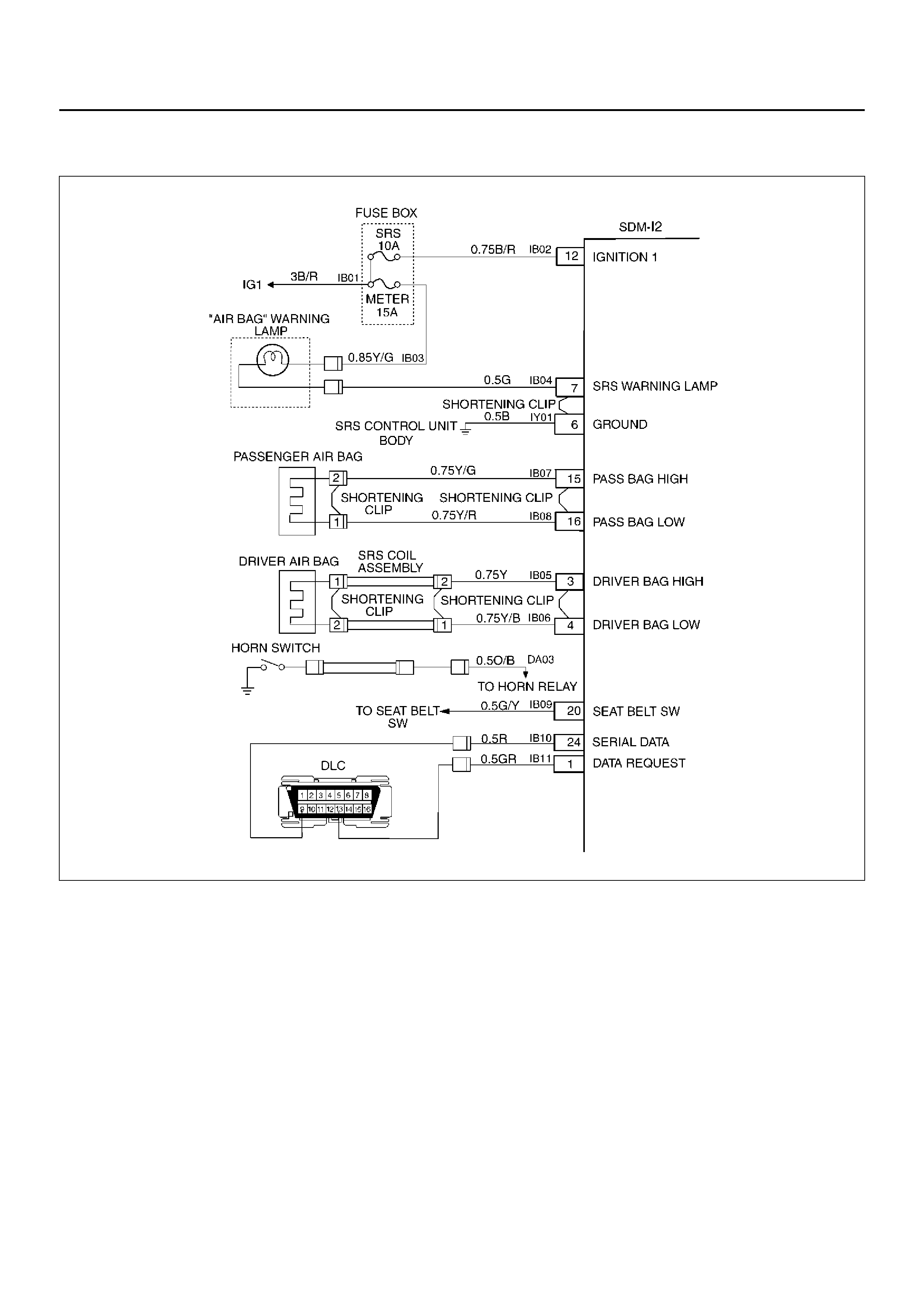
DTC 53 DEPLOYMENT COMMANDED WITH DEPLOYMENT LOOP FAULT OR
ENERGY RESERVES OUT OF RANGE
D09RX002
Circuit Description:
The Sensing and Diagnostic Module (SDM) contains a
sensing drive which converts vehicle velocity changes
to an electrical signal. The electrical signal generated
is processed by the SDM and then compared to a value
stored in memory. When the generated signal exceeds
the stored value, the SDM will cause current to flow
through the air bag assembly deploying the air bags.
Diagnostic Trouble Code (DTC) 53 is set
accompanying with DTC 51 when a deployment occurs
while an air bag assembly circuit fault is present that
could possible result in a no deployment situation in one
or both air bag assemblies.
DTC Will Set When:
The SDM detects a frontal crash, up to 30 degrees off
the centerline of the vehicle, of sufficient force to
warrant deployment of the air bags and an inflator circuit
fault is present.
Action Taken:
SDM turns “ON" the “AIR BAG" warning lamp records
“Crash Data", and sets a diagnostic trouble code.
DTC Will Clear When:
The SDM is replaced. If DTC 53 is set, one or more
DTCs will be set in addition to DTC 53. Malfunction(s)
setting DTC(s) (other than DTC 71) must be repaired so
that DTC(s) will not be set when a new SDM is
installed.

DTC Chart Test Des cription:
The number(s) below refer to step number(s) on the
diagnostic chart:
2. If air bag assembly has not deployed, Diagnostic
Trouble Code (DTC) 53 may have falsely set.
3. If DTC 53 has set with no signs of frontal impact, the
diagnostic trouble code has falsely set.

DTC 53 Deployment Commanded With Deployment Loop Fault Or Energy Reserves Out Of
Range
WARNING: DURING SERVICE PROCEDURES. BE
VERY CAREFUL WHEN HANDLING A SENSING
AND DIAGNOSTIC MODULE (SDM). NEVER STRIKE
OR JAR THE SDM. NEVER POWER UP THE SRS
WHEN THE SDM IS NOT RIGIDLY ATTACHED TO
THE VEHICLE. ALL SDM AND MOUNTING
BRACKET FASTENERS MUST BE CAREFULLY
TORQUED AND THE ARROW MUST BE POINTING
TOWARD THE FRONT OF THE VEHICLE TO
ENSURE PROPER OPERATION OF THE SRS. THE
SDM COULD BE ACTIVATED WHEN POWERED
WHILE NOT RIGIDLY ATTACHED TO THE VEHICLE
WHICH COULD CAUSE DEPLOYMENT AND
RESULT IN PERSONAL INJURY.
Step Action Yes No
1 Was the “SRS Diagnostic System Check" performed?
Go to Step 2
Go to the “SRS
Diagnostic System
Check."
2 Ignition switch “OFF."
Have air bag assemblies deployed? Replace
components
and perform
inspections as
directed in
“repairs and
inspections
required after
an accident" in
this section.
Clear
diagnostic
trouble co des .
Repeat the
“SRS
Diagnostic
System Check." Go to Step 3
3 Inspect front of vehicle and undercarriage for signs of impact.
Were signs of impact found? Replace
components
and perform
inspections as
directed in
“repairs and
inspections
required after
an accident" in
this section.
Clear
diagnostic
trouble co des .
Repeat the
“SRS
Diagnostic
System Check."
Ignition switch
“OFF."
Replace SDM.
Reconnect all
SRS system
components,
ensure all
components are
properly
mounted.
Repeat the
“SRS
Diagnostic
System Check. "

DTC 61 WARNING LAMP CIRCUIT FAILURE
D09RX002
Circuit Description:
When the ignition switch is turned “ON", battery voltage
is applied to the “AIR BAG" warning lamp and to the
“ignition 1" input terminal “12". The Sensing and
Diagnostic Module (SDM) responds by flashing the “AIR
BAG" warning lamp seven times. The SDM monitors
the lamp driver output by comparing the output state at
“Supplemental Restraint System (SRS) warning lamp"
terminal “7" to the microprocessor commanded state.
When “ignition 1" is in the specified value, and the
output state Does not match the commanded state of
the lamp driver for 500 milliseconds, DTC 61 is set.
DTC Will Set When:
“Ignition 1" voltage is in the specified value and the
output state at the “SRS warning lamp" terminal does
not match the commanded state of the lamp driver for
500 milliseconds. This test is run every 100
milliseconds during “Continuous Monitoring" tests and
once per each ignition cycle at the beginning.
Action Taken:
SDM attempts to turn “ON" the “AIR BAG" warning lamp
and sets a diagnostic trouble code.
DTC Will Clear When:
The ignition switch is turned “OFF."
Diagnostic Aids:
Refer to Charts B and C to diagnose warning lamp
circuit malfunctions.

DTC 61 Warning Lamp Circuit Failure
Step Action Yes No
1 Was the “SRS Diagnostic System Check" performed?
Go to Step 2
Go to the “SRS
Diagnostic System
Check."
2 1. Malfunctions within the “AIR BAG" warning lamp circuitry will
set this diagnostic trouble code.
2. These malfunctions are addressed in the “SRS Diagnostic
System Check" via Chart B and Chart C.
3. Failure to properly perform the “SRS Diagnostic System
Check" may result in misdiagnosis.
4. Ignition switc h “ON."
5. Clear SRS diagnostic trouble codes.
Is DTC 61 SET?
Ignition switc h
“OFF."
Go to Chart A.
Repeat the “SRS
Diagnostic System
Check."
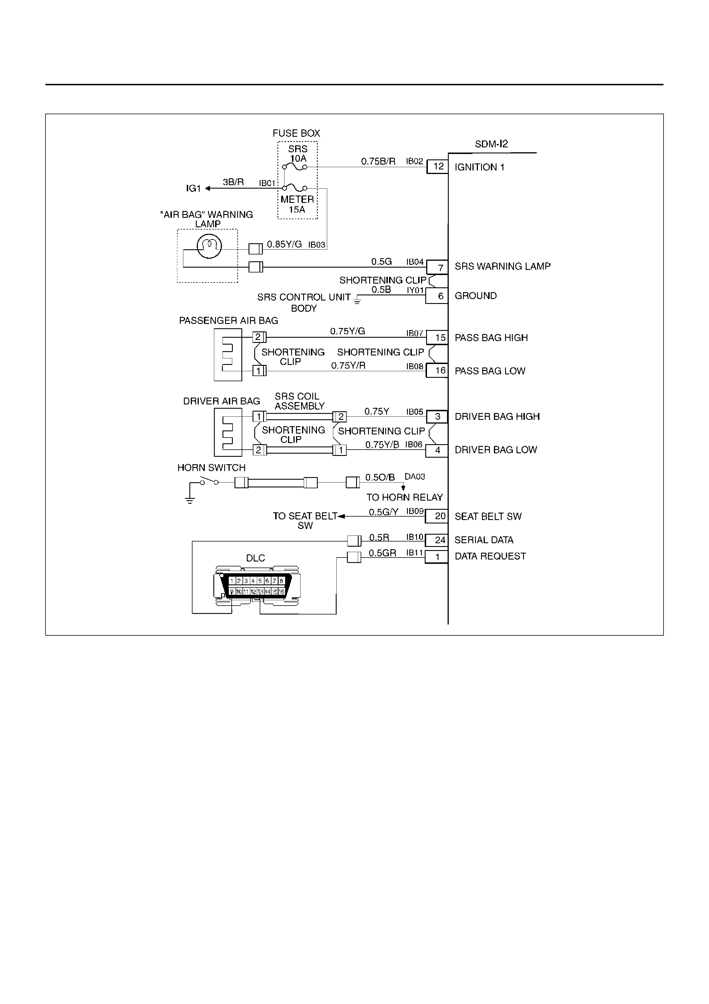
DTC 71 INTERNAL SDM FAULT
D09RX002
Circuit Description:
Diagnostic Trouble Code (DTC) 71 is an indication of a
potential internal Sensing and Diagnostic Module
(SDM) malfunction and will set if any of the following
conditions are detected:
1) Deployment or microprocessor energy reserve
failure.
2) Electronically Erasable Programmable Read Only
Memory failure. (EEPRO M).
3) Random Only Memory failure. (ROM).
4) Random Access Memory failure. (RAM).
5) Calibration check sum failure.
6) Deployment switch faults.
7) Accelerometer fault.
8) Arming sensor fault.
9) Diagnostic current faults.
10) DTC 19
11) DTC 25
12) DTC 51
13) DTC 53
DTC Will Set When:
Any of the above indicated malfunctions are detected by
the SDM. The malfunctions described above are
tested mainly during “Continuous Monitoring" and some
ones run each ignition cycle.
Action Taken:
SDM turns “ON" the “AIR BAG" warning lamp and sets
a diagnostic trouble code.
DTC Will Clear When:
A scan tool “Clear Codes" commanded is received by
the SDM. Some of the indicated malfunctions will only
allow the “AIR BAG" warning lamp to go out.
But when DTC 19, 25, 51, 53 are also set, SDM is
Replaced.

DTC 71 Internal SDM Fault
WARNING: DURING SERVICE PROCEDURES. BE
VERY CAREFUL WHEN HANDLING A SENSING
AND DIAGNOSTIC MODULE (SDM). NEVER STRIKE
OR JAR THE SDM. NEVER POWER UP THE SRS
WHEN THE SDM IS NOT RIGIDLY ATTACHED TO
THE VEHICLE. ALL SDM AND MOUNTING
BRACKET FASTENERS MUST BE CAREFULLY
TORQUED AND THE ARROW MUST BE POINTING
TOWARD THE FRONT OF THE VEHICLE TO
ENSURE PROPER OPERATION OF THE SRS. THE
SDM COULD BE ACTIVATED WHEN POWERED
WHILE NOT RIGIDLY ATTACHED TO THE VEHICLE
WHICH COULD CAUSE DEPLOYMENT AND
RESULT IN PERSONAL INJURY.
CAUTION: When Diagnostic Trouble Code (DTC) 19
or 25 or 51 or 53 has been set it is necessary to
Replace the SDM. Setting DTC 19 and 25 or 51 or 53
will also cause DTC 71 to set. When a scan tool
“CLEAR CODES" command is issued and the
malfunction is no longer present, DTC 51 or 53 and
DTC 71 will remain current. Ensure that the short to
voltage condition DTC 19, 25 is repaired prior to
installing a Replacement SDM to avoid damaging
the SDM.
CAUTION:
Step Action Yes No
1 Was the “SRS Diagnostic System Check" performed?
Go to Step 2
Go to the “SRS
Diagnostic System
Check."
2 Note SRS “Diagnostic System Check."
Is DTC 19 or 25 or 51 or 53 also set (current or history)? (Refer to
notice above).
Go to DTC 19 if
DTC 19 is set.
Go to DTC 25 if
DTC 25 is set.
Go to DTC 51 if
DTC 51 is set.
Go to DTC 53 if
DTC 53 is set.
Ignition switch
“OFF."
Replace SDM.
Repeat the
“SRS
Diagnostic
System Check. "