
SECTION 12N - WIPER / WASHER SYSTEM
Service Precaution
Windshield Wiper/Washer System
General Description
Windshield Wiper And Washer Switch
Removal and Installation
Windshield Wiper Motor
Removal
Installation
Windshield Washer Motor
Removal
Installation
Windshield Washer Spray Pattern
Windshield Wiper Linkage
Windshield Wiper Linkage and
Associated Parts
Removal
Installation
Windshield Wiper Arm/Blade
Removal
Installation
Windshield Wiper Blade Rubber
Removal
Installation
Rear Wiper/Washer System
General Description
Rear Wiper and Washer Switch
Removal
Installation
Rear Wiper Motor
Removal
Installation
Rear Washer Motor
Removal
Installation
Alarm and Relay Control Unit
Removal
Installation
Rear Wiper Arm/Blade
Removal
Installation
Rear Washer Nozzle
Removal
Installation
Rear Washer Spray Pattern
Rear Wiper Blade Rubber
Removal
Installation
Main Data and Specifications
SERVICE PRECAUTION
WARNING: THIS VEHICLE HAS A SUPPLEMENTAL
RESTRAINT SYSTEM (SRS). REFER TO THE SRS
COMPONENT AND WIRING LOCATION VIEW IN
ORDER TO DETERMINE WHETHER YOU ARE
PERFORMING SERVICE ON OR NEAR THE SRS
COMPONENTS OR THE SRS WIRING. WHEN YOU
ARE PERFORMING SERVICE ON OR NEAR THE
SRS COMPONENTS OR THE SRS WIRING, REFER
TO THE SRS SERVICE INFORMATION. FAILURE TO
FOLLOW WARNINGS COULD RESULT IN POSSIBLE
AIR BAG DEPLOYMENT, PERSONAL INJURY, OR
OTHERWISE UNNEEDED SRS SYSTEM REPAIRS.
CAUTION: Always use the correct fastener in the
proper location. When you replace a fastener, use
ONLY the exact part number for that application.
HOLDEN will call out those fasteners that require a
replacement after removal. HOLDEN will also call
out the fasteners that require thread lockers or
thread sealant. UNLESS OTHERWISE SPECIFIED,
do not use supplemental coatings (Paints, greases,
or other corrosion inhibitors) on threaded fasteners
or fastener joint interfaces. Generally, such
coatings adversely affect the fastener torque and
the joint clamping force, and may damage the
fastener. When you install fasteners, use the correct
tightening sequence and specifications. Following
these instructions can help you avoid damage to
parts and systems.
WINDSHIELD WIPER/WASHER SYSTEM
GENERAL DESCRIPTION
The circuit consists of the starter switch, windshield
wiper & washer switch, windshield wiper motor,
windshield washer motor and alarm & relay control unit.
When the windshield wiper & washer switch is turned on
with the starter switch on, the battery voltage is applied
to the wiper motor to activate the wiper.
The washer motor squirts glass cleaning fluid while the
washer switch is being pushed. The alarm & relay
control unit relay is used to control motion of the wiper.
WINDSHIELD WIPER AND WASHER SWITCH
REMOVAL AND INSTALLATION
Refer to Combination Switch in Section 9A.
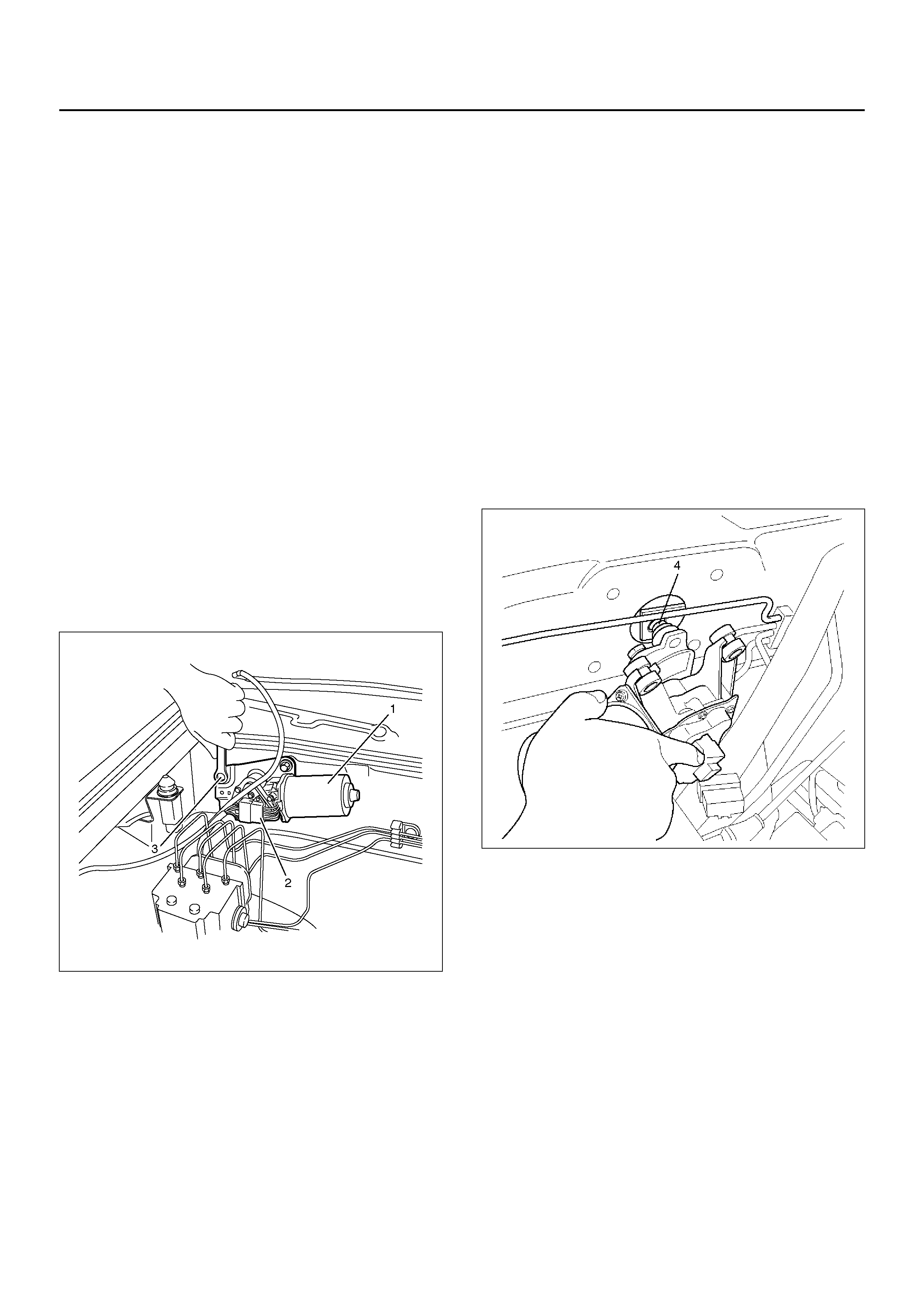
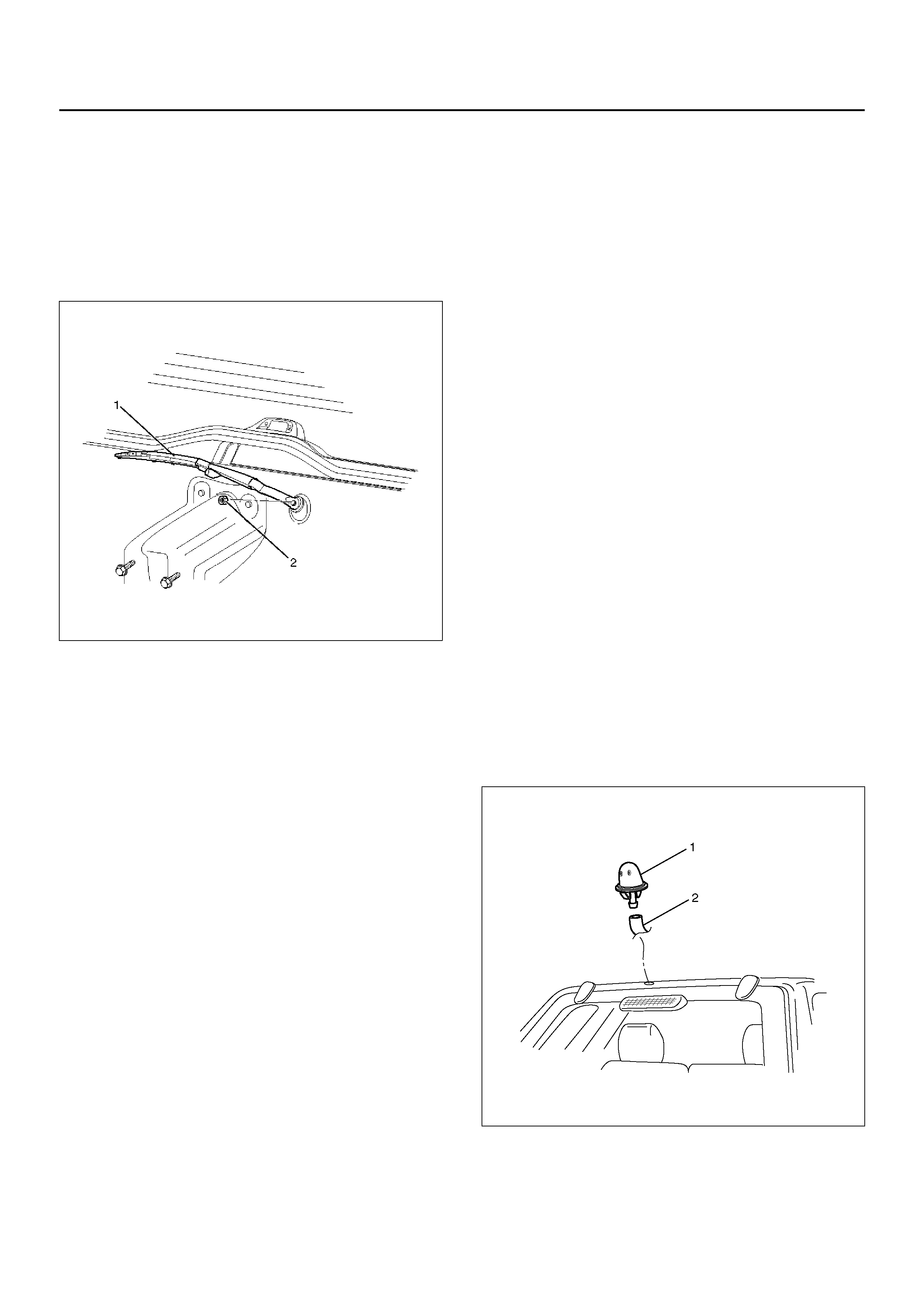
WINDSHIELD WIPER MOTOR
REMOVAL
1. Disconnect the battery ground cable.
2. Disconnect the connector (2).
3. Remove 4 mounting bolts (3).
4. Remove the windshield wiper motor(1).
880RW002-1
5. Remove the crank arm fixing ball (4).
880RX011
INSTALLATION
To install, follow the removal steps in the reverse order.
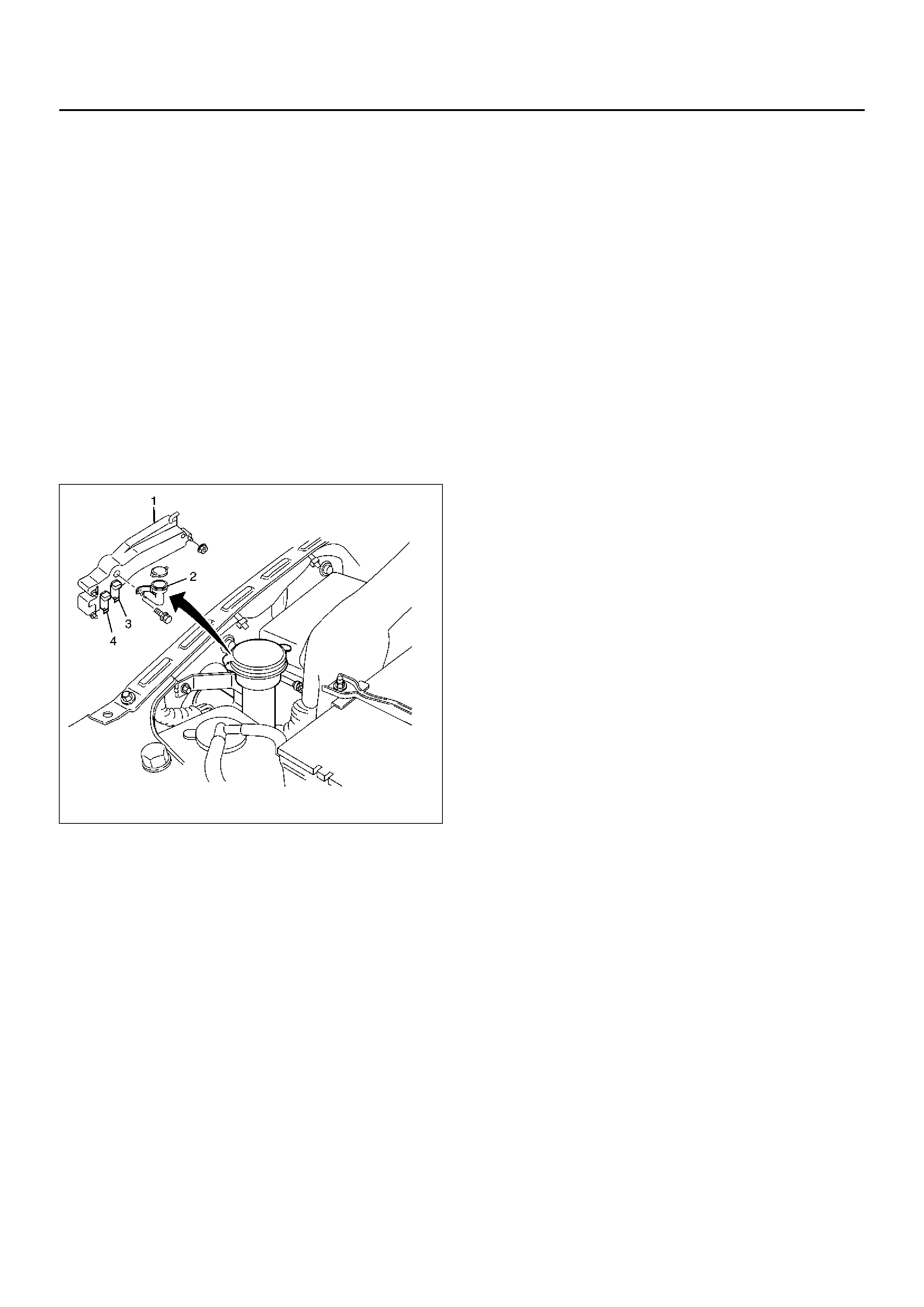
WINDSHIELD WASHER MOTOR
REMOVAL
1. Disconnect the battery ground cable.
2. Remove the fender inner liner (right side).
3. Disconnect the windshield washer motor connector
and the rear washer motor connector.
4. Disconnect the windshield washer hose connector
and the rear washer hose connector.
5. Remove the filler neck (2).
• Remove the bolt.
6. Remove the washer tank (1).
• Remove the three nuts.
7. Pull out the windshield washer motor (4) from the
washer tank.
880RW028
INSTALLATION
To install, follow the removal steps in the reverse order.
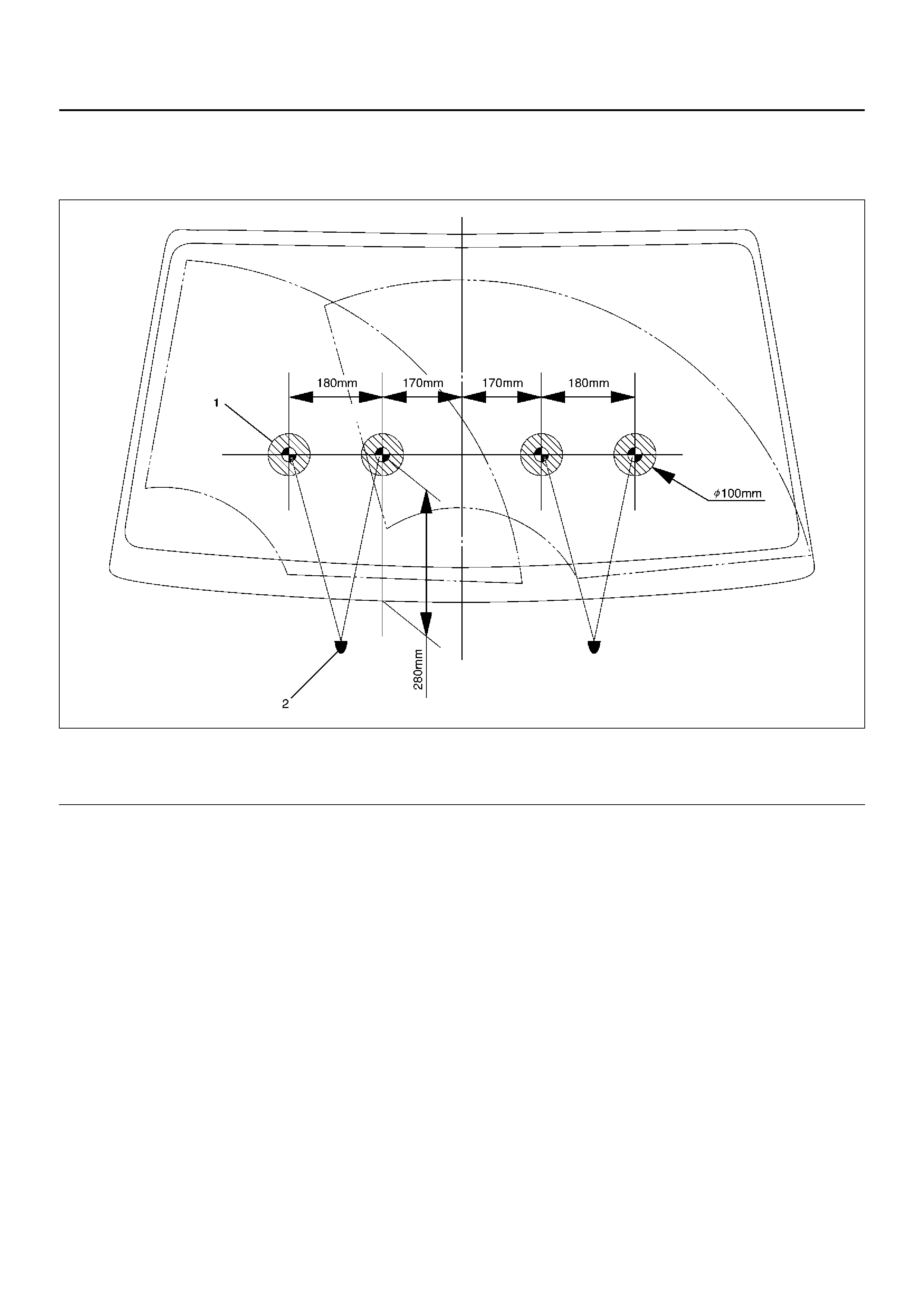
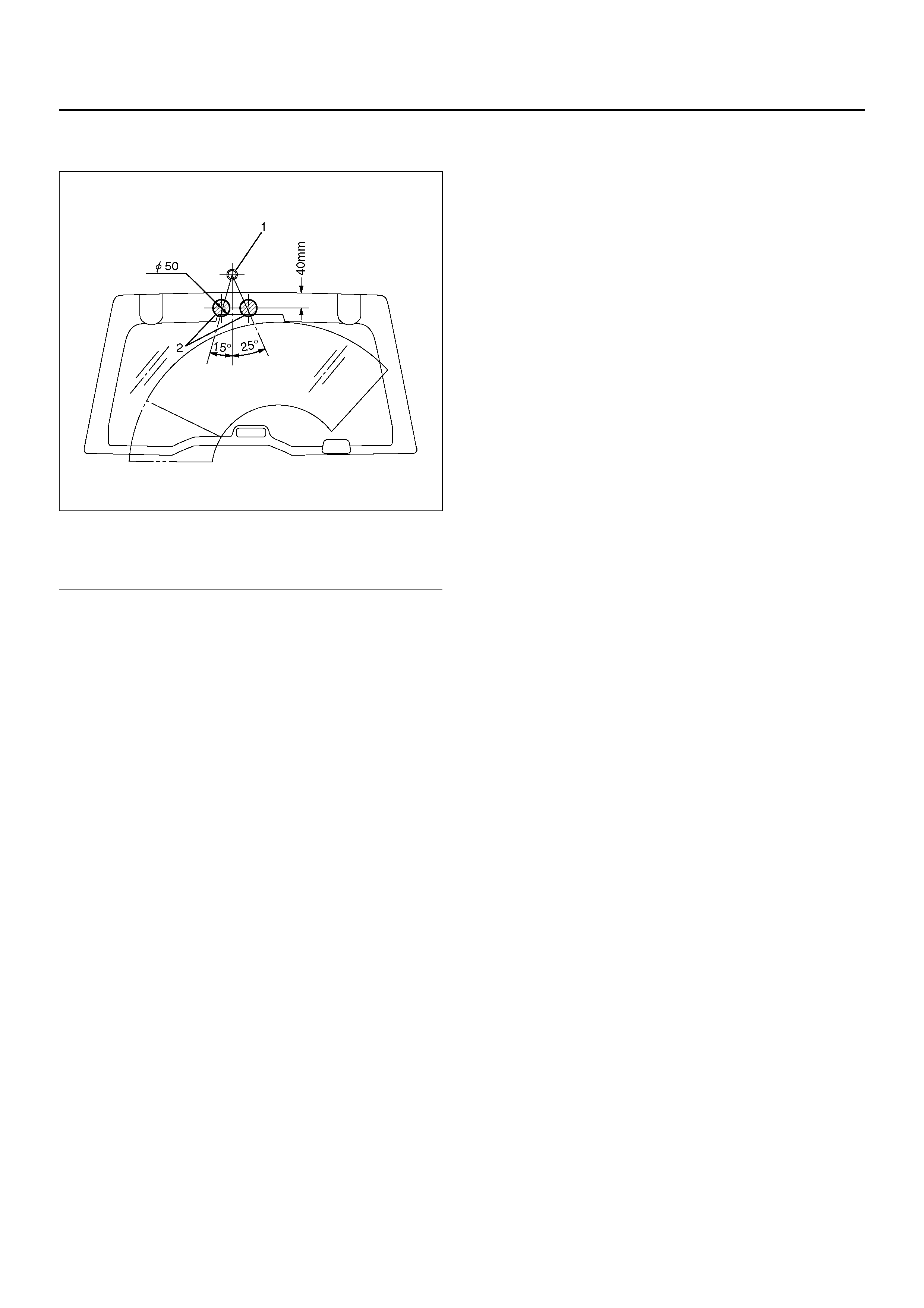
WINDSHIELD WASHER SPRAY PATTERN
880RW024
Legend
EndOFCallout
(1) Spray Target Point
(2) Washer Nozzle
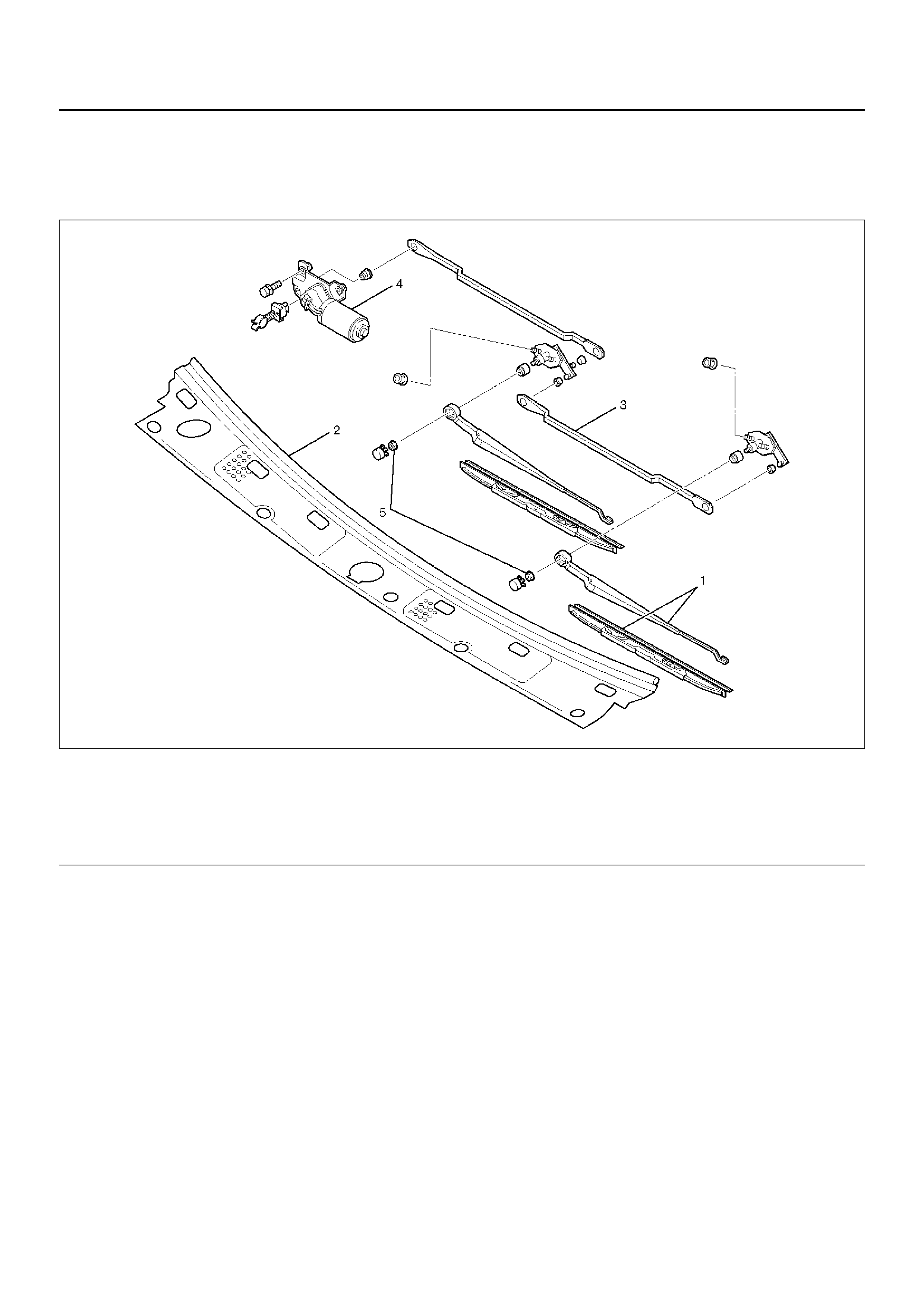
WINDSHIELD WIPER LINKAGE
WINDSHIELD WIPER LINKAGE AND ASSOCIATED PARTS
880RW026-1
Legend
EndOFCallout
REMOVAL
1. Disconnect the battery ground cable.
2. Remove the windshield wiper arm/blade.
3. Remove the vent cowl cover.
4. Remove the windshield wiper motor.
5. Remove the pivot assembly mounting nuts, fixing
screws.
6. Take out the windshield wiper linkage assembly
from the opening of the cowl.
INSTALLATION
To install, follow the removal steps in the reverse order.
(1) Windshield Wiper Arm/Blade
(2) Vent Cowl Cover
(3) Windshield Wiper Linkage Assembly
(4) Windshield Wiper Motor
(5) Windshield Wiper Arm Nut
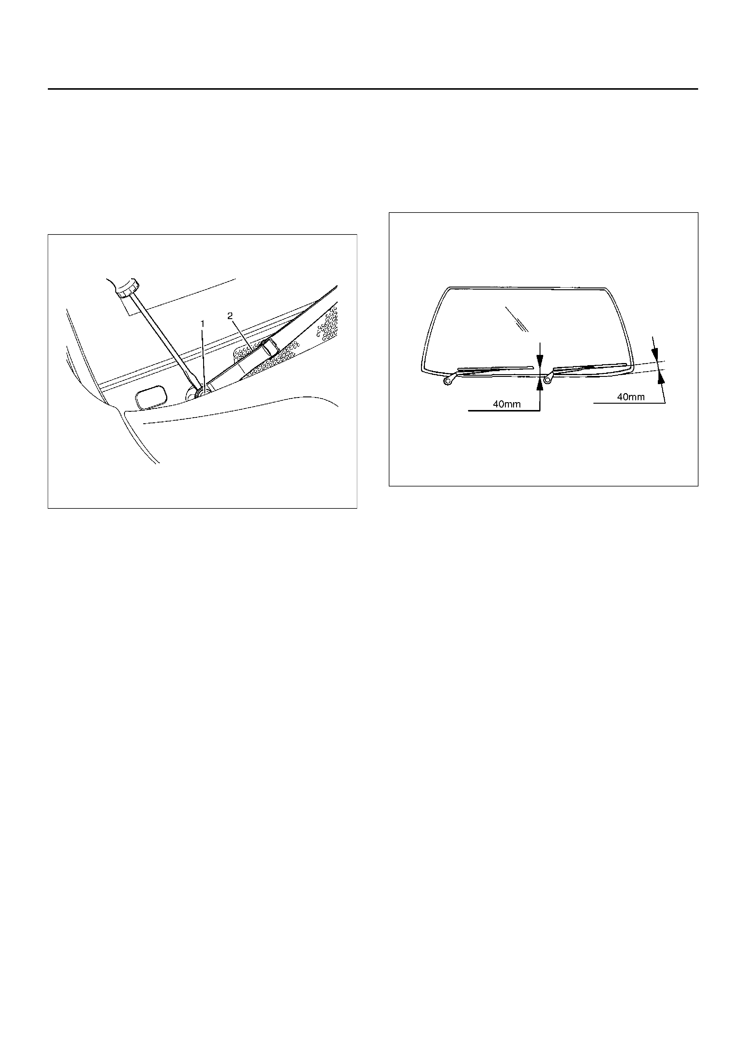
WINDSHIELD WIPER ARM/BLADE
REMOVAL
1. Dry the cap (1) off with the tip of a screwdriver.
2. Remove the nut.
3. Remove the wiper arm/blade (2).
880RW023
INSTALLATION
To install, follow the removal steps in the reverse order,
noting the foll owi ng poi nts:
880RW027
1. Before installing the wiper arm/blade to the shaft,
confirm that the motor stops at the autostop
position.
2. Set the wiper arm/blade so that the tips of both
blades are positioned about 40mm (1.57in) from
the upper edge of the cowl cover as shown in the
figure.
3. Tighten the nuts to the specified torque.
Torque: 23N·m (2.3kg·m/17lbft)
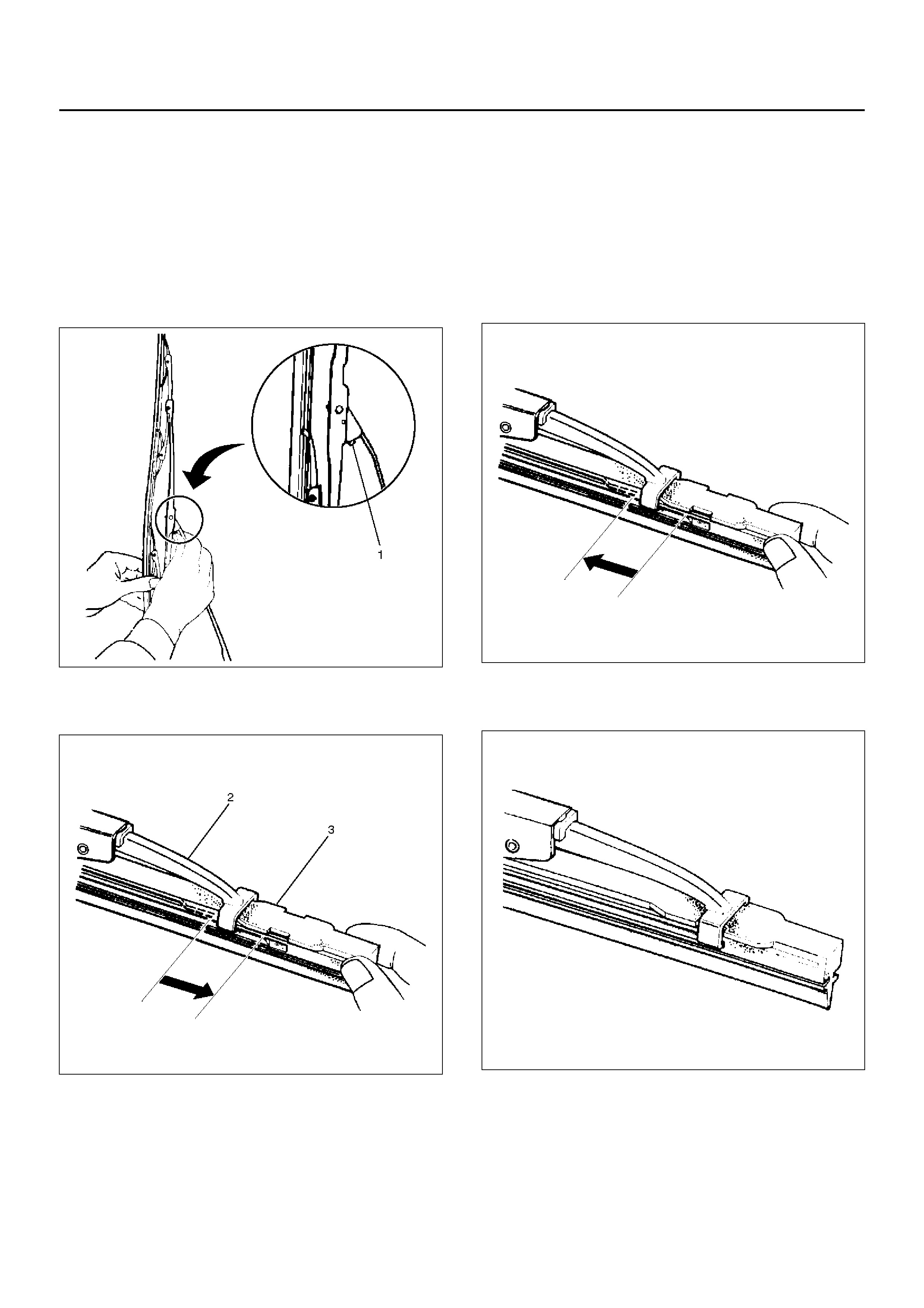
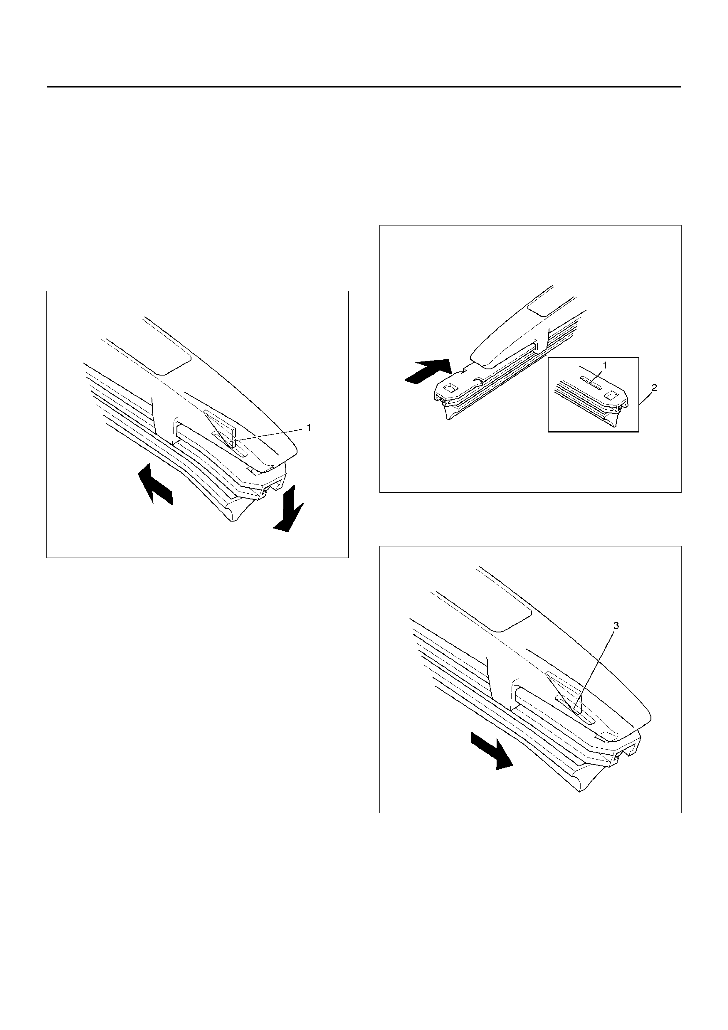
WINDSHIELD WIPER BLADE RUBBER
REMOVAL
1. Push the wiper blade lock(1) while pulling the wiper
blade in the arrow direction as shown in the figure.
CAUTION: When the wiper blade has been
removed, wrap the tip of the wiper arm with cloth, to
avoid damaging the glass.
880RS011
2. Pull the end of rubber and remove the projection(3)
from the clip of the blade stay (2).
880RS010
3. Pull the rubber out in the same direction.
INSTALLATION
To install, follow the removal steps in the reverse order,
noting the foll owi ng poi nts:
1. Install the clip of the blade stay in the groove of the
new rubber and slide it in. Complete wiper blade
installation by pushing the clip.
885RS002
2. Finally, check that the clip of the stay has caught in
the hole of the rubber.
885RS001
REAR WIPER/WASHER SYSTEM
GENERAL DESCRIPTION
The circuit consists of the starter switch, rear wiper &
washer switch, rear wiper motor, rear washer motor and
Alarm & relay control unit.
When the rear wiper & washer switch is turned on with
the starter switch on, the battery voltage is applied to
the wiper motor to activate the wiper.
The washer motor sprays glass cleaning fluid while the
washer switch is being pushed. The alarm & relay
control unit is used to control motion of the wiper.
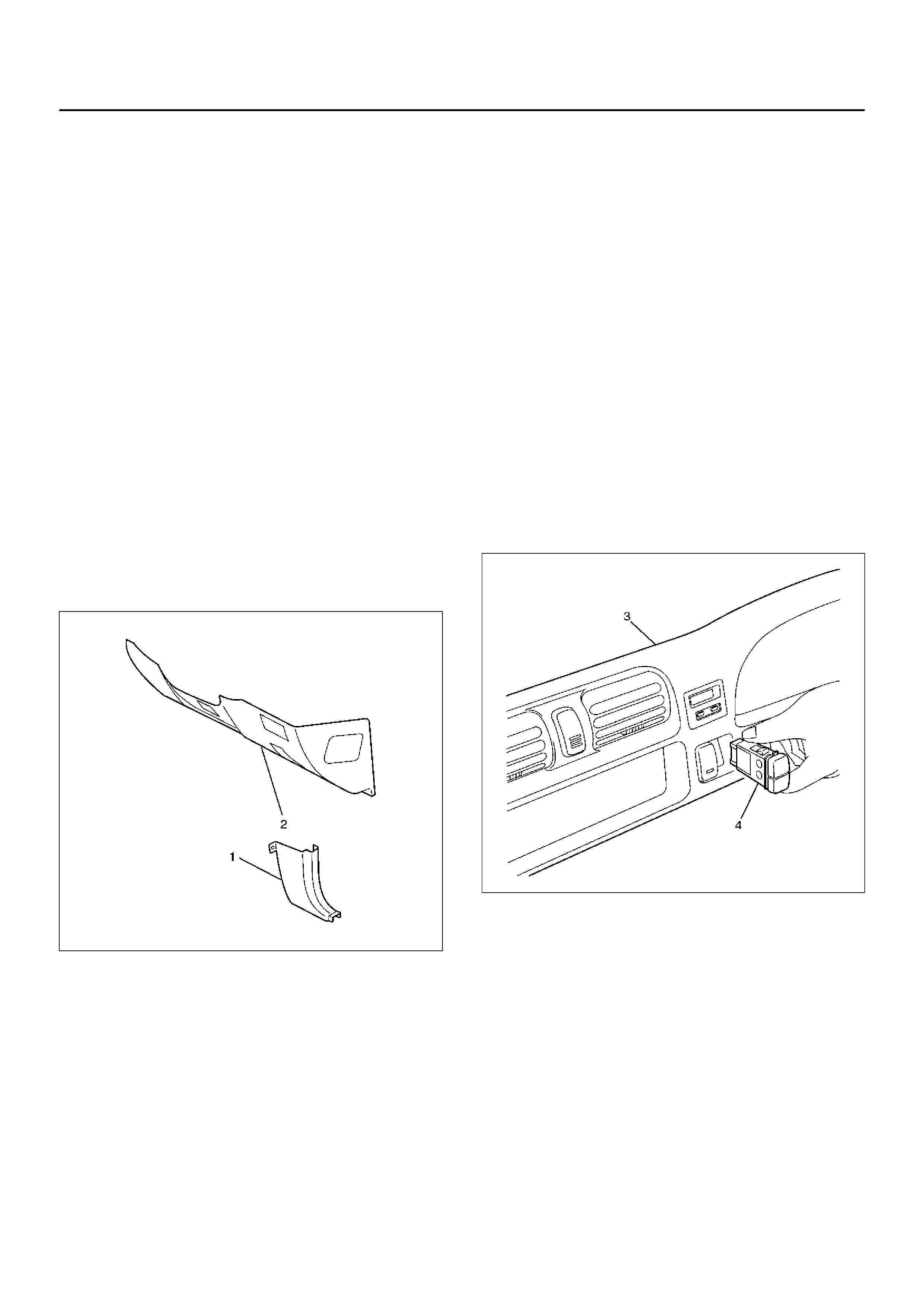
REAR WIPER AND WASHER SWITCH
REMOVAL
1. Disconnect the battery ground cable.
2. Remove the dash side trim panel(1).
3. Remove the lower cover assembly(2).
• Refer to Instrument panel Assembly in Body
Structure section.
821RW293-1
4. Remove the meter cluster assembly(3).
5. Remove the rear wiper & washer switch (4).
• Disconnect the connector.
• Push the lock from the back side of the meter
cluster assembly.
825RW285
INSTALLATION
To install, follow the removal steps in the reverse order,
noting the foll owi ng poi nt:
1. Push the switch with your fingers until it locks
securely.

REAR WIPER MOTOR
REMOVAL
1. Disconnect the battery ground cable.
2. Remove the tailgate trim pad.
3. Remove the wiper arm/blade.
Refer to Rear Wiper Arm/Blade in section.
4. Remove the rear wiper motor (1).
• Disconnect the connector.
• Remove the motor shaft nut (2).
• Remove the rear wiper motor fixing screws.
885RW001-1
INSTALLATION
To install, follow the removal steps in the reverse order,
noting the foll owi ng poi nts:
1. Before installing the wiper arm/blade to the motor
shaft, confirm that the motor stops at the autostop
position.
2. Install the wiper arm/blade so that the wiper arm (5)
contact with the stopper portion (6) on the hatch
gate cover (3) as shown in the figure.
885RW005-1
3. Tighten the motor shaft nut (2) to the specified
torque.
Torque: 10N·m (1.0kg·m/87lbin)
4. T ighten the wiper arm nut (4) to the specified torque.
Torque: 14N·m (1.4kg·m/122lbin)
REAR WASHER MOTOR
REMOVAL
1. Disconnect the battery ground cable.
2. Remove the fender inner liner (right side).
3. Disconnect the windshield washer motor connector
and the rear washer motor connector.
4. Disconnect the windshield washer hose connector
and the rear washer hose connector.
5. Remove the filler neck (2).
• Remove the bolt.
6. Remove the washer tank (1).
• Remove the three nuts.
7. Pull out the rear washer motor (3) from the washer
tank.
880RW028
INSTALLATION
To install, follow the removal steps in the reverse order.
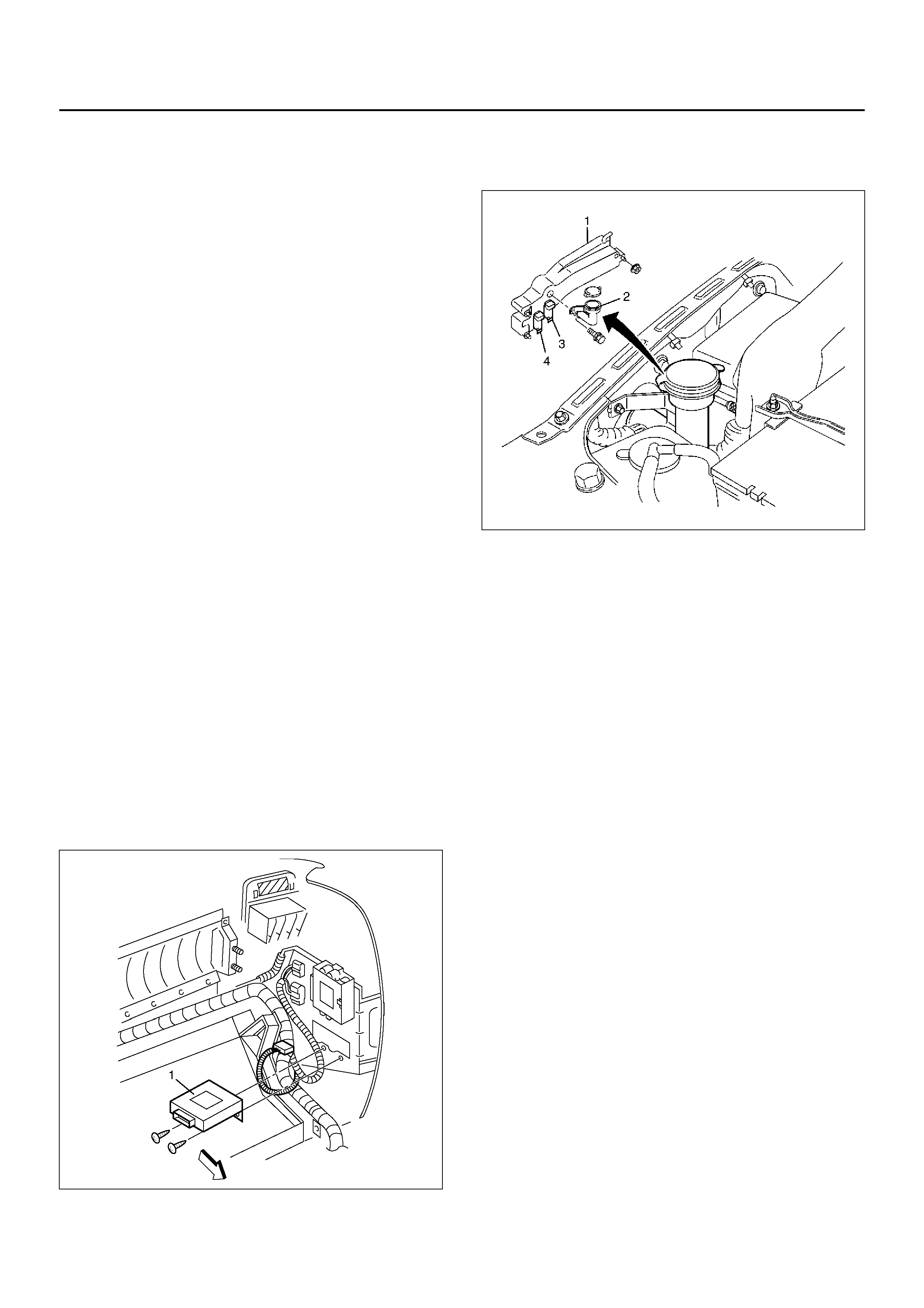
ALARM AND RELAY CONTROL UNIT
REMOVAL
1. Disconnect the battery ground cable.
2. Remove the glove box.
3. Remove the alarm and relay control unit (1).
• Remove the fixing screw and disconnect the
connector.
826R100030
INSTALLATION
To install, follow the removal steps in the reverse order.
REAR WIPER ARM/BLADE
REMOVAL
1. Remove the arm nut(2).
2. Remove the wiper arm/blade(1).
885RW007
INSTALLATION
Refer to Rear Wiper Motor (4door Model) in this section.
REAR WASHER NOZZLE
REMOVAL
1. Remove the rear roof trim cover.
• Refer to Interior Trim Panel in Interior and
Exterior Panel section.
2. Remove the washer nozzle(1).
• Pull out the washer nozzle from the washer hose
(2).
885R100003
INSTALLATION
To install, follow the removal steps in the reverse order.
REAR WASHER SPRAY PATTERN
885R100002
Legend
EndOFCallout
(1) Washer Nozzle
(2) Spray Target Points
REAR WIPER BLADE RUBBER
REMOVAL
1. Remove the wiper blade from the wiper arm.
2. Push out the wiper rubber from the wiper blade by
sliding it horizontally while holding down the rubber
on the wiper blade convex (1) side.
CAUTION: When the wiper blade has been
removed, wrap the tip of the wiper arm with cloth, to
avoid damaging the glass.
880RW022
INSTALLATION
1. Install the wiper blade rubber.
• Insert the tip of wiper rubber (2) from the opposite
side of remov al in the arro w directi on .
880RX001
• Check if the convex part (3) of wiper blade is
installed in the groove of the wiper rubber.
880RX002

MAIN DATA AND SPECIFICATIONS
Torque Specifications
Application N·m kg·m LbFt LbIn
Windshield Wiper Arm Nuts 23 2.3 17 —
Rear Wiper Motor Shaft Nut 10 1.0 — 87
Rear Wiper Arm Nut 14 1.4 — 122