
SECTION 12P - WIRING SYSTEM
Service Precaution
General Description
Notes for Working on Electrical Items
Symbols and Abbreviations
Parts for Electrical Circuit
Reading the Circuit Diagram
Main Data and Specifications
Fuse, Fusible Link and Circuit Breaker
Location
Relay & Fuse Box (Engine Bay)
Relay & Fuse Box (Instrument panel)
Fuse Block Circuit
Reference Table of Fuse, Fusible Link
and Circuit Breaker
Relay Location
Diode Location
Grounding Point
Cable Harness Routing
Start and Charging
General Description
Circuit Diagram
Parts Location
Powertrain Control Module (PCM)
General Description
Circuit Diagram
Parts Location
Headlight and Fog Light
General Description
Circuit Diagram
Parts Location
Diagnosis
Clearance Light, Tail Light and License
Plate Light
General Description
Circuit Diagram
Parts Location
Diagnosis
Interior Illumination Light
General Description
Circuit Diagram
Parts Location
Diagnosis
Turn Signal Light, Hazard Warning Light
General Description
Circuit Diagram
Parts Location
Diagnosis
Stoplight
General Description
Circuit Diagram
Parts Location
Diagnosis
Backup Light
General Description
Circuit Diagram
Parts Location
Diagnosis
Horn
General Description
Circuit Diagram
Parts Location
Diagnosis
Dome Light, Rear Compartment Light, Courtesy
Light, Map Light, Seat Belt Switch and
Warning Buzzer
General Description
Circuit Diagram
Parts Location
Diagnosis
Power Door Lock
General Description
Circuit Diagram
Parts Location
Diagnosis
Power Window
General Description
Circuit Diagram
Parts Location
Diagnosis
Anti–Lock Brake System (ABS)
General Description
Circuit Diagram
Parts Location
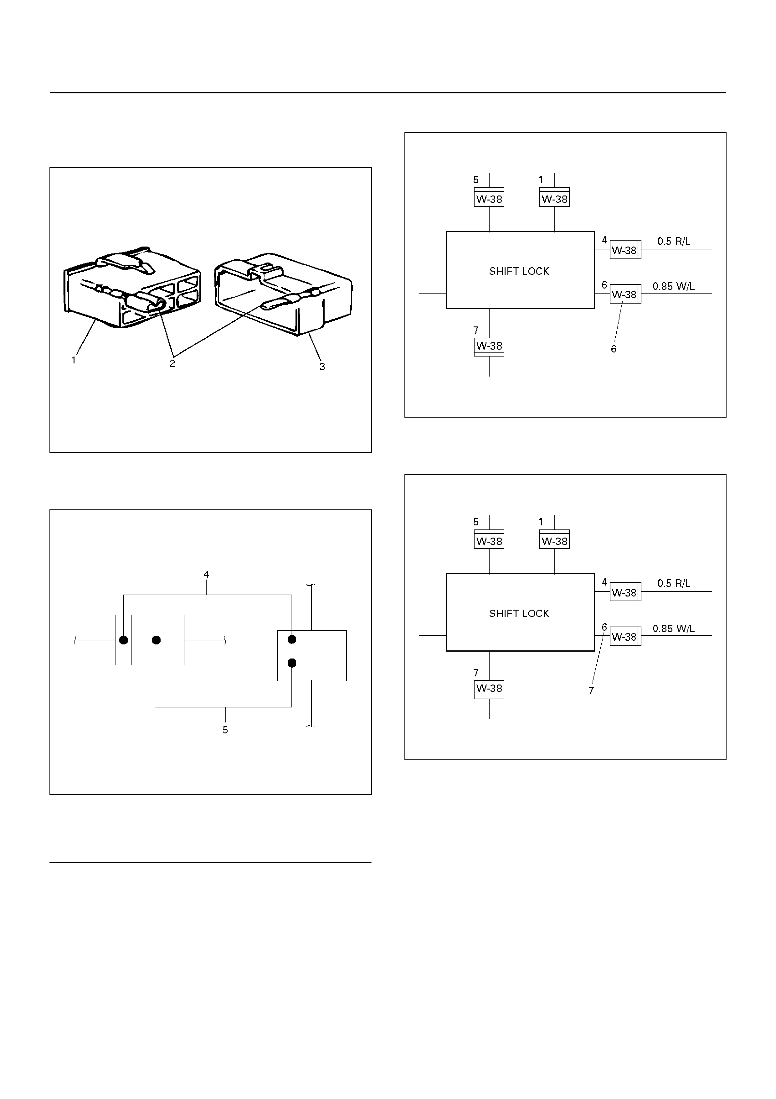
A/T Shift Lock
General Description
Circuit Diagram
Parts Location
Windshield Wiper and Washer
General Description
Circuit Diagram
Parts Location
Diagnosis
Rear Wiper/Washer
General Description
Circuit Diagram
Parts Location
Diagnosis
Audio
General Description
Circuit Diagram
Parts Location
Rear Defogger/Mirror Defogger
General Description
Circuit Diagram
Parts Location
Diagnosis

Cigarette Lighter, Digital Clock and
Accessory Socket
General Description
Circuit Diagram
Parts Location
Diagnosis
Power Door Mirror
General Description
Circuit Diagram
Parts Location
Diagnosis
Keyless Entry
General Description
Circuit Diagram
Parts Location
Keyless Entry System
Meter and Warning/Indicator Light
General Description
Circuit Diagram
Parts Location
Diagnosis
Heater and Air Conditioning (Manual)
General Description
Circuit Diagram
Parts Location
Heater and Air Conditioning (Automatic)
General Description
Circuit Diagram
Parts Location
Sunroof
General Description
Circuit Diagram
Parts Location
Diagnosis
Supplemental Restraint System (SRS)
– Air Bag
General Description
Circuit Diagram
Parts Location
Shift on the Fly System
General Description
Circuit Diagram
Parts Location
T.O.D.
General Description
Circuit Diagram
Parts Location
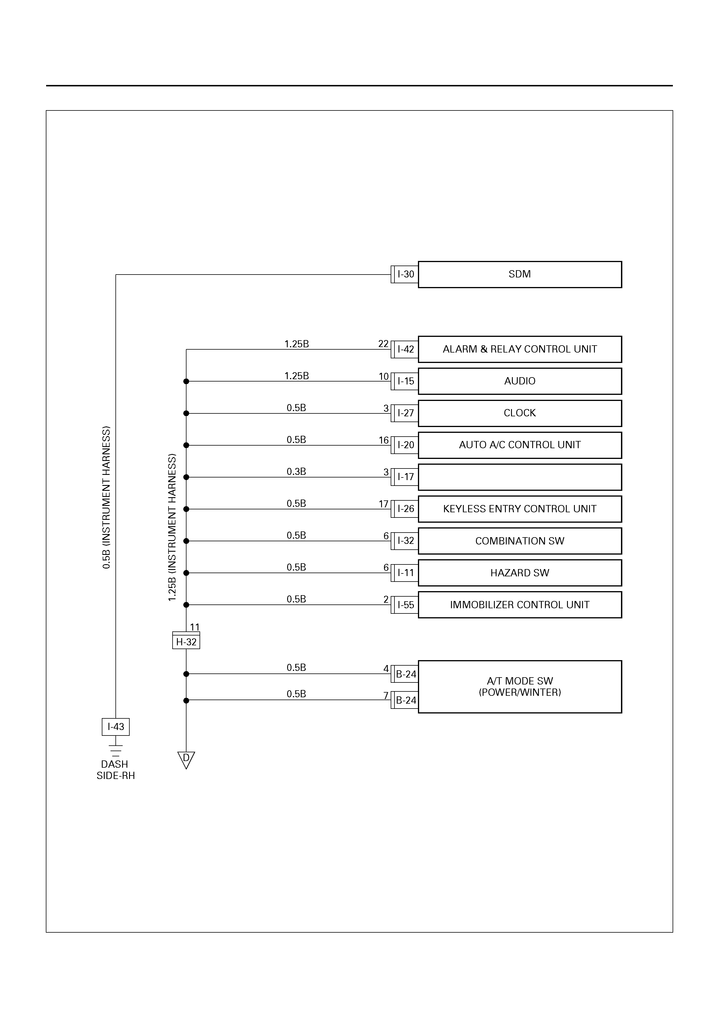
Alarm and Relay Control Unit
Circuit Diagram
Parts Location
Harness Connector Faces
SERVICE PRECAUTION
WARNING: THIS VEHICLE HAS A SUPPLEMENTAL
RESTRAINT SYSTEM (SRS). REFER TO THE SRS
COMPONENT AND WIRING LOCATION VIEW IN
ORDER TO DETERMINE WHETHER YOU ARE
PERFORMING SERVICE ON OR NEAR THE SRS
COMPONENTS OR THE SRS WIRING. WHEN YOU
ARE PERFORMING SERVICE ON OR NEAR THE
SRS COMPONENTS OR THE SRS WIRING, REFER
TO THE SRS SERVICE INFORMATION. FAILURE TOFOLLOW WARNINGS COULD RESULT IN POSSIBLEAIR BAG DEPLOYMENT, PERSONAL INJURY, OROTHERWISE UNNEEDED SRS SYSTEM REPAIRS.
CAUTION: Always use the correct fastener in the
proper location. When you replace a fastener, use
ONLY the exact part number for that application.
HOLDEN will call out those fasteners that require a
replacement after removal. HOLDEN will also call
out the fasteners that require thread lockers or
thread sealant. UNLESS OTHERWISE SPECIFIED,
do not use supplemental coatings (Paints, greases,
or other corrosion inhibitors) on threaded fasteners
or fasteners joint interfaces. Generally, such
coatings adversely affect the fastener torque and
the joint clamping force, and may damage the
fasteners. When you install fasteners, use the
correct tightening sequence and specifications.
Following these instructions can help you avoid
damage to parts and systems.
GENERAL DESCRIPTION
The chassis electrical system is a 12–volt system with a
negative ground polarity.
Wire sizes are appropriate to respective circuits, and
classified by color. (The classification of harnesses by
color is shown on the circuit diagram for ease of
harness identification.)
The wire size is determined by load capacity and the
length of wire required.
The vehicle harness are: body harness, chassis
harness, engine room harness, instrument harness,
transmission harness, engine ECGI harness, dome light
harness, door harness, rear body harness, tailgate
harness, SRS harness and battery cables.
The harnesses are protected either by tape or
corrugated tube, depending on harness location.
The circuit for each system consists of the power
source, wire, fuse, relay, switch, load parts and ground,
all of which are shown on the circuit diagram.
In this section, each electrical device is classified by
system.
For major parts shown on the circuit based on the circuit
diagram for each system, a summary, diagnosis of
troubles and inspection procedures are detailed.
NOTES FOR WORKING ON ELECTRICAL
ITEMS
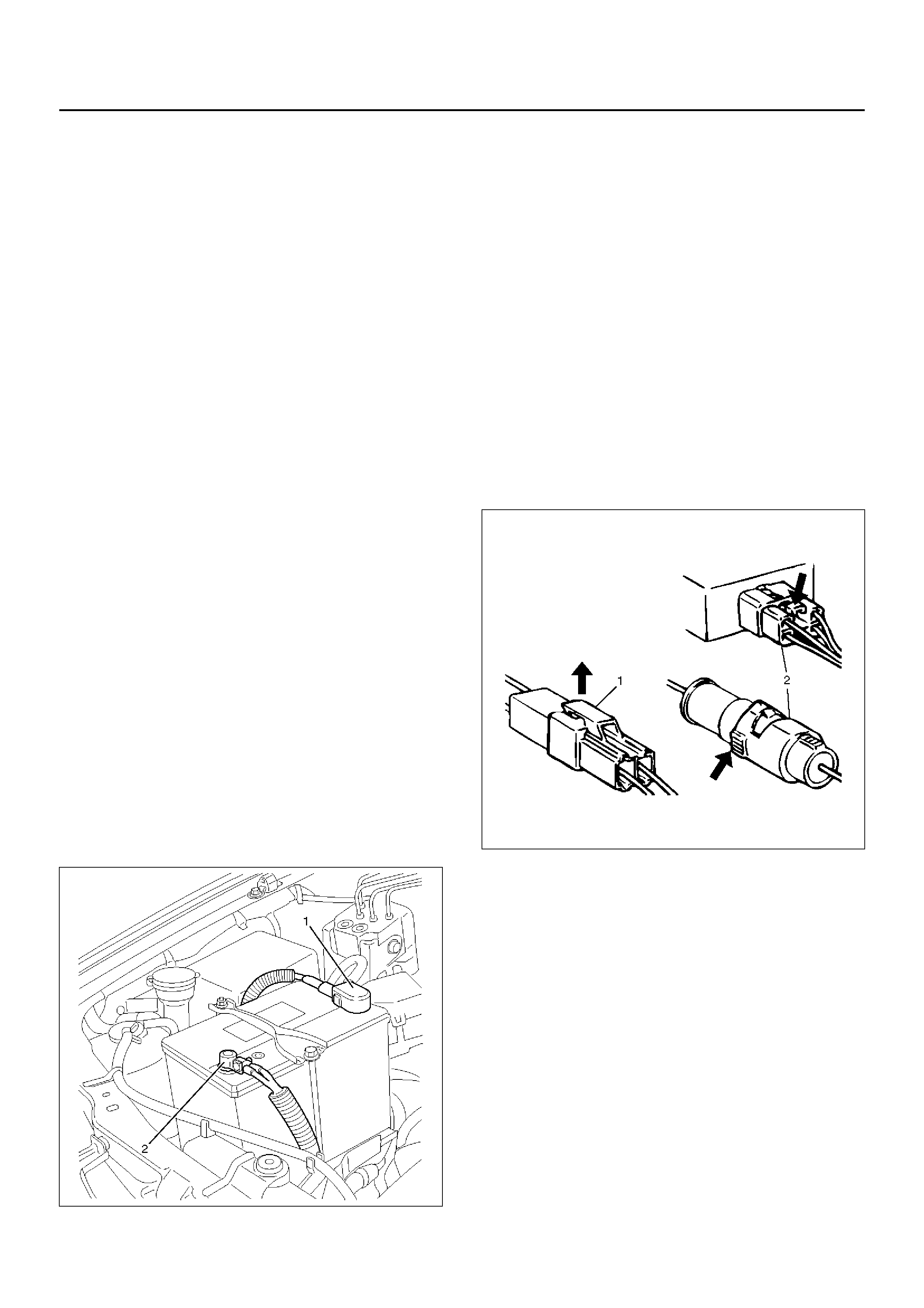
Disconnecting the Battery Cable
1. All switches should be in the “OFF" position.
2. All doors closed.
3. Disconnect the battery NEGATIVE cable (2).
4. Disconnect the battery POSITIVE cable (1).
CAUTION: It is important that the battery negative
cable be disconnected first. Disconnecting the
battery positive cable first can result in a short
circuit.
061RW002
Connecting the Battery Cable
Follow the disconnecting procedure in the reverse
order.
CAUTION: Clean the battery terminal and apply a
light coat of grease to prevent terminal corrosion.
Disconnecting the Connector
Some connectors have a tang lock to hold the
connectors together during vehicle operation.
Some tang locks are released by pulling them towards
you (1).
Other tang lock s are r eleas ed by p re ssin g the m forw a rd
(2).
Determine which type of tang lock is on the connector
being handled.
Firmly grasp both sides (male and female) of the
connector.
Release the tang lock and carefully pull the two halves
of the connector apart.
D08RW128
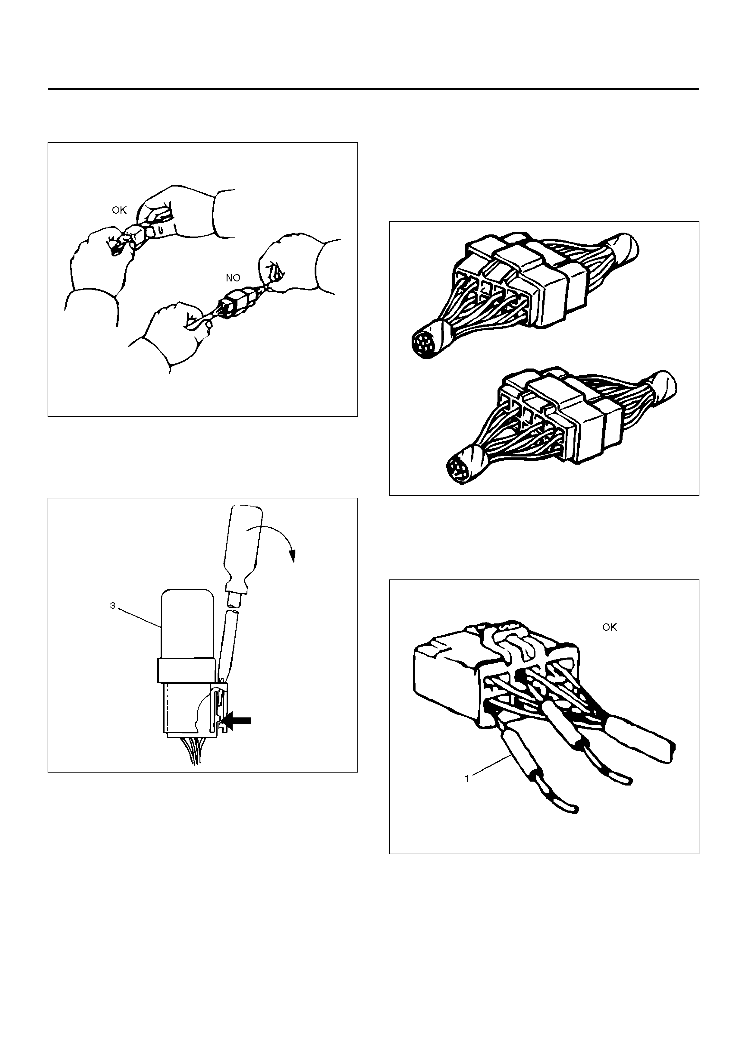
Never pull on the wires to separate the connectors. This
will result in wire breakage.
D08RW129
When removing the connector for relay (MR5B type) (3),
unfasten the tang lock of the connector by using a
screwdriver, then pull the relay out as shown in the
figure.
D08RW131
Connecting the Connector
Firmly grasp both sides (male and female) of the
connector. Be sure that the connector pins and pin
holes match, Be sure that both sides of the connector
are aligned with each other.
Firmly but carefu lly push the two sides of the connect or
together until a distinct click is heard.
D08RW130
Connector Inspection
Use a circuit tester to check the connector for continuity.
Insert the test probes (1) from the connector wire side.
D08RW132
Never insert the circuit tester test probes (2) into the
connector open end to test the continuity.
Broken or open connector terminals will result.
D08RW133
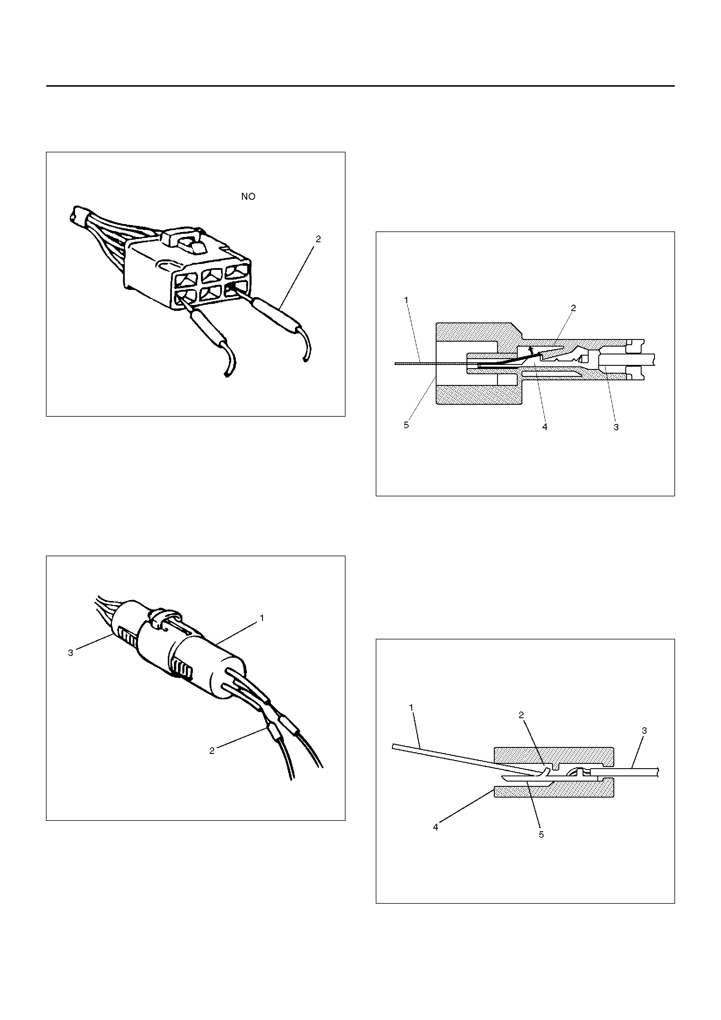
Waterproof Connector Inspection
It is not possible to insert the test probes into the
connector wire side of a waterproof connector.
Use one side of a connector (1) with its wires cut to
make the test. Connect the test connector to the
connector (3) to be tested. Connect the test probes (2)
to the cut wires for the electrical test.
D08RW134
Connector Pin Removal – Connector Housing Tang
Lock Type
1. Inse rt a sl en der s ha ft ( 1 ) in to the connector ho us ing
open end (5).
2. Push the tang lock (2) up (in the direction of the
arrow in the illustrati on) .
Pull the wire (3) with pin (4) free from the wire side
of the connector.
D08RW135
Connector Pin Removal – Pin Tang Lock Type
1. Inse rt a sl en der s ha ft ( 1 ) in to the connector ho us ing
open end (5).
2. Push the tang lock (2) flat (toward the wire (3) side
of the connector.
Pull the wire with pin (4) free from the wire side of
the connector.
D08RW136

Connector Pin Insertion
1. Check that the tang lock (1) is fully up.
2. Insert the pin (3) from the connector wire (2) side.
Push the pin in until the tang lock closes firmly.
3. Gently pull on the wires to make sure that the
connector pin is firmly set in place.
D08RW137
Parts Handling
Be careful when handling electrical parts. They should
not be dropped or thrown, because short circuiting or
other damage may result.
D08RW138
Cable Harness
1. When installing the parts, be careful not to pinch or
wedge the wiring harness.
2. All electrical connections must be kept clean and
tight.
D08RW139
3. Use a grommet or guard tube to protect the wiring
harness from contacting a sharp edge or surface.
D08RW139
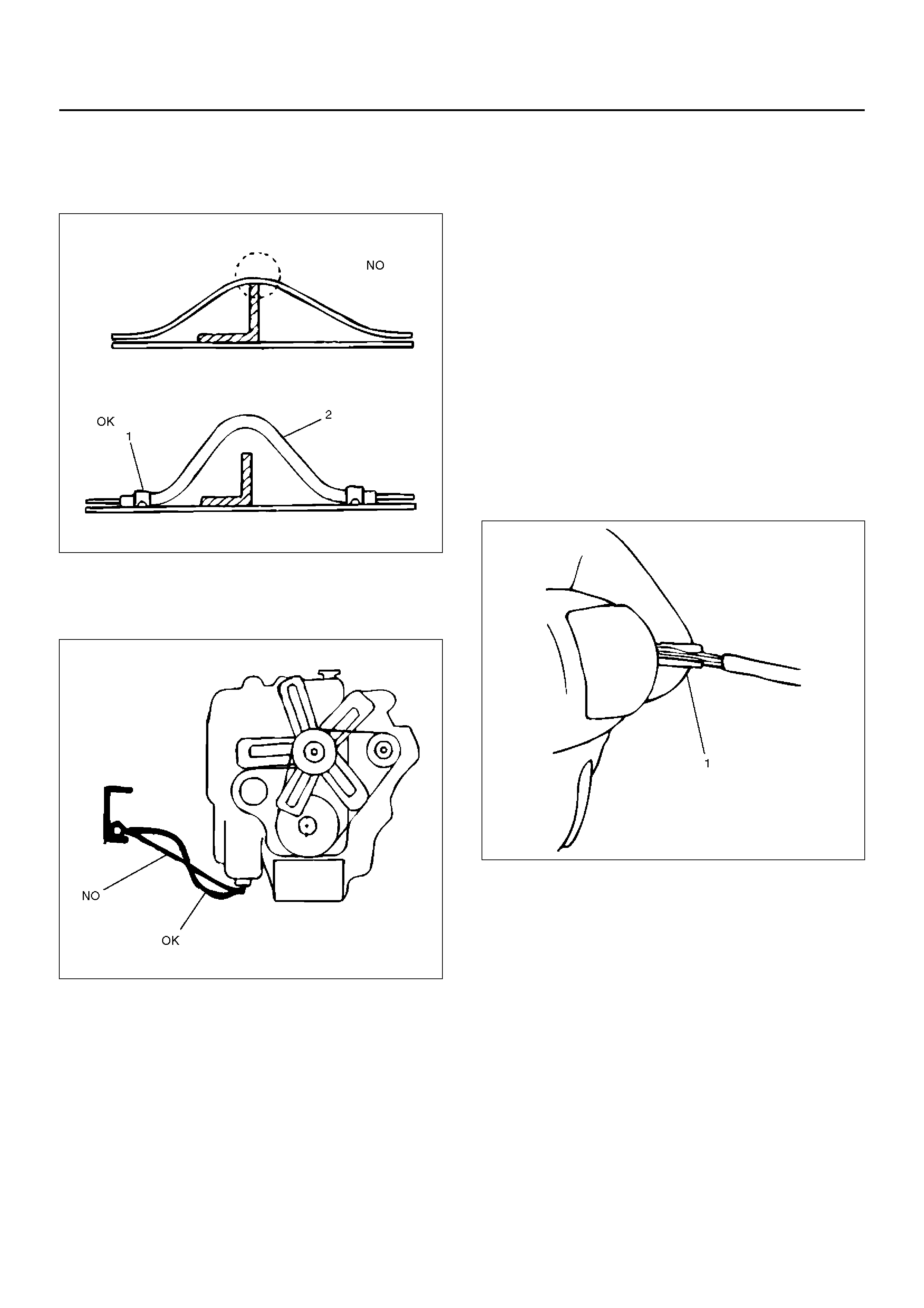
4. Position the wiring harness with enough clearance
from the other parts and guard the wiring harness
with a vinyl tube (2) and clips (1) to avoid direct
contact.
D08RW141
5. The wiring harness between engine and chassis
should be long enough to prevent chafing or
damage due to various vibrations.
D08RW142
Splicing Wire
1. If the harness is taped, remove the tape. To avoid
wire ins ulation dam age, use a sewing “sea m ripper"
(available from sewing supply stores) to cut open
the harness.
If the harness has a black plastic conduit, simply
pull out the desired wire.
2. Begin by cutting as little wire off the harness as
possib le. You ma y nee d the ext ra l engt h of w ir e late r
if you decide to cut more wire off to change the
location of a splice. You may have to adjust splice
locati ons to mak e certain tha t each s plice i s at le ast
1–1/2" (40 mm) away from other splices, harness
branches, or connectors.
3. When rep lacing a wire, use a wire of the sam e size
as the original wire.
Check the stripped wire for nicks or cut stands. If the
wire is damaged, repeat the procedure on a new
section of wire. The two stripped wire ends should
be equal in length.
4. Select the proper clip to secure the splice.
To determine the proper clip size for the wire being
spliced, follow the directions included with your
clips.
Select the correct anvil on the crimper. (On most
crimpers your choice is limited to either a small or
large anvil .)
Overlap the two stripped wire ends and hold them
between your thumb and fore finger a s s hown in the
figure.
The center the spline clip (1) under the stripped
wires and hold it in place.
D08RW143
• Open the crimping tool to its full width and rest one
handle on a firm flat surface.
• Center t he back o f the spli ce clip on the proper anvil
and close the crimping tool to the point where the
back of the spli ce cl ip touche s the wing s of the cli p.
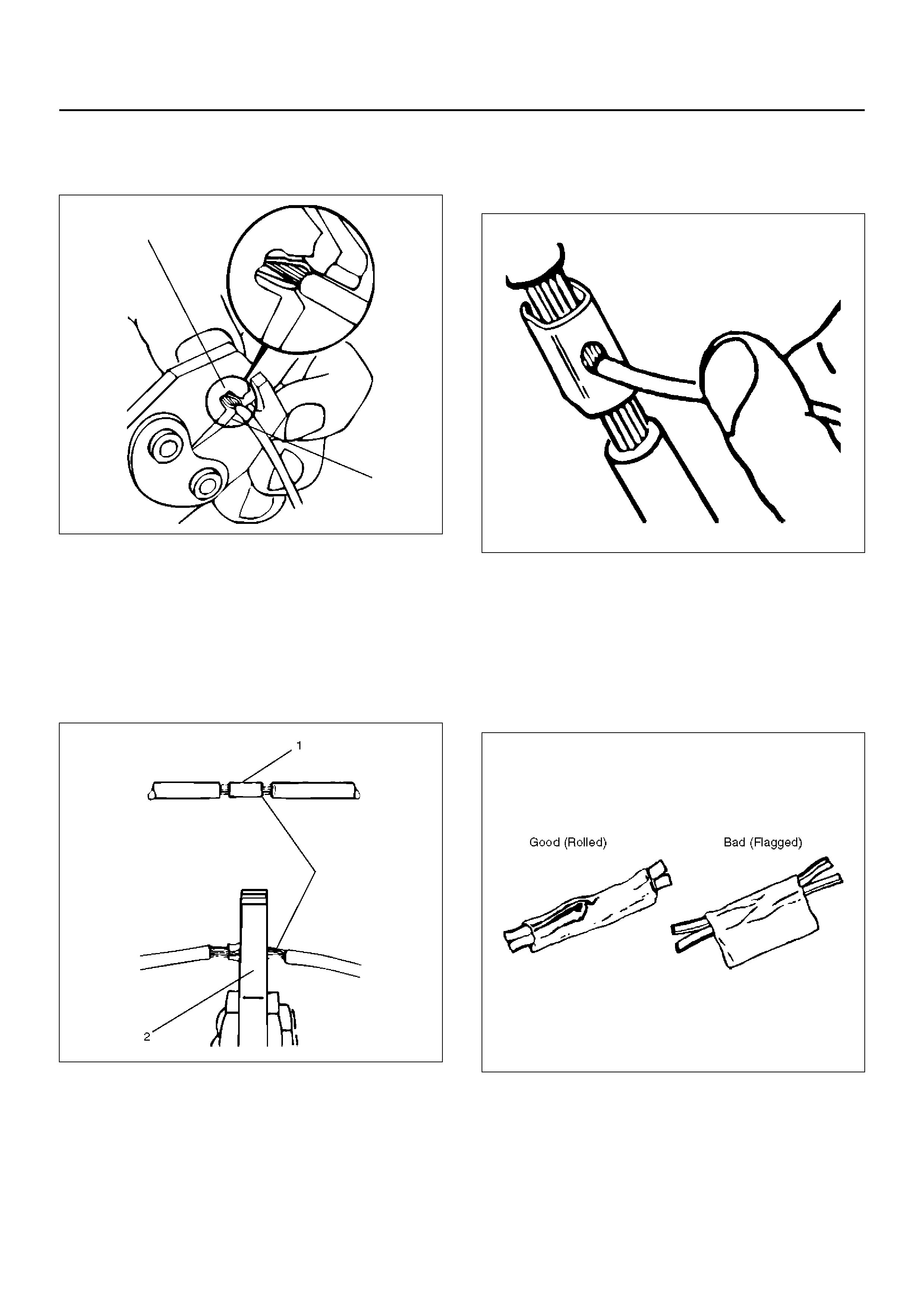
• Make sure that the clip and wires are still in the
correct position. Then, apply steady pressure until the
crimping tool closes as shown in the figure.
D08RW144
Before crimping the ends of the clip (1), be sure that:
• The wires extend beyond the clip in each direction.
• No strands of wire are cut loose, and
• No insulation is caught under the clip.
Crimp the splice again, once on each end.
Does not let the crimping tool (2) extend beyond the
edge of the clip or you may damage or nick the wires as
shown in the figure.
D08RW145
5. Apply 60/40 resin core solder to the opening in the
back of the clip as shown in the figure.
Follow the manufa cturer 's instr uctions for the sold er
equipment you are using.
D08RW146
6. Center and roll the splicing tape.
The tape should cover the entire splice.
Roll on enough tape to duplicate the thickness of the
insulation on the existing wires.
Does not flag the tape. Flagged tape may not
provide enough insulation, and the flagged ends will
tangle with th e other wires i n the harne ss as shown
in the figure.
D08RW147
If the wire does not belong in a conduit or other
harness covering, tape the wire again. use a
winding motion to cover the first piece of tape as
shown in the figure.
D08RW148
SYMBOLS AND ABBREVIATIONS
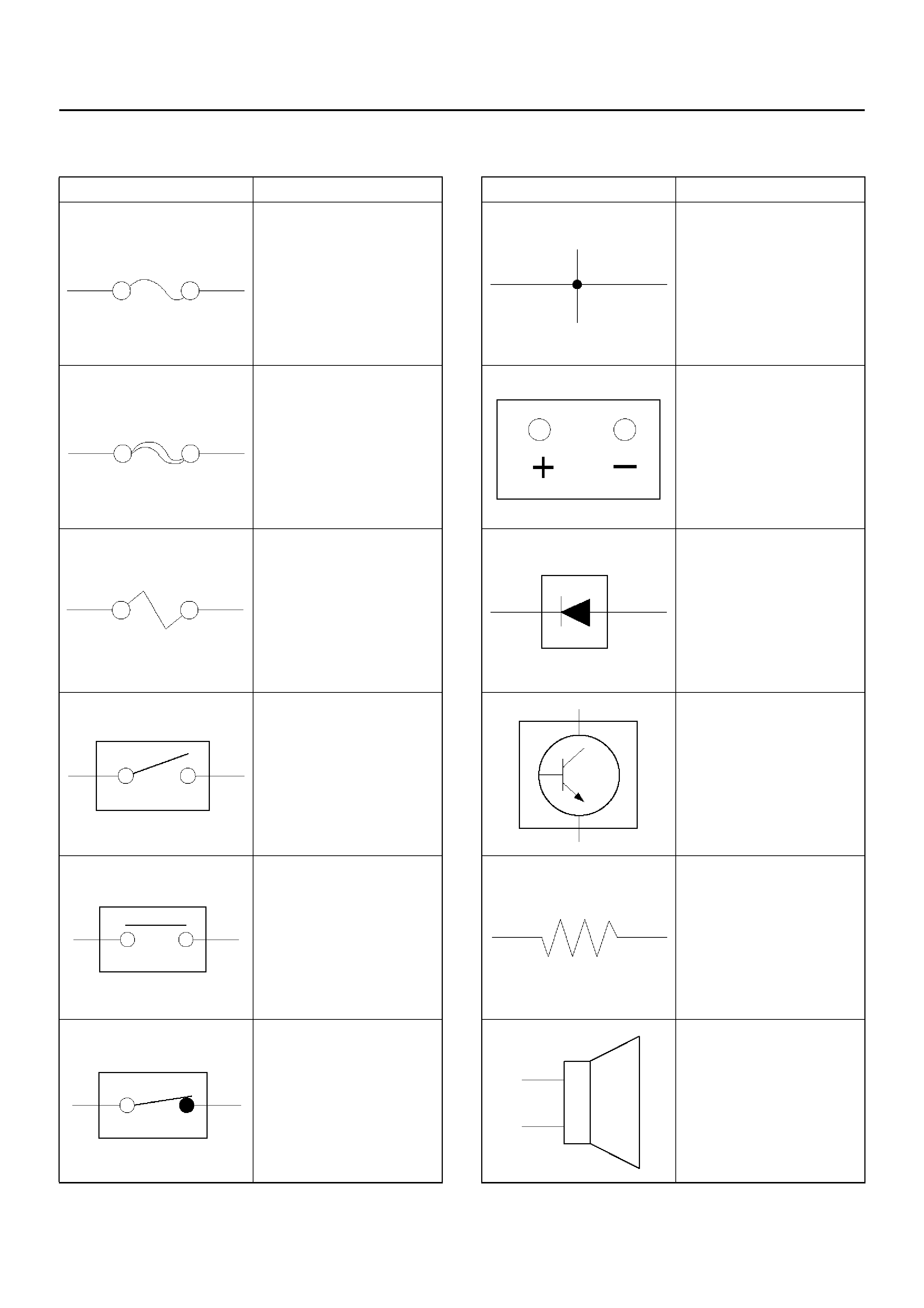
Symbols
Symbol Meaning of Symbol
Fuse
Fusible link
Fusible link wire
Switch
Switch
Switch
(Normal close type)
Contact wiring
Battery
Diode
Electronic parts
Resistor
Speaker
Symbol Meaning of Symbol
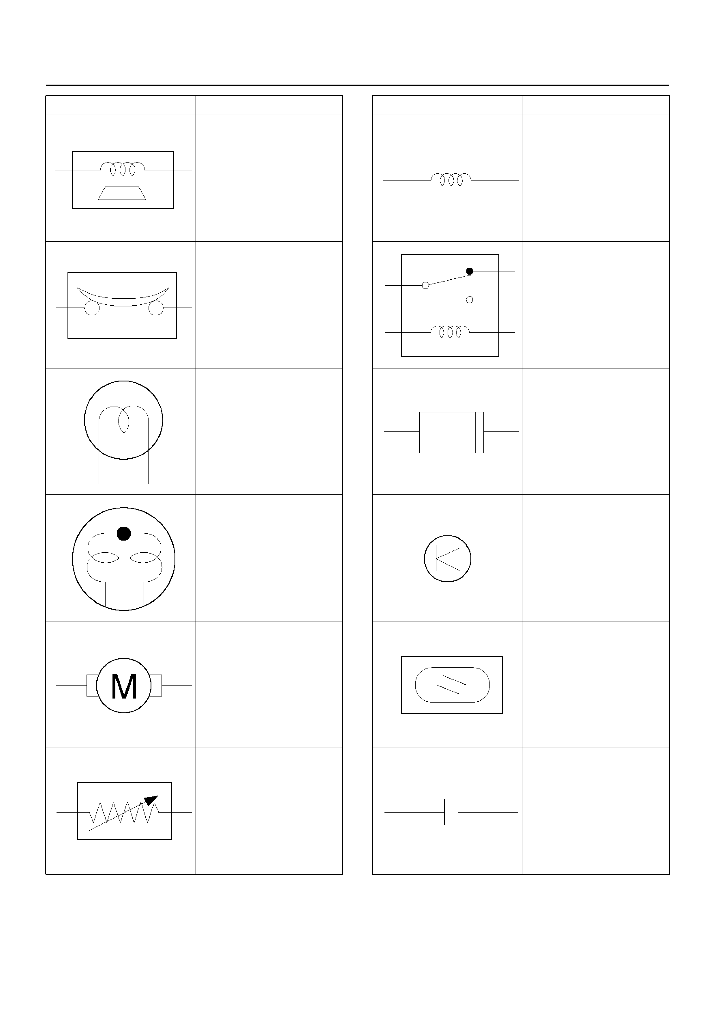
Buzzer
Circuit br eaker
Bulb
Double filament bulb
Motor
Variable register
Rheostat
Symbol Meaning of Symbol
Coil (inductor), solenoid,
magnetic valve
Relay
Connector
Light emitting diode
Reed switch
Condenser
Symbol Meaning of Symbol
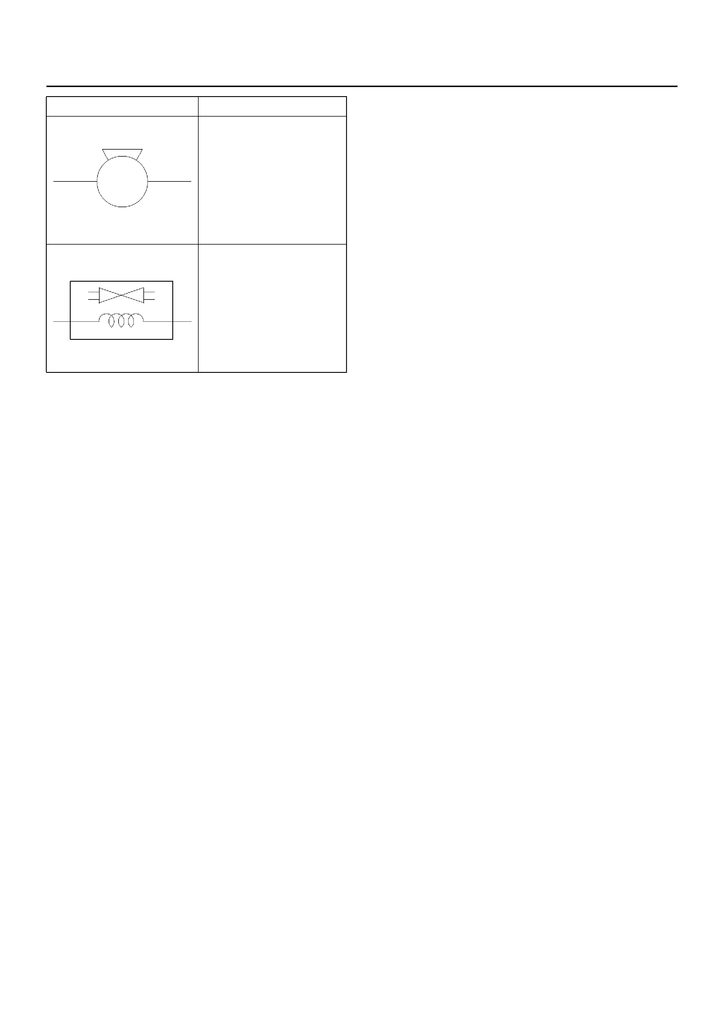
Horn
Vacuum switching valve
Symbol Meaning of Symbol

Abbreviations
Abbreviation Meaning
A Ampere (S)
ABS Anti-lock brake system
ASM Assembly
AC Alternating current
A/C Air conditioner
ACC Accessories
A/T Automatic transmission
C/B Circuit breaker
CSD Cold start device
DIS Di re ct igniti on sys tem
EBCM Electronic brake control module
ECGI Electronic control gasoline injection
ECM Engine control module
ECU Electronic control unit
EFE Early fuel evaporation
EGR Exhaust gas recirculation
4A/T 4-speed automatic transmission
4WD Four-w he el driv e
FL Fusib le link
FRT Front
H/L Headlight
IC Integrated circuit
IG Ignition
kW Kilowatt
LH Left hand
LWB Long wheel base
M/T Manual transmission
OD O ver driv e
OPT Option
PCM Powertrain control module
QOS Quick on start
RH Right hand
RR Rear
SDM Sensing and diagnostic module
SRS Supplemental restraint system
ST Start
STD Standard
SW Switch
SWB Short wheel base
3A/T 3-speed automatic transmission
VVolt
VSV Vacuum switching valve
W Watt (S)
WOT Wide open thro ttle
W/ With
W/O Without
Abbreviation Meaning
PARTS FOR ELECTRICAL CIRCUIT
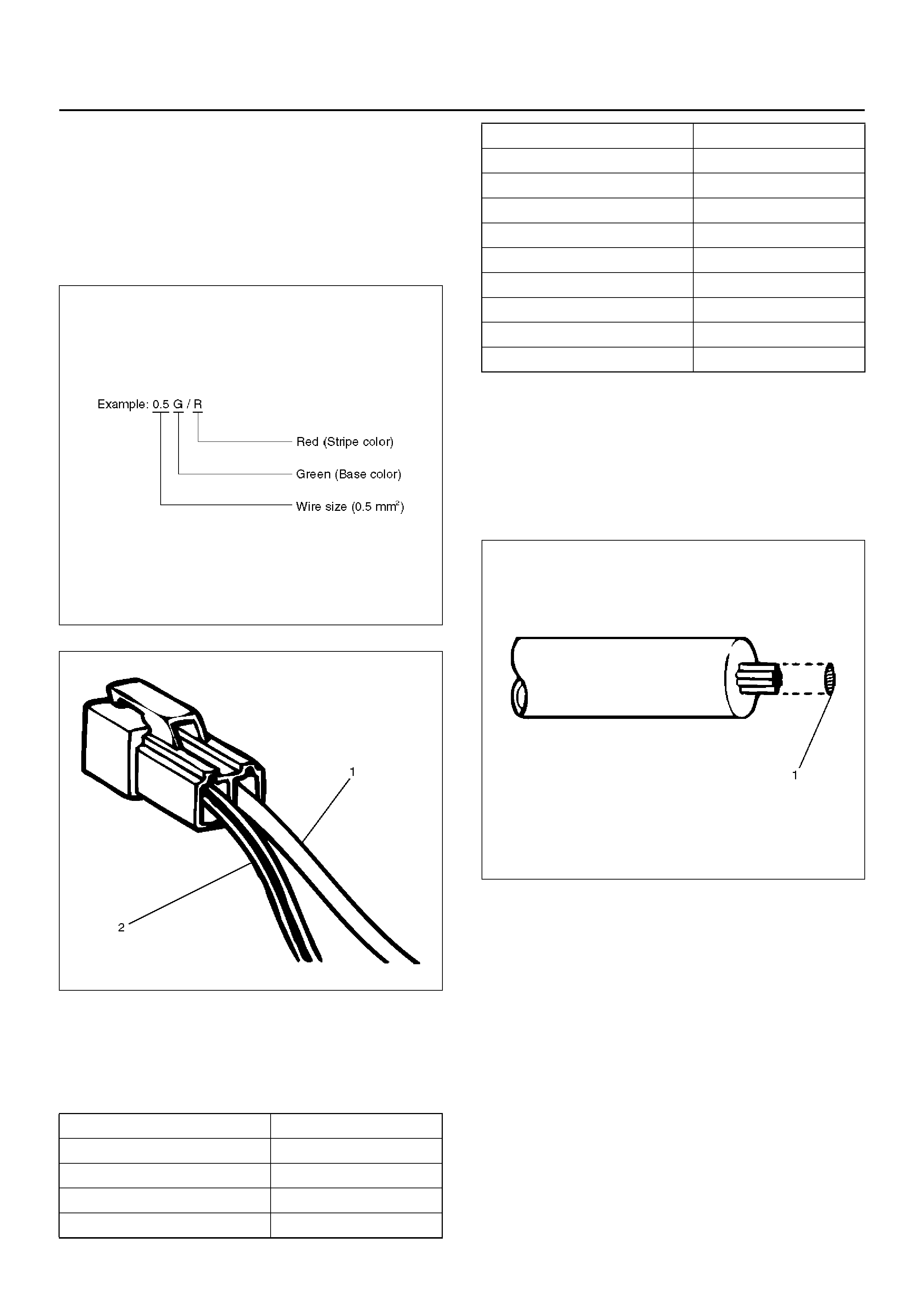
Wiring – Wire color
All wires have color–coded insulation.
Wires b elongi ng to a sy stem's main ha rness w ill ha ve a
single color (1). Wires belonging to a system's
subcircuits will have a colored stripe (2). Striped wires
use the following code to show wire size and colors.
F08RW001
D08RW150
Wiring – Wire Color Coding
Abbreviations are used to indicate wire color within a
circuit diagram.
Refer to the following table.
Wiring – Wire Size
The size of wire used in a circuit is determined by the
amount of current (amperage), the length of the circuit,
and the voltage drop allowed. The following wire size
and load capacity, shown below, are specified by AWG
(American Wire Gauge) (Nominal size means
approximate cross sectional area (1).)
D08RW151
Color–coding Meaning
BBlack
WWhite
RRed
GGreen
YYellow
LBlue
O Orange
BR Brown
LG Light green
GR Grey
PPink
LB Light blue
VViolet
Color–coding Meaning
Wiring – Wire Size Table
Fuse
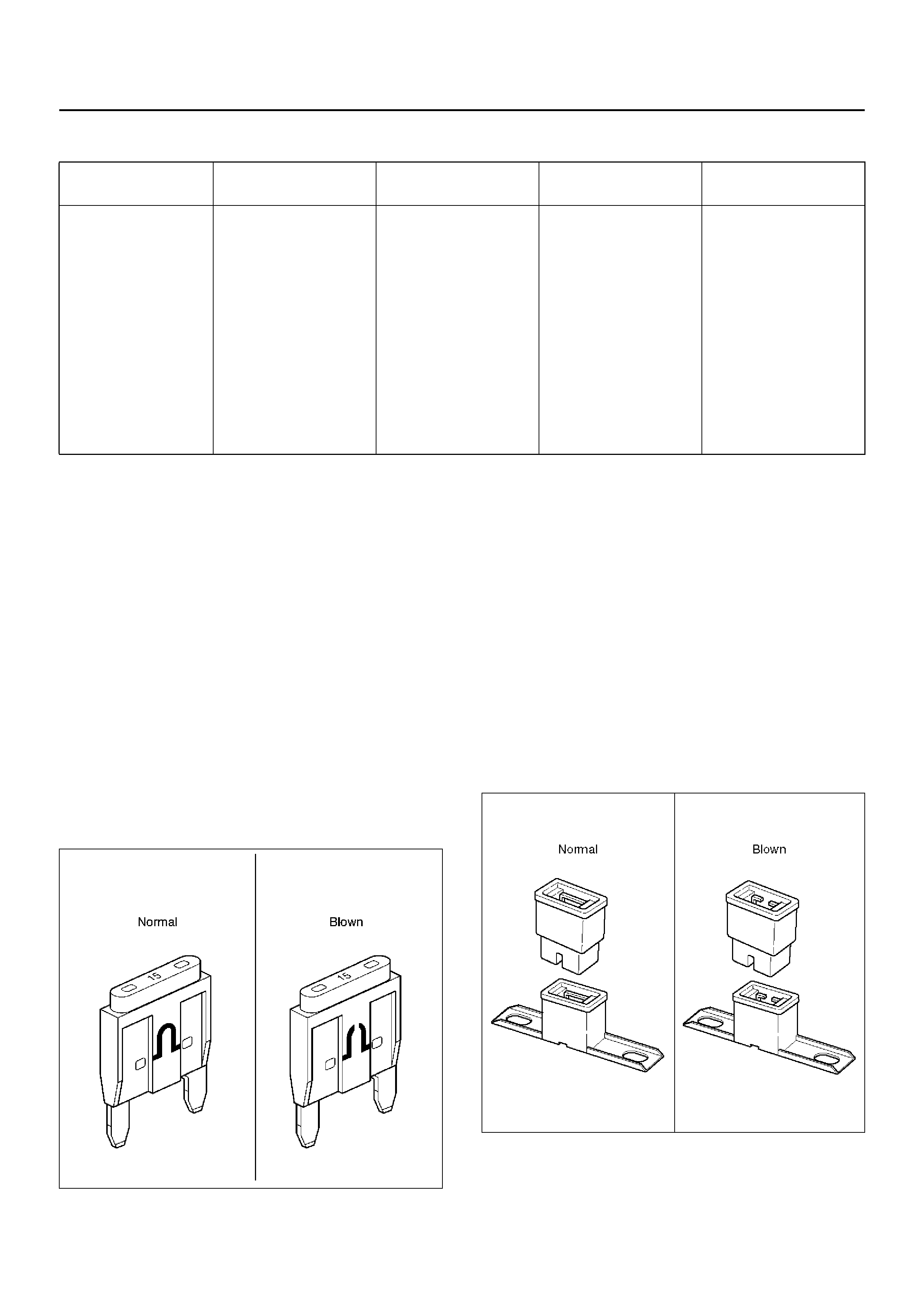
Fuses are the most common form of circuit protection
used in vehicle wiring. A fuse is a thin piece of wire or
strip of metal enc ased in a glass it or pla stic housing. It
is wired in se ries with the c irc uit in prote cts. Wh en th ere
is an overload of current in a circuit, such as a short of a
ground, the metal strip is designed to burn out and
interrupt the flow of current. This prevents a surge of
high current from reaching and damaging other
components in the circuit.
Determine the cause of the overloaded before replacing
the fuse.
The replacement fuse must have the same amperage
specification as the original fuse.
Never replace a blown fuse with a fuse of a different
amperage specification.
Doing so can result in an electrical fire or other serious
circuit damage. A blown fuse is easily identified as
shown in the figure.
810RX001
Fusible Link
The fusible link is primarily used to protect circuits
where high amounts of current flow and where it wo uld
not be practical to use a fuse. For example, the starter
circuit. When a current overload occurs, the fusible link
melts open and interrupts the flow of current so as to
prevent the rest of the wiring harness from burning.
Determine the cause of the overload before replacing
the fusible link. the replacement fusible link must have
the sam e amperage s pecification as the original fusible
link. Never replace a blown fusible link with fusible link
of a different amperage specification. Doing so can
result in an electrical fire or other serious circuit
damage.
A blown fusible link is easily identified as shown in the
figure.
D08RW154
Nominal size Cross section al
area (mm2)Outside diameter
(mm) Allowable current
(A) AWG size (cross
reference)
0.3 0.372 1.5 9 22
0.5 0.563 1.7 12 20
0.85 0.885 1.9 16 18
1.25 1.287 2.2 21 16
2 2.091 2.7 28 14
3 3.296 3.6 37.5 12
5 5.227 4.4 53 10
8 7.952 5.5 67 8
15 13.36 7.0 75 6
20 20.61 8.2 97 4
Fusible Link Specifications
Circuit Breaker
The circuit breaker is a protective device designed to
open the circuit when a current load is in excess of rated
breaker capacity. If there is a short or other type of
overload condition in the circuit, the excessive current
will open the circuit between the circuit breaker
terminals. The reset knob (1) pops out when the circuit
is open. Push the reset knob in place to restore the
circuit after repairing it.
D08RW155
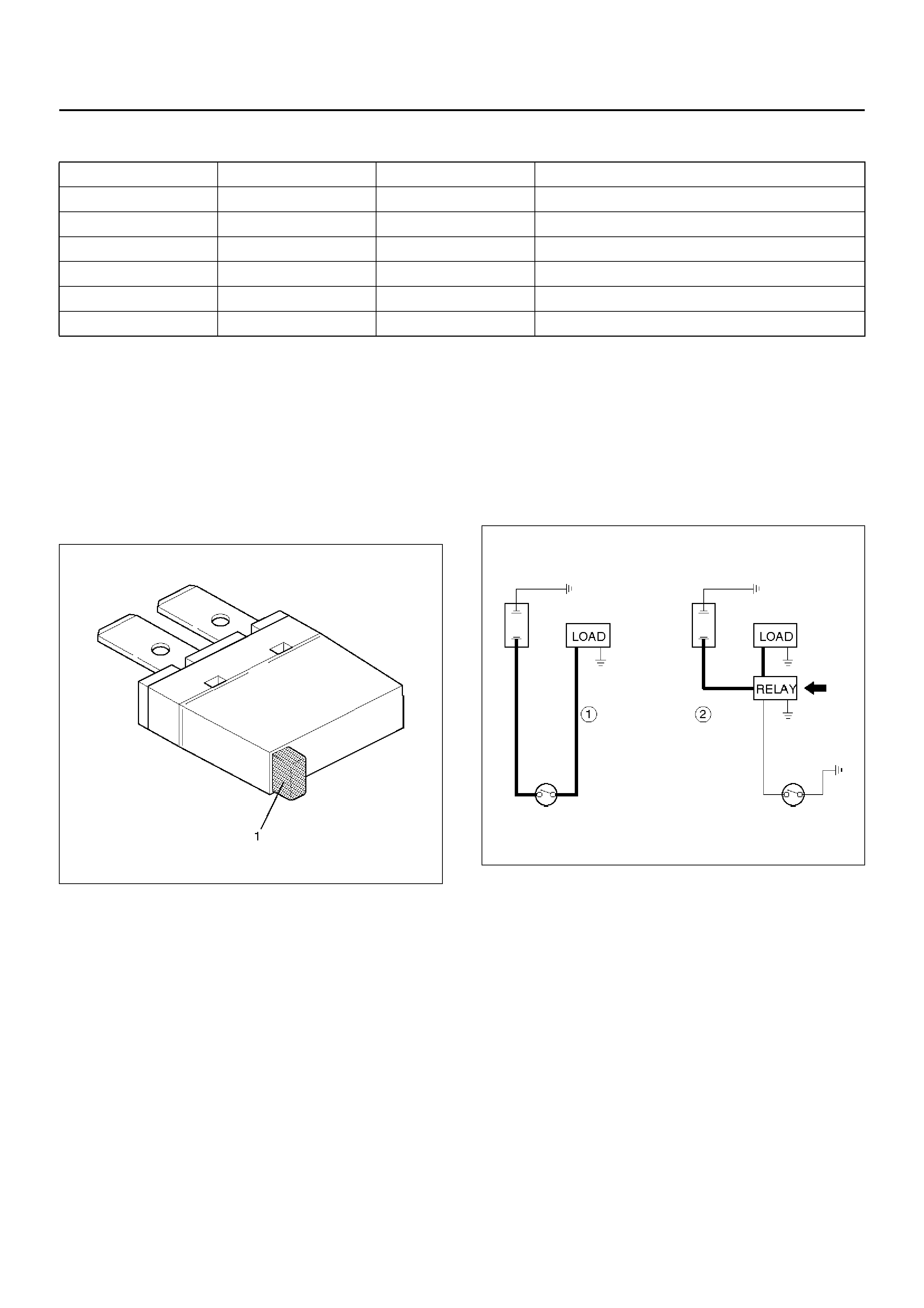
Relay
Battery and load location may require that a switch be
placed some distance from either component. This
means a longer wire and a higher voltage drop (1).
The installation of a relay between the battery and the
load reduces the voltage drop (2).
Because the switch controls the relay, amperage
through the switch can be reduced.
D08RW156
Type Rating Case Color Maximum Circuit Current (A)
Connector 30A Pink 15
Connector 40A Green 20
Bolted 50A Red 25
Bolted/Connector 60A Yellow 30
Bolted 80A Black 40
Bolted 100A Blue 50
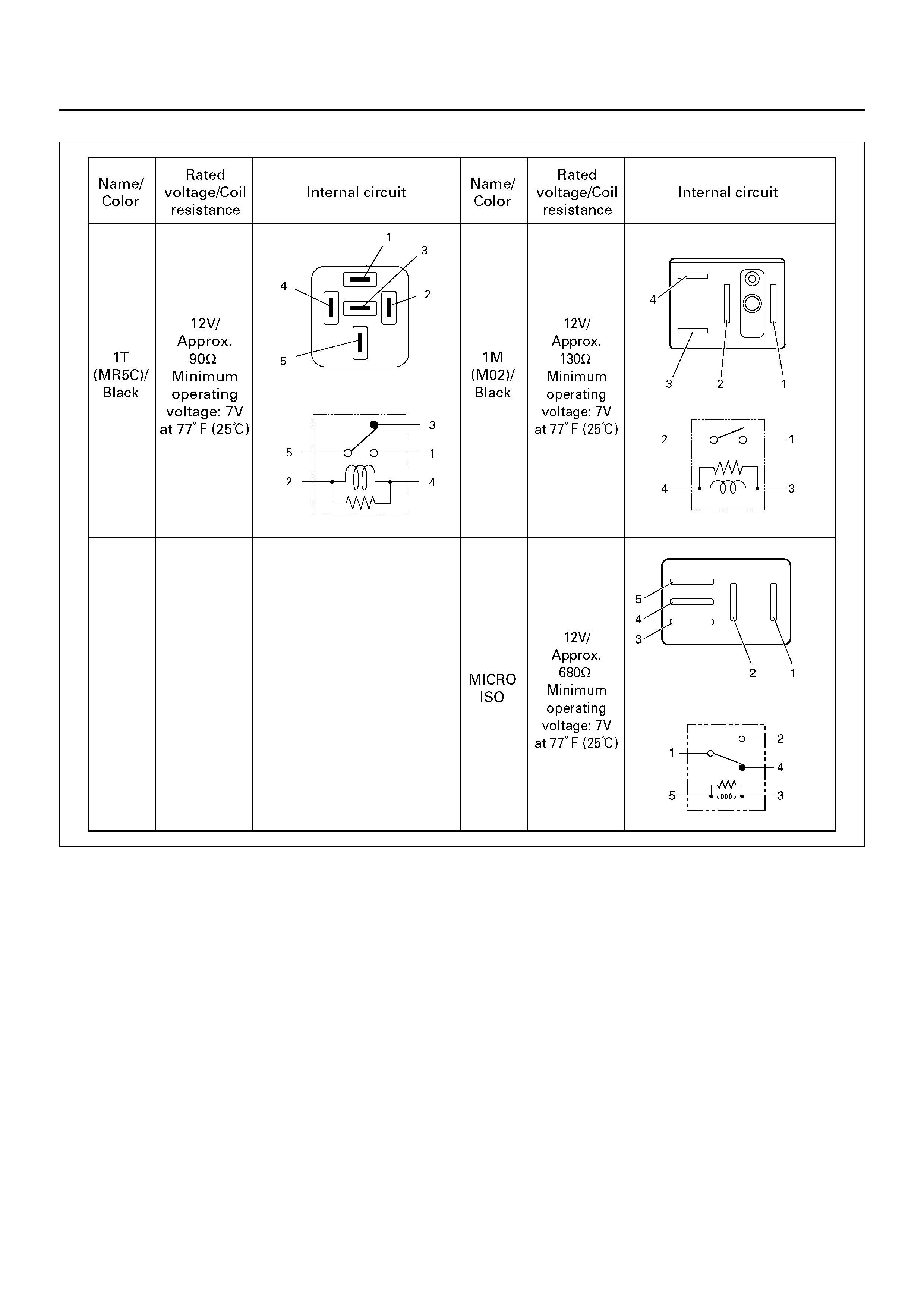
Relay Specifications and Configurations
D08R100212
*Relay contact shown in the wiring diagram indicates
condition before actuation.
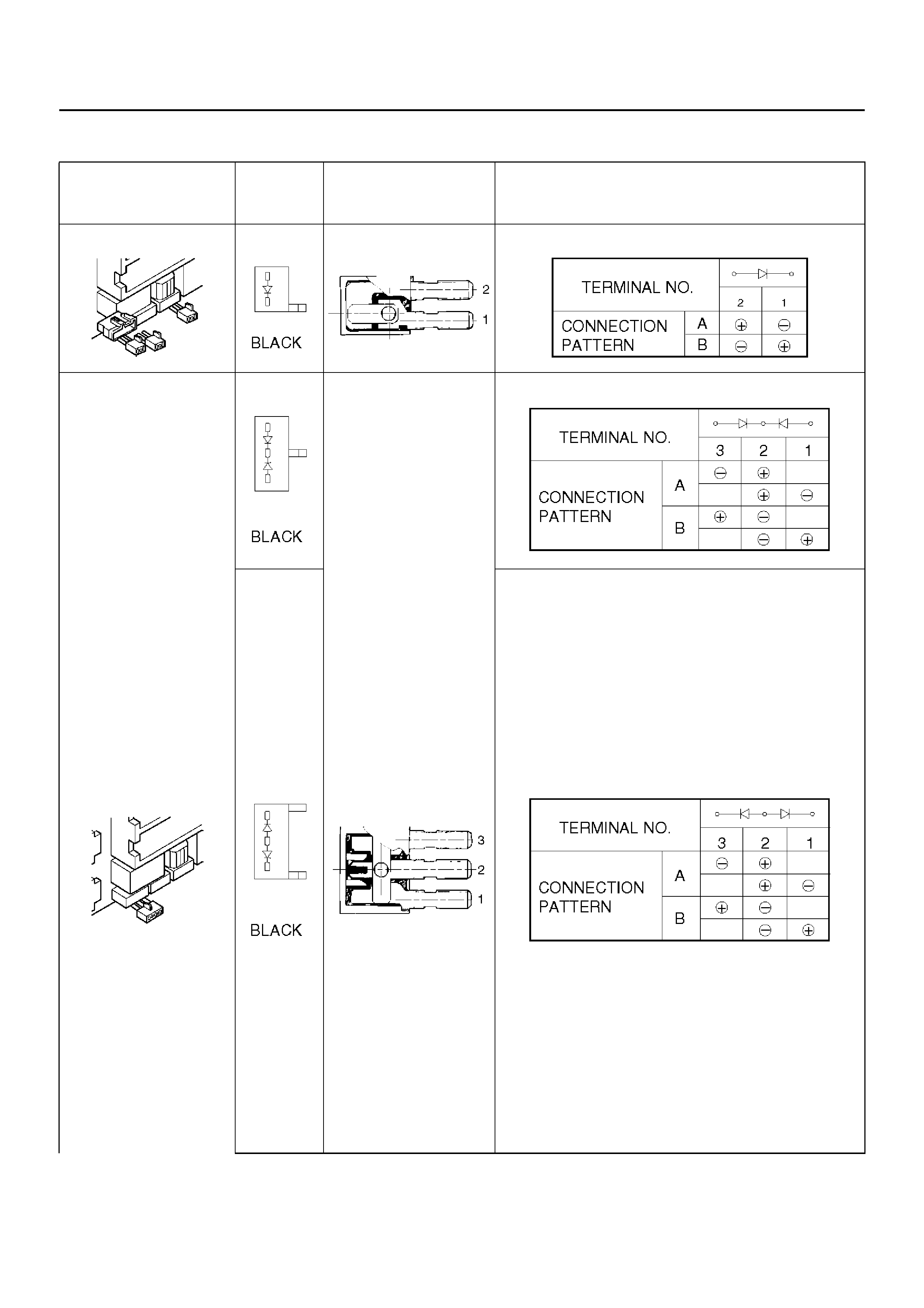
Diode – Diode Specifications and Configurations
SHAPE MARK /
COLOR CONSTRUCTION CHECKING: THERE SHOULD BE CONTINUITY
IN EITHER A OR B WHEN A CIRCUIT TESTER IS
CONNECTED WITH DIODE TERMINAL
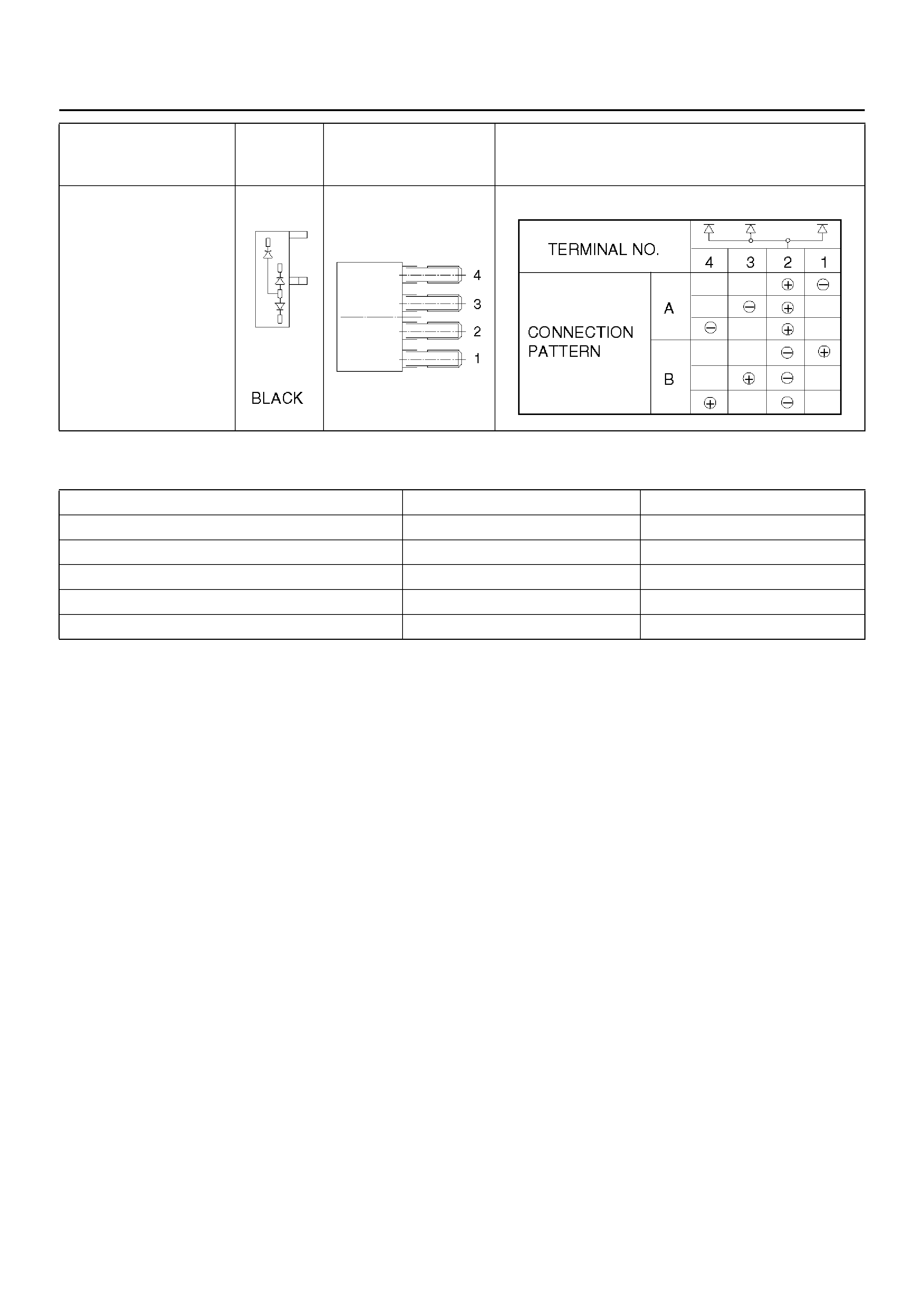
Diode – Maximum Rating (Temp. = 77°F (25°C)
SHAPE MARK /
COLOR CONSTRUCTION CHECKING: THERE SHOULD BE CONTINUITY
IN EITHER A OR B WHEN A CIRCUIT TESTER IS
CONNECTED WITH DIODE TERMINAL
Items Rating Remarks
Peak reverse voltage 400V
Transient peak reverse voltage 500V
Average output current 1.5A Temp. = 104°F (40°C)
Working ambient temperature -22°F∼176°F (-30°C∼80°C)
Storage temperature -40°F∼212°F (-40°C∼100°C)
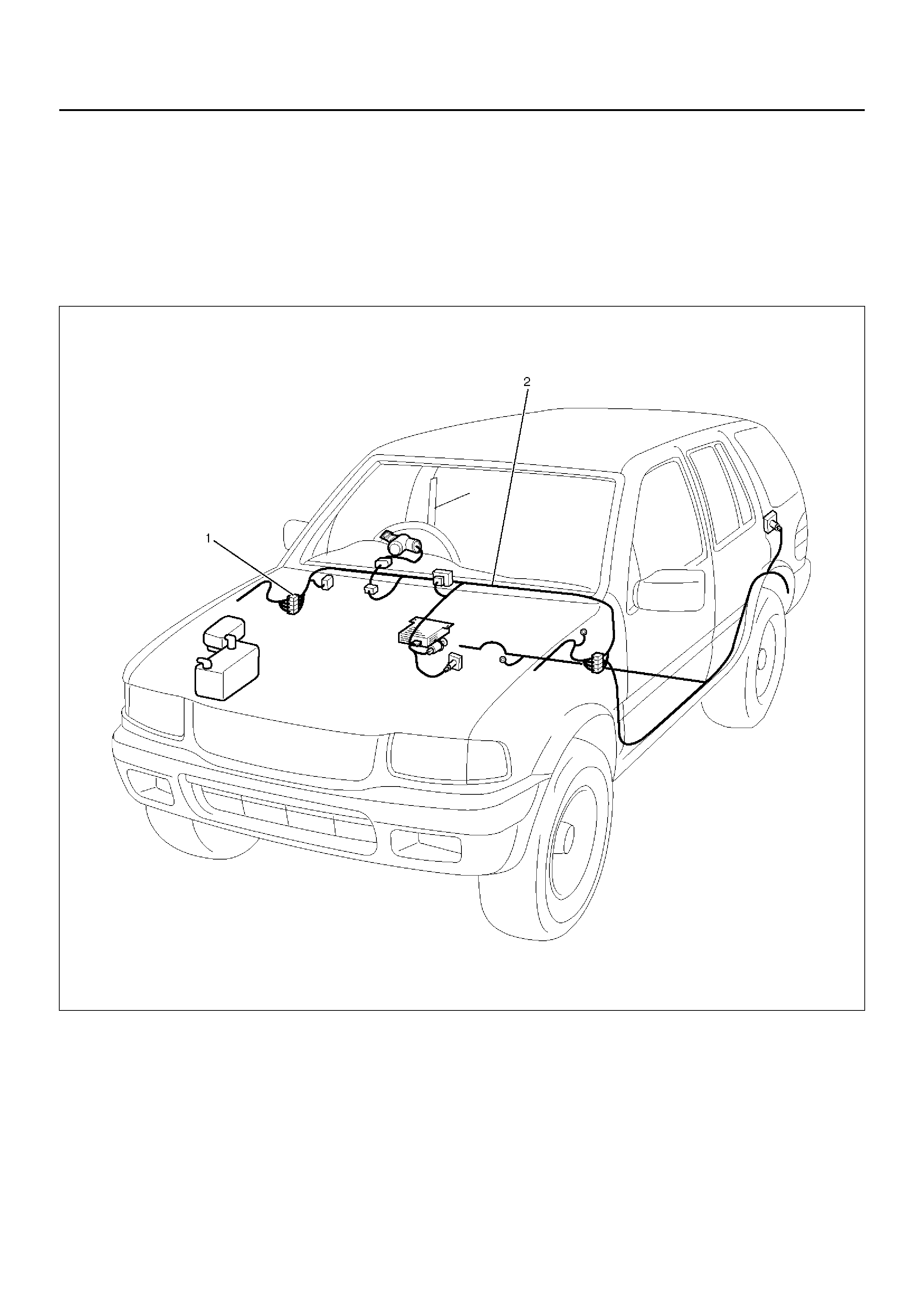
Connector
• The connec tor pin shape (2) d etermines whethe r the
connector is male (3) or female (1).
D08RW159
• The symbol illustrated in the figure is used as
connector, in the circuit of this section.
D08RW160
EndOFCallout
• Connector is identified with a connector number (6)
D08RW161
• The applicable terminal number (7) is shown for each
connector.
D08RW162
Legend
(4) Female Side Connector
(5) Male Side Connector
• Connector terminal numbers (10) are clearly shown.
Make side connector (9) terminal numbers are in
sequence from upper right to lower left.
Female side connector (8) terminal numbers are in
sequence from upper left to lower right.
D08RW163
NOTE:
1. For those connectors on which specific terminal
numb ers or symbol s are shown (such as PCM), th e
termin al numbers o r symbols are us ed in the circuit
diagram, irrespective of the above rule.
Refer to the following figure.
D08RW164
2. The connectors used for relays have their own
terminal number assignment, irrespective of the
above rule.
Refer to the following figure.
Double Lock Type Connector
Doublelock type yellow color connectors are used for
supplemental restraint system–air bag circuit. When
removing the cable harness, disconnect the connector
by unlocking at two places, outside (1) and inside (2). In
such a case, do not pull the cables. Otherwise, cable
disconnection may occur.
When connecting the connector, insert the connector
completely and lock at outside. Imperfect locking may
cause malfunction of SRS system circuit.
F00RX010
READING THE CIRCUIT DIAGRAM
In this section, each system has its own parts location
illustration and circuit diagram. And harness connector
faces used in the circuit diagram are shown at the end
of this section.
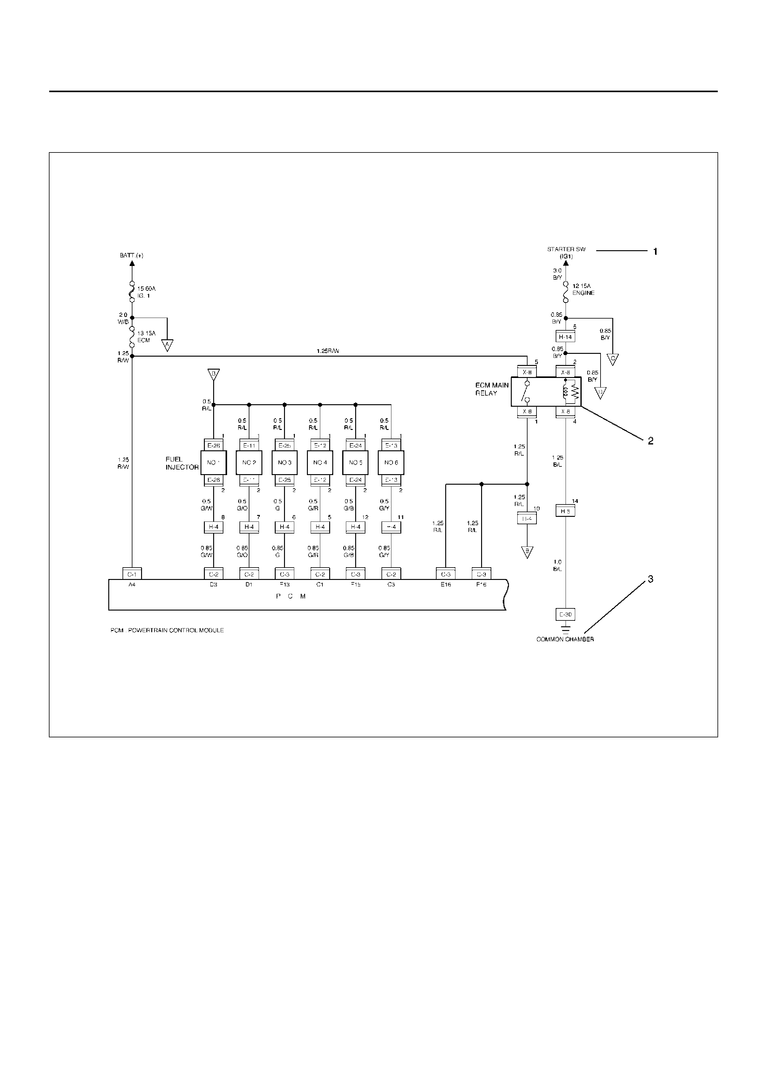
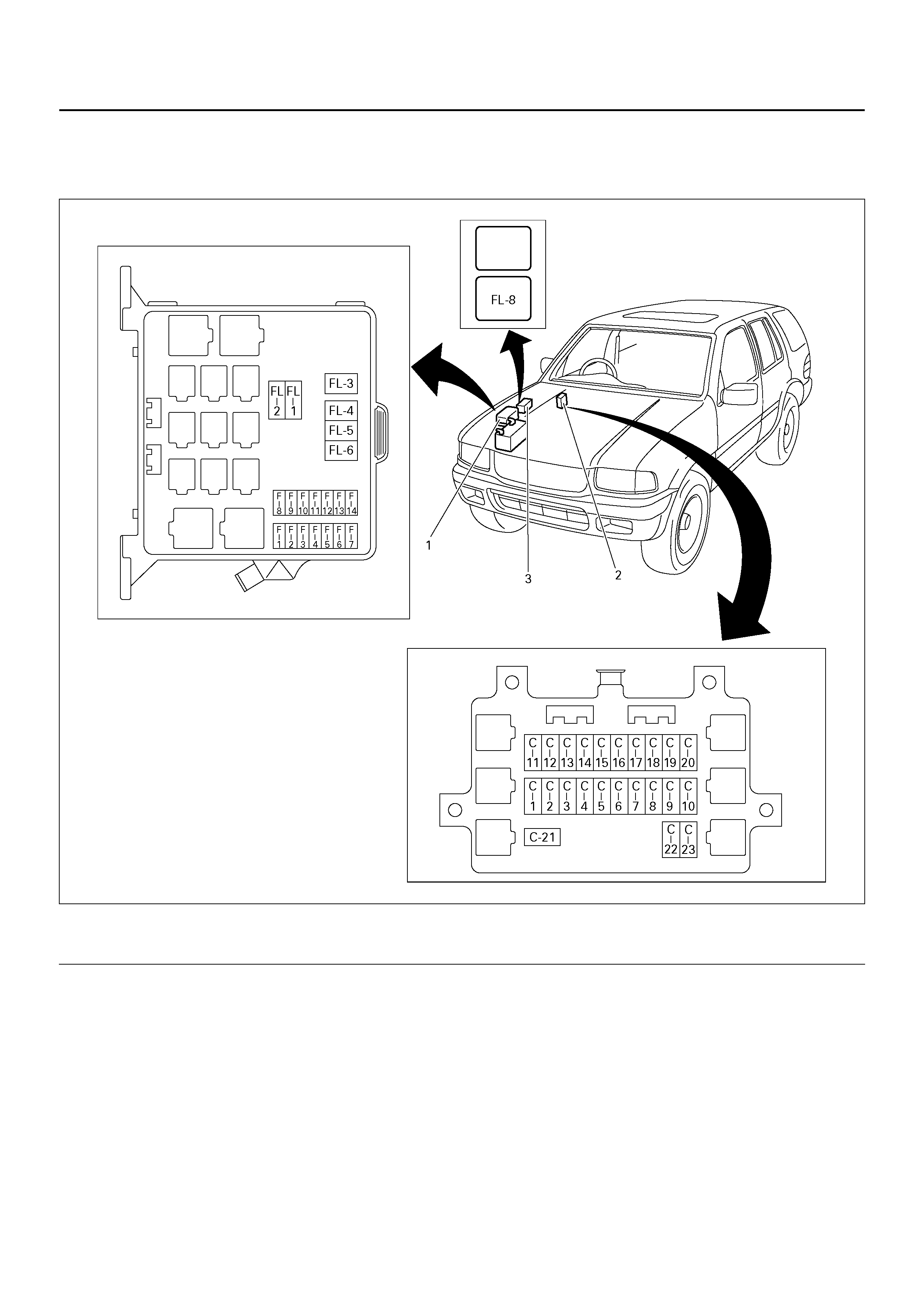
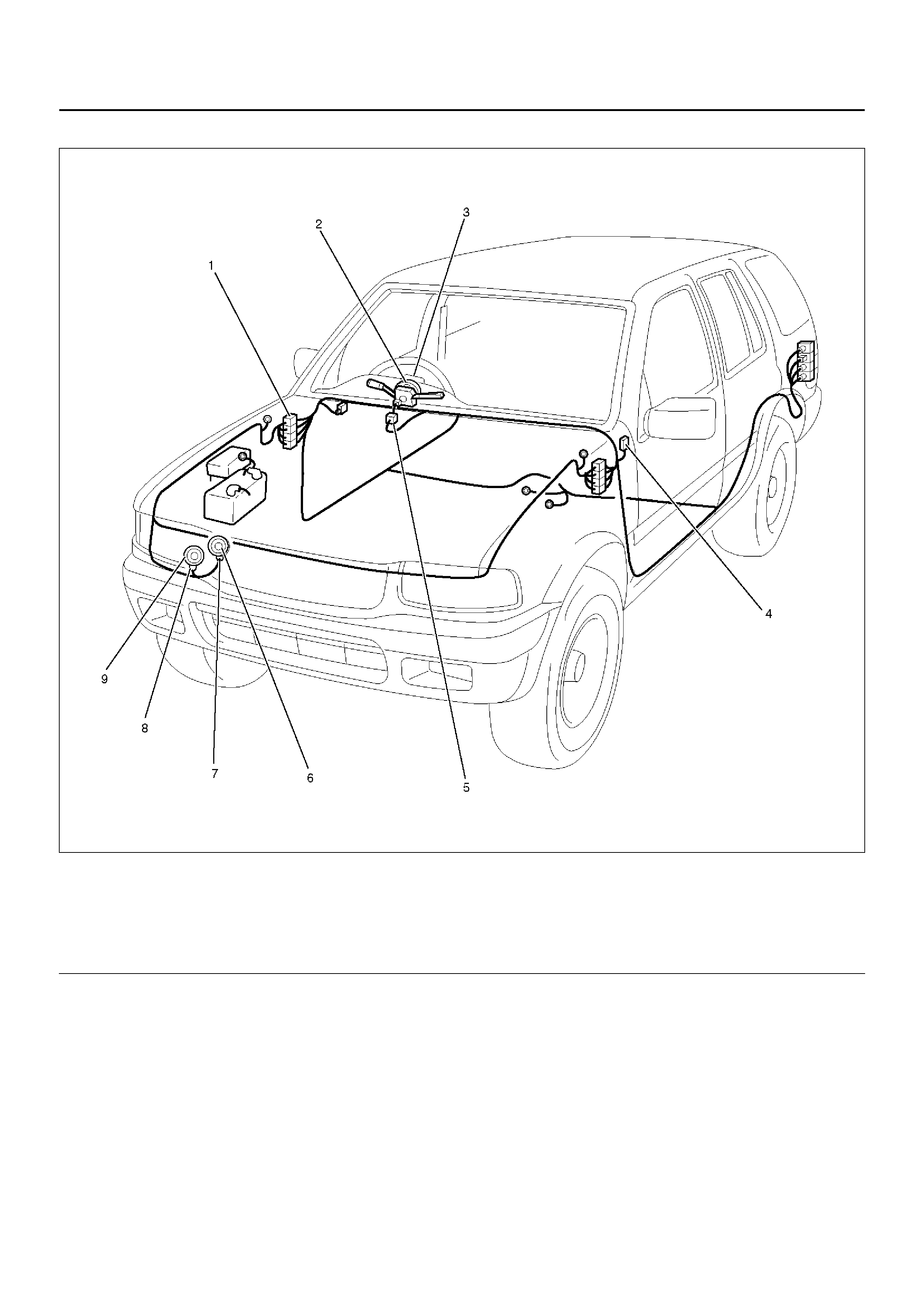
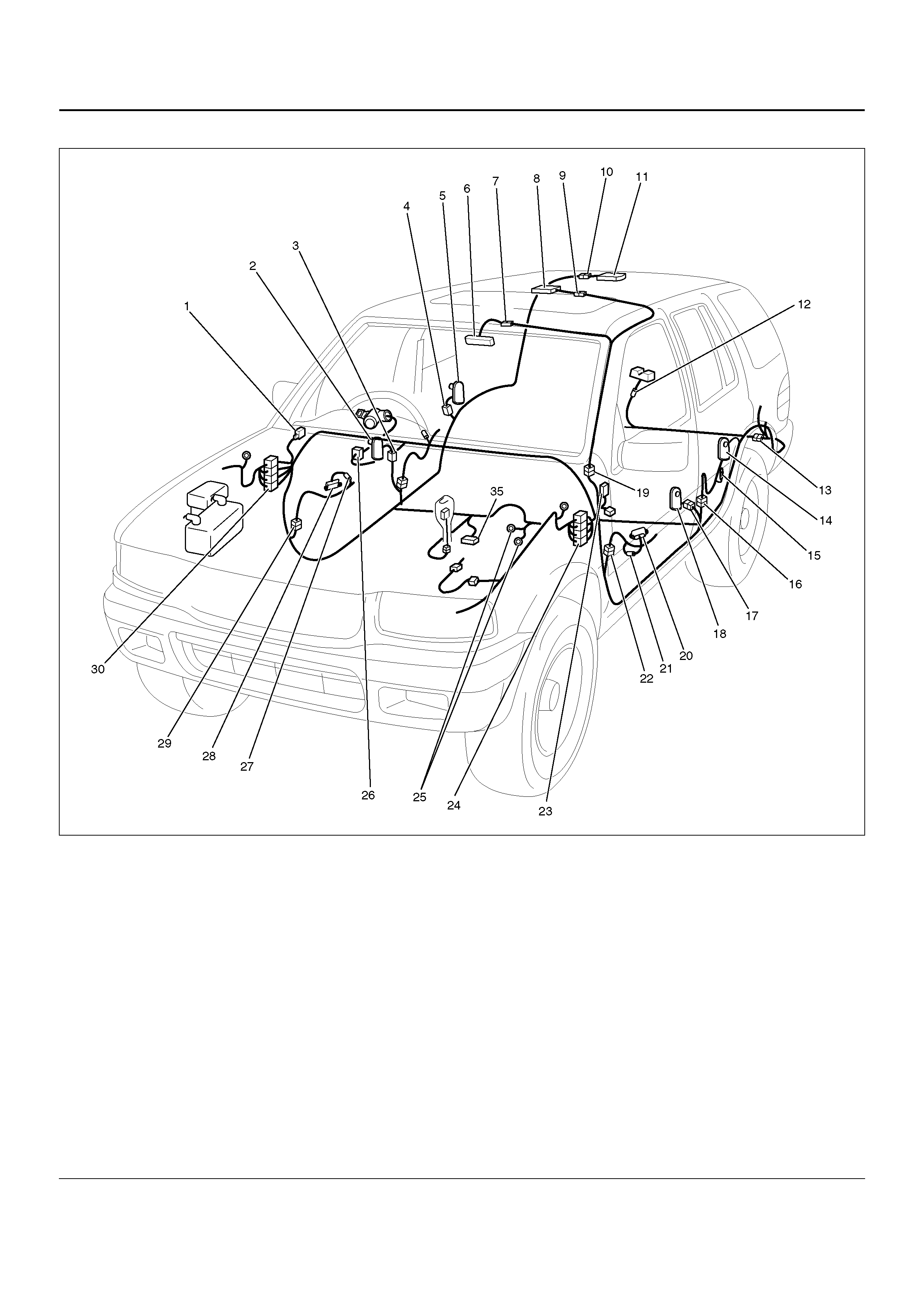
Parts Location
The parts locat ion shows th e location of the con nectors
(1) and the harness (2) used in each harness routing.
D08RWD38
Circuit Diagram
The circuit diagram shows the power supply (1) the load
or loads (2) and the grounding point(s) (3).
D08RX124
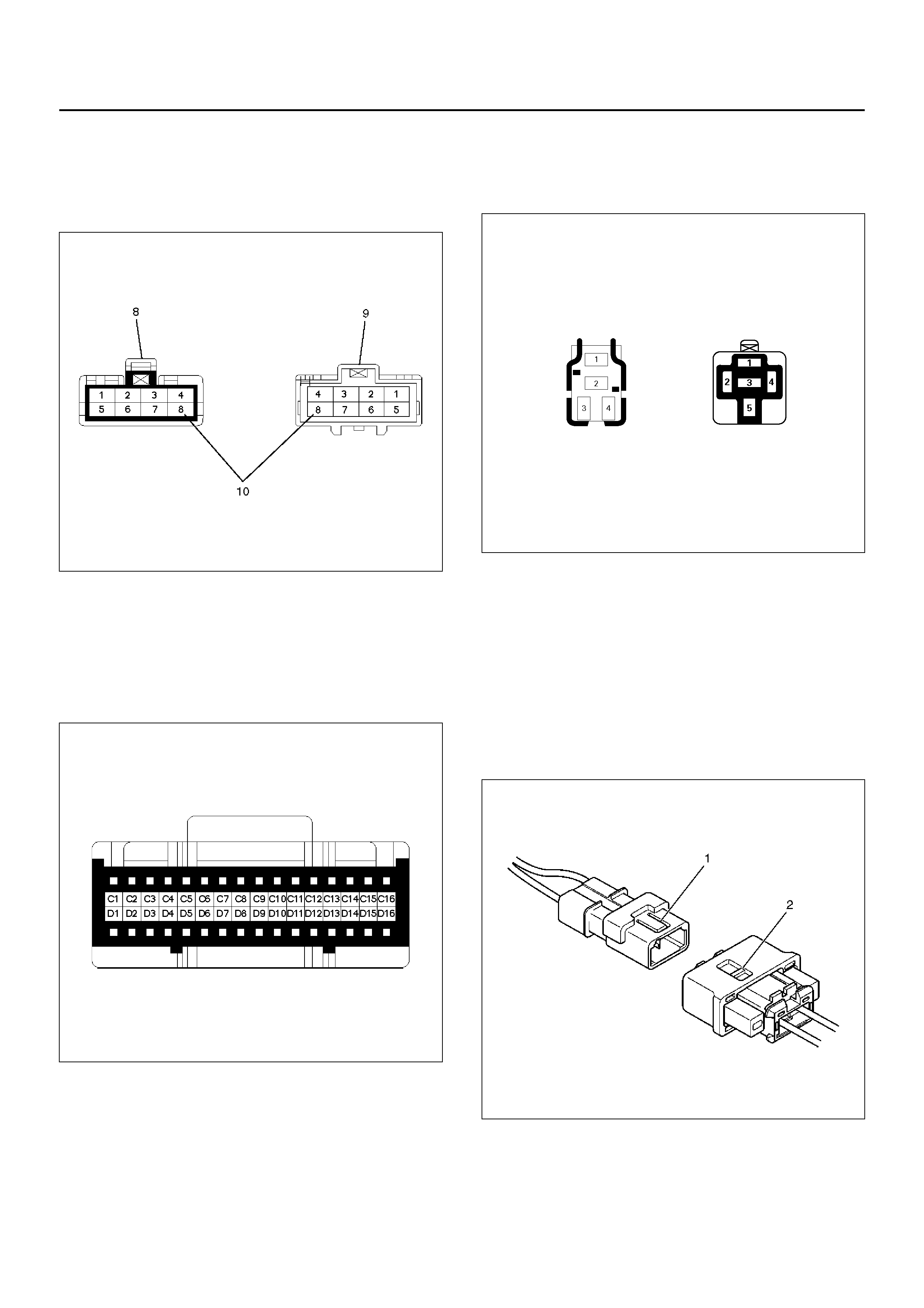
Harness Connector Faces
The harness connector faces show each connector's
number (1), configuration (2) and the pin number (3).
F00RX011
MAIN DATA AND SPECIFICATIONS
FUSE, FUSIBLE LINK AND CIRCUIT BREAKER LOCATION
810R100009
EndOFCallout
Legend
(1) Relay & Fuse Box (Engine Bay) (2) Relay & Fuse Box (Instrument Panel)
(3) Relay & Fuse Option Box (Engine Bay)

RELAY & FUSE BOX (ENGINE BAY) RELAY & FUSE BOX (INSTRUMENT
PANEL)
Fuse
No. Capacity Indication on label
F-1 15A HAZARD
F-2 10A HORN
F-3 10A ACG-S
F-4 20A BLOWER
F-5 10A A/C
F-6 – –
F-7 – –
F-8 10A H/L LIGHT-LH
F-9 10A H/L LIGHT-RH
F-10 15A (FOG LIGHT)
F-11 10A O2 SENS. HEATER
F-12 20A FUEL PUMP
F-13 15A ECM
F-14 15A (TOD)
FL-1 100A MAIN
FL-2 60A IGN.1
FL-3 30A ECM
FL-4 50A ABS
FL-5 50A IGN.2
FL-6 30A COND. FAN
FL-7 – –
FL-8 – –
Fuse
No. Capacity Indication on label
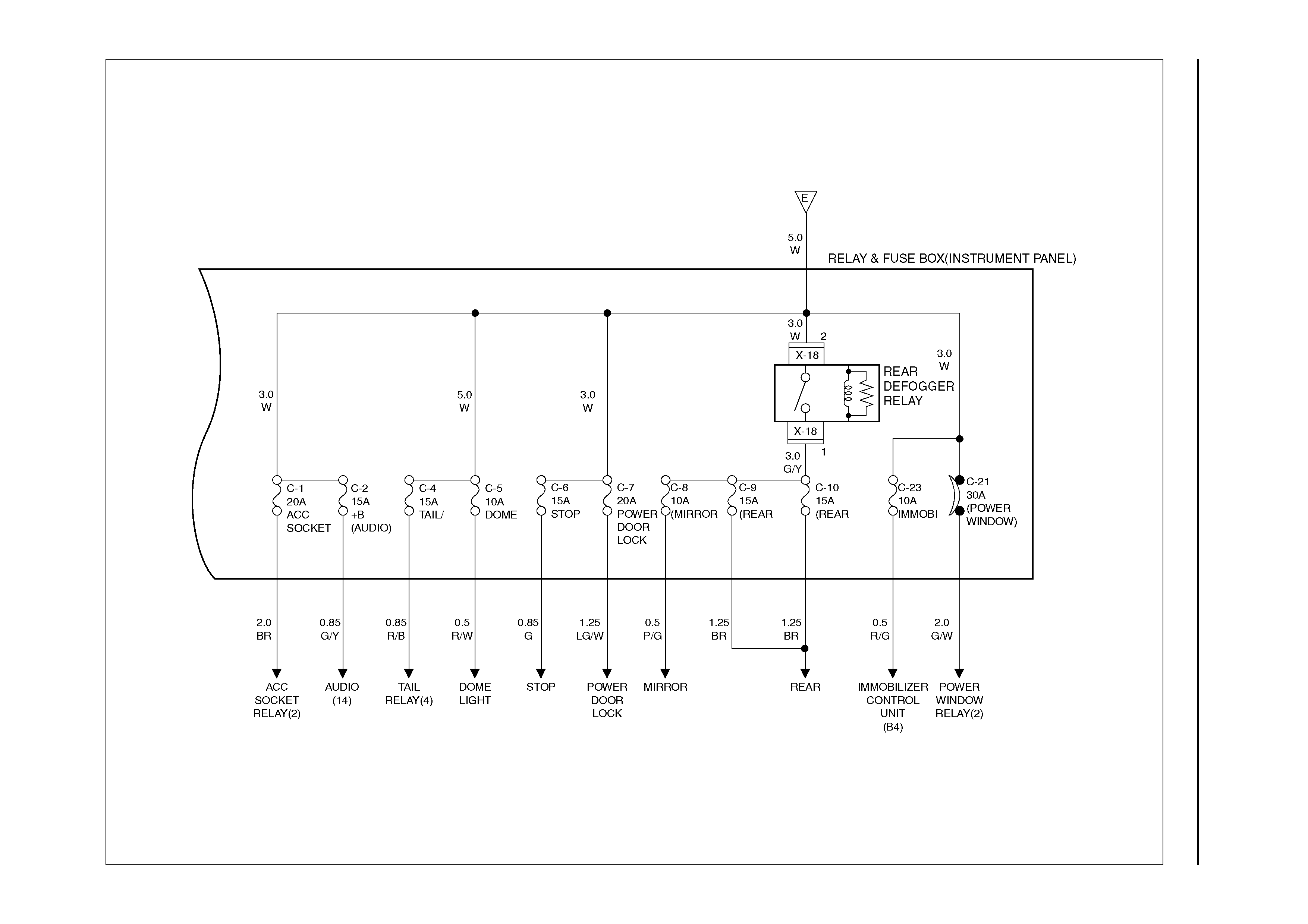
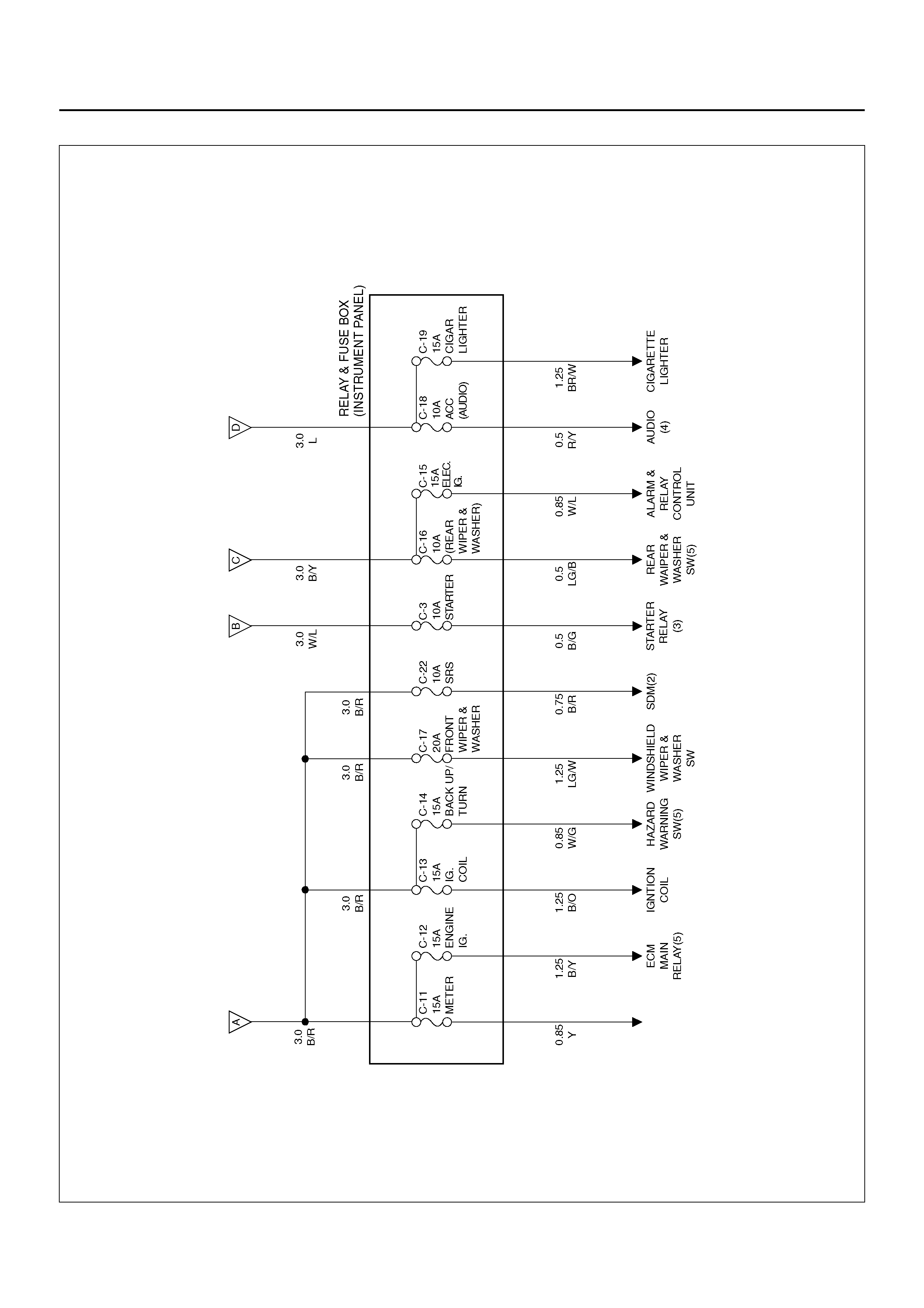
C-1 20A ACC. SOCKET
C-2 15A (AUDIO) +B
C-3 10A STARTE.
R
C-4 15A TAIL/ILLUMI. LIGHT
C-5 10A DOME LIGHT
C-6 15A STOP LIGHT
C-7 20A POWER DOOR LOCK
C-8 10A MIRROR DEFOG
C-9 15A REAR DEMIST
C-10 15A REAR DEMIST
C-11 15A METER
C-12 15A ENGINE IG.
C-13 15A IG. COIL
C-14 15A BACK UP/TURN LIGHT
C-15 15A ELEC. IG.
C-16 20A REAR WIPER & WASHER
C-17 10A FRONT WIPER & WASHER
C-18 10A ACC (AUDIO)
C-19 15A CIGAR LIGHTER
C-20 10A –
C-21 30A (POWER WINDOW)
C-22 10A SRS
C-23 10A IMMOBILISER
FUSE BLOCK CIRCUIT
Fuse Block Circuit–1
D08R100087
Fuse Block Circuit–2
D08R100222
Fuse Block Circuit–3
D08R100221
Fuse Block Circuit–4
D08R100220
DEMIST) DEMIST)
DEMIST)
DEMIST
DEMIST
LAMP
LAMP
LAMP
Fuse Block Circuit–5
D08R100219
INDIC.
INSTR.

REFERENCE TABLE OF FUSE, FUSIBLE LINK AND CIRCUIT BREAKER
Fuse (Relay and Fuse Box · Engine Bay)
Fuse No. Capacity Indication on label Parts (Load)
F-1 15A HAZARD FRT Turn signal light, RR Turn signal light, Side turn
signal light, Flasher unit
F-2 10A HORN Alarm & relay control unit, Horn
F-4 20A BLOWER Blower motor, Blower resistor, Power transistor
F-5 10A A/C Thermo switch, Blower unit, Intake actuator , In car sensor ,
Resistor, A/C thermostat relay, Electronic thermostat,
Automatic A/C control uni t, A/C compres sor relay,
Magnetic clutch, Condenser fan relay, Max high relay
F-8 10A H/L LIGHT - LH Headlamp - LH, High beam indicator light
F-9 10A H/L LIGHT - RH Headlamp - RH
F-10 15A FOG LIGHT Fog light
F-11 10A O2SENSOR Oxygen sensor
F-12 20A FUEL PUMP Fuel pump
F-13 15A ECM Engine con tr ol mod ule , Instrum ents
F-14 15A TOD TOD control unit
FL-1 100A MAIN Starter
FL-2 60A IGN.1
FL-3 30A ECM Fuel injector
FL-4 50A ABS EHCU
FL-5 50A IGN.2
FL-6 30A COND. FAN Condenser fan
FL-8 N/A N/A

Fuse (Relay & Fuse Box · Instrument Panel)
PCM: Power train module, VSV: Vacuum switching
valve
Fuse No. Capacity Indication on label Parts (Load)
C-1 20A ACC. SOCKET Acc socket
C-2 15A (AUDIO) Audio
C-3 10A STARTER Starter relay
C-4 15A TAIL/ILLUMI. LIGHT Tail relay, Tail lamp, Park Lamp, License plate lamp,
Illumination controller, Illumination light, Fog lamp relay,
Fog lamp SW
C-5 10A DOME LIGHT Dome light, Courtesy light - LH, Courtesy light - RH, Rear
Compartment light, Alarm & relay control unit, Digital
clock, Map light, Automatic A/C control unit
C-6 15A STOP LIGHT Stop lamp switch, Stop lamp - LH, Stop light - RH, High
mounted stop light, A/T shift lock relay
C-7 20A (POWER DOOR
LOCK) FRT door lock & Power window SW, Door lock actuator,
Keyless entry control unit
C-8 1 0A (MIRROR DEFOG) Mirror demist
C-9 15A (REAR DEFOG) Rear demist
C-10 15A (REAR DEFOG) Rear demist
C-11 15A EHCU Indicator and warning lights (meter), Meter gauge,
Generator, Vehicle speed sensor, Shift lock control unit,
Fuel tank unit
C-12 15A ENGINE IG. PCM main relay, VSV; purge solenoid, MAF sensor VSV;
intake air
C-13 15A IG. COIL Ignition coil, Ion sensing module, Condenser
C-14 15A BACKUP/TURN LIGHT Mode SW, Backup light, FRT axle actuator, TOD clutch
solenoid, TOD speed sensor, TOD H-L shift motor,
Indicator control unit, TOD control unit
C-15 15A ELEC. IG. Alarm & relay control unit, Power window relay, 4WD
control unit, Heater relay
C-16 15A REAR WIPER &
WASHER Rear wiper motor, Rear washer motor, Alarm & relay &
control unit, Rear defogger & mirror defogger relay
C-17 20A (FRONT WIPER &
WASHER Windshield wiper motor, Windshield washer motor, Alarm
& relay control unit
C-18 10A (AUDIO) ACC A udi o, Powe r door mirror
C-19 15A CIGAR LIGHTER ACC socket relay cigarette lighter
C-22 10A SRS SRS warning light, SDM

Fusible Link (Relay and Fuse Box · Engine Room)
ABS: Anti - lock Brake System
Circuit Breaker (Relay & Fuse Box · Instrument Panel)
Fuse Link No. Capacity Indication on label
FL-1 100A MAIN
FL-2 60A IGN. 1
FL-3 30A ECM
FL-4 50A ABS
FL-5 50A IGN. 2
FL-6 30A COND. FAN
FL-8 - -
Fuse No. Capacity Indication on label Parts (Load)
C-21 30A (POWER WINDOW) Power window SW, Power window motor.
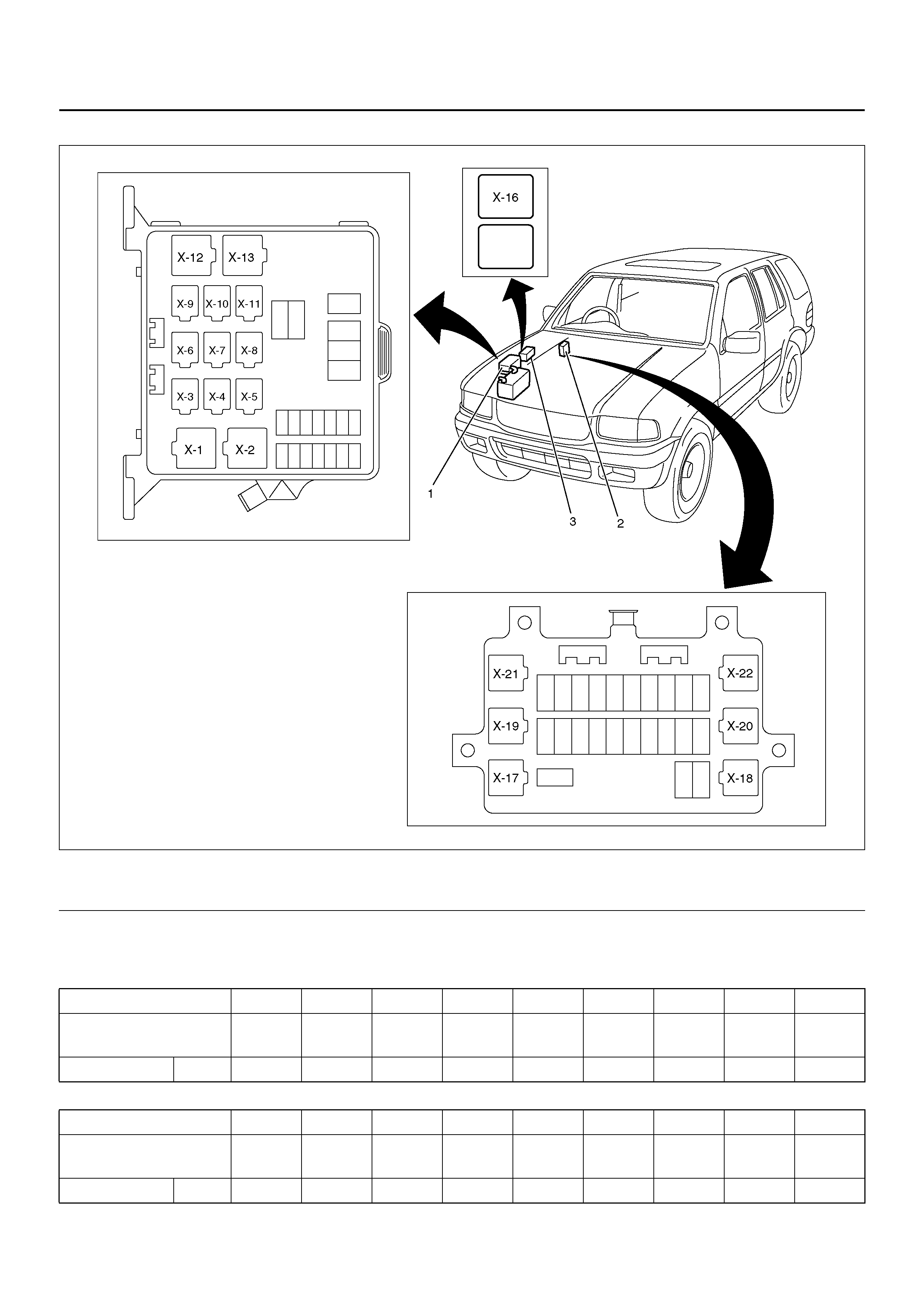
RELAY LOCATION
810RY00025
EndOFCallout
Relay List
Legend
(1) Relay & Fuse Box (Engine Bay) (2) Relay & Fuse Box (Instrument panel)
(3) Relay & Fuse Option Box (EngineBay)
Connector No. X–1 X–2 X–3 X–4 X–5 X–6 X–7 X–8 X–9
Usage Heater A/C
comp. ECM
Main –Fog
light – – Thermo Head
light
Engine 6VD1 ❍❍❍–❍––❍❍
Connecto r No. X–10 X–11 X–12 X–13 X–1 7 X–18 X–1 9 X–21 I–22
Usage Starter Conden
ser fan Fuel
pump –ACC
socket Rear
demist – Tail light Power
window
Engine 6VD1 ❍❍❍–❍❍–❍❍
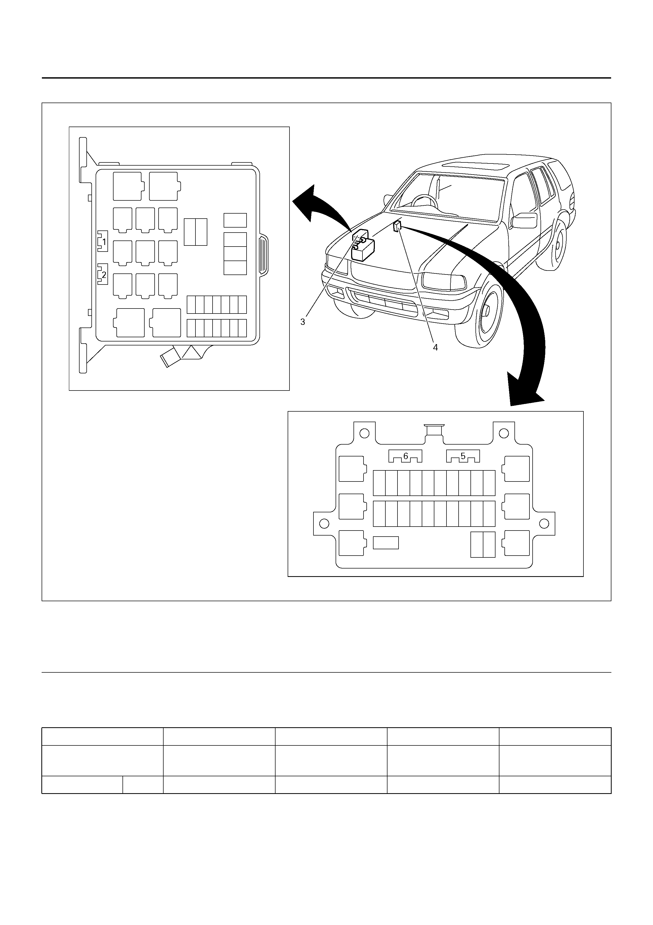
DIODE LOCATION
810R100010
EndOFCallout
Diode List
Legend
(1) X–14
(2) X–15
(3) Relay & Fuse Box (Engine Bay)
(4) Relay & Fuse Box (Instrument panel)
(5) X–24
(6) X–23
Connector No . X–14 X–15 X–23 X–24
Usage – – Tailgate SW, Door
SW. Dome light Brake
Engine 6VD1 – – ❍❍
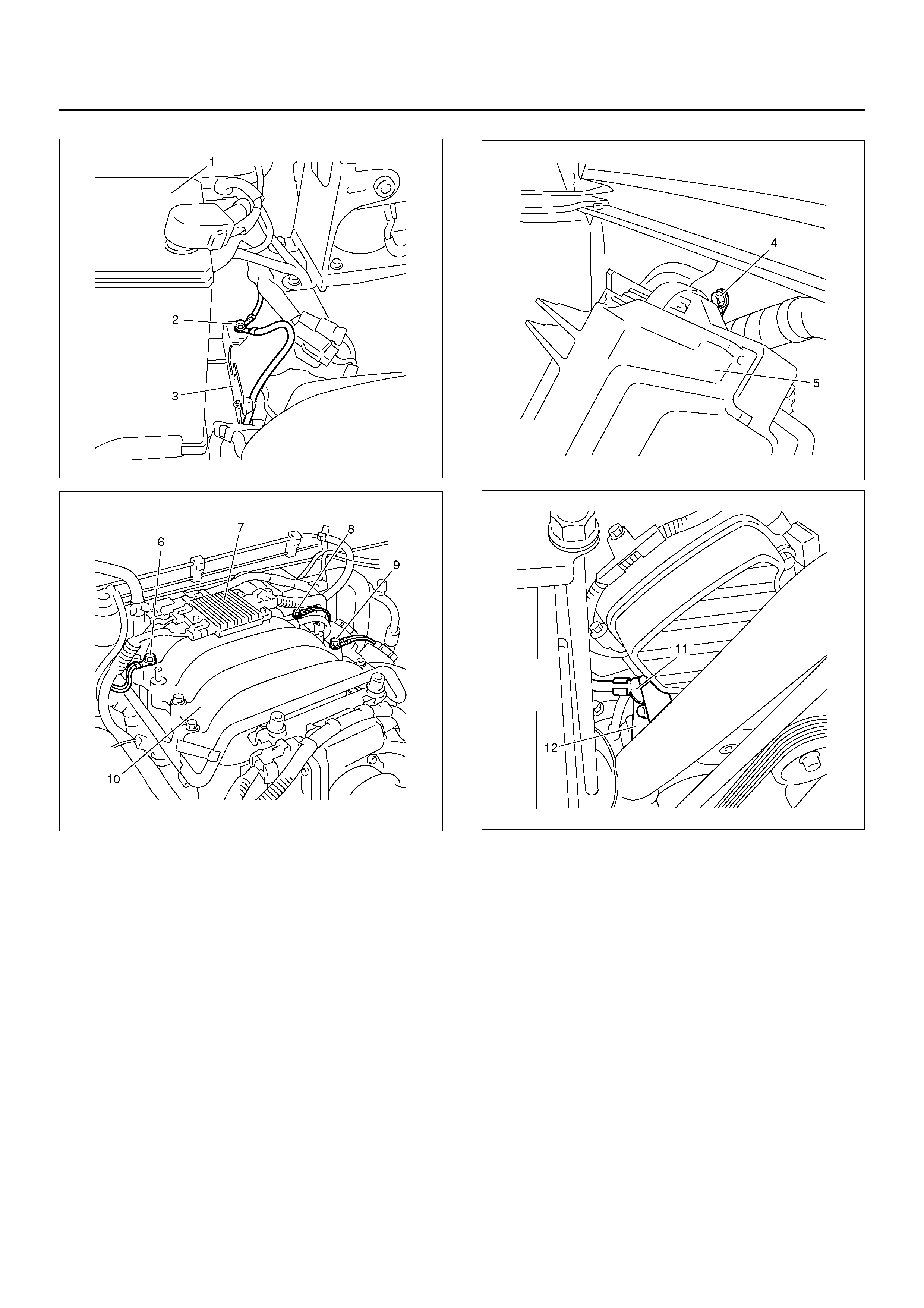
GROUNDING POINT
Circuit Diagram – 1
D08R100171
(ABS)
POWER TRANSDUCER
Circuit Diagram – 2
D08R100172
PARK LAMP - RH
PARK LAMP - LH
Circuit Diagram – 3
D08R100173
Circuit Diagram – 4
D08R100228
Circuit Diagram – 5
D08R100175
REAR DEMIST
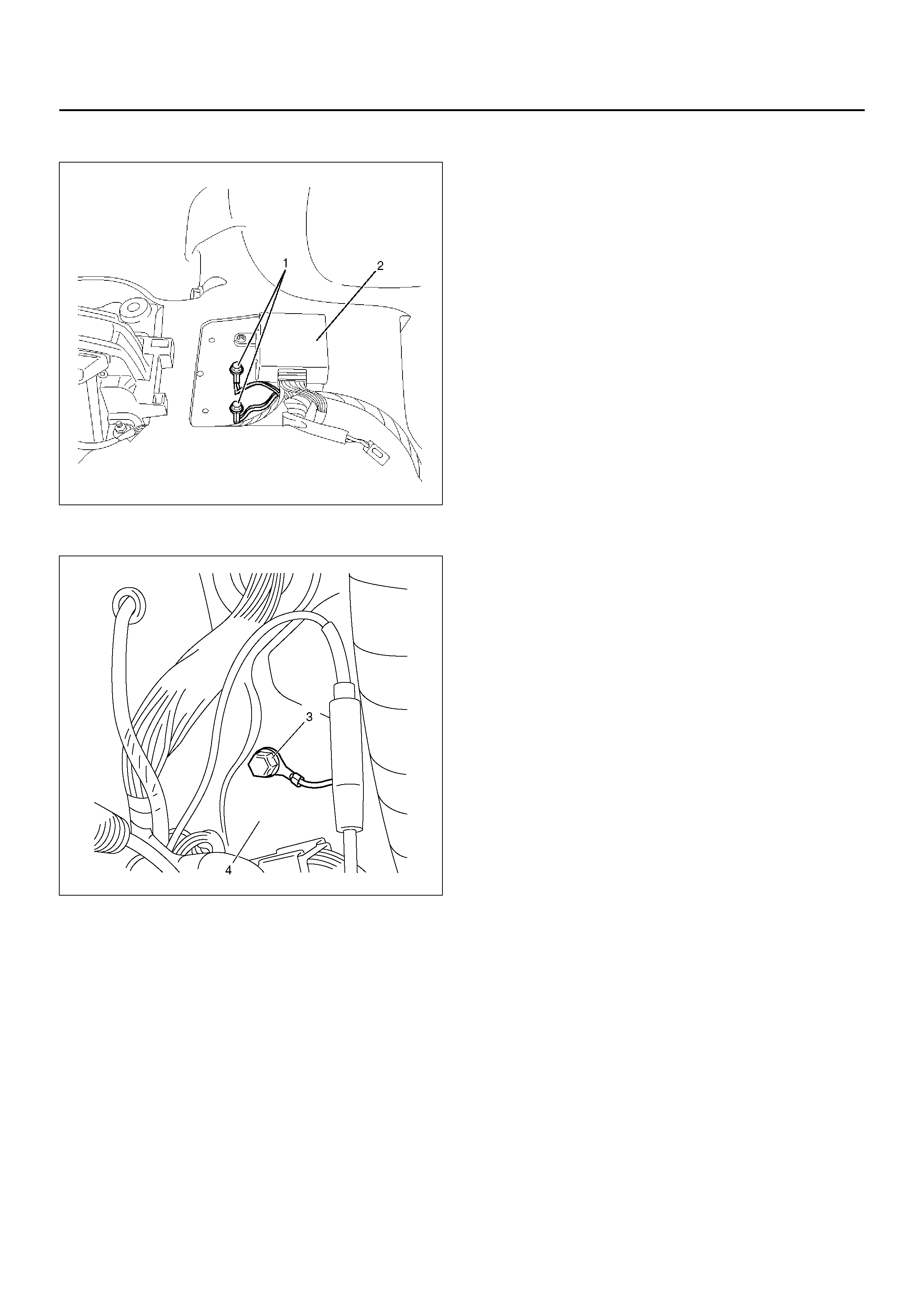
Location – 1
D08RW050
D08R100179
Legend
(1) B–6, B–7, B–8
(2) 2–4WD Control Unit
(3) I–43
(4) Dash Side Panel RH
Location – 2
D08R100180
D08R100182
D08R100181
D08R100183
EndOFCallout
Legend
(1) Battery
(2) C– 36, P–6
(3) Battery Tray
(4) C–16
(5) PCM
(6) E–30
(7) Ion Sensor
(8) E–28
(9) E–29
(10) Common Chamber
(11) P–10
(12) ACG
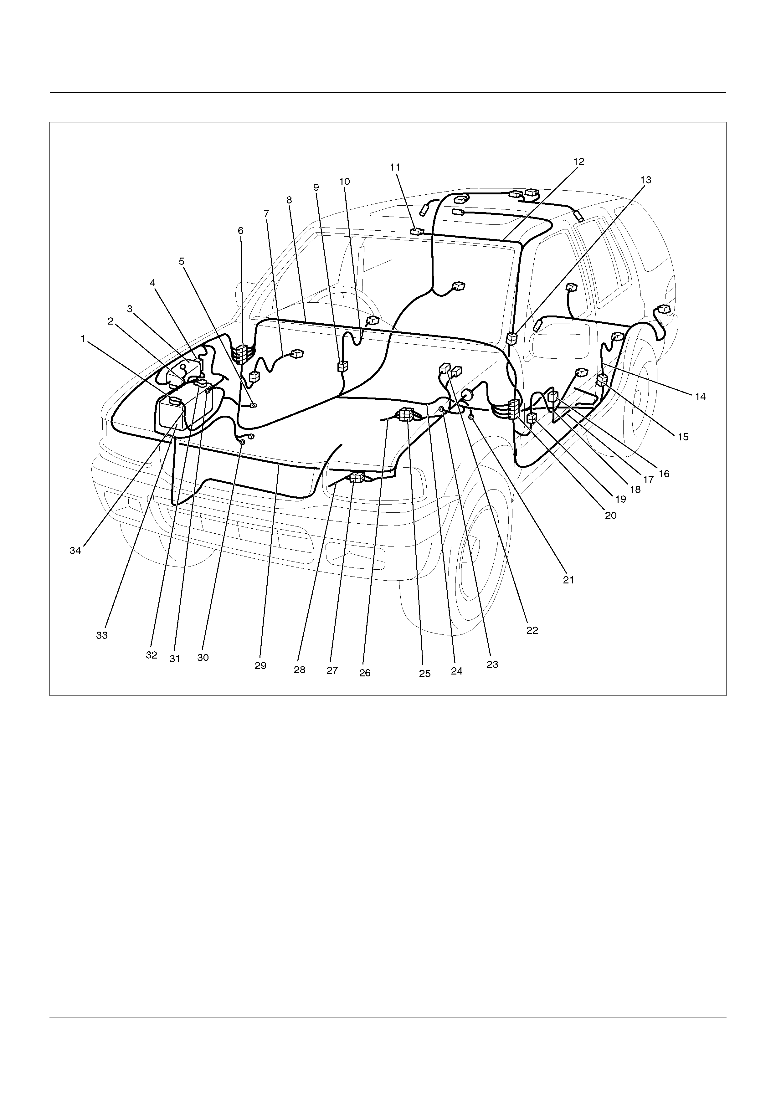
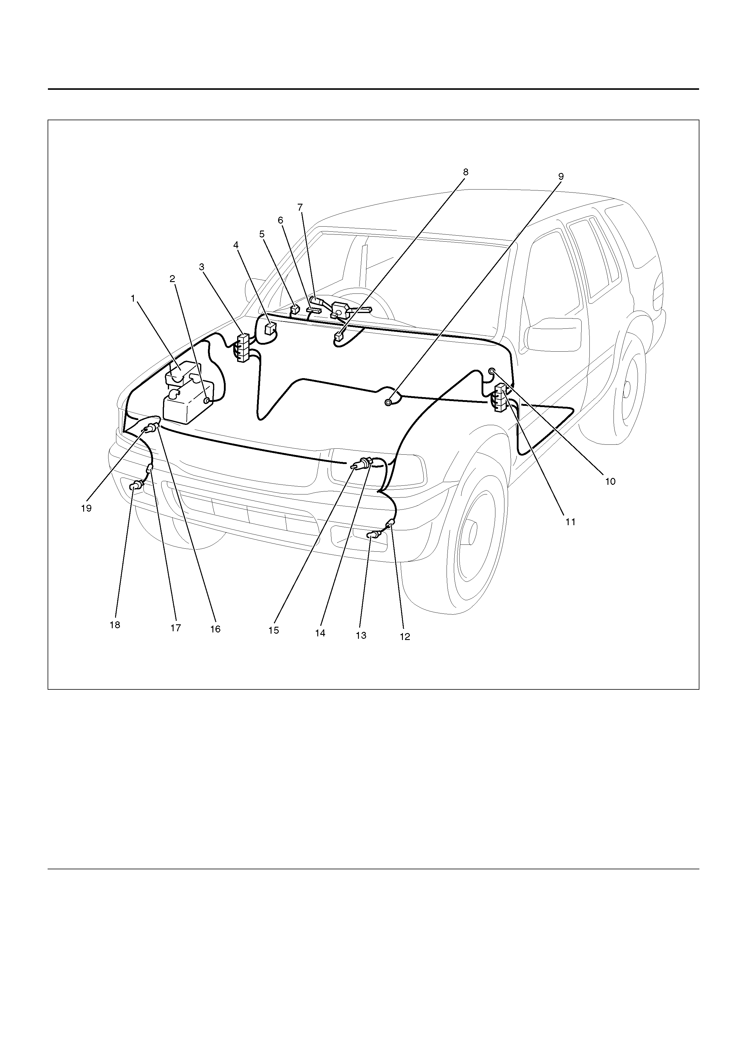
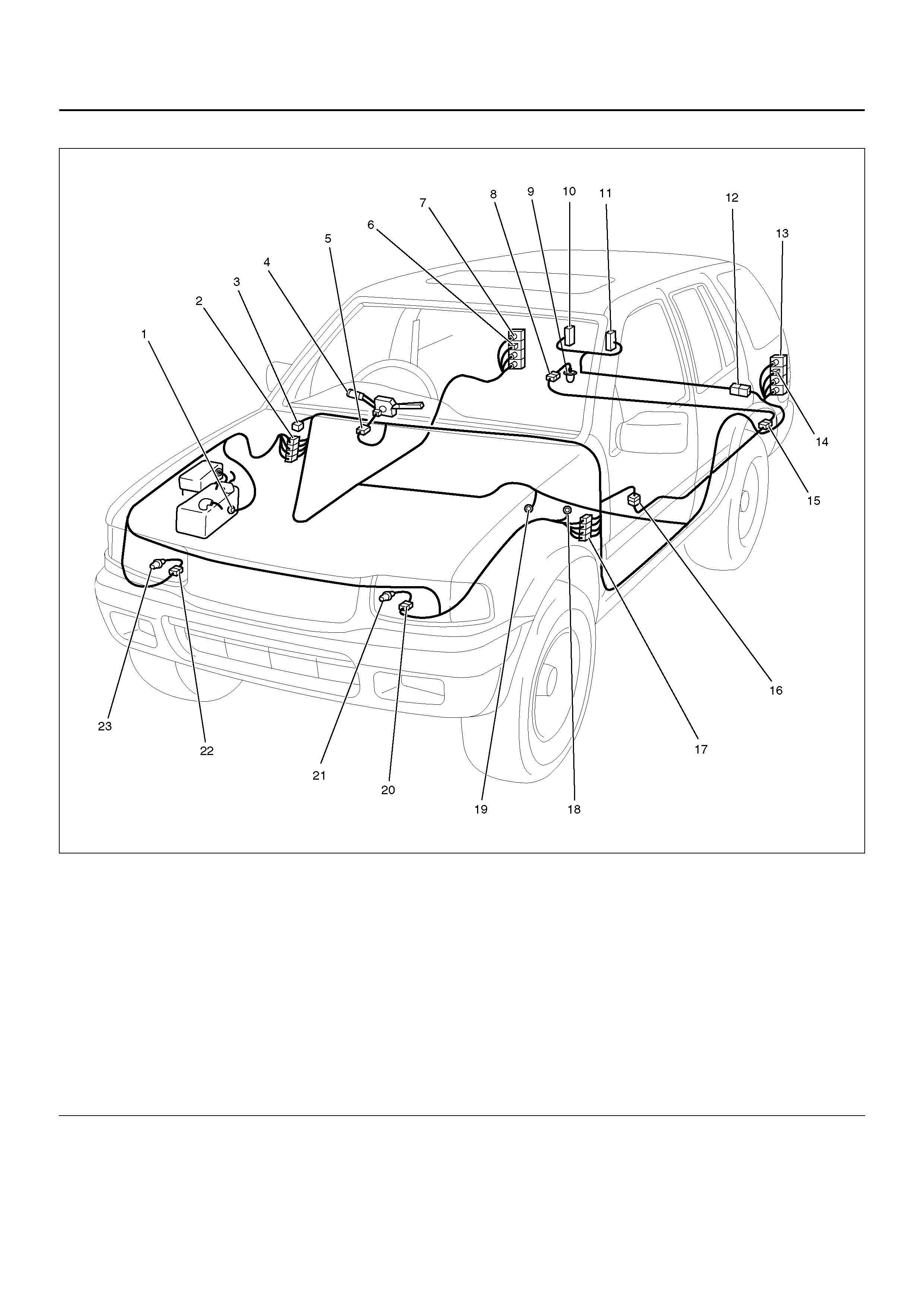
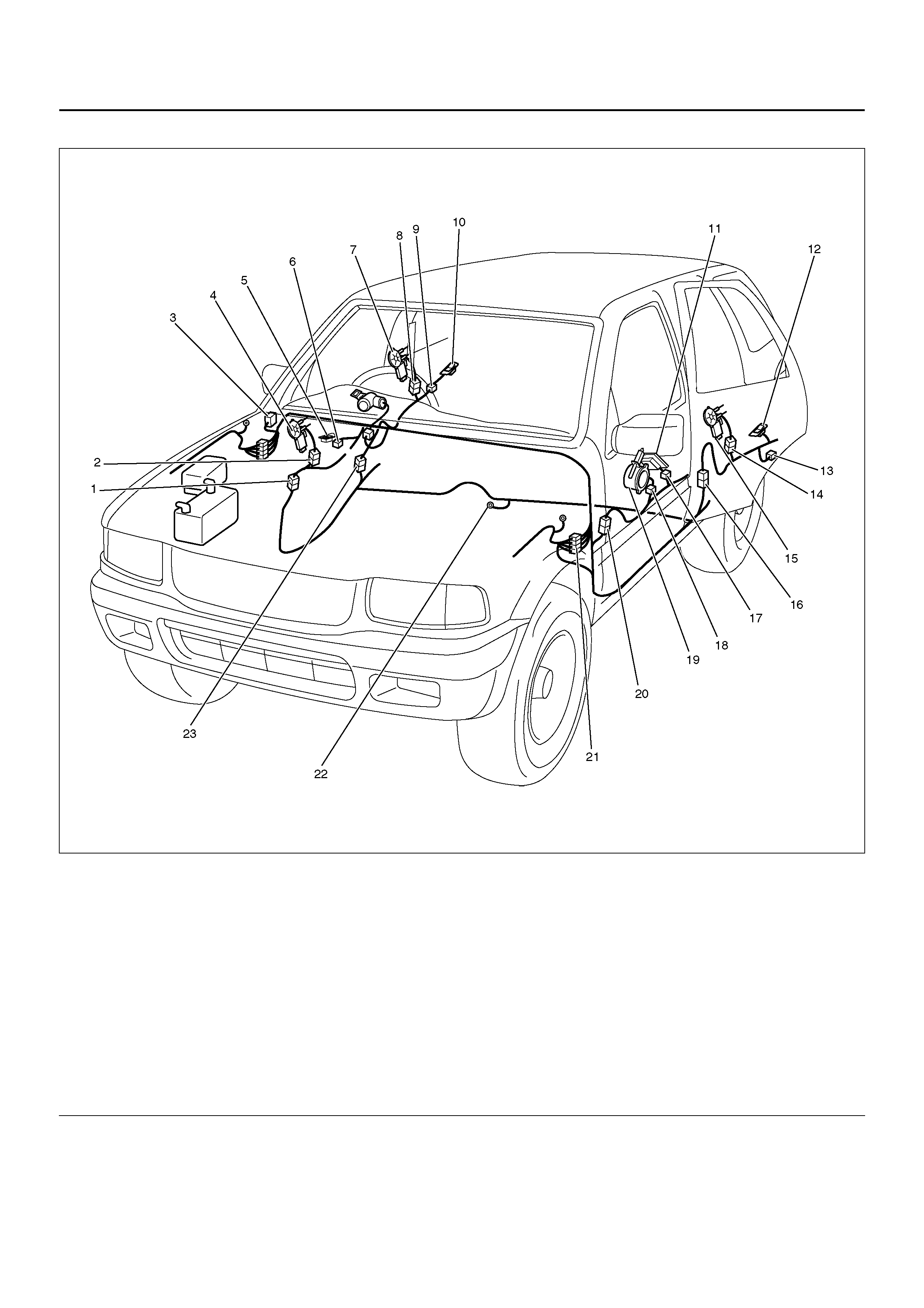
CABLE HARNESS ROUTING
D08R100186
EndOFCallout
Legend
(1) P–5
(2) Battery (+) Cable
(3) H–1
(4) H–2
(5) P–10
(6) H–13, H–14, H–19, H–32, H–45
(7) FRT Door Harness–RH
(8) Instrument Harness
(9) H–24
(10) RR Door Harness–RH
(11) L–2 (Map Light)
(12) Roof Harness
(13) H–30
(14) RR Door Harnes s– LH
(15) H–29
(16) H– 25, H–42
(17) Chassi s Harnes s
(18) FRT Door Harness – LH
(19) H–33
(20) H–15, H–16, H–17, H–31, H–40
(21) C–16
(22) C–53, C–54
(23) B–8
(24) Body Harness
(25) H–4, H–5, H–6, H–39
(26) Engine Harness
(27) H–38
(28) TOD Harness
(29) Engine Room Harness
(30) P–9
(31) P –6, C–36
(32) P–1
(33) Battery
(34) Battery (–) Cable
(4Door Model)
D08R100185
EndOFCallout
Legend
(1) H–22
(2) H–34
(3) Hatch Glass Harness LH
(4) H–21
(5) Hatch Glass Harness RH
(6) H–20
(7) H–25
(8) Body Harness
(9) Chassis Harness
(10) Tailgate Harness
(11) License Plate Light Harness
(12) Trailer Connector
(13) Tailgate Harness

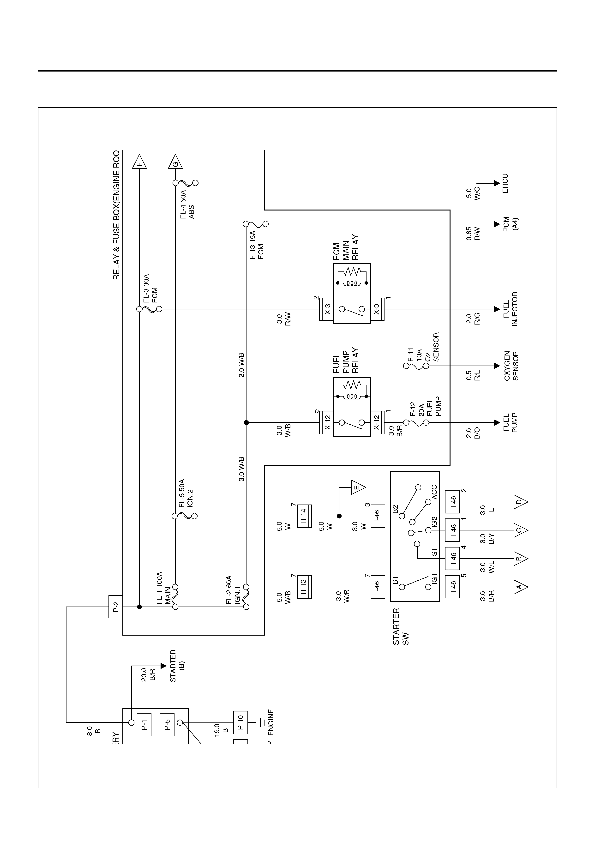
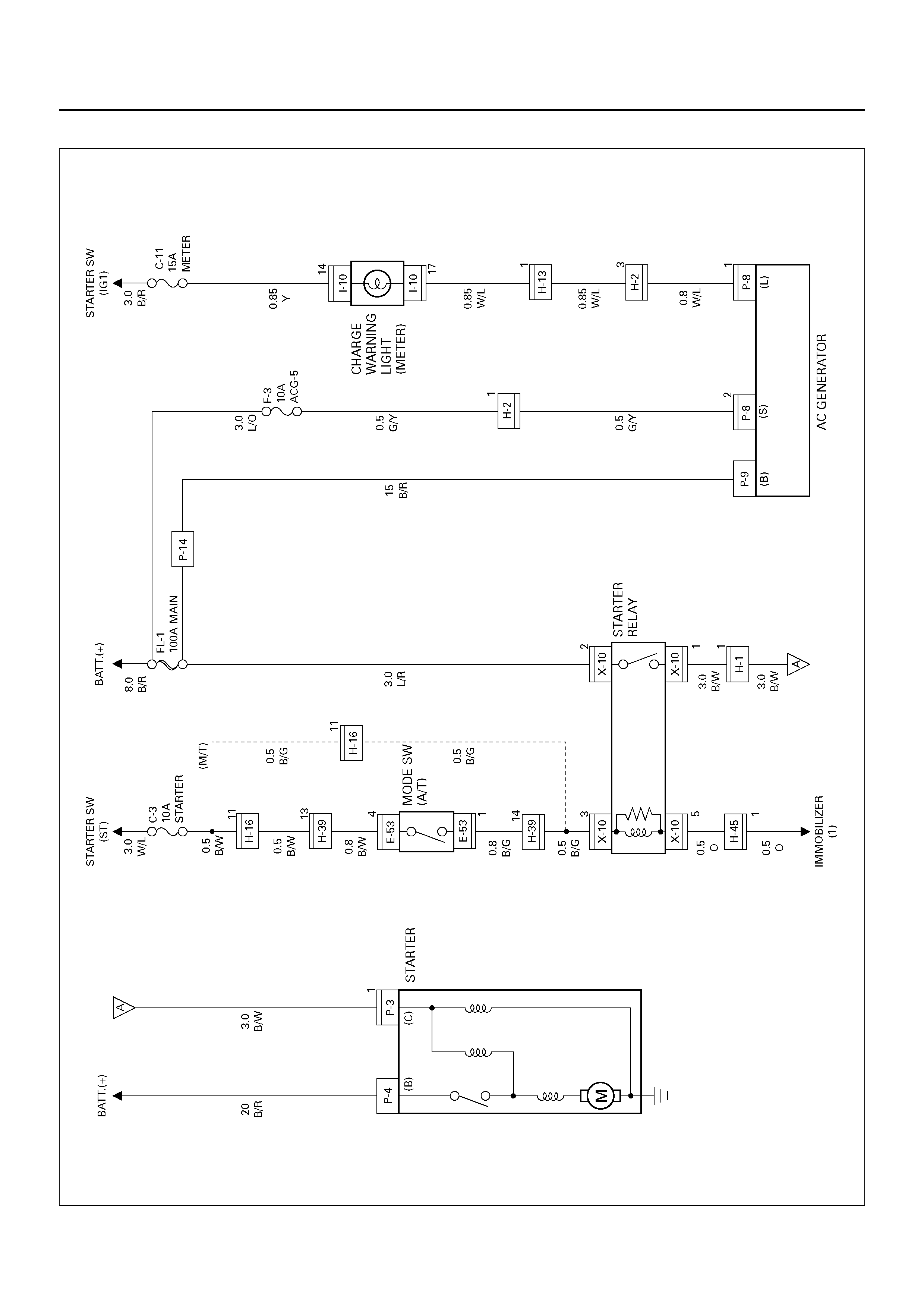
START AND CHARGING
GENERAL DESCRIPTION
This system consists of starter, AC generator, starter
relay, cl utch start SW (M /T), mode SW (A/T) and heater
& A/C relay.
When starter SW is set to “ST" position with A/T select
lever at “P" (Parking) or “N" (Neutral) position (Mode
SW “ON"), or clutch pedal depressed (Clutch start SW
“ON"), battery positive voltage is applied to starter
solen oid coil thro ugh starter re lay to start start er. At th e
some time, starter relay cuts off blower motor and A/C
circuit.
CIRCUIT DIAGRAM–1
D08R100103
PARTS LOCATION
D08R100187
EndOFCallout
Legend
(1) Relay & Fuse Box (X–10, FL–1)
(2) H–2
(3) H–13
(4) Relay & Fuse Box (C–3, C–11)
(5) I–10 (METER)
(6) Starter Switch
(7) H–16
(8) H–39
(9) E–53 (Mode Switch)
(10) P–4
(11) P–3
(12) P–8
(13) P–9
(14) C–36

POWERTRAIN CONTROL MODULE (PCM)
GENERAL DESCRIPTION
The Powertrain Control Module (PCM) is located in the
passenger compartment.
The PCM constantly monitors the information from
various sensors, and controls the systems that affect
vehicle performance.
The PCM performs the diagnostic function of the
system. It can recognize operational problems, alert the
driver through the Malfunction Indicator Light (MIL) and
store a Diagnostic Trouble Code (DTC) or DTC(s) which
identify the problem areas to aid the technician in
making repairs. The PCM is designed to process the
various input informations and then send the necessary
electrical responses to control fuel delivery, spark timing
and other emission control systems. The input
information has an interrelation to more than one output
therefore, if the one input failed, it could affect more
than one system operation.
Refer to Driveability and Emission in Engine Section
and Automatic Transmission in Transmission section.
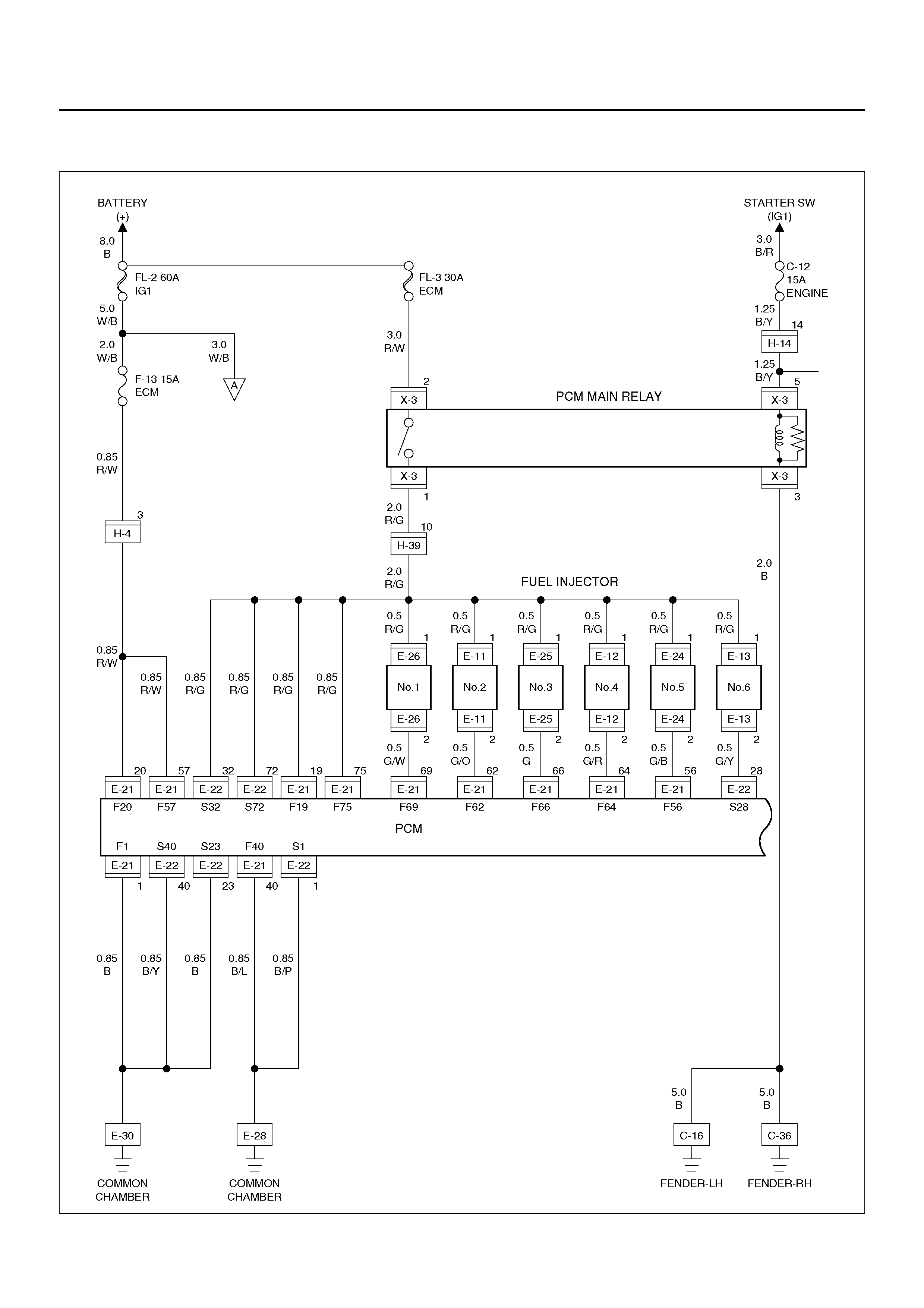
CIRCUIT DIAGRAM
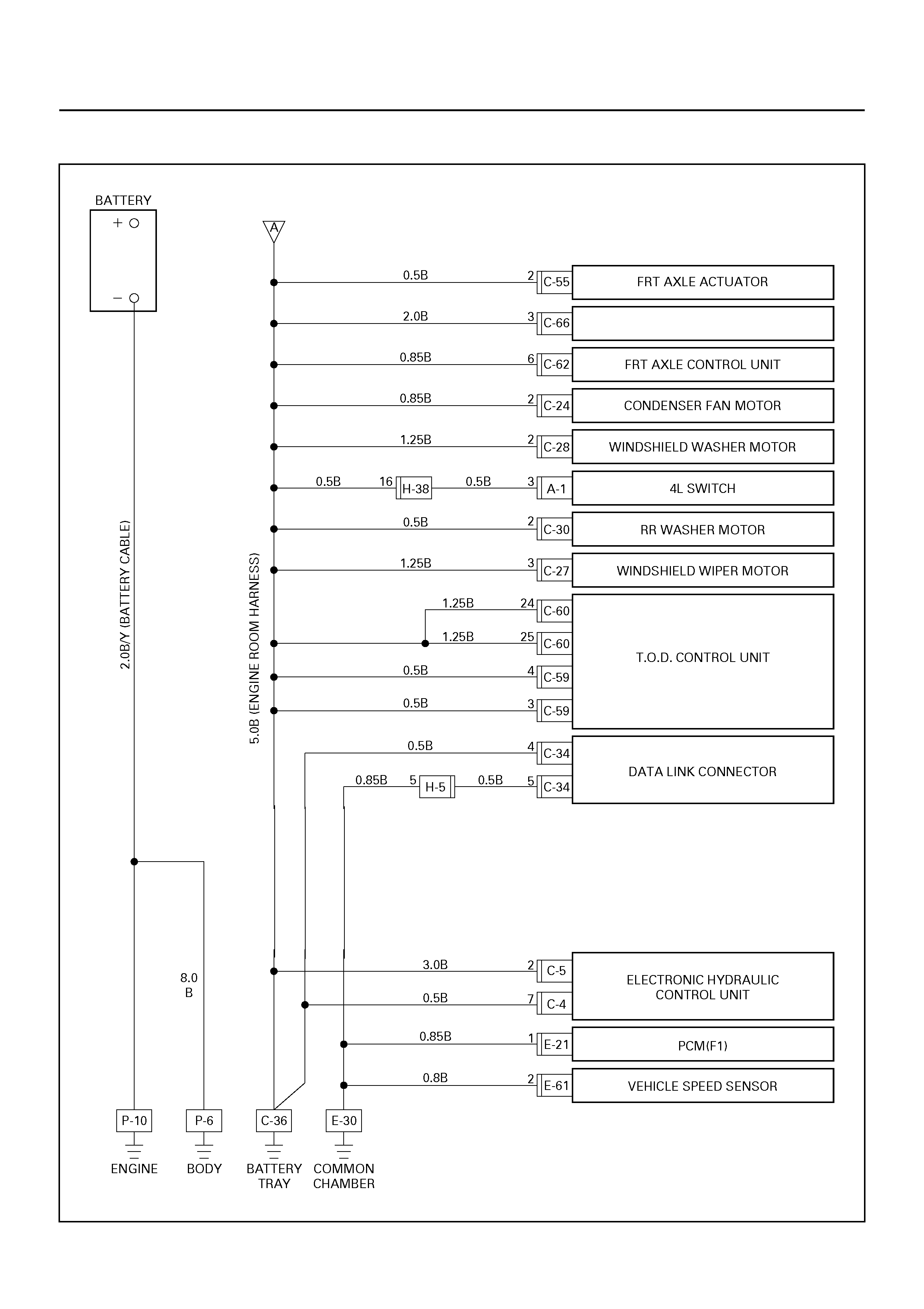
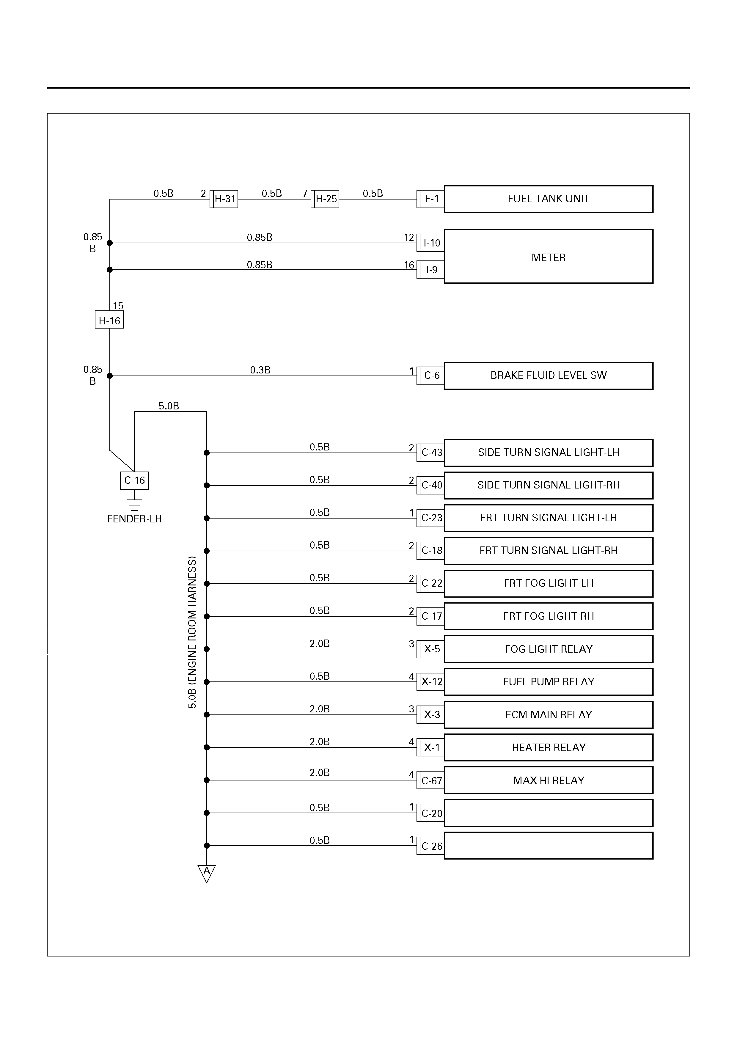
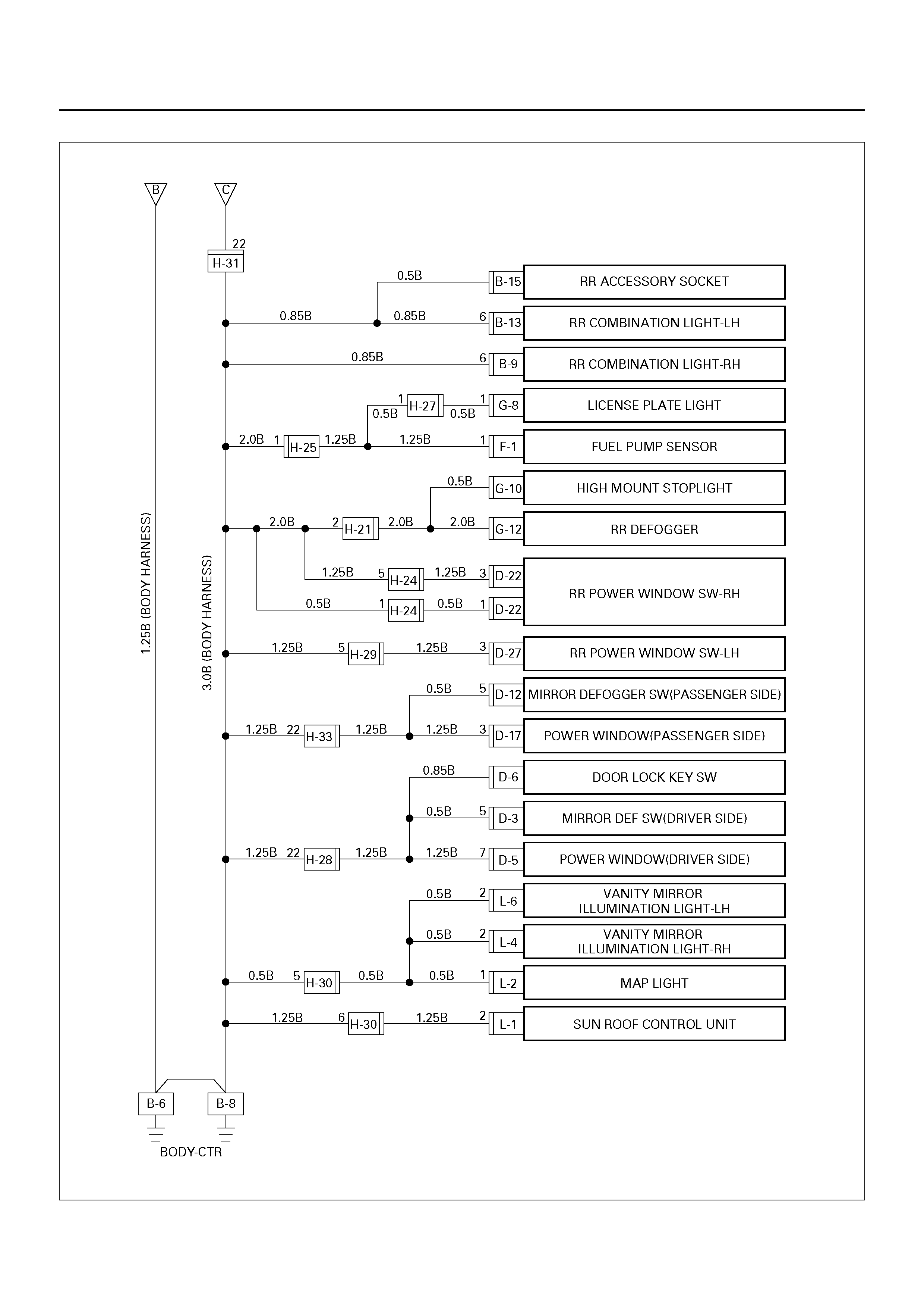
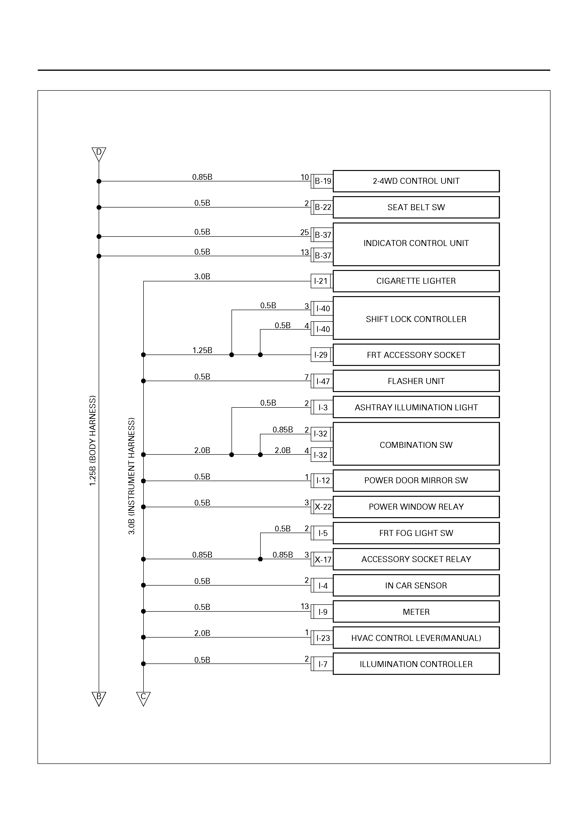
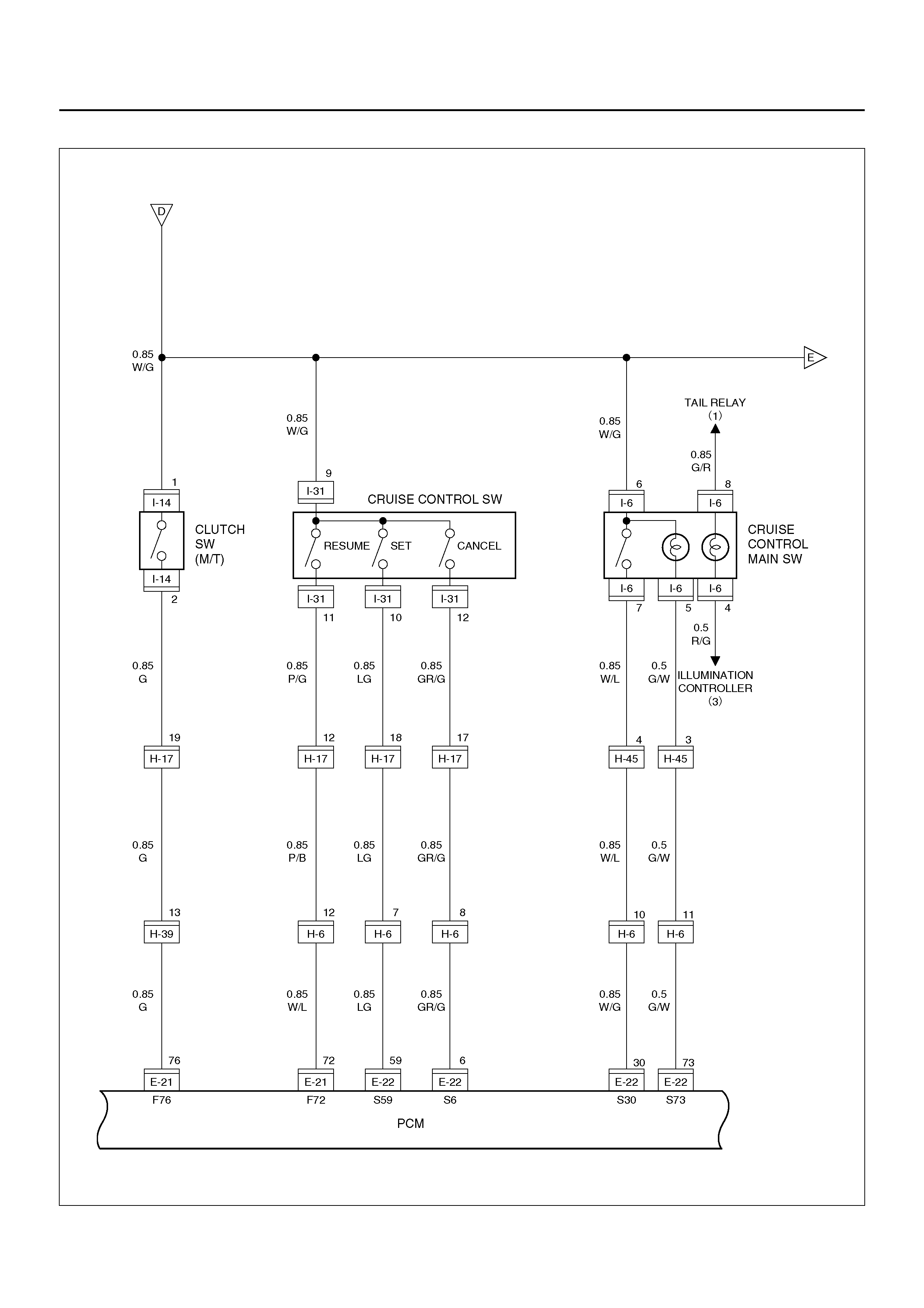
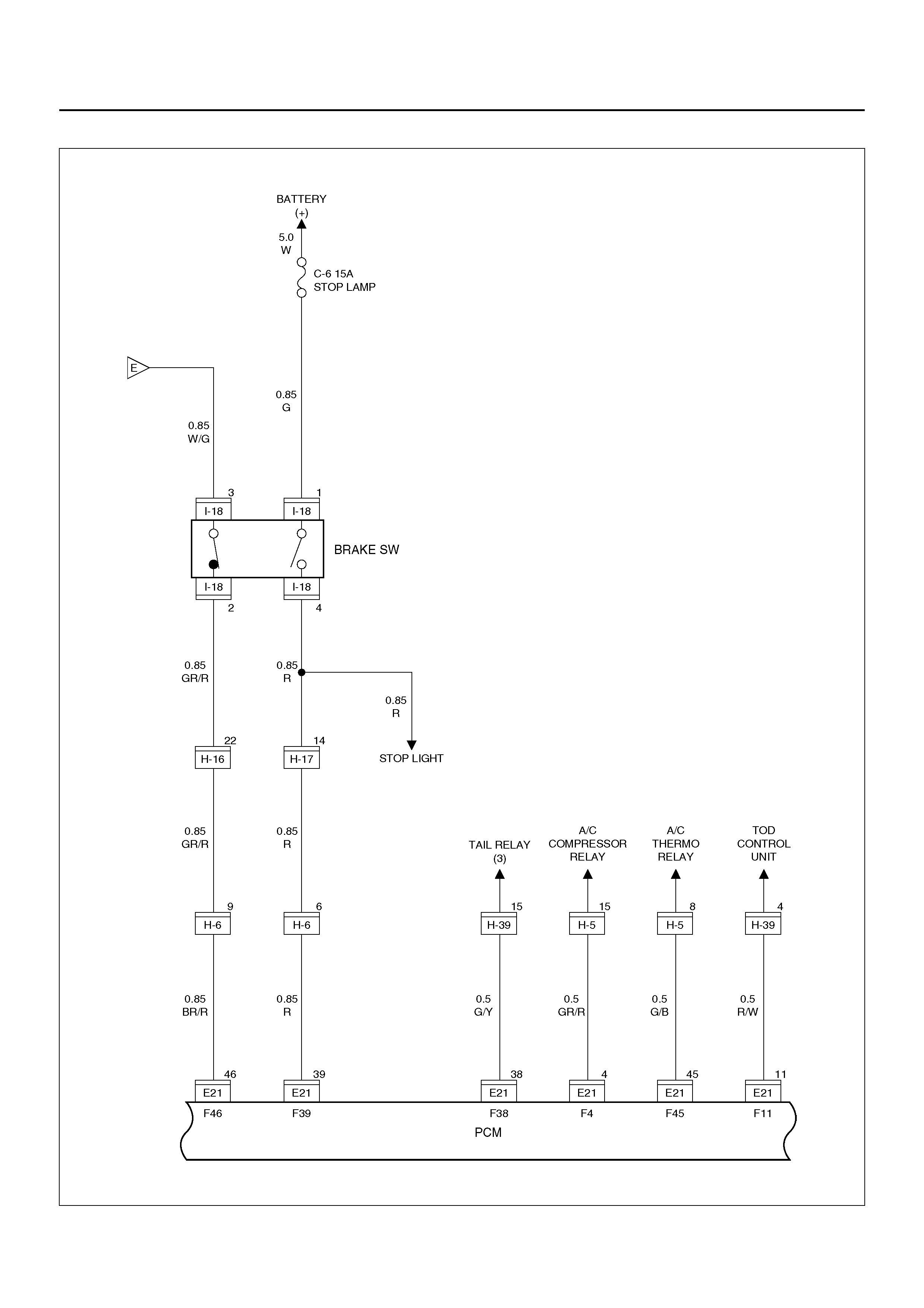
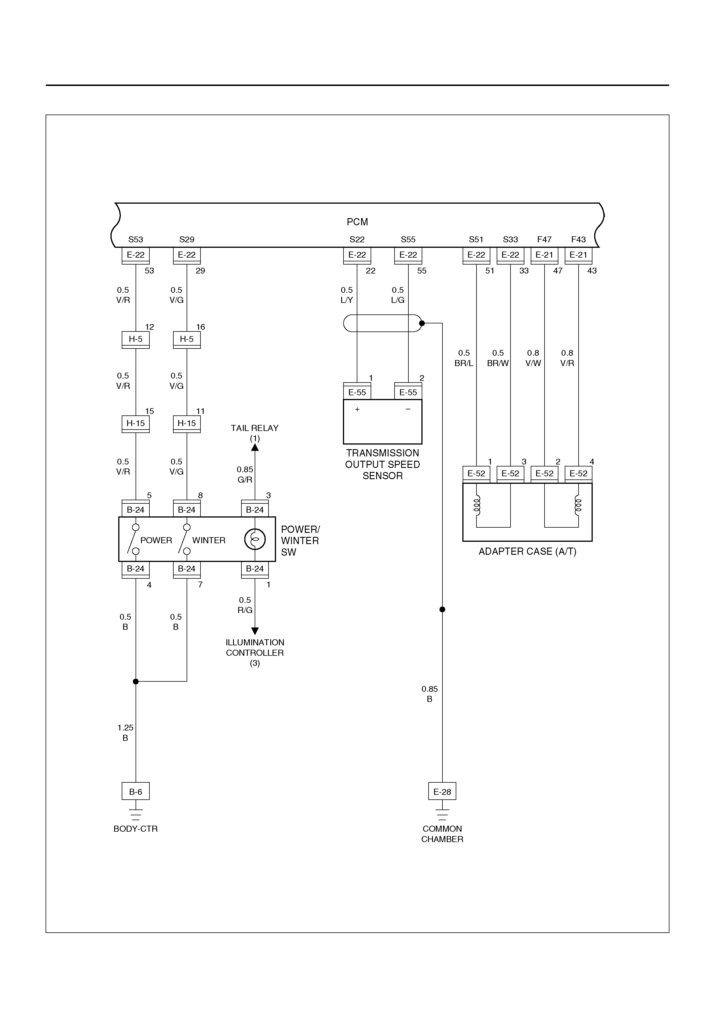
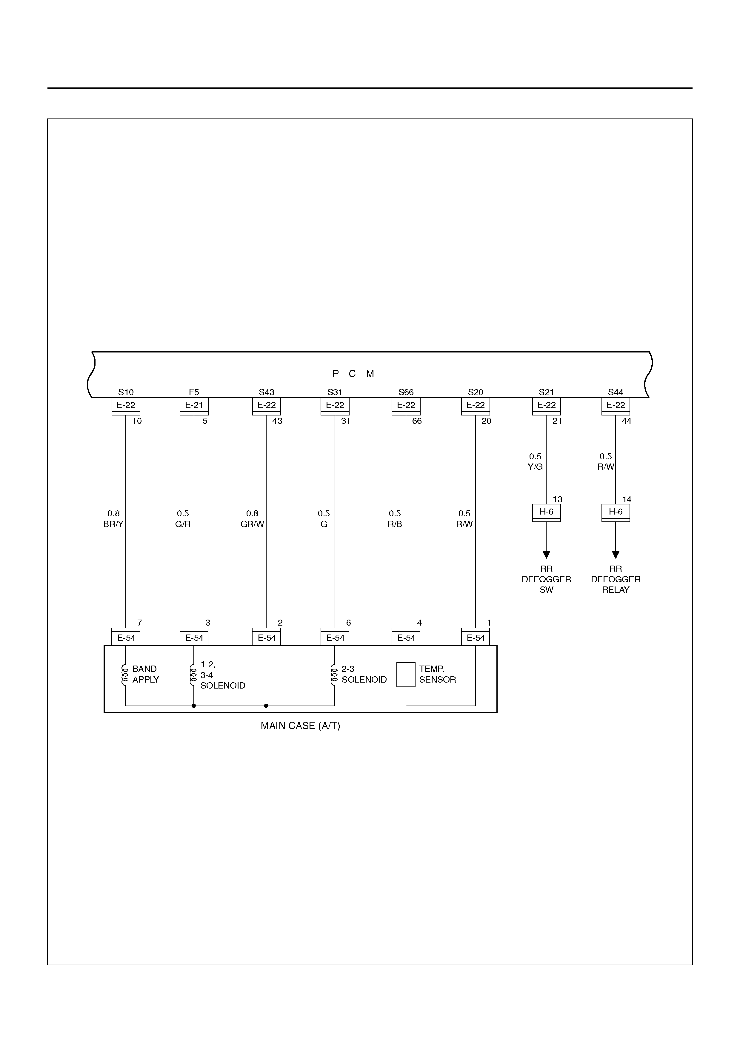
Circuit Diagram–1
D08R100073
Circuit Diagram–2
D08R100188
Circuit Diagram–3
D08R100075
Circuit Diagram–4
D08R100076
Circuit Diagram–5
D08R100189
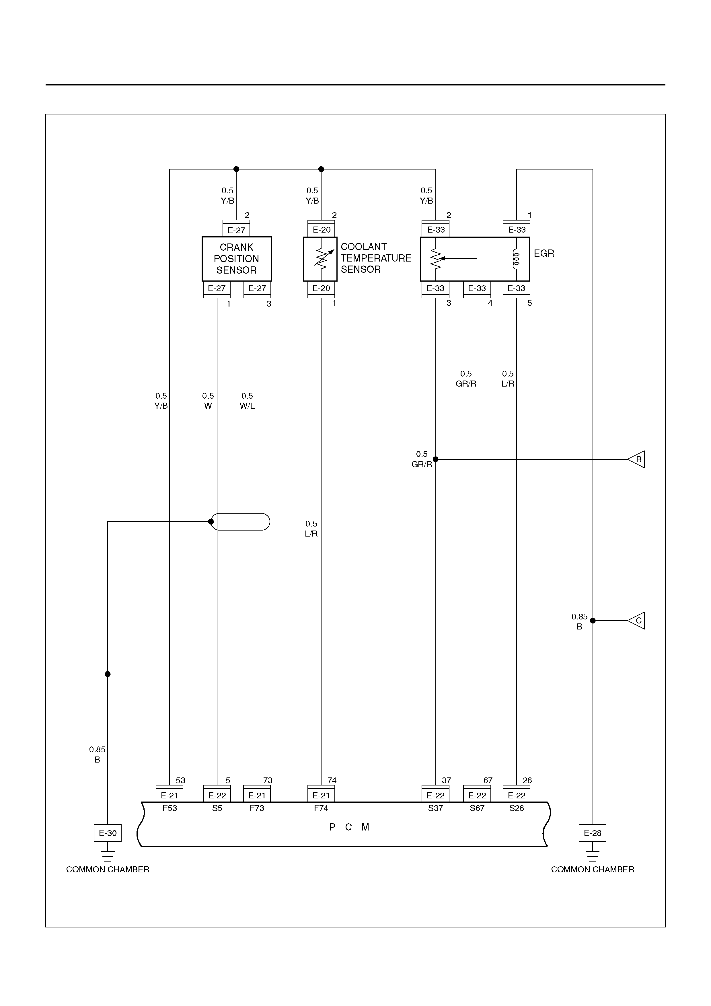
Circuit Diagram–6
D08R100078
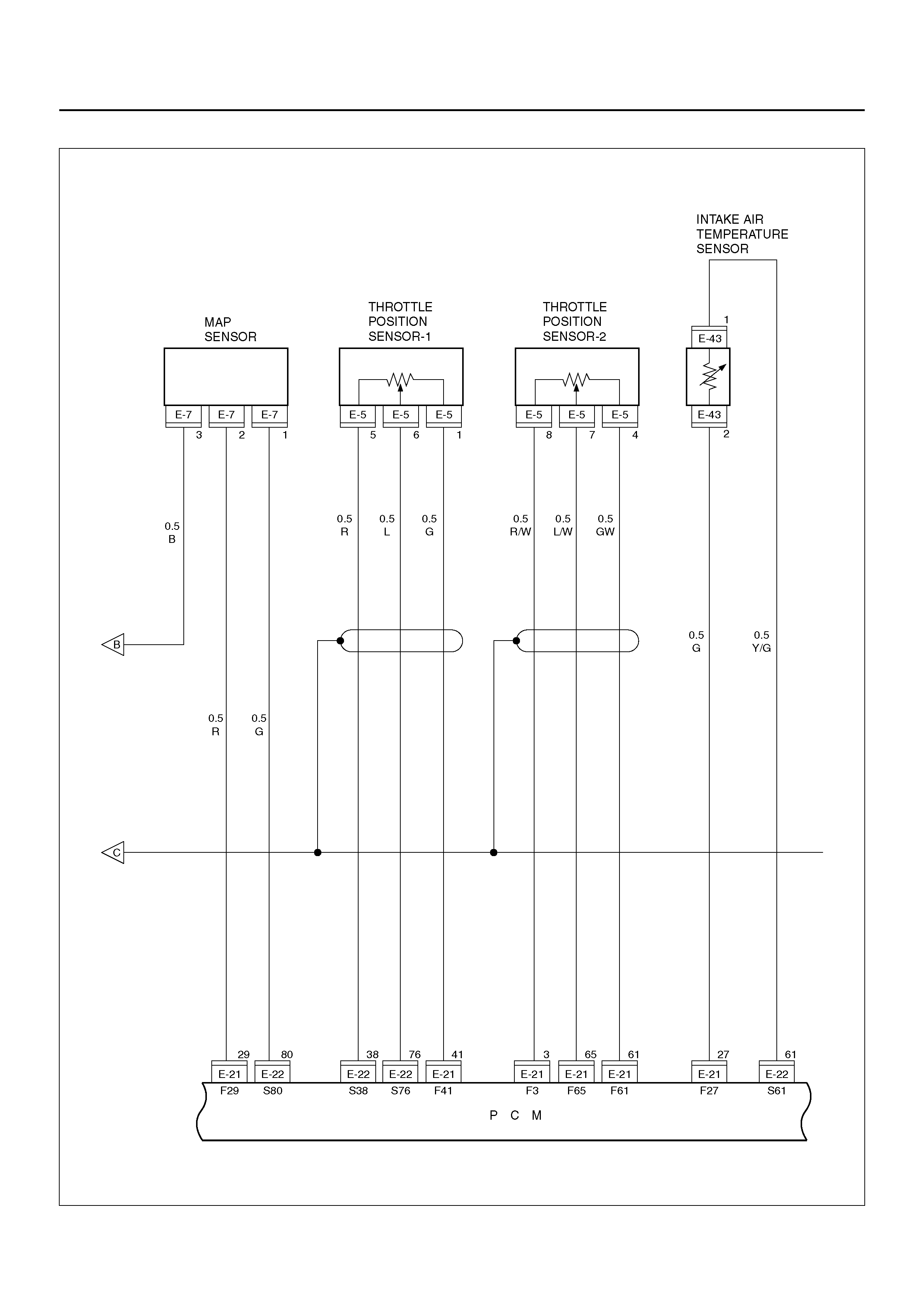
Circuit Diagram–7
D08R100079
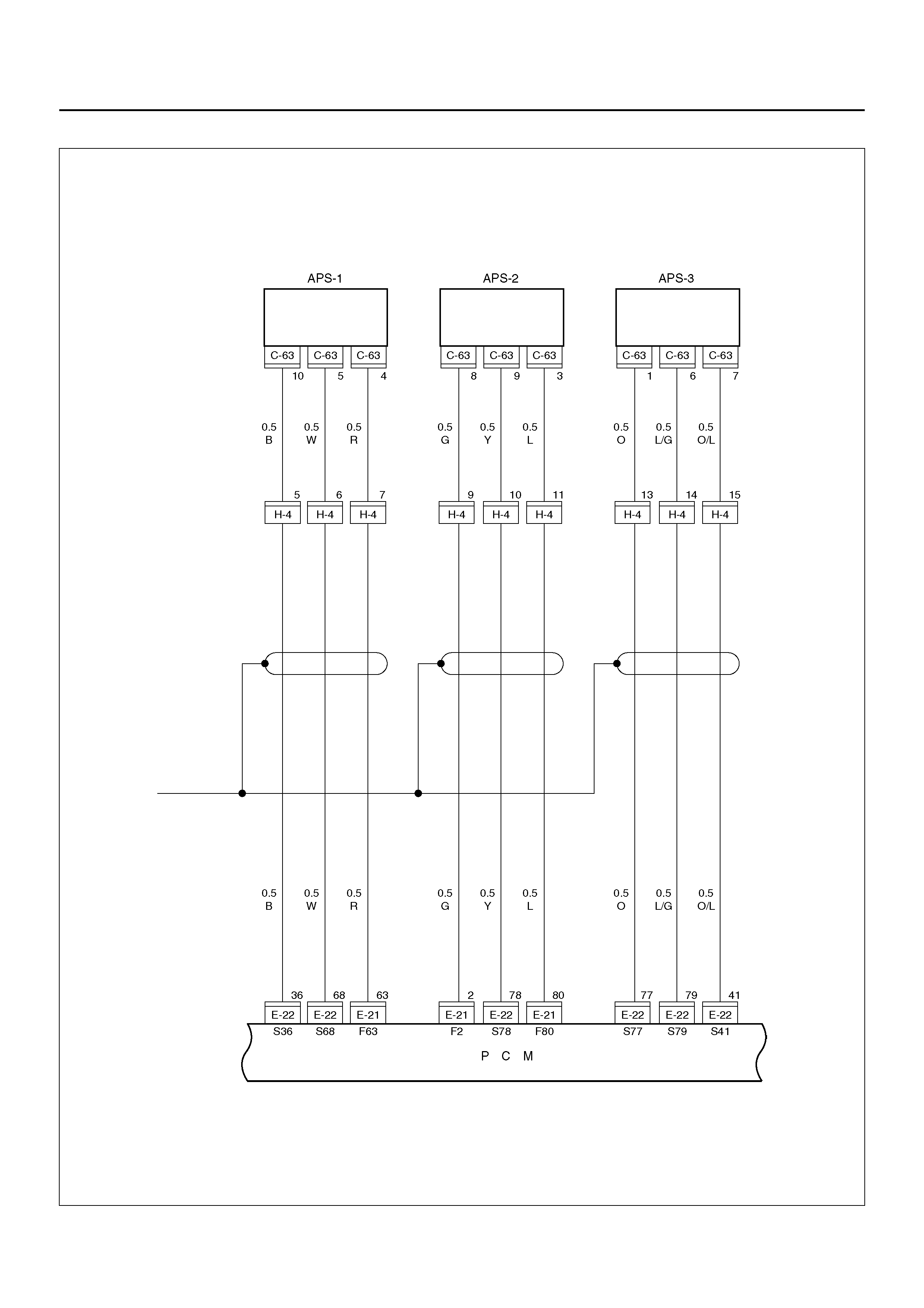
Circuit Diagram–8
D08R100080
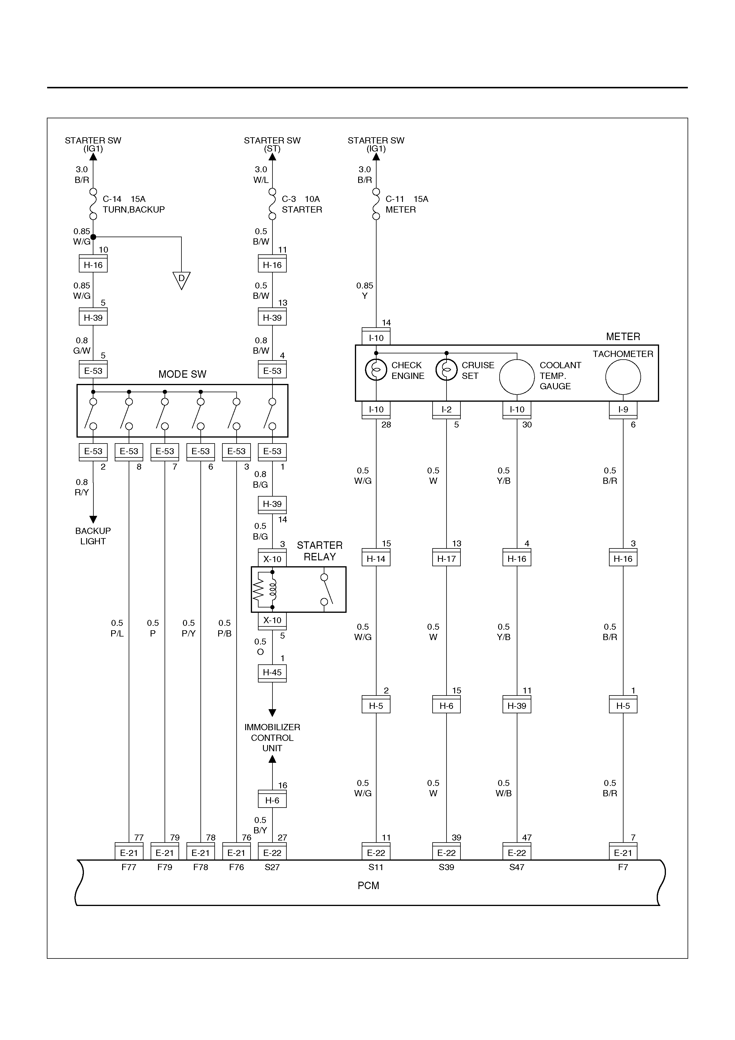
Circuit Diagram–9
D08R100081
Circuit Diagram–10
D08R100082
Circuit Diagram–11
D08R100083
Circuit Diagram–12
D08R100190
Circuit Diagram–13
D08R100085
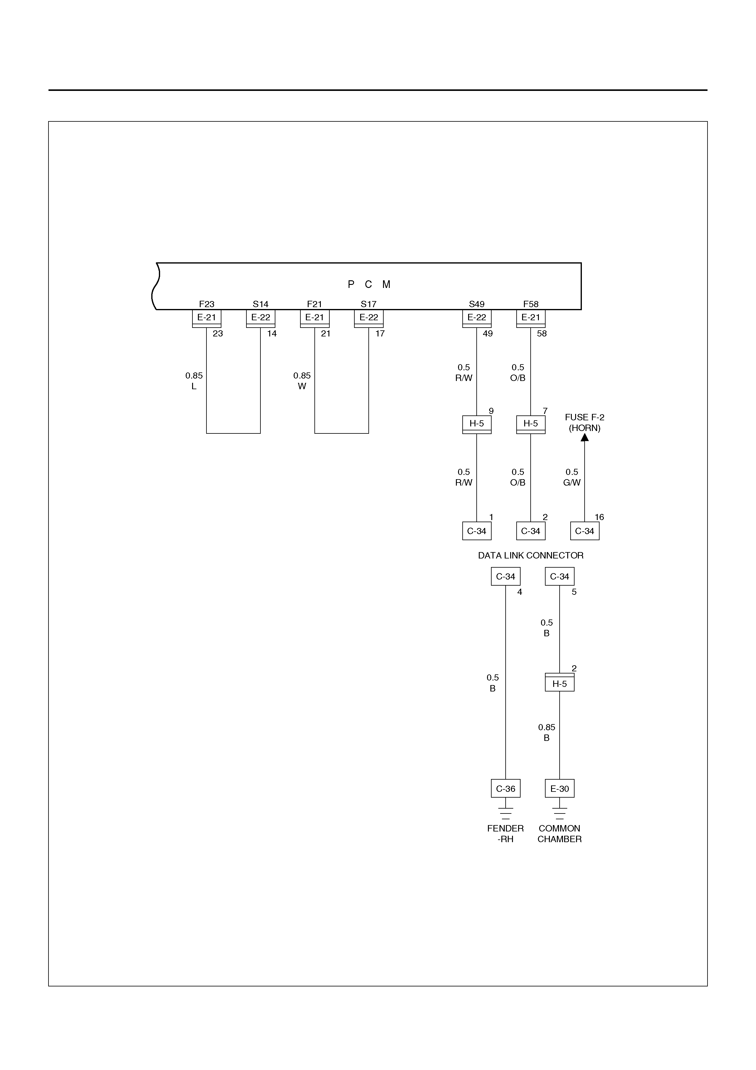
Circuit Diagram–14
D08R100086
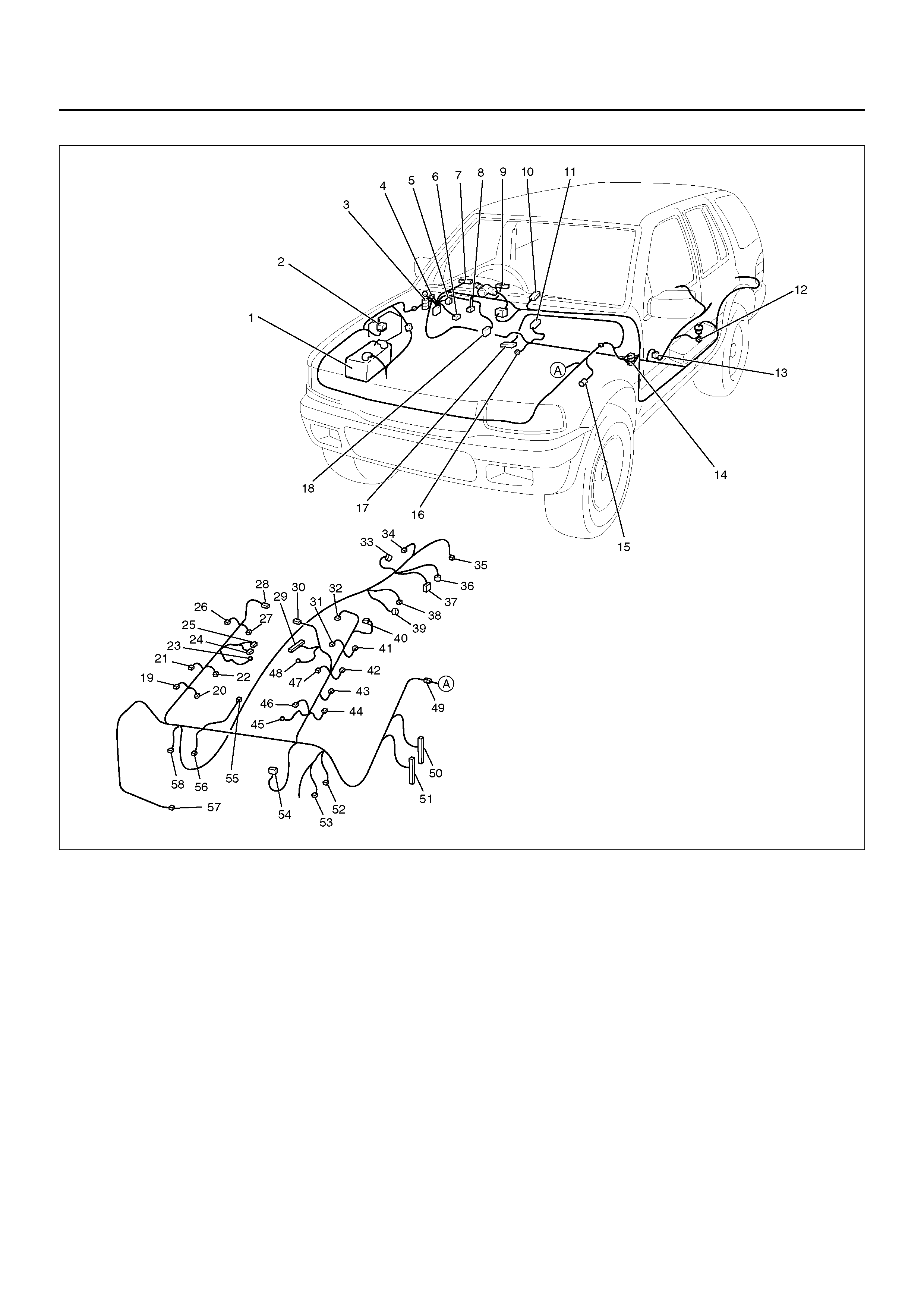
PARTS LOCATION – 1
Legend
(1) Battery
(2) Fuse & Relay Box
(3) H–14, H–15 , H–45
(4) Relay & Fuse Box
(5) C–34
(6) C–63
(7) I–9
(8) I–18
(9) I–10
(10) I–17
(11) B–24
(12) F–1
(13) H–25
(14) H– 16, H–17
(15) C–16
(16) B–6, B–8
(17) C–58
(18) C–59
(19) E–37
(20) E–26
(21) E–38
(22) E–25
(23) E–30
(24) E–17
(25) E–18
(26) E–39
(27) E–24
(28) E–33
(29) E–16
(30) E–7
(31) E–13
(32) E–44
(33) E–51
(34) E–55
(35) E–61
(36) E–54
(37) E–53

EndOFCallout
(38) E–52
(39) E–50
(40) E–32
(41) E–15
(42) E–42
(43) E–41
(44) E–40
(45) E–29
(46) E–11
(47) E–12
(48) E–28
(49) H–4, H–5, H–6, H–39
(50) E–22
(51) E–21
(52) E–9
(53) E–4
(54) E–5
(55) E–43
(56) E–8
(57) E–27
(58) E–20

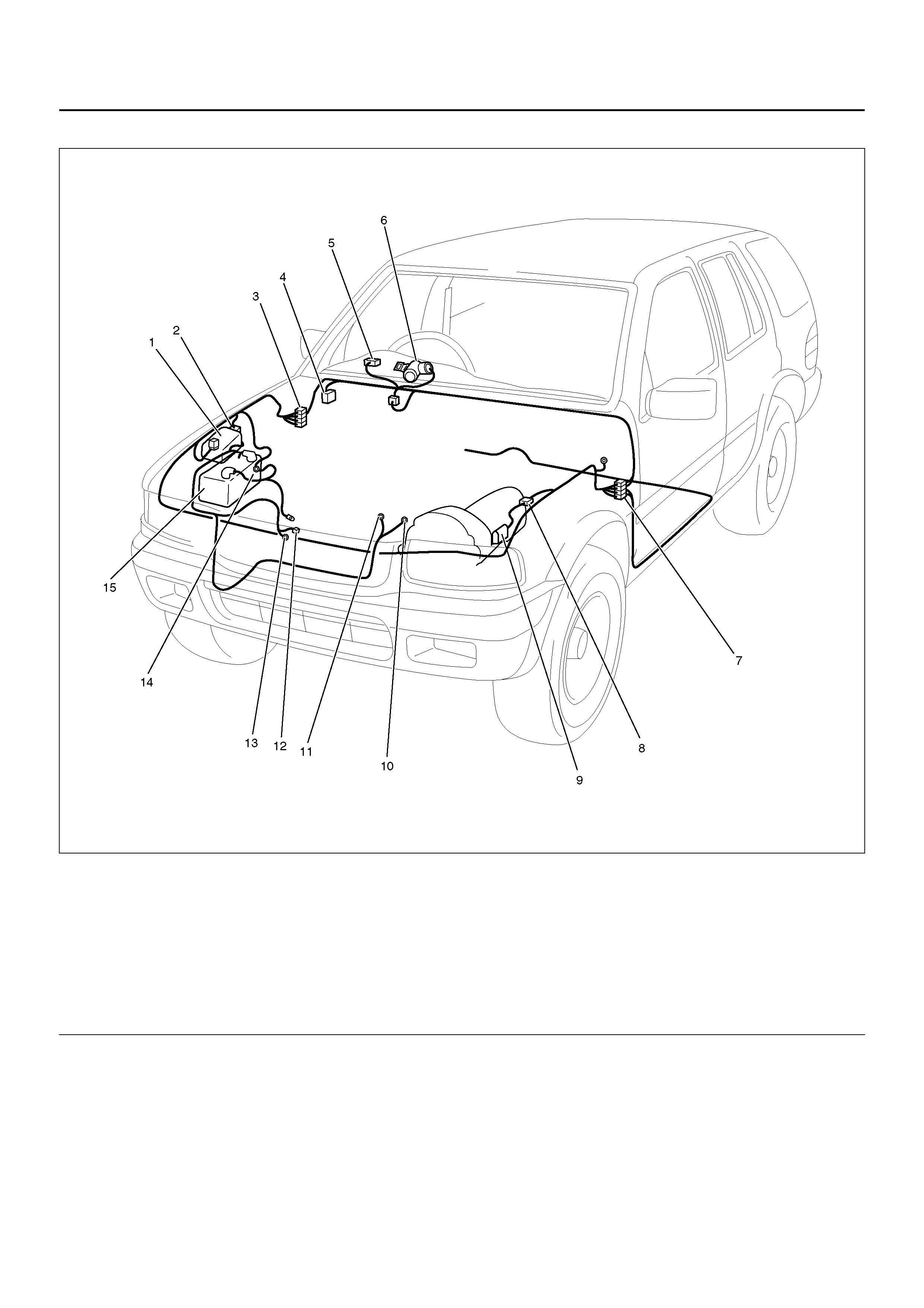
HEADLIGHT AND FOG LIGHT
GENERAL DESCRIPTION
The circuit consists of headlight, fog light, lighting
switch, dimmer·passing switch, fog light switch, high
beam indicator, lighting relay and fog light relay. When
starter switch is turned on by setting it at headlight
position, lighting relay is activated to turn on headlight.
Optical axis of headlight can be turned up or down by
operating dimmer switch wh ile headlight is on. Passing
switch is ind epe nde nt of li gh ting swi tc h, and op tica l ax is
of passing light c an be tu rned up only whi le switch lev er
is pulled up and held in this state.
When fo g light switc h is turne d on while he adlight on at
low–beam, fog light relay is activated to turn on fog light.
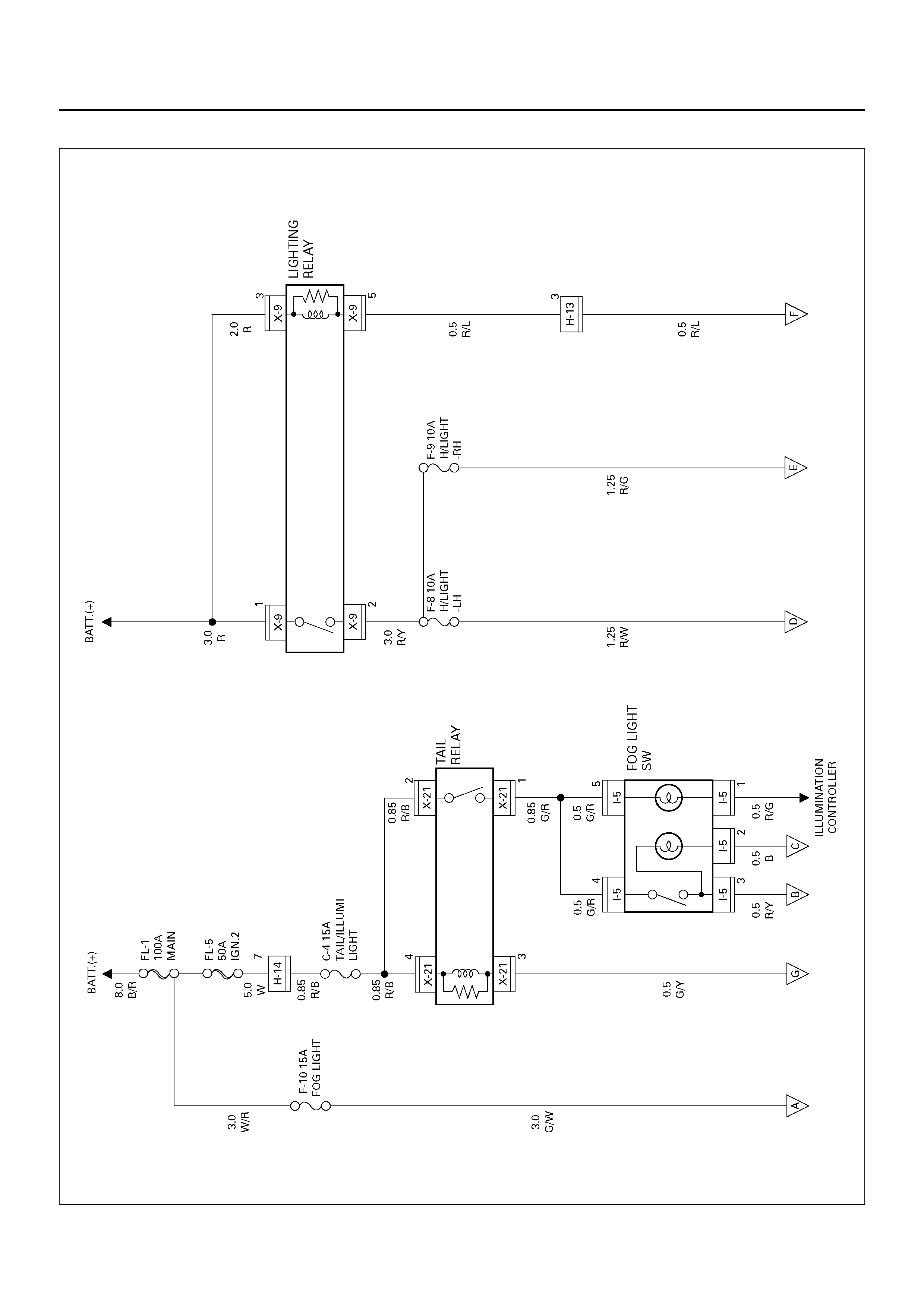
CIRCUIT DIAGRAM–1
D08R100104
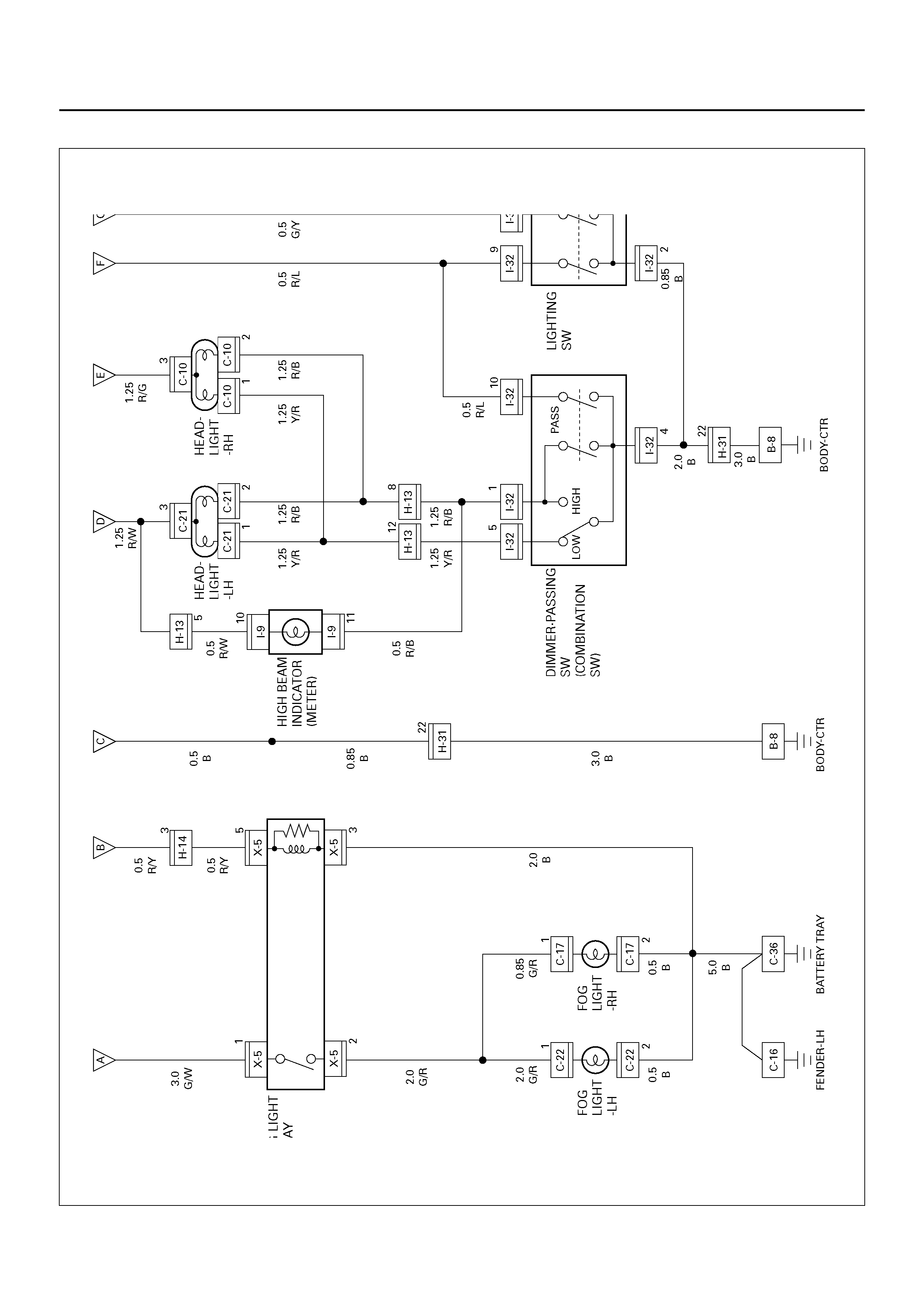
Circuit Diagram–2
D08R100105
PARTS LOCATION
D08RY00820
EndOFCallout
Legend
(1) Relay & Fuse Box (X–5, X–9)
(2) C–36
(3) H–13, H–14
(4) Relay & Fuse Box (X–21)
(5) I–5
(6) I–9
(7) Lighting Switch
(8) I–32 (Combination Switch)
(9) B–8
(10) C–16
(11) H–31
(12) C–22
(13) Fog Light – LH
(14) C–21
(15) Head Light – LH
(16) C–10
(17) C–17
(18) Fog Light – RH
(19) Head Light – RH

DIAGNOSIS
Both Headlights Inoperative
Headlight On The Left (or Right) Side Inoperative
Step Action Value(s) Yes No
1 Check the ground terminal B–8.
Is B–8 grounded securely? — Go to Step 2 Ground it
securely
2 Disconnect the combination switch connector I–32.
Is there continuity between switch side connector I–32
terminals 9 and 2 with the switch turned to headlight
position?
— Go to Step 2 Replace the
switch
3 Ch ec k con tin ui ty of dimm er -passi ng swi tc h.
Is there continuity between switch side connector I–32
terminal 5 and 4 with the switch turned to low position,
and terminal 1 and 4 with the switch turned to high
position?
— Go to Step 3 Replace the
switch
4 Check continuity between the lighting switch and the
ground B–8.
Is ther e continu ity between h arness si de connec tor I–
32 terminal 2 and the ground?
— Go to Step 5 Repair an open
circuit
5 Remove the lighting relay from the relay and fuse box.
Is the battery voltage applied between harness side
connector X–9 terminal 1 and the ground, X–9
terminal 3 and the ground?
Approx. 12V Go to Step 6 Repair an open
circuit between
battery and the
light ing relay
6 Check continuity between the lighting relay and the
lighting switch.
Is there continuity between harness side connector X–
9 terminal 5 and I–32 terminal 9?
— Go to Step 7 Repair an open
circuit
7 Check continuity between the lighting relay and fuse
F–8 or F–9.
Is there continuity between harness side connector X–
9 terminal 2 and fuse F–8 or F–9?
— Go to Step 8 Repair an open
circuit
8 Check continuity between the dimmer-passing switch
and the ground.
Is there continuity between switch side connector I–32
terminal 4 and the ground B–8?
— Replace the
lighting relay Repair an open
circuit
Step Action Value(s) Yes No
1 Is the fuse F–8 or F–9 normal? — Go to Step 2 Replace the
fuse
2 Remove the headlight bulb on the left or right side.
Is the bulb normal? — Go to Step 3 Replace the
bulb
3 1. Reinstall the bulb.
2. Turn the lighting switch to headlight position.
Is the battery voltage applied between harness side
connector C–21 terminal 3 and the ground or C–10
terminal 3 and the ground?
Approx. 12V Reconnect the
headlight
connector
securely
Repair an open
circuit between
the fuse and
headlight

Headlights In Low–Beam Inoperative
Headlight In High–Beam Inoperative
Headlights Remain On When Lighting Switch Turned Off
Headlight Comes On With Lighting Switch At Parking Light Position
Step Action Value(s) Yes No
1 Disconnect the combination switch connector I–32.
Is there continuity between switch side connector I–32
terminal 5 and 4 with the switch at low-beam position?
— Go to Step 2 Repair or
replace the
switch
2 Repair an open circuit between connector H-13
terminal 12 and connector I-32 terminal 5.
Is the action complete?
— Verify repair —
Step Action Value(s) Yes No
1 Disconnect the combination switch connector I–32.
Is there continuity between switch side connector I–32
terminal 1 and 4 with the switch at high-beam
position?
— Go to Step 2 Repair or
replace the
switch
2 Repair an open circuit between connector H–13
terminal 8 and connector I–32 terminal 1.
Is the action complete?
— Verify repair —
Step Action Value(s) Yes No
1 1. Turn the lighting switch to off position.
2. Disconnect the combination switch connector I–
32.
Do the headlights still remain on?
— Go to Step 3 Go to Step 2
2 Repair or replace the lighting switch.
NOTE: There sh oul d be no co nti nui ty betwee n swi tc h
side connector I–32 terminal 9 and 2.
Is the action complete?
— Go to Step 1 —
3 Re mov e the lig hti ng re lay.
Is there continuity between the relay side connector
X–9 terminal 1 and 2?
— Replace the
relay Go to Step 4
4 Re pair short ci rcuit between the lig hting relay and the
lighting switch.
Is the action complete?
— Verity repair —
Step Action Value(s) Yes No
1 Repair or replace the lighting switch.
NOTE: There sh oul d be no co nti nui ty betwee n swi tc h
side conn ector I–32 ter minal 9 and 2 when the swi tch
is turned to parking light pos iti on .
Is the action complete?
— Verify repair —

(While Headlight Is On In Low–Beam) Both Fog Lights Inoperative
Step Action Value(s) Yes No
1 Are the fuse F–10 and C–4 normal? — Go to Step 2 Replace the
fuse(s)
2 Is C–36 gr ound ed se curely? — Go to Step 3 Gr ou nd it
securely
3 Re mov e the fogl ig ht relay.
Is the battery voltage applied between harness side
connector X–5 terminal 1 and the ground?
Approx. 12V Go to Step 5 Go to Step 4
4 Repair an open circuit between Fuse F–10 and
connector X–5 terminal 1.
Is the action complete?
— Go to Step 3 —
5 Is there continuity between harness side connector X–
5 terminal 3 and the ground? — Go to Step 7 Go to Step 6
6 Repair an open circuit between connector X–5
terminal 3 and the ground C–36.
Is the action complete?
— Go to Step 5 —
7 1. Turn the lighting switch to clearance light position.
2. Turn the fog light switch on.
Is the battery voltage applied between harness side
connector X–5 terminal 5 and the ground?
Approx. 12V Replace the fog
light relay Go to Step 8
8 Disconnect the lighting switch connector I–32.
Is there continuity between the switch side connector
terminal 2 and 3?
— Go to Step 9 Repair or
replace the
switch.
9 Disconnect the tail relay.
Is ther e continu ity between h arness si de connec tor I–
21 terminal 3 and X–32 terminal 3?
— Go to Step 10 Repair an open
circuit
10 Is the battery voltage applied between harness side
connector X–21 terminal 2, 4 and the ground? Approx. 12V Go to Step 12 Go to Step 11
11 Repair an open circuit between the fuse C–4 and
connector X–21 terminal 2 or 4.
Is the action complete?
— Go to Step 10 —
12 1. Disconnect the fog light switch.
2. Turn the switch on.
Is there continuity between the switch terminal 3 and
4?
— Go to Step 13 Repair or
replace the
switch
13 Is there con tinuity b etween har ness side connecto r I–
5 terminal 4 and connector X–21 terminal 1? — Go to Step 14 Repair an open
circuit
14 Is there con tinuity b etween har ness side connecto r I–
5 terminal 3 and connector X–5 terminal 5? — Replace the tail
relay Rep air an open
circuit

(While Headlight Is On In Low–Beam) Fog Light On the Left (or Right) Side Inoperative
Step Action Value(s) Yes No
1 Is the fog light bulb on the left or right side normal? — Go to Step 2 Replace the
bulb
2 Disconnect the fog light connector C–22 or C–17.
Is there continuity between the fog light harness side
connector terminal 2 and the ground?
— Go to Step 3 Repair an open
circuit
3 Repair an open circuit between fog light relay
connector X–5 terminal 2 and fog light connector
terminal 1.
Is the action complete?
— Verify repair —

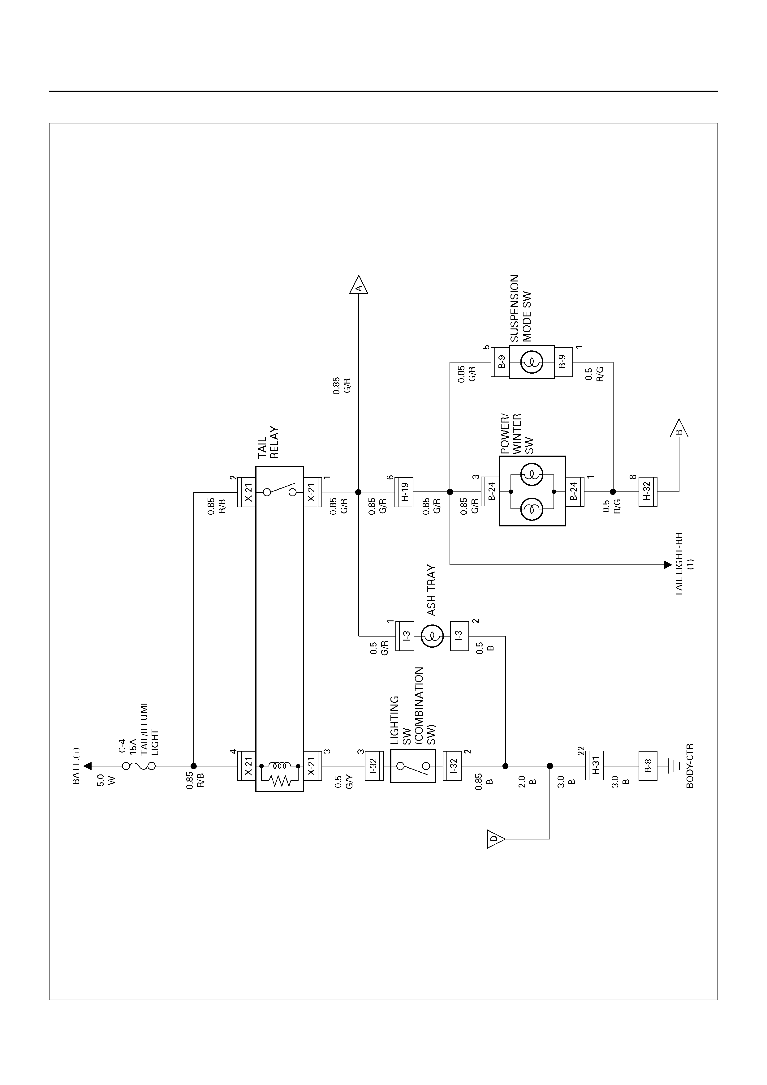
CLEARANCE LIGHT, TAIL LIGHT AND LICENSE PLATE LIGHT
GENERAL DESCRIPTION
The circuit consists of lighting switch, clearance light,
tail light and license plate light.
All these lights come on when lighting switch is turned
on with the switch to either parking or headlight position.
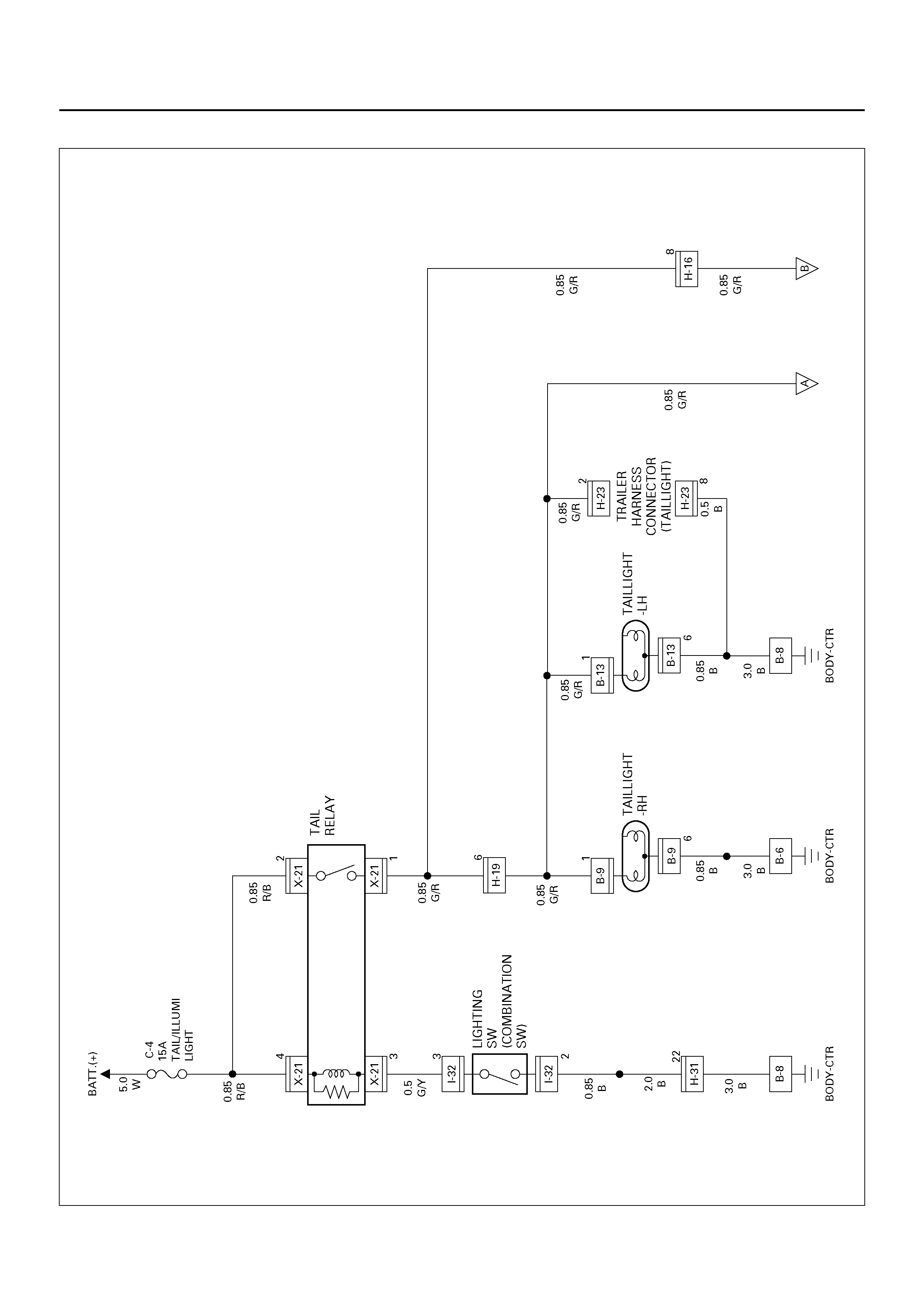
CIRCUIT DIAGRAM–1
D08R100223
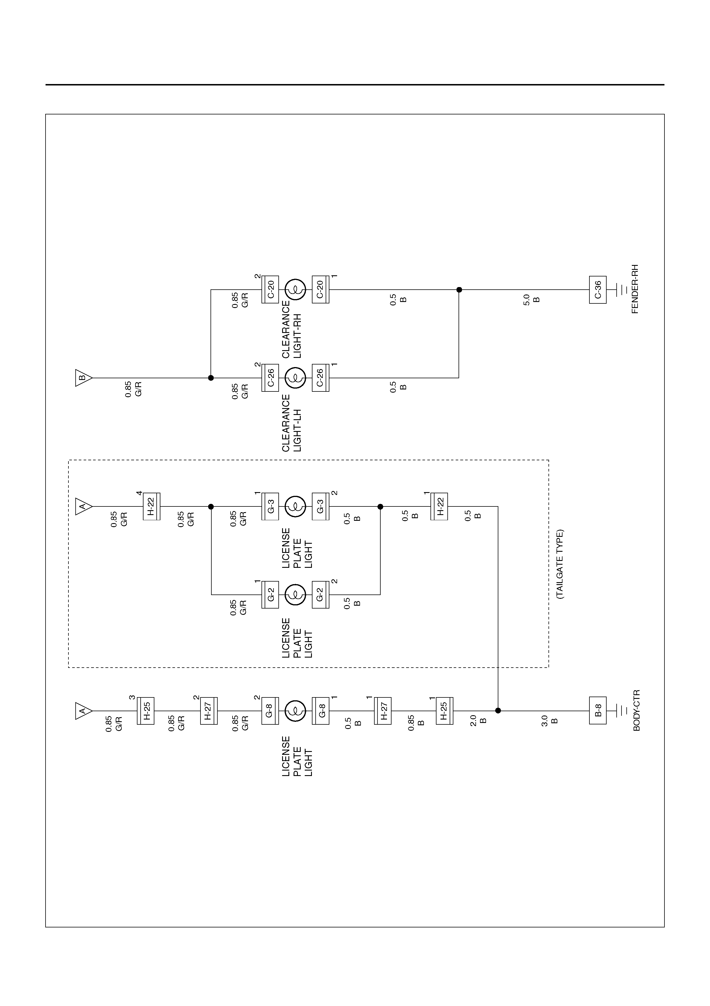
Circuit Diagram–2
D08R100107
PARTS LOCATION
D08RY00821
EndOFCallout
Legend
(1) C–36
(2) H–19
(3) Relay & Fuse Box (X–21)
(4) Lighting Switch
(5) I–32
(6) B–9
(7) Tail Light–RH
(8) G–8
(9) License Plate Light (Bumper Type)
(10) G–3 (Tailgate Type)
(11) G–2 (Tailgate Type)
(12) H–22
(13) Tail Light – LH
(14) B–13
(15) H–27
(16) H–25
(17) H–31
(18) C–16
(19) B –6, B–8
(20) C–26
(21) Clearance Light–LH
(22) C–20
(23) Clearance Light–RH

DIAGNOSIS
Both Tail Lights Inoperative
Tail Light On The Left (or Right) Side Inoperative
Clearance Light Inoperative
Clearance Light On The Left (or Right) Side Inoperative
Step Action Value(s) Yes No
1 Repair an open circuit between the tail relay and the
taillights.
Is the action complete?
— Verify repair —
Step Action Value(s) Yes No
1 Remove the taillight bulb on the left or right side.
Is the bulb normal? — Go to Step 2 Replace the
bulb
2 Is B–6 or B–8 grounded securely? — Go to Step 3 Ground it
securely
3 Disconnect the taillight connector B–9 or B–13.
Is the battery voltage applied between harness side
connector B–9 or B–13 terminal 1 and the ground?
Approx. 12V Go to Step 5 Go to Step 4
4 Repair an open circuit between the tail relay and the
taillight on the left or right side.
Is the action complete?
— Verify repair —
5 Re pair an ope n circuit between the taillig ht on the left
or right side and the groun d.
Is the action complete?
— Verify repair —
Step Action Value(s) Yes No
1 Repair an open circuit between the tail relay and the
taillights.
Is the action complete?
— Verify repair —
Step Action Value(s) Yes No
1 Remove the clearance light bulb on the left or right
side.
Is the bulb normal?
— Go to Step 2 Replace the
bulb
2 Disconnect the clearance light connector C–20 or C–
26.
Is the battery voltage applied between harness side
connector C–20, or C–26 terminal 2 and the ground?
Approx. 12V Go to Step 4 Go to Step 3
3 Repair an open circuit between the tail relay and the
clearance light on the left or right side.
Is the action complete?
— Verify repair —
4 Repair an open circuit between the clearance light
and the ground?
Is the action complete?
— Verify repair —

License Plate Light Inoperative
Step Action Value(s) Yes No
1 Do the taillights come on? Go to Step 2 Go to Step 6
2 Re mov e the lic en se plate li ght bul b.
Is the bulb normal? Go to S tep 3 Replace bulb
3 1. Disconnect the license plate light connector G–8.
2. Turn the lighting switch on.
Is the battery voltage applied between the license
plate light harness side connector terminal and the
ground?
Approx. 12V Go to Step 5 Go to Step 4
4 Repair an open circuit between connector H–19
terminal 6 and the license plate light.
Is the action complete?
— Verify repair —
5 Repair an open circuit between the license plate light
and the ground.
Is the action complete?
— Verify repair —
6 Refer to the diagnosis procedure for “Both Taillight
Inoperative" in this section.
Is the action complete?
— Verify repair —

INTERIOR ILLUMINATION LIGHT
GENERAL DESCRIPTION
The circuit consists of lighting switch, tail relay, and
illumination lights.
All these lights come on when lighting switch is turned
on with the switch to either parking or headlight position.
CIRCUIT DIAGRAM–1
D08R100108
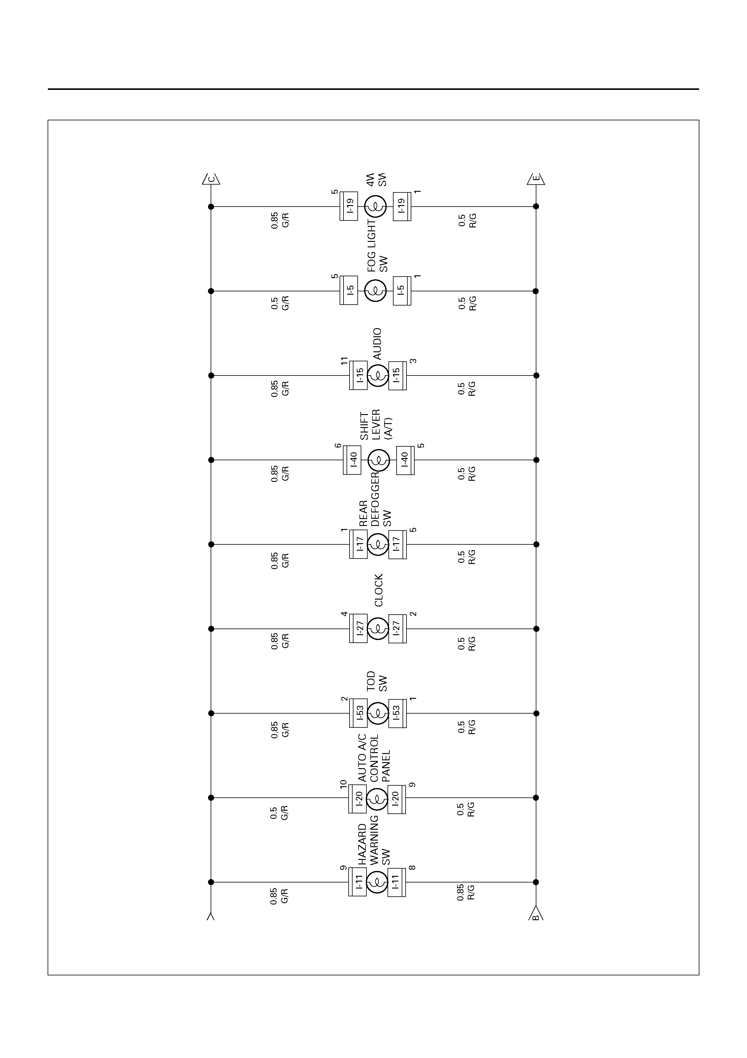
Circuit Diagram–2
D08R100109
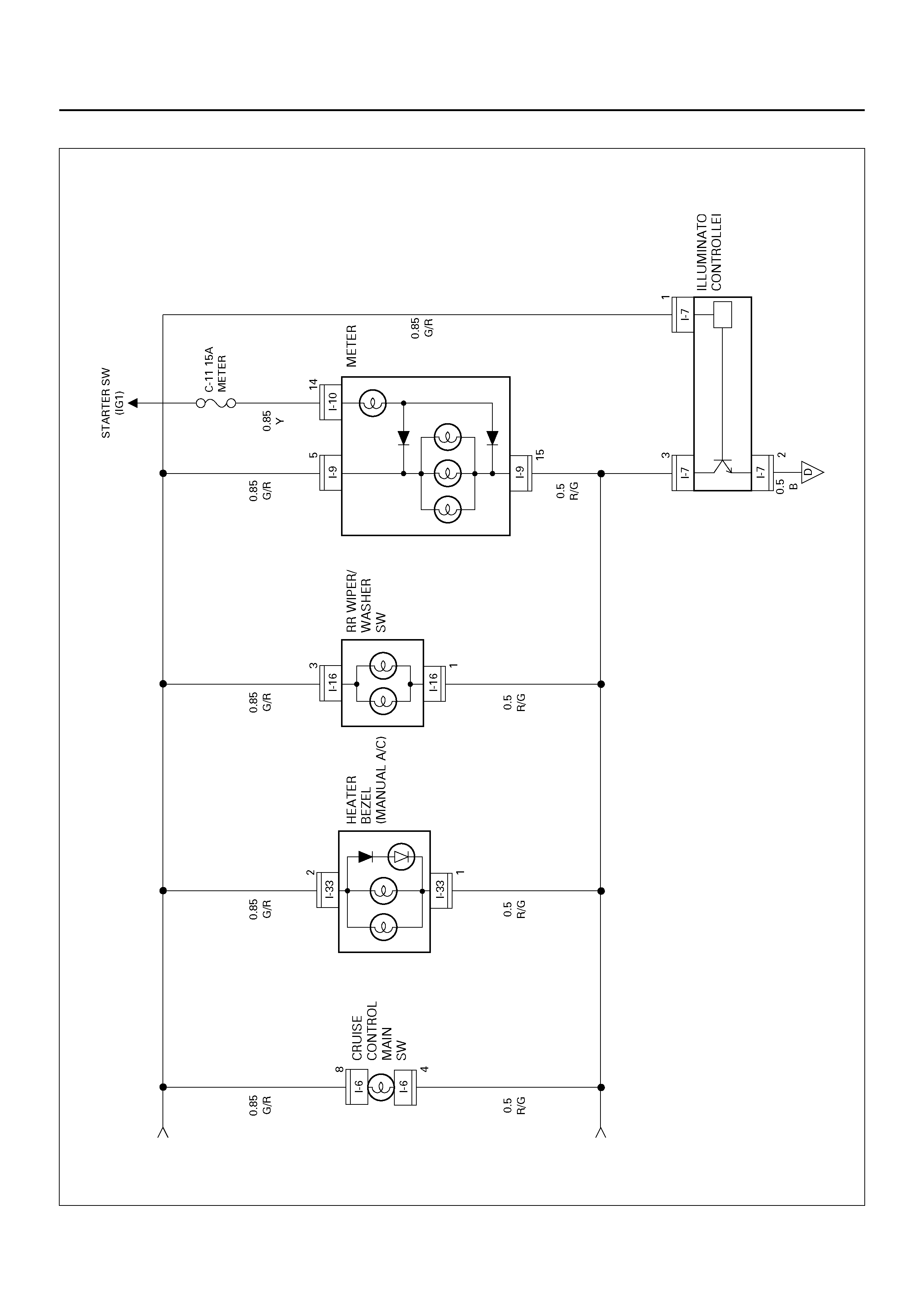
Circuit Diagram–3
D08R100110
PARTS LOCATION
D08RY00822
EndOFCallout
Legend
(1) H–19, H–32
(2) I–53
(3) I–19
(4) I–7
(5) I–5
(6) Lighting Switch
(7) I–10
(8) I–9
(9) I–27
(10) I–16
(11) I–17
(12) I–11
(13) I–33
(14) B–24
(15) H–25
(16) H–31
(17) B –6, B–8
(18) I–15
(19) I–40
(20) I–3
(21) I–32
(22) Relay & Fuse Box (X–21)

DIAGNOSIS
Interior Illumination Light s Inopera ti ve
Step Action Value(s) Yes No
1 Turn the lighting switch to clearance light position.
Do the exterior lights come on? — Go to Step 3 Go to Step 2
2 Refer to the diagnosis procedure in Clearance Light,
Taillight and License Plate Light section.
Is the action complete?
— Verify repair —
3 Re pair an op en circ uit betwe en tail re lay harn ess sid e
connector X–21 terminal 1 and interior lights.
Is the action complete?
— Verify repair —

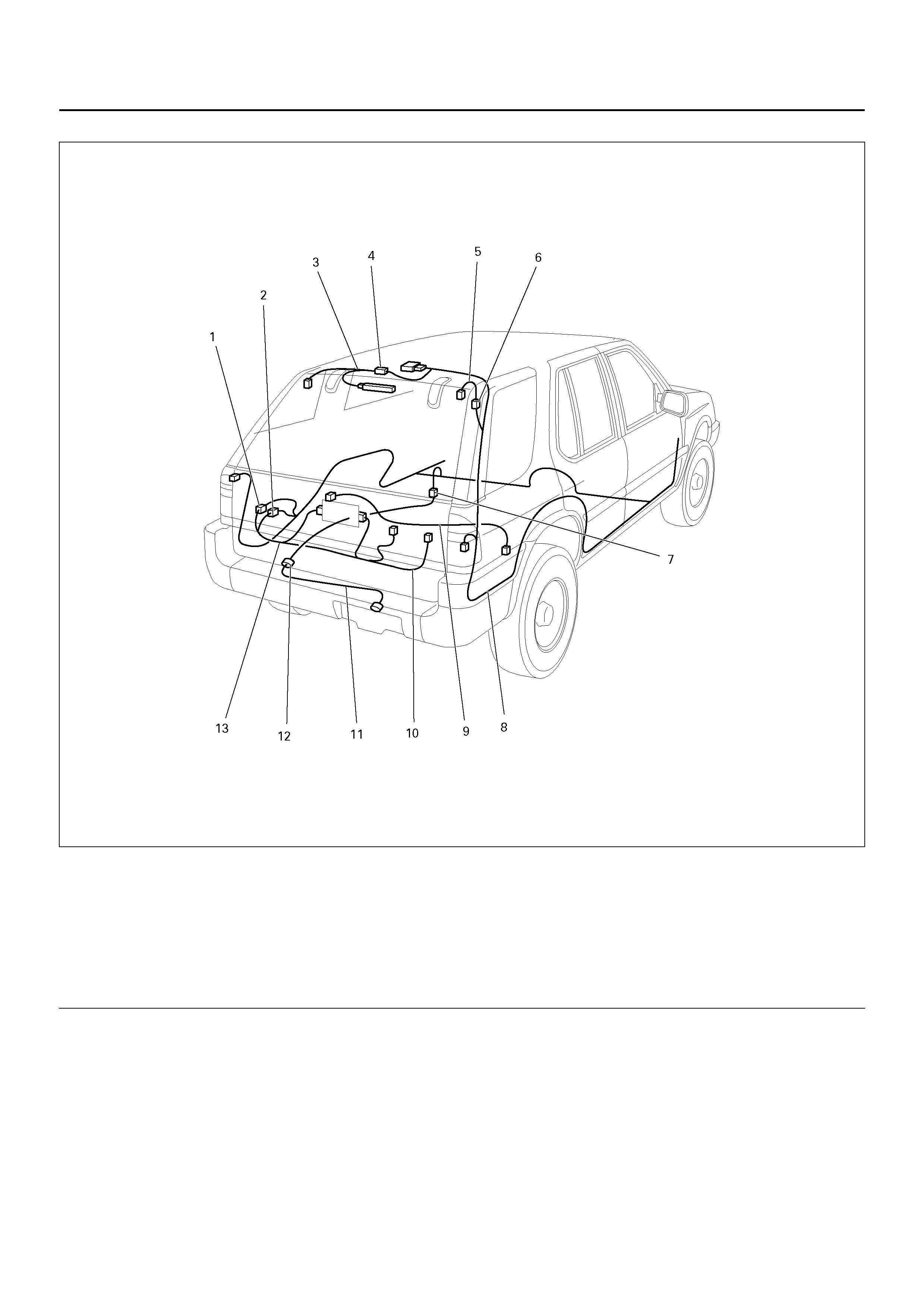
TURN SIGNAL LIGHT, HAZARD WARNING LIGHT
GENERAL DESCRIPTION
The circuit consists of turn signal light switch
(combination switch) turn signal light, hazard warning
switch and flasher unit. When turn signal light switch is
turned on with starter switch on, turn signal light will
operate. When turn signal light is flashing, indicator light
in meter also starts flashing. When hazard warning
switch i s turned on, cu rrent fl ows to flasher unit t hroug h
hazard w arning switch to cause haz ard warning lig ht to
flash independent of position of starter switch. At the
same time, indicator lights in meter also start flashing.
CIRCUIT DIAGRAM–1
D08R100111
Circuit Diagram–2
D08R100112
PARTS LOCATION
D08RX201
EndOFCallout
Legend
(1) C–36
(2) C–40
(3) H–14, H–19 , H–32
(4) Relay & Fuse Box
(5) Turn Signal light Switch
(6) I–32
(7) B–9
(8) Rear Turn Signallight – RH
(9) I–11
(10) C–16
(11) Rear Turn Signalligh t – LH
(12) B–13
(13) H–23
(14) I–47
(15) C– 43
(16) C–23
(17) Front Turn Signallight – LH
(18) B –6, B–8
(19) C–18
(20) Front Turn Signallight – RH

DIAGNOSIS
Turn Signal Light Does Not Flash
Step Action Value(s) Yes No
1 Is fuse C–14 normal? — Go to Step 2 Replace the
fuse
2 1. Disconnect the flasher unit connector I–47.
2. Turn the starter switch on.
Is the battery voltage applied between harness side
connector I–47 terminal 1 and the ground?
Approx. 12V Go to Step 4 Go to Step 3
3 Repair an open circuit between fuse C–14 and
connector I–47 terminal 1.
Is the action complete?
— Go to Step 2 —
4 Is there con tinuity b etween har ness side connecto r I–
47 terminal 7 and the ground? — Go to Step 6 Go to Step 5
5 Repair an open circuit between harness side
connector I–47 terminal 7 and the ground B–8.
Is the action complete?
— Go to Step 4 —
6 Turn the turn signal light SW to the left position.
Is ther e continu ity between h arness si de connec tor I–
47 terminal 5 and the ground?
— Go to Step 12 Go to Step 7
7 Disconnect the turn signal light switch connector I–32.
Is ther e continu ity between h arness si de connec tor I–
32 terminal 7 and I–47 terminal 5?
— Go to Step 9 Go to Step 8
8 Repair an open circuit between connector I–32
terminal 7 and I–47 terminal 5.
Is the action complete?
— Go to Step 7 —
9 Is there con tinuity b etween har ness side connecto r I–
32 terminal 6 and the ground? — Go to Step 11 Go to Step 10
10 Repair an open circuit between connector I–32
terminal 6 and the ground B–8.
Is the action complete?
— Go to Step 9 —
11 Repair or replace the combination switch.
Is the action complete? — Go to Step 5 —
12 Turn the turn signal light to the right position.
Is ther e continu ity between h arness si de connec tor I–
47 terminal 6 and ground?
— Go to Step 18 Go to Step 13
13 Disconnect the turn signal light switch connector I–32.
Is there continuity between the harness side
connector terminal I–32 terminal 8 and I–47 terminal
6?
— Go to Step 15 Go to Step 14
14 Repair an open circuit between connector I–32
terminal 8 and I–47 terminal 6.
Is the action complete?
— Go to Step 13 —
15 Is there con tinuity b etween har ness side connecto r I–
32 terminal 6 and the ground? — G o to Step 17 Go to Step 16
16 Repair an open circuit between connector I–36
terminal 6 and the ground B–8.
Is the action complete?
— Go to Step 15 —
17 Repair or replace the combination switch.
Is the action complete? — Verify repair —

Hazard Warning Light Does Not Flash
Turn Signal Light Flashes Too Quickly
18 Replace the flusher unit.
Is the action complete? — Verify repair —
Step Action Value(s) Yes No
Step Action Value(s) Yes No
1 Is fuse F–1 normal? — Go to Step 2 Replace the
fuse
2 Disconnect the flasher unit connector I–47.
Is the battery voltage applied between harness side
connector I–47 terminal 4 and the ground?
Approx. 12V Go to Step 4 Go to Step 3
3 Repair an open circuit between the fuse F–1 and
connector I–47 terminal 4.
Is the action complete?
— Go to Step 2 —
4 Is there con tinuity b etween har ness side connecto r I–
47 terminal 7 and the ground? — Go to Step 6 Go to Step 5
5 Repair an open circuit between connector I–47
terminal 7 and the ground B–8.
Is the action complete?
— Go to Step 4 —
6 Is B–8 grounded securely? — Go to Step 7 Ground it
securely
7 1. Disconnect the hazard warning switch connector
I–11.
2. Turn the hazard warning switch on.
Is there continuity between the switch side connector
I–11 terminal 6 and 10?
— Go to Step 8 Repair or
replace the
switch
8 Is there continuity between the harness side
connec tor I–11 terminal 6 and the grou nd B–8 or I–11
terminal 10 and I–47 terminal 8?
— Go to Step 10 Go to Step 9
9 Repair an open circuit between connector I–11
terminal 6 and the ground B–8 or I–11 terminal 10 and
I–47 termi nal 8.
Is the action complete?
— Verify repair —
10 Replace the flasher unit.
Is the action complete? — Verify repair —
Step Action Value(s) Yes No
1 Do all of turn signal lights flash? — Go to Step 2 Go to Step 3
2 Replace the flasher unit.
Is the action complete? — Verify repair —
3 Is the bulb of turn signal light that does not work
normal? — Go to Step 4 Replace the
bulb
4 Repair an open circuit between the turn signal light
and the turn signal light.
Is the action complete?
— Verify repair —

STOPLIGHT
GENERAL DESCRIPTION
The circuit consists of stoplight, high mounted stoplight
and stoplight switch.
With brake pedal depressed, stoplight switch is turned
to on to illuminate stoplight.
Stoplight switch controls not only the operation of
stoplight but also the input of cruise cancel signals to
cruise control unit.
CIRCUIT DIAGRAM
D08R100113
PARTS LOCATION
D08RX203
EndOFCallout
Legend
(1) H–19
(2) Relay & Fuse Box
(3) I–18
(4) B–9
(5) Stoplight – RH
(6) G–10, G–11
(7) High Mounted Stoplight
(8) H–21
(9) Stoplight – LH
(10) B–13
(11) B–8
(12) B–6

DIAGNOSIS
Both Stoplights Inoperative
Stoplight On The Left (or Right) Side Inoperative
High Mounted Stoplight Inoperative
Step Action Value(s) Yes No
1 Is the fuse C–6 normal? — Go to Step 2 Replace the
fuse
2 Dieconnect the stoplight switch connector I–18.
Is there continuity between switch side connector I–18
terminal 1 and 4 with the brake pedal depressed?
— Go to Step 3 Repair or
replace the
switch
3 Is the battery voltage applied between harness side
connector I–18 terminal 1 and the ground? Approx. 12V Go to Step 5 Go to Step 4
4 Repair an open circuit between the fuse C–6 and
connector I–18 terminal 1.
Is the action complete?
— Verify repair —
5 Repair an open circuit between stoplight switch and
the stoplight.
Is the action complete?
— Verify repair —
Step Action Value(s) Yes No
1 1. Disconnect the stoplight connector B–9 or B–13.
2. Depress the brake pedal.
Is the battery voltage applied between stoplight
harness side connector terminal 2 and the ground?
Approx. 12V Go to Step 2 Go to Step 3
2 Repair an open circuit between the stoplight and the
ground.
Is the action complete?
— Verify repair —
3 Repair an open circuit between the stoplight switch
and the stoplight.
Is the action complete?
— Verify repair —
Step Action Value(s) Yes No
1 De pr ess the br ake pedal .
Does the stoplight come on? — Go to Step 3 Go to Step 2
2 Refer to the diagnosis procedure for “Both Stoplights
inoperative" in this section.
Is the action complete?
— Verify repair —
3 Is B–8 grounded securely? — Go to Step 4 Ground it
securely
4 1. Disconnect the high mounted stoplight connector.
2. Depress the brake pedal.
Is the battery voltage applied between harness side
connector G–11 terminal 1 and the ground?
Appprox. 12V Go to Step 6 Go to Step 5
5 Repair an open circuit between connector H–19
terminal 10 and the high mounted stoplight.
Is the action complete?
— Go to Step 4 —
6 Is there continuity between high mounted stoplight
side connector terminals? — Go to Step 7 Repair or
replace the light

7 Repair an open circuit between the high mounted
stoplight and the ground B–8.
Is the action complete?
— Verify repair —
Step Action Value(s) Yes No

BACKUP LIGHT
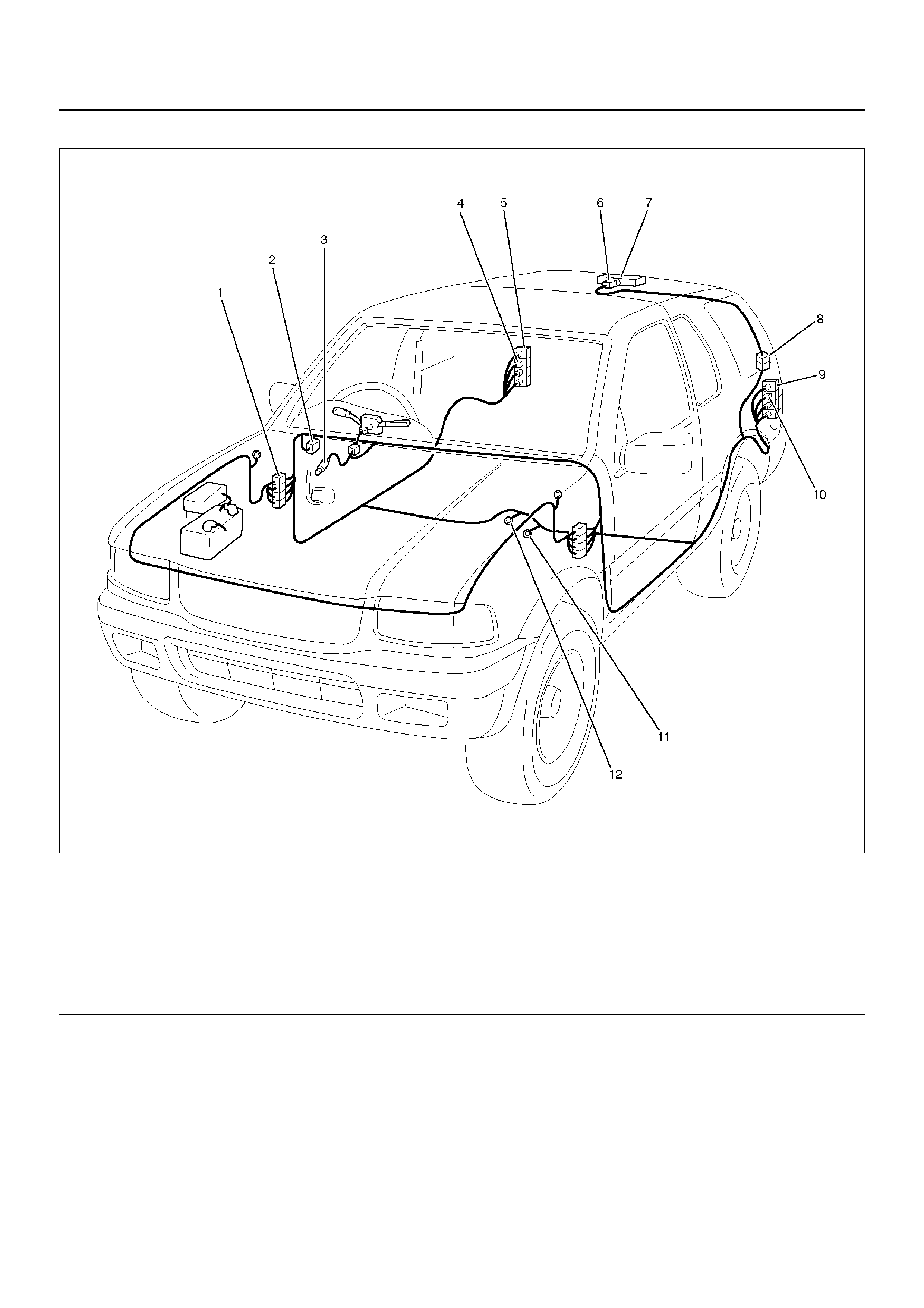
GENERAL DESCRIPTION
The circuit consists of backup light switch (M/T), mode
switch (A/T) and backup light.
When shift lever is set to “R" position, backup light
switch (M/T) or mode switch (A/T) is activated to
illumin ate bac ku p lig ht.
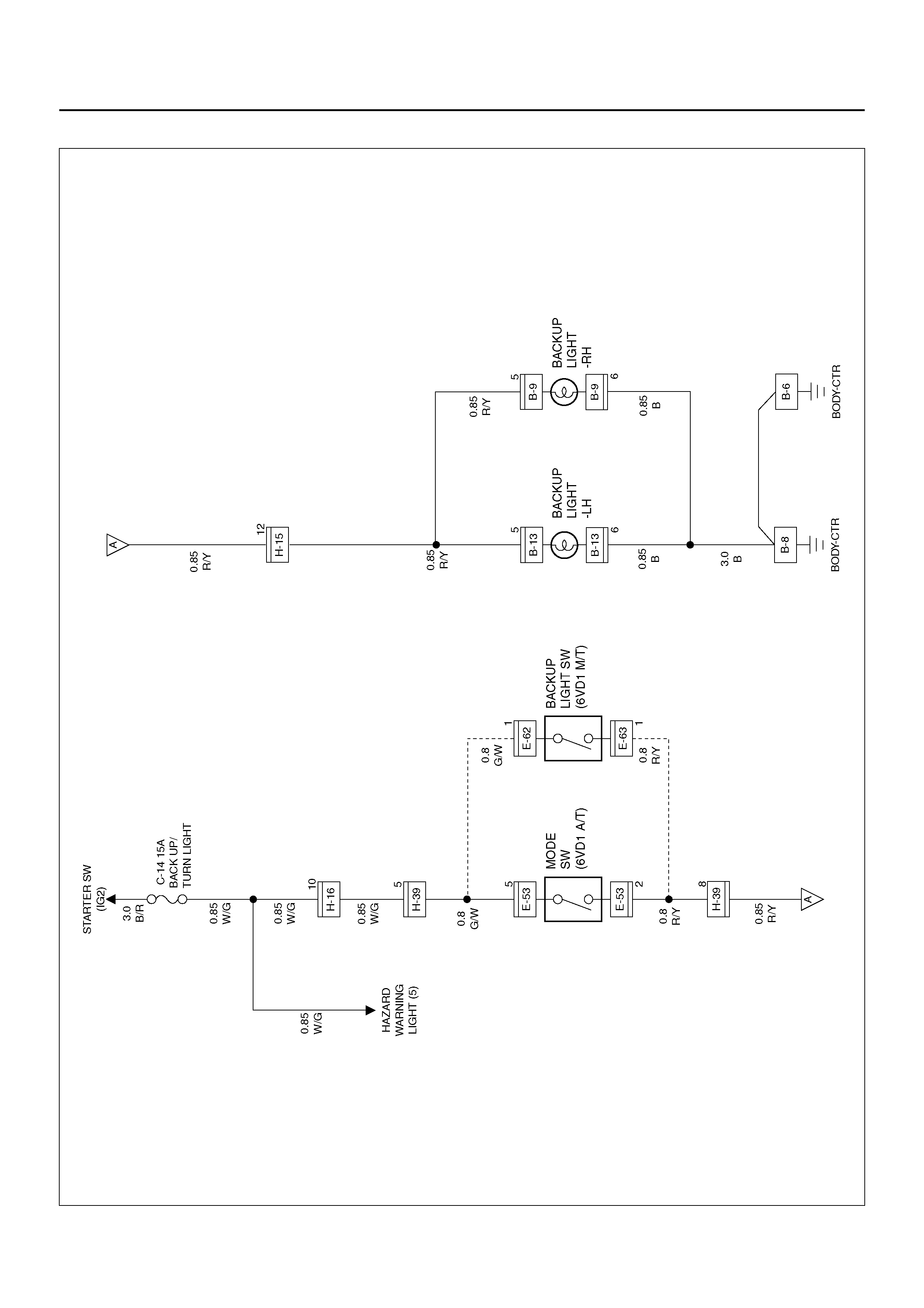
CIRCUIT DIAGRAM
D08R100114
PARTS LOCATION
D08RY00824
EndOFCallout
Legend
(1) B–9
(2) Backup Light – RH
(3) Backup Light – LH
(4) B–13
(5) H–15, H–16
(6) B–8
(7) B–6
(8) H–39
(9) E–62
(10) E–53
(11) Relay & Fuse Box

DIAGNOSIS
Both Backup Lights Inoperative
Backup Light On The Left (or Right) Side Inoperative
Step Action Value(s) Yes No
1 Is the fuse C–14 normal? — Go to Step 2 Replace the
fuse
2 Are B–6 and B–8 ground securely? — Go to Step 3 Ground them
securely
3 1. Disconnect the mode switch connector E–53 or
backup light switch connector E–62 and E–63.
2. Turn the starter switch on.
Is the battery voltage applied between harness side
connec tor E-53 termin al 5 and the gr ound, or har ness
side connector E–62 terminal 1 and the ground?
Approx. 12V Go to Step 5 Go to Step 4
4 Repair an open circuit between the fuse C–14 and
connector E–53 terminal 5 or connector E–62 terminal
1.
Is the action complete?
— Go to Step 3 —
5 Set the transmission gear to the reverse position.
Is there continuity between mode switch side
connector terminal 2 and 5, or backup light switch side
connector terminals?
— Go to Step 6 Repair or
replace the
switch
6 1. Reconnect the mode switch connector E–53 or
backup light switch connector E–62 and E–63.
2. Disconnect the backup light connector B–9 or B–
13.
Is the battery voltage applied between the backup
light harness side connector terminal 5 and the
ground?
Approx. 12V Go to Step 8 Go to Step 7
7 Repair an open circuit between the mode switch or
backup light switch and the backup lights.
Is the action complete?
— Verify repair —
8 Re pair an open circuit between backup l ights and the
ground.
Is the action complete?
— Verify repair —
Step Action Value(s) Yes No
1 Remove the backup light bulb on the left or right side.
Is the bulb normal? — Go to Step 2 Replace the
bulb
2 1. Set the transmission gear to the reverse position.
2. Turn the starter switch on.
Is the battery voltage applied between backup light
harness side connector B–9 or B–13 terminal 5 and
the ground?
Approx. 12V Go to Step 4 Go to Step 3
3 Repair an open circuit between connector H–15
terminal 12 and the backup light on the left or right
side.
Is the action complete?
— Verify repair —
4 Repair an open circuit between the backup light on the
left or right side and the ground.
Is the action complete?
— Verify repair —

Backup Lights Remain On
Step Action Value(s) Yes No
1 Re pair or replace the mo de switch or the ba ckup light
switch.
Is the action complete?
— Verify repair —

HORN
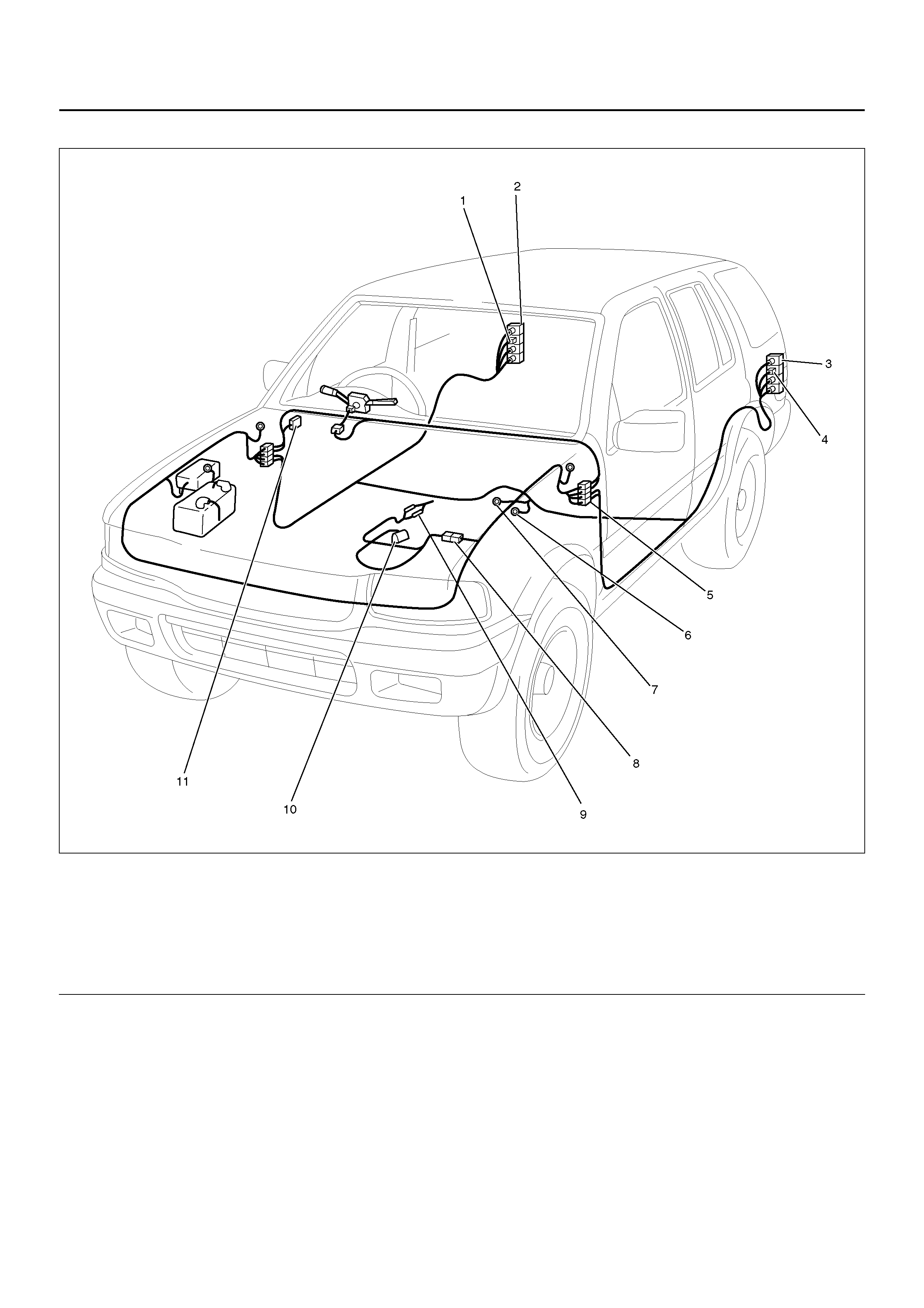
GENERAL DESCRIPTION
The circuit consists of horn (high note and low note),
horn relay (alarm & relay control unit) and horn switch.
When horn switch is pressed, (independent of position
of starter switch) horn relay is activated to sound horns.
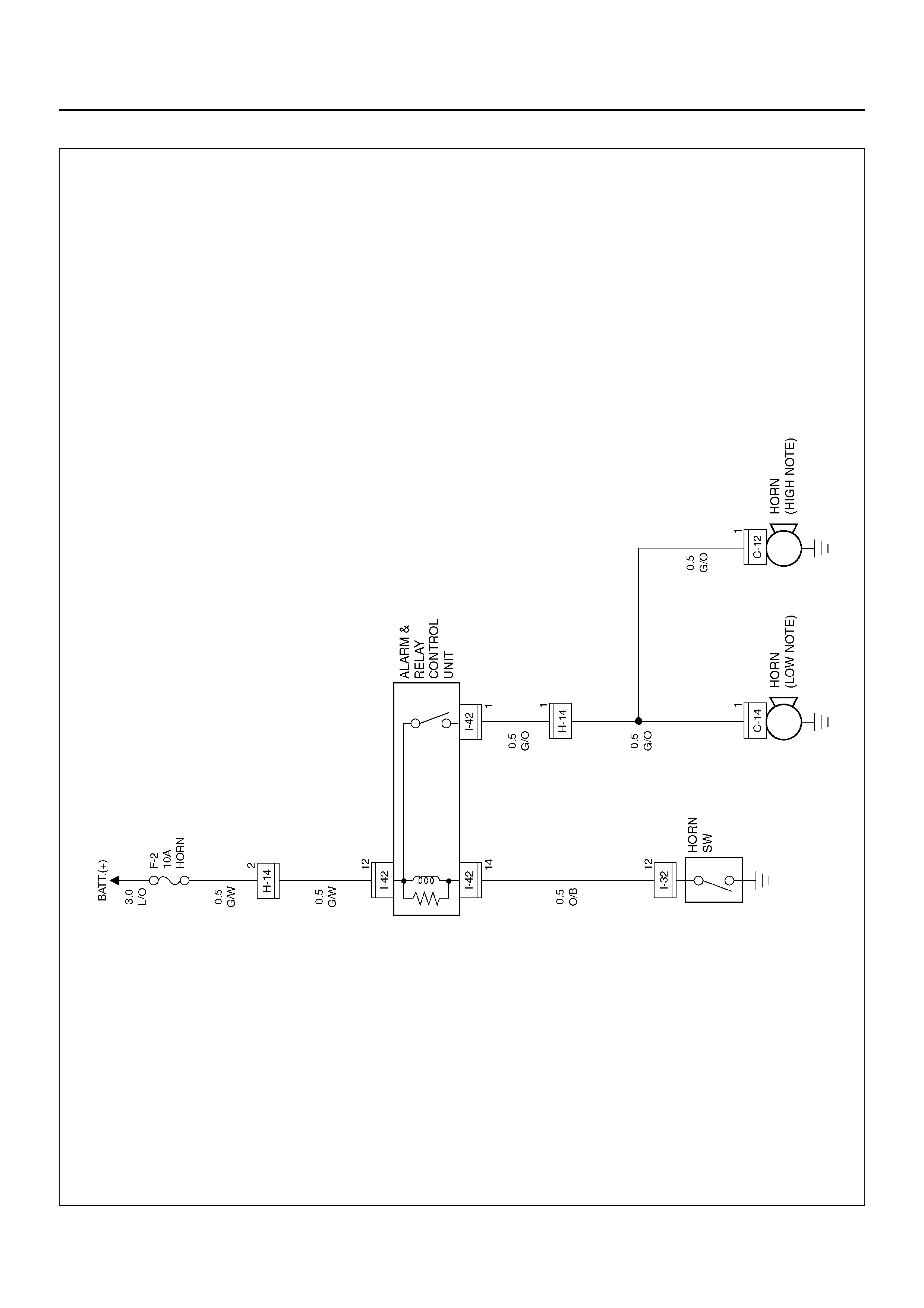
CIRCUIT DIAGRAM
D08R100115
PARTS LOCATION
D08RWD18
EndOFCallout
Legend
(1) H–14
(2) SRS Coil ASM
(3) Horn Switch
(4) I–42
(5) I–32
(6) Horn (Low note)
(7) C–14
(8) C–12
(9) Horn (High note)

DIAGNOSIS
Horn Does Not Sound
Horn Does Not Stop Sounding
Step Action Value(s) Yes No
1 Is the fuse F–2 normal? — Go to Step 2 Replace the
fuse
2 Di sco nnect the alarm & relay contr ol unit c onnec tor I–
42.
Is the battery voltage applied between harness side
connector I–42 terminal 12 and the ground?
Approx. 12V Go to Step 4 Go to Step 3
3 Repair an open circuit between the fuse F–2 and the
alarm & relay control unit.
Is the action complete?
— Verify repair —
4 Disconnect the horn switch connector I–32.
Is there continuity between switch side connector I–32
terminal 12 and the ground with the horn switch
pressed?
— Go to Step 5 Repair or
replace the
switch
5 Is there con tinuity b etween har ness side connecto r I–
32 terminal 12 and connector I–42 terminal 14? — Go to Step 7 Go to Step 6
6 Repair an open circuit between the alarm & relay
control unit and the horn switch.
Is the action complete?
— Verify repair —
7 1. Disconnect the horn connector.
2. Connect the battery positive terminal to the horn
side connector terminal 1.
Does the horn work?
— Go to Step 8 Replace the
horn
8 Is there continuity between harness side connector
terminal between the horn and the alarm & relay
control un it?
— Go to Step 9 Go to Step 10
9 Replace the alarm & relay control unit.
Is the action complete? — Verify repair —
10 Repair an open circuit between the horn and the alarm
& relay control unit.
Is the action complete?
— Verify repair —
Step Action Value(s) Yes No
1 Disconnect the horn switch connector I–32.
Do the horn stop sounding? — Repair or
replace the
horn switch
Go to Step 2
2 Di sco nnect the alarm & relay contr ol unit c onnec tor I–
42.
Is there continuity between harness side connector
terminal 14 and the ground?
— Repair shor t
circuit Replace the
alarm & relay
control unit

DOME LIGHT, LUGGAGE ROOM LIGHT, COURTESY LIGHT, MAP
LIGHT, SEAT BELT SWITCH AND WARNING BUZZER
GENERAL DESCRIPTION
The circuit consists of door switch, dome light, luggage
room light, courtesy light, map light, tail relay, key
cylinder switch and alarm & relay control unit.
Dome light comes on with dome light switch turned to
door position and any door open.
The buzzer sounds when starter switch is turned to
either “ACC" or “OFF" position and FRT door–RH, is
opened with lighting switch on.
The buzzer also sou nds when FRT door–RH is opene d
with starter key left in starter switch key cylinder.
These functions are controlled by the alarm & relay
control unit.
CIRCUIT DIAGRAM–1
D08R100118
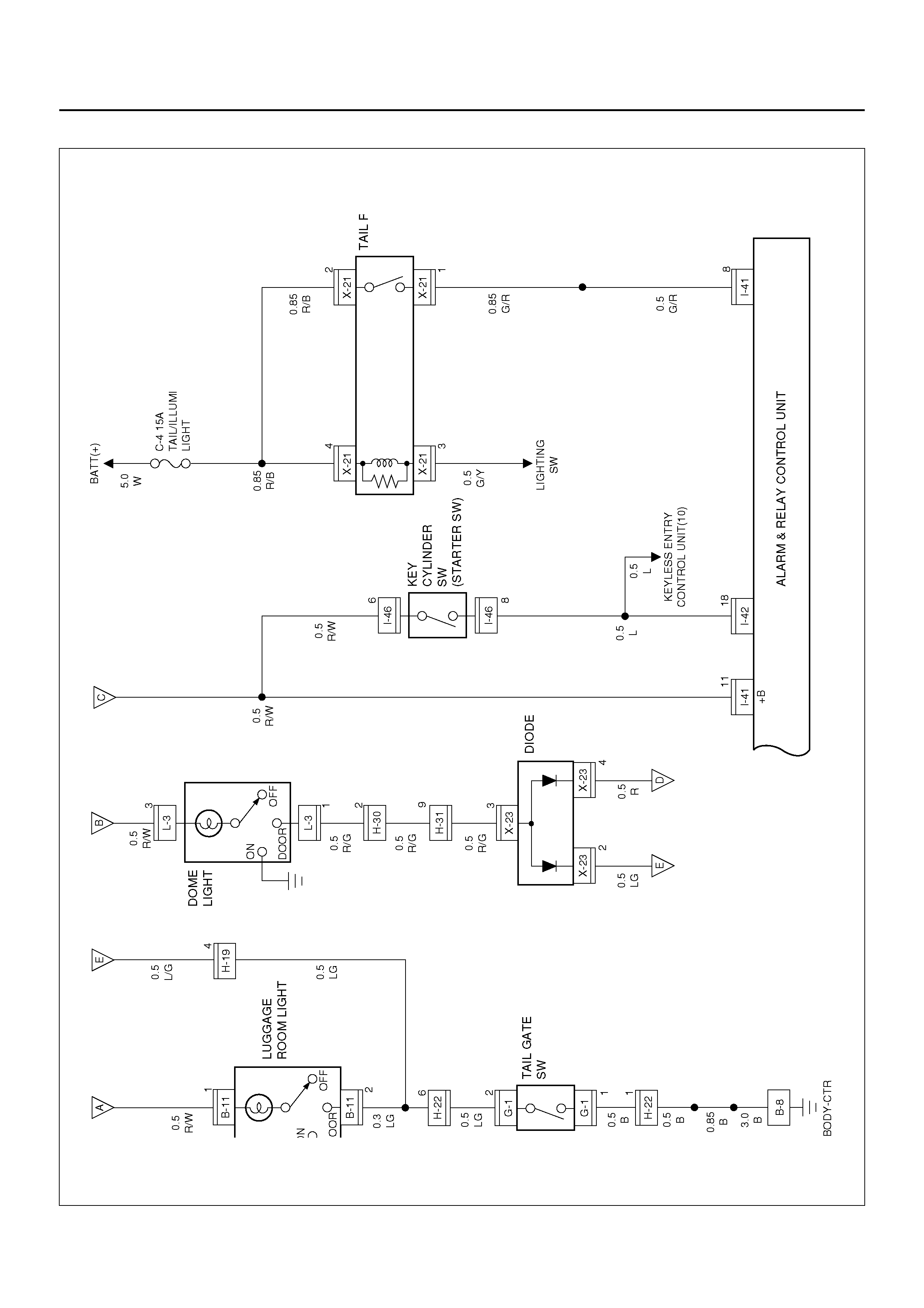
Circuit Diagram–2
D08R100230
PARTS LOCATION
D08R100192
EndOFCallout
Legend
(1) Relay & Fuse Box
(2) FRT Door SW–RH
(3) B–1
(4) B–21
(5) RR Door SW–RH
(6) Map Light
(7) L–2
(8) Do me Lig ht
(9) L–3
(10) B–11
(11) L ugga ge Room Light
(12) G–1
(13) H–22
(14) RR Door SW– LH
(15) B–16
(16) H–29
(17) B–17
(18) FRT Door SW–LH
(19) H–30
(20) F RT Courtesy –Li gh t–LH
(21) D–18
(22) H–33
(23) I–41, I–42
(24) H–31
(25) B –6, B–8
(26) I–46
(27) D–7
(28) F RT Courtesy –Ligh t–RH
(29) H–28
(30) H–19, H–32

DIAGNOSIS
Dome Light Inoperative
Step Action Value(s) Yes No
1 Re mov e the dom e ligh t bulb.
Is the bulb normal? — Go to Step 2 Replace the
bulb
2 1. Reinstall the bulb.
2. Disconnect the dome light connector L–3.
3. Set the dome light switch to door position.
Is there continuity between the dome light side
connector terminal 1 and 3?
— Go to Step 3 Repair or
replace the
dome light
3 Is the battery voltage applied between harness side
connector L–3 terminal 3 and the ground? Approx. 12V Go to Step 5 Go to Step 4
4 Repair an open circuit between the fuse C–5 and th e
dome light.
Is the action complete?
— Verify repair —
5 Repair an open circuit between the dome light and the
door switch or the tail gate switch.
Is the action complete?
— Verify repair —

POWER DOOR LOCK
GENERAL DESCRIPTION
The door lock system consists of door lock & power
window switch, key cylinder switch and door lock
actuator. Door lock switch on driver's side can actuate
the door lock mechanism.
Locking or unlocking the lock switch on the driver side
causes the door lock mechanism to be locked or
unlocked.
At this time, the c urr ent fl ows for ap prox . 1 s econd fr om
door lock switch on driv er's side to door lock actuator to
run the motor.
When the key is in the key cylinder, Door Lock can not
be done.
CIRCUIT DIAGRAM–1
D08R100234
Circuit Diagram–2
D08R100124
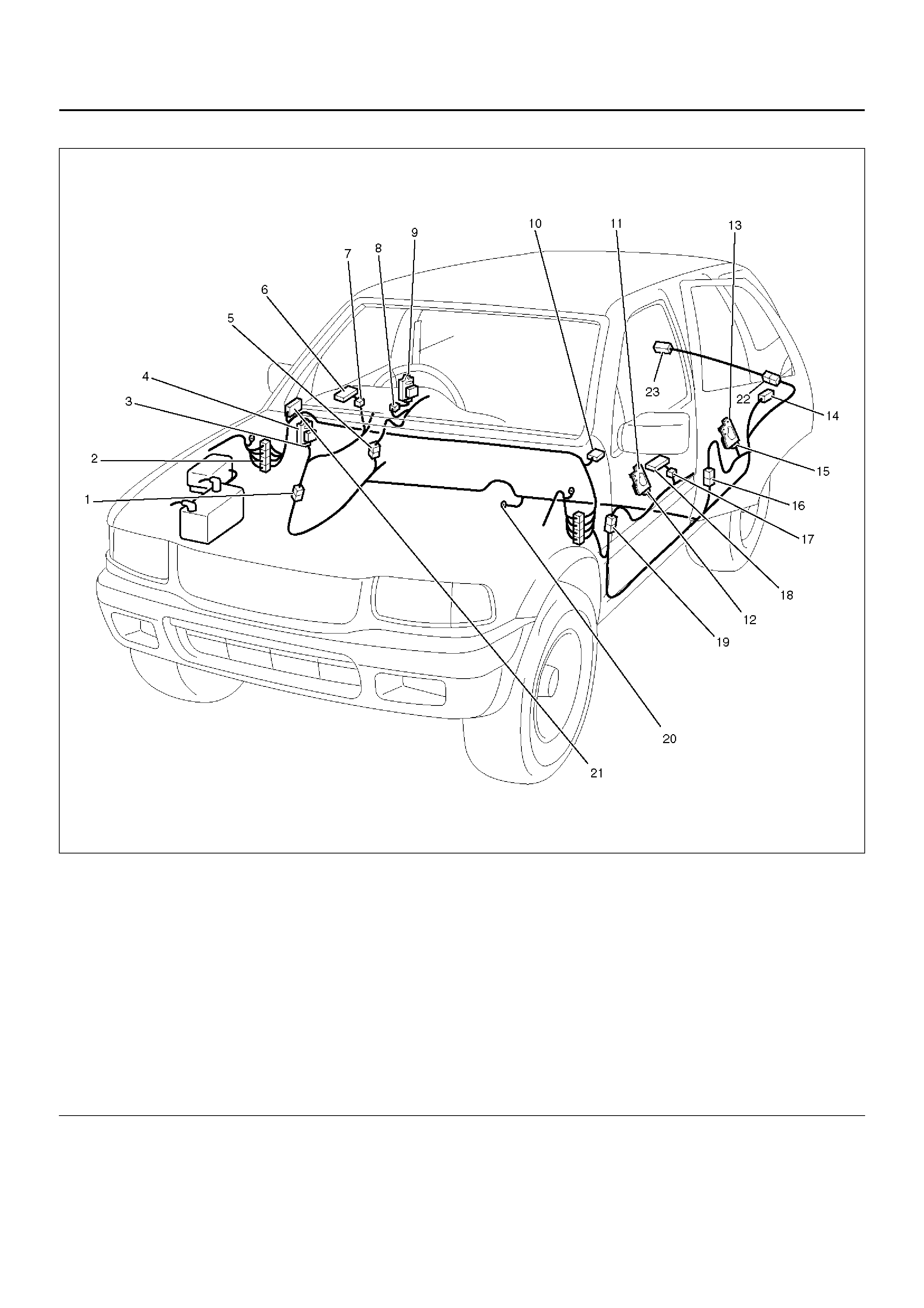
PARTS LOCATION
D08RWD15
EndOFCallout
Legend
(1) H–28
(2) H–19, H–32
(3) D–8
(4) FRT Door Lock Actuator–RH
(5) H–24
(6) FRT Door Lock Switch–RH
(7) D–6, D–5
(8) D–21
(9) RR Door Lock Actuator–RH
(10) I–26
(11) FRT Door Lock Actuator–LH
(12) D–14
(13) RR Door Lock Actuator–LH
(14) B –30
(15) D–26
(16) H–29
(17) D–17
(18) FRT Door Lock Switch–LH
(19) H–33
(20) B–8
(21) Relay & Fuse Box (Instrument Panel)
(22) H–34, H–22 (2Door Model)
(23) G–7

DIAGNOSIS
All The Doors Do Not Lock And Unlock By Door Lock SW–RH
All The Doors Do Not Lock and Unlock by FRT Door Lock SW–LH
Step Action Value(s) Yes No
1 Is the fuse C–7 normal? — Go to Step 2 Replace the
fuse
2 Disconnect the front power window & door lock SW–
RH connector D–5.
Is the battery voltage applied between harness side
connector D–5 terminal 11 and the ground?
Approx. 12V Go to Step 4 Go to Step 3
3 Repair an open circuit between the fuse C–7 and th e
switch.
Is the action complete?
— Verify repair —
4 Di sconnect the F RT door lo ck actuator–R H connector
D–8.
Is there continuity between harness side connector D–
5 terminal 10 and connector D–8 terminal 1 (or
connector D–5 terminal 12 and connector D–8
terminal 2)?
— Go to Step 5 Go to Step 6
5 Replace the FRT power window & door lock SW–RH.
Is the action complete? — Verify repair —
6 Repair an open circuit between the FRT power
window & door lock SW–RH and door lock actuator.
Is the action complete?
— Verify repair —
Step Action Value(s) Yes No
1 Disconnect the FRT power window & door lock SW–
RH and –LH connector D–5 and D–17.
Is there continuity between harness side connector D–
5 terminal 13 and connector D–17 terminal 6 (or
connector D–5 terminal 14 and connector D–17
terminal 7)?
— Go to Step 2 Go to Step 3
2 Replace the FRT power window & door lock SW–LH.
Is the action complete? — Verify repair —
3 Repair an open circuit between the FRT power
window & door lock SW–RH and –LH.
Is the action complete?
— Verify repair —

All the Doors Do Not Lock and Unlock by Door Lock Key SW
Step Action Value(s) Yes No
1 Is B–8 grounded securely? — Go to Step 2 Ground it
securely
2 Disconnect the door lock key SW connector D–6.
Is there continuity between harness side connector D–
6 terminal 2 and the ground?
— Go to Step 4 Go to Step 3
3 Repair an open circuit between connector D–6
terminal 2 and the ground B–8.
Is the action complete?
— Verify repair —
4 Is there continuity between the switch side connector
terminal 1 and 2 when the switch is turned to lock
position, and terminal 2 and 4 when the switch is
turned to unlock position?
— Go to Step 5 Repair or
replace the
switch
5 Re pair an open circui t between the door lock key SW
and FRT power window & door lock SW–RH.
Is the action complete?
— Verify repair —

POWER WINDOW
GENERAL DESCRIPTION
The power window system consists of power window
switches, power window motors and power window
relay.
With the starter switch in “ON" position, the battery
voltage is supplied through power window relay to the
power wind ow switche s. Selec tion of up or down swi tch
changes over the motor rotating direction to open or
close the window.
When the lock switch on the switch panel on the driver
side is pressed, the power window switch is in open
state. As a result, the power source to the other
switches are cut off, and the power window motors do
not run.
CIRCUIT DIAGRAM–1
D08R100194
PARTS LOCATION
D08R100195
EndOFCallout
Legend
(1) H–28
(2) D–2
(3) Relay & Fuse Box
(4) Power Window Motor (FRT RH)
(5) Power Window SW (FRT RH)
(6) D–5
(7) Power Window Motor (RR RH)
(8) D–20
(9) D–22
(10) Power Window SW (RR RH)
(11) Power Window SW (FRT LH)
(12) Power Window SW (RR LH)
(13) D–27
(14) D–25
(15) P ower Window Moto r (RR LH)
(16) H–29
(17) D–17
(18) D–11
(19) P ower Window Moto r (FRT LH)
(20) H–33
(21) H–31
(22) B–8
(23) H–24

DIAGNOSIS
All Window Do Not Operate
Step Action Value(s) Yes No
1 Is the fuse C–15 normal? — Go to Step 2 Replace the
fuse
2 Is the circuit breaker C–21 normal? — Go to Step 3 Replace the
circuit breaker
3 Is B–8 grounded securely? — Go to Step 4 Ground it
securely
4 Disconnect the power window relay connector X–22.
Is the battery voltage applied between harness side
connector X–22 terminal 2 and the ground?
Approx. 12V Go to Step 6 Go to Step 5
5 Re pair an open c ircuit between the circui t breaker C–
21 and connector X–22 terminal 2.
Is the action complete?
— Go to Step 4 —
6 Turn the starter switch on.
Is the battery voltage applied between harness side
connector X-22 terminal 5 and the ground?
Approx. 12V Go to Step 8 Go to Step 7
7 Repair an open circuit between the fuse C–15 and
connector X–22 terminal 5.
Is the action complete?
— Go to Step 6 —
8 Is there continuity between harness side connector X–
22 terminal 3 and the ground B–8? — Go to Step 10 Go to Step 9
9 Repair an open circuit between connector harness
side X–22 terminal 3 and the ground B–8.
Is the action complete?
— Go to step 8 —
10 Is there continuity between harness side connector X–
22 terminal 1 and connector D–5 terminal 4? — Replace the
power window
relay
Go to Step 11
11 Repair an open circuit between power window relay
and FRT power window & door lock switch–RH.
Is the action complete?
— Verify repair —

Window On The Driver's Side Does Not Operate
Step Action Value(s) Yes No
1 Turn the starter switch on.
Is the battery voltage applied between harness side
connector D–5 terminal 4 and the ground?
Approx. 12V Go to Step 3 Go to Step 2
2 Repair an open circuit between connector X–22
terminal 1 and connector D–5 terminal 4.
Is the action complete?
— Go to Step 1 —
3 Disconnect the front power window & door lock
switch–RH connector D–5.
Is there continuity between the front power window &
door lock switch–RH harness side connector D–5
terminal 7 and ground B–8?
— Go to Step 5 Go to Step 4
4 Repair an open circuit between connector D–5
terminal 7 an ground B–8.
Is the action complete?
— Go to Step 3 —
5 Connect the battery position terminal with harness
side connector D–5 terminal 3 or 5, and the negative
terminal with harness side connector D–5 terminal 5
or 3.
Does the motor operate?
— Replace the
front power
window & door
lock switch–RH
Go to Step 6
6 1. Disconnect the front power window motor–RH
connector D–2.
2. Connect the battery position terminal with the
motor side connector D–2 terminal 1 or 2, and
connect the battery negative terminal with the
motor side connector D–2 terminal 2 or 1.
Does the motor operate?
— Go to Step 7 Replace the
motor
7 Repair an open circuit between the front power
window and doo r lock switch–RH and the front power
window motor–RH.
Is the action complete?
— Verify repair —

Window On The Front Passenger's Side Does Not Operate
Step Action Value(s) Yes No
1 Turn the starter switch on.
Is the battery voltage applied between harness side
connector D–17 terminal 2 and the ground?
Approx. 12V Go to Step 3 Go to Step 2
2 Repair an open circuit between connector X–22
terminal 1 and connector D–17 terminal 2.
Is the action complete?
— Go to Step 1 —
3 Disconnect the front power window & door lock
switch–RH connector D–17.
Is there continuity between the front power window &
door lock switch–RH harness side connector D–17
terminal 3 and ground B–8?
— Go to Step 5 Go to Step 4
4 Repair an open circuit between connector D–17
terminal 3 an ground B–8.
Is the action complete?
— Go to Step 3 —
5 Connect the battery position terminal with harness
side conn ec tor D–17 termi nal 1 or 4, and th e ne gati v e
termin al with harness si de connector D–17 terminal 4
or 1.
Does the motor operate?
— Replace the
front power
window & door
lock switch–RH
Go to Step 6
6 1. Disconnect the front power window motor–LH
connector D–11.
2. Connect the battery position terminal with the
motor side connector D–11 terminal 1 or 2, and
connect the battery negative terminal with the
motor side connector D–11 terminal 2 or 1.
Does the motor operate?
— Go to Step 7 Replace the
motor
7 Repair an open circuit between the front power
window and door lock switch–LH and the front po wer
window motor–LH.
Is the action complete?
— Verify repair —

Rear Window On The Left (or Right) Side Does Not Operate
Window On The Front Passenger's Side Does Not Operate by the Front Power Window and
Door Lock Switch–RH
Step Action Value(s) Yes No
1 1. Disconnect the rear power window switch–RH
connector D–22 or the rear power window and
door lock switch–LH connector D–27.
2. Turn the starter switch on.
Is the battery voltage applied between harness side
connector D–22 terminal 4 and the ground, or harness
side connector D–27 terminal 4 and the ground?
Approx. 12V Go to Step 3 Go to Step 2
2 Repair an open circuit between connector X–22
terminal 1 and connector D–22 terminal 4 or
connector D–27 terminal 4.
Is the action complete?
— Go to Step 1 —
3 Is there continuity between harness side connector D–
22 terminal 3 and the ground B–8, or harness side
connector D–27 terminal 3 and the ground B–6 or 8?
— Go to Step 5 Go to Step 4
4 Repair an open circuit between connector D–22
terminal 3 or connector D–27 terminal 3 and the
ground B–6 or 8.
Is the action complete?
— Go to Step 3 —
5 Connect the battery positive terminal with harness
side connector D–22 terminals 5 or harness side
connector D–27 terminal 5, and connect the battery
negative terminal with harness side connector D–22
terminal 6 or harness side connector D–27 terminal 6.
Does the motor operate?
— Replace the
rear power
window switch–
LH or –RH
Go to Step 6
6 1. Disconnect the rear power window motor
connector D–20 or D–25.
2. Connect the battery positive terminal with motor
side con nector D–20 or D–25 termin al 1 or 2, and
connect the battery negative terminal with the
motor side connector D–20 or D–25 terminal 2 or
1.
Does the motor operate?
— Go to Step 7 Replace the
motor
7 Repair an open circuit between the rear power
window switch and the rear power window motor.
Is the action complete?
— Verify repair —
Step Action Value(s) Yes No
1 Disconnect the front power window and door lock
switch–RH connector D–5 and the front power window
and door lock switch–LH connector D–17.
Is there continuity between harness side connector D–
5 terminal 8 and harness side connector D–17
terminal 5?
— Replace the
front power
window and
door lock
switch–LH
Go to Step 2
2 Repair an open circuit between connector D–5
terminal 8 and connector D–17 terminal 5.
Is the action complete?
— Verify repair —

Lock SW Does Not Function
Step Action Value(s) Yes No
1 Repair or replace the front power window and door
lock switch–RH.
Is the action complete?
— Verify repair —

ANTI–LOCK BRAKE SYSTEM (ABS)
GENERAL DESCRIPTION
The circuit consists of the Electronic Hydraulic Control
Unit (EHCU), the starter switch, stoplight switch, wheel
speed sensor, ABS warning light, BRAKE warning light,
and data link connector.
When the service brake is applied while in the running
mode, the EHCU judges which wheel is about to lock by
using the wheel rotation speed signals sent from the
three wheel speed sensors at the front wheels and rear
differential. And the brake fluid pressure applied to the
four wheels is controlled by the EHCU to prevent the
wheels from locking.
Refer to Brake Control System in Brakes section in
detail.
CIRCUIT DIAGRAM–1
D08R100217
Circuit Diagram–2
D08R100127
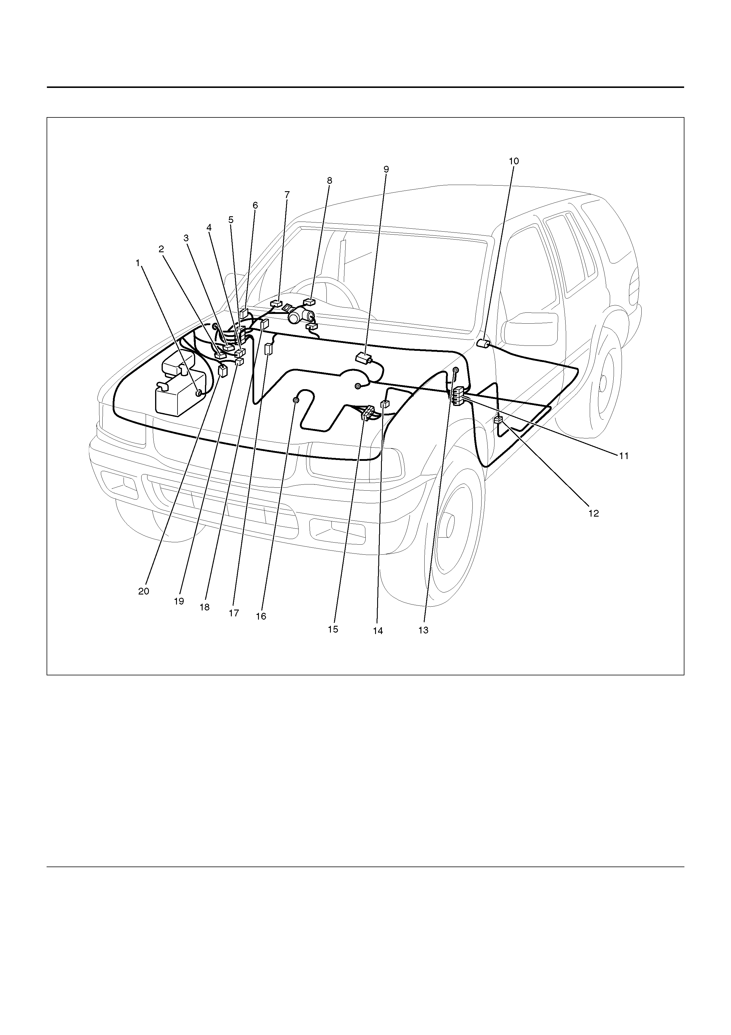
PARTS LOCATION
D08RY00828
EndOFCallout
Legend
(1) C–36
(2) C–5
(3) C–4
(4) H–60
(5) H–14, H–19
(6) Relay & Fuse Box
(7) I–9
(8) I–10
(9) B–19
(10) F–4
(11) H–15, H–16, H–17
(12) H–25
(13) C–16
(14) C–13
(15) H–5
(16) E–30
(17) I–18
(18) C–34
(19) C–6
(20) C–33

A/T SHIFT LOCK
GENERAL DESCRIPTION
With the s tarter switc h in the “O N" posit ion and the shi ft
lever in “P" position, the shift lever cannot be shifted
from “P" to another position unless the brake pedal is
depressed. This is because, unless the brake pedal is
depressed, the solenoid pin underneath the shift lever
retracts and the link lever then locks the shift lever cam.
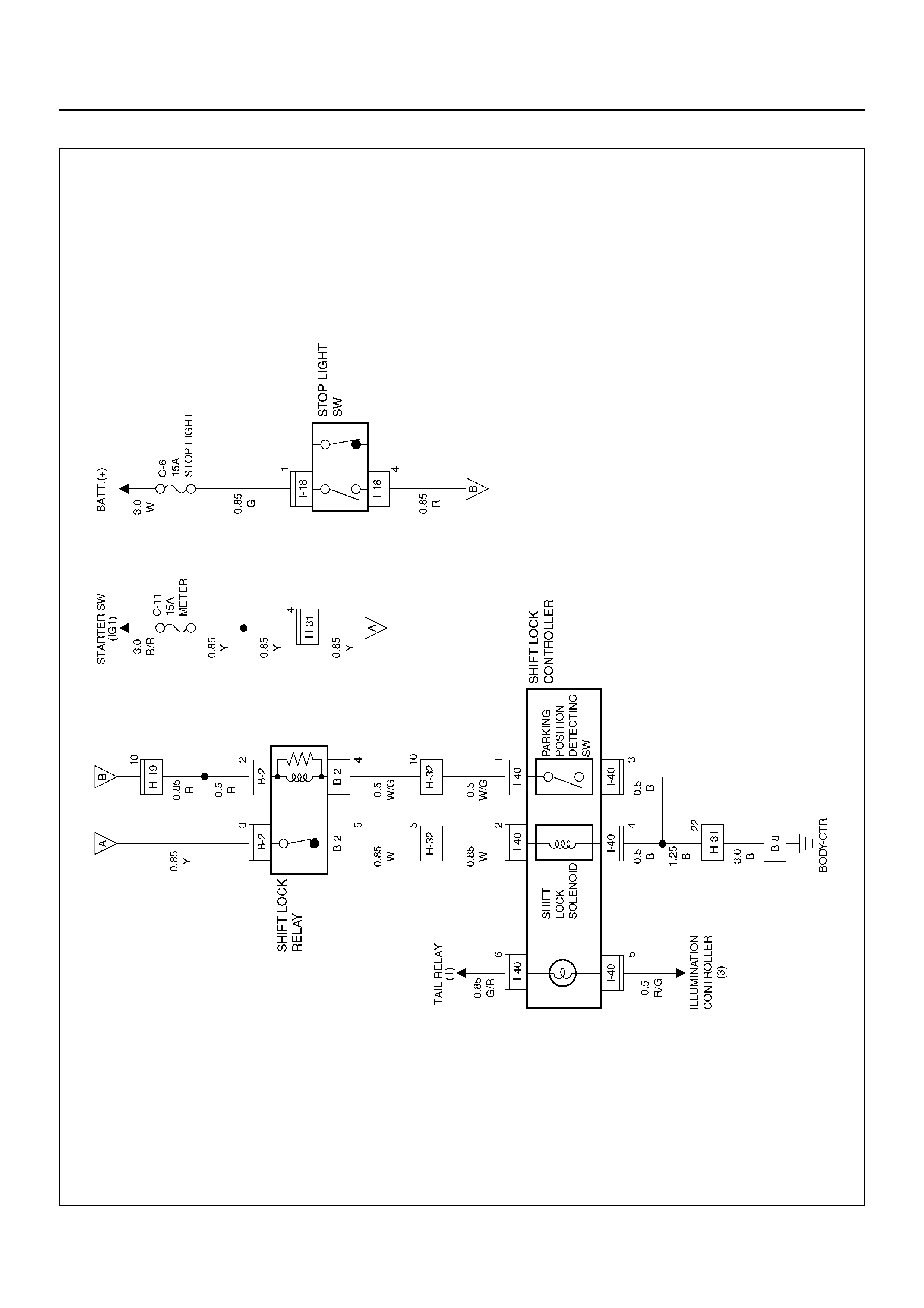
CIRCUIT DIAGRAM–1
D08R100128
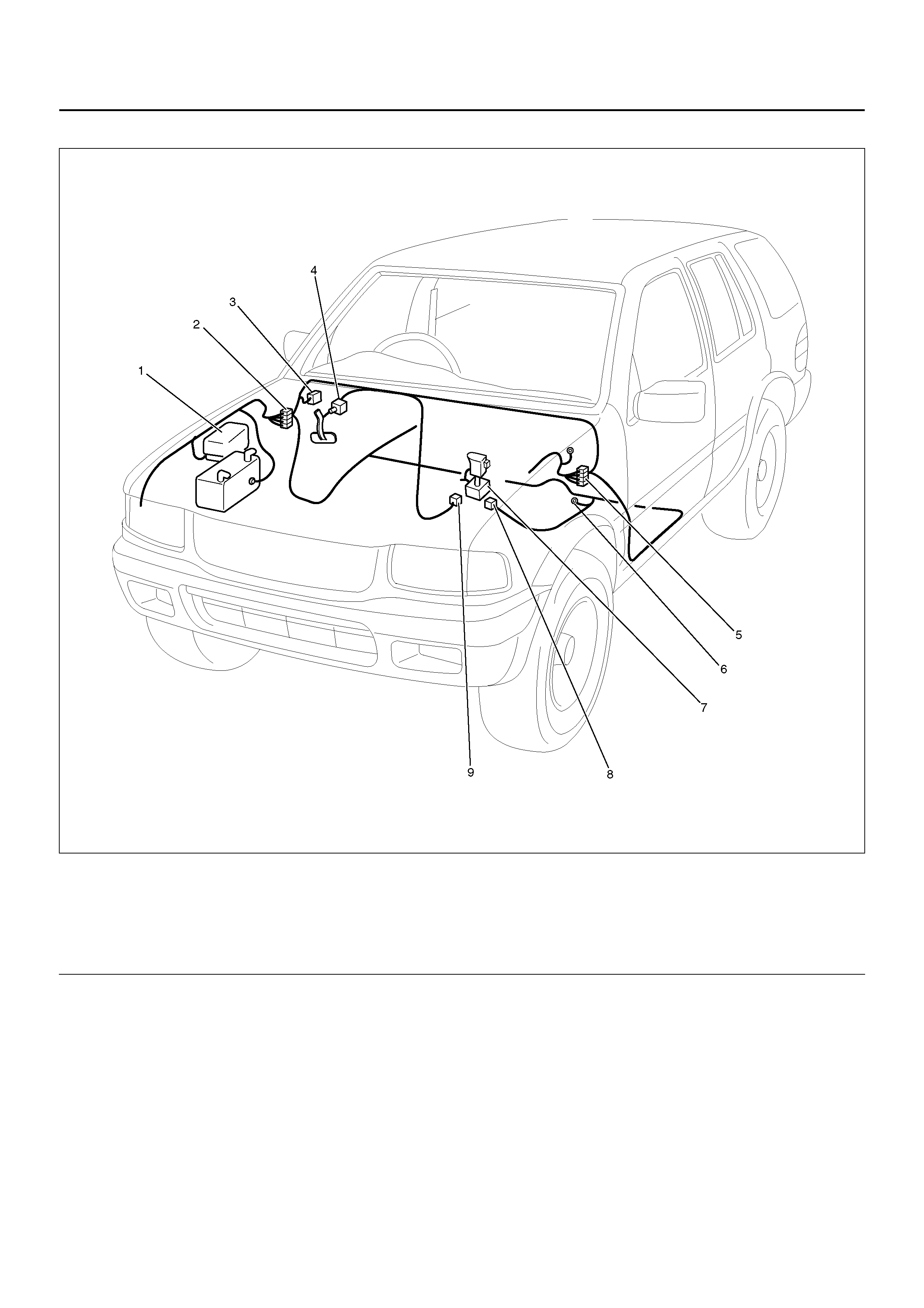
PARTS LOCATION
D08R100196
EndOFCallout
Legend
(1) Relay & Fuse Box (Engine Room)
(2) H–19, H–32
(3) Relay & Fuse Box (Instrument Panel)
(4) I–18
(5) H–31
(6) B–8
(7) A/T Shift Lever
(8) B–2
(9) I–40

WINDSHIELD WIPER AND WASHER
GENERAL DESCRIPTION
The system consists of a windshield wiper and washer
switch, alarm & relay control unit, windshield wiper
motor and windshield washer motor. With the starter
switch in the “ON" position, when the windshield wiper
switch is turned on (“LOW" or “HI") the battery voltage is
applied to the windshield wiper motor to operate the
wipers.
When the “I NT " sw it ch i s tu rned o n, the ope ra tio n of th e
wipers is controlled by the alarm & relay control unit.
When the “WASHER" swit ch is turned on, the ope ra tio n
of the wipers is also controlled by the alarm & relay
control unit and the windshield washer motor operates
to squirt the washing solution when the washer switch is
pressed.
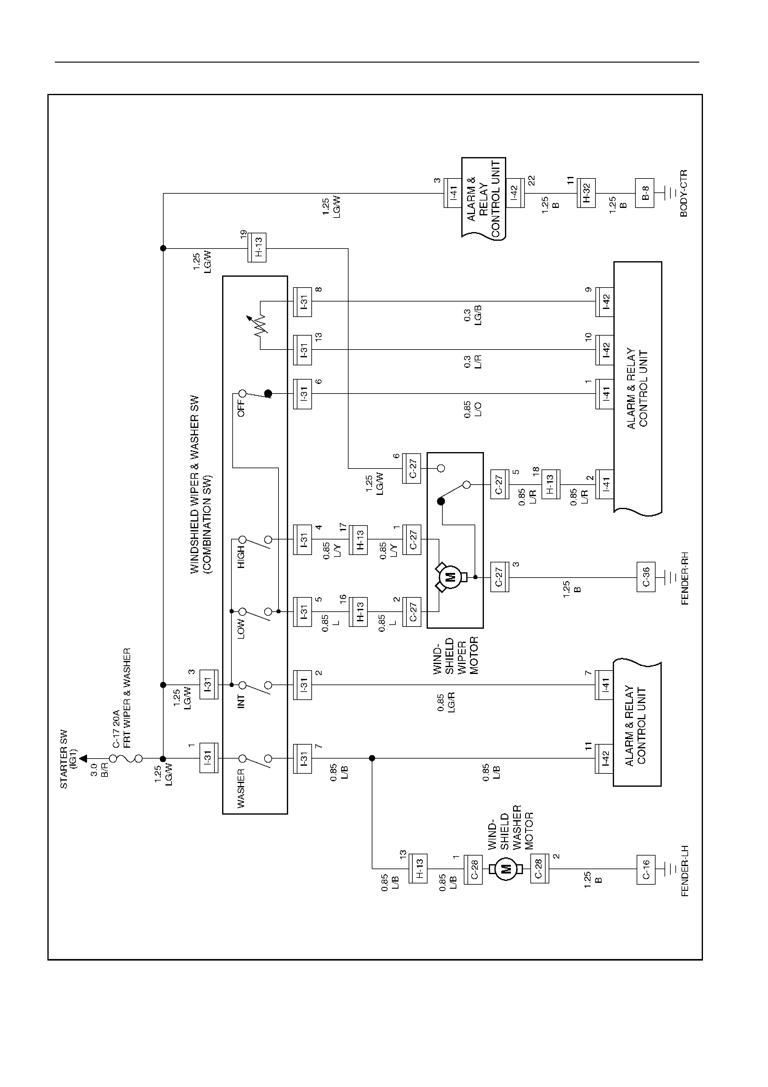
CIRCUIT DIAGRAM
D08R100132-a
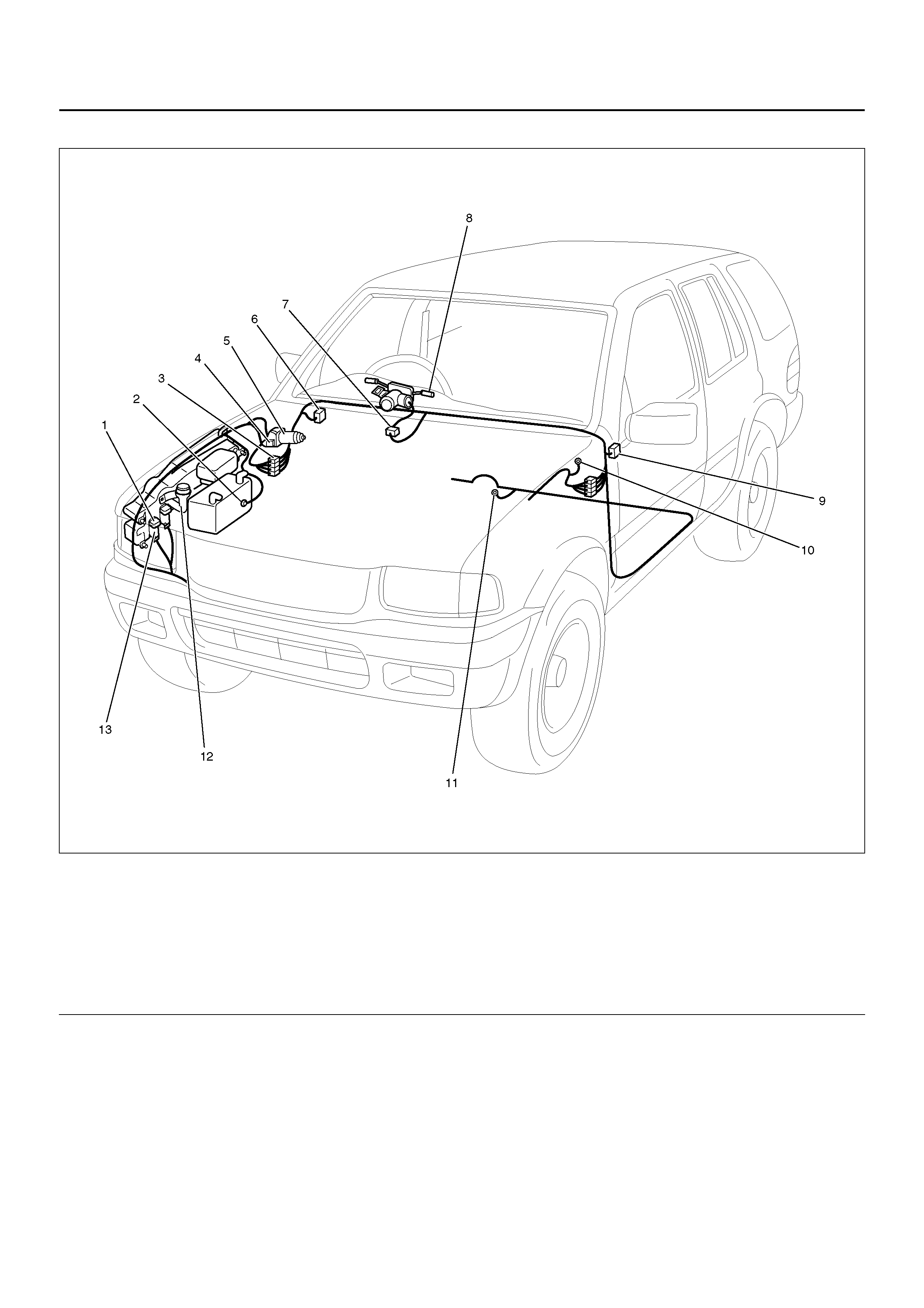
PARTS LOCATION
D08R100197
EndOFCallout
Legend
(1) C–28
(2) C–36
(3) H–13, H–32
(4) C–27
(5) Windshield Wiper Motor
(6) Relay & Fuse Box (Instrument Panel)
(7) I–31
(8) Winds hield Wiper, Washer Switch
(9) I–41, I–42
(10) C–16
(11) B–8
(12) Windshield Wa sher Tank
(13) Windshield Washer Motor

DIAGNOSIS
Windshield Wiper Does Not Operate At Any Switch Position
Step Action Value(s) Yes No
1 Is the fuse C–17 normal? — Go to Step 2 Replace the
fuse
2 Is C–36 gr ound ed se cur e ly? — Go to Step 3 Ground it
securely
3 Disconnect the windshield wiper motor connector C–
27.
Is there continuity between harness side connector C–
27 terminal 3 and the ground?
— Go to Step 5 Go to Step 4
4 Repair an open circuit between connector C–27
terminal 3 and the ground C–36.
Is the action complete?
— Go to Step 3 —
5 1. Disconnect the windshield wiper & washer switch
connector I–31.
2. Turn the starter switch on.
Is the battery voltage applied between harness side
connector I–31 terminal 3 and the ground?
Approx. 12V Go to Step 7 Go to Step 6
6 Repair an open circuit between the fuse C–17 and
connector I–31 terminal 3.
Is the action complete?
— Go to Step 5 —
7 Is the continuity between the windshield wiper and
washer switch terminal normal? — Repair or
replace the
windshield
wiper motor
Repair or
replace the
switch

Windshield Wiper Does Not Operate At “INT" Position
Windshield Wiper Does Not Operate At “LO" Position
Step Action Value(s) Yes No
1 1. Disconnect the windshield wiper and washer
swit ch co nnec to r I–31 .
2. Turn the windshield wiper and washer switch to
INT position.
Is there continuity between switch side connector I–31
terminal 2 and 3, 5 and 6?
— Go to Step 2 Repair or
replace the
switch
2 Is B–8 grounded securely? — Go to Step 3 Ground it
securely
3 1. Reconnect the windshield wiper and washer
swit ch co nnec to r I–31 .
2. Disconnect the alarm and relay control unit
connector I–41 and I–42.
3. Turn the starter switch on.
Is the battery voltage applied between harness side
connector I–42 terminal 7 and the ground?
Approx. 12V Go to Step 5 Go to Step 4
4 Repair an open circuit between connector I–31
terminal 2 and the alarm & relay control unit.
Is the action complete?
— Verify repair —
5 Is the battery voltage applied between harness side
connector I–41 terminal 3 and the ground? Approx. 12V Replace the
alarm and relay
control unit
Go to Step 6
6 Repair an open circuit between the fuse C–17 and the
alarm & relay control unit.
Is the action complete?
— Verify repair —
Step Action Value(s) Yes No
1 Repair or replace the windshield wiper and washer
switch.
NOTE: There should be continuity between switch
side connector I–31 terminal 3 and 5 with the switch
turned to the LOW position.
Is the action complete?
— Verify repair —

Windshield Wiper Does Not Operate At “HI" Position
Step Action Value(s) Yes No
1 1. Disconnect the windshield wiper and washer
swit ch co nnec to r I–31 .
2. Turn the windshield wiper and washer switch to
the HIGH position.
Is there continuity between switch side connector I–31
terminal 3 and 4?
— Go to Step 2 Repair or
replace the
switch
2 1. Reconnect the windshield wiper and washer
swit ch co nnec to r I–31 .
2. Disconnect the windshield wiper motor connector
C–27.
3. Turn the starter switch on.
Is the battery voltage applied between harness side
connector C–27 terminal 1 and the ground?
Approx. 12V Repair or
replace the
windshield
wiper motor
Go to Step 3
3 Repair an open circuit between connector I–31
terminal 4 and connector C–27 terminal 1.
Is the action complete?
— Verify repair —

Auto–Stop Function Of The Windshield Wiper Motor Does Not Operate
Step Action Value(s) Yes No
1 Disconnect the windshield wiper and washer switch
connector I–31.
Turn the windshield wiper and washer switch off.
Is there continuity between switch side connector I–31
terminal 5 and 6?
— Go to Step 2 Repair or
replace the
switch
2 Disconnect the windshield wiper motor connector C–
27.
Turn the starter switch on.
Is the battery voltage applied between harness side
connector C–27 terminal 6 and the ground?
Approx. 12V Go to Step 4 Go to Step 3
3 Repair an open circuit between the fuse C–17 and
connector C–27 terminal 6.
Is the action complete?
— Go to Step 2 —
4 1. Connect the battery positive terminal with motor
side connector C–27 terminal 2 and the battery
negative terminal with terminal 3.
2. While the motor is operating at low speed,
disconnect the battery positive terminal from
terminal 2 and then connect it with terminal 6
again.
3. Under this condition, connect motor side
connector terminal 5 with terminal 2.
Does the motor stop at the correct position?
— Go to Step 5 Repair or
replace the
motor
5 Di sconnec t the ala rm and rela y contr ol unit conn ector
I–41 and I–42.
Is the battery voltage applied between harness side
connector I–41 terminal 3 and the ground?
Approx. 12V Go to Step 7 Go to Step 6
6 Repair an open circuit between the fuse C–17 and
connector I–41 terminal 3.
Is the action complete?
— Go to Step 5 —
7 1. Reconnect the windshield wiper and washer
switch c onnec tor I–31 and windshi eld wipe r motor
connector C–27.
2. Turn the windshield wiper and washer switch to
the low position.
Is the battery voltage applied between harness side
connector I–41 terminal 4 and the ground?
Approx. 12V
intermittently Go to Step 9 Go to Step 8
8 Repair an open circuit between connector C–27
terminal 5 and connector I–41 terminal 4.
Is the action complete?
— Go to Step 7 —
9 1. Connect the alarm and relay control unit harness
side connector I–41 terminal 4 and connector I–41
terminal 1.
2. Turn the windshield wiper and washer switch to
the off position.
Does the motor stop at the correct position?
— Replace the
alarm and relay
control unit
Go to Step 10
10 Repair an open circuit between connector I–31
terminal 6 and the alarm & relay control unit.
Is the action complete?
— Verify repair —

Windshield Wiper Motor Does Not Stop
Windshield Washer Motor Does Not Operate
Step Action Value(s) Yes No
1 1. Disconnect the windshield wiper and washer
swit ch co nnec to r I–31 .
2. Turn the switch off.
NOTE: When the switch is turned of OFF position,
there is no continuity between the switch terminals
exce pt terminal 5 and 6.
Is the continuity between the switch terminal normal?
— Go to Step 2 Repair or
replace the
switch
2 Repair or replace the windshield motor.
Is the action complete? — Verify repair —
Step Action Value(s) Yes No
1 Does the windshield wiper motor operate? — Go to Step 6 Go to Step 2
2 Is the fuse C–17 normal? — Go to Step 3 Replace the
fuse
3 1. Disconnect the windshield wiper and washer
swit ch co nnec to r I–31 .
2. Turn the starter switch on.
Is the battery voltage applied between harness side
connector I–31 terminal 1 and the ground?
Approx. 12V Go to Step 5 Go to Step 4
4 Repair an open circuit between the fuse C–17 and
connector I–31 terminal 1.
Is the action complete?
— Go to Step 3 —
5 Is C–16 gr ound ed se curely? — Go to Step 6 Gr ou nd it
securely
6 Turn the windshield wiper and washer switch to the
washer position.
Is there continuity between switch side connector I–31
terminal 1 and 7?
— Go to Step 7 Repair or
replace the
switch
7 1. Disconnect the windshield washer motor
connector C–28.
2. Connect the battery positive terminal with the
motor side connector C–28 terminal 1 and
connect the battery negative terminal with terminal
2.
Does the motor operate?
— Go to Step 8 Repair or
replace the
motor
8 1. Reconnect the windshield wiper and washer
swit ch co nnec to r I–31 .
2. Turn the starter switch on.
Is the battery voltage applied between harness side
connector C–28 terminal 1 and the ground?
Approx. 12V Go to Step 10 Go to Step 9
9 Repair an open circuit between connector I–31
terminal 7 and connector C–28 terminal 1.
Is the action complete?
— Verify repair —
10 Repair an open circuit between connector C–28
terminal 2 and the ground C–16.
Is the action complete?
— Verify repair —

REAR WIPER/WASHER
GENERAL DESCRIPTION
The system consists of the rear wiper and washer
switch, the rear wiper motor, the rear washer motor and
the alarm & relay control unit. The rear wiper provides
intermittent and riseup functions and is controlled by the
alarm & re lay co ntr ol unit . When the hatch gate is open ,
the rear wiper does not operate. The hatch gate
actuator does not operate while the rear wiper is
operating.
CIRCUIT DIAGRAM–1
D08R100136
Circuit Diagram–2
D08R100137
PARTS LOCATION
D08R100198
EndOFCallout
Legend
(1) C–30
(2) FRT & Rear Washer Tank
(3) C–36
(4) H–13, H–19
(5) Relay & Fuse Box (Instrument Panel)
(6) G–1
(7) G–6
(8) Rear Wiper Motor
(9) H–22
(10) B–6
(11) B–8
(12) I–16
(13) I–41, I–42
(14) H–31

DIAGNOSIS
Rear Wiper Motor Does Not Operate
Step Action Value(s) Yes No
1 Is the fuse C–16 normal? — Go to Step 2 Replace the
fuse
2 1. Disconnect the rear wiper/washer switch
connector I–16.
2. Turn the rear wiper switch on.
Is there continuity between switch side connector I–16
terminal 8 and 7?
— Go to Step 3 Repair or
replace the
switch
3 Turn the starter switch on
Is the battery voltage applied between harness side
connector I–16 terminal 8 and the ground?
Approx. 12V Go to Step 5 Go to Step 4
4 Repair an open circuit between the fuse C–16 and
connector I–16 terminal 8.
Is the action complete?
— Go to Step 3 —
5 Di sco nnect the alarm & relay contr ol unit c onnec tor I–
41 and I–42.
Is the battery voltage applied between harness side
connector I–41 terminal 6 and the ground?
Approx. 12V Go to Step 7 Go to Step 6
6 Repair an open circuit between the fuse C–16 and
connector I–41 terminal 6.
Is the action complete?
— Go to Step 5 —
7 Is there con tinuity b etween har ness side connecto r I–
16 terminal 7 and harness side connector I–42
terminal 20?
— Go to Step 9 Go to Step 8
8 Repair an open circuit between connector I–16
terminal 7 and connector I–42 terminal 20.
Is the action complete?
— Go to Step 7 —
9 1. Disconnect the rear wiper motor connector G–6.
2. Connect the battery positive terminal with the
motor side connector G–6 terminal 4 and the
battery negative terminal with the motor side
connector G–6 terminal 6.
Does the motor operate?
— Go to Step 10 Repair or
replace the
motor
10 Is there con tinuity b etween har ness side connecto r I–
41 terminal 5 and harness side connector G–6
terminal 4?
— Go to Step 12 Go to Step 11
11 Repair an open circuit between connector I–41
terminal 5 and connector G–6 terminal 4.
Is the action complete?
— Go to Step 10 —
12 Is there con tinuity b etween har ness side connecto r I–
41 terminal 12 and harness side connector G–6
terminal 6?
— Replace the
alarm & relay
control unit
Go to Step 13
13 Repair an open circuit between connector G–6
terminal 6 and connector I–41 terminal 12.
Is the action complete?
— Verify repair —

Auto-Stop Function Of The Rear Wiper Motor Does Not Operate
Rear Wiper Motor Does Not Operate With Rear Wiper/Washer Switch At Wiper Position
Step Action Value(s) Yes No
1 1. Disconnect the rear wiper motor connector G–6
2. Connect the battery positive terminal with the
motor side connector G–6 terminal 4 and the
battery negative terminal with terminal 6.
3. While the motor is operating, disconnect the
battery positive terminal from terminal 4 and then
connect it with terminal 5 again.
4. Under this condition, connect the motor side
connector terminal 1 with terminal 4.
Does the motor stop operating?
— Go to Step 2 Repair or
replace the
motor
2 1. Connect the battery positive terminal with the
motor side connector G–6 terminal 5 and the
battery negative terminal with terminal 4.
2. Under this condition, connect the motor side
connector terminal 2 with 6.
Does the motor stop at the correct position?
— Go to Step 2 Repair or
replace the
motor
3 Turn the start switch on
Is the battery voltage applied between harness side
connector G–6 terminal 5 and the ground?
Adpprox. 12V Go to Step 5 Go to Step 4
4 Repair an open circuit between connector I–42
terminal 4 and connector G–6 terminal 5.
Is the action complete?
— Go to Step 3 —
5 Di sco nnect the alarm & relay contr ol unit c onnec tor I–
41 and I–42.
Is there continuity between harness side connector
G–6 terminal 1 and harness side connector I–42
terminal 2, harness side connector G–6 terminal 2 and
harness side connector I–42 terminal 13?
— Replace the
alarm & relay
control unit
Go to Step 4
6 Repair an open circuit between connector G–6
terminal 1 and connector I–42 terminal 2.
Is the action complete?
— Verify repair —
Step Action Value(s) Yes No
1 1. Disconnect the rear wiper/washer switch
connector I–16.
2. Turn the switch to rear wiper position.
Is there continuity between the switch side connector
I–16 terminal 8 and 7?
— Go to Step 2 Repair or
replace the
switch
2 1. Reconnect the rear wiper/washer switch
connector I–16.
2. Disconnect the alarm & relay control unit
connector I–41 and I–42.
3. Turn the starter switch on.
Is the battery voltage applied between harness side
connector I–42 terminal 20 and the ground?
Approx. 12V Replace the
alarm & relay
control unit
Go to Step 3
3 Repair an open circuit between connector I–16
terminal 7 and connector I–42 terminal 20.
Is the action complete?
— Verify repair —

Rear Wiper Motor Does Not Operate With Rear Wiper/Washer Switch At Washer Position
Rear Wiper Motor Does Not Stop Operating
Step Action Value(s) Yes No
1 1. Disconnect the rear wiper/washer switch
connector I–16.
2. Turn the switch to the washer position.
Is there continuity between the switch side connector
I–16 terminal 5 and 4?
— Go to Step 2 Repair or
replace the
switch
2 1. Reconnect the rear wiper/washer switch
connector I–16.
2. Disconnect the alarm & relay control unit
connector I–41 and I–42.
3. Turn the starter switch on.
Is the battery voltage applied between harness side
connector I–42 terminal 19 and the ground?
Approx. 12V Replace the
alarm & relay
control unit
Go to Step 3
3 Repair an open circuit between connector I–16
terminal 4 and connector I–42 terminal 19.
Is the action complete?
— Verify repair —
Step Action Value(s) Yes No
1 1. Disconnect the rear wiper/washer switch
connector I–16.
2. Turn the switch to the off position.
There should be no continuity.
Is there continuity between the switch side connector
I–16 terminal 8 and 7?
— Repair or
replace the
switch
Replace the
alarm & relay
control unit

Rear Washer Motor Does Not Operate
Step Action Value(s) Yes No
1 Does the rear wiper motor operate? — Go to Step 6 Go to Step 2
2 Is the fuse C–16 normal? — Go to Step 3 Replace the
fuse
3 1. Disconnect the rear wiper/washer switch
connector I–16.
2. Turn the switch to the rear washer position.
Is there continuity between the switch side connector
I–16 terminal 5 and 4?
— Go to Step 4 Replace the
switch
4 Turn the starter switch on.
Is the battery voltage applied between harness side
connector I–16 terminal 5 and the ground?
Approx. 12V Go to Step 6 Go to Step 5
5 Repair an open circuit between the fuse C–16 and
connector I–16 terminal 5.
Is the action complete?
— Go to Step 4 —
6 Is C–36 gr ound ed se curely? — Go to Step 7 Gr ou nd it
securely
7 1. Disconnect the rear washer motor connector C–
30.
2. Connect the battery positive terminal with the
motor side connector C–30 terminal 1 and the
battery negative terminal with terminal 2.
Does the motor operate?
— Go to Step 8 Repair or
replace the
motor
8 Reconnect the rear wiper/washer switch connector I–
16.
Is the battery voltage applied between harness side
connector C–30 terminal 1 and the ground?
Approx. 12V Go to S tep 10 Go to Step 9
9 Is there con tinuity b etween har ness side connecto r I–
41 terminal 4 and harness side connector C–30
terminal 1?
— Go to Step 10 Repair an open
circuit
10 Is there continuity between harness side connector C–
30 terminal 2 and the ground? — Go to Step 11 Repair an open
circuit
11 Replace the alarm & relay control unit.
Is the action complete? — Verify repair —

CIRCUIT DIAGRAM–1
D08R100141
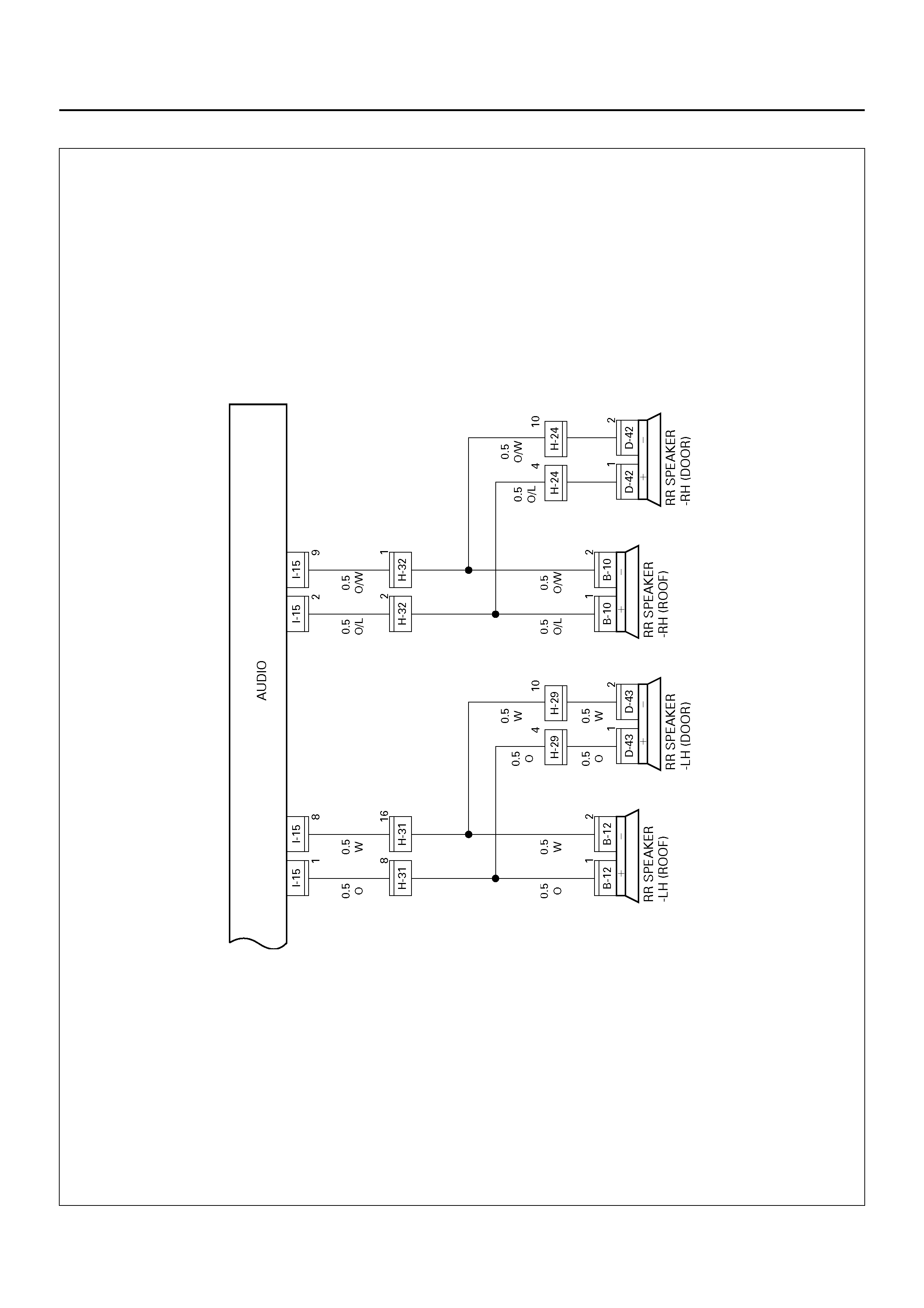
Circuit Diagram–2
D08R100199
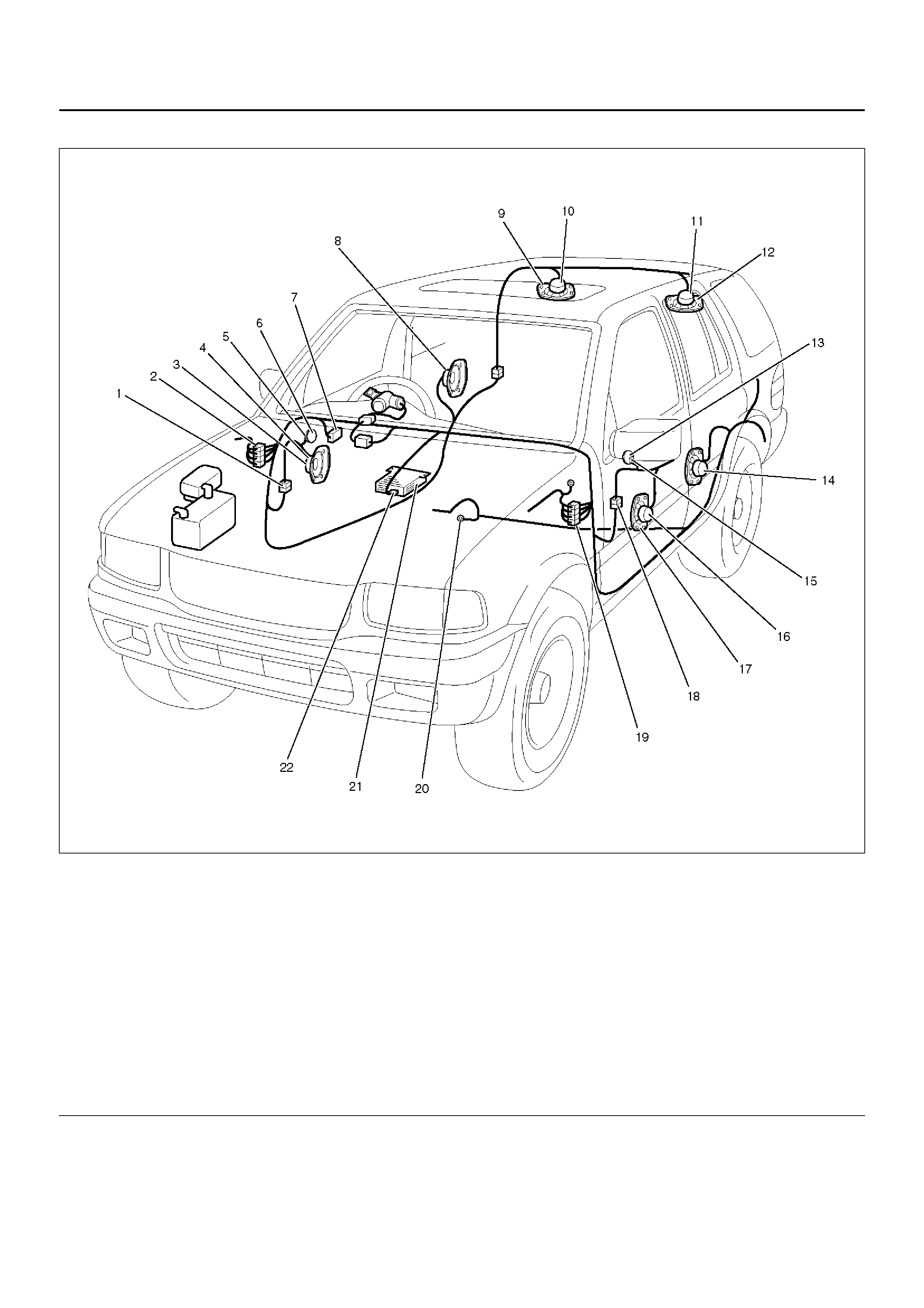
PARTS LOCATION
D08RWD13
EndOFCallout
Legend
(1) H–28
(2) H–19, H–32
(3) FRT Speaker – RH
(4) D–1
(5) D–13
(6) Tweeter – RH
(7) Relay & Fuse Box (Instrument Panel)
(8) RR Speaker – RH (Door)
(9) RR Speaker – RH (Roof)
(10) B–10
(11) B–12
(12) RR Speaker – LH (Roof)
(13) Tweeter – L H
(14) RR Speaker – LH (Door)
(15) D–4
(16) D–10
(17) FRT Speaker – LH
(18) H–33
(19) H–31
(20) B–8
(21) Audio
(22) I–15

REAR DEFOGGER/MIRROR DEFOGGER
GENERAL DESCRIPTION
The system consists of the rear defogger and mirror
defogger switch, the rear defogger & mirror defogger
relay, the rear defogger & mirror defogger and the
Powertrain Control Module (PCM).
When the rear defogger and mirror defogger switch is
turned on with the starter switch on, the rear defogger
and mirror defogger relay is activated and the battery
voltage is applied to the rear defogger and mirror
defogger.
The PCM is provided with the timer . When the operation
time of the timer elapses which has been set in
advance, the rea r defogg er and mir ror def ogger relay is
automatically deactivated and the rear defogger and
mirror defogger is turned off.
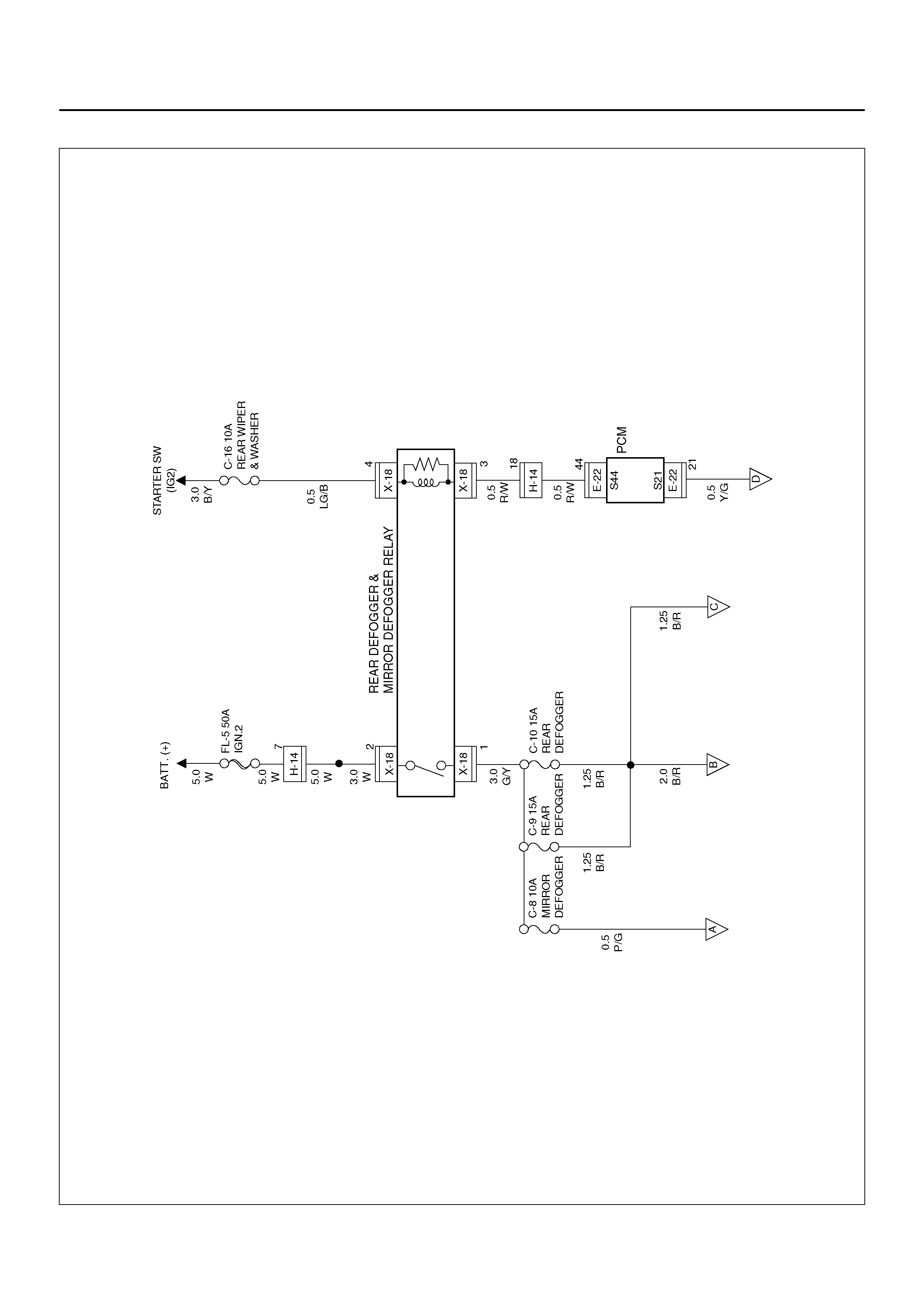
CIRCUIT DIAGRAM–1
D08R100138
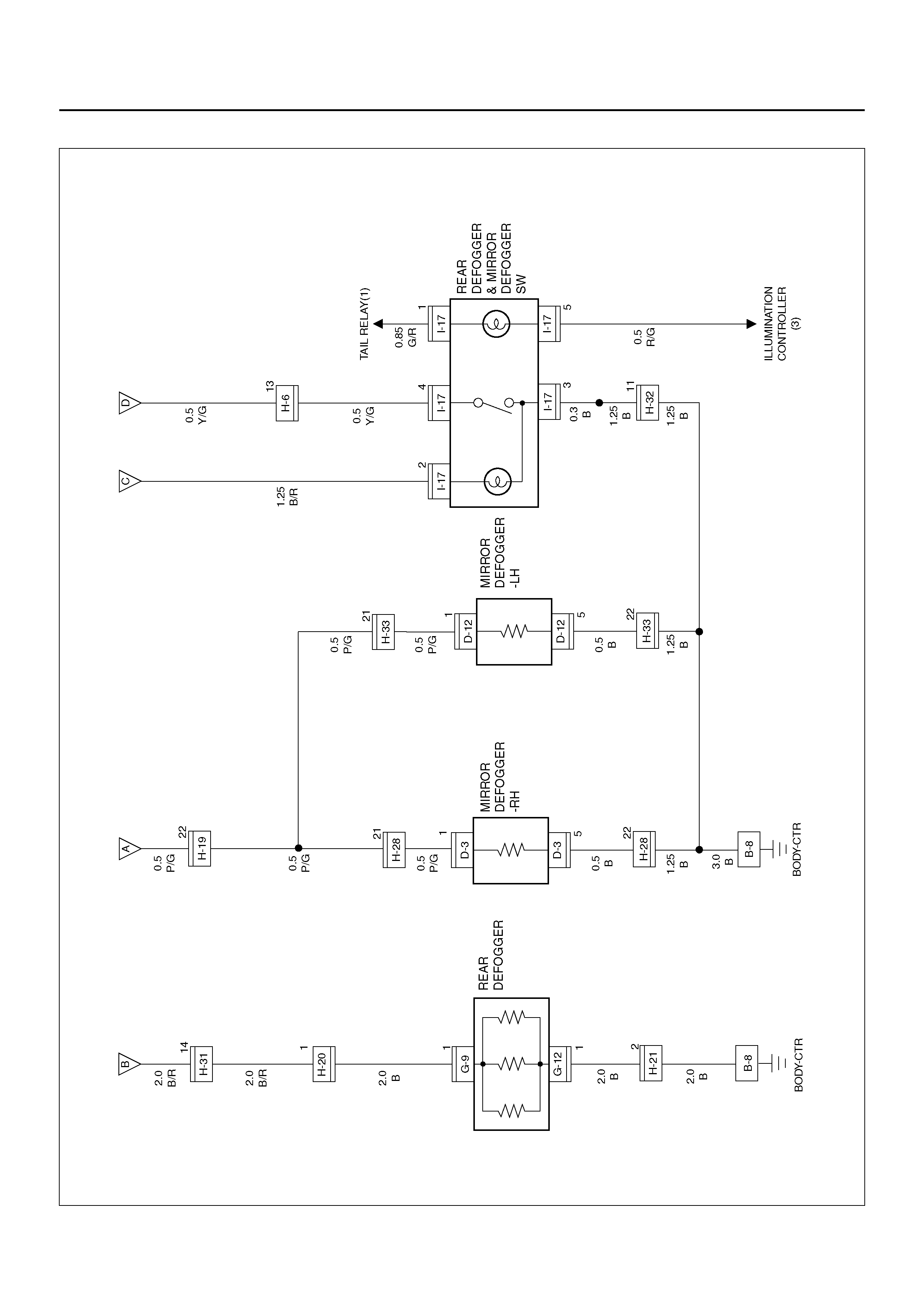
Circuit Diagram–2
D08R100139
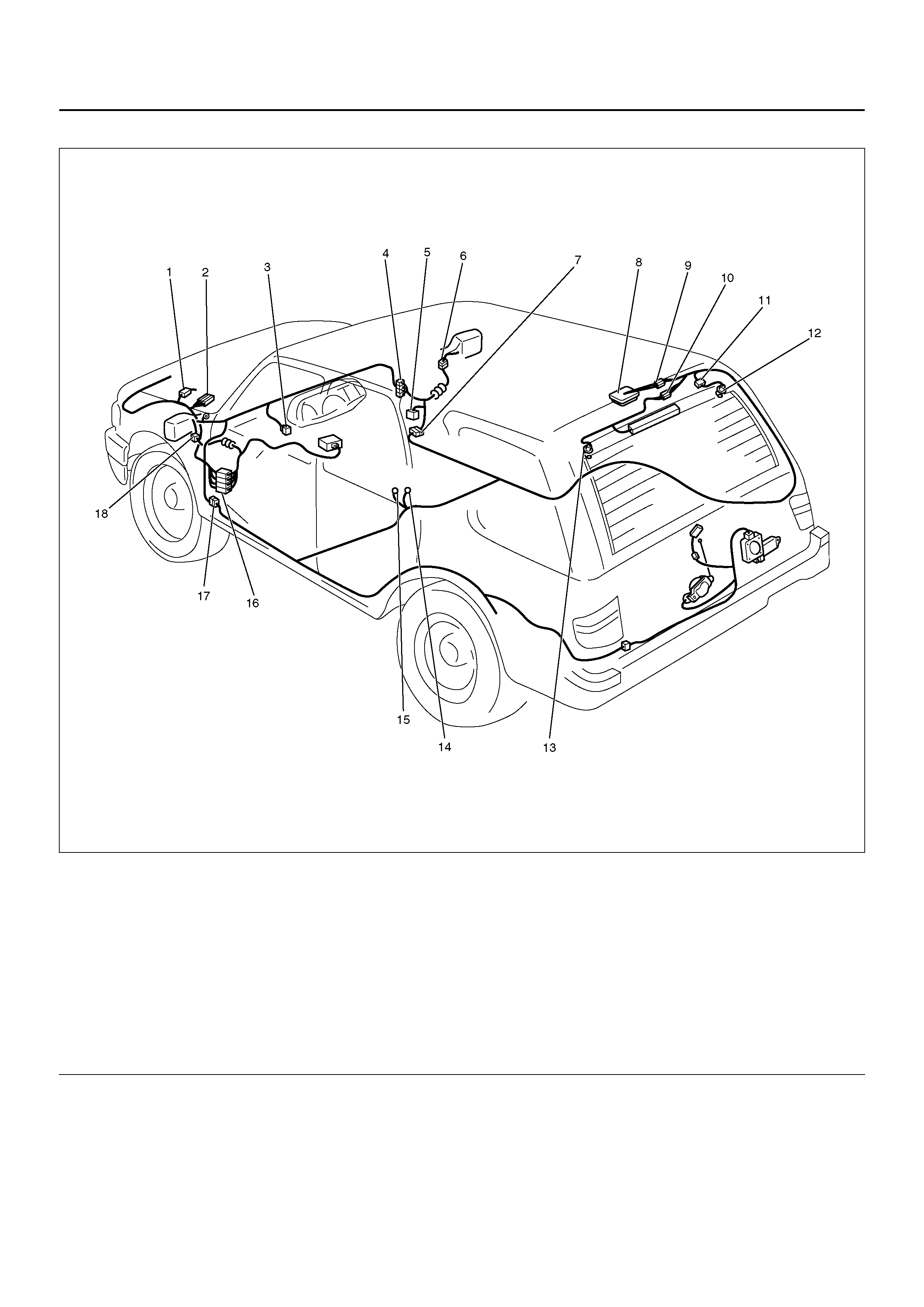
PARTS LOCATION
D08RY00834
EndOFCallout
Legend
(1) H–6
(2) E–21, E–22
(3) I–7
(4) H–14, H–19 , H–32
(5) Relay & Fuse Box
(6) D–3
(7) H–28
(8) Lugge ge Room Light
(9) B–11
(10) H–21
(11) H–20
(12) G–9
(13) G–2
(14) B–8
(15) B–6
(16) H–31
(17) H–33
(18) D–12

DIAGNOSIS
Rear Defogger Does Not Operate
Step Action Value(s) Yes No
1 Are the fuse C–9, C–10 and C–16 normal? — Go to Step 2 Replace the
fuse(s)
2 Is B–8 grounded securely? — Go to Step 3 Ground it
securely
3 Re mov e the re ar defogge r rela y.
Is the battery voltage applied between the rear
defogger relay harness side connector X–18 terminal
2 and the ground?
Approx. 12V Go to Step 5 Go to Step 4
4 Repair an open circuit between the battery and
connector X–18 terminal 2.
Is the action complete?
— Go to Step 3 —
5 Turn the starter switch on.
Is the battery voltage applied between harness side
connector X–18 terminal 4 and the ground?
Approx. 12V Go to Step 7 Go to Step 6
6 Repair an open circuit between the fuse C–16 and
connector X–18 terminal 4.
Is the action complete?
— Go to Step 5 —
7 Disconnect the PCM connector E–21, E–22.
Is there continuity between harness side connector X–
18 terminal 3 and harness side connector E–22
terminal 44 (S44)?
— Go to Step 9 Go to Step 8
8 Repair an open circuit between connector X–18
terminal 3 and connector E–22 terminal 44 (S–44).
Is the action complete?
— Go to Step 7 —
9 Is there con tinuity b etween har ness side connecto r I–
17 terminal 4 and connector E–22 terminal 21 (S21)? — Go to Step 11 Go to Step 10
10 Repair an open circuit between connector I–17
terminal 4 and connector E–22 terminal 21 (S21).
Is the action complete?
— Go to Step 9 —
11 Is ther e continu ity between h arness side connec tor I–
17 terminal 3 and the ground? — G o to Step 13 Go to Step 12
12 Repair an open circuit between connector I–17
terminal 3 and the ground B–8.
Is the action complete?
— Go to Step 11 —
13 1. Reconnect the rear defogger relay.
2. Ground the PCM harness side connector E–22
terminal 44 (S44).
Is the battery voltage applied between the rear
defogger harness side connector G–9 terminal 1 and
the ground?
Approx. 12V Go to Step 14 Repair an open
circuit between
the fuse C–9 or
C–10 and the
rear defogger
14 Is there continuity between the rear defog ger harness
side connector G–12 terminal 1 and the ground? — Go to Step 16 Go to Step 15
15 Repair an open circuit between connector G–12
terminal 1 and the ground B–8.
Is the action complete?
— Go to Step 14 —

Rear Defogger Timer Does Not Function
16 1. Reconnect the PCM connector E–21 and E–22.
2. Turn the rear defogger switch on.
Is the battery voltage applied between the rear
defogger harness side connector G–9 terminal 1 and
the ground?
Approx. 12V Go to Step 18 Go to Step 17
17 Replace the PCM.
Is the action complete? — Verify repair –
18 Repair broken heat wire or connector poor contact of
the rear defogger.
Is the action complete?
— Verify repair —
Step Action Value(s) Yes No
Step Action Value(s) Yes No
1 Replace the PCM.
Is the action complete? — Verify repair —

CIGARETTE LIGHTER, DIGITAL CLOCK AND ACCESSORY SOCKET
GENERAL DESCRIPTION
When the cigarette lighter is pushed in with the starter
switch at either “ACC" or “ON" position, a circuit is
formed in the cigarette lighter case to heat the lighter
coil.
The cigarette lighter is sprung back to its original
position after the lighte r coil is heated .
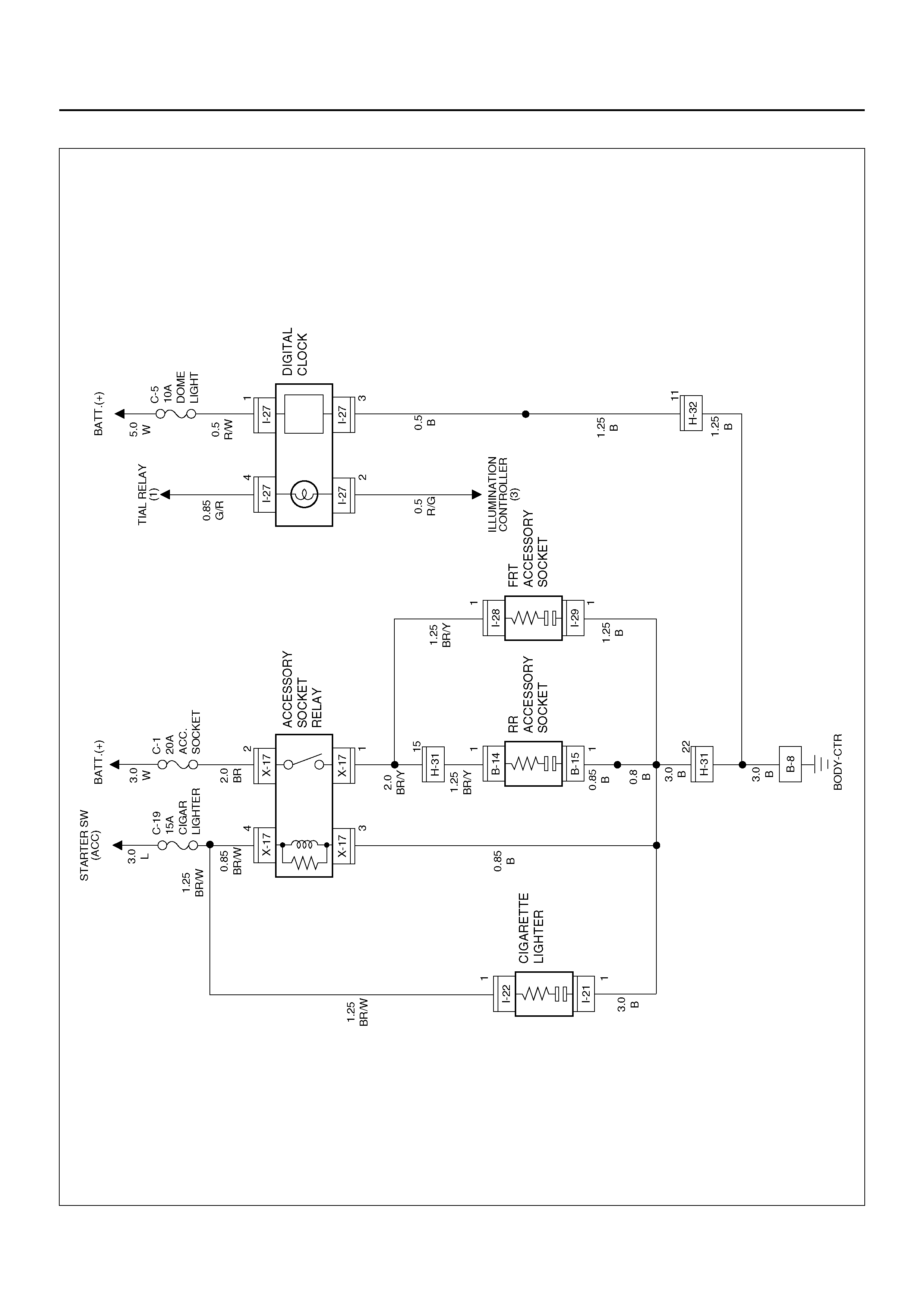
CIRCUIT DIAGRAM
D08R100218
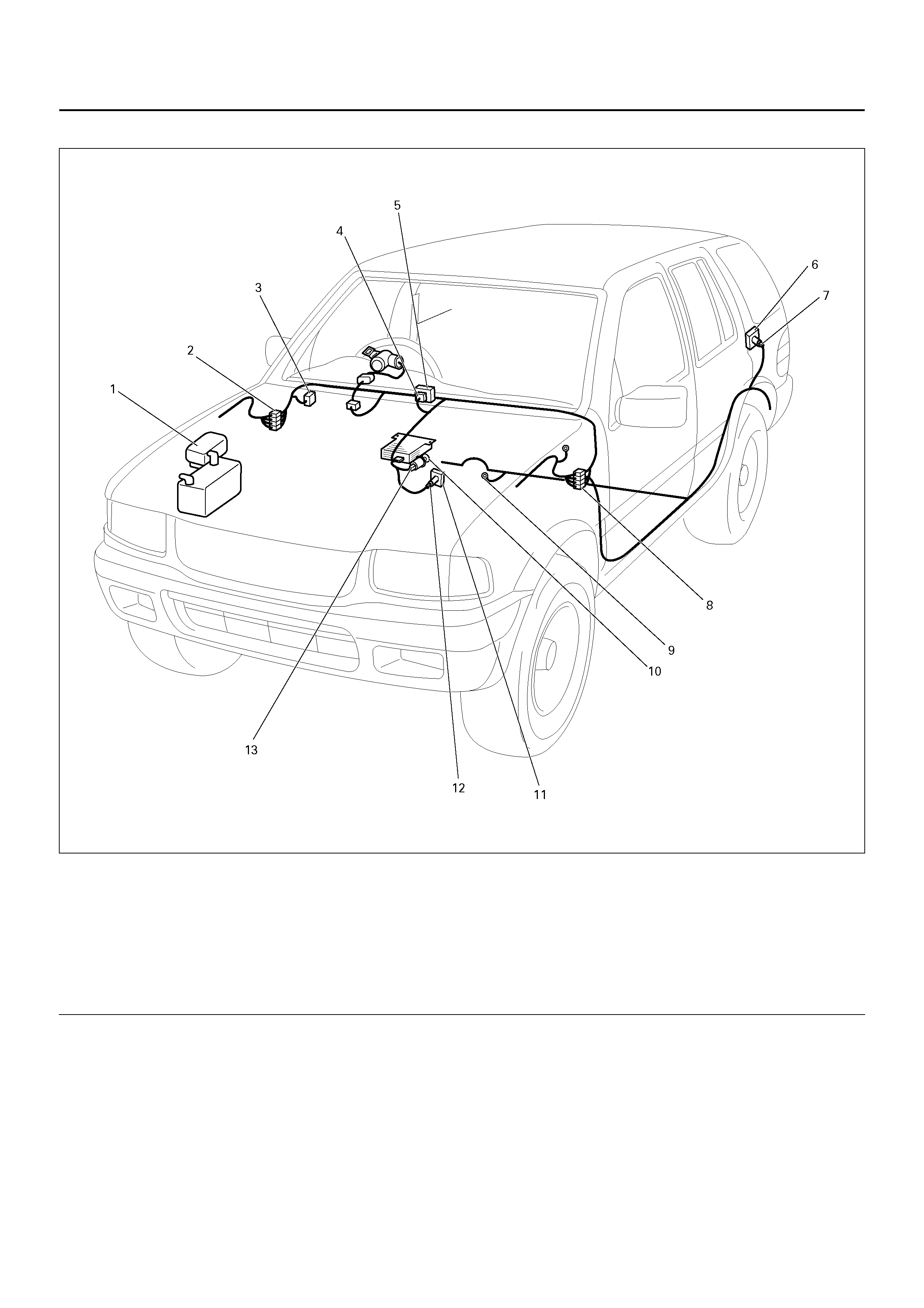
PARTS LOCATION
D08R100200
EndOFCallout
Legend
(1) Relay & Fuse Box (Engine Room)
(2) H–32
(3) Relay & Fuse Box (Instrument Panel)
(4) I–27
(5) Digital Clock
(6) Rear Accessory Socket
(7) B–14, B–15
(8) H–31
(9) B–8
(10) Cigarette Lighter
(11) Front Ac ce ss or y Sock et
(12) I–28, I–29
(13) I–21, I–22

DIAGNOSIS
Cigarette Lighter Does Not Work
Cigarette Lighter Doe s Not Spring Out After Being Heated
Step Action Value(s) Yes No
1 Is the fuse C–19 normal? — Go to Step 2 Replace the
fuse
2 Is B–8 grounded securely? — Go to Step 3 Ground it
securely
3 1. Disconnect the cigarette lighter connector I–22.
2. Turn the starter switch to the ACC or ON position.
Is the battery voltage applied between harness side
connector I–22 terminal 1 and the ground?
Approx. 12V Go to Step 5 Go to Step 4
4 Repair an open circuit between the fuse C–19 and
connector I–22 terminal 1.
Is the action complete?
— Go to Step 3 —
5 Disconnect the cigarette lighter connector I–21.
Is ther e continu ity between h arness si de connec tor I–
21 terminal 1 and the ground B–8?
— Repair or
replace the
cigarette lighter
assembly
Go to Step 6
6 Repair an open circuit between connector I–21
terminal 1 and the ground B–8.
Is the action complete?
— Verify repair —
Step Action Value(s) Yes No
1 Repair or replace the cigarette lighter.
Is the action complete? — Verify repair —

POWER DOOR MIRROR
GENERAL DESCRIPTION
The system consists of the starter switch, the mirror
control switch, and door mirrors on both sides.
When the mirror control switch is operated with the
starter switch at either “ACC" or “ON" position, the
motor in the do or mirror (on eithe r side) rotates to allow
the horizontal and vertical adjustment of mirror angles.
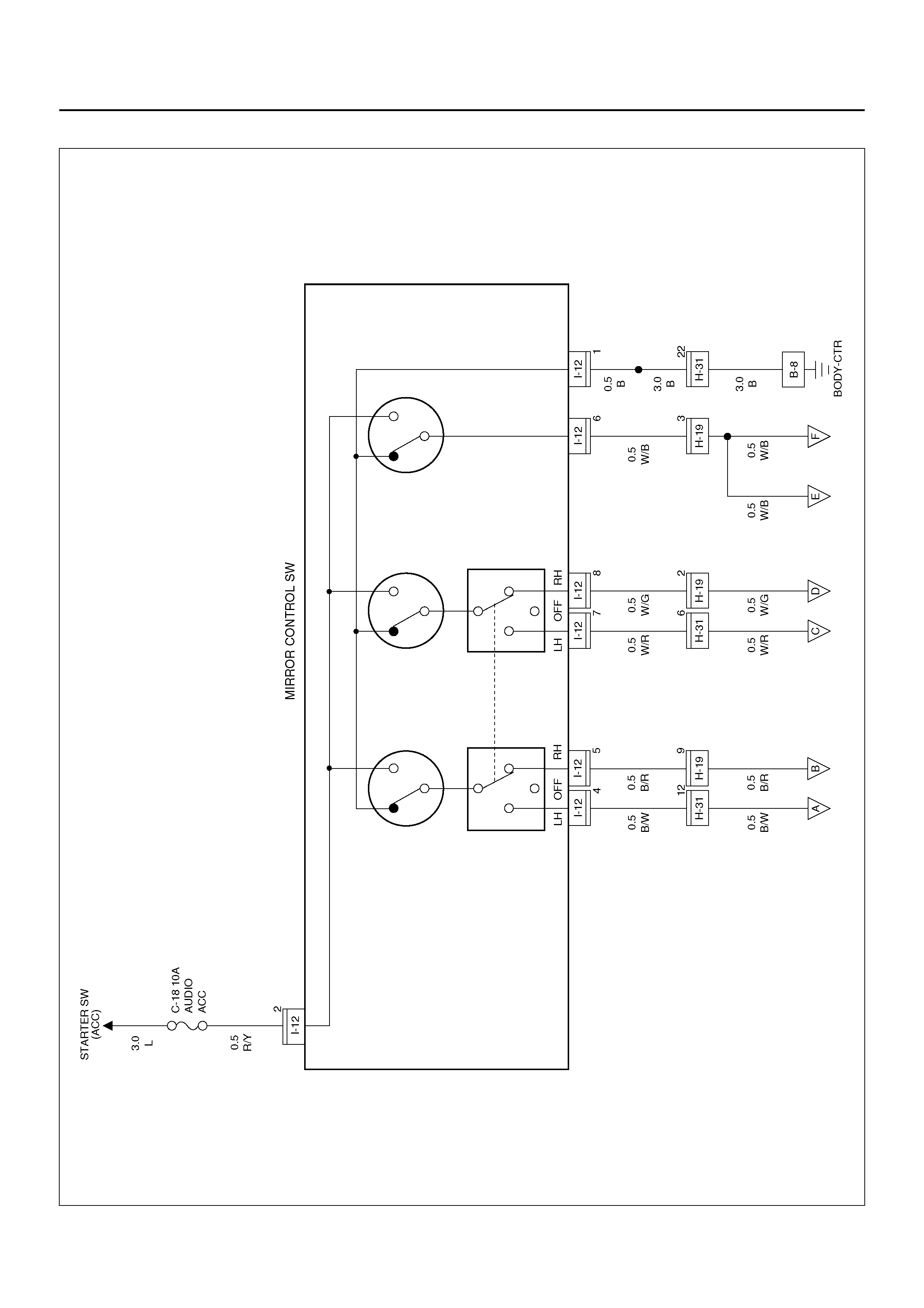
CIRCUIT DIAGRAM–1
D08R100216
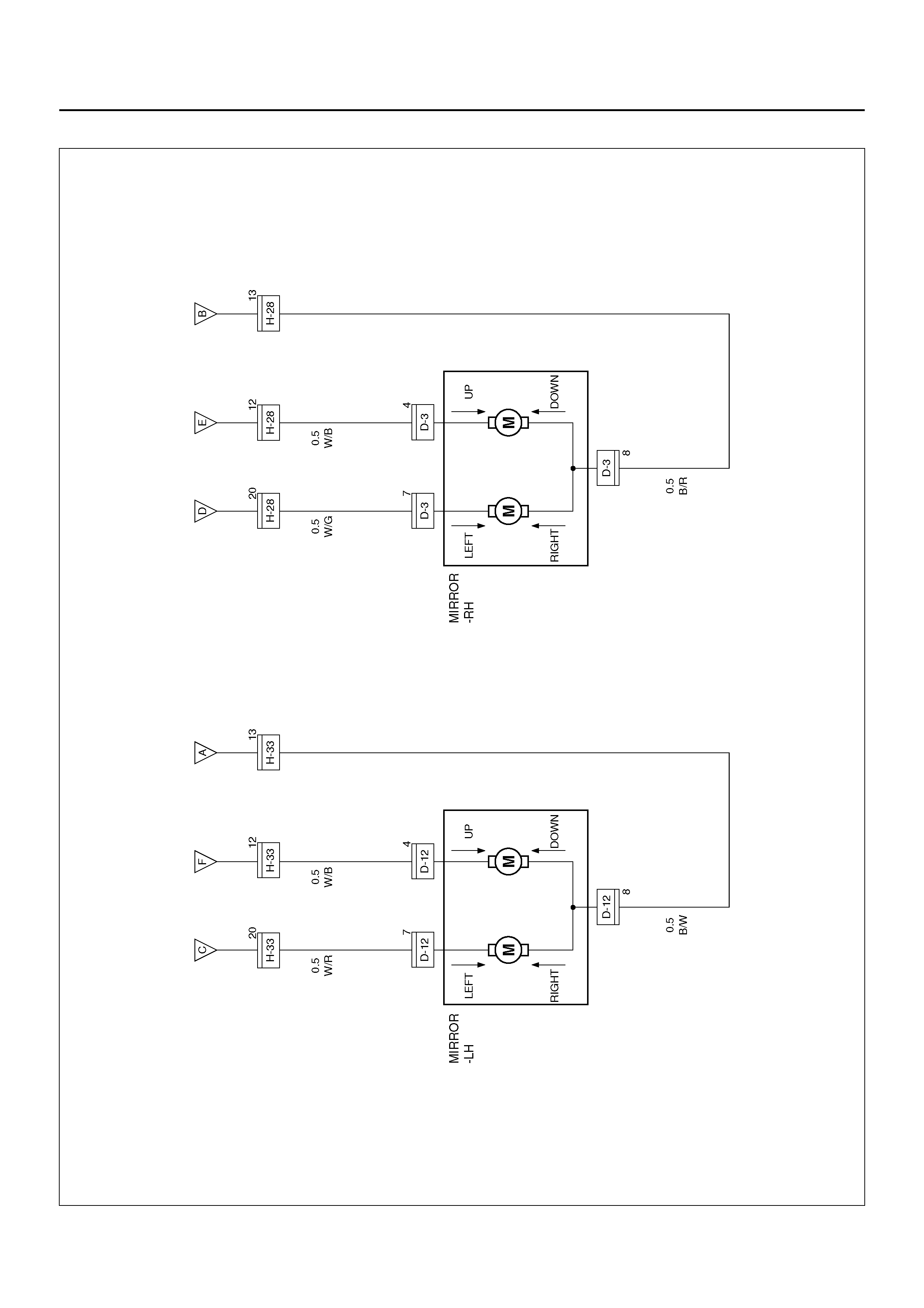
Circuit Diagram–2
D08R100146
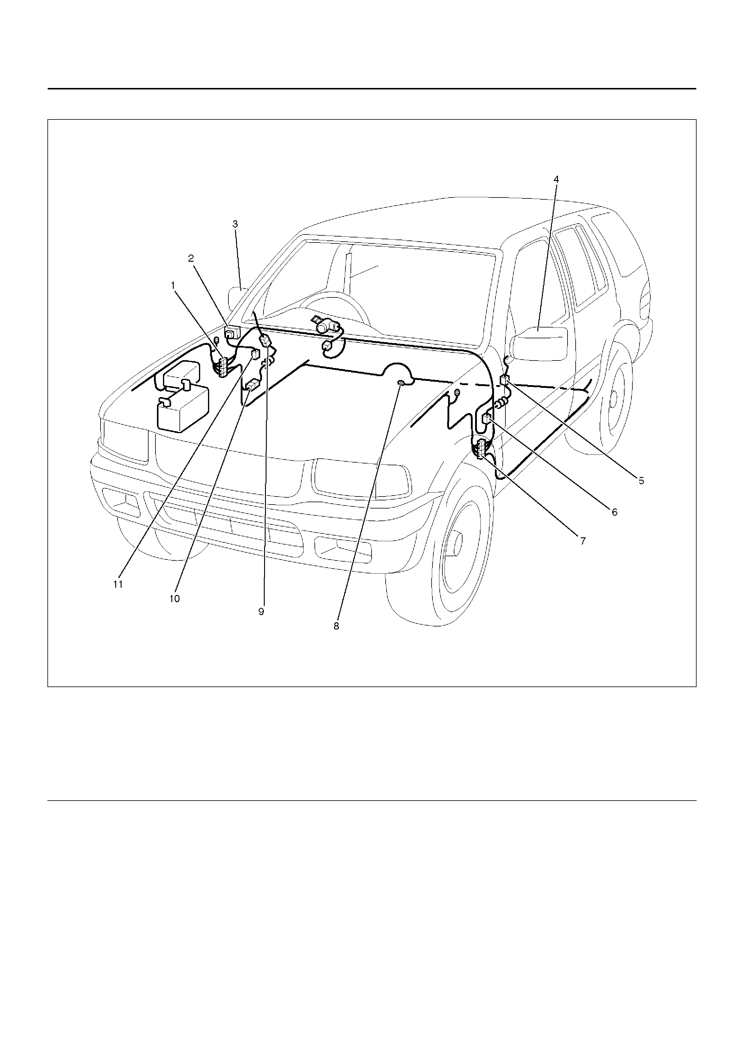
PARTS LOCATION
D08RX248
EndOFCallout
Legend
(1) H–19
(2) I–12
(3) Door Mirror – RH
(4) Door Mirror – LH
(5) D–12
(6) H–33
(7) H–31
(8) B–8
(9) D–3
(10) H–28
(11) Relay & Fuse Box (Instrument Panel)

DIAGNOSIS
Mirrors On B o th Sides Do Not Operate
Mirrors On the Left (or Right) Side Does Not O p erate
Mirrors On Both Sides Operate Only In The Vertical (Or Horizontal) Direction
Step Action Value(s) Yes No
1 Is the fuse C–18 normal? — Go to Step 2 Replace the
fuse
2 Is B–8 grounded securely? — Go to Step 3 Ground it
securely
3 Disconnect the mirror control switch connector I–12.
Is the battery voltage applied between the harness
side connector I–12 terminal 2 and the ground?
Approx. 12V Go to Step 5 Go to Step 4
4 Repair an open circuit between the fuse C–18 and
connector I–12 terminal 2.
Is the action complete?
— Go to Step 3 —
5 Is there continuity between the harness side
connector I–12 terminal 1 and the ground? — Go to Step 7 Go to Step 6
6 Repair an open circuit between connector I–12
terminal 1 and the ground.
Is the action complete?
— Verify repair —
7 Repair or replace the mirror control switch.
Is the action complete? — Verify repair —
Step Action Value(s) Yes No
1 1. Remove the mirror control switch.
2. Move the mirror select switch to the left side mirror
(or right side m irror).
Is there continuity between the switch side connector
terminal 1, 4 and 7 (or 1, 5 and 8)?
— Go to Step 2 Replace the
mirror control
switch
2 Repair an open circuit between connector I–12
terminal 4 and connector D–12 terminal 8 (or
connec tor I–12 term in al 5 and conn ector D–3 ter mi nal
8)?
Is the action complete?
— Verify repair —
Step Action Value(s) Yes No
1 Repair or replace the mirror control switch.
Is the action complete? — Verify repair –

Mirror On the Left (or Right) Side Operates Only In The Vertical (Or Horizontal) Direction
Step Action Value(s) Yes No
1 Does the mirror operate vertically? — Go to S tep 2 Go to Step 3
2 1. Remove the mirror–LH (or ? RH).
2. Connect the batter y positiv e terminal to the m irror
side connector terminal 7, and battery negative
terminal to mirror side terminal 8. Then connect
the battery positive terminal to mirror side terminal
8, and negative terminal to mirror side terminal 7.
Does the mirror operate horizontally?
— Go to Step 4 Replace the
mirror
3 1. Remove the mirror–LH (or ? RH).
2. Connect the batter y positiv e terminal to the m irror
side connector terminal 4, and battery negative
terminal to mirror side terminal 8. Then connect
the battery positive terminal to mirror side terminal
8, and negative terminal to mirror side terminal 4.
Does the mirror operate vertically?
— Go to Step 4 Replace the
mirror
4 Repair an open circuit between connector I–12
terminal 7 or 8 and mirror connector terminal 7, or
connector I–12 terminal 6 and mirror connector
terminal 4.
Is the action complete?
— Verify repair —

KEYLESS ENTRY
GENERAL DESCRIPTION
This circuit consists of the keyless entry control unit, the
front door lock, & power window switch (RH), the starter
switch, the dome light, th e door swi tch and the tail gate
switch and possible to lock/unlock each door by
operation of transmitter. Basic function of system is as
follows.
1. Lock/unlock function
When the Keyless entry control unit receives the
signal from the transmitter, the control unit sends
the locker unlock signal to the front door lock and
power window switch (RH).
Function code (lock or unlock) and proper ID code
for each vehicle are added to the signal. But, when
starter sw itch is on or any of the do ors opens, lock/
unlock function is not unable to work.
2. Answer back function
When receiving the signal from the transmitter, the
keyless entry control unit responds by using the
dome light. In case of being locked, the keyless
entry control unit turns on the dome light at two
times (about 0.5 second at each time). In case of
being unlocked, it turns on the dome light at one
time (about 3 seconds).
3. Autolock function
After unlock function is done, in case of effecting
one of following conditions within about 30 seconds,
the keyless entry control unit automatically sends
the lock signal to lock each door.
1 The doors are closed.
2 Starter key is not inserted
3 The lock operation is not done by transmitter.
Techline
Techline
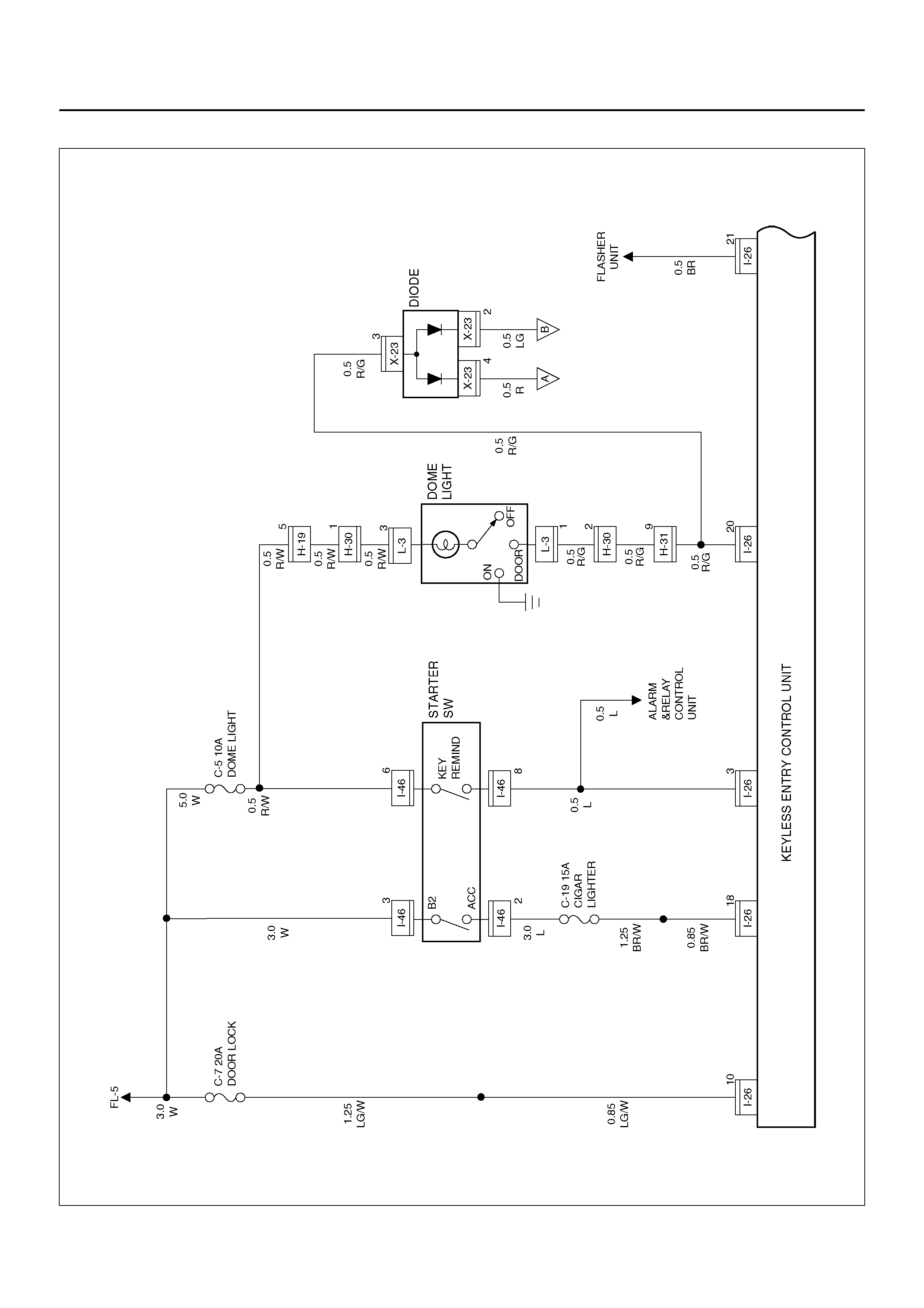
CIRCUIT DIAGRAM–1
D08R100147
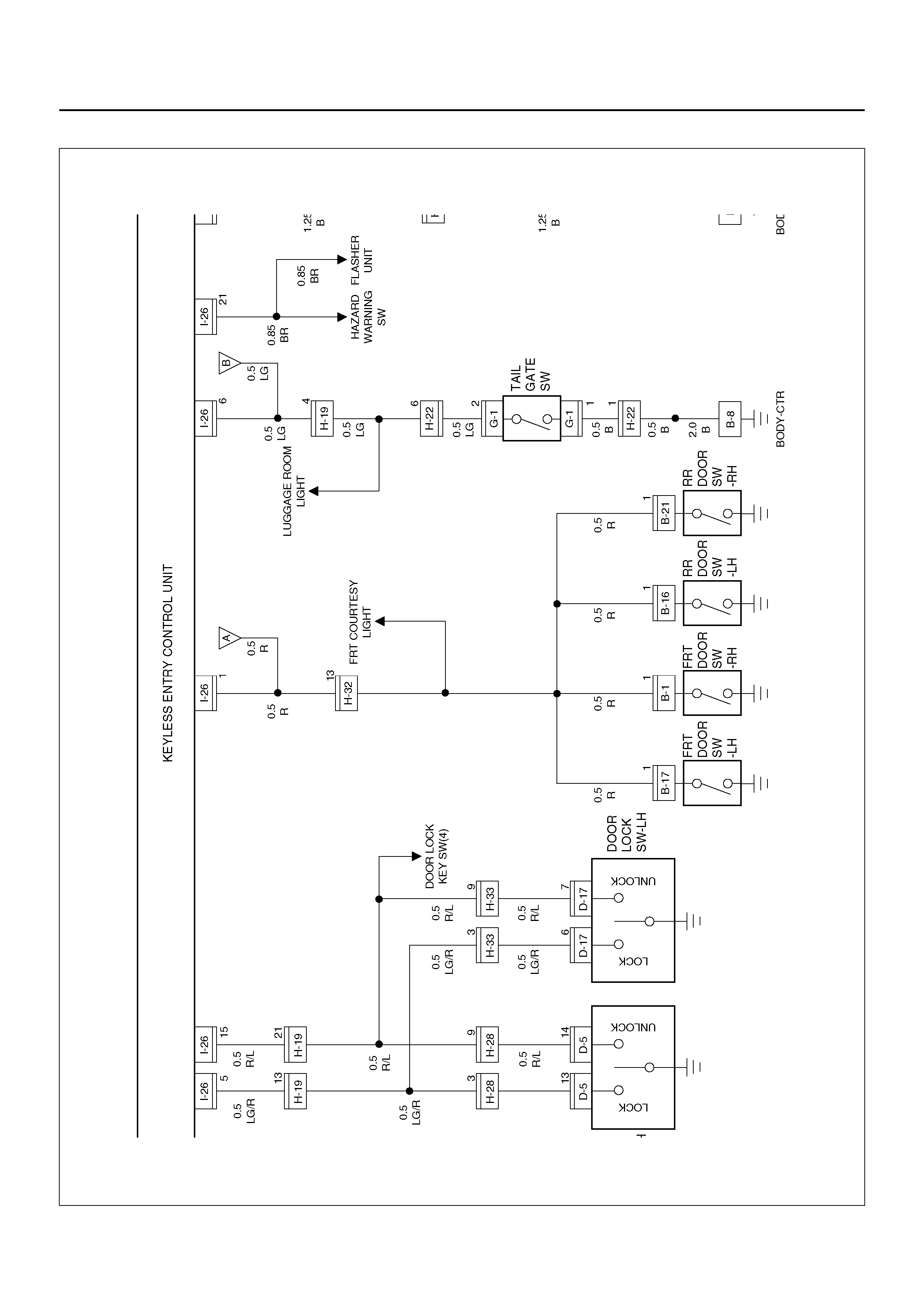
Circuit Diagram–2
D08R100148
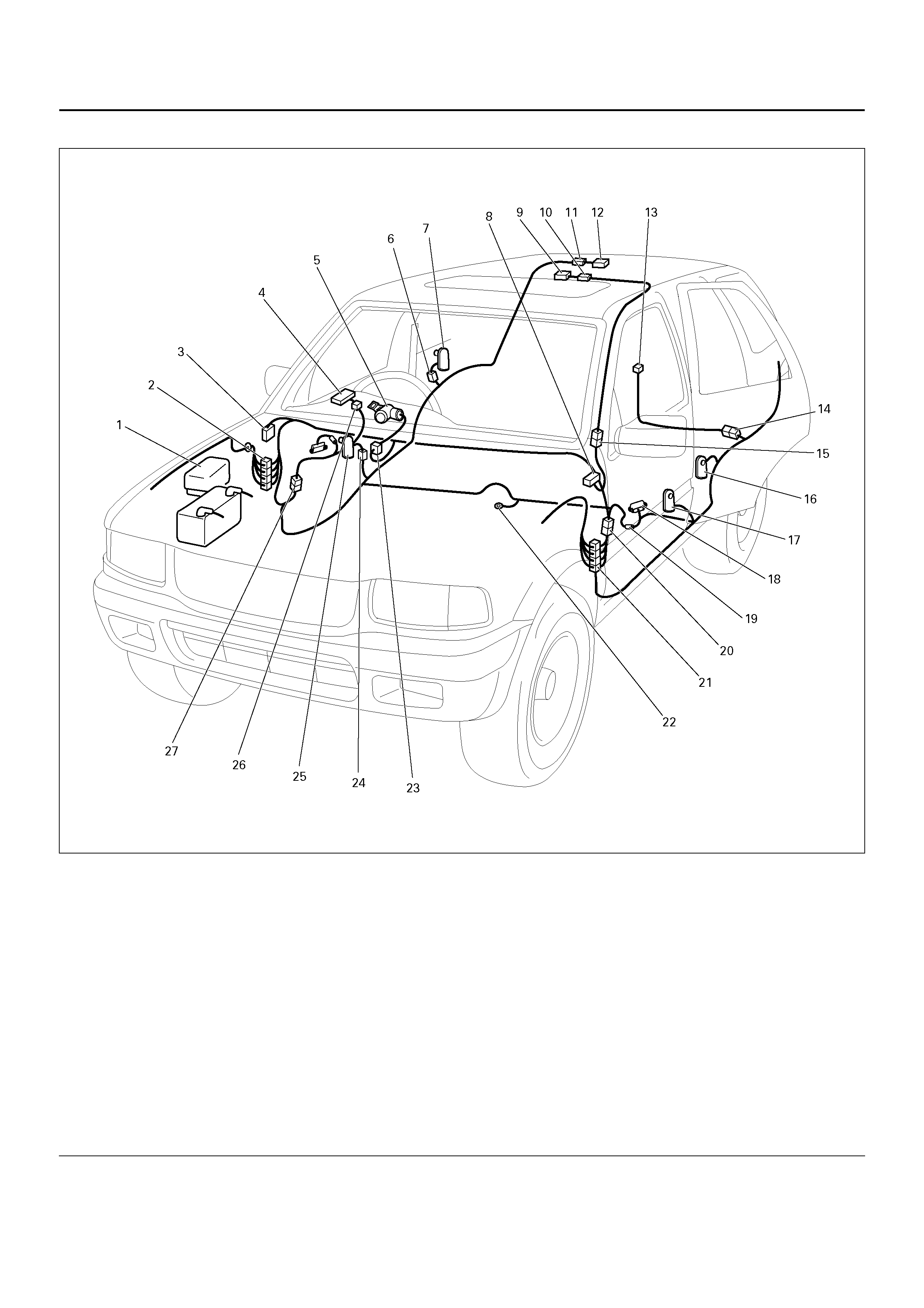
PARTS LOCATION
D08R100201
EndOFCallout
Legend
(1) Relay & Fuse Box (Engine Room)
(2) H–19, H–32
(3) Relay & Fuse Box (Instrument Panel)
(4) FRT Door Lock Switch – RH
(5) Starter Switch
(6) B–21
(7) RR Door Switch – RH
(8) I–26
(9) Do me Lig ht
(10) L–3
(11) B–11
(12) L ugga ge Room Light
(13) G–1
(14) H–22
(15) H–30
(16) B–16
(17) B–17 (FRT Door Switch – LH)
(18) FRT Door Lock Switch–LH
(19) D–17
(20) H–33
(21) H–31
(22) B–8
(23) I–46
(24) B–1
(25) FRT Door Switch – RH
(26) D–5
(27) H–28

KEYLESS ENTRY SYSTEM
ID Code Registration
This procedure registers a new ID code. A total
of four ID codes may be stored. Any attempt to
a fifth ID will result in ID code #1 being erased.
Step Action Value(s) Yes No
1 1. Confirm that all the doors are closed and
unlocked.
2. Open the driver's side door.
3. Insert the key into the starte r switc h.
Is the action complete?
— Go to Step 2 Go to Step 1
2 Turn the starter switch to ACC position and then to
OFF position three times.
NOTE: This step must be carried out within five
seconds of step 1.
Is the action complete?
— Go to Step 3 Go to Step 1
3 Close the driver's side door and then open it two
times.
NOTE: This step must be carried out within ten
seconds of step 2.
Is the action complete?
— Go to Step 4 Go to Step 1
4 1. Turn the starter switch to ON position and then to
OFF position three times.
2. Close the driver's side door and then open it.
This step must be carried out within ten seconds of
step 3.
Is the action complete?
— Go to Step 5 Go to Step 1
5 The control unit lock and unlocks the doors two times.
Does the control unit work normally? — Go to Step 6 Go to Step 1
6 Operate the lock or unlock button of the transmitter.
NOTE: This step must be carried out within twenty
seconds of step 5.
Is the action complete?
— Go to Step 7 Go to Step 1
7 The control unit locks and unlock the doors two times.
Does the control unit work normally? — Go to Step 8 Go to Step 1
8 Operate the lock or unlock button of the transmitter.
NOTE: This step must be carried out within twenty
seconds of step 7.
Is the action complete?
— Go to Step 9 Go to Step 1
9 The control unit compares the two codes sent from the
transmitter.
If the code succeeds in registration, the control unit
locks and unlocks the doors one time.
If the two codes are different from each other or fails in
registration, the control unit locks and unlocks the
doors three times.
— Go to Step 1 Go to Step 1

METER AND WARNING/INDICATOR LIGHT
GENERAL DESCRIPTION
The circuit consists of the starter switch, meter
assembly, vehicle speed sensor, alarm & relay control
unit, lighting switch, turn signal switch, engine coolant
temperature unit, oil pressure unit, Powertrain Control
Module, fuel tank unit, 4WD control unit, oil pressure
switch, parking brake switch, brake fluid switch, seat
belt switch, illumination controller.
The meter AS M contains the spe edometer, tachometer,
voltmeter, engine coolant temperature gauge, oil
pressure gauge, fuel gauge and warning/indicator lights.
The meter warning/indicator lights and their bulb
sockets are a unit, they are installed from the back of
the speedo met er asse mbl y.
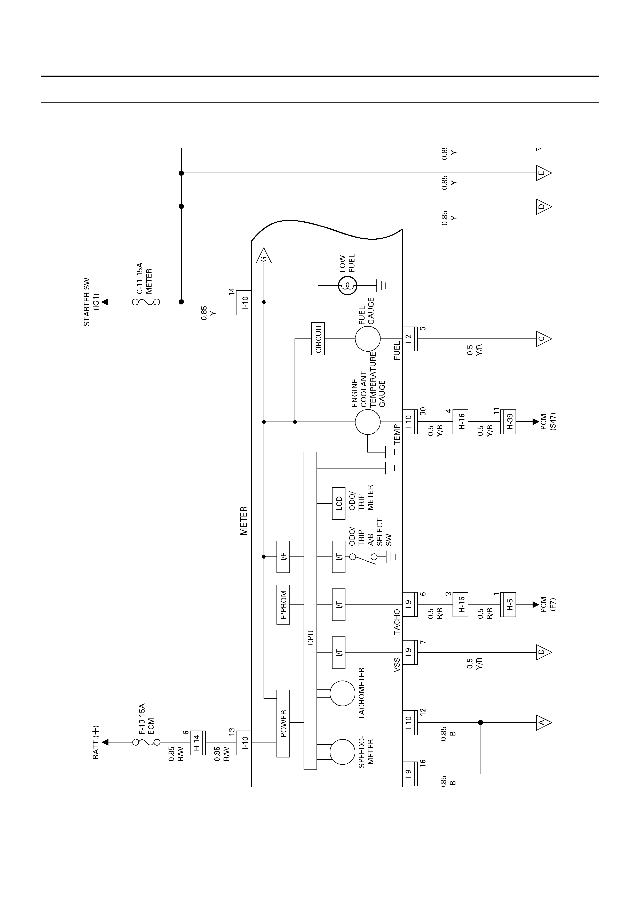
CIRCUIT DIAGRAM – 1
D08R100235
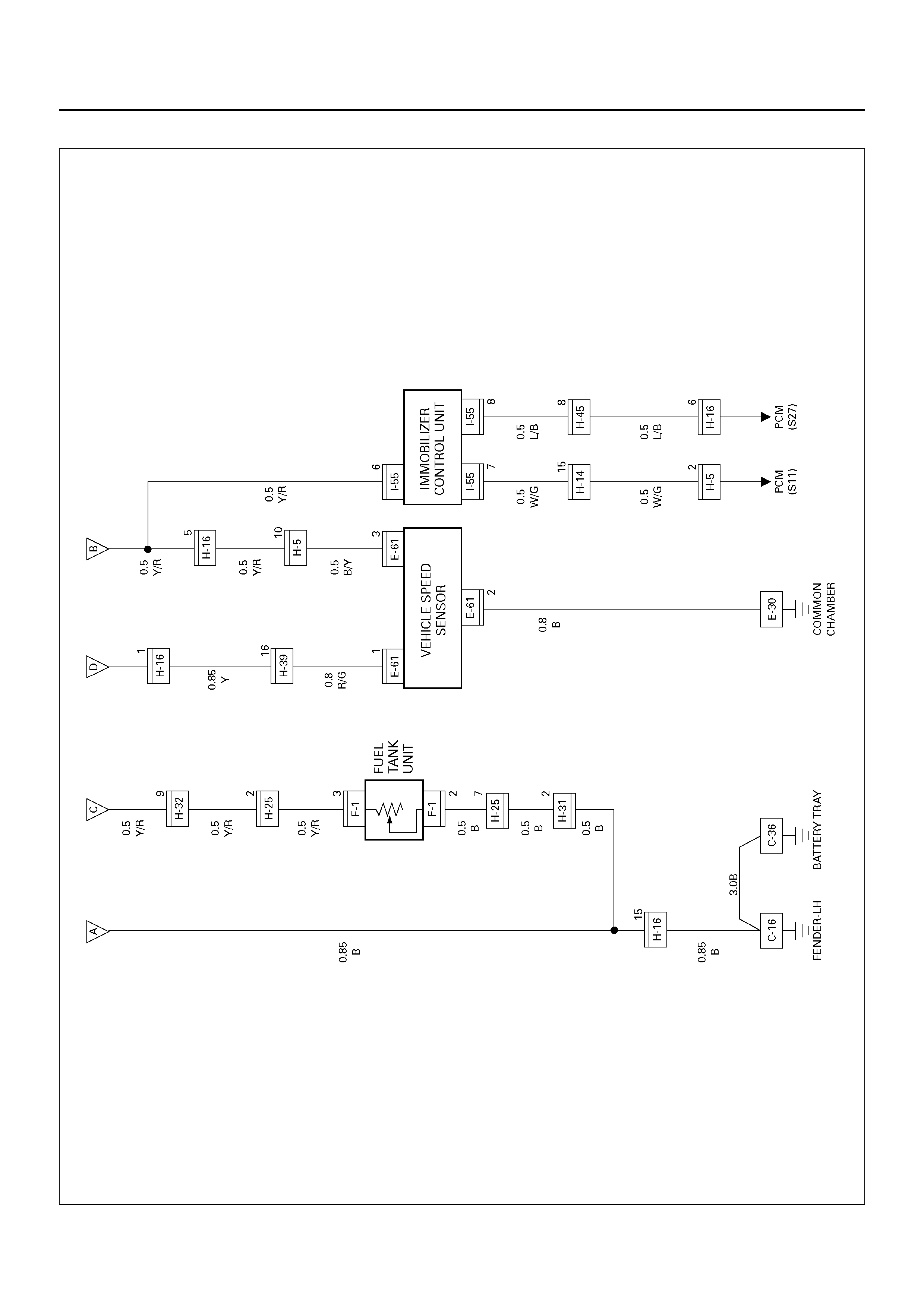
Circuit Di agram – 2
D08R100150
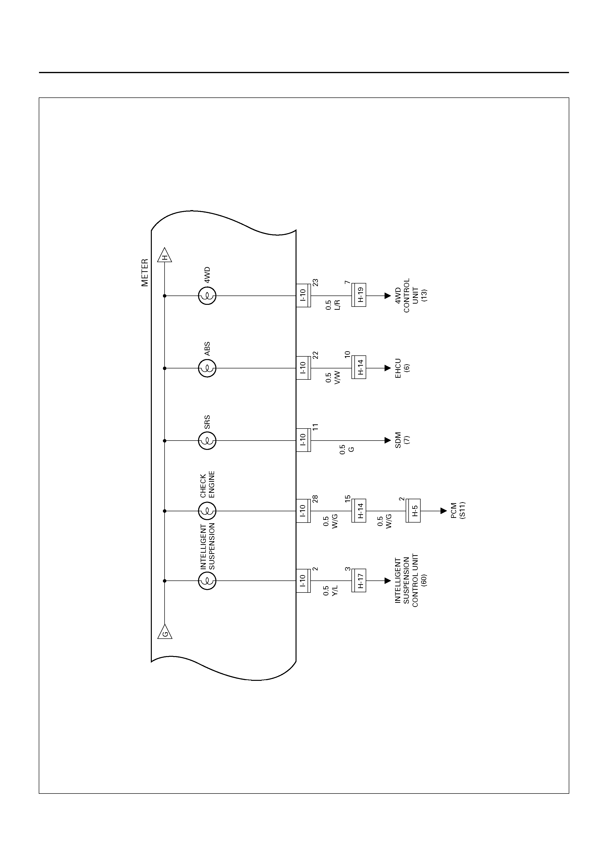
Circuit Di agram – 3
D08R100227
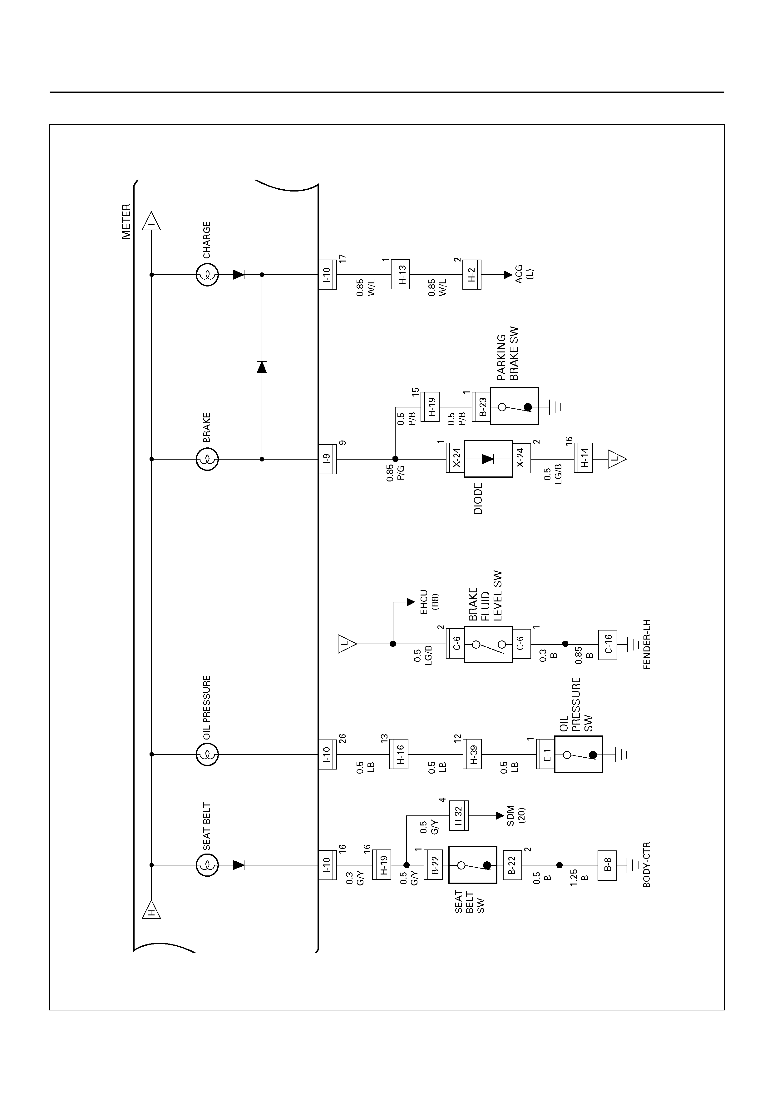
Circuit Di agram – 4
D08R100152
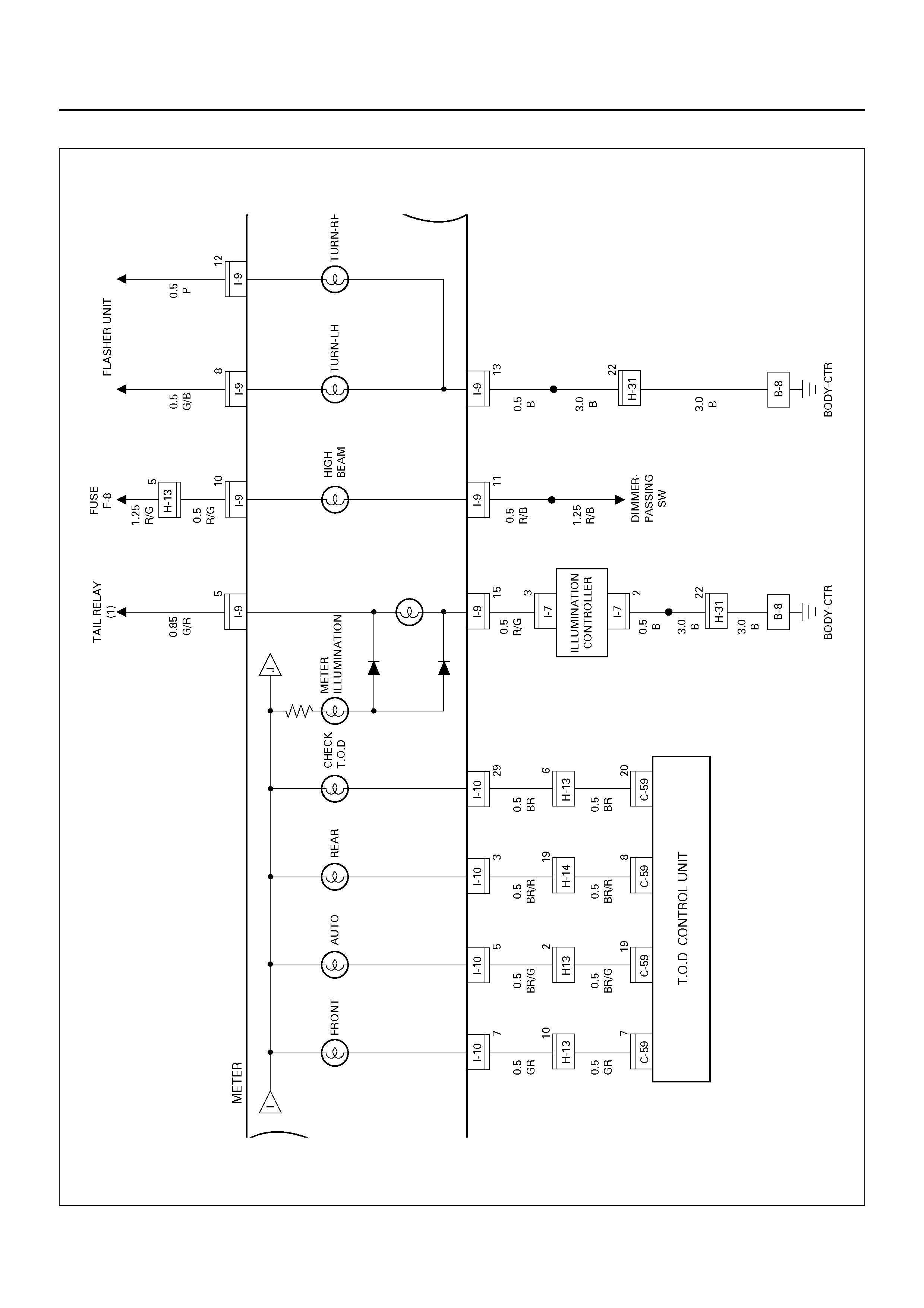
Circuit Di agram – 5
D08R100153
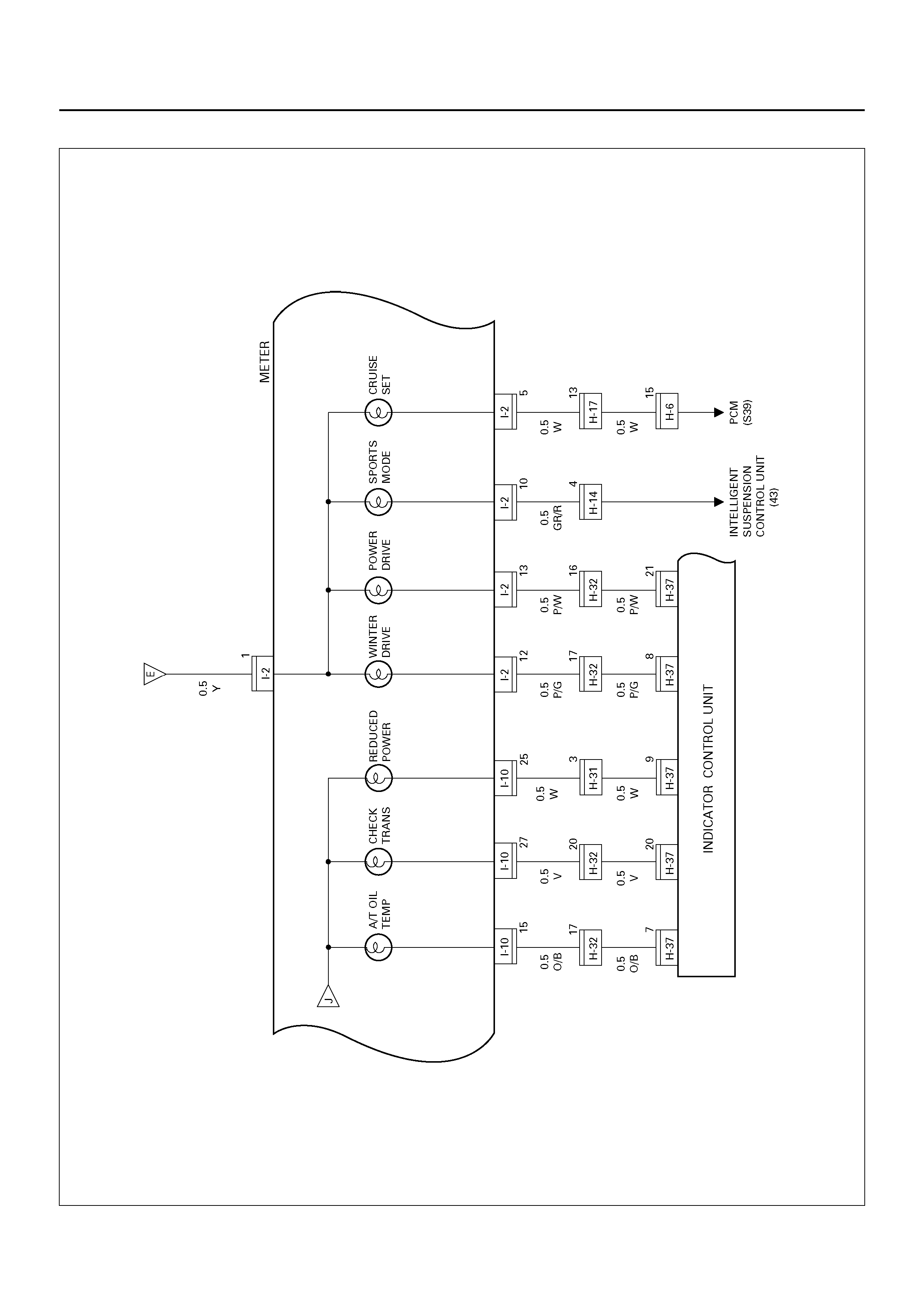
Circuit Di agram – 6
D08R100226
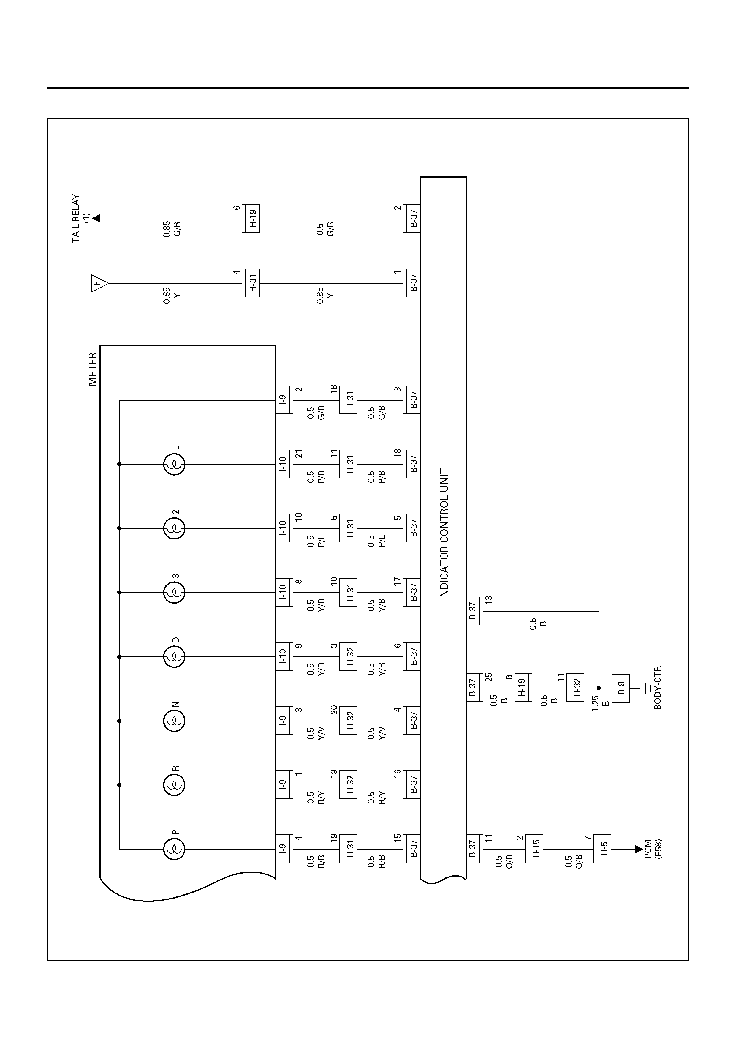
Circuit Di agram – 7
D08R100155
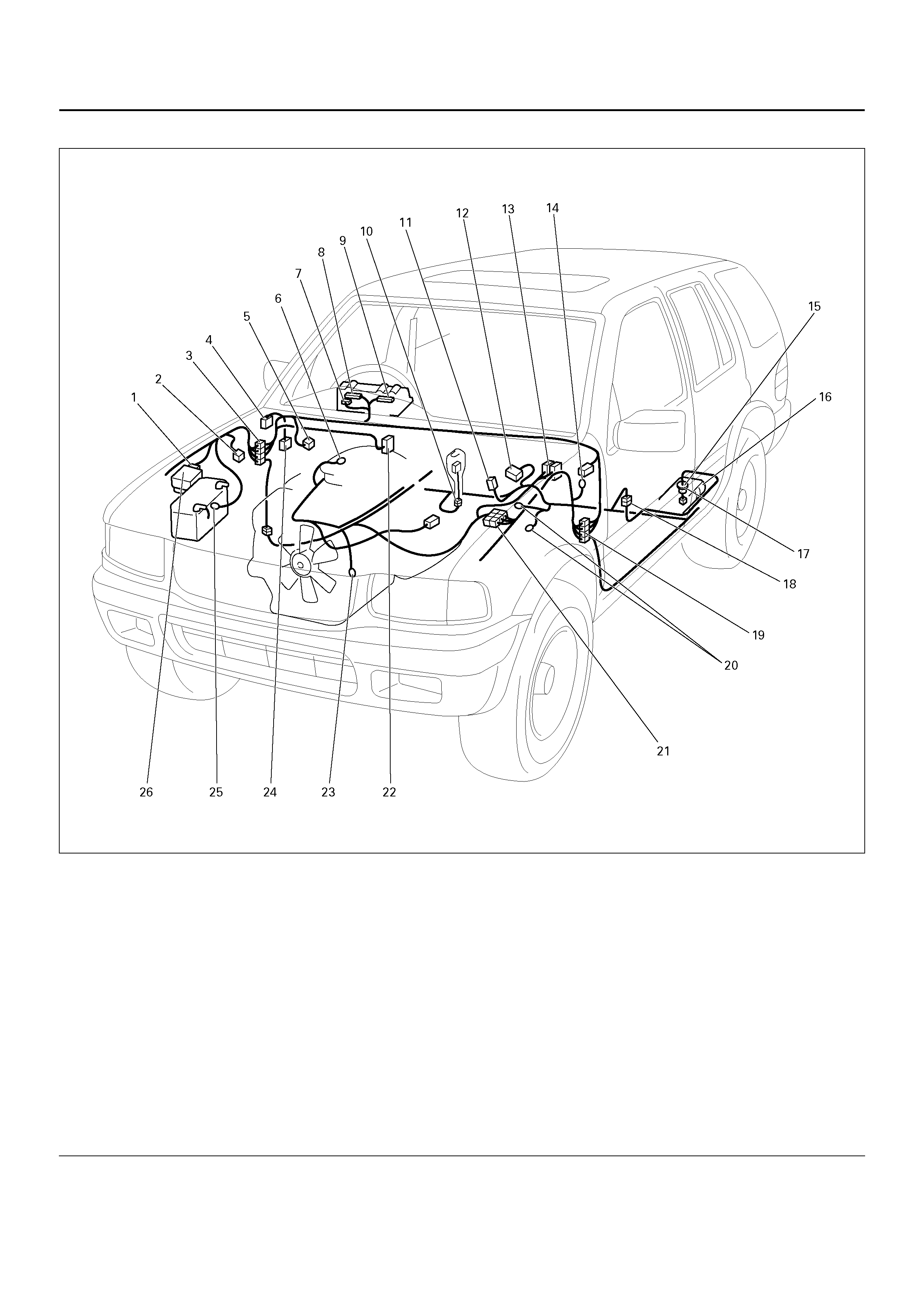
PARTS LOCATION
D08R100202
EndOFCallout
Legend
(1) H–2
(2) C–6
(3) H–13, H–14, H–19, H–32, H–45
(4) Relay & Fuse Box (Instrument Panel)
(5) I–17
(6) E–30
(7) I–2
(8) I–9
(9) I–10
(10) B–22
(11) B–23
(12) B–27
(13) E–21, E–22
(14) C–16
(15) Fuel Tank Unit
(16) Fuel Tank
(17) F–1
(18) H–25
(19) H–16, H–17, H–31
(20) B –6, B–8
(21) H–5, H–6, H–39
(22) C–59
(23) E–1
(24) I–55
(25) C–36
(26) Relay & Fuse Box (Engine Room)

DIAGNOSIS
Speedometer and Odometer Do Not Function
Speedometer Does Not Function (Odometer is Normal)
Odometer Does Not Function (Speedometer is Normal)
Step Action Value(s) Yes No
1 Is C–16 gr ound ed se curely? — Go to Step 2 Gr ou nd it
securely
2 Disconnect the vehicle speed sensor connector E–61.
Is there continuity between harness side connector E–
61 terminal 2 and the ground?
— Go to Step 4 Go to Step 3
3 Repair an open circuit between connector E–61
terminal 2 and the ground C–16.
Is the action complete?
— Go to Step 2 —
4 1. Disconnect the meter connector I–10.
2. Turn the starter switch on.
Is the battery voltage applied between harness side
connector E–61 terminal 1 and the ground?
Approx. 12V Go to Step 6 Go to Step 5
5 Repair an open circuit between fuse C–11 and
connector E–61 terminal 1.
Is the action complete?
— Go to Step 4 —
6 Disconnect the meter connector I–9.
Is ther e continu ity between h arness si de connec tor I–
9 terminal 7 and harness side connector E–61
terminal 3?
— Go to Step 8 Go to Step 7
7 Repair an open circuit between connector I–9 terminal
7 and connector E–61 terminal 3.
Is the action complete?
— Verify repair —
8 1. Co nnecto r a resistance of 1.3 to 5K oh m (1.4W or
more) between harness side connector I–10
terminal 14 and harness side connector I–9
terminal 7.
2. Install a speedometer tester.
3. Check th e waveform a t the time when the vehicle
speed is 60 Km/h with a oscilloscope.
NOTE: Normal waveform appears between approx.
12V and 2V with cycles of 23.6 m sec..
Is the waveform normal?
— Replace the
meter asse mbl y Replace the
vehicle speed
sensor
Step Action Value(s) Yes No
1 Replace the meter assembly.
Is the action complete? — Verify repair —
Step Action Value(s) Yes No
1 Replace the meter assembly.
Is the action complete? — Verify repair —

Speedometer Pointer Fluctuates (May be Wide Fluctuation)
Spee dometer Pointer Ju mps Erratically
Tachometer Does Not Function
Tachometer Pointer Fluctuates (May Be Wide Fluctuation)
Tachometer Pointer Jumps Erratically
Step Action Value(s) Yes No
1 NO TE: Refer to the st ep 8 of di agnos is proc edure for
Speedometer and Odometer Does Not Function in
this section.
Is the vehicle speed sensor signal normal?
— Replace the
meter asse mbl y Go to step 2
2 Repair a poor connections of the connectors or a
failure in the circuit between connector I–9 te rminal 7
and connector E–61 terminal 3.
Is the action complete?
— Verify repair —
Step Action Value(s) Yes No
1 NO TE: Refer to the st ep 8 of di agnos is proc edure for
Speedometer and Odometer Does Not Function in
this section.
Is the vehicle speed sensor signal normal?
— Replace the
meter asse mbl y Go to step 2
2 Repair a poor connections of the connectors or a
failur e in t he circui t betwee n conn ector 1– 9 term inal 7
and connector E–61 terminal 3.
Is the action complete?
— Verify repair —
Step Action Value(s) Yes No
1 1. Disconnect the meter connector I–9.
2. Check the waveform of terminal 6 when the
engine revolution is 3000 rpm with a oscilloscope.
NOTE: Norm al waveform ap pears between 4.3V and
0.4V with cycles of 6.7 m sec..
Is the waveform normal?
— Replace the
meter asse mbl y Go to step 2
2 Is the circuit between connector I–9 terminal 6 and the
PCM connector E–21 terminal 7(F7) normal? — Replace the
PCM Repair the
circuit
Step Action Value(s) Yes No
1 NO TE: Refer to the st ep 1 of di agnos is proc edure for
Tachometer Does Not Function in this section.
Is the waveform normal?
— Replace the
meter asse mbl y Go to step 2
2 Is the circuit between connector I–9 terminal 6 and the
PCM connector E–21 terminal 7(F7) normal? — Replace the
PCM Repair the
circuit

Engine Coolant Temperature (ECT) Gauge Pointer Does Not Move
Engine Coolant Temperature (ECT) Gauge Reading is Too Low
Engine Coolant Temperature (ECT) Gauge Pointer Overshoots (or Goes Up To the “H"
Range)
Step Action Value(s) Yes No
1 Repair or replace the PCM, the ECT sensor, or the
circuits between the PCM and the ECT sensor, if
necessary.
NOTE: Refer to PCM Diagnostic Trouble Codes in
Driveability and Emission section.
Is the action complete?
— Go to step 2 —
2 Does the ECT gauge work normally? — — Go to step 3
3 Disconnect the meter and the PCM connector.
Is ther e continu ity between h arness si de connec tor I–
10 terminal 30 and connector E–22 terminal 47 (S47)?
— Replace the
meter asse mbl y Repair an open
circuit
Step Action Value(s) Yes No
1 Repair or replace the PCM, the ECT sensor, or the
circuits between the PCM and the ECT sensor, if
necessary.
NOTE: Refer to PCM Diagnostic Trouble Codes in
Driveability and Emission section.
Is the action complete?
— Go to Step 2 —
2 Does the ECT gauge work normally? — — Go to Step 3
3 Replace the meter assembly.
Is the action complete? — Verify repair —
Step Action Value(s) Yes No
1 Repair or replace the PCM, the ECT sensor, or the
circuits between the PCM and the ECT sensor, if
necessary.
NOTE: Refer to PCM Diagnostic Trouble Codes in
Driveability and Emission section.
Is the action complete?
— Go to Step 2 —
2 Does the ECT gauge work normally? — — Go to Step 3
3 Is there a short circuit between connector I–10
terminal 30 and connector E–22 terminal 47 (S47)? — Repair a short
circuit Replace the
meter assembly

Fuel Gauge Needle Does Not Move
Even the Tank is Filled Up With Fuel, The Needle Does Not Reach “F"
Even When The Tank Is Not Filled With Fuel, The Needle Overshoots To “F"
Step Action Value(s) Yes No
1 Is C–16 grounded securely? — Go to step 2 Ground it
securely
2 Disconnect the fuel tank unit connector F–1.
Is there continuity between the harness side
connector F–1 terminal 2 and the ground?
— Go to step 4 Go to step 3
3 Repair an open circuit between connector F–1
terminal 2 and the ground C–16.
Is the action complete?
— Verify repair —
4 1. Connect a 3.4W bulb between the harness side
connector F–1 terminal 3 and the ground.
2. Turn the starter switch on.
Does the fuel gauge needle fluctuate after about 90
seconds?
— Replace the
fuel tank unit Go to step 5
5 Disconnect the meter connector I–2.
Is there continuity between the harness side
connector I–2 terminal 3 and connector F–1 terminal
3?
— Replace the
meter asse mbl y Go to step 6
6 Repair an open circuit between the meter assembly
and the fuel tank unit.
Is the action complete?
— Verify repair —
Step Action Value(s) Yes No
1 Disconnect and connect the fuel tank unit connector
F–1 seve ral times.
Does the indication of the fuel gauge vary?
— Go to step 2 Go to step 3
2 Repair a poor connection of the fuel tank unit
connector F–1.
Is the action complete?
— Verify repair —
3 1. Disconnect the fuel tank unit connector F–1.
2. Connect the harness side conn ector F–1 ter minal
2 and 3 with a lead wire.
3. Turn the starter switch on.
Does the fuel gauge needle overshoot to “F" after
about 5 minutes?
— Repair or
replace the fuel
tank unit
Replace the
meter assembly
Step Action Value(s) Yes No
1 1. Disconnect the fuel tank unit connector F–1.
2. Turn the starter switch on.
Does the needle point to “E"?
— Replace the
fuel tank unit Go to step 2
2 Is there a short circuit between the meter connector I–
2 terminal 3 and the fuel tank unit connector F–1
terminal 3?
— Repair a short
circuit Replace the
meter assembly

HEATER AND AIR CONDITIONING (MANUAL)
GENERAL DESCRIPTION
The heater and air conditioning system consists of
pressure switch, A/C switch, electronic thermostat,
blower motor, fan switch, magnetic clutch for A/C
compressor, blower resistor, relays and PCM. Basically
the air conditioning system works while the A/C switch
and the fan switch are turned on, and stops working
when the pressure switch turns off or the electronic
thermostat cuts off the circuit.
The PCM also stops working of the air conditioning
system to reduce the engine load.
Refer to Heating and Ventilation System, and Air
Conditioning System in HVAC System.
CIRCUIT DIAGRAM–1
D08R100096
Circuit Diagram–2
D08R100097
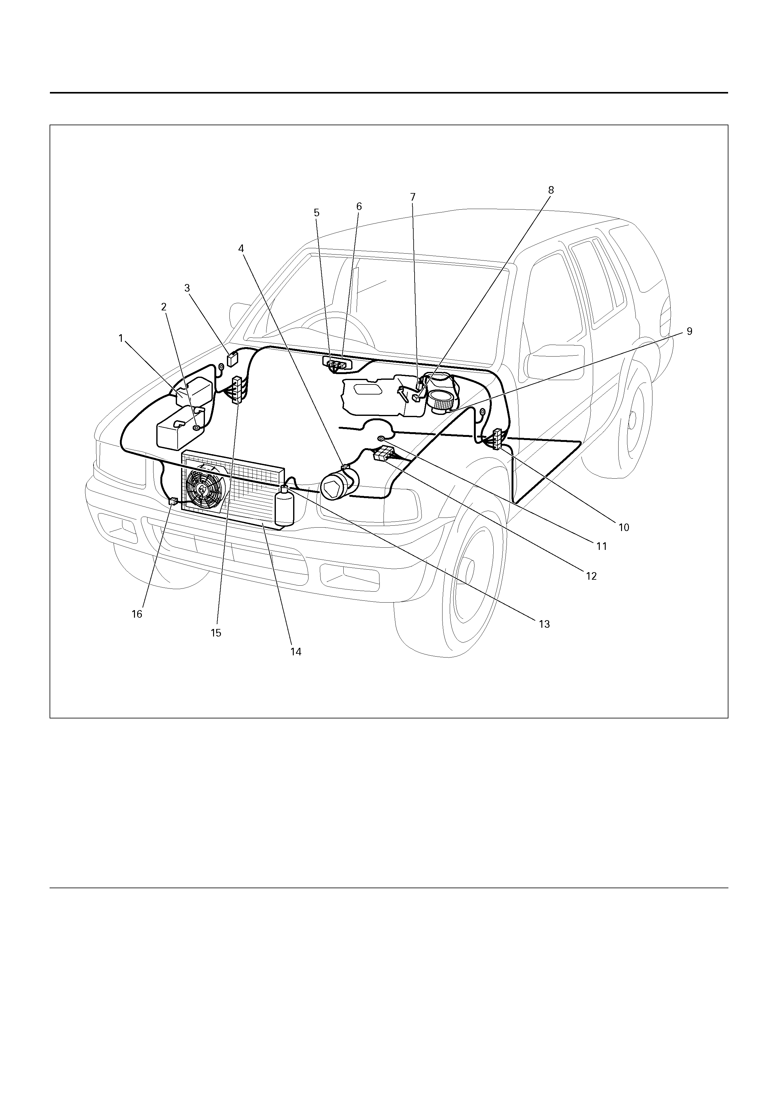
PARTS LOCATION
D08R100203
EndOFCallout
Legend
(1) Relay & Fuse Box (Engine Room)
(2) C–36
(3) Relay & Fuse Box (Instrument Panel)
(4) E–3
(5) I–23
(6) I–24
(7) C–69
(8) C–68
(9) C–70
(10) H–16, H–17, H–31
(11) B –6, B–8
(12) H–5, H–39
(13) C–11
(14) Condenser
(15) H–13, H–32
(16) C–24

HEATER AND AIR CONDITIONING (AUTOMATIC)
GENERAL DESCRIPTION
Using the signals from a variety of sensors, the full
automatic heater and air conditioning system accurately
senses outside air temperature, solar radiation quantity,
evaporator's blowing temperature, heater core water
temperature and interior temperature. These signals
enable the control unit to automatically control blow
temperature and air blow quantity, turn on or off the
compressor and switch the blow port as well as
switching between the fresh air intake and interior air
circulation. Resetting the automatic function allows the
system to switch to the manual control mode.
The self-diagnosis function of the control unit allows the
unit to access and diagnose failed parts easier and
quicker.
Refer to Air Conditioning System in HVAC System.
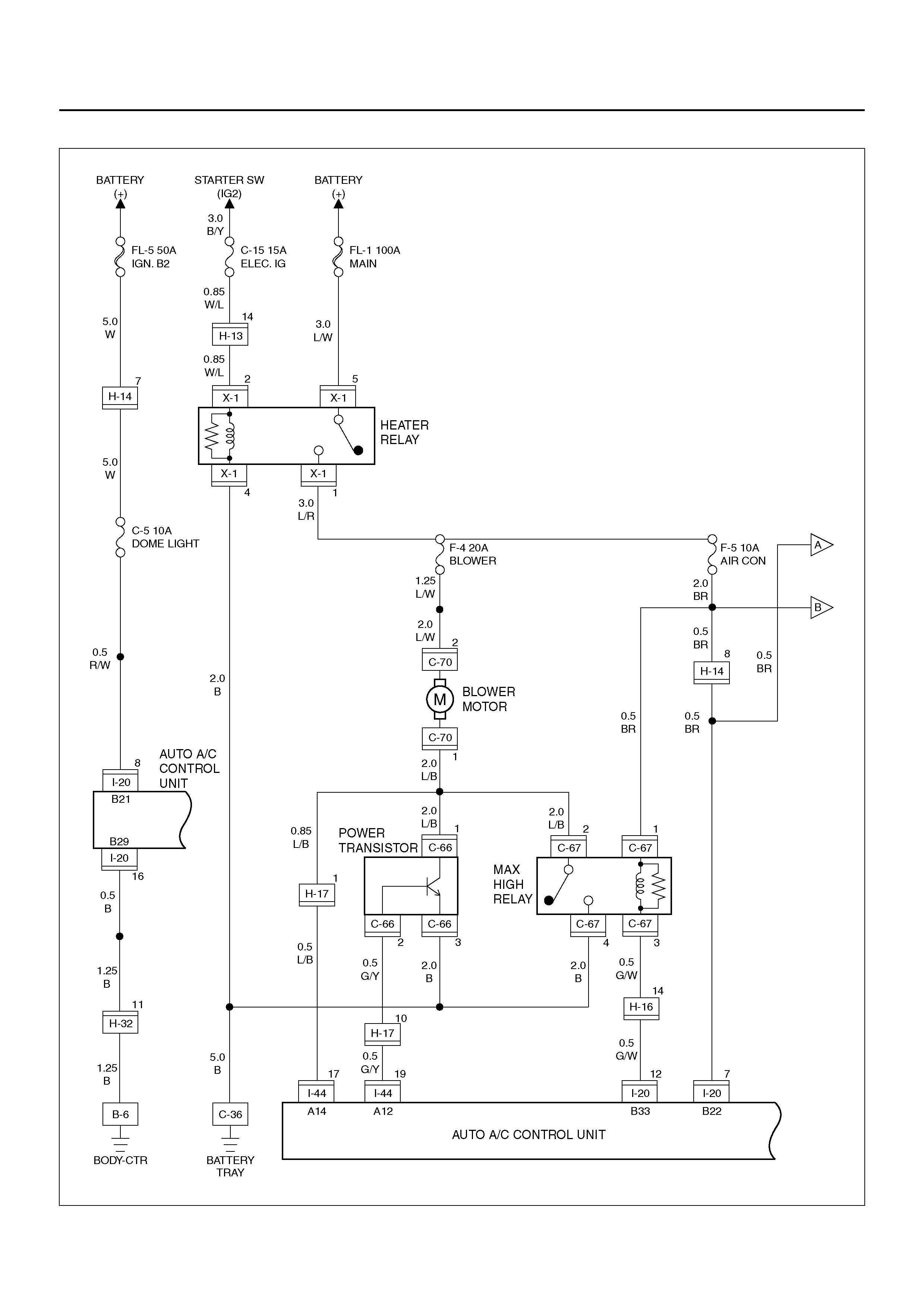
CIRCUIT DIAGRAM–1
D08R100205
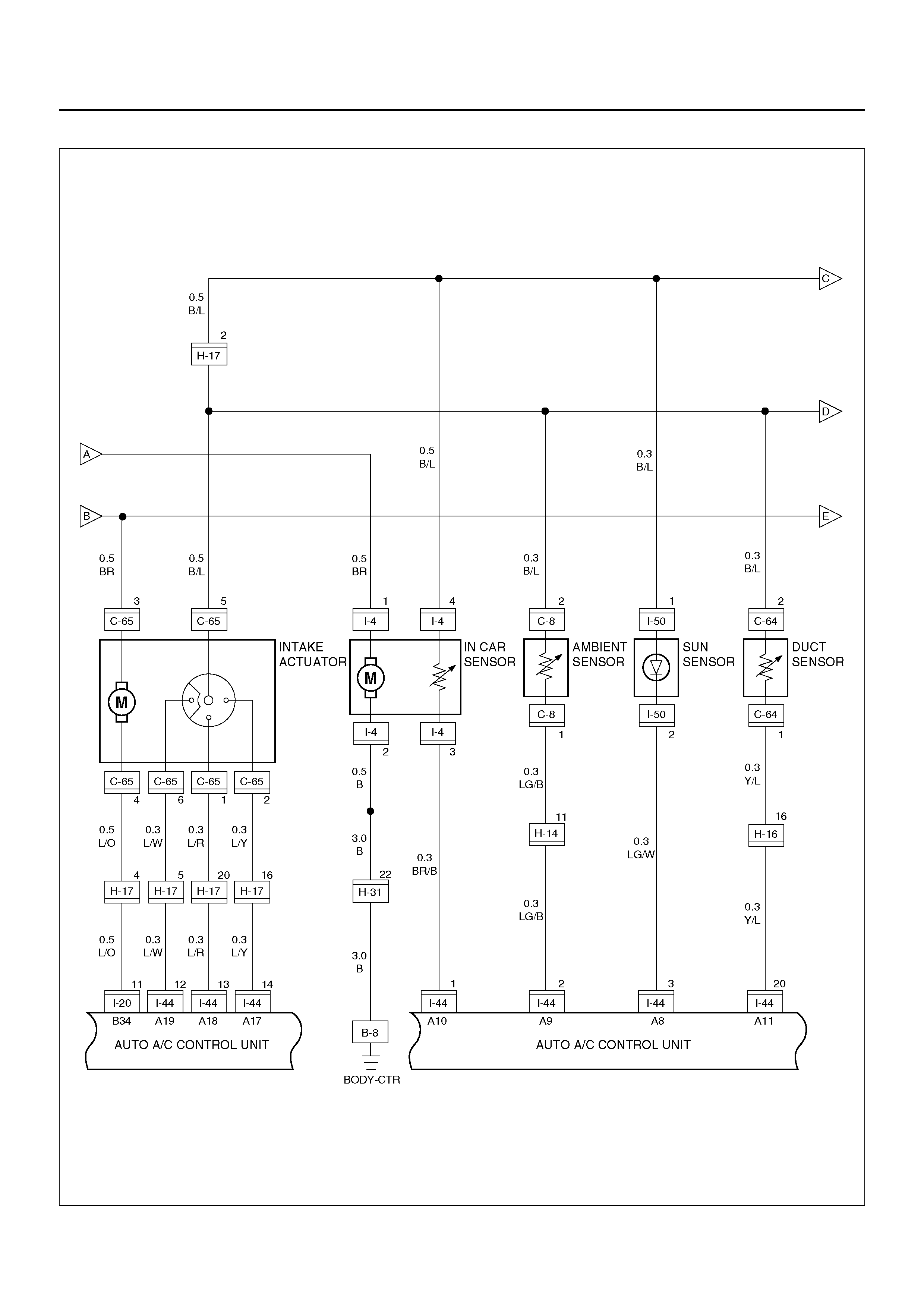
Circuit Diagram–2
D08R100099
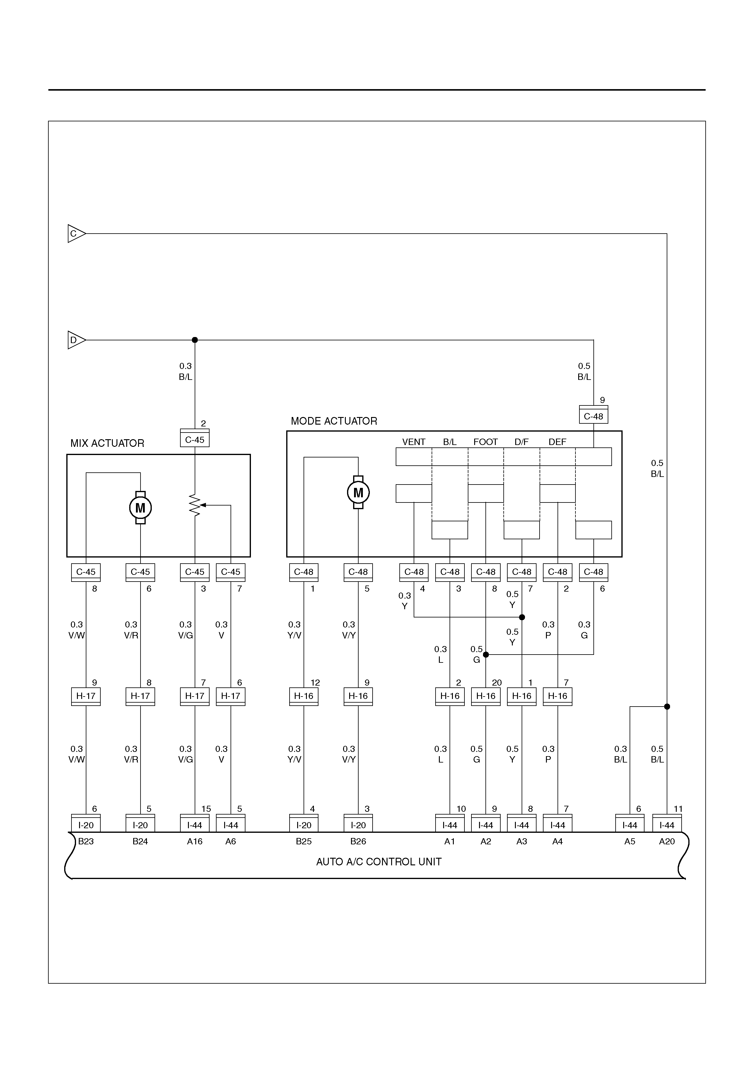
Circuit Diagram–3
D08R100100
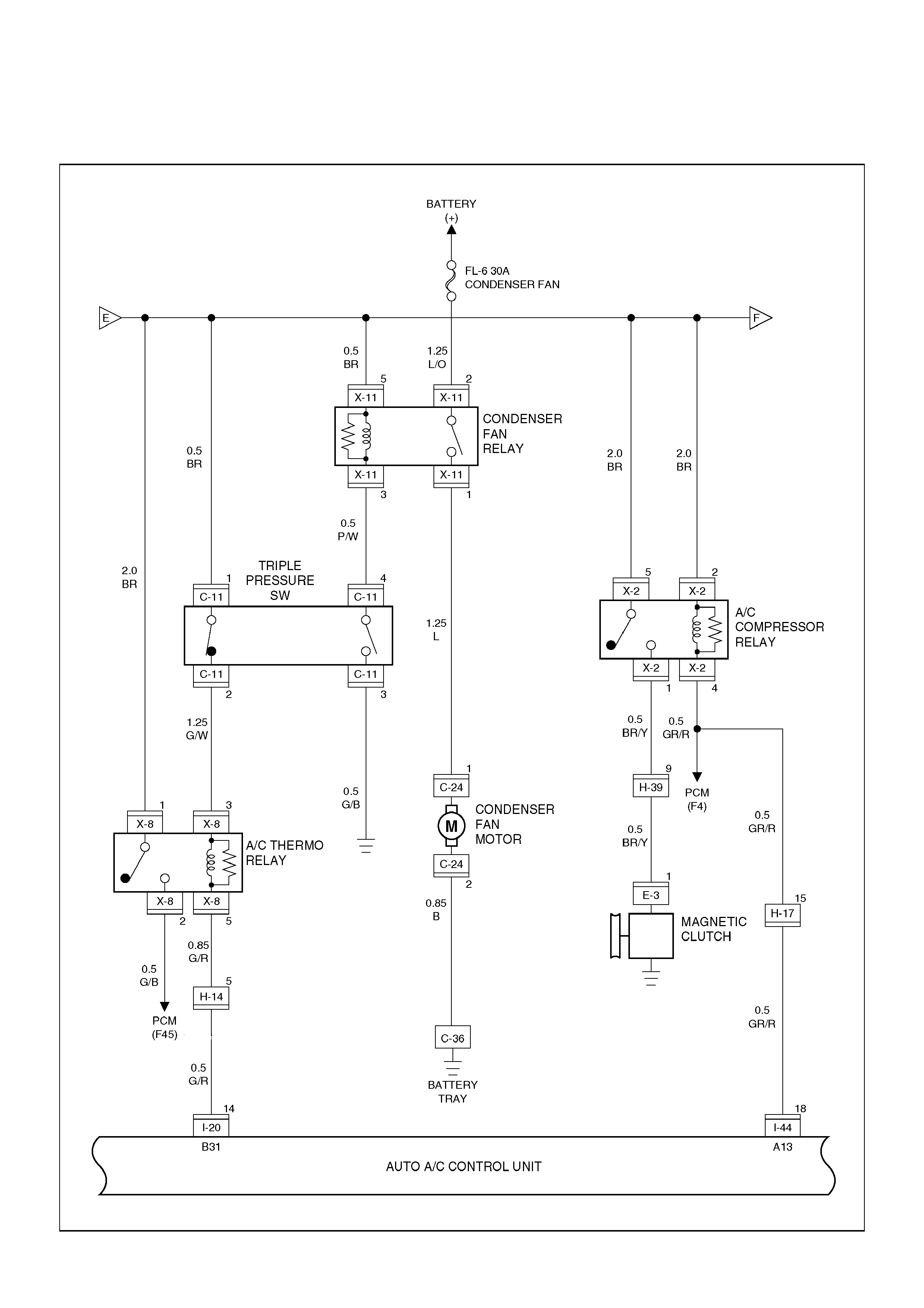
Circuit Diagram—4
D08R10001a
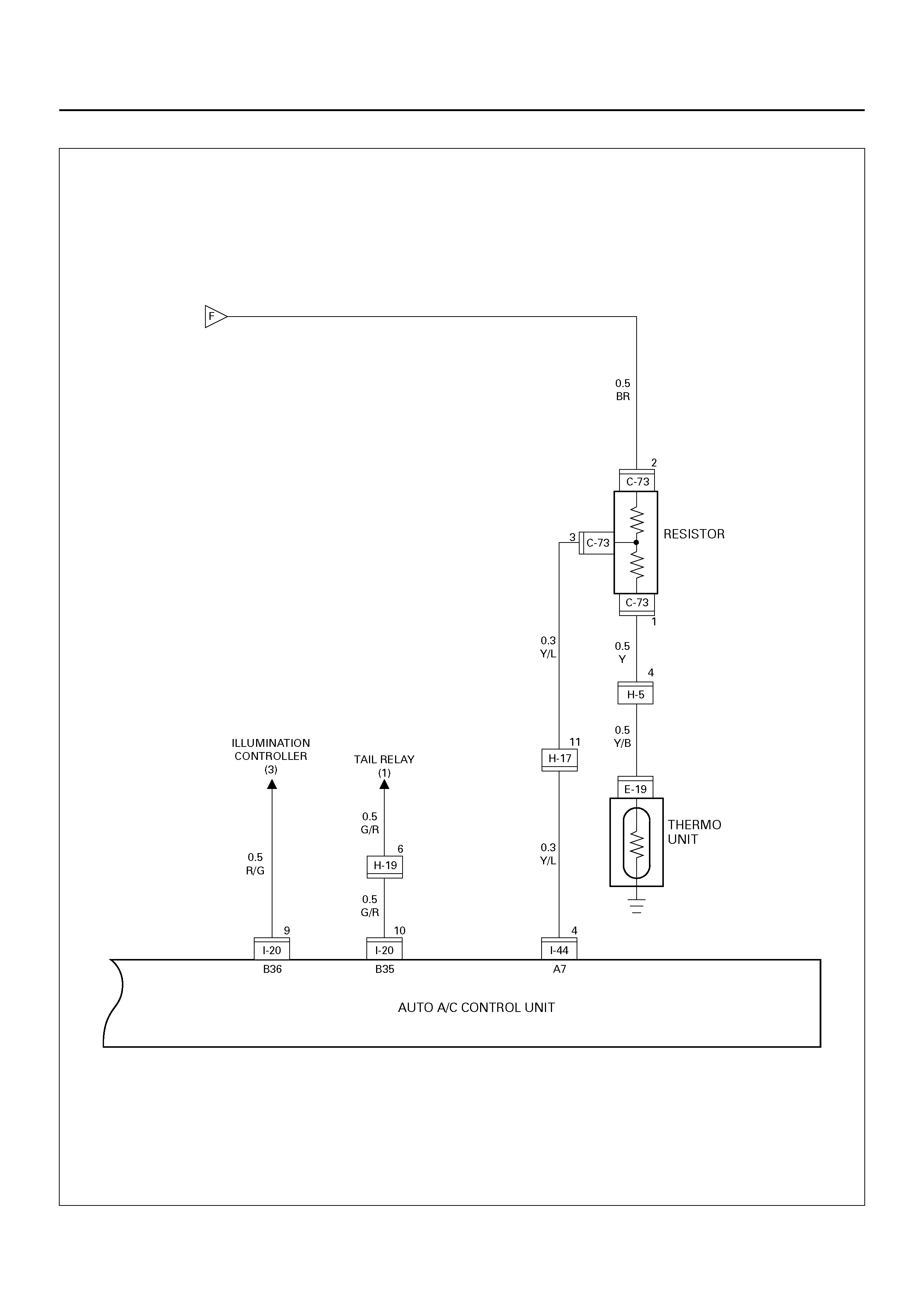
Circuit Diagram–5
D08R100102
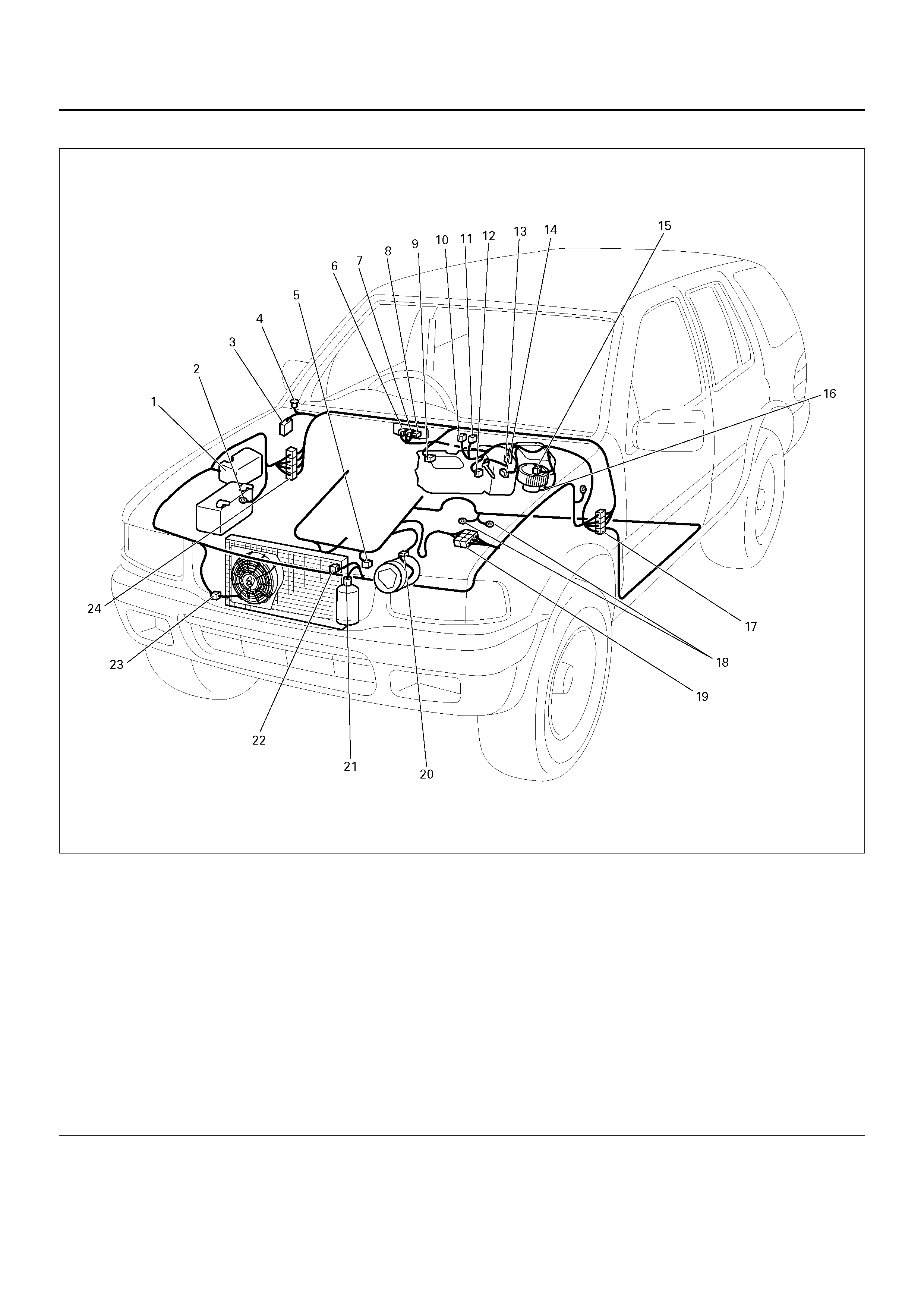
PARTS LOCATION
D08R100204
EndOFCallout
Legend
(1) Relay & Fuse Box (Engine Room)
(2) C–36
(3) Relay & Fuse Box (Instrument Panel)
(4) I–50
(5) E–19
(6) I–44
(7) I–20
(8) I–4
(9) C–48
(10) C–73
(11) C–45
(12) C–66
(13) C–65
(14) C–64
(15) C–67
(16) C–70
(17) H–16, H–17, H–31
(18) B –6, B–8
(19) H–5, H–39
(20) E–3
(21) C–11
(22) C–8
(23) C–24
(24) H–14, H–19, H–32

SUNROOF
GENERAL DESCRIPTION
The circui t con si sts of the starter swit ch, sunroo f swi tch ,
sunroof control unit, limit switch, and sunroof motor.
When the sunroof switch is turned on, the battery
voltage is applied to th e su nr oof c ont ro l un it through the
circuit breaker and the power window relay on the
circuit. Accordingly, when the sunroof switch is set to
“Open" or “Close" position, the open or close relay
incorpo rated into th e control unit is a ctivated t o change
the rotational direction of the sunroof motor to open or
close the sunroof.
Also, the operational process (full close → limit stop →
full open → safety stop → full close) of the sunroof is
control led by the contro l un it in accor dance with signa ls
sent from the sunroof switch and limit switch.
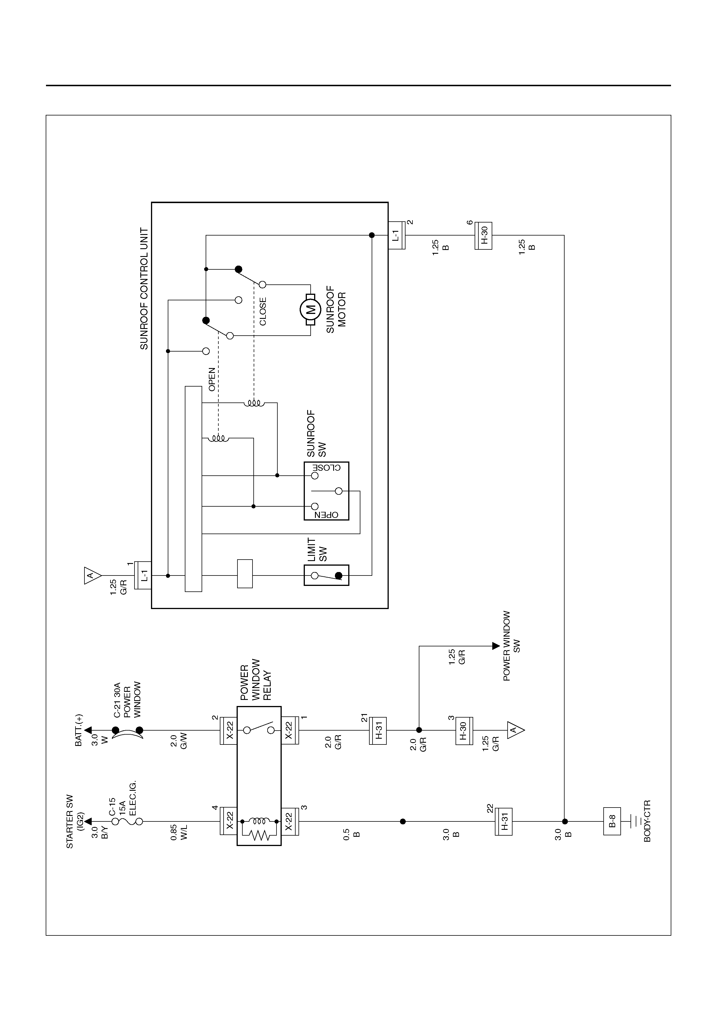
CIRCUIT DIAGRAM–1
D08R100211
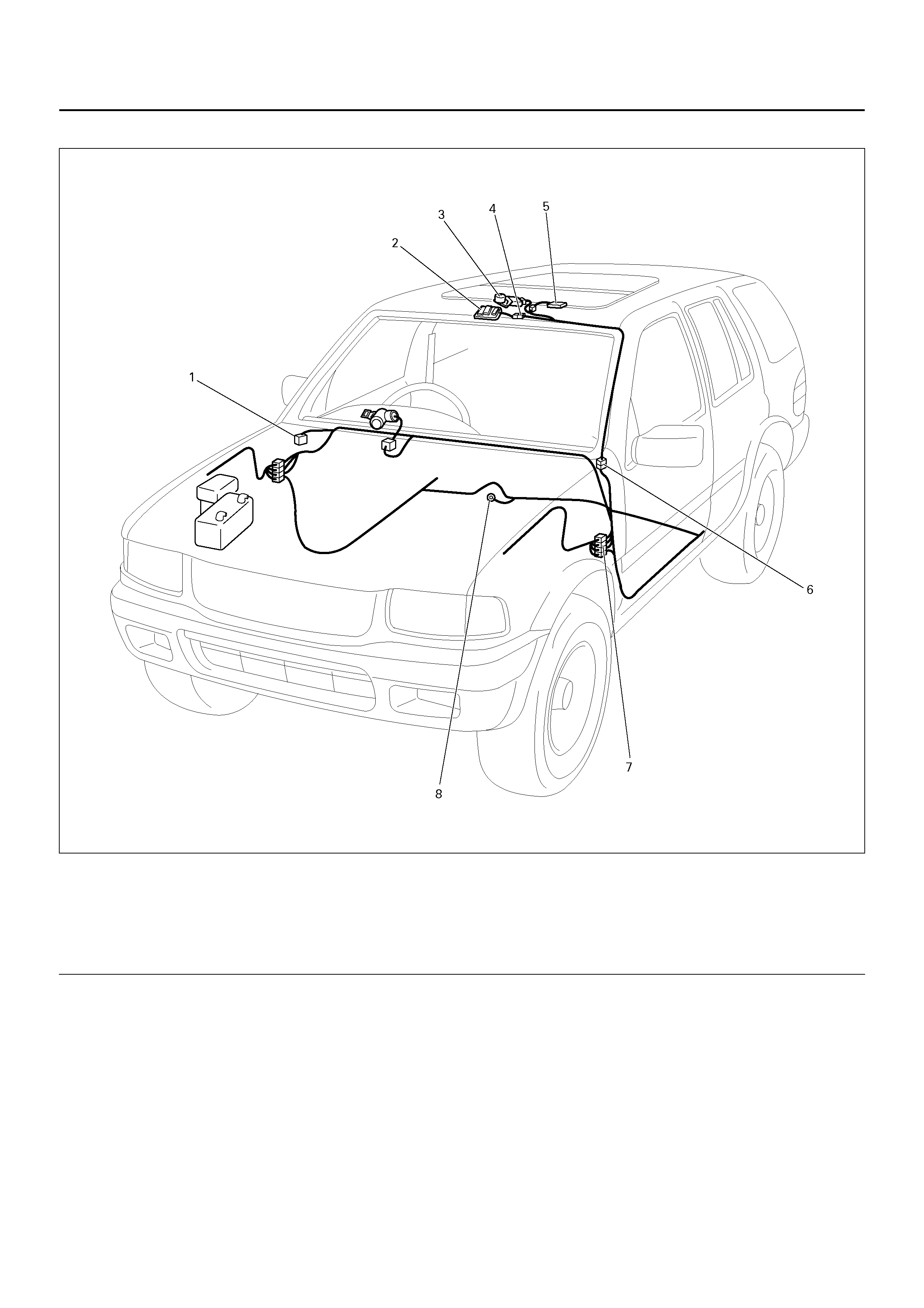
PARTS LOCATION
D08R100206
EndOFCallout
Legend
(1) Relay & Fuse Box (Instrument Panel)
(2) Sunroof Switch
(3) Sunroof Motor
(4) L–1
(5) Sunroof Control Unit
(6) H–30
(7) H–31
(8) B–8

DIAGNOSIS
Sunroof Inoperative
Safety Stop Mechanism Inoperative
Step Action Value(s) Yes No
1 1. Disconnect the sunroof connector L–1.
2. Turn the starter switch on.
Is the battery voltage applied between the harness
side connector L–1 terminal 1 and the ground?
Approx. 12V Go to Step 3 Go to Step 2
2 Repair an open circuit between the power widow relay
and the sunroof control unit.
Is the action complete?
— Verify reapir —
3 Replace the sunroof control unit.
Is the action complete? — Verify repair —
Step Action Value(s) Yes No
1 Replace the sunroof control unit.
Is the action complete? — Verify repair —

SUPPLEMENTAL RESTRAINT SYSTEM (SRS) – AIR BAG
GENERAL DESCRIPTION
The circuit consists of Sensing and Diagnostic Module
(SDM), driver's air bag assembly, SRS coil assembly,
passenger's air bag assembly, and “AIR BAG" warning
light. SDM, SRS coil assembly (driver side only), driver
air bag assembly, passenger air bag assembly and
connector wire make up the deployment loops. The
function of the deployment loops is to supply current
through air bag assembly, which will cause deployment
of the air bags in the event of a frontal crash of sufficient
force, up to 30 degrees off the center line of the vehicle.
The air bag assemblies are only supplied enough
current to deploy when the SDM detects vehicle velocity
changes severe enough to warrant deployment.
The SDM contains a sensing device which converts
vehicle velocity changes to an electrical signal.
The electrical signal generated is processed by the
SDM and then compared to a value stored in memory.
When the generated signal exceeds the stored value,
the SDM will cause current to flow through the air bag
assembly deploying the air bags.
Refer to Supplemental Restraint System (SRS) and
Restraint Control System in Restraints.
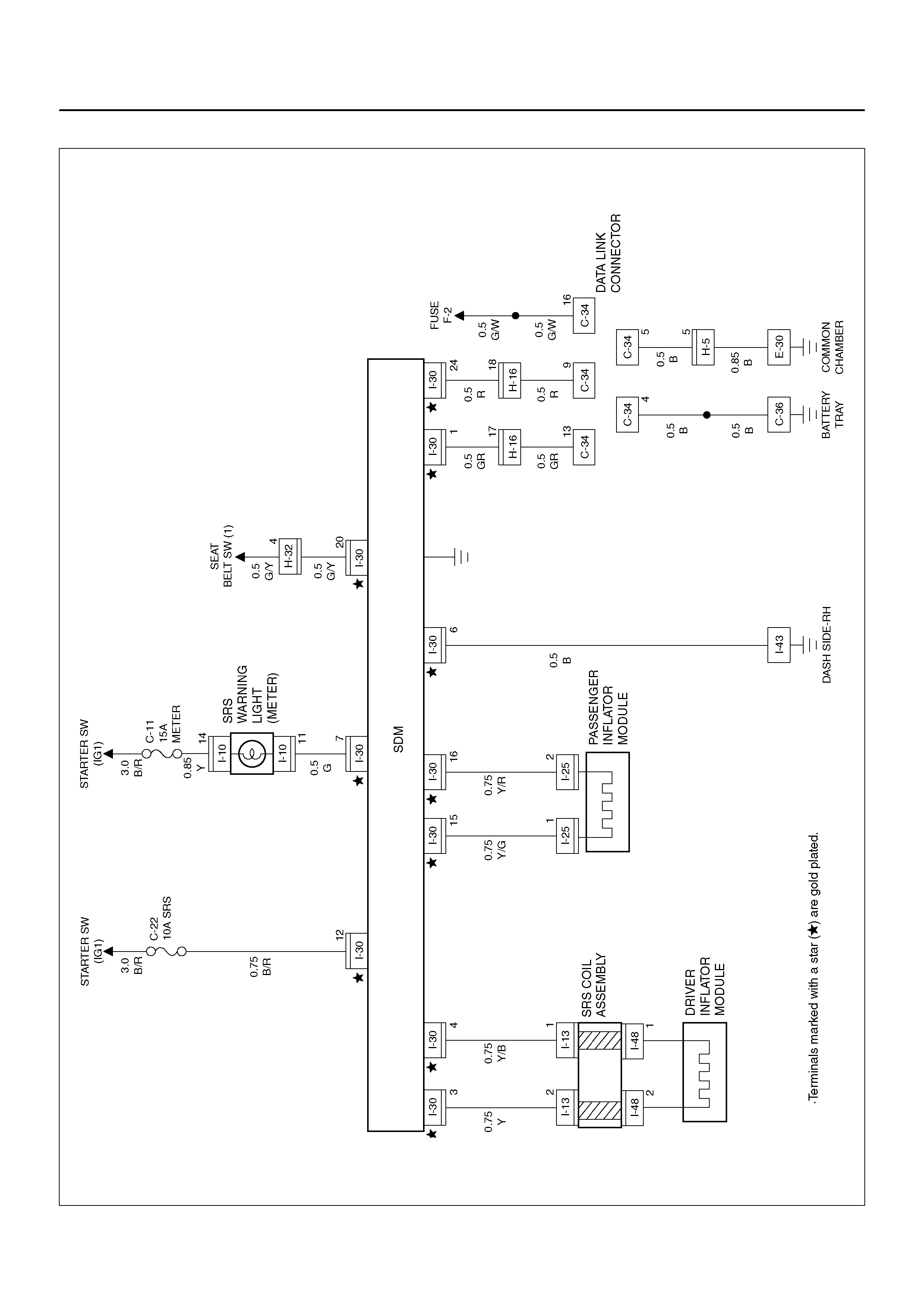
CIRCUIT DIAGRAM
D08R100170
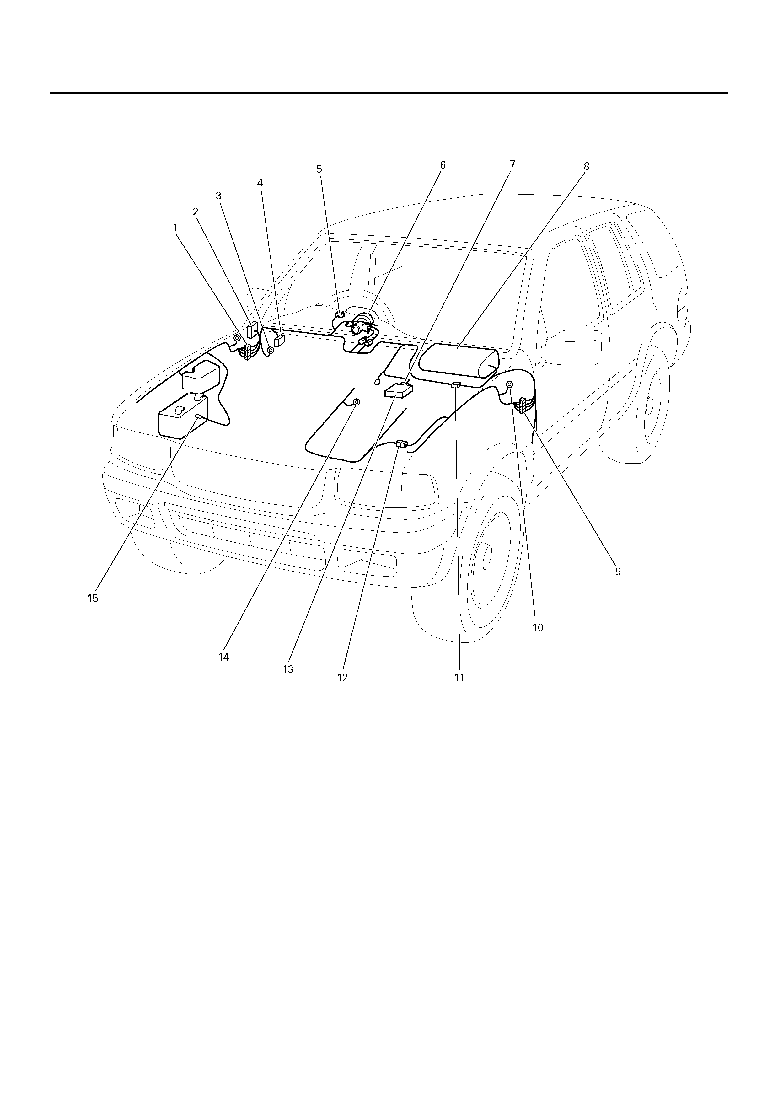
PARTS LOCATION
D08R100207
EndOFCallout
Legend
(1) H–32
(2) Relay & Fuse Box (Instrument Panel)
(3) I–43
(4) C–34
(5) I–10
(6) SRS Coil Assembly (I–13, I–48)
(7) I–30
(8) Passenger Air Bag Assembly
(9) H–16
(10) C–16
(11) I–25
(12) H–5
(13) SDM
(14) E–30
(15) C–36

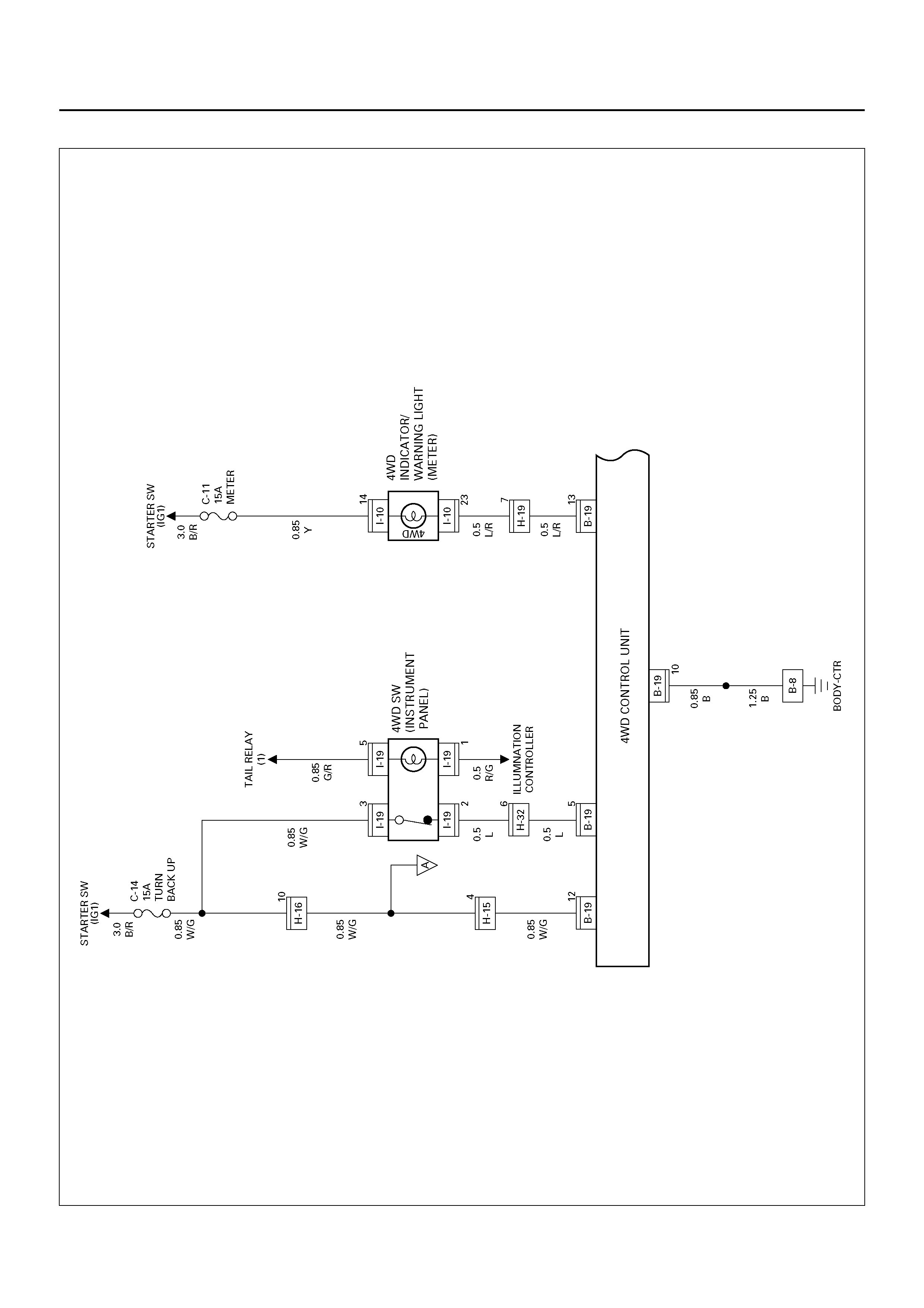
CIRCUIT DIAGRAM–1
D08R100157
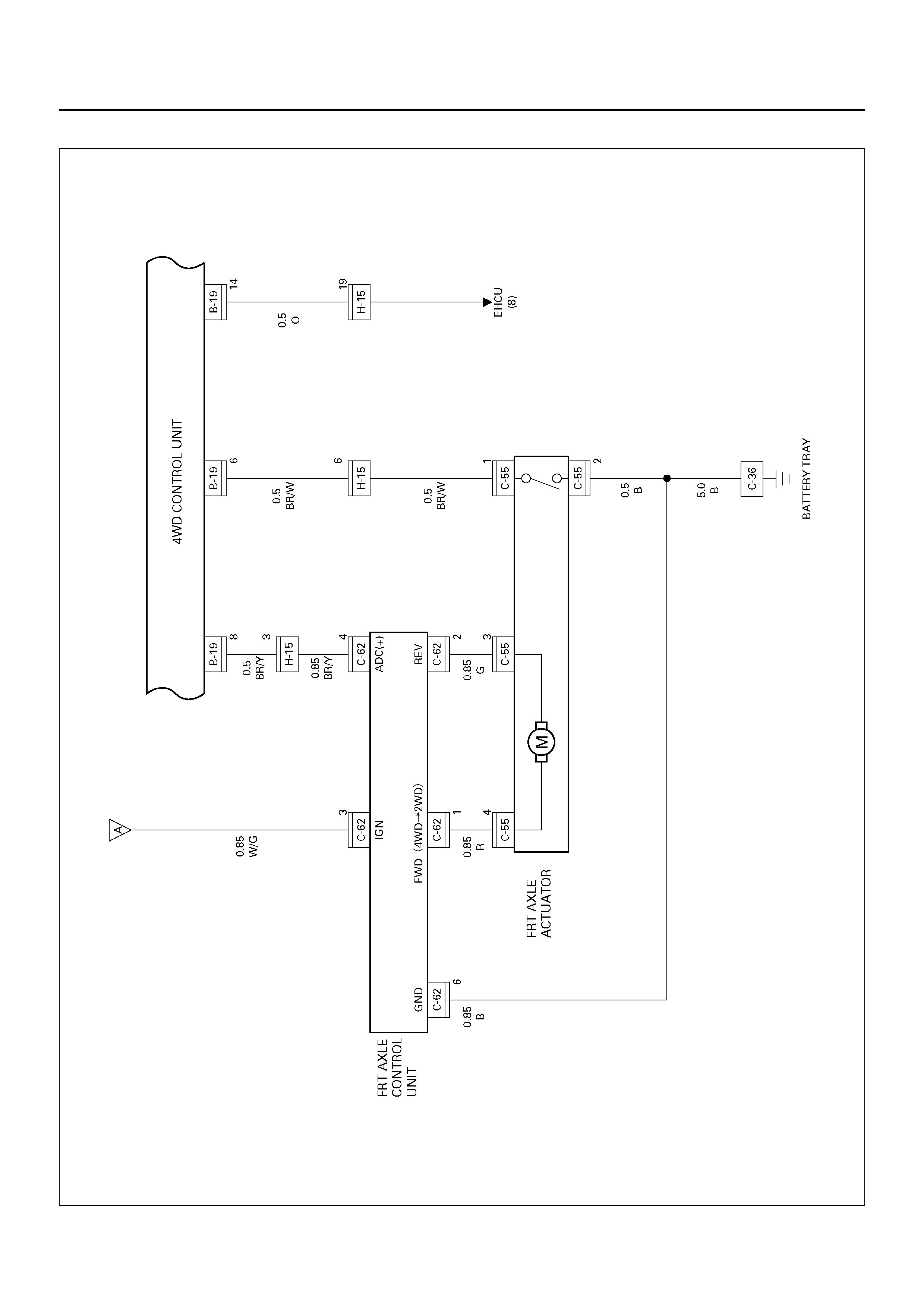
Circuit Diagram–2
D08R100158
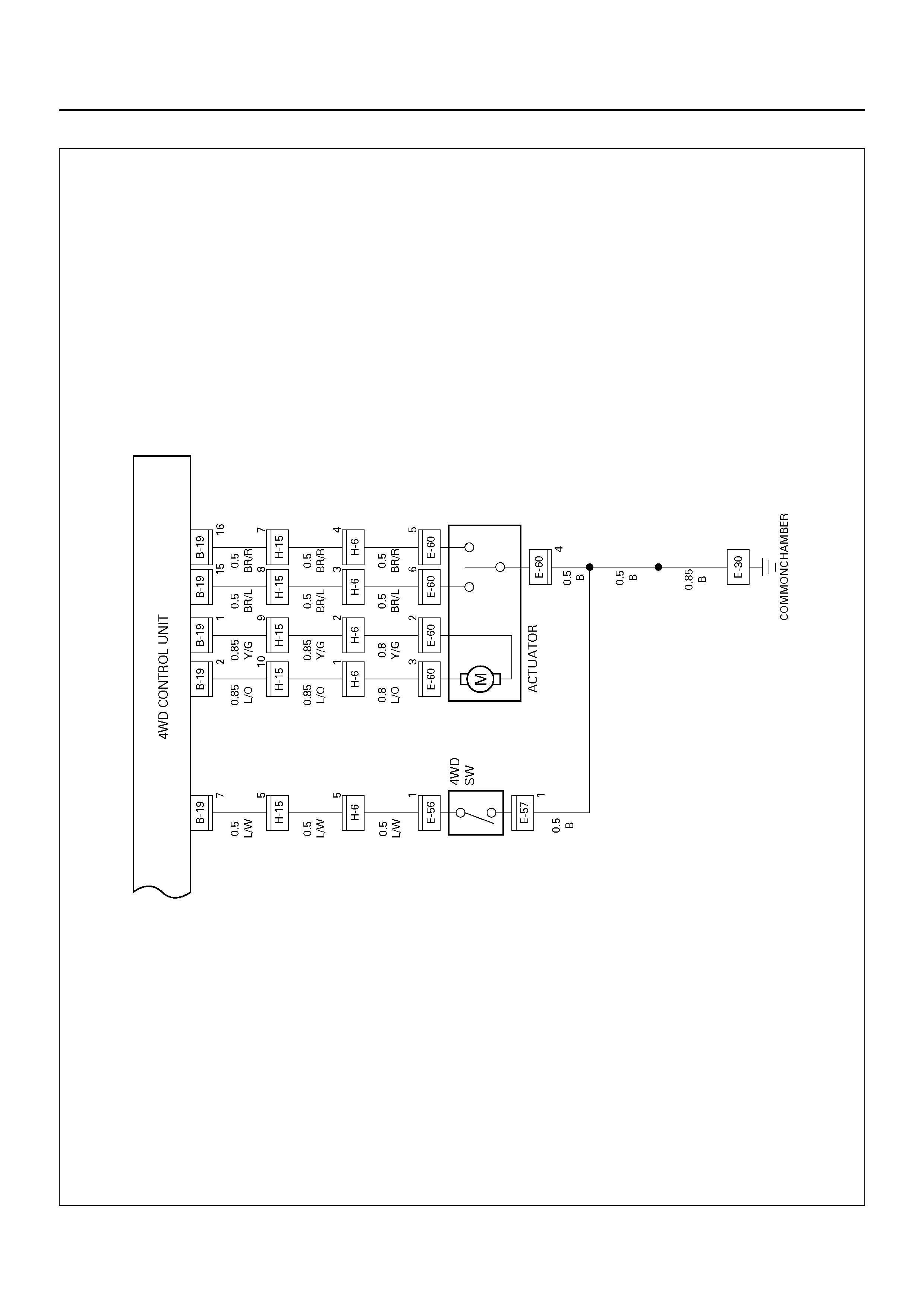
Circuit Diagram–3
D08R100159
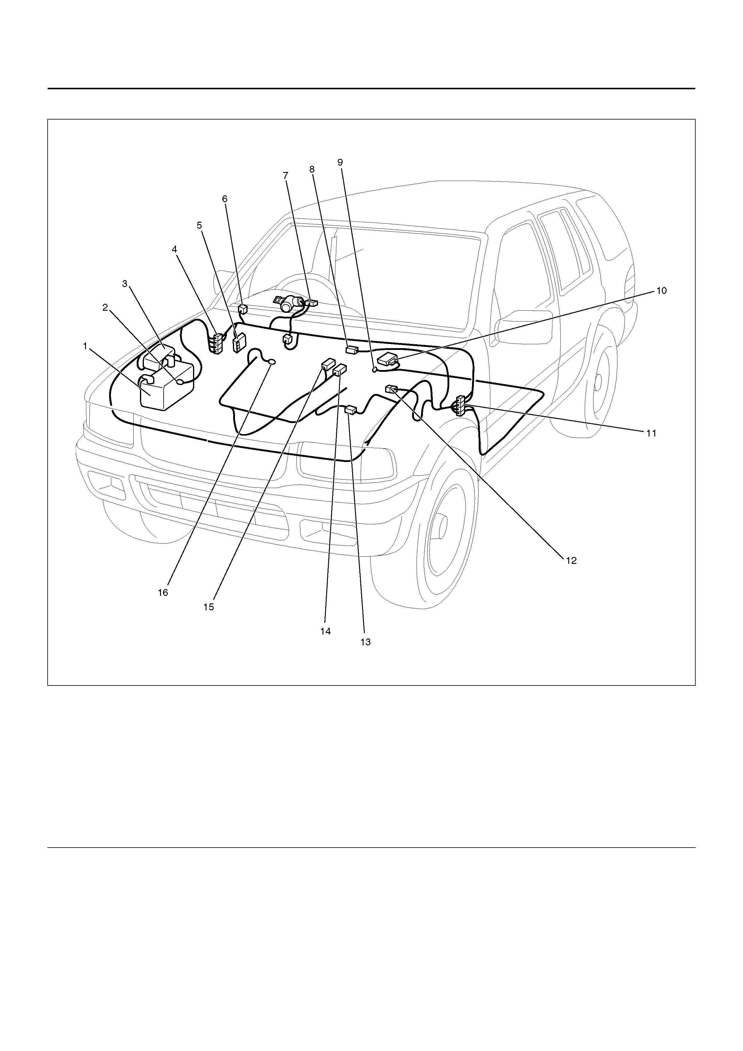
PARTS LOCATION
D08RY00857
EndOFCallout
Legend
(1) Battery
(2) C–36
(3) Relay & Fuse Box (Engine Room)
(4) H–15, H–19
(5) Relay & Fuse Box (Instrument Panel)
(6) I–19
(7) I–10
(8) C–62
(9) B–8
(10) B–19
(11) H–16
(12) C–55
(13) H–6
(14) E–60
(15) E–56, E–57
(16) E–30

T.O.D.
GENERAL DESCRIPTION
The system consists of the T.O.D. control unit, the FRT
axle control unit, the FRT axle actuator, T.O.D. switch
and indicator light and ETC. The T.O.D. control unit
always monitors road conditions that the vehicle runs
on, and varies the torque applied to the front and rear
axle to keep vehicle stability, if necessary.
Refer to Driveline Control System (T.O.D.) in Driveline/
Axle section.
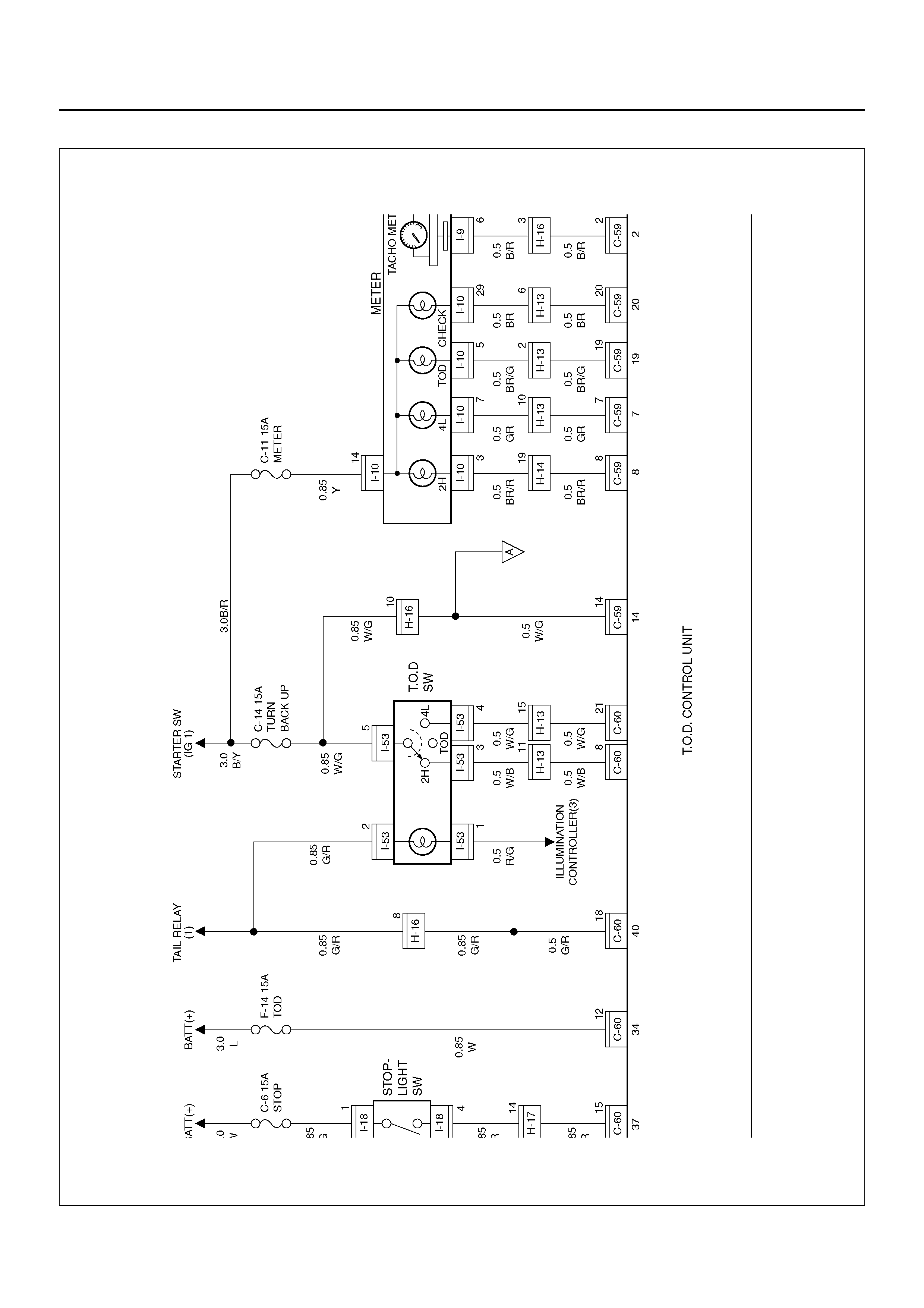
CIRCUIT DIAGRAM–1
D08R100160
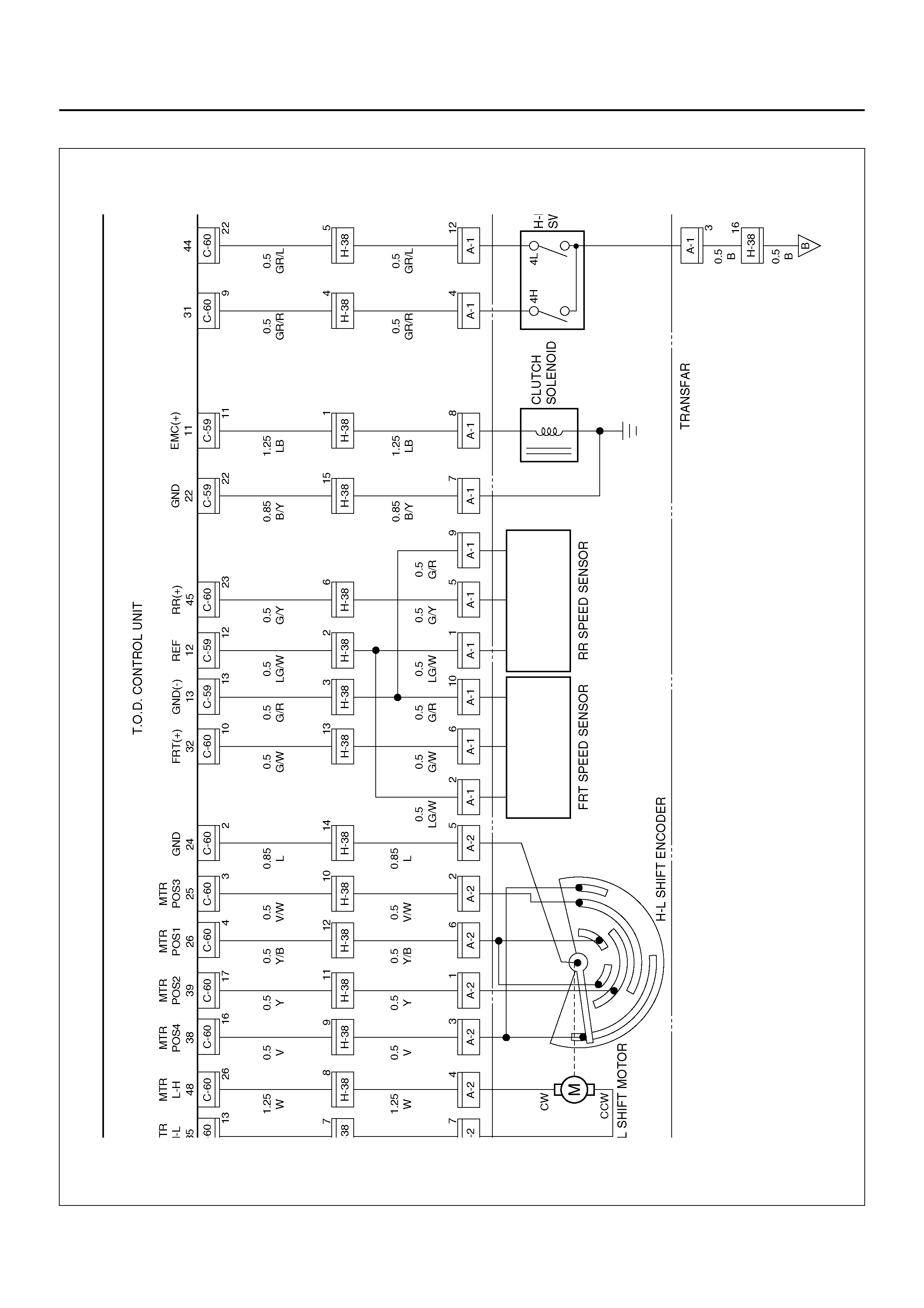
Circuit Diagram–2
D08R100161
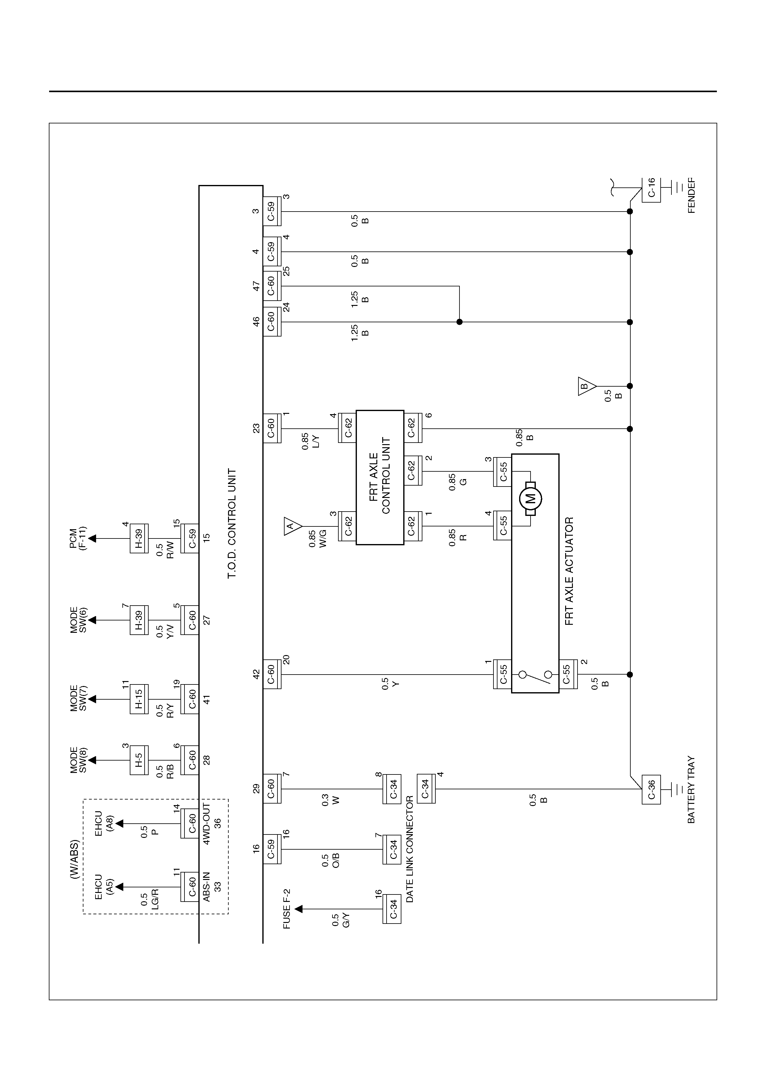
Circuit Diagram–3
D08R100162
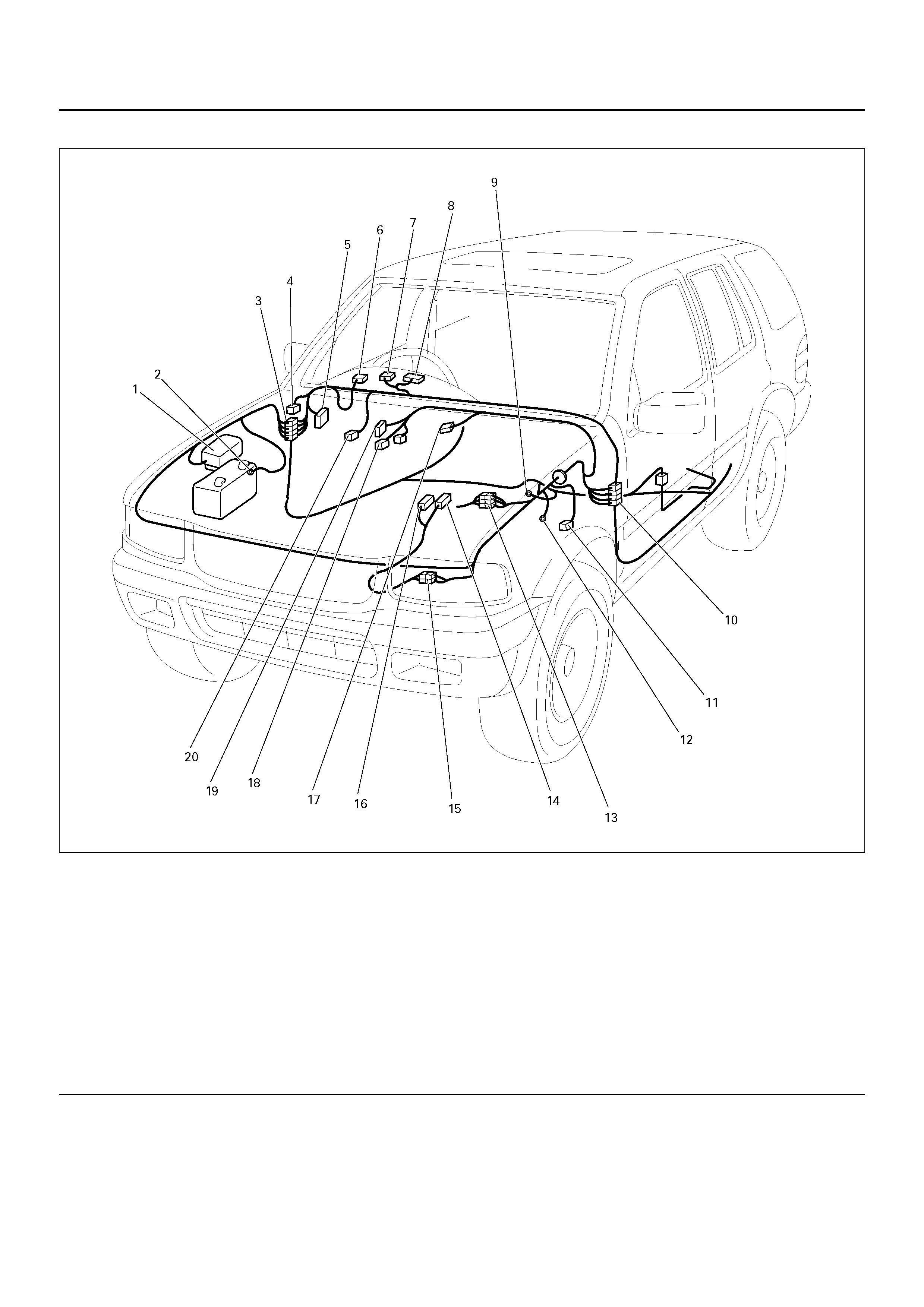
PARTS LOCATION
D08R100208
EndOFCallout
Legend
(1) Relay & Fuse Box (Engine Room)
(2) C–36
(3) H–13, H–14 , H–15
(4) C–34
(5) Relay & Fuse Box (Instrument Panel)
(6) I–53
(7) I–9
(8) I–10
(9) B–8
(10) H– 16, H–17
(11) C–55
(12) C–16
(13) H–5, H–39
(14) A–1
(15) H–38
(16) A–2
(17) C–62
(18) C–59
(19) C–60
(20) I–18
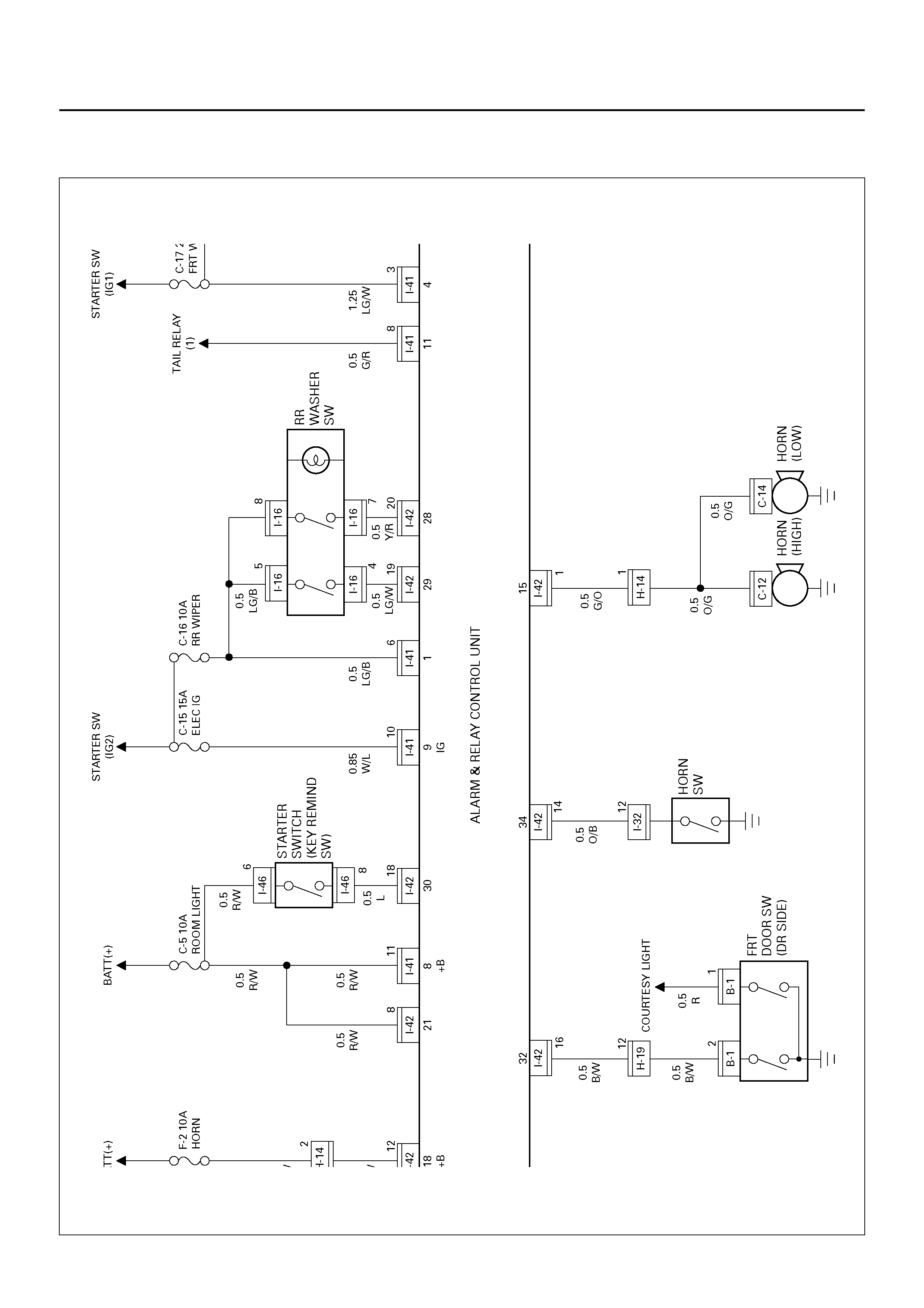
ALARM AND RELAY CONTROL UNIT
CIRCUIT DIAGRAM–1
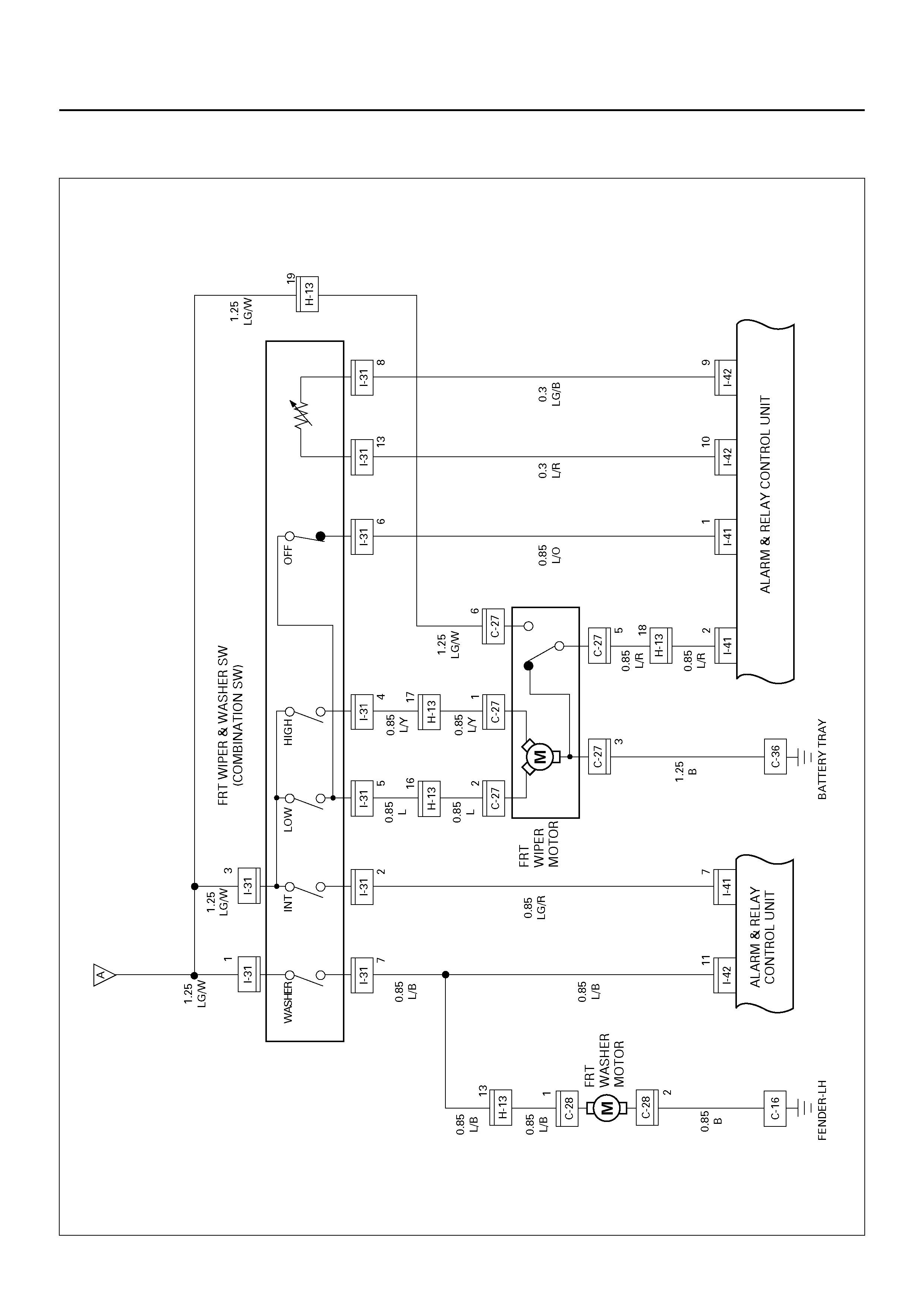
D08R100163
Circuit Diagram–2
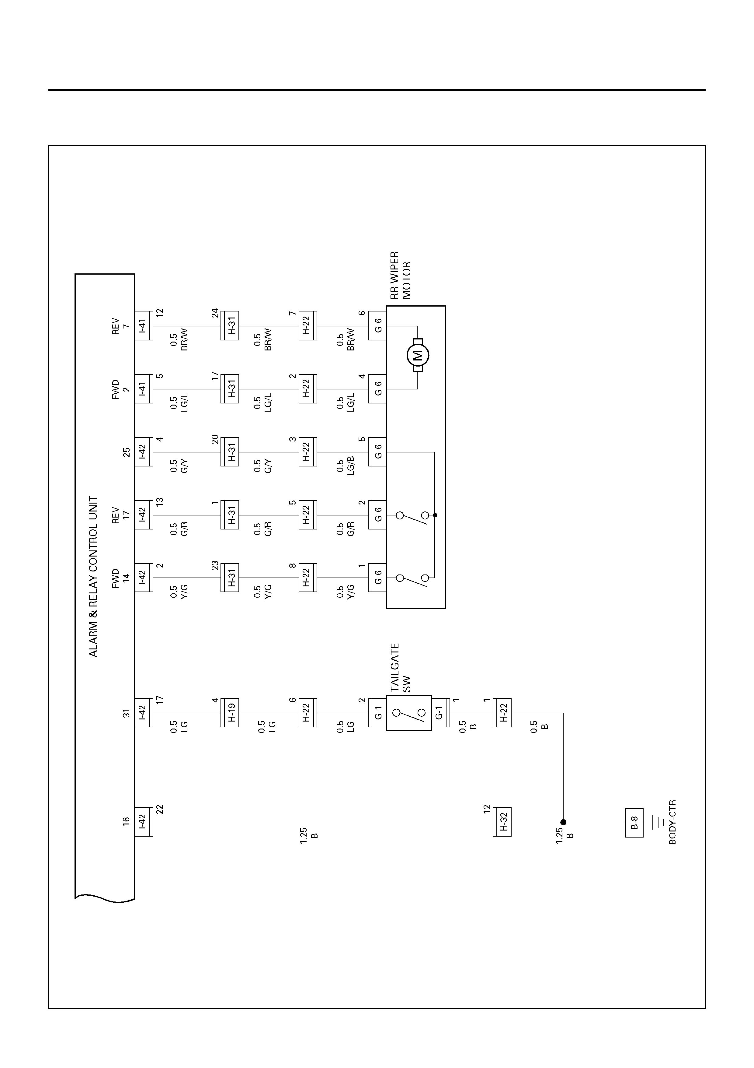
D08R100164
Circuit Diagram–3
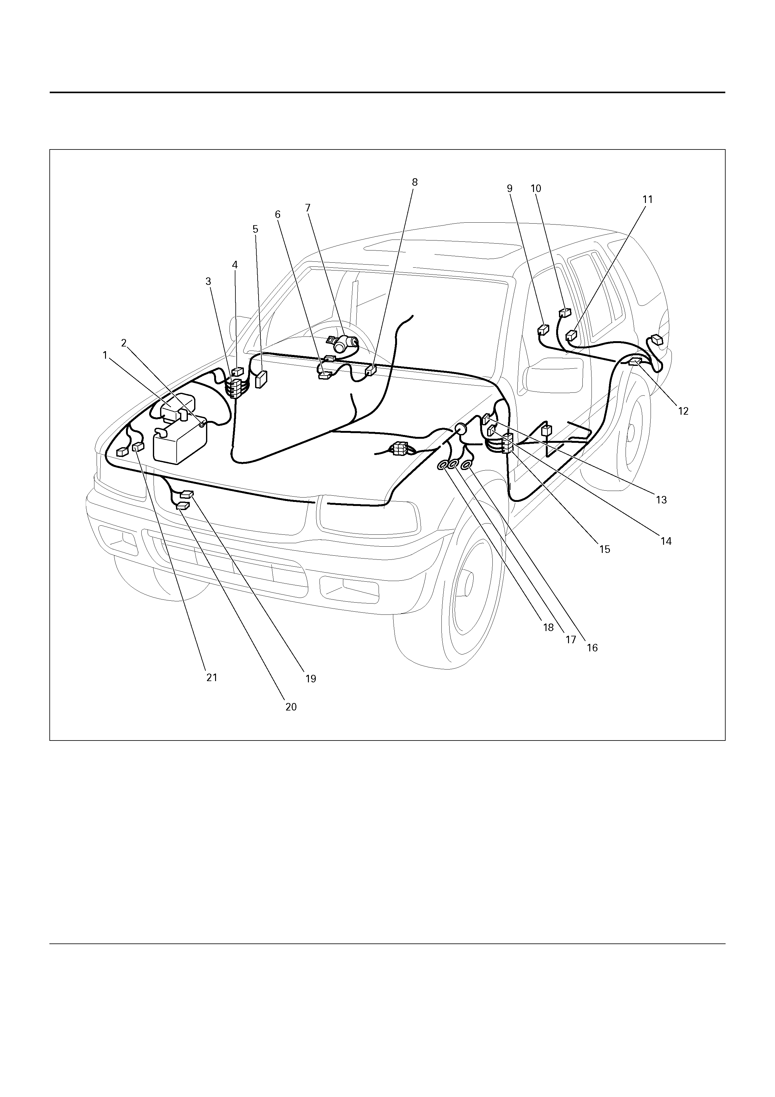
D08R100165
PARTS LOCATION
D08R100209
EndOFCallout
Legend
(1) Relay & Fuse Box (Engine Room)
(2) C–36
(3) H–13, H–14, H–19, H–32
(4) C–27
(5) Relay & Fuse Box (Instrument Panel)
(6) I–31, I–32
(7) I–46
(8) I–16
(9) G–6
(10) G–1
(11) B–20
(12) H–22
(13) I–41
(14) I–42
(15) H–31
(16) B–6
(17) B–8
(18) C–16
(19) C–14
(20) C–12
(21) C–28
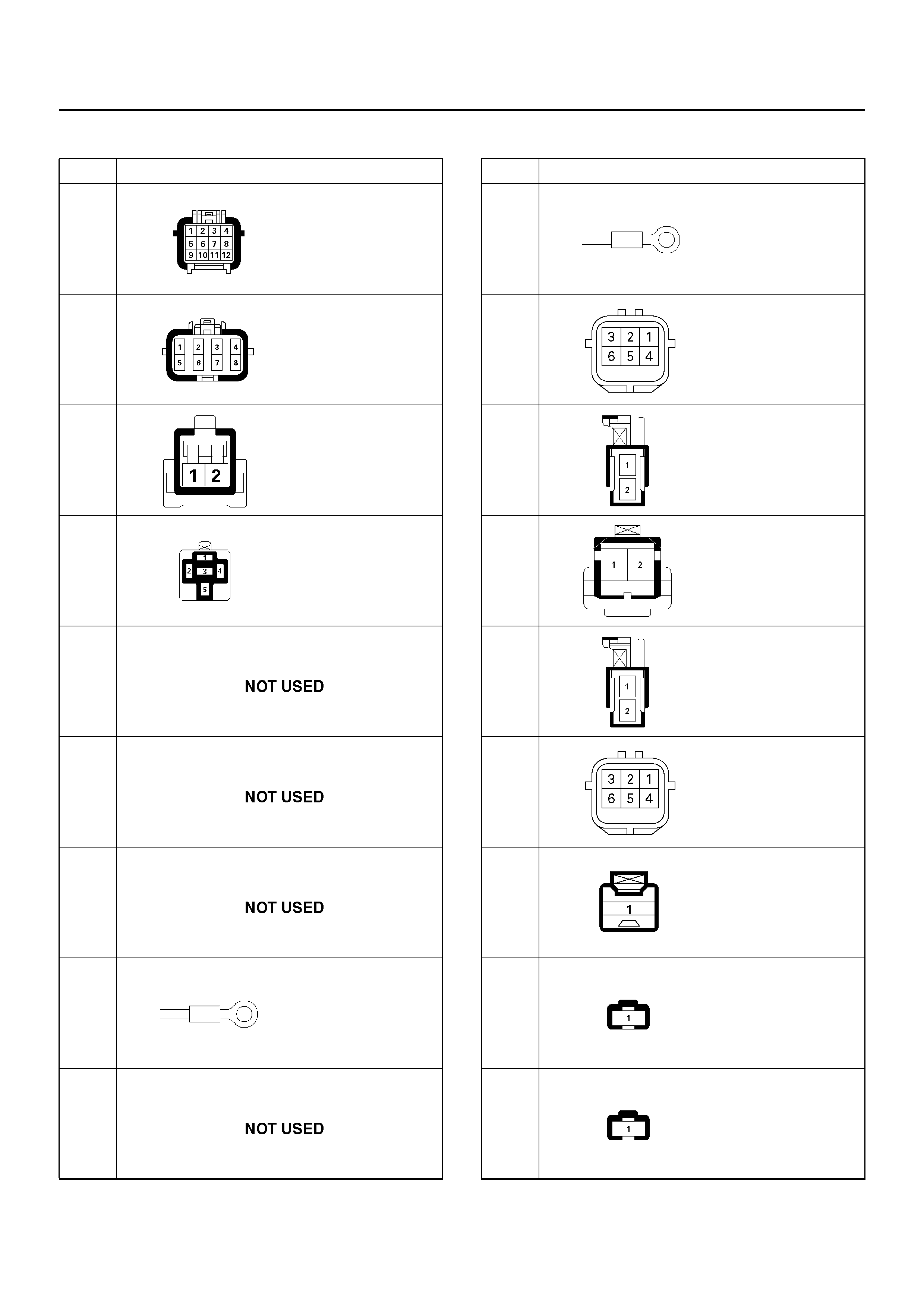
HARNESS CONNECTOR FACES
No. Connector face
A-1
A-2
B-1
B-2
B-3
B-4
B-5
B-6
B-7
B-8
B-9
B-10
B-11
B-12
B-13
B-14
B-15
B-16
No. Connector face
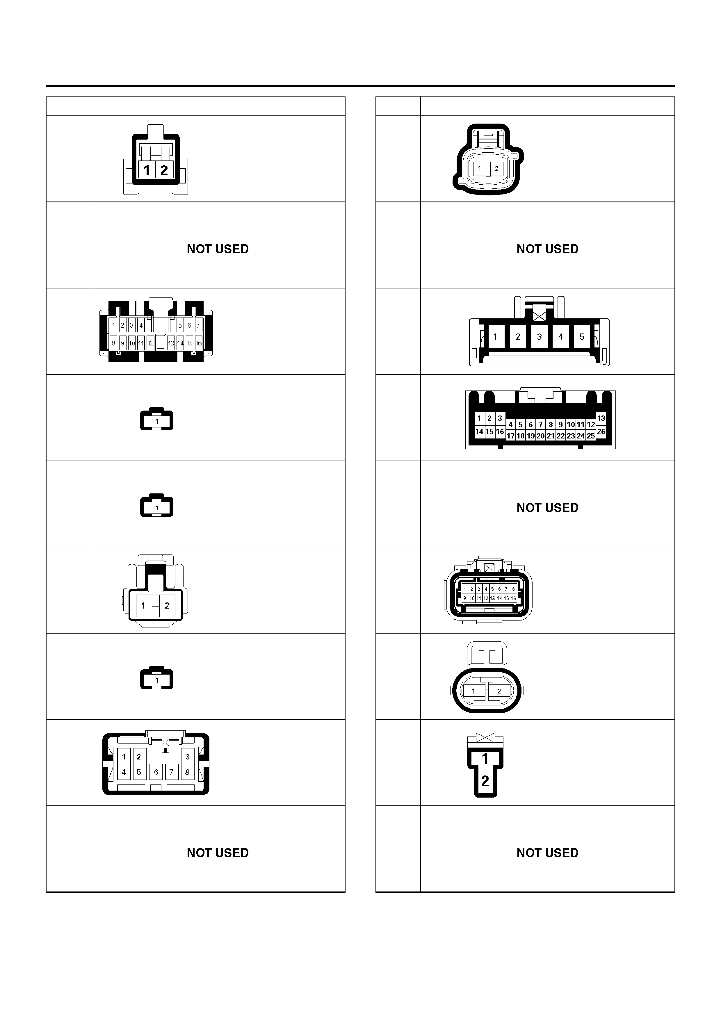
B-17
B-18
B-19
B-20
B-21
B-22
B-23
B-24
B-25
∼
B-29
No. Connector face B-30
B-31
∼
B-35
B-36
B-37
C-1 ∼
C-3
C-4
C-5
C-6
C-7
No. Connector face
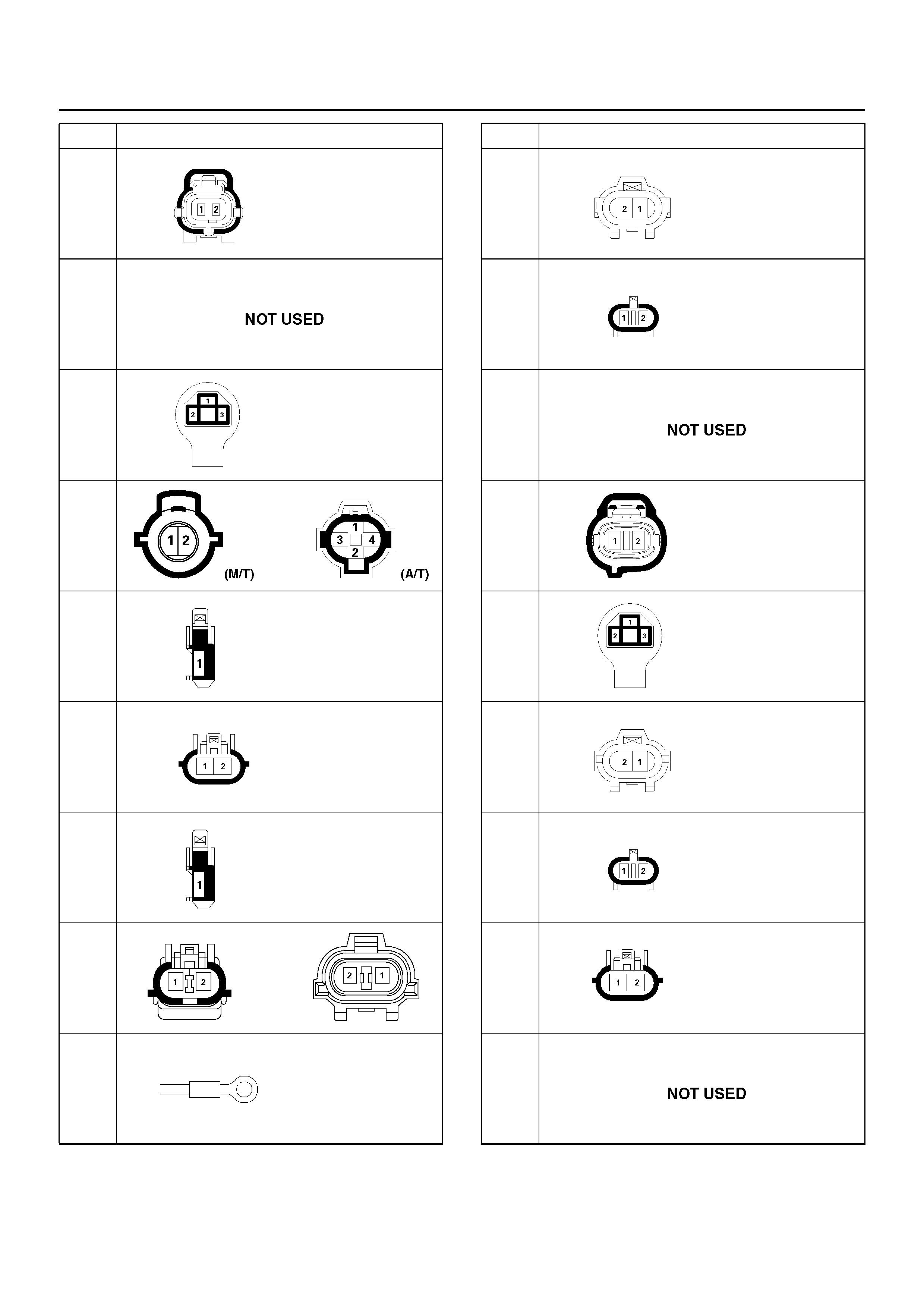
C-8
C-9
C-10
C-11
C-12
C-13
C-14
C-15
C-16
No. Connector face C-17
C-18
C-19
C-20
C-21
C-22
C-23
C-24
C-25
∼
C-26
No. Connector face

C-27
C-28
C-29
C-30
C-31
∼
C-32
C-33
C-34
C-35
C-36
No. Connector face C-37
∼
C-39
C-40
C-43
C-45
C-48
C-51
C-52
C-53
C-54
No. Connector face
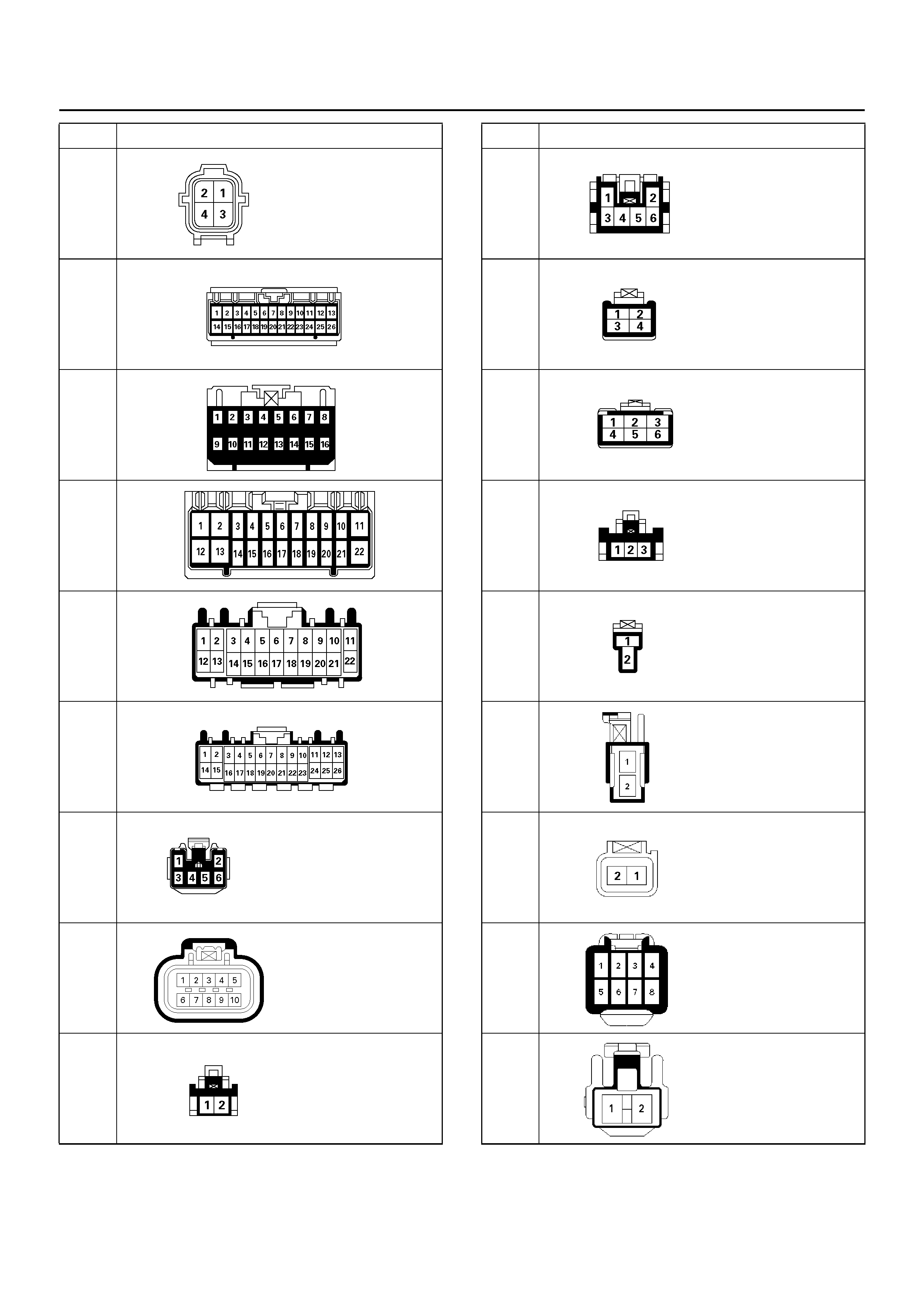
C-55
C-56
C-57
C-58
C-59
C-60
C-62
C-63
C-64
No. Connector face C-65
C-67
C-68
C-69
C-70
D-1
D-2
D-3
D-4
No. Connector face
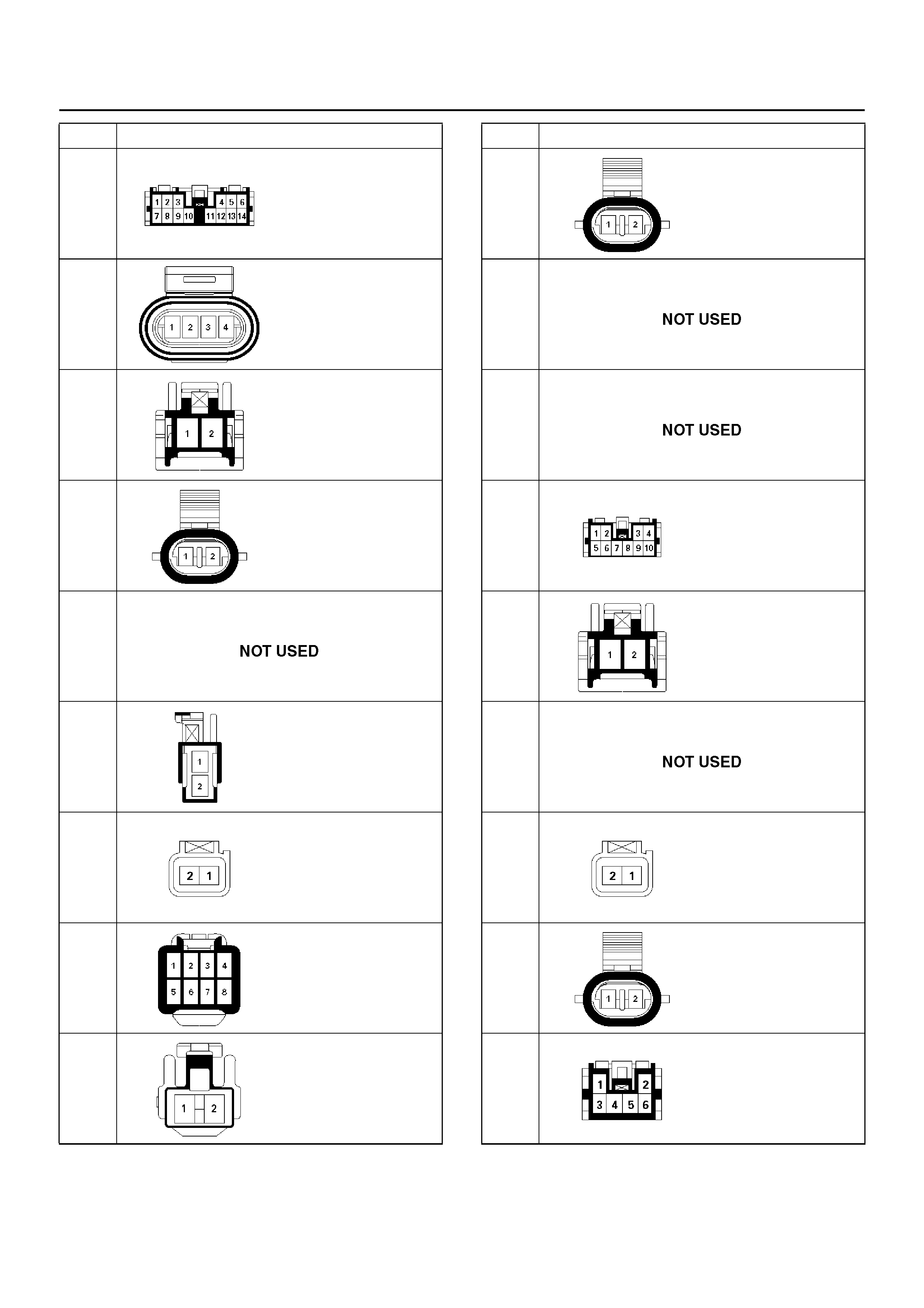
D-5
D-6
D-7
D-8
D-9
D-10
D-11
D-12
D-13
No. Connector face D-14
D-15
D-16
D-17
D-18
D-19
D-20
D-21
D-22
No. Connector face
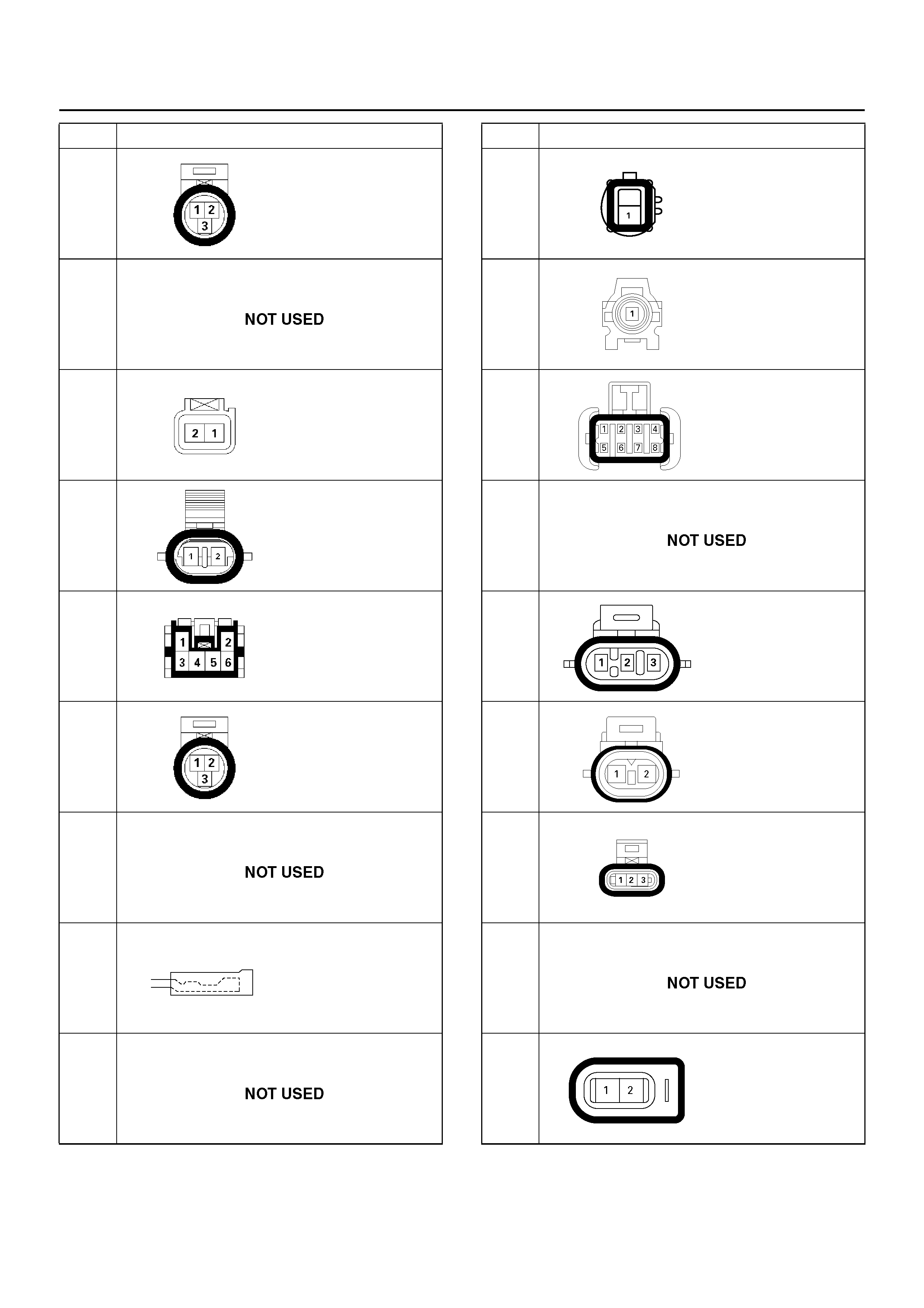
D-23
D-24
D-25
D-26
D-27
D-28
D-29
E-1
E-2
No. Connector face E-3
E-4
E-5
E-6
E-7
E-8
E-9
E-10
E-11
No. Connector face
E-12
E-13
E-14
∼
E-15
E-16
E-17
E-18
E-19
E-20
E-21
No. Connector face E-22
E-23
E-24
E-25
E-26
E-27
E-28
E-29
E-30
No. Connector face
E-31
∼
E-32
E-33
E-34
∼
E-36
E-37
E-38
E-39
E-40
E-41
E-42
No. Connector face E-43
E-44
E-45
E-46
∼
E-49
E-50
E-51
E-52
E-53
E-54
No. Connector face
E-55
E-56
E-57
E-58
∼
E-59
E-60
E-61
E-62
E-63
F-1
No. Connector face F-2 ∼
F-3
F-4
F-5
F-6
F-7
F-8
G-1
G-2
G-3
No. Connector face
G-4
G-5
G-6
G-7
G-8
G-9
G-10
G-11
G-12
No. Connector face H-1
H-2
H-3
H-4
H-5
H-6
H-7
H-8
H-9
No. Connector face
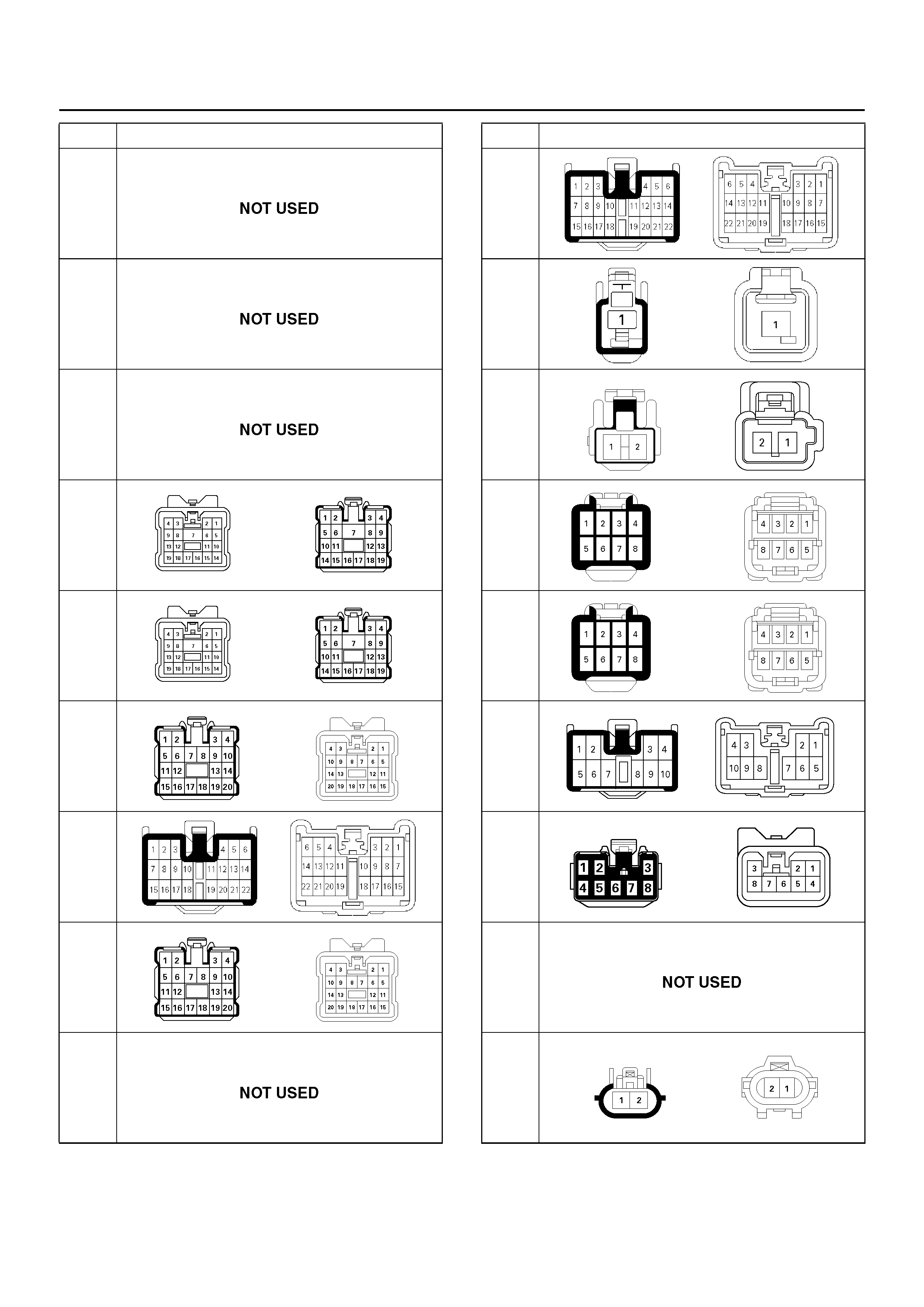
H-10
H-11
H-12
H-13
H-14
H-15
H-16
H-17
H-18
No. Connector face H-19
H-20
H-21
H-22
H-23
H-24
H-25
H-26
H-27
No. Connector face
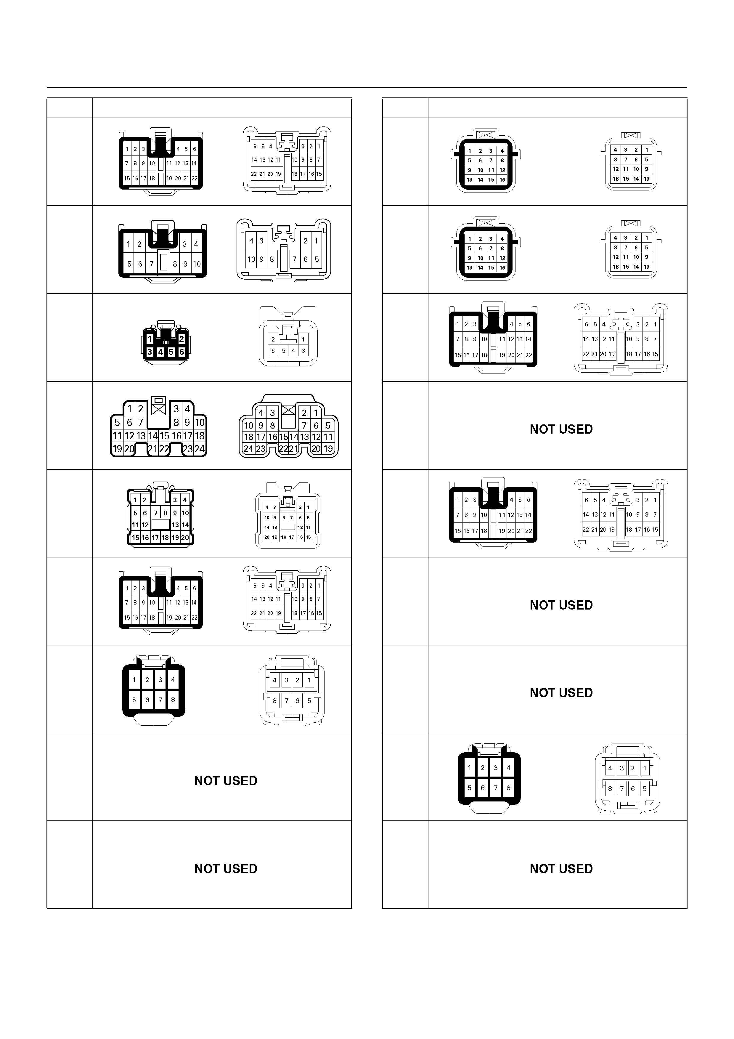
H-28
H-29
H-30
H-31
H-32
H-33
H-34
H-35
∼
H-36
H-37
No. Connector face H-38
H-39
H-40
H-41
H-42
H-43
H-44
H-45
I-1
No. Connector face
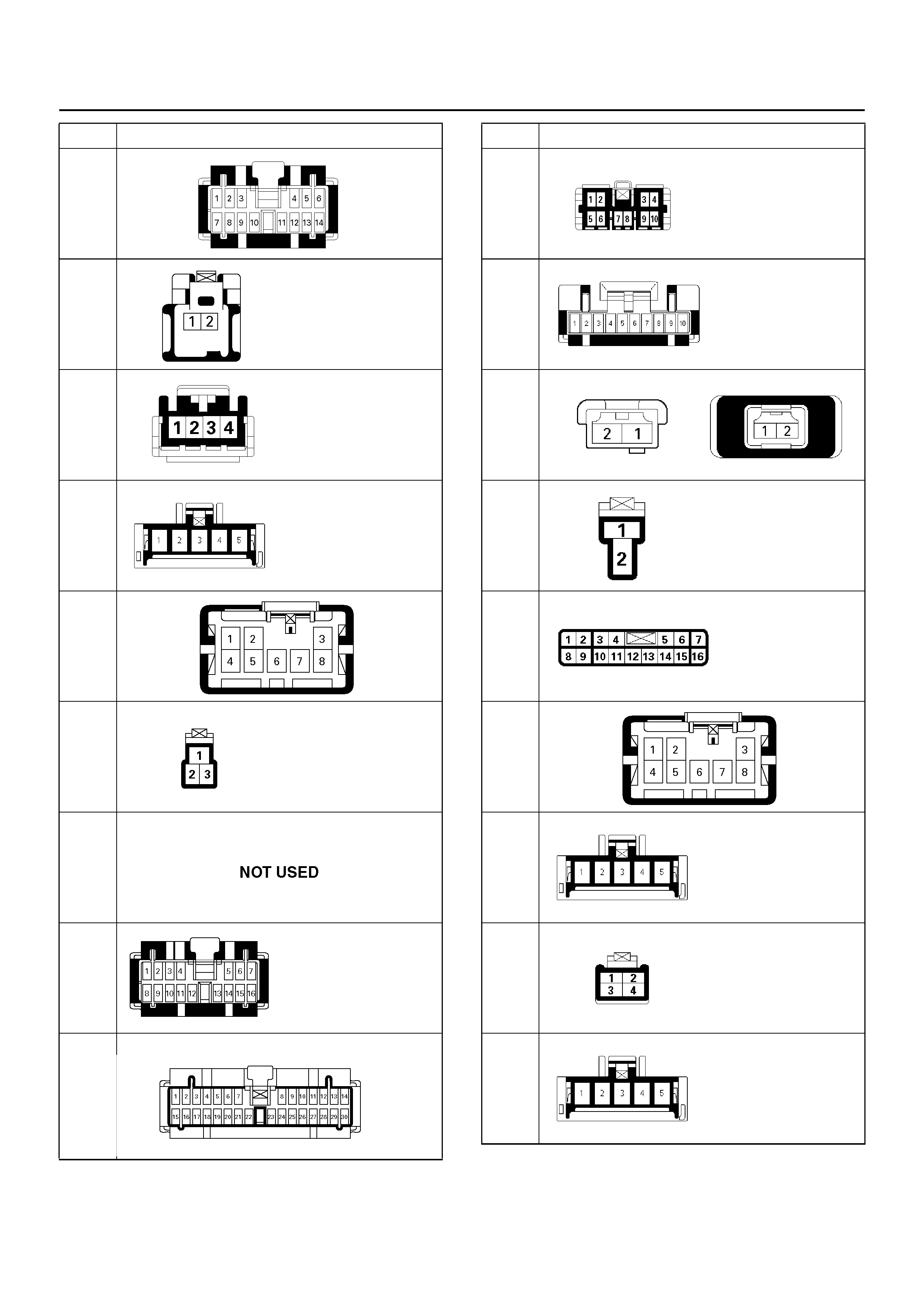
I-2
I-3
I-4
I-5
I-6
I-7
I-8
I-9
I-10
No. Connector face I-11
I-12
I-13
I-14
I-15
I-16
I-17
I-18
I-19
No. Connector face
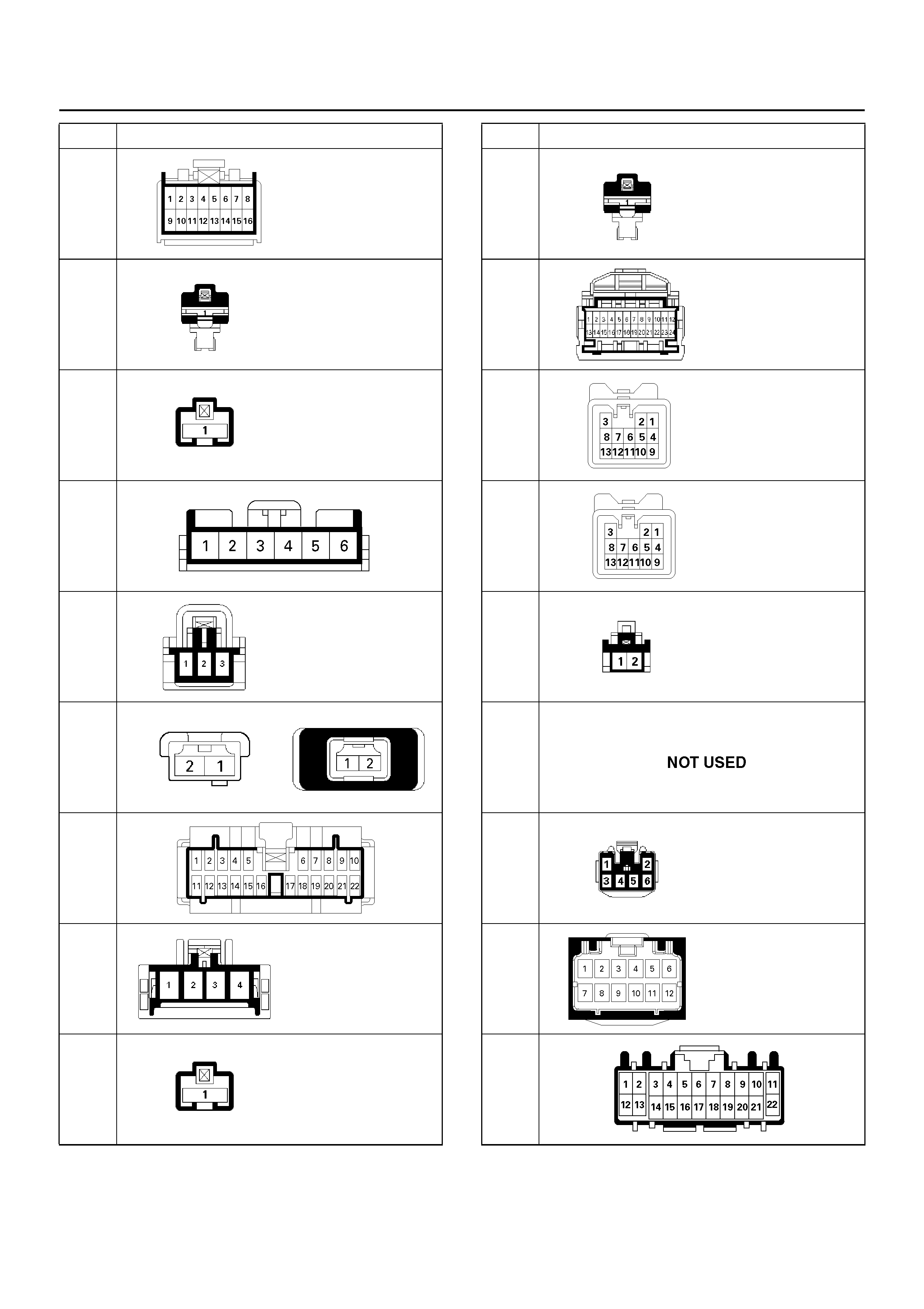
I-20
I-21
I-22
I-23
I-24
I-25
I-26
I-27
I-28
No. Connector face I-29
I-30
I-31
I-32
I-33
I-34 ∼
I-39
I-40
I-41
I-42
No. Connector face
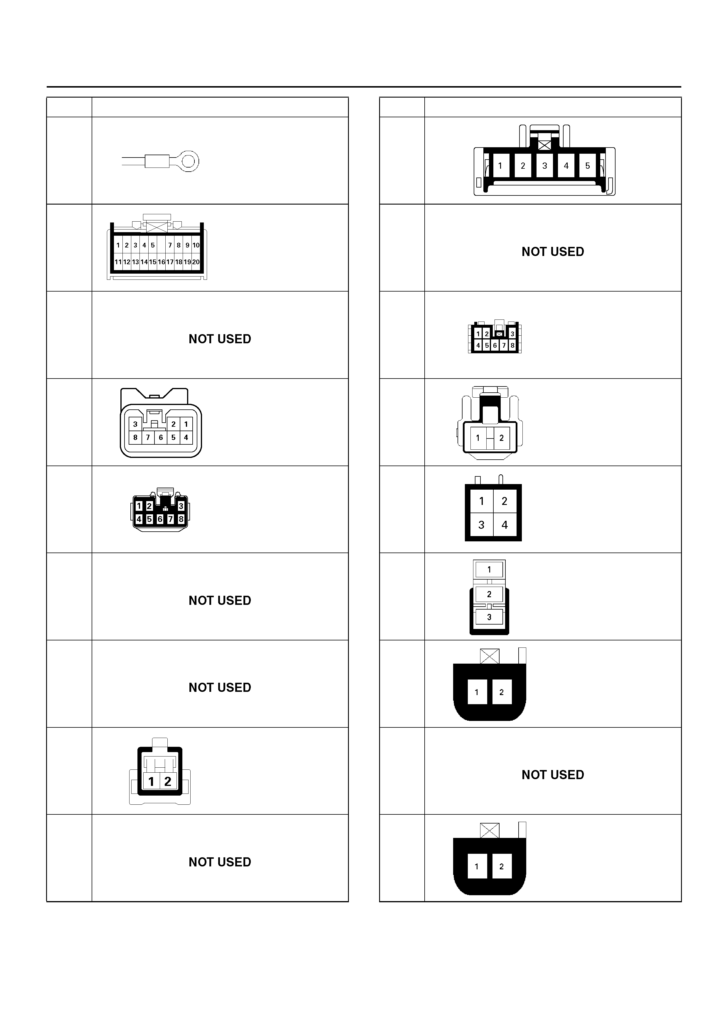
I-43
I-44
I-45
I-46
I-47
I-48
I-49
I-50
I-51 ∼
I-52
No. Connector face I-53
I-54
I-55
L-1
L-2
L-3
L-4
L-5
L-6
No. Connector face
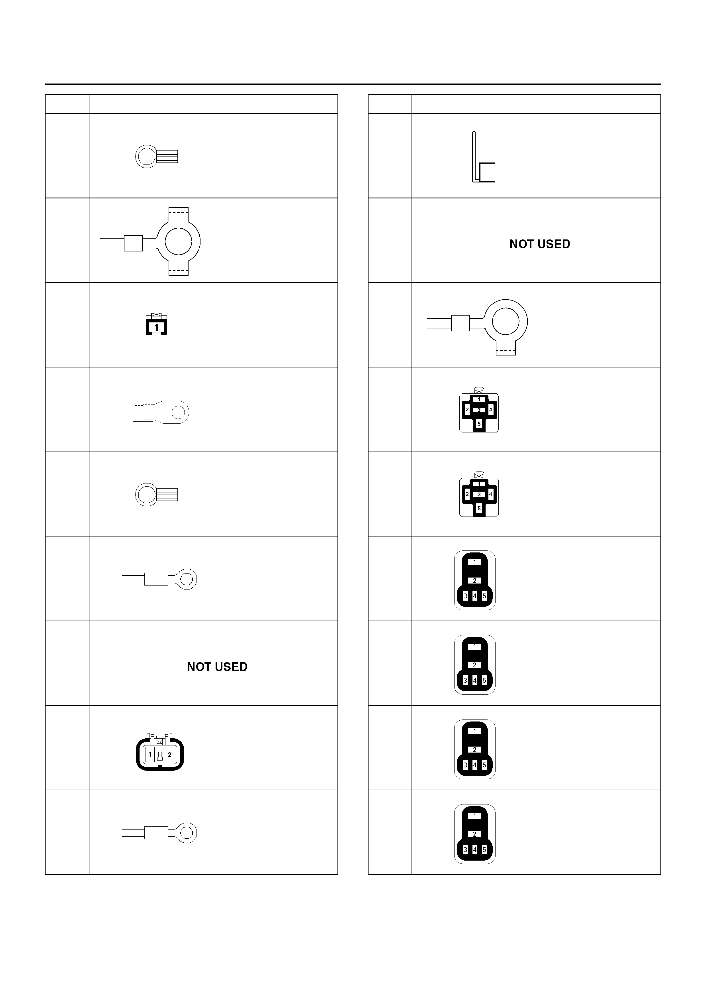
P-1
P-2
P-3
P-4
P-5
P-6
P-7
P-8
P-9
No. Connector face P-10
P-11 ∼
P-13
P-14
X-1
X-2
X-3
X-4
X-5
X-6
No. Connector face
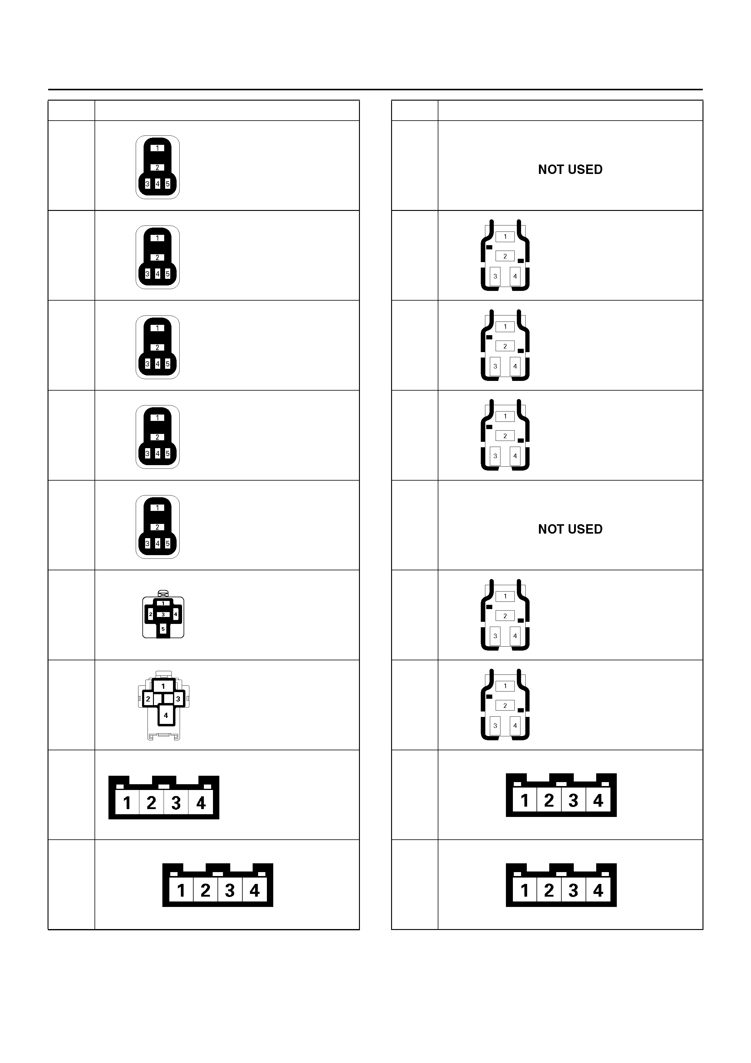
X-7
X-8
X-9
X-10
X-11
X-12
X-13
X-14
X-15
No. Connector face X-16
X-17
X-18
X-19
X-20
X-21
X-22
X-23
X-24
No. Connector face