
SECTION 2A - HEATING, VENTILATION AND AIR
CONDITIONING (HVAC) SYSTEMS
Service Precaution
Heating and Ventilation System
General Description
Heater and Ventilation Associated Parts
Ventilation
Circuit Diagram
Diagnosis
Condenser Fan Diagnosis
Individual Inspection
General Repair Procedure
Heater Unit
Heater Unit and Associated Parts
Removal
Installation
Heater Core and / or Mode Door
Disassembled View
Removal
Inspection
Installation
Heater Mode Control Link Unit
Disassembled View
Removal
Installation
Heater Temperature Control Link Unit
Disassembled View
Removal
Installation
Blower Assembly
Blower Assembly and Associated Parts
Removal
Installation
Blower Link Unit and / or Mode door
Disassembled View
Removal
Installation
Blower Motor
Blower Motor and Associated Parts
Removal
Installation
Rear Heater Duct, Defroster Nozzle and
Ventilation Duct
Rear Heater Duct, Defroster Nozzle,
Ventilation Duct and Associated Parts
Removal
Installation
Control Lever Assembly and /
or Control Cable
Control Lever Assembly, Control Cable
and Associated Parts
Removal
Installation
Control Panel Illumination Bulb
Control Panel Illumination Bulb
and Associated Parts
Removal
Installation
Resistor
Resistor and Associated Parts
Removal
Installation
Air Conditioning System
General Description
Circuit Diagram
Diagnosis
Individual Inspection
General Repair Procedure
Leak Check
Compressor Assembly
Compressor Assembly and Associated
Parts (6VD1)
Removal
Installation
New Compressor Installation
Condenser Assembly
Condenser Assembly and Associated Parts
Removal
Installation
Condenser Fan Motor
Condenser Fan Motor and Associated Parts
Removal
Installation
Receiver / Drier
Receiver / Drier and Associated Parts
Removal
Installation
Pressure Switch
Pressure Switch and Associated Parts
Removal
Installation
Evaporator Assembly
Evaporator Assembly and Associated
Parts
Removal
Installation
Techline

Electronic Thermostat, Evaporator Core
and/or Expansion Valve
Disassembled View
Removal
Installation
Refrigerant Line
Refrigerant Line and Associated Parts
Removal
Installation
Main Data And Specifications
Compressor
Service Precaution
General Description
Diagnosis
Magnetic Clutch Assembly (DKV-14G Type)
Parts Location View
Removal
Inspection and Repair
Installation
Compressor Oil
Oil Specification
Handling of Oil
Compressor Oil Check
Checking and Adjusting Oil Quantity for
Used Compressor
Checking and Adjusting for Compressor
Replacement
Contamination of Compressor Oil
Oil Return Operation
Replacement of Component Parts
Main Data and Specifications
Special Tools

SERVICE PRECAUTION
WARNING: THIS VEHICLE H AS A SUPPLEMENTAL
RESTRAINT SYSTEM (SRS). REFER TO THE SRS
COMPONENT AND WIRING LOCATION VIEW IN
ORDER TO DETERMINE WHETHER YOU ARE
PERFORMING SERVICE ON OR NEAR THE SRS
COMPONENTS OR THE SRS WIRING. WHEN YOU
ARE PERFORMING SERVICE ON OR NEAR THE
SRS COMPONENTS OR THE SRS WIRING, REFER
TO THE SRS SERVICE INFORMATION. FAILURE TO
FOLLOW WARNINGS COULD RESULT IN POSSIBLE
AIR BAG DEPLOYMENT, PERSONAL INJURY, OR
OTHERWISE UNNEEDED SRS SYSTEM REPAIRS.
CAUTION: Always use the correct fastener in the
proper location. When you replace a fastener, use
ONLY the exact part number for that application.
HOLDEN will call out those fasteners that require a
replacement after removal. HOLDEN will also call
out the fasteners that require thread lockers or
thread sealant. UNLESS OTHERWISE SPECIFIED,
do not use supplemental coatings (Paints, greases,
or other corrosion inhibi tors) on threaded faste ners
or fastener joint interfaces. Generally, such
coatings adversely affect the fastener torque and
the joint clamping force, and may damage the
fastener. When you inst all fasteners, use the correct
tightening sequence and specifications. Following
these instructions can help you avoid damage to
parts and syst ems.
HEATING AND VENTILATION SYSTEM
GENERAL DESCRIPTION
Heater
The heater system supplies warm air into the passenger
compartment. When the engine is warming up, the
engine coolant is sent into the heater core.
Outside air is circulated through the heater core of the
heater unit and then into the passenger compartment.
By contr olling the mixtu re of outsid e air and he ater cor e
air, the most comfortable passenger compartment
temperature can be selected and maintained.
The temperature of the air sent to the passenger
compartment is controlled by the temperature control
knob. This knob acts to open and close the air mix door ,
thus controlling the amount of air passed through the
heater core.
The air selector knob, with its different modes, also
allows you to sele ct and m aintain the mos t comfortable
temperature.
The air source select lever is used to select either
“FRESH" for the introduction of the outside air, or
“CIRC" for the circulation of the inside air. When the
lever is set to “FRESH", the outside air is always taken
into the passenger compartment. When setting the
lever to “CIRC" position, the circulation of air is
restricted only to the inside air with no introduction of
the outside air and the air in the passenger
compartm ent gets warm quickly. However, the lever is
norma lly set to “FRE SH" to preven t the winds hield fr om
clouding.
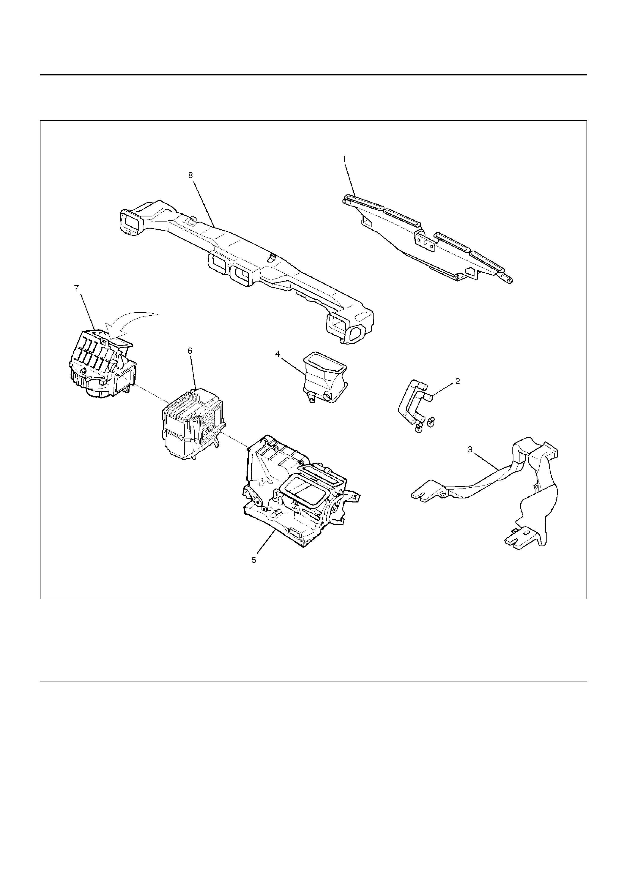
HEATER AND VENTILATION ASSOCIATED PARTS
840RY00049
EndOFCallout
Legend
(1) Defroster Nozzle
(2) Heater Hose
(3) Rear Heater Duct
(4) Ventiration Lower Duct
(5) Heater Unit
(6) Evaporato r As se mbl y
(7) Blower Assembly
(8) Ventilation Duct
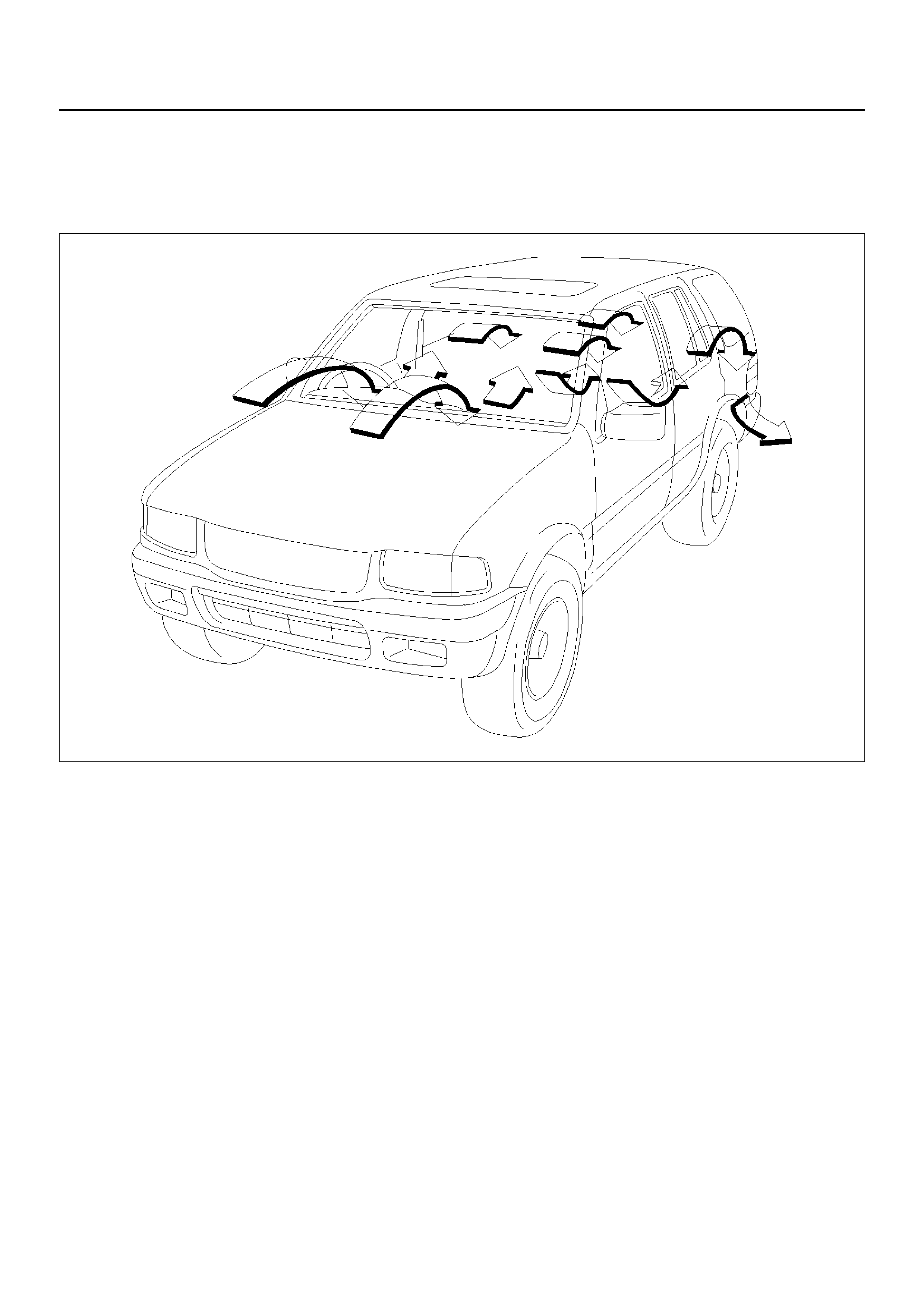
VENTILATION
Setting the air source select lever to “FRESH" position
allows the heating system to work with sending the
fresh air from outside.
The blower fan also serves to deliver fresh outside air to
the passenger compartment to assure adequate
ventilation.
810RW319
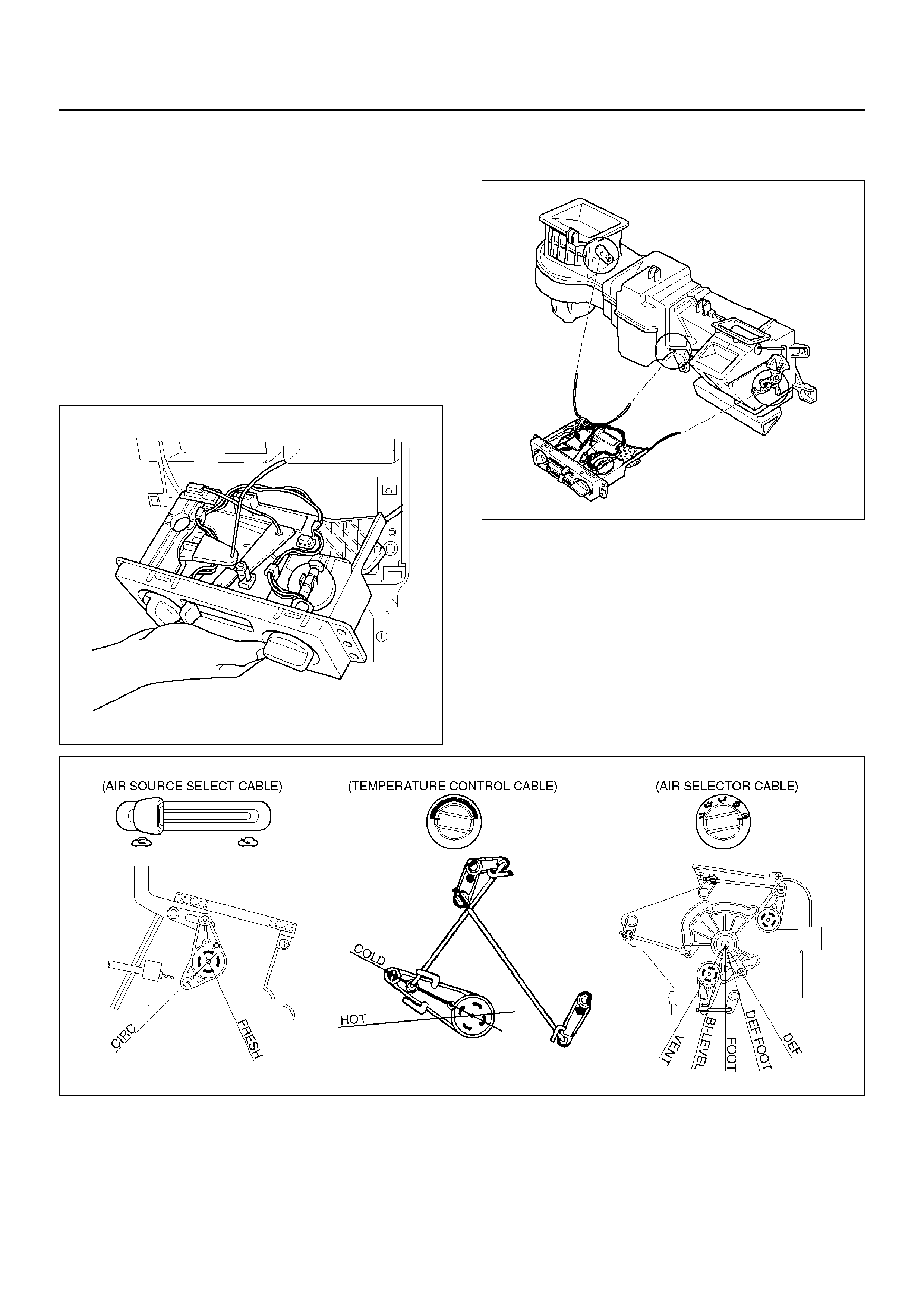
Control Lever Assembly
The control lever assembly has some cables to control
the mode and temperature of the heater unit and the
mode door for the air source of the blower assembly.
The fan control i s used to control the amoun t of air sen t
out by the resistor at four levels from “LOW" to “HIGH".
865RW006
EndOFCallout
Air Source Select Lever
The intake of outside air and the ci rculat ion of insid e air
are controlled by sliding this lever left or right.
Fan Control Lever
This lever controls the blower motor speed to regulate
the amount of air delivered to the defrost, foot, and
ventilation ducts:
1. Low
2. Medium Low
3. Medium High
4. High
Temperature Control Knob
When the temperature control knob is in the “COLD"
position, the air mix door closes to block the flow air to
the heater core.
When the temperature control knob is in the “HOT"
position, the air mix door opens to allow air to pass
through the heater core and heat the passenger
compartment.
Placi ng the knob in a intermedi ate position will cause a
lesser or gr eat er amo unt air to re ac h the hea ter c ore. In
this m ode the pass eng er c ompar tmen t te mpe ratur e c an
be regulated.
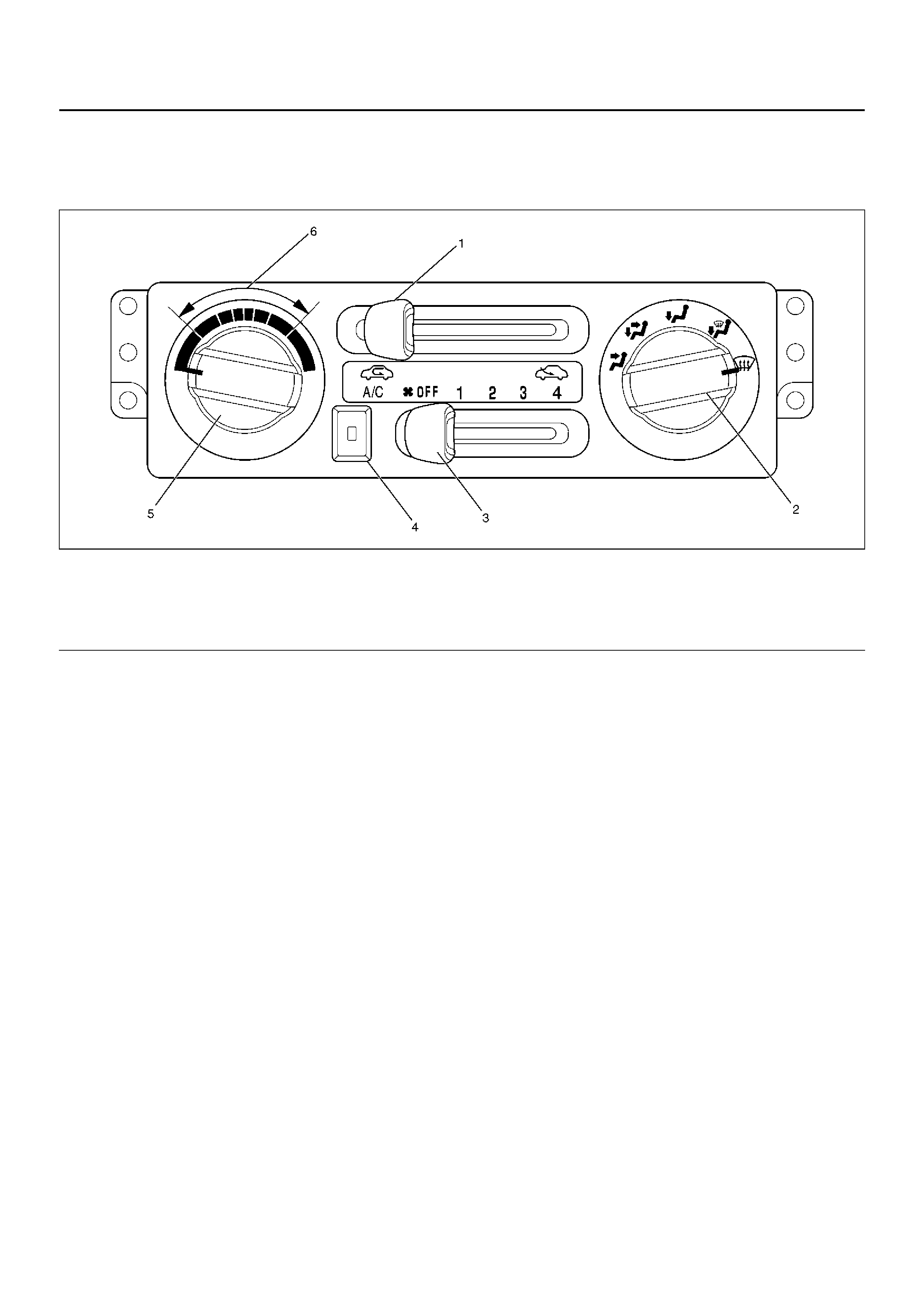
Legend
(1) Air Source Select Lever
(2) Air Select Knob
(3) Fan Control Lever (Fan Switch)
(4) Air Conditioning (A/C) Sw itch (W/ A/C)
(5) Temperature Control Knob
(6) Middle Position
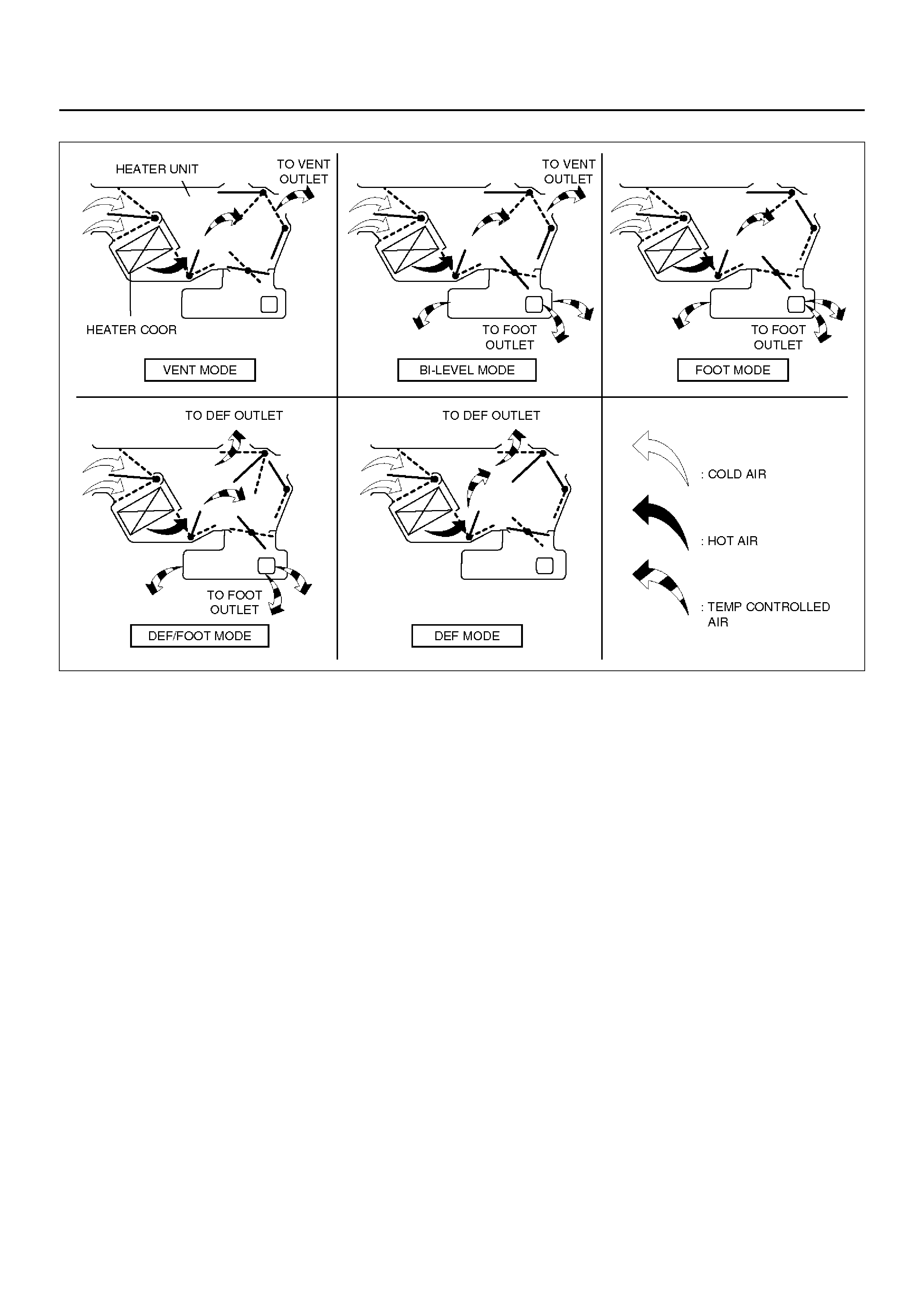
Flow of Each Position of the All Select Dials
C01RX001
Air Select Knob
The air select knob allows you to direct heated air into
the passenger compartment through different outlets.
1. Vent – In this position, air is discharged from the
upper ai r outlet. Ai r quantity is controll ed by the fa n
con tr ol lev er.
2. Bi-Level – In this position, air flow is divided
between the upper air outlets and the floor air
outlets, with warmer air deli vered to th e floor outlets
than the air delivered to the upper air outlets when
the temp lever is in mid dl e posi tio n.
3. Foot – In this position, air flow is delivered to the
foot, while sending a small amount of air to the
windshield.
4. Def/Foot – In this position, air flow is delivered to
the foot, whi le sending app rox. 40% of total am ount
of air to the windshield.
5. Defrost – In this position, most of the air is delivered
to the winds hi eld and a sm al l am ount is del iver ed to
the side windows.
Moving the air source select lever to the “CIRC" position
provides quickest heat delivery by closing the blower
assembly mode door. In this position, outside air is not
delivered to the passenger compartment.
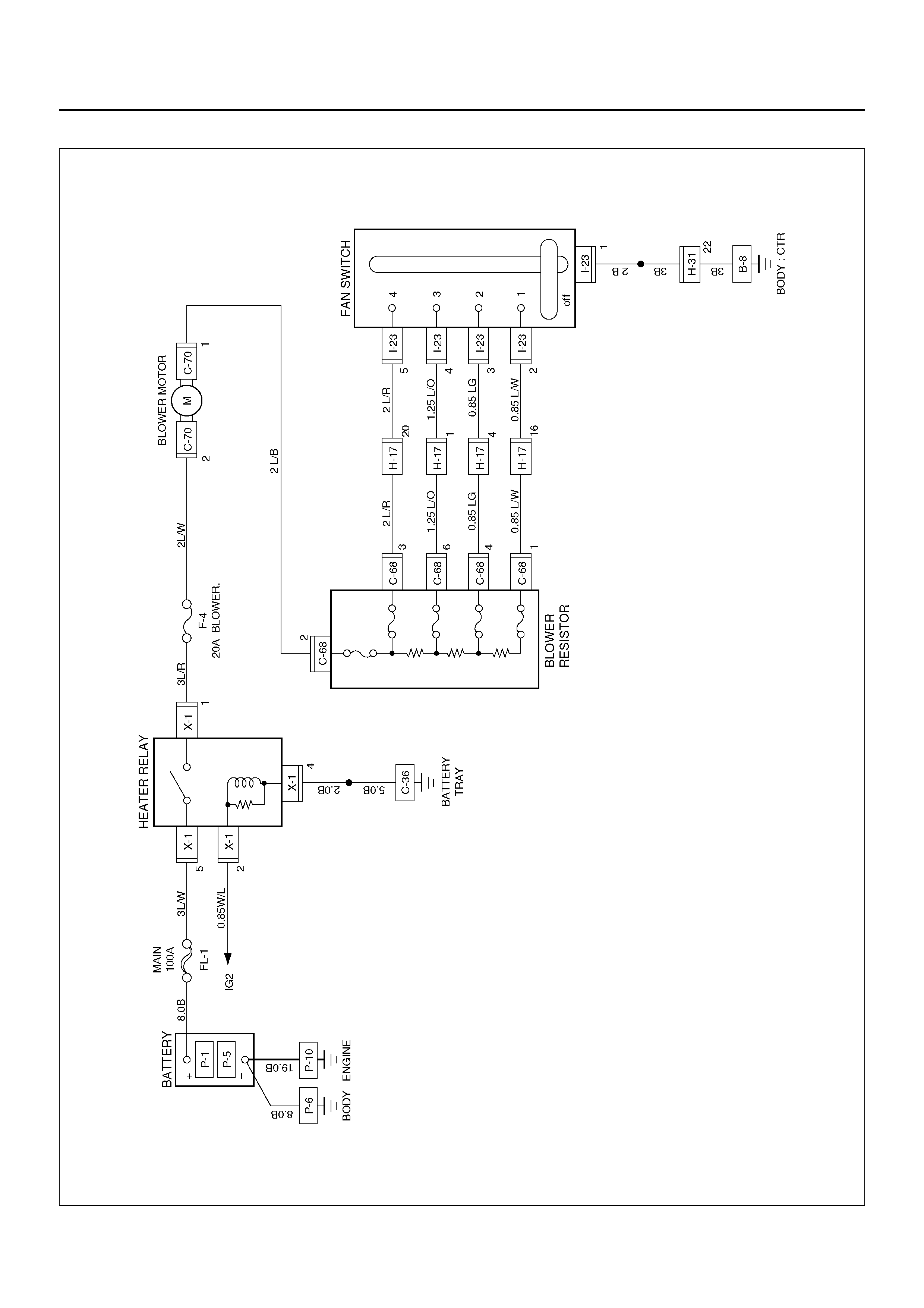
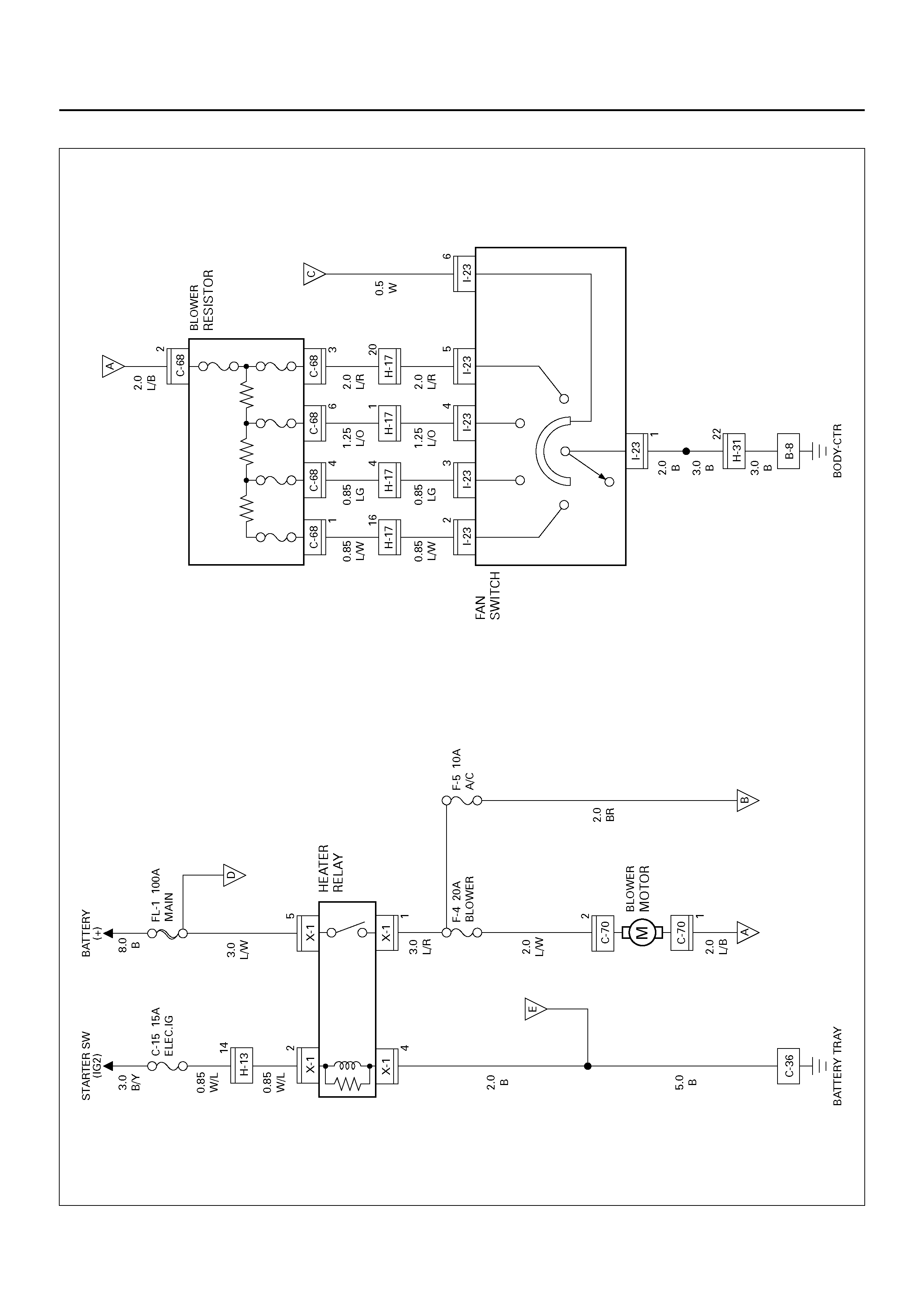
CIRCUIT DIAGRAM
D08R100116
DIAGNOSIS
Heating Cycle diagnosis
Condition Possible cause Correcti on
No heating or insufficient heating. Blower motor does not run or runs
improperly. Refer to “FAN CONTROL LEVER
(FAN SWITCH) DIAGNOSIS".
Engine coolant temperature is low. Check the engine coolant
temperature after warming up the
engine and c heck th e therm ostat.
Replace as necessary.
Insufficient engine coolant. Add engine coolant as required.
Circulation volume of engine coolant
is insufficient. Check if the water hose to the
heater core is clogged, collapsed or
twisted. Repair or replace as
necessary.
Heater core clogged or collapsed. Clean or replace as necessary.
The heater cores is not provided
with air sent from the blo wer motor. Repair the temperature control link
unit or mode doors.
Duct connections defective or
unsealing. Repair or replace as necessary.
Control lever moves but mode door
does not operate. Cable attaching clip is not correct. Repair
Link unit of heater or blower
assembly defective. Repair
The mode doo r can not be set to the
mode selected. Link unit of heater unit or blower
assembly defective. Repair.
Control cable is not adjusted. Adjust.
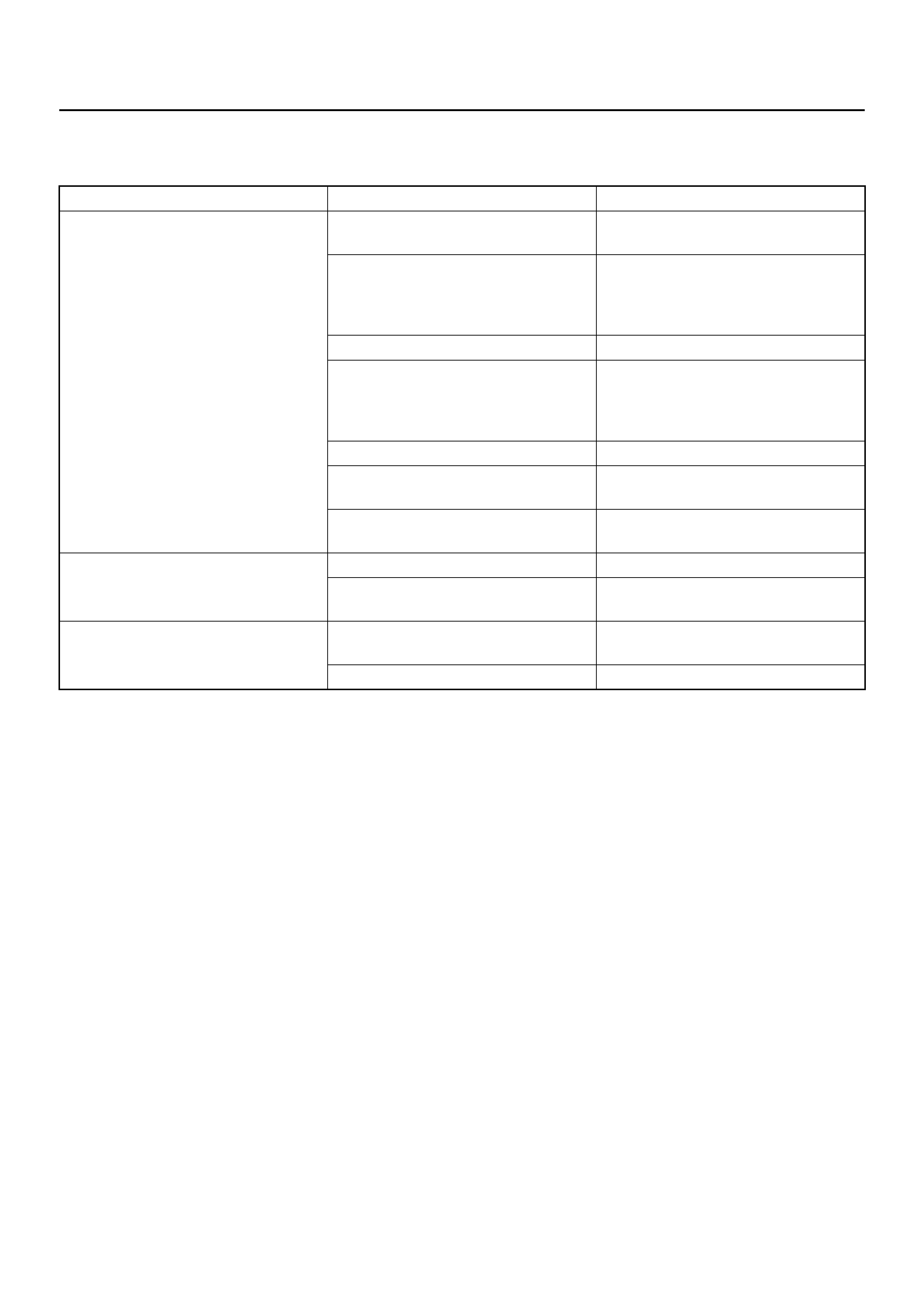
Fan Control Lever (Fan Switch) Diagnosis
Current flows to the blower motor through the heater
relay (X-1) to activate the rotation of the blower motor by
turning “ON" the fan control knob (fan switch). Blower
motor speed is controlled in stages by the resistor, by
operating the switch from “LOW" to “HIGH".
For the inspection of the relays, switches and units in
each table, refer to “INDIVIDUAL INSPECTION" in this
section.
D08R100117
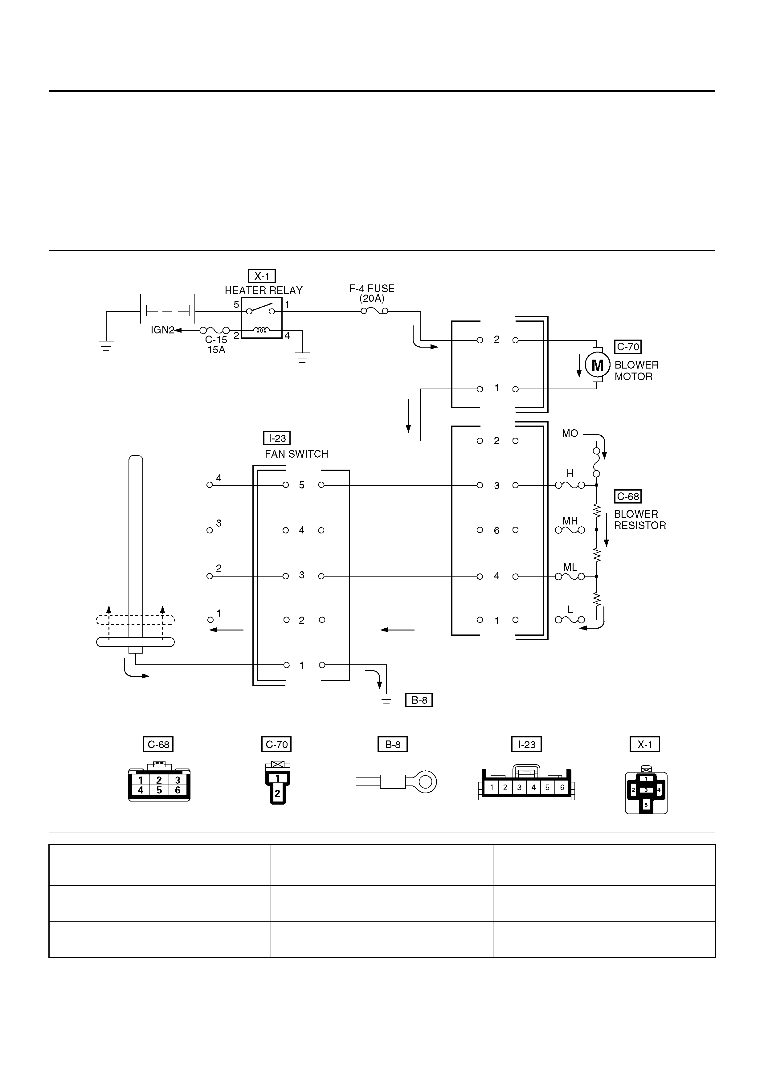
Condition Possible cause Correcti on
Blower motor does not run. — Refer to Chart A
Blower mot or does not run in cer tain
position (s) . — Refer to Chart B, C, D and E
Blower motor does not stop at “OFF"
position. — Refer to Chart F
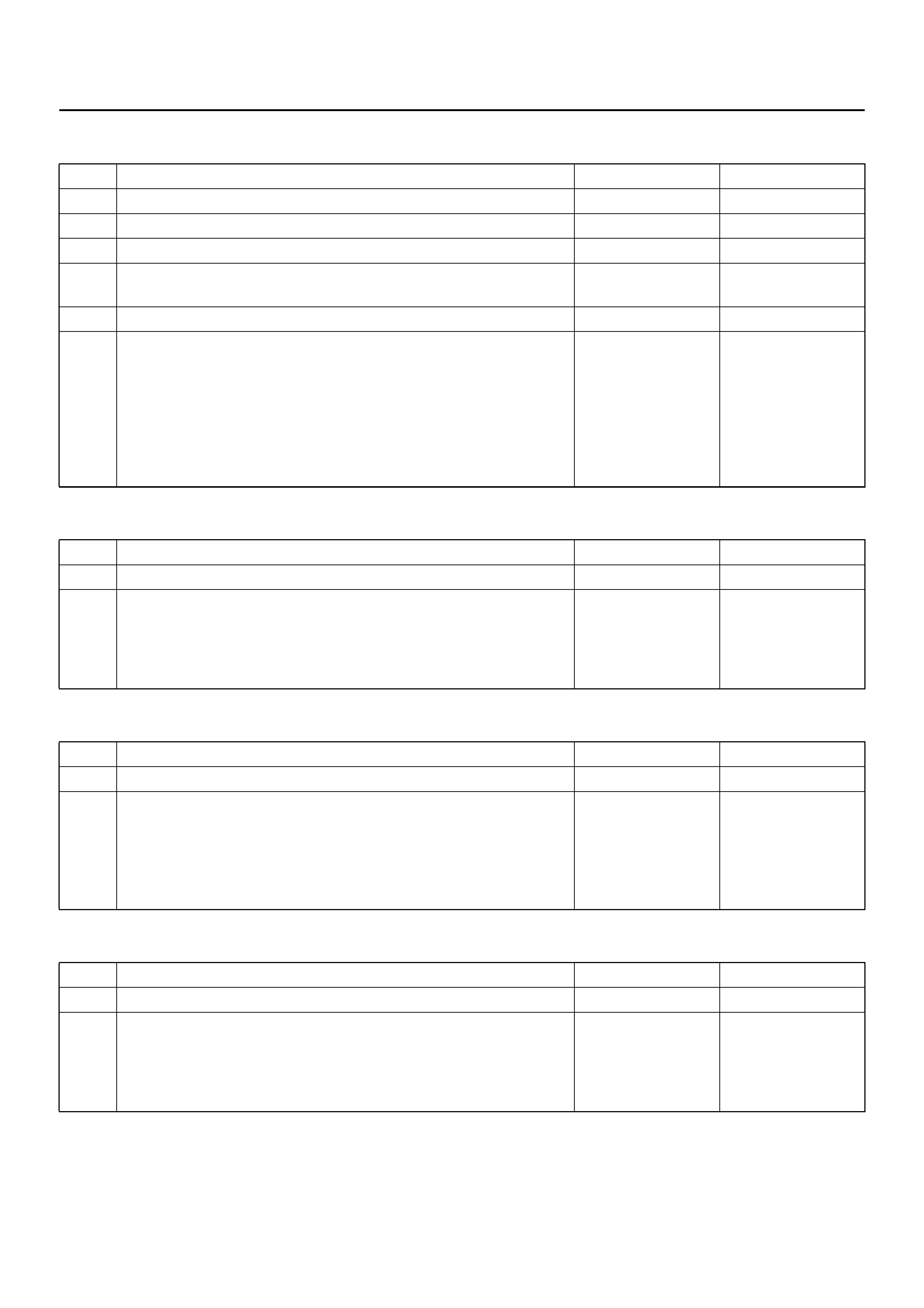
Chart “A" Blower Motor Does Not Run
Chart “B" Blower Motor Does Not Run At Low Posi tion
Chart “C" Blower Motor Does Not Run At Medium Low Position
Chart “D" Blower Motor Does Not Run At Medium High Position
Step Action Yes No
1 Is relay (X-1) OK? Go to Step 2 Replace
2 Is fuse F-4 (20A) OK? Go to Step 3 Replace
3 Is resistor OK? Go to Step 4 Replace
4 Is fan control lever OK? Go to Step 5 Replace control
lever assembly.
5 Is blower motor OK? Go to Step 6 Replace
6 1. Turn the ignition switch “ON".
2. Turn fan control lever “ON".
3. Check to see if battery voltage is present at chassis side
connector terminal No. C70-2
Is there a battery voltage?
Poor groun d or
open circuit either
between chassis
side connector
terminal No. C70-1
and No. C68-2 or
No. I23-1 and body
ground (No. B-8).
Open circui t
between No. F-4
(20A) fuse and No.
C70-2.
Step Action Yes No
1 Is resistor OK? Go to Step 2 Replace
2 Is fan control lever (Fan Switch) OK? Open circuit
between chassis
side connector
terminal No. C68-1
and No.I23-2. Replace control
lever assembly.
Step Action Yes No
1 Is resistor OK? Go to Step 2 Replace
2 Is fan control lever (Fan Switch) OK? Open circuit
between the
chassis side
connector terminal
No. C68-4 and No.
I23-3. Replace control
lever assembly.
Step Action Yes No
1 Is resistor OK? Go to Step 2 Replace
2 Is fan control lever (Fan Switch) OK? Open circuit
between chassis
side connector
terminal No. C68-6
and No. I23-4. Replace control
lever assembly.
Chart “E" Blower Motor Does Not Run At High Position
Chart “F" Blower Motor Does Not Stop In The “OFF" Position
Step Action Yes No
1 Is resistor OK? Go to Step 2 Replace
2 Is fan control lever (Fan Switch) OK? Open circuit
between Chassis
side connector
terminal No. C68-3
and No. I23-5. Replace control
lever assembly.
Step Action Yes No
1 Is the fan control lever (Fan Switch) OK? Short circuit
between chassis
side connector
terminal No.C70-1
and
No.C68-2,No.C68-
3 and No.I23-5,
No.C68-6 and
No.I23-4,
No.C68-4 and
No.I23-3 or
No.C68-1 and
No.I23-2 Replace control
lever assembly.
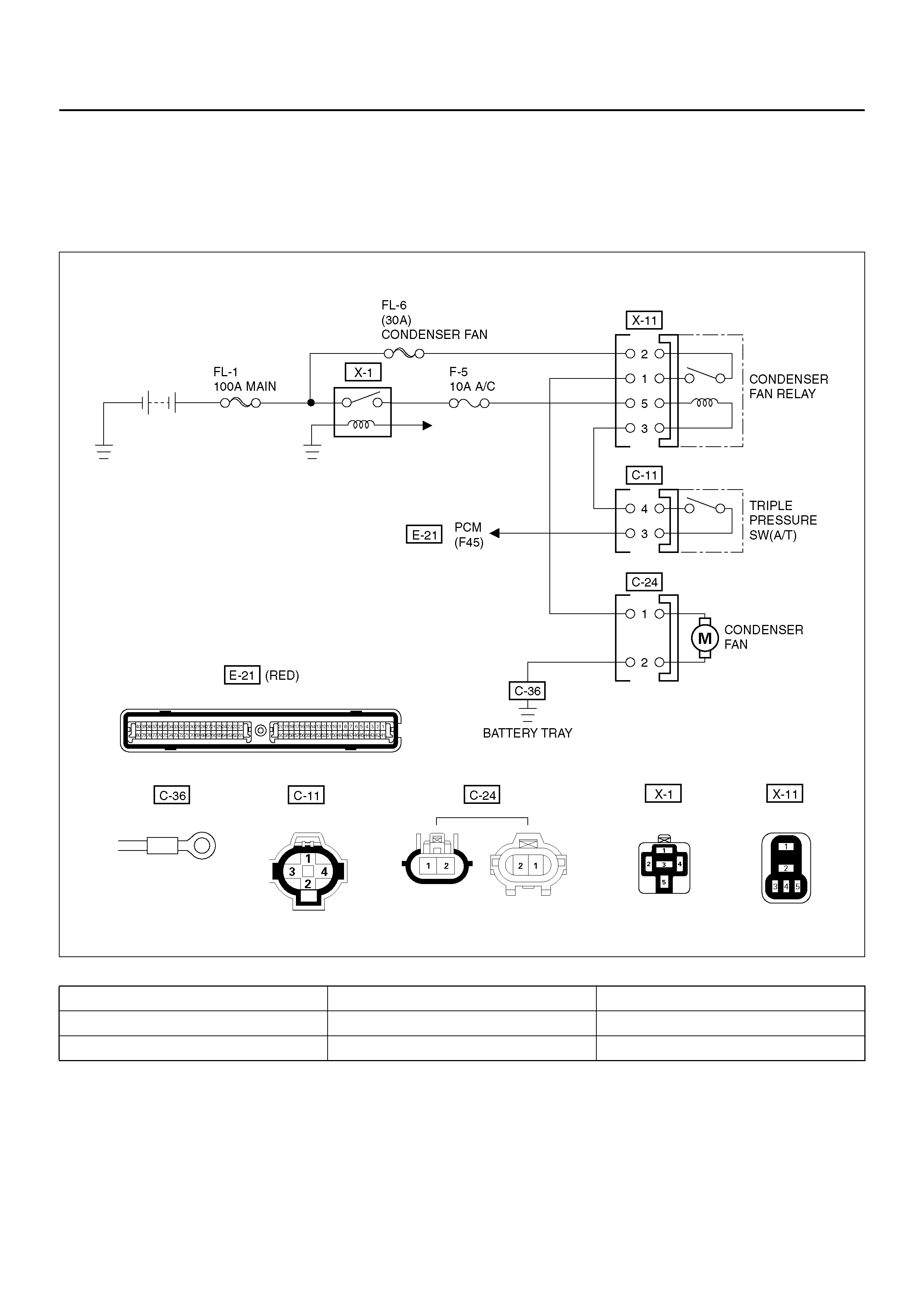
CONDENSER FAN DIAGNOSIS
While the air conditioning is ON, the cycling switch in
the triple pressure switch senses the refrigerant
pressure, and activates the condenser fan to improve
the cooling capacity of the condenser when the
refrigerant pressure exce eds a set pressure value. The
conden ser fan stops when the air conditi oning is turned
“OFF" or when the pressure goes down below the set
pressure value.
D08R100140
Condition Possible cause Correction
Condenser fan does not run. — Refer to Chart A
Condenser fan does not stop. — Refer to Chart B

Chart “A" Condenser Fan Does Not Run
Step Action Value(s) Yes No
1 Is the fusible link No.FL–6 normal? — Go to Step 2 Replace the
fusible link wire
2 Is the fuse No.F–5 normal? — Go to Step 3 Replace the
fuse
3 Is the heater relay (No.X–1) and condenser fan relay
(No.X–11) normal? — Go to Step 4 Replace the
relay
4 1. Disconnect the condenser fan motor connector
No.C–24.
2. Connect the motor side connector terminal
No.C24–1 to the battery positive terminal and
No.C24–2 to the battery negative terminal.
Does the fan operate? — Go to Step 6 Go to Step 5
5 Repair or replace the condenser fan motor.
Is the action complete? — Go to Step 4 —
6 Is there continuity between the harness side
connector terminal No.C24–2 and ground (C–36)? — Go to Step 8 Go to Step 7
7 Repair an open circuit between terminal No.C24–2
and No.C–36.
Is the action complete? — Go to Step 6 —
8 Is there continuity between the harness side
connector terminal No.C24–1 and No.X11–1? — Go to Step 10 Go to Step 9
9 Repair an open circuit between terminal No.C24–1
and No.X11–1.
Is the action complete? — Verify repair —
10 Is the battery voltage applied between the harness
side connector terminal No.X11–2 and ground? — Go to Step 12 Go to Step 11
11 Repair an open circuit between terminal No.X11–2
and No.FL–6.
Is the action complete? — Go to Step 10 —
12 Is the battery voltage applied between the harness
side connector terminal No.C11–4 and ground? — Go to Step 14 Go to Step 13
13 Repair an open circuit between terminal No.X11–3
and No.C11–4.
Is the action complete? — Go to Step 12 —
14 Is there continuity between the harness side
connector terminal No.C11–3 and No.E21–F45? — Go to Step 16 Go to Step 15
15 Repair an open circuit between terminal No.C11–3
and No.E21–F45.
Is the action complete? — Verify repair —
16 Connect the harness side connector terminal
No.C24–1 to the battery terminal and No.C24–2 to the
battery negative terminal.
Is the battery voltage between the pressure switch
side connector terminal No.C24–2 and ground? — Go to Step 18 Go to Step 17
17 Replace the triple pressure switch.
Is the action complete? — Verify repair —
18 Replace the auto air conditioner control unit.
Is the action complete? — Verify repair —
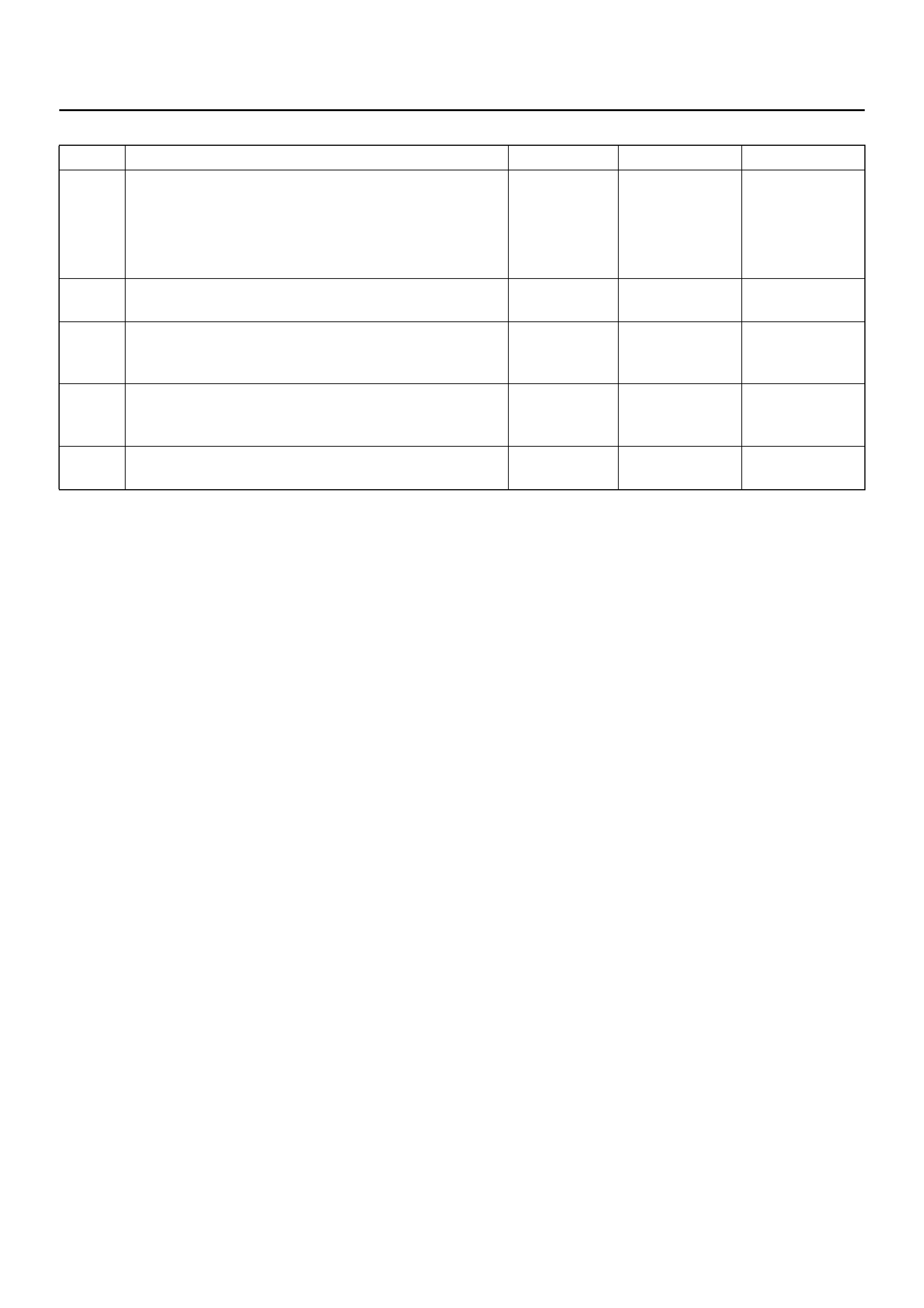
Chart “B" Condenser Fan Does Not Stop
Step Action Value(s) Yes No
1 1. Turn on the ignition switch “ON" (the engine is
run).
2. Air conditioning switch “OFF".
3. Disconnect the triple pressure switch.
Does the condenser fan stop? — Go to Step 2 Go to Step 3
2 Replace the triple pressure switch.
Is the action complete? — Verify repair —
3 Disconnect the relay.
Is there continuity between the harness side
connector terminal No.X11–3 and ground? — Go to Step 4 Go to Step 5
4 Repair short circuit between terminal No.X11–3 and
No.C11–4.
Is the action complete? — Verify repair —
5 Replace the relay condenser fan.
Is the action complete? — Verify repair —
INDIVIDUAL INSPECTION
Blower Motor
1. Dis connect the blower mo tor (C-70 ) connec tor from
the blower motor.
2. Connect the battery positive terminal to the No. 2
termin al of the bl ower m oto r and the ne gati ve to th e
No. 1.
3. Be sure to check to see if the blower motor operates
correctly.
873RW008
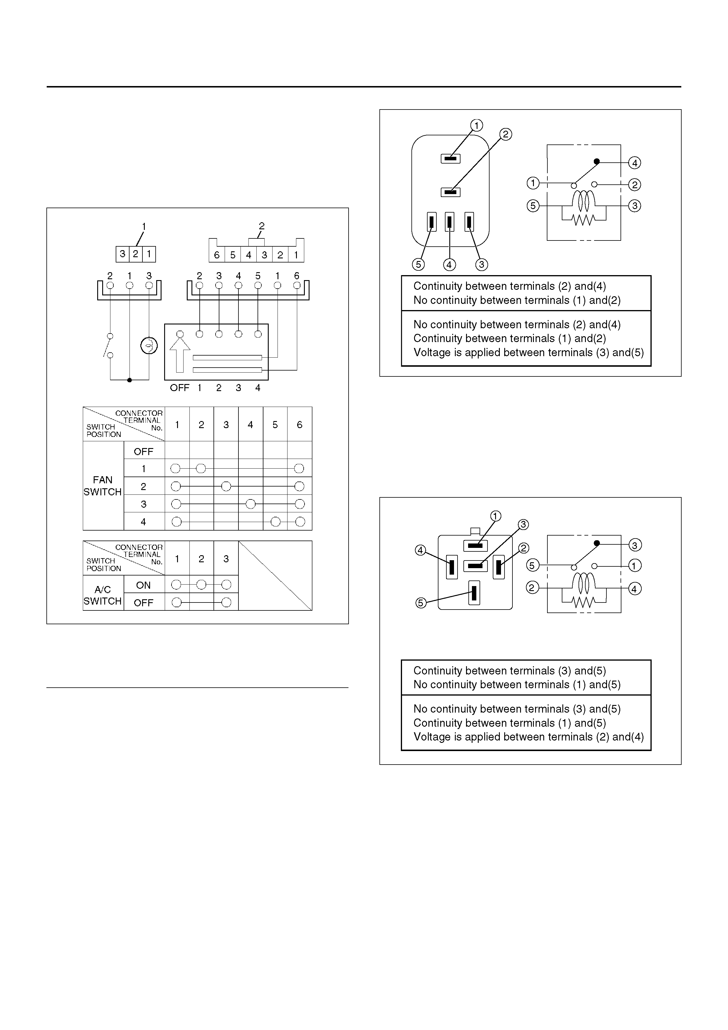
Resistor
1. Disconnect the resistor (C-68) connector.
2. Check for continuity and resistance between the
terminals of the resistor.
840R100006
EndOFCallout
Legend
(1) Resiste r As sembl y
(2) Connector Terminal (Resister Side)
(3) Position Switch
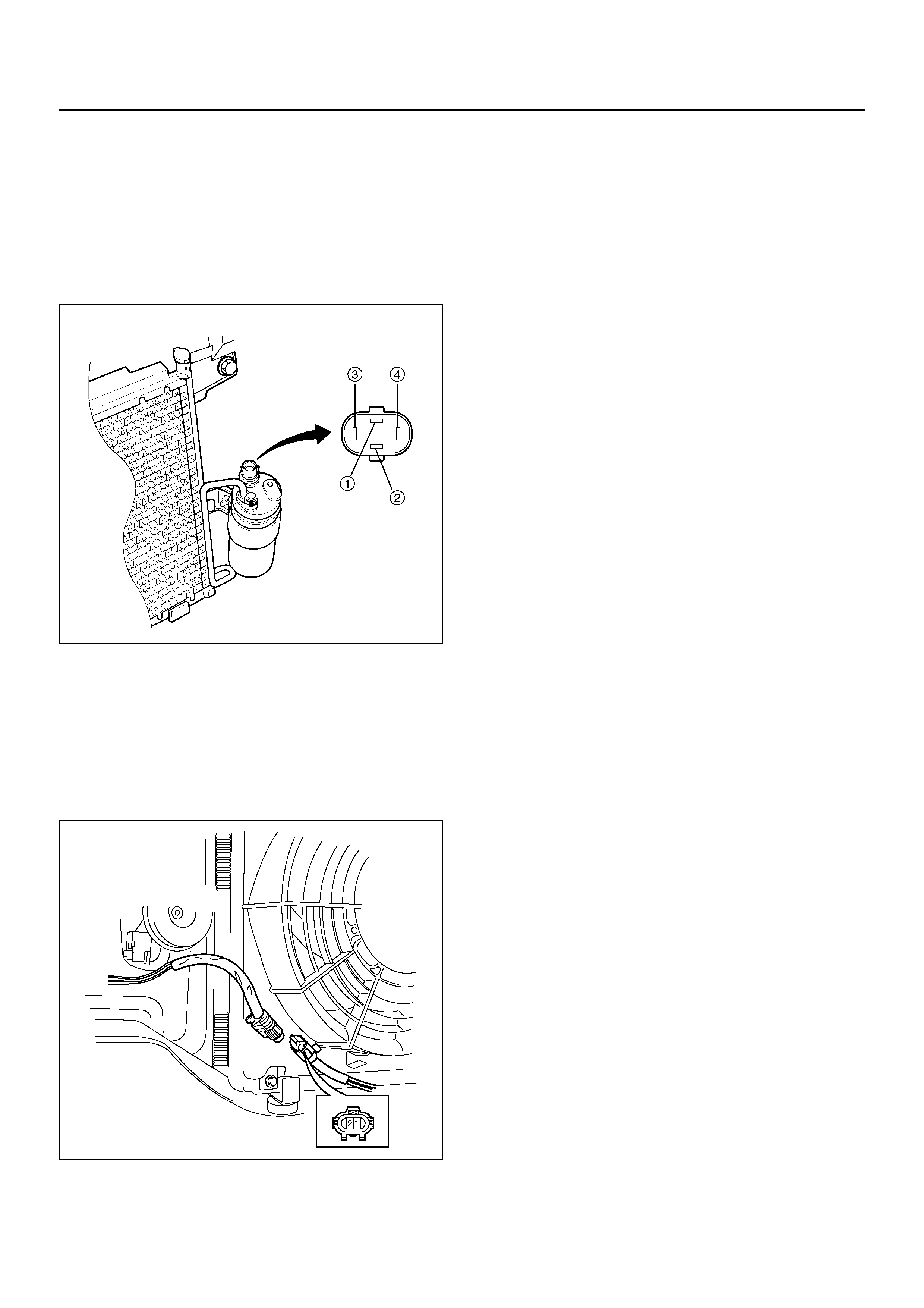
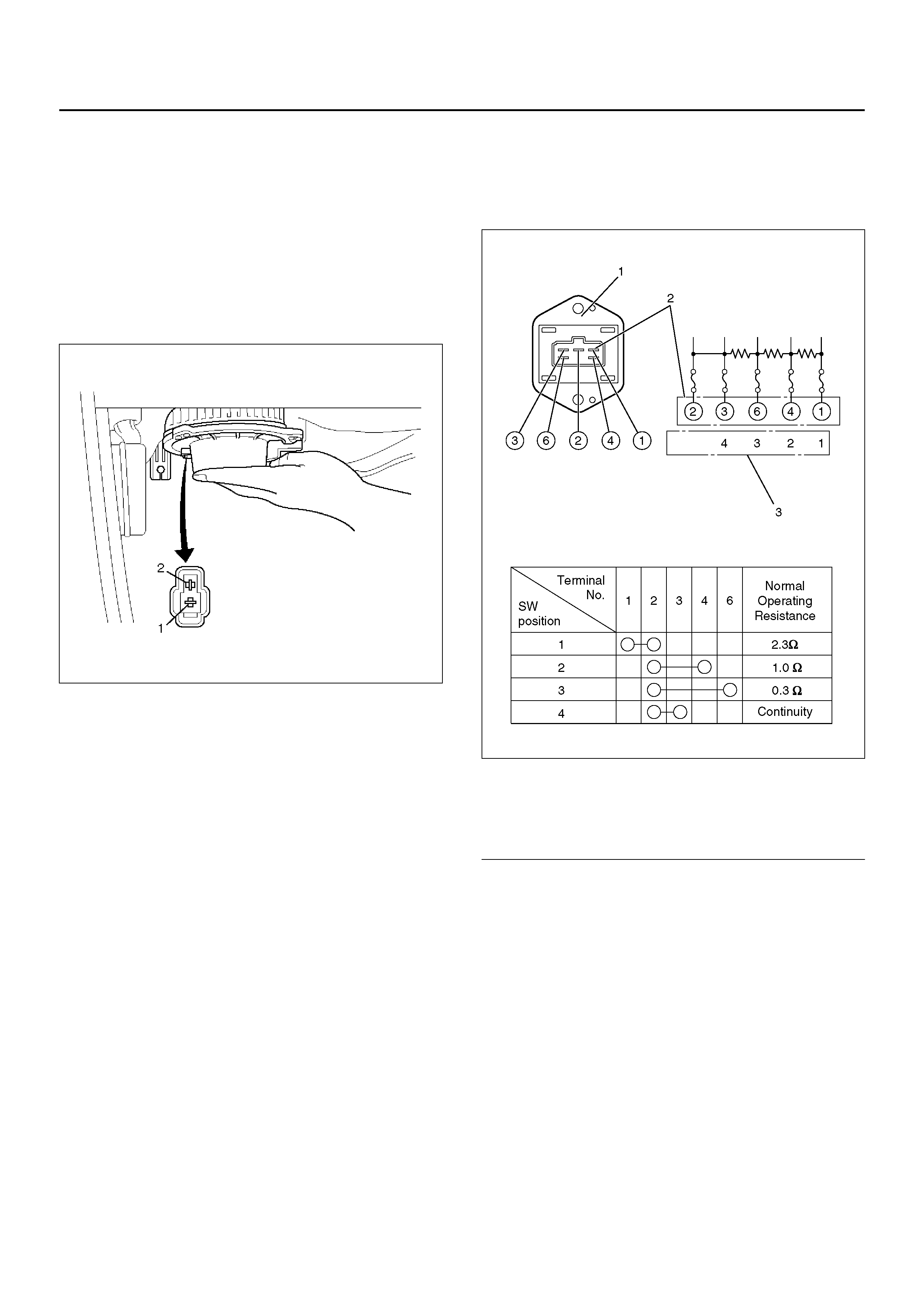
Triple Pressure Switch (V6, A/T)
1. Disconnect the connector and check for continuity
between pressure switch side connector terminals
(1) and (2).
2. Reconnect the connector to activate the A/C switch,
and check to see if there is continuity between the
chassis side connector terminals (3) and (4) and the
fan operates.
875RY00010
Condenser Fan
1. Disconnect the condenser fan connector.
2. Connect the battery positive terminal to the
condenser fan side connector terminal No.C-24-1
and negative to the No.C-24-2.
3. Check that condenser fan is rotating correctly.
875RW010
GENERAL REPAIR PROCEDURE
Precautions For Replacement or Repair of
Air Conditioning Parts
There are certain procedures, practices and precautions
that should be followed when servicing air conditioning
systems:
• Keep your work area clean.
• Always wear safety goggles and protective gloves
when working on refrigerant systems.
• Beware of the danger of carbon monoxide fumes
caused by running the engine.
• Beware of discharged refrigerant in enclosed or
improperly ventilated garages.
• Always disconnect the negative battery cable and
discharge and recover the refrigerant whenever
repairing the air conditioning system.
• When discharging and recovering the refrigerant, do
not allow refrigerant to discharge too fast; it will draw
compressor oil out of the system.
• Keep moisture and contaminants out of the system.
When disconnecting or removing any lines or parts,
use plugs or caps to close the fittings immediately.
Never remove the caps or plugs until the lines or
parts are reconnected or installed.
• When disconnecting or reconnecting the lines, use
two wrenches to support the line fitting, to prevent
from twisting or other damage.
• Alway s install new O-rings wh enever a co nnection is
disassembled.
• Before connecting any hoses or lines, apply new
specified compressor oil to the O-rings.
• When removing and replacing any parts which
require discharging the refrigerant circuit, the
operations described in this section must be
perfor med in the following seque nc e:
1 Use the J-39500 (ACR4: HFC-134a Refrigerant
Recovery / Recycling / Recharging / System) or
equivalent to thoroughly discharge and recover
the refrigerant.
2 Remove and replace the defective part.
3 After evacuation, charge the air conditioning
system and check for leaks.
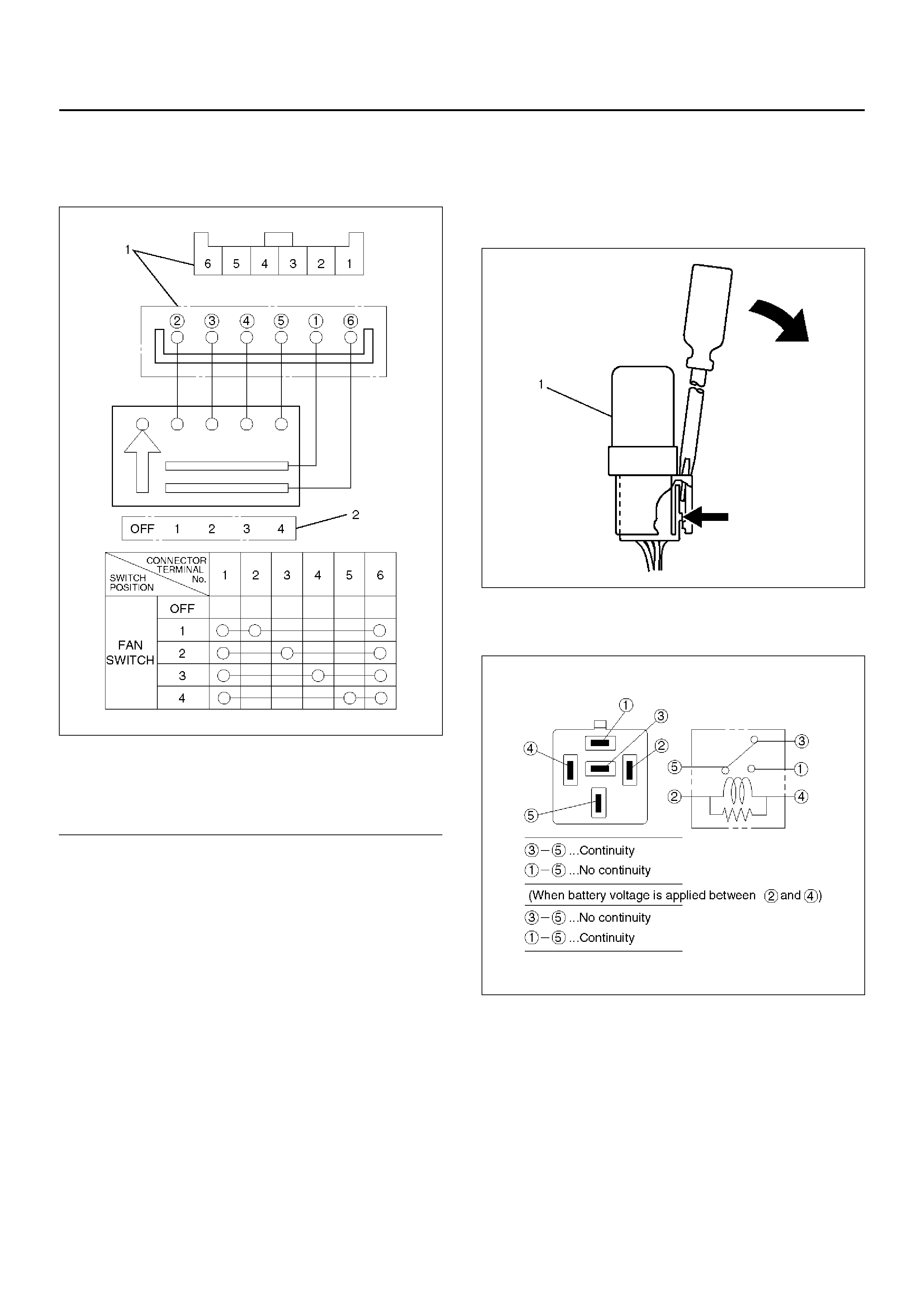
Fan Control Lever (Fan Switch)
1. Check for continuity between the terminals of the
fan switch.
D08RX157
EndOFCallout
Heater R ela y
1. Disconnect the heater relay (X-1).
• When r emoving the c onnector for re lay, unfas ten
the tank lock of the connector by using a
screwdriver, then pull the relay (1) out.
825RX046
2. Check for continuity between th e heater relay (X-1)
terminals.
901RX071
Legend
(1) Control Lever Connector Terminal (Control
Lever Side)
(2) P os iti on Swit ch
HEATER UNIT
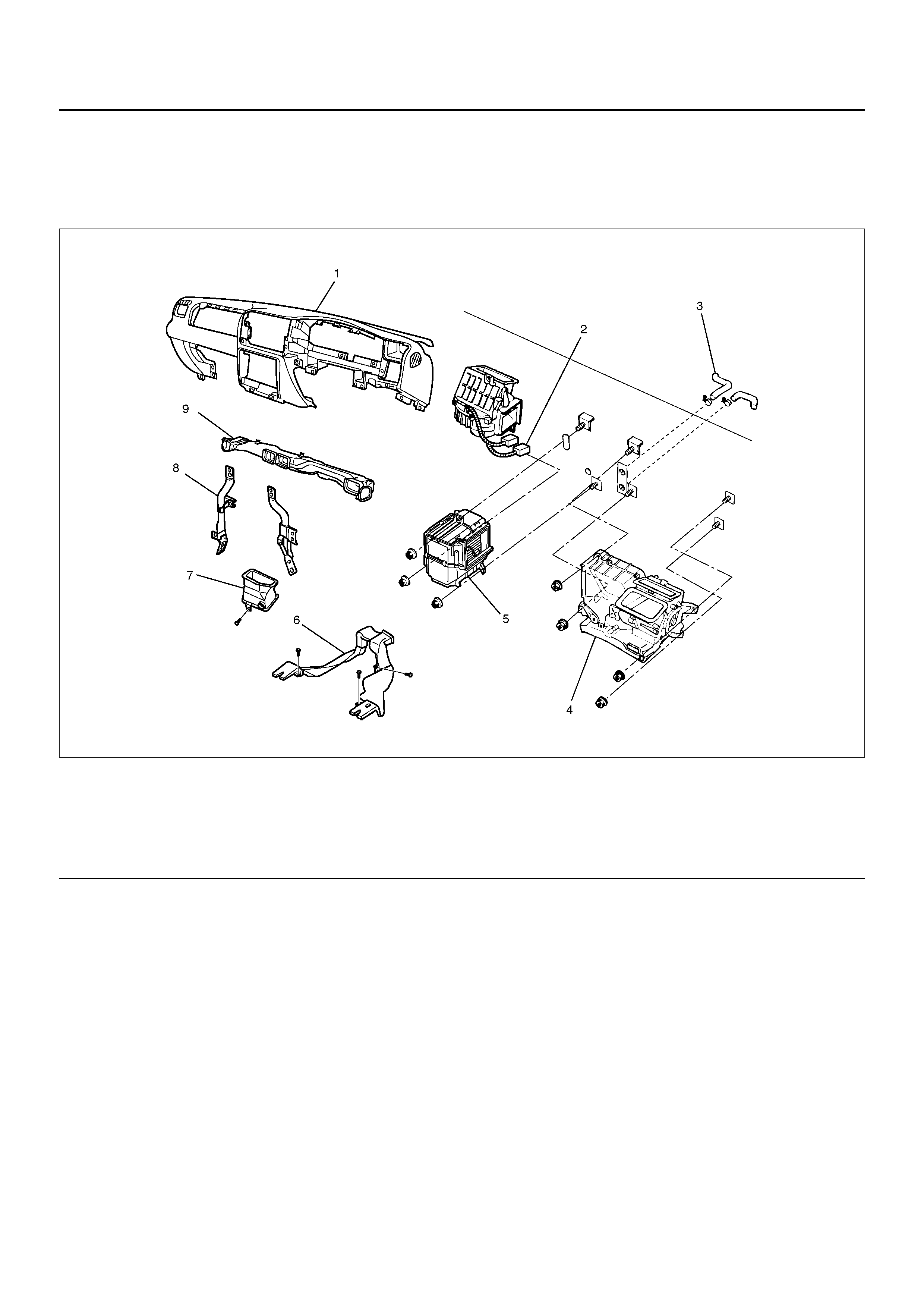
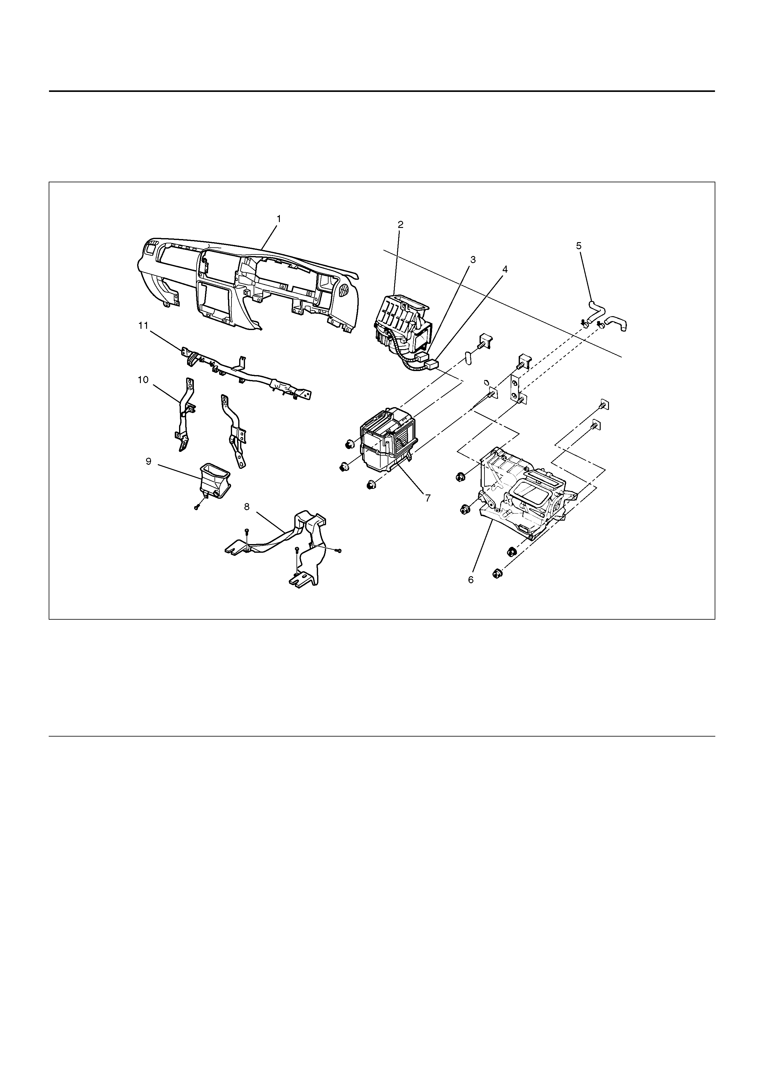
HEATER UNIT AND ASSOCIATED PARTS
840R100003
EndOFCallout
REMOVAL
1. Disconnect the battery ground cable.
2. Drain the engine coolant.
3. Discharge and recover refrigerant (with air
conditioning).
• Refer to Refrigerant Recovery in this section.
4. Remove the Instrument panel assembly.
• Refer to Instrument Panel Assembly in Body and
Accessories section.
5. R emo ve ins trument panel stay.
6. Remove center ventilation duct and side defroster.
7. D is co nnect re si stor connecto r.
8. Re mo ve evaporator ass emb ly.
• Refer to Evaporator Assembly in this section.
9. Remove ventilation lower duct.
10. Remove rear heater duct.
• Remove foot rest, carpet and 3 clips.
11. Remove heater unit assembly.
• Disconnect heater hoses at heater unit.
Legend
(1) Instrument Panel Assembly
(2) Resistor Connector
(3) Heater Hose
(4) Heater Unit Assembly
(5) Evaporato r As se mbl y
(6) Rear Heater Duct
(7) Ventilation Lower Duct
(8) Instrument Panel Stay
(9) Center Ventilation Duct and Side Defroster
INSTALLATION
To install, follow the removal steps in the reverse order,
noting the following points:
1. When handling the PCM and the control unit, be
careful not to make any improper connection of the
connectors.
2. Adjust the control cables.
• Refer to Control Lever Assembly in this section.
3. When installing the heater unit, defroster nozzle and
center vent duct, be sure that the proper seal is
made, without any gap between them.
4. After putting engine coolant in remove the air well
and confirm the quantity of coolant.
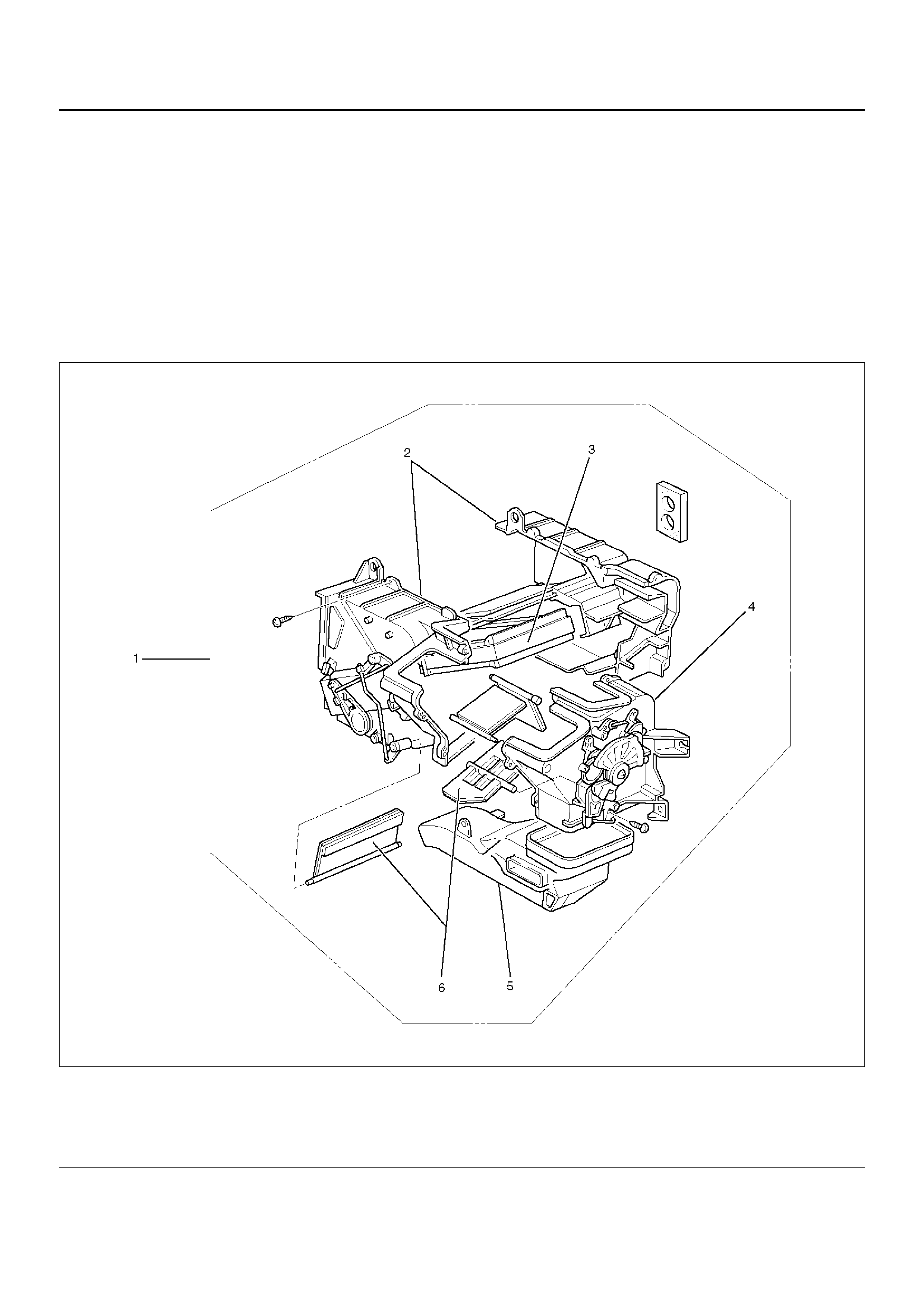
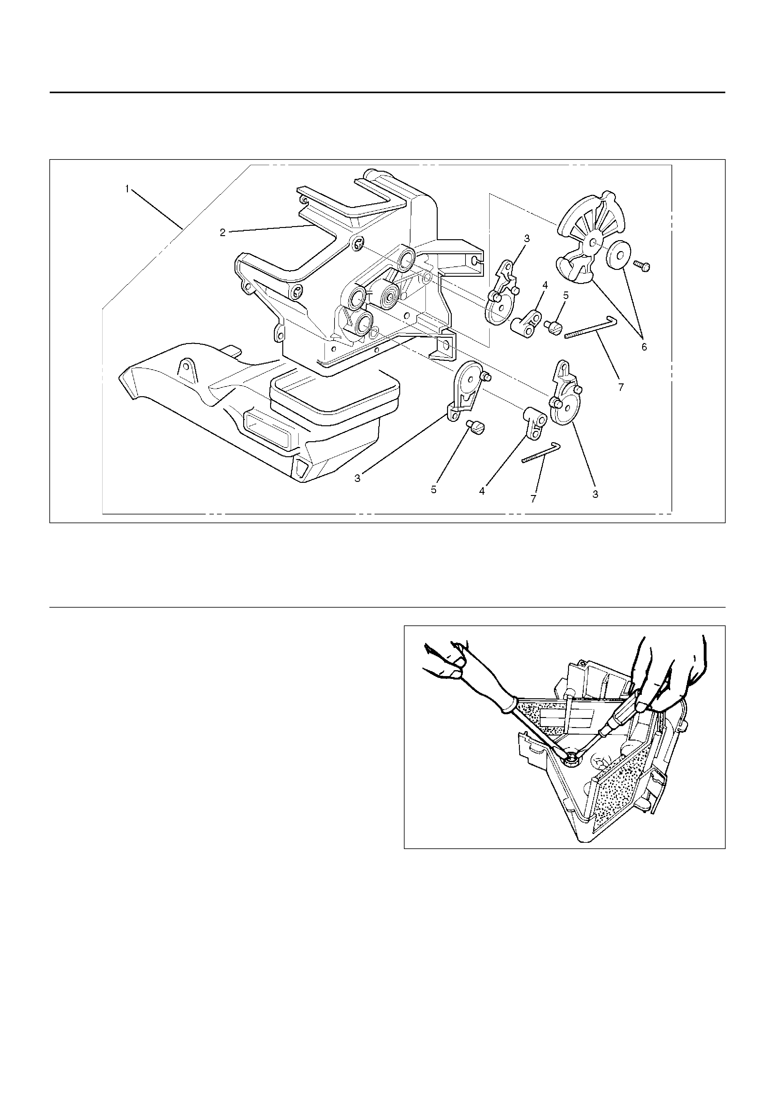
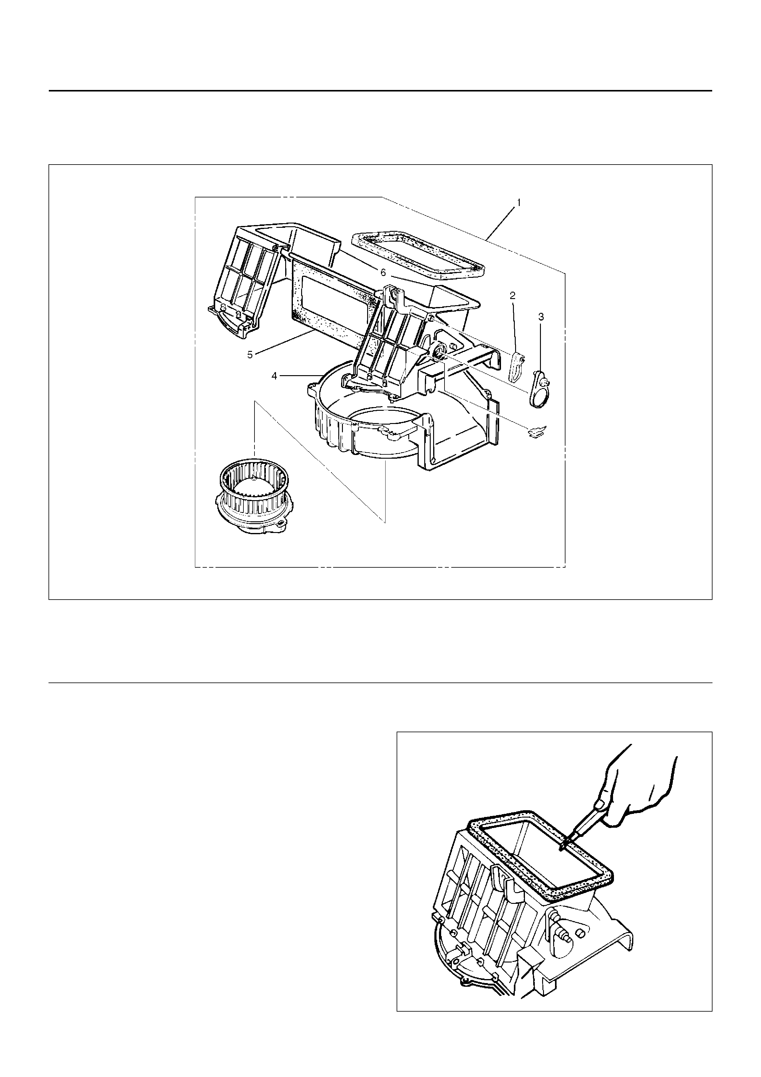
HEATER CORE AND / OR MODE DOOR
DISASSEMBLED VIEW
860RX002
EndOFCallout
Legend
(1) Heater Unit
(2) Case (Temperature Control)
(3) Heater Core
(4) Case (Mode Control)
(5) Duct
(6) Mode Door
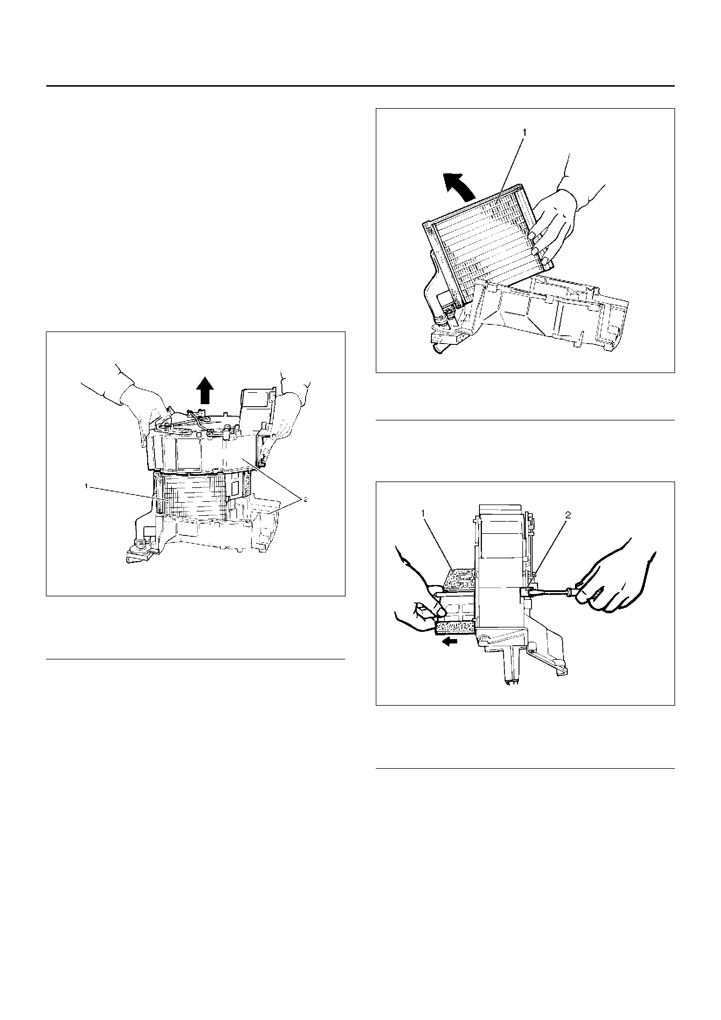
REMOVAL
1. Disconnect the battery ground cable.
2. Drain the engine coolant.
3. Discharge and recover refrigerant (with air
conditioning).
• Refer to Refrigerant Recovery in this section.4. Remove heater unit.• Refer to Heater Unit in this section.
5. Remove duct.
6. Remove case (Mode control) and do not remove
link unit at this step.
7. Remove case (Temperature control) and separate
two halves of core case.
860RW021
EndOFCallout
8. Remove heater core.
860RW020-1
EndOFCallout
9. Pull out the mode door while raising up the catch of
the door lever.
860RX004
EndOFCallout
INSPECTION
Check for foreign matter in the heater core, stain or the
core fin defacement.
INSTALLATION
To install, foll ow the removal ste ps in the reverse or der,
noting the foll owi ng poi nt:
1. Check that each mode door operates properly.
Legend
(1) Heater Core
(2) Core Case
Legend
(1) Heater Core
Legend
(1) Mode Door
(2) Door Lever
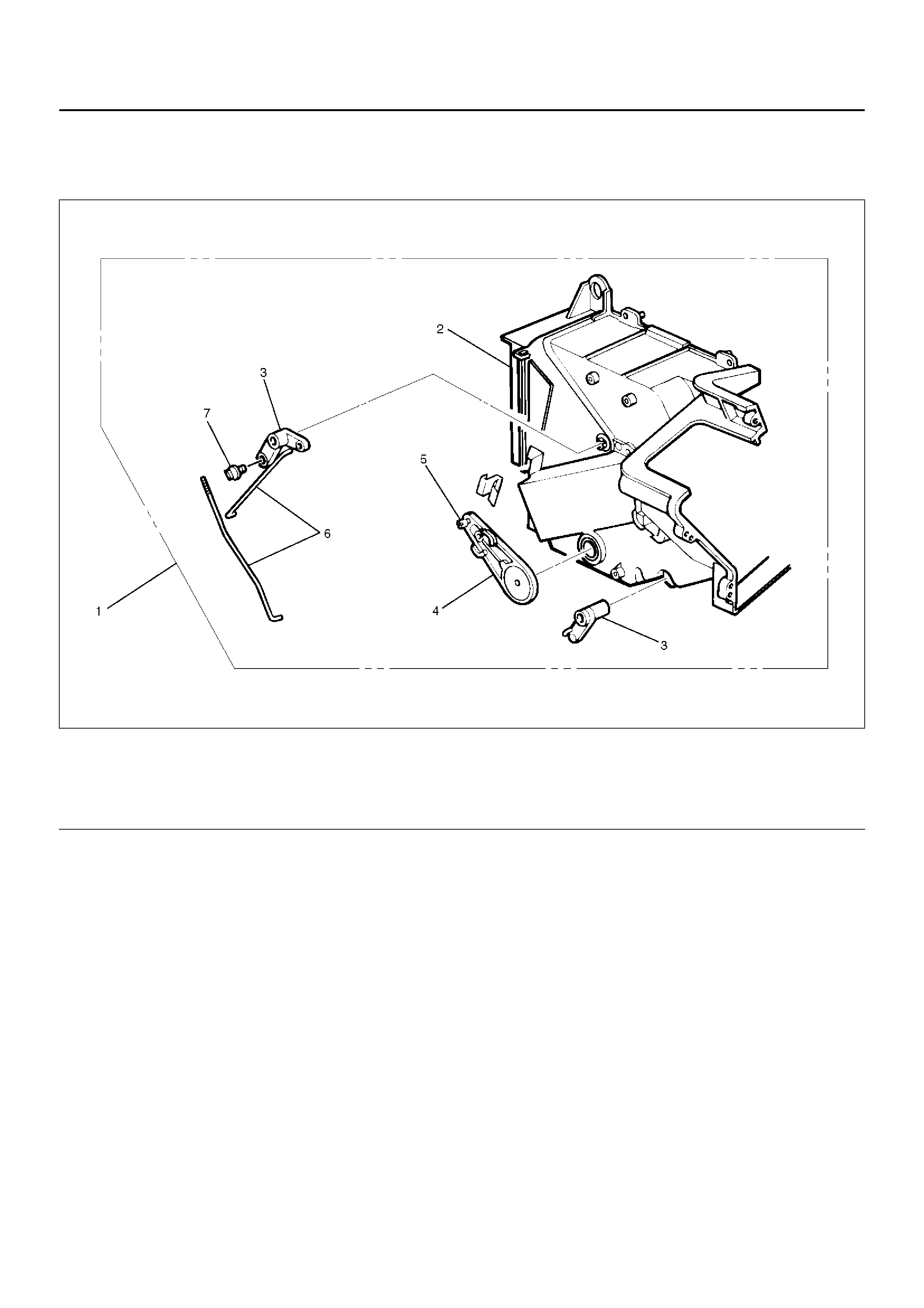
HEATER MODE CONTROL LINK UNIT
DISASSEMBLED VIEW
860RY00012
EndOFCallout
REMOVAL
1. Disconnect the battery ground cable.
2. Drain engine coolant.
3. Discharge and recover refrigerant (with air
conditioning)
• Refer to Refrigerant Recovery in this section.
4. Remove heater unit.• Refer to Heater Unit in this section.
5. Remove the case (Mode control) from heater unit.
6. Remove washer and the mode main lever.
7. Remove rod.
8. Press the tab of the sub-lever inward, and take out
the sub-lever.
860RW018
9. Pull out the door lever while raising up the catch of
the door lever.
10. Remove clip.
INSTALLATION
To install, follow the remove steps in the reverse order,
noting the foll owi ng poi nts:
1. Apply grease to the mode sub-lever and to the
abrasive surface of the heater unit.
2. After installing the link unit, check to see if the link
unit operates correctly.
Legend
(1) Heater Unit
(2) Case (Mode Control)
(3) Mode Sub Lever
(4) Door Lever
(5) Clip
(6) Washer and Mode Main Lever
(7) Rod
HEATER TEMPERATURE CONTROL LINK UNIT
DISASSEMBLED VIEW
860RX001
EndOFCallout
REMOVAL
1. Disconnect the battery ground cable.
2. Drain engine coolant.
3. Discharge and recover refrigerant (with air
conditioning).
• Refer to Refrigerant Recovery in this section.
4. Remove heater unit.
• Refer to Heater Unit in this section.
5. Remove the case (Temperature control) from the
heater unit.
6. Remove rod.
7. Remove sub-lever.
8. Pull out the door lever while raising up the catch of
the door lever.
9. Remove clip.
INSTALLATION
To install, foll ow the removal ste ps in the reverse or der,
noting the foll owi ng poi nts:
1. Apply grease to the sub-lever and to the abrasive
surface of the heater unit.
2. After installing the link unit, check to see if the link
unit operates correctly.
Legend
(1) Heater Unit
(2) Case (Temperature control)
(3) Door Lever
(4) Sub Lever
(5) Clip
(6) Rod
(7) Clip
BLOWER ASSEMBLY
BLOWER ASSEMBLY AND ASSOCIATED PARTS
840R100004
EndOFCallout
REMOVAL
1. Disconnect the battery ground cable.
2. Discharge and recover refrigerant (with air
conditioning).
• Refer to Refrigerant Recovery in this section.
3. Remove instrument panel assembly.• Refer to Instrument Panel Assembly in Body
structure section.
4. Disconnect resistor harness connector.5. Remove evaporator assembly.• Refer to Evaporator Assembly in this section.
6. Disconnect blower motor harness connector.
7. Remove blower assembly.
INSTALLATION
To install, foll ow the removal ste ps in the reverse or der,
noting the foll owi ng poi nt:
1. Adjust the control cables.• Refer to Control Lever Assembly in this section.
Legend
(1) Instrument Panel Assembly
(2) Blower Assembl y
(3) Blower Motor Harness Connector
(4) Resistor Harness Connector
(5) Heater Hose
(6) Heater Unit Assembly
(7) Evaporato r As se mbl y
(8) Rear Heater Duct
(9) Ventilation Lower Duct
(10) Instrument Pa nel Stay
(11) Cross Beam Assembly
BLOWER LINK UNIT AND / OR MODE DOOR
DISASSEMBLED VIEW
873RX002
EndOFCallout
REMOVAL
1. Disconnect the battery ground cable.
2. Discharge and recover refrigerant (with air
conditioning).
• Refer to Refrigerant Recovery in this section.
3. R emo ve blo wer assembly.
• Refer to Blower Assembly in this section.
4. R emo ve lower case .
5. Separate the upper case and slit the lining parting
face with a knife.
873RW006
Legend
(1) Blower Assembl y
(2) Door Lever
(3) S ub Lev er
(4) Lower Case
(5) Mode Door
(6) Upper Case

6. Pull out the mode door while raising up the catch of
door lever.
7. Remove sub-lever.
8. Remove door lever.
INSTALLATION
To install, f ollow the remova l st eps in the reverse order,
noting the following points:
1. Apply grease to the door lever and to the abrasive
surface of the upper case.
2. Apply an adhesive to the parting face of the lining
when assembling the upper case.
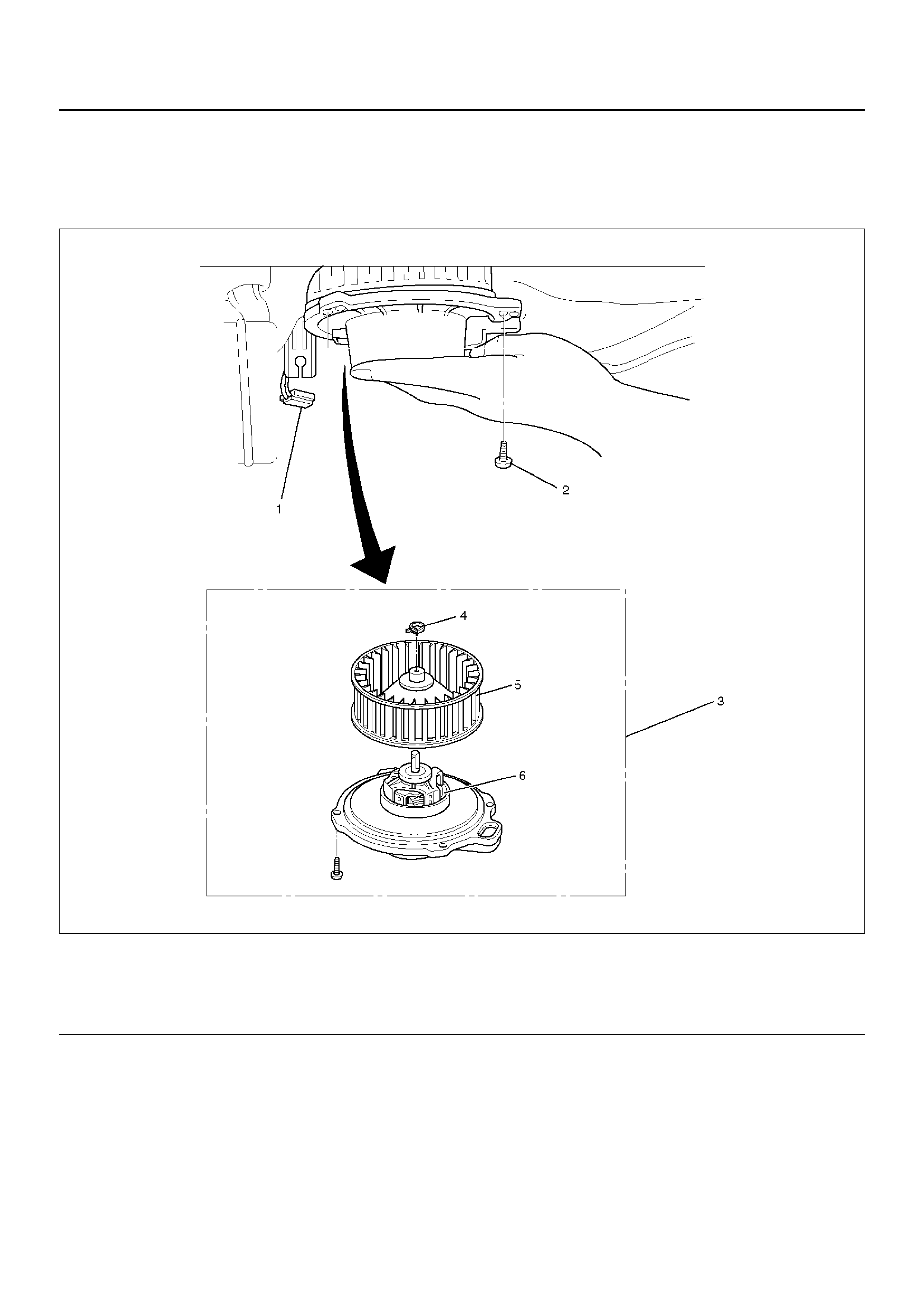
BLOWER MOTOR
BLOWER MOTOR AND ASSOCIATED PARTS
873RX001
EndOFCallout
REMOVAL
1. Disconnect the battery ground cable.
2. Remove blower motor connector.
3. Remove attaching screw.
4. Remove blower motor assembly.
5. Remove clip.
6. Remove fan.
7. Remove blower motor.
INSTALLATION
To install, follow the removal steps in the reverse order.
Legend
(1) Blower Motor Connector
(2) Attaching Screw
(3) Blower Motor Assembly
(4) Clip
(5) Fan
(6) Blower Motor
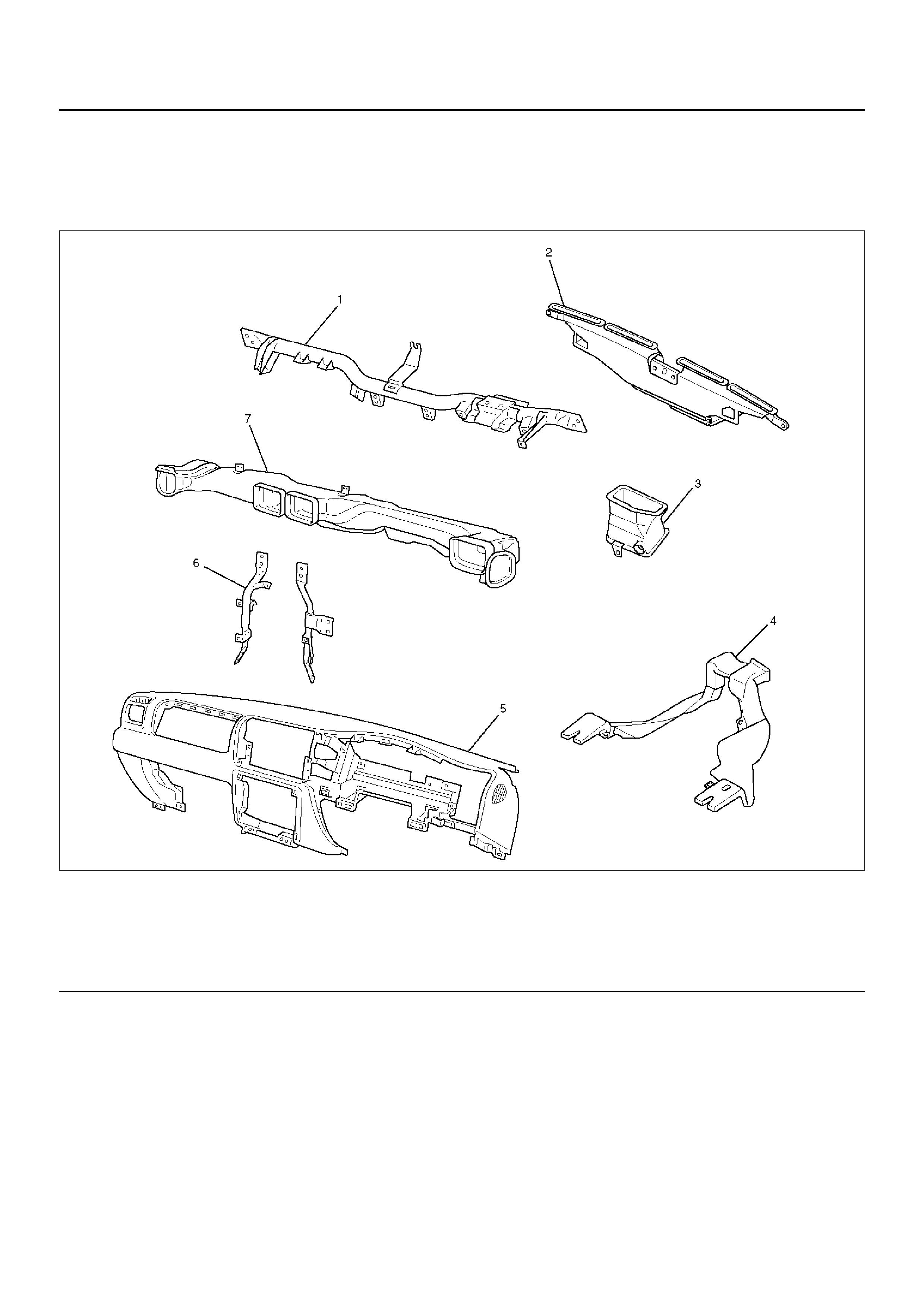
REAR HEATER DUCT, DEFROSTER NOZZLE AND VENTILATION DUCT
REAR HEATER DUCT, DEFROSTER NOZZLE, VENTILATION DUCT AND
ASSOCIATED PARTS
840RY00047
EndOFCallout
REMOVAL
1. Disconnect the battery ground cable.
2. Remove instrument panel assembly.
• Refer to Instrument Panel Assembly in Body
Structure section.
3. Remove center ventilation duct and side defroster
duct.
• Remove 5 screws.
4. Remove instrument panel Stay.
5. Remove cross beam assembly.
6. Remove ventilation lower duct.
7. Remove rear heater duct.
• Remove foot rest carpet and 3 clips.
8. Remove defroster nozzle.
INSTALLATION
To install, foll ow the removal ste ps in the reverse or der,
noting the foll owi ng poi nt:
1. Connect each duct and nozzle securely leaving no
clearance between them and making no improper
matching.
Legend
(1) Cross Beam Assembly
(2) Defroster Nozzle
(3) Ventilation Lower Duct
(4) Rear Heater Duct
(5) Instrument Pa nel Assemb ly
(6) Instrument Panel Stay
(7) Center Ventilation Duct and Side Defroster
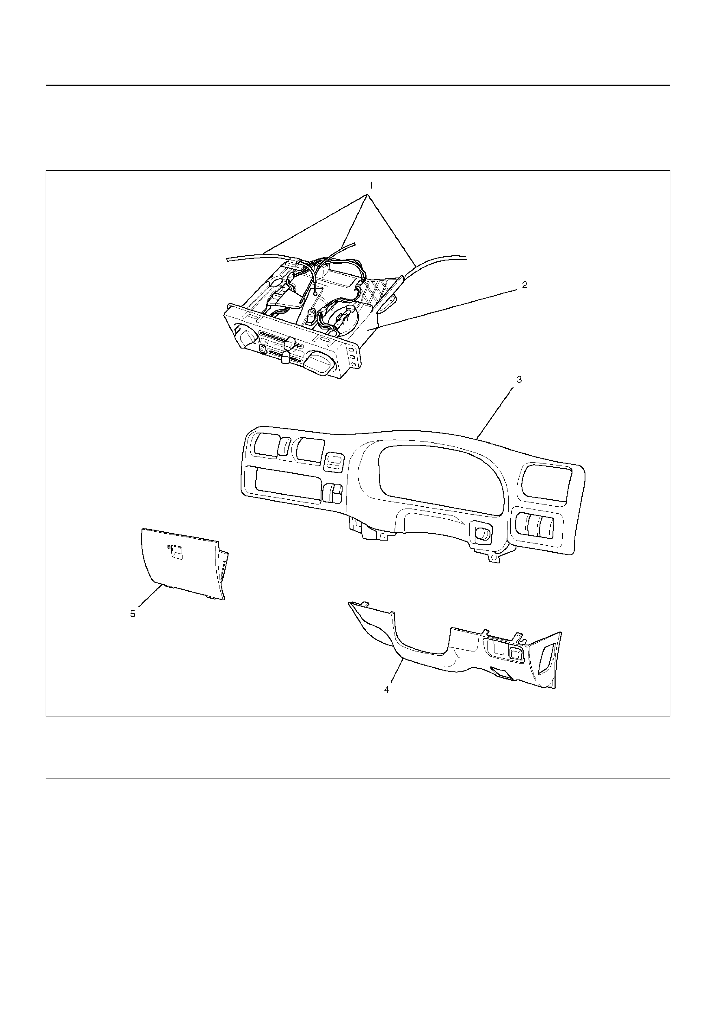
CONTROL LEVER ASSEMBLY AND / OR CONTROL CABLE
CONTROL LEVER ASSEMBLY, CONTROL CABLE AND ASSOCIATED PARTS
865RX009
EndOFCallout
Legend
(1) Control Cable
(2) Control Lever Assembly
(3) Meter Cluster Assembly
(4) Instrument Panel Driver Lower Cover Assembly
(5) Glove Box
REMOVAL
1. Disconnect the battery ground cable.
2. Remove instrument panel driver lower cover
assembly.
3. Remove meter cluster assembly.
• Refer to Instrument Panel Assembly in Body
Structure section.
4. Remove glove box.
5. Remove the control lever attaching screws.
6. Pull the control lever assembly out and disconnect
the fan switch and air conditioning switch
connectors.
865RX012
7. Remove control level assembly.
8. Disconnect control cables at each unit side.
865RX010
INSTALLATION
To install, foll ow the removal ste ps in the reverse or der,
noting the foll owi ng poi nts:
1. Adjust the control cable.
865RX013
• Air source control cable.
1 Slide the control lever to the left (“CIRC"
position).
2 Connect the control cable at the “CIRC"
position of the link unit of the blower
assembl y and se cu re it with the clip .
• Temperature control cable.
1 Turn the control knob to the left (“MAX COLD"
position).
2 Connect the control cable at the “COLD"
position of the temperature control link of the
heater unit and secure it with the clip.

• Ai r sele ct con tr ol cable
1 Turn the control knob to the right
(“DEFROST" position).
2 Connect the control cable at the “DEFROST"
position of the mo de con trol l ink of the hea ter
unit and secure it with the clip.
2. C hec k the con tr ol ca ble oper atio n.
CONTROL PANEL ILLUMINATION BULB
CONTROL PANEL ILLUMINATION BULB AND ASSOCIATED PARTS
865RX011
EndOFCallout
REMOVAL
1. Disconnect the battery ground cable.
2. Remove control lever assembly.
• Refer to Control Lever Assembly in this section.
3. Pull out the bulb socket from the panel by turning it
counterclockwise.
4. Pull the illumination bulb from the socket.
INSTALLATION
To install, follow the removal steps in the reverse order.
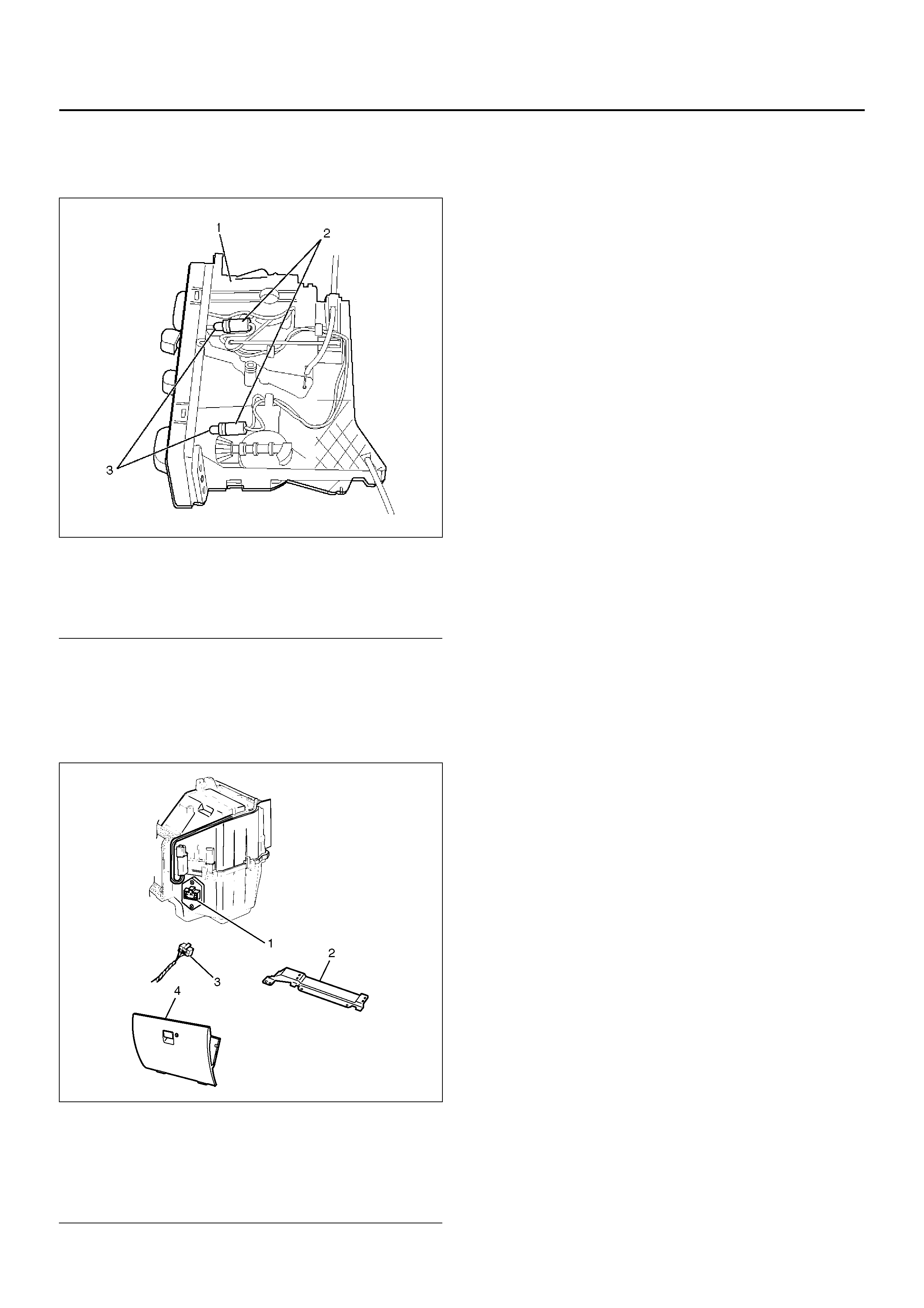
RESISTOR
RESISTOR AND ASSOCIATED
PARTS
840R100005
EndOFCallout
REMOVAL
1. Disconnect the battery ground cable.
2. Remove glove box.
• Remove the 2 inside clips.
3. Remove passenger knee bolster reinforcement.
4. Remove resistor harness connector.
5. Remove resistor.
INSTALLATION
To install, follow the removal steps in the reverse order.
Legend
(1) Control Lever Assembly
(2) Bulb Socket
(3) Il lu mi nati on Bulb
Legend
(1) Resistor
(2) P as se nge r Kne e Bol ster Rein for ceme n t
(3) Resistor Harness Connector
(4) Glove Box
AIR CONDITIONING SYSTEM
GENERAL DESCRIPTION
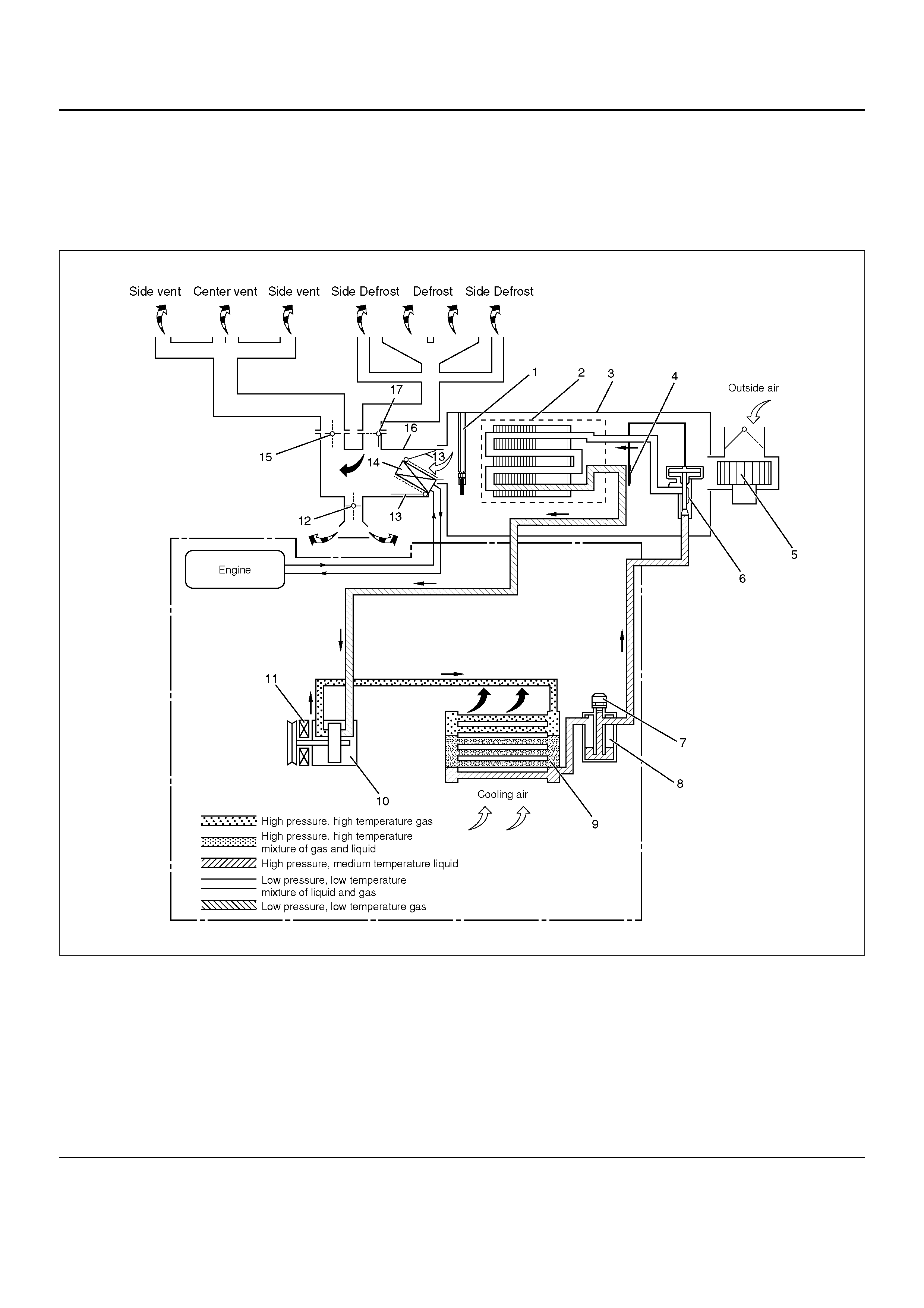
Air Conditioning Refrigerant Cycle Construction
C01RY00013
EndOFCallout
The refrigeration cycle includes the following four
processes as the refrigerant changes repeatedly from
liquid to gas and back to liquid while circulating.
Evaporation
The refrigerant is changed from a liquid to a gas inside
Legend
(1) Electronic Thermostat
(2) Evaporator Core
(3) Evaporator Assembly
(4) Temperature Sensor
(5) Blower Motor
(6) Expansion Valve
(7) Pressure Switch or Pressure Sensor
(8) Receiver/Drier
(9) Condenser
(10) Compressor
(11) Magnetic Clutch
(12) Mode (HEAT) Control Door
(13) Temp. Control Door (Air Mix Door)
(14) Heater Core
(15) Mode (VENT) Control Door
(16) Heater Unit
(17) Mode (DEF) Control Door
the evaporator. The refrigerant mist that enters the
evaporator vaporizes readily. The liquid refrigerant
removes the required quantity of heat (latent heat of
vaporization) from the air around the evaporator core
cooling fins and rapidly vaporizes. Removing the heat
cools the air, which is then radiated from the fins and
lowers the temperature of the air inside the vehicle.
The refrigerant liquid sent from the expansion valve and
the vaporized refrigerant gas are both present inside the
evaporator as the liquid is converted to gas.
With this change from liquid to gas, the pressure inside
the evaporator must be kept low enough for
vaporization to occur at a lower temperature. Because
of that, the vaporized refrigerant is sucked into the
compressor.
Compression
The refrigerant is compressed by the compressor until it
is easily liquefied at normal temperature.
The vaporized refrigerant in the evaporator is sucked
into the compressor. This action maintains the
refrigerant inside the evaporator at a low pressure so
that it can easily vaporize, even at low temperatures
close to 0°C (32°Φ).
Also, the refrigerant sucked into the compressor is
compressed inside the cylinder to increase the pressure
and temperature to values such that the refrigerant can
easily liquefy at normal ambient temperatures.
Condensation
The refrigerant inside the condenser is cooled by the
outside air and changes from gas to liquid.
The high temperature, high pressure gas coming from
the compressor is cooled and liquefied by the
condenser with outside air and accumulated in the
receiver/drier. The heat radiated to the outside air by the
high temperature, high pressure gas in the compressor
is called heat of condensation. This is the total quantity
of heat (heat of vaporization) the refrigerant removes
from the vehicle interior via the evaporator and the work
(calculated as the quantity of heat) performed for
compression.
Expansion
The expansion valve lowers the pressure of the
refrigerant liquid so that it can easily vaporize.
The process of lowering the pressure to encourage
vaporization before the liquefied refrigerant is sent to
the evaporator is called expansion. In addition, the
expansion valve controls the flow rate of the refrigerant
liquid while decreasing the pressure.
That is, the quantity of refrigerant liquid vaporized inside
the evaporator is determined by the quantity of heat
which must be removed at a prescribed vaporization
temperature. It is important that the quantity of
refrigerant be controlled to exactly the right value.
Compressor
The compressor performs two main functions:
It compresses low-pressure and low-temperature
refrigerant vapor from the evaporator into high-pressure
and high-temperature refrigerant vapor to the
condenser.
It pumps refrigerant and refrigerant oil through the air
conditioning system.
This vehicle is equipped with a five-vane rotary
compressor.
The specified amount of the compressor oil is 150cc
(5.0fl.oz.).
The oil used in the HFC-134a system compressor
differs from that used in R-12 systems.
Also, compressor oil to be used varies according to the
compressor model. Be sure to avoid mixing two or
more different types of oil.
If the wrong oil is used, lubrication will be poor and the
compressor will seize or malfunction.
The magnetic clutch connector is a waterproof type.
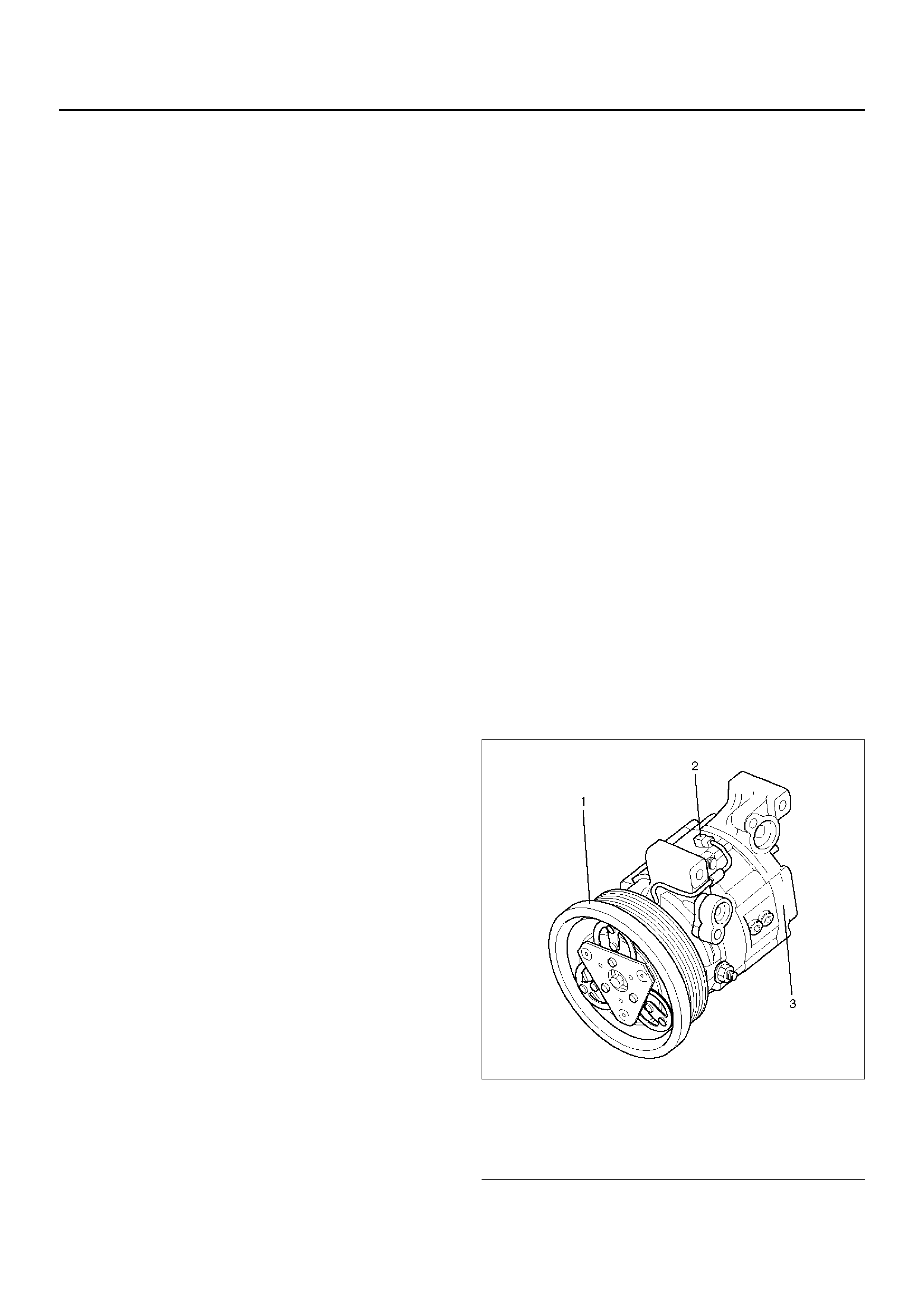
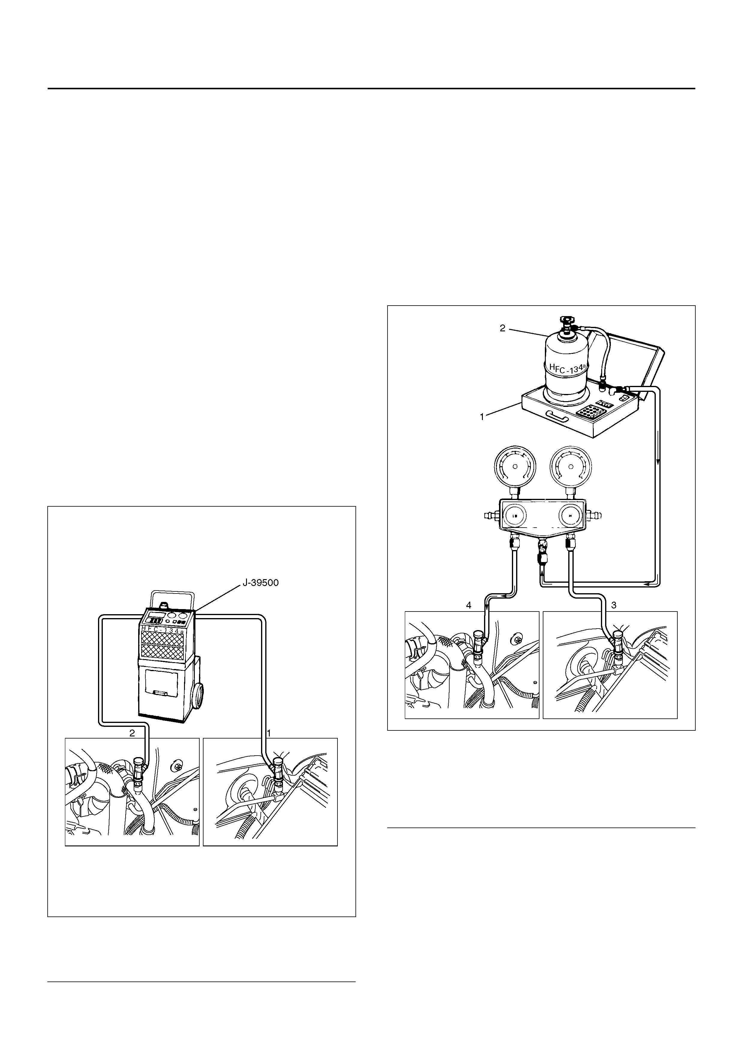
Magnetic Clutch
The compressor is driven by the drive belt from the
crank pulley of the engine. If the compressor is
activated each time the engine is started, this causes
too much load to the engine. The magnetic clutch
transmits the power from the engine to the compressor
and activates it when the air conditioning is ON. Also, it
cuts off the power from the engine to the compressor
when the air conditioning is OFF. Refer to Compressor
in this section for magnetic clutch repair procedure.
871RX026
EndOFCallout
Legend
(1) Magnetic Clutch
(2) Magnetic Clutch Harness Connector
(3) Compressor
Condenser
The condenser assembly is located in front of the
radiator. It provides rapid heat transfer from the
refrigerant to the cooling fins.
Also, it functions to cool and liquefy the high-pressure
and high-temperature vapor sent from the compressor
by the radiator fan or outside air.
A conden ser may m alfunction i n two ways: i t may leak ,
or it may be restricted. A condenser restriction will
res ult in excessive compressor discharge pressure. If a
partial restriction is present, the refrigerant expands
after passing through the restriction.
Thus, ice or frost may form immediately after the
restriction. If air flow through the condenser or radiator
is blocked, high discharge pressures will result. During
normal condenser operation, the refrigerant outlet line
will be slightly cooler than the inlet line.
The vehicle is equipped with the parallel flow type
condenser. A larger thermal transmission area on the
inner surface of the tube allows the radiant heat to
increase and the ventilation resistance to decrease.
The refrigerant line connection has a bolt at the block
joint, for easy servicing.
875R100001
EndOFCallout
Receiver / Drier
The receiver/drier performs four functions:
• As the quantity of refrigerant circulated varies
depending on the refrigeration cycle conditions,
sufficient refrigerant is stored for the refrigeration
cycle to operate smoothly in accordance with
fluctua tion s in the quan tit y circul ated .
• The l iquefied r efriger ant from th e conde nser is mixed
with refrigerant gas containing air bubbles. If
refrigerant containing air bubbles. If refrigerant
containing a ir bubble s is sen t to the expansi on valve ,
the cooling capacity will decrease considerably.
Therefore, the liquid and air bubbles are separated
and only the liquid is sent to the expansion valve.
• The receiver/d rier utilizes a filter and drier to remove
the dirt and water mixed in the cycling refrigerant.
• The sight glass, installed atop the receiver/drier,
show the state of the refrigerant.
A receiver/drier may fail due to a restriction inside the
body of th e unit. A res tricti on at the in let to the receive r/
drier will cause high pressure.
Outle t restric tions will be indica ted by low pressur e and
little or no cooling. An excessively cold receiver/drier
outlet may indicate a restriction.
The receiver/drier of this vehicle is made of aluminum
with a smaller tank. It has a 300cc refrigerant capacity.
The refrigerant line connection has a bolt at the block
joint, for easy servicing.
Dual Pressure Swit c h (V 6,M /T)
The pressure switch (Dual pressure switch) is installed
on the upper part of the receiver/drier, to detect
excessively high pressure (high pressure switch) and
prevent compressor seizure due to the refrigerant
leaki ng (low pr es su re sw itch ), so that th e compres sor is
able to be turned “ON" or “OFF".
Triple Pr ess ure Swit ch (V 6, A/T)
Triple pressure switch is installed on the upper part of
the receiver/drier. This switch is constructed with a
unitiz ed type of two switch es. One o f them is a lo w and
high pressure switch (Dual pressure switch) to switch
“ON" or “OFF" the magnetic clutch as a result of
irregularly high-pressure or low pressure of the
refrige ra nt. The other one is a med ium pressure switch
(Cycling switch) to switch “ON" or “OFF" the condenser
fan sensi ng the con den se r hig h side pres sur e.
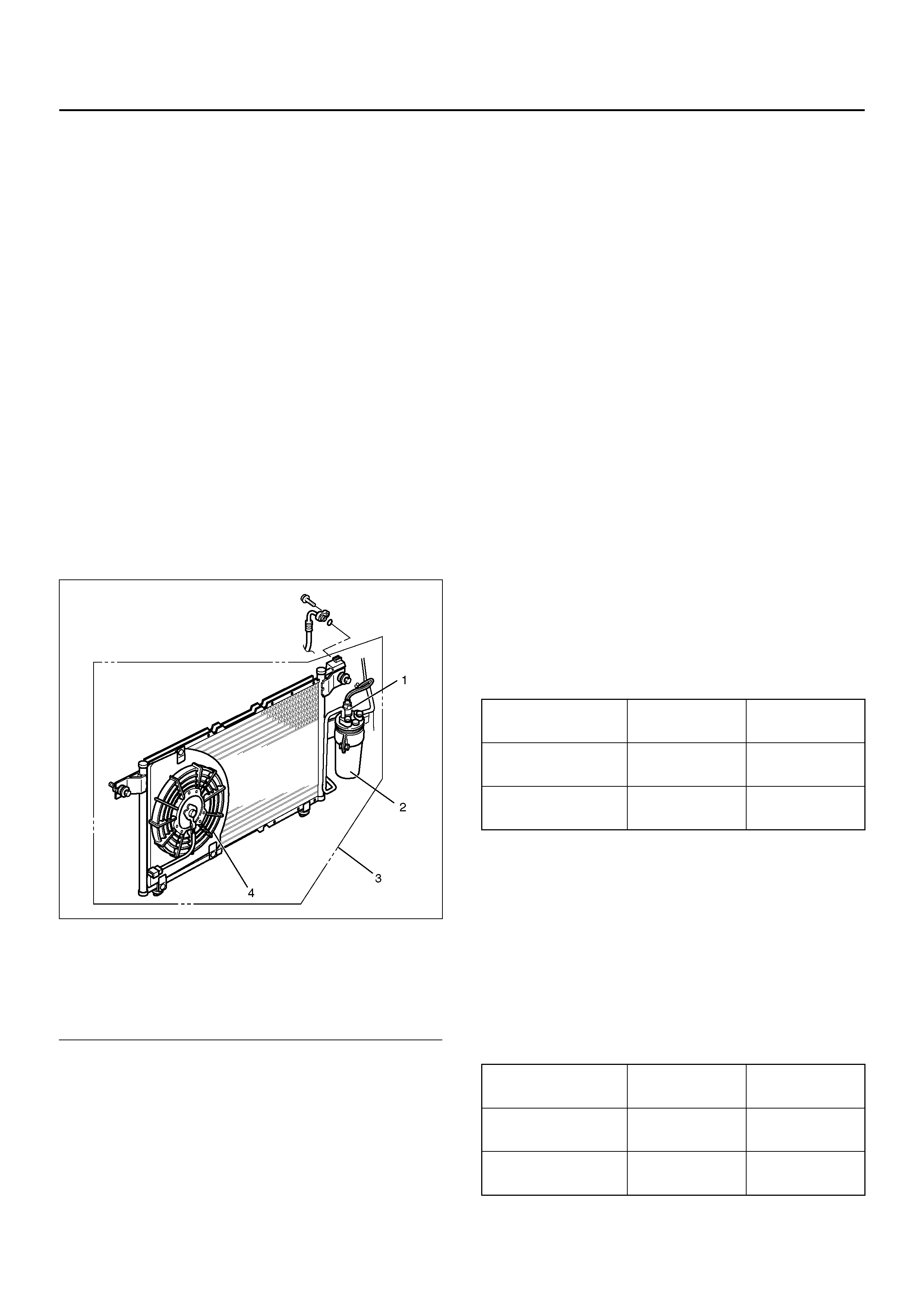
Legend
(1) Pressure Switch
(2) Receiver/Drier
(3) Condenser & Receiver Tank Assembly
(4) Condenser Fan (6VD1 A/T)
Compressor ON
(kPa/psi) OFF
(kPa/psi)
Low-pressure
control 186.3±29.4
(27.0±4.3) 176.5±19.6
(25.6±2.8)
High-pressure
control 2350.4±196.1
(340.7±28.4) 2942.0±196.1
(426.6±28.4)
Compressor ON
(kPa/psi) OFF
(kPa/psi)
Low-pressure
control 186.3±29.4
(27.0±4.3) 176.5±24.5
(25.6±3.6)
High-pressure
control 2353.6±196.1
(341.3±28.4) 2942.0±196.1
(426.6±28.4)
Expansion Valve
This expansi on v alve i s an ext er nal pres sur e type and i t
is installed at the evaporator intake port.
The expansion valve converts the high pressure liquid
refrigerant sent from the receiver/drier to a low pressure
liquid refrigerant by forcing it through a tiny port before
sending it to the evaporator.
This type of expansion valve consists of a temperature
sensor, diaphragm, ball valve, ball seat, spring
adjustment screw, etc.
The temperature sensor contacts the evaporator outlet
pipe, and co nverts changes in tem perature to pres sure.
It then transmits these to the top chamber of the
diaphragm.
The refrigerant pressure is transmitted to the
diaphragm's bottom chamber through the external
equalizing pressure tube.
The ball valve is connected to the diaphragm. The
opening angle of the expansion valve is determined by
the force acting on the diaphragm and the spring
pressure.
The expansion valve regulates the flow rate of the
refrigerant. Accordingly, when a malfunction occurs to
this expansion valve, both discharge and suction
pressure get low, resulting in insufficient cooling
capacity of the evaporator.
The calibration has been changed to match the
characteristics of HFC-134a.
874RY00023
EndOFCallout
Evaporator
The evaporator cools and dehumidifies the air before
the air enters the passenger compartment.
High-pressure liquid refrigerant flows through the
expansion valve into the low-pressure area of the
evaporator. The heat in the air passing through the
evapor ator core is lost to the coo ler sur face o f the cor e,
thereby cooling the air.
As h eat is l ost bet ween the air a nd the evaporator core
surface, moisture in the vehicle condenses on the
outside surface of the evaporator core and is drained off
as water.
When the evaporator malfunctions, the trouble will show
up as an inadequate supply of cool air. The cause is
typically a partially plugged core due to dirt, or a
malfunc ti oning blo w er motor.
The evaporator core with a laminate louver fin is a
single-sided tank type where only one tank is provided
under the cor e .
874RY00022
EndOFCallout
Electronic Thermostat (With Manual A/C)
The thermostat consists of the thermo sensor and
thermostat unit which functions electrically to reduce the
noises being generated while the system is in operation.
The electronic thermo sensor is mounted at the
evaporator core outlet and senses the surface
temperature of the evaporator core. Temperature
signa ls are in put to the th ermos tat unit . Th is in formation
is compared by the thermo unit and results in the output
to operate the A/C thermostat relay and turn the
magnetic clutch ON or OFF to prevent evaporator
freeze-up.
A characteristic of the sensor is that the resistance
Condenser fan ON
(kPa/psi) OFF
(kPa/psi)
Medium-pressure
control 1471.0±98.1
(213.3±14.2) 1078.7±117.7
(156.4±17.1)
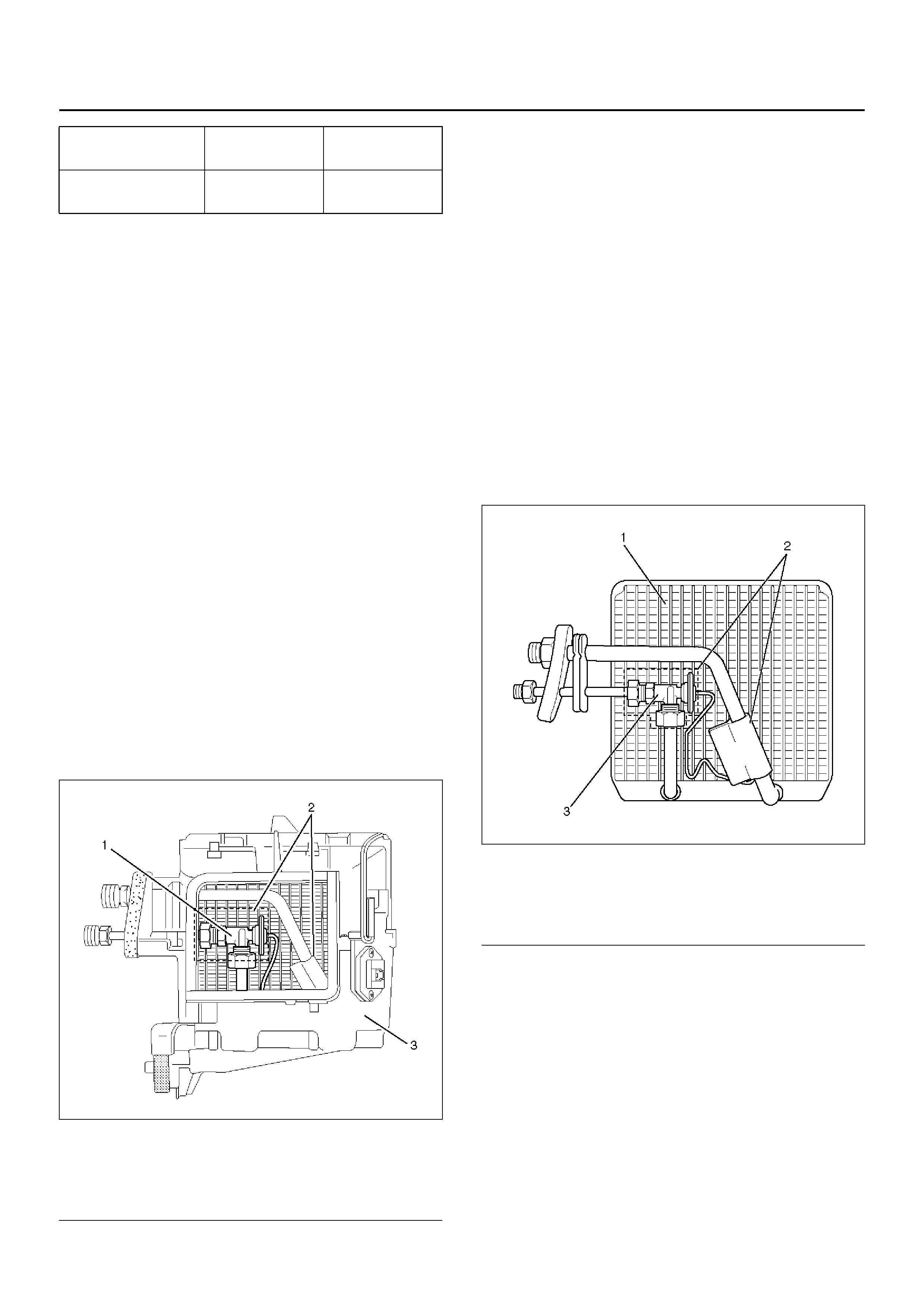
Legend
(1) Expansion Valve
(2) Insulator
(3) Evaporator Assembly
Legend
(1) Evaporato r Core
(2) Insulator
(3) Expansion Valve
decreases as the temperature increases and the
resistance increases as the temperature decreases.
874RX008
EndOFCallout
Refrigerant Line
Restriction in the refrigerant line will be indicated by:
1. Suction line — A restricted suction line will cause
low suction pressure at the compressor, low
discharge pressure and little or no cooling.
2. Discharge line — A restriction in the discharge line
generally will cause the discharge line to leak.
3. Liquid line — A liquid line restriction will be
evidenced by low discharge and suction pressure
and insufficient cooling.
Refrigerant flexible hoses that have a low permeability
to refrigerant and moisture are used. These low
permeability hoses have a special nylon layer on the
inside.
852RS001
EndOFCallout
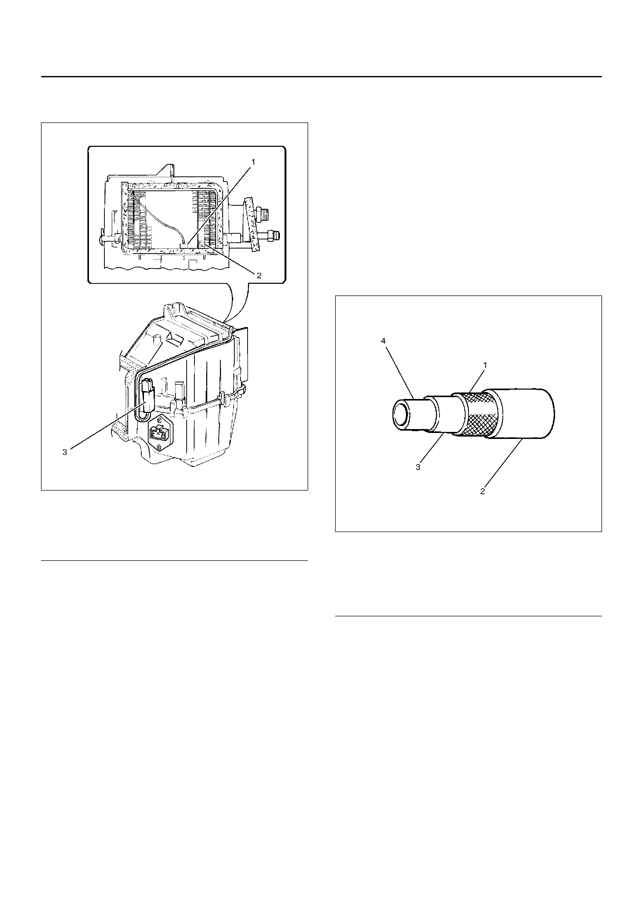
Legend
(1) Sensor Part
(2) Evaporator Core
(3) Thermostat Assembly Legend
(1) Reinforcement Layer (Polyester)
(2) External Rubber Layer
(3) Internal Rubber Layer
(4) Resin Layer (Nylon)
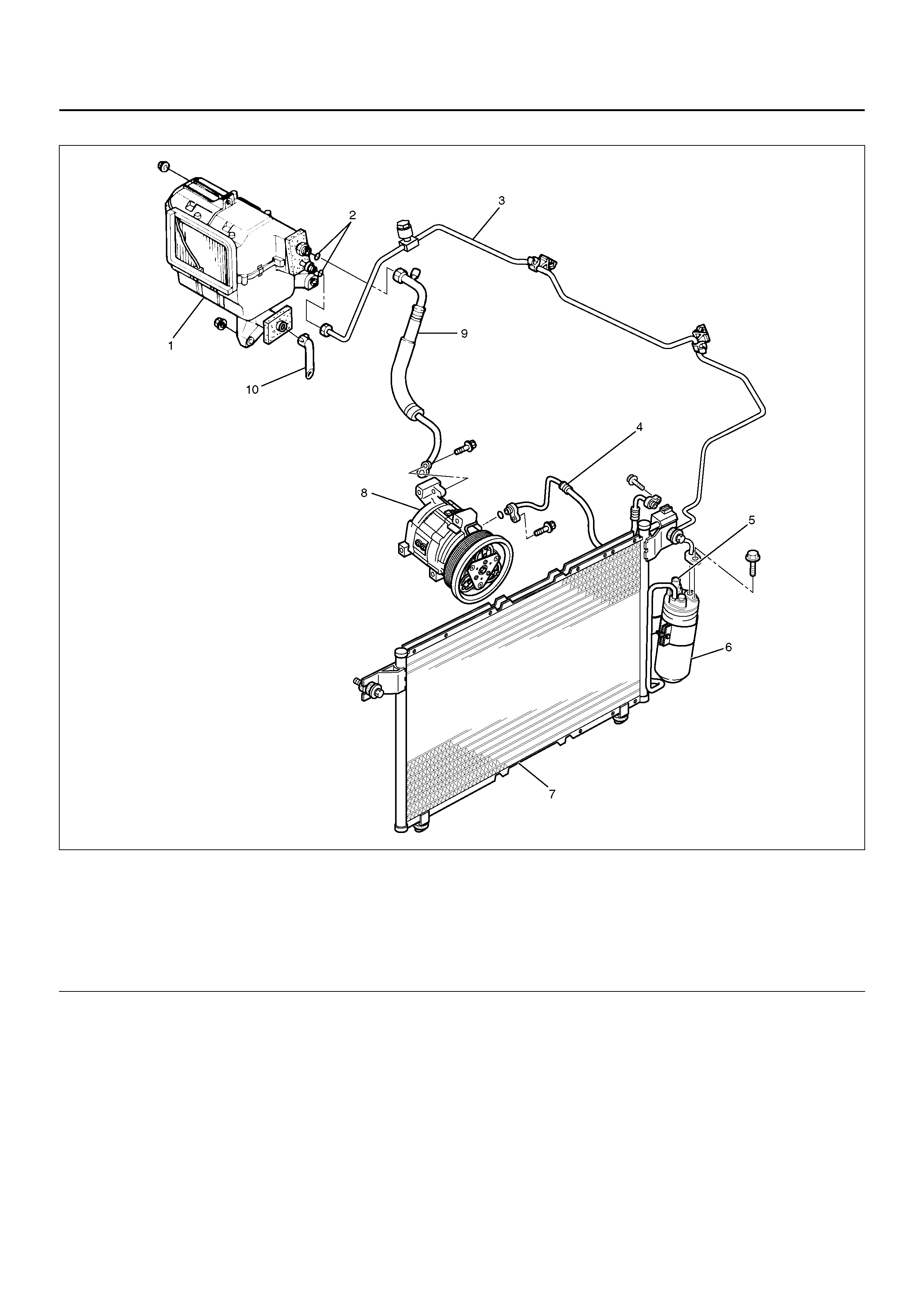
Refrig erant Line Associated Parts
852R100006
EndOFCallout
Legend
(1) Evaporator Assembly
(2) O-Ring
(3) Liquid Line (High Pressure Pipe)
(4) Discharge Line (High Pressure Hose)
(5) Pressure Switch
(6) Receiver Drier
(7) Condense r As se mbl y
(8) Compressor
(9) Suction Line (Low – Pressure Hose)
(10) Drain Hose
CIRCUIT DIAGRAM
D08R100096
D08R100097
DIAGNOSIS
Air Conditioning Cycle Diagnosis
*For the execution of the charging and discharging
operation in the table above, refer to Recovery,
Recycling, Evacuating and Charging in this section.
Condition Possible cause Correction
No cooling or insufficient cooling. Magnetic clutch does not run. Refer to “Magnetic Clutch
Diagnosis" in this section.
Compressor is not rotating properly.
Drive belt is loosened or broken. Adjust the drive belt to the specified
tension or replace the drive belt.
Compressor is not rotating properly.
Magnetic clutch face is not clean
and slips.
Clean the magnetic clutch face or
replace.
Compressor is not rotating properly.
Incorrect clearance between
magnetic drive plate and pulley.
Adjust the clearance. Refer to
Compressor in this section.
Compressor is not rotating properly.
Compressor oil leaks from the shaft
seal or shell.
Replace the compressor
Compressor is not rotating properly.
Compressor is seized.Replace the compressor
Insufficient or excessive charge of
refrigerant. Discharge and recover the
refrigerant. Recharge to the
specified amount.
Leaks in the refrigerant system. Check the refrigerant system for
leaks and repair as necessary.
Discharge and recover the
refrigerant. Recharge to the
specified amount.
Condenser is clogged or insufficient
radiation. Clean the condenser or replace as
necessary.
Temperature control link unit of the
heat unit is defective.Repair the link unit.
Unsteady operation due to a foreign
substance in the expansion valve. Replace the expansion valve.
Poor operation of the electronic
thermostat.Check the electronic thermostat and
replace as necessary.
Insufficient velocity of cooling air. Evaporator clogged or frosted. Check the evaporator core and
replace or clean the core.
Air leaking from the cooling unit or
air duct.Check the evaporator and duct
connection, then repair as
necessary.
Blower motor does not rotate
properly.Refer to Fan Control Lever (Fan
Switch) Diagnosis in this section.
Checking The Refrigerant System Wit h Manifold Gauge
Since R ef riger ant -134a ( HFC -134 a) is use d in the air
conditioning system in this vehicle, be sure to
use manifold gauges, charging hoses and other air
conditioning service tools for HFC-134a when
checking the refrigerant system.
Conditions:
• Run the engine at Idling
• Air conditioning switch is “ON"
• Run the blower motor at “HIGH" position
• Temperature control lever set to “MAX COLD"
• Air source selector lever at “CIRC"
• Open the engine hood
• Clos e all the doo rs
• At ambient temperature: approx. 25–30°C (77–86°F).
Normal Pressure:
• At low-pressure side: approx. 147.1–294.2 kPa
(21.3–4 2.7 psi).
• At high-pressure side: approx. 1372.9–1863.3 kPa
(199.1–270.2 psi).
Refer to the table on the refrigerant
pressu re -t emp era ture re lat ion ship.
HFC-134a Pressure-Temperature Relationship
Pressure Temperature
(kPa) (psi) (°C) (°F)
36 5.3 –20 –4.4
67 9.7 –15 5
104 15 –10 14
147 21 –5 23
196 28 0 32
255 37 5 41
314 45 10 50
392 57 15 59
471 68 20 68
569 82 25 77
677 98 30 86
785 114 35 95
912 132 40 104
1059 154 45 113
1216 176 50 122
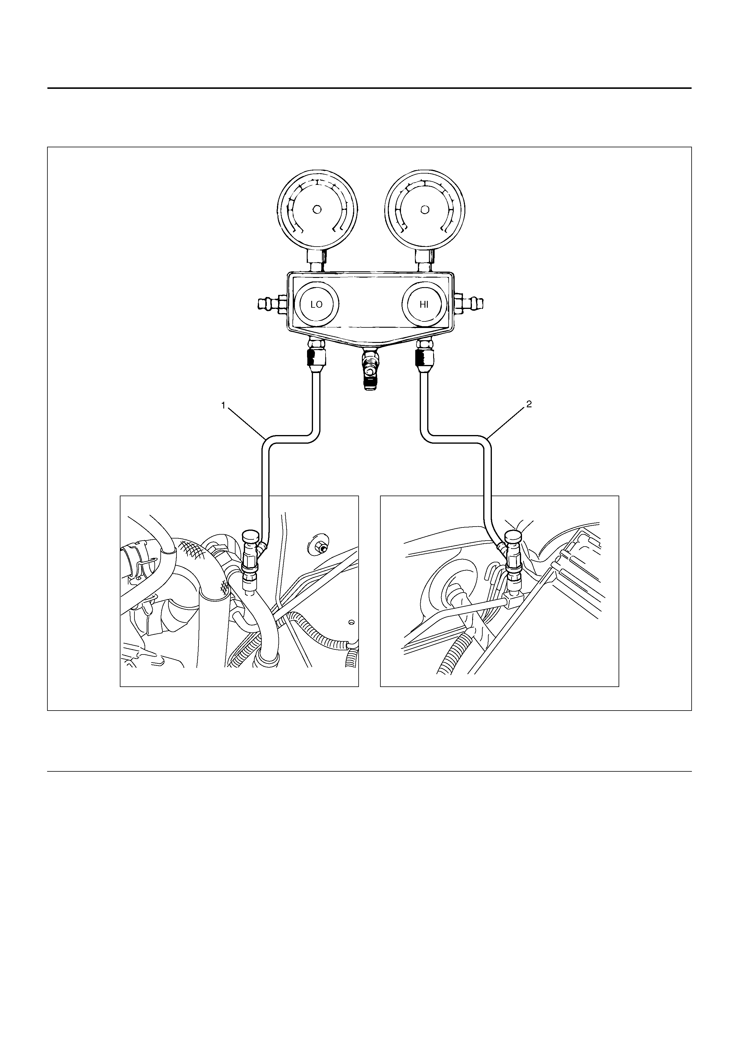
Connect The Manifold Gauge
Low-pressure hose (LOW) — Suction side
High pressure hose (HI) — Discharge side
901R100032
EndOFCallout
Legend
(1) Low Side
(2) H i gh Side
Condition Possible cause Correcti on
Discharge (High Gauge) Pressure
Abnormally High Condenser clogged or dirty. Clean the condenser fins
Cooling fan does not operate
properly. Check the cooling fan operation.
Discharge (High Gauge) Pressure
Abnormally High.
Insufficient cooling.
Excessive refrigerant in system. Discharge and recover refrigerant.
Recharge to specified amount.
Discharge (High Gauge) Pressure
Abnormally High.
High pressure gauge drop . (After
stopping A/C, the pressure drops
approx. 196kPa (28psi) quickly)
Air in system. Evacuate and charge refrigerant
system.
Discharge (High Gauge) Pressure
Abnormally Low.
Insufficient cooling
Insufficient refrigerant in system. Check for leaks. Discharge and
recover the refrigerant. Recharge to
the specified amount.
Discharge (High Gauge) Pressure
Abnormally Low.
Low pressure gauge indicates
vacuum.
Clogged or defective expansion
valve. Replace the expansion valve.
Discharge (High Gauge) Pressure
Abnormally Low.
Frost or dew on refrigerant line
before an d after th e receiv er/dri er or
expansion valve, and low pressure
gauge indicates vacuum.
Restriction caused by debris or
moisture in the receiver/drier. Check system for restriction and
replac e the rece iv er /drie r.
Discharge (High Gauge) Pressure
Abnormally Low.
High and low pressure gauge
bala nced quick ly. (After turned off A/
C)
Compressor seal defective Repair or replace the compressor.
Poor compression due to a defective
compressor gasket. Repair or replace the compressor.
Suction (Low Gauge) Pressure
Abnormally High.
Low pressure gauge (Low pressure
gauge is lowered after condenser is
cooled by water.)
Excessive refrigerant in system. Discharge and recover refrigerant
Recharge to specified amount.
Suction (Low Gauge) Pressure
Abnormally High.
Low pressure hose temperature.
(Low pressure hose temperature
around the compressor refrigerant
line connector is lower than around
evaporator.)
Unsatisfactory valve operation due
to defective temperature sensor of
expansion valve.
Replace the expansion valve.
Expansion valve opens too long. Replace the expansion valve.
Suction (Low Gauge) Pressure
Abnormally High.
High and low pressure gauge
bala nced quick ly. (After turned off A/
C)
Compressor gasket is defective. Repair or replace the compressor.
Suction (Low Gauge) Pressure
Abnormally Low.
Insufficient cooling.
Insufficient refrigerant in system. Check for leaks. Discharge and
recover the refrigerant. Recharge to
specified amount.
Suction (Low Gauge) Pressure
Abnormally Low.
Frost on the expansion valve inlet
line
Expansion valve clogged. Replace the expansion valve.
A/C — Air Conditioning
Suction (Low Gauge) Pressure
Abnormally Low
Receiver/drier inlet and outlet
refrigerant line temperature. (A
distinct difference in temperature
develops.)
Receiver/Drier clogged. Replace the receiver/drier.
Suction (Low Gauge) Pressure
Abnormally Low.
Expansion valve outlet refrigerant
line. (Not cold and low pressure
gauge indicates vacuum.)
Expansion valve temperature
sensor is defective. Replace the expansion valve.
Suction (Low Gauge) Pressure
Abnormally Low.
When the refrigerant line is clogged
or blocked, the low pressure
gauge reading will decrease, or a
vacuum reading may be shown.
Clogged or blocked refrigerant line. Replace refrigerant line.
Suction (Low Gauge) Pressure
Abnormally Low.
Evaporator core is frozen.
Thermo switch defective. Replace thermo switch.
Suction (Low Gauge) and Discharge
(High Gauge) Pressure Abnormally
High.
Insufficient cooling.
Excessive refrigerant in system. Discharge and recover the
refrigerant, the Recharge to the
specified amount.
Condenser clogged or dirty. Clean the condenser fin.
Suction (Low Gauge) and Discharge
(High Gauge) Pressure Abnormally
High.
Suction (Low) pressure hose (Not
cold).
Air in system. Evacuate and charge refrigerant.
Suction (Low Gauge) and Discharge
(High Gauge) Pressure Abnormally
Low.
Insufficient cooling
Insufficient refrigerant in system. Check for leaks. Discharge and
recover refrigerant. Recharge to
specified amount.
Condition Possible cause Correcti on

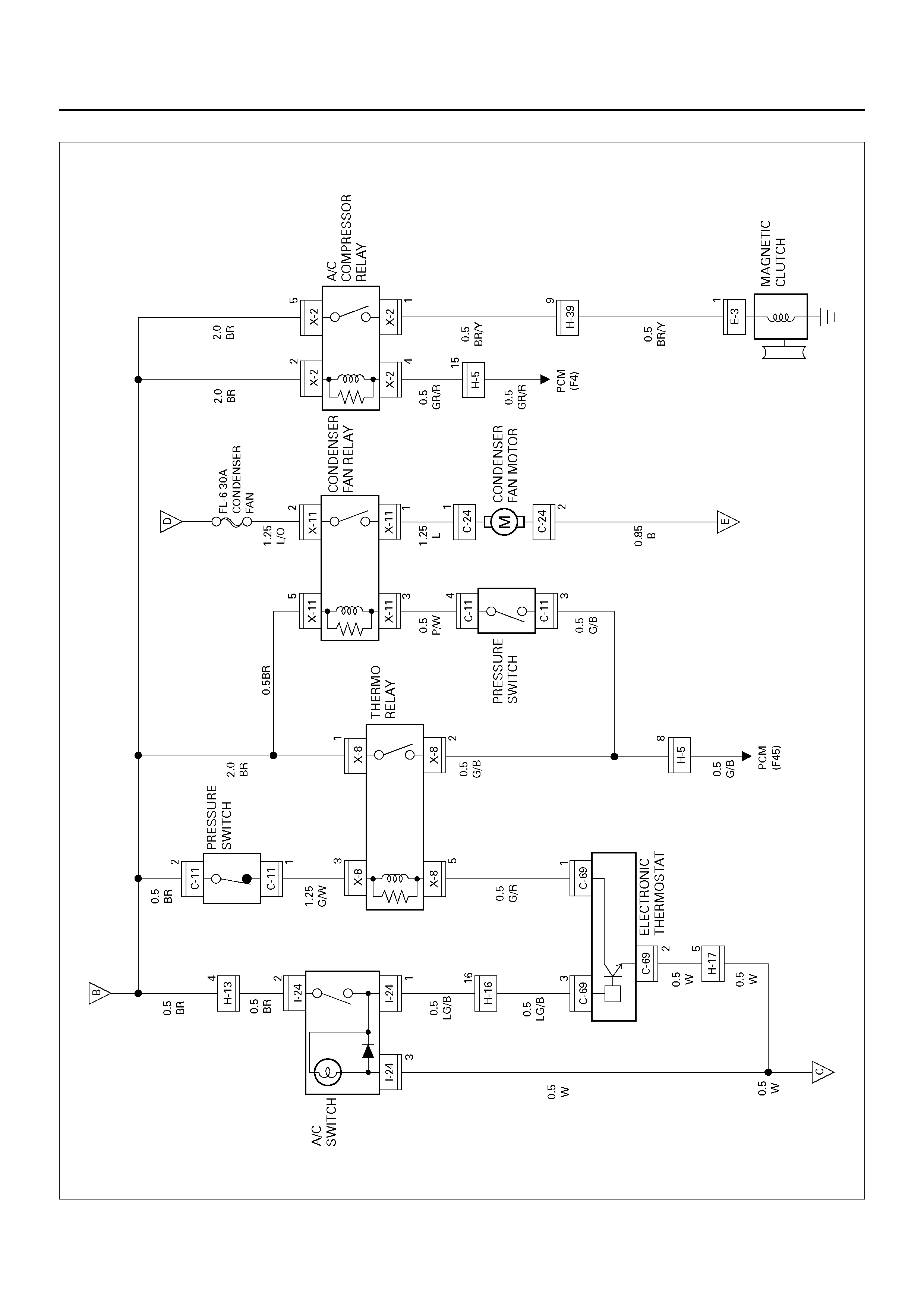
Magnetic Clutch Diagnosis
D08R100144
When the air conditioning switch and the fan control
knob (fan switch) are turned on with the engine running, current flows through the thermostat and the
compressor relay to activate the magnetic clutch.
The air conditioning can be stopped by turning of the air
conditioning switch or the fan control knob (fan switch).
However, even when the air conditioning is in operation,
the electronic thermostat, the pressure switch or the
Powertrain Control Module (PCM;V6-3.2L) is used to
stop the air conditioning temporarily by turning off the
magnetic clutch in the prearranged conditions to reduce
the engine load which is being caused by the rise in
the engine coolant temperature, and the acceleration of
the vehicle, etc.
For the inspection of the relays, switches and units in
the table, refer to “Individual Inspection" in this section.
Magnetic Clutch Does Not Run
Step Action Value(s) Yes No
1 Is the fuse No. F-5 normal? — Go to Step 2 Replace the
fuse
2 Is the relay No.X-1 (heater relay). No .X-8 (Thermo stat
relay) and No.X-2 (compressor relay) normal? — Go to Step 3 Replace the
relay
3 Is pressure switch normal? — Go to Step 4 Place the
pressure
switch.
4 Is the air condit ion er sw itch and the fan control switc h
normal? — Go to Step 5 Replace the A/
C switch and
fan control
switch
5 1. Turn the ignition switch “ON" (the engine is run).
2. Turn the air conditioner s witch and the fan control
swit ch on.
Is the battery voltage applied between harness side
connector terminal No.E3-1 and ground?
Approx.12V Go to Step 6 Go to Step 7
6 Repair an open circuit between compressor side
terminal and ground or replace compressor.
Is the action complete?
—Varify repair —
7 Is there continuity between harness side connector
terminal No.X2-1 and No.E3-1? — Go to Step 9 Go to Step 8
8 Repair an open circuit between terminal No.X2-1 and
No.E3-1.
Is the action complete?
— Go to Step 7 —
9 Is the battery voltage applied between harness side
connec tor termina l No.X2-2 and g round, No.X2-5 an d
ground?
Approx.12V Go to Step 11 Go to Step 10
10 Repair and open circuit between terminal No.X2-2 and
No.F-5 fuse, No.X2-5 and No.F-5 fuse.
Is the action complete?
— Go to Step 9 —
11 Is there continuity between harness side connector
terminal No.X2-4 and No.E21-F4? — Go to Step 13 Go to Step 12
12 Repair an open circuit between terminal No.X2-4 an d
No.E21-F4.
Is the action complete?
— Go to Step 11 —
13 Is the battery voltage applied between harness side
connector terminal No.I24-2 and ground? Approx.12V Go to Step 15 Go to Step 14
14 Repair an open circuit between term inal No.I24-2 an d
No.F-5 fuse.
Is the action complete?
— Go to Step 13 —
15 Is the battery voltage applied between harness side
connector terminal No.C69-3 and ground? Approx.12V Go to Step 17 Go to Step 16
Magnetic Clutch Does Not Run (Cont’s)
CAUTION: There are condition whitch air
conditioner system does not operate except trouble
as follows.
1. The throttle is greater than 90%.
2. The ignition voltage is below 10.5 volts.
3. The engine speed is greater than 4500 RPM for 5
seconds or 5400 RPM.
4. The engine coolant temperature (ECT) is greater
than 125°C (257°F).
5. The intake air temperature (IAT) is less than 5°C
(41°F).
6. The power steering pressure switch signals a high
pressure condition.
Step Action Value(s) Yes No
16 Repair an open circuit between terminal No.C69-3
and No.I24-1.
Is the action complete?
— Go to Step 15 —
17 Is there continuity between harness side connector
terminal No.I23-6 and No.C69-2? — Go to Step 19 Go to Step 18
18 Repair an open circuit between term inal No.I23-6 an d
No.C69-2.
Is the action complete?
— Go to Step 17 —
19 Is there continuity between harness side connector
terminal No.I23-1 and ground (No.B-8)? — Go to Step 21 Go to Step 20
20 Repair an open circuit between term inal No.I23-1 an d
No.B-8.
Is the action complete?
— Go to Step 19 —
21 Is the battery voltage applied between harness side
connector terminal No.C11-2 and ground? — Go to Step 23 Go to Step 22
22 Repair an open circuit between terminal No.C11-2 and
No.F-5 fuse.
Is the action complete?
— Go to Step 21 —
23 Is the battery voltage applied between harness side
connector terminal No.X8-3 and ground? — Go to Step 25 Go to Step 24
24 Repair an open circuit between terminal No.X8-3 an d
No.C11-1.
Is the action complete?
— Go to Step 23 —
25 Is the battery voltage applied between harness side
connector terminal No.C69-1 and ground? — Go to Step 27 Go to Step 26
26 Repair an open circuit between terminal No.C69-1
and No.X8-5.
Is the action complete?
— Go to Step 25 —
27 Is there continuity between harness side connector
terminal No.X8-2 and No.E21-F45? — Go to Step 29 Go to Step 28
28 Repair an open circuit between terminal No.X8-2 an d
No.E21-F45.
Is the action complete?
— Verify repair —
29 Replace the PCM.
Is the action complete? — Verify repair —
INDIVIDUAL INSPECTION
Fan Control Knob (Fan Switch) And Air
Conditioning (A/C) Switch
1. Check for continuity between the fan switch and the
A/C switch side connector terminals.
D08RX254
EndOFCallout
Thermostat (X-8), Condenser Fan (X-11)
Relay
1. Disconnect relays and check for continuity and
resistance between relay terminals.
• For handling of these relays, refer to Heater
Relay in this section.
C01R100002
Heater (X-1), Compressor (X-2) Relay
1. Disconnect relays and check for continuity and
resistance between relay terminals.
• For handling of these relays, refer to Heater
Relay in this section.
C01R200011
Legend
(1) A/C Switch Connector (switch side)
(2) Fan Switch Connector (switch side)
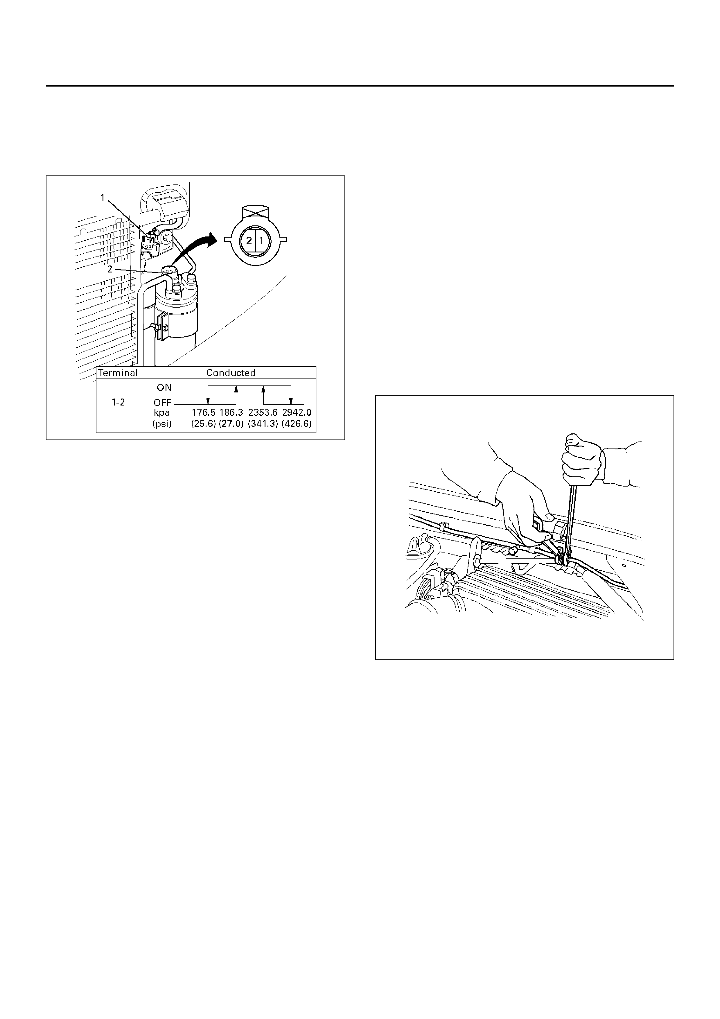
Pressure Switch
1. Disconnect pressure switch connector and check for
continuity between pressure switch side connector
terminals (1) and (2).
875RY00024
GENERAL REPAIR PROCEDURE
Precautions For Replacement or Repair of
Air Conditioning Parts
The re ar e c er tai n proc edu re s, p rac tic es an d pr ec aut ion s
that should be followed when servicing air conditioning
systems:
• Keep your work area clean.
• Always wear safety goggle and protective gloves
when working on refrigerant systems.
• Beware of the danger of carbon monoxide fumes
caused by running the engine.
• Beware of discharged refrigerant in enclosed or
improperly ventilated garages.
• Always disconnect the negative battery cable and
discharge and recover the refrigerant whenever
repairing the air conditioning system.
• When discharging and recovering the refrigerant, do
not allo w refrigerant to discharge too fas t; it will draw
compressor oil out of the system.
• Keep moisture and contaminants out of the system.
When disconnecting or removing any lines or parts,
use plugs or caps to close the fittings immediately.
Never remove the caps or plugs until the lines or
parts are reconnected or installed.
• When disconnecting or reconnecting the lines, use
two wrenches to support the line fitting, to prevent
from twisting or other damage.
• Alwa ys install new O -rings when ever a connect ion is
disassembled.
• Before connecting any hoses or lines, apply new
specified compressor oil to the O-rings.
• When removing and replacing any parts which
require discharging the refrigerant circuit, the
operations described in this section must be
perfor med in the following seque nc e:
1 Use the J-39500 (ACR4: HFC-134a Refrigerant
Recovery / Recycling / Recharging / System) or
equivalent to thoroughly discharge and recover
the refrigerant.
2 Remove and replace the defective part.
3 After evacuation, charge the air conditioning
system and check for leaks.
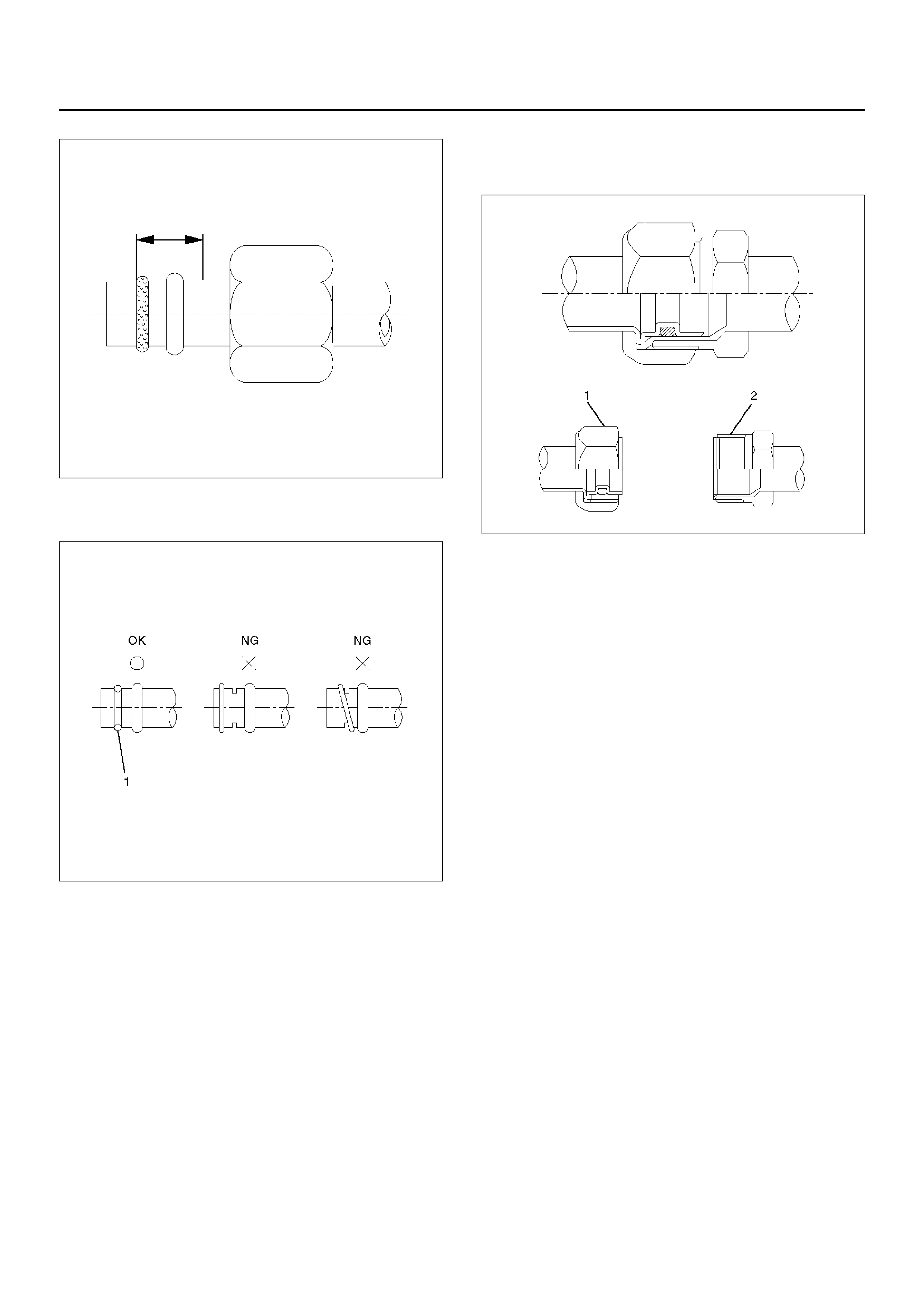
Repair Of Refrigerant Leaks
Refrigerant Line Connections
Install n ew O-rings, if required. W hen discon necting or
connecting lines, use two wrenches to prevent the
connecting portion from twisting or becoming damaged.
852RS003
When connecting the refrigerant line at a block joint,
securel y insert the projecting portion of the j oint portion
into the connecting hole on the unit side and secure with
a bolt. Apply the specified compressor oil to the
O-rings prior to connecting.
CAUTION: Compressor (PAG) oil to be used varies
according to the compressor model. Be sure to
apply oil specified for the model of compressor.
850RW002
O-rings (2) mus t be fi tted in t he g ro ove ( 1) of r ef riger an t
line.
850RW003
Insert the nut into the union.
First, tighten the nut by han d as much as possi ble, then
tighten the nut to the specified torque.
850RW004
LEAK CHECK
Inspec ti on of refrigerant leak
Refrigerant leak may cause an adverse effect not only
on the performance and durability of each component of
the air-conditioner, but also on the global atmosphere.
Therefore, it is most important to repair refrigerant leak
when there is any leak found.
Inspection flow of refrigerant leak
Inspection Steps
Check the components of ai r-cond itioner to see i f there
occurs any refrigerant leak along the flow of refrigerant.
• To avoid an error in the detection of refrigerant leak,
make sure of there being no refrigerant vapor or
cigarette smoke around the vehicle before
conducting the inspection. Also, select a location
where th e refrig erant vapor wi ll no t get bl own off with
wind.
• Inspection should be conducted chiefly on the pipe
connections and sections where a marked oil
contamination is found. When refrigerant is leaking,
oil insi de is also lea king at the same time.
• It is possible to visually check the leak from inside the
cooling unit. Follow the method below when
checking. Remove the drain hose or resistor of the
coolin g unit, and insert a leak de tector to se e if ther e
occurs any leak.
High Pressure Side
1. Discharger section of compressor.
2. In let/out let section of condenser.
3. Inlet/outlet section of receiver driver.
4. Inlet section of cooling unit.
Low Pressure Side
1. Outlet section of cooling unit.
2. Intake section of compressor.
Major Checking Points of Refrigerant Leak
Compressor
• Pipe connection
• Sealing section of shaft
• Mating section or cylinder
Condenser
• Pipe connection
• Welds of condenser body
Receiver driver
• Pipe connection
• Attaching section of pressure switch
• Section around the sight glass
Evaporator unit (cooling unit)
• Pipe connections
• Connections of expansion valve
• Brazed sections of evaporator
• The evaporator and expansion valve are contained in
the case. Remove the drain hose or the resistor of
the cooling unit and insert a leak detector when
checking for any leak.
Flexible hose
• Pipe connection
• Caulking section of the hose
• Hose (cracks, pinholes, flaws)
Pipe
• Pipe connection
• Pipe (cracks, flaws)
Charge valve
• The charge valve, which is used to connect the
gauge manifold, is normally provided with a resin
cap. When the valve inside gets deteriorated,
refrigerant will leak out.
Step Action Yes No
1 1. Evacuate the refrigerant system.
2. Charge the refrigerant.
Is there any refrigerant leak? Repair refrigerant
system. Go to Step 2.
2 1. Operate th e c om pr esso r for m or e t han 5 mi nute s to rais e t he
pressure on the high pressure side.
Is there any refrigerant leak at high pressure components? Repair refrigerant
system.
Compressor
operation to be
confirmed.

Leak at Refrigerant Line Connections
1. Check the torque on the refrigerant line fitting and, if
too loose, tighten to the specified torque.
• Use two wrenches to prevent twisting and
damage to the line.
• Do not over tighten.
2. Perform a leak test on the refrigerant line fitting.
3. If the leak is stil l presen t, disc harg e and re cover th e
refrigerant from the system.
4. Replace the O-rings.
• O-rings cannot be reused. Always replace with
new ones.
• Be sure to apply the specified compressor oil to
the new O-rings.
5. Retighten the refrigerant line fitting to the specified
torque.
• Use two wrenches to prevent twisting and
damage to the line.
6. Evacuate, charge and retest the system.
Leaks In The Hose
If the compressor inlet or outlet hose is leaking, the
entire hose must be replaced. The refrigerant hose
must not be cut or spliced for repair.
1. Locate the leak.
2. Discharge and recover the refrigerant.
3. Re mo ve the hose ass em bly.
• Cap the open connections at once.
4. Connect the new hose assembly.
• Use t wo wrenc hes to pre vent twis ting or damage
to the hose fitting.
• Tighten the hose fitting to the specified torque.
5. Evacuate, charge and test the system.
Compressor Leaks
If leaks are located around the compressor shaft seal or
shell, replace or repair the compressor.
Recovery, Recycling, Evacuation and
Charging of HFC-134a
Air conditioning systems contain HFC-134a. This is a
chemical mixture which requires special handling
procedures to avoid personal injury.
• Always wear safety goggles and protective gloves.
• Alwa ys work in a well-v entilat ed area. Do not wel d or
steam clean on or near any vehicle-installed air
conditioning lines or components.
• If HFC-134a should come in contact with any part of
the body, flush the expos ed area with col d water and
immedi atel y se ek med ic al help.
• If it is necessary to transport or carry any container of
HFC-134a in a vehicle, do not carry it in the
passenger compartment.
• If it is necessary to fill a small HFC-134a container
from a large one, never fill the container completely.
Space shou ld always be al lowed above th e liquid for
expansion.
• HFC-134a and R-12 should never be mixed as their
compos itions are not the same.
• HFC-134a PAG oil tends to absorb moisture more
quickly than R-12 mineral oil and, therefore, should
be handled more carefully.
• Keep HFC-134a containers stored below 40°C
(100°F).
WARNING:
• SHOULD HFC-134A CONTACT YOUR EYE(S),
CONSULT A DOCTOR IMMEDIATELY.
• DO NOT RUB THE AFFECTED EYE(S). INSTEAD,
SPLASH QUANTITIES OF FRESH COLD WATER
OVER THE AFFECTED AREA TO GRA DUALLY
RAISE THE TEMPERATURE OF THE
REFRIGERANT ABOVE THE FREEZING POINT.
• OBTAIN PROPER MEDICAL TREATMENT AS
SOON AS POSSIBLE. SHOULD THE HFC-134A
TOUCH THE SKIN, THE INJURY MUST BE
TREATED THE SAME AS SKIN WHICH HAS BEEN
FROSTBITTEN OR FROZEN.
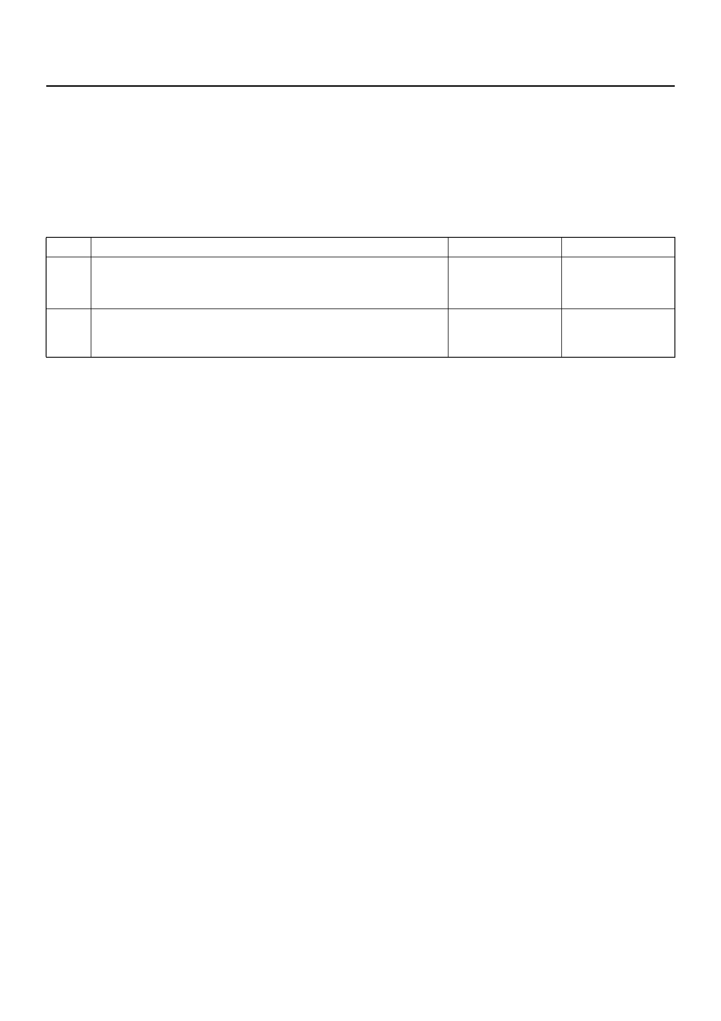
Refrigerant Recovery
The refrigerant must be discharged and recovered by
using the J-39500 (ACR4:HFC-134a Refrigerant
Recovery/Recycling/Recharging/System) or equivalent
before removing or mounting air conditioning parts.
1. Connect the high and low charging hoses of the
ACR4(or equivalent) as shown below.
901R100033
EndOFCallout
2. Recover the refrigerant by following the
Manufacturer's Instructions.
3. Whe n a part is removed , put a cap or a pl ug on th e
connecting portion so that dust, dirt or moisture
cannot get into it.
Refrigerant Recycling
Recycle the refrigerant recovered by J-39500
(ACR4:HFC-134a Refrigerant Recovery / Recycling /
Recharging / System) or equivalent.
For the details of the actual operation, follow the steps
in the ACR4(or equivalent) Manufacturer's Instructions.
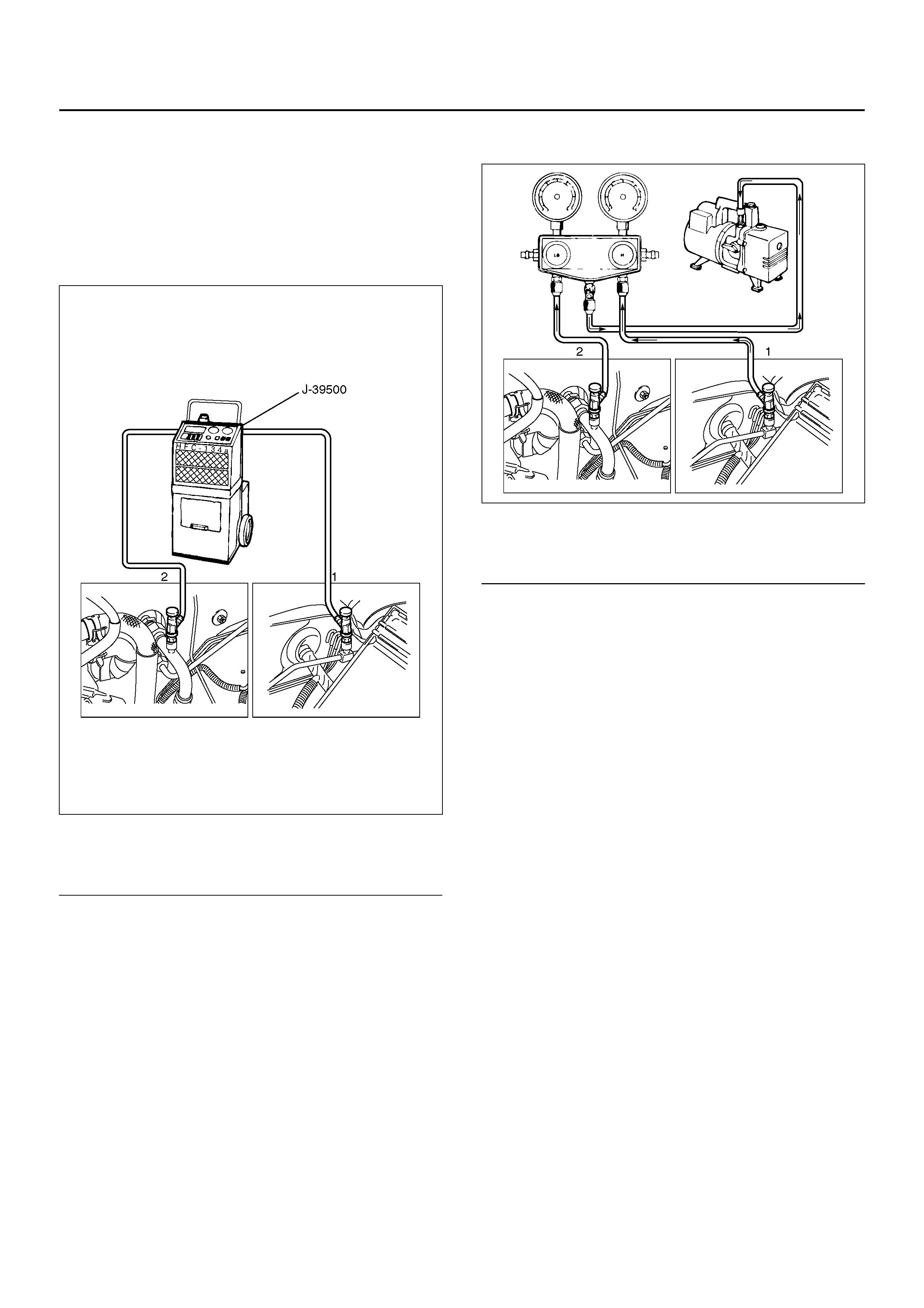
Evacuation of The Refrigerant System
901R100035
EndOFCallout
Explained below is a method using a vacuum pump.
Refer to the ACR4(or equivalent) manufacturer's
instructions when evacuating the system with a
ACR4(or equivalent).
Air and moisture in the refrigerant will cause problems in
the air conditioning system. Therefore, before charging
the refrigerant, be sure to evacuate air and moisture
thoroughly from the system.
1. Connect the gauge manifold.
• High-pressure valve (HI) — Discharge-side.
• Low-pressure valve (LOW) — Suction-side.
2. Discharge and recover the refrigerant.
3. Connect the center hose of the gauge manifold set
to the vacuum pump inlet.
4. Operate the vacuum pump, open shutoff valve and
then open both hand valves.
5. When the low-pressure gauge indicates
approximately 750mmHg (30inHg), continue the
evacuation for 5 minutes or more.
6. Close both hand valves and stop the vacuum pump.
Legend
(1) H i gh Side
(2) Low Side
Legend
(1) High Side
(2) Low Side
7. Chec k to ensu re t hat the pre ssure does not chang e
after 10 minutes or more.
• If the pressure changes, check the system for
leaks.
• If leaks occur, retighten the refrigerant line
connections and repeat the evacuation steps.
8. If no leaks are found, again operate the vacuum
pump fo r 20 mi nutes or m ore. After confirmi ng that
the gauge manifold pressure is at 750mmHg
(30inHg), close both hand valves.
9. C lose p os iti ve s huto ff va lve. Stop the va cu um pum p
and disconnect the center hose from the vacuum
pump.
Charging The Refrigerant System
There are various methods of charging refrigerant into
the air conditioning system.
These include using J-39500 (ACR4:HFC-134a
Refriger ant Recover y/Recycling/ Recharging/Sy stem) or
equivalent and direct charging with a weight scale
charging station.
Charging Procedure
•ACR4(or equivalent) Method
For the char ging of refriger ant recovered by ACR4(or
equivalent), follow t he manufacturer's instruction.
901R100033
EndOFCallout
•Direct charging with a weight scale charging
station method
1. Make sure the evacuation process is correctly
completed.
2. Connect the center hose of the manifold gauge to
the weight scale.
3. Connect the low pressure charging hose of the
manifold gauge to the low pressure side service
valve of the vehicle.
4. Connect the high pressure charging hose of the
manifold gauge to the high pressure side service
valve of the vehicle.
901R100034
EndOFCallout
5. Place the refrigerant container up right on a weight
scale.
Note the total weight before charging the refrigerant.
a Open the refrigerant container valve.
b Open the low side vale on the manifold gauge
set. Refer to the manufacturer's instructions for
a weight scale charging station.
Legend
(1) H i gh Side
(2) Low Side
Legend
(1) Weight Scale
(2) Refrigerant Container
(3) High Side
(4) Low Side

6. Perform a system leak test:
• Charge the system with approximately 200g
(0.44lbs) of HFC-134a.
• Make sure the high pressure valve of the
manifold gauge is closed.
• Check to ensure that the degree of pressure does
not change.
• Check for refrigerant leaks by using a HFC-134a
leak detector.
• If a leak occurs, recover the refrigerant. Repair
the leak and start all over again from the first step
of evacuation.
7. If no leaks are found, continue charging refrigerant
to the air conditioning system.
• Charge the refrigerant until the scale reading
decreases by the amount of the charge specified.
Specified amount: 650g (1.43lbs)
• If charging the system becomes difficult:
1 Run the engine at idle and close all the
vehicle doors.
2 Turn A/C switch “ON".
3 Set the fan switch to its highest position.
4 Set the air source selector lever to “CIRC".
5 Slowly open the low side valve on the
manifold gauge set.
WARNING: Be absolutely sure not to open the high
pressure valve of the manifold gauge. Should the
high pressure valve be opened, the high pressure
refrigerant would flow backward, and this may
cause the refrigerant container to burst.
8. When finished with the refrigerant charging, close
the low pressure valve of the manifold gauge and
container valve.
9. Check for refrigerant leaks.
Checking The A/C System
1. Run the engine and close all the vehicle doors.
2. Turn A/C switch “ON", set the fan switch to its
highest position.
3. Set the air source lever to “CIRC", set the
temperature lever to the full cool position.
4. Check the high and low pressure of the manifold
gauge.
• Immediately after charging refrigerant, both high
and low pressures might be slightly high, but they
settle down to the pressure guidelines shown
below:
• The ambient temperature should be between 25–
30°C (77–86°F).
• The pressure guideline for the high-pressure side
is approximately 1372.9–1863.3kPa (199.1–
270.2 psi).
• The pressure guideline for the low-pressure side
is approximately 147.1–294.2kPa (21.3–42.7
psi).
• If an abnormal pressure is found, refer to
Checking The Refrigerant System With Manifold
Gauge in this section.
5. Put yo ur hand in front of the air outle t and move the
temperature control lever of the control panel to
different positions. Check if the outlet temperature
changes as selected by the control knob.
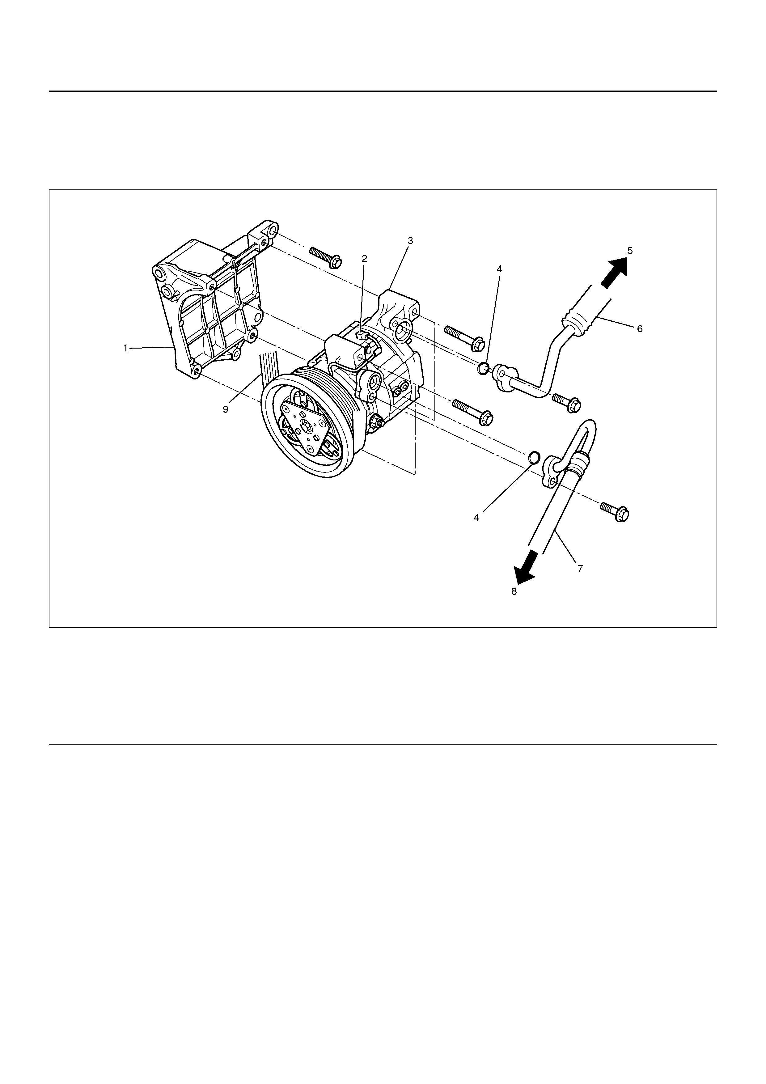
COMPRESSOR ASSEMBLY
COMPRESSOR ASSEMBLY AND ASSOCIATED PARTS (6VD1)
852R100007
EndOFCallout
REMOVAL
1. Disconnect the battery ground cable.
2. Discharge and recover refrigerant
• Refer to Refrigerant Recovery in this section.
3. D isco nne ct mag neti c cl utch ha rnes s conne cto r.
4. Re mo ve se rpenti ne belt.
• Move serpentine belt tensioner to loose side
using wrench then remove serpentine belt.
Legend
(1) Compressor Bracket
(2) Magnetic Clutch Harness Connector
(3) Compressor
(4) O-ring
(5) To Evaporator
(6) Suction Line (Low-Pressure Hose)
(7) Discharge Lin e (Hight-Pressur e Hose)
(8) To Condenser
(9) Serpentine Belt
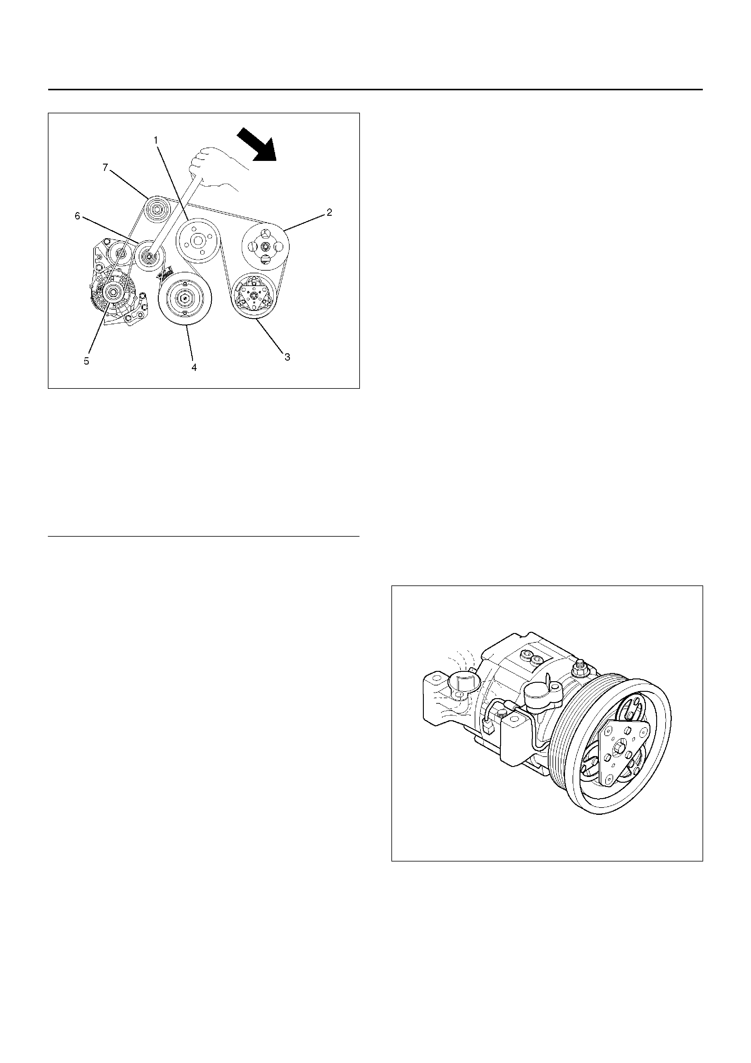
850RW009
EndOFCallout
5. Disconnect refrigerant line connector.
• When removing the line connector, the
connecting part should immediately be plugged
or capped to prevent foreign matter from being
mixed into the line.
6. Remove compressor.
INSTALLATION
1. Install compressor.
• Tighten the compressor fixing bolts to the
specified torque.
Torque: 19N•m (1.9kg•m/14lb ft)
2. Connect refrigerant line connector.
• Tighten the refrigerant line connector fixing bolts
to the specified torque.
Torque: 15N•m (1.5kg•m/11lb ft)
• O-rings cannot be reused. Always replace with
new ones.
• Be sure to apply new compressor oil to the
O-rings when connecting refrigerant lines.
3. Install serpentine belt.
• Move serpentine belt tensioner to loose side
using wrench, then install serpentine belt to
normal position.
4. Connect magnetic clutch harness connector.
NEW COMPRESSOR INSTALLATION
The new compressor is filled with 150cc (5.0fl.oz.)of
compressor oil and nitrogen gas. When mounting the
compressor on the vehicle, perform the following steps;
1. Gently release nitrogen gas from the new
compressor.
• Take care not to let the compressor oil flow out.
• Inspect O-rings and replace if necessary.
871RX033
2. Turn the compressor several times by hand and
release the compressor oil in the rotor.
Legend
(1) Cooling Fan Pulley
(2) Power Steering Oil Pump
(3) Air Conditioner Compressor
(4) Crankshaft Pulley
(5) Generator
(6) Tensioner
(7) Idler Pulley
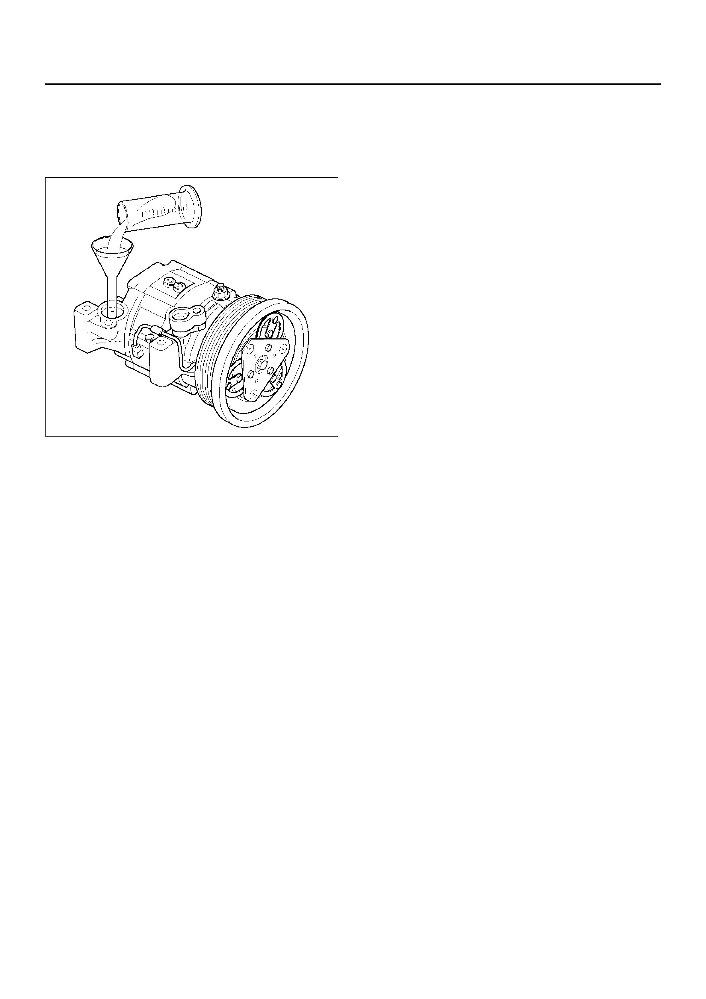
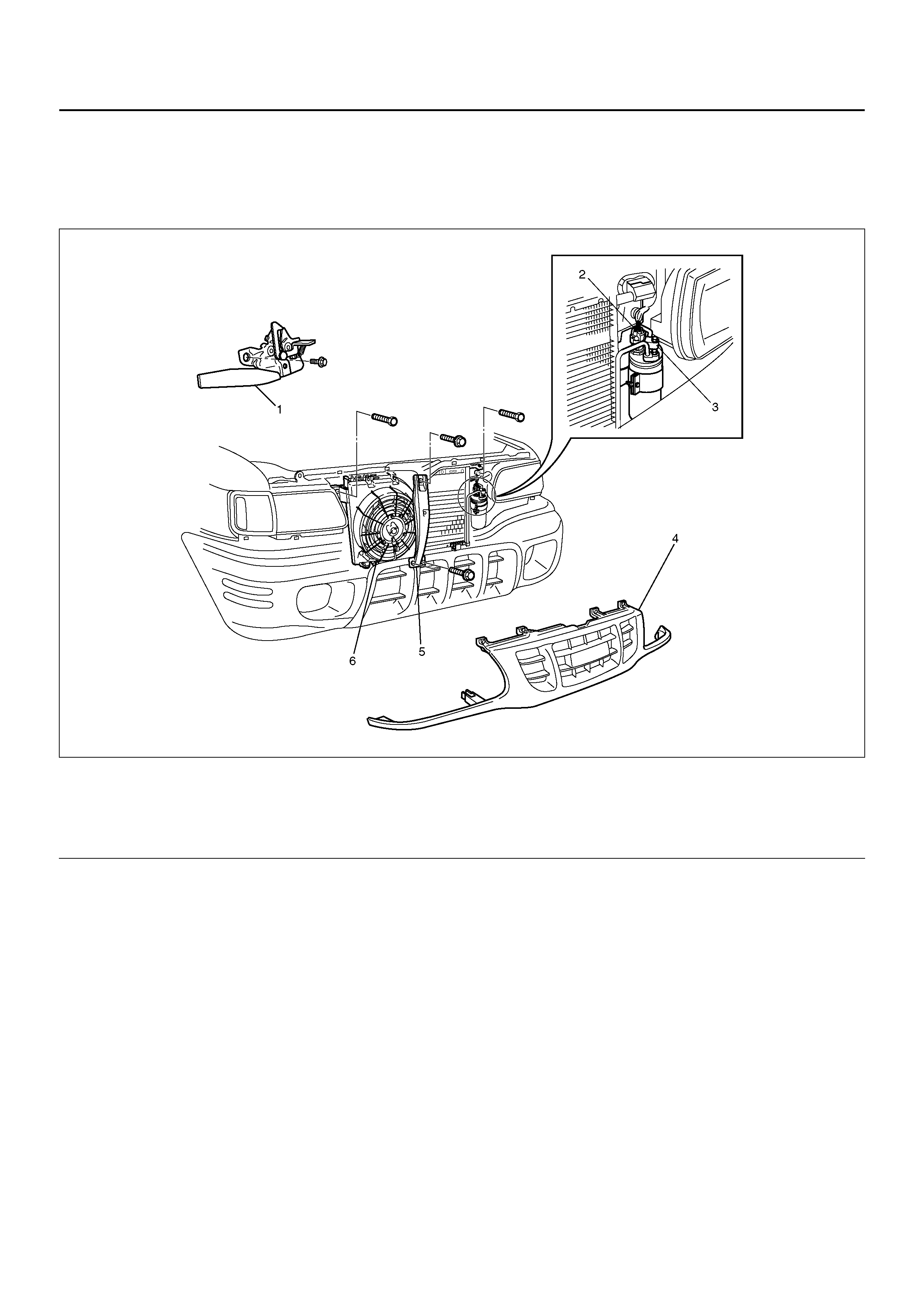
CONDENSER ASSEMBLY
CONDENSER ASSEMBLY AND ASSOCIATED PARTS
875R200014
EndOFCallout
REMOVAL
1. Disconnect the battery ground cable.
2. Discharge and recover refrigerant.
• Refer to Refrigerant Recovery in this section.
3. Remove radiator grille.
4. Remove engine hood front end stay.
5. Remove engine hood lock.
• Apply setting mark to the engine hood lock fixing
position before removing it.
6. Disconnect pressure switch & condenser fan motor
connector.
7. Disconnect refrigerant line.
• When removing the line connector, the
connecting part should immediately be plugged
or capped to prevent foreign matter from being
mixed into the line.
8. Remove condenser assembly.
• Handle with care to prevent damaging the
condenser or radiator fin.
INSTALLATION
1. Install condenser assembly.
• If installing a new condenser, be sure to add 30cc
(1.0fl.oz.) of new compressor oil to a new one.
• Tighten the condenser fixing bolts to the specified
torque.
Torque: 6N•m (0.6kg•m/52lb in)
2. Connect refrigerant line.
• Tighten the inlet line connector fixing bolt to the
specifi ed tor que .
Legend
(1) Engine Hood Lock
(2) P r essur e Swi tch Connec to r
(3) Refrigerant Line
(4) Radiator Grille
(5) Engine Hood Front End Stay
(6) Condense r As se mbl y
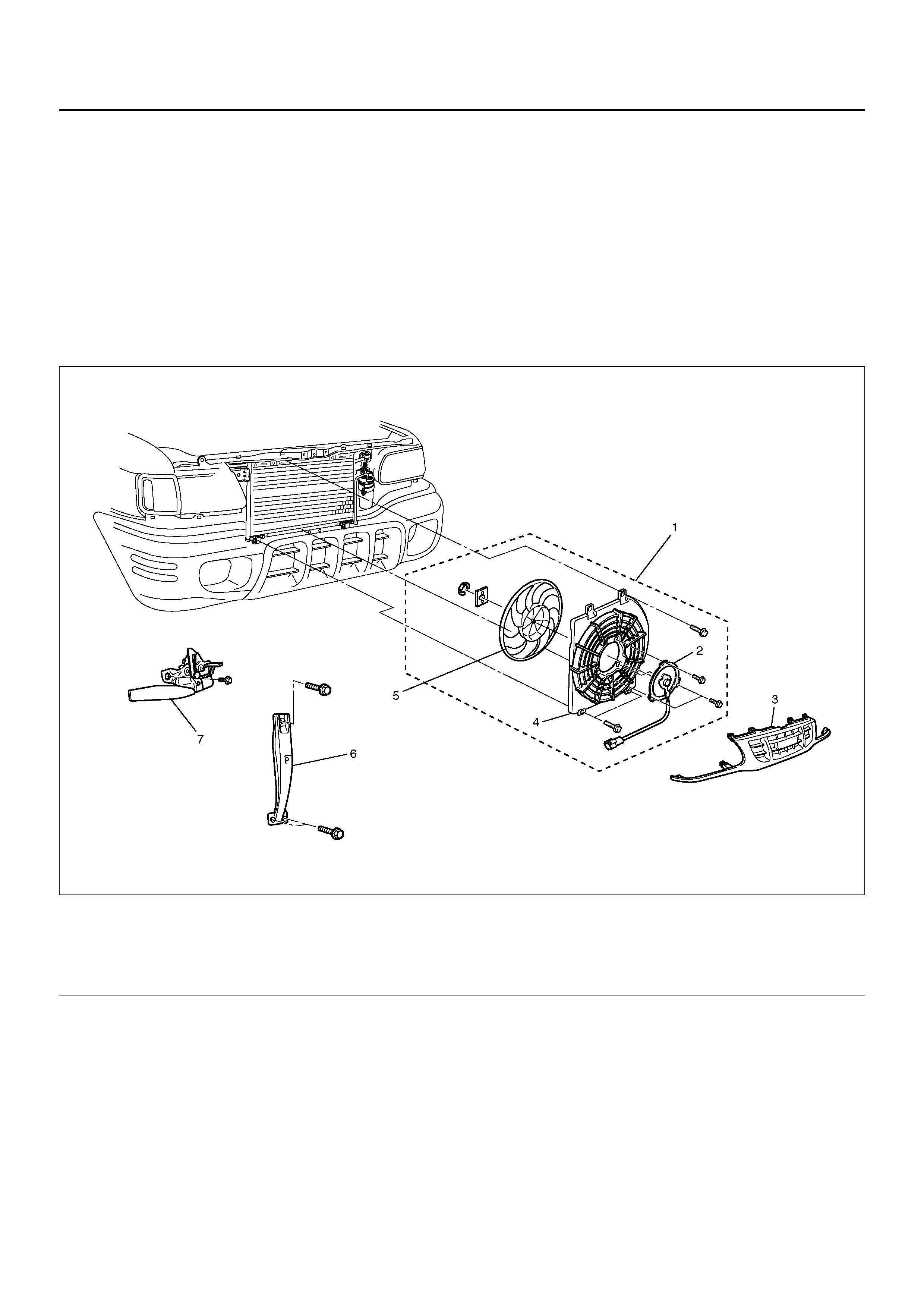
Torque: 15 N•m (1.5kg•m/11 lb ft)
• Tighten the outlet line connector fixing bolt to the
specified torque.
Torque: 6 N•m (0.6kg•m/52 lb in)
• O-rings cannot be reused. Always replace with
new ones.
• Be sure to apply new compressor oil to the
O-rings when connecting the refrigerant line.
3. Connect pressure switch & condenser fan motor
connector.
4. Install engine hood lock.
5. Install engine hood front end stay.
6. Install radiator grille.
CONDENSER FAN MOTOR
CONDENSER FAN MOTOR AND ASSOCIATED PARTS
875R100005
EndOFCallout
REMOVAL
1. Disconnect the battery ground cable.
2. Discharge and recover refrigerant.
• Refer to Refrigerant Recovery in this section.
3. Re mo ve radia t or grill e.
4. Remove engine hood front end stay.
5. Remove engine hood lock.
6. R emo ve co nde nse r fan asse mbl y.
• Disconnect the fan motor connector and remove
the 3 fixing bolts.
7. Remove shroud.
• Remove the 3 fixing nuts.
• Loosen the condenser fixing nut and disconnect
the fan motor connec to r from brack et.
8. Remove fan.
• Remove the fan fixing C-ring and plate.
9. Remove condenser fan motor.
Legend
(1) Condenser Fan Assembly
(2) Condenser Fan Motor
(3) Radiator Grille
(4) Shroud
(5) Fan
(6) Engine Hood Front End Stay
(7) Engine Hood Lock

INSTALLATION
To i nstall, foll ow the r emova l steps i n the re verse or der,
noting the following point.
1. Route the fan motor harness in its previous position,
and fix it securely with clip and bracket.
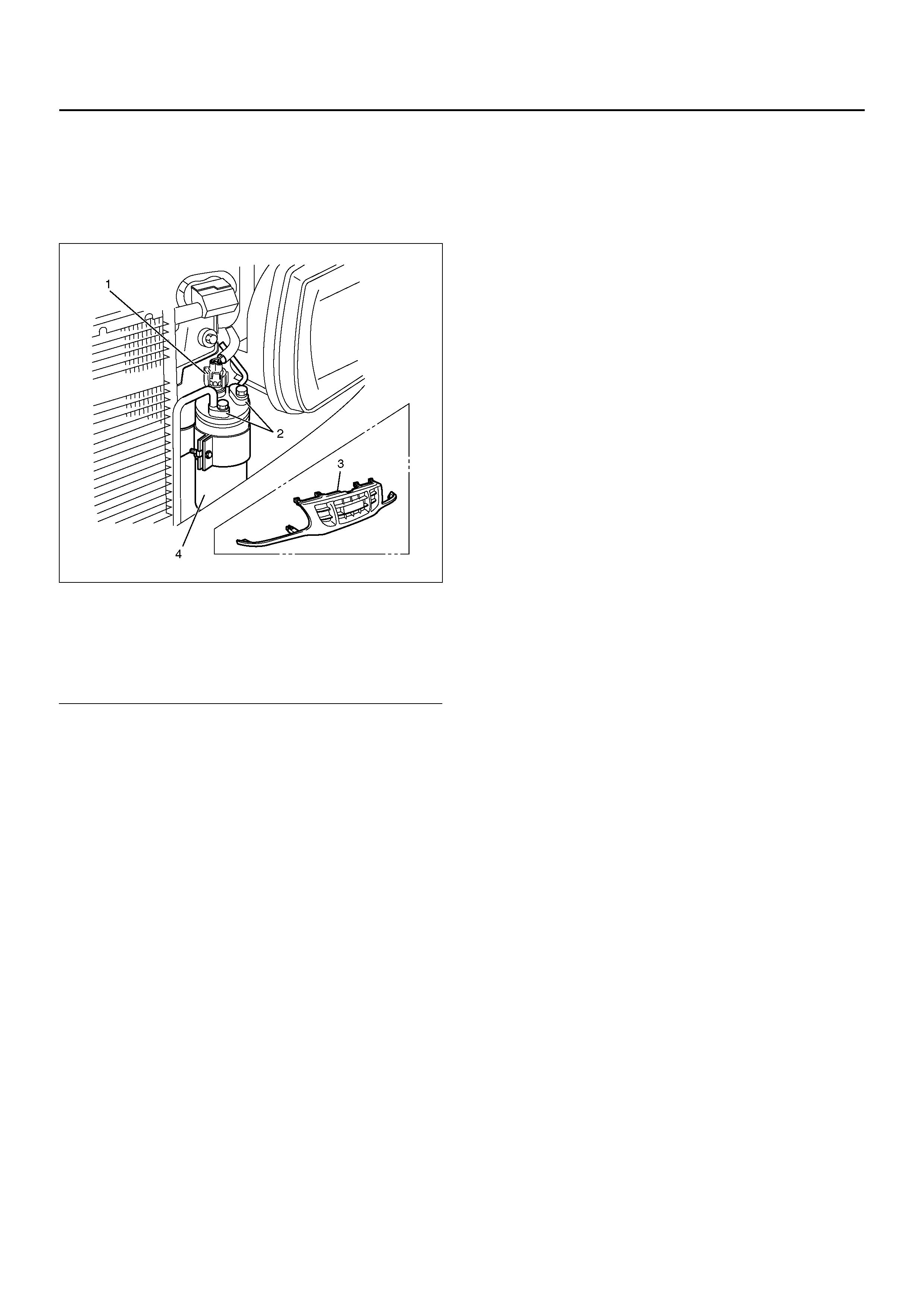
RECEIVER / DRIER
RECEIVER / DRIER AND
ASSOCIATED PARTS
875R100007
EndOFCallout
REMOVAL
1. Disconnect the battery ground cable.
2. Discharge and recover refrigerant.
• Refer to Refrigerant Recovery in this section.
3. Remove radiator grille.
4. Disconnect pressure switch connector.
5. Disconnect refrigerant line.
• When removing the line connected part, the
connecting part should immediately be plugged
or capped to prevent foreign matter from being
mixed into the line.
6. Remove receiver/drier.
• Loosen the bolt, then, using care not to touch or
bend the refrigerant line, carefully pull out the
receiver/drier.
INSTALLATION
To install, follow the removal steps in the reverse order,
noting the foll owi ng poi nts:
1. If installing a new receiver/drier, be sure to add 30cc
(1.0fl.oz.) of new compressor oil to a new one.
2. Put the receiver/drier in the bracket and connect
with the refrigerant line. Check that no excessive
force is imposed on the line. Fasten the bracket bolt
to the receiver/drier.
3. Tighten the refrigerant line to the specified torque.
Torque: 6 N•m (0.6kg•m/52 lb in)
4. O-ri ngs cannot b e reused . Always re place wit h new
ones.
5. Be sure to apply new compressor oil to the O-rings
when connecting the refrigerant line.
Legend
(1) P r essur e Swi tch Connec to r
(2) Refrigerant Line
(3) Radiator Grille
(4) Receiver / Dr ier
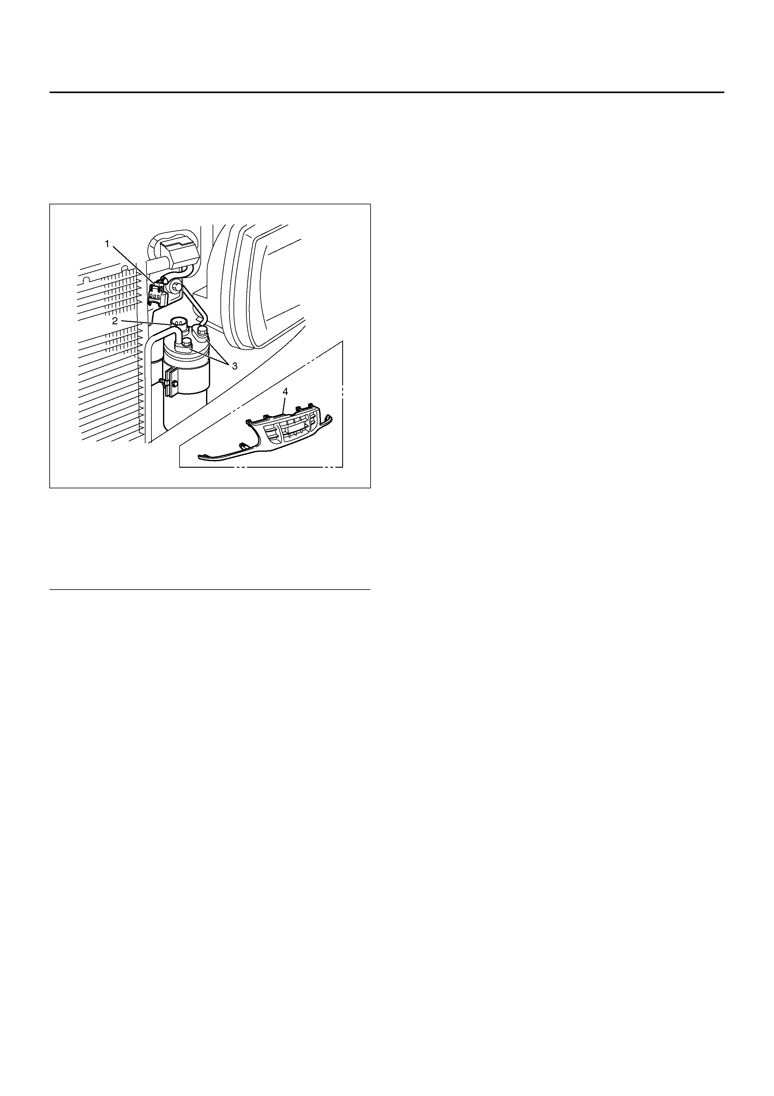
PRESSURE SWITCH
PRESSURE SWITCH AND
ASSOCIATED PARTS
875R100008
EndOFCallout
REMOVAL
1. Disconnect the battery ground cable.
2. Discharge and recover refrigerant.
• Refer to “Refrigerant Recovery in this section.
3. Remove radiator grille.
4. Disconnect pressure switch connector.
5. Disconnect pressure switch.
• When removing the switch connected part, the
connecting part should immediately be plugged
or capped to prevent foreign matter from being
mixed into the line.
INSTALLATION
To in stall, follow the remo val steps in the re verse order,
noting the foll owi ng poi nt:
1. O-ring cannot be reused. Always replace with a new
one.
2. Be sure to apply new compressor oil to the O-ring
when connecting pressure switch.
3. Tighten the pressure switch to the specified torque.
Torque: 13 N•m (1.3kg•m/113 lb in)
Legend
(1) P r essur e Swi tch Connec to r
(2) Pressure Switch
(3) Refrigerant Line
(4) Radiator Grille
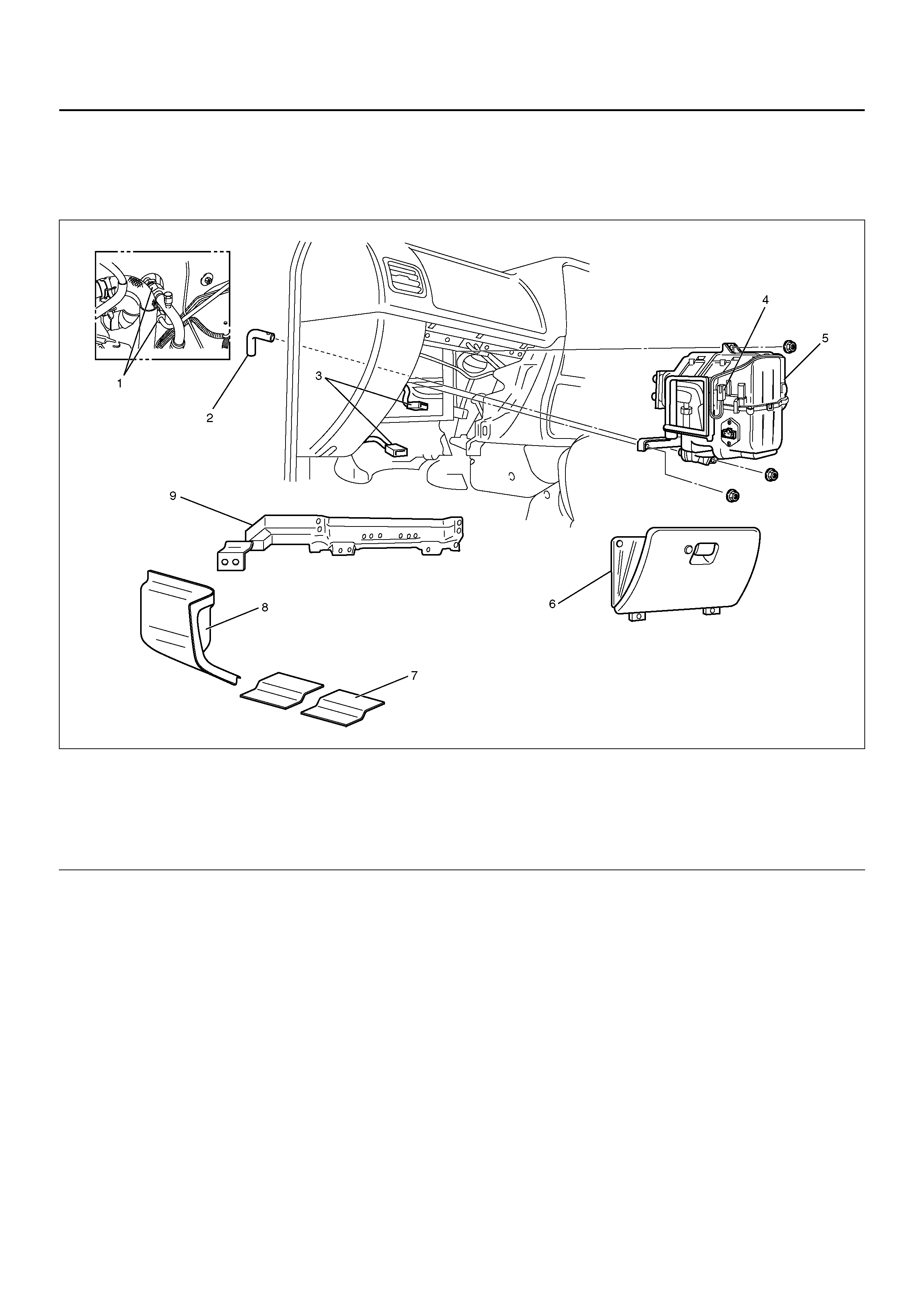
EVAPORATOR ASSEMBLY
EVAPORATOR ASSEMBLY AND ASSOCIATED PARTS
874R100005
EndOFCallout
REMOVAL
1. Disconnect the battery ground cable.
2. Discharge and recover refrigerant.
• Refer to Refrigerant Recovery in this section.
3. Remove glove box.
Legend
(1) Refrigerant Line
(2) Drain Hose
(3) Resistor and Electronic Thermostat Connector
(4) Electronic Thermostat
(5) Evaporato r As se mbl y
(6) Glove Box
(7) Sill Plate
(8) Dash Side Trim Panel
(9) Inst Panel Lower Rein forc eme nt
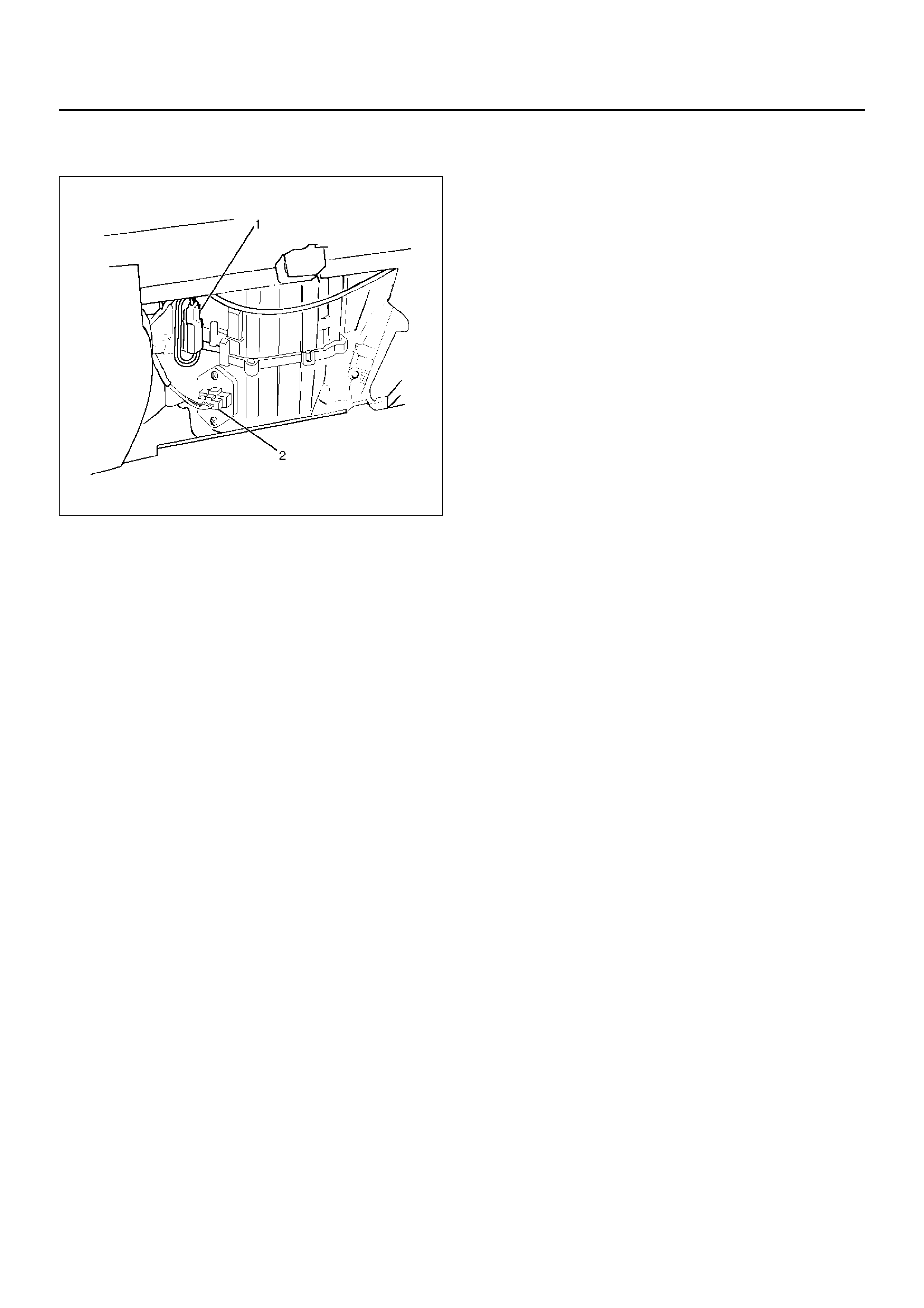
4. Disconnect resistor (2) and electronic thermostat
connector (1).
874RY00025
5. Remove sill plate.
6. Remove dash side trim panel.
7. Remove inst panel lower reinforcement.
8. Disconnect drain hose.
9. Disconnect refrigerant line.
• Use a back-up wrench when disconnecting and
reconnecting the refrigerant lines.
• When removing the refrigerant line connected
part, the connecting part should immediately be
plugged or capped to prevent foreign matter from
being mixed into the line.
10. Remove evaporator assembly.
INSTALLATION
To in stall, follow the remo val steps in the re verse order,
noting the foll owi ng poi nts:
1. To install a new evaporator assembly, add 50cc
(1.7fl.oz.) of new compressor oil to the new core.
2. Tighten the refrigerant outlet line to the specified
torque.
Torque: 25 N•m (2.5kg•m/18 lb ft)
3. Tighten the refrigerant inlet line to the specified
torque.
Torque: 15 N•m (1.5kg•m/11 lb ft)
4. O-ri ngs cannot b e reused . Always re place wit h new
ones.
5. Be sure to apply new compressor oil to the O-rings
when connecting lines.
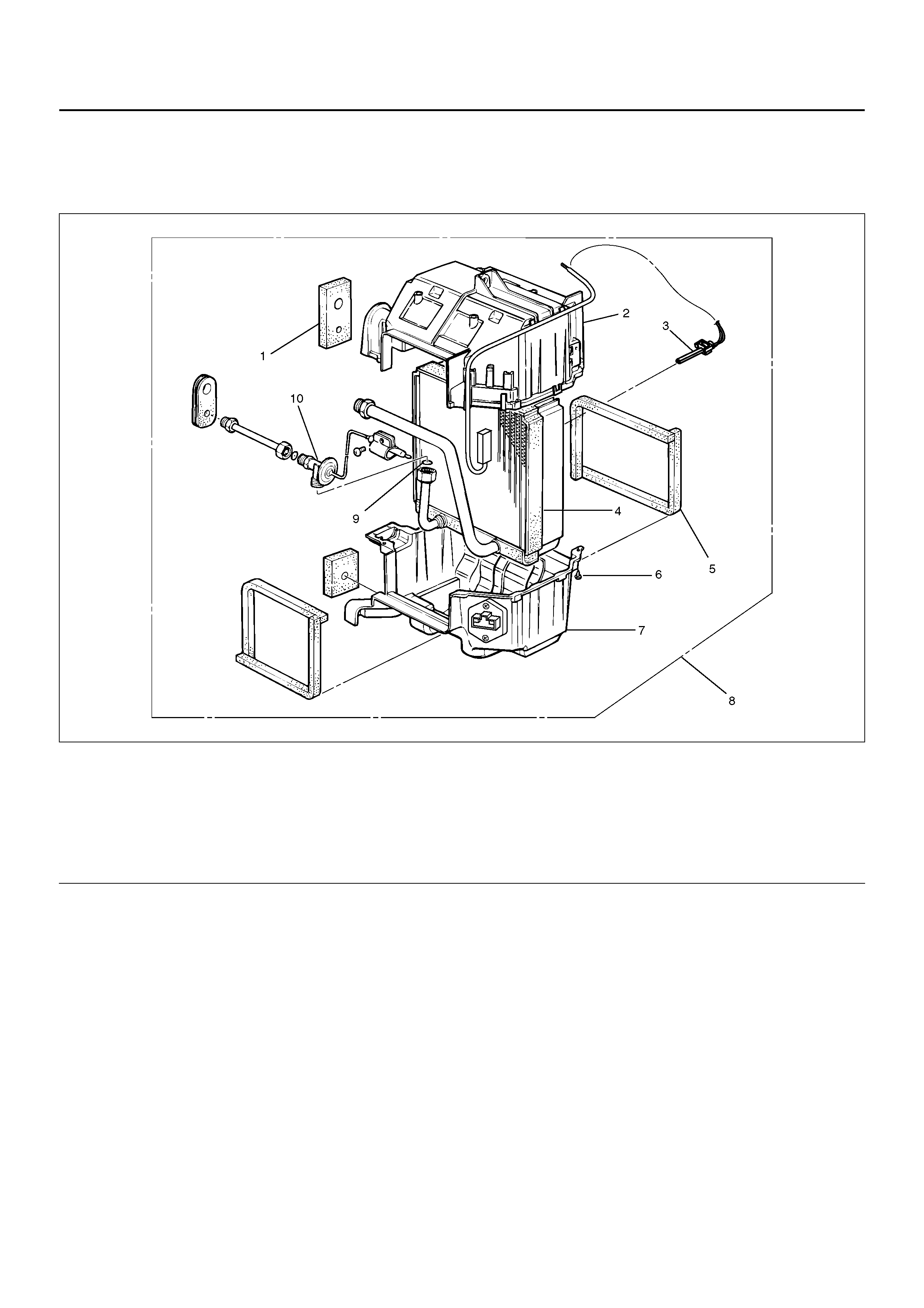
ELECTRONIC THERMOSTAT, EVAPORATOR CORE AND/OR
EXPANSION VALVE
DISASSEMBLED VIEW
874R100003
EndOFCallout
REMOVAL
1. Disconnect the battery ground cable.
2. Discharge and recover refrigerant.
• Refer to Refrigerant Recovery in this section.
3. Re mo ve evaporator ass emb ly.
• Refer to Evaporator Assembly in this section.
4. Re mo ve the ele ctro nic ther mostat se nso r fixin g clip.
Pull the sensor from the evaporator assembly.
5. R emo ve attachi ng sc rew.
6. R emo ve upp er case .
7. R emo ve lower case .
• Slit the case parting face with a knife since the
lining is separated when removing the
evaporator.
Legend
(1) Lining
(2) Upper Case
(3) Electronic Thermostat
(4) Evaporator Core
(5) Lining: Case
(6) Attaching Screw
(7) Lower Case
(8) Evaporato r As se mbl y
(9) O-ring
(10) Expansion Valve
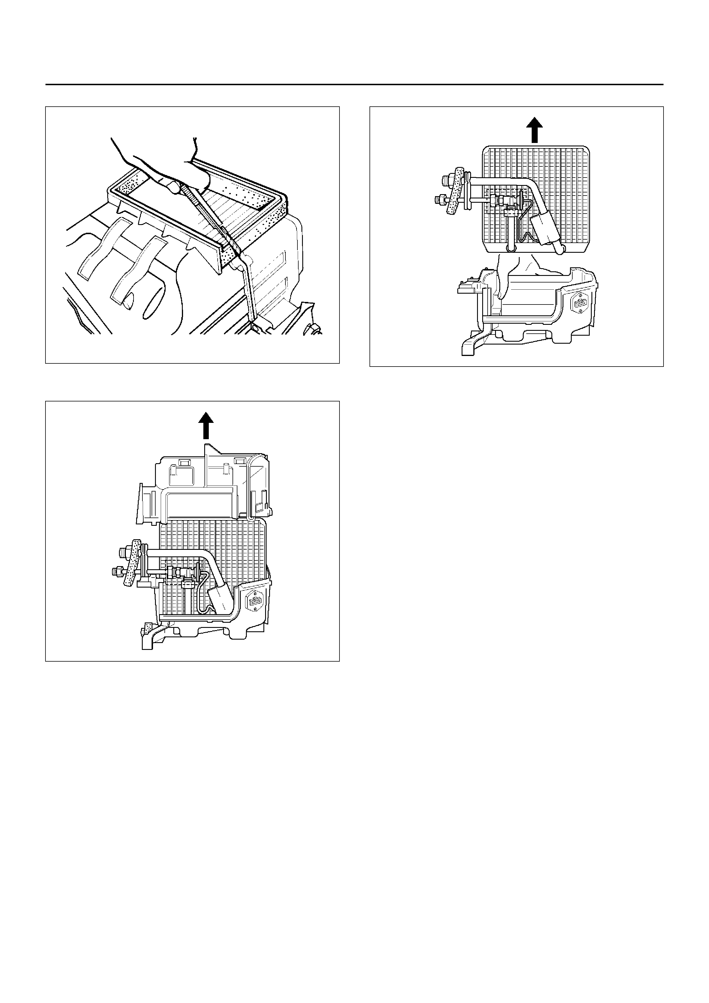
874RW034
• Lift to remove the upper case.
874RY00027
8. Remo ve ev apo ra tor cor e.
874RY00028
9. Remove expansion valve.
• Tear off the insulator carefully.
• Remove the sensor fixing clip.
• Use a back-up wrench when disconnecting all
refrigerant pipe s.
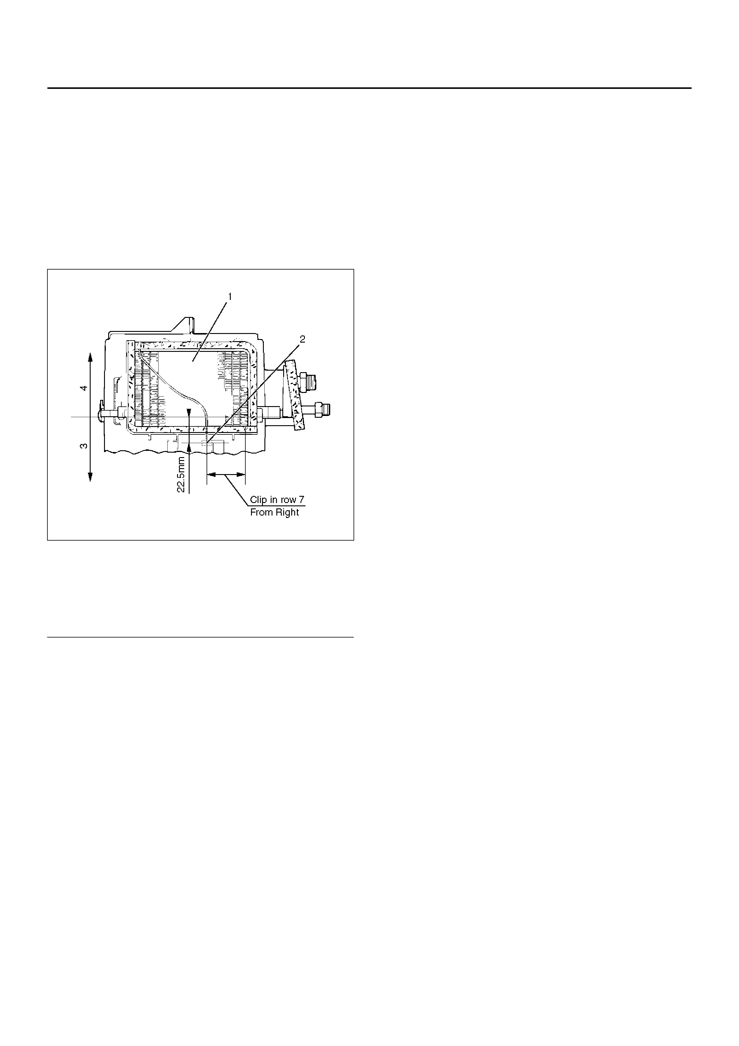
INSTALLATION
To install, follow the removal steps in the reverse order,
noting the following points:
1. The sensor is installed on the core with the clip.
2. The sensor must not interfere with the evaporator
core.
3. When installing the new evaporator core, install the
thermo sensor to the evaporator core specified
position with the clip in the illustration.
874RX014
EndOFCallout
4. O-rings cannot be reused. Always replace with new
ones.
5. Be sure to apply new compressor oil to the O-rings
when connecting lines.
6. Be sure to install the sensor and the insulator on the
place where they were before.
7. To install a new evaporator core, add 50cc (1.7 fl.
oz.) of new compressor oil to the new core.
8. Tighten the refrigerant lines to the specified torque.
Refer to Main Data and Specifications for Torque
Specifications in this section.
9. Apply an adhesive to the parting face of the lining
when assembling the evaporator assembly.
Legend
(1) Evaporator Core
(2) Thermo Sensor
(3) Lower Case
(4) Upper Case
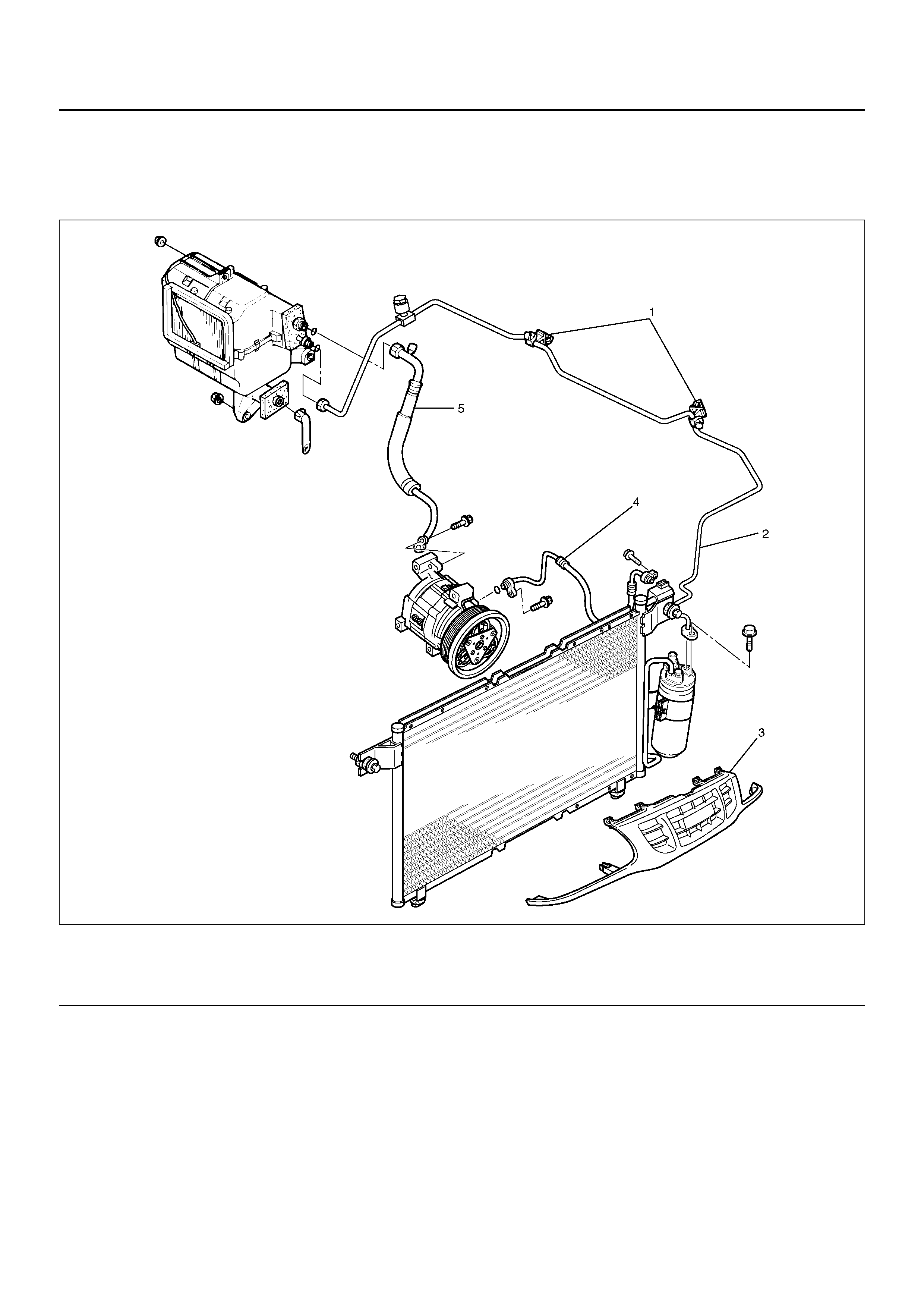
REFRIGERANT LINE
REFRIGERANT LINE AND ASSOCIATED PARTS
852R100008
EndOFCallout
REMOVAL
1. Disconnect the battery ground cable.
2. Discharge and recover refrigerant.
• Refer to Refrigerant Recovery in this section.
3. Re mo ve radia t or grill e.
4. Remove clip and clamp.
5. Disconnect liquid line (High-pressure pipe).
6. Disc on nect s uc ti on l ine ( Lo w-p r essur e pi pe) us i ng a
back-up wrench.
7. Disconnect suction line (Low-pressure hose) using
a back-up wrench.
8. Disconnect discharge line (High-pressure hose)
using a back-up wrench.
• Use a backup wrench when disconnecting and
reconnecting the refrigerant lines.
• When removing the refrigerant line connecting
Legend
(1) Clip and Clamp
(2) Liquid Line (High-Pressure Pipe)
(3) Radiator Grille
(4) Discharge Line (High-Pressure Ho se)
(5) Suction Line (Low-Pressure Pipe)

part, the connecting part should immediately be
plugged or capped to prevent foreign matter from
being mixed into the line.
INSTALLATION
To install, follow the removal steps in the reverse order,
noting the following point:
1. O-rings cannot be reused. Always replace with new
ones.
2. Be sure to apply new compressor oil to the O-rings
when connecting lines.
3. Tighten the refrigerant line to the specified torque.
Refer to Main Data and Specifications for Torque
Specifications in this section.
MAIN DATA AND SPECIFICATIONS
General Specifications
Heater Unit
Temperature control Reheat air mix system
Capacity 3,700 Kcal./hr.
Air flow 280 m3/h
HEATER CORE
Type AUTO A/C Plate and corrugate-fin type
MANU A/C Fin and tube type
Element dimension MANU A/C 161 mm (6.3) × 163 mm (6.4 in.) × 45 mm (1.8 in.)
AUTO A/C 171 mm (6.7) × 161 mm (6.3 in.) × 25 mm (1 in.)
Radiating area MANU A/C Approx. 2.1 m2
AUTO A/C Approx. 1.3 m2
EVAPORATOR ASSEMBLY
Capacity AUTO A/C 4,100 Kcal./hr.
MANU A/C 4,100 Kcal./hr.
Air flow AUTO A/C 430 m3/hr
MANU A/C 430 m3/hr
EVAPORATOR CORE
Type Al-laminate louver fin type
Element dimension 235 mm (9.3 in.) × 225.3 mm (8.9 in.) × 60 mm (2.4 in.)
EXPA NSION VALVE
Type Internal pressure equalizer type
THERMO STAT SWITCH
Type Electronic thermostat
OFF: Below 1.0 ± 0.5 °C (33.8 ± 0.9 °F)
ON: Above 3.5 ± 0.5 °C (38.3 ± 0.9 °F)
CONDENSER
Type Parallel flow type
Radiation performance 11,100 Kcal./hr
RECEIVER/DRIER
Type With dual (triple) pressure switch (V6)
Internal volume 300 cc (10 fl.oz.)
PRESSURE SWITCH
Type Dual pressure switch
Low pressure control
ON: 186.3±29.4 kPa (27.0±4.3 psi)
OFF: 176.5±24.5 kPa (25.6±3.6 psi)
High pressure control
ON: 2353.6±196.1 kPa (341.3±28.4 psi)
OFF: 2942.0±196.1 kPa (426.6±28.4 psi)
Triple pressure switch (V6, A/T)
Low pressure control
ON: 196.3±29.4 kPa (27.0±4.3 psi)
OFF: 176.5±19.6 kPa (25.6±2.8 psi)
Medium pr es su re control
ON: 1471.0±98.1 kPa (213.3±14.2 psi)
OFF: 1078.7±117.7 kPa (15 6.4±17.7 psi)
High pressure control
ON: 2353.6±196.1 kPa (341.3±28.4 psi)
OFF: 2942.0±196.1 kPa (426.6±28.4 psi)
REFRIGERANT
Type HFC-134a
Specified amount 700 g (1.54 lbs.)
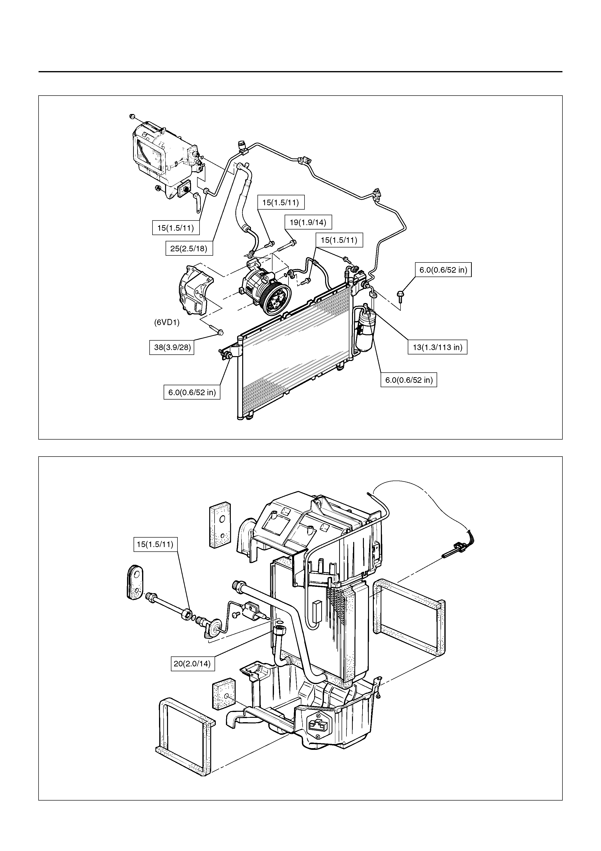
Torque Specifications N•m (kg•m/lb ft)
E06R100005
874R100004
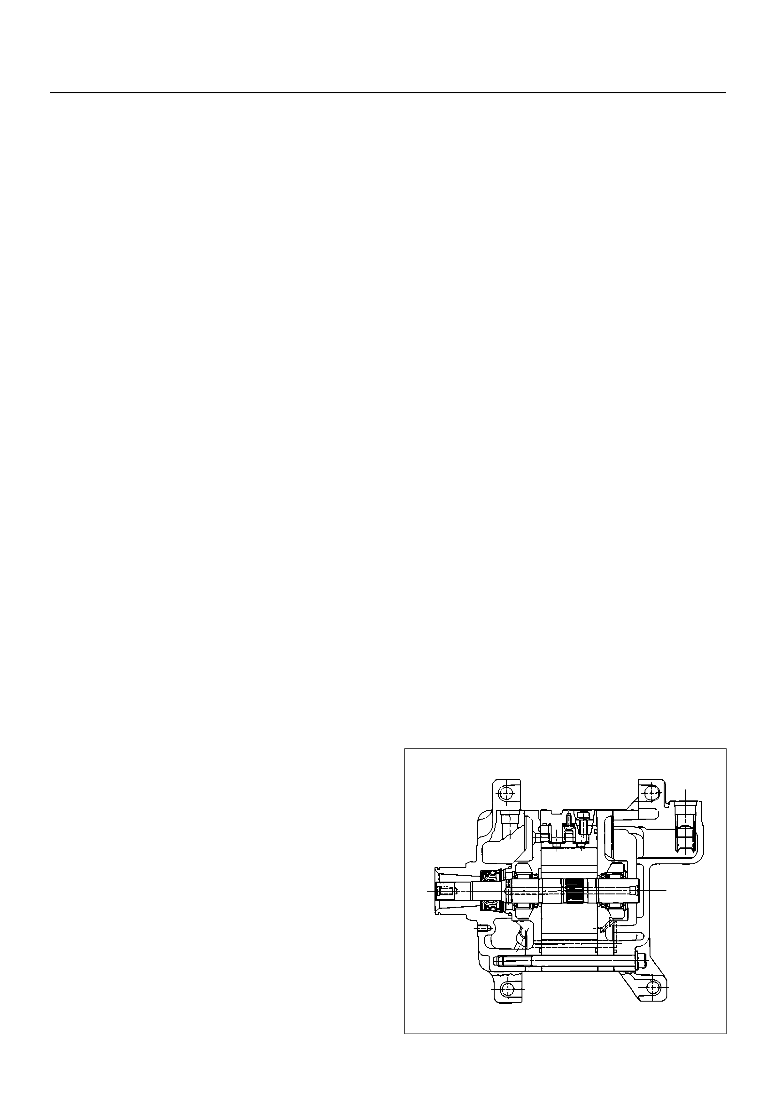
COMPRESSOR
SERVICE PRECAUTION
WARNING: This vehicle has a Supplemental
Restraint System (SRS). Refer to the SRS
Component Location View in order to determine
whether you are performing service on or near the
SRS components or the SRS wiring. When you are
performing service on or near the SRS components
or the SRS wiring, refer to the SRS On-Vehicle
Service Information. Failure to follow CAUTIONS
could result in possible air bag deployment,
personal injury, or otherwise unneeded SRS system
repairs.
CAUTION: Always use the correct fastener in the
proper location. When you replace a fastener, use
ONLY the exact part number for that application.
HOLDEN will call out those fasteners that require a
replacement after removal. HOLDEN will also call
out the fasteners that require thread lockers or
thread sealant. UNLESS OTHERWISE SPECIFIED,
do not use supplemental coatings (paints, greases,
or other corrosion inhibitors) on threaded fasteners
or fastener joint interfaces. Generally, such
coatings adversely affect the fastener torque and
the joint clamping force, and may damage the
fastener. When you install fasteners, use the correct
tightening sequence and specifications. Following
these instructions can help you avoid damage to
parts and systems.
GENERAL DESCRIPTION
When servicing the compressor, keep dirt or foreign
material from getting on or into the compressor parts
and system. Clean tools and a clean work area are
important for proper service. The compressor
connections and the outside of the compressor should
be cleaned before any "On-Vehicle" repair, or before
removal of the compressor. The parts must be kept
clean at all times and any parts to be reassembled
should be cleaned with Trichloroethane, naphtha,
kerosene, or equivalent solvent, and dried with dry air.
Use only lint free cloths to wipe parts.
The operations described below are based on bench
overhaul with compressor removed from the vehicle,
except as noted. They have been prepared in order of
access ibility of the comp onents. When th e compre ssor
is removed from the vehicle for servicing, the oil
remaining in the compressor should be discarded and
new compressor oil added to the compressor.
Compressor malfunction will appear in one of four ways:
noise, seizure, leakage or low discharge pressure.
Resonant compressor noises are not cause for alarm;
however, irregular noise or rattles may indicate broken
parts or excessive clearances due to wear. To check
seizure, de-energize the magnetic clutch and check to
see if the drive plate can be rotated. If rotation is
impossible, the compressor is seized. Low discharge
pressure may be due to a faulty internal seal of the
compressor, or a restriction in the compressor. Low
discharge pressure may also be due to an insufficient
refrigerant charge or a restriction elsewhere in the
system. These po ssibilities should be ch ecked prior to
servicing the compressor. If the compressor is
inoperative, but is not seized, check to see if current is
being supplied to the magnetic clutch coil terminals.
The compressor oil used in the HFC-134a system
compressor differs from that used in R-12 systems.
Also, compr essor oil to be us ed varies acco rding to the
compressor model. Be sure to avoid mixing two or
more different types of oil.
If the wrong oil is used, lubrication will be poor and the
compressor will seize or malfunction.
DKV-14G Type Compressor
DKV-14G is equipped with five-vane rotary compressor.
These vanes are built into a rotor which is mounted on a
shaft.
When t he shaft r otates, the van es buil t into the cylinder
block assembly are operated by centrifugal force.
This changes the volume of the spare formed by the
rotor and cylinder, resulting in the intake and
compression of the refrigerant gas. The discharge
valve and the valve stopper, which protects the
discharge valve, are built into the cylinder block
assembly. There is no suction valve but a shaft seal is
installed between the shaft and head; a trigger valve,
whic h app li es bac k pr ess ur e to th e v ane s, is i ns talled in
the cylinder block and a refrigerant gas temperature
sensor is installed in the front head.
The s pecified q uantity of c ompressor o il is contained in
the compressor to lubricate the various parts using the
refrigerant gas discharge pressure.
A01RS003
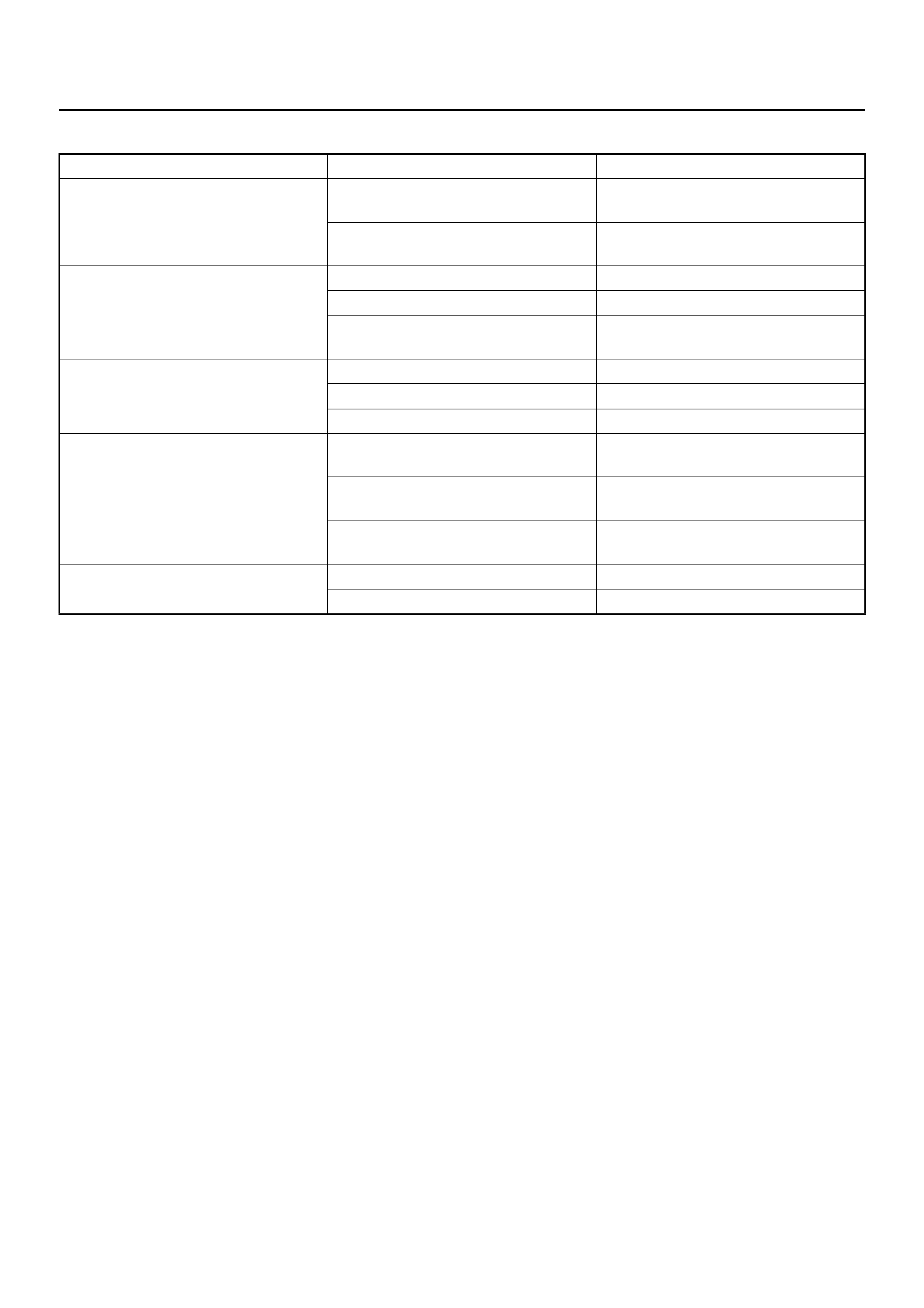
DIAGNOSIS
Condition Possible cause Correcti on
Noise from compression Defective rotor/piston Replace compressor/cylinder and
shaft assembly
Defecti ve sh aft Repl ace co mpr es so r/cy l ind er a nd
shaft assembly
Noise from magnetic clutch Defective bearing Replace magnetic clutch
Defective clutch Replace magnetic clutch
Clearance between drive plate and
pulley not standard Adjust the clearance or replace
magnetic clutch
Insufficient cooling Defective gasket Replace compressor/gasket
Defective rotor/reed valve Replace compressor/valve plate
Defective trigger valve/suction valve Replace compressor/suction valve
Not rotating Defective rotor/piston Replace compressor/cylinder and
shaft assembly
Defecti ve sh aft Repl ace co mpr es so r/cy l ind er a nd
shaft assembly
Rotating parts seized due to
insufficient oil Replace compressor
Oil and/or gas leakage Defective seal Replace compressor/shaft seal
Defecti ve O-rin g Replac e
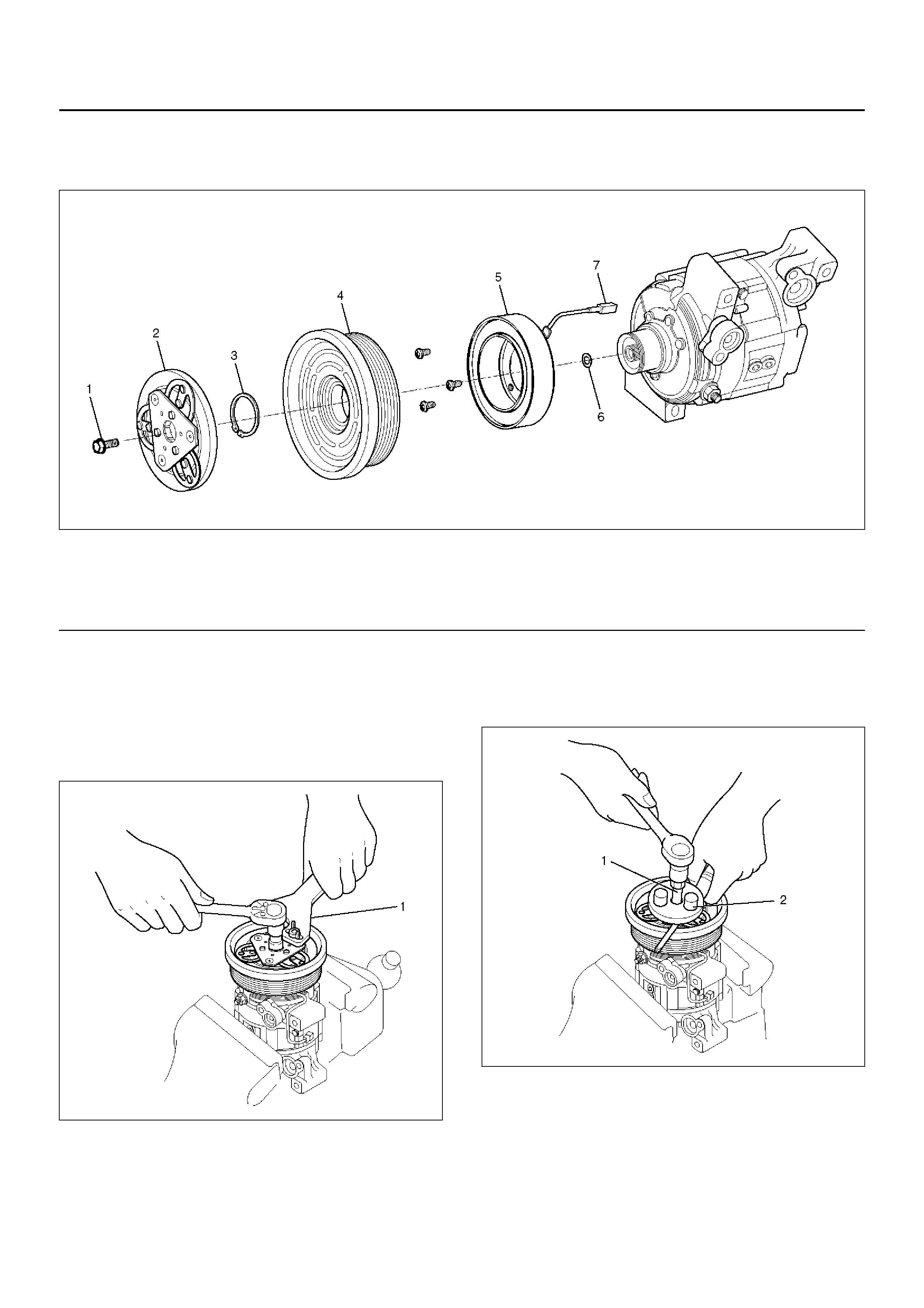
MAGNETIC CLUTCH ASSEMBLY (DKV-14G TYPE)
PARTS LOCATION VIEW
871RX025
EndOFCallout
REMOVAL
1. Using drive plate holder J-33939 (1) to prevent the
drive plate from rotating, then remove the drive plate
bolt.
871RX029
2. Remove drive plate by using drive plate puller
J-339 44-A (2 ) and forcing scr ew J-339 44- 4 (1).
871RX023
Legend
(1) Drive Plate bolt
(2) Drive Plate
(3) Snap Ring
(4) Pulley Assembly
(5) Field Coil
(6) Shim (s)
(7) Lead Wire
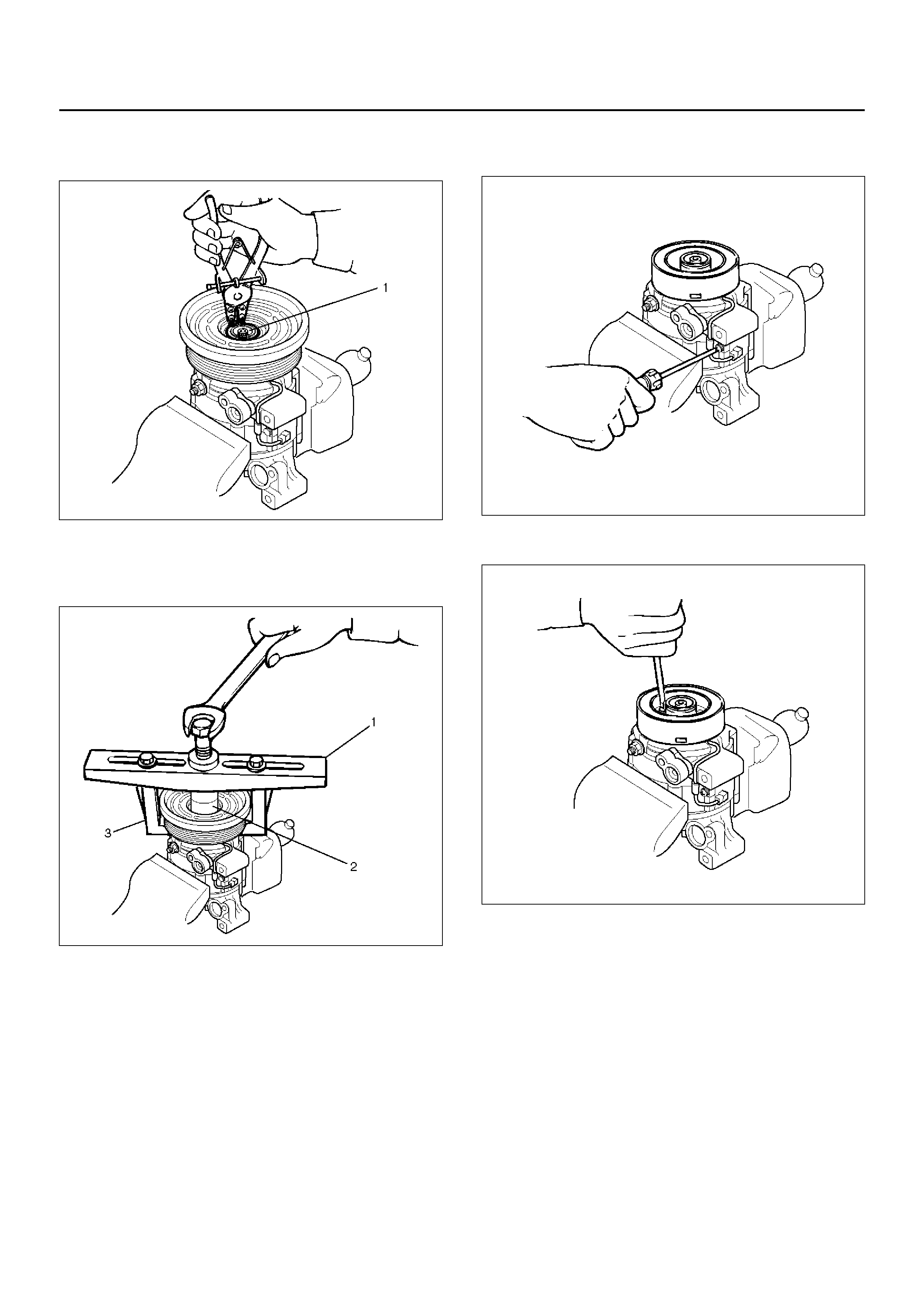
3. R emove sh im (s ).
4. Remove snap ring (1) by using snap ring pliers.
871RY00029
5. R emove p ulley assem bly by us ing pul ley pul ler pilo t
J-384 24(2), p ulley pulle r J-843 3(1) and pulle y pull er
leg J-24092-2(3).
871RY00033
6. Loosen screw and disconnect the field coil wire
connector.
871RY00030
7. Loosen three screws and remove the field coil.
871RY00034
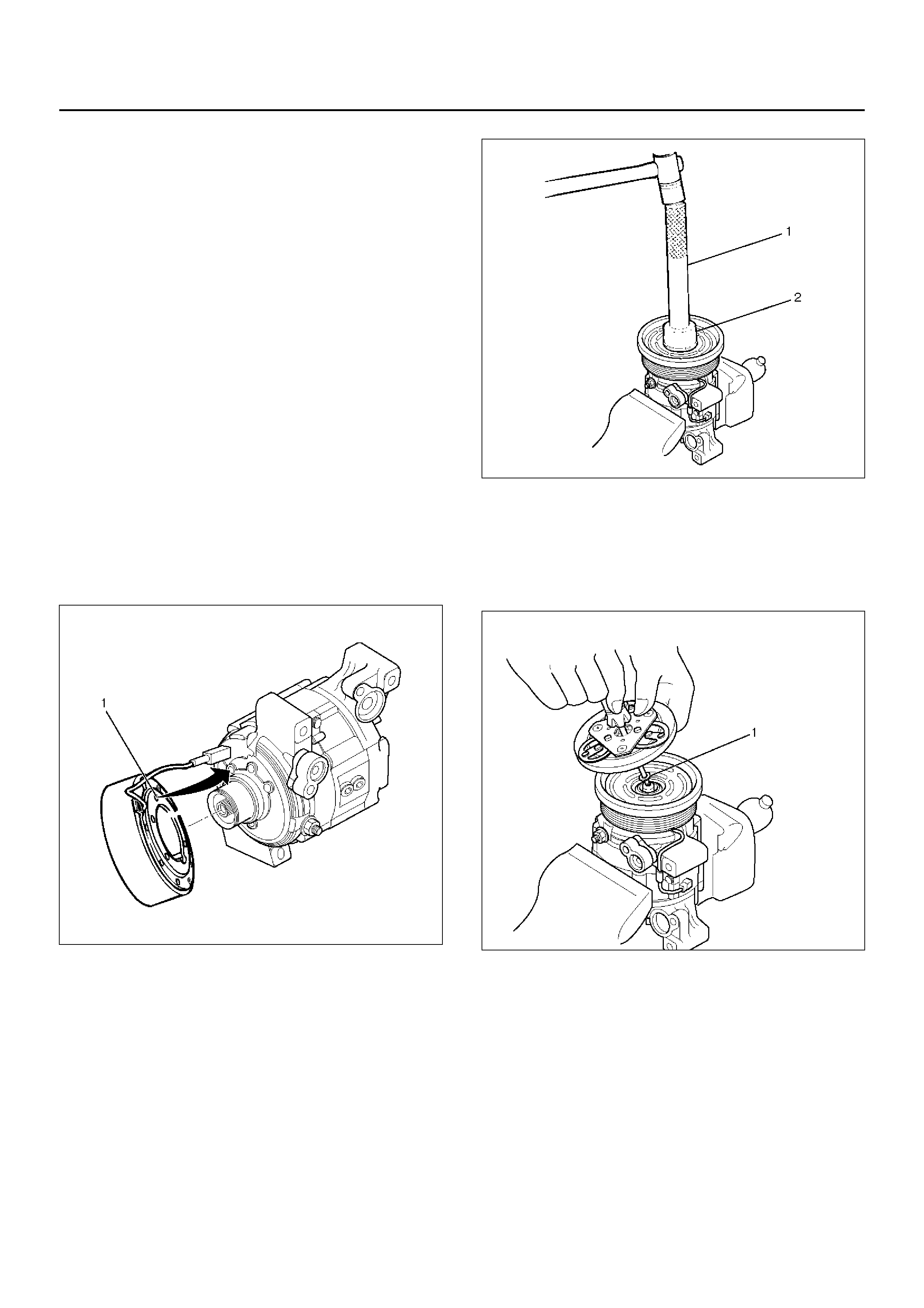
INSPECTION AND REPAIR
Drive Plate
If the frictional surface shows signs of damage due to
excessive heat, the drive plate and pulley should be
replaced.
Pulley Assembly
Check the appearance of the pulley assembly. If the
frictional surface of the pulley shows signs of excessive
grooving due to slippage, both the pulley and drive plate
should be replaced. The frictional surfaces of the pulley
assembly should be cleaned with a suitable solvent
before reinstallation.
Coil
Check coil for loose connector or cracked insulation.
INSTALLATION
1. In stall field coil.
• Align the located portion (1) of the field coil and
compressor.
871RY00035
• Tighten the mounting screw to the specified
torque.
Torque: 5N·m (0.5kg·m/44 lb in)
2. Connect the lead wire connector with the rubber
hold and tighten the screw.
3. Install pulley assembly by using pulley installer
J-339 40-A (2 ) and driv e hand le J-809 2( 1).
871RY00032
4. Install snap ring.
5. Install shim (s).
6. Install the drive plate to the compressor drive shaft
together with the original shim(s)(1). Press the drive
plate by hand.
871RY00031
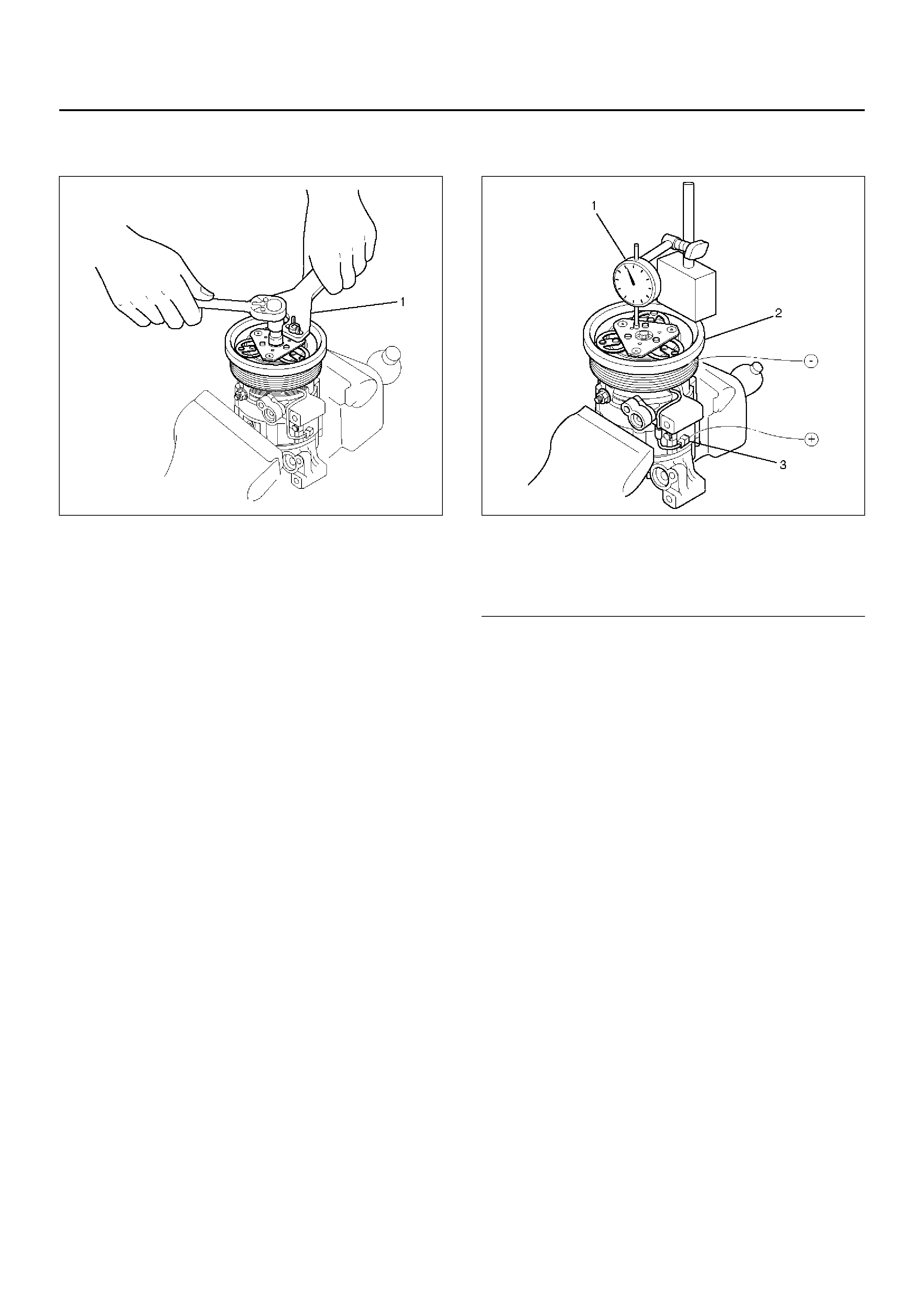
7. Install drive plate bolt by using drive plate holder
J-33939 (1) to prevent the drive plate from rotating.
871RX029
• Tighten the drive plate bolt to the specified
torque.
Torque: 13 N·m (1.3kg·m/113 lb in)
• After tightening the drive plate bolt, check to be
sure the pulley rotates smoothly.
• Check to be sure that the clutch clearance is
between 0.3-0.6 mm (0.01-0.02 in.)
871RY00028
EndOFCallout
• If necessary, install adjusting shim(s).
• Adjusting shims are available in the following
thickness.
Thickness
•0.1 mm (0.0039 in.)
•0.3 mm (0.0118 in.)
•0.5 mm (0.0197 in.)
Legend
(1) Dial Gauge
(2) Pulley Assembly
(3) Field Coil Wire Connector
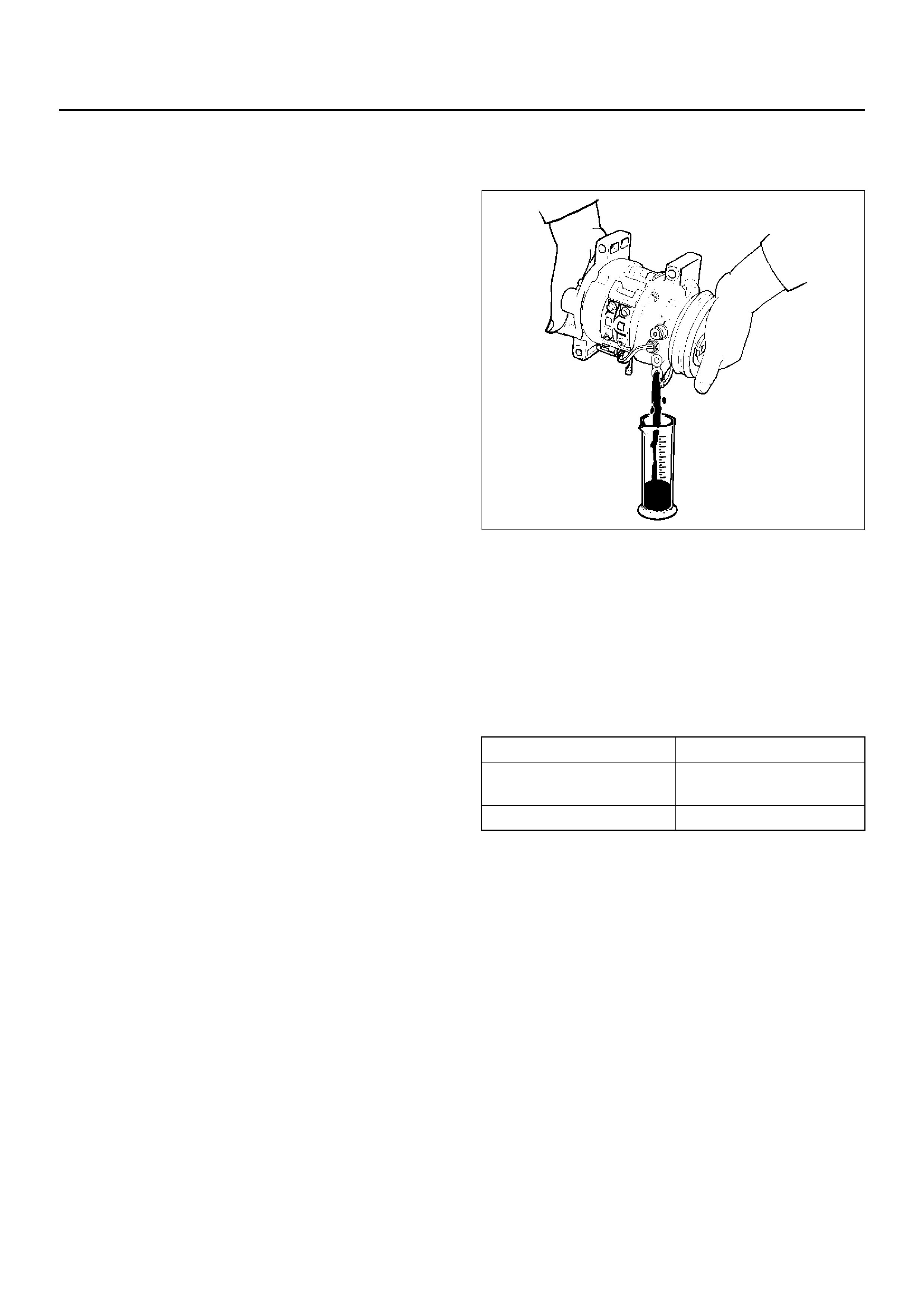
COMPRESSOR OIL
OIL SPECIFICATION
• The HFC-134a system requires a synthetic (PAG)
compressor oil whereas the R-12 system requires a
mineral compressor oil. The two oils must never be
mixed.
• Compressor (PAG) oil varies according to
compressor model. Be sure to use oil specified for
the model of compressor.
• Always use HFC-134a Vane Rotary Type
Compressor Oil (AIPDN Part No.2-90188-301-0)
HANDLING OF OIL
• The oil should be free from moisture, dust, metal
powder, etc.
• Do not mix with other oil.
• The water content in the oil increases when exposed
to the air. After use, seal oil from air immediately.
(HFC-134a Vane Rotary Compressor Oil absorbs
moisture very easily.)
• The compressor oil must be stored in steel
containers, not in plastic containers.
COMPRESSOR OIL CHECK
The oil used to lubricate the compressor is circulating
with the refrigerant.
Whenever replacing any component of the system or a
large amount of gas leakage occurs, add oil to maintain
the original amount of oil.
Oil Capacity
Capacity total in system: 150cc (5.0 fl.oz)
Compressor (Service parts) charging amount:
150 cc (5.0 fl.oz)
CHECKING AND ADJUSTING OIL
QUANTITY FOR USED
COMPRESSOR
1. Perform oil return operation. Refer to Oil Return
Operation in this section.
2. Discharge and recover refrigerant and remove the
compressor.
3. Drain the compressor oil and measure the extracted
oil with a measuring cylinder.
871RX020
4. If the amount of oil drained is much less than 90 cc
(3.0 fl. oz.), some refrigerant may have leaked out.
Conduct a leak tests on the connections of each
system, and if necessary, repair or replace faulty
parts.
5. Check the compressor oil contamination. (Refer to
Contamination of Compressor Oil in this section.)
6. Adjust the oil level following the next procedure
below.
7. Install the compressor, then evacuate, charge and
perform the oil return operation.
8. Check system operation.
When it is impossible to preform oil return
operation, the compressor oil should be checked in
the following order:
1. Discharge and recover refrigerant and remove the
compressor.
2. Drain the compressor oil and measure the extracted
oil with a measuring cylinder.
3. Check the oil for contamination.
4. If more than 90 cc (3.0 fl. oz.) of oil is extracted from
the compressor, supply the same amount of oil to
the compressor to be installed.
5. If the amount of o il extrac ted is les s than 90 cc (3.0
fl. oz.), recheck the compressor oil in the following
order.
6. Supply 90 cc (3.0 fl. oz.) of oil to the compressor
and install it onto the vehicle.
(Charging Amount) (Collected Amount)
more than 90cc (3.0 fl.oz) same as collected
amount
less than 90 cc (3.0 fl.oz) 90cc (3.0 fl.oz)
7. Evacuate and recharge with the proper amount of
refrigerant.
8. Perform the oil return operation.
9. Remove the compressor and recheck the amount of
oil.
10. Adjust the compressor oil, if necessary.
CHECKING AND ADJUSTING FOR
COMPRESSOR REPLACEMENT
150 cc (5.0 fl.oz.) of oil is charged in compressor
(service parts). So it is necessary to drain the proper
amount of oil from the new compressor.
1. Perform oil return operation.
2. Discharge and recover the refrigerant and remove
the compressor.
3. Drain the compressor oil and measure the extracted
oil.
4. Check the compressor oil for contamination.
5. Adjust the oil level as required.
6. Evacuate, charge and perform the oil return
operation.
7. Check the system operation.
CONTAMINATION OF COMPRESSOR
OIL
Unlike engine oil, no cleaning agent is added to the
compressor oil. Even if the compressor runs for a long
period of time (approximately one season), the oil never
becomes contaminated as long as there is nothing
wrong with the compressor or its method of use.
Inspect the extracted oil for any of the following
conditions:
• The capacity of the oil has increased.
• The oil has changed to red.
• Foreign substances, metal powder, etc., are present
in the oil.
If any of these conditions exists, the compressor oil
is contaminated. Whenever contaminated
compressor oil is discovered, the receiver/drier
must be replaced.
OIL RETURN OPERATION
There is close affinity between the oil and the
refrigerant. During normal operation, part of the oil
recirculates with the refrigerant in the system. When
checking the amount of oil in the system, or replacing
any component of the system, the compressor must be
run in advance for oil return operation. The procedure
is as follows:
1. Open all the doors and the engine hood.
2. Start the engine and air conditioning switch to “ON"
and set the fan control knob at its highest position.
3. Run the compressor for more than 20 minutes
between 800 and 1,000 rpm in order to operate the
system.
4. Stop the engine.
REPLACEMENT OF COMPONENT
PARTS
When replacing the system component parts, supply
the followi ng amo unt of oil to the c omp onen t parts to be
installed.
(Collected Amount) (Charging Amount)
more than 90 cc (3.0 fl.oz) same as collected
amount
less than 90 cc (3.0 fl.oz) 90 cc (3.0 fl.oz)
(Amount of oil drained
from used compressor) (Draining a m ount of oil
from new compre sso r)
less than 90 cc (3.0 fl.oz) Same as drained amount
more than 90 cc (3.0 fl.oz) 90 cc (3.0 fl.oz)
(Component parts to be
installed) (Amount of Oil)
Evaporator 50 cc (1.7 fl. oz.)
Condenser 30 cc (1.0 fl. oz.)
Receiver/dryer 30 cc (1.0 fl. oz.)
Refrigerant line (one
piece) 10 cc (0.3 fl. oz.)
MAIN DATA AND SPECIFICATIONS
General Specifications
COMPRESSOR
Model DKV-14G
Type Vane rotary type
Number of vanes 5
Rotor diameter 64 mm (2.52 in.)
Stroke 8.75 mm (0.34 in.)
Displacement 140 cc (47.3 fl.oz.)
Maximum speed 7,000 rpm (up to 8,400 rpm)
Dir ection of rotation Clockwise (Front-side view)
Lubrication system Pressure differential type
Lubricant HFC-134a Vane Rotary Type Compressor Oil
Be Equivalent to ZXL 200 PG
150 cc (5.0 fl.oz.)
Refrigerant HFC-134a, 650 g (1.43 lbs.)
Shaft seal Lip type
Weight 3.6 kg
MAGNETIC CLUTCH
Type Electromagnetic single-plate dry clutch
Rated voltage 12 Volts D.C.
Current consumption 3.7 A
Starting torque 49 N·m (36 lb·ft)
Dir ection of rotation Clockwise (Front-side view)
Weight 2.4 kg (5.3 lbs.)
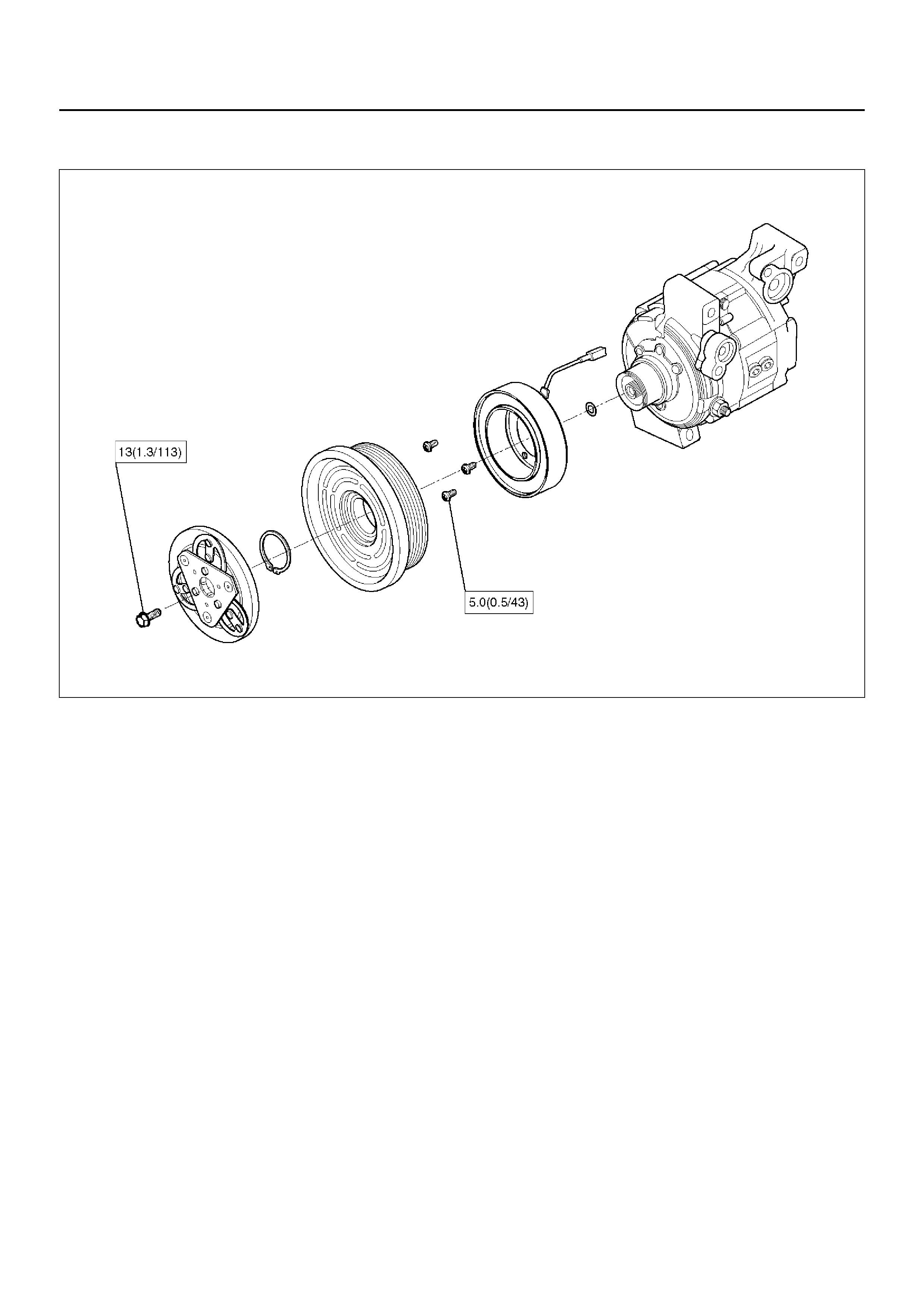
Torque Specifications
N·m (kg·m/lb in)
871RY00038
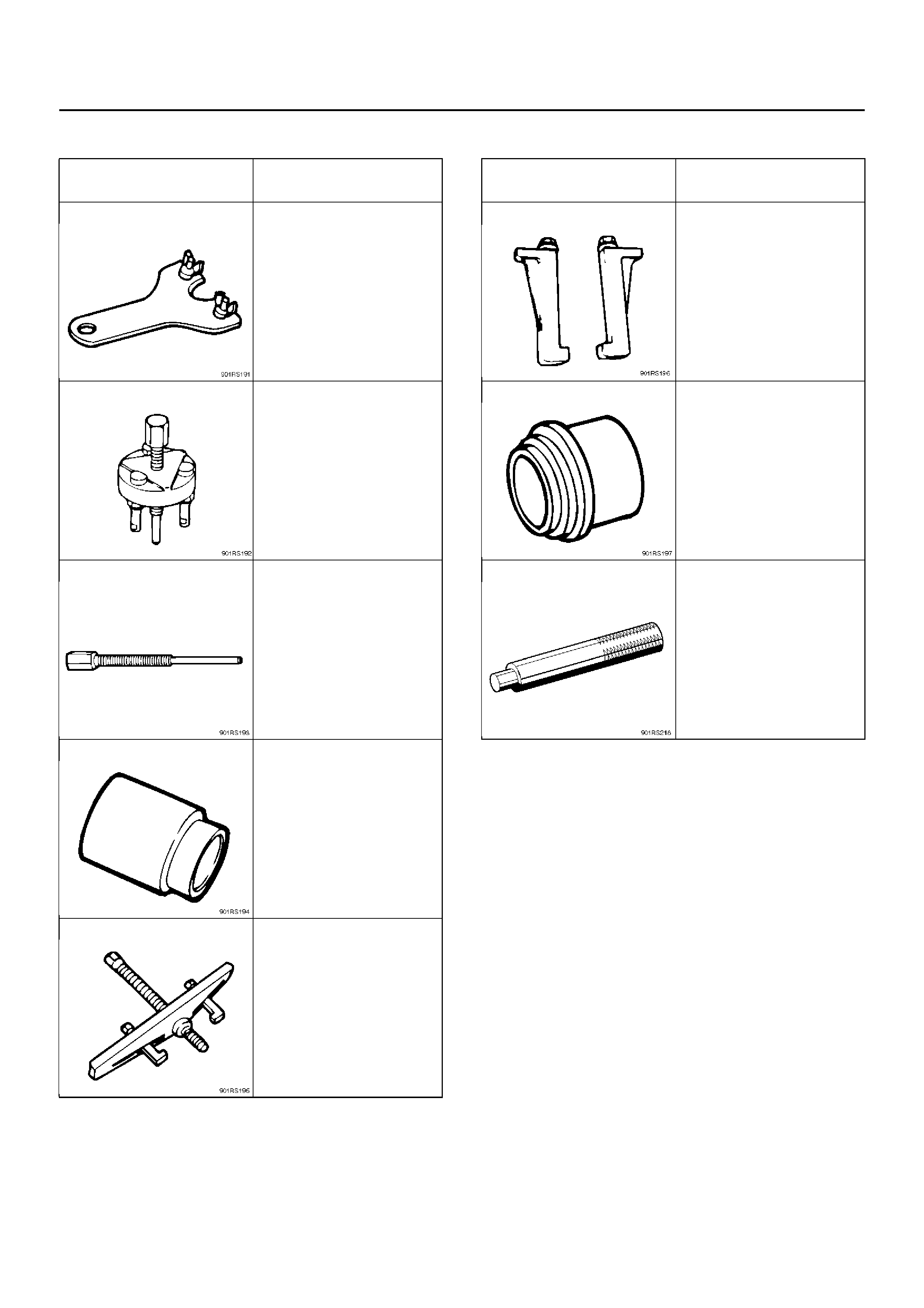
SPECIAL TOOLS
ILLUSTRATION TOOL NO.
TOOL NAME
J-33939
Drive plate holder
J-33944-A
Drive plate puller
J-33944-4
Forcing screw
J-38424
Pulley puller pilot
J-8433
Pulley puller
J-24092-2
Pulley puller leg
J-33940-A
Pulley installer
J-8092
Drive handle
ILLUSTRATION TOOL NO.
TOOL NAME