
SECTION 2D - AUTOMATIC AIRCONDITIONING SYSTEM
Automatic Air Conditioning System
General Description
Automatic Air Conditioner Parts
Configuration
Refrigerant Line and Associated Parts
Circuit Diagram
Functions and Features
Automatic Air Conditioner Block Diagram
Control Panel Layout
Air Control Functions
Operation and Functions of Control Panel
Switches
Overview of Construction, Movement
and Control of Major Parts of Automatic
Air Conditioner System
Overview of Automatic Control of
Automatic Air Conditioner
Troubleshooting
Troubleshooting, Its Overview
and Procedures
Auto Air Conditioner Control Unit Power
Supply Diagnosis
Performance and Movement checklist for
Automatic Air Conditioner Related Parts
Troubleshooting With Self-Diagnosis
Function
Inspection By Failed Location
Inspection of the Sensors
Inspection of the Intake Actuator System
Inspection of the Mix Actuator System
Inspection of the Mode Actuator System
Inspection of the Fan Motor System
Inspection of the Heater Control System
Inspection of the Magnetic Clutch System
Condenser Fan Diagnosis
Individual Inspection
On-Vehicle Service
Power Transistor
Removal
Installation
Automatic Air Conditioner Control Unit
Removal
Installation
In Car Sensor
Removal
Installation
Ambient Sensor
Removal
Installation
Sun Sensor
Removal
Installation
Duct Sensor
Removal
Installation
Mode Actuator
Removal
Installation
Mix Actuator
Removal
Installation
Intake Actuator
Removal
Installation
AUTOMATIC AIR CONDITIONING SYSTEM
GENERAL DESCRIPTION
Using a variety of sensors, this automatic heater and air
conditioner accurately senses outside air temperature,
solar radiation quantity, evaporator's blowing
temperature, and interior temperature, then enters
these data to the automatic heater/air conditioner
control unit (equipped wi th the built- in micro-co mputer).
The data provided to the control unit enables to
automatically control blow temperature and blow air
quantity, turn on or off the compressor and switch the
blow port as well as switching between the fresh air
intake and interior air circulation.
Resetti ng the aut omatic function a llows you to switc h to
the manual control mode.
The self-diagnoisis function of the automatic air
conditioner control unit (with the built-in micro-
computer) allows the unit to access and diagnose a
failed part easier and quicker.
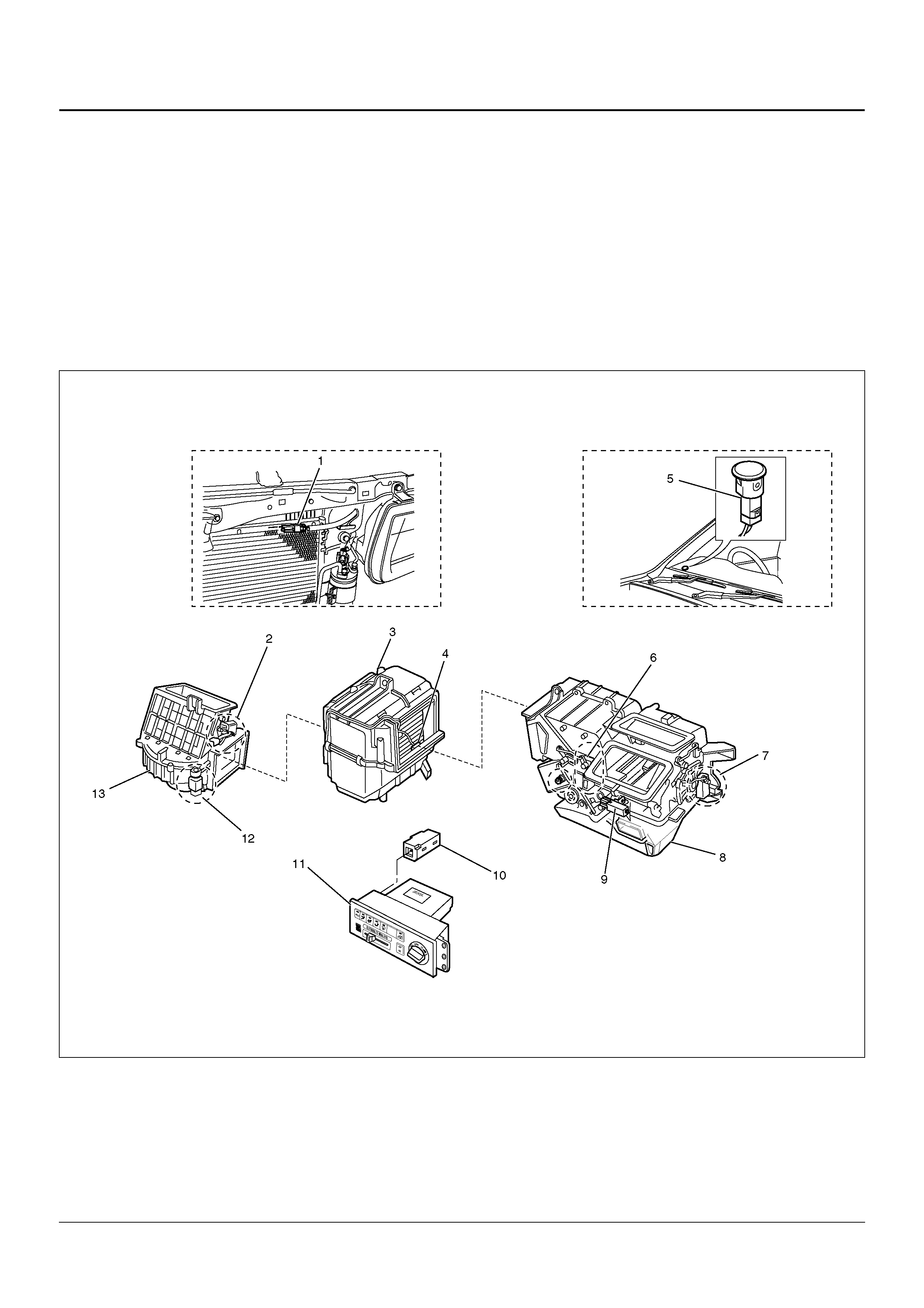
AUTOMATIC AIR CONDITIONER PARTS CONFIGURATION
865R100001
EndOFCallout
Legend
(1) Ambient Sensor
(2) Intake Actuator
(3) Evaporator Assembly
(4) Duct Sensor
(5) Sun Sensor
(6) Mix Actuator
(7) Mode Actuator
(8) Heater Unit
(9) Resistor
(10) In Car Sensor
(11) Automatic Air Conditioner Control Unit
(12) Max – High Relay
(13) Blower Unit
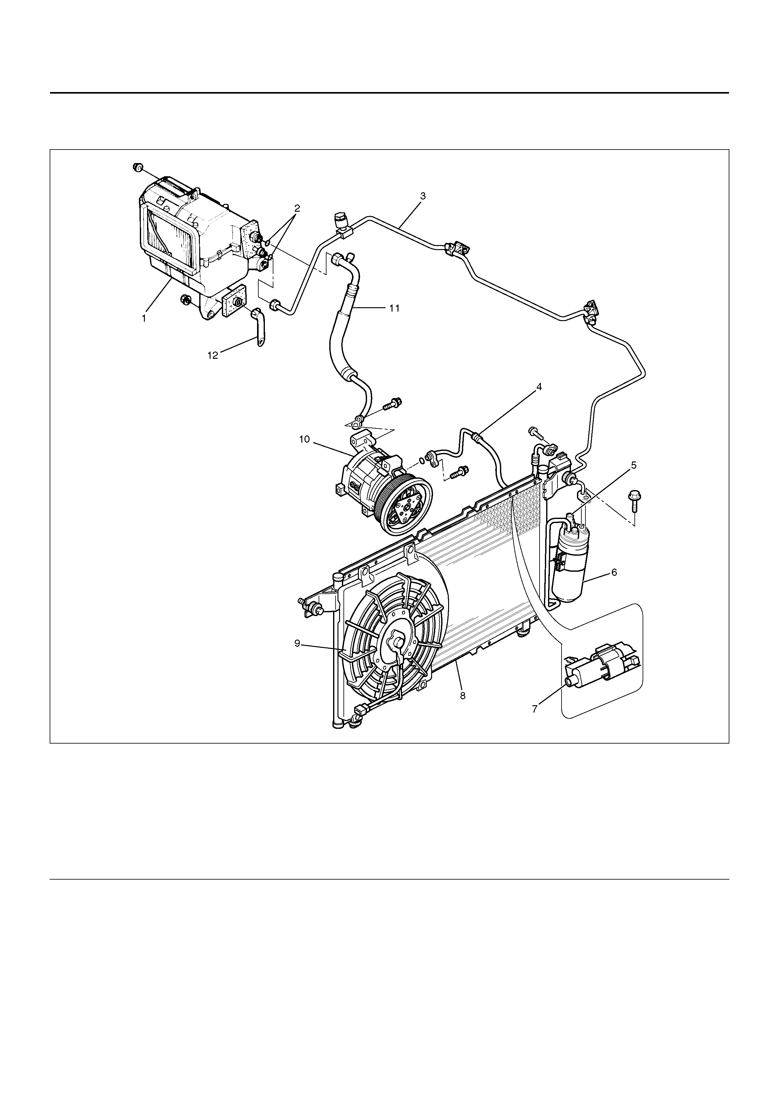
REFRIGERANT LINE AND ASSOCIATED PARTS
852R100009
EndOFCallout
Legend
(1) Eva pol ato r Asse mbl y
(2) O – Ring
(3) Liquid Line (High Pressure Pipe)
(4) High Pressure Hose
(5) Pressure Switch
(6) Receiver Dryer
(7) Ambient Sensor
(8) Con den ser Asse mbl y
(9) Con den se r Fan
(10) Compressor
(11) Suction Line (Low Pressure Hose)
(12) Drain Hose
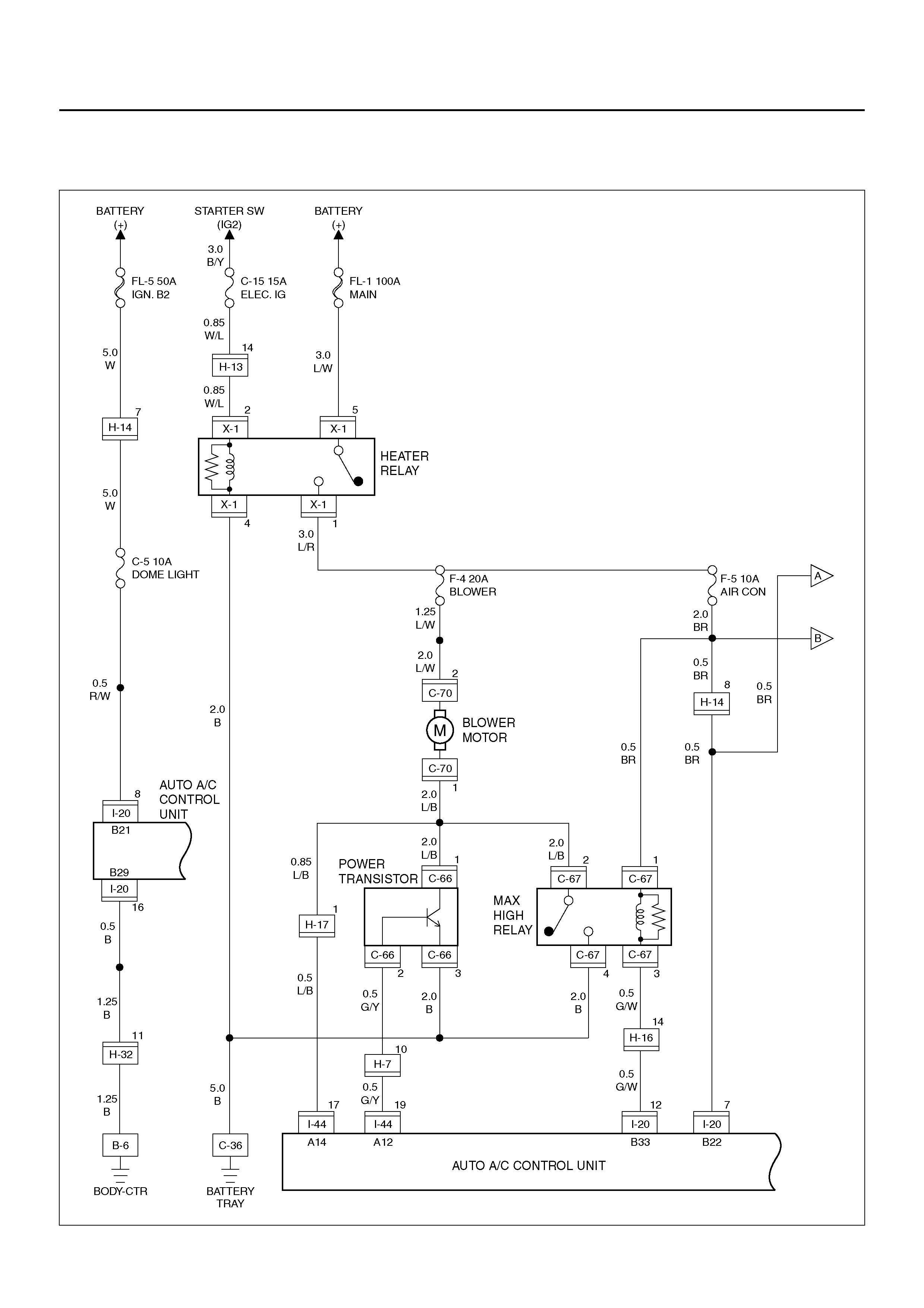
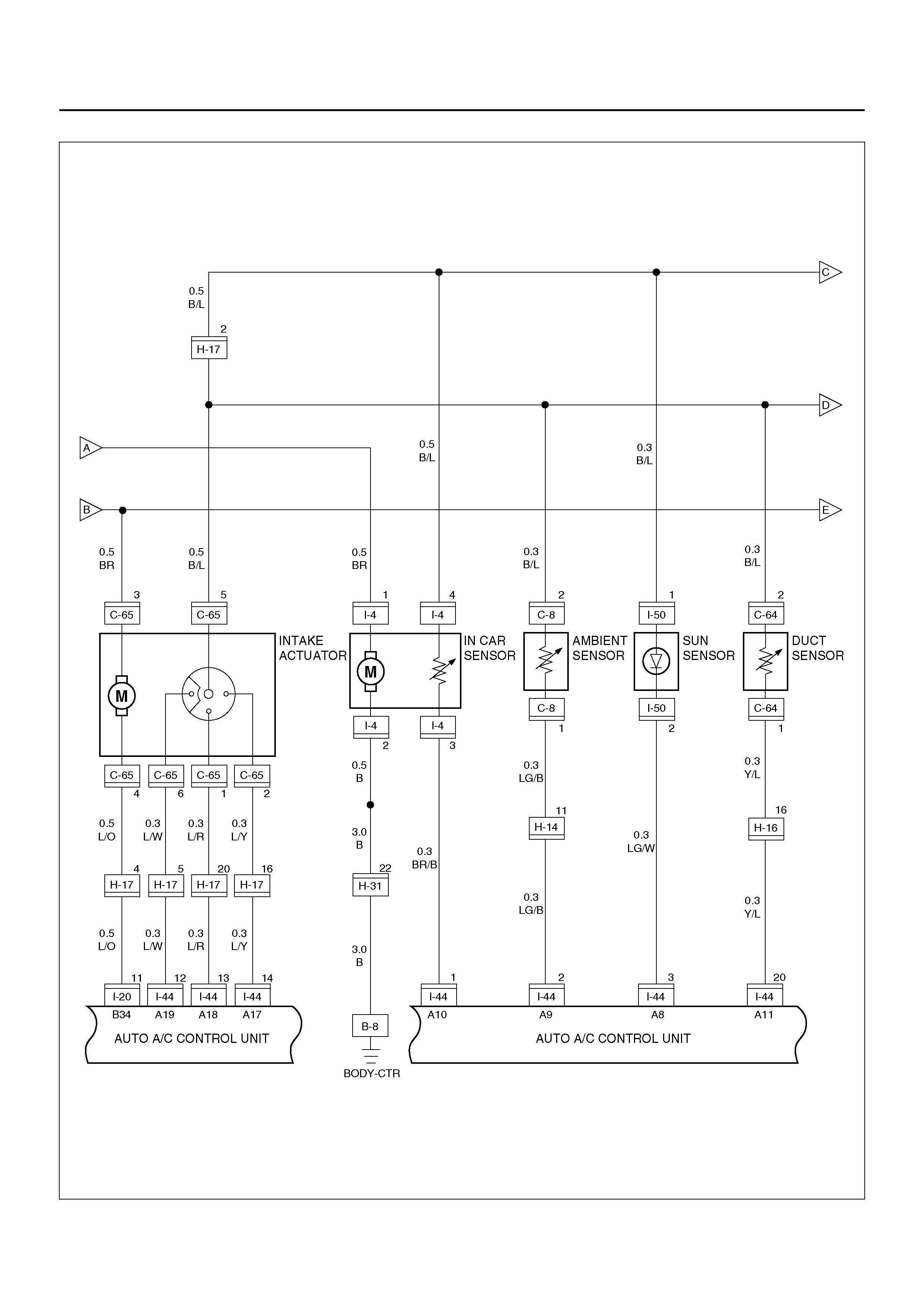
CIRCUIT DIAGRAM
6VD1 Engine
D08R100176
D08R100099
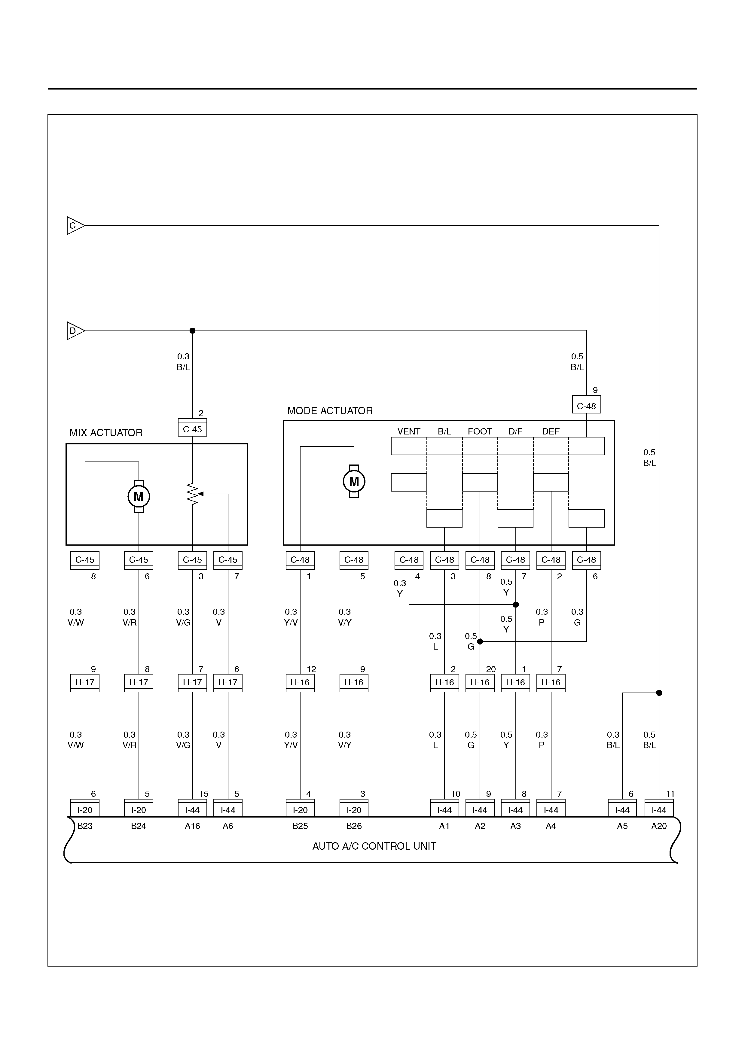
D08R100100
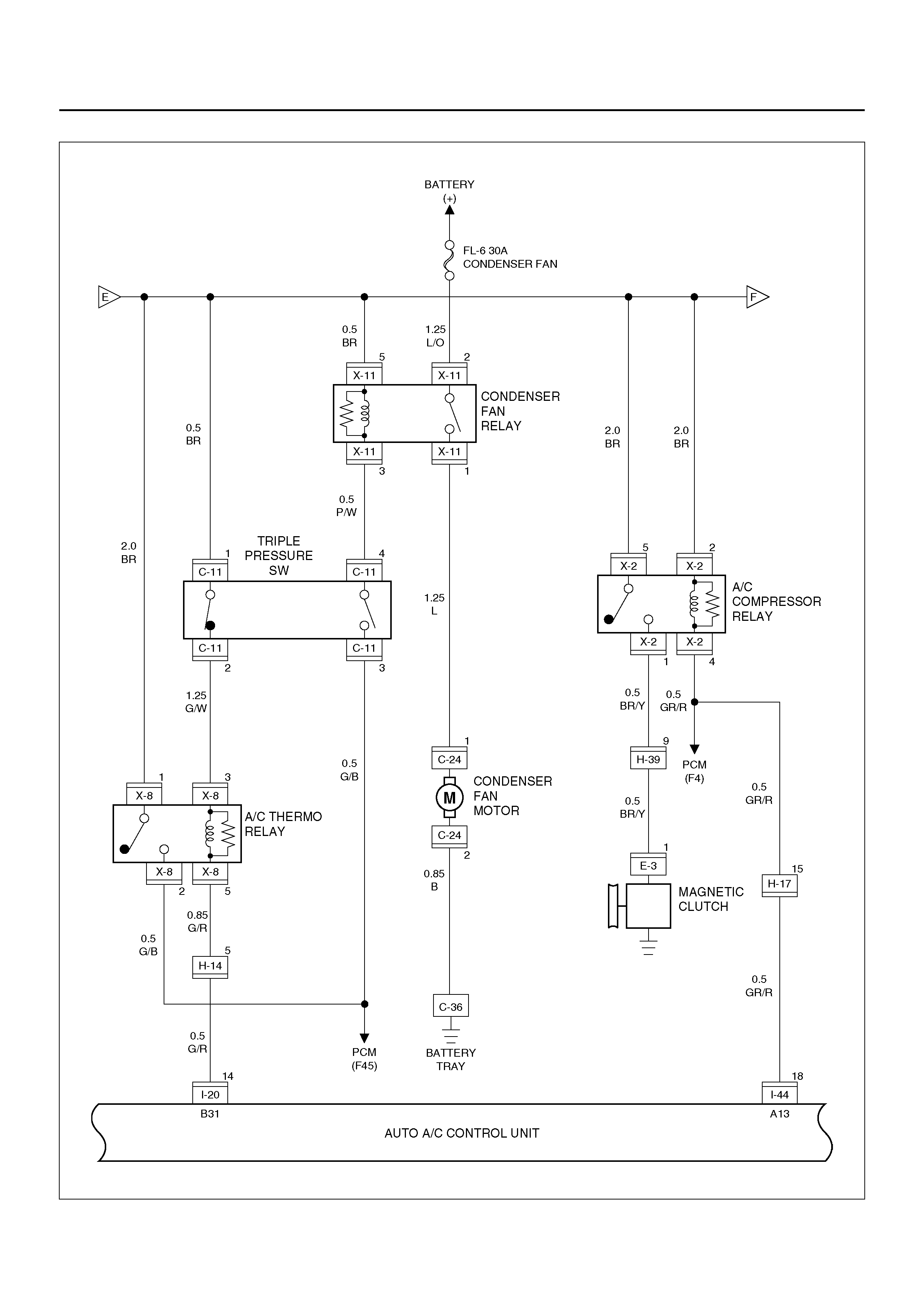
D08R100101
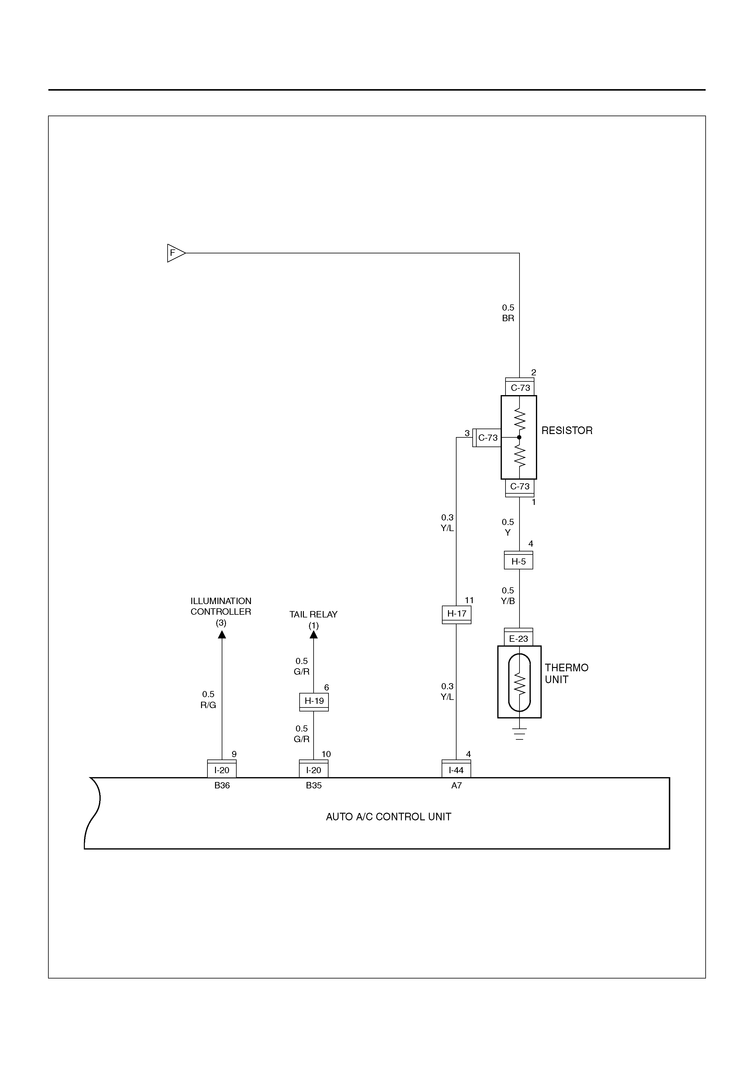
D08R100215

FUNCTIONS AND FEATURES
Automatic interior temperature control
This function enables to maintain the interior
temperature at the level specified from the
temperature control switch despite of changes in
factors such as vehicle speeds, outside air
temperature and number of passengers.
Maximum cooling and heating function
You can select FC (Full cool, namely maximum cooling
temperature) or FH (Full heat, maximum heating
temperature) from the temperature control lever.
Automatic air flow control
Air flow is automatically and consecutively fine tuned
according to the specified interior temperature and
changes in aperture of the heater unit mix door.
Mode (blow port) control
This function automatically selects either one of the
VENT, BI-LEVEL, FOOT or DEF mode for the blow
port according to changes of temperature on the
blow port. Using the mode switch allows you to
select a desired blow port manually.
Intake (switching between the fresh air intake and
circulation of interior air) control
The intake (switching between fresh air intake and
circulation of interior air) mode automatically selects
either FRESH (fresh air intake), MIX or RECIRC
(interior air circulation) according to changes of the
blow port temperature. Using the intake switch
allows you to select a desired intake port manually
(in the manual operation, FRESH and RECIRC
modes alone are available). Pressing the DEF
(defrost) mode switch selects the FRESH (fresh air
intake).
Cooler start-up timing control
This function is used for maintaining the air flow at
“LOW" level until the evaporator is sufficiently cooled
down. It is intended to prevent a large volume of hot
air being blowing into inside of a vehicle when the
cooler is turned on in hot summer season.
Heater start-up timing control
This function is used for maintained the air flow at
“LOW" level and also for maintaining the defrost
mode until temperature of coolant in the heater core
is sufficiently heated. It is intended to prevent a
large volume of cool air being blown into inside of a
vehicle when the heater is turned on in cold winter
season.
Solar radiation quantity offset control
The photodiode on the solar radiation sensor
determines solar radiation quantity accurately to
offset interior temperature quickly.
Switch position storing function
This function is used for storing switch positions being
selected in the immediately preceding operation,
namely the last time the ignition has been turned off.
It simplifies the setup procedures when restarting the
system.
Self-diagnosis function
The self-diagnosis function turned on from the panel
switch makes your troubleshooting easier (for detail
of this function, refer to the section titled
“Self-Diagnosis").
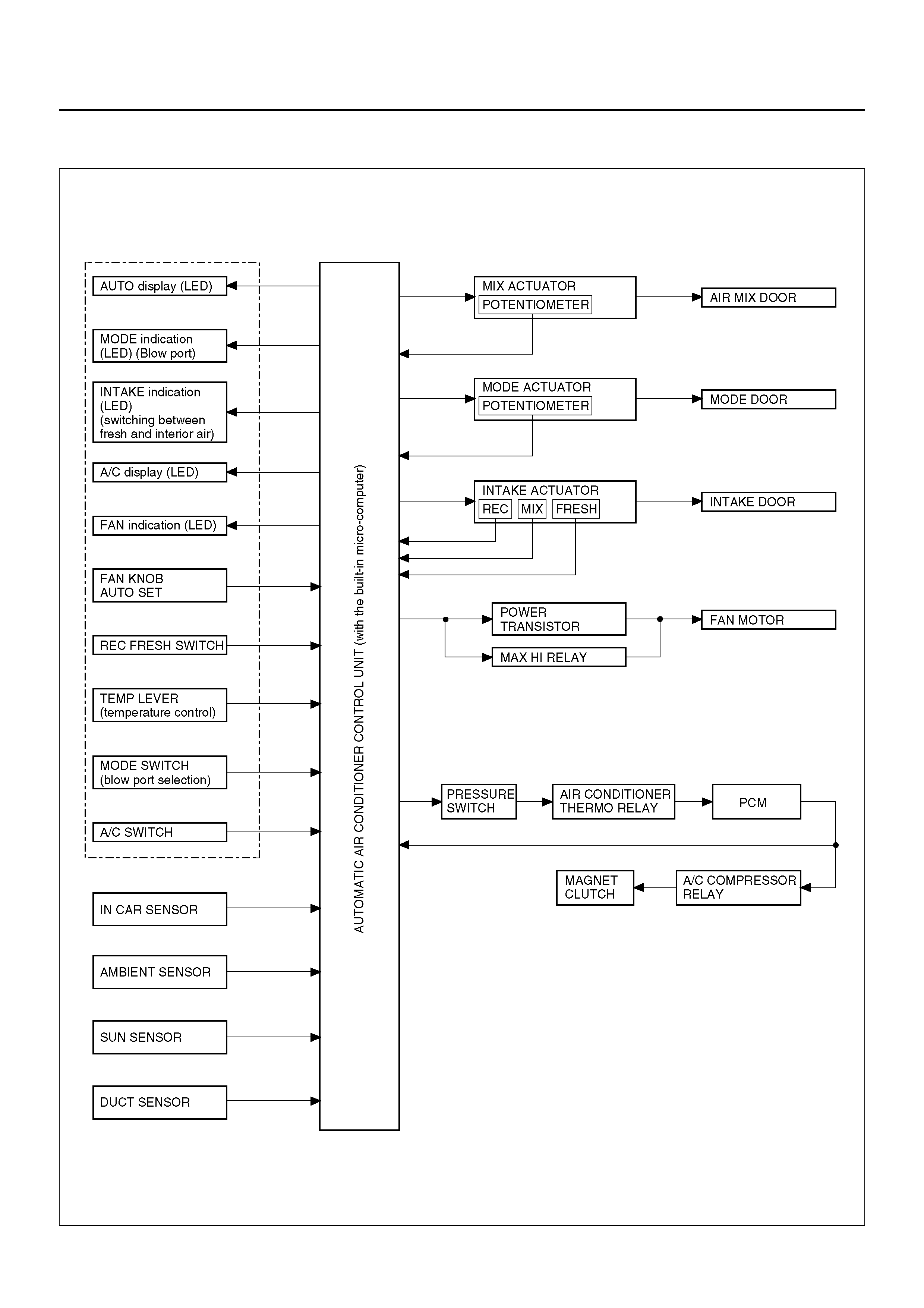
AUTOMATIC AIR CONDITIONER BLOCK DIAGRAM
F01R100001
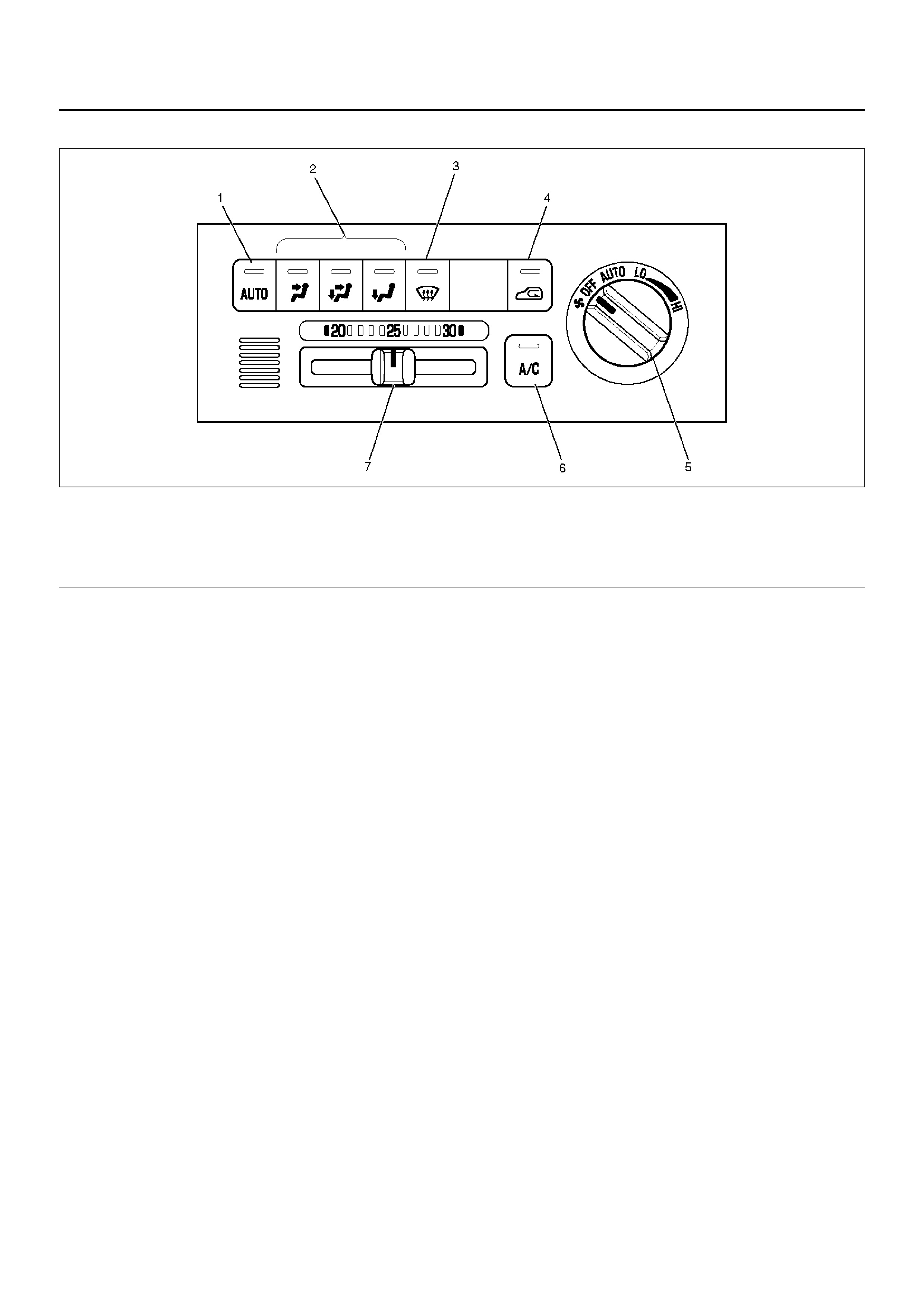
CONTROL PANEL LAYOUT
C01RW007
EndOFCallout
Legend
(1) Auto Switch
(2) Mode Switch
(3) DEF Switch
(4) Int ake Switch
(5) Fan Switch
(6) Air Conditioning Switch
(7) Temperature Control Knob

AIR CONTROL FUNCTIONS
C01RX002
EndOFCallout
Legend
(1) In t er ior Air I ntak e
(2) Fresh Air Intake
(3) Evaporator Core
(4) Air Mix Door
(5) DEF Door
(6) VENT Door
(7) Foot Door
(8) Sub Air Mix Door
(9) Heater Unit
(10) Heater Core
(11) Evapor ato r Unit
(12) Blower Unit
OPERATION AND FUNCTIONS OF CONTROL PANEL SWITCHES
Auto Switch
1. Pressing this switch turns on the automatic control
mode. It resets all manual sw itches except that for
the fan co ntrol. However, when the Manua l REC is
selected for the intake or the Manual Open is
selected, the modes are maintained.
2. It causes the A/C (air conditioner) to the ON mode
(this function, however, available only when the fan
is turned on and also the compressor is turned on
because of the given outside air temperature level).
Indication
• The AUTO LED comes on.
• Currently selec ted mod e for the M ode and Inta ke are
respectively indicated.
• The A/C LED remains turned on even if the
compressor has been turned off because of the given
outside air temperature level. Pressing the air
conditioning switch in this state turns off the A/C LED.
Mode Switch
1. Pressi ng the V ENT, B/L or FO OT s witch selects the
corresponding mode.
2. When the Aut o is select ed for the Mode and Intake ,
pressing the mode switch fixes the Intake to the
immedi atel y prec edi ng status .
Indication
• Turns off the Auto LED.
• Currently selected blow port is indicated.
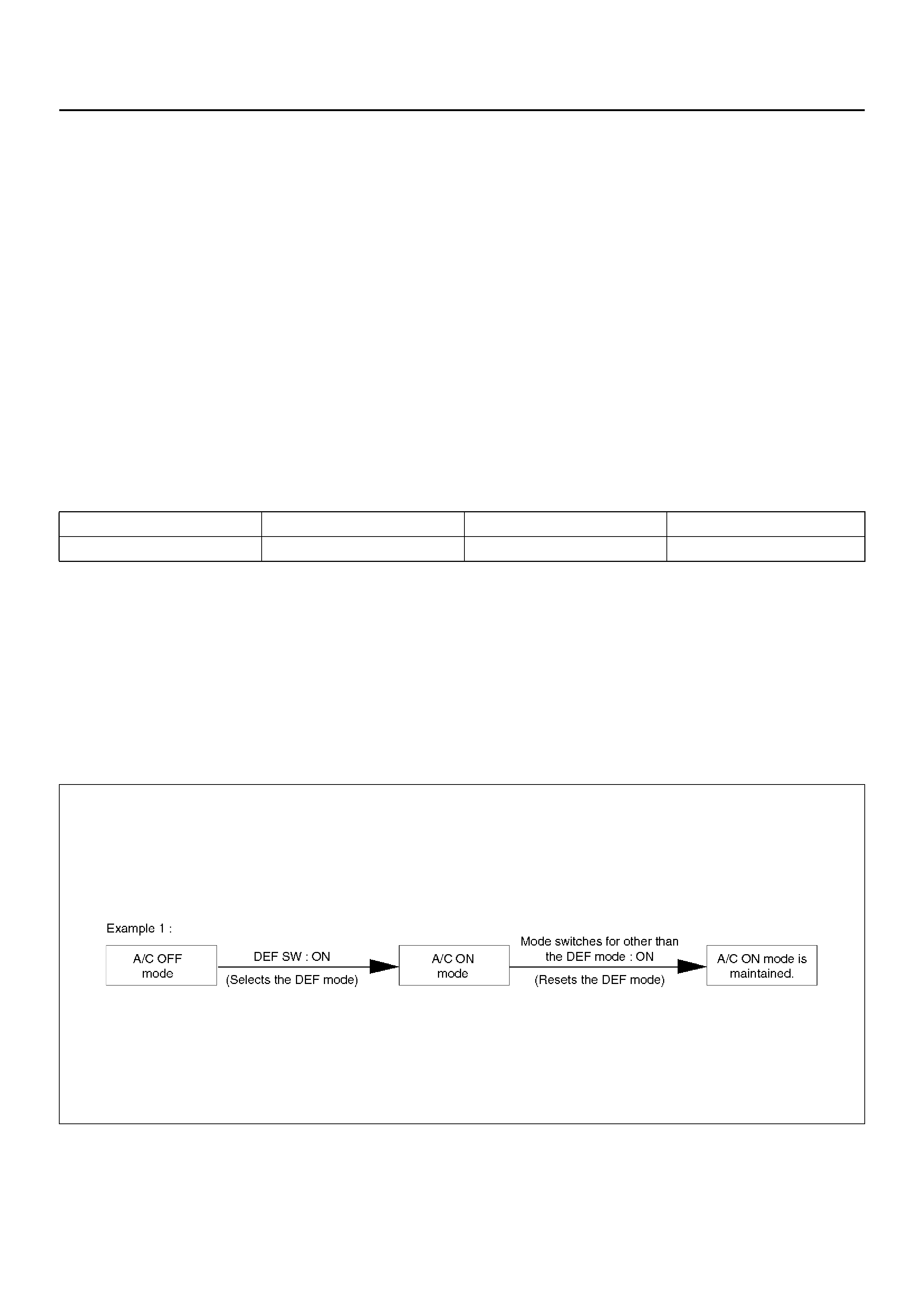
DEF Switch
Press this sw itch to select the DEF mode.
*1: When the manual REC is selected for the Intake, the
manual REC is maintained.
*2: The ON mode is enabled only when the fun is turned
on, and also the compressor is turned on because of
the given outside air temperature level.
Indication
• The Auto LED is turned off.
• DEF is indicated for the blow port, A/C LED comes on
(only when the fan is turned on), and status display is
provided for the Intake and Cold Air Bypass.
F01RX006
Blow port Intake port A/C MIX
DEF Auto FRESH *1 ON mode *2 Auto
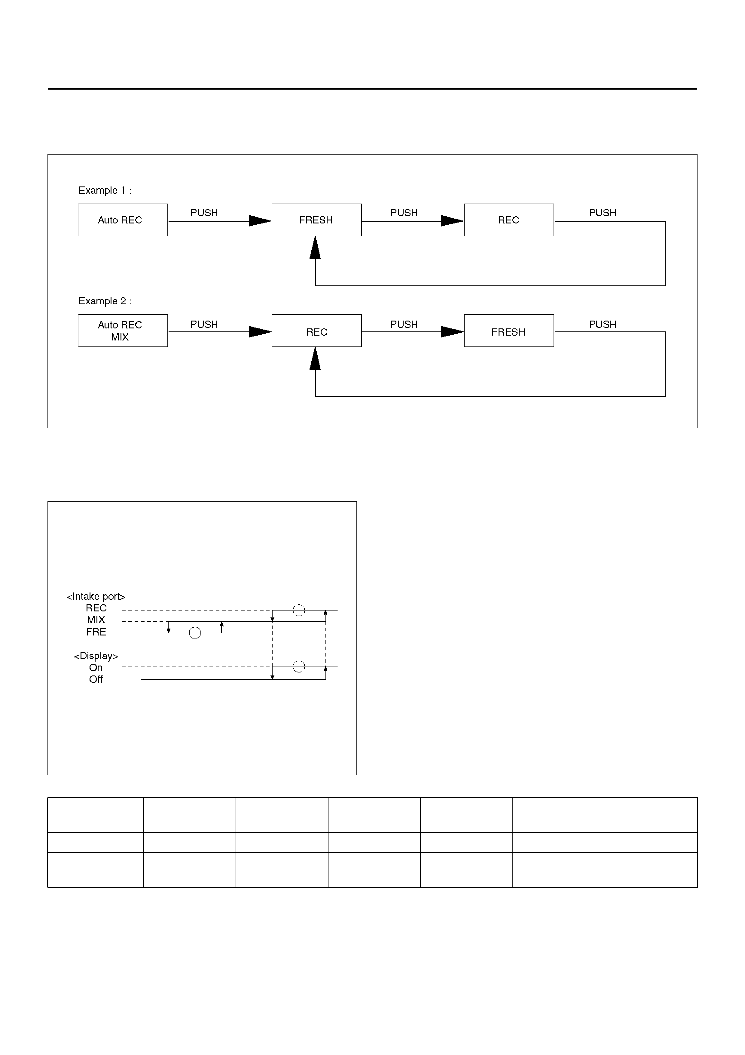
Intake Switch
Pressing this switch sequentially selects a different
intake port in the following order.
F01RX005
Indication
• The Auto LED maintains unaffected.
• Currently selected intake port is indicated.
F01RX007
Fan Switch
1. Sets the fan to the specified mode.
2. Even when the fan switch is turned off, status
displa y for the Mode, Intake an d Cold Air Bypass is
maintained.
Temperature Control Knob
1. This knob is operable only when the fan is turned
on. It may be used for the MAX control of each
block except the fan.
2. When the manual mode is selected for the fan
control, this manual mode is maintained.
MAX Control Mix Fan Mode Intake Cold air
bypass A/C
MAX/COOL Full cool MAX/HI VENT REC*1 OPEN*2 ON mode*3
MAX/HEAT Full hot AUTO/HI FOOT*4 FRESH CLOSE Current status
is maintained
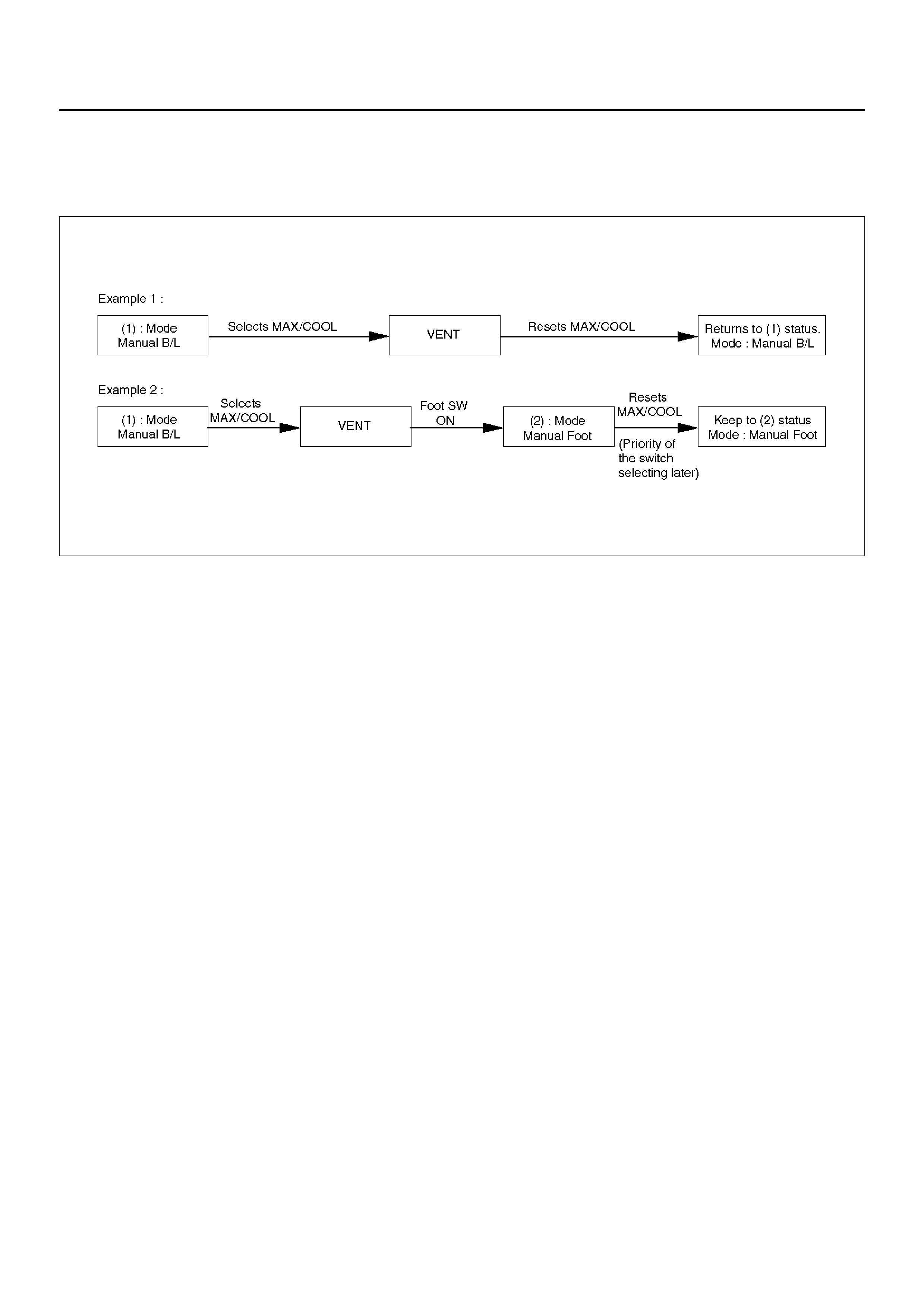
*1: In the A/C: OFF mode, FRESH shall be selected.
*2: When the fan is turned ON, CLOSE shall be
selected.
*3: The O N m ode is av ai lab le onl y wh en ON i s se lec ted
for the fan as well as for the cold outside air ON/OFF
selection.
*4: When the MAX control is selected from the DEF
mode, this DEF mode shall be maintained.
F01RX008
Indication
• As long as the MAX control is selected, the
immedi ately preced ing indic ation shall be maintained
for the AUTO.
• Status display is provided for others.
Air Conditioning Switch
Pressing this switch turns on or off the A/C (air
conditioning) control. (The compressor remains turned
off if the fan is turned off and also the compressor has
been turned off because of the given outside air
temperature level.)
Indication
1. The A/C LED remains turned on even if the
compressor has been turned off because of the
given outside air temperature level. In this case,
however, the AUTO or DEF switch must be turned
on and the A/C ON mode must also be turned on
(by the MAX/C mode).
2. Pressing the A/C switch from the above state (1)
turns off the A/C LED.
OVERVIEW OF CONSTRUCTION, MOVEMENT AND CONTROL OF MAJOR
PARTS OF AUTOMATIC AIR CONDITIONER SYSTEM
Automatic Air Conditioner Control Unit
Equipped with the built-in micro-computer, this control
unit oper ates on signa ls from sensors an d input si gnals
from switches to offer total control of the blower fan, and
actuators used for the mode door, intake door and air
mix door.
Its self-diagnosis function enables quicker access to a
failed part and its more accurate troubleshooting.
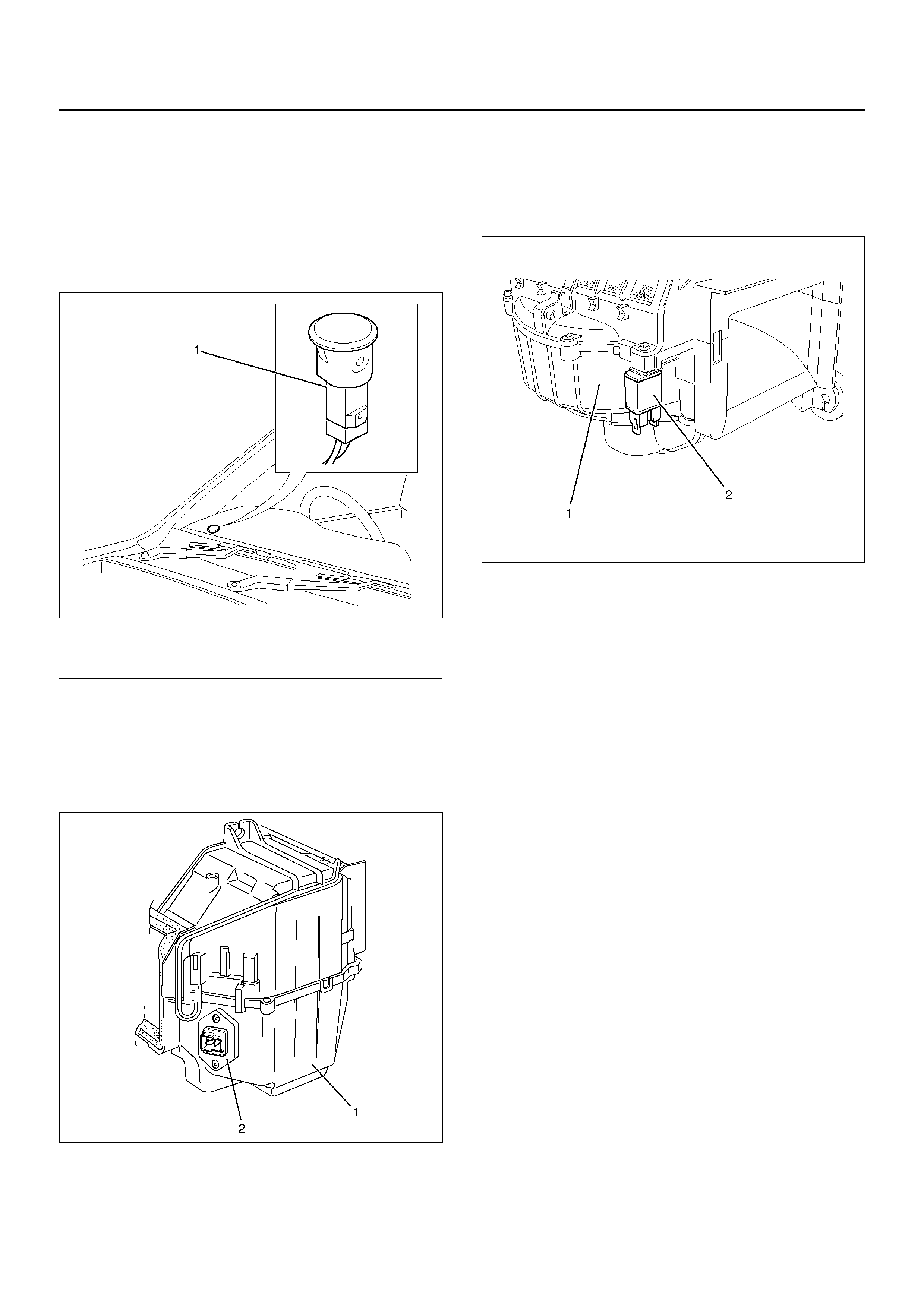
In Car Sensor
It is a sensor used for detecting room temperature of a
vehicle. This sensor converts a given room temperature
into a resistance value before entering the data to the
automatic air conditioner control unit.
This in car sensor unites the power driven aspirator and
the motor fan so that a small amount of room air may be
constantly fed to the sensor.
This sensor is provided on the control panel.
865RX015
EndOFCallout
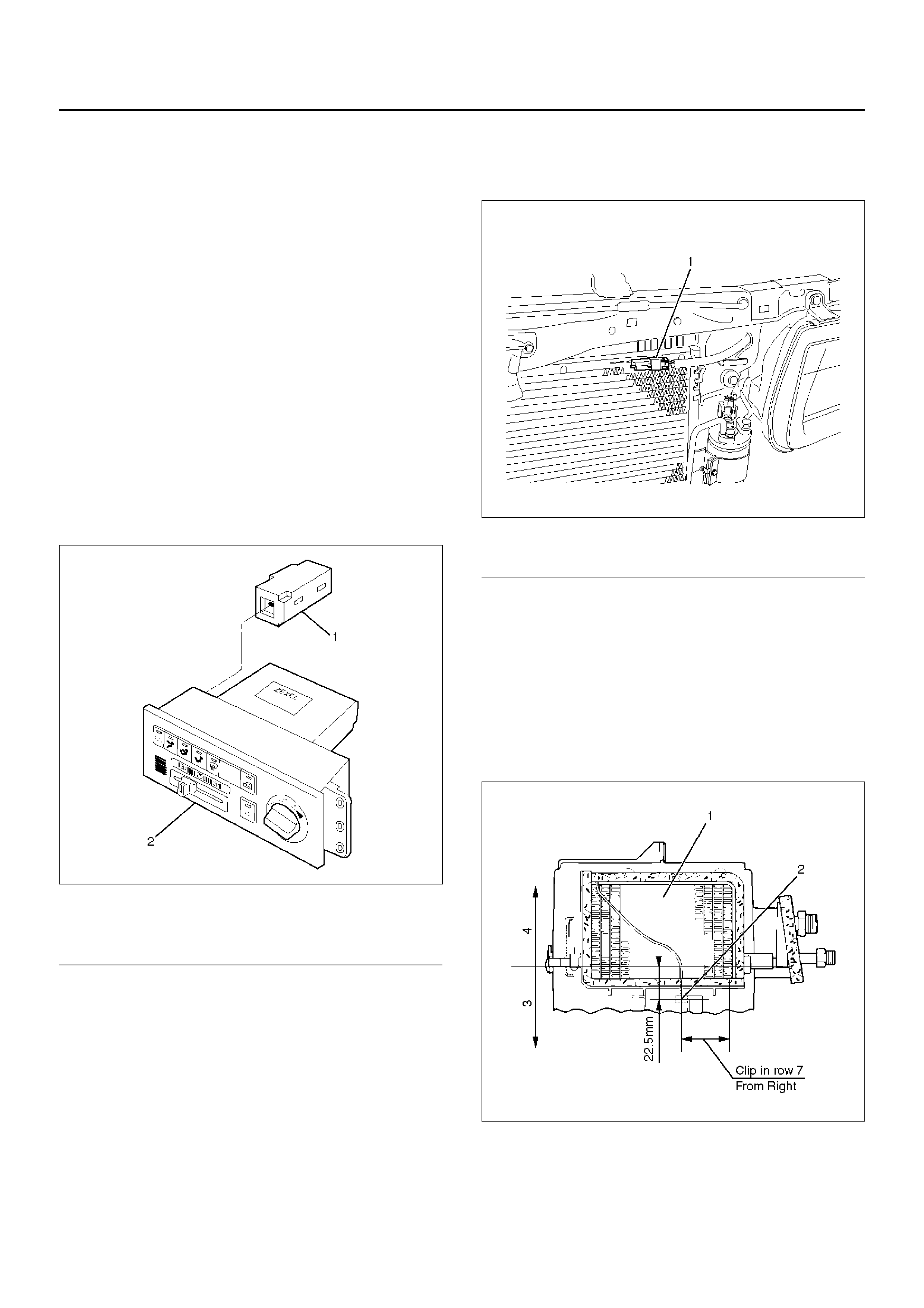
Ambient Sensor
This sensor is used for detecting temperature outside
the vehicle . It converts a give n outside air temperat ure
into a resistance value before entering the data to the
automatic air conditioner control unit.
Therma l effects from the co ndenser and radiato r during
idling after a run can be measured and offset the
automatic amplifier.
This sensor is provided on the side plate situated at
upper right side of the condenser.
875RY00021
EndOFCallout
Duct Sensor
The duct sensor is the sensor to detect temperature
change of the side of evaporator blower coming by fresh
recirculation of intake door or “on" “off" of compressor.
The temperature is converted to resistant rate.
And it works as thermostat to control to prevent freezing
of evaporator.
This sensor is installed in the upper case of evaporator.
874RX014
Legend
(1) In Car Sensor
(2) Automati c Air Conditi one r Cont rol Unit
Legend
(1) Ambient Sensor
Legend
(1) Eva por ato r Core
(2) Duct Sensor
(3) Lower Case
(4) Upper Case
Sun Sensor
It is a photodiode used for detecting quantity of solar
radiation. This sensor converts the offset signal
generated by changes in the interior temperature (which
results from fluctuations in solar radiation) into
photoelectric current to enter into the automatic air
conditioner control unit.
This sensor is provided at top of the defroster grill.
865RW009
EndOFCallout
Power Transistor
Receiving base current from the automatic air
conditioner control unit, the power transistor implements
stage-less speed chang e of the blower fan motor. Th is
transistor is provided on the evaporator.
874RX031
Max Hi Relay
This relay turned on or off by the signal from the
automatic heater/air conditioner control unit. As the
Max Hi relay is turned on, supply voltage is directly fed
to the blower fan motor to select the Max Hi mode.
860RW028
EndOFCallout
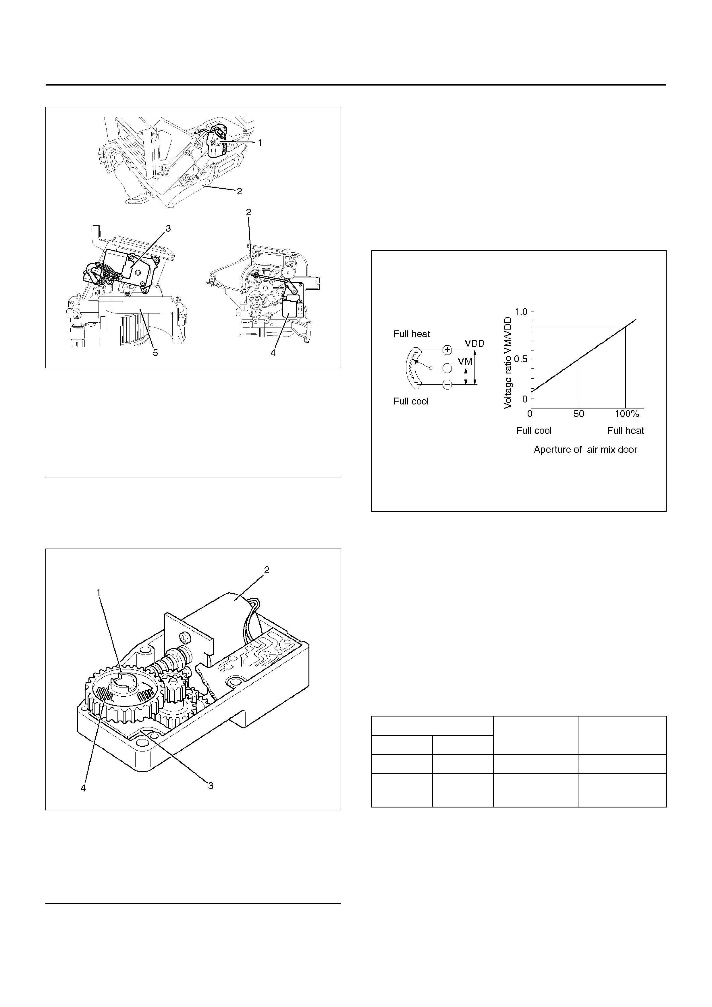
Actuator
The a ctuators are po wer driven type containing a sma ll
motor. Receiving output current from the automatic air
conditioner control unit, actuators drive the heater and
blower unit mode doors.
Actuators consist of the mode actuator used for
switching the mode (blow port selection), the mix
actuato r used f or chang ing apertur e of the ai r mix door,
the intake actuator used for switching the intake
mode(fresh air/interior air) and the cold air bypassing
actuator.
Legend
(1) Sun Sensor
Legend
(1) Evaporator Assembly
(2) Power Transistor
Legend
(1) Blower Unit
(2) Max High Relay
860R100001
EndOFCallout
The actuator changes the motor speed using the gear
and drives each door rotating the output axis united with
the sliding contact.
860RW026
EndOFCallout
The mode and mix actuators are common actuators
with the built-in potentiometer. For the intake actuator,
the contact switch type is selected.
The potentiometer is a register assembled to the printed
circuit board of the mix and mode actuators. It detects
the air mix door position specified by rotation of the
output axis as a ratio of the variable terminal (VM)
voltage against the reference voltage (VDD: 5V), then
signals the value to the automatic air conditioner control
unit.
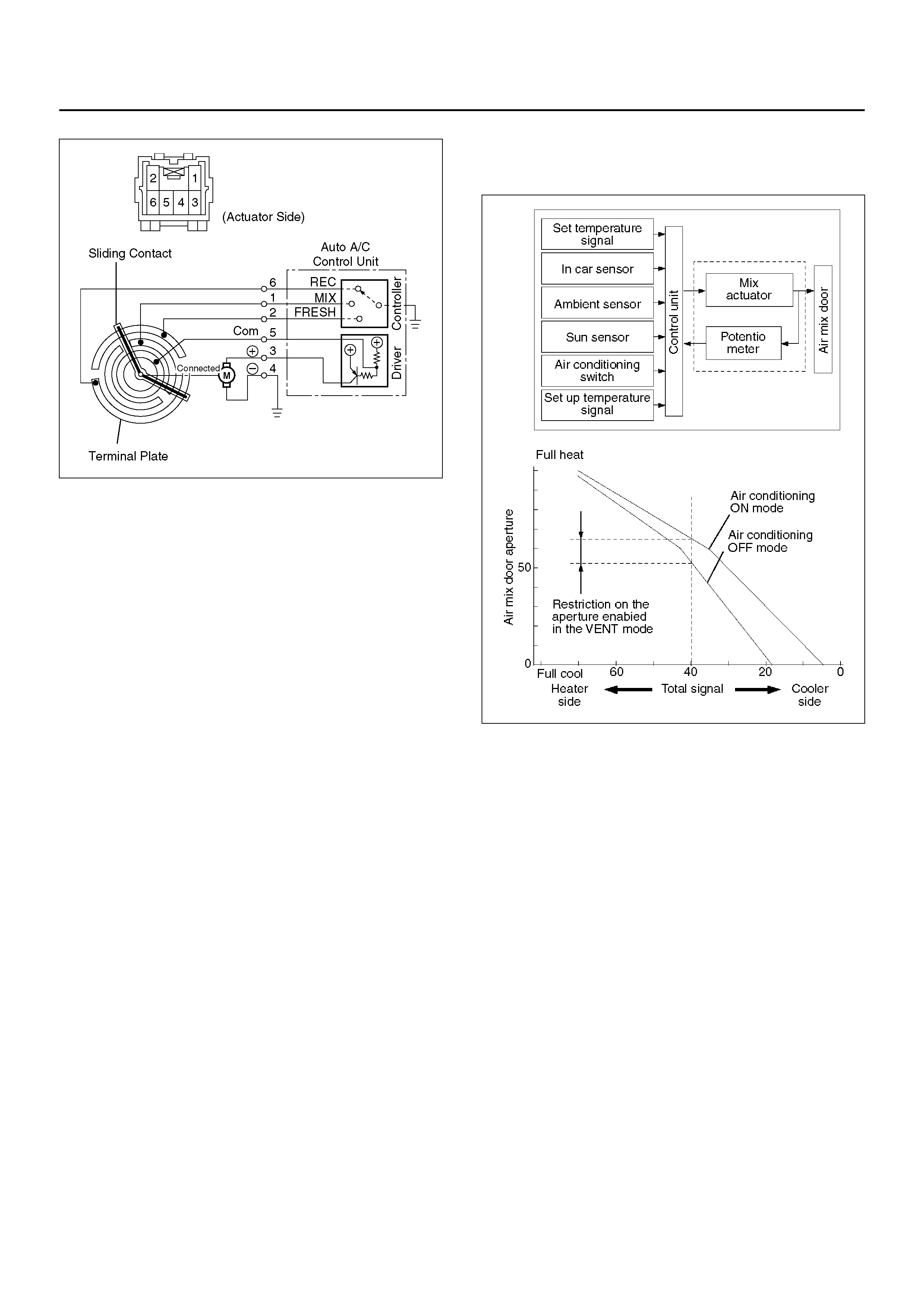
C01RX016
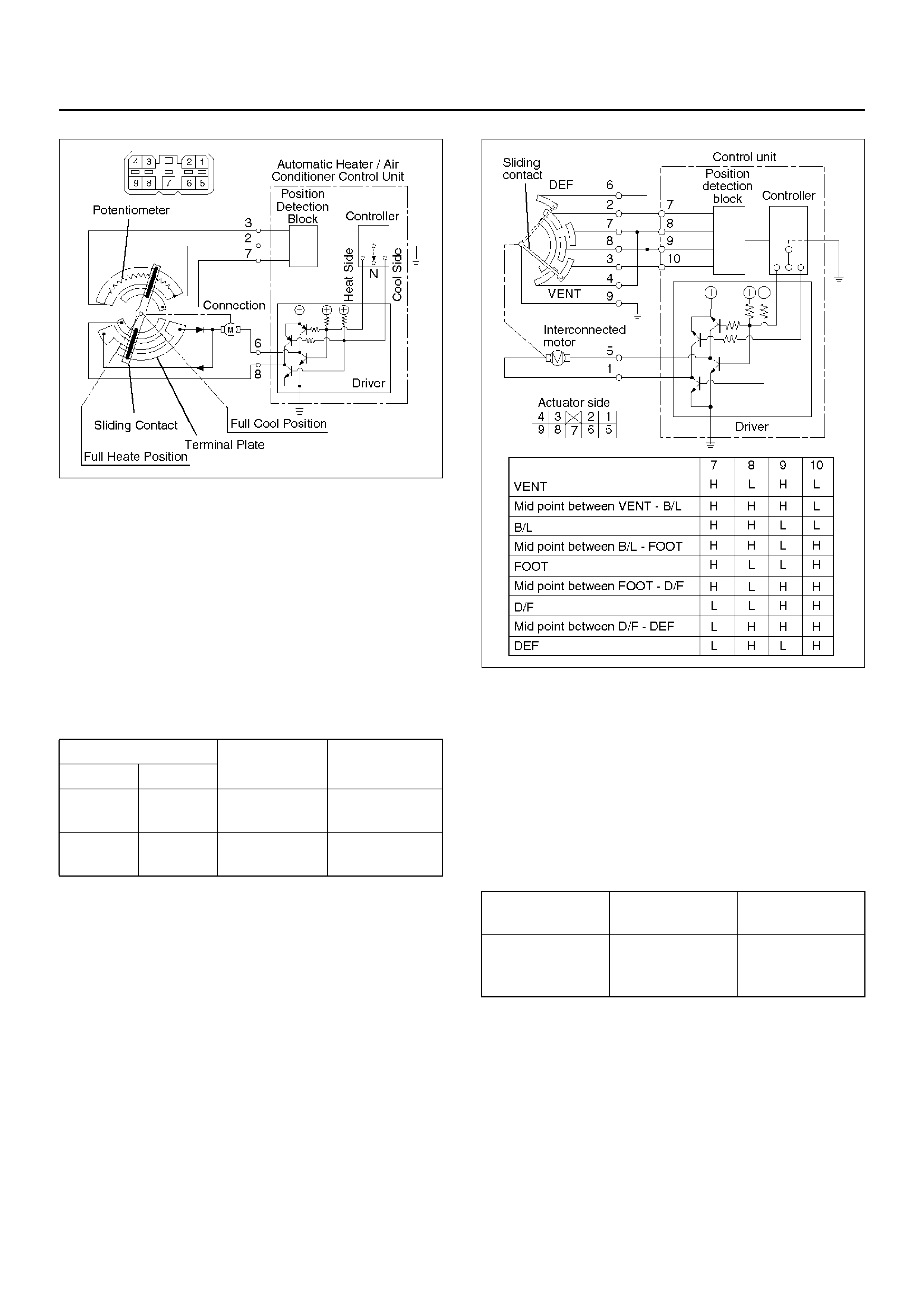
Movement of Mix Actuator
Position of the air mix door is determined by the
controller on the automatic heater/air conditioner control
unit.
As the heat or cool side of the controller is grounded,
the transistor on the driver is activated and, thus, the
motor rotation is turned on. The sliding contact
connected to the motor sends the position detection
signal from the potentiometer to the automatic air
conditioner control unit. As the set temperature and
interior temperature ar e balanced, the con troller retur ns
to the neutral and the motor rotation is stopped.
Legend
(1) Mix Actuator
(2) Heater Unit
(3) Intake Actuator
(4) Mode Actuator
(5) Blower Unit
Legend
(1) Output Axis
(2) Motor
(3) Printed Circuit Board
(4) Sliding Contact
C-45 Rotation
direction Remarks
(+) side (-) side
8 6 Clockwise Full heat side
68Counter
clockwise Full cool side
C01RX005
Movement of Mode Actuator
As target position of the mode door is decided on the
controller of the control unit, the control unit reads the
position detectio n signal from the actuator to select the
clockwise or counter clockwise motor rotation direction.
Grounding the controller VENT or DEF side after the
directi on selection a ctivates the trans istor on the dri ver,
thus turning on the motor rotation. Accompanying the
motor rotation, the sliding contact rotates, too. When
the target position is reached, the controller on the
control unit returns to the neutral and the motor stops.
C01RX017
Movement of Intake Actuator
The controller on the automatic air conditioner control
unit selects an intake mode to be used.
As the Terminal No.5 C65 is grounded via the sliding
contact on the terminal plate, the transistor on the driver
is activated, thus turning on the motor rotation. Then,
accompanying move of the motor, the sliding contact
rotates until grounding of the Terminal No.5 C65 is
removed, thus stopping the motor.
Conduction pin Rotation
direction Remarks
(+) side (-) side
5 1 Clockwise VENT to DEF
direction
1 5 Counter
clockwise DEF to VENT
direction
Grounding
terminal Rotation
direction Remarks
No.5 C-65 Clockwise RE-CIRCULATI
ON→MIX→FRE
SH
C01RX006
OVERVIEW OF AUTOMATIC
CONTROL OF AUTOMATIC AIR
CONDITIONER
The auto mati c heater a nd a ir c ond itio n er on thi s ve hic le
has the following features:
• Interior temp er ature contr ol .
• Air flow control.
• Mode (blow port) control.
• Intake (switching between fresh air and interior air)
control.
• Heater start timing control.
• C o ole r start timing control .
• Compressor ON/OFF function according to outside
air temperature level.
• Evaporator anti-freeze control.
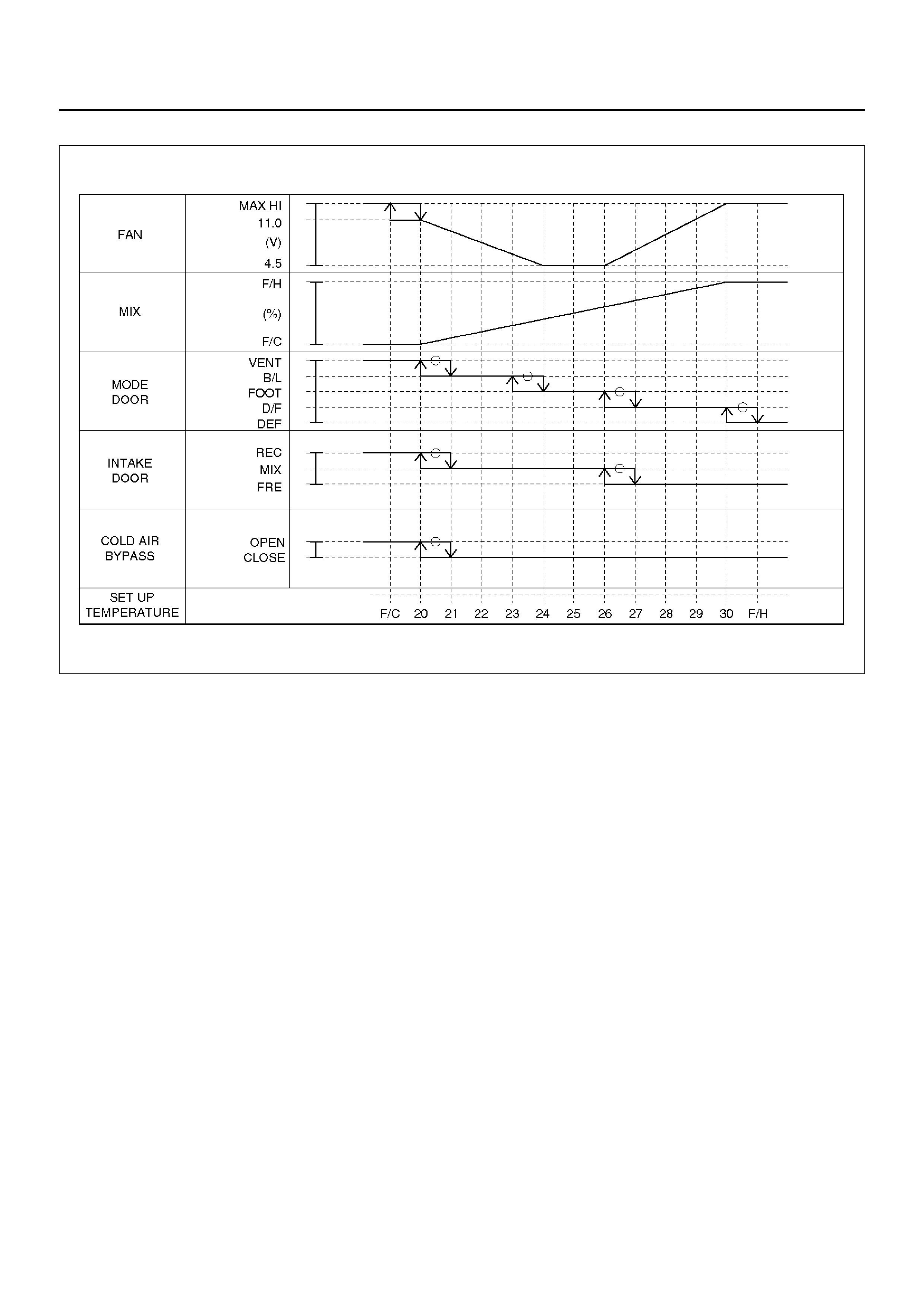
Interior Temperature Control
The automatic air conditioner control unit operates on
the setup temperature signal from the temperature
control switch and other sensor signals to derive the
total signal. Then, the cont rol unit c ompares this sig nal
against the signal from the potentiometer to determine
rotation direction of the mix actuator. The mix actuator
moves the air mix door to the aperture specified by the
total signal so that the specified interior temperature is
achieved.
If the compressor is turned off in the A/C (air
conditioning) mode, aperture of the air mix door is offset
according to the outside air temperature or the specified
interior temperature. This function removes the
difference in the blowing temperature in this state and
that of when the compressor is turned on.
When FH or FC is selected for the setup temperature,
the air mix door is accordingly fixed to the Full Heat or
Full Cool mode.
When the VENT mode is selected, aperture of the air
mix door is controlled so that excessively heated air
may not be blown from the VENT blow port.
C01RY00015
Air Flow Control
In t he Auto Mode
• The automatic air conditioner control unit operates on
the setup temperature signal and other sensor
signals to derive the total signal. Then, the control
unit adjusts base potential of the power transistor to
match it to the voltage pattern of the target fan so that
stage-less fan speed control can be achieved.
When solar radiation quantity is detected in the VENT
or B/L mode, the control unit increases the minimum
fan voltage to offset.
When FH or FC is selected from the temperature
control s witch, a ir flow i s accor dingly f ixed t o MAX H I
or AUTO HI.
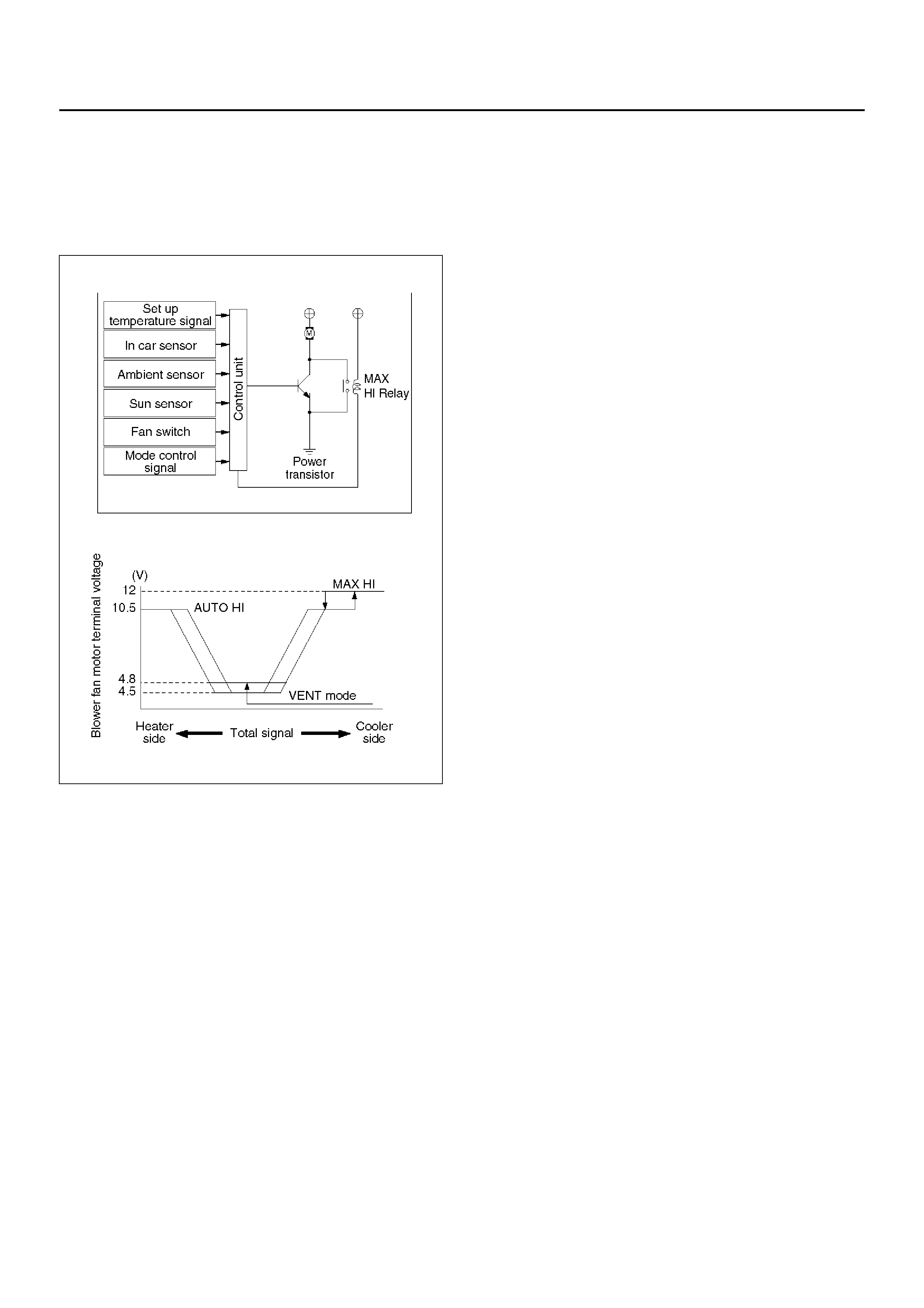
In the Manual Mode
• Air flow specified from the fan switch is entered to the
automatic air conditioner control unit as the manual
signal. The signal modifies the air flow to the level
specif ied from t he fan s witch s o that the required fan
voltage is attained.
C01RY00008
Mode (Blow Po rt) Control
The automatic air conditioner control unit operates on
the setup temperature from the control switch, and
temperature and solar radiation quantify from the
sensors to determine the total mode control signal.
According to the pattern specified by this signal, the
control unit selects either one of the VENT, BI-LEVEL,
FOOT or DEF/FOOT mode.
The mode actuator determines the rotation direction
comparing the target position against the current
position being determined by the position detection
signal.
When FH or FC is selected for the temperature from the
temperature control switch, mode is accordingly fixed to
the VENT or FOOT.
• In the manual oper ation of the mode switc h, you can
select a desired blow port mode pressing the
corresponding mode switch.

• Operating the DEF mode switch selects the DEF for
the blow port mode.
C01RY00009
Intake (Fresh air/interior air switching)
Control
In the Full Auto mode, the automatic heater/air
conditioner control unit operates on the setup
temperature signal and other sensor input signals to
derive the total signal. According to the pattern
specified by this signal, the control unit provides the
intake control.
When the fan is turned off or the A/C (air conditioning) is
turned off, the intake is fixed to the FRESH mode.
When FC or FH is selecte d from the contro l switch, the
intake mode is accordingly fixed to the RECIRC or
FRESH.
In the Manual Operation
• Pressing the FRESH (fresh air intake) or the RECIRC
(room air circulation) accordingly selects t he FRESH
or RECIRC mode.
When the DEF Mode Switch is depressed
• The intake mode is fixed to the FRESH. When the
MANU REC is selected, however, the mode is fixed
the RECIRC.
When the Mode Switch is depressed
• If the automatic intake control is selected, the intake
is fixed to the currently selected mode.
C01RY00012
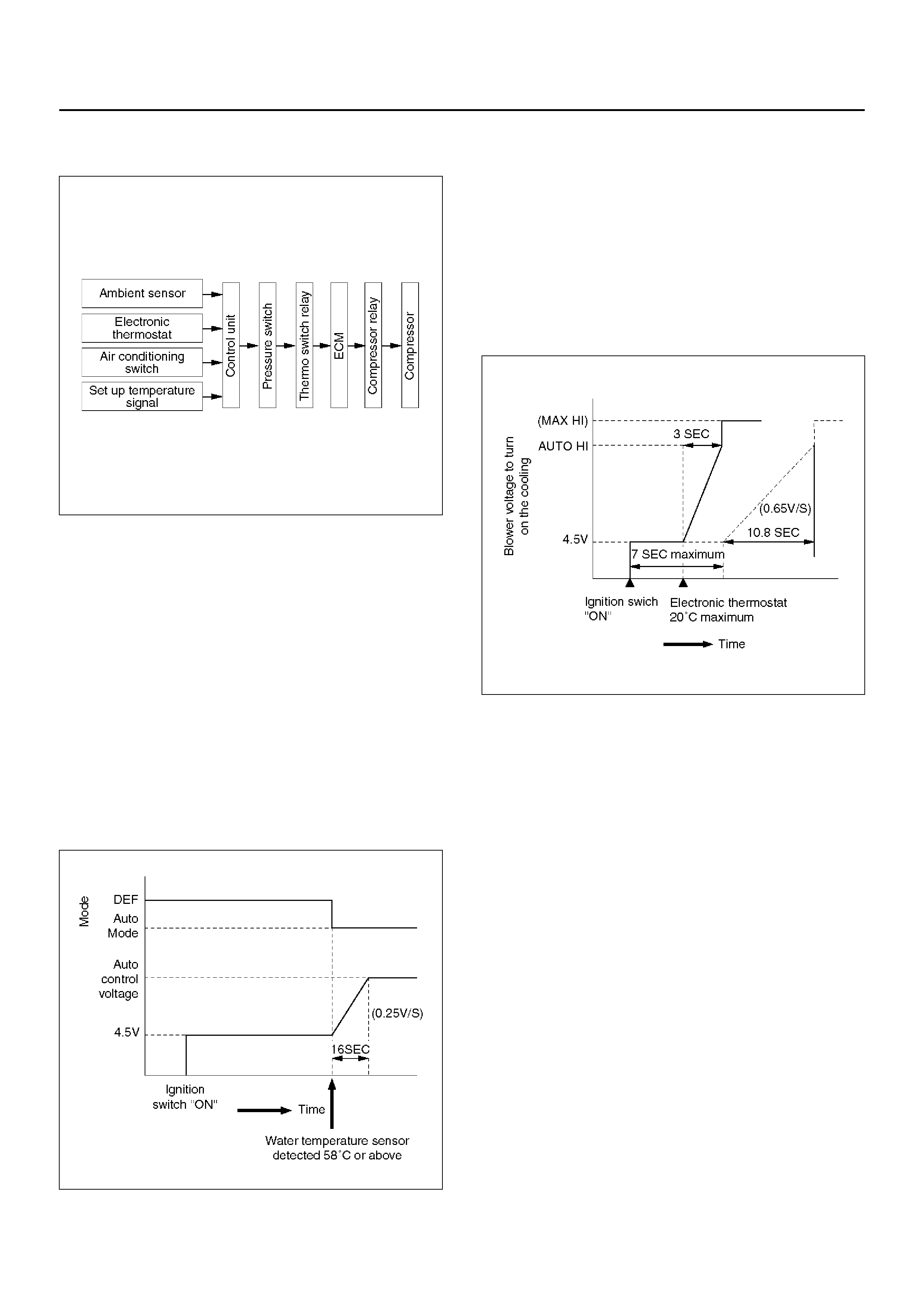
Compressor Control
In the automatic control mode, the automatic air
conditioner control unit turns on or off the compressor
with the evaporator anti-freeze mechanism using the
evaporation sensor. And, when outside air is detected
to be low through the outside air temperature sensor
signal, the control unit turns off the compressor using
the compressor control function.
Manual Control
• In the automatic control mode, pressing the A/C (air
conditioning) switch turns off the compressor.
• Pressing the DEF mode switch automatically turns on
the compressor.
C01RY00010
Heating Start Timing Control
When th e auto mat ic air c ond iti one r is s tarted , hea tin g is
turned on only when the coolant temperature detected
by the coolant temperature sensor is 18°C or less and
total signal derived from the sensor signals has
detected that the heating condition is met.
If the coolant temperature detected by the sensor is
18°C or less, 4.5V is set for the blower fan motor
terminal voltage and the DEF is selected for the blow
port mode.
When the tempe rature detect ed by the sensor is ab ove
18°C, the blow port mode is switched to the Auto
Control and the voltage across the blower fan motor
terminal is linearly increased from 4.5V to auto control
voltage (auto airflow).
840RX015
Cooling Start Timing Control
Whe n the aut omatic air con dit ioner is started, cooli ng is
turned on only when the temperature detected by the
interior temperature sensor is 30°C or above and the
total signal derived from the sensor signals has
detected that the cooling condition is met.
When the cooling condition has been met, the fan
voltage across the blower fan motor terminal is set to
4.5V for 7 seconds maximum, then it is linearly
increased up to the auto airflow level at the rate of 0.6V/
sec.
C06RX003
TROUBLESHOOTING
TROUBLESHOOTING, ITS OVERVIEW AND PROCEDURES
The automatic heater and air conditioner equips with the
“Self-Diagnosis Function" to check its major
components.
This function makes access to the sensors, actuators
and blower fan motor system easier when checking
them up and, when a failed part is located, thi s function
restores its original performance.
When implementing the troubleshooting, this
self-diagnosis function narrows the range to be
searche d at th e fi rst s tep, t hen check rele va nt parts one
by one according to the “Checking Procedures by
Failed Location". As for a location this function is
unappreciable, the system accurately determines
characteristics of a given trouble and checks relevant
parts according to the “Checking Procedures by Failed
Location".
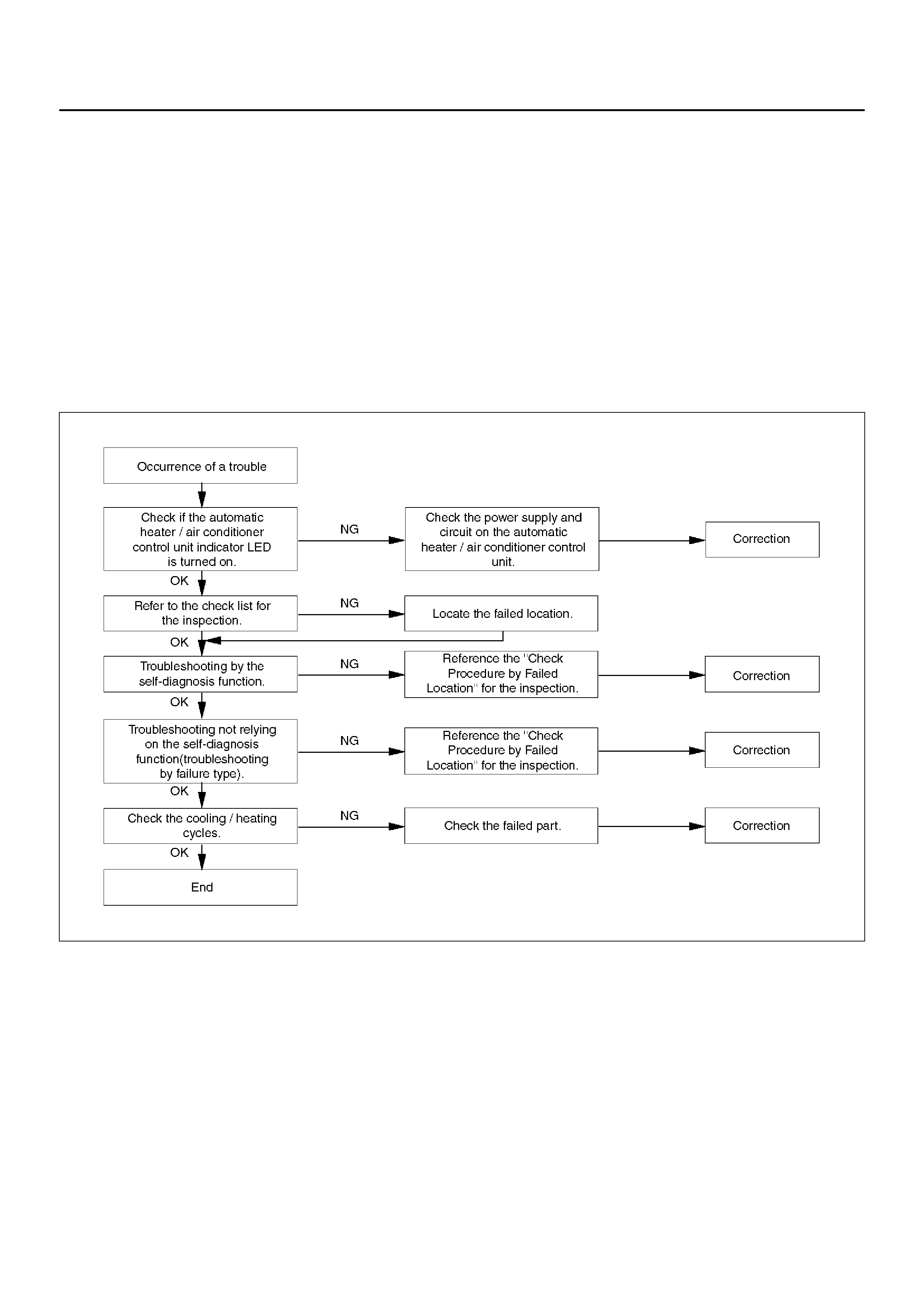
The following illustrates basic troubleshooting flow.
Basic Troubleshooting Flow
F01RX009
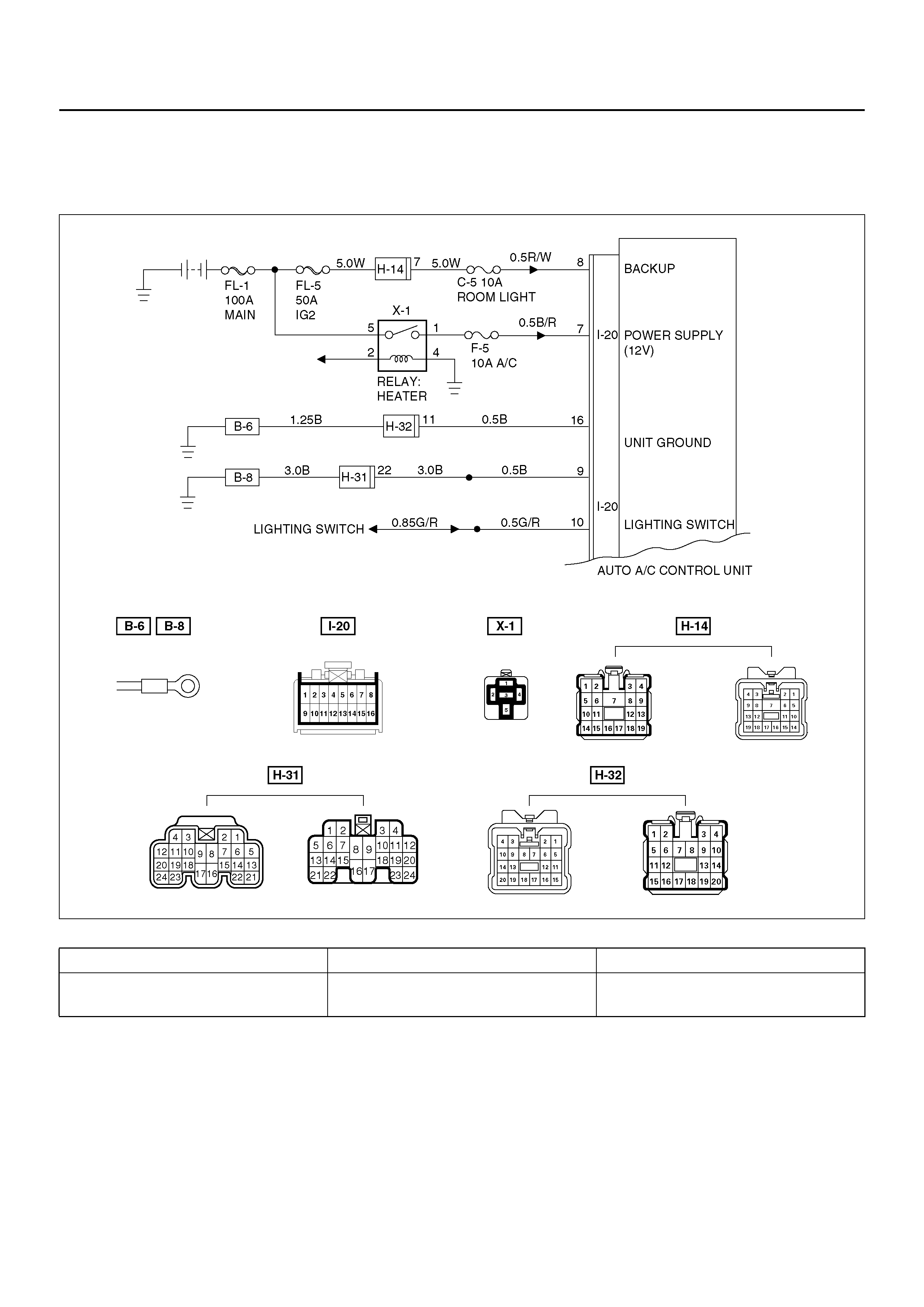
AUTO AIR CONDITIONER CONTROL UNIT POWER SUPPLY DIAGNOSIS
This check is required because a trouble on the auto
amplifie r (contr ol unit) powe r suppl y circu it or ground ing
circuit prevents accurate troubleshooting.
D08R100120
Condition Possible cause Correction
Power source does not supply to
auto air conditioner control unit. — Refer to Chart A

Chart “A": Check of Auto Amplifier Power Supply System
Step Action Value(s) Yes No
1 Is the fuse C–5 normal? — Go to Step 2 Replace the
fuse
2 Is the fuse F–5 normal? — Go to Step 3 Replace the
fuse
3 Disconnect the auto A/C control unit connector I–20.
Is the battery voltage applied between the harness
side connector terminal No.I20–8 and the ground? Approx. 12V Go to Step 5 Go to Step 4
4 Repair an open circuit between the fuse C–5 and
terminal No.I20–8.
Is the action complete? — Go to Step 4 —
5 Is there continuity between the harness side
connector terminal No.I20–16 and the ground? — Go to Step 7 Go to Step 6
6 Repair an open circuit between terminal No.I20–16
and the ground No.B–6.
Is the action complete? — Go to Step 5 —
7 Is there continuity between the harness side
connector terminal No.I20–9 and the ground? — Go to Step 9 Go to Step 8
8 Repair an open circuit between terminal No.I20–9 and
the ground No.B–8.
Is the action complete? — Go to Step 7 —
9 Turn the lighting switch on.
Is the battery voltage applied between the harness
side connector terminal No.I20–10 and the ground? Approx. 12V Go to Step 11 Go to Step 10
10 Repair an open circuit between the lighting switch and
terminal No.I20–10.
Is the action complete? — Go to Step 9 —
11 Turn the starter switch on.
Is the battery voltage applied between the harness
side connector terminal No.I20–7 and the ground? Approx. 12V — Go to Step 12
12 Repair an open circuit between the fuse F–5 and
terminal No.I20–7.
Is the action complete? — Verify repair —

PERFORMANCE AND MOVEMENT CHECKLIST FOR AUTOMATIC AIR
CONDITIONER RELATED PARTS
Start the engine, and when the eng ine coolant reached
50°C check performance and movement of the related
parts accordin g the following checklist.
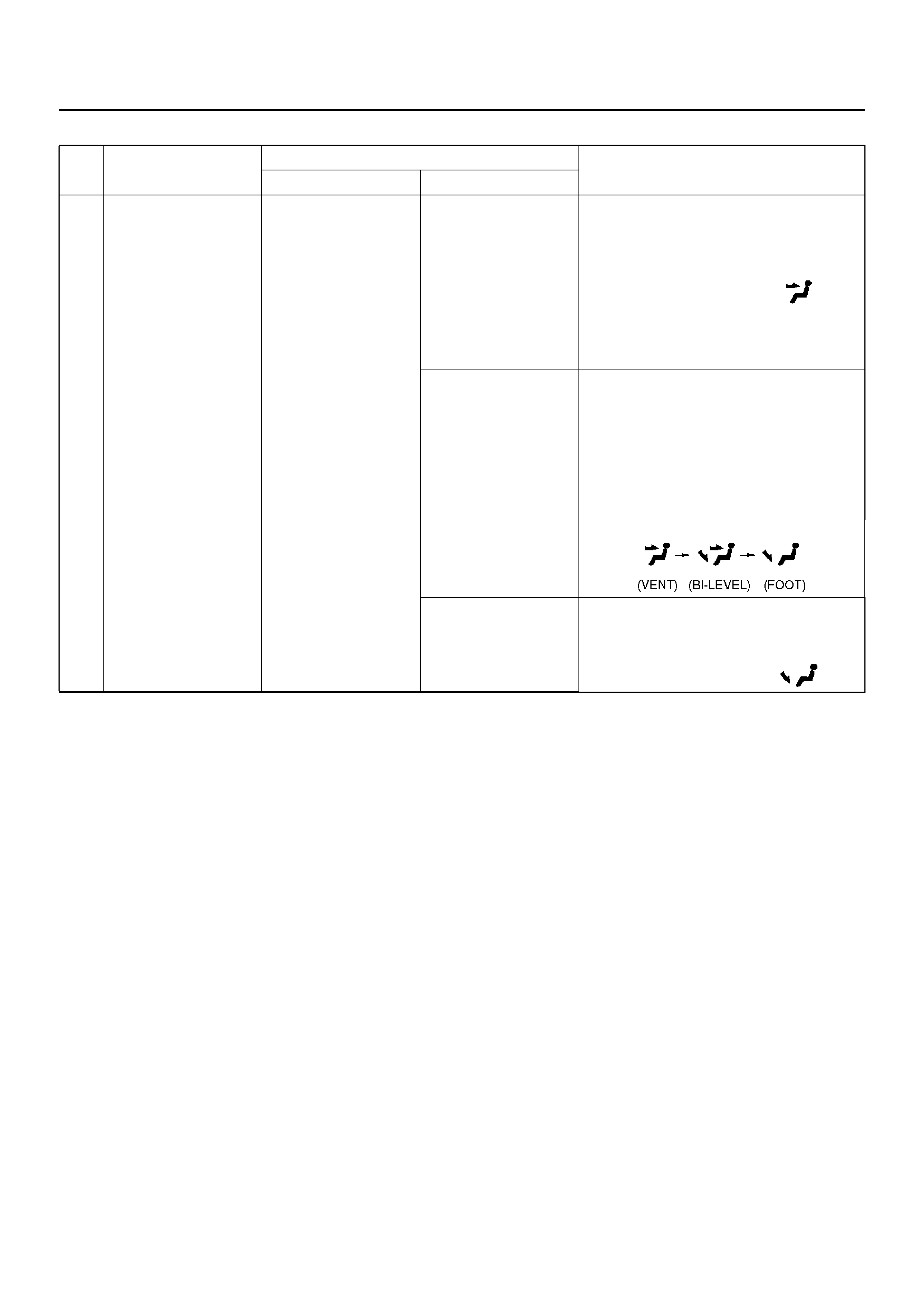
Performance Check Using the Manual Switch
No. Item Checking Approach Acceptance criteria
Condition Operation
1
Blowing
temperature
(check movement
of air mix door)
Auto switch must be
turned on (FAN-
AUTO MODE-AUTO)
1. Select FC for the
setup temperature.
2. Select FH for the
setup temperature.
→ Then, select the
MAX Control.
1. Cold air shall be blown out.
2. Hot air shall be blown out.
2
Airflow volume
(check movement
of the mode door)
Set temperature to
25.0°C. 1. Turn the fan knob
off.
2. Turn the fan knob
from LOW to HI.
1. The fan shall be stopped, thus
stopping air blow, too.
2. Airflow volume shall change
from LOW to HI.
3
Blowing
temperature
(check movement
of the mode door)
Set temperature to
25.0°C. Set the fan
knob to HI.
Press the mode switch
to change the blow p ort
mode sequentially from
the VENT through
BI-LEVEL, FOOT up to
DEF.
LED corresponding to each mode
shall be t urned on and the blow port
mode shall be switched smoothly.
4
The inter i or/outsid e
air switching mode
(check movement
of intake door)
Set temperature to
25.0°C. Turn the LED off using
the interior/outside air
switch (this introduces
the outside air intake
mode). Then, the set
fan knob to HI and
press the interior/
outside switch to turn
on the LED.
The LED indication shall be switched
from OFF to ON accompanying a
change in air blowing sound.
5
Compressor Set the temperature to
18.0°C (FC). (Outside
air temperature is 0°C
or above and interior
temperature at ordinary
temperature.)
Press the “ O FF" switch.
1. Press the Auto
switch.
2. Press the Air
Conditioner switch.
1. As the fan knob is set to the Auto
position, the A/C switch LED
shall come on and the
compr essor shall be turned on.
2. As the A/C LED comes off, the
compr essor shall be turned off.
Check of Auto Function
No. Item Checking Approach Acceptance criteria
Condition Operation
1 Auto function FAN KNOB “AUTO"
MODE SW “AUTO"
Select FC for the
temperature.
The LED shall come on.
Cold air shall be blown out.
The following LEDs shall come on:
• B low por t mode :
• Intake mode
• Fan speed: MAX
Hi
•A/C
Change the
temperature
gradually starting
with 18°C up to
32°C.
The following phenomena shall be
recognized.
• Temperature of blown air: Cold air is
changed to hot air.
• Change in the air flow volume.
• The blow port mode LED indication
changes in the following sequence:
Select FH for the
temperature.
Cold air shall be blown out. The
following LEDs shall come on.
• B low por t mode :
• Fan speed: Max.

TROUBLESHOOTING WITH SELF-DIAGNOSIS FUNCTION
Overview of Self-Diagnosis Function
The self-diagnosis is implemented in 3 steps for each
target. For detail of check procedure contained in each
step, refer to the relevant section of “Check Procedure
by Failed Location" listed in the Self-Diagnosis
Operation Procedure.
For turning on the self-diagnosis function and switching
of the check step, refer to the flow chart given below.
You can reset the self-diagnosis function by turning the
ignition switch off or turning the DEF switch on for 5
seconds.
Self-Diagnosis Operation Procedure
Step Action Value(s) Yes No
1 1. Set the IG to the OFF position.
2. Apply 60W bulb light to the solar radiation sensor.
3. Set the temperature setting lever on the automatic
heater/air conditioner panel to the center position
(25°C).
4. Set the fan switch on the same panel to the Auto
position.
Is the action complete? — Go to Step 2 —
2 While holding both the Auto switch and the DEF
switch on the au tomatic air condi tioner panel, tu rn th e
IG off and then on.
Is the current trouble diagnosing function turned on
approximately in 10 seconds? — Go to Step 3 —
3 Does the A/C LED flash every 0.5 second interval? — Go to Step 4 Refer to *1.
4 Press the A/C switch once.
Does the A/C LED flash every 0.5 second interval? — Go to Step 5 Refer to *2.
5 Refer to *3 chart “Check of Output Equipment".
Does each output equipment function normally
according to operation of the temperature setting
level?
— Go to Step 6
Repair or
replace the
output
equipment or
repair the
harness
6 Press the DEF switch for 5 seconds consecutively or
turn on and off the IG.
Is the action complete? — Go to Step 1 —
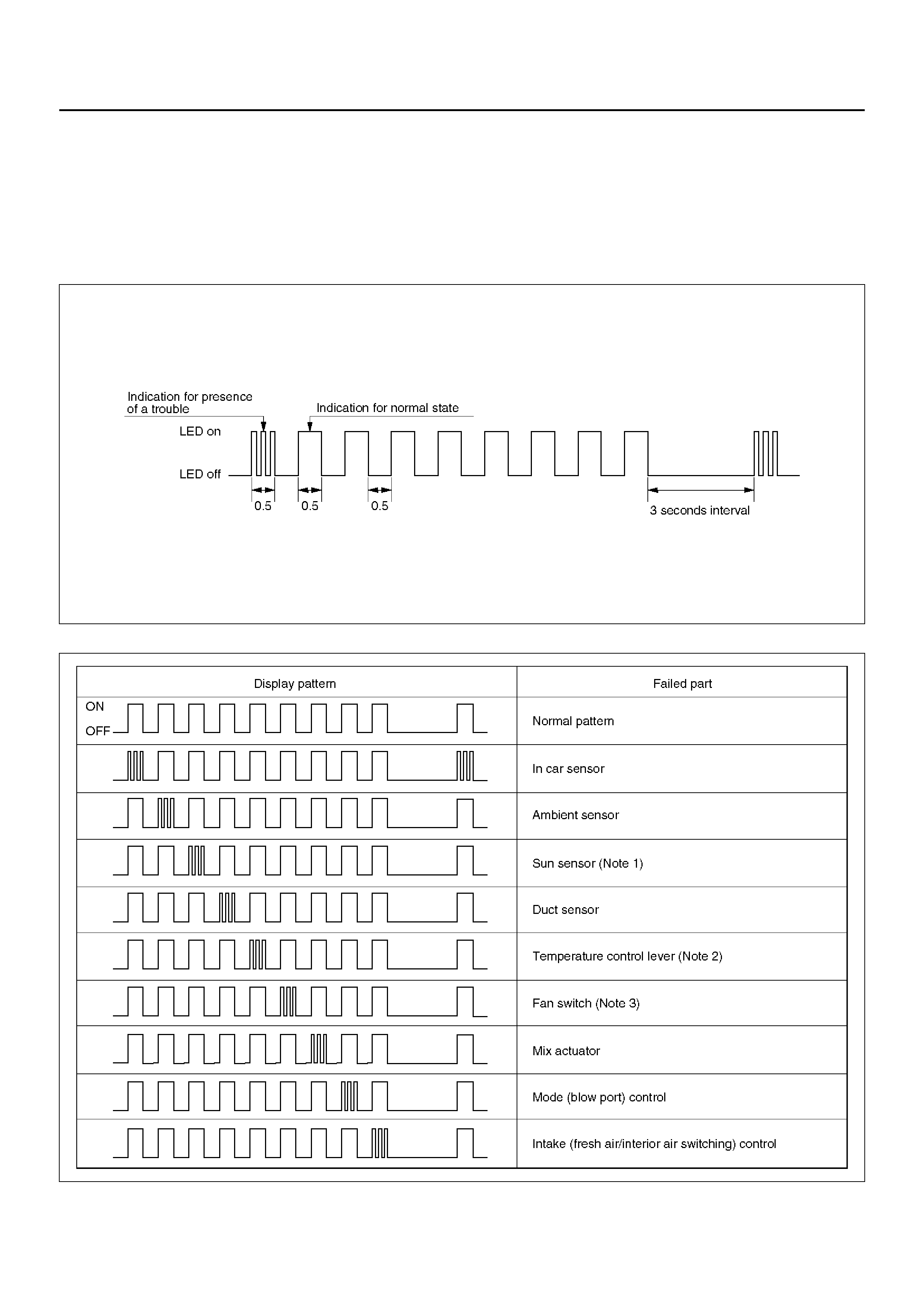
Displaying the Current Trouble Diagnosing Table
Start the engine while holding down both the Auto
switch and the DEF switch on the control panel, and the
table will appear in approximately 10 seconds to the
indicator lamp (LED) of the air conditioning switch.
Result of the diagnosis along the following 9 items will
be shown one by one in 0.5 second in ter v al irre spective
of presence or absence of a trouble for a given item.
When the display 9 items is completed, it is repeated
with 3 seconds of interval in between. A failed item is
indicated by flashing of the LED that is repeated 3 times
within 0.5 seconds. If a trouble is indicated, you can
locate the failed section by knowing when in the total
sequence it has been displayed.
F01RX010
Item for Current Trouble Diagnosis
F01RY00008
As shown above, display of result along nine items is
repeated with 3-second interval in between.
Note 1: When checking the solar radiation sensor , apply
sufficient light using a 60W bulb. Otherwise, it can be
diagnosed as failed.
Note 2: If the temperature setting lever is set on both
ends (one set to 18°C, blue scale = Full cool and the
other to 31°C, red scale = Full hot), they can be
diagnosed as failed.
Note 3: Likewise, the fan switch can be diagnosed as
failed if set on both ends.
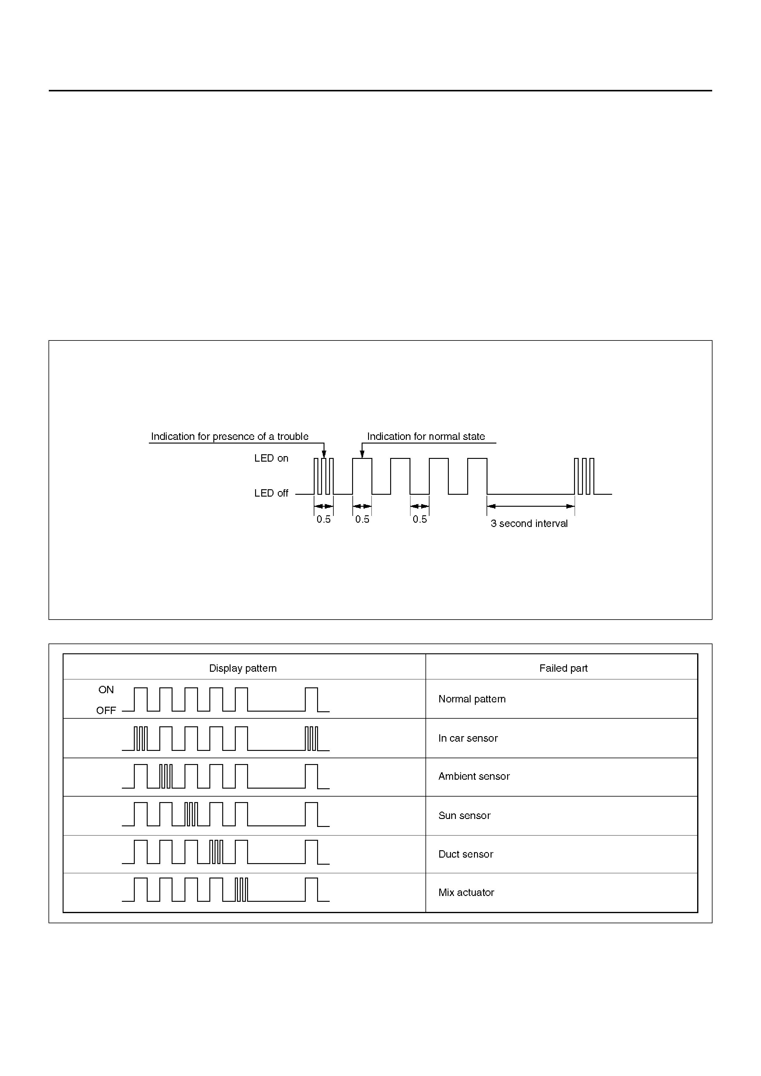
Displaying the Past Trouble Diagnosing Table
The past trouble diagnosis displays only the items on
which trouble has recurred 16 times in the past.
If you press the air conditioning switch once while the
current trouble diagnosis is taking place, display of the
past trouble diagn osis will appear on the indicat or lamp
(LED) of the air conditioning switch.
Results of the diagnosis along the following five items
are displayed one by one in 0.5 second interval
irrespective of presence or absence of a trouble. A
failed item is indicated by flashing of the LED that is
repeated 3 times within 0.5 seconds. You can locate the
fail ed se ction by co unting in wha t seque nce i t has b een
displayed.
F01RX011
F01RY00007
Check of Output Equipment
F01RX015

INSPECTION BY FAILED LOCATION
INSPECTION OF THE SENSORS
When the self-diagnosis function has determined that
trouble is present on the sensors, check them according
to the following flow chart.
F01RY00005

Chart 1: In Car Sensor
D08RY00888
Step Action Value(s) Yes No
1 Disconnect the in car sensor connector. (No.I-4)
Is performance of the sensor normal? (Refer to the
later section on “Individual Inspection") — Go to Step 2 Replace the in
ca r sensor
2 Is there continuity between the harness side
connector No.I44–1 and No.I4–3? — Go to Step 4 Go to Step 3
3 Repair an open circuit between terminal No.I44–1 and
No.I4–3.
Is the action complete? — Go to Step 2 —
4 Is there continuity between the harness side
connector No.I44–11 and No.I4–4? — Go to Step 6 Go to Step 5
5 Repair an open circuit between terminal No.I44–11
and No.I4–4.
Is the action complete? — Go to Step 4 —
6 Replace the auto air conditioner control unit.
Is the action complete? — Verify repair —
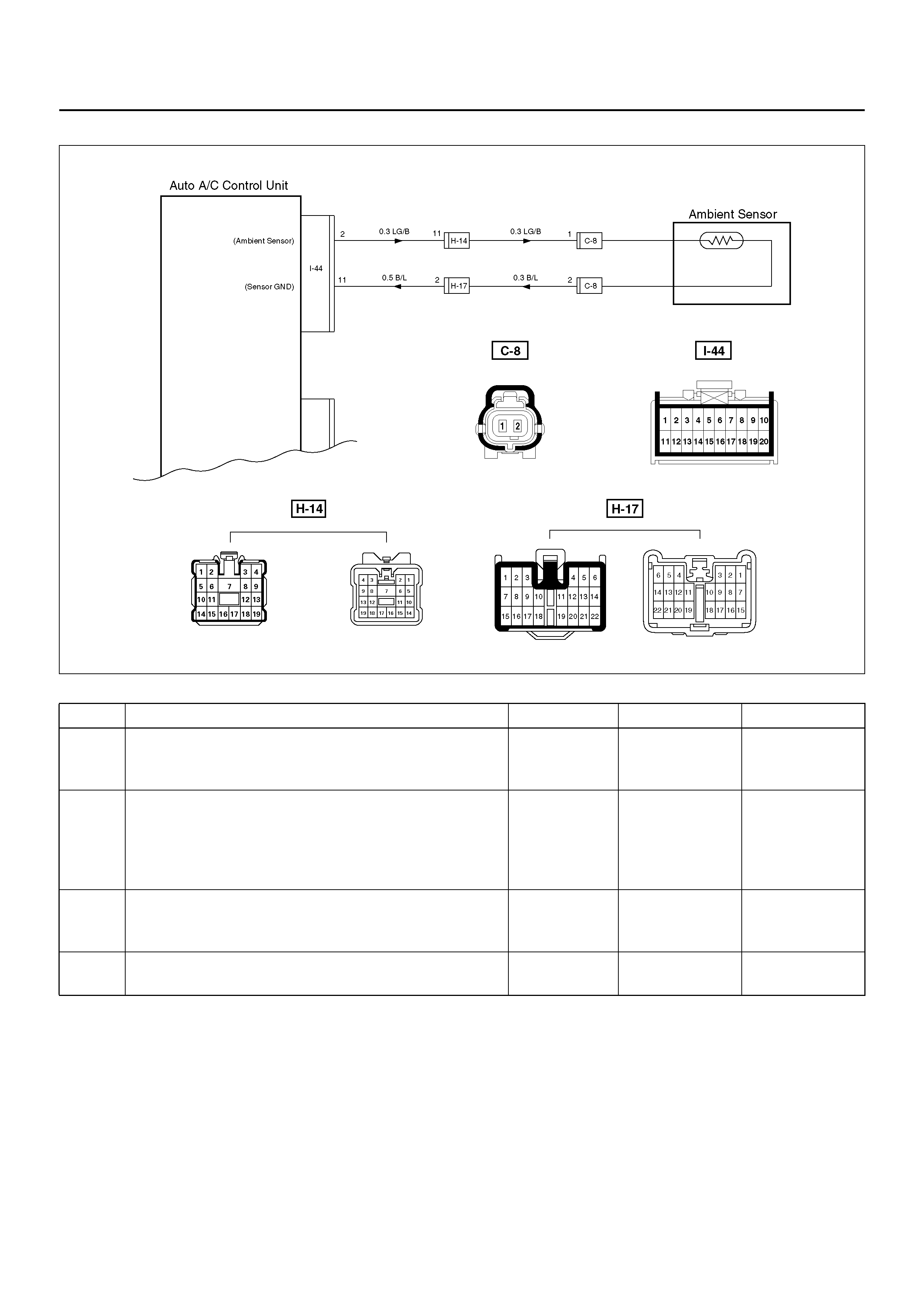
Chart 2: Ambient Sensor
D08R100121
Step Action Value(s) Yes No
1 Disconnect ambient sensor connector. (No.C–8)
Is performance of the ambie nt sensor normal? (Refer
to the later section on “Individual inspection") — Go to Step 2 Replace the
ambient sensor
2 Connect the ambient sensor connector.
Disconnect auto air conditioner control unit
connector.(No.I–44)
Is resistance between the harness side connector
No.I44–2 and No.I44–11 normal?
Refer to the
later section
on “Individual
inspection" Go to Step 4 Go to Step 3
3 Repair an open circuit between terminal No.I44–2 and
No.C8–1 or No.I44–11 and No.C8–2.
Is the action complete? — Go to Step 2 —
4 Replace the auto air conditioner control unit.
Is the action complete? — Verify repair —
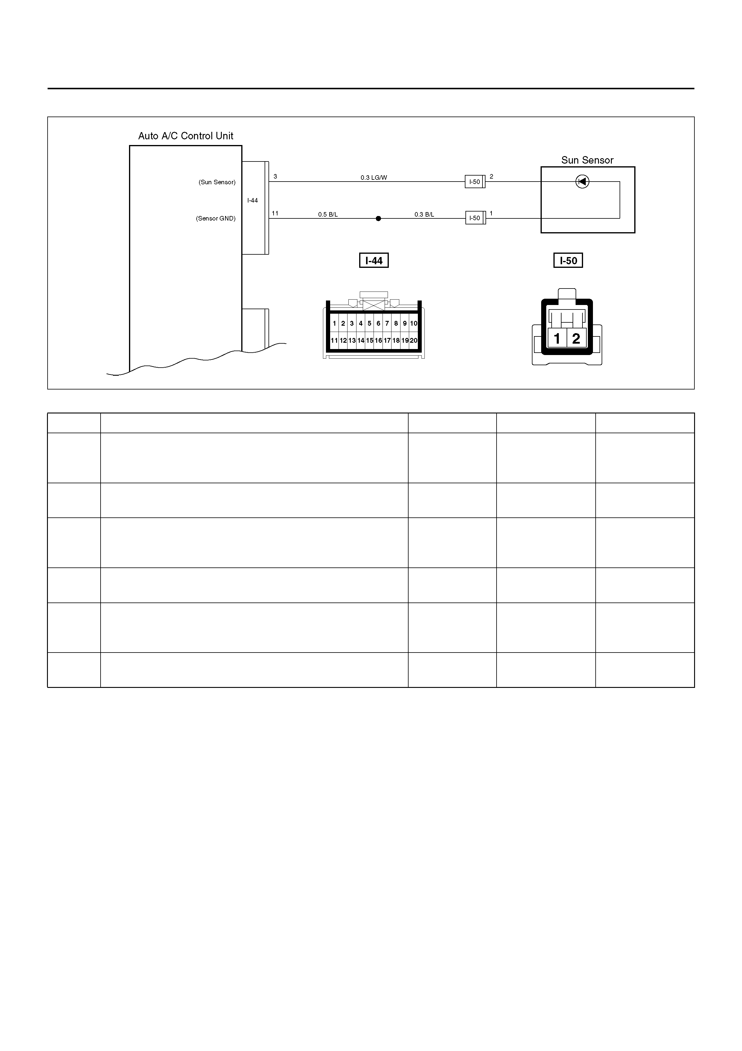
Chart 3: Sun Sensor
D08R100177
Step Action Value(s) Yes No
1 Disconnect the sun sensor connector. (No.I–50)
Is performance of the sun sensor normal? (Refer to
the later section on individual inspection) — Go to Step 2 Replace the
sun sensor.
2 Is there continuity between the harness side
connector terminal No.I44–3 and No.I50–2? — Go to Step 4 Go to Step 4
3 Repair an open circuit between terminal No.I44–3 and
No.I50–2.
Is the action complete? — Go to Step 2 —
4 Is there continuity between the harness side
connector terminal No.I44–11 and No.I50–1? — Go to Step 6 Go to Step 5
5 Repair an open circuit between terminal No.I44–11
and I50–1.
Is the action complete? — Go to Step 4 —
6 Replace the auto air conditioner control unit.
Is the action complete? — Verify repair —
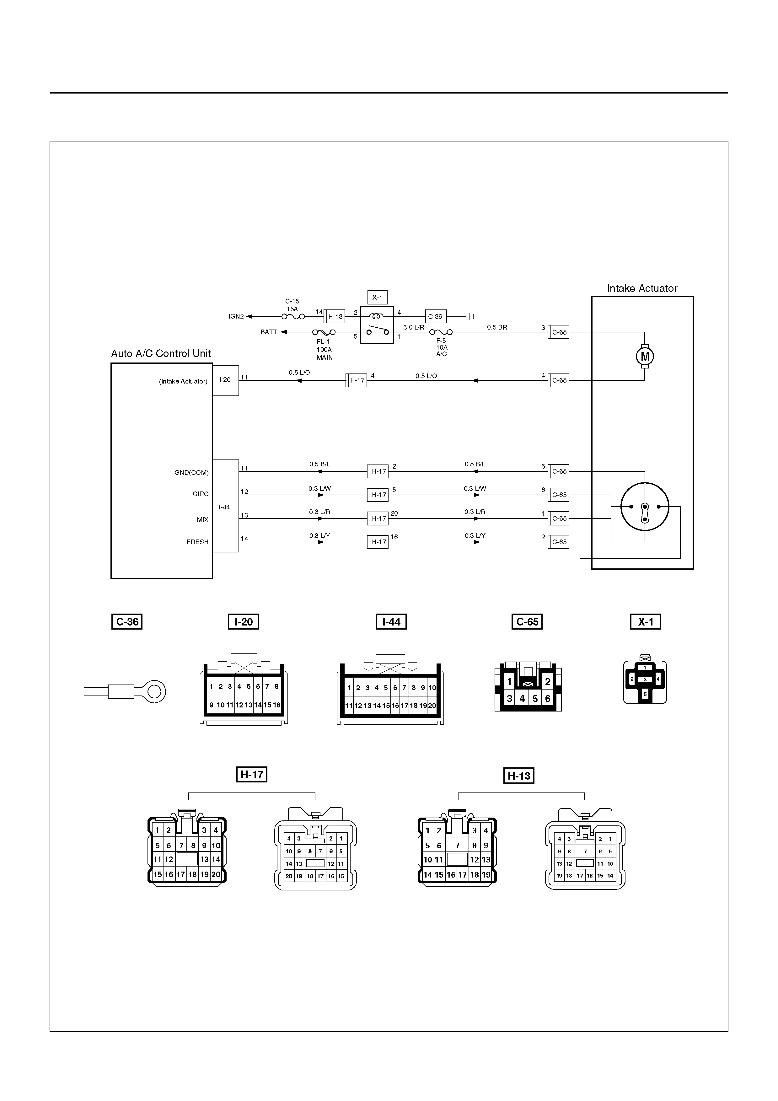
INSPECTION OF THE INTAKE ACTUATOR SYSTEM
D08R100129
Chart A: Does Not Work At All
Condition Possible cause Correction
Does not work at all — Refer to Chart A
Control failure — Refer to Chart B
Step Action Value(s) Yes No
1 Is the fuse C–15 normal? — Go to Step 2 Replace the
fuse
2 Is the fuse F–5 normal? — Go to Step 3 Replace the
fuse
3 Is the relay X–1 normal? — Go to Step 4 Replace the
relay
4 Turn on the ignition switch. (the engine is run.)
Is the battery voltage applied between the harness
side connector terminal No.C65–3 and ground? Approx 12V Go to Step 6 Go to Step 5
5 Repair an open circuit between terminal No.C65–3
and No.X1–1.
Is the action complete? — Go to Step 4 —
6 Is the battery voltage applied between the harness
side connector terminal No.C65–4 and ground? Approx 12V Go to Step 8 Go to Step 7
7 Replace the intake actuator motor.
Is the action complete? — Go to Step 6 —
8 Is there continuity between the harness side
connector terminal No.I20–11 and No.C65–4? — Go to Step 10 Go to Step 9
9 Repair an open circuit between No.I20–11 and C65–4.
Is the action complete? — Go to Step 8 —
10 Replace the auto air conditioner control unit.
Is the action complete? — Verify repair —

Chart B: Failure on the Intake Control
Step Action Value(s) Yes No
1 Is the fuse No.C–15 normal? — Go to Step 2 Replace the
fuse
2 Is the fuse No.F–5 normal? — Go to Step 3 Replace the
fuse
3 Is the relay No.X–1 normal? — Go to Step 4 Replace the
relay
4 Turn on the ignition switch. (the engine is run.)
Is the intake actuator stopped? — Go to Step 6 Go to Step 5
5 Replace or repair the auto air conditioner control unit.
Is the action complete? — Verify repair —
6 Is there continuity between the harness side
connector terminal No.C65–5 and No.I44–11? — Go to Step 8 Go to Step 7
7 Repair an open circuit between terminal No.C65–5
and No.I44–11.
Is the action complete? — Go to Step 6 —
8 Is there continuity between the harness side
connector terminal No.C65–6 and No.I44–12? — Go to Step 10 Go to Step 9
9 Repair an open circuit between terminal No.C65–6
and No.I44–12.
Is the action complete? — Go to Step 8 —
10 Is there continuity between the harness side
connector terminal No.C65–1 and No.I44–13? — Go to Step 12 Go to Step 11
11 Repair an open circuit between terminal No.C65–1
and I44-13.
Is the action complete? — Go to Step 10 –
12 Is there continuity between the harness side
connector terminal No.C65–2 and No.I44–14? — Go to Step 14 Go to Step 13
13 Repair an open circuit between harness No.C65–2
and No.I44–14.
Is the action complete? — Go to Step 12 —
14 1. Disconnect the intake actuator connector No.C–
65.
2. Is the battery voltage applied between harness
side connector terminal
No.C65–6 and ground?
No.C65–2 and ground?
No.C65–1 and ground?
— Go to Step 15 Go to Step 16
15 Replace or repair the intake actuator.
Is the action complete? — Verify repair —
16 Replace or repair the air conditioner control unit.
Is the action complete? — Verify repair —
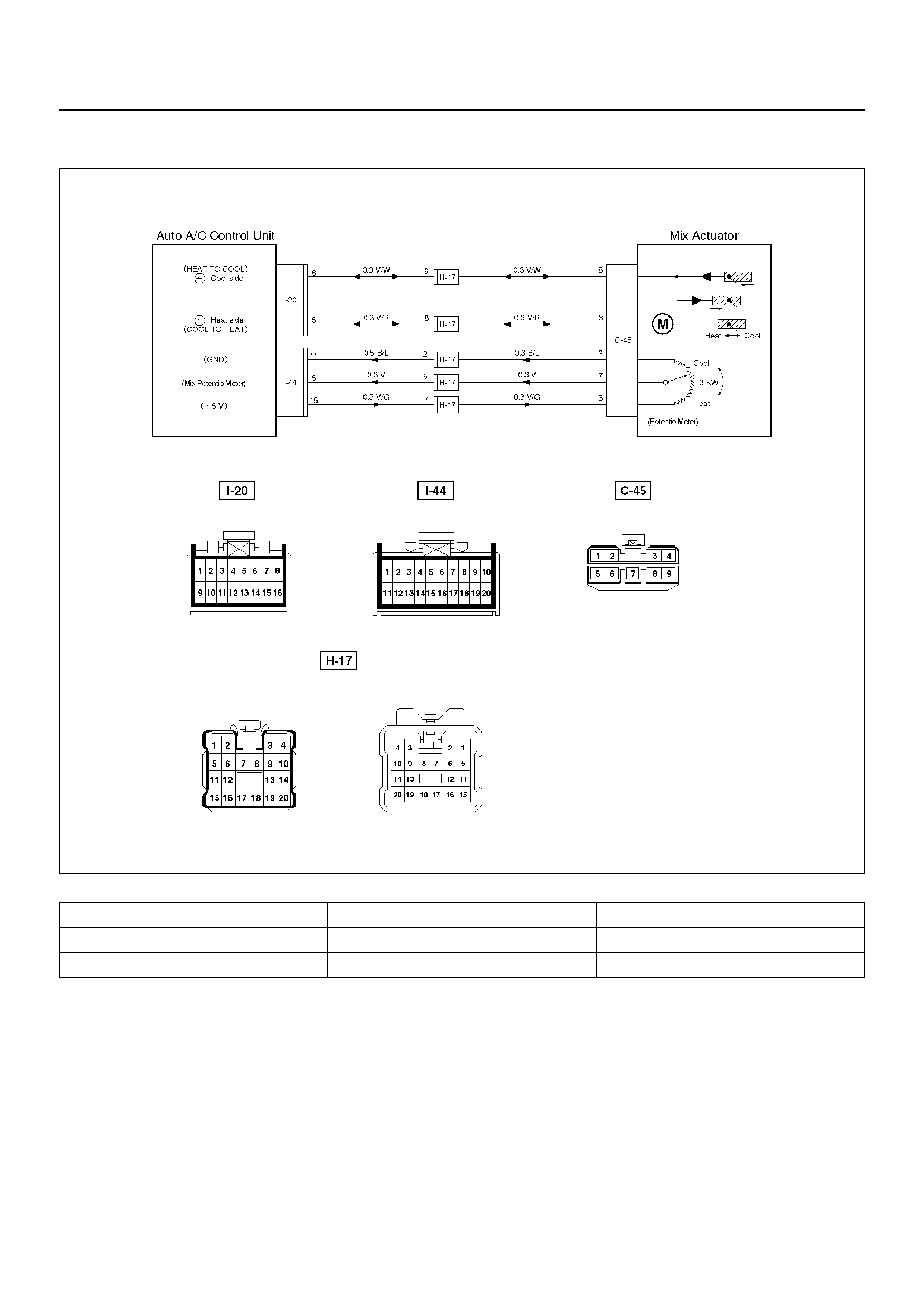
INSPECTION OF THE MIX ACTUATOR SYSTEM
D08RX229
Condition Possible cause Correction
Does not work at all — Refer to Chart A
Control failure — Refer to Chart B

Chart A: Does Not work At All
Step Action Value(s) Yes No
1 1. Turn on the ignition switch (the engine is run).
2. Disconnect the mix actuator connector (C–45).
3. Short-circuit the chassis harness side connector
termina l No.C45 –2 and No.C4 5–7 .
4. Using the temperature control lever, select FH for
the temperature.
Is the battery voltage applied on a regular interval
basis between the harness side connector terminal
No.C45–8 (-) and No.C45–6 (+)? — Go to Step 3 Go to Step 2
2 Replace the auto air conditioner control unit.
—Varify repair —
3 Using the temperature control lever, select FC for the
temperature.
Is the battery voltage applied on a regular interval
basis between the harness side connector terminal
No.C45–8 (+) and No.C45–6 (-)? — Go to Step 5 Go to Step 4
4 Replace the auto air conditioner control unit.
— Verify repair —
5 Is there continuity between the harness side
connector terminal No.I20–6 and No.C45–8? — Go to Step 7 Go to Step 6
6 Repair an open circuit between terminal No.I20–6 and
No.C45–8.
Is the action complete? — Go to Step 5 —
7 Is there continuity between the harness side
connector terminal No.I20–5 and No.C45–6? — Go to Step 9 Go to Step 8
8 Repair an open circuit between terminal No.I20–5 and
No.C45–6.
Is the action complete? — Go to Step 7 —
9 Replace the mix actuator.
Is the action complete? — Verify repair —

Chart B: Mix Actuator Control Failure
Step Action Value(s) Yes No
1 Turn the ignition switch (the engine is run).
Does th e m ix ac tu ator fully st ro ke whe n F H and F C o f
the temperature control lever? — Go to Step 3 Go to Step 2
2 Repair or replace the air mix door or the link unit.
Is the action complete? — Varify repair —
3 Is there continuity between the harness side
connector terminal No.C45–2 and No.I44–11? — Go to Step 5 Go to Step 4
4 Repair an open circuit between terminal No.C45–2
and No.I44–11.
Is the action complete? — Go to Step 3 —
5 Is there continuity between harness side connector
terminal No.C45–7 and No.I44–5? — Go to Step 7 Go to S tep 6
6 Repair an open circuit between terminal No.C45–7
and No.I44–5.
Is the action complete? — Go to Step 5 —
7 Is there continuity between the harness side
connector terminal No.C45–3 and No.I44–15? — Go to Step 9 Go to Step 8
8 Repair an open circuit between terminal No.C45–3
and No.I44–15.
Is the action complete? — Go to Step 7 —
9 Is sum of the voltage between the following chassis
harness side connector terminals approximately 5V?
No.I44–15 and No.I52–5, No.I44–5 and No.I44–11 — Go to Step 11 Go to Step 10
10 Replace the actuator.
Is the action complete? — Go to Step 9 —
11 Replace the auto air conditioner control unit.
Is the action complete? — Verify repair —
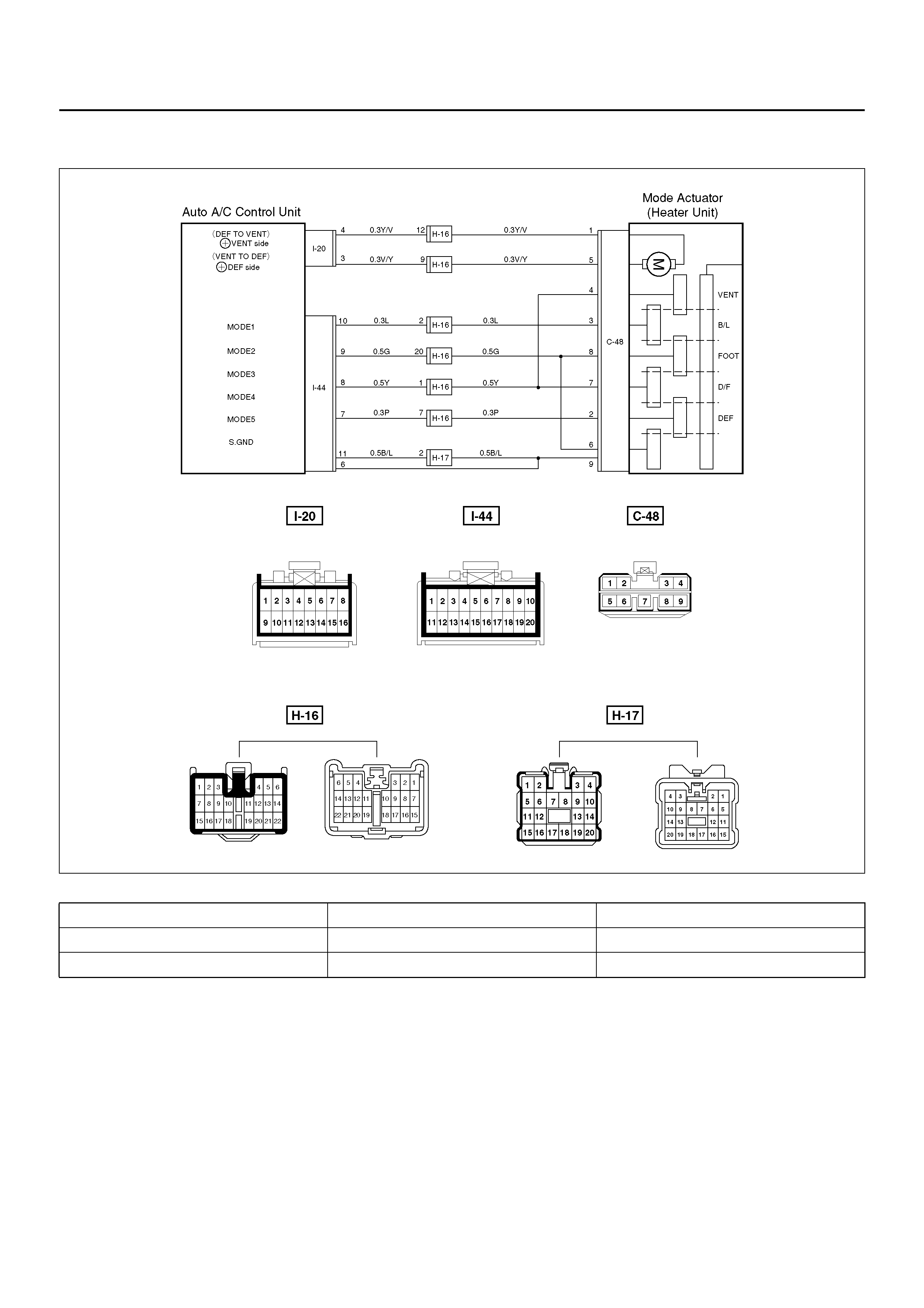
INSPECTION OF THE MODE ACTUATOR SYSTEM
D08R100130
Condition Possible cause Correction
Does not work at all — Refer to Chart A
Control failure — Refer to Chart B

Chart A: Does Not Work At All
Step Action Value(s) Yes No
1 1. Turn on the ignition switch (the engine is run).
2. Disconnect the mode actuator connector (C–48)
3. Select VENT pressing the mode actuator.
Is the battery voltage provided on a regular interval
between the harness side connector terminal
No.C48–1 (+) and No.C48–5 (-)? — Go to Step 3 Go to Step 2
2 Replace the auto air conditioner control unit.
Is the action complete? — Varify repair —
3 Turn on the DEF mode switch.
Is the battery voltage provided on a regular interval
between the chassis side connector terminal No.C48–
5 (+) and No.C48–1 (-)? — Go to Step 5 Go to Step 4
4 Replace the auto air conditioner control unit.
—Varify repair —
5 Is there continuity between the harness side
connector terminal No.C48–1 and No.I20–4? — Go to Step 7 Go to Step 6
6 Repair an open circuit between terminal No.C48–1
and No.I20–4.
Is the action complete? — Go to Step 5 —
7 Is there continuity between the harness side
connector terminal No.C48–5 and No.I20–3? — Go to Step 9 Go to Step 8
8 Repair an open circuit between terminal No.C48–5
and No.I20–3.
Is the action complete? — Go to Step 7 —
9 Replace the mode actuator.
— Verify repair —

Chart B: Mode Actuator Control Failure
Step Action Value(s) Yes No
1 Turn on the ignition switch (the engine is run).
Does the mode actuator fully stroke when the defrost
mode and the vent mode are selected? — Go to Step 3 Go to Step 2
2 Repair or replace the mode door or the link unit.
Is the action complete? — Go to Step 1 —
3 Is there continuity between the harness side
connector terminal No.C48–9 and No.I44–11? — Go to Step 5 Go to Step 4
4 Repair an open circuit between terminal No.C48–9
and No.I44–11.
Is the action complete? — Go to Step 3 —
5 Is there continuity between the harness side
connector terminal No.C48–3 and No.I44–10? — Go to Step 7 Go to Step 6
6 Repair an open circuit between terminal No.C48–3
and No.I44–10.
Is the action complete? — Go to Step 5 —
7 Is there continuity between harness side connector
terminal No.C48–4 and No.I44–8? — Go to Step 9 Go to S tep 8
8 Repair an open circuit between terminal No.C48–4
and No.I44–8.
Is the action complete? — Go to Step 7 —
9 Is sum of the voltage between the following harness
side connector terminal approximately 5V? Voltage
between No.I44–8 and No.I44–10 plus voltage
between No.I44–8 and No.I44–11 5V Go to Step 11 Go to Step 10
10 Replace the actuator.
Is the action complete? — Verify repair —
11 Does the mode actuator work normally through
manual operation? — Go to Step 13 Go to Step 12
12 Replace the sensor.
Is the action complete? — Go to Step 11 —
13 Replace the auto air conditioner control unit.
Is the action complete? — Verify repair —
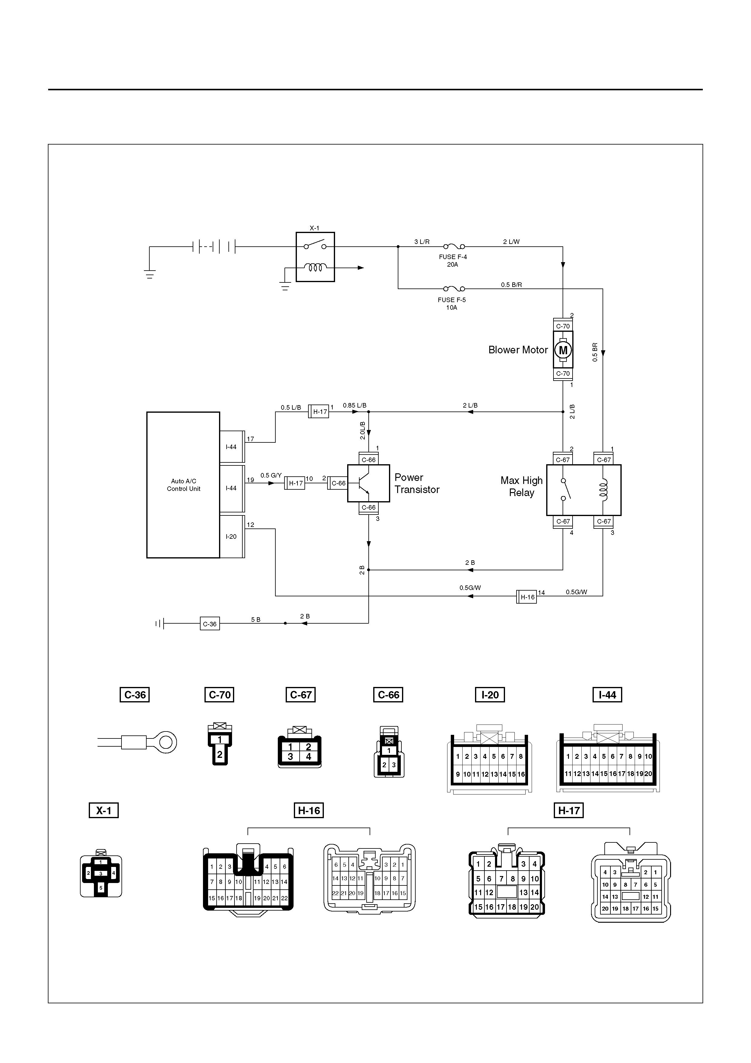
INSPECTION OF THE FAN MOTOR SYSTEM

D08R100131
Chart A: Fan Does Not Rotate At All
Condition Possible cause Correction
The fan does not rotate at all — Refer to Chart A
The fan d oes not rotate in the MAX–
HI mode — Refer to Chart B
The fan does not rotate in any mode
other than MAX–HI — Refer to Chart C
The fan does not stop — Refer to Chart D
Step Action Value(s) Yes No
1 Is the fuse No.F–4 and No.F–5 normal? — Go to Step 2 Replace the
fuse
2 Is the relay No.X–1 and No.C–67 normal? — Go to Step 3 Replace the
relay
3 Turn on the ignition switch (the engine is run).
Is the battery voltage applied between the harness
side connector terminal No.C70–2 and ground? — Go to Step 5 Go to Step 4
4 Repair an open circuit between terminal No.C70–2
and No.F–4 fuse.
Is the action complete? — Go to Step 3 —
5 Is there continuity between the harness side
connector terminal No.C70–1 and ground (No.C–36)? — Go to Step 7 Go to Step 6
6 Repair an open circuit between terminal No.C70–1
and ground.
Is the action complete? —
7 Is the battery voltage applied between the harness
side connector terminal No.C70–1 and No.C70–2? — Go to Step 9 Go to Step 8
8 Replace the blower motor.
Is the action complete? — Verify repair —
9 Refer to chart B and C.
Is the action complete? — Verify repair —

Chart B: Fan Does Not Rotate in MAX HI Mode
Step Action Value(s) Yes No
1 Is the MAX-HI relay (C–67) normal? — Go to Step 2 Replace the
relay
2 1. Turn on the ignition switch (the engine is run).
2. Set the fan switch to the MAX-HI.
Is there continuity between the harness side
connector terminal No.C70–1 and No.C67–2? — Go to Step 4 Go to Step 3
3 Repair an open circuit between terminal No.C70–1
and No.C67–2.
Is the action complete? — Go to Step 2 —
4 Is there continuity between the harness side
connector terminal No.C67–4 and ground (No.C–36)? — Go to Step 6 Go to Step 5
5 Repair an open circuit between terminal No.C67–4
and ground (No.C–36).
Is the action complete? — Go to Step 4 —
6 Is the battery voltage applied between the harness
side connector terminal No.C67–1 and ground? — Go to Step 8 Go to Step 7
7 Repair an open circuit between terminal No.C67–1
and No.F–5 fuse.
Is the action complete? — Go to Step 6 —
8 Is the battery voltage applied between the harness
side connector terminal No.I20–12 and ground? — Go to Step 10 Go to Step 9
9 Repair an open circuit between terminal No.C67–3
and No.I20–12.
Is the action complete? — Go to Step 8 —
10 Replace the auto air conditioner control unit.
Is the action complete? — Verify repair —
Chart C: Fan Does Not Rotate In Any Mode Other Than MAX HI
Chart D: Fan Does Not Stop
Step Action Value(s) Yes No
1 Is t he p ower tra nsi s tor pe rf or man ce norma l? ( Refer t o
the later section on “individual inspection") — Go to Step 2 Replace the
power transistor
2 Is there continuity between the harness side
connector terminal No.C70–1 and No.C66–1,
No.C70–1 and No.I44–17? — Go to Step 4 Go to Step 3
3 Repair an open circuit between terminal.
No.C70–1 and C66–1
No.C70–1 and I44–17
— Go to Step 2 —
4 Is there continuity between the harness side
connector terminal No.C66–3 and ground (No.C–36)? — Go to Step 6 Go to Step 5
5 Repair an open circuit between terminal No.C66–3
and ground.
Is the action complete? — Go to Step 4 —
6 Is there continuity between the harness side
connector terminal No.C66–2 and No.I44–19? — Go to Step 8 Go to Step 7
7 Repair an open circuit between terminal No.C66–2
and No.I44–19.
Is the action complete? — Go to Step 6 —
8 Replace the auto air conditioner control unit.
Is the action complete? — Verify repair —
Step Action Value(s) Yes No
1 1. Disconnect the max high relay, the power
transistor connector C–66 and the auto A/C
control unit connector I–44.
2. Turn on the ignition switch.
Does the blower motor stop? — Go to Step 3 Go to Step 2
2 Repair a short circuit between connector No.C70–1
and No.C67–2, No.C70–1 and No.C66–1, or No.C70–
1 and I44–17.
Is the action complete? — Verify repair —
3 Is the max high relay normal? (Refer to the later
section on “individual inspection".) — Go to Step 4 Replace the
relay
4 Reinstall the max high relay.
Does the blower motor start operating? — Go to Step 6 Go to Step 5
5 Repair a short circuit between connector No.C67–3
and No.I20–12.
Is the action complete? — Go to Step 4 —
6 Is the power transistor normal? (Refer to the later
section on “individual inspection".) — Go to Step 7 Replace the
power transistor
7 Rein stall the power trans istor.
Does the blower motor start operating? —
Replace the
auto A/C control
unit —
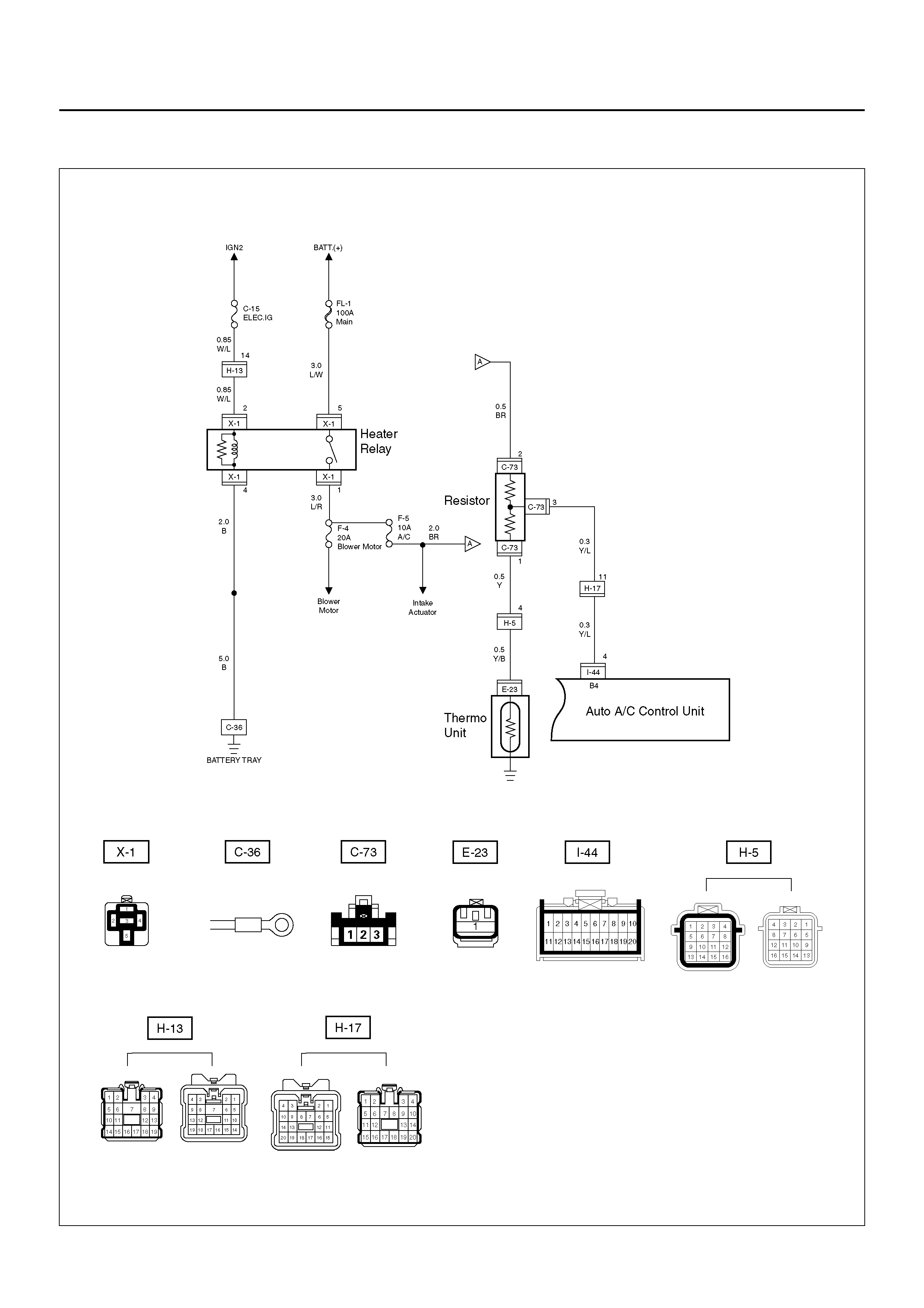
INSPECTION OF THE HEATER CONTROL SYSTEM
D08R100214

Chart A: Heating Start Timing Control Failure
CAUTION: There are conditions which air
conditioner system does not operate except trouble
as follows.
1. The throttle is griater than 90%.
2. The ignition voltage is below 10.5 volts.
3. The engine speed greater than 4500 RPM for 5
seconds or 5400 RPM.
4. The engine coolant temperature (ECT) is greater
than 125°C (257°F).
5. The intake air temperature (IAT) is less than 5°C
(41°F).
6. The power steering pressure switch signals a high
pressure condition.
Condition Possible cause Correction
Heating start timing control failure — Refer to Chart A
Step Action Value(s) Yes No
1 Is the fuse No.F–5 normal? — Go to Step 2 Replace the
fuse
2 Is the relay No.X–1 normal? — Go to Step 3 Replace the
relay
3 Is the thermo unit No.E–23 normal? — Go to Step 4 Replace the
thermo unit
4 Is the resistor No.C–73 normal? — Go to Step 5 Replace the
resistor
5 Is there continuity between the harness side
connector terminal No.C73–1 and No.E23–1? — Go to Step 7 Go to Step 6
6 Repair an open circuit between terminal No.C73–1
and No.E23–1.
Is the action complete? — Go to Step 5 —
7 Is there continuity between the harness side
connector terminal No.C73–3 and No.I44–4? — Go to Step 9 Go to Step 8
8 Repair an open circuit between terminal No.C73–3
and No.I44–4.
Is the action complete? — Go to Step 7 —
9 Turn on the ignition switch (the engine is run).
Is the battery voltage applied between the harness
side connector terminal No.C73–2 and ground? — Go to Step 11 Go to Step 10
10 Repair an open circuit between terminal No.C73–2
and No.F–5 fuse.
Is the action complete? — Go to Step 9 —
11 Replace the auto air conditioner control unit.
Is the action complete? — Verify repair —
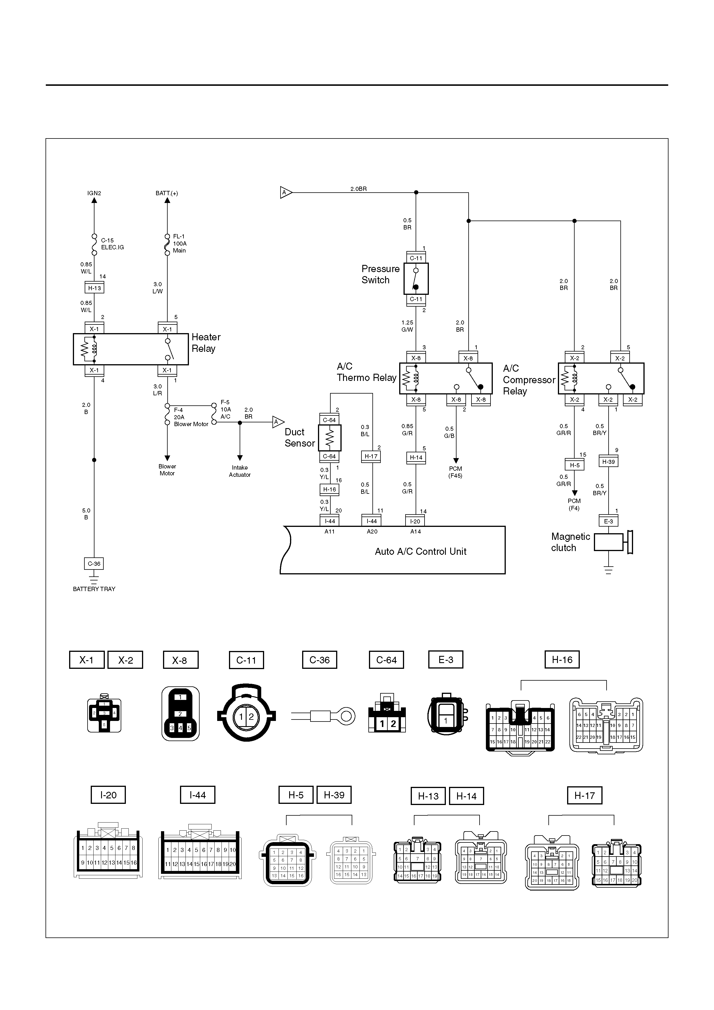
INSPECTION OF THE MAGNETIC CLUTCH SYSTEM
6VD1 Engine
D08R100231

Chart A: Magnetic Clutch Does Not work
Condition Possible cause Correction
Magnetic clutch does not work — Refer to Chart A
Step Action Value(s) Yes No
1 Is the fuse No.F–5 normal? — Go to Step 2 Replace the
fuse
2 Is the relay No.X–2 (compressor relay) No.X–8 (A/C
thermo relay) and No.X–1 (heater relay) normal? — Go to Step 3 Replace the
relay
3 Is the pressure switch normal? — Go to Step 4 Replace the
pressure switch
4 Is the duct sensor normal? — Go to Step 5 Replace the
duct sensor
5 1. Turn the ignition switch on. (the engine is run.)
2. Turn the air conditioner switch on.
Is the battery voltage applied between the harness
side connector terminal No.E3–1 and the ground? — Go to Step 6 Go to Step 7
6 Repair or replace the magnetic clutch.
Is the action complete? — Verify repair —
7 Is there continuity between the harness side
connector terminal No.X2–1 and No.E3–1? — Go to Step 9 Go to Step 8
8 Repair an open c ircuit bet ween ter minal No.X 2–1 an d
No.E3–1.
Is the action complete? — Go to Step 7 —
9 Is the battery voltage applied between the harness
side conn ector termina l No.X2 –5 and ground, No .X2–
2 and ground? — Go to Step 11 Go to Step 10
10 Repair an open circ uit bet ween termi nal No.X2– 5 and
fuse No.F–5, No.X2–2 and fuse No.F–5.
Is the action complete? — Go to Step 9 –
11 Is the battery voltage applied between the harness
side connector terminal No.C11–1 and ground? — Go to Step 13 Go to Step 12
12 Repair an open circuit between terminal No.C11–1
and fuse No.F–5.
Is the action complete? — Go to Step 11 —
13 Is the battery voltage applied between the harness
side conn ector termina l No.X8 –3 and ground, No .X8–
1 and ground? — Go to Step 15 Go to Step 14
14 Repair an open circ uit bet ween termi nal No.X8– 3 and
No.C11–2, No.X8–1 and fuse No.F–5.
Is the action complete? — Go to Step 13 —
15 Is the battery voltage applied between the harness
side connector terminal No.I20–14 and ground? — G o to Step 17 Go to Step 16
16 Repair an open circ uit bet ween termi nal No.X8– 5 and
I20–14.
Is the action complete? — Go to Step 15 —
17 Is there continuity between the harness side
connector terminal No.C64–1 and No.I44–20? — Go to Step 19 Go to Step 18
18 Repair an open circuit between terminal No.C64–1
and No.I44–20.
Is the action complete? — Go to Step 17 —

Chart A: Magnetic Clutch Does Not work (Cont’d)
CAUTION: There are conditions which air
conditioner system does not operate except trouble
as follows.
1. The throttle is griater than 90%.
2. The ignition voltage is below 10.5 volts.
3. The engine speed greater than 4500 RPM for 5
seconds or 5400 RPM.
4. The engine coolant temperature (ECT) is greater
than 125°C (257°F).
5. The intake air temperature (IAT) is less than 5°C
(41°F).
6. The power steering pressure switch signals a high
pressure condition.
Step Action Value(s) Yes No
19 Is there continuity between the harness side
connector terminal No.C64–2 and No.I44–11? — Go to Step 21 Go to Step 20
20 Repair an open circuit between terminal No.C64–2
and No.I44–11.
Is the action complete? — Go to Step 19 —
21 Is there continuity between the harness side
connector terminal No.X8–2 and PCM (F45)? — Go to Step 23 Go to Step 22
22 Repair an open circ uit bet ween termi nal No.X8– 2 and
PCM (F45)?
Is the action complete? — Go to Step 21 —
23 Is there continuity between the harness side
connector terminal No.X2–4 and PCM (F4)? — Go to Step 25 Go to Step 24
24 Repair an open circ uit bet ween termi nal No.X2– 4 and
PCM (F4).
Is the action complete? — Go to Step 23 —
25 1. Connect the connector of PCM.
2. Connect the harness side connector terminal
I20–14 to the ground.
Does the magnetic clutch work?
—
Replace the
auto air
conditioner
control unit
Refer to
Powertrain
Control Modul
in ENGINE
DRIVEABILITY
AND
EMISSIONS
section
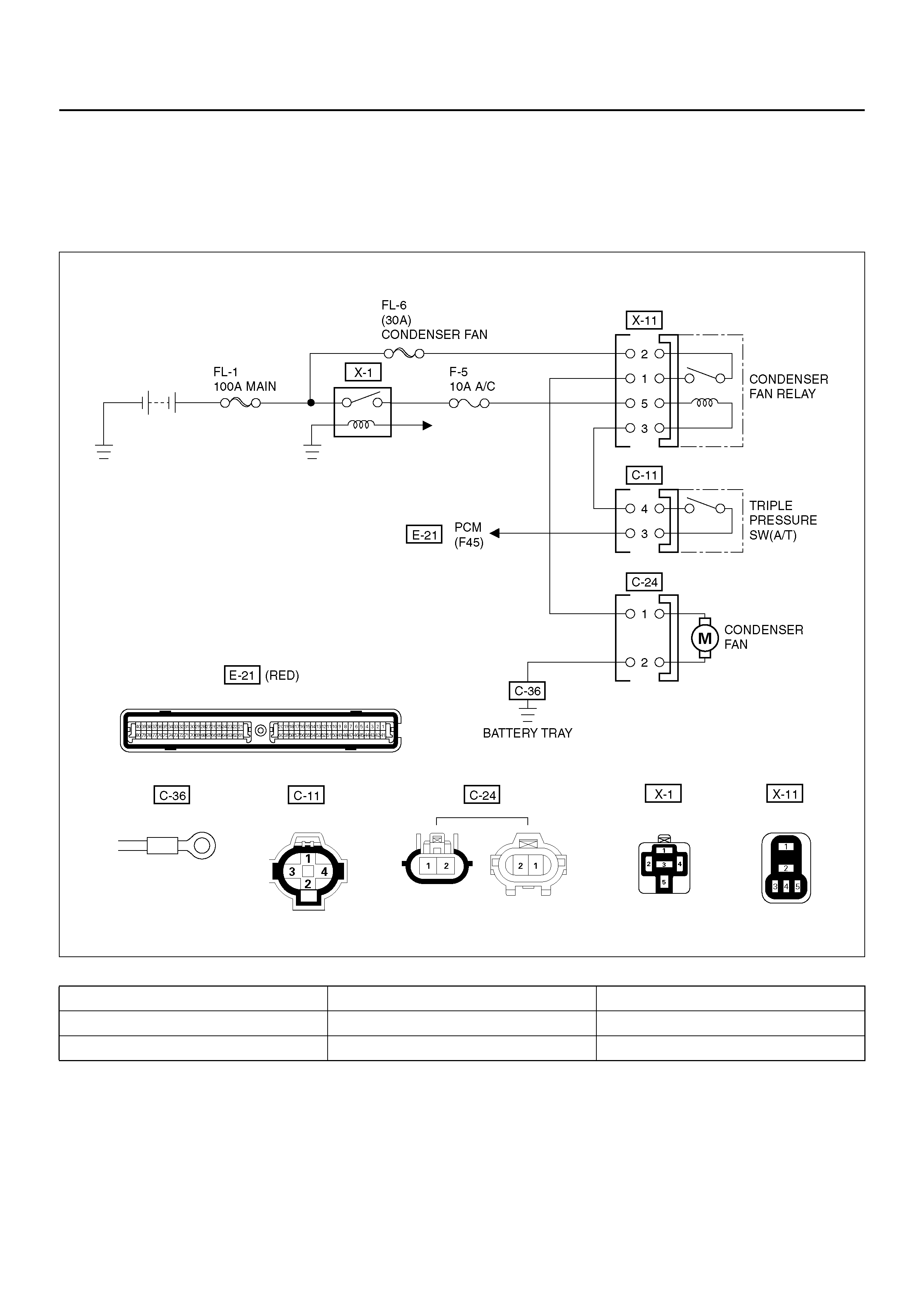
CONDENSER FAN DIAGNOSIS
While the air conditioning is ON, the cycling switch in
the triple pressure switch senses the refrigerant
pressure, and activates the condenser fan to improve
the cooling capacity of the condenser when the
refrigerant pressure exceeds a set pressure value. The
conden ser fan stops when the air conditi oning is turned
“OFF" or when the pressure goes down below the set
pressure value.
D08R100140
Condition Possible cause Correction
Condenser fan does not run. — Refer to Chart A
Condenser fan does not stop. — Refer to Chart B

Chart “A" Condenser Fan Does Not Run
Step Action Value(s) Yes No
1 Is the fusible link No.FL–6 normal? — Go to Step 2 Replace the
fusible link wire
2 Is the fuse No.F–5 normal? — Go to Step 3 Replace the
fuse
3 Is the heater relay (No.X–1) and condenser fan relay
(No.X–11) normal? — Go to Step 4 Replace the
relay
4 1. Disconnect the condenser fan motor connector
No.C–24.
2. Connect the motor side connector terminal
No.C24–1 to the battery positive terminal and
No.C24–2 to the battery negative terminal.
Does the fan operate? — Go to Step 6 Go to Step 5
5 Repair or replace the condenser fan motor.
Is the action complete? — Go to Step 4 —
6 Is there continuity between the harness side
connector terminal No.C24–2 and ground (C–36)? — Go to Step 8 Go to Step 7
7 Repair an open circuit between terminal No.C24–2
and No.C–36.
Is the action complete? — Go to Step 6 —
8 Is there continuity between the harness side
connector terminal No.C24–1 and No.X11–1? — Go to Step 10 Go to Step 9
9 Repair an open circuit between terminal No.C24–1
and No.X11–1.
Is the action complete? — Verify repair —
10 Is the battery voltage applied between the harness
side connector terminal No.X11–2 and ground? — Go to Step 12 Go to Step 11
11 Repair an open circuit between terminal No.X11–2
and No.FL–6.
Is the action complete? — Go to Step 10 —
12 Is the battery voltage applied between the harness
side connector terminal No.C11–4 and ground? — Go to Step 14 Go to Step 13
13 Repair an open circuit between terminal No.X11–3
and No.C11–4.
Is the action complete? — Go to Step 12 —
14 Is there continuity between the harness side
connector terminal No.C11–3 and No.E21–F45? — Go to Step 16 Go to Step 15
15 Repair an open circuit between terminal No.C11–3
and No.E21–F45.
Is the action complete? — Verify repair —
16 Connect the harness side connector terminal
No.C24–1 to the battery terminal and No.C24–2 to the
battery negative terminal.
Is the battery voltage between the pressure switch
side connector terminal No.C24–2 and ground? — G o to Step 18 Go to Step 17
17 Replace the triple pressure switch.
Is the action complete? — Verify repair —
18 Replace the auto air conditioner control unit.
Is the action complete? — Verify repair —

Chart “B" Condenser Fan Does Not Stop
Step Action Value(s) Yes No
1 1. Turn on the ignition switch “ON" (the engine is
run).
2. Air conditioning switch “OFF".
3. Disconnect the triple pressure switch.
Does the condenser fan stop? — Go to Step 2 Go to Step 3
2 Replace the triple pressure switch.
Is the action complete? — Verify repair —
3 Disconnect the relay.
Is there continuity between the harness side
connector terminal No.X11–3 and ground? — Go to Step 4 Go to Step 5
4 Repair short circuit between terminal No.X11–3 and
No.C11–4.
Is the action complete? — Go to Step 3 —
5 Replace the relay condenser fan.
Is the action complete? — Verify repair —
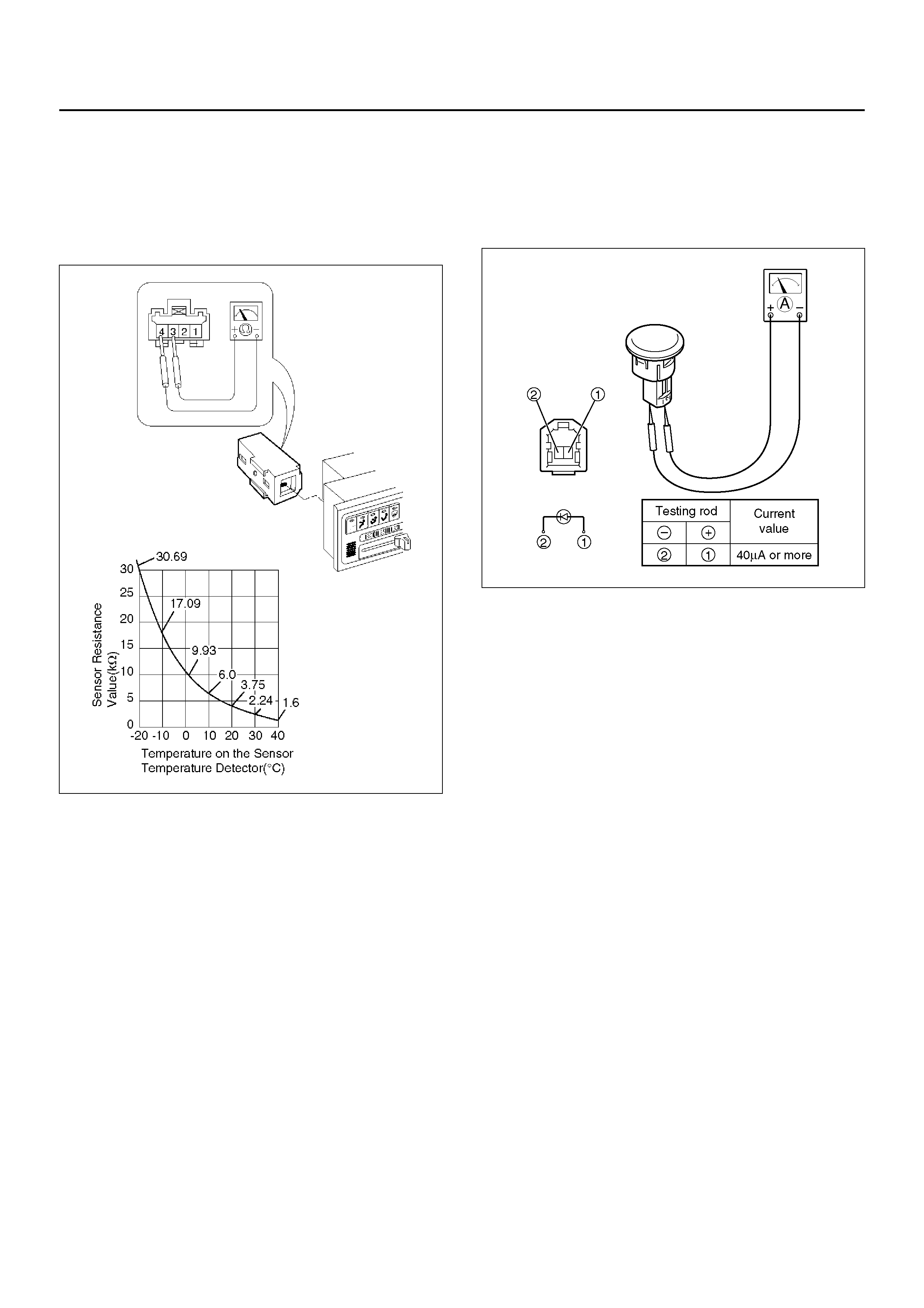
INDIVIDUAL INSPECTION
In Car Sensor
1. Disconnect the in car sensor connector (I–4).
2. Measure resistance between the in car sensor side
terminal No.I4–3 and No.I4–4.
865RX007
Sun Sensor
1. Disconnect the sun sensor connector (I–50).
2. Measure th e current value on the sun sensor when
placed it approximately 15 cm away from 60W
incandescent lamp.
D06R200001
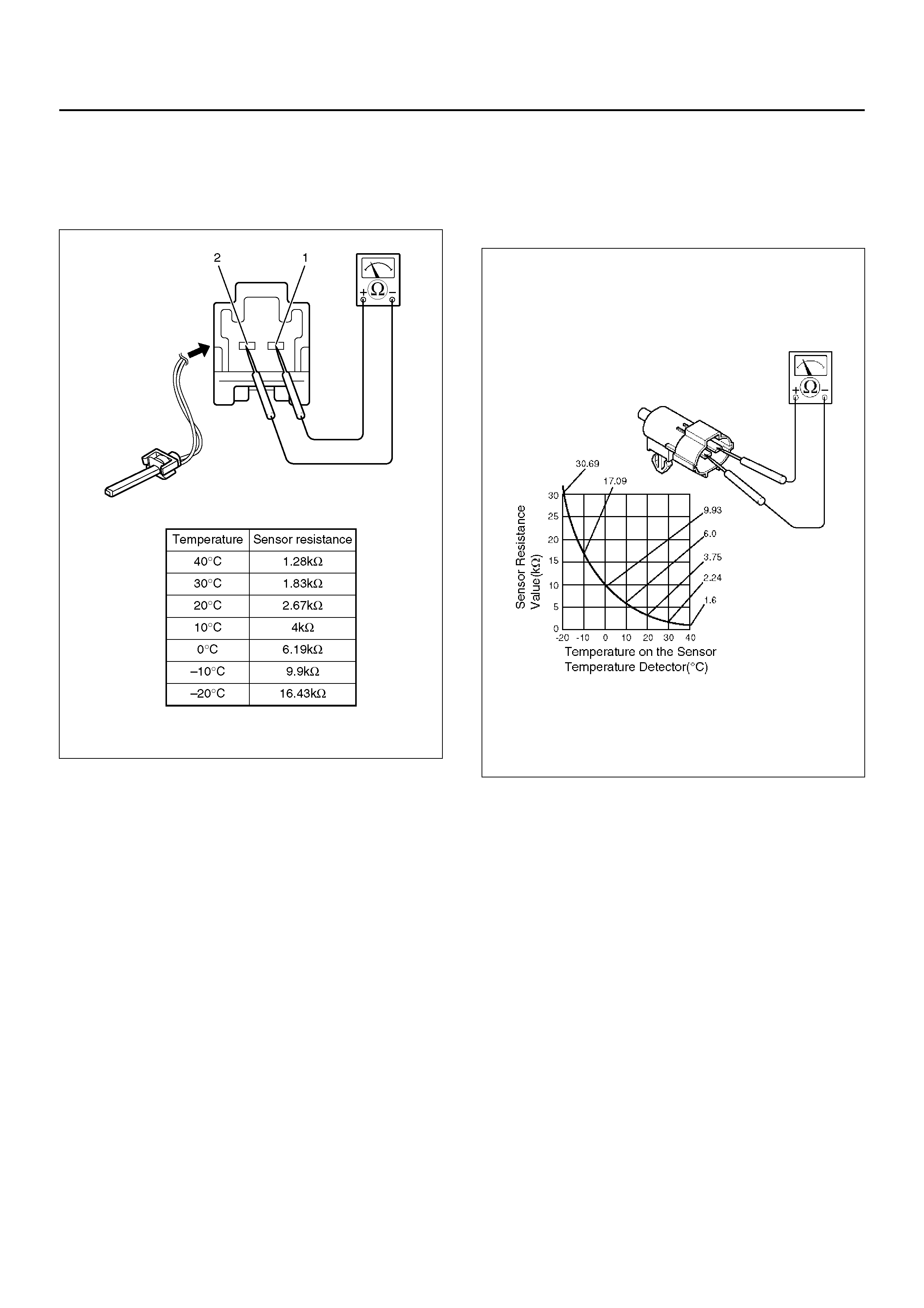
Duct Sensor
1. Disconnect the duct sensor connector (C–64).
2. Measure resistance between the duct sensor side
terminal No.C64–1 and No.C64–2.
C01R100006
Ambient Sensor
1. Disconnect the connector (C–8) on the ambient
sensor.
2. Measure resistance between the ambient sensor
side terminals.
C01RX012
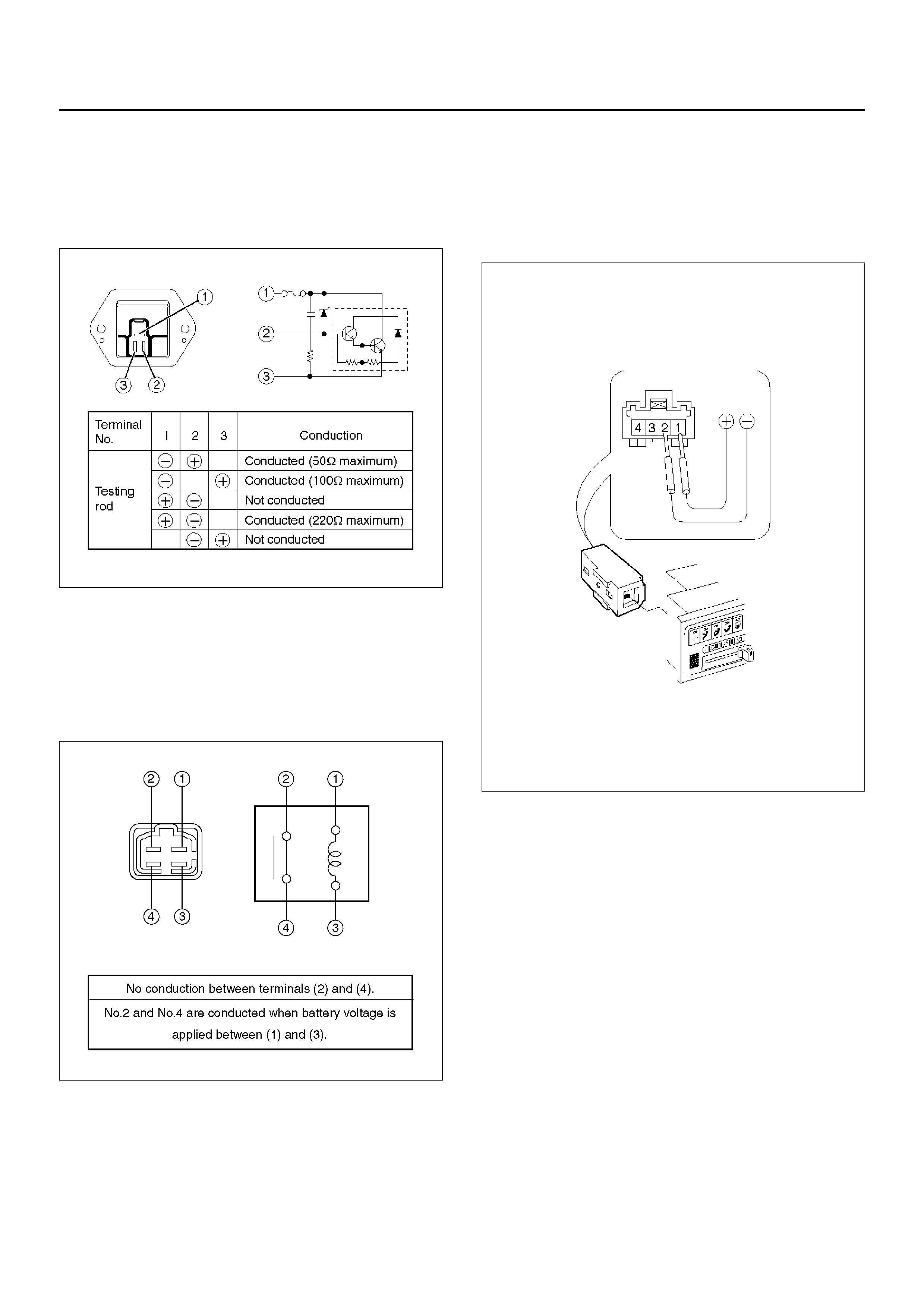
Power Transistor
1. Remove the power transistor connector (C–66) from
the evaporator assembly.
2. Check the cond uction b etween the power tra nsistor
side terminals.
C01RX015
MAX HI Relay
1. Remo ve the MA X – HI rela y connec tor (C–67) from
the blower assembly.
2. Check the conduction between the MAX – HI relay
side terminals.
C01R100001
In Car Sensor
1. Turn on the ignition switch (the engine is started).
St art the air conditioner in “Auto".
2. Make sure that the interior sensor suctions cigarette
smokes and such.
In Car Sensor
1. Dismount the in car sensor from the automatic
heater/air conditioner control unit. Connect (+)
end and (-) end of the battery to the aspirator motor
side terminals No.I4–1 and No.I4–2, respectively,
then check if the motor runs normally.
C01RW020
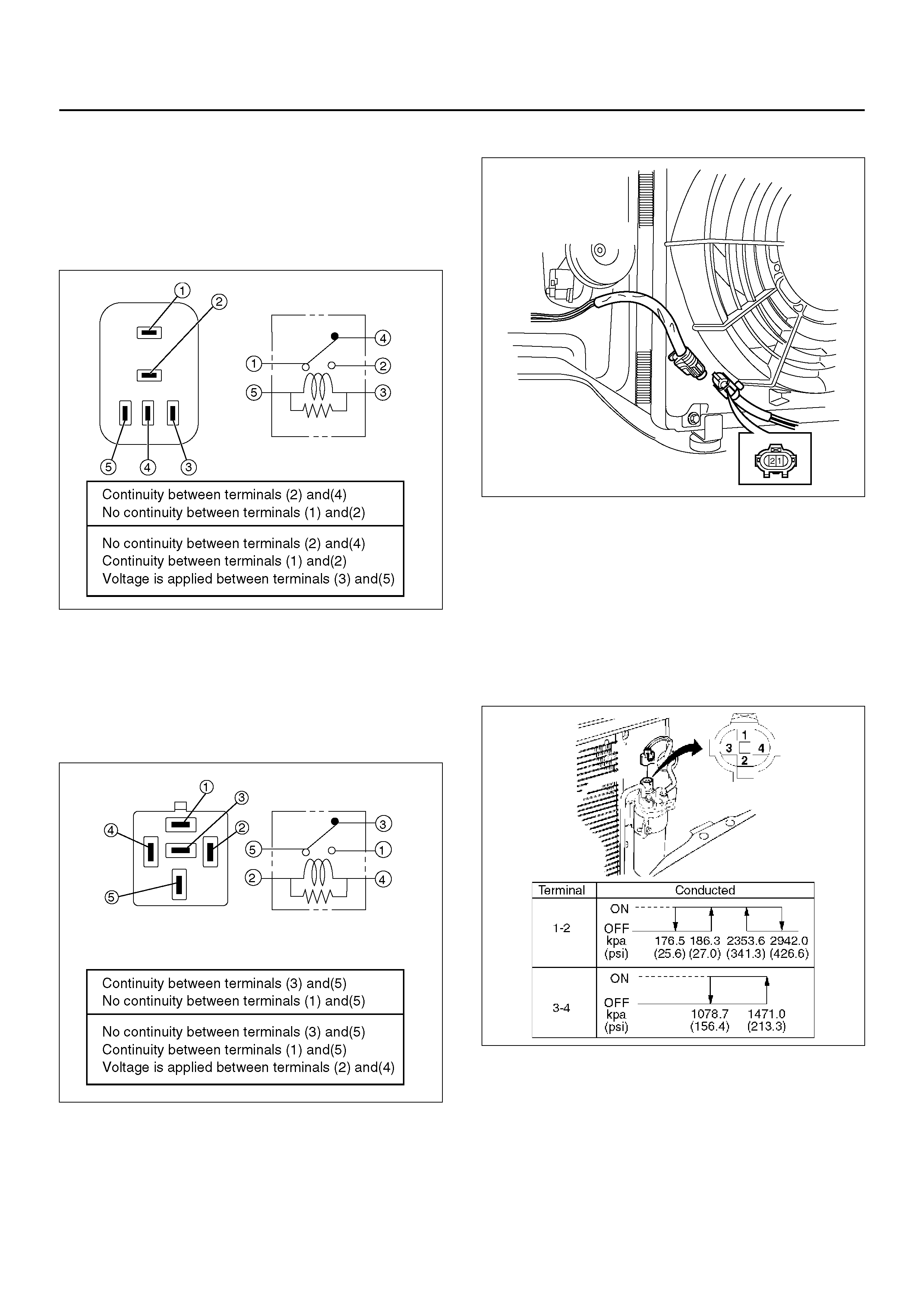
Thermostat (X-8), Condenser Fan (X-11)
Relay
1. Disconnect relays and check for continuity and
resistance between relay terminals.
• For handling of these relays, refer to Heater
Relay in this section.
C01R100002
Heater (X–1), Compr ess or (X– 2) Relay
1. Disconnect relays and check for continuity and
resistance between relay terminals.
• For handling of these relays, refer to Heater
Relay in this section.
C01R200011
Condenser Fan
1. Disconnect the condenser fan connector.
2. Connect the battery positive terminal to the
conden ser fan side conn ector terminal N o.C24-2
and negative to the No.C24-1.
3. Check that condenser fan is rotating correctly.
875RW010
Triple Pressure Swit ch (V 6, A/T)
1. Disconnect the connector and check for continuity
between pressure switch side connector
terminals (1) and (2).
2. Reconne ct the conn ec tor to a ct iv ate t he A /C s wit ch ,
and check to see if there is continuity between the
chassis side connector terminal (3) and (4) and the
fan operates.
875RX009
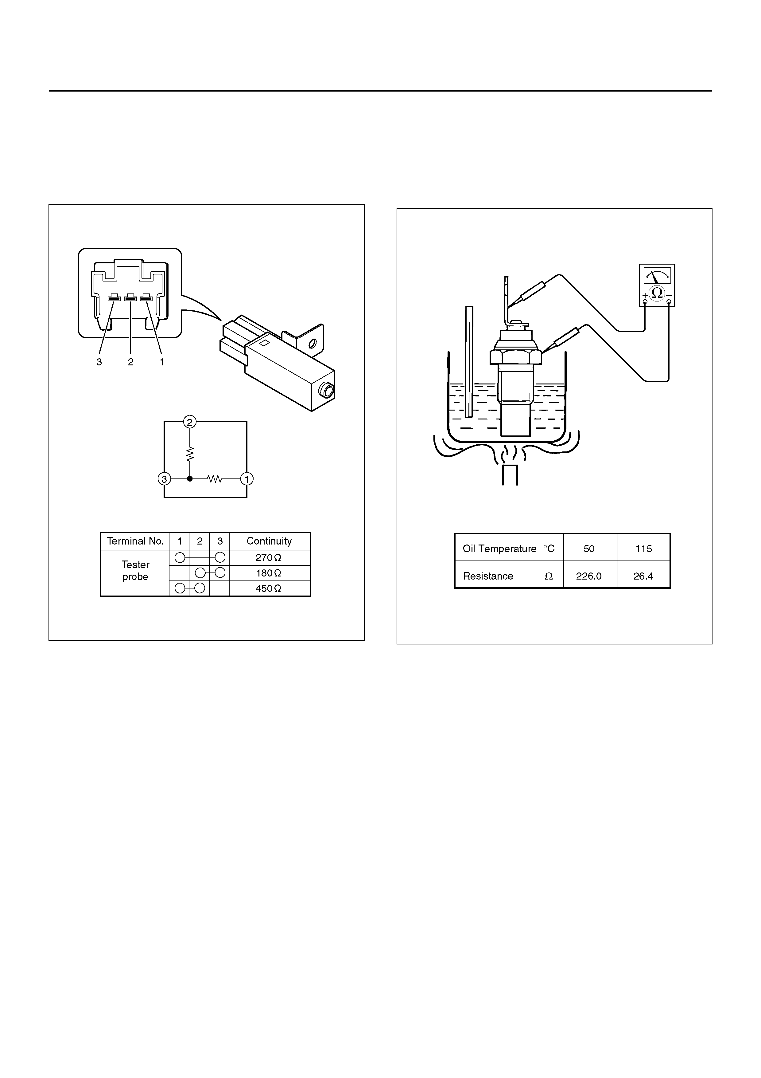
Resistor
1. Disconnect the resistor connector (C-73) from the
heater unit assembly.
2. Check the continuity and resistance value between
the resistor terminals.
C01R100004
Thermo Unit
1. Submerge the sensor portion of the thermo unit in
the oil.
2. Heat the oil.
3. Check the resistance valve of the unit.
C01R100007
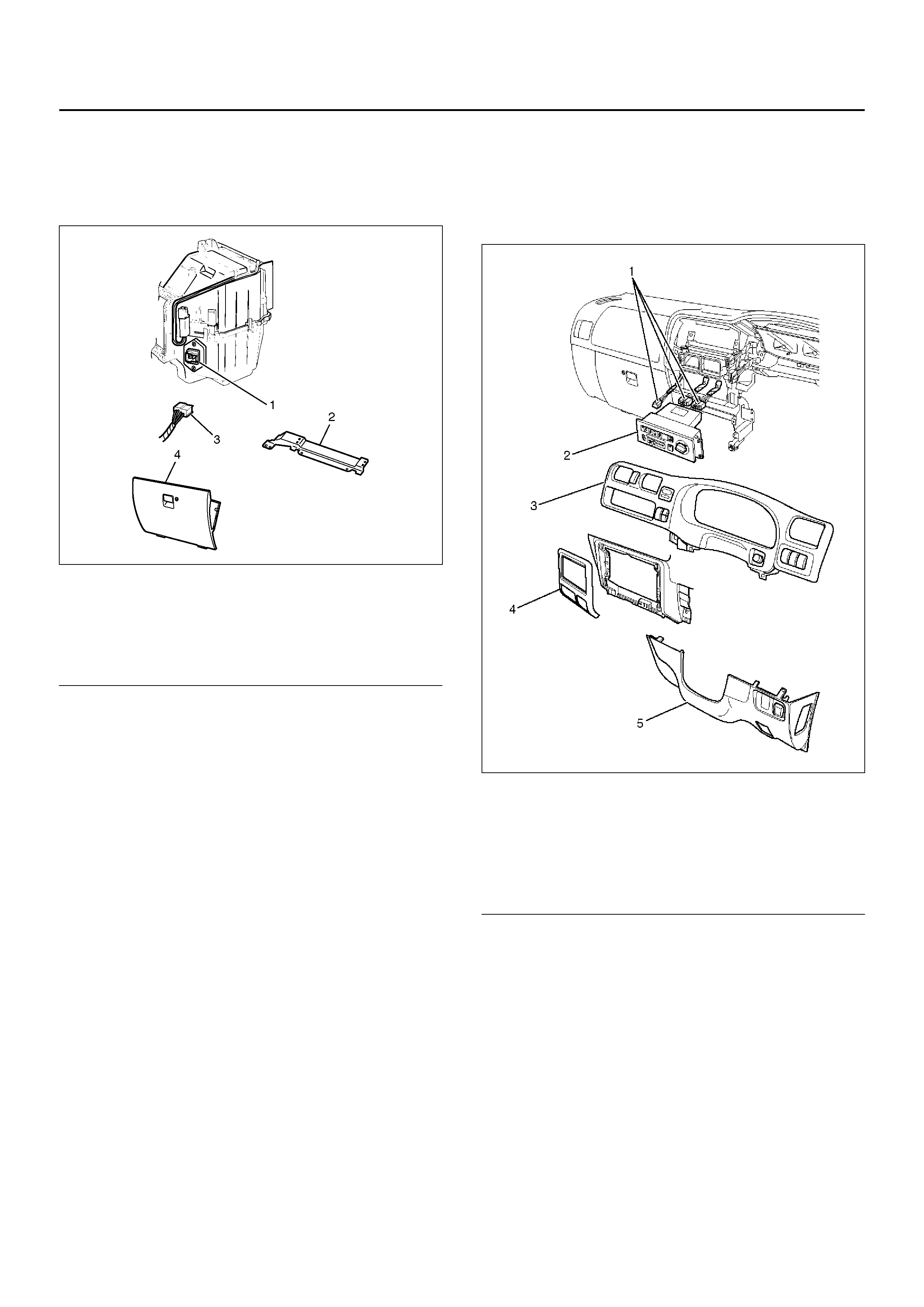
ON-VEHICLE SERVICE
POWER TRANSISTOR
874R100006
EndOFCallout
REMOVAL
1. Remove glove box.
2. Remove passenger knee bolster reinforcement.
3. Disconnect the power transistor connector.
4. Remove power transistor.
INSTALLATION
To install, follow the removal step in the reverse order.
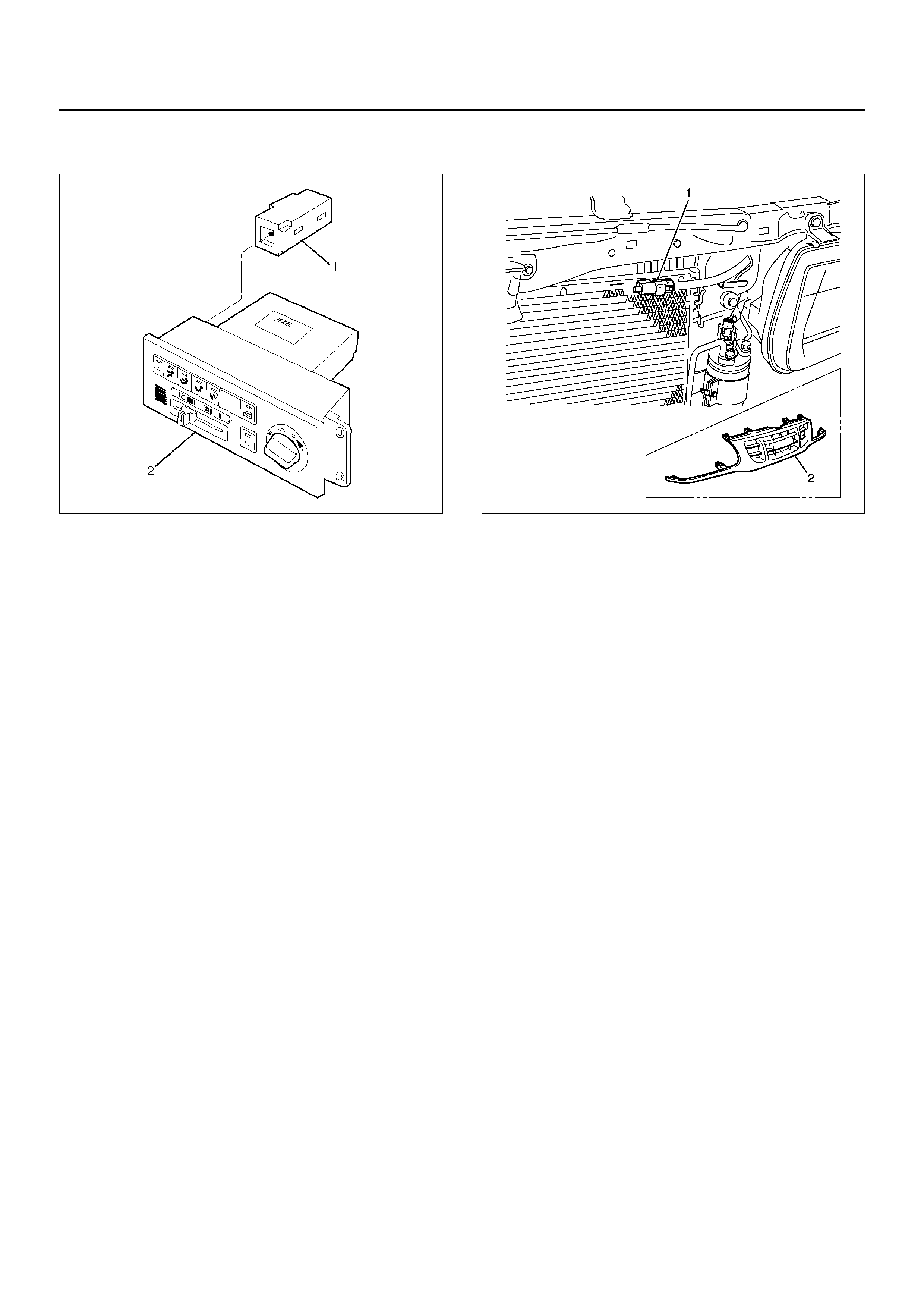
AUTOMATIC AIR CONDITIONER
CONTROL UNIT
865RW016
EndOFCallout
REMOVAL
1. Disconnect the battery ground cable.
2. Remove instrument lower cover.
3. Remove meter cluster assembly.
• Refer to Instrument Panel Assembly in Body
Structure section.
4. Remove the automatic air conditioner control unit
attaching screws.
5. Pull the automatic air conditioner unit out and
disconnect the connectors.
INSTALLATION
To install, follow the removal step in the reverse order.
Legend
(1) Power Transistor
(2) Passenger knee bolster Reinforcement
(3) Power Transistor Connector
(4) Glove Box
Legend
(1) Connector
(2) Automatic Air Control Unit
(3) Meter Cluster Assembly
(4) Instrum ent Center Cluster
(5) Instrum ent Lowe r Cover
IN CAR SENSOR
865RW014
EndOFCallout
REMOVAL
1. Disconnect the battery ground cable.
2. Remove the automatic air conditioner control unit.
• Refer to the automatic air conditioner control unit
section.
3. Remove in car sensor.
INSTALLATION
To install, follow the removal step in the reverse order.
AMBIENT SENSOR
875R100006
EndOFCallout
REMOVAL
1. Disconnect the battery ground cable.
2. Remove radiator grille.
• Refer to Radiator Grille in Body Structure section.
3. Disconnect the ambient sensor connector.
4. Remove the ambient sensor.
INSTALLATION
To install, follow the removal step in the reverse order.
Legend
(1) In Car Sensor
(2) Automatic Air Control Unit
Legend
(1) Ambient Sensor
(2) Radiator Grille
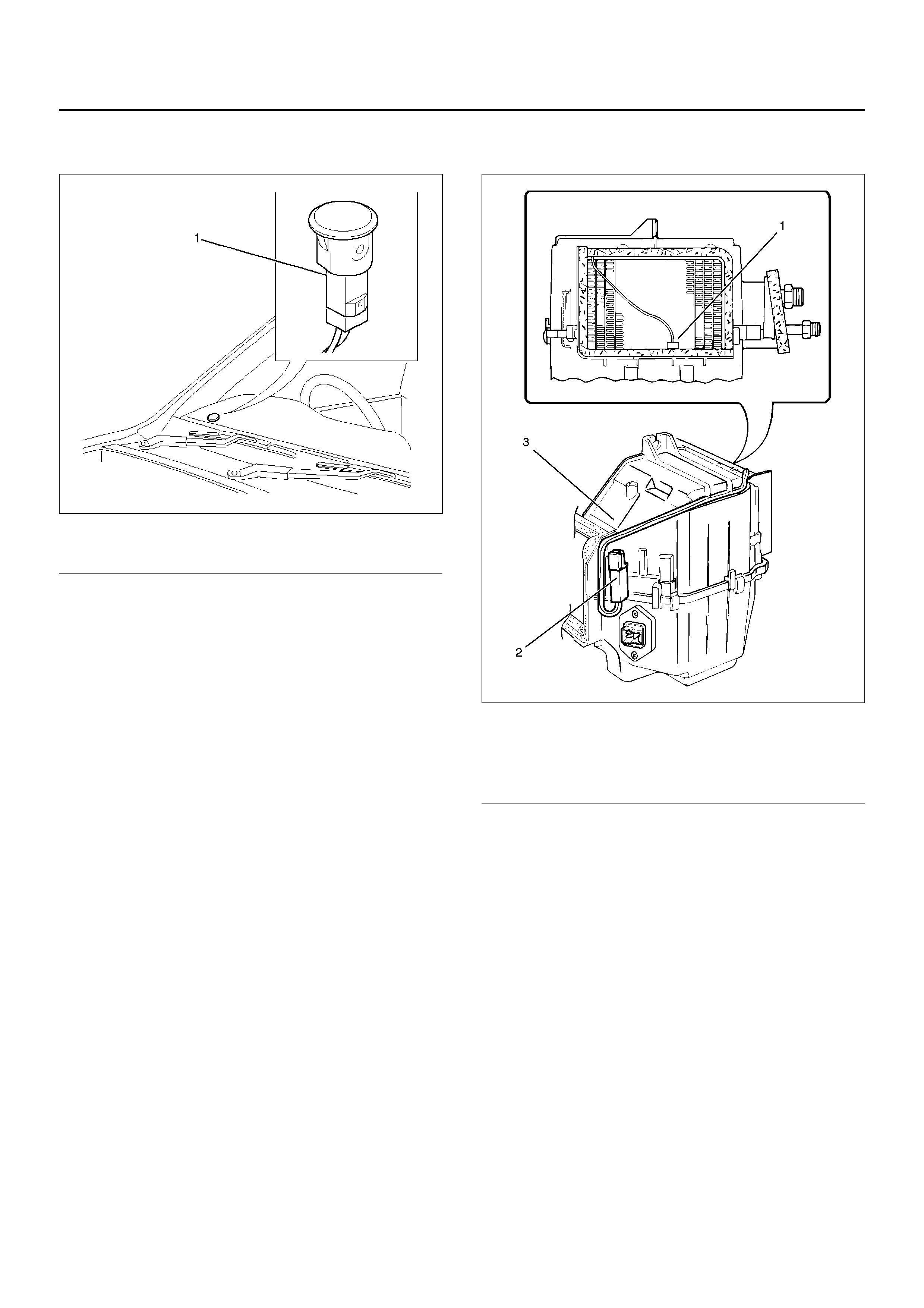
SUN SENSOR
865RW009
EndOFCallout
REMOVAL
1. Disconnect the battery ground cable.
2. Remove the sun sensor.
3. Disconnect the sun sensor connector.
INSTALLATION
To install, follow the removal step in the reverse order.
DUCT SENSOR
874RY00002
EndOFCallout
REMOVAL
1. Disconnect the battery ground cable.
2. Remove the evaporator assembly.
• Refer to Evaporator Assembly section.
3. Remove the duct sensor assembly.
INSTALLATION
To install, follow the removal step in the reverse order.
Legend
(1) Sun Sensor
Legend
(1) Sensor Part
(2) Duct Sensor Assembly
(3) Evapolator Assembly
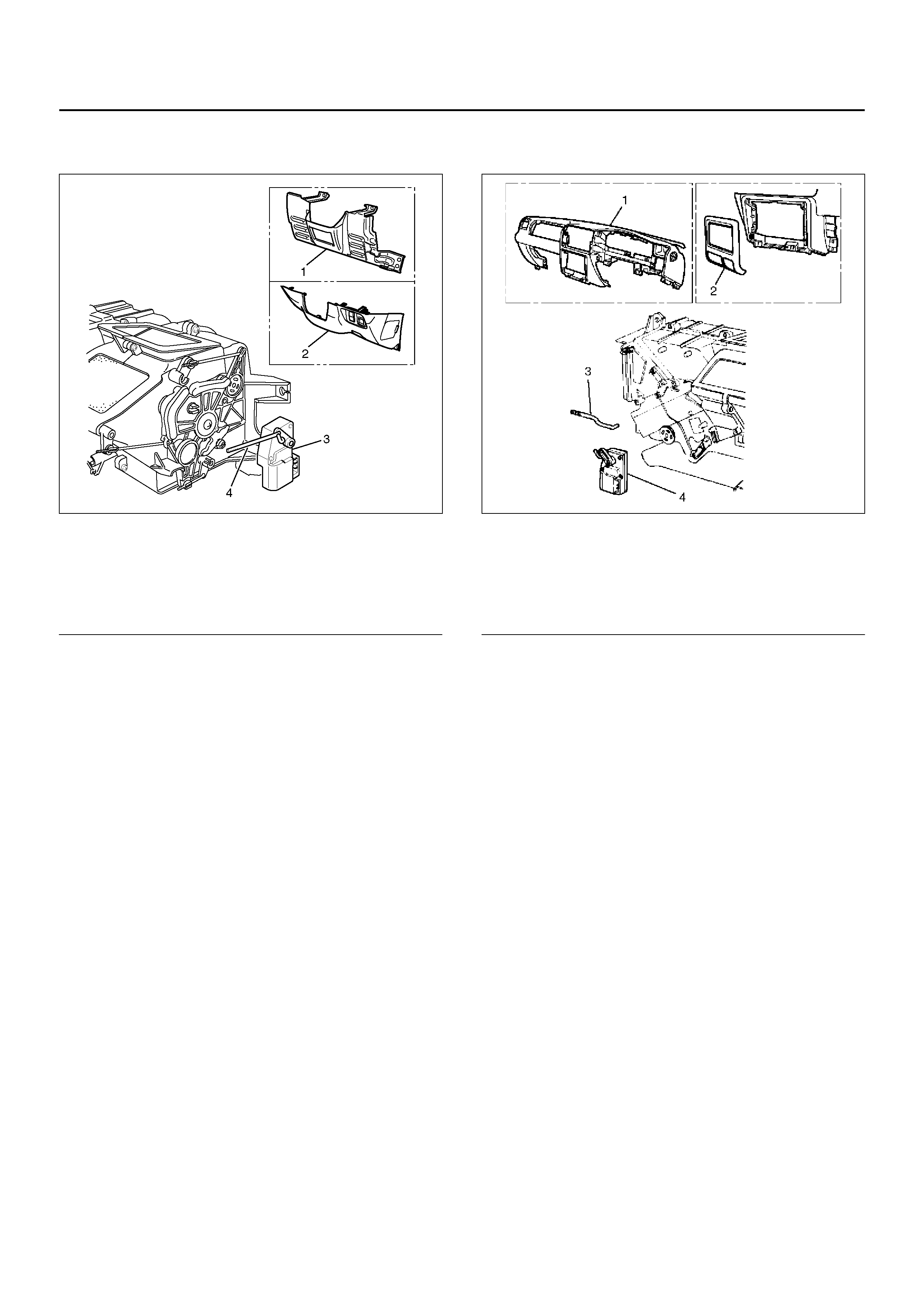
MODE ACTUATOR
860R100002
EndOFCallout
REMOVAL
1. Disconnect the battery ground cable.
2. Remove the instrument panel driver lower cover.
3. Remove the driver knee bolster assembly.
• Refer to the Instrument Panel Assembly in Body
Structure section.
4. Remove the actuator rod.
5. Remove the mode actuator.
INSTALLATION
To install, follow the remove step in the reverse order.
MIX ACTUATOR
860RW033
EndOFCallout
REMOVAL
1. Disconnect the battery ground cable.
2. Remove the instrument panel assembly.
• Refer to the Instrument Panel Assembly in Body
Structure section.
3. Remove the instrument panel center cluster.
4. Remove the actuator rod.
5. Remove the mix actuator.
INSTALLATION
To install, follow the remove step in the reverse order.
Legend
(1) Driver Knee Bolster Assembly
(2) Instrument Panel Driver Lower Cover
(3) Mode Actuator
(4) Actuator Rod
Legend
(1) Instr um ent Pa nel Assemb ly
(2) Instrument Panel Center Cluster
(3) Actuator Rod
(4) Mix Actuator
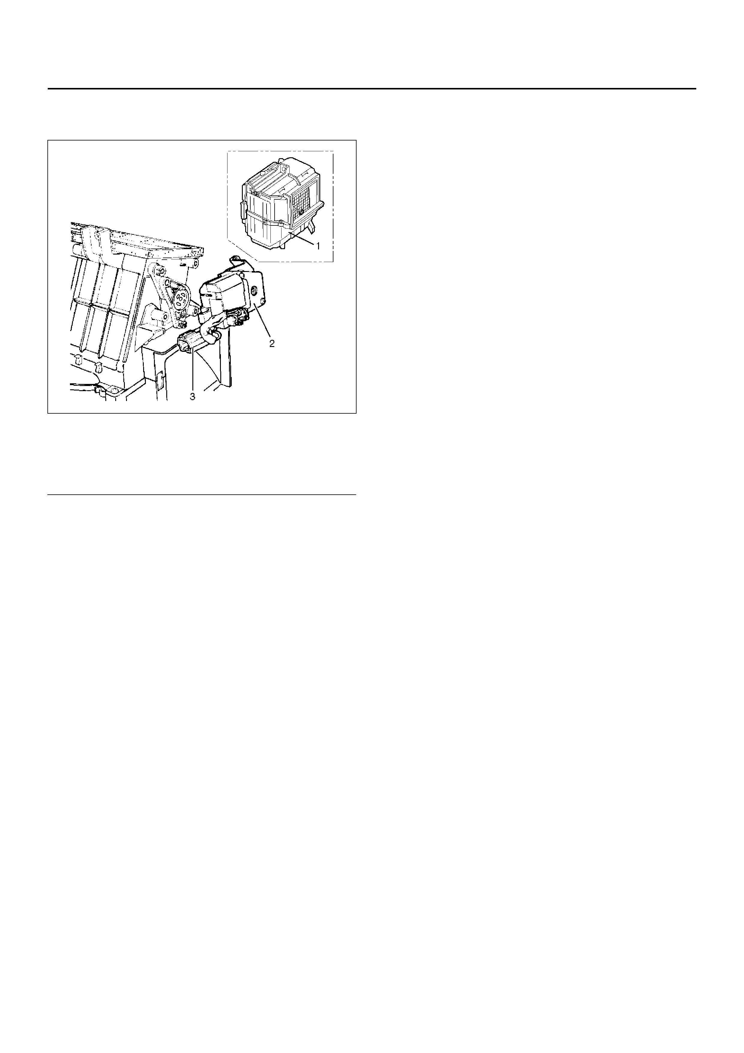
INTAKE ACTUATOR
860RX018
EndOFCallout
REMOVAL
1. Disconnect the battery ground cable.
2. Remove the blower assembly.
• Refer to Blower Assembly section.
3. Disconnect the intake actuator connector.
4. Remove the intake actuator.
INSTALLATION
To install, follow the remove step in the reverse order.
Legend
(1) Evaporator Assembly
(2) Intake Actuator
(3) Intake Actuator Connector