
SECTION 3C - FRONT SUSPENSION
Service Precaution
General Description
Diagnosis
Shock Absorber
Shock Absorber and Associated Parts
Removal
Inspection and Repair
Installation
Stabilizer Bar
Stabilizer Bar and Associated Parts
Removal
Inspection and Repair
Installation
Torsion Bar
Torsion Bar and Associated Parts
Removal
Inspection and Repair
Installation
Knuckle
Knuckle and Associated Parts
Removal
Inspection and Repair
Installation
Upper Control Arm
Upper Control Arm and Associated Parts
Removal
Inspection and Repair
Installation
Lower Control Arm
Lower Control Arm and Associated Parts
Removal
Inspection and Repair
Installation
Upper Ball Joint
Upper Ball Joint and Associated Parts
Removal
Inspection and Repair
Installation
Lower Ball Joint
Lower Ball Joint and Associated Parts
Removal
Inspection and Repair
Installation
Main Data and Specifications
Steering Wheel Free Play Inspection
Front End Alignment Inspection and Adjustment
Main Data and Specifications
Special Tools
SERVICE PRECAUTION
WARNING: THIS VEHICLE HAS A SUPPLEMENTAL
RESTRAINT SYSTEM (SRS). REFER TO THE SRS
COMPONENT AND WIRING LOCATION VIEW IN
ORDER TO DETERMINE WHETHER YOU ARE
PERFORMING SERVICE ON OR NEAR THE SRS
COMPONENTS OR THE SRS WIRING. WHEN YOU
ARE PERFORMING SERVICE ON OR NEAR THE
SRS COMPONENTS OR THE SRS WIRING, REFER
TO THE SRS SERVICE INFORMATION. FAILURE TO
FOLLOW WARNINGS COULD RESULT IN POSSIBLE
AIR BAG DEPLOYMENT, PERSONAL INJURY, OR
OTHERWISE UNNEEDED SRS SYSTEM REPAIRS.
CAUTION: Always use the correct fastener in the
proper location. When you replace a fastener, use
ONLY the exact part number for that application.
HOLDEN will call out those fasteners that require a
replacement after removal. HOLDEN will also call
out the fasteners that require thread lockers or
thread sealant. UNLESS OTHERWISE SPECIFIED,
do not use supplemental coatings (Paints, greases,
or other corrosion inhibitors) on threaded fasteners
or fastener joint interfaces. Generally, such
coatings adversely affect the fastener torque and
the joint clamping force, and may damage the
fasteners. When you install fasteners, use the
correct tightening sequence and specifications.
Following these instructions can help you avoid
damage to parts and systems.
GENERAL DESCRIPTION
The front suspension is designed to allow each wheel to
compensate for changes in the road surface level
without greatly affecting the opposite wheel. Each
wheel is independently connected to the frame by a
steering knuckle, ball joint assemblies, and upper and
lower control arms. The front wheels are held in proper
relationship to each other by two tie-rods which are
connected to steering arms on the knuckles, and to a
steering unit.
All models have a front suspension system consisting of
control arms, stabilizer bar, shock absorber and a
torsion bar. The front end of the torsion bar is attached
to the lower control arm. The rear of the torsion bar is
mounted into a height control arm at the crossmember.
Vehicle trim height is controlled by adjusting this arm.
Shock absorbers are mounted between the brackets on
the frame and the lower control arms. The lower portion
of each shock absorber is attached to the lower control
arm. The upper portion of each shock absorber extends
through a frame bracket and is secured with two rubber
bushings, two retainers and a nut.
Ball joint assemblies are bolted to the outer end of the
upper and lower control arm and are attached to the
steering knuckle.
The inner ends of the upper control arm have pressed in
bushings. Bolts, passing through the bushing, attach the
control arm to the frame. The inner ends of the lower
control arm are attached to the frame by bolts passing
through the bushings.
Side roll of the front suspension is controlled by a spring
steel stabilizer bar. It is mounted in rubber bushings,
which are held to the frame by brackets. The ends of
the stabilizer bar are connected to the lower control
arms by links.
DIAGNOSIS
Condition Possible cause Correcti on
Vehicle Pulls Mismatched or uneven tires. Replace tire.
Tires not adequately inflated. Adjust tire pressure.
Broken or sagging springs. Replace spring.
Radial tire lateral force. Replace tire.
Improper wheel alignment. Adjust wheel alignment.
Brake dragging in one wheel. Repair brake.
Loose, bent or broken front or rear
suspension parts. Tighten or replace the appropriate
suspension part(s).
Faulty shock absorbers. Replace shock absorber.
Parts in power steering valve
defective. Replace power steering unit.
Abnormal or Excessive Tire Wear Sagging or broken spring. Replace spring.
Tire out of balance. Balance or replace tire.
Improper wheel alignment. Check front end alignment.
Faulty shock absorber. Replace shock absorber.
Hard driving. Replace tire.
Overloaded vehicle. Replace tire and reduce load.
Tires not rotated periodically. Replace or rotate tire.
Worn or loose road wheel bearings. Replace wheel bearing.
Wobbly wheel or tires. Replace wheel or tire.
Tires not adequately inflated. Adjust the pressure.
Wheel Hop Blister or bump on tire. Replace tire.
Improper shock absorber operation. Replace shock absorber.
Shimmy, Shake or Vibration Tire or wheel out of balance. Balance wheels or replace tire/or
wheel.
Loose wheel bearings. Replace wheel bearing.
Worn steering linkage ball joints. Replace ball joints.
Worn upper or lower end ball joints. Replace ball joints.
Excessive wheel runout. Repair or replace wheel and/or tire.
Blister or bump on tire. Replace tire.
Excessive loaded radial runout of
tire/wheel assembly. Replace tire or wheel.
Improper wheel alignment. Check wheel alignment.
Loose or worn steering linkage. Tighten or replace steering linkage.
Loose steering unit. Tighten steering unit.
Tires not adequately inflated. Adjust tire pressure.
Loose, bent or broken front or rear
suspension parts. Tighten or replace the appropriate
suspension parts.
Faulty shock absorber. Replace shock absorber.
Hub bearing preload misadjustment. Adjust preload.
Parts in power steering valve
defective. Replace power steering unit.
Hard Steering Bind in steering linkage ball studs,
upper or lower ball joint. Replace ball joint.
Improper wheel alignment. Check wheel alignment.
Tire not adequately inflated. Inflate tires to proper pressure.
Bind in steering column or shaft. Repair or replace.
Improper power steering system
operation. Repair or replace. Refer to Steering
section.
Too Much Play In Steering Wheel bearings worn. Replace wheel bearings.
Loose steering unit or linkage. Retighten or repair.
Worn or loose steering shaft
universal joint. Retighten or replace steering shaft.
Worn steering linkage ball joints. Replace ball joints.
Worn upper or lower end ball joints. Replace ball joints.
Poor Steering Wheel Returnability Bind in steering linkage ball joints. Replace ball joints.
Bind in upper or lower ball joints. Replace ball joints.
Bind in steering column and shaft. Repair or replace.
Bind in steeri ng gear. Check and repair ste ering gear.
Improper wheel alignment. Adjust wheel alignment.
Tires not adequately inflated. Adjust pressure.
Loose steering wheel nut. Retighten.
Worn wheel bearing. Replace.
Misassemble Transfer Gear ASM. Reassemble Transfer Gear to
proper portion.
Condition Possible cause Correcti on
Abnormal Noise Worn, sticky or loose upper or lower
ball joint, steering linkage ball joints
or drive axle joints.
Replace.
Faulty shock absorbers. Replace.
Worn upper or lower control arm
bushing. Replace.
Loose stabilizer bar. Retighten bolts or replace bushings.
Loose wheel nuts. Tighten nuts. Check for elongated
wheel nut holes. Replace wheel if
required.
Loose suspension bolts or nuts. Retighten suspension bolts or nuts.
Broken or otherwise damaged
wheel bearings. Replace wheel bearing.
Broken suspension springs. Replace spring.
Loose steering unit. Retighten mounting bolt.
Faulty steering unit. Replace steering unit.
Wandering or Poor Steering Stability Mismatched or unevenly worn tires. Replace tire or inflate tires to proper
pressure.
Loose steering linkage ball joints. Replace ball joints.
Faulty shock absorbers. Replace shock absorber.
Loose stabilizer bar. Tighten or replace stabilizer bar or
bushings.
Broken or sagging springs. Replace spring (pairs).
Improper wheel alignment. Adjust wheel alignment.
Erratic Steering When Braking Worn wheel bearings. Replace wheel bearings.
Broken or sagging springs. Replace spring (pairs).
Leaking caliper. Repair or replace caliper.
Warped discs. Replace brake disc.
Badly worn brake pads. Replace brake pads.
Tires are inflated unequally. Inflate tires to proper pressure.
Low or Uneven Trim Height Broken or sagging springs. Replace springs (In pairs).
Vehicle overloaded. Reduce load.
Incorrect springs. Adjust or replace torsion bar.
Trim Height out of Spec. Adjust Trim Height.
Suspension Bottoms Vehicle overloaded. Reduce load.
Faulty shock absorber. Replace shock absorber.
Incorr e ct, brok en or saggi ng
springs. Replace springs.
Tires are inflated unequally. Inflate tires to proper pressure.
Body Leans Trim Height out of Spec. Adjust Trim Height.
Loose stabilizer bar. Tighten stabilizer bar bolts or
replace bus hi ngs.
Faulty shock absorber, struts or
mounting. Replace shock absorber.
Broken or sagging springs. Replace springs (In pairs).
Vehicle overloaded. Reduce load.
Condition Possible cause Correcti on
Cupped Tires Worn wheel bearings. Replace wheel bearing.
Excessive tire or wheel run out. Replace tire or wheel.
Worn ball joints. Replace ball joints.
Tire out of balance. Adjust tire balance.
Condition Possible cause Correcti on
SHOCK ABSORBER
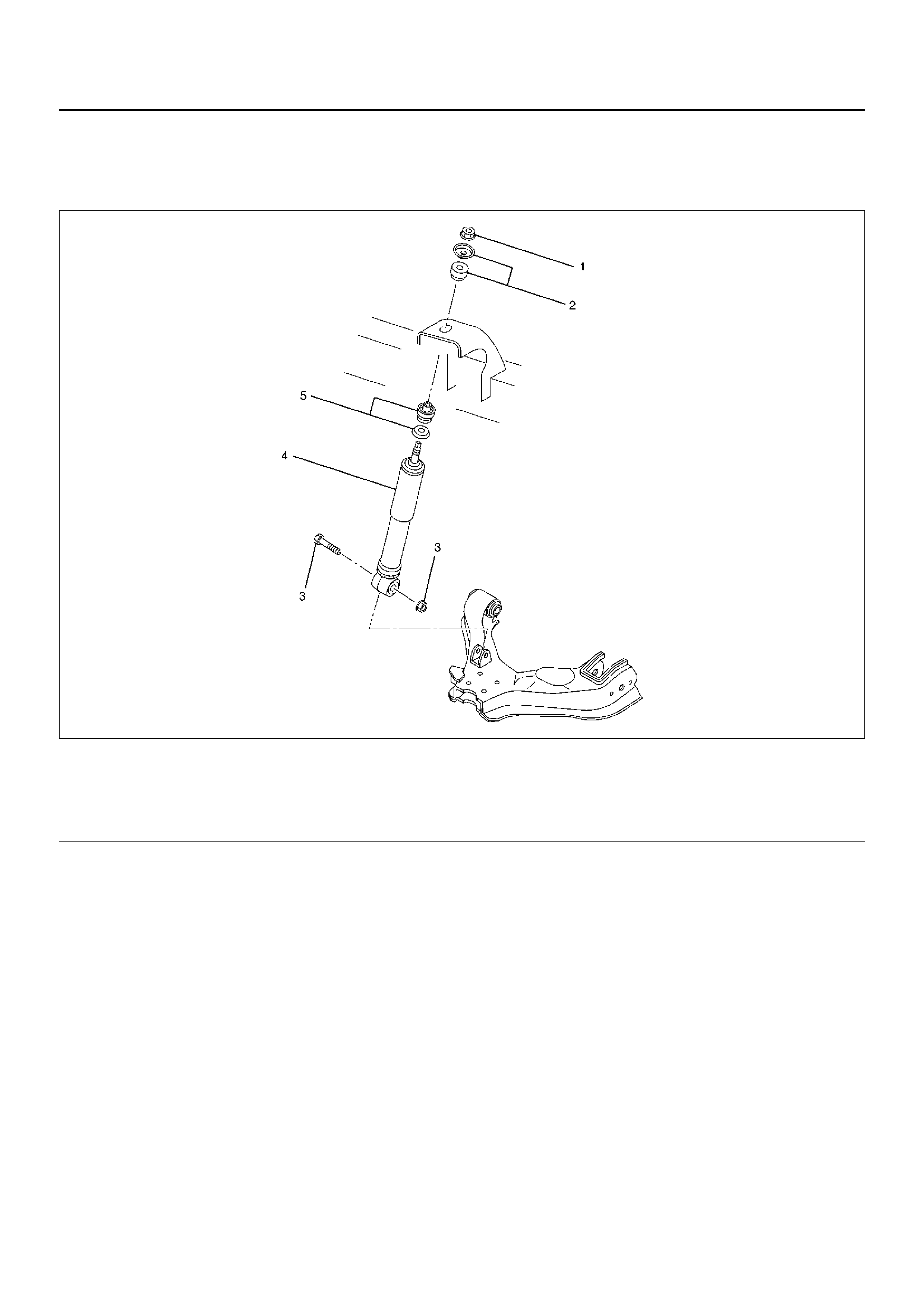
SHOCK ABSORBER AND ASSOCIATED PARTS
450RW009
Legend
EndOFCallout
REMOVAL
1. Raise the vehicle and support it with suitable safety
stands.
2. Remove wheel and tire assembly. Refer to Wheel
Replacement in this section.
3. Remove bolt and nut.
4. Remove nut.
5. Remove rubber bushing and washer.
6. Remove shock absorber.
7. Remove rubber bushing and washer.
INSPECTION AND REPAIR
Make necessary correction or parts replacement if wear,
damage, corrosion or any other abnormal condition are
found through inspection.
Check the following parts :
• Shock absorber
• Rubber bushing
INSTALLATION
1. Install rubber bushing and washer.
2. Install shock absorber.
3. Install rubber bushing and washer.
4. Install nut, then tighten it to the specified torque.
Torque: 20N·m (2.0kg·m/14lbft)
5. Install bolt and nut, then tighten to the specified
torque.
Torque: 93N·m (9.5kg·m/69lbft)
(1) Nut
(2) Rubber Bushing and Washer
(3) Bolt and Nut
(4) S hoc k Ab sorber
(5) Rubber Bushing and Washer
STABILIZER BAR
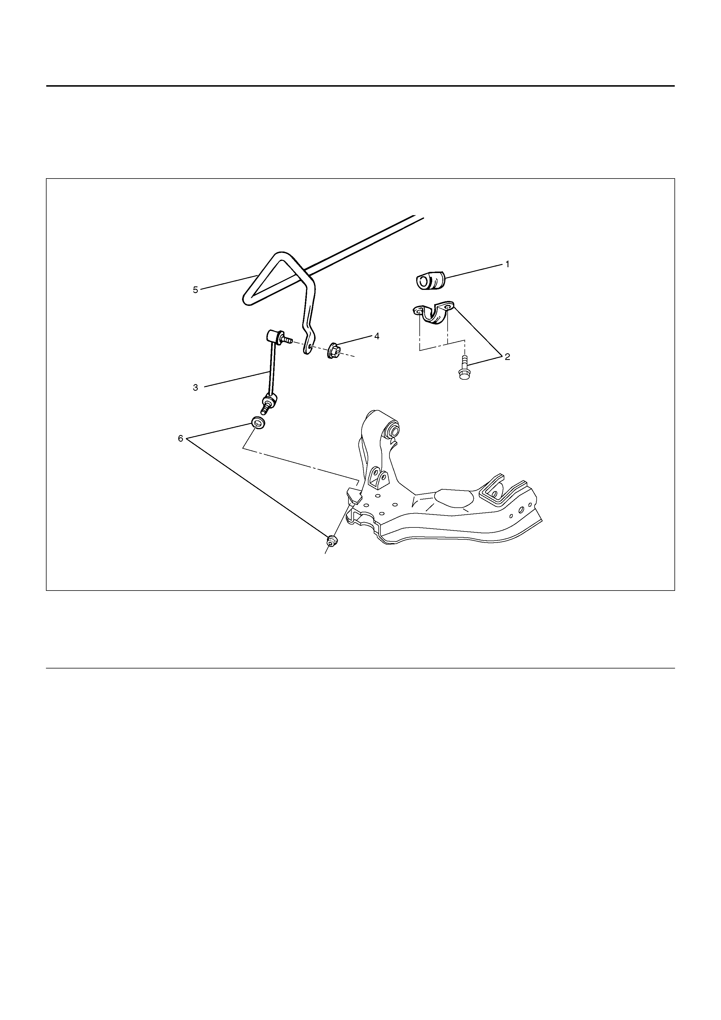
STABILIZER BAR AND ASSOCIATED PARTS
410R100001
Legend
EndOFCallout
REMOVAL
1. Raise the vehicle and support the frame with
suitable safety stands.
2. Remove the stone guard.
3. Remove wheel and tire assembly. Refer to Wheel
Replacement in section 10.
4. Remove nut (4) and (6).
CAUTION: Be careful not to break the ball joint
boot.
5. Remove link.
6. Remove bracket.
7. Remove stabilizer bar.
8. Remove rubber bushing.
INSPECTION AND REPAIR
Make necessary correction or parts replacement if wear,
damage, corrosion or any other abnormal condition are
found through inspection.
Check the following parts :
• Stabilizer bar
• Rubber bushing
• Link ball joint
INSTALLATION
1. Install rubber bushing.
2. Install stabi lizer bar.
3. Install bracket and bolt, then tighten it to the
specified torque.
Torque: 25N·m (2.6kg·m/18lbft)
4. Install link.
5. Install nut (4), (6) and washer, then tighten it to the
specified torque.
Torque: 50N·m (5.1kg·m/37lbft)
(1) Rubber Bushing
(2) Bracket and Bolt
(3) Link
(4) Nut
(5) Stabili zer Bar
(6) Nut and Washer
TORSION BAR
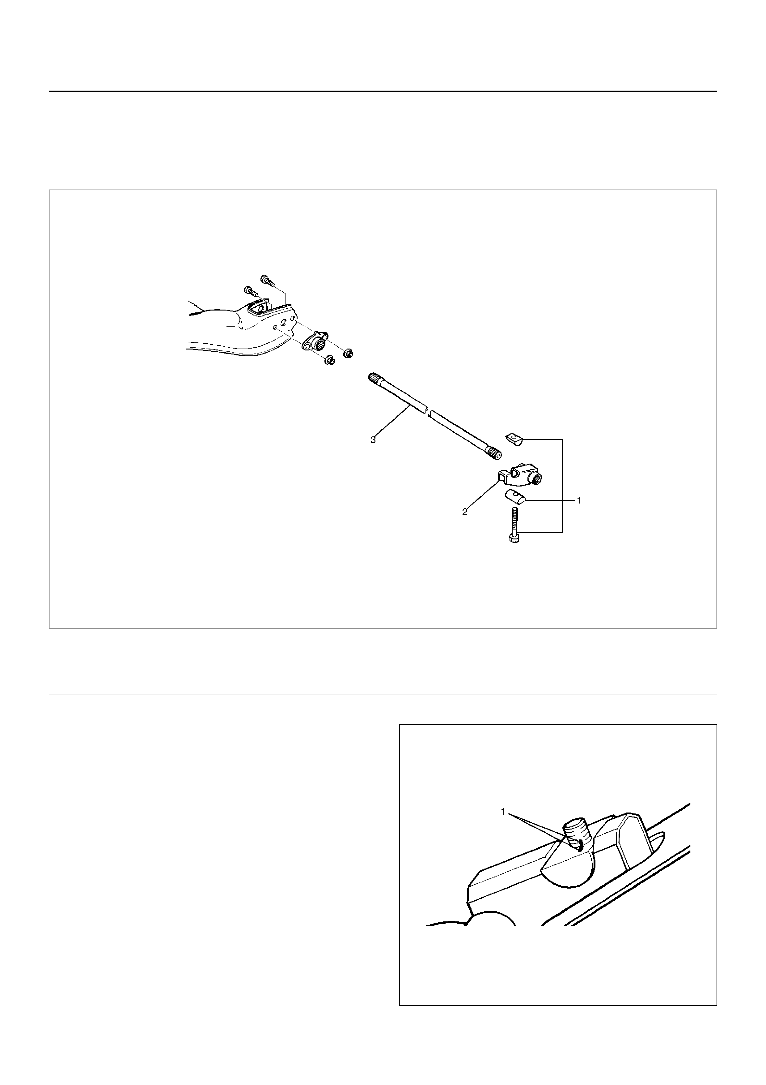
TORSION BAR AND ASSOCIATED PARTS
410RS003
Legend
EndOFCallout
REMOVAL
1. Raise the vehicle and support the frame with
suitable safety stands.
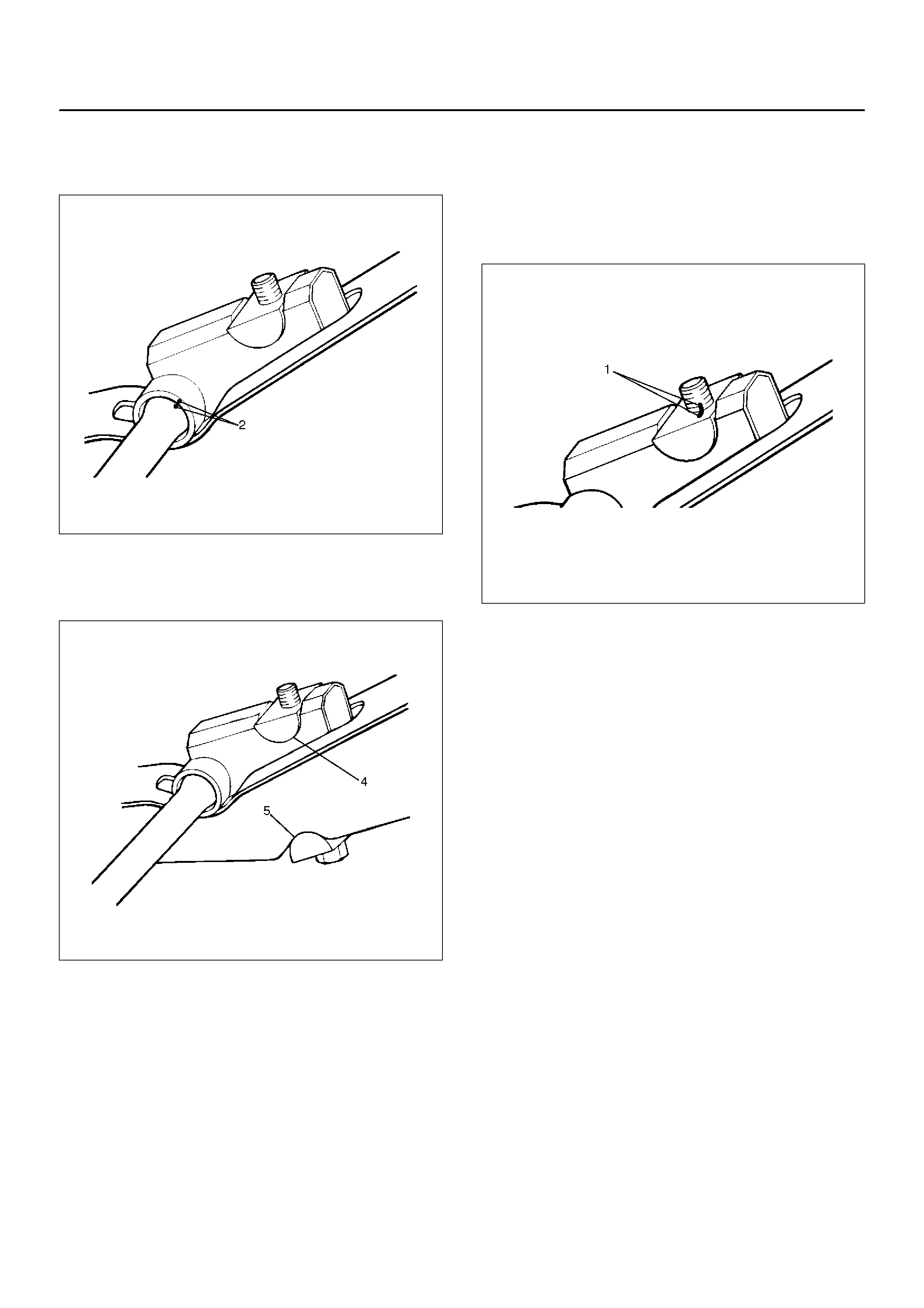
2. Apply the setting marks(1) to the adjust bolt and end
piece, then remove adjust bolt, end piece and seat.
410RS004
(1) Adjust Bolt, End Piece and Seat
(2) Height Control Arm (3) Torsi on Bar
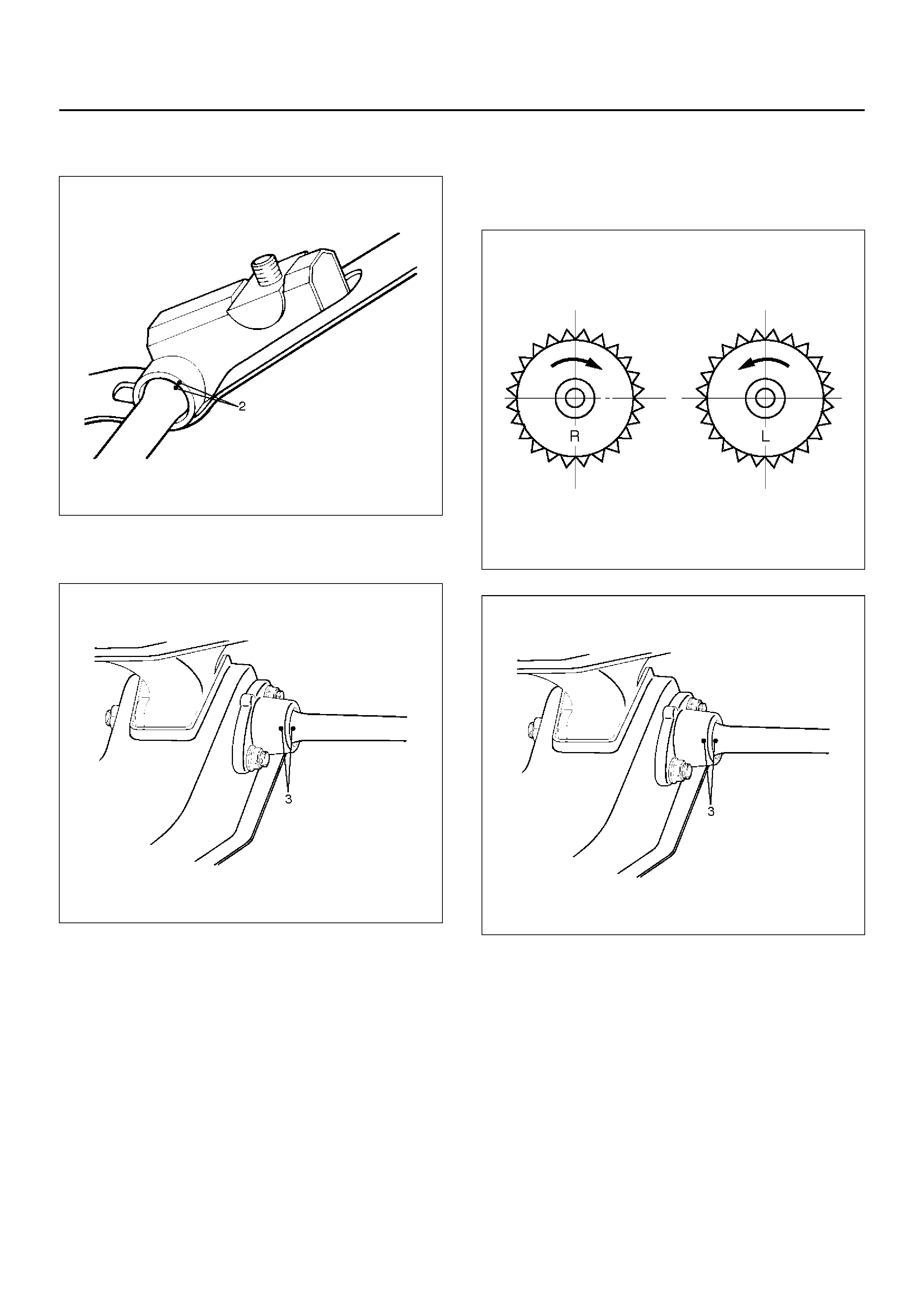
3. Apply the setting marks(2) to the height control arm
and torsion bar, then remove height control arm.
410RS005
4. Apply the setting marks(3) to the torsion bar and
lower control arm, then remove torsion bar.
410RS006
INSPECTION AND REPAIR
Make necessary correction or parts replacement if wear,
damage, corrosion or any other abnormal condition are
found through inspection.
Check the following parts:
• Torsion bar
• Height control arm
• Adjust bolt
• Rubber seat
INSTALLATION
1. Apply grease to the serrated portions, then install
torsion bar. Make sure the bars are on their correct
respe ctive sides and ali gn the se ttin g mar ks( 3).
410RS007
410RS006
2. Apply grease to the portion that fits into the bracket
then install height control arm and align the setting
marks(2).
410RS005
3. Apply grease to the bolt portion of the end piece(4).
Apply grease to the portion of the seat(5) that fits
into the bracket.
410RS008
4. Apply grease to the serrated portions.
5. Install adjust bolt and seat, then turn the adjust bolt
to the setting mark(1) applied during disassembly.
NOTE: Adjust the trim height. Refer to Front End
Alignment Inspection and Adjustment in Steering
section.
410RS004
KNUCKLE
KNUCKLE AND ASSOCIATED PARTS
410RW006
Legend
EndOFCallout
REMOVAL
1. Raise the vehicle and support the frame with
suitable safety stands.
2. Remove wheel and tire assembly. Refer to Wheel in
this section.
3. Remove the brake caliper. Refer to Disc Brakes in
Brake section.
4. Remove the hub assembly. Refer to Front Hub and
Disk in this section.
5. Remove tie–rod end from the knuckle. Refer to
Power Steering Unit in Steering section.
6. Remove the speed sensor from the knuckle.
7. Loosen torsion bar by height control arm adjust bolt,
then remove torsion bar. Refer to Torsion Bar in this
section.
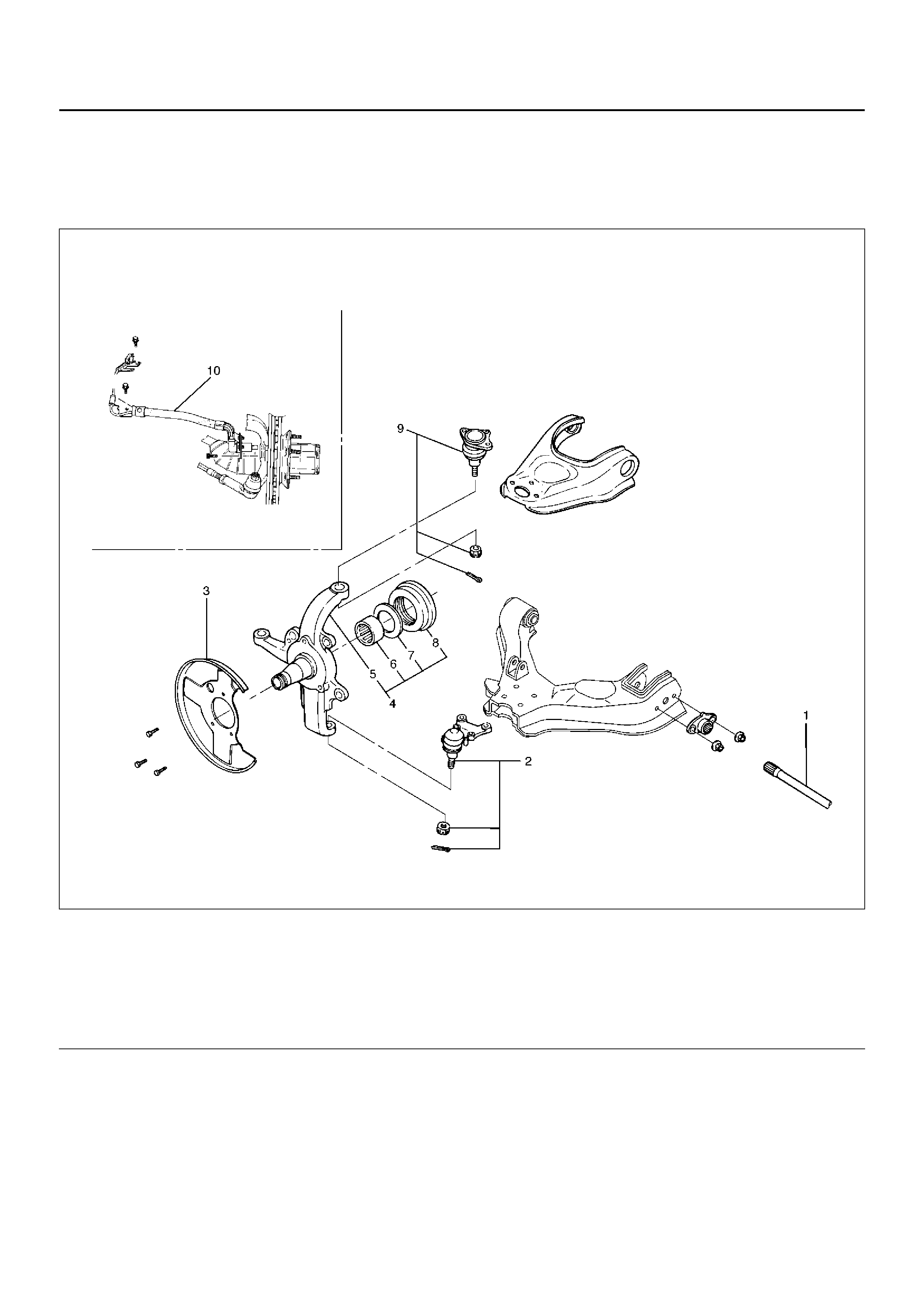
(1) Torsion Bar
(2) Lower Ball Joint, Nut and Cotter Pin
(3) Back Pl ate
(4) Knuck le As se mbl y
(5) Knuckle
(6) Needle Bearing
(7) Thrust Washer
(8) Oil Seal
(9) Upper Ball Joint, Nut and Cotter Pin
(10) Wheel Speed Sensor
8. Remove wheel speed sensor.
9. Remove back plate.
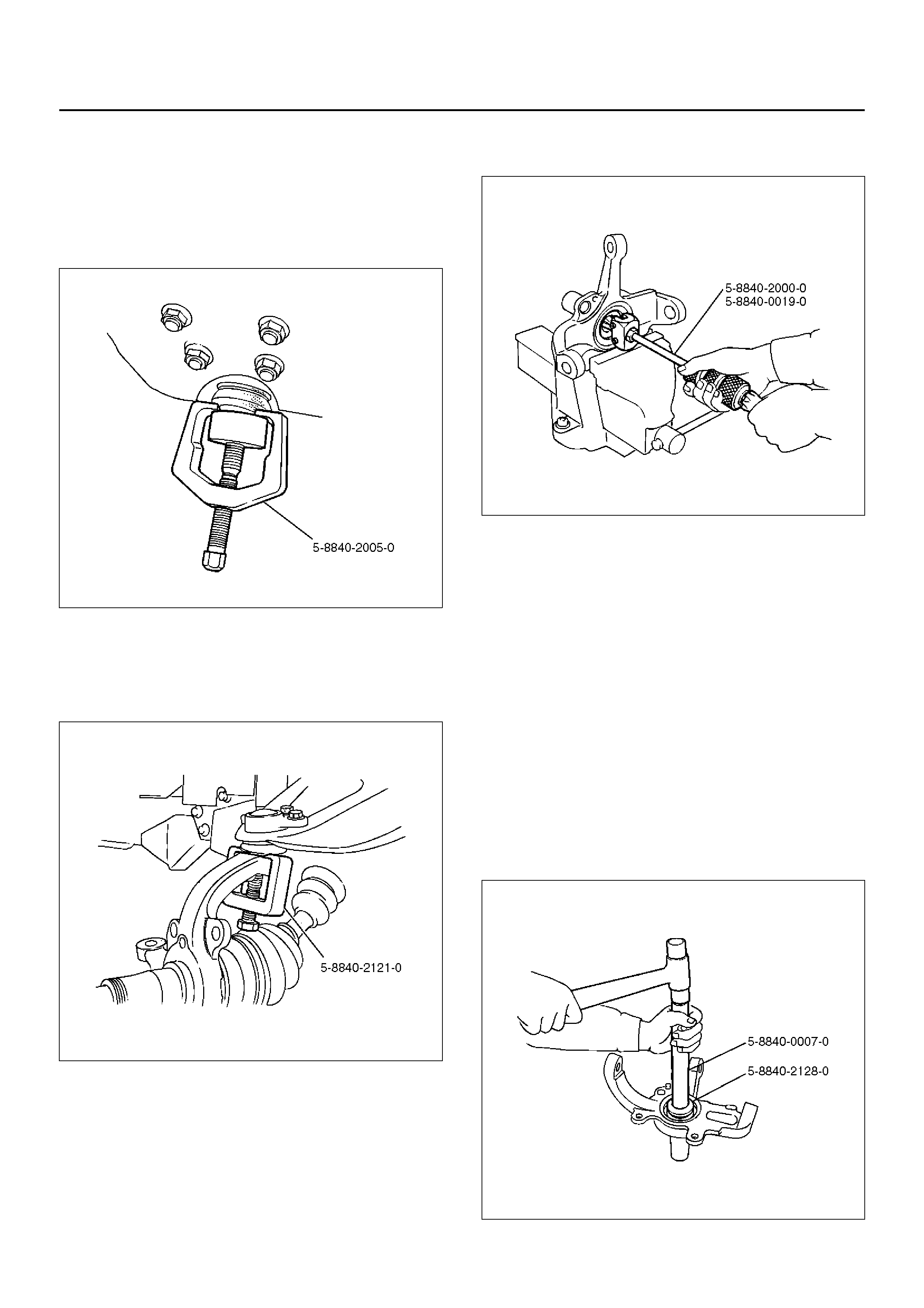
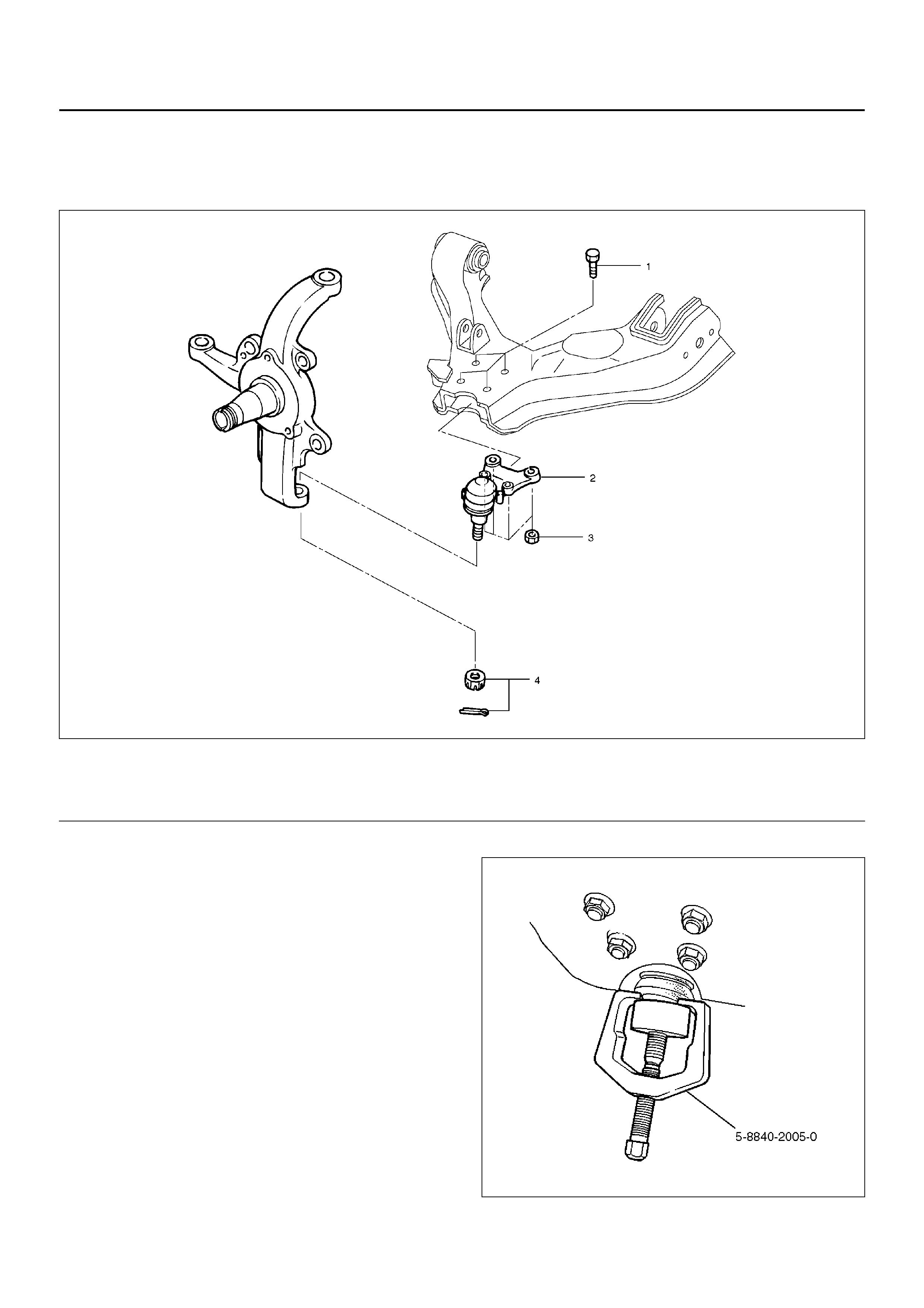
10. Remove lower ball joint by using remover 5–8840–
2005–0.
CAUTION: Be careful not to damage the ball joint
boot.
901RW271
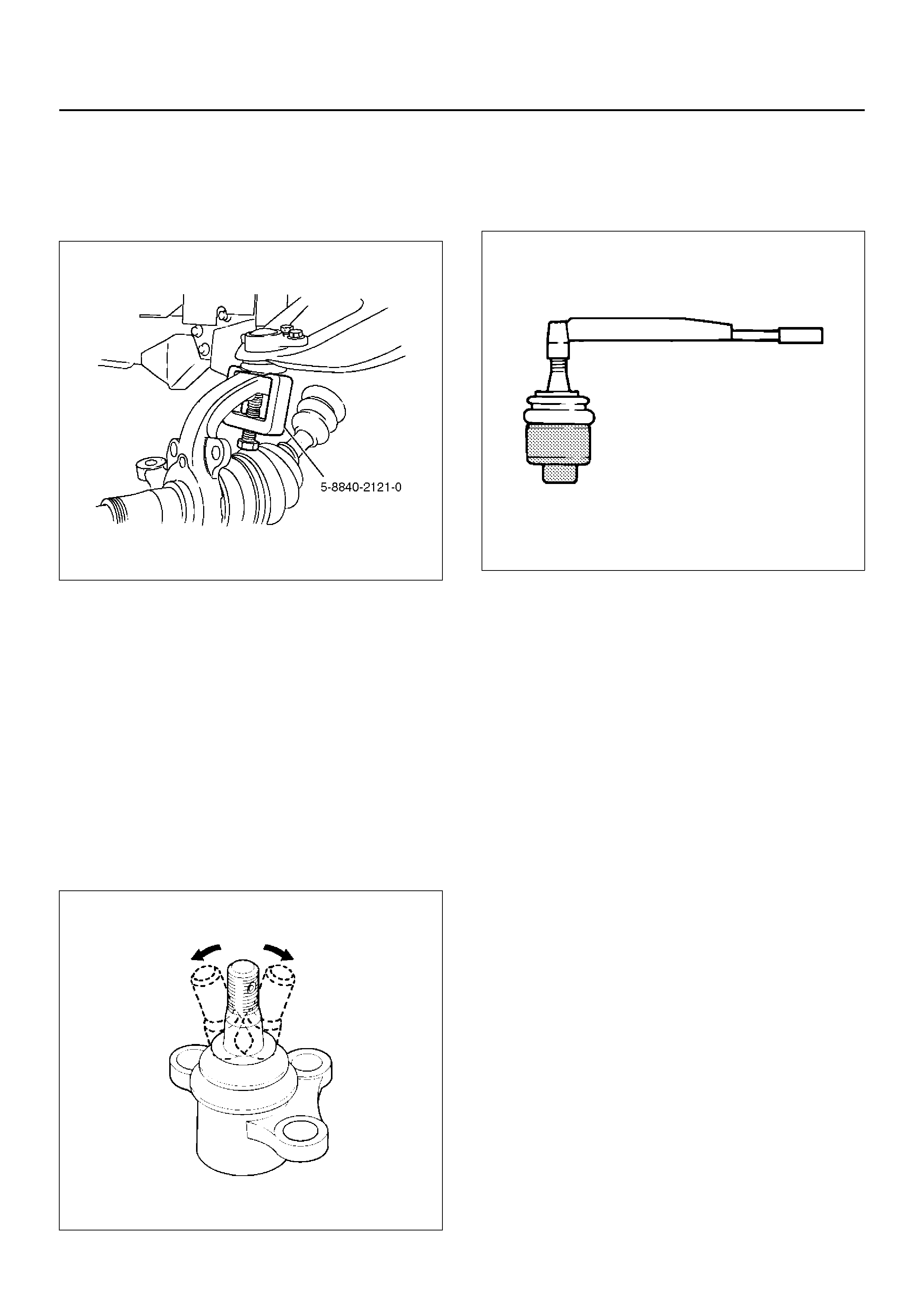
11. Remove upper ball joint by using remover 5–8840–
2121–0.
CAUTION: Be careful not to damage the ball joint
boot.
901RW273
12. Remove knuckle assembly.
13. Remove oil seal.
14. Remove washer.
15. Remove needle bearing by using remover 5–8840–
2000–0 and sliding hammer 5–8840–0019–0.
901RW272
INSPECTION AND REPAIR
Make necessary correction or parts replacement if wear,
damage, corrosion or any other abnormal condition are
found through inspection.
Check the following parts:
• Knuckle
• Knuckle arm
• Needle bearing
• Thrust washer
INSTALLATION
1. Apply appropriate amount of multipurpose type
grease to the new bearing (Approx. 5 g) and install
needle bearing by using installer 5–8840–2128–0
and grip 5–8840–0007–0.
901RW275
2. Apply multipurpose type grease to the thrust
washer, and install washer with chamfered side
facing knuckle.
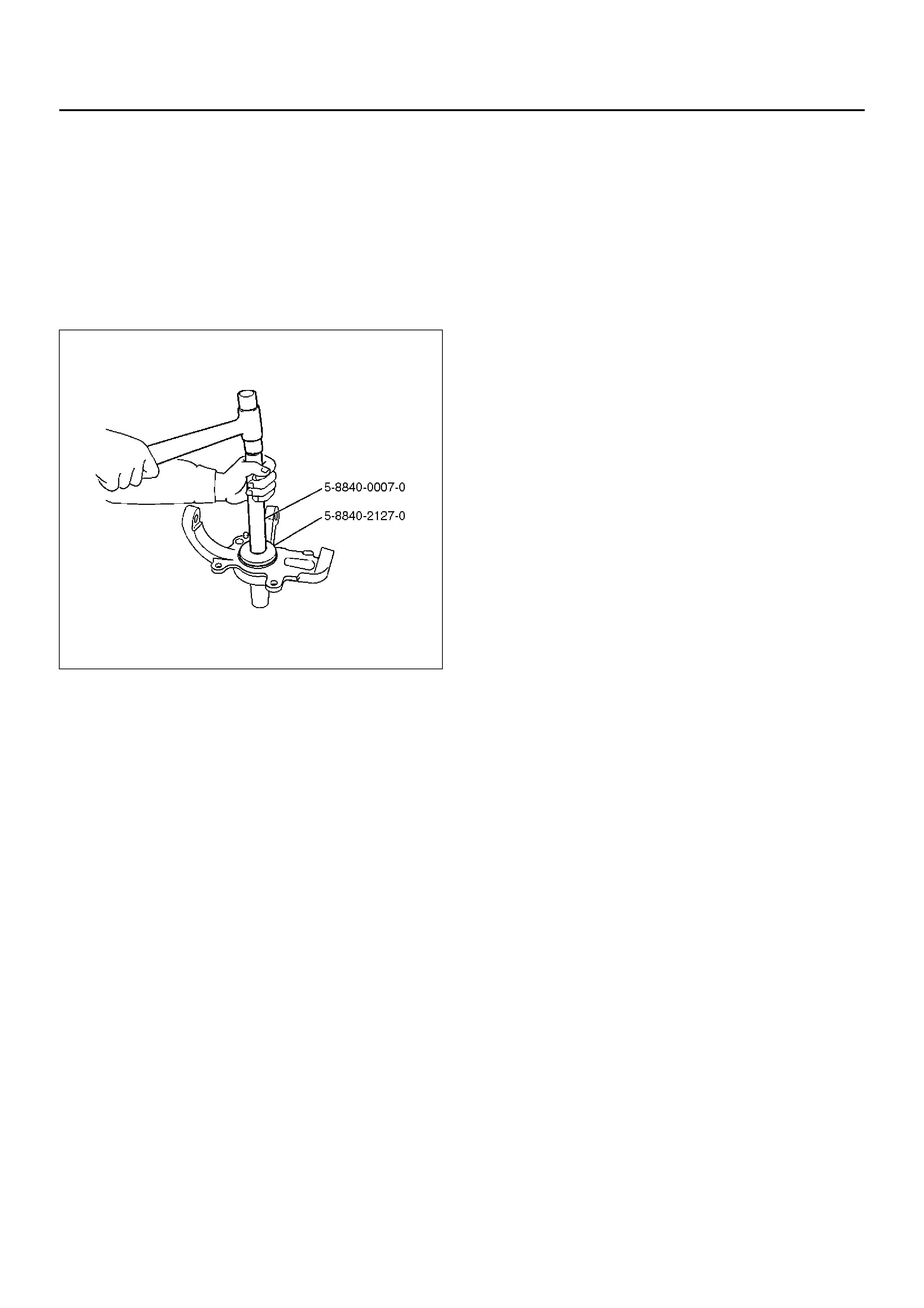
3. Use a new oil seal, and apply multipurpose type
grease to the area surrounded by the lip (approx. 2
g). Then use installer 5–8840–2127–0 and grip 5–
8840–0007–0 to install oil seal. After fitting the oil
seal to the installer, drive it to the knuckle using a
hammer or bench press until the tool front face
contacts with the thrust washer.
901RW274
4. Install knuckle assembly.
5. Install upper ball joint and tighten the nut to the
specified torque, with just enough additional torque
to align cotter pin holes. Install new cotter pin.
Torque: 98N·m (10.0kg·m/72lbft)
6. Install lower ball joint and tighten the nut to the
specified torque, with just enough additional torque
to align cotter pin holes. Install new cotter pin.
Torque: 147N·m (15.0kg·m/108 lbft)
7. Install back plate.
8. Install wheel speed sensor.
9. Install torsion bar, refer to Torsion Bar in this
section.
NOTE: Adjust the trim height. Refer to Front End
Alignment Inspection and Adjustment in Steering.
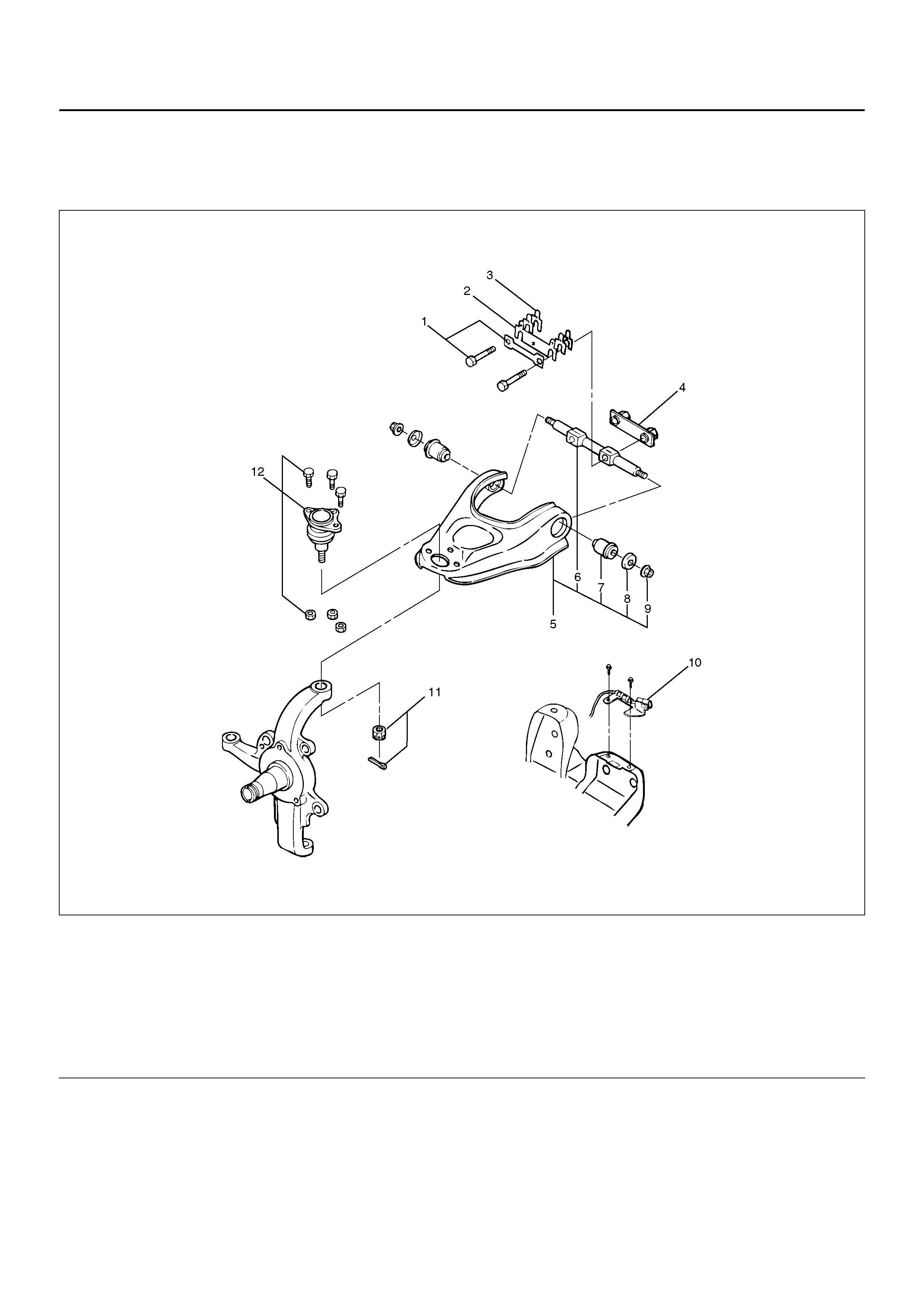
UPPER CONTROL ARM
UPPER CONTROL ARM AND ASSOCIATED PARTS
450R100001
Legend
EndOFCallout
REMOVAL
1. Raise the vehicle and support the frame with
suitable safety stands.
2. Remove wheel and tire assembly. Refer to Wheel in
section 10.
3. Remove the brake caliper and disconnect brake
pipe. Refer to Disc Brakes in section 5.
4. Support lower control arm with a jack.
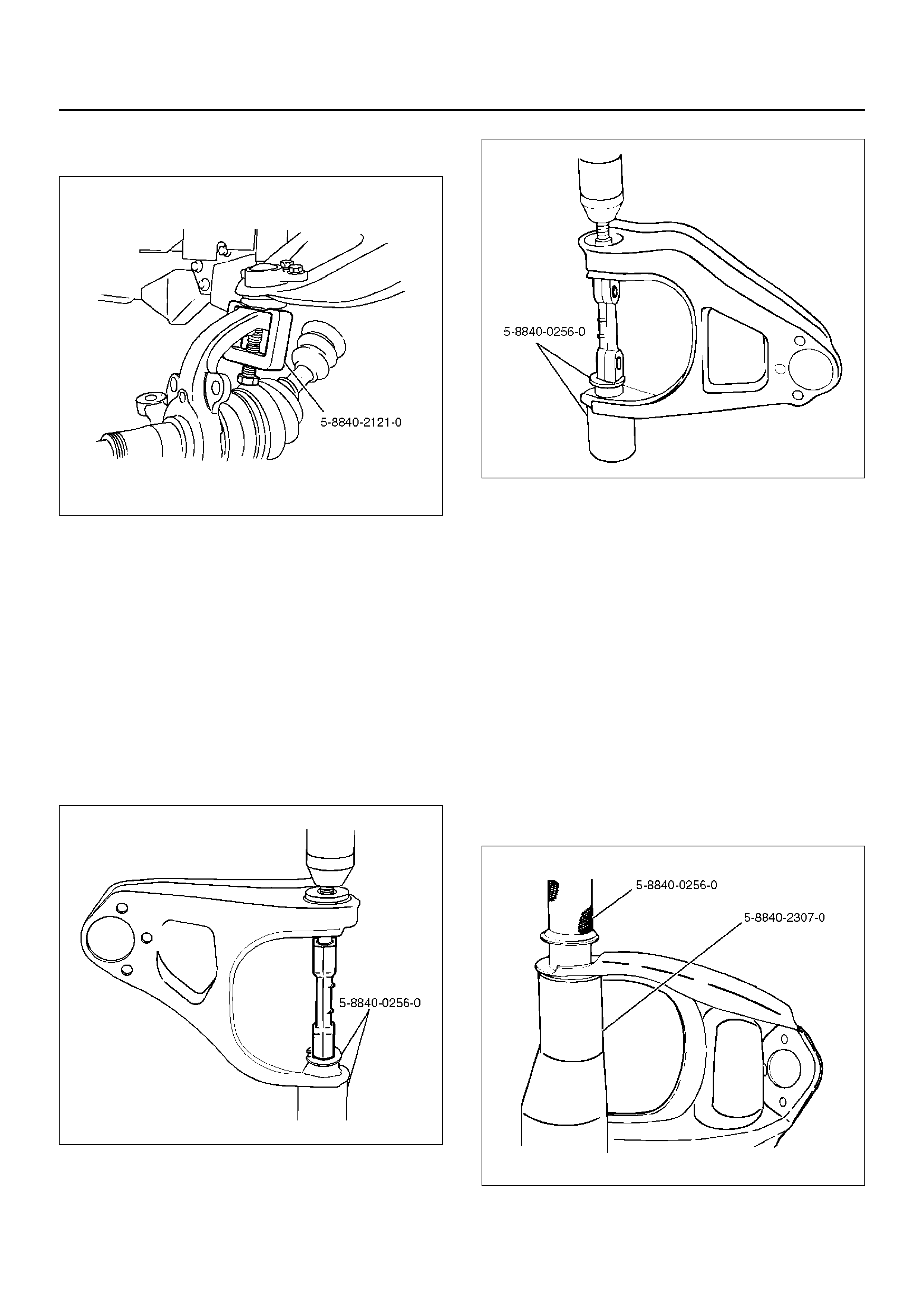
5. Remove speed sensor cable.
6. Remove nut and cotter pin then remove knuckle
using remover 5–8840–2121–0.
(1) Bolt and Plate
(2) Camber Shims
(3) Caster Shims
(4) Nut Assembly
(5) Upper Control Arm Assembly
(6) Fulcrum Pin
(7) Bushing
(8) Plate
(9) Nut
(10) Speed Sensor Cable
(11) Nut and Cotter Pin
(12) Upper Ball Joint, Bolt and Nut
CAUTION: Be careful not to damage the ball joint
boot.
901RW273
7. Remove upper ball joint.
8. Remove bolt and plate.
9. Remove nut assembly.
10. Remove camber shims and note the positions and
number of shims.
11. Remove caster shims and note the positions and
number of shims.
12. Remove upper control arm assembly.
13. Remove nut (9).
14. Remove plate (8).
15. Remove bushing (7) by using remover 5–8840–
0256–0.
901RW277
901RW276
16. Remove fulcrum pin (6).
INSPECTION AND REPAIR
Make necessary parts replacement if wear, damage,
corrosion or any other abnormal conditions are found
through inspection.
Check the following parts:
• Upper control arm
• Bushing
• Fulcrum pin
INSTALLATION
1. Install fulcrum pin.
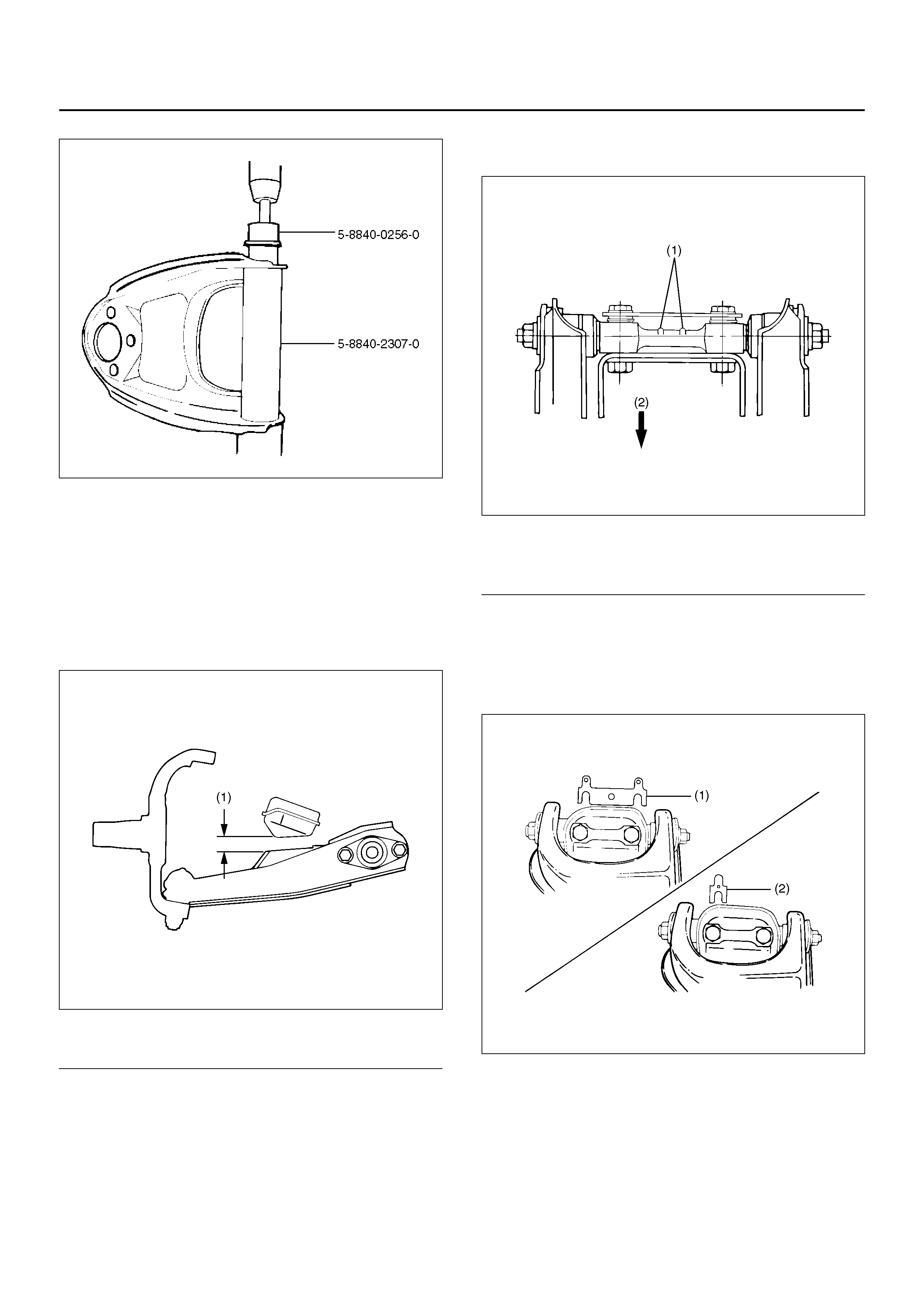
2. Install bushing by using installer 5–8840–0256–0
and 5–8840–2307–0.
901RW278
901RW279
3. Install pla te (8).
4. Install nut (9) and tighten fulcrum pin nut finger–
tight.
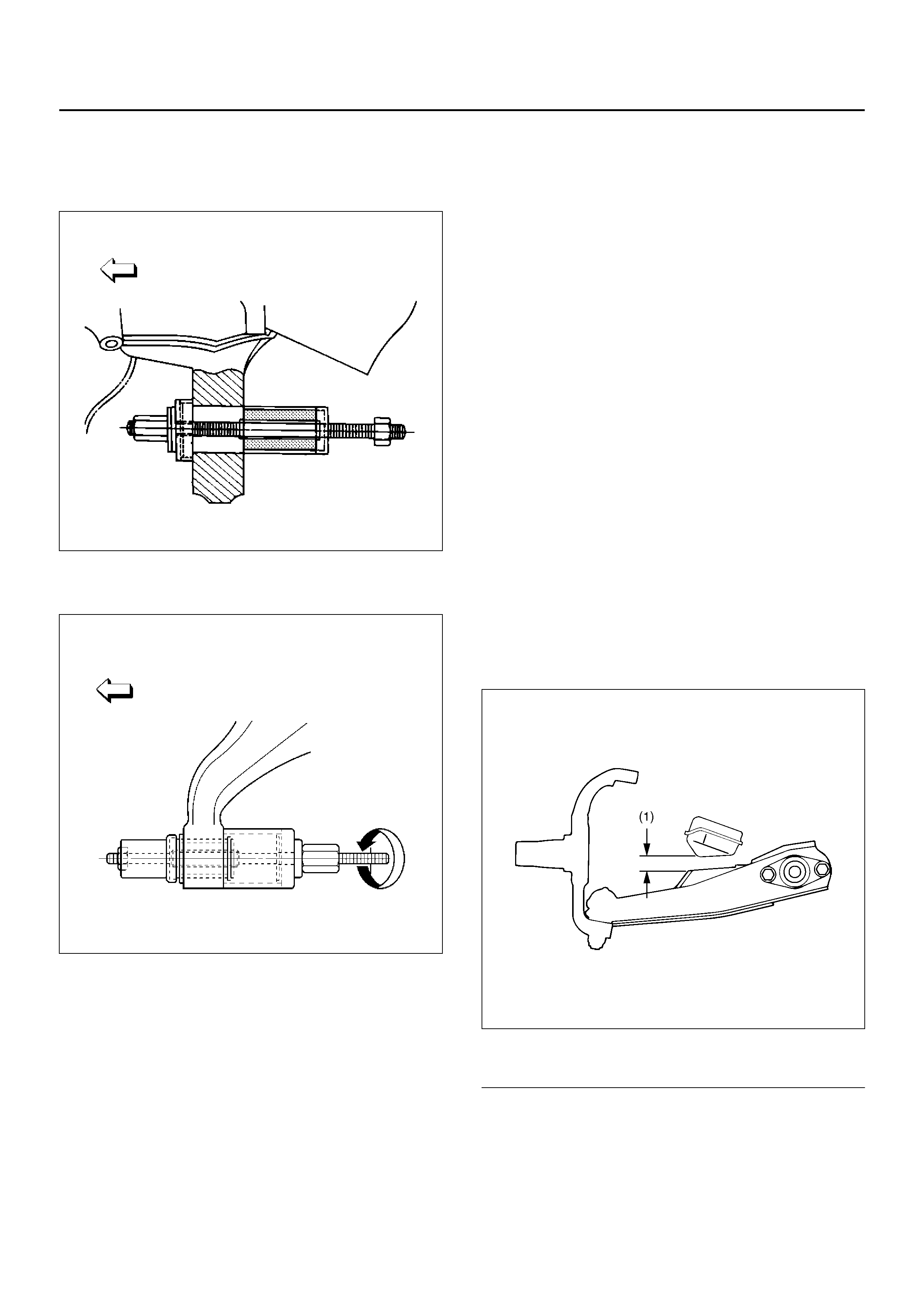
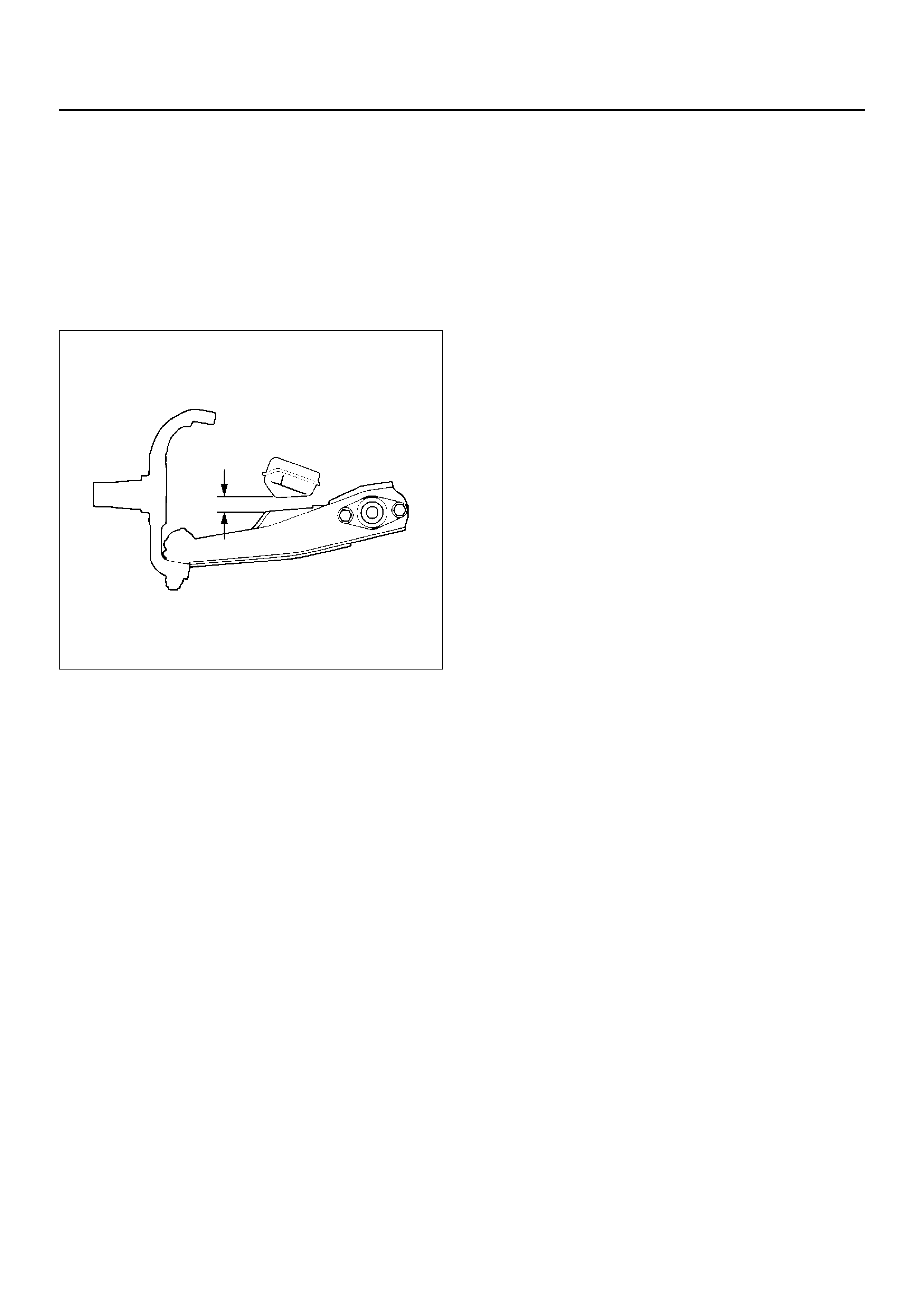
NOTE: Torque fulcrum pin nut after adjusting buffer
clearance.
Buffer clearance: 22mm (0.87in)
Torque: 108N·m (11.0kg·m/80lbft)
450R100002
Legend
EndOFCallout
5. Install upper control arm assembly with the fulcrum
pin projections turned inward.
450R100003
Legend
EndOFCallout
6. Install the caster shims(2) between the chassis
frame and fulcrum pin.
7. Install the camber shims(1) between the chassis
frame and fulcrum pin.
450R100004
(1) Buffer Clearance
(1) Projection
(2) Outward

8. Inst all nut assembly.
9. Install bolt and plate, then tighten the bolt to the
specified torque.
Torque: 152N·m (15.5kg·m/112lbft)
10. Install upper ball joint and tighten it to the specified
torque.
Torque: 57N·m (5.8kg·m/42lbft)
11. Install nut and cotter pin then tighten the nut to the
specified torque, with just enough additional torque
to align cotter pin holes. Install new cotter pin.
Torque: 98N·m (10.0kg·m/72lbft)
12. Install speed sensor cable.
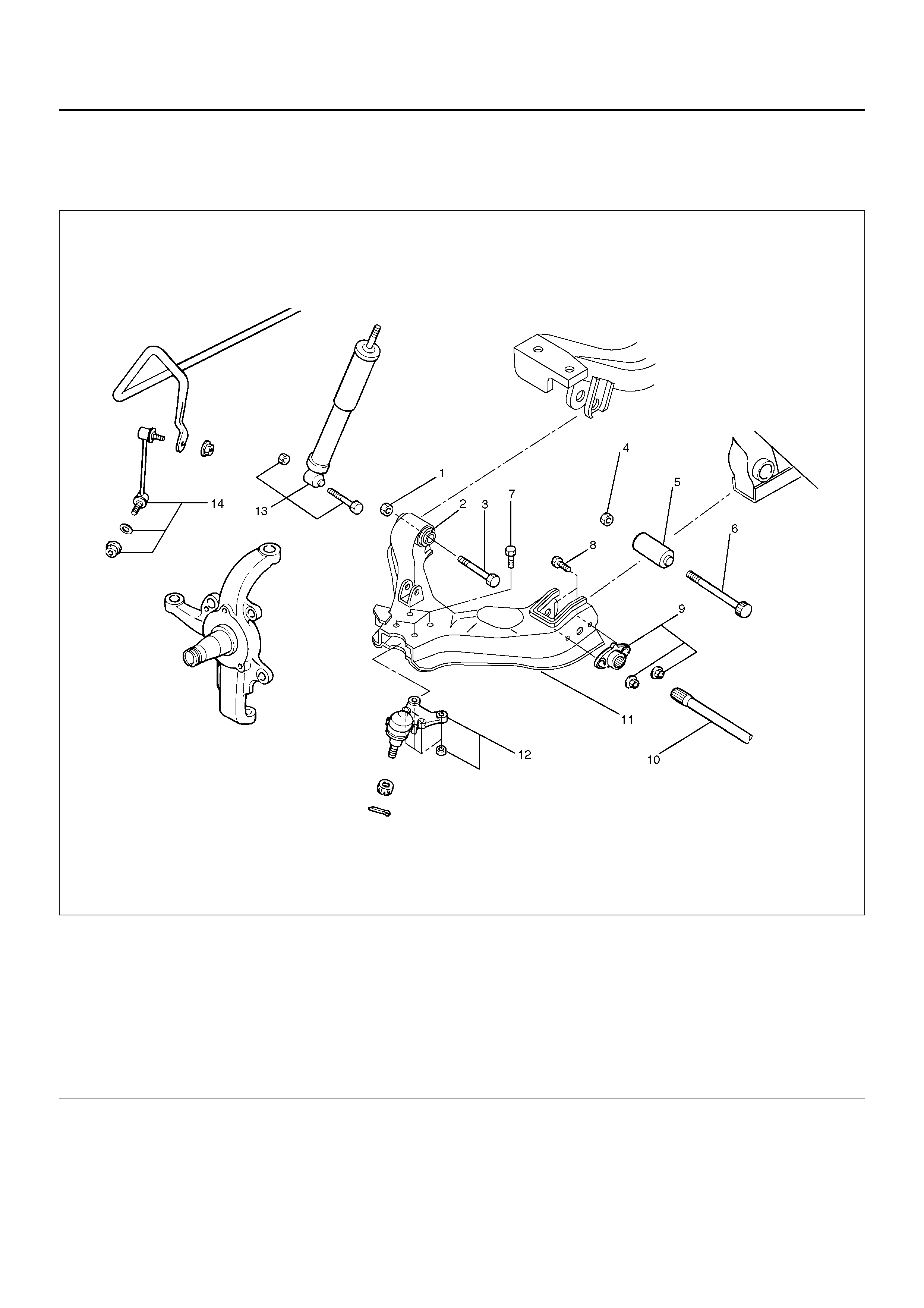
LOWER CONTROL ARM
LOWER CONTROL ARM AND ASSOCIATED PARTS
450R100005
Legend
EndOFCallout
REMOVAL
1. Raise the vehicle and support the frame with
suitable safety stands.
2. Remove wheel and tire assembly. Refer to Wheel in
this section.
3. Remove the tie-rod end from the knuckle. Refer to
Power Steering Unit in Steering section.
4. Remove the retaining ring from the front axle driving
shaft to release the shaft from hub. Refer to Front
Hub and Disc in Driveline/Axle section4C.
5. Support lower control arm with a jack.
(1) Nut, Front
(2) Bush, Front
(3) Bolt, Front
(4) Nut, Rear
(5) Bush, Rear
(6) Bolt, Rear
(7) Bolt, Lower Ball Joint
(8) Bolt, Torsion Bar Arm
(9) Torsion Bar Arm Bracket and Nut
(10) Torsion Bar
(11) Lower Control Arm
(12) Lower Ball Joint and Nut
(13) Shock Absorber, Bolt and Nut
(14) Stabili ze r Link, Washer and Nut
6. Remove front nut.
7. Remove rear nut.
8. Remove torsion bar, refer to Torsion Bar in this
section.
9. Remove torsion bar arm bracket.
10. Disconnect the stabilizer link at the lower control
arm.
11. Remove the shock absorber lower end from the
lower control arm.
12. Remove the lower ball joint from the lower control
arm.
13. Remove front bolt.
14. Remove rear bolt.
15. Remove lower control arm.
16. Remove torsion bar arm bolt.
17. Remove lower ball joint bolt.
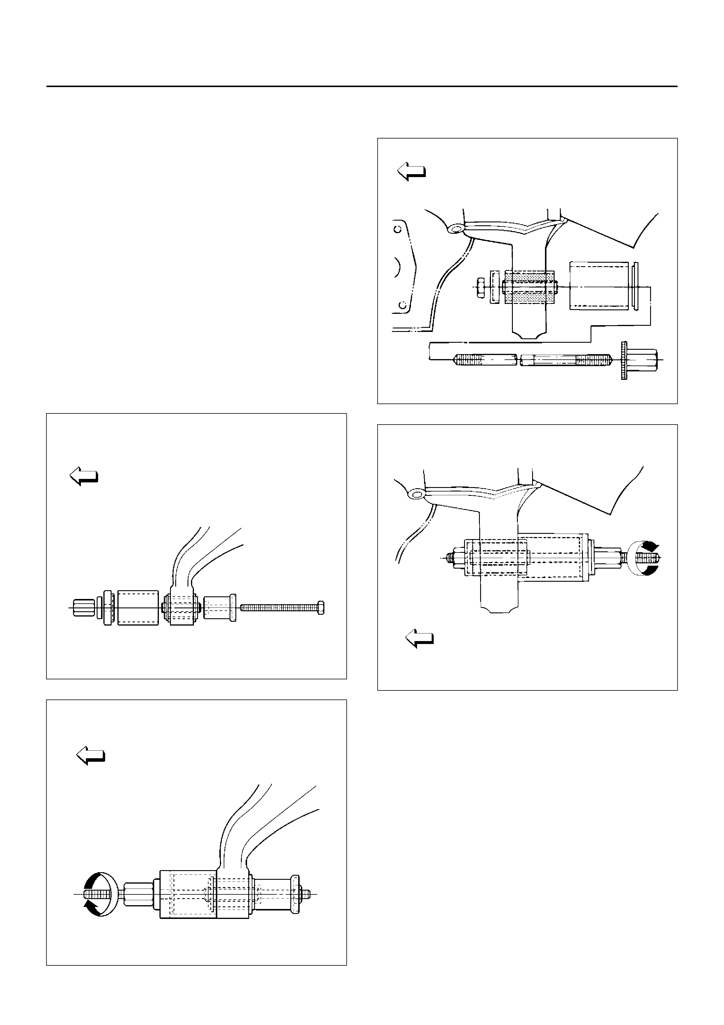
18. Remove front bushing by using remover 5–8840–
2123–0.
901RW154
901RW155
19. Remove rear bushing by using remover 5–8840–
2124–0.
901RW051
901RW052
INSPECTION AND REPAIR
Make the necessary correction or parts replacement if
wear, damage, corrosion or any other abnormal
condition are found through inspection.
Check the following parts:
• Lower control arm
• Bushing
INSTALLATION
1. Install rear bushing by using installer 5–8840–2124–
0.
901RW053
2. Install front bushing by using installer 5–8840–
2123–0.
901RW156
3. Install lower ball joint bolt.
4. Install torsion bar arm bolt.
5. Install lower control arm.
6. Install rear bolt.
7. Install front bolt.
8. Install lower ball joint and tighten it to the specified
torque.
Torque: 116N·m (11.8kg·m/85lbft)
9. Install shock absorber and tighten it to the specified
torque.
Torque: 93N·m (9.5kg·m/69lbft)
10. Install stabilizer link and tighten it to the specified
torque.
Torque: 50N·m (5.1kg·m/37lbft)
11. Install torsion bar arm bracket and tighten it to the
specified torque.
Torque: 116N·m (11.8kg·m/85lbft)
12. Install Torsion bar, refer to Torsion Bar in this
section.
13. Install rear nut and tighten lower link nut finger–tight.
NOTE: Torque lower control arm nut after adjusting
buffer clearance.
Buffer clearance: 22mm (0.87in)
Torque: 235N·m (24.0kg·m/174lbft)
450R100002
Legend
EndOFCallout
(1) Buffer Clearance
14. Install front nut then tighten lower link nut
finger-tight.
NOTE: Torque lower control arm nut after adjusting
buffer clearance .
Buffer clearance: 22mm (0.87in)
Torque: 186N·m (19.0kg·m/137lbft)
NOTE: Adjust the trim height. Refer to Front End
Alignment Inspection and Adjustment in Steering
section.
450RS012
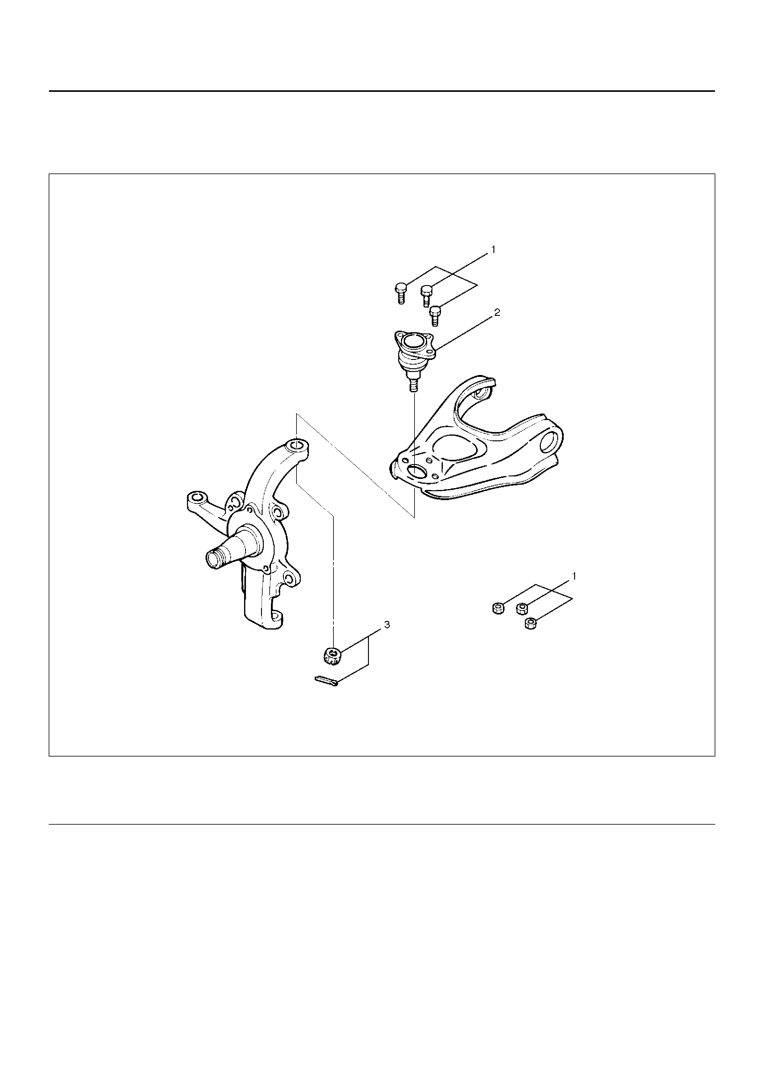
UPPER BALL JOINT
UPPER BALL JOINT AND ASSOCIATED PARTS
450RW004
Legend
EndOFCallout
REMOVAL
1. Raise the vehicle and support the frame with
suitable safety stands.
2. Remo ve the sp eed se ns or from the knu ckle .
(1) Bolt and Nut
(2) Upper Ball Joint (3) Nut and Cotter Pin
3. Remove upper ball joint nut and cotter pin, then use
remover 5–8840–2121–0 to remove the upper ball
joint from the knuckle.
CAUTION: Be careful not to damage the ball joint
boot.
901RW273
4. Remove bolt and nut.
5. Remove upper ball joint.
INSPECTION AND REPAIR
Make necessary parts replacement if wear, damage,
corrosion or any other abnormal conditions are found
through inspection.
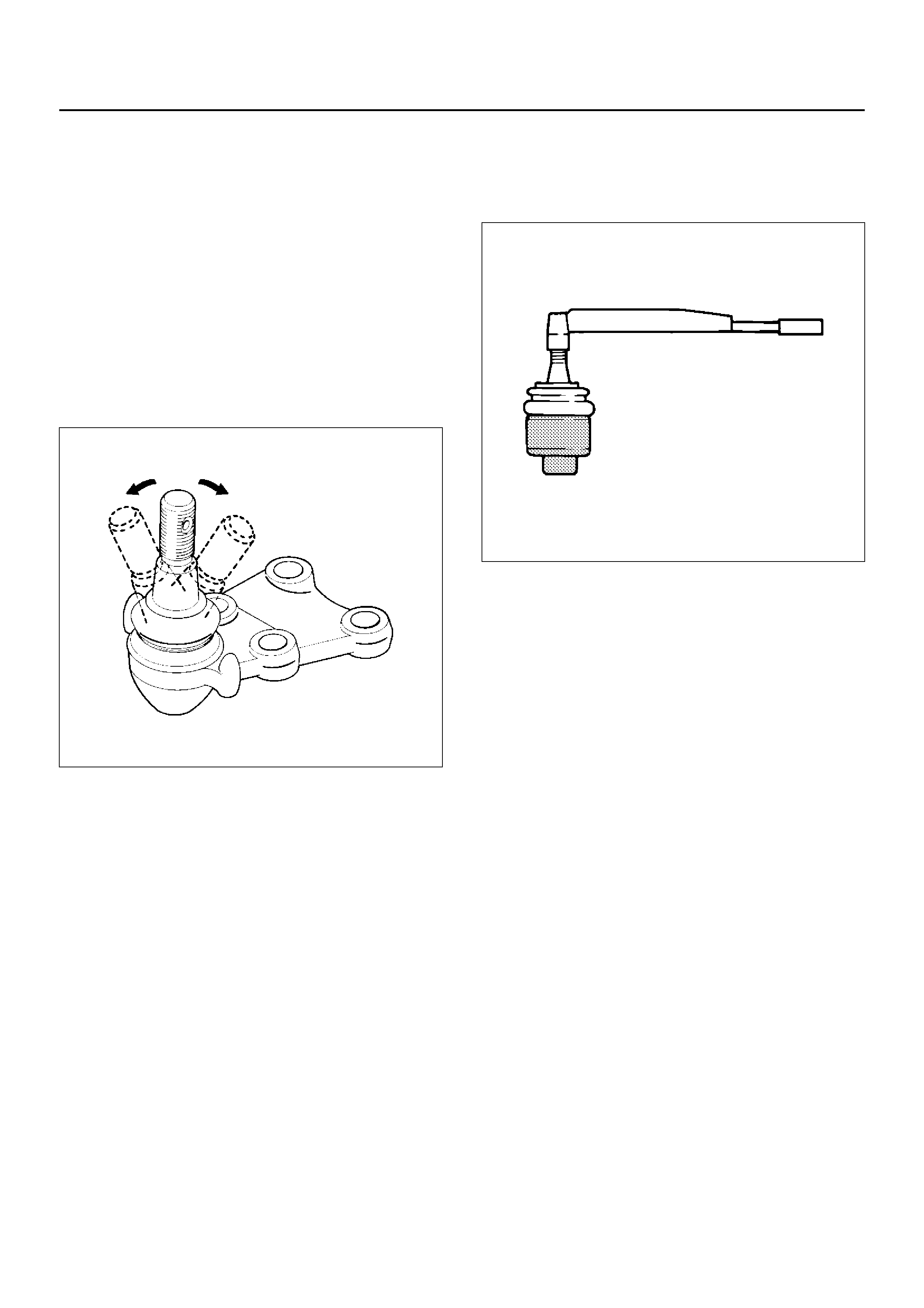
• Inspect the lower end boot for damage or grease
leak. Move the ball joint as shown in the figure to
confirm its normal movement.
• Inspect screw/taper area of ball for damage.
• If any defects are found by the above inspections,
replace the ball joint assembly with new one.
450RS023
• After moving the ball joint 4 or 5 times, attach nut
then measure the preload.
Starting torque: 0.5 –3.2N·m (0.05–0.33kg·m/0.4–
2.4lbft)
450RS024
If the above limits specified are exceeded, replace the
ball joint assembly.
INSTALLATION
1. Install upper ball joint.
2. Install bolt and nut, then tighten them to the
specified torque.
Torque: 57N·m (5.8kg·m/42lbft)
3. Install nut and cotter pin, then tighten the nut to the
specified torque with just enough additional torque
to align cotter pin holes. Install new cotter pin.
Torque: 98N·m (10.0kg·m/72lbft)
LOWER BALL JOINT
LOWER BALL JOINT AND ASSOCIATED PARTS
450R100006
Legend
EndOFCallout
REMOVAL
1. Raise the vehicle and support the frame with
suitable safety stands.
2. Remove wheel and tire assembly. Refer to Wheel in
this section.
3. Remove the tie-rod end from the knuckle. Refer to
Power Steering Unit in Steering section.
4. Remove the retaining ring from the front axle driving
shaft to release the shaft from hub. Refer to Front
Hub and Disc in Driveline/Axle section4C.
5. Support lower control arm with a jack.
6. Remove lower ball joint nut and cotter pin, then use
remover 5–8840–2005–0 to remove the lower ball
joint from the knuckle.
CAUTION: Be careful not to damage the ball joint
boot.
901RW271
(1) Bolt
(2) Lower Ball Joint (3) Nut
(4) Nut and Cotter Pin
7. Remove nut.
8. Remove bolt.
9. Remove lower ball joint.
INSPECTION AND REPAIR
Make necessary parts replacement if wear, damage,
corrosion or any other abnormal condition are found
through inspection.
• Inspect the lower end boot for damage or grease
leak. Move the ball joint as shown in the figure to
confirm its normal movement .
• Inspect screw/taper area of ball for damage.
• If any defects are found by the above inspections,
replace the ball joint assembly with new one.
450RS026
• After moving the ball joint 4 or 5 times, attach nut
then measure the preload.
Starting torque: 0.5–6.4N·m (0.05–0.65kg·m/0.4–
4.7lbft)
450RS024
• If the above limits specified are exceeded, replace
the ball joint assembly.
INSTALLATION
1. Install lower ball joint.
2. Install bolt.
3. Install nut and tighten it to the specified torque.
Torque: 116N·m (11.8kg·m/85lbft)
4. Install ball joint nut, then tighten it to the specified
torque with just enough additional torque to align
cotter pin holes. Install new cotter pin.
Torque: 147N·m (15.0kg·m/108lbft)
MAIN DATA AND SPECIFICATIONS
General Specifications
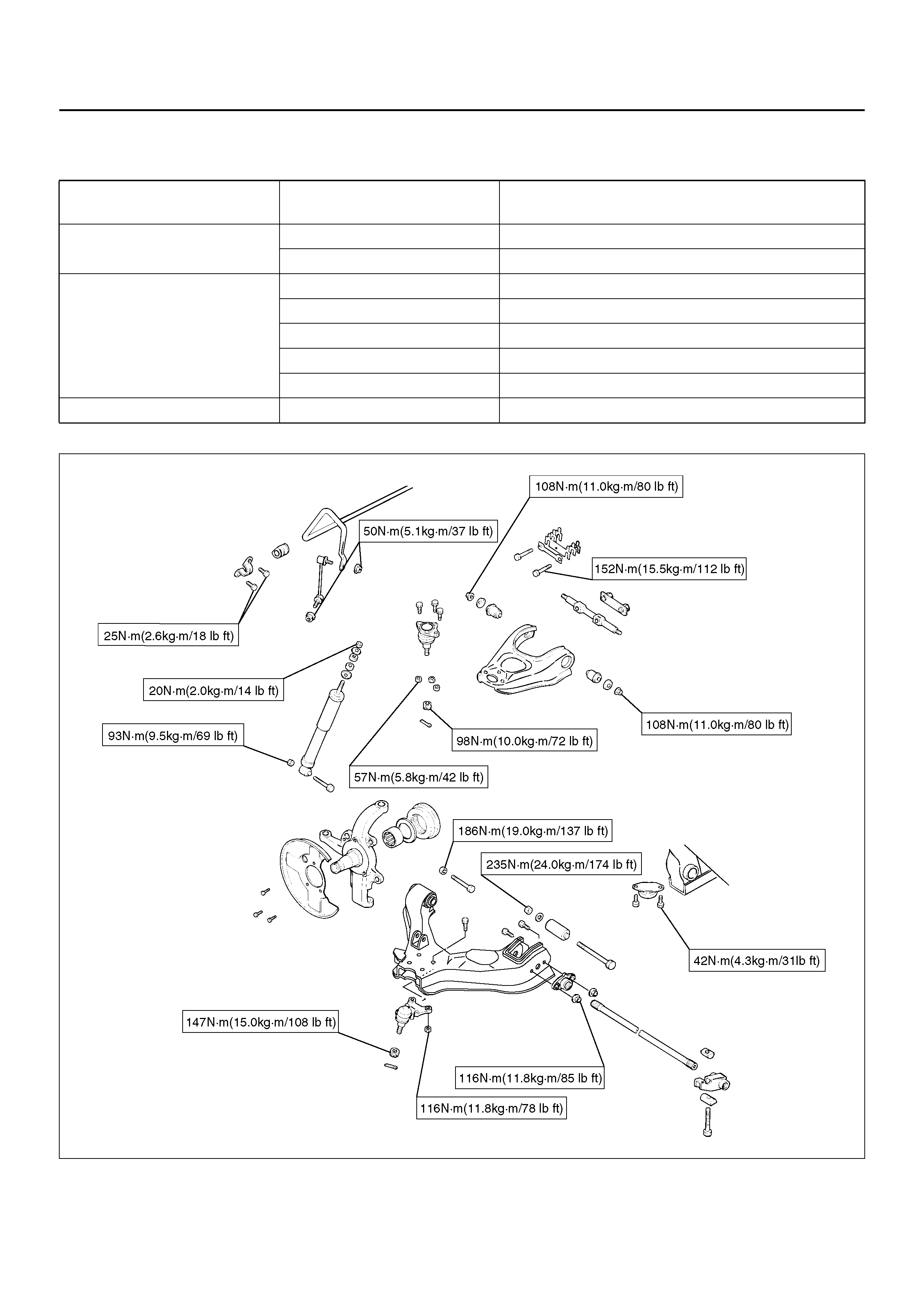
Torque Specifications
450R100007
Front suspension T ype Independent wishbone arms, torsion bar spring with
stabilizer bar.
Torsion bar sprin g Length 1142mm (45.0in)
Diameter 28.0 mm (1.10 in)
Front shock absorber Type Hydraulic, double acting, telescopic
Piston diameter 30.0mm (1.18in)
Stroke 125.0mm (4.92in)
Compressed length 255.0mm (10.04in)
Extended length 380.0mm (14.96in)
Stabilizer bar Diameter 24.0 mm (0.94 in)
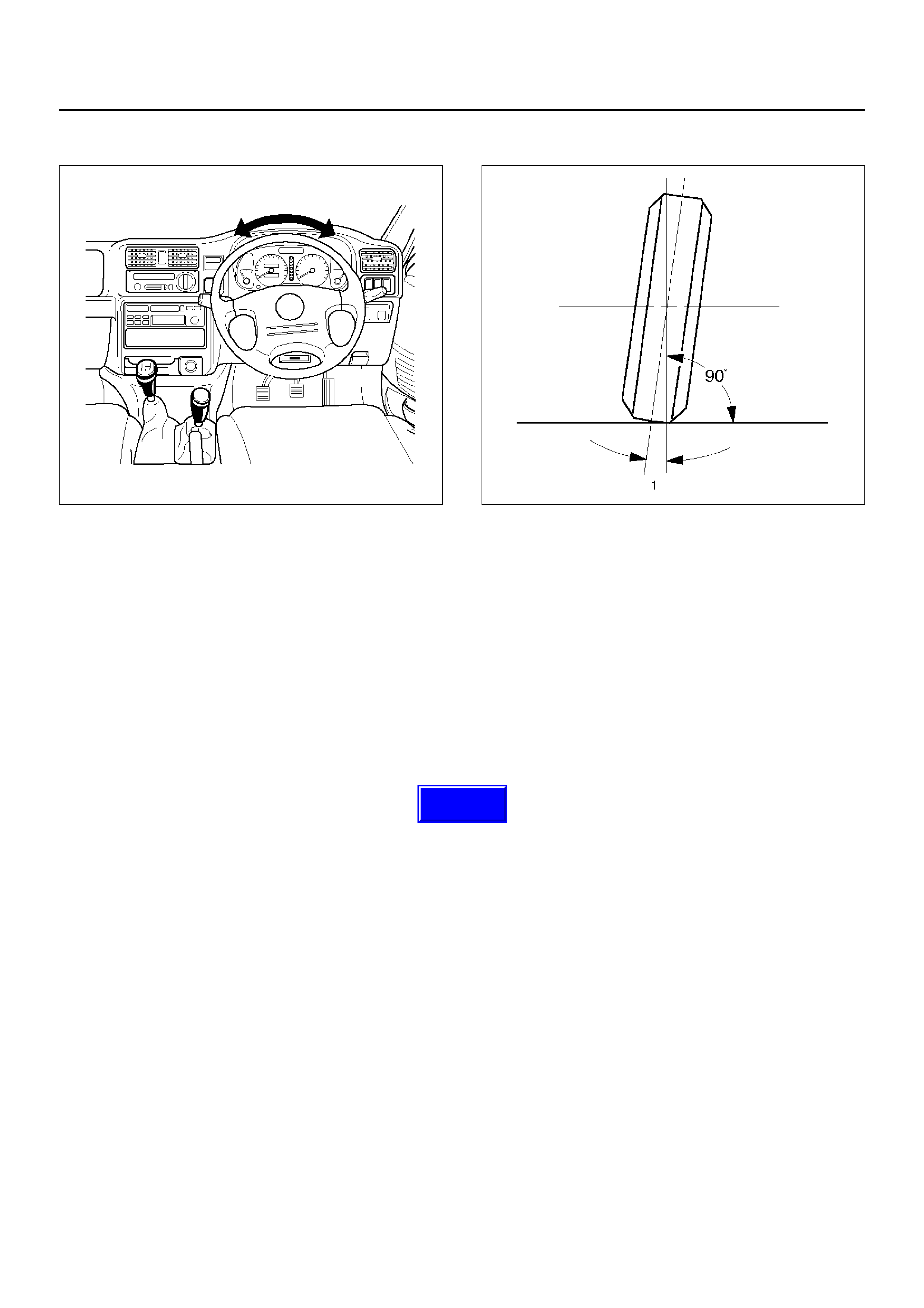
STEERING WHEEL FREE PLAY INSPECTION
430RW020
1. With the tires in the straight-ahead position, check
the amount of steering wheel play by turning the
wheel in both directions until the tires begin to
move.
NOTE: The wheel free play should be checked with the
engine running.
Free play: 0 – 30mm (0 – 1.18in)
2. Also check the steering wheel for play and
looseness in the mount by moving it back and forth
and sideways. When test driving, check for hard
steering, steering shimmy and tendency to pull to
one side.
FRONT END ALIGNMENT
INSPECTION AND ADJUSTMENT
General Description
“Front End Alignment" refers to the angular relationship
between the front wheels, the front suspension
attaching parts and the ground.
Proper front end alignment must be maintained in order
to insure efficient steering, good directional stability and
to prevent abnormal tire wear.
The most important factors of front end alignment are
wheel toe-in, wheel camber and axle caster.
Camber:
This illustration shows view from the front of the vehicle.
480RS004
Camber is the vertical tilting inward or outward of the
front wheels. When the wheels tilt outward at the top,
the camber is positive (+). When the wheels tilt inward
at the top, the camber is negative (-). The amount of tilt
measured in degrees from the vertical is called the
camber angle (1). If camber is extreme or unequal
between the wheels, improper steering and excessive
tire wear will result. Negative camber causes wear on
the inside of the tire, while positive camber causes wear
to the outside.
Techline
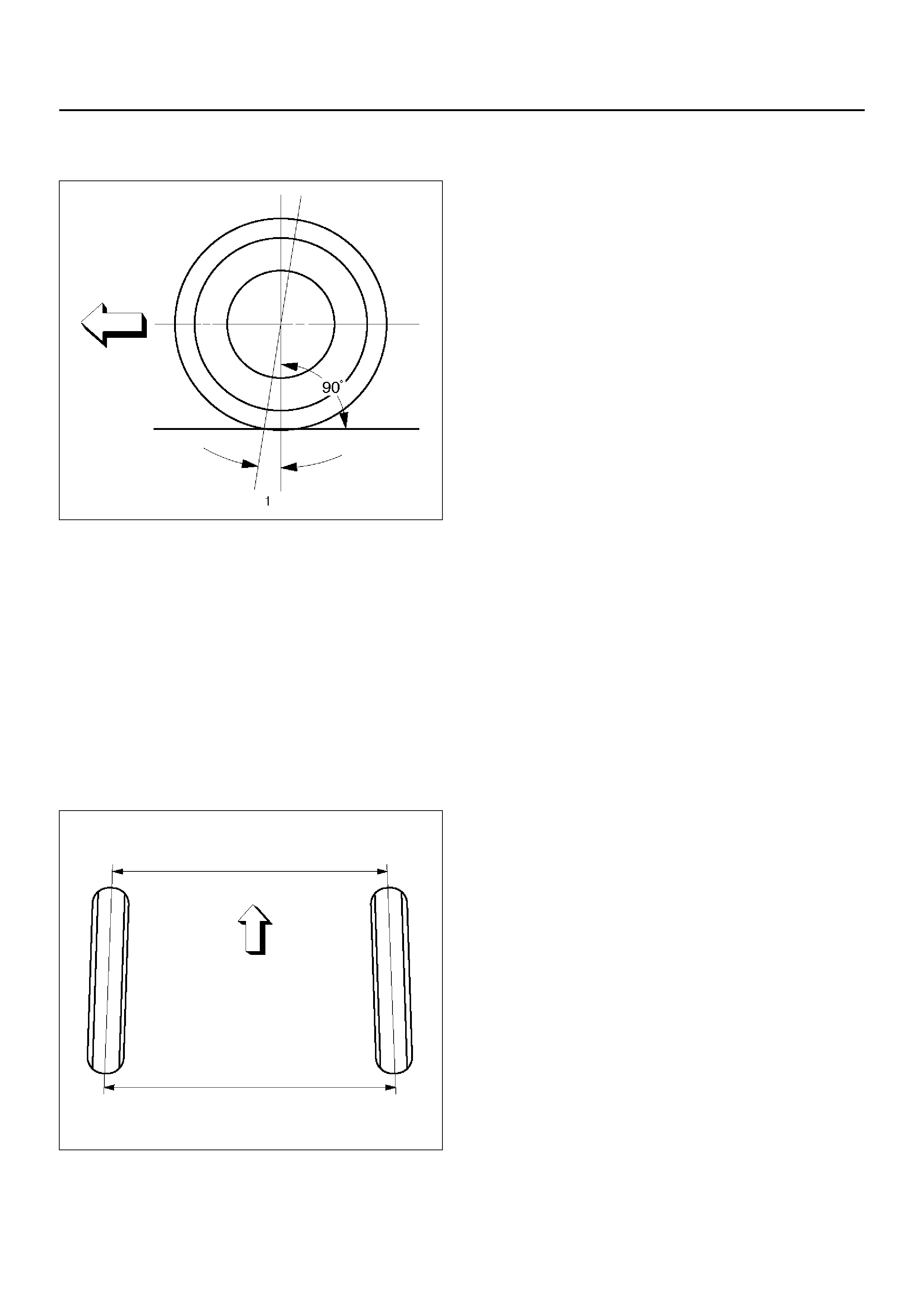
Caster:
This illustration shows view from the side of the vehicle.
480RS005
Caster (1) is the vertical tilting of the wheel axis either
forward or backward (when viewed from the side of the
vehicle). A backward tilt is positive (+) and a forward tilt
is negative (-). On the short and long arm type
suspension you cannot see a caster angle without a
special instrument, but if you look straight down from
the top of the upper control arm to the ground, the ball
joints do not line up (fore and aft) when a caster angle
other than 0 degree is present. With a positive angle,
the lower ball joint would be slightly ahead (toward the
front of the vehicle) of the upper ball joint center line.
Toe-in:
This illustration shows view from the top of the vehicle.
480RS003
Toe-in is the measured amount the front wheels are turn
in. The actual amount of toe-in is normally a fraction of
a meter. Toe-in is measured from the center of the tire
treads or from the inside of the tires. The purpose of
toe-in is to insure parallel rolling of the front wheels and
to offset any small deflections of the wheel support
system which occurs when the vehicle is rolling forward.
Incorrect toe-in results in excessive toe-in and unstable
steering. Toe-in is the last alignment to be set in the
front end alignment procedure.
INSPECTION
Before making any adjustments affecting caster,
camber or toe-in, the following front end inspection
should be made.
1. Inspect the tires for proper inflation pressure. Refer
to Main Data and Specifications in Wheel and Tire
System section.
2. Make sure that the vehicle is unladen condition
(With no passenger or loading).
3. Make sure that the spare tire is installed at the
normal position.
4. Inspect the front wheel bearings for proper
adjustment. Refer to Front Hub and Disc in
Driveline section.
5. Inspect the ball joints and tie rod ends. If excessive
looseness is noted, correct before adjusting. Refer
to Steering Linkage in this section.
6. Inspect the wheel and tires for run-out. Refer to
Wheel Replacement in Wheel and Tire System
section.
7. Inspect the trim height. If not within specifications,
the correction must be made before adjusting
caster.
8. Inspect the steering unit for looseness at the frame.
9. Inspect shock absorbers for leaks or any noticeable
noise. Refer to Shock Absorber in Suspension
section.
10. Inspect the control arms or stabilizer bar attachment
for looseness. Refer to Suspension section .
11. Inspect the front end alignment using alignment
equipment. Follow the manufacturer's instructions.
12. Park the veh icle must be on a level sur face.
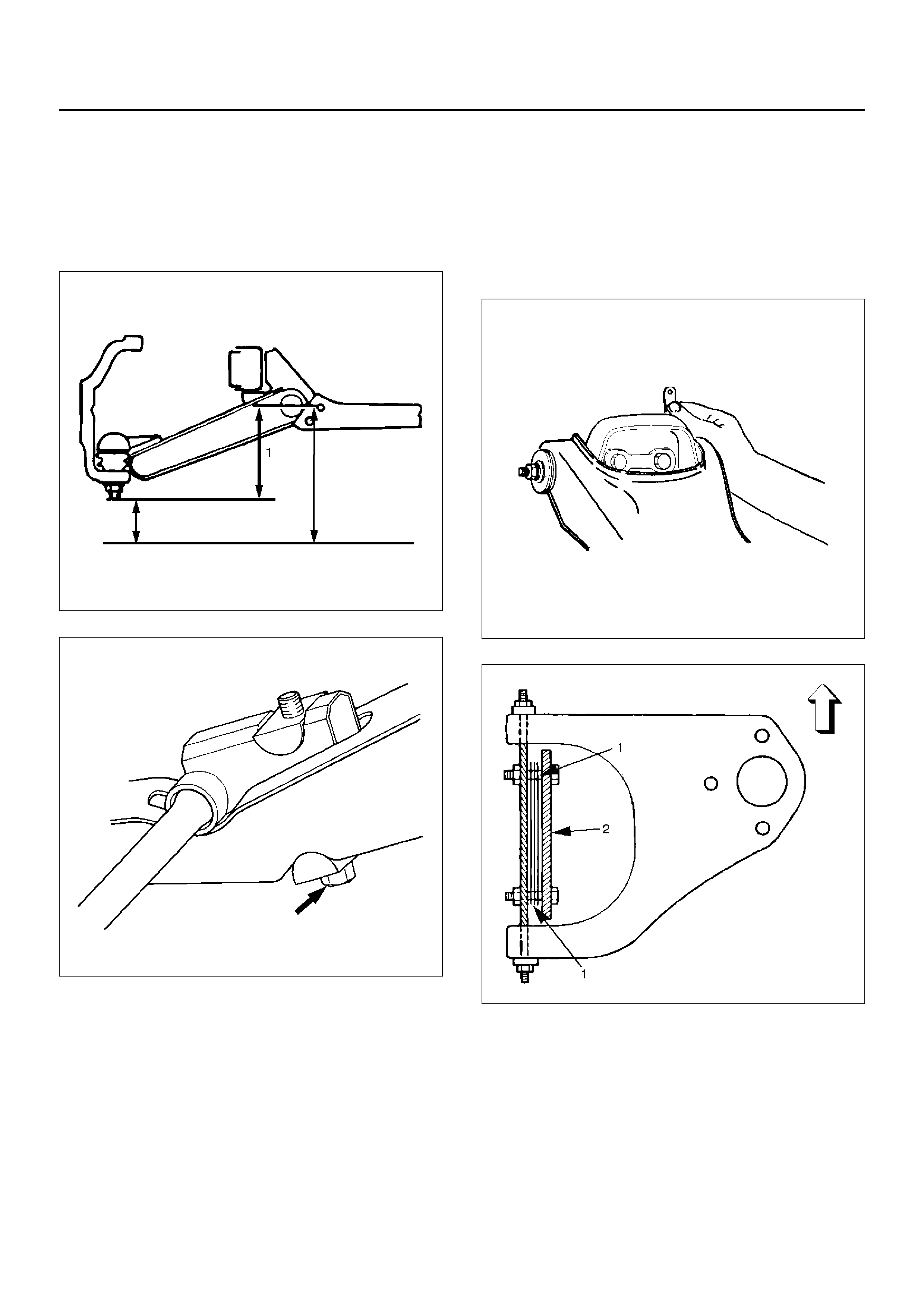
TRIM HEIGHT ADJUSTMENT
Adjust the trim height (1) by means of the adjusting bolt
on the height control arms.
CAUTION: When adjusting front end alignment, be
sure to begin with trim height first, as it may change
other adjusted alignments.
450RS003
410RS001
1. Check and adjust the tire inflation pressures.
2. Park the vehicle on a level ground and move the
front of the vehicle up and down several times to
settle the suspension.
3. Make necessary adjustment with the adjusting bolt
on the height control arms.
Trim height: 119 ± 5mm (4.69 ± 0.2in)
Caster Adjustment
The caster angle can be adjusted by means of the
caster shims (1) installed between the chassis frame
(2) and fulcrum pins.
Caster angle: 2°30' ± 1°
CAUTION: Left and right side must be equal within
30'.
450RW006
450RS002
NOTE: Difference of the caster shim front/rear
thickness should be 3.6mm (0.142in) or less. Overall
thickness of cast er shim and camber shim should be
10.8mm (0.425in) or less.
Tighten the fulcrum pin bolt to the specified torque.
Torque: 152N·m (15.5kg·m/112lbft)
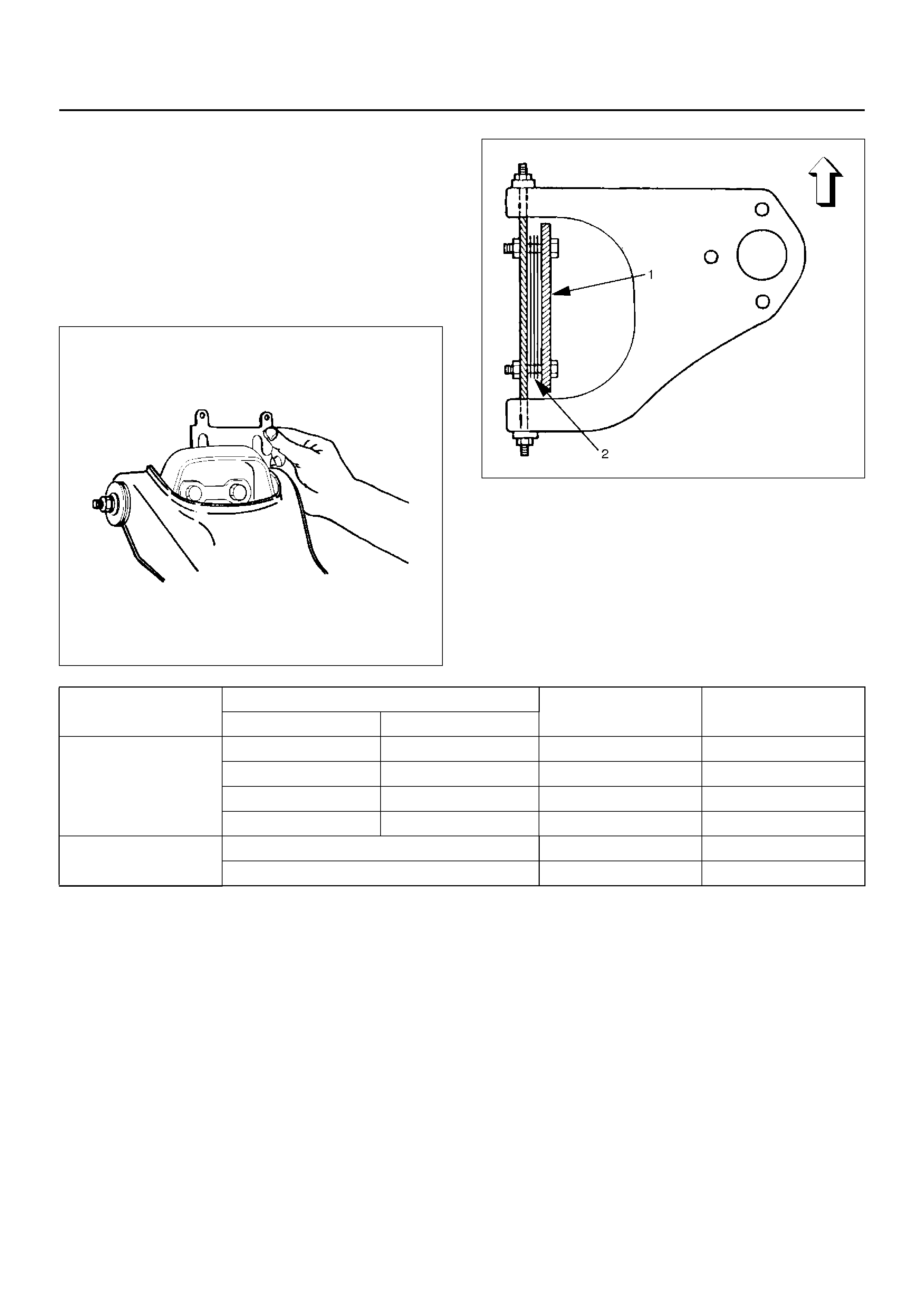
CAMBER ADJUSTMENT
The camber angle can be adjusted by means of the
camber shims (2) installed in position between the
chassis frame (1) and fulcrum pins.
Camber angle: 0° ± 30'
Steering Axis inclination: 12°30' ± 30'
CAUTION: Left and right side must be equal within
30'.
450RW007
450RS005
NOTE: Overall thickness of caster shim and camber
shim should be 10.8mm (0.425in) or less.
Tighten the fulcrum pin bolt to the specified torque.
Torque: 152N·m (15.5kg·m/112lbft)
Position of shims Camber angle Caster angle
Front side Rear side
Caster shim
When added When removed Dec reas es Decreases
When removed When added Increases Increases
— When removed Unchanged Decreases
— When added Unchanged Increases
Camber shim When added Decreases Unchanged
When removed Increases Unchanged
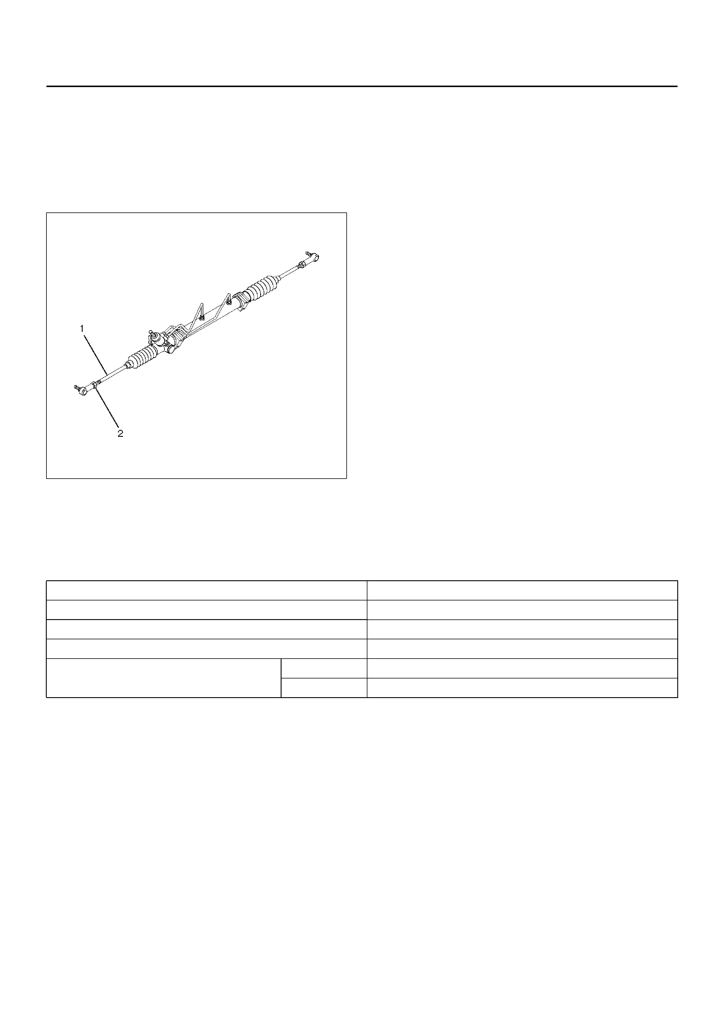
Toe-in Adjustment
1. To adjust the toe-in angle, loosen the lock nuts (2)
on the tie rod (1) and turn the tie rod. Turn both rods
the same amount, to keep the steering wheel
centered .
Toe-in: 0 to +2mm (0 to +0.08in)
433RW006
2. Tighten the lock nut to the specified torque.
Torque: 98N·m (10.0kg·m/72lbft)
MAIN DATA AND SPECIFICATIONS
General Specification
Caster 2°30' ± 1°
Camber 0° ± 30'
Steering Axis Inclination 12°30' ± 30'
Toe-in 1mm ± 1mm
Max. ste erin g angle insid e 32.6° (+0°30' to –2°30' )
outside 31.8°
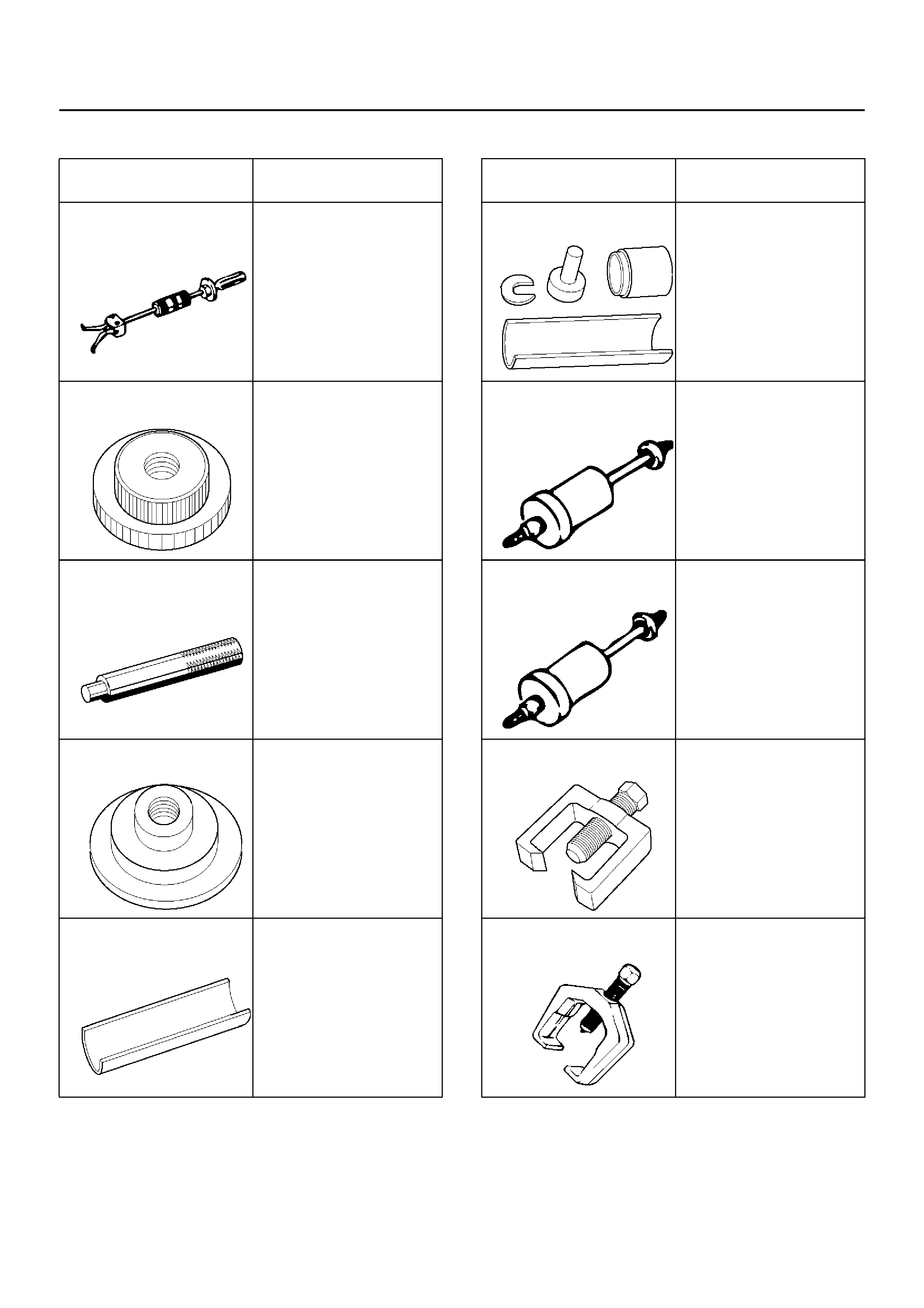
SPECIAL TOOLS
ILLUSTRATION TOOL NO.
TOOL NAME
5–8840–2000–0
(J–23907)
Remover;Needle bearing
5–8840–0019–0
Sliding hammer
5–8840–2128–0
(J–36838)
Installer; Needle bearing
5–8840–0007–0
(J–8092)
Grip
5–8840–2127–0
(J–36837)
Installer; Oil seal
5–8840–2307–0
(J–39376)
Installer; Uppe r arm
bushing
5–8840–0256–0
(J–29775)
Remover and Installer
Upper arm bush in g
5–8840–2123–0
(J–36833)
Remover and Installer kit;
Lower arm front bushing
5–8840–2124–0
(J–36834)
Remover and Installer kit;
Lower arm rear bushing
5–8840–2121–0
(J–36831)
Ball joint remover
5–8840–2005–0
(J–29107)
Tie-rod end rem over
ILLUSTRATION TOOL NO.
TOOL NAME