
SECTION 4B1 - DRIVELINE CONTROL SYSTEM
Service Precaution
Shift On The Fly System
Outline of Shift on The Fly System
Functions of Indicator Lamp
Diagnosis
Shift On The Fly Electrical Equipment
Axle Shaft Connection and Disconnection
Actuator Assembly
4WD Control Unit
4WD Control Unit Associated Parts
Removal
Installation
Shift On The Fly Controller
Shift On The Fly Controller and
Associated Parts
Removal
Installation
SERVICE PRECAUTION
WARNING: THIS VEHICLE HAS A SUPPLEMENTAL
RESTRAINT SYSTEM (SRS). REFER TO THE SRS
COMPONENT AND WIRING LOCATION VIEW IN
ORDER TO DETERMINE WHETHER YOU ARE
PERFORMING SERVICE ON OR NEAR THE SRS
COMPONENTS OR THE SRS WIRING. WHEN YOU
ARE PERFORMING SERVICE ON OR NEAR THE
SRS COMPONENTS OR THE SRS WIRING, REFER
TO THE SRS SERVICE INFORMATION. FAILURE
TO FOLLOW WARNINGS COULD RESULT IN
POSSIBLE AIR BAG DEPLOYMENT, PERSONAL
INJURY, OR OTHERWISE UNNEEDED SRS
SYSTEM REPAIRS.
CAUTION: Always use the correct fastener in the
proper location. When you replace a fastener, use
ONLY the exact part number for that application.
HOLDEN will call out those fasteners that require a
replacement after removal. HOLDEN will also call
out the fasteners that require thread lockers or
thread sealant. UNLESS OTHERWISE SPECIFIED,
do not use supplemental coatings (Paints, greases,
or other corrosion inhibitors) on threaded fasteners
or fastener joint interfaces. Generally, such
coatings adversely affect the fastener torque and
the joint clamping force, and may damage the
fastener. When you install fasteners, use the correct
tightening sequence and specifications. Following
these instructions can help you avoid damage to
parts and systems.
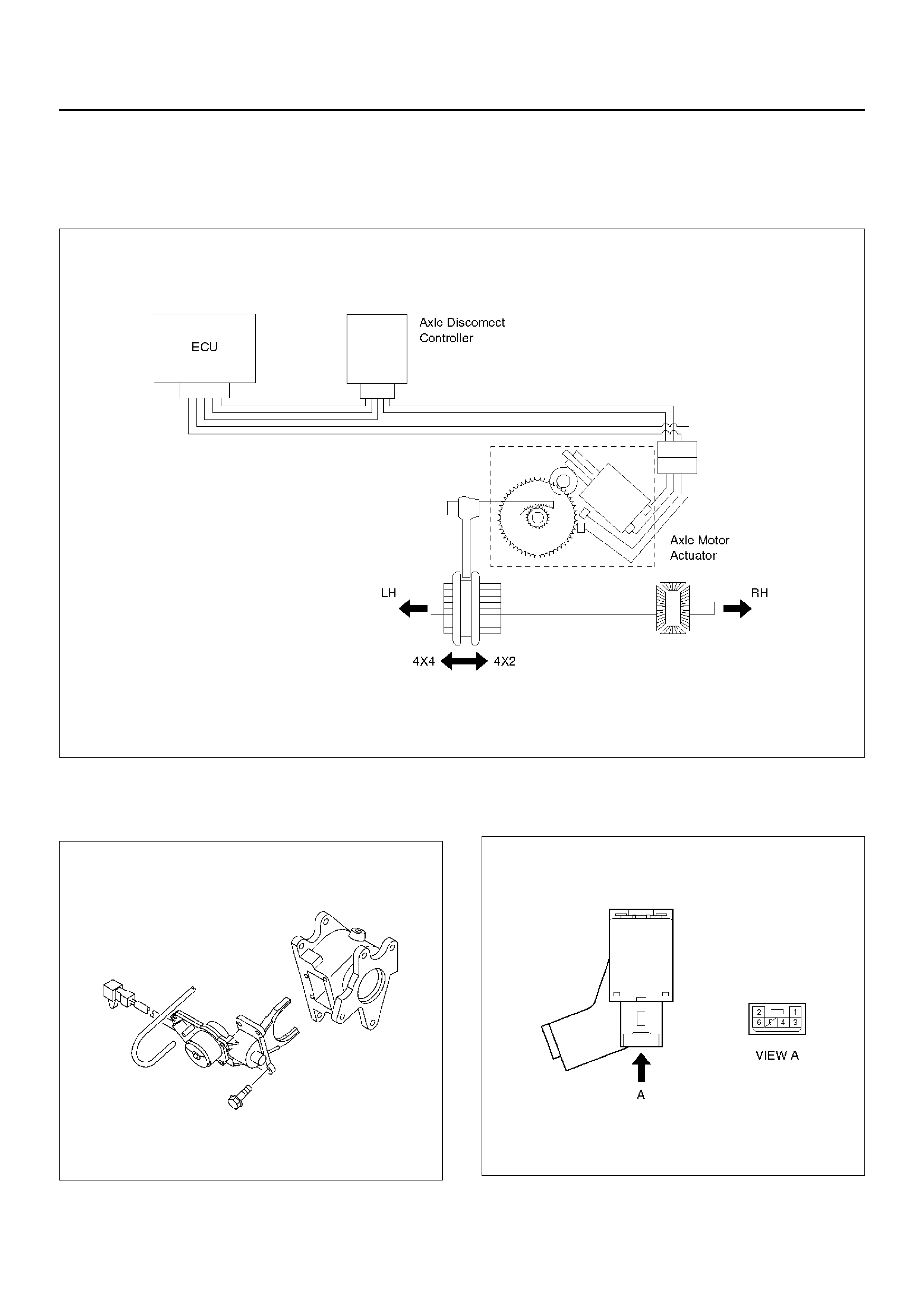
SHIFT ON THE FLY SYSTEM
OUTLINE OF SHIFT ON THE FLY
SYSTEM
The Shift On the Fly system allows the driver to
electrica lly switch between 2 WD High and 4WD High a t
vehicle speeds up to 100km/h. Shifting between 4WD
High and 4WD Low is accomplished by moving the
transfer case lever with the vehicle stationary.
Manual or automatic lo cking hubs are not requir ed with
this system.
The SOF system controls the following operations:
1. Shifting the transfer front output gear (Connecting,
and disconnecting, the drive to the front propeller
shaft by a motor actuator).
2. Connecti ng fr ont wheels to, and di sc on necti ng them
from, the front axles by axle motor actuator.
3. Send a ‘4WD Engaged’ signal to the Electronic
Hydraulic Control Unit ( ABS Modulator)
4. Illuminate the 4WD Indicator on instrument panel.
5. Monitor system operation and provide a fault
indication to the driver if necessary.
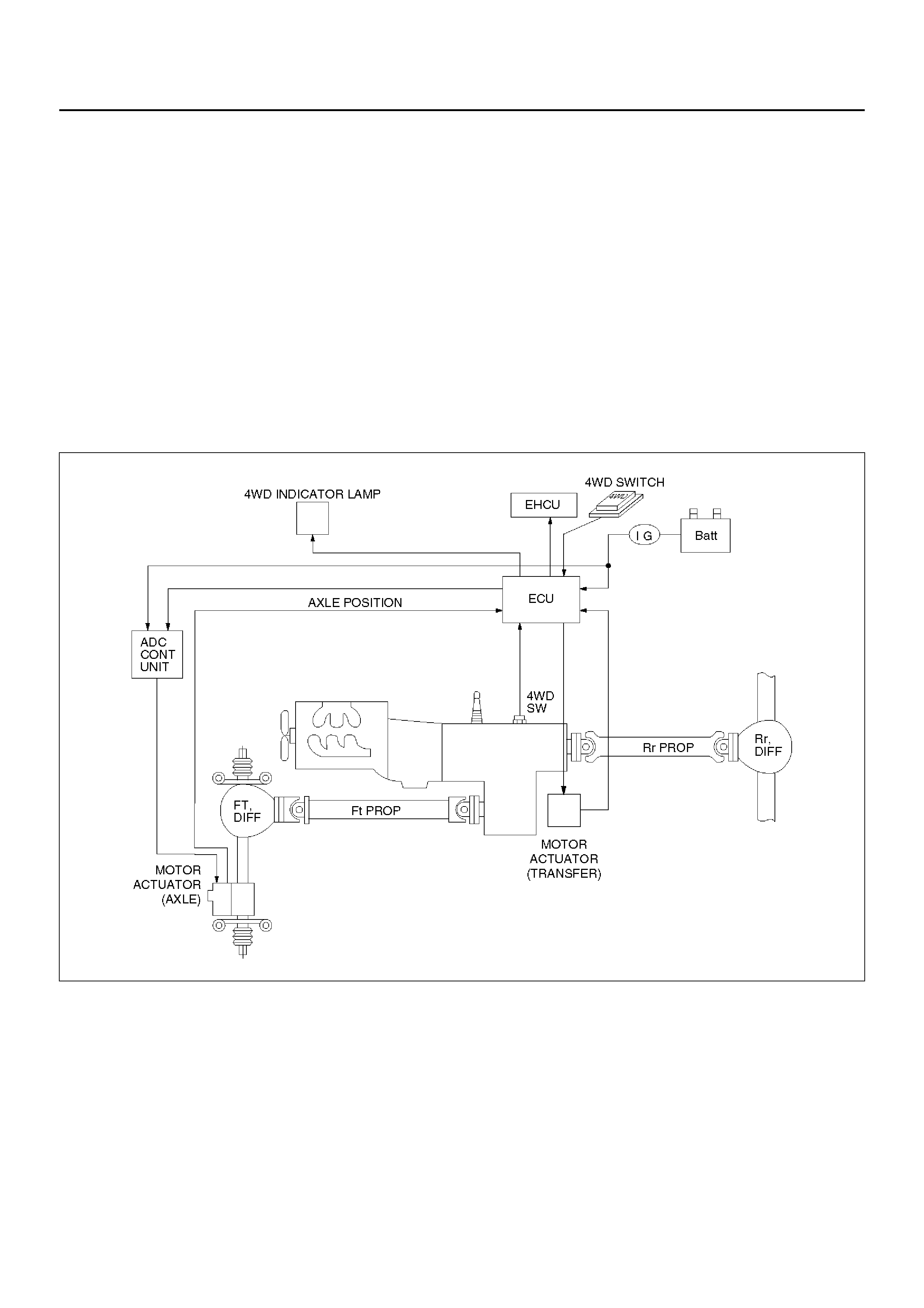
System Diagra ms
412RY00005
Normal Operation
The motor act uator, mou nted on the rear of th e transfer
rear case, is driven by a signal from the Instrument
Panel (IP) 4WD switch. The output signal of the transfer
position switch changes as the front output gear is
connected or disconnected from the front propeller
shaft. The Axle Disconnect Controller receives the the
signal from the transfer position switch and commands
the axle motor actuator to connect or disconnect the
front wheels to the front axles.
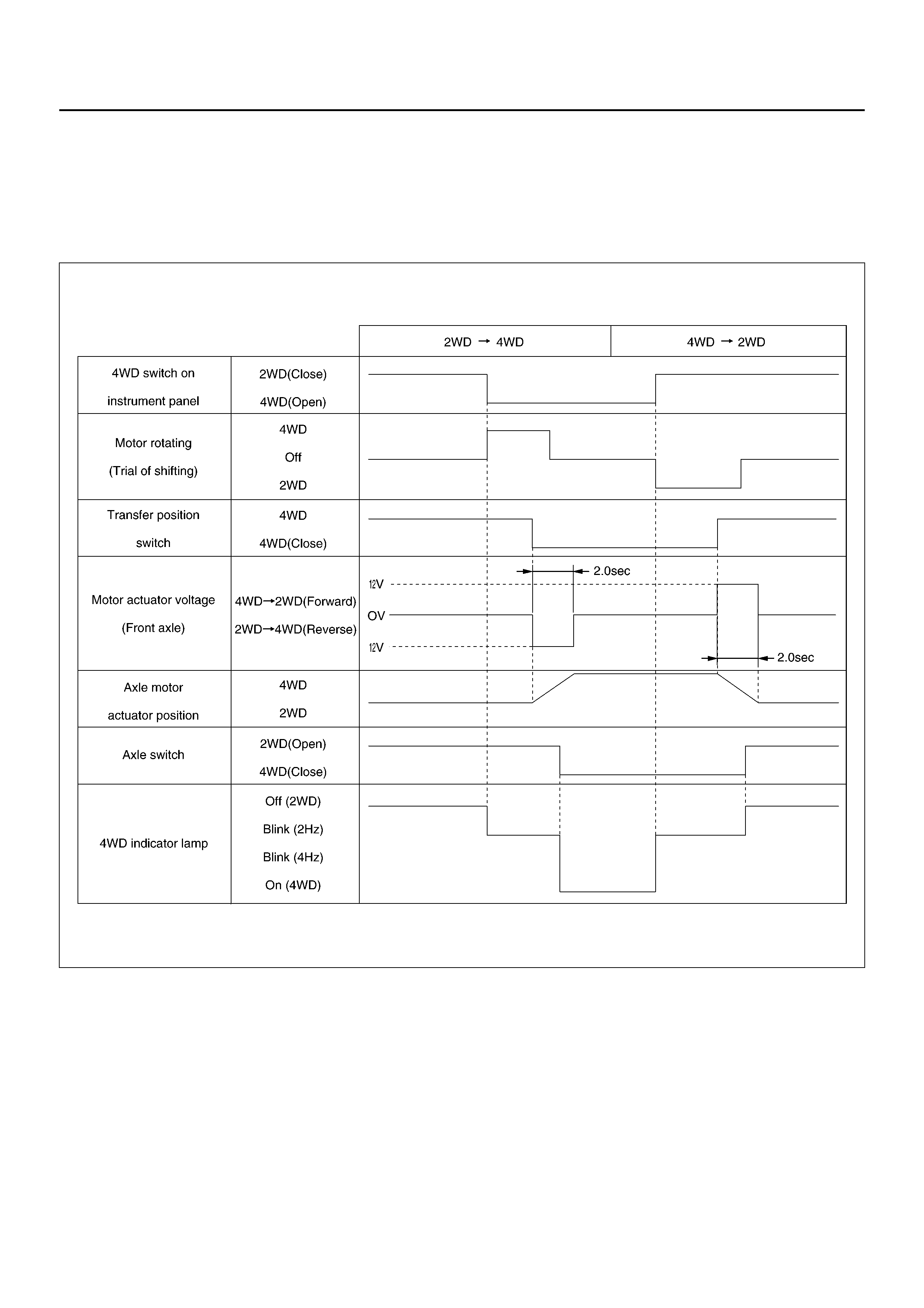
Time Chart of Shifting Under Normal Condition
F04R100004
Retrial
The transfer motor actuator starts the transfer case gear
moving after a command is received from the Axle
Disconnect Controller. However, shifting may not occur
in severe cold wea ther or unde r high speed (>100 km/h)
conditions. When 2 seconds have passed since the
transfer gear shifting has commenced and the transfer
position switch does not activate (gear engagement is
not completed), the motor reverses its rotation for 1.2
secon ds and automa tically rep eats the operation aga in.
If after 3 attempts the transfer position switch does not
activate, the transfer motor actuator will be disabled and
the 4WD i ndicator lam p will blink 4 tim es per second to
alert the driver that the SOF operation has failed. The
lamp will continue to blink until the driver selects 2WD
mode.
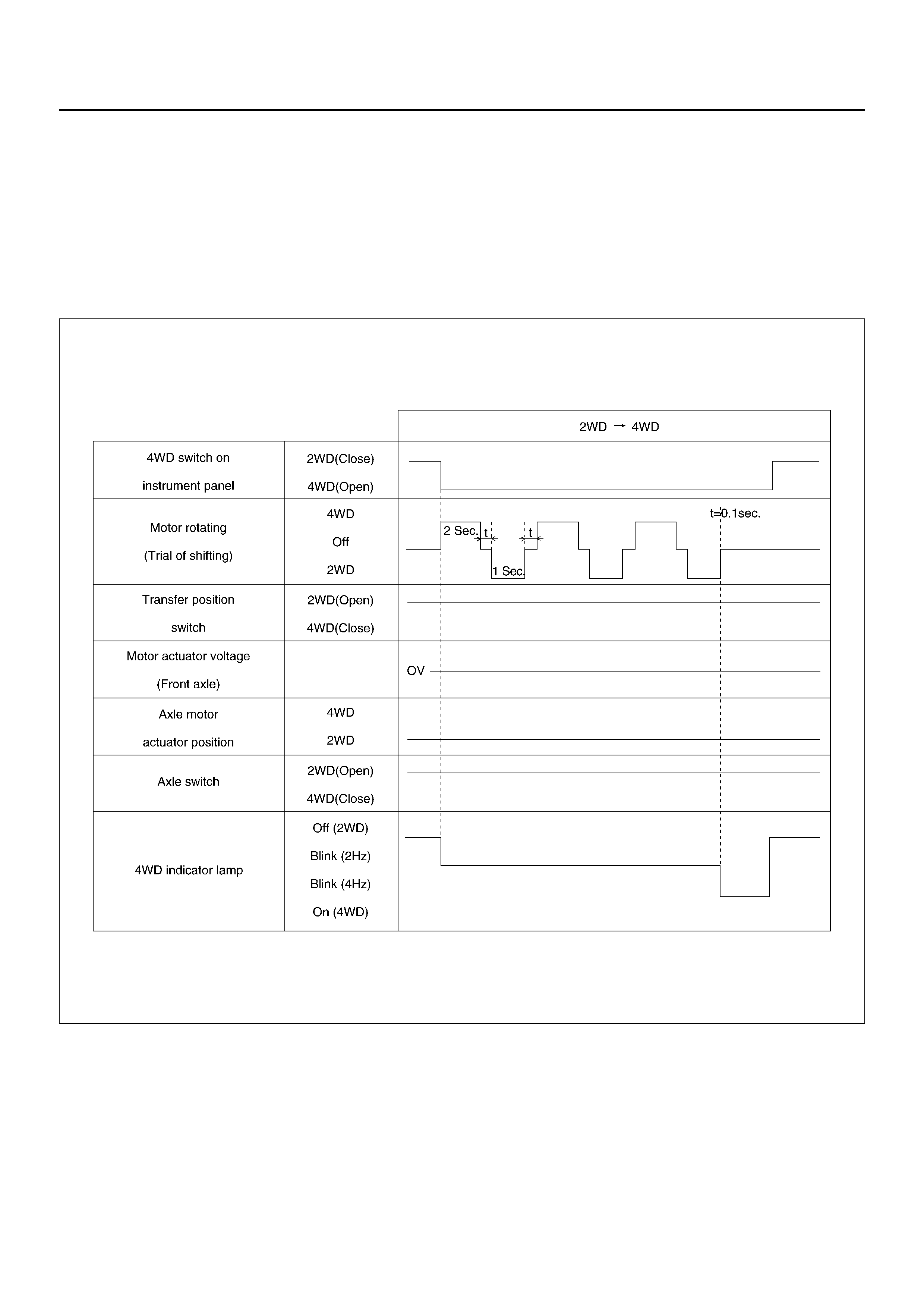
Time Chart of Shifting Under Severe Conditions (retrial)
F04R100002
Wa rning at “4L" position : Shifti ng from 4WD to 2WD
while in “4L" mode is not possible. While in “4L" mode,
the transfer position switch cannot be deactivated.
Should the 4WD switch be pressed while in "4L", then
the 4WD i ndicator lam p will blink 4 tim es per second to
alert the driver of the incorrect operation and the 4WD
to 2WD mode will be cancelled.
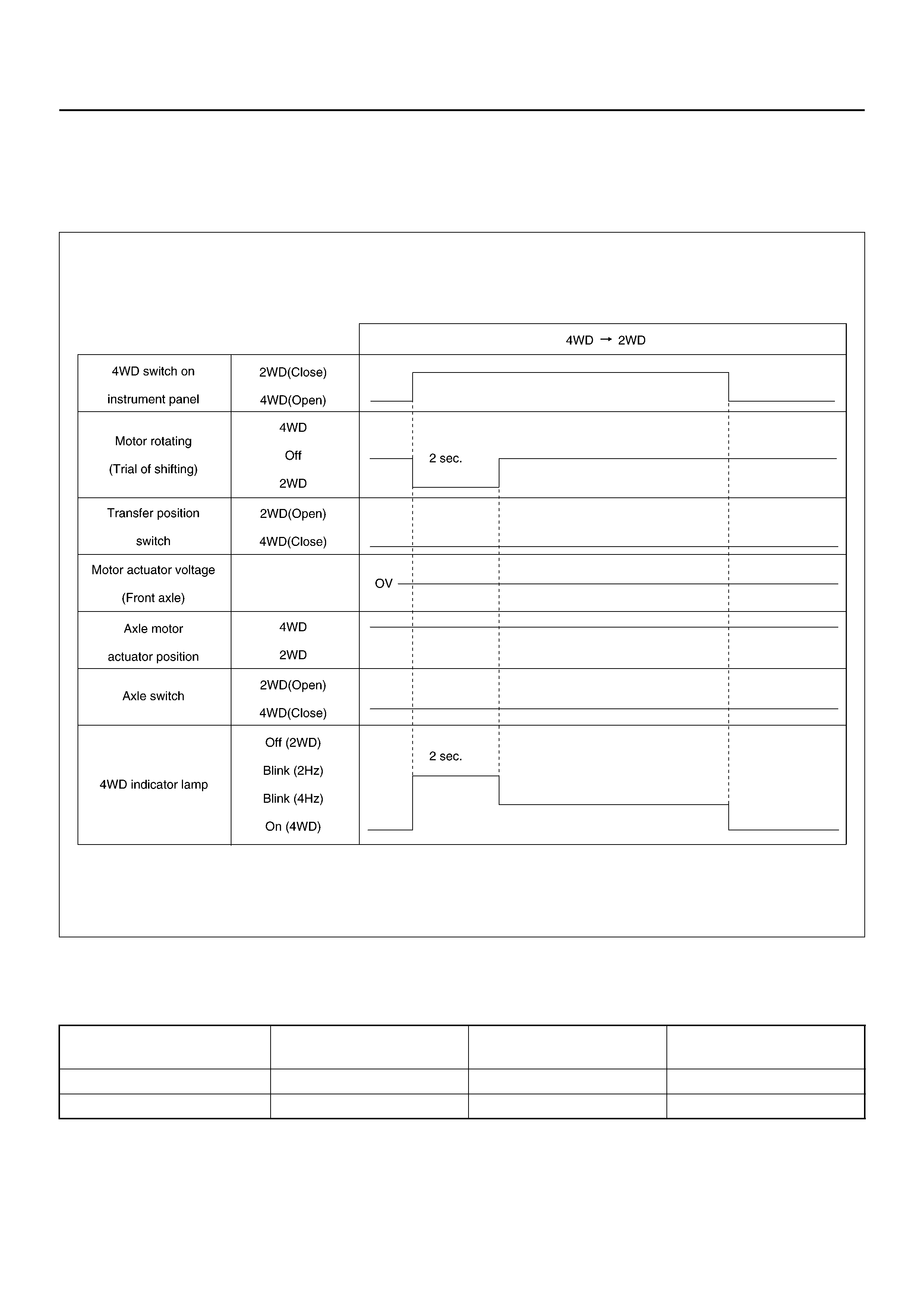
Time Chart of Shifting from 4WD to 2WD at “4L" Condition
F04R100003
4WD out signal to the Electronic Hydraulic Control
Unit : The SOF Axle Disconnect Controller transmits a
4WD output signal to the Electronic Hydraulic Control
Unit (ABS Modulator). The frequency of signal
transmitted will depend on the drive range selected.
Based upon this signal, the calibration of the ABS
system will be varied to suit the selected driving mode.
4WD Output Sig nal
(Period) Vehicle Condition Transfer Case Position
switch Front Axle Switch
120 ms 2WD 2WD (Open) 2WD (Open)
240 ms 4WD 4WD (Close) 4WD (Close)
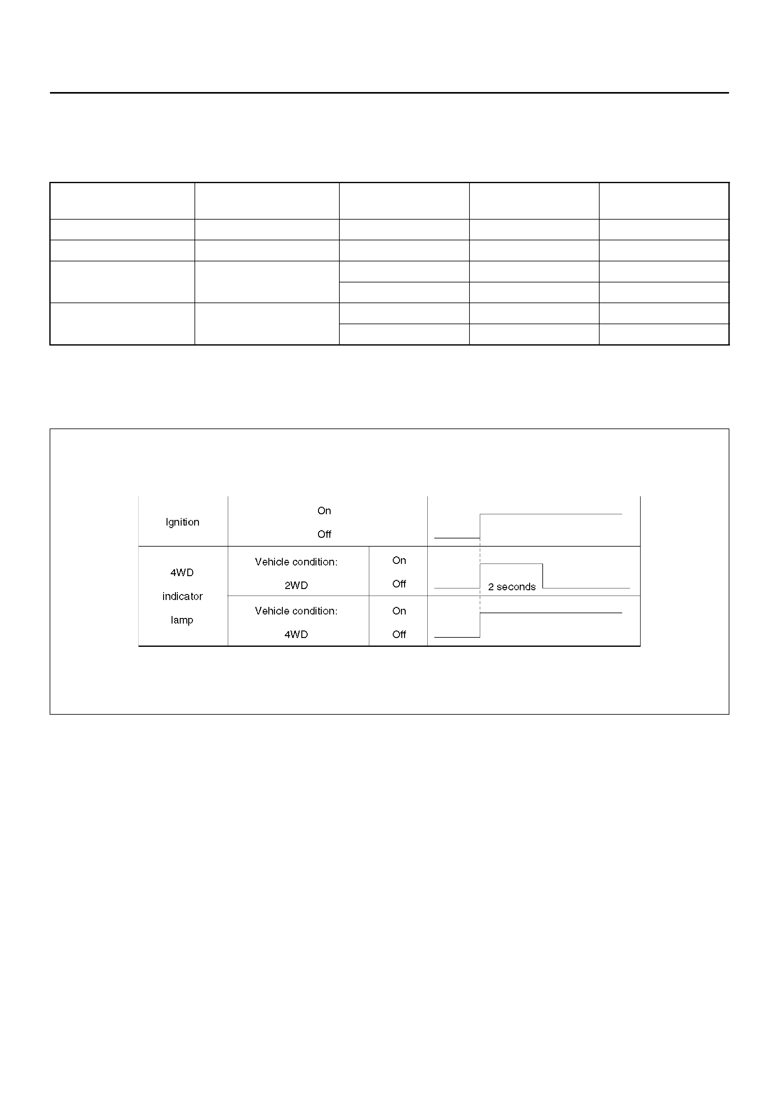
FUNCTIONS OF INDICATOR LAMP
Indication of vehicle condition :
Indicator lamp is controlled by the Axle Disconnect
Controller and indicates vehicle conditions as below.
Bulb check :The indicator lamp is illuminated for 2
seconds when the ignition is first turned on.
Time Chart of Bulb Checking
F04RW004
Retrials from 2WD to 4WD :Shifting from 2WD to 4WD
may not occur when in severe cold weather
conditions or under high speed conditions. Should this
occur, the 4WD indic ato r lamp will fla sh cont ino us ly at a
rate of 4 times per second until the driver disengages
the 4WD operation (see Retrial for more information).
Indicator Vehicle condition 4WD switch Transfer Position
Switch Front Axle Switch
Off 2WD Off (Close) 2WD (Open) 2WD (Open)
On 4WD On (Open) 4WD (Close) 4WD (Close)
Flash 2 times per
second (2Hz) Operating On (Open) 4WD (Close) 2WD (Open)
Off (Close) 2WD (Open) 4WD (Close)
Flash 4 times per
second (4Hz) Shift inoperative On (Open) 2WD (Open) 2WD (Open)
Off (Cl ose) 4WD (Close) 4WD (Close)
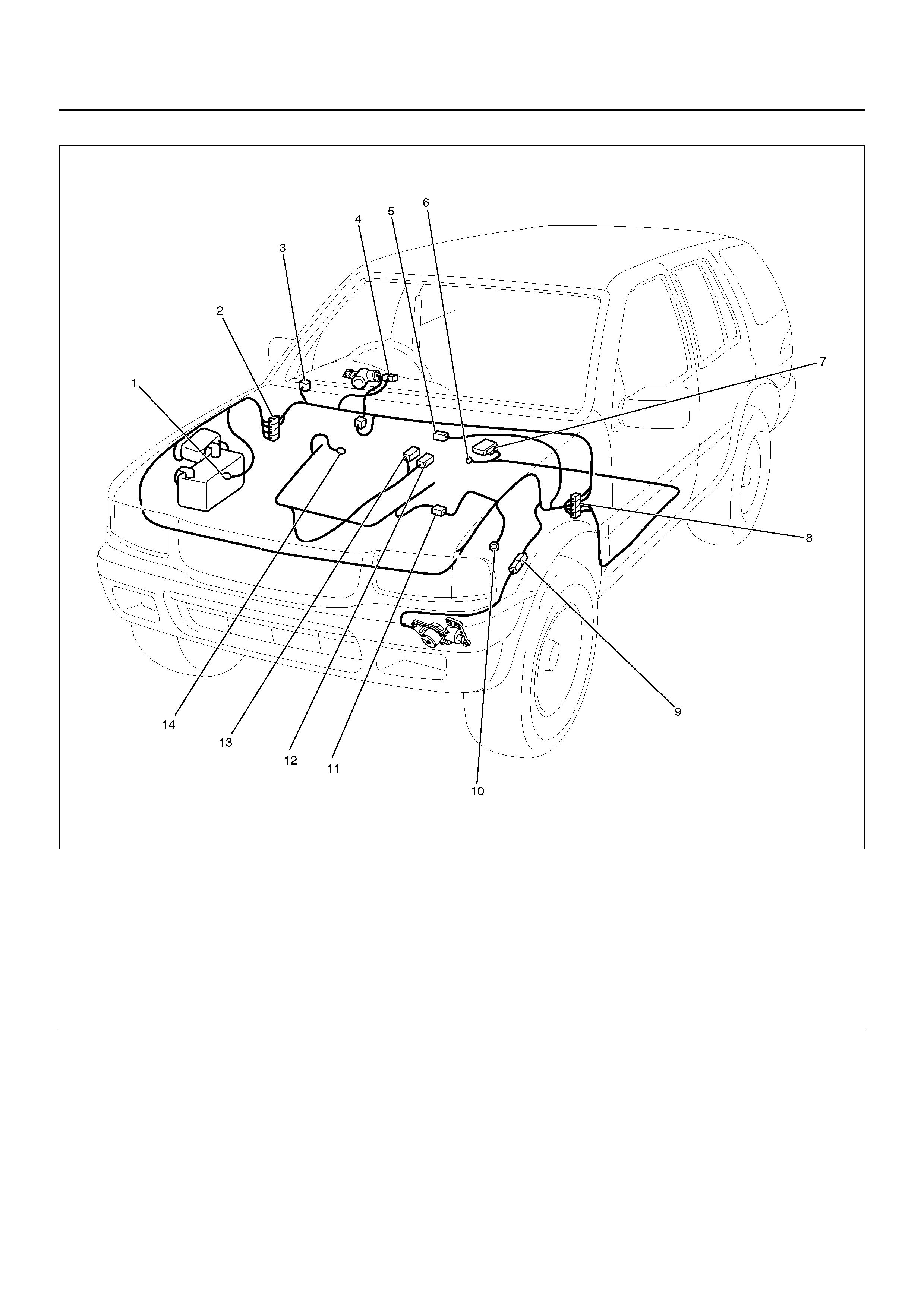
Parts Location
828R100003
EndOFCallout
Legend
(1) C–36
(2) H–18
(3) I–19
(4) I–1
(5) C–49
(6) B–8
(7) B–19
(8) H–15, H–17
(9) C–55
(10) C–16
(11) H–6
(12) E–60
(13) E–56, E–57
(14) E–30
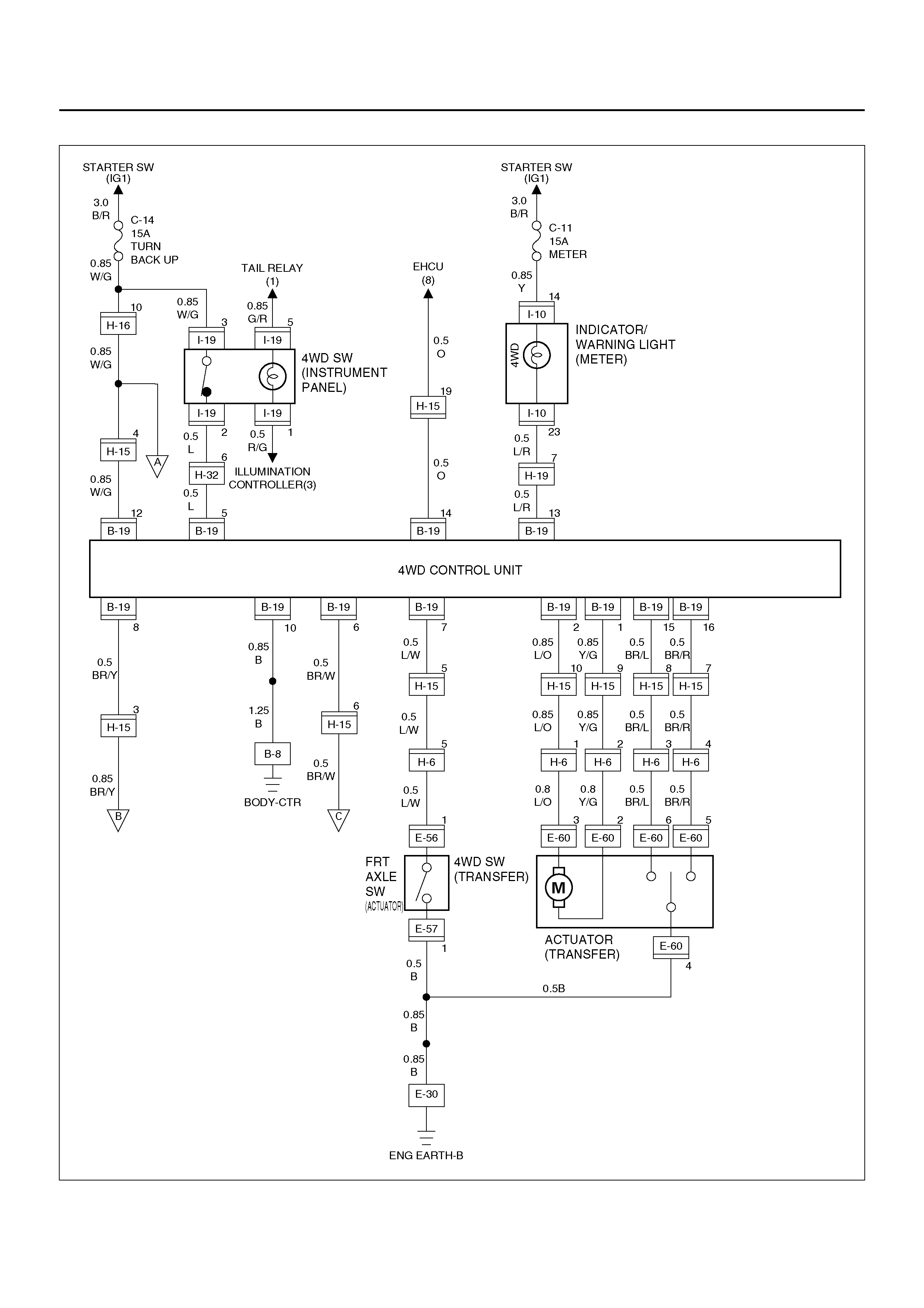
Wiring Diagram
D04R100026
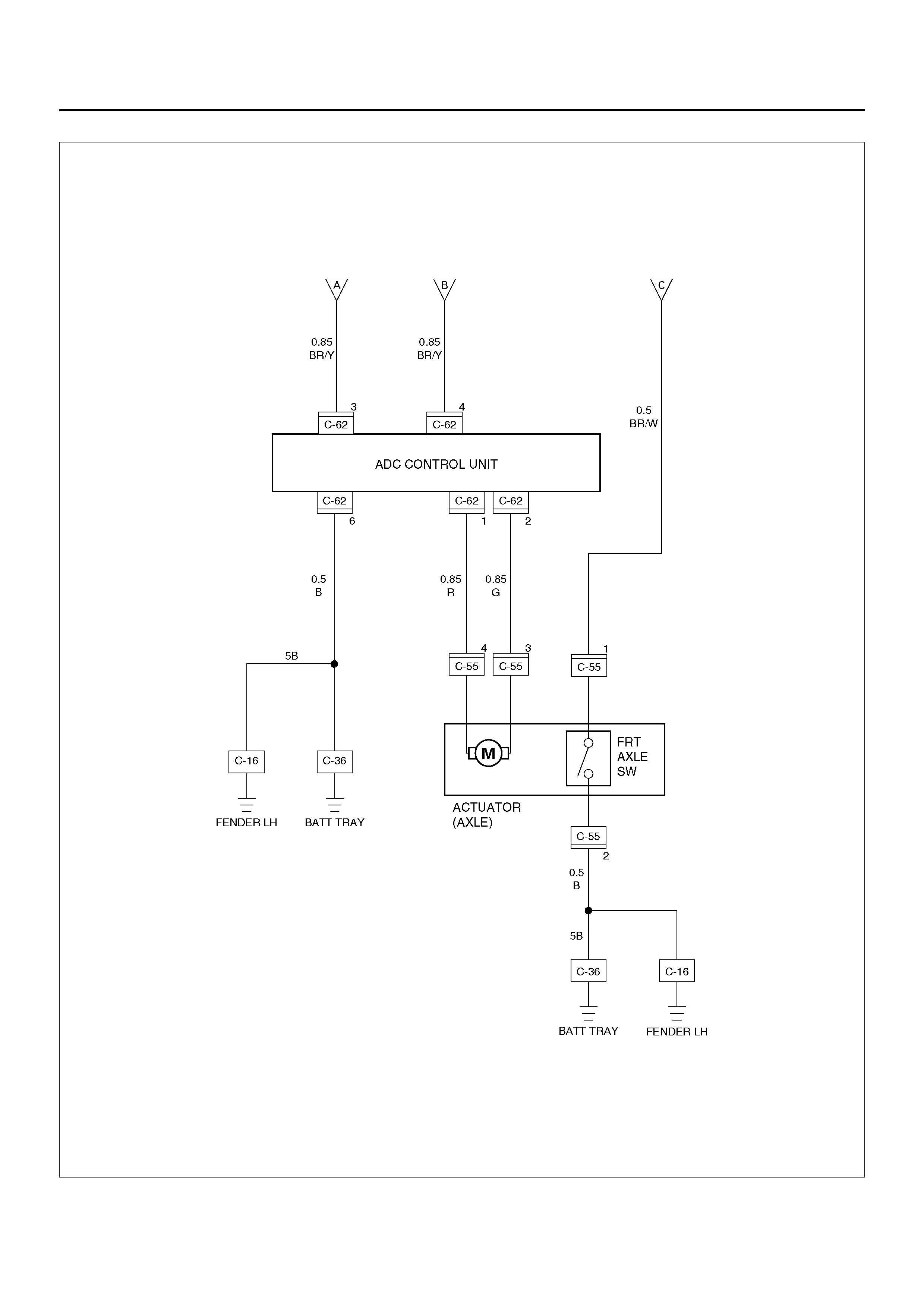
D04R100027
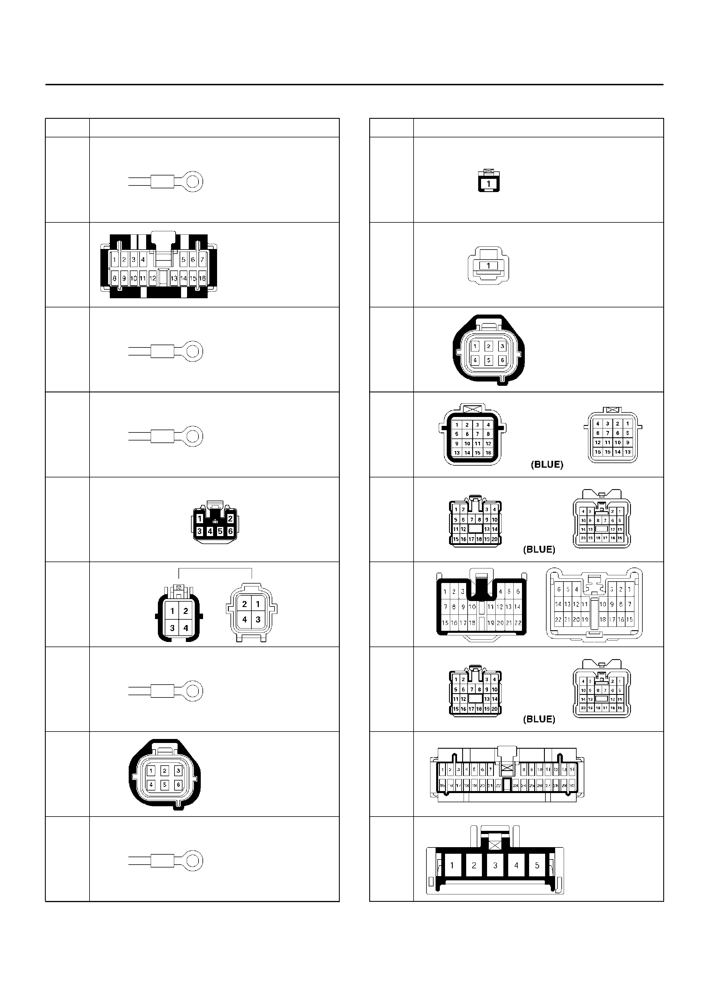
Connector List
No. Connector face
B-8
B-19
C-16
C-36
C-49
C-55
E-4
E-19
E-30
E-56
E-57
E-60
H-6
H-15
H-17
H-18
I-1
I-19
No. Connector face

DIAGNOSIS
Identifying the problem
When Switching from 2WD to 4WD
1. Flashing of the 4WD indicator changes from 2
times per second (2Hz) , to 4 times per second
(4Hz).
When a high synchronization load is encountered,
the motor actuator will make up to 3 attempts to shift
the tran sfer gear. The 4WD indicator lamp will flas h
at 2Hz whi le th e m oto r actuator attemp ts the s hift. If
after the 3rd att empt, the shift is not co mpleted, the
4WD indicator lamp will begin to flash at 4Hz and
the motor actuator will return to 2WD mode.
A high synchronization load occurs:
• At severe low temperatures.
• A high rotational difference in speed occurs
between the front wheels and the front axles
during cornering .
Solution 1: Attempt to select 4WD mode again at
a lower speed or when the vehicle is stationary.
2. The 4WD indicator continues flashing at 2Hz for
more than 11.5 seconds.
When there is rotational difference in speed
between the front wheels and axles, the front
wheels and the front axles may have difficulty
engaging. The flashing of the 4WD indicator lamp at
2Hz will indicate that the transfer case is shifting into
the 4WD mode. Shifting into 4WD mode is
impossible if a high rotational difference in speed
occurs between the front whe els and the front axles
during cornering, resulting in the indicator flashing
for an extended period.
Solution 2: If the vehicle is moving, drive the
vehicle straight while accelerating and
decelerating, and if the vehicle is at a stop,
move the vehicle forward an d backward fo r 2 to
3 met res.
When Switching from 4WD to 2WD
1. The 4WD indicator lamp continues to flash 2
times per second.
When switching from 4WD to 2WD, the 4WD
indicator lamp continues to flash until both shifting of
the transfer gear and disconnecting the front wheels
are completed. When drive line is subject to a high
torque load, the shifting transfer gear and
disconnecting of the front wheels are impossible.
In this case , remo val o f the torque load on t he d rive
line makes the shifting transfer gear and
disconnecting front wheels possible.
Solution 3: If the vehicle is moving, drive the
vehicle straight while accelerating and
decelerating, and if the vehicle is at a stop,
move the vehicle forward an d backward fo r 2 to
3 met res.
2. When the 4WD indicator lamp flash pattern changes
from 2Hz to 4Hz.
Check the position of the transfer lever. Is it in the
“4L" position? Shifting from 4WD to 2WD while at
“4L" will not occur.
Solution 4: Push the 4WD switch ON (to 4WD),
then shift the transfer lever to the “High"
position and then push the 4WD switch OFF (to
engage to 2WD).

Fault diagnosis based on the status of 4WD Indicator Lamp, 4WD Switch and T/F Change
Lever
A diagnostic flow chart is shown below. If after performing the diagnosis and a condition still exists, then there may be
a fault in the Axle Disconnect Controller. The Axle Disconnect Controller will need to be replaced and perform the
diagnostic flow chart again.
Fault on Switching from 2WD to 4WD
1. When the 4WD indicator lamp flash pattern changes from 2Hz to 4H z after perf orming “Solution 1."
The mo tor ac tua tor or th e tr ansfer case a ssem bly m ay be i nop erati ve . Rem ove an d be nc h te stth e m otor ac tu ator.
Make any necessary repairs and perform “Solution 1" again. Then disassemble and inspect the transfer case
assembly. Repair or replace as needed. If after the repairs, the condition still exists, then replace the Axle
Disco nne ct Control le r.
2. When the 4WD indicator lamp does not flash or light up when switching from 2WD to 4WD.
Step Action Yes No
1Is ignition turned on? Go to Step 2
Turn on the ignition
and trace this chart
from start.
2Does the 4WD indicator lamp light up during the two second
initialization after the ignition is turned on?
Go to Step 3
Failed indicator
lamp or
disconnected
harness wire.
Perform the
diagnostic chart
from step 1 after
repair or
replacement.
3Is the 4WD switch activated from 2WD to 4WD mode? Short-circuit
(body short) on
harness of the
4WD switch.
Inoperative
4WD switch
(stuck closed
condition).
T rac e this cha rt
fr om th e st ep 1
after repair or
replace. Push the 4WD
switch to 4WD.

3. When the 4WD Indicator lamp continues to flash after performing Solution 2.
Step Action Yes No
1 Check tire pressure and tire wear.
Were problems found? Correct the tire
pressure and
replace worn tires
then perform
“Solution 2." Go to Step 2
2Can the transfer lever be operated from High to 4L or vice versa?
Go to Step 3
If the motor
actuator
harnes s was
disconnected,
then repair and
repeat ste p 1.
If the motor
actuator is
inoperative,
replace the
motor actuator
and repeat step
1.
If the transfer
case was not
operating
correctly , repair
as neccessary
and repeat step
1.
3 Confirm that the transfer swit ch is operatin g correctly. Replace if
necessary. Go to Step 4 —
4 1. Disconnect the connector C–47.
2. Turn on the starter switch
3. Measure voltage between the connector C–47 terminals 4
and 3, when 4WD sw itch on instrum ent panel is swit ched on
2WD and 4WD position.in
Is the motor actuator voltage on the axle as “Time Chart of
Shifting Under Normal Condition" Refer to the page (4B–3). Go to Step 8 Go to Step 5
5 1. Inspect the wiring for poor electrical connections, open or
short to ground between the connector-terminal E56–1 and
B19–7, E57–1 and ground, C47–1 and B19–6, C47–2 and
ground, H1 8–1 and B1 9–1 2, B 19– 8 an d C49 –3, H17– 19 a nd
C49–3, C49–1 and C47–4, C49–2 and C47–3, and C49–6
and ground.
2. Repair the circuit.
Is the motor actuator voltage on the axle as in “Time Chart of
Shifting Under Normal Condition" Refer to the page (4B–3). Go to Step 8 Go to Step 6
6 Check the axle switch continuity between the connector C–47
termina ls 1 and 2.
Is the axle switch open or closed as in “Time Chart of Shifting
Under Normal Condition". Refer to the page (4B–3). Go to Step 8 Go to Step 7
7 Replace the axle motor actuator. Go to Step 8 —
8 Reconnect all components, ensure all components are properly
mounted.
Was this step finished Trace this chart
from the start. Go to Step 8

Fault on Switching from 4WD to 2WD
1. Indicator lamp on continuously.
2. When the indicator lamp continues to flash at
2Hz after performing Solution 3.
Step Action Yes No
1Does the indicator lamp turn off at ignition off? Go to Step 2 Short circuit of the
indicator harness.
2Is the 4WD switch on 2WD position? Disconnection on
the 4WD switch
harness or
breakdown of the
4WD switch in
open state. Trace
this chart from the
start after repair or
replace.
Turn the 4WD
switch to 2WD
position. Trace this
chart from the
start.
Step Action Yes No
1 Check the air pressure and wear on all tires.
Were problems found? Perform “Solution
3" after correcting
the tire air pressure
and replacing worn
tires. Go to Step 2
2Can the transfer lever be operated from High to 4L or vice versa? If the motor
actuator
harness was
disconnected,
then repair as
needed and
repeat step 1.
If the transfer
case was not
working
properly, then
repair as
needed and
repeat step 1.
If the motor
actuator is
inoperative,
then replace the
motor actuator
and repeat step
1. Go to Step 3
3 1. Disconnect the connector C–47.
2. Turn on the starter switch
3. Measure voltage between the connector C–47 terminals 4
and 3, when 4WD sw itch on instrum ent panel is swit ched on
2WD and 4WD position.
Is the motor actuator voltage on the axle as “Time Chart of
Shifting Under Normal Condition" aforementioned? Refer to the
page (4B–3). Go to Step 7 Go to Step 4

3. Indicator flash changes to 4Hz after Solution 4 is
carried out.
4 1. Inspect the wiring for poor electrical connections, open or
short to ground between the connector-terminal C47–1 and
B19–6, C47–2 and ground, H18–1 and B19–12, B19–8 and
C49–3, H17–19 and C49–3, C49–1 and C47–4, C49–2 and
C47–3, and C49–6 and gro und.
2. Repair the circuit.
Is the motor actuator voltage on the axle as “Time Chart of
Shifting Under Normal Condition" aforementioned? Refer to the
page (4B–3). Go to Step 7 Go to Step 5
5 Check the axle switch continuity between the connector C–47
termina ls 1 and 2.
Is the axle swi tch ope n or close as “Time Chart of Shifting Under
Normal Condition" aforementioned? Refer to the page (4B–3). Go to Step 7 Go to Step 6
6 Replace the axle motor actuator. Go to Step 7 —
7 Reconnect all components, ensure all components are properly
mounted.
Was this step finished Trace this chart
from the start. Go to Step 7
Step Action Yes No
Step Action Yes No
1Can the transfer lever be operated from High to 4L or vice versa? If the motor
actuator
harness was
disconnected,
then repair as
needed and
repeat step 1.
If the motor
actuator is
inoperative,
then replace the
motor actuator
and repeat step
1.
If the transfer
case was not
working
properly, then
repair as
needed and
repeat step 1.
Faults on the ECU.
Trace this chart
from the start after
replace.
SHIFT ON THE FLY ELECTRICAL EQUIPMENT
AXLE SHAFT CONNECTION AND DISCONNECTION
412RY00035
ACTUATOR ASSEMBLY
412RY00004
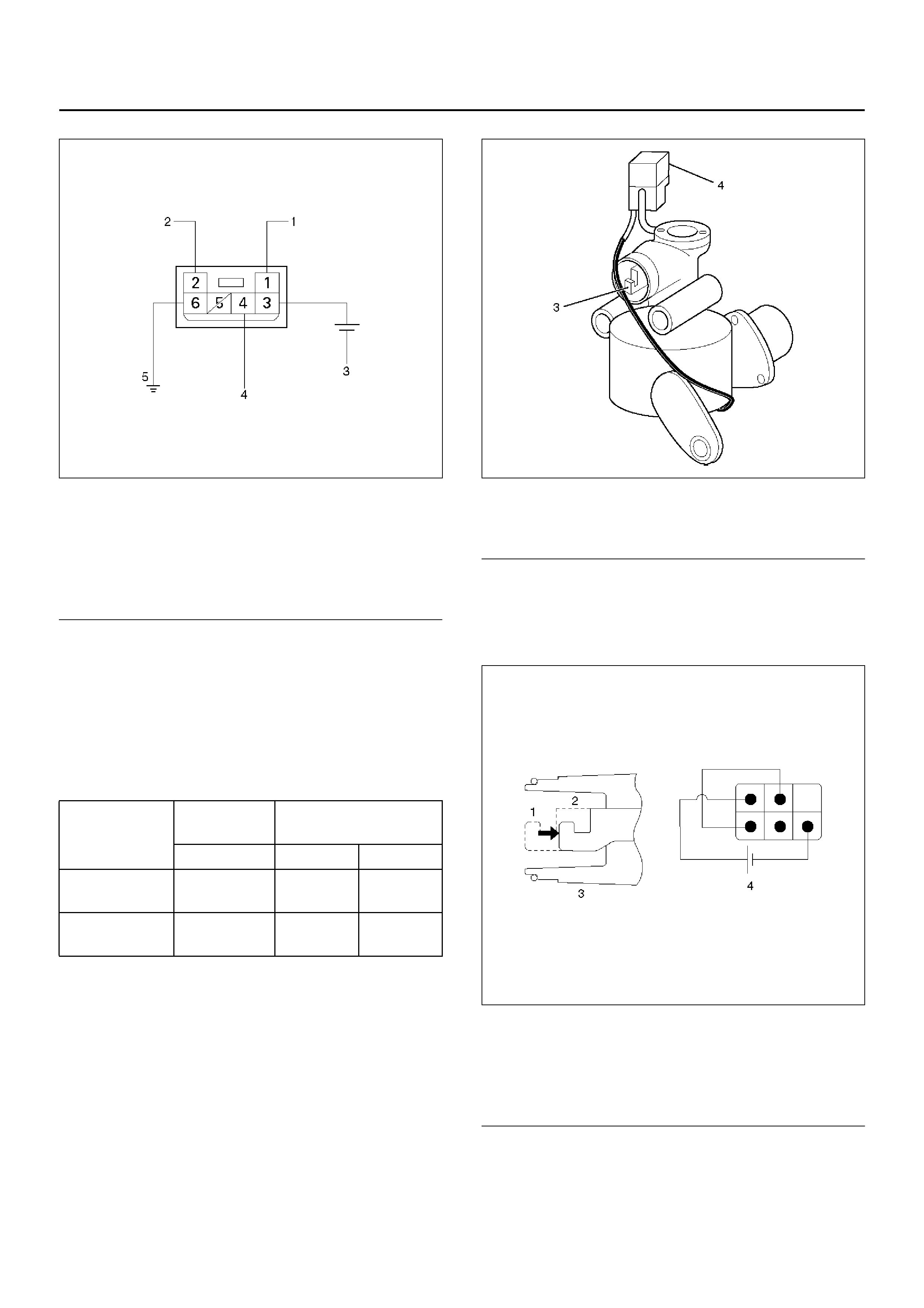
Axle Disconnect Controller
828RY00009
828RY00010
EndOFCallout
1. Connect 12V with terminal (3) and the ground with
the terminal (6).
2. Send the signal to the terminal (4)
2WD → 4WD less than 2.4V
4WD → 2WD more than 9.0V
3. Confirm the output signal from the terminals (1) &
(2) (2 seconds output)
4. If the trouble occurs afther above test, charge the
Axle Disconnect Controller to the new one.
Motor Actuator Assembly (Tra nsfer)
Inspect the function of the motor actuator assembly as
follows:
1. Disassemble the motor actuator from transfer rear
case.
412RW037
EndOFCallout
2. Connect the terminals as shown in figure.
Shift rod of the motor actuator moves and stops
at 4WD position.
412RW038
EndOFCallout
Legend
(1) Output Signal
(2) Output Signal
(3) 12V
(4) Input Signa l
(5) GND
INPUT
SIGNAL OUTPUT SIGNAL (2
seconds)
412
2WD → 4WD Les s than
2.4V 0V 12V
4WD → 2WD More than
9.0V 12V 0V
Legend
(3) Shift Rod
(4) Connector
Legend
(1) 2WD
(2) 4WD
(3) Shift Rod
(4) Connector
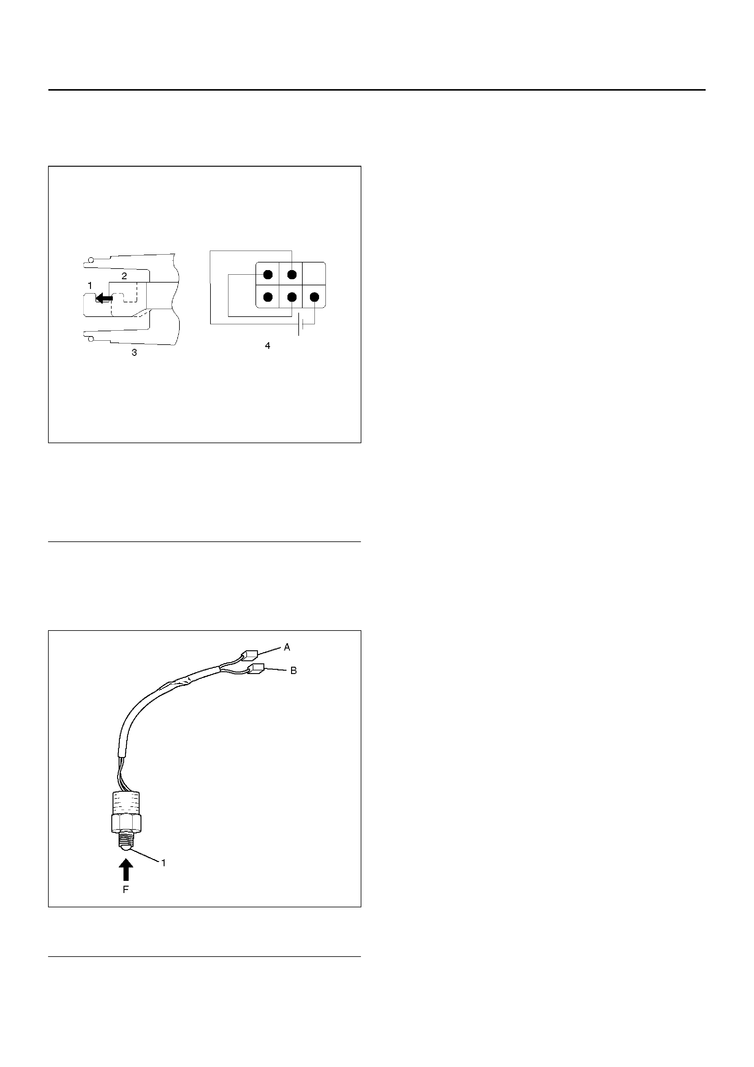
3. Connect the terminals as shown in figure.
Shift rod of the motor actuator moves and stops
at 2WD position.
412RW039
EndOFCallout
4. If 2) and 3) fail, replace with a new motor actuator.
Tran sfer Position Switch
412RW040
EndOFCallout
1. With ball being free.
A–B : There is continuity.
2. With ball forced into the switch.
A–B : No continuity.
3. If 1) and 2) fail, replace with a new switch.
Legend
(1) 2WD
(2) 4WD
(3) Shift Rod
(4) Connector
Legend
(1) Ball
4WD CONTROL UNIT
4WD CONTROL UNIT ASSOCIATED PARTS
412RW042
EndOFCallout
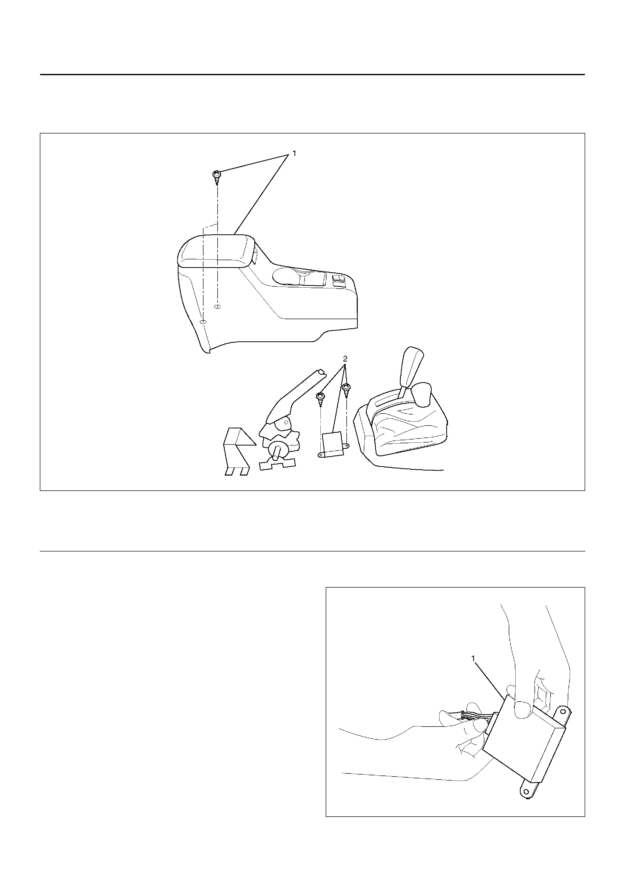
REMOVAL
1. Remove center console assembly.
Refer to Interior Trim in Body and Accessories
section.
2. Remove two screws and harness connector (1)
from 4WD control unit.
412RW041
Legend
(1) Center Console Assembly (2) 4WD Control Unit
Legend
(1) Harness Connector

INSTALLATION
1. Connect harness connector, then install 4WD
contr ol uni t.
2. Install center console assembly.
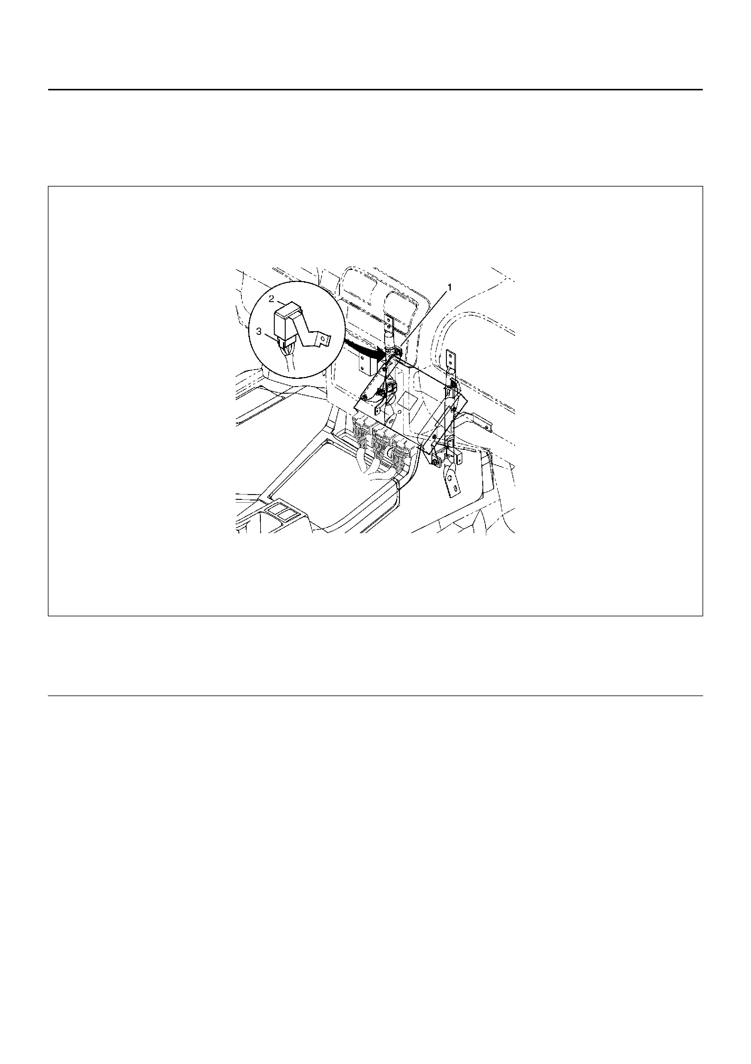
SHIFT ON THE FLY CONTROLLER
SHIFT ON THE FLY CONTROLLER AND ASSOCIATED PARTS
828RY00003
EndOFCallout
REMOVAL
1. Disconnect the battery ground cable.
2. Remove the front console assembly.
Refer to Console in Body and Accessories section.
3. Disconnect the connector from the controller.
4. Remove the nut.
5. Remove the controller.
INSTALLATION
To install, follow the rem oval st eps in t he revers e orde r,
noting the following points.
Torque: Nut (1) 8 N·m (0.8 kg·m/69 Ib in)
Legend
(1)
(2) Nut
SOF Cont roll er (3) Connector