
SECTION 4B2 - DRIVELINE CONTROL SYSTEM (TOD)
Service Precaution
General Description
Abbreviations
System Components
Parts Location
TOD Switch and Indicator Lamp Function
Diagnosis
Basic Diagnostic Flow Chart
Parts Location
Circuit Diagram
Connector List
Checking Failed Pin
Checking Failed TOD Control Unit Pin
Diagnostic Trouble Codes
Diagnosis from Trouble Codes
Trouble Diagnosis Depending on The Status
of TOD Indicator
Diagnosis from Symptom
SERVICE PRECAUTION
WARNING: THIS VEHICLE HAS A SUPPLEMENTAL
RESTRAINT SYSTEM (SRS), REFER TO THE SRS
COMPONENT AND WIRING LOCATION VIEW IN
ORDER TO DETERMINE WHETHER YOU ARE
PERFORMING SERVICE ON OR NEAR THE SRS
COMPONENTS OR THE SRS WIRING. WHEN YOU
ARE PERFORMING SERVICE ON OR NEAR THE
SRS COMPONENTS OR THE SRS WIRING, REFER
TO THE SRS SERVICE INFORMATION. FAILURE TO
FOLLOW WARNINGS COULD RESULT IN
POSSIBLE AIR BAG DEPLOYMENT, PERSONAL
INJURY, OR OTHERWISE UNNEEDED SRS SYSTEM
REPAIRS.
CAUTION: Always use the correct fastener in the
proper location. When you replace a fastener, use
ONLY the exact part number for that application.
HOLDE N will call out those f asten ers th at requir e a
replacement after removal. HOLDEN will also call
out the fasteners that require thread lockers or
thread sealant. UNLESS OTHERWISE SPECIFIED,
do not use supplemental coatings (Paints , greases,
or other corrosion inhibitors ) on threaded fast eners
or fastener joint interfaces. Generally, such
coatings adversely affect the fastener torque and
the joint clamping force, and may damage the
fastener. When you install fasteners, use the
correct tightening sequence and specifications.
Following these instructions can help you avoid
damage to parts and systems.
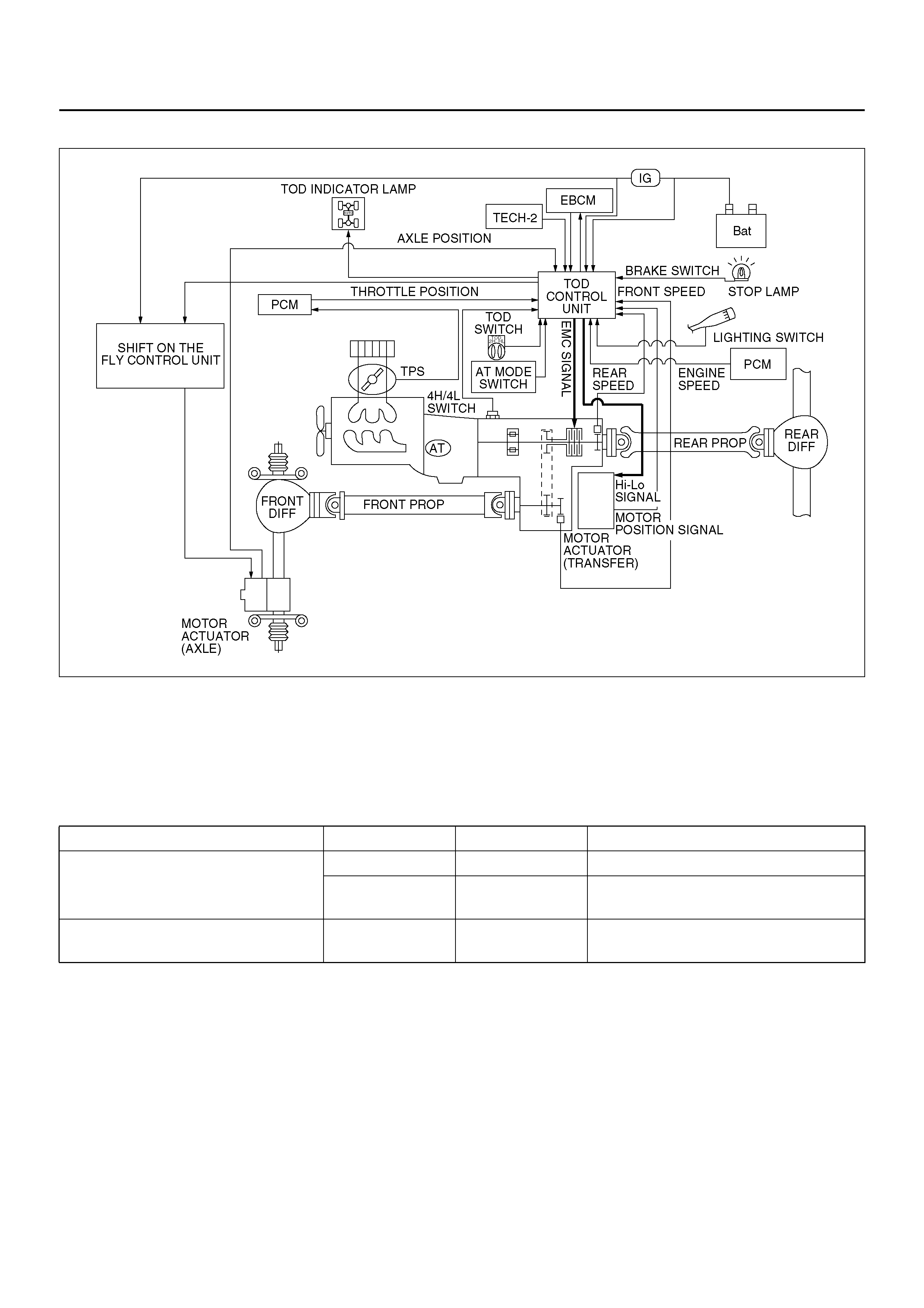
GENERAL DESCRIPTION
412R200008
TOD (Torque on Demand) system is traction state
control system to vehicle.
Transfer Po sition and Driv e Mode
Three drive modes can be selected through operation of
TOD switch.
The electronic control unit (ECU) judges the signals
from the TOD switch and controls the transfer drive
mode and shift-on-the-fly system status.
TOD Control
The TOD position usually drives the rear wheels, and
transmits the torque to the front wheels with the help of
electronically controlled torque split mechanism
according to running conditions encountered. The
driving force is directly transmitted to the rear wheels.
This force is split by the transfer and delivered to the
front wheels. The magnitude of the torque transmitted to
the front wheels is controlled by changing the pressing
force of the multi plate disk clutch built in the transfer
unit. The pressing force of the clutch is controlled by
changing the duty ratio to the electromagnetic coil
mounted to the rear of the clutch. When the clutch is
completely disengaged, the rear wheels are driven.
When the clutch is completely engaged, a rigid four
whee l drive mode is obtained. The tor que split status is
controlled continuously between the rear wheel and four
whee l driv e mode s. T his system inc ludes fr ont an d re ar
speed sensors, and receives throttle position sensor
and engine speed information from the PCM, ABS
control unit signal, brake switch signal, and shift motor
position information .
The control unit receives signals sent from these
sensors and changes the pressing force of the
Transfer Position TOD SWITCH Mode Drive mode
HIGH 2H RWD Rear wheel drive
TOD 4WD (HIGH) Electronically controlled torque split
four wheel drive
LOW 4L 4WD (LOW) Low-speed mechanical lock-up four
wheel drive

multi-plate disk clutch to determine the torque
distribution on the front and rear wheels. Therefore,
when the slip of the rear wheels is increased against the
current torque level in the normal rear wheel drive
mode, the control unit detects the slip condition,
determines the optimum torque based on the feedback
control logic, and increases the torque to the front
wheels.
The control unit uses the signal from the throttle position
sensor to predict the future vehicle condition and the
intention of the driver with respect to acceleration and
deceleration, and determines the initial torque
distribution using these data and the information from
the speed sensors.
In case of small circle turning in the parking lot, for
example, the control unit minimizes the clutch pressing
force to restrict a braking phenomenon. When the ABS
becomes active, the control unit optimizes the clutch
pressing force to ensure stable braking.
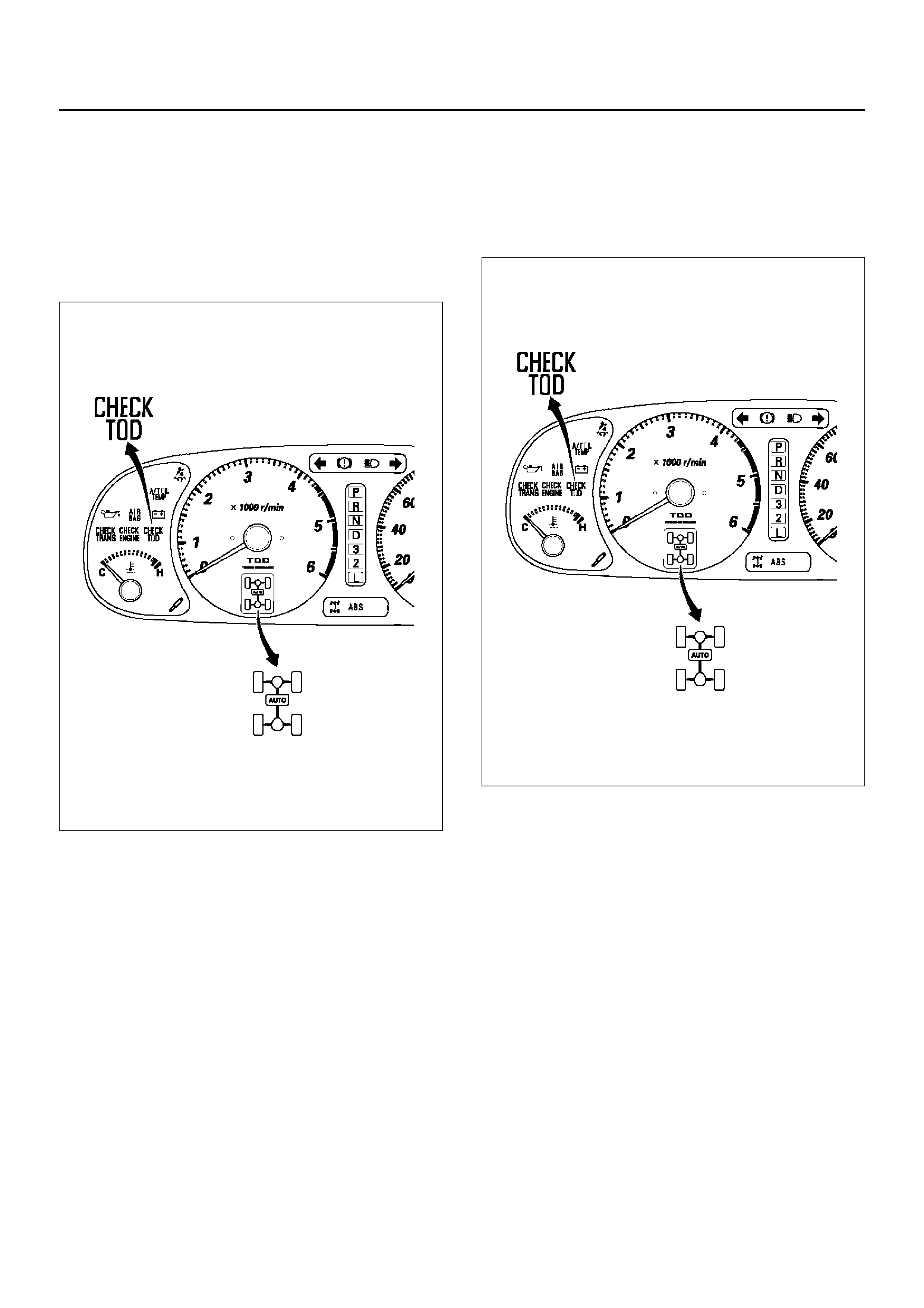
TOD Indicator Control
The TOD indicator on the instrument panel informs the
driver of the current working status of the transfer unit.
The information is the drive mode (2H, TOD, 4L,
transition). The indicator can display occasional errors
and corresponding error codes.
ABBREVIATIONS
ABS Anti-lock Brake System
ADC Axle Disconnect
(Shift On the Fly system)
VB Battery Voltage
VIGN Ignition Voltage
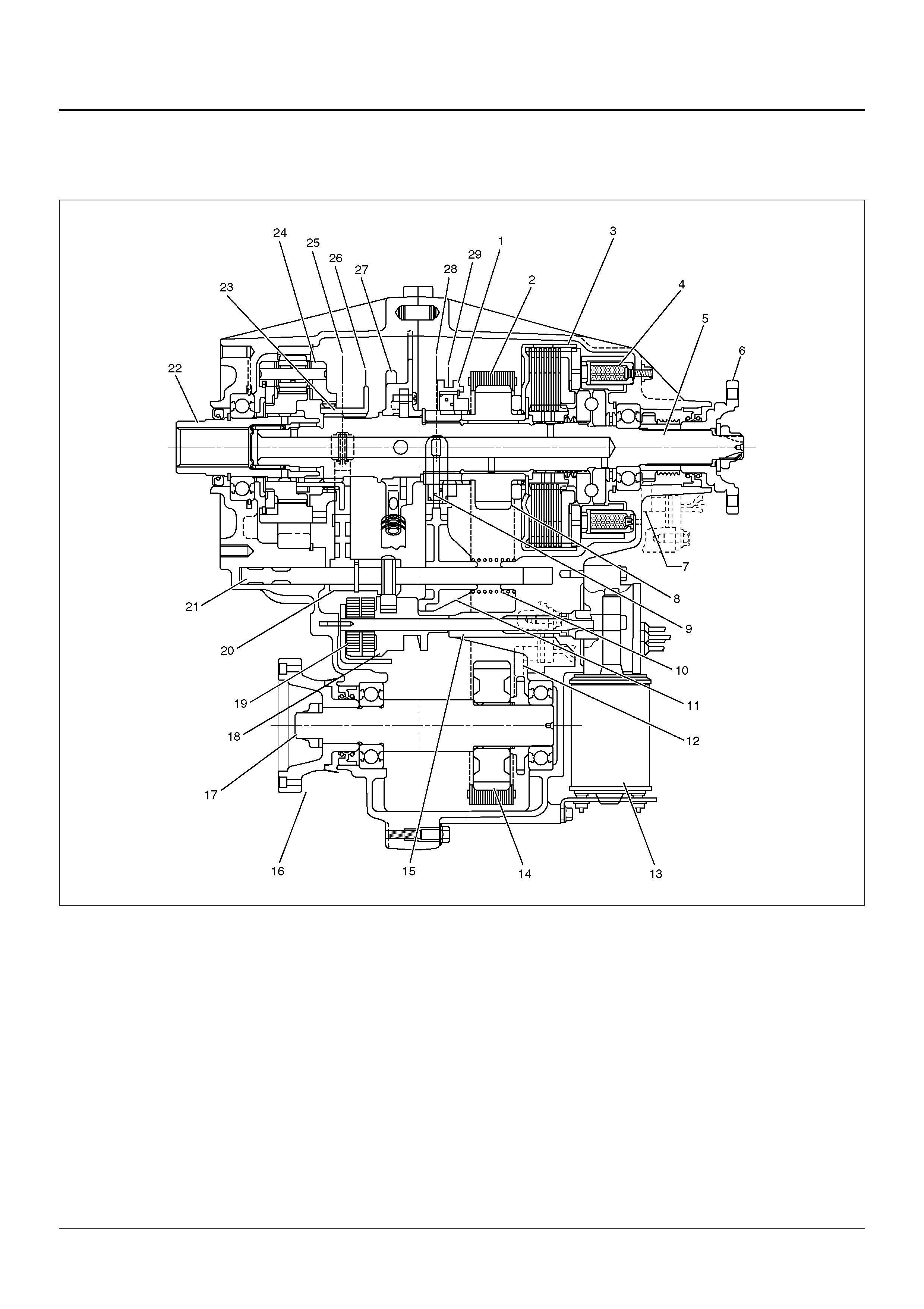
SYSTEM COMPONENTS
PARTS LOCATION
A04R200004
EndOFCallout
Legend
(1) Mechani c al Loc k Sl eeve
(2) Drive Chain
(3) Clutch Pa ck
(4) Electromagnetic Clutch Solenoid
(5) Out put Shaft
(6) Rear Output Coupling
(7) Rear Speed Sensor
(8) Drive Sprocket
(9) Spring
(10) Return Spring
(11) Lockup Shift Fork
(12) Front Speed Sensor
(13) High-Low Shift Motor
(14) Driven Sprocket
(15) Shift Shaft
(16) Front Output Coupli ng
(17) Front Output Shaft
(18) Shift Cam
(19) Torsional Spring
(20) High-Low Shift Fork
(21) Shift Rod
(22) Input Shaft
(23) Reduction Hub
(24) High-Low Planetary Gear
(25) High Position
(26) Low Position
(27) Oil Pump
(28) Free Position
(29) Lock Position
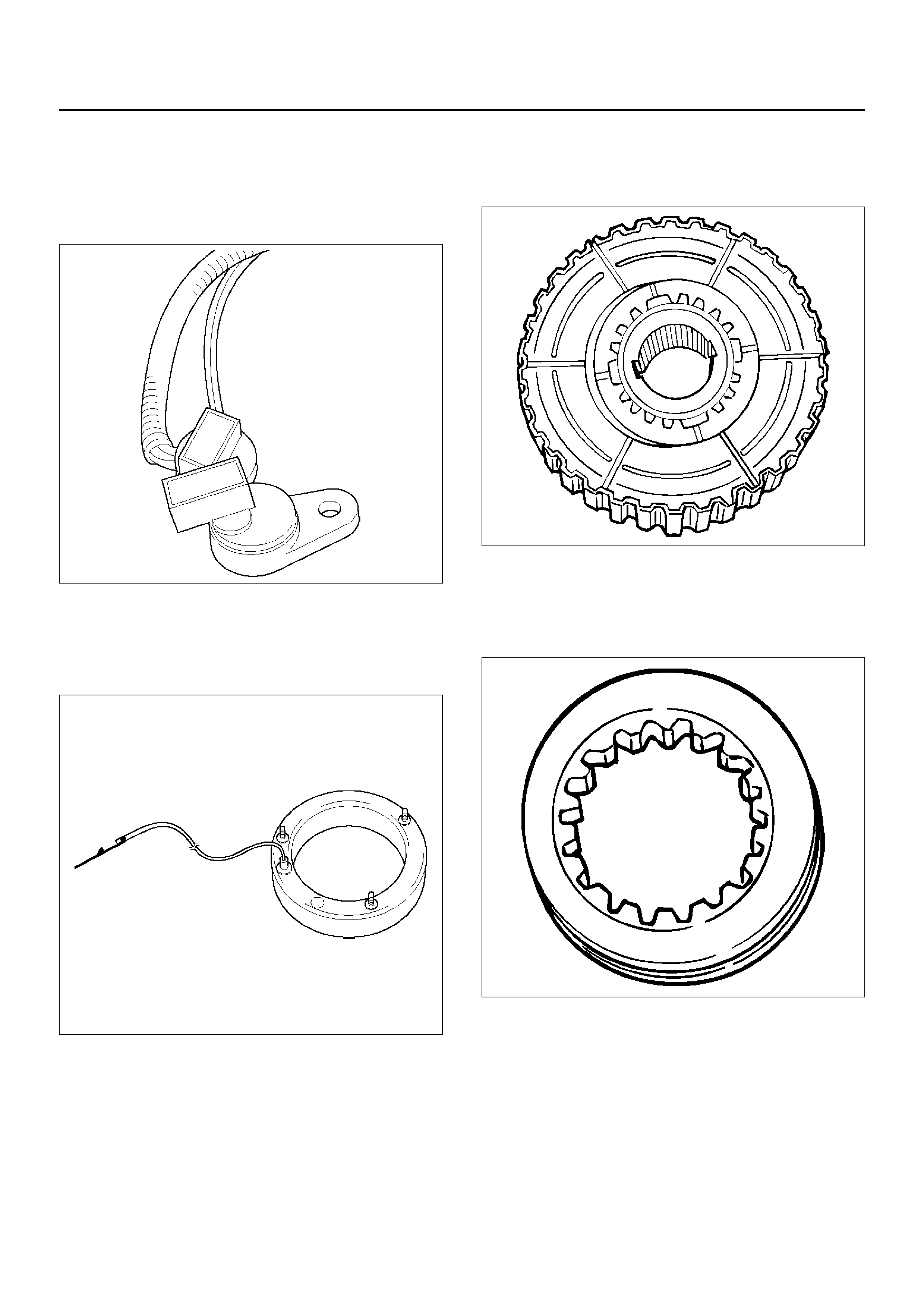
Front and Rear Speed Sensors
The sensors are built in the transfer case, and detect
the rotation of rotors directly coupled to the propeller
shafts. Thirty rectangular pulses are output per one
rotation of the propeller shaft.
261RW045
Electromagnetic Coil
Receives the duty signals from the TOD control unit and
controls the pressing force of the clutch pressure cam.
261RW044
Multi Plate Disk Clutch Pack
Transm its the torque determined b y the clutch pr essing
forc e t o th e fr on t pr op e ll er sh af t via th e f r on t d r i ve ch ai n.
262RW029
Mechanical Lock Sleeve
Couples the front and rear propeller shaft mechanically
when the transfer shaft is in the 4L position.
262RW028
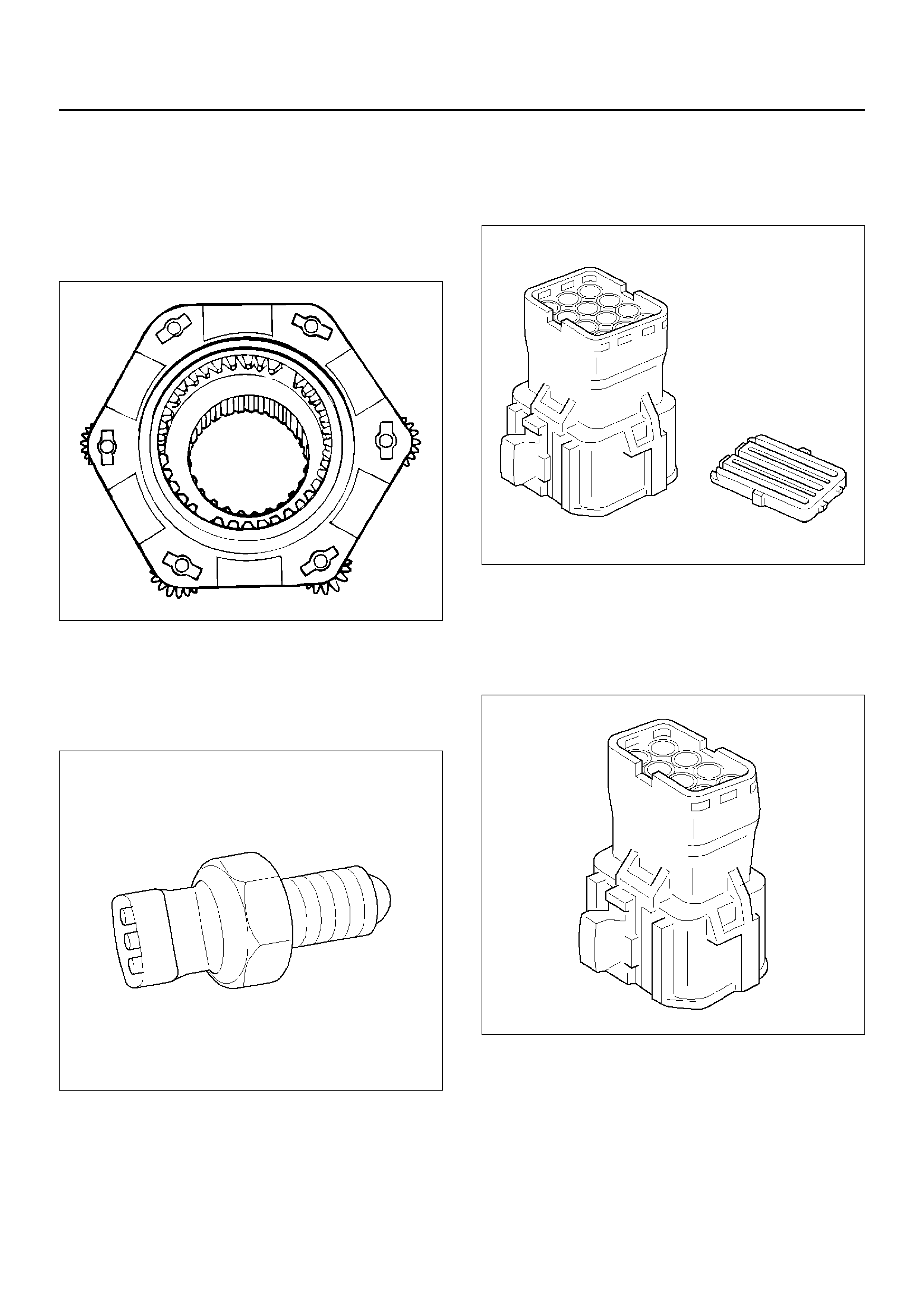
High-Low Planetary Gear Set
Establishes an auxiliary transmission mechanism.
When the TOD switc h is set to the 2H or TOD position ,
the reduc tion gear ratio i s 1.000 and the c orrespondin g
driving force is generated. Whe n the TOD switch is set
to the 4 L position, the reduction gea r ratio is 2 .480 and
the corresponding driving force is generated.
262RW030
4H and 4L Switch
Detects the shift position of the transfer from the
movement of the shift rod and outputs signals to the
TOD control unit.
261RW002
Transfer Connector (12-pin type)
Transmits the input and output signals of the speed
sensors, electromagnetic coil, and 4H and 4L switche to
the vehicle harness. A waterproof 12-pin type is used.
261RW046
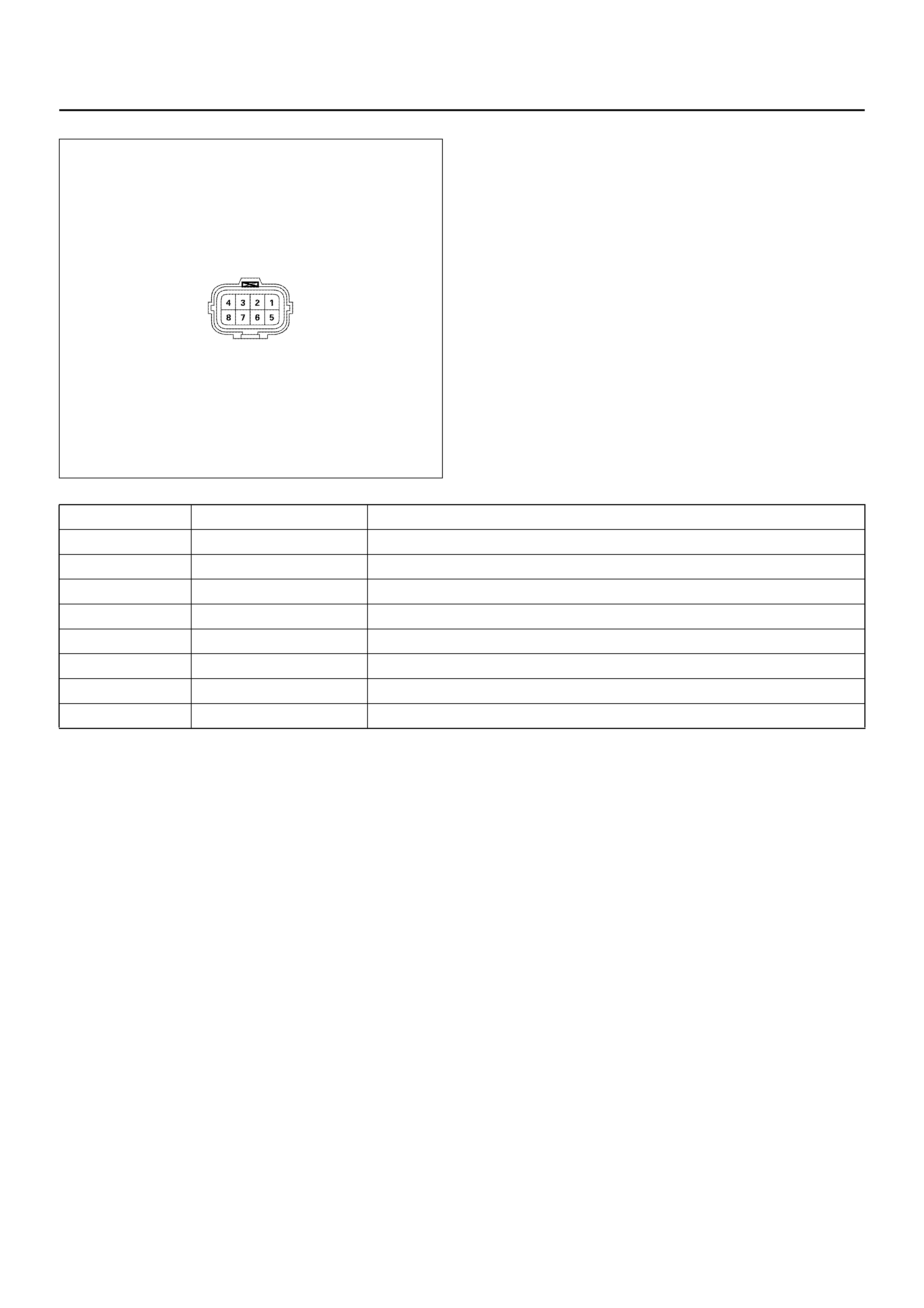
Transfer Connector (8-pin type)
Transmits the output signals of the shift motor position
to the vehicle harness and power for the shift motor to
the transfer. A waterproof 8-pin type is used.
261RY00039
TOD Indicator Lamps
(on the instrument panel)
Functions:
• Bulb check
•Drive mode
• ABS IN status
• BRAKE O N statu s
821RY00082
Check Lamp
Functions:
• Bulb check
•System Failure
• Trouble code read out
821RY00082
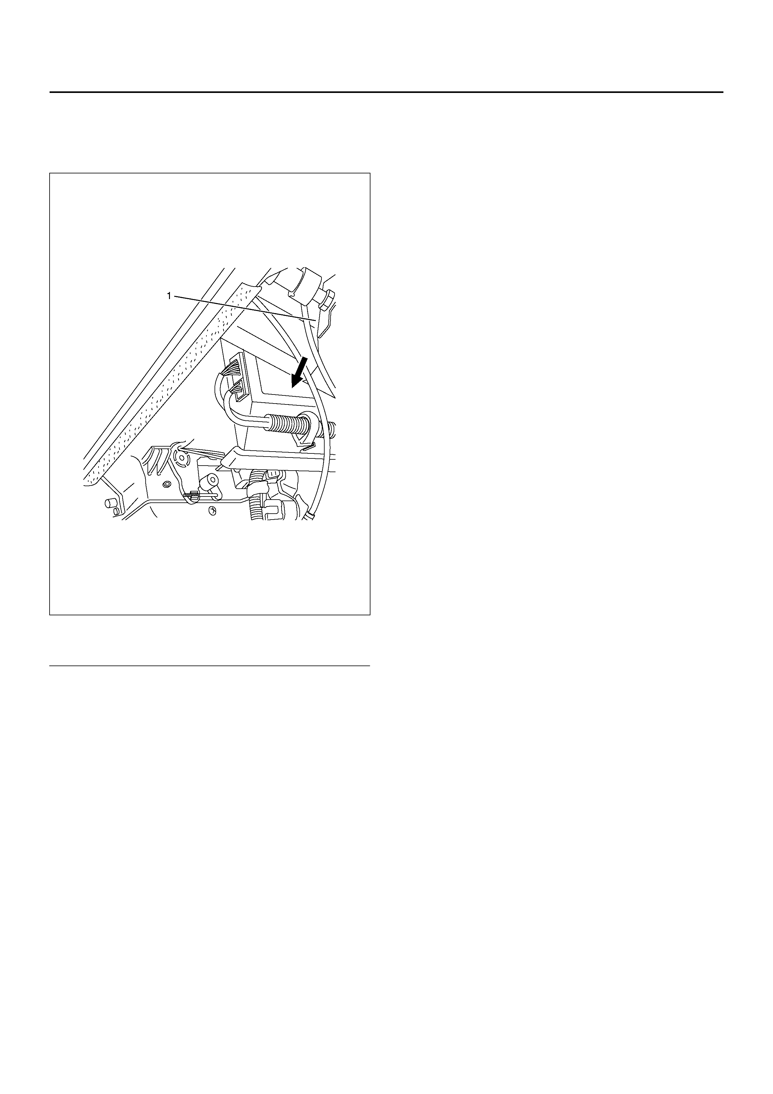
TO D ECU
This control unit is mounted to the left of the brake pedal
bracket.
826R100027
EndOFCallout
Legend
(1) Brake Pedal Bracket
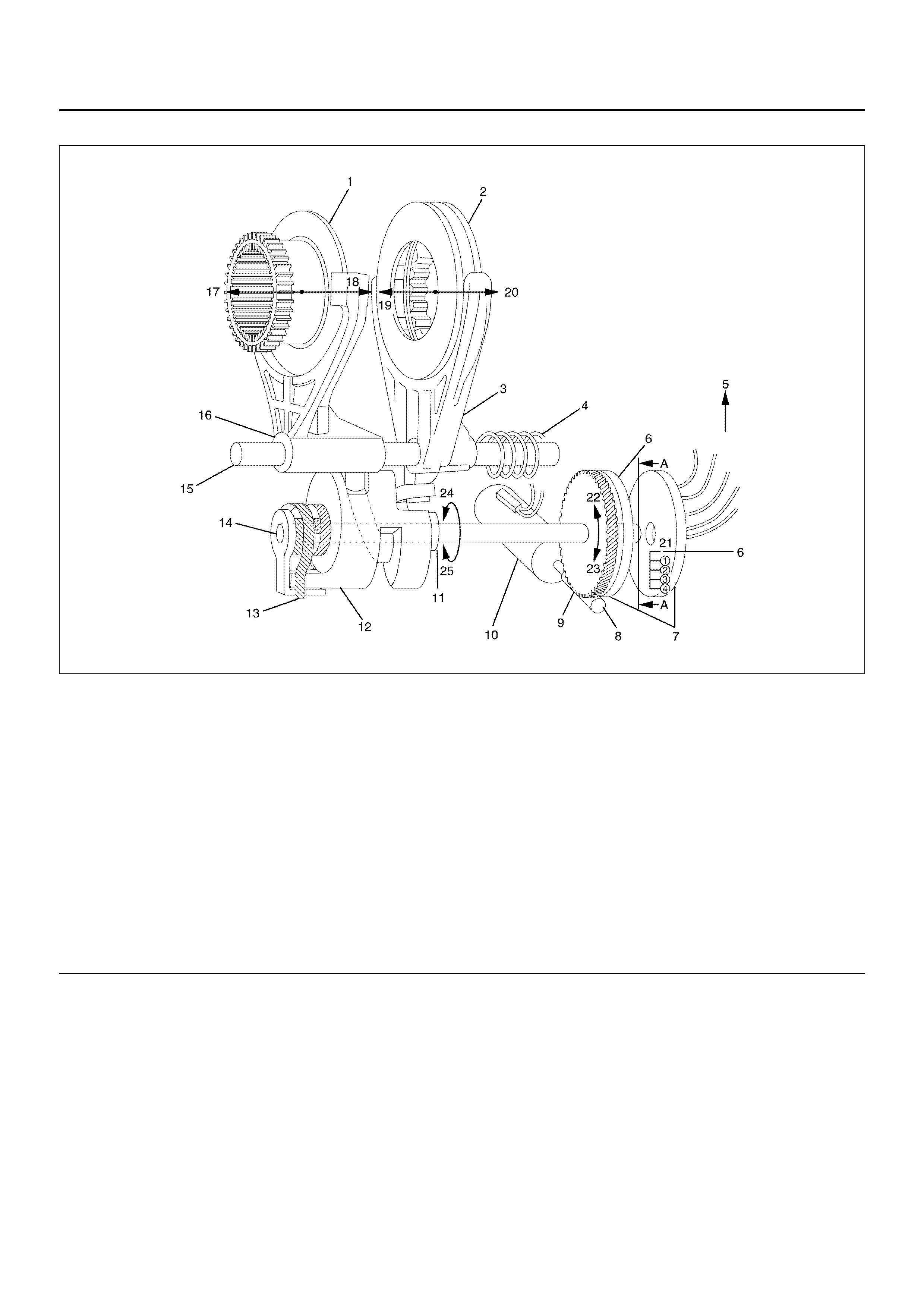
High-Low Shift Motor
F07R200002
EndOFCallout
When the TOD switch is changed to the 4L (or TOD)
position from the TOD (or 4L) po sition, the TOD control
unit drives the high-low shift motor according to the
signal. The transfer is shifted to low range from high
range (or to high range from low range) by the shift
motor.
The high-low shift motor can run, only when the
operation meets the following conditions to prevent an
unexpected shift between high and low range by a
operation error.
1. Ve hicle speed i s less than 2km/h and engi ne speed
is below 1500rpm
2. The AT selector position is neutral.
3. The brake is applied. (brake switch is on.)
The shift motor has a built-in encoder which monitors
shift s haft posi tion. T he con trol u nit co ntrols th e rotation
of the shift motor based on the detected shaft position
and the TOD switch signal to the TOD ECU.
The encoder position plate turns together with the shift
shaft and switches on or off the signals from the 4 (four)
fixed contact points on the case. The ECU calculates
the position of the shift motor from the combination of
switch signals.
Legend
(1) Reduction Hub
(2) Mechani c al Lock Sl eev e (In cludi ng the bui lt- in
Spring)
(3) Lockup Shift Fork
(4) Return Spring
(5) To TOD Control Unit
(6) Fixed Contact Point
(7) Encoder
(8) Worm gear
(9) Rotate
(10) Shift Motor
(11) The shift cam (12) can be turned freely around
the shift shaft (14).
(12) Shift Cam
(13) Torsional Spring
(14) Shift Shaft
(15) Shift Rod
(16) High-Low Shift Fork
(17) High
(18) Low
(19) 2H and TOD Position
(20) Direct Four Wheel Drive (4L Position)
(21) Earth
(22) High
(23) Low
(24) High
(25) Low
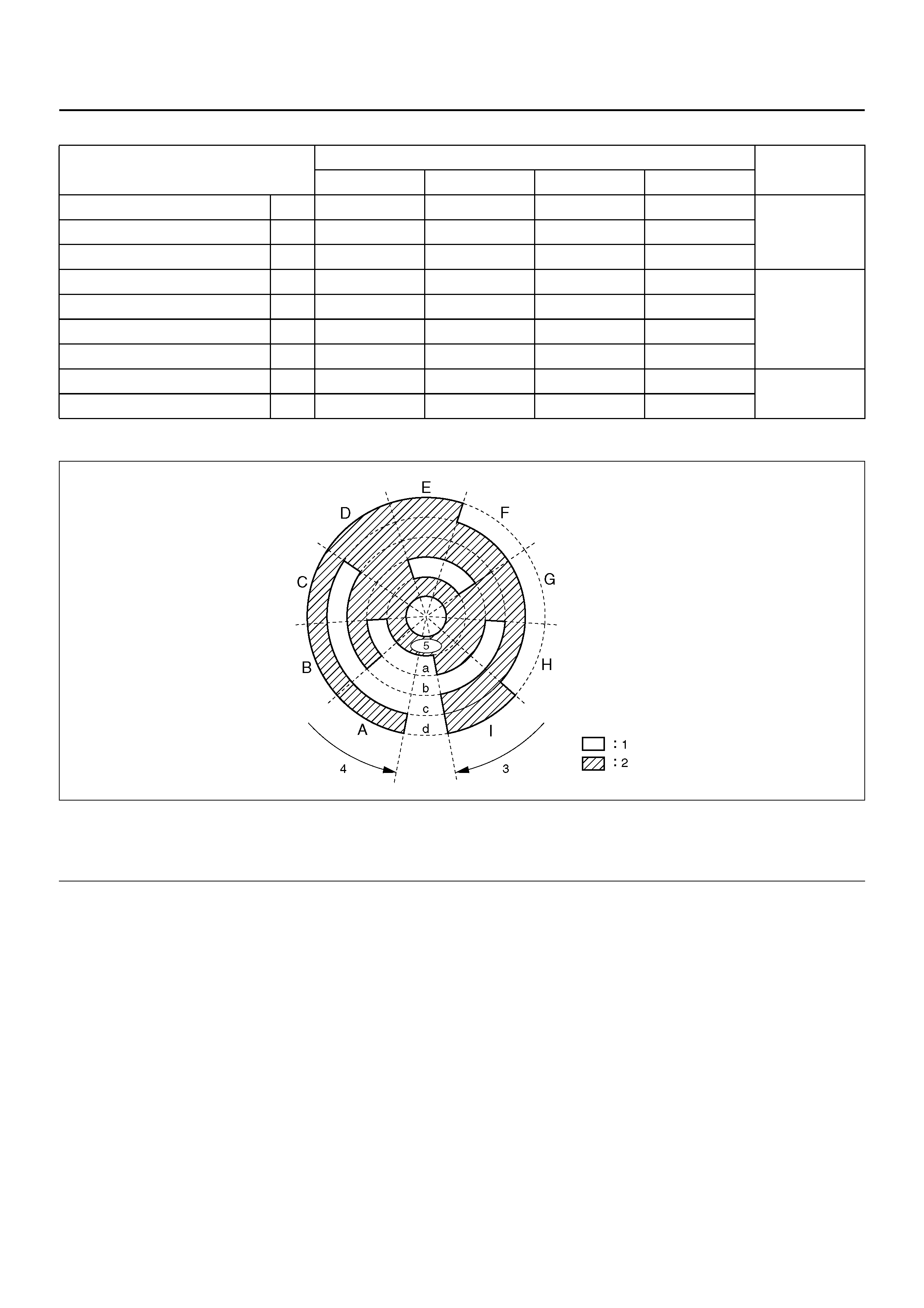
Motor Position and Encoder Position Code
Encode Position Plate
F04R100005
EndOFCallout
Shift High Range and Low Range
When the car is stops (less than 2km/h or 1.2 mph and
less than 1500 rpm), the AT selecto r position i s neutral,
the brake is applied, and t he TOD switch is c hanged to
4L from TOD (or to TOD from 4L), the high-low shift
motor starts by po wer ap pli ed from th e TOD co ntrol uni t
and turns the shift shaft through the worm gear.
The shift shaft turns the sh ift cam through the torsional
spring.
The end of the shift cam moves the lockup shift fork and
the spiral groove on the outside of the shift cam slides
the high-low shift fork.
High-Low Shift Motor Position High-Low shift Motor Encoder Signal State of
Motor
Position a Position b Position c Position d
High End A OFF OFF OFF ON High Position
Near High End B OFF ON OFF ON
High Position C ON ON OFF ON
Middle Zone (1) D ON ON ON ON
Middle Zone (2) E OFF ON ON ON
Neutral Position F OFF ON ON OFF
Middle Zone (3) G ON ON ON OFF
Low Position H ON OFF ON OFF Low Position
Low End I ON OFF ON ON
Legend
(1) OFF Aria
(2) ON Aria
(3) Low
(4) High
(5) Earth
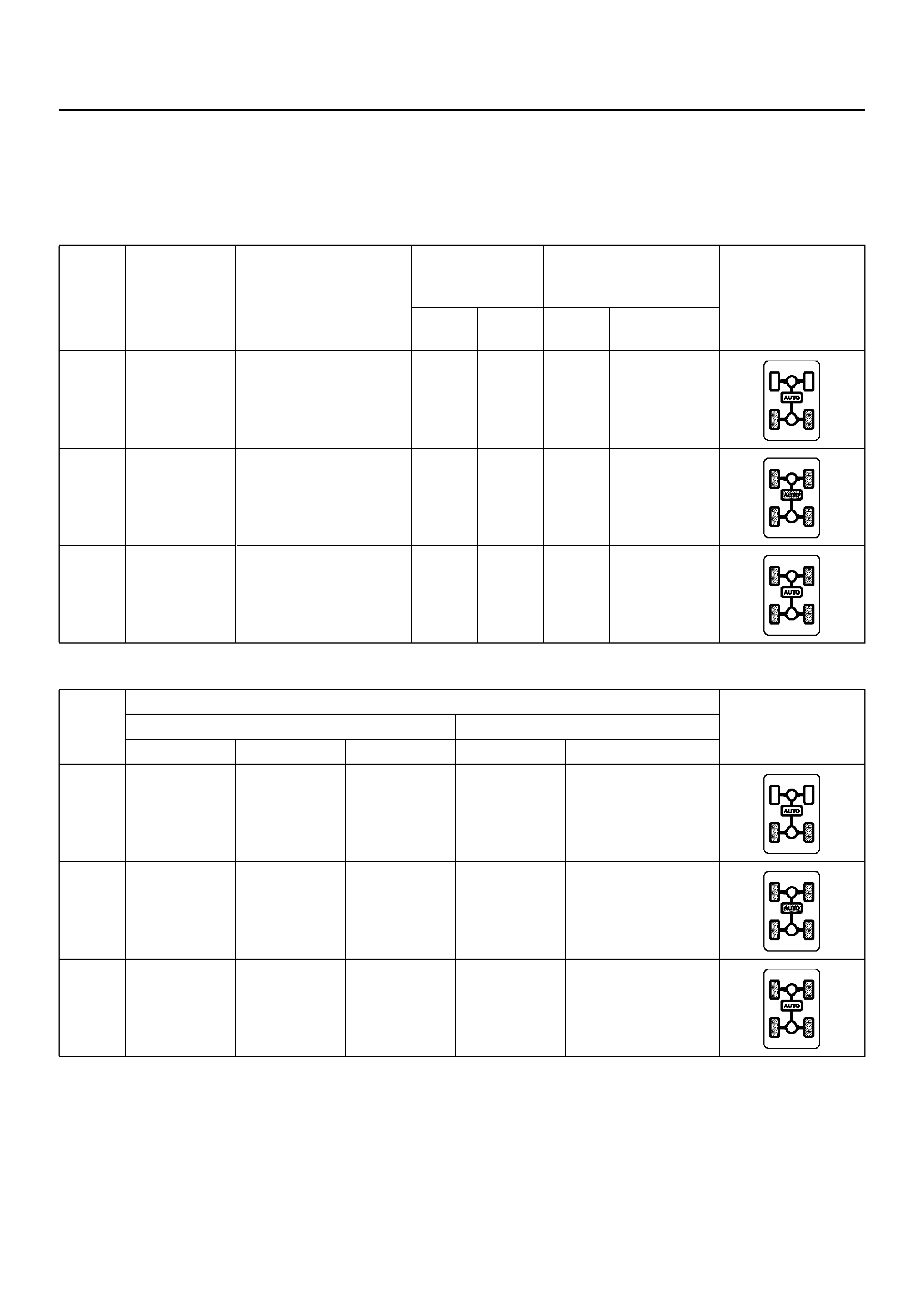
TOD SWITCH AND INDICATOR LAMP FUNCTION
TOD Switch and Indication of Drive Mode
The TOD switch sends signals to the TOD control unit
which s elects drive m odes and co ntrols the shift on th e
fly system (axle disconnect : ADC).
ADC: Shift on the fly
SW: Switch
TOD
switch
state
Drive mode Transfer shift
condition Transfer
position
detection
Shift on the fly TOD indicator
state
4HSW 4LSW Axle
SW ADC circuit
2H Rear-wheel
drive (RWD) Permissible at vehicle
speeds bel ow 100km/h OFF OFF OFF Power ON
TOD Electronic
torque sp li t
4WD (TOD)
OFF OFF ON Power OFF
AT: Neutral
Brakes: Applied
Vehicle Speed: <2km/h
Engine Speed: <1500rpm
4L Low range
mechanical
direct 4WD
(4L)
OFF ON ON Power OFF
TOD
Switch
state
TOD control unit terminal No. TOD indicator
state
TOD indicator TOD switch
7(Front) 8(Rear) 19(Auto) 30(2H) 43(4L)
2H OFF ON OFF ON OFF
TOD ON ON ON OFF OFF
4L ON ON OFF OFF ON
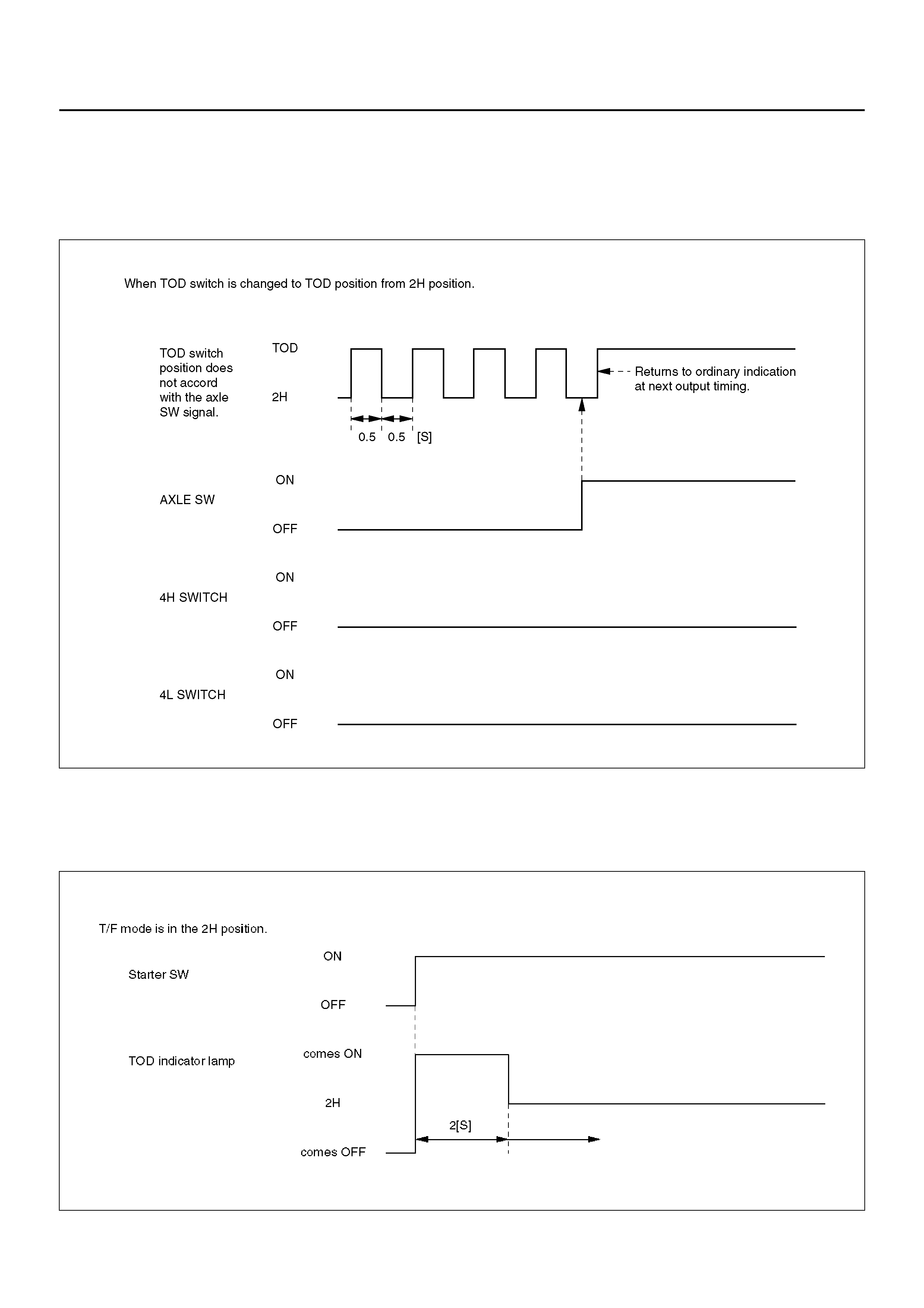
Indicator Lamp Operation During Movement of Shift
Rod
When the TOD switch is turned, and the signals from
the AXLE switch do not comply with the signal
conditions of the 4H and 4L switch, the indicator lamp
state select e d on the TOD switch and light-off mode ar e
repeatedly output at an interval of 1.0 second.
NOTE: After the TOD switch is turned to the specified
position and the AXLE switch generates compliant
signals, the normal output status is returned.
C07R100010
Bulb Check
When the starter swi tch is tur ned on, the TOD indi cator
lamps go on as shown below.
NOTE: Once the starter switch is turned on, all the TOD
indicator lamps are lit for two seconds regardless of the
TOD switch position.
C07RW016
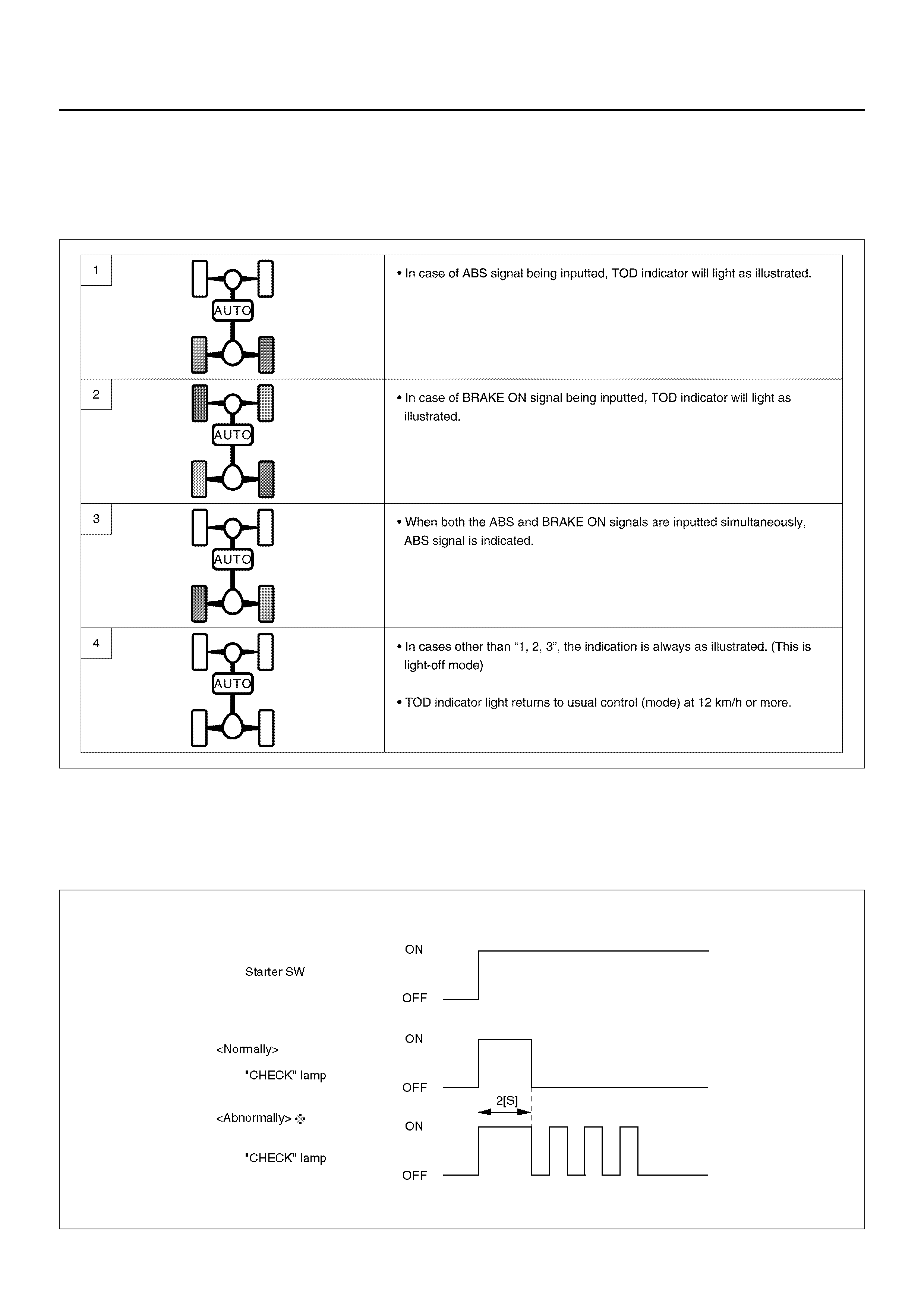
ABS INPUT and BRAKE ON signals quick test:
1. Bridge DLC terminals 5 & 8.
2. Tur n the ign ition ON.
3. Observe the TOD Indicator lamp for condition (1).
4. Apply the foot brake and check the TOD Indicator
lamp for condition (2)
C07R200002
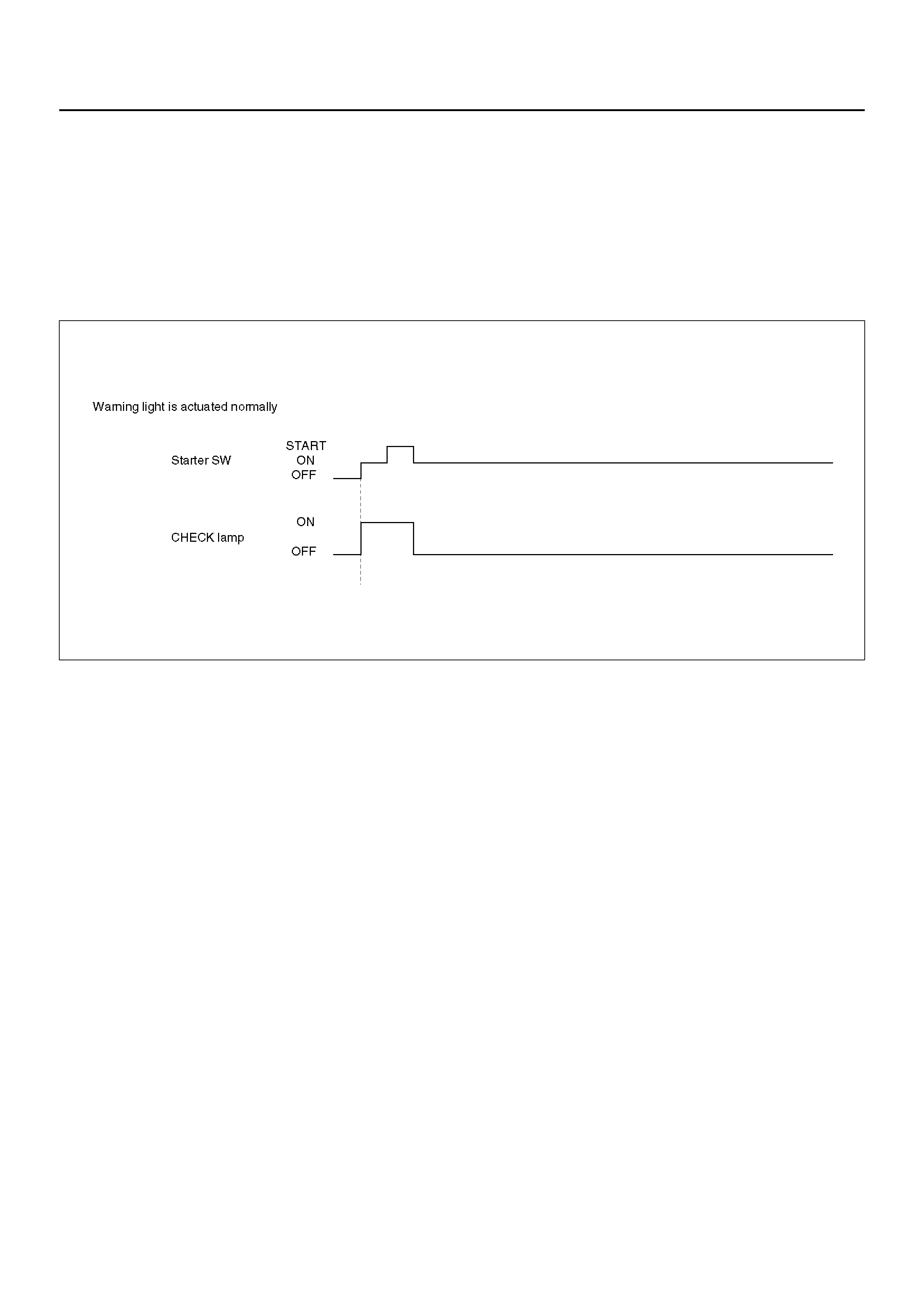
‘CHECK TOD’ Lamp
‘CHECK TOD’ Lamp Bulb Check
When the ignition switch is turned on, the ECU
illuminates the CHECK TOD lamp for 3 seconds.
C07RW019
DIAGNOSIS
General Information Diagnosis
The TOD system faults are classified into two groups:
- Those that can be identified by the status of the TOD
indicator lamps. These faults are diagnosed using the
procedures listed in “Diagnosis from Trouble Codes"
and “Trouble Diagnosis Depending on The Status of
TOD Indicator".
- Those that can be recognized as an abnormal
condition by the driver. These are diagnosed using the
prcedures listed in ‘Diagnosis from Symptom”
Self-diagnosis
The control unit has a function of self-diagnosis
function. If a fault occurs in the during of system startup,
the control unit flashes the CHECK TOD lamp and
stores the Diagnostic Trouble Code.
C07RW021
NOTE: If an intermittent fault occurs, the control unit
stops flashing upon correction of the fault. The DTC is
stored in the ECU.
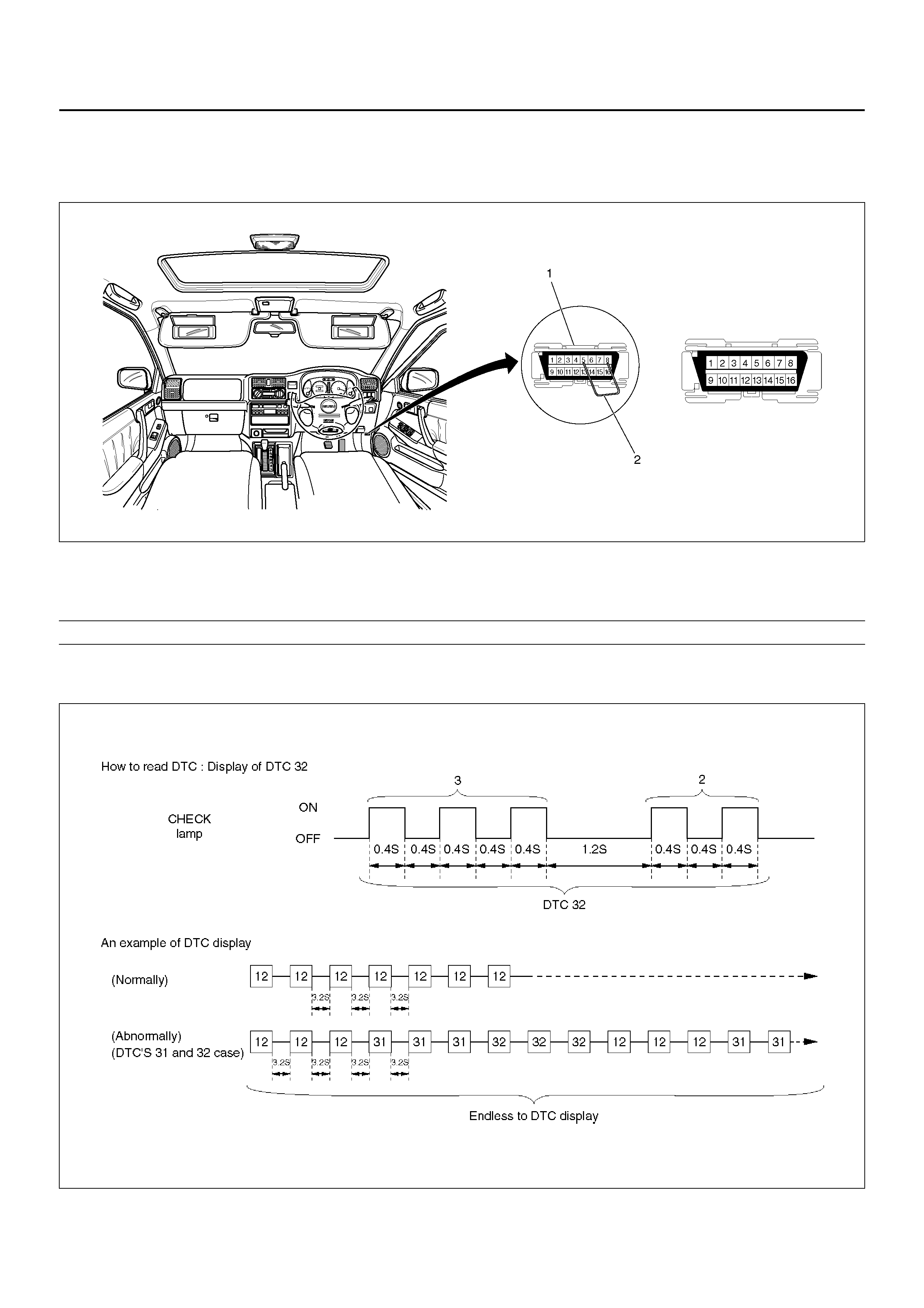
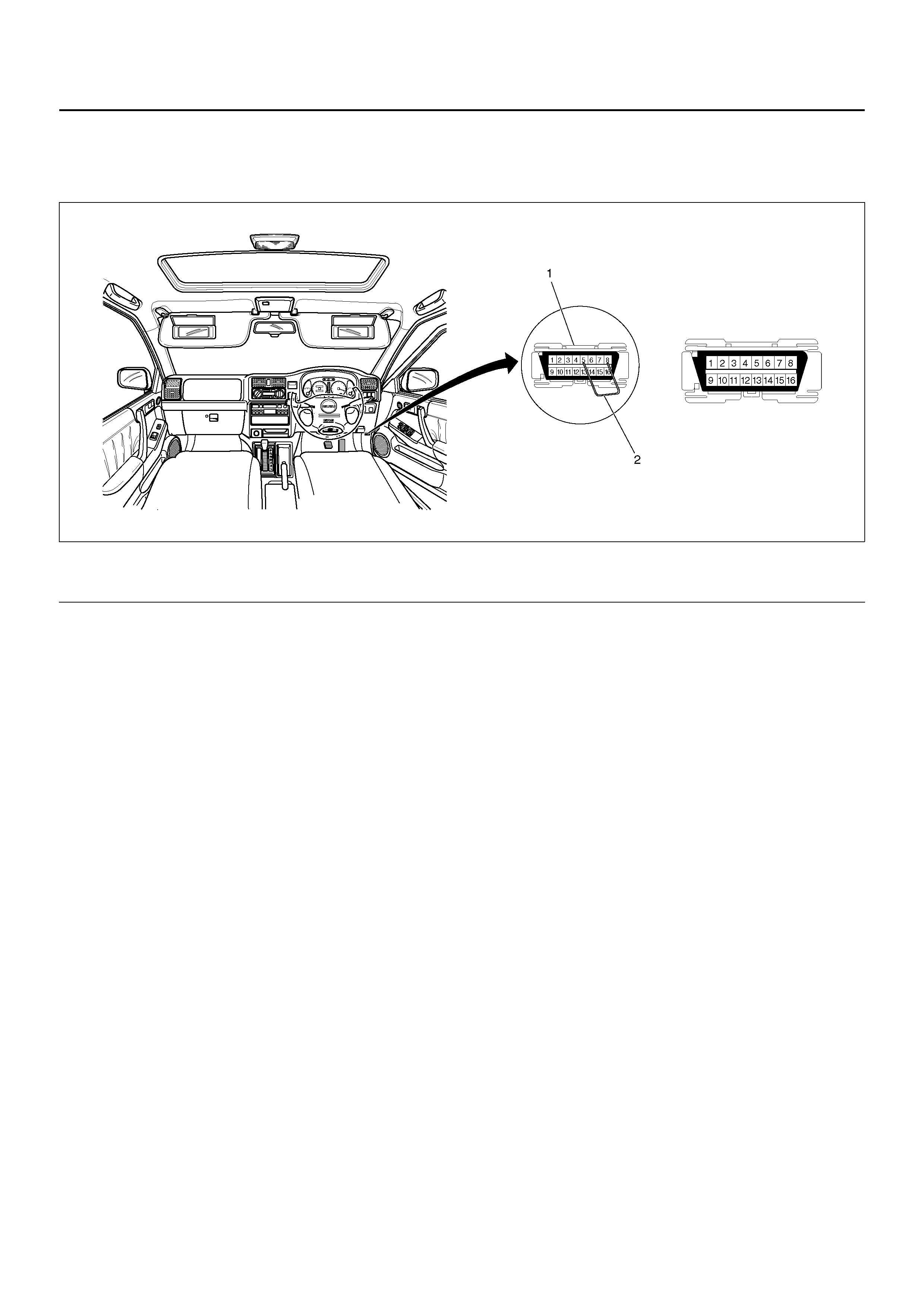
Diagnostic Trouble Code Display
1) Turn on the ignition ON
2) Bridge terminals 5 & 8 of the DLC.
3) The CHECK TOD lamp will display the DTC/s
350R100005
- A code “12" is displayed continuously if there a no stored DTC’s.Should any DTC’s be stored, a code ‘12’ is
displayedthree times followed by each DTC starting from the lowest number first.
C07RY00018
Legend
(1) Data Link Connector (DLC) (2) Bridging Wire
Clearing Diagnostic Trouble Codes
1) Bridge terminals 5 & 8 of the DLC.
2) Turn on the ignition ON and remove DLC bridge.
3) Verify the DTC’s have been cleared
350R100005
EndOFCallout
Diagnostic Precautions
Replacement of Control Unit
The control unit itself rarely fails. In most cases, the
harnesses have failed (i.e. short-circuit), resulting in a
secondary failure. In other cases the exact cause
unknown due to intermittent nature of the fault and the
fault is removed accidentally along with replacement of
control unit.
Therefore, before replacing the control unit, always
check the harness connectors and whether a short
circuit has resulted in excessive current flow damaging
the ECU.
Intermittent Faults
Intermittent faults are mostly attributal to the improper
wiring harness and connector failure.
When intermittent troubles are occur, check the
associated circuit according to the following procedure.
1. Check that the connectors are correctly mated and
that the connector terminals are completely
engaged.
2. Check for deformed or damaged the terminals.
Repair or replace the terminals and reconnect the
terminals securely.
3. Check for broken wires in the harness. Perform a
contin uity check while wriggling the harness, looing
for any indication of an open circuit. Take care not to
use excessive force which may damage the
harness.
Test Run of Failed TOD Vehicle
If the TOD indi cator lamps e xperience d faulty o peration
even once in the past, the failed portion can be
identified by use of the procedure “Diagnosis from
T rouble Codes" or “Trouble Diagnosis Depending on the
Status of TOD Indicator". If the troubles that are only
recognized as abnormal phenomena of the vehicle by
the driver are observed, conduct the test run in the
followi ng procedure to reproduce the faul ty phenomena
and diagno se the fault for each phenome non.
1. Start the engine, and check that the TOD indicator
lamps are tur ned on for about two se conds for initi al
check; the CHECK lamp goes off; and the TOD
indica tor lamps display the specifie d drive mode. (I f
the CHECK lamp starts blinking, read the trouble
codes and identify the failed portion.)
2. While keeping the vehicle standstill, operate the
TOD switch to change the modes: 2H mode→TOD
mode→4L mode→TOD mode→2H mode. Check
that the TOD indicator lamps correctly display the
status whenever the mode is changed. If the
transition status is displayed during the shift
operation, run the vehicle a little to complete
shifting.
3. Slowly start the vehicle in the TOD mode, and add
the power to accelerate to at least 40 km/h (25
mph)an d maintain the speed for about two minutes .
Apply the brake to completely stop the vehicle.
Repeat this test pattern at least three times.
4. Turn the stee ring to the r ight end (or left end) in the
TOD mode, a nd sl owly start th e v ehi cle a nd mak e a
Legend
(1) Data Link Connector (2) Jumper Wire

circle five times. Next, conduct the same test in the
2H mode.
5. Slowly start the vehicle in the TOD mode, and
accelerate to at least 40 km/h (25 mph). Keep the
established speed, carefully change the mode in the
sequence “TOD mode→2H mode →TOD mode"
while checking that the shift is complete in each
mode change. After the test, apply the brake to
completely stop the vehicle.
6. Slowly start the vehicle in the TOD mode, and
accelerate to at least 40 km/h (25 mph). Apply the
brake strongly so that the ABS works, and
completely stop the vehicle.
7. Slowly start the vehicle in the 4L mode, and
accelerate to at least 20 km/h (13 mph). Apply the
brake to completely stop the vehicle.
If the CHECK lamp starts blinking during the test run,
read the trouble codes and give appropriate
maintenance according to the diagnostic procedure. If
the TOD indicator lamps are lit abnormally during the
run, check the lighting condition and give appropriate
maintenance according to the diagnostic procedure.
Even if the phenomena are not observed, try to
reprodu ce the abno rmal state reporte d by the custom er
to the possible extent.
Post-Repair Check
As long as the starter is not turned off, the TOD indicator
lamps continue blinking even after the failed portion is
repaired. Therefore, upon completion of repair, be sure
to turn off the starter switch once and then turn on it to
conduct the test run sequence specified in steps 1
through 7 above and check that the TOD indicator
lamps no longer show any faulty status.
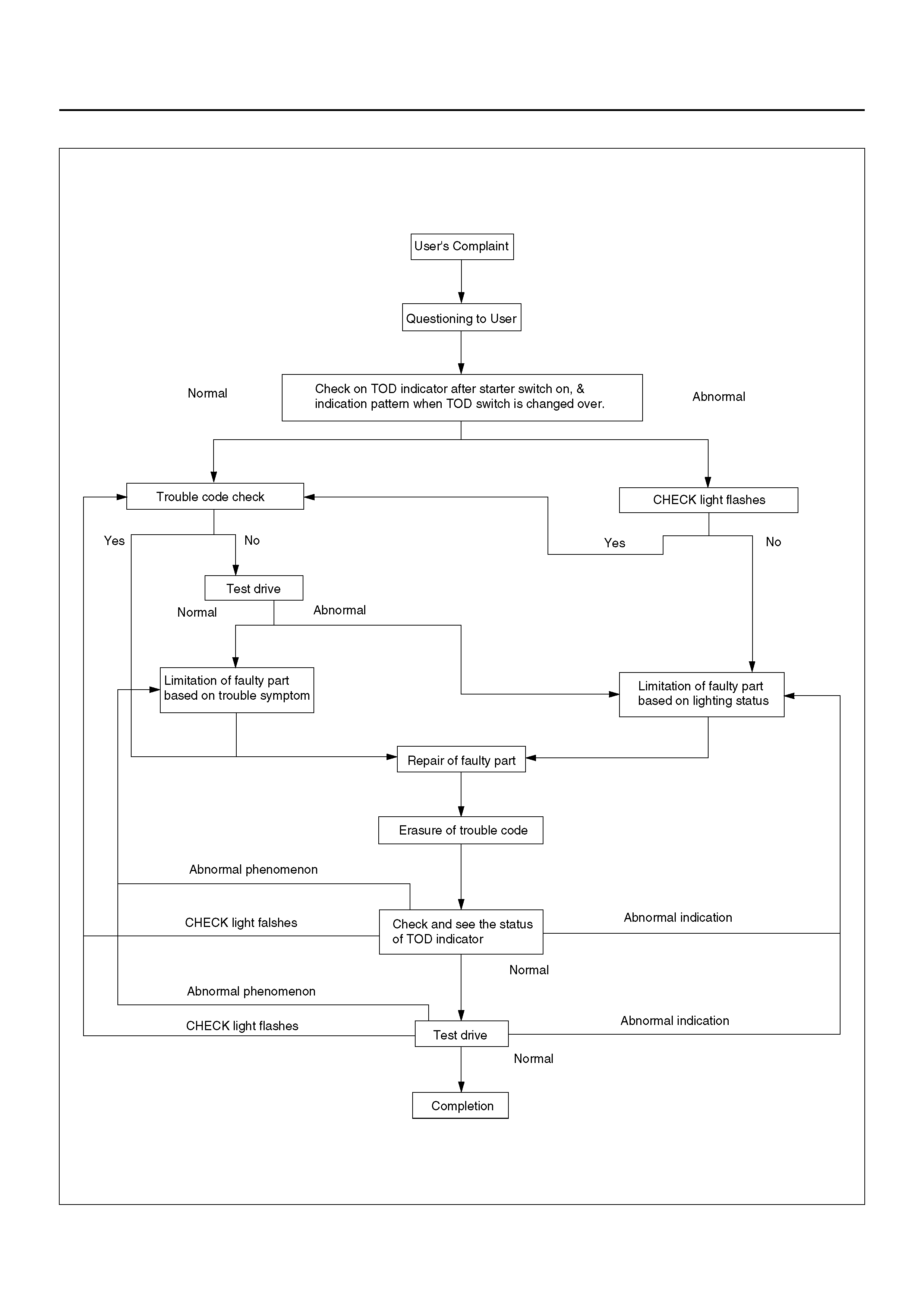
BASIC DIAGNOSTIC FLOW CHART
C07R100011
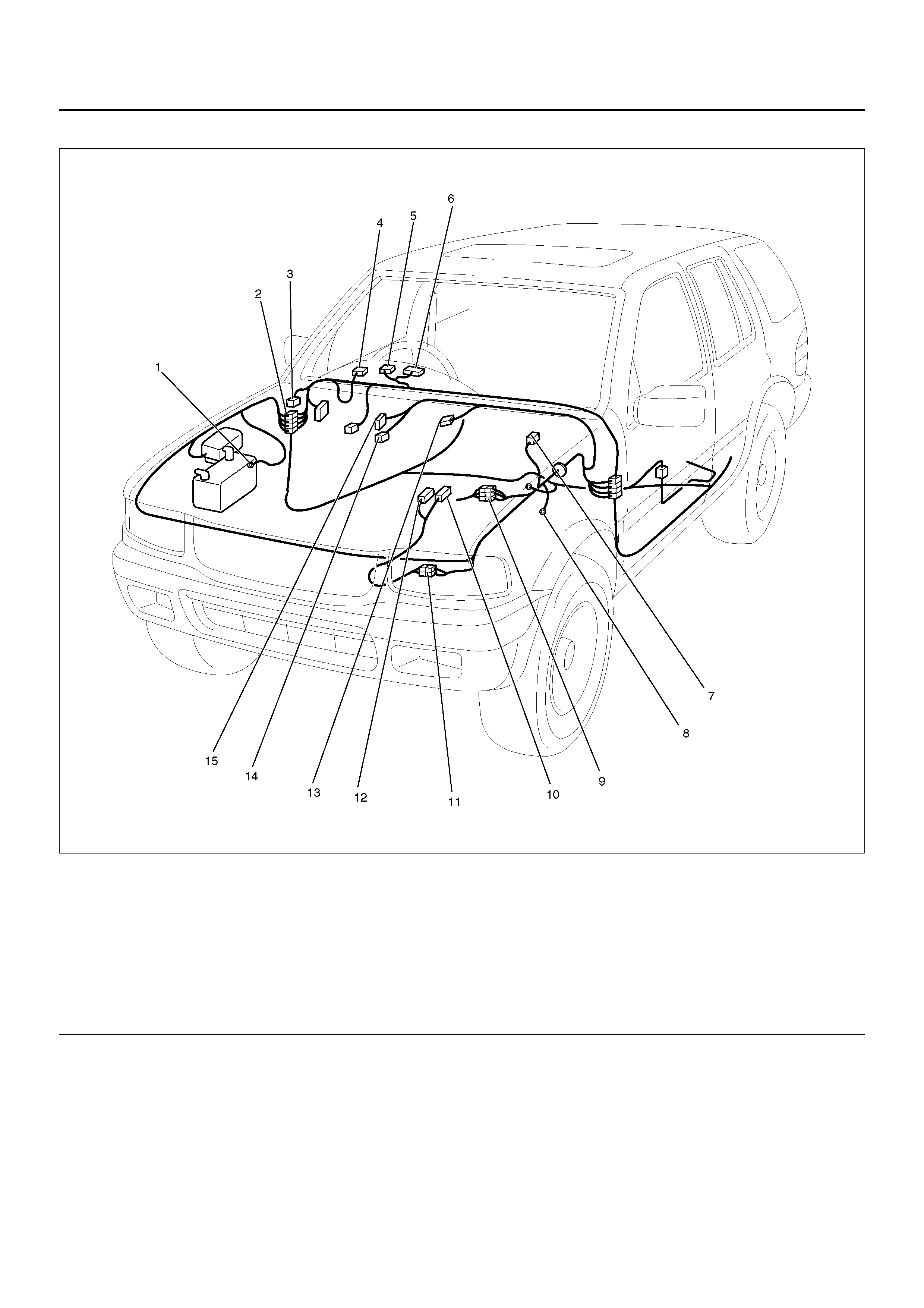
PARTS LOCATION
D04R100023
EndOFCallout
Legend
(1) C–36
(2) H–13, H–14
(3) C–34
(4) I–53
(5) I–9
(6) I–10
(7) H–16, H–17
(8) C–16
(9) H–5, H–39
(10) A–1
(11) H–38
(12) A–2
(13) C–62
(14) C–59
(15) C–60
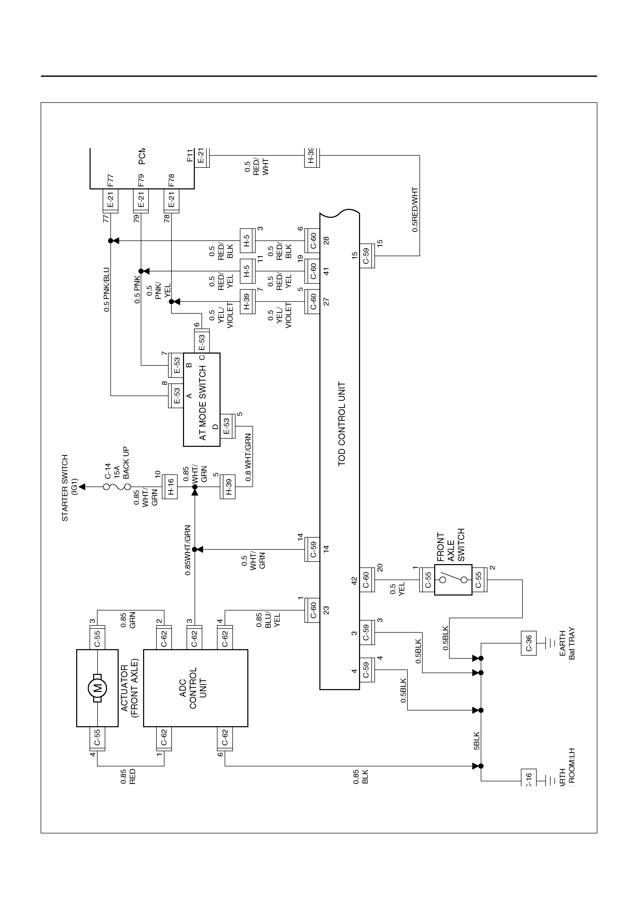
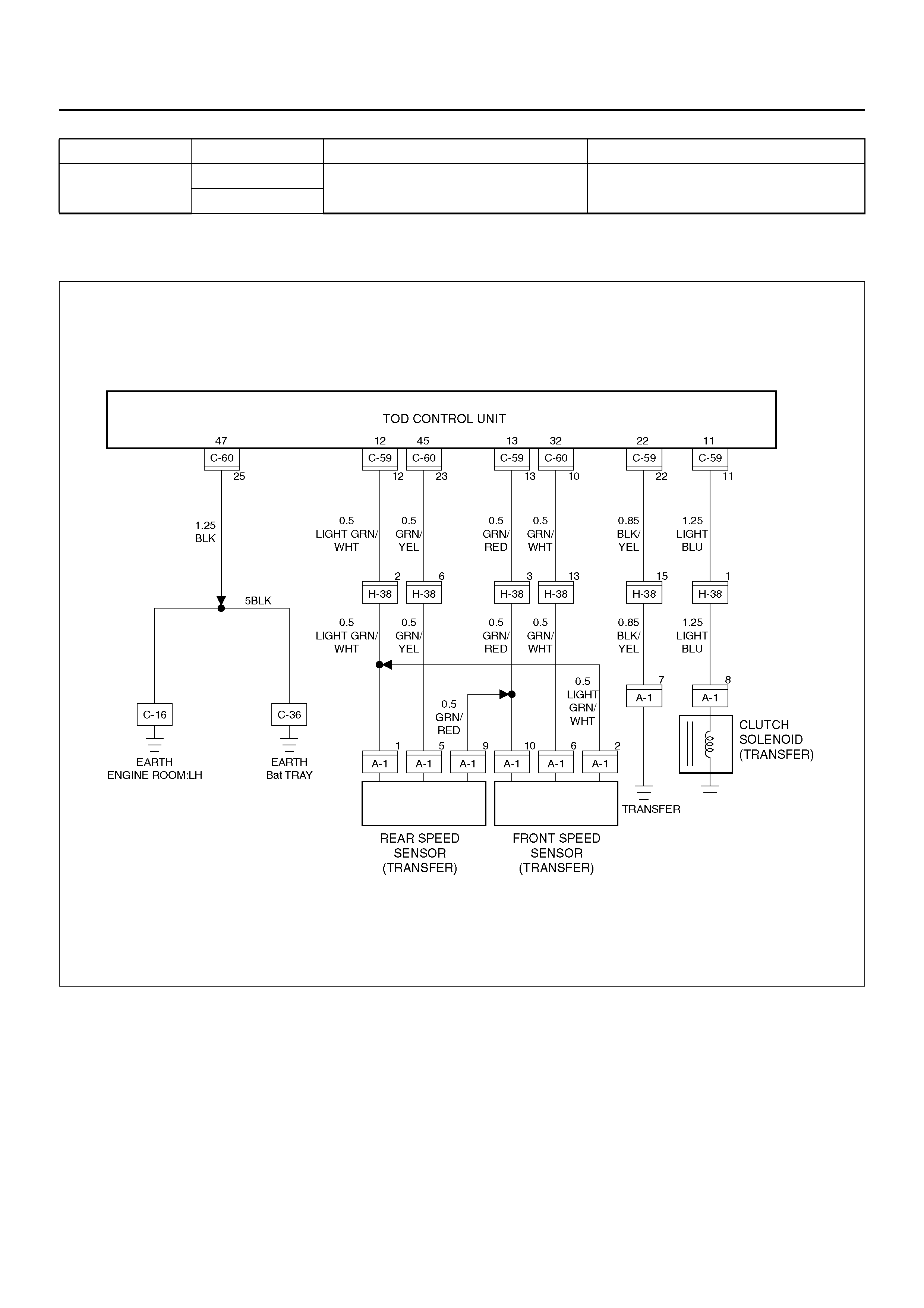
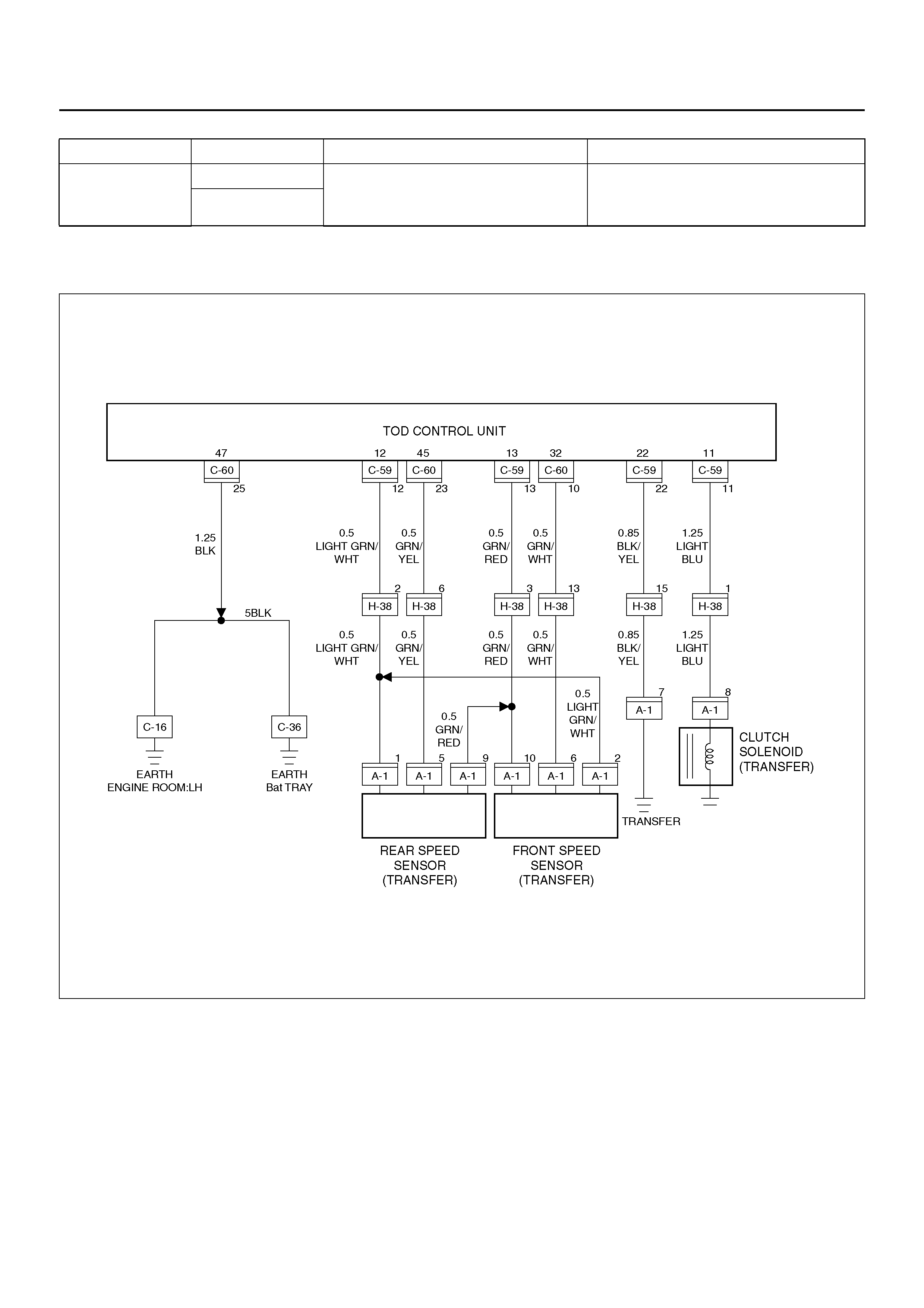
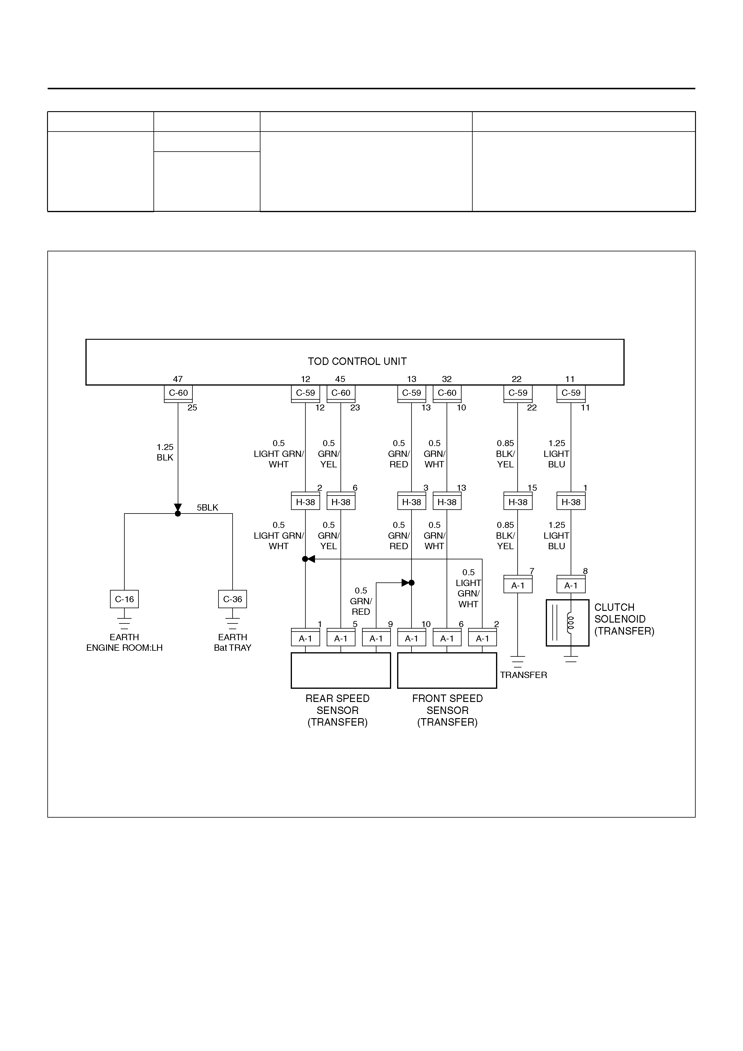
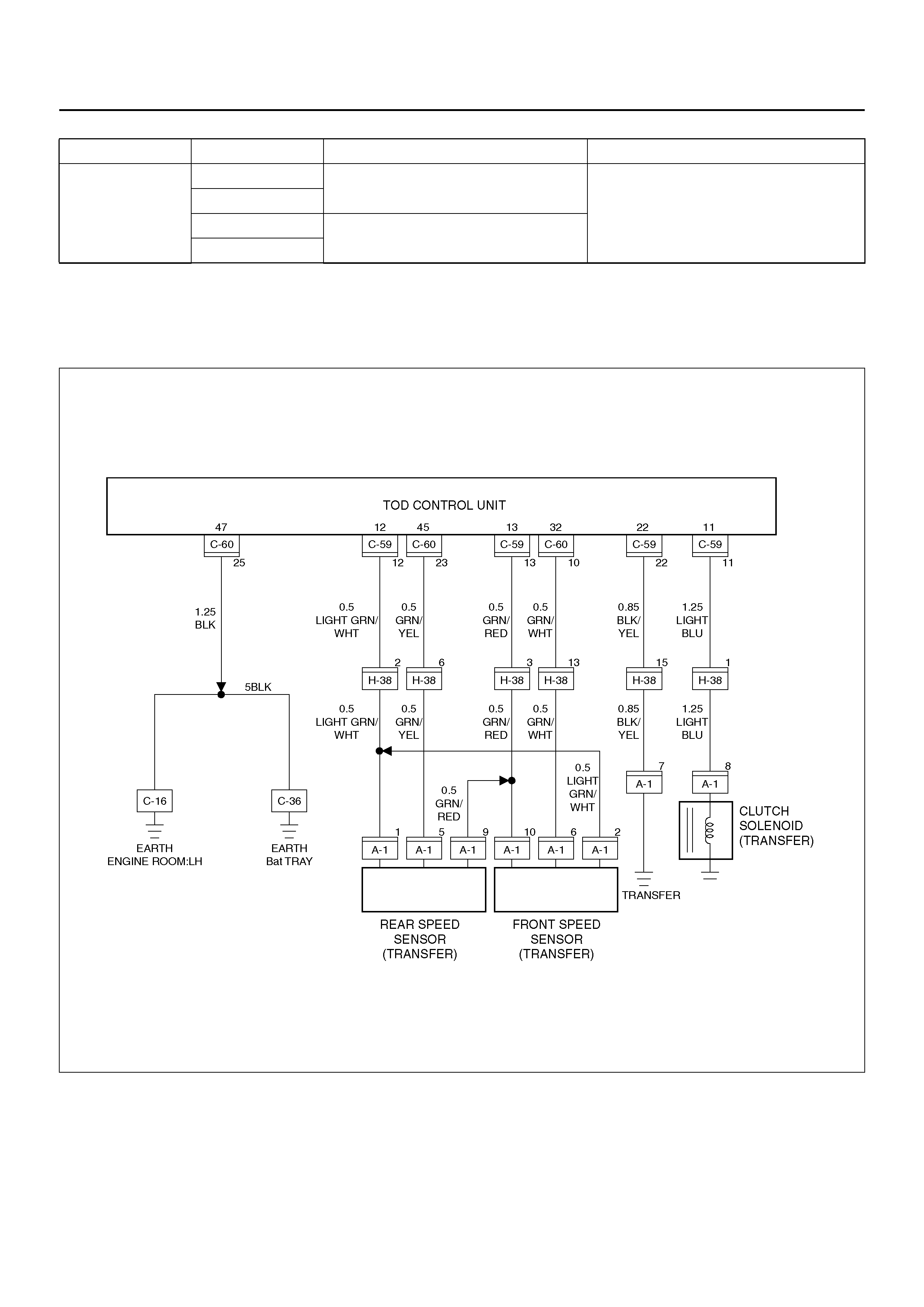
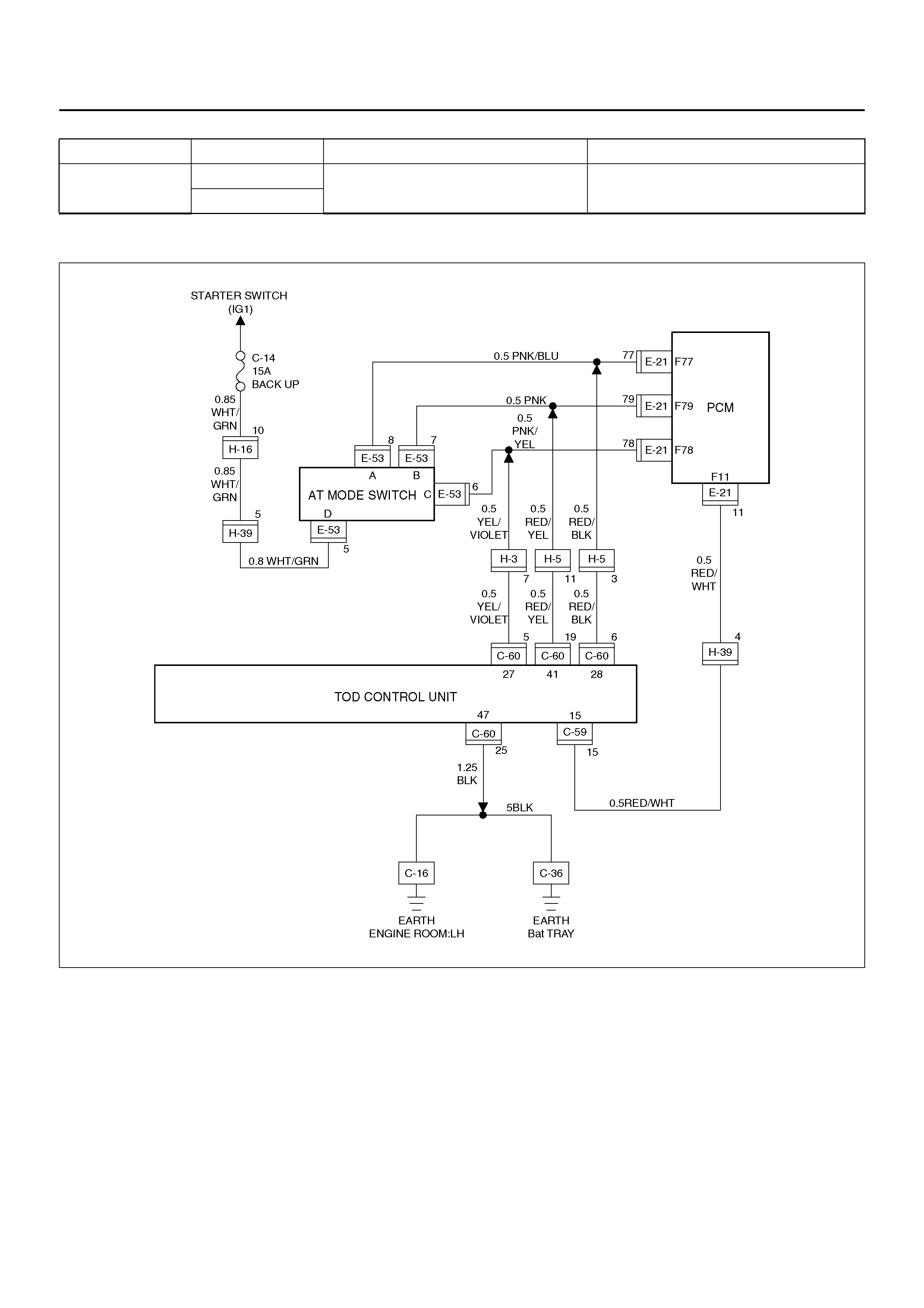
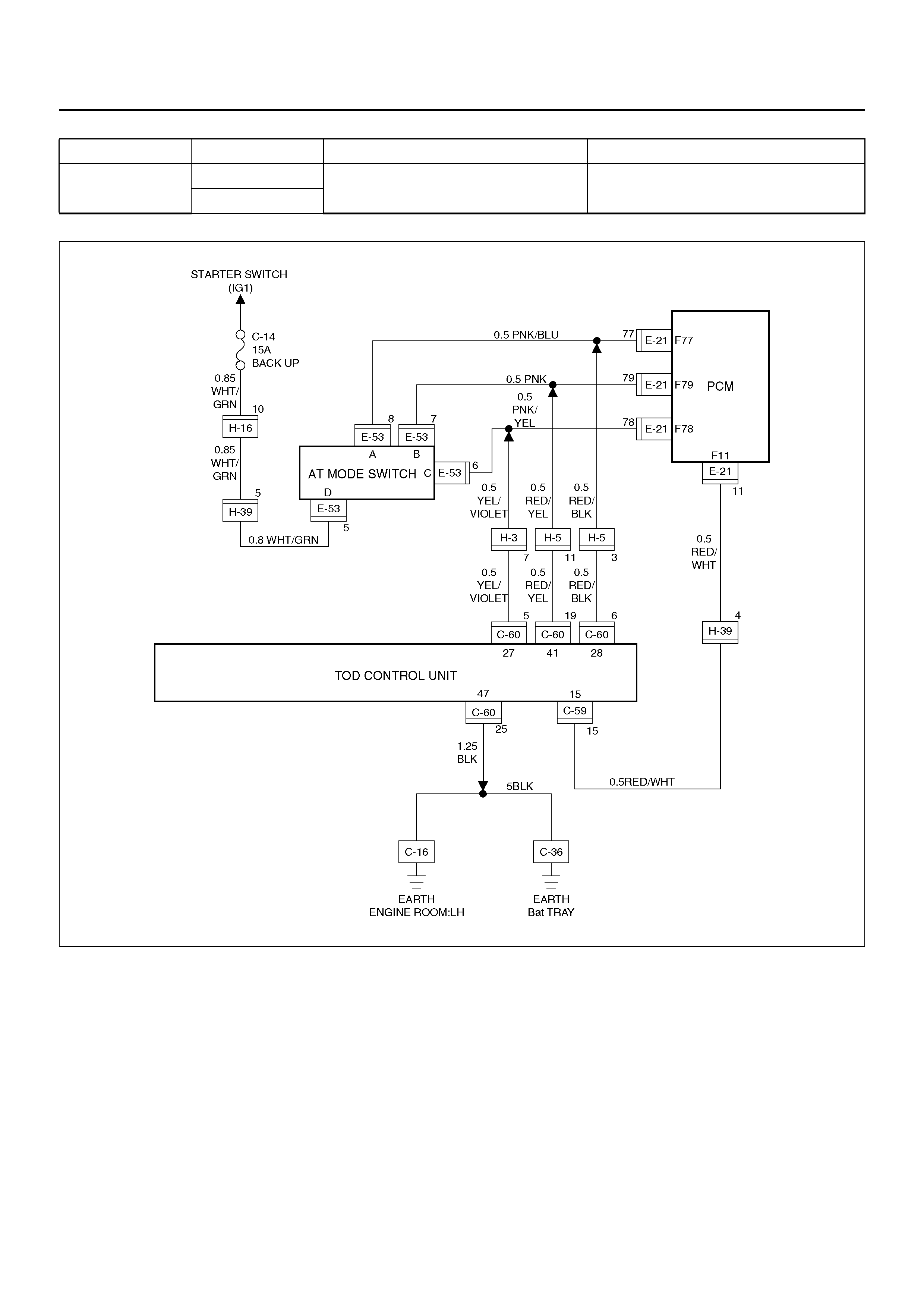
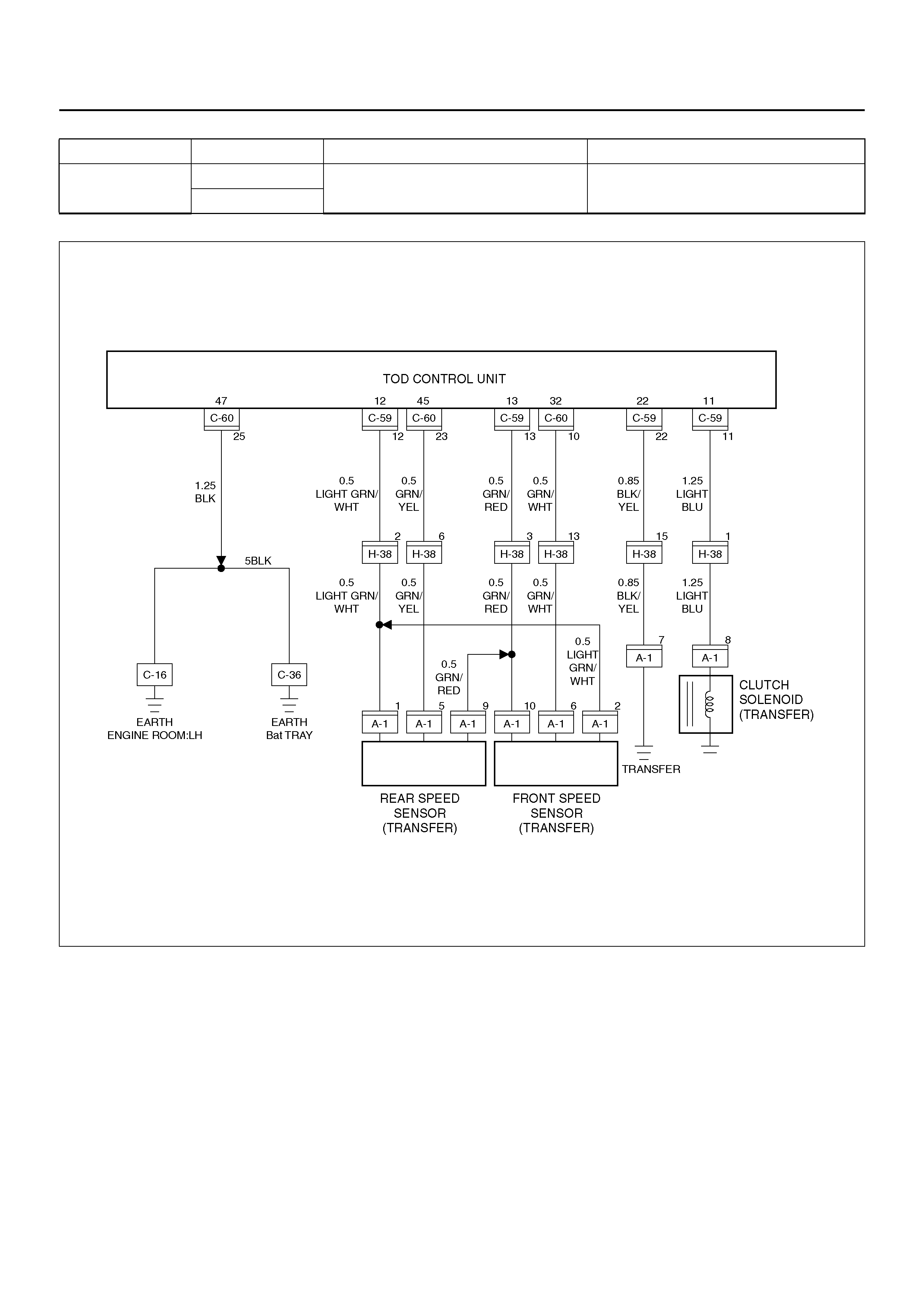
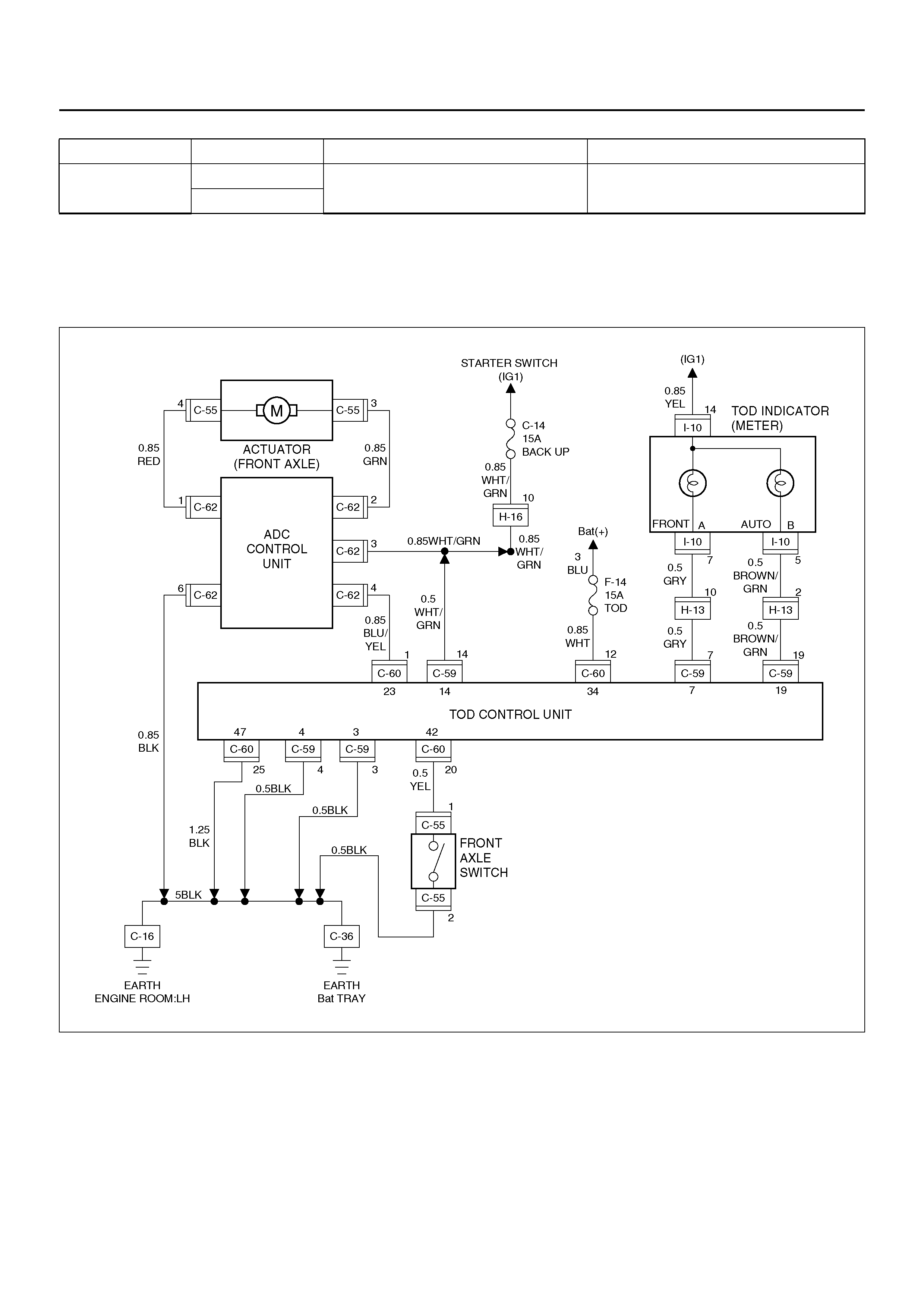
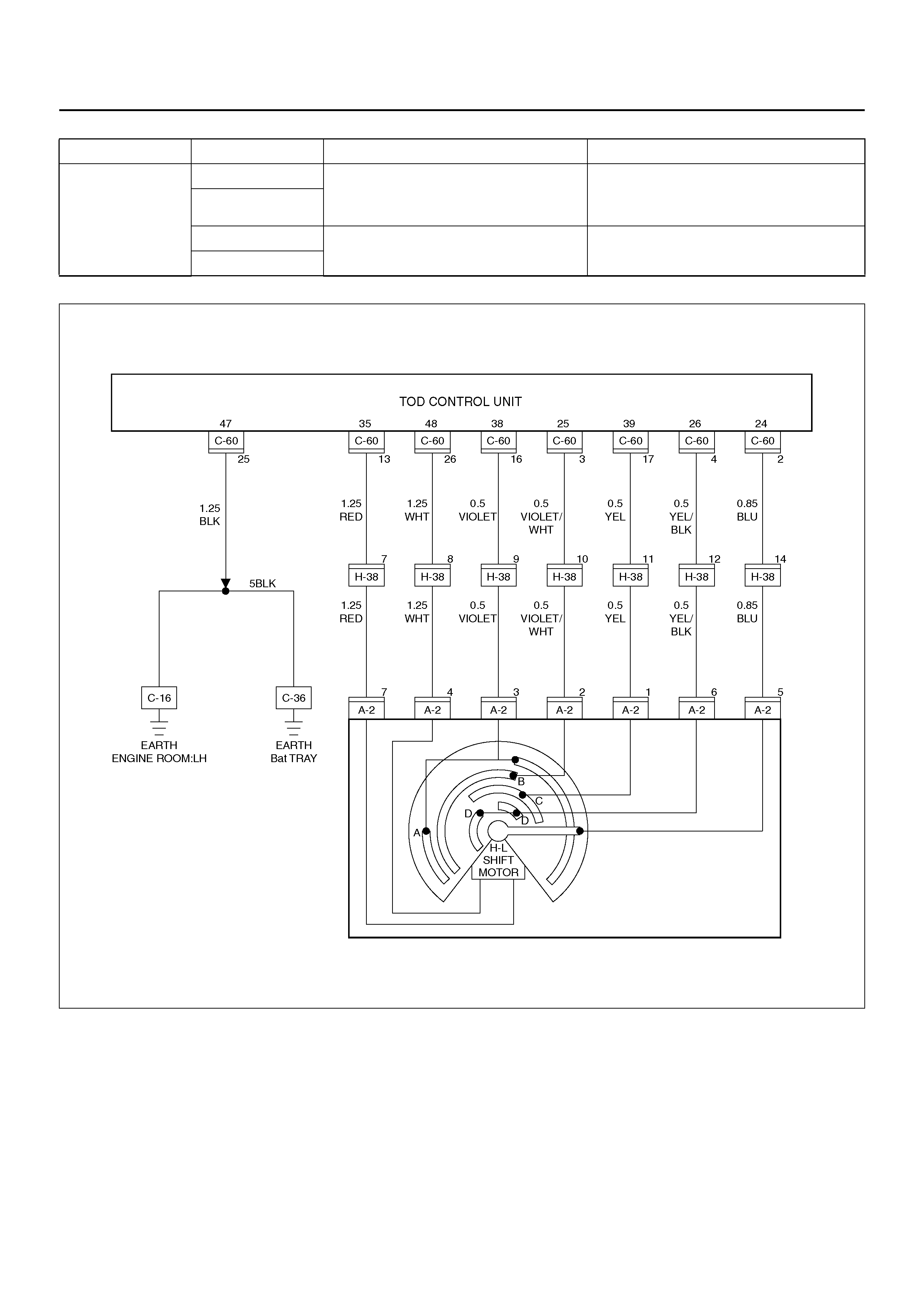
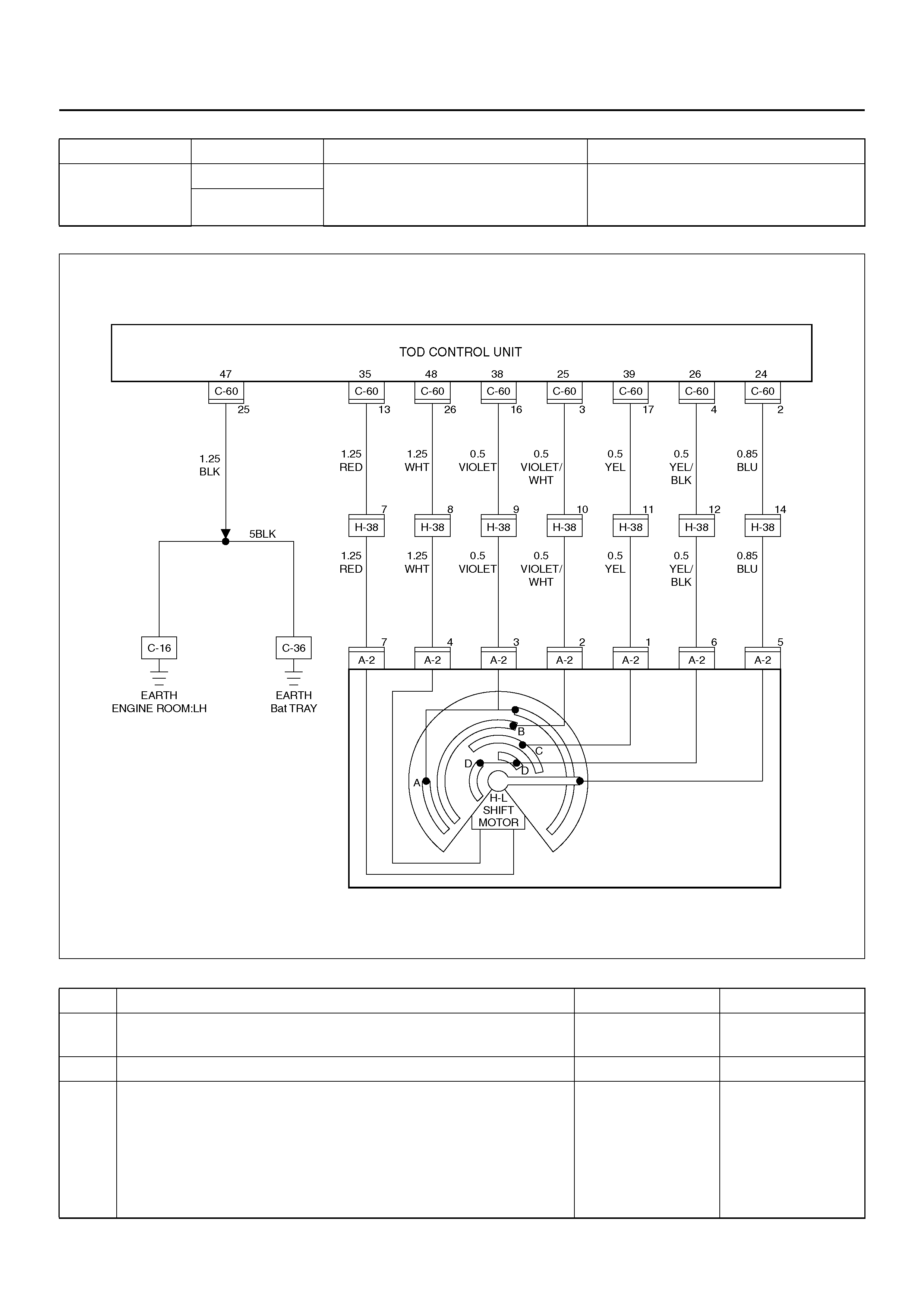
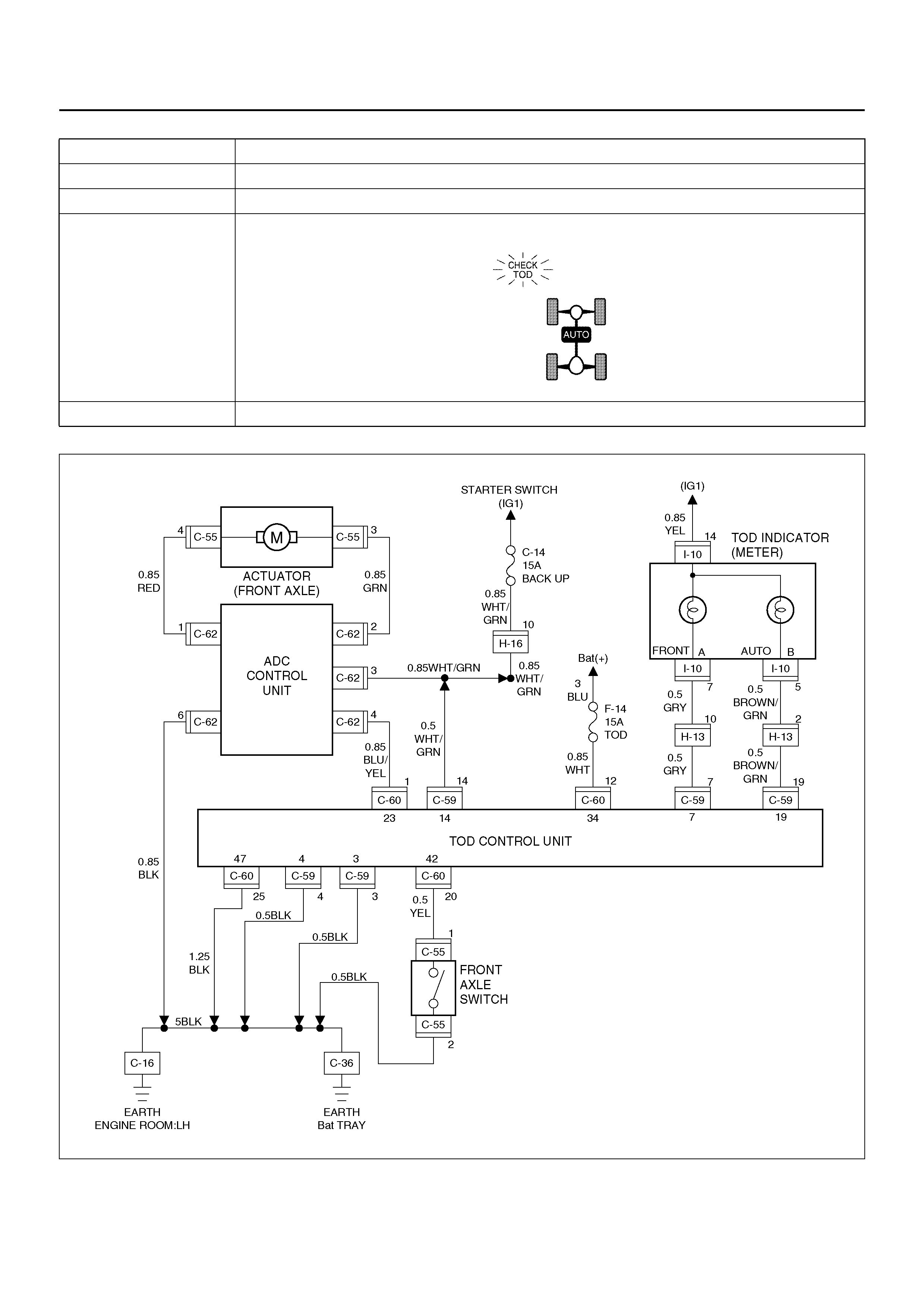
CIRCUIT DIAGRAM
D04R100003
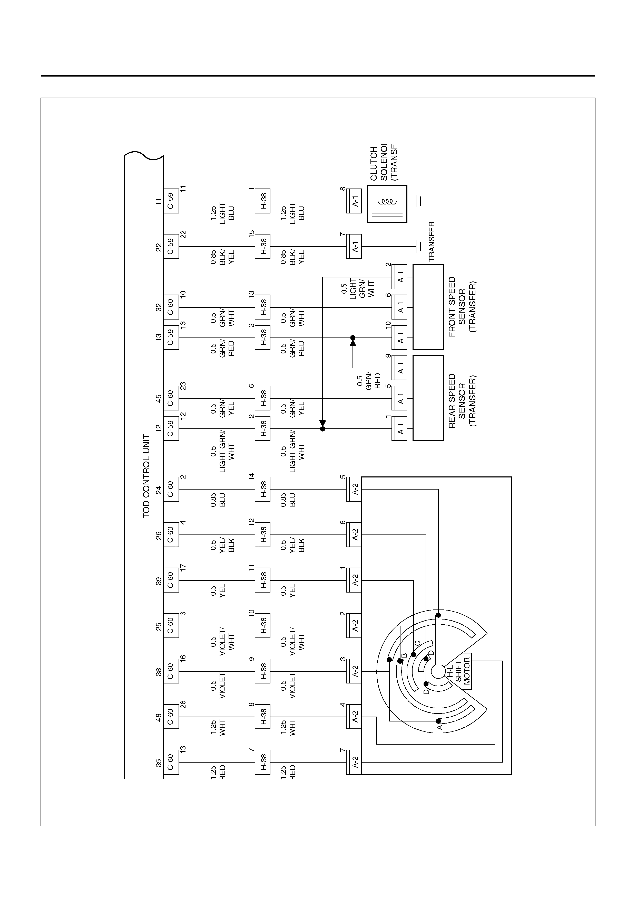
D04R100004
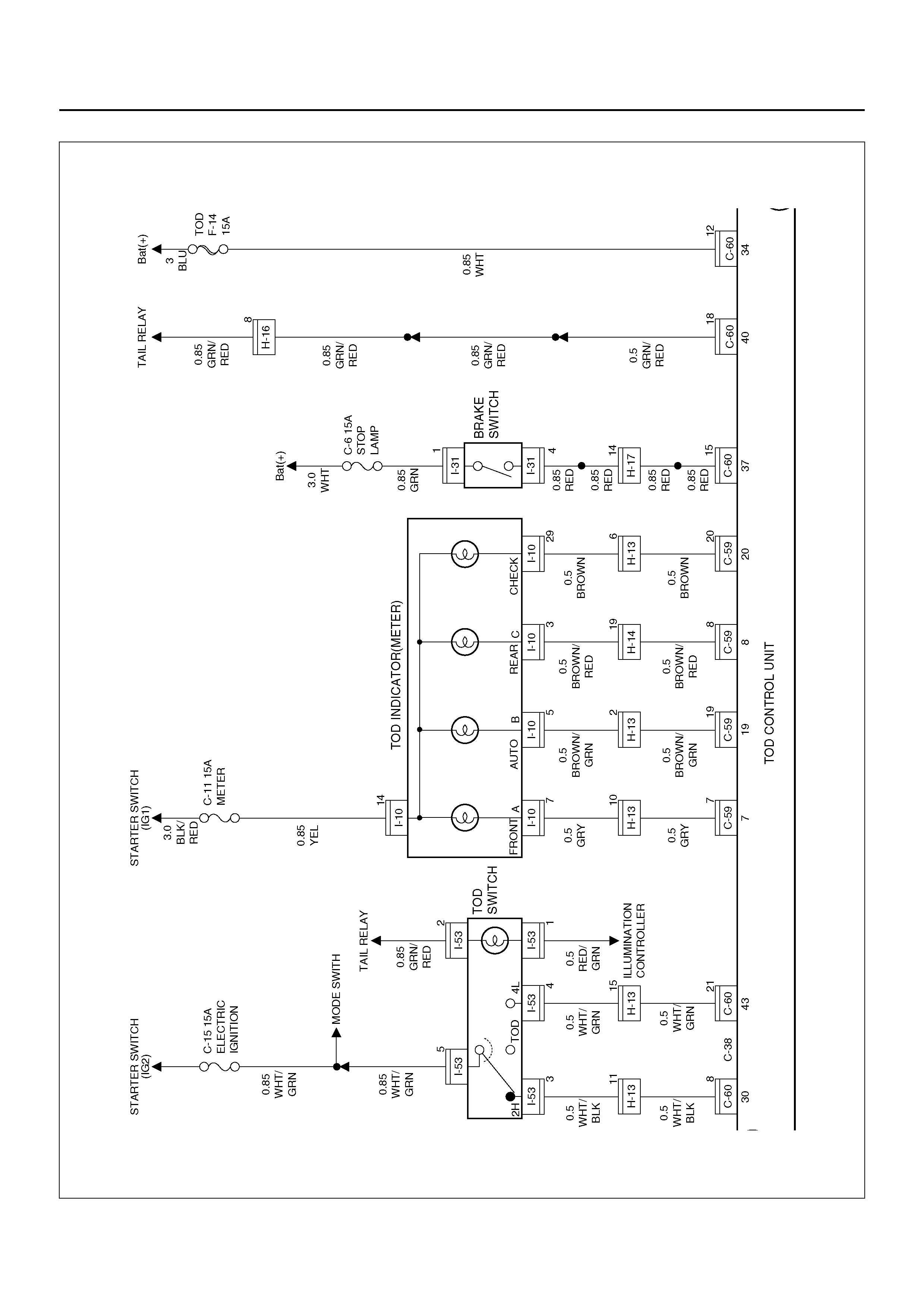
D04R100005
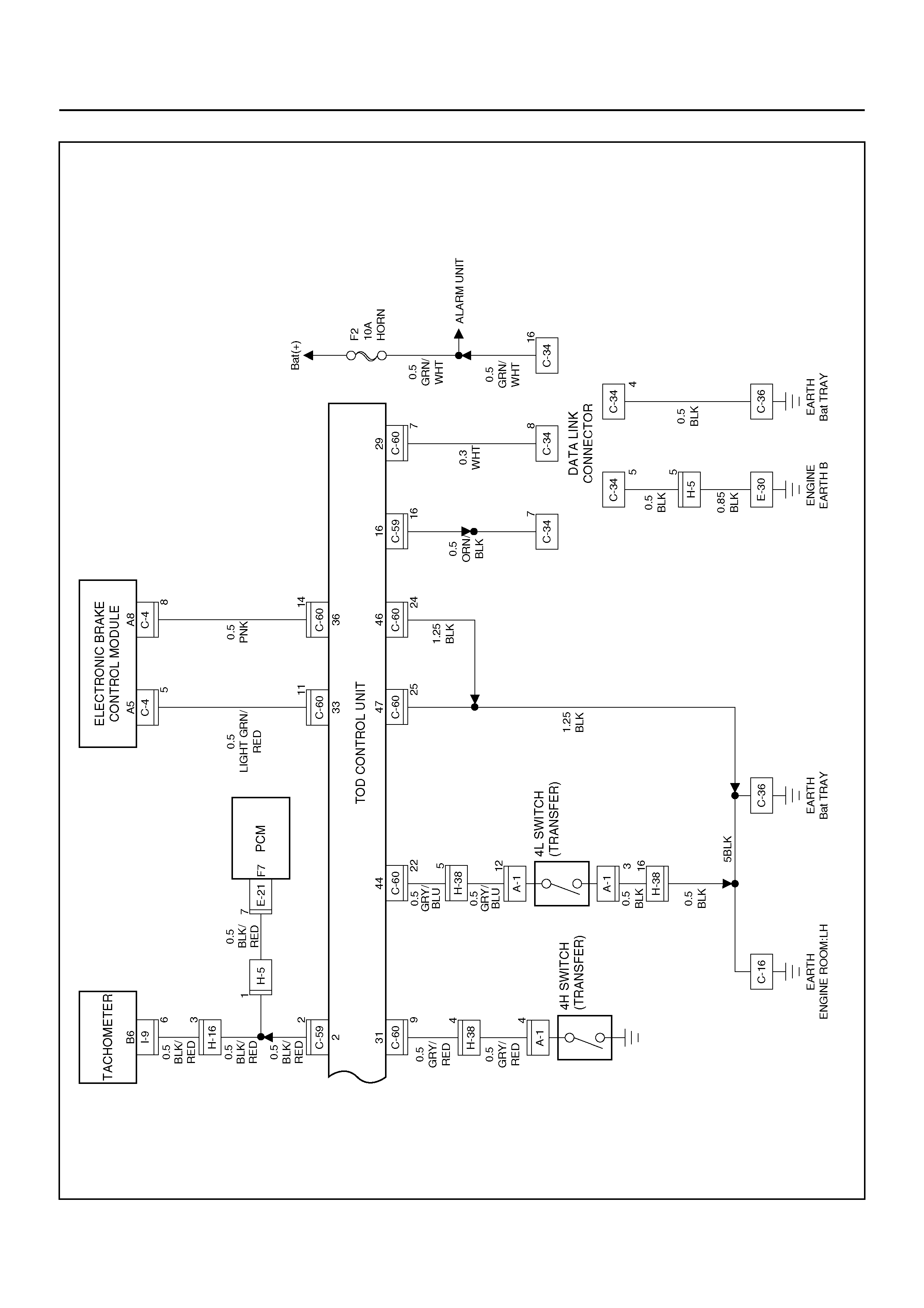
D04R100006
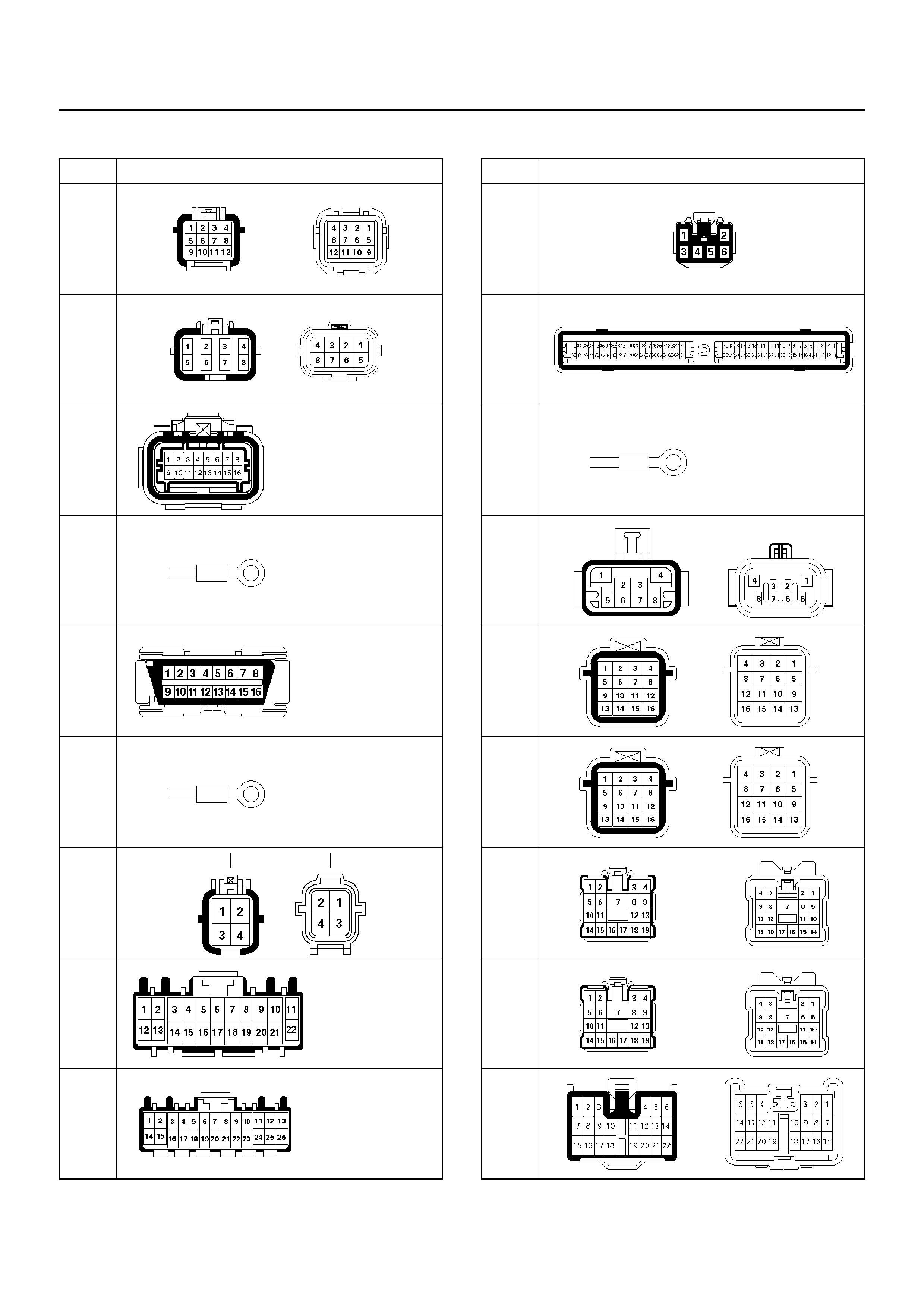
CONNECTOR LIST
No. Connector face
A-1
A-2
C-4
C-16
C-34
C-36
C-55
C-59
C-60
C-62
E-21
E-30
E-53
H-5
H-6
H-13
H-14
H-16
No. Connector face
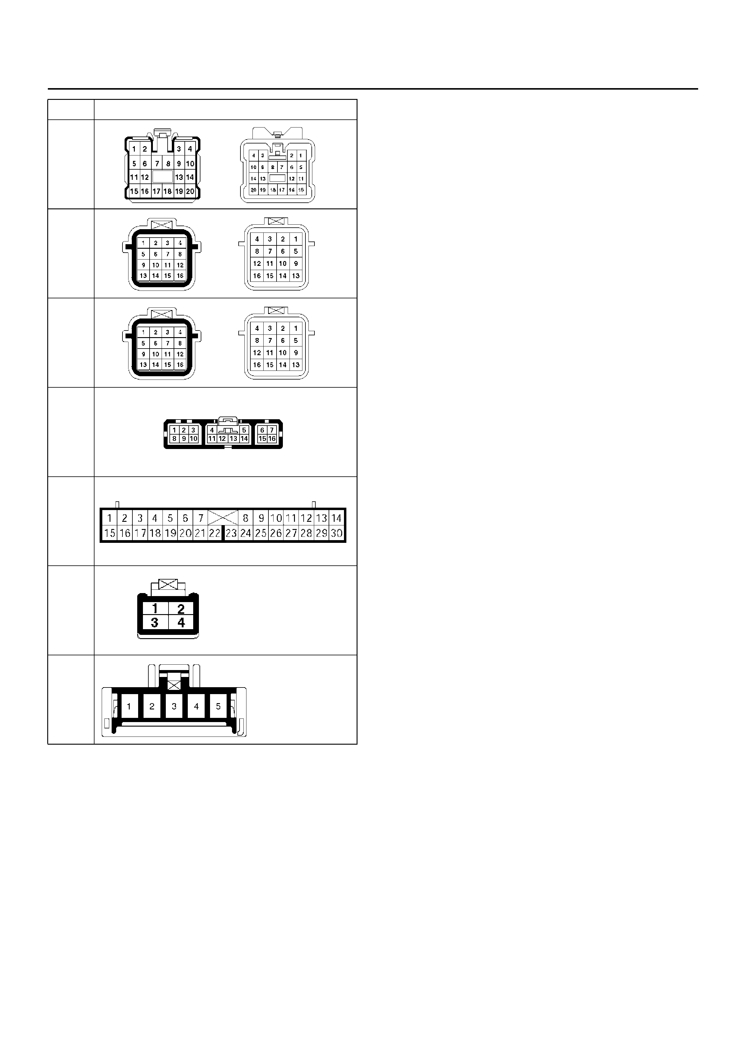
H-17
H-38
H-39
I-9
I-10
I-18
I-53
No. Connector face
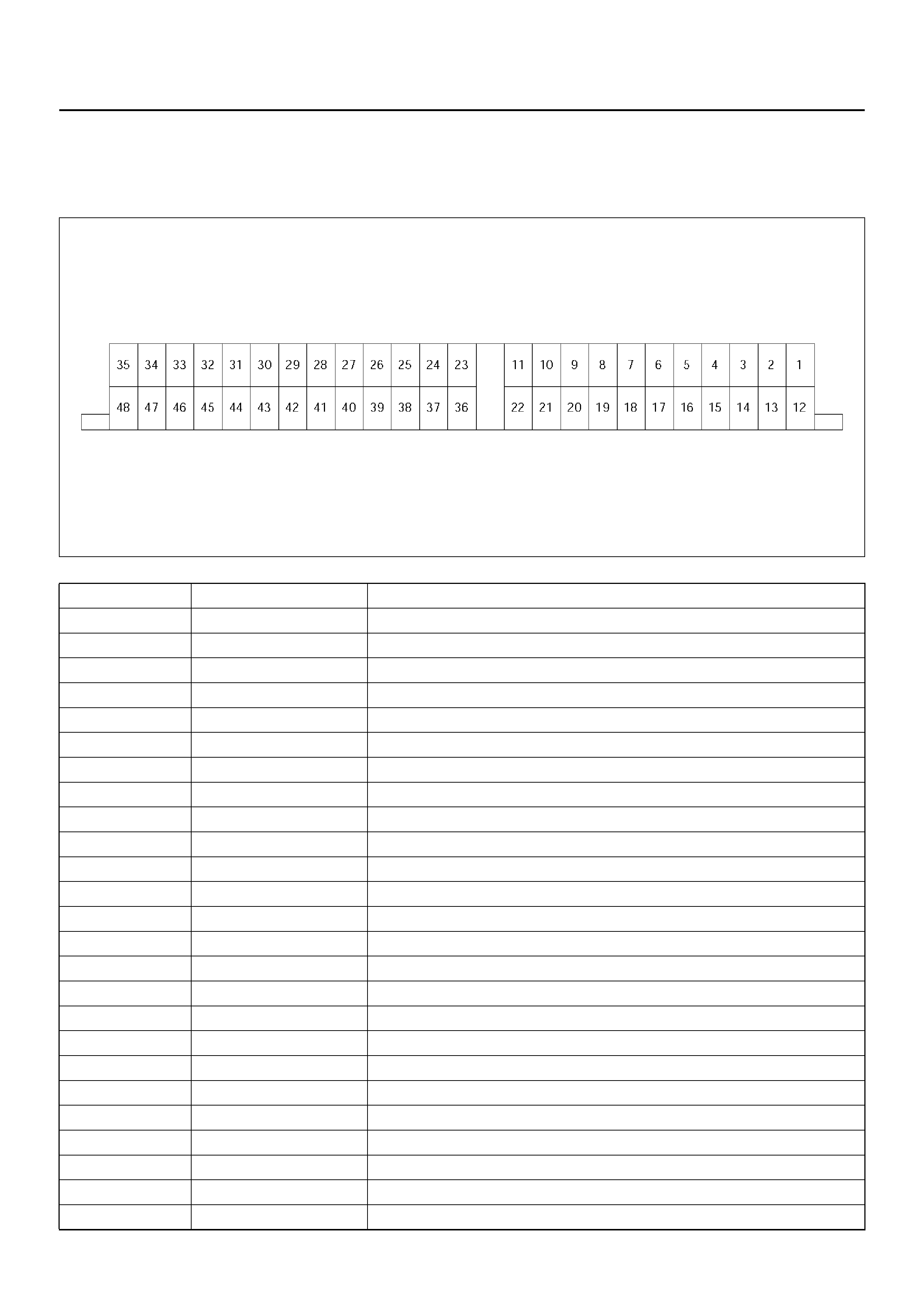
CHECKING FAILED PIN
Connector Pin Assignment
• TOD control unit pin assignment
D04RY00011
No. NAME CONTENTS
1 N.C Not used
2 ENG REV Engine Speed
3 N.C Not used
4 N.C Not used
5 N.C Not used
6 N.C Not used
7 IND.A Display Front
8 IND. C Display Rear
9 N.C Not used
10 N.C Not used
11 EMC Clutch Solenoid
12 REF Speed Reference
13 COM (–) Speed GND
14 VIG Ignition
15 TPS TPS (PWM)
16 TECH 2 TECH–2
17 N. C Not used
18 N. C Not used
19 IND. B Display Auto
20 CHK TOD Check TOD
21 N.C Not used
22 PWR GND Power Ground
23 ADC (+) Axle Disconnect Output
24 COM GND Shift Motor Position GND
25 MTR POS3 Shift Motot Position 3

26 MTR POS1 Shift Motor Position 1
27 POSC AT Position C
28 POSA AT Position A
29 DIAG Diagnosti c Inpu t
30 TOD SW A TOD Swi tch A (2H)
31 4H SW 4H Switch Inpu t
32 FT. SIG Front Speed Signal
33 ABS IN ABS In
34 VB Power Bat
35 MTR H-L Power Shift Motor H-L
36 4WD OUT 4WD Signal Output
37 BRAKE SW Brake Switch Input
38 MTR POS4 Shift Motor Position 4
39 MTR POS2 Shift Motor Position 2
40 LIGHTING SW Lighting Switch Input
41 POSB AT Position B
42 AXLE SW Axle Switch Input
43 TOD SWB TOD Switch B (4L)
44 4L SW 4L Switch Input
45 RR. SIG Rear Speed Signal
46 GND. 1 ECU Ground 1
47 GND. 2 ECU Ground 2
48 MTR L-H Power Shift Motor L-H
No. NAME CONTENTS
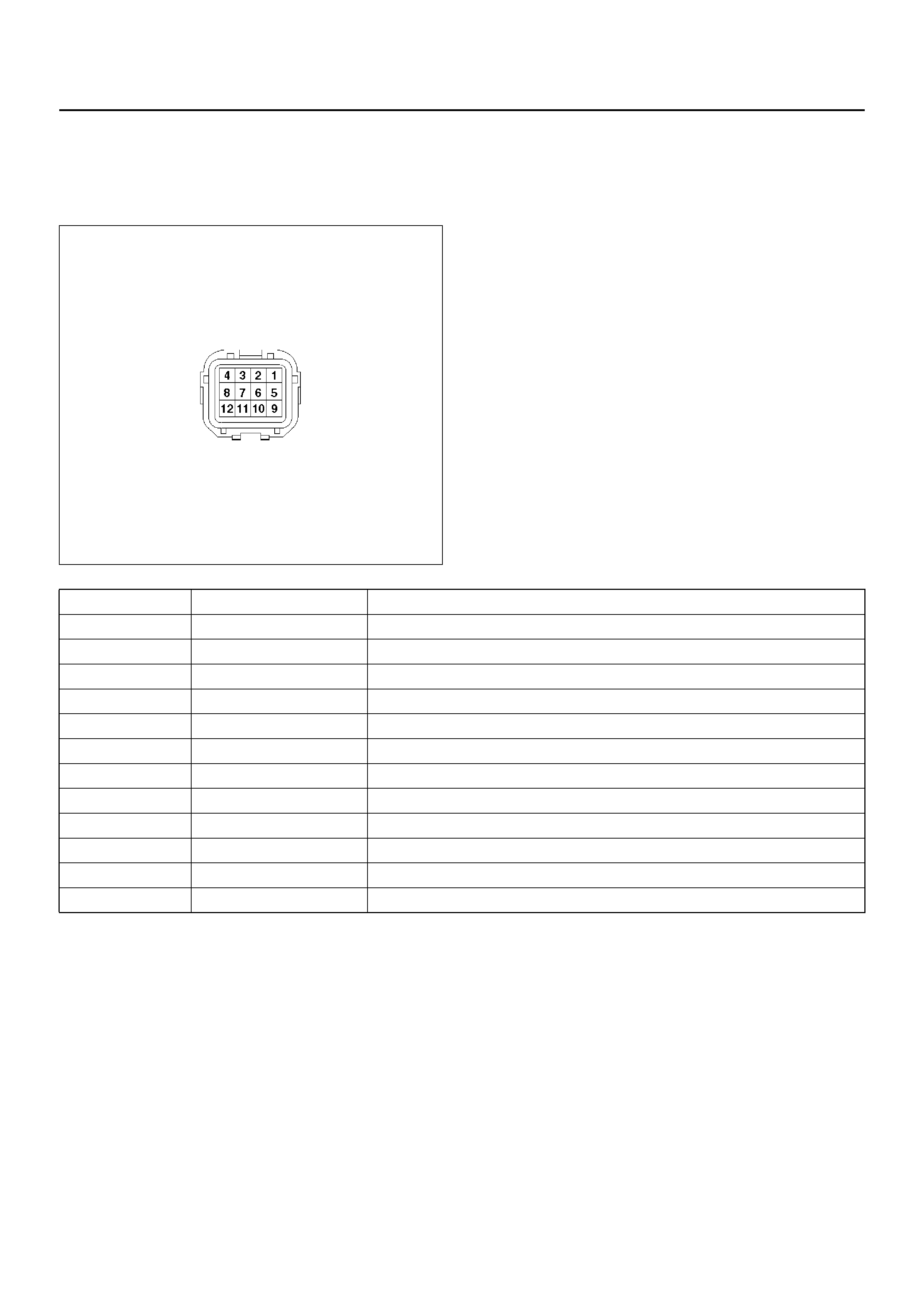
Reference
• Transfer conn ector pin assi gnment (c onnec tor on the
transfer case)
for inspe ction of tran sf er pins .
810RW310
No. NAME CONTENTS
1 Ref. (Rer. ) Rear speed sensor reference output
2 Ref. (Frt. ) Front speed sensor reference output
3 SW GND SW GND
4 4H SW (+) 4H SW plus terminal
5 RR. SIG Rear Speed Sensor Signal
6 FT. SIG Front Speed Sensor Signal
7 POWER GND Power GND
8 SOL (+) Electromagnetic solenoid
9 COM (–) (Rer. ) Rear speed sensor GND
10 COM (–) (Frt. ) Front speed sensor GND
11 NC Not used
12 4L SW (+) 4L SW Plus Terminal
8-6
No. NAME CONTENTS
1 MTR POS2 Shift Motor Position 2
2 MTR POS3 Shift Motor Position 3
3 MTR POS4 Shift Motor Position 4
4 MTR L-H Power Shift Motor L-H
5 POS RETURN Shift Motor Position GND
6 MTR POS1 Shift Motor Position 1
7 MTR H-L Power Shift Motor H-L
8 NC Not Used

CHECKING FAILED TOD CONTROL UNIT PIN
NOTE:
1. Unplug the ECU connector and the pins, unless
otherwise specified.
2. Before removing the ECU, turn off the ignition
switch.
3. If the standard values are not observed, check the
pins with other testers.
Check
Pin No. Circuit to
be tested Ignition
Switch
Position
Engine
State Unit
Scale/
Range
Measure
between
Pin No.
Standard Value Note
22 P-GND OFF STOP Ω22, 47 Continuity : OK
46 GND 1 OFF STOP Ω46, 47 Continuity : OK
47 GND 2 OFF STOP Ω47, GND Continuity : OK
31 4H SW OFF STOP Ω31, 47 No continuity (high,
4L) : OK
44 4L SW OFF STOP Ω44, 47 No continuity (high)
and continuity (4L) :
OK
42 AXLE SW ON RUN Ω42, 47 Continuity(TOD, 4L) :
OK Remove ECU connector and
start the engine. Move the
vehicle forth and back to
connect ax le sure ly.
29 DIAG OFF STOP Ω29 (TOD), 8
(DLC
Connector)
Continuity : OK DLC connector terminal 8
7 IND.A ON STOP DCV 7 (+), 47 (–) 8.0 ∼14.5 V when the indicator lamp is
turned off.
20 CHECK
TOD ON STOP DCV 20 (+), 47 (–) 8.0 ∼14.5 V When the indicator lamp is
turned off.
33 ABS IN ON STOP DCV 33 (+), 47 (–) 6.0 ∼11.0 V
12 REF ON STOP DCV 12 (+), 47 (–) 5 ∼9 V Connect ECU
32 FR T.(+) O N STOP DCV 32 (+), 47 (–) 0.7 ∼6 V Connect ECU and move the
vehicle (off one tooth of s peed
sensor ring) making sure of
volt a ge cha nge.
45 RR.(+) ON ST OP DCV 45 (+), 47 (–) 0.7 ∼6 V Connect ECU and move the
vehicle (off one tooth of s peed
sensor ring) making sure of
volt a ge cha nge.
13 COM(-) ON STOP DCV 13 (+), 47 (–) 0V Connect ECU
14 VIG ON STO P DCV 14 (+), 47 (–) 8 ∼14.5 V
34 VB OFF STOP DCV 34 (+), 47 (–) 8.0 ∼14.5 V
37 BRAKE SW OFF STOP DCV 37 (+), 47 (–) 8 ∼14.5 V Press brake pedal
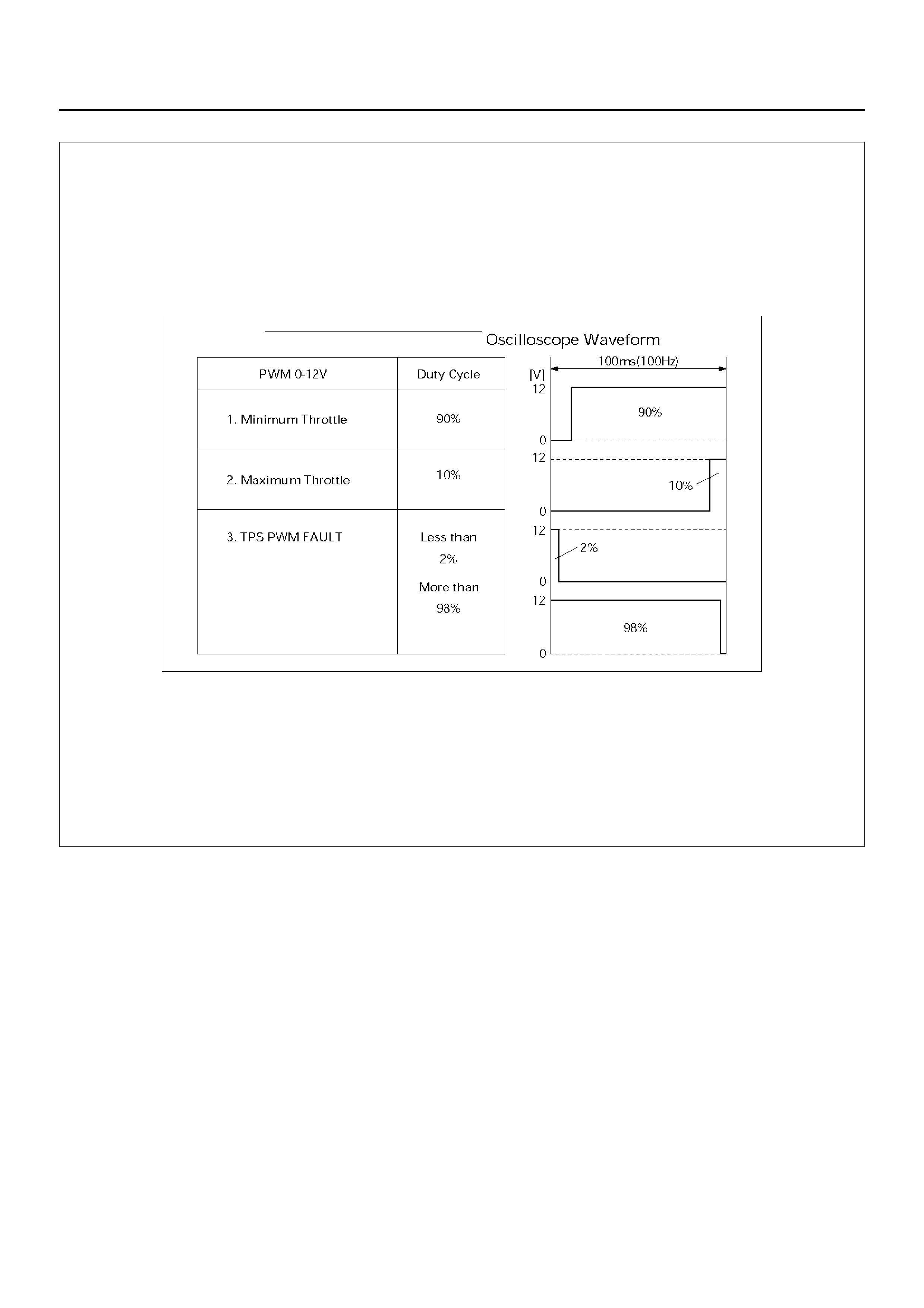
15 TPS ON STOP DCV 15 (+), 47 (–) PWM duty cycle
10%(MAX)–
90%(MIN)
Step on the accelerator pedal
and make sure that du ty cy cl e
changes.
36 4WD OUT OFF STOP Ω 36, 47 7 ∼12 kΩ Disconnect battery GND
terminal
11 EMC(+) OFF STOP Ω11, 22 1.0 ∼5.0 ΩDisconnect battery GND
terminal
30 TOD SW A ON STOP DCV 30 (+), 47 (–) SW: TOD, 4L: 0 V
SW:2H:8.0 ∼ 14.5 V
43 TOD SWB ON STOP DCV 43 (+), 47 (–) SW: 2H, TOD:0V
SW: 4L: 8.0 ∼ 14.5V
40 LIGHT ON STOP DCV 40 (+), 47 (–) SW OFF : 0 V
SW ON : 8.0 ∼ 14.5 V

19 IND B ON STOP DCV 19 (+), 47 (–) 8.0 ∼14.5 V When the indicator lamp is
turned off
8 IND C ON STOP DCV 8 (+), 47 (–) 8.0 ∼ 14.5 V When the indicator lamp is
turned off
27 AT POSC ON STOP DCV 27 (+), 47 (–) ON:D, 3, 2, 1
OFF:PRN ON:8.0 ∼ 14.5 V
OFF:0V
41 AT POSB ON STOP DCV 41 (+), 47 (–) ON:R, N, D, 3
OFF:P, 2, 1 ON:8.0 ∼ 14.5 V
OFF:0V
28 AT POSA ON STOP DCV 28 (+), 47 (–) ON:P, R, 3, 2
OFF:N, D, 1 ON:8.0 ∼ 14.5 V
OFF:0V
2 ENG REV ON RUN ms 2, 47 Waveform (PWM) 50 ms (1000 rpm)
Check
Pin No. Circuit to
be tested Ignition
Switch
Position
Engine
State Unit
Scale/
Range
Measure
between
Pin No.
Standard Value Note
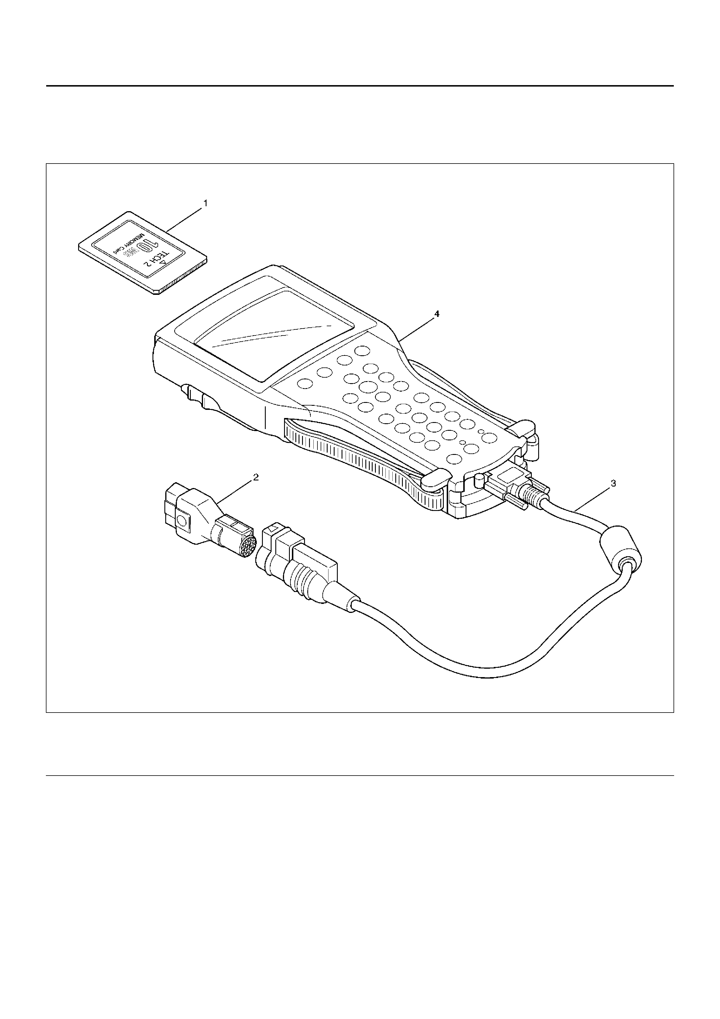
Tech 2 Scan Tool
From 98 MY, HOLDEN dealer service departments are
recommended to use Tech 2. Please refer to Tech 2
scan tool user guide.
901RW257
EndOFCallout
Legend
(1) PCMCIA Card
(2) SAE 16/19 Adaptor
(3) DLC Cable
(4) Tech 2
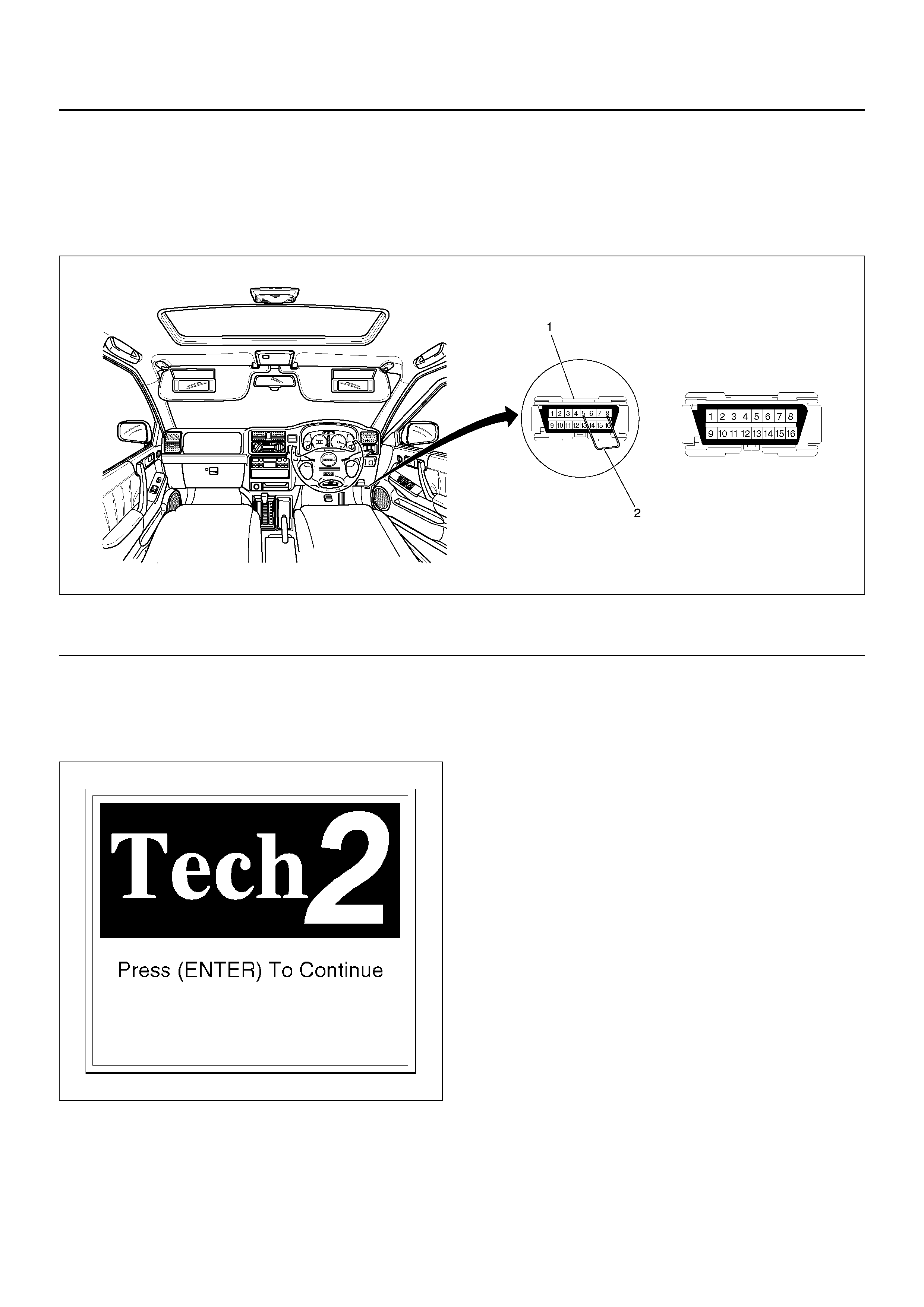
Getting Started
• Before operating the HOLDEN PCMCIA card with the
Tech 2, the following steps must be performed:
1. The HOLDEN 98 System PCMCIA card (1) inserts
into the Tech 2 (4).
2. Connect the SAE 16/19 adapter (2) to the DLC
cable (4).
3. Connect the DLC cable to the Tech 2 (4)
4. Mark sure the vehicle ignition is off.
5. Connect the Tech 2 SAE 16/19 adapter to the
vehicle DLC connec tor.
350R100005
EndOFCallout
6. The vehicle ignition turns on.
7. Power up the Tech 2.
8. Verify the Tech 2 power up display.
060RW009
Legend
(1) Data Link Connector (2) Jumper Wire
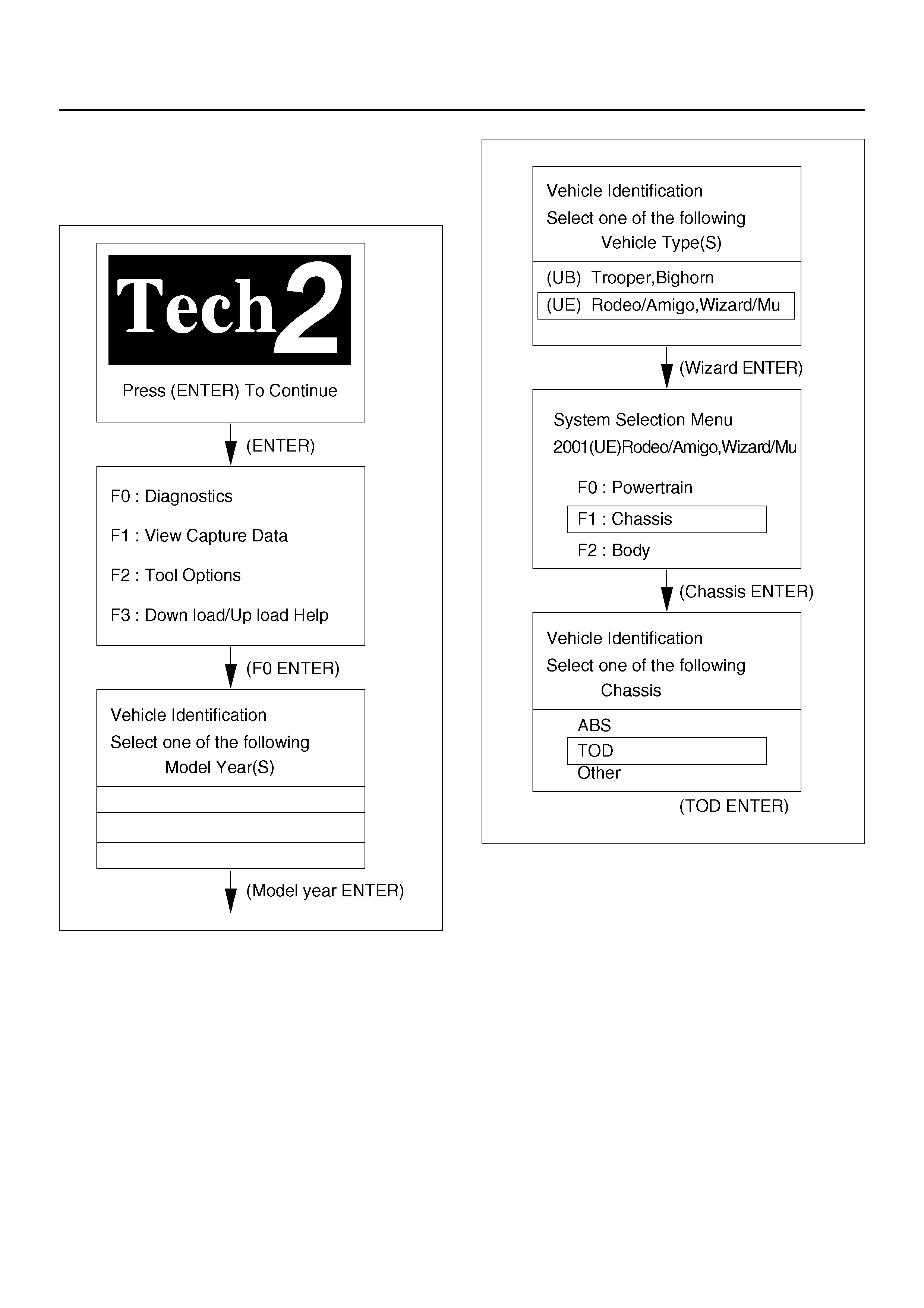
Operating Procedure
The power up screen is displayed when you power up
the tester with the HOLDEN systems PCMCIA card.
Follow the operating procedure below.
060R100102
060R100114

DIAGNOSTIC TROUBLE CODES
TPS : Throttle Position Sensor
EMC : Electromagnetic coil
ADC : Shift on the fly (Axle Dis Connect)
Code Item Tech2 code (P code) Diagnosis Check flow No.
12 — Start code Normal —
13 P1735 Ref Shorted GND 6
14 P1731 Front speed sensor Input abnormality (open, sig or com) 2
15 P1736 Ref Shorted VB6
16 P1737 Front speed sensor Input abnormality 4
17 P1774 Inhibitor switch Input abnormality 8
21 P1716 TPS Shorted or disconnected wiring,
abnorma li ty in inp ut 7
23 — ECU CPU abnormality 1
24 P1733 Rear speed sensor Input abnormality (open, sig or com) 3
27 P 17 38 Rear sp eed se ns or Inp ut abno rm alit y 5
28 P1760 ADC (+) & AXLE SW Output abnormality 10
31 P1721 EMC (+) Shorted VB, disconnected coil/wiring or
shorted GND 9
32 P1761 ADC (+) Shorted VB or disconnected wiring 11
33 P1762 ADC (+) Shorted GND 12
36 — ECU CPU abnormality 1
37 P1712 ECU CPU abnormality 1
38 P1714 ECU CPU abnormality 1
41 P1741 Hight-Low shift motor Shorted GND or disconnected wiring 13
42 P1773 Hight-Low shift motor User operation error (not failure) 14
43 P1743 Hight-Low shift motor Motor moving more than 5s 15
55 P1755 Hight-Low shift motor Input abnormality of motor position signal 16

DIAGNOSIS FROM TROUBLE CODES
• Diagnose the fault that have been saved to the
control unit according to the system self-diagnostic
function.
Check flow Trouble code Phenomenon Standard
1 23, 36, 37, 38 The ECU has failed. —
P1712, P1714
Step Action Yes No
1 Turn on the starter switch.
Is the trouble reproduced? Replace the
ECU and
conduct the test
run.
Go to Step 3 Go to Step 2
2 1. Clear the trouble codes.
2. Conduct the test run.
Is the trouble reproduced during the test run? Replace the
ECU and
conduct the test
run.
Go to Step 3
The trouble is
not reproduced.
Refer to
“Trouble
intermittently
observed".
Go to Step 3
3 1. Check that all the parts are mounted.
2. Clear the trouble codes.
Is this step complete? Verify the repair. Return to Step 3
NOTE: The following procedure shows the case that
the front or rear sensor common grounding line is
broken.
D04R100007
Check flow Trouble code Phenomenon Standard
2 14 Front speed sensor signal open or
GND short, speed sensor com open. 0.2V > sen sor voltage
P1731

Step Action Yes No
1 1. Start the engine.
2. Select TOD mode.
Is there the memory except DTC 14(P1731)? Go to Step 4 Go to Step 2
2 1. Turn off the starter switch.
2. Disconnect the ECU connector (C–59) and (C–60).
Is ther e the contin uity between the c onnector (C–6 0) term inal 10
and 25?
Repair the
circuit.
Go to Step 7 Go to Step 3
3 1. Disconnect the transfer connector (A–1).
Is ther e the contin uity between the c onnector (C–6 0) term inal 10
and the connector (A–1) terminal 6, the connector (C–59)
terminal 12 and connector (A–1) terminal 2, and the connector
(C–59) terminal 13 and connector (A–1) terminal 10?
Replace the
front speed
sensor.
Go to Step 7
Repair the
circuit.
Go to Step 7
4 Is the memory DTC 24(P1733)? Go to Step 5 Refer to other
trouble check flow.
5 Is there the continuity between harnesses of terminal 32 and 45
(vehicle side terminal of the front and rear speed sensor)? Go to Step 6
Repair the
circuit.
Go to Step 7
6 Is there the continuity between harnesses of terminal 12 and 13
(vehicle side terminal of the speed sensor COM(−) and ref)? Replace front
and rear speed
sensor.
Go to Step 7
Repair the
circuit.
Go to Step 7
7 1. Check that all the parts are mounted.
2. Clear the trouble code.
Is the step complete? Verify the repair. Return to Step 7
NOTE: The following procedure shows the case that
the front or rear sensor common grounding line is
broken.
D04R100007
Check flow Trouble code Phenomenon Standard
3 24 Rear speed sensor signal open or
GND short, speed sensor COM
open.
0.2 V > sensor voltage
P1733

Step Action Yes No
1 1. Start the engine.
2. Select TOD mode.
Is there the memory except DTC 24(P1733)? Go to Step 4 Go to Step 2
2 1. Turn off the starter switch.
2. Disconnect the ECU connector (C–59) and (C–60).
Is ther e the contin uity between the c onnector (C–6 0) term inal 23
and 25?
Repair the
circuit.
Go to Step 7 Go to Step 3
3 1. Disconnect the transfer connector (A–1).
Is ther e the contin uity between the c onnector (C–6 0) term inal 23
and the connector (A–1) terminal 5, the connector (C–59)
terminal 12 and connector (A–1) terminal 1, and the connector
(C–59) terminal 13 and connector (A–1) terminal 9?
Replace the
rear sp eed
sensor.
Go to Step 7
Repair the
circuit.
Go to Step 7
4 Is the memory DTC 14(P1731)? Go to Step 5 Refer to other
trouble cheek flow.
5 Is there the continuity between harnesses of terminal 32 and 45
(vehicle side terminal of the front and rear speed sensor)? Go to Step 6
Repair the
circuit
Go to Step 7
6 Is there the continuity between harnesses of terminal 12 and 13
(vehicle side terminal of the speed sensor COM(−) and ref)? Replace front
and rear speed
sensor.
Go to Step 7
Repair the
circuit.
Go to Step 7
7 1. Check that all the parts are mounted.
2. Clear the trouble code.
Is the step complete? Verify the repair Return to Step 7

NOTE: Find the trouble in which the pulse
corresponding to the running speed is not input.
D04R100007
Check flow Trouble code Phenomenon Standard
4 16 The front speed sensor no pulse. Hi level : 4.5 ∼ 6.0 V
Lo level : 0.7 ∼ 2.0 V
Frequency (F) =
700 – 850 Hz (at 50 km/h or 31
mph)
P1737

Step Action Yes No
1 1. Connect TECH 2.
While run ning in TOD mod e, does TECH–2 's front spe ed sensor
indication change with vehicle speed?
Go to Step 2
Repair and
inspection front
speed sensor
tone wheel.
Go to Step 6
2 1. Clear the trouble code.
While running at 40 km/h or 25 mph in TOD mode for 30
consecutive sec, is the trouble code reissued?
Go to Step 3
The trouble is
not reproduced.
Refer to
“Troubles
intermittently
observed".
3 1. Turn off the starter switch.
2. Disconnect the ECU connector (C–59) and (C–60).
Is ther e the contin uity between the c onnector (C–6 0) term inal 10
and 25?
Repair the
circuit.
Go to Step 6 Go to Step 4
4 1. Disconnect the transfer connector (A–1).
Is ther e the contin uity between the c onnector (C–6 0) term inal 10
and the connector (A–1) terminal 6, the connector (C–59)
terminal 12 and connector (A–1) terminal 2, and the connector
(C–59) terminal 13 and connector (A–1) terminal 10?
Replace the
front speed
sensor.
Go to Step 5
Repair the
circuit.
Go to Step 5
5 1. Clear the trouble code.
While running at 40 km/h or 25 mph in TOD mode for 30
consecutive sec, is the trouble code reissued?
1.Replace
ECU.
2.Go to Step 6 Go to Step 6
6 1. Check that all the parts are mounted.
2. Clear the trouble code.
Is this step complete? Repeat the
“Diagnosis Flow". Return to Step 6
NOTE: Find the trouble in which the pulse
corresponding to the running speed is not input.
D04R100007
Check flow Trouble code Phenomenon Standard
5 27 The rear speed sensor no pulse. Hi level : 4.5 ∼ 6.0 V
Lo level : 0.7 ∼ 2.0 V
Frequency (F) =
700 – 850 Hz (at 50 km/h or 31
mph)
P1738

Step Action Yes No
1 1. Connect TECH 2.
While running in TOD mode, d oes TECH–2's rear speed sensor
indication change with vehicle speed?
Go to Step 2
Repair and
inspection front
speed sensor
tone wheel.
Go to Step 6
2 1. Clear the trouble code.
While running at 40 km/h or 25 mph in TOD mode for 30
consecutive sec, is the trouble code reissued?
Go to Step 3
The trouble is
not reproduced.
Refer to
“Troubles
intermittently
observed".
3 1. Turn off the starter switch.
2. Disconnect the ECU connector (C–59) and (C–60).
Is ther e the contin uity between the c onnector (C–6 0) term inal 23
and 25?
Repair the
circuit.
Go to Step 5 Go to Step 4
4 1. Disconnect the transfer connector (A–1).
Is ther e the contin uity between the c onnector (C–6 0) term inal 23
and the connector (A–1) terminal 5, the connector (C–59)
terminal 12 and connector (A–1) terminal 1, and the connector
(C–59) terminal 13 and connector (A–1) terminal 9?
Replace the
rear sp eed
sensor.
Go to Step 5
Repair the
circuit.
Go to Step 5
5 1. Clear the trouble code.
While running at 40 km/h or 25 mph in TOD mode for 30
consecutive sec, is the trouble code reissued? Replace EUC.
Go to Step 6 Go to Step 6
6 1. Check that all the parts are mounted.
2. Clear the trouble code.
Is this step complete? Repeat the
“Diagnosis Flow". Return to Step 6
NOTE: If the reference wire (12) is short-circuited to
GND, the speed signal is not generated. If the wire is
short-circuited to the battery voltage, the signal level
becomes faulty.
D04R100007
Check flow Trouble code Phenomenon Standard
6 13 The reference is short-circuited to
GND. Reference = 5 V
P1735
15 The reference is short-circuited to
VB.
P1736

Step Action Yes No
1 1. Start the engine.
Does the voltage between terminals 12 and 47 meet the standard
5V?
Refer to “Trouble
intermittently
observed". Go to Step 2
2 Is the voltage below the standard? Go to Step 3 Go to Step 7
3 1. Turn off the starter switch.
2. Disconnect the ECU connector.
Is the continuity established between vehicle harness terminals
(C–59)12 and (C–60)25? Go to Step 4
The ECU is
failed. Replace
the ECU.
Go to Step 8
4 1. Disconnect the H-38 connector.
Is the continuity established between floor harness connector
termina ls (H- 38)2 and (H- 3 8)15?
Go to Step 5
Short to GND
between (C–
59)12 and (H–
38)2.
Repair the
circuit.
Go to Step 8
5 1. Disconnect the A-1 connector.
Is the conti nuity establishe d between trans fer harness con nector
male terminals (A–1)1 and (A–1)7?
Replace the
rear sp eed
sensor.
Go to Step 8
The reference
harness for the
rear speed
sensor is short–
circuited to
GND. Repair
the circuit.
Go to Step 6
6 1. Disconnect the A-1 connector.
Is the conti nuity establishe d between trans fer harness con nector
terminals (A–1)2 and (A–1)7?
Replace the
front speed
sensor.
Go to Step 8
The reference
harness for the
rear speed
sensor is short–
circuited to
GND. Repair
the circuit.
Go to Step 8
7 1. Turn off the starter switch.
2. Disconnect the ECU connector.
3. Turn on the starter switch.
Is the battery voltage observed between harness connector
terminals (C–59)12 and (C–60)25?
Repair the
circuit.
Go to Step 8
The ECU has
failed. Replace
the ECU.
Go to Step 8
8 1. Check that all the parts are mounted.
2. Clear the trouble code.
Is this step complete? Repeat the
“Diagnosis Flow" Go to Step 8
NOTE: The signal voltage from the TPS deviates from
the standard range .
D04R100008
Check flow Trouble code Phenomenon Standard
6 7 The voltage of the throttle position
sensor (TPS) is faulty. See below table.
P1716
D04RY00012

Step Action Yes No
1 1. Turn off the starter switch.
Is the battery voltage normal?
Go to Step 2
Charge or
replace the
battery.
Go to Step 7
2 1. Turn on the starter switch.
Does the voltage between terminals 15 and 47 fall within the
standard range? Go to Step 3 Go to Step 4
3 1. Clear the trouble code.
2. Turn on the starter switch.
Is there DTC21 (P1716)? Go to Step 4
Refer to “Trouble
intermittently
observed".
4 1. Turn off the starter switch.
2. Disconnect the ECU connector.
3. Turn on the starter switch.
Does the voltage between terminals (C–59)15 and (C–60)25 fall
within the standard range?
The ECU has
failed. Replace
the ECU.
Go to Step 7 Go to Step 5
5 Is the harness healthy?
Go to Step 6
Repair the
harness.
Go to Step 7
6 Is the TPS healthy?
Go to Step 7
Replace the
TPS.
Go to Step 7
7 1. Check that all the parts are mounted.
2. Clear the trouble code.
Is this step complete? Repeat the
“Diagnosis Flow". Go to Step 7
D04R100008
Check flow Trouble code Phenomenon Standard
8 17 The input from the mode switch is
abnormal. —
P1774

Step Action Yes No
1 Is the TOD control unit the regular part? (Verity the part number.)
Go to Step 2
Replace with
the regular part.
Go to Step 2
2 1. Turn on the starter switch.
Does the voltage between the terminal 28 and 47 accord with the
table 1 corresponding to the AT selector positions? Go to Step 3 Go to Step 5
3 Does the voltage between the terminal 41 and 47 accord with the
table 1 corresponding to the AT selector positions? Go to Step 4 Go to Step 6
4 Does the voltage between the terminal 27 and 47 accord with the
table 1 corresponding to the AT selector positions? Refer to “Trouble
intermittently
observed". Go to Step 7
5 1. Disconnect the AT mode connector (E–53).
Does the continuity between the inhibitor switch terminal 5 (D)
and 8 (A) accord with the table 2 corresponding to the AT
selector positions?
Repair the
circuit between
the connector
terminal (C–60)
6 and (E–53) 8.
Go to st e p 8
Replace the
inhibitor switch.
Go to Step 8
6 1. Disconnect the AT mode connector (E–53).
Does the continuity between the inhibitor switch terminal 5 (D)
and 7 (B) accord with the table 2 corresponding to the AT
selector positions?
Repair the
circuit between
the connector
terminal (C–60)
19 and (E–53)
7.
Go to Step 8
Replace the
inhibitor switch.
Go to Step 8
7 1. Disconnect the AT mode connector (E–53).
Does the continuity between the inhibitor switch terminal 5 (D)
and 6 (C) accord with the table 2 corresponding to the AT
selector positions?
Repair the
circuit between
the connector
terminal (C–60)
5 and (E–53) 6.
Go to St e p 8
Replace the
inhibitor switch.
Go to Step 8
8 1. Check that all the parts are mounted.
2. Clear the trouble code.
Is this step complete? Verify the repair. Go to S tep 8

Table 1
Table 2
Unit: V
AT selector position Voltage between
terminal 28 and 47 Voltage between
terminal 41 and 47 Voltage between
terminal 27 and 47
P120 0
R1212 0
N0120
D01212
3121212
212012
10012
Continuity between term inals of inhibitor switch connector (E–41)
AT selector position Continuity between
terminal 8(A) and 5(D) Cont in u i t y be tw een
terminal 7(B) and 5(D) Continuity between
terminal 6(C) and 5(D)
P YES NO NO
R YES YES NO
NNOYESNO
DNOYESYES
3 YES YES YES
2 YES NO YES
1NONOYES
D04R100007
Check flow Trouble code Phenomenon Standard
9 31 The electromagnetic coil is broken or
shorted to the battery or GND. —
P1721

Step Action Yes No
1 1. Clear the trouble code.
2. Start the engine
3. Set the TOD mode.
Is there DTC31 (P1721)? Go to Step 2
Refer to “Trouble
intermittently
observed".
2 1. Turn off the starter switch.
2. Disconnect the ECU connector from ECU.
Is the continuity established between terminals (C–59)11 and (C–
59)22? Go to Step 3 Go to Step 5
3 1. Connect the ECU connector.
2. Start the engine.
3. Set the TOD mode.
Does the voltage between terminals 11 and 22 indicate at least
0.4V? Go to Step 4 Go to Step 6
4 Is the battery voltage always observed between terminals 11 and
22? The harness is
short–circuited
on the battery.
Repair the
circuit.
Go to Step 8 Go to Step 6
5 1. Disconnect the A–1 connector.
Is the continuity established between transfer connector
terminals (A–1)8 and (A–1)7? The harness is
broken. Repair
the circuit.
Go to Step 8
Replace the
transfer
electromagnetic
coil (solenoid
clutch).
Go to Step 8
6 1. Turn off the starter switch.
2. Disconnect the ECU connector from ECU.
Is the resistance between the connector (C–59) terminal 11 and
22 1.0 ∼ 5.0Ω?
The ECU has
failed. Replace
the ECU
Go to Step 8 Go to Step 7
7 Is the resistance between the transfer connector (A–1) terminal 8
and 7 1.0 ∼ 5.0Ω?The harness is
disconnection
or short to
GND. Repair
the circuit.
Go to Step 8
Replace the
transfer
electromagnetic
coil (solenoid
clutch).
Go to Step 8
8 1. Check that all the parts are mounted.
2. Clear the trouble code.
Is this step complete? Repeat the
“Diagnosis Flow". Return to Step 8

NOTE: The shift on the fly system is not changed
between 2WD and 4WD modes normally.
CAUTION: If code 32 or 33 is also observed,
remove the trouble associated with code 32 or 33
first.
D04R100013
Check flow Trouble code Phenomenon Standard
10 28 The shift on the fly system (front axle
disconnect) works incorrectly. —
P1760

Step Action Yes No
1 1. Turn on the starter switch.
2. Set the transfer to the 2H mode.
Is the battery voltage observed between terminals 23 and 47? Go to Step 2 Go to Step 5
2 Is 5V observed between terminals 42 and 47? Go to Step 3 Go to Step 6
3 1. Set the transfer to the TOD mode.
Does the voltage between terminals 23 and 47 indicate 0∼1V?
Go to Step 4
The ECU has
failed. Replace
the ECU.
Go to Step 7
4 Does the voltage between terminals 42 and 47 indicate 0V? The phe nom enon
is not reproduced.
Refer to “Troubles
intermittently
observed".
The shift on the
fly sy st em is
failed (refer to
Section 4B1
and 4C).
Go to Step 7
5 Does the TOD indicator show the 2H mode? The ECU has
failed. Replace
the ECU.
Go to Step 7
See “Trouble
Diagnosis
Depending on The
Status of TOD
Indicator".
6 Set the transfer to the TOD mode.
Does the voltage between terminals 23 and 47 indicate 0∼1V? The shift on the
fly system has
failed (refer to
Section 4B1
and 4C).
Go to Step 7
The ECU has
failed. Replace
the ECU.
Go to Step 7
7 1. Check that all the parts are mounted.
2. Clear the trouble code.
Is this step complete? Verify the repair. Return to Step 7

NOTE: The on/off signal line of the shift on the fly
system is broken, or the line is short–circuited to the
battery.
D04R100013
Check flow Trouble code Phenomenon Standard
11 32 The on/off signal (ADC) line of the
shift on the fly system (front axle
disconnect) is broken, or the line is
short-circuited to the battery.
—
P1761

Step Action Yes No
1 1. Turn off the starter switch.
2. Disconnect the ECU connector from ECU.
3. Disconnect ADC control unit connector (C–62).
Is the contin ui ty es tablishe d b etwe en termi nal s (C –60 ) 1 and (C–
62) 4? After checking, connect the ADC control unit connector. Go to Step 2
The harness is
broken. Repair
the circuit.
Go to Step 6
2 1. Disconnect the battery ground cable.
Is there the continuity between the connector terminal (C–60) 1
and (C–59) 14?
The harness is
short-circuited
to VIGN. Repair
the circuit.
Go to Step 6 Go to Step 3
3 1. Disconnect the battery ground cable.
Is there the continuity between the connector terminal (C–60) 1
and (C–60) 12?
The harness is
short-circuited
to VB. Repair
the circuit.
Go to Step 6 Go to Step 4
4 Is the resistance between the connector terminal (C–60) 1 and
(C–60) 25 less than 1Ω?The harness is
short-circuited
to GND. Repair
the circuit.
Go to Step 6 Go to Step 5
5 1. Turn off the starter switch.
2. Connect ECU connector.
3. Turn on the starter switch.
4. Set the transfer to the 2H mode.
Is the battery voltage observed between the connector (C–60)
termina ls 1 and 25?
The
phenomenon is
not reprodu ce d.
Refer to
“Trouble
intermittently
observed" or
Refer to
“Sec.4B1 Shift
on the Fly".
The ECU has
failed. Replace
the ECU.
Go to Step 6
6 1. Check that all the parts are mounted.
2. Clear the trouble code.
Is this step complete? Verify the repair. Return to S tep 6
NOTE:
• The on/off sign al line of the shift on t he fly system is
short–circuited to GND.
• The system enters into the fail-safe mode because of
fusing or system protection.
(If a short–circuit is observed on GND, the output to
the on/off signal line becomes 0V.)
D04R100013
Check flow Trouble code Phenomenon Standard
12 33 The ADC line is short-circuited to
GND. —
P1762

Step Action Yes No
1 1. Turn off the starter switch.
2. Disconnect the ECU connector from ECU.
3. Disconnect the ADC control unit connector (C–62).
Is there the continuity between the connector terminal (C–60) 1
and (C–62) 4? After checking, connect the ADC control unit
connector . Go to Step 2
The harness is
broken. Repair
the circuit.
Go to Step 4
2 Is th e r es istan ce be twee n te rm in als (C–60) 1 an d ( C–6 0) 25 l es s
than 1Ω?The si gna l lin e
circuit of the
shift on the fly
system is
short-circuited
to GND. Repair
the circuit.
Go to Step 4 Go to Step 3
3 1. Connect the ECU connector.
2. Turn on the starter switch.
3. Set the transfer to the 2H mode.
Is the battery voltage observed between the connector (C–60)
terminal 1 and 25?
The
phenomenon is
not reproduced.
Refer to
“Trouble
intermittently
observe" or
Refer to
“Sec.4B1 Shift
on the Fly".
The ECU has
failed. Replace
the ECU.
Go to Step 4.
4 1. Check that all the parts are mounted.
2. Clear the trouble code.
Is this step complete? Verify the repair. Return to Step 4
D04R100009
Check flow Trouble code Phenomenon Standard
13 41 The High-Low motor circuit is
broken.
The circuit is short-circuited to GND.
—
P1741
43 The High-Low motor has moved
consecutive more than 5 sec. —
P1743

Step Action Yes No
1 1. Turn on the starter switch.
When the motor is not moving, is the voltage between the
terminals 35 and 47 8.0 ∼ 14.5V? Go to Step 2 Go to Step 3
2 When the motor is not moving, is the voltage between the
terminal 48 and 47 8.0 ∼ 14.5V? Go to Step 5 Go to Step 3
3 1. Turn off the starter switch.
2. Disconnect the ECU connector (C–60) and transfer
connector (A–2).
Is ther e the contin uity between the c onnector term inal (C–60) 13
and (A–2) 7? Go to Step 4
Repair the
circuit.
Go to Step 11
4 Is th ere t he co ntinui ty bet ween the conn ector te rmin al (C –60) 26
and (A–2) 4? Go to Step 5
Repair the
circuit
Go to Step 11
5 1. Connect the ECU connector (C–60) and transfer connector
(A–2).
2. Turn on the starter switch
Is the transfer shifted to the low range from the high range? Go to Step 6 Go to Step 7
6 1. Is the transfer shifted to the high range from the low range. The
phenomenon is
not reprodu ce d.
Refer to
“Trouble
intermittently
observed". Go to Step 8
7 1. After the starter switch is turned off, turn on the starter switch.
2. Right after the TOD switch is changed to the 4L position from
the TOD position, measure the voltage for 5 seconds.
Is the v oltage betwe en ter minal 48 a nd 4 7 0V whil e the mo tor is
moving and 8.0 ∼ 14.5V after the motor moving stops? Go to Step 9
Replace the
ECU.
Go to Step 11
8 1. After the starter switch is turned off, turn on the starter switch.
2. Right after the TOD switch is changed to the TOD position
from 4L position, measure the voltage for 5 seconds.
Is the voltage between terminals 35 and 47 0V while motor is
moving and 8.0 ∼14.5V after the motor moving stops? Go to Step 9
Replace the
ECU.
Go to Step 11
9 1. Remove the motor asm with the connector (A–2) from the
transfer.
2. Connect the ECU connector (C–60).
3. Turn on the starter switch.
When the TOD switch is changed to the 4L position from the
TOD position , does the sha ft in the motor asm rotate to the L ow
direction? Go to Step 10
Replace the
high-low motor
asm.
Go to Step 11
10 When the TOD switch is changed to the TOD position from the
4L position, does the shaft in the motor asm rotate to the High
direction? Repair the
transfer asm.
Go to Step 11
Replace the
high–low motor
asm.
Go to Step 11
11 1. Check that all the parts are mounted.
2. Clear the trouble code.
Is this step complete? Verify the repair Return to Step 11

NOTE:
• Confirm the operation conditions when changing high
and low range.
– The car stops. (less than 2 km/h or 1.2 mph and
engine speed less than 1500 rpm)
– The AT selector position is neutral.
– Th e br ake is applied (brake switch : ON)
• Verify the completion of changing the high/low range
by the TOD indicator on the instrument panel.

NOTE:
• Confirm the operation conditions when changing
high/low range.
– The car stops. (less than 2 km/h or 1.2 mph and
engine speed: less than 1500 rpm)
– The AT selector position is neutral.
– Th e br ake is applied (brake switch : ON)
• Verify the complet ion of chan ging the hi gh/low range
by the TOD indicator on the instrument panel.
• This code does not indicate the trouble of the transfer
or ECU, an d is memoried when an error operati on is
carried out under high-low motor running.
There fore this code i s not memoried if the transfe r is
operated according to “Owner's Manual".
Check flow Trouble code Phenomenon Standard
14 42 Error operation was carried out
under high-low motor running. —
P1773
Step Action Yes No
1 1. Clear the trouble code.
Is the transfer changed to the low range from the high range? Go to Step 2 Go to Step 3
2 Is the transfer changed to the high range from the low range? The
phenomenon is
not reprodu ce d.
Refer to
“Trouble
intermittently
observed". Go to Step 3
3 Is the trouble code memoried? Go to Step 4 See “Diagnosis
from Symptom".
4 Is the memory DTC42 (P1773)?
Go to Step 5
Remove the
trouble
associ ated with
codes except
DTC 42 first.
Confirm the
DTC again.
Go to Step 5
5 1. Clear the trouble code.
2. Confirm the condition and operation of the transfer range
changing and check the state of the TOD indicator. Change
the transfer to the low from the high and vice versa.
Is the transfer changed to the low from the high and to the high
from the low?
The transfer is
changed in both
ranges by the
correct operation.
Operate the
transfe r accor d ing
to “Owner's
Manual". Go to Step 6
6 Is the trouble code memoried? Go to Step 7 See “Diagnosis
from Symptom".
7 Is the memory DTC 42 (P1773)?
Replace the
ECU.
Go to Step 8
Remove the
trouble
associ ated with
codes except
DTC 42 first.
Confirm the
DTC again.
Go to Step 5
8 1. Check that all the parts are mounted.
2. Clear the trouble code.
Is this step complete? Verify the repair. Go to Step 8
D04R100009
Check flow Trouble code Phenomenon Standard
15 55 High-Low motor position signal is
abnormal.
Circuit is shorted to GND.
—
P1755
Step Action Yes No
1 1. Turn on the starter switch.
Is the transfer changed to the low range from the high range? Go to Step 2 Go to Step 4
2 Is the transfer changed to the high range from the low range? Go to Step 3 Go to Step 5
3 1. Clear the trouble code.
2. Turn on the starter switch.
Is the memory DTC 55 (P1755)?
Go to Step 1
The
phenomenon is
not reproduced.
Refer to
“Trouble
intermittently
observed".

NOTE:
• Confirm the operation conditions when changing high
and low range.
– The car stops. (less than 2 km/h or 1.2 mph and
engine speed: less than 1500 rpm)
– The AT selector position is neutral.
– Th e br ake is applied (brake switch : ON)
• Verify the completion of changing the high/low range
by the TOD indicator on the instrument panel.
• When changing high/low range, start the engine to
prevent the battery dead.
Table (1) (high position standard)
Table (2) (low position standard)
Table (3) (high position standard)
Table (4) (low position standard)
4 1. Turn off the starter switch.
2. Disconnect the ECU connector (C–60).
Is the continuity between the terminals ranged within the any
case (case1, 2 or 3) in the following table (1)? Go to Step 8 Go to Step 6
5 1. Turn off the starter switch.
2. Disconnect the ECU connector (C–60).
Does the continuity between the terminals comply with the
following table (2)? Go to Step 8 Go to Step 7
6 1. Turn off the starter switch.
2. Disconnect the transfer connector (A–2).
Is the continuity between the male terminals ranged within the
any case (case1, 2 or 3) in the following table (3)?
Go to Step 8
The encoder
has failed .
Replace the
high-low motor
asm.
Go to Step 9
7 1. Turn off the starter switch.
2. Disconnect the transfer connector (A-2).
Does the continuity between male terminals comply with the
following table (4)?
Go to Step 8
The encoder
has failed .
Replace the
high-low motor
asm.
Go to Step 9
8 1. Turn off the starter switch.
2. Disconnect the ECU connector (C–60) and transfer
connector (A–2).
Is there the continuity between co nnector terminal (C–60) 4 and
(A–2) 6, (C–60) 17 and (A–2) 1, (C–60) 3 and (A–2) 2, (C–60) 16
and (A–2) 3, and (C–60) 2 and (A–2) 5?
The encoder
has failed.
Replace the
high-low moto r
asm.
Go to Step 9
The circui t in
which there is
no continuity is
broken. Repair
the circuit.
Go to Step 9
9 1. Check that all the parts are mounted.
2. Clear the trouble code.
Is this step complete? Verify the repair. Go to Step 9
Step Action Yes No
Cas
eContinuity between terminals:
26 and 24 39 and 24 25 and 24 38 and 24
1NO NO NO YES
2 NO YES NO YES
3 YES YES NO YES
Continuity between terminals:
26 and 24 39 and 24 25 and 24 38 and 24
YES NO YES YES or NO
Cas
eContinuity between the connector (A–2)
terminals:
6 and 5 1 and 5 2 and 5 3 and 5
1NONONOYES
2 NO YES NO YES
3 YES YES NO YES
Continuity bet ween the conne ctor (A– 2) te rminals:
6 and 5 1 and 5 2 and 5 3 and 5
YES NO YES YES or NO
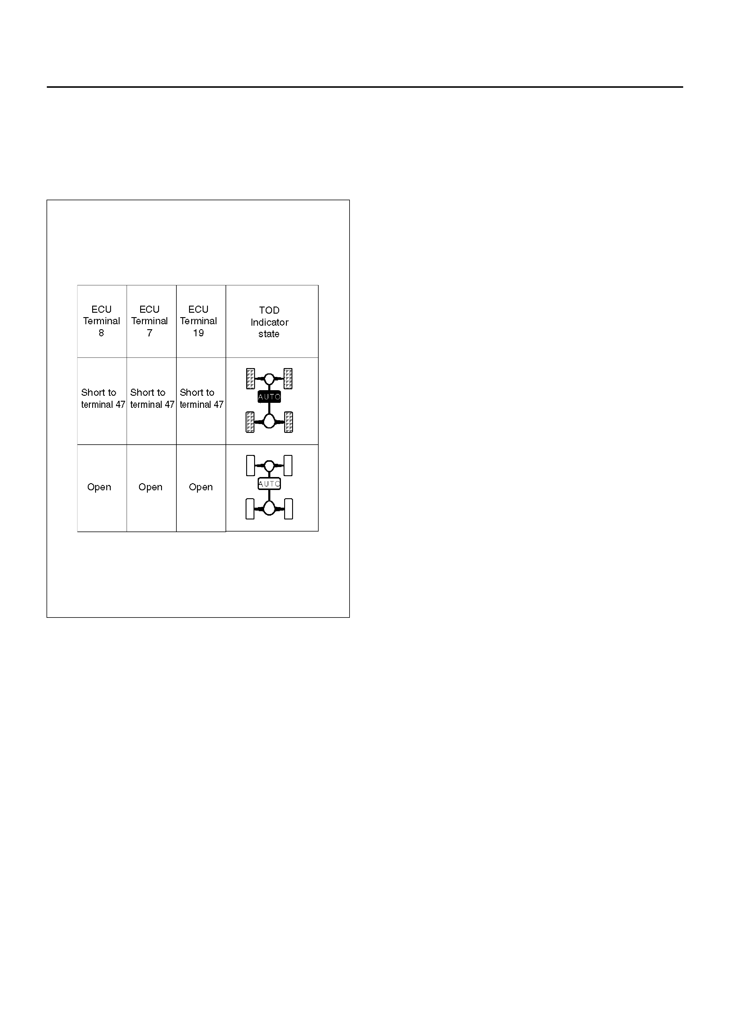
TROUBLE DIAGNOSIS DEPENDING ON THE STATUS OF TOD INDICATOR
Functional check with TOD indicator light is conducted
prior to check on Charts A–H.
• After the starter is switched on, check and see if the
status has become as tabulated below .
C04R200003
• If the status is as tabulated above, there is no
problem. If not as tabulated above, inspect the
harness.
D04R100013
Chart A Indicator drive circuit
Function of circuit The circuit informs the indicator of the working condition of the ECU.
Fail condition All the TOD indicator lamps and CHECK lamp are lit.
Indicator lamp state
TOD switch position 2H/TOD/4L

Step Action Yes No
1 Turn on the starter switch.
Is the battery voltage observed between terminals 14 and 47? The ECU has
failed. Replace
the ECU.
Go to Step 2
Check the
battery ci rcui t.
Go to Step 2
2 Check that all the parts are mounted.
Is this step complete? Repeat the
“Diagnosis Flow". Return to Step 2
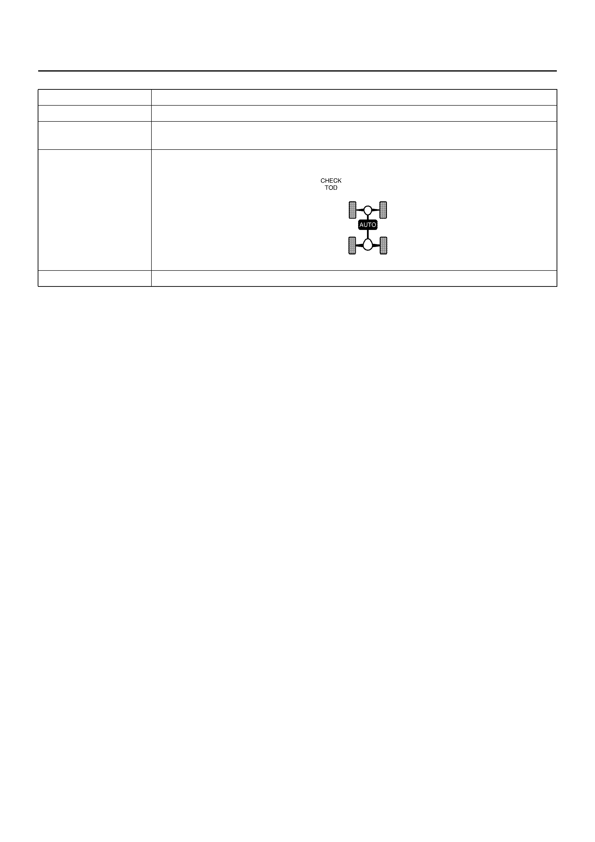
Chart B–1 The TOD switch A circuit wires are broken or short-circuited to the GND
Function of circuit —
Fail condition Even after the TOD switch position is selected from TOD to 2H, the indicator lamp status is
not changed.
Indicator lamp state
TOD switch position 2H

D04R100012

Table: Indicator Voltage
Step Action Yes No
1 1. Turn on the starter switch.
When the TOD switch is selected to the TOD position, is 0V
observ ed be twee n termi nal 3 0 a nd 47, an d 43 and 47? Does t he
voltage between the terminals 7 and 47, 19 and 47, and 8 and 47
comply with the TOD mode in the following table? Go to Step 2
Repair the TOD
switc h circuit.
Go to Step 4
2 When the TOD switch is selected to the 2H position, is 12 V
observed between terminals 30 and 47 and is 0V observed
between terminal 43 and 47? Does the voltage between the
termina ls 7 and 47, 19 and 47, and 8 and 47 compl y with the 2H
mode is the following table? Go to Step 3
Repair the TOD
switc h circuit.
Go to Step 4
3 When the TOD switch is selected to the 4L position, is 0V
observed between terminals 30 and 47 and is 12V observed
between terminal 43 and 47? Does the voltage between
termina ls 7 and 47, 19 and 47, and 8 a nd 47 comply with the 4L
mode in the followi ng table?
The phenom enon
is not reproduced.
Refer to “Trouble
intermittently
observed".
Repair the TOD
switc h circuit.
Go to Step 4
4 Check that all the parts are mounted.
Is this step complete? Verify the repair. Return to S tep 4
Unit: V
TOD
switch
mode
Terminals measured
Front 7 and
47 AUTO 19
and 47 Rear 8 and
47
2H 8.0 ∼ 14.5 8.0 ∼ 14.5 0
TOD000
4L 0 8.5 ∼ 14.5 0

Chart B–2 The TOD switch A circuit is shorted to battery.
Function of circuit —
Fail condition Even after the transfer mode is selected from 2H to TOD, the indicator lamp state does not
change.
Indicator lamp state
TOD switch position TOD

D04R100012
Table: Indicator terminal voltage
Step Action Yes No
1 1. Turn off the starter switch.
2. Disconnect the ECU connector (C–59).
Is the continuity established between the connector terminals (C–
59) 14 and (C–59) 7? Go to Step 2
Replace TOD
indica to r lam p
bulb.
Go to Step 6
2 Is the continuity established between the connector terminals (C–
59) 14 and (C–59) 19?
Go to Step 3
Replace TOD
indica to r lam p
bulb.
Go to Step 6
3 1. Turn off the starter switch and connect the ECU connector.
2. Turn on the starter switch.
When the TOD switch is selected to the TOD position, is 0V
observed between terminals 30 and 47, and 43 and 47? Does
the voltage between the terminals 7 and 47, 19 and 47, and 8
and 47 comply with the TOD mode in the following table? Go to Step 4
Repair the TOD
switc h circuit.
Go to Step 6
4 When the TOD switch is selected to the 2H position, is 12V
observed between terminals 30 and 47, and 0V observed
between terminals 43 and 47? Does the voltage between the
termina ls 7 and 47, 19 and 47, and 8 and 47 compl y with the 2H
mode in the followi ng table? Go to Step 5
Repair the TOD
switc h circuit.
Go to Step 6
5 When the TOD switch is selected to the 4L position, is 0V
observed between the terminal 30 and 47 and 12V observed
between t he terminal 43 and 47? Do es the voltage betwee n the
termina ls 7 and 47, 19 and 47, and 8 a nd 47 comply with the 4L
mode in the followi ng table?
The
phenomenon is
not reprodu ce d.
Refer to
“Trouble
intermittently
observed".
Repair the TOD
switc h circuit.
Go to Step 6
6 1. Check that all the parts are mounted.
Is this step complete? Verify repair. Go to Step 6
Unit: V
TOD
switch
mode
Terminals measured
Front 7 and
47 AUTO 19
and 47 Rear 8 and
47
2H 8.0 ∼ 14.5 8.0 ∼ 14.5 0
TOD000
4L 0 8.0 ∼ 14.5 0

Chart B–3 The TOD switch B circuit is shorted to GND or broken.
Function of circuit —
Fail condition Even after the transfer mode is selected from TOD to 4L, the indicator lamp state does not
change.
Indicator lamp state
TOD switch position 4L

D04R100012
Table: Indicator terminal voltage
Step Action Yes No
1 1. Turn on the starter switch.
When the TOD switch is selected to the TOD position, is 0V
observed between terminals 30 and 47, and 43 and 47? Does
the voltage between the terminals 7 and 47, 19 and 47, and 8
and 47 comply with the TOD mode in the following table? Go to Step 2
Repair the TOD
switc h circuit.
Go to Step 4
2 When the TOD switch is selected to the 2H position, is 12V
observed between terminals 30 and 47, and 0V observed
between terminals 43 and 47? Does the voltage between the
termina ls 7 and 47, 19 and 47, and 8 and 47 compl y with the 2H
mode in the followi ng table? Go to Step 3
Repair the TOD
switc h circuit.
Go to Step 4
3 When the TOD switch is selected to the 4L position, is 0V
observed between the terminal 30 and 47 and 12V observed
between t he terminal 43 and 47? Do es the voltage betwee n the
termina ls 7 and 47, 19 and 47, and 8 a nd 47 comply with the 4L
mode in the followi ng table?
The
phenomenon is
not reprodu ce d.
Refer to
“Trouble
intermittently
observed".
Repair the TOD
switc h circuit.
Go to Step 4
4 1. Check that all the parts are mounted.
Is this step complete? Verify repair. Go to Step 4
Unit: V
TOD
switch
mode
Terminals measured
Front 7 and
47 AUTO 19
and 47 Rear 8 and
47
2H 8.0 ∼ 14.5 8.0 ∼ 14.5 0
TOD000
4L 0 8.0 ∼ 14.5 0

Chart B–4 The TOD switch B circuit is shorted to battery.
Function of circuit —
Fail condition Even after the transfer mode is selected from 4L to TOD, the indicator lamp state does not
change.
Indicator lamp state
TOD switch position TOD

D04R100012
Table: Indicator terminal voltage
Step Action Yes No
1 1. Turn off the starter switch.
2. Disconnect the ECU connector (C–59).
Is the continuity established between the connector terminals (C–
59) 14 and (C–59) 19? Go to Step 2
Replace TOD
indica to r lam p
bulb.
Go to Step 5
2 1. Turn off the starter switch and connect the ECU connector.
2. Turn on the starter switch.
When the TOD switch is selected to the TOD position, is 0V
observed between terminals 30 and 47, and 43 and 47? Does
the voltage between the terminals 7 and 47, 19 and 47, and 8
and 47 comply with the TOD mode in the following table? Go to Step 3
Repair the TOD
switc h circuit.
Go to Step 5
3 When the TOD switch is selected to the 2H position, is 12V
observed between terminals 30 and 47, and 0V observed
between terminals 43 and 47? Does the voltage between the
termina ls 7 and 47, 19 and 47, and 8 and 47 compl y with the 2H
mode in the followi ng table? Go to Step 4
Repair the TOD
switc h circuit.
Go to Step 5
4 When the TOD switch is selected to the 4L position, is 0V
observed between the terminal 30 and 47 and 12V observed
between t he terminal 43 and 47? Do es the voltage betwee n the
termina ls 7 and 47, 19 and 47, and 8 a nd 47 comply with the 4L
mode in the followi ng table?
The
phenomenon is
not reprodu ce d.
Refer to
“Trouble
intermittently
observed".
Repair the TOD
switc h circuit.
Go to Step 5
5 1. Check that all the parts are mounted.
Is this step complete? Verify repair. Go to Step 5
Unit: V
TOD
switch
mode
Terminals measured
Front 7 and
47 AUTO 19
and 47 Rear 8 and
47
2H 8.0 ∼ 14.5 8.0 ∼ 14.5 0
TOD000
4L 0 8.0 ∼ 14.5 0
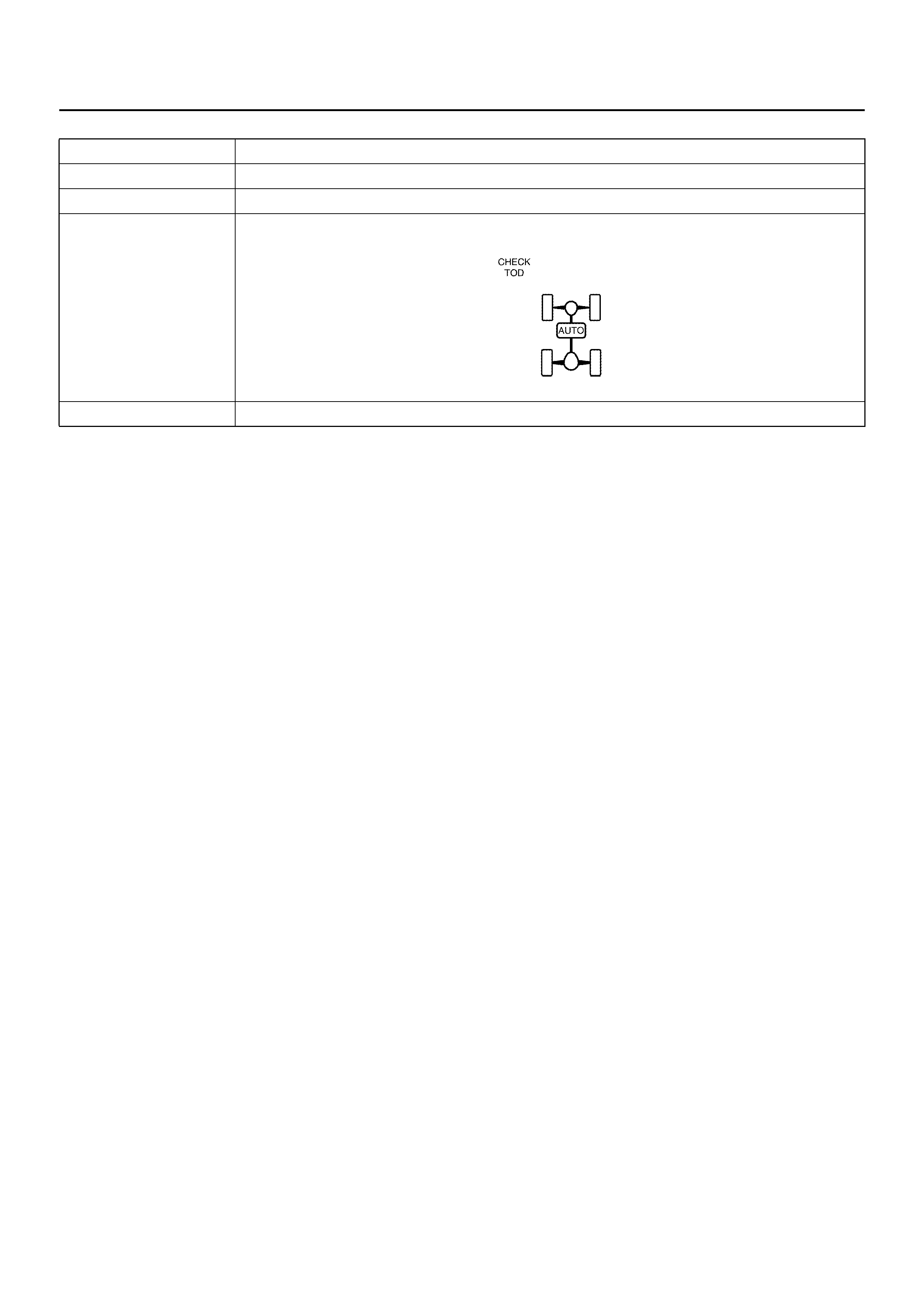
Chart C–1 4H switch circuit is short-circuited to GND.
Function of circuit —
Fail condition When the TOD switch is selected to 4L from TOD, all the indicator lamps are turned off.
Indicator lamp state
TOD switch position 4L

D04R100012

Step Action Yes No
1 1. Turn on the starter switch.
2. The car stops, the AT selector is N position and the brake is
applied.
When the TOD switch is changed to the TOD position, is 12V
observed between terminals 31 and 47 (4H switch)? Go to Step 2 Go to Step 9
2 1. The car stops the AT selector is N position and the brake is
applied.
When the TOD switch is changed to the 4L position, is 12V
observed between terminals 31 and 47 (4H switch)? Go to Step 3 Go to Step 9
3 1. Turn off the starter switch.
Is there the continuity terminal 14 and 7?
Go to Step 4
Replace the
TOD indicator
lamp bulb.
Go to Step 13
4 Is there the continuity between the terminals 14 and 19?
Go to Step 5
Replace the
TOD indicator
lamp bulb.
Go to Step 13
5 Is there the continuity between the terminal 14 and 8?
Go to Step 6
Replace the
TOD indicator
lamp bulb.
Go to Step 13
6 1. Turn on the starter switch.
2. The car stops the AT selector is N position and the brake is
applied.
When the TOD switch is changed to the 4L position, is 0V
observed between terminal 7 and 47? (for 2 seconds after the
starter switch ON)? Go to Step 7
The ECU has
frailed. Replace
the ECU.
Go to Step13
7 Is 0V observed between terminal 19 and 47? (for 2 seconds after
the starter switch ON)
Go to Step 8
The ECU has
failed. Replace
the ECU.
Go to Step 13
8 Is 0V observed betwe en terminal 8 an d 47? (for 2 sec onds after
the starter switch ON) The
phenomenon is
not reprodu ce d.
Refer to
“Trouble
intermittently
observed".
The ECU has
failed. Replace
the ECU.
Go to Step 13
9 1. T he car stops, the AT select or is N posit ion, and the bra ke is
applied.
2. The TOD switch is changed to the TOD (or 2H) position.
3. Turn off the starter switch.
4. Disconnect the ECU connector (C–60).
Is there the continuity between the connector (C–60) terminal 9
and 25? Go to Step 11 Go to Step 10

10 1. Connect the ECU connector (C–60) and turn on the starter
switch.
2. T he car stops, the AT sele ctor is N posit ion, and the bra ke is
applied.
3. Change the TOD switch to the 4L position.
4. Turn off the starter switch and di scon nec t the E CU con nector
(C–60).
Is there the continuity between the connector (C–60) terminal 9
and 25? Go to Step 11
The ECU has
failed. Replace
the ECU.
Go to Step 13
11 1. Disconnect the connector (H–38).
Is the continuity established between the transfer connector
terminals (H–38)4 and (C–60) 9?
Go to Step 12
The harness is
broken between
terminal (H–38)
4 and (C–60) 9.
Repair the
circuit.
Go to Step 13
12 1. Connect the connector (H–38).
2. Disconnect the connector (A–1).
Is there the continuity between the connector terminal (A–1) 4
and (C–60) 9?
Repair the
transfer.
Go to Step 13
The harness
between the
connector
terminal (C–60)
9 and (A–1) 4 is
short-circuited
to GND.
Repair the
circuit.
Go to Step 13
13 Check that all the parts are mounted.
Is this step complete? Verify the repair. Return to Step 13
Step Action Yes No
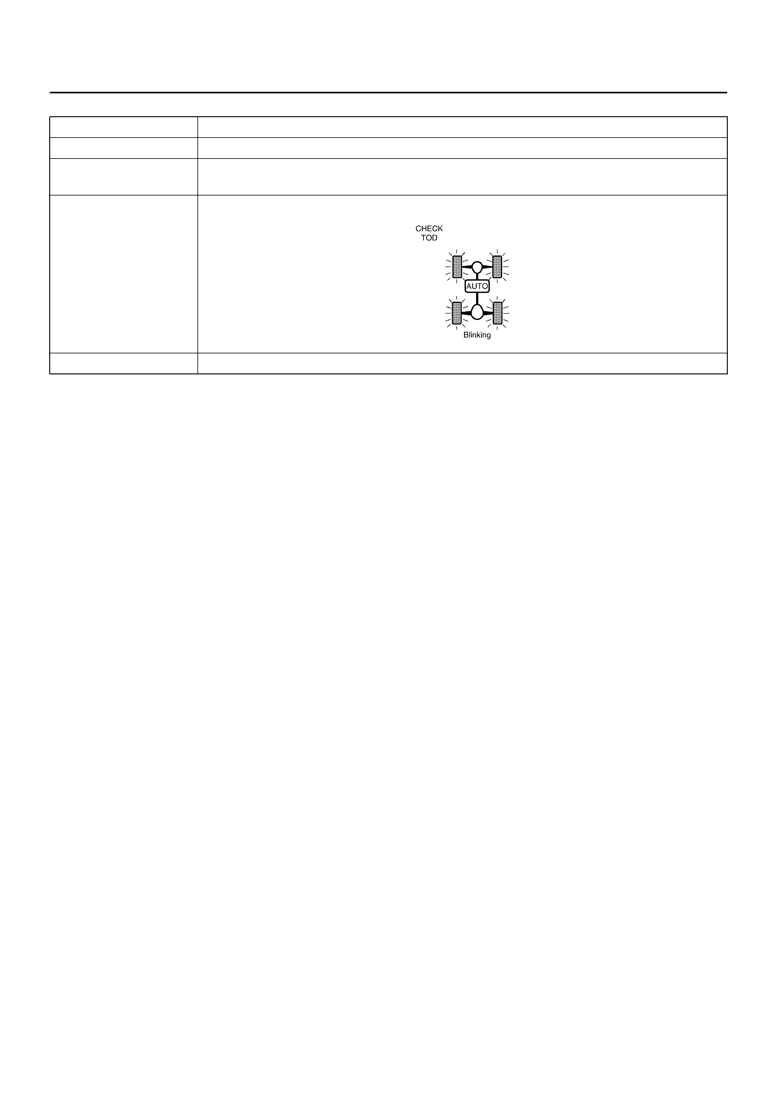
Chart D–1 4L switch circuit wires are broken or the battery circuit is short-circuited.
Function of circuit —
Fail condition When the TOD switch is changed to the 4L position, the indicator 4L mode goes on and
off.
Indicator lamp state
TOD switch position 4L

D04R100012

Step Action Yes No
1 1. Turn on the starter switch.
2. The car stops, the AT selector is the N position, and the brake
is applied.
When the TOD switch is changed to the TOD (or 2H) pos ition, is
12V observed between terminals 44 and 47 (4L switch)? Go to Step 2 Go to Step 4
2 1. The car stops, the AT selector is the N position, and the brake
is applied.
When the TOD switch is changed to the 4L position, does the
transfer become the 4L state? Go to Step 3 Refer to “Diagnosis
from symptom".
3 Is 0V observed between the terminal 44 and 47? The ECU has
failed. Replace
the ECU.
Go to Step 10 Go to Step 4
4 1. The car stops, the AT selector is the N position, and the brake
is applied.
When the TOD switch is changed to the TOD (or 2H) pos ition, is
12V observed between the connector (C–60) terminal 22 and
25? Go to Step 5 Go to Step 6
5 1. Turn off the starter switch and connect the EUC connector.
2. The car stops, the AT selector is the N position, and the brake
is applied.
When the TOD switch is changed to the 4L position, is 0V
observed between terminals (C–60) 22 and (C–60) 25 (4L
switch)?
The
phenomenon is
not reprodu ce d.
Refer to
“Trouble
intermittently
observed". Go to Step 6
6 1. Turn off the starter switch and connect ECU connector.
2. Turn on the starter switch.
3. The car stops, the AT selector is the N position, and the brake
is applied.
4. Change the TOD switch to the TOD (or 2H) position.
5. After the transfer has changed to the TOD (or 2H) mode, turn
off the starter switch and disconnect the ECU connector (C–
60).
Is ther e the contin uity between the c onnector (C–6 0) term inal 22
and 25? Go to Step 9 Go to Step 7
7 1. Turn off the starter switch and connect the ECU connector.
2. Turn on the starter switch.
3. The car stops, the AT selector is the N position, and the brake
is applied.
4. Change the TOD switch to the 4L position.
5. After the transfer has changed to the 4L mode, turn off the
starter switch.
6. Disconnect the ECU connector.
Is ther e the contin uity between the c onnector (C–6 0) term inal 22
and 25?
The
phenomenon is
not reprodu ce d.
Refer to
“Trouble
intermittently
observed". Go to Step 8

8 1. Turn off the starter switch and connect the ECU connector.
2. Turn on the starter switch.
3. The car stops, the AT selector is the N position, and the brake
is applied.
4. Change the TOD switch to the TOD (or 2H) position.
5. After the transfer has changed to the TOD (or 2H) mode, turn
off the starter switch.
6. Disconnect the transfer connector (A–1).
Is there the continuity between the connector terminal (A–1) 12
and GND?
Repair the
transfer.
Go to Step 10
Repair the
circuit between
(C–60) 22 and
(A–1) 12.
Go to Step 10
9 1. Turn off the starter switch and connect the connector (A–1).
2. Turn on the starter switch.
3. T he car stops, the AT sele ctor is N posit ion, and the bra ke is
applied.
4. Change the TOD switch to the 4L position.
5. After the transfer has changed to the 4L mode, turn off the
starter switch.
6. Disconnect the transfer connector (A–1).
Is there the continuity between the connector terminal (A–1) 12
and GND?
Repair the
circuit between
(C–60)22 and
(A–1)12.
Go to Step 10
Repair the
transfer.
Go to Step 10
10 Check that all the parts are mounted.
Is this step complete? Verify the repair. Go to Step 10
Step Action Yes No
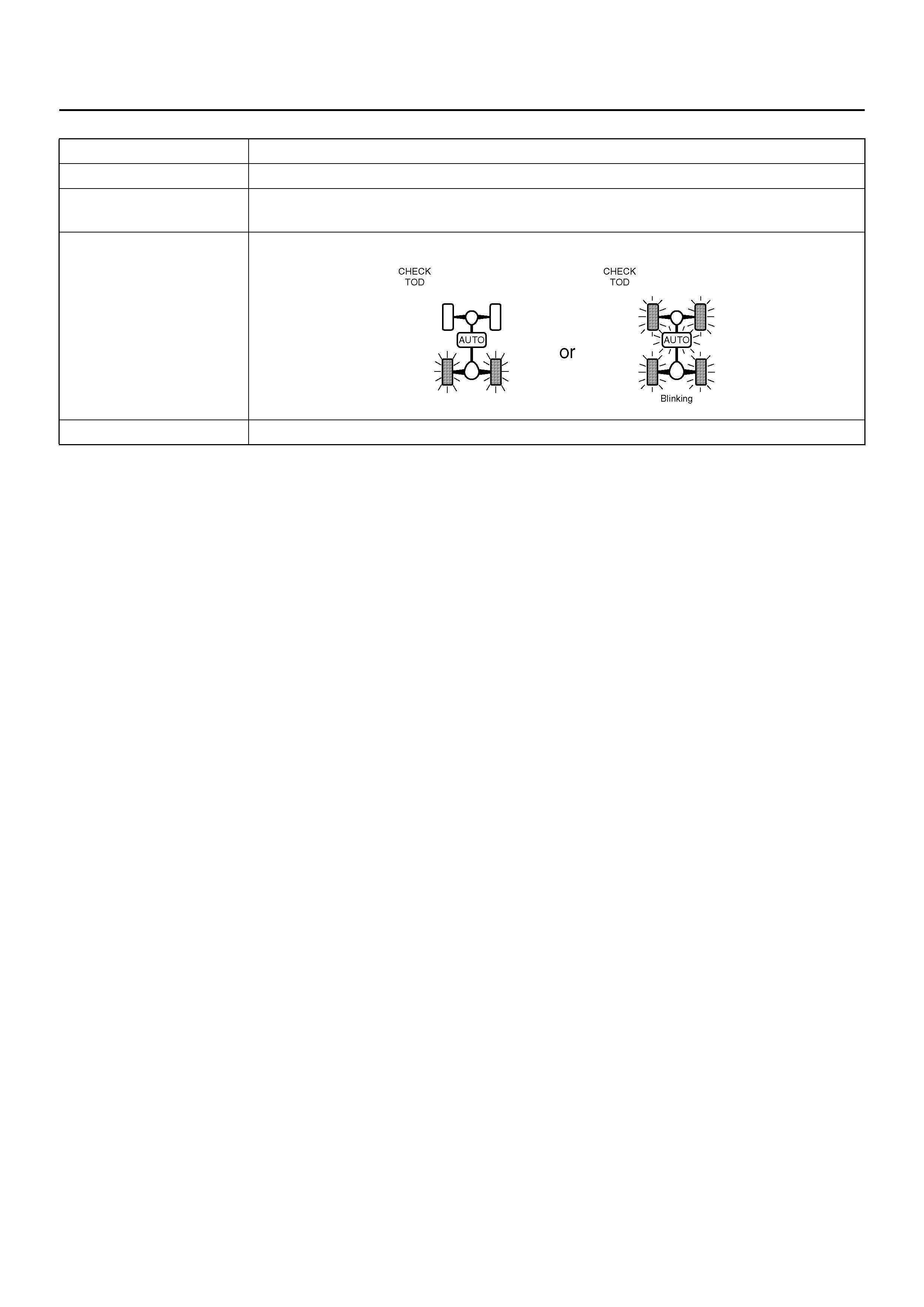
Chart D–2 The 4L switch circuit is short-circuited to GND.
Function of circuit —
Fail condition When the TOD switch is changed to the 2H or TOD position, the indicator mode goes on
and off.
Indicator lamp state
TOD switch position 2H or TOD
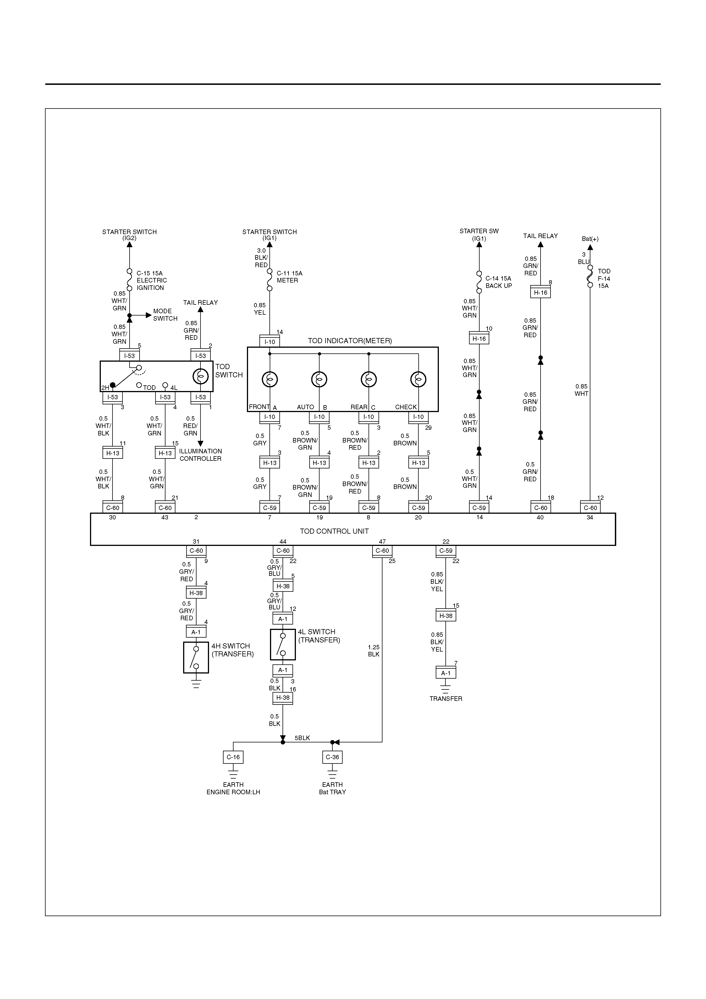
D04R100012

Step Action Yes No
1 1. The car stops, the AT selector is the N position, and the brake
is applied.
When the TOD switch is changed to the TOD (or 2H) pos ition, is
12V observed between terminals 44 and 47 (4L switch)? Go to Step 2 Go to Step 3
2 1. The car stops, the AT selector is the N position, and the brake
is applied.
When the TOD switch is changed to the 4L position, is 0V
observed between terminals 44 and 47 (4L switch)?
Refer to “Trouble
intermittently
observed". Go to Step 3
3 1. The car stops, the AT selector is the N position, and the brake
is applied.
2. Select the TOD switch to the TOD (or 2H) position.
Is ther e the contin uity between the c onnector (C–6 0) term inal 22
and 25? Go to Step 5 Go to Step 4
4 1. Connect the ECU connector (C–60) and turn on the starter
switch.
2. The car stops, the AT selector is the N position, and the brake
is applied.
3. Select the TOD switch to the 4L position.
4. Turn off the starter switch and di scon nec t the E CU con nector
(C–60).
Is ther e the contin uity between the c onnector (C–6 0) term inal 22
and 25?
The ECU has
failed. Replace
the ECU.
Go to Step 9 Go to Step 5
5 1. Connect the ECU connector (C–60) and turn on the starter
switch.
2. The car stops, the AT selector is the N position, and the brake
is applied.
3. Select the TOD switch to the TOD (or 2H) position.
4. Turn off the starter switch and disconnect the connector (H–
38).
Is there the continuity between the connector terminal (H–38) 5
and (C–60) 25? Go to Step 7 Go to Step 6
6 1. Connect the connector (H–38) and turn on the starter switch.
2. The car stops, the AT selector is the N position, and the brake
is applied.
3. Select the TOD switch to the 4L position.
4. After the transfer has changed to the 4L mode, turn off the
starter switch and disconnect the connector (H–38).
Is there the continuity between the connector terminal (H–38) 5
and (C–60) 25? Go to Step 7
GND is
short-circuited
between
terminals (C–
60) 2 and (H–
38) 5. Repair
the circuit.
Go to Step 9
7 1. Connect the connector (H–38) and turn on the starter switch.
2. The car stops, the AT selector is the N position, and the brake
is applied.
3. Select the TOD switch to the TOD (or 2H) position.
4. After the transfer has changed to the TOD (or 2H) mode, turn
off the starter switch and disconnect the connector (A–1).
Is there the continuity between the connector terminal (A–1) 12
and GND?
Repair the
transfer.
Go to Step 9 Go to Step 8

8 1. Connect the connector (A–1) and turn on the starter switch.
2. The car stops, the AT selector is the N position, and the brake
is applied.
3. Select the TOD switch to the 4L position.
4. After the transfer has changed to the 4L mode, disconnect
the connector (A–1).
Is there the continuity between the connector terminal (A–1) 12
and GND?
GND is
short-circuited
between
termi nals (A –1)
12 and (H–38)
5. Repair the
circuit.
Go to Step 9
Repair the
transfer.
Go to Step 9
9 Check that all the parts are mounted.
Is this step complete? Verify the repair. Go to Step 9
Step Action Yes No
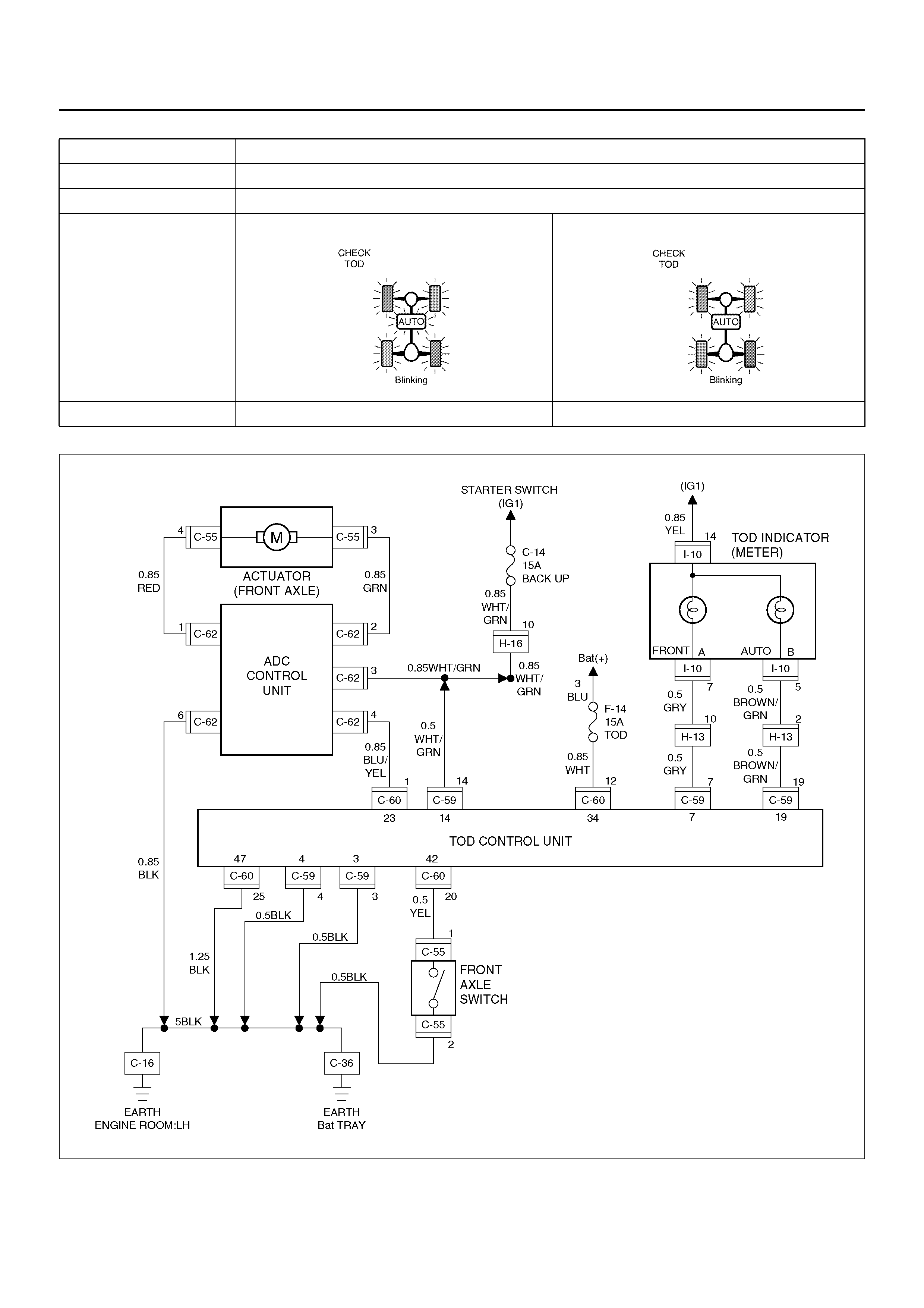
D04R100013
Chart E–1 AXLE switch circuit wires are broken.
Function of circuit —
Fail condition Both the TOD and 4L modes are disabled. (The transition status is not removed.)
Indicator lamp state
TOD switch position TOD 4L

Step Action Yes No
1 Start the engine.
When the TOD switch is selected to the TOD position, is 0V
observed between terminals 42 and 47? Go to Step 2 Go to Step 4
2 1. T he car stops, the AT select or is N posit ion, and the bra ke is
applied.
2. Select the TOD switch to the 4L position.
Is 0V observed between terminals 42 and 47? Go to Step 3 Go to Step 4
3 1. T he car stops, the AT select or is N posit ion, and the bra ke is
applied.
When the TOD switch is selected to the 4L position, is 12V
observed between the terminal 19 and 47?
The
phenomenon is
not reprodu ce d.
Refer to
“Troubles
intermittently
observed".
The ECU has
failed. Replace
the ECU.
Go to Step 8
4 1. T he car stops, the AT select or is N posit ion, and the bra ke is
applied.
When the TOD switch is selected to the 2H position, is the
battery voltage observed between the terminal 23 and 47. Go to Step 5 Go to Step 7
5 When the TOD switch is selected to the TOD position (TOD
mode), is 0 ∼ 1V observed between terminals 23 and 47? Go to Step 6 Go to Step 7
6 1. T he car stops, the AT select or is N posit ion, and the bra ke is
applied.
When the TOD switch is selected to the 4L position, is 0V
observed between terminals 23 and 47?
Repair the
circuit or check
the “Front Axle
Disconnect".
(Refer to
section 4B)
Go to Step 8 Go to Step 7
7 Is any of the trouble codes 28 (P1760), 32 (P1761) and 33
(P1 7 62) recorde d? Examine the
trouble based on
“Diagnosis from
Trouble Codes".
The ECU has
failed. Replace
the ECU.
Go to Step 8
8 Check that all the parts are mounted.
Is this step complete? Verify the repair. Go to Step 8
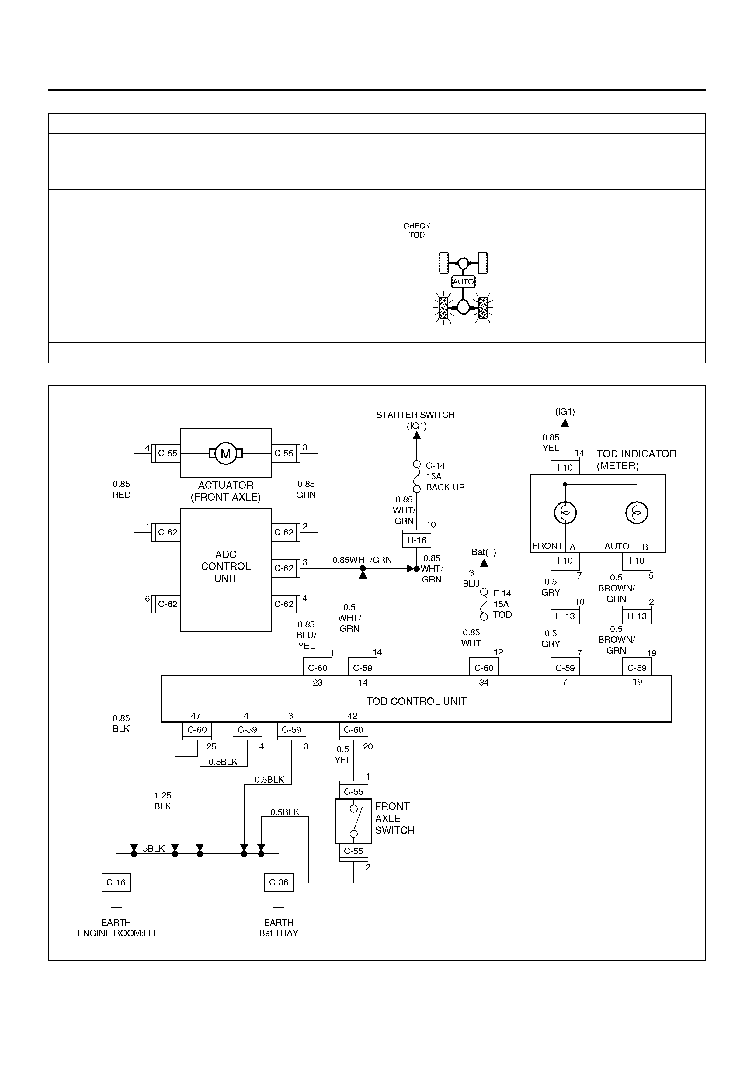
D04R100013
Chart E–2 The AXLE switch circuit is short-circuited to GND.
Function of circuit —
Fail condition Even after the TOD switch is selected to the 2H position, the 2H mode is not enabled. (The
transition status is not removed.)
Indicator lamp state
TOD switch position 2H

Step Action Yes No
1 Start the engine.
When the TOD switch is selected to the TOD position, is 0V
observed between terminals 42 and 47? Go to Step 2 Go to Step 6
2 1. T he car stops, the AT select or is N posit ion, and the bra ke is
applied.
When the TOD switch is selected to the 4L position, is 0V
observed between terminals 42 and 47? Go to Step 3 Go to Step 6
3 1. T he car stops, the AT select or is N posit ion, and the bra ke is
applied.
2. Select the TOD switch to the 2H position.
Is 5V observed between terminals 42 and 47? Go to Step 4 Go to Sep 6
4 Is 12V observed between terminals 7 and 47?
Go to Step 5
Replace the
ECU.
Go to Step 10
5 Is 12V observed between terminals 19 and 47? The
phenomenon is
not reprodu ce d.
Refer to
“Troubles
intermittently
observed".
The ECU has
failed. Replace
the ECU.
Go to Step 10
6 1. T he car stops, the AT select or is N posit ion, and the bra ke is
applied.
When the TOD switch is selected to the 2H position, is the
battery voltage observed between terminals 23 and 47? Go to Step 7 Go to Step 9
7 1. T he car stops, the AT select or is N posit ion, and the bra ke is
applied.
When the TOD switch is selected to the TOD position, is 0V
observed between terminals 23 and 47? Go to Step 8 Go to Step 9
8 1. T he car stops, the AT select or is N posit ion, and the bra ke is
applied.
When the TOD switch is selected to the 4L position, is 0V
observed between terminals 23 and 47?
Repair the
circuit or check
the “Front Axle
Disconnect".
(Refer to
section 4B)
Go to Step 10 Go to Step 9
9 Is any of the trouble codes 28 (P1760), 32 (P1761) and 33
(P1 7 62) recorde d? Examine the
trouble based on
“Diagnosis from
Trouble Codes".
The ECU has
failed. Replace
the ECU.
Go to Step 10
10 Check that all the parts are mounted.
Is this step complete? Verify the repair. Go to Step 10

Chart G The trouble codes are displayed.
Function of circuit —
Fail condition
Indicator lamp state
TOD switch position —
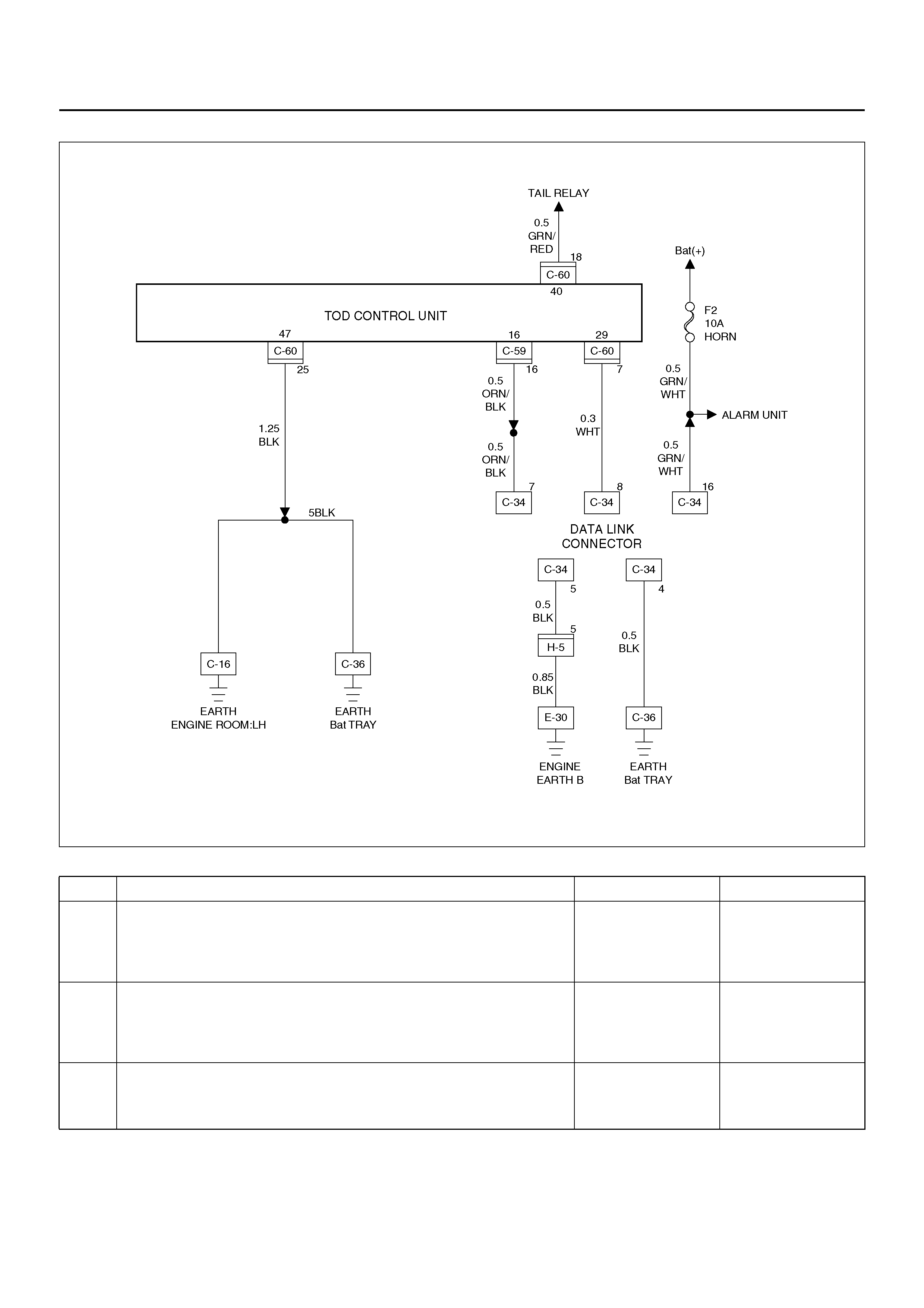
D04R100011
Step Action Yes No
1 Disconnect the ECU connector from ECU.
Is there the continuity established between terminals (C–60)7
and (C–60)25? Go to Step 2
The ECU has
failed. Replace
the ECU.
Go to Step 3
2 Is the self-diagnostic connector short-circuited?
Go to Step 3
Open the
self-diagnostic
connector.
Go to Step 3
3 1. Check that all the parts are mounted.
2. Clear the trouble codes.
Is this step complete? Verify the repair. Go to Step 3
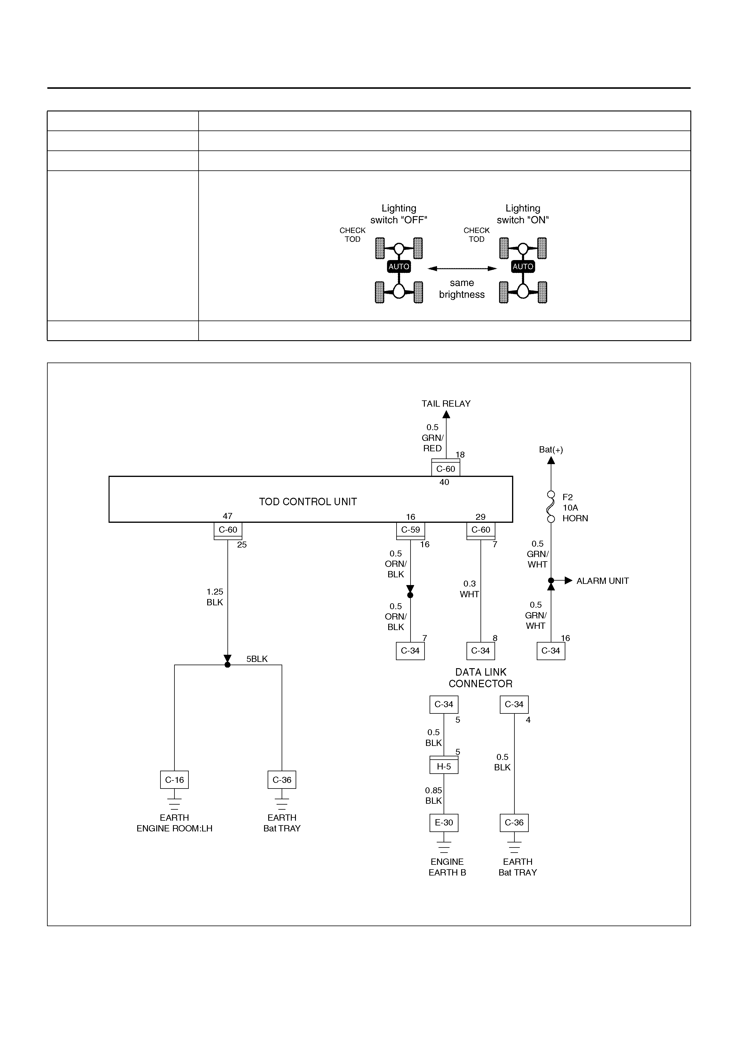
D04R100011
Chart H Lighting switch circuit
Function of circuit Reads in the status of lighting switch, and reduces the indicator at night.
Fail condition Even if the lighting switch is pressed on and off, brightness does not change.
Indicator lamp state
TOD switch position All position (exsample TOD mode)

Step Action Yes No
1 1. Turn on the starter switch.
2. Turn off the lighting switch.
Is 0V observed between the EUC terminal 40 and 47?
Go to Step 2
Lighting switch
battery circuit
short. Repair
the circuit.
Go to Step 4
2 Turn lighting switch “ON".
Is the battery voltage observed between ECU terminal 40 and
47?
Go to Step 3
Wires are
broken in
lighting switch
circuit. Repair
the circuit.
Go to Step 4
3 While the lighting switch is pressed on and off, does the
brightness of the indicator change? The phenomenon
is not reproduced.
Refer to “Troubles
intermittently
observed"
The ECU has
failed. Replace
the ECU.
Go to Step 4
4 Check that all the parts are mounted.
Is this step complete? Verify the repair. Go to Step 4

DIAGNOSIS FROM SYMPTOM
Tr oubl es that are n ot in dicate d by th e war ning l amp are
listed in the table below. These troubles are caused by
the faults that canno t be detected by the se lf-diagn ostic
function of the control unit.
If this type of trouble is observed, interview the
customer and conduct test runs to reproduce the
trouble, cross-check the reported trouble with the listed
phenomena, and diagnose and analyze the trouble on
the item by item basis.
Phenomen a Major cause Corre cti ve actio n
1 The tight corner braking is observed
when the vehicle is subject to full
steering.
• The standard tires are not used.
• The tire pressure is incorrect.
• The tires are worn inuniformity.
• The transfer or wiring is imperfect.
• T he limi ted sl ip differe nti al is
failed.
Check and recondition the
vehicle according to Chart 1.
2 Even if the TOD switch is selected to
the TOD position, the F4WD mode is
not active, resulting in remarkable
rear wheel spin.
• The transfer or wiring is imperfect.
• The shift on the fly system is
failed.
Check and recondition the
vehicle according to Chart 2.
3 • When the TOD switch is selected
to the TOD position, the drive
resistance of the F4WD system is
too large to get sufficient runni ng
speed.
• Noised drive line.
• The standard tires are not used.
• The tires are worn inuniformity.
• The transfer or wiring is imperfect.
• T he limi ted sl ip differe nti al is
failed.
Check and recondition the
vehicle according to Chart 1.
4 The shift on the fly system (front axle
disconnect) generates gear noises. • The wiring is imperfect.
• The shift on the fly system is
failed.
Check and recondition the
vehicle according to Chart 3.
5 The braking distance gets long even
when the ABS is active. • The wiring is imperfect.
• The ABS is failed. Check and recondition the
vehicle according to Chart 4.
6 The transfer does not change to the
low range from the high range. • The transfer or wiring is imperfect.
• The TOD switch is imperfect.
• The AT inhibitor switch is
imperfect.
• The brake switch is imperfect.
• The engine speed signal is
imperfect.
• The speed sensor is imperfect.
Check and recondition the
vehicle according to chart 5.
7 The transfer does not change to the
high range from the low range. Check and recondition the
vehicle according to chart 6.
8 The transfer stays neutral and the
vehicle does not run. • The transfer is imperfect. Check and recondition the
vehicle according to chart 7.
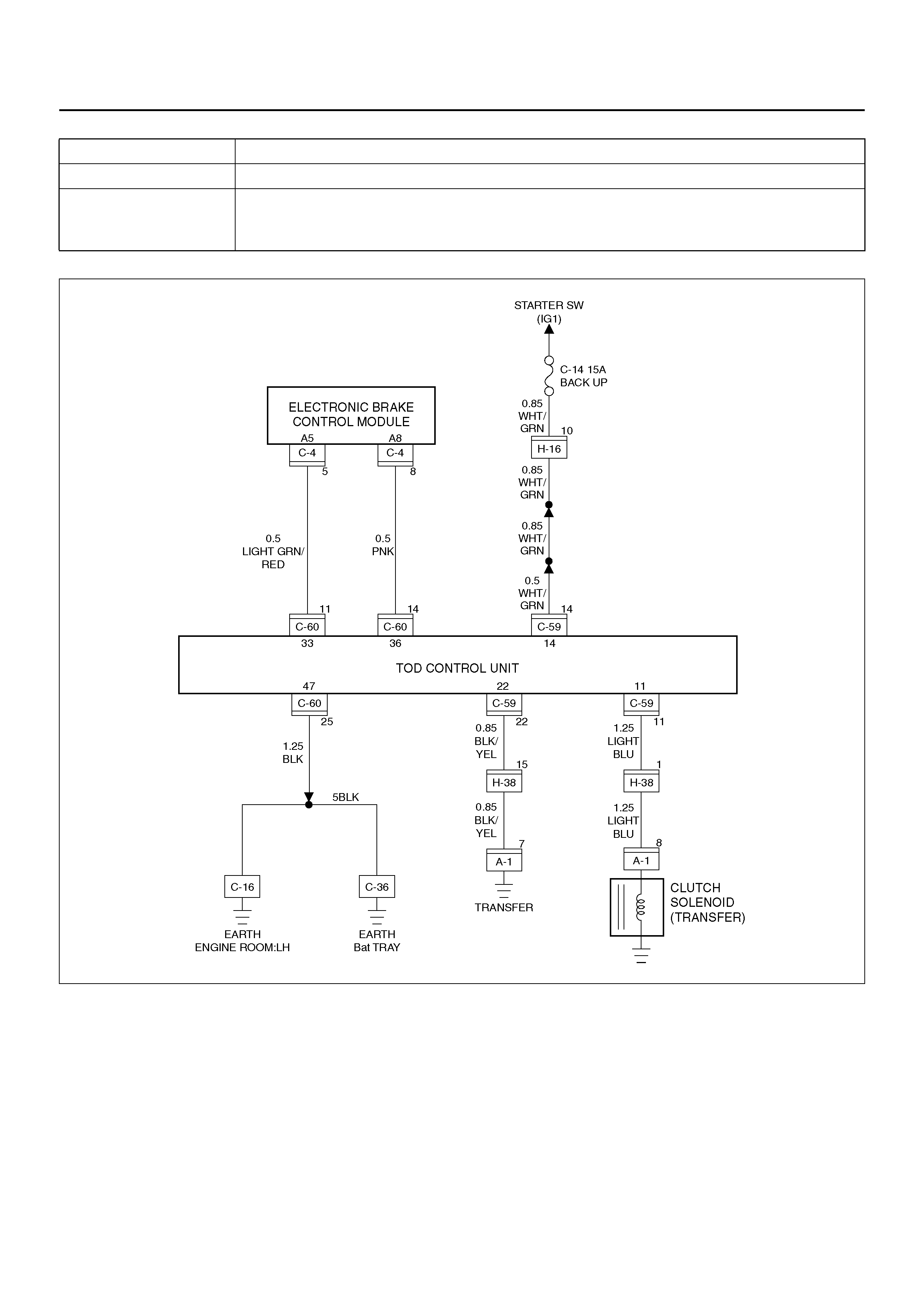
D04R100010
Chart 1 The tight corner braking is observed.
Function of circuit —
Fail condition When the vehicle is subject to full steering in the TOD mode, the drive resistance gets
large or the judder occurs. Otherwise, the above phenomenon is observed only when the
brake is app lied.

Step Action Yes No
1 Are the front and rear tires in specified size?
Go to Step 2
Replace the
tires with
specified ones,
and service the
new tires.
Go to Step 16
2 Is the tire pressure correct?
Go to Step 3
Inflate the tires
with specified
pressure.
Go to Step 16
3 Are the tires free from abnormal wear?
Go to Step 4
Replace the
tires with
specified ones,
and service the
new tires.
Go to Step 16
4 Are different types of tires used?
Go to Step 5
Replace the
tires with
specified ones,
and service the
new tires.
Go to Step 16
5 1. Start the engine.
2. Sele ct the TOD switch to the TOD position.
3. F ully turn the ste erin g to the left (or righ t) end, and select the
D range and start the creep run.
Does the tight corner braking occur? Is the judder with chug-chug
sound observed? *Use caution on the operation. Go to Step 6 Go to Step 11
6 1. Select the TOD switch to the 2H position.
2. F ully turn the ste erin g to the left (or righ t) end, and select the
D range and start the creep run.
Does the tight corner braking occur? Is the judder with chug-chug
sound observed? *Use caution on the operation. Go to Step 7 Go to Step 14
7 Is an LSD mounted to the rear differential? Go to Step 8 Go to Step 9
8 Is the genuine LSD oil used in the rear differential?
Go to Step 9
Replace the
differential oil.
Go to Step 16
9 Does the engine output the power correctly?
Go to Step 10
Check the
engine.
Go to Step 16
10 Do the speed sensors work correctly? (Check trouble codes.) The ECU has
failed. Replace
the ECU.
Go to Step 16
Replace the
speed se nso r s.
Go to Step 16
11 Is the tight corner braking observed only when the brake is
applied?
Go to Step 12
Conduct full
steering under
WOT.
Go to Step 5

*NOTE: Before ch ecki ng this item, r un the v ehicle m ore
than 10 meters with the steering wheel in straight
position so that the 4L mechanical lock sleeve can be
released certainly.
12 1. Turn on the starter switch.
Is 8 ∼ 10 V observed between terminals 33 and 47?
Go to Step 13
Repair the
circuit of the
ECU connector
terminal 33
(ABS IN).
Go to Step 16
13 1. Apply the br ak e and fully turn the stee ri ng to the le ft (or right)
end, and start the creep run.
Does the voltage between terminals 11 and 22 range between
0.1 and 1.0V?
Repair the
transfer
assembly.
Go to Step 16
The ECU has
failed. Replace
the ECU.
Go to Step 16
14 1. Select the TOD switch to the TOD position.
2. F ully turn the ste erin g to the left (or righ t) end, and select the
D range and start the creep run.
Does the voltage between terminals 11 and 22 range between
0.1 and 1.0V? Go to Step 15 Go to Step 10
15 1. Select the TOD switch to the 2H position.
2. Jack up the right front wheel.
Does the front tire rotate smoothly?
The phenom enon
is not reproduced.
Refer to “Troubles
intermittently
observed".
Repair the
transfer
assembly.
Go to Step 16
16 Check that all the parts are mounted.
Is this step complete? Verify the repair Go to Step 16
Step Action Yes No

D04R100010
Chart 2 The TOD mode is not active.
Function of circuit —
Fail condition The rear wheels spin in the TOD mode, so the driving torque is not transmitted to the front
wheels. The indicator lamps will not show the 4L and TOD status.

Step Action Yes No
1 Is the trouble code 31(P1721) recorded? Examine the
trouble based on
“Diagnosis from
Trouble Codes". Go to Step 2
2 Is any of the trouble codes 28(P1760), 32(P1761) and 33(P1762)
recorded? Examine the
trouble based on
“Diagnosis from
Trouble Codes". Go to Step 3
3 When the T OD swit ch is sele ct ed to th e sp ec ifi ed posi t io n, do the
TOD indicator lamps show the correct status?
Go to Step 4
Exami ne the
trouble based on
“Trouble Diagnosis
Depending on The
Status of TOD
Indicator".
4 Select the TOD switch to the 4L position, fully turn the steering to
the left (or right) end, and start the creep run. Does the tight
corner braking occur? Go to Step 5
Repair the
transfer
assembly.
Go to Step 7
5 1. Select the TOD switch to the TOD position.
2. Turn on the starter switch.
Does the voltage between terminals 11 and 22 indicate at least
3V while the throttle is completely open? Go to Step 6
The ECU has
failed. Replace
the ECU.
Go to Step 7
6 Does the voltage between terminals 11 and 22 indicate at least
0.1V while the throttle is completely closed? The TOD clutch
is worn. Repair
the transfer
assembly.
Go to Step 7
The ECU has
failed. Replace
the ECU.
Go to Step 7
7 Check that all the parts are mounted.
Is this step complete? Verify the repair. Go to Step 7
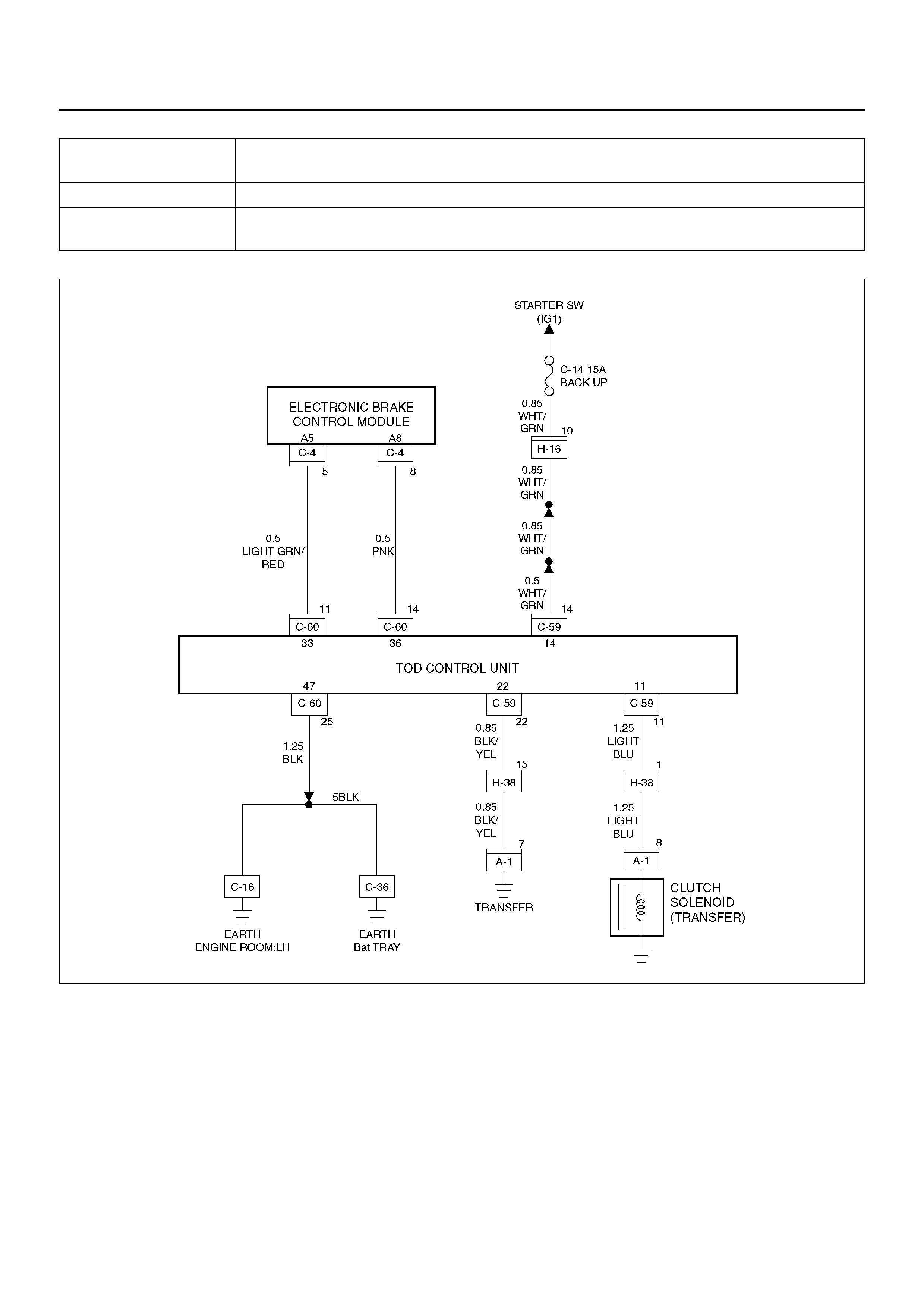
D04R100010
Chart 3 The shift on the fly system generates gear noises.
(The fuel economy is bad in the 2H mode.)
Function of circuit —
Fail condition When the vehicle is run in the 2H mode, the shift on the fly system generates gear noises
or the front wheel gears are engaged to generate a shock.

Step Action Yes No
1 Do the indicator lamps show the correct status?
Go to Step 2
Exami ne the
trouble based on
“Trouble Diagnosis
Depending on the
Status of TOD
Indicator".
2 Is any of the trouble codes 28(P1760), 32(P1761) and 33(P1762)
recorded? Examine the
trouble based on
“Diagnosis from
Trouble Codes". Go to Step 3
3 Turn on the starter switch.
Is the battery voltage observed between terminals 14 and 47? Go to Step 4 Go to Step 5
4 When the TOD Switch is selected to the 2H position, are the front
axle gears correctly disengaged (and when the left front tire is
jacked up and turned, is the front propeller shaft standstill)?
The phenom enon
is not reproduced.
Refer to “Trouble
intermittently
observed".
The shift on t h e f ly
system is failed
(refer to Section
4B1 and 4C).
5 Do es the batt er y voltage maintain the correct level?
Repair the
battery circuit.
Go to Step 6
Repair the
battery and
charging
system.
Go to Step 6
6 Check that all the parts are mounted.
Is this step complete? Verify the repair. Go to Step 6
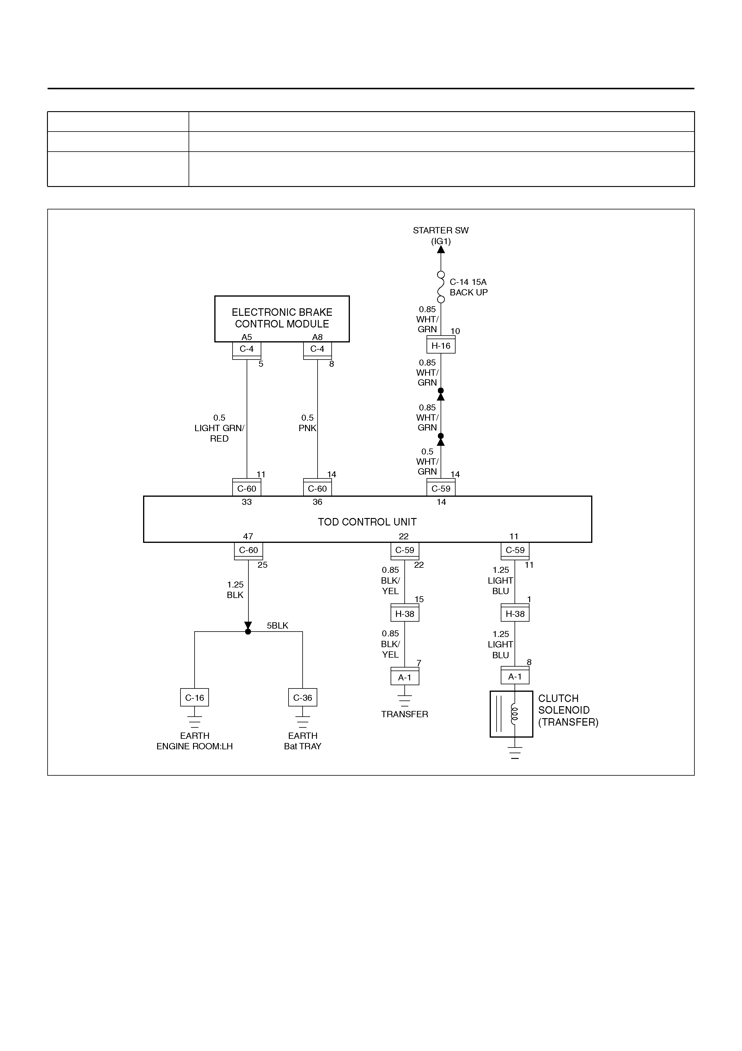
D04R100010
Chart 4 The braking distance gets long even when the ABS is active.
Function of circuit —
Fail condition Enough deceleration is not obtained and the braking distance gets long even when the
ABS is active in the 2H mode.
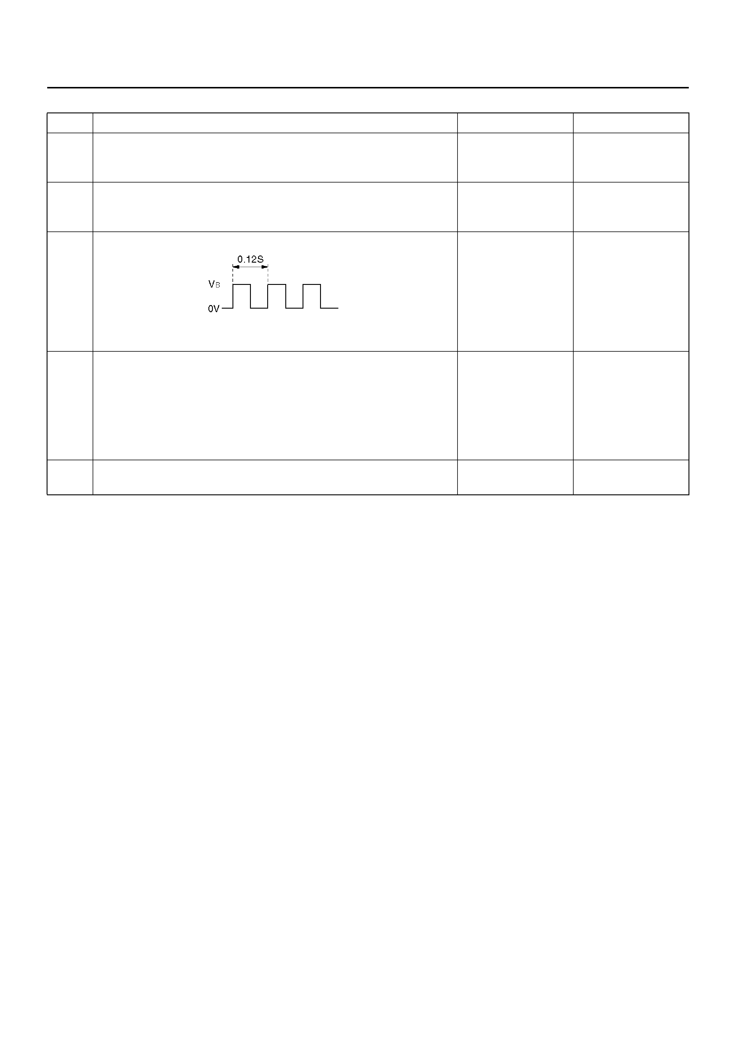
Step Action Yes No
1 Are the brake and ABS systems healthy?
Go to Step 2
Repair the brake
and ABS. (Refer to
section 5A and 5B)
2 Turn on the starter switch.
Is the battery voltage observed between terminals 14 and 47? Go to Step 3
Repair the
battery system.
Go to Step 5
3 1. Select the TOD switch to the 2H position.
Does the voltage between terminals 36 and 47 range between
7.5 and 16V (0.12 seconds make a cycle)? Go to Step 4
The ECU has
failed. Replace
the ECU.
Go to Step 5
4 1. Turn off the starter switch.
2. Disconnect the connector (C–60).
Is ther e the contin uity between the c onnector term inal (C–60) 14
and (C–4) 8?
The
phenomenon is
not reprodu ce d.
Refer to
“Trouble
intermittently
observed".
Repair the
harness.
Go to Step 5
5 Check that all the parts are mounted.
Is this step complete? Verify the repair. Go to Step 5

D04R100014
Chart 5 The transfer does not change to low from high.
Function of circuit —
Fail condition When the TOD switch is selected to the 4L position, the transfer does not change to the
low range.

Step Action Yes No
1 1. Turn on the starter switch.
Is any of the trouble codes 41 (P1741), 42 (P1773), 43 (P1743)
and 55 (P1755) recorded?
Examine the
trouble based on
“Diagnosis from
Trouble Codes". Go to Step 2
2 Is any of the troub le codes 13 (P1735 ), 14 (P1731), 15 (P17 36),
16 (P1737), 24 (P1733), and 27 (P1738) recorded? Examine the
trouble based on
“Diagnosis from
Trouble Codes". Go to Step 3
3 Is the trouble code 17 (P1774) recorded? Examine the
trouble based on
“Diagnosis from
Trouble Codes". Go to Step 4
4 1. Turn on the starter switch.
2. The car stops, engine speed is less than 1500 rpm, the AT
selector is N position, and select the TOD switch to the 4L
position.
Do the front lamp and rear lamp in the indicator blink? Go to Step 5
Exami ne the
trouble based on
“Trouble Diagnosis
Depending on the
Status of TOD
Indicator".
5 1. Step on the brake pedal.
Is the transfer changed to the 4L mode? The phe nomenon
is not reproduced.
Refer to “Trouble
intermittently
observed". Go to Step 6
6 When the vehicle is moved forth and back, is the transfer
changed to the 4L mode? The phenom enon
is not reproduced.
Refer to “Trouble
intermittently
observed". Go to Step 7
7 Does the continuity corresponding to the encoder position
between the terminals comply with the 4L position in the following
table (continuity)?
Examine the
trouble based on
“Trouble diagnosis
Depending on The
Status of TOD
Indicat or ". Go to Step 8
8 1. Step on the brake pedal.
Is the battery voltage observed between the terminal 37 and 47? Go to Step 10 Go to Step 9
9 1. Turn off the starter switch.
2. Disconnect the ECU connector (C–60) and the brake switch
connector (I–31).
Is ther e the contin uity between the c onnector term inal (C–60) 15
and (I–31) 4?
The brake
switch is
abnormal.
Repair or
repla ce the
brake switch.
Go to Step 13
Repair the
harness.
Go to Step 13
10 1. Select the AT selector to the N position.
Is the voltage between the terminals ranged within the following
table (voltage)? Go to Step 12 Go to Step 11
11 1. Turn off the starter switch.
2. Disconnect the ECU connector (C–60).
3. Disconnect the AT mode switch connector (E–53).
Is there the continuity between the following connector
terminals? (C–60)6 and (E–53)8 (C–60)19 and (E–53)7 (C–
60)5 and (E–53)6
Repair or
replace the AT
mode switch.
Go to Step 13
Repair the
circuit which
has no
continuity.
Go to Step 13
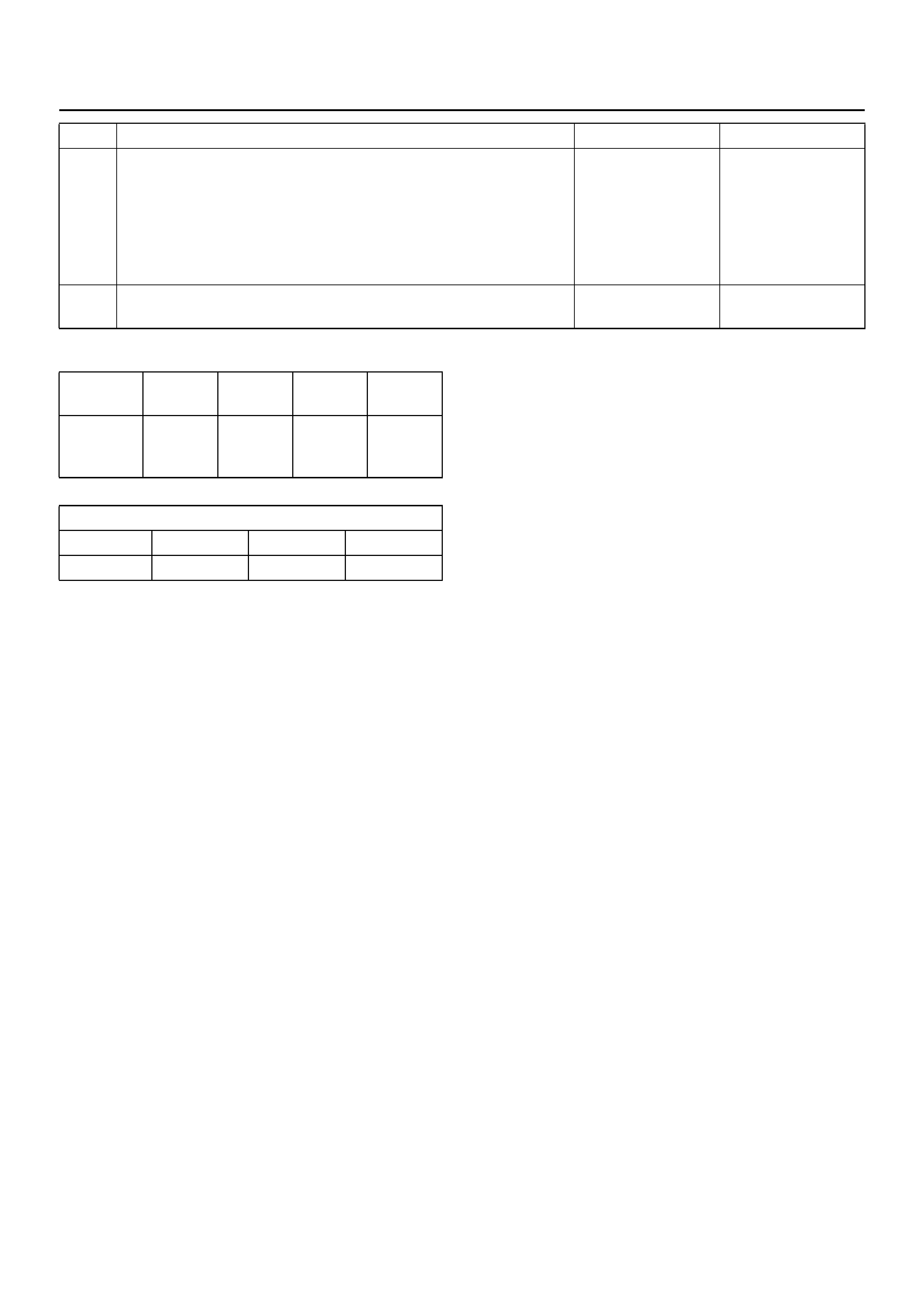
Continuity between terminal in 4L position (Table:
continuity)
Standar d (Tab le: volta ge)
12 1. Start the engine.
Is the engine pulse signal between terminal 2 and 47 at engine
speed under 1500 rpm within the standard? Standard: less than
4500 Hz Replace the
ECU.
Go to Step 13
The engine
pul se signa l is
abnormal.
Repair or
replace the
PCM.
Go to Step 13
13 Check that all the parts are mounted.
Is this step complete? Verify the repair. Go to Step 13
Step Action Yes No
Terminal
s No. 26 and
24 39 and
24 25 and
24 38 and
24
Continuity
of 4L
position
YES NO YES YES or
NO
Unit: V
Terminals 28 and 47 41 and 47 27 and 47
Voltage 0 12 0
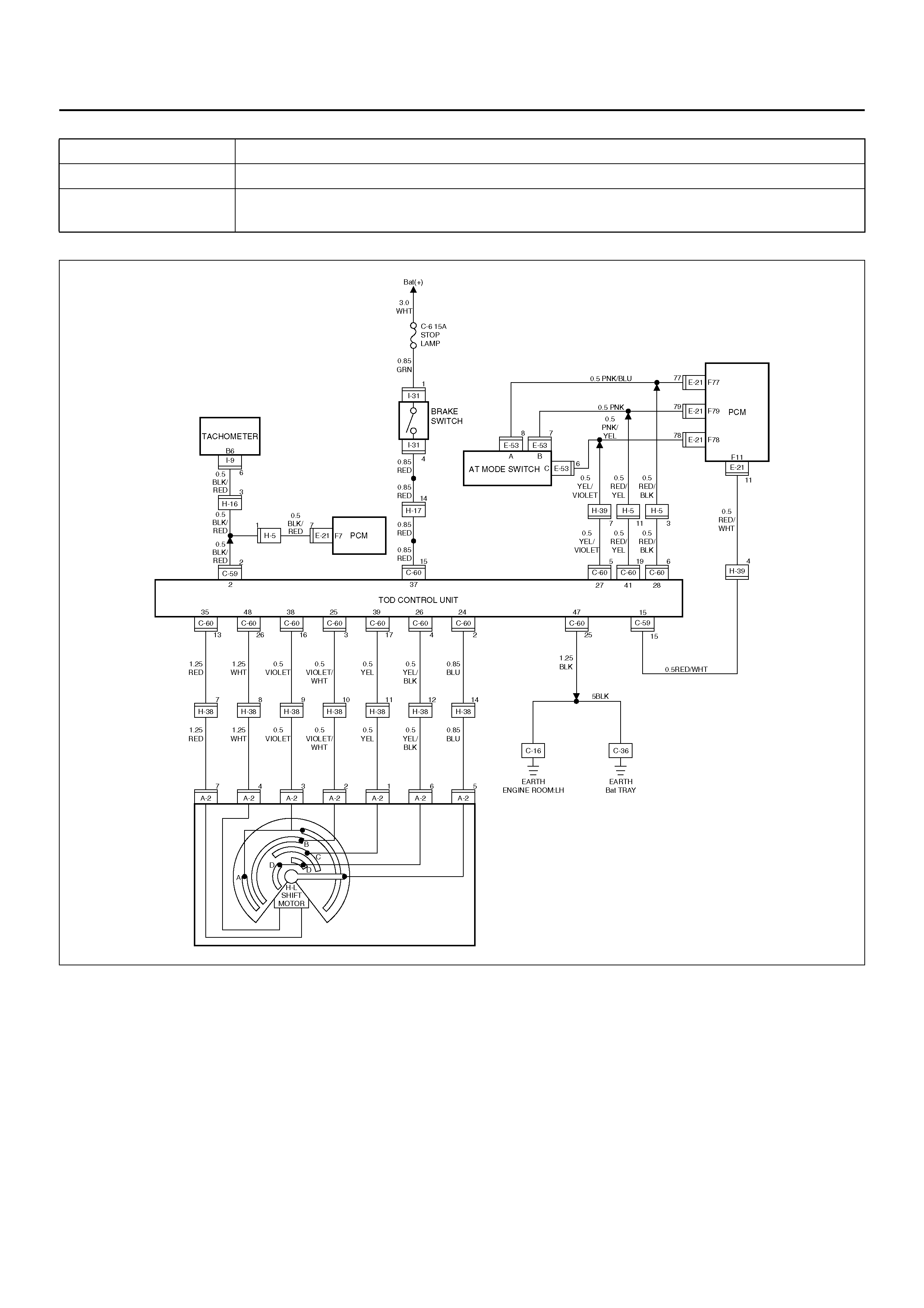
D04R100014
Chart 6 The transfer does not change to high from low.
Function of circuit —
Fail condition When the TOD switch is selected to the TOD, the transfer does not change to the high
range.

Step Action Yes No
1 1. Turn on the starter switch.
Is any of the trouble codes 41 (P1741), 42 (P1773), 43 (P1743)
and 55 (P1755) recorded?
Examine the
trouble based on
“Diagnosis from
Trouble Codes". Go to Step 2
2 Is any of the troub le codes 13 (P1735 ), 14 (P1731), 15 (P17 36),
16 (P1737), 24 (P1733), and 27 (P1738) recorded? Examine the
trouble based on
“Diagnosis from
Trouble Codes". Go to Step 3
3 Is the trouble code 17 (P1774) recorded? Examine the
trouble based on
“Diagnosis from
Trouble Codes". Go to Step 4
4 1. Turn on the starter switch.
2. The car stops, engine speed is less than 1500 rpm, the AT
selector is N position, and select the TOD switch to the TOD
position.
Do the front, rear, and AUTO lamps in the indicato r blink ? Go to Step 5
Exami ne the
trouble based on
“Trouble Diagnosis
Depending on the
Status of TOD
Indicator".
5 1. Step on the brake pedal.
Is the transfer changed to the TOD mode? The
phenomenon is
not reprodu ce d.
Refer to
“Trouble
intermittently
observed". Go to Step 6
6 When the vehicle is moved forth and back, is the transfer
changed to the TOD mode? The phenom enon
is not reproduced.
Refer to “Trouble
intermittently
observed". Go to Step 7
7 Is the continuity corresponding to the encoder position between
the terminals ranged within the any case (case 1, 2 and 3) of
TOD position in the following table (continuity)?
Examine the
trouble based on
“Trouble diagnosis
Depending on The
Status of TOD
Indicat or ". Go to Step 8
8 1. Step on the brake pedal.
Is the battery voltage observed between the terminal 37 and 47? Go to Step 10 Go to Step 9
9 1. Turn off the starter switch.
2. Disconnect the ECU connector (C–60) and the brake switch
connector (I–31).
Is ther e the contin uity between the c onnector term inal (C–60) 15
and (I–31) 4?
The brake
switch is
abnormal.
Repair or
repla ce the
brake switch.
Go to Step 13
Repair the
harness.
Go to Step 13
10 1. Select the AT selector to the N position.
Is the voltage between the terminals ranged within the following
table (voltage)? Go to Step 12 Go to Step 11
Continuity in TOD position (Table: continuity)
Standar d (Tab le: volta ge)
11 1. Turn off the starter switch.
2. Disconnect the ECU connector (C–60) and brake switch
connector (I–31).
3. Disconnect the AT mode switch connector (E–53).
Is there the continuity between the following connector
terminals? (C–60)6 and (E–53)8 (C–60)19 and (E–53)7 (C–
60)5 and (E–53)6
Repair or
replace the AT
mode switch.
Go to St ep 13
Repair the
circuit which
has no
continuity.
Go to Step 13
12 1. Start the engine.
Is the engine pulse signal between terminal 2 and 47 at engine
speed under 1500 rpm within the standard? Standard: less than
4500 Hz Replace the
ECU.
Go to Step 13
The engine
pul se signa l is
abnormal.
Repair or
replace the
PCM.
Go to Step 13
13 Check that all the parts are mounted.
Is this step complete? Verify the repair. Go to Step 13
Step Action Yes No
Cas
eContinuity between terminals
26 and 24 39 and 24 25 and 24 38 and 24
1NO NO NO YES
2 NO YES NO YES
3 YES YES NO YES
Unit: V
Terminals 28 and 47 41 and 47 27 and 47
Voltage 0 12 0

Chart 7 The transfer does not change to low from high.
Function of circuit —
Fail condition When the TOD switch is selected to the 4L position, the transfer does not change to the
low position. (The transfer stays neutral and the vehicle does not run.)
Step Action Yes No
1 1. Turn on the starter switch.
2. Set the TOD switch to the any position.
Is the transfer changed to high or low? Go to Step 2 Go to Step 3
2 Is the transfer changed to high from low and the low from high? The phenomenon
is not reproduced.
Refer to “Trouble
intermittently
observed". Go to Step 3
3 Is any of the troub le codes 41 (P1741 ), 42 (P1773), 43 (P17 43),
and 55 (P1755) recorded? Examine the
trouble based on
“Diagnosis from
Trouble Codes".
The transfer is
abnormal.
Repair the
transfer.
Go to Step 4
4 Check that all the parts are mounted.
Is this step complete? Verify the repair. Go to Step 4