
SECTION 5A - BRAKE CONTROL SYSTEM
Service Precaution
General Description
Functional Description
System Components
Electronic Hydraulic Control Unit (EHCU)
ABS Warning Light
Wheel Speed Sensor
G-Sensor
Normal and Anti-lock Braking
Brake Pedal Travel
Acronyms and Abbreviations
General Diagnosis
General Information
ABS Service Precautions
Computer System Service Precautions
General Service Precautions
Note on Intermittents
Test Driving ABS Complaint Vehicles
“ABS" Warning Light
Normal Operation
Tech 2 Scan Tool
Data List
Basic Diagnostic Flow Chart
Basic Inspection Procedure
EHCU Connector Pin-out Checks
Circuit Diagram
Connector List
Part Location
Symptom Diagnosis
Chart A-1 ABS Works Frequently But
Vehicle Does Not Decelerate
Chart TA-1 ABS Works Frequently But
Vehicle Does Not Decelerate
(Use TECH 2)
Chart A-2 Uneven Braking Occurs
While ABS Works
Chart TA-2 Uneven Braking Occurs
While ABS Works (Use TECH 2)
Chart A-3, TA-3 The Wheels Are Locked
Chart A-4 Brake Pedal Feed Is Abnormal
Chart A-5, TA-5 Braking Sound
(From EHCU) Is Heard While Not Braking
Diagnostic Trouble Codes
Diagnosis By “ABS" Warning Light
Illumination Pattern
Diagnostic Trouble Codes (DTCs)
Chart B-1 With the key in the ON position
(Before starting the engine). Warning
light (W/L) is not activated.
Chart B-2 CPU Error (DTC 14 (Flash out) /
C0271, C0272, C0273, C0284 (Serial
communications))
Chart B-3 Low or High Ignition Voltage
(DTC 15 (Flash out) / C0277, 0278 (Serial
communications))
Chart B-4 Excessive Dump Time
(DTC 17 (Flash out) / C0269 (Serial
communications))
Chart B-5 Excessive Isolation Time
(DTC 18 (Flash out) / C0274 (Serial
communications))
Chart B-6 G-Sensor Output Failure
(DTC 21 (Flash out) / C0276 (Serial
communications))
Chart B-7 Brake Switch Failure
(DTC 22 (Flash out) / C0281 (Serial
communications))
Chart B-8 2WD Controller in 4WD Vehicle
Controller (DTC 13 (Flash out) / C0285
(Serial communications)), 4WD State
Input Signal Failure (DTC 24 (Flash out) /
C0282 (Serial communications))
Chart B-9 Pump Motor Failure (DTC 32
(Flash out) / C0267, C0268 (Serial
communications))
Chart B-10 EHCU Valve Relay Failure
(DTC 35 (Flash out) / C0265, C0266 (Serial
communications))
Chart B-11 FL Isolation Solenoid Coil
Failure (DTC 41 (Flash out) / C0245,
C0247 (Serial communications))
Chart B-12 FL Dump Solenoid Coil
Failure (DTC 42 (Flash out) / C0246,
C0248 (Serial communications))
Chart B-13 FR Isolation Solenoid Coil
Failure (DTC 43 (Flash out) /
C0241, C0243 (Serial communications))
Chart B-14 FR Dump Solenoid Coil
Failure (DTC 44(Flash out) /
C0242, C0244 (Serial communications))
Chart B-15 Rear Isolation Solenoid
Coil Failure (DTC 45 (Flash out) / C0251,
C0253 (Serial communications))

Chart B-16 Rear Dump Solenoid Coil
Failure (DTC 46 (Flash out) /
C0252, C0254 (Serial communications))
Chart B-17 FL Speed Sensor Open or
Shorted (DTC 51 (Flash out) / C0225 (Serial
communications))
Chart B-18 FR Speed Sensor Open or
Shorted (DTC 52 (Flash out) / C0221 (Serial
communications))
Chart B-19 Rear Speed Sensor Open or
Shorted (DTC 53 (Flash out) / C0235 (Serial
communications))
Chart B-20 FL Speed Sensor Missing
(DTC 61 (Flash out) / C0226, C0227 (Serial
communications))
Chart B-21 FR Speed Sensor Missing
(DTC 62 (Flash out) / C0222, C0223 (Serial
communications))
Chart B-22 Rear Speed Sensor Missing
(DTC 63 (Flash out) / C0236, C0237 (Serial
communications))
Chart B-23 Simultaneous Drop-out of
Front Speed Sensor Signal (DTC 64
(Flash out) / C0229 (Serial
communications))
Chart B-24 Wheel Speed Input
Abnormality (DTC 65 (Flash out) /
C0238 (Serial communications))
Unit Inspection Procedure
Chart C-1-1 FL Sensor Output Inspection
Procedure
Chart C-1-2 FR Sensor Output Inspection
Procedure
Chart C-1-3 Rear Sensor Output Inspection
Procedure
Chart TC-1 Sensor Output Inspection
Procedure
Special Tools
SERVICE PRECAUTION
WARNING: THIS VEHICLE HAS A SUPPLEMENTAL RESTRAINT SYSTEM (SRS). REFER TO THE SRS
COMPONENT AND WIRING LOCATION VIEW IN ORDER TO DETERMINE WHETHER YOU ARE PERFORMING
SERVICE ON OR NEAR THE SRS COMPONENTS OR THE SRS WIRING. WHEN YOU ARE PERFORMING
SERVICE ON OR NEAR THE SRS COMPONENTS OR THE SRS WIRING, REFER TO THE SRS SERVICE
INFORMATION. FAILURE TO FOLLOW WARNINGS COULD RESULT IN POSSIBLE AIR BAG DEPLOYMENT,PERSONAL INJURY, OR OTHERWISE UNNEEDED SRS SYSTEM REPAIRS.Always use the correct fastener inthe proper location. WARNING: When you replace a fastener, use ONLY the exact part number for that application. HOLDEN will
call out those fasteners that require a replacement after removal. HOLDEN will also call out the fasteners that
require thread lockers or thread sealant. UNLESS OTHERWISE SPECIFIED, do not use supplemental
coatings (Paints, greases, or other corrosion inhibitors) on threaded fasteners or fastener joint interfaces.
Genera lly, such c oatin gs adve rsely affect t he faste ner to rque and th e joint c lamping forc e, and may damag e
the fastener. When you install fasteners, use the correct tightening sequence and specifications. Following
these instructions can help you avoid damage to parts and systems.
GENERAL DESCRIPTION
The Anti-lock Brake System (ABS) works on all four wheels. The combination of wheel speed sensors and Electronic
Hydraulic Con trol Unit (EHCU) determine w hen a wheel is ab out to lock and adju st brake pres sure to maintain best
braking performance.
This system helps the driver maintain greater control of the vehicle under heavy braking conditions.
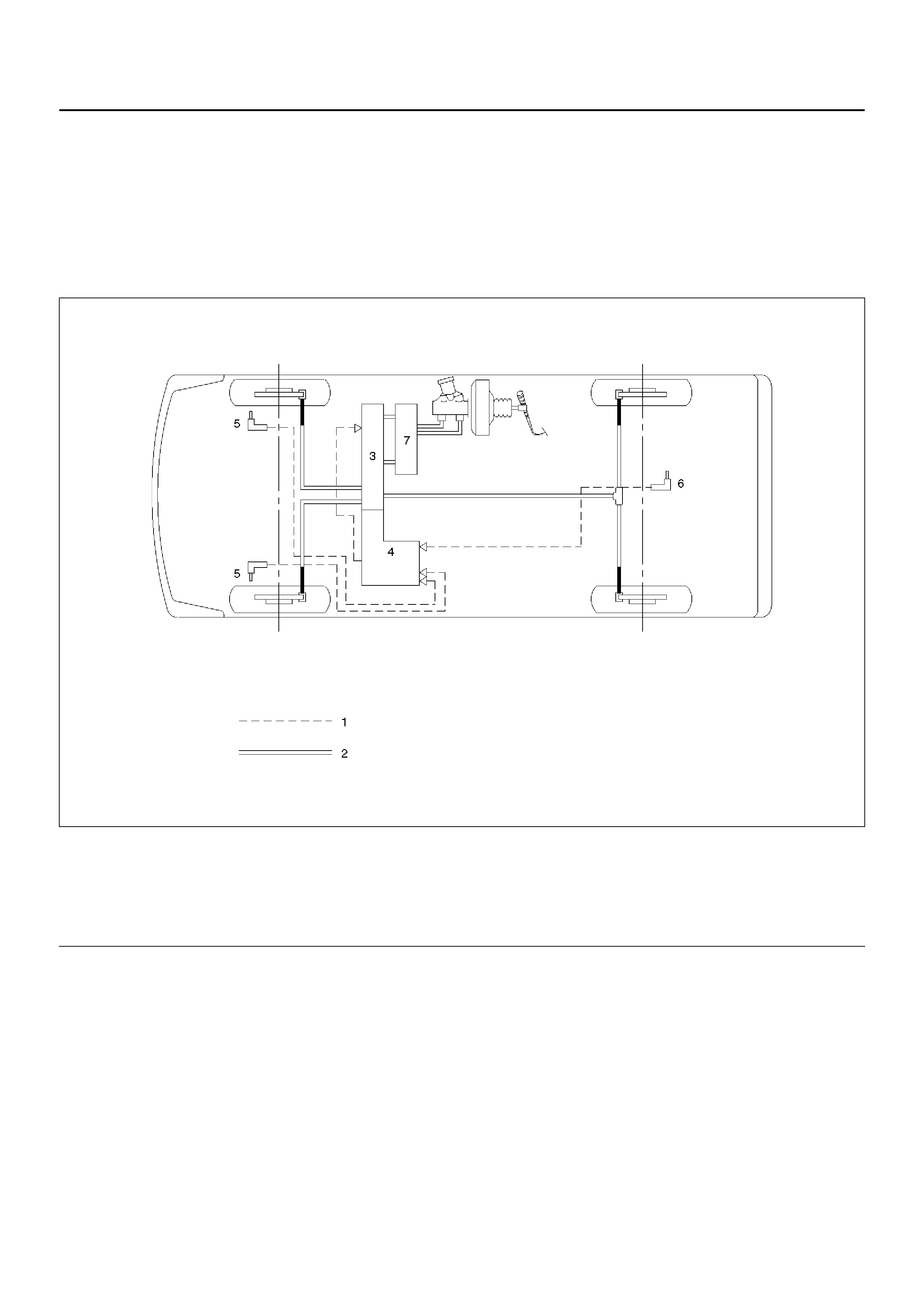
NOTE: The Electronic Hydraulic Control Unit (EHCU) comprises the Hydraulic Unit (H/U) and the Coil Integrated
Module.
C05RW004
Legend
EndOFCallout
(1) Electronic
(2) Hydraulic
(3) Hydraulic Unit (H/U)
(4) Coil Integrated Module
(5) Front Wheel Speed Sensor
(6) Rear Wheel Speed Sensor
(7) Proporti oni ng and By pass (P& B) Valve
FUNCTIONAL DESCRIPTION
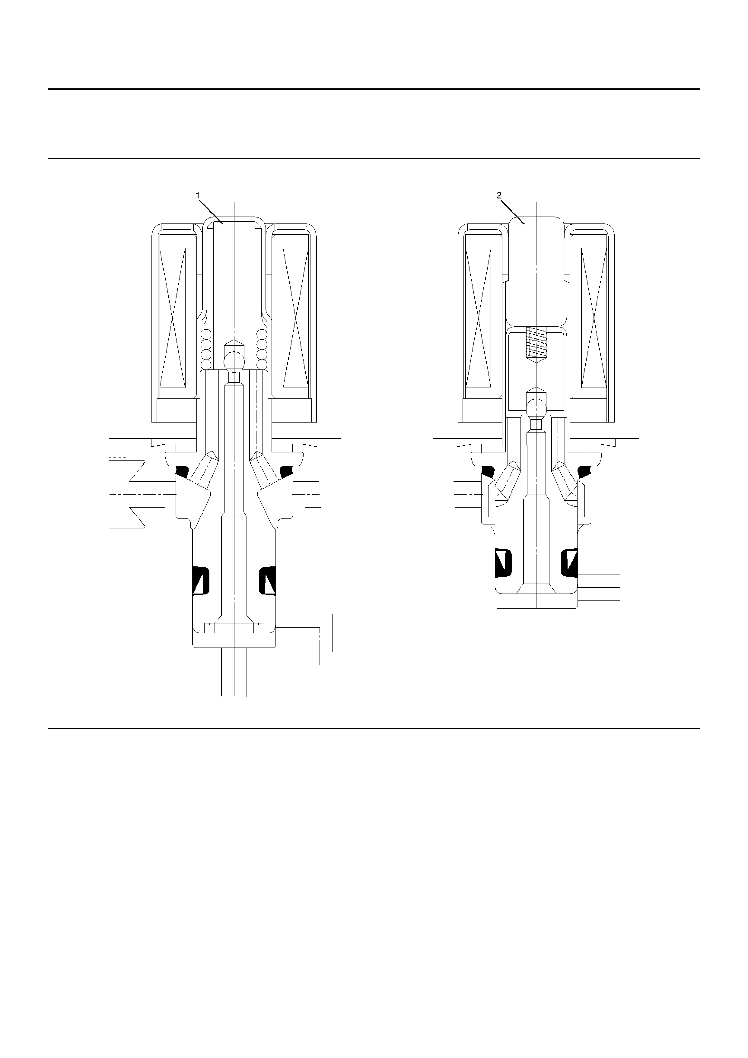
Hydraulic Unit (H/U)
Solenoid Valve
C05RW012
Legend
EndOFCallout
(1) Isolation Valve (2) Dump valve
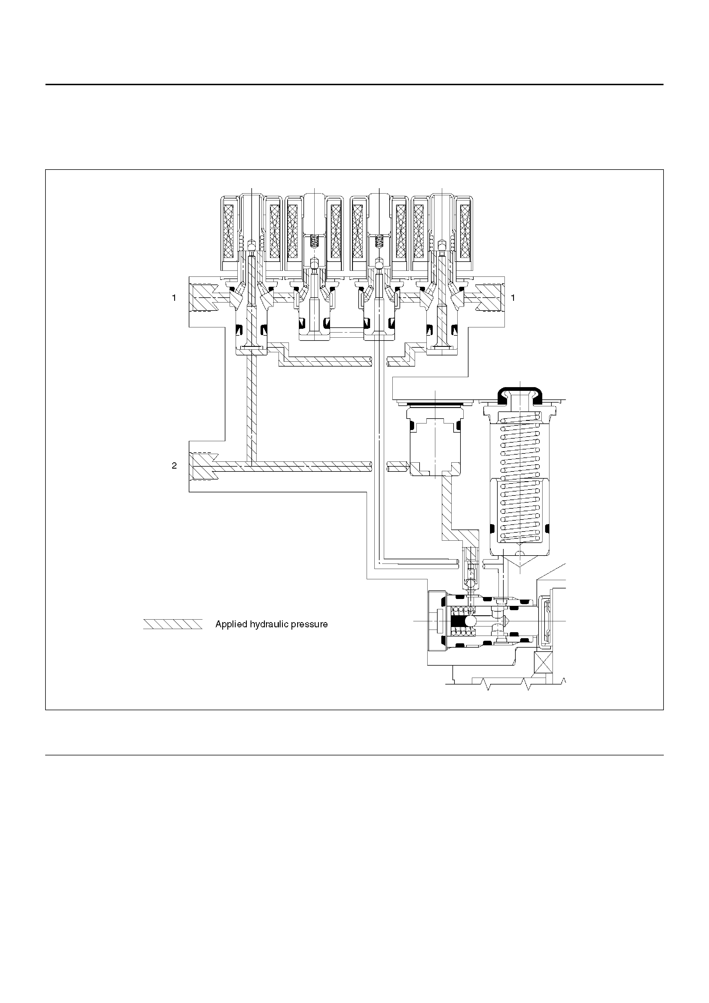
Normal Braking
During normal (non anti-lock) braking, the solenoid valves are disabled and remain closed due to spring force.
Brake fluid travels through the centre of the normally open isolation valve around the normally closed dump valve and
on to the brake pistons.
C05RW010
Legend
EndOFCallout
(1) Brake (2) Master Cylinder
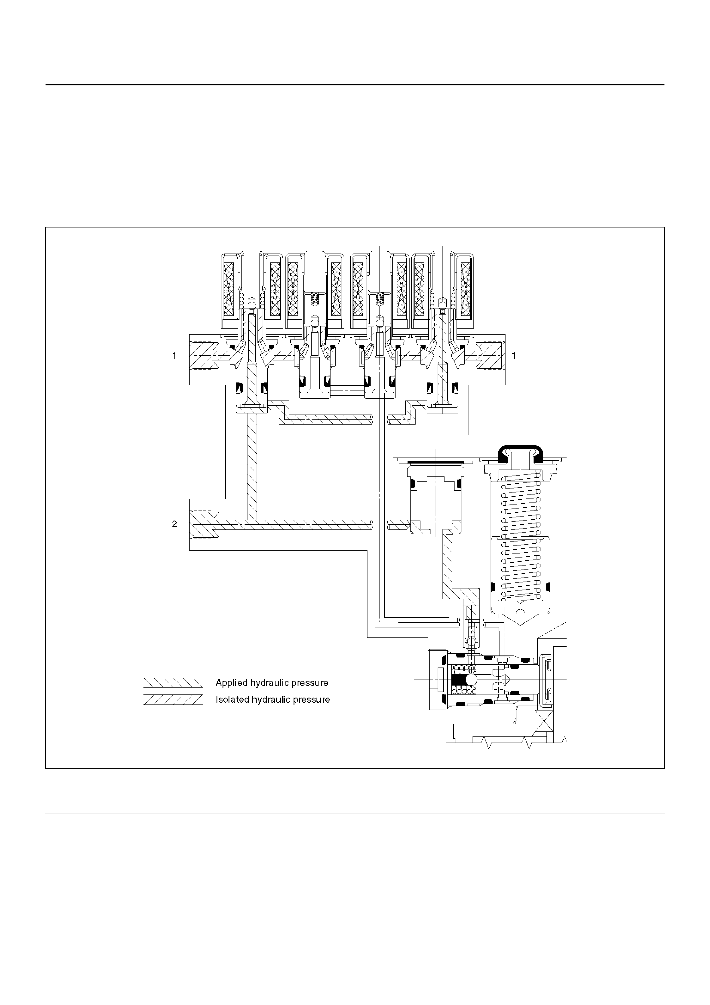
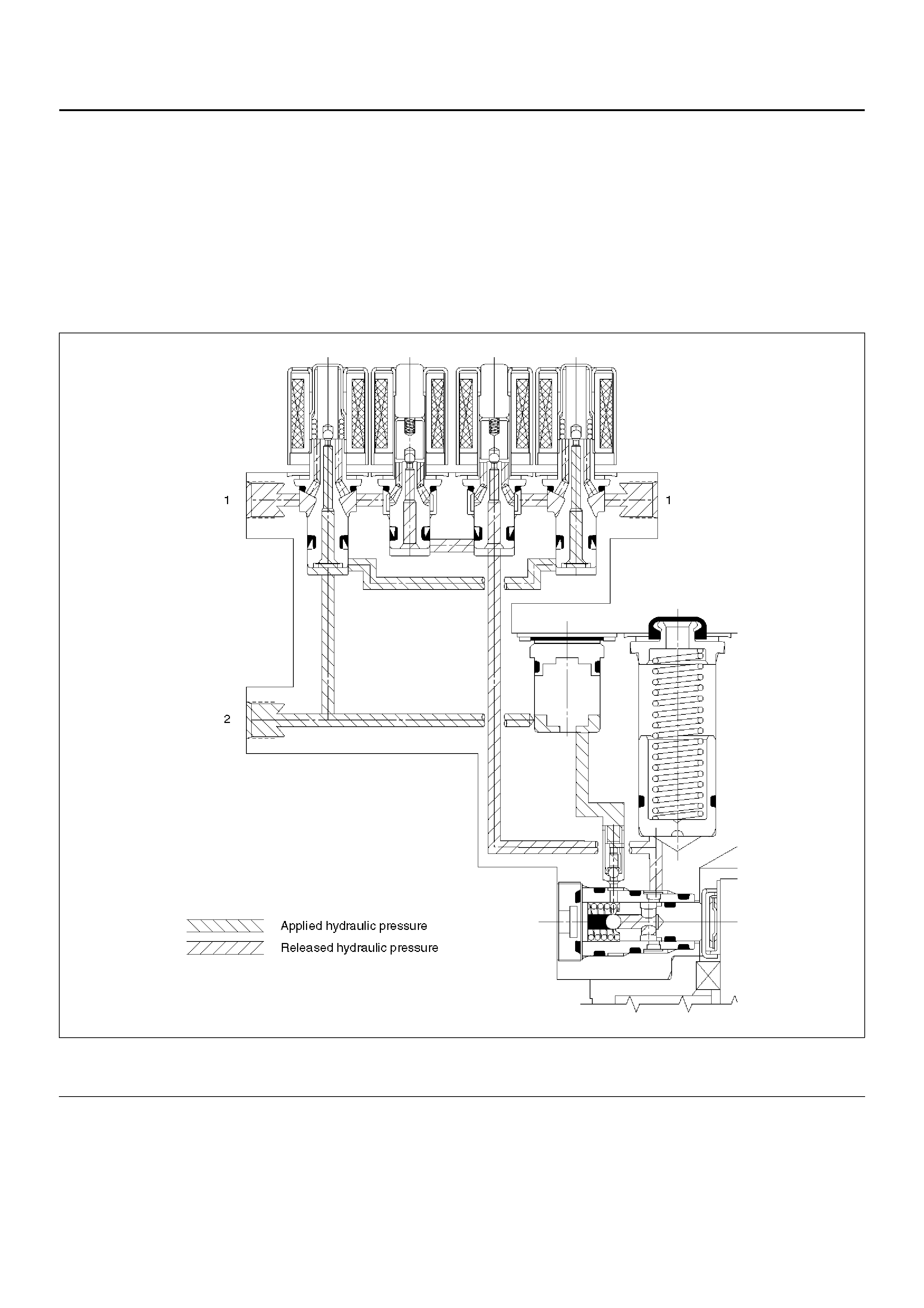
Pressure Isolation (Pressure Maintain)
The ele ctro-h ydrauli c c ontrol u nit i s activ ated wh en the brak es are appl ied wh ich sen ds a sign al to the c oil inte grated
module to prepare for a possible anti-lock stop.
If the information from the wheel speed sensors indicates excessive wheel deceleration (imminent lockup), the first
step in the anti-lock sequence is to isolate the brake pressure being applied by the brake pedal.
The micro pr oces so r in the co il inte gr ated mod ul e se nds a volta ge to the coi l to ener g ize an d cl os e the is olati on v al ve .
This prevents any additional fluid pressure applied by the brake pedal from reaching the wheel. With the isolation
valves closed, further increase in the braking pressure is prevented.
C05RW011
Legend
EndOFCallout
(1) Brake (2) Master Cylinder
Pressure Reduction
Once the brake pressure is isolated, it must be reduced to allow the wheels to unlock. This is accomplished by
dumping a portion of the brake fluid pressure into a low pressure accumulator.
The microp rocessor activates the normally closed dump va lve to open, allowing fluid from the wheels to be dumped
into the accumul ator. This is done wi th very shor t acti vatio n puls es open ing and closin g the dump va lve passage way.
Brake pressure is reduced at the wheel and allows the wheel to begin rotating again. The fluid from the brake piston is
stored in the accumulator against spring pressure and a portion of this fluid also primes the pump.
The dump v alve s are op er ate d in depe nde ntl y to con tr ol th e dec eler ati on o f the wh eel . At th is poi nt, th e br ak e pe dal is
isolated from the base brake system, the hydraulic control unit pumps are primed and the attenuators are ready to
pump fluid.
C05RW009
Legend
EndOFCallout
(1) Brake (2) Master Cylinder
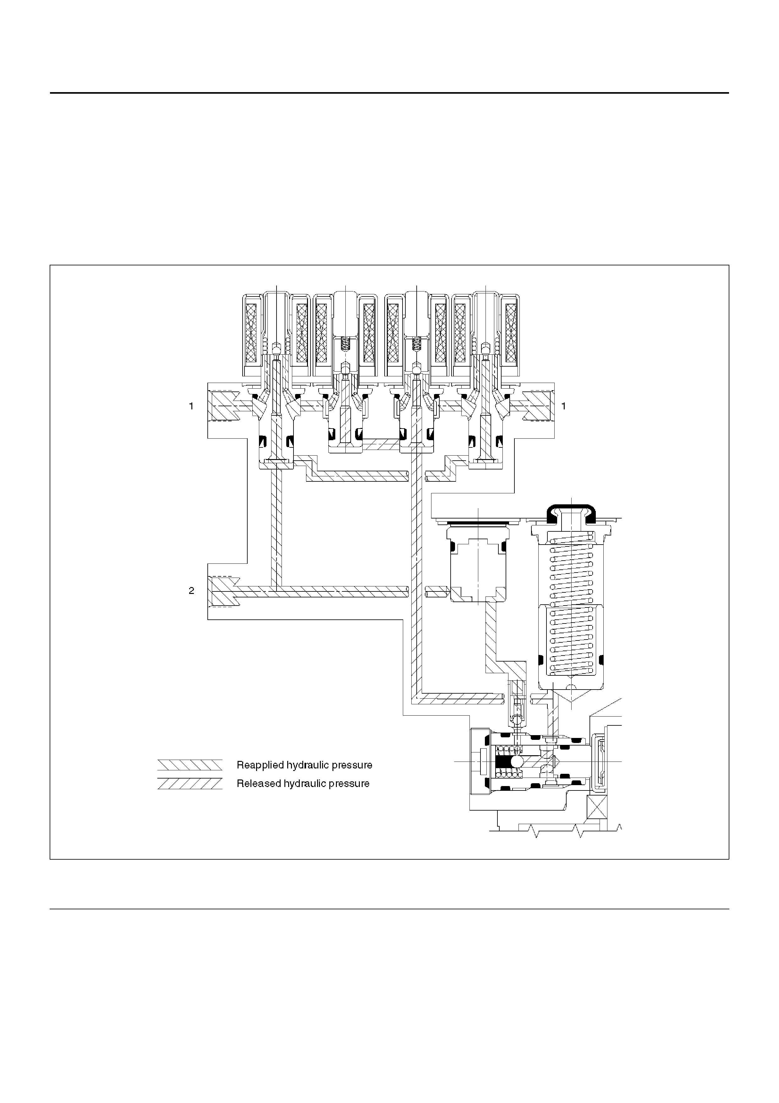
Pressure Increase (Re-apply)
The re-apply sequence is initiated to achieve optimum braking. The isolation valve is momentarily opened to allow
master cylinder and pump pressure to reach the brakes. This controlled pressure rise continues until the wheel is at
optimum brake output or until the brake pressure is brought up to the master cylinder output pressure.
If more p ressure is r equired, more fluid is drawn from the mas ter cylinder and applied to the brakes. T he driver m ay
feel slight pedal pulsations, or pedal drop, this is normal and expected.
As fluid is re-applied to the brakes, the whe el speed will reduce. If the wheels approach imminent lockup again, the
module will isolate, dump and re-apply again. This cycle occurs in millisecond intervals, allowing several cycles to
occur each second. It is a much faster and more controlled way of “pumping the pedal".
C05RW014
Legend
EndOFCallout
(1) Brake (2) Master Cylinder
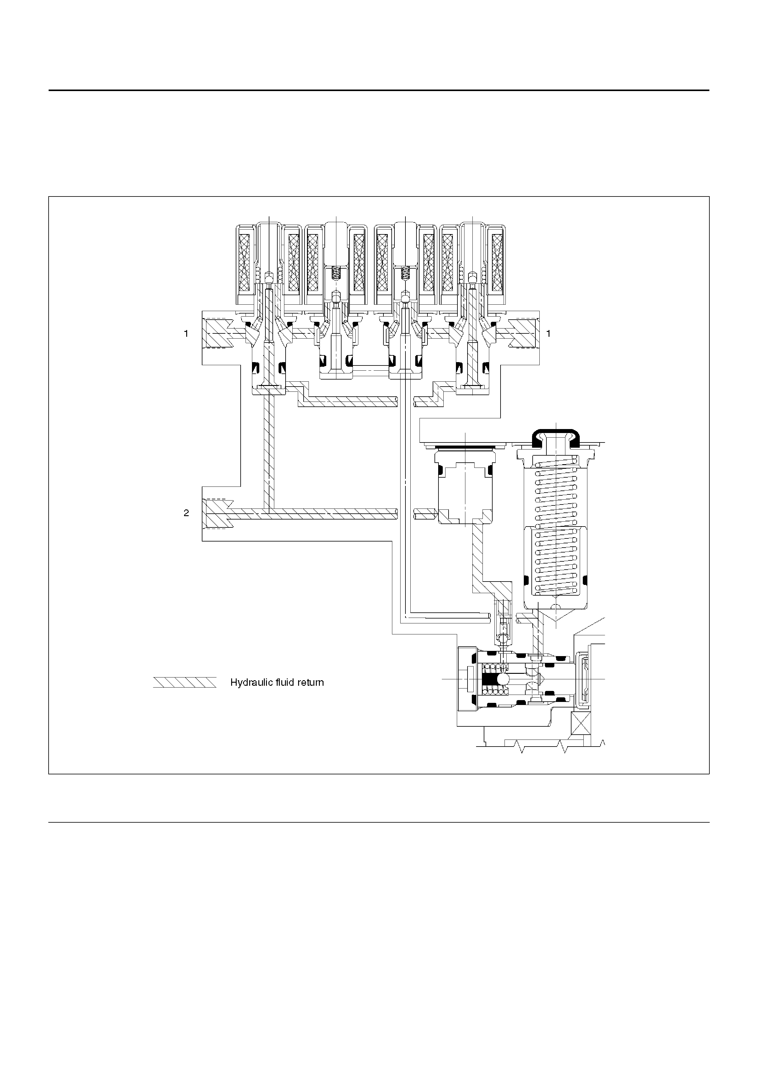
Brake Release
At the end of the anti-lock stop, when the brake pedal is released, the pump will remain running for a short time to help
drain any fluid from the accumulators. As this fluid returns into the system, the spring forces the piston back to its
original position.
The isolation valve opens and fluid may return to the master cylinder. Conventional braking is then resumed.
C05RW013
Legend
EndOFCallout
(1) Brake (2) Master Cylinder
SYSTEM COMPONENTS
Electronic Hydraulic Control Unit (EHCU), three Wheel Speed Sensors, Warning Light, and G-sensor.
ELECTRONIC HYDRAULIC CONTROL UNIT (EHCU)
The EHCU consists of ABS control circuits, fault detector, and a fail-safe. It drives the hydraulic unit according to the
signal from each sensor, cancelling ABS to return to normal braking when a malfunction has occurred in the ABS.
The EHCU has a self-diagnosing function which can indicate faulty circuits during diagnosis.
The EHCU is mounted on the engine compartment rear right side. It consists of a Motor, Plunger Pump, Solenoid
Valves.
Solenoid Valves: Reduces or holds the caliper fluid pressure for each front disc brake or both rear disc brakes
according to the signal sent from the EHCU.
Reservoir: Temporarily holds the brake fluid that returns from the front and rear disc brake caliper so that pressure of
front disc brake caliper can be reduced smoothly.
Plunger Pump: Feeds the brake fluid held in the reservoir to the master cylinder.
Motor: Drives the pump according to the signal from EHCU.
Check Valve: Controls the brake fluid flow.
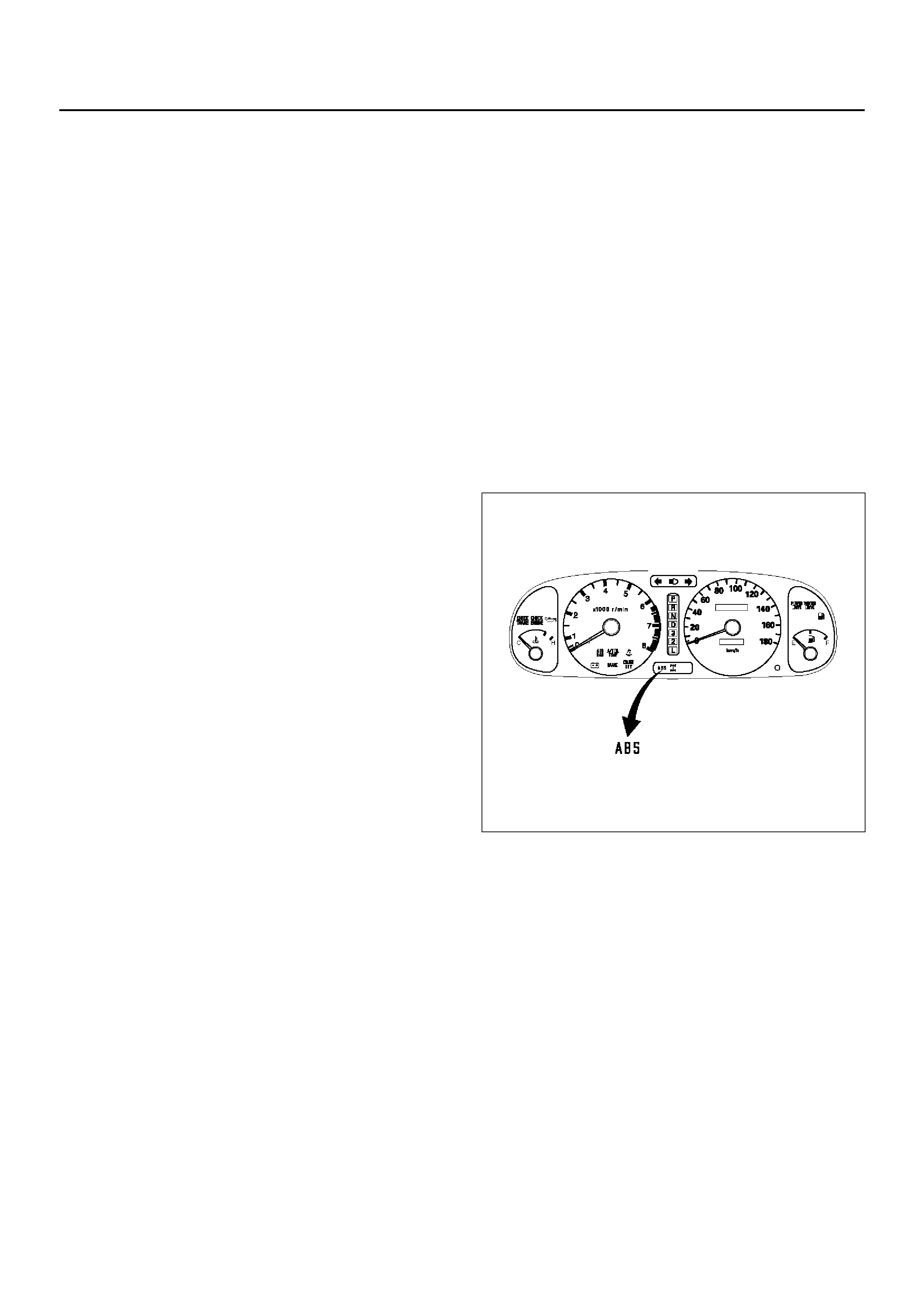
ABS WARNING LIGHT
Vehicles equipped with the Anti-lock Brake System have an
amber “ABS" warning light in the instrument panel. The
“ABS" warning light will illuminate if a malfunction in the
Anti-lock Brake System is detected by the Electronic
Hydraulic Control Unit (EHCU). In case of an electronic
malfunction, the EHCU will turn “ON" the “ABS" warning light
and disable the Anti-lock braking function.
The “ABS" light will turn “ON" for approximately three
seconds after the ignition switch is to the “ON" position.
If the “ABS" light stays “ON" after the ignition switch is the
“ON" position, or comes “ON" and stays “ON" while driving,
the Anti-lock Brake System should be inspected for a
malfunction according to the diagnosis procedure.
WHEEL SPEED SENSOR
It consists of a sensor and a rotor. The sensor is attached
to the knuckle on the front wheels and to the rear axle case
on the rear differential.
The rotor is press-fit in the axle shaft.
The flux generated from electrodes magnetized by a magnet in the sensor varies due to rotation of the rotor, and the
electromagnetic induction generates alternating voltage in the coil. This voltage draws a “sine curve" with the
frequency proportional to rotor speed and it allows detection of wheel speed.
G-SENSOR
The G-sensor installed inside the EHCU detects the vehicle deceleration speed and sends a signal to the EHCU. In
4WD operation, all four wheels may be decelerated in almost the same phase, since all wheels are connected
mechanically.
This tendency is noticeable particularly on roads with low friction coefficient, and the ABS control is adversely
affected.
The G-sensor judges whether the friction coefficient of road surface is low or high, and changes the EHCU's operating
system to ensure ABS control.
NORMAL AND ANTI-LOCK BRAKING
Under normal driving conditions, the Anti-lock Brake System functions the same as a standard power assisted brake
system. However, with the detection of wheel lock-up, a slight bump or kick-back will be felt in the brake pedal. This
pedal “bump" will be followed by a series of short pedal pulsations which occurs in rapid succession. The brake pedal
pulsation will continue until there is no longer a need for the anti-lock function or until the vehicle is stopped. A slight

ticking or popping noise may be heard during brake applications when the Anti-lock features is being used.
When the Anti-lock feature is being used, the brake pedal may rise even as the brakes are being applied. This is also
normal. Maintaining a constant force on the pedal will provide the shortest stopping distance.
BRAKE PEDAL TRAVEL
Vehicles equipped with the Anti-lock Brake System may be stopped by applying normal force to the brake pedal.
Although there is no need to push the pedal beyond the point where it stops or holds the vehicle, by applying more
force the pedal will continue to travel toward the floor.
This extra brake pedal travel is normal.
ACRONYMS AND ABBREVIATIONS
Several acronyms and abbreviations are commonly
used throughout this section:
ABS
Anti-lock Brake System
CIM
Coil Integrated Module
CKT
Circuit
DLC
Data Link Connector
EHCU
Electronic Hydraulic Control Unit
FL
Front Left
FR
Front Right
GEN
Generator
H/U
Hydraulic Unit
MV
Millivolts
RR
Rear
RPS
Revolution per Second
VDC
DC Volts
VAC
AC Volts
W/L
Warning Light
WSS
Wheel Speed Sensor
GENERAL DIAGNOSIS
GENERAL INFORMATION
ABS troubles can be classified into two types, those which can be detected by the ABS warning light and those which
can be detected as a vehicle abnormality by the driver.
In either case, locate the fault in accordance with the “Basic Diagnostic Flowchart" and repair.
Please refer to Section 5C for the diagnosis of mechanical troubles such as brake noise, brake judder (brake pedal or
vehicle vibration felt when braking), uneven braking, and parking brake trouble.

ABS SERVICE PRECAUTIONS
Required Tools and Items:
• Box Wrench
•Brake Fluid
• Special Tool
Some diagnosis procedures in this section require the installation of a special tool.
5-8840-0366-0 High Impedance Multimeter
When circuit measurements are requested, use a circuit tester with high impedance.
COMPUTER SYSTEM SERVICE PRECAUTIONS
The Anti-lock Brake System interfaces directly with the Electronic Hydraulic Control Unit (EHCU) which is a control
computer that is similar in some regards to the Powertrain Control Module. These modules are designed to withstand
normal current draws associated with vehicle operation. However, care must be taken to avoid overloading any of the
EHCU circuits. In testing for opens or shorts, do not ground or apply voltage to any of the circuits unless instructed to
do so by the appropriate diagnostic procedure. These circuits should only be tested with a high impedance
multimeter 5-8840-0366-0 or special tools as described in this section. Power should never be removed or applied to
any control module with the ignition in the “ON" position.
Before removing or connecting battery cables, fuses or connectors, always turn the ignition switch to the “OFF"
position.
GENERAL SERVICE PRECAUTIONS
The following are general precautions which should be observed when servicing and diagnosing the Anti-lock Brake
System and/or other vehicle systems. Failure to observe these precautions may result in Anti-lock Brake System
damage.
• If welding work is to be performed on the vehicle using an electric arc welder, the EHCU and valve block
connectors should be disconnected before the welding operation begins.
• The EHCU and valve block connectors should never be connected or disconnected with the ignition “ON" .
• If only rear wheels are rotated using jacks or drum tester, the system will diagnose a speed sensor malfunction and
the “ABS" warning light will illuminate. But actually no trouble exists. After inspection stop the engine once and
re-start it, then make sure that the “ABS" warning light does not illuminate.
If the battery has been discharged
The engine may stall if the battery has been completely discharged and the engine is started via jumper cables. This
is because the Anti-lock Brake System (ABS) requires a large quantity of electricity. In this case, wait until the battery
is recharged, or set the ABS to a non-operative state by removing the fuse for the ABS (60A). After the battery has
been recharged, stop the engine and install the ABS fuse. Start the engine again, and confirm that the ABS warning
light does not light.
NOTE ON INTERMITTENTS
As with virtually any electronic system, it is difficult to identify an intermittent failure. In such a case duplicating the
system malfunction during a test drive or a good description of vehicle behavior from the customer may be helpful in
locating a “most likely" failed component or circuit. The symptom diagnosis chart may also be useful in isolating the
failure. Most intermittent problems are caused by faulty electrical connections or wiring. When an intermittent failure is
encountered, check suspect circuits for:
• Suspected harness damage.
• Poor mating of connector halves or terminals not fully seated in the connector body (backed out).
• Improperly formed or damaged terminals.
TEST DRIVING ABS COMPLAINT VEHICLES
In case that there has been an abnormality in the lighting pattern of “ABS" warning light, the fault can be located in
accordance with the “Diagnosis By “ABS" Warning Light Illumination Pattern". In case of such trouble as can be
detected by the driver as a vehicle symptom, however, it is necessary to give a test drive following the test procedure
mentioned below, thereby reproducing the symptom for trouble diagnosis on a symptom basis:
1. Start the engine and make sure that the “ABS" W/L goes OFF. If the W/L remains ON, it means that the
Diagnostic Trouble Code (DTC) is stored. Therefore, read the code and locate the fault.

NOTE: The DTC cannot be cleared if the vehicle speed does not exceed 12 km/h (8 mph) at DTC, even though the
repair operation is completed.
2. Start the vehicle and accelerate to about 30 km/h (19 mph) or more.
3. Slowly brake and stop the vehicle completely.
4. Then restart the vehicle and accelerate to about 40 km/h (25 mph) or more.
5. Brake at a time so as to actuate the ABS and stop the vehicle.
6. Be cautious of abnormality during the test. If the W/L is actuated while driving, read the DTC and locate the fault.
7. If the abnormality is not reproduced by the test, make best efforts to reproduce the situation reported by the
customer.
8. If the abnormality has been detected, repair in accordance with the “Symptom Diagnosis" .
NOTE:
• Be sure to give a test drive on a wide, even road with a small traffic.
• If an abnormality is detected, be sure to suspend the test and start trouble diagnosis at once.
“ABS" WARNING LIGHT
When ABS trouble occurs to actuate “ABS" warning light, the trouble code corresponding to the trouble is stored in
the EHCU. Only ordinary brake is available with ABS being unactuated. Even when “ABS" warning light is actuated,
if the starter switch is set ON after setting it OFF once, the EHCU checks up on the entire system and, if there is no
abnormality, judges ABS to work currently and the warning light is lit normally even though the trouble code is stored.
NOTE: Illumination of the “ABS" warning light indicates that anti-lock braking is no longer available. Power assisted
braking without anti-lock control is still available.
NORMAL OPERATION
“ABS" Warning Light
When the ignition is first moved from “OFF" to “RUN" , the amber “ABS" warning light will turn “ON" . The “ABS"
warning light will turn “ON" during engine starting and will usually stay “ON" for approximately three seconds after the
ignition switch is returned to the “ON" position. The warning light should remain “OFF" at all other times.
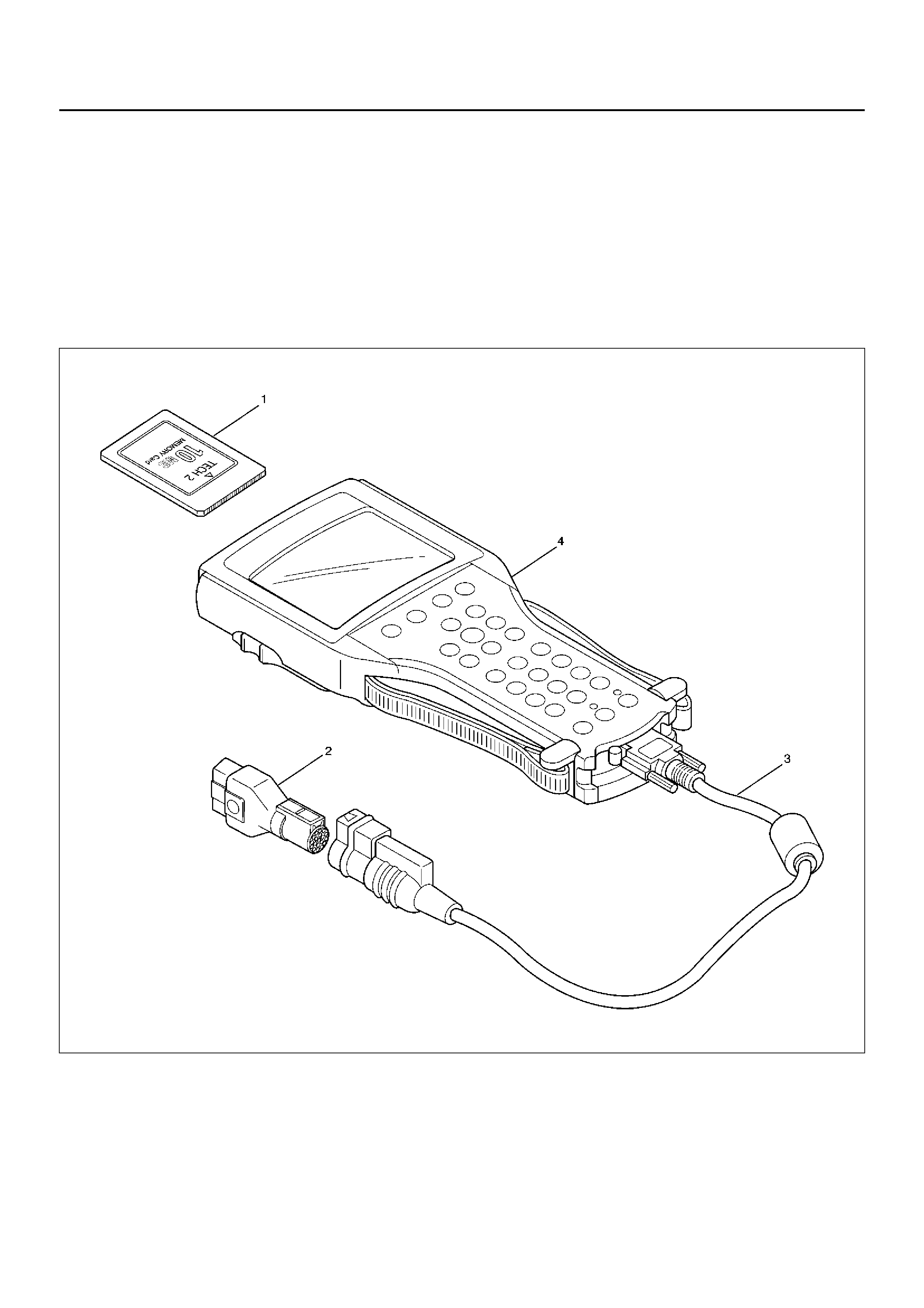
TECH 2 SCAN TOOL
TECH 2 is the preferred diagnostic tool for the MY2001 UES Frontera.
CAUTION:
• Before testing, ensure the base braking system is functioning correctly.
• Make sure that the battery is fully charged.
• Do not conduct the ACTUATOR TEST with the engine running. Before testing, make sure that all obvious electrical
faults have been repaired. Testing of the ABS solenoids while electrical circuit faults exist may damage the control
unit.
• Refer to Section 0C and Section 0C-1 for further information on the applications specific to this vehicle
.
901RW25
Legend
(1) PCMCIA Card
(2) SAE 16/19 Adaptor
(3) DLC Cable
(4) Tech–2
DATA LIST
The data displayed by DATA LIST are as follows:
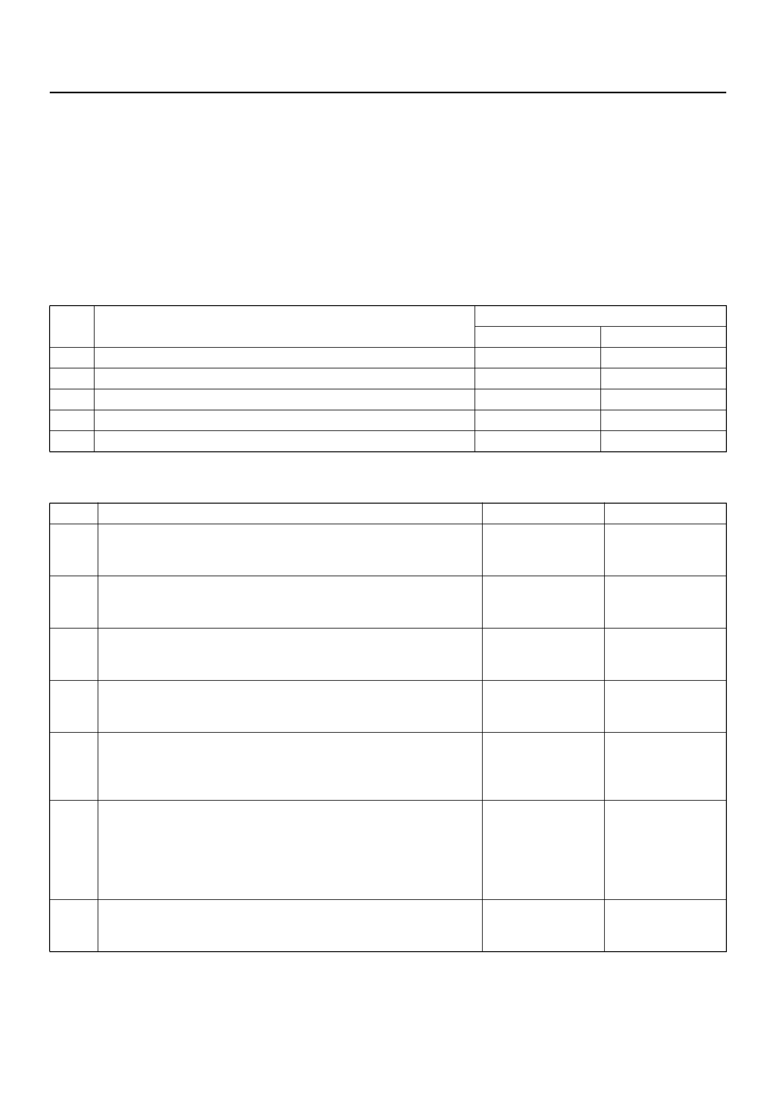
Display Content OK/NG Criteria for Data
Front Left Wheel Speed
Front Right Wheel Speed
Rear Wheel Speed s
km/h (MPH) • Start the vehicle and make sure of linear change in each
wheel speed.
• Turn each wheel by hand and make sure that each
speed data change.
W arning Lamp ON/OFF • To be OFF usually
ABS State ON/OFF • To be OFF usually
ABS Relay Active/Inactive • To be Active usually
4 Wheel Drive Active/Inactive • 2WD: Inactive
•4WD: Active
Brake Switch Active/Inactive • Inactive (Released)
• Active (Pressed)
Brake Fluid Level Normal or not • To be Normal usually
Return Pump Active/Inactive • To be Inactive usually
DRP (Dynamic Rear
Proportioning) Active/Inactive • To be Inactive usually
Rear Dump Valve Commanded Active/Inactive • To be Inactive usually
Rear Dump Valve Feedback
Rear Isolation Valve
Commanded
Rear Isolation Valve Feedback
FL Dump Valve Commanded Active/Inactive • To be Inactive usually
FL Dump Valve Feedback
FL Isolation Valve Commanded
FL Isolation Valve Feedback
FR Dump Valve Commanded Active/Inactive • To be Inactive usually
FR Dump Valve Feedback
FR Isolation Valve Commanded
FR Isolation Valve Feedback
G–Sensor Voltage • 0.00V when vehicle is stopped
Battery Voltage Voltage • Between 10–16.9V

BASIC DIAGNOSTIC FLOW CHART
BASIC INSPECTION PROCEDURE
1. Basic Inspection of Service Brake
2. Ground Inspection
Step Action Yes No
1 1. Customer complaint.
2. Questioning to customer.
3. Basic inspection (Refer to “Basic inspection procedure")
Using TECH 2? Go to Step 2 Go to Step 4
2 Make sure of DTC by mode “F0: Diagnostic Trouble Codes".
Is EHCU including DTC? Clear code and
check for
repeatability.
Go to Step 3 Go to Step 5
3 1. Repair of faulty part.
2. Elimination of DTC.
3. Inspection of “ABS" W/L Illumination pattern with ignition SW
“ON".
4. Test drive.
Does troubl e repeat ?
Repeat the
diagnosis it the
symp tom or
DTC appears
again
Go to Step 1 Go to Step 5
4 Check if the DTC is stored or not.
Is EHCU including DTC?
Clear code and
check for
repeatability
Go to Step 3
Trouble
diagnosis
based on
symptom (Refer
to “Symptom
Diagnosis")
Go to Step 3
5 1. Reconnect all components. Ensure all component are
properly mounted.
2. Clear diagnostic trouble code.
Was this step finished? Finished Go to Step 5
Step Action Yes No
1 Is the fluid level normal?
Go to Step 2
Repleni sh with
fluid
Go to Step 2
2 Does fluid leak? Repair
Go to Step 3 Go to Step 3
3 Is the booster function normal? Go to Step 4 Repair
Go to Step 4
4 Is the pad and rotor normal? Go to Step 5 Repair
Go to Step 5
5 Reconnect all components. Ensure all component are properly
mounted.
Was this step finished? Finished Go to Step 5
Step Action Yes No
1 Does ABS—related ground points normally? Go to Step 2 Repair
Go to Step 2
2 Reconnect all components. Ensure all component are properly
mounted.
Was this step finished? Finished Go to Step 2

EHCU CONNECTOR PIN-OUT CHECKS
• Disconnect Electronic Hydraulic Control Module. • Perform checks with high impedance digital
multimeter 5-8840-0366-0 or equivalent.
No. Circuit to be Tested Ignition
Switch
Position
Multimeter
Scale/RangeMeasure
between Pin
Number
Nominal Value Note
1 Power supply OFF 20DCV 1 (C–5)
2 (C–5)11.5V to 14.5V
2 Ignition enable OFF 20DCV 1 (C–4)
7 (C–4)0V to 0.1V
ON 20DCV 1 (C–4)
7 (C–4)11.5V to 14.5V
3 Stoplight switch OFF 20DCV 13 (C–4)
7 (C–4) 10.5V to 14.5V Press brake pedal
4 Ground connection OFF 200Ω7 (C–4)
Ground Less than 2Ω
OFF 1Ω2 (C–5)
Ground Les s than 0.2Ω
5 FL speed se ns or OFF 2kΩ 2 (C–4)
10 (C–4) 2.0kΩ to 2.8kΩInternal Resistance
OFF 200kΩ2 (C–4)
7 (C–4) more than
100kΩInsulation Resistance
OFF 200mACV 2 (C–4)
10 (C–4) more than
200mV Turn wheel at 1RPS
6 FR speed sensor OFF 2kΩ 3 (C–4)
11 (C–4) 2.0kΩ to 2.8kΩInternal Resistance
OFF 200kΩ3 (C–4)
7 (C–4) more than
100kΩInsulation Resistance
OFF 200mACV 3 (C–4)
11 (C–4) more than
200mV Turn wheel at 1RPS
7 RR speed sensor OFF 2kΩ 4 (C–4)
12 (C–4) 1.0kΩ to 1.7kΩInternal Resistance
OFF 200kΩ4 (C–4)
7 (C–4) more than
100kΩInsulation Resistance
OFF 200mACV 4 (C–4)
12 (C–4) more than
200mV Turn wheel at 1RPS
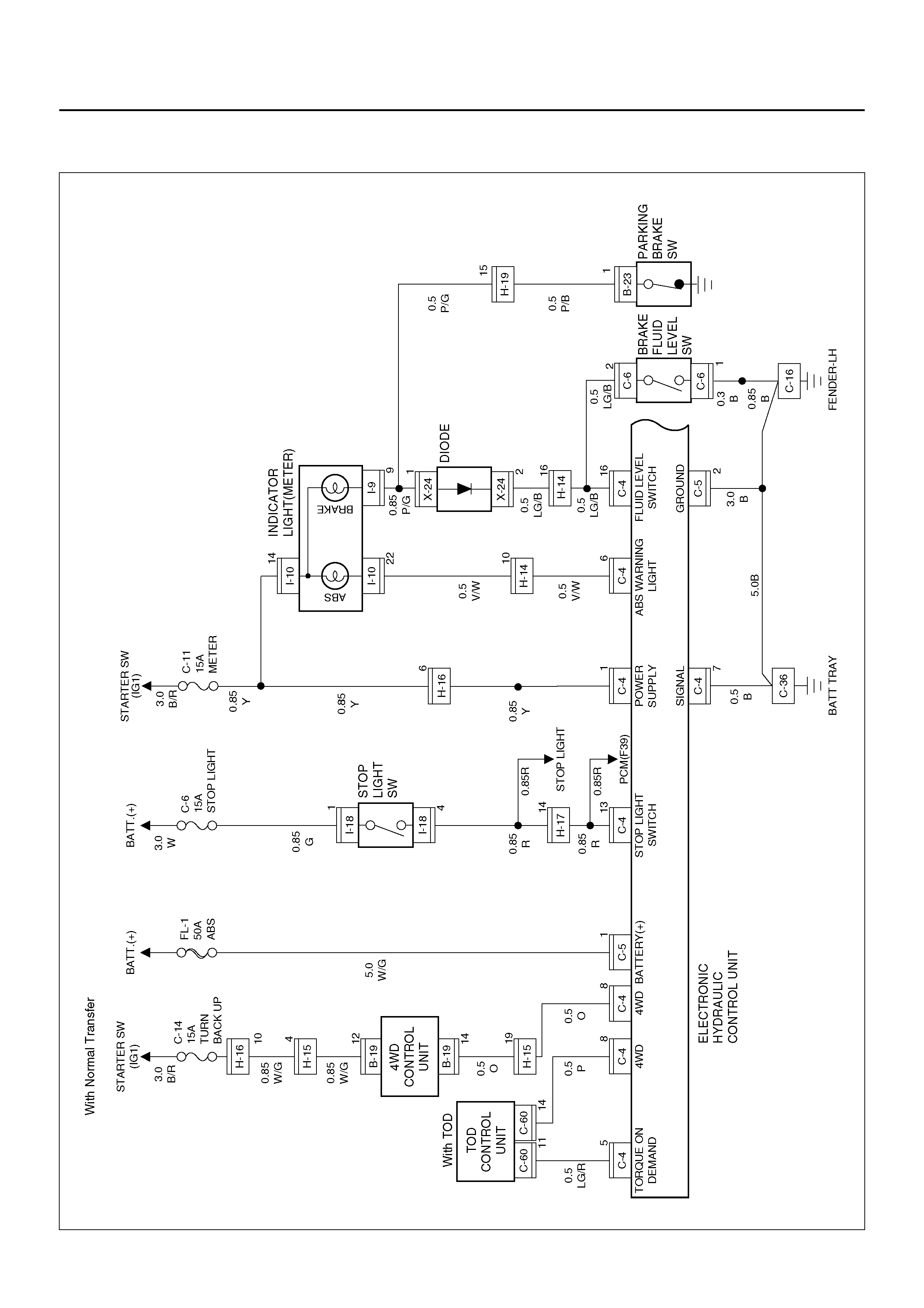
CIRCUIT DIAGRAM
D08R100134
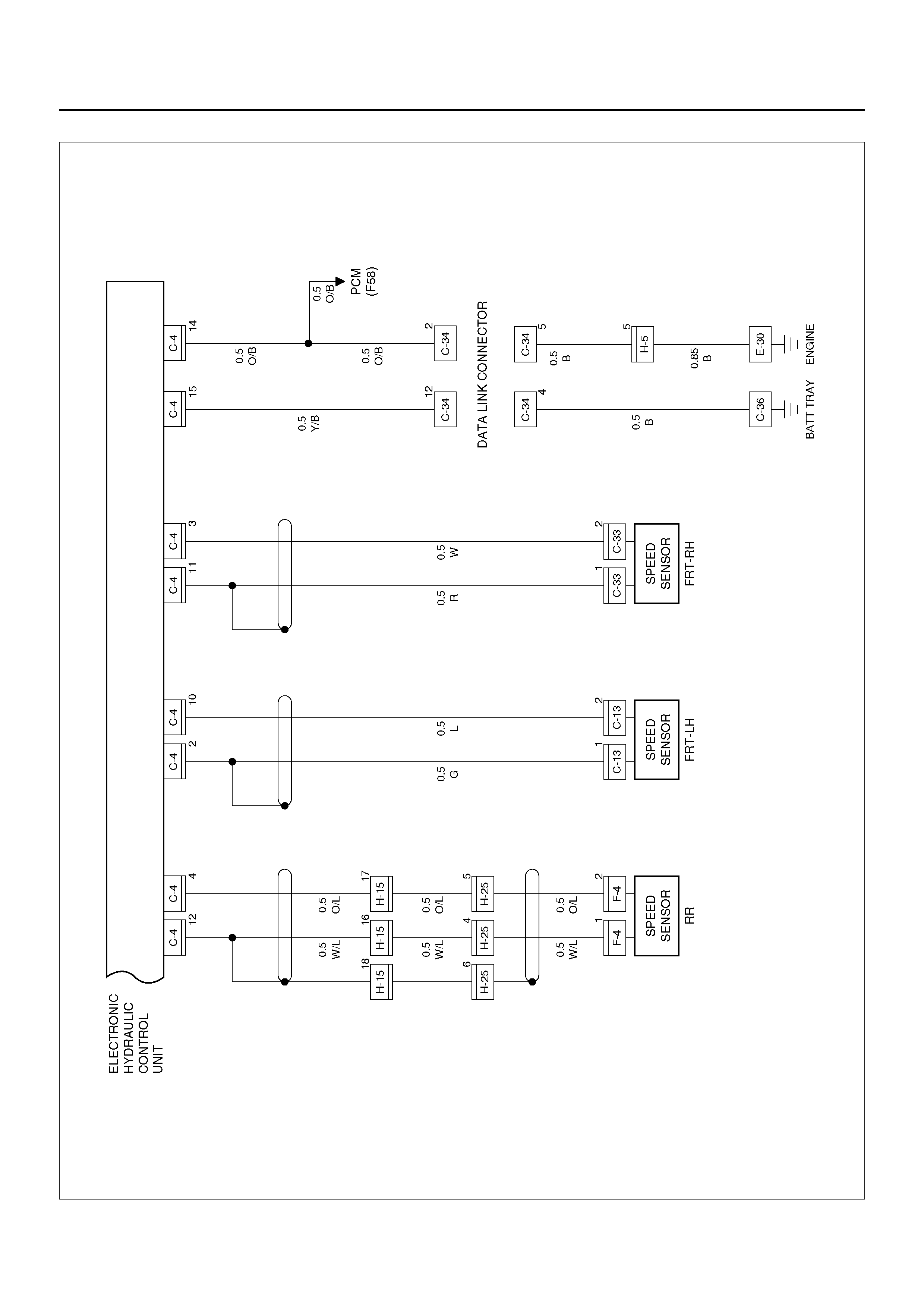
D08R100135
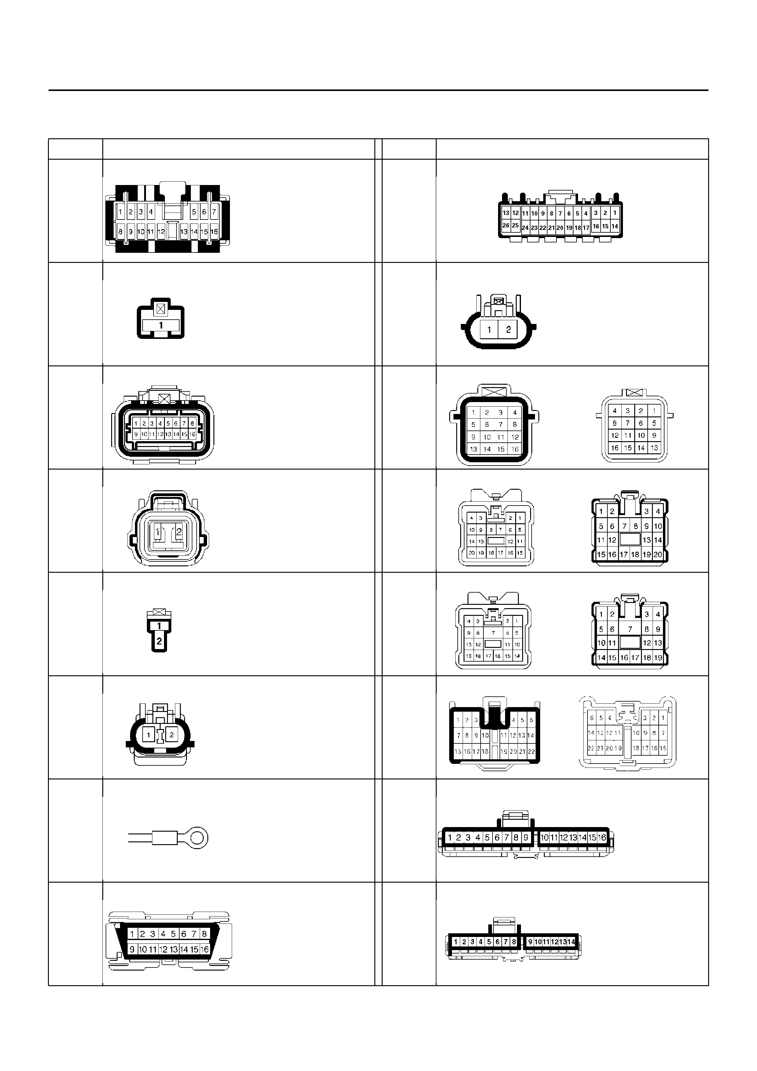
CONNECTOR LIST
No. Connector face No. Connector face
B-19 C-60
B-23 F-4
C-4 H-5
C-5 H-15
H-25
C-6 H-14
C-13
C-33 H-19
C-16
E-30 I-1
C-34 I-2

I-18 I-45
No. Connector face No. Connector face
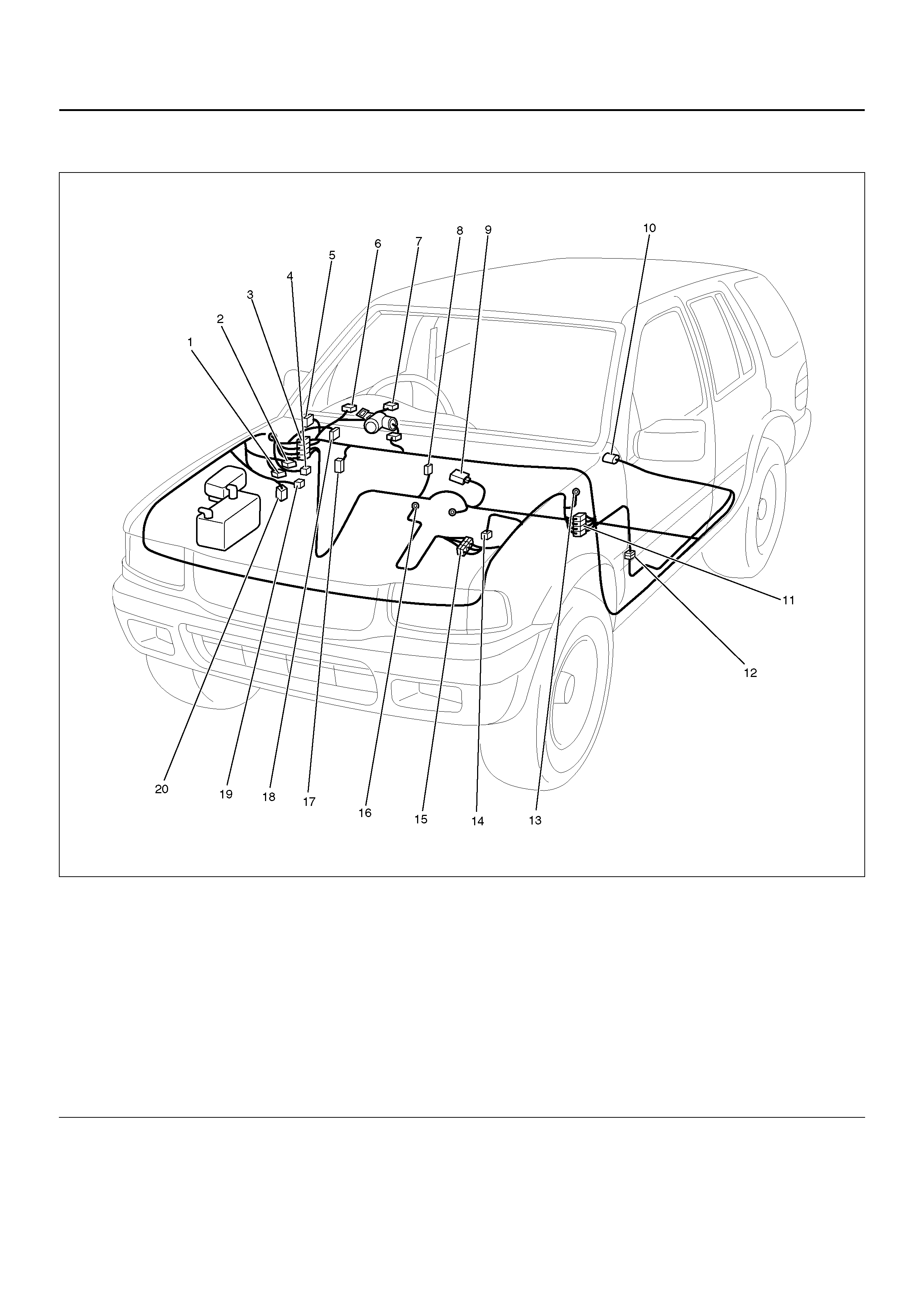
PART LOCATION
D08R100072
Legend
EndOFCallout
(1) C–5
(2) C–4
(3) H– 14, H–19
(4) C–60
(5) I–45 (Relay & Fuse Box)
(6) I–1
(7) I–2
(8) B–23
(9) B–19
(10) F–4
(11) H–15
(12) H–25
(13) C–16
(14) C–13
(15) H–5
(16) E–30
(17) I–18
(18) C–34
(19) C–6
(20) C–33
SYMPTOM DIAGNOSIS
The symptoms that cannot be indicated by warning light can be divided in the following five categories:
1. ABS works frequently but vehicle does not decelerate.
2. Uneven braking occurs while ABS works.
3. The wheels lock during braking.
4. Brake pedal feel is abnormal.
5. Braking sound (from EHCU) is heard while not braking.
These are all attributable to problems which cannot be detected by EHCU self-diagnosis. Use the customer
complaint and a test to determine which symptom is present. Then follow the appropriate flow chart listed below.
CHART A-1 ABS WORKS FREQUENTLY BUT VEHICLE DOES NOT DECELERATE
No. Symptom Diagnostic Flow Charts
Without TECH 2 With TECH 2
1 ABS works frequently but vehicle does not decelerate. Chart A-1 Chart TA-1
2 Uneven braking occurs while ABS works. Chart A-2 Chart TA-2
3 The wheels are locked. Chart A-3 Chart TA-3
4 Brake pedal feel is abnormal. Chart A-4 —
5 Braking sound (from EHCU) is heard while not braking. Chart A-5 Chart TA-5
Step Action Yes No
1 Is braking force distribution normal between front and rear of
vehicle? Go to Step 2
Repair brake
parts.
Go to Step 7
2 Are axle parts installed normally?
Go to Step 3
Repair axle
parts.
Go to Step 7
3 Is there play in each or any wheel speed sensor? Repair wheel
speed sensor.
Go to Step 7 Go to Step 4
4 Is there damage, or powered iron sticking to each or any wheel
speed sensor/sensor ring? Replace sensor
or sensor ring.
Go to Step 7 Go to Step 5
5 Is the output of each wheel speed sensor normal? (Refer to chart
C-1 or TC-1)
Go to Step 6
Replace wheel
speed sensor or
repair harness.
Go to Step 7
6 Is the input of 4WD controller or TOD controll unit normal?
Go to Step 7
Replace 4WD
controller or
TOD controll
unit or repair
harness.
Go to Step 7
7 Reconnect all components, ensure all components are properly
mounted.
Was this step finished?
Repeat the “Basic
diagnostic flow
chart" Go to Step 7

CHART TA-1 ABS WORKS FREQUENTLY BUT VEHICLE DOES NOT DECELERATE
(USE TECH 2)
CHART A-2 UNEVEN BRAKING OCCURS WHILE ABS WORKS
CHART TA-2 UNEVEN BRAKING OCCURS WHILE ABS WORKS (USE TECH 2)
Step Action Yes No
1 1. Connect TECH 2.
2. Make sure of the output conditions of each sensor.
Is the output of each sensor normal? Go to Step 2
Replace wheel
speed sensor.
Go to Step 3
2 Return to Chart A-1.
Was the Chart A-1 finished? Go to Step 3 Go to Step 2
3 Reconnect all components, ensure all components are properly
mounted.
Was this step finished?
Repeat the “Basic
diagnostic flow
chart" Go to Step 3
Step Action Yes No
1 Is there play in each or any sensor? Repair.
Go to Step 5 Go to Step 2
2 Damage or powdered iron sticking to each or any sensor/sensor
ring? Repair.
Go to Step 5 Go to Step 3
3 Is the output of each sensor normal? (Refer to chart C-1 or TC-1)
Go to Step 4
Replace sensor
or repair
harness.
Go to Step 5
4 Is brake pipe connecting order correct?
Replace H/U.
Go to Step 5
Reconnect
brake pipe
correctly.
Go to Step 5
5 Reconnect all components, ensure all components are properly
mounted.
Was this step finished?
Repeat the “Basic
diagnostic flow
chart" Go to Step 5
Step Action Yes No
1 1. Connect TECH 2.
2. Make sure of the output conditions of each sensor.
Is the output of each sensor normal? Go to Step 2 Go to Step 3
2 Check piping by TECH 2 ACTUATOR TEST
Is the piping normal? Replace EHCU.
Go to Step 4 Repair the pipe.
Go to Step 4
3 Repair and check the wheel speed sensor (Refer to chart B-20 to
B-23 , C-1 or TC-1).
Was the each chart finished? Go to Step 4 Go to Step 3
4 Reconnect all components, ensure all components are properly
mounted.
Was this step finished?
Repeat the “Basic
diagnostic flow
chart" Go to Step 4

CHART A-3, TA-3 THE WHEELS ARE LOCKED
CHART A-4 BRAKE PEDAL FEED IS ABNORMAL
Step Action Yes No
1 Is ABS working? Go to Step 2 Go to Step 4
2 Is vehicle speed under 10 km/h (6mph)? Go to Step 3 Normal.
3 Is sensor output normal? (Chart C-1 or TC-1)
Go to Step 4
Replace sensor
or repair
harness.
Go to Step 6
4 Is front 4WD controller or TOD controll unit normal?
Go to Step 5
Replace 4WD
controller or
TOD controll
unit or repair
harness.
Go to Step 6
5 Is hydraulic unit grounded properly? Replace EHCU.
Go to Step 6 Repair.
Go to Step 6
6 Reconnect all components, ensure all components are properly
mounted.
Was this step finished?
Repeat the “Basic
diagnostic flow
chart" Go to Step 6
Step Action Yes No
1 Is the stop light actuated when the brake pedal is depressed? Go to Step 2 Go to Step 3
2 1. Turn the ignition switch off.
2. Dis conn ec ted EHCU co nne cto r.
Is the check voltage EHCU connector terminals 13 to 7 when
brake pedal is depressed than battery voltage? Go to Step 4
Harness NG
between brake
SW and EHCU.
Go to Step 6
3 Is stop light fuse normal?
Go to Step 5
Replace sto p
light fuse.
Go to Step 6
4 Is the check continuity between EHCU connector terminals, 7 to
body grounded?
Go to Step 6
Repair body
grounded
harness.
Go to Step 6
5 Is brake SW normal? Repair stop
light harne ss .
Go to Step 6
Replace brake
SW.
Go to Step 6
6 Reconnect all components, ensure all components are properly
mounted.
Was this step finished?
Repeat the “Basic
diagnostic flow
chart" Go to Step 6

CHART A-5, TA-5 BRAKING SOUND (FROM EHCU) IS HEARD WHILE NOT BRAKING
Step Action Yes No
1 Is this the first vehicle start after engine start? It is self
checking sound
Normal. Go to Step 2
2 Is vehicle speed under 10 km/h (6 mph)? It is self
checking sound
Normal. Go to Step 3
3 Check for the following condi tio n:
• At the time of shift down or clutch operation.
• At the tim e of low ro ad fricti on driv e (ice or sn ow road) or rou gh
road drive.
• At the time of high-speed turn.
• At the time of passing curb.
• At the time of operating electrical equipment switches.
• At the time of racing the engine (over 5000 rpm).
Did it occur under any one condition above?
ABS may
sometime be
actuated even
when brake pedal
is not applied. Go to Step 4
4 Is there play in each or any sensor/wheel speed sensor rings? Repair.
Go to Step 7 Go to Step 5
5 Damage or powdered iron sticking to each or any sensor/wheel
speed sensor ring? Repair.
Go to Step 7 Go to Step 6
6 Is each sensor output normal? (Refer to chart C-1 or TC-1). Check harness/
connector for
suspected
disconnection
If no
disconnection is
found, replace
Coil integrated
module.
Go to Step 7 Repair.
Go to Step 7
7 Reconnect all components, ensure all components are properly
mounted.
Was this step finished?
Repeat the “Basic
diagnostic flow
chart" Go to Step 7

DIAGNOSTIC TROUBLE CODES
Choose and trace an appropriate flowchart by the numbers listed below to find fault and repair.
Code Diagnosis Item Chart
No.
Flash out Serial
Communications
12 — — — —
13 C0285 2 WD Controller in 4WD Vehi cle Control le r Wiring B-8
14 C0271 RAM read/write error
Coil
Integrated
Module B-2
C0272 ROM ch ecks um erro r
C0270 ALU function error
C0273 Inoperative isolation item
C0284 Loop time over run
15 C0277 Low ignition voltage Wiring B-3
C0278 High ign ition vo ltag e
17 C0269 Excessive dump time Coil
Integrated
Module
B-4
18 C0274 Excessive isolation time B-5
21 C0276 G-Sensor Failure B-6
22 C0281 Brake switch Failure B-7
24 C0282 Open or shorted 4×4 input signal Wiring B-8
32 C0267 Open motor circuit or shorted ECU output Motor B-9
C0268 Stalled motor or open ECU output
35 C0265 Open relay circuit Relay B-10
C0266 Shorted relay circuit
41 C0245 FL Open is ola tio n sol enoid or sh or ted ECU outp ut
Solenoid
B-11
C0247 FL Shorted isolation solenoid or open ECU output
42 C0246 FL Open dump solenoid or shorted ECU output B-12
C0248 FL Shorted dump solenoid or open ECU output
43 C0241 FR Open isolation solen oid or shorted ECU output B-13
C0243 FR Shorted isolation solenoid or open ECU output
44 C0242 FR Open dump solenoid or shorted ECU output B-14
C0244 FR Shorted dump solenoid or open ECU output
45 C0251 Rear Open isolation solenoid or shorted ECU output B-15
C0253 Rear Shorted isolation solenoid or open ECU output
46 C0252 Rear Open dump solenoid or shorted ECU output B-16
C0254 Rear Shorted dump solenoid or open ECU output
51 C0225 FL Open or sh or ted sen so r
Sensor or
Wiring
B-17
52 C0221 FR Open or shorted sensor B-18
53 C0235 Rear Open or shorted sensor B-19
61 C0226 FL Missing sensor signal B-20
C0227 FL Senso r signal dropou t
62 C0222 FR Missing sensor signal B-21
C0223 FR Sensor signal dropout
63 C0236 Rear Missing sensor signal B-22
C0237 Rear Sensor signal dropout
64 C0229 Simultaneous dropout of front sensor signal B-23
65 C0238 Wheel speed error Vehicle or
Sensor B-24
— C0286 Shorted indicator lamp Wiring —
Code Diagnosis Item Chart
No.
Flash out Serial
Communications
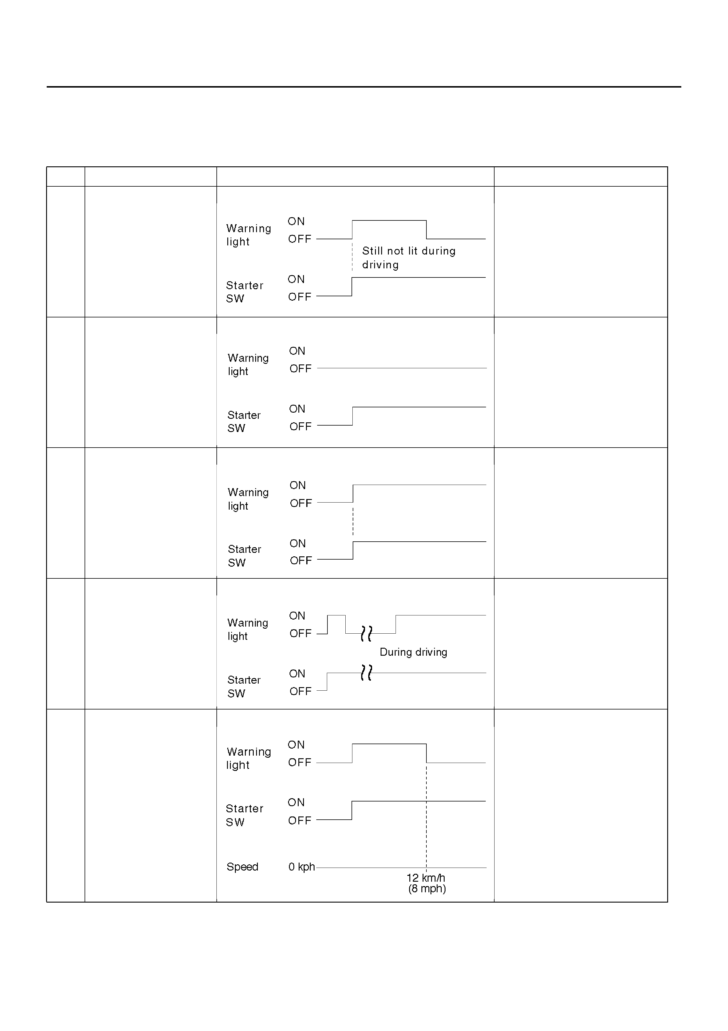
DIAGNOSIS BY “ABS" WARNING LIGHT ILLUMINATION PATTERN
In the event that there is abnormality in the “ABS" warning light illumination pattern while the key is in the ON position
or if the warning light is actuated during driving, trouble should be diagnosed on a illumination pattern basis as follows:
No. Condition “ABS" Warning Light Illumination Pattern Diagnostic
1 Warni ng light i s
actuated nor ma ll y Normal
2 Warning light is not lit Warning light lighting circuit
trouble→Go to Chart B-1
3 Warning light remains
ON Diagnostic trouble codes are
stored.
Displa y dia gno sti c trouble
codes and diagnose on a
code basis according to the
flow char ts.
4 Warni ng light i s
actuated whil e driv ing Diagnostic trouble codes are
stored.
Displa y dia gno sti c trouble
codes and diagnose on a
code basis according to the
flow char ts.
5 Warning light goes at
12 km/h (8 mph) or
higher (After repairing
the faulty part)
Even after repairing the faulty
part the warning light (W/L)
dose not go out it vehicle is at
a stop.
Turn the ignition switch to the
ON position and drive the
vehicle at 12 km/h (8 mph) or
higher to make sure that the
warning light goes out.
DIAGNOSTIC TROUBLE CODES (DTCS)
When the warning light in the instrument cluster remains ON, the EHCU stores the fault identification and disables the
ABS.
Displaying and erasing DTCs:
TECH 2 is the prefered method of displaying and erasing DTC’s - refer to Section 0C. However should it be necessary,
the methods listed below can be adopted using the DLC terminals.
1. E na bli ng the DTC disp lay :
• Confirm that the vehicle has come to a complete stop (with the wheels standing still) and that the brake pedal is
not depressed. (Unless these two condition are satisfied, DTC display cannot be started.)
• With IGN OFF, connect #12 terminal with #4 terminal or # 5 terminal (GND) . Then turn IGN ON.
• Keep #12 terminal connected with #4 terminal or # 5 terminal (GND) during DTC display. (If #12 terminal is
separated from #4 terminal or # 5 terminal (GND) during display, display will stop.)
2. DTC display:
• DTC is displayed by blinking warning light.
• Double-digit display.
• First, normal DTC 12 is displayed three times and then any other DTCs are displayed three times. (If no other
DTCs have been stored, the display of DTC 12 will be repeated.)
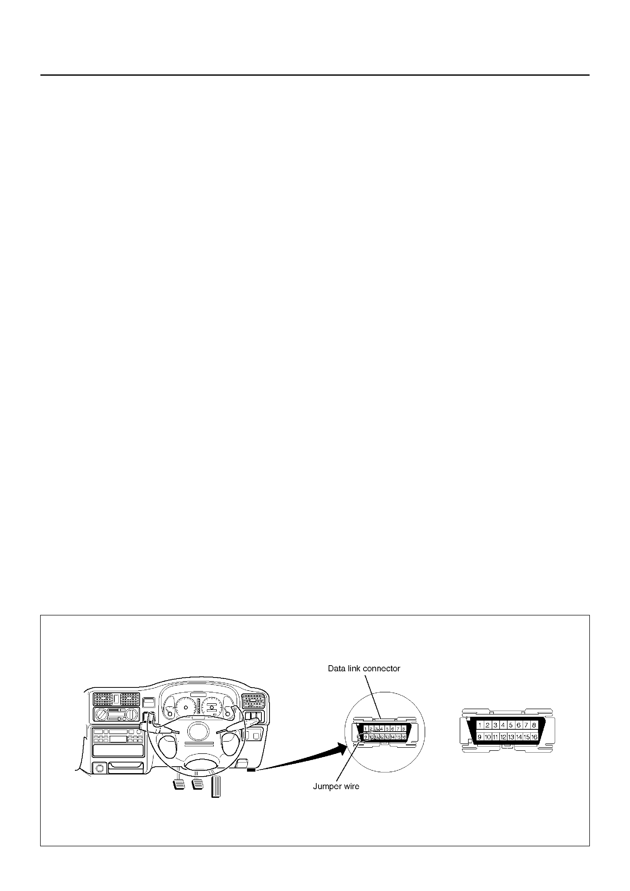
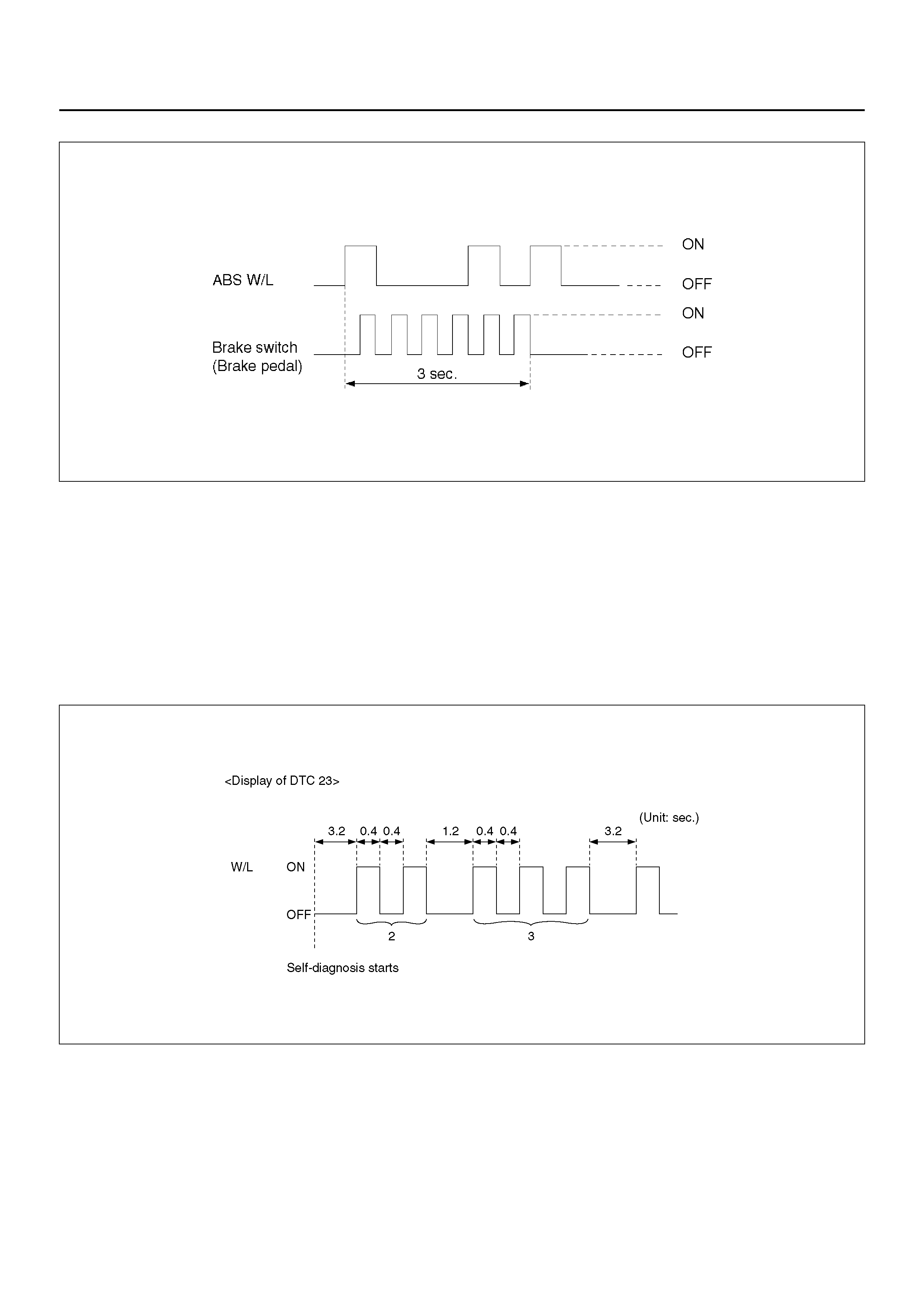
3. How to erase code:
• Conduct brake switch ON/OFF operation 6 or more times within 3 seconds of self-diagnosis startup.
• The code cannot be erased if more than 3 seconds have passed since self-diagnosis startup, or if
self-diagnosis has started with brake switched on (brake pedaled).
•The ABS warning lamp may remain ‘ON’ after the fault is repaired and the DTC’s cleared. Drive the
vehicle above 12 km/h and ensure that the warning light goes out. Should the ABS warning remain ‘ON’
or come ON whilst driving, re the ABS system.
B05RW005
4. Notes
• If the following should occurs during Diagnostic Trouble Code (DTC) display the display will be discontinued.
After initial check, the status that is under the control of ABS will be returned :
– The vehicle starts (The wheels turn) or the brake pedal is depressed.
• Up to 3 different codes can be stored.
• If the ABS should turn OFF due to an intermittent defect, the system will be restored at the next key cycle, if the
initial check finds no abnormality (when IGN is switched from OFF to ON).
5. An example of DTC display
Display of DTC 23
B05R100001
After displaying DTC 12 three times, one DTC after another is displayed, starting with the most recent one.
(However, display is discontinued after about 5 minutes.)
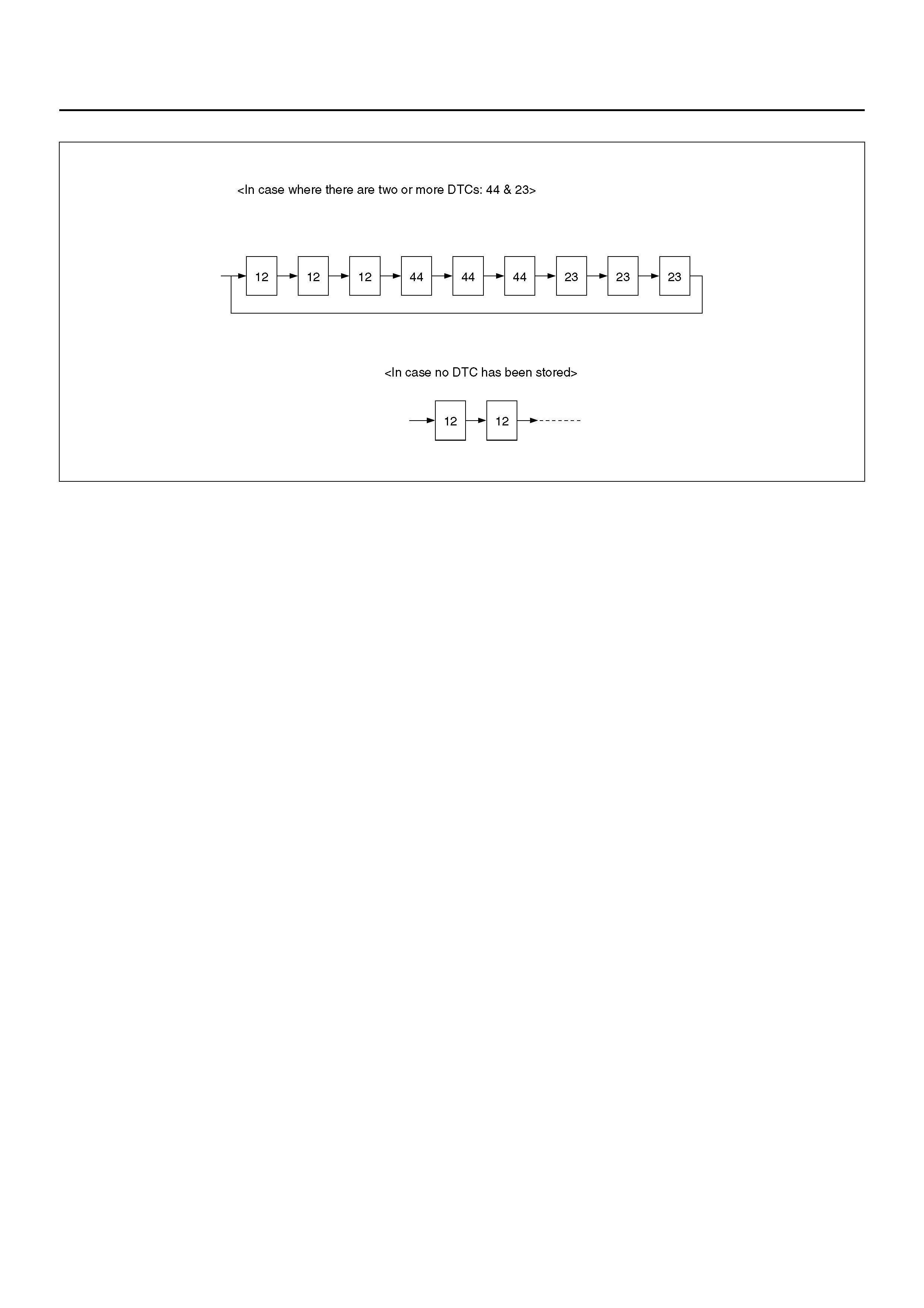
B05R100002
The DTC 12 is displayed repeatedly. (display is discontinued after about 5 minutes after)

CHART B-1 WITH THE KEY IN THE ON POSITION (BEFORE STARTING THE ENGINE).
WARNING LIGHT (W/L) IS NOT ACTIVATED.
CHART B-2 CPU ERROR (DTC 14 (FLASH OUT) / C0271, C0272, C0273, C0284 (SERIAL
COMMUNICATIONS))
Step Action Yes No
1 Is W/L fuse disconnected? Replace fuse.
Go to Step 5 Go to Step 2
2 Is W/L burnt out? Replace W/L bulb.
Go to Step 5 Go to Step 3
3 1. Turn the key off.
2. Disconnect coil integrated module connector (C-4).
3. Turn the key ON.
Is the check voltage between coil integrated module connector
(C-4) terminals 6 and 7 than battery voltage?
Go to Step 4 Repair harness
and connec to r.
Go to Step 5
4 Is the check continuity coil integrated module connector (C-4)
terminals, 1 and 7 and body ground. Check harness for
suspected
disconnection
No fault found:
Replace EHCU .
Go to Step 5
Repair harness
and connec to r.
Go to Step 5
5 Reconnect all components, ensure all components are properly
mounted.
Was this step finished?
Repeat the “Basic
diagnostic flow
chart"
Go to Step 5
Step Action Yes No
1 1. Turn the key off.
2. Dis connected co il int egr ate d modu le con nec tor.
3. Ins pe ct coil int egr ate d module gro und .
Is the check resistance between the coil integrated module
connector terminals, 2 (C-5) and 7 (C-4) and body ground?
Go to Step 2 Repair the body
ground harness.
Go to Step 3
2 1. Turn the key off, connect the coil integrated module
connector.
2. Erase the trouble code.
3. Turn Ignition off, then on, to perform system self-check.
4. If warning light remains on, display trouble codes once again.
Is the check trouble code 14 (Flash out) / C0271, C0272, C0273,
C0284 (Serial commun ic ati ons )?
Replace EHCU .
Go to Step 3 Inspect in
accordance with
the DTC displayed.
3 1. Reconnect all components, ensure all components are
properly mounted.
2. Clear diagnostic trouble code.
Was this step finished?
Repeat the “Basic
diagnostic flow
chart"
Go to Step 3

CHART B-3 LOW OR HIGH IGNITION VOLTAGE (DTC 15 (FLASH OUT) / C0277, 0278
(SERIAL COMMUNICATIONS))
CHART B-4 EXCESSIVE DUMP TIME (DTC 17 (FLASH OUT) / C0269 (SERIAL
COMMUNICATIONS))
CHART B-5 EXCESSIVE ISOLATION TIME (DTC 18 (FLASH OUT) / C0274 (SERIAL
COMMUNICATIONS))
Step Action Yes No
1 Is the check battery voltage normal? (Battery capacity check) Go to Step 2 Charge or replace
battery.
Go to Step 2
2 1. Turn the key off.
2. Disconnect coil integrated module connector.
3. Turn the key on.
Is the check voltage between coil integrated module connector
(C-4) terminals 1 and 7, higher than 10V?
Check harness
connector for
suspected
disconnection
Fault found:
Repair, and
perform system
self-check
No fault found:
replace EHCU.
Go to Step 3
Repair harness or
connector.
Go to Step 3
3 1. Reconnect all components, ensure all components are
properly mounted.
2. Clear diagnostic trouble code.
Was this step finished?
Repeat the “Basic
diagnostic flow
chart"
Go to Step 3
Step Action Yes No
1 Check for anything ca us ing exten ded AB S act ivati on, su ch as
locked brakes or an erratic speed sensor signal.
Was a problem found?
Repair or Replace Go to Step 2
2 1. The key turned off.
2. Replace EHCU.
3. Reconnect all components, ensure all components are
properly mounted.
Was this step finished?
Repeat the “Basic
diagnostic flow
chart"
Go to Step 2

CHART B-6 G-SENSOR OUTPUT FAILURE (DTC 21 (FLASH OUT) / C0276 (SERIAL
COMMUNICATIONS))
CHART B-7 BRAKE SWITCH FAILURE (DTC 22 (FLASH OUT) / C0281 (SERIAL
COMMUNICATIONS))
Step Action Yes No
1 1. Turn the key off.
2. Replace EHCU.
3. Reconnect all components, ensure all components are
properly mounted.
Was this step finished?
Repeat the “Basic
diagnostic flow
chart"
Go to Step 1
Step Action Yes No
1 Is the stop light actuated when the brake pedal is depressed? Go to Step 2 Go to Step 4
2 1. Turn the key off.
2. Dis connected co il int egr ate d modu le con nec tor.
Is the check voltage coil integrated module connector (C-4)
terminals 13 to 7 when brake pedal is depressed than battery
voltage?
Go to Step 3 Harness between
brake SW an d coil
integrated module
is faulty.
Go to Step 6
3 Is the check that pins C-5 connector 2, and C-4 connector 7 have
good ground? Check harness /
connector for
disconnection
Fault found:
Repair, and
perform system
self-check.
No fault found:
replace EHCU.
Go to Step 6
Repair.
Go to Step 6
4 Is stop light fuse normal? Go to Step 5 Replace.
Go to Step 6
5 Is brake SW normal? Abnormal harness
in stop light circuit.
Repair the
harness.
Go to Step 6
Replace.
Go to Step 6
6 1. Reconnect all components, ensure all components are
properly mounted.
2. Clear diagnostic trouble code.
Was this step finished?
Repeat the “Basic
diagnostic flow
chart"
Go to Step 6

CHART B-8 2WD CONTROLLER IN 4WD VEHICLE CONTROLLER (DTC 13 (FLASH OUT) /
C0285 (SERIAL COMMUNICATIONS)), 4WD STATE INPUT SIGNAL FAILURE (DTC 24
(FLASH OUT) / C0282 (SERIAL COMMUNICATIONS))
CHART B-9 PUMP MOTOR FAILURE (DTC 32 (FLASH OUT) / C0267, C0268 (SERIAL
COMMUNICATIONS))
Step Action Yes No
1 Remove coil integrated module connector.
Is the coil integrated module connector (C-4) terminal 8 line
normally?
Go to Step 2 Repair.
Go to Step 3
2 Is the 4WD controller or TOD controll unit normally? Replace EHCU.
Go to Step 3 Replace 4WD
controller or TOD
controll unit.
Go to Step 3
3 1. Reconnect all components, ensure all components are
properly mounted.
2. Clear diagnostic trouble code.
Was this step finished?
Repeat the “Basic
diagnostic flow
chart"
Go to Step 3
Step Action Yes No
1 1. Turn the key off.
2. Disconnect module harness connector.
3. Measure the voltage between terminal 1 of the module
harness connector (C-5) and body ground.
Is the voltage equal to the battery voltage?
Go to Step 2 Repair fuse/
harness between
battery and coil
integrated module
connector (C-5)
terminal 1.
Go to Step 5
2 Is the harness from the hydraulic unit reconnected to the module
connector? Go to Step 3 Connect to the
connector.
Go to Step 3
3 Perform the EHCU Connector Pin-Out Check (refer 5A-24)
Were any faults found? Rec ti fy faul ts.
Go to Step 5 Go to Step 4
4 Is the resistance between hydraulic unit connector terminals 1
and 2 between 0.2 and 1.0 ohm ? Replace EHCU .
Go to Step 5 Go to Step 5
5 1. Reconnect all components, ensure all components are
properly mounted.
2. Clear diagnostic trouble code.
Was this step finished?
Repeat the “Basic
diagnostic flow
chart"
Go to Step 5

CHART B-10 EHCU VALVE RELAY FAILURE (DTC 35 (FLASH OUT) / C0265, C0266 (SERIAL
COMMUNICATIONS))
CHART B-11 FL ISOLATION SOLENOID COIL FAILURE (DTC 41 (FLASH OUT) / C0245,
C0247 (SERIAL COMMUNICATIONS))
CHART B-12 FL DUMP SOLENOID COIL FAILURE (DTC 42 (FLASH OUT) / C0246, C0248
(SERIAL COMMUNICATIONS))
Step Action Yes No
1 1. Turn the key off.
2. Disconnect coil integrated module connector.
3. Measure the voltage between terminal 1 of the coil integrated
module connector (C-5) and body ground.
Is the voltage equal to the battery voltage?
Replace EHCU .
Go to Step 2 Repair fuse and
harness coil
integrated module
connector (C-5)
terminal 1 and
battery.
Go to Step 2
2 1. Reconnect all components, ensure all components are
properly mounted.
2. Clear diagnostic trouble code.
Was this step finished?
Repeat the “Basic
diagnostic flow
chart"
Go to Step 2
Step Action Yes No
1 Was the “EHCU Connector Pin–out Checks" performed? Go to Step 2 Go to “EHCU
Connector Pin–out
Checks."
2 1. Turn the key switch to off.
2. Disconnect the 2–way EHCU connector (C–5) from the
EHCU.
3. Inspect the connector for damage or corrosion.
Is the connector free from damage or corrosion?
Go to Step 3 Repair the
connector. Repeat
the “Basic
Diagnostic Flow
Chart."
3 1. Replace the Coil Integrated Module.
2. Reconnect all component, ensure all components are
properly mounted.
Was this step finished?
Repeat the “Basic
diagnostic flow
chart"
Go to Step 3

CHART B-13 FR ISOLATION SOLENOID COIL FAILURE (DTC 43 (FLASH OUT) / C0241,
C0243 (SERIAL COMMUNICATIONS))
CHART B-14 FR DUMP SOLENOID COIL FAILURE (DTC 44(FLASH OUT) / C0242, C0244
(SERIAL COMMUNICATIONS))
CHART B-15 REAR ISOLATION SOLENOID COIL FAILURE (DTC 45 (FLASH OUT) / C0251,
C0253 (SERIAL COMMUNICATIONS))
Step Action Yes No
1 Was the “EHCU Connector Pin–out Checks" performed? Go to Step 2 Go to “EHCU
Connector Pin–out
Checks."
2 1. Turn the key switch to off.
2. Disconnect the 2–way EHCU connector (C–5) from the
EHCU.
3. Inspect the connector for damage or corrosion.
Is the connector free from damage or corrosion?
Go to Step 3 Repair the
connector. Repeat
the “Basic
Diagnostic Flow
Chart."
3 1. Replace the Coil Integrated Module.
2. Reconnect all component, ensure all components are
properly mounted.
Was this step finished?
Repeat the “Basic
diagnostic flow
chart"
Go to Step 3

CHART B-16 REAR DUMP SOLENOID COIL FAILURE (DTC 46 (FLASH OUT) / C0252, C0254
(SERIAL COMMUNICATIONS))
CHART B-17 FL SPEED SENSOR OPEN OR SHORTED (DTC 51 (FLASH OUT) / C0225
(SERIAL COMMUNICATIONS))
Step Action Yes No
1 Was the “EHCU Connector Pin–out Checks" performed? Go to Step 2 Go to “EHCU
Connector Pin–out
Checks."
2 1. Turn the key switch to off.
2. Disconnect the 2–way EHCU connector (C–5) from the
EHCU.
3. Inspect the connector for damage or corrosion.
Is the connector free from damage or corrosion?
Go to Step 3 Repair the
connector. Repeat
the “Basic
Diagnostic Flow
Chart."
3 1. Replace the Coil Integrated Module.
2. Reconnect all component, ensure all components are
properly mounted.
Was this step finished?
Repeat the “Basic
diagnostic flow
chart"
Go to Step 3
Step Action Yes No
1 1. Turn the key off.
2. Disconnect coil integrated module connector.
3. Measure the resistance between coil integrated module
connector (C-4) terminals 2 and 10.
Is the resistance between 2.0k and 2.8k ohms?
Check for faults in
harness between
speed sensor and
coil integrated
module.
Fault found:
Repair, and
perform system
self-check.
No fault found:
Replace co il
integrated module.
Go to Step 3
Go to Step 2
2 Measure the FL speed sensor resistance at the sensor
connector.
Is the resistance between 2.0k and 2.8k ohms?
Repair harness
abnormality
between sensors
and coil integrated
module.
Go to Step 3
Replace sensor.
Go to Step 3
3 1. Reconnect all components, ensure all components are
properly mounted.
2. Clear diagnostic trouble code.
Was this step finished?
Repeat the “Basic
diagnostic flow
chart"
Go to Step 3

CHART B-18 FR SPEED SENSOR OPEN OR SHORTED (DTC 52 (FLASH OUT) / C0221
(SERIAL COMMUNICATIONS))
Step Action Yes No
1 1. Turn the key off.
2. Disconnect coil integrated module connector.
3. Measure the resistance between coil integrated module
connector (C-4) terminals 3 and 11.
Is the resistance between 2.0k and 2.8k ohms?
Check for faults in
harness between
speed sensor and
coil integrated
module.
Fault found:
Repair, and
perform system
self-check.
No fault found:
Replace co il
integrated module.
Go to Step 3
Go to Step 2
2 Measure the FR speed sensor resistance at the sensor
connector.
Is the resistance between 2.0k and 2.8k ohms?
Repair harness
abnormality
between sensors
and coil integrated
module.
Go to Step 3
Replace sensor.
Go to Step 3
3 1. Reconnect all components, ensure all components are
properly mounted.
2. Clear diagnostic trouble code.
Was this step finished?
Repeat the “Basic
diagnostic flow
chart"
Go to Step 3

CHART B-19 REAR SPEED SENSOR OPEN OR SHORTED (DTC 53 (FLASH OUT) / C0235
(SERIAL COMMUNICATIONS))
Step Action Yes No
1 1. Turn the key off.
2. Disconnect coil integrated module connector.
3. Measure the resistance between coil integrated module
connector (C-4) terminals 4 and 12.
Is the resistance between 1.0k and 1.7k ohms?
Check for faults in
harness between
speed sensor and
coil integrated
module.
Fault found:
Repair, and
perform system
self-check.
No fault found:
Replace EHCU .
Go to Step 3
Go to Step 2
2 Measure the Rear speed sensor resistance at the sensor
connector.
Is the resistance between 1.0k and 1.7k ohms?
Repair harness
abnormality
between sensors
and coil integrated
module.
Go to Step 3
Replace sensor.
Go to Step 3
3 1. Reconnect all components, ensure all components are
properly mounted.
2. Clear diagnostic trouble code.
Was this step finished?
Repeat the “Basic
diagnostic flow
chart"
Go to Step 3

CHART B-20 FL SPEED SENSOR MISSING (DTC 61 (FLASH OUT) / C0226, C0227 (SERIAL
COMMUNICATIONS))
NOTE: Even after repairing the faulty part the warning
light (W/L) does not go out if the vehicle is at a stop.
Turn the ignition switch to the ON position and drive the
vehicle at 12 km/h (8 mph) or higher to make sure that
the warning light goes out.
Step Action Yes No
1 1. Turn the key off.
2. Disconnect coil integrated module connector.
3. Measure the FL speed sensor resistance between coil
integrated module connector (C-4) terminals 2 and 10.
Is the resistance between 2.0k and 2.8k ohms?
Go to Step 2 Go to Step 3
2 Is there play sensor/sensor rotor? Repair.
Go to Step 6 Go to Step 4
3 Measure the FL speed sensor resistance at the sensor
connector.
Is the resistance between 2.0k and 2.8k ohms?
Repair harness
abnormality
between sensors
and coil integrated
module.
Go to Step 6
Replace sensor.
Go to Step 6
4 Damage and powered iron sticking to sensor/sensor ring? Repair.
Go to Step 6 Go to Step 5
5 Is sensor output normal? (Chart C-1-1 or TC-1) Check for faults in
harness between
speed sensor and
coil integrated
module.
Fault found: repair ,
and perform
system self-check.
No fault found:
replace EHCU.
Go to Step 6
Replace sensor.
Go to Step 6
6 1. Reconnect all components, ensure all components are
properly mounted.
2. Clear diagnostic trouble code.
Was this step finished?
Repeat the “Basic
diagnostic flow
chart"
Go to Step 6

CHART B-21 FR SPEED SENSOR MISSING (DTC 62 (FLASH OUT) / C0222, C0223 (SERIAL
COMMUNICATIONS))
NOTE: The ABS warning lamp may remain ‘ON’ after the fault is repaired and the DTC’s cleared. Drive the
vehicle above 12 km/h and ensure that the warning light goes out. Should the ABS warning remain ‘ON’ or
come ON while driving re-diagnose the ABS system.
Step Action Yes No
1 1. Turn the key off.
2. Disconnect coil integrated module connector.
3. Measure the FR speed sensor resistance between coil
integrated module connector (C-4) terminals 3 and 11.
Is the resistance between 2.0k and 2.8k ohms?
Go to Step 2 Go to Step 3
2 Is there play sensor/sensor rotor? Repair.
Go to Step 6 Go to Step 4
3 Measure the FR speed sensor resistance at the sensor
connector.
Is the resistance between 2.0k and 2.8k ohms?
Repair harness
abnormality
between sensors
and coil integrated
module.
Go to Step 6
Replace sensor.
Go to Step 6
4 Damage and powered iron sticking to sensor/sensor ring? Repair.
Go to Step 6 Go to Step 5
5 Is sensor output normal? (Chart C-1-2 or TC-1) Check for faults in
harness between
speed sensor and
coil integrated
module.
Fault found: repair ,
and perform
system self-check.
No fault found:
replace EHCU.
Go to Step 6
Replace sensor.
Go to Step 6
6 1. Reconnect all components, ensure all components are
properly mounted.
2. Clear diagnostic trouble code.
Was this step finished?
Repeat the “Basic
diagnostic flow
chart"
Go to Step 6

CHART B-22 REAR SPEED SENSOR MISSING (DTC 63 (FLASH OUT) / C0236, C0237
(SERIAL COMMUNICATIONS))
NOTE: Even after repairing the faulty part the warning
light (W/L) does not go out if the vehicle is at a stop.
Turn the ignition switch to the ON position and drive the
vehicle at 12 km/h (8 mph) or higher to make sure that
the warning light goes out.
Step Action Yes No
1 1. Turn the key off.
2. Disconnect coil integrated module connector.
3. Measure the Rear speed sensor resistance between coil
integrated module connector (C-4) terminals 4 and 12.
Is the resistance between 1.0k and 1.7k ohms?
Go to Step 2 Go to Step 3
2 Is there play sensor/sensor rotor? Repair.
Go to Step 6 Go to Step 4
3 Measure the rear speed sensor resistance at the sensor
connector.
Is the resistance between 1.0k and 1.7k ohms?
Repair harness
abnormality
between sensors
and coil integrated
module.
Go to Step 6
Replace sensor.
Go to Step 6
4 Damage and powered iron sticking to sensor/sensor ring? Repair.
Go to Step 6 Go to Step 5
5 Is sensor output normal? (Chart C-1-3 or TC-1) Check for faults in
harness between
speed sensor and
coil integrated
module.
Fault found: repair ,
and perform
system self-check.
No fault found:
replace EHCU.
Go to Step 6
Replace sensor.
Go to Step 6
6 1. Reconnect all components, ensure all components are
properly mounted.
2. Clear diagnostic trouble code.
Was this step finished?
Repeat the “Basic
diagnostic flow
chart"
Go to Step 6

CHART B-23 SIMULTANEOUS DROP-OUT OF FRONT SPEED SENSOR SIGNAL (DTC 64
(FLASH OUT) / C0229 (SERIAL COMMUNICATIONS))
NOTE: Even after repairing the faulty part the warning
light (W/L) does not go out if the vehicle is at a stop.
Turn the ignition switch to the ON position and drive the
vehicle at 12 km/h (8 mph) or higher to make sure that
the warning light goes out.
Step Action Yes No
1 1. Turn the key off.
2. Disconnect coil integrated module connector.
3. Measure the FL speed sensor resistance between coil
integrated module connector (C-4) terminals 2 and 10.
Is the resistance between 2.0k and 2.8k ohms?
Go to Step 2 Go to Step 3
2 Measure the FR speed sensor resistance between coil integrated
module connector (C-4) terminals 3 and 11.
Is the resistance between 2.0k and 2.8 k ohms?
Go to Step 5 Go to Step 4
3 Measure the FL speed sensor resistance at the sensor
connector.
Is the resistance between 2.0k and 2.8k ohms?
Repair harness
abnormality
between sensors
and coil integrated
module.
Go to Step 2
Replace sensor.
Go to Step 2
4 Measure the FR speed sensor resistance at the sensor
connector.
Is the resistance between 2.0k and 2.8k ohms?
Repair harness
abnormality
between sensors
and coil integrated
module.
Go to Step 5
Replace sensor.
Go to Step 5
5 Damage and powered iron sticking to sensor/sensor ring? Repair.
Go to Step 6 Go to Step 6
6 Is there play sensor/sensor rotor? Repair.
Go to Step 7 Go to Step 7
7 Is sensor output normal? (Chart C-1-1&C-1-2 or TC-1) Check for faults in
harness between
speed sensor and
coil integrated
module.
Fault found: repair ,
and perform
system self-check.
No fault found:
replace EHCU.
Go to Step 8
Replace sensor.
Go to Step 8
8 1. Reconnect all components, ensure all components are
properly mounted.
2. Clear diagnostic trouble code.
Was this step finished?
Repeat “Basic
diagnostic flow
chart"
Go to Step 8

CHART B-24 WHEEL SPEED INPUT ABNORMALITY (DTC 65 (FLASH OUT) / C0238 (SERIAL
COMMUNICATIONS))
Sensor Signal Abnormality Criteria using TECH 2
1. While driving, the speed of one or two wheels is
25% or more higher or lower than that of the other
wheels.
2. The speed of one or two wheels is 10 km/h (6 mph)
or more higher or lower than that of the other
wheels.
3. During steady driving, wheel speed changes
abruptly.
*1 The vehicle must run on a level paved road.
NOTE: Even after repairing the faulty part the warning
light (W/L) does not go out if the vehicle is at a stop.
Turn the ignition switch to the ON position and drive the
vehicle at 12 km/h (8 mph) or higher to make sure that
the warning light goes out.
It is important to verify that the correct tires are installed
on vehicle.
Step Action Yes No
1 Using TECH 2? Go to Step 2 Go to Step 3
2 1. Connect TECH 2.
2. Select Snap shot manual trigger.
3. With wheel speed data displayed, run the vehicle when
speed has arrived at 30 km/h (18 mph).
4. Check speed data on each wheel (refer to the criterion given
below). * 1
Is the abnormal sensor condition found?
Replace.
Go to Step 8 G o to Step 3
All the sensors
should follow the
following flowchart
(without using
TECH 2).
3 Is there play in sensor/sensor ring? Repair.
Go to Step 8 G o to Step 4
4 Is there powdered iron sticking to sensor/sensor ring? Repair.
Go to Step 8 G o to Step 5
5 Is there a broken tooth or indentation in sensor ring? Replace sensor
ring.
Go to Step 8
Go to Step 6
6 Is there play in wheel bearing? Adjust or repair.
Go to Step 8 G o to Step 7
7 Is the check wiring between sensor and coil integrated module
normal? Replace EHCU .
Go to Step 8 Repair, and
perform system
self-check.
Go to Step 8
8 1. Reconnect all components, ensure all components are
properly mounted.
2. Clear diagnostic trouble code.
Was this step finished?
Repeat
<FmSdata>[rsquor]
Basic diagnostic
flow chart"
Go to Step 8

UNIT INSPECTION PROCEDURE
This section describes the following inspection
procedures referred to during “Symptom Diagnosis" and
“Diagnosis By ‘ABS' Warning Light Illumination Pattern"
:
CHART C-1-1 FL SENSOR OUTPUT INSPECTION PROCEDURE
without TECH 2 with TECH 2
Sensor Output Inspection Chart C-1-1 to C-1-3 Chart TC-1
Step Action Yes No
1 1. Turn the key off.
2. Disconnect coil integrated module connector.
3. Jack up the vehicle with all four wheels off the ground.
Measure the AC voltage between coil integrated module
connector terminals while turning FL wheel at a speed of 1
RPS:
Is the check between coil integrated module connector (C-4)
terminals 2 and 10 than under 200 mV?
Go to Step 2 OK.
Go to Step 3
2 1. Disconnect the wheel speed sensor.
2. Measure resistance between the wheel speed sensor
connector terminals 1 and 2.
Is the check between connector (C-13) terminals 1 and 2 within
2.0k - 2.8k ohms?
Connector is faulty ,
or open or short
circuit of harnes s
between wheel
speed sensor
connector and coil
integrated module.
Inspect and correct
the connector or
harness.
Go to Step 3
Whe el sp eed
sensor is faulty.
Replace the wheel
speed sensor.
Go to Step 3
3 Reconnect all components, ensure all components are properly
mounted.
Was this step finished?
Repeat the “Basic
diagnostic flow
chart"
Go to Step 3

CHART C-1-2 FR SENSOR OUTPUT INSPECTION PROCEDURE
Step Action Yes No
1 1. Turn the key off.
2. Disconnect coil integrated module connector.
3. Jack up the vehicle with all four wheels off the ground.
Measure the AC voltage between coil integrated module
connector terminals while turning FR wheel at a speed of 1
RPS:
Is the check between coil integrated module connector (C-4)
terminals 3 and 11 than under 200 mV?
Go to Step 2 OK.
Go to Step 3
2 1. Disconnect the wheel speed sensor.
2. Measure resistance between the wheel speed sensor
connector terminals 1 and 2.
Is the check between connector (C-33) terminals 1 and 2 within
2.0k - 2.8k ohms?
Connector is faulty ,
or open or short
circuit of harnes s
between wheel
speed sensor
connector and coil
integrated module.
Inspect and correct
the connector or
harness.
Go to Step 3
Whe el sp eed
sensor is faulty.
Replace the wheel
speed sensor.
Go to Step 3
3 Reconnect all components, ensure all components are properly
mounted.
Was this step finished?
Repeat the “Basic
diagnostic flow
chart"
Go to Step 3

CHART C-1-3 REAR SENSOR OUTPUT INSPECTION PROCEDURE
CHART TC-1 SENSOR OUTPUT INSPECTION PROCEDURE
Step Action Yes No
1 1. Turn the key off.
2. Disconnect coil integrated module connector.
3. Jack up the vehicle with all four wheels off the ground
measure the AC voltage between coil integrated module
connector terminals while turning Rear wheel at a speed of 1
RPS:
Is the check between coil integrated module connector (C-4)
terminals 4 and 12 than under 200 mV?
Go to Step 2 OK.
Go to Step 3
2 1. Disconnect the wheel speed sensor.
2. Measure resistance between the wheel speed sensor
connector terminals 1 and 2.
Is the check between connector (F-4) terminals 1 and 2 within
1.0k - 1.7k ohms?
Connector is faulty ,
or open or short
circuit of harnes s
between wheel
speed sensor
connector and coil
integrated module.
Inspect and correct
the connector or
harness.
Go to Step 3
Whe el sp eed
sensor is faulty.
Replace the wheel
speed sensor.
Go to Step 3
3 Reconnect all components, ensure all components are properly
mounted.
Was this step finished?
Repeat the “Basic
diagnostic flow
chart"
Go to Step 3
Step Action Yes No
1 1. Connect TECH 2.
2. Check the wheel speed of each sensor by Data List.
Is the vehicle speed normal?
Go to Step 6 Go to Step 2
2 Check the sensor harness for suspected disconnection (check
while shaking harness/connector).
Is the sensor harness connection normal?
Replace sp eed
sensor.
Go to Step 4
Repair.
Go to Step 3
3 Check the wheel speed of each sensor by Data List.
Is the vehicle speed normal? Go to Step 6 Go to Step 4
4 Check the sensor rotor.
Is the sensor rotor normal? Replace sp eed
sensor.
Go to Step 5
Replace sensor
rotor.
Go to Step 5
5 Check the harness between coil integrated module and speed
sensor.
Is the harness connection normal?
Go to Step 6 Repair harness or
connector between
coil integr ate d
module and speed
sensor.
Go to Step 6
6 Reconnect all components, ensure all components are properly
mounted.
Was this step finished?
Repeat the “Basic
diagnostic flow
chart"
Go to Step 6
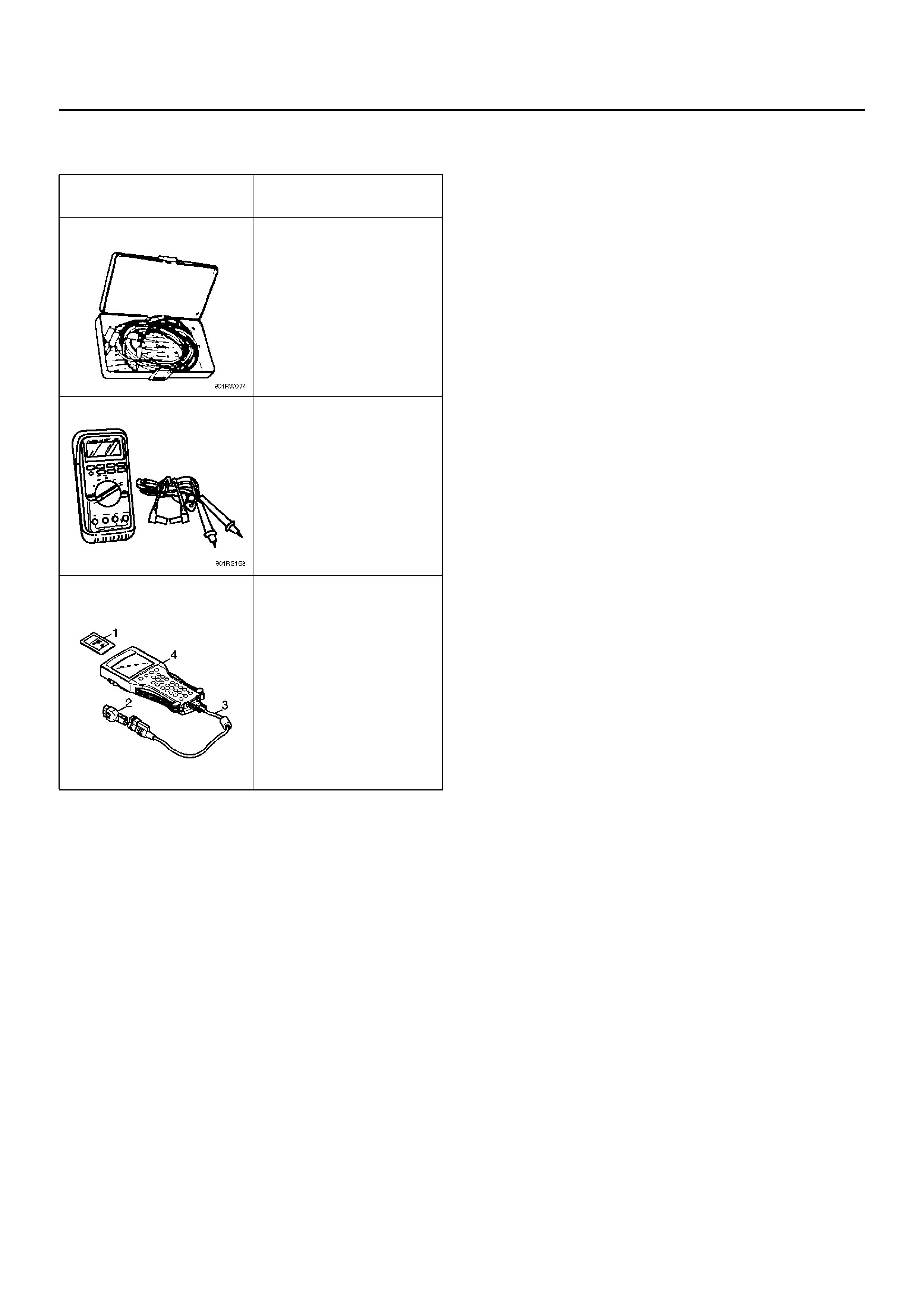
SPECIAL TOOLS
ILLUSTRATION TOOL NO.
TOOL NAME
5–8840–0385–0
(J–35616)
Connector test adapter kit
5–8840–0366–0
(J–39200)
High impedance
multimeter
7000086–ISU
Tech 2 Set
(1) PCMCI A Car d
(2) SAE 16/19 Adapter
(3) DLC Cable
(4) Tech 2