
SECTION 5B - ANTI-LOCK BRAKE SYSTEM
Service Precaution
Electronic Hydraulic Control Unit
Electronic Hydraulic Control Unit and
Associated Parts
Removal
Disassembled View
Disassembly
Reassembly
Installation
Front Wheel Speed Sensor
Front Wheel Speed Sensor and
Associated Parts
Removal
Inspection and Repair
Installation
Rear Wheel Speed Sensor
Removal
Inspection and Repair
Installation
SERVICE PRECAUTION
WARNING: THIS VEHICLE HAS A SUPPLEMENTAL RESTRAINT SYSTEM (SRS). REFER TO THE SRS
COMPONENT AND WIRING LOCATION VIEW IN ORDER TO DETERMINE WHETHER YOU ARE PERFORMING
SERVICE ON OR NEAR THE SRS COMPONENTS OR THE SRS WIRING. WHEN YOU ARE PERFORMING
SERVICE ON OR NEAR THE SRS COMPONENTS OR THE SRS WIRING, REFER TO THE SRS SERVICE
INFORMATION. FAILURE TO FOLLOW WARNINGS COULD RESULT IN POSSIBLE AIR BAG DEPLOYMENT,
PERSONAL INJURY, OR OTHERWISE UNNEEDED SRS SYSTEM REPAIRS.
CAUTION: Always use the correct fastener in the proper location. When you replace a fastener, use ONLY the
exact part number for that application. HOLDE N will call out those fasteners that require a repla cement after
removal. HOLDEN will also call out the fasteners that require thread lockers or thread sealant. UNLESS
OTHERWISE SPECIFIED, do not use supplemental coatings (Paints, greases, or other corrosion inhibitors)
on threaded fasteners or fastener joint interfaces. Generally, such coatings adversely affect the fastener
torque and the joint clamping force, and may damage the fastener. When you install fasteners, use the
correct t ightening sequen ce and spe cifications . Following these i nstruction s can help you avoid damage to
parts and systems.
Techline
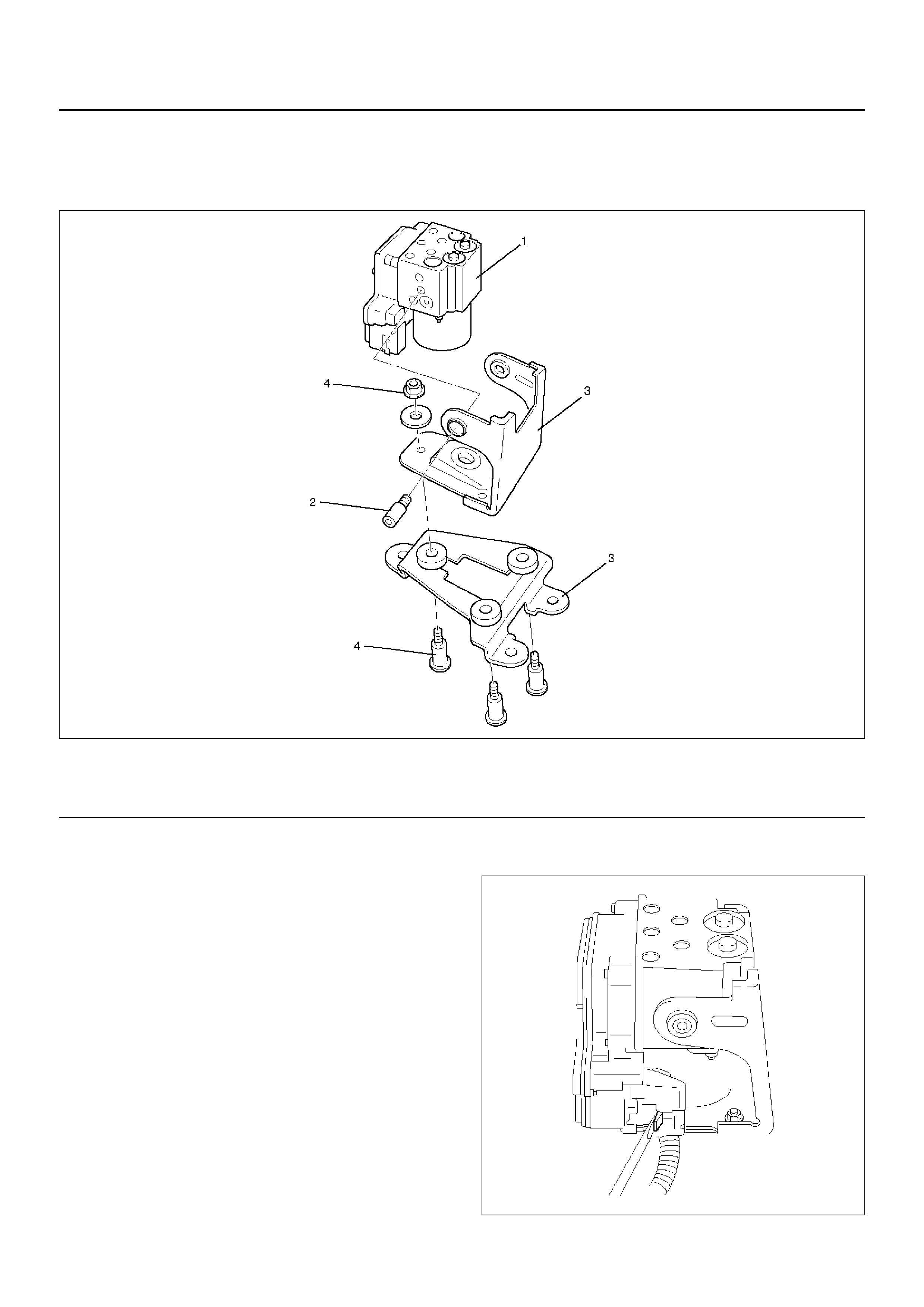
ELECTRONIC HYDRAULIC CONTROL UNIT
ELECTRONIC HYDRAULIC CONTROL UNIT AND ASSOCIATED PARTS
350RW017
Legend
EndOFCallout
REMOVAL
1. Remo ve brak e pipe s.
• After disconnecting brake pipe, cap or tape the
openings of the brake pipe to prevent the entry of
foreign matter.
2. Remo ve three br ac ke fixi ng bolts.
3. Disconnect red clip from harness connector.
4. Remo ve harne ss conn ec tor.
5. Remo ve EHCU ASM.
6. Remove EHCU .
350RW018
(1) EHCU
(2) Bolt (3) Bracket
(4) Bolt and Nut
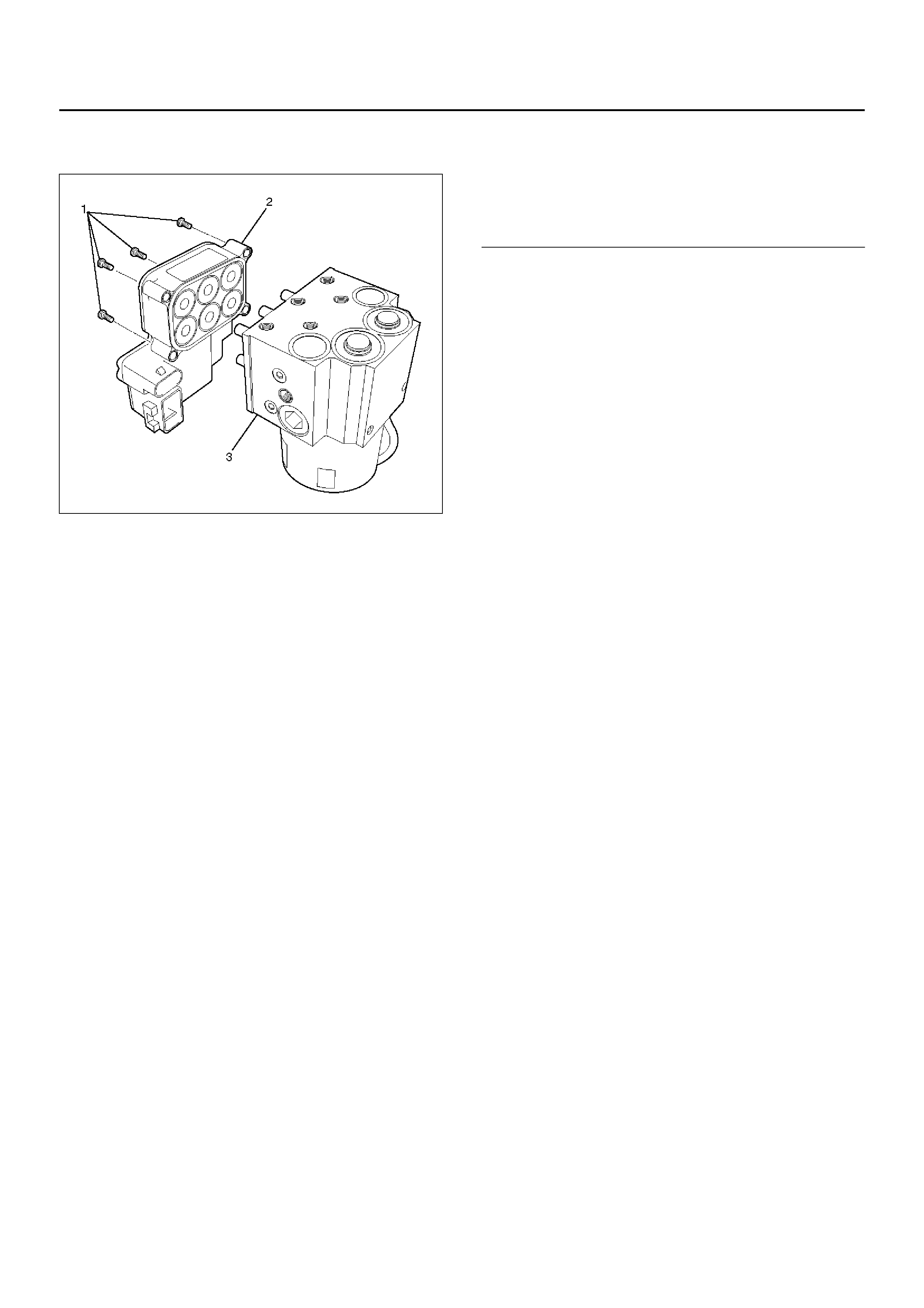
DISASSEMBLED VIEW
350RW025
Legend
EndOFCallout
DISASSEMBLY
1. Remove fixing bolts from EHCU.
2. Remove coil integrated module from hydraulic unit.
REASSEMBLY
To reassembly, follow the disassembly steps in the
reverse order, noting the following points:Torque:
Fixing bolts: 4.4 Nm
INSTALLATION
To install, follow the removal steps in the reverse order,
noting the following points:
Torque:
Hydraulic unit fixing nuts : 22 Nm
Ground cable : 14 Nm)
Brake pipe (joint bolts) : 16 Nm
• After installing the hydraulic unit, bleed brakes
completely . See Hydraulic Brakes in Power–assisted
brake sy st em se cti on.
(1) Fixing Bolts
(2) C oil Inte gr ated Modul e
(3) Hydraulic Unit (H/U)
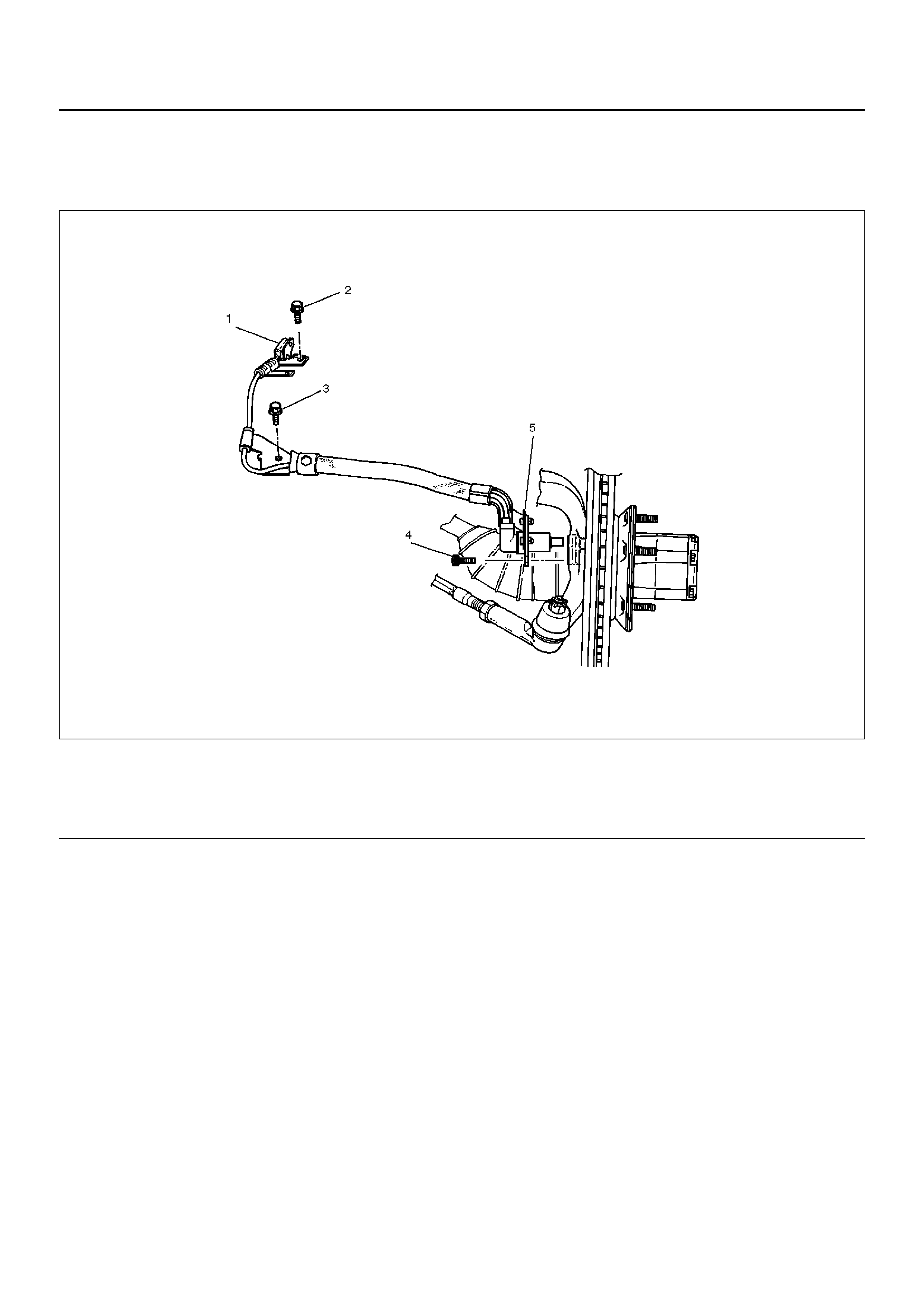
FRONT WHEEL SPEED SENSOR
FRONT WHEEL SPEED SENSOR AND ASSOCIATED PARTS
350RS033
Legend
EndOFCallout
REMOVAL
1. Remove speed sensor connector.
2. Remove sensor cable fixing bolt (Upper side).
3. Remove sensor cable fixing bolt (Lower side).
4. Remove the speed sensor cable fixing bolt.
5. Remove speed sensor.
INSPECTION AND REPAIR
1. Check the speed sensor pole piece for presence of foreign materials; remove any dirt, etc.
2. Check the pole piece for damage; replace speed sensor if necessary.
3. Check the speed sensor cable for short or open circuit, and replace with a new one if necessary.
To check for cable short or open, bend or stretch the cable while checking for continuity.
4. Check the sensor ring for damage including tooth chipping, and if damaged, replace the sensor ring assembly.
Refer to removal of the sensor ring in “Front hub and disc".
(1) Speed Sensor Connector
(2) Sensor Cable Fixing Bolt (Upper side)
(3) Sensor Cable Fixing Bolt (Lower side)
(4) Speed Sensor Fixing Bolt
(5) Speed Sensor
INSTALLATION
1. Install speed sensor and take care not to hit the speed sensor pole piece during installation.
2. Install speed sensor fixing bolt and tighten the fixing bolt to the specified torque.
Torque: 8 Nm
3. Install speed sensor cable fixing bolt (Lower side) and tighten the fixing bolt to the specified torque.
Torque : 24 Nm
4. Install speed sensor cable fixing bolt (Upper side) and tighten the fixing bolt to the specified torque.
Torque : 6 Nm
NOTE: Confirm that a white line marked on the cable is not twisted when connecting the speed sensor cable.
5. Install speed sensor connector.
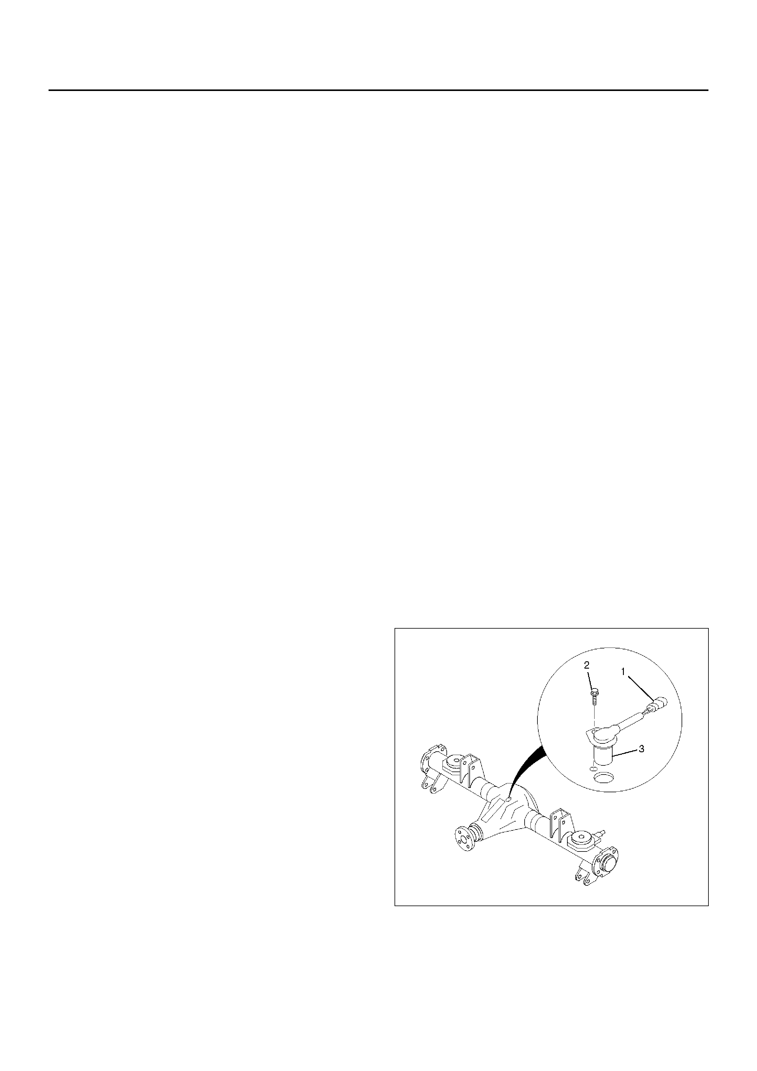
REAR WHEEL SPEED SENSOR
REMOVAL
1. Disconnect harness connector (1).
2. Remove sensor fixing bolt (2) .3. Remove speed sensor (3).
INSPECTION AND REPAIR
1. Check speed sensor pole piece for presence of
foreign materials; remove any dirt, etc.
2. Check the pole piece for damage, and replace
speed sensor if necessary.
3. Check speed sensor cable for short or open, and
replace with a new one if necessary. To check for
cable short or open, bend or stretch the cable while
checking for continuity.
4. Check the sensor ring for damage including tooth
chipping, and if damaged, replace the axle shaft
assembly. Refer to removal of the sensor ring in
“Differential (Rear)".
INSTALLATION
1. Install speed sensor (3).
2. Tighten the sensor fixing bolt (2) to the specified
torque.
Torque : 24 Nm
3. Connect harness connector (1).
350RX003