
SECTION 6C - IGNITION SYSTEM
Service Precaution
General Description
Diagnosis
Ignition Coil
Removal
Inspection and Repair
Installation
Spark Plug
Inspection
Replacement spark plugs
Crankshaft Position Sensor
Removal
Installation
Main Data and Specifications
SERVICE PRECAUTION
WARNING: THIS VEHICLE HAS A SUPPLEMENTAL
RESTRAINT SYSTEM (SRS), REFER TO THE SRS
COMPONENT AND WIRING LOCATION VIEW IN
ORDER TO DETERMINE WHETHER YOU ARE
PERFORMING SERVICE ON OR NEAR THE SRS
COMPONENTS OR THE SRS WIRING. WHEN YOU
ARE PERFORMING SERVICE ON OR NEAR THE
SRS COMPONENTS OR THE SRS WIRING, REFER
TO THE SRS SERVICE INFORMATION. FAILURE TO
FOLLOW WARNINGS COULD RESULT IN
POSSIBLE AIR BAG DEPLOYMENT, PERSONAL
INJURY, OR OTHERWISE UNNEEDED SRS SYSTEM
REPAIRS.
CAUTION: Always use the correct fastener in the
proper location. When you replace a fastener, use
ONLY the exact part number for that application.
HOLDE N will call out those f asten ers th at requir e a
replacement after removal. HOLDEN will also call
out the fasteners that require thread lockers or
thread sealant. UNLESS OTHERWISE SPECIFIED,
do not use supplemental coatings (Paints , greases,
or other corrosion inhibitors ) on threaded fast eners
or fastener joint interfaces. Generally, such
coatings adversely affect the fastener torque and
the joint clamping force, and may damage the
fastener. When you install fasteners, use the
correct tightening sequence and specifications.
Following these instructions can help you avoid
damage to parts and systems.
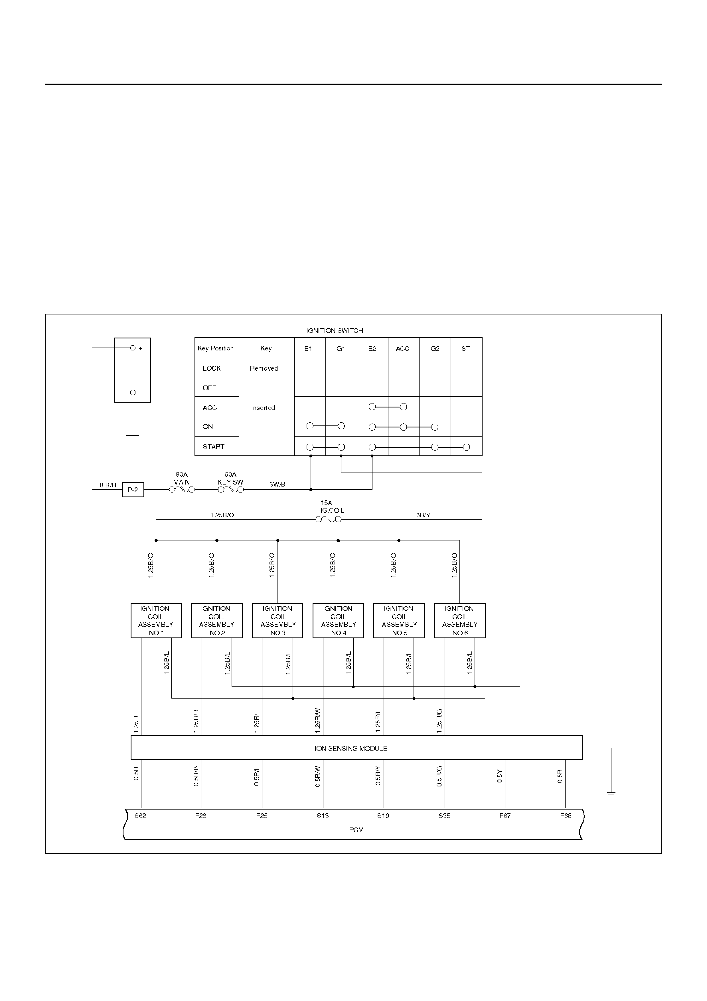
GENERAL DESCRIPTION
The 6VD1 engine is fitted withan electronic Ion Sensing Ignition (ISI) system. The ISI system is able to electronically
bias the spark gap after the spark plug has fired to facilitate the monitoring of a ‘Combustion Event’, essentially
enabling the spark plug to function as an in-cylinder combustion sensor.
The ISI system allows the PCM to perform three functions:
1) Cylinder identification.
2) Individual cylinder knock detection.
3) Individual misfire detection.
These additional PCM functions elimnate the requirement for cam shaft positon and knock sensors.
During cranking, the ISI operates in ‘Waste-Spark” mode, while the PCM monitors the combustion events on Bank ‘A’
(cylinders 1, 3 & 5). After a predetermined number of events, the PCM will synchronise the ignition to the individual
cylinders. Should any of the events fail, the system will remain in Waste-Spark mode and set a DTC 1340.
D06RY00037
DIAGNOSIS
Refer to Section 6E - Drivability and Emissions, for ISI system DTC diagnostics .
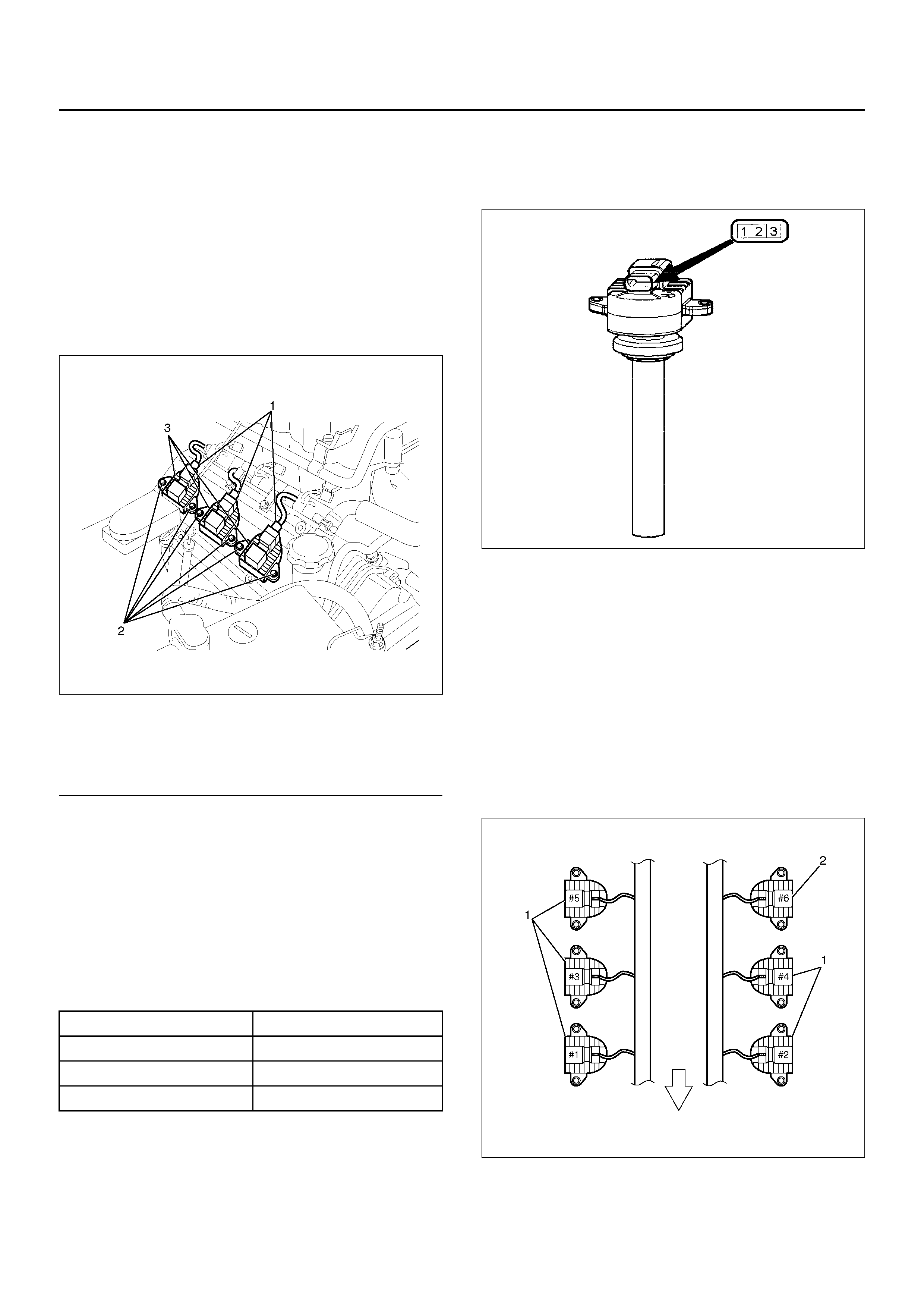
IGNITION COIL
REMOVAL
1. Disconnect battery ground cable.
2. Ignition coil connector and ignition coil.
• Disconnect three connector from ignition coil.
• Remove harness bracket bolt on cylinder head
cover.
• Remove fixing bolts on ignition coil.
060R100116
EndOFCallout
INSPECTION AND REPAIR
Check the ignition coil assembly for physical damage
and the terminals for corrosion or damage. Replace as
necessary.
Measure resistance of ignition coil windings, and
replace the ignition coil assembly if any value is not as
specified below:
INSTALLATION
CAUTION:
Ignition coil assembly #6 is 4mm shorter than
ignition coil assemblies #1 to #5. Fitting #6 coil to
the incorrect cylinder will result in misfire DTC’s
being set.
1. Install the ignition coil assembly. Connect ignition
coil connector,then tighten mounting bolts to the
specified torque.
Torque: 4 N·m (0.4 kg·m/35 lb in)
2. Connect batter y groun d cable.
Legend
(1) Ignition Coil Connector
(2) Bolt
(3) Ignition Coil Assembly
Terminal Value
1 to 3 0.2 - 0.6 Ohms
2 to HT terminal 2.5k to 3.5k Ohms
2 to 3 Open Circuit
Legend
(1) Long type Ignition Coil Assemblies (#1 ∼ #5)
(2) Short type Ignition Coil Assembly (#6)
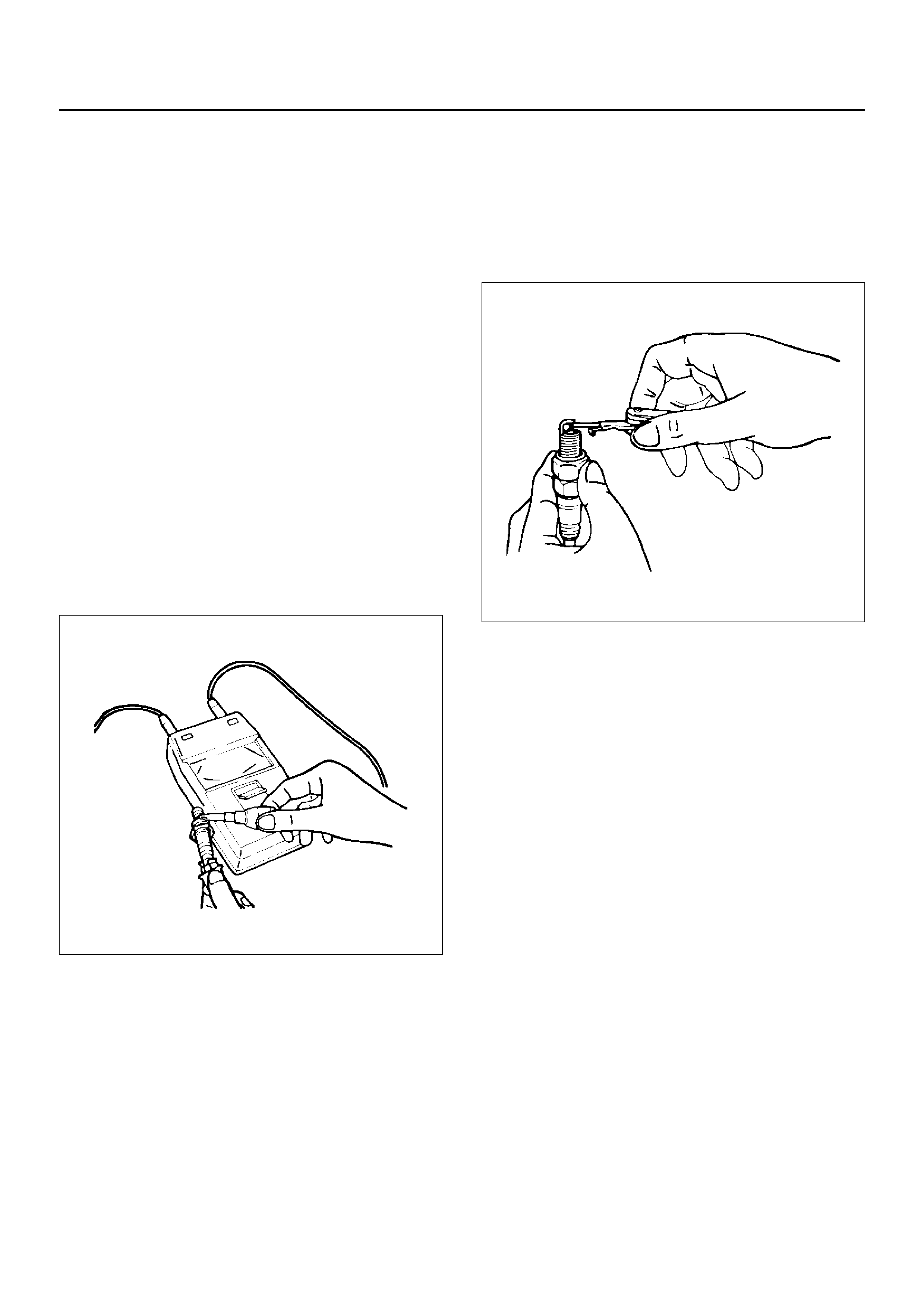
SPARK PLUG
INSPECTION
Poor spark plug condition adversely affects engine
performance. Carefully inspect each spark plug
following the procedure outlined below.
1. Remove the spark plug.
2. Check the plug for dirt and other foreign material.
If the plug is extremely dirty, the fuel and electrical
systems must be checked.
3. If necessary, clean the spark plugs by placing them
in a spark plug cleaning machine for no more than
20 seconds.
4. Check the electrode and insulator for wear and/or
cracking. If there is significant wear or cracking, the
plug must be replaced.
5. Check the gasket for damage. Replace the gasket if
necessary.
6. Measure the insulation resistance with a 500-volt
megaohm meter. Replace the plug if the resistance
is less than the specified value.
Insulation resistance: 50 MΩ or more
011RS010
7. Check the spark plug gap. Replace the spark plug
the if gap is not as specified.
Standard: 1.0–11mm (0.04–0.043in)
Limit: 1.3mm (0.05in)
011RS011
• Do not attempt to adjust the gap of an old spark
plug. Replace the plug and adjust the gap of the
new plug if required.
• Take care not to damage the spark plug tip during
handling.
8. Tighten the spark plugs to the specified torque.
Torque: 18N·m (13lbft)
REPLACEMENT SPARK PLUGS
• Under normal conditions (no problem with the fuel
and/or electrical systems), use replacement spark
plugs with a low heat value (hot-type plug).
• If insulator and electr ode scor ching i s signif icant, use
replaceme n t spark pl ugs plu gs with a high he at va lue
(cold-type plu g).
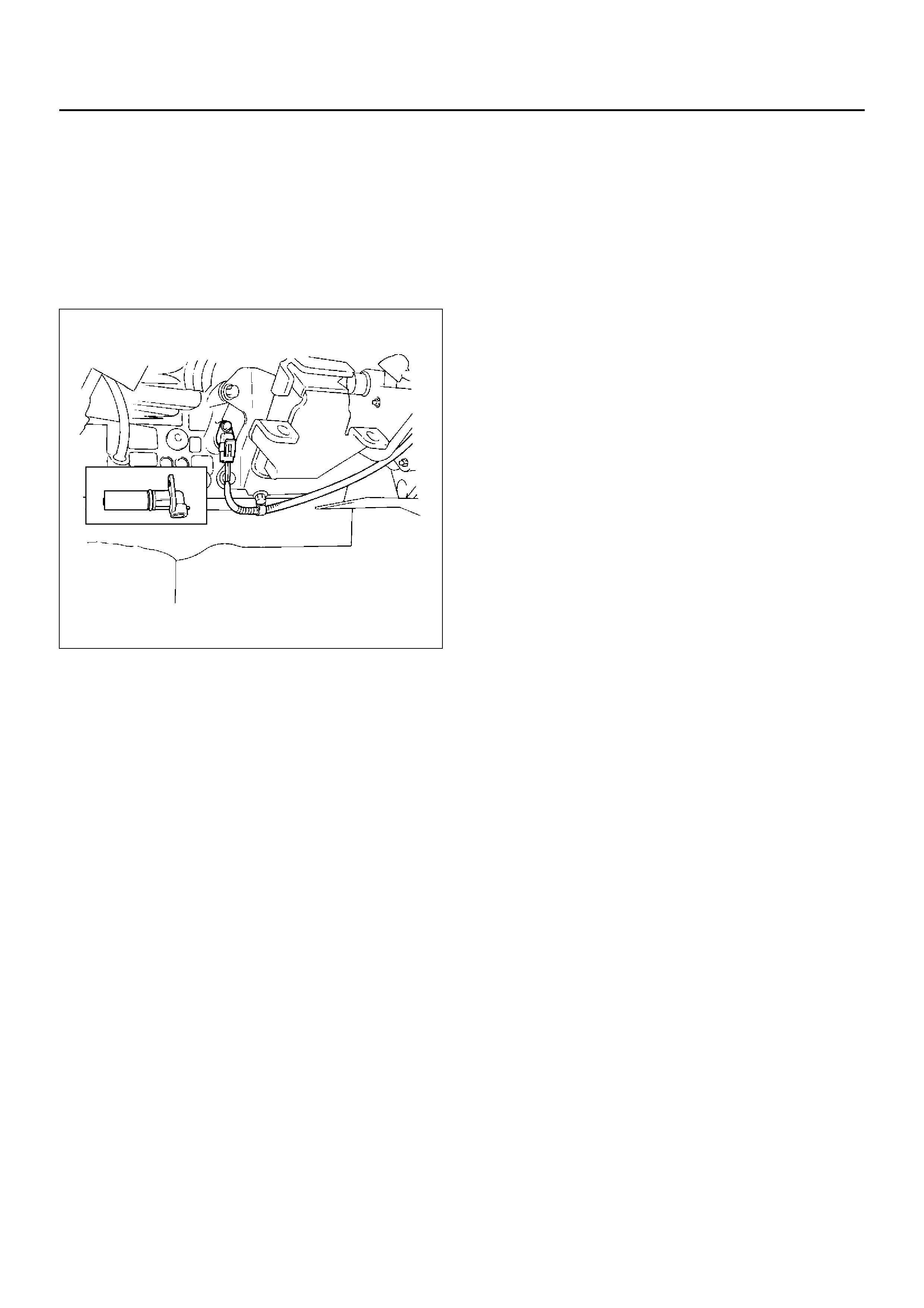
CRANKSHAFT POSITION SENSOR
REMOVAL
1. Disconnect battery ground cable
2. Wiring connector from crankshaft angle sensor.
3. Remove crankshaft angle sensor from cylinder
block.
012RS008
INSTALLATION
1. Install crankshaft angle sensor into the cylinder
block.
Before installation,apply small amount of engine oil
to the O–ring.
Torque: 10 N·m (1.0 kg·m/87 lb in)
2. Reconnect wiring connector to crankshaft position
sensor.
MAIN DATA AND SPECIFICATIONS
General Specifications
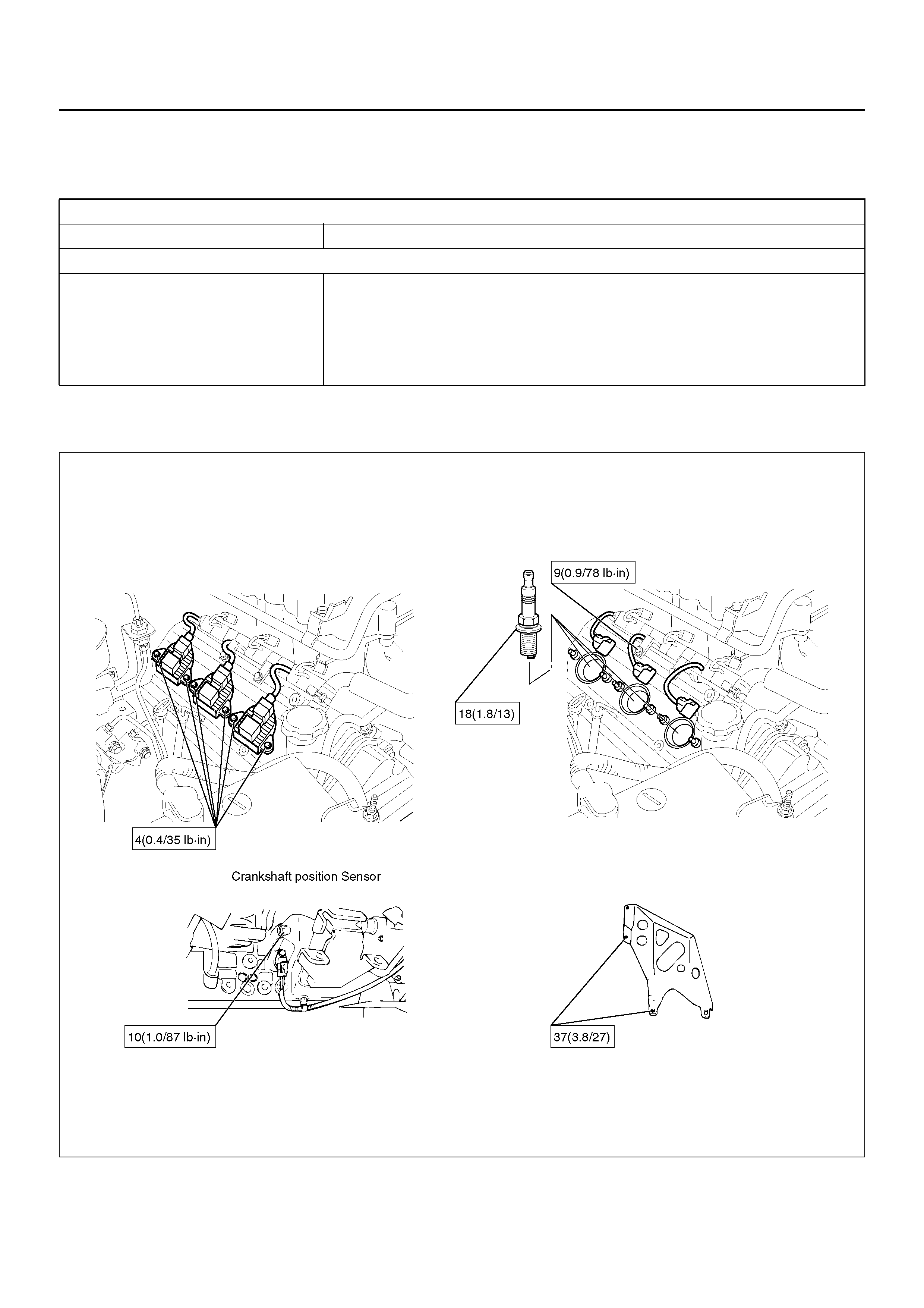
Torque Specifications
N·m (kg·m/lbft)
060R100115
Ignition System
Type Ion Sensing Ignition System (ISI) with Crankshaft Position Sensor (CKP)
Spark Plug Type K16PR–P11
RC10PYP4
PK16PR11
Plug gap 1.0 mm (0.04 in) – 1.1 mm (0.043 in)
Torque 18 N·m (1.8 kg·m/13 lb ft)