
SECTION 6C1 — 3.2L ENGINE DRIVEABILITY AND
EMISSIONS
Specifications
Torque Sp ecifications
Diagram s and Schem atics
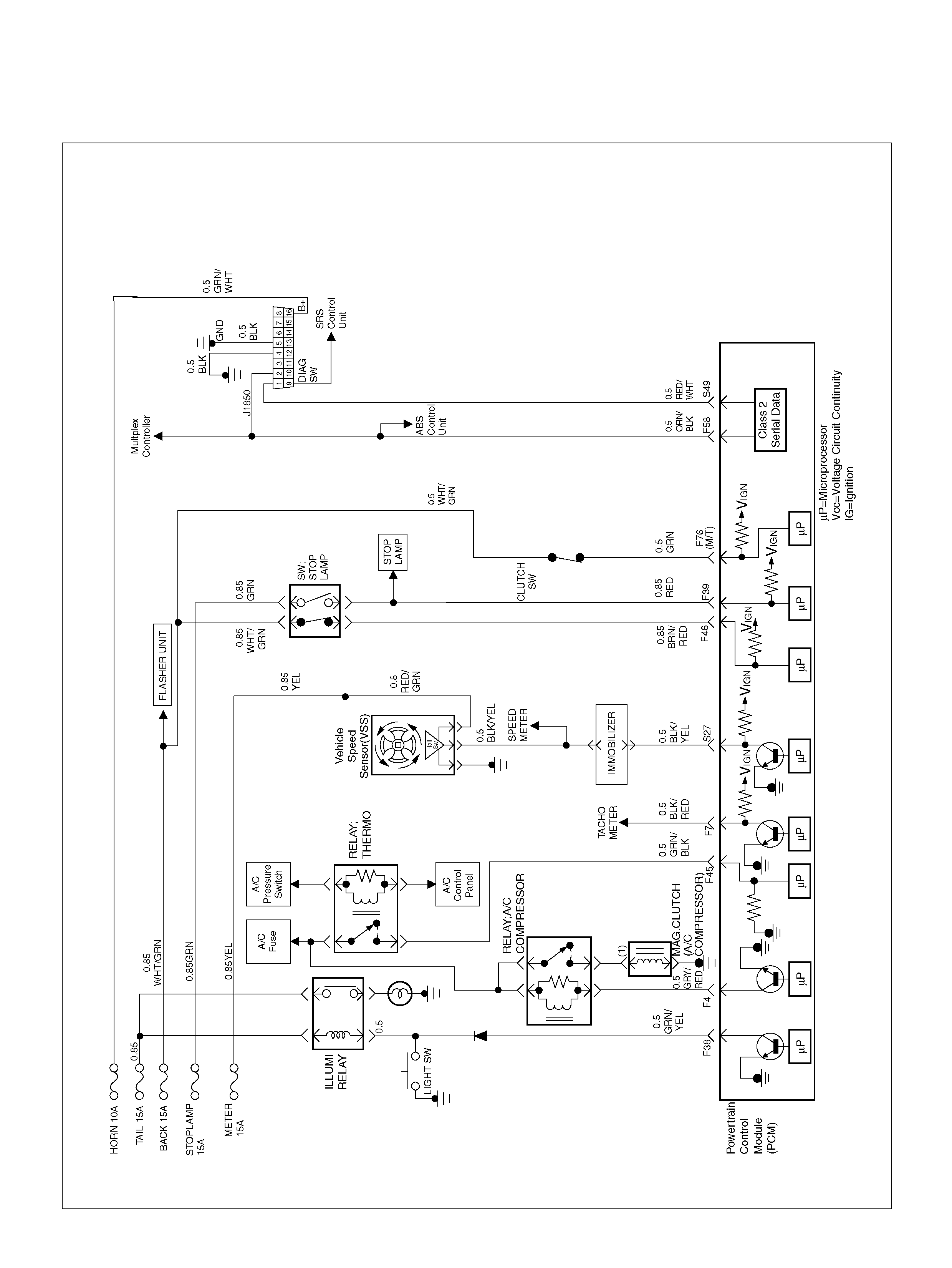
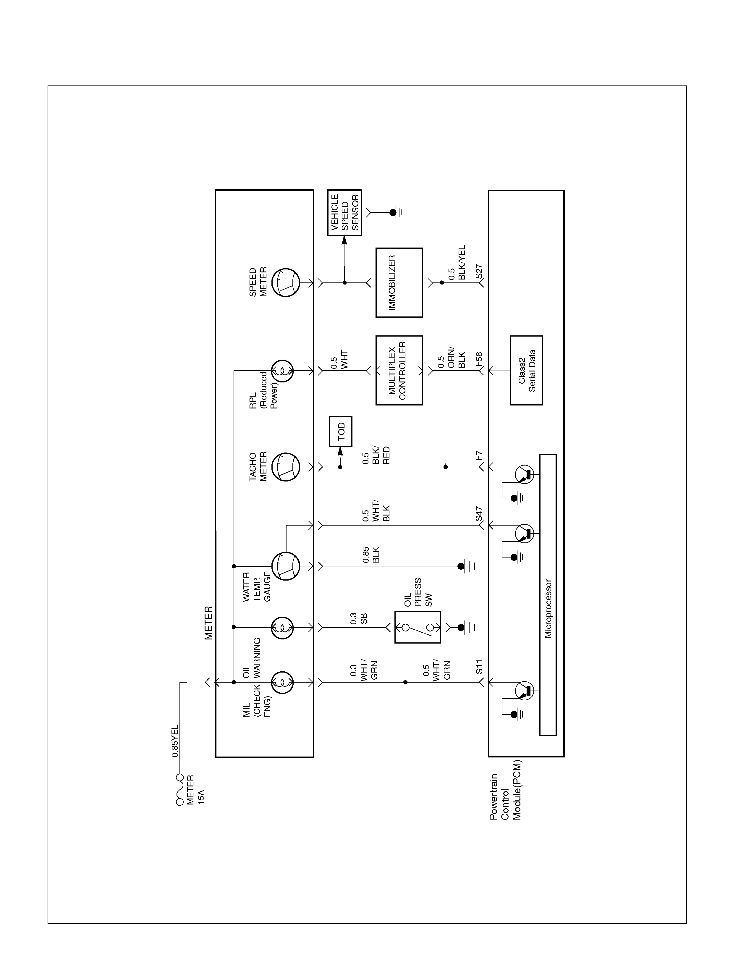
PCM Wiring Diagram (1 of 7)
PCM Wiring Diagram (2 of 7)
PCM Wiring Diagram (3 of 7)
PCM Wiring Diagram (4 of 7)
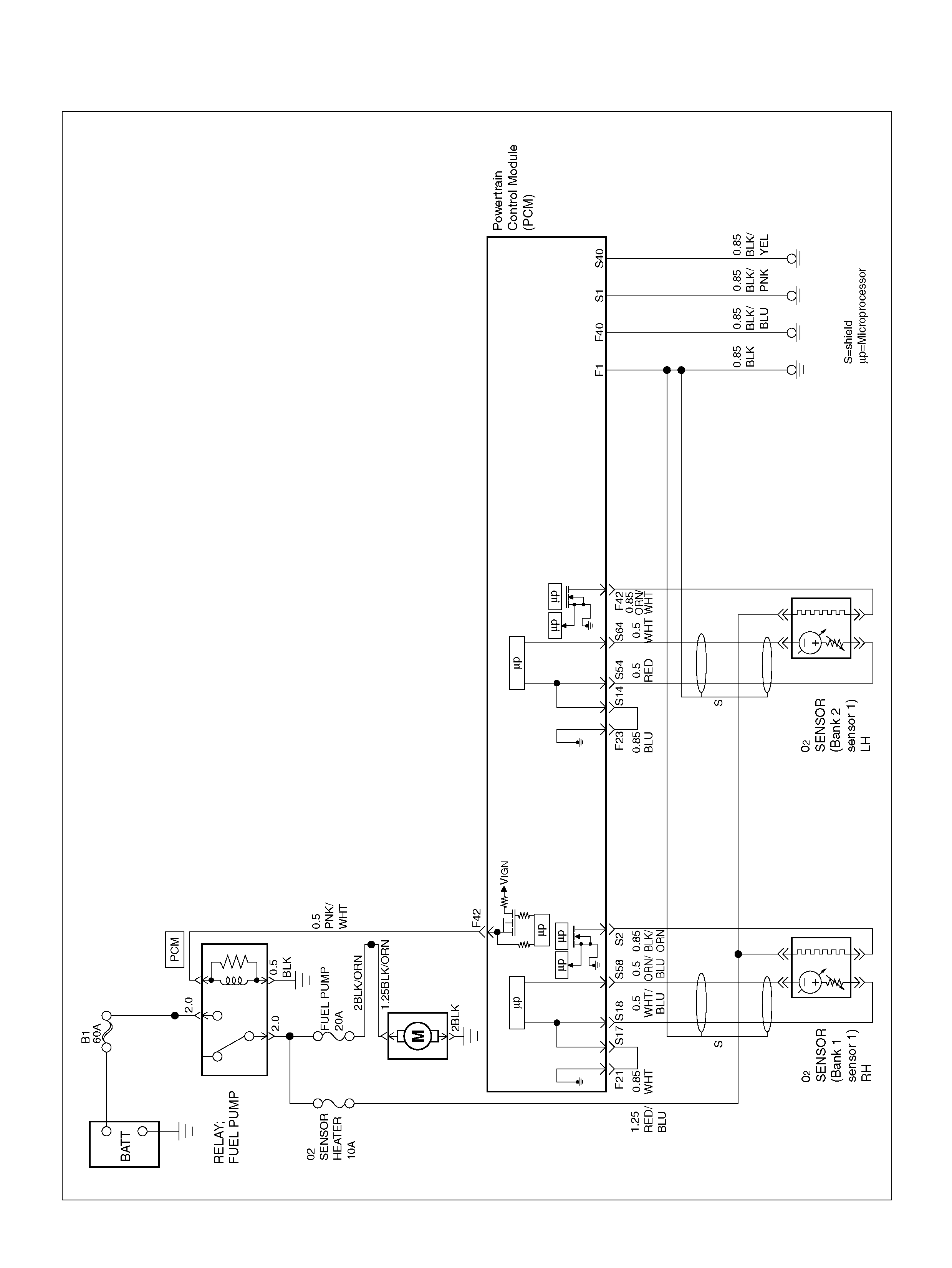
PCM Wiring Diagram (5 of 7)
PCM Wiring Diagram (6 of 7)
PCM Wiring Diagram (7 of 7)
PCM Pi n outs
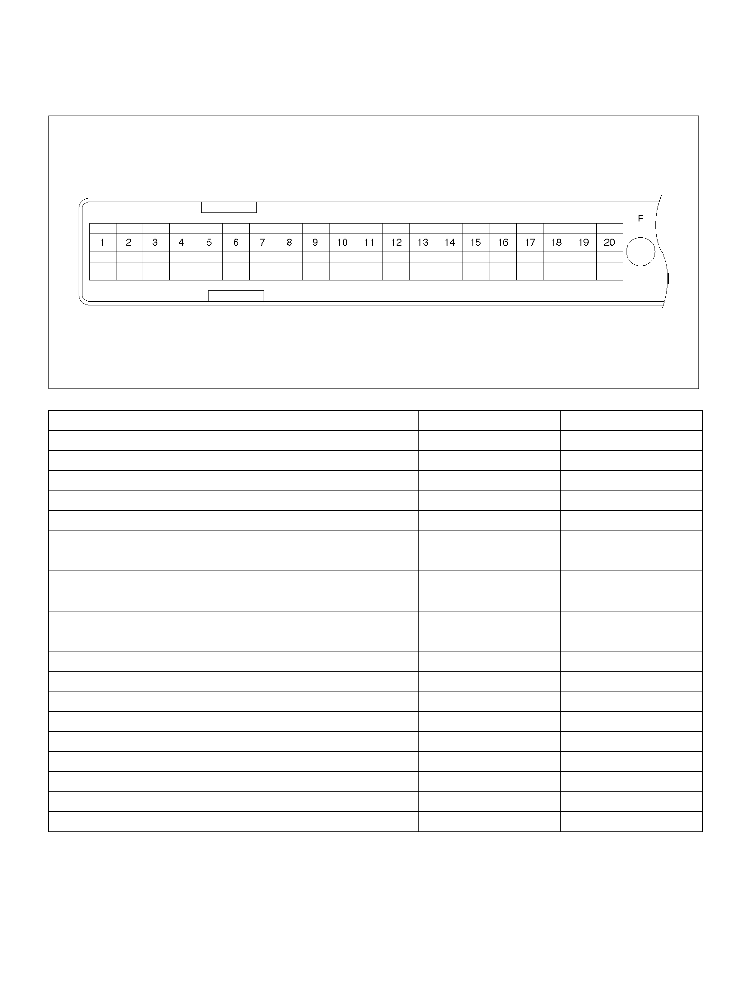
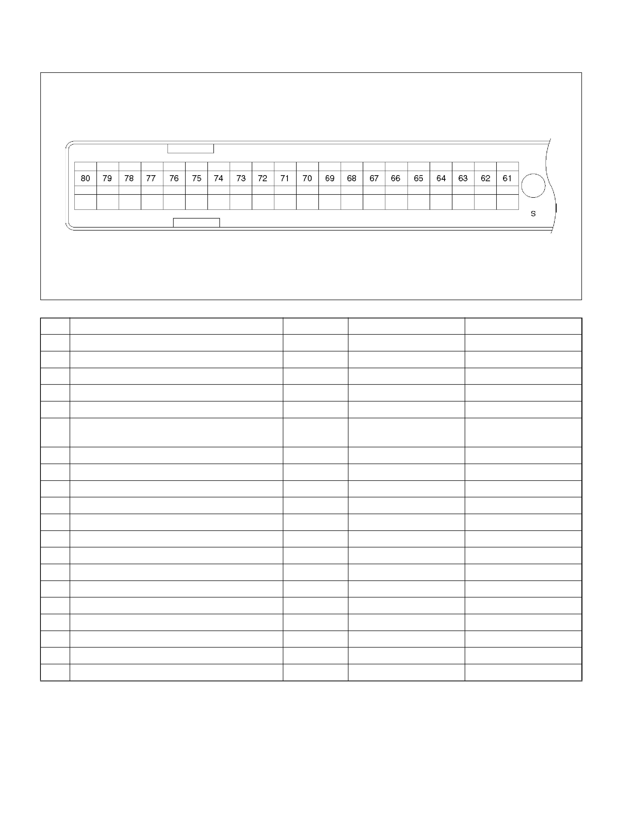
PCM Pinout Table, 80-Way Blue Connector
– Row “F1 ∼ 20"
PCM Pinout Table, 80-Way Blue Connector
– Row “F20 ∼ 40"
PCM Pinout Table, 80-Way Blue Connector
– Row “F41 ∼ 60"
PCM Pinout Table, 80-Way Blue Connector
– Row “F61 ∼ 80"
PCM Pinout Table, 80-Way Red Connector
– Row “S1 ∼ 20"
PCM Pinout Table, 80-Way Red Connector
– Row “S21 ∼ 40"
PCM Pinout Table, 80-Way Red Connector
– Row “S41 ∼ 60"
PCM Pinout Table, 80-Way Red Connector
– Row “S61 ∼ 80"
Compon ent Locat ors
Engine Component Locator
Undercarriage Component Locator
Fuse and Relay Panel (Underhood Electrical Center)
Sensors and Miscellaneous Component Locators
Diagnosis
Strategy-Bas ed Diagno stics
DTC Stored
No DTC
No Matching Sym ptom
Intermittents
No Trouble Foun d
Verifying Vehicle Repair
General Serv ice Information
OBD Serv iceability Issues
Visual / Physical Engine Compart me nt Inspection
Basic Knowledge of Tools Required
Serial Data Communications
Class 2 Serial Data Com m unicat ions
On-Board Diagnostic (OBD)
On-Board Diagnostic Tests
Comprehensive Component Monitor
Diagnostic Operation
The Diagnostic Executive
DTC Types
Decimal/Binary/ Hexadec imal Conversions
Verifying Vehicle Repair
Reading Diagno stic Trouble Codes Using
The Tech 2 Scan Tool
Tech 2
Tech 2 Features
Getting Started
Primary System-Based Diagnostic
Primary System-Ba sed Diagnostic
Fuel Control Heated Oxygen Sensor
HO2S Heater
On-Boar d Diagnostic (OBD) System Check
A/C Clutch Control Circuit Diagnos is
Electronic Ignition Syste m Diagnos is
Visual Check of The Evaporative E mission Canister
Fuel Metering System Check
Powertrain Control Module (PCM) Diagnosis
Multiple PCM Information Sensor DTCs Set
Exhaust Gas Recirculation (EGR) Diagnosis
Engin e Tech2 Data Definitions and Ranges
Typical Scan Data Va lues
No Malfunction Indica tor Lamp (MIL)
Malfunction Indicator Lamp (MIL) “ON" Steady
No Reduced Power Lamp (RPL)
Reduce d Power Lamp (RPL) “ON" Steady
Engine Cranks But Will Not Run
Fuel System Electrical Test
Electric T hrottle Control (ETC) Syste m Check
Fuel System Diagnosis
Exhaust Gas Recirculation (EGR) System Check
Manifold Absolute Pressure (MAP ) Output Check
Evaporat ive (EVAP) Emissions Ca nister Purge Valve
Check
PCM Diagnostic Trouble Codes
DTC P0101 MAF System Performance
DTC P0102 MAF Sensor Circuit Low Frequency
DTC P0103 MAF Sensor Circuit High Frequency
DTC P0106 MAP System Performance
DTC P0107 MAP Sensor Circuit Low Voltage
DTC P0108 MAP Sensor Circuit High Voltage
DTC P0112 IAT Sensor Circuit Low Voltage
DTC P0113 IAT Sensor Circuit High Voltage
DTC P0117 ECT Sensor Circuit Low Voltage
DTC P0118 ECT Sensor Circ uit High Voltage
DTC P0131 HO2S Circuit Low Voltage
Bank 1 Se nsor 1
DTC P0132 HO2S Circuit High Voltage
Bank 1 Se nsor 1
Techline
Techline
Techline

DTC P0134 HO2S Circuit Insufficient
Activity Bank 1 Sensor 1
DTC P0135 HO2S Heater Circuit
Bank 1Sensor 1
DTC P0151 HO2S Circuit Low Volt age
Bank 2 Sensor 1
DTC P0152 HO2S Circuit High Voltage
Bank 2 Sensor 1
DTC P0154 HO2S Circuit Insufficient
Activity Bank 2 Sensor 1
DTC P0155 HO2S Heater Circuit Open
Bank 2 Sensor 1
DTC P0171 Fuel Trim System Lean Bank 1
DTC P0172 Fuel Trim System Rich Bank 1
DTC P0174 Fuel Trim System Lean Bank 2
DTC P0175 Fuel Trim System Rich Bank 2
DTC P0201 Injector 1 Control Circuit
DTC P0202 Injector 2 Control Circuit
DTC P0203 Injector 3 Control Circuit
DTC P0204 Injector 4 Control Circuit
DTC P0205 Injector 5 Control Circuit
DTC P0206 Injector 6 Control Circuit
DTC P0300 Engine Misfire Detected
DTC P0301 Cylinder Misfire Detected
DTC P0302 Cylinder Misfire Detected
DTC P0303 Cylinder Misfire Detected
DTC P0304 Cylinder Misfire Detected
DTC P0305 Cylinder Misfire Detected
DTC P0306 Cylinder Misfire Detected
DTC P0325 ION Sensing Module/ION
Sensing Knock Intensity Circuit Fault
DTC P0336 58X Reference Signal Circuit
DTC P0337 CKP Sensor Circuit
Low Frequency
DTC P0351 Ignition 1 Control Circuit
DTC P0352 Ignition 2 Control Circuit
DTC P0353 Ignition 3 Control Circuit
DTC P0354 Ignition 4 Control Circuit
DTC P0355 Ignition 5 Control Circuit
DTC P0356 Ignition 6 Control Circuit
DTC P0402 EGR Pintle Crank Error
DTC P0404 EGR Open Stuck
DTC P0405 EGR Low Voltage
DTC P0406 EGR High Voltage
DTC P0502 VSS Circuit Low Input
DTC P0506 Idle Air Control System
Low RPM
DTC P0507 Idle Air Control System
High RPM
DTC P0562 System Voltage Low
DTC P0563 System Voltage High
DTC P0565 Cruise Main Switch Circuit Error
DTC P0566 Cruise Cancel Switch Circuit Error
DTC P0567 Cruise Resume Switch Circuit Error
DTC P0571 No Brake Switch Signal
DTC P0601 PCM Memory
DTC P0602 PCM Programming Error
DTC P0604 PCM RAM Error
DTC P0606 PCM Internal Performance
DTC P1106 MAP Sensor Circuit Intermittent
High Voltage
DTC P1107 MAP Circuit Intermittent Low Voltage
DTC P1111 IAT Sensor Circuit Intermittent
High Voltage
DTC P1112 IAT Sensor Circuit Intermittent
Low Voltage
DTC P1114 ECT Sensor Circuit Intermittent
Low Voltage
DTC P1115 ECT Sensor Circuit Intermittent
High Voltage
DTC P1120-TPS 1 Throttle Position Sensor
(TP S1) Output Abnormal
DTC P1125 ETC (Electric Throttle Control)
Lim it Performance Mode
DTC P1167 Fuel System Rich During Decel
Fuel Cut Off (Bank 1)
DTC P1169 Fuel System Rich During Decel
Fuel Cut Off (Bank 2)
DTC P1171 Fuel System Lean During Accelerator
DTC P1220 Throttle Position Senser2
(TP S2) Circ ui t Fault
DTC P1221 TPS1 – TPS2 Cor relation
(Circuit Performance)
DTC P1271 APS 1- 2 Correlation Error
DTC P1272 APS 2 – 3 Correlation Error
DTC P1273 APS 1 – 3 Correlation Error
DTC P1275 APS 1 Output Fault
DTC P1280 APS 2 Output Fault
DTC P1285 APS 3 Output Fault
DTC P1290 ETC Forced Idle Mode
DTC P1295 ETC Power Management Mode
DTC P1299 ETC Forced Engine Shutdown Mode
DTC P1310 ION Sensing Module Diagnos is
DTC P1311 ION Sensing Module SEC
Line 1 Circuit Fault
DTC P1312 ION Sensing Module SEC
Line 2 Circuit Fault
DTC P1326 ION Sensing Module Com bust ion
Quali ty Input Circuit F ault
DTC P1340 ION Sensing Module Cylinder
ID Fault (Cylinder Synchronizat ion Fail)
DTC P1404 EGR Stuck Closed
DTC P1514 TPS - MAF Correlation Error
DTC P1515 Command - Actual TPS
Correlation Error
DTC P1516 Command - Actual TPS
Correlation Error
DTC P1523 Actuator Control Return Performance
DTC P1571 Brake Switch No Operation
DTC P1626 No respons e from im mobiliz er
DTC P1631 Received response was not correct
DTC P1635 ence Voltage # 1 Circuit Fault
DTC P1639 Reference Voltage # 2 Circuit Fault
DTC P1640 Driver-1-Output Circuit Fault (ODM)
DTC P1648 Received incorrect security code
DTC P1649 Security code & security key
not programm ed
DTC P1650 Quad Driver Module “A" Fault

Symp tom Diagnosis
Defaul t Matrix Table
On Vehicle Service
Crankshaft Position (CKP) Sensor
Removal Procedure
Inspection Procedure
Installation Procedure
Engine Coolant Temperature (ECT) Sensor
Removal Procedure
Installation Procedure
Heated Oxygen S ens or (HO2S )
Removal Procedure
Inspection Procedure
Installation Procedure
Intake Air Temperature (IAT) Sensor
Removal Procedure
Installation Procedure
ION Sensing Mo dule
Removal Procedure
Installation Procedure
Mass Air Flow (MAF) Sensor
Removal Procedure
Installation Procedure
Manifold Absolute Pressure (MAP ) Sensor
Removal Procedure
Installation Procedure
Malfunction Indi cator Lamp (MIL)
Removal and Installation Procedure
Reduced Power Lamp
Powertrain Control Module (PCM)
Service Precaution
Electrostatic Discharge (ESD) Dama ge
Removal Proc edure
Installation Proced ure
Throttle Position (TP) Sensor
Removal Proc edure
Function Check
Installation Proced ure
Vehicle Speed Sensor (VSS)
Removal Proc edure
Inspection Procedure
Installation Proced ure
Air Cleaner/Air Filt er
Removal Proc edure
Installation Proced ure
Comm on Cham ber
Removal and Ins tallation Proced ure
Accelerator Pedal Replacement
Removal Proc edure
Installation Proced ure
Accelerator Position Sensor Replacement
Removal Proc edure
Installation Proced ure
Accelerator Position Sensor Adjustment
Removal Proc edure
How To Adj u st For AP Senso r
Fuel Filler Cap
General Desc ription
Inspection Procedure
Fuel Filter
Removal Procedure
Inspection Procedure
Installation Proced ure
Fuel Gaug e Unit
Removal Procedure
Fuel Injectors
Removal Procedure
Inspection Procedure
Installation Proced ure
Fuel Metering System
Fuel Pressure Relief Procedure
F ue l Pump As sembly
Removal Procedure
Fuel Pump Relay
Removal Procedure
Installation Proced ure
Fuel Rail Assembly
Removal Procedure
Installation Proced ure
Fuel Tank
Removal Procedure
Throttle Body (TB)
Removal Procedure
Inspection Procedure
Installation Proced ure
Electronic Igni tion Syste m
Removal Procedure
Installation Proced ure
Catalytic Converter
Removal and Installati on Procedu re
Air Conditioning Thermo Relay
Removal Procedure
Installation Proced ure
EVAP Canister
Removal Procedure
Inspection Procedure
Installation Proced ure
EVAP Can ister Purg e Solenoid
Removal Procedure
Installation Proced ure
Linear Exhaust Gas Recirc. (EGR) Valve
Removal Procedure
Installation Proced ure
Posi ti ve Cr ankcase Ventilation (PCV) Valve
Removal Procedure
Inspection Procedure
PCV Valve
Installation Proced ure
Wiring and Connectors
Wiring Harness Service
Connectors and Terminals
PCM Connectors and Terminals
Removal Procedure
Installation Proced ure
Wire Harness Repair: Shielded Cable
Removal Procedure
Installation Proced ure

Twisted Leads
Removal Procedure
Installation Procedure
Weather-Pack Connector
Tools Required
Removal Procedure
Installation Procedure
Com-Pack III
General Information
Metri-Pack
Tools Required
Removal Procedure
Installation Procedure
General Description (PCM and Sensors)
General Description (Air Induction)
General Description (Fuel Metering)
General Description (Electronic Ignition System)
A/C Clutch Di agnosis
General Description (Evaporative
(EVAP) Emission System)
General Description (Exhaust Gas
Recirculation (EGR) System)
General Description (Positive Crankcase
Ventilation (PCV) System)
Spe c ial To ols

SPECIFICATIONS
TORQUE SPECIFICATI ONS
Application N·m
EGR Bolt 25
Engine Coolant Temperature Sensor 30
Fuel Drain Plug 20
Fuel Pressure Regulator Attaching Screw 3
Fuel Rail Bolts 25
Fuel Tank Undercover Retaining Bolts 36
Heated Oxygen S ens or 55
Lower Intake Manifold to Engine Block Bolts 25
Lower Intake M ani fol d to Engine Block Nuts 25
Spark Plugs 18
Throttle Body Mounting B olts 10
Common C ham ber t o Lower Intake Mani fold Bo lts 25
VSS R etainin g Bolt 16
DIAGRAMS AND SCHEMATICS
PCM WIRING DIAGRAM (1 OF 7)
060R100120

PCM WIRING DIAGRAM (2 OF 7)
060R100121
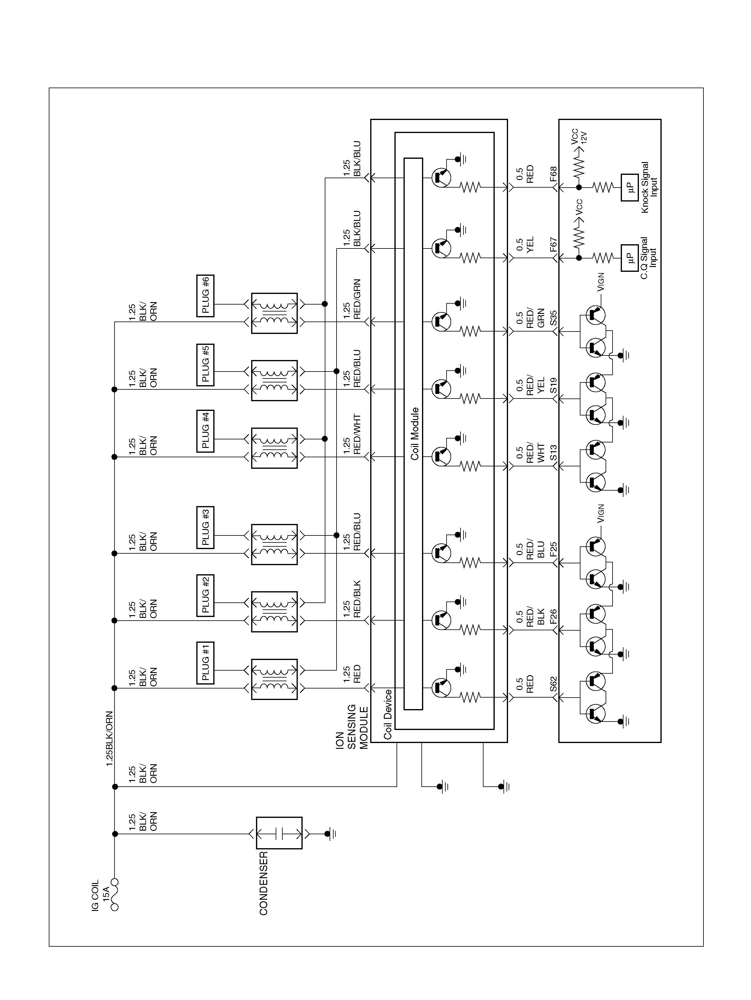
PCM WIRING DIAGRAM (3 OF 7)
060R100122
STATE
CAPACITOR
SOLID

PCM WIRING DIAGRAM (4 OF 7)
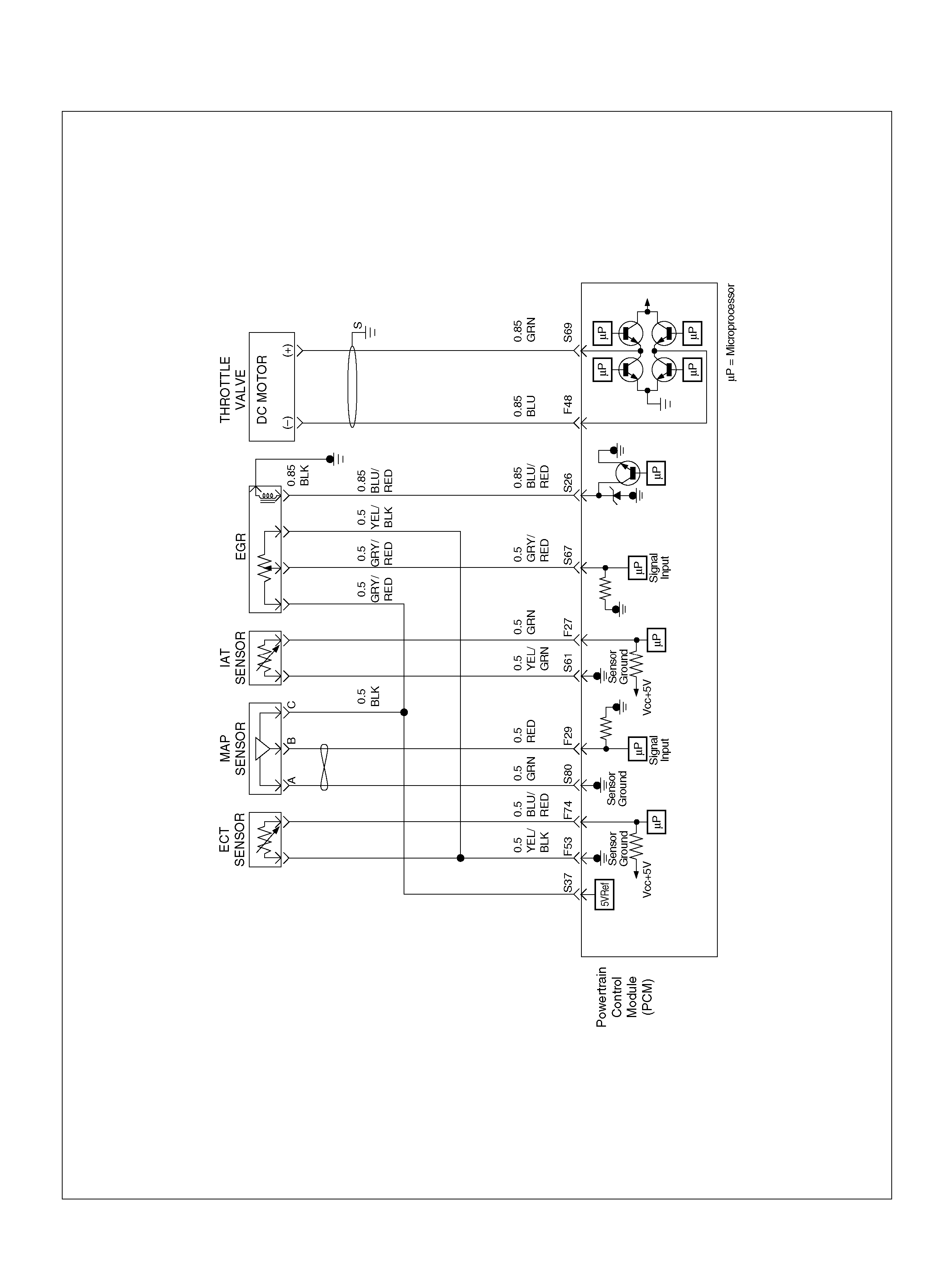
060R100123
PCM WIRING DIAGRAM (5 OF 7) 060R100124
PCM WIRING DIAGRAM (6 OF 7)
060R100125
PCM WIRING DIAGRAM (7 OF 7)
060R100126
PCM PINOUTS
PCM PINOUT TABLE, 80-WAY BLUE CONNECTOR – ROW “F1 ∼ 20"
060RY00045
PIN PIN Function Wire Color IGN ON ENG RUN
F1 PCM Gr oun d BLK 0.0V 0.0 V
F2 5Volt Reference“2" (AP Sensor 2) GRN 5.0V 5.0V
F3 5Vol t Reference“2" (TP Sensor 2) RED/WHT 5.0V 5.0V
F4 A/C Clutch GRY/RED B+(A/C off) B+(A/C off )
F5 1-2/3-4 Shift Solenoid GRN/RED 0.0V 0.0V
F6 Not Used — — —
F7 Tachomet er BLK/RED 8.8V 10.0V (at idle)
F8 Not Used — — —
F9 Not Used — — —
F10 Not Used — — —
F11 TP Sensor (TOD) RED/WHT — —
F12 Not Used — — —
F13 Not Used — — —
F14 Mass Air Flow(MAF) BLK/BLU 4.9V 4 .2V
F15 Not Used — — —
F16 Not Used — — —
F17 Not Used — — —
F18 Not Used — — —
F19 Ignition Feed RED/GRN B+ B+
F20 Ignition Feed RED/WHT B+ B+
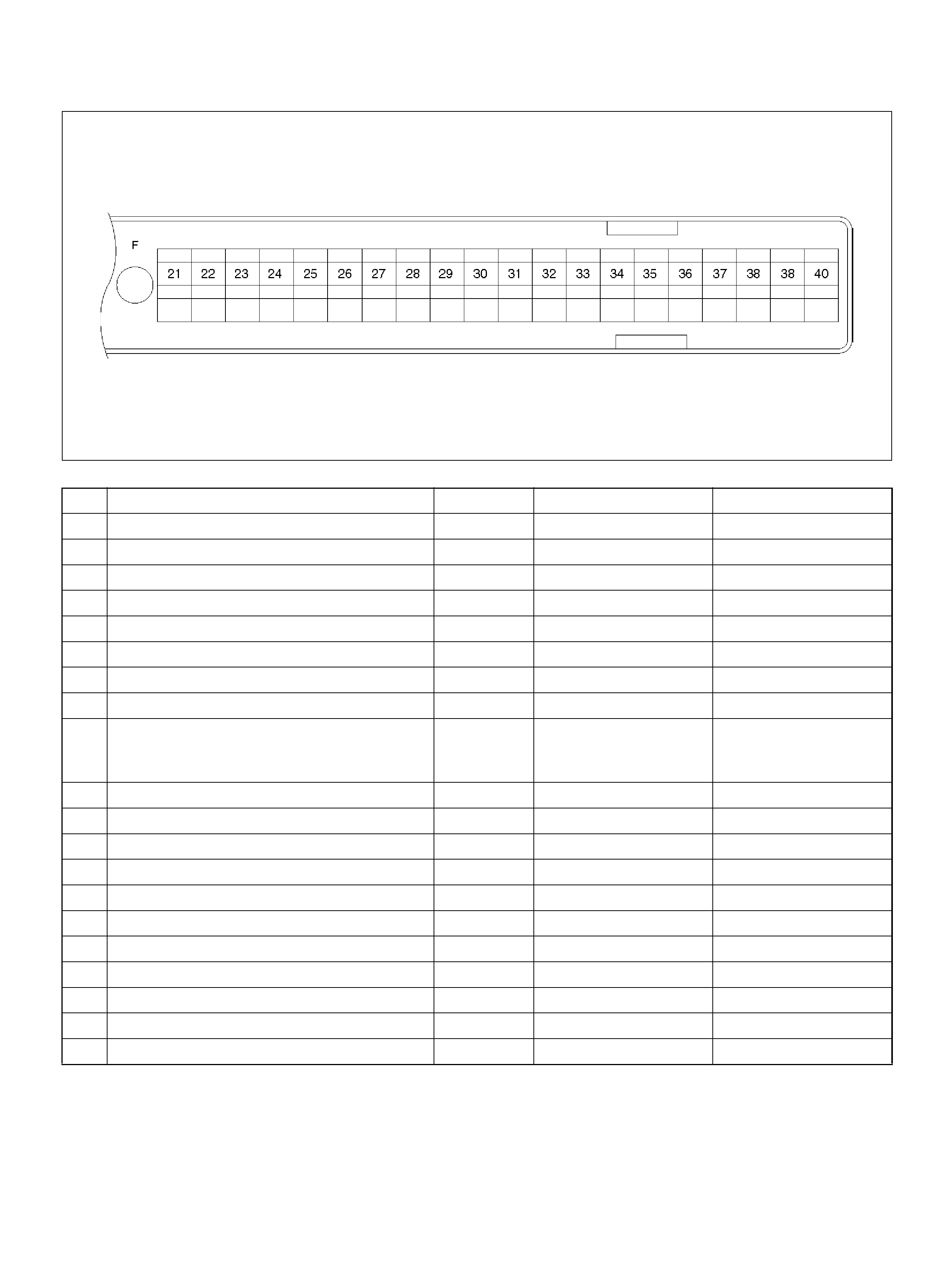
PCM PINOUT TABLE, 80-WAY BLUE CONNECTOR – ROW “F20 ∼ 40"
060RY00156
PIN PIN Function Wire Color IGN ON ENG RUN
F21 Bank 1 HO2S 1 Ground WHT 0.0V 0.0V
F22 Not Used — — —
F23 Bank 2 HO2S 1 Ground BLU 0.0V 0.0V
F24 Not Used — — —
F25 ION Sensing Mod ule RED/B LU 1.555V 1.555 V
F26 ION Sensing Mod ule RED/BLK 1. 555V 1 .555V
F27 Intake Air Temperature (IAT) Sensor GRN 0.5–4.9V 0.5–4.9V
F28 Not Used — — —
F29 Manifold Absolute Pressure (MAP ) RED 3.5V–4. 9V (depends
on altitude and
barometric pressure)
0.6-1.3V
F30 Not Used — — —
F31 Not Used — — —
F32 Not Used — — —
F33 Not Used — — —
F34 Not Used — — —
F35 Not Used — — —
F36 Not Used — — —
F37 Powe r Steering Pre ssu r e ( PSP) GRN/YEL B+ B+
F38 Illuminated Switch GRN/YEL B+ B+
F39 Brake Switch RED 0.0V 0. 0 V
F40 PCM Groun d BLK/BLU 0.0V 0.0V
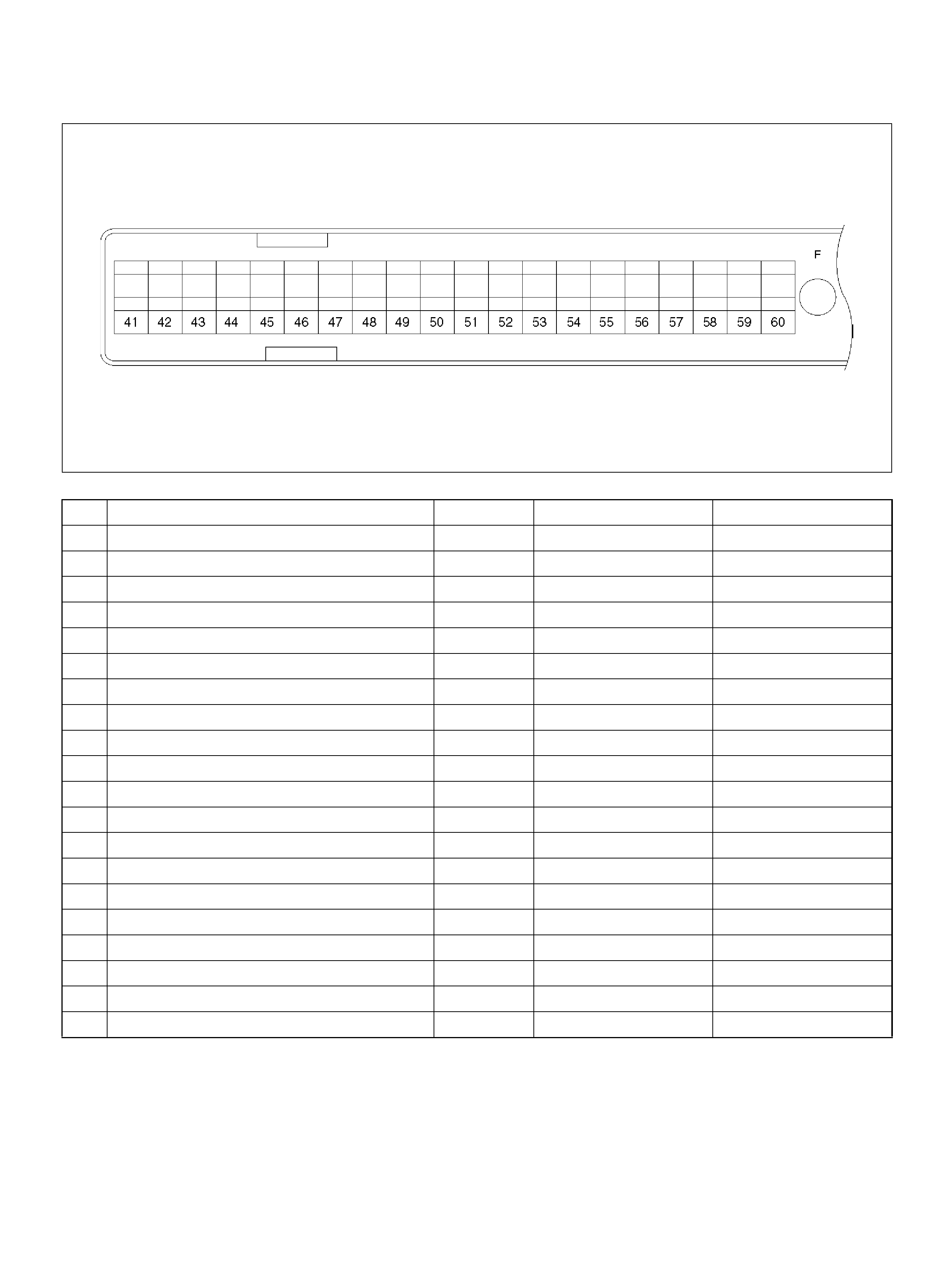
PCM PINOUT TABLE, 80-WAY BLUE CONNECTOR – ROW “F41 ∼ 60"
060RY00046
PIN PIN Function Wire Color IGN ON ENG RUN
F41 Throttle Position(TP) 1 Sensor Ground GRN 0.0V 0.0V
F 42 Fuel Pump R e lay PN K/ WH T 0.0V B+
F43 Adaptor Case VIO/RED 0.0V 0.0V
F44 Not Used — — —
F45 A /C Requ est GRN/BLK 0.0V 0.0V
F46 Stop Lamp Switch GRY/RED 0 .0 V 0.0V
F47 Adaptor Case VIO/WHT B+ B+
F48 Throttle Valve DC Motor(–) BLU Duty Cycle Duty Cycle
F49 Not Used — — —
F50 Not Used — — —
F51 Not Used — — —
F52 Not Used — — —
F53 ECT Groun d YEL/BLK 0.0V 0.0V
F54 Not Used — — —
F55 Not Used — — —
F56 Injector Cylinder #5 GRN/BLK B+ B+
F57 I gnition Feed RED/WHT B+ B +
F58 Class 2 Data ORN/BLK 0.0V 0.0V
F59 Not Used — — —
F60 Not Used — — —
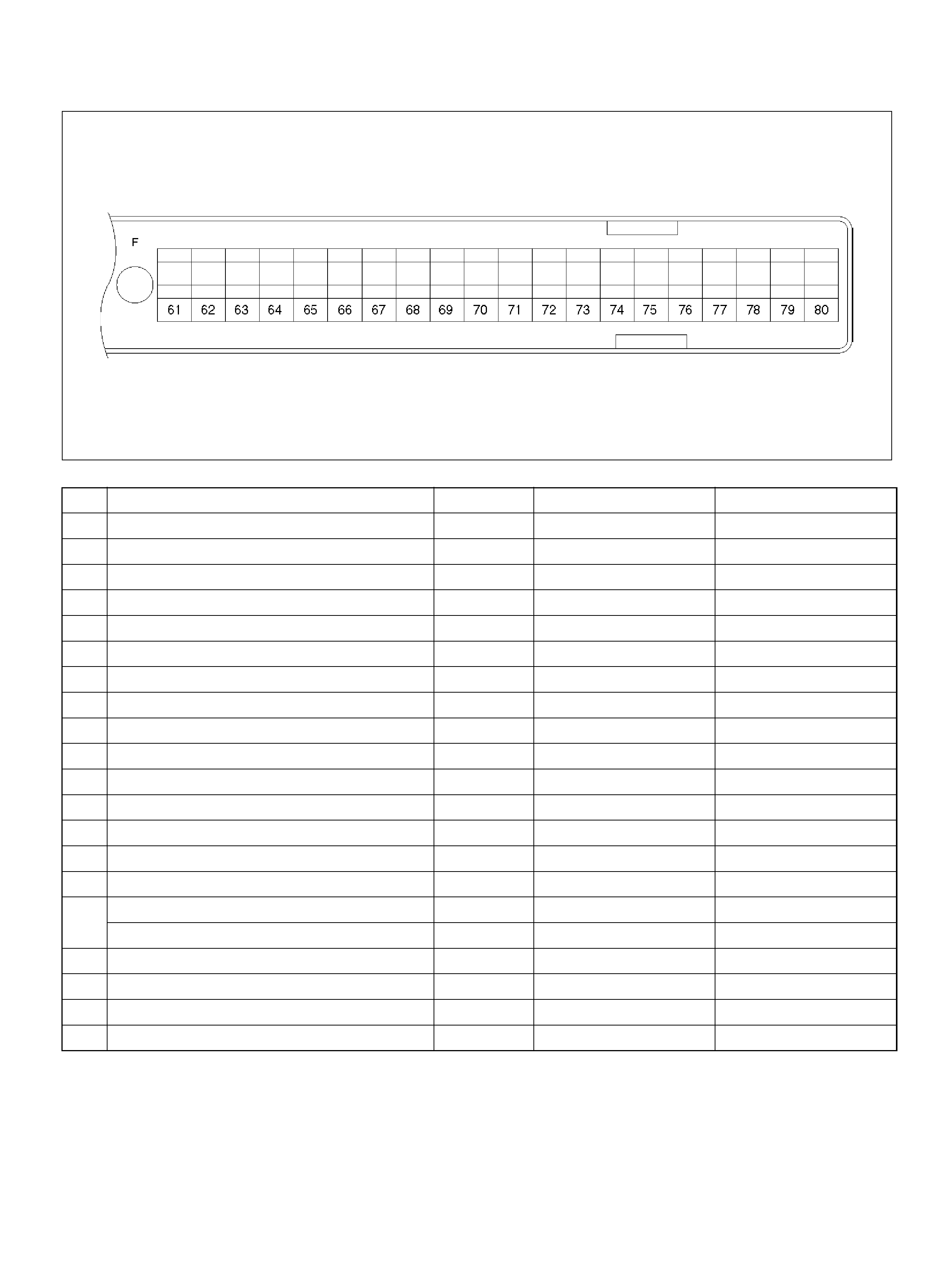
PCM PINOUT TABLE, 80-WAY BLUE CONNECTOR – ROW “F61 ∼ 80"
060RY00047
PIN PIN Function Wire Color IGN ON ENG RUN
F61 Throttle Position(TP) 2 Sensor Ground GRN/WHT 0.0V 0.0V
F62 Injector Cylinder #2 GRN/ORN B+ B+
F63 AP Sensor 1 Sensor Ground RED 0.0V 0.0V
F64 Injector Cylinder #4 GRN/RED B+ B+
F65 Throttle Position(TP) 2 Sensor Signal BLU/WHT 0.5– 0.8V 0.8–0.8V (at idle)
F66 Injector Cylinder #3 GRN B+ B+
F67 ION Sens ing Mod ule YEL 1.555V 1.555V
F68 ION Sens ing Module RE D 1.555V 1.555V
F69 Injector Cylinder #1 GRN/WHT B+ B+
F70 Not Used — — —
F71 Not Used — — —
F72 Auto Cruise Resume WHT/BLU 0.0V 0.0V
F73 Crankshaft Position Sensor WHT/BLU 0.3V 2.2V
F74 ECT Sensor BLU/RE D 0.5– 4.9V 0.5–4.9V
F75 Ignition Feed RED/GRN B+ B+
F76 Clutch Switch (M/T only) GRN B+ B+
Mode Sw itch (A/T only) PNK/BLK B + B+
F77 Mode Sw itch PNK/BLU B+ B+
F78 Mode Sw itch PN K/Y EL 0.0V 0.0V
F79 Mode Sw itch PNK 0.0V 0.0V
F80 AP Sensor 2 Ground BLU 0.0V 0.0V
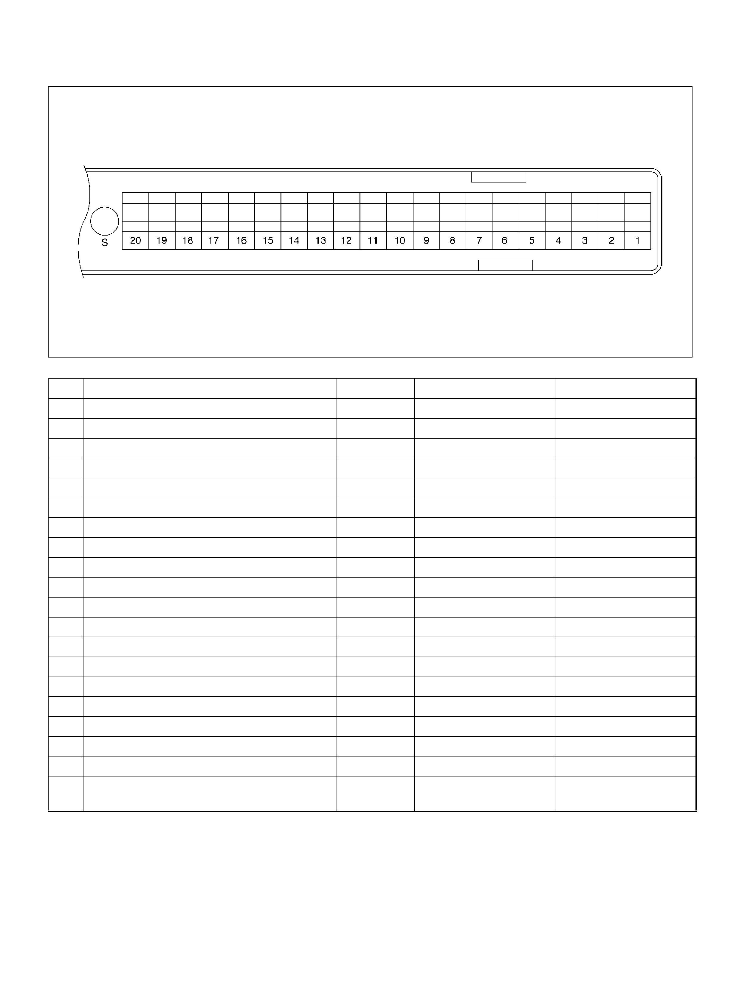
PCM PINOUT TABLE, 80-WAY RED CONNECTOR – ROW “S1 ∼ 20"
060RY00069
PIN PIN Function Wire Color IGN ON ENG RUN
S1 PCM Gr oun d BLK/PNK 0.0V 0.0V
S2 Bank 1 HO2S 1 Heater Ground BLK/ORN 0.0V 0.0V
S3 Not Used — — —
S4 Not Used — — —
S5 5Volt Reference“2" (CKP Sensor) WHT 5.0V 5 .0V
S6 Auto Cruise Control GRY/GRN 0.0V 0.0V
S7 C/P urge Solenoid Val v e YEL/RED B+ B+
S8 Not Used — — —
S9 Not Used — — —
S10 Shift High (Band Apply) BRN/YEL B+ B+
S11 Malfunction Indicator (Check Engine) Lamp WHT/GRN 0.0V B+
S12 Not Used — — —
S13 ION Sensing Module RED/ WHT 1.555V 1.555V
S14 Bank 2 HO2S 1 Ground BLU 0.0V 0.0V
S15 Not Used — — —
S16 Not Used — — —
S17 Bank 1 HO2S 1 Ground WHT 0.0V 0.0V
S18 Bank 1 HO2S 1 Low WHT/BLU 0.0V 0.1V
S19 ION Sensing Mod ule RED/YEL 1.555V 1.555V
S20 Transm ission Fluid Temperat ure Sens or
Ground RED/WHT 0.0V 0.0V
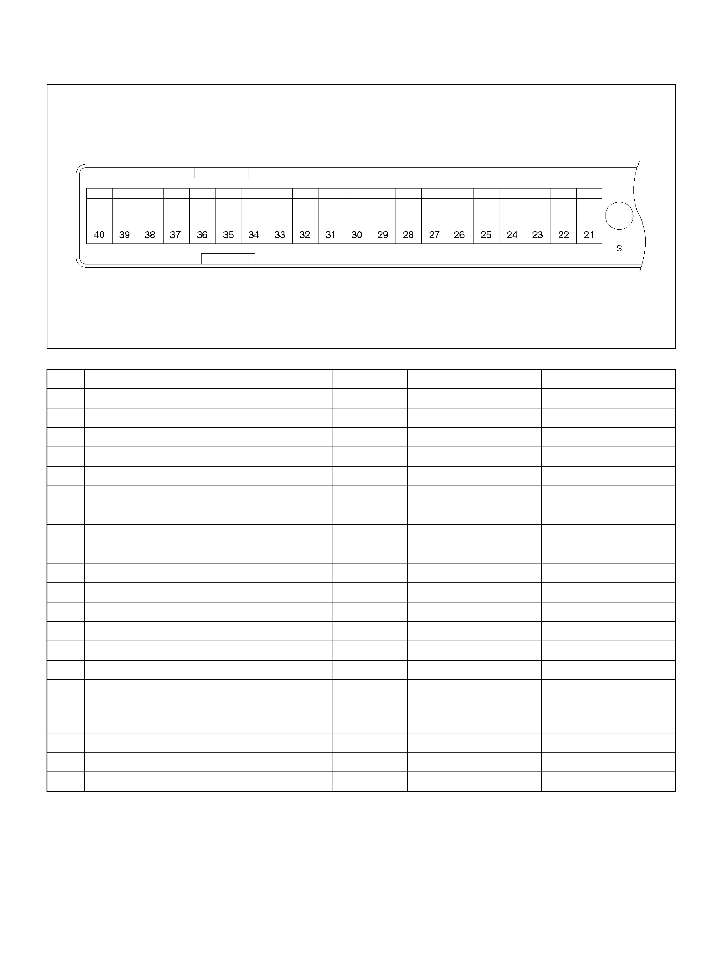
PCM PINOUT TABLE, 80 -WAY RED CONNECTOR – ROW “S21 ∼ 40"
060RY00049
PI N PIN Function Wire C ol or IGN ON EN G RUN
S21 Rr Window Demist Switch YEL/GRN — —
S22 Transmission Output Speed S ensor B LU/YEL 0.0V 0.0V
S23 PCM Groun d BLK 0. 0V 0.0V
S24 Not Used — — —
S25 Not Used — — —
S26 EGR Control High BLU/ RED B+ B+
S27 VSS Input BLK/YEL 0.0V 0.1V (at rest)
S28 Injector Cylinder #6 GR N/YEL B+ B+
S2 9 W inter Switc h VIO/ GR N B+ B +
S3 0 C r uis e Main Sw i tc h WHT/B LU 0.0V 0.0V
S31 Transm ission Range Signal“2–3'' GRN 0.0V 0.0V
S32 Ignition Feed R ED/GRN B+ B+
S33 TCC Soleno id BRN/WHT 0.0V 0.0V
S34 Not Used — — —
S35 ION Sensing Module RED/GRN 1.555V 1.555V
S36 5Volt Reference (AP Sensor 1) BLK 5.0V 5.0V
S37 5V olt Reference (MAP Sensor/EGR Position
Sensor) GRY/RED 5.0V 5.0V
S38 5Volt Reference (TP Sensor 1) RED 5. 0V 5.0V
S39 Auto Cruise Lamp WHT 0.0V 0.0V
S40 PCM Groun d BLK /YE L 0.0V 0.0V
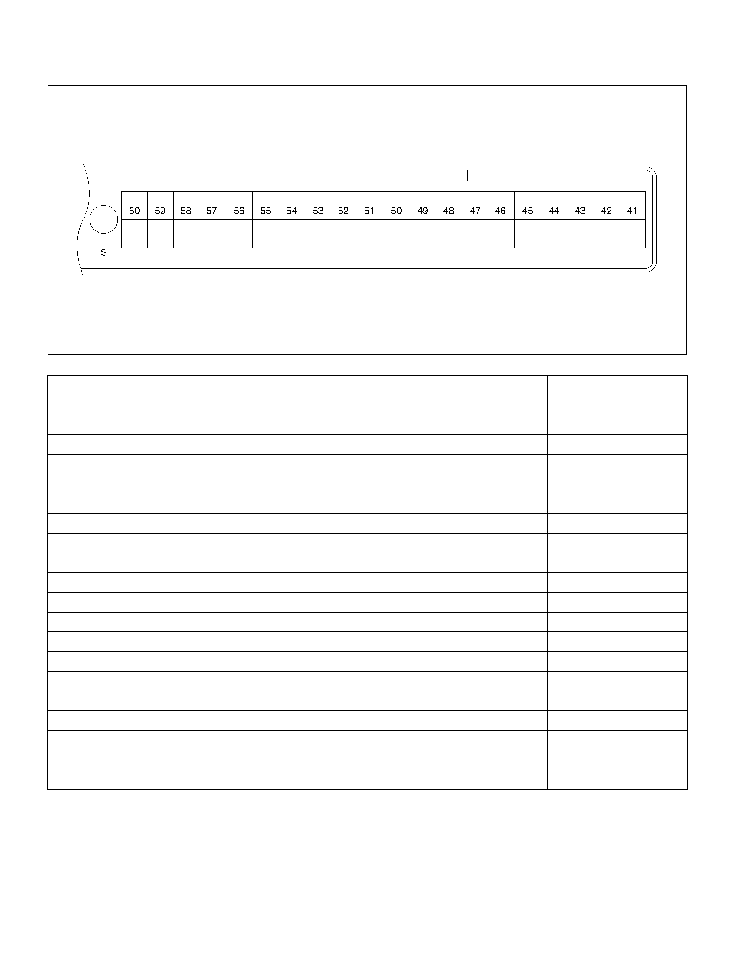
PCM PINOUT TABLE, 80 -WAY RED CONNECTOR – ROW “S41 ∼ 60"
060RY00050
P I N PIN Function Wire Color IGN ON ENG RU N
S41 AP Sensor 3 Senso r Ground ORN/ BLU 0. 0V 0.0V
S42 Bank 2 HO2S 1 Heater Ground WHT/RED 0.0V 0.0V
S43 Trans m ission Range Signal“1–2'' “3–4'' GRY/WHT B + B+
S44 Rr Def. Relay RED/WHT — —
S45 Not Used — — —
S46 Not Used — — —
S47 Water Temp. Gauge WHT/BLK B+ B+
S48 Not Used — — —
S49 DLC RED/WHT B+ B+
S50 Not Used — — —
S51 TCC Solenoid BRN/BLU 0.0V 0.0V
S52 Not Used — — —
S53 Power Switch VIO/RED B + B+
S54 Bank 2 HO2S 1 Low BLU 0.0V 0.1V
S55 T ransmission Output Sp eed Sensor BLU/GRN 0.0V 0.0V
S56 Not Used — — —
S57 Not Used — — —
S58 Bank 1 HO2S 1 High ORN/BLU 0.3V 0.1–0.9V
S59 Cruise Set GRN 0.0V 0.0V
S60 Not Used — — —
PCM PINOUT TABLE, 80 -WAY RED CONNECTOR – ROW “S61 ∼ 80"
060RY00051
PIN PIN Function Wire Color IGN ON ENG RUN
S61 Intake Air Temperature (IAT) Sensor Ground YEL/GRN 0.0V 0.0V
S62 ION Sensing Mod ule RED 1.555V 1.555 V
S63 Not Used — — —
S64 Bank 2 HO2S 1 High PNK 0.3V 0.1–0.9V
S65 Not Used — — —
S66 Transm ission Fluid Temperature S ensor RED/BLK 0.5–4.9V
( Vari e s with temp) 0.5–4.9V
(Va r i e s w i th te mp )
S67 Exhaust Ga s Recirculation (EGR) GRY/RED 0.6V 0.6V
S68 Accelerator Position (AP) Sensor 1 WHT 0.41–0.45V 0.41–0.45V
S69 Throttle Valve DC Motor(+) GRN Duty Cycle Duty Cycle
S70 Not Used — — —
S71 Not Used — — —
S72 Ignition Feed fo r ETC RED/GRN B+ B+
S73 Cruise Enable Lamp GRN/WHT 0.0V 0.0V
S74 Variable Intake Manifold YEL/BLK 0.0V B+ (>3600 rpm)
S75 Not Used — — —
S76 Throttle Position (TP) 1 Sensor Signal BLU 0.5–0.8V 0.5–0.8V (at idle)
S77 5Volt Reference (AP Sensor 3) ORN 5.0V 5.0V
S78 Accelerator Position (AP) Sensor 2 YEL 0.41–0.45V 0.41–0.45V
S79 Accelerator Position (AP) Sensor 3 BLU/GRN 4.55–4.99V 0.41–0.45V
S80 Manifold Absolute Pressure (MAP) GRN 0V 0V
COMPONENT LOCATORS
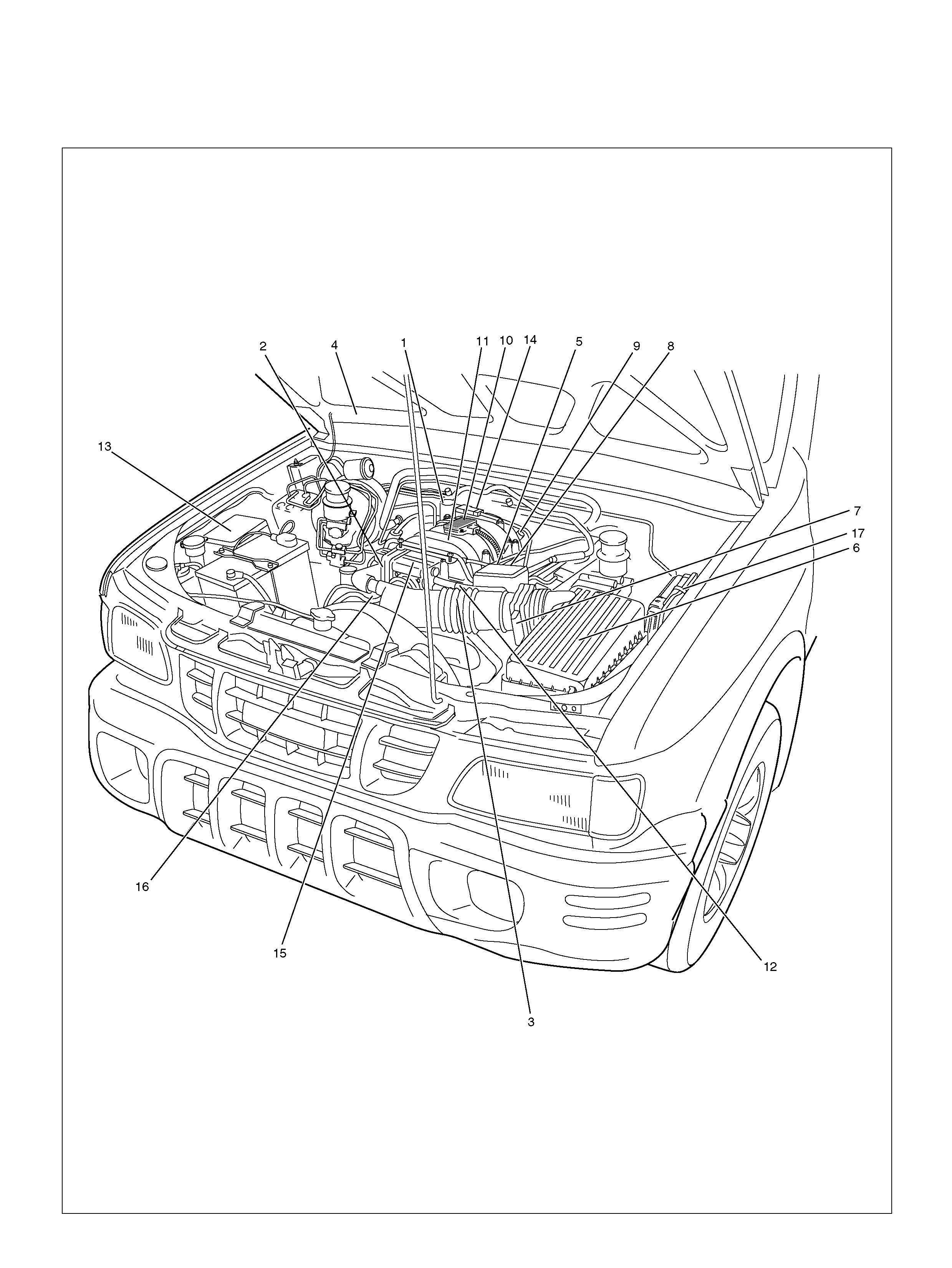
ENGINE COMPONENT LOCATOR
060R100144

Engine C omponent Loca tor Tab le
Number Name Location
1 Linear Exhaust Gas Recirculation (EGR) Valve Rear right side of the engine
2 Throttle Position (TP) Sensor On the throttle body
3 Intake Air Temperature (IAT) Sensor On the intake air duct near th e throttle body
4 Check Engine (MIL) Light On the instrument panel beneath the tachometer
5 Positive Crankcase Ventilation (PCV) Valve On the left of the cylinder head cover
6 Air Cleaner Left front of the engine bay
7 Mass Air Flow (MA F ) Sensor Attached to the air filter bo x
8 Fuel Rail On the Common Chamber
9 Fuel Pressure Regulator Left- Rear of the Common Cham ber
10 ION Sensing module Bolted to the top of the Common Chamber
11 Common Chamber Top of the engine
12 EVAP Duty Solenoid Valve Bolted to the front of the coolant pipe
13 Fuse/R ela y Box Along the inside of the right f ende r
14 Ma nifold Absolute Press ure (MAP ) Sensor Bolted to the top of the Common Chambe r
15 Throttle Body Between the intake air duct and the Common
Chamber
16 Engine Coolant Temperature Sensor On the coolant crossover pipe at the front of the
engine, near the throttle body
17 Power Train Control Module (PCM) Along the inside of the left fender
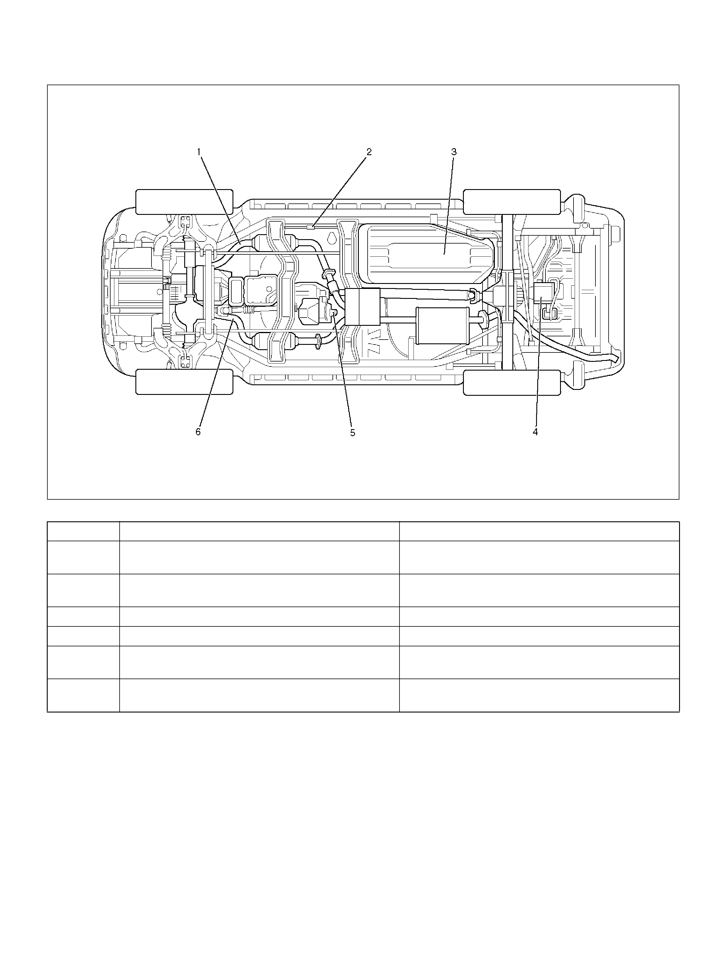
UNDERCARRIAGE COMPONENT LOCATOR
014RW188
Undercarriage Component Locator Table
Number Name Location
1 Heated Oxygen Sensor (Bank 2) Threaded into the exhaust pipe ahead the left-
hand catalytic converter
2 Fuel Filter Located along the inside of the right frame rail,
ahead of the propeller shaft
3 Fuel P um p and Gauge Unit Installed in the top of the f uel tank
4 Evaporative (EVAP) Canister Behind of the cross member
5 Vehicle Speed Sensor (VSS) Protrudes from the transmission housing, just
ahead of the fuel ta nk
6 Heated Oxygen Sensor (Bank 1) Threaded into the exhaust pipe ahead the right-
hand catalytic converter
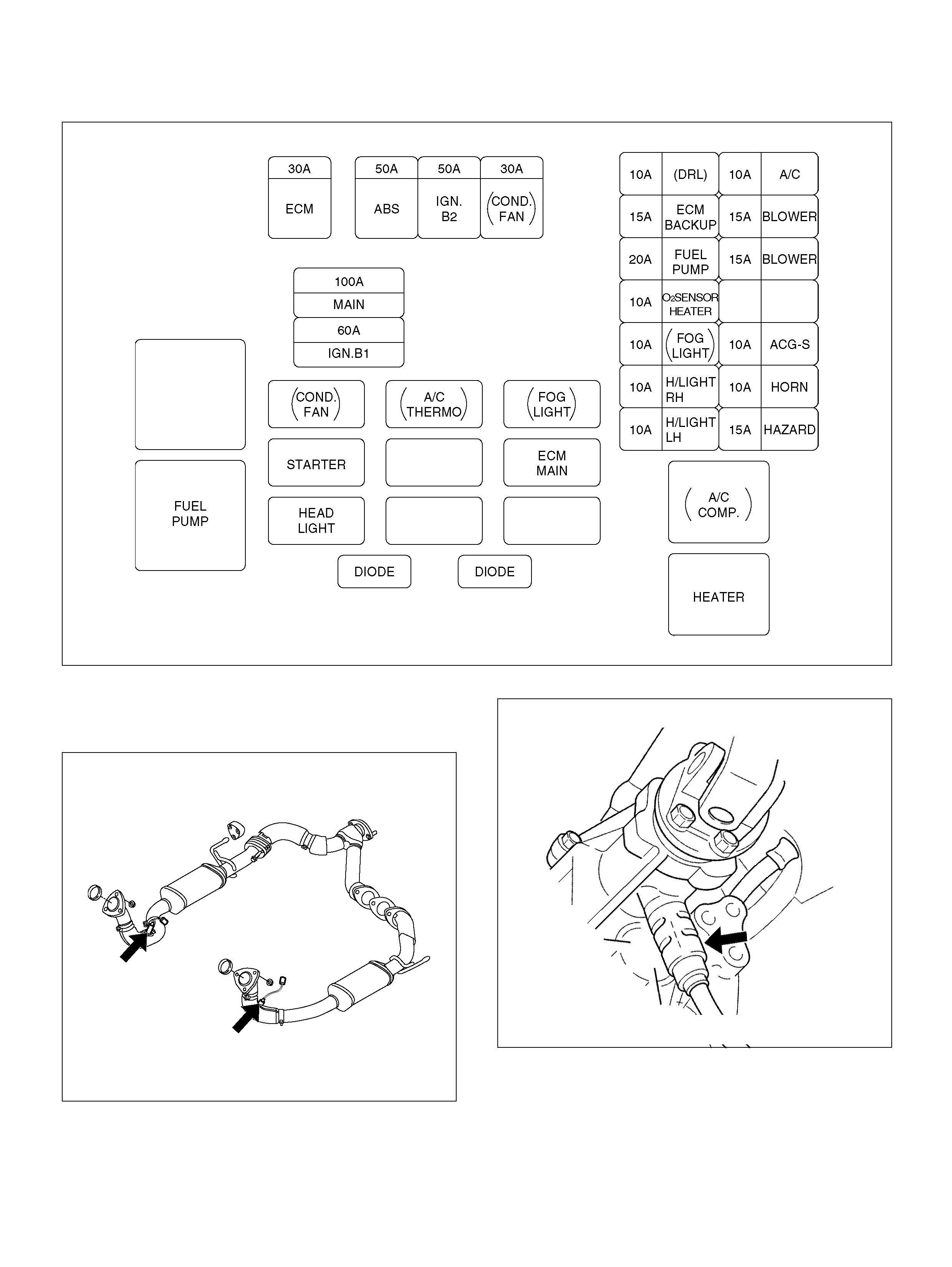
FUSE AND RELAY PANEL (UNDERHOOD ELECTRICAL CENTER)
SENSORS AND MISCELLANEOUS
COMPONENT LO CATORS
HO2 Sensor
150RY00023
Vehicle Speed Sensor
035RW112
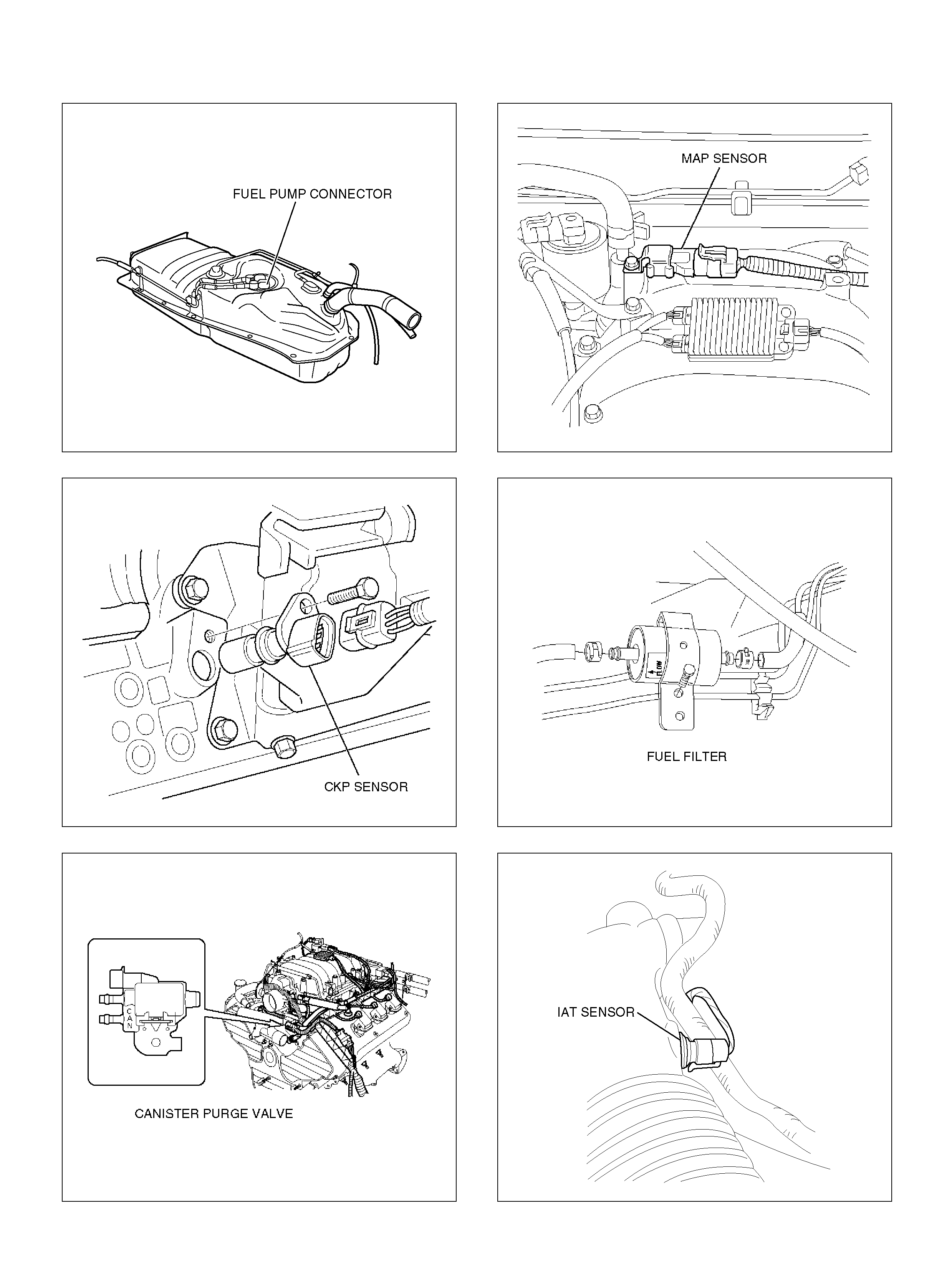
Fuel Tank
060R100129
CKP Sensor
060RW111
Canist er Purg e Valve
141R100005
Ma p S ensor
055RY00002
Fuel Fi l ter
041RW004
IAT Se nsor
060R100130
FUEL GAUGE AND
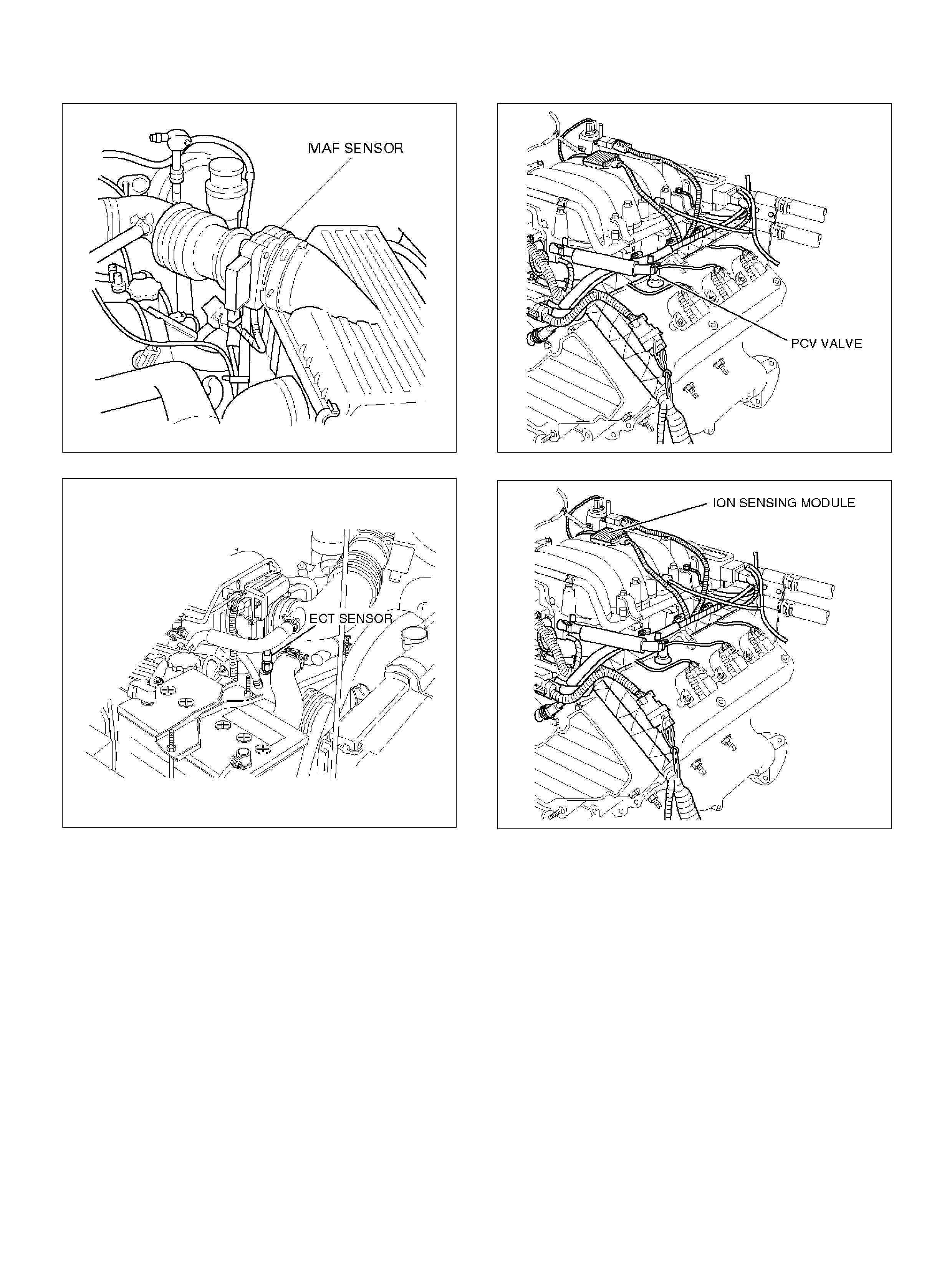
MA F S e nsor
T321078
EC T S ensor
060RY00014
PCV Valv e
060RY00016
ION Sensing Module
060RY00023

DIAGNOSIS
STRATEGY-BASED DIAGNOSTICS
Strategy-Based Diagnostics
The st ra tegy-based diagnostic is a uni form ap proach to
repair all Electrical/Electronic (E/E) systems. The
diagnostic flow can always be used to resolve an E/E
system problem and is a starting point when repairs are
necessary. The following steps will instruct the
technician how to proceed with a diagnosis:
1. Verify the customer complaint.
• To verify the customer complaint, the technician
shou ld know the normal operation of the system .
2. Perfo rm preliminary checks.
• Conduct a thorough vis ual inspection.
• Review the service history.
• Detect unusual sounds or odors.
• Gather diagnostic trouble code information to
achieve an effective repair.
3. Check bulletins and other service information.
• This includes videos, newsletters, etc.
4. Refer to service information check(s).
• “System checks" contain informa tion on a system
that m ay not be support ed by one or m ore DTCs.
System checks verify proper operation of the
system. This will lead the technician in an
organized approac h to diagnost ics .
5. Refer to service diagnostics.
DTC STORED
Follow the designated DTC chart exactly to make an
effective repair.
NO DTC
Select the symptom from the symptom tables. Follow
the diagnostic paths or suggestions to complete the
repair. You may refer to the applicable component/
system check in the system checks.
NO MATCHING SYMPTOM
1. A nalyze th e complaint.
2. Develop a plan for diagnostics.
3. Utilize the wiring diagrams and the theory of
operation.
Combine technician knowledge with efficient use of the
available service information.
INTERMITTENTS
Conditions that are not always present are called
intermittents. To resolve intermittents, perform the
following steps:
1. Observe history DTCs, DTC modes, and freeze
frame data.
2. Evaluate the symptoms and the conditions
described by the customer.
3. Use a check sheet or other method to identify the
circuit or elec t rical system component.
4. Follow the suggestions for intermittent diagnosis
found in the service documentation.
Most Scan Tools, such as the Tech 2, have
data-capturing capabilities that can assist in detecting
intermittents.
NO TROUBLE FOUND
This condition exists when the vehicle is found to
operate normally. The condition described by the
customer may be normal. Verify the customer complaint
against another vehicle that is operating normally. The
condition may be intermittent. Verify the complaint
under the conditions described by the customer before
releasing the vehicle.
1. Re-examine the compl aint.
When the complaint cannot be successfully found or
isolated, a re-evaluation is necessary. The
complaint should be re-verified and could be
intermittent as defined in Intermittents section, or
could be normal.
2. Repair and ve rify.
After isolating the cause, the repairs should be
made. Validate for proper operation and verify that
the symptom has been corrected. This may involve
road testing or other methods to verify that the
complaint has been resolved under the following
conditions:
• Conditions noted by the customer.
• If a DTC was diagnosed, verify a repair by
duplicating conditions present when the DTC was
set as noted in the Failure Records or Freeze
Frame data.
VERIFYING VEHICLE REPAIR
Verification of the vehicle repair will be more
comprehensive for vehicles with OBD system
diagnostics. Following a repair, the technician should
perform the following steps:
Important: Follow the steps below when you verify
repairs on OBD systems. Failure to follow these steps
could result in unnecessary repairs.
1. Review and record the Failure Records and the
Freeze Frame data for the DTC which has been
diagnosed (Freeze Frame data will only be stored
for an A or B type diagnostic and only if the
MIL("Check En gine" lamp) has been reques ted).
2. Clear the DTC(S).
3. Operate the vehicle within conditions noted in the
Failure Records and Freeze Frame data.
4. Monitor the DTC status information for the DTC
which has been diagnosed until the diagnostic test
associated with that DTC runs.

GENERAL SERVICE INFORMATION
OBD SERVICEABILITY ISSUES
With the introduction of OBD diagnostics across the
entire passenger car and light-duty truck market in
1996, illumination of the MIL (“Check Engine" lamp) due
to a non-vehicle fault could lead to misdiagnosis of the
vehicle, increased warranty expense and customer
dissatisfaction. The following list of non-vehicle faults
does not include every p ossible fault and may not apply
equally to all product lines.
Fuel Quality
Fuel quality is not a new issue for the automotive
industry, but its potent ial for t urning on the MIL (“Check
Engine" lamp) with OBD syste ms is new.
Fuel addi tives such as “dry gas" and “octane enhances"
may affect the performance of the fuel. If this results in
an incomplete combustion or a partial burn, it will show
up as a Misfire DTC P0300. The vapor pressure of the
fuel can also create problems in the fuel system,
especially during the spring and fall months when
severe ambient temperature swings occur . A high vapor
pressure could show up as a Fuel Trim DTC due to
excessive canister loa ding.
Using fuel with the wrong octane rating for the vehicle
may cause derivability problems. Many of the major fuel
companies advertise that using “premium" gasoline will
improve the performance of the vehicle. Most premium
fuels use alcohol to increase the octane rating of the
fuel. Although alcohol-enhanced fuels may raise the
octane rating, the fuel's ability to turn into vapor in cold
temperatures deteriorates. This may affect the starting
ability and cold derivability of the engine.
Low fuel levels can lead to fuel starvation, lean engine
operati on, and eventually engine misfire.
Non-OEM Parts
All of the OBD diagnostics have been calibrated to run
with OEM parts. Something as simple as a
high-performance exhaust system that affects exhaust
syste m back pressure co uld potenti a lly inte rfer e with t he
operation of the EGR v alve and thereby turn on the M IL
(“Check Engine" lamp). Small leaks in the exhaust
system near the post catalyst oxygen sensor can also
cause the MIL (“Check Engine" lamp) to turn on.
Aftermarket electronics, such as transceivers, stereos,
and anti-theft devices, may radiate EMI into the control
system if they are improperly installed. This may cause
a false sensor reading and turn on the MIL (“Check
Engine" lamp).
Environment
Temporary environmental conditions, such as localized
flooding, will have an effect on the vehicle ignition
system. If the ignition system is rain-soaked, it can
temporarily cause engine misfire and turn on the MIL
(“Check Engine" lamp).
Vehicle Marshaling
The transportation of new vehicles from the assembly
plant to the dealership can involve as many as 60 key
cycles within 2 to 3 miles of driving. This type of
operation contributes to the fuel fouling of the spark
plugs and will turn on the MIL (“Check Engine" lamp)
with a P0300 Misfire DTC.
Poor Vehicle Maintenance
The sensitivity of OBD diagnostics will cause the MIL
(“Check Engine" lamp) to turn on if the vehicle is not
maintained properly. Restricted air f i lters, fuel filt ers, and
crankcase deposits due to lack of oil changes or
improper oil viscosity can trigger actual vehicle faults
that were not previously monitored prior to OBD. Poor
vehicle maintenance can't be classified as a
“non-vehicle fault", but with the sensitivity of OBD
diagnostics, vehicle maintenance schedules must be
more closely followed.
Related System Faults
Many of the OBD system diagnostics will not run if the
PCM dete cts a fault on a related system or componen t.
One example would be that if the PCM detected a
Misfire fault, the diagnostics on the catalytic converter
would be suspended until Misfire fault was repaired. If
the Misfire fault was severe enough, the catalytic
converter could be damaged due to overheating and
would never set a Catalyst DTC until the Misfire fault
was repaired and the Catalyst diagnostic was allowed to
run to completion. If this happens, the customer may
have to make two trips to the dealership in order to
repair the vehic le .
VISUAL / PHYSICAL ENGINE
COMPARTMENT INSPECTION
Perform a careful visual and physical engine
compartment inspection when performing any
diagnostic procedure or diagnosing the cause of an
emission test failure. This can often lead to repairing a
problem without further steps. Use the following
guidelines when performing a visual/physical
inspection:
• Inspect all vacuum hoses for pinches, cuts,
disco nnections , and proper routing.
• Inspect hoses that are difficult to see behind other
components.

• Inspect all wires in the engine compartment for
pro per connections, burned or c hafed spo ts, pin ched
wires, contact with sharp edges or contact with hot
exh aust manif olds or pipes.
BASIC KNOWLEDGE OF TOOLS
REQUIRED
NOTE: Lack of basic knowledge of this powertrain
when performing diagnostic procedures could result in
an incorrect diagnosis or damage to powertrain
components. Do not attempt to diagnose a powertrain
problem without this basic knowledge.
A basic understanding of hand tools is necessary to
effectively use this section of the Serv ice M anual .
SERIAL DAT A COMMUNICATIONS
CLASS 2 SERIAL DATA
COMMUNICATIONS
Government regulations require that all vehicle
manufacturers establish a common communication
system. This vehicle utilizes the “Class 2"
communication system. Each bit of information can
have one of two lengths: long or short. This allows
vehicle wiring to be reduced by transmitting and
receiving multiple signals over a single wire. The
messages carried on Class 2 data streams are also
prioritized. If two messages attempt to establish
comm unications on the data line at the same time, only
the message with higher priority will continue. The
device with the lower priority message must wait. The
most significant result of this regulation is that it
provides Scan tool manufacturers with the capability to
access data from any make or model vehicle that is
sold.
The data displayed on other Scan tools will appear the
same, wi th some exceptions. Some Scan tools will only
be able to display certain vehicle parameters as values
that are a coded representation of the true or actual
value. On this vehicle the Scan tool displays the actual
values for vehicle parameters. It will not be necessary to
perform any conversions from coded values to actual
values.
ON-BOARD DIAGNOSTIC (OBD)
ON-BOARD DIAGNOSTIC TESTS
A di agnost ic test i s a series of steps, the resul t o f which
is a pass or fail reported to the diagnostic executive.
When a diagnostic test reports a pass result, the
diagnostic executive records the following data:
• The diagnostic test has been completed since the
last ignitio n cycle.
• The diagnostic test has passed during the current
ignition cy cle.
• The fault identified by the diagnostic test is not
currently active.
When a diagnostic test reports a fail result, the
diagnostic executive records the following data:
• The diagnostic test has been completed since the
last ignitio n cycle.
• The fault identified by the diagnostic test is currently
active.
• The fault has been acti ve during this ignition cycle.
• The operating condition s at the time of t he failure.
Remember, a fuel trim DTC may be triggered by a list of
vehicle faults. Make use of all information available
(other DTCs stored, rich or lean condition, etc.) when
diagnosing a fuel trim fault.
COMPREHENSIVE COMPONENT MONITOR
DIAGNOSTIC OPERATION
Comprehensive component monitoring diagnostics are
required to monitor emissions-related input and output
powertrain components. The OBD Comprehensive
Component Monitoring List Of Components Intended To
illuminate MIL is a list of components, features or
functions that could fall under this requirement.
In put Co m pone nts:
Input components are monitored for circuit continuity
and out-of-range values. This includes rationality
checking. Rationality checking refers to indicating a fault
when the signal from a sensor does not seem
reasonable, i.e. Throttle Position (TP) sensor that
indicates high throttle position at low engine loads or
MAP voltage. Input components may include, but are
not limited to the following sensors:
• Vehicle S peed Sensor (VSS)
• Crankshaft Position (CKP) sensor
• Throttle Position (TP) sensor
• Engine Coolant Tempe rature (ECT) sensor
• Manifold Absolute Pressure (MAP) sensor
• Mass Air Flow (MAF) sensor
In addition to the circuit continuity and rationality check,
the ECT sensor is monitored for its ability to achieve a
steady state temperature to enable closed loop fuel
control.
Ou t put C om ponents:
Output components are diagnosed for proper response
to control module commands. Components where
functional monitoring is not feasible will be monitored for
circuit continuity and out-of-range values if applicable.
Output components to be monitored include, but are not
limited to, the following circuits:
• Control module controlled EVAP Canister Purge
Valve
• Electronic Trans mission con trols

•A/C relays
• VSS outp ut
•MIL control
Refer to PCM and Se ns ors in General Descriptions.
Passive an d Active Diagnostic Tests
A passive test is a diagnostic test which simply monitors
a vehicle system or component. Conversely, an active
test, actually takes some sort of action when performing
diagnostic functions, often in response to a failed
passive test. For example, the EGR diagnostic active
test will force the E GR valve open du ring closed t hrottle
decel. Either action should result in a change in
manifold pressure.
Intrusive Diagnostic Tests
This is any on-board test run by the Diagnostic
Management System which may have an effect on
vehicle performance or emission levels.
Warm-Up Cycle
A warm-up cycle means that engine at temperature
must reach a minimum of 70°C (160°F) and rise at least
22°C (40°F) over the course of a trip.
Freeze Fra m e
Freeze Frame is an element of the Diagnostic
Management System which stores various vehicle
information at the moment an emissions-related fault is
stored in mem ory and when the MIL is com manded on.
These data can help to identify the cause of a fault.
Refer to Storing And Erasing Freeze Fram e D ata in this
section for more detailed information.
Failure Records
Failure Records data is an enhancement of the OBD II
Freeze Frame feature. Failure Records store the same
vehicle information as does Freeze Frame, but it will
store that information for any fault which is stored in
on-board memory, while Freeze Frame stores
information only for emission-related faults that
comm and the M IL on.
Enable Criteria
The term “enable criteria" is engineering language for
the conditions necessary for a given diagnostic test to
run. Each diagnostic has a specific list of conditions
which must be met before the diagnostic will run.
“Enable criteria" is another way of saying “conditions
required".
The enable criteria for each diagnostic is listed on the
first page of the DTC description in Section 6C1 under
the heading “Conditions for Setting the DTC". Enable
criteria varies with each diagnostic, and typically
includes, but is not limited to the following items:
• e ngine speed
• vehicle speed
•ECT
•MAF/MAP
• b arome tric pressure
•IAT
•TP
• h igh caniste r purge
• fuel tr im
• T CC enabled
•A/C on
Trip
Technically, a trip is a key on-run-key off cycle in which
all the enable criteria for a given diagnostic are met,
allowing the diagnostic to run. Unfortunately, this
concept is not quite that simple. A trip is official when all
the enable criteria for a given diagnostic are met. But
because the enable criteria vary fro m one diagnostic to
another, the definition of trip varies as well. Some
diagnostics are run when the vehicle is at operating
temperature, some when the vehicle first starts up;
some require that the vehicle be cruising at a steady
highway s peed, some run on ly when the veh icle is idle;
some diagnostics function with the TCC disabled. Some
run only immediately following a cold engine start-up.
A trip then, is defined as a key on-run-key off cycle in
which the vehicle was operated in such a way as to
satisfy the enabling criteria for a given diagnostic, and
this diagnostic will consider this cycle to be one trip.
However, another diagnostic with a different set of
enable criteria (which were not met) during this driving
event, would not consider it a trip. No trip will occur for
that particular diagnostic until the vehicle is driven in
such a way as to meet all t he enabl e criteria.
THE DIAGNOSTIC EXECUTIVE
The Diagnostic Executive is a unique segment of
software which is designed to coordinate and prioritize
the diag nostic procedu res as well as defi ne the protocol
for recording and displaying their results. The main
responsibilit ies of the Diagnost ic E x ecuti ve ar e l isted as
the following:
• Commanding the MIL (“Check Engine" lamp) on and
off
• DTC logging and clearing
• F reeze F ram e data f or the f irst em ission rel ated DTC
recorded
• Non-emission related Service Lamp
• Operating conditions Failure Records buffer, (the
number of records will vary)
• Current stat us information on each diagnostic
• Sy ste m Status (I/ M ready)
The Diagnostic Executive records DTCs and turns on
the MIL when e mission-related faults occur. It can also
turn off t he MIL if the conditions cease which caused the
DTC to set.
Diagnostic Inform ation
The diagnostic charts and functional checks are
designed t o lo cate a fau lty circuit or component throug h
a process of logical decisions. The charts are prepared
with the requirement that the vehicle functioned

correctly at the time of assembly and that there are no
multiple faults present.
There is a continuous self-diagnosis on certain control
functions. This diagnostic capability is complemented by
the diagnostic procedures contained in this manual. The
language of communicating the source of the
malfunction is a system of diagnostic trouble codes.
When a malfunction is detected by the control module, a
diagnostic trouble code is set and the Malfunction
Indicator Lamp (MIL) (“Check Engine" lamp) is
illuminated.
Malfunction Indicator Lamp (MIL)
The Malfunction Indicator Lamp (MIL) looks the same
as the MIL you ar e already familiar with (“Check Engine"
lamp). However, OBD require s t hat it illumi nate under a
strict set of guide lines.
Basically, the M IL is turned on when the PCM detects a
DTC that will imp act vehicle emissions.
The MIL is under the control of the Diagnostic
Executive. The MIL will be turned on if an
emissions-related diagnostic test indicates a
ma lf u nc t io n h as o c cu rre d. It w ill s tay on un ti l the s y ste m
or component passes the same test, for three
consecut ive trips, with no e mi ssions related faults.
Extinguishing the MIL
When the MIL is on, the Diagnostic Executive will turn
off the MIL after three(3) consecutive trips that a “test
passed" has been reported for the diagnostic test that
originally caused the MIL to illuminate.
Although the MIL has been turned off, the DTC will
remain in the PCM memory (both Freeze Frame and
Failure Records) until forty(40) warm-up cycles after no
faults have been comp leted.
If the MIL was set by eit her a fuel t rim or misfire -related
DTC, additional requirements must be met. In addition
to the requirements stated in the previous paragraph,
these requirements are as follows:
• The diagnostic tests that are passed must occur
within 375 RPM of the RPM data stored at the time
the last test failed.
• Plus or minus ten (10) percent of the engine load that
was stored at t he time t he l ast fail ed.
• Sim ilar engine temperat ure conditions (warm ed up or
w armin g up ) as those stored at the time the last test
failed.
Meeting these requirements ensures that the fault which
turned on the MIL has been corrected.
The MIL (“Check Engine" lamp) is on the instrument
panel and has the following function:
• It informs the driver that a fault affects vehicle
emission levels has occurred and that the vehicle
shou ld be taken for service as soon as possible.
• As a bul b and syste m check, the MIL will come “ON"
with the key “ON" and the engine no t running. When
the engi ne is starte d, the MIL will turn “OFF."
• When the MIL remains “ON" while the engine is
running, or when a m al function is s uspecte d due to a
derivability or emissions problem, a Powertrain
On-Board Diagnostic System Check must be
performed. The procedures for these checks are
given in On-Board Diagnostic (OBD) System Check.
These checks will expose faults which may not be
detected if other diagnostics are performed first.
DTC TYPES
Each DTC is directly related to a diagnostic test. The
Diagnostic Management System sets DTC based on
the failure of the tes ts during a trip or trips. Certain t ests
must fail two (2) consecutive trip s before the DTC is set.
The following are the four (4) types of DTCs and the
characteristics of those codes:
•Type A
• Emissions related
• Requests illumination of the MIL of the first trip with
a fail
• St ores a History DTC on t he first trip with a fail
• Stores a Freeze Frame (if empty)
• Stores a F ail Record
• Updates the Fail Record each time the diagnostic
test fails
•Type B
• Emissions related
• “Armed" aft er one (1) trip with a fail
• “Disarmed" after one (1) trip with a pass
• Requests illumination of the MIL on the second
consecutive trip with a fail
• Stores a History DTC on the second consecutive
trip with a fail (The DTC will be armed after the first
fail)
• Stores a Free ze Fram e on the se cond c onsec utive
tr ip wi th a fai l (i f em p ty)
• Stores a Fail Record when the first test fails (not
dependent on consecutive trip fails )
• Updates the Fail Record each time the diagnostic
test fails
(Some special conditions apply to misfire and fuel trim
DTCs)

• Typ e C (if t he vehicle is so equipped)
• Non-Emissions related
• Requests illumination of the Service Lamp
• St ores a History DTC on the fir st tr ip with a fai l
•Does not store a Freez e Fram e
• Stores Fail Record when test fails
• Updates the Fail Record each time the diagnostic
test fails
•Type D
• Non-Emissions related
• Not reque st illumin atio n of any lamp
• St ores a History DTC on the fir st tr ip with a fai l
•Does not store a Freez e Fram e
• Stores Fail Record when test fails
• Updates the Fail Record each time the diagnostic
test fails
Important: Only four Fa il Records can be stored. E ac h
Fail Record is for a different DTC. It is possible that
there will not be Fail Records for every DTC if multiple
DTCs are set.
Special Cases of Ty pe B Diagno stic Tests
Unique to the misfire diagnostic, the Diagnostic
Executive has the capability of alerting the vehicle
operator to potentially damaging levels of misfire. If a
misfire condition exists that could potentially damage
the catalytic converter as a result of hig h misfire levels,
the Diagnostic Executive will command the MIL to
“flash" at a rate of once per second during those the
time that the catalyst damaging misfire condition is
present.
Fuel trim and misfire are special cases of Type B
diagnost ics. Each time a fuel trim or misfire malfunction
is detected, engine load, engine speed, and engine
coolant temp erature are recorded.
When the ignition is turned off, the last reported set of
conditions remain stored. During subsequent ignition
cycles, the stored conditions are used as reference for
similar conditions. If a malfunction occurs during two
consecutive trips, the Diagnostic Executive treats the
failure as a normal Type B diagnostic, and does not use
the stored conditions. However, if a malfunction occurs
on two non-consecutive trips, the stored conditions are
compared with the current conditions. The M IL wil l the n
illuminate under the following conditions:
• When the engine load conditions are within 10% of
the previous te st that failed.
• Eng ine sp eed is within 37 5 rpm, of the previous test
that failed.
• Engine coolant temperature is in the same range as
the previous te st that failed.
Storing and Erasing Freeze Frame Data and Failure
Records
Government regulations require that engine operating
conditions be captu red whenev er the M IL is illuminat ed.
The data captured is called Freeze Frame data. The
Freeze Frame data is very similar to a single record of
operating conditions. Whenever the MIL is illuminated,
the corresponding record of operating conditions is
recorded to the Freeze Frame buffer.
Freeze Frame data can only be overwritten with data
associated with a misfire or fuel trim malfunction. Data
from these faults take preced ence over data asso ciated
with any other fault. The Freeze Frame data will not be
erased unles s the associated history DTC is cleared.
Each tim e a dia gnos tic t est rep orts a failure, the c urrent
engine op erating conditions are recorded in the Failure
Records buffer. A subsequent failure will update the
recorded operating conditions. The following operating
conditions for the diagnostic test which failed typically
include the following parameters:
• Air Fuel Ratio
•Air Flow Rate
• Fuel Trim
• Engine Speed
• Engine Load
• Engine Coolant Tem perature
• Vehicle Speed
• TP Angle
• MAP/BARO
• Injector Base Pulse Width
• Loop Status
Int erm i t te nt Malfunct i on I ndi c at o r La m p
In the case of an “intermittent" fault, the MIL (“Check
Engine" lamp) may illuminate and then (after three trips)
go “OFF". However, the corresponding diagnostic
trouble code will be stored in memory. When
unexpected diagnostic trouble codes appear, check for
an intermittent malfun ction.
A diagnostic trouble code may reset. Consult the
“Diagnostic Aid s" associated with the dia gnostic trouble
code. A physical inspection of the applicable
sub-system most often will resolv e the probl e m.
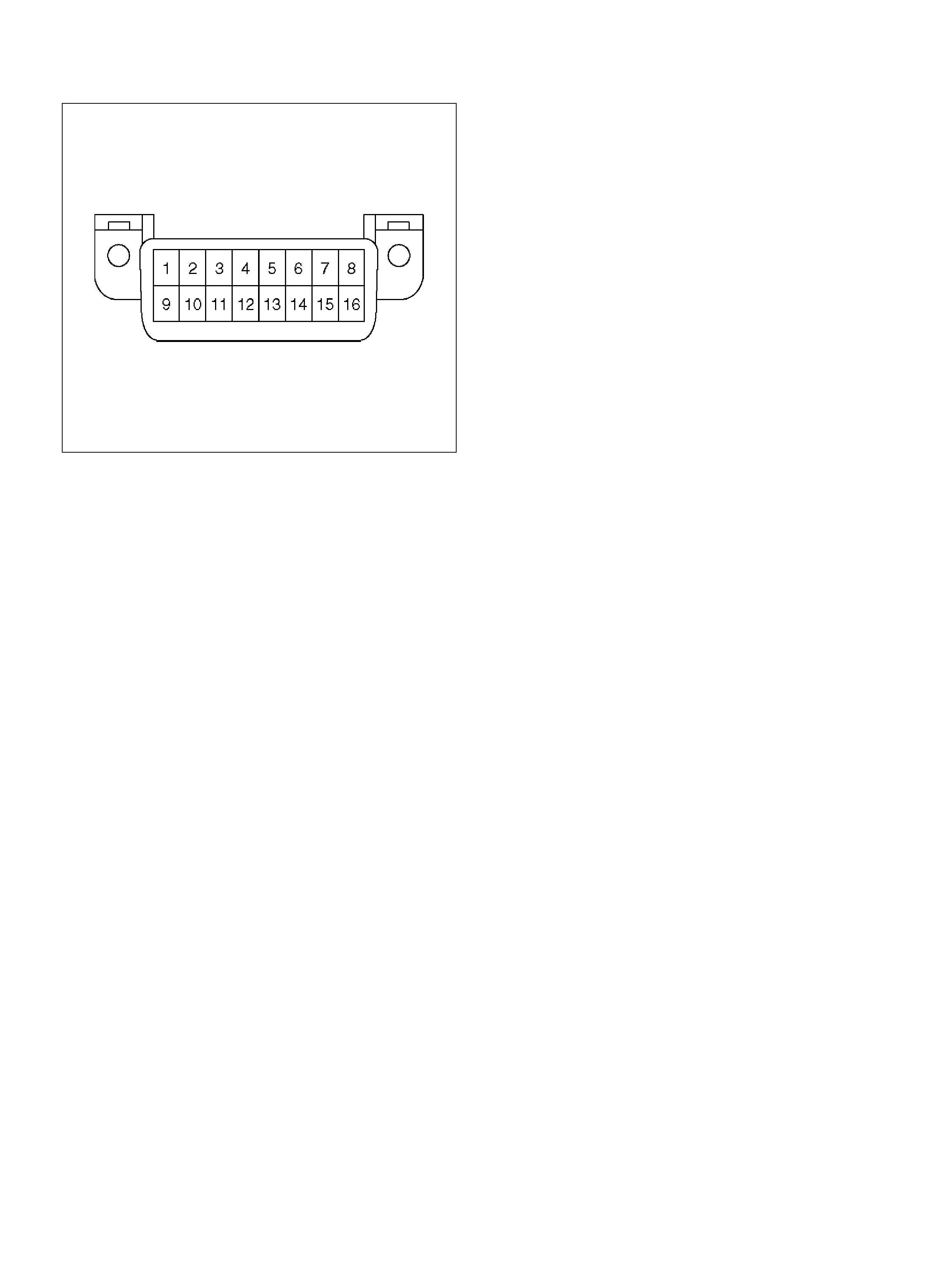
Data Link Connect or (D LC )
The provision for communication with the control
module is the Data Link Connector (DLC). It is located
at the lower left of the instrument panel behind a small
square cover. The DLC is use d to connect to the Tech 2
Scan Tool. Som e common us es of the Tech 2 are listed
below:
• Ident ifying stored Diagnosti c Troubl e Codes (DTCs).
• Cl earing DTCs.
• Perf orming outp ut control tests.
• Re ading serial data.
TS24064
DECIMAL/BINARY/HEXADECIMAL
CONVERSIONS
Beginning in 1996, Federal Regulations require that all
auto manufacturers selling vehicles in the United Stat es
provide Scan Tool manufacturers with software
information to display vehicle operating parameters. All
Scan Tool man ufacturers will display a va riety of vehicle
in formation wh ich will aid in repair ing th e vehic le. S ome
Scan Tools will display encoded messages which will
aid in determining the nature of the concern. The
met hod of enc odi ng invol ves the u se of a two additiona l
numbe ring systems: Binary and Hexade cimal.
The bina ry number system has a base of two numbers.
Each digit is either a 0 or a 1. A binary number is an
eight digit number and is read from right to left. Each
digit has a position number with the farthest right being
the 0 position and the farthest left being th e 7 position.
The 0 position, when displayed by a 1, indicates 1 in
decimal . Each position to the left is doubl e the previous
position and adde d t o any ot her po sition v alu es m arke d
as a 1.
A hexadecimal system is composed of 16 different
alpha numeric characters. The alpha numeric
characters used are numbers 0 through 9 and letters A
through F. The he xadecimal system is the most natural
and common approach for Scan Tool manufacturers to
display data represented by binary num bers and digital
code.
VERIFYING VEHICLE REPAIR
Verification of vehicle repair will be more
comprehensive for vehicles with OBD II system
diagnostic. Following a repair, the technician should
perform the following steps:
1. Review and record the Fail Records and/or Freeze
Frame d ata for the DTC which h as been diagno sed
(Freeze Frame data will only be stored for an A or B
type diagnostic and only if the MIL has been
requested).
2. Clear DT C(s).
3. Operate the vehicle within conditions noted in the
Fail Records and/or Freeze Frame data.
4. Monitor the DTC status information for the DTC
which has been diagnosed until the diagnostic test
associated with that DTC runs.
Following these steps are very important in verifying
repairs on OB D ll system s. Failure t o foll ow t hese steps
could result in unnecessary repairs.
READING DIAGNOSTIC TROUBLE CODES
USING THE TECH 2 SCAN TOOL
The procedure for reading diagnostic trouble code(s) is
to use a diagnostic Scan Tool. When reading DTC(s),
follow instructions supplied by tool manufacturer.
Clearing Diagnostic Trouble Codes
Important: Do not c lea r DTCs un less directed t o do so
by the service information provided for each diagnostic
procedure. When DTCs are cleared, the Freeze Frame
and Failure Record data which may help diagnose an
intermittent fault will also be erased from memory.
If the fault that caused the DTC to be stored into
memory has been corrected, the Diagnostic Executive
will begin to count the “warm-up" cycles with no further
faults detected, the DTC will automatically be cleared
from the PCM memory.
To clear Diagnostic Trouble Codes (DTCs), use the
diagnost ic Scan Tool “clear DTCs" or “clear inform ation"
function. When clearing DTCs follow instructions
supplied by the tool man ufacturer.
When a Scan Tool is not available, DTCs can also be
cleared by disconnecting one of the following sources
for at least thir ty (30) seconds.
NOTE: To prevent system damage, the ignition key
must be “OFF" when disconnecting or reconnecting
battery power.
• The power source to the control module. Examples:
fuse, pigtail at battery PCM connectors, etc.
•The negative battery cable. (Disconnecting the
negative battery cable will result in the loss of other
on-board mem ory data, such as preset radio tuning).
TECH 2
Holden dealer service departments are recommended
to use the TECH 2 Scan Tool. Refer to th e Secti on 0C
and Section 0C-1 for full instructions on the use of
TECH 2.
901RW180
EndOFCallout
TECH 2 FEATURES
1. Tec h 2 is a 12 volt system. Do not apply 24 volts.
2. After connecting and/or installing the Vehicle
Communications Interface (VCI) module, PCMCIA
card and DLC connector to the Tech 2, connect the
tool to the vehicle DLC.
3. Make sure the Tech 2 is OFF when removing or
installing the PCMCIA card.
4. The PCMCIA card has a capacity of 10 Megabytes
which is 10 times greater than the memory of the
Tech 1 Mass Storage Cartridge.
5. The Tech 2 has the capability of two snapshots.
6. The PCMCIA card is sensitive to magnetism and
static electricity, so care should be taken in the
handling of the card.
7. The Tech 2 can plot a graph when replaying a
snapshot.
8. Always return to the Main Menu by pressing the
EXIT key se vera l ti mes bef o re shutt ing down.
9. To clear Diagnostic Trouble Codes (DTCs), open
Application Menu and press “F1: Clear DTC Info".
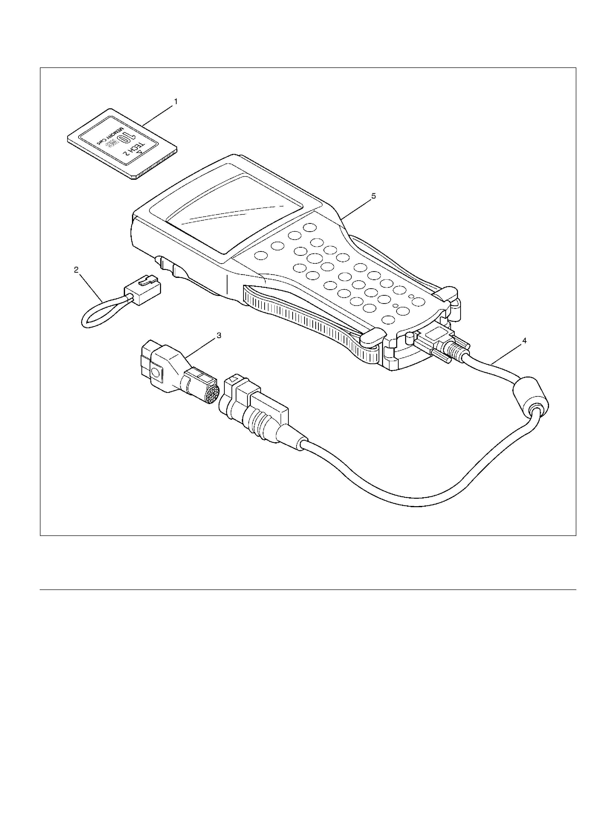
Legend
(1) P CM CIA Card
(2) RS 232 Loop Back Connector
(3) SAE 16/19 Ad apter
(4) DLC Cable
(5) Tech–2
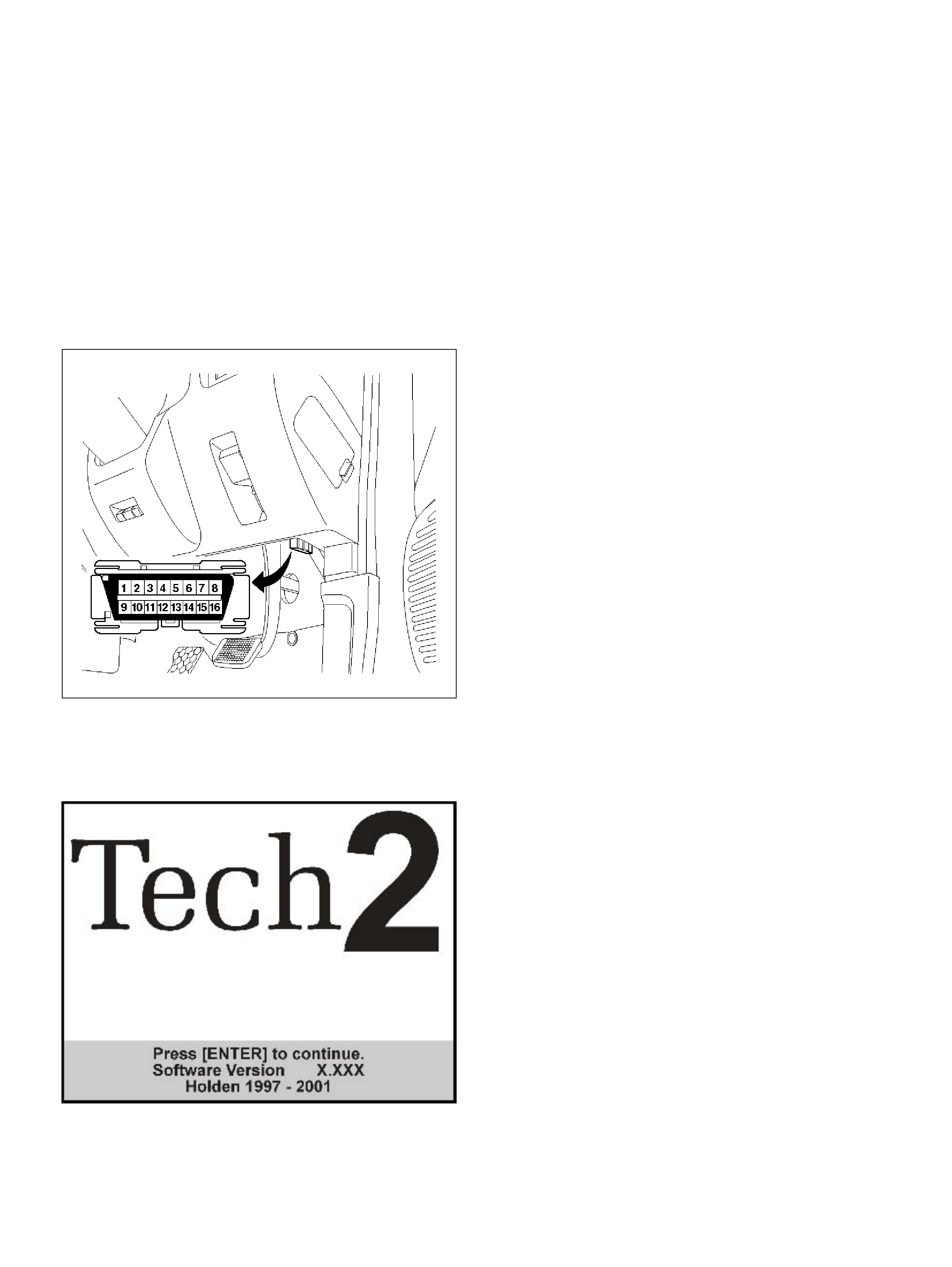
GETTING STARTED
• Before operating the Holden PCMCIA card with the
Tech 2, the following steps must be performed:
1. Insert the Holden system PCMCIA card (1) into the
Tech 2 (5).
2. Connect the SAE 16/19 adapter (3) to the DLC
cable (4).
3. Connect the DLC cable to the Tech 2 (5)
4. M ake sure the vehicle ignition is off.
5. Connect the Tech 2 SAE 16/19 adapter to the
vehicle DLC.
810RW317
6. Turn on the vehicle ignition.
7. Power the Tech 2 ON and verify the Tech 2 power
up display.
Refer to Section 0C-1 TECH 2 Diagnosis - Engine
Application for further procedures.
NOTE: T he RS232 Loop ba ck connector is only to us e
for diagnosis of Tech 2. Refer to user guide of the
TECH 2.
PRIMARY SYSTEM-BASED
DIAGNOSTIC
PRIMARY SYSTEM-BASED DIAGNOSTIC
There are primary system-based diagnostics which
evaluate system operation and its effect on vehicle
emissions. The primary system-based diagnostics are
listed below with a brief description of the diagnostic
function:
Oxygen Sensor Diagnosis
The fuel control heated oxygen sensors are diagnosed
for the following conditions:
• Heater performance (time to activity on cold start)
• Slow response
• Response time (time to switch R/L or L/R)
• Inactive signal (output steady at bias voltage –
approx . 450 mV)
• Sig nal fixed high
• S ign al fix ed lo w
If the oxygen sensor pigtail wiring, connector or terminal
are damaged, the entire oxygen sensor assembly must
be replaced. DO NOT attempt to repair the wiring,
connector or terminals. In order for the sensor to
function properly, it must have clean reference air
provided to it. This clean air reference is obtained by
way of the oxygen sensor wire(s). Any attempt to repa ir
the wires, connector or terminals could result in the
obstruction of the reference air and degrade oxygen
sensor performance. Refer to On-Vehicle Service,
Heated Oxyg en Senso rs in this section.
FU E L CONTR O L HEATED OX YGEN
SENSOR
The main function of the fuel control heated oxygen
sensors is to provide the control module with exhaust
stream oxygen content information to allow proper
fueling and maintain emissions within mandated levels.
After it reaches operating temperature, the sensor will
generate a voltage, inversely proportional to the amount
of oxygen present in the exhaust gases. The control
module uses the signal voltage from the fuel control
heated oxygen sensors while in closed loop to adjust
fuel inject or pulse wi dt h. While in c losed lo op, the P CM
can adjust fuel delivery to maintain an air/fuel ratio
which allows the best combination of emission control
and deriva bility. The fuel control heated oxy gen sens ors
are also used to determine catalyst effi ciency.

HO2S HEATER
Heated oxygen sensors are used to minimize the
amount of time required for closed loop fuel control to
begin operation and to allow accurate catalyst
monitoring. The oxygen sensor heater greatly
decreases the amount of time required for fuel control
sensors (Bank 1 HO2S 1 and Bank2 HO2S 1) to
become ac tiv e.

ON-BOARD DIAGNOSTIC (OBD) SYST EM CHECK 060R100062
Circuit Description
The on-board diagnostic system check is the starting
point for any derivability complaint diagnosis. Before
using this procedure, perform a careful visual/physical
check of the PCM and engine grounds for cleanliness
and tightness.
The on-board diagnostic system check is an organized
approach to identifying a problem created by an
electronic engine control system malfunction.
Diagn ostic Aids
An intermittent may be caused by a poor connection,
rubbed-through wire insulation or a wire broken inside
the insulation. Check for poor connections or a
damaged harness. Inspect the PCM harness and
connector for improper mating, broken locks, improperly
formed or damaged terminals, poor terminal-to-wire
conne ction , and damaged harness .
Test Description
Number(s) below refer to the step number(s) on the
Diagnostic Chart:
1.The MIL (“Check Engine lamp") should be “ON"
steady with the ignition “ON " and th e e ngine “OFF".
If not, the “No MIL" chart should be used to isolate
the ma lfunction.
3.Checks the Class 2 data circuit and ensures that the
PCM is able to transmit serial data.
4.This test ensures that the PCM is capable of
controlling the MIL (“Check Engine lamp") and the
MIL (“Check Engine lamp") driver circuit is not
shorted to ground.
5.This test ensures that the PCM is capable of
controlling the RPL (“Reduced Power lamp ") and the
RPL (“Reduced Power lamp") driver circuit is not
shorted to ground.
7.Check the DTCs (System ,Vol ts Supply circuit).
8.Check the DTCs (PCM{Software} detect Errors).
10.If the engine will not start, the Cranks But Will Not
Run chart should be used to diagnose the condition.
13.A Tech2 parameter which is not within the typical
range m ay help to isolate the area which is causing
the problem.
14.This vehicle is equipped with a PCM which utilizes
an electrically erasable programmable read only
memory (EEPROM). When the PCM is replaced, the
new PCM must be programmed. Refer to PCM
Replacement and Programming Procedures in
Powertrain Control Module (PCM) and Sensors of
t h is sect ion .

On-Board Diagnostic (OBD) System Check
Step Action Value(s) Yes No
1 1. Ignition “ON", engine “OFF".
2. Observe the malfunction indicator lamp (MIL or
“Check Engine lamp").
Is the MIL (“Check Engine lamp")“ON"? — Go to St ep 2
Go to No
MIL(“Check
Engi ne lamp" )
2 1. Ignition “ON", engine “OFF".
2. O bs erve the “Reduced Power lamp".
Is the RPL (“Reduced Power lamp") “ON" for 3
seconds? — G o to St ep 3
Go to No
RPL(“Reduced
Power lamp")
3 1 . Ig nit io n “ OFF" .
2 . Install Te ch2.
3. Ignition “ON".
4. Attempt to display PCM engine data with the
Tech2.
Does the Tech2 display PCM data? G o to St ep 4 Go to Step 12
4 1. Using th e Tech2 output tests funct ion, select MIL
(“Check Engine lamp") control and command the
MIL (“Check Engine lamp") “ON".
2. Observe the MIL (“Check Engine lamp").
Did the MIL (“Check Engine lamp") turn “ON"? — Go to Step 5
Go to
MIL(“Check
Engi ne lamp" )
On Steady
5 1. Using th e Tech2 output tests funct ion, select MIL
(“Check Engine lamp") control and command the
RPL (“Reduced Power lamp") “OFF".
2. Observe the RPL (“Reduced Power lamp").
Did the MIL (“Reduced Power lamp") turn “OFF"? — Go to Step 6
Go to
RPL(“Reduced
Power lamp")
On Steady
6 Select “Display DTCs" with the Tech2.
Are any DTCs stored? — Go to Step 7 Go to Step 11
7 Stored DTCs;
P0562, P 0563, P0601, P0602, P0604, P0 606, P1625,
P1635, P1 639, P1640, P1650
Are the any of the above DTCs stored? —
Go to
applicable DTC
table Go to Step 8
8 Stored DTCs;
P1514, P 1515, P15 16, P1523, P 1125, P 1290 , P1295,
P1299
Are the any of the above DTCs stored? —
Go to
applicable DTC
table Go to Step 9
9 Stored DTCs;
1. P0106, P0107, P1107, P0401, P1404, P0405,
P1120, P1221, P1515, P1516, P1275, P1635,
P1271, P12 73, P1285, P1 272
2. P0336, P0337, P1220, P1515, P1221, P1516,
P1280, P16 39, P1271, P1 272
Are the any of the above DTCs stored?
Go t o “Multiple
PCM
Information
sensor DTCs
Set" Go to Step 10
10 Attempt to start the engine.
Did the engine start and continue to run? —Go to Step 6
Go to Cranks
Bu t Will Not
Run

11 Compare P CM d ata values displayed on th e Tech2 to
the typical engine scan data values.
Are the displayed values normal or close to t he typical
values? —Go to Symptom
Refer to
indicated
Component
Syste m Checks
12 1. Ignition “OFF", disconnect the PCM.
2. Ignition “ON", engine “OFF".
3. Check the Class 2 data circuit for an open, short
to ground, or short t o vol t age. Also, check the DLC
ignition feed circu it for an op en or short to ground
and the DLC ground circuit for an open.
4. I f a problem is found, repair a s necess ary.
Was a problem found? — Go to St ep 2 Go to Step 13
13 1. Attempt to reprogram the PCM. Refer to
Powertrain Control Module (PCM) in On-Vehicle
Service.
2. Attempt to display PCM data with the Tech2.
Does the Tech2 display PCM engine data? — Go to Step 2 Go to Step 14
14 Replace the PCM.
Important: The replacement PCM must be
programmed. Refer to Section 0C-1 - Service
Program ming Syst em.
Important: Refer to Section 11 - Engin e Im mobiliser
System for the Immobiliser Programming procedure.
Important: Ensure the latest software program is
downloaded to the PCM.
Is the action complete ? —Go to St ep 2 —
Step Action Value(s) Yes No
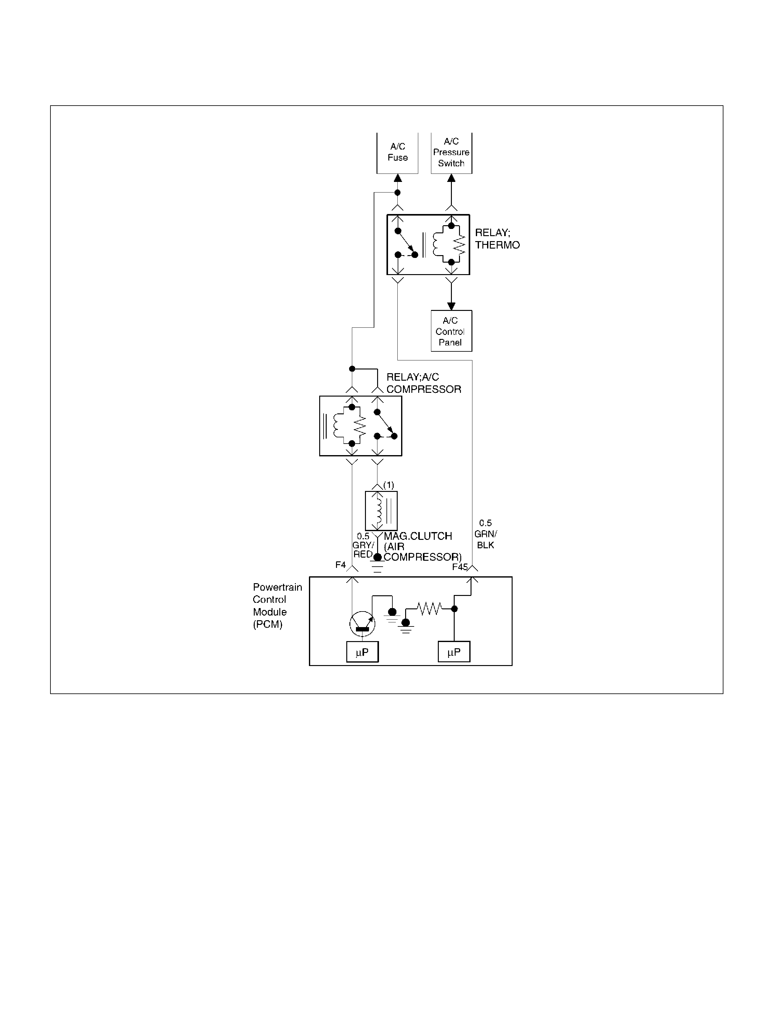
A/C CLUTCH CONTROL CIRCUIT DIAGNOSIS
060R100063
Circuit Description
W hen air conditioning and blo wer fan are selecte d, and
if the system has a sufficient refrigerant charge, a
12-vol t signal is supplied to the A/C request input of th e
powertrain control module (PCM). The A/C request
signal may be temporarily canceled during system
operati on b y the electro nic therm os tat in the evaporat or
case. When the A/C request signal is received by the
PCM, th e PCM supplies a ground from the compressor
clutch rela y if the e ngine operat ing con ditions are wi thin
acceptable ranges. With the A/C compressor relay
energized, voltage is supplied to the compressor clutch
coil.
The PCM will enable the compressor clutch to engage
whenever A/C has been selected with the engine
running, unless any of the following conditions are
present:
• T he ignition voltage is below 10.5 volts.
• The engine coolant temperature (ECT) is greater
than 119 °C (246 °F).
• The intake air temperature (IAT) is less than 5°C
(41°F).
• The power steering pressure switch signals a high
pressure condition during 3 seconds after ignition
“ON".
Diag nostic Ai ds
To diagnos e an the intermi ttent fault, check for following
conditions:
• Poor c onnection at the P CM–Inspe ct connections for
backed -out term inals, impr oper ma ting, broken locks,
improperly formed or damaged terminals, and poor
terminal-to-wire connection.
• Damaged harness–Inspect the wiring harness for
damage. If the harness appears to OK, observe the
A/C clutch while moving connectors and wiring

harnesses related to the A/C. A sudden clutch
malfunction will indicate the source of the intermittent
fault.
A/C Clutch Diagnosis
This chart should be used for diagnosing the electrical
portion of the A/C compressor clutch circuit. A Tech2
will be used in diagnosing the system. The Tech2 has
the ability to read the A/C request input to the PCM. The
Tech2 can display when the PCM has commanded the
A/C clutch “ON". The Tech2 should have the ability to
override the A/C request signal and energize the A/C
compressor relay.
Test Description
Important: Do not engage the A/C compressor clutch
with the engine running if an A/C mode is not selected
at the A/C control switch.
The numbers below refer to the step numbers on the
Diagnostic Chart:
3. This a test determine is the problem is with the
refrigerant system. If the switch is open, A/C
pressure gauges will be used to determine if the
pressure switch is faulty or if the system is partially
discharged or empty.
4. Although the normal complaint will be the A/C clutch
failing to engage, it is possible for a short circuit to
cause the clutch to run when A/C has not been
selected. This step is a test for that condition.
7. There is an extremely low probability that both relays
will fail at the same time, so the substitution process
is one way to check the A/C Thermostat relay. Use a
known good relay to do a substitution check.
A/C Clutch Control Circuit Diagnosis
Step Action Value(s) Yes No
1 Was the “On-Board Diagnostic (OBD) System Check"
performed? —Go to Step 2 Go to OBD
System Check
2 Are any other DTCs stored?
—
Go to the other
DTC chart(s)
firs t Go to Step 3
3 1. Disconnect the electrical connector at the
pressure switch located on the receiver/drier.
2. Use an ohmmeter to check continuity across the
pressure swit ch.
Is the pressure switch open? —
Go to Air
Conditioning to
diagnose t he
cause of the
open pressure
switch Go to Step 4
4Important: Before continuing with the diagnosis, the
following conditions mu st be met:
• The intake air temperature must be greater than
15°C. (60°F).
• The engine coolant temperature must be less than
119°C (246°F).
1. A/C “OFF".
2. Start th e engine and idle for 1 minute.
3. O bse rve the A/C compressor.
Is the A/C compressor clutch engaged even though A/
C has not been requested? — Go to Step 37 Go to S tep 5
5 1 . Idle the engine.
2. A/C “ON".
3. Blower “ON".
4. O bse rve the A/C compressor.
Is the A/C compressor magnetic clutch engaged? — Refer to
Diagnostic Aids Go to Step 6
6 1. Engine idling.
2. A/C “ON".
3. Blower “ON".
4. Observe the “A/C Request" display on the Tech2.
(Refer to the Miscellaneous test)
Does the tool “A/C Request" display indicate “Ye s"? — Go to Step 26 Go to Step 7

7 Temporarily substitute the A/C compressor relay in
place of the A/C thermostat relay, then repeat Step 5.
Did the “A/C Request " display indicate “Yes"? — Go to St ep 8 Go to Step 9
8 Replac e the original A/C thermostat rel ay.
Is the action complete ? — Verify r epair —
9 Does the blower operate? — Go to S tep 10 Go to Step 11
10 Repair the blower.
Is the action complete ? — Verify r epair —
11 Check for a faulty 10A A/C fuse in the underdash fuse
panel.
Was the 10A fuse OK ? — Go to S tep 13 Go to St ep 12
12 Check for short circuit and make repairs if necessary.
Replace the 10A A/C fuse.
Is the action complete ? — Verify r epair —
13 1. Remove the glove box to gain access to the A/C
thermostat.
2. Disconnect the thermostat connector.
3. Attach a fused jumper between ground and the
thermostat wire.
4. A/C “ON".
5. Blower “ON".
Dose A/C request indicate “YES" on the Tech2? — Go to Step 14 Go to St ep 17
14 1. Ignition “ON".
2. Use a DVM to check voltage at the electronic A/C
thermostat.
Was vol tage equal to the specified value? B+ Go to S t ep 17 Go to Step 15
15 Check for open wire between the thermostat and the
A/C switch.
Was the wire open? — Go to Step 16 Go to St ep 17
16 Repair the open wire between the therm ostat and the
A/C switch.
Is the action complete ? — Verify r epair —
17 Check for an open circuit between A/C thermostat
relay and PCM A/C request terminal (F45).
Was there an open c ircuit? — Go to Step 18 Go to St ep 19
18 Repair the open circuit between the PCM and A/C
thermostat relay.
Is the action complete ? — Verify r epair —
19 1. Ignition “ON".
2. Use a DVM to check voltage at the A/C pressure
switc h (BRN).
Was vol tage equal to the specified value? B+ Go to S t ep 21 Go to Step 20
20 Repair the open circuit between the 10A A/C fuse and
the pressure switch.
Is the action complete ? — Verify r epair —
21 Use an ohmmeter to check continuity between the
pressure switch and the A/C thermostat relay.
Was the circuit open? — Go to Step 22 Go to St ep 23
22 Repair the open circuit between the pressure switch
and the A/C thermostat relay.
Is the action complete ? — Verify r epair —
23 Check for damaged pin or terminal at F45 of the PCM.
Was a damaged pin or terminal found? — Go to St ep 24 Go to Step 25
Step Action Value(s) Yes No

24 Repair the damaged pin or terminal.
Is the action complete ? — Verify r epair —
25 Replace the PCM.
Important: The replacement PCM must be
programmed. Refer to On-Vehicle Service in
Powertrain Control Module Sensor s for procedures.
And also refer to latest Service Bulletin.
Check to se e if t he Latest software is released or not.
And then Down Load the LATEST PROGRAMMED
SOFTWARE to the replacement PCM.
Is the action complete ? — Verify r epair —
26 1. Remove the A/C compresso r rela y.
2. Ignition “ON".
3. Use a DVM to c heck volt age at bot h of the wires at
the A/C compresso r relay so cket.
Is the voltage equal to t he spec ified value? B+ Go to Step 28 Go to St ep 27
27 Repair the faulty wire between the A/C fuse and the A/
C compre ssor relay .
Is the action complete ? — Verify r epair —
28 1. A/C compresso r relay removed.
2. Engine idling.
3. A/C “ON".
4. Blower “ON".
5. Use a DVM to measure voltage between the wire
at the A/C compressor relay socket and battery±.
Did the DVM indicate the specified value? B+ Go to S tep 32 Go to St ep 29
29 Check for an open wire between PCM terminal F4 and
the A/C compressor re lay.
Was the wire open? — Go to Step 30 Go to St ep 31
30 Repair the open wire between the PCM and the A/C
compressor relay.
Is the action complete ? — Verify r epair —
31 Check for a damaged pin or terminal at F4 of the
PCM.
Was a damaged pin or a terminal found? — Go to Step 24 Go to St ep 25
32 1. A/C compresso r relay removed.
2. Connect a fused jumper at the A/C compressor
relay socket with eithe r wire.
3. Engine idling.
4. A/C “ON".
5. Blower “ON".
Did the compressor magnet ic clutch engage? — Go to Step 33 Go to St ep 34
33 Repair the A/C compressor relay.
Is the action complete ? — Verify r epair —
34 Check for an open circuit between the A/C
compressor relay and the A/C clutch.
Was an open circuit found? — Go to Step 35 Go to St ep 36
35 Repair the open circuit between the compressor
Clutch and the A/C compressor relay.
Is the action complete ? — Verify r epair —
36 Service the compressor clutch or replace the
compresso r due to a f aulty i nter nal overheat switch .
Is the action complete ? — Verify r epair —
Step Action Value(s) Yes No

ELECTRONIC IGNITION SYSTEM
DIAGNOSIS
If the engine cranks but will not run or immediately
stalls, the Engine Cranks But Will Not Start chart must
be used to determine if the failure is in the ignition
system or the fuel system. If DTC P0300 through
P0306, P0341, or P0336 is set, the appropriate
diagnostic trouble code chart must be used for
diagnosis.
If a misfire i s being experienced with no DTC set, refer
to the Symptoms section for diagnosis.
VI SUAL CHECK OF THE
EVAPORATIVE EM ISSION
CANISTER
• If the canister is cracked or damaged, replace the
canister.
• If fuel is leaking from the canister, replace the
can ister and check hose s and hose routing.
FUEL METERING SYSTEM CHECK
Some failures of the fuel metering system will result in
an “Engine Cranks But Will Not Run" symptom. If this
condition e xists, refer to the Cranks But Will Not Run
chart. This chart will determine if the prob lem is caused
by the ignition system, the PCM, or the fuel pump
electrical circuit.
Refer to Fuel System Electrical Test for the fuel
system wiring schematic.
If there is a fu el delivery problem, refer to
Fuel System Diagnosis, which diagnoses the fuel
injectors, the fuel pressure regulator, and the fuel pump.
If a malfunction occurs in the fuel metering system, it
usually results in either a rich HO2S signal or a lean
HO2S signal. This condition is indicated by the HO2S
voltage, which causes the PCM to change the fuel
calculation (fuel injector pulse width) based on the
HO2S reading. Changes made to the fuel calculation
will be indicated by a change in the long term fuel trim
values which can be m onitored with a Tech2. Ideal lon g
term fuel trim values are around 0%; for a lean HO2S
signal, the PCM will add fuel, resulting in a fuel trim
value abov e 0%. Som e variations in fuel t rim values are
normal because all en gines are not exactly the same. If
the evaporative emission canister purge is “ON", the
fuel trim may be as low as –38%. If the fuel trim v alues
are greater than +23% , refer to DTC P0131,
DTC P0151, DTC P0171, and DTC 1171 for items
which can cause a lean HO2S signal.
POWERTRAIN CONTROL MODULE
(PCM) DIAGNOSIS
To read and clear diagnostic trouble codes, use a
Tech2.
Important: Use of a Tech2 is recommended to clear
diagnostic trouble codes from the PCM memory.
Diagnostic troub le codes c an also be cleared by t urnin g
the ignition “OFF" and disconnecting the battery power
from the PCM for over 3 hours. Turning off the ignition
and disconnecting the battery power from the PCM will
cause all diagnostic information in the PCM memory to
be cleared. Therefore, all the diagnostic tests will have
to be re-run.
Since the PCM can have a failure which may aff ect only
one circuit, following the diagnostic procedures in this
37 1. Remove the A/C compresso r rela y.
2. Idle the engine.
Is the compressor clutch still engaged when A/C is not
selected? — Go to Step 38 Go to St ep 39
38 Repair the short to voltage between the A/C clutch
and A/C compressor relay.
Is the action complete ? — Verify r epair —
39 1. Reinsta ll the A/C c ompr e s s or relay.
2. Remove the A/C thermostat relay.
3. Engine idling.
Is the compressor clutch still engaged when A/C is not
selected? — Go to Step 40 Go to St ep 42
40 Use a DVM to check for a s hort to ground between the
A/C compressor relay and F4 of t he PC M.
Was a short detected? — Go to Step 41 Go to St ep 25
41 Repair the short to g round betwe en the P CM and A /C
compressor relay.
Is the action complete ? — Verify r epair —
42 Repair the short to ground between the A/C
thermostat relay and the electronic thermostat.
Is the action complete ? — Verify r epair —
Step Action Value(s) Yes No

section will determine which circuit has a problem and
where it is.
If a diagnost ic chart indicates that the PCM co nnections
or the PCM is the cause of a problem, and the PCM is
replaced, but this does not correct the problem, one of
the following may be the reason:
• There is a problem with the PCM terminal
con nections. The terminals m ay ha ve to be removed
from the connector in order to check them properly.
• EEPROM program is not correct for the application.
Incorrect components or reprogramming the PCM
with the wrong EEPROM program may cause a
mal function and may or may not set a DTC.
• The problem is intermittent. This means that the
problem is not present at the time the system is being
checked. In this case, refer to the Symptoms portion
of the man ual and m ake a careful physical inspec tion
of all component and wiring associated with the
af fe cte d system.
• There is a shorted solenoid, relay coil, or harness.
Solenoids and relays are turned “ON" and “OFF" by
the PCM using internal electronic switches called
drivers. A sh orted s olenoid, relay coil, or harness will
not damage the PCM but will cause the solenoid or
relay to be inoperative.
MULTIPLE PCM INFORMATION
SENS OR DTCS SET
Circuit Description
The po wertrain control module (PCM) monitors various
sensors to determine the engine operating condition s.
The PCM controls fuel delivery, spark advance,
transmission operation, and emission control device
operation based on the sensor inputs.
The PCM provides a sensor ground to all of the
sensors.
The P CM appl ies 5 volts through a pu ll-up resistor, and
determines the status of the following sensors by
monitoring the voltage present between the 5-volt
supply and the resistor:
• The engine coolant temperature (ECT) sensor
• T he intake air tem perature (IAT) sensor
• T he transmiss ion fluid temperatu re (TFT) sensor
The PCM provides the following sensors with a 5-volt
reference and a senso r ground signal:
1
• The exhaust gas recirculating (EGR) pintle position
sensor
• T he ma nifold absolute pressure (MAP) sensor
• T he throttle position (TP) sensor 1
• The accelerator position (AP) sensor 1
• The accelerator position (AP) sensor 3
2
• T he Crank position (CKP) sen sor
• T he throttle position (TP) sensor 2
• The accelerator position (AP) sensor 2
The PCM mo nitors the separate feedback signals from
these sensors in order to determine their operating
status.
Diag nostic Ai ds
Important: Be sure to inspect PCM and engine
grounds for being secure and clean.
A short to voltage in one of the sensor input circuits may
cause one or more of the following DTCs to be set:
• P0108, P1106
• P0406
• P1120, P1515, P122 1, P1516, P16 35
• P1275, P1639, P12 71, P1273
• P1285, P1272, P12 73
• P0336, P0337
• P1220, P1515, P12 21, P1515, P1516
• P1280, P1271, P12 72
Important: I f a se nsor input c ircuit has been s horted t o
voltage, ensure that the sensor is not damaged. A
damaged sensor will continue to indicate a high or low
voltage after the affected circuit has been repaired. If
the sensor has been damaged, replace it.
An open in the sensor ground circuit between the PCM
and the splice will cause one or more of the following
DTCs to be set:
• P0108, P1106
• P0406
• P1120, P1515, P122 1, P1516, P16 35
• P1275, P1639, P12 71, P1273
• P1285, P1272, P12 73
• P0336, P0337
• P1220, P1515, P12 21, P1515, P1516
• P1280, P1271, P12 72
A short to ground in the 5-volt reference A or B circuit
will c au se one or more of the followi ng DTCs to be set:
• P0106, P0107, P1107
• P0401, P1404, P04 05
• P1120, P1515, P122 1, P1516, P16 35
• P1275, P1639, P12 71, P1273
• P1285, P1272, P12 73
• P0336, P0337
• P1220, P1515, P12 21, P1515, P1516
• P1280, P1271, P12 72
Check for the following conditions:
•Poor connection at PCM. Inspect the harness
connectors for backed-out terminals, improper
mating, broken locks, improperly formed or damage
terminals, and a poor terminal-to-wire connection.
•Damaged harness. Inspect the wiring harness for
damage. If the harness is not damaged, observe an
affected sensor fs d isplayed value on the Tech 2 with
the ignition “ON" and the engine “OFF" while you
move the connectors and the wiring harnesses

related to the following sensors:
• MAP Sensor
•EGR
• TPS1/TPS2
• APS1/APS2/APS3
•CKP
MULTIPLE PCM INFORMATION SENSOR DTCS SET
Step Action Value(s) Yes No
1 Was the “On-Board (OBD) System Check"
performed? — G o to St ep 2 Go to OBD
System Check
2 1. T urn the ignition “OFF", disconnect the PCM.
2. Turn the ignition “ON" , c heck the 5 volt reference
1 and 2 circ ui t for the following conditions:
• A poor connection at the PCM.
• An open between the PCM connector and the
splice.
• A sho rt to ground.
• A shor t to vo lta ge.
Is there an open or short? — G o to St ep 3 Go to S tep 4
3 Repair the open or short.
Is the action complete ? — Verify r epair —
4 Check the sensor ground circuit for the following
conditions:
• A poor connection at the PCM or the affected
sensors.
• An open between the PCM connector and the
affected sensors.
Is there an open or a poor connection? — Go to Step 5 Go to Step 6
5 Repair the open or the poor connection.
Is the action complete ? — Verify r epair —
6 Following below the DTCs stored:
P1635, P1 639 —
Go to
applicable DTC
table Go to S tep 7
7 Measure the resistance below the items:
• EGR sensor supply circuit and ground circuit.
• Between MAP sensor supply circuit and EGR
Sensor supply c ircuit.
• Between MAP Sensor supply circuit and PCM
harn ess connector. (5Volt supply circuit)
Is the resistance near the specified value? 0 ΩGo to Step 9 Go to S tep 8
8 Locate and repair the open circuit in the MAP or EGR
sensor supply circuit.
Is the action complete ? — Verify r epair —
9 1. Disconnec t the MAP, and EGR con nector.
2. Igni tion “ON ".
3. Measure the resistance below the items:
• MA P sensor GND circuit.
• EGR GND circuit.
Does the voltage resistance near the specified value? 0 ΩGo to Step 11 Go to St ep 10
10 Locate and repair the short circuit in th e MAP or EGR
sensor signal or GND circuit.
Is the action complete ? — Verify r epair —
11 Measure the resistance below the items:
• CKP sensor supply circuit.
• Between CKP Sensor supply circuit and PCM
harn ess connector. (5Volt supply circuit)
Does the voltage resistance near the specified value? 0 ΩGo to Step 13 Go to St ep 12
12 Locate and repair the open circuit in the CKP sensor
supply circuit.
Is the action complete ? — Verify r epair —

EXHAUST GAS RECIRCULATION
(EGR) DIAGNOSIS
An EG R f low che ck diagno sis of the li near EGR sy stem
is covered by DTC P0401. Pintle position error
diagnosis is covered by DTC P0402, P0404, P1404,
P0405, P0406. If EGR diagnostic trouble codes P0401
and/or P0402, P0404, P1404, P0405, P0406 are
encou ntere d, refer to t he DTC charts.
ENGINE TECH2 DATA DEFINITIONS
AND RANGES
A/C CLUTCH – Tech2 Displays ON or OFF –
Indicates whether the PCM has commanded the A/C
clutch ON. Used in A/C system diagnostic.
A/C REQUE ST — Tech2 Di splays YES or NO —
Indicates the state of the A/C request input circuit from
the HVAC controls. The PCM uses the A/C request
signal to determine whether A/C compressor operation
is being requested.
AIR/FUEL RATIO — Tech2 Range 0.0-25.5 —
Air/fuel ratio indicates the PCM commanded value. In
closed loop, the air/fuel ratio should normally be
displayed around “14.2-14.7". A lower air/fuel ratio
indicates a richer commanded mixture, which may be
seen during power enrichment or TWC protection
modes. A higher air/fuel ratio indicates a leaner
commanded mixture. This can be seen during
deceleration fue l mode.
AP1 —Tech2 Rang e 0%-100% —
AP (accelerator pedal) angle is computed by the PCM
from the AP sensor voltage. AP angle should display
“13%" at idle and “85-89%" at wide open throttle.
AP2 —Tech2 Rang e 0%-100% —
AP (accelerator pedal) angle is computed by the PCM
from the AP sensor voltage. AP angle should display
“85-89%" at idle and “11-1 5%" at wide open thro ttle.
AP3 —Tech2 Rang e 0%-100% —
AP (accelerator pedal) angle is computed by the PCM
from the AP sensor voltage. AP angle should display
“85-89%" at idle and “32-36%" at wide open throttle.
BAROMETRIC PRESSURE — Tech2 Range 10-105
kPa/0.00-5.00 Volts —
The barometric pressure reading is determined from the
MAP sensor signal monitored during key up and wide
open throttle (WOT) conditions. The barometric
pressure is used to compensate for altitude differences
and is normally displayed around “61-104" depending
on altitude and baromet ric pressure.
13 1. Disconnec t the CKP sensor connec tor.
2. Igni tion “ON ".
3. M eas ure the vo ltage below the items:
• CKP sensor GND circuit and shiel d circuit.
Does the voltage resistance near the specified value? 0 ΩGo to Step 15 Go to St ep 14
14 Locate and repair the short circuit in the CKP sensor
signal or GND circuit.
Is the action complete ? — Verify r epair —
15 Are more of the following items for DTCs stored?
EGR, MAP, CK P, TPS, APS —
Go to
applicable DTC
table Go to Step 16
16 Replace the PCM.
Important: The replacement PCM must be
programmed. Refer to Section 0C-1 - Service
Program ming Syst em.
Important: Refer to Section 11 - Engin e Im mobiliser
System for the Immobiliser Programming procedure.
Important: Ensure the latest software program is
downloaded to the PCM.
Is the action complete ? —Go to OBD
System Check —
Step Action Value(s) Yes No

CHECK TRANS LAMP — AUT O TRANSMISSI ON —
Indicates the need to check for a DTC with the Tech 2
when the lamp is flashing 0.2 seconds ON and 0.2
seconds OFF.
DESIRED EGR POS. — Tech2 Range 0%-100% —
Represents the EGR pintle position that the PCM is
commanding.
DESIRED IDLE — Tech2 Range 0-3187 RPM —
The idle speed that the PCM is comm anding. The PCM
will compensate for various engine loads based on
engine coolant temperature, to keep the engine at the
desired speed.
ECT — (Engine Coolant Temp erature) Tech2 Rang e
–40°C to 151°C (–40°F to 304°F) —
The engine coolant temperature (ECT) is mounted in
the coolant stream and sends engine temperature
informat ion to the P CM. The PCM appl ies 5 volts t o th e
ECT sensor circuit. The sensor is a thermistor which
changes internal resistance as temperature changes.
When the sensor is cold (high resistance), the PCM
monitors a high signal voltage and interprets that as a
cold engine. As the sensor warms (decreasing
resistance), the voltage signal will decrease and the
PCM will interpret the lower voltage as a warm engine.
EGR DUTY CYCLE — Tech2 Range 0%-100% —
Represents th e EGR valve driver PWM signal from the
PCM. A duty cycle of 0% indicates that no EG R flow is
being commanded; a 100% duty cycle indicates
maximum EGR flow command ed.
EGR FEEDBACK — Tech2 R ang e 0.00-5.00 Vol ts —
Indicates the EGR pintle position sensor signal voltage
being monitored by the PCM. A low volta ge indicates a
fully extended pintle (closed valve); a voltage near 5
volts indicates a retracted pintle (open valve).
ENGINE LOAD — Tech2 Range 0%-100% —
Engine load is calculated by the PCM from engine
speed and MAF sensor readings. Engine load should
increase with an inc rease in RPM or air flow.
ENGINE RUN TIME — Tech2 Range
00:0 0:00-99:99:99 Hrs:M in:S ec —
Indicates the time elapsed since the engine was st arted.
If the eng ine i s s topped, engine run tim e will b e res et t o
00:00:00.
ENGIN E SPEED — Ran ge 0-9999 RP M —
Engine speed is computed by the PCM from the 58X
reference input. It should remain close to desired idle
under various eng ine loads with engine idling.
EVAP PURGE PWM — Tech2 Range 0%-100% —
Represents the PCM commanded PWM duty cycle of
the EVAP purge solenoid valve. “0%" displayed
indicates no purge; “100%" displayed indicates full
purge.
FUEL PUMP — Tech2 Dis plays ON or OFF —
Indicates the PCM commanded state of the fuel pump
relay dr iv er ci r cu it.
HO2S BANK 1, SEN. 1 — Tech2 Ran ge 0-1132 mV —
Represents the fuel control exhaust oxygen sensor
output voltage. Should fluctuate constantly within a
exhau st) while operating in closed loop.
HO2S BANK2, SEN. 1 —Tech2 Range 0-1132 mV—
Represents the fuel control exhaust oxygen sensor
output voltage. Should fluctuate constantly within a
range bet ween 10mV (lea n exhaus t) and 1000 m V (rich
exhau st) while operating in closed loop.
HO2S BANK 1, SEN. 1—Tech2 Displays NOT
READY or READY—
Indicates the status of the exhaust oxygen sen so r. The
Tech2 will indicate that the exhaust oxygen sensor is
ready when the PCM detects a fluctuating HO2S
voltage sufficient to allow closed loop operation. This
will not occur unless the exhaust oxygen sensor is
warmed up.
HO2S BANK 2, SEN. 1 — Tech2 Displays NOT
READY or READY —
Indicates the status of the exhaust oxygen sen so r. The
Tech2 will indicate that the exhaust oxygen sensor is
ready when the PCM detects a fluctuating HO2S
voltage sufficient to allow closed loop operation. This
will not occur unless the exhaust oxygen sensor is
warmed up.
IAT (INTAKE AI R T EMPER ATURE) — Te ch2 Range –
40°C to 151°C (–40°F to 304°F) —
The PCM converts the resistance of the intake air
temperature sensor to degrees. Intake air temperature
(IAT) is used by the PCM to adjust fuel delivery and
spark timing according to incoming air density.
IGNITION 1 — Tech2 Range 0-25.5 Volts —
This represents the system voltage measured by the
PCM at its ignition feed.
INJ. PULSE BANK 1/INJ. PULSE BANK 2 — Tech2
Range 0-1000 mse c. —
Indicates the amount of time the PCM is commanding
each injector “ON" during each engine cycle. A longer
injector pulse width wi ll cause more fuel to be delivered.
Injector pulse width should increase with increased
engine load.

LONG TERM FUEL TRIM BANK 1/BANK 2 —
The long term fuel trim is derived from the short term
fuel tri m values and represents a long term correction of
fuel delivery for the bank in question. A value of 0%
indicat es that fuel delive ry requires no compens ation to
maintain the PCM com manded ai r/ fuel ratio. A n egative
value significantly below 0% indicates that the fuel
system is rich and fuel delivery is being reduced
(decreased injector pulse width). A positive value
significantly greater than 0% indicates that a lean
condition exists and the PCM is compensating by
adding fuel (increased injector pulse width). Because
long term f uel t rim t ends to f ollow short term f uel t rim, a
value in the negative ra nge due to ca nister pu rge at idle
should not be considered unusual. Fuel trim values at
maximum authority may indicate an excessively rich or
lean syste m .
Fuel System STATUS — Tech2 Displays OPEN or
CLOSED —
“CLOSED" indicates that the PCM is controlling fuel
delivery ac cording to oxyge n sensor voltage. In “OPEN"
the PCM ignores the oxygen sensor voltage and bases
the am ount of fue l to be del ivered on T P senso r, engin e
coolant, and MAF sensor inputs only.
MAF — T ech2 Range 0.0-512 gm/s —
MAF (mass air flow) is the MAF input frequency
converted to grams of air per second. This indica tes the
amoun t of air entering the engine.
MAP — Tech2 Range 10-105 kPa (0.00-4.97 Volts) —
The manifold absolute pressure (MAP) sensor
measures the change in the intake manifold pressure
from engine load, EGR flow, and speed changes. As
intake manifold pressure increases, intake vacuum
decreases, resulting in a higher MAP sensor voltage
and kPa reading. The MAP sensor signal is used to
monitor intake manifold pressure changes during the
EGR flow test, to update the BARO reading , and as an
enabling factor for several of the diagnostics.
MIL — Tech2 Di splays ON or OFF —
Indicates the PCM com manded state of the malfunction
indicator lamp.
MISFIRE CUR. CYL. #1 /#2 /#3 /#4 / #5 / #6 — Tech2
Range 0-255 Counts —
The misfire current counters increase at a rate
according to the number of the possible misfires being
detected on each cylinder. The counters may normally
display some activity, but the activity should be nearly
equal for all the cyli nders .
MISFIRE CUR. CYL. #1 /#2 /#3 /#4 / #5 / #6 — Tech 2
Range 0-65535 Counts —
The misfire history counters display the relative level of
misfire that has been detected on each cylinder. The
misfire history counters will not update or show any
activity until a misf ire DTC (P0300) has become active.
MISFIRE FAILURES SINCE FIRST FAIL — Tech2
Range 0-65535 Counts —
Indicates the number of 200 crankshaft revolution
sample periods during which the level of misfire was
sufficiently high to report a fail.
MISFIRE PASSES SINCE FIRST FAIL — Tech2
Range 0-65535 Counts —
Indicates the number of 200 crankshaft revolution
sample periods during which the level of misfire was
suff iciently low to report a pass.
POWER ENRICHMENT — Tech2 Displays ACTIVE or
INACTIVE —
“ACTIVE" displayed indicates that the PCM has
detected conditions appropriate to operate in power
enrichment mode. The PCM will command power
enrichment mode when a large increase in throttle
position and load is detected. While in power
enrich ment mo de, the PCM will increas e the amount of
fuel delivered b y entering open lo op and i ncreasing th e
injector pulse width. This is done to prevent a possible
sag or hesitation from oc curring during accelerator.
SPARK — Tech2 Range –64° to 64° —
Displays the amount of spark advance being
comma nded by the PCM on the IC circuit.
START-UP ECT — Tech 2 Range –40°C to 151°C (–
40°F to 304°F) —
Indicates the engine coolant temperature at the time
that the vehicle was started. Used by the HO2S
diagnostic to determine if the last start-up was a cold
start.
START-UP IAT — Tech2 Range –40°C to 151°C (–
40°F to 304°F) —
Indicates the intake air temperature at the time that the
vehicle was started. Used by the HO2S diagnostic to
determine if the last start-u p was a cold start.
TOTAL MISFIRE CURRENT COUNT — Tec h 2 Range
0-255 —
Indicates the total number of cylinder firing events that
were detected as being misfires during the last 200
crankshaft revolution sample period.

TP — Tech2 Range 0%- 100% —
TP (throttle position) angle is computed by the PCM
from the TP sensor voltage. TP angle should display
“3-5%" at idle and “100%" at wide open throttle.
CATALYST PROTECTION MODE — Tech2 Displays
YES or NO —
“YES" displayed indicates that the PCM has detected
conditions appropriate to operate in TWC protection
mode. The PCM will decrease the air/fuel ratio to a
value that depends on mass air flow (higher mass air
flow = lower air/ fuel ratio).
WEAK CYLINDER — Tech2 Displays Cylinder
Number —
This indicates that the PCM has detected crankshaft
speed variations t hat indi cate 2 % or m ore c ylinde r firing
events are misfires.
TYPICAL SCAN DATA VALUES
Use the Typical Scan Data Values Table only after the
On-Board Diagnostic System Check has been
completed, no DTC(s) were noted, and you have
determined that the on-board diagnostics are
functioning properly. Tech2 values from a
properly-running engine may be used for comparison
with the engine you are diagnosing. The typical scan
data values represent values that would be seen on a
normall y-run ning engine.
NOTE: A Tech2 th at di splays faulty da ta should not be
used, and t he problem s hould be reported to the Tech2
manufacturer. Use of a faulty Tech2 can result in
misdiagnosis and unnecessary replacement of parts.
Only the parameters listed below are referred to in this
service manual for use in diagnosis. For further
information on using the Tech2 to diagnose the PCM
and related sensors, refer to the applicable reference
section listed below. If all values are within the typical
range described below, refer to the Symptoms section
for diagnosis.
Test Conditions
Engine running, lower radiator hose hot, transmission in
park or neutral, closed loop, accessories off, brake not
applied and air conditioning off.

3.2L V-6 Engine (Automatic an d Manual Transm is sion)
Te ch2
Parameter Data Li st Units
Displayed Typ ical Data
Values (IDLE) Typical Data
Values
(2500RPM)
Refer To
A/C Clutch Relay Engine O n/Off Off Off General Desc ription and
Operation, A/C Clutch
Circuit Operation
A/C Request Engi ne Yes/No No No General Desc ription and
Operation, A/C Requ est
Signal
Air/Fuel Ratio Engi ne Ratio: _ to 1 14.7 14.7 General Desc ription and
Operati on, Fuel System
Mete ring Purpos e
AP Sensor1 Engine Percent 11–13 35–4 0 General Description and
Operation
AP Sensor2 Engine Percent 87–88 60–65 General Description and
Operation
AP Sensor3 Engine Percent 87–88 50–57 General Description and
Operation
Barometric
Pressure Engine k P a 61-104 (depen ds
on altitude and
barometric
pressure)
61-104 (depe nds
on altitude and
barometric
pressure)
General Desc ription and
Operation
Brake Light
Switch Engine Open 0V /
Closed 12V Open 0V Open 0V Refer to Secti on 5
Check Trans
Lamp (Auto
Trans)
Engi ne O n/O ff Off Off 4L30-E Auto matic
Trans m ission Diagno sis
Cruise Main
Switch Engine Active/
Inactive Inactive Inactive Refer to Section 10
De c e l Fu el C u to ff E n g in e Activ e /
Inactive Inactive Inac tive Ge neral Desc ription and
Operati on, Deceleration
Mode
Desired EGR
Position Engi ne Perc ent 0% 0% General Desc ription and
Operation, EGR P intle
Position Sens or
Desired Idle
Speed Engi ne RP M 750 (AT )
700 (MT) — General Desc ription and
Operation
ECT (Engine
Coolant Temp) Engine Degrees C,
Degrees F 80-100°C
(176-212°F) 80-100°C
(176-212°F) General Description and
Operati on, Engine Coolant
Temperature (ECT) Sensor
EGR Closed
Pintle Po sition Engi ne Steps 20-40 20-40 General Desc ription and
Operation, EGR P intle
Position Sens or
EGR Duty Cycle Engi ne P ercent 0% 0% Ge neral Description and
Operation, Linear EG R
Operation and Results of
Incorrect Operation
EGR Feedbac k E ngi ne Volts 0.45-0.80 0.45-0. 80 —
EGR Normalized Engi ne P ercent 0% 0% —
Engine Load Engi ne Perc ent 2.0% - 5.5% 8. 0% - 16.0% General Desc ription and
Operati on, Mass Air Flow
(MAF) Sensor

T i me From Start Engine Sec Varies. Resets at
each engine start. Var i e s . R e se ts a t
each engine start. —
Engine Speed Engi ne RPM W ithin –50 to
+100 of “Desir ed
Idle"
Actual engine
speed —
EVAP Purge
Solenoid Engine P ercent 0% 0% Diagnosis, EVAP Emission
Canister Purge Valve
Check
F uel S ystem
Status Engi ne O pen Loop/
Closed Loop Closed Loop Clos ed Loo p General Description
Fuel Pump Engine On/Off On On Engine Fuel
HO2S Bank 1
Sen.1 (millivolts) O2 Sensor
Data Millivolts 50-950 changing
quickly 50-950, always
changing quickly General Desc ription and
Operati on, Fuel control
HO2S
HO2S Bank 2
Sen.1 (millivolts) O2 Sensor
Data Millivolts 50-950 changing
quickly 50-950 changing
quickly General Desc ription and
Operati on, Fuel Control
HO2S
HO2S Bank 1
Sen.1 (ready/not
ready)
O2 Sensor
Data Ready
Yes/No Ready
Yes Ready
Yes Ge neral Description and
Operati on, Fuel Control
HO2S; DTC: P0135
HO2S Bank 2
Sen.1 (ready/not
ready)
O2 Sensor
Data Ready
Yes/No Ready
Yes Ready
Yes Ge neral Description and
Operati on, Fuel Control
HO2S
HO2S Warm-Up
Time Bank 1
Sen.1
O2 Sensor
Data Seconds 25-45 25-45 General Description and
Operati on, Fuel Control
HO2S
HO2S Warm-Up
Time Bank 2
Sen.1
O2 Sensor
Data Seconds 25-45 25-45 General Description and
Operati on, Fuel Control
HO2S
IAT (Intake Air
Temp) Engine Degrees C,
Degrees F 0-100°C,
depends on
underhood
temperature
0-80°C, depends
on underhood
temperature
General Desc ription and
Operati on, Intake Air
Temperature (IAT) Sensor
Illumination
Switch Engine Closed 0V/
Open 12V Closed 0V Closed 0V Refer to Section 8
Ignition Vol tage Engine Volts 12.8-14. 1 12.8-14. 1 General Desc ription and
Operati on, Electronic
Ignition System
Inj. Pulse Bank 1 Engine M ill iseconds 2.0-4.0 2.5-4.0 General Description, Fuel
Meter ing, Fuel Injector
Inj. Pulse Bank 2 Engine M ill iseconds 2.0-4.0 2.5-4.0 General Description, Fuel
Meter ing, Fuel Injector
Knock Present Engine No/ Yes No No General Description and
ION Sensing Mo dule
Knock Signal Engine Percent 1∼41∼4 General Description and
ION Sensing Mo dule
Knock Sensor
Retard Engine °CA 0 0 General Description and
ION Sensing Mo dule
Knock Counter Engine Counts — — General Description
Te ch2
Parameter Data Li st Units
Displayed Typ ical Data
Values (IDLE) Typical Data
Values
(2500RPM)
Refer To

Long Term FT
Bank 1 (Long
Term Fuel Trim)
Misfire Counts and
Percentage 100 to 150
counts, –15% to
+15%
100 to 150
counts, –15% to
+15%
Diagnosis, Fuel Trim
System Monitor; DTCs:
P0171, P0 172
Long Term FT
Bank 2 (Long
Term Fuel Trim)
Misfire Counts and
Percentage 100 to 150
counts, –15% to
+15%
100 to 150
counts, –15% to
+15%
Diagnosis, Fuel Trim
System Monitor; DTCs:
P0171
MAF (Mass Air
Flow) Engi ne Grams per
second 2.8 5-6.6 5 9.5-16.5 General Desc ription and
Operation, MA F; DTCs:
P101, P0102, P0103
MAP kPa
(Manifold
Absolute
Pressure)
Engi ne Kil opascals 23-40 19-32 General Description and
Operati on, Manifold
Absolute Pressure (MAP)
Sensor; DTCs: P0106,
P0107, P0 108
Volts 0.65-1.32 0.46-1.10
MIL Engine On/Off Off Off On-Board Diagnostic
System Check
Misfire Cur. Cyl
#1 Misfire Counts 0-2 0-2 DTC P0300
Misfire Cur. Cyl
#2 Misfire Counts 0-2 0-2 DTC P0300
Misfire Cur. Cyl
#3 Misfire Counts 0-2 0-2 DTC P0300
Misfire Cur. Cyl
#4 Misfire Counts 0-2 0-2 DTC P0300
Misfire Cur. Cyl
#5 Misfire Counts 0-2 0-2 DTC P0300
Misfire Cur. Cyl
#6 Misfire Counts 0-2 0-2 DTC P0300
Misfire Hist. Cyl
#1 Misfire Counts 0 0 DTC P0300
Misfire Hist. Cyl
#2 Misfire Counts 0 0 DTC P0300
Misfire Hist. Cyl
#3 Misfire Counts 0 0 DTC P0300
Misfire Hist. Cyl
#4 Misfire Counts 0 0 DTC P0300
Misfire Hist. Cyl
#5 Misfire Counts 0 0 DTC P0300
Misfire Hist. Cyl
#6 Misfire Counts 0 0 DTC P0300
Mis fire Failur e s
Since First Fail Misfire Counts 0 0 DTC P0300
Misfire Passes
Since First Fail Misfire Counts 0 0 DTC P0300
PNP (Park/
Neutral Position) Engine P -N /
R-D-3-2-L P-N P-N 4L30-E Automatic
Trans m ission Diagno sis
Power
Enrichment E ngi ne NO /YES NO NO General Description and
Operation, Ac celerator
Mode
Te ch2
Parameter Data Li st Units
Displayed Typ ical Data
Values (IDLE) Typical Data
Values
(2500RPM)
Refer To

PSP Switch
(Power S teering
Pressure)
Engine Normal/Hi Normal Pressure Normal Pressure Refer to 2A Section
Spark (Advance) Engi ne Degrees
Before To p
Dead Center
15-22 34-44 General Description and
Operati on, Electronic
Ignition System
Start -Up ECT
(Engine Coolant
Temp)
Engine Degrees C,
Degrees F Depends on
engine coolant
temperature at
time of start -up
Depends on
engine coolant
tempera ture at
time of start-up
General Desc ription and
Operati on, Engine Coolant
Temperature (ECT) Sensor
Start- U p IAT
(Intak e Air Temp) Engine Degrees C,
Degrees F Depends on
intake air
temperature at
time of start -up
Depends on
intake air
tempera ture at
time of start-up
General Desc ription and
Operati on, Intake Air
Temperature (IAT) Sensor
Total Mis fire
Current Count Misfire Counts 0-5 0-5 DTC P0300
TP Sensor 1
(Throttle Position
Sensor 1)
Engi ne Perc entage 8–12 28–36 General Description and
Operation, Throttle Position
(TP) Sensor
TP Sensor 2
(Throttle Position
Sensor 2)
Engi ne Perc entage 8–12 28–36 General Description and
Operation, Throttle Position
(TP) Sensor
Throttle at Idle Engine No/ Yes Yes No Ge neral Description and
Operation, Throttle Position
(TP) Sensor
Vehicle Speed Engi ne M P H / km/h 0 0 4L30-E Automatic
Trans m ission Diagno sis
Weak Cylinder Misfire Cylinder # — — DTC P0300
Te ch2
Parameter Data Li st Units
Displayed Typ ical Data
Values (IDLE) Typical Data
Values
(2500RPM)
Refer To
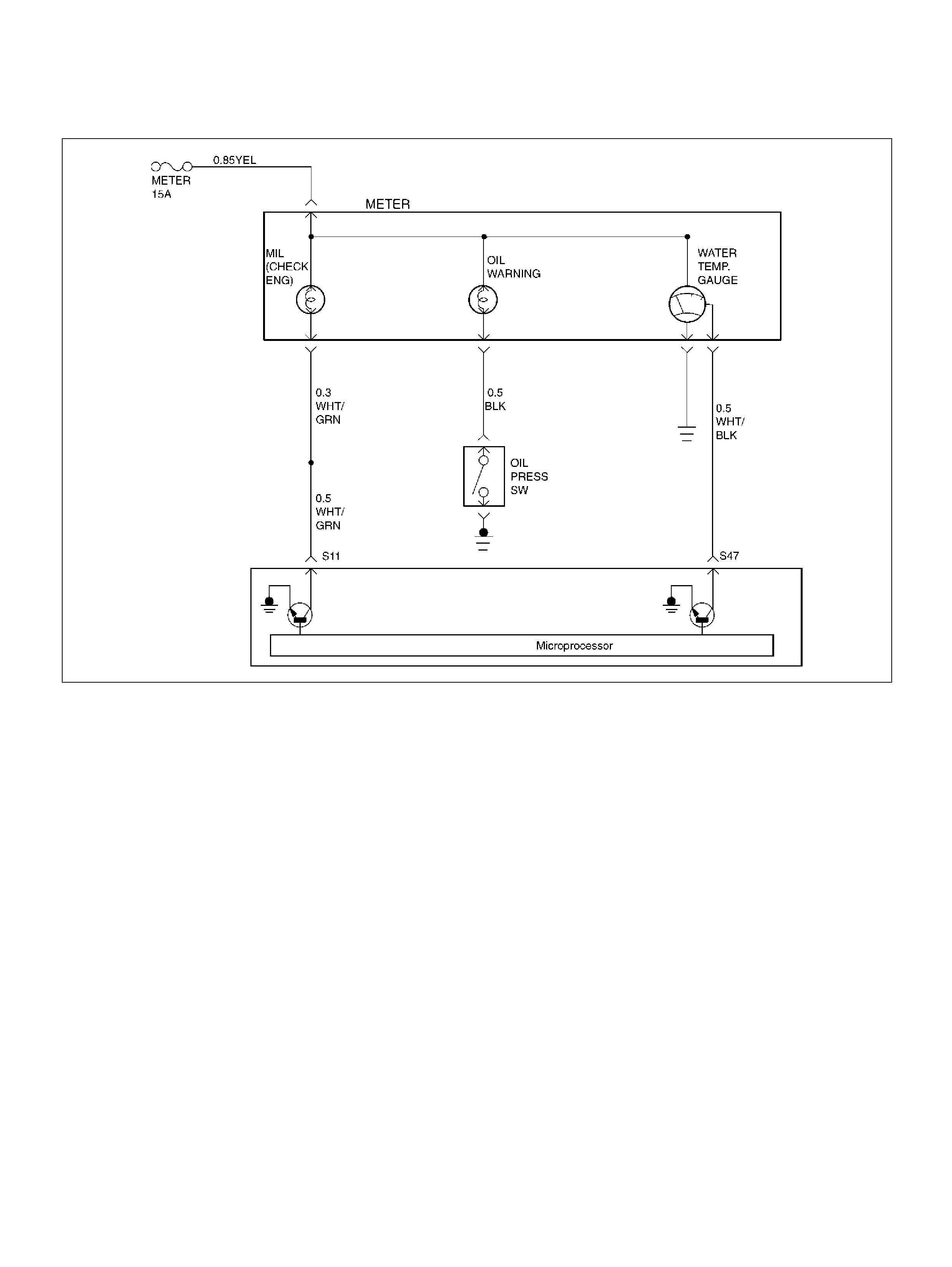
NO MALFUNCTION INDICATOR LAMP (MIL)
060R100064
Circuit Description
The “Check Engine" lamp (MIL) should always be
illuminated and steady with the ignition “ON" and the
engine stopped. Ignition feed voltage is supplied to the
MIL bulb through the meter fuse. The powertrain contro l
module (PCM) turns the MIL “ON" by grounding the MIL
driver circuit.
Diagn ostic Aids
An intermittent MIL may be cased by a poor connection,
rubbed-through wire insulation, or a wire broken inside
the insulation. Check for the followi ng items:
• Inspect the PCM harness and connections for
impro per mating, broken locks, improperly formed or
damaged terminals, poor terminal-to-wire connection,
and damaged harness.
• If the engine runs OK, check for a faulty light bulb, an
open in the MIL driver circuit, or an open in the
instrument cluster ignition feed.
• If the engine cranks but will not run, check for an
open PCM ignition or battery fee d, or a poor PCM to
engine ground.
Test Descr iption
Number(s) below refer to the step number(s) on the
Diagnostic Chart.
2. A “No MIL" condition accompanied by a no-start
condition suggests a faulty PCM ignition feed or
battery feed circuit.
9. Using a test light connected to B+, probe eac h o f th e
PCM grou nd t erm inal s t o en su re t hat a good ground
is present. Refer to PCM Terminal End View for
terminal locations of the PCM ground circuits.
12. In this step, temporarily substitute a known good
relay for the PCM relay. The horn relay is nearby,
and it can be verified as “good" simply by honking
the horn. Replace the horn relay after completing
this step.
17. This vehicle is equipped with a PCM which utilizes
an electrically erasable programmable read only
memory (EEPROM). When the PCM is replaced, the
new PCM must be programmed. Refer to
PCM Replacement and Programming Procedures
in Powertrain Control Module (PCM ) and Se nsors.

No Malfunction Indicator Lamp (MIL)
Step Action Value(s) Yes No
1 Was the “On-Board Diagnostic (OBD) System Check"
performed? —Go to Step 2 Go to OBD
System Check
2 Attempt to start the engine.
Does the engine start? — G o to St ep 3 Go to S tep 6
3 Check the meter fuse for the instrument cluster
ignition feed circuit.
Is the fuse OK? — Go to Step 4 Go to Step 16
4 Ignition “ON", probe the ignition feed circuit at the
cluster connector with a test ligh t to ground.
Is the test light “ON" ? — Go to Step 5 Go to Step 13
5 1 . Ig nit io n “ OFF" .
2. Disconnect the PCM.
3. Jumper the MIL driver circuit at the PCM
connector to ground.
4. Ignition “ON".
Is the MIL “ON"? — G o to St ep 10 Go to Step 11
6 Check the PCM ignition feed and battery feed fuses
(15 A engine fuse and 15 A PCM fuse).
Are both fuses OK? — Go to St ep 7 Go to St ep 15
7 1 . Ig nit io n “ OFF" .
2. Disconnect the PCM.
3. Ignition “ON".
4. Probe the ignition feed ci rcuit at th e PC M harness
connector with a test light to ground.
Is the test light “ON" ? — Go to Step 8 Go to Step 12
8 Probe the battery feed circuit at the PCM harness
connector w ith a test light to ground.
Is the test light “ON" ? — Go to Step 9 Go to Step 14
9 Check for a faulty PCM ground connect ion.
Was a problem found? — Verify repair Go to Step 10
10 Check for damaged termi nals at the PCM.
Was a problem found? — Verify repair Go to Step 17
11 Check for an open MIL driver circuit between the PCM
and the MIL.
Was a problem found? — Verify repair Go to Step 18
12 Substitute a known “good" relay for the PCM main
relay.
Was the malfunction fixed? — Verify repair Go to Step 13
13 Repair the open in the ignition feed circuit.
Is the action complete ? — Verify r epair —
14 Locate and repair the open PCM battery feed circuit.
Is the action complete ? — Verify r epair —

15 Locate and repair the short to ground in the PCM
ignition feed circuit or PCM battery feed circuit.
Is the action complete ? — Verify r epair —
16 Locate and repair the short to ground in the ignition
feed circuit to the instrument cluster, and replace the
fuse.
Is the action complete ? — Verify r epair —
17 Replace the PCM.
Important: The replacement PCM must be
programmed. Refer to Section 0C-1 - Service
Program ming Syst em.
Important: Refer to Section 11 - Engin e Im mobiliser
System for the Immobiliser Programming procedure.
Important: Ensure the latest software program is
downloaded to the PCM.
Is the action complete ? — Verify r epair —
18 Check the MIL driver circuit for a poor connection at
the instrument panel connector.
Was a problem found?
— Verify repair
Go to
Instrument
Panel in
Electrical
Diagnosis
Step Action Value(s) Yes No
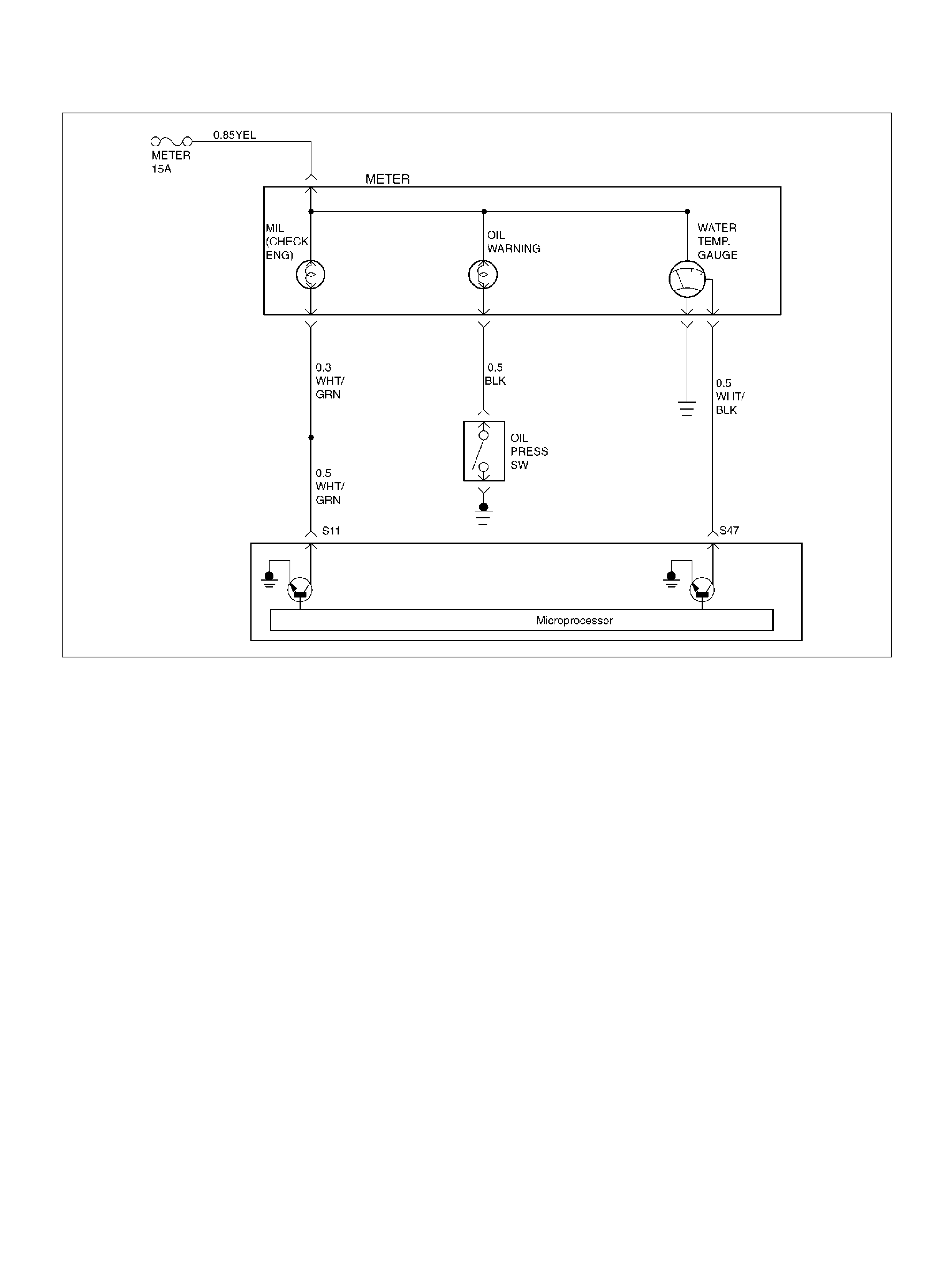
MALFUNCTION INDICATOR LAMP (MIL) “ON" STEADY
060R100064
Circuit description
The malfunction indicator lamp (MIL) should always be
illuminated and steady with ignition “ON" and the engine
stopped. Ignition feed volta ge is supp lied directly to the
MIL indicator. The powertrain control module (PCM)
turns the MIL “ON" by grounding the MIL driver circuit.
The MIL should not remain “ON" with the engine
running and no DTC(s) set. A steady MIL with the
engine running and no DTC(s) suggests a short to
ground in the MIL driver circuit.
Diagn ostic Aids
An intermittent may be caused by a poor connection,
rubbed-through wire insulation, or a wire broken inside
the insulation. Check for the followi ng items:
• Poor connection or damaged harness – Inspect the
PCM harness and connectors for improper mating,
broken locks, improperly formed or damaged
terminals, poor terminal-to-wire connection, and
dama ged harnes s.
Test Descr iption
Number(s) below refer to the step number(s) on the
Diagnostic Chart.
2. If the MIL does not remain “ON" when the PCM is
disconnected, the MIL driver wiring is not faulty.
3. If the MIL driver circuit is OK, the instrument panel
clu ste r is faulty.
6. This vehicle is equipped with a PCM which utilizes an
electrically erasable programmable read only
memory (EEPROM). When the PCM is replaced, the
new PCM must be programmed. Refer to
PCM Replacement and Programming Procedures
in Powertrain Control Module (PCM ) and Se nsors.

Malfunction Indicator Lamp (MIL) “ON" Steady
Step Action Value(s) Yes No
1 Was the “On-Board diagnostic (OBD) System Check"
performed? —Go to Step 2 Go to OBD
System Check
2 1. Ignition “OFF", disconne ct PCM.
2. Ignition “ON", observe the MIL (Service Engine
Soon lamp).
Is the MIL “ON"? — Go to Step 3 Go to S tep 5
3 1. Ignition “OFF", disconnect the instrument panel
cluster.
2. Check the MIL driver circuit between the PCM and
the instrument panel cluster for a short to ground.
3. If a problem is found, repair as necessary.
Was the M IL driver circuit shorted to ground? — Go to OBD
System Check Go to Step 4
4 Replac e the instrume nt panel cluster.
Is the action complete ? —Go to OBD
System Check —
5 1. Ignition “OFF", reconnect the PCM.
2. Ignition “ON", reprogram the EEPROM. Refer to
On-Vehicle Service in Powertrain Control Module
and Sensors fo r pr ocedu res.
3. Using the Tech 2 output controls function, select
MIL dash lamp control and command the MIL
“OFF". (Refer to the Miscellaneous test)
Did the MIL turn “OFF"? — Go to OBD
System Check Go to Step 6
6 Replace the PCM.
Important: The replacement PCM must be
programmed. Refer to Section 0C-1 - Service
Program ming Syst em.
Important: Refer to Section 11 - Engin e Im mobiliser
System for the Immobiliser Programming procedure.
Important: Ensure the latest software program is
downloaded to the PCM.
Is the action complete ? —Go to OBD
System Check —
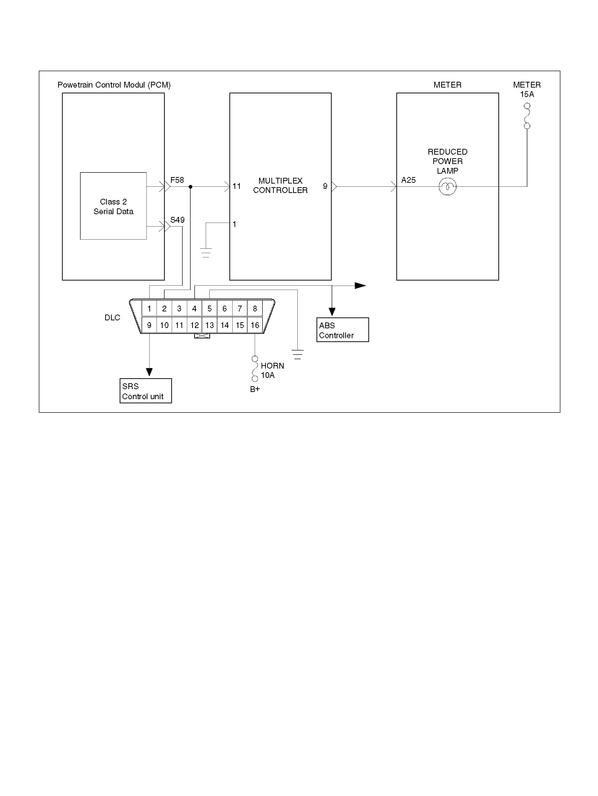
NO REDUCED POWER LAMP (RPL)
060R100065
Circuit Description
The Reduced Power lamp (RPL) should be illuminated
during 3 seconds with the ignition “ON" and the engine
stopped. Ignition feed voltage is supplied to the RPL
bulb through the meter fuse. The powertrain control
module (PCM) orderes the RPL “ON" signal for
Multiplex Control Unit. When Multiplex Control Unit is
received RPL “ON" signal that turn RPL “ON" by
grounding the R PL driver circuit.
Diagn ostic Aids
An intermittent RPL may be caused by a poor
connection, rubbed-through wire insulation, or a wire
broken inside the insulation. Check for the following
items:
• Inspect the PCM and Multiplex Control Unit harness
and connections for improper mating, broken locks,
improperly formed or damaged terminals, poor
terminal to wire connection, and damaged harness.
• If the engine runs OK, check for a faulty light bulb, an
open in the MIL driver circuit, or an open in the
instrument cluster ignition feed.
• If the engine cranks but will not run, check for an
open PCM ignition or battery fee d, or a poor PCM to
engine ground.
Test Descr iption
Number(s) below refer to the step number(s) on the
Diagnostic Chart.
2. A “No RPL" condition accompanied by a no-start
condition suggests a faulty PCM ignition feed or
battery feed circuit.
9. Using a test light connected to B+, probe eac h o f th e
Multiplex Control Unit ground terminals to ensure
that a good ground is present. Refer to
Multiplex Control Unit Terminal End View for
terminal locations of the Unit Terminal End View for
terminal locations of the Multiplex Control Unit
ground circuits.
12.Using a test light connect ed to B+, probe each of the
PCM grou nd t erm inal s t o en su re t hat a good ground
is present. Refer to PCM Terminal End View for
terminal locations of the PCM ground circuits.
21.In this step, temporarily substitute a known good
relay for the PCM relay. The horn relay is nearby,
and it can be verified as “good" simply by honking
the horn. Replace the horn relay after completing
this step.
24.This vehicle is equipped with a PCM which utilizes
an electrically erasable programmable read only
memory (EEPROM). When the PCM is replaced, the
new PCM must be programmed. Refer to
PCM Replacement and Programming Procedures
in Powertrain Control Module (PCM ) and Se nsors.
GND
A7

No Reduced Power Lamp (RPL)
Step Action Value(s) Yes No
1 Was the “On-Board Diagnostic (OBD) System Check"
Performed? —Go to Step 2 Go to OBD
System Check
2 Attempt to start the engine.
Does the engine start? — G o to St ep 3 Go to Step 11
3 Check the following fuses:
MAIN(100A), B+1(60A), B+2(50A), METER(15A),
ECM(15A) , ENGINE(15A)
Was a problem found? — Go to St ep 14 Go to Step 4
4 1. Ignition "OFF".
2. Disconnect the cluster meter connector.
3. Ignition “ON", Probe the i gnition feed circuit at the
cluster connector with a test light to ground.
Is the test light “ON" ? — Go to Step 5 Go to Step 15
5 1 . Ig nit io n “ OFF" .
2. Disconnect the Multiplex Control Unit.
3. Check the circuit (Lamp driver Circuit) between
PCM and Multiplex Control Unit.
Was a problem found? — Go to St ep 16 Go to Step 6
6 1. Reconne ct the cluster meter connector.
2. Disconnect the Multiplex Control Unit.
3. Jumper the RPL driver circuit at the Multiplex
Control Unit connector to ground.
4. Ignition “ON".
Is the RPL “ON"? — G o to Step 7
Go to
Instrument
Panel in
Electrical
Diagnosis
7 1 . Ig nit io n “ OFF" .
2. Probe the ignition feed circuit at the Multiplex
Control Unit connector with a test light to ground.
3. Ignition “ON".
Is the test light “ON" ? — Go to Step 8 Go to Step 17
8 1 . Ig nit io n “ OFF" .
2. Disconnect the PCM.
3. Check the circuit (Lamp driver Circuit) between
PCM and Multiplex Control Unit.
Was a problem found? — Go to St ep 18 Go to Step 9
9 Check the Multiplex Control Unit ground connection
and circuit.
Was a problem found? — Go to St ep 19 Go to Step 10
10 Check for damaged terminals at the Multiplex Cont rol
Unit.
Was a problem found? — Go to St ep 20 Go to S tep 11
11 1. Ignition “ON".
2. Probe the ignition feed ci rcuit at th e PC M harness
connector with a test light to ground.
Is the test light “ON "? — G o to Step 12 Go to Step 21
12 1. Ignition “OFF".
2. Check for a faulty PCM ground connection and
Circuit.
Was a problem found? — Go to St ep 23 Go to Step 13
13 Check for damaged termi nals at the PCM.
Was a problem found? — Go to St ep 24 Go to Step 25
14 Replace the fuse.
Is the action complete ? — Verify r epair —

15 Locate an d repair the cluster m eter battery feed open
circuit.
Is the action complete ? — Verify r epair —
16 Locate and repair the circuit between cluster meter
and Multiplex Control Unit open circuit.
Is the action complete ? — Verify r epair —
17 Locate and repair the circuit Multiplex Control Unit
battery feed open circuit.
Is the action complete ? — Verify r epair —
18 Locate and repair the between Multiplex Control Unit
and PCM open circuit.
Is the action complete ? — Verify r epair —
19 Locate an d repair the ground connection for M ultiplex
Control Unit circuit.
Is the action complete ? — Verify r epair —
20 Replace the Multiplex Control Unit. circuit.
Is the action complete ? — Verify r epair —
21 Substitute a known “good" relay for the PCM main
relay.
Was the malfunction fixed? — Verify repair Go to Step 22
22 Repair the open in the ignition feed circuit.
Is the action complete ? — Verify r epair —
23 Locate and repair the ground connection for PCM
circuit.
Is the action complete ? — Verify r epair —
24 Replace the PCM.
Important: The replacement PCM must be
programmed.
Refer to O N-Veh icle Service in Power Control Mo dule
and Sensors for procedures.
And also refer to latest Service Bulletin.
Check to see if the latest software is released or not.
And then Down Load the LATEST PROGRAMMED
SOFTWARE to the replacement PCM.
Is the action complete ? — Verify r epair —
25 1. Ignition “OFF".
2. Reconnect all connectors.
3. Install the Tech2.
4. Ignition “ON".
5. Using the Tech2 output controls function, select
RPL dash lamp control and command the RPL
“ON". (Refer to the Miscellaneous test)
Did the RPL turn “ON"? — Verify repair Go to St ep 26
26 1. Ignition “OFF".
2. Disconnect the PCM.
3. Check the circuit (DLC line) between PCM and
DLC.
Was a problem found? — Go to St ep 27 Go to Step 24
27 Locate and repair the circuit between PCM and DLC.
Is the action comple te ? — Go to St ep 25 —
Step Action Value(s) Yes No

REDUCED POWER LAMP (RPL) “ON" STEADY
060R100065
Circuit Description
The Reduced Power lamp (RPL) should be illuminated
during 3 seconds with the ignition “ON" and the engine
stopped. Ignition feed voltage is supplied to the RPL
bulb through the meter fuse. The powertrain control
module (PCM) orderes the RPL “ON" signal for
Multiplex Control Unit. When Multiplex Control Unit is
received RPL “ON" signal that turn RPL “ON" by
grounding the R PL driver circuit.
The RPL should not remain “ON" with the engine
running and no DTC(s) set. A steady RPL with the
engine running and no DTC(s) suggests a short to
ground in the RPL driver circuit.
Diagn ostic Aids
An intermittent RPL may be caused by a poor
connection, rubbed through wire insulation, or a wire
broken inside the insulation. Check for the following
items:
• Poor connection or damaged harness - Inspect the
PCM harness and connectors for improper mating,
broken locks, improperly formed or damaged
terminals, poor terminal to wire connection, and
dama ged harnes s.
• C ontamination of the APS with dust or grease, which
affects the resistance values of APS1 & APS2
Test Descr iption
Number(s) below refer to the step number(s) on the
Diagnostic Chart.
2. If the RPL does n ot remain “ON" when the Multiplex
Control Unit is disconnected, the RPL driver wiring is
no t fa ulty.
3. If the RPL driver circuit is OK, the instrument panel
clu ste r is faulty.
10. This vehicle is equipped with a PCM which utilizes
an electrically erasable programmable read only
memory (EEPROM). When the PCM is replaced, the
new PCM must be programmed. Refer to
PCM Replacement and Programming Procedures
in Powertrain Control Module (PCM ) and Se nsors.
GND
A7

Reduced Power Lamp (RPL) “ON" Steady
Step Action Value(s) Yes No
1 Was the “On-Board Diagnostic (OBD) System Check"
performed? —Go to Step 2 Go to OBD
System Check
2 1. Ignition “OFF", disconnect Multi plex Control Unit.
2. Ignition “ON", observe the RPL (Reduced Power
Lamp).
Is the RPL “ON"? — G o to Step 3 Go to Step 4
3 1. Ignition “OFF", disconnect the instrument panel
cluster.
2. Check the RPL driver ci rcuit bet ween the Multiplex
Control Unit and t he i nstrument panel cl uster for a
short to ground.
3. If a problem is found, repair as necessary.
Was the RPL driver circuit shorted to ground? — Verify repair Go to Step 4
4 1. Replace the Multiplex Control Unit.
2. Install the Tech2
3. Ignition “ON".
4. Using the Tech2 output controls function, select
RPL dash lamp control and command the RPL
“OFF". (Refer to the Miscellaneous test)
Did the MIL turn “OFF"? — Verify repair Go to S tep 5
5 1 . Ig nit io n “ OFF" .
2. Disconnect the PCM.
3. Check the circuit (Lamp driver Circuit) between
PCM and Multiplex Control Unit.
Was a problem found? — Go to St ep 6 Go to Step 7
6 Locate and repair the circuit between Multiplex
Control Unit and PCM open circuit.
Is the action complete ? — Go to Step 7 —
7 1. Instal l th e Tec h2
2. Ignition “ON".
3. Using the Tech2 output controls function, select
RPL dash lamp control and command the RPL
“OFF". (Refer to the Miscellaneous test)
Did the MIL turn “OFF"? — Go to Verify
repair Go to S tep 8
8 1. Ignition "OFF".
2. Disconnect the PCM.
3. Check the circuit (DLC line) between PCM and
DLC.
Was a problem found? — Go to St ep 9 Go to Step 10
9 Locate and repair the circuit bet ween P CM and DLC.
Is the action complete ? — Go to Step 2 —
10 Replace the PCM.
Important: The replacement PCM must be
programmed. Refer to Section 0C-1 - Service
Program ming Syst em.
Important: Refer to Section 11 - Engin e Im mobiliser
System for the Immobiliser Programming procedure.
Important: Ensure the latest software program is
downloaded to the PCM.
Is the action complete ? —Go to OBD
System Check —
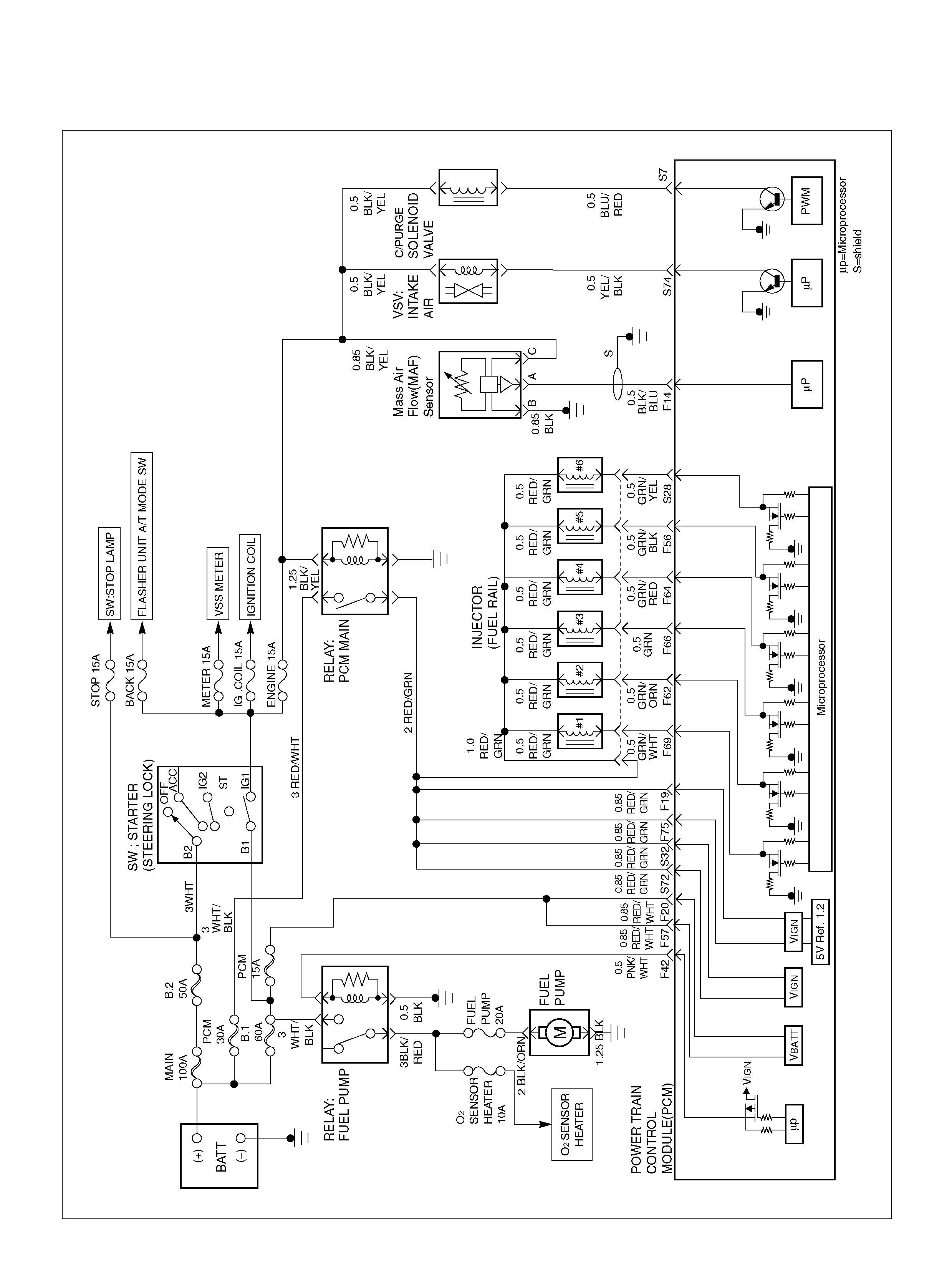
ENGINE CRANKS BUT WILL NOT RUN
060R100121
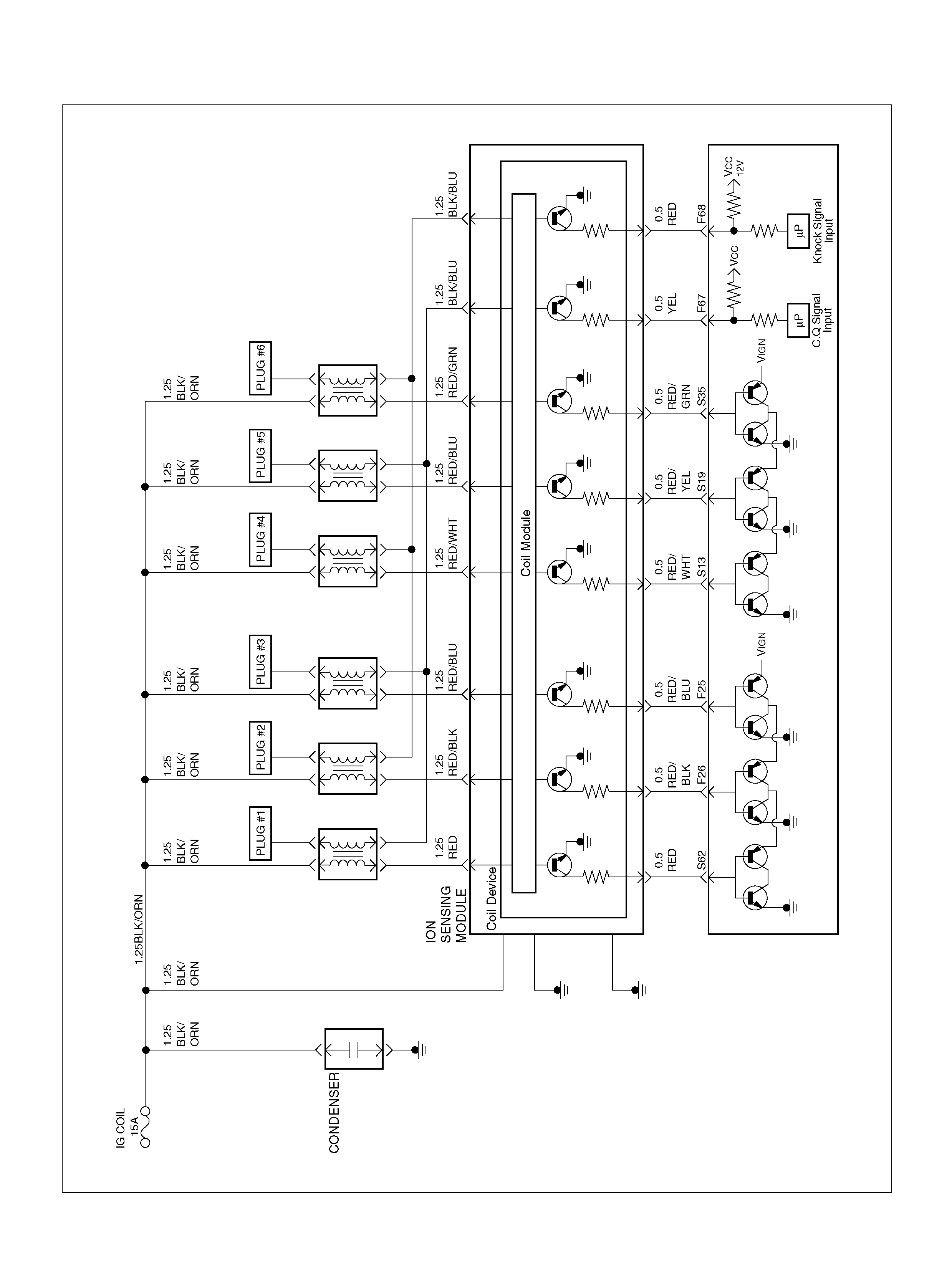
060R100122

Circuit Description
The electronic Ignition system uses a coil -at-plug
method of spark distribution. In this type of ignition
system, the powertrain control module (PCM) triggers
the correct driver outside the Ignition Current Sense
System (ICSS), which then triggers the correct ignition
coil based on the 58X signal received from the
crankshaft position sensor (CKP). The spark plug
connected to the coil fires when the ICSS opens the
ground circuit for the coil's primary circ uit.
During crank, the PCM monitors the CKP 58X signal.
The CKP signal is used to determ ine whic h cylinder will
fire first. After the CKP 58X signal has been processed
by the PCM, it will command all six injectors to allow a
priming shot of fuel for all the cylinders. After the
priming, the injectors are left “OFF" during the next six
58X reference pulses from the CKP. This allows each
cylinder a c hance to use the fuel from the priming sho t.
During this waiting been rec eived by the PC M. Th e IO N
sensor signal allows the PCM to operate the injectors
sequentially based on camshaft position. If the camshaft
position signal is not present at start - up, the PCM will
begin seque ntial fuel de liv ery with a 1 -in-6 chanc e that
fuel delivery is correct.
The engine w ill ru n wit hout a IO N s ensor sign al, but wil l
set a DTC code.
Diagn ostic Aids
An intermittent problem may be caused by a poor
connection, rubbed - through wire insulation or a wire
broken inside the insulation. Check for the following
items:
• Poor connection or damaged harness-Inspect the
PCM harness and connectors for improper mating,
broken locks, improperly formed or damaged
terminals, poor terminal-to-wire connection, and
dama ged harnes s.
• Faulty engine coolant temperature sensor-Using a
Tech 2, compare engine coolant temperature with
intake air temperature on a completely cool engine.
Engine coolant temperature should be within 10 ° C
of intake air temperature. If not, replace the ECT
sensor.
Test Descr iption
Number(s) below refer to the step number(s) on the
Diagnostic Chart.
5. An obvious cause of low fuel pressure would be an
empty fuel tank.
6. A blinking test light verifies that the PCM is
monitoring the 58X crankshaft reference signal and
is capable of activating the injectors. If there is an
open or shorted driver circuit, DTCs 201 – 206 and a
misfire DTC 300 – 306 should be set.
18. By u sing a spark tester, each ignition coi l's ability to
produce 25,000 volts is verified.
24. If there is an open or shorted driver circuit, DTCs
201 – 206 and a misfire DTC 301 – 306 should be
set. All six injector driver circuits can be checked at
one time w ithout rem oving the intake m ani fold if a J
39021 – 95 test light is available. This is the
alternative procedure:
• With the ignition “OFF", disconnect the gray
connector located at the rear of the air filter,
attached to a bracket on the purge canister.
• Connect test light 5-8840-2636-0 to the connector.
Do any of the light constantly illuminate or fail to
blink whe n th e engi ne is cr anked? If so, repair th e
short or open circuit, or replace the PCM if
indicated.
This procedure only tests the driver circuit as far as the
test connection, so step 31 is added to test the circuit all
the way to the injector.

Engine Cranks But Will Not Run
Step Action Value(s) Yes No
1 Was the “On-Board Diagnostic (OBD) System Check"
performed? —Go to Step 2 Go to OBD
System Check
2 Check the ignition coil fuse (15A), the engine fuse
(15A), and the PCM fuse (30A).
Was a fuse blown? — Go to St ep 3 Go to Step 4
3 Check for a short to ground and replace the fuse.
Is the action complete ? — Verify r epair —
4 1. Ignition “OFF " , install a fuel pressure gauge at the
test fitting on the fuel supply line in the engine
compartment. (Use a shop cloth to absorb any fuel
leakage while making the connect ion.)
2. Ignition “ON", observe the fuel pressure.
Is the fuel pressure within the specified values, and
does it hold steady? 285 - 375 kPa
(43 – 55 psi) Go to St ep 6 Go to S tep 5
5 Is any fuel pressure indicated?
—
Go to Fuel
System
Electrical Test
Go t o Fuel
System
Diagnosis
6 Install an injector test light at the #2 cylinder injector
harness connector (or install 5-8840-2636-0 test light
to the injector test connector).
Does the light blink when the engine is cranked? — Go to St ep 8 Go to Step 24
7 1 . Ig nit io n “ OFF" .
2. Disconnect the 11-pin connector at the ION
sensing module .
3. With a test light to B + , probe each of the 6
exposed ION sensing module pins, one at a time,
while the engine is cranked. (Use the gray narrow
Metri - Pak © flexible female conne ctor from the J
- 35616 kit to make the pin accessible.)
Does the light flash at each pin when the engine is
cranked? — Go to Step 11 Go to Step 8
8 1. Remove the 4-pin connector at the ION sensing
module.
2. Ignition “ O N ".
3. Use a test light at the harness connector to verify
that the module is being supplied with B + and
ground.
Was a problem found? — Go to St ep 9 Go to Step 10
9 Repair the open ignition feed circuit or ground circuit
to the ION sensing module.
Is the action complete ? — Verify r epair —
10 Repair the I ON sens ing module.
Is the action complete ? — Verify r epair —
11 1. Reconnect the ION sensing module 11-pin
connector.
2. Remo ve the electrical connec tor from each coil.
3. With a test light to B+, probe each of the coil
connectors at the wire which runs to the ION
sensing module .
Does the light flash at each coil connector when the
engine is cranked? — Go to Step 13 Go to Step 12

12 Check for an open circuit between the coil and ION
sensing module.
Is the action complete ? — Verify r epair —
13 1. Ignition “ON".
2. While the coil connecto rs are disc onnected, touch
each coil connector's ignition feed terminal with a
grounded test light (the ignition feed wire is YEL
tracer).
Did the test light illuminate? — Go to Step 15 Go to Step 14
14 Repair the open ignition feed circuit.
Is the action complete ? — Verify r epair —
15 While the coil connectors are disconnected, touch
each connector's secondary ground terminal with a
test light to B +. (The ground wires are black.)
Did the test light il luminate at each coil connect or? — Go to St ep 17 Go to Step 16
16 Repair the open secondary ground circuit.
Is the action complete ? — Verify r epair —
17 1. Test the fuel for conta mination.
2. If a problem is found, clean the fuel system and
correct the contaminated fuel condition as
necessary. Replace the fuel filter and replace any
injectors that are not delivering fuel (see Injector
Balance Test).
Was a problem found? — Verify repair Go to Step 18
18 1. Remove any igni tio n coil and install a spark tester
at the spark plug end of the co il.
2. Observe the tester while the engine is cranking.
Was a crisp, blue spark observed? Only one or two
sparks followed by no result is considered the same
as “No Spark". — Go to S tep 20 Go to Step 19
19 Replace t he ignition coi l, and return to Step 19 to test
the remaining coils.
Is the action complete ? — Verify r epair —
20 Repeat St ep 19 for eac h coil. Rem ove only one coil at
a time, and reinstall each coil on its spark plug after
testing, but do not refasten coils with screws at this
time.
After all coils have passed the spark test, does the
engine start? —
Refasten all
coils with their
screws Go to Step 21
21 1. Remove the spark plugs from all cylinders.
2. Vi sually inspect the spark plug electrodes.
3. Replace any spark plugs with loose or missing
electrodes or cracked insulators.
Did your inspection reveal any spark plugs exhibiting
excessi ve fo uli n g ? —
Correct the
fouling
condition Go to Step 22
Step Action Value(s) Yes No

22 Refer to Engine Mechanical Diagnosis to diagnose the
following conditions:
• F aulty or incorrect camshaft driv e belts
• Le aking or sticky valves or ring s
• Excessive va lve deposits
• Weak valve springs
• Inc orrect valve timing
• Le ak ing head gasket
Is the action com plete? — Verify repair Go to Step 24
23 Obse rve the “E ngi ne Speed" data display on the Tech
2 while cranking the engine.
Is the engine RPM indicated? — Go to Step 24 Go to Step 33
24 1. Disconnect the 7-pin gray conne ctor at t he rear of
the air filter beneath the point where the air duct
attaches to the MAF sensor.
2. Ignition “ON".
3. Using a test light connected to ground, probe the
ignition terminal at the PCM (female) side of the
7-pin connector.
Is the test light “ON "? — G o to Step 25 Go to St ep 31
25 1. At the PCM (female) side of the connector,
connect a test light between the ignition + terminal
and one of the injector driver circuits at the same
connector.
2. Ignition “ON".
3. Observe the test light, and repeat the test for each
injector driver circui t.
Did the test light stay on when checking any of the 6
injector driver circ ui ts? — Go to Step 26 Go to Step 28
26 1. Ignition “OFF", disconne ct the PCM.
2. Ignition “ON", observe the test lig ht.
Is the test light “ON "? — G o to Step 27 Go to St ep 32
27 Locate and repair the short to ground in the injector
driver circuit.
Is the action complete ? — Verify r epair —
28 1. Using the same test location as in step 26,
connect a test light between the ignition terminal
and one of the driver c i rcuits.
2. Crank the engine and observe the test light.
3. Repeat for each injector driver circ uit.
Did the light blink during the test for each circuit? — Go to Step 30 Go to Step 29
29 Check for an open injector driver circui t.
Was a problem found? — Verify repair Go to Step 32
30 1. At the injector (male) side of the gray connector
mentioned in step 25, connect an ohmmeter
between the ignition pin and one of the driver
circuit pins.
2. Check for continuity in the circuit.
3. Repeat for each injector circuit. The readings
should be approximately equal to the specified
value for in jector resistance.
Was a problem found? 12.5 ΩVe r ify repa ir Go to Step 7
Step Action Value(s) Yes No

31 Repair the ignition feed circuit.
Is the action complete ? — Verify r epair —
32 Replace the PCM.
Important: The replacement PCM must be
programmed. Refer to Section 0C-1 - Service
Program ming Syst em.
Important: Refer to Section 11 - Engin e Im mobiliser
System for the Immobiliser Programming procedure.
Important: Ensure the latest software program is
downloaded to the PCM.
Is the action complete ? — Verify repair —
33 1. Raise the ve hicle and di sconnect the CKP sensor
harness.
2. Ignition “ON".
3. With a test light to ground, probe the harness
ignition feed terminal.
Did the lig ht illu m in ate? — Go t o St ep 35 Go to Step 34
34 Check the ignition feed wire between the sensor and
the PCM for a short to ground or open circuit.
Is the action complete ? — Verify r epair —
35 1. Ignition “ON".
2. At the CKP harness connector, connect a test light
between the ignition and ground terminals.
Did the lig ht illu m in ate? Go t o St ep 37 Go to Step 36
36 Check the sensor ground circuit for an open or short
to voltage.
Is the action complete ? — Verify r epair —
37 Check the signal circuit between the sensor and the
PCM for a short to ground, short to voltage, or an
open.
Was a problem found? — Verify repair Go to Step 38
38 Replace the CKP position sensor.
Is the action com plete? — Verify repair Go to Step 32
Step Action Value(s) Yes No
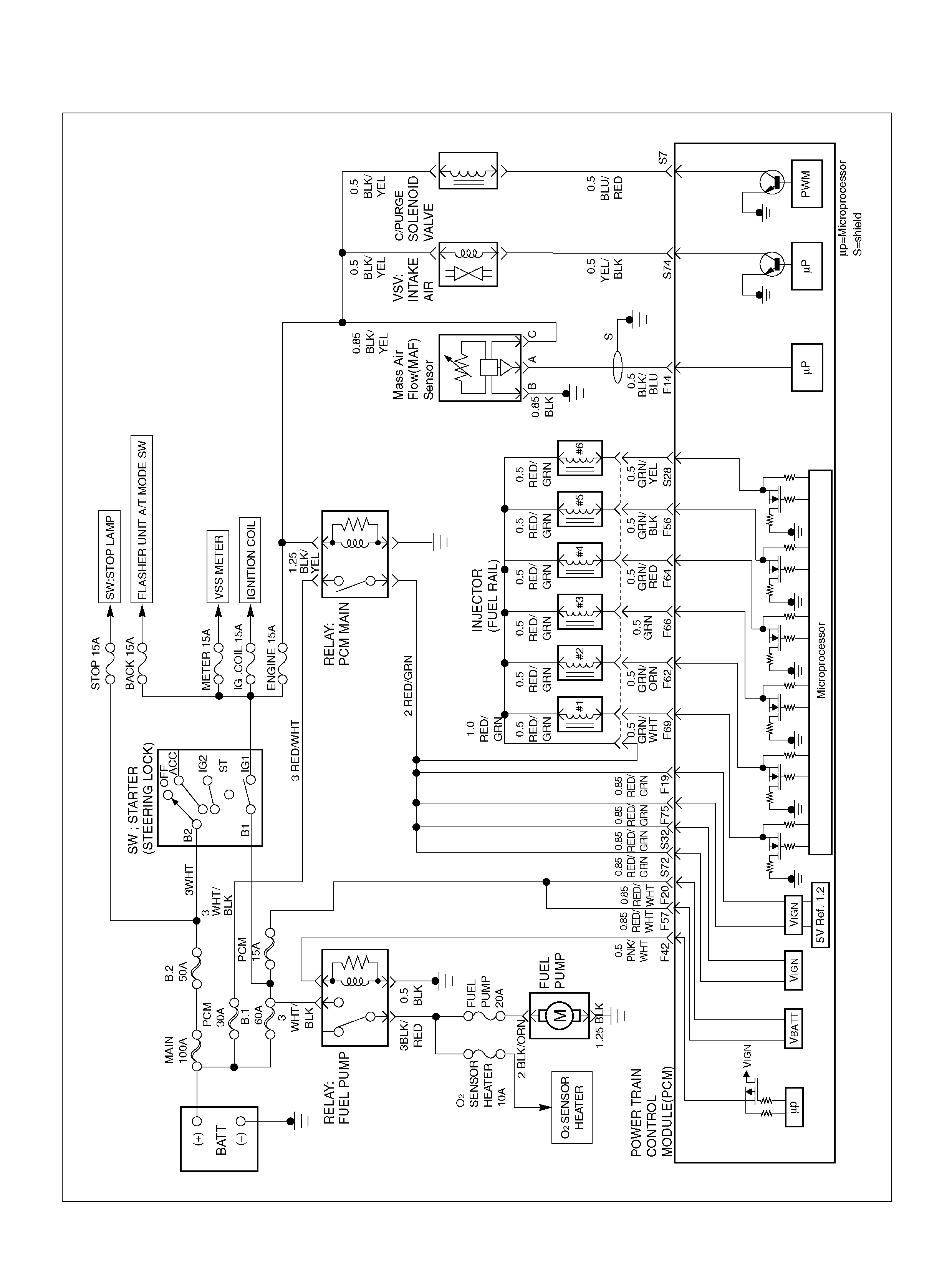
FUEL SYSTEM ELECTRICAL TEST
060R100121

Circuit Description
When the ignition switch is first turned “ON", the
powertrain control module (PCM) energizes the fuel
pump relay which applies power to the in-tank fuel
pump. The fuel pump rel ay will remain “ON" as long as
the engine is running or cranking and the PCM is
receiving 58X crankshaft position pulses. If no 58X
crankshaft position pulses are present, the PCM
de-e nergizes the fu el p ump rela y within 2 sec on ds after
the ignition is turned “ON" or the engine is stopped.
The f uel pum p del ivers fue l to t he fuel rail and in jecto rs,
then to the fuel pressure regulator. The fuel pressure
regulator controls fuel pressure by allowing excess fuel
to be returned to the fu el tank. With the engi ne stopped
and ignition “ON", the f uel pump can be turned “ON" by
using a command by the Tech 2.
Diagn ostic Aids
An intermittent may be caused by a poor connection,
rubbed-through wire insulation, or a wire broken inside
the insulation. Check for the followi ng items:
• Poor connection or damaged harness – Inspect the
PCM harness and connectors for improper mating,
broken locks, improperly formed or damaged
terminals, poor terminal-to-wire connection, and
dama ged harnes s.
Test Description
Number(s) below refer to the step number(s) on the
Diagnostic Chart.
2. If the fuel pump is operating but incorrect pressure is
noted, the fuel pump wiring is OK and the “Fuel
System Pressure Test" chart should be used for
diagnosis.
CAUTION: To reduce the risk of fire and personal
injury:
• It is necessary to relieve fuel system pressure
before connecting a fuel pressure gauge. Refer to
Fuel Pressure Relief Procedure, below.
• A small amount of fuel may be released when
disconnecting the fuel lines. Cover fuel line
fittings with a shop towel before disconnecting,
to catch any fuel that may leak out. Place the
towel in an approved container when the
proc edu re is completed.
Fuel Pressure Relief Procedure
1. Remove the fuel cap.
2. Remove the fuel pump relay from the underhood
relay center.
3. Start the e ngine and allow it to stall .
4. Crank the engine for an additional 3 s econds.
Fuel Gauge Installation
1. Remove the shoulder fitting cap.
2. Install fuel gauge 5-8840-0378-0 to the fuel feed line
located in front of and above the right side valve
t rai n cover .
3. Reinstall the fuel pump relay.

Fuel System Electrical Test
Step Action Value(s) Yes No
1 Was the “On-Board Diagnostic (OBD) System Check"
performed? —Go to Step 2 Go to OBD
System Check
2 1. Read the “Caution" above.
2. Relieve the fuel system pressure and install the
fuel pump pressure gaug e to the test fitting.
3. Ignition ON, Engine is Off .
4. Use a Tech 2 to command the fuel pump “ON".
(Refer to the Miscellaneous Test.)
Is there an immediate pressure build-up which
indicates the pump is running? — G o to St ep 3 Go to S tep 4
3 1. Verify that the pump is not running by removing
the fuel fille r cap and list ening.
2. Command the pump “ON" with the Tech 2.
Did the pump turn “OFF" after 2 seconds? — Test completed Go to Step 12
4 1 . Ig nit io n “ OFF" .
2. Remove the fuel pump relay.
3. Using a test light connected to ground, probe the
battery feed to the relay.
Did the lig ht illu m in ate? — G o to Step 6 Go to S tep 5
5 Repair short or open battery feed to fuel pump relay.
Is the action complete ? — Verify r epair —
6 1. Connect a test light between the two wires that
connect to the fuel pump relay pull-in coil.
2. Ignition “ON".
Did the test light illuminate for 2 seconds and then turn
off? — Go to Step 12 Go to S tep 7
7 1. With a test light connected to battery (–), probe
the fuel pump relay connector at the wire which
runs from the relay pull-in coil to the PCM.
2. Ignition “ON".
Did the test light illuminate for 2 seconds and then turn
off? — G o to St ep 8 Go to S tep 9
8 Locate a nd repair open i n the fuel pump relay ground
circuit.
Is the action complete ? — Verify r epair —
9 Check for short or open between the PCM and the
fuel pump relay.
Was a problem found? — Verify repair Go to Step 10
10 1. Check the fuel pump relay circuit for a poor
terminal connection at the PCM.
2. If a problem is found, replace terminal as
necessary.
Was a problem found? — Verify repair Go to Step 11

11 Replace the PCM.
Important: The replacement PCM must be
programmed. Refer to On-Vehicle Service in
Powertrain Control Module and Sensors for
procedures.
And also refer to latest Service Bulletin.
Check to se e if t he Latest software is released or not.
And then Down Load the LATEST PROGRAMMED
SOFTWARE to the replacement PCM.
Is the action complete ? — Verify r epair —
12 1. Reconne ct the fuel pump relay.
2. Disconnect the fuel pump electrical connector at
the fuel tank.
3. Using a test light connected to ground, probe the
fuel pump feed wire (harness side).
4. Command the fuel pump “ON" with a Tech 2.
Did the light illum ina te for 2 seconds? — Go to Step 15 Go to Step 13
13 1. Honk the horn to verify that the horn relay is
functioning.
2. Substitute the horn relay for the fuel pump relay.
3. Leave the test light connected as in step 12.
4. Command the fuel pump “ON" with the Tec h 2.
Did the test light illuminate for 2 seconds when the
fuel pump was commanded “ON"? — Go to St ep 17 Go to St ep 14
14 1. Re-connect the horn relay in its proper location.
2. Check for a short circuit, blown fuse or open circuit
between the relay and the fuel tank.
Is the action complete ? — Verify r epair —
15 1. With the fuel pu mp electrical connect or at the fuel
tank disconnected, connect a test light between
the feed wire and the ground wire (harness side).
2. Command the fuel pump “ON" with a Tech 2.
Did the test light il luminate for 2 seconds? — Go to Step 18 Go to St ep 16
16 Repair the open circuit in the fuel pump ground wire.
Is the action complete ? — Verify r epair —
17 1. Re-connect the horn relay in its proper location.
2. Replace the fuel pump relay.
Is the action complete ? — Verify r epair —
18 Replace the fuel pum p.
Is the action complete ? — Verify r epair —
Step Action Value(s) Yes No
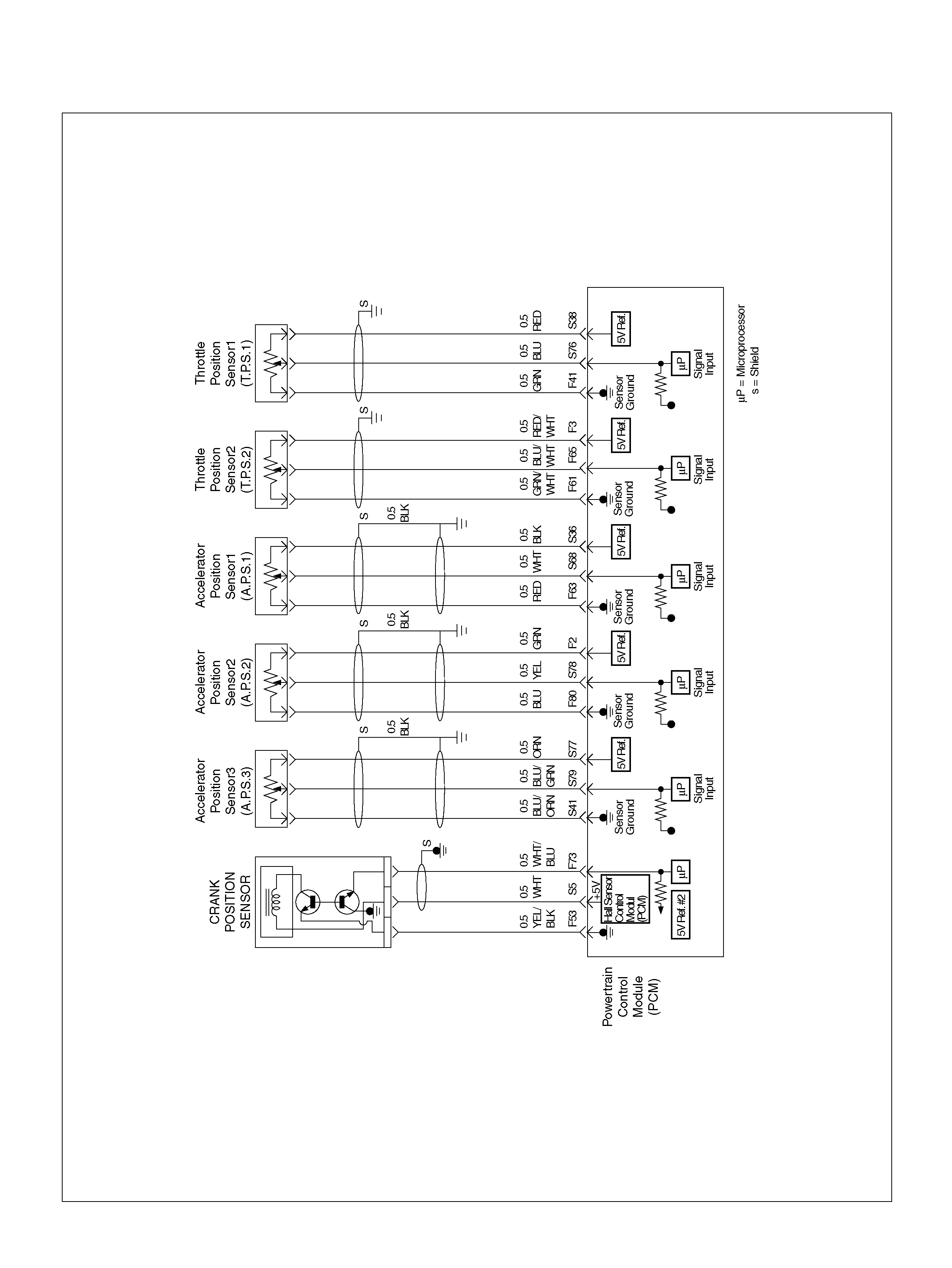
ELECTRI C THROTTLE CONTROL (ETC) SYSTEM CHECK
060R100123

Circuit Description
• The powertrain control module (PCM) controls
engine speed by adjusting the position of the throttle
control valve (DC motor). The throttle motor is a DC
motor driven by one coil. The PCM applies current to
the DC motor coil in PWM (%) to adjust the throttle
valve into a passage in the throttle body to allow air
flow. This method allows highly accurate control of
engine speed and quick response to changes in
engine loa d.
• The accelerator position (AP1) sensor circuit
provides a voltage signal relative to accelerator pedal
angle.
The accelerator pedal angle will vary about 13% at
idle position to about 87% at wide open
throttle(WOT).
APS signal is used to determine which DC motor will
adjust throttle position.
After the APS signal has been processed by the
PCM, it will command DC motor to allow movement
of throttle position.
Diagn ostic Aids
• An interm ittent may be caused by a poor connection,
rubbed-through wire insulation or a wire broken
inside the insulation. Chec k for poor connect ions or a
damaged harness. Inspect the PCM harness and
connector for improper mating, broken locks,
improperly formed or damaged terminals, poor
terminal -to-wire connection, and dam aged harnes s.
• Throttle body – Check for objects blocking the DC
motor or thro tt le bore, excessive deposits in the ET C
passage and on the valve spring, and excessive
deposits in the throttle bore and on the throttle valve
plate.
• Accelerator pedal – Check for objects blocking the
AP sensor or pedal arm with spring, and excessive
deposits in the accelerator pedal arm and on the
accelerator peda l.
Test Descr iption
Number(s) below refer to the step number(s) on the
Diagnostic Chart:
2. Visually/physically inspect for the following throttle
valve condition s.
3. Visually/physically inspect for the following
accele rator pedal conditions .
5. Check the following circuits for throttle valve and DC
motor. Check the following TP sensor resistance and
DC motor.
7. Check the following circuits for accelerator pedal.
Check the following AP sensor resistance.
10. Following DTC: Software detect Error for ETC
system.
11. Following DTC: Software detect Error for ETC
system.

Electric Throttle Control (ETC) System Check
Step Action Value(s) Yes No
1 Was the “On-Board (OBD) System Check"
performed? —Go to Step 2 Go to OBD
System Check
2 Visually/physically inspect for the following conditi ons:
• T hrottle body tampering.
• Restricted intake throttle system. Check for a
possible coll apsed air i ntake duct, restricted air fi lter
element, or foreign objects blocking the air intake
system.
• Throttle body: Check for objects blocking the
throttle passage or throttle bore, excessive deposits
in the throttle passage and on the throttle valve,
and excessive carbon deposits in the throttle bore
and on the throttle plate.
• Throttle lever: Check for smooth operation without
excessive play.
Do any of the above require a repair? —
Refer to
appropriate
sec tion fo r on-
vehicle service Go to Step 3
3 Visually/physically inspect for the following conditi ons:
• Accelerator pedal : Ch eck fo r objects resticting the
spring or pedal arm.
• Accelerator pedal : Check for Check for smooth
operation without excessive play.
• Do any of the above require a repair? —
Refer to
appropriate
sec tion fo r on-
vehicle service Go to Step 4
4 Check for a poor connection at the throttle body
harness connec tor.
Check for a poor connection at the accelerator
position sensor harness connector.
If a problem is found, replace faulty terminals as
necessary.
Was a problem found? — Verify repair Go to Step 5
5 Check the following circuits for an open, short to
voltage, short to ground, or poor connection at the
PCM:
• T hrottle position sensor 1 circuit.
• T hrottle position sensor 2 circuit.
• Throttle DC motor circuit.
If a problem is found, repair as neces sary.
Was a problem found? Verify repair Go to S tep 6
6 Check the Throttle Position sensor resistance.
If a problem is found, repair as neces sary.
Was a problem found? 0.56k - 2.6kΩVer ify repair Go to Step 7
7 1. Instal l th e Tec h2
2. Ignition “ON" but not engine running.
3. Chech the APS a nd TP S valu e s .
Was the problem found?
Id l e
TP1 = 1–6%
TP2 = 1–6%
WOT
TP1 = 98–
100% TP2 =
98–100% Go to St ep 8 Go to S tep 9
8 Replac e the throttle valve.
Is the action complete ? — Verify r epair —

9 1. Instal l th e Tec h2
2. Ignition “ON" but not engine running.
3. Check the APS values .
Was the problem found?
Idle
AP1 = 11–
13%
AP2 = 87–
88%
AP3 = 87–
88%
WOT
AP1 = 85–
89%
AP2 = 11–
15%
AP3 = 32–
36% Go to Step 10 Goto S tep 11
10 Replace the Accelerator Pedal Sensor.
Is the action complete ? — Verify r epair —
11 Check the following circuits for an open, short to
voltage, short to ground, or poor connection at the
PCM:
• Accelerator position sensor 1 circuit.
• Accelerator position sensor 2 circuit.
• Accelerator position sensor 3 circuit.
If a problem is found, repair as neces sary.
Was a problem found? Verify repair Go to Step 12
12 Check the Accelerator Position sensor resist ance
If a problem is found, repair as neces sary.
Was a problem found? 4-6 Go to Step 13 Go to Step 14
13 Replace the accelerator position sensor.
Is the action complete ? — Verify r epair –
14 Following below the DTCs stored:
P1125, P1290, P1295, P1 299 —
Go to
applicable DTC
chart Go to Step 15
15 Following below the DTCs stored:
P1514, P1515, P1516, P1523, P1271, P1272, P1273 —
Go to
applicable DTC
chart Go to Step 16
16 Replace the PCM.
Important: The replacement PCM must be
programmed. Refer to Section 0C-1 - Service
Program ming Syst em.
Important: Refer to Section 11 - Engin e Im mobiliser
System for the Immobiliser Programming procedure.
Important: Ensure the latest software program is
downloaded to the PCM.
Is the action complete ? — Verify repair —
Step Action Value(s) Yes No

FUEL SYSTEM DIAGNOSIS
060R100121

Circuit Description
When the ignition switch is turned “ON", the powertrain
control module (PCM) will turn “ON" the in-tank fuel
pump. The in-tank fuel pump will remain “ON" as long
as the engine is cranking or running and the PCM is
receiving 58X cra nksh aft position pulses. If there a re no
58X crankshaft position pulses, the PCM will turn the
in-tank fuel pump “OFF" 2 seconds after the ignition
switch is turned “ON" or 2 seconds after the engine
stops running.
The in-tank fuel pump is an electric pump within an
integral reservoir. The in-tank fuel pump supplies fuel
through an in-line fuel fi lter to the fuel rail assembly. The
fuel pump is designed to provide fuel at a pressure
above the pressure needed by the fuel injectors. A fuel
pressure regulator, attached to the fuel rail, keeps the
fuel available to the fuel injectors at a regulated
pressure. Unused fuel is returned to the fuel tank by a
separate fuel return line.
Test Description
Number(s) below refer to the step number(s) on the
Diagnostic Chart.
2. Conne ct th e fuel pressure gauge to the fuel feed line
as shown in the fuel system illustration. Wr ap a shop
towel around the fuel pressure connection in order to
absorb any fuel leakage that may occur when
installing the fuel pressure gauge. With the ignition
switch “ON" and the fuel pump running, the fuel
pressure indicated by the fuel pressure gauge
should be 333-376kPa (48-55 psi). This pressure is
controlled by the amount of pressure the spring
inside the fuel pressure regulator can provide.
3. A fuel system that cannot maintain a constant fuel
pressure has a leak in one or more of the following
areas:
• The fuel pump check va lve.
• The fuel pump flex line.
• The valve or valve seat within the fuel pressure
regulator.
• The fuel injec tor(s).
4. Fuel pressure that drops off during accelerator,
cruise, or ha rd cornering may case a lean condition.
A lean condi ti on can cause a loss of power, surging,
or misfire. A lean condition can be diagnosed using a
Tech 2. If an extremely lean condition occurs, the
oxygen sensor(s) will stop toggling. The oxygen
sensor output voltage(s) will drop below 500 mV.
Also, the fuel injector pulse width will increase.
Important: Make sure the fuel system is not operating
in the “Fuel Cut-Off Mode".
When the engine is at idle, the manifold pressure is
low (hig h vacuum ). This low pressure (hig h v acuum )
is applied to the fuel pressure regulator diaphragm.
The low pressure (high vacuum) will offset the
pressure be ing ap plied to the fuel p ressure reg ulator
diaphragm by the spring inside the fuel pressure
regulator. When this happens, the result is lower fuel
pressure. The fuel pressure at idle will vary slightly
as the barometric pressure changes, but the fuel
pressure at idle should always be less than the fuel
pressure noted in step 2 with the engine “OFF".
16. Check the spark plug associated with a particular
fuel injector for fouling or saturation in order to
determine if that particular fuel injector is leaking. If
checking the spark plug associated w ith a particular
fuel injector for fouling or saturation does not
determine that a particular fuel injector is leaking,
use the following procedure:
• Remove the fuel rail, but leave the fuel lines and
injectors connect ed to the fuel rail. Ref er to
Fuel Rail Assemb ly in On-Vehicle Service.
• Lift the fuel rail just enough to leave the fuel
injector nozzles in the fuel injector ports.
CAUTION: In order to reduce the risk of fire and
personal injury that may result from fuel spraying
on the engine, verify that the fuel rail is positioned
over the fuel injector ports and verify that the fuel
injector retaining clips are intact.
• Pressurize the fuel system by connecting a 10
am p fu sed jumper b etwee n B+ and the fuel p ump
relay connector .
• Visually and physically inspect the fuel injector
nozzles for leaks.
17. A rich condition may result from the fuel pressure
being above 376kPa (55psi). A rich condition may
cause a DTC P0132 or a DTC P0172 to set.
Derivability conditions associated with rich
conditions can include hard starting (followed by
black smoke) and a strong sulfur smell in the
exhaust.
20. T his test determines if the high fuel pressure is du e
to a restricted fuel return line or if the high fuel
pressure is due to a faulty fuel pressure regulator.
21. A lean condition may result from fuel pressure below
333kPa (48 psi). A lean condition may cause a DTC
P0131 or a DTC P0171 to set. Derivability conditions
associated with lean conditions can include hard
starting (when the engine is cold ), hesitation, poor
derivability, lack of power , surging , and misfiring.
22. Restricting the fuel return line causes the fuel
pressure to rise above the regulated fuel pressure.
Command the fuel pum p “ON" with the Tech 2. The
fuel pressure should rise above 376kPa (55psi) as
the fuel return line becomes partiall y closed.
NOTE: Do not allow the fuel pressure to exceed
414kPa (60psi). Fuel pressure in excess of 414kPa
(60psi) may damage the fuel pressure regulator.
CAUTION: To reduce the risk of fire and personal
injury:
• It is necessary to relieve fuel system pressure
before connecting a fuel pressure gauge. Refer to
Fuel Pressure Relief Procedure, below.

• A small amount of fuel may be released when
disconnecting the fuel lines. Cover fuel line
fittings with a shop towel before disconnecting,
to catch any fuel that may leak out. Place the
towel in an approved container when the
procedure is completed.
Fuel Pressure Relief Procedure
1. Remove the fuel cap.
2. Remove the fuel pump relay from the underhood
relay center.
3. Start the engine and allow it to stall.
4. Crank the engine for an additional 3 seconds.
Fuel Gauge Installation
1. Remove the shoulder fitting cap.
2. Install fuel gauge 5-8840-0378-0 to the fuel feed line
located in front of and above the right side valve
train cover.
3. Reinstall the fuel pump relay.
Fuel System Diagnosis
Step Action Value(s) Yes No
1 Was the “On-Board Diagnostic (OBD) System Check"
performed? —Go to Step 2 Go to OBD
System Check
2 1. Turn the ignition “OFF".
2. Turn the air conditioning system “OFF".
3. Relieve fuel system pressure and install the fuel
pressure gauge.
4. Turn the ignition “ON".
NOTE: The fuel pump will run for approximately 2
seconds. Use the Tech 2 to command the fuel pump
“ON".
(Refer to the Miscellaneous Test.)
5. Observe the fuel pressure indicated by the fuel
pressure gauge with the fuel pump running.
Is the fuel pressure within the specified limits? 290-376kPa
(42- 55psi) G o to St ep 3 Go to Step 17
3NOTE: The fuel pressure will drop when the fuel
pump stops running, then it should stabilize and
remain constant.
Does the fuel pressure indicated by the fuel pressure
gauge remain constant? — Go to Step 4 Go to St ep 12
4 1. When the vehicle is at normal operation
temperature, turn the ignition “ON" to build fuel
pressure and observe the measurement on the
gauge.
2. Start the engine and observe the fuel pressure
gauge.
Did the reading drop by the amount s pecified after the
engine was started? 21-105kPa
(3-15psi) G o to Step 5 Go to Step 9
5 Is fuel pressure dropping off during accelerator,
cruise, or hard cornering? —Go to St ep 6 Che ck for
improper fuel
6 Visually and physically i nspect the following items for
a restriction:
• T he in-pipe fuel filter.
• T he fuel feed line.
Was a restr iction found? — Verify rep air Go to Step 7

7 Remove the fuel tank and visually and physically
insp ect the f o llow ing ite ms :
• T he fuel pump strainer for a rest riction.
• T he fuel line for a leak .
• V erify that the correct fuel pump is in the vehicle.
Was a problem found in any of these areas? — Verify repair Go to Step 8
8 Replac e the fuel pump.
Is the action complete ? — Verify r epair —
9 1. Disconnect the vacuum hose from the fuel
pressure regulator.
2. With the engine idling, apply 12-14 inches of
vacuum to the fuel pressure regulator.
Does the fuel pressure indicated by the fuel pressure
gauge drop by the amount specified? 21-105k Pa
(3-15psi) Go to Step 10 Go to Step 11
10 Locate and repair the loss of vacuum to the fuel
pressure regulator.
Is the action complete ? — Verify r epair —
11 Replace the fuel pressure regulato r.
Is the action complete ? — Verify r epair —
12 1. Run the fuel pump with t he Tec h 2.
2. After pressure has built up, turn off the pump and
clamp the supply hose shut with suitable locking
pliers which will n ot damage the hose .
Does the fuel pressure indicated by the fuel pressure
gauge remain constant? — Go to Step 13 Go to Step 15
13 Visually inspect the fuel supply line and repair any
leaks.
Was a problem found? — Verify repair Go to Step 14
14 Remove the fuel tank and inspect for leaky hose or
in-tank fuel line .
Was a problem found? — Verify repair Go to Step 8
15 1. If the pliers are still clamped to the fuel supply
hose, remove the locking pliers.
2. With suitable locking pliers, which will not dam age
the hose, clamp the fuel return line t o prevent fuel
from returning to the fuel tank.
3. Run the fuel pump with t he Tec h 2.
4. After pressure has built up, remove power to the
pump.
Does the fuel pressure indicated by the fuel pressure
gauge remain constant? — Go to Step 11 Go to St ep 16
16 Locate and replace any leaking fuel injector(s).
Is the action complete ? — Verify r epair —
17 Is the fuel pressure indicated by the fuel pressure
gauge above the specified limit? 37 6kPa
(55psi) Go to St ep 18 Go to St ep 21
Step Action Value(s) Yes No

18 1. Relieve the fuel pressure. Refer to the Fuel
Pressur e Relief.
2. Disconnect the fuel return line from the fuel rai l.
3. Attach a length of flexible hose to the fuel rail
return outlet passage.
4. Place the open end of the flexible hose into an
approved gasoline container.
5. Run the fuel pump with t he Tec h 2.
6. Observe the fuel pressure indicated by the fuel
pressure gauge with the fuel pump running.
Is the fuel pressure within the specified limits? 290-376kPa
(42- 55psi) Go to S t ep 19 Go to St ep 20
19 Locate and correct the restriction in the fuel return
line.
Is the action complete ? — Verify r epair —
20 Visually and physically inspect the fuel rail outlet
passages for a restriction.
Was a restr iction found? — Verify rep air Go to Step 11
21 Is the fuel pressure indicated by the fuel pressure
gauge above the specified value? 0kPa (0psi) Go to Step 22 Go to St ep 23
22 1. Command the fuel pump “ON" with the Tec h 2.
2. Using suitable pliers which will not damage the
fuel hose , gradually apply press ure with the plie rs
to pinch the flexible fuel return hos e closed.
CAUTION: Do n ot let the fuel pressure excee d the
second specified value.
Does the fuel pressure indicated by the fuel pressure
gauge rise above the first specified value?
376kPa
(55psi)
414kPa
(60psi) Go to St ep 11 Go to Step 7
23 1. Command the fuel pump “ON" with the Tec h 2.
2. Remove the fuel filler ca p and listen f or t he sound
of the fuel pump running.
3. Turn the pump off.
Was the fuel pump running? — Go to Step 7
Go t o Fuel
System
Electrical Tes t
Chart
Step Action Value(s) Yes No

EXHAUST GAS RECIRCULATION (EGR) SYST EM CHECK
060R100131
Circuit Description
A properly operation exhaust gas recirculation (EGR)
system will directly affect the air/fuel requirements of the
engine. Since the exhaust gas introduced into the air/
fuel mixture is an inert gas (contains very little or no
oxygen), less fuel is required to maintain a correct air/
fuel ratio.
Introducing exhaust gas into the combustion chamber
lowers combustion temperatures and reduces the
formation of oxides of nitrogen (NOx) in the exhaust
gas. Lower combustion temperatures also prevent
detonation.
If the EGR pintle were to sta y closed, the inert exhaust
gas would be replaced with air and the air/fuel mixture
would be leane r. Th e powertrain control module (PCM)
would compe nsa te for the lean condition by adding fuel,
resulting in higher long term fuel trim values.
Diag nostic Ai ds
The EGR valve ch art is a check of the EGR s ystem. An
EGR pintle constantly in the closed position could cause
detonation and high emissions of NOx. It could also
result in high long term fuel trim values in the open
throttle cell, but not in the closed throttle cell. An EGR
pintle constantly in the open position would cause a
rough idle. Also, an EGR mounted incorrectly (rotated
180°) could cause rough idle. Check for the following
items:
• EGR passages – Check for restricted or blocked
EGR passages.
• Manifold absolute pressure sensor – A manifold
absolute pressure sensor may shift in calibration
enough to affect fu el delivery. Refer to
Manifold Absolute Pressure Output Check.

Exhaust Gas Recirculation (EGR) System Check
Step Action Value(s) Yes No
1 Check the EGR valve for looseness.
Is the EGR valve Loose? — Go to St ep 2 Go to S tep 3
2 T i ghten the EGR valve.
Is the action complete ? — Verify r epair —
3 1. Place the transmission selector in Pa rk or Neutral.
2. Start th e engine and idle until warm.
3. Using a Te ch 2, command E GR “50% ON".
(Refer to the Miscellaneous Test.)
Does the engine idle rough and lose RPMs? —
EGR system
working
properly. No
problem found. Go to Step 4
4 1. Engine “OFF".
2. Ignition “ON".
3. Using a test light to ground, check the EGR
harness between the EGR valve and the ignition
feed.
Does the test light ill um inat e? — G o to Step 6 Go to Step 5
5 Repair the EGR harness ignition feed.
Was the proble m corrected? — Veri fy repair Go to S tep 6
6 1. Remove the EGR valve.
2. Visually and physically inspect the EGR valve
pintle, valve passages and adapter for excessive
deposits, obstructions or any restrictions.
Does the EGR valve have excessive deposits,
obstructions or any restrictions? — Go to St ep 7 Go to S tep 8
7 Clean or replace EGR system components as
necessary.
Was the proble m corrected? — Veri fy repair Go to S tep 8
8 1. Ground the EGR valve metal case to battery (–).
2. Using a Tech 2, command EGR “ON" and observe
the EGR valve pintle for movement.
Does the EGR valve pintle move according to
comma nd? — G o to St ep 9 Go to DT C
P1406 chart
9 1. Remove the EGR inlet and outlet pipes from the
intake and exhaust manifolds .
2. Visually and physically inspect manifold EGR
ports and EGR inlet and outlet pipes for blockage
or restriction caused by excessive deposits or
other damage.
Do the manifold EGR ports or inlet and outlet pipes
have excessive deposits, obstructions, or any
restrict ions? — Go to Step 10
EGR system
working
properly. No
problem found.
10 Clean or replace EGR system components as
necessary.
Is the action complete ? — Verify r epair —

MANIFOLD ABSOLUTE PRESSURE (MAP) OUTPUT CHECK
060R100132
Circuit Description
The manifold absolute pressure (MAP) sensor
measures the changes in the intake MAP which result
from engine load (intake manifold vacuum) and engine
speed changes; and converts these into a voltage
output. The powertrain control module (PCM) sends a
5-volt reference voltage to th e MAP sensor. As the MAP
changes, the output voltage of the sensor also changes.
By monitoring the sensor output voltage, the PCM
knows the MAP. A lower pressure (low voltage) output
voltage will be about 1-2 volts at idle. Higher pressure
(high voltage) output voltage will be about 4-4.8 volts at
wide open thrott le. The MA P sens or is also u se d, under
certain conditions, to measure barometric pressure,
allowing the PCM to make adjustments for different
altitudes. The PCM uses the MAP sensor to diagnose
proper operation of the EGR system, in addition to other
functions.
Test Descr iption
Important: Be sure to used the same diagnostic test
equipment for all measurements.
The num ber(s) below refer to the step number(s ) on the
Diagnostic Chart.
2. Applying 34 kPa (10 inch Hg) vacuum to the MAP
sensor should cause the voltage to be 1.5-2.1 volts
less than the voltage at step 1. Upon applying
vacuum to the sensor, the change in voltage should
be instantaneous . A slow voltage change i ndicat es a
faulty sensor.
3. Check the vacuum hose to the sensor for leaking or
restriction, Be sure that no other vacuum devices are
conne cted to the MAP hos e.
Important: M ake s ure th e e lectrical connector remains
securely fastened.
4. Disconnect the sensor from the bracket. Twist the
sensor with your hand to check for an intermittent
connection. Output changes greater than 0.10 volt
indicat e a bad sensor.

Manifold Absolute Pressure (MAP) Output Check
Step Action Value(s) Yes No
1 1. Turn the ignition “OFF" and leave it “OFF" for 15
seconds.
2. Ignition “ON". Don't crank engine.
3. The Tech 2 should indicate a manifold absolute
pressure (MAP) sensor voltage.
4. Compare this scan reading to scan reading of a
known good vehicle obtained using the exact
same procedure as in S teps 1-4.
Is the voltage reading the same +/–0.40 volt? — G o to St ep 2 Go to Step 5
2 1. Disconnect the vacuum hose at the MAP sensor
and plug the hose.
2. Connect a hand vacuum pump to the MAP sensor.
3. Start th e engine.
4. Apply 34 kPa (10 in.Hg) of vacuum and note the
voltage change.
Is the voltage change 1.5-2.1 volts less t han Ste p 1? — G o to Step 3 Go to S tep 4
3 Check the sensor cover for leakage or restriction.
Does the hose supply vacuum to the MAP sensor
only? — G o to St ep 5 Go to S tep 4
4 Repair the hose blockage.
Is the action complete ? — Verify r epair —
5 Check the sensor connect ion.
Is the sensor connection good ? — G o to St ep 6 Go to S tep 7
6 Refer to On-Ve hicle Service, MAP Sensor.
Is the action complete ? — Verify r epair —
7 Repair the poor connection.
Is the action complete ? — Verify r epair —
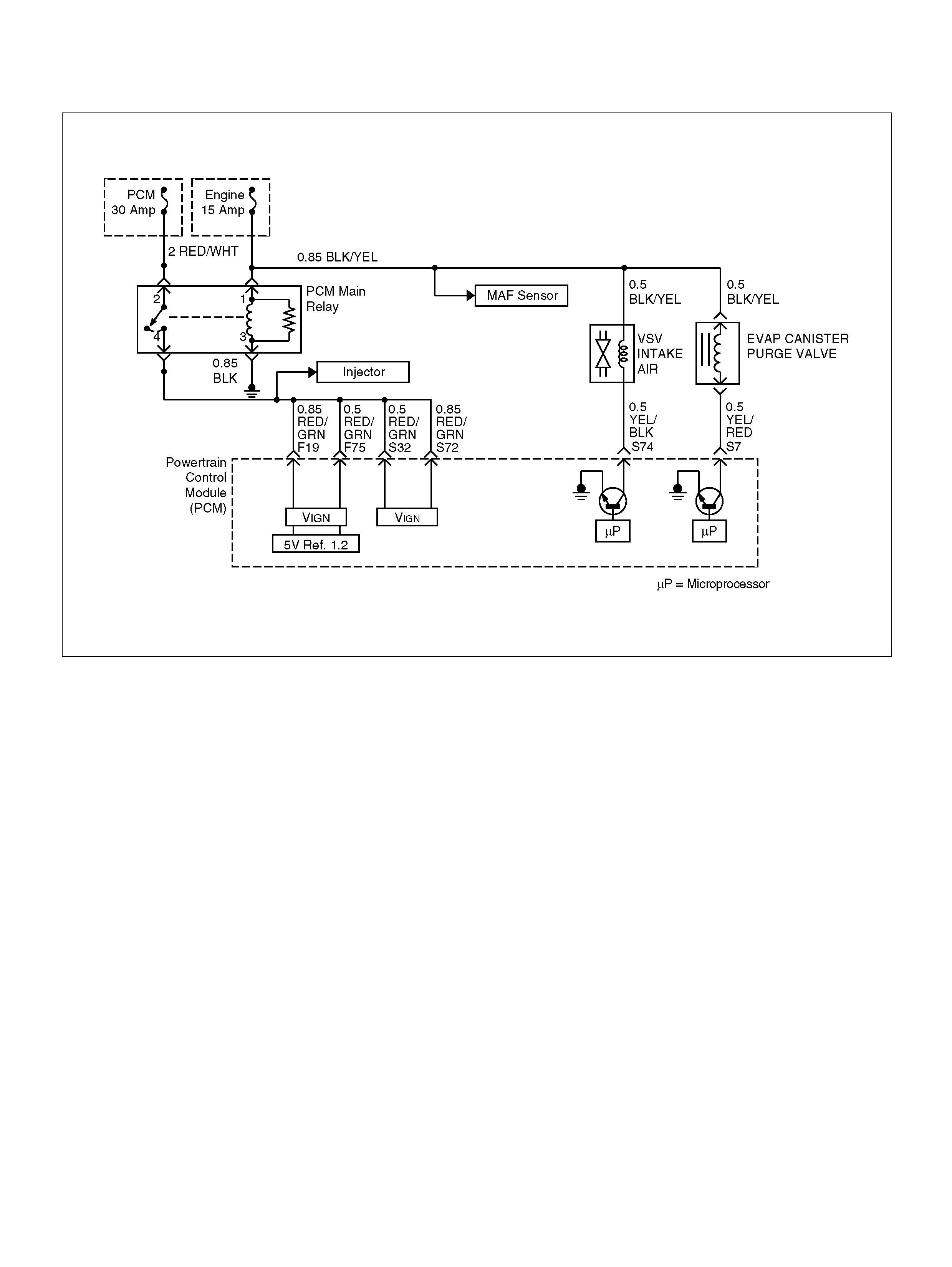
EVAPORATIVE (EVAP) EMISSIONS CANISTER PURGE VALVE CHECK
060R100111
Circuit Description
Canister purge is controlled by a solenoid valve that
allows manifold vacuum to purge the canister. The
powertrain control module (PCM) supplies a ground to
energize the solenoid valve (purge “ON"). The EVAP
purge solenoid control is turned “ON" and “OFF" several
times a second. The duty cycle (pulse width or “ON"
time) is determined by engine operating conditions
including load, throttle position, coolant temperature
and ambient temperature. The duty cycle is calculated
by the PCM and the purge solenoid is enabled when the
appropriate conditions have been met:
• The fuel control system is operating in the
close d-loop mode.
• The engine coolant temperature (ECT) is more than
10°C at start up, and then the ECT is more than
40°C.
• The ECT is less than 10°C at start up, an d then it is
more than 60°C.
• The ECT is more than 40°C at start up, and the
engine run time after start is more than 30 seconds.
• The ECT is less than 40°C at start up, and the engine
run time after start is more than 90 seconds.
Diag nostic Ai ds
• M ake a visu al check of vacuum hos es.
• Check the throttle body for cracks.
• Check the malfunction indicator lamp for a possible
mechani c al problem.
Test Descr iption
The num ber(s) below refer to the step number(s ) on the
Diagnostic Chart.
1. Check to see if the solenoid is open or closed. The
solenoid is normally de-energized in this step, so it
should be closed.
2. This step checks to determine if the solenoid was
open due to an electrical circuit problem or a
defective solenoid.
3. This should normally energize the solenoid, opening
the valve and allowing the vacuum to drop (purge
“ON").

Evaporative (EVAP) Emissions Canister Purge Valve Check
Step Action Value(s) Yes No
1 1 . Ig nit io n “ OFF" .
2. Ignition “ON", engine “OFF".
3. At the throttle body, disconnect the hose t hat goes
to the purge solenoid.
4. Using a hand vacuum pump with an attached
vacuum gauge 5 -8 840-0279-0 , apply vacuu m (10
in. Hg or 34 kPa) to the s olenoid.
Does the solenoid hold the vacuum? — G o to St ep 3 Go to S tep 2
2 1 . Disconnect the solenoid electrica l connector.
2. As in Step 1, apply vacuum (10 in. Hg or 34 kPa)
to the solenoid.
Does the solenoid hold the vacuum? — G o to St ep 4 Go to S tep 7
3 1. At the throttle body, put a cap over the vacuum
port whe re t he hos e wa s disconnected for t esting.
This is to prevent a v acuum leak when the engine
is started.
2. Ignition “OFF".
3. Install the Tech 2.
4. Apply vacuum to the purge sole noid with the hand
vacuum pump.
5. Start th e engine, run at 2500 RPM.
6. Using the Tech 2, select Powertrain, 3.2–V6
6VD1, F3: Misc. Tests, F2: EVAP Purge, F0:
EVAP Purge.
(Refer to the Miscellaneous Test.)
7. Turn the purge solenoid “ON".
Did the vacuum drop when the purge was turned on? — G o to St ep 8 Go to S tep 9
4 Check for a short to ground in the YE L/ RED wire.
Is there a short? — G o to St ep 5 Go to S tep 6
5 Repair the short to ground.
Is the action complete ? — Verify r epair —
6 Replace the PCM.
Important: The replacement PCM must be
programmed. Refer to Section 0C-1 - Service
Program ming Syst em.
Important: Refer to Section 11 - Engin e Im mobiliser
System for the Immobiliser Programming procedure.
Important: Ensure the latest software program is
downloaded to the PCM.
Is the action complete ? — Verify repair —
7 Replace the faulty purge solenoid. Refer to
On-Vehicle Service, EVAP Caniste r Purge Solenoi d.
Is the action complete ? — Verify r epair —

8 1. Turn the ignition “OFF".
2. At the throttle body, install a vacuum gau ge where
the hose from the purge solenoid was
disconne cted for testing.
3. Start th e engine.
4. Stabilize the engine speed at about 2500 RPM.
5. Momentarily snap the throttle open and let i t r eturn
to idle.
Is there approximately 10 in. Hg (34 kPa) of vacuum
available at the EVAP emission canister purge
solenoid? —
No problem
found in the
EV AP emission
canister purge
valve check Refer to
Diagnostic Aids
9 1 . Disconnect the solenoid electrica l connector.
2. Connect a test lamp between the harness
terminals.
Does the test lam p ligh t? — Go to Step 7 Go to St ep 10
10 Probe terminal A and terminal B with a test lamp to
ground.
Does the test lamp light on both terminals? — G o to St ep 11 Go to St ep 12
11 Repair the short to voltage in the YEL/RED wire.
Is the action complete ? — Verify r epair —
12 Does one of the terminals light the test lamp? — Go to S tep 13 Go to St ep 14
13 Check for an open in the YEL/RED wire between the
purge solenoid and the PCM.
Was there an open c ircuit? — Go to Step 15 Go to S tep 6
14 Repair the open in the BLK/YEL wire.
Is the action complete ? — Verify r epair —
15 Repair the open in the YEL/RED wire.
Is the action complete ? — Verify r epair —
Step Action Value(s) Yes No

PCM DIAGNOSTIC TRO UBLE CODES
The following table lists the diagnostic trouble codes
supported by this vehicle application. If any DTCs not
listed here are displayed by a Tech 2, the Tech 2 data
may be faulty; notify the Tech 2 manufacturer of any
DTCs displayed that are not included in the following
table.
PCM Diagnostic Trouble Codes
DTC Description Type Illum inate
MIL
(Check
Engine
Lamp)
Illum inate
RPL
(Reduced
Power
Lamp)
P0101 MA F System Performance B Yes No
P0102 MA F Sensor Circuit Low Frequency B Yes No
P0103 MA F Sensor Circuit High Frequency B Yes No
P0106 MA P Rationality/Performance B Yes No
P0107 MAP Circuit Low Input Voltage B Yes No
P0108 MA P Circuit Hi gh Input Vol tage B Yes No
P0112 IAT Circuit Low Input Voltage B Yes No
P0113 IAT Circuit High Input V o l t age B Yes No
P0117 ECT Circuit Low Input Voltage B Yes No
P0118 ECT Circuit High Input Vo ltage B Yes No
P0131 O2 Sensor Circuit Low Voltage (Bank 1 Sensor 1) B Yes No
P0132 O2 Sensor Circuit High Vol t age (Bank 1 Sensor 1) B Yes No
P0134 O2 Sensor Circuit No Activi ty Detected (Bank 1 Sensor 1) B Yes No
P0135 O2 Sensor Heater Circuit (Bank 1 Sensor 1) B Yes No
P0151 O2 Sensor Circuit Low Voltage (Bank 2 Sensor 1) B Yes No
P0152 O2 Sensor Circuit High Vol t age (Bank 2 Sensor 1) B Yes No
P0154 O2 Sensor Circuit No Activi ty Detected (Bank 2 Sensor 1) B Yes No
P0155 O2 Sensor Heater Circuit (Bank 2 Sensor 1) B Yes No
P0171 O2 Sensor - System too Lean (Bank 1) B Yes No
P0172 O2 Sensor - System too Rich (Bank 1) B Yes No
P0174 O2 Sensor - System too Lean (Bank 2) B Yes No
P0175 O2 Sensor - System too Rich (Bank 2) B Yes No
P0201 Injector 1 Control Circuit A Yes No
P0202 Injector 2 Control Circuit A Yes No
P0203 Injector 3 Control Circuit A Yes No
P0204 Injector 4 Control Circuit A Yes No
P0205 Injector 5 Control Circuit A Yes No
P0206 Injector 6 Control Circuit A Yes No
P0300 Engine Misfire Detected B Yes No
P0301 Engine Misfire Detected Cylinder #1 B Yes No
P0302 Engine Misfire Detected Cylinder #2 B Yes No
P0303 Engine Misfire Detected Cylinder #3 B Yes No
P0304 Engine Misfire Detected Cylinder #4 B Yes No
P0305 Engine Misfire Detected Cylinder #5 B Yes No

P0306 Engine Misfire Detected Cylinder #6 B Yes No
P0325 ION Sens ing Module B Yes No
P0336 CKP Sensor Circuit Range/Performance (58X) B Yes No
P0337 CKP Sensor Circuit No signal (58X) B Yes No
P0351 Ignition 1 Control Circuit A Yes No
P0352 Ignition 2 Control Circuit A Yes No
P0353 Ignition 3 Control Circuit A Yes No
P0354 Ignition 4 Control Circuit A Yes No
P0355 Ignition 5 Control Circuit A Yes No
P0356 Ignition 6 Control Circuit A Yes No
P0402 EGR Fl ow Excessive B Yes No
P0404 EGR Range/Performance (Open Valve) B Yes No
P0405 EGR Sensor Circuit Low Vo ltage B Yes No
P0406 EGR Sensor Circuit High Vo l t age B Yes No
P0502 No VSS Signal B Yes No
P0506 Idle Speed Control RPM too Low B Yes No
P0507 Idle Speed Control RPM too High B Yes No
P0562 System V ol tage is Low D No No
P0563 System Voltage is High B Yes No
P0565 Cruise M ain Switch Circuit Error D No No
P0566 Cruise Cancel Switch Circuit Error D No No
P0567 Cruise Resum e Switch Circuit Error D No No
P057 1 No Br ak e Swi tch Signal D No No
P 0601 PCM/EC M Me mory Ch ecksum A Yes N o
P0602 PCM/ECM Programming error D No No
P0604 PCM/ECM RAM error D No No
P0606 PCM/ECM Internal Performance D No No
P1106 MAP Circuit Intermittent High Voltage) D No No
P1107 MAP Circuit Intermittent Low Input Vol tage D No No
P1111 IAT Circuit Intermittent High Voltage D No No
P1112 IAT Cir cu it Inte r mi t te nt Lo w In put Vol ta g e D No N o
P1114 ECT Circuit Intermittent Low Volt age D No No
P1115 ECT Circuit Intermittent High Volt age D No No
P1120 TPS1 Circuit B Yes No
P1125 ETC Limit Performance Mode A Yes Yes
P1167 Fuel supply System RICH During Decel Fuel Cut Off D No No
P1169 Fuel supply System RICH During Decel Fuel Cut Off D No No
P1171 Fuel supply System Lean During Power Enrichment D No No
P1220 TPS2 Circuit B Yes No
P1221 TPS1-T PS2 Correlation (Circuit P erform anc e) D No No
P127 1 APS 1-APS2 Corr elation (Ci r cu it Perf orm a nce) D No No
DTC Description Type Illum inate
MIL
(Check
Engine
Lamp)
Illum inate
RPL
(Reduced
Power
Lamp)

P127 2 APS 2-APS3 Corr elation (Ci r cu it Perf orm a nce) D No No
P127 3 APS 1-APS3 Corr elation (Ci r cu it Perf orm a nce) D No No
P1275 APS1 Circuit B Yes No
P1280 APS2 Circuit B Yes No
P1285 APS3 Circuit B Yes No
P1290 ETC Forced Idle Mode A Yes Yes
P1295 ETC Power Man agem ent Mode A Yes Yes
P1299 ETC Forced Engine Shutdown Mode A Yes Yes
P1310 ION Sens ing Module Diagnos tic A Yes No
P1311 ION Sens ing Module SEC 1 Line Circuit Fault A Yes No
P1312 ION Sens ing Module SEC 2 Line Circuit Fault A Yes No
P1326 ION Sens ing Module Com bustion Qual ity circuit A Yes No
P1340 ION Sensing Mo dule - Cylinder Synchronization B Yes No
P1404 EGR Range/Performance (Closed Valve) B Yes No
P1514 TPS-MAF Correlation A Yes No
P1515 Comm and-A crual TPS Correlation A Yes No
P1516 Command-Acrual TPS Correlati on Error A Yes No
P1523 Throttle Actuator Control Return Performance D No No
P1571 Brake Switch D No No
P1635 Reference Voltage #1 Circuit D No No
P1639 Reference Voltage #2 Circuit D No No
P1640 OD M Output circuit Fault D No No
P1650 QD M Output Circuit Fault D No No
DTC Description Type Illum inate
MIL
(Check
Engine
Lamp)
Illum inate
RPL
(Reduced
Power
Lamp)
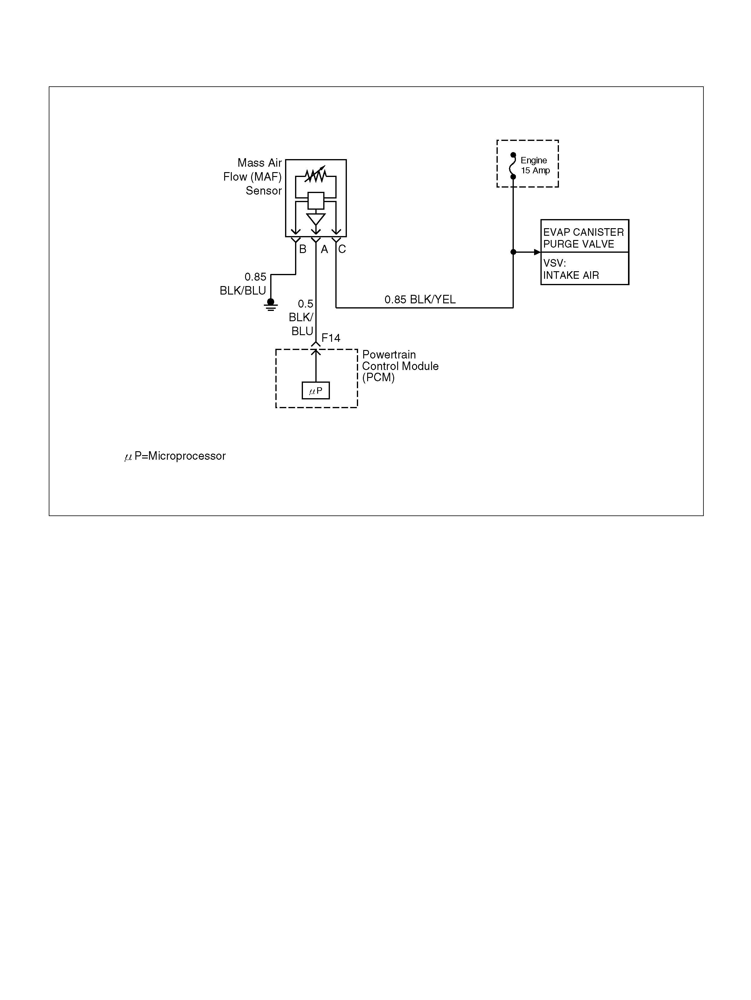
DIAGNOSTIC TROUBLE CODE (DTC) P0101 MAF SYSTEM PERFORMANCE
060R100112
Circuit Description
The mass air flow (MAF) sensor measures the amount
of air which passes through it into the engine during a
given time. The powertrain con trol module (PCM) uses
the mass air flow information to monitor engine
operating conditions for fuel delivery calculations. A
large quantity of air entering the engine indicates an
accele rator or hig h lo ad situat ion, while a s m all quantity
or air indicates deceleration or idle.
The MAF sensor produces a frequency signal which
canbe monitored using a Tech 2. The frequency will
vary wi thin a ran ge of a ro und 4 to 7g/s at idl e t o aroun d
25 to 40g/s at maximum engine load. DTC P0101 will
be set if the signal from the MAF sensor does not match
apredicted value based on throttle position and engine
RPM.
Conditions for setting the DTC
• T he engin e is running.
• N o TP sensor and MAP senso r DTCs are set.
• No MAF frequency DTCs are set.
• Sy ste m voltage is between 11.5 volts and 16 volts.
• TP angle is more than 37.5%.
• Difference BARO pressure between current and
calculated value based on MAF sensor signal
becomes more than 20 kPa and more than 5 seconds
in a tr ip.
Action Taken When the DTC Sets
• The PCM will ON the MIL after second trip with
d e te ct e d fa ult.
• The PCM calculates an air flow value based on idle
air control valve position, throttle position, RPM and
barome tric pressure.
• The PCM will store condition which were present
when the DTC was set as Freeze Frame and in the
Failure Records data.
Conditi ons for Clea r ing the MIL/DTC
• The PCM will turn the MIL “OFF" on the third
consecutive trip cycle during which the diagnostic has
been run and the fault condition is no longer present.
• A history DTC P0101 will clear after 40 consecutive
trip cycle during which the warm up cycles have
occurred without a fault.
• DTC P0101 can be cleared using the Tech 2 “Clear
Info" function.

Diagnostic Aids
An intermittent may be caused by the following:
• Poor connections.
• Misrouted harness.
• Rubbed through wire insulation.
• Broken wire inside the insulation.
• he duct work at the MAF sensor for leaks.
• An engine vacuum leak.
• The PCV system for vacuum leaks.
• An incorrect PCV valve.
• The engine oil dip stick not fully seated.
• The engine oil fill cap loose or missing.
Check for the following conditions:
• Poor connection at PCM-Inspect harness connectors
for backed out terminals, improper mating, broken
locks, improperly formed or damaged terminals, and
poor terminal to wire connection.
• Damaged harness- Inspect the wiring harness for
damage. If the harness appears to be OK, observe
the Mass Air Flow (MAF) display on the Tech2 while
moving connectors and wiring harnesses related to
the sensor.
• Plugged intake air duct or filter element
• A wide-open throttle accelerator from a stop should
cause the mass air flow displayed on a Tech2 to
increase from about 3–6 g/s at idle to 100 g/s or
greater at the time of the 1–2 shift. If not, check for a
restriction.
A change in the display will indicate the location of
the fault.
If DTC P0101 cannot be duplicated, the information
included in the Failure Records data can be useful in
determined vehicle mileage since the DTC was last
set.
If it is determined that the DTC occurs intermittently,
performing the DTC P001 Diagnostic Chart may
isolate the cause of the fault.
DTC P0101 – MAF System Performance
Step Action Value(s) Yes No
1 Was the “On-Board Diagnostic (OBD) System Check"
performed? —Go to Step 2 Go to OBD
System Check
2 1 . Ig nit io n “ OFF" .
2. Disconnect the Mass Air Flow (MAF) Sensor
harness connec tor from the MAF Sens or.
3. Place an unpowered test lamp between the 12
volt signal circuit and the ground circuit, both at
the MAF Sensor connector.
4. Ignition “ON", Engine“OFF".
Did the test lamp illuminate? — Go to St ep 6 Go toStep 3
3 1. Ignition “ON", Engine “OFF".
2. Using a Digital Voltmete r (DVM), check the 12 volt
signal circuit for the correct voltage.
Did the DVM indicate a value within the following
range? 11.5 to 12.5
Volt Go to Step 5 Go to Step 4
4 1 . Ig nit io n “ OFF" .
2. Check the 12 volt signal circuit for the following
conditions:
• An open c ircuit
• A sho rt to ground
Was the proble m found? — Verify repair —
5 Check the MAF ground circuit for the following
conditions:
• An open c ircuit
• A short to vo lt a ge
Was a problem found? — Verify repa ir —

6 1 . Ig nit io n “ OFF" .
2. Check the MAF S ensor s ignal circuit b etw een the
PCM and the MAF Sensor for the following
conditions:
• An open c ircuit
• A sho rt to ground
• A sh or t to b a t tery vo lta g e
Was a problem found? — Verify repair Go to Step 7
7 1. Connect the MAF Sensor wiring harness
connector to the MAF Sensor.
2. Connect the Tech 2 to the vehicle.
3. Place the Transmission in Park/Neutral, and fully
apply the Parking Brake.
4. Start th e engine.
5. Select the Mass Air Flow (MAF) parameter on the
Tech 2.
With the engine idling, does the Tech 2 display the
following value(s)? 4 to 7 g/s Go to St ep 8 Go toStep 9
8 Obse rv e the Tech 2 v alue while i ncreasing the engine
RPM to its upper limit.
Does the Tech 2 display the following value(s)? 25 to 40 g/s Go to Step 10 Go toStep 9
9 Replace the MAF Sensor .
Is the action complete ? — Verify r epair —
10 Replace the PCM.
Important: The replacement PCM must be
programmed. Refer to Section 0C-1 - Service
Program ming Syst em.
Important: Refer to Section 11 - Engin e Im mobiliser
System for the Immobiliser Programming procedure.
Important: Ensure the latest software program is
downloaded to the PCM.
Is the action complete ? — Verify repair —
Step Action Value(s) Yes No

DIAGNOSTIC TROUBLE CODE (DTC) P0102 MAF SENSOR CIRCUIT
LOW FREQUENCY
060R100112
Circuit Description
The mass air flow (MAF) sensor measures the amount
of air which passes through it into the engine during a
given time. The powertrain con trol module (PCM) uses
the mass air flow information to monitor engine
operating conditions for fuel delivery calculations. A
large quantity of air entering the engine indicates an
accele rator or hig h lo ad situat ion, while a s m all quantity
of air indicates deceleration or idle.
The MAF sensor produces a frequency signal which
can be monitored using a Tech 2. The frequency will
vary wi thin a ran ge of a ro und 4 to 7g/s at idl e t o aroun d
25 to 40 g/s at maximum engine load. DTC P0102 will
be set if the signal from the MAF sensor is below the
possib le range of a normally operating MAF sensor.
Conditions for Setting the DTC
• T he engine is running above 50 0 RPM for more than
10 seconds.
• Sy ste m voltage is above 11.5 volts.
• MAF signal frequency is below 1 kHz for a total of
50-percent of the last 1000 samples monitored. A
sample is taken every cylinder event.
Action Taken When the DTC Sets
• The PCM will ON the MIL after second trip with
d e te ct e d fa ult.
• The PCM calculates an air flow value based on
throttle position, RPM and barometric pressure.
• The PCM will store conditions which were present
when the DTC was set as Freeze Frame and in the
Failure Records data.
Conditi ons for Clea r ing the MIL/DTC
• The PCM will turn the MIL “OFF" on the third
consecutive trip cycle during which the diagnostic has
been run and the fault condition is no longer present.
• A history DTC P0102 will clear after 40 consecutive
warm-up cy cles have occurred without a fault.
• DTC P0102 can be cleared by using the Tech 2
“Clear Info" function.
Diag nostic Ai ds
Check for the following conditions:
• Poor connection at PCM – Inspect harness
connectors for backed-out terminals, improper
mating, broke n l ocks, i mpro perly f orm ed o r dam aged
terminals, and poor terminal-to-wire connection.

• Misrouted harness – Inspect the MAF sensor harness
to ensure that it is not routed too close to high voltage
wires.
• Damaged harness – Inspect the wiring harness for
damage. If the harness appears to be OK, observe
the Tech 2 while moving connectors and wiring
harnesses related to the MAF sensor. A change in
the display will indicate the location of the fault.
• Plugged intake air duct or filter element – A
wide-open throttle accelerator from a stop should
cause the mass air flow displayed on a Tech 2 to
increase from about 3-6 g/second at idle to 100 g/
second or greater at the time of the 1-2 shift. If not,
check for a restriction.
If DTC P0102 cannot be duplicated, the information
included in the Failure Records data can be useful in
determining vehicle mileage since the DTC was last set.
Test Description
Number(s) below refer to the step number(s) on the
Diagnostic Chart.
2. This step verifies that the problem is present at idle.
4. A voltage reading of less than 4 or over 5 volts at the
MAF sensor signal circuit indicates a fault in the
wiring or a poor connection.
5. This verifies that ignition feed voltage and a good
ground are available at the MAF sensor.
DTC P0102 – MAF Sensor Circuit Low Frequency
Step Action Value(s) Yes No
1 Was the “On-Board Diagnostic (OBD) System Check"
performed? — Go to Step 2 Go to OBD
System Check
2 1. Start th e engine.
2. With the engine idling, monitor “MAF Frequency"
display on the Tech 2.
Is the “MAF Frequenc y" below the specified value? 1.6 g/s Go to St ep 4 Go to Step 5
3 1. Ignition “ON", engine “OFF".
2. Review and record Te ch 2 Failure Records data.
3. Operate the vehicle within Failure Records
condition s as noted.
4. Using a Tech 2, monitor “DTC" info for DTC
P0102.
Does the Tech 2 indicate DTC P0102 failed this
ignition? — Go to Step 4 Refe r to
Diagnostic Aids
4 1 . Ig nit io n “ OFF" .
2. Disconnect the MAF sensor connector.
3. Ignition “ON", engine “OFF".
4. Using a DVM, measure voltage between the MAF
sensor signal circuit and battery ground.
Is the voltage near the specified value? 11.5–12 V G o to St ep 5 Go to Step 8
5 Connect a test light between the MAF sensor ignition
feed and ground circuits at the MAF sensor harness
connector.
Is the test light “ON "? — G o to St ep 13 Go to Step 6
6 Connect a test light between the MAF sensor ignition
feed circuit and battery ground.
Is the test light “ON "? — G o to St ep 12 Go to Step 7
7 1. Check for a poor connection at the MAF sensor.
2. If a poor connection is found, replace the faulty
terminal(s).
Was a poor connect ion found? — Veri fy repair Go to Step 11

8 1 . Ig nit io n “ OFF" .
2. Disconnect the MAF sensor.
3. Disconnect the PCM connect or for the MAF signal
circuit.
4. Ignition “ON", engine “OFF".
5. With the DVM, measure the voltage between the
MAF signal terminal at the PCM and battery
ground.
Is the voltage under the specified value? 11.5–12 V Go to Step 9 Go to Step 10
9 1 . Ig nit io n “ OFF" .
2. Disconnect the PCM connect or.
3. Ignition “ON".
4. Check the M AF sensor sign al circuit fo r a short to
5 volts.
Is the action complete ? — Verify repair —
10 1. Ignition “OFF".
2. Disconnect the PCM connect or.
3. Ignition “ON".
4. Check the MAF sensor signal circuit b etwe en the
PCM and the MAF sensor for an open, short to
ground, or short to the MAF ground circuit.
Is the action com plete? — Verify repair Go to Step 13
11 Locate and repair the ope n in the ground circuit to the
MAF senso r.
Is the action complete ? — Verify repair —
12 Locate and repair the open in the ignition feed circuit
to the MAF sensor .
Is the action complete ? — Verify repair —
13 Replace the MAF sensor.
Is the action com plete? — Verify repair Go to Step 14
14 Replace the PCM.
Important: The replacement PCM must be
programmed. Refer to Section 0C-1 - Service
Program ming Syst em.
Important: Refer to Section 11 - Engin e Im mobiliser
System for the Immobiliser Programming procedure.
Important: Ensure the latest software program is
downloaded to the PCM.
Is the action complete ? — Verify repair —
Step Action Value(s) Yes No
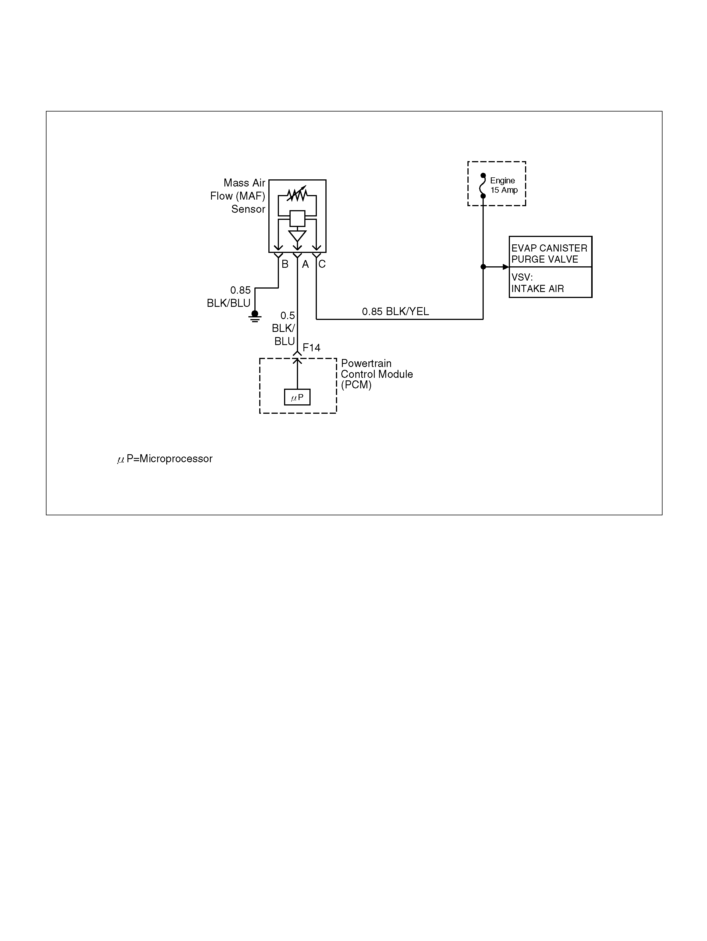
DIAGNOSTIC TROUBLE CODE (DTC) P0103 MAF SENSOR CIRCUIT
HIGH FREQUENCY
060R100112
Circuit Description
The mass air flow (MAF) sensor measures the amount
of air which passes through it into the engine during a
given time. The powertrain con trol module (PCM) uses
the mass air flow information to monitor engine
operating conditions for fuel delivery calculations. A
large quantity of air entering the engine indicates an
accele rator or hig h lo ad situat ion, while a s m all quantity
of air indicates deceleration or idle.
The MAF sensor produces a frequency signal which
can be monitored using a Tech 2. The frequency will
vary wi thin a ran ge of a ro und 4 to 7g/s at idl e t o aroun d
25 to 40 g/s at maximum engine load. DTC P0103 will
be set if the signal from the MAF sensor is above the
possib le range of a normally operating MAF sensor.
Conditions for Setting the DTC
• T he engine is running above 50 0 RPM for more than
10 seconds.
• Sy ste m voltage is above 11.5 volts.
• MAF signal frequency is above 10 kHz for a total of
50 percent of the last 1000 samples monitored. A
sample is taken every cylinder event.
Action Taken When the DTC Sets
• The PCM will ON the MIL after second trip with
detect ed the fault.
• The PCM calculates an airflow v alue based on i dle air
control valve position, throttle position, RPM and
barome tric pressure.
• The PCM will store conditions which were present
when the DTC was set as Freeze Frame and in the
Failure Records data.
Conditions for clearing the MIL/DTC
• The PCM will turn the MIL “OFF" on the third
consecutive trip cycle during which the diagnostic has
been run and the fault condition is no longer present.
• A history DTC P0103 will clear after 40 consecutive
warm-up cy cles have occurred without a fault.
• DTC P0103 can be cleared by using the Tech 2
“Clear Info" function.

Diagnostic Aids
If DTC P0103 cannot be duplicated, the information
included in the Failure Records data can be useful in
determining vehicle mileage since the DTC was last set.
Test Description
Number(s) below refer to the step number(s) on the
Diagnostic Chart.
2. This step verifies that the problem is present at idle.
4. A frequency reading with the MAF sensor connector
disconnected indicates an electromagnetic
interference (EMI) related fault.
8. This vehicle is equipped with a PCM which utilizes an
electrically erasable programmable read only
memory (EEPROM). When the PCM is being
replaced, the new PCM must be programmed.
DTC P0103 – MAF Sensor Circuit High Frequency
Step Action Value(s) Yes No
1 Was the “On-Board Diagnostic (OBD) System Check"
performed? —Go to Step 2 Go to OBD
System Check
2 1. Ignition “ON", engine “OFF".
2. Review and record Te ch 2 Failure Records data.
3. Operate the vehicle within Failure Records
condition s as noted.
4. Using a Tech 2, monitor “DTC" info for DTC
P0103.
Does the Tech 2 indicate DTC P0103 failed this
ignition? — G o to Step 3 Refe r to
Diagnostic Aids
3 1. Start th e engine.
2. With the engine idling, monitor “MAF Frequency"
display on the Tech 2.
Is “MAF Frequency" above the specified value? 40g/s Go to Step 4 Go to Step 7
4 1 . Ig nit io n “ OFF" .
2. Disconnect the MAF sensor connector.
3. Ignition “ON", engine idling.
4. Using a Te ch 2, monitor “MAF Frequency".
Does the Tech 2 indicate a “MAF Frequency" at the
specified value? 0g/s G o to Step 5 Go to Step 6
5 Replace the MAF sensor.
Is the action comple te ? — Verify repair Go to S tep 8
6 1. Check the M AF harnes s for incorrect routing near
high voltage components (solenoids, relays,
motors).
2. If incorrect routing is found, correct the harness
routing.
Was a problem found? — Verify repair Go to Step 6
7 1. With the engine idling, monitor “MAF Frequency"
display on the Tech 2.
2. Quickly snap open throttle to wide open throttle
while under a road load and record value.
Does the Tech 2 in dicate “M A F F requency" a bove t he
specified value? 40g/s G o to Step 5 Go to Step 8

8 Replace the PCM.
Important: The replacement PCM must be
programmed. Refer to Section 0C-1 - Service
Program ming Syst em.
Important: Refer to Section 11 - Engin e Im mobiliser
System for the Immobiliser Programming procedure.
Important: Ensure the latest software program is
downloaded to the PCM.
Is the action complete ? — Verify repair —
Step Action Value(s) Yes No
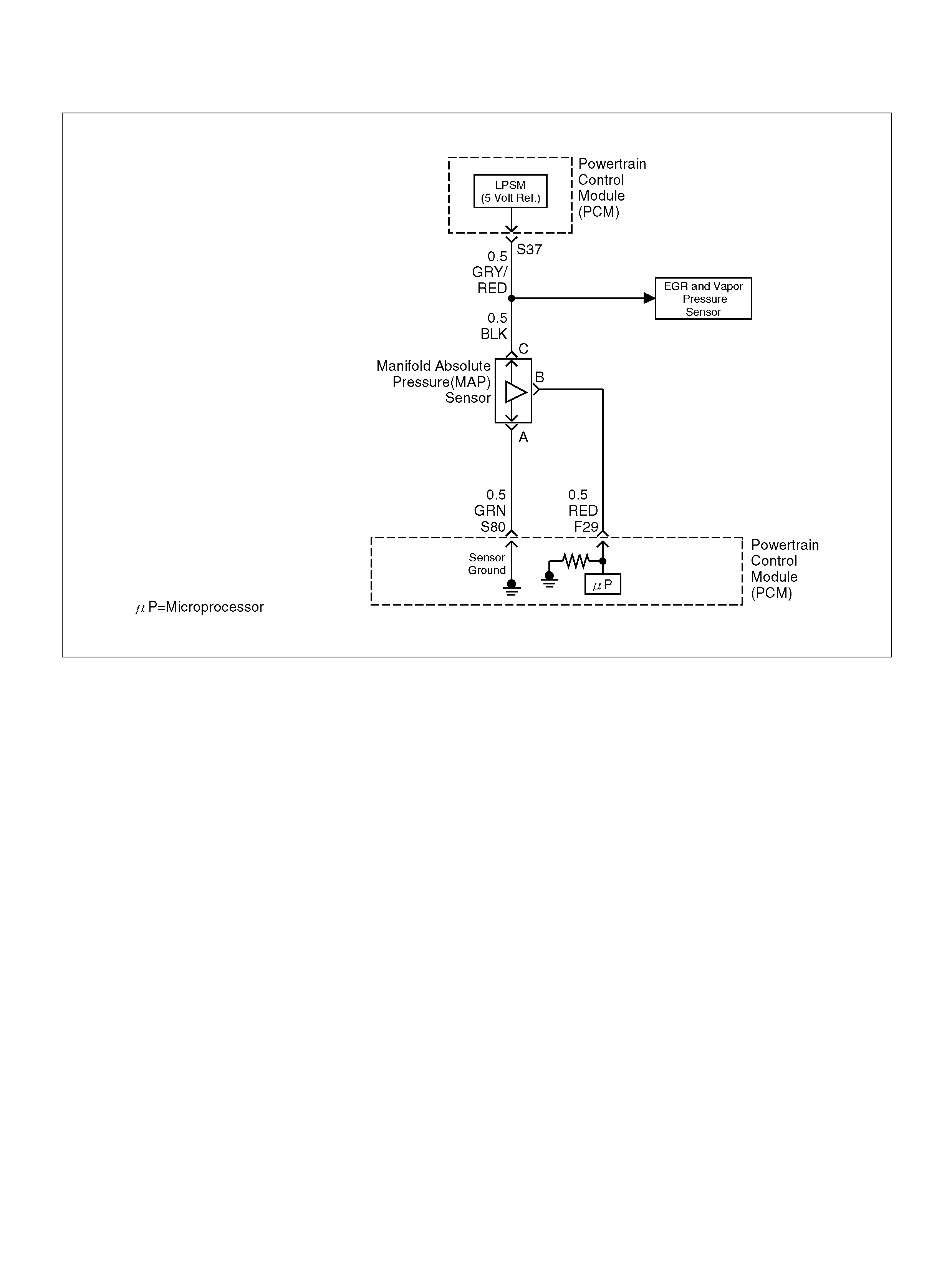
DIAGNOSTIC TROUBLE CODE (DTC) P0106 MAP SYSTEM PERFORMANCE
060R100132
Circuit Description
The manifold absolute pressure (MAP) sensor responds
to changes in intake manifold pressure (vacuum). The
MAP sensor signal voltage to the powertrain control
module (PCM) varies from below 2 volts at idle (high
vacuum) to above 4 volts at wide-open throttle (low
vacuum) at sea level.
The MAP sensor is used to determine manifold
pressure changes while the linear exhaust gas
recirculation (EGR) flow test diagnostic is being run
(refer to DTC P0401), engine vacuum level for some
other diagnostics, and barometric pressure (BARO).
The PCM compares the MAP sensor signal to a
calculated MAP based on throttle position and various
engine load factors. If the PCM detects a MAP signal
that varies excessively above or below the calculated
value, DTC P0106 will s et.
Conditions for Setting the DTC
• N o TP sensor DTCs are present.
• Engine speed is steady, changing less then 100
RPM.
• Engine speed is betwee n 1000 rpm and 4000 rpm.
• Throttle position is steady, throttle angle changes less
than 1%.
• EGR flow rate is steady, changing less than 4%.
• No change in brake switch, A/C clutch, TCC or power
steering pressure sw itch status.
• Abov e condi tions are met for longer than 1 second.
• Calculated MAP signal indicates an value
significantly higher or lower than a predicated value
base d on t hrottle pos ition and engine RP M for a total
of 12.5 second s over 25 second period of time.
Action Taken When the DTC Sets
• The PCM will illuminate the malfunction indicator
lamp (M IL) after the second c onsecutive trip in which
the fault is detected .
• T he PC M will default to a BARO value of 79.3k Pa.
• The PCM will store conditions which were present
when the DTC was set as Freeze Frame and in the
Failure Records data.
Conditi ons for Clea r ing the MIL/DTC
• The PCM will turn the MIL “OFF" on the third
consecutive trip cycle during which the diagnostic has
been run and the fault condition is no longer present.
• A history DTC P0106 will clear after 40 consecutive
warm-up cy cles have occurred without a fault.
• DTC P0106 can be cleared by using the Tech 2
“Clear Info" function.

Diagnostic Aids
Check for the following conditions:
• Poor connection at PCM – Inspect harness
connectors for backed-out terminals, improper
mating, broken locks, improperly formed or damaged
terminals, and poor terminal-to-wire connection.
• Damaged harness – Inspect the wiring harness for
damage. If the harness appears to be OK, observe
the MAP display on the Tech 2 while moving
connectors and wiring harnesses related to the
sensor. A change in the display will indicate the
location of the fault.
If DTC P0106 cannot be duplicated, the information
included in the Failure Records data can be useful in
determining vehicle mileage since the DTC was last set.
If it is determined that the DTC occurs intermittently,
performing the DTC P1107 Diagnostic Chart may
isolate the cause of the fault.
DTC P0106 – MAP System Performance
Step Action Value(s) Yes No
1 Was the “On-Board Diagnostic (OBD) System Check"
performed? — Go to Step 2 Go to OBD
System Check
2 1. Ignition “ON", engine “OFF".
2. Review and record Te ch 2 Failure Records data.
3. Operate the vehicle within Failure Records
condition s as noted.
4. Using a Tech 2, monitor “DTC" info for DTC
P0106.
Does the Tech 2 indicate DTC P0106 failed? — G o to Step 4 Go to Step 3
3 1. Check for the follo wing conditions:
• Vacuum hoses disconnected, damaged, or
incorrectly routed
• Intake man ifold vacuum leaks
• Vacuum leaks at throttle body
• Vacuum leaks at EGR valve flange and pipes;
• Crankcase ventilation valve faulty, missing or
incorrectly installed.
2. If a problem is found, repair as necessary.
Was a problem found? — Verify repair Refer to
Diagnostic Aids
4 1. Disconnect the MAP sensor electrical connector .
2. Observe the MAP value displayed on the Tech 2.
Is the MAP value near the specified value? 11kPa Go to Step 5 Go to Step 13
5 1. Connect a test light between B+ and the MAP
sensor signal circuit at the MAP sensor harness
connector.
2. Observe the MAP value displayed on the Tech 2.
Is the MAP value near the specified value? 105kPa Go to St ep 6 Go to Step 9
6 1. Jumper the 5 volt reference circuit and the MAP
signal circuit together at the MAP sensor harness
connector.
2. Observe the MAP value displayed on the Tech 2.
Is the MAP value near the specified value? 104kPa Go to St ep 7 Go to Step 8
7 1 . Ig nit io n “ OFF" .
2. Disconnect the PCM and check the sensor ground
circuit for high resistance, an open between the
PCM and the MAP sensor, or for a poor
connection at the PCM.
3. If a problem is found, repair as necessary.
Was a problem found? — Verify rep air Go to Step 11

8 1. Check the 5 volt reference circuit for high
resistance, an open between the PCM and the
MAP sens or, or a poor connection at the PCM.
2. If a problem is found, repair as necessary.
Was a problem found? — Verify rep air Go to Step 10
9 1 . Ig nit io n “ OFF" .
2. Disconnect the PCM, and check the MAP sensor
signal circuit for high resistance, an open, a short
to ground, or a short to the sensor ground circuit.
3. If a problem is found, repair as necessary.
Was a problem found? — Verify rep air Go to Step 10
10 1. Check the MAP sensor signal circuit for a poor
connection at the PCM.
2. If a problem is found, repair as necessary.
Did the terminal require replacement? — Verify rep air Go to Step 14
11 1. Check for a poor connection at the MAP sensor.
2. If a problem is found, repair as necessary.
Was a problem found? — Verify rep air Go to Step 12
12 Replace the MAP se nsor.
Is the action complete ? — Verify repair —
13 1. Ignition “OFF", disconne cted the PCM .
2. Ignition “ON", check the MAP signal circuit for a
short to voltage or a short to the 5 volt reference
circuit.
3. If a problem is found, repair as necessary.
Was a problem found? — Verify rep air Go to Step 14
14 Replace the PCM.
Important: The replacement PCM must be
programmed. Refer to Section 0C-1 - Service
Program ming Syst em.
Important: Refer to Section 11 - Engin e Im mobiliser
System for the Immobiliser Programming procedure.
Important: Ensure the latest software program is
downloaded to the PCM.
Is the action complete ? — Verify repair —
Step Action Value(s) Yes No

DIAGNOSTIC TROUBLE CODE (DTC) P0107 MAP SENSOR CIRCUIT
LOW VOLTAGE
060R100132
Circuit Description
The manifold absolute pressure (MAP) sensor responds
to changes in intake manifold pressure (vacuum). The
MAP sensor signal voltage to the powertrain control
module (PCM) varies from below 2 volts at idle (high
vacuum) to above 4 volts with the ignition “ON", engine
not running or at wide-open throttle (low vacuum).
The MAP sensor is used to determine manifold
pressure changes while the exhaust gas recirculation
(EGR) flow test diagnostic is being run (refer to
DTC P0401), to determine engine vacuum level for
some other diagnostics and to determine barometric
pressure (BARO). The PCM monitors the MAP signals
for voltages outside the normal range of the MAP
sensor. If the PCM de tects a MAP signal vol tage that is
excessively low, DTC P0107 will be set.
Conditions for Setting the DTC
• N o TP sensor DTCs present.
• Engine is running.
• Throttle angle is above 1% if engine speed is less
than 100 0RP M .
• Throttle angle is abo ve 2% if engine speed is above
1000RPM.
• The MAP sensor indicates manifold absolute
pressure at or below 11kPa for a total of
approx imatel y 10 seconds over a 16-second perio d.
• Ignition voltage more than 11 volts.
Action Taken When the DTC Sets
• The PCM will ON the MIL after second trip with
d e te ct e d fa ult.
• T he PC M will default to a BARO value of 79.3k Pa.
• The PCM will store conditions which were present
when the DTC was set as Freeze Frame and in the
Failure Records data.
Conditi ons for Clea r ing the MIL/DTC
• The PCM will turn the MIL “OFF" on the third
consecutive trip cycle during which the diagnostic has
been run and the fault condition is no longer present.
• A history DTC P0107 will clear after 40 consecutive
warm-up cy cles have occurred without a fault.
• DTC P0107 can be cleared by using the Tech 2
“Clear Info" function.

Diagnostic Aids
Check for the following conditions:
• Check for intermittent codes.
• The MAP sensor shares a 5 Volt reference with the
Fuel Tank Pressure Sensor. If these codes are also
set, it could indicate a problem with the 5 Volt
reference circuit .
• The MAP sensor shares a ground with the Fuel Tank
Pressure Sensor, the ECT sensor, and the
Transmission Fluid Temperature sensor.
• Poor connection at PCM – Inspect harness
connectors for backed-out terminals, improper
mating, broken locks, improperly formed or damaged
terminals, and poor terminal-to-wire connection.
• Damaged harness – Inspect the wiring harness for
damage. If the harness appears to be OK, observe
the MAP display on the Tech 2 while moving
connectors and wiring harnesses related to the
sensor. A change in the display will indicate the
location of the fault.
If DTC P0107 cannot be duplicated, the information
included in the Failure Records data can be useful in
determining vehicle mileage since the DTC was last set.
If it is determined that the DTC occurs intermittently,
performing the DTC P0107 Diagnostic Chart may
isolate the cause of the fault.
DTC P0107 – MAP Sensor Circuit Low Voltage
Step Action Value(s) Yes No
1 Was the “On-Board Diagnostic (OBD) System Check"
performed? — Go to Step 2 Go to OBD
System Check
2 1. Ignition “ON", engine “OFF".
2. With the throttle closed, observe the MAP value
displayed on the Tech 2.
Is the MAP value near the specified value? 0V 11kPa at
sea level Go to Step 4 Go to Step 3
3 1. Ignition “ON", engine “OFF".
2. Review and record Te ch 2 Failure Records data.
3. Operate the vehicle within Failure Records
condition s as noted.
4. Using a Tech 2, monitor “DTC" info for DTC
P0107.
Does the Tech 2 indicate DTC P0107 failed? — G o to Step 4 R efer to
Diagnostic Aids
4 1 . Ig nit io n “ OFF" .
2. Disconnect the MAP sensor electrical connector.
3. Jumper the 5 volt reference circuit and the MAP
signal together at the MAP sensor harness
connector.
4. Ignition “ON".
5. Observe the MAP value displayed on the Tech 2.
Is the MAP value near the specified value? (If no, start
with diagnosis chart f or other sensors in the circuit and
see if 5V returns.) 5 V 104kPa Go to Step 10 Go to Step 5
5 1. Disconnect the jumper .
2. Connect a test light between B+ and the MAP
sensor signal circuit at the MAP sensor harness
connector.
3. Observe the MAP value displayed on the Tech 2.
Is the MAP value near the specified value. 5 V 104kPa Go to Step 6 Go to Step 8
6 1 . Ig nit io n “ OFF" .
2. Disconnect the PCM and check the 5 volt
reference circuit for an open or sh ort to ground.
3. If the 5 volt reference circuit is open or shorted to
ground, repair it as necessary.
Was the 5 volt reference circuit open or shorted to
ground? — Verify repair Go to Step 7

7 Check the 5 volt reference circuit for a poor
connection at the PCM and replace the terminal if
necessary.
Did the terminal require replacement? — Verify repair Go to Step 11
8 1 . Ig nit io n “ OFF" .
2. Disconnect the PCM, and check the MAP signal
circuit for an open, sh ort to ground , or short to t he
sensor ground circuit.
3. If the MAP s ensor signal circu it is ope n or s ho rted
to ground, repair it as necessary.
Was the MAP signal circuit open or shorted to
ground? — Verify repair Go to Step 9
9 Check the MAP sensor signal circuit for a poor
connection at the PCM and the MAP sensor; replace
the terminal if necessary.
Did the terminal require replacement? — Verify repair Go to Step 11
10 Replace the MAP se nsor.
Is the action complete ? — Verify repair —
11 Replace the PCM.
Important: The replacement PCM must be
programmed. Refer to Section 0C-1 - Service
Program ming Syst em.
Important: Refer to Section 11 - Engin e Im mobiliser
System for the Immobiliser Programming procedure.
Important: Ensure the latest software program is
downloaded to the PCM.
Is the action complete ? — Verify repair —
Step Action Value(s) Yes No

DIAGNOSTIC TROUBLE CODE (DTC) P0108 MAP SENSOR CIRCUIT
HIGH VOLTAGE
060R100132
Circuit Description
The manifold absolute pressure (MAP) sensor responds
to changes in intake manifold pressure (vacuum). The
MAP sensor signal voltage to the powertrain control
module (PCM) varies from below 2 volts at idle (high
vacuum) to above 4 volts with the key “ON", engine not
running or at wide-open throttle (low vacuum).
The MAP sensor is used to determine manifold
pressure changes while the linear EGR flow test
diagnostic is being run (refer to DTC P0401), to
determine engine vacuum level for some other
diagnostics and to determine barometric pressure
(BARO). The PCM monitors the MAP signals for
voltages outside the norm al rang e of the MA P sen so r. If
the PCM detects a MAP signal voltage that is
exces s ively high, DTC P0 108 will be s et.
Conditions for Setting the DTC
• N o TP sensor DTCs present.
• Engine is running for more than 10 seconds.
• Throttle position is below 3% if engine speed is below
1000 RPM.
• Throttle position is below 10% if engine speed is
above 1000 RPM.
• The MAP sensor indicates an intermittent manifold
absolute pressure above 80kPa for a total of
approx imatel y 10 seconds over a 16-second perio d.
Action Taken When the DTC Sets
• The PCM will ON the MIL after second trip with
d e te ct e d fa ult.
• T he PC M will default to a BARO value of 79.3k Pa.
• The PCM will store conditions which were present
when the DTC was set as Freeze Frame and in the
Failure Records data.
Conditi ons for Clea r ing the MIL/DTC
• The PCM will turn the MIL “OFF" on the third
consecutive trip cycle during which the diagnostic has
been run and the fault condition is no longer present.
• A history DTC P0108 will clear after 40 consecutive
warm-up cy cles have occurred without a fault.
• DTC P0108 can be cleared by using the Tech 2
“Clear Info" function.

Diagnostic Aids
Check for the following conditions:
• The MAP sensor shares a 5 Volt reference with the
Fuel Tank Pressure Sensor (Vapor Pressure Sensor).
If these codes are also set, it could indicate a
problem with the 5 Volt reference circuit.
• The MAP sensor shares a ground with the Fuel Tank
Pressure Sensor, the ECT sensor, and the
Transmission Fluid Temperature sensor.
• Poor connection at PCM – Inspect harness
connectors for backed-out terminals, improper
mating, broken locks, improperly formed or damaged
terminals, and poor terminal-to-wire connection.
• Damaged harness – Inspect the wiring harness for
damage. If the harness appears to be OK, observe
the MAP display on the Tech 2 while moving
connectors and wiring harnesses related to the
sensor. A change in the display will indicate the
location of the fault.
If DTC P0108 cannot be duplicated, the information
included in the Failure Records data can be useful in
determining vehicle mileage since the DTC was last set.
If it is determined that the DTC occurs intermittently,
performing the DTC P1108 Diagnostic Chart may
isolate the cause of the fault.
DTC P0108 – MAP Sensor Circuit High Voltage
Step Action Value(s) Yes No
1 Was the “On-Board Diagnostic (OBD) System Check"
performed? — Go to Step 2 Go to OBD
System Check
2 1. If the engine idle is rough, unstable or incorrect,
repair the idle problem before using this chart.
Refer to Symptoms section.
2. With the engine idling, no te the MAP value on the
Tech 2.
Is the MAP reading above the specified value? 90kPa Go to St ep 4 Go to S tep 3
3 1. Ignition “ON", engine “OFF".
2. Review and record Te ch 2 Failure Records data.
3. Operate the vehicle within Failure Records
condition s as noted.
4. Using a Tech 2, monitor “DTC" info for DTC
P0108.
Does the Tech 2 indicate DTC P0108 failed this
ignition? — Go to Step 4 Refe r to
Diagnostic Aids
4 1 . Ig nit io n “ OFF" .
2. Disconnect the MAP sensor electrical connector.
3. Ignition “ON".
4. Note the MAP sensor voltage displayed on the
Tech 2. (If no, start with diagnostic chart for other
sensors in the circuit and see if 5V returns.)
Is the MAP sensor voltage at the specified value? 11kP a 0.0 V G o to Step 5 Go to Step 6
5 Probe the sensor ground circuit with a test light to B+.
Is the test light “ON" ? — Go to St ep 7 Go to S tep 9
6 1. Check the MAP signal circuit for a short to voltage
or a short to the 5 volt reference circuit.
2. If the MAP sensor signal circuit is shorted, repair
circuit as necessary.
Was the M AP sens or signal circuit shorted? — Verify repair Go to Step 11
7 1. Check for a poor sensor ground terminal
connection at the MAP sensor electrical
connector.
2. If a p ro blem is found, replace the faulty terminal.
Did the terminal require replacement? — Verify repair Go to Step 8

8 Check for a plugg ed or leaking vacuum supply to the
MA P sensor.
Is the vacuum supply plug ged or leaking? — Veri fy repair Go to Step 12
9 1. Check for a poor sensor ground terminal
connection at the PCM.
2. If a p ro blem is found, replace the faulty terminal.
Did the terminal require replacement? — Verify rep air Go to Step 10
10 1. Check the continuity of the MAP sensor ground
circuit.
2. If th e MAP sensor groun d c ircuit measures over 5
ohms, repair open or poor connection.
Was a condition found and corrected? — Verify repair Go to Step 11
11 Replace the PCM.
Important: The replacement PCM must be
programmed. Refer to Section 0C-1 - Service
Program ming Syst em.
Important: Refer to Section 11 - Engin e Im mobiliser
System for the Immobiliser Programming procedure.
Important: Ensure the latest software program is
downloaded to the PCM.
Is the action complete ? — Verify Repair —
12 Replace the MAP se nsor.
Is the action complete ? — Verify repair —
Step Action Value(s) Yes No

DIAGNOSTIC TROUBLE CODE (DTC) P0112 IAT SENSOR CIRCUIT
LOW VOLTAG E
D06RY00147
Circuit Description
The intake air temperature (IAT) sensor is a thermistor
which measures the temperature of the air entering the
engine. The powert rain control m odul e (P CM ) applies 5
volts through a p ull-up resis tor t o the IAT senso r. Whe n
the intake air is cold, the sensor resistance is high and
the PCM will monitor a high signal voltage on the IAT
signal circuit. If the intake air is warm, the sensor
resistance is lower, c ausing the P CM t o m onitor a l ower
voltage. DTC P0112 will set when the PCM detects an
excessively low signal voltage on the intake air
temperature sensor signal circuit.
Conditions for Setting the DTC
• T he engin e has been running for over 15 seconds.
• V ehicle speed is greater than 30 mph (48 km/h) .
• IAT signal voltage indicates and intake air
temperature greater than 148°C (298°F) (about 5
volts) for a total of 12.5 seconds over a 25-second
period of time.
Action Taken When the DTC Sets
• The PCM will ON the MIL after second trip with
d e te ct e d fault.
• The PCM will store conditions which were present
when the DTC was set as Freeze Frame and in the
Failure Records data.
Conditi ons for Clea r ing the MIL/DTC
• The PCM will turn the MIL “OFF" on the third
consecutive trip cycle during which the diagnostic has
been run and the fault condition is no longer present.
• A history DTC P0112 will clear after 40 consecutive
warm-up cy cles have occurred without a fault.
• DTC P0112 can be cleared by using the Tech 2
“Clear Info" function.
Diag nostic Ai ds
Check for the following conditions:
• Poor connection at PCM – Inspect harness
connectors for backed-bout terminals, improper
mating, broke n l ocks, i mpro perly f orm ed o r dam aged
terminals, and poor terminal-to-wire connection.
• Damaged harness – Inspect the wiring harness for
damage. If the harness appears to be OK, observe
the IAT display on the Tech 2 while moving
connectors and wiring harnesses related to the IAT
sensor. A change in the IAT display will indicate the
location of the fault.

If DTC P0112 cannot be duplicated, the information
included in the Failure Records data can be useful in
determining vehicle mileage since the DTC was last set.
Test Description
Number(s) below refer to the step number(s) on the
Diagnostic Chart:
2. Verifies that the fault is present.
3. If DTC P0112 can be repeated only by duplicating the
Failure Records condition, refer to the Temperature
vs. Resistance Value table. The t able may be used to
test the IAT sensor at various temperatures to
evaluate the possibility of a “shifted" sensor that may
be stored above or below a certain temperature. If
this is the case, replace the IAT sensor. If the IAT
sensor appears to be OK, the fault is intermittent;
refer to Diagnostic Aids.
Intake Air Temperature Sensor
°C°FOHMS
Temperature vs. Resistance Values (approxim ate)
100 212 177
80 176 332
60 140 667
45 113 1188
35 95 1802
25 77 2796
15 59 4450
5417280
–5 23 12300
–15 5 21450
–30 –22 52700
–40 –40 100700

DTC P0112–IAT Sensor Circuit Low Voltage
Step Action Value(s) Yes No
1 Was the “On-Board Diagnostic (OBD) System Check"
performed? — Go to Step 2 Go to OBD
System Check
2 1. Ignition “ON", engine “OFF".
2. Using a Tech 2, monitor the intake air tempe rature
(IAT).
Is the intake air temperature greater than the specified
value? 148°C
(283°F) Go to Step 4 Go to Step 3
3 1. Ignition “ON", engine “OFF". Review and record
Tech 2 Failure Records data .
2. Operate the vehicle within Failure Records
condition s as noted.
3. Using a Tech 2, monitor the “DTC" info for DTC
P0112.
Does the Tech 2 indicate DTC P0112 failed this
ignition? — Refer to Test
Description Refe r to
Diagnostic Aids
4 1 . Ig nit io n “ OFF" .
2. Disconnect the IAT sensor electrical connec tor.
3. Ignition “ON".
4. Observe the intake air temperature on the Tech 2.
Is the intake air temperature below the specified
value? –38°C (–
36°F) Go to Step 6 Go to S tep 5
5 1 . Ig nit io n “ OFF" .
2. Disconnect the PCM electrical connect ors.
3. Check the IAT sensor signal circuit for a short to
ground.
Is the IAT sensor signal circuit shorted to ground? — Verify repair Go to Step 7
6 Replace the IAT sensor.
Is the action complete ? — Verify repair —
7 Replace the PCM.
Important: The replacement PCM must be
programmed. Refer to Section 0C-1 - Service
Program ming Syst em.
Important: Refer to Section 11 - Engin e Im mobiliser
System for the Immobiliser Programming procedure.
Important: Ensure the latest software program is
downloaded to the PCM.
Is the action complete ? — Verify repair —
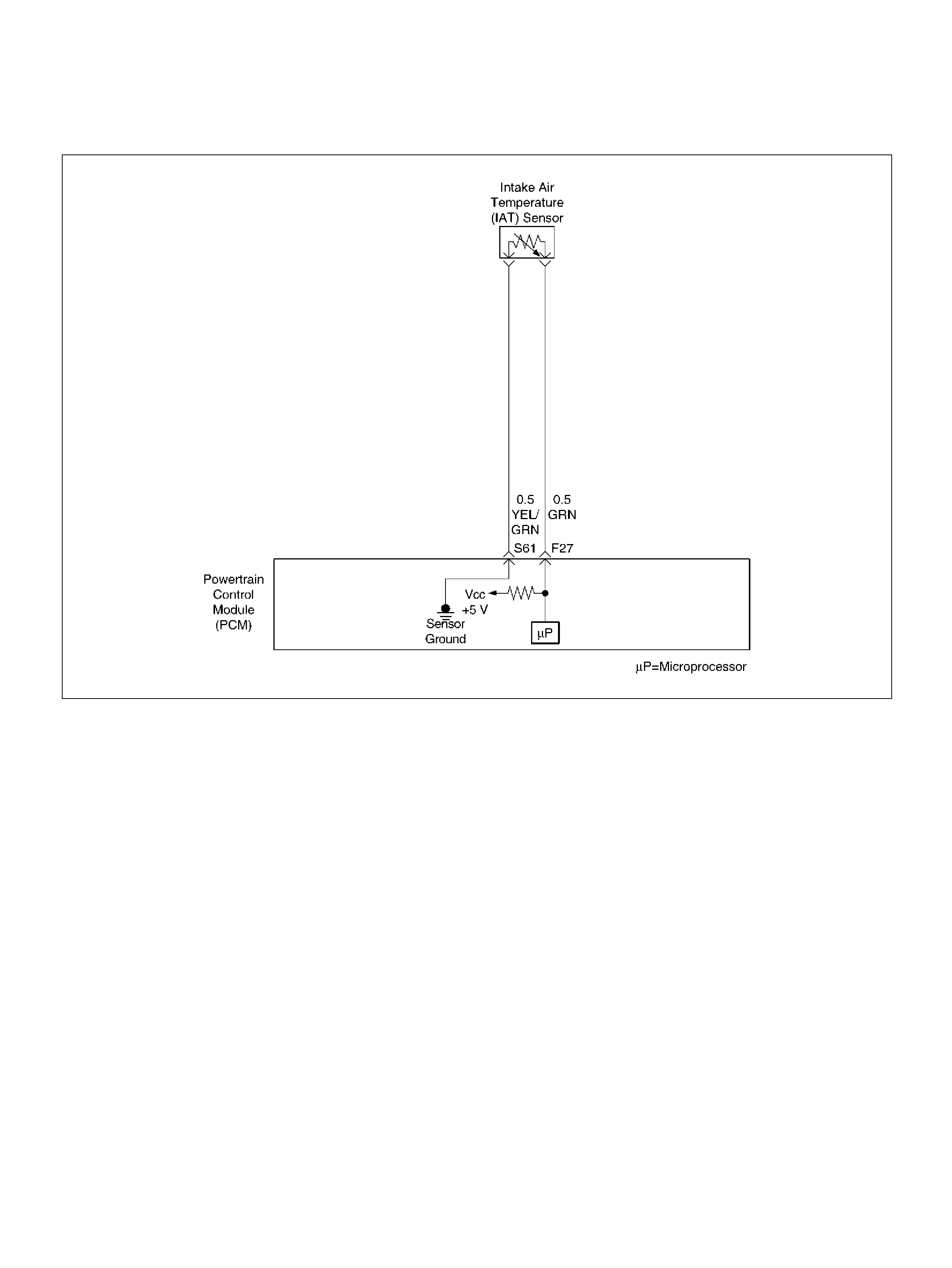
DIAGNOSTIC TROUBLE CODE (DTC) P0113 IAT SENSOR CIRCUIT
HIGH VOLTAGE
D06RY00147
Circuit Description
The intake air temperature (IAT) sensor is a thermistor
which measures the temperature of the air entering the
engine. The powert rain control m odul e (P CM ) applies 5
volts through a p ull-up resis tor t o the IAT senso r. Whe n
the intake air is cold, the sensor resistance is high and
the PCM will monitor a high signal voltage on the IAT
signal circuit. If the intake air is warm, the sensor
resistance is lower cau sing the PC M to m onitor a lower
voltage. DTC P0113 will set when the PCM detects an
excessively high signal voltage on the intake air
temperature sensor signal circuit.
Conditions for Setting the DTC
• T he engin e has been running for over 30 seconds.
• V ehi cle speed is less than 20 mph (32 km/h).
• ECT signal temperature is above 60°C (140°F).
• Mas s air flow is less t hen 20 g/secon d.
• IAT signal voltage indi cates an i ntake air temperat ure
less than –39°C (–38°F) for total of 12.5 seconds
ove r a 25-second period.
Action Taken When the DTC Sets
• The PCM will ON the MIL after second trip with
d e te ct e d fa ult.
• The PCM will store conditions which were present
when the DTC was set as Freeze Frame and in the
Failure Records data.
Conditi ons for Clea r ing the MIL/DTC
• The PCM will turn the MIL “OFF" on the third
consecutive trip cycle during which the diagnostic has
been run and the fault condition is no longer present.
• A history DTC P0113 will clear after 40 consecutive
warm-up cy cles have occurred without a fault.
• DTC P0113 can be cleared by using the Tech 2
“Clear Info" function.
Diag nostic Ai ds
Check for the following conditions:
• Poor connection at PCM – Inspect harness
connectors for backed-out terminals, improper
mating, broke n l ocks, i mpro perly f orm ed o r dam aged
terminals, and poor terminal-to-wire connection.

• Damaged harness – Inspect the wiring harness for
damage. If the harness appears to be OK, observe
the IAT display on the Tech 2 while moving
connectors and wiring harnesses related to the IAT
sensor. A change in the IAT display will indicate the
location of the fault.
If DTC P0113 cannot be duplicated, the information
included in the Failure Records data can be useful in
determining vehicle mileage since the DTC was last set.
Test Description
Number(s) below refer to the step number(s) on the
Diagnostic Chart:
2. Verifies that the fault is present.
3. If DTC P0113 can be repeated only by duplicating the
Failure Records conditions, refer to the
“Temperature vs. Resistance Values" table. The
table may be used to test the IAT sensor at various
temperatures to evaluate the possibility of a “shifted"
sensor that may be open above or below a certain
temperature. If this is the case, replace the IAT
sensor. If the IAT sensor appears to be OK, the fault
is intermittent; refer to Diagnostic Aids.
Intake Air Temperature Sensor
DTC P0113 –IAT Sensor Circuit High Voltage
°C °FOHMS
Temperature vs. Resistance Values (approximate)
100 212 177
80 176 332
60 140 667
45 113 1188
35 95 1802
25 77 2796
15 59 4450
5417280
–5 23 12300
–15 5 21450
–30 –22 52700
–40 –40 100700
Step Action Value(s) Yes No
1 Was the “On-Board Diagnostic (OBD) System Check"
performed? — Go to Step 2 Go to OBD
System Check
2 Ignition “ON", engine “OFF". Observe the “Intake Air
Temp" display on the Tech 2.
Is the “Intake Air Temp" below the specified value? –38°C (–
36°F) Go to Step 4 Go to S tep 3
3 1. Ignition “ON", engine “OFF".
2. Review and record Tech 2 Failure Records data
parameters.
3. Operate the vehicle within Failure Records
condition s as noted.
4. Using a Tech 2, monitor “DTC" info for DTC
P0113.
Does the Tech 2 indicate DTC P0113 failed? — Refer to Test
Description Refe r to
Diagnostic Aids
4 1 . Ig nit io n “ OFF" .
2. Disconnect the IAT sensor electrical connec tor.
3. Jumper the IAT signal circuit and the sensor
ground circuit together at the IAT sensor harness
connector.
4. Ignition “ON".
5. Observe the “Intake A ir Temp" display on the Tech
2.
Is the “Intake Air Temp" at the specified value? 140°C
(284°F) Go to Step 6 Go to Step 5
5 1. Jumper the IAT signal circuit at the IAT sensor
harness connec tor to chassis ground.
2. Observe the “Intake A ir Temp" display on the Tech
2.
Is the “Intake Air Temp" at the specified value? 140°C
(284°F) Go to Step 7 Go to Step 8

6 Check for poor connections at the IAT sensor and
replace terminals if necessary.
Did any terminals require replacement? — Verify repair Go to Step 10
7 1 . Ig nit io n “ OFF" .
2. Disconnect the PCM, and check the IAT sensor
ground circuit for an open.
3. If the IAT sensor ground circuit is open, repair it as
necessary.
Was the IAT sensor ground circuit open? — Verify repair Go to Step 9
8 1 . Ig nit io n “ OFF" .
2. Disconnect the PCM, and check the IAT signal
circuit for an open.
3. If the IAT sensor signal circuit is open, repair it as
necessary.
Was the IAT signal cir cuit open? — Verify repair Go to S tep 9
9 Check for a poor sensor ground or IAT signal circuit
terminal connection at the PCM and replace
terminal(s) if necessary.
Did any of the terminals need to be replaced? — Verify r epair Go to Step 11
10 Replace the IAT sensor.
Is the action complete ? — Verify repair —
11 Replace the PCM.
Important: The replacement PCM must be
programmed. Refer to Section 0C-1 - Service
Program ming Syst em.
Important: Refer to Section 11 - Engin e Im mobiliser
System for the Immobiliser Programming procedure.
Important: Ensure the latest software program is
downloaded to the PCM.
Is the action complete ? — Verify repair —
Step Action Value(s) Yes No

DIAGNOSTIC TROUBLE CODE (DTC) P0117 ECT SENSOR CIRCUIT
LOW VOLTAG E
D06RY00148
Circuit Description
The engine coolant temperature (ECT) sensor is a
thermistor mounted on a coolant crossover pipe at the
front of the engine. The powertrain control module
(PCM) applies a voltage (about 5 volts) through a
pull-up resistor to the ECT signal circuit. When the
engine coolant is cold, the sensor (thermistor)
resistance is high, therefore the PCM will measure a
high signal voltage. As the engine coolant warms, the
sensor resistance becomes lower, and the ECT signal
voltage measured at the PCM drops. With a fully
warmed-up engine, the ECT signal voltage should
measure about 1.5 to 2.0 volts.
Conditions for Setting the DTC
• Engine running time is longer than 120 seconds.
• The ECT sensor signal indicates an engine coolant
temperature greater than 150°C (302°F) (about 0.10
V) for a total of 50 seconds over a 100–second
period.
Action Taken When the DTC Sets
• The PCM will ON the MIL after second trip with
d e te ct e d fault.
• The PCM will substitute the ECT reading with a
default engine coolant temperature value. The default
value is based on start -up intak e air tem perature and
running time.
• The PCM will store conditions which were present
when the DTC was set as Freeze Frame and in the
Failure Records data.
Conditi ons for Clea r ing the MIL/DTC
• The PCM will turn the MIL “OFF" on the third
consecutive trip cycle during which the diagnostic has
been run and the fault condition is no longer present.
• A history DTC P0117 will clear after 40 consecutive
warm-up cy cles have occurred without a fault.
• DTC P0117 can be cleared by using the Tech 2
“Clear Info" function.
Diag nostic Ai ds
Check for the following conditions:
• Poor connection at PCM – Inspect harness
connectors for backed-out terminals, improper
mating, broke n l ocks, i mpro perly f orm ed o r dam aged
terminals, and poor terminal-to-wire connection.

• Damaged harness – Inspect the wiring harness for
damage. If the harness appears to be OK, observe
the ECT display on the Tech 2 while moving
connectors and wiring harnesses related to the ECT
sen so r. A change in the EC T display will indicat e th e
locati on of the fault.
If DTC P0117 cannot be duplicated, the information
included in the Failure Records data can be useful in
determining vehicle mileage since the DTC was last set.
If it is determined that the DTC occurs intermittently,
performing the DTC P1114 Diagnostic Chart may isolate
the cause of the fault.
Test Description
Number(s) below refer to the step number(s) on the
Diagnostic Chart.
2. Verifies that the fault is present.
3. f DT C P 0117 can be repeat ed only by duplicating th e
Failure Records conditions, refer to the
“Temperature vs. Resistance Values" table. The
table may be used to test the ECT sens or at va ri ous
temperat ures to evaluat e the pos sibility of a “shifted"
sensor that may be shorted above or b elow a certain
temperature. If this is the case, replace the ECT
sensor . If the ECT sensor appears to be OK, the fault
is intermittent; refer to Diagnostic Aids.
Engine Coolant Temperature Sensor
°C°FOHMS
Temperature vs. Resistance Values (approxim ate)
100 212 177
80 176 332
60 140 667
45 113 1188
35 95 1802
25 77 2796
15 59 4450
5417280
–5 23 12300
–15 5 21450
–30 –22 52700
–40 –40 100700

DTC P0117 – ECT Sensor Low Voltage
Step Action Value(s) Yes No
1 Was the “On-Board Diagnostic (OBD) System Check"
performed? — Go to Step 2 Go to OBD
System Check
2 1. Ignition “ON", engine “OFF".
2. Observe the “E ng Coo l Tem p" display on the Tech
2.
Is the “Eng Cool Temp" below the specified value? 139°C
(282°F) Go to Step 4 Go to Step 3
3 1. Ignition “ON", engine “OFF".
2. Review and record Te ch 2 Failure Records data.
3. Operate the vehicle within Failure Records
condition s as noted.
4. Using a Tech 2, monitor “DTC" info for DTC
P0117.
Does the Tech 2 indicate DTC P0117 failed this
ignition? — Go to Step 4 Refe r to
Diagnostic Aids
4 1. Disconnect the ECT sensor electrical connector.
2. Observe the “E ng Coo l Tem p" display on the Tech
2.
Is the “Eng Cool Temp" at the specified value? –39°C (–
38°F) Go to Step 6 Go to S tep 5
5 1 . Ig nit io n “ OFF" .
2. Disconnect the PCM and check the ECT signal
circuit for a short to ground or a short to the sensor
ground circuit.
3. If the ECT signal circuit is shorted. repair it as
necessary.
Was the ECT signal circuit shorted to ground? — Verify repair Go to Step 7
6 Replac e the ECT sens or.
Is the action complete ? — Verify repair —
7 Replace the PCM.
Important: The replacement PCM must be
programmed. Refer to Section 0C-1 - Service
Program ming Syst em.
Important: Refer to Section 11 - Engin e Im mobiliser
System for the Immobiliser Programming procedure.
Important: Ensure the latest software program is
downloaded to the PCM.
Is the action complete ? — Verify repair —
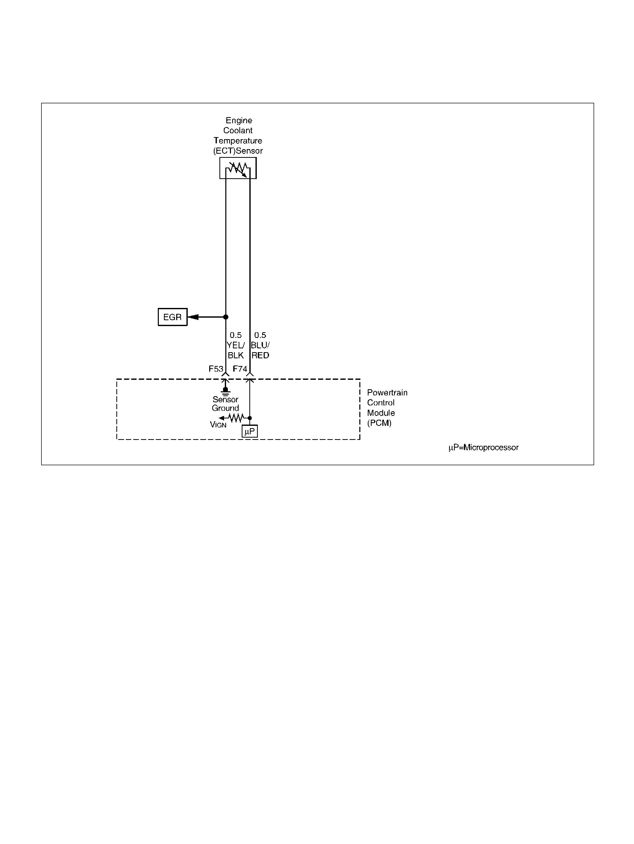
DIAGNOSTIC TROUBLE CODE (DTC) P0118 ECT SENSOR CIRCUIT
HIGH VOLTAGE
D06RY00148
Circuit Description
The engine coolant temperature (ECT) sensor is a
thermistor mounted in on a coolant crossover pipe at
the front of the engine. The powertrain control module
(PCM) applies a voltage (about 5 volts) through a
pull-up resistor to the ECT signal circuit. When the
engine coolant is cold, the sensor (thermistor)
resistance is high, therefore the PCM will measure a
high signal voltage. As the engine coolant warms, the
sensor resistance becomes less, and the ECT signal
voltage measured at the PCM drops. With a fully
warmed-up engine, the ECT signal voltage should
measure about 1.5 to 2.0 volts.
Conditions for Setting the DTC
• Engine running time is longer than 90 seconds.
• The ECT sensor signal indicates an engine coolant
temperature of –39°C (–38°F) or less (abou t 5 volts)
for a total of 50 seconds over a 100-second period.
Action Taken When the DTC Sets
• The PCM will ON the MIL after second trip with
d e te ct e d fault.
• The PCM will substitute the ECT reading with a
default engine coolant temperature value. The default
value is based on start -up intak e air tem perature and
running time.
• The PCM will store conditions which were present
when the DTC was set as Freeze Frame and in the
Failure Records data.
Conditi ons for Clea r ing the MIL/DTC
• The PCM will turn the MIL “OFF" on the third
consecutive trip cycle during which the diagnostic has
been run and the fault condition is no longer present.
• A history DTC P0118 will clear after 40 consecutive
warm-up cy cles have occurred without a fault.
• DTC P0118 can be cleared by using the Tech 2
“Clear Info" function.
Diag nostic Ai ds
Check for the following conditions:
The ECT shares a ground with the Transmission Fluid
Temperature sensor, the Fuel Tank Pressure sensor,
and the MAP sensor.
Check the ground if these DTCs are also set.

• Poor connection at PCM – Inspect harness
connectors for backed-out terminals, improper
mating, broken locks, improperly formed or damaged
terminals, and poor terminal-to-wire connection.
• Damaged harness – Inspect the wiring harness for
damage. If the harness appears to be OK, observe
the ECT display on the Tech 2 while moving
connectors and wiring harnesses related to the ECT
sensor. A change in the ECT display will indicate the
location of the fault.
If DTC P0118 cannot be duplicated, the information
included in the Failure Records data can be useful in
determining vehicle mileage since the DTC was last set.
If it is determined that the DTC occurs intermittently,
performing the DTC P1115 Diagnostic Chart may isolate
the cause of the fault.
Test Description
Number(s) below refer to the step number(s) on the
Diagnostic Chart.
2. Verifies that the fault is present.
3. If DTC P0118 can be repeated only by duplicating the
Failure Records conditions, refer to the
“Temperature vs. Resistance Value" table. The table
may be used to test the ECT sensor at various
temperatures to evaluate the possibility of a “shifted"
sensor that may be shorted above or below a certain
temperature. If this is the case, replace the ECT
sensor. If the ECT sensor appears to be OK, the fault
is intermittent; refer to Diagnostic Aids.
Engine Coolant Temperature Sensor
DTC P0118 – ECT Sensor Circuit High Voltage
°C °FOHMS
Temperature vs. Resistance Values (approximate)
100 212 177
80 176 332
60 140 667
45 113 1188
35 95 1802
25 77 2796
15 59 4450
5417280
–5 23 12300
–15 5 21450
–30 –22 52700
–40 –40 100700
Step Action Value(s) Yes No
1 Was the “On-Board Diagnostic (OBD) System Check"
performed? — Go to Step 2 Go to OBD
System Check
2 1. Ignition “ON", engine “OFF".
2. Observe the “E ng Coo l Tem p" display on the Tech
2.
Is the “Eng Cool Temp" below the specified value? –39°C (–
38°F) Go to Step 4 Go to S tep 3
3 1. Ignition “ON", engine “OFF".
2. Review and record Te ch 2 Failure Records data.
3. Operate the vehicle within Failure Records
condition s as noted.
4. Using a Tech 2, monitor the “DTC" info for DTC
P0118.
Does the Tech 2 indicate DTC P0118 failed? — Refer to Test
Description Refe r to
Diagnostic Aids
4 1. Disconnect the ECT sensor electrical connector.
2. Jumper the ECT signal circuit and the sensor
ground circuit toget her at the ECT sens or harness
connector.
3. Observe the “E ng Coo l Tem p" display on the Tech
2.
Is the “Eng Cool Temp" at the specified value? 140°C
(284°F) Go to Step 6 Go to Step 5

5 1. Jumper the ECT signal circuit at the ECT sensor
harness connec tor to chassis ground.
2. Observe the “E ng Coo l Tem p" display on the Tech
2.
Is the “Eng Cool Temp" at the specified value? 140°C
(284°F) Go to Step 7 Go to S tep 8
6 Check for poor connections at the ECT sensor and
replace terminals if necessary.
Did any terminals require replacement? — Verify repair Go to Step 10
7 1 . Ig nit io n “ OFF" .
2. Disconnect the PCM, and check the ECT sensor
ground circuit for an open.
3. If the ECT sensor ground circuit is open, repair it
as necess ar y.
Was the ECT sensor ground circuit open? — Verify repair Go to S tep 9
8 1 . Ig nit io n “ OFF" .
2. Disconnect the PCM, and check the ECT signal
circuit for an open.
3. If the ECT sensor signal circuit is open, repair it as
necessary.
Was the ECT signal circuit open? — Verify repair Go to S tep 9
9 Check for a poor sensor ground or ECT signal circuit
terminal connection at the PCM and replace
terminal(s) if necessary.
Did any of the terminals need to be replaced? — Verify r epair Go to Step 11
10 Replace the ECT sens or.
Is the action complete ? — Verify repair —
11 Replace the PCM.
Important: The replacement PCM must be
programmed. Refer to Section 0C-1 - Service
Program ming Syst em.
Important: Refer to Section 11 - Engin e Im mobiliser
System for the Immobiliser Programming procedure.
Important: Ensure the latest software program is
downloaded to the PCM.
Is the action complete ? — Verify repair —
Step Action Value(s) Yes No

DIAGNOSTIC TROUBLE CODE (DTC)
P0131 HO2S CIRCUIT LOW VOLTAGE BANK 1 SENSOR 1
060R100133
Circuit Description
The powertrain control module (PCM) supplies a bias
voltage of about 450 mV between the heated oxygen
sensor (HO2S) signal high and signal low ci rcuit s. When
measured with a 10 megaohm digital voltmeter, this
may display as low as 350 mV. The oxygen sensor
varies the voltage within a range of about 1000 mV
when the exhaust is rich, down through about 10 mV
when exh aust is lean. The PCM constantly mon itors the
HO2S signal during “closed loop" operation and
compensates for a rich or lean condition by decreasing
or increasing injector pulse width as necessary. If the
Bank 1 HO2S 1 voltage rema ins excessively low for an
extended period of time, D TC P0 131 will be s et .
Conditions for Setting the DTC
• No related DTCs.
• V ehi cle is operating in “closed loop".
• Engine coolant temperat ure is above 60°C (140°F).
• Ban k 1 HO2S 1 s ignal voltage remains bel ow 30 mV
during norm al “closed loop" operation for a total of 77
seconds over a 90-second period of time.
Action Taken When the DTC Sets
• The PCM will ON the MIL after second trip with
d e te ct e d fa ult.
• The PCM will store conditions which were present
when the DTC was set as Freeze Frame and in the
Failure Records data.
• “Open loop" fuel control will be in effect.
Conditi ons for Clea r ing the MIL/DTC
• The PCM will turn the MIL “OFF" on the third
consecutive trip cycle during which the diagnostic has
been run and the fault condition is no longer present.
• A history DTC P0131 will clear after 40 consecutive
warm-up cy cles have occurred without a fault.
• DTC P0131 can be cleared by using the Tech 2
“Clear Info" function.
Diag nostic Ai ds
Check for the following conditions:
• Heated oxygen sensor wiring – The sensor pigtail
may be routed incorrec tly and c on tacting th e exhaus t
system.
• Poor P CM to engine block grounds .

• Fuel pressure – The system will go lean if pressure is
too low. The PCM can compensate for some
decrease. However, If fuel pressure is too low, a DTC
P0131 may be set. Refer to Fuel System Diagnosis.
• Lean injector(s) – Perform “Injector Balance Test".
• Vacuum leaks – Check for disconnected or damaged
vacuum hoses and for vacuum leaks at the intake
manifold, throttle body, EGR system, and PCV
system.
• Exhaust leaks – An exhaust leak may cause outside
air to be pulled into the exhaust gas stream past the
HO2S, causing the system to appear lean. Check for
exhaust leaks that may cause a false lean condition
to be indicated.
• MAF sensor – The system can go lean if the MAF
sensor signal indicates an engine airflow
measurement that is not correct. Disconnect the MAF
sensor to see if the lean condition is corrected. If so,
replace the MAF sensor.
• Fuel contamination – Water, even in small amounts,
can be delivered to the fuel injectors. The water can
cause a lean exhaust to be indicated. Excessive
alcohol in the fuel can also cause this condition.
Refer to Fuel System Diagnosis for the procedure
to check for fuel contamination.
• If none of the above conditions are present, replace
the affected HO2S.
Test Description
Number(s) below refer to step numbers on the
diagnostic chart.
3. DTC P0131 failing during operation may indicate a
condition described in the “Diagnostic Aids" above. If
the DTC P0131 test passes while the Failure
Records conditions are being duplicated, an
intermittent condition is indicated.
Reviewing the Failure Records vehicle mileage since
the diagnostic test last failed may help determine how
often the condition that caused the DTC to be set
occurs. This may assist in diagnosing the condition.
DTC P0131 –HO2S Circuit Low Voltage Bank 1 Sensor 1
Step Action Value(s) Yes No
1 Was the “On-Board Diagnostic (OBD) System Check"
performed? — Go to Step 2 Go to OBD
System Check
2 1. Instal l th e Tec h 2 .
2. Run the engine at normal operating temperature.
3. Operate the vehicle within the parameters
specified under “Conditions for Setting the DTC"
criteria included in Diagnostic Support.
4. Using a Tech 2, monitor Bank 1 HO2S 1 voltage.
Does the Bank 1 HO2S 1 voltage remain below the
specified value? 22 mV G o to St ep 4 Go to Step 3
3 1. Ignition “ON", engine “OFF", review and record
Tech 2 Failure Records data and note parameters.
2. Operate the vehicle within Failure Records
condition s as noted.
3. Using a Tech 2, monitor “ DTC" info for DTC P0131
until the DTC P0131 test runs.
Note test result.
Does Tech 2 indicate DTC P0131 failed this igniti on? — Go to Step 4 Refe r to
Diagnostic Aids
4 1. Turn the ignition “OFF".
2. Disconnect the PCM.
3. Check the Bank 1 HO2S 1 high and low circuits for
a short to ground or a short to the heater ground
circuit.
Are the Bank 1 HO2S 1 signal circuits shorted to
ground? — Go to Step 5 Go to Step 6
5 Repair the Bank 1 HO2S 1 signal circuit.
Is the action complete ? — Verify repair —

6 1. Turn the ignition “OFF", HO2S 1 and PCM
disconnected.
2. Check for continuity between the high and low
signal circuits.
Was there continuity between the high and low
circuits? — Go to Step 7 Go to Step 8
7 Repair the short between the high and low circuit s.
Is the action complete ? — Verify repair —
8 1 . Ig nit io n “ OFF" .
2. Reconnect the PCM, leave the sensor
disconnected.
3. Ignition “ON".
Does the Tech 2 indicate Bank 1 HO2S 1 voltage
between the spe cified values? 425-475 mV Refer to
Diagnostic Aids Go to Step 9
9 Replace the PCM.
Important: The replacement PCM must be
programmed. Refer to Section 0C-1 - Service
Program ming Syst em.
Important: Refer to Section 11 - Engin e Im mobiliser
System for the Immobiliser Programming procedure.
Important: Ensure the latest software program is
downloaded to the PCM.
Is the action complete ? — Verify repair —
Step Action Value(s) Yes No
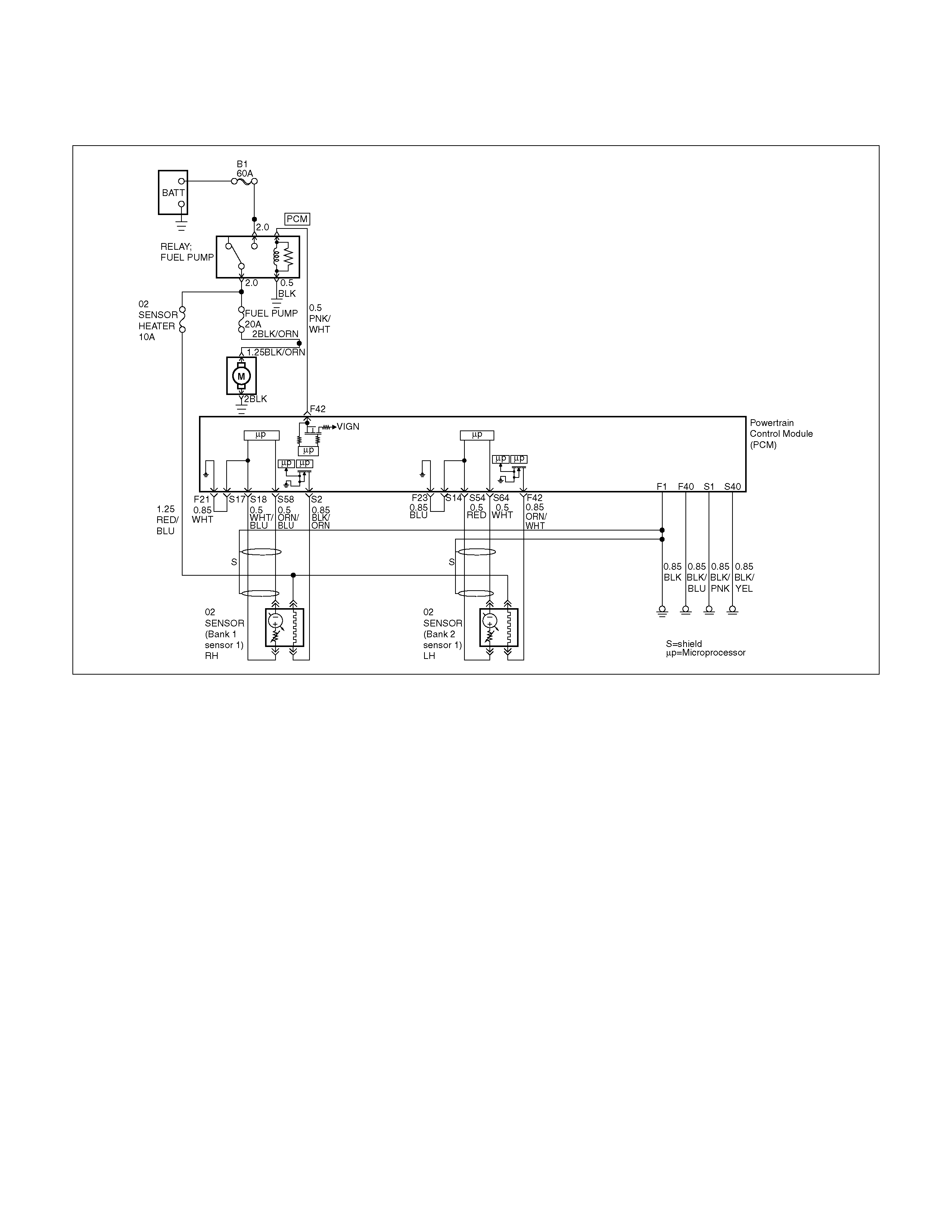
DIAGNOSTIC TROUBLE CODE (DTC)
P0132 HO2S CIRCUIT HIGH VOLTAGE BANK 1 SENSOR 1
060R100133
Circuit Description
The powertrain control module (PCM) supplies a bias
voltage of about 450 mV between the heated oxygen
sensor (HO2S) signa l and low circuits. When mea sured
with a 10 megaohm digital voltmeter, this may display
as low as 320 mV. The oxygen sensor varies the
voltage within a range of about 1000 mV whe n exhaust
is rich, down through about 10 mV when exhaust is
lean. The PCM constantly monitors the HO2S signal
during “closed loop" operation and compensates for a
rich or lean condition by decreasing or increasing
injector pulse width as nece ssary. If the Bank 1 HO 2S 1
voltage remains excessively high for an extended
period of time, DTC P0132 will be set.
Conditions for Setting the DTC
• No related DTCs.
• Engine coolant temperat ure is above 60°C (140°F)
• Bank 1 HO2S 1 signal voltage remains above 952
mV during normal “closed loop" operation for a total
of 77 seconds over a 90-second period.
• The fuel control system is operating in the closed
loop mo de.
Action Taken When the DTC Sets
• The PCM will ON the MIL after second trip with
d e te ct e d fa ult.
• The PCM will store conditions which were present
when the DTC was set as Freeze Frame and in the
Failure Records data.
• “Open loop" fuel control will be in effect.
Conditi ons for Clea r ing the MIL/DTC
• The PCM will turn the MIL “OFF" on the third
consecutive trip cycle during which the diagnostic has
been run and the fault condition is no longer present.
• A history DTC P0132 will clear after 40 consecutive
warm-up cy cles have occurred without a fault.
• DTC P0132 can be cleared by using the Tech 2
“Clear Info" function or by disconnecting the PCM
battery feed.

Diagn ostic Aids
Check the following items:
• F uel p ress ure – The sy stem w ill go rich if pr ess ure is
too high. The PCM can compensate for some
increase. However , if fuel pressure is too high, a DTC
P0132 may be set. Refer to Fuel System Diagnosis.
• Perform “Injector Balance Test" – Refer to
Fuel Sy stem Diagnos is.
• C hec k the EVAP caniste r for fuel saturation – If full of
fuel, check canister control and hoses. Refer to
Evaporative (EVAP) Emission Control System.
• MAF sensor – The system can go rich if MAF sensor
signal indicates an engine airflow measurement that
is not correct. Disconnect the MAF sensor to see it
the rich condition is correcte d. If so, rep lace the MAF
sensor.
• Check for a leak in the fuel pressure regulator
diaphragm by checking the vacuum line to the
regulator for the presence of fuel. There should be no
fuel in the vacuum line.
• An intermittent TP sensor output will cause the
system to go rich due to a false indication of the
engine acc elerator.
• Shorted Heated Oxygen Sensor (HO2S) –If the
HO2S is internally shorted, the HO2S voltage
displayed on the Tech 2 will be over 1 volt. Try
disconnecting the affected HO2S with the key “ON",
engine “OFF". If the displayed HO2S voltage
changes from over 1000 mV to around 450 mV,
replace the HO2S. Silicon contamination of the HO2S
can also cause a h igh HO2S voltage to be indicated.
This condition is indicated by a powdery deposit on
the portion of the HO2S exposed to the exhaust
stream. If contamination is noticed, replace the
affected HO2S.
• Open HO2S Signal Circuit or Faulty HO2S–A poor
connection or open in the HO2S signal circuit can
cause the DTC to set during d eceleration fuel mode.
An HO2S which is faulty and not allowing a full
voltage swing between the rich and lean thresholds
can also cause this c ondition. Operate the vehicle by
monitoring the HO2S voltage with a Tech 2. If the
HO2S voltage is limited within a range between 300
mV to 600 mV, check the HO2S signal circuit wiring
and associa ted terminal conditions.
• If none of the above conditions are present, replace
the affected HO2S.
Test Descr iption
Number(s) below refer to the step number(s) on the
Diagnostic Chart.
3. DTC P0132 failing during “deceleration fuel cutoff
mode" opera tion may indicate a condition described
in the “Diagnostic Aids" above. If the DTC P0132 test
passes while the Failure Records conditions are
being duplicated, an intermittent condition is
indicated.
Reviewing the Failure Records vehicle mileage since
the diagnostic test last failed may help determine how
often the condition that caused the DTC to be set
occurs. This may assist in diagnosing the condition.

DTC P0132 – HO2S Circuit High Voltage Bank 1 Sensor 1
Step Action Value(s) Yes No
1 Was the “On-Board Diagnostic (OBD) System Check"
performed? — Go to Step 2 Go to OBD
System Check
2 1. Instal l th e Tec h 2 .
2. Run the engine at operating temperature.
3. Operate the vehicle within parameters specified
under “Conditions for Setting the DTC " included in
Diagnostic Support.
4. Using a Tech 2, monitor Bank 1 HO2S 1 voltage.
Does the Bank 1 HO2S 1 voltage remain above the
specified value?
952 mV (500
mV in
deceleration
fuel cutoff
mode) Go to Step 4 Go to Step 3
3 1. Ignition “ON", review and record Tech 2 Failure
Records data.
2. Operate the vehicle within Failure Records
condition s as noted.
3. Using a Tech 2, monitor “ DTC" info for DTC P0132
until the DTC P0132 test runs.
4. Note the te st re sult.
Does the Tech 2 indicate DTC P0132 failed this
ignition? — Go to Step 4 Refe r to
Diagnostic Aids
4 1 . Ig nit io n “ OFF" .
2. Disconnect Bank 1 HO2S 1.
3. Ignition “ON".
4. At HO2S Bank 1 Sensor 1 connector (PCM side)
use a DVM to measure voltages at the high and
low signal terminals.
Are the voltages in the specified range? 3-4 V Go to Step 5 Go to Step 6
5 Repair short to voltage in signal circuit.
Is the action complete ? — Verify repair —
6 1. Ignition “ON", engine“OFF".
2. At Bank 1 HO2S 1 connector (PCM side) jumper
both the HO2S high and low signa l circuits (PCM
side) to ground.
3. Using a Tech 2, monitor Bank 1 HO2S 1 voltage.
Is Bank 1 HO2S 1 voltage below the specified value? 10 mV Go to Step 7 Go to Step 8
7 1. Disconnect the jumpers to ground from Bank 1
HO2S 1 PCM-s ide connect or.
2. With the HO2S 1 connector disconnected, monitor
Bank 1 HO2S 1 voltage.
Is Bank 1 HO2S 1 voltage between the specified
values? 425-475 mV Refer to
Diagnostic Aids Go to Step 8
8 Replace the PCM.
Important: The replacement PCM must be
programmed. Refer to On-Vehicle Service in
Powertrain Control Module and Sensors for
procedures.
And also refer to latest Service Bulletin.
Check to se e if t he Latest software is released or not.
And then Down Load the LATEST PROGRAMMED
SOFTWARE to the replacement PCM.
Is the action complete ? — Verify r epair —
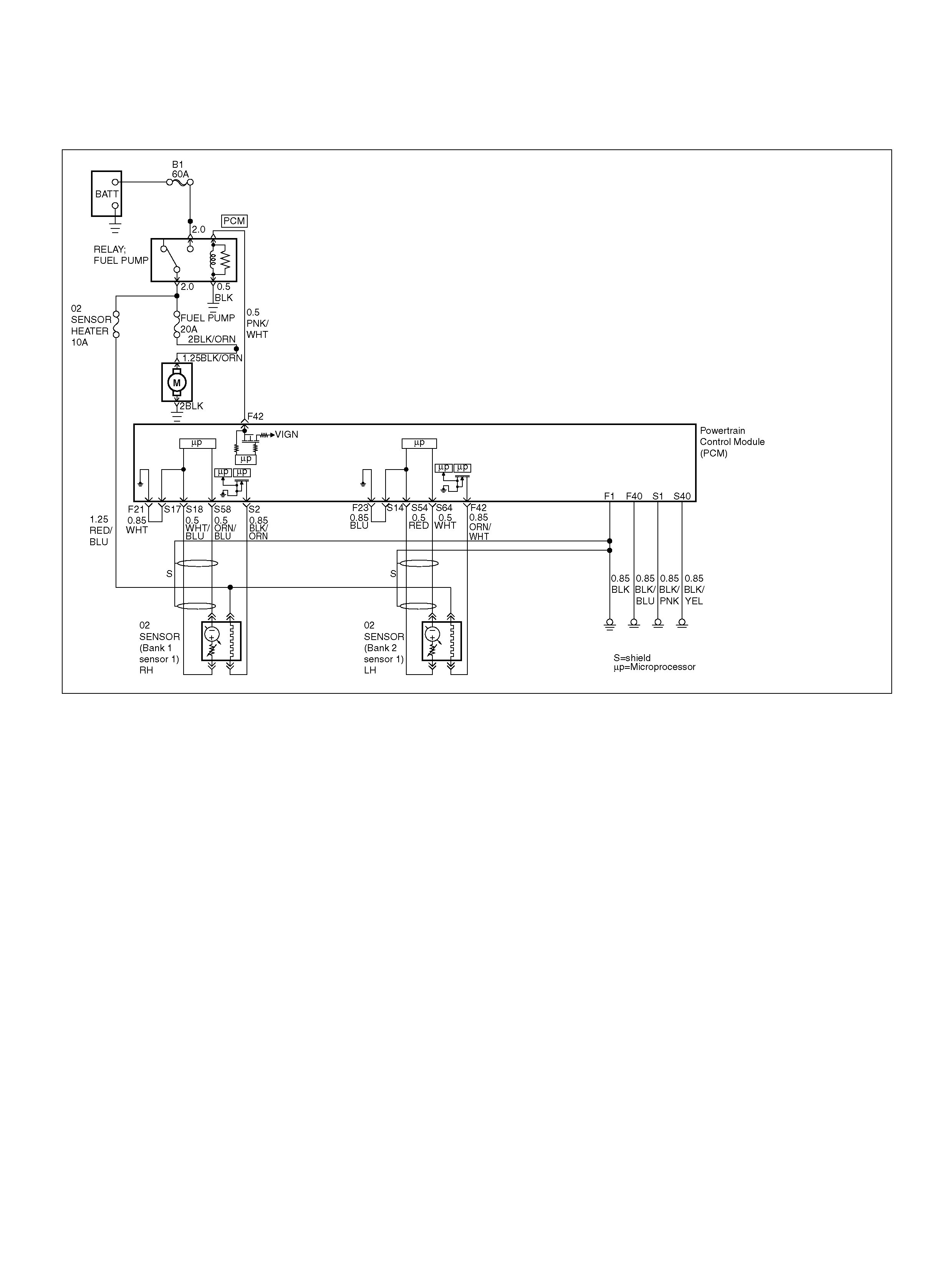
DIAGNOSTIC TROUBLE CODE (DTC)
P0134 HO2S CIRCUIT INSUFFICIENT ACTIVITY BANK 1 SENSOR 1
060R100133
Circuit Description
• T he powertrain control module (PCM) supplies a bias
voltage of about 450mV between the heated oxygen
sensor (HO2S) high and low circuits. When
measured with a 10 megaohm digital voltmeter, this
may display as low as 320mV. The oxygen sensor
varies the voltage within a range of about 1000mV
when the exhaust i s rich, down through about 10 mV
when exhaust is lean. The PCM con stantly monitors
the HO2S signal during “closed loop" operation and
compensates for a rich or lean condition by
decreasing or increasing injector pulse width as
necessary. If the Bank 1 HO2S 1 voltage remains at
or near the 450mV bias for an extended period of
time, DTC P0134 will be set, indicating an open
sen sor signal or sensor low ci rcuit.
• Heated oxygen sensors are used to minimize the
amou nt of time required for “closed l oop" fuel control
operation and to allow accurate catalyst monitoring.
The oxygen sensor heater greatly decreases the
amou nt of time requi red for fuel control sensors Bank
1 HO2S 1 and Bank 2 HO2S 1 to become active.
• Oxygen sensor heaters are required by post-catalyst
monitor sensors to maintain a sufficiently high
temperature for accurate exhaust oxygen content
readings further from the engine.
Conditions for Setting the DTC
• No related DTCs.
• Bat te ry voltage is above 10 volts.
• The engine has been running for over 5 seconds.
• Engine coolant temperature (ETC) is above 60°C
(140°F).
• Oxygen sensor heater has been determined to be
functioning properly.
• Bank 1 HO2S 1 signal voltage remains between
400 mV and 500 mV for a total of 77 seconds over a
90-se cond period of time.
Action Take When th e DTC Sets
• The PCM will ON the MIL after second trip with
d e te ct e d fa ult.
• The PCM will store conditions which were present
when the DTC was set as Freeze Frame and in the
Failure Records data.
• “Open loop" fuel control will be in effect.

Conditions for Clearing the MIL/DTC
• The PCM will turn the MIL “OFF" on the third
consecutive trip cycle during which the diagnostic has
been run and the fault condition is no longer present.
• A history DTC P0134 will clear after 40 consecutive
warm-up cycles have occurred without a fault.
• DTC P0134 can be cleared by using the Tech 2
“Clear Info" function.
Diagnostic Aids
Check for the following conditions:
• Poor connection or damaged harness – Inspect the
harness connectors for backed-out terminals,
improper mating, broken locks, improperly formed or
damaged terminals, poor terminal-to-wire connection,
and damaged harness.
• Faulty HO2S heater or heater circuit – With the
ignition “ON", engine “OFF", after a cool down period,
the HO2S 1 voltage displayed on the Tech 2 is
normally 455-460mV. A reading over 1000mV
indicates a signal line shorted to voltage. A reading
under 5mV indicates a signal line shorted to ground
or signal lines shorted together. Disconnect the
HO2S and connect a test light between the HO2S
ignition feed and heater ground circuits. If the test
light does not light for 2 seconds when the ignition is
turned on, repair the open ignition feed or sensor
ground circuit as necessary. If the test light lights and
the HO2S signal and low circuits are OK, replace the
HO2S.
• Intermittent test – With the Ignition “ON", monitor the
HO2S signal voltage while moving the wiring harness
and related connectors. If the fault is induced, the
HO2S signal voltage will change. This may help
isolate the location of the malfunction.
Test Description
Number(s) below refer to the step number(s) on the
Diagnostic Chart.
3. If the DTC P0134 test passes while the Failure
Records conditions are being duplicated, an
intermittent conditions is indicated.
Reviewing the Failure Records vehicle mileage since
the diagnostic test last failed may help determine how
often the condition that caused the DTC to be set
occurs. This may assist in diagnosing the condition.
DTC P0134 –HO2S Circuit Insufficient Activity Bank 1 Sensor 1
Step Action Value(s) Yes No
1 Was the “On-Board Diagnostic (OBD) System Check"
performed? — Go to Step 2 Go to OBD
System Check
2 1. Instal l th e Tec h 2 .
2. Run the engine at operating temperature.
3. Operate the engine above 1200 RPM for two
minutes.
Does the Tech 2 indicate Bank 1 HO2S 1 voltage
varying outside the specified values? 400-500mV Go to Step 3 Go to Step 4
3 1. Ignition “ON", engine “OFF", review and record
Tech 2 Failure Records data and note parameters.
2. Operate the vehicle within Failure Records
condition s as noted.
3. Using a Tech 2, monitor “ DTC" info for DTC P0134
until the DTC P0134 test runs.
4. Note the te st re sult.
Does the Tech 2 indicate DTC P0134 failed this
ignition? — Go to Step 4 Refe r to
Diagnostic Aids
4 Check for a damaged harnes s.
Was a problem found? — Verify rep air Go to Step 5
5 Check for poor Bank 1 HO2S 1 high and low circuit
terminal connections at the Bank 1 HO2S 1 harness
connector and replace termina l(s) if ne cessary.
Did any terminals require replacement? — Verify repair Go to Step 6
6 Check for poor Bank 1 HO2S 1 high and low circuit
terminal connections at the PCM and replace
terminals if necessary.
Did any terminals require replacement? — Verify repair Go to Step 7

7 1 . Ig nit io n “ OFF" .
2. With the PCM disconnected, check continuity of
the Bank 1 HO2S 1 high circuit.
3. If the Bank 1 HO2S 1 high circuit measures over
5.0 ohms, repair open or poor connection as
necessary.
Was a Bank 1 HO 2S 1 h igh circui t problem found and
corrected? — Verify repair Go to Step 8
8 1 . Ig nit io n “ OFF" .
2. With the PCM disconnected, check continuity of
the Bank 1 HO2S 1 low circ ui t.
3. If the Bank 1 HO2S 1 l ow circuit measures over 5
ohms, repair open or poor connection as
necessary.
Was a Bank 1 HO2S 1 low circuit pro blem found and
corrected? — Verify repair Go to Step 9
9 1. Ignition “ON", engine “OFF".
2. Disconnect B ank 1 HO2S 1 and jumper t he HO2 S
high and low circuit s (PCM side) to ground.
3. Using a Tech 2, monitor Bank 1 HO2S 1 voltage.
Is Bank 1 HO2S 1 voltage in the specified range? 0-10mV Go to St ep 10 Go to Step 11
10 Replace Bank 1 HO2S 1.
Is the action complete ? — Verify repair —
11 Replace the PCM.
Important: The replacement PCM must be
programmed. Refer to Section 0C-1 - Service
Program ming Syst em.
Important: Refer to Section 11 - Engin e Im mobiliser
System for the Immobiliser Programming procedure.
Important: Ensure the latest software program is
downloaded to the PCM.
Is the action complete ? — Verify repair —
Step Action Value(s) Yes No

DIAGNOSTIC TROUBLE CODE (DTC) P0135 HO2S
HEATER CIRCUIT BANK 1 SENSOR 1
060R100133
Circuit Description
Heated oxygen sensors are used to minimize the
amount of time required for “closed loop" fuel control
operation and to allow accurate catalyst monitoring. The
oxygen sensor heater greatly decreases the amount of
time required for fuel control sensors Bank 1 HO2S 1
and Bank 2 HO2S 1 to become active. Oxygen sensor
heaters are required by post-catalyst monitor sensors to
maintain a sufficiently high temperature which allows
accurate exhaust oxygen content readings further from
the engin e.
The powertrain control module (PCM) will run the heater
test only after a cold start (determined by engine coolant
and intake air temperature at the time of start-up) and
only once during an ignition cycle. When the engine is
started the PCM will monitor the HO2S voltage. When
the HO2S voltage indicates a suffi ciently active sensor,
the PCM looks at how much time has elapsed since
start-up. If th e PCM determines that t oo much time was
required for the Bank 1 HO2S 1 to become active, a
DTC P0135 will set. The time it should take the HO2S to
reach operating temperature is based on the
accum ulated amount of air that has passed through th e
MA F sensor and into the engin e (more accumula ted air
flow = shorter ti me to HO2S activity).
Conditions for Setting the DTC
• The engine has been running for over 120 seconds.
• He ater signal is below 0.1A.
• No related DTCs.
Action Taken When the DTC Sets
• The PCM will illuminate the malfunction indicator
lamp (M IL) after the second c onsecutive trip in which
the fault is detected .
• The PCM will store conditions which were present
when the DTC was set as Freeze Frame and in the
Failure Records data.
Conditi ons for Clea r ing the MIL/DTC
• The PCM will turn the MIL “OFF" on the third
consecutive trip cycle during which the diagnostic has
been run and the fault condition is no longer present.
• A history DTC P0135 will clear after 40 consecutive
warm-up cy cles have occurred without a fault.
• DTC P0135 can be cleared by using the Tech 2
“Clear Info" function.

Diagnostic Aids
Check for the following conditions:
• Poor connection at PCM – Inspect harness
connectors for backed-out terminals, improper
mating, broken locks, improperly formed or damaged
terminals, and poor terminal-to-wire connection.
• Damaged harness – Inspect the wiring harness for
damage. If the harness appears to be OK, observe
the ECT display on the Tech 2 while moving
connectors and wiring harnesses related to the
sensor. A change in the display will indicate the
location of the fault.
Reviewing the Failure Records vehicle mileage since
the diagnostic test last failed may help determine how
often the condition that caused the DTC to be set
occurs. This may assist in diagnosing the condition.
Test Description
Number(s) below refer to the step number(s) on the
Diagnostic Chart.
2. The HO2S should be allowed to cool before
performing this test. If the HO2S heater is
functioning, the signal voltage will gradually increase
or decrease as the sensor element warms. If the
heater is not functioning, the HO2S signal will remain
near the 450mV bias voltage.
4. Ensures that the ignition feed circuit to the HO2S is
not open or shorted. The test light should be
connected to a good chassis ground, in case the
HO2S low or HO2S heater ground circuit is faulty.
5. Checks the HO2S heater ground circuit.
6. Checks or an open or shorted HO2S heater element.
10. An open HO2S signal or low circuit can cause the
HO2S heater to appear faulty. Check these circuits
before replacing the sensor.
DTC P0135 – HO2S Heater Circuit Bank 1 Sensor 1
Step Action Value(s) Yes No
1 Was the “On-Board Diagnostic (OBD) System Check"
performed? — Go to Step 2 Go to OBD
System Check
2NOTE: If the engine has just been operating ,allow
the engine to cool for at least 15 minutes before
proceeding.
1. Remove the fuel pump relay.
2. Connect a fused jumper at the fuel pump relay
socket, between the battery positive at the relay
and the relay wire that leads to the fuel pump and
HO 2S fuses.
3. Ignition “OFF".
4. Install a Tech 2.
5. Ignition “ON", engine “OFF".
6. Monitor the Bank 1 HO2S 1 voltage for several
minutes.
Did the HO2S voltage go from bias voltage to above
or below the specified values?
Above
650mV or
below 250mV Refer to
Diagnostic Aids Go to Step 3
3 Inspec t the fuse for the Bank 1 HO2S 1 ignition feed.
Is the fuse open? — Go to Step 15 Go to S tep 4
4 1 . Ig nit io n “ OFF" .
2. Raise the vehicle.
3. Disconnect the Bank 1 HO2S 1 electrical
connector.
4. Using a test lig ht c onnected to a good g ro und (do
not use Bank 1 HO2S 1 heater ground or Bank 1
HO2S 1 low), probe t he ignition fe ed circuit at the
Bank 1 HO2S 1 electrical connector (PCM
harness side).
Does the test light illuminate? — Go to St ep 5 Go to Step 7
5 Connect the test light between the Bank 1 HO2S 1
ignition feed and the Bank 1 HO2S 1 heater ground.
Does the test light illuminate? — Go to St ep 6 Go to Step 8

6 1. Allow the HO2S to cool for at le ast 15 minutes.
2. Using a DVM, measure the resistance between
the Bank 1 HO2S 1 ignition feed and the Bank 1
HO2S 1 heater ground at the Bank 1 HO2S 1
pigtail.
Is the HO2S heater resistance within the specified
values? 3-6 ohms G o to St ep 9 Go to St ep 10
7 Repair the open Bank 1 HO2S 1 ignition feed circuit to
Bank 1 HO2S 1.
Is the action complete ? — Verify repair —
8 Repair the open B an k 1 HO 2S 1 he ater ground circuit
to Bank 1 HO2S 1.
Is the action complete ? — Verify repair —
9 1. Check for a poor connection at the Bank 1 HO2 S
1 harness terminals.
2. If a poor connection is found, replace terminals.
Was a poor connect ion found? — Veri fy repair Go to Step 10
10 Check for a poor Bank 1 HO2S 1 high or low circuit
terminal connection at the Bank 1 HO2S 1 harness
connector and replace termina l(s) if ne cessary.
Did any terminals require replacement? — Verify repair Go to Step 11
11 1. Ignition “OFF".
2. Disconnect the PCM and check the continuity of
the Bank 1 HO2S 1 signal circuit and the Bank 1
HO2S 1 low ci rcuit.
3. If the Bank 1 HO2S 1 high circuit or HO2S low
circuit measure s over 5 ohms, repair open or poor
connection as nec essa ry.
Was a problem found? — Verify rep air Go to Step 12
12 Check for a poor Bank 1 HO2S 1 low circuit terminal
connection at the PCM and replace the terminal if
necessary.
Did the terminal require replacement? — Verify rep air Go to Step 13
13 Check for a poo r Bank 1 HO2S 1 high circui t terminal
connection at the PCM and replace the terminal if
necessary.
Did the terminal require replacement? — Verify rep air Go to Step 14
14 Replace the Bank 1 HO2S 1.
Is the action complete ? — Verify repair —
15 Locate and repair the short t o ground in Bank 1 HO2S
1 ignition feed circuit and replace the fault fuse.
Is the action complete ? — Verify r epair —
Step Action Value(s) Yes No

DIAGNOSTIC TROUBLE CODE (DTC)
P0151 HO2S CIRCUIT LOW VOLTAGE BANK 2 SENSOR 1
060R100133
Circuit Description
The powertrain control module (PCM) supplies a bias
voltage of about 450mV between the heated oxygen
sensor (HO2S) signal high and signal low ci rcuit s. When
measured with a 10 megaohm digital voltmeter, this
may display as low as 320mV. The oxygen sensor
varies the voltage within a range of about 1000mV
when the exhaust is rich, down through about 10mV
when exh aust is lean. The PCM constantly mon itors the
HO2S signal during “closed loop" operation and
compensates for a rich or lean condition by decreasing
or increasing injector pulse width as necessary. If the
Bank 2 HO2S 1 voltage rema ins excessively low for an
extended period of time, D TC P0 151 will be s et .
Conditions for Setting the DTC
• No related DTCs.
• The engine is operating in “closed loop".
• Engine coolant temperat ure is above 60°C (140°F).
• Ban k 2 HO2S 1 signal volta ge remains below 30 mV
during norm al “closed loop" operation for a total of 77
seconds over a 90-second period of time.
Action Taken When the DTC Sets
• The PCM will ON the MIL after second trip with
d e te ct e d fa ult.
• The PCM will store conditions which were present
when the DTC was set as Freeze Frame and in the
Failure Records data.
• “Open loop" fuel control will be in effect.
Conditi ons for Clea r ing the MIL/DTC
• The PCM will turn the MIL “OFF" on the third
consecutive trip cycle during which the diagnostic has
been run and the fault condition is no longer present.
• A history DTC P0151 will clear after 40 consecutive
warm-up cy cles have occurred without a fault.
• DTC P0151 can be cleared by using the Tech 2
“Clear Info" function.
Diag nostic Ai ds
Check for the following conditions:
• Heated oxygen sensor wiring – The sensor pigtail
may be mispositioned and contacting the exhaust
system.
• Poor P CM to engine block grounds .

• Fuel pressure – The system will go lean if pressure is
too low. The PCM can compensate for some
decrease. However, if fuel pressure is too low, a DTC
P0151 may be set. Refer to Fuel System Diagnosis.
• Lean injector(s) – Perform “Injector Balance Test".
• Vacuum leaks – Check for disconnected or damaged
vacuum hoses and for vacuum leaks at the intake
manifold, throttle body, EGR system, and PCV
system.
• Exhaust leaks – An exhaust leak may cause outside
air to be pulled into the exhaust gas stream past the
HO2S, causing the system to appear lean. Check for
exhaust leaks that may cause a false lean condition
to be indicated.
• MAF sensor –The system can go lean if the MAF
sensor signal indicates an engine airflow
measurement that is not correct. Disconnect the MAF
sensor to see if the lean condition is corrected. If so,
replace the MAF sensor.
• Fuel contamination – Water, even in small amounts,
can be delivered to the fuel injectors. The water can
cause a lean exhaust to be indicated. Excessive
alcohol in the fuel can also cause this condition.
Refer to Fuel System Diagnosis for the procedure
to check for fuel contamination.
• If none of the above conditions are present, replace
the affected HO2S.
Test Description
Number(s) below refer to the step number(s) on the
Diagnostic Chart.
3. DTC P0151 failing during operation may indicate a
condition described in the “Diagnostic Aids" above. If
the DTC P0151 test passes while the Failure
Records conditions are being duplicated, an
intermittent condition is indicate.
Reviewing the Failure Records vehicle mileage since
the diagnostic test last failed may help determine how
often the condition that caused the DTC to be set
occurs. This may assist in diagnosing the condition.
DTC P0151 – HO2S Circuit Low Voltage Bank 2 Sensor 1
Step Action Value(s) Yes No
1 Was the “On-Board Diagnostic (OBD) System Check"
performed? — Go to Step 2 Go to OBD
System Check
2 1. Instal l th e Tec h 2 .
2. Run the engine at operating temperature.
3. Operate the vehicle within the parameters
specified under “Conditions for Setting the DTC"
criteria included in Diagnostic Support.
4. Using a Tech 2, monitor Bank 2 HO2S 1 voltage.
Does the Bank 2 HO2S 1 voltage remain below the
specified value? 22m V Go to St ep 4 Go to Step 3
3 1. Ignition “ON", engine “OFF", review and record
Tech 2 Failure Records data and note parameters.
2. Operate the vehicle within Failure Records
condition s as noted.
3. Using a Tech 2, monitor “ DTC" info for DTC P0151
until the DTC P0151 test runs.
4. Note test re su l t.
Does the Tech 2 indicate DTC P0151 failed this
ignition? — Go to Step 4 Refe r to
Diagnostic Aids
4 1. Turn ignition “OFF".
2. Disconnect the PCM.
3. Check the Bank 2 HO2S 1 high and low signal
circuits for a short to ground or a short to the
heater ground circuit.
Were Bank 2 HO2S 1 signal circuits short ed? — G o to St ep 5 Go to Step 6
5 Repair the Bank 2 HO2S 1 signal circuit.
Is the action complete ? — Verify repair —

6 1 . Ig nit io n “ OFF" .
2. Leave the PCM and HO2S 1 disconnec ted .
3. Check for continuity between the high and low
signal circuits.
Was there continuity between the high and low
circuits? — Go to Step 7 Go to Step 8
7 Repair the short between the high and low circuit s.
Is the action complete ? — Verify repair —
8 1 . Ig nit io n “ OFF" .
2. Reconne ct the PCM, leave HO2S disconnec ted.
3. Ignition “ON".
Does the Tech 2 indicate Bank 2 HO2S 1 voltage near
the specified value? 42 5-475mV Refer to
Diagnostic Aids Go to Step 9
9 Replace the PCM.
Important: The replacement PCM must be
programmed. Refer to Section 0C-1 - Service
Program ming Syst em.
Important: Refer to Section 11 - Engin e Im mobiliser
System for the Immobiliser Programming procedure.
Important: Ensure the latest software program is
downloaded to the PCM.
Is the action complete ? — Verify repair —
Step Action Value(s) Yes No

DIAGNOSTIC TROUBLE CODE (DTC)
P0152 HO2S CIRCUIT HIGH VOLTAGE BANK 2 SENSOR 1
060R100133
Circuit Description
The powertrain control module (PCM) supplies a bias
voltage of about 450mV between the heated oxygen
sensor (HO2S) signal high and signal low ci rcuit s. When
measured with a 10 megaohm digital voltmeter, this
may display as low as 320mV. The oxygen sensor
varies the voltage within a range of about 1000mV
when the exhaust is rich, down through about 10mV
when exh aust is lean. The PCM constantly mon itors the
HO2S signal during “closed loop" operation and
compensates for a rich or lean condition by decreasing
or increasing the injector pulse width as necessary. If
the Bank 2 HO2S 1 voltage remains excessively high
for an extended period of time, DTC P0152 will be set.
Conditions for Setting the DTC
• No related DTCs.
• The engine is operating in “closed loop".
• The engine coolant temperature is above 60°C
(140°F).
• Bank 2 HO2S 1 signal voltage remains above 952mV
during norm al “closed loop" operation for a total of 77
seconds over a 90-second period.
Action Taken When the DTC Sets
• The PCM will “ON" the MIL after second trip with
d e te ct e d fa ult
• The PCM will store conditions which were present
when the DTC was set as Freeze Frame and in the
Failure Records data.
• “Open loop" fuel control will be in effect.
Conditi ons for Clea r ing the MIL/DTC
• The PCM will turn the MIL “OFF" on the third
consecutive trip cycle during which the diagnostic has
been run and the fault condition is no longer present.
• A history DTC P0152 will clear after 40 consecutive
warm-up cy cles have occurred without a fault.
• DTC P0152 can be cleared by using the Tech 2
“Clear Info" function.
Diag nostic Ai ds
Check for the following conditions:
• F uel pressure – T he system will go rich if pressure is
too high. The PCM can compensate for some
increase. However, if fuel pressure is too high, a DTC
P0152 may be set. Refer to Fuel System Diagnosis.

• Rich injector(s) – Perform “Injector Balance Test".
• Leaking injector – Refer to Fuel System Diagnosis.
• Evaporative emissions (EVAP) system – Check the
canister for fuel saturation. If the canister is full of
fuel, check EVAP control system components and
hoses. Refer to Evaporative Emission (EVAP)
Control System.
• MAF sensor – The system can go rich if the MAF
sensor signal indicates an engine airflow
measurement that is not correct. Disconnect the MAF
sensor to see if rich condition is corrected. If so,
replace MAF sensor.
• Check for leaking fuel pressure regulator diaphragm
by checking vacuum line to regulator for the presence
of fuel. There should be no fuel in the vacuum line.
• TP sensor – An intermittent TP sensor output will
cause the system to go rich, due to a false indication
of the engine accelerating.
• Shorted Heated Oxygen Sensor (HO2S)– If the
HO2S is internally shorted, the HO2S voltage
displayed on the Tech 2 will be over 1 volt. Try
disconnecting the affected HO2S with the key “ON",
engine “OFF". If the displayed HO2S voltage
changes from over 1000mV to around 450mV,
replace the HO2S. Silicon contamination of the HO2S
can cause a high HO2S voltage to be indicated. This
condition is indicated by powdery deposit on the
portion of the HO2S exposed to the exhaust stream.
If contamination is noticed, replace the affected
HO2S.
• Open HO2S Signal Circuit of Faulty HO2S– A poor
connection or open in the HO2S signal circuit can
cause the DTC to set during deceleration fuel mode.
An HO2S which is faulty and not allowing a full
voltage switch between the rich and lean thresholds
can also cause the condition. Operate the vehicle
while monitoring the HO2S voltage with a Tech 2. If
the HO2S is limited within a range between 300mV to
600mV, check the HO2S signal circuit wiring and
associated terminal connections.
• If none of the above conditions are present, replace
the affected HO2S.
Test Description
Number(s) below refer to the step number(s) on the
Diagnostic Chart.
3. DTC P0152 failing during deceleration fuel cutoff
mode operation may indicate a condition described
in the “Diagnostic Aids" above. If the DTC P0152 test
passes while the Failure Records conditions are
being duplicated, an intermittent condition is
indicated.
Reviewing the Failure Records vehicle mileage since
the diagnostic test last failed may help determine how
often the condition that caused the DTC to be set
occurs. This may assist in diagnosing the condition.
DTC P0152 – HO2S Circuit High Voltage Bank 2 Sensor 1
Step Action Value(s) Yes No
1 Was the “On-Board Diagnostic (OBD) System Check"
performed? — Go to Step 2 Go to OBD
System Check
2 1. Instal l th e Tec h 2 .
2. Engine is at operating temperature.
3. Operate the vehicle within the parameters
specified under “Conditions for Setting the DTC"
criteria included in Diagnostic Support.
4. Using a Tech 2, monitor Bank 2 HO2S 1 voltage.
Does the Bank 2 HO2S 1 voltage remain above the
specified value?
952mV
(500mV in
deceleration
fuel cut-off
mode) Go to Step 4 Go to Step 3
3 1. Ignit io n “ O N" .
2. Review and record Te ch 2 Failure Records data.
3. Operate the vehicle within Failure Records
condition s as noted.
4. Using a Tech 2, monitor “ DTC" info for DTC P0152
until the DTC P0152 test runs.
5. Note the te st re sult.
Does the Tech 2 indicate DTC P0152 failed this
ignition? — Go to Step 4 Refe r to
Diagnostic Aids

4 1 . Ig nit io n “ OFF" .
2. Disconnect Bank 2 HO2S 1.
3. Ignition “ON".
4. At HO2S Bank 2 Sensor 1 connector (PCM side)
use a DVM to measure voltages at the high and
low signal terminals.
Are the voltages in the specified range? 3-4 V Go to Step 5 Go to Step 6
5 Repair short to voltage in signal circuit.
Is the action complete ? — Verify r epair —
6 1. Ignition “ON", engine“OFF".
2. At Bank 2 HO2S 1 connector (PCM side) jumper
both the HO2S high and low signa l circuits (PCM
side) to ground.
3. Using a Tech 2, monitor Bank 2 HO2S 1 voltage.
Is Bank 2 HO2S 1 voltage below the specified value? 10m V G o to Step 7 Go to Step 8
7 1. Disconnect the jumpers to ground from Bank 2
HO2S 1 PCM-s ide connect or.
2. With the HO2S 1 connector disconnected, monitor
Bank 2 HO2S 1 voltage.
Is the Bank 2 HO2S 1 voltage between the specified
values? 425-475mV Refer to
Diagnostic Aids Go to Step 8
8 Replace the PCM.
Important: The replacement PCM must be
programmed. Refer to Section 0C-1 - Service
Program ming Syst em.
Important: Refer to Section 11 - Engin e Im mobiliser
System for the Immobiliser Programming procedure.
Important: Ensure the latest software program is
downloaded to the PCM.
Is the action complete ? — Verify repair —
Step Action Value(s) Yes No

DIAGNOSTIC TROUBLE CODE (DTC)
P0154 HO2S CIRCUIT INSUFFICIENT ACTIVITY BANK 2 SENSOR 1
060R100133
Circuit Description
The powertrain control module (PCM) supplies a bias
voltage of about 450mV between the heated oxygen
sensor (HO2S) high and low circuits. When measured
with a 10 megaohm digital voltmeter, this may display
as low as 320mV. The oxygen sensor varies the voltage
within a range of about 1000mV when the exhaust is
rich, down through about 10 mV when exhaust is lean.
The PCM constantly monitors the HO2S signal during
“closed loop" operation and compensates for a rich or
lean condition by decreasing or increasing injector pulse
width as necessary. If the Bank 2 HO2S 1 voltage
remains at or near the 450mV bias for an extended
period of time, DTC P0154 will be set, indicating an
open sensor signal or sensor low circuit.
Heated oxygen sensors are used to minimize the
amount of time required for “closed loop" fuel control
operation and to allow accurate catalyst monitoring. The
oxygen sensor heater greatly decreases the amount of
time required for fuel control sensors Bank 1 HO2S 1
and Bank 2 HO2S 1 to become active. Oxygen sensor
heaters are required by post-catalyst monitor sensors to
maintain a sufficiently high temperature for accurate
exhaust oxygen content readings further from the
engine.
Conditions for Setting the DTC
• No related DTCs.
• Engine coolant temperature is above 60°C (140°F).
• The engine has been running for over 5 seconds.
• Oxygen sensor heater is functioning properly.
• Bank 2 HO2S 1 signal voltage remains between
400 mV and 500 mV for a total of 77 seconds over a
90-se cond period of time.
Action Taken When the DTC Sets
• The PCM will ON the MIL after second trip with
d e te ct e d fa ult.
• The PCM will store conditions which were present
when the DTC was set as Freeze Frame and in the
Failure Records data.
• “Open loop" fuel control will be in effect.
Conditi ons for Clea r ing the MIL/DTC
• The PCM will turn the MIL “OFF" on the third
consecutive trip cycle during which the diagnostic has
been run and the fault condition is no longer present.
• A history DTC P0154 will clear after 40 consecutive
warm-up cy cles have occurred without a fault.

• DTC P0154 can be cleared by using the Tech 2
“Clear Info" function.
Diagnostic Aids
Check for the following conditions:
• Poor connection or damaged harness – Inspect the
harness connectors for backed-out terminals,
improper mating, broken locks, improperly formed or
damaged terminals, poor
terminal-to-wire-connection, and damaged harness.
• Faulty HO2S heater or heater circuit – With the
ignition “ON", engine “OFF", the HO2S 1 voltage
displayed on the Tech 2 is normally 455-460mV. A
reading over 1000mV indicates a signal line shorted
to voltage. A reading under 5mV indicates a signal
line shorted to ground or signal lines shorted
together. If not, disconnect the HO2S and connect a
test light between the HO2S ignition feed and heater
ground circuits. If the test light does not light for 2
seconds when the ignition is turned on, repair the
open ignition feed or sensor ground circuit as
necessary. If the test light lights and the HO2S signal
and low circuits are OK, replace the HO2S.
• Intermittent test – With the ignition “ON", monitor the
HO2S signal voltage while moving the wiring harness
and related connectors. If the fault is induced, the
HO2S signal voltage will change. This may help
isolate the location of the malfunction.
Test Description
Number(s) below refer to the step number(s) on the
Diagnostic Chart.
3. If the DTC P0154 test passes while the Failure
Records conditions are being duplicated, an
intermittent condition is indicated.
Reviewing the Failure Records vehicle mileage since
the diagnostic test last failed may help determine how
often the condition that caused the DTC to be set
occurs. This may assist in diagnosing the condition.
DTC P0154 –HO2S Circuit Insufficient Activity Bank 2 Sensor 1
Step Action Value(s) Yes No
1 Was the “On-Board Diagnostic (OBD) System Check"
performed? — Go to Step 2 Go to OBD
System Check
2 1. Instal l th e Tec h 2 .
2. Run the engine at operating temperature.
3. Operate the engine above 1200 RPM for two
minutes .
Does the Tech 2 indicate Bank 2 HO2S 1 voltage
varying outside the specified values? 400-500mV G o to St ep 3 Go to Step 4
3 1. Ignition “ON", engine “OFF".
2. Review and record Tech 2 Failure Records data
and note parameters.
3. Operate the vehicle within Failure Records
condition s as noted.
4. Using a Tech 2, monitor “ DTC" info for DTC P0154
until the DTC P0154 test runs.
5. Note the te st re sult.
Does the Tech 2 indicate DTC P0154 failed this
ignition? — Go to Step 4 Refe r to
Diagnostic Aids
4 Check for a damaged harnes s.
Was a problem found? — Verify rep air Go to Step 5
5 Check f or a poor Bank 2 H O2S 1 high and low circuit
terminal connections at the Bank 2 HO2S 1 harness
connector and replace termina l(s) if ne cessary.
Did any terminals require replacement? — Verify repair Go to Step 6
6 Check f or a poor Bank 2 H O2S 1 high and low circuit
terminal connections at the PCM and replace
terminal(s) if necessary.
Did the terminal require replacement? — Verify repair Go to Step 7

7 1 . Ig nit io n “ OFF" .
2. With the PCM disconnected, check continuity of
the Bank 2 HO2S 1 high circuit.
3. If the Bank 2 HO2S 1 high circuit measures over
5.0 ohms, repair open or poor connection as
necessary.
Was a Bank 2 HO 2S 1 h igh circui t problem found and
corrected? — Verify repair Go to Step 8
8 1 . Ig nit io n “ OFF" .
2. With the PCM disconnected, check continuity of
the Bank 2 HO2S 1 low circ ui t.
3. If the Bank 2 HO2S 1 low circuit measures over
5.0 ohms, repair open or poor connection as
necessary.
Was a Bank 2 HO2S 1 low circuit pro blem found and
corrected? — Verify repair Go to Step 9
9 1. Ignition “ON", engine “OFF".
2. Disconnect B ank 2 HO2S 1 and jumper t he HO2 S
high and low circuit s (PCM side) to ground.
3. Using a Tech 2, monitor Bank 2 HO2S 1 voltage.
Is the Bank 2 HO2S 1 voltage in the specified range? 0-10mV Go t o St ep 10 Go to Step 11
10 Replace Bank 2 HO2S 1.
Is the action complete ? — Verify repair —
11 Replace the PCM.
Important: The replacement PCM must be
programmed. Refer to Section 0C-1 - Service
Program ming Syst em.
Important: Refer to Section 11 - Engin e Im mobiliser
System for the Immobiliser Programming procedure.
Important: Ensure the latest software program is
downloaded to the PCM.
Is the action complete ? — Verify repair —
Step Action Value(s) Yes No

DIAGNOSTIC TROUBLE CODE (DTC)
P0155 HO2S HEATER CIRCUIT OPEN BANK 2 SENSOR 1
060R100133
Circuit Description
Heated oxygen sensors are used to minimize the
amount of time required for closed loop fuel control
operation and to allow accurate catalyst monitoring. The
oxygen sensor heater greatly decreases the amount of
time required for fuel control sensors Bank 1 HO2S 1
and Bank 2 HO2S 1 to become active. Oxygen sensor
heaters are required by post-catalyst monitor sensors to
maintain a sufficiently high temperature which allows
accurate exhaust oxygen content readings further from
the engin e.
The powertrain control module (PCM) will run the heater
test only after a cold start (determined by engine coolant
and intake air temperature at the time of start-up) and
only once during an ignition cycle. When the engine is
started the PCM will monitor the HO2S voltage. When
the Bank HO2S voltage indicates a sufficiently active
sensor, the PCM looks at how much time has elapsed
since start-up. If the PCM determines that too much
time was required for the Bank 2 HO2S 1 to become
active, a DTC P0155 will set. The time it should take the
HO2S to reach operating temperature is based on the
total amount of air that has passed through the mass air
flow (MAF) sensor and into the engine (more total air
flow = shorter ti me to HO2S activity).
Conditions for Setting the DTC
• No related DTCs.
• The engine has been running for over 120 seconds.
• He ater signal is below 0.1A.
Action Taken When the DTC Sets
• The PCM will illuminate the malfunction indicator
lamp (M IL) after the second c onsecutive trip in which
the fault is detected .
• The PCM will store conditions which were present
when the DTC was set as Freeze Frame and in the
Failure Records data.
Conditi ons for Clea r ing the MIL/DTC
• The PCM will turn the MIL “OFF" on the third
consecutive trip cycle during which the diagnostic has
been run and the fault condition is no longer present.
• A history DTC P0155 will clear after 40 consecutive
warm-up cy cles have occurred without a fault.
• DTC P0155 can be cleared by using the Tech 2
“Clear info" function.

Diagnostic Aids
Check for the following conditions:
• Poor connection at PCM – Inspect harness
connectors for backed-out terminals, improper
mating, broken locks, improperly formed or damaged
terminals, and poor terminal-to-wire connection.
• Damaged harness – Inspect the wiring harness for
damage. If the harness appears to be OK, observe
the display on the Tech 2 while moving connectors
and wiring harnesses related to the sensor. A change
in the display will indicate the location of the fault.
Reviewing the Failure Records vehicle mileage since
the diagnostic test last failed may help determine how
often the condition that caused the DTC to be set
occurs. This may assist in diagnosing the condition.
Test Description
Number(s) below refer to the step number(s) on the
Diagnostic Chart.
2. The HO2S should be allowed to cool before
performing this test. If the HO2S heater is
functioning, the signal voltage will gradually increase
or decrease as the sensor element warms. If the
heater is not functioning, the HO2S signal will remain
near the 450mV bias voltage.
4. Ensures that the ignition feed circuit to the HO2S is
not open or shorted. The test light should be
connected to a good chassis ground, in case the
HO2S low or HO2S heater ground circuit is faulty.
5. Checks the HO2S heater ground circuit.
6. Checks for an open or shorted HO2S heater element.
10. An open HO2S signal or low circuit can cause the
HO2S heater to appear faulty. Check these circuits
before replacing the sensor.
DTC P0155 – HO2S Heater Circuit Open Bank 2 Sensor 1
Step Action Value(s) Yes No
1 Was the “On-Board Diagnostic (OBD) System Check"
performed? — Go to Step 2 Go to OBD
System Check
2NOTE: If the engine has just been operating, allow
the engine to cool for at least 15 minutes before
proceeding.
1. Remove the fuel pump relay.
2. Connect a fused jumper at the fuel pump relay
socket, between the battery positive at the relay
and the relay wire that leads to the fuel pump and
HO 2S fuses.
3. Ignition “OFF".
4. Install a Tech 2.
5. Ignition “ON", engine “OFF".
6. Monitor the Bank 1 HO2S 1 voltage for several
minutes.
Did the HO2S voltage go from bias voltage to above
or below the specified value?
Above
650mV or
below 250mV Refer to
Diagnostic Aids Go to Step 3
3 Inspec t the fuse for the Bank 2 HO2S 1 ignition feed.
Is the fuse open? — Go to Step 15 Go to S tep 4
4 1 . Ig nit io n “ OFF" .
2. Raise the vehicle.
3. Disconnect the Bank 2 HO2S 1 electrical
connector.
4. Using a test light connected to a known good
ground (do not use B ank 2 HO2S 1 heater ground
or Bank 2 HO2S 1 low), probe the ignition feed
circuit at the Bank 2 HO2S 1 electrical connector
(PCM harness side).
Does the test light illuminate? — Go to St ep 5 Go to Step 7
5 Connect the test light between Bank 2 HO2S 1 ignition
feed and Bank 2 HO2S 1 heater ground.
Does the test light illuminate? — Go to St ep 6 Go to Step 8

6 1. Allow the HO2S to cool for at le ast 15 minutes.
2. Using a DVM, measure resistance between the
Bank 2 HO2S 1 ignition feed and the Bank 2
HO2S 1 heater ground at the Bank 2 HO2S 1
pigtail.
Is the HO2S resistance within the specified values? 3-6 ohm s G o to St ep 9 Go to Step 10
7 Repair the open Bank 2 HO2S 1 ignition feed circuit to
Bank 2 HO2S 1.
Is the action complete ? — Verify repair —
8 Repair the open Bank 2 HO2S 1 heater ground circuit.
Is the action complete ? — Verify repair —
9 1. Check for a poor connection at the Bank 2 HO2 S
1 harness terminals.
2. If a poor connection is found, replace terminals.
Was a poor connect ion found? — Veri fy repair Go to Step 10
10 Check for a poor Bank 2 HO2S 1 signal or low circuit
terminal connection at the Bank 2 HO2S 1 harness
connector and replace termina l(s) if ne cessary.
Did any terminals require replacement? — Verify repair Go to Step 11
11 1. Ignition “OFF".
2. Disconnect the PCM and check the continuity of
the Bank 2 HO2S 1 signal circuit and the Bank 2
HO2S 1 low ci rcuit.
3. If the Bank 2 HO2S 1 signal circuit or HO2S low
circuit measure s over 5 ohms, repair open or poor
connection as nec essa ry.
Was a problem found? — Verify rep air Go to Step 12
12 Check for a poor Bank 2 HO2S 1 low circuit terminal
connection at the PCM and replace the terminal if
necessary.
Did the terminal require replacement? — Verify rep air Go to Step 13
13 Check for a poor Bank 2 HO2S 1 signal circuit
terminal connection at the PCM and replace the
terminal if necessary.
Did the terminal require replacement? — Verify rep air Go to Step 14
14 Replace Bank 2 HO2S 1.
Is the action complete ? — Verify repair —
15 Locate and repair short to ground in Bank 2 HO2S 1
ignition feed circuit and replace the faulty fuse.
Is the action complete ? — Verify r epair —
Step Action Value(s) Yes No

DIAGNOSTIC TROUBLE CODE (DTC) P0171 FUEL TRIM
SYSTEM LEAN BANK 1
060R100133
Circuit Description
To provide the best possible combination of derivability,
fuel econ omy, and emiss ion control, a “closed loop" air/
fuel metering system is used. While in “closed loop", the
powertrain control module (PCM) monitors the Bank 1
HO2S 1 and Bank 2 HO2S 1 signals and adjusts fuel
delivery based upon the HO2S signal voltages. A
change made to fuel delivery will be indicated by the
long and short term fuel trim values which can be
monitored with a Tech 2. Ideal fuel trim values are
around 0%; if the HO2S signals are indicating a lean
condition the PCM will add fuel, resulting in fuel trim
values above 0%. If a rich condition is detected, the fuel
trim values will be below 0%, indicating tha t th e P CM is
reducing t he amou nt of fuel del ivered. If an ex cessively
lean condition is detected on Bank 1, the PCM will set
DTC P0171.
The P CM's ma xi mum au thori ty to control long t erm fuel
trim allows a range between –15% and +15%. The PCM
monitors f uel trim under various engine spe ed/load fuel
trim cells before determining the status of the fuel trim
diagnostic.
Conditions for Setting the DTC
• None of the following: EGR DTCs, HO2S DTCs,
(response, transition, open, low volts, no activity),
MAF DTCs, TP sensor DTCs, MAP DTCs, IAT DTCs,
injector circuit D TCs, or misfire DTCs .
• Engi ne coolan t temperature is between 6°C (42.8°F)
and 105°C (221°F).
• Intake ai r temperature is between –40°C (–40°F) and
120°C (248°F).
• Manifold absolute pressure is between 24 kPa and
99 kPa .
• Throttle angle is steady below 95%.
• V ehi cle speed is below 136 km/h (85 mph).
• Engine speed is between 400 and 6,000 RPM.
• Barometric pressure is greater than 72.5 kPa.
• Mass air flow is between 2 g/second and 200 g/
second.
• Ignition voltage is above 9.5 volts.
• F uel system is in “closed loop".
• The short term fuel trim is more than 2%, and the
long term fuel trim is more than 15%.

Action Taken When the DTC Sets
• The PCM will illuminate the malfunction indicator
lam p (M IL) after the second cons ecut ive trip i n which
the fault is detected .
• The PCM will store conditions which were present
when the DTC was set as Freeze Frame and in the
Failure Records data.
Conditions for Clearing the MIL/DTC
• The PCM will turn the MIL “OFF" on the third
consecutive tri p cycl e during whi ch the dia g nost i c h a s
been run and the fault condition is no longer present.
• A history DTC P0171 will clear after 40 consecutive
warm-up cycles have occurred without a fault.
• DTC P0171 can be cleared by using the Tech 2
“Clear Info" function.
Diagn ostic Aids
Check for the following conditions:
• Poor connection at PCM – Inspect harness
connectors for backed-out terminals, improper
mating, broken locks, i mp roperly form ed or dam aged
terminal s, and poor terminal-to-wire connection.
• Damaged harness – Inspect the wiring harness for
damage. If the harness appears to be OK, observe
the Bank 1 HO2S 1 display on the Tech 2 while
moving connectors and wiring harnesses related to
the engine harness. A change in the display will
indicat e the location of the fault.
Reviewing the Failure Records vehicle mileage since
the diagnostic test last failed may help determine how
often the condition that caused the DTC to be set
occurs. This may assist in diagnosing the condition.
Test Descr iption
Number(s) below refer to the step number(s) on the
Diagnostic Chart.
2. DTCs other than P0171 and P0174 may indicate a
conditi on present w hich m ay c ause a l ean condition.
If this is the case, repairing the condition which
caused the other DTC will most likely correct the
DTC P0171/P0174.
4. If the DTC P0171 test passes while the Failure
Records conditions are being duplicated, the lean
condition is intermittent. Refer to Diagnostic Aids or
Symptoms for additional information on diagnosing
intermittent problems.

DTC P0171 – Fuel Trim System Lean Bank 1
Step Action Value(s) Yes No
1 Was the “On-Board Diagnostic (OBD) System Check"
performed? — Go to Step 2 Go to OBD
System Check
2 Are any DTCs set other than P0171 and P0174?
—
Go to the
applicable DTC
charts and
repa ir the other
DTCs before
proceeding with
this chart Go to Step 3
3 1. Start the engine and operate the vehicle in “closed
loop".
2. Observe the “BANK 1 L.T. FUEL TRIM" display on
the Tech 2.
Is the displayed value greater than the specified
value? L.T. Fuel
T rim: +20% Go to Step 5 Go to Step 4
4 1. Review and record the Tech 2 Failure Records
data.
2. Clear the DTC P0171/P0174 and operate the
vehicle to duplicate the Failure Records
condition s.
3. Monitor the Tech 2 “DTC" info for DTC P0171
while operating the vehicle to duplicate the Failure
Records conditions.
4. Continue operating the vehicle until the DTC
P0171 test runs and note the test result.
Does the Tech 2 indicate DTC P0171 failed this
ignition? — Go to Step 5
The lean
condition is not
present. I f a
derivability
symptom still
ex i s ts, r e fer to
Symptoms
section.
5 Was DTC P0174 also set? — Go to Step 6 Go to Step 15
6 Visually and physically inspect the vacuum hoses for
disconnections, splits, kinks, improper routing and
improper connect ions and repair any problem found.
Did your inspection reveal a problem requiring repair? — Verify repair Go to Step 7
7 Visually and physically inspect the crankcase
ventilation valve for proper installation and repair any
problem found (refer to Crankcase Ventilation
System).
Did your inspection reveal a problem requiring repair? — Verify repair Go to S tep 8
8 1. Inspect the MAF sensor inlet screen for damage
or for the presence of foreign objects which may
parti ally block the air flow sample through the MAF
sensor.
2. Correct any problem that is found as necessary.
Did your inspection of the MAF sensor reveal a
condition requiring repair? — Verify repair Go to S tep 9
9 Start the engine and note the idle quality.
Is a high or unsteady idle being experienced? — Go to Step 10 Go to Step11
10 1. Visually and physically inspect the throttle body,
intake manifold, EGR valve and the EGR feed
pipe for vacuum leaks.
2. Repair any vac uum leaks as necessary.
Did your inspection reveal a vacuum leak? — Veri fy repair Go to Step 11

11 Check the fuel for excessive water, alcohol, or other
contaminants (see Diagnosis in Engine Fuel for the
procedure) and correct the contaminated fuel
condition if present (see Engine Fuel).
Was the fu el contaminated? — Veri fy repair Go to Step 12
12 1. Visually and physically inspect the PCM injector
grounds, power grounds and sensor grounds to
ensure that they are clean, tight, and in their
proper locations.
2. If a faulty ground condition i s present, correc t it as
necessary.
Did your inspection reveal a condition requiring
repair? — Veri fy repair Go to Step 13
13 1. Disconnect the MAF sen sor electrical connect or.
2. Operate the vehicle in “closed loop" while
monitoring the “BANK 1 S.T. FUEL TRIM"
displayed on the Tech 2.
Does “BANK 1 S.T. FUEL TRIM" value decrease to
near the specified value? 0% Go to Step 19 Go to Step 14
14 Perform the procedure in the “Fuel System Pressure
Test" and repair f uel system problem if necessary.
Did Fuel System Pressure Test isolate a condition
requiring repair? — Veri fy repair Go to St ep 15
15 1. Visually and physically inspect the intake
manifold, injector O-rings, EGR adapter, EGR
valve and the EGR feed pipes for vacuum leaks.
2. Repair any problem that is found.
Did your inspection reveal a problem? — Verify repair Go to Step 16
16 Visually and physically inspect the Bank 1 exhaust
manifold for leaks and loose or missing hardware and
correct any problem found.
Did your inspection reveal a problem? — Verify repair Go to Step 17
17 Perform the “Injector Balance Test", and correct any
problem found (refer to Fuel Metering System).
Did Injector Balance Test isolate a problem? — Verify repa ir Go to Step 18
18 1. Visually and physically inspect the Bank 1 HO2S 1
to ensure that it is installed securely and that the
Bank 1 HO2S 1 pigtail an d wiring harness are n ot
contacting the exhaust or otherwise damaged .
2. If a problem is found, correct it as necessary.
Did your inspection reveal a problem? — Verify repair Refe r to
Diagnostic Aids
19 Replace the MAF sensor.
Is the action complete ? — Verify r epair —
Step Action Value(s) Yes No

DIAGNOSTIC TROUBLE CODE (DTC) P0172 FUEL TRIM SYSTEM
RICH BANK 1
060R100109
Circuit Description
To provide the best possible combination of derivability,
fuel econ omy, and emiss ion control, a “closed loop" air/
fuel metering system is used. While in “closed loop", the
powertrain control module (PCM) monitors the Bank 1
heated oxygen sensors (HO2S) 1 and Bank 2 HO2S 1
signals and adjusts fuel delivery based upon the HO 2S
signal voltages. A change made to fuel delivery will be
indicated by the long and short term fuel trim values
which can be monitored with a Tech 2. Ideal fuel trim
values are around 0%; if the HO2S signals are
indicating a lean condition the PCM will add fuel,
resulting in fuel trim values above 0%. If a ri ch condition
is detected, the fuel trim values will be below 0%,
indicating that the PCM is reducing the amount of fuel
delivered. If an exces sively rich con dition is detected on
Bank 1, the PCM w ill set DTC P0172 .
The P CM's ma xi mum au thori ty to control long t erm fuel
trim allows a range between –15% and +15%. The PCM
monitors f uel trim under various engine spe ed/load fuel
trim cells before determining the status of the fuel trim
diagnostic.
Conditions for Setting the DTC
• None of the following was set: EGR DTCs, HO2S
DTCs, (response, transition, open, low volts, no
activity), MAF DTCs, TPS DTCs, MAP DTCs, IAT
DTCs, injector circuit DT Cs, or misfire DTCs.
• Engi ne coolan t temperature is between 6°C (42.8°F)
and 105°C (221°F).
• Intake ai r temperature is between –40°C (–40°F) and
120°C (248°F).
• Manifold absolute pressure is between 24 kPa and
99 kPa .
• Throttle angle is steady below 95%.
• V ehi cle speed is below 136 km/h (85 mph).
• Engine speed is between 400 and 6,000 RPM.
• Barometric pressure is greater than 72.5 kPa.
• Mass air flow is between 2 g/second and 200 g/
second.
• Ignition voltage is above 9.5 volts.
• F uel system is in “closed loop".
• The short term fuel trim is less than –2%, and the
long term fuel trim is more than –15%.

Action Taken When the DTC Sets
• The PCM will illuminate the malfunction indicator
lamp (MIL) after the second consecutive trip in which
the fault is detected.
• The PCM will store conditions which were present
when the DTC was set as Freeze Frame and in the
Failure Records data.
Conditions for Clearing the MIL/DTC
• The PCM will turn the MIL “OFF" on the third
consecutive trip cycle during which the diagnostic has
been run and the fault condition is no longer present.
• A history DTC P0172 will clear after 40 consecutive
warm-up cycles have occurred without a fault.
• DTC P0172 can be cleared by using the Tech 2
“Clear Info" function.
Diagnostic Aids
Check for the following conditions:
• Poor connection at PCM – Inspect harness
connectors for backed-out terminals, improper
mating, broken locks, improperly formed or damaged
terminals, and poor terminal-to-wire connection.
• Damaged harness – Inspect the wiring harness for
damage. If the harness appears to be OK, observe
the Bank 1 HO2S 1 display on the Tech 2 while
moving connectors and wiring harnesses related to
the engine harness. A change in the display will
indicate the location of the fault.
Reviewing the Failure Records vehicle mileage since
the diagnostic test last failed may help determine how
often the condition that caused the DTC to be set
occurs. This may assist in diagnosing the condition.
Test Description
Number(s) below refer to the step number(s) on the
Diagnostic Chart.
2. DTCs other than P0172 and P0175 may indicate a
condition present which may cause a lean condition.
If this is the case, repairing the condition which
caused the other DTC will most likely correct the
DTC P0172/P0175.
4. If the DTC P0172 test passes while the Failure
Records conditions are being duplicated, the rich
condition is intermittent. Refer to Diagnostic Aids or
Symptoms for additional information on diagnosing
intermittent problems.
DTC P0172 – Fuel Trim System Rich Bank 1
Step Action Value(s) Yes No
1 Was the “On-Board Diagnostic (OBD) System Check"
performed? — Go to Step 2 Go to OBD
System Check
2 Are any DTCs set other than P0172 and P0175?
—
Go to the
applicable DTC
charts and
repa ir the other
DTCs before
proceeding with
this chart Go to Step 3
3 1. Start the engine and operate the vehicle in “closed
loop".
2. Observe “B1 Lo ng Term Fuel Trim" display on t he
Tech 2.
Is the displayed value more negative than the
specified value?
L.T. Fuel
Trim : –15%
(auto. trans.)
OR –12%
(man. trans.) Go to Step 5 Go to Step 4
4 1. Review and record the Tech 2 Failure Records
data.
2. Clear the DTC P0172/P0175 and operate the
vehicle to duplicate the Failure Records
condition s.
3. Monitor the Tech 2 “DTC" info for DTC P0172
while operating the vehicle to duplicate the Failure
Records conditions.
4. Continue operating the vehicle until the DTC
P0172 test runs and note test result.
Does the Tech 2 indicate DTC P0172 failed this
ignition? — Go to Step 5
The rich
condition is not
present. I f a
derivability
symptom still
ex i s ts, r e fer to
Symptoms.
5 Is DTC P0175 also set? — Go to Step 6 Go to Step 15

6 Visually and physically inspect the air filter element
and replace it if necessary.
Did the air filter require replacement ? — Verify repair Go to S tep 7
7 Visually and physically inspect the air intake duct for
collapse or rest riction and repair if necessary.
Did your inspection reveal a condition requiring
repair? — Verify repair Go to Step 8
8 Inspect the MAF sensor inlet screen f or damag e or for
the presence of foreign objects which may partially
block air flow through the screen and correct any
problem found.
Did your inspection of the MAF sensor reveal a
condition requiring repair or replac em ent? — Verify repair Go to S tep 9
9 Start the engine and note the idle quality.
Is a low or u nstead y idle being experienced? — Go t o Step 10 Go to Step 11
10 1. Ignition “OFF".
2. Physically inspect the throttle body bore and
throttle plate for coking and foreign objects.
3. If a problem was found, repair as necessary.
Did your inspection reveal a condition requiring
repair? — Verify repair Go to Step 11
11 1. Disconnect the vacuum hose from the fuel
pressure regulator and inspect the hose for the
presence of fuel.
2. If fuel is present in the vacuum hose, repl ace the
fuel pressure regulator (refer to Fuel Metering
System).
Did the fuel pressure regulator require replacement? — Veri fy repair Go to Step 12
12 Ignition “ON", engine “OFF", monitor the TP1 Angle
display on the Tech 2 while slowly depressing the
accelerator pedal.
Does the TP Angle display increase steadily and
evenly from minimum value at closed throttle to
maximum value at wide-open throttle?
Minimum 8%
Maximum
92% Go to Step 13 Go to Step 21
13 1. Disconnect the MAF sen sor electrical connect or.
2. Operate the vehicle in “closed loop" while
monitoring the “BANK 1 L.T. FUEL TRIM" and
“BANK 1 S. T. FUEL TRIM" display on the Tech 2.
Did both values change to near the specified value? 0% Go to Step 22 Go to Step 14
14 1. Perform “Fuel System Pressure Test".
2. If Fuel System Pressure Test isolates a problem,
repair as necessary (refer to Engine Fuel or Fuel
Metering System).
Did the Fuel System Pressure Test isolate a problem
requiring repair? — Veri fy repair Go to St ep 15
15 1. Ignition “ON", engine “OFF".
2. Connect a test light between the harness
connector terminals of canister purge solenoid.
Is the test light on? — Go to Step 16 Go to Step 19
16 Check for short to ground in the wire (YEL/RED)
between the canister purge solenoid and PCM
terminal S-48.
Was there a sh ort to ground? — Go to Step 17 Go to Step 18
17 Repair the short to ground.
Is the action complete ? — Verify repair —
Step Action Value(s) Yes No

18 Replace the PCM.
Important: The replacement PCM must be
programmed. Refer to Section 0C-1 - Service
Program ming Syst em.
Important: Refer to Section 11 - Engin e Im mobiliser
System for the Immobiliser Programming procedure.
Important: Ensure the latest software program is
downloaded to the PCM.
Is the action complete ? — Verify repair —
19 1. Perform the “Injector Balance Test".
2. If Injector Balance Test isolates a problem, repair
as n ecessary (refer to Fuel Metering System).
Did the Injector Balance Test isolate a problem
requiring repair? — Veri fy repair Go to St ep 20
20 1. Remove and visually/physically inspect the Bank
1 HO2S 1 for silicon contamination. This will be
indicated by a powdery deposit on the portion of
the HO2S that is exposed to the exhaust stream.
2. If contamination is evident on the Ban k 1 HO2S 1,
replace the contaminated sen sors.
Did the sensor require replacement? — Verify r epair Refe r to
Diagnostic Aids
21 1. Check the TP sensor mounting screws and tighten
or replace them as necessary if they are loose or
missing.
2. If the screws are OK, replace the TP sensor.
Is the action complete ? — Verify repair —
22 Replace the MAF sensor.
Is the action complete ? — Verify r epair —
Step Action Value(s) Yes No

DIAGNOSTIC TROUBLE CODE (DTC) P0174 FUEL TRIM SYSTEM
LEAN BANK 2
060R100133
Circuit Description
To provide the best possible combination of derivability,
fuel econ omy, and emiss ion control, a “closed loop" air/
fuel metering system is used. While in “closed loop", the
powertrain control module (PCM) monitors the Bank 1
HO2S 1 and Bank 2 HO2S 1 signals and adjusts fuel
delivery based upon the HO2S signal voltages. A
change made to fuel delivery will be indicated by the
long and short term fuel trim values which can be
monitored with a Tech 2. Ideal fuel trim values are
around 0%; if the HO2S signals are indicating a lean
condition the PCM will add fuel, resulting in fuel trim
values above 0%. If a rich condition is detected, the fuel
trim values will be below 0%, indicating tha t th e P CM is
reducing t he amou nt of fuel del ivered. If an ex cessively
lean condition is detected on Bank 2, the PCM will set
DTC P0174.
The P CM's ma xi mum au thori ty to control long t erm fuel
trim allows a range between –15% and +15%. The PCM
monitors f uel trim under various engine spe ed/load fuel
trim cells before determining the status of the fuel trim
diagnostic.
Conditions for Setting the DTC
• None of the following DTCs are set: idle system,
EGR, HO2S, (response, transition, open, low volts,
no activity), MAF, TP sensor, MAP, IAT, injector
circuit, or misfire.
• Engi ne coolan t temperature is between 6°C (42.8°F)
and 105°C (221°F).
• Intake ai r temperature is between –40°C (–40°F) and
120°C (248°F).
• Manifold absolute pressure is between 24 kPa and
99 kPa .
• Throttle angle is steady between 3 and 95%.
• V ehi cle speed is below 136 km/h (85 mph).
• Engine speed is between 400 and 6,000 RPM.
• Barometric pressure is greater than 72.5 kPa.
• Mass air flow is between 2 g/second and 200 g/
second.
• Ignition voltage is above 9.5 volts.
• F uel system is in “closed loop".
• The short term fuel trim is more than 2%, and the
long term fuel trim is more than 15%.

Action Taken When the DTC Sets
• The PCM will illuminate the malfunction indicator
lam p (M IL) after the second cons ecut ive trip i n which
the failure is detected.
• The PCM will store conditions which were present
when the DTC was set as Freeze Frame and in the
Failure Records data.
Conditions for Clearing the MIL/DTC
• The PCM will turn the MIL “OFF" on the third
consecutive tri p cycl e during whi ch the dia g nost i c h a s
been run and the fault condition is no longer present.
• A history DTC P0174 will clear after 40 consecutive
warm-up cycles have occurred without a fault.
• DTC P0174 can be cleared by using the Tech 2
“Clear Info" function.
Diagn ostic Aids
Check for the following conditions:
• Poor connection at PCM – Inspect harness
connectors for backed-out terminals, improper
mating, broken locks, i mp roperly form ed or dam aged
terminal s, and poor terminal-to-wire connection.
• Damaged harness – Inspect the wiring harness for
damage. If the harness appears to be OK, observe
the Bank 2 HO2S 1 display on the Tech 2 while
moving connectors and wiring harnesses related to
the engine harness. A change in the display will
indicat e the location of the fault.
Reviewing the Failure Records vehicle mileage since
the diagnostic test last failed may help determine how
often the condition that caused the DTC to be set
occurs. This may assist in diagnosing the condition.
Test Descr iption
Number(s) below refer to the step number(s) on the
Diagnostic Chart.
2. DTCs other than P0171 and P0174 may indicate a
conditi on present w hich m ay c ause a l ean condition.
If this is the case, repairing the condition which
caused the other DTC will most likely correct the
DTC P0171/P0174.
4. If the DTC P0174 test passes while the Failure
Records conditions are being duplicated, the lean
condition is intermittent. Refer to Diagnostic Aids or
Symptoms for additional information on diagnosing
intermittent problems.

DTC P0174 – Fuel Trim System Lean Bank 2
Step Action Value(s) Yes No
1 Was the “On-Board Diagnostic (OBD) System Check"
performed? — Go to Step 2 Go to OBD
System Check
2 Are any DTCs set other than P0174 and P0171?
—
Go to the
applicable DTC
charts and
repa ir the other
DTCs before
proceeding with
this chart. Go to S tep 3
3 1. Start the engine and operate the vehicle in “closed
loop".
2. Observe the “BANK 2 L.T. FUEL TRIM" display on
the Tech 2.
Is the displayed values greater than the specified
values? L. T. Fuel
T rim: +20% Go to Step 5 Go to Step 4
4 1. Review and record Te ch 2 Failure Records data.
2. Clear the DTC P0171/P0174 and operate the
vehicle to duplicate the Failure Records
condition s.
3. Monitor the Tech 2 “DTC" info for DTC P0174
while operating the vehicle to duplicate the Failure
Records conditions.
4. Continue operating the vehicle until the DTC
P0174 test runs.
5. Note the te st re sult.
Does the Tech 2 indicate DTC P0174 failed this
ignition? — Go to Step 5
The lean
condition is not
present. I f a
derivability
symptom still
ex i s ts, r e fer to
Symptoms
section.
5 Was DTC P0171 also set? — Go to Step 6 Go to Step 15
6 Visually and physically inspect the vacuum hoses for
disconnections, splits, kinks, improper routing and
improper connect ions and repair any problem found.
Did your inspection reveal a problem requiring repair? — Verify repair Go to Step 7
7 Visually and physically inspect the crankcase
ventilation valve for proper installation and repair any
problem found (refer to Crankcase Ventilation
System).
Did your inspection reveal a problem requiring repair? — Verify repair Go to S tep 8
8 1. Inspect the MAF sensor inlet screen for damage
or for the presence of foreign objects which may
parti ally block the air flow sample through the MAF
sensor.
2. Correct any problem that is found as necessary.
Did your inspection of the MAF sensor reveal a
condition requiring repair? — Verify repair Go to S tep 9
9 Start the engine and note the idle quality.
Is a high or unsteady idle being experienced? — Go to Step 10 Go to Step 11
10 1. Visually and physically inspect the throttle body,
intake manifold, EGR valve and the EGR feed
pipe for vacuum leaks.
2. Repair any vac uum leaks as necessary.
Did your inspection reveal a vacuum leak? — Veri fy repair Go to Step 11

11 Check the fuel for excessive water, alcohol, or other
contaminants (see Diagnosis in Engine Fuel for
procedure) and correct the contaminated fuel
condition is present (see Engine Fuel).
Was the fu el contaminated? — Veri fy repair Go to Step 12
12 1. Visually and physically inspect the PCM injector
grounds, power grounds and sensor grounds to
ensure that they are clean, tight, and in their
proper locations.
2. If a faulty ground condition i s present, correc t it as
necessary.
Did your inspection reveal a condition requiring
repair? — Veri fy repair Go to Step 13
13 1. Disconnect the MAF sen sor electrical connect or.
2. Operate the vehicle in “closed loop" while
monitoring the “BANK 2 S.T. FUEL TRIM"
displayed on the Tech 2.
Does the “BANK 2 S.T. FUEL TRIM" value decrease
to near the specified value? 0% Go to S t ep 19 Go to Step 14
14 Perform the procedure in the "Fuel System Pressure
Test" and repair f uel system problem if necessary.
Did the Fuel System Pressure Tes t isola te a co ndition
requiring repair? — Veri fy repair Go to Step 15
15 1. Visually and physically inspect the intake
manifold, injector O-rings, EGR adapter, EGR
valve and the EGR feed pipes for vacuum leaks.
2. Repair any problem that is found.
Did your inspection reveal a problem? — Verify repair Go to Step 16
16 Visually and physically inspect the Bank 2 exhaust
manifold for leaks and loose or missing hardware and
correct any problem found.
Did your inspection reveal a problem? — Verify repair Go to Step 17
17 Perform the “Injector Balance Test" and correct any
problem found (refer to Fuel Metering System).
Did the Injector Balance Test isolate a problem? — Veri fy repair Go to Step 18
18 1. Visually and physically inspect the Bank 2 HO2S 1
to ensure that it is installed securely and that the
Bank 2 HO2S 1 pigtail an d wiring harness are n ot
contacting the exhaust or otherwise damaged .
2. If a problem is found, correct it as necessary.
Did your inspection reveal a problem? — Verify repair Refe r to
Diagnostic Aids
19 Replace the MAF sensor.
Is the action complete ? — Verify r epair —
Step Action Value(s) Yes No

DIAGNOSTIC TROUBLE CODE (DTC) P0175 FUEL TRIM SYSTEM
RICH BANK 2
060R100133
Circuit Description
To provide the best possible combination of derivability,
fuel econ omy, and emiss ion control, a “closed loop" air/
fuel metering system is used. While in “closed loop", the
powertrain control module (PCM) monitors the Bank 1
HO2S 1 and Bank 2 HO2S 1 signals and adjusts fuel
delivery based upon the HO2S signal voltages. A
change made to fuel delivery will be indicated by the
long and short term fuel trim values which can be
monitored with a Tech 2. Ideal fuel trim values are
around 0%; if the HO2S signals are indicating a lean
condition the PCM will add fuel, resulting in fuel trim
values above 0%. If a rich condition is detected, the fuel
trim values will be below 0%, indicating tha t th e P CM is
reducing t he amou nt of fuel del ivered. If an ex cessively
rich condition is detected on Bank 2, the PCM will set
DTC P0175.
The P CM's ma xi mum au thori ty to control long t erm fuel
trim allows a range between –15%(automatic
transmission) or –12%(manual transmission) and
+15%. The PCM monitors fuel trim under various
engine speed/load f uel trim cel ls bef ore det erm ining th e
status of the fuel trim diagn os tic.
Conditions for Setting the DTC
• None of the following DTCs are set: idle system,
EGR, HO2S, (response, transition, open, low volts,
no activity), MAF, TPS, MAP, IAT, canister purge,
EVAP, in jecto r circuit, or misfire.
• Engi ne coolan t temperature is between 6°C (42.8°F)
and 105°C (221°F).
• Intake ai r temperature is between –40°C (–40°F) and
120°C (248°F).
• Manifold absolute pressure is between 24 kPa and
99 kPa .
• Throttle angle is steady between 3 and 95%.
• V ehi cle speed is below 136 km/h (85 mph).
• Engine speed is between 400 and 6,000 RPM.
• Barometric pressure is greater than 72.5 kPa.
• Mass air flow is between 2 g/second and 200 g/
second.
• Ignition voltage is above 9.5 volts.
• F uel system is in “closed loop".
• The short term fuel trim is less than –2%, and the
long term fuel trim is more than –15%.

Action Taken When the DTC Sets
• The PCM will illuminate the malfunction indicator
lamp (MIL) after the second consecutive trip in which
the failure is detected.
• The PCM will store conditions which were present
when the DTC was set as Freeze Frame and in the
Failure Records data.
Conditions for Clearing the MIL/DTC
• The PCM will turn the MIL “OFF" on the third
consecutive trip cycle during which the diagnostic has
been run and the fault condition is no longer present.
• A history DTC P0175 will clear after 40 consecutive
warm-up cycles have occurred without a fault.
• DTC P0175 can be cleared by using the Tech 2
“Clear Info" function.
Diagnostic Aids
Check for the following conditions:
• Poor connection at PCM – Inspect harness
connectors for backed -out terminals, improper
mating, broken locks, improperly formed or damaged
terminals, and poor terminal-to-wire connection.
• Damaged harness – Inspect the wiring harness for
damage. If the harness appears to be OK, observe
the Bank 2 HO2S 1 display on the Tech 2 while
moving connectors and wiring harnesses related to
the engine harness. A change in the display will
indicate the location of the fault.
Reviewing the Failure Records Vehicle mileage since
the diagnostic test last failed may help determine how
often the condition that caused the DTC to be set
occurs. This may assist in diagnosing the condition.
Test Description
Number(s) below refer to the step number(s) on the
Diagnostic Chart.
2. DTCs other than P0172 and P0175 may indicate a
condition present which may cause a lean condition.
If this is the case, repairing the condition which
caused the other DTC will most likely correct the
DTC P0172/P0175.
4. If the DTC P0175 test passes while the Failure
Records conditions are being duplicated, the rich
condition is intermittent. Refer to Diagnostic Aids or
Symptoms for additional information on diagnosing
intermittent problems.
DTC P0175 – Fuel Trim System Rich Bank 2
Step Action Value(s) Yes No
1 Was the "On-Board Diagnostic (OBD) System Check"
performed? — Go to Step 2 Go to OBD
System Check
2 Are any DTCs set other than P0172 and P0175?
—
Go to the
applicable DTC
charts and
repa ir the other
DTCs before
proceeding with
this chart. Go to S tep 3
3 1. Start the engine and operate the vehicle in “closed
loop".
2. Observe the “BANK 2 L.T. FUEL TRIM" display on
the Tech 2.
Is the displayed value more negative than the
specified value?
L.T. Fuel
Trim : –15%
(auto. trans.)
OR –12%
(man. trans.) Go to Step 5 Go to Step 4
4 1. Review and record the Tech 2 Failure Records
data.
2. Clear the DTC P0172/P0175 and operate the
vehicle to duplicate the Failure Records
condition s.
3. Monitor the Tech 2 “DTC" info for DTC P0175
while operating the vehicle to duplicate the Failure
Records conditions.
4. Continue operating the vehicle until the DTC
P0175 test runs.
5. Note the te st re sult.
Does the Tech 2 indicate DTC P0175 failed this
ignition? — Go to Step 5
The rich
condition is not
present. I f a
derivability
symptom still
ex i s ts, r e fer to
Symptoms.

5 Was DTC P0172 also set? — Go to Step 6 Go to Step 15
6 Visually and physically inspect the air filter element
and replace it if necessary.
Did the air filter require replacement ? — Verify repair Go to S tep 7
7 Visually and physically inspect the air intake duct for
collapse or rest riction and repair if necessary.
Did your inspection reveal a problem requiring repair? — Verify repair Go to S tep 8
8 Inspect the MAF sensor inlet screen f or damag e or for
the presence of foreign objects which may partially
block air flow through the screen and correct any
problem found.
Did your inspection of the MAF sensor reveal a
condition requiring repair or replac em ent? — Verify repair Go to S tep 9
9 Start the engine and note the idle quality.
Is a low or u nstead y idle being experienced? — Go t o Step 10 Go to Step 11
10 1. Turn the ignition off and physically inspect the
throttle body bore, throttle plate, and IAC
passages for coking and foreign objects.
2. If a problem was found, repair as necessary.
Did your inspection reveal a condition requiring
repair? — Verify repair Go to Step 11
11 1. Disconnect the vacuum hose from the fuel
pressure regulator and inspect the hose for the
presence of fuel.
2. If fuel is present in the vacuum hose, repl ace the
fuel pressure regulator (refer to Fuel Metering
System).
Did the fuel pressure regulator require replacement? — Veri fy repair Go to Step 12
12 1. Ignition “ON", engine “OFF".
2. Monitor the TP Angle displ ay on the Tech 2 w hile
slowly depressing the accelerator pedal.
Does the TP Angle display increase steadily and
evenly from minimum value at closed throttle to
maximum value at wide-open throttle?
Minimum 8%
Maximum
92% Go to Step 13 Go to Step 21
13 1. Disconnect the MAF sen sor electrical connect or.
2. Operate the vehicle in “closed loop" while
monitoring the “BANK 2 L.T. FUEL TRIM" and
“BANK 2 S.T. FUEL TRIM " display on the Tec h 2.
Did both values change to near the specified value? 0% Go to Step 22 Go to St ep 14
14 1. Perform the “Fuel Sy ste m Pressu re Test".
2. If Fuel System Pressure Test isolates a problem,
repair as necessary (refer to Engine Fuel or Fuel
Metering System).
Did the Fuel System Pressure Tes t isola te a co ndition
requiring repair? — Veri fy repair Go to Step 15
15 1. Ignition “ON", engine “OFF".
2. Connect a test light between the harness
connector terminals of canister purge solenoid.
Is the test light on? — Go to Step 16 Go to Step 19
16 Check for short to ground in the wire (YEL/RED)
between the canister purge solenoid and PCM
terminal S-48.
Was there a sh ort to ground? — Go to Step 17 Go to Step 18
Step Action Value(s) Yes No

17 Repair the short to ground.
Is the action complete ? — Verify repair —
18 Replace the PCM.
Important: The replacement PCM must be
programmed. Refer to Section 0C-1 - Service
Program ming Syst em.
Important: Refer to Section 11 - Engin e Im mobiliser
System for the Immobiliser Programming procedure.
Important: Ensure the latest software program is
downloaded to the PCM.
Is the action complete ? — Verify repair —
19 1. Perform the “Injector Balance Test".
2. If the Injector Balance Test isolates a problem,
repair as necessary (refer to Fuel Metering
System).
Did the Injector Balance Test isolate a problem
requiring repair? — Veri fy repair Go to St ep 20
20 1. Remove and visually/physically inspect the Bank
2 HO2S 1 for silicon contamination. This will be
indicated by a powdery deposit on the portion of
the HO2S that is exposed to the exhaust stream.
2. If contamination is evident on the Ban k 2 HO2S 1,
replace the contaminated sen sor.
Did the sensor require replacement? — Verify r epair Refe r to
Diagnostic Aids
21 1. Check the TP sensor mounting screws and tighten
or replace them as necessary if they are loose or
missing.
2. If the screws are OK, replace the TP sensor.
Is the action complete ? — Verify repair —
22 Replace the MAF sensor.
Is the action complete ? — Verify r epair —
Step Action Value(s) Yes No

DIAGNOSTIC TROUBLE CODE (DTC) P0201 INJECTOR 1 CONTROL CIRCUIT
060R100134
Circuit Description
The powert ra in con trol module (PCM) has six in dividual
injector driver circuits. Each controls an injector. When a
driver circuit is grounded by the PCM, the injector is
activated. The PCM monitors the current in each driver
circuit. The voltage on each driver is monitored to detect
a fault. If the voltage is not what the PCM expects to
monitor on the circuit, a DTC is set. This DTC is also set
if an injector d ri ver is shorted to voltage or if there is an
open circuit.
Conditions for Setting the DTC
• T he battery voltage is more than 9 v ol ts.
• Engine speed is more than 700 rpm.
• The engine is turning, determined by 58X crankshaft
pos ition input signal.
• The injector voltage does not equal the ignition
voltage when the injector is commanded “OFF" or the
injector voltage does not equal 0 volts when the
injector is commanded “ON" .
• T he above c onditions are met for 5 seconds.
Action Taken When the DTC Sets
• The PCM will illuminate the malfunction indicator
l a mp (M IL ) the fi r s t time th e fa ult is d e te c te d .
• The PCM will store conditions which were present
when the DTC was set as Freeze Frame and in the
Failure Records data.
Conditi ons for Clea r ing the MIL/DTC
• The PCM will turn “OFF" the MIL on the third
consecutive trip cycle in which the diagnostic has
been run and the fault is no longer present.
• A history DTC P0201 will clear after 40 consecutive
warm-up cy cles occur without a fault.
• DTC P0201 can be cleared by using the Tech 2
“Clear Info" function.
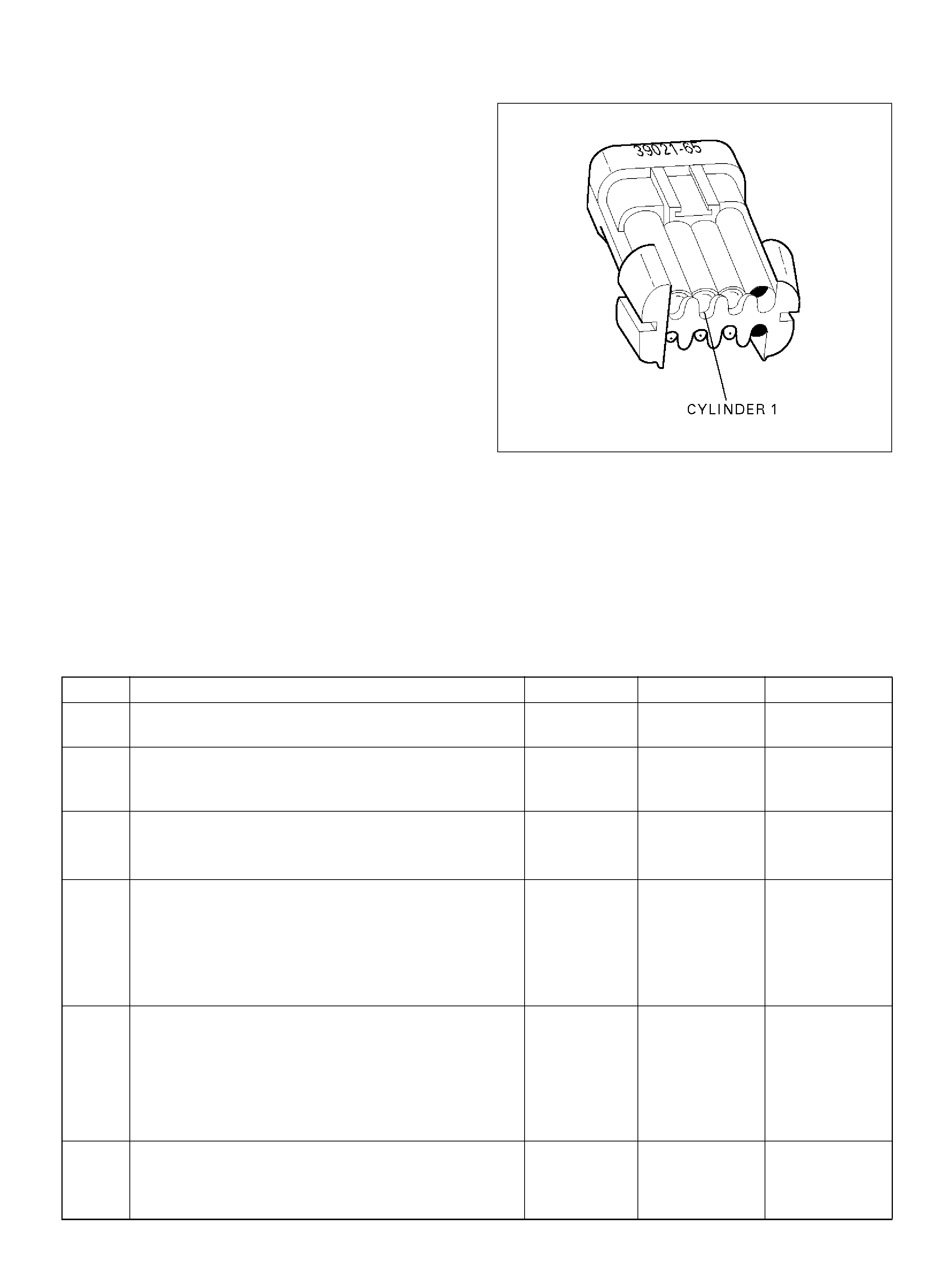
Diagnostic Aids
An injector driver circuit that is open or shorted to
voltage will cause a DTC P0201 to set. It will also cause
a misfire due to an inoperative injector. A misfire DTC
will also be set indicating which cylinder is inoperative.
Long term and short term fuel trims that are excessively
high or low are a good indication that an injector is
faulty.
Use Fuel Injector Coil Test Procedure to check for faulty
injectors.
Test Description
The number(s) below refer to the step number(s) on the
Diagnostic Chart.
3. This step determines if DTC P0201 is the result of a
hard failure or an intermittent condition.
5. A special injector test connector is provided so that
the injectors can be electrically tested without
removal of the manifold. The test connector can be
identified by the blue connector lock which is
tethered to the wiring harness. If the light for cylinder
1 is “ON" steady before cranking the engine as well
as while cranking the engine, then the injector driver
circuit is shorted to ground.
If the test light blinks while cranking, the PCM and
the wiring to the injectors are OK. The Fuel Injector
Coil Test Procedure will check if the injectors are
faulty.
R321054
7. Because the test light was “ON" steady, voltage to the
injector is OK, but the driver circuit is grounded at all
times. This step determines if the circuit is shorted to
ground or the PCM is faulty.
9. The reading should be about 12-14Ω.
10. Locating the open in the harness or in the injector
will require removal of the manifold to provide
access.
DTC P0201 – Injector 1 Control Circuit
Step Action Value(s) Yes No
1 Was the “On-Board Diagnostic (OBD) System Check"
performed? — Go to Step 2 Go to OBD
System Check
2 Will the engine start?
— Go to St ep 3
Go to Engine
Cranks But Will
Not Run chart
3 1. Install the Tech 2. Clear t he DTC.
2. Idle the engine for one minute.
Does DTC P0201 reset? — Go to St ep 5 Go to S tep 4
4 1. Review the Freeze Frame data with the ignition
“ON" and the engine “OFF" and note the
parameters.
2. Operate the vehicle within the Freeze Frame
condition s as noted.
Does P0201 res et? — Go to Step 5 Go to
Diagnostic Aids
5 1. Engine “OFF".
2. Disconnect the injector connector.
3. Install an injector test light 5-8840-2636-0 on the
injector test connector.
4. Crank the engine and note the light.
Doe s the in jec tor tes t light blink? —
Go to Fuel
Inje c to r Co il
Test Procedure Go to Step 6
6 Note whether the injector test light for cylinder 1 was
“OFF" or “ON" steady in step 5.
Was the test light “ON" steady while cranking the
engine? — Go to Step 7 Go to Step 9

7 1. Disconnect the PCM connector for the affected
injectors.
2. With a test light connected to B+, probe the
affected injector driver circui t.
Does the test light illuminate? — Go to St ep 8 Go to Step 15
8 Repair short to ground in the injector driver circuit.
Is the action complete ? — Go to OBD
System Check —
9 1. Disconnect the injector test connector.
2. At the injector side of the harness, connect an
ohmmeter between the posit ive wire (red with blue
tracer) and the wire for cylinder 1 (green with
white tracer).
Does the ohmmeter indicate continuity? — Go to Step 11 Go to Step 10
10 Repair the open injector harness wire or open injector .
Is the action complete ? — Verify repair —
11 At the PCM side of the injector test connector, check
the green/white wire for a short to voltage.
Was there a sh ort to voltage? — Go to Step 12 Go to Step 13
12 Repair the short to voltage.
Is the action complete ? — Verify repair —
13 Check for an open circuit between the injector test
connector and the PCM .
Was there an open c ircuit? — Go to Step 14 Go to Step 15
14 Repair the open circuit.
Is the action complete ? — Verify repair —
15 Replace the PCM.
Important: The replacement PCM must be
programmed. Refer to Section 0C-1 - Service
Program ming Syst em.
Important: Refer to Section 11 - Engin e Im mobiliser
System for the Immobiliser Programming procedure.
Important: Ensure the latest software program is
downloaded to the PCM.
Is the action complete ? — Verify repair —
Step Action Value(s) Yes No
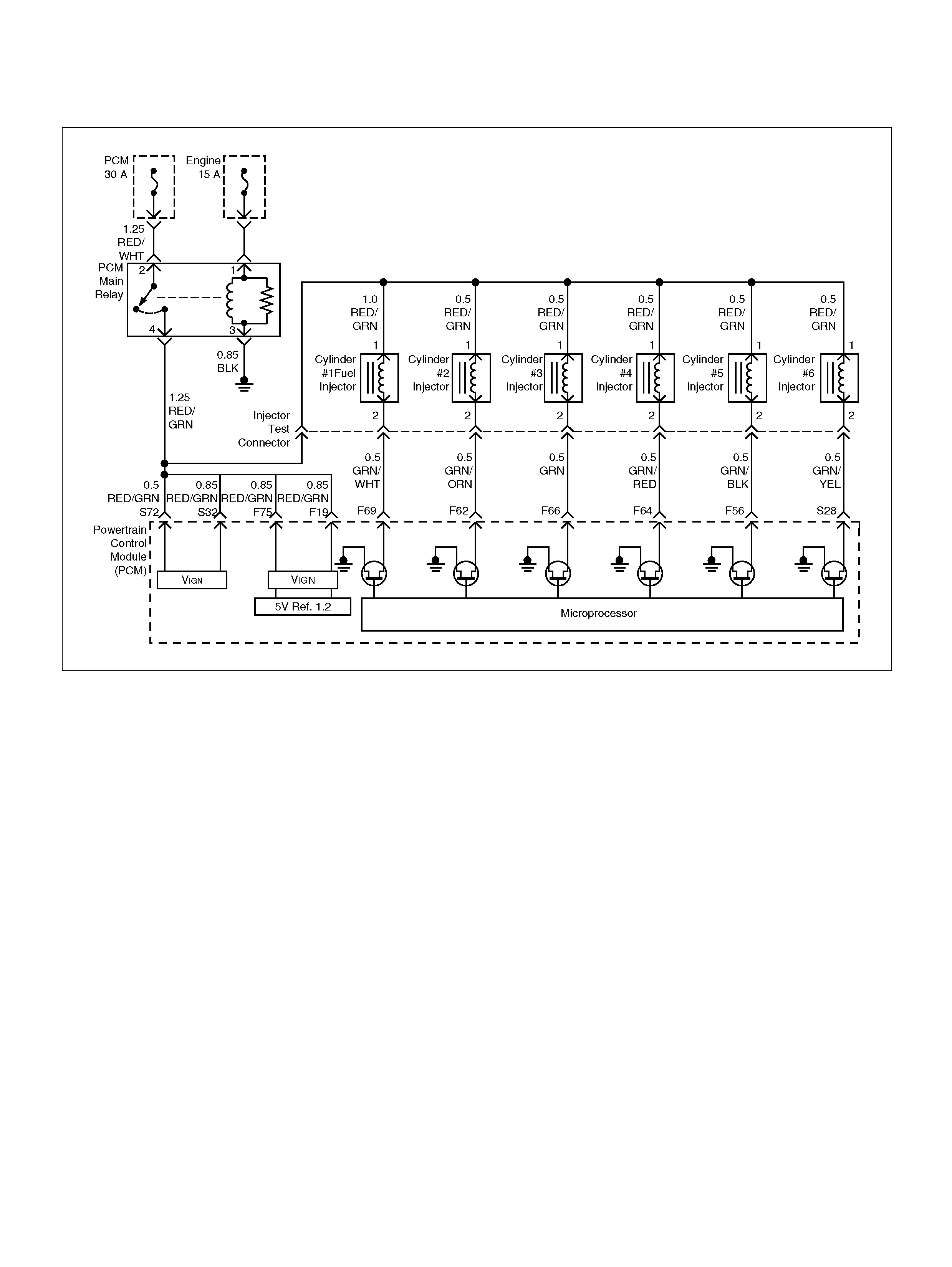
DIAGNOSTIC TROUBLE CODE (DTC) P0202 INJECTOR 2 CONTROL CIRCUIT
060R100134
Circuit Description
The powert ra in con trol module (PCM) has six in dividual
injector driver circuits. Each controls an injector. When a
driver circuit is grounded by the PCM, the injector is
activated. The PCM monitors the current in each driver
circuit. The voltage on each driver is monitored to detect
a fault. If the voltage is not what the PCM expects to
monitor on the circuit, a DTC is set. This DTC is also set
if an injector d ri ver is shorted to voltage or if there is an
open circuit.
Conditions for Setting the DTC
• T he battery voltage is more than 9 v ol ts.
• Engine speed is more than 700 rpm.
• The engine is turning, determined by 58X crankshaft
pos ition input signal.
• The injector voltage does not equal the ignition
voltage when the injector is commanded “OFF" or the
injector voltage does not equal 0 volts when the
injector is commanded “ON" .
• T he above c onditions are met for 5 seconds.
Action Taken When the DTC Sets
• The PCM will illuminate the malfunction indicator
l a mp (M IL ) the fi r s t time th e fa ult is d e te c te d .
• The PCM will store conditions which were present
when the DTC was set as Freeze Frame and in the
Failure Records data.
Conditi ons for Clea r ing the MIL/DTC
• The PCM will turn “OFF" the MIL on the third
consecutive trip cycle in which the diagnostic has
been run and the fault is no longer present.
• A history DTC P0202 will clear after 40 consecutive
warm-up cy cles occur without a fault.
• DTC P0202 can be cleared by using the Tech 2
“Clear Info" function.

Diagnostic Aids
An injector driver circuit that is open or shorted to
voltage will cause a DTC P0202 to set. It will also cause
a misfire due to an inoperative injector. A misfire DTC
will also be set indicating which cylinder is inoperative.
Long term and short term fuel trims that are excessively
high or low are a good indication that an injector is
faulty.
Use Fuel Injector Coil Test Procedure to check for faulty
injectors.
Test Description
The number(s) below refer to the step number(s) on the
Diagnostic Chart.
3. This step determines if DTC P0202 is the result of a
hard failure or an intermittent condition.
5. A special injector test connector is provided so that
the injectors can be electrically tested without
removal of the manifold. The test connector can be
identified by the blue connector lock which is
tethered to the wiring harness. If the light for cylinder
2 is “ON" steady before cranking the engine as well
as while cranking the engine, then the injector driver
circuit is shorted to ground.
If the test light blinks while cranking, the PCM and
the wiring to the injectors are OK. The Fuel Injector
Coil Test Procedure will check if the injectors are
faulty.
R321055
7. Because the test light was “ON" steady, voltage to the
injector is OK, but the driver circuit is grounded at all
times. This step determines if the circuit is shorted to
ground or the PCM is faulty.
9. The reading should be about 12-14Ω.
10. Locating the open in the harness or in the injector
will require removal of the manifold to provide
access.
DTC P0202 – Injector 2 Control Circuit
Step Action Value(s) Yes No
1 Was the “On-Board Diagnostic (OBD) System Check"
performed? — Go to Step 2 Go to OBD
System Check
2 Will the engine start?
— Go to St ep 3
Go to Engine
Cranks But Will
Not Run chart
3 1. Install the Tech 2. Clear t he DTC.
2. Idle the engine for one minute.
Does DTC P0202 reset? — Go to St ep 5 Go to S tep 4
4 1. Review the Freeze Frame data with the ignition
“ON" and the engine “OFF" and note the
parameters.
2. Operate the vehicle within the Freeze Frame
condition s as noted.
Does P0202 res et? — Go to Step 5 Go to
Diagnostic Aids
5 1. Engine “OFF".
2. Disconnect the injector test c on nec tor.
3. Install an injector test light 5-8840-2636-0 on
injector connector.
4. Crank the engine and note the light.
Does the cylinder 2 test light blink? —
Go to Fuel
Inje c to r Co il
Test Procedure Go to Step 6
6 Note whether the injector test light for cylinder 2 was
“OFF" or “ON" steady in step 5.
Was the test light “ON" steady while cranking the
engine? — Go to Step 7 Go to Step 9

7 1. Disconnect the PCM connector for the affected
injectors.
2. With a test light connected to B+, probe the
affected injector driver circui t.
Does the test light illuminate? — Go to St ep 8 Go to Step 15
8 Repair short to ground in the injector driver circuit.
Is the action complete ? — Go to OBD
System Check —
9 1. Disconnect the injector test connector.
2. At the injector side of the harness, connect an
ohmmeter between the posit ive wire (red with blue
tracer) and the wire for cylinder 2 (green with
orange tracer).
Does the ohmmeter indicate continuity? — Go to Step 11 Go to Step 10
10 Repair the open injector harness wire or open injector .
Is the action complete ? — Verify repair —
11 At the PCM side of the injector test connector, check
the green/orange wire for a short to voltag e.
Was there a sh ort to voltage? — Go to Step 12 Go to Step 13
12 Repair the short to voltage.
Is the action complete ? — Verify repair —
13 Check for an open circuit between the injector test
connector and the PCM .
Was there an open c ircuit? — Go to Step 14 Go to Step 15
14 Repair the open circuit.
Is the action complete ? — Verify repair —
15 Replace the PCM.
Important: The replacement PCM must be
programmed. Refer to Section 0C-1 - Service
Program ming Syst em.
Important: Refer to Section 11 - Engin e Im mobiliser
System for the Immobiliser Programming procedure.
Important: Ensure the latest software program is
downloaded to the PCM.
Is the action complete ? — Verify repair —
Step Action Value(s) Yes No

DIAGNOSTIC TROUBLE CODE (DTC) P0203 INJECTOR 3 CONTROL CIRCUIT
060R100134
Circuit Description
The powert ra in con trol module (PCM) has six in dividual
injector driver circuits. Each controls an injector. When
the driver circuit is grounded by the PCM, the in jector is
activated. The PCM monitors the current in each driver
circuit. The voltage on each driver is monitored to detect
a fault. If the voltage is not what the PCM expects to
monitor on the circuit, a DTC is set. This DTC is also set
if an injector d ri ver is shorted to voltage or if there is an
open circuit.
Conditions for Setting the DTC
• T he battery voltage is more than 9 v ol ts.
• Engine speed is more than 700 rpm.
• The engine is turning, determined by the 58X
cranks haft position input signal.
• The injector voltage does not equal the ignition
voltage when the injector is commanded “OFF" or the
injector voltage does not equal 0 volts when the
injector is commanded “ON" .
• T he above c onditions are met for 5 seconds.
Action Taken When the DTC Sets
• The PCM will illuminate the malfunction indicator
l a mp (M IL ) the fi r s t time th e fa ult is d e te c te d .
• The PCM will store conditions which were present
when the DTC was set as Freeze Frame and in the
Failure Records data.
Conditi ons for Clea r ing the MIL/DTC
• The PCM will turn “OFF" the MIL on the third
consecutive trip cycle in which the diagnostic has
been run and the fault is no longer present.
• A history DTC P0203 will clear after 40 consecutive
warm-up cy cles occur without a fault.
• DTC P0203 can be cleared by using the Tech 2
“Clear Info" function.

Diagnostic Aids
An injector driver circuit that is open or shorted to
voltage will cause a DTC P0203 to set. It will also cause
a misfire due to an inoperative injector. A misfire DTC
will also be set indicating which cylinder is inoperative.
Long term and short term fuel trims that are excessively
high or low are a good indication that an injector is
faulty.
Use Fuel Injector Coil Test Procedure to check for faulty
injectors.
Test Description
The number(s) below refer to the step number(s) on the
Diagnostic Chart.
3. This step determines if DTC P0203 is the result of a
hard failure or an intermittent condition.
5. A special injector test connector is provided so that
the injectors can be electrically tested without
removal of the manifold. The test connector can be
identified by the blue connector lock which is
tethered to the wiring harness. If the light for cylinder
3 is “ON" steady before cranking the engine as well
as while cranking the engine, then the injector driver
circuit is shorted to ground.
If the test light blinks while cranking, the PCM and
the wiring to the injectors are OK. The Fuel Injector
Coil Test Procedure will check if the injectors are
faulty.
R321056
7. Because the test light was “ON" steady, voltage to the
injector is OK, but the driver circuit is grounded at all
times. This step determines if the circuit is shorted to
ground or the PCM is faulty.
9. The reading should be about 12-14Ω.
10. Locating the open in the harness or in the injector
will require removal of the manifold to provide
access.
DTC P0203 – Injector 3 Control Circuit
Step Action Value(s) Yes No
1 Was the “On-Board Diagnostic (OBD) System Check"
performed? — Go to Step 2 Go to OBD
System Check
2 Will the engine start?
— Go to St ep 3
Go to Engine
Cranks But Will
Not Run chart
3 1. Install the Tech 2. Clear t he DTC.
2. Idle the engine for one minute.
Does DTC P0203 reset? — Go to St ep 5 Go to S tep 4
4 1. Review the Freeze Frame data with the ignition
“ON" and the engine “OFF" and note the
parameters.
2. Operate the vehicle within the Freeze Frame
condition s as noted.
Does P0203 res et? — Go to Step 5 Go to
Diagnostic Aids
5 1. Engine “OFF".
2. Disconnect the injector test connector .
3. Install an injector test light 5-8840-2636-0 on
injector connector.
4. Crank the engine and note the light.
Does the cylinder 3 test light blink? —
Go to Fuel
Inje c to r Co il
Test Procedure Go to Step 6
6 Note whether the injector test light for cylinder 3 was
“OFF" or “ON" steady in step 5.
Was the test light “ON" steady while cranking the
engine? — Go to Step 7 Go to Step 9

7 1. Disconnect the PCM connector for the affected
injectors.
2. With a test light connected to B+, probe the
affected injector driver circui t.
Does the test light illuminate? — Go to St ep 8 Go to Step 15
8 Repair short to ground in the injector driver circuit.
Is the action complete ? — Go to OBD
System Check —
9 1. Disconnect the injector test connector.
2. At the injector side of the harness, connect an
ohmmeter between the posit ive wire (red with blue
tracer) and the wire for cylinder 3 (green).
Does the ohmmeter indicate continuity? — Go to Step 11 Go to Step 10
10 Repair the open injector harness wire or open injector .
Is the action complete ? — Verify repair —
11 At the PCM side of the injector test connector, check
the green wire for a sho rt to voltage.
Was there a sh ort to voltage? — Go to Step 12 Go to Step 13
12 Repair the short to voltage.
Is the action complete ? — Verify repair —
13 Check for an open circuit between the injector test
connector and the PCM .
Was there an open c ircuit? — Go to Step 14 Go to Step 15
14 Repair the open circuit.
Is the action complete ? — Verify repair —
15 Replace the PCM.
Important: The replacement PCM must be
programmed. Refer to Section 0C-1 - Service
Program ming Syst em.
Important: Refer to Section 11 - Engin e Im mobiliser
System for the Immobiliser Programming procedure.
Important: Ensure the latest software program is
downloaded to the PCM.
Is the action complete ? — Verify repair —
Step Action Value(s) Yes No

DIAGNOSTIC TROUBLE CODE (DTC) P0204 INJECTOR 4 CONTROL CIRCUIT
060R100134
Circuit Description
The powert ra in con trol module (PCM) has six in dividual
injector driver circuits. Each controls an injector. When
the driver circuit is grounded by the PCM, the in jector is
activated. The PCM monitors the current in each driver
circuit. The voltage on each driver is monitored to detect
a fault. If the voltage is not what the PCM expects to
monitor on the circuit, a DTC is set. This DTC is also set
if an injector d ri ver is shorted to voltage or if there is an
open circuit.
Conditions for Setting the DTC
• T he battery voltage is more than 9 v ol ts.
• Engine speed is more than 700 rpm.
• The engine is turning, determined by the 58X
cranks haft position input signal.
• The injector voltage does not equal the ignition
voltage when the injector is commanded “OFF" or the
injector voltage does not equal 0 volts when the
injector is commanded “ON" .
• T he above c onditions are met for 5 seconds.
Action Taken When the DTC Sets
• The PCM will illuminate the malfunction indicator
l a mp (M IL ) the fi r s t time th e fa ult is d e te c te d .
• The PCM will store conditions which were present
when the DTC was set as Freeze Frame and in the
Failure Records data.
Conditi ons for Clea r ing the MIL/DTC
• The PCM will turn “OFF" the MIL on the third
consecutive trip cycle in which the diagnostic has
been run and the fault is no longer present.
• A history DTC P0204 will clear after 40 consecutive
warm-up cy cles occur without a fault.
• DTC P0204 can be cleared by using the Tech 2
“Clear Info" function.
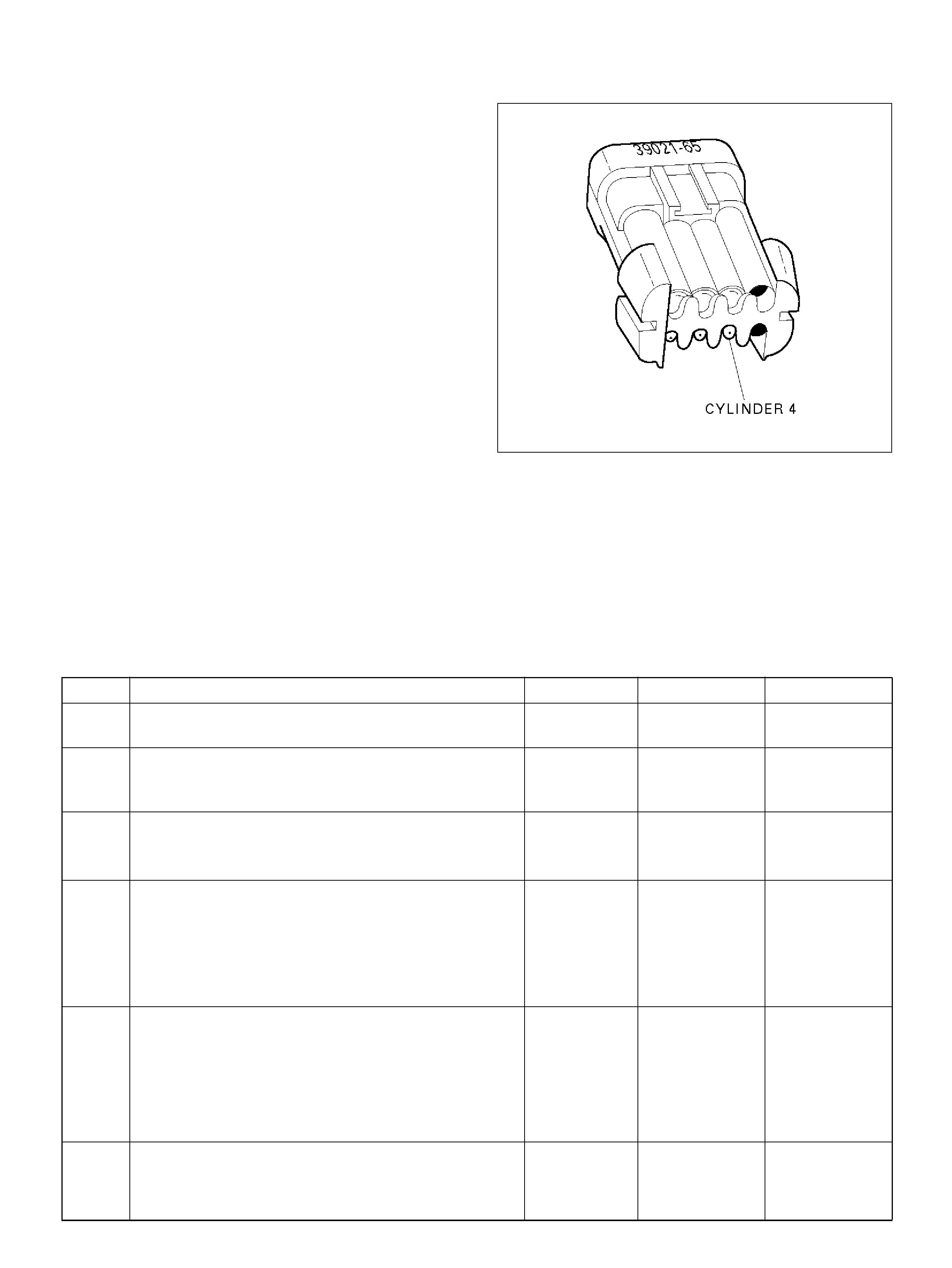
Diagnostic Aids
An injector driver circuit that is open or shorted to
voltage will cause a DTC P0204 to set. It will also cause
a misfire due to an inoperative injector. A misfire DTC
will also be set indicating which cylinder is inoperative.
Long term and short term fuel trims that are excessively
high or low are a good indication that an injector is
faulty.
Use Fuel Injector Coil Test Procedure to check for faulty
injectors.
Test Description
The number(s) below refer to the step number(s) on the
Diagnostic Chart.
3. This step determines if DTC P0204 is the result of a
hard failure or an intermittent condition.
5. A special injector test connector is provided so that
the injectors can be electrically tested without
removal of the manifold. The test connector can be
identified by the blue connector lock which is
tethered to the wiring harness. If the light for cylinder
4 is “ON" steady before cranking the engine as well
as while cranking the engine, then the injector driver
circuit is shorted to ground.
If the test light blinks while cranking, the PCM and
the wiring to the injectors are OK. The Fuel Injector
Coil Test Procedure will check if the injectors are
faulty.
R321057
7. Because the test light was “ON" steady, voltage to the
injector is OK, but the driver circuit is grounded at all
times. This step determines if the circuit is shorted to
ground or the PCM is faulty.
9. The reading should be about 12-14Ω.
10. Locating the open in the harness or in the injector
will require removal of the manifold to provide
access.
DTC P0204 – Injector 4 Control Circuit
Step Action Value(s) Yes No
1 Was the “On-Board Diagnostic (OBD) System Check"
performed? — Go to Step 2 Go to OBD
System Check
2 Will the engine start?
— Go to St ep 3
Go to Engine
Cranks But Will
Not Run chart
3 1. Install the Tech 2. Clear t he DTC.
2. Idle the engine for one minute.
Does DTC P0204 reset? — Go to St ep 5 Go to S tep 4
4 1. Review the Freeze Frame data with the ignition
“ON" and the engine “OFF" and note the
parameters.
2. Operate the vehicle within the Freeze Frame
condition s as noted.
Does P0204 res et? — Go to Step 5 Go to
Diagnostic Aids
5 1. Engine “OFF".
2. Disconnect the injector test c on nec tor.
3. Install an injector test light 5-8840-2636-0 on
injector connector.
4. Crank the engine and note the light.
Does the cylinder 4 test light blink? —
Go to Fuel
Inje c to r Co il
Test Procedure Go to Step 6
6 Note whether the injector test light for cylinder 4 was
“OFF" or “ON" steady in step 5.
Was the test light “ON" steady while cranking the
engine? — Go to Step 7 Go to Step 9

7 1. Disconnect the PCM connector for the affected
injectors.
2. With a test light connected to B+, probe the
affected injector driver circui t.
Does the test light illuminate? — Go to St ep 8 Go to Step 15
8 Repair short to ground in the injector driver circuit.
Is the action complete ? — Go to OBD
System Check —
9 1. Disconnect the injector test connector.
2. At the injector side of the harness, connect an
ohmmeter between the posit ive wire (red with blue
tracer) and the wire for cylinder 4 (green/red).
Does the ohmmeter indicate continuity? — Go to Step 11 Go to Step 10
10 Repair the open injector harness wire or open injector.
Is the action complete ? — Verify repair —
11 At the PCM side of the injector test connector, check
the green/red wire for a short to voltage.
Was there a sh ort to voltage? — Go to Step 12 Go to Step 13
12 Repair the short to voltage.
Is the action complete ? — Verify repair —
13 Check for an open circuit between the injector test
connector and the PCM .
Was there an open c ircuit? — Go to Step 14 Go to Step 15
14 Repair the open circuit.
Is the action complete ? — Verify repair —
15 Replace the PCM.
Important: The replacement PCM must be
programmed. Refer to Section 0C-1 - Service
Program ming Syst em.
Important: Refer to Section 11 - Engin e Im mobiliser
System for the Immobiliser Programming procedure.
Important: Ensure the latest software program is
downloaded to the PCM.
Is the action complete ? — Verify repair —
Step Action Value(s) Yes No

DIAGNOSTIC TROUBLE CODE (DTC) P0205 INJECTOR 5 CONTROL CIRCUIT
060R100134
Circuit Description
The powert ra in con trol module (PCM) has six in dividual
injector driver circuits. Each controls an injector. When
the driver circuit is grounded by the PCM, the in jector is
activated. The PCM monitors the current in each driver
circuit. If the voltage is not what the PCM expects to
monitor on the circuit, a DTC is set. This DTC is also set
if an injector d ri ver is shorted to voltage or if there is an
open circuit.
Conditions for Setting the DTC
• T he battery voltage is more than 9 v ol ts.
• Engine speed is more than 700 rpm.
• The engine is turning, determined by the 58X
cranks haft position input signal.
• The injector voltage does not equal the ignition
voltage when the injector is commanded “OFF" or the
injector voltage does not equal 0 volts when the
injector is commanded “ON" .
• T he above c onditions are met for 5 seconds.
Action Taken When the DTC Sets
• The PCM will illuminate the malfunction indicator
l a mp (M IL ) the fi r s t time th e fa ult is d e te c te d .
• The PCM will store conditions which were present
when the DTC was set as Freeze Frame and in the
Failure Records data.
Conditi ons for Clea r ing the MIL/DTC
• The PCM will turn “OFF" the MIL on the third
consecutive trip cycle in which the diagnostic has
been run and the fault is no longer present.
• A history DTC P0205 will clear after 40 consecutive
warm-up cy cles occur without a fault.
• DTC P0205 can be cleared by using the Tech 2
“Clear Info" function.
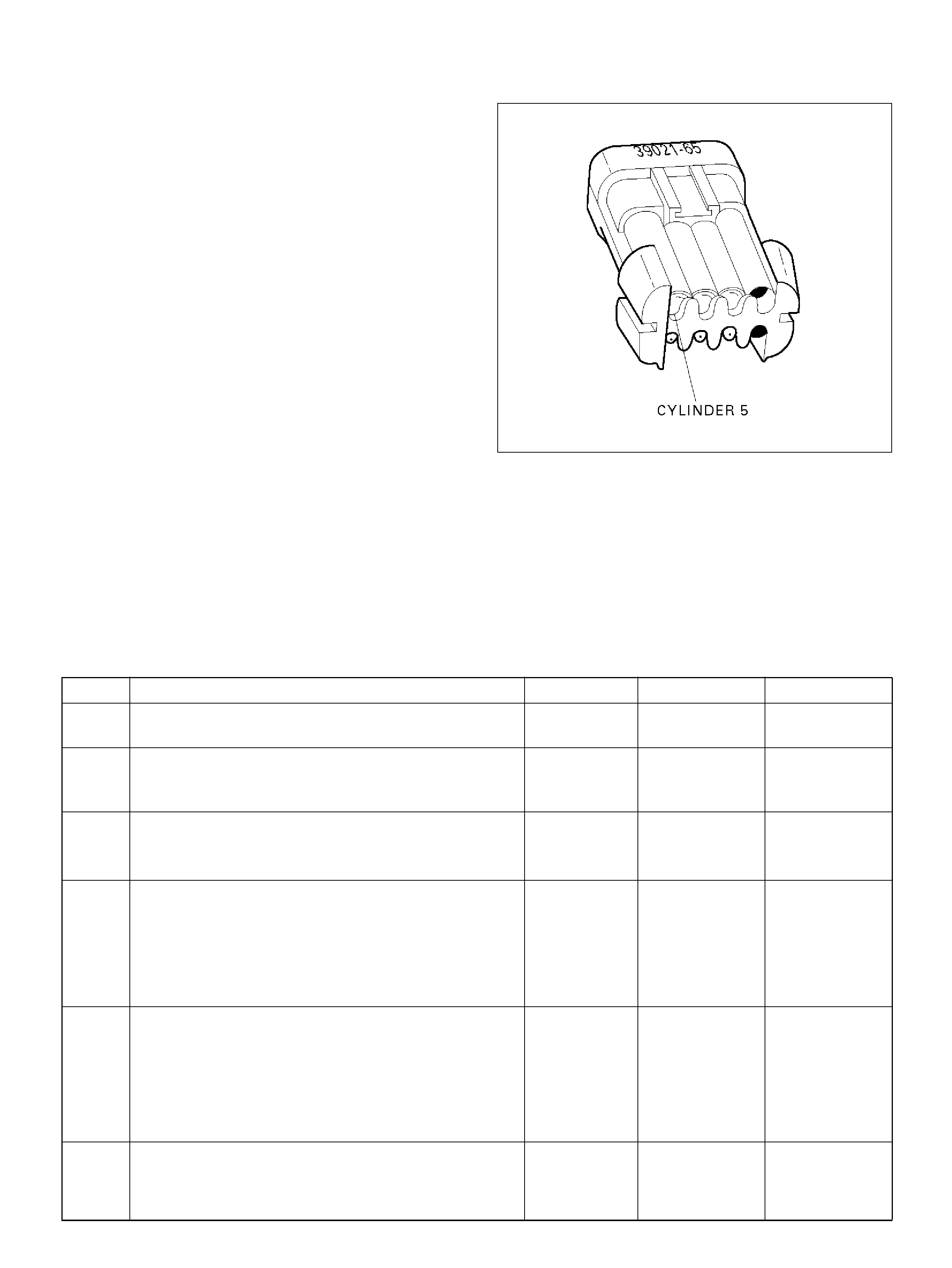
Diagnostic Aids
An injector driver circuit that is open or shorted to
voltage will cause a DTC P0205 to set. It will also cause
a misfire due to an inoperative injector. A misfire DTC
will also be set indicating which cylinder is inoperative.
Long term and short term fuel trims that are excessively
high or low are a good indication that an injector is
faulty.
Use Fuel Injector Coil Test Procedure to check for faulty
injectors.
Test Description
The number(s) below refer to the step number(s) on the
Diagnostic Chart.
3. This step determines if DTC P0205 is the result of a
hard failure or an intermittent condition.
5. A special injector test connector is provided so that
the injectors can be electrically tested without
removal of the manifold. The test connector can be
identified by the blue connector lock which is
tethered to the wiring harness. If the light for cylinder
5 is “ON" steady before cranking the engine as well
as while cranking the engine, then the injector driver
circuit is shorted to ground.
If the test light blinks while cranking, the PCM and
the wiring to the injectors are OK. The Fuel Injector
Coil Test Procedure will check if the injectors are
faulty.
R321058
7. Because the test light was “ON" steady, voltage to the
injector is OK, but the driver circuit is grounded at all
times. This step determines if the circuit is shorted to
ground or the PCM is faulty.
9. The reading should be about 12-14Ω.
10. Locating the open in the harness or in the injector
will require removal of the manifold to provide
access.
DTC P0205 – Injector 5 Control Circuit
Step Action Value(s) Yes No
1 Was the “On-Board Diagnostic (OBD) System Check"
performed? — Go to Step 2 Go to OBD
System Check
2 Will the engine start?
— Go to St ep 3
Go to Engine
Cranks But Will
Not Run chart
3 1. Install the Tech 2. Clear t he DTC.
2. Idle the engine for one minute.
Does DTC P0205 reset? — Go to St ep 5 Go to S tep 4
4 1. Review the Freeze Frame data with the ignition
“ON" and the engine “OFF" and note the
parameters.
2. Operate the vehicle within the Freeze Frame
condition s as noted.
Does P0205 res et? — Go to Step 5 Go to
Diagnostic Aids
5 1. Engine “OFF".
2. Disconnect the injector test c on nec tor.
3. Install an injector test light 5-8840-2636-0 on
injector connector.
4. Crank the engine and note the light.
Does the cylinder 5 test light blink? —
Go to Fuel
Inje c to r Co il
Test Procedure Go to Step 6
6 Note whether the i njector te st light for c ylinder 5 was
“OFF" or “ON" steady in step 5.
Was the test light “ON" steady while cranking the
engine? — Go to Step 7 Go to Step 9

7 1. Disconnect the PCM connector for the affected
injectors.
2. With a test light connected to B+, probe the
affected injector driver circui t.
Does the test light illuminate? — Go to St ep 8 Go to Step 15
8 Repair short to ground in the injector driver circuit.
Is the action complete ? — Go to OBD
System Check —
9 1. Disconnect the injector test connector.
2. At the injector side of the harness, connect an
ohmmeter between the posit ive wire (red with blue
tracer) and the wire for cylinder 5 (green with
black tracer).
Does the ohmmeter indicate continuity? — Go to Step 11 Go to Step 10
10 Repair the open injector harness wire or open injector.
Is the action complete ? — Verify repair —
11 At the PCM side of the injector test connector, check
the green/black wire for a short to voltage.
Was there a sh ort to voltage? — Go to Step 12 Go to Step 13
12 Repair the short to voltage.
Is the action complete ? — Verify repair —
13 Check for an open circuit between the injector test
connector and the PCM .
Was there an open c ircuit? — Go to Step 14 Go to Step 15
14 Repair the open circuit.
Is the action complete ? — Verify repair —
15 Replace the PCM.
Important: The replacement PCM must be
programmed. Refer to Section 0C-1 - Service
Program ming Syst em.
Important: Refer to Section 11 - Engin e Im mobiliser
System for the Immobiliser Programming procedure.
Important: Ensure the latest software program is
downloaded to the PCM.
Is the action complete ? — Verify repair —
Step Action Value(s) Yes No

DIAGNOSTIC TROUBLE CODE (DTC) P0206 INJECTOR 6 CONTROL CIRCUIT
060R100134
Circuit Description
The powert ra in con trol module (PCM) has six in dividual
injector driver circuits. Each controls an injector. When
the driver circuit is grounded by the PCM, the in jector is
activated. The PCM monitors the current in each driver
circuit. The voltage on each driver is monitored to detect
a fault. If the voltage is not what the PCM expects to
monitor on the circuit, a DTC is set. This DTC is also set
if an injector d ri ver is shorted to voltage or if there is an
open circuit.
Conditions for Setting the DTC
• T he battery voltage is more than 9 v ol ts.
• Engine speed is more than 700 rpm.
• The engine is turning, determined by 58X crankshaft
pos ition input signal.
• The injector voltage does not equal the ignition
voltage when the injector is commanded “OFF" or the
injector voltage does not equal 0 volts when the
injector is commanded “ON" .
• T he above c onditions are met for 5 seconds.
Action Taken When the DTC Sets
• The PCM will illuminate the malfunction indicator
l a mp (M IL ) the fi r s t time th e fa ult is d e te c te d .
• The PCM will store conditions which were present
when the DTC was set as Freeze Frame and in the
Failure Records data.
Conditi ons for Clea r ing the MIL/DTC
• The PCM will turn “OFF" the MIL on the third
consecutive trip cycle in which the diagnostic has
been run and the fault is no longer present.
• A history DTC P0206 will clear after 40 consecutive
warm-up cy cles occur without a fault.
• DTC P0206 can be cleared by using the Tech 2
“Clear Info" function.

Diagnostic Aids
An injector driver circuit that is open or shorted to
voltage will cause a DTC P0206 to set. It will also cause
a misfire due to an inoperative injector. A misfire DTC
will also be set indicating which cylinder is inoperative.
Long term and short term fuel trims that are excessively
high or low are a good indication that an injector is
faulty.
Use Fuel Injector Coil Test Procedure to check for faulty
injectors.
Test Description
The number(s) below refer to the step number(s) on the
Diagnostic Chart.
3. This step determines if DTC P0206 is the result of a
hard failure or an intermittent condition.
5. A special injector test connector is provided so that
the injectors can be electrically tested without
removal of the manifold. The test connector can be
identified by the blue connector lock which is
tethered to the wiring harness. If the light for cylinder
6 is “ON" steady before cranking the engine as well
as while cranking the engine, then the injector driver
circuit is shorted to ground.
If the test light blinks while cranking, the PCM and
the wiring to the injectors are OK. The Fuel Injector
Coil Test Procedure will check if the injectors are
faulty.
R321059
7. Because the test light was “ON" steady, voltage to the
injector is OK, but the driver circuit is grounded at all
times. This step determines if the circuit is shorted to
ground or the PCM is faulty.
9. The reading should be about 12-14Ω.
10. Locating the open in the harness or in the injector
will require removal of the manifold to provide
access.
DTC P0206 – Injector 6 Control Circuit
Step Action Value(s) Yes No
1 Was the “On-Board Diagnostic (OBD) System Check"
performed? — Go to Step 2 Go to OBD
System Check
2 Will the engine start?
— Go to St ep 3
Go to Engine
Cranks But Will
Not Run chart
3 1. Install the Tech 2. Clear t he DTC.
2. Idle the engine for one minute.
Does DTC P0206 reset? — Go to St ep 5 Go to S tep 4
4 1. Review the Freeze Frame data with the ignition
“ON" and the engine “OFF" and note the
parameters.
2. Operate the vehicle within the Freeze Frame
condition s as noted.
Does P0206 res et? — Go to Step 5 Go to
Diagnostic Aids
5 1. Engine “OFF".
2. Disconnect the injector test c on nec tor.
3. Install an injector test light 5-8840-2636-0 on
injector connector.
4. Crank the engine and note the light.
Does the cylinder 6 test light blink? —
Go to Fuel
Inje c to r Co il
Test Procedure Go to Step 6
6 Note whether the injector test light for cylinder 6 was
“OFF" or “ON" steady in step 5.
Was the test light “ON" steady while cranking the
engine? — Go to Step 7 Go to Step 9

7 1. Disconnect the PCM connector for the affected
injectors.
2. With a test light connected to B+, probe the
affected injector driver circui t.
Does the test light illuminate? — Go to St ep 8 Go to Step 15
8 Repair short to ground in the injector driver circuit.
Is the action complete ? — Go to OBD
System Check —
9 1. Disconnect the injector test connector.
2. At the injector side of the harness, connect an
ohmmeter between the posit ive wire (red with blue
tracer) and the wire for cylinder 6 (green with
yellow tracer).
Does the ohmmeter indicate continuity? — Go to Step 11 Go to Step 10
10 Repair the open injector harness wire or open injector
Is the action complete ? — Verify repair —
11 At the PCM side of the injector test connector, check
the green/yellow wire for a sh ort to volta ge.
Was there a sh ort to voltage? — Go to Step 12 Go to Step 13
12 Repair the short to voltage.
Is the action complete ? — Verify repair —
13 Check for an open circuit between the injector test
connector and the PCM .
Was there an open c ircuit? — Go to Step 14 Go to Step 15
14 Repair the open circuit.
Is the action complete ? — Verify r epair —
15 Replace the PCM.
Important: The replacement PCM must be
programmed. Refer to Section 0C-1 - Service
Program ming Syst em.
Important: Refer to Section 11 - Engin e Im mobiliser
System for the Immobiliser Programming procedure.
Important: Ensure the latest software program is
downloaded to the PCM.
Is the action complete ? — Verify repair —
Step Action Value(s) Yes No

DIAGNOSTIC TROUBLE CODE (DTC) P0300 ENGINE MISFIRE DETECTED
Circuit Description
Misfire is monitored as a function of the combustion
quality (CQ) signals generated from the ION Sensing
Module. Combustion signals represent the degree of
combustion in each cylinder. Misfire is detected when
the combustion signal is below a predetermined value.
This DTC P0300 will determine if a multiple cylinder
misfire is occurring by monitoring the Combustion
Quality.
Conditions for Setting the DTC
• None of the following DTCs occur: TP sensor, MAF
sensor, VSS, ECT se nsor.
• The engine speed is between 600 and 6250 RPM.
• T he system voltage is between 11 and 16 volts.
• The engine temperature sensor (ECT) indicates an
engine tem peratu re be tween –7 °C (20°F) and 110°C
(230°F).
• Throttle angle is steady and throttle changes less
than 0.4% per 125 milliseconds.
Action Taken When the DTC Sets
• The PCM will ON the MIL after second trip with
detect ed the fault.
• If the misfire is severe enough to cause possible
catalyst damage, the PCM will flash the MIL for as
long as the misfire remains at catalyst damaging
levels.
• T he PC M will disable the TCC operation.
• The PCM will store conditions which were present
when the DTC was set as Freeze Frame and in the
Failure Records data.
Conditions for Clearing the MIL/DTC
• The PCM will turn the MIL “OFF" on the third
consecutive trip cycle in which the diagnostic has
been run and the fault condition is no longer present.
• A history DTC P0300 will clear after 40 consecutive
w arm-up cycles occur without a fault.
• DTC P0300 can be cleared by using the Tech 2
“Clear Info" function.
Diagn ostic Aids
The Tech 2 display “Misfire Cur. #1 through #6" can be
useful to determine whether the misfire is isolated to a
single cylinder.
• D ama ged or faulty ignition coil – Che ck for cracks or
other damage.
• Substitute a known good coil – Swap the ignition coils
and retest. If the misfire follows the coil, replace the
ignition coil.
If the misfire is random, check for the following
conditi ons :
• System grounds – Ensure all connections are clean
and properly tightened.
• MAF – A mass air flow (MAF) sensor output that
causes the PCM to sense a lower than normal air
flow will cause a lean condition.
• Air induction system – Air leaks into the induction
system which bypass the MAF sensor will cause a
lean condition. Check for disconnected or damaged
vacuum hoses, incorrectly installed or faulty PCV
valve, or for vacuum leaks at the throttle body, EGR
valve , and intake manifold mounting surfaces.
• Fuel pressure – Perform a fuel system pressure test.
A faulty fuel pump, plugged filter, or faulty fuel system
pre ssure regulator will contribute to a lean c ondi tion.
• Injector(s) – Perform an injector coil/balance test to
locate faulty injector(s) contributing to a lean or
flooding condition. In addition to the above test,
check the condition of the injector O-rings.
• EGR – Check for a leaking valve, adapter, or feed
pipes which will contribute to a lean condition or
excessive EGR flo w.
• F uel q uality – Using fuel with the wrong octane rating
for the vehicle may cause derivability problems.
Although alcohol-enhanced fuels may raise the
octane rating, the fuel's ability to turn into vapor in
cold temperatures deteriorates. This may affect the
cold derivability of the engine. The Reid Vapor
Pressure of the fuel can also create problems in the
fuel system, especially during the spring and fall
when changes by the refineries may not coincide with
changes in the weather.
• Vehicle marshalling – The transportation of new
vehicles from the assembly plant to the dealership
can involve as many as 60 key cycles within 2 to 3
miles of driving. This type of operation contrib utes to
the fuel f ouling of t he spark pl ugs and will turn on th e
MIL with a P0300 Misfire DTC.
Reviewing the Failure Records vehicle mileage since
the diagnostic test last failed may help determine how
often the condition that caused the DTC to be set
occurs. This may assist in diagnosing the condition.

DTC P0300 – Engine Misfire Detected
Step Action Value(s) Yes No
1 Was the “On-Board Diagnostic (OBD) System Check"
performed? — Go to Step 2 Go to OBD
System Check
2 1. Start th e engine. Run the engi ne at idle.
2. Review and recor d the Tech 2 Freeze Frame data.
3. Operate the vehicle to duplicate the conditions
present when the DTC was s et (as defined by the
Freeze Frame data).
4. Monitor the Tech 2 “Misfire Cur. #" display for each
cylinder.
Is “Misfire Cur. #" display increasing for any cylinder
(indicating a misfire currently occurring)? — Go to Step 3 Refe r to
Diagnostic Aids
3 1. Visually and physically inspect the vacuum ho ses
for splits, kink s, and improper connec tions.
2. If a problem is found, repair or replace the vacuum
hoses as necessary.
Did your inspection reveal a problem? — Veri fy repair Go to S tep 4
4 1. Vis ual ly and physicall y inspec t t he following areas
for vacuum leaks:
• The intake manifold
• The injector O-rings
• The EGR adapter
• The EGR feed pipes
• ION S ensing M odule
2. If a problem is found, repair the vacuum leak as
necessary.
Did your inspection reveal a vacuum leak? — Veri fy repair Go to S tep 5
5 1. Visually and physically inspect the crankcase
ventilation valve for improper installation or
damaged grommet.
2. If a problem is found, repair as necessa ry (refer to
Crankcase Ventilat ion Sy stem).
Did your inspection reveal a problem? — Veri fy repair Go to S tep 6
6 1. Inspect the MAF sensor inlet screen for damage
or for the presence of foreign objects that may
parti ally block the air flow sample through the MAF
sensor.
2. If a problem is found, repair or replace the MAF
sensor as necessary.
Did your inspection of the MAF sensor reveal a
condition requiring repair or replac em ent? — Verify repair Go to S tep 7
7 1. Remove the EGR valve and visually/physically
inspect the valve to ensure that the pintle is not
sticking partially open. Also, inspect the EGR
valve pintle and seat for carbon deposits or burrs
that may interfere with the pintle closing
completely.
2. If a problem is found, clean the EGR valve pintle
and seat or replace the EGR valve as necessary.
Did your inspection reveal a problem? — Veri fy repair Go to S tep 8

8 1. Install a spark tester at the spark plug end of the
ignition coil for a cylinder that indicated a misfire.
2. Crank the engine while observing the spark tester .
A crisp, blue spark should be observed.
Is adequate spark present? — Go to St ep 14 Go to Step 9
9 1. Remove and visually/physically inspect the
ignition coil(s) associated with the cylinders that
were indicated as m isfiring. E nsure t hat t he coi l(s)
are free of cracks.
2. If a problem is found, replace the damaged
ignition coil(s) as necessary.
Did any ignition coils require replacement? — Verify repair Go to Step 10
10 1. Remove the spark plugs from the cylinders that
were indicated as misfiring.
2. Vi sually inspect the spark plug electrodes.
Does your inspection reveal any spark plugs
exhib iting excessive f ouling ? —
Go to Engine
Mechanical
Diagnosis Go to Step 11
11 1. Visually inspect the spark plug insulators for
cracks, carbon tracking, or other damage.
2. If a problem is found, replace the faulty spark
plug(s) as necessary.
Did your inspection reveal a problem? — Verify repair Go to Step 12
12 1. Disconnect the MAF sen sor electrical connect or.
2. Operate the vehicle in “closed loop" while
monitoring the “BANK 1 L.T. FUEL TRIM" and
“BANK 1 S.T. FUEL TRIM " display on the Tec h 2.
Do both values decrease below the specified values?
"BAN K 1 L. T.
FUEL TRIM"
bel ow +20%;
“BA N K 1 S.T.
FUEL TRIM"
below +50% Go to Step 13
Replace the
ignition coil of
the affe ct ed
cylinder
13 Replace the ignition coil control module.
Is the action complete ? — Verify repair —
14 1. Visually and physically inspect the PCM injector
grounds, power grounds and sensor grounds to
ensure that they are clean, tight and in their proper
locations.
2. If a problem is found, correct the faulty ground
condition as necessary.
Did your inspection reveal a poor ground? — Veri fy repair Go to Step 15
15 1. Perform the “Fuel System Pressure Test"
procedure.
2. If a problem is found, repair as necessa ry (refer to
Engine Fuel or Fuel Metering System).
Was a fuel system problem found? — Verify repair Go to Step 16
16 1. Check the fuel for excessive water, alcohol, or
other contaminants (refer to Diagnosis in Engine
Fuel for procedure).
2. If a problem is found, correct the contaminated
fuel condition as neces sary.
Was the fu el contaminated? — Veri fy repair Go to Step 17
17 1. Perform the “Injector Coil/Balance Test".
2. If a problem is found, replace faulty injector(s) as
necessary.
Did any of the injectors require replacement? — Verify rep air Go to Step 18
Step Action Value(s) Yes No

18 1. Check for an engine mechanical problem. Refer to
Engine Mechanical Diagnosis to diagnose the
following conditions:
• A faulty or incorrect camshaft
• Lea king or sticky valves or rings
• Excessive valve deposits
• Weak valve springs
• Inc orrect valve timing
• A leaking head gasket
• A loose or broken motor mount
2. If a problem is found, repair as necessary.
Was a basic engine mechanical problem found and
repaired? — Veri fy repair Go to Step 19
19 1. Check for a transmission TCC problem. Refer to
4L30-E Automat ic Trans m ission Diagnosis.
2. If a problem is found, repair the transmission as
necessary. Refer to 4L30-E Automatic
Transmiss ion Unit Repair.
Was a transmission problem found and repaired? — Verify repair Go to Step 20
20 Replace the MAF sensor.
Is the action complete ? — Verify r epair —
Step Action Value(s) Yes No

DIAGNOSTIC TROUBLE CODE (DTC) P0301 CYLINDER MISFIRE DETECTED
Circuit Description
Misfire is monitored as a function of the combustion
quality (CQ) signals generated from the ignition current
sense system. Combustion signals represent the
degree of combustion in each cylinder. Misfire is
detected when the combustion signal is below a
predetermined value.
This DTC P0301 will determine if the No.1 cylinder
misfire is occurring by monitoring the Combustion
Quality.
Conditions for Setting the DTC
• None of the following DTCs occur: TP sensor, MAF
sensor, vehicle speed sensor, ECT sensor.
• The engine speed is between 600 and 6250 RPM.
• The system voltage is between 11 and 16 volts.
• The ECT indicates an engine temperature between –
7°C (28°F) and 110°C (230°F).
• The throttle angle is steady and throttle change less
than 0.4% per 125 milliseconds.
Action Taken When the DTC Sets
• The PCM will ON the MIL after second trip with
detected the fault.
• If the misfire is severe enough to cause possible
catalyst damage, the PCM will flash the MIL for as
long as the misfire remains at catalyst damaging
levels.
• The PCM will store conditions which were present
when the DTC was set as Freeze Frame and in the
Failure Records data.
Conditions for Clearing the MIL/DTC
• The PCM will turn the MIL “OFF" on the third
consecutive ignition cycle in which the diagnostic has
been run and the fault condition is no longer present.
• A history DTC P0301 will clear after 40 consecutive
ignition cycles occur without a fault.
• DTC P0301 can be cleared by using the Tech 2
“Clear Info" function.
Diagnostic Aids
Check for the following conditions:
• System grounds – Ensure all connections are clean
and properly tightened.
• Injector – Perform the injector coil/balance test to
locate a faulty injector that contributes to a lean
condition on the affected cylinder. In addition to the
above test, check the condition of the injector O-ring.
• Faulty spark plug – Check for a cracked insulator,
carbon tracking, incorrect gap, and worn electrodes.
• Damaged or faulty ignition coil – Check for cracks or
other damage.
• Substitute a known good coil – Swap the ignition coils
and retest. If the misfire follows the coil, replace the
ignition coil.
DTC P0301 – Cylinder Misfire Detected
Step Action Value(s) Yes No
1 Was the “On-Board Diagnostic (OBD) System Check"
performed? — Go to Step 2 Go to OBD
System Check
2 1. Start th e engine. Run the engi ne at idle.
2. Review and record Tech 2 Freeze Frame data.
3. Monitor “Misfire Cur. #1" on the Tech 2.
Is “Misfire Cur. #1" increasing (indicating a misfire
currently occurring)? — Go to Step 4 Go to Step 3
3 Monitor “Misfire Hist. #1" while operating the vehicle to
duplicate the conditions present when the DTC was
set (as defined by the Free ze Frame data recorded in
Step 2).
Is “Misfire Hist. #1" increasing (indicating a misfire
currently occurring)? — Go to Step 4 Refe r to
Diagnostic Aids
4 1. Visually and physically inspect the vacuum ho ses
for splits, kinks, and improper connections. Also,
inspect the intake manifold for a vacuum leak.
2. If a problem is found, repair it as necessary.
Did the inspection reveal a problem? — Veri fy repair Go to Step 5

5 1. Install a spark tester at the spark plug end of the
cylinder #1 ignition coil.
2. Crank the engine while observing the spark tester .
A crisp, blue spark should be observed.
Is adequate spark present? — Go to St ep 8 Go to Step 6
6 1. Remove and visually/physically inspect the
ignition coil associated with cylinder #1. Ensure
that the coil is free of cracks and carbon tracking.
2. If a problem is found, replace the damaged
ignition coil as necessary.
Did the visual inspection reveal a problem? — Verify repair Go to Step 7
7 1. Measure the ignition coil primary resistance.
2. If resistance is not within the specified value,
replace the faulty ignition coil.
Did the ignition coil require replacement? 2.6-2.7 KΩVe r ify repa ir G o to Step 12
8 Remove the cylinder #1 spark plug and visually
inspect the spark plug electrode.
Does the inspection reveal excessive fouling?
—
Go to
Contamination
Diagnosis chart
in Engine
Mechanical
Diagnosis Go to Step 9
9 1. Visua lly in spect the sp ark plug insul ator fo r cracks,
carbon tracking, or other damage.
2. If the spark plug is damaged, replace the spark
plug.
Did the inspection reveal a problem? — Veri fy repair Go to Step 10
10 1. Perform the “Injector Coil/Balance Test".
2. If any faulty injectors are found, replace them as
necessary.
Did any of the injectors require replacement? — Verify rep air Go to Step 11
11 1. Inspect the injector O-rings for a vacuum leak.
2. If a problem is found, repair it as necessary.
Did the inspection reveal a problem? — Veri fy repair Go to Step 12
12 Check for an engine mechanical problem. Refer to
Engine Mechanical Diagnosis to diagnose and repair
the following conditions:
• A fa ulty o r in co r rect camsh a ft
• Le aking or sticky valves or ring s
• Excessive va lve deposits
• Weak valve springs
• A leaking head gasket
Was a basic engine mechan ical problem fou nd? — Veri fy repair Refer to
Diagnostic Aids
Step Action Value(s) Yes No

DIAGNOSTIC TROUBLE CODE (DTC) P0302 CYLINDER MISFIRE DETECTED
Circuit Description
Misfire is monitored as a function of the combustion
quality (CQ) signals generated from the ignition current
sense system. Combustion signals represent the
degree of combustion in each cylinder. Misfire is
detected when the combustion signal is below a
predetermined value.
This DTC P0302 will determine if the No.2 cylinder
misfire is occurring by monitoring the Combustion
Quality.
Conditions for Setting the DTC
• None of the following DTCs occur: TP sensor, MAF
sensor, vehicle speed sensor, ECT sensor.
• The engine speed is between 600 and 6250 RPM.
• The system voltage is between 11 and 16 volts.
• The ECT indicates an engine temperature between –
7°C (28°F) and 110°C (230°F).
• The throttle angle is steady and throttle change less
than 0.4% per 125 milliseconds.
Action Taken When the DTC Sets
• The PCM will illuminate the malfunction indicator
lamp (MIL) the first time the fault is detected.
• If the misfire is severe enough to cause possible
catalyst damage, the PCM will flash the MIL for as
long as the misfire remains at catalyst damaging
levels.
• The PCM will store conditions which were present
when the DTC was set as Freeze Frame and in the
Failure Records data.
Conditions for Clearing the MIL/DTC
• The PCM will turn the MIL “OFF" on the third
consecutive ignition cycle in which the diagnostic has
been run and the fault condition is no longer present.
• A history DTC P0302 will clear after 40 consecutive
ignition cycles occur without a fault.
• DTC P0302 can be cleared by using the Tech 2
“Clear Info" function.
Diagnostic Aids
Check for the following conditions:
• System grounds – Ensure all connections are clean
and properly tightened.
• Injector – Perform the injector coil/balance test to
locate a faulty injector that contributes to a lean
condition on the affected cylinder. In addition to the
above test, check the condition of the injector O-ring.
• Faulty spark plug – Check for a cracked insulator,
carbon tracking, incorrect gap, and worn electrodes.
• Damaged or faulty ignition coil – Check for cracks,
carbon tracking or other damage.
• Substitute a known good coil – Swap the ignition coils
and retest. If the misfire follows the coil, replace the
ignition coil.
DTC P0302 – Cylinder Misfire Detected
Step Action Value(s) Yes No
1 Was the “On-Board Diagnostic (OBD) System Check"
performed? — Go to Step 2 Go to OBD
System Check
2 1. Start th e engine. Run the engi ne at idle.
2. Review and record Tech 2 Freeze Frame data.
3. Monitor “Misfire Cur. #2" on the Tech 2.
Is “Misfire Cur. #2" increasing (indicating a misfire
currently occurring)? — Go to Step 4 Go to Step 3
3 Monitor “Misfire Hist. #2" while operating the vehicle to
duplicate the conditions present when the DTC was
set (as defined by the Free ze Frame data recorded in
Step 2).
Is “Misfire Hist. #2" increasing (indicating a misfire
currently occurring)? — Go to Step 4 Refe r to
Diagnostic Aids
4 1. Visually and physically inspect the vacuum ho ses
for splits, kinks, and improper connections. Also,
inspect the intake manifold for a vacuum leak.
2. If a problem is found, repair it as necessary.
Did the inspection reveal a problem? — Veri fy repair Go to Step 5

5 1. Install a spark tester at the spark plug end of the
cylinder #2 ignition coil.
2. Crank the engine while observing the spark tester .
A crisp, blue spark should be observed.
Is adequate spark present? — Go to St ep 8 Go to Step 6
6 1. Remove and visually/physically inspect the
ignition coil associated with cylinder #2. Ensure
that the coil is free of cracks and carbon tracking.
2. If a problem is found, replace the damaged
ignition coil as necessary.
Did the visual inspection reveal a problem? — Verify repair Go to Step 7
7 1. Measure the ignition coil primary resistance.
2. If resistance is not within the specified value,
replace the faulty ignition coil.
Did the ignition coil require replacement? 2.6-2.7 KΩVe r ify repa ir G o to Step 12
8 Remove the cylinder #2 spark plug and visually
inspect the spark plug electrode.
Does the inspection reveal excessive fouling?
—
Go to
Contamination
Diagnosis chart
in Engine
Mechanical
Diagnosis Go to Step 9
9 1. Visua lly in spect the sp ark plug insul ator fo r cracks,
carbon tracking, or other damage.
2. If the spark plug is damaged, replace the spark
plug.
Did the inspection reveal a problem? — Veri fy repair Go to Step 10
10 1. Perform the “Injector Coil/Balance Test".
2. If any faulty injectors are found, replace them as
necessary.
Did any of the injectors require replacement? — Verify rep air Go to Step 11
11 1. Inspect the injector O-rings for a vacuum leak.
2. If a problem is found, repair it as necessary.
Did the inspection reveal a problem? — Veri fy repair Go to Step 12
12 Check for an engine mechanical problem. Refer to
Engine Mechanical Diagnosis to diagnose and repair
the following conditions:
• A fau lty or incorrect camshaft
• Le aking or sticky valves or ring s
• Excessive va lve deposits
• Weak valve springs
• A leaking head gasket
Was a basic engine mechan ical problem fou nd? — Veri fy repair Refer to
Diagnostic Aids
Step Action Value(s) Yes No

DIAGNOSTIC TROUBLE CODE (DTC) P0303 CYLINDER MISFIRE DETECTED
Circuit Description
Misfire is monitored as a function of the combustion
quality (CQ) signals generated from the ignition current
sense system. Combustion signals represent the
degree of combustion in each cylinder. Misfire is
detected when the combustion signal is below a
predetermined value.
This DTC P0303 will determine if the No.3 cylinder
misfire is occurring by monitoring the Combustion
Quality.
Conditions for Setting the DTC
• None of the following DTCs occur: TP sensor, MAF
sensor, vehicle speed sensor, ECT sensor.
• The engine speed is between 600 and 6250 RPM.
• The system voltage is between 11 and 16 volts.
• The ECT indicates an engine temperature between –
7°C (28°F) and 110°C (230°F).
• The throttle angle is steady and throttle change less
than 0.4% per 125 milliseconds.
Action Taken When the DTC Sets
• The PCM will ON the MIL after second trip with
detected the fault.
• If the misfire is severe enough to cause possible
catalyst damage, the PCM will flash the MIL for as
long as the misfire remains at catalyst damaging
levels.
• The PCM will store conditions which were present
when the DTC was set as Freeze Frame and in the
Failure Records data.
Conditions for Clearing the MIL/DTC
• The PCM will turn the MIL “OFF" on the third
consecutive ignition cycle in which the diagnostic has
been run and the fault condition is no longer present.
• A history DTC P0303 will clear after 40 consecutive
ignition cycles occur without a fault.
• DTC P0303 can be cleared by using the Tech 2
“Clear Info" function.
Diagnostic Aids
Check for the following conditions:
• System grounds – Ensure all connections are clean
and properly tightened.
• Injector — Perform the injector coil/balance test to
locate a faulty injector that contributes to a lean
condition on the affected cylinder. In addition to the
above test, check the condition of the injector O-ring.
• Faulty spark plug – Check for a cracked insulator,
carbon tracking, incorrect gap, and worn electrodes.
• Damaged or faulty ignition coil – Check for cracks,
carbon tracking or other damage.
• Substitute a known good coil – Swap the ignition coils
and retest. If the misfire follows the coil, replace the
ignition coil.
DTC P0303 – Cylinder Misfire Detected
Step Action Value(s) Yes No
1 Was the “On-Board Diagnostic (OBD) System Check"
performed? — Go to Step 2 Go to OBD
System Check
2 1. Start th e engine. Run the engi ne at idle.
2. Review and record Tech 2 Freeze Frame data.
3. Monitor “Misfire Cur. #3" on the Tech 2.
Is “Misfire Cur. #3" increasing (indicating a misfire
currently occurring)? — Go to Step 4 Go to Step 3
3 Monitor “Misfire Hist. #3" while operating the vehicle to
duplicate the conditions present when the DTC was
set (as defined by the Free ze Frame data recorded in
Step 2).
Is “Misfire Hist. #3" increasing (indicating a misfire
currently occurring)? — Go to Step 4 Refe r to
Diagnostic Aids
4 1. Visually and physically inspect the vacuum ho ses
for splits, kinks, and improper connections. Also,
inspect the intake manifold for a vacuum leak.
2. If a problem is found, repair it as necessary.
Did the inspection reveal a problem? — Veri fy repair Go to Step 5

5 1. Install a spark tester at the spark plug end of the
cylinder #3 ignition coil.
2. Crank the engine while observing the spark tester .
A crisp, blue spark should be observed.
Is adequate spark present? — Go to St ep 8 Go to Step 6
6 1. Remove and visually/physically inspect the
ignition coil associated with cylinder #3. Ensure
that the coil is free of cracks and carbon tracking.
2. If a problem is found, replace the damaged
ignition coil as necessary.
Did the visual inspection reveal a problem? — Verify repair Go to Step 7
7 1. Measure the ignition coil primary resistance.
2. If resistance is not within the specified value,
replace the faulty ignition coil.
Did the ignition coil require replacement? 2.6-2.7 KΩVe r ify repa ir G o to Step 12
8 Remove the cylinder #3 spark plug and visually
inspect the spark plug electrode.
Does the inspection reveal excessive fouling?
—
Go to
Contamination
Diagnosis chart
in Engine
Mechanical
Diagnosis Go to Step 9
9 1. Visua lly in spect the sp ark plug insul ator fo r cracks,
carbon tracking, or other damage.
2. If the spark plug is damaged, replace the spark
plug.
Did the inspection reveal a problem? — Veri fy repair Go to Step 10
10 1. Perform the “Injector Coil/Balance Test".
2. If any faulty injectors are found, replace them as
necessary.
Did any of the injectors require replacement? — Verify rep air Go to Step 11
11 1. Inspect the injector O-rings for a vacuum leak.
2. If a problem is found, repair it as necessary.
Did the inspection reveal a problem? — Veri fy repair Go to Step 12
12 Check for an engine mechanical problem. Refer to
Engine Mechanical Diagnosis to diagnose and repair
the following conditions:
• A fau lty or incorrect camshaft
• Le aking or sticky valves or ring s
• Excessive va lve deposits
• Weak valve springs
• A leaking head gasket
Was a basic engine mechanical problem found? — Veri fy repair Refer to
Diagnostic Aids
Step Action Value(s) Yes No

DIAGNOSTIC TROUBLE CODE (DTC) P0304 CYLINDER MISFIRE DETECTED
Circuit Description
Misfire is monitored as a function of the combustion
quality (CQ) signals generated from the ignition current
sense system. Combustion signals represent the
degree of combustion in each cylinder. Misfire is
detected when the combustion signal is below a
predetermined value.
This DTC P0304 will determine if the No.4 cylinder
misfire is occurring by monitoring the Combustion
Quality.
Conditions for Setting the DTC
• None of the following DTCs occur: TP sensor, MAF
sensor, vehicle speed sensor, ECT sensor.
• The engine speed is between 600 and 6250 RPM.
• The system voltage is between 11 and 16 volts.
• The ECT indicates an engine temperature between –
7°C (28°F) and 110°C (230°F).
• The throttle angle is steady and throttle change less
than 0.4% per 125 milliseconds.
Action Taken When the DTC Sets
• The PCM will ON the MIL after second trip with
detected the fault.
• If the misfire is severe enough to cause possible
catalyst damage, the PCM will flash the MIL for as
long as the misfire remains at catalyst damaging
levels.
• The PCM will store conditions which were present
when the DTC was set as Freeze Frame and in the
Failure Records data.
Conditions for Clearing the MIL/DTC
• The PCM will turn the MIL “OFF" on the third
consecutive ignition cycle in which the diagnostic has
been run and the fault condition is no longer present.
• A history DTC P0304 will clear after 40 consecutive
ignition cycles occur without a fault.
• DTC P0304 can be cleared by using the Tech 2
“Clear Info" function.
Diagnostic Aids
Check for the following conditions:
• System grounds – Ensure all connections are clean
and properly tightened.
• Injector – Perform the injector coil/balance test to
locate a faulty injector that contributes to a lean
condition on the affected cylinder. In addition to the
above test, check the condition of the injector O-ring.
• Faulty spark plug – Check for a cracked insulator,
carbon tracking, incorrect gap, and worn electrodes.
• Damaged or faulty ignition coil – Check for cracks,
carbon tracking or other damage.
• Substitute a known good coil – Swap the ignition coils
and retest. If the misfire follows the coil, replace the
ignition coil.
DTC P0304 – Cylinder Misfire Detected
Step Action Value(s) Yes No
1 Was the “On-Board Diagnostic (OBD) System Check"
performed? — Go to Step 2 Go to OBD
System Check
2 1. Start th e engine. Run the engi ne at idle.
2. Review and record Tech 2 Freeze Frame data.
3. Monitor “Misfire Cur. #4" on the Tech 2.
Is “Misfire Cur. #4" increasing (indicating a misfire
currently occurring)? — Go to Step 4 Go to Step 3
3 Monitor “Misfire Hist. #4" while operating the vehicle to
duplicate the conditions present when the DTC was
set (as defined by the Free ze Frame data recorded in
Step 2).
Is “Misfire Hist. #4" increasing (indicating a misfire
currently occurring)? — Go to Step 4 Refe r to
Diagnostic Aids
4 1. Visually and physically inspect the vacuum ho ses
for splits, kinks, and improper connections. Also,
inspect the intake manifold for a vacuum leak.
2. If a problem is found, repair it as necessary.
Did the inspection reveal a problem? — Veri fy repair Go to Step 5

5 1. Install a spark tester at the spark plug end of the
cylinder #4 ignition wire.
2. Crank the engine while observing the spark tester .
A crisp, blue spark should be observed.
Is adequate spark present? — Go to St ep 8 Go to Step 6
6 1. Remove and visually/physically inspect the
ignition coil associated with cylinder #4. Ensure
that the coil is free of cracks and carbon tracking.
2. If a problem is found, replace the damaged
ignition coil as necessary.
Did the visual inspection reveal a problem? — Verify repair Go to Step 7
7 1. Measure the ignition coil primary resistance.
2. If resistance is not within the specified value,
replace the faulty ignition coil.
Did the ignition coil require replacement? 2.6-2.7 KΩVe r ify repa ir G o to Step 12
8 Remove the cylinder #4 spark plug and visually
inspect the spark plug electrode.
Does the inspection reveal excessive fouling?
—
Go to
Contamination
Diagnosis chart
in Engine
Mechanical
Diagnosis Go to Step 9
9 1. Visua lly in spect the sp ark plug insul ator fo r cracks,
carbon tracking, or other damage.
2. If the spark plug is damaged, replace the spark
plug.
Did the inspection reveal a problem? — Veri fy repair Go to Step 10
10 1. Perform the “Injector Coil/Balance Test".
2. If any faulty injectors are found, replace them as
necessary.
Did any of the injectors require replacement? — Verify rep air Go to Step 11
11 1. Inspect the injector O-rings for a vacuum leak.
2. If a problem is found, repair it as necessary.
Did the inspection reveal a problem? — Veri fy repair Go to Step 12
12 Check for an engine mechanical problem. Refer to
Engine Mechanical Diagnosis to diagnose and repair
the following conditions:
• A fau lty or incorrect camshaft
• Le aking or sticky valves or ring s
• Excessive va lve deposits
• Weak valve springs
• A leaking head gasket
Was a basic engine mechan ical problem fou nd? — Veri fy repair Refer to
Diagnostic Aids
Step Action Value(s) Yes No

DIAGNOSTIC TROUBLE CODE (DTC) P0305 CYLINDER MISFIRE DETECTED
Circuit Description
Misfire is monitored as a function of the combustion
quality (CQ) signals generated from the ignition current
sense system. Combustion signals represent the
degree of combustion in each cylinder. Misfire is
detected when the combustion signal is below a
predetermined value.
This DTC P0305 will determine if the No.5 cylinder
misfire is occurring by monitoring the Combustion
Quality.
Conditions for Setting the DTC
• None of the following DTCs occur: TP sensor, MAF
sensor, vehicle speed sensor, ECT sensor.
• The engine speed is between 600 and 6250 RPM.
• The system voltage is between 11 and 16 volts.
• The ECT indicates an engine temperature between –
7°C (28°F) and 110°C (230°F).
• The throttle angle is steady and throttle change less
than 0.4% per 125 milliseconds.
Action Taken When the DTC Sets
• The PCM will ON the MIL after second trip with
detected the fault.
• If the misfire is severe enough to cause possible
catalyst damage, the PCM will flash the MIL for as
long as the misfire remains at catalyst damaging
levels.
• The PCM will store conditions which were present
when the DTC was set as Freeze Frame and in the
Failure Records data.
Conditions for Clearing the MIL/DTC
• The PCM will turn the MIL “OFF" on the third
consecutive ignition cycle in which the diagnostic has
been run and the fault condition is no longer present.
• A history DTC P0305 will clear after 40 consecutive
ignition cycles occur without a fault.
• DTC P0305 can be cleared by using the Tech 2
“Clear Info" function.
Diagnostic Aids
Check for the following conditions:
• System grounds – Ensure all connections are clean
and properly tightened.
• Injector – Perform the injector coil/balance test to
locate a faulty injector that contributes to a lean
condition on the affected cylinder. In addition to the
above test, check the condition of the injector O-ring.
• Faulty spark plug – Check for a cracked insulator,
carbon tracking, incorrect gap, and worn electrodes.
• Damaged or faulty ignition coil – Check for cracks,
carbon tracking or other damage.
• Substitute a known good coil – Swap the ignition coils
and retest. If the misfire follows the coil, replace the
ignition coil.
DTC P0305 – Cylinder Misfire Detected
Step Action Value(s) Yes No
1 Was the “On-Board Diagnostic (OBD) System Check"
performed? — Go to Step 2 Go to OBD
System Check
2 1. Start th e engine. Run the engi ne at idle.
2. Review and record Tech 2 Freeze Frame data.
3. Monitor “Misfire Cur. #5" on the Tech 2.
Is “Misfire Cur. #5" increasing (indicating a misfire
currently occurring)? — Go to Step 4 Go to Step 3
3 Monitor “Misfire Hist. #5" while operating the vehicle to
duplicate the conditions present when the DTC was
set (as defined by the Free ze Frame data recorded in
Step 2).
Is “Misfire Hist. #5" increasing (indicating a misfire
currently occurring)? — Go to Step 4 Refe r to
Diagnostic Aids
4 1. Visually and physically inspect the vacuum ho ses
for splits, kinks, and improper connections. Also,
inspect the intake manifold for a vacuum leak.
2. If a problem is found, repair it as necessary.
Did the inspection reveal a problem? — Veri fy repair Go to Step 5

5 1. Install a spark tester at the spark plug end of the
cylinder #5 ignition wire.
2. Crank the engine while observing the spark tester .
A crisp, blue spark should be observed.
Is adequate spark present? — Go to St ep 8 Go to Step 6
6 1. Remove and visually/physically inspect the
ignition coil associated with cylinder #5. Ensure
that the coil is free of cracks and carbon tracking.
2. If a problem is found, replace the damaged
ignition coil as necessary.
Did the visual inspection reveal a problem? — Verify repair Go to Step 7
7 1. Measure the ignition coil primary resistance.
2. If resistance is not within the specified value,
replace the faulty ignition coil.
Did the ignition coil require replacement? 2.6-2.7 KΩVe r ify repa ir G o to Step 12
8 Remove the cylinder #5 spark plug and visually
inspect the spark plug electrode.
Does the inspection reveal excessive fouling?
—
Go to
Contamination
Diagnosis chart
in Engine
Mechanical
Diagnosis Go to Step 9
9 1. Visua lly in spect the sp ark plug insul ator fo r cracks,
carbon tracking, or other damage.
2. If the spark plug is damaged, replace the spark
plug.
Did the inspection reveal a problem? — Veri fy repair Go to Step 10
10 1. Perform the “Injector Coil/Balance Test".
2. If any faulty injectors are found, replace them as
necessary.
Did any of the injectors require replacement? — Verify rep air Go to Step 11
11 1. Inspect the injector O-rings for a vacuum leak.
2. If a problem is found, repair it as necessary.
Did the inspection reveal a problem? — Veri fy repair Go to Step 12
12 Check for an engine mechanical problem. Refer to
Engine Mechanical Diagnosis to diagnose and repair
the following conditions:
• A fau lty or incorrect camshaft
• Le aking or sticky valves or ring s
• Excessive va lve deposits
• Weak valve springs
• A leaking head gasket
Was a basic engine mechan ical problem fou nd? — Veri fy repair Refer to
Diagnostic Aids
Step Action Value(s) Yes No

DIAGNOSTIC TROUBLE CODE (DTC) P0306 CYLINDER MISFIRE DETECTED
Circuit Description
Misfire is monitored as a function of the combustion
quality (CQ) signals generated from the ignition current
sense system. Combustion signals represent the
degree of combustion in each cylinder. Misfire is
detected when the combustion signal is below a
predetermined value.
This DTC P0306 will determine if the No.6 cylinder
misfire is occurring by monitoring the Combustion
Quality.
Conditions for Setting the DTC
• None of the following occur: TP sensor, MAF sensor,
vehicle speed sensor, ECT sensor.
• The engine speed is between 600 and 6250 RPM.
• The system voltage is between 11 and 16 volts.
• The ECT indicates an engine temperature between –
7°C (28°F) and 110°C (230°F).
• The throttle angle is steady and throttle change less
than 0.4% per 125 milliseconds.
Action Taken When the DTC Sets
• The PCM will ON the MIL after second trip with
detected the fault.
• If the misfire is severe enough to cause possible
catalyst damage, the PCM will flash the MIL for as
long as the misfire remains at catalyst damaging
levels.
• The PCM will store conditions which were present
when the DTC was set as Freeze Frame and in the
Failure Records data.
Conditions for Clearing the MIL/DTC
• The PCM will turn the MIL “OFF" on the third
consecutive ignition cycle in which the diagnostic has
been run and the fault condition is no longer present.
• A history DTC P0306 will clear after 40 consecutive
ignition cycles occur without a fault.
• DTC P0306 can be cleared by using the Tech 2
“Clear Info" function.
Diagnostic Aids
Check for the following conditions:
• System grounds – Ensure all connections are clean
and properly tightened.
• Injector – Perform the injector coil/balance test to
locate a faulty injector that contributes to a lean
condition on the affected cylinder. In addition to the
above test, check the condition of the injector O-ring.
• Faulty spark plug – Check for a cracked insulator,
carbon tracking, incorrect gap, and worn electrodes.
• Damaged or faulty ignition coil – Check for cracks or
other damage.
• Substitute a known good coil – Swap the ignition coils
and retest. If the misfire follows the coil, replace the
ignition coil.
DTC P0306 – Cylinder Misfire Detected
Step Action Value(s) Yes No
1 Was the “On-Board Diagnostic (OBD) System Check"
performed? — Go to Step 2 Go to OBD
System Check
2 1. Start th e engine. Run the engi ne at idle.
2. Review and record Tech 2 Freeze Frame data.
3. Monitor “Misfire Cur. #6" on the Tech 2.
Is “Misfire Cur. #6" increasing (indicating a misfire
currently occurring)? — Go to Step 4 Go to Step 3
3 Monitor “Misfire Hist. #6" while operating the vehicle to
duplicate the conditions present when the DTC was
set (as defined by the Free ze Frame data recorded in
Step 2).
Is “Misfire Hist. #6" increasing (indicating a misfire
currently occurring)? — Go to Step 4 Refe r to
Diagnostic Aids
4 1. Visually and physically inspect the vacuum ho ses
for splits, kinks, and improper connections. Also,
inspect the intake manifold for a vacuum leak.
2. If a problem is found, repair it as necessary.
Did the inspection reveal a problem? — Veri fy repair Go to Step 5

5 1. Install a spark tester at the spark plug end of the
cylinder #6 ignition wire.
2. Crank the engine while observing the spark tester .
A crisp, blue spark should be observed.
Is adequate spark present? — Go to St ep 8 Go to Step 6
6 1. Remove and visually/physically inspect the
ignition coil associated with cylinder #6. Ensure
that the coil is free of cracks and carbon tracking.
2. If a problem is found, replace the damaged
ignition coil as necessary.
Did the visual inspection reveal a problem? — Verify repair Go to Step 7
7 1. Measure the ignition coil primary resistance.
2. If resistance is not within the specified value,
replace the faulty ignition coil.
Did the ignition coil require replacement? 2.6-2.7 KΩVe r ify repa ir G o to Step 12
8 Remove the cylinder #6 spark plug and visually
inspect the spark plug electrode.
Does the inspection reveal excessive fouling?
—
Go to
Contamination
Diagnosis chart
in Engine
Mechanical
Diagnosis Go to Step 9
9 1. Visua lly in spect the sp ark plug insul ator fo r cracks,
carbon tracking, or other damage.
2. If the spark plug is damaged, replace the spark
plug.
Did the inspection reveal a problem? — Veri fy repair Go to Step 10
10 1. Perform the “Injector Coil/Balance Test".
2. If any faulty injectors are found, replace them as
necessary.
Did any of the injectors require replacement? — Verify rep air Go to Step 11
11 1. Inspect the intake manifold and the injector
O-rings for a vacuum leak.
2. If a problem is found, repair it as necessary.
Did the inspection reveal a problem? — Veri fy repair Go to Step 12
12 Check for an engine mechanical problem. Refer to
Engine Mechanical Diagnosis to diagnose and repair
the following conditions:
• A fau lty or incorrect camshaft
• Le aking or sticky valves or ring s
• Excessive va lve deposits
• Weak valve springs
• A leaking head gasket
Was a basic engine mechanical problem found? — Veri fy repair Refer to
Diagnostic Aids
Step Action Value(s) Yes No

DIAGNOSTIC TROUBLE CODE (DTC) P0325
ION SENSING MODULE/ION SENSING KNOCK INTENSITY CIRCUIT FAULT
060R100135
Circuit Description
The P ower Co ntrol Mo dule (PCM ) chec ks the validity of
the signals used in the ION Sensing module at the
following engine operating co nditions.
• The test is performed to evacuate the Knock Intensity
(KI) signal pulse width if it is within a predetermined
range. If the KI signal pulse width is out of the
predetermined range, the fail counter will be
incremented. If the failure counter exceeds the
cal ibrat ion, then test is comp le te and a failure w ill be
reported. If the sample counter threshold is reached
before t he failure threshold, then the te st is complete
and a pass will be reported. This test will detect an
open/short in the KI line circuit, ION module faults
and analog input faults in the PCM.
Conditions for setting the DTC
• Ignition voltage is between 10volt and 16 volts.
• N o Crank DTCs set.
• N o EST DTCs set.
• No Misfire DTCs set.
Action Taken When the DTC Sets
• The PCM will ON the MIL after second trip with
detect ed the fault.
• The PCM calculates an air flow value based on idle
air control valve position, throttle position, RPM and
barome tric pressure.
• The KI signal pulse width are less th an 30µ seco nds
or more than 1070 µ seconds.
• The PCM will store condition which were present
when the DTC was set as Freeze Frame and in the
Failure Records data.
Conditi ons for Clea r ing the MIL/DTC
• The PCM will turn the MIL “OFF" on the third
consecutive trip cycle during which the diagnostic has
been run and the fault condition is no longer present.
• A history DTC P0325 will clear after 40 consecutive
trip cycle during which the warm up cycles have
occurred without a fault.
• DTC P0325 can be cleared using the Tech2 “Clear
Info" function.

Diagnostic Aids
An intermittent may be caused by the following:
• Poor connections.
• Misrouted harness.
• Rubbed through wire insulation.
• Broken wire inside the insulation.
Check for the following conditions:
• Poor connection at PCM- Inspect harness connectors
for backed out terminals, improper mating, broken
locks, improperly formed or damaged terminals, and
poor terminal to wire connection.
• Damaged harness-Inspect the wiring harness for
damage.
If the harness appears to be OK, observe the Knock
Present, Knock Sensor Noise Channel display on the
Tech2 while moving connectors and wiring harnesses
related to the sensor.
A change in the display will indicate the location of
the fault.
If DTC P0325 cannot be duplicated, the information
included in the Failure Records data can be useful in
determined vehicle mileage since the DTC was last
set.
If it is determined that the DTC occurs intermittently,
performing the DTC P0325 Diagnostic Chart may
isolate the cause of the fault.
DTC P0325 - ION Sensing Module Knock Intensity Circuit Fault
Step Action Value(s) Yes No
1 Was the “On-Board (OBD) System Check"
performed? —Go to Step 2 Go to OBD
System Check
2 1. Ignition “ON", engine “OFF".
2. Review and record Te ch2 Failure Records data.
3. Operate the vehicle within Failure Records
condition s as noted.
4. Using a Tech2, monitor “DTC" info for DTC
P0325.
Does the Tech2 indicate DTC P0325 failed this
ignition? — G o to Step 3 Refe r to
Diagnostic Aids
3 1 . Ig nit io n “ OFF" .
2. Disconnect the ION sensing module.
3. Disconnect the PCM.
Is the action complete ? — Go to Step 4 —
4 Check the ION sensing harness between the PCM
(F68) and ION sensing module circuit (RED Wire) at
the KI line harness connecto r.
Was a problem found? — Verify repair Go to Step 5
5 1. Disconnect the ignition coil.
Is the action complete ? — Go to Step 6 —
6 Check the ION sensing harness between the ignition
coil and ION sensing module circuit at the DC motor
harness connec tor.
Was a problem found? — Verify repair Go to Step 7
7 Check the following items;
1. Ignition coil and ignition coil circuit.
2. Ignition coil ground circuit for a poor conne ction.
3. If a problem is found, repair wiring harness as
necessary.
Was a problem found? — Verify repair Go to Step 8
8 Replac e the Ignition coil.
Is the action comple te ? — Verify repair Go to S tep 9
9 Check the following items;
1. ION sensing module ground circuit for a poor
connection.
2. If a problem is found, repair wiring harness as
necessary.
Was a problem found? — Go to Step 10 Go to Step 11

10 Replace the ION Sensing module.
Is the action com plete? — Verify repair Go to Step 10
11 Replace the PCM.
Important: The replacement PCM must be
programmed. Refer to Section 0C-1 - Service
Program ming Syst em.
Important: Refer to Section 11 - Engin e Im mobiliser
System for the Immobiliser Programming procedure.
Important: Ensure the latest software program is
downloaded to the PCM.
Is the action complete ? — Verify repair —
Step Action Value(s) Yes No
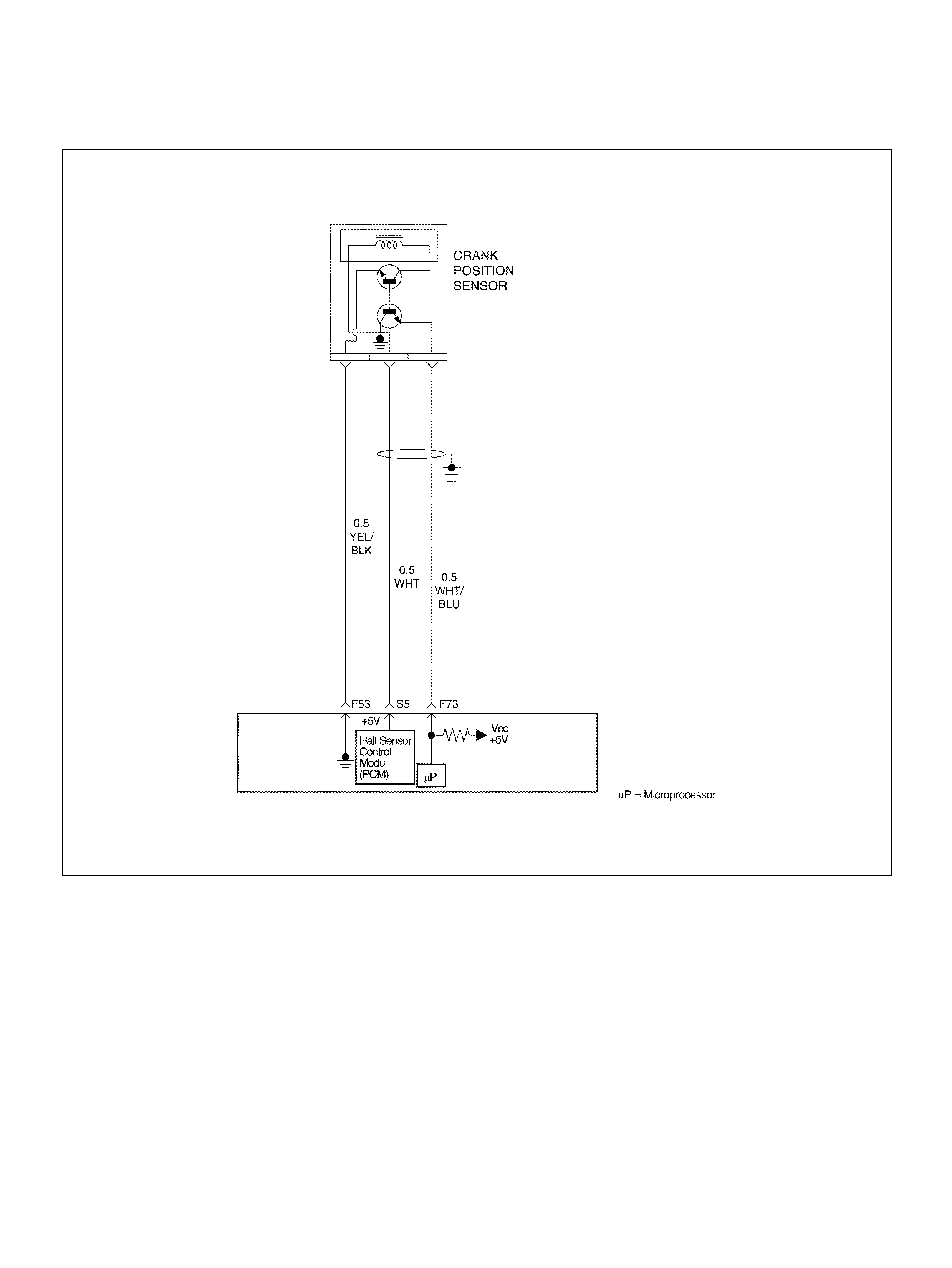
DIAGNOSTIC TROUBLE CODE (DTC) P0336 58X
REFERENCE SIGNAL CIRCUIT
060R100101
Circuit Description
The 58X ref erence s i gnal is produced by th e crank shaft
position (CKP) sensor. During one crankshaft
revolution, 58 crankshaft pulses will be produced. The
powertrain control module (PCM) uses the 58X
reference signal to calculate engine RPM and
crankshaft position. The PCM constantly monitors the
number of pulses on the 58X reference circuit. If the
PCM receives an incorrect number of pulses on the 58X
reference circuit, DTC P0336 will set .
Conditions for Setting the DTC
• Engine is running.
• Extra or missing pulse is detected between
con secu tive 58X reference pulse s.
• Above condition is detected in 10 of 100 crankshaft
rotations.
Action Taken When the DTC Sets
• The PCM will illuminate the malfunction indicator
lamp (M IL) after the second c onsecutive trip in which
the fault is detected .
• The PCM will store conditions which were present
when the DTC was set as Freeze Frame and in the
Failure Records data.
Conditi ons for Clea r ing the MIL/DTC
• The PCM will turn the MIL “OFF" on the third
consecutive trip cycle during which the diagnostic has
been run and the fault condition is no longer present.

• A history DTC P0336 will clear after 40 consecutive
warm–up cycles have occurred without a fault.
• DTC P0336 can be cleared by using the Tech 2
“Clear Info" function.
Diagnostic Aids
An intermittent may be caused by a poor connection,
rubbed-through wire insulation or a wire broken inside
the insulation. Check for:
• Poor connection - Inspect the PCM harness and
connectors for improper mating, broken locks,
improperly formed or damaged terminals, and poor
terminal-to-wire connection.
• Damaged harness – Inspect the wiring harness for
damage. If the harness appears to be OK, disconnect
the PCM, turn the ignition on and observe a voltmeter
connected to the 58X reference circuit at the PCM
harness connector while moving connectors and
wiring harnesses related to the PCM. A change in
voltage will indicate the location of the fault.
Reviewing the Failure Records vehicle mileage since
the diagnostic test last failed may help determine how
often the condition that caused the DTC to be set
occurs. This may assist in diagnosing the condition.
DTC P0336 – 58X Reference Signal Circuit
Step Action Value(s) Yes No
1 Was the “On-Board Diagnostic (OBD) System Check"
performed? — Go to Step 2 Go to OBD
System Check
2 Attempt to start the engine.
Does the engine start? — Go to St ep 3
Go to “Engine
Cranks But Will
N ot Run" cha r t
3 1. Review and record Failure Records information.
2. Clear DTC P0336.
3. Start th e engine and idle for 1 minute.
4. Observe DTCs.
Is DTC P0336 set? — Go to Step 4 Refe r to
Diagnostic Aids
4 1. Disconnect the PCM and CKP sensor.
2. Check for an open or a short to ground in the 58X
reference circuit between the CKP sensor
connector and the PCM harness connec tor.
3. If a problem is found, repair as necessary.
Was a problem found? — Verify rep air Go to Step 5
5 1. Reconnect the PCM and CKP sensor.
2. Connect a DVM to measure voltage on the 58X
reference circuit at the PCM connector.
3. Observe the voltage while cranking the engine.
Is the voltage near the specified value? 2. 5 V Go to St ep 8 Go to Step 6
6 Check the connections at the CKP sensor and replace
the terminals if necessary.
Did any terminals require replacement? — Verify repair Go to Step 7
7 Replace the CKP sensor . Use caution to avoid any hot
oil that may drip out.
Is the action complete ? — Verify repair —
8 Check connections at the PCM and replace the
terminals if necessary.
Did any terminals require replacement? — Verify repair Go to Step 9
9 Replace the PCM.
Important: The replacement PCM must be
programmed. Refer to Section 0C-1 - Service
Program ming Syst em.
Important: Refer to Section 11 - Engin e Im mobiliser
System for the Immobiliser Programming procedure.
Important: Ensure the latest software program is
downloaded to the PCM.
Is the action complete ? — Verify repair —

DIAGNOSTIC TROUBLE CODE (DTC) P0337
CKP SENSOR CIRCUIT LOW FREQUENCY
060R100101
Circuit Description
The 58X ref erence s i gnal is produced by th e crank shaft
position (CKP) sensor. During one crankshaft
revolution, 58 crankshaft reference pulses will be
produced. The powertrain control module (PCM) uses
the 58X reference signal to calculate engine RPM and
crankshaft position. The PCM constantly monitors the
number of pulses on the 58X reference circuit. If the
PCM does not receive pulses on the 58X reference
circuit, DTC P0337 will set.
Conditions for Setting the DTC
• Engine cranking.
• Crankshaft position (CKP) sensor signal is not
pre sent between tw o cam pulses.
• CKP reference pulse is not detected within 8 CMP
pulses.
Action Taken When the DTC Sets
• The PCM will illuminate the malfunction indicator
lamp (M IL) after the second c onsecutive trip in which
the fault is detected .
• The PCM will store conditions which were present
when the DTC was set as Freeze Frame and in the
Failure Records data.
Conditi ons for Clea r ing the MIL/DTC
• The PCM will turn the MIL “OFF" on the third
consecutive trip cycle during which the diagnostic has
been run and the fault condition is no longer present.

• A history DTC P0337 will clear after 40 consecutive
warm-up cycles have occurred without a fault.
• DTC P0337 can be cleared by using the Tech 2
“Clear Info" function.
Diagnostic Aids
An intermittent may be caused by a poor connection,
rubbed-through wire insulation or a wire broken inside
the insulation. Check for:
• Poor connection – Inspect the PCM harness and
connectors for improper mating, broken locks,
improperly formed or damaged terminals, and poor
terminal-to-wire connection.
• Damaged harness – Inspect the wiring harness for
damage. If the harness appears to be OK, disconnect
the PCM, turn the ignition on and observe a voltmeter
connected to the 58X reference circuit at the PCM
harness connector while moving connectors and
wiring harnesses related to the PCM. A change in
voltage will indicate the location of the fault.
Reviewing the Failure Records vehicle mileage since
the diagnostic test last failed may help determine how
often the condition that caused the DTC to be set
occurs. This may assist in diagnosing the condition.
DTC P0337 – CKP Sensor Circuit Low Frequency
Step Action Value(s) Yes No
1 Was the “On-Board Diagnostic (OBD) System Check"
performed? — Go to Step 2 Go to OBD
System Check
2 Attempt to start the engine.
Does the engine start? — G o to St ep 3 Go to Chart 3
3 1. Review and record Failure Records information.
2. Clear DTC P0337.
3. Start th e engine and idle for 1 minute.
4. Observe DTCs.
Is DTC P0337 set? — Go to Step 4 Refe r to
Diagnostic Aid
4 1. Disconnect the CKP sensor.
2. Ignition “ON".
3. Using a DVM, veri fy that 5 V reference and ground
are being supp lied at the sensor connector (PCM
side).
Are 4-6 volts and ground available at the sensor? — Go to Step 7 Go to Step 5
5 1. Ignit io n “ O N" .
2. With a DVM, backprobe the PCM connector 5 V
reference and ground connections.
Are 5 V reference and ground available at the PCM? — Go to Step 6 Go to Step 11
6 Check 5 V reference or ground between the CKP
sensor and PCM and repair the open circuit, short to
ground or short to voltage.
Is the action complete ? Verify r epair —
7 1 . Ig nit io n “ OFF" .
2. Disconnect the PCM and CKP sensor .
3. Check for an open or a short to ground in the 58X
reference circuit between the CKP sensor
connector and the PCM harness connec tor.
4. If a problem is found, repair as necessary.
Was a problem found? — Verify rep air Go to Step 8
8 1. Reconnect the PCM and CKP sensor.
2. Connect a DVM to measure voltage on the 58X
reference circuit at the PCM connector.
3. Observe the voltage while cranking the engine.
Is the voltage near the specified value? — G o to St ep 11 Go to Step 9
9 Check the connections at the CKP sensor and replace
the terminals if necessary.
Did any terminals require replacement? 2.5 V Verify repair Go to Step 10

10 Replace the CKP sensor. Use caution and avoid hot
oil that may drip out.
Is the action complete ? — Verify repair —
11 Check the connections at the PCM and replace the
terminals if necessary.
Did any terminals require replacement? — Verify repair Go to Step 12
12 Replace the PCM.
Important: The replacement PCM must be
programmed. Refer to Section 0C-1 - Service
Program ming Syst em.
Important: Refer to Section 11 - Engin e Im mobiliser
System for the Immobiliser Programming procedure.
Important: Ensure the latest software program is
downloaded to the PCM.
Is the action complete ? — Verify repair —
Step Action Value(s) Yes No

DIAGNOSTIC TROUBLE CODE (DTC) P0351 IGNITION 1 CONTROL CIRCUIT
060R100135
Circuit Description
ION Sensing Module has the function to energize and
de-energize the primary ignition coil in response to
signals f rom t he P CM . Th e P CM cont rols i gnition ti ming
and dwell time.
This diagnosis detects open circuit or short-circuiting in
the Ignition Electronic Spark Timing (EST) line by
monitoring EST signals. A failure determination is made
when the signal voltage remains higher or lower than
the threshold for corresponding fault code beyond a
predetermined time period.
When the PCM detects a problem on EST control circuit
1, it will set a DTC P0351.
Conditions for Setting the DTC
• T he ignition is “ON".
• The engine is running, determined by the 58X
crankshaft position input signal.
• The output voltage is not equal to 5 volts when output
is “ON".
• The output voltage is not equal to 0 volts when output
is “OFF".
• 20 test failures occur within 40 samples of continuous
spark events.
Action Taken When the DTC Sets
• The PCM will illuminate the malfunction indicator
l a mp (M IL ) the fi r s t time th e fa ult is d e te c te d .
• The PCM will store conditions which were present
when the DTC was set as Freeze Frame and in the
Failure Records data.
Conditions for Clearing the MIL/DTC • The PCM will turn the MIL “OFF" on the third

consecutive trip cycle in which the diagnostic has
been run and the fault condition is no longer present.
• A history DTC P0351 will clear after 40 consecutive
warm-up cycles occur without a fault.
• DTC P0351 can be cleared by using the Tech 2
“Clear Info" function.
Diagnostic Aids
Check for the following conditions:
• Poor connection at PCM – Inspect the harness
connectors for backed-out terminals, improper
mating, broken locks, improperly formed or damaged
terminals, and poor terminal-to-wire connections.
• Damaged harness – Inspect the wiring harness for
damage. If the harness appears to be OK, observe
the Tech 2 display related to DTC P0351 while
moving the connector and wiring related to the
ignition system. A change in the display will indicate
the location of the fault.
Reviewing the Failure Records vehicle mileage since
the diagnostic test last failed may help determine how
often the condition that caused the DTC to be set
occurs. This may assist in diagnosing the condition.
DTC P0351 – Ignition 1 Control Circuit
Step Action Value(s) Yes No
1 Was the “On-Board Diagnostic (OBD) System Check"
performed? —Go to Step 2 Go to OBD
System Check
2 1. Ignition “ON", engine “OFF".
2. Review and record Te ch 2 Failure Records data.
3. Operate the vehicle within Failure Record
condition s as noted.
4. Use a Te ch 2 to monitor the “DTC" inf ormation for
DTC P0351 until the DTC P0351 test runs.
5. No te th e test result.
Does the Tech 2 indicate DTC P0351 failed this
ignition cycle? — G o to St ep 3 Go to
Diagnostic Aids
3 Check for faulty connection at ignition coil.
Was a problem found? — Verify repair Go to Step 4
4 Check for faulty connection at PCM connec tor.
Was a problem found? — Verify repair Go to Step 5
5 1. Ignition “ON", engine “OFF".
2. Back probe the igni tion cont rol circui t 1 at t he ION
Sensing Module with a DVM.
Is the voltage near the specified value? 25-55 mV G o to St ep 6 Go to S tep 9
6 1. Ignition “ON", engine running.
2. Back probe the ignition control circuit at the ION
Sensing Module for t he cylinder being tested.
Is the voltage in the specified range, rapidly toggling
back and forth to a reading 20-50 mV higher? 100-180 mV G o to St ep 7 Go to Step 13
7 1 . Ig nit io n “ OFF" .
2. Disconnect the 3-pin and conn ector at the ignition
coil.
3. Check ignition control circuit 1 voltage at the
ignition coil connector while cranking the engine.
Does the voltage measure between the specified
values? 200-1200 mV Go to St ep 8 Go to Step 11
8 Replace the ignition coil.
Is the action complete ? — Verify r epair —

9 1 . Ig nit io n “ OFF" .
2. Disconnect the PCM and the ignition coil.
3. Check ignition control circuit 1 for short to ground.
Was a problem found? — Verify repair Go to Step 10
10 Check ignition control circuit 1 for short to voltage.
Was a problem found? — Verify repair Go to Step 13
11 Check for an open ignition control circuit 1.
Was the igniti on control circuit open? — Go to Step 12 Go to Step 13
12 Repair the open ignition control circuit.
Is the action complete ? — Verify r epair —
13 Replace the PCM.
Important: The replacement PCM must be
programmed. Refer to Section 0C-1 - Service
Program ming Syst em.
Important: Refer to Section 11 - Engin e Im mobiliser
System for the Immobiliser Programming procedure.
Important: Ensure the latest software program is
downloaded to the PCM.
Is the action complete ? — Verify repair —
Step Action Value(s) Yes No
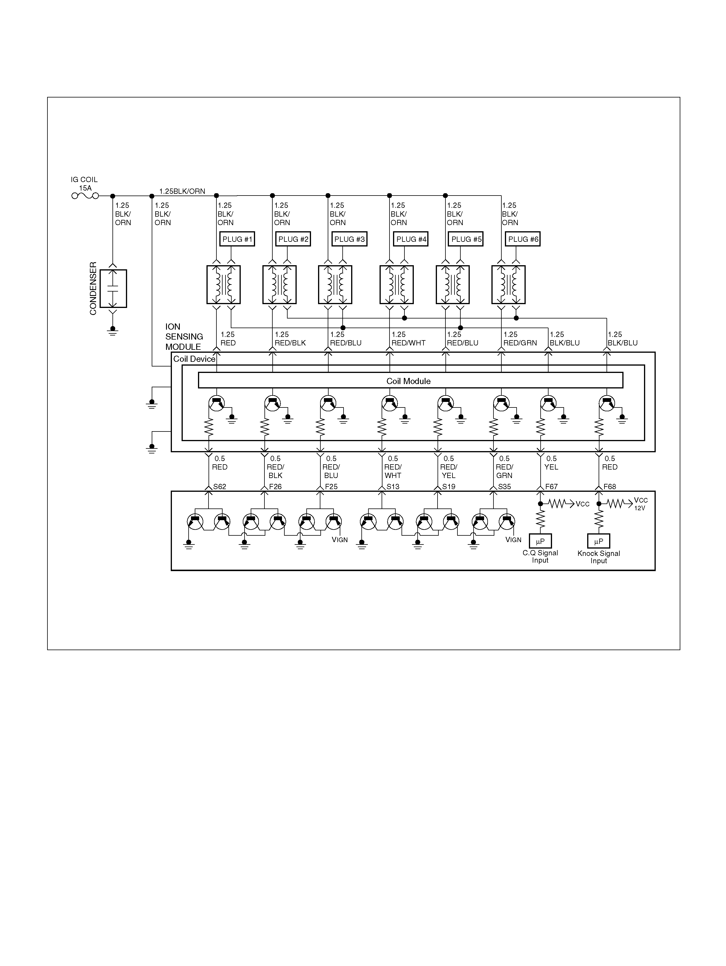
DIAGNOSTIC TROUBLE CODE (DTC) P0352 IGNITION 2 CONTROL CIRCUIT
060R100135
Circuit Description
ION Sensing Module has the function to energize and
de-energize the primary ignition coil in response to
signals f rom t he P CM . Th e P CM cont rols i gnition ti ming
and dwell time.
This diagnosis detects open circuit or short-circuiting in
the Ignition Electronic Spark Timing (EST) line by
monitoring EST signals. A failure determination is made
when the signal voltage remains higher or lower than
the threshold for corresponding fault code beyond a
predetermined time period.
When the PCM detects a problem on EST control circuit
2, it will set a DTC P0352.
Conditions for Setting the DTC
• T he ignition is “ON".
• The engine is running, determined by the 58 X
cranks haft position input signal.
• The output voltage is not equal to 5 volts when output
is “ON".
• The output voltage is not equal to 0 volts when output
is “OFF".
• 20 test failures occur within 40 samples of continuous
spark events.
Action Taken When the DTC Sets
• The PCM will illuminate the malfunction indicator
l a mp (M IL ) the fi r s t time th e fa ult is d e te c te d .
• The PCM will store conditions which were present
when the DTC was set as Freeze Frame and in the
Failure Records data.

Conditions for Clearing the MIL/DTC
• The PCM will turn the MIL “OFF" on the third
consecutive trip cycle in which the diagnostic has
been run and the fault condition is no longer present.
• A history DTC P0352 will clear after 40 consecutive
warm-up cycles occur without a fault.
• DTC P0352 can be cleared by using the Tech 2
“Clear Info" function.
Diagnostic Aids
Check for the following conditions:
• Poor connection at PCM – Inspect the harness
connectors for backed-out terminals, improper
mating, broken locks, improperly formed or damaged
terminals, and poor terminal-to-wire connections.
• Damaged harness – Inspect the wiring harness for
damage. If the harness appears to be OK, observe
the Tech 2 display related to DTC P0352 while
moving the connector and wiring related to the
ignition system. A change in the display will indicate
the location of the fault.
Reviewing the Failure Records vehicle mileage since
the diagnostic test last failed may help determine how
often the condition that caused the DTC to be set
occurs. This may assist in diagnosing the condition.
DTC P0352 – Ignition 2 Control Circuit
Step Action Value(s) Yes No
1 Was the “On-Board Diagnostic (OBD) System Check"
performed? —Go to Step 2 Go to OBD
System Check
2 1. Ignition “ON", engine “OFF".
2. Review and record Te ch 2 Failure Records data.
3. Operate the vehicle within Failure Record
condition s as noted.
4. Use a Te ch 2 to monitor the “DTC" inf ormation for
DTC P0352 until the DTC P0352 test runs.
5. No te th e test result.
Does the Tech 2 indicate DTC P0352 failed this
ignition cycle? — G o to St ep 3 Go to
Diagnostic Aids
3 Check for faulty connection at ignition coil.
Was a problem found? — Verify repair Go to Step 4
4 Check for faulty connection at PCM connec tor.
Was a problem found? — Verify repair Go to Step 5
5 1. Ignition “ON", engine “OFF".
2. Back probe the igni tion cont rol circui t 2 at t he ION
Sensing Module with a DVM .
Is the voltage near the specified value? 25-55 mV G o to St ep 6 Go to S tep 9
6 1. Ignition “ON", engine running.
2. Back probe the ignition control circuit at the ION
Sensing Module for t he cylinder being tested.
Is the voltage in the specified range, rapidly toggling
back and forth to a reading 20-50 mV higher? 100-180 mV G o to St ep 7 Go to Step 13
7 1 . Ig nit io n “ OFF" .
2. Disconnect the 3-pin connector at the ignition coil.
3. Check ignition control circuit 2 voltage at the
ignition coil connector while cranking the engine
connector.
Does the voltage measure between the specified
values? 200-1200 mV Go to St ep 8 Go to Step 11
8 Replace the ignition coil.
Is the action complete ? — Verify r epair —
9 1 . Ig nit io n “ OFF" .
2. Disconnect the PCM and the ignition coil.
3. Check ignition control circuit 2 for short to ground.
Was a problem found? — Verify repair Go to Step 10

10 Check ignition control circuit 2 for short to voltage.
Was a problem found? — Verify repair Go to Step 13
11 Check for an open ignition control circuit 2.
Was the igniti on control circuit open? — Go to Step 12 Go to St ep 13
12 Repair the open ignition control circuit.
Is the action complete ? — Verify r epair —
13 Replace the PCM.
Important: The replacement PCM must be
programmed. Refer to Section 0C-1 - Service
Program ming Syst em.
Important: Refer to Section 11 - Engin e Im mobiliser
System for the Immobiliser Programming procedure.
Important: Ensure the latest software program is
downloaded to the PCM.
Is the action complete ? — Verify repair —
Step Action Value(s) Yes No

DIAGNOSTIC TROUBLE CODE (DTC) P0353 IGNITION 3 CONTROL CIRCUIT
060R100135
Circuit Description
ION Sensing Module has the function to energize and
de-energize the primary ignition coil in response to
signals f rom t he P CM . Th e P CM cont rols i gnition ti ming
and dwell time.
This diagnosis detects open circuit or short-circuiting in
the Ignition Electronic Spark Timing (EST) line by
monitoring EST signals. A failure determination is made
when the signal voltage remains higher or lower than
the threshold for corresponding fault code beyond a
predetermined time period.
When the PCM detects a problem on EST control circuit
3, it will set a DTC P0353.
Conditions for Setting the DTC
• T he ignition is “ON".
• The engine is running, determined by the 58X
cranks haft position input signal.
• The output voltage is not equal to 5 volts when output
is “ON".
• The output voltage is not equal to 0 volts when output
is “OFF".
• 20 test failures occur within 40 samples of continuous
spark events.
Action Taken When the DTC Sets
• The PCM will illuminate the malfunction indicator
l a mp (M IL ) the fi r s t time th e fa ult is d e te c te d .
• The PCM will store conditions which were present
when the DTC was set as Freeze Frame and in the
Failure Records data.

Conditions for Clearing the MIL/DTC
• The PCM will turn the MIL “OFF" on the third
consecutive trip cycle in which the diagnostic has
been run and the fault condition is no longer present.
• A history DTC P0353 will clear after 40 consecutive
warm-up cycles occur without a fault.
• DTC P0353 can be cleared by using the Tech 2
“Clear Info" function.
Diagnostic Aids
Check for the following conditions:
• Poor connection at PCM – Inspect the harness
connectors for backed-out terminals, improper
mating, broken locks, improperly formed or damaged
terminals, and poor terminal-to-wire connections.
• Damaged harness – Inspect the wiring harness for
damage. If the harness appears to be OK, observe
the Tech 2 display related to DTC P0353 while
moving the connector and wiring related to the
ignition system. A change in the display will indicate
the location of the fault.
Reviewing the Failure Records vehicle mileage since
the diagnostic test last failed may help determine how
often the condition that caused the DTC to be set
occurs. This may assist in diagnosing the condition.
DTC P0353 – Ignition 3 Control Circuit
Step Action Value(s) Yes No
1 Was the “On-Board Diagnostic (OBD) System Check"
performed? —Go to Step 2 Go to OBD
System Check
2 1. Ignition “ON", engine “OFF".
2. Review and record Te ch 2 Failure Records data.
3. Operate the vehicle within Failure Record
condition s as noted.
4. Use a Te ch 2 to monitor the “DTC" inf ormation for
DTC P0353 until the DTC P0353 test runs.
5. No te th e test result.
Does the Tech 2 indicate DTC P0353 failed this
ignition cycle? — G o to St ep 3 Go to
Diagnostic Aids
3 Check for faulty connection at ignition coil.
Was a problem found? — Verify repair Go to Step 4
4 Check for faulty connection at PCM connec tor.
Was a problem found? — Verify repair Go to Step 5
5 1. Ignition “ON", engine “OFF".
2. Back probe the igni tion cont rol circui t 3 at t he ION
Sensing Modul e with a DVM pos itive lea d with the
negative lead to ground.
Is the voltage near the specified value? 25-55 mV G o to Step 6 Go to Step 9
6 1. Ignition “ON", engine running.
2. Back probe the ignition control circuit at the ION
Sensing Module for t he cylinder being tested.
Is the voltage in the specified range, rapidly toggling
back and forth to a reading 20-50 mV higher? 100-180 mV G o to St ep 7 Go to Step 13
7 1 . Ig nit io n “ OFF" .
2. Disconnect the 3-pin connector at the ignition coil.
3. Check ignition control circuit 3 voltage at the
ignition coil connector while cranking the engine.
Does the voltage measure between the specified
values? 200-1200m V G o to St ep 8 Go to Step 11
8 Replace the ignition coil.
Is the action complete ? — Verify r epair —
9 1 . Ig nit io n “ OFF" .
2. Disconnect the PCM and the ignition coil.
3. Check ignition control circuit 3 for short to ground.
Was a problem found? — Verify repair Go to Step 10

10 Check ignition control circuit 3 for short to voltage.
Was a problem found? — Verify repair Go to Step 13
11 Check for an open ignition control circuit 3.
Was the igniti on control circuit open? — Go to Step 12 Go to St ep 13
12 Repair the open ignition control circuit.
Is the action complete ? — Verify r epair —
13 Replace the PCM.
Important: The replacement PCM must be
programmed. Refer to Section 0C-1 - Service
Program ming Syst em.
Important: Refer to Section 11 - Engin e Im mobiliser
System for the Immobiliser Programming procedure.
Important: Ensure the latest software program is
downloaded to the PCM.
Is the action complete ? — Verify repair —
Step Action Value(s) Yes No

DIAGNOSTIC TROUBLE CODE (DTC) P0354 IGNITION 4 CONTROL CIRCUIT
060R100135
Circuit Description
ION Sensing Module has the function to energize and
de-energize the primary ignition coil in response to
signals f rom t he P CM . Th e P CM cont rols i gnition ti ming
and dwell time.
This diagnosis detects open circuit or short-circuiting in
the Ignition Electronic Spark Timing (EST) line by
monitoring EST signals. A failure determination is made
when the signal voltage remains higher or lower than
the threshold for corresponding fault code beyond a
predetermined time period.
When the PCM detects a problem on EST control circuit
4, it will set a DTC P0354.
Conditions for Setting the DTC
• T he ignition is “ON".
• The engine is running, determined by the 58X
cranks haft position input signal.
• The output voltage is not equal to 5 volts when output
is “ON".
• The output voltage is not equal to 0 volts when output
is “OFF".
• 20 test failures occur within 40 samples of continuous
spark events.
Action Taken When the DTC Sets
• The PCM will illuminate the malfunction indicator
l a mp (M IL ) the fi r s t time th e fa ult is d e te c te d .
• The PCM will store conditions which were present
when the DTC was set as Freeze Frame and in the
Failure Records data.

Conditions for Clearing the MIL/DTC
• The PCM will turn the MIL “OFF" on the third
consecutive trip cycle in which the diagnostic has
been run and the fault condition is no longer present.
• A history DTC P0354 will clear after 40 consecutive
warm-up cycles occur without a fault.
• DTC P0354 can be cleared by using the Tech 2
“Clear Info" function.
Diagnostic Aids
Check for the following conditions:
• Poor connection at PCM – Inspect the harness
connectors for backed-out terminals, improper
mating, broken locks, improperly formed or damaged
terminals, and poor terminal-to-wire connections.
• Damaged harness – Inspect the wiring harness for
damage. If the harness appears to be OK, observe
the Tech 2 display related to DTC P0354 while
moving the connector and wiring related to the
ignition system. A change in the display will indicate
the location of the fault.
Reviewing the Failure Records vehicle mileage since
the diagnostic test last failed may help determine how
often the condition that caused the DTC to be set
occurs. This may assist in diagnosing the condition.
DTC P0354 – Ignition 4 Control Circuit
Step Action Value(s) Yes No
1 Was the “On-Board Diagnostic (OBD) System Check"
performed? —Go to Step 2 Go to OBD
System Check
2 1. Ignition “ON", engine “OFF".
2. Review and record Te ch 2 Failure Records data.
3. Operate the vehicle within Failure Record
condition s as noted.
4. Use a Te ch 2 to monitor the “DTC" inf ormation for
DTC P0354 until the DTC P0354 test runs.
5. No te th e test result.
Does the Tech 2 indicate DTC P0354 failed this
ignition cycle? — G o to St ep 3 Go to
Diagnostic Aids
3 Check for faulty connection at ignition coil.
Was a problem found? — Verify repair Go to Step 4
4 Check for faulty connection at PCM connec tor.
Was a problem found? — Verify repair Go to Step 5
5 1. Ignition “ON", engine “OFF".
2. Back probe the igni tion cont rol circui t 4 at t he ION
Sensing with a DVM positive lead with the
negative lead to ground.
Is the voltage near the specified value? 25-55 mV G o to Step 6 Go to Step 9
6 1. Ignition “ON", engine running.
2. Back probe the ignition control circuit at the ION
Sensing Module for t he cylinder being tested.
Is the voltage in the specified range, rapidly toggling
back and forth to a reading 20-50 mV higher? 100-180 mV G o to St ep 7 Go to Step 13
7 1 . Ig nit io n “ OFF" .
2. Disconnect the 3-pin connector at the ignition coil.
3. Check ignition control circuit 4 voltage at the
ignition coil connector while cranking the engine.
Does the voltage measure between the specified
values? 200-1200 mV Go to St ep 8 Go to Step 11
8 Replace the ignition coil.
Is the action complete ? — Verify r epair —
9 1 . Ig nit io n “ OFF" .
2. Disconnect the PCM and the ignition coil.
3. Check ignition control circuit 4 for short to ground.
Was a problem found? — Verify repair Go to Step 10

10 Check ignition control circuit 4 for short to voltage.
Was a problem found? — Verify repair Go to Step 13
11 Check for an open ignition control circuit 4.
Was the igniti on control circuit open? — Go to Step 12 Go to St ep 13
12 Repair the open in ignition control circuit.
Is the action complete ? — Verify r epair —
13 Replace the PCM.
Important: The replacement PCM must be
programmed. Refer to Section 0C-1 - Service
Program ming Syst em.
Important: Refer to Section 11 - Engin e Im mobiliser
System for the Immobiliser Programming procedure.
Important: Ensure the latest software program is
downloaded to the PCM.
Is the action complete ? — Verify repair —
Step Action Value(s) Yes No

DIAGNOSTIC TROUBLE CODE (DTC) P0355 IGNITION 5 CONTROL CIRCUIT
060R100135
Circuit Description
ION Sensing Module has the function to energize and
de-energize the primary ignition coil in response to
signals f rom t he P CM . Th e P CM cont rols i gnition ti ming
and dwell time.
This diagnosis detects open circuit or short-circuiting in
the Ignition Electronic Spark Timing (EST) line by
monitoring EST signals. A failure determination is made
when the signal voltage remains higher or lower than
the threshold for corresponding fault code beyond a
predetermined time period.
When the PCM detects a problem on EST in control
circuit 5, it wi ll set a DTC P0355.
Conditions for Setting the DTC
• T he ignition is “ON".
• The engine is running, determined by the 58X
cranks haft position input signal.
• The output voltage is not equal to 5 volts when output
is “ON".
• The output voltage is not equal to 0 volts when output
is “OFF".
• 20 test failures occur within 40 samples of continuous
spark events.
Action Taken When the DTC Sets
• The PCM will illuminate the malfunction indicator
l a mp (M IL ) the fi r s t time th e fa ult is d e te c te d .
• The PCM will store conditions which were present
when the DTC was set as Freeze Frame and in the
Failure Records data.

Conditions for Clearing the MIL/DTC
• The PCM will turn the MIL “OFF" on the third
consecutive trip cycle in which the diagnostic has
been run and the fault condition is no longer present.
• A history DTC P0355 will clear after 40 consecutive
warm-up cycles occur without a fault.
• DTC P0355 can be cleared by using the Tech 2
“Clear Info" function.
Diagnostic Aids
Check for the following conditions:
• Poor connection at PCM – Inspect the harness
connectors for backed-out terminals, improper
mating, broken locks, improperly formed or damaged
terminals, and poor terminal-to-wire connections.
• Damaged harness – Inspect the wiring harness for
damage. If the harness appears to be OK, observe
the Tech 2 display related to DTC P0355 while
moving the connector and wiring related to the
ignition system. A change in the display will indicate
the location of the fault.
Reviewing the Failure Records vehicle mileage since
the diagnostic test last failed may help determine how
often the condition that caused the DTC to be set
occurs. This may assist in diagnosing the condition.
DTC P0355 – Ignition 5 Control Circuit
Step Action Value(s) Yes No
1 Was the “On-Board Diagnostic (OBD) System Check"
performed? —Go to Step 2 Go to OBD
System Check
2 1. Ignition “ON", engine “OFF".
2. Review and record Te ch 2 Failure Records data.
3. Operate the vehicle within Failure Record
condition s as noted.
4. Use a Te ch 2 to monitor the “DTC" inf ormation for
DTC P0355 until the DTC P0355 test runs.
5. No te th e test result.
Does the Tech 2 indicate DTC P0355 failed this
ignition cycle? — G o to St ep 3 Go to
Diagnostic Aids
3 Check for faulty connection at ignition coil.
Was a problem found? — Verify repair Go to Step 4
4 Check for faulty connection at PCM connec tor.
Was a problem found? — Verify repair Go to Step 5
5 1. Ignition “ON", engine “OFF".
2. Back probe the igni tion cont rol circui t 5 at t he ION
Sensing Modul e with a DVM pos itive lea d with the
negative lead to ground.
Is the voltage near the specified value? 25-55 mV G o to Step 6 Go to Step 9
6 1. Ignition “ON", engine running.
2. Back probe the ignition control circuit at the ION
Sensing Module for t he cylinder being tested.
Is the voltage in the specified range, rapidly toggling
back and forth to a reading 20-50 mV higher? 100-180 mV G o to St ep 7 Go to Step 13
7 1 . Ig nit io n “ OFF" .
2. Disconnect the 3-pin connector at the ignition coil.
3. Check ignition control circuit 5 voltage at the
ignition coil connector while cranking the engine.
Does the voltage measure between the specified
values? 200-1200 mV Go to St ep 8 Go to Step 11
8 Replace the ignition coil.
Is the action complete ? — Verify r epair —
9 1 . Ig nit io n “ OFF" .
2. Disconnect the PCM and the ignition coil.
3. Check ignition control circuit 5 for short to ground.
Was a problem found? — Verify repair Go to Step 10

10 Check ignition control circuit 5 for short to voltage.
Was a problem found? — Verify repair Go to Step 13
11 Check for an open ignition control circuit 5.
Was the igniti on control circuit open? — Go to Step 12 Go to St ep 13
12 Repair the open ignition control circuit.
Is the action complete ? — Verify r epair —
13 Replace the PCM.
Important: The replacement PCM must be
programmed. Refer to Section 0C-1 - Service
Program ming Syst em.
Important: Refer to Section 11 - Engin e Im mobiliser
System for the Immobiliser Programming procedure.
Important: Ensure the latest software program is
downloaded to the PCM.
Is the action complete ? — Verify repair —
Step Action Value(s) Yes No

DIAGNOSTIC TROUBLE CODE (DTC) P0356 IGNITION 6 CONTROL CIRCUIT
060R100135
Circuit Description
ION Sensing Module has the function to energize and
de-energize the primary ignition coil in response to
signals f rom t he P CM . Th e P CM cont rols i gnition ti ming
and dwell time.
This diagnosis detects open circuit or short-circuiting in
the Ignition Electronic Spark Timing (EST) line by
monitoring EST signals. A failure determination is made
when the signal voltage remains higher or lower than
the threshold for corresponding fault code beyond a
predetermined time period.
When the PCM detects a problem on EST control circuit
6, it will set a DTC P0356.
Conditions for Setting the DTC
• T he ignition is “ON".
• The engine is running, determined by the 58X
cranks haft position input signal.
• The output voltage is not equal to 5 volts when output
is “ON".
• The output voltage is not equal to 0 volts when output
is “OFF".
• 20 test failures occur within 40 samples of continuous
circuit monitoring.
Action Taken When the DTC Sets
• The PCM will illuminate the malfunction indicator
l a mp (M IL ) the fi r s t time th e fa ult is d e te c te d .
• The PCM will store conditions which were present
when the DTC was set as Freeze Frame and in the
Failure Records data.

Conditions for Clearing the MIL/DTC
• The PCM will turn the MIL “OFF" on the third
consecutive trip cycle in which the diagnostic has
been run and the fault condition is no longer present.
• A history DTC P0356 will clear after 40 consecutive
warm-up cycles occur without a fault.
• DTC P0356 can be cleared by using the Tech 2
“Clear Info" function.
Diagnostic Aids
Check for the following conditions:
• Poor connection at PCM – Inspect the harness
connectors for backed-out terminals, improper
mating, broken locks, improperly formed or damaged
terminals, and poor terminal-to-wire connections.
• Damaged harness – Inspect the wiring harness for
damage. If the harness appears to be OK, observe
the Tech 2 display related to DTC P0356 while
moving the connector and wiring related to the
ignition system. A change in the display will indicate
the location of the fault.
Reviewing the Failure Records vehicle mileage since
the diagnostic test last failed may help determine how
often the condition that caused the DTC to be set
occurs. This may assist in diagnosing the condition.
DTC P0356 – Ignition 6 Control Circuit
Step Action Value(s) Yes No
1 Was the “On-Board Diagnostic (OBD) System Check"
performed? —Go to Step 2 Go to OBD
System Check
2 1. Ignition “ON", engine “OFF".
2. Review and record Te ch 2 Failure Records data.
3. Operate the vehicle within Failure Record
condition s as noted.
4. Use a Te ch 2 to monitor the “DTC" inf ormation for
DTC P0356 until the DTC P0356 test runs.
5. No te th e test result.
Does the Tech 2 indicate DTC P0356 failed this
ignition cycle? — G o to St ep 3 Go to
Diagnostic Aids
3 Check for faulty connection at ignition coil.
Was a problem found? — Verify repair Go to Step 4
4 Check for faulty connection at PCM connec tor.
Was a problem found? — Verify repair Go to Step 5
5 1. Ignition “ON", engine “OFF".
2. Back probe the igni tion cont rol circui t 6 at t he ION
Sensing Modul e with a DVM pos itive lea d with the
negative lead to ground.
Is the voltage near the specified value? 25-55 mV G o to Step 6 Go to Step 9
6 1. Ignition “ON", engine running.
2. Back probe the ignition control circuit at the ION
Sensing Module for t he cylinder being tested.
Is the voltage in the specified range, rapidly toggling
back and forth to a reading 20-50 mV higher? 100-180 mV G o to St ep 7 Go to Step 13
7 1 . Ig nit io n “ OFF" .
2. Disconnect the 3-pin connector at the ignition coil.
3. Check ignition control circuit 6 voltage at the
ignition coil connector while cranking the engine.
Does the voltage measure between the specified
values? 200-1200 mV Go to St ep 8 Go to Step 11
8 Replace the ignition coil.
Is the action complete ? — Verify r epair —
9 1 . Ig nit io n “ OFF" .
2. Disconnect the PCM and the ignition coil.
3. Check ignition control circuit 6 for short to ground.
Was a problem found? — Verify repair Go to Step 10

10 Check ignition control circuit 6 for short to voltage.
Was a problem found? — Verify repair Go to Step 13
11 Check for an open ignition control circuit 6.
Was the igniti on control circuit open? — Go to Step 12 Go to St ep 13
12 Repair the open ignition control circuit.
Is the action complete ? — Verify r epair —
13 Replace the PCM.
Important: The replacement PCM must be
programmed. Refer to Section 0C-1 - Service
Program ming Syst em.
Important: Refer to Section 11 - Engin e Im mobiliser
System for the Immobiliser Programming procedure.
Important: Ensure the latest software program is
downloaded to the PCM.
Is the action complete ? — Verify repair —
Step Action Value(s) Yes No

DIAGNOSTIC TROUBLE CODE (DTC) P0402 EGR PINTLE CRANK ERROR
060R100136
Circuit Description
The powertrain control module (PCM) monitors the
EGR valve pintle po sition input to ensure that the va lve
responds properly to commands from the PCM, and to
detect a fa ult if pintle position is stuck open . If t he PCM
detects a pintle position signal indicates more than
21.5% and more than for 625 msec during cranking, the
PCM will set DTC P 0402.
Conditions for Setting the DTC
• Igni tio n voltage is between 11 and 16 volts.
• At Engine revolution less than 600 RPM, EGR pintle
position indicates more than 21.5% and more than for
625 msecs.
Action Taken When the DTC Sets
• The PCM will illuminate the malfunction indicator
lam p (M IL) after the second cons ecut ive trip i n which
the fault is detected .
• The PCM will store conditions which were present
when the DTC was set as Freeze Frame and in
Failure Records data.
Conditions for Clearing the MIL/DTC
• The PCM will turn the MIL “OFF" on the third
consecutive tri p cycl e during whi ch the dia g nost i c h a s
been run and the fault condition is no longer present.
• A history DTC P0402 will clear after 40 consecutive
warm-up cy cles have occurred without a fault.
• DTC P0402 can be cleared by using the Tech 2
“Clear Info" function.
Diag nostic Ai ds
Check for the following conditions:
• Foreign material on EGR valve between pintle and
seat may cause EGR stuck open. Inspect foreign
material in EGR valve.
• Excessive carbon deposit may cause unsmooth
operation of EGR valve shaft. Inspect for carbon
deposit and clean up inside of carbon deposit.
• Poor connection or damaged harness–inspect the
wiring harness for damage If the harness appea rs to
be OK, observe the EGR actual position display on
the Tech 2 while moving connectors and wiring
harnesses related to EGR valve. A change in the
d is pla y w ill ind i c a te t h e lo c ati o n o f th e fault .
NOTE: If the EGR valve shows signs of excessive
heat, check the exhaust system for blockage (possibly a
plugged catalytic converter) using the “Restricted
Exhaust System Check".

DTC P0402 – EGR Pintle Crank Open Error
Step Action Value(s) Yes No
1 Was the “On-Board Diagnostic (OBD) System Check"
performed? —Go to Step 2 Go to OBD
System Check
2 1. Ignition “ON", engine “OFF", review and record
Tech 2 Failure Records data .
2. Operate the vehicle within Failure Records
condition s as noted.
3. Using a Tech 2, monitor “ DTC" info for DTC P0402
until the DTC P0402 test runs. Note the result.
Does the Tech 2 indicates DTC P0402 failed this
ignition? — G o to Step 3 Refe r to
Diagnostic Aids
3 1. Disconnect the EGR valve harnes s connec tor.
2. Inspect the EGR valve and connectors for
damaged pin or terminals.
Were there any damaged pins or terminals? — Go to Step 4 Go to Step 5
4 Repair the damaged pin or terminal.
Is the action complete ? — Verify r epair —
5 1. Remove EGR valve from Engine.
2. Inspect EGR valve whether there is any foreign
material between se at and pintle.
Was a ny foreign material in EGR v al ve? — Go to Step 6 Go to Step 7
6 1. Remove EGR valve foreign material from EGR
valve and clean up inside.
2. Visually inspect for damage of pintle and seat,
which leakage may oc cur.
Was there any severe damage which affects function? — Go to Step 7 Verify repair
Go to S tep 8
7 1. Reconnect.
2. Ignition “OFF".
3. Install the Tech 2.
4. Run the engine at idle.
5. On Tech-II, select special function for EGR.
6. Use the “UP" arrow to increase the EGR from 0%
to 40%.
Did EGR wo rk prop erly? — — G o to Step 8
8 Replac e the EGR valve.
Does DTC P0402 still fail “DT C" test on the Tec h 2? — G o to St ep 9 Verify repair
9 Replac e the EGR valve.
Is the action complete ? — Verify r epair —

DIAGNOSTIC TROUBLE CODE (DTC) P0404 EGR OPEN STUCK
060R100136
Circuit Description
The powertrain control module (PCM) monitors the
EGR valve pintle po sition input to ensure that the va lve
responds properly to commands from the PCM, and to
detect a fault if pintle position is different from
commanded position. If the PCM detects a pintle
position signal indicates more than 15 points different
between current and commanded and more than 15
seconds, the PCM will set DTC P0404.
Conditions for Setting the DTC
• T he engin e is running.
• Igni tio n voltage is between 11 and 16 volts.
• Intake Air Temp is more than 3°C (37.4°F).
• Difference EGR pintle position between current and
commanded position becomes more than 3% and
last more than 15 seconds, and this condition meets
greather than 0.4 seconds in a trip. Then it trigger , the
PCM lights on.
Action Taken When the DTC Sets
• The PCM will ON the MIL after second trip with
detect ed the fault.
• The PCM will store conditions which were present
when the DTC was set as Freeze Frame and in
Failure Records data.
Conditi ons for Clea r ing the MIL/DTC
• The PCM will turn the MIL “OFF" on the third
consecutive trip cycle during which the diagnostic has
been run and the fault condition is no longer present.
• A history DTC P0404 will clear after 40 consecutive
warm-up cy cles have occurred without a fault.
• DTC P0404 can be cleared by using the Tech 2
“Clear Info" function.
Diag nostic Ai ds
Check for the following conditions:
• Excessive carbon deposit on EGR valve shaft may
cause EGR stuck open or unsmooth operation.
Those carbon deposit may occur by unusual port
operation. Clean up carbon may make smooth
function of EGR valve.
• Poor connection or damaged harness – Inspect the
wiring h arness for dam age. I f the harness ap pears to
be OK, observe the EGR actual position display on
the Tech 2 while moving connectors and wiring
harnesses related to EGR valve. A change in the
d is pla y w ill ind i c a te t h e lo c ati o n o f th e fault .

DTC P0404 – EGR Open Stuck
Step Action Value(s) Yes No
1 Was the “On-Board Diagnostic (OBD) System Check"
performed? —Go to Step 2 Go to OBD
System Check
2 1. Ignition “ON", engine “OFF", review and record
Tech 2 Failure Records Data .
2. Operate the vehicle within Failure Records
condition s as noted.
3. Using a Tech 2, monitor “ DTC" info for DTC P0404
until the DTC P0404 test runs. Note the result.
Does the Tech 2 indicates DTC P0404 failed this
ignition? — G o to Step 3 Refe r to
Diagnostic Aids
3 1. Disconnect the EGR valve harnes s connec tor.
2. Inspect the EGR valve and connectors for
damaged pin or terminals.
Were there any damaged pins or terminals? — Go to St ep 4 Go to S tep 5
4 Repair the damaged pin or terminal. — Verify repair I s the action
complete?
5 1. Remove EGR valve from Engine.
2. Inspect EGR valve whether there is any excessive
carbon deposit on EGR shaft.
Was e xcessive carbon depos it on EG R valve shaft? — G o to Step 6 Go to Step 7
6 1. Clean up EGR valve shaft and inside of EGR
valve.
2. Visually inspect damage of pintle and seat if is
bent, leakage may oc cur.
Was there any severe damage which affects function? — Go to St ep 8 Verify repa ir
Go to Step 7
7 1. Reconnect.
2. Ignition “OFF".
3. Install the Tech 2.
4. Run the engine at idle.
5. On the Tech 2, select EGR Control Tes t.
6. Use the “UP" arrow to increase the EGR from 0%
to 40%.
Did EGR wo rk prop erly? — — G o to Step 8
8 Replac e the EGR valve.
Does DTC P0404 still fail “DT C" test on the Tech 2? — Go to St ep 9 Verify repair
9 Replace the PCM.
Important: The replacement PCM must be
programmed. Refer to Section 0C-1 - Service
Program ming Syst em.
Important: Refer to Section 11 - Engin e Im mobiliser
System for the Immobiliser Programming procedure.
Important: Ensure the latest software program is
downloaded to the PCM.
Is the action complete ? — Verify repair —

DIAGNOSTIC TROUBLE CODE (DTC) P0405 EGR LOW VOLTAGE
060R100136
Circuit Description
The powertrain control module (PCM) monitors the
EGR valve pintle po sition input to ensure that the va lve
respon ds properly t o comm and from the PCM. If current
pintle pos i tion voltag e in dicates less t han 0.1 V and last
more than 10 seconds, then the PCM will set DTC
P0405.
Conditions for Setting the DTC
• Igni tio n voltage is between 11 and 16 volts.
• Intake Air Temp is more than 3°C (37.4°F).
• EGR pintle position is less than 2% and last more
than 10 sec. Action taken when the DTC sets .
Action Taken When the DTC Sets
• The PCM will ON the MIL after second trip with
detect ed the fault.
• The PCM will store conditions which were present
when the DTC was set as Freeze Frame and in
Failure Records data.
Conditi ons for Clea r ing the MIL/DTC
• The PCM will turn the MIL “OFF" on the third
consecutive trip cycle during which the diagnostic has
been run and the fault condition is no longer present.
• A history DTC P0402 will clear after 40 consecutive
warm-up cy cles have occurred without a fault.
• DTC P0405 can be cleared by using the Tech 2
“Clear Info" function.
Diag nostic Ai ds
Check for the following conditions:
• Poor connection or damaged harness – Inspect the
wiring h arness for dam age. I f the harness ap pears to
be OK, observe the EGR actual position display on
the Tech 2 while moving connectors and wiring
harnesses related to EGR valve. A change in the
d is pla y w ill ind i c a te t h e lo c ati o n o f th e fault .

DTC P0405 – EGR Low Voltage
Step Action Value(s) Yes No
1 Was the “On-Board Diagnostic (OBD) System Check"
performed? —Go to Step 2 Go to OBD
System Check
2 1. Ignition “ON", engine “OFF", review and record
Tech 2 Failure Records Data .
2. Operate the vehicle within Failure Records
condition s as noted.
3. Using a Tech 2, monitor “ DTC" info for DTC P0405
until the DTC P0405 test runs. Note the result.
Does the Tech 2 indicates DTC P0405 failed this
ignition? — G o to Step 3 Refe r to
Diagnostic Aids
3 1. Disconnect the EGR valve harnes s connec tor.
2. Inspect the EGR valve and connectors for
damaged pin or terminals.
Were there any damaged pins or terminals? — Go to St ep 4 Go to S tep 5
4 Repair the damaged pin or terminal.
Is the action complete ? — Verify r epair —
5 1. Disconnect the EGR harness connector.
2. Ignition “ON".
3. At the EGR valve, use a DVM to check the voltage
at the 5 volt reference wire (BLU/RED) and
ground.
Did the DVM indicate the specified value? 4–6 V Go to St ep 6 Go to S tep 7
6 1. Disconnect the EGR harness connector.
2. Measure resistance between terminal 5 volt
reference wire and ground.
Was resistance in range? 5–5.5 KΩGo to Step 10 Go to Step 17
7 1. Ignit io n “ O N" .
2. At the PCM connector, backprove with a DVM at
the 5 volt reference for the EGR valve.
Did the DVM indicate the specified value? 4–6 V Go to St ep 8 Go to St ep 18
8 Repair the open 5 volt reference circuit.
Is the action complete ? — Verify r epair —
9 Repair the damaged sensor ground wire.
Is the action complete ? — Verify repair —
10 1. Disconnect the EGR harness
2. Use an ohmmeter to measure between the pintle
position pin and the sensor ground pin on the
EGR valve.
NOTE: J-35616 Connector Test Adapter Kit may be
useful for ga ining access to the recessed pins on the
valve.
Was the ohmmeter reading approximately equal to the
specified value? 1 to 1.25 KΩGo to Step 13 Go to St ep 17
11 1. Ignition “ON".
2. Backprobe with a DVM to measure voltage at
EGR valve pintle position pin and sensor ground
pin.
Was vol tage in range? Less than
0.1V Go to Step 17 Go to Step 12

12 1. Ignition “ON".
2. Backprobe with a DVM to measure voltage at
PCM sensor ground pin and pin tle position pin.
Was vol tage in range? Less than
0.1V Go to Step 13 Go to Step 18
13 1. Ignition “OFF".
2. Disconnect the EGR harness.
3. Check short circuit between EGR pintle position
circuit and EGR ground circuit.
W a s any sho rt circuit? — Go to Step 14 Go to Step 18
14 Locate and repair the short to ground in the pintle
position circuit
Is the action complete ? — Verify r epair —
15 1. Ignition “OFF".
2. Disconnect the PCM.
3. Ignition “ON".
4. Measure the voltage between the EGR pintle
position circuit and ground.
Is the measured voltage near the specified value? Less than
0.1V Go to Step 17 Go to Step 16
16 Check for a short circuit between other wires and the
pintle position circuit
Is there any short c ircui t? —
Repair short
circuit and
then
Verify repair Go to Step 17
17 Replace the EGR valve.
Does DTC P1404 still fail “DTC test on the Tech 2? — Go to Step 18 Verify repair
18 Examine the PCM pin and terminal connection.
Was there a dam aged te rmina l? — Go to St ep 4 Go to St ep 19
19 Replace the PCM.
Important: The replacement PCM must be
programmed. Refer to Section 0C-1 - Service
Program ming Syst em.
Important: Refer to Section 11 - Engin e Im mobiliser
System for the Immobiliser Programming procedure.
Important: Ensure the latest software program is
downloaded to the PCM.
Is the action complete ? — Verify repair —
Step Action Value(s) Yes No

DIAGNOSTIC TROUBLE CODE (DTC) P0406 EGR HIGH VOLTAGE
060R100136
Circuit Description
The powertrain control module (PCM) monitors the
EGR valve pintle po sition input to ensure that the va lve
respon ds properly t o comm and from the PCM. If current
pintle position voltage indicates more than 4.8 V and
last more than 10 seconds, then the PCM will set DTC
P0406.
Conditions for Setting the DTC
• Igni tio n voltage is between 11 and 16 volts.
• Intake Air temp is more than 3°C (37.4 °F).
• EG R pintle position is more than 9 9% and last more
than 10 sec.
Action Taken When the DTC Sets
• The PCM will ON the MIL after second trip with
detect ed the fault.
• The PCM will store conditions which were present
when the DTC was set as Freeze Frame and in
Failure Records data.
Conditi ons for Clea r ing the MIL/DTC
• The PCM will turn the MIL “OFF" on the third
consecutive trip cycle during which the diagnostic has
been run and the fault condition is no longer present.
• A history DTC P0402 will clear after 40 consecutive
warm-up cy cles have occurred without a fault.
• DTC P0404 can be cleared by using the Tech 2
“Clear Info" function.
Diag nostic Ai ds
Check for the following conditions:
• Poor connection or damaged harness – Inspect the
wiring h arness for dam age. I f the harness ap pears to
be OK, observe the EGR actual position display on
the Tech 2 while moving connectors and wiring
harnesses related to EGR valve. A change in the
d is pla y w ill ind i c a te t h e lo c ati o n o f th e fault .

DTC P0406 – EGR High Voltage
Step Action Value(s) Yes No
1 Was the “On-Board Diagnostic (OBD) System Check"
performed? —Go to Step 2 Go to OBD
System Check
2 1. Ignition “ON", engine “OFF", review and record
Tech 2 Failure Records Data .
2. Operate the vehicle within Failure Records
condition s as noted.
3. Using a Tech 2, monitor “ DTC" info for DTC P0406
until the DTC P0406 test runs. Note the result.
Does the Tech 2 indicates DTC P0406 failed this
ignition? — G o to Step 3 Refe r to
Diagnostic Aids
3 1. Disconnect the EGR valve harnes s connec tor.
2. Inspect the EGR valve and connectors for
damaged pin or terminals.
Were there any damaged pins or terminals? — Go to Step 4 Go to Step 5
4 Repair the damaged pin or terminal.
Is the action complete ? — Verify repair Is the action
complete?
5 1. Disconnect the EGR harness connector.
2. Ignition “ON".
3. At the EGR valve, use a DVM to check the voltage
at the 5 volt reference wire (BLU/RED).
Did the DVM indicate the specified value? 4–6V Go to St ep 8 Go to S tep 6
6 1. Ignit io n “ O N" .
2. At the PCM connector, backprobe with a DVM at
the 5 volt reference for the EGR valve.
Did the DVM indicate the specified value? 4–6 V Go to St ep 7 Go to St ep 16
7 Repair the open 5 volt reference circuit
Is the action complete ? — Verify r epair —
8 1 . Ig nit io n “ OFF"
2. Disconnect the EGR harness.
3. Use a DVM to check for an resistance between 5
V reference and Sensor Ground at EGR sensor
terminals.
NOTE: J-35616 Connector Test Adapter Kit may be
useful for ga ining access to the recessed pins on the
valve.
Was the m eas ured resistance in range? 5 to 5 KΩGo to Step 9 Go to Step 15
9 1 . Ig nit io n “ OFF" .
2. Disconnect the EGR harness.
3. Use a DVM to check for an resistance between
Sensor Ground and Signal Wire at EGR sensor
terminal.
Is there an open circuit? — Go to St ep 15 Go to Step 10
10 1. Ignition “OFF".
2. Disconnect the EGR harness at PCM connect or.
3. Use a DVM to check for shorted wire between S37
and F53.
Is there a shorted wire? — Go to S t ep 14 Go to Step 11

11 1. Ignition “ON".
2. Use a DVM to backprobe at termina l Connect or of
EGR valve for voltage.
Was measured voltage more than 4.8V? more than
4.8V Go to Step 12 Go to Step 12
12 1. Ignition “ON".
2. Stay t he EGR harnes s conn ected.
3. Check voltage by backprobing at PCM S37
terminal.
Was vol tage more than 4.8V? 4.8V Go to S t ep 16 Go to Step 13
13 1. Locate short circuit at EGR harness between BLU/
RED to GRY/RED or GRY/RED to YEL, BLU/
RED.
2. Replace EGR harness.
Is the action complete ? — Verify r epair —
14 Replace EGR harness.
Is the action complete ? — Verify r epair —
15 Replace the EGR valve.
Does DTC P1404 still fail “DTC test on the Tech 2? — Go to Step 16 Verify repair
16 Replace the PCM.
Important: The replacement PCM must be
programmed. Refer to Section 0C-1 - Service
Program ming Syst em.
Important: Refer to Section 11 - Engin e Im mobiliser
System for the Immobiliser Programming procedure.
Important: Ensure the latest software program is
downloaded to the PCM.
Is the action complete ? — Verify repair —
Step Action Value(s) Yes No
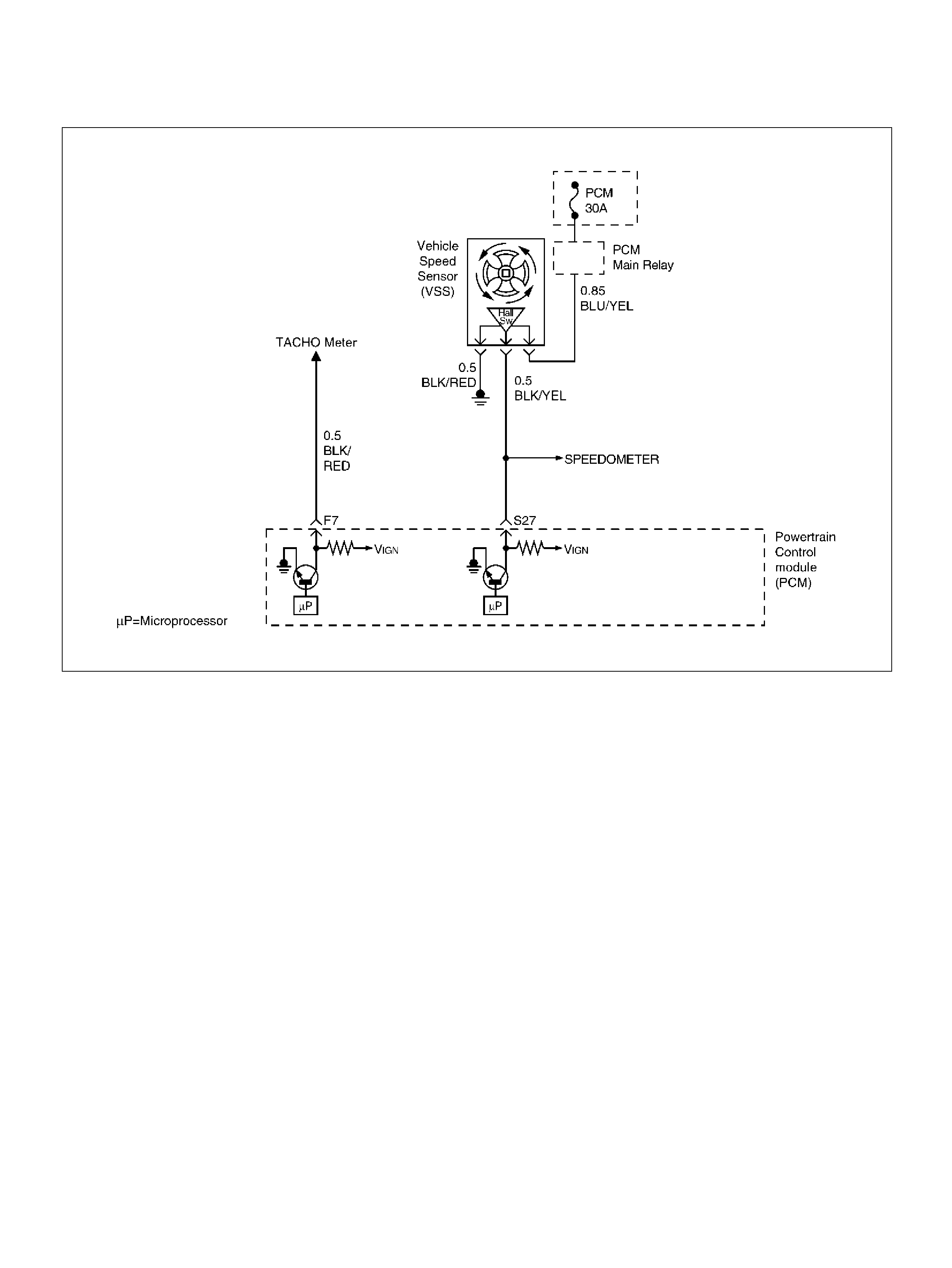
DIAGNOSTIC TROUBLE CODE (DTC) P0502 VSS CIRCUIT LOW INPUT
060R100071
Circuit Description
The vehi cle speed sensor has a magnet rotated by the
transmission output shaft. Attached to the sensor is a
hall effect circuit the interacts with the magnetic field
treated by the rotating magnet. A 12-volt operating
supply for the speed sensor ha ll circuit is s upplied from
the meter fuse. The VSS pulses to ground the 9-volt
signal sent from the powertrain control module (PCM)
on the reference circuit. The PCM interprets vehicle
speed by the number of pulses to ground per second on
the reference circuit.
Conditions for Setting the DTC
• Engine is running.
• Engine speed is between 1800 RPM and 2500 RPM.
• Throttle angle is between 10% and 40%.
• Engine load is greater than 50 kPa.
• PCM detects no VSS signal for 12.5 seconds over a
period of 15 seconds.
Action Taken When the DTC Sets
• The PCM will ON the MIL after second trip with
detect ed the fault.
• The PCM will store conditions which were present
when the DTC was set as Freeze Frame and in the
Failure Records data.
Conditi ons for Clea r ing the MIL/DTC
• The PCM will turn the MIL “OFF" on the third
consecutive trip cycle during which the diagnostic has
been run and the fault condition is no longer present.
• A history DTC P0502 will clear after 40 consecutive
warm-up cy cles have occurred without a fault.
• DTC P0502 can be cleared by using the Tech 2
“Clear Info" function.
Test Descr iption
Number(s) below refer to the step number(s) on the
Diagnostic Chart.
10. To avoid backprobing the VSS and possibly
damaging a seal or terminal, the VSS output can be
tested at the point where the transmission harness
connects to the engine harness. Power and ground
are applied by jumpers to the VSS through the
connectors which are located to the rear of the air
clea ner assembly. The VSS signal is monitored with
a DVM as the rear driveshaft turns. The wheels ca n
be turned to rotate the driveshaft, or in
2-wheels-drive vehicle s the driveshaft can be turned
directly.

DTC P0502 – VSS Circuit Low Input
Step Action Value(s) Yes No
1 Was the “On-Board Diagnostic (OBD) System Check"
performed? — Go to Step 2 Go to OBD
System Check
2 Does the spee dom eter work? — Go to Step 10 Go to Step 3
3 1 . Disconnect the VSS connect or.
2. Ignition “ON".
3. Using a test light to bat t ery +, probe the connec tor
ground wire.
Did the lig ht illu m in ate? — Go to Step 5 Go to Step 4
4 Repair the sensor ground.
Is the action complete ? — Verify repair —
5 1. Ignition “ON", sensor disconnected.
2. Using a DVM, measure at the VSS connector
between ground and volt age supply.
Was the measurement near the specified value? Battery
voltage Go to St ep 7 Go to Step 6
6 Repair the open or short to ground which may have
blown the meter fuse.
Is the action complete ? — Verify repair —
7 1. Ignition “ON", VSS disconnected.
2. Using a DVM, measure at the VSS connector
between ground and the wire from the
speedometer.
Was the m eas urem ent near the specified value? 7.5-8 V Go to St ep 9 Go to S tep 8
8 Check for an open or short circuit between the
speedo meter and the VSS.
Was an open or short circuit located? — Verify repair Go to Step 9
9 Replace the speedometer.
Is the action complete ? — Verify repair —
10 1. Ignition “OFF".
2. Disconnect the MAF sensor. The connector
attaches the VSS wires from the transmission
harness to the left- side engine harness.
3. Disconnect the black 16-way connecto r.
4. Select a terminal adapter from kit 5-8840-0385-0
that can be used with a jumper to supply B+ to the
blue wire wit h a yellow tracer (transmission side of
the connector).
5. Use another terminal adapter to attach a voltmeter
to the light-green wire with a white tracer (n ext to
the wire in the previous step.)
6. Disconnect the blue connector next to the black
16-way connector, and locate the black/red tracer
wire at one corner of the blue connector. The
black/red wire is the VSS ground. Use a terminal
adapter to at tac h a jumper to ground to the black/
red VSS ground wire at the transmission side of
the blue connector.
7. Raise the rear wheels off the ground with
transmission in neutral.
Does the DVM toggle back and forth between 0.6 V
and 10 V as the wheels (and driveshaft) are rotated? — G o to St ep 11 Go to St ep 10

11 Replace the VSS.
Is the action complete ? — Verify repair —
12 Check for a n open or sh ort betw een the PCM and t he
speedometer.
Was a problem found? — Verify rep air Go to Step 13
13 Replace the PCM.
Important: The replacement PCM must be
programmed. Refer to Section 0C-1 - Service
Program ming Syst em.
Important: Refer to Section 11 - Engin e Im mobiliser
System for the Immobiliser Programming procedure.
Important: Ensure the latest software program is
downloaded to the PCM.
Is the action complete ? — Verify repair —
Step Action Value(s) Yes No
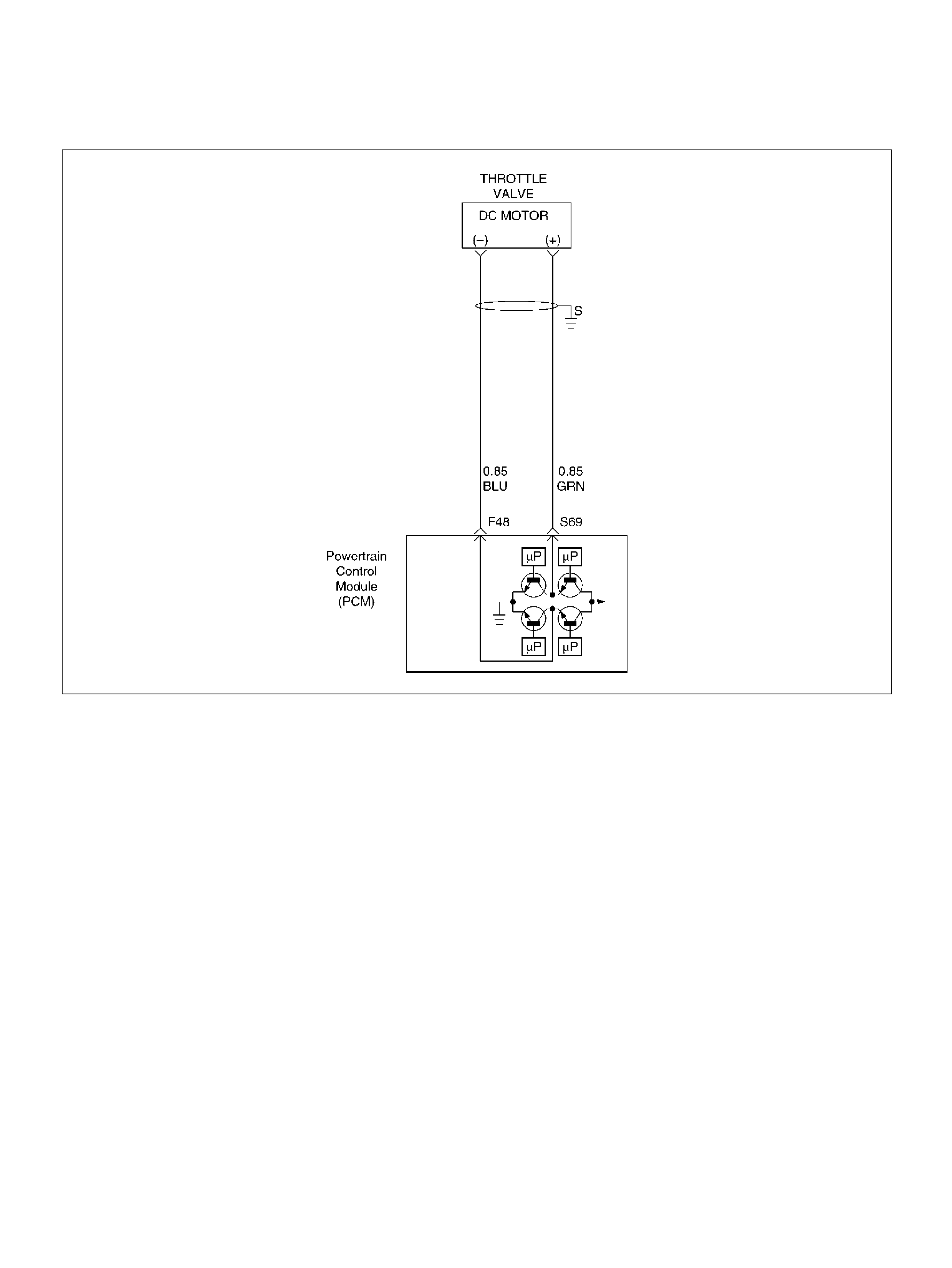
DIAGNOSTIC TROUBLE CODE (DTC) P0506
IDLE AIR CONTROL SYSTEM LOW RPM
D06RY00161
Circuit Description
The powertrain control module (PCM) controls engine
speed by adjusting the position of the throttle control
valve (DC motor). The throttle motor is a DC motor
driven by one coil. The PCM applies current to the DC
motor coil in position (%) to adjustment the throttle valve
into a passage in the throttle body to air flow. This
method allows highly accurate control of engine speed
and quick response to changes in engine load.
If the PCM detects a condition where too low of an idle
speed is present and the PCM is unable to adjust idle
speed by increasing the throttle position, DTC P0506
will set, indicating a problem with the idle control
system .
Conditions for Setting the DTC
• No TPS, VSS, ECT, EGR, MAF, MAP, IAT, low
voltage, fuel system, canister purge, injector control,
or ignition control DTCs are set.
• M AP is less than 60 kPa.
• Engine running time is more than 125 seconds.
• Engine coolant temperature (ECT) is above 50°C
(122°F).
• Ignition voltage is between 9.5 volts and 16.7 volts.
• T he throttle is closed.
• EVAP purge duty cycle mo re than 10%.
• All conditions are met for 10 seconds.
• Engine speed is more than 100 RPM lower than
desired idle based upon coolant temp erature.
Action Taken When the DTC Sets
• The PCM will illuminate the malfunction indicator
lamp (M IL) after the second c onsecutive trip in which
the fault is detected .
• The PCM will store conditions which were present
when the DTC was set as Freeze Frame and in the
Failure Records data.
Conditi ons for Clea r ing the MIL/DTC
• DTC P0506 can be cleared by using the Tech 2
“Clear Info" function.

Diagnostic Aids
Check for the following conditions:
• Poor connection at PCM or throttle DC motor –
Inspect harness connectors for backed-out terminals,
improper mating, broken locks, improperly formed or
damaged terminals, and poor terminal-to-wire
connection.
• Damaged harness – Inspect the wiring harness for
damage.
• Restricted air intake system – Check for a possible
collapsed air intake duct, restricted air filter element,
or foreign objects blocking the air intake system.
• Throttle body – Check for objects blocking the ETC
passage or throttle bore, excessive deposits in the
ETC passage and on the ETC position, and
excessive deposits in the throttle bore and on the
throttle plate.
• Large vacuum leak – Check for a condition that
causes a large vacuum leak, such as an incorrectly
installed or faulty PCV valve or brake booster hose
disconnected.
Reviewing the Failure Records vehicle mileage since
the diagnostic test last failed may help determine how
often the condition that caused the DTC to be set
occurs. This may assist in diagnosing the condition.
DTC P0506 – Idle Air Control System Low RPM
Step Action Value(s) Yes No
1 Was the “On-Board (OBD) System Check"
performed? —Go to Step 2 Go to OBD
System Check
2 Visually/physically inspect for the following conditi ons:
• T hrottle body tampering.
• Restricted intake throttle system. Check for a
possible coll apsed air i ntake duct, restricted air fi lter
element, or foreign objects blocking the air intake
system.
• Throttle body: Check for objects blocking the
throttle passage or throttle bore, excessive deposits
in the throttle passage and on the throttle valve,
and excessive carbon deposits in the throttle bore
and on the throttle plate.
• Throttle lever: Check for smooth operation without
excessive play.
Do any of the above require a repair? —
Refer to
appropriate
sec tion fo r on-
vehicle service Go to Step 3
3 Visually/physically inspect for the following conditi ons:
• Accelerator pedal : Ch eck fo r objects resticting the
spring or pedal arm.
• Accelerator pedal : Check for Check for smooth
operation without excessive play.
• Do any of the above require a repair? —
Refer to
appropriate
sec tion fo r on-
vehicle service Go to Step 4
4 Check for a poor connection at the throttle body
harness connec tor.
Check for a poor connection at the accelerator
position sensor harness connector.
If a problem is found, replace faulty terminals as
necessary.
Was a problem found? — Verify repair Go to Step 5
5 Check the following circuits for an open, short to
voltage, short to ground, or poor connection at the
PCM:
• T hrottle position sensor 1 circuit.
• T hrottle position sensor 2 circuit.
• Throttle DC motor circuit.
If a problem is found, repair as neces sary.
Was a problem found? Verify repair Go to S tep 6

6 Check the Throttle Position sensor resistance.
If a problem is found, repair as neces sary.
Was a problem found? 0.56k - 2.6kΩVer ify repair Go to Step 7
7 Check the Throttle DC motor re sistance.
If a problem is found, repair as neces sary.
Was a problem found? 3.0 - 4.0ΩG o to St ep 8 Go to Step 9
8 Replac e the throttle valve.
Is the action complete ? — Verify r epair —
9 Check the following circuits for an open, short to
voltage, short to ground, or poor connection at the
PCM:
• Accelerator position sensor 1 circuit.
• Accelerator position sensor 2 circuit.
• Accelerator position sensor 3 circuit.
If a problem is found, repair as neces sary.
Was a problem found? Verify repair Go to Step 10
10 Check the Accelerator Position sensor resist ance
If a problem is found, repair as neces sary.
Was a problem found? 4-6 Go to Step 11 Go to Step 12
11 Replace the accelerator position sensor.
Is the action complete ? — Verify r epair —
12 Are any of the f ollowing DT Cs: P1125, P1290 , P129 5,
P1299 present ? —
Go to
applicable DTC
table Go to Step 13
13 Are any of the following DTCs: P1514, P1515, P1516,
P1523, P1 271, P1272, P1273 pres ent? —
Go to
applicable DTC
table Go to Step 11
14 Replace the PCM.
Important: The replacement PCM must be
programmed. Refer to Section 0C-1 - Service
Program ming Syst em.
Important: Refer to Section 11 - Engin e Im mobiliser
System for the Immobiliser Programming procedure.
Important: Ensure the latest software program is
downloaded to the PCM.
Is the action complete ? — Verify repair —
Step Action Value(s) Yes No

DIAGNOSTIC TROUBLE CODE (DTC) P0507
IDLE AIR CONTROL SYSTEM HIGH RPM
D06RY00161
Circuit Description
The powertrain control module (PCM) controls engine
speed by adjusting the position of the throttle control
valve (DC motor). The throttle motor is a DC motor
driven by one coil. The PCM applies current to the DC
motor coil in position (%) to adjustment the throttle valve
into a passage in the throttle body to air flow. This
method allows highly accurate control of engine speed
and quick response to changes in engine load.
If the PC M detects a c ondition where t oo high o f a n idl e
speed is present and the PCM is unable to adjust idle
speed by increasing the throttle position, DTC P0507
will set, indicating a problem with the idle control
system.
Conditions for Setting the DTC
• No TPS, VSS, ECT, EGR, MAF, MAP, IAT, low
voltage, fuel system, canister purge, injector control
or ignition control DTCs are set.
• M AP is less than 60 kPa.
• Engi ne ru nning time is more than 125 seconds.
• Engine coolant temperature (ECT) is above 50°C
(122°F).
• Ignition voltage is between 9.5 volts and 16.7 volts.
• T he throttle is closed.
• EVAP purge duty cycle is m ore than 1 0%.
• All conditions are met for 10 seconds.
• Engine speed is more than 100 RPM higher than
desired idle based upon coolant temp erature.
Action Taken When the DTC Sets
• The PCM will illuminate the malfunction indicator
lamp (M IL) after the second c onsecutive trip in which
the fault is detected .
• The PCM will store conditions which were present
when the DTC was set as Freeze Frame and in the
Failure Records data.

Conditions for Clearing the MIL/DTC
• The PCM will turn the MIL “OFF" on the third
consecutive trip cycle during which the diagnostic has
been run and the fault condition is no longer present.
• A history DTC P0507 will clear after 40 consecutive
warm-up cycles have occurred without a fault.
• DTC P0507 can be cleared by using the Tech 2
“Clear Info" function.
Diagnostic Aids
Check for the following conditions:
• Poor connection at PCM or throttle DC motor –
Inspect harness connectors for backed-out terminals,
improper mating, broken locks, improperly formed or
damaged terminals, and poor terminal-to-wire
connection.
• Damaged harness – Inspect the wiring harness for
damage.
• Vacuum leak – Check for a condition that causes a
vacuum leak, such as disconnected or damaged
hoses, leaks at EGR valve and EGR pipe to intake
manifold, leak at the throttle body, a faulty or
incorrectly installed PCV valve, leaks at the intake
manifold, etc.
• Throttle body – Check for sticking throttle plate. Also
inspect the air passage for deposits or objects which
will not allow the ETC position to fully extend or
properly seat.
If DTC P0507 cannot be duplicated, reviewing the
Failure Records vehicle mileage since the diagnostic
test last failed may help determine how often the
condition that caused the DTC to be set occurs. This
may assist in diagnosing the condition.
DTC P0507 – Idle Air Control System High RPM
Step Action Value(s) Yes No
1 Was the “On-Board (OBD) System Check"
performed? —Go to Step 2 Go to OBD
System Check
2 Visually/physically inspect for the following conditi ons:
• T hrottle body tampering.
• Restricted intake throttle system. Check for a
possible coll apsed air i ntake duct, restricted air fi lter
element, or foreign objects blocking the air intake
system.
• Throttle body: Check for objects blocking the
throttle passage or throttle bore, excessive deposits
in the throttle passage and on the throttle valve,
and excessive carbon deposits in the throttle bore
and on the throttle plate.
• Throttle lever: Check for smooth operation without
excessive play.
Do any of the above require a repair? —
Refer to
appropriate
sec tion fo r on-
vehicle service Go to Step 3
3 Visually/physically inspect for the following conditi ons:
• Accelerator pedal : Ch eck fo r objects resticting the
spring or pedal arm.
• Accelerator pedal : Check for Check for smooth
operation without excessive play.
• Do any of the above require a repair? —
Refer to
appropriate
sec tion fo r on-
vehicle service Go to Step 4
4 • Check for a poor connection at the throttle body
harn ess connect or.
• Check for a poor connection at the accelerator
position sen sor harness connecto r.
• If a problem is found, replace faulty terminals as
necessary.
Was a problem found? — Verify repair Go to Step 5

5 Check the following circuits for an open, short to
voltage, short to ground, or poor connection at the
PCM:
• T hrottle position sensor 1 circuit.
• T hrottle position sensor 2 circuit.
• Throttle DC motor circuit.
If a problem is found, repair as neces sary.
Was a problem found? Verify repair Go to S tep 6
6 Check the Throttle Position sensor resistance.
If a problem is found, repair as neces sary.
Was a problem found? 0.56k - 2.6kΩVerify repair Go to Ste p 7
7 Check the Throttle DC motor re sistance.
If a problem is found, repair as neces sary.
Was a problem found? 3.0 - 4.0ΩG o to St ep 8 Go to Step 9
8 Replac e the throttle valve.
Is the action complete ? — Verify r epair —
9 Check the following circuits for an open, short to
voltage, short to ground, or poor connection at the
PCM:
• Accelerator position sensor 1 circuit.
• Accelerator position sensor 2 circuit.
• Accelerator position sensor 3 circuit.
If a problem is found, repair as neces sary.
Was a problem found? Verify repair Go to Step 10
10 Check the Accelerator Position sensor resist ance
If a problem is found, repair as neces sary.
Was a problem found? 4-6 Go to Step 11 Go to Step 12
11 Replace the accelerator position sensor.
Is the action complete ? — Verify r epair —
12 Are any of the f ollowing DT Cs: P1125, P1290 , P129 5,
P1299 present ? —
Go to
applicable DTC
table Go to Step 13
13 Are any of the following DTCs: P1514, P1515, P1516,
P1523, P1 271, P1272, P1273 pres ent? —
Go to
applicable DTC
table Go to Step 11
14 Replace the PCM.
Important: The replacement PCM must be
programmed. Refer to Section 0C-1 - Service
Program ming Syst em.
Important: Refer to Section 11 - Engin e Im mobiliser
System for the Immobiliser Programming procedure.
Important: Ensure the latest software program is
downloaded to the PCM.
Is the action complete ? — Verify repair —
Step Action Value(s) Yes No
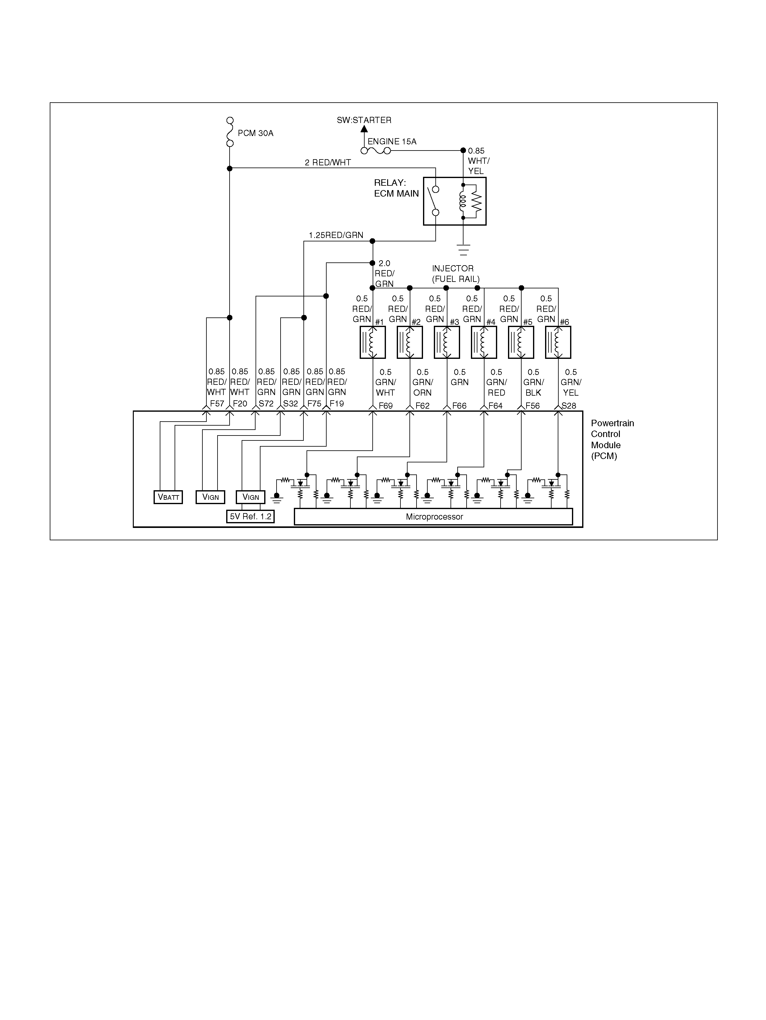
DIAGNOST IC TROUBLE CODE (DTC) P0562 SYSTEM VOLTAG E LO W
060R100139
Circuit Description
The powertrain control module (PCM) monitors the
syste m vol tage on the ignition fe e d te rmi na l to th e PCM.
A system voltage DTC will set whenever the voltage is
below a calibrated value.
Conditions for Setting the DTC
• Igniti on “ON".
• System voltage is below 11.5 volts for 40 seconds.
Action Taken When the DTC Sets
• The PCM wi ll not illuminate the malfunction indicator
lamp (MIL).
• The PCM will store as Failure Records conditions
which were present when the DTC was set. This
informat ion will not be stored as Freeze Frame data.
Conditi ons for Clea r ing the MIL/DTC
• A history DTC P0562 will clear after 40 consecutive
warm-up cy cles have occurred without a fault.
• DTC P0562 can be cleared by using the Tech 2
“Clear Info" function.
Diag nostic Ai ds
If the DTC sets when an accessory is operated, check
for a poor connection or excessive current draw.

DTC P0562 – System Voltage Low
Step Action Value(s) Yes No
1 Was the “On-Board Diagnostic (OBD) System Check"
performed? — Go to Step 2 Go to OBD
System Check
2 Using a DVM, measure the battery voltage at the
battery.
Is the battery voltage greater than the specified value? 11.5 V Go t o St ep 3
Charge battery,
then go to Step
3
3 1 . Install a Tec h 2.
2. Select “Ignition Vo lts" on the Tech 2.
3. Start the engine and raise the engin e speed to the
specified value.
4. Load the electrical system by turning on the
headlights, high blower , etc.
Is the ignition voltage approximately equal to the
specified value? 2000 RPM
12.8-14.1 V Go to Step 4 Go to Starting/
Charging
4 1 . Ig nit io n “ OFF" .
2. Disconnect the PCM connect or at the PCM.
3. Using a DVM, measure the battery voltage at the
PCM connect or F-20 and F-57.
Is it approxim ately equal to battery voltage? —
Check for
excessive
current draw
with ignition
“OFF", engine
“OFF". Go to Step 5
5 1. Check for faulty connections at the PCM harn ess
terminals.
2. Repair as neces sary.
Was a repair necessary? — Verify repair Go to S tep 6
6 Check for an open battery feed circuit to the PCM.
Is the action comple te ? — Verify r epair Go to S tep 7
7 Replace the PCM.
Important: The replacement PCM must be
programmed. Refer to Section 0C-1 - Service
Program ming Syst em.
Important: Refer to Section 11 - Engin e Im mobiliser
System for the Immobiliser Programming procedure.
Important: Ensure the latest software program is
downloaded to the PCM.
Is the action complete ? — Verify repair —

DIAGNOSTIC TROUBLE CODE ( DTC) P0563 SYSTEM VOLTAGE HIGH
060R100139
Circuit Description
The powertrain control module (PCM) monitors the
system voltage on the ignition feed terminals to the
PCM. A system voltage DTC will set whenever the
voltage is above a calibrated value.
Conditions for Setting the DTC
• Igniti on “ON".
• System voltage is above 16 volts for 40 seconds.
Action Taken When the DTC Sets
• The PCM will ON the MIL after second trip with
detect ed the fault.
• The PCM will store conditions which were present
when the DTC was set as Freeze Frame and in the
Failure Records data.
Conditi ons for Clea r ing the MIL/DTC
• A history DTC P0563 will clear after 40 consecutive
warm-up cy cles have occurred without a fault.
• DTC P0563 can be cleared by using the Tech 2
“Clear Info" function.
Diag nostic Ai ds
If the DTC sets when an accessory is operated, check
for a poor connection or excessive current draw.

DTC P0563 – System Voltage High
Step Action Value(s) Yes No
1 Was the “ON-Board Diagnostic (OBD) System Check"
performed? — Go to Step 2 Go to OBD
System Check
2 Using a DVM, measure the battery voltage at the
battery.
Is the battery voltage less than the specified value? 11.5 V Go to St ep 3 Go to S tep 4
3 1. Charge the battery and clean the battery
terminals.
2. Clean the battery ground cable connection if
corrosion is indicated.
Is the battery voltage less than the specified value? 11.5 V Replace battery Go to Step 4
4 1. Turn “OFF" all the accessories.
2. Install a Tech 2.
3. Select the ignition voltage parameter on the Tech
2.
4. Start the engine and rai se the engine RPM to the
specified value.
Is the voltage more than 2.5 volts greater than the
measurem ent taken in step 2 or 3? 20 00 RPM Go t o Starting/
Charging Go to S tep 5
5 Replace the PCM.
Important: The replacement PCM must be
programmed. Refer to Section 0C-1 - Service
Program ming Syst em.
Important: Refer to Section 11 - Engin e Im mobiliser
System for the Immobiliser Programming procedure.
Important: Ensure the latest software program is
downloaded to the PCM.
Is the action complete ? — Verify repair —

DIAGNOSTIC TROUBLE CODE (DTC) P0565 CRUISE MAIN SWITCH
CIRCUIT ERROR
060R100137
Circuit Description
When enabled, the cruise control maintains a constant
cruising speed without manual control of the accelerator
pedal. The vehicle speed will remain constant until a
cancel ling signal is received.
When the cruise main switch is turned on and vehicle
speed is above 36km/h, battery voltage is applied to
Powertrain Control Module (PCM). When a signal from
the Cruise Control switch is input to PCM while the
vehicle is in this state, the cruise control system is
activated. Also, while the cruise system is operating, the
“CRUISE MAIN" indicator light is illuminated.
Conditions for setting the DTC
• T he Ignition is “ON''.
• Engine is running.
• Sy ste m voltage is between 11.5 volts and 16 volts.
• The switch contact remains on for 15 seconds or
more.
• Noises are generated by poor switch contact 60
times within 1 second.
Action Taken When the DTC Sets
• The PCM will not illuminate the malfunction indicator
lamp (MIL).
• The PCM will store conditions which were present
when the DTC was set in the Failure Records data
only.
Conditi ons for Clea r ing the MIL/DTC
• The PCM will turn the MIL “OFF" on the third
consecutive trip cycle during which the diagnostic has
been run and the fault condition is no longer present.

• A history DTC P0565 will clear after 40 consecutive
trip cycle during which the warm up cycles have
occurred without a fault.
• DTC P0565 can be cleared using the Tech2 “Clear
Info" function.
Diagnostic Aids
An intermittent may be caused by the following:
• Poor connections.
• Misrouted harness.
• Rubbed through wire insulation.
• Broken wire inside the insulation.
Check for the following conditions:
• Poor connection at PCM-Inspect harness connectors
for backed out terminals, improper mating, broken
locks, improperly formed or damaged terminals, and
poor terminal to wire connection.
• Damaged harness-Inspect the wiring harness for
damage. If the harness appears to be OK, observe
the cruise main switch display on the Tech2 while
moving connectors and wiring harnesses related to
the sensor.
A change in the display will indicate the location of
the fault.
If DTC P0565 cannot be duplicated, the information
included in the Failure Records data can be useful in
determined vehicle mileage since the DTC was last
set.
If it is determined that the DTC occurs intermittently,
performing the DTC P0565 Diagnostic Chart may
isolate the cause of the fault.
DTC P0565 Cruise Main Switch Circuit Error
Step Action Value(s) Yes No
1 Was the “On-Board (OBD) System Check"
performed? —Go to Step 2 Go to OBD
System Check
2 1. Ignition “ON," engine “ON."
2. Observe th e cruise main lam p in the switch.
Is the cruise main lamp “ON?" — Go to St ep 3 Go to Step 4
3 1. Push the auto cruise main switch.
2. Observe th e cruise main lam p in the switch.
Is the cruise main lamp “OFF?" — Go to
Diagnostic Aids Go to Step 4
4 Check the signal circuit for auto cruise main switch.
1. Ignition is “O FF ".
2. Disconnect the powertrain control module(PCM).
3. Disconnect the cruise main switch.
Check for an open cruise main switch signal
circuit between the PCM and the cruise main
switch.
Is a problem found? — Go to St ep 5 Go to Step 6
5 Repair the auto cruise main switch signal circuit.
Is the action complete ? — Verify r epair —
6 Check th e auto cruise mai n switch and lamp ci rcu it.
Is a problem found? — Go to St ep 7 Go to Step 8
7 Repair or replace the auto cruise main switch and
lam p c ir c u it .
Is the action complete ? — Verify r epair —
8 Replace the PCM.
Important: The replacement PCM must be
programmed. Refer to Section 0C-1 - Service
Program ming Syst em.
Important: Refer to Section 11 - Engin e Im mobiliser
System for the Immobiliser Programming procedure.
Important: Ensure the latest software program is
downloaded to the PCM.
Is the action complete ? — Verify repair —

DIAGNOSTIC TROUBLE CODE (DTC) P0566 CRUISE CANCEL SWITCH
CIRCUIT ERROR
060R100137
Circuit Description
When enabled, the cruise control maintains a constant
cruising speed without manual control of the accelerator
pedal. The vehicle speed will remain constant until a
cancel ling signal is received.
When the cruise main switch is turned on and vehicle
speed is above 36km/h, battery voltage is applied to
Powertrain Control Module (PCM). When a signal from
the Cruise Control switch is input to PCM while the
vehicle is in this state, the cruise control system is
activated. Also, while the cruise system is operating, the
“CRUISE MAIN" indicator light is illuminated.
When the cancel switch is “ON", cruise system is “OFF".
Conditions for setting the DTC
• T he Ignition is “ON".
• Engine is running.
• Sy ste m voltage is between 11.5 volts and 16 volts .
• The switch contact remains on for 40 seconds or
more.
• Noises are generated by poor switch contact 100
times within 1.6 seconds.
Action Taken When the DTC Sets
• The PCM will not illuminate the malfunction indicator
lamp (MIL).
• The PCM will store conditions which were present
when the DTC was set in the Failure Records data
only.
Conditi ons for Clea r ing the MIL/DTC
• The PCM will turn the MIL “OFF" on the third
consecutive trip cycle during which the diagnostic has

been run and the fault condition is no longer present.
• A history DTC P0566 will clear after 40 consecutive
trip cycle during which the warm up cycles have
occurred without a fault.
• DTC P0566 can be cleared using the Tech2 “Clear
Info" function.
Diagnostic Aids
An intermittent may be caused by the following:
• Poor connections.
• Misrouted harness.
• Rubbed through wire insulation.
• Broken wire inside the insulation.
Check for the following conditions:
• Poor connection at PCM-Inspect harness connectors
for backed out terminals, improper mating, broken
locks, improperly formed or damaged terminals, and
poor terminal to wire connection.
• Damaged harness-Inspect the wiring harness for
damage. If the harness appears to be OK, observe
the cruise cancel switch display on the Tech2 while
moving connectors and wiring harnesses related to
the sensor.
A change in the display will indicate the location of
the fault. If DTC P0566 cannot be duplicated, the
information included in the Failure Records data can
be useful in determined vehicle mileage since the
DTC was last set.
If it is determined that the DTC occurs intermittently,
performing the DTCP0566 Diagnostic Chart may
isolate the cause of the fault.
DTC P0566 Cruise Cancel Switch Circuit Error
Step Action Value(s) Yes No
1 Was the “On-Board (OBD) System Check"
performed? —Go to Step 2 Go to OBD
System Check
2 Check the signal circuit for auto cruise cancel switch.
1. Ignition is “O FF ".
2. Disconnect the powertrain control module(PCM).
3. Disconnect the cruise cancel switch.
Check for cruise cancel switch signal circuit
between the PCM and the cruise cancel switch.
Is a problem found? — Go to St ep 3 Go to Step 4
3 Repair the main cruise cancel switch signal circuit.
Is the action complete ? — Verify r epair —
4 Check th e auto cruise mai n switch.
Is a problem found? — Go to St ep 5 Go to Step 6
5 Repair or replace the main cruise main switch.
Is the action complete ? — Verify r epair —
6 Replace the PCM.
Important: The replacement PCM must be
programmed. Refer to Section 0C-1 - Service
Program ming Syst em.
Important: Refer to Section 11 - Engin e Im mobiliser
System for the Immobiliser Programming procedure.
Important: Ensure the latest software program is
downloaded to the PCM.
Is the action complete ? — Verify repair —
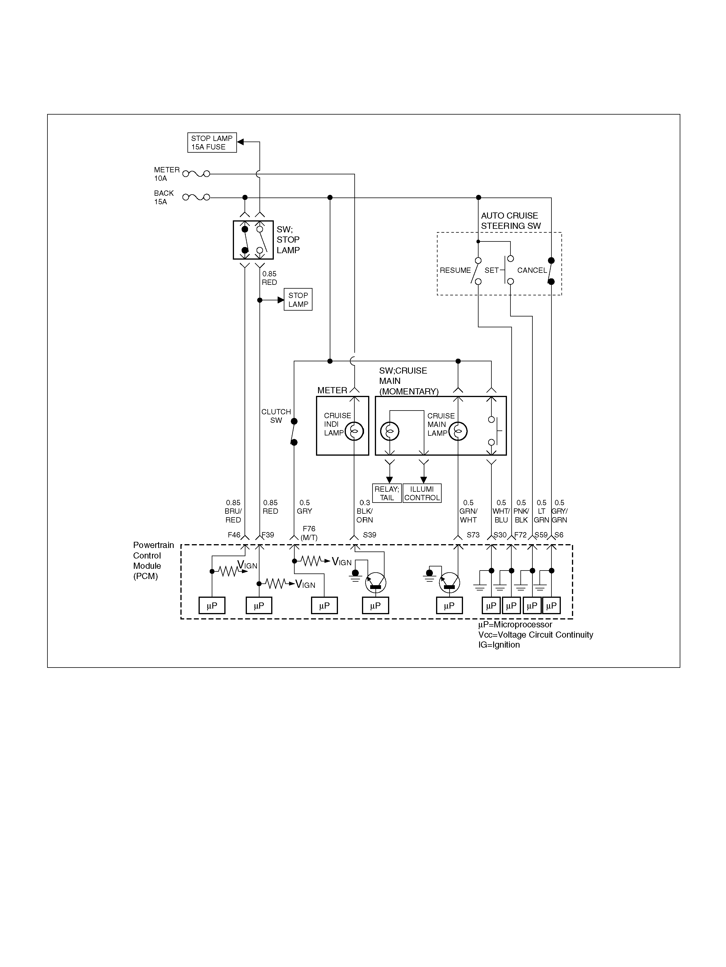
DIAGNOSTIC TROUBLE CODE (DTC) P0567 CRUISE RESUME SWITCH
CIRCUIT ERROR
060R100137
Circuit Description
When enabled, the cruise control maintains a constant
cruising speed without manual control of the accelerator
pedal. The vehicle speed will remain constant until a
cancel ling signal is received.
When the cruise main switch is turned on and vehicle
speed is above 36km/h, battery voltage is applied to
Powertrain Control Module (PCM). When a signal from
the Cruise Control switch is input to PCM while the
vehicle is in this state, the cruise control system is
activated. Also, while the cruise system is operating, the
“CRUISE MAIN" indicator light is illuminated.
When the resume switch is “ON", vehicle speed is
reseated to the previous set speed.
Conditions for settin g the DTC
• T he Ignition is “ON".
• Engi ne is running.
• Sy ste m voltage is between 11.5 volts and 16 volts .
• The switch contact remain on for 50 seconds or
more.
• Noises are generated by poor switch contact 100
times within 1.6 seconds.
Action Taken When the DTC Sets
• The PCM will not illuminate the malfunction indicator
lamp (MIL).
• The PCM will store conditions which were present
when the DTC was set in the Failure Records data
only.

Conditions for Clearing the MIL/DTC
• The PCM will turn the MIL “OFF" on the third
consecutive trip cycle during which the diagnostic has
been run and the fault condition is no longer present.
• A history DTC P0567 will clear after 40 consecutive
trip cycle during which the warm up cycles have
occurred without a fault.
• DTC P0567 can be cleared using the Tech2 “Clear
Info" function.
Diagnostic Aids
An intermittent may be caused by the following:
• Poor connections.
• Misrouted harness.
• Rubbed through wire insulation.
• Broken wire inside the insulation.
Check for the following conditions:
• Poor connection at PCM-Inspect harness connectors
for backed out terminals, improper mating, broken
locks, improperly formed or damaged terminals, and
poor terminal to wire connection.
• Damaged harness-Inspect the wiring harness for
damage.
If the harness appears to be OK, observe the Cruise
resume switch display on the Tech2 while moving
connectors and wiring harnesses related to the
sensor.
A change in the display will indicate the location of
the fault.
If DTC P0567 cannot be duplicated, the information
included in the Failure Records data can be useful in
determined vehicle mileage since the DTC was last
set.
If it is determined that the DTC occurs intermittently,
performing the DTCP0567 Diagnostic Chart may
isolate the cause of the fault.
DTC P0567 Cruise Resume Switch Circuit Error
Step Action Value(s) Yes No
1 Was the “On-Board (OBD) System Check"
performed? —Go to Step 2 Go to OBD
System Check
2 Check the signal circuit for auto cruise resume switch.
1. Ignition is “O FF ".
2. Disconnect the powertrain control module (PCM).
3. Disconnect the cruise resume switch. Check for
cruise resume switch signal circuit between the
PCM and the cruise resume switch.
Is a problem found? Go to St ep 3 Go to Step 4
3 Repair the main cruise re su me switch signal circuit.
Is the action complete ? — Verify r epair —
4 Check the auto cruise resume switch.
Is a problem found? — Go to St ep 5 Go to Step 6
5 Repair or replace the main cruise resume switch.
Is the action complete ? — Verify r epair —
6 Replace the PCM.
Important: The replacement PCM must be
programmed. Refer to Section 0C-1 - Service
Program ming Syst em.
Important: Refer to Section 11 - Engin e Im mobiliser
System for the Immobiliser Programming procedure.
Important: Ensure the latest software program is
downloaded to the PCM.
Is the action complete ? — Verify repair —
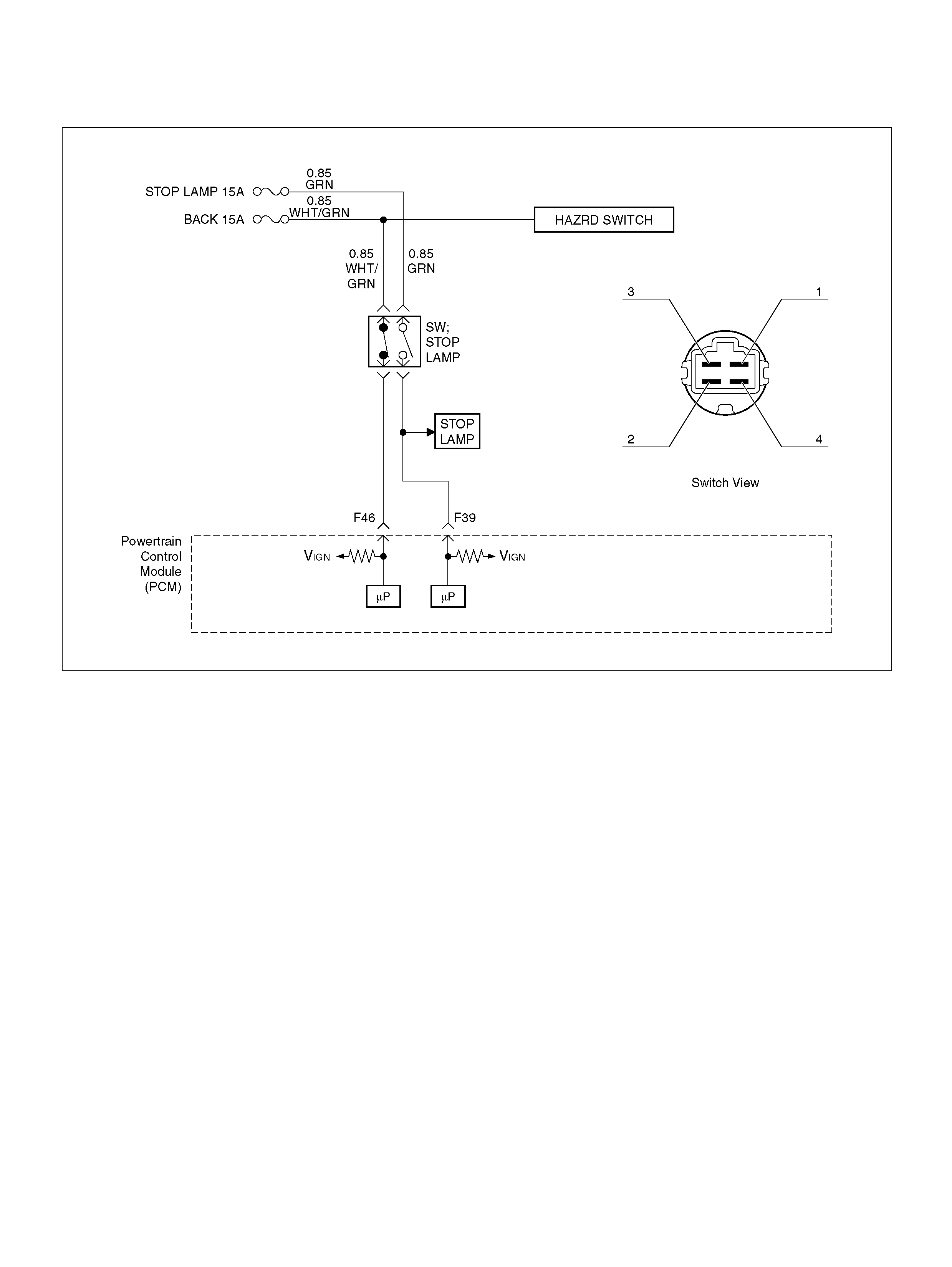
DIAGNOSTIC TROUBLE CODE (DTC) P0571 NO BRAKE SWITCH SIGNAL
060R100138
Circuit Description
The primary function of the brake switch signal is to
operate the stop lamps.
A dual-contact brake switch provides two signals to the
PCM.
The two signals are used by the PCM in the operation of
the Cruise Control System and Aut omatic Transmissio n
operation.
The PCM monitors vehicle speed and brake switch
position to calculate brake operating conditions.
Conditions for Setting the DTC
• Two brake switch signals do not correspond after
signal after pedal operation.
• VSS not defe c tive .
• Engine is running.
• V ehicle speed above 20km/h.
Action Taken When the DTC Sets
• The PCM will not turn the malfunction indicator lamp
(MIL) “ON".
• The PCM will store conditions which were present
when t he DTC was set a s Failure Records onl y. Th is
informat ion will not be st ored as Freez e Frame data.
Conditions for Clearing the DTC
• DTC P0571 can be cleared by using the scan tool
“Clear Info" function.
Diag nostic Ai ds
• Damaged harness–Inspect the wiring harness for
damage. If the harness appears to be OK, observe
the fuel level display on the scan tool while moving
connectors and wiring harnesses related to the
sensor. A change in the display will indicate the
location of the fault.

DTC P0571 No Brake Switch Signal
Step Action Value(s) Yes No
1 Was the “On-Board Diagnostic (OBD) System Check"
performed? —Go to Step 2 Go to OBD
System Check
2 1. Ignit io n “ O ff".
Engine “Off".
2. Check following fuses.
• BACK 15 A
• S TOP LAM P 15A
Was a problem found? — Verify repair Go to Step 3
3 1. Make adjustment to the brake switch.
The brake switch is installed to the brake pedal
assembly. (Refer to “Brake switch" in “10A
CRUISE CONTROL SYSTEM".)
Was the proble m found? — Verify repair Go to Step 4
4 1. Push the shaft at brake switch.
2. Check shaft operation for smooth movem ents.
Was the proble m found? — Verify repair Go to Step 5
5 1. Disconnect the connector at brake switch.
2. Check following terminal pin at ohmmet er.
(Leave the shaft position at brake switch. Don't
push it.)
• Bet ween pin 1 and pin 2
• Bet ween pin 3 and pin 4
Was i t specified value?
Between pin1
and pin2 is
0Ω, Be tween
pin3 and pin4
is ∞Ω Go to Step 6 Go to S tep 9
6 1. Disconnect the connector at brake switch.
2. Check following terminal pin at ohmmet er.
(Push the shaft position at brake switch and hold
it)
• Bet ween pin 1 and pin 2
• Bet ween pin 3 and pin 4
Was i t specified value?
Between pin1
and pin2 is
∞Ω, Between
pin3 and pin4
is 0ΩGo to Step 7 Go to Step 9
7 1. Probe related circuits for open or short to ground.
2. If a problem was found, repair as necessary.
Was a problem found? — Verify repair Go to Step 8
8 Replace the PCM.
Important: The replacement PCM must be
programmed. Refer to Section 0C-1 - Service
Program ming Syst em.
Important: Refer to Section 11 - Engin e Im mobiliser
System for the Immobiliser Programming procedure.
Important: Ensure the latest software program is
downloaded to the PCM.
Is the action complete ? — Verify repair —
9 1. Replace the brake switch.
Was the ac tion compl eted? — Veri fy repair —

DIAGNOSTIC TROUBLE CODE (DTC) P0601 PCM MEMORY
060RY014
Circuit Description
The Powertrain Control Module (PCM) used in this
vehicle utilizes an Electrically Erasable Programmable
Read-only M em ory (EEPROM ). The EEPR OM conta ins
program information and the calibrations required for
engine, transmission, and powertrain diagnostics
operati on.
Unlike the PROM used in past applications, the
EEPROM is not replaceable. When the PCM is
replaced or a calibration update is required, the PCM
must be programmed using a Tech 2. Refer to
On-Vehicle Service in Powertrain Control Module and
Senso r s fo r th e EEPROM pr o gramming proced ure.
Conditions for Setting the DTC
• The PCM detects an internal program fault (check
sum error).
Action Taken When the DTC Sets
• The PCM will illuminate the Malfunction Indicator
L a m p (MIL ) the fi r st t i me th e fa ult is d e te c te d .
• The PCM will store condition which were present
when the DTC was set as Freeze Frame and in the
Failure Records data.
Conditi ons for Clea r ing the MIL/DTC
• The PCM will turn the MIL “OFF" on the third
consecutive trip cycle during which the diagnostic has
been run and the fault condition is no longer present.
• A history DTC P0601 will clear after 40 consecutive
warm-up cy cles have occurred without a fault.
• DTC P0601 can be cleared by using the Tech 2
“Clear Info" function.
Diag nostic Ai ds
• DTC P0601 indicates that the contents of the
EEPROM have changed since the PCM was
programmed. The only possible repair is PCM
replacem ent. Reme mbe r to program the re placem ent
PCM with the correct software an d calibration for the
vehicle.

DTC P0601 – PCM Memory
Step Action Value(s) Yes No
1 Was the “On-Board Diagnostic (OBD) System Check"
performed? — Go to Step 2 Go to OBD
System Check
2 Replace the PCM.
Important: The replacement PCM must be
programmed. Refer to Section 0C-1 - Service
Program ming Syst em.
Important: Refer to Section 11 - Engin e Im mobiliser
System for the Immobiliser Programming procedure.
Important: Ensure the latest software program is
downloaded to the PCM.
Is the action complete ? — Verify repair —

DIAGNOSTIC TROUBLE CODE (DTC) P0602 PCM PROGRAMMING ERROR
060RY014
Circuit Description
The Powertrain Control Module (PCM) uses Main CPU
and Watchdog CPU software/calibration.
Conditions for Setting the DTC
• This code detects inconsistencies between Main
C PU and Watchd og CPU software/calibration.
Action Taken When the DTC Sets
• T he PCM will not illuminate the Ma lfunction Indicator
Lamp (MIL).
• The PCM will store conditions which were present
when the DTC was set in the Failure Records data
only.
Conditi ons for Clea r ing the MIL/DTC
• The PCM will turn the MIL “OFF" on the third
consecutive trip cycle during which the diagnostic has
been run and the fault condition is no longer present.
• A history DTC P0602 will clear after 40 consecutive
warm-up cy cles have occurred without a fault.
• DTC P0602 can be cleared by using the Tech 2
“Clear Info" function or by disconnecting the PCM
battery feed.

DTC P0602 – PCM Programming Error
Step Action Value(s) Yes No
1 Was the “On -Board Diagnostic (OBD) System Chec k"
performed? — Go to Step 2 Go to OBD
System Check
2 Replace the PCM.
Important: The replacement PCM must be
programmed. Refer to Section 0C-1 - Service
Program ming Syst em.
Important: Refer to Section 11 - Engin e Im mobiliser
System for the Immobiliser Programming procedure.
Important: Ensure the latest software program is
downloaded to the PCM.
Is the action complete ?
— Verify repair —
DIAGNOSTIC TROUBLE CODE (DTC) P0604 PCM RAM ERROR
060RY014
Circuit Description
The Powertrain Control Module (PCM) uses Main CPU
RAM and Watchdog CPU RAM.
Conditions for Setting the DTC
• This code detects inconsistencies between Main
C PU RAM and Watchdog CPU RAM.
Action Taken When the DTC Sets
• T he PCM will not illuminate the Ma lfunction Indicator
Lamp (MIL).
• The PCM will store conditions which were present
when the DTC was set in the Failure Records data
only.
Conditi ons for Clea r ing the MIL/DTC
• The PCM will turn the MIL “OFF" on the third
consecutive trip cycle during which the diagnostic has
been run and the fault condition is no longer present.
• A history DTC P0604 will clear after 40 consecutive
warm-up cy cles have occurred without a fault.
• DTC P0604 can be cleared by using the Tech 2
“Clear Info" function or by disconnecting the PCM
battery feed.

DTC P0604 – PCM RAM Error
Step Action Value(s) Yes No
1 Was the “On-Board Diagnostic (OBD) System Check"
performed? — Go to Step 2 Go to OBD
System Check
2 Replace the PCM.
Important: The replacement PCM must be
programmed. Refer to Section 0C-1 - Service
Program ming Syst em.
Important: Refer to Section 11 - Engin e Im mobiliser
System for the Immobiliser Programming procedure.
Important: Ensure the latest software program is
downloaded to the PCM.
Is the action complete ?
— Verify repair —

DIAGNOSTIC TROUBLE CODE (DTC) P0606 PCM INTERNAL PERFORMANCE
060RY014
Circuit Description
The input/output devices in the PCM include
analog-to-digital converters, signal buffers, counters,
and special drivers. The PCM controls most
components with electronic switches which complete a
ground circuit when turned “ON". These switches are
arranged in groups of 4 and 7, called either a
surface-mou nted quad driver m odul e (QDM ), whic h can
independently control up to 4 output terminals, or QDMs
which can independently control up to 7 outputs.
Conditions for Setting the DTC
• This code detects inconsistencies between Main
CPU A/D converters and Watchdog CPU A/D
converters.
Action Taken When the DTC Sets
• T he PCM w ill n ot il lum inate the Mal fun ction In dicat or
Lamp (MIL).
• The PCM will store conditions which were present
when the DTC was set in the Failure Records data
only.
Conditi ons for Clea r ing the MIL/DTC
• The PCM will turn the MIL “OFF" on the third
consecutive trip cycle during which the diagnostic has
been run and the fault condition is no longer present.
• A history DTC P0606 will clear after 40 consecutive
warm-up cy cles have occurred without a fault.
• DTC P0606 can be cleared by using the Tech 2
“Clear Info" function or by disconnecting the PCM
battery feed.

DTC P0606 – PCM Internal Performance
Step Action Value(s) Yes No
1 Was the “On-Board Diagnostic (OBD) System Check"
performed? — Go to Step 2 Go to OBD
System Check
2 Replace the PCM.
Important: The replacement PCM must be
programmed. Refer to Section 0C-1 - Service
Program ming Syst em.
Important: Refer to Section 11 - Engin e Im mobiliser
System for the Immobiliser Programming procedure.
Important: Ensure the latest software program is
downloaded to the PCM.
Is the action complete ? — Verify repair —
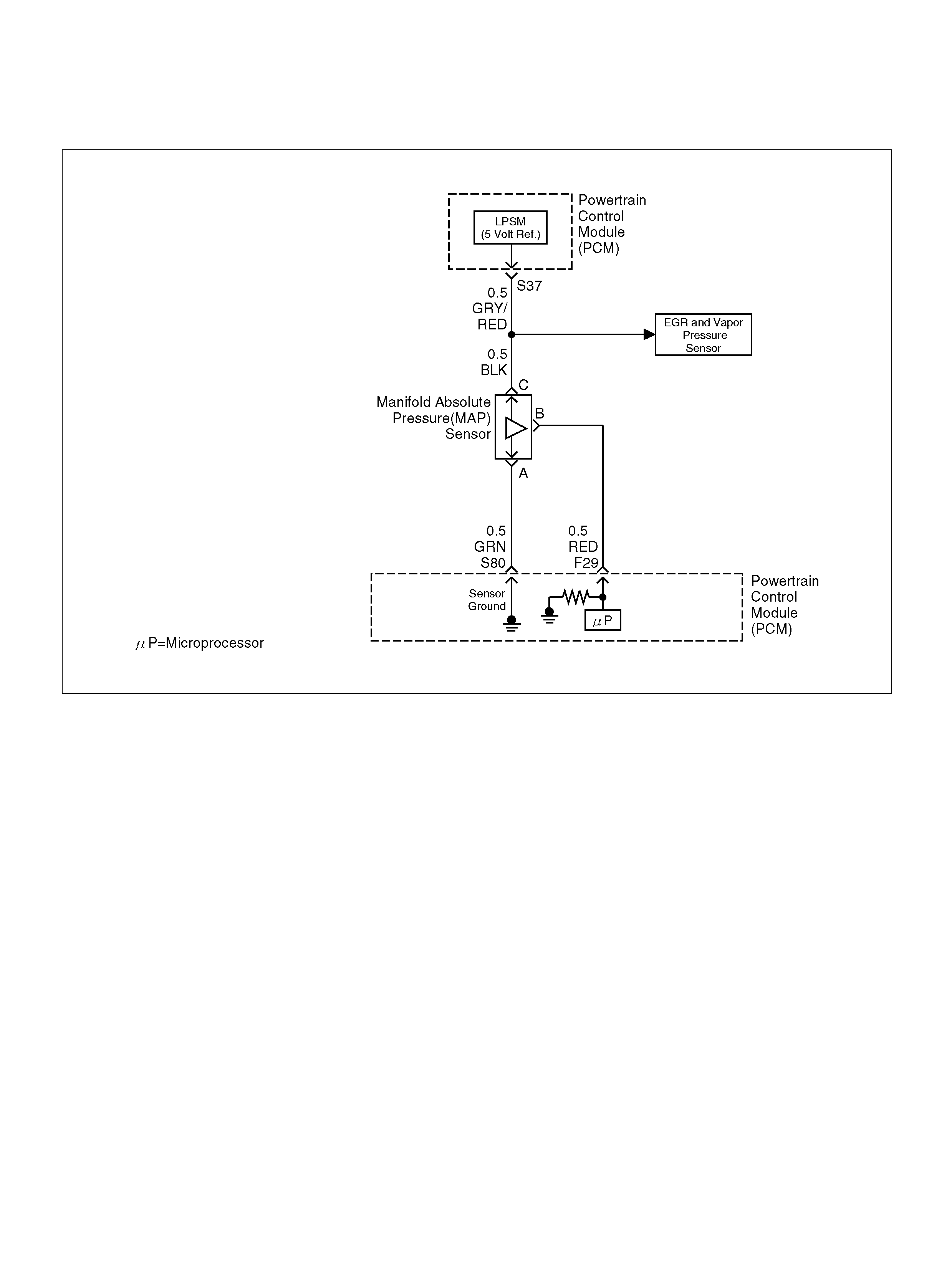
DIAGNOSTIC TROUBLE CODE (DTC)
P1106 MAP SENSOR CIRCUIT INTERMITTENT HIGH VOLTAGE
060R100132
Circuit Description
The Manifold Absolute Pressure (MAP) sensor
responds to changes in intake manifold pressure
(vacuum). The MAP sensor signal voltage to the PCM
varies from below 2 volts at idle (high vacuum) to above
4 volts with the ignition “ON", engine not running or at
wide-open throttle (low vacuum).
The MAP sensor is used to determine manifold
pressure changes while the linear EGR flow test
diagnostic is being run (refer to DTC P0401), to
determine engine load for some other diagnostics and
to determine barometric pressure (BARO). The PCM
compares the MAP sensor signal to a calculated MAP
based on throttle position and various engine load
factors. If the PCM detects a MAP signal that is
intermittently above the calculated value, DTC P1106
wi ll set.
Conditions for Setting the DTC
• N o TP sensor DTCs are present.
• Engine is running for at l eas t 10 seconds.
• Throttle angle is below 3% if engine speed is below
1000 RPM.
• T hrottle ang le i s bel ow 10% if e ngine s peed is above
1000 RPM.
• The MAP sensor indicates an intermittent manifold
absolute pressure above 80 kPa for a total of
approx imately 5 seconds over a 16-second period of
time.
Action Taken When the DTC Sets
• The PCM will not illuminate the malfunction indicator
lamp (MIL).
• The PCM will store conditions which were present
when the DTC was set as Failure Records data only.
This information will not be stored as Freeze Frame
data.
Conditi ons for Clea r ing the MIL/DTC
• A history DTC P1106 will clear after 40 consecutive
warm-up cy cles have occurred without a fault.
• DTC P1106 can be cleared by using the Tech 2
“Clear Info" function.
Diag nostic Ai ds
Check for the following conditions:
• Leaking or plugged vacuum supply line to the MAP
sensor.

• Inspect PCM harness connectors for backed-out
terminals, improper mating, broken locks, improperly
formed or damaged terminals, and poor
terminal-to-wire connection.
• Inspect the wiring harness for damage. If the harness
appears to be OK, observe the MAP display on the
Tech 2 while moving connectors and wiring
harnesses related to the sensor. A change in the
display will indicate the location of the fault.
Reviewing the Failure Records vehicle mileage since
the diagnostic test last failed may help determine how
often the condition that caused the DTC to be set
occurs. This may assist in diagnosing the condition.
• The MAP sensor shares a 5 Volt Reference with the
Fuel Tank Pressure sensor. Check the 5 Volt
reference if this DTC is also set.
• The MAP sensor shares a ground with the Fuel Tank
Pressure sensor and the ECT Sensor. Check the
ground if these other DTCs are also set.
DTC P1106 – MAP Sensor Circuit Intermittent High Voltage
Step Action Value(s) Yes No
1 Was the “On-Board Diagnostic (OBD) System Check"
performed? — Go to Step 2 Go to OBD
System Check
2 Is DTC P0108 also set?
—
Go t o DTC
P0108 chart
first Go to Step 3
3 Are DTC P1111, P1115, and/or P1120 also set? — Go to St ep 6 Go to S tep 4
4 Check for a poor sensor ground circuit terminal
connection at the MAP sens or.
Was a problem found? — Go to St ep 9 Go to S tep 5
5 Check the MAP signal circuit between the MAP
sensor connector and the PCM for an intermittent
short to voltage.
Was a problem found? — Go to Step 10 Go to S tep 8
6 Check f or an intermi ttent short to voltage on t he 5 volt
reference circuit between the PCM and the following
components:
• MAP sensor
•EGR valve
• TP sensor
Was a problem found? — Go to Step 10 Go to Step 7
7 Check for a poor sensor ground circuit terminal
connection at the PCM.
Was a problem found? — Go to St ep 9 Go to Step 8
8 Check for an interm ittent o pen or a f aulty spl ice i n t he
sensor ground circuit.
Was a problem found? — Go to Step 10 R efe r to
Diagnostic Aids
9 Replace the faulty harness connector terminal for the
sensor ground circuit.
Is the action complete ? — Verify repair —
10 Locate an d repair the intermittent ope n/short circuit in
the wiring harness as necessary.
Is the action complete ? — Verify r epair —

DIAGNOSTIC TROUBLE CODE (DTC) P1107 MAP CIRCUIT
INTERMITTENT LOW VOLTAGE
060R100132
Circuit Description
The Manifold Absolute Pressure (MAP) sensor
responds to changes in intake manifold pressure
(vacuum). The MAP sensor signal voltage to the
powertrain control module (PCM) varies from below 2
volts at idle (high vacuum) to above 4 volts with the
ignition “ON", engine not running or at wide-open
throttle (low vacuum).
The MAP sensor is used to determine manifold
pressure changes while the linear EGR flow test
diagnostic is being run (refer to DTC P0401), to
determine engine load for some other diagnostics and
to determine barometric pressure (BARO). The PCM
compares the MAP sensor signal to a calculated MAP
based on throttle position and various engine load
factors. If the PCM detects a MAP signal that is
intermittently below the calculated value, DTC P1107
wi ll b e set .
Conditions for Setting the DTC
• N o TP sensor DTCs are present.
• Engine is running.
• Ignition voltage is more than 11 volts.
• Throttle angle is above 1% if engine speed is less
than 100 0 RPM.
• Throttle angle is abo ve 3% if engine speed is above
1000 RPM.
• The MAP sensor indicates an intermittent manifold
absolute pressure below 80 kPa for a total of
approx imately 5 seconds over a 16-second period of
time.
Action Taken When the DTC Sets
• The PCM will not illuminate the malfunction indicator
lamp (MIL).
• The PCM will store conditions which were present
when the DTC was set as Failure Records data only.
This information will not be stored as Freeze Frame
data.
Conditi ons for Clea r ing the MIL/DTC
• A history DTC P1107 will Clear after 40 consecutive
warm-up cy cles have occurred without a fault.
• DTC P1107 can be cleared by using the Tech 2
“Clear Info" function.

Diagnostic Aids
Check for the following conditions:
• Poor connection at PCM – Inspect harness
connectors for backed-out terminals, improper
mating, broken locks, improperly formed or damaged
terminals, and poor terminal-to-wire connection.
• The MAP Sensor shares a 5 Volt reference with the
EGR Valve. If these codes are also set, it could
indicate a problem with the 5 Volt reference circuit or
components itself.
• The MAP Sensor share a ground with the EGR Valve
and the IAT Sensor.
• Damaged harness – Inspect the wiring harness for
damage. If the harness appears to be OK, observe
the MAP display on the Tech 2 while moving
connectors and wiring harnesses related to the
sensor. A change in the display will indicate the
location of the fault.
Reviewing the Failure Records vehicle mileage since
the diagnostic test last failed may help determine how
often the condition that caused the DTC to be set
occurs. This may assist in diagnosing the condition.
DTC P1107 – MAP Sensor Circuit Intermittent Low Voltage
Step Action Value(s) Yes No
1 Was the “On-Board Diagnostic (OBD) System Check"
performed? —Go to Step 2 Go to OBD
System Check
2 Is DTC P0107 also set?
—
Go t o DTC
P0107 chart
first Go to Step 3
3 Check for a poor 5 volt reference circuit or MAP signal
circuit terminal connection at the MAP sensor.
Was a problem found? — Go to St ep 8 Go to Step 4
4 Check the MAP signal circuit between the MAP
sensor connector and the PCM for an intermittent
open or short to ground.
Was a problem found? — Go to St ep 9 Go to Step 7
5 Check for an intermittent short to ground on the 5 volt
reference circuit between the PCM and the following
components:
• MAP sensor
•EGR valve
• TP sensor
Was a problem found? — Go to St ep 9 Go to Step 6
6 Check for a poor 5 volt reference terminal connection
at the PCM.
Was a problem found? — Go to St ep 8 Go to Step 7
7 Check for an interm ittent o pen or a f aulty spl ice i n t he
5 volt reference circuit.
Was a problem found? (If no, start with the diagnosis
chart for other sensors in the circuit and see if 5V
returns.) — Go to Step 9 R efe r to
Diagnostic Aids
8 Replace the faulty harness connector terminal(s) for
the 5 volt reference circuit and/or the MAP signal
circuit as necessary.
Is the action complete ? — Verify repair —
9 Repair intermittent open/short circuit in the wiring
harness as necessary.
Is the action complete ? — Verify r epair —

DIAGNOSTIC TROUBLE CODE (DTC)
P1111 IAT SENSOR CIRCUIT INTERMITTENT HIGH VOLTAGE
D06RY00147
Circuit Description
The I ntake A ir Temperature (IAT ) sensor is a the rmistor
which measures the temperature of the air entering the
engine. The powert rain control m odul e (P CM ) applies 5
volts through a p ull-up resis tor t o the IAT senso r. Whe n
the intake air is cold, the sensor resistance is high and
the PCM will monitor a high signal voltage on the IAT
signal circuit. If the intake air is warm, the sensor
resistance is lower cau sing the PC M to m onitor a lower
voltage. DTC P1111 will set when the PCM intermittently
detects an ex ces sively hi gh s ign al vol tage o n the intake
air temperatu re sensor signal circuit.
Conditions for Setting the DTC
• T he engin e has been running for over 30 seconds.
• V ehi cle speed is less than 32 km/h (20 mph).
• Engine coolant temperat ure is above 60°C (140°F).
• M ass air flow is less t han 20g/ second.
• IAT signal voltage indi cates an i ntake air temperat ure
intermittently less than –39°C (–38°F ) (about 5 volts )
for approximately 2.5 seconds over a 25-second
period of time.
Action Taken When the DTC Sets
• The PCM will substitute a default value for intake air
temperature.
• The PCM will store conditions which were present
when t he DTC set as Failure Records data only. Th is
informat ion will not be st ored as Freez e Frame data.
• D TC P1111 does not illuminate t he MI L.
Conditi ons for Clea r ing the MIL/DTC
• A history DTC P1111 will clear after 40 consecutive
warm-up cy cles have occurred without a fault.
• DTC P1111 can be cleared by using the Tech 2 “Clear
Info" function.

Diagn ostic Aids
Check for the following conditions:
• Poor connection at PCM –Inspect harness
connectors for backed-out terminals, improper
mating, broken locks, i mp roperly form ed or dam aged
terminal s, and poor terminal-to-wire connection.
• Damaged harness – Inspect the wiring harness for
damage. If the harness appears to be OK, observe
the IAT display on the Tech 2 while moving
connectors and wiring harnesses related to the IAT
sensor. A change in the IAT display will indicate the
locati on of the fault.
Reviewing the Failure Records Distance Travelled since
the diagnostic test last failed may help determine how
often the condition that caused the DTC to be set
occurs. This may assist in diagnosing the condition.
Intake Air Temperature Sensor
°C°FOHMS
Temperature vs. Resistance Values (approximate)
100 212 177
80 176 332
60 140 667
45 113 1188
35 95 1802
25 77 2796
15 59 4450
5417280
–5 23 12300
–15 5 21450
–30 –22 52700
–40 –40 100700

DTC P1111 –IAT Sensor Circuit Intermittent High Voltage
Step Action Value(s) Yes No
1 Was the “On-Board Diagnostic (OBD) System Check"
performed? — Go to Step 2 Go to OBD
System Check
2 Is DTC P0113 also set ?
—
Go t o DTC
P0113 chart
first Go to Step 3
3 Is DTC P1115, also set? — Go to St ep 6 Go to S tep 4
4 1. Check for a poor sensor ground circuit terminal
connection at the IAT sensor.
2. If a problem is found, repair as necessary.
Was a problem found? — Verify rep air Go to Step 5
5 1. Check for a poor IAT signal circuit terminal
connection at the IAT sensor.
2. If a problem is found, repair as necessary.
Was a problem found? — Verify rep air Go to Step 6
6 1. Check the IAT signal circuit between the IAT
sensor con nector and the PCM for a n intermittent
open.
2. If a problem is found, repair as necessary.
Was a problem found? — Verify rep air Go to Step 7
7 1. Check the IAT signal circuit between the IAT
sensor con nector and the PCM for a n intermittent
short to voltage.
2. If a problem is found, repair as necessary.
Was a problem found? — Verify rep air Go to Step 8
8 1. Check for a poor sensor ground circuit terminal
connection at the PCM.
2. If a problem is found, repair as necessary.
Was a problem found? — Verify rep air Go to Step 9
9 1. Check for an intermittent open or a fau lty splice in
the sensor ground circuit.
2. If a problem is found, repair as necessary.
Was a problem found? — Verify repa ir R efer to
Diagnostic Aids
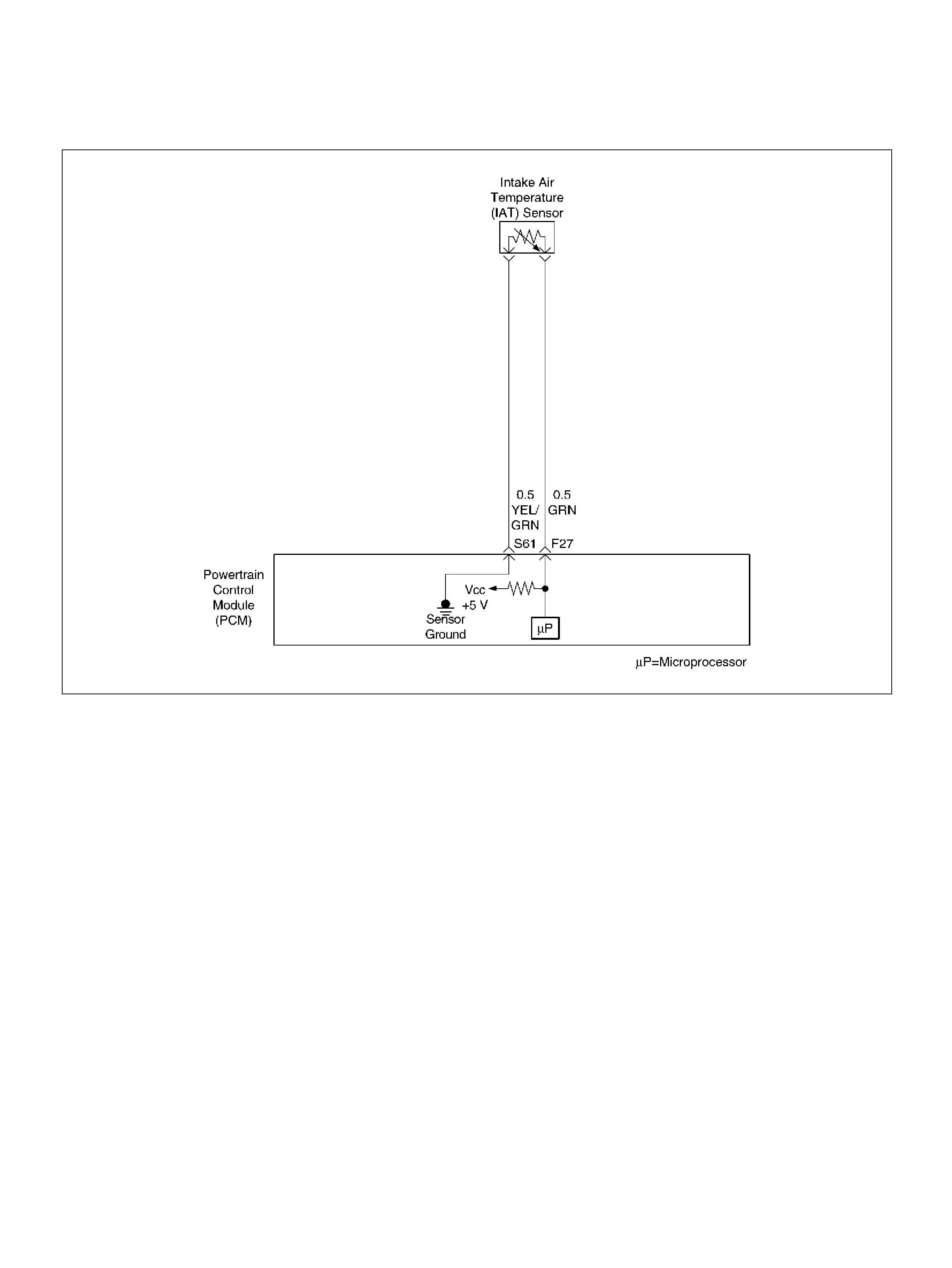
DIAGNOSTIC TROUBLE CODE (DTC)
P1112 IAT SENSOR CIRCUIT INTERMITTENT LOW VOLTAGE
D06RY00147
Circuit Description
The I ntake A ir Temperature (IAT ) sensor is a the rmistor
which measures the temperature of the air entering the
engine. The Powertrain Control Module (PCM) applies 5
volts through a p ull-up resis tor t o the IAT senso r. Whe n
the intake air is cold, the sensor resistance is high and
the PCM will monitor a high signal voltage on the IAT
signal circuit. If the intake air is warm, the sensor
resistance bec omes lowe r, causing the PCM to monitor
a lower voltage. DTC P1112 will set when the PCM
intermittently detects an excessively low signal voltage
on the intake air tem perat ure sensor signal circuit.
Conditions for Setting the DTC
• T he engin e has been running for over 15 seconds.
• V ehi cle speed is greater than 48 km/h (30 mph).
• IAT signal voltage is greater than 148°C (298°F)
(about 0.10 volt) for a total of 2.5 seconds over a
25-second period of time.
Action Taken When the DTC Sets
• T he PCM will not illuminate the Ma lfunction Indicator
Lamp (MIL).
• The PCM will store conditions which were present
when the DTC was set as Failure Records data only.
This information will not be stored as Freeze Frame
data.
• The PCM will substitute a default value for intake air
temperature.
Conditi ons for Clea r ing the MIL/DTC
• A history DTC P1112 will clear after 40 consecutive
warm-up cy cles have occurred without a fault.
• DTC P1112 can be cleared by using the Tech 2 “Clear
Info" function.
Diag nostic Ai ds
Check for the following conditions:
• Poor connection at PCM – Inspect harness
connectors for backed-out terminals, improper
mating, broke n l ocks, i mpro perly f orm ed o r dam aged
terminals, and poor terminal-to-wire connection.
• Damaged harness – Inspect the wiring harness for
damage. If the harness appears to be OK, observe
the IAT display on the Tech 2 while moving
connectors and wiring harnesses related to the IAT

sensor. A change in the IAT display will indicate the
location of the fault.
Reviewing the Failure Records vehicle mileage since
the diagnostic test last failed may help determine how
often the condition that caused the DTC to be set
occurs. This may assist in diagnosing the condition.
Test Description
Number(s) below refer to the step number(s) on the
Diagnostic Chart.
2. Verifies that the fault is present.
3. If DTC P1112 can be repeated only by duplicating the
Failure Records conditions, refer to the
“Temperature vs. Resistance Value Chart". The chart
may be used to test the IAT sensor at various
temperatures to evaluate the possibility of a “shifted"
sensor that may be shorted above or below a certain
temperature. If this is the case, replace the IAT
sensor.
Intake Air Temperature Sensor
DTC P1112 – IAT Sensor Circuit Intermittent Low Voltage
°C °FOHMS
Temperature vs. Resistance Values (approximate)
100 212 177
80 176 332
60 140 667
45 113 1188
35 95 1802
25 77 2796
15 59 4450
5417280
–5 23 12300
–15 5 21450
–30 –22 52700
–40 –40 100700
Step Action Value(s) Yes No
1 Was the “On-Board Diagnostic (OBD) System Check"
performed? — Go to Step 2 Go to OBD
System Check
2 Is DTC P0112 also set ? — Go t o DTC
P0112 first Go to Step 3
3 1. Check the IAT signal circuit between the IAT
sensor con nector and the PCM for a n intermittent
short to ground.
2. If a problem is found, repair as necessary.
Was a problem found? — Verify repa ir Refe r to
Diagnostic Aids

DIAGNOSTIC TROUBLE CODE (DTC)
P1114 ECT SENSOR CIRCUIT INTERMITTENT LOW VOLTAGE
D06RY00148
Circuit Description
The Engine Coolant Temperature (ECT) sensor is a
thermistor mounted in the engine coolant stream. The
Powertrain Control Module (PCM) applies a voltage
(about 5.0 volts) through a pull-up resistor to the ECT
signal circuit. When the engine coolant is cold, the
sensor (thermistor) resistance is high, therefore the
PCM will measure a high signal voltage. As the engine
coolant warms, the sensor resistance becomes less,
and the ECT signal voltage measured at the PCM
drops. With a fully warmed up engine, the ECT signal
voltage should measure about 1.5 to 2.0 volts. If the
PCM detects an ECT signal that is intermittently below
the range of the ECT sensor, DTC P1114 will set.
Conditions for Setting the DTC
• Engine run time longer than 120 seconds .
• The ECT sensor signal is intermittently greater than
150°C (302°F) (about 0.10 volt) for a total of 2.5
seconds over a 25-second period.
Action Taken When the DTC Sets
• T he PCM w ill n ot il lum inate the Mal fun ction In dicat or
Lamp (MIL).
• The PCM will store conditions which were present
when t he DTC set as Failure Records data only. Th is
informat ion will not be st ored as Freez e Frame data.
Conditi ons for Clea r ing the MIL/DTC
• A history DTC P1114 will clear after 40 consecutive
warm-up cy cles have occurred without a fault.
• DTC P1114 can be cleared by using the Tech 2 “Clear
Info" function.

Diagnostic Aids
Check for the following conditions:
• Poor connection at PCM – Inspect harness
connectors for backed-out terminals, improper
mating, broken locks, improperly formed or damaged
terminals, and poor terminal-to-wire connection.
• Damaged harness – Inspect the wiring harness for
damage. If the harness appears to be OK, observe
the ECT display on the Tech 2 while moving
connectors and wiring harnesses related to the ECT
sensor. A change in the ECT display will indicate the
location of the fault.
Reviewing the Failure Records vehicle mileage since
the diagnostic test last failed may help determine how
often the condition that caused the DTC to be set
occurs. This may assist in diagnosing the condition.
Engine Coolant Temperature Sensor
DTC P1114 – ECT Circuit Intermittent Low Voltage
°C °FOHMS
Temperature vs. Resistance Values (approximate)
100 212 177
80 176 332
60 140 667
45 113 1188
35 95 1802
25 77 2796
15 59 4450
5417280
–5 23 12300
–15 5 21450
–30 –22 52700
–40 –40 100700
Step Action Value(s) Yes No
1 Was the “On-Board Diagnostic (OBD) System Check"
performed? — Go to Step 2 Go to OBD
System Check
2 Is DTC P0117 also set ? — Go t o DTC
P0117 first Go to Step 3
3 1. Check the ECT signal circuit between the ECT
sensor con nector and the PCM for a n intermittent
short to ground.
2. If a problem is found, repair as necessary.
Was a problem found? — Verify repa ir Refe r to
Diagnostic Aids
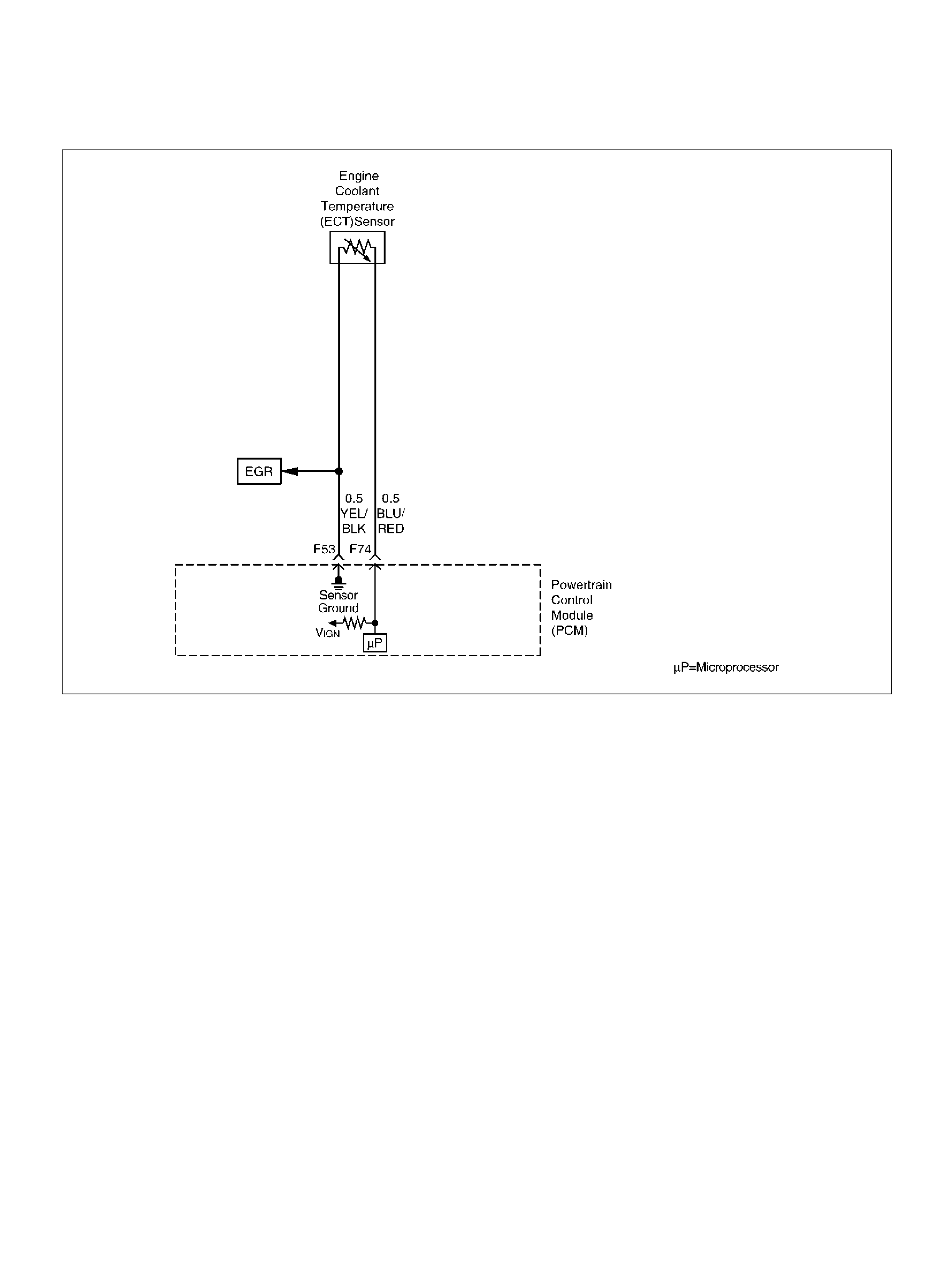
DIAGNOSTIC TROUBLE CODE (DTC)
P1115 ECT SENSOR CIRCUIT INTERMITTENT HIGH VOLTAGE
D06RY00148
Circuit Description
The Engine Coolant Temperature (ECT) sensor is a
thermistor mounted in the engine coolant stream. The
Powertrain Control Module (PCM) applies a voltage
(about 5.0 volts) through a pull-up resistor to the ECT
signal circuit. When the engine coolant is cold, the
sensor (thermistor) resistance is high, therefore the
PCM will measure a high signal voltage. As the engine
coolant warms, the sensor resistance becomes less,
and the ECT signal voltage measured at the PCM
drops. With a fully warmed up engine, the ECT signal
voltage should measure about 1.5 to 2.0 volts. If the
PCM detects an ECT signal that is intermittently above
the range of the ECT sensor, DTC P1115 will set.
Conditions for Setting the DTC
• Engine running time longer than 90 seconds.
• The ECT sensor signal is intermittently less than –
39°C (–38°F) (about 5 volt s) for a total of 2.5 seconds
ove r a 25-second period.
Action Taken When the DTC Sets
• T he PCM w ill n ot il lum inate the Mal fun ction In dicat or
Lamp (MIL).
• The PCM will store conditions which were present
when the DTC was set as Failure Records data only.
This information will not be stored as Freeze Frame
data.
Conditi ons for Clea r ing the MIL/DTC
• A history DTC P1115 will clear after 40 consecutive
warm-up cy cles have occurred without a fault.
• DTC P1115 can be cleared by using the Tech 2 “Clear
Info" function.

Diagn ostic Aids
Check for the following conditions:
• Poor connection at PCM – Inspect harness
connectors for backed-out terminals, improper
mating, broken locks, i mp roperly form ed or dam aged
terminal s, and poor terminal-to-wire connection.
• Damaged harness – Inspect the wiring harness for
damage. If the harness appears to be OK, observe
the ECT display on the Tech 2 while moving
connectors and wiring harnesses related to the ECT
sen so r. A change in the EC T display will indicat e th e
locati on of the fault.
Reviewing the Failure Records vehicle mileage since
the diagnostic test last failed may help determine how
often the condition that caused the DTC to be set
occurs. This may assist in diagnosing the condition.
Engine Coolant Temperature Sensor
°C°FOHMS
Temperature vs. Resistance Values (approximate)
100 212 177
80 176 332
60 140 667
45 113 1188
35 95 1802
25 77 2796
15 59 4450
5417280
–5 23 12300
–15 5 21450
–30 –22 52700
–40 –40 100700

DTC P1115 – ECT Sensor Circuit Intermittent High Voltage
Step Action Value(s) Yes No
1 Was the “On-Board Diagnostic (OBD) System Check"
performed? — Go to Step 2 Go to OBD
System Check
2 Is DTC P0118 also set ?
—
Go t o DTC
P0118 chart
first Go to Step 3
3 Is DTC P1111 also set? — Go to St ep 8 Go to S tep 4
4 1. Check for a poor sensor ground circuit terminal
connection at the ECT sensor.
2. If a problem is found, repair as necessary.
Was a problem found? — Verify rep air Go to Step 5
5 1. Check for a poor ECT signal circuit terminal
connection at the ECT sensor.
2. If a problem is found, repair as necessary.
Was a problem found? — Verify rep air Go to Step 6
6 1. Check the ECT signal circuit between the ECT
sensor con nector and the PCM for a n intermittent
open.
2. If a problem is found, repair as necessary.
Was a problem found? — Verify rep air Go to Step 7
7 1. Check the ECT signal circuit between the ECT
sensor con nector and the PCM for a n intermittent
short to voltage.
2. If a problem is found, repair as necessary.
Was a problem found? — Verify rep air Go to Step 8
8 1. Check for a poor sensor ground circuit terminal
connection at the PCM.
2. If a problem is found, repair as necessary.
Was a problem found? — Verify rep air Go to Step 9
9 1. Check for an intermittent open or a fau lty splice in
the sensor ground circuit.
2. If a problem is found, repair as necessary.
Was a problem found? — Verify repa ir Refe r to
Diagnostic Aids

DIAGNOSTIC TROUBLE CODE(DTC)
P1120-TPS 1 THROTTLE POSITION SENSOR (TPS1) OUTPUT ABNORMAL
D06RY00111
Circuit Description
• The Throttle Position (TP) sensor circuit provides a
voltage signal relative to throttle blade angle.
The T PS1 voltage will vary about 8% (0.4V) to about
92% (4.6V) at Wide Open Throttle (WOT) in the
specified voltage (about 5V).
This code detects a continuous short to ground or
high in either the circuit or th e sensor.
Conditions for setting the DTC
• T he Ignition is “ON".
• The TPS1 output is more than 93.6 milliseconds, less
than 2.5% or more than 97.5% in the specified
voltage (5V).
Action Taken When the DTC Sets
• The PCM will ON the MIL after second trip with
d e te ct e d fault.
• The PCM will store conditions which were present
when the DTC was set as Freeze Frame and in the
Failure Records data.
Conditi ons for Clea r ing the MIL/DTC
• The PCM will turn the MIL “OFF" on the third
consecutive trip cycle during which the diagnostic has
been run and the fault condition is no longer present.
• A history DTC P1120 will clear after 40 consecutive
trip cycle during which the warm up cycles have
occurred without a fault.
• DTC P1120 can be cleared using the Tech2 “Clear
Info" function.
Diag nostic Ai ds
An intermittent may be caused by the following:
• Poor c onnect ions.
• M isrouted harnes s.
• Ru bbed th rough wire insulation.
• Brok en wire inside the insulation.
Check for the following conditions:
• Poor c onnection at PCM-Ins pect harness connectors
for backed out terminals, improper mating, broken
locks, improperly formed or damaged terminals, and
poor terminal to wire connection.

• Damaged harness-Inspect the wiring harness for
damage. If the harness appears to be OK, observe
the TPS 1 display on the Tech2 while moving
connectors and wiring harnesses related to the
sensor.
A change in the display will indicate the location of
the fault.
If DTC P1120 cannot be duplicated, the information
included in the Failure Records data can be useful in
determined vehicle mileage since the DTC was last
set.
If it is determined that the DTC occurs intermittently,
performing the DTC P1120 Diagnostic Chart may
isolate the cause of the fault.
Diagnostic Trouble Code(DTC)P1120-TPS 1 Output Abnormal
Step Action Value(s) Yes No
1 Was the “On-Board(OBD)System Check" performed?—Go to Step 2 Go to OBD
System Check
2 1. Ignition “ON", engine not running.
2. Observe the MAP reading on the Tech2.
Is the MAP reading less than the specified value? 65kPa Go to Step 3 Go to Step 6
3 1 . Disconnect the MAP sens or.
2. Connect a test 5 volt reference circuit and the
MAP signal at the MAP sensor harness connector.
3. Observe the MAP reading on the Tech2.
Is the MAP reading less than the specified value? (If
no, start with diagnosis chart for other sensors in the
circuit and see if 5V returns.) — Go to St ep 5 Go to Step 4
4 1. Check the MAP signal circuit between the PCM
and MAP shorte d circuit.
2. If the MAP signal circuit is open or shorted, repair
it as necessary.
Was the M AP signal circuit open or shorted? — Veri fy repair Go to St ep 12
5 Replac e the MAP sens or.
Is the action complete ? — Verify r epair —
6 Observe the TP angle reading on the Tech2 while
slowly opening the throttle.
Does the TP angle increase steadily and evenly from
the closed throttle value to the wide open throttle
value ?
Throttle
Closed TPS1
8–10 % TPS2
8–10 % Wide
Open Throttle
TPS1 90–92
% TPS2 90–
92 % Refer to
Diagnostic Aids Go to St ep 7
7 1 . Disconnect the TP sensor.
2. Observe the TP sensor reading on the Tech2.
Is the TP sensor reading near the specif ied value? 0V Go to St ep 8 Go to St ep 9
8 1. Connect a test light between the 5Volt reference
circuit and the TP sensor signal circuit at the TP
sensor harness connector .
2. Observe the TP sensor reading on the Tech2.
Is the TP sensor reading near the specif ied value? 5V Go to Step 11 Go to Step 10
9 Check the following items;
1. TP1 signal circuit for a sho rt to voltage.
2. TP1 sensor ground circuit for high resistance
between the PCM and the TP sensor.
3. TP1 sensor ground circuit for a poor connection.
4. If a problem is found, repair wiring harness as
necessary.
Was a problem found? — Verify repair Go to Step 12

10 Check the following items;
1. TP signal circuit or 5 volt reference circuit for a
poor connection.
2. TP signal circuit or 5 volt reference circuit for high
resistance between the PCM and the TP sens or.
3. If a problem is found, repair wiring harness as
necessary.
Was a problem found? — Verify repair Go to Step 12
11 Replace the TP sensor.
Is the action complete ? — Verify r epair —
12 Replace the PCM.
Important: The replacement PCM must be
programmed. Refer to Section 0C-1 - Service
Program ming Syst em.
Important: Refer to Section 11 - Engin e Im mobiliser
System for the Immobiliser Programming procedure.
Important: Ensure the latest software program is
downloaded to the PCM.
Is the action complete ? — Verify repair —
Step Action Value(s) Yes No
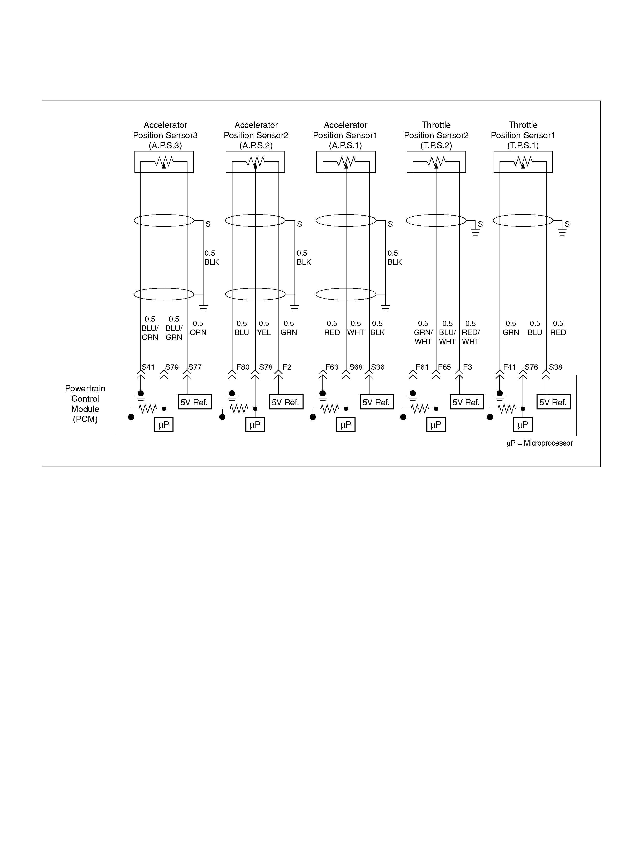
DIAGNOSTIC TROUBLE CODE (DTC)
P1125 ETC (ELECTRIC THROTTLE CONTROL) LIMIT PERFORMANCE MODE
060R100140
Circuit Description
• The Accelerator Position (AP1) sensor circuit
provides a voltage signal relative to accelerator pedal
angle.
The accelerator pedal angle will vary about 13 % at
idle position to about 87 % at wide open throttle
(WOT).
This code detects if the system is in Limit
Performance Mode (Fail safe Mode) and Multiple
DTCs performance Mode.
Conditions for setting the DTC
• T he Ignition is “ ON".
• L im it Performance Mode is active. (Fail safe Mode)
Action Taken When the DTC Sets
• The PCM will illuminate the malfunction indicator
lamp (MIL) and reduced power lamp (RPL) the first
time the fault is detected.
• The PCM will store condition which were present
when the DTC was set as Freeze Frame and in the
Failure Records data.
Conditi ons for Clea r ing the MIL/DTC
• The PCM will turn the MIL “OFF" on the third
consecutive trip cycle during which the diagnostic has
been run and the fault condition is no longer present.
• A history DTC P1125 will clear after 40 consecutive
trip cycle during which the warm up cycles have
occurred without a fault.
• DTC P1125 can be cleared using the Tech 2 “Clear
Info" function.
Diag nostic Ai ds
An intermittent may be caused by the following:
• Poor c onnect ions.
• M isrouted harnes s.
• Ru bbed th rough wire insulation.
• Brok en wire inside the insulation.
Check for the following conditions:
• Poor c onnection at PCM-Ins pect harness connectors
for backed out terminals, improper mating, broken
locks, improperly formed or damaged terminals, and
poor terminal to wire connection.

• Damaged harness-Inspect the wiring harness for
damage. If the harness appears to be OK, observe
the AP sensor 1, AP sensor 2, AP sensor 3 display
on the Tech2 while moving connectors and wiring
harnesses related to the sensor.
A change in the display will indicate the location of
the fault.
If DTC P1125 cannot be duplicated, the information
included in the Failure Records data can be useful in
determined vehicle mileage since the DTC was last
set.
If it is determined that the DTC occurs intermittently,
performing the DTC P1125 Diagnostic Chart may
isolate the cause of the fault.
DTC P1125 – ETC Limit Performance Model
Step Action Value(s) Yes No
1 Was the “On-Board (OBD) System Check"
performed? —Go to Step 2 Go to OBD
System Check
2 Was the “Electric Throttle Control (ETC) System
Check" performed? —Go to St ep 3 Go to ETC
System Chec k
3 Observe the AP angle reading on the Tech2 while
slowly opening the throttle.
Does the AP angle increase steadily and evenly from
the closed throttle value to the wide open throttle
value?
Idle position
AP sensor 1
=13 % AP
sensor 2, 3
=85 ∼ 89 %
open throttle
AP sensor 1
=85 ∼ 89 %
AP sensor 2
=11 ∼ 15 % Refer to
Diagnostic Aids Go to St ep 4
4 1. Disconnect the AP sensor .
2. Observe the AP sensor reading on the Tech2.
Is the AP sensor reading near the specified value? 0V Go to Step 5 Go to St ep 6
5 1. Connect a t est light between the 5 Voltage s upply
circuit and the AP1, AP2 AND AP3 sensor signal
circuit at the AP sensor harness connector.
2. Observe the AP sensor reading on the Tech2.
Is the AP sensor reading near the specified value? 5V Go to Step 7 Go to St ep 8
6 Check the following items;
1. AP1, AP2 or AP3 signal circuit for a short to
voltage.
2. AP1, AP2 or AP3 sensor ground circuit for high
resistance between the PCM and the AP sensor.
3. AP1, AP2 or AP3 s ensor ground c ircuit for a poor
connection.
4. If a problem is found, repair wiring harness as
necessary.
Was a problem found? — Verify repair Go to Step 9
7 Check the following items;
1. AP1, AP2 or AP3 sign al circuit or 5 voltage supply
circuit for a poor connection.
2. AP1, AP2 or AP3 sign al circuit or 5 voltage supply
circuit for high resistance between the PCM and
the AP1 , AP2 or AP3 se ns or.
3. If a problem is found, repair wiring harness as
necessary.
Was a problem found? — Verify repair Go to Step 9
8 Replac e the AP sensor.
Is the action complete ? — Verify r epair —

9 Replace the PCM.
Important: The replacement PCM must be
programmed. Refer to Section 0C-1 - Service
Program ming Syst em.
Important: Refer to Section 11 - Engin e Im mobiliser
System for the Immobiliser Programming procedure.
Important: Ensure the latest software program is
downloaded to the PCM.
Is the action complete ? — Verify repair —
Step Action Value(s) Yes No

DIAGNOSTIC TROUBLE CODE (DTC)
P1167 FUEL SYSTEM RICH DURING DECEL FUEL CUT OFF (BANK 1)
060R100133
Circuit Description
The powertrain control module (PCM) continuously
monitors the heated oxygen sensor (HO2S) activity for
90 seconds after “closed loop" has been enabled.
During the monitoring period the powertrain control
module (PCM) counts the number of times a rich to lean
response is indicated and adds the amount of time it
look to complete all rich to lean transitions and lean to
rich transitions.
This code detects if Bank1 O2 sensor indicated rich
exhaust while in Decel Fuel Cut Off (DFCO) for fuel
control sensors .
Conditions for setting the DTC
• No related DTCs.
• The engine coolant temperature is more than 60 °C
(140 °F).
• Engine is operating in “closed loop" power
enrichm ent mode for 0.4 seconds.
• While in “decel fuel cut off (DFCO)" mode the oxygen
sensor voltage remains more than 600mV.
Action Taken When the DTC Sets
• The PCM will not illuminate the malfunction
malfunct ion indicator lamp (MIL).
• The PCM will store conditions which were present
when t he DTC was set a s Failure Records onl y. Th is
informat ion will not be st ored as Freez e Frame data.
Conditi ons for Clea r ing the MIL/DTC
• A history DTC P1167 will clear after 40 consecutive
trip cycle during which the warm up cycles have
occurred without a fault.
• DTC P1167 can be cleared using the Tech2 “Clear
Info" function.
Diag nostic Ai ds
• Ch ec k for faulty f uel injectors and fuel pump.

Diagnostic Trouble Code (DTC)
P1167 Fuel System Rich During Decel Fuel Cut Off (Bank1)
Step Action Value(s) Yes No
1 Was the “On-Board (OBD) System Check"
performed? —Go to Step 2 Go to OBD
System Check
2 Are any componen t related DTCs set? Go to
component
DTC charts Go to St ep 3
3 1. Place the transmission in Park.
2. Using a Tech2, HO2S 1 voltage while running
warm engine 75 °C – 95 °C (167 °F – 203 °F) at
1200 RPM.
3. HO2S 1 voltages should vary within the specified
range. (100 – 900mV)
4. Quickly open the wide open the throttle for a few
seconds.
Did the voltage suddenly rise toward the low end of
the specified range? 100 – 600 mV Go to OBD
System Check Go to Step 4
4 1. Disconnect the fuel pump relay and crank the
engine to relieve the fuel pressure.
2. Inst all the fuel pressure gauge.
3. Start the engine and idle at normal operating
temperature.
4. Disconnect the vacuum line going to the fuel
pressure regulator.
With the engine running, is the fuel pressure within the
specified range? 280 – 325Kpa
(41 – 46ps i) Go to OBD
System Check Go to Step 5
5 1 . Ig nit io n “ OFF" .
2. Remove the fuel pum p relay and repl ace it with a
fused jumper which will connect the relay's battery
terminal to the terminal leading to the fuel pump
fuse.
3. While the fuel pump is operating, use pliers to
slowly close the return l ine (do not exceed the first
specified value).
Using the pliers to restrict the return line, can the
fuel pressure be manipulated to exceed the
second value?
Is the TP sensor reading near the specif ied value?
414KPa
(60psi)
325KPa
(46psi) Refer to
Diagnostic Aids Go to Step 6
6 Check the following items;
• Faulty fuel pump
• Inc orrect fuel pump
• Inc orrect fuel being used
• Cold fuel
If a problem is found, repair as necessary.
Was a problem found? — Verify repa ir —
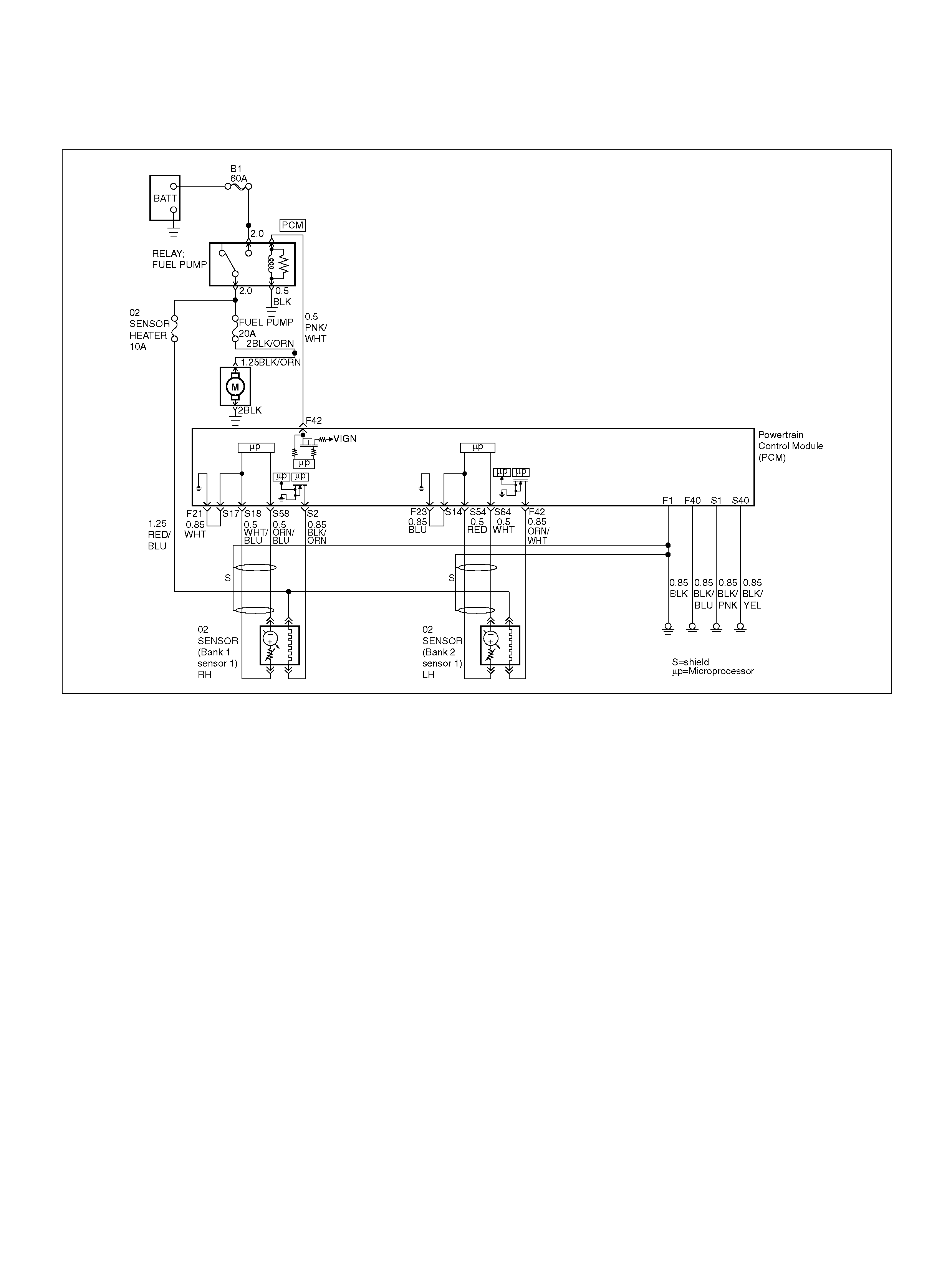
DIAGNOSTIC TROUBLE CODE (DTC)
P1169 FUEL SYSTEM RICH DURING DECEL FUEL CUT OFF (BANK 2)
060R100133
Circuit Description
The powert rain control module(PCM )
continuously monitors the heated oxygen sensor
(HO2S) activity for 90 seconds after “closed loop" has
been enabled. During the monitoring period the
powertrain control module (PCM) counts the number of
times a rich to lean respone is indicated and adds the
amount of time it look to complete all rich to lean
transitions and lean to rich transitions.
This code detects if Bank2 sensor indicated rich
exhaust while in Decel Fuel Cut Off (DFCO) for fuel
control sensors .
Conditions for setting the DTC
• No related DTCs.
• The engine coolant temperature is more than 60 °C
(140 °F).
• Engine is operating in “closed loop" power
enrichm ent mode for 0.4 seconds.
• While in “clocel fuel cut off (DFCO)" mode the oxygen
sen sor voltage remains more than 600mV in DFCO.
Action Taken When the DTC Sets
• The PCM will not illuminate the malfunction
malfunct ion indicator lamp(MIL).
• The PCM will store conditions which were present
when t he DTC was set a s Failure Records onl y. Th is
informat ion will not be st ored as Freez e Frame data.
Conditi ons for Clea r ing the MIL/DTC
• A history DTC P1169 will clear after 40 consecutive
trip cycle during which the warm up cycles have
occurred without a fault.
• DTC P1169 can be cleared using the Tech2 “Clear
Info" function.
Diag nostic Ai ds
• Ch ec k for faulty f uel injectors and fuel pump.

Diagnostic Trouble Code (DTC)
P1169 Fuel System Rich During Decel Fuel Cut Off (Bank2)
Step Action Value(s) Yes No
1 Was the “On-Board (OBD) System Check"
performed? —Go to Step 2 Go to OBD
System Check
2 Are any componen t related DTCs set? Go to
component
DTC charts Go to St ep 3
3 1. Place the transmission in Park.
2. Using a Tech2, HO2S 2 voltage while running
warm engine7 5 C – 95 C (167 F – 203 F ) at 1200
RPM.
3. HO2S 1 voltages should vary within the specified
range. (100 – 900mV)
4. Quickly open the wide open the throttle for a few
seconds.
Did the voltage suddenly rise toward the low end of
the specified range? 100 – 600 mV Go to OBD
System Check Go to Step 4
4 1. Disconnect the fuel pump relay and crank the
engine to relieve the fuel pressure.
2. Inst all the fuel pressure gauge.
3. Start the engine and idle at normal operating
temperature.
4. Disconnect the vacuum line going to the fuel
pressure regulator.
With the engine running, is the fuel pressure within the
specified range? 280 – 325Kpa
(41 – 46ps i) Go to OBD
System Check Go to Step 5
5 1 . Ig nit io n “ OFF" .
2. Remove the fuel pum p relay and repl ace it with a
fused jumper which will connect the relay's battery
terminal to the terminal leading to the fuel pump
fuse.
3. While the fuel pump is operating, use pliers to
slowly close the return l ine (do not exceed the first
specified value).
Using the pliers to restrict the return line, can the fuel
pressure be manipulated to exceed the second value?
Is the TP sensor reading near the specif ied value?
414KPa
(60psi)
325KPa
(46psi) Refer to
Diagnostic Aids Go to Step 6
6 Check the following items;
• Faulty fuel pump
• Inc orrect fuel pump
• Inc orrect fuel being used
• Cold fuel.
If a problem is found, repair one as necessary.
Was a problem found? — Verify repa ir —

DIAGNOSTIC TROUBLE CODE (DTC)
P1171 FUEL SYSTEM LEAN DURING ACCELERATOR
060R100133
Circuit Description
The powertrain control module (PCM) internal circuitry
can identify if the vehicle fuel system is capable of
supplying adequate amounts of fuel during heavy
accelerator (power enrichment). The PCM monitors th e
voltage of the o xygen sensor during po wer en ri chment.
When a power enrichment mode of operation is
requested during “closed loop" operation (by heavy
accelerator), the PCM will provide more fuel to the
engine. Un der these conditions the PCM should detect
a “rich" condition (high oxygen sensor voltage). If this
“rich" exhaust i s not det ected at this time, a DTC P117 1
will set. A plugged fuel filter, restricted fuel line,
restricted in-tank filter or defective fuel pump can
prevent adequate amounts of fuel from being supplied
during power enrichm ent mode.
Conditions for Setting the DTC
• No related DTCs.
• Engine is operating in “closed loop power
enrichm ent" mode for 3 seconds.
• Engine coolant temperat ure is above 60°C (140°F).
• While in “power enrichment" mode the oxygen sensor
voltage remains below 400 mV for 3 seconds.
Action Taken When the DTC Sets
• The PCM will not turn the malfunction indicator lamp
(MIL) “ON".
• The PCM will store conditions which were present
when t he DTC was set a s Failure Records onl y. Th is
informat ion will not be st ored as Freez e Frame data.
Conditi ons for Clea r ing the MIL/DTC
• The PCM will turn the MIL “OFF" on the third
consecutive trip cycle during which the diagnostic has
been run and the fault condition is no longer present.
• A history DTC P1171 will clear after 40 consecutive
warm-up cy cles have occurred without a fault.
• DTC P1171 can be cleared by using the Tech 2
“Clear Info" function.
Diag nostic Ai ds
• A restricted fuel filter or fuel line, restricted in-tank
filter, or a defective fuel pump may supply adequate
amounts of fuel at idle, but may not be able to supply
enough fu el during heavy acce lerator.

• Water or alcohol in the fuel may cause low HO2S
voltage during accelerator.
• Check for faulty or plugged fuel injector(s).
• Check for low fuel.
Test Description
Number(s) below refer to the step number(s) on the
Diagnostic Chart.
4. When the engine is idling or at steady cruise, the
HO2S voltage should vary from between
approximately 100 mV to 900 mV. It is possible to
measure a satisfactory fuel pressure at idle even
though the pressure may drop at high flow
requirements. It may be necessary to watch fuel
pressure at high engine load.
5. Wrap a shop towel around the fuel pressure
connector to absorb any small amount of fuel
leakage that may occur when installing gauge.
Ignition “ON", pump pressure should be 280-320
kPa.
7. Add Caution, Use correct pliers so damage to fuel
lines will not occur.
DTC P1171 – Fuel System Lean During Accelerator
Step Action Value(s) Yes No
1 Was the “On-Board Diagnostic (OBD) System Check"
performed? —Go to Step 2 Go to OBD
System Check
2 Are any component-related DTCs set?
—
Go to
component
DTC charts Go to Step 3
3 1. Check the vehicle's fuel tank for an adequate
amount of fuel.
2. Add fuel to the vehicle's fuel tank if the tank is
almost empty.
Was fuel added to the vehicle's fuel tank? — Go to Step 4 Go to Step 5
4 1. Place the transmission in park.
2. Using a Tech 2, observe HO2S 1 voltage while
running warm engine 75 °C-95°C (167°F-203°F) at
1200 RPM.
3. HO2S 1 voltage should vary within the specified
range.
4. Quickly open the throttle halfway for a few
seconds.
Did the voltage suddenly rise toward the high end of
the specified range? 10 0-900mV
Go to Fuel
System
Electrical Test Go to Step 5
5 1. Disconnect the fuel pump relay and crank the
engine to relieve the fuel pressure.
2. Inst all the fuel pressure gauge.
3. Start the engine and idle at normal operating
temperature.
4. Disconnect the vacuum line going to the fuel
pressure regulator.
With the engine running, is the fuel pressure within the
specified range? 280-325 kP a
(41-46 psi) Go to OBD
System Check Go to Step 6
6 Check for restricted fuel l ines or restricted in-line fil ter.
Was a problem found? — Verify repair Go to Step 7
7 1 . Ig nit io n “ OFF" .
2. Remove the fuel pum p relay and repl ace it with a
fused jumper which will connect the relay's battery
terminal to the terminal leading to the fuel pump
fuse.
3. While the fuel pump is operating, use pliers to
slowly close the return l ine (do not exceed the first
specified value).
Using the pliers to restrict the return line, can the fuel
pressure be manipulated to exceed the second
specified value?
414kPa
(60psi)
325kPa
(46psi) Go to
Diagnostic Aids Go to Step 8

8 Check for:
• Faulty fuel pump
• Re stricted fuel pump strainer (sock)
• Inc orrect fuel pump
• Inc orrect fuel being used
• Hot fuel
Is the action complete ? — Verify r epair —
Step Action Value(s) Yes No

DIAGNOSTIC TROUBLE CODE (DTC)
P1220 THROTTLE POSITION SENSER2 (TPS2) CIRCUIT FAULT
D06RY00111
Circuit Description
• The throttle position (TP2) sensor circuit provides a
voltage signal relative to throttle blade angle.
The T PS2 voltage will vary about 8% (0.4V) to about
92% (4.6V) at Wide Open Throttle (WOT) in the
specified voltage (about 5V).
This code detects a continuous short to ground or
high in either the circuit or th e sensor.
Conditions for setting the DTC
• T he Ignition is “ON".
• The TPS2 output is more than 93.6 milliseconds, less
than 2.5% or more than 97.5% in the specified
voltage (5V).
Action Taken When the DTC Sets
• The PCM will ON the MIL after second trip with
d e te ct e d fault.
• The PCM will store conditions which were present
when the DTC was set as Freeze Frame and in the
Failure Records data.
Conditi ons for Clea r ing the MIL/DTC
• The PCM will turn the MIL “OFF" on the third
consecutive trip cycle during which the diagnostic has
been run and the fault condition is no longer present.
• A history DTC P1120 will clear after 40 consecutive
trip cycle during which the warm up cycles have
occurred without a fault.
• DTC P1120 can be cleared using the Tech2 “Clear
Info" function.
Diag nostic Ai ds
An intermittent may be caused by the following:
• Poor c onnect ions.
• M isrouted harnes s.
• Ru bbed th rough wire insulation.
• Brok en wire inside the insulation.
Check for the following conditions:
• The MAP sensor shares a 5 Volt reference with the
Fuel Tank Pressure. If these codes are also set, it
could indicate a problem with the 5 Volt reference
circuit.
• T he MAP sensor shares a grou nd with the Fuel Tank
Pressure, the ECT sensor, and the Transmission
Fluid

• Poor connection at PCM-Inspect harness connectors
for backed out terminals, improper mating, broken
locks, improperly formed or damaged terminals, poor
terminal to wire connection.
• Damaged harness-Inspect the wiring harness for
damage. If the harness appears to be OK, observe
the TP sensor display on the Tech2 while moving
connectors and wiring harnesses related to the
sensor.
A change in the display will indicate the location of
the fault. If DTC P1120 cannot be duplicated, the
information included in the Failure Records data can
be useful in determined vehicle mileage since the
DTC was last set.
If it is determined that the DTC occurs intermittently,
performing the DTC
P1120 Diagnostic Chart may isolate the cause of the
fault.
DTC P1220-TPS 2 Circuit Fault
Step Action Value(s) Yes No
1 Was the “On-Board (OBD) System Check"
performed? —Go to Step 2 Go to OBD
System Check
2 Was the “Electric Throttle Control (ETC) System
Check" performed? —Go to St ep 3 Go to ETC
System Check
3 1. Ignition “ON", engine not running.
2. Observe the MAP reading on the Tech2.
Is the MAP reading less than the specified value? 65 kPa Go to Step 4 Go to St ep 7
4 1 . Disconnect the MAP sens or.
2. Connect a test 5 volt reference circuit and the
MAP signal at the MAP sensor harness connector.
3. Observe the MAP reading on the Tech2.
Is the MAP reading less than the specified value? (If
no, start with diagnosis chart for other sensors in the
circuit and see if 5V returns.) — Go to St ep 6 Go to St ep 5
5 1. Check the MAP signal circuit between the PCM
and MAP ground circuit.
2. If the MAP signal circuit is open or shorted, repair
as necess ar y.
Was the M AP signal circuit open or shorted? — Veri fy repair Go to Step 13
6 Replac e the MAP sens or.
Is the action complete ? — Verify r epair —
7 Observe the TP angle reading on the Tech-2 while
slowly opening the throttle.
Does the TP angle increase steadily and evenly from
the closed throttle value to the wide open throttle
value?
Closed TPS1
8–10 % TPS2
8–10 % WT O
TPS1 90–92
% TPS2 90–
92 % Refer to
Diagnostic Aids Go to Step 8
8 1 . Disconnect the TP sensor.
2. Observe the TP sensor reading on the Tech2.
Is the TP sensor reading near the specif ied value? 0V Go to St ep 9 Go to Step 10
9 1. Connect a test light between the 5Volt reference
circuit and the TP2 sensor signal circuit at the TP
sensor harness connector .
2. Observe the TP sensor reading on the Tech2.
Is the TP sensor reading near the specif ied value? 5V Go to Step 12 Go to Step 11

10 Check the following items;
1. TP2 signal circuit for a sho rt to voltage.
2. TP2 sensor ground circuit for high resistance
between the PCM and the TP2 sensor.
3. TP2 sensor ground circuit for a poor connection.
4. If a problem is found, repair wiring harness as
necessary.
Was a problem found? — Verify repair Go to St ep 13
11 Check the following items;
1. TP2 signal circuit or 5 volt reference circuit for a
poor connection.
2. TP2 signal circuit or 5 volt reference circuit for
high resistance between the PCM and the TP
sensor.
3. If a problem is found, repair wiring harness as
necessary.
Was a problem found? — Verify repair Go to St ep 13
12 Replace the TP sensor.
Is the action complete ? — Verify r epair —
13 Replace the PCM.
Important: The replacement PCM must be
programmed. Refer to Section 0C-1 - Service
Program ming Syst em.
Important: Refer to Section 11 - Engin e Im mobiliser
System for the Immobiliser Programming procedure.
Important: Ensure the latest software program is
downloaded to the PCM.
Is the action complete ? — Verify r epair —
Step Action Value(s) Yes No

DIAGNOSTIC TROUBLE CODE(DTC)
P1221 TPS1 – TPS2 CORRELATION(CIRCUIT PERFORMANCE)
060R100140
Circuit Description
• The powertrain control module (PCM) controls
engine speed by adjusting the position of the throttle
control valve (DC motor). The throttle motor is a DC
motor driven by one coil. The PCM applies current to
DC motor coil in duty (%) to adjustment the valve into
a passage in the throttle body to air flow.
This method allows high ly accurate control of engine
speed and quick response to changes in engine load.
• The accelerator position (AP) sensor circuit pro vides
a voltage signal relative to accelerator pedal angle.
The accelerator pedal angle (AP1) will vary about
13% at idle position to about 87% at open
throttle(WOT).
APS signal is used to determine which DC will adjust
throttle position.
After the APS signal has been processed by the
PCM, it will command DC motor to allow a move of
throttle position.
• Accelerator pedal – Check for objects bloc king the
AP sensor or pedal arm with spring, and excessive
deposits in the accelerator pedal arm and on the
accel erator pedal.
Conditions for Setting the DTC
• T he ignition is “ON".
• Difference of between TPS1 and TPS2 correlation is
o ver 6.5% wi th over 125 mi llis econds.
Action Taken When the DTC Sets
• The PCM will not turn the malfunction indicator lamp
(MIL) “ON".
• The PCM will store conditions which were present
when t he DTC was set a s Failure Records onl y. Th is
informat ion will not be st ored as Freez e Frame data.
Condition for Clearing the MIL/DTC
• A history DTC 1221 will clear after 40 consecutive trip
cycle during which the warm up cycl e s have occurred
with out a fa u lt.
• DTC 1221 can be cleared using the Tech2 “Clear
Info" function.

Test Description
Number(s) below refer to the step number(s) on the
Diagnostic Chart:
2. Visually/physically inspect for the following throttle
valve conditions.
3. Visually/physically inspect for the following
accelerator pedal conditions.
5. Check the following circuits for throttle valve and DC
motor. Check the following TP sensor resistance and
DC motor.
7. Check the following circuits for accelerator pedal
problems. Check the following AP sensor resistance.
9. Following DTC: Software detect Error for ETC
system.
10.Following DTC: Software detect Error for ETC
system.
Diagnostic Aids
• An intermittent may be caused by a poor connection,
rubbed-through wire insulation or a wire broken
inside the insulation. Check for poor connections or a
damaged harness. Inspect the PCM harness and
connector for improper mating, broken locks,
improperly formed or damaged terminals, poor
terminal-to-wire connection,and damaged harness.
• Throttle body – Check for objects blocking the DC
motor or throttle bore, excessive deposits in the ETC
passage and on the valve spring, and excessive
deposits in the throttle bore and on the throttle
valveplate.
Diagnosis Trouble Code(DTC)
P1221 TPS1 – TPS2 Correlation(Circuit Performance)
Step Action Value(s) Yes No
1 Was the “On-Board (OBD) System Check"
performed? —Go to Step 2 Go to OBD
System Check
2 Was the “Electric Throttle Control (ETC) System
Check" performed? —Go to St ep 3 Go to ET C
System Chec k
3 Visually/physically inspect for the following conditi ons:
• T hrottle body tampering.
• Restricted intake throttle system. Check for a
possible coll apsed air i ntake duct, restricted air fi lter
element, or foreign objects blocking the air intake
system.
• Throttle body: Check for objects blocking the
throttle passage or throttle bore, excessive deposits
in the throttle passage and on the throttle valve,
and excessive deposits in the throttle bore and on
the throttle plate.
• Throttle body with lever: Check for objects send
round the throttle spring lever that lever is smooth
movem ent , and spring lever has not excessive play
Do any of the above require a repair? —
Refer to
appropriate
sec tion fo r on-
vehicle service Go to Step 5
4 Visually/physically inspect for the following conditi ons:
• Accelerator pedal tampering.
• Accelerator pedal : Check for objects blocking the
spring or pedal arm.
• Accelerator pedal : Check for objects move the
accelerator pedal that pedal is smooth movement,
and accelerator pedal arm has not excessive play.
Do any of the above require a repair? —
Refer to
appropriate
sec tion fo r on-
vehicle service Go to Step 5

5 1. Check for a poor connection at the throttle body
harness connec tor.
2. Check for a poor connection at the accelerator
position sensor harness connec tor.
3. If a problem is found, rep lace faulty terminals as
necessary.
Was a problem found? — Verify repair Go to Step 8
6 1. Check the following circuits for an open, short to
voltage, short to ground, or po or connecti on at the
PCM:
1 Throttle positi on se nsor 1 circuit.
2 Throttle positi on se nsor 2 circuit.
3 Throttle DC motor circuit.
4 Throttle position sensor resistance.
5 Throttle DC motor resistance.
2. If a problem is found, repair as necessary.
Was a problem found?
Vc c-G ND 1–
7kΩ
SIG-GND
change
resistance 0.3
– 100ΩVerify repair Go to Step 7
7 Replac e the throttle valve.
Is the action complete ? — Go to Step 4 —
8 1. Check the following circuits for an open, short to
voltage, short to ground, or po or connecti on at the
PCM:
• Accelerator position sensor 1 circuit.
• Accelerator position sensor 2 circuit.
• Accelerator position sensor 3 circuit.
• Accelerator position sensor resistance.
2. If a problem is found, repair as necessary.
Was a problem found?
Vc c-G ND 4–
6kΩ
SIG-DND
change
resistance Verify re pair Go to Step 9
9 Replace the accelerator position sensor.
Is the action comple te ? — Go to Step 10 —
10 St ored D TCs;
P1125, P1290, P1295, P1 299 —
Go to
applicable DTC
table Go to Step 11
11 Stored D T Cs;
P1514, P1515, P1516, P1523, P1271, P1272, P1273 —
Go to
applicable DTC
table Go to Step 12
12 Replace the PCM.
Important: The replacement PCM must be
programmed. Refer to Section 0C-1 - Service
Program ming Syst em.
Important: Refer to Section 11 - Engin e Im mobiliser
System for the Immobiliser Programming procedure.
Important: Ensure the latest software program is
downloaded to the PCM.
Is the action complete ? — Verify repair —
Step Action Value(s) Yes No

DIAGNOSTIC TROUBLE CODE (DTC) P1271 APS 1- 2 CORRELATION ERROR
060R100141
Circuit Description
• The accelerator position (AP) sensor circuit pro vides
a voltage signal relative to accelerator pedal angle.
The accelerator pedal sensor (APS1) will vary about
13 % at idle position to about 87 % at wide open
throttle(WOT) to specified voltage (about 5V).
This code detects a correlation error between APS1
and APS2.
Conditions for setting the DTC
• T he Ignition is “ON"
• APS1 and APS2 are inverse signals and should
always add up to 100% ±1%. A DTC wi ll set when the
sum is less than 96% or more than 104%
Action Taken When the DTC Sets
• The PCM will not turn the malfunction indicator lamp
(MIL) “ON".
• The PCM will store conditions which were present
w hen the DTC was s et as Failure Records onl y. T his
informat ion will not be stored as Freeze Frame data.
Conditi ons for Clea r ing the MIL/DTC
• The PCM will turn the MIL “OFF" on the third
consecutive trip cycle during which the diagnostic has
been run and the fault condition is no longer present.
• A history DTC P1271 will clear after 40 consecutive
trip cycle during which the warm up cycles have
occurred without a fault.
• DTC P1271 can be cleared using the Tech 2 “Clear
Info" function.
Diag nostic Ai ds
An intermittent may be caused by the following:
• Poor c onnect ions.
• M isrouted harnes s.
• Ru bbed th rough wire insulation.
• Brok en wire inside the insulation.
Check for the following conditions:
• Poor c onnection at PCM-Ins pect harness connectors
for backed out terminals, improper mating, broken
locks, improperly formed or damaged terminals, and
poor terminal to wire connection.
• Damaged harness-Inspect the wiring harness for
damage. If the harness appears to be OK, observe
the AP sensor 1, AP sensor 2 display on the Tech 2
while moving connectors and wiring harnesses
related to the sensor.
A change in the display will indicate the location of
the fault. If DTC P1271 cannot be duplicated, the

information included in the Failure Records data can
be useful in determined vehicle mileage since the
DTC was last set.
If it is determined that the DTC occurs intermittently,
performing the DTCP1271 Diagnostic Chart may
isolate the cause of the fault.
DTC P1271 – APS 1– 2 Correlation Error
Step Action Value(s) Yes No
1 Was the “On-Board (OBD) System Check"
performed? —Go to Step 2 Go to OBD
System Check
2 Check t he AP sensor adjustm ent. Re fer to AP S ensor
Replacement (6C1-425)
Was a problem found? Ver ify repair Go to Step 3
3 Was the “Electric Throttle Control (ETC) System
Check" performed? —Go to St ep 4 Go to ETC
System Chec k
4 Observe the AP angle reading on the Tech2 while
slowly opening the throttle.
Does the AP angle increase steadily and evenly from
the closed throttle value to the wide open throttle
value?
Idle position
AP sensor 1
=13 % AP
sensor 2 =85
∼ 89 % Wide
open throttle
AP sensor 1
=85 ∼ 89 %
AP sensor 2
=11 ∼ 15 % Refer to
Diagnostic Aids Go to Step 5
5 1. Disconnect the AP sensor .
2. Observe the AP sensor reading on the Tech2.
Is the AP sensor reading near the specified value? 0V Go to Step 6 Go to Step 7
6 1. Connect a t est light between the 5 Voltage s upply
circuit and the AP sensor signal circuit at the AP 1,
AP2 sensor harness connector.
2. Observe the AP sensor reading on the Tech2.
Is the AP sensor reading near the specified value? 5V Go to Step 8 Go to Step 9
7 Check the following items;
1. AP1 and AP2 signal circuit for a short to voltage.
2. AP1 and AP2 sensor ground circuit for high
resistance between the PCM and the AP sensor.
3. AP1and AP2 sensor ground circuit for a poor
connection.
4. If a problem is found, repair wiring harness as
necessary.
Was a problem found? — Verify repair Go to St ep 10
8 Check the following items;
1. AP1and AP2 signal circuit or 5 voltage supply
circuit for a poor connection.
2. AP1and AP2 signal circuit or 5 voltage supply
circuit for high resistance between the PCM and
the AP1 and AP2 sensor.
3. If a problem is found, repair wiring harness as
necessary.
Was a problem found? — Verify repair Go to St ep 10

9 Replac e the AP sensor.
The sensor MUST be adjusted after fitment. Refer to
AP Sensor Replacement (6C1-425)
Is the action complete ? — Verify r epair —
10 Replace the PCM.
Important: The replacement PCM must be
programmed. Refer to Section 0C-1 - Service
Program ming Syst em.
Important: Refer to Section 11 - Engin e Im mobiliser
System for the Immobiliser Programming procedure.
Important: Ensure the latest software program is
downloaded to the PCM.
Is the action complete ? — Verify repair —
Step Action Value(s) Yes No

DIAGNOSTIC TROUBLE CODE (DTC) P1272 APS 2 – 3 CORRELATION ERROR
060R100141
Circuit Description
• The accelerator position (AP) sensor circuit pro vides
a voltage signal relative to accelerator pedal angle.
The accelerator pedal sensor (AP2) will vary about
87 % at idle position to about 13 % at wide open
throttle (WOT) to specified voltage (about 5V).
This code detects a correlation error betweenAPS2
and APS3.
Conditions for setting the DTC
• T he Ignition is “ON".
• The accelerator pedal angle difference is more than
4.5 % between ASP2 and APS3 for more than 265
millisecond.
Action Taken When the DTC Sets
• The PCM will not turn the malfunction indicator lamp
(MIL) “ON".
• The PCM will store conditions which were present
w hen the DTC was s et as Failure Records onl y. T his
informat ion will not be stored as Freeze Frame data.
Conditi ons for Clea r ing the MIL/DTC
• The PCM will turn the MIL “OFF" on the third
consecutive trip cycle during which the diagnostic has
been run and the fault condition is no longer present.
• A history DTC P1272 will clear after 40 consecutive
trip cycle during which the warm up cycles have
occurred without a fault.
• DTC P1272 can be cleared using the Tech 2 “Clear
Info" function.
Diag nostic Ai ds
An intermittent may be caused by the following:
• Poor c onnect ions.
• M isrouted harnes s.
• Ru bbed th rough wire insulation.
• Brok en wire inside the insulation.
Check for the following conditions:
• Poor c onnection at PCM-Ins pect harness connectors
for backed out terminals, improper mating, broken
locks, improperly formed or damaged terminals, and
poor terminal to wire connection.

• Damaged harness-Inspect the wiring harness for
damage. If the harness appears to be OK, observe
the AP sensor 2, AP sensor 3 display on the Tech2
while moving connectors and wiring harnesses
related to the sensor.
A change in the display will indicate the location of
the fault. If DTC P1272 cannot be duplicated, the
information included in the Failure Records data can
be useful in determined vehicle mileage since the
DTC was last set.
If it is determined that the DTC occurs intermittently,
performing the DTC
P1272 Diagnostic Chart may isolate the cause of the
fault.
DTC P1272 – APS 2 – 3 Correlation Error
Step Action Value(s) Yes No
1 Was the “On-Board (OBD) System Check"
performed? —Go to Step 2 Go to OBD
System Check
2 Check t he AP sensor adjustm ent. Re fer to AP S ensor
Replacement (6C1-425)
Was a problem found? Verify repair Go to Step 4
3 Was the “Electric Throttle Control (ETC) System
Check" performed? —Go to St ep 4 Go to ET C
System Chec k
4 Observe the AP angle reading on the Tech2 while
slowly opening the throttle.
Does the AP angle increase steadily and evenly from
the closed throttle value to the wide open throttle
value?
Idle position
AP sensor 2
=86 ∼ 88 %
AP sensor 3
=86 ∼ 88 %
Wide open
thro ttle AP
sensor 2 =12
∼ 14 % AP
sensor 3 =32
∼ 36 % Refer to
Diagnostic Aids Go to Step 5
5 1. Disconnect the AP sensor .
2. Observe the AP sensor reading on the Tech2.
Is the AP sensor reading near the specified value? 0V Go to St ep 6 Go to St ep 7
6 1. Connect a t est light between the 5 Voltage s upply
circuit and the A P sensor signa l circuit at the AP2
and AP3 sensor harness con necto r.
2. Observe the AP sensor reading on the Tech2.
Is the AP sensor reading near the specified value? 5V Go to Step 7 Go to Step 9
7 Check the following items;
1. AP2 and AP3 signal circuit for a short to voltage.
2. AP2 and AP3 sensor ground circuit for high
resistance between the PCM and the AP sensor.
3. AP2 and AP3 sensor ground circuit for a poor
connection.
4. If a problem is found, repair wiring harness as
necessary.
Was a problem found? — Verify repair Go to St ep 10

8 Check the following items;
1. AP2 and AP3 signal circuit or 5 voltage supply
circuit for a poor connection.
2. AP2 and AP3 signal circuit or 5 voltage supply
circuit for high resistance between the PCM and
the AP2 and AP3 sensor.
3. If a problem is found, repair wiring harness as
necessary.
Was a problem found? — Verify repair Go to St ep 10
9 Replac e the AP sensor.
The sensor MUST be adjusted after fitment. Refer to
AP Sensor Replacement (6C1-425)
Is the action complete ? — Verify r epair —
10 Replace the PCM.
Important: The replacement PCM must be
programmed. Refer to Section 0C-1 - Service
Program ming Syst em.
Important: Refer to Section 11 - Engin e Im mobiliser
System for the Immobiliser Programming procedure.
Important: Ensure the latest software program is
downloaded to the PCM.
Is the action complete ? — Verify repair —
Step Action Value(s) Yes No

DIAGNOSTIC TROUBLE CODE (DTC) P1273 APS 1 – 3 CORRELATION ERROR
060R100141
Circuit Description
• The accelerator position (AP) sensor circuit pro vides
a voltage signal relative to accelerator pedal angle.
The accelerator pedal sensor (AP1) will vary about
13 % at idle position to about 87 % at wide open
throttle (WOT) to specified voltage (about 5V).
This code detects a correlation error between APS1
and APS3.
Conditions for setting the DTC
• T he Ignition is “ON".
• The accelerator pedal angle difference is more than
4.5 % between ASP1 and APS3 for more than 265
milliseconds.
Action Taken When the DTC Sets
• The PCM will not turn the malfunction indicator lamp
(MIL) “ON".
• The PCM will store conditions which were present
w hen the DTC was s et as Failure Records onl y. T his
informat ion will not be stored as Freeze Frame data.
Conditi ons for Clea r ing the MIL/DTC
• The PCM will turn the MIL “OFF" on the third
consecutive trip cycle during which the diagnostic has
been run and the fault condition is no longer present.
• A history DTC P1273 will clear after 40 consecutive
trip cycle during which the warm up cycles have
occurred without a fault.
• DTC P1273 can be cleared using the Tech 2 “Clear
Info" function.
Diag nostic Ai ds
An intermittent may be caused by the following:
• Poor c onnect ions.
• M isrouted harnes s.
• Ru bbed th rough wire insulation.
• Brok en wire inside the insulation.
Check for the following conditions:
• Poor c onnection at PCM-Ins pect harness connectors
for backed out terminals, improper mating, broken
locks, improperly formed or damaged terminals, and
poor terminal to wire connection.

• Damaged harness-Inspect the wiring harness for
damage. If the harness appears to be OK, observe
the AP sensor 1, AP sensor 3 display on the Tech2
while moving connectors and wiring harnesses
related to the sensor.
A change in the display will indicate the location of
the fault. If DTC P1273 cannot be duplicated, the
information included in the Failure Records data can
be useful in determined vehicle mileage since the
DTC was last set.
If it is determined that the DTC occurs intermittently,
performing the DTC
P1273 Diagnostic Chart may isolate the cause of the
fault.
DTC P1273 – APS 1 – 3 Correlation Error
Step Action Value(s) Yes No
1 Was the “On-Board (OBD) System Check"
performed? —Go to Step 2 Go to OBD
System Check
2 Check t he AP sensor adjustm ent. Re fer to AP S ensor
Replacement (6C1-425)
Was a problem found? Verify repair Go to Step 3
3 Was the “Electric Throttle Control (ETC) System
Check" performed? —Go to St ep 4 Go to ET C
System Chec k
4 Observe the AP angle reading on the Tech2 while
slowly opening the throttle.
Does the AP angle increase steadily and evenly from
the closed throttle value to the wide open throttle
value?
Idlep os ition
AP sensor 1
=13 % AP
sensor 3 =85
∼ 89 % Wide
open throttle
AP sensor 1
=85 ∼ 89 %
AP sensor 3
=32 ∼ 36 % Refe r to
Diagnostic Aids Go to Step 5
5 1. Disconnect the AP sensor .
2. Observe the AP sensor reading on the Tech2.
Is the AP sensor reading near the specified value? 0V Go to St ep 6 Go to St ep 7
6 1. Connect a t est light between the 5 Voltage s upply
circuit and the A P sensor signa l circuit at the AP1
and AP3 sensor harness con necto r.
2. Observe the AP sensor reading on the Tech2.
Is the AP sensor reading near the specified value? 5V Go to Step 8 Go to S tep9
7 Check the following items;
1. AP1 and AP3 signal circuit for a short to voltage.
2. AP1 and AP3 sensor ground circuit for high
resistance between the PCM and the AP sensor.
3. AP1 and AP3 sensor ground circuit for a poor
connection.
4. If a problem is found, repair wiring harness as
necessary.
Was a problem found? — Verify repair Go to St ep 10
8 Check the following items;
1. AP1 and AP3 signal circuit or 5 voltage supply
circuit for a poor connection.
2. AP1 and AP3 signal circuit or 5 voltage supply
circuit for high resistance between the PCM and
the AP1 and AP3 sensor.
3. If a problem is found, repair wiring harness as
necessary.
Was a problem found? — Verify repair Go to St ep 10

9 Replac e the AP sensor.
The sensor MUST be adjusted after fitment. Refer to
AP Sensor Replacement (6C1-425)
Is the action complete ? — Verify r epair —
10 Replace the PCM.
Important: The replacement PCM must be
programmed. Refer to Section 0C-1 - Service
Program ming Syst em.
Important: Refer to Section 11 - Engin e Im mobiliser
System for the Immobiliser Programming procedure.
Important: Ensure the latest software program is
downloaded to the PCM.
Is the action complete ? — Verify repair —
Step Action Value(s) Yes No

DIAGNOSTIC TROUBLE CODE (DTC) P1275 APS 1 OUTPUT FAULT
060R100141
Circuit Description
• The accelerator position (AP) sensor circuit pro vides
a voltage signal relative to accelerator pedal angle.
The accelerator pedal sensor (AP1) will vary about
13 % at idle position to about 87 % at wide open
throttle (WOT) to specified voltage (about 5V).
This code detects a continuous short to ground or
high in either the circuit or th e sensor.
Conditions for setting the DTC
• T he Ignition is “ON".
• The accelerator pedal sensor 1 is less than 2.5 % or
more than 97 % in the specified voltage (5V) with
more than 62.4 milliseconds.
Action Taken When the DTC Sets
• The PCM will ON the MIL after second trip with
d e te ct e d fault.
• The PCM will store conditions which were present
when the DTC was set as Freeze Frame and in the
Failure Records data.
Conditi ons for Clea r ing the MIL/DTC
• The PCM will turn the MIL “OFF" on the third
consecutive trip cycle during which the diagnostic has
been run and the fault condition is no longer present.
• A history DTC P1275 will clear after 40 consecutive
trip cycle during which the warm up cycles have
occurred without a fault.
• DTC P1275 can be cleared using the Tech 2 “Clear
Info" function.
Diag nostic Ai ds
An intermittent may be caused by the following:
• Poor c onnect ions.
• M isrouted harnes s.
• Ru bbed th rough wire insulation.
• Brok en wire inside the insulation.
Check for the following conditions:
• Poor c onnection at PCM-Ins pect harness connectors
for backed out terminals, improper mating, broken
locks, improperly formed or damaged terminals, and
poor terminal to wire connection.

• Damaged harness-Inspect the wiring harness for
damage. If the harness appears to be OK, observe
the AP sensor 1 display on the Tech2 while moving
connectors and wiring harnesses related to the
sensor.
A change in the display will indicate the location of
the fault. If DTC P1275 cannot be duplicated, the
information included in the Failure Records data can
be useful in determined vehicle mileage since the
DTC was last set.
If it is determined that the DTC occurs intermittently,
performing the DTC
P1275 Diagnostic Chart may isolate the cause of the
fault.
DTC P1275 – APS 1 Circuit Fault
Step Action Value(s) Yes No
1 Was the “On-Board (OBD) System Check"
performed? — G o to St ep 2 Go to OBD
System Check
2 Check t he AP sensor adjustm ent. Re fer to AP S ensor
Replaceme nt (6C1-425 )
Was a problem found? Verify repair Go to Step 4
3 Was the “Electric Throttle Control (ETC) System
Check" performed? — Go to St ep 3 Go to ET C
System Chec k
4 Observe the AP angle reading on the Tech2 while
slowly opening the throttle.
Does the AP angle increase steadily and evenly from
the closed throttle value to the wide open throttle
value?
Idle position
=12 ∼ 14 %
Wide open
throttle =86 ∼
88 % Refer to
Diagnostic Aids Go to Step 5
5 1. Disconnect the AP sensor .
2. Observe the AP sensor reading on the Tech2.
Is the AP sensor reading near the specified value? 0V Go to St ep 6 Go to Step7
6 1. Connect a test light between the 5 Volt supply
circuit and the A P1 sensor sign al circuit at the AP
sensor harness connector .
2. Observe the AP sensor reading on the Tech2.
Is the AP sensor reading near the specified value? 5V Go to Step 8 Go to St ep 9
7 Check the following items;
1. AP1 signal circuit for a short to voltage.
2. AP1 sensor ground circuit for high resistance
between the PCM and the AP sensor.
3. AP1 sensor ground circuit for a poor connection.
4. If a problem is found, repair wiring harness as
necessary.
Was a problem found? — Verify repair Go to St ep 10
8 Check the following items;
1. AP1 signal circuit or 5 volt supply circuit for a poor
connection.
2. AP1 signal circuit or 5 volt supply circuit for high
resistance between the PCM and the AP1 sensor.
3. If a problem is found, repair wiring harness as
necessary.
Was a problem found? — Verify repair Go to St ep 10
9 Replac e the AP sensor.
The sensor MUST be adjusted after fitment. Refer to
AP Sensor Replacem ent (6C1-425)
Is the action complete ? — Verify r epair —

10 Replace the PCM.
Important: The replacement PCM must be
programmed. Refer to Section 0C-1 - Service
Program ming Syst em.
Important: Refer to Section 11 - Engin e Im mobiliser
System for the Immobiliser Programming procedure.
Important: Ensure the latest software program is
downloaded to the PCM.
Is the action complete ? — Verify repair —
Step Action Value(s) Yes No

DIAGNOSTIC TROUBLE CODE (DTC) P1280 APS 2 OUTPUT FAULT
060R100141
Circuit Description
• The accelerator position (AP) sensor circuit pro vides
a voltage signal relative to accelerator pedal angle.
The accelerator pedal sensor (AP2) will vary about
87 % at idle position to about 13 % at wide open
throttle(WOT) to specified voltage (about 5V).
This code detects a continuous short to ground or
high in either the circuit or th e sensor.
Conditions for setting the DTC
• T he Ignition is “ON".
• The accelerator pedal sensor 2 is less than 2.5 % or
more than 97 % in the specified voltage (5V) with
more than 62.4 milliseconds.
Action Taken When the DTC Sets
• The PCM will ON the MIL after second trip with
d e te ct e d fault.
• The PCM will store conditions which were present
when the DTC was set as Freeze Frame and in the
Failure Records data.
Conditi ons for Clea r ing the MIL/DTC
• The PCM will turn the MIL “OFF" on the third
consecutive trip cycle during which the diagnostic has
been run and the fault condition is no longer present.
• A history DTC P1280 will clear after 40 consecutive
trip cycle during which the warm up cycles have
occurred without a fault.
• DTC P1280 can be cleared using the Tech 2 “Clear
Info" function.
Diag nostic Ai ds
An intermittent may be caused by the following:
• Poor c onnect ions.
• M isrouted harnes s.
• Ru bbed th rough wire insulation.
• Brok en wire inside the insulation.
Check for the following conditions:
• Poor c onnection at PCM-Ins pect harness connectors
for backed out terminals, improper mating, broken
locks, improperly formed or damaged terminals, and
poor terminal to wire connection.

• Damaged harness-Inspect the wiring harness for
damage. If the harness appears to be OK, observe
the AP sensor 2 display on the Tech2 while moving
connectors and wiring harnesses related to the
sensor.
A change in the display will indicate the location of
the fault. If DTC P1280 cannot be duplicated, the
information included in the Failure Records data can
be useful in determining vehicle mileage since the
DTC was last set.
If it is determined that the DTC occurs intermittently,
performing the DTC
P1280 Diagnostic Chart may isolate the cause of the
fault.
DTC P1280 - APS 2 Circuit Fault
Step Action Value(s) Yes No
1 Was the “On-Board (OBD) System Check"
performed? — G o to St ep 2 Go to OBD
System Check
2 Check t he AP sensor adjustm ent. Re fer to AP S ensor
Replaceme nt (6C1-425 )
Was a problem found? Verify repair Go to Step 4
3 Was the “Electric Throttle Control (ETC) System
Check" performed? — Go to St ep 4 Go to ET C
System Chec k
4 Observe the AP angle reading on the Tech2 while
slowly opening the throttle.
Does the AP angle increase steadily and evenly from
the closed throttle value to the wide open throttle
value?
Idle position
=86 ∼ 88 %
Wide open
throttle =12 ∼
14 % Refer to
Diagnostic Aids Go to Step 5
5 1. Disconnect the AP sensor .
2. Observe the AP sensor reading on the Tech2.
Is the AP sensor reading near the specified value? 0V Go to St ep 6 Go to St ep 7
6 1 . Conne ct a t est light betwee n the 5 voltage supply
circuit and the A P2 sensor sign al circuit at the AP
sensor harness connector .
2. Observe the AP sensor reading on the Tech2.
Is the AP sensor reading near the specified value? 5V Go to Step 8 Go to St ep 9
7 Check the following items;
1. AP2 signal circuit for a short to volt.
2. AP2 sensor ground circuit for high resistance
between the PCM and the AP sensor.
3. AP2 sensor ground circuit for a poor connection.
4. If a problem is found, repair wiring harness as
necessary.
Was a problem found? — Verify repair Go to St ep 10
8 Check the following items;
1. AP2 signal circuit or 5 volt supply circuit for a poor
connection.
2. AP2 signal circuit or 5 volt supply circuit for high
resistance between the PCM and the AP2 sensor.
3. If a problem is found, repair wiring harness as
necessary.
Was a problem found? — Verify repair Go to St ep 10
9 Replac e the AP sensor.
The sensor MUST be adjusted after fitment. Refer to
AP Sensor Replacem ent (6C1-425)
Is the action complete ? — Verify r epair —

10 Replace the PCM.
Important: The replacement PCM must be
programmed. Refer to Section 0C-1 - Service
Program ming Syst em.
Important: Refer to Section 11 - Engin e Im mobiliser
System for the Immobiliser Programming procedure.
Important: Ensure the latest software program is
downloaded to the PCM.
Is the action complete ? — Verify repair —
Step Action Value(s) Yes No
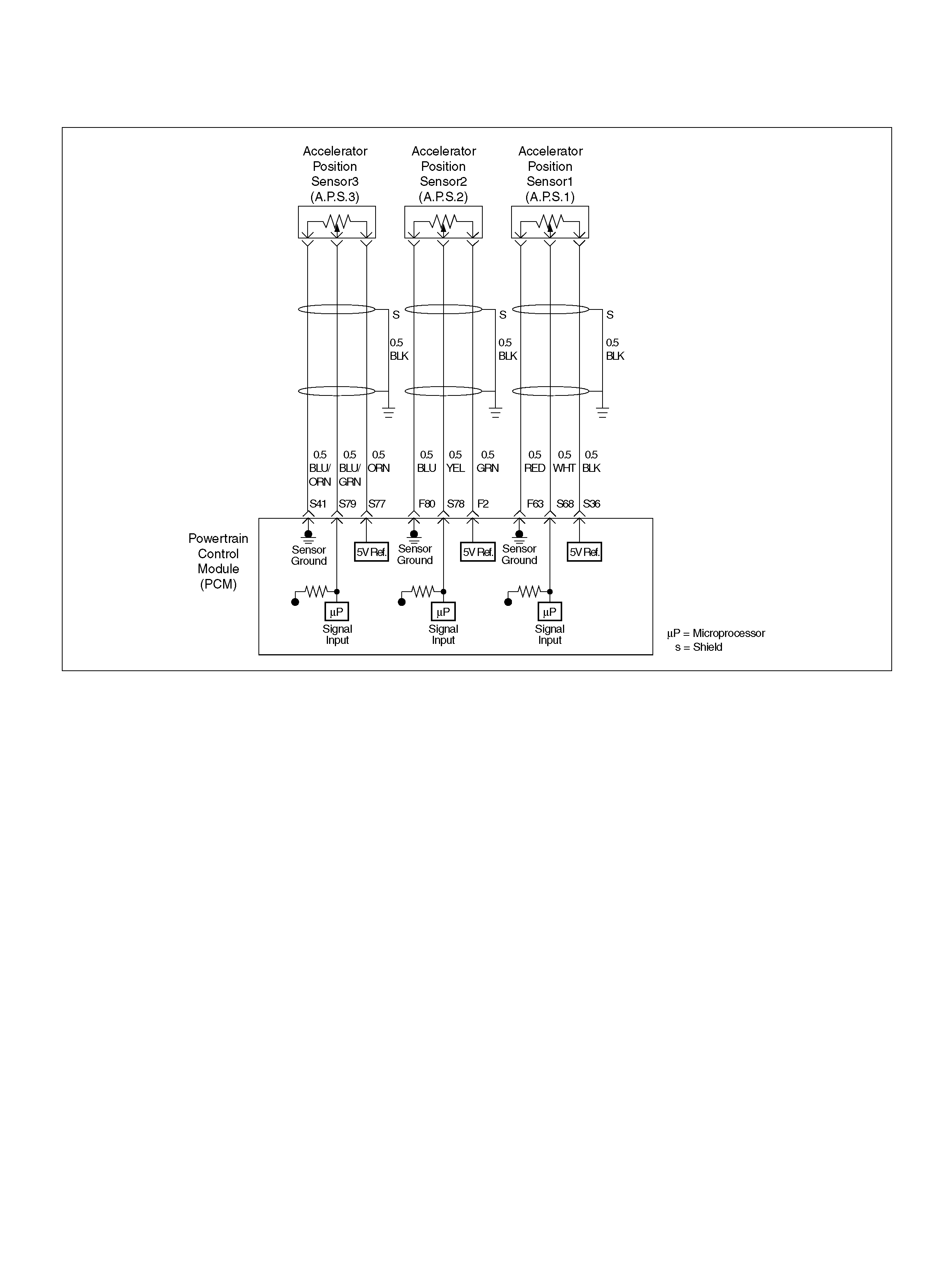
DIAGNOSTIC TROUBLE CODE (DTC) P1285 APS 3 OUTPUT FAULT
060R100141
Circuit Description
• The accelerator position (AP) sensor circuit pro vides
a voltage signal relative to accelerator pedal angle.
The accelerator pedal sensor (AP3) will vary about
87 % at idle position to about 34 % at wide open
throttle(WOT) to specified voltage (about 5V).
This code detects a continuous short to ground or
high in either the circuit or th e sensor.
Conditions for setting the DTC
• T he Ignition is “ON".
• The accelerator pedal sensor 3 is less than 2.5 % or
more than 97 % in the specified voltage (5V) with
more than 62.4 milliseconds.
Action Taken When the DTC Sets
• The PCM will ON the MIL after second trip with
detect ed the fault.
• The PCM will store conditions which were present
when the DTC was set as Freeze Frame and in the
Failure Records data.
Conditi ons for Clea r ing the MIL/DTC
• The PCM will turn the MIL “OFF" on the third
consecutive trip cycle during which the diagnostic has
been run and the fault condition is no longer present.
• A history DTC P1285 will clear after 40 consecutive
trip cycle during which the warm up cycles have
occurred without a fault.
• DTC P1285 can be cleared using the Tech 2 “Clear
Info" function.
Diag nostic Ai ds
An intermittent may be caused by the following:
• Poor c onnect ions.
• M isrouted harnes s.
• Ru bbed th rough wire insulation.
• Brok en wire inside the insulation.
Check for the following conditions:
• Poor c onnection at PCM-Ins pect harness connectors
for backed out terminals, improper mating, broken
locks, improperly formed or damaged terminals, and
poor terminal to wire connection.
• Damaged harness-Inspect the wiring harness for
damage. If the harness appears to be OK, observe
the AP sensor 3 display on the Tech2 while moving
connectors and wiring harnesses related to the
sensor.
A change in the display will indicate the location of
the fault. If DTC P1285 cannot be duplicated, the

information included in the Failure Records data can
be useful in determining vehicle mileage since the
DTC was last set.
If it is determined that the DTC occurs intermittently,
performing the DTC
P1285 Diagnostic Chart may isolate the cause of the
fault.
DTC P1285 – APS 3 Circuit Fault
Step Action Value(s) Yes No
1 Was the “On-Board (OBD) System Check"
performed? — G o to St ep 2 Go to OBD
System Check
2 Check t he AP sensor adjustm ent. Re fer to AP S ensor
Replaceme nt (6C1-425 )
Was a problem found? Verify repair Go to Step 3
3 Was the “Electric Throttle Control (ETC) System
Check" performed? — Go to St ep 4 Go to ETC
System Chec k
4 Observe the AP angle reading on the Tech2 while
slowly opening the throttle.
Does the AP angle increase steadily and evenly from
the closed throttle value to the wide open throttle
value?
Idle position
=86 ∼ 88 %
Wide open
throttle =32 ∼
36 % Refer to
Diagnostic Aids Go to Step 5
5 1. Disconnect the AP sensor .
2. Observe the AP sensor reading on the Tech2.
Is the AP sensor reading near the specified value? 0V Go to St ep 6 Go to Step 7
6 1. Connect a test light between the 5 volt supply
circuit and the A P3 sensor sign al circuit at the AP
sensor harness connector .
2. Observe the AP sensor reading on the Tech2.
Is the AP sensor reading near the specified value? 5V Go to Step 8 Go to St ep 9
7 Check the following items;
1. AP3 signal circuit for a short to voltage.
2. AP3 sensor ground circuit for high resistance
between the PCM and the AP sensor.
3. AP3 sensor ground circuit for a poor connection.
4. If a problem is found, repair wiring harness as
necessary.
Was a problem found? — Verify repair Go to St ep 10
8 Check the following items;
1. AP3 signal circuit or 5 volt supply circuit for a poor
connection.
2. AP3 signal circuit or 5 volt supply circuit for high
resistance between the PCM and the AP3 sensor.
3. If a problem is found, repair wiring harness as
necessary.
Was a problem found? — Verify repair Go to St ep 10
9 Replac e the AP sensor.
The sensor MUST be adjusted after fitment. Refer to
AP Sensor Replacem ent (6C1-425)
Is the action complete ? — Verify r epair —

10 Replace the PCM.
Important: The replacement PCM must be
programmed. Refer to Section 0C-1 - Service
Program ming Syst em.
Important: Refer to Section 11 - Engin e Im mobiliser
System for the Immobiliser Programming procedure.
Important: Ensure the latest software program is
downloaded to the PCM.
Is the action complete ? — Verify repair —
Step Action Value(s) Yes No
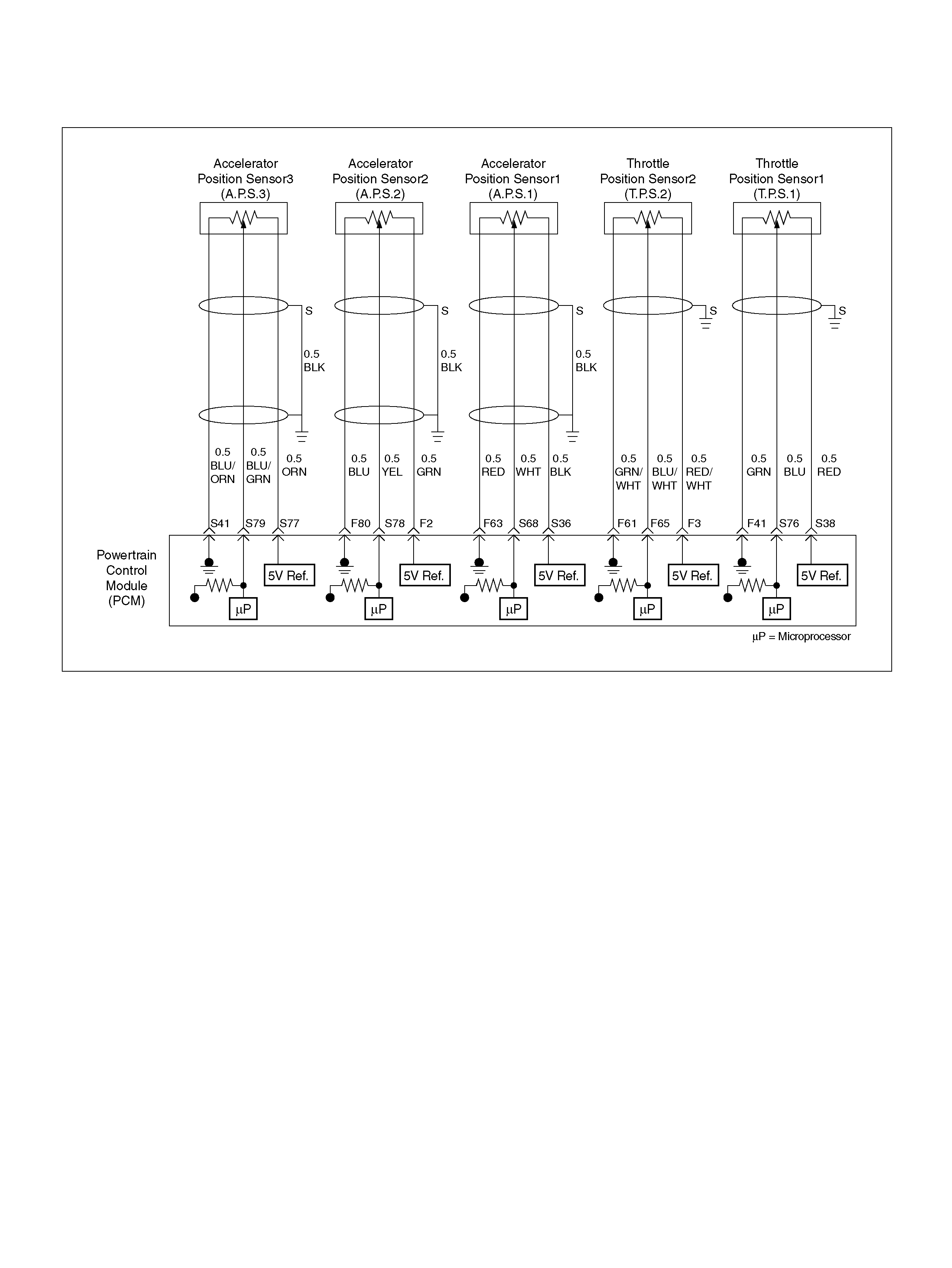
DIAGNOSTIC TROUBLE CODE (DTC) P1290 ETC FORCED IDLE MODE
060R100140
Circuit Description
• The accelerator position (AP) sensor circuit pro vides
a voltage signal relative to accelerator pedal angle.
This code detects that if the system is in Forced Idle
Mode . (Fail safe Mode)
DTC P1290 is recorded by the PCM when all AP
sen sors are failed.
Conditions for setting the DTC
• T he Ignition is “ON".
• F orced Idle Mode is active. (Fail safe Mode)
Action Taken When the DTC Sets
• The PCM will illuminate the malfunction indicator
lamp (MIL) and reduced powered lamp (RPL) the first
time the fault is detected.
• The PCM will store conditions which were present
when the DTC was set as Freeze Frame and in the
Failure Records data.
Conditi ons for Clea r ing the MIL/DTC
• The PCM will turn the MIL “OFF" on the third
consecutive trip cycle during which the diagnostic has
been run and the fault condition is no longer present.
• A history DTC P1290 will clear after 40 consecutive
trip cycle during which the warm up cycles have
occurred without a fault.
• DTC P1290 can be cleared using the Tech 2 “Clear
Info" function or by disconnecting the PCM battery
feed.
Diag nostic Ai ds
An intermittent may be caused by the following:
• Poor c onnect ions.
• M isrouted harnes s.
• Ru bbed th rough wire insulation.
• Brok en wire inside the insulation.
Check for the following conditions:
• Poor c onnection at PCM-Ins pect harness connectors
for backed out terminals, improper mating, broken
locks, improperly formed or damaged terminals, and
poor terminal to wire connection.

• Damaged harness-Inspect the wiring harness for
damage. If the harness appears to be OK, observe
the AP sensor 1, AP sensor 2, AP sensor 3 display
on the Tech2 while moving connectors and wiring
harnesses related to the sensor.
A change in the display will indicate the location of
the fault. If DTC P1290 cannot be duplicated, the
information included in the F ailure Records data can
be useful in determined vehicle mileage since the
DTC was last set.
If it i s determining t hat the DTC occurs intermittently,
performing the DTC
P1290 Diagnostic Chart may isolate the cause of the
fault.
DTC P1290 - ETC Forced Idle Mode
Step Action Value(s) Yes No
1 Was the “On - Board (OBD) System Check"
performed? —Go to Step 2 Go to OBD
System Check
2 Was the “Electric Throttle Control (ETC) System
Check" performed? —Go to St ep 3 Go to ET C
System Chec k
3 Observe the AP angle reading on the Tech2 while
slowly opening the throttle.
Does the AP angle increase steadily and evenly from
the closed throttle value to the wide open throttle
value?
Idle position
AP sensor 1
=12 ∼ 14 %
AP se nsor 2,
3 =86 ∼ 88 %
Wide open
thro ttle AP
sensor 1 =86
∼ 88 % AP
sensor 2 =12
∼ 14 % AP
sensor 3 =32
∼ 36 % Refer to
Diagnostic Aids Go to Step 4
4 1. Disconnect the AP sensor .
2. Observe the AP sensor reading on the Tech2.
Is the AP sensor reading near the specified value? 0V Go to St ep 5 Go to St ep 6
5 1. Connect a test light between the 5 volt supply
circuit and the AP1, AP2 and AP3 sensor signal
circuit at the AP sensor harness connector.
2. Observe the AP sensor reading on the Tech2.
Is the AP sensor reading near the specified value? 5V Go to St ep 7 Go to St ep 8
6 Check the following items;
1. AP1,AP2 and AP3 signal circuit for a short to
voltage.
2. AP1, AP2 and AP3 sensor ground circuit for high
resistance between the PCM and the AP sensor.
3. AP1, AP2 and AP3 sensor ground circuit for a
poor connection.
4. If a problem is found, repair wiring harness as
necessary.
Was a problem found? — Verify repair Go to Step 9
7 Check the following items;
1. AP1, AP2 and AP3 signal circuit or 5 volt supply
circuit for a poor connection.
2. AP1, AP2 and AP3 signal circuit or 5 volt supply
circuit for high resistance between the PCM and
the AP1, AP2 and AP3 sens or.
3. If a problem is found, repair wiring harness as
necessary.
Was a problem found? — Verify repair Go to Step 9

8 Replac e the AP sensor.
The sensor MUST be adjusted after fitment. Refer to
AP Sensor Replacement (6C1-425)
Is the action complete ? — Verify r epair —
9 Replace the PCM.
Important: The replacement PCM must be
programmed. Refer to Section 0C-1 - Service
Program ming Syst em.
Important: Refer to Section 11 - Engin e Im mobiliser
System for the Immobiliser Programming procedure.
Important: Ensure the latest software program is
downloaded to the PCM.
Is the action complete ? — Verify repair —
Step Action Value(s) Yes No

DIAGNOSTIC TROUBLE CODE (DTC) P1295 ETC
POWER MANAGEMENT MODE
D06RY00111
Circuit Description
• The throttle position (TP) sensor circuit provides a
voltage signal relative to throttle position (blade
angle).
• The DC motor circuit provides a voltage signal
relative to command t hrottle position (blade angle).
• This DTC detects that if the system is in Power
Mana gem ent M ode.(Fai l safe Mode)
• DTC P1295 recorded by the PCM when all TP
sen sors are failed.
Conditions for setting the DTC
• T he ignition is “ON".
• Power Manage men t Mode is active. (Fail saf e Mo de)
Action Taken When the DTC Sets
• The PCM will illuminate the malfunction indicator
lamp (MIL) and the reduced power lamp (RPL) the
first time the fault is detected.
• The PCM calculates an air flow value based on idle
air control valve position, throttle position, RPM and
barome tric pressure.
• The PCM will store condition which were present
when the DTC was set as Freeze Frame and in the
Failure Records data.
Conditi ons for Clea r ing the MIL/DTC
• The PCM will turn the MIL “OFF" on the third
consecutive trip cycle during which the diagnostic has
been run and the fault condition is no longer present.
• A history DTC P1295 will clear after 40 consecutive
trip cycle during which the warm up cycles have
occurred without a fault.
• DTC P1295 can be cleared using the Tech 2 “Clear
Info" function.

Diagnostic Aids
An intermittent may be caused by the following:
• Poor connections.
• Misrouted harness.
• Rubbed through wire insulation.
• Broken wire inside the insulation.
Check for the following conditions:
• Poor connection at PCM-Inspect harness connectors
for backed out terminals, improper mating, broken
locks, improperly formed or damaged terminals, and
poor terminal to wire connection.
• Damaged harness-Inspect the wiring harness for
damage. If the harness appears to be OK, observe
the TP sensor 1, TP sensor 2 display on the Tech2
while moving connectors and wiring harnesses
related to the sensor.
A change in the display will indicate the location of
the fault. If DTC P1295 cannot be duplicated, the
information included in the Failure Records data can
be useful in determined vehicle mileage since the
DTC was last set.
If it is determining that the DTC occurs intermittently,
performing the DTC
P1295 Diagnostic Chart may isolate the cause of the
fault.
DTC P1295 - ETC Power Management Mode
Step Action Value(s) Yes No
1 Was the “On-Board (OBD) System Check"
performed? —Go to Step 2 Go to OBD
System Check
2 Was the “Electric Throttle Control (ETC) System
Check" performed? —Go to St ep 3 Go to ET C
System Chec k
3 1. Ignition “ON", engine “OFF".
2. Review and record Te ch2 Failure Records data.
3. Operate the vehicle within Failure Records
condition s as noted.
4. Using a Tech2, monitor “DTC" info for DTC
P1295.
Does the Tech2 indicate DTC P1295 failed this
ignition? — G o to Step 4 Refer to
Diagnostic Aids
4 Observe the TP angle reading on the Tech2 while
slowly opening the throttle.
Does the TP angle increase steadily and evenly from
the closed throttle value to the wide open throttle
value?
Closed
throttle TP
sensor 1 =8 ∼
10 % TP
sensor 2 =90
∼ 92 % Wide
open throttle
TP sensor 1
=90 ∼ 92 %
TP sensor 2
=8 ∼ 10 % G o to St ep 9 Go to St ep 5
5 1 . Ig nit io n “ OFF" .
2. Disconnect the DC motor.
Is the DC motor reading near the specified value? 0.3 ∼ 100 ΩGo to Step 6 Go to St ep 8
6 Check the DC motor harness between the PCM and
DC Motor circuit at the DC motor harness connector.
Was a problem found? — Verify repair Go to Step 7
7 Check the throttle valve assembly.
Was a problem found? Verify repair Go to St ep 8
8 Replace the DC motor. (Replace the Throttle valve
assembly)
Is the action comple te ? — Verify repair Go to Step 7
9 1 . Disconnect the TP sensor.
2. Observe the TP sensor reading on the Tech2.
Is the TP sensor reading near the specif ied value? 0V Go to Step 10 Go to Step 11

10 1. Connect a test light between the 5Volt reference
“A" circuit and the TP1 and TP2 sensor signal
circuit at the TP sens or harness conne ctor.
2. Observe the TP sensor reading on the Tech2.
Is the TP sensor reading near the specif ied value? 5V Go to Step 13 Go to St ep 12
11 Check the following items;
1. TP1 and TP2 signal circuit for a sho rt to voltage.
2. TP1 and TP2 sensor ground circuit for high
resistance between the PCM and the TP sens or.
3. TP1and TP2 sensor ground circuit for a poor
connection.
4. If a problem is found, repair wiring harness as
necessary.
Was a problem found? — Verify repair Go to St ep 14
12 Check the following items;
1. TP1and TP2 signal circuit or 5 volt reference
circuit for a poor connection.
2. TP1 and TP2 signal circuit or 5 volt reference
circuit for high resistance between the PCM and
the TP1and TP2 s ensor.
3. If a problem is found, repair wiring harness as
necessary.
Was a problem found? — Verify repair Go to St ep 14
13 Replace the TP sensor.
Is the action complete ? — Verify r epair —
14 1. Start th e engine.
2. With the engine idling, monitor “MAF Frequency"
display on the Tech2.
Is the “MAF Frequenc y" below the specified value? 6 ∼ 10 g/s Go to Step 15 Go to Step 18
15 1. Ignition “OFF".
2. Disconnect the MAF sensor connector.
3. Ignition “ON", engine idling.
4. Using a Te ch2, moni tor “MAF Frequency".
Does the Tech2 indicate a “MAF Frequency" at the
specified value? 0g /s Go t o Step 16 Go to St ep 17
16 Replace the MAF sensor.
Is the action com plete? — Verify repair Go to Step 19
17 1. Check the M AF harness for incorrect routing near
high voltage components (solenoids, relays,
motors).
2. If incorrect routing is found, correct the harness
routing.
Was a problem found? — Verify repair Go to St ep 17
18 1. With the engine idling, monitor “MAF Frequency"
display on the Tech 2.
2. Quickly snap open throttle to wide open throttle
while under a road load and record value.
Does the Tech2 indicate a “MAF Frequency" at the
specified value? 6 ∼ 10 g/s G o to Step 16 Go to Step 19
19 1. Ignition “ON", engine not running.
2. Observe the MAP reading on the Tech2.
Is the MAP reading less than the specified value? 65kPa Go to Step 20 Go to St ep 23
Step Action Value(s) Yes No

20 1. Disconnect the MAP sens or.
2. Connect a test 5 volt reference circuit and the
MAP signal at the MAP sensor harness connector.
3. Observe the MAP reading on the Tech2.
Is the MAP reading less than the specified value? (If
no, start with diagnosis chart for other sensors in the
circu it and se e if 5V return s.) — Go to St ep 22 Go to Step 21
21 1. Check the MAP signal circuit between the PCM
and MAP ground circuit.
2. If the MAP signal circuit is open or shorted, repair
it as necessary.
Was the M AP signal circuit open or shorted? — Veri fy repair Go to Step 23
22 Replace the MAP se nsor.
Is the action complete ? — Verify r epair —
23 Replace the PCM.
Important: The replacement PCM must be
programmed. Refer to Section 0C-1 - Service
Program ming Syst em.
Important: Refer to Section 11 - Engin e Im mobiliser
System for the Immobiliser Programming procedure.
Important: Ensure the latest software program is
downloaded to the PCM.
Is the action complete ? — Verify repair —
Step Action Value(s) Yes No
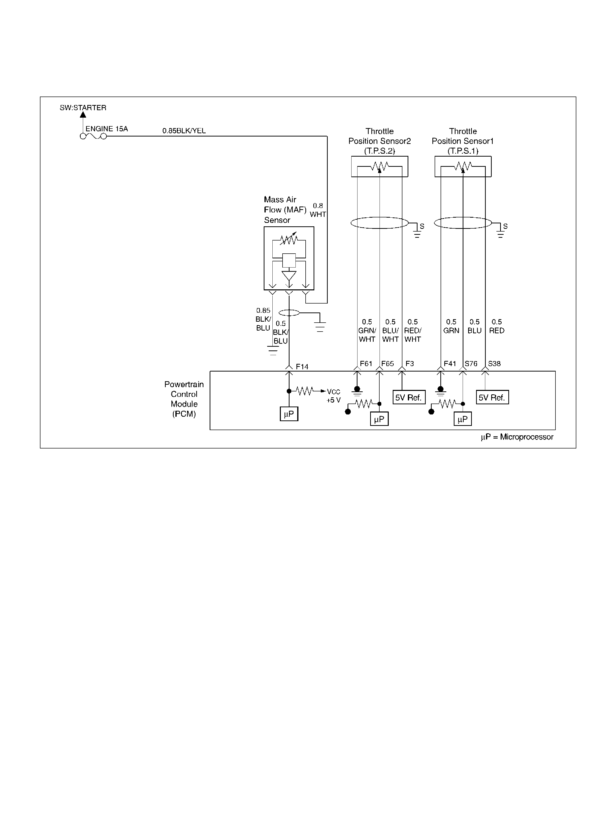
DIAGNOSTIC TROUBLE CODE (DTC)
P1299 ETC FORCED ENGINE SHUTDOWN MODE
060R100073
Circuit Description
• T he throttle position sensor circuit provides a voltage
signal relative to throttle position (blade angle).
• The DC motor circuit provides a voltage signal
relative to command t hrottle position (blade angle).
• This DTC detects if the system is in ETC Forced
Engine Shutdown Mode.(Fail safe Mode)
Conditions for setting the DTC
• T he ignition is “ON".
• ETC Forced Engine Shutdown Mode is active. (Fail
safe Mo de)
Action Taken When the DTC Sets
• The PCM will illuminate the malfunction indicator
lamp (MIL) and the reduced power lamp (RPL) the
first time the fault is detected.
• The PCM will store condition which were present
when the DTC was set as Freeze Frame and in the
Failure Records data.
Conditi ons for Clea r ing the MIL/DTC
• The PCM will turn the MIL “OFF" on the third
consecutive trip cycle during which the diagnostic has
been run and the fault condition is no longer present.
• A history DTC P1299 will clear after 40 consecutive
trip cycle during which the warm up cycles have
occurred without a fault.
• DTC P1299 can be cleared using the Tech 2 “Clear
Info" function or by disconnecting the PCM battery
feed.
Diag nostic Ai ds
An intermittent may be caused by the following:
• Poor c onnect ions.
• M isrouted harnes s.
• Ru bbed th rough wire insulation.
• Brok en wire inside the insulation.
Check for the following conditions:
• Poor c onnection at PCM-Ins pect harness connectors
for backed out terminals, improper mating, broken
locks, improperly formed or damaged terminals, and
poor terminal to wire connection.

• Damaged harness-Inspect the wiring harness for
damage. If the harness appears to be OK, observe
the TP sensor 1, TP sensor 2 display on the Tech2
while moving connectors and wiring harnesses
related to the sensor.
A change in the display will indicate the location of
the fault. If DTC P1299 cannot be duplicated, the
information included in the Failure Records data can
be useful in determined vehicle mileage since the
DTC was last set.
If it is determining that the DTC occurs intermittently,
performing the DTC P1299 Diagnostic Chart may
isolate the cause of the fault.
DTC P1299 - ETC Forced Engine Shutdown Mode
Step Action Value(s) Yes No
1 Was the “On-Board (OBD) System Check"
performed? —Go to Step 2 Go to OBD
System Check
2 Was the “Electric Throttle Control (ETC) System
Check" performed? —Go to St ep 3 Go to ET C
System Chec k
3 Observe the TP angle reading on the Tech2 while
slowly opening the throttle.
Does the TP angle increase steadily and evenly from
the closed throttle value to the wide open throttle
value?
Closed
throttle TP
sensor 1 =8 ∼
10 % TP
sensor 2 =90
∼ 92 % Wide
open throttle
TP sensor 1
=90 ∼ 92 %
TP sensor 2
=8 ∼ 10 % G o to St ep 8 Go to St ep 4
4 1 . Ig nit io n “ OFF" .
2. Disconnect the DC motor.
Is the DC motor reading near the specified value? 0.3 ∼ 100ΩGo to Step 5 Go to Step 7
5 Check the DC motor harness between the PCM and
DC Motor circuit at the DC motor harness connector.
Was a problem found? — Verify repair Go to Step 6
6 Check the throttle valve assembly.
Was a problem found? Verify repair Go to St ep 7
7 Replace the DC motor. (Replace the Throttle valve
assembly)
Is the action comple te ? — Verify repair Go to Step 8
8 1 . Disconnect the TP sensor.
2. Observe the TP sensor reading on the Tech2.
Is the TP sensor reading near the specif ied value? 0V Go to St ep 9 Go to Step 10
9 1. Connect a test light between the 5 Volt reference
circuit and the TP1 and TP2 sensor signal circuit
at the TP sensor harness connect or.
2. Observe the TP sensor reading on the Tech2.
Is the TP sensor reading near the specif ied value? 5V Go to Step 12 Go to Step 11
10 Check the following items;
1. TP1 and TP2 signal circuit for a short to voltage .
2. TP1 and TP2 sensor ground circuit for high
resistance between the PCM and the TP sens or.
3. TP1and TP2 sensor ground circuit for a poor
connection.
4. If a problem is found, repair wiring harness as
necessary.
Was a problem found? — Verify repair Go to St ep 13

11 Check the following items;
1. TP1and TP2 signal circuit or 5 volt reference
circuit for a poor connection.
2. TP1 and TP2 signal circuit or 5 volt reference
circuit for high resistance between the PCM and
the TP1and TP2 s ensor.
3. If a problem is found, repair wiring harness as
necessary.
Was a problem found? — Verify repair Go to St ep 13
12 Replace the TP sensor.
Is the action complete ? — Verify r epair —
13 1. Start the engine.
2. With the engine idling, monitor “MAF Frequency"
display on the Tech2.
Is the “MAF Frequenc y" below the specified value? 6 ∼ 10 g/s Go to Step 16 Go to Step 17
14 1. Ignition “OFF".
2. Disconnec t the MAF sensor co nnecto r.
3. Ignition “ON", engine idling.
4. Using a Tech2, monitor “MAF Frequency".
Does the Tech2 indicate a “MAF Frequency" at the
specified value? 0g /s Go t o Step 15 Go to St ep 16
15 Replace the MAF sensor.
Is the action com plete? — Verify repair Go to Step 18
16 1. Check the MAF harness for incorrect routing near
high voltage components (solenoids, relays,
motors).
2. If incorrect routing is found, correct the harness
routing.
Was a problem found? — Verify repair Go to St ep 16
17 1. With the engine idling, monitor “MAF Frequency"
display on the Tech2.
2. Quickly snap open throttle to wide open throttle
while under a road load and record value.
Does the Tech2 indicate a “MAF Frequency" at the
specified value? 6 ∼ 10 g/s G o to Step 15 Go to Step 18
18 1. Ignition “ON", engine not running.
2. Observe the MAP reading on the Tech2.
Is the MAP reading less than the specified value? 65kPa Go to Step 19 Go to St ep 22
19 1. Disconnect the MAP sens or.
2. Connect a test 5 volt reference circuit and the
MAP signal at the MAP sensor harness connector.
3. Observe the MAP reading on the Tech2.
Is the MAP reading less than the specified value?(If
no, start with diagnosis chart for other sensors in the
circu it and se e if 5V return s.) — Go to St ep 21 Go to Step 20
20 1. Check the MAP signal circuit between the PCM
and MAP ground circuit.
2. If the MAP signal circuit is open or shorted ,repair
it as necessary.
Was the M AP signal circuit open or shorted? — Veri fy repair Go to Step 22
21 Replace the MAP se nsor.
Is the action complete ? — Verify r epair —
Step Action Value(s) Yes No

22 Replace the PCM.
Important: The replacement PCM must be
programmed. Refer to Section 0C-1 - Service
Program ming Syst em.
Important: Refer to Section 11 - Engin e Im mobiliser
System for the Immobiliser Programming procedure.
Important: Ensure the latest software program is
downloaded to the PCM.
Is the action complete ? — Verify repair —
Step Action Value(s) Yes No
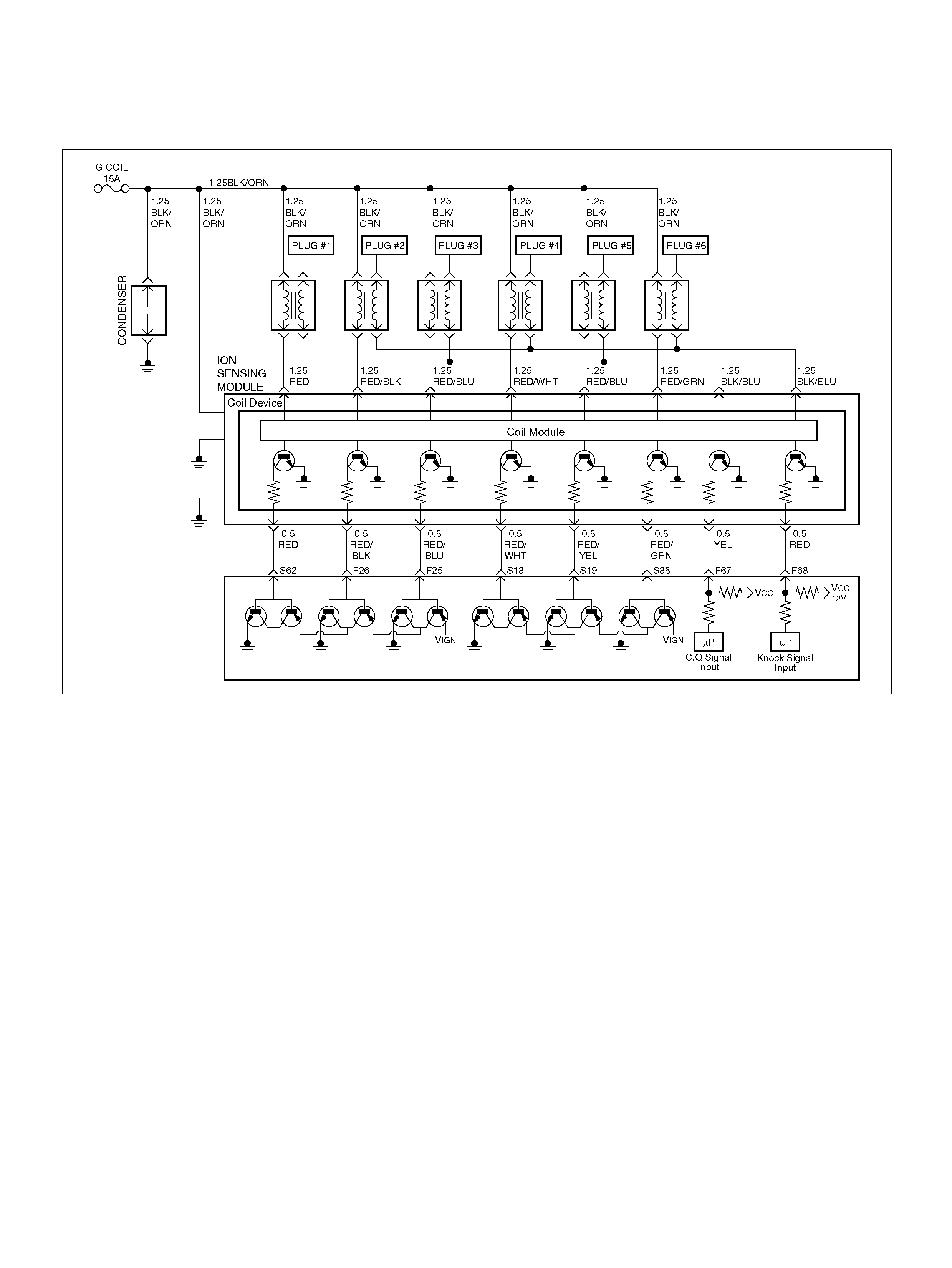
DIAGNOSTIC TROUBLE CODE (DTC)
P1310 ION SENSING MODULE DIAGNOSIS
060R100135
Circuit Description
The P ower Co ntrol Mo dule (PCM ) chec ks the validity of
the signals used in the ION Sensing module at the
following engine operating co nditions.
• The Deceleration Fuel Cut Off (DFCO) test is
performed to evaluate the Combustion Quality (CQ)
signal pulse width. If it is below a predetermined
value, the value it is expected to be during DFCO
conditions. If the CQ signal pilse width is above the
predetermined threshold, the fail counter will be
incremented. If the failure counter exceeds the
calibration, t hen t he tes t is c om plete an d a f ail ure will
be reporte d.
• The Power Enrichment (PE) test is performed to
evaluate the Combustion Quality (CQ) signal pulse
width. If it is below a predetermined value, the value it
is expected to be during PE conditions.
If the CQ signal pulse width is above the
predetermined threshold, the fail counter will be
incremented. If the failure counter exceeds the
calibration, t hen t he tes t is c om plete an d a f ail ure will
be reporte d.
• The Combustion Quality (CQ) test is performed to
check if inappropriate (CQ) signal status were
detected. I f missing CQ pulses or mu ltiple CQ p ulses
or CQ pulse width calculation errors were detected,
the fail counter will be incremented. If the failure
counter exceeds the calibration, then the test is
com plete and a failure will be report ed.
Conditions for settin g the DTC
• Ignition voltage is between 10volt and 16 volts.
• MAP sensor signal is between 26kPa and 100 kPa.
• Fuel level is more than 19%.
• Engi ne sp eed is betwee n 650rpm and 6250 rpm.
• No Crank DTCs set.
• No System voltage DTCs set.
• CQ pulse width is less than 30µs or more than
1070µs.
Action Taken When the DTC Sets
• The PCM will illuminate the malfunction indicator
l a mp (M IL ) the fi r s t time th e fa ult is d e te c te d .
• The PCM calculates an air flow value based on idle
air control valve position, throttle position, RPM and
barome tric pressure.

• The PCM will store conditions which were present
when the DTC was set as Freeze Frame and in the
Failure Records data.
Conditions for Clearing the MIL/DTC
• The PCM will turn the MIL “OFF" on the third
consecutive trip cycle during which the diagnostic has
been run and the fault condition is no longer present.
• A history DTC P1310 will clear after 40 consecutive
trip cycle during which the warm up cycles have
occurred without a fault.
• DTC P1310 can be cleared using the Tech2 “Clear
Info" function.
Diagnostic Aids
An intermittent may be caused by the following:
• Poor connections.
• Misrouted harness.
• Rubbed through wire insulation.
• Broken wire inside the insulation.
Check for the following conditions:
• Poor connection at PCM-Inspect harness connectors
for backed out terminals, improper mating, broken
locks, improperly formed or damaged terminals, and
poor terminal to wire connection.
• Damaged harness-Inspect the wiring harness for
damage. If the harness appears to be OK, observe
the moving connectors and wiring harnesses related
to the sensor.
A change in the display will indicate the location of
the fault. If DTC P1310 cannot be duplicated, the
information included in the Failure Records data can
be useful in determined vehicle mileage since the
DTC was last set.
If it is determined that the DTC occurs intermittently,
performing the DTC P1310 Diagnostic Chart may
isolate the cause of the fault.
DTC P1310 - ION Sensing Module Diagnostic
Step Action Value(s) Yes No
1 Was the “On-Board (OBD) System Check"
performed? —Go to Step 2 Go to OBD
System Check
2 1. Ignition “ON", engine “OFF".
2. Review and record Te ch2 Failure Records data.
3. Operate the vehicle within Failure Records
condition s as noted.
4. Using a Tech2, monitor “DTC" info for DTC
P1310.
Does the Tech2 indicate DTC P1310 failed this
ignition? — G o to Step 3 Refer to
Diagnostic Aids
3 1 . Ig nit io n “ OFF" .
2. Disconnect the ION Sensing module.
3. Disconnect the PCM.
Is the action complete ? — Go to St ep 4 Go to St ep 3
4 Check the ION Sensing harness between the PCM
and ION Sensing mo dule circuit harness connect or.
Was a problem found? — Verify repair Go to Step 6
5 1. Disconnect the ignition coil.
Is the action complete ? — Go to St ep 6 Go to St ep 5
6 Check the ION Sensin g harness between the ignition
coil and ION Sensing module circuit at the ION
Sensing Module harness connector .
Was a problem found? — Verify repair Go to Step 7
7 Check the following items;
1. Ignition coil and ignition coil circuit.
2. Ignition coil ground circuit for a poor conne ction.
3. If a problem is found, repair wiring harness as
necessary.
Was a problem found? — Verify repair Go to Step 8
8 Replac e the Ignition coil.
Is the action comple te ? — Verify repair Go to Step 9

9 Check the following items;
1. ION Sensing module ground circuit for a poor
connection.
2. If a problem is found, repair wiring harness as
necessary.
Was a problem found? — Go to Step 10 Go to Step 11
10 Replace the ION Sensing module.
Is the action com plete? — Verify repair Go to Step 10
11 Replace the PCM.
Important: The replacement PCM must be
programmed. Refer to Section 0C-1 - Service
Program ming Syst em.
Important: Refer to Section 11 - Engin e Im mobiliser
System for the Immobiliser Programming procedure.
Important: Ensure the latest software program is
downloaded to the PCM.
Is the action complete ? — Verify repair —
Step Action Value(s) Yes No

DIAGNOSTIC TROUBLE CODE (DTC)
P1311 ION SENSING MODULE SEC LINE 1 CIRCUIT FAULT
060R100135
Circuit Description
• The Power Control Module (PCM) will compare the
secondary current reading to predetermined
maximum and minimum thresholds.
If the secondary current signal pulse width is out of
the predetermined range, the fail counter will be
incremented. If the failure counter exceeds the
calibration, then the PCM is complete and a failure
will be reported. If the sample counter threshold is
reach ed before t he fa ilure threshold , then the P CM is
compl ete and pass will be reported.
This PCM will detect an open/short circuit in the
secondary current sense input circuit, misfire on the
entire bank for the secondary current sense input
circuit, coil failure, a nd same internal Igni tion Current
Sen se System (ICSS) module faults.
Conditions for settin g the DTC
• Ignition voltage is between 10volt and 16 volts.
• MAP sensor signal is between 26kPa and 100 kPa.
• Fuel level is more than 19%.
• Engi ne sp eed is betwee n 650rpm and 6250 rpm.
• ION Sensing Module circuit is open or shorted
signals on the SEC 1 line.
Action Taken When the DTC Sets
• The PCM will illuminate the malfunction indicator
l a mp (M IL ) the fi r s t time th e fa ult is d e te c te d .
• The PCM calculates an air flow value based on idle
air control valve position, throttle position, RPM and
barome tric pressure.

• The PCM will store conditions which were present
when the DTC was set as Freeze Frame and in the
Failure Records data.
Conditions for Clearing the MIL/DTC
• The PCM will turn the MIL “OFF" on the third
consecutive trip cycle during which the diagnostic has
been run and the fault condition is no longer present.
• A history DTC P1311 will clear after 40 consecutive
trip cycle during which the warm up cycles have
occurred without a fault.
• DTC P1311 can be cleared using the Tech2 “Clear
Info" function.
Diagnostic Aids
An intermittent may be caused by the following:
• Poor connections.
• Misrouted harness.
• Rubbed through wire insulation.
• Broken wire inside the insulation.
Check for the following conditions:
• Poor connection at PCM-Inspect harness connectors
for backed out terminals, improper mating, broken
locks, improperly formed or damaged terminals, and
poor terminal to wire connection.
• Damaged harness-Inspect the wiring harness for
damage. If the harness appears to be OK, observe
the moving connectors and wiring harnesses related
to the sensor.
• A change in the display will indicate the location of
the fault. If DTC P1311 cannot be duplicated, the
information included in the Failure Records data can
be useful in determining vehicle mileage since the
DTC was last set.
• If it is determined that the DTC occurs intermittently,
performing the DTC P1311 Diagnostic Chart may
isolate the cause of the fault.
DTC P1311 - ION Sensing Module SEC Line 1 Circuit Fault
Step Action Value(s) Yes No
1 Was the “On-Board (OBD) System Check"
performed? —Go to Step 2 Go to OBD
System Check
2 1. Ignition “ON", engine “OFF".
2. Review and record Tech2 Failure Records data.
3. Operate the vehicle within Failure Records
condition s as noted.
4. Using a Tech2, monitor “DTC" info for DTC P131 1.
Does the Tech2 indicate DTC P1311 failed this
ignition? — G o to Step 3 Refer to
Diagnostic Aids
3 1 . Ig nit io n “ OFF" .
2. Disconnect the ION Sensing module.
3. Disconnect the PCM.
Is the action complete ? — Go to St ep 4 Go to St ep 3
4 Check t he ION S ensing m odule harne ss between t he
PCM and ION Sensing module circuit at the ION
Sensing module harness connector .
Was a problem found? — Verify repair Go to Step 6
5 1. Disconnect the ignition coil.
Is the action complete ? — Go to St ep 6 Go to Step 5
6 Check t he ION S ensing m odule harne ss between t he
ignition coil and ION Sensing module circuit at the
SEC line 1 harness connector.
Was a problem found? — Verify repair Go to Step 7
7 Check the following items;
1. Ignition coil and ignition coil circuit.
2. Ignition coil ground circuit for a poor conne ction.
3. If a problem is found, repair wiring harness as
necessary.
Was a problem found? — Verify repair Go to Step 8
8 Replac e the Ignition coil.
Is the action comple te ? — Verify repair Go to Step 9

9 Check the following items;
1. ION Sensing module ground circuit for a poor
connection.
2. If a problem is found, repair wiring harness as
necessary.
Was a problem found? — Go to Step 10 Go to Step 11
10 Replace the ION Sensing module.
Is the action com plete? — Verify repair Go to Step 10
11 Replace the PCM.
Important: The replacement PCM must be
programmed. Refer to Section 0C-1 - Service
Program ming Syst em.
Important: Refer to Section 11 - Engin e Im mobiliser
System for the Immobiliser Programming procedure.
Important: Ensure the latest software program is
downloaded to the PCM.
Is the action complete ? — Verify repair —
Step Action Value(s) Yes No

DIAGNOSTIC TROUBLE CODE (DTC)
P1312 ION SENSING MODULE SEC LINE 2 CIRCUIT FAULT
060R100135
Circuit Description
• The Power Control Module (PCM) will compare the
secondary current reading to predetermined
maximum and minimum thresholds.
If the secondary current signal pulse width is out of
the predetermined range, the fail counter will be
incremented. If the fail counter exceeds the
calibration, then the PCM is complete and a failure
will be reported. If the sample counter threshold is
reach ed before t he fa ilure threshold , then the P CM is
compl ete and pass will be reported.
This PCM will detect an open/short circuit in the
secondary current sense input circuit, misfire on the
entire bank for the secondary current sense input
circuit, coil failure, a nd same internal Igni tion Current
Sen se System (ICSS) module faults.
Conditions for settin g the DTC
• Ignition voltage is between 10volt and 16 volts.
• MAP sensor signal is between 26kPa and 100 kPa.
• Fuel level is more than 19%.
• Engi ne sp eed is betwee n 650rpm and 6250 rpm.
• ION Sensing Module circuit is open or shorted
signals on the SEC 2 line.
Action Taken When the DTC Sets
• The PCM will illuminate the malfunction indicator
l a mp (M IL ) the fi r s t time th e fa ult is d e te c te d .
• The PCM calculates an air flow value based on idle
air control valve position, throttle position, RPM and
barome tric pressure.

• The PCM will store conditions which were present
when the DTC was set as Freeze Frame and in the
Failure Records data.
Conditions for Clearing the MIL/DTC
• The PCM will turn the MIL “OFF" on the third
consecutive trip cycle during which the diagnostic has
been run and the fault condition is no longer present.
• A history DTC P1312 will clear after 40 consecutive
trip cycle during which the warm up cycles have
occurred without a fault.
• DTC P1312 can be cleared using the Tech2 “Clear
Info" function or by disconnecting the PCM battery
feed.
Diagnostic Aids
An intermittent may be caused by the following:
• Poor connections.
• Misrouted harness.
• Rubbed through wire insulation.
• Broken wire inside the insulation.
Check for the following conditions:
• Poor connection at PCM-Inspect harness connectors
for backed out terminals, improper mating, broken
locks, improperly formed or damaged terminals, and
poor terminal to wire connection.
• Damaged harness-Inspect the wiring harness for
damage. If the harness appears to be OK, observe
the moving connectors and wiring harnesses related
to the sensor.
A change in the display will indicate the location of
the fault. If DTC P1312 cannot be duplicated, the
information included in the Failure Records data can
be useful in determined vehicle mileage since the
DTC was last set.
If it is determining that the DTC occurs intermittently,
performing the DTC P1312 Diagnostic Chart may
isolate the cause of the fault.
DTC P1312 - ION Sensing Module SEC Line 2 Circuit Fault
Step Action Value(s) Yes No
1 Was the “On-Board (OBD) System Check"
performed? —Go to Step 2 Go to OBD
System Check
2 1. Ignition “ON", engine “OFF".
2. Review and record Tech2 Failure Records data.
3. Operate the vehicle within Failure Records
condition s as noted.
4. Using a Tech2, monitor “DTC" info for DTC
P1312.
Does the Tech2 indicate DTC P1312 failed this
ignition? — G o to Step 3 Refer to
Diagnostic Aids
3 1 . Ig nit io n “ OFF" .
2. Disconnect the ION Sensing module.
3. Disconnect the PCM.
Is the action complete ? — Go to St ep 4 Go to St ep 3
4 Check t he ION S ensing m odule harne ss between t he
PCM and ICSS module circuit at the ION Sensing
Module harness connector.
Was a problem found? — Verify repair Go to Step 6
5 1. Disconnect the ignition coil.
Is the action complete ? — Go to St ep 6 Go to St ep 5
6 Check t he ION S ensing m odule harne ss between t he
ignition coil and ION Sensing module circuit at the
SEC line 2 harness connector.
Was a problem found? — Verify repair Go to Step 7

7 Check the following items;
1. Ignition coil and ignition coil circuit.
2. Ignition coil ground circuit for a poor conne ction.
3. If a problem is found, repair wiring harness as
necessary.
Was a problem found? — Verify repair Go to Step 8
8 Replac e the Ignition coil.
Is the action comple te ? — Verify repair Go to Step 9
9 Check the following items;
1. ION Sensing module ground circuit for a poor
connection.
2. If a problem is found, repair wiring harness as
necessary.
Was a problem found? — Go to Step 10 Go to Step 11
10 Replace the ION Sensing module.
Is the action com plete? — Verify repair Go to Step 10
11 Replace the PCM.
Important: The replacement PCM must be
programmed. Refer to Section 0C-1 - Service
Program ming Syst em.
Important: Refer to Section 11 - Engin e Im mobiliser
System for the Immobiliser Programming procedure.
Important: Ensure the latest software program is
downloaded to the PCM.
Is the action complete ? — Verify repair —
Step Action Value(s) Yes No
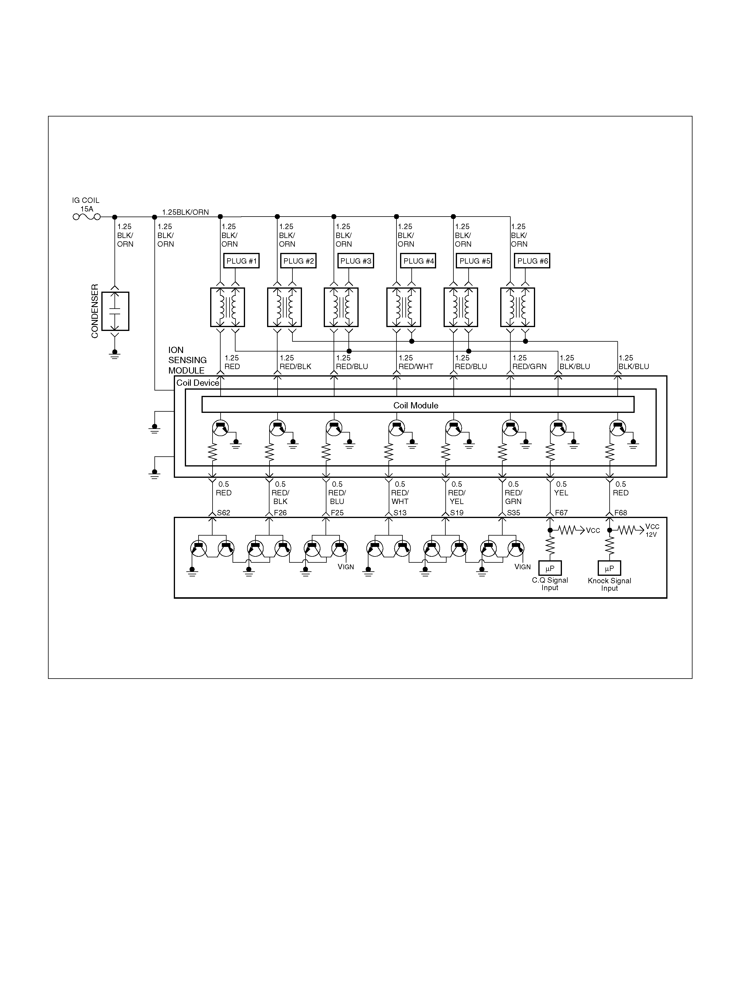
DIAGNOSTIC TROUBLE CODE (DTC)
P1326 ION SENSING MODULE COMBUSTION QUALITY INPUT CIRCUIT FAULT
060R100135
Circuit Description
The P ower Co ntrol Mo dule (PCM ) chec ks the validity of
the signals used in the ION Sensing module at the
following engine operating co nditions.
• The test is performed to evacuate the Combustion
Quality (CQ) signal pulse width if it is within a
predetermined range. If the CQ signal pulse width is
out of the predetermined range, the fail counter will
be incremented. If the failure counter exceeds the
calibration, t hen te st is com plete and a failure wil l be
reported. If the sample counter threshold is reached
before t he failure threshold, then the te st is complete
and a pass will be reported. This test will detect an
open/short in t he CQ line circ uit , ION Sensing module
faul ts and analog input faults in the PCM .
Conditions for settin g the DTC
• Ignition voltage is between 10volt and 16 volts.
• No Crank DTCs set.
• N o cylinder ID DTCs se t .
• CQ pulse width is less than 30µs or more than
1070µs.
Action Taken When the DTC Sets
• The PCM will illuminate the malfunction indicator
l a mp (M IL ) the fi r s t time th e fa ult is d e te c te d .
• The PCM calculates an air flow value based on idle
air control valve position, throttle position, RPM and
barome tric pressure.

• The PCM will store conditions which were present
when the DTC was set as Freeze Frame and in the
Failure Records data.
Conditions for Clearing the MIL/DTC
• The PCM will turn the MIL “OFF" on the third
consecutive trip cycle during which the diagnostic has
been run and the fault condition is no longer present.
• A history DTC P1326 will clear after 40 consecutive
trip cycle during which the warm up cycles have
occurred without a fault.
• DTC P1326 can be cleared using the Tech2 “Clear
Info" function.
Diagnostic Aids
An intermittent may be caused by the following:
• Poor connections.
• Misrouted harness.
• Rubbed through wire insulation.
• Broken wire inside the insulation.
Check for the following conditions:
• Poor connection at PCM-Inspect harness connectors
for backed out terminals, improper mating, broken
locks, improperly formed or damaged terminals, and
poor terminal to wire connection.
• Damaged harness-Inspect the wiring harness for
damage. If the harness appears to be OK, observe
the moving connectors and wiring harnesses related
to the sensor.
A change in the display will indicate the location of
the fault. If DTC P1326 cannot be duplicated, the
information included in the Failure Records data can
be useful in determined vehicle mileage since the
DTC was last set.
If it is determining that the DTC occurs intermittently,
performing the DTC P1326 Diagnostic Chart may
isolate the cause of the fault.
DTC P1326 - ION Sensing Module Combustion
Step Action Value(s) Yes No
1 Was the “On-Board (OBD) System Check"
performed? —Go to Step 2 Go to OBD
System Check
2 1. Ignition “ON", engine “OFF".
2. Review and record Te ch2 Failure Records data.
3. Operate the vehicle within Failure Records
condition s as noted.
4. Using a Tech2, monitor “DTC"info for DTC
P1326.
Does the Tech2 indicate DTC P1326 failed this
ignition? — G o to Step 3 Refer to
Diagnostic Aids
3 1 . Ig nit io n “ OFF" .
2. Disconnect the ION Sensing module.
3. Disconnect the PCM.
Is the action complete ? — Go to St ep 4 Go to St ep 3
4 Check t he ION S ensing m odule harne ss between t he
PCM and ION Sensing module circuit at the QC line
harness connec tor.
Was a problem found? — Verify repair Go to Step 6
5 1. Disconnect the ignition coil.
Is the action complete ? — Go to St ep 6 Go to St ep 5
6 Check t he ION S ensing m odule harne ss between t he
ignition coil and ICSS module circuit at the ION
Sensing Module harness connector .
Was a problem found? — Verify repair Go to Step 7
7 Check the following items;
1. Ignition coil and ignition coil circuit.
2. Ignition coil ground circuit for a poor conne ction.
3. If a problem is found, repair wiring harness as
necessary.
Was a problem found? — Verify repair Go to Step 8
8 Replac e the Ignition coil.
Is the action comple te ? — Verify repair Go to Step 9

9 Check the following items;
1. ION Sensing module ground circuit for a poor
connection.
2. If a problem is found, repair wiring harness as
necessary.
Was a problem found? — Go to Step 10 Go to Step 11
10 Replace the ION Sensing module.
Is the action com plete? — Verify repair Go to Step 10
11 Replace the PCM.
Important: The replacement PCM must be
programmed. Refer to Section 0C-1 - Service
Program ming Syst em.
Important: Refer to Section 11 - Engin e Im mobiliser
System for the Immobiliser Programming procedure.
Important: Ensure the latest software program is
downloaded to the PCM.
Is the action complete ? — Verify repair —
Step Action Value(s) Yes No

DIAGNOSTIC TROUBLE CODE (DTC) P1340 ION SENSING MODULE
CYLINDER ID FAULT (CYLINDER SYNCHRONIZATION FAIL)
060R100135
Circuit Description
The P ower Co ntrol Mo dule (PCM ) chec ks the validity of
the signals used in the ION Sensing module at the
following engine operating co nditions.
• This test will return a fault if the cylinder
synchroni za tion routine has not been c om pleted after
a predetermined number of events after crank. This
test will detect fault that will prevent the PCM from
synchronization, such as Knock Signal (KI) -
Combustion Quality (CQ) lines being swapped,
shorted spark plugs, ION Sensing module faults, an
PCM hardware faults.
Conditions for setting the DTC
• Ignition voltage is between 11volts and 16 volts.
• Engine speed is between 650rpm and 6250rpm.
• No ECT DTCs set.
• No injector DTCs set.
• No Fuel T ri m DTCs set.
• No Misfire DTCs set.
• N o system voltage DTC s set.
Action Taken When the DTC Sets
• The PCM will ON the MIL after second trip with
detect ed the fault.
• The PCM calculates an air flow value based on idle
air control valve position, throttle position, RPM and
barome tric pressure.
• The PCM will store conditions which were present
when the DTC was set as Freeze Frame and in the
Failure Records data.
Conditi ons for Clea r ing the MIL/DTC
• The PCM will turn the MIL “OFF" on the third
consecutive trip cycle during which the diagnostic has
been run and the fault condition is no longer present.
• A history DTC P1340 will clear after 40 consecutive
trip cycle during which the warm up cycles have
occurred without a fault.
• DTC P1340 can be cleared using the Tech 2 “Clear
Info" function.

Diagnostic Aids
An intermittent may be caused by the following:
• Poor connections.
• Misrouted harness.
• Rubbed through wire insulation.
• Broken wire inside the insulation.
Check for the following conditions:
• Poor connection at PCM-Inspect harness connectors
for backed out terminals, improper mating, broken
locks, improperly formed or damaged terminals, and
poor terminal to wire connection.
• Damaged harness-Inspect the wiring harness for
damage. If the harness appears to be OK, observe
the moving connectors and wiring harnesses related
to the sensor.
A change in the display will indicate the location of
the fault. If DTC P1340 cannot be duplicated, the
information included in the Failure Records data can
be useful in determining vehicle mileage since the
DTC was last set.
If it is determined that the DTC occurs intermittently,
performing the DTC P1340 Diagnostic Chart may
isolate the cause of the fault.
DTC P1340 - ION Sensing Module Cylinder ID Fault
(Cylinder Synchronization Fail)
Step Action Value(s) Yes No
1 Was the “On-Board (OBD) System Check"
performed? —Go to Step 2 Go to OBD
System Check
2 1. Ignition “ON", engine “OFF".
2. Review and record Te ch2 Failure Records data.
3. Operate the vehicle within Failure Records
condition s as noted.
4. Using a Tech2, monitor “ DTC" info for DTC
P1340.
Does the Tech2 indicate DTC P1340 failed this
ignition? — G o to Step 3 Refer to
Diagnostic Aids
3 1 . Ig nit io n “ OFF" .
2. Disconnect the ION Sensing module.
3. Disconnect the PCM.
Is the action complete ? — Go to St ep 4 Go to St ep 3
4 Check t he ION S ensing m odule harne ss between t he
PCM and IC SS module circuit at t he QC line harn ess
connector.
Was a problem found? — Verify repair Go to Step 6
5 1. Disconnect the ignition coil.
Is the action complete ? — Go to St ep 6 Go to St ep 5
6 Check t he ION S ensing m odule harne ss between t he
ignition coil and ION Sensing module circuit at the ION
Sensing Module harness connector .
Was a problem found? — Verify repair Go to Step 7
7 Check the following items;
1. Ignition coil and ignition coil circuit.
2. Ignition coil ground circuit for a poor conne ction.
3. If a problem is found, repair wiring harness as
necessary.
Was a problem found? — Verify repair Go to Step 8
8 Replac e the Ignition coil.
Is the action comple te ? — Verify repair Go to Step 9

9 Check the following items;
1. ION Sensing module ground circuit for a poor
connection.
2. If a problem is found, repair wiring harness as
necessary.
Was a problem found? — Go to Step 10 Go to Step 11
10 Replace the ION Sensing module.
Is the action com plete? — Verify repair Go to Step 10
11 Replace the PCM.
Important: The replacement PCM must be
programmed. Refer to Section 0C-1 - Service
Program ming Syst em.
Important: Refer to Section 11 - Engin e Im mobiliser
System for the Immobiliser Programming procedure.
Important: Ensure the latest software program is
downloaded to the PCM.
Is the action complete ? — Verify repair —
Step Action Value(s) Yes No
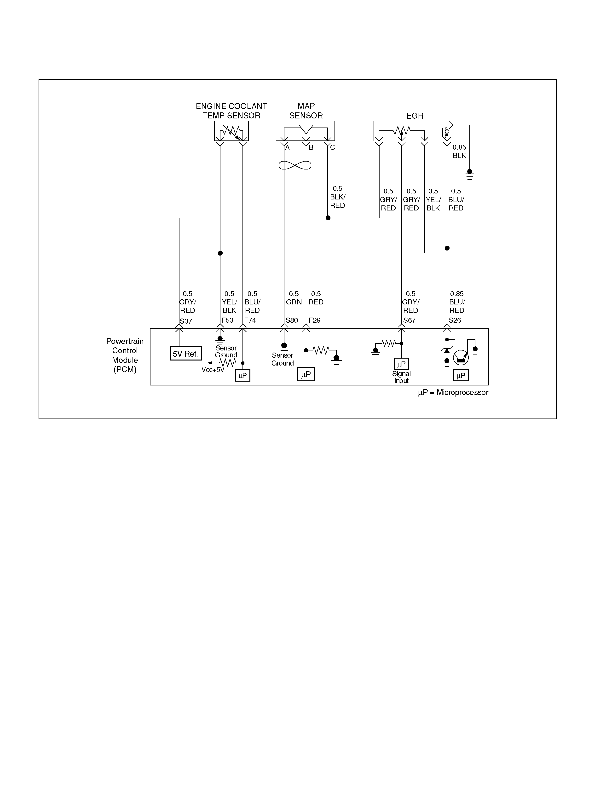
DIAGNOSTIC TROUBLE CODE (DTC) P1404 EGR STUCK CLOSED
060R100136
Circuit Description
The powertrain control module (PCM) monitors the
EGR valve pintle po sition input to ensure that the va lve
responds properly to commands from the PCM, and to
detect a fault if current pintle zero position is different
from the learned zero position. If the PCM detects a
pintle pos ition signal i ndicates more than 30 % different
between current zero position and the learned zero
position for more than 5 seconds, and this condition
exists 3 times during trip, then the PCM will set DTC
P1404.
Conditions for Setting the DTC
• Igni tio n voltage is between 11 and 16 volts.
• Intake Air temp is more than 3°C.
• Desired EGR position is more than 3 %.
• Difference of EGR pintle position between current
and the learn ed zero is more than 15 %.
Action Taken When the DTC Sets
• The PCM will illuminate the malfunction indicator
lamp (MIL) after consecutive 2nd trip in which the
faul t is detected.
• The PCM will store conditions which were present
when the DTC was set as Freeze Frame and in
Failure Records data.
Conditi ons for Clea r ing the MIL/DTC
• The PCM will turn the MIL “OFF" on the third
consecutive trip cycle during which the diagnostic has
been run and the fault condition is no longer present.
• A history DTC P1404 will clear after 40 consecutive
warm-up cy cles have occurred without a fault.
• DTC P1404 can be cleared by using the Tech 2
“Clear Info" function.
Diag nostic Ai ds
Check for the following conditions:
• Ex cessive carbon deposit on EGR valve shaft and/or
foreign material may cause the EGR valve not to fully
seat. The carbon deposit may occur b y unusual port
operation. Re move foreign material and/or excessive
carbon deposit on EGR valve shaft and to allow the
EGR valve to be fully seated.
• Poor connection or damaged harness – Inspect the
wiring harness for damage.
Reviewing the Failure Records vehicle mileage since
the diagnostic test last failed may help determine how
often the condition that caused the DTC to be set
occurs. This may assist in diagnosing the condition.

DTC P1404 – EGR Stuck Closed
Step Action Value(s) Yes No
1 Was the “On-Board Diagnostic (OBD) System Check"
performed? —Go to Step 2 Go to OBD
System Check
2 1. Ignition “ON", engine “OFF", review and record
Tech 2 Failure Records Data .
2. Operate the vehicle within Failure Records
condition s as noted.
3. Using a Tec h 2 , monitor “DTC inf." for DTC P1404
until the DTC P1404 test runs. Note the result.
Does the Tech 2 indicates DTC P1404 failed this
ignition? — Go to Step 3 Refe r to
Diagnostic Aids
3 1. Disconnect the EGR valve harnes s connec tor.
2. Inspect the EGR valve and connectors for
damaged pin or terminals.
Were there any damaged pins or terminals? — Go to Step 4 Go to S tep 5
4 Repair the damaged pin or terminal.
Is the action complete ? — Verify r epair —
5 1. Remove EGR valve from Engine.
2. Inspect EGR valve for any excessive carbon
deposit on EGR shaft.
3. Inspect for any foreign material inside of EGR
valve.
Was excessive carbon deposit on EGR valve shaft
and/or foreign material in EGR valve ? — G o to Step 6 Go to Step 7
6 1. Clean up EGR valve shaft and inside of EGR
valve.
2. Remove foreign material from EGR valve.
3. Visually inspect damage of pintle and seat to see
if it is bent. If damaged, leakage may occur.
Was there any severe damage which affects function? — Go to St ep 8 Verify repa ir
Go to Step 7
7 1. Insta ll the EGR v alv e .
2. Ignition “OFF".
3. Install the Tech 2.
4. Run the engine at idle.
5. On the Tech 2, select EGR Control Tes t.
6. Use the “UP" arrow to increase the EGR from 0%
to 40%.
Did EGR wo rk prop erly? — — G o to Step 8
8 1. Reset the learned zero EGR valve position.
2. Repeat step 7.
Did EGR work pr operly? — Verify repair Go to Step 9
9 Replac e the EGR valve.
Does DTC P1404 still fail “DT C" test on the Tec h 2? — Go to St ep 10 Verify repair
10 Replace the PCM.
Important: The replacement PCM must be
programmed. Refer to Section 0C-1 - Service
Program ming Syst em.
Important: Refer to Section 11 - Engin e Im mobiliser
System for the Immobiliser Programming procedure.
Important: Ensure the latest software program is
downloaded to the PCM.
Is the action complete ? — Verify repair —

DIAGNOSTIC TROUBLE CODE (DTC) P1514 TPS -
MAF CORRELATION ERROR
060R100073
Circuit Description
• The throttle position (TP) sensor circuit provides a
voltage signal relative to throttle blade angle.
The t hrottle blad e angle will vary about 8 % at cl osed
throttle to about 92 % at wide open throttle ( WOT).
• The mass air flow (MAF) sensor measures the
amou nt of air which passes through it in to the engine
during a given time. The powertrain Control Module
(PCM) uses the mass air flow information to monitor
engine operating conditions for fuel delivery
calculations.
A large quantity of air entering the engine indicates
an accelerator or high load situation, while a small
quantity or air indicates deceleration or idle.
The MAF sensor produces a frequency signal which
can be monitored using a Tech 2. The frequency will
vary within a range of around 4 to 7g/s at idle to
aro und 25 to 40g/s at maximum engine load.
Conditions for setting the DTC
• T he engin e is running.
• No MAF sensor DTCs are set.
• T hrottle actuation mode is not off.
• MAF reading-ETC estimated air flow is less than 40g/
s for 250 failures within te st 1000 test samples
(15.6 m sec).
Action Taken When the DTC Sets
• The PCM will illuminate the malfunction indicator
l a mp (M IL ) the fi r s t time th e fa ult is d e te c te d .
• The PCM calculates an air flow value based on idle
air control valve position, throttle position, RPM and
barome tric pressure.
• The PCM will store condition which were present
when the DTC was set as Freeze Frame and in the
Failure Records data.
Conditi ons for Clea r ing the MIL/DTC
• The PCM will turn the MIL “OFF" on the third
consecutive trip cycle during which the diagnostic has
been run and the fault conditions is no longer
present.
• A history DTC P1514 will clear after 40 consecutive
trip cycle during which the warm up cycles have
occurred without a fault.
• DTC P1514 can be cleared using the Tech 2 “Clear
Info" function.

Diagn ostic Aids
An intermittent may be caused by the following:
• Poor connections.
• M isrouted harnes s.
• R ubbed th rough wire insulation.
• Brok en wire inside the insulation.
Check for the following conditions:
• Poor connection at PCM - Inspect harness
connectors for backed out terminals, improper
mating, broken locks, i mp roperly form ed or dam aged
terminals, and poor terminal to wire connection.
• Damaged harness - Inspect the wiring harness for
damage. If the harness appears to be OK, observe
the Mas s Air Flow, TP se nsor 1, TP sensor 2 display
on the Tech2 while moving connectors and wiring
harnesses related to the sensor.
• Plu gged intake air duct or fil ter element
• A wi de - open t hrottle accelerator fr om a stop shoul d
cause the mass air flow displayed on a Tech2 to
increase from about 3 – 6 g/s at idle to 100 g/s or
greater at the time of the 1 – 2 shift. If not, check for a
restriction.
A change in the display will indicate the location of
the fault. If DTC P1514 cannot be duplicated, the
information included in the F ailure Records data can
be useful in vehicle mileage since the DTC was last
set.
If it is determined that the DTC occurs intermittently,
performing the DTC P1514 Diagnostic Chart may
isolate the cause of the fault.
DTC P1514 - TPS-MAF Correlation Error
Step Action Value(s) Yes No
1 Was the “On-Board (OBD) System Check"
performed? —Go to Step 2 Go to OBD
System Check
2 Was the “Electric Throttle Control (ETC) System
Check" performed? —Go to St ep 3 Go to ET C
System Chec k
3 1. Ignition “ON", engine “OFF".
2. Review and record Te ch 2 Failure Records data.
3. Operate the vehicle within Failure Records
condition s as noted.
4. Using a Tech2, monitor “DTC" info for DTC
P1514.
Does the Tech2 indicate DTC P1514 failed this
ignition? — G o to Step 4 Refer to
Diagnostic Aids
4 1. Start the engine.
2. With the engine idling, monitor “MAF Frequency"
display on the Tech 2.
Is the “MAF Frequenc y" below the specified value? 6 ∼ 10 g/s Go t o St ep 5 Go to St ep 8
5 1. Ignition “OFF".
2. Disconnect the MAF sensor connector.
3. Ignition “ON", engine idling.
4. Using a Te ch2, moni tor “MAF Frequency".
Does the Tech2 indicate a “MAF Frequency" at the
specified value? 0g/s G o to Step 6 Go to Step 7
6 Replace the MAF sensor.
Is the action comple te ? — Verify repair Go to Step 9
7 1. Check the M AF harnes s for incorrect routing near
high voltage components (solenoids, relays,
motors).
2. If incorrect routing is found, correct the harness
routing.
Was a problem found? — Verify repair Go to Step 7

8 1. With the engine idling, monitor “MAF Frequency"
display on the Tech 2.
2. Quickly snap open throttle to wide open throttle
while under a road load and record value.
Does the Tech2 indicate a “MAF Frequency" at the
specified value? 6 ∼ 10 g/s Go to Step 6 Go to Step 9
9 1. Ignition“ON", engine not running.
2. Observe the MAP reading on the Tech2.
Is the MAP reading less than the specified value? 65kPa Go to Step 10 Go to St ep 13
10 1. Disconnect the MAP sens or.
2. Connect a test 5 volt reference circuit and the
MAP signal at the MAP sensor harness connector.
3. Observe the MAP reading on the Tech2.
Is the MAP reading less than the specified value? (If
no, start with diagnosis chart for other sensors in the
circu it and se e if 5Vretu rn s.) — Go to Step 12 Go to Step 11
11 1. Check the MAP signal circuit between the PCM
and MAP ground circuit.
2. If the MAP signal circuit is open or shorted, repair
it as necessary.
Was the M AP signal circuit open or shorted? — Veri fy repair Go to Step 13
12 Replace the MAP se nsor.
Is the action complete ? — Verify r epair —
13 Observe the TP angle reading on the Tech2 while
slowly opening the throttle.
Does the TP angle increase steadily and evenly from
the closed throttle value to the wide open throttle
value?
Closed
throttle TP
sensor 1 =8 ∼
10 % TP
sensor 2 =90
∼ 92 % Wide
open throttle
TP sensor 1
=90 ∼ 92 %
TP sensor 2
=8 ∼ 10 % Refer to
Diagnostic Aids Go to St ep 14
14 1. Disconnect the TP sensor.
2. Observe the TP sensor reading on the Tech2.
Is the TP sensor reading near the specif ied value? 0V Go to Step 15 Go to St ep 16
15 1. Connect a test light between the 5Volt reference
circuit and the TP1 and TP2 sensor signal circuit
at the TP sensor harness connect or.
2. Observe the TP sensor reading on the Tech2.
Is the TP sensor reading near the specif ied value? 5V Go to Step 18 Go to St ep 17
16 Check the following items;
1. TP1 and TP2 signal circuit for a short to voltage .
2. TP1 and TP2 sensor ground circuit for high
resistance between the PCM and the TP sens or.
3. TP1 and TP2 sensor ground circuit for a poor
connection.
4. If a problem is found, repair wiring harness as
necessary.
Was a problem found? — Verify repair Go to St ep 19
Step Action Value(s) Yes No

17 Check the following items;
1. TP1and TP2 signal circuit or 5 volt reference
circuit for a poor connection.
2. TP1 and TP2 signal circuit or 5 volt reference
circuit for high resistance between the PCM and
the TP1and TP2 s ensor.
3. If a problem is found, repair wiring harness as
necessary.
Was a problem found? — Verify repair Go to St ep 18
18 Replace the TP sensor.
Is the action complete ? — Verify r epair —
19 Replace the PCM.
Important: The replacement PCM must be
programmed. Refer to Section 0C-1 - Service
Program ming Syst em.
Important: Refer to Section 11 - Engin e Im mobiliser
System for the Immobiliser Programming procedure.
Important: Ensure the latest software program is
downloaded to the PCM.
Is the action complete ? — Verify repair —
Step Action Value(s) Yes No

DIAGNOSTIC TROUBLE CODE (DTC)
P1515 COMMAND - ACTUAL TPS CORRELATION ERROR
D06RY00111
Circuit Description
• The throttle position (TP) sensor circuit provides a
voltage signal relative to throttle position (blade
angle).
The t hrottle blad e angle will vary about 8 % at cl osed
throttle to about 92 % at wide open throttle(WOT).
• The DC motor circuit provides a voltage signal
relative to command t hrottle position (blade angle).
• This DTC detects the difference between actual
throttle position and command throttle position.
Conditions for setting the DTC
• T he ignition is “ON".
• T hrottle actuat ion mode is normal.
• Command Throttle position - Actual Throttle position
is more than + 5 % for 100 counts within test 1000
test samples (15.6 m sec) else Actual Throttle
position is less than + 40 % and Command Throttle
positi on - Actual Throttle position is more than - 5 %
or Command Throttle position - Actual Throttle
position is more than - 20 % for 150 failures within
test 1000 test sample s (15.6 m sec).
Action Taken When the DTC Sets
• The PCM will illuminate the malfunction indicator
l a mp (M IL ) the fi r s t time th e fa ult is d e te c te d .
• The PCM calculates an air flow value based on idle
air control valve position, throttle position, RPM and
barome tric pressure.
• The PCM will store conditions which were present
when the DTC was set as Freeze Frame and in the
Failure Records data.
Conditi ons for Clea r ing the MIL/DTC
• The PCM will turn the MIL “OFF" on the third
consecutive trip cycle during which the diagnostic has
been run and the fault condition is no longer present.
• A history DTC P1515 will clear after 40 consecutive
trip cycle during which the warm up cycles have
occurred without a fault.
• DTC P1515 can be cleared using the Tech 2 “Clear
Info" function.

Diagnostic Aids
An intermittent may be caused by the following:
• Poor connections.
• Misrouted harness.
• Rubbed through wire insulation.
• Broken wire inside the insulation.
Check for the following conditions:
• Poor connection at PCM-Inspect harness connectors
for backed out terminals, improper mating, locks,
improperly formed or damaged terminals, and poor
terminal to wire connection.
• Damaged harness-Inspect the wiring harness for
damage. If the harness appears to be OK, observe
the TP sensor 1, TP sensor 2 display on the Tech2
while moving connectors and wiring harnesses
related to the sensor.
A change in the display will indicate the location of
the fault. If DTC P1515 cannot be duplicated, the
information included in the Failure Records data can
be useful in determining vehicle mileage since the
DTC was last set.
If it is determined that the DTC occurs intermittently,
performing the DTC P1515 Diagnostic Chart may
isolate the cause of the fault.
DTC P1515 - Command - Actual TPS Correlation Error
Step Action Value(s) Yes No
1 Was the “On-Board (OBD) System Check"
performed? —Go to Step 2 Go to OBD
System Check
2 Was the “Electric Throttle Control (ETC) System
Check" performed? —Go to St ep 3 Go to ET C
System Chec k
3 1. Ignition “ON", engine “OFF".
2. Review and record Te ch2 Failure Records data.
3. Operate the vehicle within Failure Records
condition s as noted.
4. Using a Tech2, monitor “ DTC" info for DTC
P1515.
Does the Tech2 indicate DTC P1515 failed this
ignition? — G o to Step 4 Refer to
Diagnostic Aids
4 Observe the TP angle reading on the Tech2 while
slowly opening the throttle.
Does the TP angle increase steadily and evenly from
the closed throttle value to the wide open throttle
value?
Closed
throttle TP
sensor 1 =8 ∼
10 % TP
sensor 2 =90
∼ 92 % Wide
open throttle
TP sensor 1
=90 ∼ 92 %
TP sensor 2
=8 ∼ 10 % G o to St ep 8 Go to St ep 5
5 1 . Ig nit io n “ OFF" .
2. Disconnect the DC motor.
Is the DC motor reading near the specified value? 0.3 ∼ 100 ΩGo to Step 6 Go to St ep 7
6 Check the DC motor harness between the PCM and
DC Motor circuit at the DC motor harness connector.
Was a problem found? — Verify repair Go to Step 8
7 Replac e the DC motor.
Is the action comple te ? — Verify repair Go to Step 6
8 1 . Disconnect the TP sensor.
2. Observe the TP sensor reading on the Tech2.
Is the TP sensor reading near the specif ied value? 0V Go to St ep 9 Go to Step 10
9 1. Connect a test light between the 5Volt reference
circuit and the TP1 and TP2 sensor signal circuit
at the TP sensor harness connect or.
2. Observe the TP sensor reading on the Tech2.
Is the TP sensor reading near the specif ied value? 5V Go to Step 12 Go to Step 11

10 Check the following items;
1. TP1 and TP2 signal circuit for a short to voltage .
2. TP1 and TP2 sensor ground circuit for high
resistance between the PCM and the TP sens or.
3. TP1and TP2 sensor ground circuit for a poor
connection.
4. If a problem is found, repair wiring harness as
necessary.
Was a problem found? — Verify repair Go to St ep 13
11 Check the following items;
1. TP1and TP2 signal circuit or 5 volt reference
circuit for a poor connection.
2. TP1 and TP2 signal circuit or 5 volt reference
circuit for high resistance between the PCM and
the TP1and TP2 s ensor.
3. If a problem is found, repair wiring harness as
necessary.
Was a problem found? — Verify repair Go to St ep 13
12 Replace the TP sensor.
Is the action complete ? — Verify r epair —
13 Replace the PCM.
Important: The replacement PCM must be
programmed. Refer to Section 0C-1 - Service
Program ming Syst em.
Important: Refer to Section 11 - Engin e Im mobiliser
System for the Immobiliser Programming procedure.
Important: Ensure the latest software program is
downloaded to the PCM.
Is the action complete ? — Verify repair —
Step Action Value(s) Yes No

DIAGNOSTIC TROUBLE CODE (DTC)
P1516 COMMAND - ACTUAL TPS CORRELATION ERROR
D06RY00111
Circuit Description
• The throttle position (TP) sensor circuit provides a
voltage signal relative to throttle position (blade
angle). The t hrott le blade angle will vary about 8% at
closed throttle to about 92 % at wide open throttle
(WOT).
• The DC motor circuit provides a voltage signal
relative to command t hrottle position (blade angle).
• This DTC detects the difference between actual
throttle position and command throttle position in
steady s tate.
Conditions for setting the DTC
• T he ignition is “ON".
• Throttle Actuation mode is normal.
• Command Throttle position-Actual Throttle position is
more than 2 % when desired TPS is steady within 0.5
% for 30 second within test samples (30 second)
Action Taken When the DTC Sets
• The PCM will illuminate the malfunction indicator
lamp (MIL) the first time the fault is detected.
• The PCM calculates an air flow value based on idle
air control valve position, throttle position, RPM and
barome tric pressure.
• The PCM will store conditions which were present
when the DTC was set as Freeze Frame and in the
Failure Records data.
Conditi ons for Clea r ing the MIL/DTC
• The PCM will turn the MIL “OFF" on the third
consecutive trip cycle during which the diagnostic has
been run and the fault condition is no longer present.
• A history DTC P1516 will clear after 40 consecutive
trip cycle during which the warm up cycles have
occurred without a fault.
• DTC P1516 can be cleared using the Tech 2 “Clear
Info" function.
Diag nostic Ai ds
An intermittent may be caused by the following:
• Poor c onnect ions.
• M isrouted harnes s.
• Ru bbed th rough wire insulation.
• Brok en wire inside the insulation.

Check for the following conditions:
• Poor connection at PCM-Inspect harness connectors
for backed out terminals, improper mating, broken
locks, improperly formed or damaged terminals, and
poor terminal to wire connection.
• Damaged harness - Inspect the wiring harness for
damage. If the harness appears to be OK, observe
the TP sensor 1, TP sensor 2 display on the Tech2
while moving connectors and wiring harnesses
related to the sensor.
A change in the display will indicate the location of
the fault. If DTC P1516 cannot be duplicated, the
information included in the Failure Records data can
be useful in determined vehicle mileage since the
DTC was last set.
If it is determining that the DTC occurs intermittently,
performing the DTC P1516 Diagnostic Chart may
isolate the cause of the fault.
DTC P1516 - Command - Actual TPS Correlation Error
Step Action Value(s) Yes No
1 Was the “On-Board (OBD) System Check"
performed? —Go to Step 2 Go to OBD
System Check
2 Was the “Electric Throttle Control (ETC) System
Check" performed? —Go to St ep 3 Go to ET C
System Chec k
3 1. Ignition “ON", engine “OFF".
2. Review and record Te ch2 Failure Records data.
3. Operate the vehicle within Failure Records
condition s as noted.
4. Using a Tech2, monitor “DTC" info for DTC
P1516.
Does the Tech2 indicate DTC P1516 failed this
ignition? — G o to Step 4 Refer to
Diagnostic Aids
4 Observe the TP angle reading on the Tech2 while
slowly opening the throttle.
Does the TP angle increase steadily and evenly from
the closed throttle value to the wide open throttle
value?
Closed
throttle TP
sensor 1 =8 ∼
10 % TP
sensor 2 =90
∼ 92 % Wide
open throttle
TP sensor 1
=90 ∼ 92 %
TP sensor 2
=8 ∼ 10 % G o to St ep 8 Go to St ep 5
5 1 . Ig nit io n “ OFF" .
2. Disconnect the DC motor.
Is the DC motor reading near the specified value? 0.3 ∼ 100 ΩGo to Step 6 Go to St ep 7
6 Check the DC motor harness between the PCM and
DC Motor circuit at the DC motor harness connector.
Was a problem found? — Verify repair Go to Step 8
7 Replac e the DC motor.
Is the action comple te ? — Verify repair Go to Step 6
8 1 . Disconnect the TP sensor.
2. Observe the TP sensor reading on the Tech2.
Is the TP sensor reading near the specif ied value? 0V Go to St ep 9 Go to Step 10
9 1. Connect a test light between the 5 Volt reference
circuit and the TP1 and TP2 sensor signal circuit
at the TP sensor harness connect or.
2. Observe the TP sensor reading on the Tech2.
Is the TP sensor reading near the specif ied value? 5V Go to Step 12 Go to Step 11

10 Check the following items;
1. TP1 and TP2 signal circuit for a short to voltage .
2. TP1 and TP2 sensor ground circuit for high
resistance between the PCM and the TP sens or.
3. TP1and TP2 sensor ground circuit for a poor
connection.
4. If a problem is found, repair wiring harness as
necessary.
Was a problem found? — Verify repair Go to St ep 13
11 Check the following items;
1. TP1and TP2 signal circuit or 5 volt reference
circuit for a poor connection.
2. TP1 and TP2 signal circuit or 5 volt reference
circuit for high resistance between the PCM and
the TP1 and TP2 sensor .
3. If a problem is found, repair wiring harness as
necessary.
Was a problem found? — Verify repair Go to St ep 13
12 Replace the TP sensor.
Is the action complete ? — Verify r epair —
13 Replace the PCM.
Important: The replacement PCM must be
programmed. Refer to Section 0C-1 - Service
Program ming Syst em.
Important: Refer to Section 11 - Engin e Im mobiliser
System for the Immobiliser Programming procedure.
Important: Ensure the latest software program is
downloaded to the PCM.
Is the action complete ? — Verify repair —
Step Action Value(s) Yes No
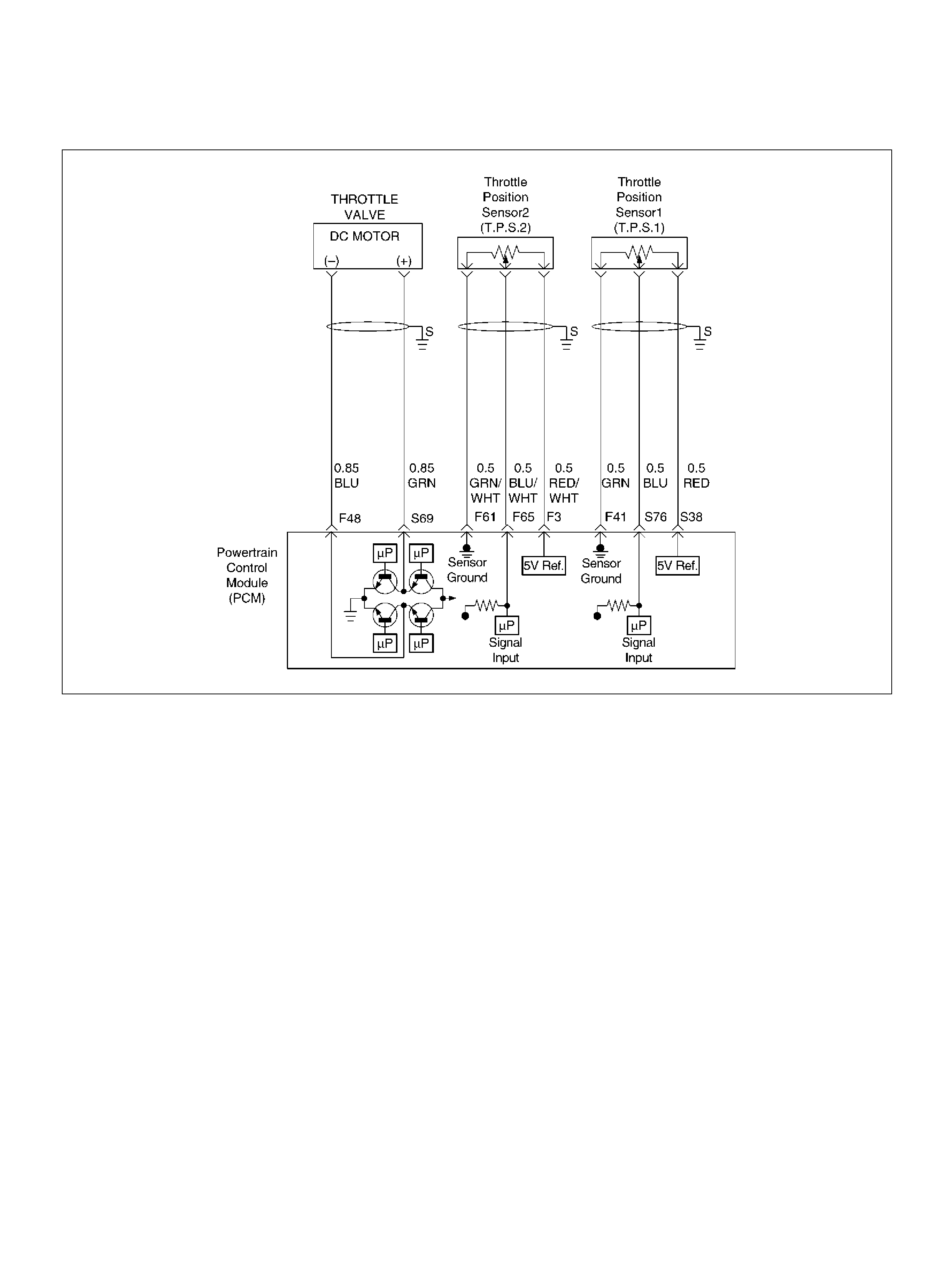
DIAGNOSTIC TROUBLE CODE (DTC)
P1523 ACTUATOR CONTROL RETURN PERFORMANCE
D06RY00111
Circuit Description
• The throttle position (TP) sensor circuit provides a
voltage signal relative to throttle position (blade
angle).
The t hrottle blad e angle will vary about 8 % at cl osed
throttle to about 92 % at wide open throttle(WOT).
• The DC motor circuit provides a voltage signal
relative to command t hrottle position (blade angle).
• This DTC detects if the throttle return to the default
pos ition at key on is steady.
Conditions for setting the DTC
• T he ignition is “ON".
• Normalized TPS is less than 7 % but Normalized TPS
is more than 25 %.
Action Taken When the DTC Sets
• The PCM will not turn the malfunction indicator lamp
(MIL) “ON".
• The PCM will store conditions which were present
w hen the DTC was s et as Failure Records onl y. T his
informat ion will not be stored as Freeze Frame data.
Conditi ons for Clea r ing the MIL/DTC
• The PCM will turn the MIL “OFF" on the third
consecutive trip cycle during which the diagnostic has
been run and the fault condition is no longer present.
• A history DTC P1523 will clear after 40 consecutive
trip cycle during which the warm up cycles have
occurred without a fault.
• DTC P1523 can be cleared using the Tech 2 “Clear
Info" function.
Diag nostic Ai ds
An intermittent may be caused by the following:
• Poor c onnect ions.
• M isrouted harnes s.
• Ru bbed th rough wire insulation.
• Brok en wire inside the insulation.
Check for the following conditions:
• Poor c onnection at PCM-Ins pect harness connectors
for backed out terminals, improper mating, broken
locks, improperly formed or damaged terminals, and
poor terminal to wire connection.

• Damaged harness-Inspect the wiring harness for
damage. If the harness appears to be OK, observe
the TP sensor 1, TP sensor 2 display on the Tech2
while moving connectors and wiring harnesses
related to the sensor.
A change in the display will indicate the location of
the fault. If DTC P1523 cannot be duplicated, the
information included in the Failure Records data can
be useful in determined vehicle mileage since the
DTC was last set.
If it is determing that the DTC occurs intermittently,
performing the DTC P1523 Diagnostic Chart may
isolate the cause of the fault.
DTC P1523 - Actuator Control Return Performance
Step Action Value(s) Yes No
1 Was the “On-Board (OBD) System Check"
performed? —Go to Step 2 Go to OBD
System Check
2 Was the “Electric Throttle Control (ETC) System
Check" performed? —Go to St ep 3 Go to ET C
System Chec k
3 Observe the TP angle reading on the Tech2 while
slowly opening the throttle.
Does the TP angle increase steadily and evenly from
the closed throttle value to the wide open throttle
value?
Closed
throttle TP
sensor 1 =8 ∼
10 % TP
sensor 2 =90
∼ 92 % Wide
open throttle
TP sensor 1
=90 ∼ 92 %
TP sensor 2
=8 ∼ 10 % G o to St ep 7 Go to St ep 4
4 1 . Ig nit io n “ OFF" .
2. Disconnect the DC motor.
Is the DC motor reading near the specified value? 0.3 ∼ 100 ΩGo to Step 5 Go to St ep 6
5 Check the DC motor harness between the PCM and
DC Motor circuit at the DC motor harness connector.
Was a problem found? — Verify repair Go to Step 7
6 Replac e the DC motor.
Is the action comple te ? — Verify repair Go to Step 5
7 1 . Disconnect the TP sensor.
2. Observe the TP sensor reading on the Tech2.
Is the TP sensor reading near the specif ied value? 0V Go to St ep 8 Go to St ep 9
8 1. Connect a test light between the 5 Volt reference
circuit and the TP1 and TP2 sensor signal circuit
at the TP sensor harness connect or.
2. Observe the TP sensor reading on the Tech2.
Is the TP sensor reading near the specif ied value? 5V Go to Step 11 Go to Step 10
9 Check the following items;
1. TP1 and TP2 signal circuit for a short to voltage .
2. TP1 and TP2 sensor ground circuit for high
resistance between the PCM and the TP sens or.
3. TP1and TP2 sensor ground circuit for a poor
connection.
4. If a problem is found, repair wiring harness as
necessary.
Was a problem found? — Verify repair Go to St ep 12

10 Check the following items;
1. TP1and TP2 signal circuit or 5 volt reference
circuit for a poor connection.
2. TP1 and TP2 signal circuit or 5 volt reference
circuit for high resistance between the PCM and
the TP1and TP2 s ensor.
3. If a problem is found, repair wiring harness as
necessary.
Was a problem found? — Verify repair Go to St ep 12
11 Replace the TP sensor.
Is the action complete ? — Verify r epair —
12 Replace the PCM.
Important: The replacement PCM must be
programmed. Refer to Section 0C-1 - Service
Program ming Syst em.
Important: Refer to Section 11 - Engin e Im mobiliser
System for the Immobiliser Programming procedure.
Important: Ensure the latest software program is
downloaded to the PCM.
Is the action complete ? — Verify repair —
Step Action Value(s) Yes No
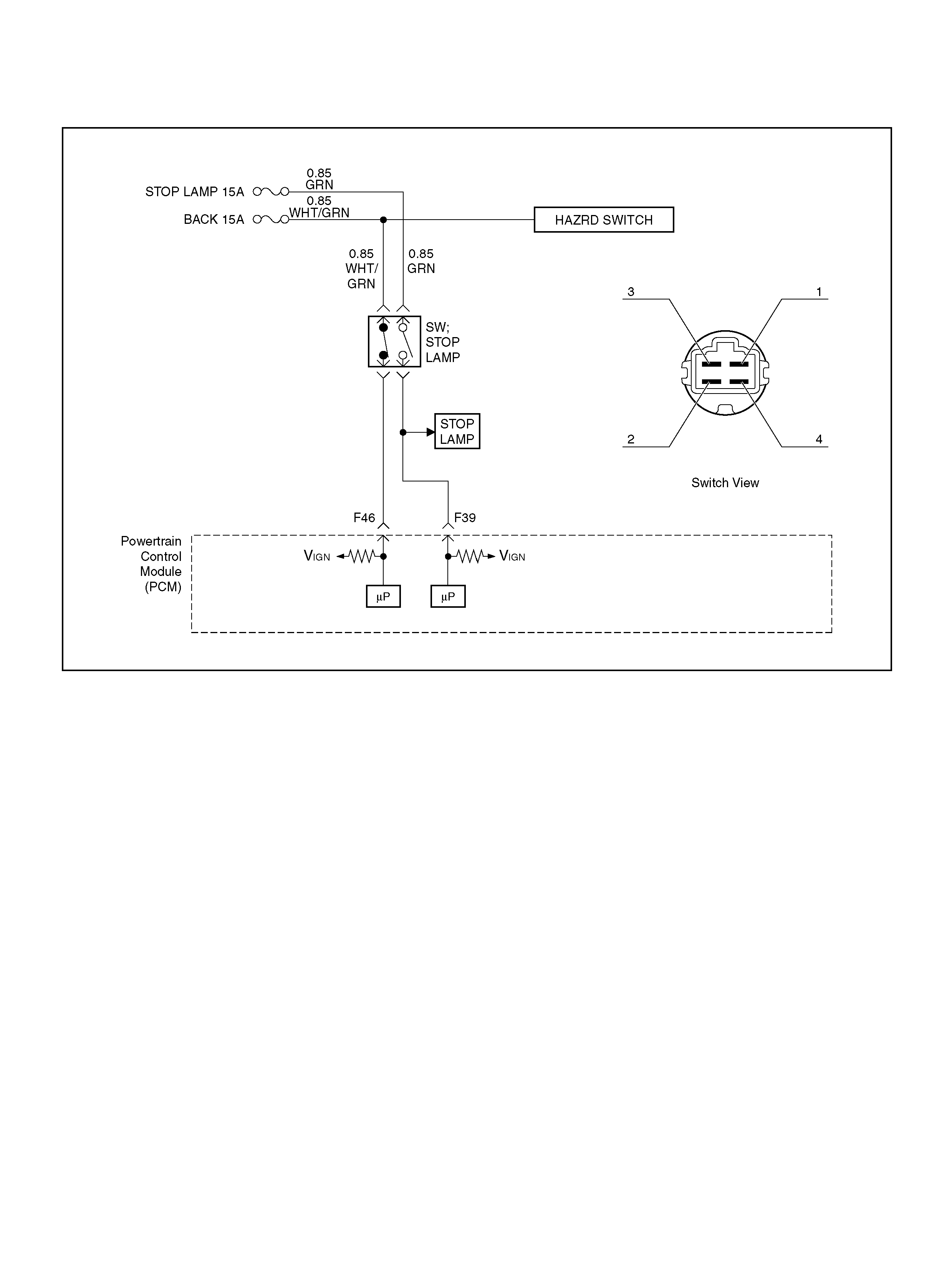
DIAGNOSTIC TROUBLE CODE (DTC) P1571 BRAKE SWITCH NO OPERATION
060R100138
Circuit Description
The brake switch has 3 functions.
• Brake pedal operation check
• Brak e light operation (On and off)
• Cruise control (Cancel)
The PCM receives vehicle speed and switch position
signals from the brake switch. The PCM sets brake
operating conditions in response to these signals.
If the brake switch is on, the brake system is in normal
operation (cruise control cancelled).
Conditions for Setting the DTC
• Two break switch signals do not acknowledge after
signal changed.
• Switch does not change during accelerating vehicle
or decel erating.
• VSS is not fa u lt.
• Engine is running.
Action Taken When the DTC Sets
• The PCM will not turn the malfunction indicator lamp
(MIL) “ON".
• The PCM will store conditions which were present
when t he DTC was set a s Failure Records onl y. Th is
informat ion will not be st ored as Freez e Frame data.
Conditions for Clearing the DTC
• DTC P1571 can be cleared by using the scan tool
“Clear Info" function.
Diag nostic Ai ds
• Damaged harness–Inspect the wiring harness for
damage. If the harness appears to be OK, observe
the fuel level display on the scan tool while moving
connectors and wiring harnesses related to the
sensor. A change in the display will indicate the
location of the fault.

DTC P1571 Brake Switch No Operation
Step Action Value(s) Yes No
1 Was the “On -Board Diagnostic (OBD) System Chec k"
performed? —Go to Step 2 Go to OBD
System Check
2 1. Ignit io n “ O ff".
Engine “Off".
2. Check following fuses.
• BACK 15 A
• S TOP LAM P 15A
Was a problem found? — Verify repair Go to Step 3
3 1. Make adjustment to the brake switch.
(Refer to “Brake switch" in “10A CRUISE
CONTROL SYSTEM".)
Was the proble m found? — Verify repair Go to Step 4
4 1. Push the shaft on brake switch.
2. Check shaft operation for smooth movem ent.
Was the proble m found? — Verify repair —
5 1. Disconnect the connector at brake switch.
2. Check following terminal pin by ohmmet er.
(Leave the shaft position at brake switch. Don't
push it.)
• Bet ween pin 1 and pin 2
• Bet ween pin 3 and pin 4
Was i t specified value?
Between pin1
and pin2 is
0Ω, Be tween
pin3 and pin4
is ∞Ω Go to Step 6 Go to S tep 9
6 1. Disconnect the connector at brake switch.
2. Check following terminal pin at ohmmet er.
(Don't press the button of the brake switch.)
• •Between pin 1 and pin 2
• •Between pin 3 and pin 4
Was i t specified value?
Between pin1
and pin2 is
∞Ω, Between
pin3 and pin4
is 0ΩGo to Step 7 Go to Step 9
7 1. Probe related circuits for open or short to ground.
2. If a problem was found, repair as necessary.
Was a problem found? — Verify repair Go to Step 8
8 Replace the PCM.
Important: The replacement PCM must be
programmed. Refer to Section 0C-1 - Service
Program ming Syst em.
Important: Refer to Section 11 - Engin e Im mobiliser
System for the Immobiliser Programming procedure.
Important: Ensure the latest software program is
downloaded to the PCM.
Is the action complete ? — Verify repair —
9 1. Replace the brake switch.
Was the ac tion compl eted? — Veri fy repair —

DIAGNOSTIC TROUBLE CODE (DTC) P1626 -
NO RESPONSE FROM IMMOBILISER
060RA00003
Circuit Description
An encrypted signal is transmitted from the Immobiliser
Control Unit to the PCM when the ignition is turned ON.
Condition for Setting the DTC
A DTC 1626 will be set when:
• No there is no signal transmission from the ICU to
the PCM within 0.5 seconds of turning the ignition
ON.
Action Taken When the DTC sets
• R apid flashing of the MIL (“CHECK ENGI NE” lamp).
• T he Engine does not start.
Condition for Cle aring the MIL/DTC
• Clear DTC information with TECH 2. Refer to
Se ctio n 0C TECH 2 Diagnosis
Diag nostic Ai ds
Check for the following conditions:
• Poor connection at PCM and Immobiliser Inspect
harness connectors for backed out terminals,
improper mating, b roken locks, improperly formed or
damaged terminals, and poor terminal to wire
connection.
• Damaged harness-Inspect the wiring harness for
damage, If the harness appears to be OK, disconnect
the PCM and Immobiliser, turn the ignition “ON" and
observe a voltmeter connected to the suspect driver
circuit at the PCM and Immobiliser harness connector
while moving connectors and wiring harnesses
relates to the MIL. A change in voltage will indicate
the location of the fault.

DTC P1626-No Response From Immobiliser
Step Action Value(s) Yes No
1 Was the “On-Board Diagnostic (OBD) system Check"
performed? — Go to Step 2 Go to OBD
system check
2 Using the Tec h2 system se lection me nu, s elect ‘Body
- Immobiliser - DTC’ function.
Does the Tech2 display B**** appear?
—
Refer to
Section11
“Engine
Immobiliser
System" Go to Step 3
3 Does the Tech2 display DTC P1626 appear? — Go to Step 4 R efe r to
Diagnostic Aids
4 Check the PCM and ICU harness and connectors for:
1. Backed out terminals, improper mating, broken
locks, improperly formed or damaged terminals,
and poor terminal to wire connection.
2. Damaged ha rness - Inspect the wiring harnes s for
damage.
If a problem found, repair as necessary.
Was a problem found? Verify repair Go to Step 5
5 1. Disconnect the Vehicle Speed Sensor line VSS
OUT harness.
2. Check the circuit open or short voltage between
the Pin No.7 and Pin No.6 by DMM.
If a problem found, repair as necessary.
Was a problem found? — Verify repair Go to Step 5
6 Replace the PCM.
Important: The replacement PCM must be
programmed. Refer to Section 0C-1 - Service
Program ming Syst em.
Important: Refer to Section 11 - Engin e Im mobiliser
System for the Immobiliser Programming procedure.
Important: Ensure the latest software program is
downloaded to the PCM.
Is the action complete ? — Verify repair —

DIAGNOSTIC TROUBLE CODE (DTC) P1631 -
RECEIVED RESPONSE WAS NOT CORRECT
060RA00003
Circuit Description
An encrypted signal is transmitted from the Immobiliser
Control Unit to the PCM when the ignition is turned ON.
Condition for Setting the DTC
A DTC 1631 will be set when:
• An incorrect sign al is trans mitted from the ICU to th e
PCM within 0.5 seconds of turning the ignition ON.
Action Taken When the DTC Sets
• R apid flashing of the MIL (“CHECK ENGI NE” lamp).
• T he Engine does not start.
Condition for Cle aring the MIL/DTC
• Clear DTC information with TECH 2. Refer to
Se ctio n 0C TECH 2 Diagnosis
Diag nostic Ai ds
Check for the following conditions:
• Poor connection at PCM and Immobiliser. Inspect
harness connectors for backed out terminals,
improper mating, b roken locks, improperly formed or
damaged terminals, and poor terminal to wire
connection.
• Damaged harness-Inspect the wiring harness for
damage, If the harness appears to be OK, disconnect
the PCM and Immobiliser, turn the ignition “ON" and
observe a voltmeter connected to the suspect driver
circuit at the PCM and Immobiliser harness connector
while moving connectors and wiring harnesses
relates to the MIL. A change in voltage will indicate
the location of the fault.

DTC P1631 Received response was not correct
Step Action Value(s) Yes No
1 Was the “On-Board Diagnostic (OBD) system Check"
performed? — Go to Step 2 Go to OBD
system check
2 Check the PCM and ICU harness and connectors for:
1. Backed out terminals, improper mating, broken
locks, improperly formed or damaged terminals,
and poor terminal to wire connection.
2. Damaged ha rness - Inspect the wiring harnes s for
damage.
If a problem found, repair as necessary.
Was a problem found? Ve rify repair Go to Step 3
3 Replace the PCM.
Important: The replacement PCM must be
programmed. Refer to Section 0C-1 - Service
Program ming Syst em.
Important: Refer to Section 11 - Engin e Im mobiliser
System for the Immobiliser Programming procedure.
Important: Ensure the latest software program is
downloaded to the PCM.
Is the action complete ? — Verify repair —
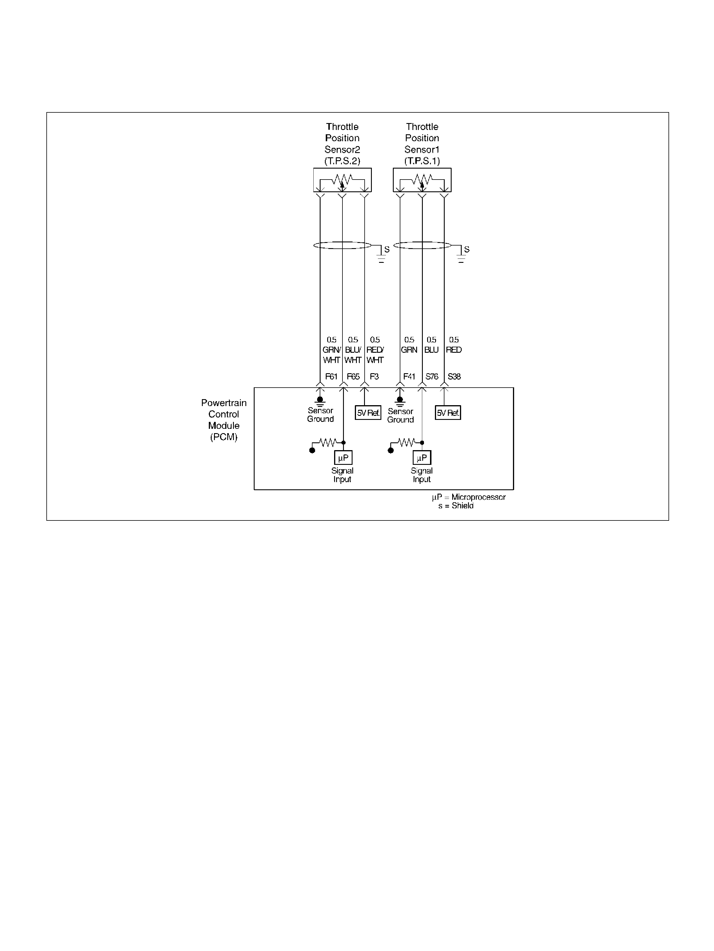
DIAGNOSTIC TROUBLE CODE (DTC)
P1635 REFERENCE VOLTAGE # 1 CIRCUIT FAULT
D06RY00093
Circuit Description
The TP sensor # 1 shares a 5 Volt reference with the
PCM.
If the PCM detects the 5 Volt reference for the TP
sensor # 1 is failure, DTCP1635 will be set.
Conditions for setting the DTC
• T he ignition is “ON".
• T he 5 Volt reference voltage for the TP sensor # 1 is
less than 4 volts.
• T he 5 Volt reference voltage for the TP sensor # 1 is
more than 5 volts.
Action Taken When the DTC Sets
• The PCM wi ll not illuminate the malfunction indicator
lamp (MIL) .
• The PCM will store conditions which were present
w hen the DTC was s et as Failure Records onl y. T his
informat ion will not be stored as Freeze Frame data.
Conditi ons for Clea r ing the MIL/DTC
• The PCM will turn the MIL “OFF" on the third
consecutive trip cycle during which the diagnostic has
been run and the fault condition is no longer present.
• A history DTC P1635will clear after 40 consecutive
trip cycle during which the warm up cycles have
occurred without a fault.
• DTC P1635 can be cleared using the Tech 2 “Clear
Info" function or by disconnecting the PCM battery
feed. Tech 2 “ Clear Info" function.

Diagnostic Trouble Code (DTC)
P1635 Reference Voltage # 1 Circuit Fault
Step Action Value(s) Yes No
1 Was the “On-Board(OBD)System Check" performed?—Go to Step 2 Go to OBD
System Check
2 1. Ignition “ON", engine not running.
2. Using a DVM at the PCM side of the connector,
check the voltage at t erm inal S38 (RED) pin.
Is the voltage in specified range? 4.95 – 5.0V Go t o ET C
System Check Go to Step 3
3 1. Ignition “ON", engine not running.
2. Using a DVM at the PCM side of the connector,
check the voltage at terminal F20 (RED/WHT) pin.
Is the voltage in specified range? 11. 6 – 12.7V Go to Step 4 Go to St ep 5
4 1. Ignition “ON", engine not running.
2. Using a DVM at the PCM side of the connector,
check the voltage at terminal F57 (RED/WHT) pin.
Is the voltage in specified range? 11. 6 – 12.7V Go to Step 6 Go to St ep 5
5 Obse rve th e bat tery voltage and circuit. If a p roblems,
repair it as necessary.
Was the proble m found? — Verify repair Go to Step 6
6 Replace the PCM.
Important: The replacement PCM must be
programmed. Refer to Section 0C-1 - Service
Program ming Syst em.
Important: Refer to Section 11 - Engin e Im mobiliser
System for the Immobiliser Programming procedure.
Important: Ensure the latest software program is
downloaded to the PCM.
Is the action complete ? — Verify repair —
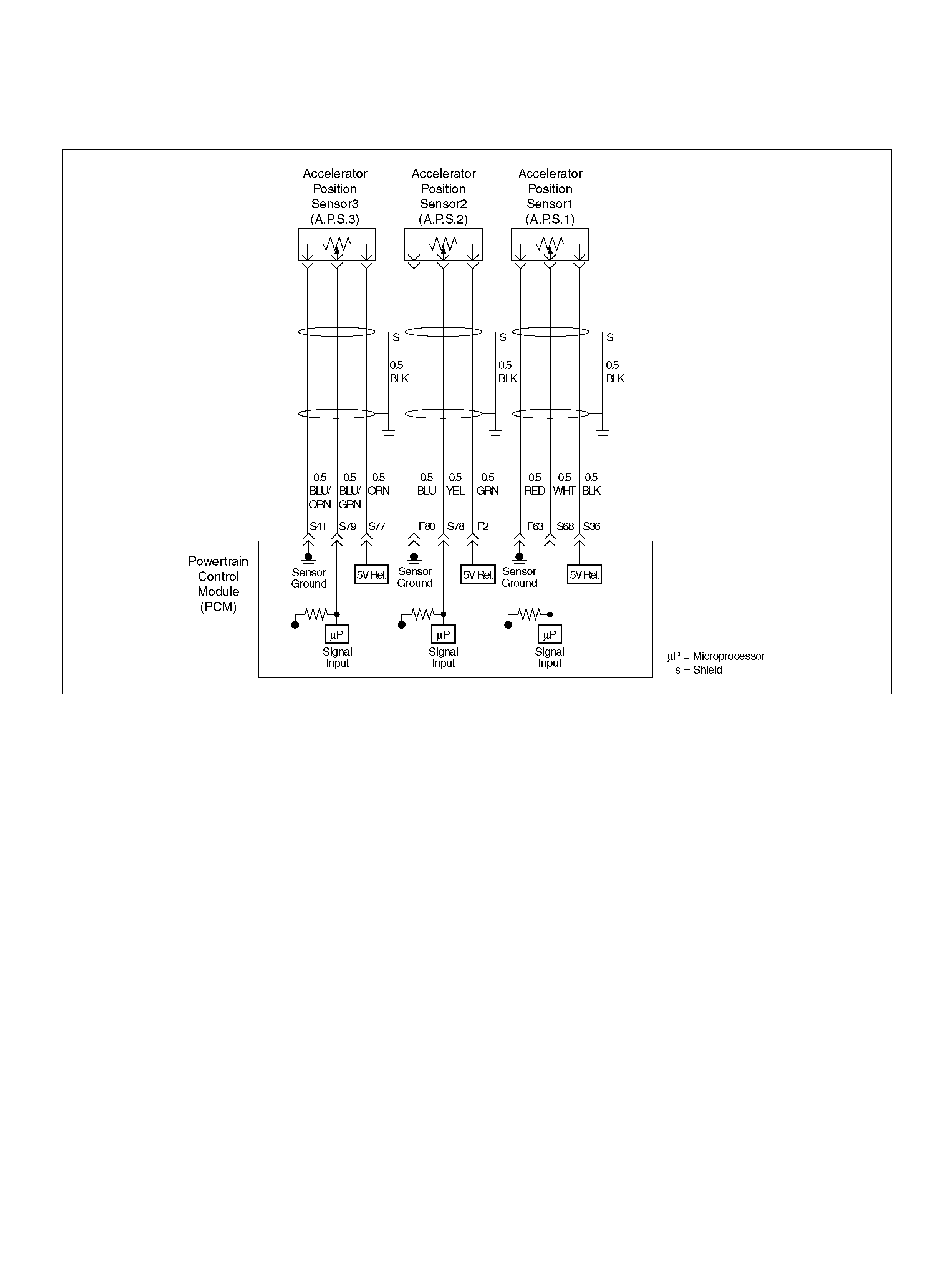
DIAGNOSTIC TROUBLE CODE (DTC)
P1639 REFERENCE VOLTAGE # 2 CIRCUIT FAULT
060R100141
Circuit Description
The AP sensor # 1shares a 5 Volt reference with the
PCM.
If the PCM detects the 5 Volt reference for the AP
sensor # 1 is failure, DT C P1 635 w ill be set.
Conditions for setting the DTC
• T he ignition is “ON".
• T he 5 Volt reference v oltage for t he AP senso r # 1 is
less than 4 volts.
• T he 5 Volt reference v oltage for t he AP senso r # 1 is
more than 5 volts.
Action Taken When the DTC Sets
• The PCM will not illuminate the malfunction indicator
lamp (MIL).
• The PCM will store conditions which were present
when t he DTC was set a s Failure Records onl y. Th is
informat ion will not be st ored as Freez e Frame data.
Conditi ons for Clea r ing the MIL/DTC
• The PCM will turn the MIL “OFF" on the third
consecutive trip cycle during which the diagnostic has
been run and the fault condition is no longer present.
• A history DTC P1639 will clear after 40 consecutive
trip cycle during which the warm up cycles have
occurred without a fault.
• DTC P1639 can be cleared using the Tech 2 “Clear
Info" function or by disconnecting the PCM battery
feed. Tech2 “Clear Info" function.

Diagnostic Trouble Code (DTC)
P1639 Reference Voltage # 2 Circuit Fault
Step Action Value(s) Yes No
1 Was the “On-Board (OBD) System Check"
performed? —Go to Step 2 Go to OBD
System Check
2 1. Ignition “ON", engine not running.
2. Using a DVM at the PCM side of the connector,
check the voltage at t erm inal S36 (BLK) pin.
Is the voltage in specified range? 4.95 – 5.0V Go t o ET C
System Check Go to Step 3
3 1. Ignition “ON", engine not running.
2. Using a DVM at the PCM side of the connector,
check the voltage at t erm inal F20(RED/WHT) pin.
Is the voltage in specified range? 11. 6 – 12.7V Go to Step 4 Go to St ep 5
4 1. Ignition “ON", engine not running.
2. Using a DVM at the PCM side of the connector,
check the voltage at terminal F57 (RED/WHT) pin.
Is the voltage in specified range? 11. 6 – 12.7V Go to Step 6 Go to St ep 5
5 Obse rve the battery voltage and ci rcu it.
If a problem is found, repair as neces sary.
Was the proble m found? — Verify repair Go to Step 6
6 Replace the PCM.
Important: The replacement PCM must be
programmed. Refer to Section 0C-1 - Service
Program ming Syst em.
Important: Refer to Section 11 - Engin e Im mobiliser
System for the Immobiliser Programming procedure.
Important: Ensure the latest software program is
downloaded to the PCM.
Is the action complete ? — Verify repair —

DIAGNOSTIC TROUBLE CODE (DTC)
P1640 DRIVER-1-OUTPUT CIRCUIT FAULT (ODM)
Circuit Description
Output driver modules (ODMs) are used by the
powertrain control module (PCM) to turn “ON" many of
the current-driven devices that are needed to control
various engine and transmission functions. Each ODM
is capable of controlling up to 7 separate outputs by
applying ground to the device which the PCM is
commanding “ON".
Unlike the Quad Driver Modules (QDMs) used in prior
model years, ODMs have the capability of diagnosing
each output circuit i ndividually. DTC P1640 set indicates
an improper voltage level has been detected on an
OD M output.
Since A/C is an option, No A/C will cause the air
conditioning clutch relay output to always fail. If a fault is
seen on the air conditioning clutch relay output, it will
not be logged as a fault until the A/C request input
interrupts a high voltage, indicating that A/C has been
installed.
Conditions for Setting the DTC
• Igniti on “ON".
• Engine running.
• Igni tion voltage is above 11 v olts for 4 seconds.
• Output voltage does not equal ignition voltage when
output is “OFF" or output voltage is zero volt when
output is “ON".
• Above conditions occur for at least 1 second.
Action Taken When the DTC Sets
• The PCM wi ll not illuminate the malfunction indicator
lamp (MIL).
• The PCM will store conditions which were present
w hen the DTC was s et as Failure Records onl y. T his
informat ion will not be stored as Freeze Frame data.
Conditions for Clearing the MIL/DTC
• A history DTC P1640 will clear after 40 consecutive
w arm-up cycles occur without a fault.
• DTC P1640 can be cleared by using the Tech 2
“Clear Info" function.
Diag nostic Ai ds
Check for the following conditions:
• Poor connection at PCM – Inspect harness
connectors for backed-out terminals, improper
mating, broke n l ocks, i mpro perly f orm ed o r dam aged
terminals, and poor terminal-to-wire connection.
• Damaged harness – Inspect the wiring harness for
damage, If the harness appears to be OK, disconnect
the PCM, turn the ignition “ON" and observe a
voltmeter connected to the suspect driver circuit at
the PCM harness connector while moving connectors
and wi ring harness es rela ted to t he M I L. A change i n
vol tage will ind icate the locat ion of the fault.
• Poor connection at component – Examine for
damaged connectors, unplugged connector, or
damaged terminals at the following locations:
Instrument cluster harness, canister purge solenoid,
A/C clutch relay. An open ignition feed circuit at any
of t hese components will cause DTC P1640 to be set.
Reviewing the Failure Records vehicle mileage since
the diagnostic test last failed may help determine how
often the condition that caused the DTC to be set
occurs. This may assist in diagnosing the condition.
Test Descr iption
Number(s) below refer to the step number(s) on the
Diagnostic Chart.
4. The Tech 2 Driver Module Status indicates the PCM
pin that is affected.
9. The Tech 2 may indicate “short circuit" even when the
problem is an open circuit. The cause of an open
circuit may be in the component itself-lamp, purge,
solenoid, or A/C compressor relay.
11. A short to ground on the ignition side of the
component will blow the fuse. Since the fuse was
checked in Step 2, a short to ground would be
between the affected component and the PCM.

DTC P1640 – Driver-1-Output Circuit Fault (ODM)
Step Action Value(s) Yes No
1 Was the “On-Board Diagnostic (OBD) System Check"
performed? — Go to Step 2 Go to OBD
System Check
2 Check the fuse for the driver circuit that was shown as
faulty.
Was the fuse blown? — Go to St ep 3 Go to S tep 4
3 1. Check for a s hort to ground between the fuse and
the affected component.
2. Replace the fuse after making any necessary
repairs.
Is the action complete ? — Verify r epair —
4 Disconnect the PCM connector for the affected driver
circuit.
Is there any damage to the PCM pin or connector? — G o to St ep 5 Go to Step 6
5 Repair the damaged pin or terminal.
Is the action complete ? — Verify r epair —
6 Were either of the lam p circuits f or “Check Engine" or
“Check Tran s" indica ted as faulty by the Tech 2? — G o to St ep 7 Go to Step 13
7 1. Leave the PCM connector for the lamp driver
circuit disconnected.
2. Ignition “ON".
3. Using a DVM, check the voltage at the PCM
connector for the aff ected lamp driver circuit.
Was the voltage equal to the specified value? B+ Go to St ep 15 Go to Step 8
8 1. Ignit io n “ O N" .
2. Check for battery voltage at the fuse for the
affecte d l a mp c i r cui t.
Was battery voltage available at the fuse? — Go to Step 10 Go to Step 9
9 Repair the open circuit between the ignition switch
and the fuse.
Is the action complete ? — Verify r epair —
10 1. Ignition “OFF".
2. Disconnect the PCM connector for the affected
driver terminal.
3. Connect an ohmmeter between a good ground
and the PCM connec tor for the affect ed driver.
Did the ohmmeter indicate continuity? — G o to Step 11 Go to St ep 12
11 Repair the short to ground between the affected
component and its PCM driver terminal.
Is the action complete ? — Verify r epair —
12 Repair the open circuit between the fuse and the PCM
driver terminal f or the affected circuit.
Is the action complete ? — Verify r epair —

13 1. Connect the PCM .
2. Start th e engine and let it idle.
3. Backprobe the affected terminal at the PCM with a
DVM.
Was the voltage equal to the specified value? +B Go to St ep 15 Go to St ep 14
14 1. Run the engine at idle.
2. Check for battery voltage at the fuse for the
affected circuit.
Was battery voltage available at the fuse? — Go to Step 10 Go to Step 9
15 Replace the PCM.
Important: The replacement PCM must be
programmed. Refer to Section 0C-1 - Service
Program ming Syst em.
Important: Refer to Section 11 - Engin e Im mobiliser
System for the Immobiliser Programming procedure.
Important: Ensure the latest software program is
downloaded to the PCM.
Is the action complete ? — Verify repair —
Step Action Value(s) Yes No

DIAGNOSTIC TROUBLE CODE (DTC)
P1648 RECEIVED INCORRECT SECURITY CODE
060RA00003
Circuit Description
A security code is transm itted from the I CU to the PCM
immedia tel y the ignition is turned ON.
Condition for Setting the DTC
A DTC 1648 will be set when:
• The incorrect security code is transmitted from the
ICU to the PCM.
Action Taken When the DTC Sets
• R apid flashing of the MIL (“CHECK ENGI NE” lamp).
• T he Engine does not start.
Condition for Cle aring the MIL/DTC
• Clear DTC information with TECH 2. Refer to
Se ctio n 0C TECH 2 Diagnosis
Diag nostic Ai ds
Check for the following conditions:
• Poor connection at PCM and Immobiliser. Inspect
harness connectors for backed out terminals,
improper mating, b roken locks, improperly formed or
damaged terminals, and poor terminal to wire
connection.
• Damaged harness-Inspect the wiring harness for
damage, If the harness appears to be OK, disconnect
the PCM and Immobiliser, turn the ignition “ON" and
observe a voltmeter connected to the suspect driver
circuit at the PCM and Immobiliser harness connector
while moving connectors and wiring harnesses
relates to the MIL. A change in voltage will indicate
the location of the fault.

DTC P1648-Received incorrect security code
Step Action Value(s) Yes No
1 Was the “On-Board Diagnostic (OBD) system Check"
performed? — Go to Step 2 Go to OBD
system check
2 Check the PCM and ICU harness and connectors for:
1. Backed out terminals, improper mating, broken
locks, improperly formed or damaged terminals,
and poor terminal to wire connection.
2. Damaged ha rness - Inspect the wiring harnes s for
damage.
If a problem found, repair as necessary.
Was a problem found? Verify repair Go to Step 3
3 Recheck the security code.
Is the action complete? — Verify repair —

DIAGNOSTIC TROUBLE CODE (DTC)
P1649 SECURITY CODE & SECURITY KEY NOT PROGRAMMED
060RA00003
Circuit Description
The P CM is prog rammed wi th security code inform ation
during installation
Condition for Setting the DTC
A DTC 1649 will be set when:
• The Security code & the transponder key not
pro grammed into th e PCM.
Action Taken When the DTC Sets
• R apid flashing of the MIL (“CHECK ENGI NE” lamp).
• T he Engine does not start.
In case replacement PCM/ECM, Action
Taken When the DTC Sets
• R apid flashing of the MIL (“CHECK ENGI NE” lamp).
• T he Engine does not start.
Condition for Clearing the MIL/DTC
• Clear DTC information with TECH 2. Refer to
Section 0C TECH 2 Diagnosis
Diag nostic Ai ds
Check for the following conditions:
• Poor connection at PCM and Immobiliser. Inspect
harness connectors for backed out terminals,
improper mating, b roken locks, improperly formed or
damaged terminals, and poor terminal to wire
connection.
• Damaged harness-Inspect the wiring harness for
damage, If the harness appears to be OK, disconnect
the PCM and Immobiliser, turn the ignition “ON" and
observe a voltmeter connected to the suspect driver
circuit at the PCM and Immobiliser harness connector
while moving connectors and wiring harnesses
re la tes to th e MIL .
CAUTION: A change in voltage will indicate the
lo cati on of t he fault.

DTC P1649 Security code & secret key not programmed
Step Action Value(s) Yes No
1 Was the “On-Board Diagnostic (OBD) system Check"
performed? — Go to Step 2 Go to OBD
system check
2 Using the Tech 2 system selection menu, select Body
function.
Does the Tech2 display B**** appear?
—
Refer to
Section11
“Engine
Immobiliser
System" Go to Step 3
3 Replace the PCM.
Important: The replacement PCM must be
programmed. Refer to Section 0C-1 - Service
Program ming Syst em.
Important: Refer to Section 11 - Engin e Im mobiliser
System for the Immobiliser Programming procedure.
Important: Ensure the latest software program is
downloaded to the PCM.
Is the action complete ? — Go to Step 4 —
4 Does th e Tech2 display P1 649 appear? — Go to Step 3 Verify repair

DIAGNOSTIC TROUBLE CODE (DTC) P1650 QUAD DRIVER
MODULE “A" FAULT
Circuit Description
The Quad Driver Module (QDMs) are used by the
powertrain control module (PCM) to turn “ON" current–
driven devices that are needed to control two engine
functions. The PCM monitors open or short circuit of
either of Canister Control Purge (CCP) Vent solenoid or
Variable Intake Manifold (VIM).
Conditions for Setting the DTC
• Ignition “ON".
• Engine running.
• Ignition voltage is above II volts for 4 seconds.
• Output voltage does not equal voltage is zero volt
when out put is “ON".
• Above conditions occur for at least 0.5 second.
Action Taken When the DTC Sets
• The PCM will not illuminate the malfunction indicator
lamp (MIL).
• The PCM will store conditions which were present
when the DTC was set as Failure Records only. This
information will not be stored as Freeze Frame data.
Conditions for Clearing the MIL/DTC
• The PCM will turn the MIL “OFF" on the third
consecutive trip cycle during which the diagnostic has
been run and the fault condition is no longer present.
• A history DTC P1650 will clear after 40 consecutive
warm-up cycles have occurred without a fault.
• DTC P1650 can be cleared by using the Tech 2
“Clear Info" function or by disconnecting the PCM
battery feed.
Diagnostic Aids
Check for the following conditions:
• Poor connection at PCM – Inspect harness
connectors for backed-out terminals, improper
mating, broken locks, improperly formed or damaged
terminals, and poor terminal-to-wire connection.
• Damaged harness – Inspect the wiring harness for
damage, If the harness appears to be OK, disconnect
the PCM, turn the ignition “ON" and observe a
voltmeter connected to the suspect driver circuit at
the PCM harness connector while moving connectors
and wiring harnesses relates to the MIL. A change in
voltage will indicate the location of the fault.
• Poor connection at component – Examine for
damaged connectors, unplugged connector, or
damaged terminals at the following locations:
canister purge solenoid, fuel level sensor. An open
ignition feed circuit at any of these components will
cause DTC P1650 to be set.
Reviewing the Failure Records vehicle mileage since
the diagnostic test last failed may help determine how
often the condition that caused the DTC to be set
occurs. This may assist in diagnosing the condition.
The following PCM pins are controlled by
Quad driver modules (QDMs):
• S74 – VIM
• S48 – Canister control purge
Test Description
Number(s) below refer to the step number(s) on the
Diagnostic Chart.
4. The Tech 2 Driver Module Status indicates the PCM
pin that is affected.
9. The Tech 2 may indicate “short circuit" even when the
problem is an open circuit. The cause of an open
circuit may be in the component itself.
11. A short to ground on the ignition side of the
component will blow the fuse. Since the fuse was
checked in Step 2, a short to ground would be
between the affected component and the PCM.
DTC P1650 – Quad Driver Module (QDM) Fault
Step Action Value(s) Yes No
1 Was the “On-Board Diagnostic (OBD) System Check"
performed? — Go to Step 2 Go to OBD
System Check
2 Check the fuse for the driver circuit that was shown as
faulty.
Was the fuse blown? — Go to St ep 5 Go to S tep 6
3 1. Check for a s hort to ground between the fuse and
the affected component.
2. Replace the fuse after making any necessary
repairs.
Is the action complete ? — Verify r epair —

4 Disconnect the PCM connector for the affected driver
circuit.
Is there any damage to the PCM pin or connector? — G o to St ep 5 Go to Step 6
5 Repair the damaged pin or terminal.
Is the action complete ? — Verify r epair —
6 Were either of the lam p circuits f or “Check Engine" or
“Check Trans". indicated as faulty by the Tech 2? — Go to Step 7 Go to Step 13
7 1. Leave the PCM connector for the lamp driver
circuit disconnected.
2. Ignition “ON".
3. Using a DVM, check the voltage at the PCM
connector for the aff ected lamp driver circuit.
Was the voltage equal to the specified value? B+ Go to St ep 15 Go to Step 8
8 1. Ignit io n “ O N" .
2. Check for battery voltage at the fuse for the
affecte d l a mp c i r cui t.
Was battery voltage available at the fuse? — Go to Step 10 Go to Step 9
9 Repair the open circuit between the ignition switch
and the fuse.
Is the action complete ? — Verify r epair —
10 1. Ignition “OFF".
2. Disconnect the PCM connector for the affected
driver terminal.
3. Connect an ohmmeter between a good ground
and the PCM connec tor for the affect ed driver.
Did the ohmmeter indicate continuity? — G o to Step 11 Go to St ep 12
11 Repair the short to ground between the affected
component and its PCM driver terminal.
Is the action complete ? — Verify r epair —
12 Repair the open circuit between the fuse and the PCM
driver terminal f or the affected circuit.
Is the action complete ? — Verify r epair —
13 1. Connect the PCM .
2. Start th e engine and let it idle.
3. Backprobe the affected terminal at the PCM with a
DVM.
Was the voltage equal to the specified value? +B Go to St ep 15 Go to St ep 14
14 1. Run the engine at idle.
2. Check for battery voltage at the fuse for the
affected circuit.
Was battery voltage available at the fuse? — Go to Step 10 Go to Step 9
15 Replace the PCM.
Important: The replacement PCM must be
programmed. Refer to Section 0C-1 - Service
Program ming Syst em.
Important: Refer to Section 11 - Engin e Im mobiliser
System for the Immobiliser Programming procedure.
Important: Ensure the latest software program is
downloaded to the PCM.
Is the action complete ? — Verify repair —
Step Action Value(s) Yes No

SYMPTOM DIAGNOSIS
Preliminary Checks
Before using this section, perform the “On-Board
Diagnostic (OBD) System Check" and verify all of the
following it ems :
• The powertrain control module (PCM), and
malfunction indicator lamp (MIL) (Check Engine
lamp) and Reduced Power Lamp (RPL) are operating
correctly.
• T here are no DTC(s) stored.
• Tech 2 data is wi thin normal operating range. Refer to
Typical Scan Data Val ues.
• Verify the customer complaint and locate the correct
symptom in the table of contents. Perform the
procedure included in the symptom chart.
Visual/Physical Check
Several of the symptom procedures call for a careful
visual/physical check. This can lead to correcting a
problem without further checks and can save valuable
time.
This check should include the following items:
• PCM grounds for cleanliness, tightness and proper
location.
• Vacuum hoses for splits, kinks, and proper
connections, as shown on the “Vehicle Emission
Control Information" label. Check thoroughly for any
type of leak or restriction.
• Air intake ducts for collaps ed or damag ed areas.
• Air leaks at throttle body mounting area, mass air flow
(MAF) sensor and intake manifold sealing surfaces.
• Ignition components for cracking, hardness, and
carbon trackin g .
• Wiring for proper connections, pinches and cuts.
Intermittents
Important: An intermittent problem may or may not
turn on the malfunction indicator lamp (MIL) or store a
DTC. DO NOT use t he Diagnostic Trouble C ode (DTC)
charts for intermittent problems. The fault must be
presen t to locate the problem.
Most intermittent problems are caused by faulty
electrical connections or wiring. Perform a careful
visual/physical check for the following conditions:
• Poor mating of the connect or halves or a terminal not
fully seated in the conne ctor (backed out).
• Im properly formed or damaged termina l.
• All connector terminals in the problem circuit should
be carefully checked for proper contact tension.
• Poor terminal-to-wire connection. This requires
removing the terminal from the connector body to
check.
Road test the vehicle with a J 39200 Digita l Multimeter
connected to a suspected circuit. An abnormal voltage
when the malfunction occurs is a good indication that
there is a fault in the circ uit being monitored.
Use a Tech 2 to help detec t in termittent conditions. The
scan tool has several features that can be used to
locate an intermittent condition. Use the following
feature to find intermittent fault s:
• Using a Tech 2's “Freeze Frame" buffer or “Failure
Records" buffer can aid in locating an intermittent
condition. Review and record the information in the
freeze frame or failure record associated with the
intermittent DTC being diagnosed. The vehicle can
be driven within the conditions that were present
when the DTC originally set.
To check for loss of diagnostic code memory,
disconn ect the MAP sensor and idle the engine until the
MIL (Check Engine lamp) comes on. DTC P0107
should b e stored and kept in memory when the ignition
is turned “OFF ". If not, the P CM is f aul ty. When this test
is co mpleted, make sure that you cl ear the DT C P0107
from memory.
An inte rmittent M IL (Check Engin e la mp) with no stored
DTC may be caused by the following:
• Ignition coil shorted to ground and arcing.
• MIL (Check Engine lamp) wire to PCM shorted to
ground.
• Poor P CM ground s. Refer to the
PCM wiring di agra m s.
Check for improper installation of electrical options such
as lights, cellular phones, etc. Check all wires from the
PCM to the ignition coils for poor con nections .
Check for an open diode across the A/C compressor
clutch and check for other open diodes (refer to
wiring diagrams in E lectrical Diagnosi s).
If problem has not been found, refer to
PCM Connector Symptom tables.
• Ch eck the “Cali brati on ID" of the P CM, and c ompare
it with the latest Holden service bulletins and/or
Holden EEPROM reprogramming equipment to
determine if an update to the PCM's reprogrammable
memory has been released. To c heck the “Calibration
ID", connect the Tech 2, then look for “Powertrain",
then select “Calibration ID". This identifies the
contents of the reprogrammable software and
calibration contained in the PCM. If the “Calibration
ID" is not the m os t current av ailable, it is adv isabl e t o
reprogram the PCM's EEPROM memory, which may
either help identify a hard-to-find problem or may fix
the proble m.

Hard Start Symptom
Step Action Value(s) Yes No
1 DEFINITION:
Engine cranks, but does not start for a long time. Does
eventually run, or may start but immediately stall.
Was the “On-Board Diagnostic (OBD) System Check"
performed? — G o to St ep 2 Go to OBD
System Check
2 Was the “Electric Throttle Control (ETC) System
Check" performed? —Go to St ep 3 Go to ET C
System Chec k
3 1. Perform a bulletin search.
2. If a bulletin that addresses the symptom is found,
correct the condition as instructed in the bulletin.
Was a bulletin found that addresses the symptom? — Verify rep air Go to Step 4
4 Was a visual/physical check performed? —Go to Step 5 Go to Visual/
Physical Check
5 Check engine coolant temperature (ECT) sensor for
shift in value. After 8 hours with the hood up and the
engine not running, connect the Tech 2. With the
ignition “ON" and the engine not running, compare
engine coolant temperat ure to intake air te mpe rature.
Are ECT and IAT within the specified value of each
other? ± 5°C (± 9°F) Go to St ep 10 Go to Step 6
6 1. Using a Tech 2, display the engine coolant
temper ature and note the value.
2. Check the resistance of the engine coolant
temper ature sensor.
3. Refer to Engine Coolant Temperature Sensor
Temperature vs. Resistance chart on DTC P0118
Diagnostic Support for resistance specifications.
Is the resistance value near the resistance for the
temperature noted? — Go to Step 8 Go to S tep 7
7 Replac e the ECT sens or.
Is the action complete ? — Verify r epair —
8 Locate and repair high resistance or poor connection
in the ECT signal circuit or the ECT sensor ground.
Is the action complete ? — Verify r epair —
9 1. Check for a faulty, plugged, or incorrect ly in stalled
PCV val v e .
2. If a problem is found, repair as necessary.
Was a problem found? — Verify repair Go to Step 10
10 1. Check for water- or alcohol-contaminate d fuel.
2. If a problem is found, repair as necessary.
Was a problem found? — Verify repair Go to Step 11
11 1. Perform the procedure in Fuel System Pressure
Test.
2. If a problem is found, repair as necessary.
Was a problem found? — Verify repair Go to Step 12
12 1. Check for proper ignition voltage output with sp ark
tester 5-8840-0383-0. Refer to Electric Ignition
System for procedure.
2. If a problem is found, repair as necessary.
Was a problem found? — Verify repair Go to Step 13

13 1 . Remove spark plugs. Che ck for wet plugs, cracks,
wear, improper gap, burned electrodes, or heavy
deposits. Refer to E lect ronic Ignition Syst em.
NOTE: If spark plugs are gas or oil fouled, the cause
of the fouling must be determined before replacing the
spa rk plug s.
2. If a problem is found, repair as necessary.
Was a problem found? — Verify repair Go to Step 14
14 1. Check for a loose ignition coil ground and ION
Sensing module circuit.
2. If a problem is found, repair as necessary.
Was a problem found? — Verify repair Go to Step 15
15 1. Remove the ignition coils and check the ignition
coils for cracks or carbon tracking.
2. If a problem is found, replace affected coil(s) as
necessary.
Was a problem found? — Verify repair Go to Step 16
16 1. Check for the following engine mechanical
problems (refer to Engine Mechanical):
• Low compression
• Lea king cylinder head gas kets
• Worn or incorrect camshaft
• Camshaft drive belt slipped or stripped
2. If a problem is found, repair as necessary.
Was a problem found? — Verify repair Go to Step 17
17 1. Review all diagnostic procedures within this table.
2. If all procedures have been completed and no
malfunctions have been found, review/inspect the
following:
• Visual/physical inspection
• Tech 2 data
• Freeze Frame data/ Failure Records buffer
• All electrical connections within a suspected
circuit and/or system.
3. If a problem is found, repair as necessary.
Was a problem found? — Verify repa ir
Contact
Technical
Assistance
Step Action Value(s) Yes No

Surges and/or Chuggles Symptom
Step Action Value(s) Yes No
1 DEFINITION:
Engine power variation under steady throttle or cruise.
Feels like the vehicle speeds up and slows down with
no change in the accelerator pedal.
Was the “On-Board Diagnostic (OBD) System Check"
performed? — G o to St ep 2 Go to OBD
System Check
2 Was the “Electric Throttle Control (ETC) System
Check" performed? —Go to St ep 3 Go to ET C
System Chec k
3 1. Perform a bulletin search.
2. If a bulletin that addresses the symptom is found,
correct the condition as instructed in the bulletin.
Was a bulletin found that addresses the symptom? — Verify rep air Go to Step 4
4 Was a visual/physical check performed? —Go to Step 5 Go to Visual/
Physical Check
5 Be sure that the driver understands transmission
torque converter clutch and A/C compressor operation
as explained in the owner's manual.
Inform the customer how the TCC and the A/C clutch
operate.
Is the customer expe riencing a normal condit ion? — Sy stem OK Go to S tep 6
6 1. Check the fuel control heated oxygen sensors
(HO2S, B1S1 and B2S1). The fu el control heated
oxygen sensors (HO2S) should respond quickly to
different throttle positions. If they don't, check
them for silicone or other contaminants from fuel
or use of improper RTV sea lant. T he sens ors may
have a white powdery coating.
Silicon contamination causes a high but false
HO2S signal voltage (rich exhaust indication).
The PCM will then reduce the amount of fuel
delivered to the engine, causing a severe
derivability problem. For more information, refer to
Powertrain Control Module (PCM) and Sensors.
2. If a problem is found, repair as necessary.
Was a problem found? — Verify repair Go to Step 7
7 1. Check the fuel pressure. Refer to Fuel System
Pressure Test .
2. If a problem is found, repair as necessary.
Was a problem found? — Verify repair Go to Step 8
8 Monitor the long term fuel trim on the Tech 2.
Is the long term fuel trim significantly in the negative
range (rich condition)? — G o to Step 9 Go to Step 10
9 1. Check items that can cause the engine to run rich.
Refer to Diagnos tic Aids in DTC P0172 Diagnostic
Support.
2. If a problem is found, repair as necessary.
Was a problem found? — Go to Step 11 Verify repair
10 1. Check items that can cause the engine to run
lean. Refer to Diagnostic Aids in DTC P0171.
2. If a problem is found, repair as necessary.
Was a problem found? — Go to Step 11 Verify repair

11 1. Check for proper ignition voltage output with spark
tester 5-8840-0383-0. Refer to Electric Ignition
System for procedure.
2. If a problem is found, repair as necessary.
Was a problem found? — Verify repair Go to Step 12
12 1. Check for a loose ignition coil ground and ION
Sensing module circuit.
2. If a problem is found, repair as necessary.
Was a problem found? — Verify repair Go to Step 13
13 1. Check the ignition coils for cracks or carbon
tracking.
2. If a problem is found, repair as necessary.
Was a problem found? — Verify repair Go to Step 15
14 1. Remove the spark plugs and check for wet plugs ,
cracks, wear, improper gap, burned elect rodes, or
heavy deposits. Refer to Electronic Ignition
System.
NOTE: If spark plugs are gas or oil fouled, the cause
of the fouling must be determined before replacing the
spa rk plug s.
2. If a problem is found, repair as necessary.
Was a problem found? — Verify repair Go to Step 15
15 1. Check the injector connections.
2. If any of the injector connectors are connected to
an incorrect cylinder, correct as necessary.
Was a problem found? — Verify repair Go to Step 16
16 1. Check PC M g rounds fo r the clea nliness, tig htness
and proper locations. Refer to the PCM wiring
diagrams in Electrical Diagnosis.
2. If a problem is found, repair as necessary.
Was a problem found? — Verify repair Go to Step 17
17 1. Check MAF sensor connec tions.
2. If a problem is found, replace the faulty terminals
as necessary. Refer to Electrical Diagnosis for
wiring repair procedures.
Was a problem found? — Verify repair Go to Step 18
18 1 . Visually/ph ysically check vacuum hoses for splits,
kinks, and proper connections and routing as
shown on the “Vehicle Emission Control
Information" label.
2. If a problem is found, repair as necessary.
Was a problem found? — Verify repair Go to Step 19
Step Action Value(s) Yes No

19 1. Check the exhaust syste m for possible rest riction:
• Inspect the exhaust system for damaged or
collapsed pipes.
• Ins pect the m uff ler for heat dist ress or possible
internal failure.
• Check for a possible plugged three-way
catalytic converter by checking the exhaust
system back pressure. Refer to Restricted
Exhaust System Check.
2. If a problem is found, repair as necessary.
Was a problem found? — Verify repair Go to Step 20
20 1. Review all diagnostic procedures within this table.
2. If all procedures have been completed and no
malfunctions have been found, review/inspect the
following:
• Visual/physical inspection
• Tech 2 data
• Freeze Frame data/ Failure Records buffer
• All electrical connections within a suspected
circuit and/or system.
3. If a problem is found, repair as necessary.
Was a problem found? — Verify repa ir
Contact
Technical
Assistance
Step Action Value(s) Yes No

Lack of Power, Sluggish, or Spongy Symptom
Step Action Value(s) Yes No
1 DEFINITION:
Engine delivers less than expected power. Little or no
increase in speed when accelerator pedal is pushed
down part-way.
Was the “On-Board Diagnostic (OBD) System Check"
performed? — G o to St ep 2 Go to OBD
System Check
2 Was the “Electric Throttle Control (ETC) System
Check" performed? —Go to St ep 3 Go to ET C
System Chec k
3 1. Perform a bulletin search.
2. If a bulletin that addresses the symptom is found,
correct the condition as instructed in the bulletin.
Was a bulletin found that addresses the symptom? — Verify rep air Go to Step 4
4 Was a visual/physical check performed? —Go to Step 5 Go to Visual/
Physical Check
5 1. Remove and c heck the air filter element for dirt or
restrictions. Refer to Air Intake System in
ON- Vehic le S e rvi c e .
2. Replace the air fil ter element if necessary.
Was a repair required? — Verify rep air Go to Step 6
6 1. Check for low fuel pres sure. R efer to Fuel Sys te m
Pressure Test .
2. If a problem is found, repair as necessary.
Was a problem found? — Verify repair Go to Step 7
7 1. Check for water- or alc ohol-contaminate d fuel.
2. If a problem is found, repair as necessary.
Was a problem found? — Verify repair Go to Step 8
8 1. Instal l th e Tec h 2 .
2. Run the engine at idle.
3. On the Tech 2, sele ct F3: Mi scellaneous Test, F6:
Varia bl e I nt ake M ani fold .
4. Repeat Switch ON or OFF of VIM solenoid valve
by using the Tech 2.
5. Check to see if t he actuator works normally.
6. If a problem is found, repair as necessary.
Was a problem found? — Verify repair Go to Step 9
9 1. Check for proper ignition voltage output with spark
tester J 26792 (ST-125). Refer to Electronic
Ignition System for proc edure.
2. If a problem is found, repair as necessary.
Was a problem found? — Verify repair Go to Step 10
10 1. Remove the spark plugs and check for wet plugs ,
cracks, wear, improper gap, burned elect rodes, or
heavy deposits. Refer to Electronic Ignition
System.
NOTE: If spark plugs are gas or oil fouled, the cause
of the fouling must be determined before replacing the
spa rk plug s.
2. If a problem is found, repair as necessary.
Was a problem found? — Verify repair Go to Step 11

11 1. Check the ignition coils for cracks or carbon
tracking.
2. If a problem is found, repair as necessary.
Was a problem found? — Verify repair Go to Step 12
12 1. Check the PC M grou nds for clea nliness, tightn ess
and proper locations. Refer to the PCM wiring
diagrams in Electrical Diagnosis.
2. If a problem is found, repair as necessary.
Was a problem found? — Verify repair Go to Step 13
13 1. Check the exhaust syste m for possible rest riction:
• Inspect the exhaust system for damaged or
collapsed pipes.
• Ins pect the m uff ler for heat dist ress or possible
internal failure.
• Check for a possible plugged three-way
catalytic converter by checking the exhaust
system back pressure. Refer to Restricted
Exhaust System Check.
2. If a problem is found, repair as necessary.
Was a problem found? — Verify repair Go to Step 14
14 1. Check the torque converter clutch (TCC) for
proper operation. Refer to 4L30-E Transmission
Diagnosis.
2. If a problem is found, repair as necessary.
Was a problem found? — Verify repair Go to Step 15
15 1. Check for an engine mechanical problem. Check
for low compression, incorrect or worn camshaft,
loose timing belt, etc. Refer to Engine Mechanical.
2. If a problem is found, repair as necessary.
Was a problem found? — Verify repair Go to Step 16
16 1. Review all diagnostic procedures within this table.
2. If all procedures have been completed and no
malfunctions have been found, review/inspect the
following:
• Visual/physical inspection
• Tech 2 data
• Freeze Frame data/ Failure Records buffer
• All electrical connections within a suspected
circuit and/or system.
3. If a problem is found, repair as necessary.
Was a problem found? — Verify repa ir
Contact
Technical
Assistance
Step Action Value(s) Yes No

Detonation/Spark Knock Symptom
Step Action Value(s) Yes No
1 DEFINITION:
A mild to severe ping, usually worse under
accelerator. The engine makes sharp metallic knocks
that change with throttle opening.
Was the “On-Board Diagnostic (OBD) System Check"
performed? — G o to St ep 2 Go to OBD
System Check
2 1. Perform a bulletin search.
2. If a bulletin that addresses the symptom is found,
correct the condition as instructed in the bulletin.
Was a bulletin found that addresses the symptom? — Verify rep air Go to Step 3
3 Was a visual/physical check performed? —Go to Step 4 Go to Visual/
Physical Check
4 If Tech 2 readings are normal (refer to Typical Scan
Values) and there are n o engi ne m ec hani cal faults, f ill
the fuel tank with a known quality gasoline that has a
minimum octane rating of 87 and re-evaluate the
vehicle performance.
Is detonation present? — G o to Step 5 Verify repair
5 1. Check the transmissi on ra n ge swi tch circuit. Use a
Tech 2 and be sure the Tech 2 indicates that the
vehicle is in drive with the g ear s elector in drive or
overdrive.
2. If a problem is found, diagnose and repair the
transmission range switch as necessary (refer to
4L30-E Automat ic Trans m ission Diagnosis).
Was a problem found? — Verify repair Go to Step 6
6 1. Check TCC operation. Refer to 4L30-E
Transm ission Diagnos is.
2. If a problem is found, repair as necessary.
Was a problem found? — Verify repair Go to Step 7
7 1. Check for obvious overheating probl ems:
• Low engine coolant.
• Restricted air flow to radiator , or restricted water
flow through radiator.
• Correct coolant solution should be a 50/50 mix
of approved antifreeze/coolant and water . Refer
to Engine Cooling.
• EGR operat ion. Refer to D TC P0401.
• ION s ensing m odule fault.
2. If a problem is found, repair as necessary.
Was a problem found? — Verify repair Go to Step 8
8 1 . Ig nit io n “ OFF" .
2. Disconnect the ION sensing module.
3. Disconnect the PCM.
Is the action complete ? — Go to Step 9 —
9 Check the ION sensing harness between the PCM
(F68) and ION sensing module circuit (RED Wire) at
the Kl line harness connector .
Was a problem found? — Verify repair Go to Step 10
10 1. Disconnect the ignition coil.
Is the action comple te ? Go to St ep 11 —
11 Check the ION sensing harness between the ignition
coil and ION sensing module circuit at the DC motor
harness connec tor.
Was a problem found? Verify repair Go to St ep 12

12 Check the following items;
1. Ignition coil and ignition coil circuit.
2. Ignition coil ground circuit for a poor conne ction.
3. If a problem is found, repair wiring harness as
necessary.
Was a problem found? — Verify repair Go to Step 13
13 Replace the Ignition coil.
Is the action com plete? — Verify repair Go to Step 14
14 Check the following items;
1. ION sensing module ground circuit for a poor
connection.
2. If a problem is found, repair wiring harness as
necessary.
Was a problem found? — Go to Step 10 Go to St ep 16
15 Replace the ION sensing module.
Is the action com plete? — Verify repair Go to Step 16
16 1. Check fuel pressure. Refer to Chart Fuel System
Pressure Test .
2. If a problem is found, repair as necessary.
Was a problem found? — Verify repair Go to Step 17
17 1. Check items that can cause an engine to run lean
(long term fuel trim significantly in the positive
range). For a lean condition, refer to Diagnostic
Aids in DTC P0171 Diagno stic Support.
2. If a problem is found, repair as necessary.
Was a problem found? — Verify repair Go to Step 18
18 1. Spark plugs for proper heat range. Refer to
General Information.
2. If incorrect spark plugs are installed, replace spark
plugs as necessary.
Did any spark plugs require replacem ent ? — Veri fy repair Go to St ep 19
19 1. Remove excessive carbon buildup with a top
engine cleaner. Refer to instructions on the top
engine cleaner can.
2. Re-evaluate vehicle performance.
Is detonation still present? — Go to Step 20 Verify repair
20 1. Check for an engine mechanical problem. Perform
a cylinder compression check. Refer to Engine
Mechanical.
2. If a problem is found, repair as necessary.
Was a problem found? — Verify repair Go to Step 21
21 1. Review all diagnostic procedures within this table.
2. If all procedures have been completed and no
malfunctions have been found, review/inspect the
following:
• Visual/physical inspection
• Tech 2 data
• Freeze Frame data/ Failure Records buffer
• All electrical connections within a suspected
circuit and/or system.
3. If a problem is found, repair as necessary.
Was a problem found? — Verify repa ir
Contact
Technical
Assistance
Step Action Value(s) Yes No

Rough, Unstable, or Incorrect Idle, Stalling Symptom
Step Action Value(s) Yes No
1 DEFINITION:
Engine runs unevenly at idle. If severe, the engine or
vehicle may shake. Engine idle speed may vary in
RPM. Either condition may be severe enough to stall
the engine.
Was the “On-Board Diagnostic (OBD) System Check"
performed? — G o to St ep 2 Go to OBD
System Check
2 Was the “Electric Throttle Control (ETC) System
Check" performed? —Go to St ep 3 Go to ET C
System Chec k
3 1. Perform a bulletin search.
2. If a bulletin that addresses the symptom is found,
correct the condition as instructed in the bulletin.
Was a bulletin found that addresses the symptom? — Go to Step 14 Go to Step 4
4 Was a visual/physical check performed? —Go to Step 5 Go to Visual/
Physical Check
5 1. Check the PC M grou nds for cleanliness, tightness
and proper routing. Refer to the PCM wiring
diagrams in Electrical Diagnosis.
2. If a problem is found, repair as necessary.
Was a problem found? — Verify repair Go to Step 6
6 Observe the long term fuel trim on the Tech 2.
Is the long term fuel trim significantly in the negative
range (rich condition)? — G o to Step 7 Go to S tep 8
7 1. Check items that can cause the engine to run rich.
Refer to Diagnos tic Aids in DTC P0172 Diagnostic
Support.
2. If a problem is found, repair as necessary.
Was a problem found? — Verify repair Go to Step 10
8 Is the long term fuel trim significantly in the positive
range (lean condition)? — Go to Step 9 Go to Step 10
9 1. Check items that can cause the engine to run
lean. Refer to Diagnostic Aids in DTC P0171
Diagnostic Support.
2. If a problem is found, repair as necessary.
Was a problem found? — Verify repair Go to Step 10
10 1. Check for incorrect idle speed. Ensure that the
following conditions are present:
• The engine is fully warm.
• T he accessories are “OFF".
2. Using a Te ch 2, monitor the E ngi ne Sp eed.
Is the Engine Speed within the specified values? Desired Idle
Sp ee d Go to St ep 12 Go to Step 11

11 1. Visually/physically inspect for the following
conditions:
• Restricted air intake system. Check for a
possible collapsed air in take duct, restricted air
filter elemen t, or foreign objects blocking t he air
inta ke system.
• Large vacuum leak. Check for a condition that
causes a large vacuum leak, such as an
incorrectly installed or faulty crankcase
ventilation valve or a disconnected brake
booster hose.
2. If a problem is found, repair as necessary.
Was a problem found? — Verify repair Go to Step 9
12 Check the injector connections. If any of the injectors
are connected to an incorrect cylinder, correct as
necessary.
Was a problem found? — Verify repair Go to Step 13
13 1. Perform the “Injector Coil/Balance Test" in Fuel
Metering System.
2. If a problem is found, repair as necessary.
Was a problem found? — Verify repair Go to Step 14
14 1. Check for fuel in the pressure regulator vacuum
hose.
2. If fuel is present, replace the fuel pressure
regulator assembly. Refer to Fuel Metering
System.
3. If a problem is found, repair as necessary.
Was a problem found? — Verify repair Go to Step 15
15 1. Check for proper ignition voltage output with sp ark
tester J 26792 (ST-125). Refer to Electronic
Ignition System for the procedure.
2. If a problem is found, repair as necessary.
Was a problem found? — Verify repair Go to Step 16
16 1 . Remove spark plugs. Che ck for wet plugs, cracks,
wear, improper gap, burned electrodes, or heavy
deposits. Refer to E lect ronic Ignition Syst em.
NOTE: If spark plugs are gas or oil fouled, the cause
of the fouling must be determined before replacing the
spa rk plug s.
2. If a problem is found, repair as necessary.
Was a problem found? — Verify repair Go to Step 17
17 1. Check for a loose ignition coil ground and ION
Sensing Module circuit.
2. If a problem is found, repair as necessary.
Was a problem found? — Verify repair Go to Step 18
18 1. Check ignition coils for cracks or carbon tracking.
2. If a problem is found, repair as necessary.
Was a problem found? — Verify repair Go to Step 19
19 Using a Tech 2, monitor the throttle position 1 and 2
angle with the engine idling.
Is the TP angle at the specified value and steady? 8 ∼ 10% Go to St ep 20
Refer to DTC
for further
diagnosis
Step Action Value(s) Yes No

20 1. Check the positive crankcase ventilation (PCV)
valve for proper operation. Refer to Crankcase
Ventilation System.
2. If a problem is found, repair as necessary.
Was a problem found? — Verify repair Go to Step 21
21 1. Check the transmission range switch circuit . Us e a
Tech 2 and be sure the Tech 2 indicates that the
vehicle is in drive with the g ear s elector in drive or
overdrive.
2. If a problem is found, diagnose and repair the
transmission range switch as necessary (refer to
4L30-E Automat ic Trans m ission Diagnosis).
Was a problem found? — Verify repair Go to Step 22
22 1. Check for the following engine mechanic al items.
Refer to Engine Mechanical for diagnosis
procedures:
• Low compression
• St icking or leaking valves
• Worn camshaft lobe(s)
• Camshaft drive belt slipped or stripped
• Inc orrect valve timing
• Worn rocker arms
• Brok en valve springs
2. If a problem is found, repair as necessary.
Was a problem found? — Verify repair Go to Step 23
23 1. Check for faulty motor mounts. Refer to Engine
Mechanical for inspection of mounts.
2. If a problem is found, repair as necessary.
Was a problem found? — Verify repair Go to Step 24
24 1. Review all diagnostic procedures within this table.
2. If all procedures have been completed and no
malfunctions have been found, review/inspect the
following:
• Visual/physical inspection
• Tech 2 data
• Freeze Frame data/ Failure Records buffer
• All electrical connections within a suspected
circuit and/or system.
3. If a problem is found, repair as necessary.
Was a problem found? — Verify repa ir
Contact
Technical
Assistance
Step Action Value(s) Yes No

Poor Fuel Economy Symptom
Step Action Value(s) Yes No
1 DEFINITION:
Fuel economy, as measured by an actual road test, is
noticeably lower than expected. Also, economy is
noticeably lower than it was on this vehicle at one
time, as previously shown by an actual road test.
(Non-standard tires will cause odometer readings to
be incorrect, and that may cause fuel economy to
appear poor when it is actually normal.)
Was the “On-Board Diagnostic (OBD) System Check"
performed? — G o to St ep 2 Go to OBD
System Check
2 1. Perform a bulletin search.
2. If a bulletin that addresses the symptom is found,
correct the condition as instructed in the bulletin.
Was a bulletin found that addresses the symptom? — Verify rep air Go to Step 3
3 Was a visual/physical check performed? —Go to Step 4 Go to Visual/
Physical Check
4 Check owner's driving habits.
• Is the A/C “ON" full time (defroster mode “ON")?
• Are tires at the correct pressure?
• Are ex cessively heavy loads being carried?
• Is accelerator too much, too often?
Was a problem found? — Go to St ep 5 Go to S tep 6
5 Review the items in Step 4 with the customer and
advise as neces sary.
Is the action complete ? — Syste m OK —
6 1. Vi sually/physically check: V acuum hoses for splits,
kinks, and improper connections and routing as
shown on the “Vehicle Emission Control
Information" label.
2. If a problem is found, repair as necessary.
Was a problem found? — Verify repair Go to Step 7
7 1. Remove and c heck the air filter element for dirt or
for restrictions. Refer to A ir In take Sy ste m.
2. Replace the air fil ter element if necessary.
Was a repair required? — Verify rep air Go to Step 8
8 1. Remove spark plugs and check for wet plugs,
cracks, wear, improper gap, burned elect rodes, or
heavy deposits. Refer to Spark Plug
Replacement.
NOTE: If spark plugs are gas or oil fouled, the cause
of the fouling must be determined before replacing the
spa rk plug s.
2. If a problem is found, repair as necessary.
Was a problem found? — Verify repair Go to Step 9
9 1. Check for low engine coolant level. Refer to
Engine Cooling.
2. If a problem is found, repair as necessary.
Was a problem found? — Verify repair Go to Step 10

10 1. Check for an incorrect or fau lty engine thermostat.
Refer to Engine Cooling.
2. If a problem is found, repair as necessary.
Was a problem found? — Verify repair Go to Step 11
11 1. Check for low engine compression. Refer to
Engine Mechanical.
2. If a problem is found, repair as necessary.
Was a problem found? — Verify repair Go to Step 12
12 1. Check the TCC operation. Refer to 4L30-E
Transm ission Diagnos is.
2. If a problem is found, repair as necessary.
Was a problem found? — Verify repair Go to Step 13
13 1. Check the exhaust syste m for possible rest riction:
• Inspect the exhaust system for damaged or
collapsed pipes.
• Ins pect the m uff ler for heat dist ress or possible
internal failure.
2. If a problem is found, repair as necessary.
Was a problem found? — Verify repair Go to Step 14
14 Check for proper calibration of t he speedom et er.
Does the speed indi cated on the s peedo meter c losely
match the veh icle speed displayed on the Tech 2? — Go t o Step 16 Go to St ep 15
15 Diagnose and repair an inaccurate speedometer
condition as necessary. Refer to Vehicle Speed
Sensor in Electrical Diagnosis.
Was a problem found? — Verify repa ir —
16 1. Check the air intake system and the crankcase for
air leaks. Refer to Air Intake System and
Crankcase Ventilat ion Sy stem.
2. If a problem is found, repair as necessary.
Was a problem found? — Verify repair Go to Step 17
17 1. Review all diagnostic procedures within this table.
2. When all procedures have been completed and no
malfunctions have been found, review/inspect the
following:
• Visual/physical inspection
• Tech 2 data
• Freeze Frame data/ Failure Records buffer
• All connections within a suspected circuit and/
or system.
3. If a problem is found, repair as necessary.
Was a problem found? — Verify repair Go to Step 18
18 Perform the procedure in Fuel Syste m Pressure Test.
Was the fuel pressure normal? —
Contact
Technical
Assistance Verify repair
Step Action Value(s) Yes No

Excessive Exhaust Emissions or Odors Symptom
Step Action Value(s) Yes No
1 DEFINITION:
Vehicle fails an emission test. Vehicle has excessive
“rotten egg" smell. (Excessive odors do not
necessarily indicate excessive emissions.)
Was the “On-Board Diagnostic (OBD) System Check"
performed? — G o to St ep 2 Go to OBD
System Check
2 1. Perform a bulletin search.
2. If a bulletin that addresses the symptom is found,
correct the condition as instructed in the bulletin.
Was a bulletin found that addresses the symptom? — Go to Step 13 Go to Step 3
3 Was a thorough visual/physical check performed? —Go to Step 4 Go to Visual/
Physical Check
4 1. Check for vacuum leaks. Check vacuum lines,
intake manifold, throttle body, etc.
2. If a problem is found, repair as necessary.
Were any vacuum leaks located? — Go to Step 13 Go to Step 5
5 1. Check the fuel cap for proper installa tion.
2. Secure the fuel cap if necessary.
Was the fu el cap installed properly? — G o to Step 6 Go to Step 13
6 1. Check the fuel pressure. Perform the procedure in
Fuel System Press ure Test.
2. If a problem is found, repair as necessary.
Was a problem found? — Go to Step 13 Go to Step 7
7 1. Check for a faulty, plugged, or incorrect ly in stalled
crankcase ventilation valve; also check the
crankcase ve ntilation syst em for pluggi n g .
2. If a problem is found, repair as necessary.
Was a problem found? — Go to Step 13 Go to Step 8
8 1. Check the injector connect ions.
2. If any of the injectors are connected to an
inco rrect cylinder, correct as necessary.
Was a problem found? — Go to Step 13 Go to Step 9
9 1. Perform the “Injector Coil/Balance Test" in Fuel
Metering System.
2. If a problem is found, repair as necessary.
Was a problem found? — Go to Step 13 Go to St ep 10
10 1. Refer to Engine Cooling for cooling system
diagnosis.
2. If a problem is found, repair as necessary.
Was a problem found? — Go to Step 13 Go to Step 11
11 1. Check EVAP canister for fuel loading. Refer to
Evaporat ive Emission Control System.
2. If a problem is found, repair as necessary.
Was a problem found? — Go to Step 13 Go to St ep 12
12 1. Remove excessive carbon buildup with a top
engine cleaner . Refer to the instructions on the top
engine cleaner can.
2. Perform the exhaust emission test.
Does the vehicle pass the test? — Sy stem OK Go to St ep 14

13 Perform the exhaust emission test.
Does the vehicle pass the test? — Sy stem OK Go to St ep 14
14 Does the exhaust emission test i ndi cate excessive CO
and HC levels or is long term fuel trim significantly in
the negative range (rich condition)? — Go to S tep 15 Go to St ep 16
15 1. Check items that can cause the engine to run rich.
Refer to Diagnos tic Aids in DTC P0172 Diagnostic
Support. Make any necessary repairs.
2. Perform the exhaust emission test.
Does the vehicle pass the test? — Sy stem OK Go to St ep 17
16 1. Check items that can cause the engine to run
lean. Refer to Diagnostic Aids in DTC P0171
Diagnostic Support. Mak e any necessary repairs.
2. Perform the exhaust emission test.
Does the vehicle pass the test? — Sy stem OK Go to St ep 17
17 1. Check the EGR system (refer to DTC P0401).
2. If a problem is found, repair as necessary.
Was a problem found? — Go to Step 13 Go to St ep 18
18 1. Check for an engine mechanica l problem.
Perform a cylinder compression check (refer to
Engine Mechanical).
2. If a problem is found, repair as necessary.
Was a problem found? — Go to Step 13 Go to St ep 19
19 1. Review all diagnostic procedures within this table.
2. If all procedures have been completed and no
malfunctions have been found, review/inspect the
following:
• Visual/physical inspection
• Tech 2 data
• Freeze Frame data/Failure Records butter
• All electrical connections within a suspected
circuit and/or system.
3. If a problem is found, repair as necessary.
Was a problem found? — Verify repa ir
Contact
Technical
Assistance
Step Action Value(s) Yes No

Dieseling, Run-On Symptom
Step Action Value(s) Yes No
1 DEFINITION:
Engine continues to run after key is turned “OFF," but
runs very rough. If engine runs smooth, check ignition
switch and adjustment.
Was the “On-Board Diagnostic (OBD) System Check"
performed? — G o to St ep 2 Go to OBD
System Check
2 1. Perform a bulletin search.
2. If a bulletin that addresses the symptom is found,
correct the condition as instructed in the bulletin.
Was a bulletin found that addresses the symptom? — Verify rep air Go to Step 3
3 Was a visual/physical check performed? —Go to Step 4 Go to Visual/
Physical Check
4 1. Check for a short between B+ and any of the
ignition feed circuits.
2. If a problem is found, repair as necessary.
Was a problem found? — Verify repair Go to Step 5
5 1. Review all diagnostic procedures within this table.
2. If all procedures have been completed and no
malfunctions have been found, review/inspect the
following:
• Visual/physical inspection
• Tech 2 data
• Freeze Frame data/Failure Records butter
• All electrical connections within a suspected
circuit and/or system
3. If a problem is found, repair as necessary.
Was a problem found? — Verify repa ir
Contact
Technical
Assistance

Backfire Symptom
Step Action Value(s) Yes No
1 DEFINITION:
Fuel ignites in the intake manifold, or in the exhaust
system, making a loud popping noise.
Was the “On-Board Diagnostic (OBD) System Check"
performed? — G o to St ep 2 Go to OBD
System Check
2 1. Perform a bulletin search.
2. If a bulletin that addresses the symptom is found,
correct the condition as instructed in the bulletin.
Was a bulletin found that addresses the symptom? — Verify rep air Go to Step 3
3 Was a visual/physical check performed? —Go to Step 4 Go to Visual/
Physical Check
4 1. Check for proper ignition voltage coil output with
spark tester J 26792 (ST-125). Refer to Electric
Ignition System for proc edure.
2. If a problem is found, repair as necessary.
Was a problem found? — Verify repair Go to Step 5
5 1. Remove spark plugs and check for wet plugs,
cracks, wear, improper gap, burned elect rodes, or
heavy deposits. Refer to Electronic Ignition
System.
NOTE: If spark plugs are gas or oil fouled, the cause
of the fouling must be determined before replacing the
spark plugs. Refer to DTC P0172 to determine the
cause o f a rich condi ti on or Engi ne Mechani ca l for an
oil fouling condition.
2. If a problem is found, repair as necessary.
Was a problem found? — Verify repair Go to Step 6
6 1. Visually/physically inspect the ignition coils for
cracks.
2. If a problem is found, repair as necessary.
Was a problem found? — Verify repair Go to Step 7
7 1. Check for an intermittent ignition system
malfunction:
• Inte rmittent CKP 58X signal.
• Intermittent ignition feed circuit or sensor
ground circuit to the crankshaft position sensor.
2. If a problem is found, repair as necessary.
Was a problem found? — Verify repair Go to Step 8
8 1. Check the fuel pressure. Refer to Fuel System
Pressure Test .
2. If a problem is found, repair as necessary.
Was a problem found? — Verify repair Go to Step 9

9 1. Check for the following engine mechanical
conditions.
Refer to Engine Mechanical for diagnosis
procedures:
• Low compression
• St icking or leaking valves
• Worn camshaft lobe(s)
• Camshaft drive belt slipped or stripped
• Inc orrect valve timing
2. If a problem is found, repair as necessary.
Was a problem found? — Verify repair Go to Step 10
10 1. Check the intake and exhaust manifold(s) for
casting flash. Refer to Engine Mechanical.
2. If a problem is found, repair as necessary.
Was a problem found? — Verify repair Go to Step 11
11 1. Review all diagnostic procedures within this table.
2. If all procedures have been completed and no
malfunctions have been found, review/inspect the
following:
• Visual/physical inspection
• Tech 2 data
• Freeze Frame data/Failure Records butter
• All electrical connections within a suspected
circuit and/or system.
3. If a problem is found, repair as necessary.
Was a problem found? — Verify repa ir
Contact
Technical
Assistance
Step Action Value(s) Yes No

Cuts Out, Misses Symptom
Step Action Value(s) Yes No
1 DEFINITION:
Steady pulsation or jerking that follows engine speed;
usually more pronounced as engine load increases.
Was the “On-Board Diagnostic (OBD) System Check"
performed? — G o to St ep 2 Go to OBD
System Check
2 1. Perform a bulletin search.
2. If a bulletin that addresses the symptom is found,
correct the condition as instructed in the bulletin.
Was a bulletin found that addresses the symptom? — Go to Step 14 Go to Step 3
3 Was a visual/physical check performed? —Go to Step 4 Go to Visual/
Physical Check
4 Was the “Electric Throttle Control (ETC) System
Check" performed? —Go to St ep 5 Go to ETC
System Chec k
5 1. Check the PCM grounds for clearness, tightness
and proper routing. Refer to the PCM wiring
diagrams in Electrical Diagnosis.
2. If a problem is found, repair as necessary.
Was a problem found? — Verify repair Go to Step 6
6 Observe the long term fuel trim on the Tech 2.
Is the long term fuel trim significantly in the negative
range (rich condition)? — G o to Step 7 Go to S tep 8
7 1. Check items that can cause the engine to run rich.
Refer to Diagnos tic Aids in DTC P0172 Diagnostic
Support.
2. If a problem is found, repair as necessary.
Was a problem found? — Verify repair Go to Step 10
8 Is the long term fuel trim significantly in the positive
range (lean condition)? — Go to Step 9 Go to Step 10
9 1. Check items that can cause the engine to run
lean. Refer to Diagnostic Aids in DTC P0171
Diagnostic Support.
2. If a problem is found, repair as necessary.
Was a problem found? — Verify repair Go to Step 10
10 1. Check for incorrect idle speed. Ensure that the
following conditions are present:
• The engine is fully warm.
• T he accessories are “off" .
2. Using a Te ch 2, monitor the E ngi ne Sp eed.
Is the Engine Speed within the specified values? Desired Idle
Sp ee d Go to St ep 12 Go to Step 11
11 1. Visually/physically inspect for the following
conditions:
• Restricted air intake system. Check for a
possible collapsed air in take duct, restricted air
filter elemen t, or foreign objects blocking t he air
inta ke system.
• Large vacuum leak. Check for a condition that
causes a large vacuum leak, such as an
incorrectly installed or faulty PCV valve or brake
booster hose disconnected .
2. If a problem is found, repair as necessary.
Was a problem found? — Verify repair Go to Step 9

12 Check the injector connections. If any of the injectors
are connected to an incorrect cylinder, correct as
necessary.
Was a problem found? — Verify repair Go to Step 13
13 1. Perform the “Injector Coil/Balance Test" in Fuel
Metering System.
2. If a problem is found, repair as necessary.
Was a problem found? — Verify repair Go to Step 14
14 1. Check for fuel in the pressure regulator vacuum
hose.
2. If fuel is present, replace the fuel pressure
regulator assembly. Refer to Fuel Metering
System.
3. If a problem is found, repair as necessary.
Was a problem found? — Verify repair Go to Step 15
15 1. Check for proper ignition voltage output with sp ark
tester J 26792 (ST-125). Refer to Electronic
Ignition System for the procedure.
2. If a problem is found, repair as necessary.
Was a problem found? — Verify repair Go to Step 16
16 1 . Remove spark plugs. Che ck for wet plugs, cracks,
wear, improper gap, burned electrodes, or heavy
deposits. Refer to E lect ronic Ignition Syst em.
NOTE: If spark plugs are gas or oil fouled, the cause
of the fouling must be determined before replacing the
spa rk plug s.
2. If a problem is found, repair as necessary.
Was a problem found? — Verify repair Go to Step 17
17 1. Check for a loose ignition coil ground and ION
Sensing module circuit.
2. If a problem is found, repair as necessary.
Was a problem found? — Verify repair Go to Step 18
18 1. Check ignition coils for cracks or carbon tracking.
2. If a problem is found, repair as necessary.
Was a problem found? — Verify repair Go to Step 19
19 Using a Tech 2, monitor the TP 1, 2 angle with the
engine idling.
Is the TP angle at the specified value and steady? 8 ∼ 10% Go to St ep 20
Refer to DTC
P0123 for
further
diagnosis
20 1. Check the PCV valve for proper operation. Refer
to Crankcase Ventila tion System.
2. If a problem is found, repair as necessary.
Was a problem found? — Verify repair Go to Step 21
21 1. Check the transmission range switch circuit . Us e a
Tech 2 and be sure the Tech 2 indicates that the
vehicle is in drive with the g ear s elector in drive or
overdrive.
2. If a problem is found, diagnose and repair the
transmission range switch as necessary (refer to
4L30-E Automat ic Trans m ission Diagnosis).
Was a problem found? — Verify repair Go to Step 22
Step Action Value(s) Yes No

22 1. Check the following engine mechani cal items.
Refer to Engine Mechanical for diagnosis
procedures:
• Low compression
• St icking or leaking valves
• Worn camshaft lobe(s)
• Camshaft drive belt slipped or stripped
• Inc orrect valve timing
• Worn rocker arms
• Brok en valve springs
2. If a problem is found, repair as necessary.
Was a problem found? — Verify repair Go to Step 23
23 1. Check for faulty motor mounts. Refer to Engine
Mechanical for inspection of mounts.
2. If a problem is found, repair as necessary.
Was a problem found? — Verify repair Go to Step 24
24 1. Review all diagnostic procedures within this table.
2. If all procedures have been completed and no
malfunctions have been found, review/inspect the
following:
• Visual/physical inspection
• Tech 2 data
• Freeze Frame data/Failure Records butter
• All electrical connections within a suspected
circuit and/or system
3. If a problem is found, repair as necessary.
Was a problem found? — Verify repa ir
Contact
Technical
Assistance
Step Action Value(s) Yes No

Hesitation, Sag, Stumble Symptom
Step Action Value(s) Yes No
1 DEFINITION:
Momentary lack of response as the accelerator is
pushed down. Can occur at any vehicle speed.
Usually most pronounced when first trying to make the
vehicle move, as from a stop sign. May cause the
engine to stall if severe enough.
Was the “On-Board Diagnostic (OBD) System Check"
performed? — G o to St ep 2 Go to OBD
System Check
2 Was the “Electric Throttle Control (ETC) System
Check" performed? —Go to St ep 3 Go to ET C
System Chec k
3 1. Perform a bulletin search.
2. If a bulletin that addresses the symptom is found,
correct the condition as instructed in the bulletin.
Was a bulletin found that addresses the symptom? — Verify rep air Go to Step 4
4 Was a visual/physical check performed? —Go to Step 5 Go to Visual/
Physical Check
5 1. Check the fuel control heated oxygen sensors
(HO2S, B1S1 and B2S1). The fu el control heated
oxygen sensors (HO2S) should respond quickly to
different throttle positions. If they don't, check
them for silicon or other co ntaminants from fuel or
use of improper RTV sealant. The sensors may
have a white powdery coating.
Silicon contamination causes a high but false
HO2S signal voltage (rich exhaust indication).
The PCM will then reduce the amount of fuel
delivered to the engine, causing a severe
derivability problem. For more information, refer to
Powertrain Control Module (PCM) and Sensors.
2. If a problem is found, repair as necessary.
Was a problem found? — Verify repair Go to Step 6
6 1. Check the fuel pressure. Refer to Fuel System
Pressure Test .
2. If a problem is found, repair as necessary.
Was a problem found? — Verify repair Go to Step 7
7 Observe the TP 1, 2 angle display on the Tech 2 while
slowly increasing throttle pedal.
Does the TP angle display steadily increase from 8 ∼
10% at closed throttle to 90 ∼ 92% at WOT? — G o to St ep 8 Go to S tep 9
8 Monitor the long term fuel trim on the Tech 2.
Is the long term fuel trim significantly in the negative
range (rich condition)? — G o to Step 9 Go to Step 10
9 1. Check items that can cause the engine to run rich.
Refer to Diagnos tic Aids in DTC P0172 Diagnostic
Support.
2. If a problem is found, repair as necessary.
Was a problem found? — Verify repair Go to Step 11
10 1. Check items that can cause the engine to run
lean. Refer to Diagnostic Aids in DTC P0171
Diagnostic Support.
2. If a problem is found, repair as necessary.
Was a problem found? — Verify repair Go to Step 11

11 1. Check for proper ignition voltage output with spark
tester J 26792 (ST-125). Refer to Electronic
Ignition System for the procedure.
2. If a problem is found, repair as necessary.
Was a problem found? — Verify repair Go to Step 12
12 1. Check for a loose ignition coil ground and ION
Sensing module circuit.
2. If a problem is found, repair as necessary.
Was a problem found? — Verify repair Go to Step 13
13 1. Check the ignition coils for cracks or carbon
tracking.
2. If a problem is found, repair as necessary.
Was a problem found? — Verify repair Go to Step 14
14 1. Remove spark plugs and check for wet plugs,
cracks, wear, improper gap, burned elect rodes, or
heavy deposits. Refer to Electronic Ignition
System.
NOTE: If spark plugs are gas or oil fouled, the cause
of the fouling must be determined before replacing the
spa rk plug s.
2. If a problem is found, repair as necessary.
Was a problem found? — Verify repair Go to Step 15
15 1. Check the PCM grounds for clearness, tightness
and proper routing. Refer to the PCM wiring
diagrams in Electrical Diagnosis.
2. If a problem is found, repair as necessary.
Was a problem found? — Verify repair Go to Step 16
16 1. Check the MAF senso r connections.
2. If a problem is found, replace the faulty terminals
as necessary. Refer to Electrical Diagnosis for
wiring repair procedures.
Was a problem found? — Verify repair Go to Step 17
17 1 . Visually/ph ysically check vacuum hoses for splits,
kinks, and proper connections and routing as
shown on the “Vehicle Emission Control
Information" label.
2. If a problem is found, repair as necessary.
Was a problem found? — Verify repair Go to Step 18
18 1. Review all diagnostic procedures within this table.
2. If all procedures have been completed and no
malfunctions have been found, review/inspect the
following:
• Visual/physical inspection
• Tech 2 data
• Freeze Frame data/Failure Records butter
• All electrical connections within a suspected
circuit and/or system
3. If a problem is found, repair as necessary.
Was a problem found? — Verify repa ir
Contact
Technical
Assistance
Step Action Value(s) Yes No

DEFAULT MATRIX TABLE
Service Procedure Default Strategy
A referral strategy has been established to assist the
technician with additional information when the cause of
the fail ure cannot be det erm ined. I f no problem is foun d
after performing diagnostics, then refer to the default
matrix table for further diagnostic information.
Default Matrix Table
Strategy Based Diagnostic Charts Initial Diagnosis D efau lt Section(s)
On-Board Diagnos tic (OBD) System
Check Vehicle does not enter diagnostics. Chassis Electrical
On-Board Diagnos tic (OBD) System
Check Vehicle enters diagnostics and
communicates with the Tech 2. MIL is
“ON" in diagnostics. Engine does not
start and run.
Ignition System Check
On-Board Diagnos tic (OBD) System
Check Engine starts and runs, no PCM codes
set. Customer comp lains of vibration. —
On-Board Diagnos tic (OBD) System
Check Engine starts and runs, no PCM codes
set. Customer complains of harsh or
soft shi ft, poor performance, delayed or
no engagem ent into drive or reverse,
transmission fluid leak, transmission
noise or vibration, or improper TCC
operation.
Auto matic Transmission
PCM Power and Ground Check On-Board Diagnostic (OBD) System
Check. Chassis Electrical
PCM Power and Ground Check On-Board Diagnostic (OBD) System
Check. PCM power and ground circuits
OK. Data link voltage incorrect.
Chassis Electrical
On-Board Diagnos tic (OBD) System
Check Engine starts and runs, no PCM codes
set. Customer complains of harsh or
soft shi ft, poor performance, delayed or
no engagem ent into drive or reverse,
transmission fluid leak, transmission
noise or vibration, or improper TCC
operation.
Auto matic Transmission
Symptoms In itial Diagnosis Default Section(s)
Intermittents 1. On-board Diagnostic (OBD) system
check.
2. Careful visual/physical inspections.
Chassis Electrical
Hard Starts 1. OBD system check.
2. ETC system check.
3. Sensors (ECT, MAP, MAF, TP) ;
MAP output chart.
4. Fuel system electrical test, fuel
system diagnosis.
5. Ignition system.
Engine Mechanical, Ignition
System Check, Exhaust System
Diagnosis

Surges and/or Chuggles 1. OBD system check.
2. ETC system check.
3. Heated oxygen sens ors.
4. Fuel system dia gnosi s.
5. Ignition system.
Calibration ID/Service Bulletins,
Ignition System Check, Generator
Output, Exhaust System
Diagnosis, 4L30 -E System Test
Lack of Power, Sluggish or Spongy 1. OBD system check.
2. ETC system check.
3. Fuel system dia gnosi s.
4. Ignition system.
5. EGR operation.
6. EGR system check.
Refe r to Exhaus t System in
Engine Exhaust, TCC Operation,
Calibration ID/Service Bulletins
Detonation/Spark Knoc k 1. OB D system check.
2. Transmission range switch.
3. EGR operation.
4. EGR system check.
5. TCC operation.
6. Fuel system dia gnosi s.
7. Ignition system.
8. ION sensing module check.
TCC operation, Cooling System,
Ignition System Check,
Calibration ID/Service Bulletins
Rough, Unstable, or I ncorrec t Idle,
Stalling 1. OBD system check.
2. ETC system check.
3. Fuel injector and fuel injector
bal ance te st.
4. EVAP emission canister purge
valve check.
5. Ignition system.
6. EGR operation.
MAP Output Check, Throttle
Linkage, EGR System Check, A/C
Clutch Control Ci rcuit Diagnosis,
Crankcase Ventilation System,
Calibration ID/Service Bulletins,
Generator Output V oltage (refer to
Chassis Electrical ), Exhaust
Diagnosis
Poor Fuel Economy 1. OBD system check.
2. Careful visual/physical inspection.
3. Ignition system.
4. Cooling system .
TCC Operation, Exhaust System
(refer to Engi ne Exhaust)
Hesitation, Sag, Stumble 1. OBD system check.
2. ETC system check.
3. TP.
4. MAP output check .
5. Fuel system dia gnosi s.
6. Fuel injector and fuel injector
bal ance te st.
7. EVAP emission canister purge
valve.
8. Ignition system.
EGR Operation , EGR System
Check, Generator Output Voltage
(refer to C hassis Ele ctrical ),
Calibration ID/Service Bulletins,
Ignition System Check
Cut s Out, Miss es 1 . OBD syste m che ck.
2. Cylinder balance test.
3. ETC system check.
Ignition System Check
Engine Cranks But Will Not Run 1. OBD system check. Fuel System Electrical Diagnosis,
Fuel System Diagnos is, Fuel
Injector and Fuel Injector Balance
Test.
Symptoms In itial Diagnosis Default Section(s)

Excessive Exh aust Emissions or
Odors 1. OBD system check.
2. Emissi on test.
3. Cooling system .
4. Fuel system dia gnosi s.
5. Fuel injector and fuel injector
bal ance te st.
6. EVAP emission canister purge
valve.
7. Crankcase ventilation system.
8. Ignition system.
9. MAP output check .
EGR System Check, Exhaust
Diagnosis, Calibration ID/Service
Bulletins
Dieseling, Run-On 1. OBD system check.
2. Careful visual/physical inspection.
3. Fuel system dia gnosi s.
—
Backfire 1. OBD system check.
2. Ignition system.
3. Fuel system dia gnosi s.
4. Fuel injector and fuel injector
bal ance te st.
5. EGR operation, EGR system
check.
Exhaust System Diagnosis, Intake
Casting Flash, Ignition System
Check
Misfire 1. OBD system check.
2. Ignition system.
3. Fuel system dia gnosi s.
4. Fuel injector and fuel injector
bal ance te st.
Vibrations, Transmission,
Driveshaft and Axle
Cat a l yst Mon it o r 1. OBD system check.
2. Careful visual/physical inspection.
3. Heated oxygen sens ors.
Exhaus t System
Fuel Trim 1. OBD system check.
2. Careful visual/physical inspection.
3. Fuel system dia gnosi s.
4. Heated oxygen sens ors, MAF
sensors.
Exhaust System Intake Air
System
Evaporative Emissions 1. OBD system check.
2. Careful visual/physical inspection.
3. Fuel system dia gnosi s.
—
Heated Oxygen S ens ors 1. OBD system check.
2. Careful visual/physical inspection. Exhaust Sy stem
Symptoms In itial Diagnosis Default Section(s)
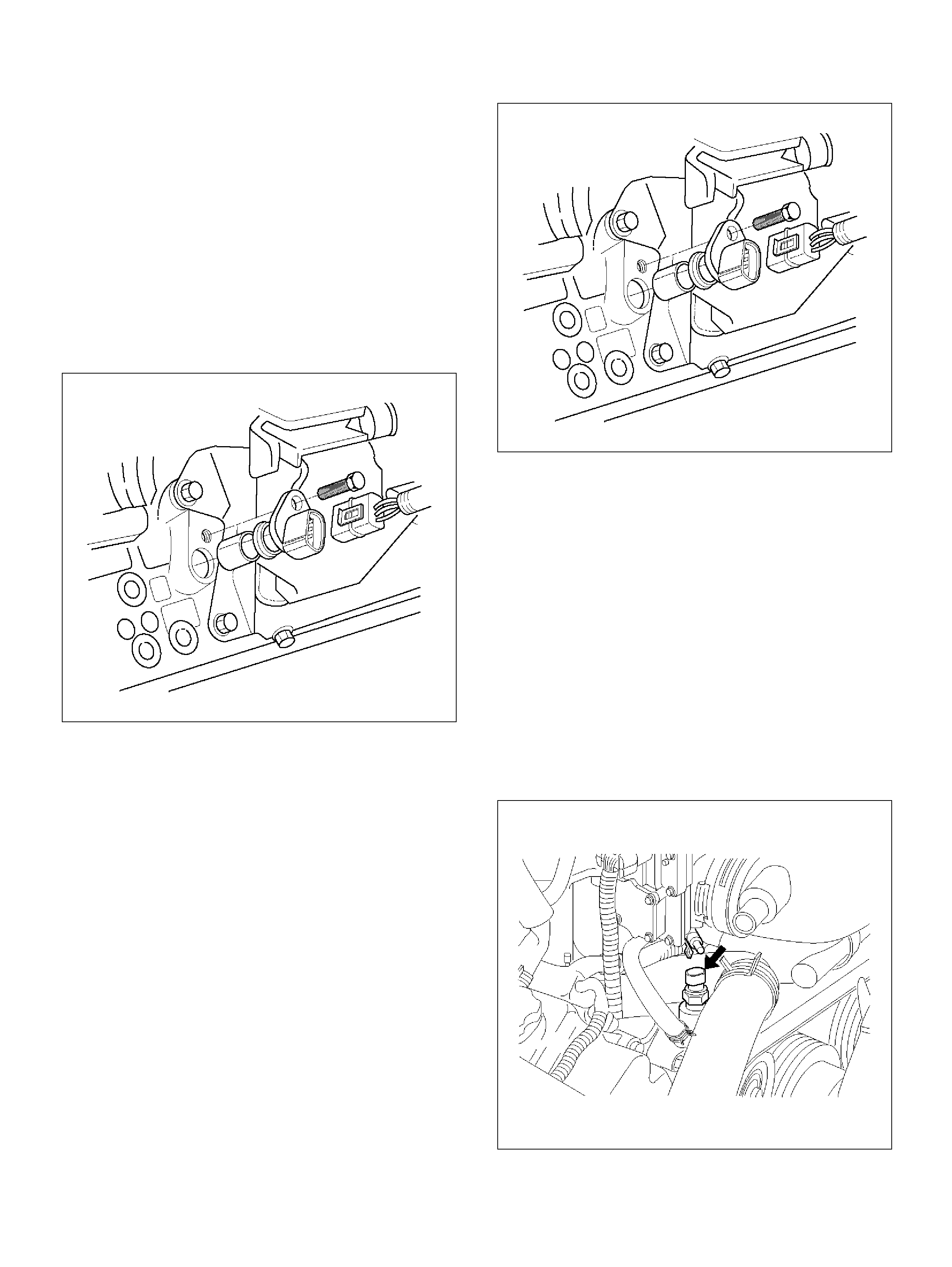
ON VEHICLE SERVICE
CRANKSHAFT POSITI ON (CKP) SENSOR
REMOVAL PROCEDURE
1. Disconnect the negative battery cable.
2. Disconnect the electrical connector to the CKP
sensor.
3. Rem ove one bolt and th e CKP sens or from the right
side of the engine block, just behind the mount.
NOTE: Use caution to avoid any hot oil th at might drip
out.
TS22909
INSPECTION PROCEDURE
1. Inspect the senso r O-rin g for cracks o r leaks.
2. Repl ace the O-ring if it is worn or damaged.
3. Lubricate the new O-ring with engine oil.
4. Install the lubricated O-ring.
INSTALLATION PROCEDURE
1. Ins tall the CKP senso r in the engine block.
2. Ins tall the CKP sensor mount ing bolt.
Tighten
Important: Tighten the mounting bolt to 9 N·m
(78 lb in . ).
TS22909
3. Connect the electrical connector to the CKP sensor.
4. Connect the negative battery cable.
ENGINE COOLANT TE MPERATURE (ECT)
SENSOR
REMOVAL PROCEDURE
Care must be taken when handling the engine coolant
temperature (ECT) sensor. Damage to the ECT sensor
will affect pr o per op er at ion of th e fuel injec tion system.
1. Disconnect the nega tive battery cable.
2. Drain the radiator coolant. Refer to
Draining and Refilling Co oling Sys te m in Engine
Cooling section.
3. Disconnect the electrical connect or.
014RY00001
4. Remove the ECT sensor from the coolant
crossover.
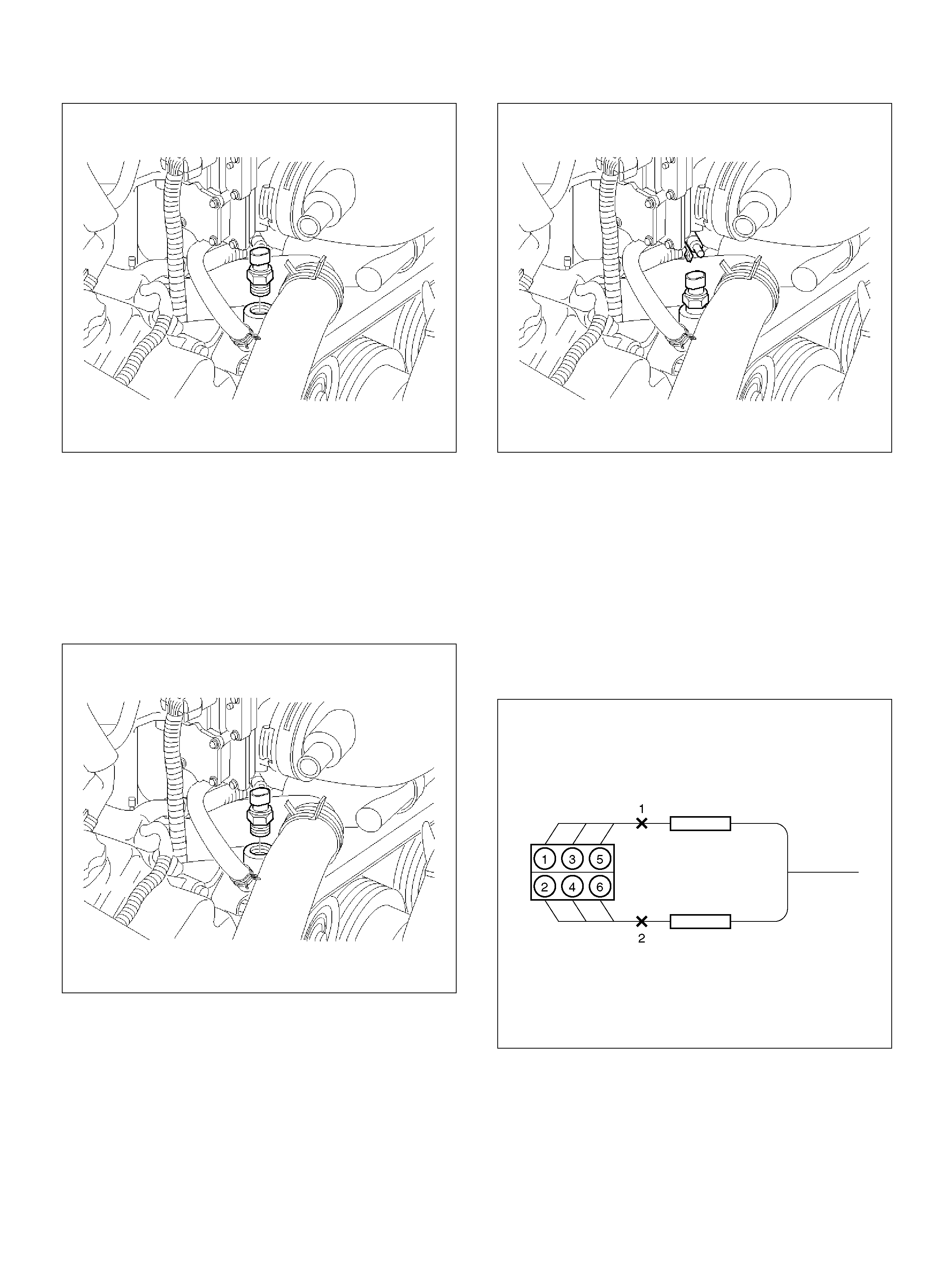
014RY00002
INSTALLATION PROCEDURE
1. Apply sealer or the equivalent to the threads of the
ECT sensor.
2. Ins tall the ECT sensor in the coolant cross over.
Tighten
• Tight en the ECT sensor to 30 N·m (22 lb ft.).
014RY00002
3. Conn ec t the electrical connector.
014RY00003
4. Fill the radiator with coolant. Refer t o
Draining and Refilling Co oling Sys te m in Engine
Cooling section.
5. Connect the negative battery cable.
HEATED OXYGEN SENSOR (HO2S)
REMOVAL PROCEDURE
1. Disconnect the nega tive battery cable.
2. Locate the two oxygen sensors.
060R100113
• Bank 1 sensor 1 is mounted on the exhaust pip e
ahead of the right-hand catalytic converter.
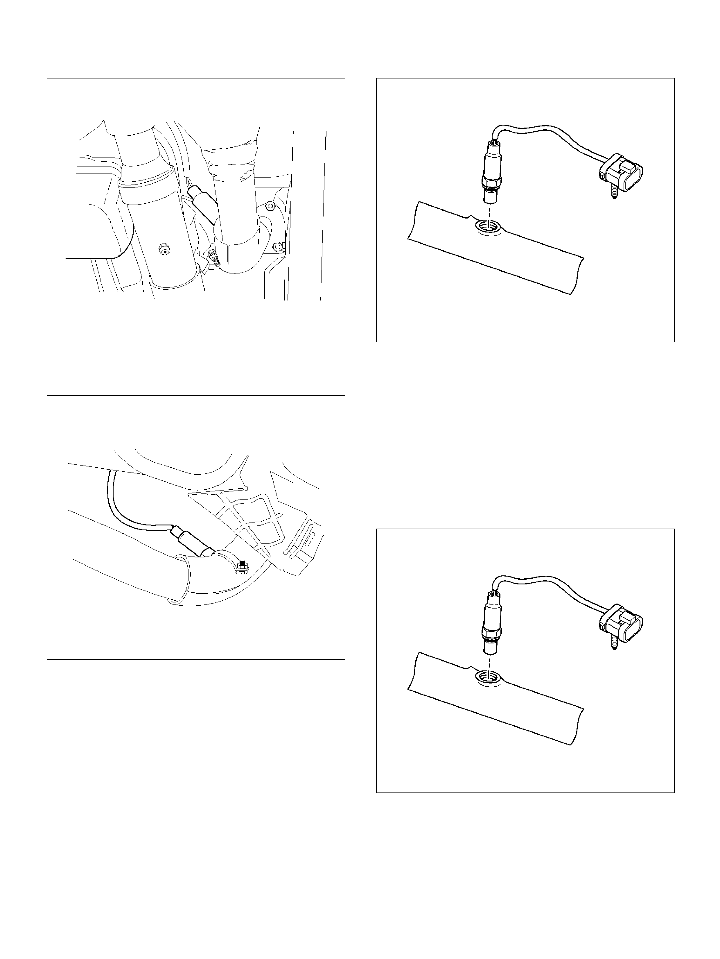
TS22912
• Bank 2 sensor 1 is mounted on the exhaust pipe
ahead of the left-hand catalytic converter.
TS22914
3. Disconnect the pigtail from the wiring harness.
060RY00128
Important: The pigtail is permanently attached to the
sensor . Be careful not to pull the wires out.
Do not use a torch to remove an HO2S unless the
sensor is being replaced. Using a torch could damage
the sensor.
4. Remove the sensor from the exhaust pipe.
• Because of the expan sion and contraction of the
metal in the exhaust system over time, this may
be difficult if the engine temperature is below
48°C (120°F).
060RY00128
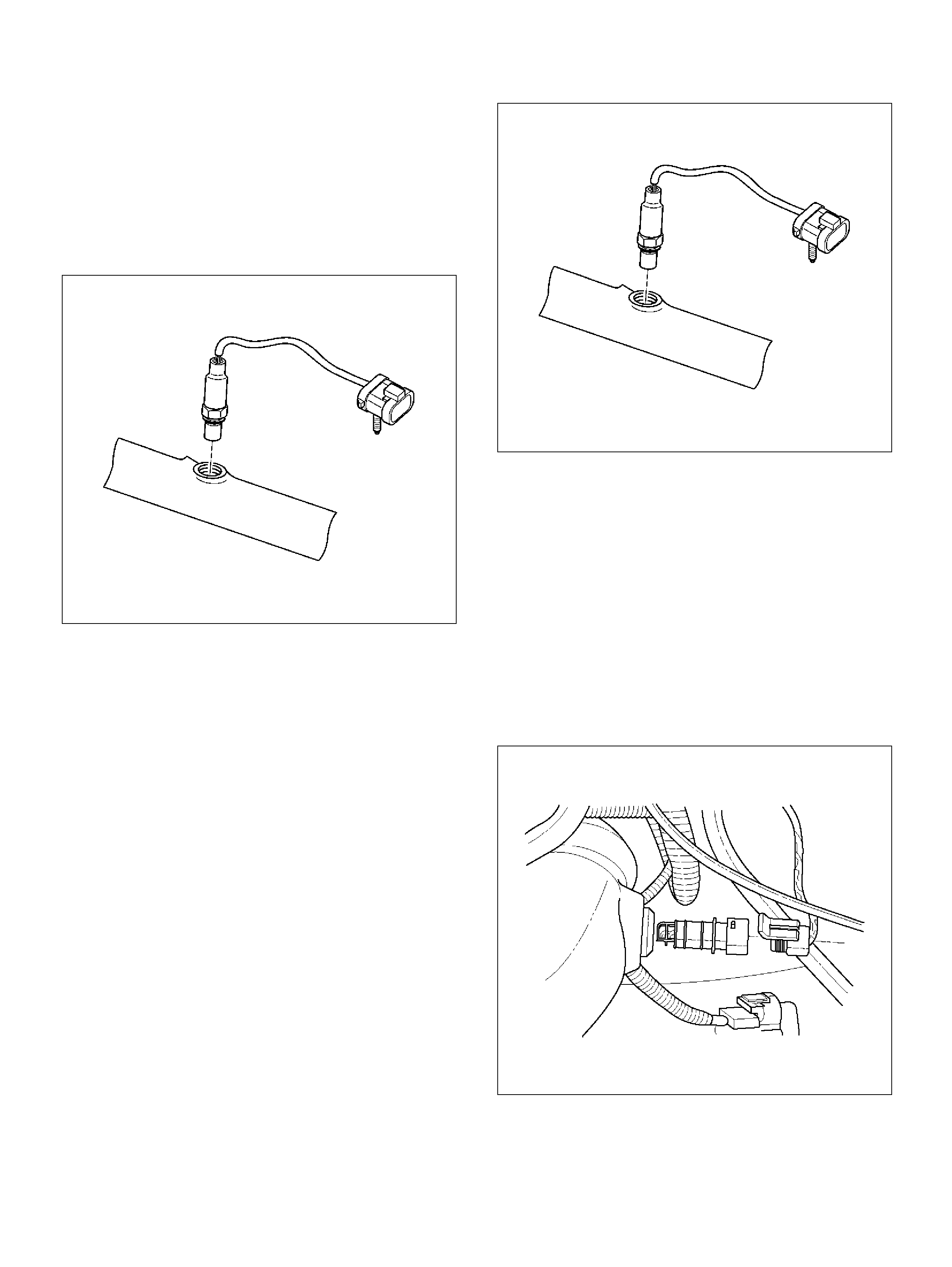
INSPECTION PROCEDURE
All four sensors are identical. Inspect each in the same
way.
1. Inspect the pigtail and the electrical connector for
grease, dirt, corrosion, and bare wires or worn
insulation.
2. Inspect the louvered end of the sensor for grease,
dirt, or other contaminations.
060RY00128
INSTALLATION PROCEDURE
Important:
• T here is a s pe cial an ti-seize comp ound on the HO2S
threads. This compound consists of glass beads
suspended in a liquid graphite solution. The graphite
burns away with engine heat, but the glass beads will
remai n, making the sensor easier to remove.
• New or service sensors will already have the
compound applied to the threads. If a sensor is
removed and is to be reinstalled for any reason, the
thread s must have anti-se ize compou nd applie d.
1. Apply anti-seize compound or the equivalent to the
threads of the oxygen sensor , if necessary.
2. Install the oxygen sensor on the exhaust pipe in its
original position.
Tighten
• Tight en the oxygen sensor to 55 N·m (40 lb ft.).
060RY00128
3. Connect the pigtail to the wiring harness.
4. Connect the negative battery cable.
INTAKE AIR TEMP ERATURE (IAT) SENSOR
REMOVAL PROCEDURE
1. Disconnect the nega tive battery cable.
2. Remove the eng ine cover
3. The IAT sensor is located in the intake air duct,
behind the throttle body.
4. Disconnect the electrical connector from the IAT
sensor.
TS23741
5. Remove the IAT sensor from the intake air duct by
using a rocking motion while pulling the sensor.

INSTALLATION PROCEDURE
1. Ins tall the IAT sens or i nto the grommet in the intake
air duct.
2. Correct the IAT electrical connector.
TS23741
3. Ins tall the engine cover.
4. Connect the negative battery cable.
ION SENSING MODULE
REMOVAL PROCEDURE
1. Disconnect the negative battery cable.
2. Disconnect the ION sensing module connect or.
3. Rem ove the bolts and the I ON sensing modu le from
the common c ham ber.
060R100143
INSTALLATION PROCEDURE
1. Install the ION sensing module on the common
chamber with the bolts.
Tighten
Important: Tighten the ION sensing module to 4 N·m
(35 lb in . ).
2. Connect the ION sensing module connectors as
shown in the illustration.
060RY00003
EndOFCallout
3. Connect the negative battery cable.
Legend
(1) Green (Light Blue) Color Connector
(2) Blue Color Connector
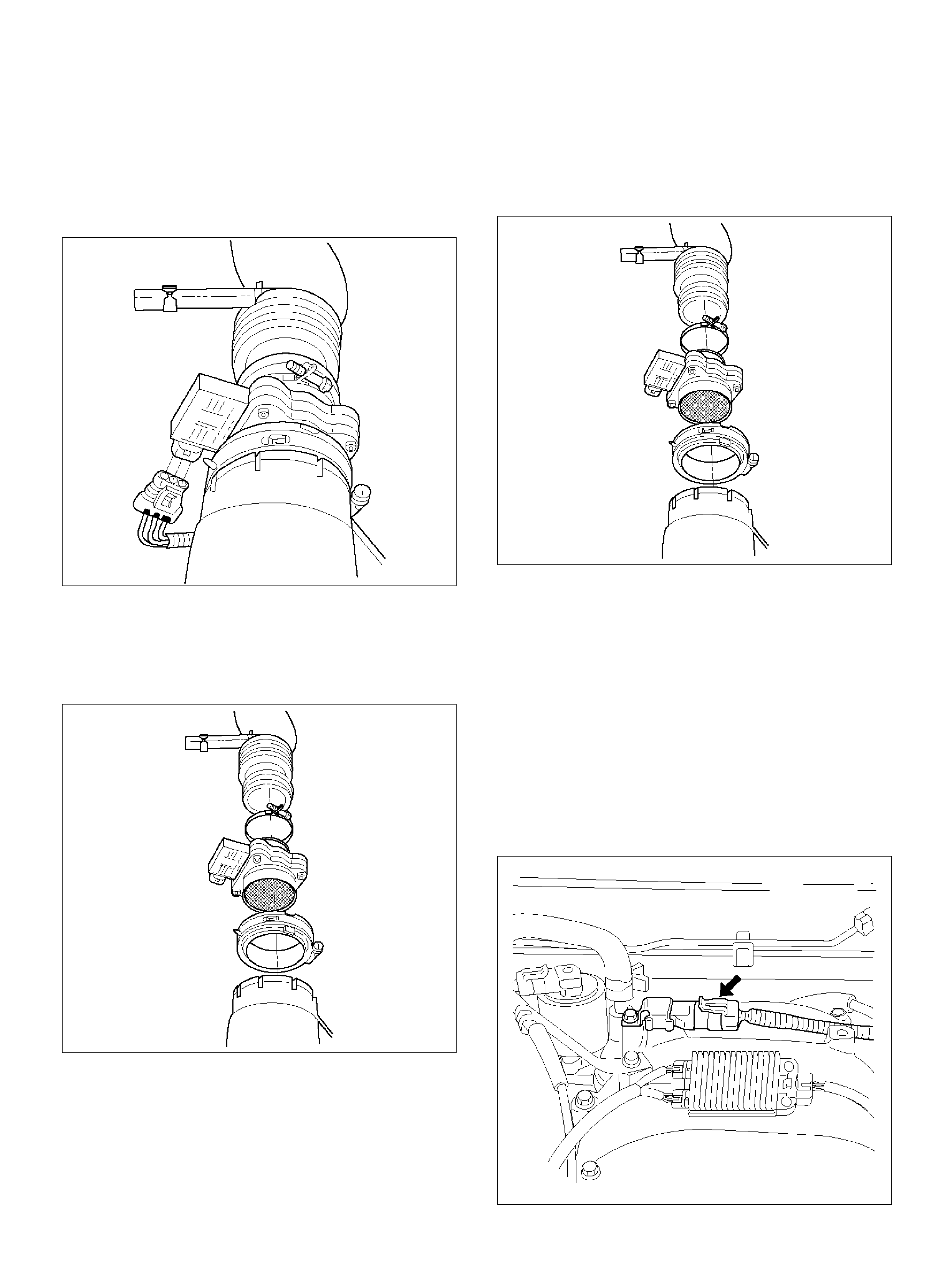
MASS AI R FLOW (MAF ) SENSOR
REMOVAL PROCEDURE
1. Disconnect the negative battery cable.
2. Disconnect the electrical connector from the MAF
sensor.
TS23740
3. Loo sen the clam ps which secure the intake air duct
and the air cleaner to the MAF sensor.
4. Remove the intake air duct from the MAF sensor .
5. Rem ove the MAF sensor from the air c le aner.
TS23781
INSTALLATION PROCEDURE
1. Install the MAF sensor on the air cleaner with the
clamp.
2. Install the inta ke air duct and th e clam p on the MA F
sensor.
TS23781
3. Tighten t he clamps to sec ure the MA F sensor t o the
intake air duct and the air cleaner .
4. Connect the MAF electrica l connector.
5. Connect the negative battery cable.
MANIFOLD ABSOLUTE PRESSURE (MAP)
SENSOR
REMOVAL PROCEDURE
1. Disconnect the nega tive battery cable.
2. Disconnect the electrical connector from the MAP
sensor.
055RY00001
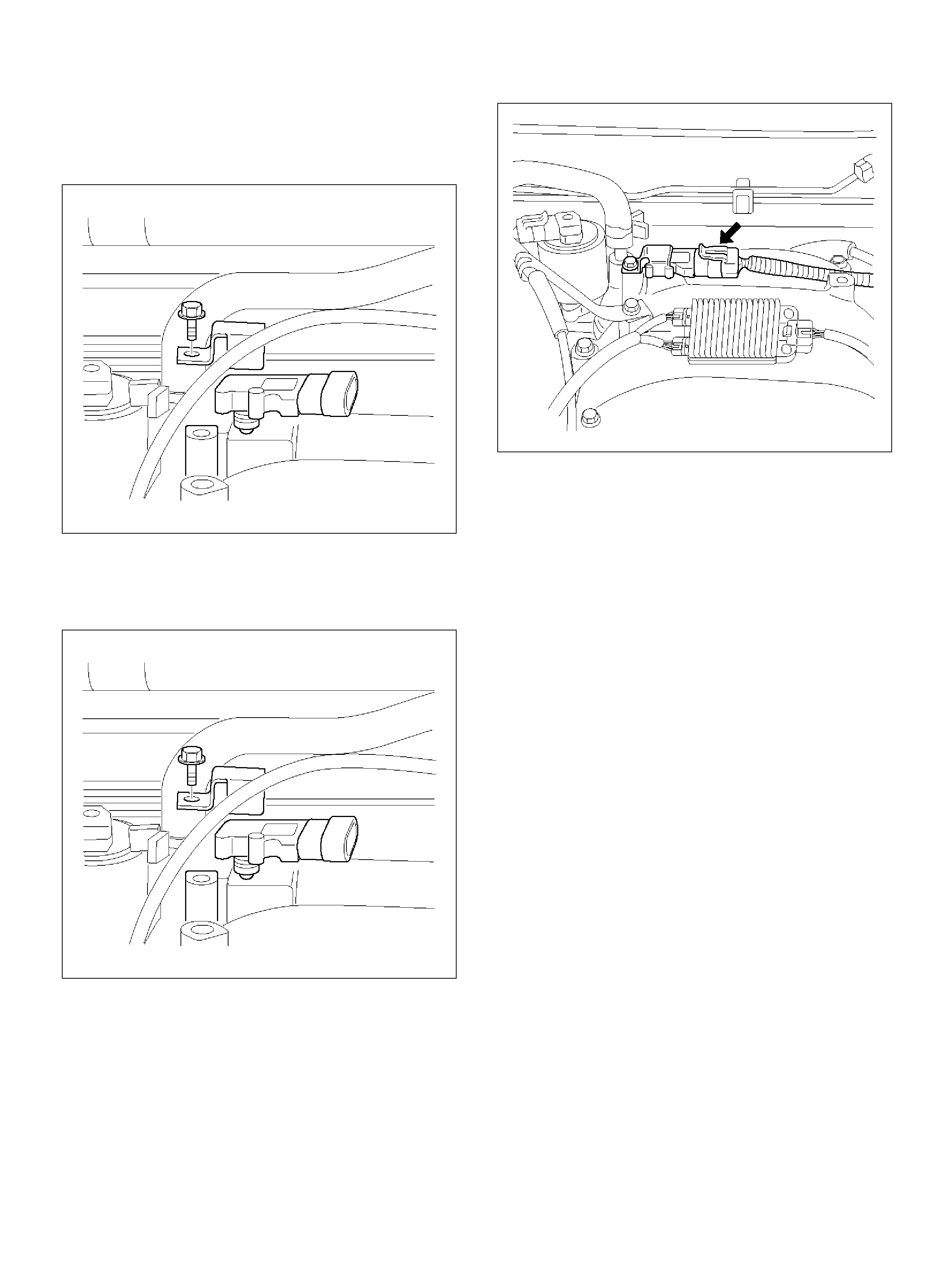
3. Remove the bolt securing the MAP sensor to the
mount ing bracket on the comm on chamb er.
4. Remove the MAP sensor from the mounting
bracket.
055RW002
INSTALLATION PROCEDURE
1. Ins tall the MAP sensor in the mounting bracket.
055RW002
2. Install the mounting bracket retaining bolt on the
common chamber.
Tighten
Important: Tighten the bolt to 20 N·m (12 lb ft.).
3. Conn ec t the MAP electrical connect or.
055RY00001
4. Connect the negative battery cable.
MALFUNCTION INDICATOR LAMP (MIL)
REMOVAL AND INSTALLATION
PROCEDURE
Refer to Warning light bulb, indicator light valve,
illumination light bulb, A/T indicator light bulb in
Meter and Gauge.
REDUCED POWER LAMP
The reduced power lamp (RPL) turns on when the
ignition key is moved to the ON position. It should turn
off in approximately 3 seconds or immediately after the
engine starts.
If the RPL turns on during vehicle operation, a vehicle
system failure resulting in reduced engine output is
indicated.
If bot h the reduc ed RPL and t he c heck engine li ght t urn
on, a serious problem affecting vehicle performance is
indicated.
Re fe r to the OBD system check NO and
RPL “ON" steady in this manual.
POWERTRAIN CONTROL MODULE
(PCM)
SERVICE PRECAUTION
To prevent possible electrostatic discharge damage to
the PCM, do not touch the connector pins or soldered
components on the circuit board.
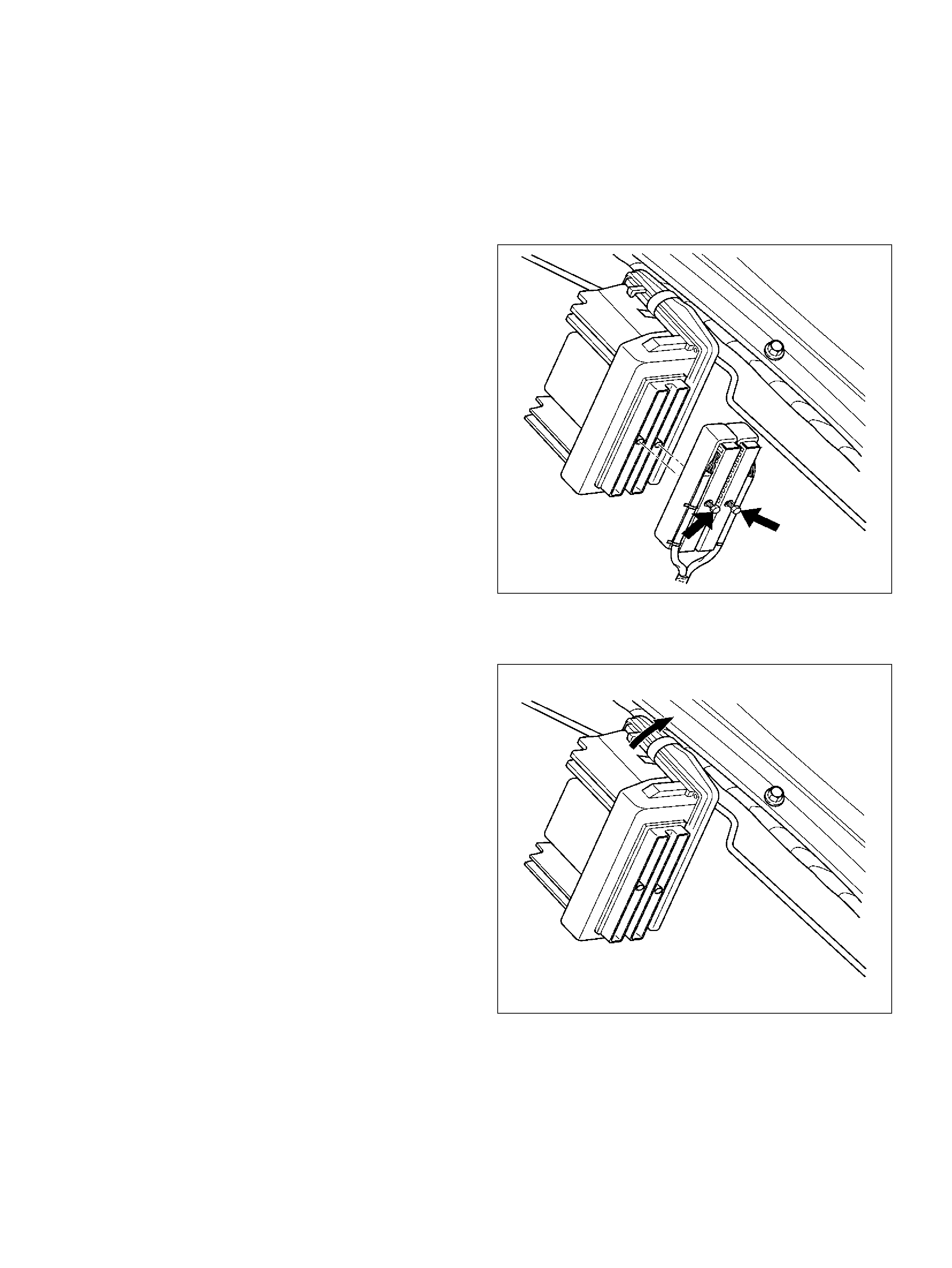
ELECTROSTATIC DISCHARGE (ESD)
DAMAGE
Electronic components used in the control systems are
often designed to carry very low voltage. Electronic
components are susceptible to damage caused by
electrostatic discharge. Less than 100 volts of static
electricity can cause damage to some electronic
componen ts. By comparison, it takes as much as 4,000
volts for a person to even feel the zap of a static
discharge.
There are several ways for a person to become
statically charged. The most common methods of
charging are by friction and by ind uction. An ex am ple of
charging by friction is a person sliding across a car seat.
Charging by induction occurs when a person with well
insulated shoes stands near a highly charged object
and m omentarily touches ground. Charge s of the s ame
polarity are drained off leaving the person highly
charged with the opposite polarity. Static charges can
cause damage, therefore, it is important to use care
when handling and testing electronic components.
To prevent possible Electrostatic Discharge damage,
follow these guidelines:
• Do not touch the control module connector pins or
soldered components on the control module circuit
board.
• Do not open the replacement part package until the
part is ready to be installed.
• Before removing the part from the package, ground
the package to a known good ground on the vehicl e.
• If the part has been handl ed while slid ing across the
seat, or while sitting down from a standing position, or
while walking a distance, touch a known good ground
before installing the part.
To prevent internal PCM damage, the ignition must be in
the “OFF" position in order to disconnect or reconnect
power to the PCM (for example: battery cable, PCM
pigtail, PCM fuse, jumper cables, etc.).
Important: When rep lacing the produc ti on PCM with a
service PCM, it is important to transfer the broadcast
code and production PCM number to the service PCM
la bel. Th is will allo w pos itiv e id entific ation of PC M parts
throughout the service life of the ve hicle. Do not record
this information on the metal PCM cover .
Important: T he ignition should a lways b e in the “OFF"
position in order to install or remove the PCM
connectors.
Service of the PCM should normally consist of either
replacement of the PCM or EEPROM programming. If
the diagnostic procedures call for the PCM to be
replaced, the PCM should be checked first to ensure it
is the correct part. If it is, remove the faulty PCM and
in sta ll the new s e r v ic e PCM.
The service PCM EEPROM will not be programmed.
DTC P0601 indicates the check sum error.
REMOVAL PROCEDURE
1. Disconnect the nega tive battery cable.
2. Block the wheels.
3. Remove the two screws from the PCM electrical
connectors.
4. Disconnect the PCM electrical connectors.
060RY00065
5. After removing the clip which fixes the PCM to the
bracket, remove PCM.
060RY00067
INSTALLATION PROCEDURE
1. Install the PCM to bracket and fix wit h the clip.
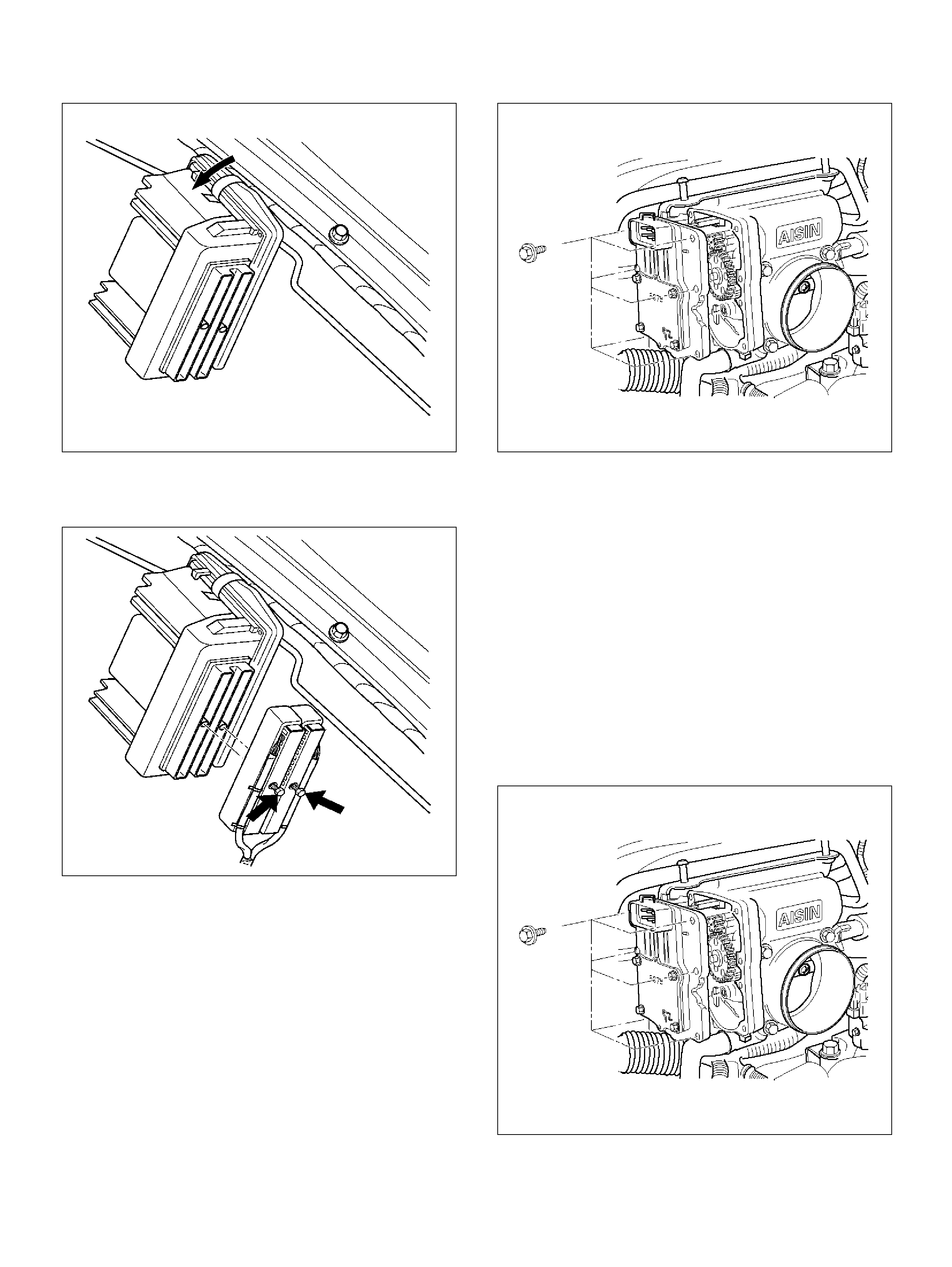
060RY00066
2. Connect the PCM electrical connectors.
3. Install the two screws to PCM electrical connectors.
060RY00065
THROTTLE POSIT ION (TP) SENSOR
REMOVAL PROCEDURE
1. Disconnect the negative battery cable.
2. Disconnect the TPS electrical connecto r.
3. Remove the bolts and the TP sensor from the
throttle body.
060RY00159
Do not clean the TP sensor by soaking it in solvent. The
sensor w ill be dam aged as a r esult.
FUNCTION CHECK
Use a Te ch 2 to check the TP sensor output voltage at
closed throttle.
• The voltage should be TP1 about 0.4V, TP2 about
4.6V and TP 3 about 4.6V.
• If the reading is abnormal value, check the throttle
shaft to see if it is binding.
INSTALLATION PROCEDURE
1. Install the TP sensor on the throttle body with the
bolts.
060RY00159
2. Connect the TP electrical connect or.
3. Install the negative battery cable.
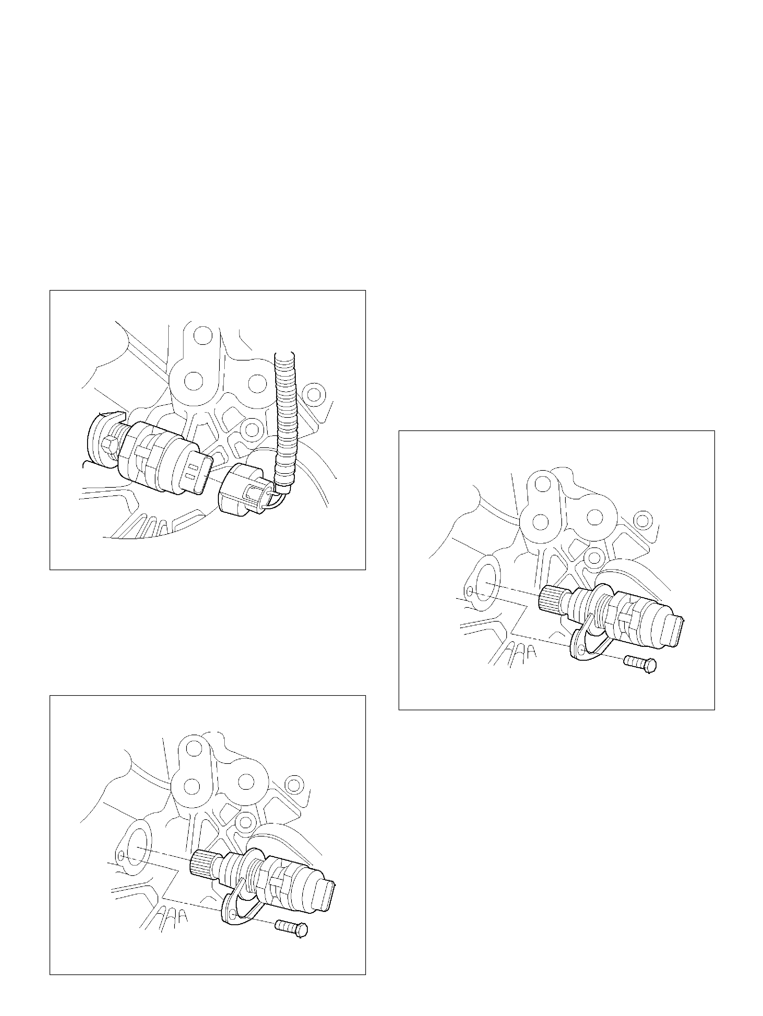
VEHICLE SPEED SENSOR (VSS)
REMOVAL PROCEDURE
CAUTION: The VSS is located on the right side of
the transfer case just ahead of the rear propeller
shaft and very close to the exhaust pipes for 4WD
and on the extension cover for 2WD. Be sure that
the exhaust pipes are cool enough to touch before
trying to remove the VSS. If the pipes are hot, you
co ul d be burn e d.
1. Disconnect the negative battery cable.
2. Disconnect the VSS electrical connector.
TS23748
3. Rem ove t he bolt and t he clam p sec uring the VS S in
place.
Important: Have a container ready to catch any fluid
that leaks out when the VSS is removed from the
transfer case for 4WD and on the extension cover for
2WD.
TS23780
4. Remove the V SS f rom the tr ansfe r case by wigglin g
it slightly and pulling it straight out.
INSPECTION PROCEDURE
1. Inspect the electrical connector for signs of
corrosion or warping. Replace the VSS if the
electrical connector is corroded or warped.
2. Inspect the VSS driven gear for chips, breaks, or
worn condition. Replace the VSS if the driven gear
is chipped, broken or worn.
3. Inspect the O-ring for wear, nicks, tears, or
loosenes s. Replace the O-ring if necessary.
INSTALLATION PROCEDURE
1. Install the VSS in the transfer case with the notch for
the connector facing the rear.
2. Secure the VSS in place with the clamp and the
bolt.
Tighten
• Tight en the bolt to 16 N·m (12 lb ft.).
TS23780
3. Connect the VSS electrical connect or.
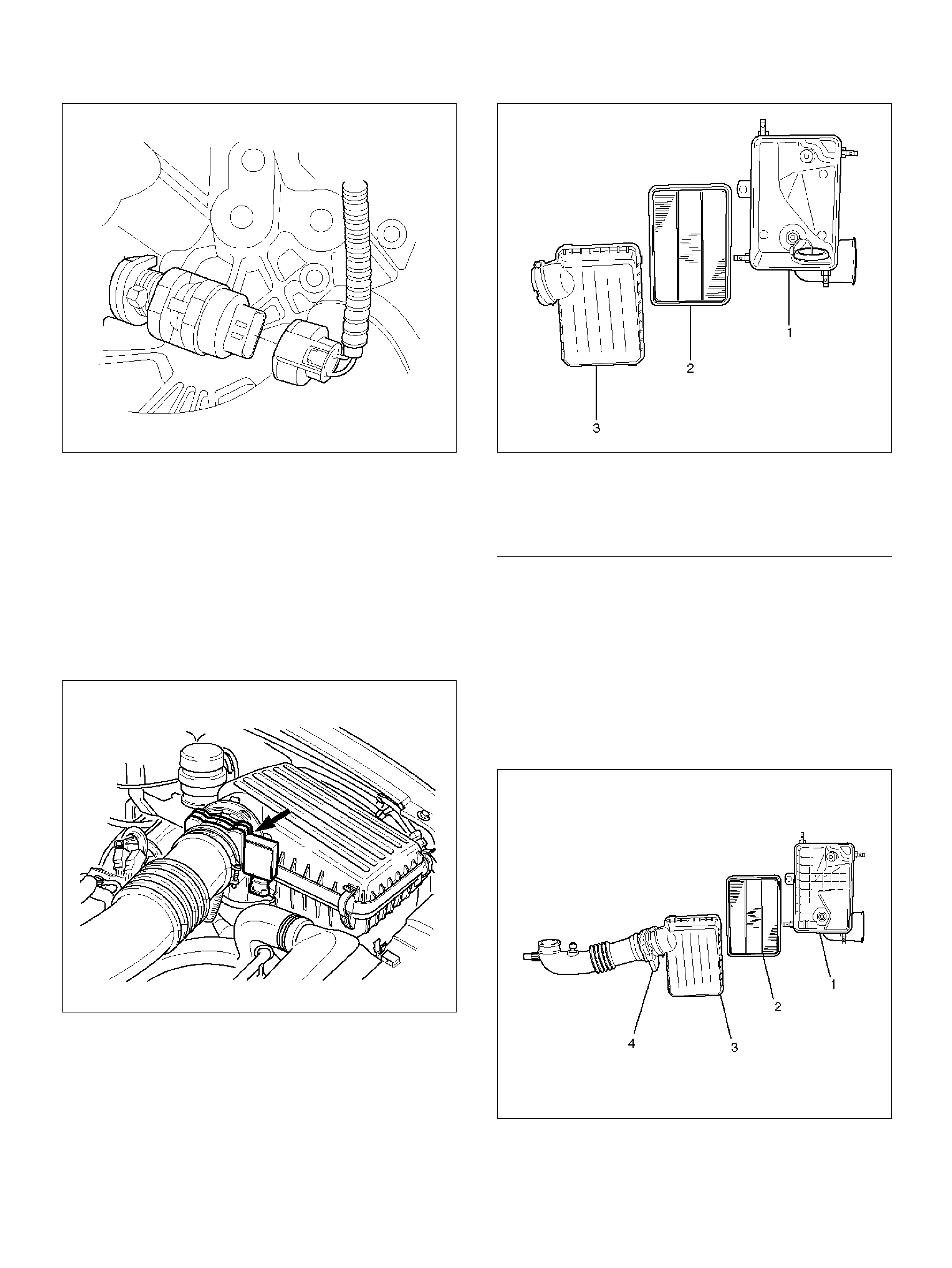
TS23748
4. Check the transfer case oil level. Add fluid if
necessary.
5. Connect the negative battery cable.
AIR CLEANER/AIR FILTER
REMOVAL PROCEDURE
1. Loosen the clamp between the air cleaner lid and
the mass air flow sensor.
025RY00001
2. Release the four latches securing the lid to the air
cleaner housing.
3. Remove the air cleaner lid.
4. Remove the air filter element.
5. Remove the retaining bolts and the air cleaner
housing from the vehicle.
025RY00002
EndOFCallout
INSTALLATION PROCEDURE
1. Install the air clean er housin g in the vehicle with th e
retaining bolts .
2. Install the air filter element in the air cleaner
housing.
3. Install the air cleane r lid on th e M AF s ensor and the
air cleaner housing.
025RY00003
Legend
(1) Air Cleaner Housing
(2) Air Filter Element
(3) Air Cleaner Lid
Legend
(1) Air Cleaner Housing
(2) Air Filter Element
(3) Air Cleaner Lid
(4) Mass Air Flow Sensor
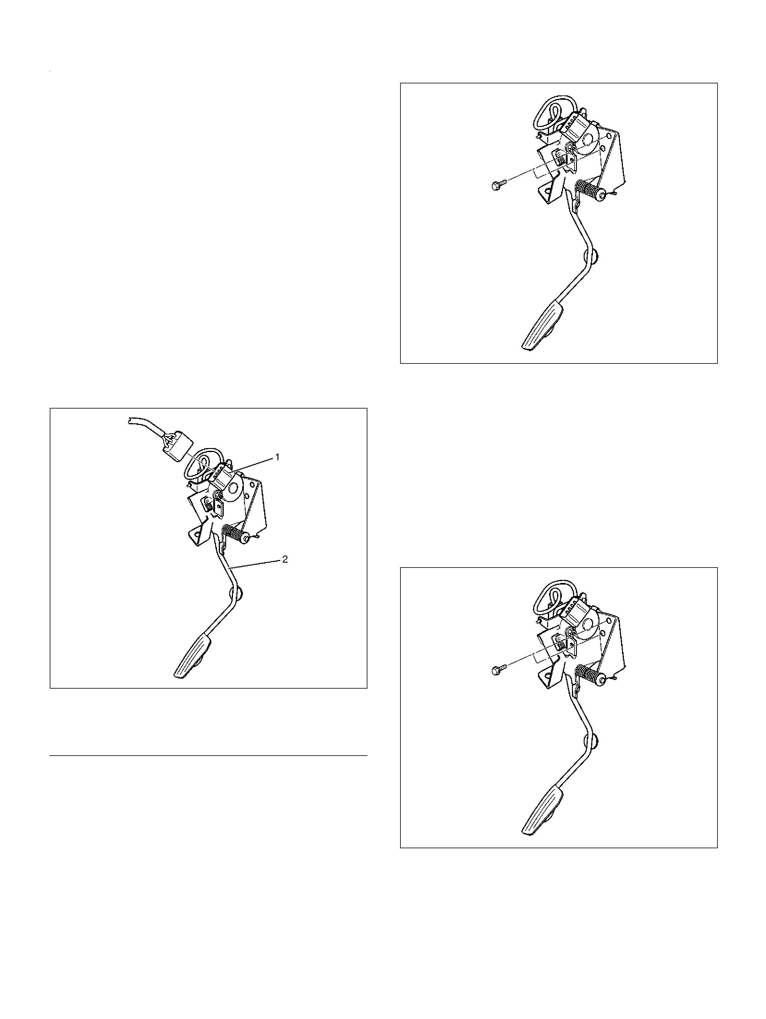
EndOFCallout
4. Tighten the clamp and secure the four latches
between the lid and the air cleaner housing.
COMMON CHAMBER
REMOVAL AND INSTALLATION
PROCEDURE
Refer to Common Chamber in Engine Mechanical
section.
ACCELERATOR PEDAL
REPLACEMENT
REMOVAL PROCEDURE
1. Disconnect the negative battery cable.
2. Disconnect the electrical harness from the
accelerator position sens or.
101RY00006
EndOFCallout
3. Remove the two screws from the accelerator pedal
assembly.
101RY00007
4. Remove the accelerator pedal assembly from the
bulkhead.
INSTALLATION PROCEDURE
1. Install the accelerator pedal assembly on the
bulkhead.
2. Install the two screws to the accelerator pedal
assembly.
Tighten
• Ti ghten the screws to 22 N·m (16 lb ft.).
101RY00007
3. Connect the electrical harness to the accelerator
position sensor.
Legend
(1) Accelerator Position Sensor
(2) Accelerator Pedal Assembly
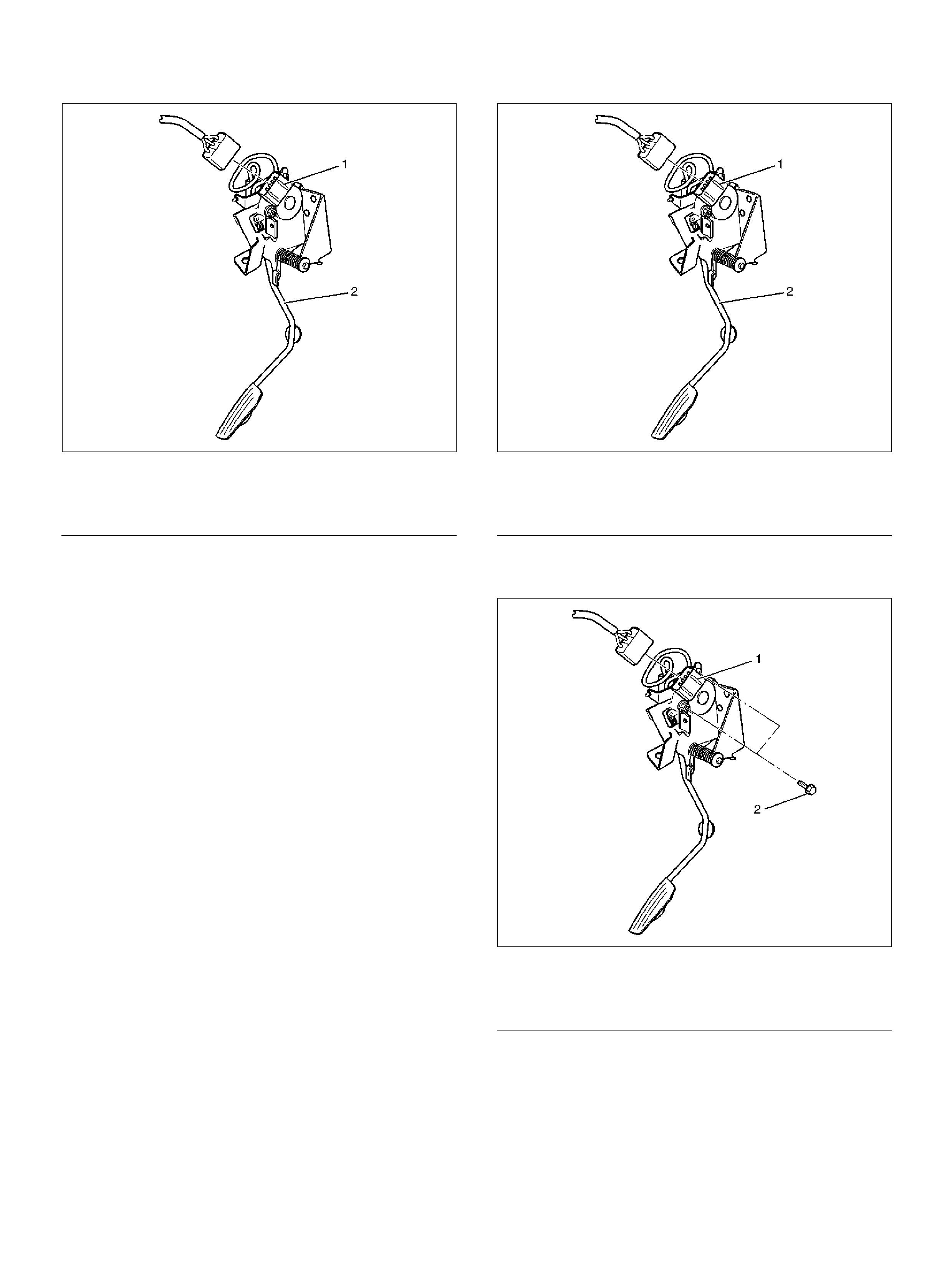
101RY00006
EndOFCallout
4. Install the negative battery cable.
ACCELERATOR POSITION SENSOR
REPLACEMENT
CAUTION: Remove the Accelerator (A) pedal
assembly as a unit to have it services. Do not
rem ove the Accelerator Posi tion (AP ) sensor on th e
A ped al. If the AP sen sor i s removed for em erg enc y
cause, refer to following items as necessary.
REMOVAL PROCEDURE
1. Disconnect the negative battery cable.
2. Disconnect the electrical harness from the AP
sensor.
101RY00006
EndOFCallout
3. Remove the AP sensor.
101RY00009
EndOFCallout
INSTALLATION PROCEDURE
1. Install the accelerator position (AP) sensor to bolts
with accelerator (A) pedal.
2. Connect the conne ctor to AP sensor.
3. Install the negative battery cable.
Legend
(1) Accelerator Position Sensor
(2) Accelerator Pedal Assembly
Legend
(1) AP Sensor
(2) A Pedal Assembly
Legend
(1) AP Sensor
(2) AP Screw
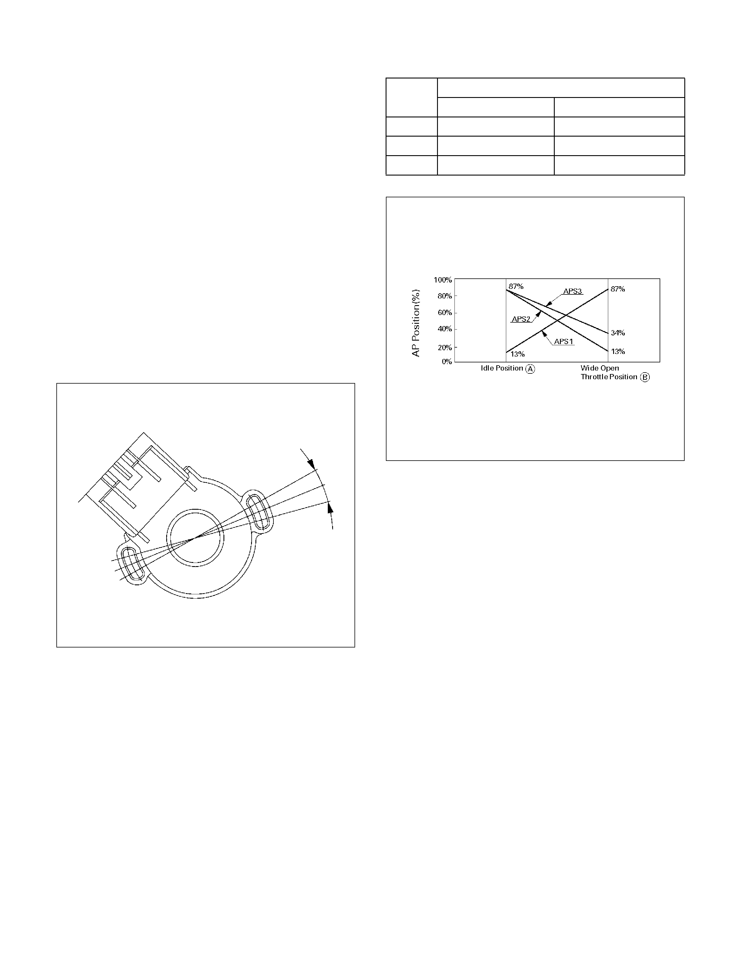
ACCELERATOR POSITION SENSOR
ADJUSTMENT
AP sensor is controlled three multiple control system,
and adjust the idle position and WOT position are
between A and B for AP sensor 1, AP s ensor 2, and AP
sensor 3.
Refer to “How to adj ust for AP sensor".
REMOVAL PROCEDURE
1. Disconnect the negative battery cable.
2. Disconnect the electrical harness from the AP
sensor.
HOW TO ADJUST FOR AP SENSOR
1. Conn ec t the Tec h 2 to DLC on vehicle.
2. Ignition “ON, " engine “OF F.".
3. Displ ay the APS data list.
4. Adjust the AP sensor until APS1 opening is between
11% and 15%
5. Tighten the s en so r screws.
6. With a DVOM, measure the APS1 signal vo ltage at
C-63 (pin #5 - whi te wire) of the AP S con nector.
Note: With A PS1 reading 13% open, the sign al voltag e
should be 0.6 volt.
7. Should the signal voltage reading be less than 0.6
volt, check for:
a.High resisistance in the circuit between PCM
pin# S36 and APS1 (pin# 10 C63 - black wire),
b.Low 5v Ref. signal from the PCM pin#S36
8. If APS1 signal violtage is more than 0.6 volt, check
for:
a.High resistance in the circuit between APS1
(pin #4 C63) and PCM pin# F63 - red wire)
9. After adjustment, verify the following readings with
TECH 2.
060RY00305
FUEL FILLE R CAP
GENERAL DESCRIPTION
The fuel filler cap includes a vacuum valve and a
pressure valve.
If high vacuu m or high pressure occurs in the fuel tank,
each valve works to adjust the pressure in order to
prevent dam age to the tank.
AP position (%)
Idle position A WOT position B
APS1 13% 87 ± 2%
APS2 87 ± 2% 13 ± 2%
APS3 87 ± 1% 34 ± 2%
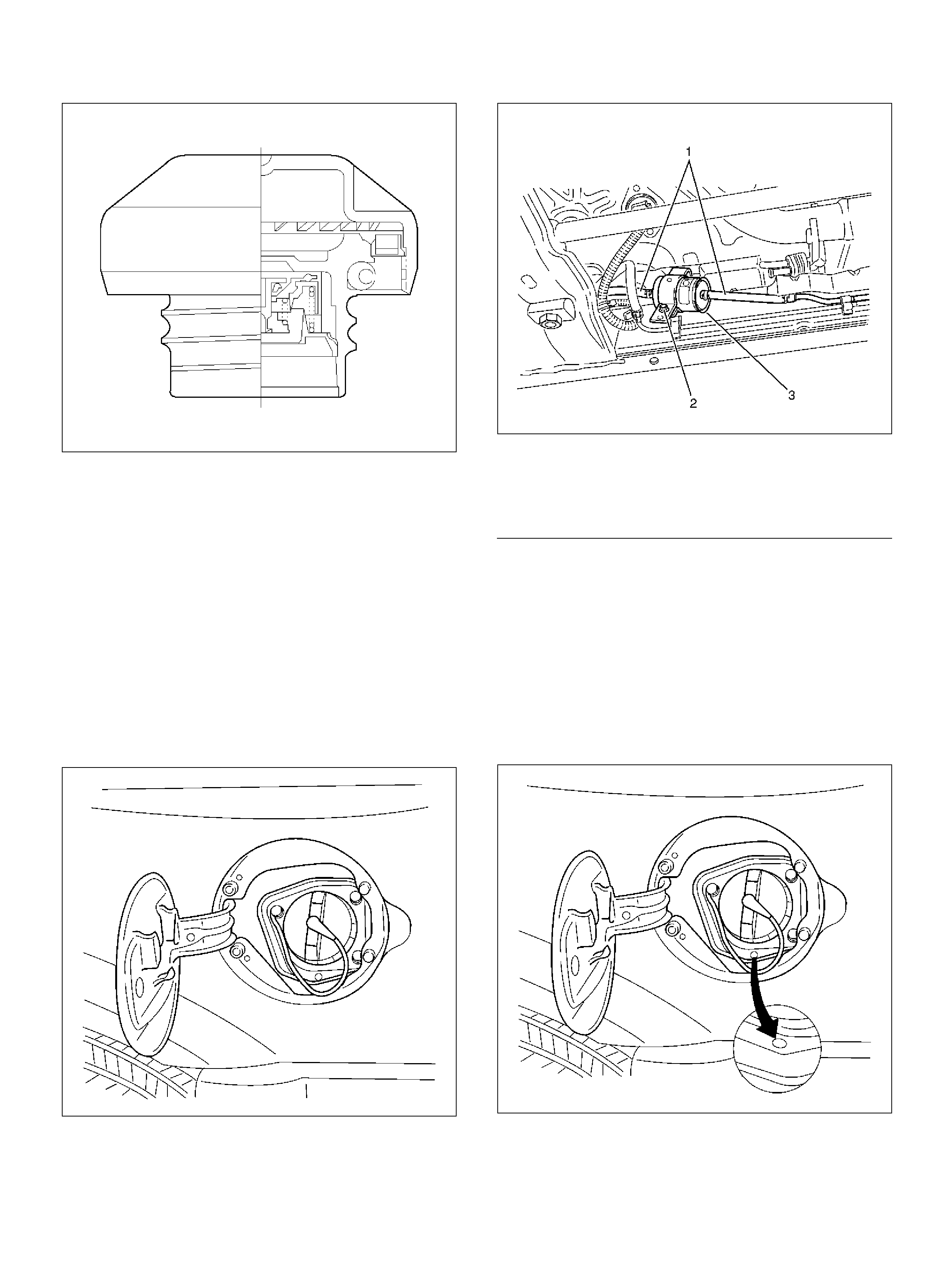
TS23767
INSPECTION PROCEDURE
Replace the fuel filler cap with t he same type of filler cap
that was originally installed on the vehicle.
• Check the seal ring in the filler cap for any
abnormality and for seal condition.
• Replace the filler cap if any abnormality is found.
FUEL FILTER
REMOVAL PROCEDURE
1. Disconnect the negative battery cable.
2. Rem ove the fuel filler cap.
041RY00001
3. Disconnect the fuel hose from the fuel filter on the
engine side.
4. Disconnect the fuel hose from the fuel filter on the
fuel tank s i de.
5. Rem ove the bolt on the fuel filt er holder.
041RW003
EndOFCallout
6. Remove the fuel filter.
INSPECTION PROCEDURE
1. Replace the fuel filter when th e following occur:
• F uel leaks from the fuel filter body.
• T he fuel filter body is damaged.
• The fuel filter is clogged with dirt or sediment.
2. If the drain hole is clogged, clean the drain.
041RY00002
Legend
(1) Fuel Hose
(2) Fuel Filter Fixing Bolt
(3) Fuel Filter
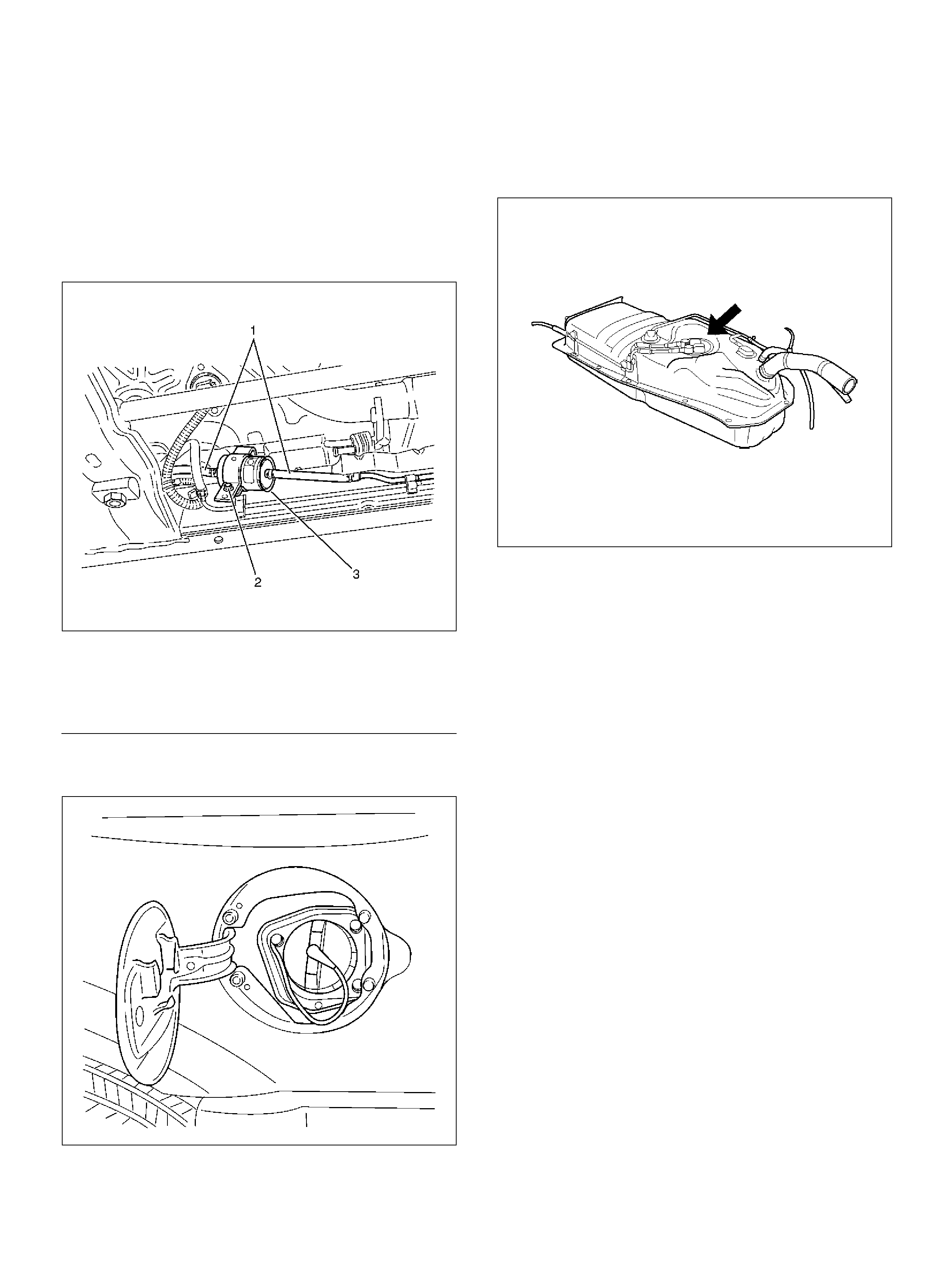
INSTALLATION PROCEDURE
1. Ins tall the fuel filter i n the correct direction.
2. Install the bolt on the fuel filter holder.
Tighten
Important: Tighten the screws to 20 N·m (14 lb ft . ).
3. Conn ec t the fuel hose on the engine side.
4. Conn ec t the fuel hose on the fuel tank side.
041RW003
EndOFCallout
5. Ins tall th e fuel filler c ap .
041RY00001
6. Connect the negative battery cable.
FUEL GAUGE UNIT
REMOVAL PROCEDURE
Refer to Fuel Ga uge Unit in Engine Fu el section.
014RW133
FUEL INJECTORS
REMOVAL PROCEDURE
If the fuel injectors are leaking, the engine oil may be
contaminated with fuel. Check the oil for signs of
contamination and change the oil and the filter if
necessary.
Use care in removing the fuel injectors in order to
prevent damage to the fuel injector electrical connector
pins or the fuel injector nozzles. The fuel injector is an
electrical component and should not be immersed in
any type of cleaner as this may damage the fuel
injector.
Important: Fuel injectors are serviced as a complete
assem bly only.
1. Disconnect the nega tive battery cable.
2. Remove the commo n chamber. Refer to
Comm on Cham be r in Engine Mechanical section.
3. Remove the fuel rail. R efer to Fuel Rail secti on .
Legend
(1) Fu el Hose
(2) Fu el Filter Fix ing Bol t
(3) Fuel Filter
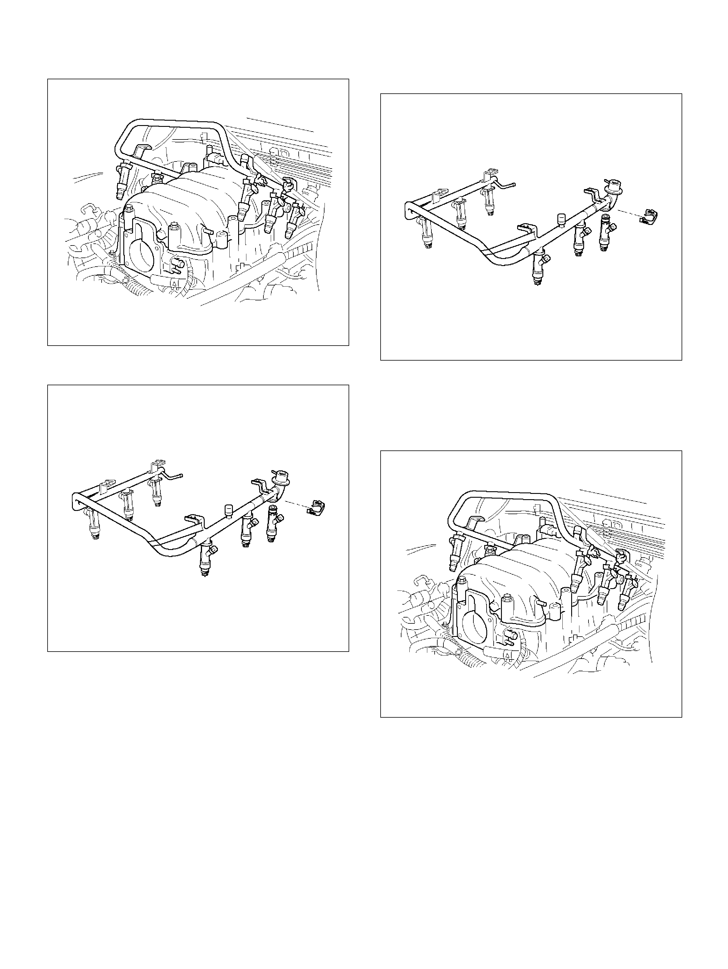
014RW164
4. Rem ov e the inje c tor retainer clip.
040RY00001
5. Rem ove the fuel injector assembly.
6. Remove the O-ring from the fuel injector.
7. Remove the O-ring backup from the fuel injector .
INSPECTION PROCEDURE
1. Inspect the O -rings for cracks or leaks.
2. Replace worn or damaged O-rings.
3. Lubricate the new O-rings with engine oil before
installation.
INSTALLATION PROCEDURE
1. Install the O-ring backup on the fuel injector.
2. Ins tall the new O-ring on the fuel injector.
3. Install the fuel injector on the fuel rail.
040RY00001
4. Use new fue l injector retainer clips to retain the fuel
injector to the fuel rai l.
5. Coat the end of t he fu el injector with gasoline.
6. Install the fuel rail. Refer to Fuel Rail sectio n .
014RW164
7. Install the common chamber. Refer to
Comm on Cham be r in Engine Mechanical section.
8. Install the engine cover.
9. Connect the negative battery cable.
FUEL METERING SYSTEM
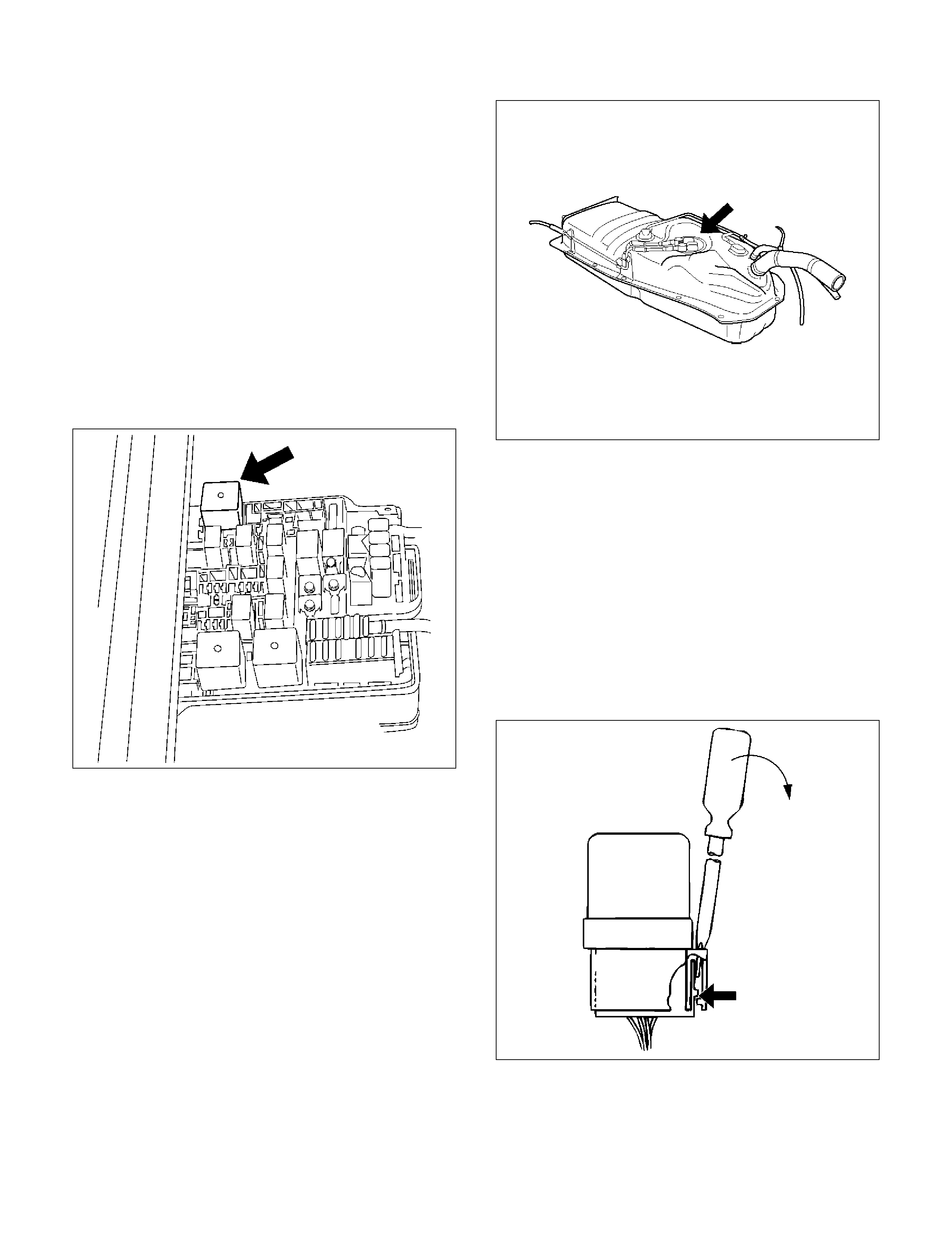
FUEL PRESSURE RELIEF PROCEDURE
CAUTION: To reduce the risk of fire and personal
injury, there are necessary to relieve the fuel system
pressure before filler and gauge unit servicing the
fuel system co mponents.
CAUTION: After relieving the system pressure, a
small amount of fuel may be released when
servicing fuel lines or connections. Reduce the
chance of personal injury by covering the fuel line
fittings with a shop towel before you disconnect the
fittings. The towels will absorb any fuel that may
leak out. When the disconnect is completed, place
the towel in an approved co ntainer.
1. Rem ove the fuel cap.
2. Remove the fuel pump relay from the underhood
relay box. Refer to Fue l Pum p Relay section.
014RY00004
3. Start the engine and allow it to stall.
4. Crank the engine for 30 seconds.
5. Disconnect the negative battery cable.
FUEL PUMP ASSEMBLY
REMOVAL PROCEDURE
Refer to Fuel Tank In Fuel Pump Relay sect ion .
014RW133
FUEL PUMP RELAY
REMOVAL PROCEDURE
1. Remove the fuse and relay box cover from under
the hood.
2. Consult the diagram on the cover to determine
whic h is the corr e c t rela y.
3. Insert a small screwdriver into the catch slot on the
forward side of the fuel pump relay.
• The screwdriver blade will release the catch
inside.
D08RY00291
4. Pull the relay straight up and out of the fuse and
relay box.
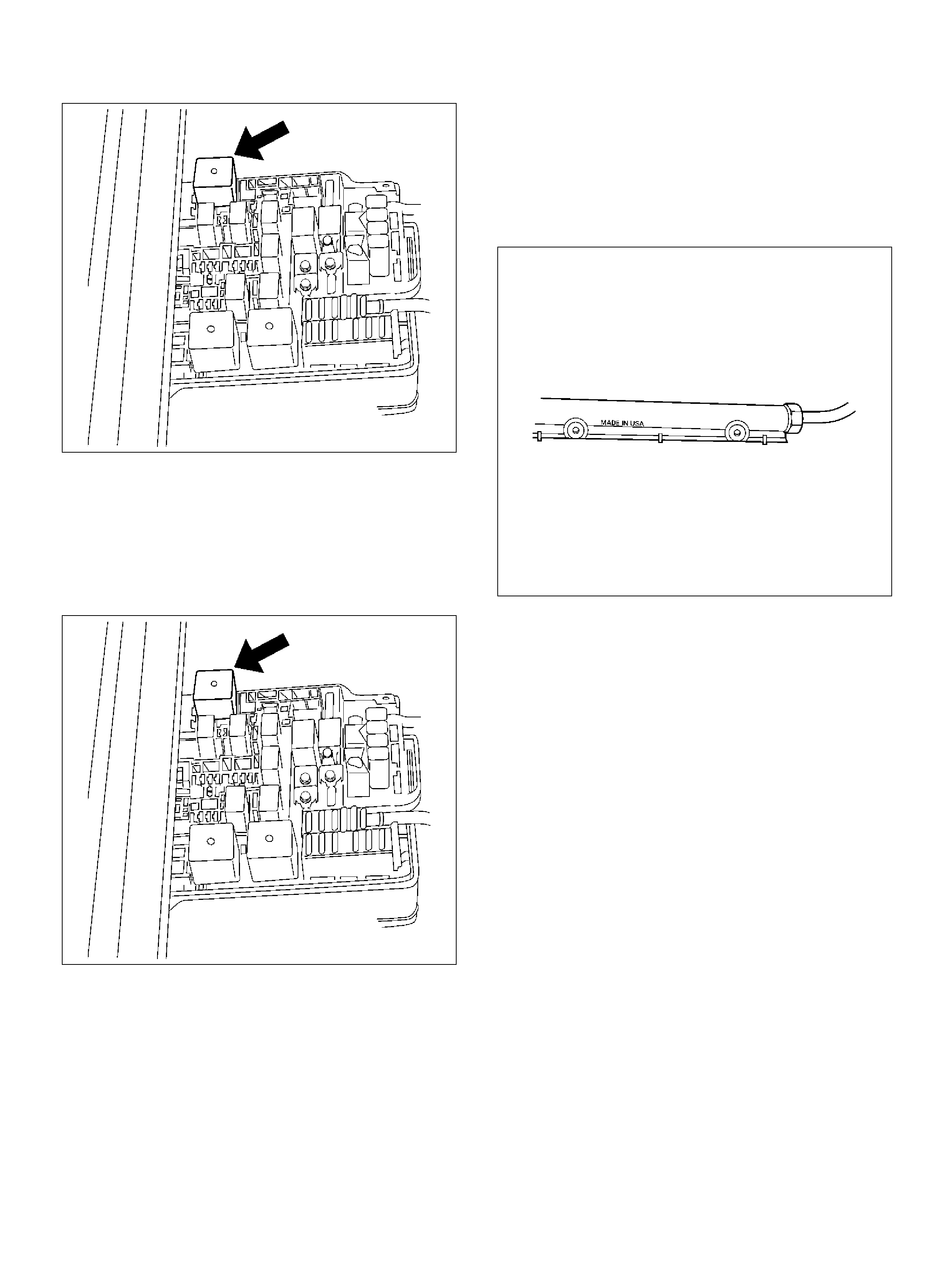
014RY00004
INSTALLATION PROCEDURE
1. Insert the relay into the correct place in the fuse and
relay box with the catch slot f acing forw ard.
2. Press down until the catch engages.
• An audi ble “click" will be heard.
014RY00004
3. Install the fuse and relay box cover.
FUEL RAIL ASSEMBLY
REMOVAL PROCEDURE
• Do not attempt to remove the fuel inlet fitting on the
fuel rail. It i s staked in p lace. Removi ng the fuel i nlet
fitting will result in damage to the fuel rail or the
intern al O-ring seal.
• Use care when removing the fuel rail assembly in
order to prevent damage to the injector electrical
con nector terminals and the injector spray tips.
• Fittings should be capped and holes plugged during
servicing to preven t dirt and other contaminants from
entering open lines and passag es.
Important: An eight-digit identification number is
stamped on the side of the fuel rail. Refer to this number
when you service the fuel rail or when a replacement
part is re quired.
014RY00008
Before removal, the fuel rail assembly may be cleaned
with a spray type engine cleaner. Follow the spray
package instructions. Do not immerse the fuel rails in
liquid cleaning so lvent.
1. Depressurize the fuel syst em . Refer to
Fuel Pressure Relief Procedure in this S e c tion.
2. Disconnect the nega tive battery cable.
3. Remove the eng ine cover.
4. Disconnect the throttle position sensor electrical
connector from throttle body.
5. Disconnect the connectors from manifold absolute
pressure sensor, solenoid valve, electric vacuum
sensing valve.
6. Disconnect the vacuum hose on canister VSV and
positive crankcase ventilation hose.
7. Remove the common chamber. Refer to the
common chamber in Engine Mechanical section.
1. Lift up carefully on the fuel injectors. Do not
separate the fuel inj ec tors from the fuel rail.
2. If an injector becomes separated from the fuel
rail, the infector O-ring seals and the retainer
clip must be replaced.
3. Drain residual fuel int o an approved c ontainer.
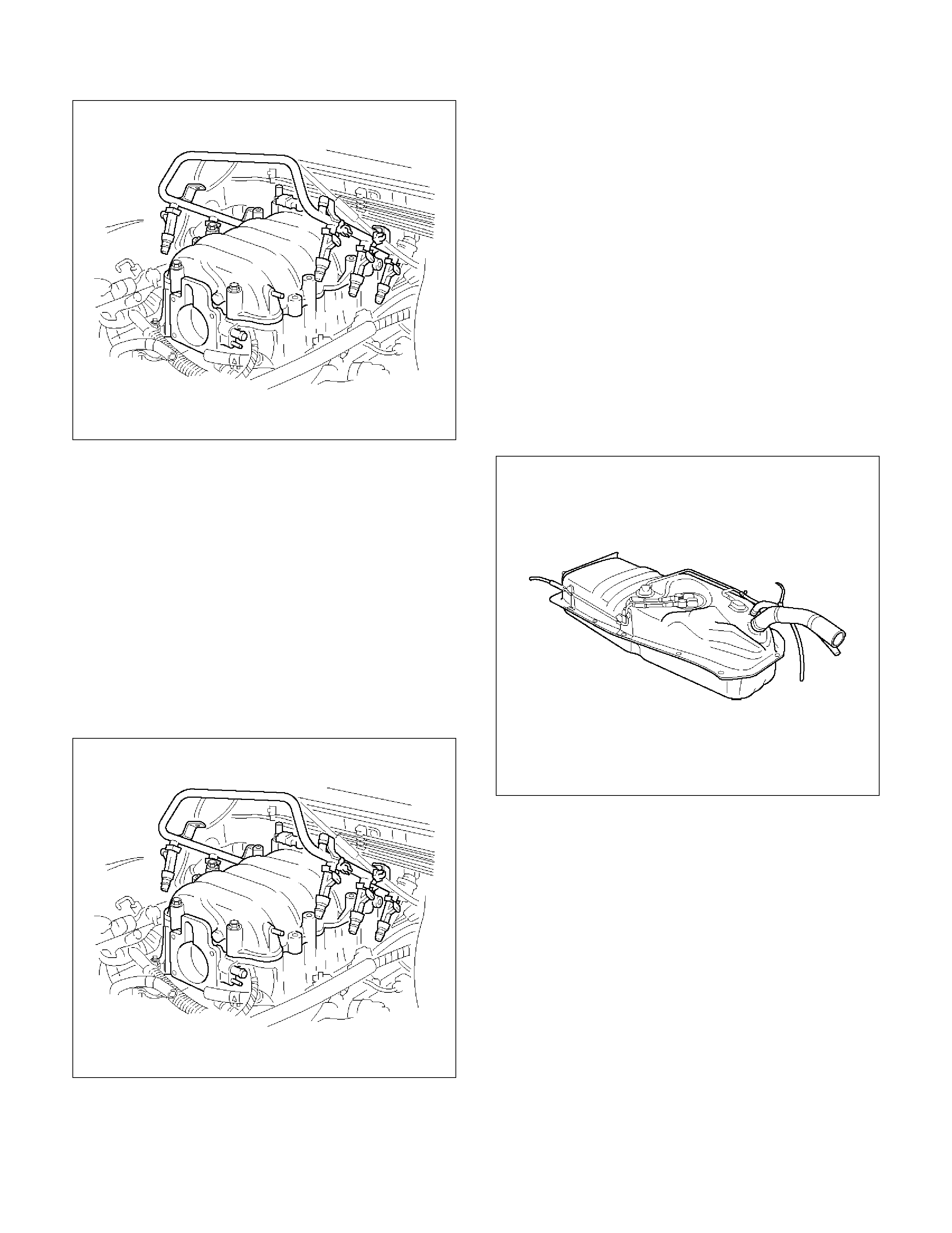
014RW164
8. If removal of the fuel pressure regulator is
necessary, refer to Fuel Pressure Regulator
section.
9. If removal of the fuel inje ct ors is neces sary, refer t o
Fuel Injectors section.
INSTALLATION PROCEDURE
1. If the fuel injectors were removed, install them.
Refe r to Fuel Injectors section.
2. If the fuel p re ssure regulator was rem oved, install it.
Refe r to Fuel Pressure Regu la tor section.
3. Install the common chamber. Refer to common
chamber in engine Mechanical section.
014RW164
4. Connect the vacuum hose on Canister VSV and
positive crankcase ventilation hose.
5. Connect the connectors to manifold absolute
pressure sensor, solenoid valve, electric vacuum
sensing valve.
6. Connect the throttle position sensor electrical
connector to throttle body.
7. Install the engine cover.
8. Connect the negative battery cable.
9. Crank the engi ne until it starts . Crank ing the engin e
may take lo nger than us ual due to trappe d air i n the
fuel rail and in th e injectors.
FUEL TANK
REMOVAL PROCEDURE
Refer to Fuel Tank In Fu el Pu mp Relay
014RW134
THROTTLE BODY (TB)
REMOVAL PROCEDURE
1. Disconnect the nega tive battery cable.
2. Drain the cooling system. Refer to Cooling System
section.
3. Disconnect the electrical connectors :
• T hrottle position (TP) sensor.
• Intake air temperature (IAT) sensor. Refer to
Intake Air Temperature Sensor section.
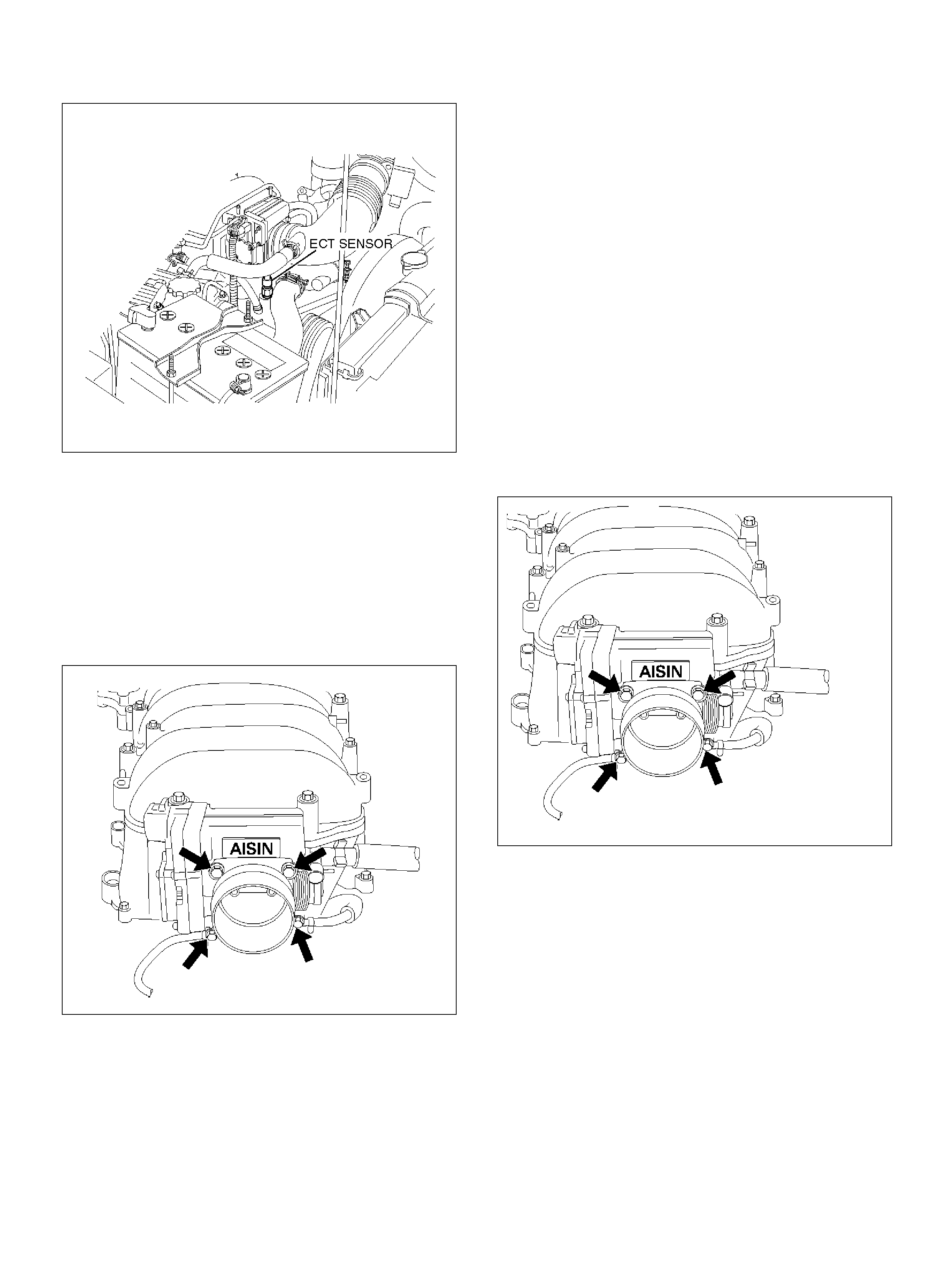
060RY00014
4. Disconnect the vacuum hose below the air horn.
5. Remove the intake air duct clamp.
6. Disconnect the intake air duct.
7. Disconnect the coolant lines from the throttle body.
8. Remove the bolts from the common chamber.
9. Remove the throttle body from the common
chamber.
10. Remove the gasket from the common chamber.
025RY00004
11. Rem ove the TP sensor. Refer to
T h rottle Pos ition (TP ) Senso r sectio n.
INSPECTION PROCEDURE
Do not use solvent of any type when you clean the
gasket surfaces on the intake manifold and the throttle
body assembly. The gasket surfaces and the throttle
body assem bly may be dam aged as a result.
• If the throttle body gasket needs to be replaced,
remove any gasket ma terial that may be stuck to the
mating surfaces of the manifold.
• Do not leave any scratches in the aluminum casting.
INSTALLATION PROCEDURE
1. Install the TP sensor. Refer to
Throttl e Po si tion (T P ) Sensor section.
2. Install the gasket on the common chamber.
3. Install the throttle body on the common chamb er.
4. Secure the gasket and the throttle body with the four
bolts.
• The vacuum lines must be properly routed under
the throttle body before tightening the mounting
bolts.
Tighten
• Tight en the throttle body mounting bolts to 10 N·m
(87 lbin).
025RY00004
5. Install the coolant lines.
6. Connect all the vacuum lines.
7. Install the intake air duct.
8. Tighten the intake air duct clamp.
9. Connect all the electrical connectors:
• T hrottle position (TP) sensor.
• Intake air temperature (IAT) sensor. Refer to
Intake Air Temperature Sensor secti on.
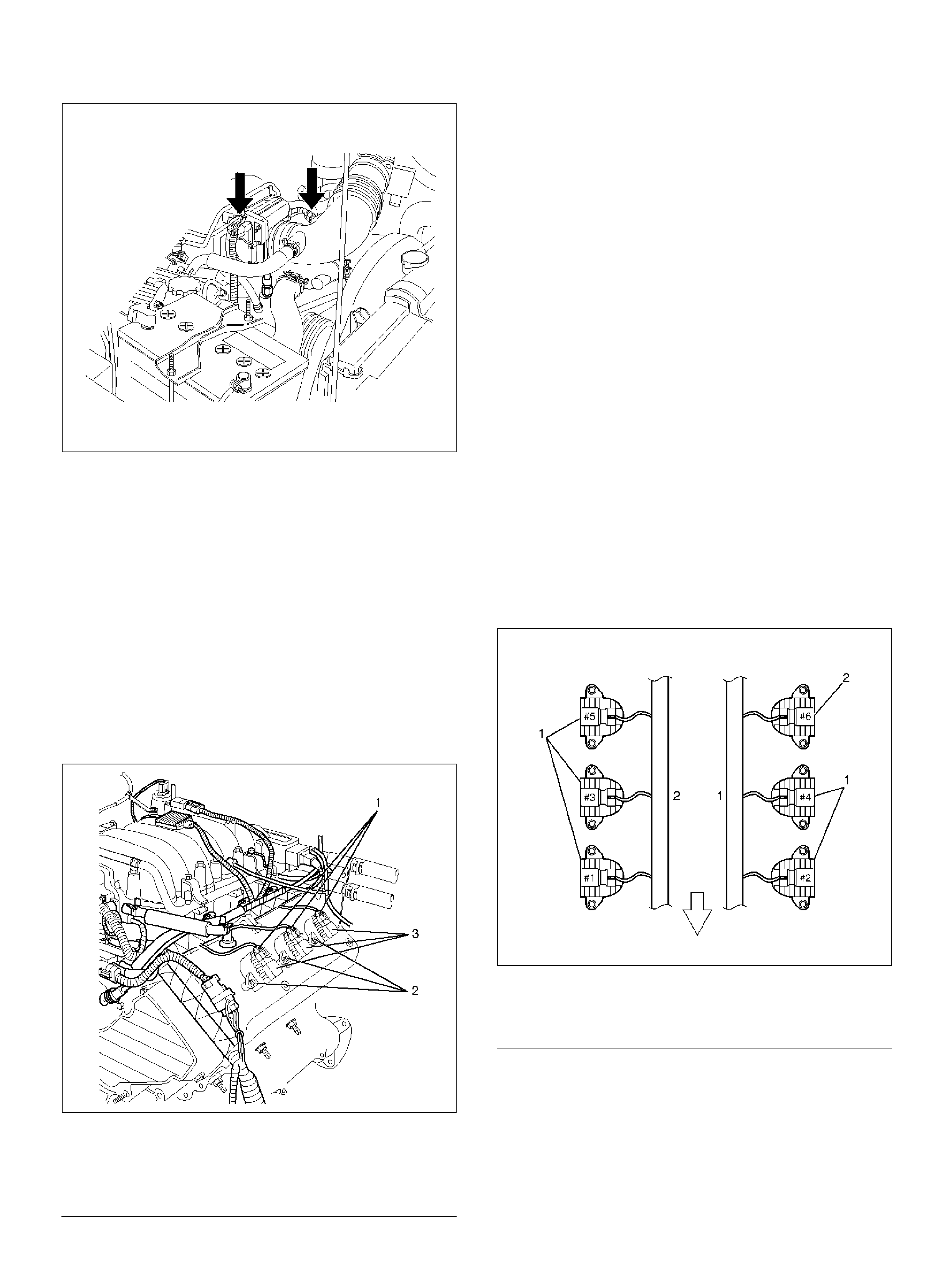
060RY00020
10. Fill the cooling system. Refer to Cooling System
section.
11. Install the negative battery cable.
ELECTRONIC IGNITION SYSTEM
REMOVAL PROCEDURE
1. Disconnect the negative battery cable.
2. Disconne ct the ignition coil con nector at the ignition
coil asse mbl ies .
3. Rem ove the two screws tha t s ecure the ignition coil
assemblies to the rocker cover.
060RY022
EndOFCallout
4. Remove the ignition coil assemblies and the spark
plug boot from the spark plug.
• Twist the ignition coil assemblies while pulling it
straight up.
5. Use the appropriate spark plug socket in order to
remove the spark plug from the engine.
INSTALLATION PROCEDURE
The plug must thread smoothly into the cylinder head
and be fully seated. Use a thread chaser if necessary to
clean the threads in the cylinder head. Cro ss-threading
or failure to fully seat the spark plug can cause plug
overheating, exhaust blow-by gases, or thread damage.
Do not overtighte n the s park pl ugs. Over tightenin g ca n
cause aluminu m threads to strip.
1. Install the spark plug in the engine. Use the
appropriate spark plug socket.
Tighten
Important: Tighten the spark plug to 18 N·m (13 lb ft.).
2. Install the ignition coil assemblies and spark plug
boot over the spark plug.
CAUTION: Ignition coil assembly #6 is different
from ignition coil assembly #1 to #5. Ignition coil
assemblies #6 is short type. Be careful it when
installing i gn ition coil assemb ly of #6.
060RY00002
EndOFCallout
3. Install ignition coil assemblies and tighten the fixing
bolts to t he spec ified torque.
Torq ue: 4 N·m (35.4 Ib in)
Legend
(1) Ignition Coil Connectors
(2) Bolts
(3) Ignition Coil Assemblies
Legend
(1) Long Type Ignition Coil Assemb lies (#1 ∼ #5)
(2) Short Ty pe Ignition Coil Assembly (#6)
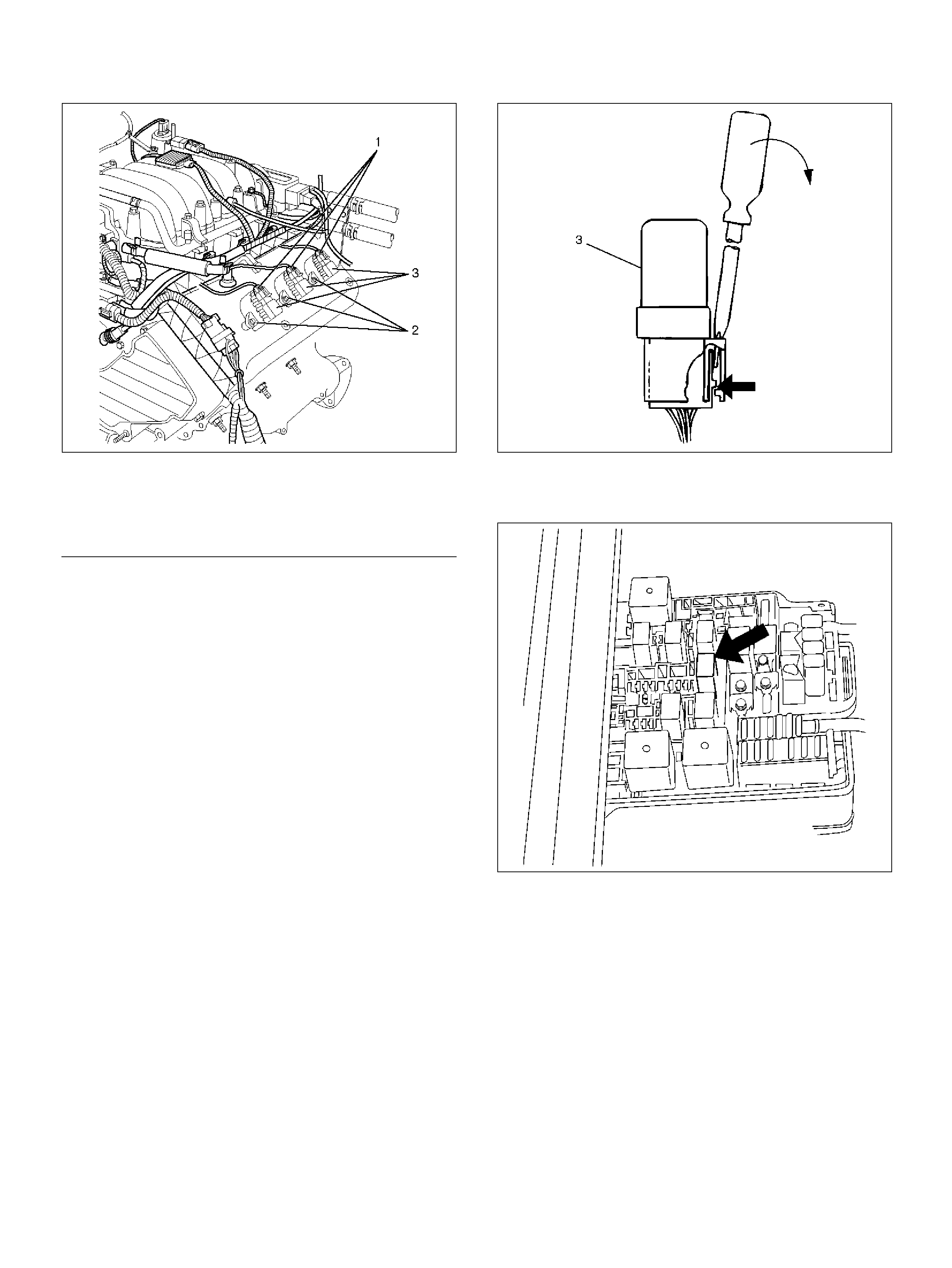
060RY022
EndOFCallout
4. Connect the ignition coil connector at the ignition
coil asse mbl ies .
5. Connect the negative battery cable.
CATALYTIC CONVERTER
REMOVAL AND INSTALLATION
PROCEDURE
Refer to Engi ne Exhaus t in Engine section.
AIR CONDITIONING THERMO RELAY
REMOVAL PROCEDURE
1. Remove the fuse and relay box cover from under
the hood.
2. Consult the diagram on the cover to determine
which is the correct relay.
3. Insert a small screwdriver into the catch slot on the
forward side of the fuel pump relay.
• The screwdriver blade will release the catch
inside.
D08RW131
4. Pull the relay straight up and out of the fuse and
relay box.
014RY00007
INSTALLATION PROCEDURE
1. Insert the relay into the correct place in the fuse and
relay box with the catch slot facing forward.
2. Press down until the catch engage s.
• An audib le “click" will be heard.
3. Install the fuse and relay box cover.
Legend
(1) Ignition Coil Connectors
(2) Bolts
(3) Ignition Coil Assemblies
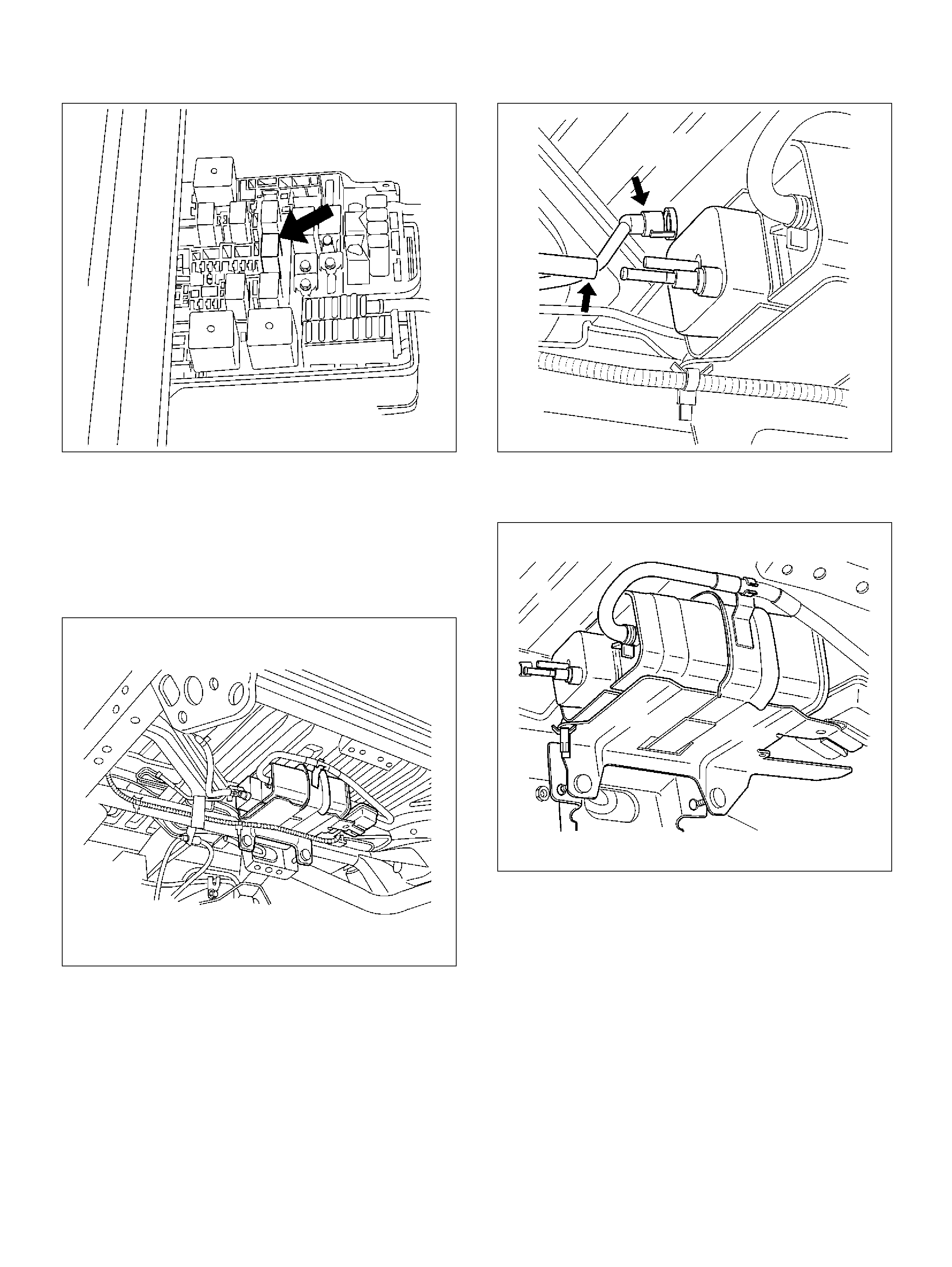
014RY00007
EVAP CANISTER
REMOVAL PROCEDURE
1. Disconnect the negative battery cable.
2. Disconnect the two hoses from the EVAP canister.
014RW117
3. Disconnect the fuel vapor connector and the purge
hose from the EVAP canister vent solenoid.
014RW130
4. Remove the two retaining bolts the EVAP canister to
the mounting bracket on the cross member.
014RW131
5. Remove the retaining bolt on the mounting bracket
the slide the canister out of mounting bracket.
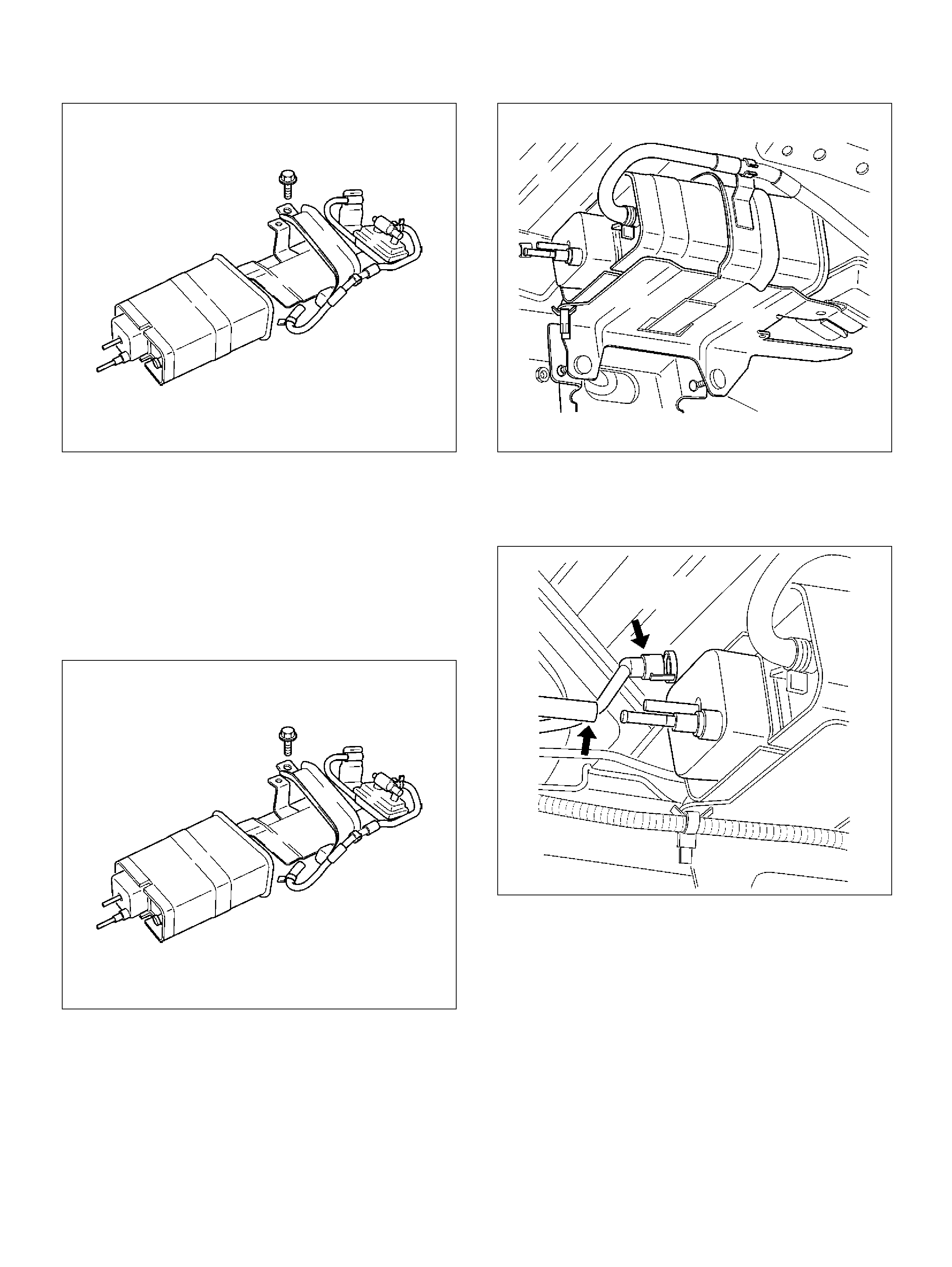
014RW129
INSPECTION PROCEDURE
1. Inspect the hoses for cracks and leaks .
2. Ins pect the canister for a damaged case.
INSTALLATION PROCEDURE
1. Slide the canister into mounting bracket and install
the mou nting bracket bolt.
014RW129
2. Install the retaining bolts the EVAP canister to the
mount ing bracket on the cross member.
014RW131
3. Connect the fuel vapor connector to the EVAP
canister vent solenoid.
4. Connect the two hoses to the EVAP canister.
014RW130
5. Disconnect the nega tive battery cable.
EVAP CANISTER PURGE SOLENOID
REMOVAL PROCEDURE
1. Disconnect the nega tive battery cable.
2. Disconnect the electrical connector from the EVAP
canister purge solenoid.
3. Disconnect the vacuum hoses from the EVAP
canister purge solenoid.
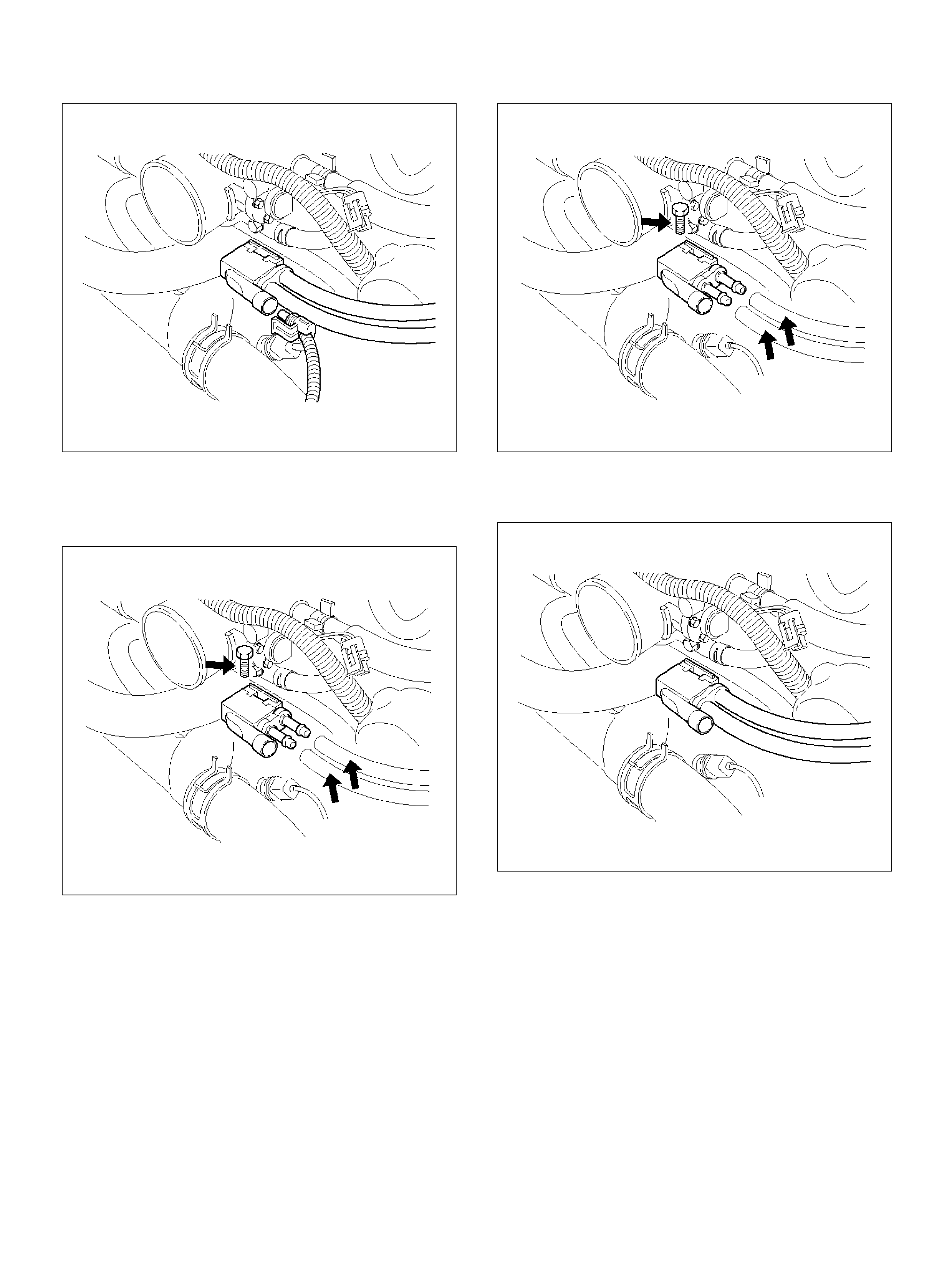
014RW136
4. Rem ove the EVAP canister purge solenoid retaining
bolt from the commo n chamber.
5. Remove the EVAP canister purge solenoid.
014RW137
INSTALLATION PROCEDURE
1. Install the EVAP canister purge solenoid on the
upper intake manifold.
2. Install the EVAP canister purge solenoid retaining
bolt.
Tighten
Important: Tighten the bolts to 20 N·m ( 16 lb ft.).
3. Connect the vacuum hoses to the EVAP canister
purge solenoid.
014RW137
4. Connect the electrical connector to the EVAP
canister purge solenoid.
014RW138
LINEAR EXHAUST GAS
RECIRCULATION (EGR) VALVE
REMOVAL PROCEDURE
1. Disconnect the nega tive battery cable.
2. Disconnect the electrical connector at the EGR
valve.
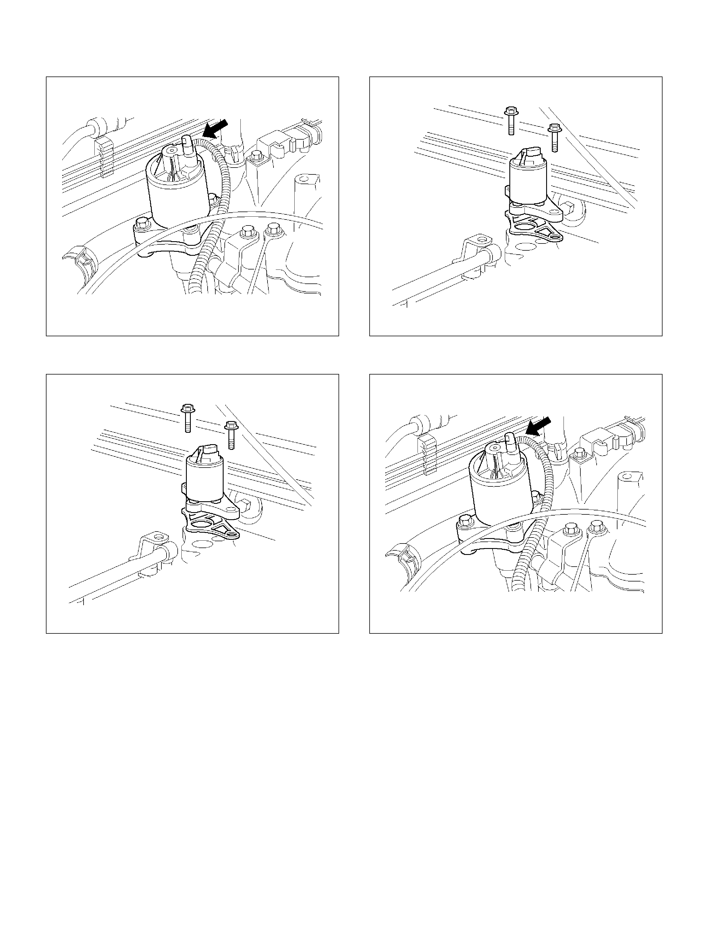
014RW139
3. Remove the bolts from the common chamber.
014RW098
4. Remove the EGR valve from the common chamber
manifold.
5. Remove the gasket from the common chamber
manifold.
INSTALLATION PROCEDURE
1. Ins tall the gasket on the com mon chamber.
2. Install the EGR valve on the common chamber.
3. Secure the EGR valve and the gasket with the bolt s.
Torque: 25 N·m (18 Ib ft)
It is possible to install the EGR valve rotated 180° from
the correct position. Make sure that the base of the
valve is placed so that it aligns with the mounting flange.
014RW098
4. Connect the electrical connector at the EGR valve.
014RW139
5. Connect the negative battery cable.
POSITIVE CRANKCASE
VENTILATION (PCV) VALVE
REMOVAL PROCEDURE
1. Remove the vacuum hose at the PCV valve.
• Slide the clamp back to release the hose.
2. Pull the PCV valve from the rubber grommet in the
right valve cover.
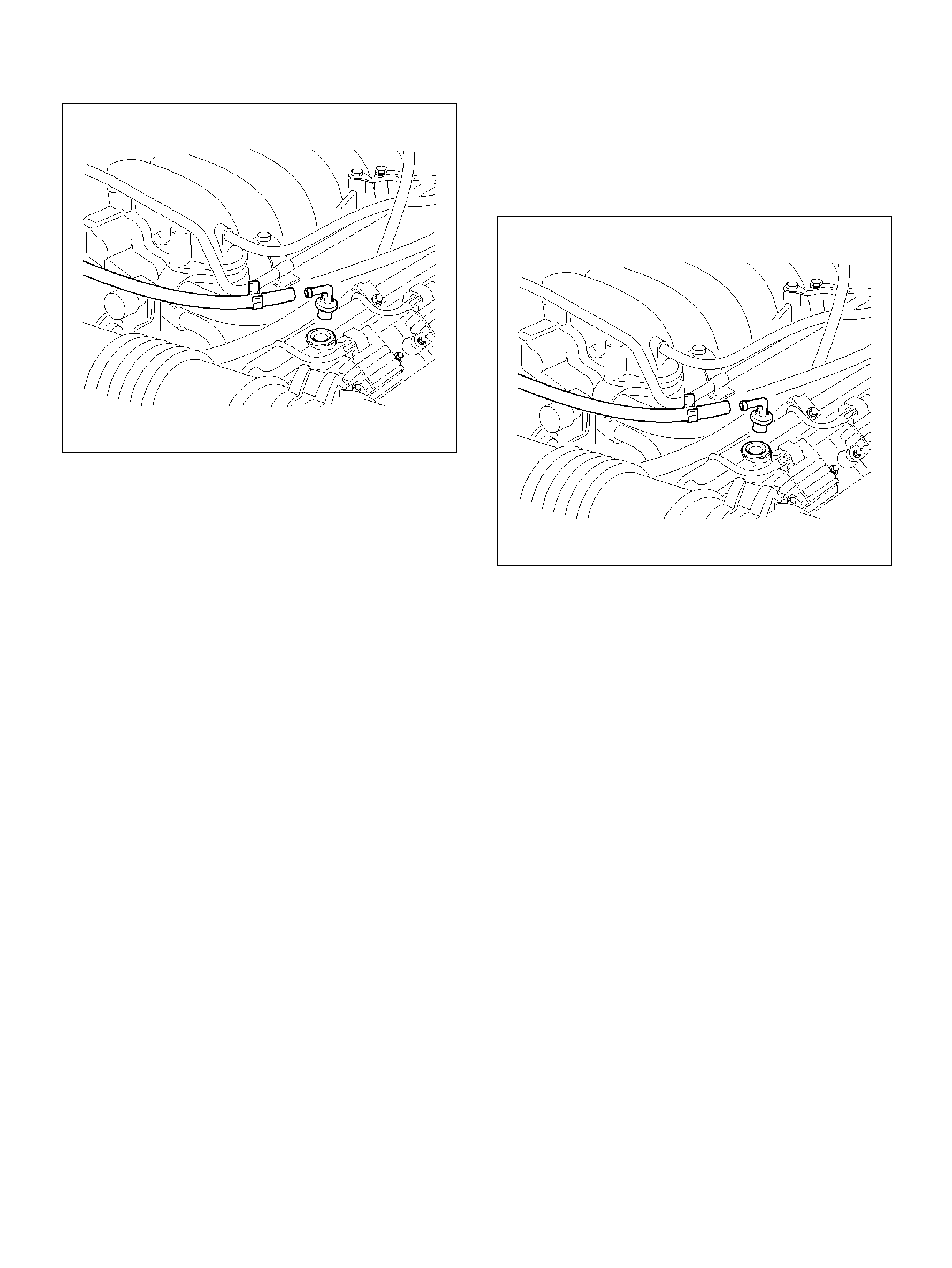
014RW097
INSPECTION PROCEDURE
Before inspecting the PCV valve, make sure that the
hoses are connected properly and are in good
condition. Also check that the oil pan and rocker cover
gaskets are sealing properly.
PCV VALVE
1. Run the engine at normal operating temperature.
2. Disconne ct the valve from the rocker cov er.
RESULT: A hissing noise should b e heard from the
valve. If no noise is heard, the PCV valve or hose is
plugged.
3. Remove the PCV valve from the engine.
a. Blow air into the rocker cover side of the valve.
RESULT: Air should pass freely.
b. Blow air into the air cleaner side of the valve.
RESULT: Air should not pass through the valve.
4. Re-install the PCV valve and remove the oil filler
cap.
RESULT: A small vacuum should be felt at the oil
filler hole.
INSTALLATION PROCEDURE
1. Push the PCV valve into t he rubber grom met in th e
left valve cov er.
2. Install the vacuum hose on the PCV valve and
secure the vacuum hose with the cl amp.
014RW097
WIRING AND CONNECTORS
WIRING HARNESS SERVICE
The control module harness electrically connects the
control module to the various solenoids, switches and
sensors in the vehicle engine compartment and
passenger compartment.
Replace wire harnesses with the proper part number
replacement.
Because of the low amperage and volt age levels utilized
in powertrain control systems, it is essential that all
wiring in environmentally exposed areas be repaired
with crimp and seal splice sleeves.
The following wire harness repair information is
intended as a general guideline only. Refer to
Chassis Electrical section for all wire harness repair
procedures.
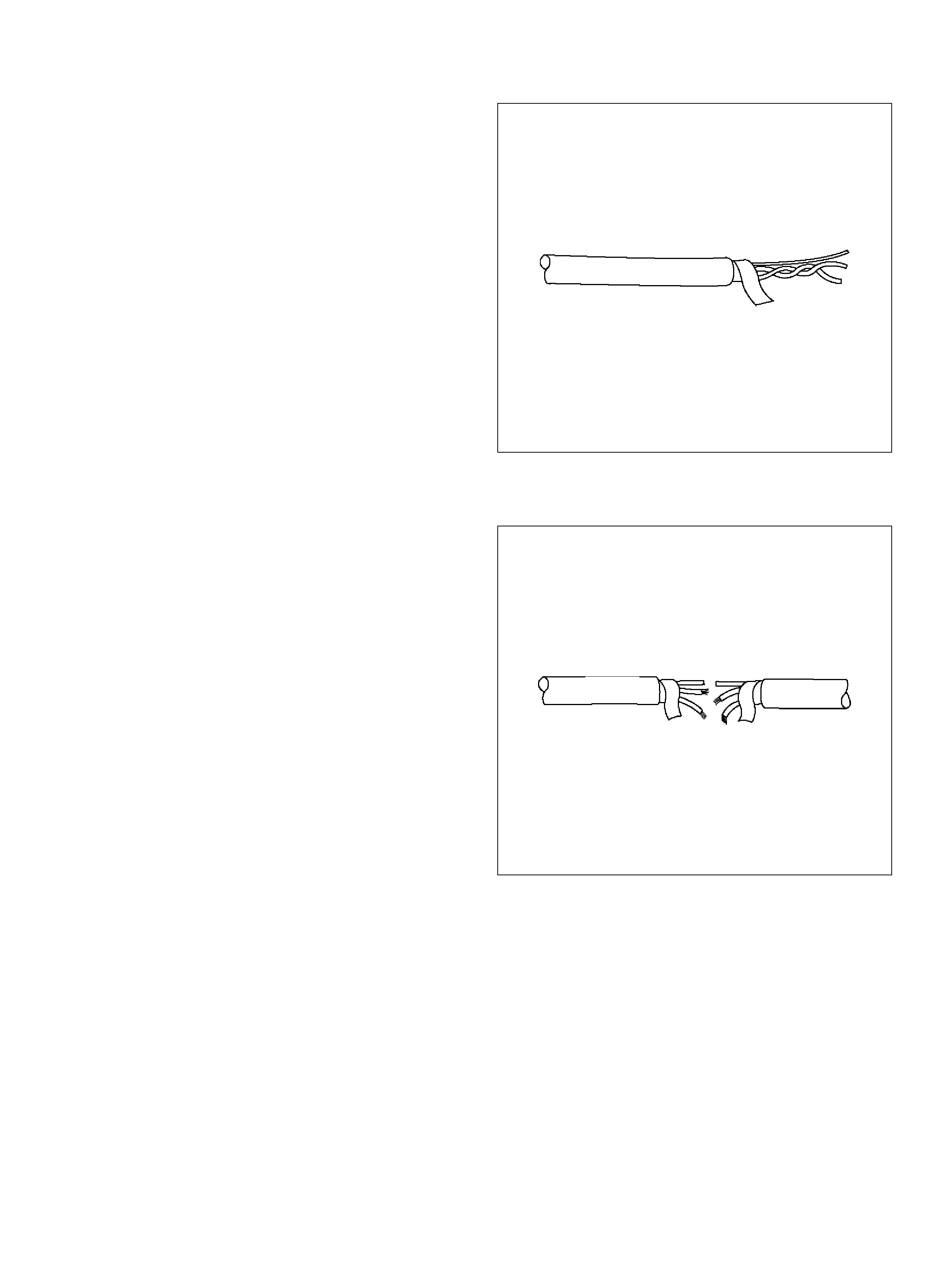
CONNECTORS AND TERMINALS
Use care when probing a connector and when replacing
terminals. It is possible to short between opposite
terminals. Damage to components could result. Always
use jumper wires between connectors for circuit
checking. NEVER probe through Weather-Pack seals.
Use an appropriate connector test adapter kit which
contains an assortment of flexible connectors used to
probe terminals during diagnosis. Use an appropriate
fuse remover and test tool for removing a fuse and to
adapt the fuse holder to a meter for diagnosis.
Open circuits are often difficult to locate by sight
because oxidation or terminal misalignment are hidden
by the connectors. Merely wiggling a connector on a
sensor , or in the wiring harness, may temporarily correct
the open circuit. Intermittent problems may also be
caused by ox idized or loose connections .
Be certain of the type of connector/terminal before
making any conn ector or termin al repair. Weather-Pack
and Com-Pack III terminals look similar, but are
serviced differently.
PCM CONNECTORS AND
TERMINALS
REMOVAL PROCEDURE
1. Remove the connector terminal retainer.
2. Push the wire connected to the affected terminal
through the connector face so that the terminal is
exposed.
3. Serv ice the terminal as necessary.
INSTALLATION PROCEDURE
1. Bend the tab on the connector to allow the terminal
to be pulled into position within the connector.
2. Pull carefully on the wire to install the connector
terminal retainer.
WIRE HARNESS REPAIR: TWISTED
SHIELDED CABLE
REMOVAL PROCEDURE
1. Rem ove the outer jacket.
2. Unwrap the aluminum/mylar tape. Do not remove
the mylar.
047
3. Untwist the conductors.
4. Strip the insulation as necessary.
048
INSTALLATION PROCEDURE
1. Splice the wires using splice clips and rosin core
solder.
2. W rap eac h s pl i ce to i nsu late.
3. Wrap the splice with mylar and with the drain
(uninsulated) wire.
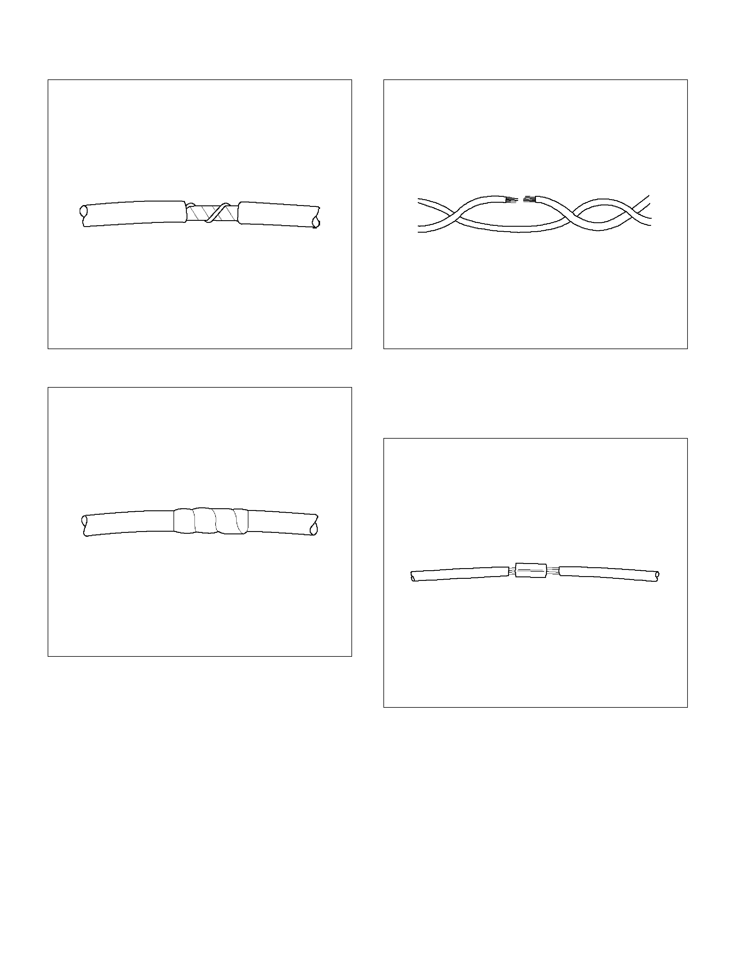
049
4. Tape ov er the whole bundle to secure.
050
TWISTED LEADS
REMOVAL PROCEDURE
1. Locate the damaged wire.
2. Rem ove the insulation as required.
051
INSTALLATION PROCEDURE
1. Use splice clips and rosin core solder in order to
splice the two wires together.
052
2. Cover the splice with tape in order to insulate it from
the other wires.

053
3. Twist the wires as they were before starting this
procedure.
054
4. Tape the wires with electrical tape. Hold in place.
055
WEATHER-PACK CONNECTOR
TOOLS REQUIRED
5-8840-6632-0 Weather -Pack II Terminal Remover
REMOVAL PROCEDURE
A Weather-Pack connector can be identified by a rubber
seal at the rear of the connector. This engine room
connector protects against moisture and dirt, which
could from oxidation and deposits on the terminals. This
protection is important, because of the l ow voltage and
the low amperage found in the electronic system s.
1. Open the secondary lock hinge on the connector.
070
2. Use tool 5-8840-6632-0 or the eq uivalen t to remov e
the pin and the sleeve terminals. Push on
5-8840-6 632-0 to release.
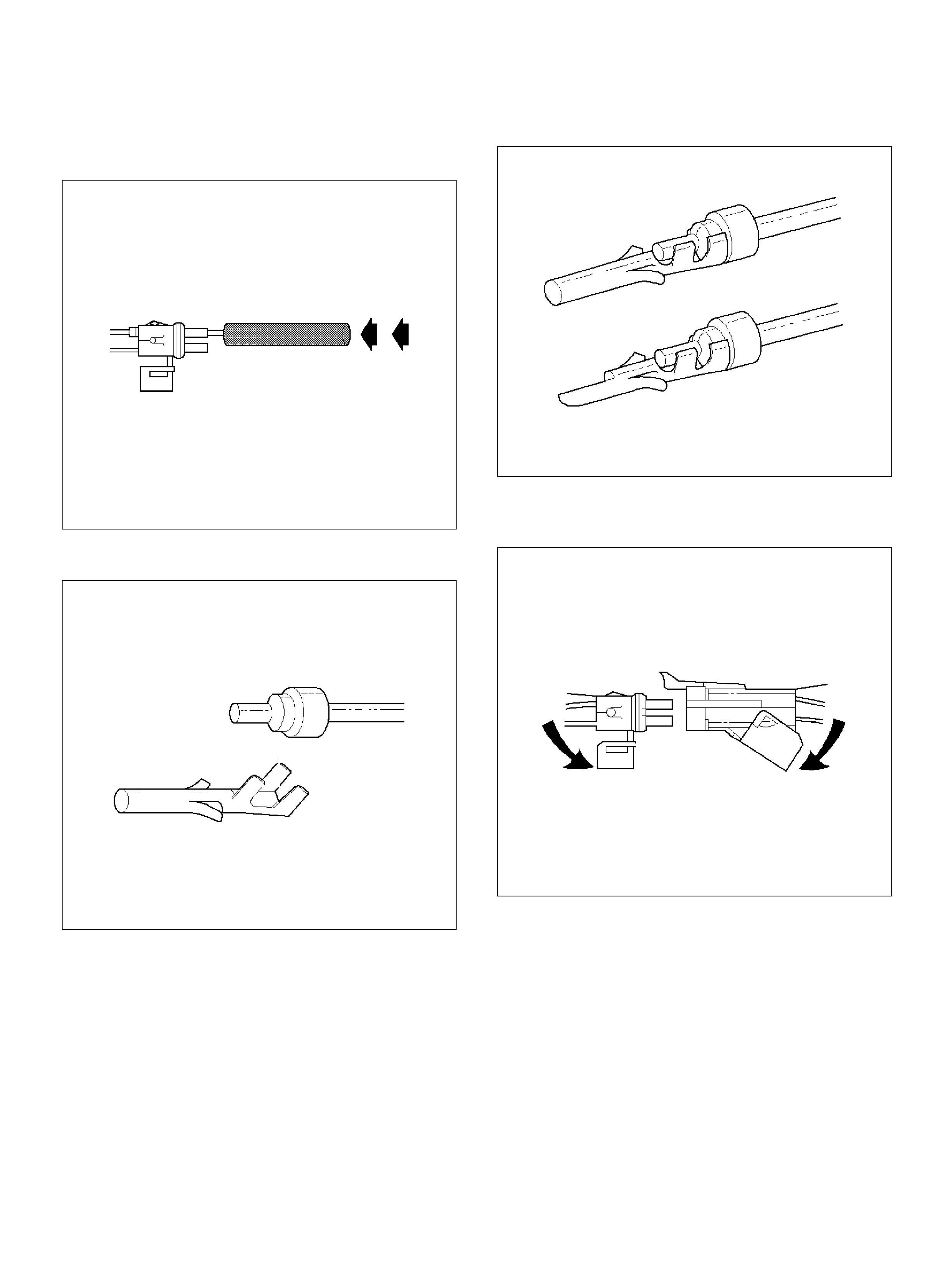
Do the use an ordina ry pick or the terminal may be bent
or deformed. Unlike standard blade terminals, these
terminals cannot be straightened after they have been
improperly bent.
071
3. Cut the wire immediately behind the cable seal.
072
INSTALLATION PROCEDURE
Make ce rtain the connectors are properly seated and all
of the sealing rings are in place when you reconnect the
leads. The secondary lock hinge provides a backup
locking feature for the connector. The secondary lock
hinge is used for added reliability. This flap should retain
the terminals even if the small terminal lock tangs are
not positioned prope rly.
Do not replace the Weather-Pack connections with
standard connections. Read the instructions provided
with the Weather-Pack connector and terminal
packages.
1. Replace the terminal.
2. Slip the new seal onto the wire.
3. Strip 5 mm (0.2") of insulation from the wire.
4. Crimp the terminal over t he wire and the seal.
073
5. Push the terminal and the connector to engage the
locking tangs.
070
6. Close the secondary locking hinge.
COM-PACK III
GENERAL INFORMATION
The Com-Pack III terminal looks similar to some
Weather-Pack terminals. This terminal is not sealed and
is used where resistance to the environment is not
required. Use the standard method when repairing a
terminal. Do not use the Weather-Pack terminal tool J
28742-A or equivalent. These will damage the
terminals.
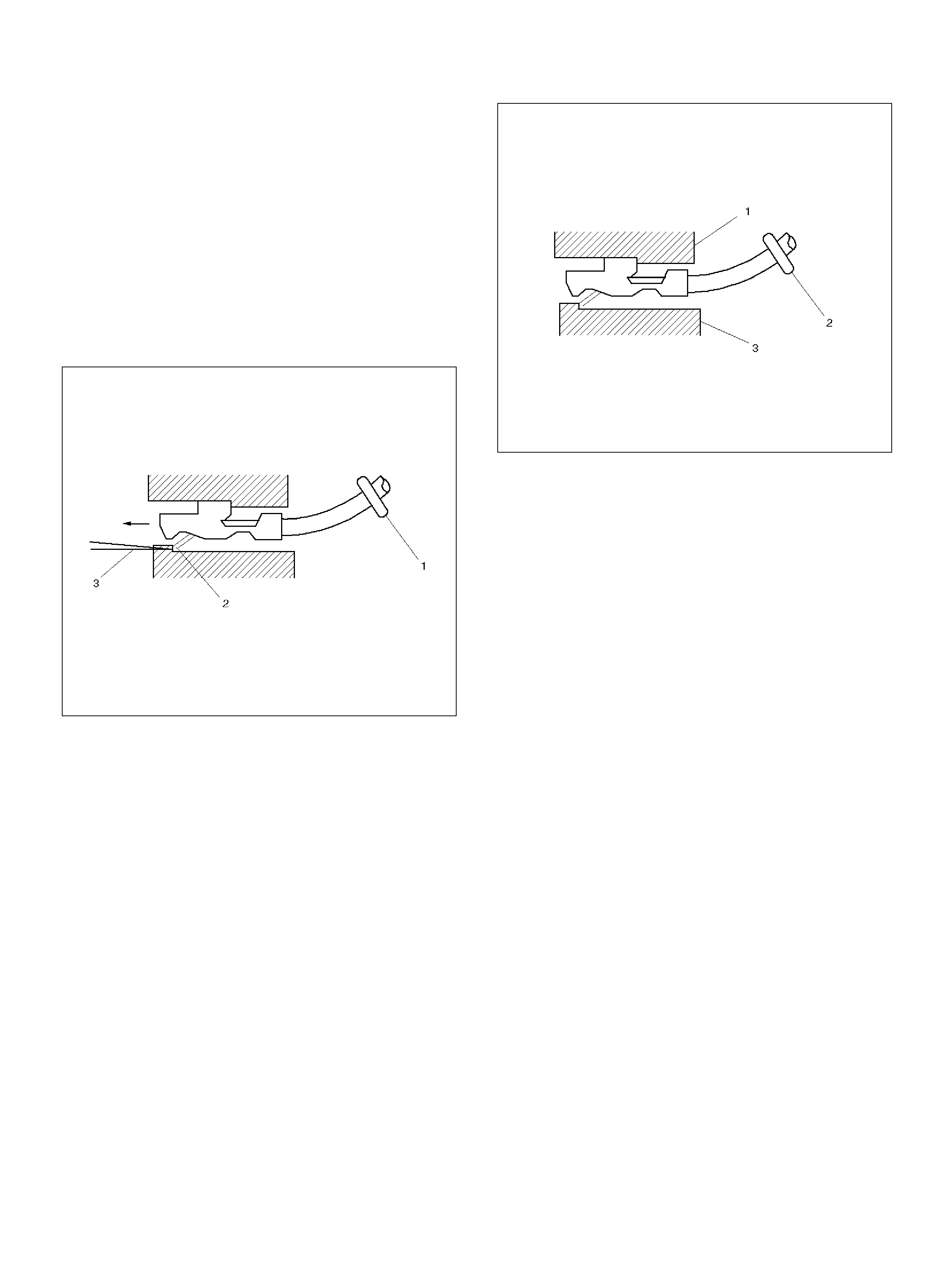
METRI-PACK
TOOLS REQUIRED
J 35689 Terminal Remov er
REMOVAL PROCEDURE
Some connectors use terminals called Metri-Pack
Series 150. These may be used at the engine coolant
temperature (ECT) sensor.
1. Slide the seal (1) bac k on the wire.
2. Insert the J 35689 tool or equivalent (3) in order to
release the terminal locking tang (2).
060
3. Push the wire and the terminal out through the
connector. If you reuse the terminal, reshape the
l ock ing tang.
INSTALLATION PROCEDURE
Metri-Pack terminals are also referred to as
“pull-to-seat" terminals.
1. In order to install a terminal on a wire, the wire must
be inserted through the seal (2) and through the
conne ctor (3).
2. The terminal (1) is then crimped onto the wire.
061
3. Then the terminal is pulled back into the connector
to seat it in place.
GENERAL DESCRIPTION (PCM AND
SENSORS)
58X Reference PCM Input
The Powertrain Control Module (PCM) uses this signal
from the Crankshaft Position (CKP) sensor to calculate
engine RPM and crankshaft position at all engine
speed s. Th e PC M als o uses the pulses on this c ircuit to
initiate injector pulses. If the PCM receives no pulses on
this c irc uit , DTC P033 7 w ill se t. T he engi ne w ill not start
and run without using the 58X reference signal.
A/C Request Signal
This signal tells the PCM when the A/C mode is
selected at th e A/C control head. The P CM uses this to
adjust the idle speed before turning “ON" the A/C cl utch.
The A/C compressor will be inoperative if this signal is
not availab le to the PCM.
Refer to A/C Clutch Circuit Di agnosis section f or A/ C
wiring diagrams and diagnosis for the A/C electrical
system .
Crankshaft Position (CKP) Sensor
The cr ankshaft position (CK P) s ensor prov ides a signal
used by the powertrain control module (PCM) to
calculate the ignition sequence. The CKP sensor
initiates the 58X reference pulses which the PCM uses
to calculate RPM and crankshaft position.
Refer to Electronic Ignition System section for
additional informati on.
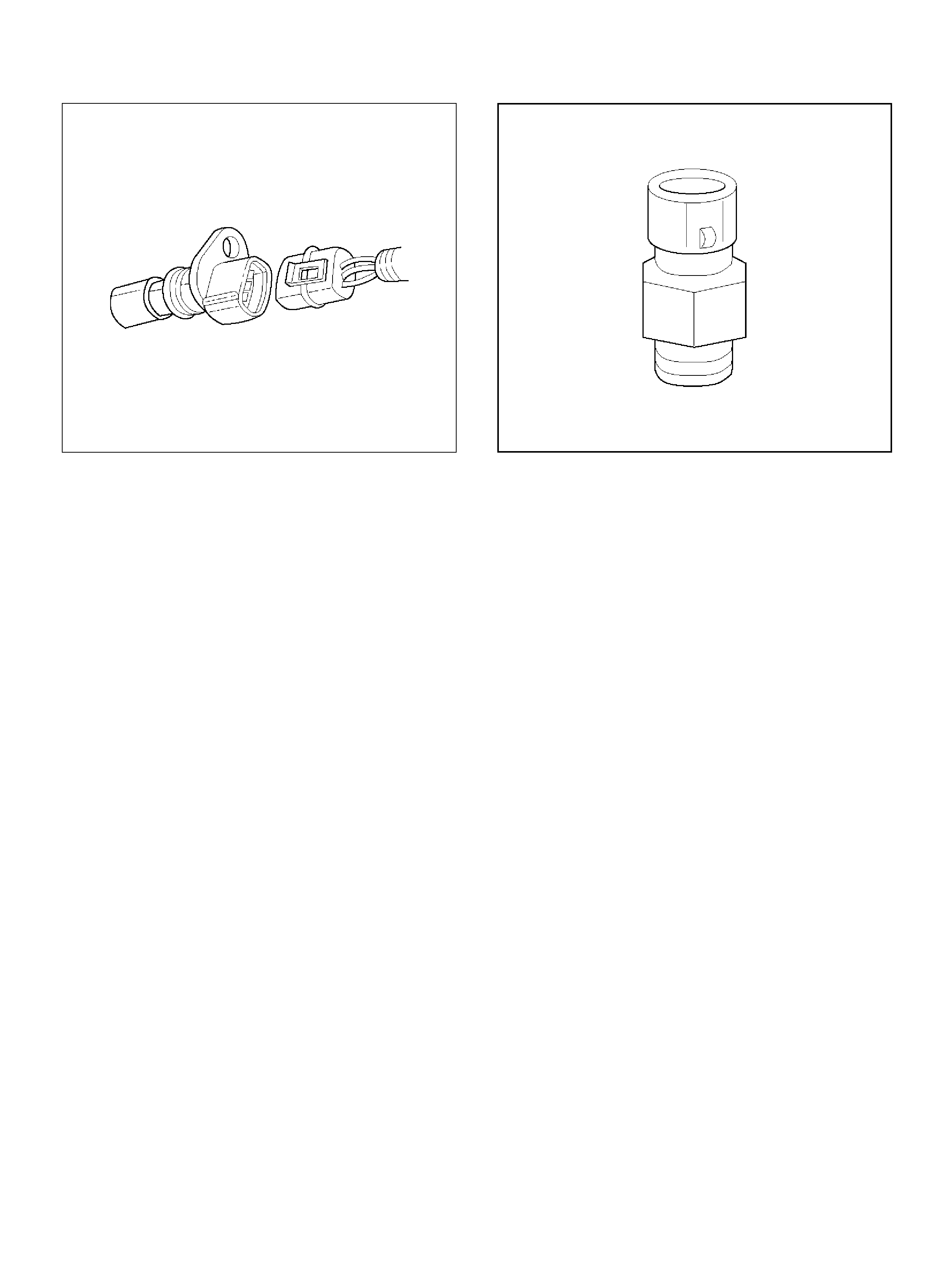
0013
Engine Coolant Temperature (ECT) Sensor
The engine coolant temperature (ECT) sensor is a
thermistor (a resistor which changes value based on
temperature) mounted in the engine coolant stream.
Low c oolant t emperature prod uces a high resistance of
100,000 ohms at –40°C (–40°F). High temperature
causes a low resistance of 70 ohms at 130°C (266°F).
The PCM supplies a 5-volt signal to the ECT sensor
through resistors in the PCM and measures the voltage.
The sign al voltag e will be high when the engi ne is cold
and low when the engine is hot. By measuring the
voltage, the PCM calculates the engine coolant
temperature. Engine coolant temperature affects most
of the systems that the PCM controls.
The Tech 2 displays engine coolant temperature in
degrees. After engine start-up, the temperature should
rise steadily to about 85°C (185°F). It then stabilizes
when the thermostat opens. If the engine has not been
run for several hours (overnight), the engine coolant
temperat ure and intake air tempe rature displays shoul d
be close to each other. A hard f ault in the engine coolant
sensor circuit will set DTC P0177 or DTC P0118. An
intermittent fault will set a DTC P1114 or P1115.
0016
Electrically Erasable Programmable Read
Only Memory (EEPROM)
The electrically erasable programmable read only
memory (EEPROM) is a permanent memory chip that is
physically soldered within the PCM. The EEPROM
contains the program and the calibration information
that the PCM needs to control powertrain operation.
Unlike the PROM used in past applications, the
EEPROM is not replaceable. If the PCM is replaced, the
new PCM will need to be programmed. Equipment
containing the correct program and calibration for the
vehicle is required to program the PCM.
Fuel Cont rol Heated Oxygen Sensors
The fuel control heated oxygen sensors (Bank 1 HO2S
1 and Bank 2 HO2S 1) are mounted in the exhaust
stream where they can monitor the oxygen content of
the exhaust gas. The oxygen present in the exhaust gas
reacts with the sen so r to produce a voltage output. Th is
voltage should constantly fluctuate from approximately
100 m V to 900 mV. T he heated oxygen sensor voltage
can be monitored with a Tech 2. By monitoring the
voltage output of the oxygen sensor, the PCM
calculates the pulse width command for the injectors to
produce the proper combustion chamber mi xture.
• L ow HO 2S v oltage is a lea n m ixture w hich w ill result
in a rich command to compensate.
• High HO2S voltage is a rich mixture which will result
in a lean command to com pensat e.
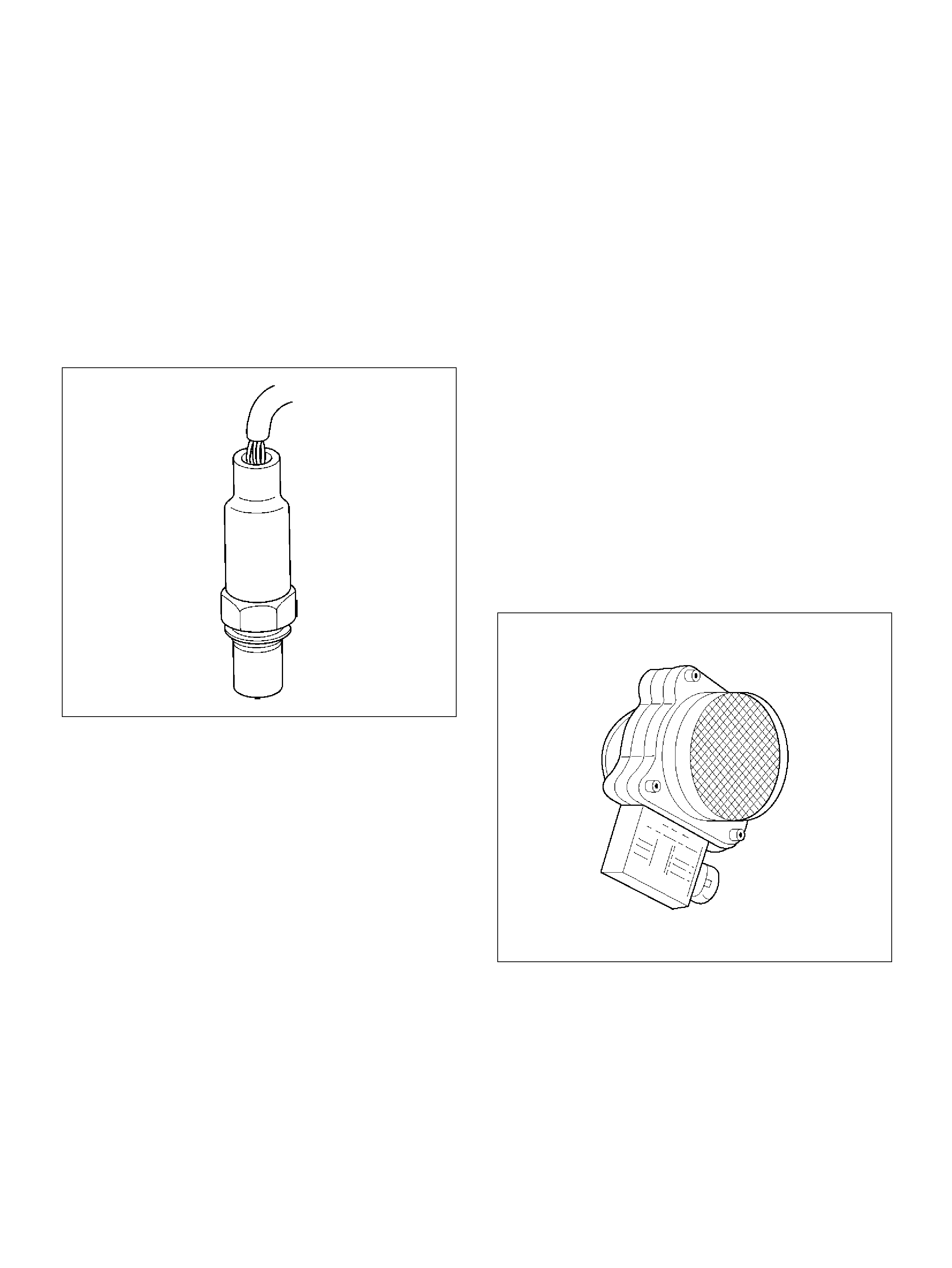
An open Bank 1 HO2S 1 signal circuit will set a DTC
P0134 and the Tech 2 will display a constant voltage
between 400-500 mV. A constant voltage below 300 mV
in the sensor circuit (circuit grounded) will set DTC
P0131. A constant voltage above 800 mV in the circuit
will set DTC P0132. Faults in the Bank 2 HO2S 1 signa l
circuit will cause DTC 0154 (open circuit), DTC P0151
(grounded circuit), or DTC P0152 (signal voltage high)
to set. A fault in the Bank 1 HO2S 1 heater circuit will
cause DT C P0135 to set. A fault in the Bank 2 HO2S 1
heater circuit will cause DTC P0155 to set. The PCM
can also detect HO2S response problems. If the
response time of an HO2S is determined to be too slow,
the PCM will store a DT C that i ndicates degraded HO2S
perform anc e.
060RY00127
Intake Air Temperature (IAT) Sen sor
The intake air temperature (IAT) sensor is a thermistor
which c hanges its resistanc e based on t he temperat ure
of air entering the engine. Low temperature produces a
high resistance of 100,000 ohms at –40°C (–40°F). High
temperature causes low resistance of 70 ohms at 130°C
(266°F) . The PCM supplies a 5-volt signal to the sensor
through a resistor in the PCM and monitors the signal
voltage. The voltage will be high when the incoming air
is cold. T he voltage will be low when the incom ing air is
hot. By measuring the voltage, the PCM calculates the
incoming air temperature. The IAT sensor signal is used
to adjust spark timing according to the incoming air
density.
The Tech 2 displays the temperature of the air en tering
the engine. The temperature should read close to the
ambient air temperature when the engine is cold and
rise as underhood temperature increases. If the engine
has not been run for several hours (overnight), the IAT
sensor temperature and engine coolant temperature
should read close to each other. A fault in the IAT
sensor circuit wil l set DTC P0112 or DTC P 011 3.
Linear Exhaust Gas Recirculation (EGR)
Control
The P CM monitors the exhaus t ga s recirculation (EGR)
actual position and adjusts the pintle position
accordingly. The PCM uses information from the
following sens ors to control the pintle position:
• Engi ne Coolan t Tempe rature (ECT) sensor.
• Throttle Position (TP) sensor.
• Mass Air Flow (MAF) sensor.
Mass Air Flow (MAF) Sensor
The MASS AIR FLOW (MAF) sensor measures the
difference between the volume and the quantity of air
that enters the engine. “Volume" means the size of the
space to be filled. “Quantity" means the number of air
molecul es that will fit into the space. This information is
important to the PCM because heavier, denser air will
hold more fuel than lighter, thinner air. The PCM adjusts
the air/fuel ratio as needed depending on the MAF
value. The Tech 2 reads the MAF value an d displays it
in terms of gra ms per second (gm / s). At idle, the Tech 2
should read between 4-7 gm/s on a fully warmed up
engine. Values should change quickly on accelerator.
Values should remain stable at any given RPM. A failure
in the MAF sensor or circuit will set DTC P0101, DTC
P0102, or DTC P0103.
0007
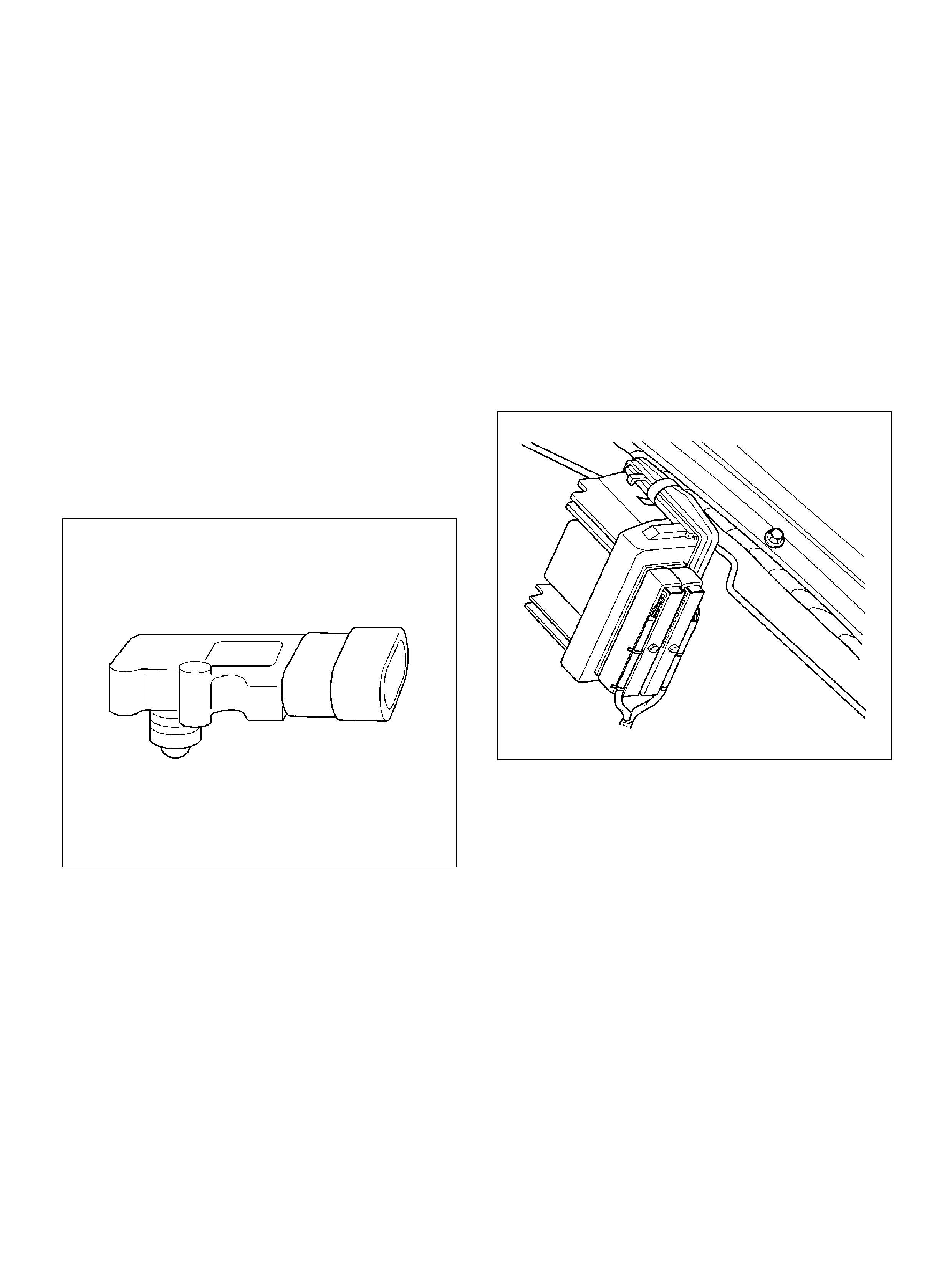
Manifold Absolute Pressure (MAP) Sensor
The Manifold Absolute Pressure (MAP) sensor
responds to changes in intake manifold pressure
(vacuum). The MAP sensor signal voltage to the PCM
varies from below 2 volts at idl e (high vacuum) to above
4 volts with the ignition ON, engine not running or at
wide-open throttle (low vacuum).
The MAP sensor is used to determine the following:
• Manifold pressure c hange s while the linear EGR flow
test diagnostic is being run. Refer to DTC P0401.
• Barometric pressure (BARO).
If the PCM detects a voltage that is lower than the
possible range of the MAP sensor, DTC P0107 will be
set. A signal voltage higher than the possible range of
the sensor will set DTC P0108. An intermittent low or
high voltage will set DTC P1107, respectively. The PC M
can detect a shifted MAP sensor. The PCM compares
the MAP sensor signal to a calculated MAP based on
throttle position and various engine load factors. If the
PCM detects a MAP signal that varies excessively
above or below the calculated value, DTC P0106 will
set.
055RW004
Powertrain Control Module (PCM)
The Powertrain Control Module (PCM) is located in the
passenger compartment below the center console. The
PCM controls the following:
• F uel mete ring system.
• Transmission shifting (automatic transmission only).
• Ignition timing.
• O n-board diag nos tics for powertrain functions.
The PCM constantly observes the information from
various sensors. The PCM controls the systems that
affect vehicle performance. The PCM performs the
diagnostic function of the system. It can recognize
operational problems, alert the driver through the MIL
(Check Engine lamp), and store diagnostic trouble
codes (DTCs). DTCs identify the problem areas to aid
the techn ician in making repairs.
PCM Function
The P CM supplies either 5 or 12 volts to power vari ous
sensors or switches. The power is supplied through
resistances in the PCM which are so high in value that a
test light will not light when connected to the circuit. In
some cases, even an ordinary shop voltmeter will not
give an accurate reading because its resistance is too
low. Therefore, a digital voltmeter with at least 10
megohms input impedance is required to ensure
accurate voltage readings. Tool J 39200 meets this
requirement. The PCM controls output circuits such as
the injectors, fan relays, etc., by controlling the ground
or the power feed circuit through transistors or through
either of the following two devices:
• O utput Driver Module (ODM)
• Q uad Driver Module (QDM)
060RY00068
PCM Components
The PCM is designed to maintain exhaust emission
levels to government mandated standards while
providing excellent derivability and fuel efficiency. The
PCM monitors numerous engine and vehicle functions
via electronic sensors such as the throttle position (TP)
sensor, heated oxygen sensor (HO2S), and vehicle
speed sensor (VSS). The PCM also controls certain
engine operations throu gh the following:
• F uel injector control
• Ignition control module
• ION s ensing m odule
• Automatic transmission shift functions
• Cruise control
• Ev aporative em iss ion (EVAP ) purge
• A/C clutch cont rol
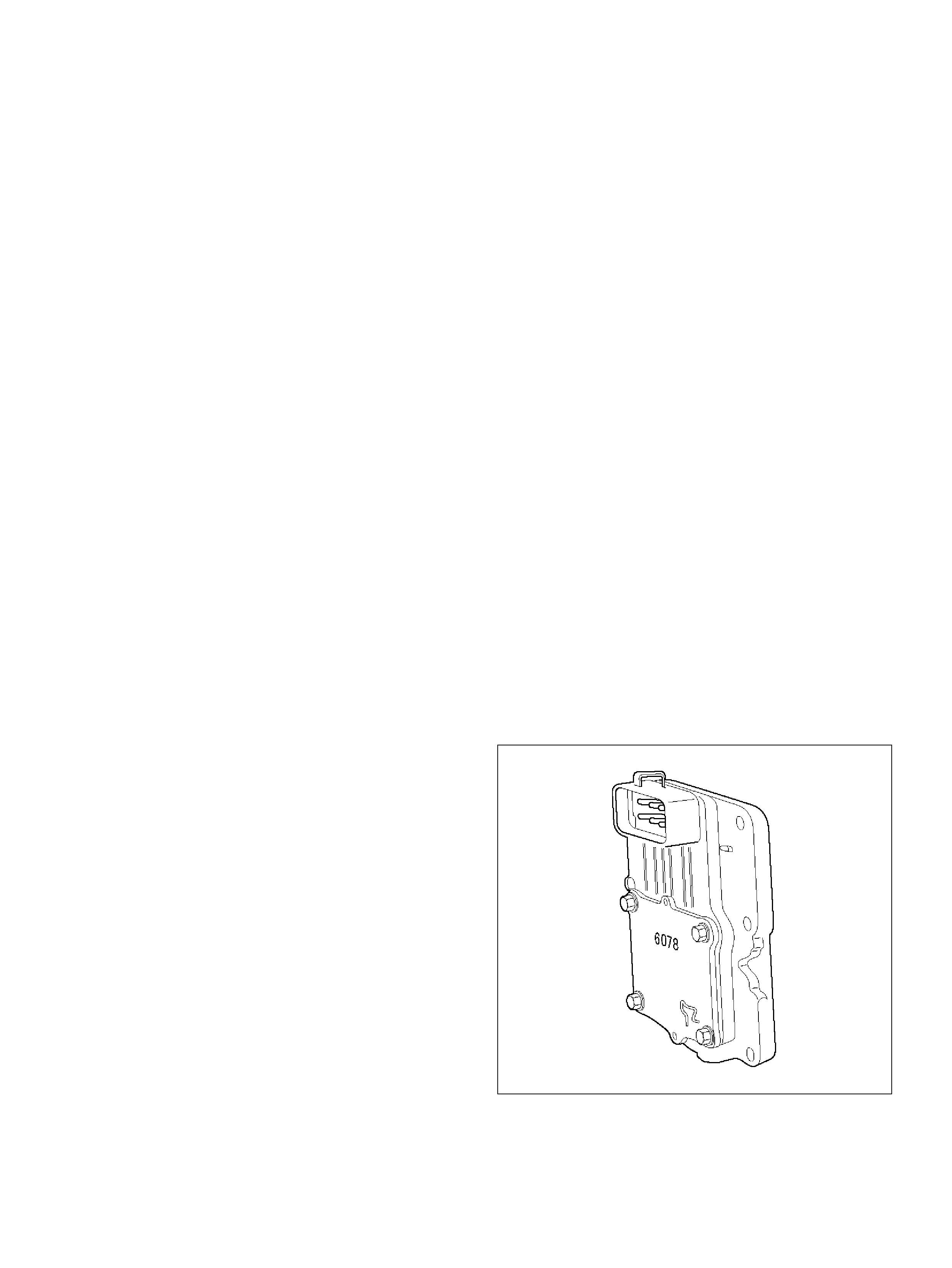
PCM Voltage Description
The PCM supplies a buffered voltage to various
switches and sens ors. It can do this because resistance
in the PCM is so high in value that a test light may not
illuminate when connected to the circuit. An ordinary
shop voltmeter may not give an accurate reading
because the voltmeter input impedance is to o low. Use
a 10-megohm input impedance digital voltmeter (such
as J 39200) to assure accurate voltage readings.
The input/output devices in the PCM include
analog-to-digital converters, signal buffers, counters,
and special drivers. The PCM controls most
components with electronic switches which complete a
ground circuit when turned “ON." These switches are
arranged in groups of 4 and 7, called either a
surface-mou nted quad driver m odul e (QDM ), whic h can
independently control up to 4 output terminals, or QDMs
which c an independently cont rol up t o 7 out puts. Not al l
outputs are always used.
PCM Input/Outputs
Inputs – Opera ting Conditions Read
• Air Condi tioning “ON" or “OFF"
• Engine Coolant Temperature
• Cran k sh aft P o s i tio n
• Exhaust Oxygen Content
• Ele ctronic Ignition
• Manifold Absolute Pressure
• Battery Voltage
• Throttle Position
• V ehicle Speed
• F uel Pum p Voltage
• Power Steering Pressure
• Intake Air Temperature
• Mass Air Flow
• Engine Knoc k
Outpu ts – System s Con trolle d
• EVAP Canister Purge
• Exhaust Gas Recirc ulation (EGR)
• Ignition Control
• F uel Control
• ION S ensing Modul e
• Ele ctric Fuel Pump
• Air Condi tioning
• Diagnostics
– Malfunction Indicator Lamp
– Data Link Connector (DLC)
– Data Output
• Transmission Control Module
PCM Service Prec aution s
The PCM is designed to withstand normal current draws
associated with vehicle operation. Avoid overloading
any circuit. When testing for opens and shorts, do not
ground or apply voltage to any of the PCM's circuits
unless instructed to do so. These circuit s should only be
tested using dig ital voltmet er J 39200 . The PCM should
remain connected to the PCM or to a recommended
breakou t box.
Re programming The PCM
Reprogramming of the PC M is done wi thout removin g it
from the vehicle This provides a flexible and
cost-effective method of making changes in software
calibrations.
Refer to the latest Techline information on
reprogramm ing or flashing procedures.
Throttle Position (TP) Sensor
The throttle position (TP) sensor is a potentiometer
connected to the throttle shaft on the throttle b ody. The
PCM monitors the voltage on the signal line and
calculates t hrottle pos ition. A s th e th rottle val ve angle is
changed (accelerator pedal moved), the TP sensor
signal also changes. At a closed throttle position, the
output of the TP1 sensor is low. As the throttle valve
opens, t he output increases so that at wide open throttle
(WOT), the output volt age should be above 92% (Tech2
Display).
The PCM calculates fuel delivery based on throttle
valve angle (driver demand). A broken or loose TP
sensor may cause intermittent bursts of fuel from an
injector and unstable idle because the PCM thinks the
th ro tt le is mo v i n g.
060RY00027
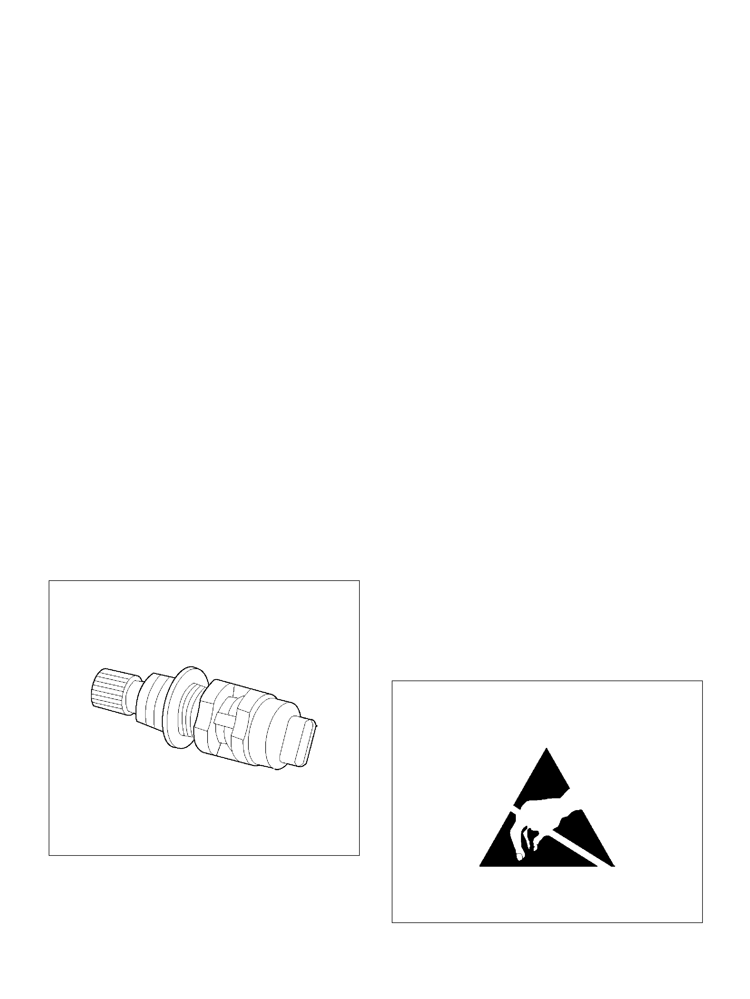
Transmission Fluid Temperature (TFT)
Sensor
The transmission fluid temperature sensor is a
thermistor which changes its resistance based on the
temperature of the transmission fluid. For a complete
description of t he TF T sensor, refer to
4L30-E Automatic Transmission Diagnosis secti o n .
A failure in the TFT sensor or associated wiring will
cause DTC P0712 or DTC P0713 to set. In this case,
engine coolant temperature will be substituted for the
TFT sensor value and the transmission will operate
normall y.
Transmission Range Switch
Important: The vehicle should not be driven with the
transmi ssion range sw itch disc onn ected; idl e quality wil l
be affected.
The four inputs from the transmission range switch
indicate to the PCM which position is selected by the
transmi ssion selector lever. This informat ion is u sed for
ignition timing, EVAP ca nister purge, EGR operation.
For more information on the transmission on the
transmission range switch, refer to
4L30-E Automatic Transmission secti o n.
Vehicle Speed Sensor (VSS)
The PCM determines the speed of the vehicle by
converting a pulsing voltage signal from the vehicle
speed sens or (VSS) into m ile s per hour. T he PC M uses
this signal to operate the cruise control, speedometer,
and the TCC and shift solenoids in the transmission. For
more information on the TCC and shift solenoids, refer
to 4L30-E Automatic Tran smi ssion section.
0008
Us e of Ci rcuit Testing Too ls
Do not use a test light to diagnose the powertrain
electrical systems unless specifically instructed by the
diagnostic p rocedures. Use Connector Test Adapter Kit
J 35616 whenever diagnostic procedures call for
probing connec tors.
Aftermarket Electr ical and Vacuum
Equipment
Aftermarket (add-on) electrical and vacuum equipment
is defined as any equipment which connects to the
vehicle's electrical or vacuum systems that is installed
on a vehicle after it leaves the factory. No allowances
have been made in the vehicle design for this type of
equipment.
NOTE: No add-on vacuum equipment should be added
to this vehicle.
NOTE: Add-on electrical equipment must only be
connected to the vehicle's electrical system at the
battery (power and ground).
Add-on electrical equipment, even when installed to
these gu idelines, may st ill cause the po wertrain system
to malfunction. This may also include equipment not
connected to the vehicle electrical system such as
portable telephones and radi os. Th erefore, the f irst step
in diagnosing any powertrain problem is to eliminate all
aftermarket electrical equipment from the vehicle. After
this is done, if the problem still exists, it may be
diagnosed in th e normal manner.
Electrostatic Discharge Damage
Electronic components used in the PCM are often
designed to carry very low voltage. Electronic
components are susceptible to damage caused by
electrostatic discharge. Less than 100 volts of static
electricity can cause damage to some electronic
componen ts. By comparison, it takes as much as 4000
volts for a person to feel even the zap of a static
discharge .
TS23793
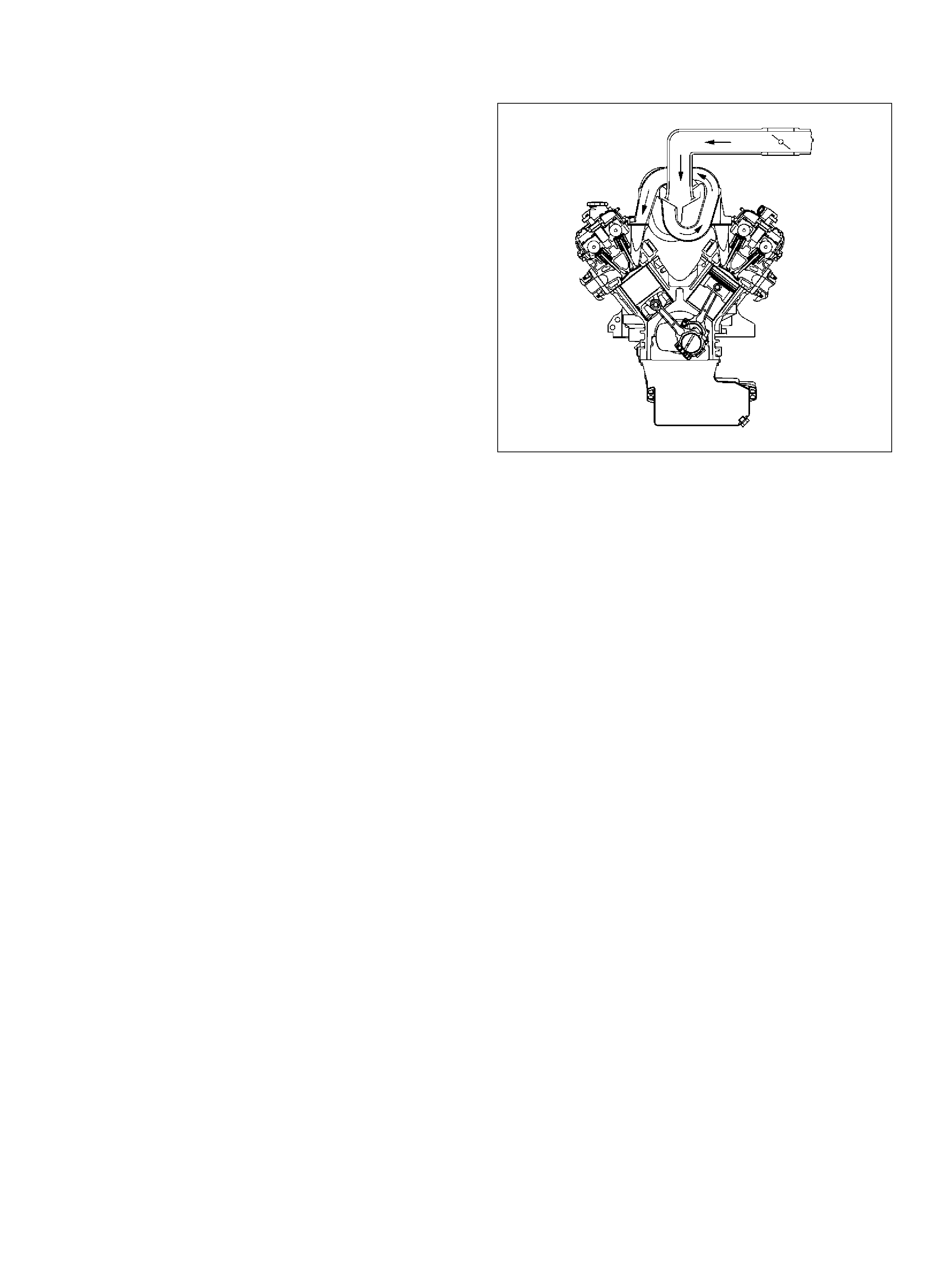
There are several ways for a person to become
statically charged. The most common methods of
charging ar e by friction and induction.
• An ex ample of charging by fric tion is a person s lidin g
across a vehicle seat.
• Charge by induction occurs when a person with well
insulated shoes stands near a highly charged object
and momentary touches ground. Charges of the
same polarity are drained off leaving the person
highly charged with the opposite polarity. Static
charges can cause damage, therefore it is important
to use care when handling and testing electronic
components.
NOTE: To prevent possible electrostatic discharge
damag e, follow these guidelines:
• Do not touch the PCM connector pins or soldered
components on the PCM circuit board.
• Do not open the replacement part package until the
part is ready to be installed.
• Before removing the part from the package, ground
the package to a known good ground on the vehicl e.
• If the part has been handl ed while slid ing across the
seat, while sitting down from a standing position, or
while walking a distance, touch a known good ground
before installing the part.
GENERAL DESCRIPTION (AIR
INDUCTION)
Air Induction System
The air induction system filters contaminants from the
outside air, and directs the progress of the air as it is
drawn into the engine. A remote-mounted air cleaner
prevents dirt and debris in the air from entering the
engine. The air duct assembly routes filtered air to the
throttle body . Air enters the engine by to following steps:
1. Through the throttle body.
2. Into the common chamber.
3. Through the cylinder head intake ports.
4. Into the cylinders.
055RV010
GENERAL DESCRIPTION (FUEL
METERING)
Acceleration Mode
The PCM provides extra fuel when it detects a rapid
increa se in the throttl e pos ition and the air fl ow.
Battery Voltage Correction Mode
When battery voltage is low, the PCM will compensate
for the weak spark b y increasin g the following:
• The amount of fuel delivered.
• The idle R P M .
• Ignition dwell time.
Clear Flood Mode
Clear a flooded engine by pushing the accelerator pedal
down all the way. The PCM then de-energizes the fuel
injectors. The PCM holds the fuel injectors de-energized
as long as the throttle remains above 80% and the
engine speed is below 800 RPM. If the throttle position
becomes less than 80%, the PCM again begins to pulse
the injectors “ON" and “OFF," allowing fuel into the
cylinders.
Deceleration Fuel Cut Mode
The PCM reduces the amount of fuel injected when it
detects a decrease in the throttle position and the air
flow. When deceleration is very fast, the PCM may cut
off f uel completely for short periods.
High RPM Fuel Cut Mode
The PCM monitors engine speed. It turns off the fuel
injectors wh en the eng ine speed increases a bove 640 0
RPM. The fuel injectors are turned back on when
engine speed dec reases below 6150 RPM .
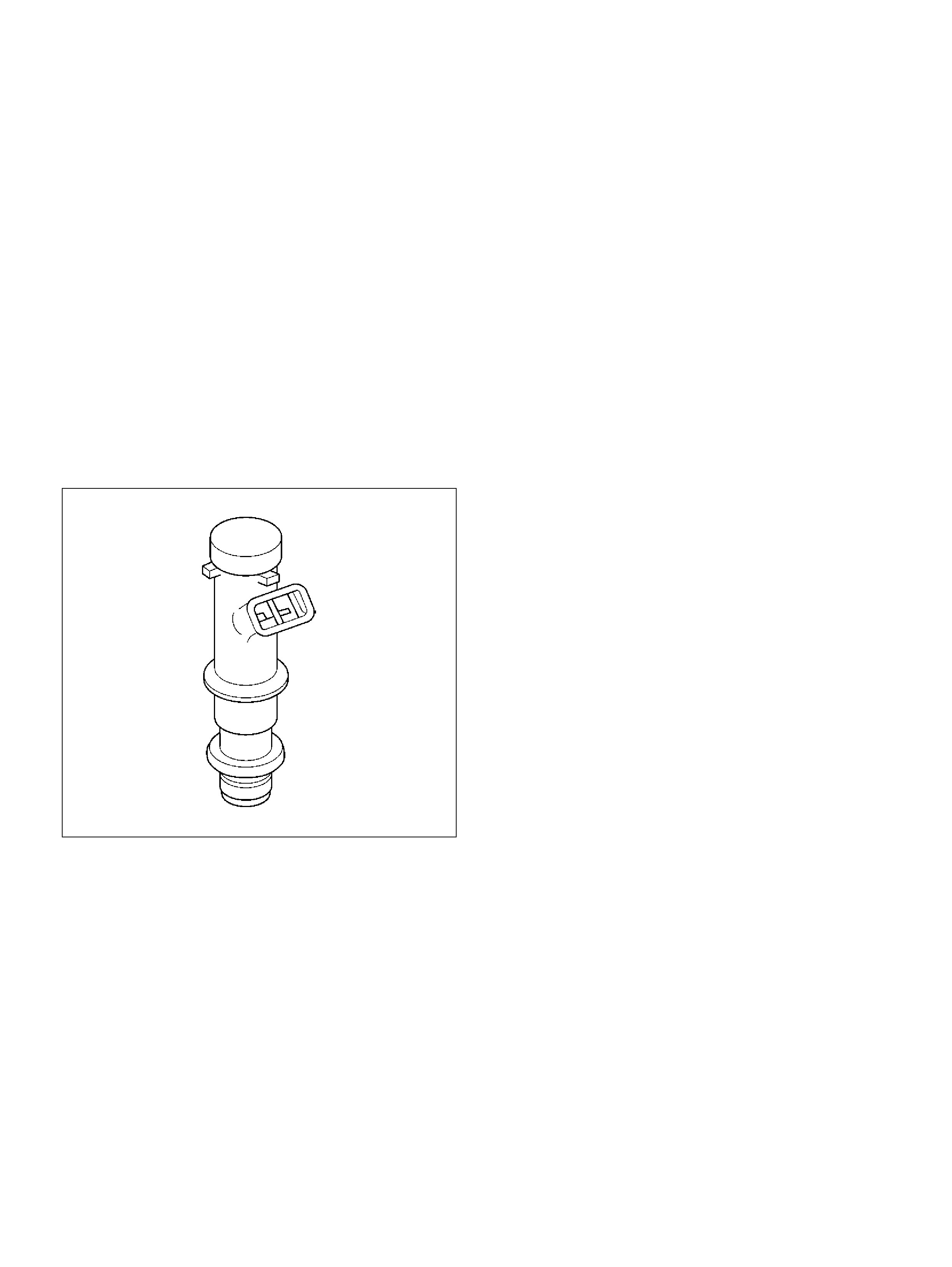
Fuel Cutoff Mode
No fuel is delivered by the fuel injectors when the
ignition is “OFF." This prevents engine run-on. In
addition, the PCM suspends fuel delivery if no reference
pulses are detected (engine not running) to prevent
engine flooding .
Fuel Injector
The seque ntial multiport f uel injection (SFI) fuel injector
is a solenoid-operated device controlled by the PCM.
The PCM energizes the solenoid, which opens a valve
to allow fuel deliv ery.
The fuel is injected under pressure in a conical spray
pattern at the opening of the intake valve. Excess fuel
not used by the injectors passes through the fuel
pressure regulator before being returned to the fuel
tank.
A fuel injector which is stuck partly open will cause a
loss of fuel pressure after engine shut down, causing
long crank times.
014RY00009
Fuel Metering System Components
The fuel metering system is made up of the following
parts:
• T he fuel injectors.
• T he thro ttle body.
• T he fuel rail.
• T he fuel pressure regulato r.
• T he P CM.
• T he crank shaft position (CKP) sensor.
• The ION sensing module.
• T he fuel pump .
• The fuel pump relay.
Basic System Ope ration
The fuel metering system starts with the fuel in the fuel
tank. An electric fuel pump, located in the fuel tank,
pumps fuel to the fuel rail through an in-line fuel filter.
The pump is designed to provide fuel at a pressure
above the pressure needed by the injectors. A fuel
pressure regulat or in the f uel rail keeps fue l avai lable to
the fuel injectors at a constant pressure. A return line
delivers unused fuel back to the fuel tank. Refer to
Section 6C for further information on the fuel tank, line
filter, and fuel pipes.
Fuel Metering System Purpose
The basic function of the air/fuel metering system is to
control the air/fuel delivery to the engine. Fuel is
delivered to the engine by individual fuel injectors
mounted in the intake manifold near each intake valve.
The main control sensor is the heated oxygen sensor
(HO2S) located in the exhaust system. The HO 2S tells
the PCM how much oxygen is in the exhaust gas. The
PCM changes the air/fuel ratio to the engine by
controlling the amoun t of time that fuel injector is “ON."
The best mixt ure to mi nimize ex ha us t emi ssions is 14. 7
parts of a ir to 1 part of ga soline by weight, whic h allows
the catalytic converter to operate most efficiently.
Becaus e of the constant measuring and adjusting of the
air/fuel ratio, th e fuel injection syste m is called a “close d
loop" system.
The PCM monitors signals from several sensors in
order to d etermine the fuel nee ds of the engine. Fuel is
delivered under one of several conditions called
“modes. " All modes are controlled by the PCM.
Fuel Pressure Regulator
The fuel pressure regulator is a diaphragm-operated
relief valve mounted on the fuel rail with fuel pump
pressure on one side and manifold pressure on the
other side. The fuel pressure regulator maintains the
fuel pressure available to the injector at three times
barometric pressure adjusted for engine load. It may b e
serviced separate.
If the pressure is too low, poor perf ormance and a DT C
P0131, DTC P0151,DTC P0171 or DTC P1171 will be
the result. If the pressure is too high, excessive odor
and/or a DTC P0132, DTC P0152,DTC P0172 will be
the result. Refer to Fuel System Diagnosis for
informat ion on diagnosing fuel pressure conditions.
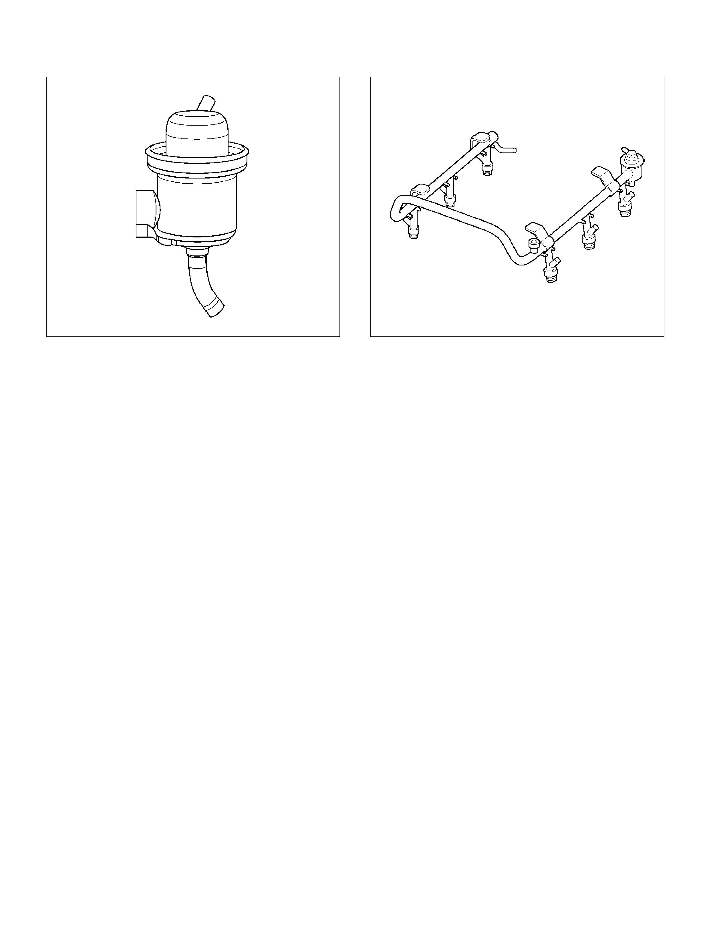
014RY00010
Fuel Pump Electrical Circuit
When the key is first turned “ON," the PCM energizes
the fuel pump rela y for two secon ds to buil d up the fue l
pressure quickly. If the engine is not started within two
seconds, the PCM shuts the fuel pump off and waits
until the engine is cr anked. When the engine is cra nked
and the 58 X crankshaft position signal has been
detect ed by th e PCM, the PCM supplies 1 2 volts to the
fuel pump relay to energize the electric in-tank fuel
pump.
An inoperative fuel pump will cause a “no-start"
condition. A fuel pump which does not provide enough
pressure will result in poor performanc e.
Fuel Rail
The fuel rail is mounted to the top of the engine and
distributes fuel to the individual injectors. Fuel is
delivered to t he fuel inlet tube of the fuel rail by the fuel
lines. The fuel goes through the fuel rail to the fuel
pressure regulator. The fuel pressure regulator
maintains a constant fuel pressure at the injectors.
Remai ning fuel is then returned to the fuel tank.
055RW009
Run Mode
The run mode has the following two conditions:
• O pen loop
• Cl osed loop
When the engine is first started the system is in “open
loop" operation. In “open loop," the PCM ignores the
signal from the heated oxygen sensor (HO2S). It
calculates the air/ fuel ratio based on inputs from the T P,
ECT, and MAF senso rs.
The system remains in “open loop" until the following
conditions are met:
• T he HO2S has a v arying v oltage output showi ng t hat
it is hot enough to op erate prope rl y (this dep ends o n
temperat ure).
• T he EC T has reached a specified temp erature.
• A specific amount of time has elapsed since starting
the engi ne.
• Engine speed has been greater than a specified RPM
since start-up.
The specific values for the above conditions vary with
different engines and are stored in the programmable
read only memory (PROM). When these conditions are
met, the system enters “closed loop" operation. In
“closed loop," the PCM calculates the air/fuel ratio
(injector on-time) based on the signal from the HO2S.
This allows the air/fuel ratio to stay very close to 14.7:1.
Starting Mode
When the ignition is first turned “ON," the PCM
energizes the fuel pump rel ay for two seconds to allow
the fuel pump to build up pressure. The PCM then
checks the engine coolant temperature (ECT) sensor
and the throttle position (TP) sensor to determine the
proper air/fuel ratio for starting.
The PCM controls the amount of fuel delivered in the
starting mode by adjusting how long the fuel injectors
are energized by pulsing the injectors for very short
times.
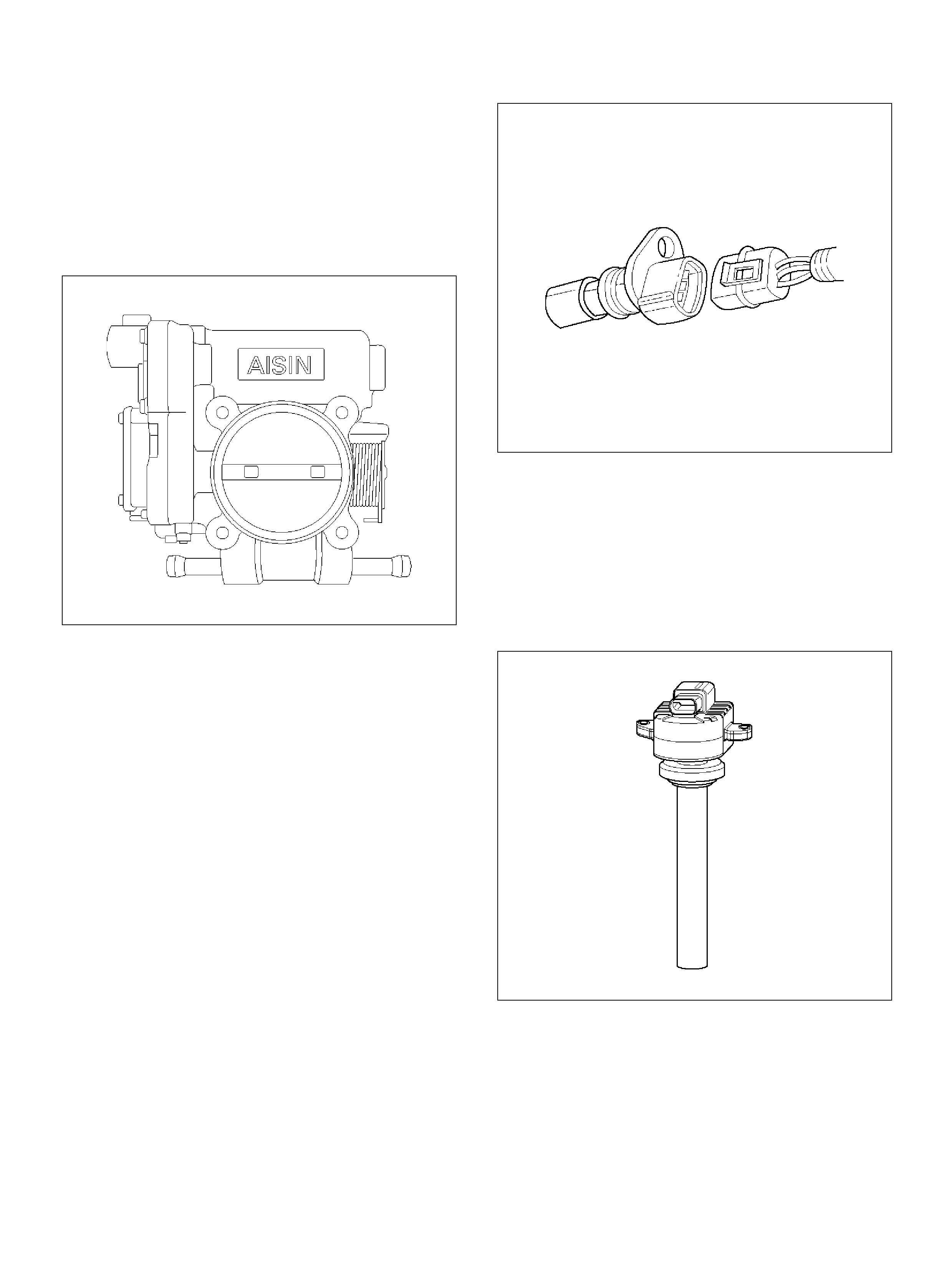
Throttle Body Unit
The throttle body has a throttle plate to control the
amount of air delivered to the engine. The TP sensor
are also mounted on the throttle body. Vacuum ports
located behind the throttle plate provide the vacuum
signals needed by various components.
Engine coolant is directed through a coolant cavity in
the throttle body to warm the throttle valve and to
preven t icing.
025RY00005
GENERAL DESCRIPTION
(ELECTRONIC IGNITIO N SYSTEM)
Crankshaft Position (CKP) Sensor
The cr ankshaft position (CK P) sensor provides a signa l
used by the powertrain control module (PCM) to
calculate the ignition s equen ce . The s ensor initiates th e
58X reference pulses whi ch the PCM u ses to calculate
RPM and crankshaft posit ion. Refer to
Electronic Ignition System section for additional
information.
Electro nic Ignition
The electronic ignition system controls fuel combustion
by providing a spark to ignite the compressed air/fuel
mixture at the correct time. To provide optimum engine
performance, fuel economy, and control of exhaust
emissions, the PCM controls the spark advance of the
ignition system. Electronic ignition has the following
advantages over a mechanical dist ributor system:
• No moving parts.
• L es s maintenance.
• Remote mount ing c apabilit y.
• N o mechanical load on the engine.
• More c oil cooldown time between firing events.
• Eli minat ion of mechanical timing adju stments.
• Increased available ignition coil saturation time.
0013
Igniti on Coils
A separat e coil-at-plug modul e is located at each spark
plug. The coil-at-plug module is attached to the engine
with two screws. It is in stalled directly to the spark plug
by an electrical contact inside a rubber boot. A
three-way connector provides 12-volt primary supply
from the 15-amp ignition fuse, a ground-switching
trigger line from the PCM, and a ground.
060RY00022
Ign ition Cont ro l
The ignition control (IC) spark timing is the PCM's
method of controlling the spark advance and the ignition
dwell.
The IC spark advance and the ignition dwell are
calculated by the PCM using the following inputs:
• Engi ne sp eed.
• Cran ksha ft position (58X ref erence).
• Engi ne co olant temperature (ECT ) sensor.
• Throttle position (TP) sensor.
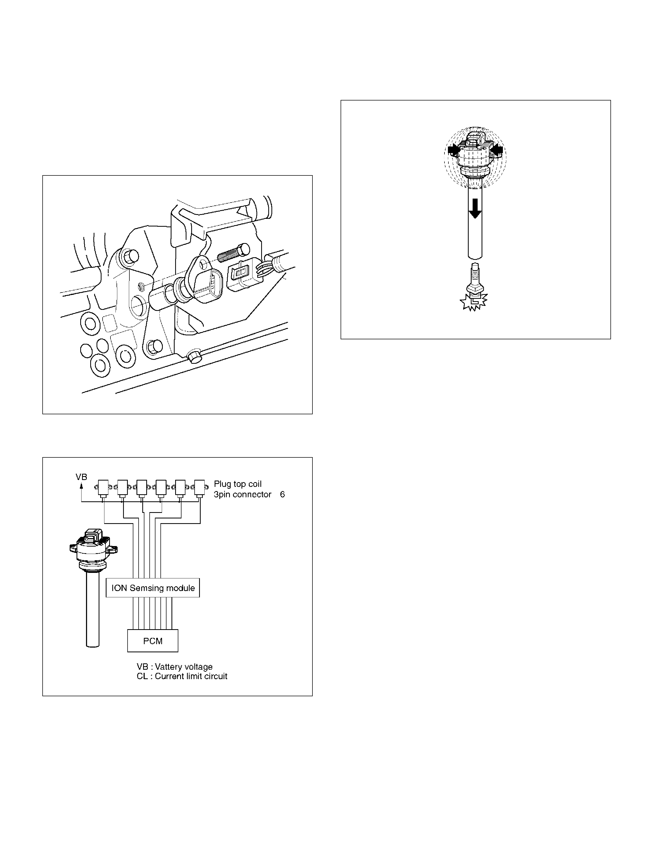
• ION s ensing modul e.
• Park/Neutral position (PRNDL input).
• V ehi cle speed (vehicle speed sensor).
• PCM and ignition system supply voltage.
• The crankshaft position (CKP) sensor sends the PCM
a 58X signal related to the exact position of the
cranks haft.
TS22909
Based on these sensor signals and engine load
information, the PCM sends 5V to each ignition coil.
060RY00116
This module has the function to energize and
de-energize the primary ignition coil in response to
signals from the PCM. The Throttle PCM controls
ignition timing and dwell time.
Continuity and out-or-range value chec k:
This diagnosis detects open circuit or short-circuiting in
the Electronic Spark Timing (EST) line by monitoring
EST signals. A failure determination is made when the
signal voltage remains higher or lower than the
threshold for corresponding fault code beyond a
predetermined time period.
Diagnosis enabli ng conditions are as follows:
• RPM is higher than the specified threshold.
• ES T line is enabled.
060RY00029
Ignition Control PCM Outp ut
The PCM provides a zero volt (actually about 100 mV to
200 m V) or a 5-volt output signal to th e ig nition control
(IC) module. Each spark plug has its own primary and
secondary ignition coil assembly ("coil-at-plug") located
at the spark plug itself. When the ignition coil receives
the 5-volt signal from the PCM, it provides a ground
path for the B+ supply to the primary side of the coil-at
-plug m odule. W hen th e PC M s huts o ff the 5-volt signal
to the ION sensing module, the ground path for the
primary coil is broken. T he m agnetic field colla pses an d
induces a high voltage secondary impulse which fires
the spark plug and ignites the air/ f uel mixture.
The circuit between the PCM and the ignition coil is
monitored for open circuits, shorts to volt age, and shorts
to ground. If the PCM detects one of these events, it will
set one of the following DTCs:
• P0351: Ignition coil Fault on Cylinder #1
• P0352: Ignition coil Fault on Cylinder #2
• P0353: Ignition coil Fault on Cylinder #3
• P0354: Ignition coil Fault on Cylinder #4
• P0355: Ignition coil Fault on Cylinder #5
• P0356: Ignition coil Fault on Cylinder #6
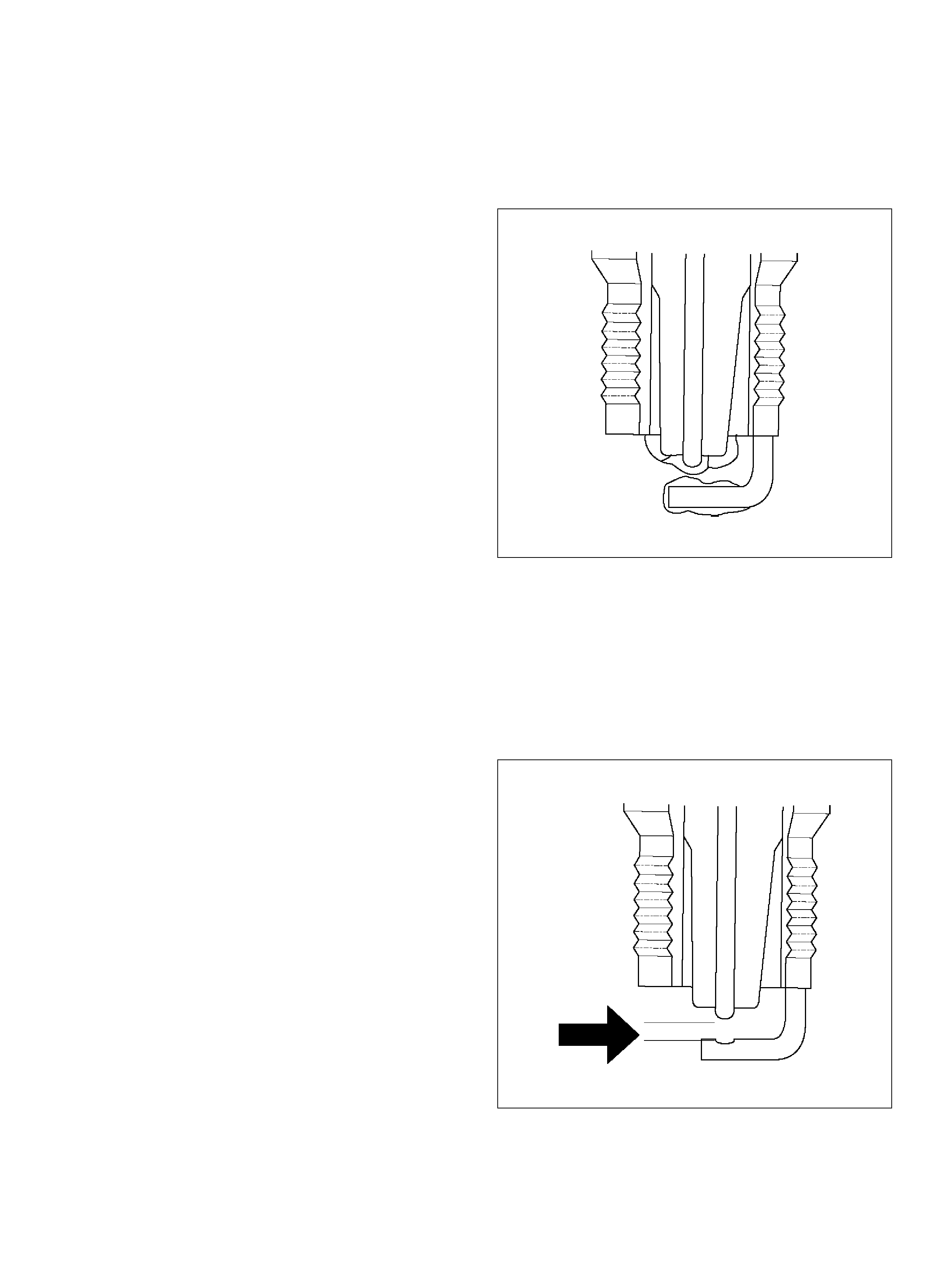
Powertrain Control Module (PCM)
The PCM is responsible for maintaining proper spark
and fuel injection timing for all driving conditions. To
provide optimum derivability and emissions, the PCM
monitors the input signals from the following
components in order to calculate spark timing:
• Engine coolant temperature (ECT) sensor.
• Intake air temperature (IAT) sensor.
• Mas s air flow (MAF) sensor.
• PRNDL input from transmission range switch.
• Throttle positi on (TP) sensor .
• V ehi cle speed sensor (VSS) .
• C rank shaft position (CKP) sensor.
Spark Plug
Although worn or dirty spark plugs may give satisfactory
operation at idling speed, they frequency fail at higher
engine speeds . Faulty spark plugs may caus e poor fuel
economy, power loss, loss of speed, hard starting and
generally poor engine performance. Follow the
scheduled maintenance service recommendations to
ensure satisfactory spark plug performance. Refer to
Mainten ance an d Lubricati on secti on.
Normal spark plug operation will result in brown to
grayish-tan deposits appearing on the insulator portion
of the spark plug. A small am ount of red -brown, y ellow,
and white powdery m at erial ma y also b e pres ent on the
insulator tip around the center electrode. These
deposits are normal combustion by-products of fuels
and lubri cating oil s with addi tives. S om e ele ctrode wear
will also occur. Engines which are not running properly
are often referred to as “misfiring." This means the
ignition spark is not igniting the air/fuel mixture at the
proper ti me. Whil e other igni tio n and fuel syste m causes
must also be considered, possible causes include
ignition system conditions which allow the spark voltage
to reach grou nd in some o ther mann er th an by jumpin g
across the air gap at the tip of the spark plug, leaving
the air/fuel mixture unburned. Refer to DTC P0300
Misfiring may also occur when the tip of the spark plug
becomes overheated an d ignites the mixture before the
spark jumps. Thi s is referred to as “pre-ignition."
Spark plugs may also misfire due to fouling, excessive
gap, or a cra cked or brok en insul ator. If misfiring occ urs
before the recommended replacement interval, locate
and correct the cause.
Carbon fouling of the spark plug is indicated by dry,
black carbo n (soot) deposits on the portion of the spark
plug in the cylinder. Excessive idling and slow speeds
under light engine loads can keep the spark plug
temperat ures so low that these deposits are not burned
off. Very rich fuel mixtures or poor ignition system output
may also be the cause. Refer to DTC P0172.
Oil fouling of the spark plug is indicated by wet oily
depos its on t he portion of the spark pl ug in the c ylinder,
usually with little electrode wear. This may be caused by
oil during break-in of new or newly overhauled engines.
Deposit fouling of the spark plug occurs when the
normal red-brown, yellow or white deposits of
combustion by products become sufficient to cause
misfiring. In some cases, these deposits may melt and
form a shiny glaze on the insulator around the center
electrode. If the fouling is found in only one or two
cylinders, valve stem clearances or intake valve seals
may be allowing excess lubricating oil to enter the
cylinder, particularly if the deposits are heavier on the
side of the spark plug faci ng the intake valve.
TS23995
Excessive gap means that the air space between the
center and the side electrodes at the bottom of the
spark plug is to o wide fo r consistent firing. This may be
due to improper gap adjustment or to excessive wear of
the electrode during use. A spark plug gap that is too
small may cause an unstable idle condition. Excessive
gap wear can be an indication of continuous operation
at high speeds or with engine loads, causing the spark
to run too hot. Anothe r possi ble cause is an ex ces sively
lean fuel mixture.
TS23992
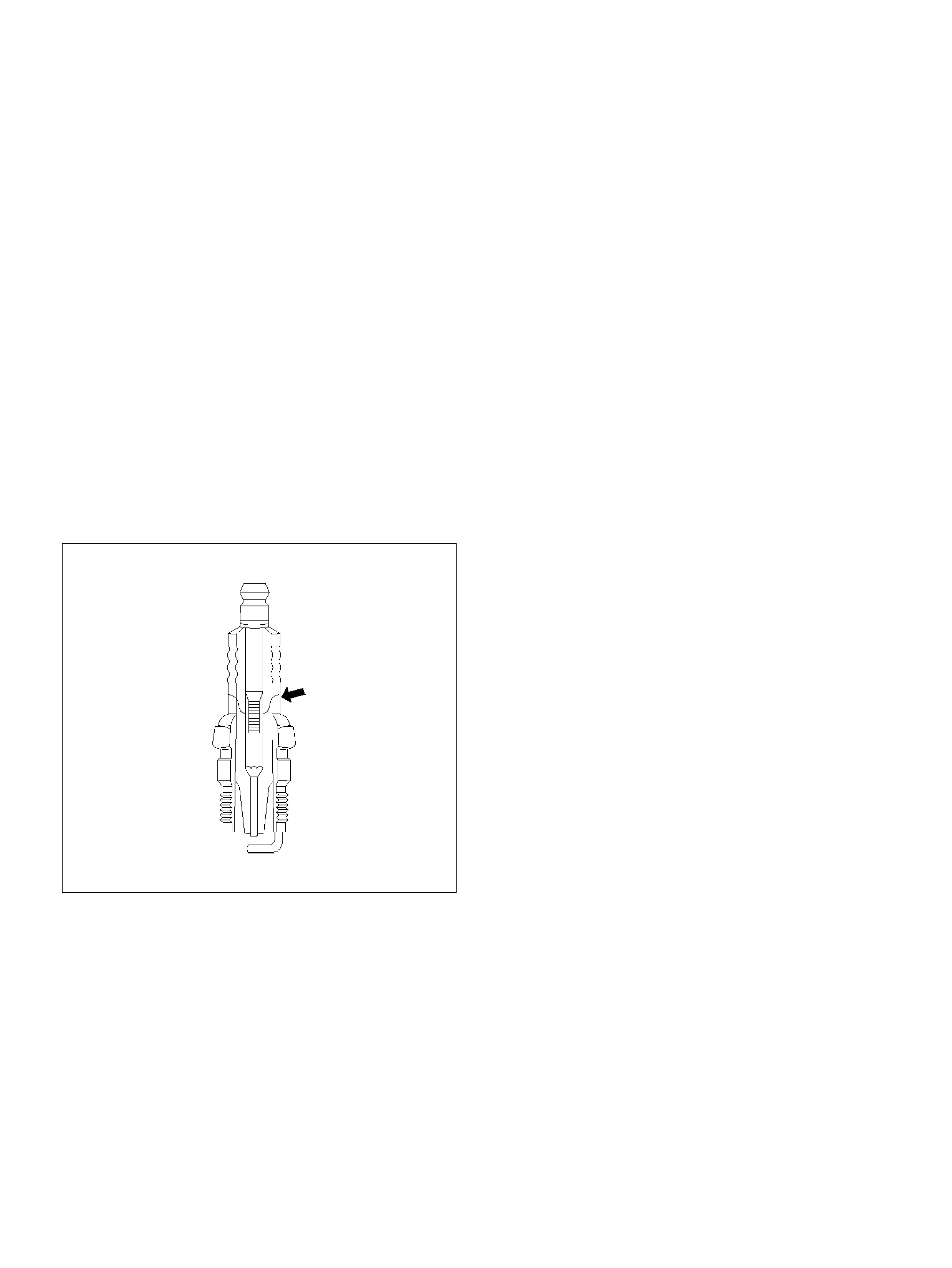
Low or high spark plug installation torque or improper
seating can result in the spark plug running too hot and
can cause excessive center electrode wear. The plug
and th e c ylinder h ead seats m ust be in good c on tact for
proper heat transfer and spark plug cooling. Dirty or
damag ed threads in the head or on the spark plug can
keep it from seating even though the proper torque is
applied. Once spark plugs are properly seated, tighten
them to the torque shown in the Specifications Table.
Low torque may result in poor contact of the seats due
to a loose spark plug. Overtightening may cause the
spark plug shell to be stretched and will result in poor
contact between the seats. In extreme cases, exhaust
blow-by and damage beyond simple gap wear may
occur.
Cracked or broken insulators may be the result of
improper installation, damage during spark plug
re-gapping, or heat shock to the insulator material.
Upper insulators can be broken when a poorly fitting
tool is used during installation or removal, when the
spark plug is hit from the outside, or is dropped on a
hard surface. Cracks in the upper insulator may be
inside t he shell and n ot visible. Also, the b re akage m ay
not cause problems until oil or moisture penetrates the
crack late r.
TS23994
A/C CLUTCH DIAGNOSIS
A/C Clutch Circuit Operation
A 12-volt signal is supplied to the A/C request input of
the PCM when the A/C is selected through the A/C
control switch.
The A/C compressor clutch relay is controlled through
the PCM. This allows the PCM to modify the idle air
control position prior to the A/C clutch engagement for
better idle quality. If the engine o perating conditions are
within their specified calibrated acceptable ranges, the
PCM will enable t he A / C com pre ss or re lay. This is done
by providing a ground path for the A/C relay coil within
the PCM. When the A/C compressor relay is enabled,
battery voltage i s supplied to the compressor clutch coil.
The PCM will enable the A/C compressor clutch
whenever the engine is running and the A/C has been
requested. The PCM will not enable the A/C
compressor clutch if any of the following conditions are
met:
• T he throttle is greater than 90%.
• The engine speed is greater than 6315 RPM.
• T he EC T is greater tha n 11 9°C (246°F).
• T he IAT is less than 5°C (41°F).
• The throttle is more than 80% open.
A/C Clutch Circ uit Purpose
The A/C compressor operation is controlled by the
powertrain control module (PCM) for the following
reasons:
• It improvises idle quality during compressor clutch
engagement.
• It improvises wide open throttle (WOT) performance.
• It provides A /C c om presso r protection from operation
with incorrect refrigerant pressures.
The A/C electrical system consists of the following
components:
• T he A/C control head.
• T he A/C refrigerant pressure switches.
• T he A/C compressor clutch.
• T he A/C compressor clutch relay.
• T he PC M.
A/C Request Signal
This signal tells the PCM when the A/C mode is
selected at th e A/C control head. The P CM uses this to
adjust the idle speed before turning on the A/C clutch.
The A/C compressor will be inoperative if this signal is
not availab le to the PCM.
Refer to A/C Clutch Circuit Di agnosis section f or A/ C
wiring diagrams and diagnosis for A/C electrical system.
GENERAL DESCRIPTION
(EVAPORATIVE (EVAP) EMISSION
SYSTEM)
EVAP Emission Control System Purpose
The ba sic evaporative emission (EVAP) control system
used on all vehicles is the charcoal canister storage
method. Gasoline vapors from the fuel tank flow into the
canister thro ugh the inlet labe led “TANK ." T hese v apors
are absorbed into the activated carbon (charcoal)
storage device (canister) in order to hold the vapors
when the vehicle is not operating. The canister is
purged by PCM control when the engine coolant
temperature is over 60°C (140°F), the IAT reading is
over 10°C (50°F), and the engine has been running. Air
is drawn into the canister through the air inlet grid. The
air mixes with the vapor and the mixture is drawn into
the intake manifold.
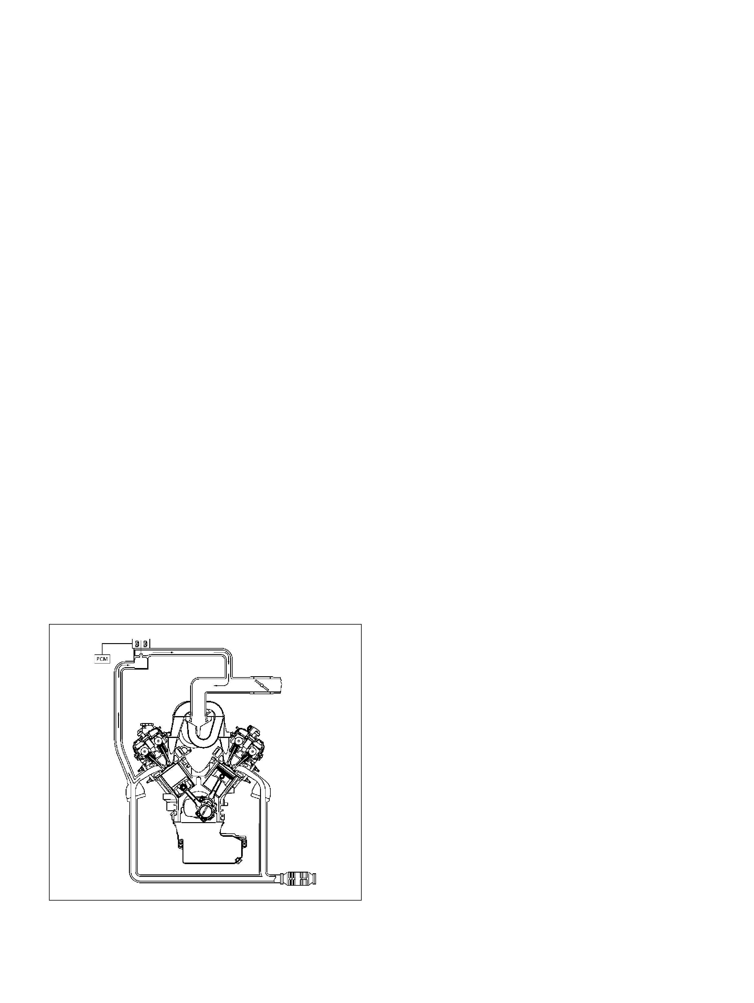
EVAP Emission Control System Operation
The EVAP canister purge is controlled by a solenoid
valve that allows the manifold vacuum to purge the
canister. The powertrain control modul e (PC M) suppl ies
a ground to ene rgize the solenoid val ve (purge on). The
EVAP purge solenoid control is pulse-width modulated
(PWM) (turned on and off several ti mes a second). The
duty cycle (pulse width) is determined by engine
operating conditions including load, throttle positron,
coolant temperature and ambient temperature. The duty
cycle is calculated by the PCM. The output is
commanded when the appropriate conditions have
been met. These conditions are:
• T he engin e is fully warmed up.
• T he engin e has been running for a specified time.
• The IAT reading is above 10°C (50°F).
Poor idle, stalling and poor derivability can be caused
by:
• A ma lfunc tioning purge soleno id.
• A dam aged c anist er.
• Hoses that are split, cracked, or not connected
properly.
GENERAL DESCRIPTION (EXHAUST
GAS RECIRCULATION (EGR)
SYSTEM)
EGR Purpose
The exhaust gas recirculation (EGR) system is use to
reduce emission levels of oxi des of nitr ogen (NOx). NOx
emission levels are caused by a high combustion
temperature. The EGR system lowers the NOx
emission levels by decreasing the combustion
temperature.
057RW002
Linear EGR Valve
The main element of the system is the linear EGR
valve. The EGR valve feeds small amounts of exhaust
gas back into the combustion chamber. The fuel/air
mixture will be diluted and combustion temperatures
reduced.
Linear EGR Contro l
The P CM moni tors the EG R actu al positron and a djusts
the pintle position accordingly. The uses information
from the following sensors to control the pintle position:
• Engi ne co olant temperature (ECT ) sensor.
• Throttle position (TP) sensor.
• Mass air flow (MAF) sensor.
Linear EGR Valve Operatio n and Results of
Incorrect Operation
The linear EGR valve is designed to accurately supply
EGR to the engine independent of intake manifold
vacuum . The valve con trols EGR flo w from the ex haust
to the intake manifold through an orifice with a PCM
controlled pintle. During operation, the PCM controls
pintle posit ion by monitoring the pintle position feedback
signal. The feedback signal can be monitored with a
Tech 2 as “Ac tual EGR Pos ." “A ctual E G R P os. " s houl d
always be near the commanded EGR position ("Desired
EGR Pos."). If a problem with the EGR system will not
allow the PCM to control the pintle position properly,
DTC P1406 will set. The PCM also tests for EGR flow. If
incorrect flow is detected, DTC P0401 will set. If DTCs
P0401 and/or P1406 are set, refer to the DTC charts.
The linear EGR valve is usually activated under the
following condit ions:
• Warm engine operation.
• Abov e-i dle speed.
Too much EGR flow at idle, cruise or cold operation may
cause any of the following conditions to occur:
• Engine st alls after a cold start.
• Engine st alls at idle after deceleration.
• Vehicle surges during cruise.
• Ro ugh idle.
• DT C P03 00 (misfire detected).
Too little or no EGR flow may allow combustion
temperatures to get too high. This could cause:
• S park knock (detonation).
• Engi ne ov erheat ing.
• Em iss ion test failure.
• DTC P0401 (EGR flow test).
• Poor fu el econom y.
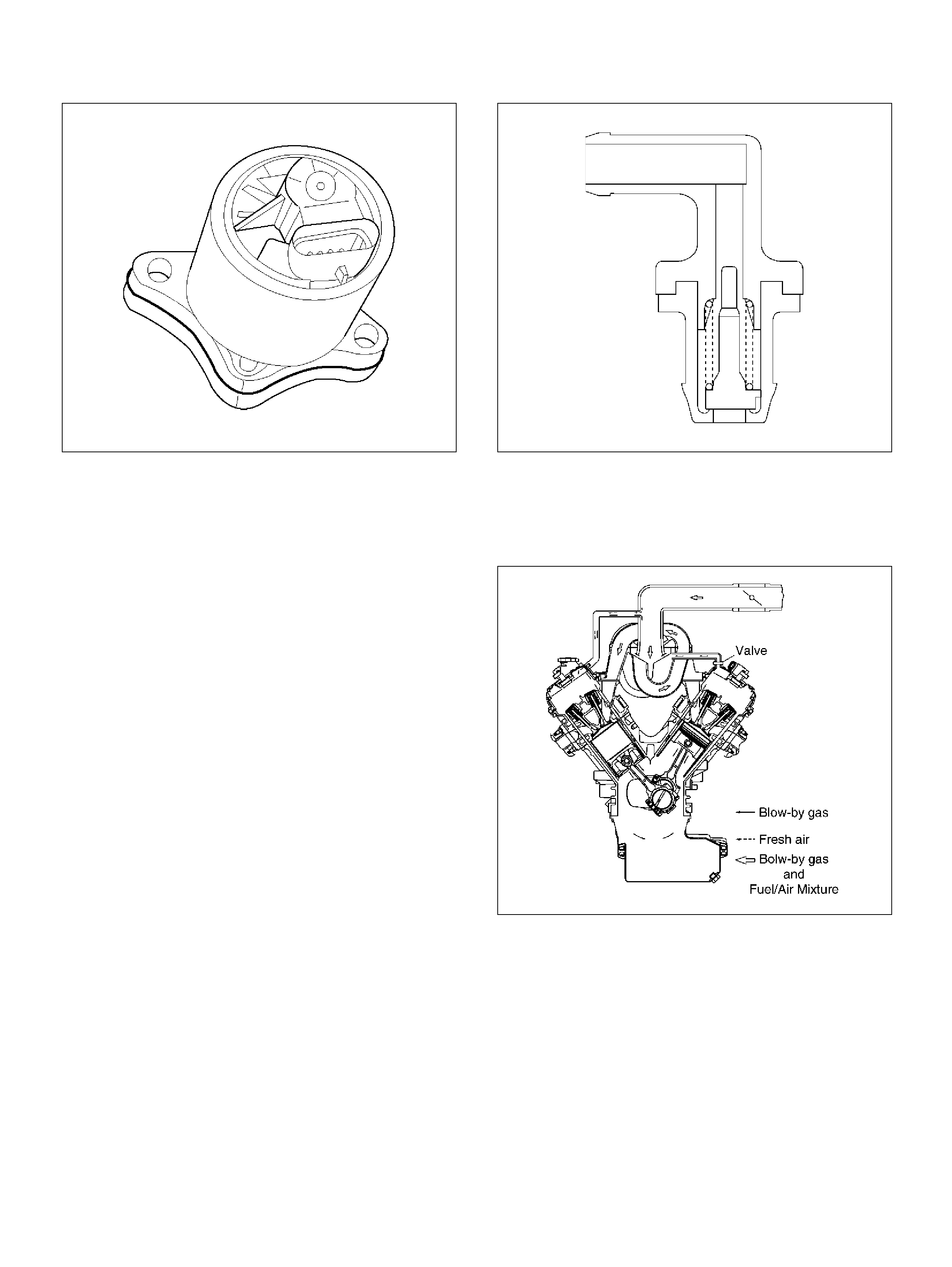
0017
EGR Pintle Position Sensor
The PCM monitors the EGR valve pintle position input
to endure that the valve responds properly to
commands from the PCM and to detect a fault if the
pintle position sensor and control circuits are open or
shorted. If the PCM detects a pintle position signal
voltage outside the normal range of the pintle position
sensor, or a signal vol tage t hat is no t w ithin a tole rance
considered acceptable for proper EGR system
op eration, the PCM will s et DT C P1406 .
GENERAL DESCRIPTION (POSITIVE
CRANKCASE VENTILATION (PCV)
SYSTEM)
Crankcase Ventilation System Purpose
The crankcase ventilation system is use to consume
crankcas e vapors in the com bustion process i nstead of
venting them to the atmosphere. Fresh air from the
throttle body is supplied to the crankcase and mixed
with blow-by gases. This mixture is then passed through
the positive crankcase ventilation (PCV) valve into the
common chamber.
Crankcase Ventilation System Oper ation
The primary control is through the positive crankcase
ventilation (PCV) valve. Th e PCV valve meters the flow
at a rate that depends on the intake vacuum. The PCV
valve restricts the flow when the inlet vacuum is highest.
In addition, the PCV valve can seal the common
chamber off in case of sudden high pressure in the
crankcase.
028RV002
While the engine is running, exhaust fuses and small
amounts of the fuel/air mixture escape past the piston
rings and enter the crankcase. These gases are mixed
with clean air entering through a tube from the air intake
duct.
028RW002
During normal, part-throttle operation, the system is
designed to allow crankcase gases to flow through the
PCV valve into the throttle body to be consumed by
normal com bustion.
A plugged valve or PCV hose may cause the following
conditio ns :
• Ro ugh idle.
• S t alling of slow idle speed.
• Oil lea k s .
• Slu dge in the engine.
A leaking PCV hose would cause:
• Ro ugh idle.
• Stal ling.
• Hi gh idle speed.
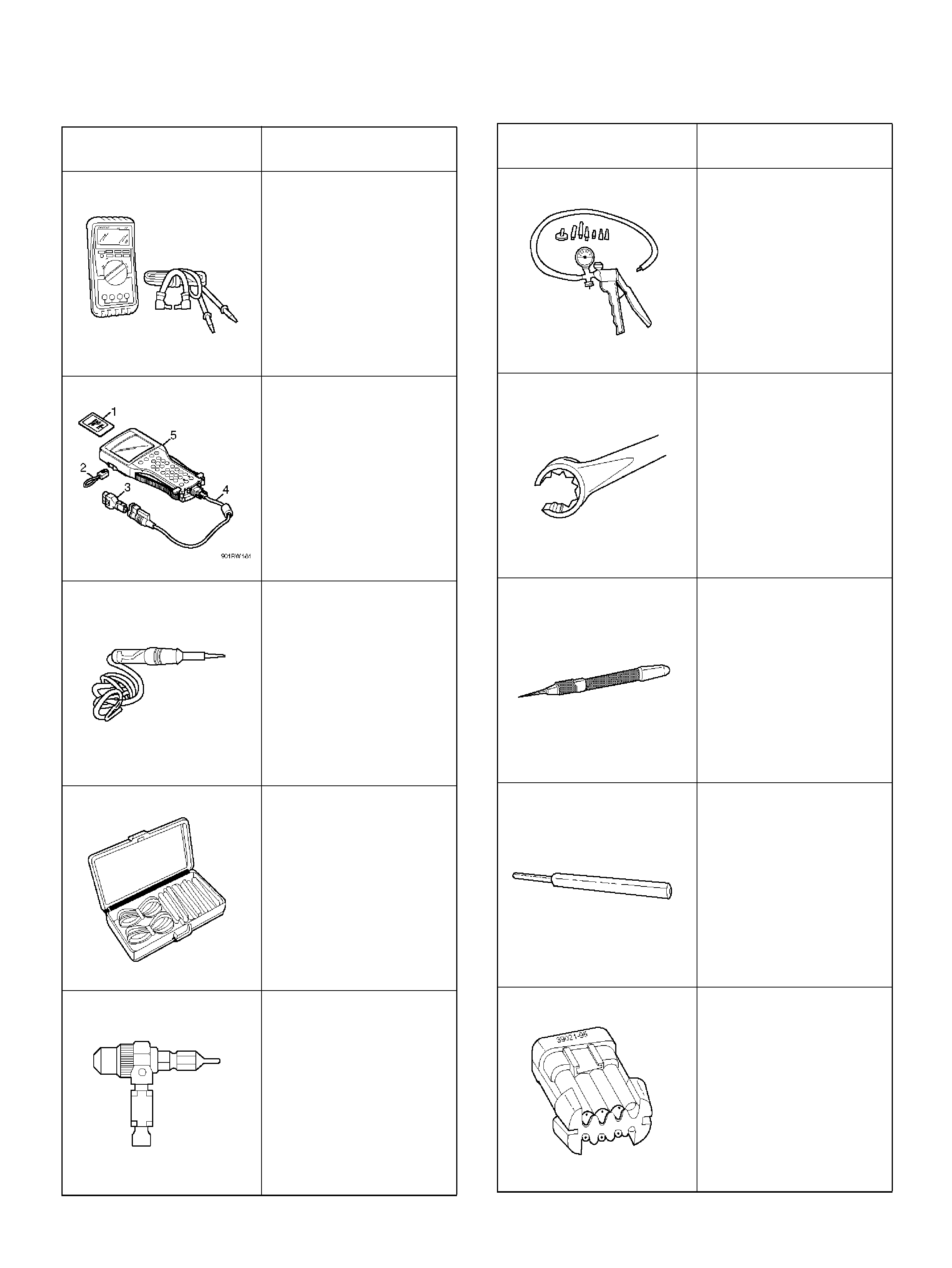
SPECIA L TOOLS
ILLUSTRATION TOOL NO.
TOOL NAME
5-8840-0285-0
High Impedance
Multimeter (Digital
Voltmeter – DVM)
(1) PCMCIA Card
(2) RS232 Loop Back
Connector
(3) SAE 16/19 Adapter
(4) DLC Cable
(5) TECH–2
5-8840-0607-0
U npowered Test Light
5-8840-0385-0
Connec tor Test Adapter
5-8840-0383-0
Spark Tester
5-8840-0279-0
Vacuum Pump with
Gauge
5-8840-2640-0
Heated Oxygen Sensor
Wrench
5-8840-0632-0
Terminal Remover
5-8840-0388-0
Weather Pack II Terminal
Remover
5-8840-2636-0
Injector Test Light
ILLUSTRATION TO OL N O.
TOOL NAME
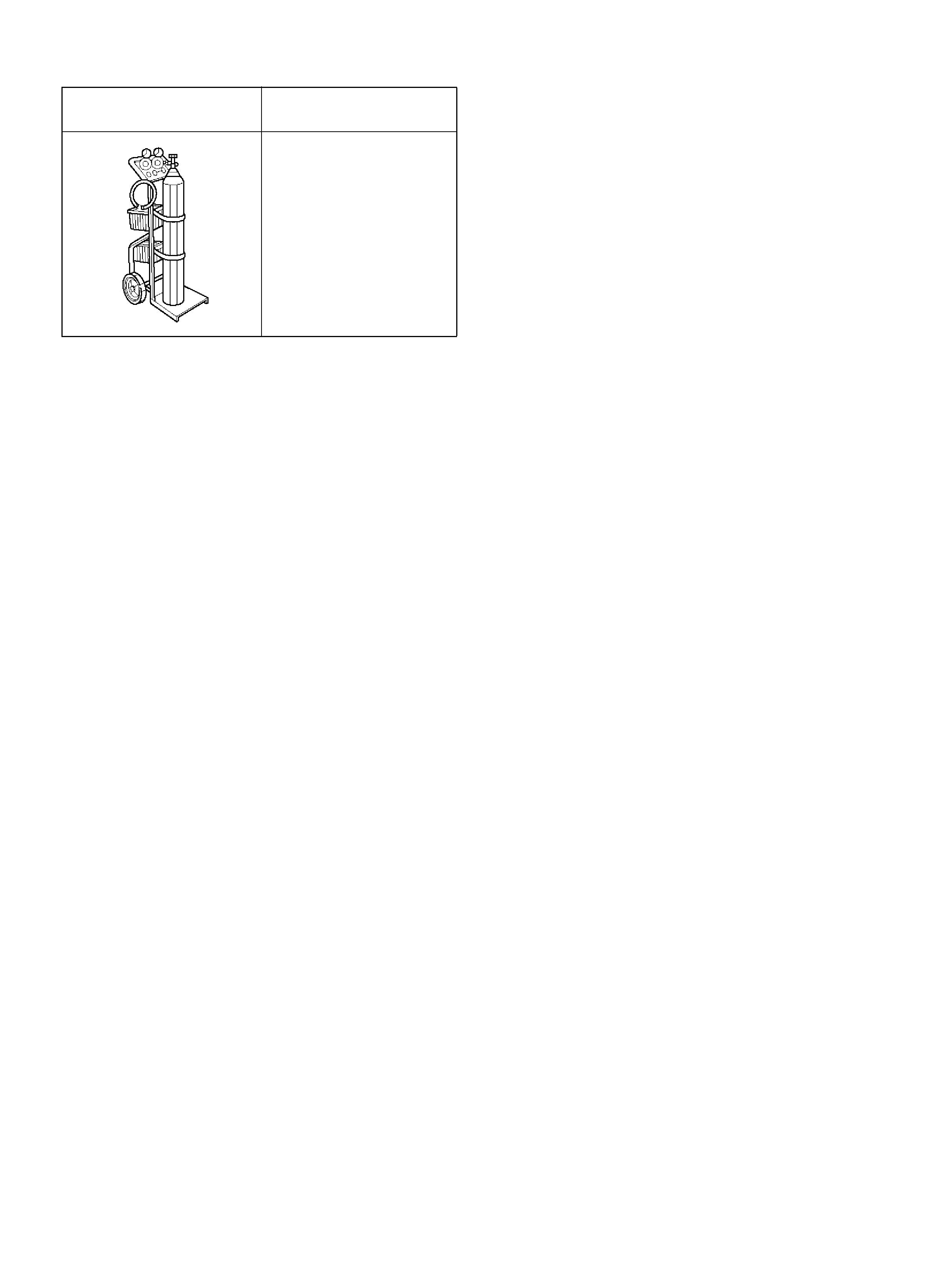
5-8840-2607-0
EVAP Pressure/Purge
Diagnostic Station
ILLUSTRATION TOOL NO.
TOOL NAME