
SECTION 6D - CHARGING SYSTEM
Service Precaution
Charging System
General Description
General On–Vehicle Inspection
Generator
Removal
Inspection
Installation
Disassembled View
Disassembly
Inspection and Repair
Reassembly
Bench Test
Main Data and Specifications
SERVICE PRECAUTION
WARNING: THIS VEHICLE HAS A SUPPLEMENTAL
RESTRAINT SYSTEM (SRS), REFER TO THE SRS
COMPONENT AND WIRING LOCATION VIEW IN
ORDER TO DETERMINE WHETHER YOU ARE
PERFORMING SERVICE ON OR NEAR THE SRS
COMPONENTS OR THE SRS WIRING. WHEN YOU
ARE PERFORMING SERVICE ON OR NEAR THE
SRS COMPONENTS OR THE SRS WIRING, REFER
TO THE SRS SERVICE INFORMATION. FAILURE TO
FOLLOW WARNINGS COULD RESULT IN
POSSIBLE AIR BAG DEPLOYMENT, PERSONAL
INJURY, OR OTHERWISE UNNEEDED SRS SYSTEM
REPAIRS.
CAUTION: Always use the correct fastener in the
proper location. When you replace a fastener, use
ONLY the exact part number for that application.
HOLDE N will call out those f asten ers th at requir e a
replacement after removal. HOLDEN will also call
out the fasteners that require thread lockers or
thread sealant. UNLESS OTHERWISE SPECIFIED,
do not use supplemental coatings (Paints , greases,
or other corrosion inhibitors ) on threaded fast eners
or fastener joint interfaces. Generally, such
coatings adversely affect the fastener torque and
the joint clamping force, and may damage the
fastener. When you install fasteners, use the
correct tightening sequence and specifications.
Following these instructions can help you avoid
damage to parts and systems.
CHARGING SYSTEM
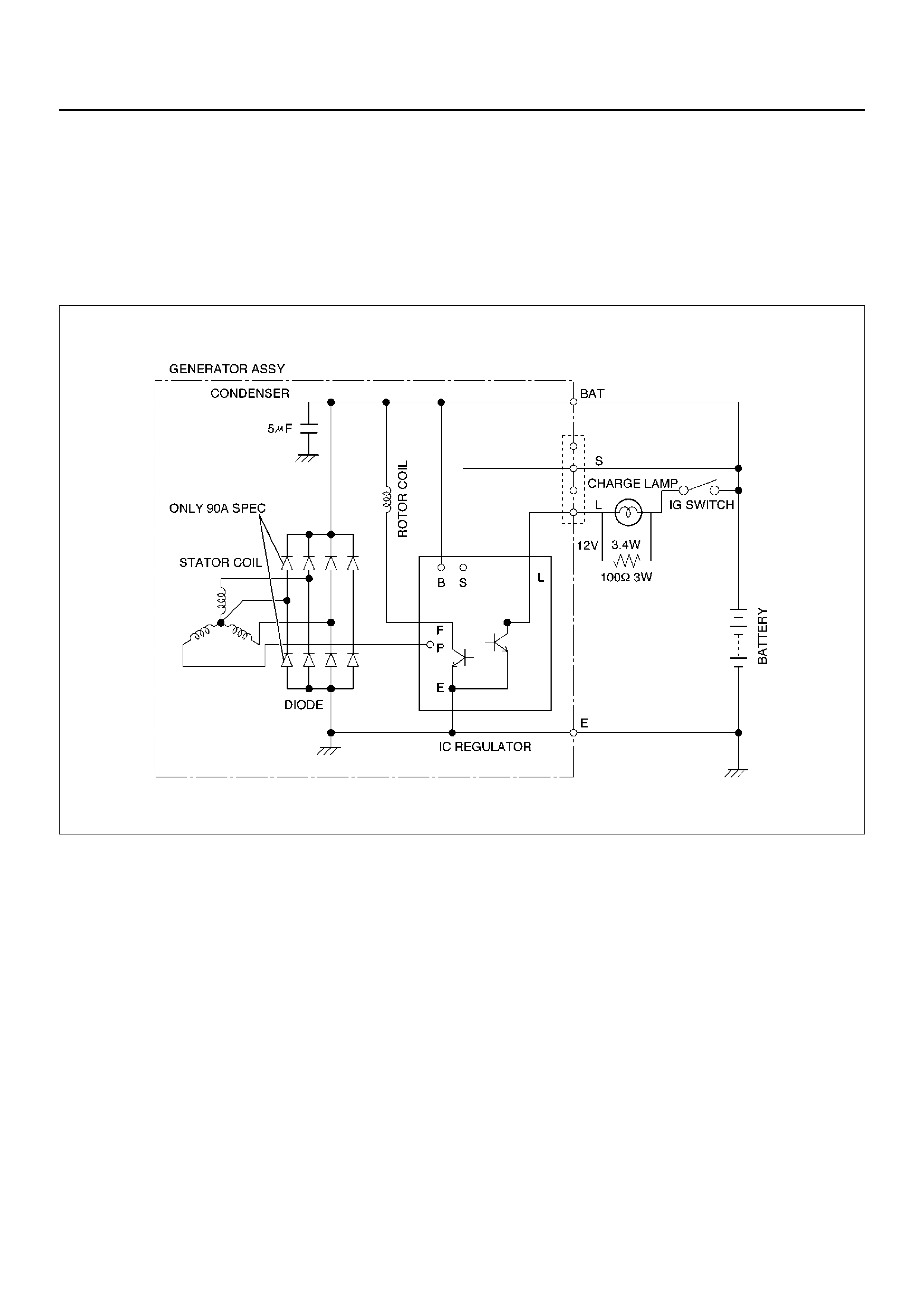
GENERAL DESCRIPTION
The IC integral regulator charging system and its main
components are connected as shown in illustration.
The regulator is a solid state type and it is mounted
along with the brush holder assembly inside the
generator installed on the rear end cover.
The generator does not require particular maintenance
such as vo ltag e adju stm ent.
The rectifier connected to the stator coil has diodes to
transform AC voltage into DC voltage.
This DC voltage is connected to the output terminal of
generator.
F06RX002

GENERAL ON–VEHICLE INSPECTION
A basic wiring diagram is shown in the illustration. When
operating normally, the indicator bulb will come on when
the switch is turned on, and will then go out when the
engine starts. If the indicator operates abnormally, or if
an undercharged or overcharged battery condition
occurs, the following procedure may be used to
diagnose the charging system. Remember that an
undercharged battery is often caused by accessories
being left on overnight, or by a defective switch which
allows a bu lb, such as a trunk or glo ve box light, to s tay
on.
OBSERVE THE FOLLOWING PRO C EDURE:
1. Visually check drive belt and wiring.
2. Go to step 5. for vehicles without charge indicator
light.
3. Ignition on, engine stationary, light should be on. If
not, detach harness at generator, ground “L"
terminal lead.
a Lamp lights, replace or repair generator.
b Lamp dose not light, locate open circuit between
groundi ng lead and ig nition switch. Bu lb may be
open.
4. Switch on, eng ine runni ng at moder ate sp eed. Ligh t
should be off. If not, detach wiring harness at
generator.
a If light goes off, replace or repair generator.
b If light stays on, ch eck for gr ounded “L" termi nal
wire in harness.
5. Battery undercharged or overcharged.
a Detach wiring harness connector from
generator.
b With switch on, engine not running connect
voltmeter from ground to “L" terminal in wiring
harness, and to “IG" terminal. If used. Wiring
harness may connect to either “L" or “IG" or
both.
c Zero reading indicates open circuit between
terminal and battery. Connect as required.
d Re-con nec t harne ss c onne ct or to gen er ator, run
engine at moderate speed, with electrical
accessories turned off.
e Measur e voltage acros s battery. If abo ve 16.0V,
replace or repair generator.
f Connect ammeter at generator output terminal.
Turn on accessories, load battery with carbon
pile to obtain maximum amperes output.
Maintain voltage at 13.0V or above.
1 If within 15 amperes of rated output,
generato r is OK.
2 If not within 15 amperes of rated output,
replace or repair generator.
GENERATOR
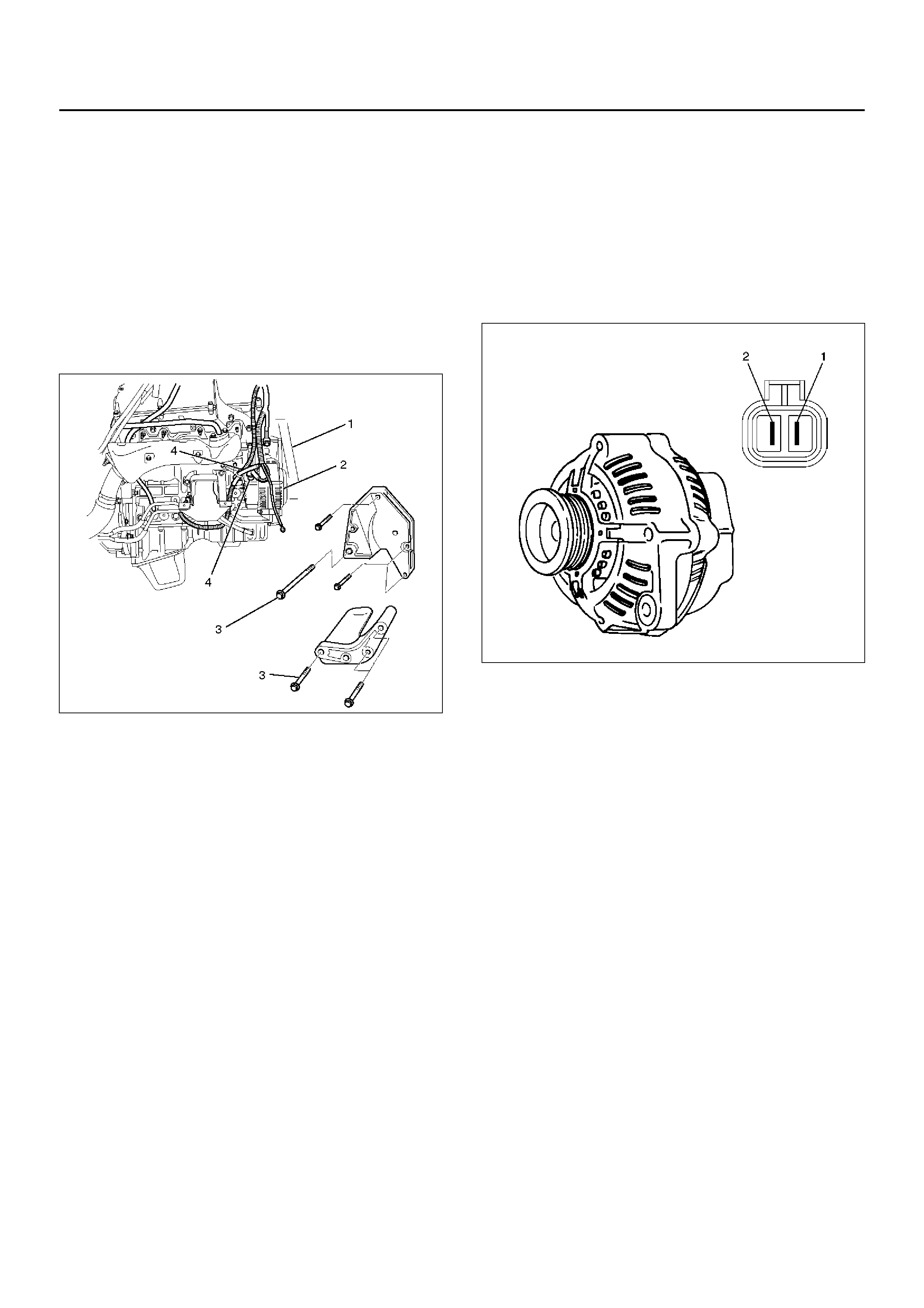
REMOVAL
1. Disconnect battery ground cable.
2. Move drive belt tensioner to loose side using
wrench then remove drive belt (1).
3. Disconnect the wire from terminal “B" and
disconnect the connector (4).
4. Remove generator fixing bolt (3).
5. Remove generator assembly (2).
060RW002
INSPECTION
1. Disconnect the wiring connector from generator.
2. With the engine stopped, turn starter switch to “on"
and connect a voltmeter between connector
terminal L (1) and ground or between terminal IG (2)
and ground.
066RX002
If voltage is not present, the line between battery
and connector is disconnected and so requires
repair.
3. Reconnect the wiring connector to the generator,
run the engine at middle speed, and turn off all
electrical devices other than engine.
4. Measure battery voltage. If it exceeds 16V, repair or
replace the generator.
5. Connect an ammeter to output terminal of
generator, and measure output current under load
by turning on the other electrical devices (eg.,
headlights). At this time the amperes must not be
less than 15A and the voltage must not be less than
13V.
INSTALLATION
1. Install generator assembly to the position.
2. Install generator assembly and tighten the fixing
bolts to the specified torque.
Torque:
M10 bolt: 41N·m, M8 bolt: 21N·m
3. Connect wiring harness connector and direct
termina l “B ".
4. Move drive belt tensioner to loose side using
wrench, then install drive belt to normal position.
5. Reconnect battery ground cable.
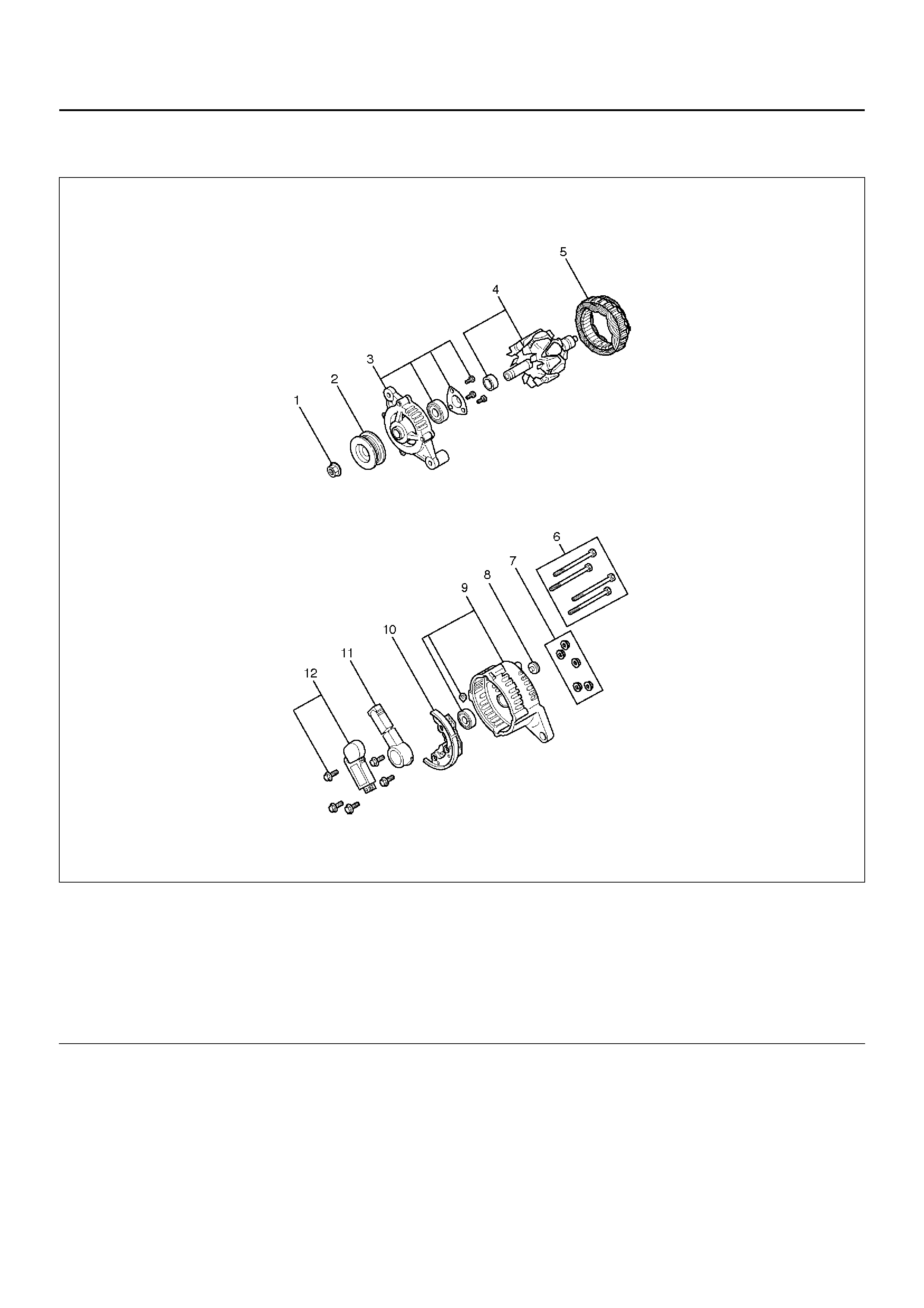
DISASSEMBLED VIEW
066RW022
EndOFCallout
Legend
(1) Pulley Nut
(2) Pulley
(3) Front Cover Assembly
(4) Rotor Assembly
(5) Stator Assembly
(6) Thr ou gh Bol t
(7) Nut
(8) Terminal Insulator
(9) Rear Cover Assembly
(10) Rectifier
(11) Brush Holder Assembly
(12) Regulator Assembly
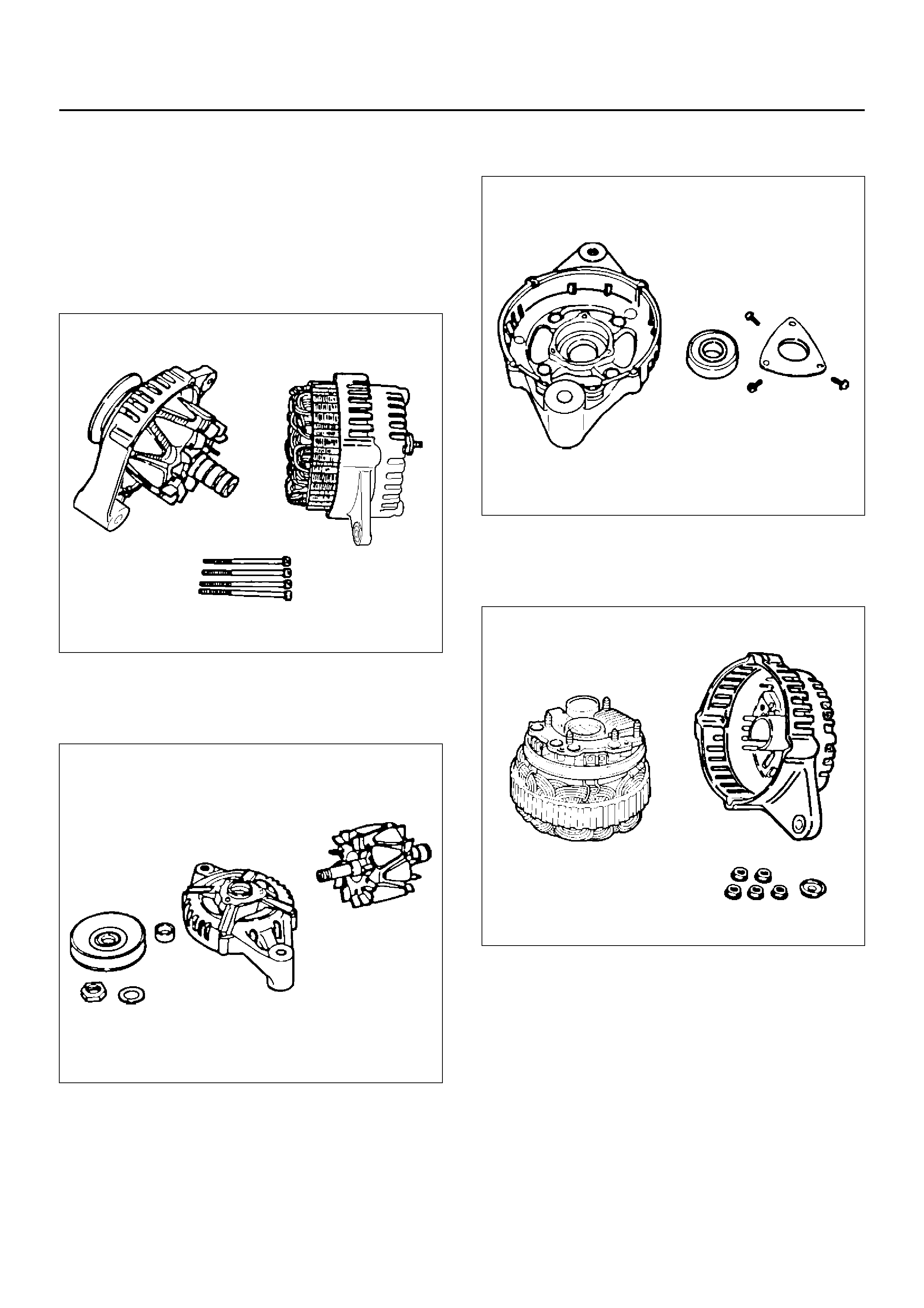
DISASSEMBLY
1. Remo ve the throug h bolt.
Inser t the tip of a pry bar into the g aps between the
front cover and the stator core.
Pry apart and separate the front cover, rotor, the
rear co ver and stator.
NOTE: Take care not to scratch or otherwise damage
the stator coil with pry bar.
F06RT021
2. Clamp the rotor in a vise and then remove the nut
and pulley.
3. Remove the rotor assemb ly from front cover.
F06RT022
4. Remove screws with bearing retainer from front
cover and remove bearing.
F06RT023
5. Remove the m ounting n uts h old in g t he “ B" te rmin al ,
the diode, and the brush holder.
6. Separate the rear cover from the stator.
F06RT024
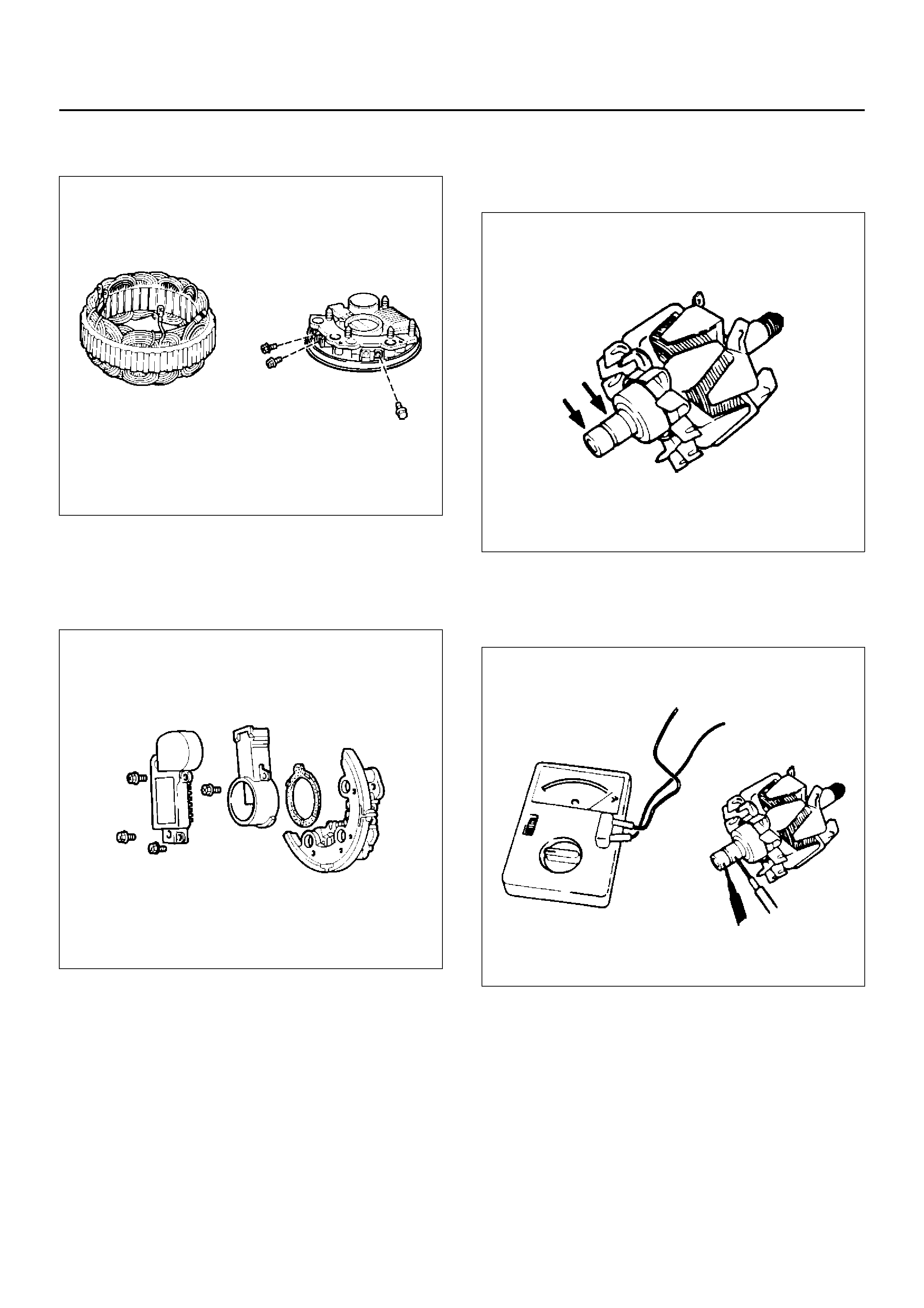
7. Remove bolts which secure stator terminal to
rectifier terminal, and remove stator.
066RS030
8. Remove Bolts which secure regulator, rectifier and
brush-holder, and separate these parts.
NOTE: Do not apply a shock or load to regulator,
rectifier and brush holder.
066RW025
INSPECTION AND REPAIR
Repair or replace necessary parts if extreme wear or
damage is found during inspection.
Rotor Assembly
1. Check the face of the slip rings for contamination
and roughness. If found to be scored, dress with a
fine sandpaper (#500 –600). If found to be
contaminated, clean with a cloth saturated with
alcohol.
2. Measure the outside diameter of the slip rings.
Standard: 27mm (1.06in)
Limit: 26mm (1.02in)
066RS032
3. Check resistance between slip rings, and replace if
there is no continuity.
Standard: 3.75Ω or less
066RS033
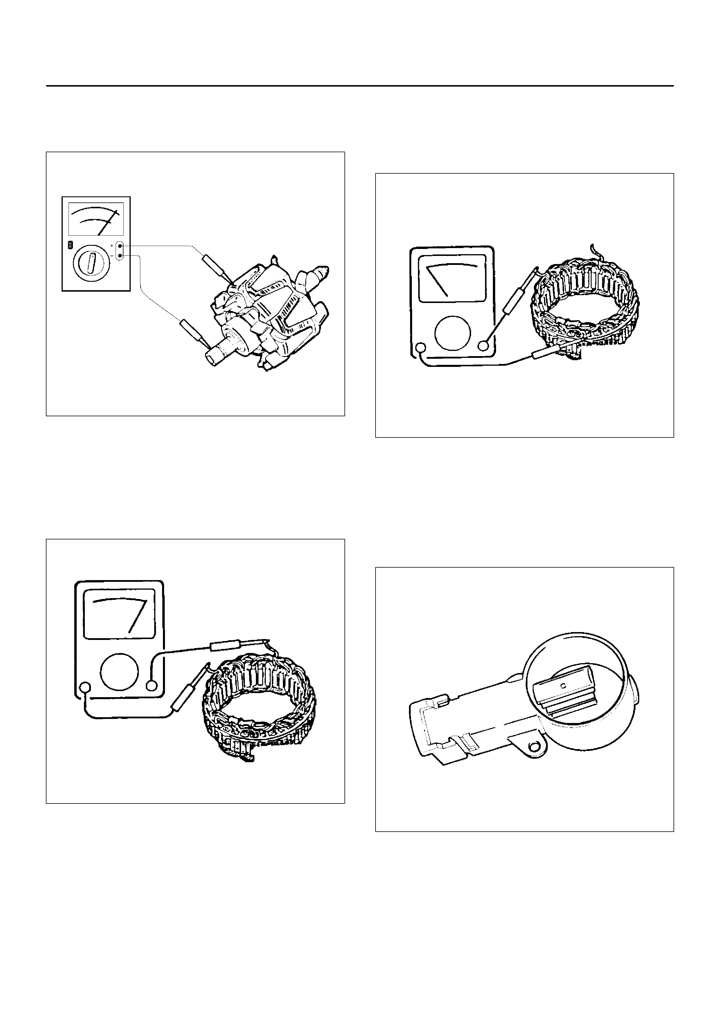
4. Check for continuity between slip ring and rotor
core.
In case of continuity, replace the rotor assembly.
066RS017
Stator Coil
1. Check for continuity across the stator coils. If no
continuity exist s, replace the coils.
Resistance value at 20°C.
Standard: Approx. 0.07Ω
066RS034
2. Check for continuity across one of the stator coils
and stator core. If a continuity exists, replace the
coil.
Standard: More than 1MΩ
066RS035
Brush
Measur e the brus h lengt h.
If more than limit, replace the brush.
Standard: 18.0mm (0.709in)
Limit: 5.5mm (0.217in)
066RW024
Rectifier Assembly
1. Measure the resistance between each diode
terminal and aluminum diode fin in forward and
reverse directions with the connection of the tester
leads switched. The diodes are normal if resistance
is near ly zero ohms in one directio n and is infin itely
high in the other direction.
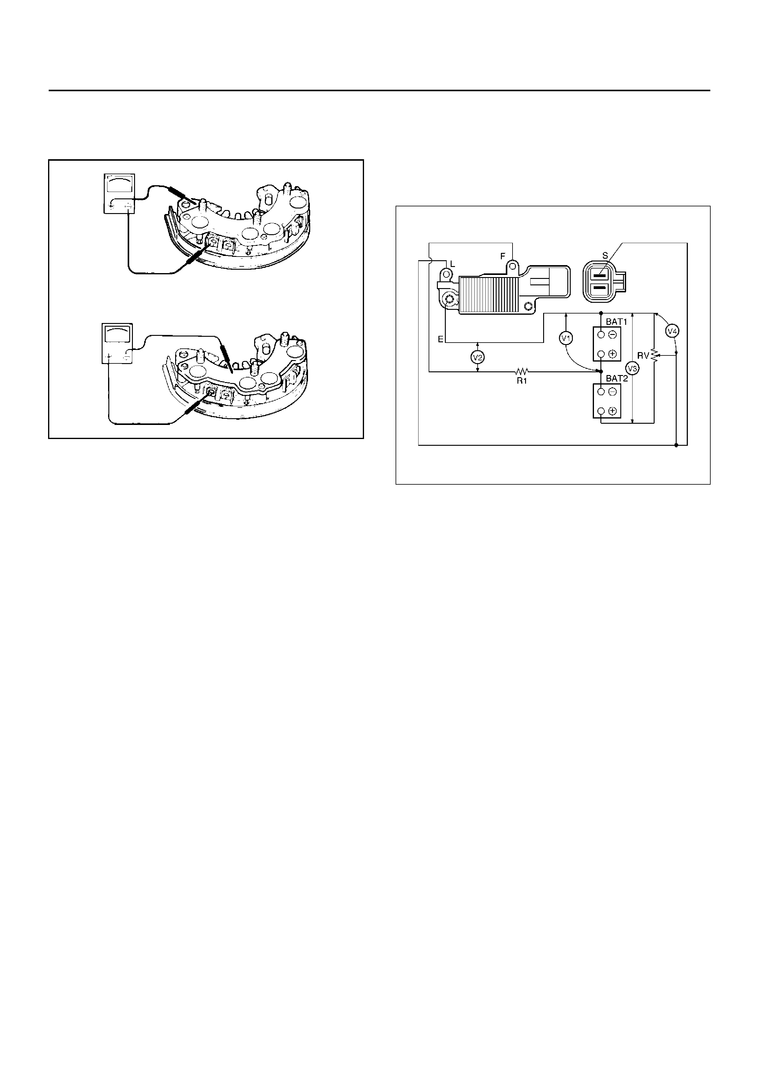
2. If a diode has no resistance or equal resistance in
both directions, it is defective and should be
replaced together with the holder.
066RS036
IC Regulator Assembly
Connect a variable resistor, two 12V batteries, a fixed
resistor, and a voltmeter to the IC regulator as shown in
illustration.
a Measuring equipment specifications
1 Fixed resistor (R1) : 10 Ohms /3W
2 Variable resistor (Rv) : 0-300 Ohms/12W
3 Batteries (BAT1, BAT2) : 12V (2 Batteries)
4 DC voltmeter : 0-50V/0.5 steps (4 Check points)
b Measuring procedure
1 Measure the voltage “V1" across the first battery
(BAT1). If the reading is between 10 and 13
volts, the battery is normal.
2 Measure the voltage “V3" across both the
batteries (BAT1, BAT2). If the reading is
between 20 and 26 bolts, the batteries are
normal.
3 Gradually increase the resistance of the variable
resistor from zero. Measure the voltage “V2"
(the voltage across the F and E terminals).
Check to see that the voltage across “V1"
changes at this time. If there is no change, the
voltage regulator is faulty and must be replaced.
4 Measure the voltage at “V4" (the voltage across
the variable resistor center tap and terminal E
with the variable resistor resistance held
constant). The measure voltage should be
within the specified (14.4±0.3 volts) limits. If it is
not, the regulator must be replaced.
066RX003
REASSEMBLY
To reassemble, follow the disassembly steps in the
reverse order, noting the following points:
NOTE:
• Never make battery connections with polarities
reversed, or battery will be shorted via the diodes.
This will cause damage to the diodes.
• Do not connect generator B terminal to ground; it is
connected directly to the battery.
This cable will burn if it is connected to ground.
• Make sure to disconnect the positive (+) terminal of
the battery when quick-charging battery .
Diodes may be damaged due to abnormal pulse
voltage generated bye the quick charger.
• When reassembling the front section to rear section,
inse rt a stiff wire into hol e in the rear face of the rear
cover from the outboard side to support the brush in
raised position, then insert the front section to which
rotor is assembled.
• Reassemble parts carefully to be sure they fit into
their original position, paying attention to the
insulated portions.
• Wipe insulat ing tubes , washers an d plates clean and
install the m in posi tion ca refull y to av oid ge tting o il or
grease on them.
1. Using a press with a socket wrench attached,
reassemble rotor and rear end cover assembly in
the front cover.
066RS022
2. Install pulley on the rotor.
Secure the pulley directly in the vise between two
copper plates, and tighten nut to the specified
torque.
Torque: 111N·m (11.3kg·m/82lbft)
066RS010
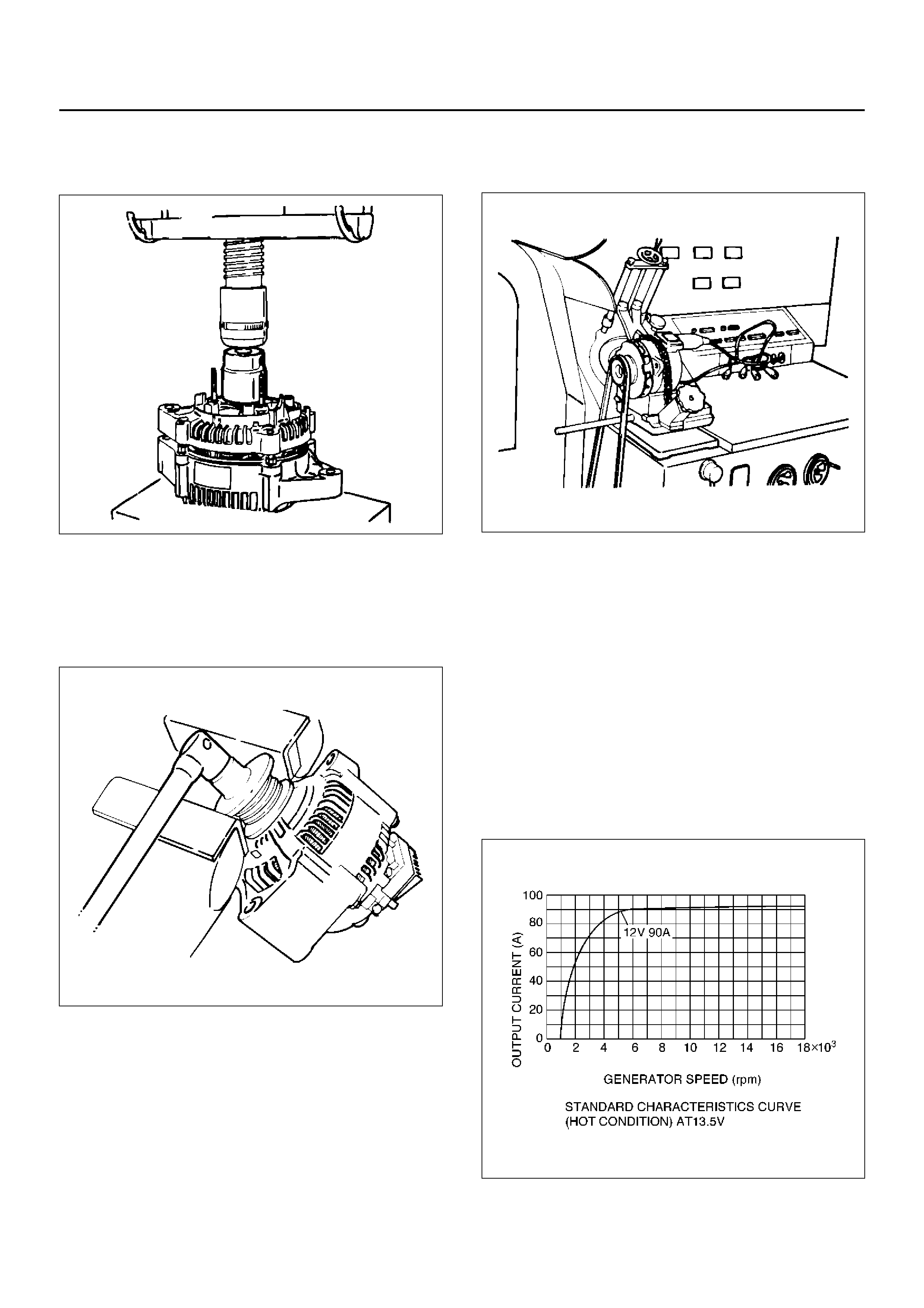
BENCH TEST
Conduct a bench test of the generator.
066RS023
Preparation
Remove generator from the vehicle (see “Generator
removal").
1. Secure generator to the bench test equipment and
connect wires.
Terminal “IG" for energization
Terminal “L" for neutral (warning lamp)
Terminal “B" for output
2. Conduct the generator characteristic test.
Characteristics of generator are shown in
illustration.
Repair or replace the generator if its outputs are
abnormal.
066RX001

MAIN DATA AND SPECIFICATIONS
General Specifications
Battery voltage V 12
Rated output A 90
Direction of rotation
(as viewed from pulley side) Clockwise
Rated rotation speed rpm 5000
Maximum speed rpm 18000