
SECTION 6E - STARTING SYSTEM
Service Precaution
Starting System
General Description
Diagnosis
Starter
Removal
Installation
Disassembled View
Disassembly
Inspection and Repair
Reassembly
Main Data and Specifications
SERVICE PRECAUTION
WARNING: THIS VEHICLE HAS A SUPPLEMENTAL
RESTRAINT SYSTEM (SRS), REFER TO THE SRS
COMPONENT AND WIRING LOCATION VIEW IN
ORDER TO DETERMINE WHETHER YOU ARE
PERFORMING SERVICE ON OR NEAR THE SRS
COMPONENTS OR THE SRS WIRING. WHEN YOU
ARE PERFORMING SERVICE ON OR NEAR THE
SRS COMPONENTS OR THE SRS WIRING, REFER
TO THE SRS SERVICE INFORMATION. FAILURE TO
FOLLOW WARNINGS COULD RESULT IN
POSSIBLE AIR BAG DEPLOYMENT, PERSONAL
INJURY, OR OTHERWISE UNNEEDED SRS SYSTEM
REPAIRS.
CAUTION: Always use the correct fastener in the
proper location. When you replace a fastener, use
ONLY the exact part number for that application.
HOLDE N will call out those f asten ers th at requir e a
replacement after removal. HOLDEN will also call
out the fasteners that require thread lockers or
thread sealant. UNLESS OTHERWISE SPECIFIED,
do not use supplemental coatings (Paints , greases,
or other corrosion inhibitors ) on threaded fast eners
or fastener joint interfaces. Generally, such
coatings adversely affect the fastener torque and
the joint clamping force, and may damage the
fastener. When you install fasteners, use the
correct tightening sequence and specifications.
Following these instructions can help you avoid
damage to parts and systems.

STARTING SYSTEM
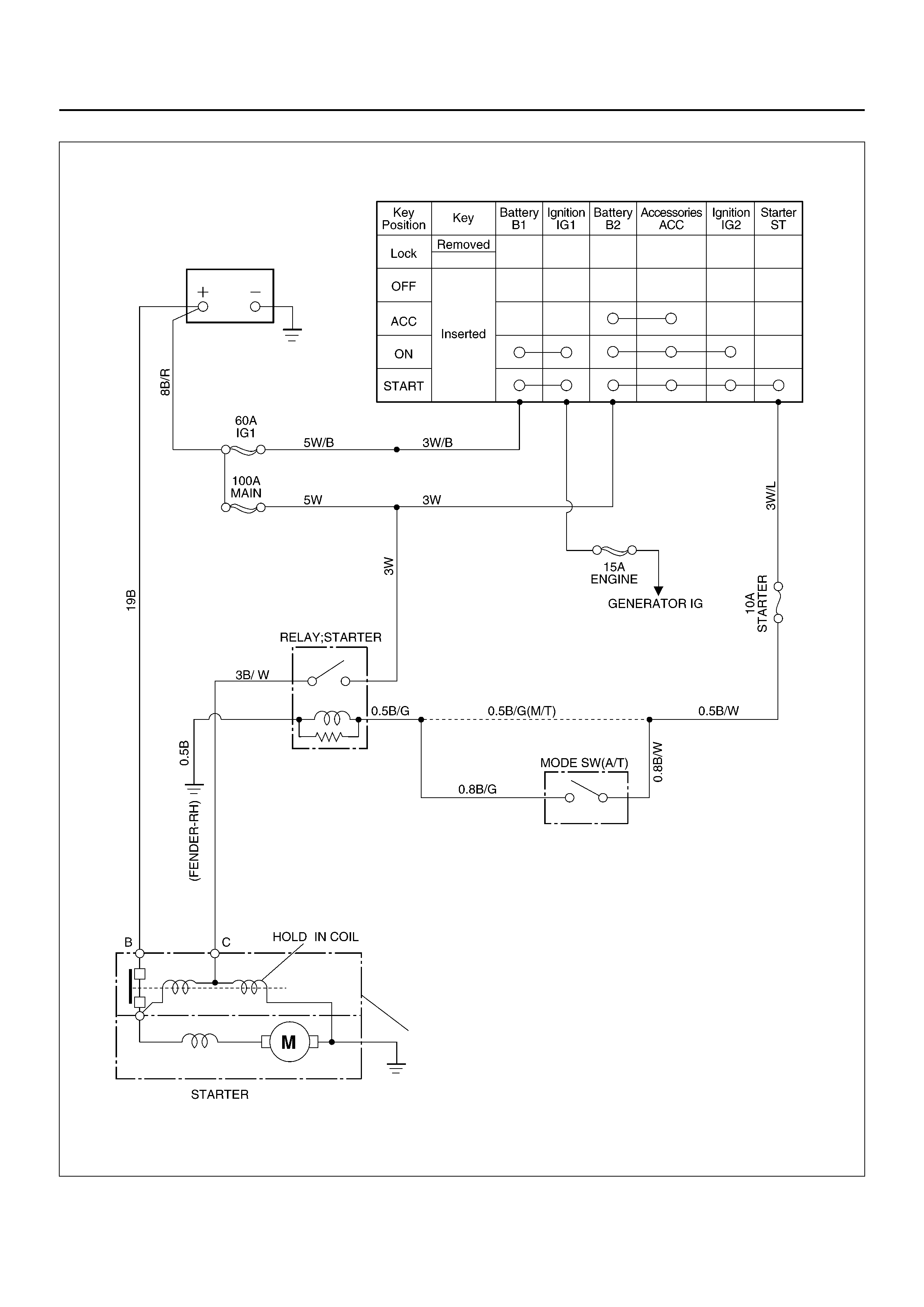
GENERAL DESCRIPTION
Cranking Circuit
The cranking system consists of a battery, starter,
starter switch, starter relay, etc. These main
components are connected.
Starter
The cranking system employs a magnetic type
reduction starter in which the motor shaft is also used as
a pinion shaft. Wh en the starter switch is turned on, the
contacts of solenoid are closed, and the armature
rotates. At the same time, the plunger is attracted, and
the pinion is pushed forward by the shift lever to mesh
with the ring gear.
Then, the ring gear runs to start the engine. When the
engine starts and the starter switch is turned off, the
plunger returns, the pinion is disengaged from the ring
gear, and th e armatur e stops rotatio n. When the eng ine
speed is higher than the pini on, the pinion id les, so that
the armature is not driven.
C06RX004
SOLENOID

DIAGNOSIS
Condition Possible cause Correcti on
Starter does not run Charging failure Repair charging system
Battery Failure Replace Battery
Terminal connection failure Repair or replace terminal connector
and/or wiring harness
Starter switch failure Repair or replace starter switch
Starter failure Repair or replace starter
STARTER
REMOVAL
1. Battery ground cable.
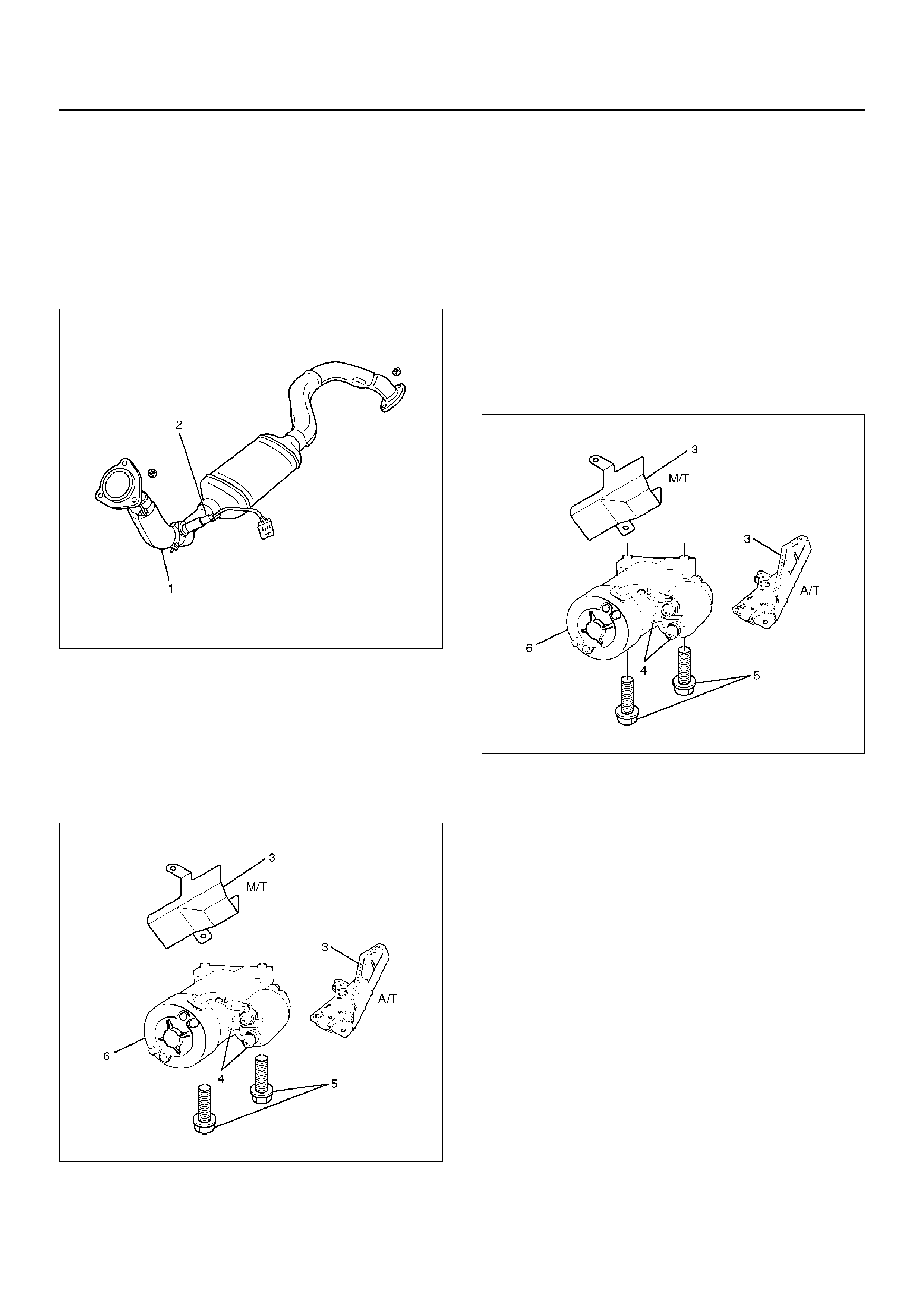
2. Disconnect heated oxygen (O2) sensor connector
(1).
3. Remove exhaust front left pipe(2).
150RX015
4. Remove heat protector(3).
5. Disconnect starter wiring connector from terminals
“B" and “S"(4).
6. Remove starter assembly mounting bolts on inside
and outside(5).
7. Remove starter assembly toward the bottom of
engine(6).
065RW027
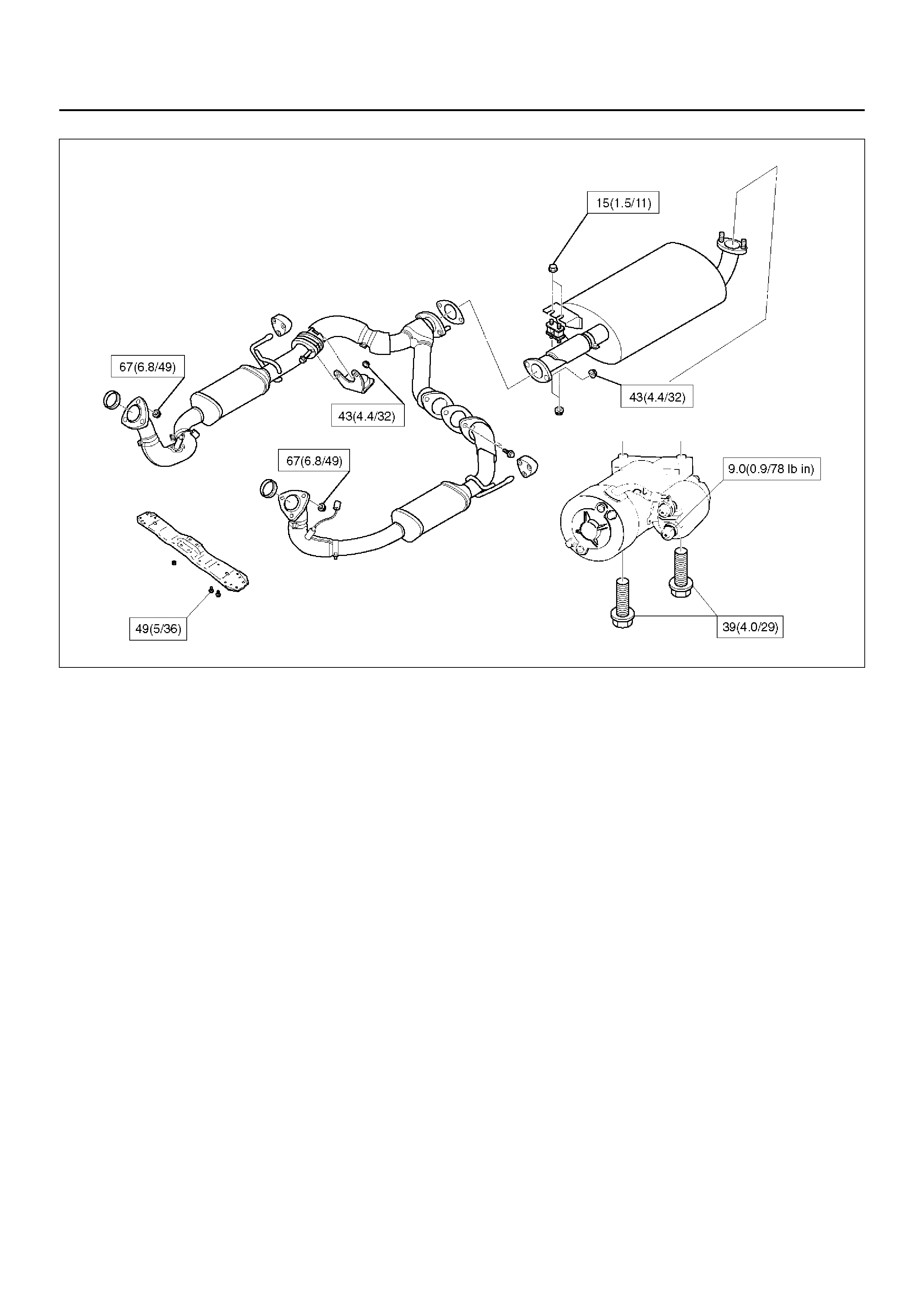
INSTALLATION
1. Install starter assembly(6).
2. Install mounting bolts and tighten bolts to specified
torque(5).
Torque: 40 N·m (4.1 kg·m/30 lb ft)
3. Reconnect the connectors to terminals “B" and “S"
and tighten Terminals “B" to specified torque.
Torque: 9 N·m (0.9 kg·m/78 lb in)
4. Install heat protector(3).
065RW027
5. Install exhaust front left pipe and tighten bolts and
nuts to specified torque(2).
Stud Nuts
Torque: 67 N·m (6.8 kg·m/49 lb ft)
Nuts
Torque: 43 N·m (4.4 kg·m/32 lb ft)
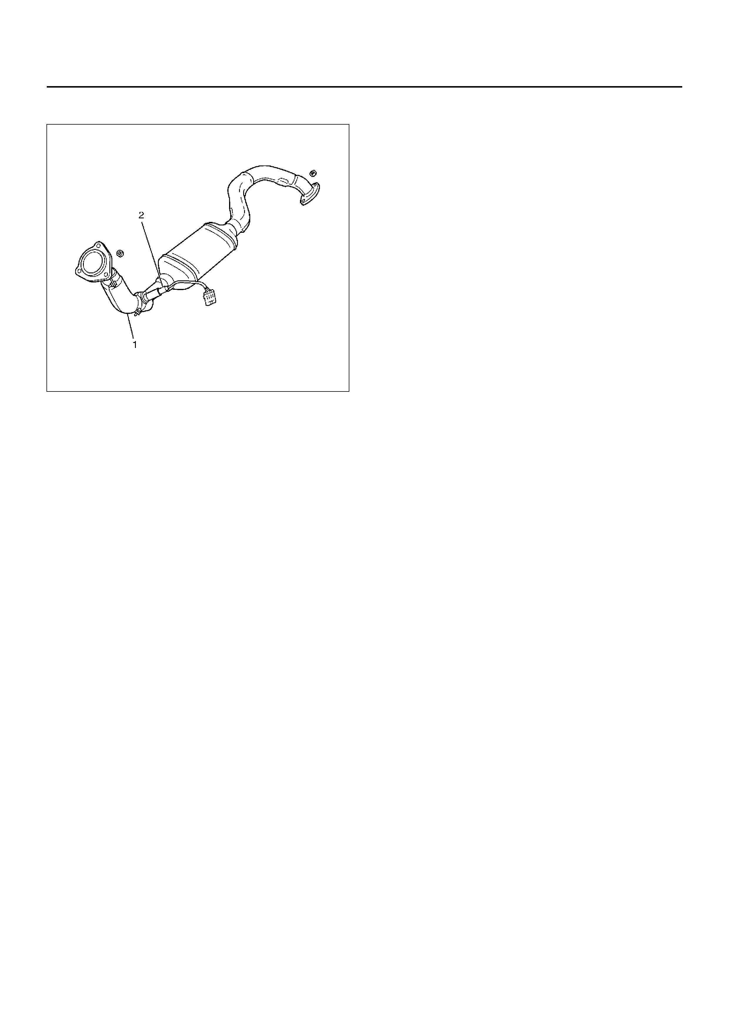
6. Connect O2 sensor connector (2).
150RX015
7. Reconnect the battery ground cable.
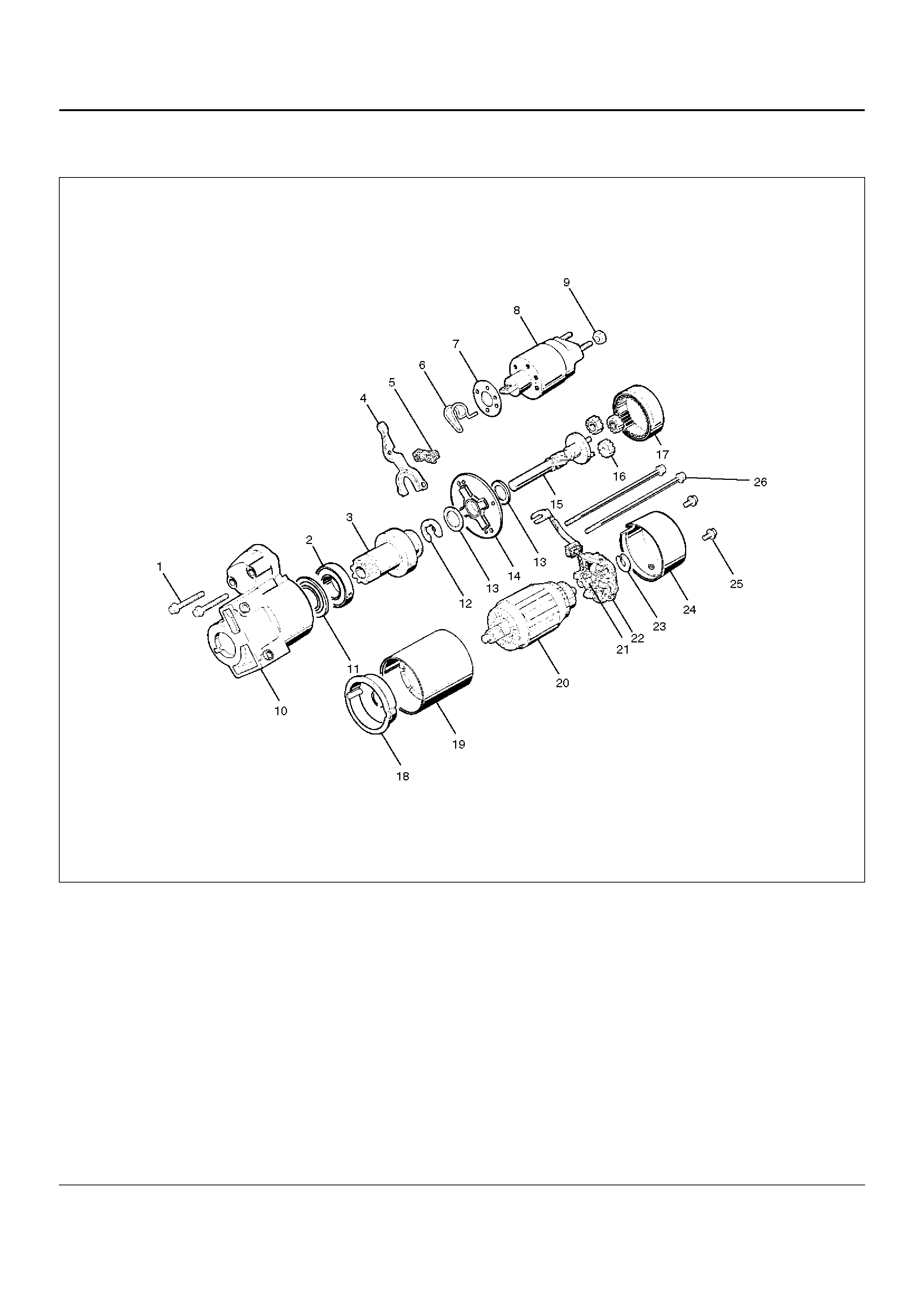
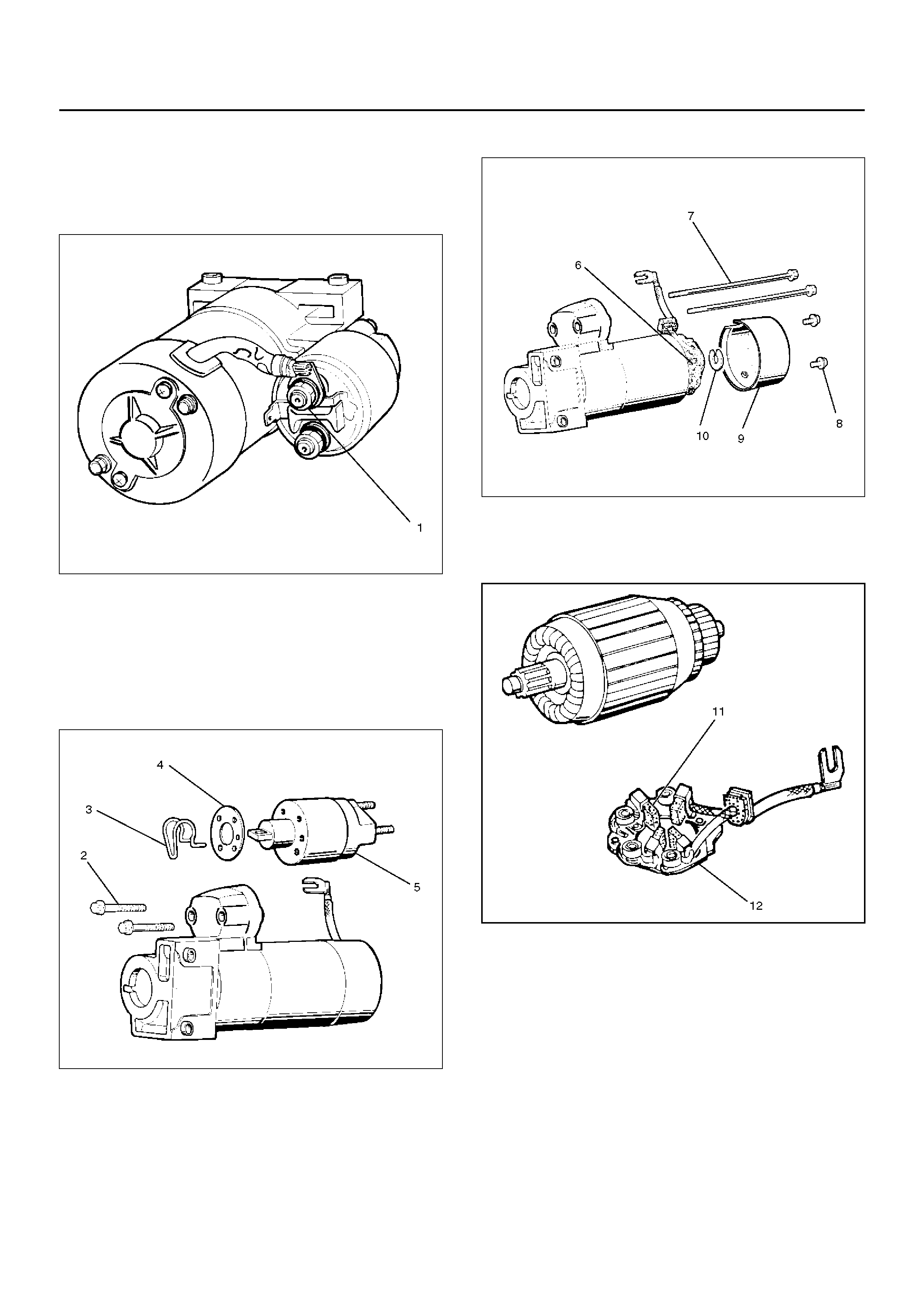
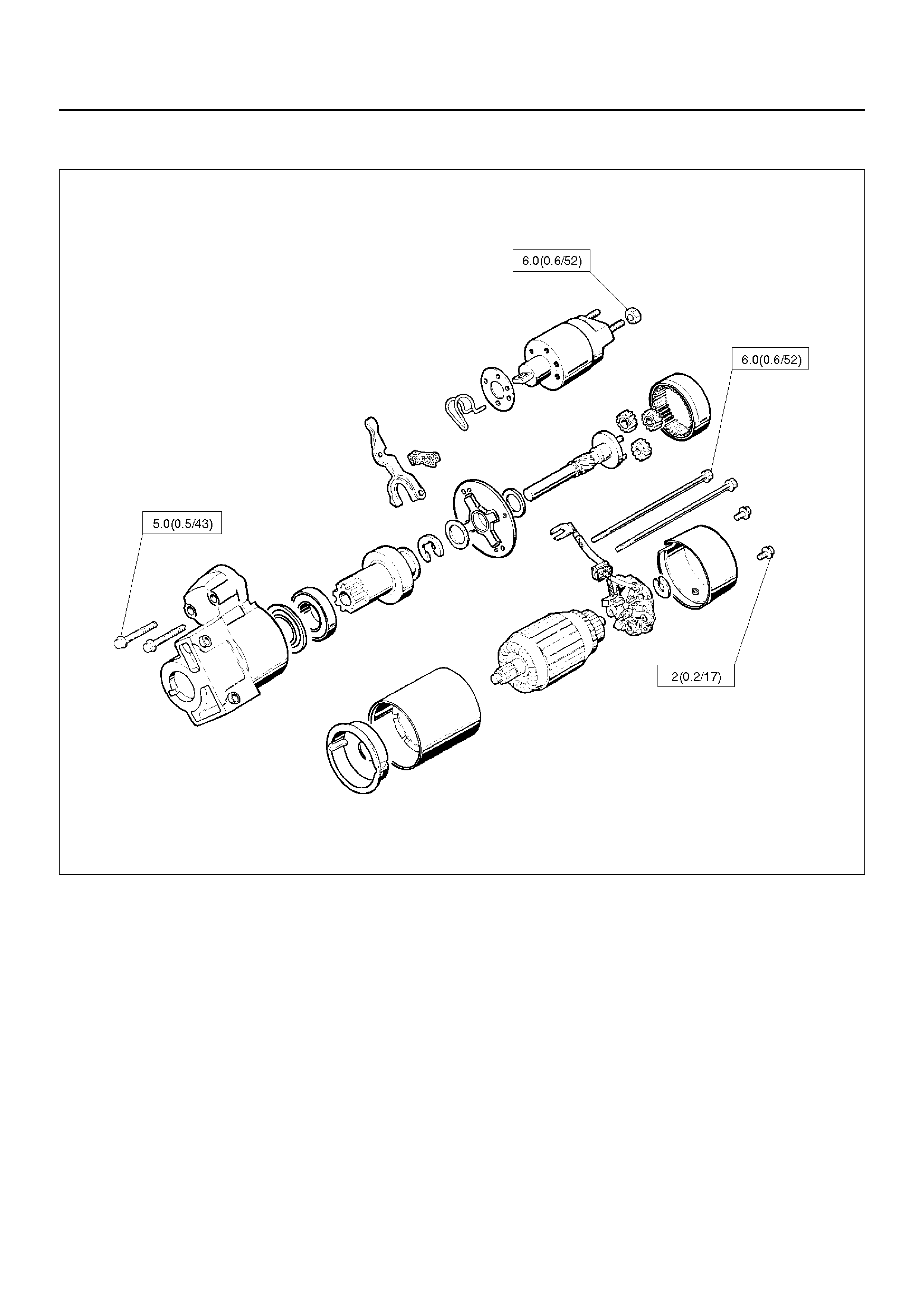
DISASSEMBLED VIEW
065RW002
EndOFCallout
Legend
(1) Bolt (2 pcs)
(2) Ball Bearing
(3) Pinion
(4) Shift Lever
(5) Dust Cover
(6) Torsion Spring
(7) Dust Cover
(8) solenoid
(9) Nut
(10) Gear Case
(11) Bearing Cover
(12) E–Ring
(13) Thrust Washer (2)
(14) Center Bracket
(15) Pinion Sh aft
(16) Planet Gear (3)
(17) Internal Gear
(18) C enter Bracket (A)
(19) Yoke Assembly
(20) Armature
(21) Brush
(22) Brush Holder
(23) Thrust Washer
(24) Rear Cover
(25) Screw (2 pcs)
(26) Through Bolt (2 pcs)
DISASSEMBLY
1. Loosen the nut(1) on terminal “M" of solenoid and
disconnect the connector cable.
2. Remove bolt (2 pcs) (2).
065RW003
3. Remo ve so lenoid( 5) .
4. Remove dust cover(4).
5. Remove torsion spring bolts, then the solenoid
assembly.
6. Remove torsion spring(3) from solenoid
assembly(5).
065RW004
7. Remove screw (2 pcs) (8).
8. Remove through bolt (2 pcs) (7).
9. Remove screws and through bolts, then the rear
cover(9) then remove thrust washer(10).
10. Remove brush holder(6).
065RW005
11. Raise a brush spring to detach brushes (4 pcs) from
the commutator face and pull off the brush
holder(12) and brush(11).
065RW006
12. Remove yoke assembly(14).
13. Remove armature(15).
14. Pull off the yoke assembly, then remove armature,
washer and center bracket.(A) (13).
NOTE: In disassembling the yoke assembly, hold the
armature and pull off slowly the yoke assembly.
Because of strong magnetic force, avoid placing a
metallic part near armature.
065RW007
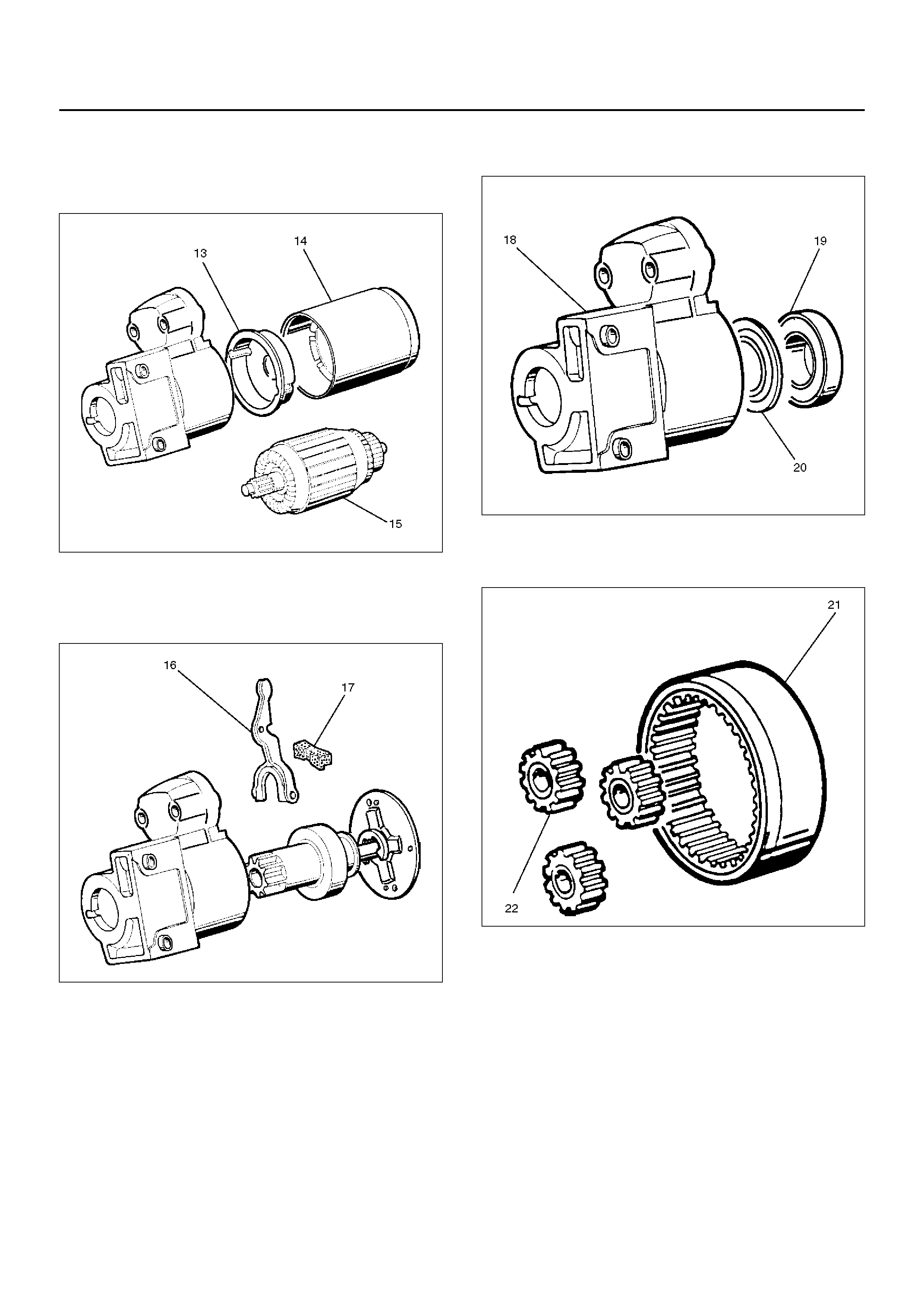
15. Remove dust cover (17) .
16. Remove a dust cover and shift lever(16) from the
gear case.
065RW008
17. Remove ball bear i ng(19 ).
18. Remo ve beari ng co ver (20 ).
19. Remove a ball bearing and bearing cover from the
gear case(18).
065RW021
20. Internal gear(21).
21. Remove internal gear and planet gear(3) (22).
065RW009
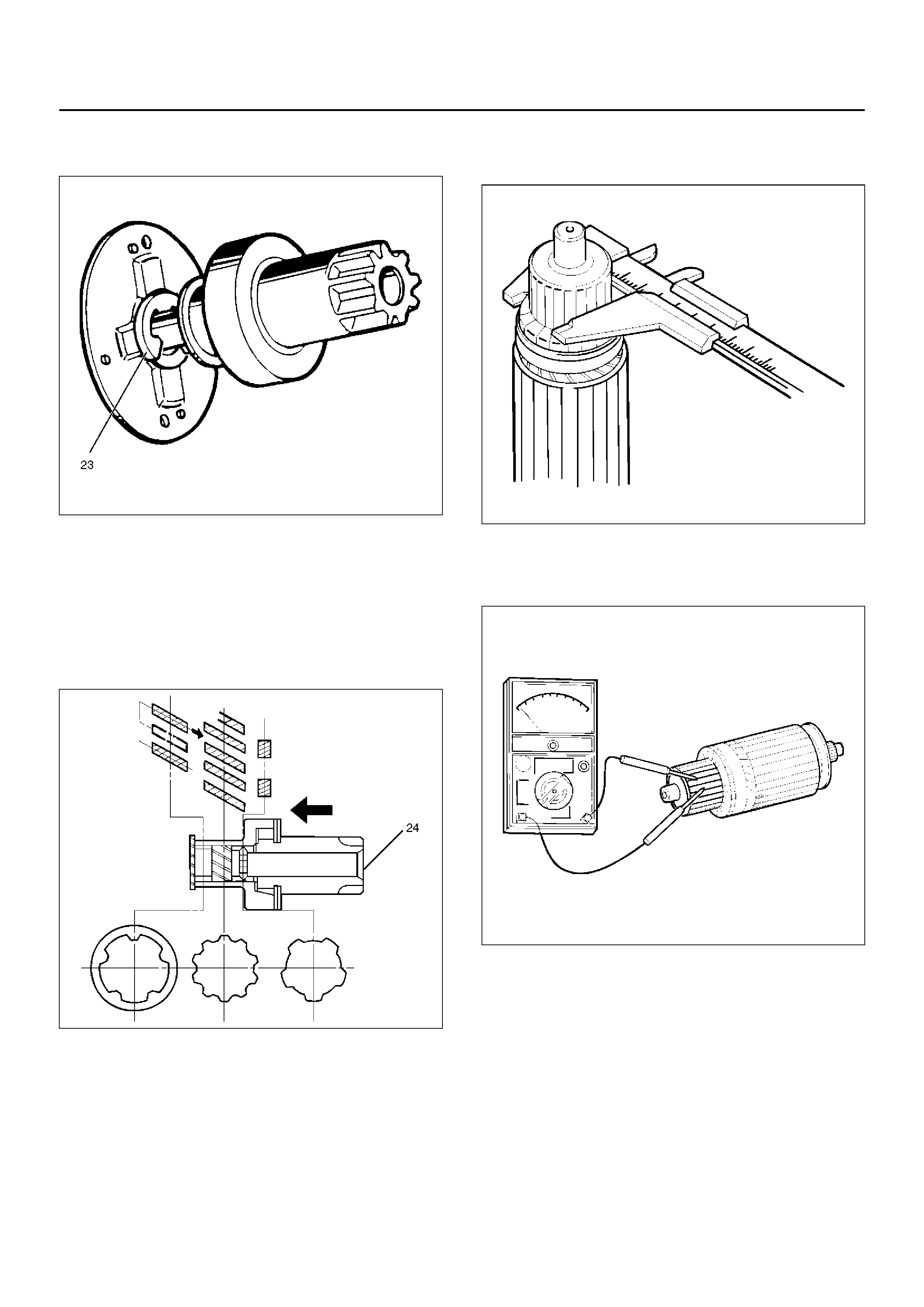
22. Remove an E–ring(23) from the pinion shaft using a
flat blade screwdriver.
065RW010
23. Holding the pinion shaft, push pinion toward the
center bracket. and turn the pinion clockwise or
counterclockwise by one tooth of spline, then pull off
the pinion.
24. Remove thrust washer(24).
25. Remove center bracket
26. Remove pinion shaft.
065RW011
INSPECTION AND REPAIR
Repair or replace necessary parts if extreme wear or
damage is found during inspection.
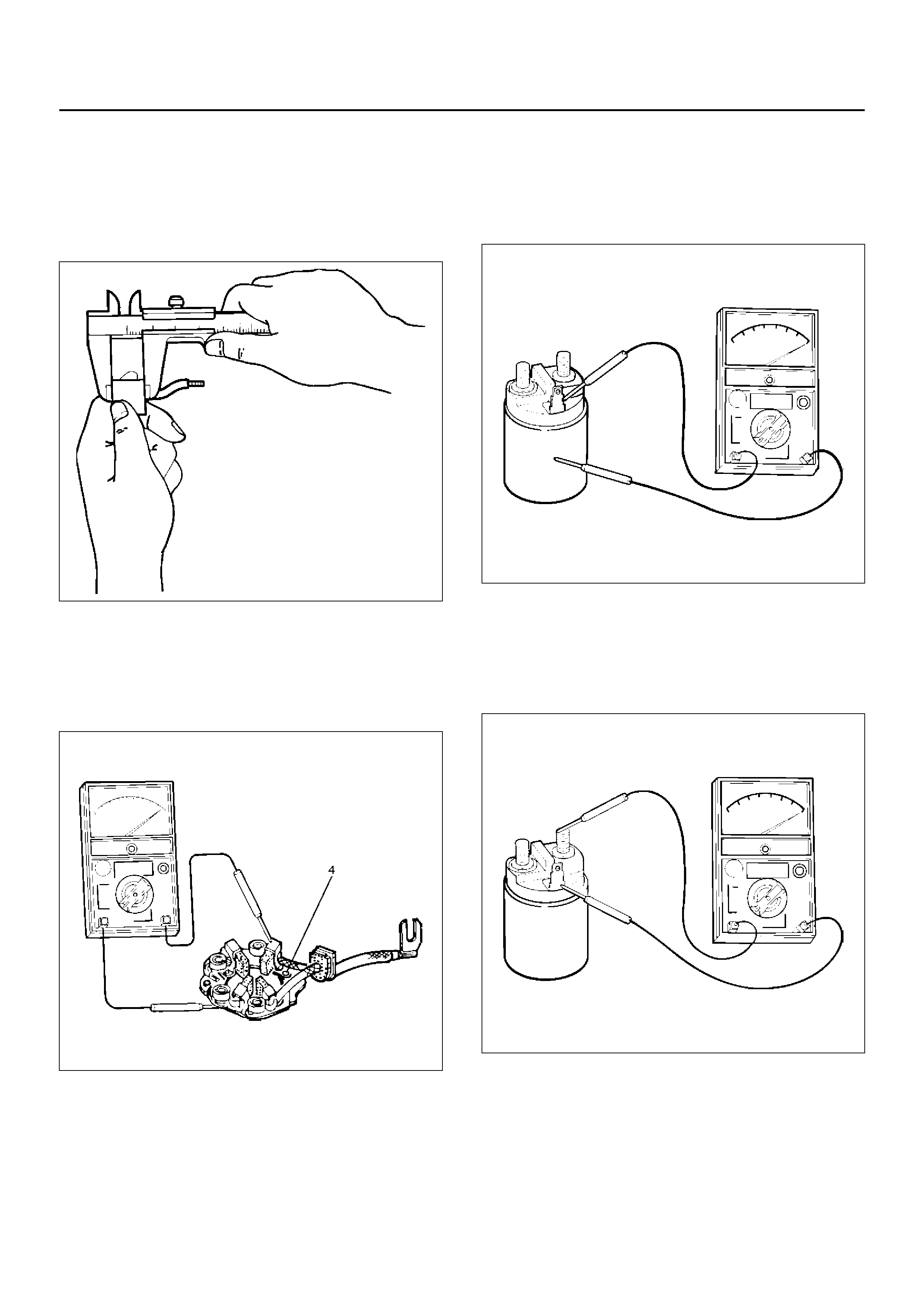
Armature
Measure the outer diameter of commutator, and replace
with a new one if it is out of the limit.
Standard: 33.0 mm (1.30 in)
Limit: 32.0 mm (1.26 in)
065RS014
Check for continuity between commutator and segment.
Replace commutator if there is no continuity (i.e.,
disconnected).
065RS015
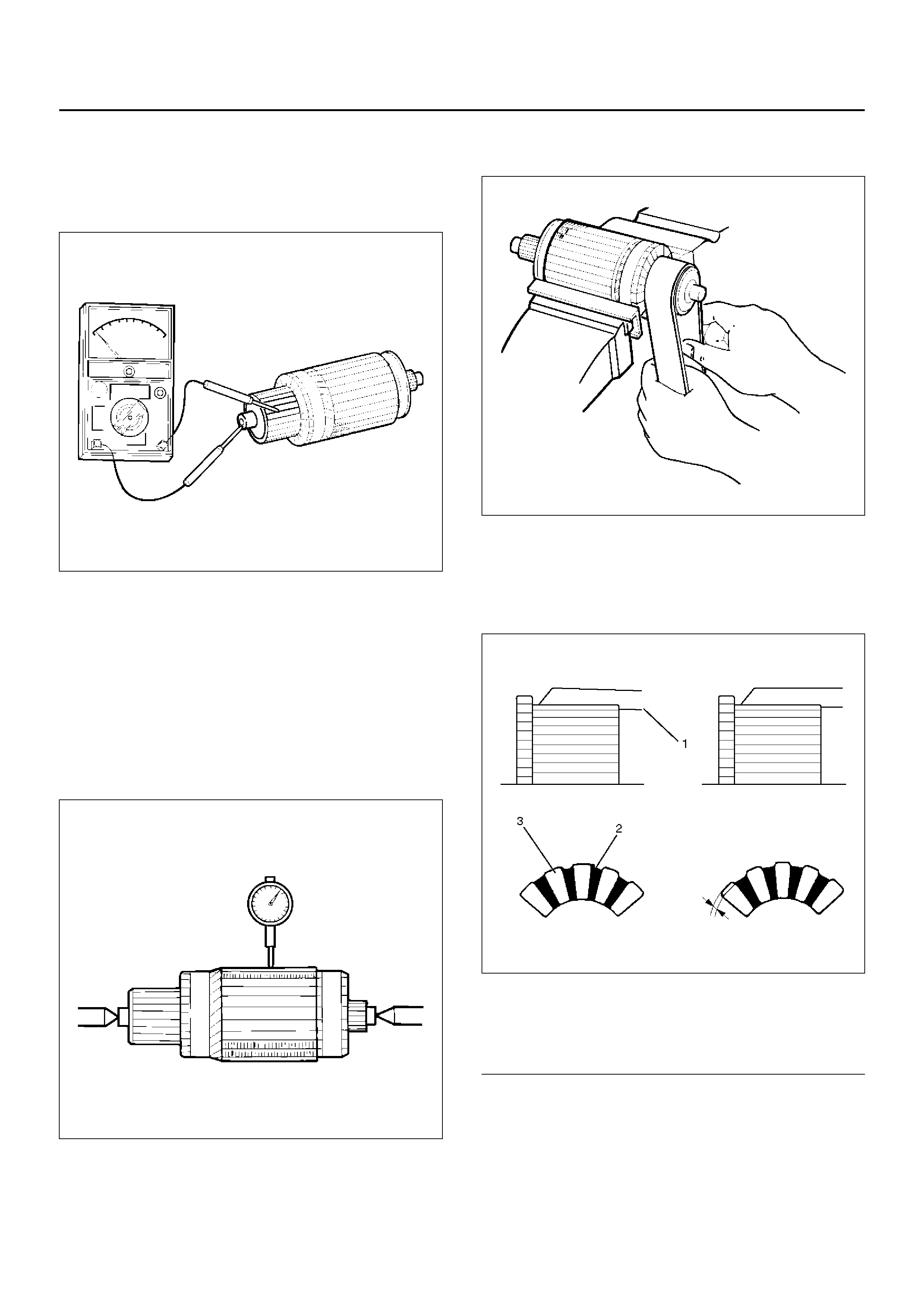
Check for continuity between commutator and shaft.
Also, check for continuity between commutator and
armature core,armature core and shaft. Replace
commutator if there is continuity (i.e., internally
grounded).
065RS016
Measure runout of armature core and commutator with
a dial gauge. Repair or replace, if it exceeds the limit.
Armature
Standard: 0.05 mm (0.002 in) Max.
Limit: 0.10 mm (0.004 in)
Commutator
Standard: 0.05 mm (0.002 in) Max.
Limit: 0.10 mm (0.004 in)
065RS017
Polish the commutator surface with sandpaper #500 to
#600 if it is rough.
065RW012
Measure the depth of insulator in commutator . Repair, if
it is below the limit.
Standard: 0.05 mm to 0.8 mm (0.02 in to 0.03 in)
Limit: 0.2 mm (0.008 in)
065RW013
EndOFCallout
Legend
(1) Steel Saw
(2) Insulator
(3) Commutator Segments
Brush
Measure the length of brush.
Replace with a new one, if it is below the limit.
Standard: 16 mm (0.63 in)
Limit: 11 mm (0.43 in)
065RW014
Brush Holder
Check for continuity between brush holder (+) (4) and
base (–). Replace, if there is continuity (i.e., insulation is
broken).
065RW015
solenoid
Check for continuity of shunt coil between terminals S
and M.
Replace, if there is no continuity (i.e., coil is
disconnected).
065RW016
Continuity of Series Coil
Check for continuity between terminals S and M.
Replace, if there is no continuity (i.e., coil is
disconnected).
065RW017
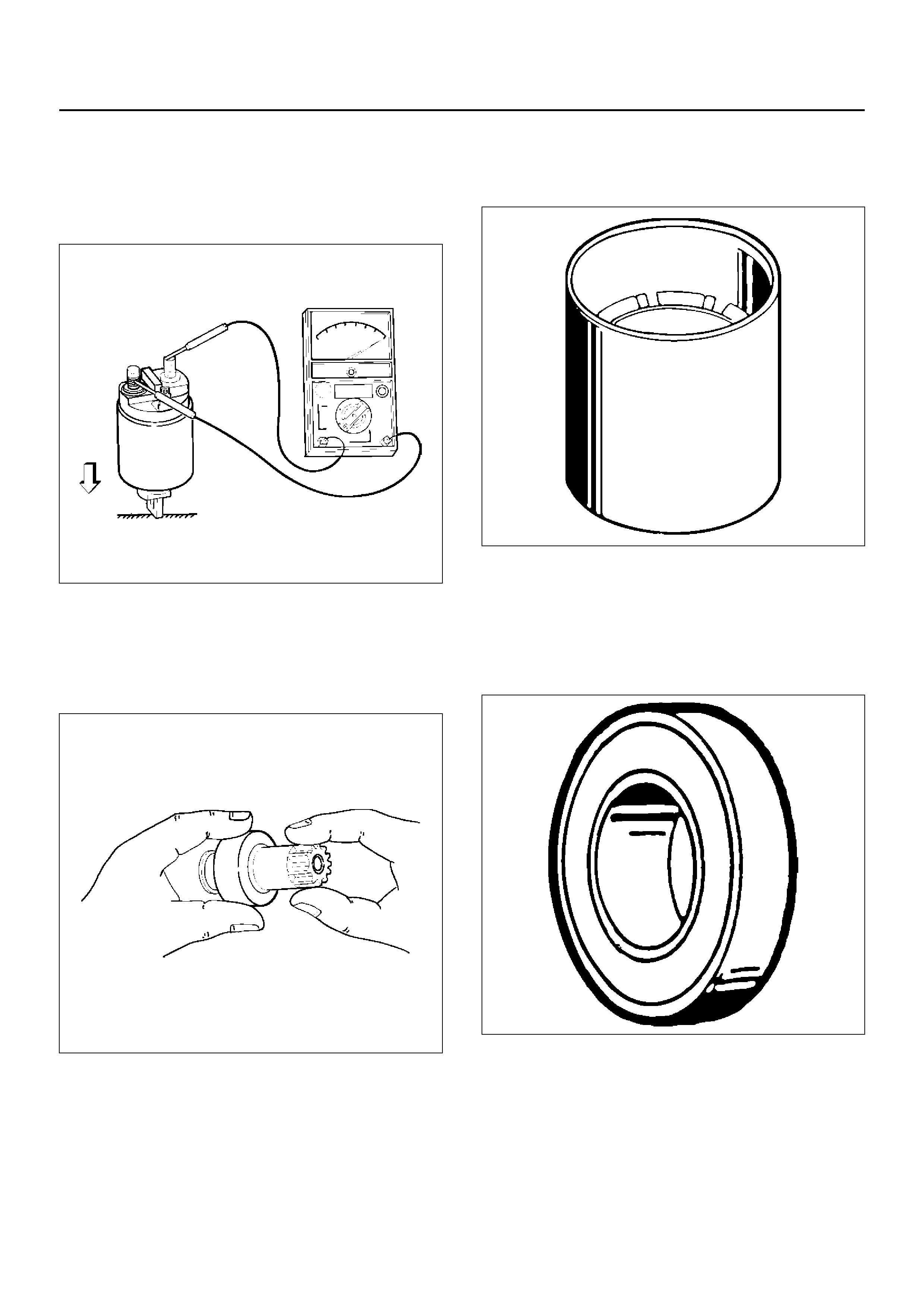
Continuity of Contacts
With the plunger faced downward, push down the
solenoid. In this state, check for continuity between
terminals B and M. Replace, if there is no continuity
(i.e., contacts are faulty).
065RW018
Pinion
Check if the pinion rotates smoothly in drive direction by
hand, or if it is locked when it is rotated in reverse. If not,
replace the pinion.
065RS025
Yoke Assembly
Check a magnet inside the yoke.
Replace the yoke assembly if it is broken.
065RS026
Ball Bearing
Clamp the inner race of the ball bearing with your finger,
and check for sticking or play when rotating the outer
race.
Replace, if abnormality is found.
065RS027
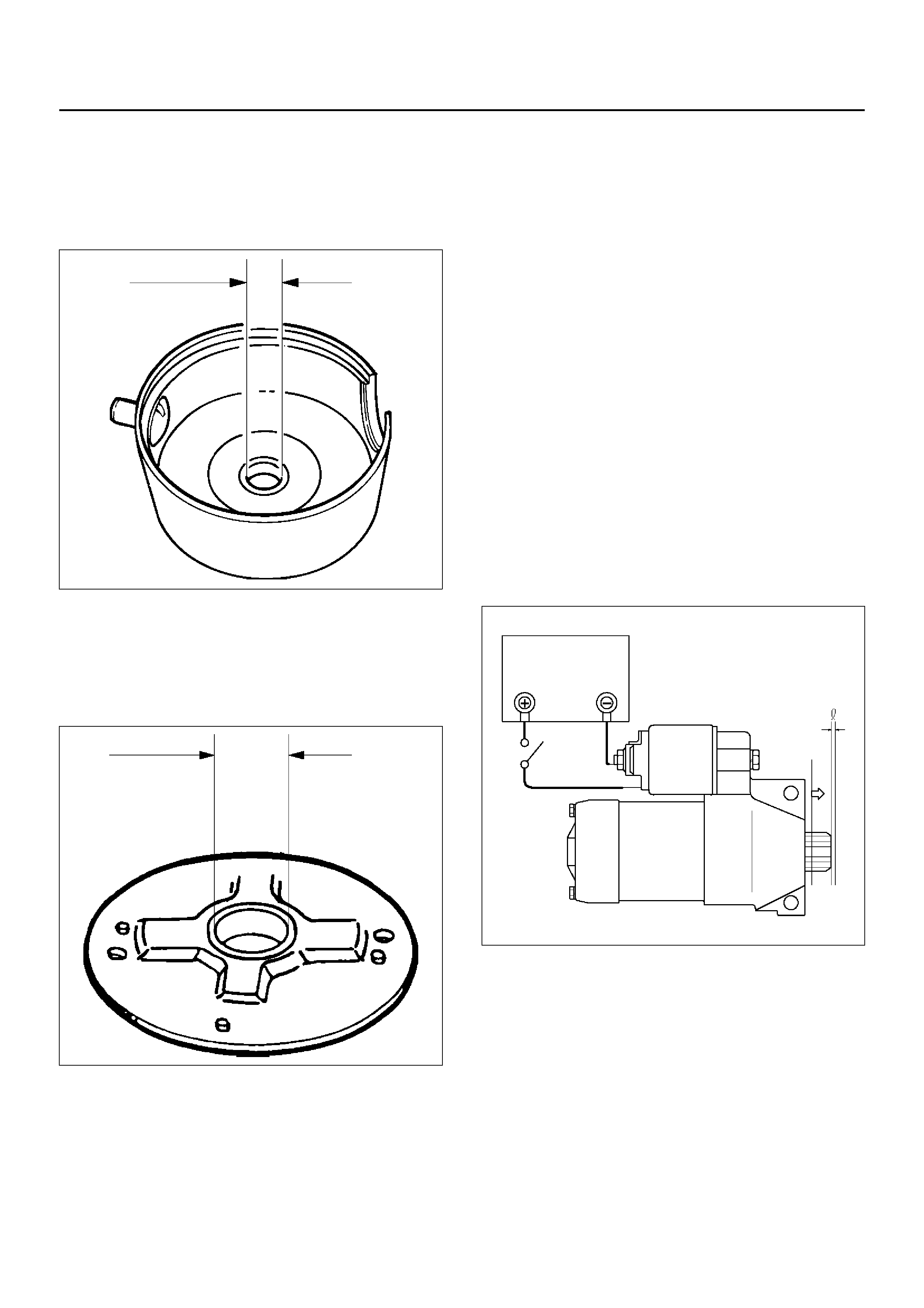
Measure inner diameter of bushing in the rear cover,
and replace if it exceeds the limit.
Standard: 12.50 mm to 12.527 mm (0.492 in to
0.4932 in)
Limit: 12.60 mm (0.4961 in)
065RS028
Measure inner diameter of bushing in the center bracket
(P), and replace if it exceeds the limit.
Standard: 18.01 mm to 18.127 mm (0.7091 in to
0.7137 in)
Limit: 18.15 mm (0.7146 in)
065RS029
REASSEMBLY
To install, f ollow the remova l st eps in the reverse order,
noting the following points:
Grease application places
• Bushing in rear cover and center bracket
• Gears in reduction gear
• Shift lever operating portion
• Sliding portion of pinion
• Plunger sliding portion of solenoid
Reassembling Yoke Assembly
Before reassembly, make sure that no metallic parts
attach to the yoke assembly. Because of strong
magnetic force, hold the yoke assembly and insert it
slowly into the armature.
Torque
Torque for each part (See Torque Specifications in
this section)
Pinion Jump–out Dimension
Connect the “+" cable of battery to terminal S and the “–
" cable to terminal M. Turn the switch on, and measure
pinion travel dimension in thrust direction from the
jump–out position.
In mea suri ng the dimens io n, pul l the pini on ou t a little in
the arrow direction.
Dimension(L): 0.05 mm to 1.5 mm (0.002 in to 0.06
in)
065RS030
If the measured value is out of standard, insert dust
cover, or disassemble and adjust.
065RW019
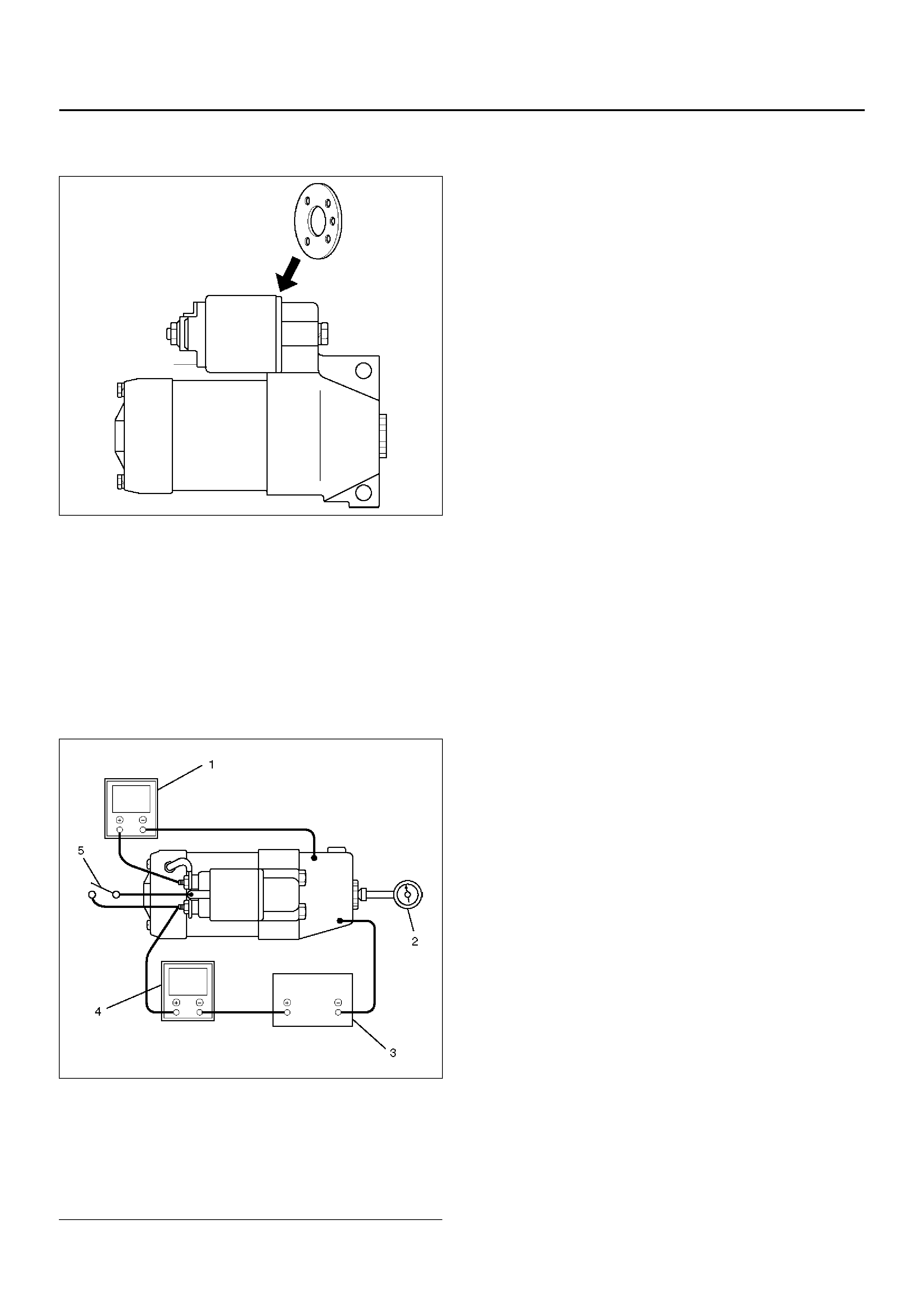
Characteristic Test
For easily confirming the characteristics, conduct the no
load test as follows:
Rating as short as 30 seconds requires rapid testing.
Fix the starter on the test bench, and wire as shown in
illustration. When the switch is closed, the current flows
and the starter runs under no load. At this time,
measure current, voltage and speed to check if they
satisfy the standard.
065RW020
EndOFCallout
Legend
(1) Volt Meter
(2) Tachometer
(3) Battery
(4) Ammeter
(5) Switch

MAIN DATA AND SPECIFICATIONS
General Specifications
Model Specification
Rating
Voltage 12 V
Output 1.4 Kw
Time 30 sec
Number of teeth of pinion 9
Rotating direction(as viewed from pinion) Clockwise
Weight(approx .) 37 N
No load charac te rist ic s
Voltage /Current 11.5V/90A or less
Speed 3000rpm or more
Load characteristics
Voltage/current 8.5V/350A or more
Torque 13.2N·m(117lb·in.) or more
Speed 1000rpm or more
Locking characteristics
Voltage/current 2.4V/500A or less
Torque 11.8N·m(104lb·in) or more
Torque Specifications
N·m (kg·m/lbin)
E06RY00009
N·m (kg·m/lbft)
150RY00044