
SECTION 7A - CLUTCH
Service Precaution
General Description
Diagnosis
Clutch Assembly
Clutch Assembly and Associated Parts
Removal
Inspection and Repair
Installation
Clutch Control
Parts Location View
Removal
Inspection and Repair
Installation
Master Cylinder
Disassembly
Inspection and Repair
Reassembly
Slave Cylinder
Disassembled View
Disassembly
Inspection and Repair
Reassembly
Damper Cylinder
Disassembled View
Disassembly
Inspection and Repair
Reassembly
Main Data and Specifications
Special Tools
SERVICE PRECAUTION
WARNING: THIS VEHICLE HAS A SUPPLEMENTAL
RESTRAINT SYSTEM (SRS). REFER TO THE SRS
COMPONENT AND WIRING LOCATION VIEW IN
ORDER TO DETERMINE WHETHER YOU ARE
PERFORMING SERVICE ON OR NEAR THE SRS
COMPONENTS OR THE SRS WIRING. WHEN YOU
ARE PERFORMING SERVICE ON OR NEAR THE
SRS COMPONENTS OR THE SRS WIRING, REFER
TO THE SRS SERVICE INFORMATION. FAILURE TO
FOLLOW WARNINGS COULD RESULT IN POSSIBLE
AIR BAG DEPLOYMENT, PERSONAL INJURY, OR
OTHERWISE UNNEEDED SRS SYSTEM REPAIRS.
CAUTION: Always use the correct fastener in the
proper location. When you replace a fastener, use
ONLY the exact part number for that application.
HOLDEN will call out those fasteners that require a
replacement after removal. HOLDEN will also call
out the fasteners that require thread lockers or
thread sealant. UNLESS OTHERWISE SPECIFIED,
do not use supplemental coatings (Paints, greases,
or other corrosion inhibitors) on threaded fasteners
or fastener joint interfaces. Generally, such
coatings adversely affect the fastener torque and
the joint clamping force, and may damage the
fastener. When you install fasteners, use the correct
tightening sequence and specifications. Following
these instructions can help you avoid damage to
parts and systems.
GENERAL DESCRIPTION
Clutch
A07RW031
The 6VD1 (3.2L) engine with MUA manual transmission
employs a pull-type clutch.
The clutch assembly consists of the pressure plate
assembl y and the driv en pla te a ssem bly.
The clutch pedal is connected to the release bearing
through the shift fork.
The driven plate assembly is installed between the
flywheel and the pressure plate. Diaphragm spring
pressure holds the driven plate against the flywheel and
the pressure plate to provide the friction necessary to
engage the clutch.
Depressing the clutch pedal moves the shift fork against
the release bearing. The release bearing force
overcomes the force of the diaphragm spring and
separates the driven plate from the flywheel and
pressu re plate to diseng age the cl utc h.
Master Cylinder
A07RW071
The master cylinder converts mechanical energy into
hydraulic energy.
Depressing the clutch pedal causes the push rod to
move against the piston to close the return port.
Clutch fluid is forced out of the master cylinder.
Releasing the clutch pedal causes the return spring to
force the piston back to its original position.
Damper Cylinder
A07RS004
In order to reduce pulsations in the clutch hydraulic
system, a damper cylinder is used in the clutch
hydraulic line between the master cylinder and slave
cylinder.
Slave Cylinder
A07RW037
The slave cylinder converts hydraulic energy into
mechanical energy. Hydraulic fluid supplied by the
master cylinder moves the slave cylinder piston to
actuate th e shift fork. The mechani cal ene rgy pr oduced
by the slave cylinder is directly proportional to the ratio
between the diameters of the master cylinder and the
slave cylinder.
Pressure Plate Asse mbly
A07RW025
The pressure plate assembly consists of the clutch
cover, the pressure plate with diaphragm spring.
Operati ng the cl utch pedal caus es the pres sure pl ate to
move in an ax ial direc tion to en gage and di sengage th e
clutch.
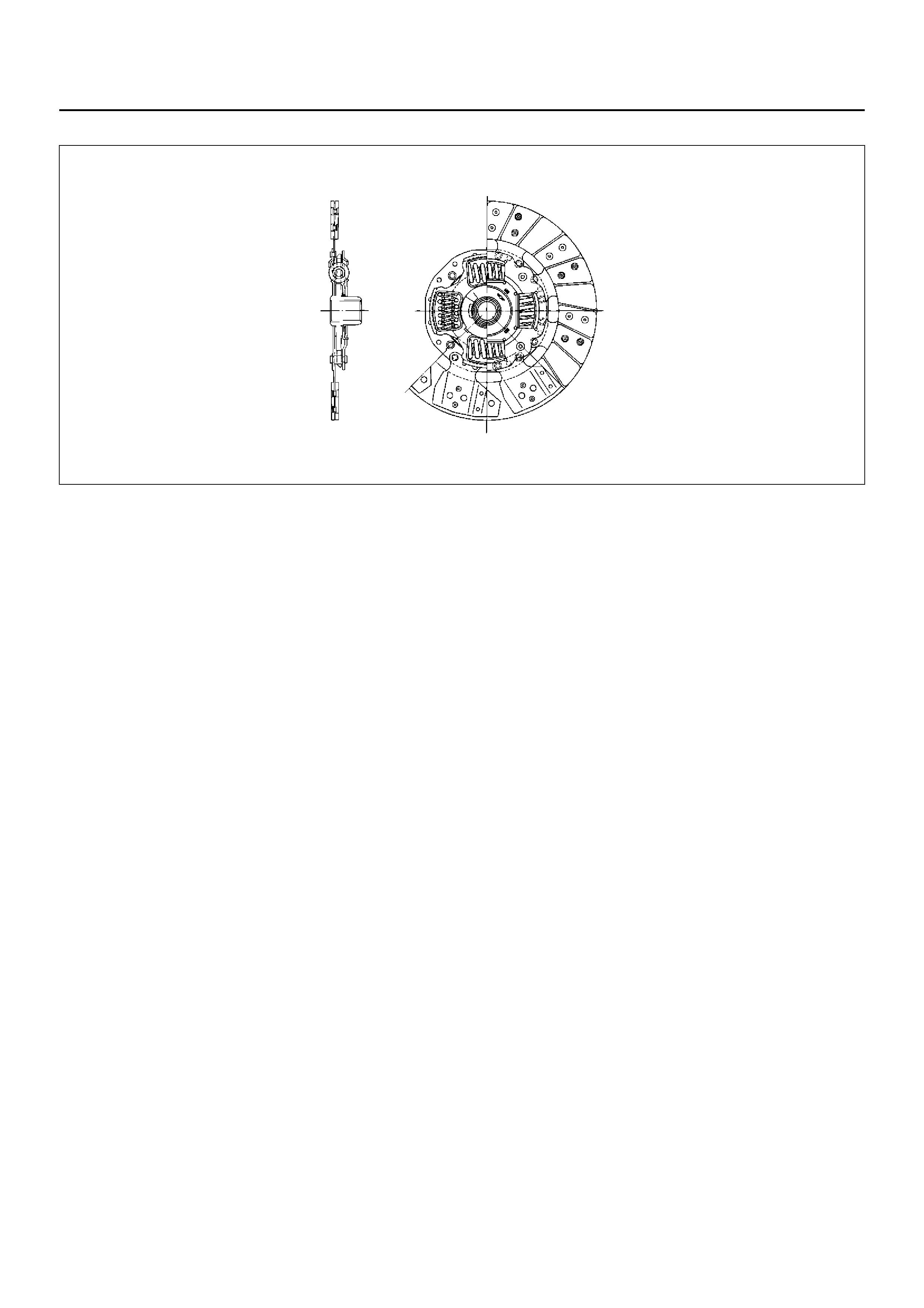
Driven Plat e Assembly
A07RW027
The driven plate ass embly consi sts of the plate and the
facing.
The plate consists of the clutch center, the cushioning
plate, and the torsi on springs .
The facing is riveted to both sides of the cushioning
plate.
The cushioning plate provides a longer service life by
minimizing wear and vibration at the clutch contact
surfaces.

DIAGNOSIS
Condition Possible cause Correcti on
Dragging Air in circuit. Bleed and check for damage.
Driven plate worn or warped. Replace.
Clutch fork off the ball stud. Install correctly and lubricate.
Diaphragm spring weak or tip of
fingers worn. Replace.
Driven plate sticking on splines. Clean and free splines and lubricate
with grease.
Pilot bearing worn or damaged. Replace.
Master cylinder and slave cylinder
seals worn. Replace.
Slipping Clutch facing worn. Replac e.
Driven plate friction pads worn or
oilsoaked. Replace and check for leaks as
needed.
Diaphragm spring weak. Replace pressure plate.
Pressure plate or flywheel warped. Replace.
Master cylinder and slave cylinder
seals worn. Replace as needed.
Chattering Clutch facing in poor contact or
facing warped. Replace.
Surface of faci ng har den ed. Replac e.
Driven plate friction pads oil soaked. Replace and check for leaks.
Damper springs weakened or
broken. Replace.
Rivets on clutch plate loosened. Replace.
Pressure plate or flywheel warped. Replace as needed.
Rattling Diaphragm spring weak. Replace the pressure plate.
Clutch fork loose or off the ball stud. Replace the retaining spring or
install the fork correctly.
Driven plate springs weak or oil in
the damper. Replace and check for leaks as
needed.
Release bearing noisy with the
clutch engaged Release bearing binding. Clean, or replace if damaged, and
lubricate.
Clutch fork off the ball stud or loose
spring tension. Install correctly, and lubricate.
Linkage return springs weak. Replace.
Noisy Release bearing worn or damaged. Replace.
Clutch fork off the ball stud. Install correctly and lubricate.
Pilot bearing loose. Replace.
Pedal stays on the floor when
disengaged Replace bearing binding. Free up, or replace, and lubricate.
Diaphragm spring weak. Replace the pressure plate.
Pedal is hard to push down Hydraulic line blocked or crimped. Clean out or replace.
Master or slave cylinders bindinig. Repair or replace as needed.
Driven plate worn. Replace.
Squeaking Ball stud not lubricated or incorrectly
lubricated. Lubricate with high temperature
grease.
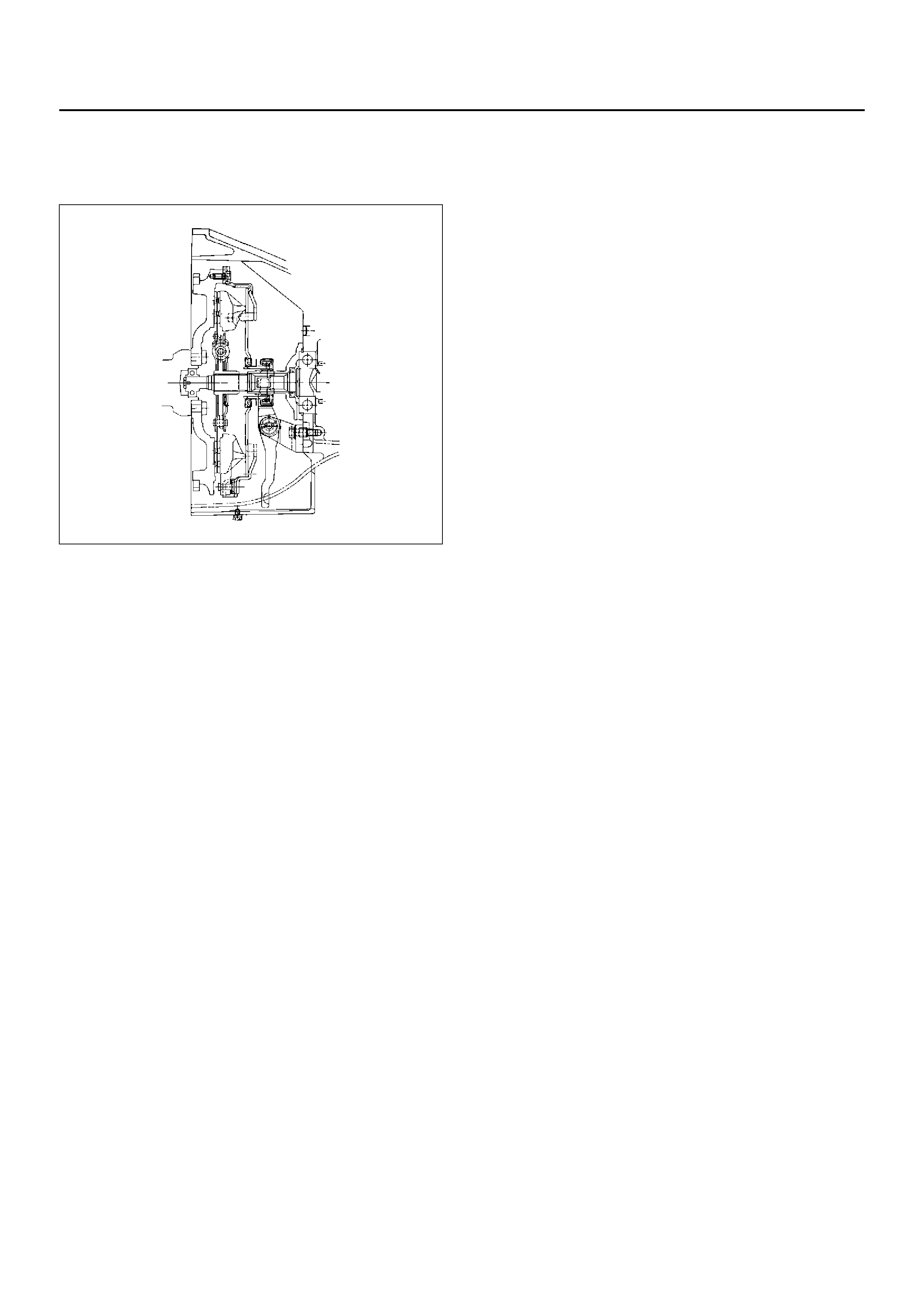
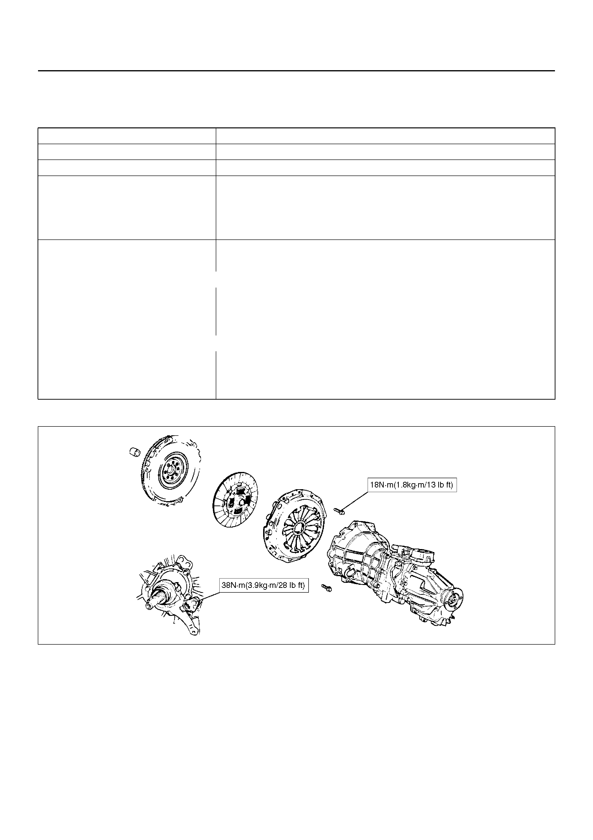
CLUTCH ASSEMBLY
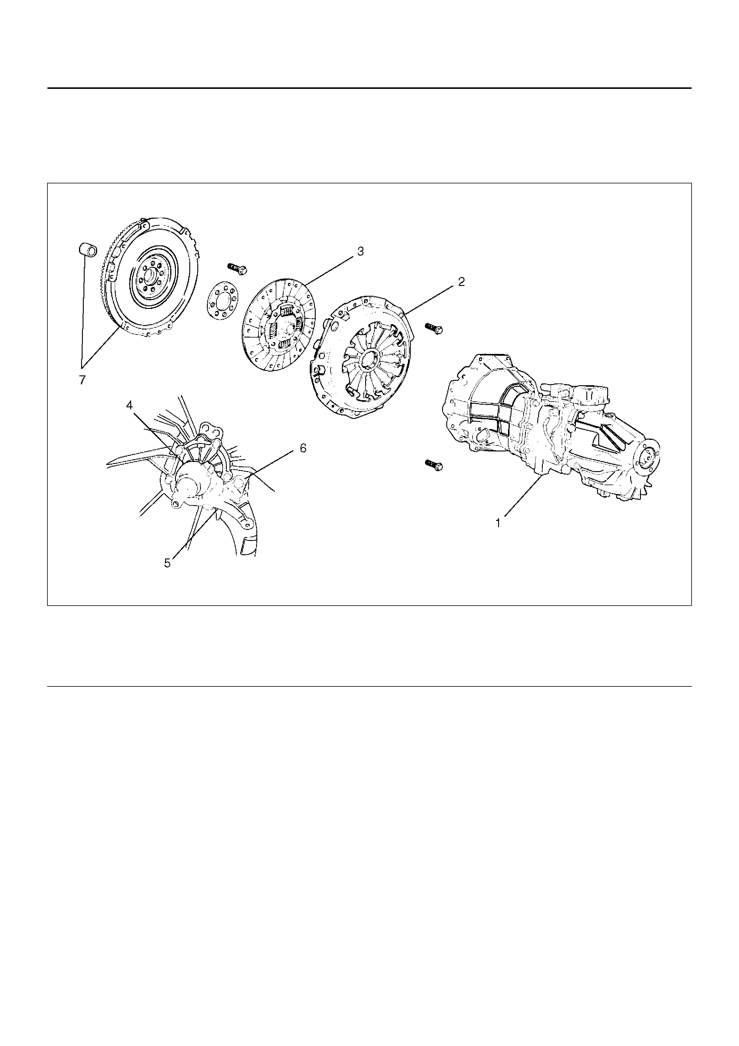
CLUTCH ASSEMBLY AND ASSOCIATED PARTS
201RS023
EndOFCallout
REMOVAL
1. Refer to “Manual Transmission" of Section 7B for
“Removal and Installation" procedure of the
transmission assembly (1).
Legend
(1) Transmission Assembly
(2) Press ur e Pl ate Assembly
(3) Driven Plate Assembly
(4) Release Bearing
(5) Shift Fork
(6) Fulcrum Bridge
(7) Flywheel Assembly and Crankshaft Bearing

2. Use the pilot aligner J24547 to prevent the driven
plate assembly (3) from falling free.
201RS001
EndOFCallout
3. Mark the flywheel, clutch cover and pressure plate
lug for alignment when installing.
4. Remove the release bearing (4) from the
transmission case.
201RS024
5. Remove the snap pin. Remove the shift fork pin
and shift fork from the fulcrum bridge.
201RS025
6. Remove the fulcrum bridge bolts. Remove the
fulcrum bridge (6) from the transmission case.
201RS026
• Do not remove crankshaft spigot bearing (7)
except for replacement.
Legend
(2) Press ur e Pl ate Assembly
(3) Driven Plate Assembly
(8) Pilot Aligner
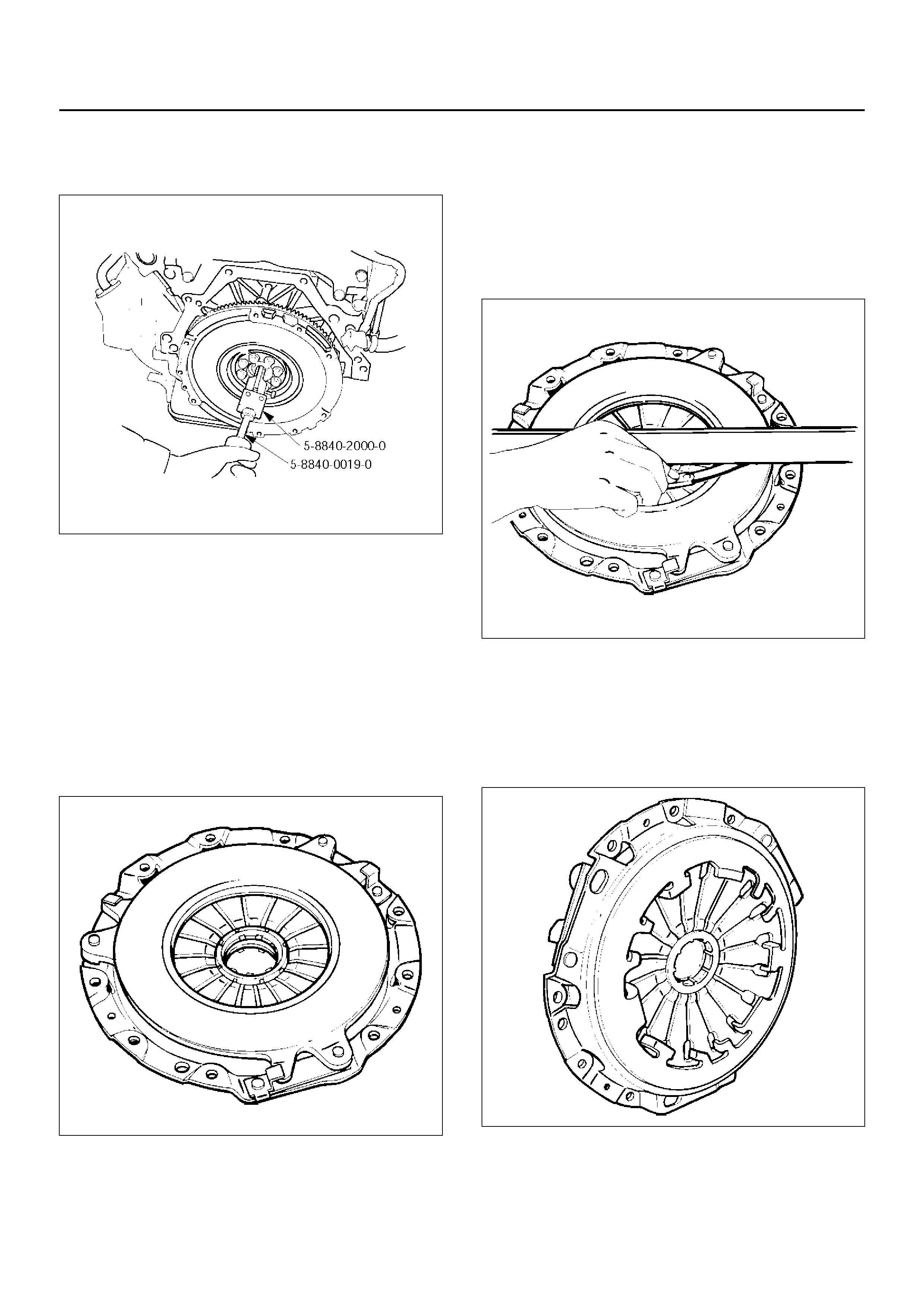
• Use the remover 5–8840–2000–0 and sliding
hammer 5–8840–0019–0 to remove the
crankshaft spigot bearing.
015RW053
INSPECTION AND REPAIR
Make necessary correction or parts replacement if wear ,
damage, or any other abnormal condition are found
through inspection.
Pressure Plate Asse mbly
• Visually check the pressure plate friction surface for
excessive wear and heat cracks. If excessive wear or
deep heat cracks are present, the pressure plate
must be replaced.
201RS002
Pressure Plate Warpage
• Use a straight edge and a feeler gauge to measure
the pressure plate friction surface flatness in four
direct ions. If any of the meas ured valu es exc eed the
specified limit, the pressure plate must be replaced.
Pressu re Pla te Wa rpage
Limit: 0.3 mm
201RS003
Clutch Cover
• Visually check the entire clutch cover for excessive
wear, cracking, and other damage. The clutch cover
must be replaced if any of these conditions are
present.
201RS004
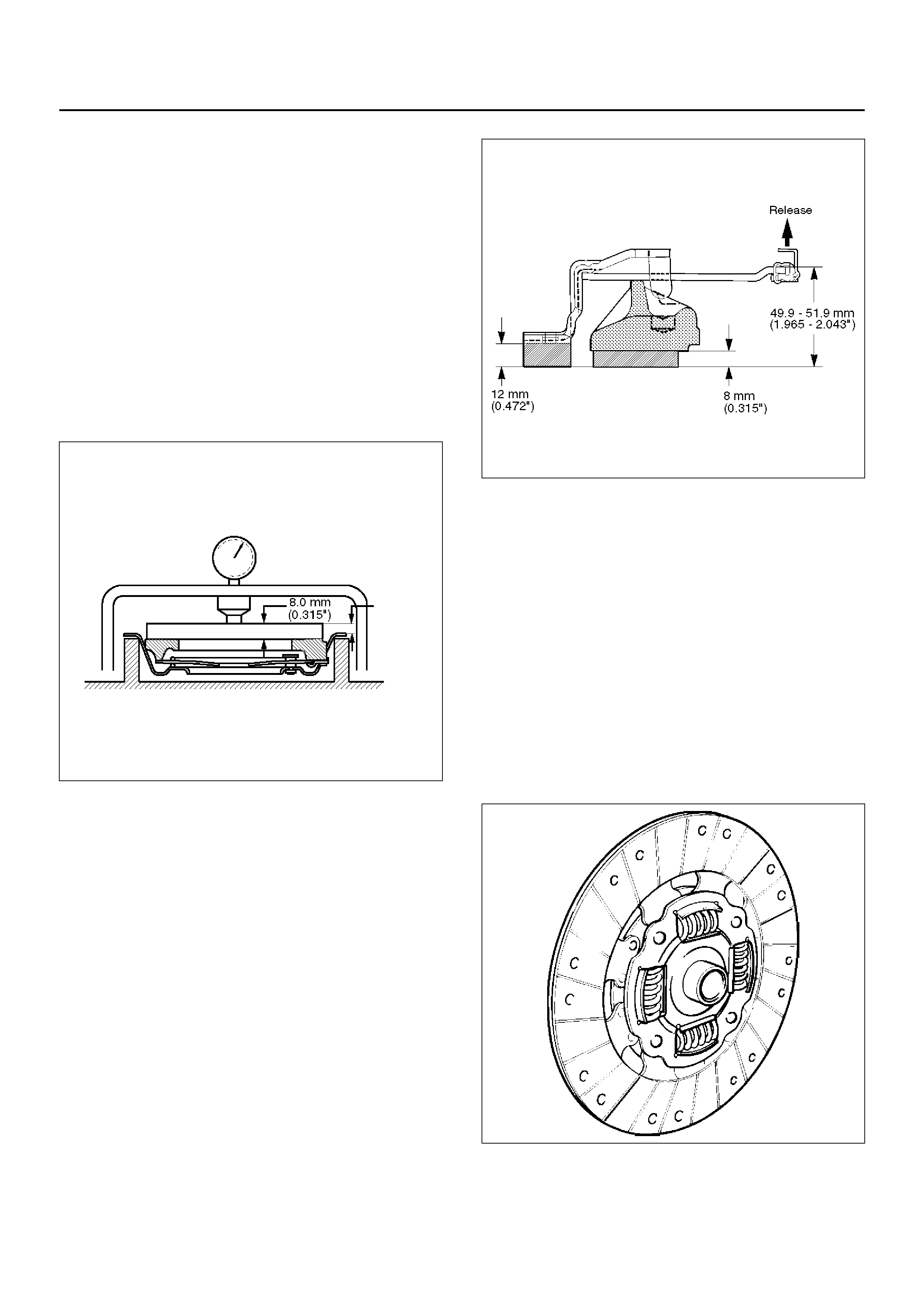
Clutch Set Force
1. Invert the pressure plate assembly.
2. Place a new driven plate over the pressure plate.
An 8.0mm thick piece of sheet metal may be used in
place of the driven plate.
3. Compress the pressure plate assembly until the
distance (A) is12m m.
4. Note the pressure gauge reading. If the measured
value is less than the specified limit, the pressure
plate assembly must be re placed.
Clutch Set Force
Standard: 7208N
Limit: 6670N
201RW014
Diaphragm Spring Finger Height
1. Place a new driven plate or a 8.0mm spacer
beneath the pr ess ure pla t e.
2. Fully compress the pressure plate and diaphragm
spring.
There are two ways to do this:
a Use a bench press to press down on the
assembly from the top.
b Tighten the fixing bolts.
Preload on diaphragm spring finger must be 5000N in
direction of release, when clutch cover assembly is
bolted to the flywheel.
3. Measur e the spr ing he igh t fr om b ase to s pring ti p. If
the me asured value ex ceeds the specifi ed limit, the
pressure plate assembly must be replaced.
Spring Finger Height
Standard: 49.9 – 51.9 mm
201RW016
Driven Plate Assembly
• Visually check the torsion spring for looseness,
breakage, and weakening. If any of these conditions
are discovered, the driven plate assembly must be
replaced.
• Visually check the facing surfaces for cracking and
excessive scorching. Visually inspect the facing
surfaces for the presence of oil or grease. If any of
these conditions are discovered, the facing must be
cleaned or replaced.
• Check that the driven plate moves smoothly on the
transmission top gear shaft spline. Minor ridges on
the top gear s haft spline may be removed with an oil
stone.
201RS007
(A)
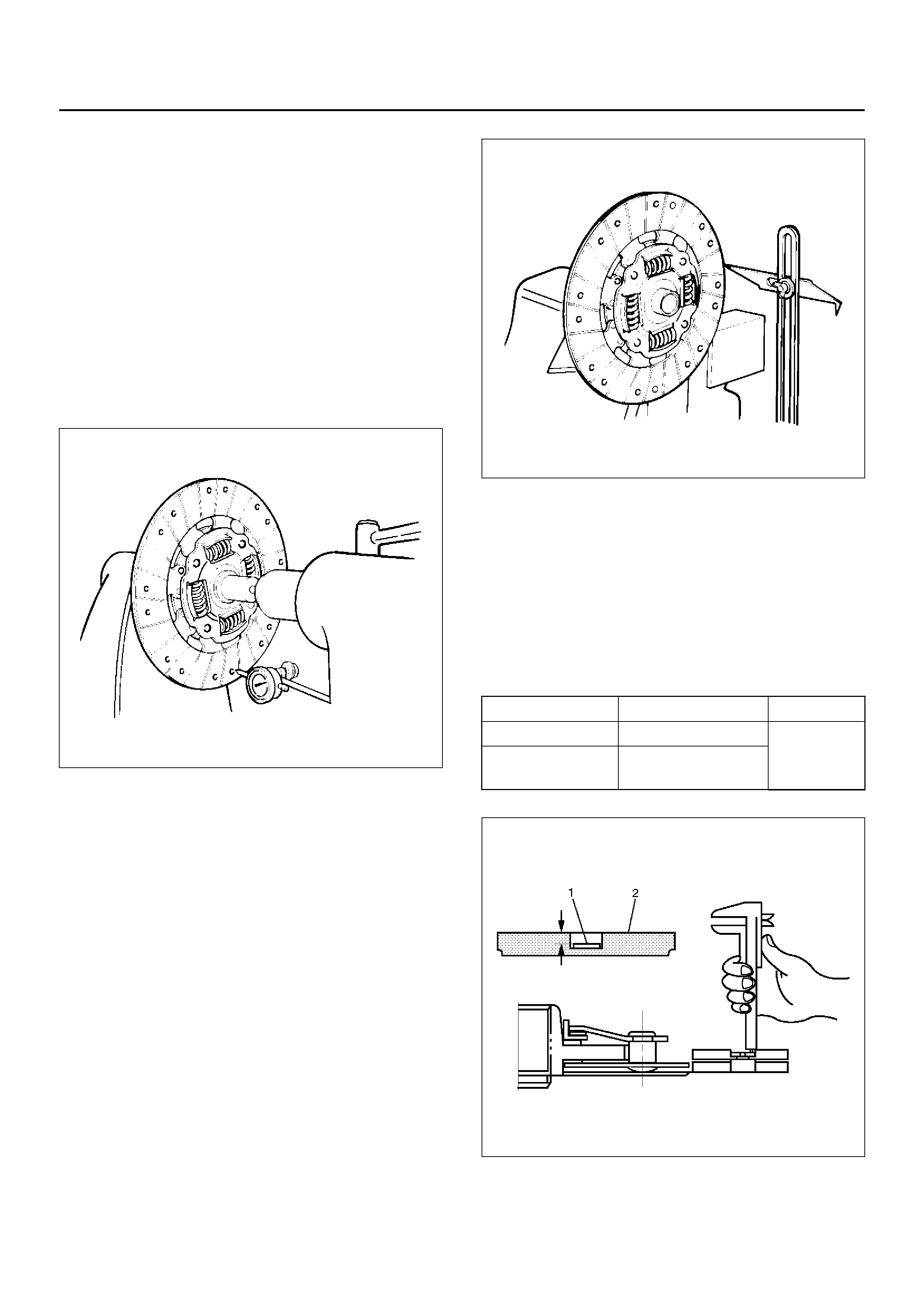
Driven Plat e Warpa ge
1. Insert the clutch pilot aligner J–24547 into the driven
plate splined hub. The clutch pilot aligner must be
held perfectly horizontal.
2. Set a dial indicator to the driven plate outside
circumference.
3. Slowly turn th e driven plate. Re ad the dial indi cator
as you turn the driven plate. If the m easured valu e
exceeds the specified limit, the driven plate
assembly must be replaced.
Driven Plate Warpage
Standard: 0.7mm
Limit: 1.0mm
201RS008
Driven Plate Splined Hub Spline Wear
1. Clean the driven plate splined hub.
2. Install the driven plate to the transmission top gear
shaft spline.
3. Set a surface gauge to the driven plate outside
circumference.
4. Slowly turn the driven plate counterclockwise.
Measure the spline rotation play as you turn the
driven plate. If the measured value exceeds the
specified limit, the driven plate assembly must be
replaced.
Driven Plate Warpage
Standard: 0.5mm
Limit: 1.0mm
201RS009
Rivet Head Depression
• Use a depth gauge or a straight edge with steel rule
to measure the rivet head depression (1) from the
facing surface (2).
• Be sure to measure the rivet head depression on
both sides of the driven pl ate. If the measu red value
is less than the specified limit, the driven plate
assembly must be replaced.
Rivet Head Depression
201RS010
Standard Limit
Fly wheel side 1.2–1.8mm 0.2mm
Pressure plate
side 1.6–2.2mm
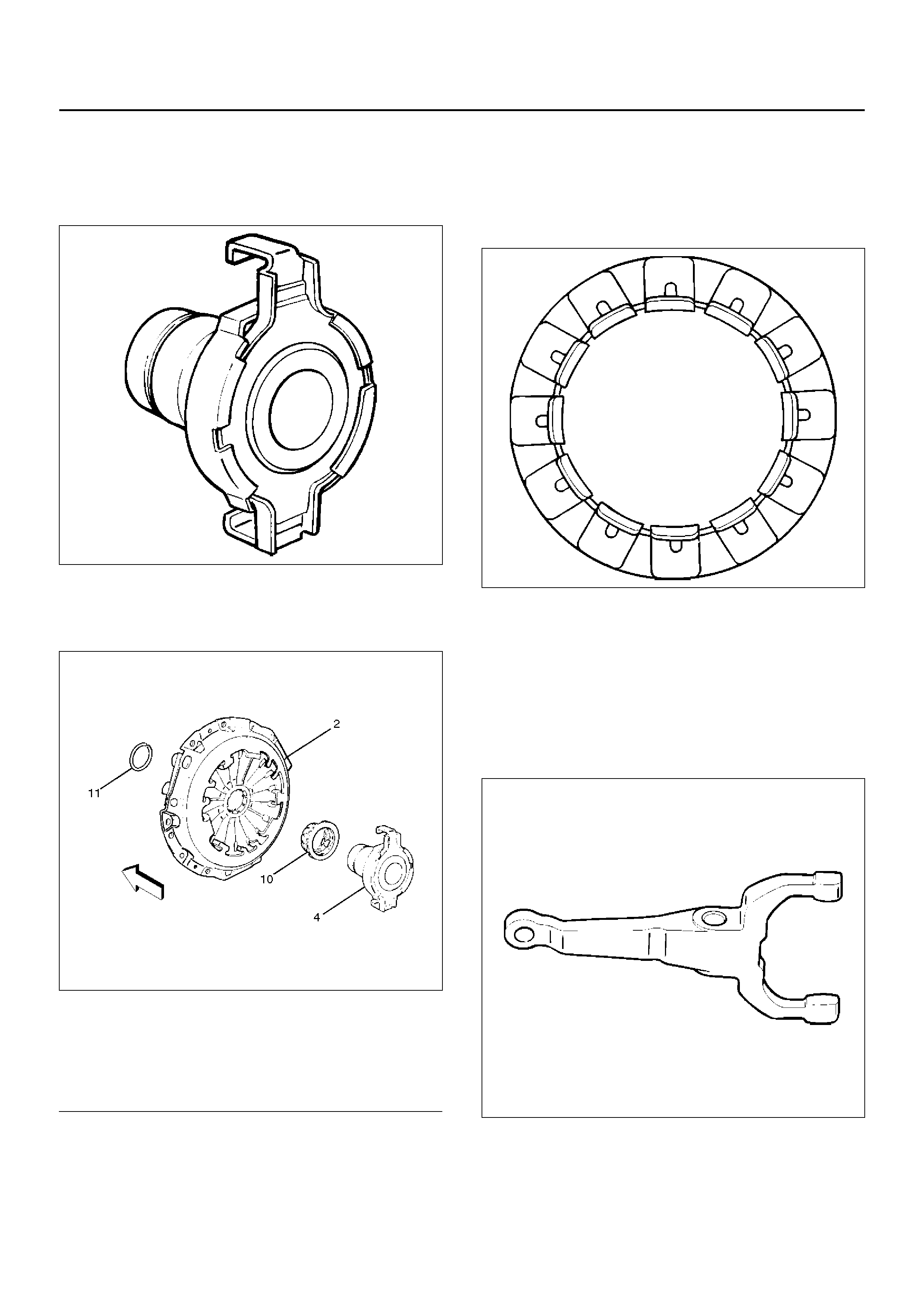
Release Bea ri ng
• V isually check the release bearing for excessive play,
noise a nd br eakag e. I f any of thes e con ditions are
discovered, the release bearing must be replaced.
201RS011
• When replacin g the releas e bearing (4), rep lace both
the wedge collar (10) and wire ring (11) at the same
time.
201RS012
EndOFCallout
Wedge Collar (10)
• Visually check the surfaces of the wedge collar
making contact with the release bearing for excessive
wear and damage .
• Replace exhibiting excessive wear or damage.
201RS013
Shift Fork
• Visually check the surfaces of the shift fork making
contact with the release bearing for excessive wear
and damage.
• Remove any minor stepping or abrasion from shift
fork with an oil stone. Replace exhibiting excessive
wear or damage.
201RS014
Legend
(2) Press ur e Pl ate Assembly
(4) Release Bearing
(10) Wedge collar
(11) Wire Ring
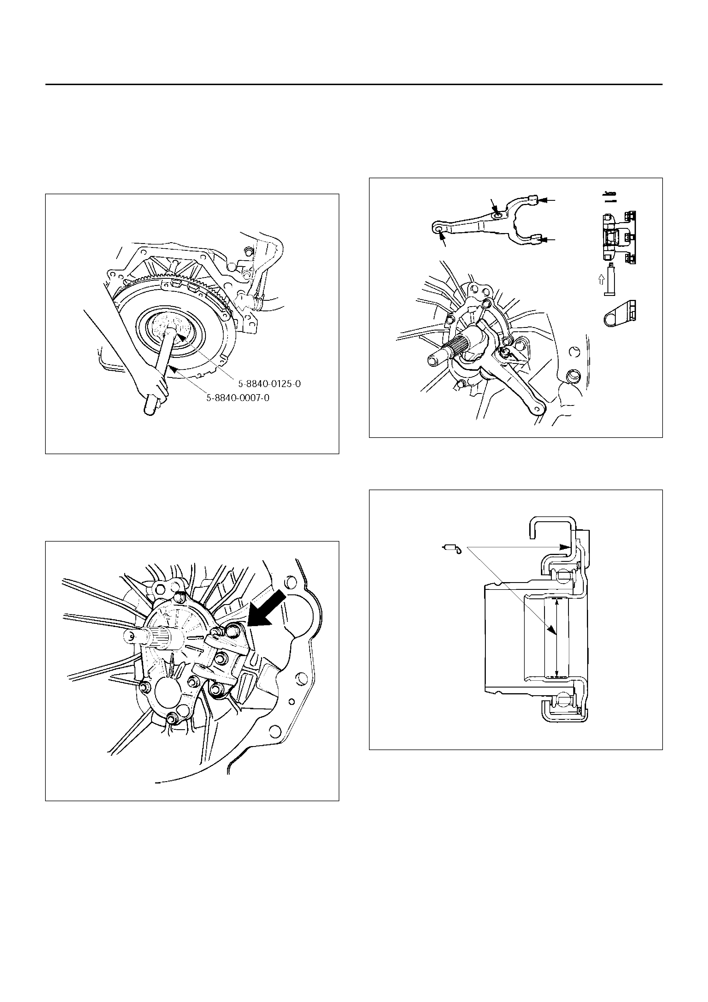
INSTALLATION
1. Clean and lubricate with grease.
2. Use the installer 5–88 40–0125–0 and driver han dle
5–8840–0007–0 to install the crankshaft spigot
bearing (7).
015RW054
3. Install the fulcrum bridge (6) to the transmission
case. Tighten three fulcrum bridge bolts to the
specified torque.
Torque: 38 Nm
201RS026
4. Apply molybdenum disulfide type grease to the pin
hole inner circumferences and thrust surfaces.
Attach the shift fork (5) to the fulcrum bridge (6) and
insert the pin from below of the fulcrum bridge.
Install the washer and snap pin.
201RS018
5. Apply molybdenum disulphide type grease to the
areas shown in the figure.
201RW012
Install the release bearing (4) in the correct
direction.
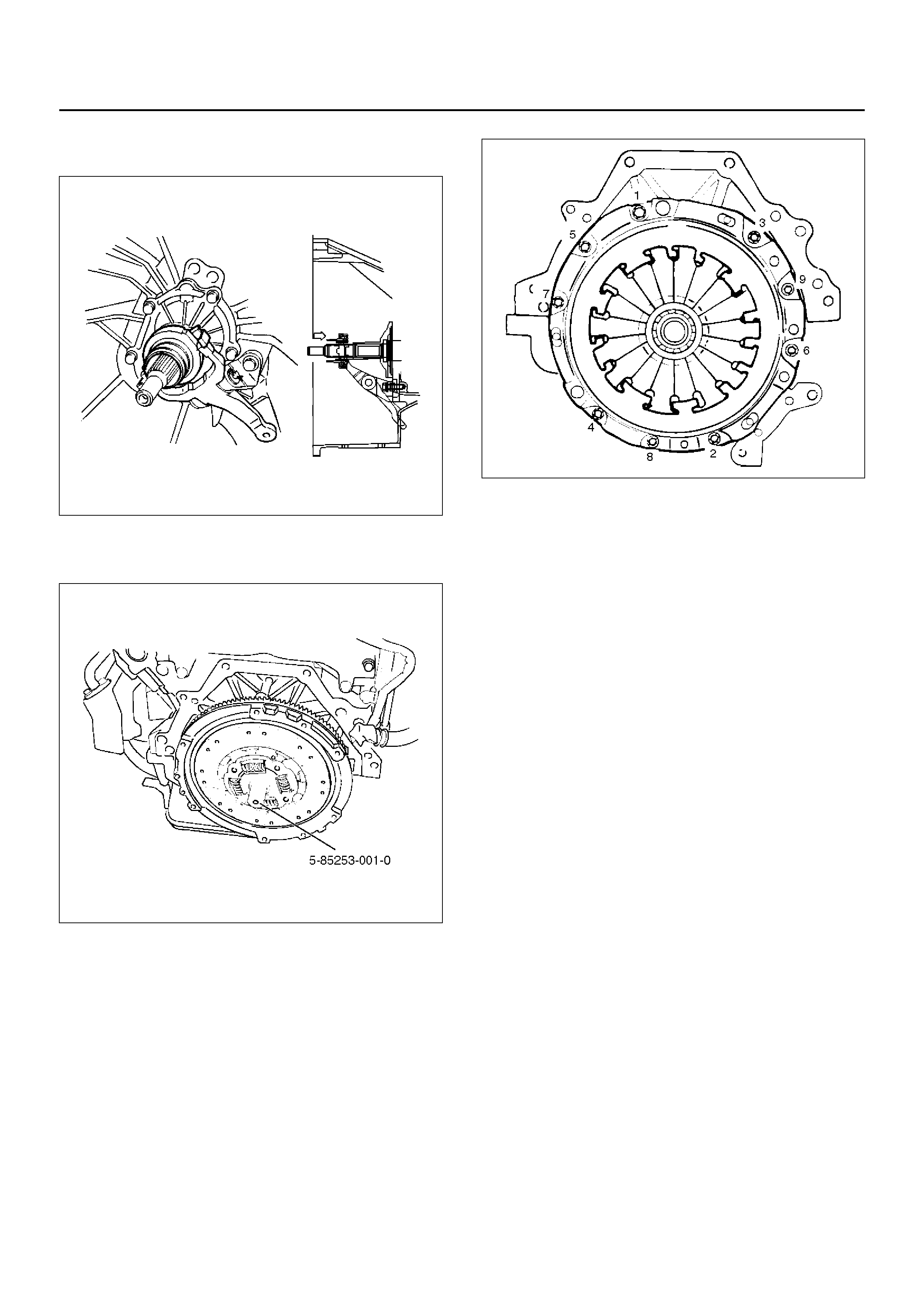
NOTE: Ensure release bearing is properly positioned
during installation, as shown in the figure.
201RS019
6. Use the pilot aligner 5–85253–001–0 to install the
driven plate assembly (3).
201RX004
7. Tighten the bolts holding the pressure plate
assembly (2) in the order shown in the figure.
201RS017
Torque: 18 Nm
8. Remove the aligner.
Do not strike the aligner with a hammer to remove it.
9. Install transmission assembly to the engine.
CLUTCH CONTROL
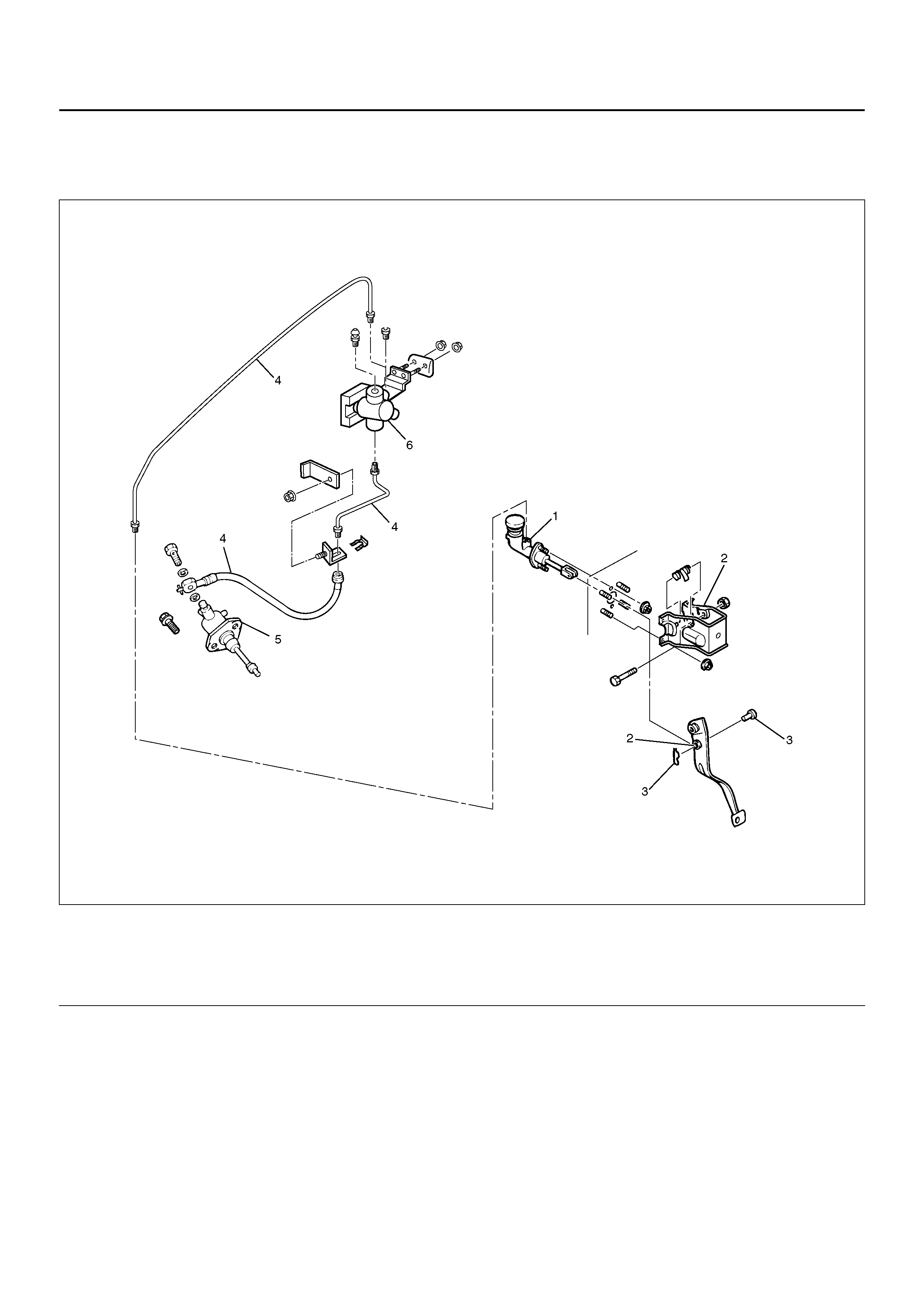
PARTS LOCATION VIEW
203R100001
EndOFCallout
Legend
(1) Master Cylinder Assembly
(2) Pedal Assembly
(3) Pin and Jaw Joint Pin
(4) Oil Line Pipe and Hose
(5) Slave Cylinder Assembly
(6) Damper Cylinder Assembly
REMOVAL
1. Disconnect the ground battery cable.
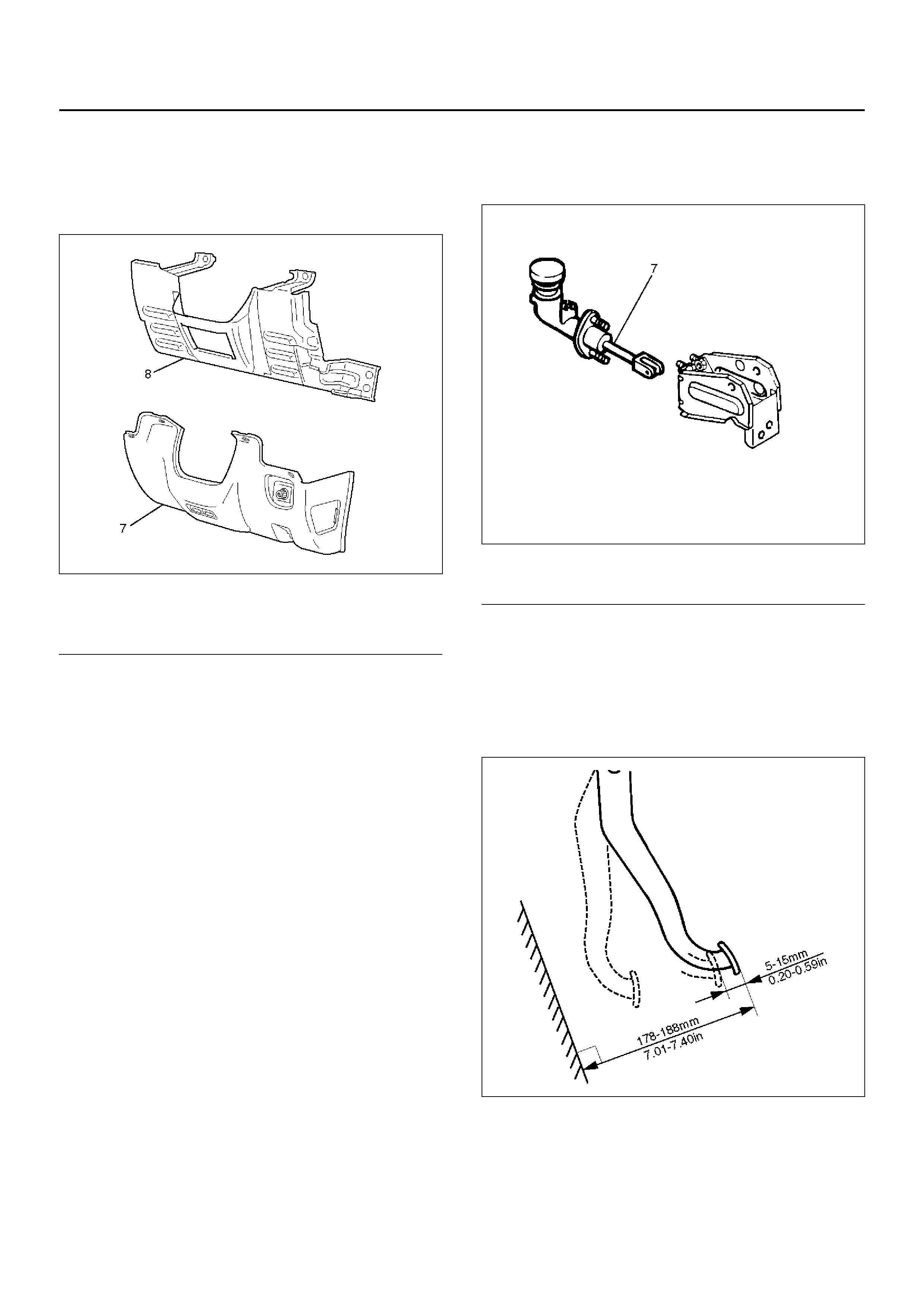
2. Remove the instrument panel lower cover (7) and
driver knee bolster panel assembly (8).
740RW162
EndOFCallout
3. Remove pin and jaw joint pin (3).
4. Remove pedal assembly (2).
5. Remove oil line pipe (4).
6. Remove slave cylinder assembly (5).
7. Remove master cylinder assembly (1).
8. Remove damper cylinder assembly (6).
9. Remove oil line hose (5).
INSPECTION AND REPAIR
Make necessary adjustments, repairs, and part
replacements if wear, damage or other problems are
discovered during inspection.
INSTALLATION
Clutch Pedal Adjustment
208RX004
EndOFCallout
1. Loosen clutch master cylinder push rod lock nut.
Turn push rod by hand to set clutch pedal height to
within specification. Tighten push rod lock nut.
Clutch Pedal Height
178 – 188 mm (7.01 – 7.40 in)
F07RW026
2. For vehicles with cruise control, refer to Section 12 -
Cruise Control for clutch switch adjustment.
F07RW027
Legend
(7) Driver Lower Cover
(8) Driver Knee Bolster Panel
Legend
(7) Push Rod
3. After adjusting the clutch pedal height, push the
clutch ped al b y ha nd to ens ure the cl utch ped al fre e
play is within specification.
Pedal Free Pla y
5 – 15 mm
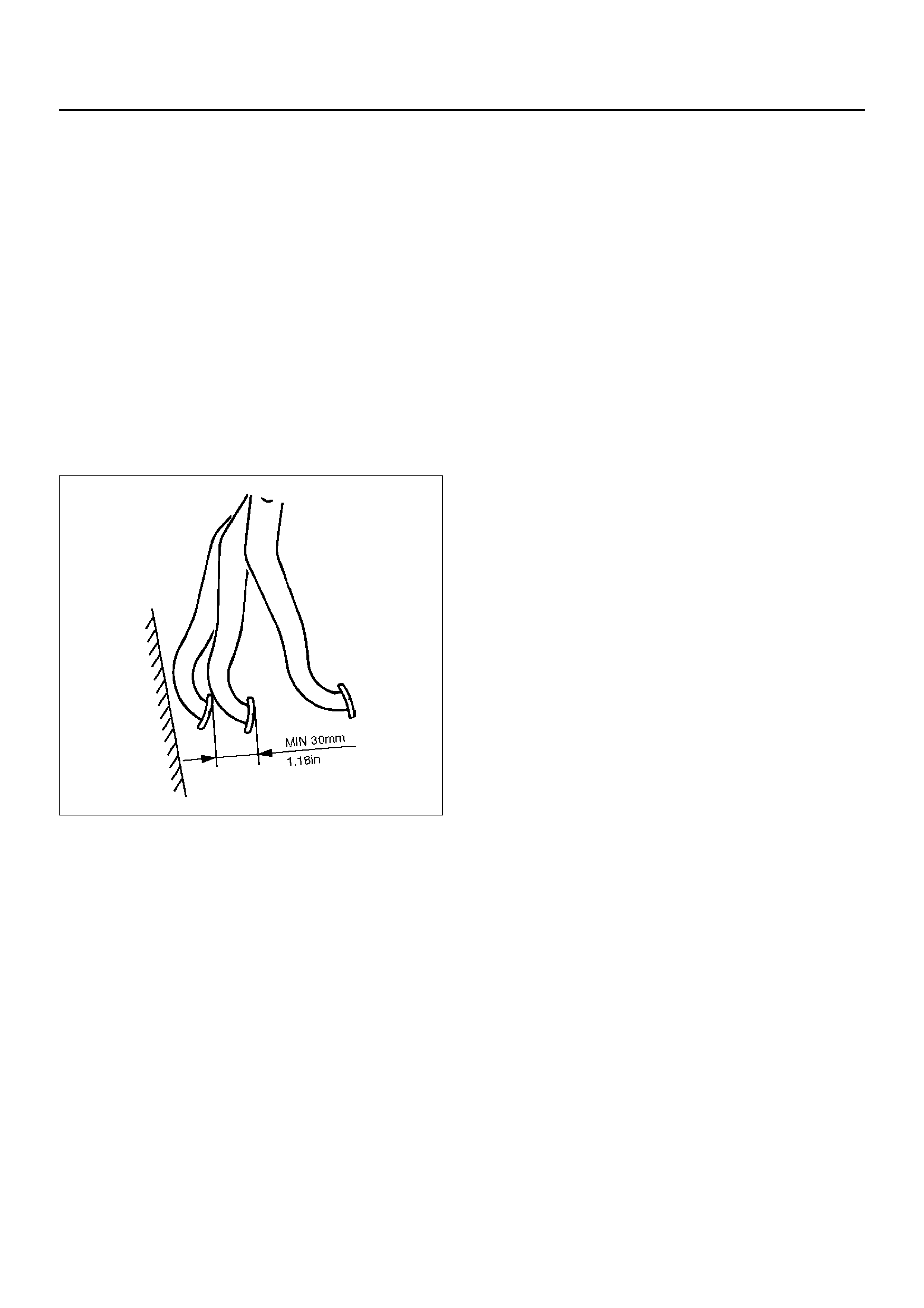
4. Perform clutch pedal engagement height inspection:
1. Operate the parking brake lever and block the
wheels.
2. Start the engine, fully step on the clutch pedal
slowly and move the shift lever 1st position.
3. With the engine idling, release the clutch pedal
slowly and measure its stroke - just prior to its
clutching position.
Clutch Pedal Engagement Height (H3)
MIN. 30 mm
F07RW028
5. If the measured value exceeds the specified limit,
check the following points and repair if necessary:
• Hydraulic circuit for fluid leakage or air in circuit.
• Clutch disc warped.
• Diaphragm spring weakened or tip of fingers
worn.
• Driven plate sticking on sprines.
• Release bearing worn or damaged.
• Master cylinder and slave cylinder worn.
Torque
•Master cylinder to dash panel
16 N·m
•Clutch pedal to dash panel
15 N·m
•Master cylinder push rod to yoke
17 N·m
•Clutch pipe to master cylinder
20 N·m )
•Clutch pipe to damper cylinder
12 N·m
•Clutch pipe to flex, hose
20 N·m
•Flexible hose to slave cylinder
20 N·m
•Slave cylinder to case
40 N·m
•Slave cylinder bleeder screw
8 N·m
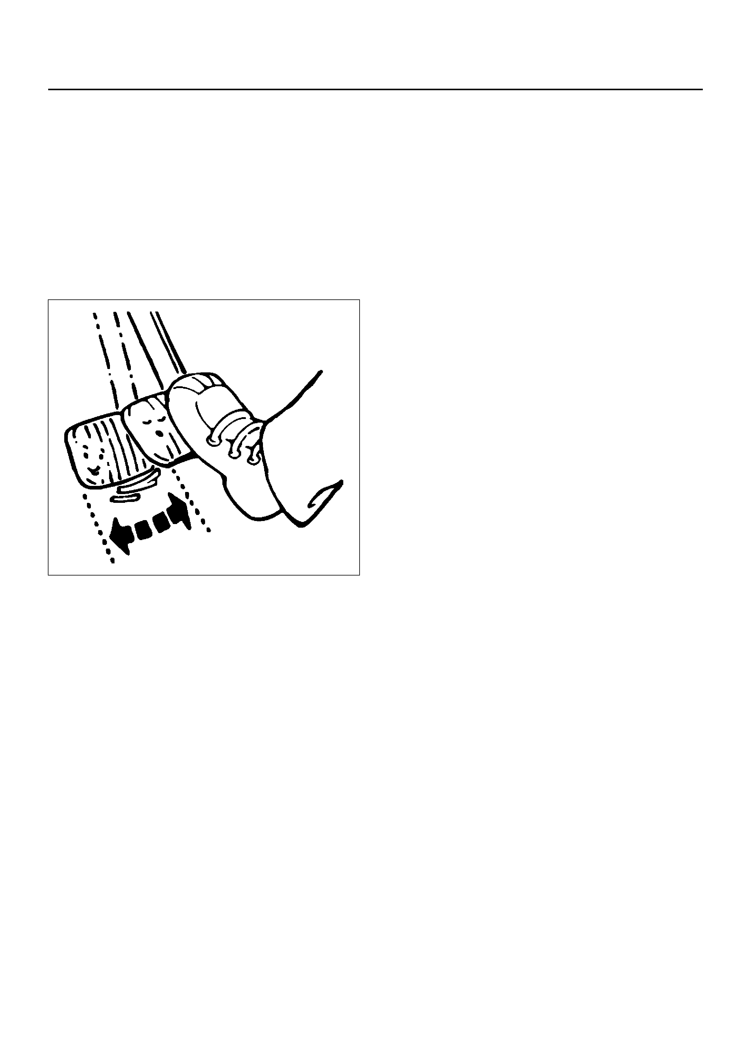
Bleeding
1. Check the level of clutch fluid in the reservoir and
replenish if necessary.
2. Bleedi ng the sl ave cyl inder.
1. Remove the rubber cap from the bleeder screw
and wipe clean the bleeder screw. Connect a
vinyl tube to the bleeder screw and insert the
other end of the vinyl tube into a transparent
container.
2. Pump the clutch pedal repeatedly and hold it
depressed.
203RS005
3. Loosen th e bleed er scr ew to relea se cl utch flui d
with air bubbles into the container, then tighten
the bleeder screw immediately.
4. Release the clutch pedal carefully. Repeat the
above operation until air bubbles disappear from
the clutch fluid being pumped out into the
container. During the bleeding operation, keep
the clutch fluid reservoir filled to the specified
level. Reinstall the rubber cap.
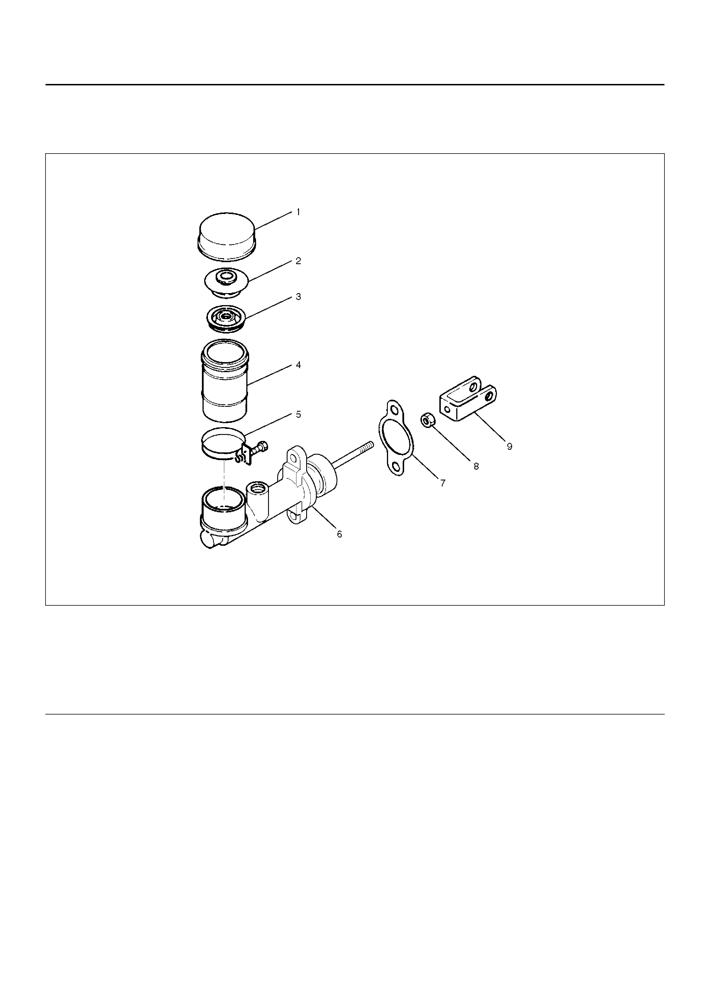
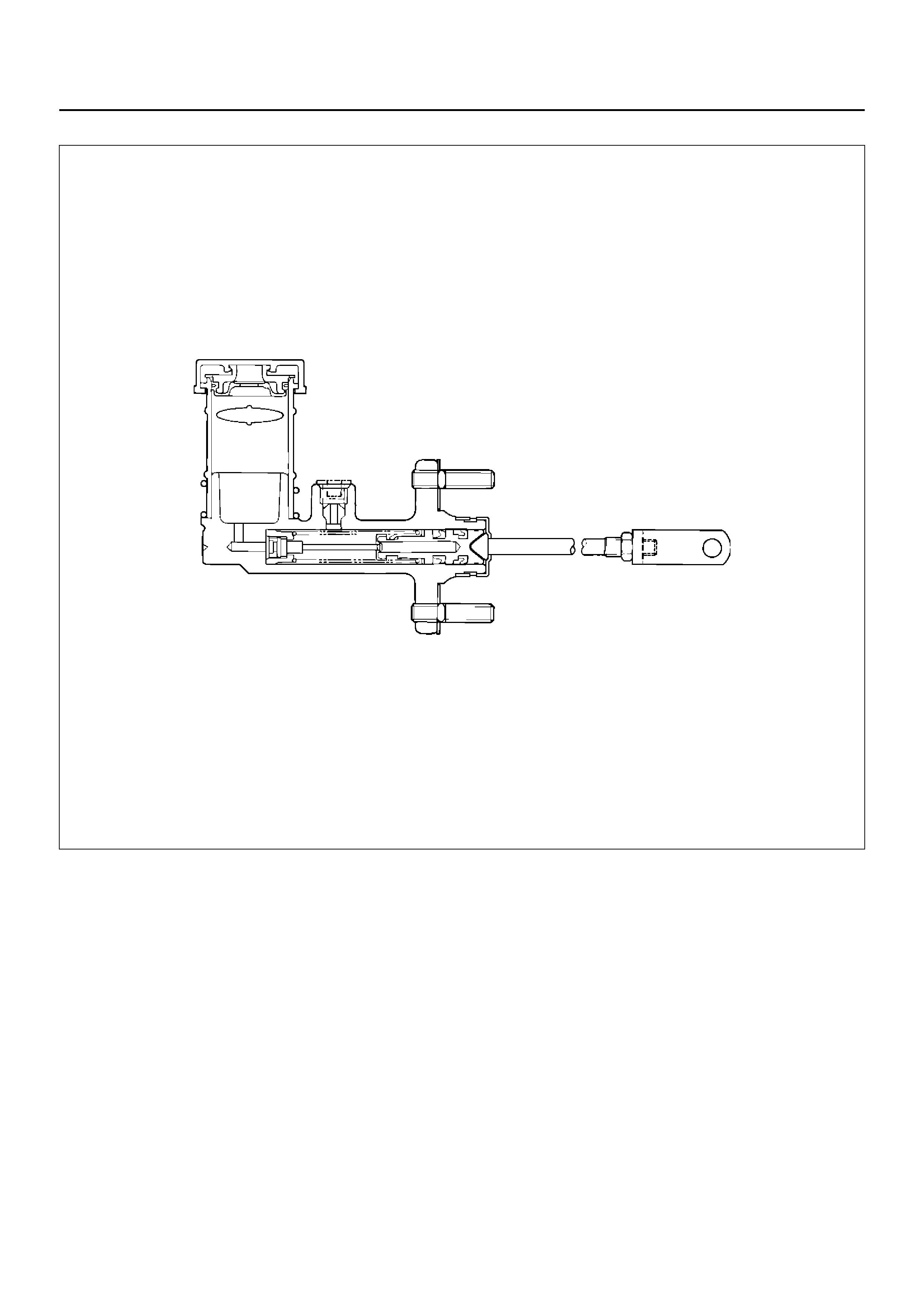
MASTER CYLINDER
208RX003
EndOFCallout
DISASSEMBLY
1. Disassemble reservoir cap (1), inner cap (2), seal
(3), clip (5), and reservoir (4).
2. Disassembly gasket (7), yoke (9), nut (8) and body
sub assembly.
INSPECTION AND REPAIR
Make the necessary adjustments, repair, and part
replacements if excessive wear or damage is
discovered during inspection.
REASSEMBLY
To reassemble, follow the disassembly steps in the
reverse or der.
Legend
(1) Reservoir Cap
(2) Inner Cap
(3) Seal
(4) Reservoir
(5) Clip
(6) Body Sub Assembly
(7) Gasket
(8) Nut
(9) Yoke
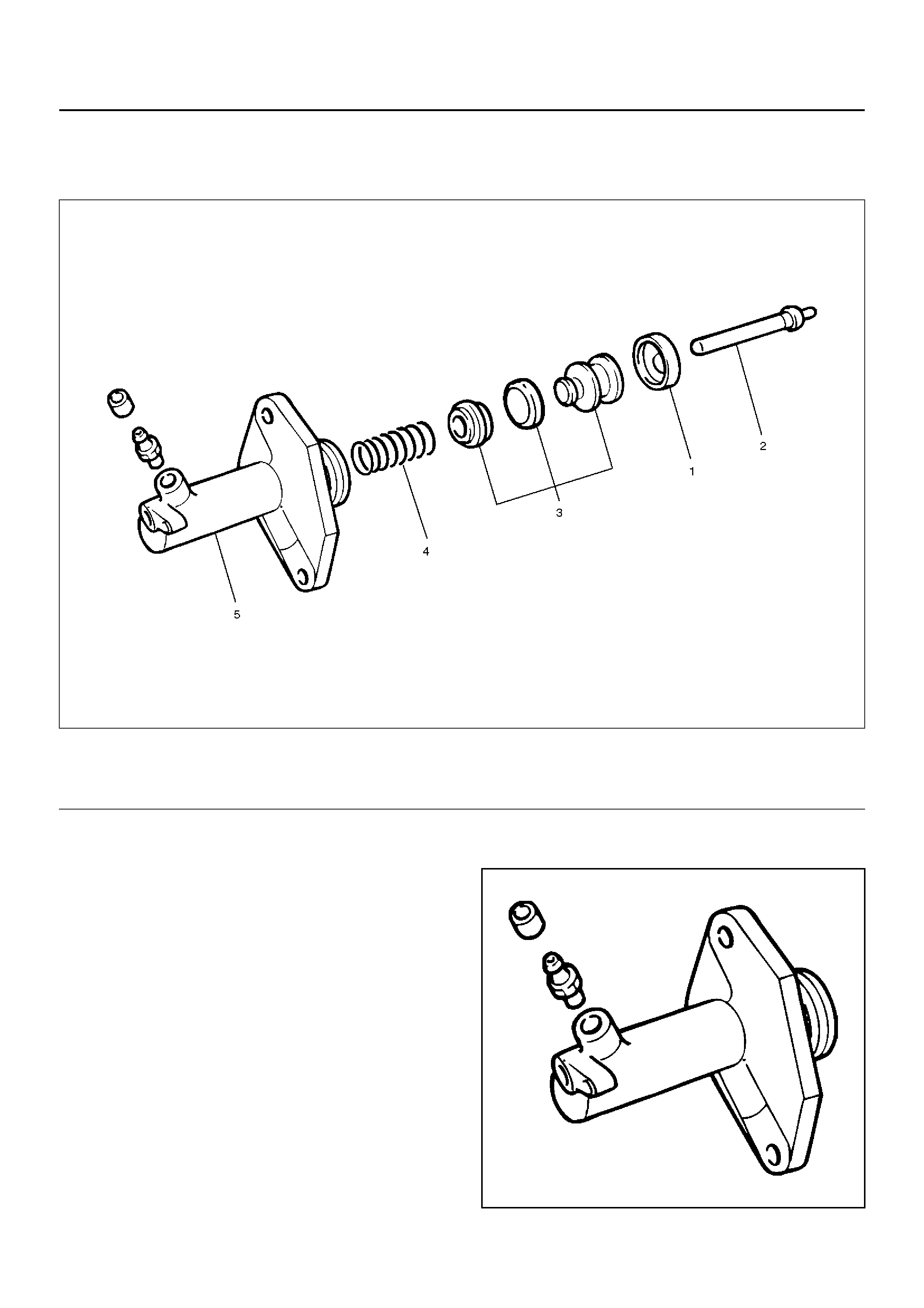
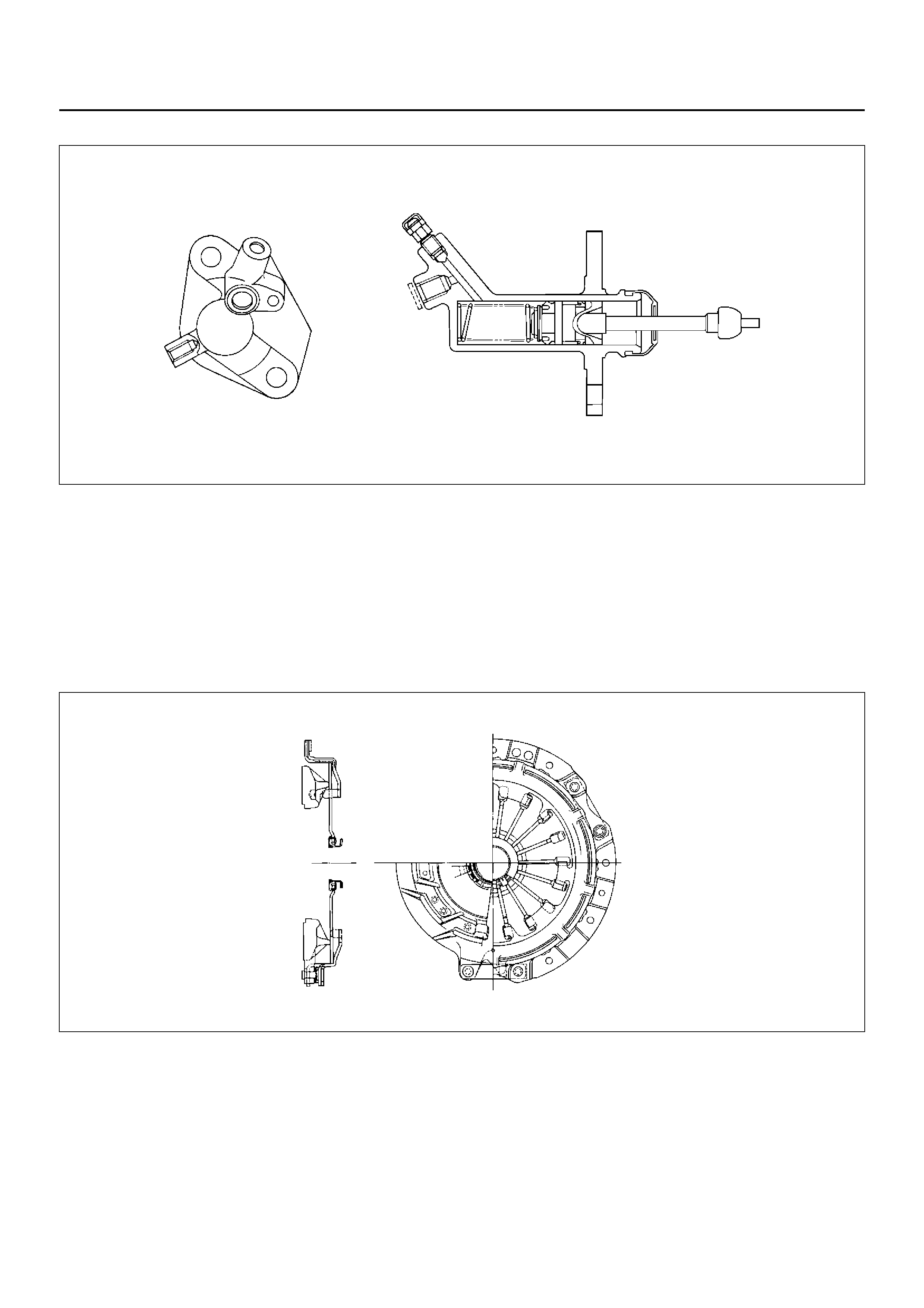
SLAVE CYLINDER
DISASSEMBLED VIEW
206RS002
EndOFCallout
DISASSEMBLY
1. Disassemble boot (1), push rod (2), piston and
piston cup (3), and spring (4) from cylinder body (5).
INSPECTION AND REPAIR
Make the necessary adjustments, repairs, and part
replacements if excessive wear or damage is
discovered during inspection.
Cylinder Body
1. Clean the cylinder body.
2. Chec k the fluid return port for rest rictions and clea n
it if necessary.
206RS003
Legend
(1) Push Rod
(2) Boot
(3) Piston and Piston Cup
(4) Spring
(5) Cyli n de r Bo d y
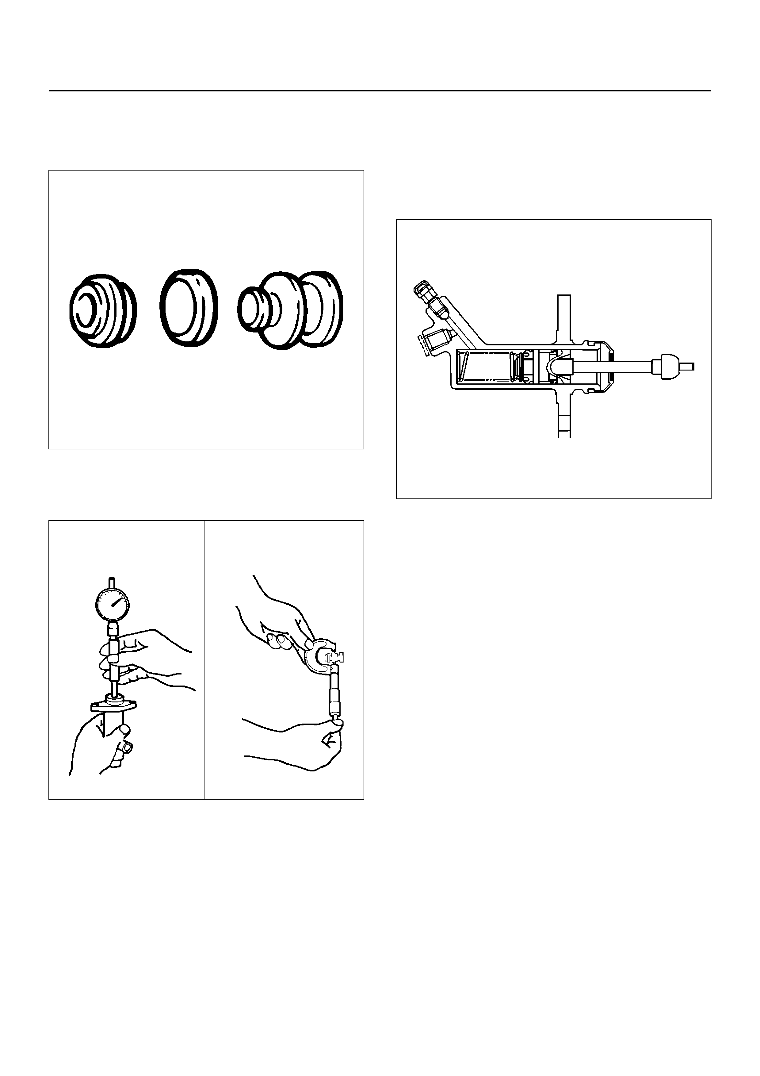
Piston and Piston Cup
1. Visually inspect the disassembled piston and piston
cup for excessive wear and damage.
206RS004
Replace the inner parts with new parts if necessary.
2. Measure the clearance between slave cylinder wall
and piston.
206RS005
If the measured value exceeds the specified limit,
the slave cylinder assembly must be replaced.
Standard: 0.07 mm (0.0028 in)
Limit: 0.15 mm (0.0059 in)
REASSEMBLY
To reassemble, follow the disassembly steps in the
reverse or der, noting the following points:
Piston Assembly
1. Before installing the parts, apply a thin coat of
rubber grease.
2. Install cup in groove in piston with the lip turned to
the front o f cylinder. Us e care so as n ot to scratch
the cylinder.
206RS006
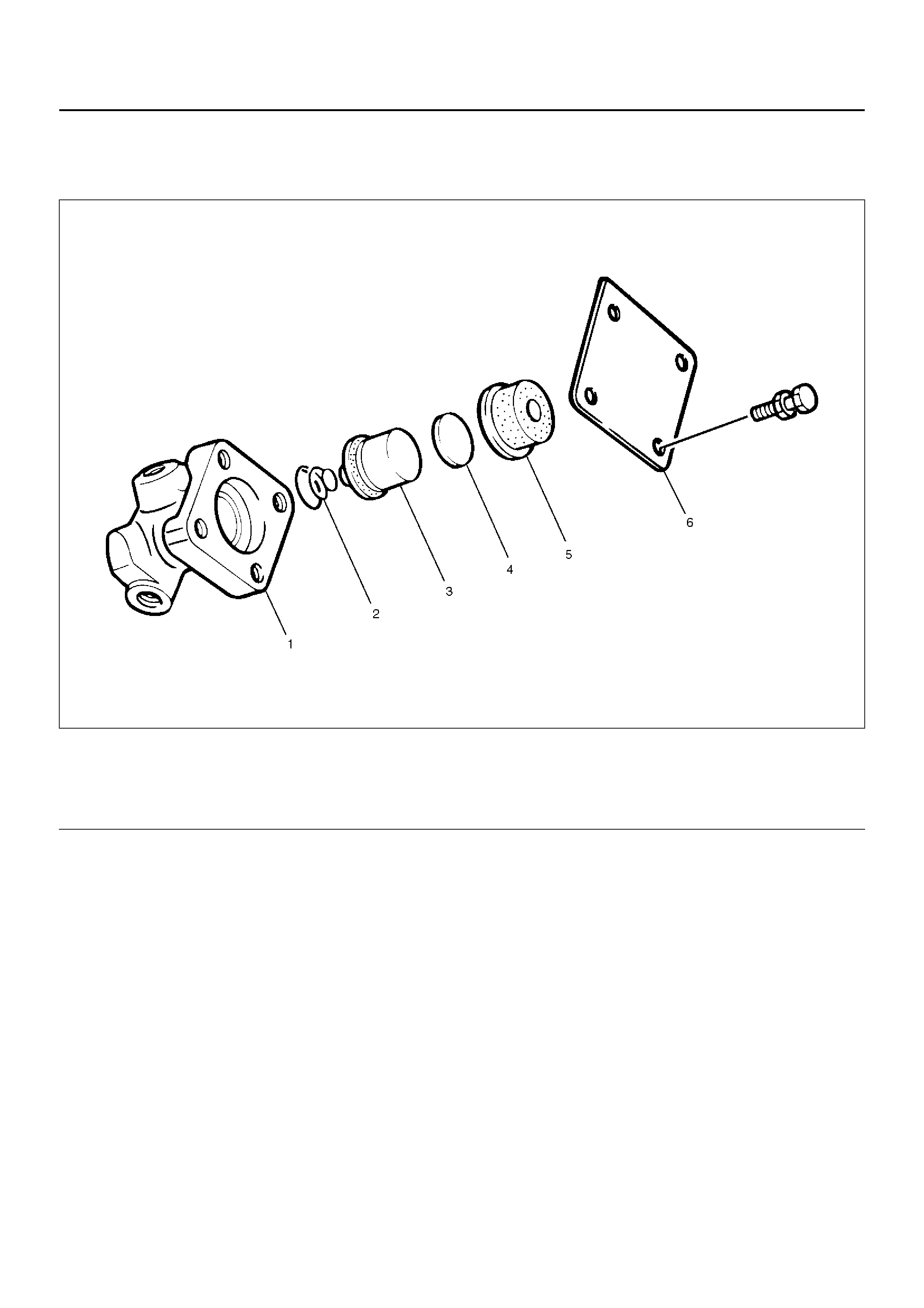
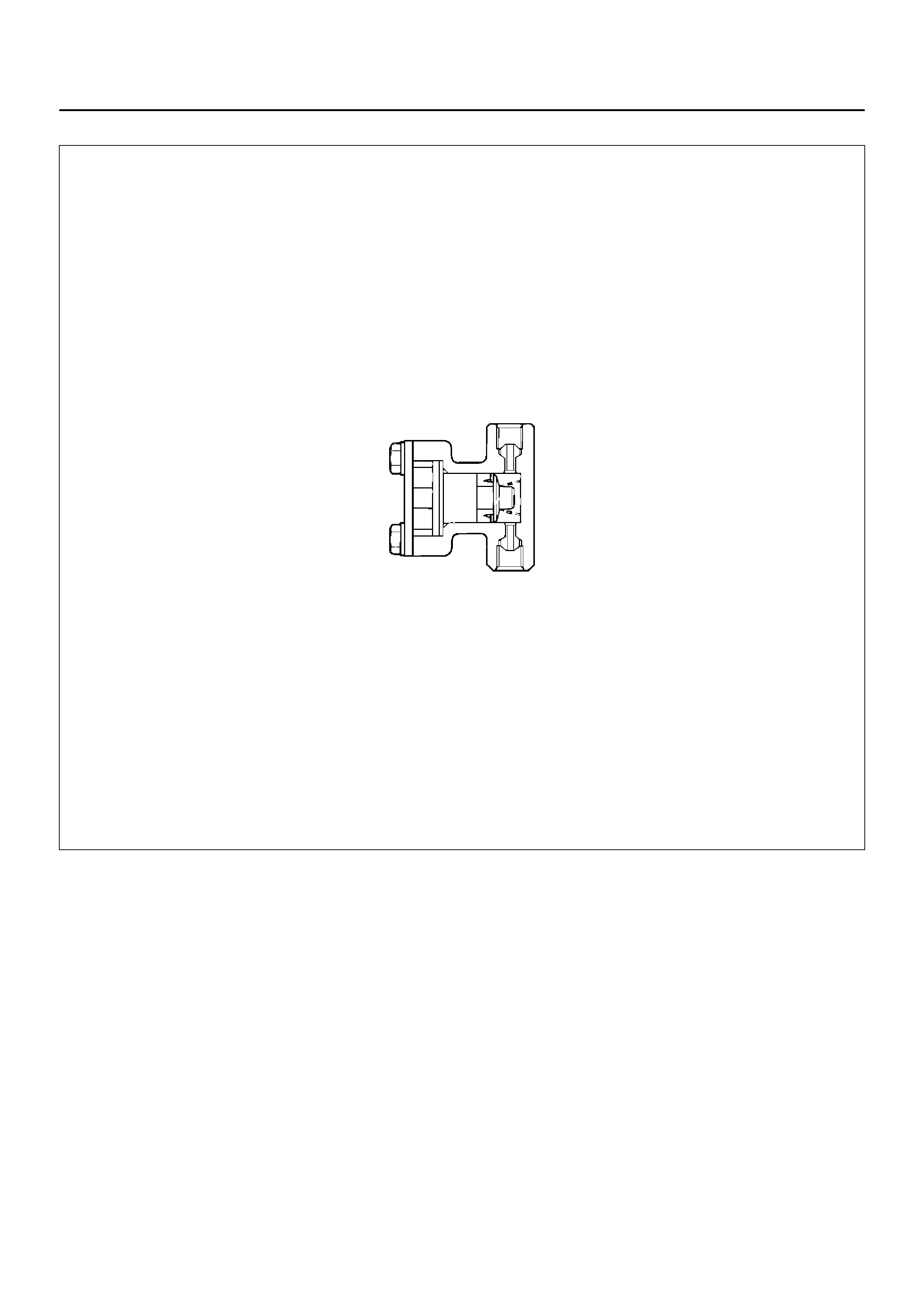
DAMPER CYLINDER
DISASSEMBLED VIEW
205RW005
EndOFCallout
DISASSEMBLY
1. Disassembly cover and gasket (6).
2. Disassembly damper rubber (5).
3. Disassembly spacer (4).
4. Disassembly piston assembly (3).
5. Disassembly spring (2).
6. Disassembly cylinder body (1).
INSPECTION AND REPAIR
Check damper rubber and piston cup for cracks,
deformation or damage.
Replace the damper cylinder assembly if necessary.
REASSEMBLY
To assemble, follow the disassembly steps in the
reverse or der.
Legend
(1) Cylinder Body
(2) Spring
(3) Piston Assembly
(4) Spacer
(5) Damper Rubber
(6) Cover and Gasket
MAIN DATA AND SPECIFICATIONS
General Specifications
Torque Specifications
E07RX020
Engine 6VD1
Type Dry single plate type with diaphragm spring
Size 260 mm
Pressure plate
Outside diameter 332 mm
Clamping force 7208 N
Spring finger height 49.9 – 51.9 mm
Driven plate
Outside diameter × inside diameter 260 × 170 mm
Thickness
Clutch disengaged 8.6 mm
Clutch engaged 8.0 mm
Total friction area 304 × 2 cm2
Clutch control type Hydraulic
Clutch pedal free play 5 – 15 mm
Clutch pedal stroke 165.5 –175.5 mm
Clutch pedal height 178 – 188 mm

203R100002
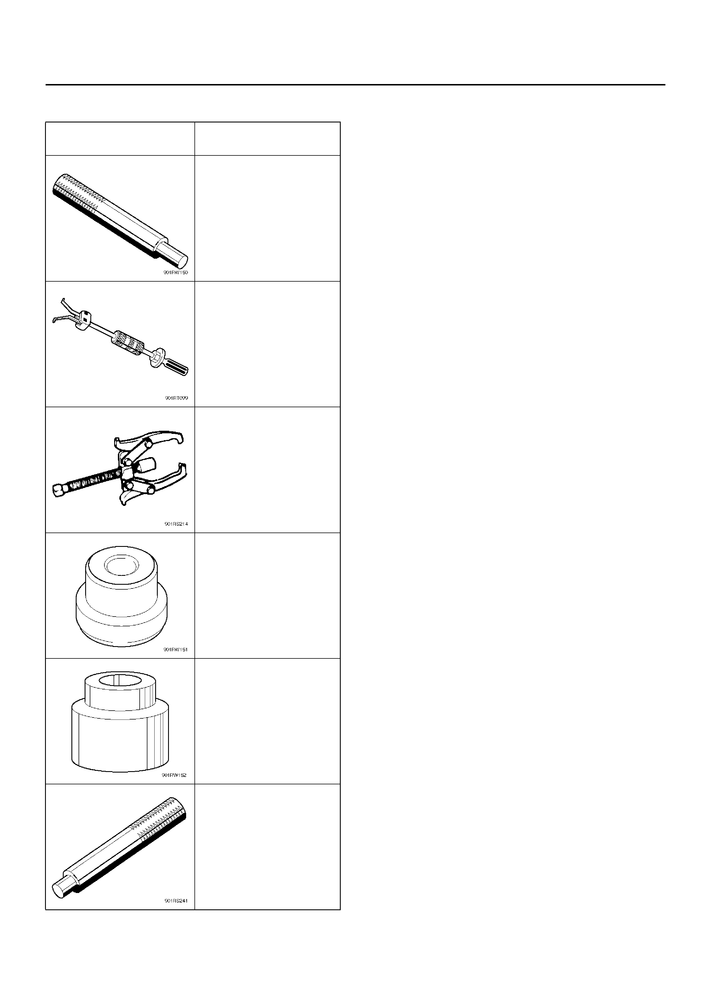
SPECIAL TOOLS
ILLUSTRATION PART NO.
PART NAME
5–85253–001–0
Driven plate aligner
(6VD1)
5–8840–2000–0
5–8840–0019–0
Pilot bearing remover and
Sliding hammer
5–8840–0013–0
Bearing puller
5–8840–0124–0
Adapter
5–8840–0007–0
Crankshaft pilot bearing
installe r (6 VD 1 )
5–8840–0007–0
Driver hand le