
SECTION 7B2 - TRANSFER CASE
Service Precaution
General Description
Transfer Rear Oil Seal
Transfer Rear Oil Seal and Associated
Parts
Removal
Installation
Transfer Case Assembly (A/T)
Transfer Case Assembly (A/T) and
Associated Parts
Removal
Installation
Transfer Rear Case Assembly (A/T)
Transfer Rear Case Assembly (A/T) and
Associated Parts
Removal
Installation
Transfer Rear Cover Assembly
Disassembly
Inspection and Repair
Reassembly
Detent, Shift Arm, and Interlock Pin
(Transfer Case Assembly)
Disassembled View
Disassembly
Inspection and Repair
Reassembly
Transfer Case Assembly
Disassembled View
Disassembly
Inspection and Repair
Reassembly
Main Data and Specifications
Special Tools
SERVICE PRECAUTION
WARNING: THIS VEHICLE HAS A SUPPLEMENTAL
RESTRAINT SYSTEM (SRS). REFER TO THE SRS
COMPONENT AND WIRING LOCATION VIEW IN
ORDER TO DETERMINE WHETHER YOU ARE
PERFORMING SERVICE ON OR NEAR THE SRS
COMPONENTS OR THE SRS WIRING. WHEN YOU
ARE PERFORMING SERVICE ON OR NEAR THE
SRS COMPONENTS OR THE SRS WIRING, REFER
TO THE SRS SERVICE INFORMATION. FAILURE
TO FOLLOW WARNINGS COULD RESULT IN
POSSIBLE AIR BAG DEPLOYMENT, PERSONAL
INJURY, OR OTHERWISE UNNEEDED SRS
SYSTEM REPAIRS.
CAUTION: Always use the correct fastener in the
proper location. When you replace a fastener, use
ONLY the exact part number for that application.
HOLDEN will call out those fasteners that require a
replacement after removal. HOLDEN will also call
out the fasteners that require thread lockers or
thread sealant. UNLESS OTHERWISE SPECIFIED,
do not use supplemental coatings (Paints, greases,
or other corrosion inhibitors) on threaded fasteners
or fastener joint interfaces. Generally, such
coatings adversely affect the fastener torque and
the joint clamping force, and may damage the
fastener. When you install fasteners, use the correct
tightening sequence and specifications. Following
these instructions can help you avoid damage to
parts and systems.
GENERAL DESCRIPTION
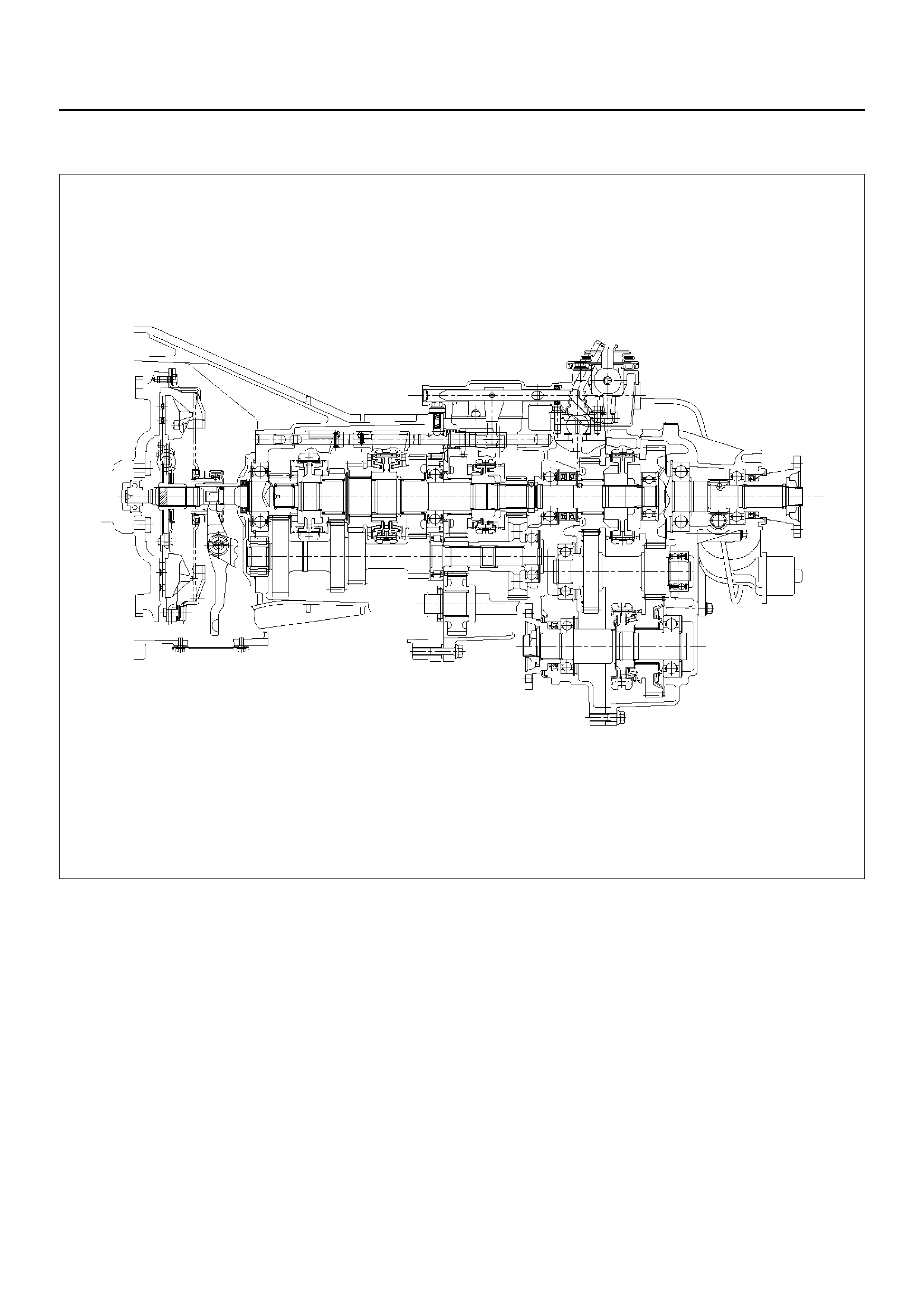
Transfer Case (for Manual Transmission)
A07RX005
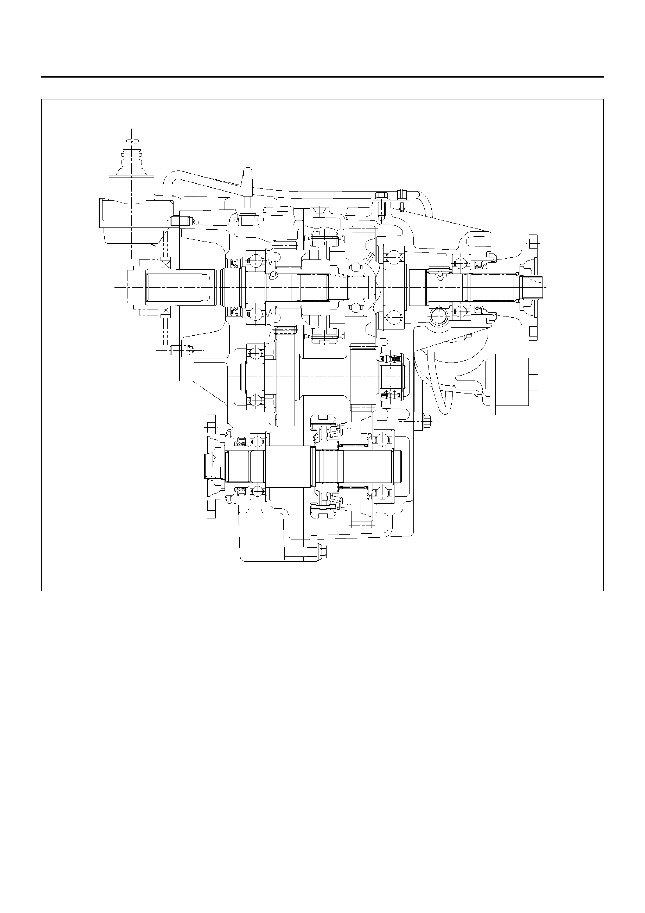
Transfer Case (for Automatic Transmission)
A07RW001-1
The transfer case is used to provide a means of
providing power flow to the front axle. The transfer
case also provi des a means of d isconne cting the fron t
axle, providing better fuel economy and quieter
operation when the vehicle is driven on improved
roads where four wheel drive is not required. In
addition, the transfer case provides an additional gear
reduction when placed in low range, which is useful
when difficult off–road conditions are encountered.
A floor mounted shift lever is used to select the high–
low range. When four wheel drive switch has been
turned on, the four wheel drive indicator light is
designed to come on and the front axle has been
engaged.
TRANSFER REAR OIL SEAL
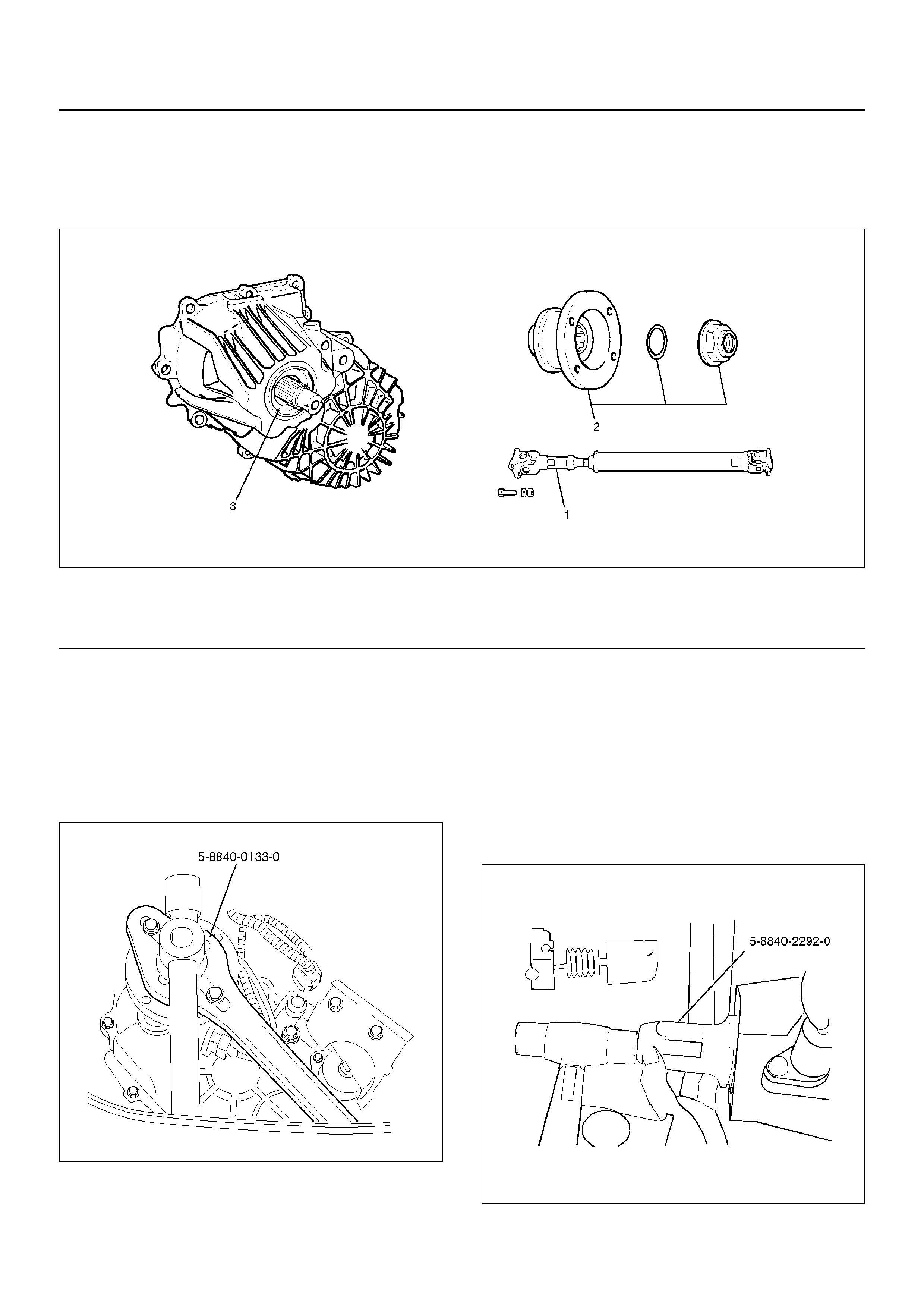
TRANSFER REAR OIL SEAL AND ASSOCIATED PARTS
220RS015
EndOFCallout
REMOVAL
1. Disconnect the rear propeller shaft (1) from the
transfer case side.
2. Remove end nut and rear companion flange (2),
using the companion flange holder 5–8840–0133–0.
266RW026
3. Use the universal puller to remove the rear
companion flange and O–ring.
4. Remove the oil seal from the transfer case.
INSTALLATION
1. Install oil seal and apply engine oil to the oil seal
outer surfaces.
2. Apply the recommended grease (BESCO L2) or
equivalent to the oil seal lip.
3. Use the oil seal installer 5–8840–2292–0 to install
the rear seal (3) to the transfer rear case.
220RW105
4. Install the rear companion flange (2) and O–ring (2).
Legend
(1) Rear Propeller Shaft
(2) End Nut and Rear Companion Flange
(3) Oil Seal
5. Use the companion flange holder 5–8840–0133–0
to install a new end nut (2) and tighten to the
specified torque.
Torque: 167 N·m (17.0kg·m/123 lbft)
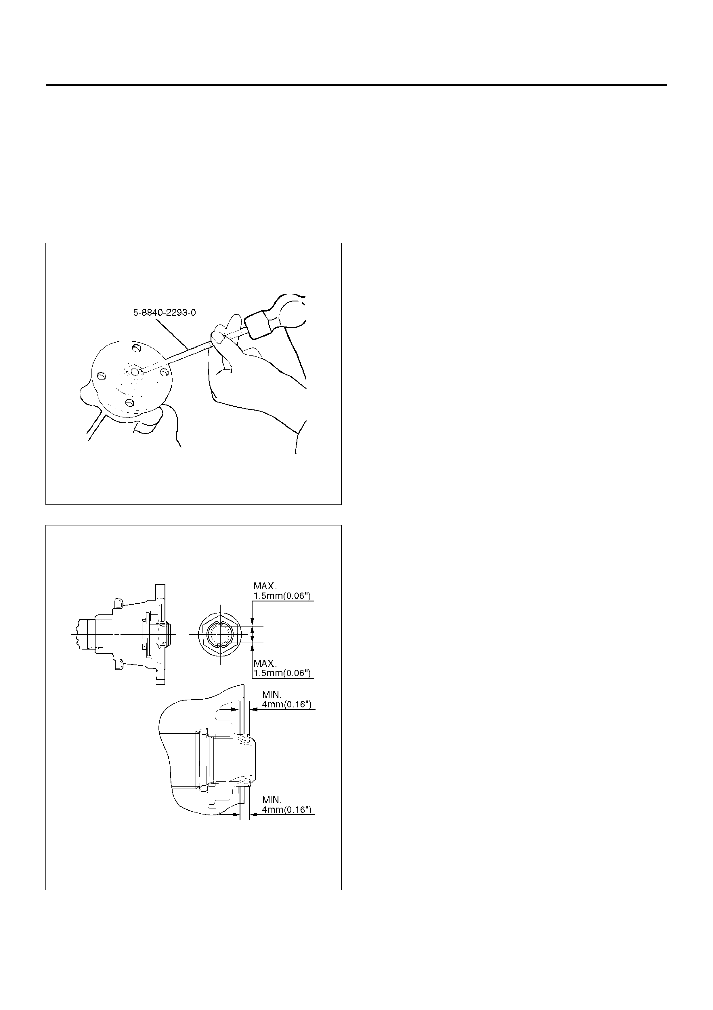
6. Use the punch 5–8840–2293–0 to stake the end nut
at two spots.
NOTE: Be sure to confirm that there is no crack at the
staked portion of the end nut (2) after staking.
266RW027
266RW002
7. Conne ct the rear propel ler shaft to the tr ans fer c as e
and tighten to the specified torque.
Torque: 63 N·m (6.4kg·m/46 lbft)
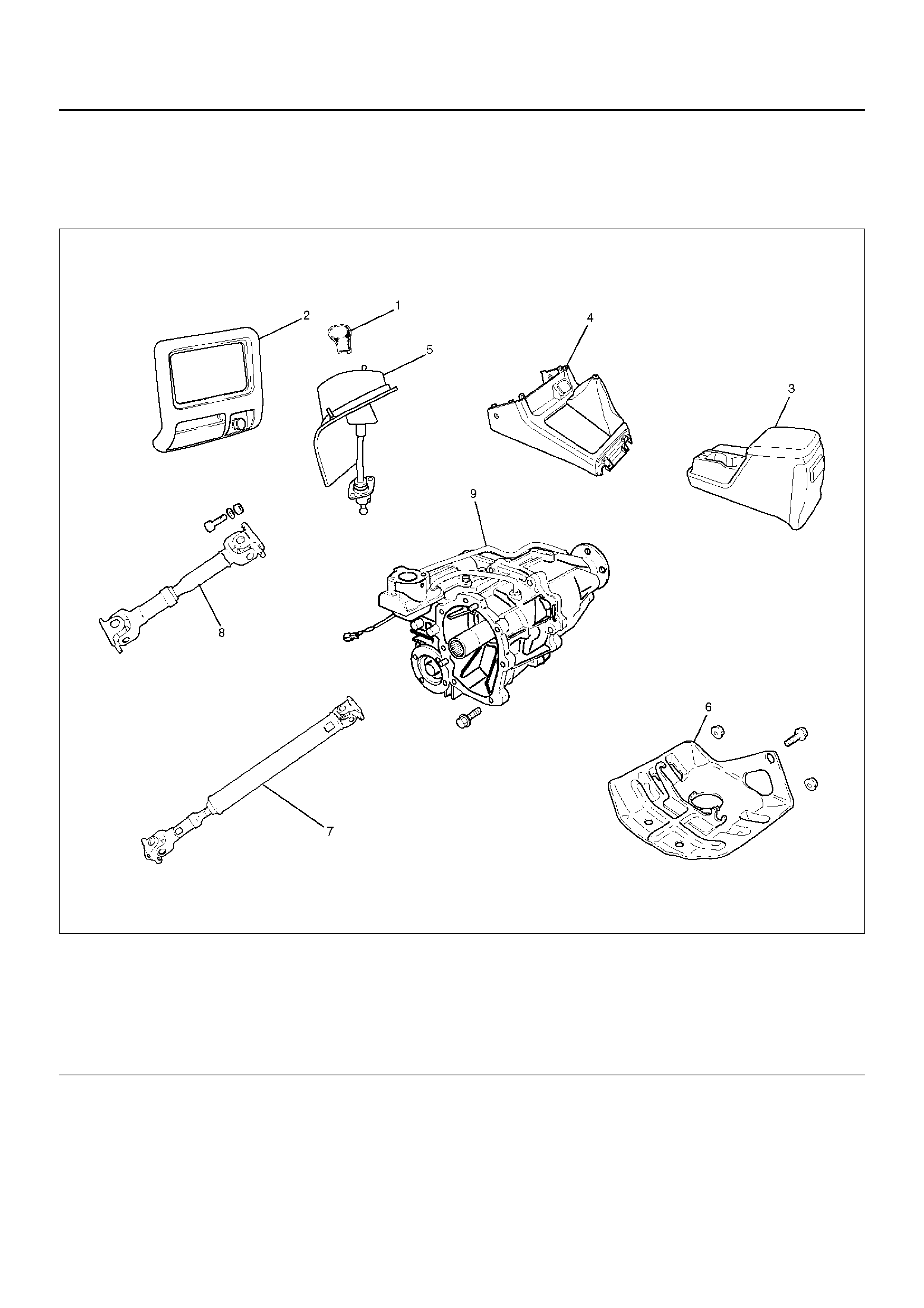
TRANSFER CASE ASSEMBLY (A/T)
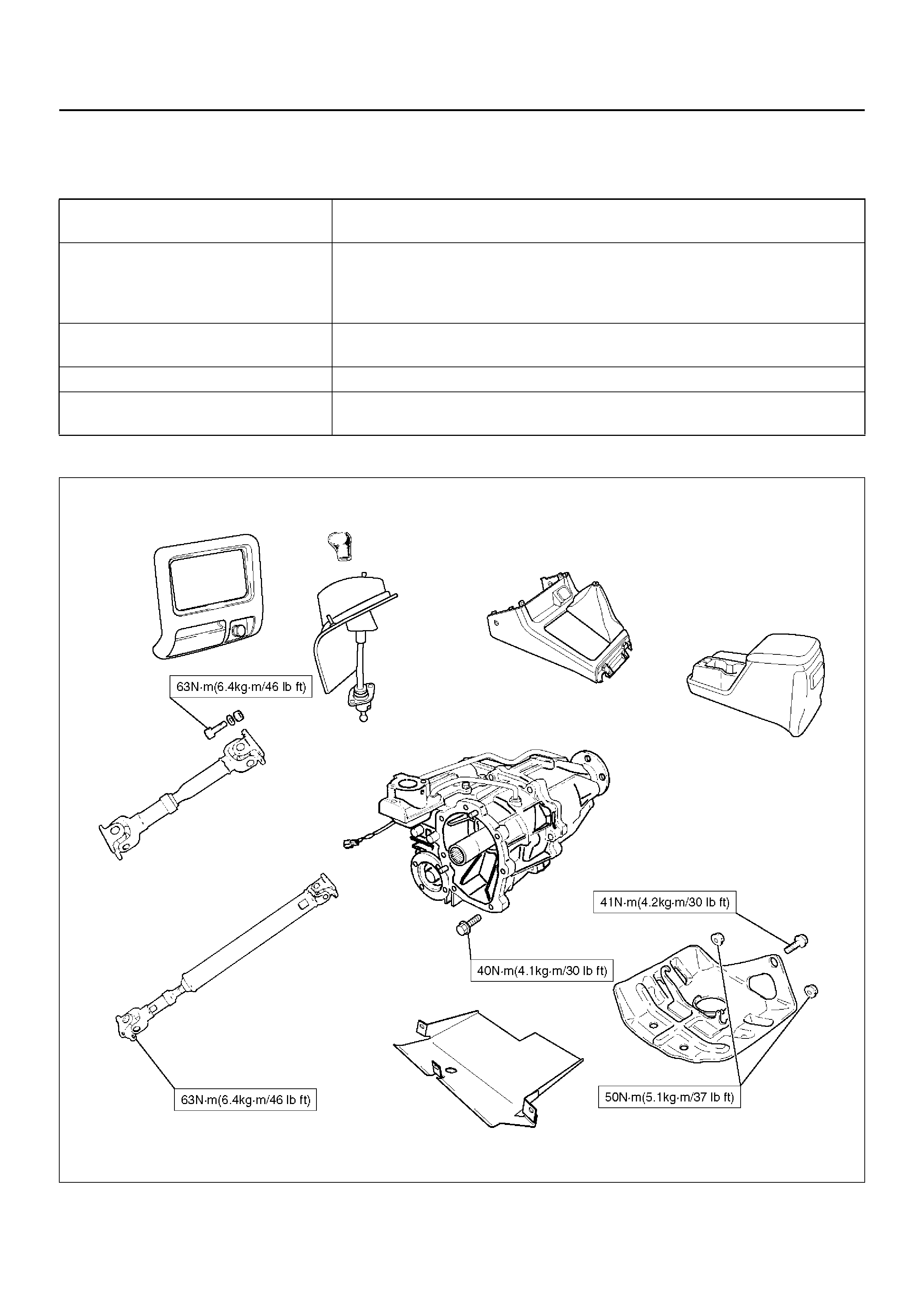
TRANSFER CASE ASSEMBLY (A/T) AND ASSOCIATED PARTS
260RX001
EndOFCallout
Legend
(1) Transfer Control Lever Knob
(2) Lower Cluster Assembly
(3) Rear Consol e
(4) Center Console
(5) Grommet Assembly and Transfer Control Lever
(6) Transfer guard
(7) Rear Propeller Shaft
(8) Front Pr ope ll er Shaft
(9) Transfer Case Assembly

REMOVAL
NOTE: Before removing transmission and transfer
assembly from vehicle, change the transfer mode to
2WD using the 4WD push button switch on dash panel.
1. Disconnect battery ground cable.
2. Remove transfer control lever knob (1).
3. Remove lower cluster assembly (2).
740RW021
4. Remove rear console (3).
256RW045
5. Remove center console (4).
256RW006
6. Remove grommet assembly and transfer control
lever (5).
256RW007
7. Raise and support vehicle with suitable stands.
Drain transfer case fluid.
8. Remove transfer guard (6).
150RX010
9. Remove rear propeller shaft (7) and front propeller
shaft (8).
NOTE: Apply alignment marks on the flange at both
front and rear sides.
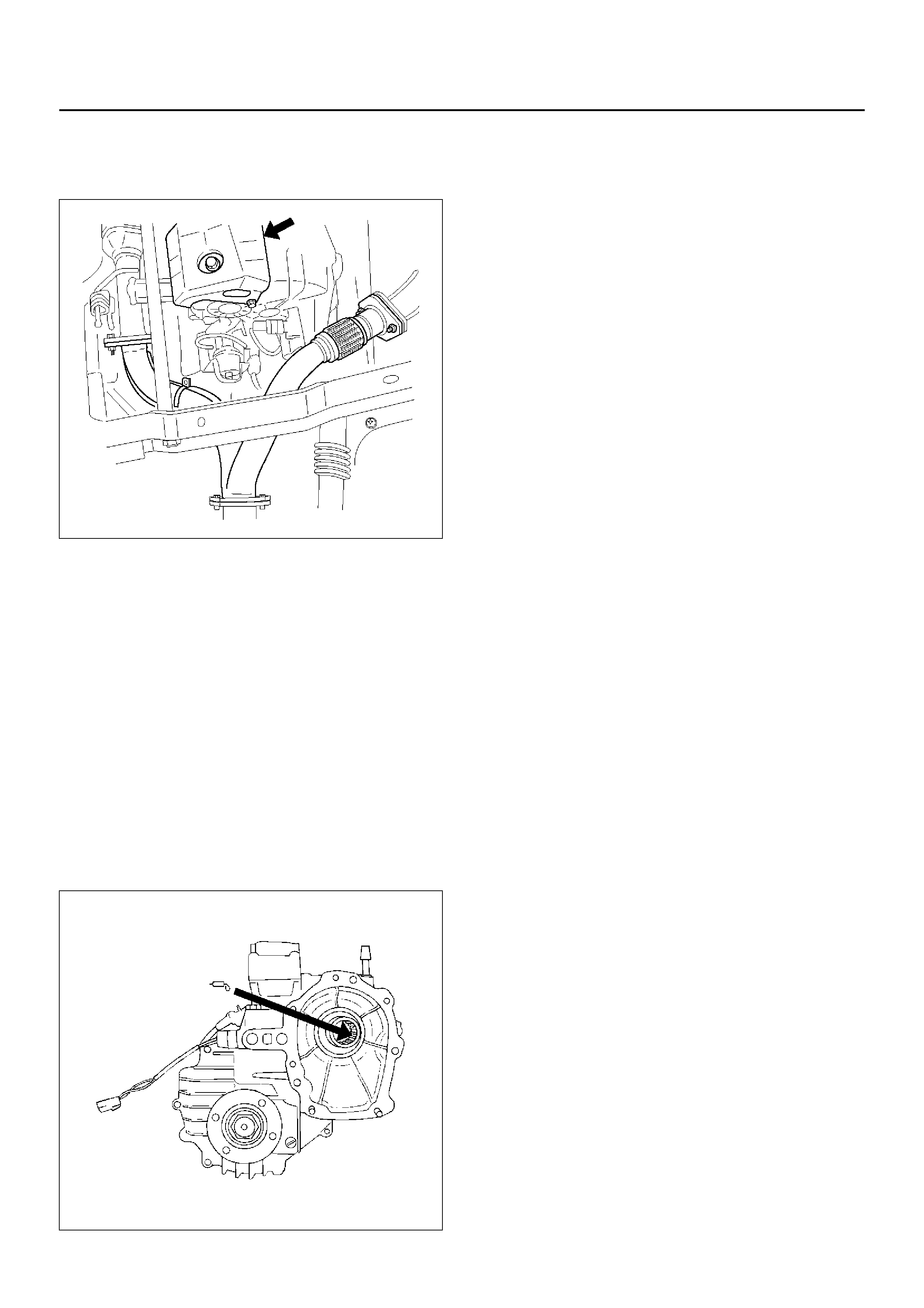
10. Disconnect harness connectors and clip.
Connector: transfer switch, 2WD–4WD actuator,
speed sensor.
11. Support transmission case with a transmission jack.
12. Remove the top position bolt from transfer control
lever hole and others under the floor.
Remove transfer case (9) from the vehicle.
INSTALLATION
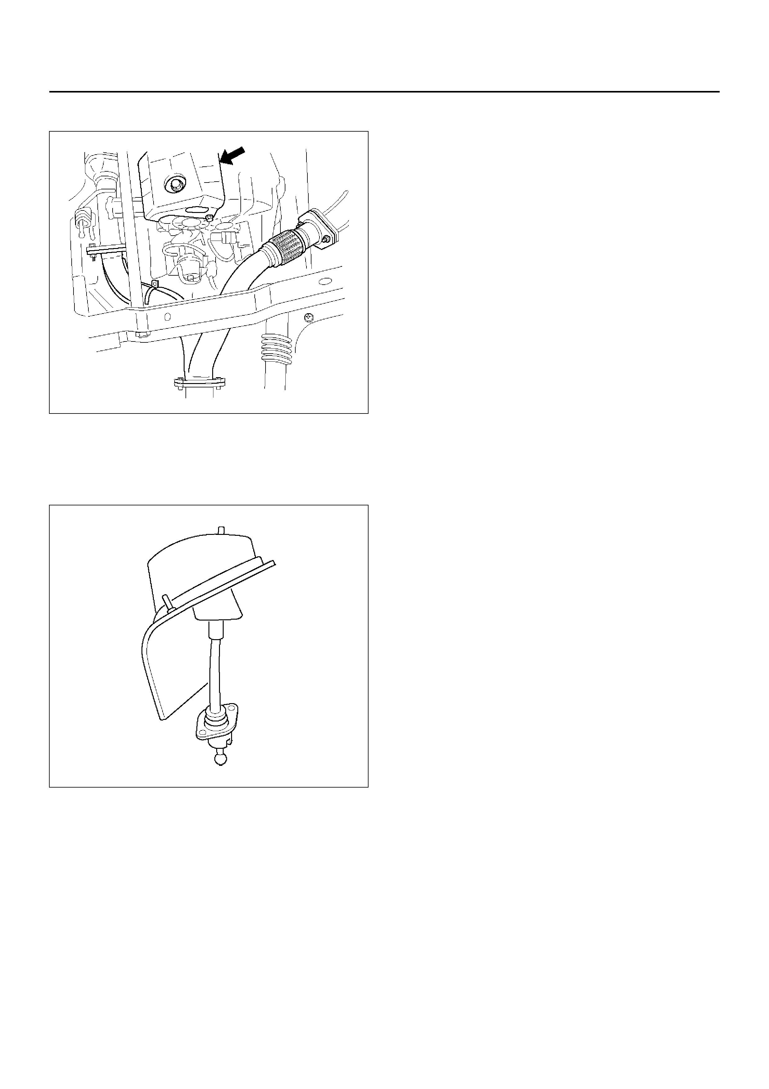
1. Apply a thin coat of molybdenum disulphide grease
to the input shaft spline as shown in the figure.
260RW001
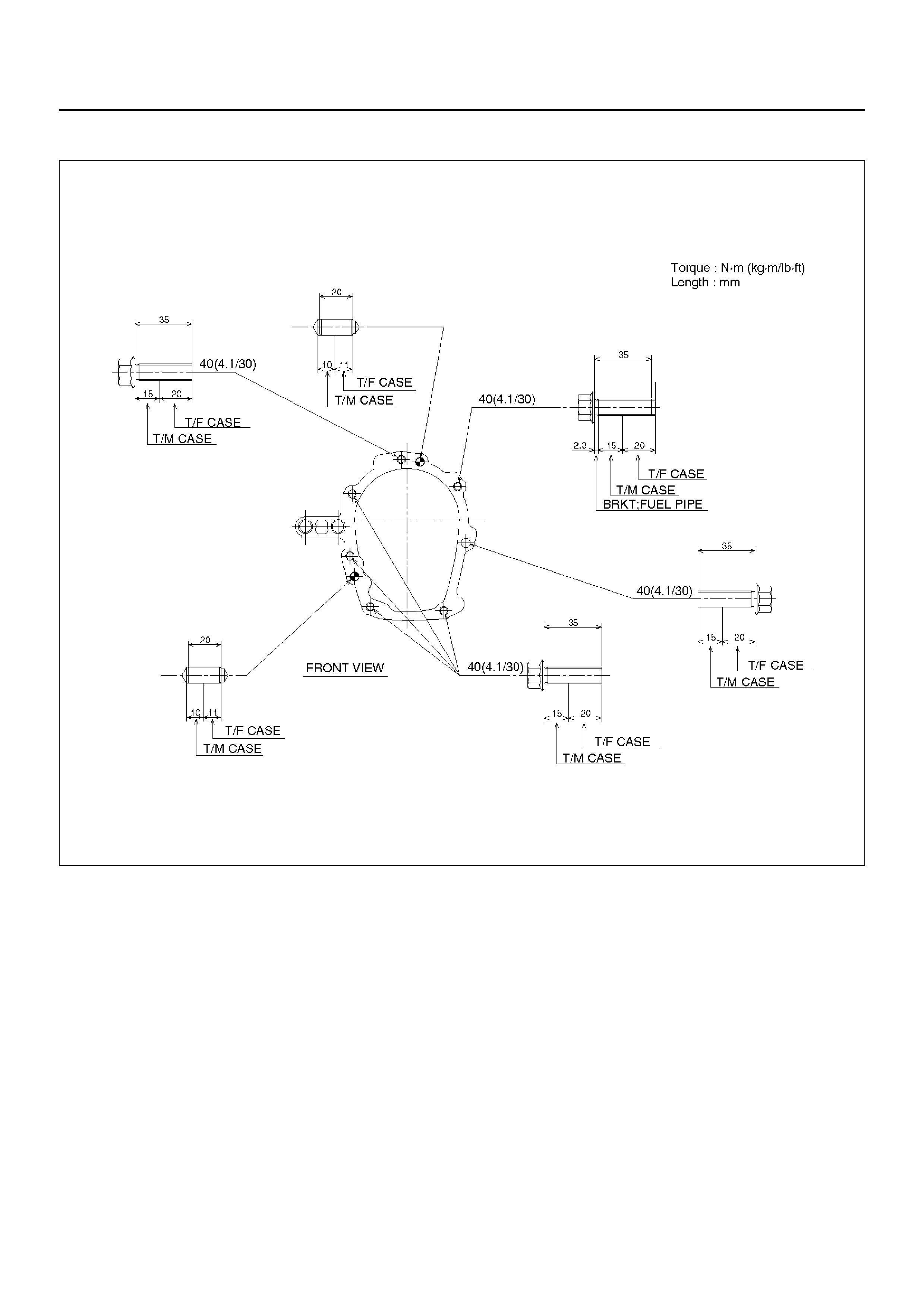
2. Install tra nsfer case (9) to the transmi ssion. Tighten
transfer bolts as shown in the figure.
261RX001
3. Remove the transmission jack from transmission
side.
4. Connect harness connectors and clip.
Connector: transfer switch, 2WD–4WD actuator,
speed sensor.
5. Install rear propeller shaft (7) and front propeller
shaft (8).
Torque: 63 N·m (6.4kg·m/46 lbft)
6. Install transfer guard (6).
150RX010
7. Fill transfer case fluid.
8. Lowe r the vehicle.
Install grommet assembly and transfer control lever
(5).
256RW007
9. Install center console (4), rear console (3) and lower
cluster assembly (2).
10. Install transfer control lever knob (1).
TRANSFER REAR CASE ASSEMBLY (A/T)
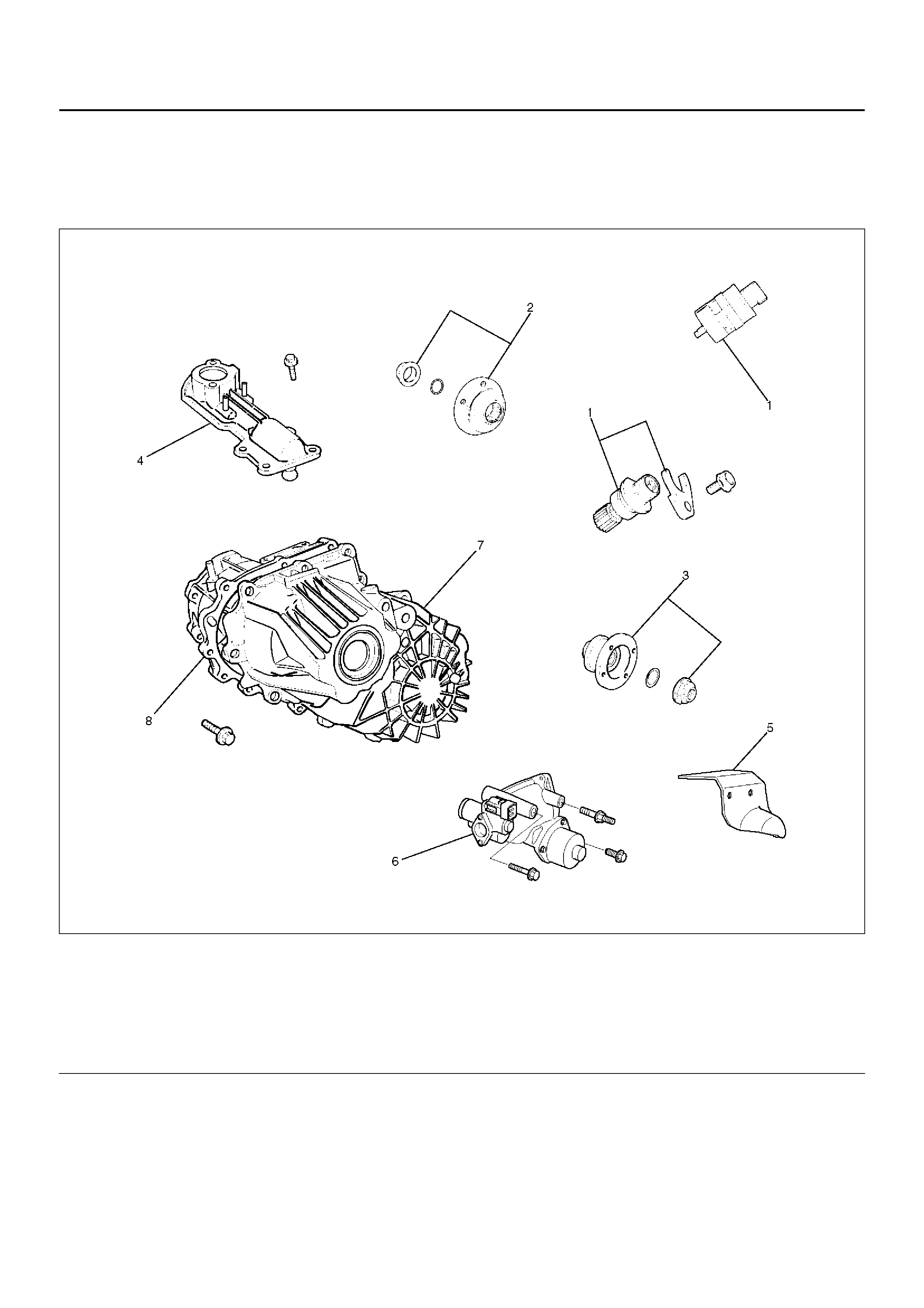
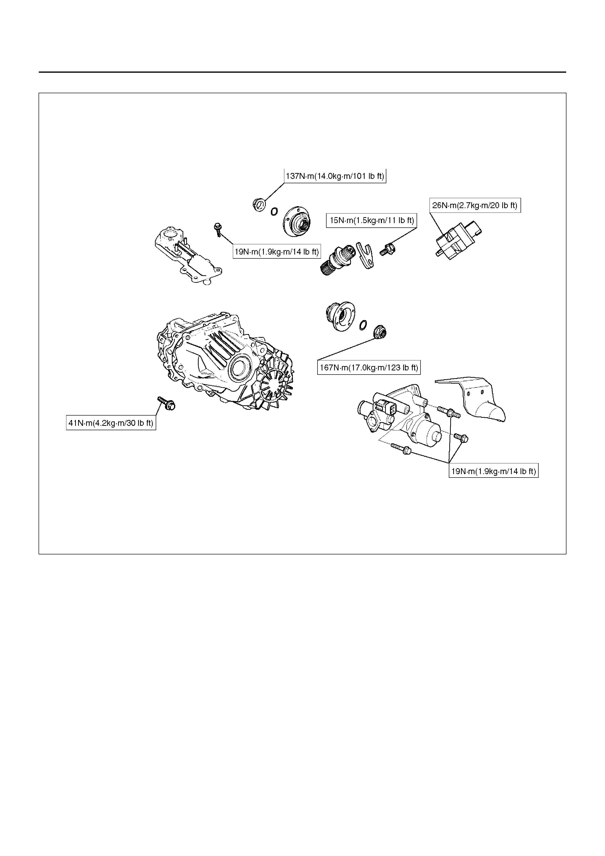
TRANSFER REAR CASE ASSEMBLY (A/T) AND ASSOCIATED PARTS
220RW133-1
EndOFCallout
REMOVAL
1. Remo ve the sp eedo met er sens or (1).
2. Remo ve the pla te (1).
3. Remove the speedometer driven gear bushing and
driven gear (1).
NOTE: Apply a reference mark to the driven gear
bushing before removal.
Legend
(1) Speedometer Sensor, Speedometer Driven
Gear and Plate
(2) Front Companion Flange
(3) Rear Companion Flange
(4) Control Box Assembly
(5) 2WD–4WD Actuator Heat guard
(6) 2WD –4 WD Ac tua tor Ass em bly
(7) Transfer Rear Cover Assembly
(8) Transfer Case Assembly
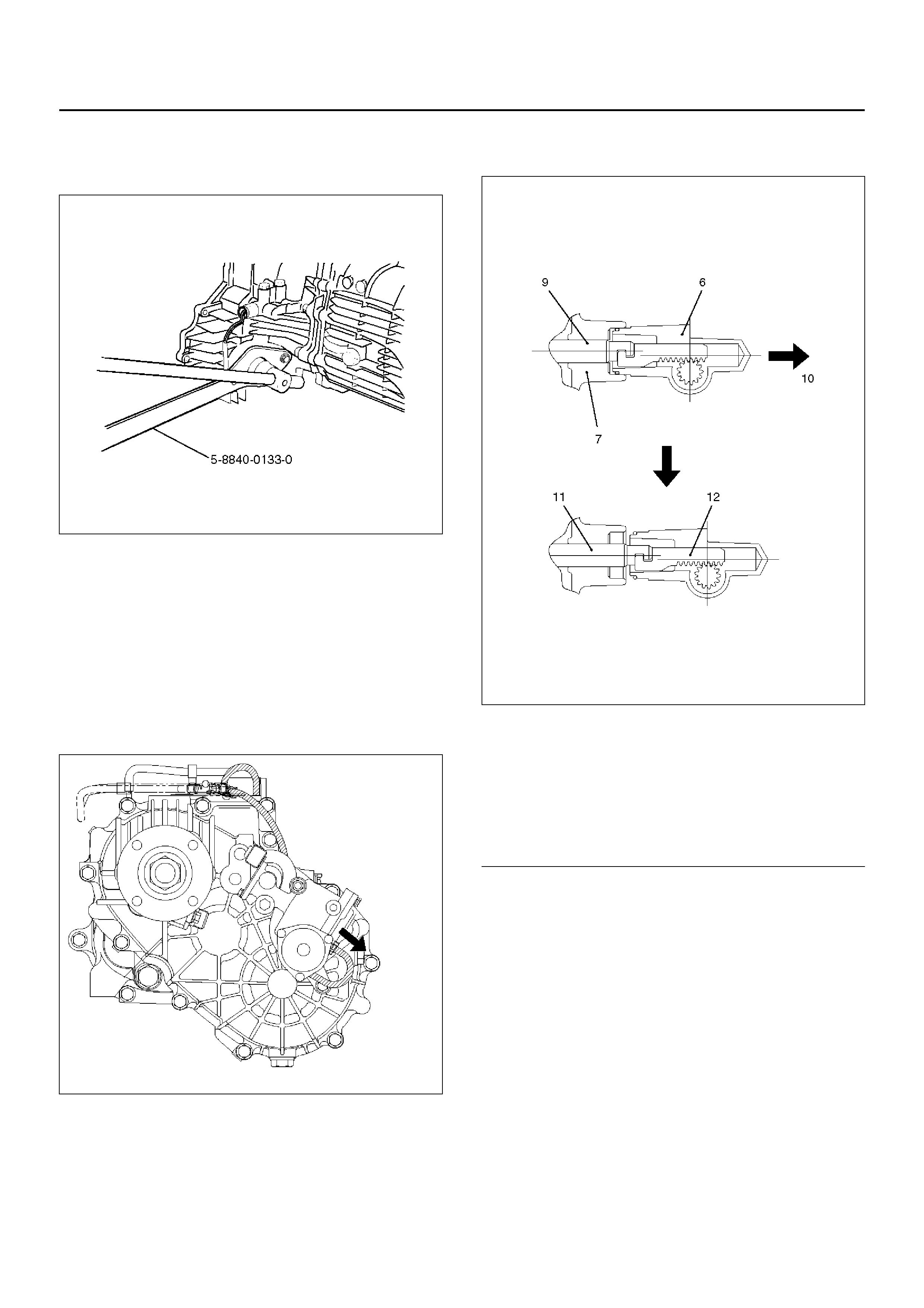
4. Remove front companion flange (2) and rear
companion flange (3), using the flange companion
holder 5–8840–0133–0 to remove the end nut.
262RW067
5. Remove the front and rear companion flange.
NOTE: Use the universal puller to remove the rear
companion flange.
6. Disconnect the actuator breather hose and transfer
breather hose from control box (4).
7. Remove control box assembly (4).
8. Disconnect the actuator breather hose and 2WD–
4WD actuator heat guard (5) from the 2WD–4WD
actuator assembly (6).
220RW085-1
9. Remove the 2WD–4WD actuator assembly bolts.
10. Pull the 2WD–4WD actuator assembly (6) with
2WD–4WD shift rod.
220RW065
EndOFCallout
Legend
(6) 2WD –4 WD Ac tua tor Ass em bly
(7) Rear Cover Assembly
(9) Shift Rod: 2WD–4WD (Position: 2WD)
(10) Pull
(11) Position: 4W D
(12) Mode: 2W D
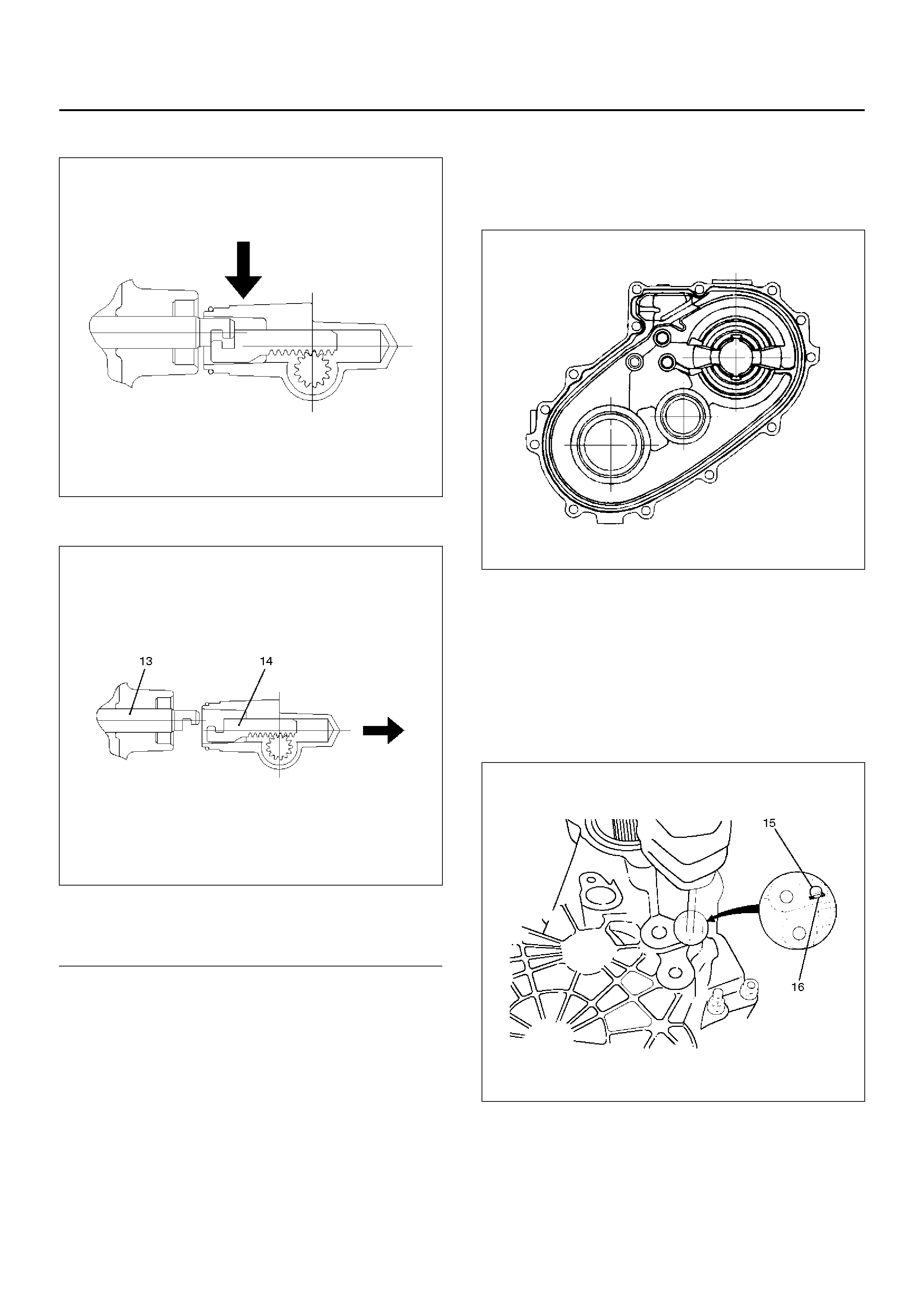
11. Off set the actuator assembly.
220RW028
12. Remove the actuator assembly (6).
220RW066
EndOFCallout
13. Remove transfer rear cover assembly (7) from
transfer case assembly.
INSTALLATION
1. Apply the recommended liquid gasket (LOCTITE
17430) or its equivalent to the transfer rear cover
fitting faces.
220RS017
2. Install transfer rear cover assembly (7) to transfer
case assembly (8).
3. Perform the following steps before fitting the transfer
rear case.
1. Shift the high–low shift rod to the 4H side.
2. The cut–away portion of the select rod head
(15) should align with that of the rear case hole's
stopper (16).
230RW009
4. Tighten the transfer rear case bolts to the specified
torque.
Torque: 37 N·m (3.8kg·m/27 lbft)
5. Shift the 2WD–4WD shift rod (17) to the 4WD side.
Legend
(13) Position: 4WD
(14) Mode: 2WD
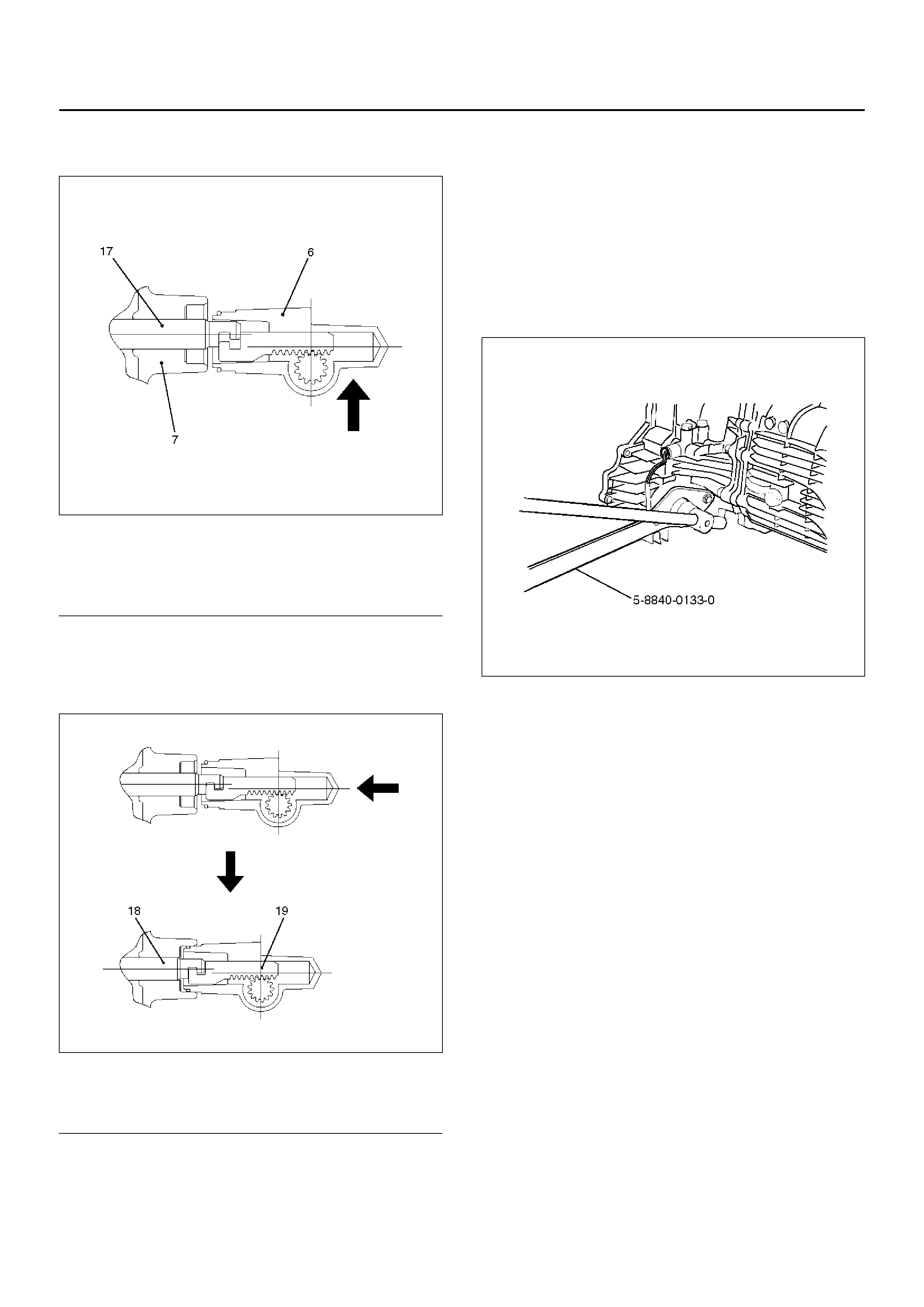
6. Join the rod grooves of 2WD–4WD actuator
assembly (6) and shift rod (17).
220RW067
EndOFCallout
7. Push the 2WD–4WD actuator assembly (6) with
2WD–4WD shift rod (17) till the shift rod (17)
reaches t he 2WD position.
220RW068
EndOFCallout
8. Tighten the 2WD–4WD actuator bolts to the
specified torque.
Torque: 19 N·m
9. Connect the act uato r breath er hose to actuator.
10. Install actuator heat shield (5).
11. I nstall control box assembly (4).
Torque: 19 N·m
12. Connect breather hoses to control box (4).
13. Install rear companion flange (3) and front
companion flange (2), using the companion flange
holder 5–8840–0133 –0 to tighten the flange nuts to
the transfer case.
262RW067
14. Tighten the new tran sfe r fl ang e nu ts to the spec if ied
torque.
Torque:
Rear companion flange: 167 N·m
Front companion flange: 137 N·m
Legend
(6) 2WD–4WD Actuator Assembly (Mode: 2WD)
(7) Rear Cover Assembly
(17) Shift Rod: 2WD–4WD (Position: 4WD)
Legend
(18) Position: 2WD
(19) Mode: 2WD
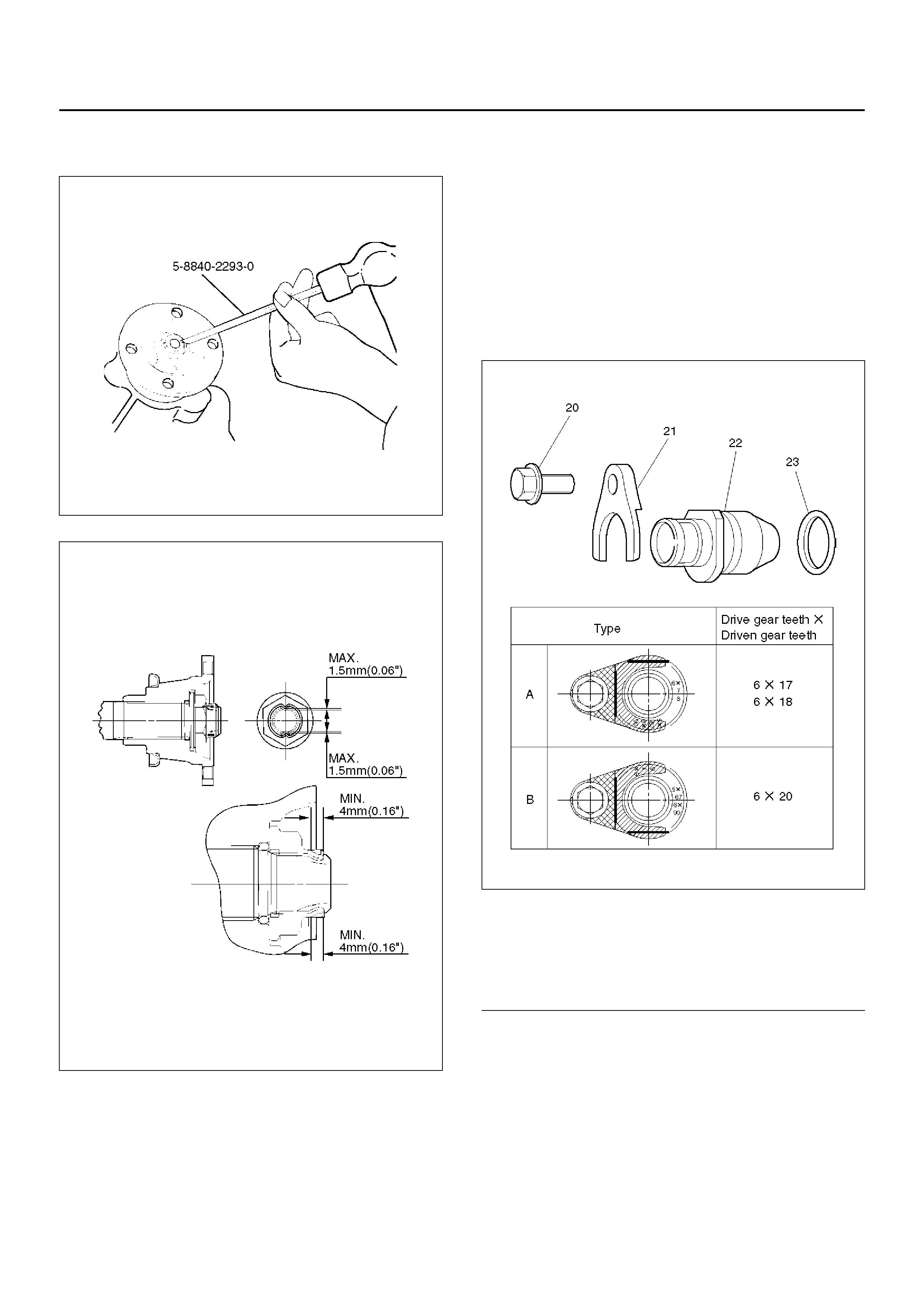
15. Use the punch 5–8840–2293–0 to stake the rear
companion flange nut (3) at two spots.
266RW027
266RW002
16. Stake the front companion flange nut (2) at one
spot.
NOTE: Be sure to confirm that there is no crack at the
staked portion of the flange nut after staking.
17. Install the O–ring (23) to the speedometer driven
gear bushing (22).
18. Install the driven gear to the speedometer driven
gear bushing (22).
19. Install the speedometer driven gear assembly to the
transfer rear cover.
20. Install the plate (21) to the transfer rear case and
tighten to the specified torque.
Torque: 15 N·m
21. Install the speedometer sensor and tighten to the
specified torque.
Torque: 26 N·m
225RW004
EndOFCallout
Legend
(20) Bolt
(21) Plate
(22) Bushing
(23) O–ring
TRANSFER REAR COVER ASSEMBLY
226RW154
EndOFCallout
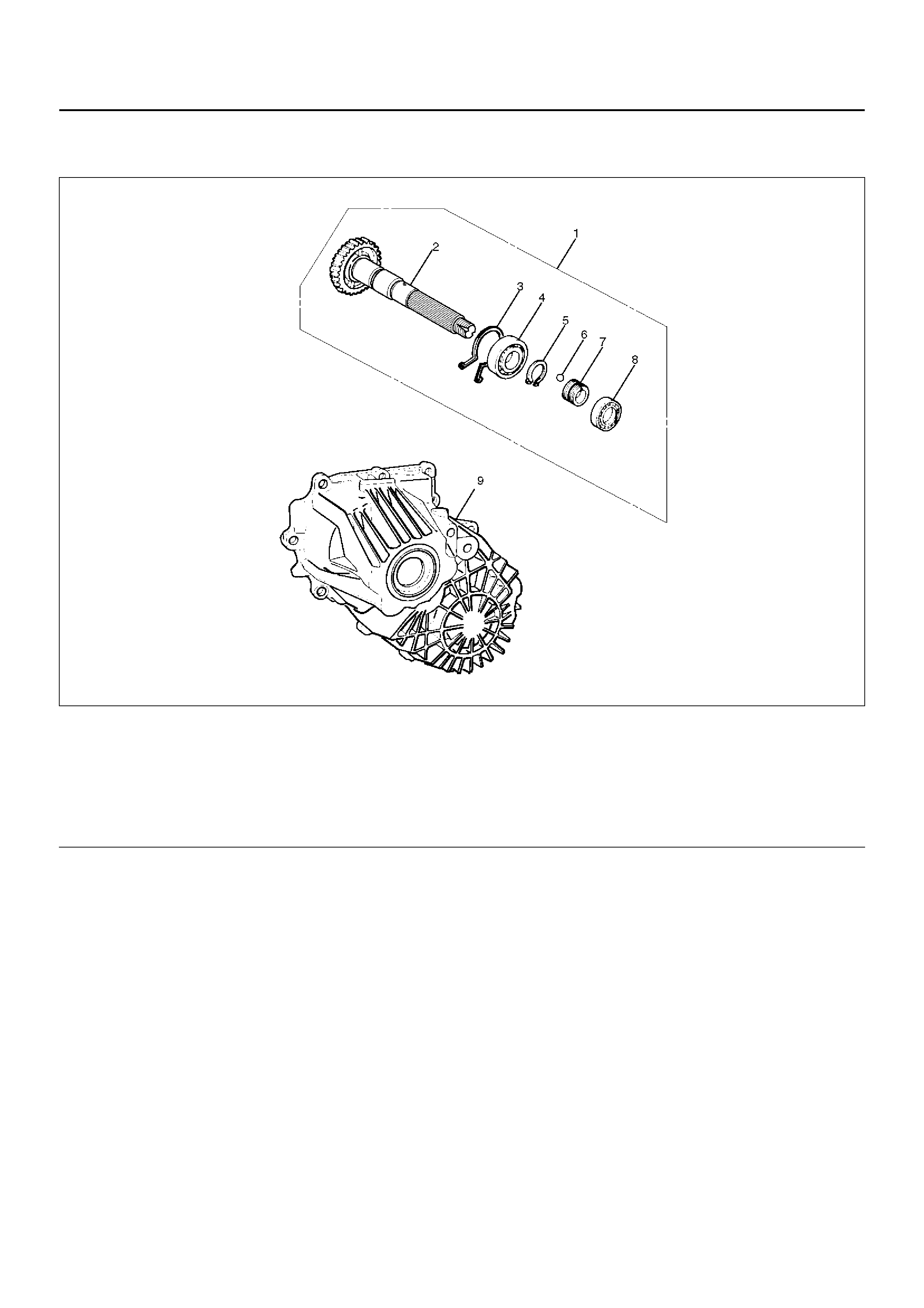
DISASSEMBLY
1. Remove bearing snap ring, use a pair of snap ring
pliers to remove the snap ring (3).
Legend
(1) Rear Output Shaft Assembly
(2) Rear Output Shaft
(3) Bearing Snap Ring
(4) Ball Bearing
(5) Bearing Snap Ring
(6) Ball
(7) Speedometer Drive Gear
(8) Ball Bearing
(9) Transfer Rear Cover (with oil seal)
226RS060
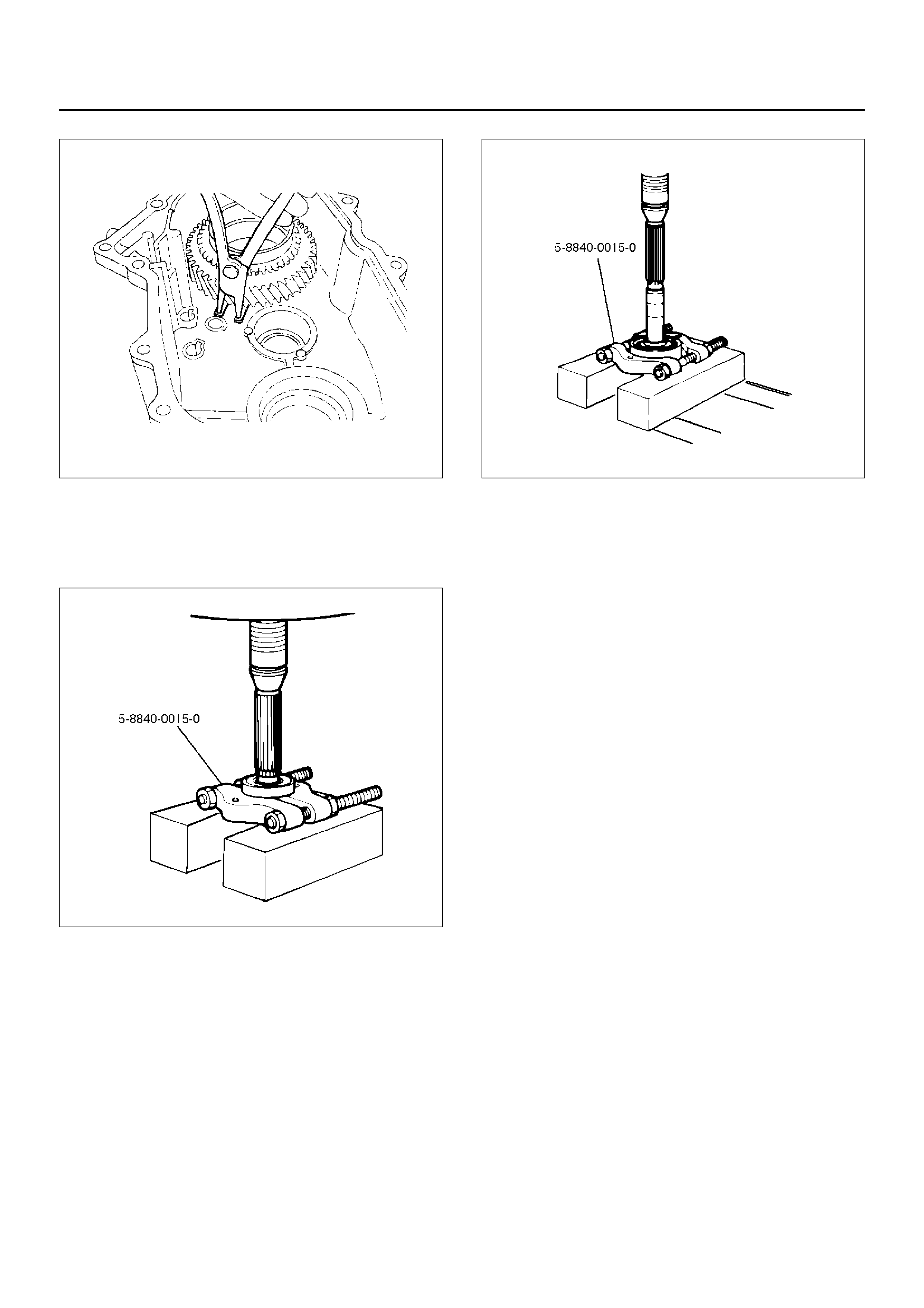
2. Remove the rear output shaft assembly (1) from the
transfer rear cover (with oil seal) (9).
3. Remove ball bearing (8), using a bench press and
the bearing remover 5–8840–0015–0.
226RW186
4. Remove speedometer drive gear (7).
5. Remove ball (6).
6. Remove bearing snap ring (5), using a pair of snap
ring pliers.
7. Remove rear output shaft (2) from the ball bearing
(4), using a bench press and the bearing remover
5–8840–0015–0.
226RW187
INSPECTION AND REPAIR
Refer to “Transfer Case Assembly" in this section for
inspe ction and repair.
REASSEMBLY
Transfer rear cover (with oil seal) (9). Oil seal
replacement.
• Remove the oil seal from the transfer rear cover.
• Apply engine oil to the oil seal outer surfaces.
• Fill in recommended grease (BESCO L2) or
equivalent in the oil seal lip.
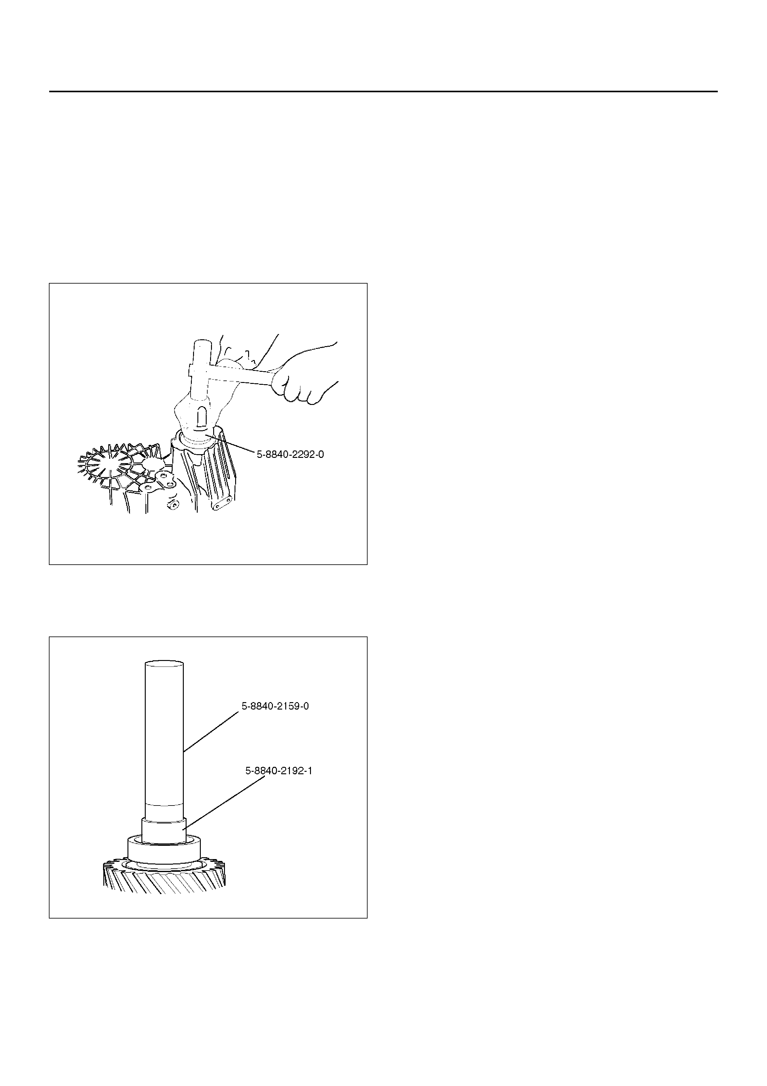
• Use the oil seal installer 5–8840–2292–0 to install the
rear oil seal to the transfer rear cover.
220RW104
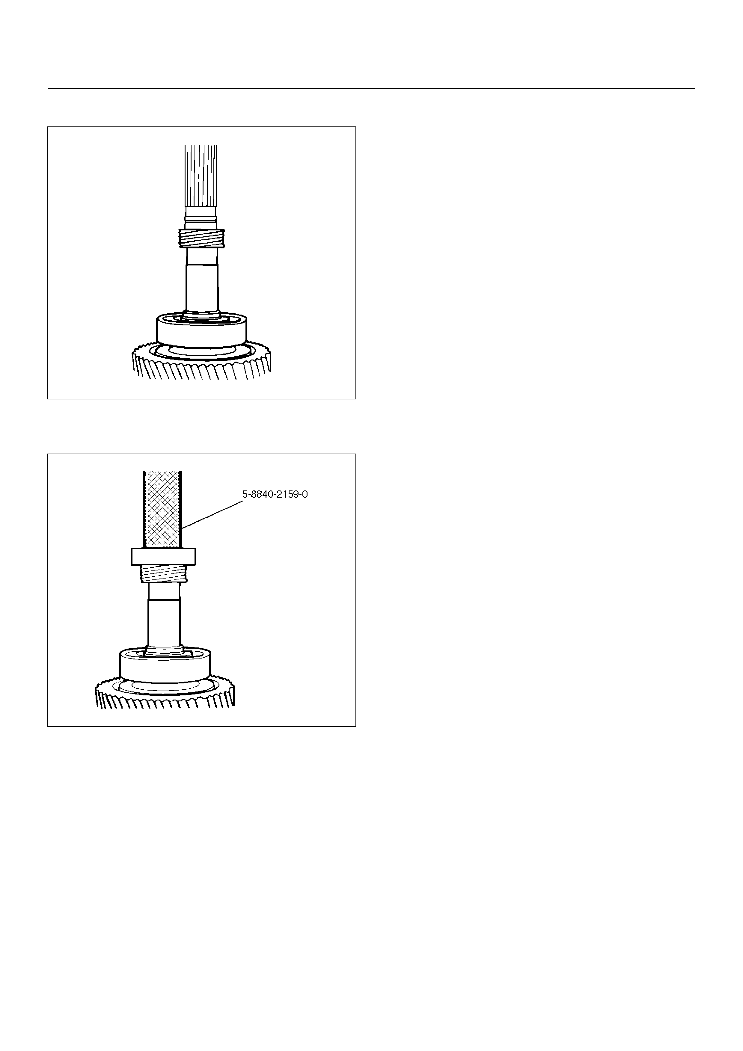
1. Install ball bearing (4) to the rear output shaft (2),
using the ball be aring installer 5 –8840–215 9–0 and
the adapter 5–8840–2192–1.
262RW068
2. Install bearing snap ring (5), using a pair of snap
ring pliers.
3. Install ball (6).
4. Install speedometer drive gear (7).
226RS064
5. Use the ball bearing installer 5–8840–2159–0 to
install the ball bearing (8).
226RW188
6. Install the rear output shaft assembly (1) to the
transfer rear cover (9).
7. Install bearing snap ring (3).
NOTE: The snap ring must be fully inserted into the
transfer rear cover snap ring groove.
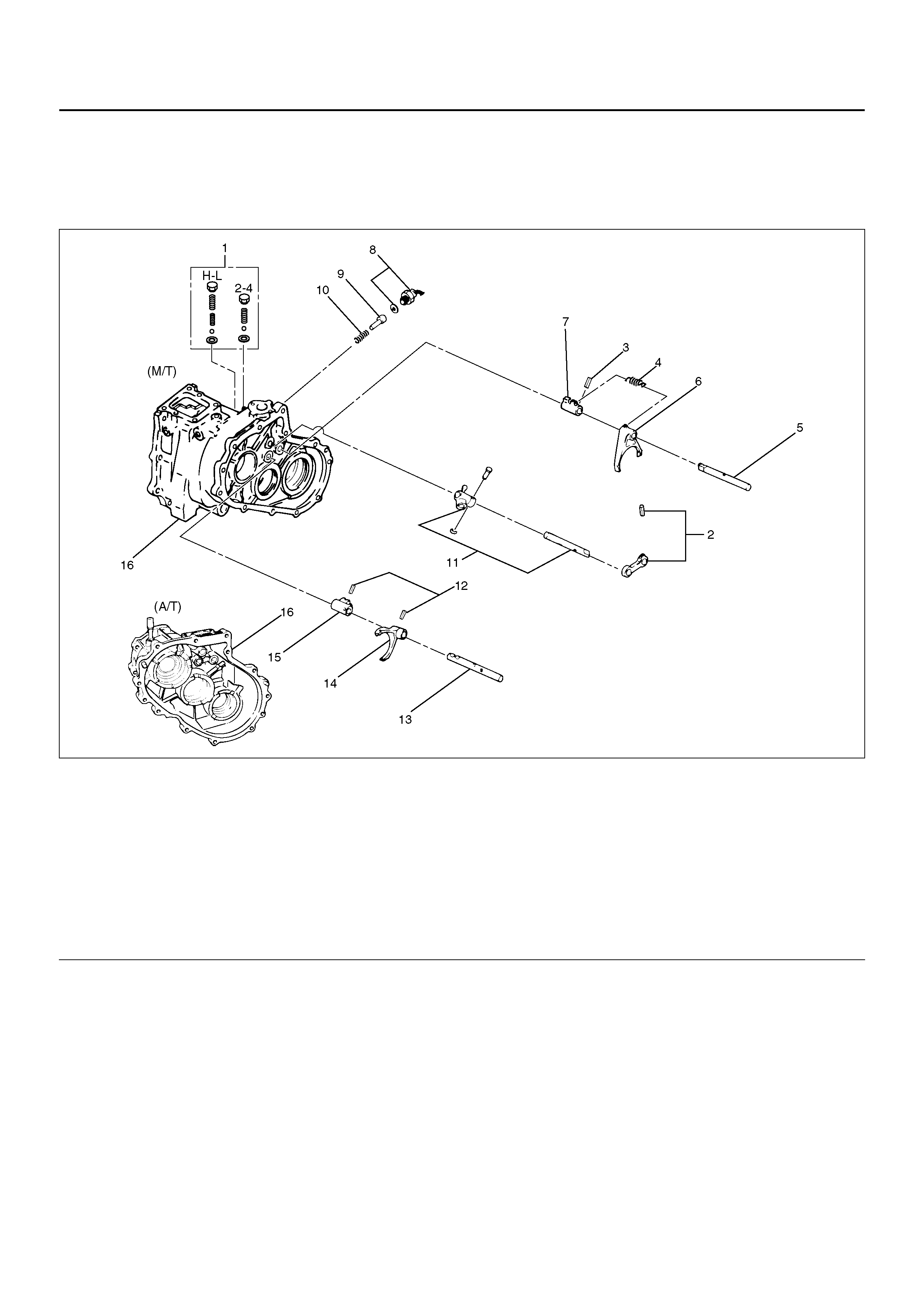
DETENT, SHIFT ARM, AND INTERLOCK PIN (TRANSFER CASE
ASSEMBLY)
DISASSEMBLED VIEW
262R100003
EndOFCallout
Legend
(1) Detent Ball, Spring, Spacer and Plug
(2) Spring Pin and Bridge
(3) Spring Pin
(4) Spring
(5) 2WD–4WD Shift Rod
(6) Shift Arm
(7) Shift Block
(8) 4WD Indicator Switch
(9) Interlock Pin
(10) Spring
(11) Select Rod Assembly
(12) Spring Pin
(13) High–Low Shift Rod
(14) Shift Arm
(15) Shift Block
(16) Transfer Case
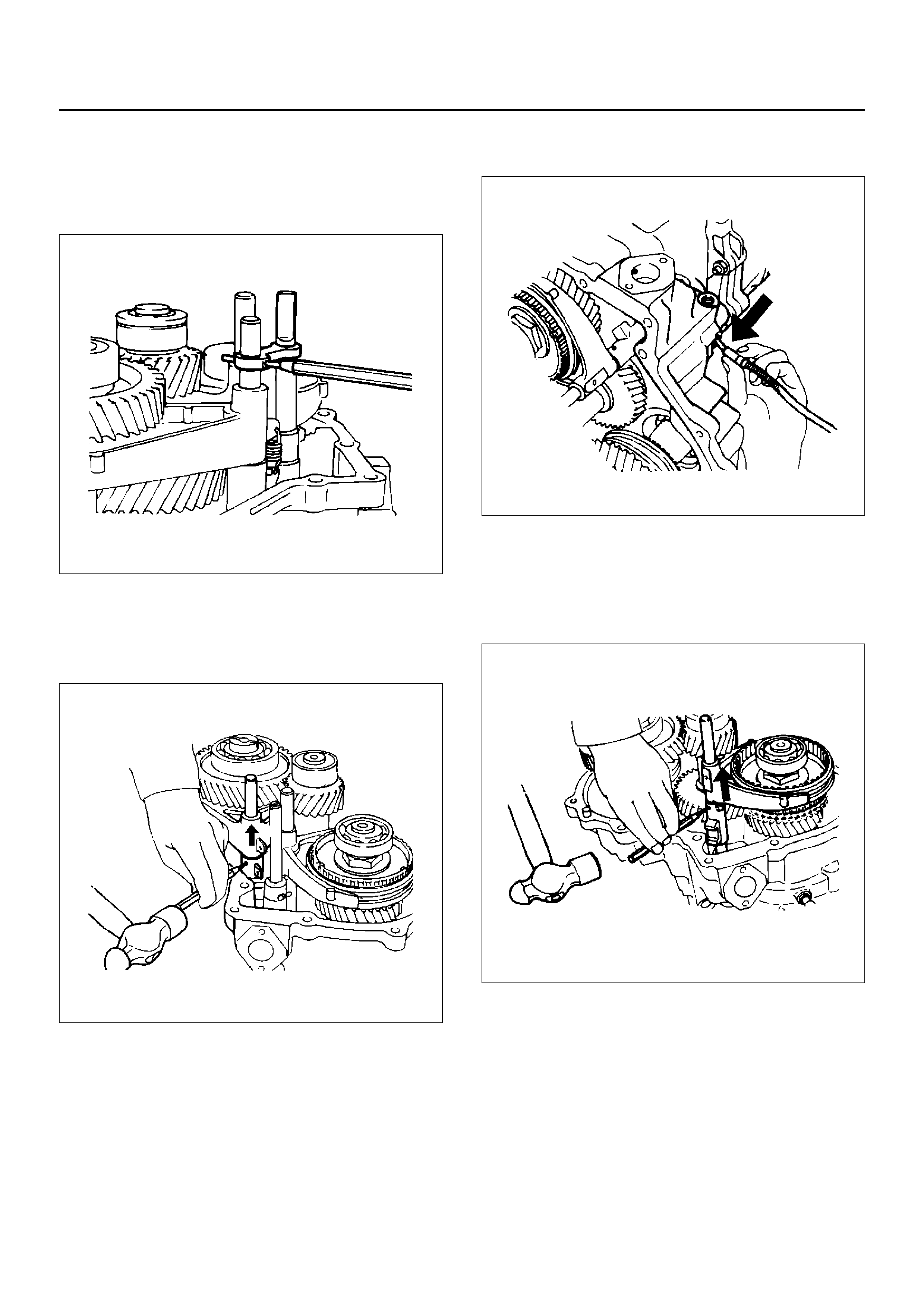
DISASSEMBLY
1. Remove detent ball, spring and plug (1).
2. Use a spring pin remover to remove the spring pin
(2) from the bridge (2).
262RW011
3. Remove spring (4).
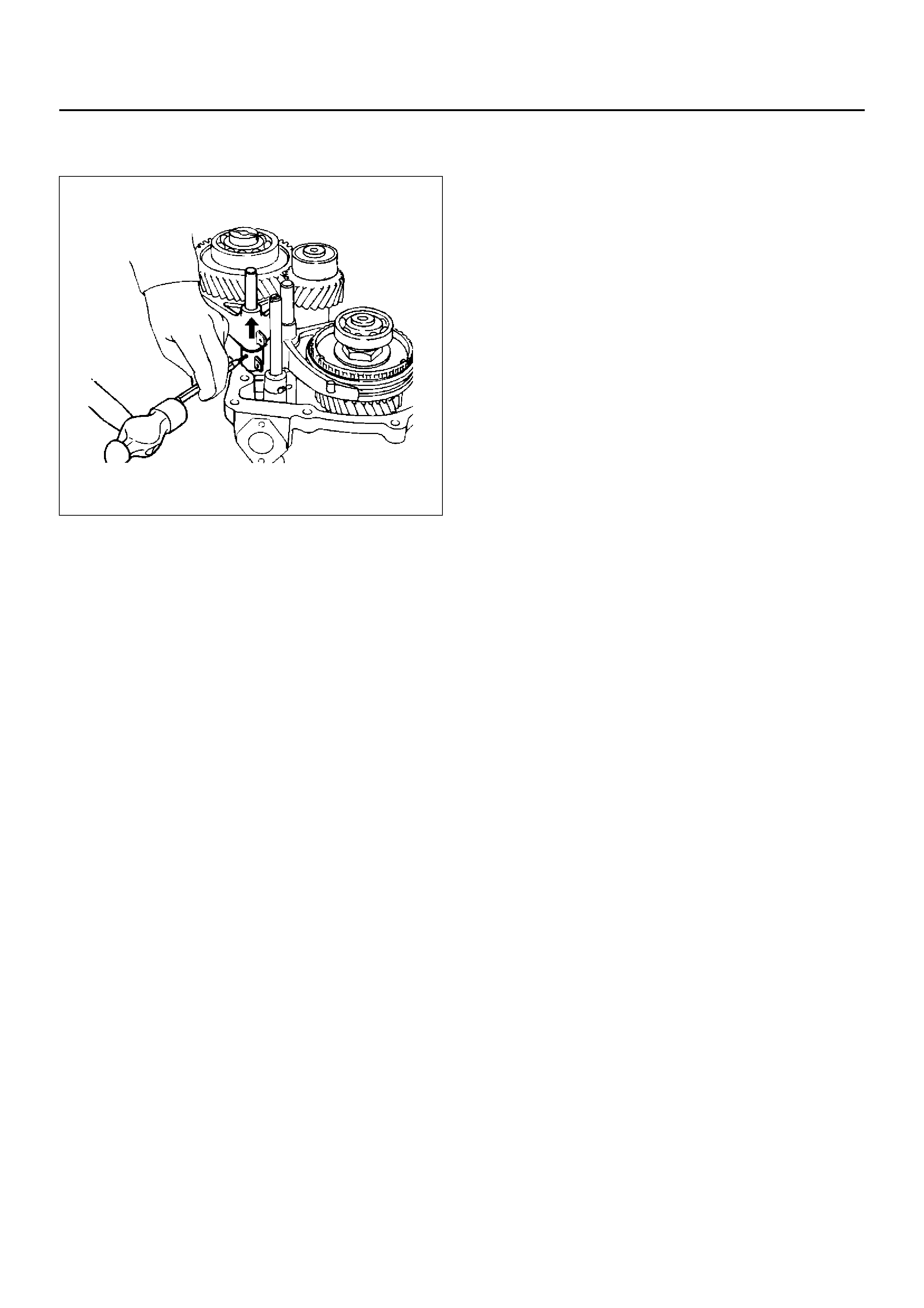
4. Engage the 2WD–4WD sleeve with front output
gear. Remove the spring pin (3) from the block (7).
Remove the shift rod (5).
262RW022
5. Remove shift arm (6).
6. Remove shift block (7).
7. Remove 4WD indicator switch (8).
8. Use a magnetic tool to remove the interlock pin (9)
and spring (10) from the transfer case (16).
262RS005
9. Remove select rod assembly (11).
10. Use a spring pin remover to remove the shift arm
spring pin (12) from the shift arm (14) and shift
block (15). Remove the high–low shift rod (13) from
transfer case (16).
262RS006
11. Remove shift arm (14).
12. Remove shift block (15) from transfer case (16).
INSPECTION AND REPAIR
Refer to “Transfer Case Assembly" in this section for
inspection and repair.
REASSEMBLY
1. Place shift block (15) in transfer case (16).
2. Set shift arm (14) on the High–Low sleeve.
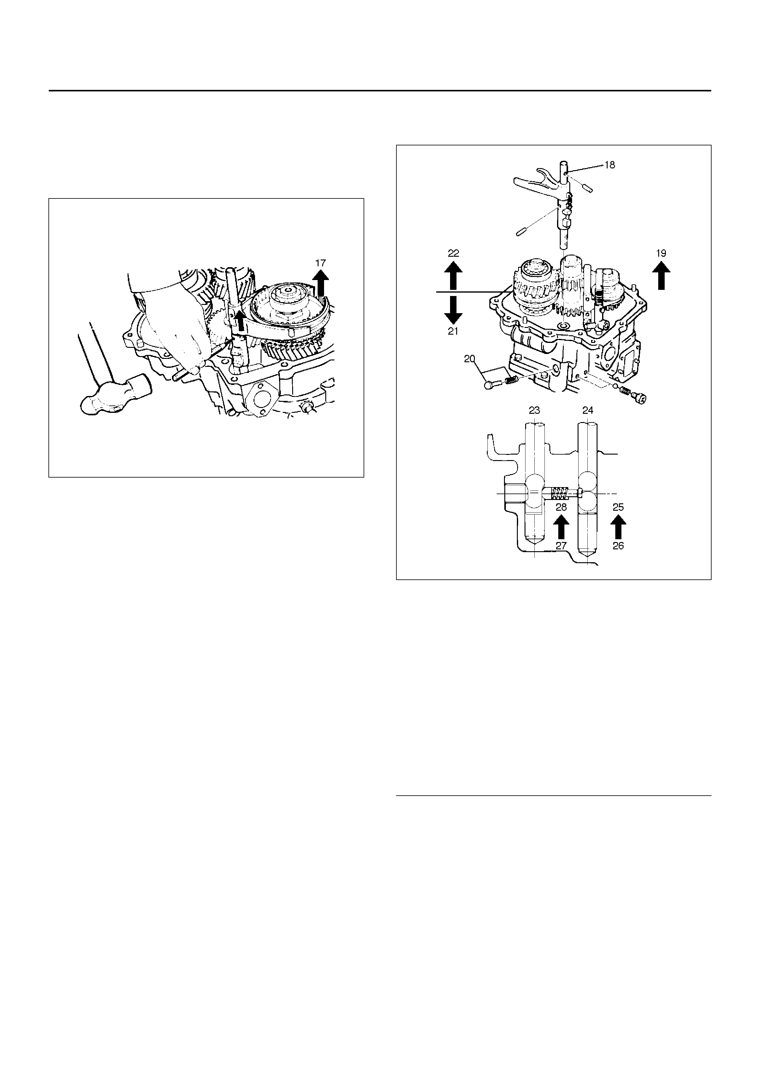
3. Push High–L ow shift rod (13 ) through shift arm ( 14)
and block (15).
4. Engage the High–Low sleeve with the 4H (1) side.
5. Install the spring pin (12) to the shift block (15) and
shift arm (14).
262RW034
6. Install select rod assembly (11), joining its lever to
shift block (15) groove.
7. Engage the High–Low sleeve with the 4H side and
install the interlock pin (9) and spring (10) in the
proper direction.
8. Place 2WD–4WD shift block (7) in the transfer case
(16).
9. Set 2WD–4WD shift arm (6) on the 2WD–4WD
sleeve.
10. Puh 2WD–4WD shift rod (5) through 2WD–4WD
shift arm (6) and 2WD–4WD shift block (7).
11. Install the 2WD–4WD shift rod (5) with interlock pin
push ed in.
262RW035
EndOFCallout
12. Install 4WD indicator switch and gasket (8).
Tighten to the specified torque.
Torque: 39 N·m
13. Install spring (4).
Legend
(18) 2WD–4WD
(19) 4H Side
(20) Interlock pin
(21) 2WD
(22) 4WD
(23) Rod: 2–4
(24) Rod: H–L
(25) 4H
(26) 4L
(27) 4×2
(28) 4×4
14. Engage the 2WD–4WD sleeve with the 4WD side
and install the spring pin (3).
262RW022
15. Install spring pin (2) and bridge (2).
16. Install detent ball, spring and plug and tighten the
plug to the specif ied tor que.
Torque: 25 N·m
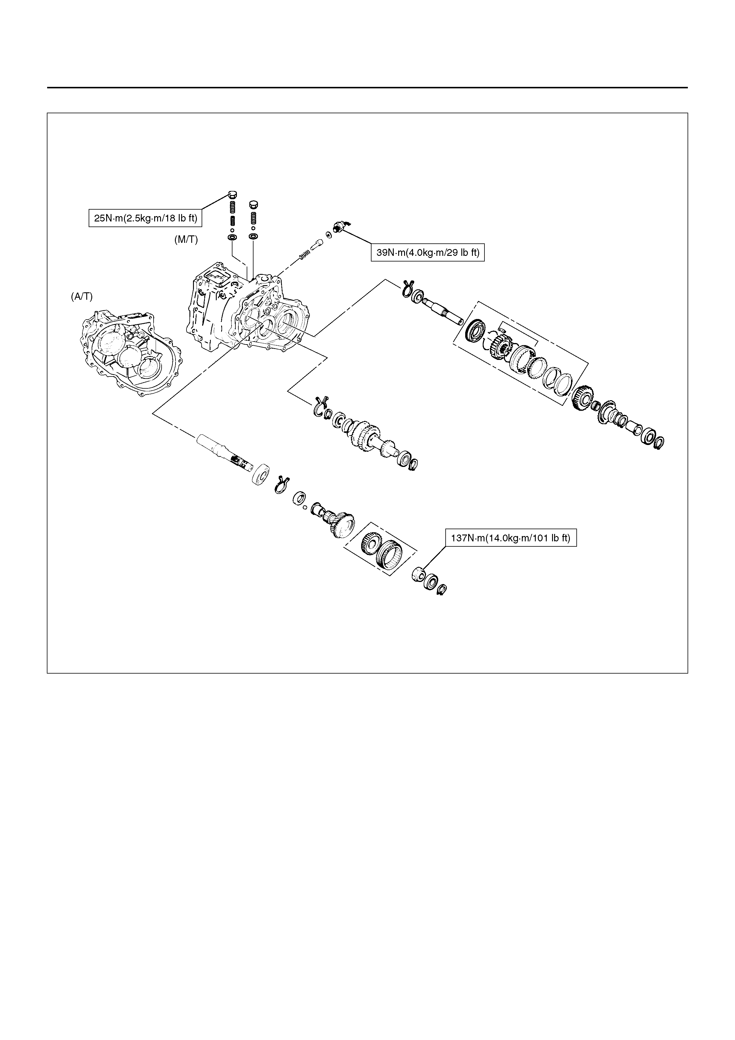
TRANSFER CASE ASSEMBLY
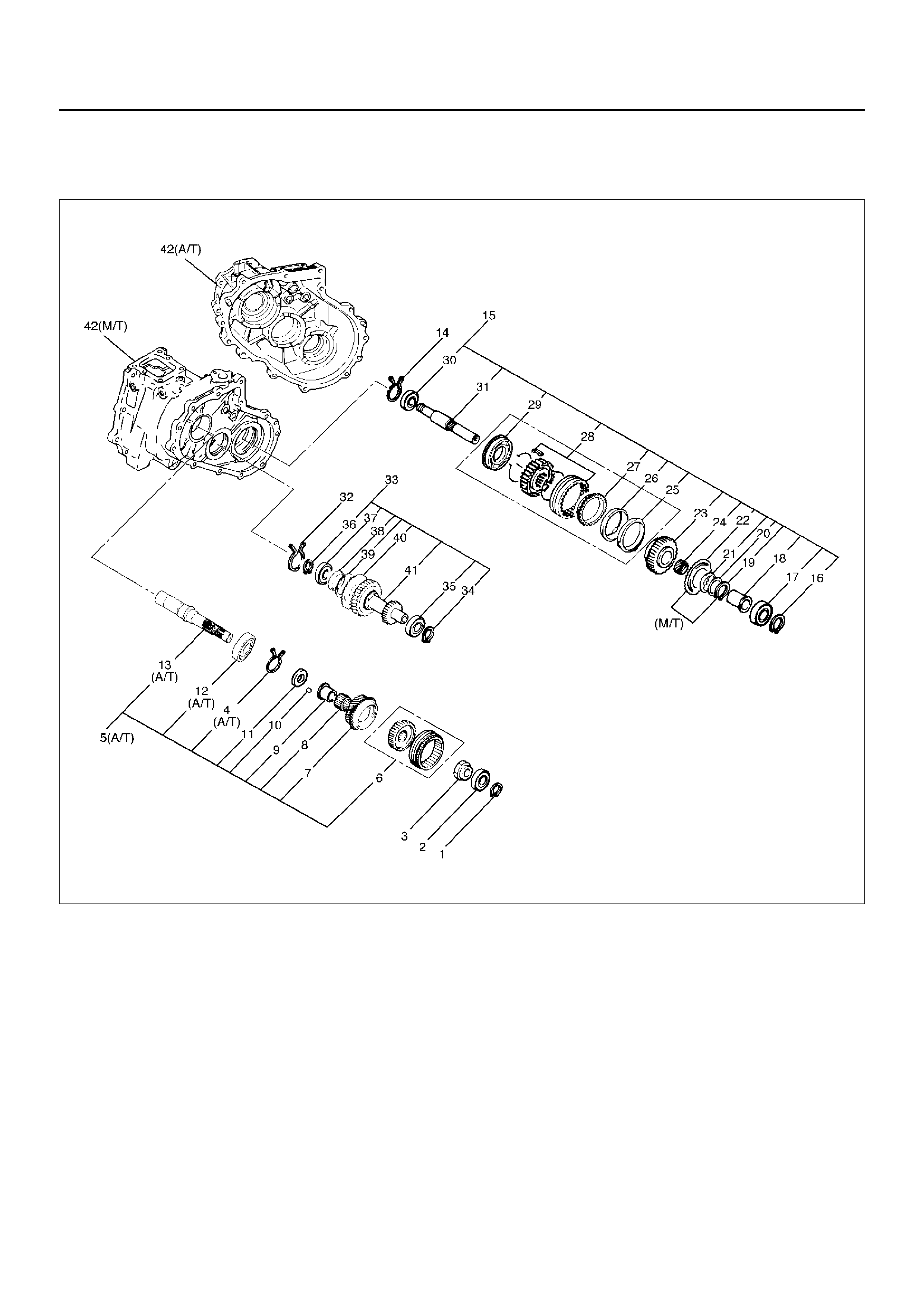
DISASSEMBLED VIEW
226RW209
Legend
(1) Bearing Snap Ring
(2) Ball Bearing
(3) Lock Nut
(4) Snap Ring (A/T)
(5) Input Shaft Assembly (A/T)
(6) High–Low Clutch Hub and Sleeve
(7) Transfer Input Gear
(8) Needle Bearing
(9) Bearing Collar
(10) Ball
(11) Plate
(12) Ball Bearing (A/T)
(13) Input Shaft (A/T)
(14) Bearing Snap Ring
(15) Front Output Gear Assembly
(16) Bearing Snap Ring
(17) Ball Bearing
(18) Bearing Collar
(19) Sub–Gear Snap Ring (M/T)
(20) Spacer (M/T)
(21) Belleville Spring (M/T)
(22) Sub–Gear (anti–lash plate) (M/T)
(23) Front Output Gear
(24) Need le Bearing
(25) Inside Ring
(26) Outside Ring
(27) Block R ing
(28) 2WD–4WD Clutch Hub and Sleeve Assembly
(29) Stopper Plate
(30) Ball Bearing
(31) Fr ont Ou tput Shaft
EndOFCallout
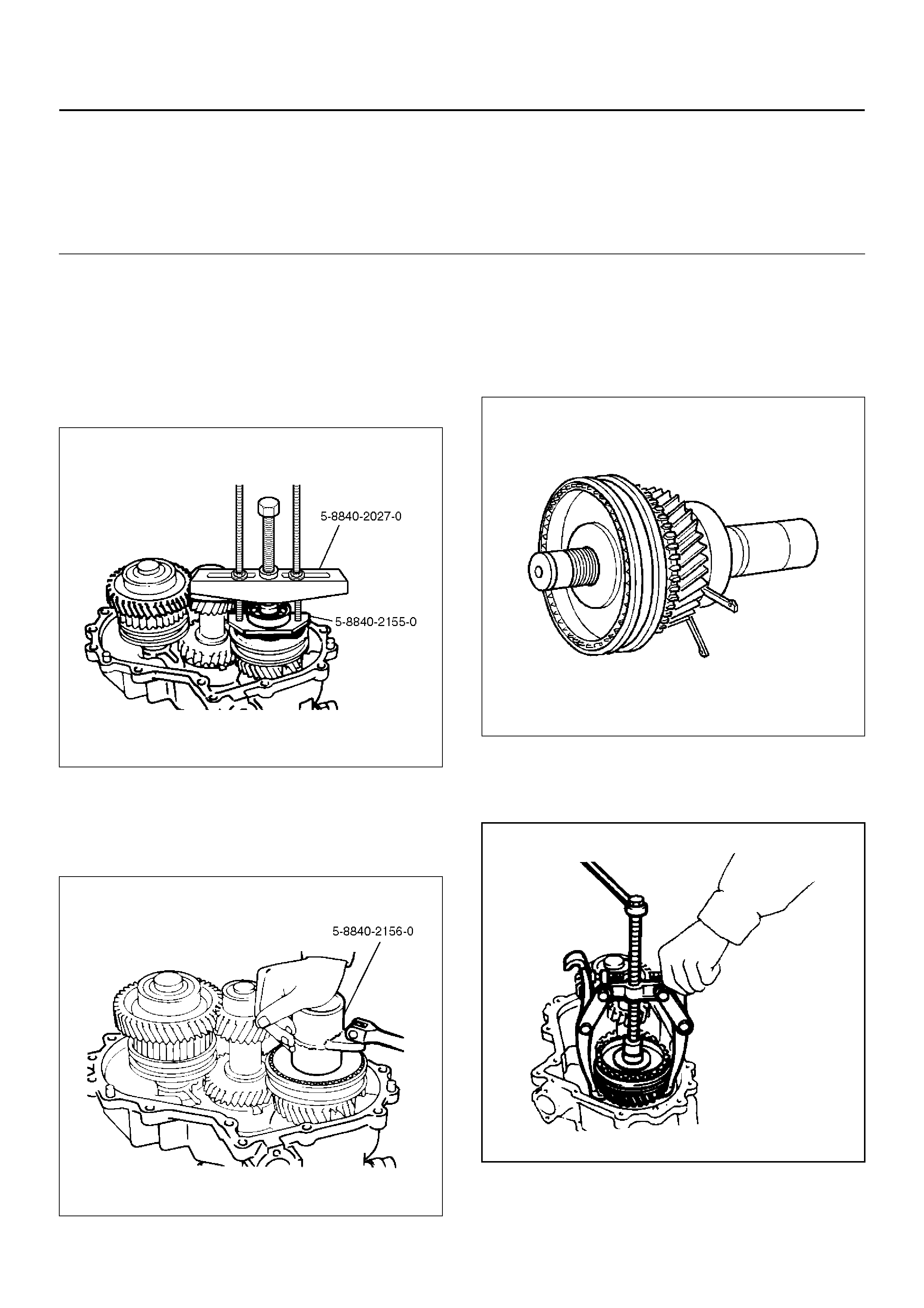
DISASSEMBLY
1. Use a pair of snap ring pliers to remove the snap
ring (1).
2. Use a bearing remover 5–8840–2155–0 and puller
5–8840–2027–0 to remove the ball bearing (2).
262RW069
3. Install the front companion flange temporarily.
4. Use the Companion flange holder 5–8840–0133–0
and loc k nu t wrench 5– 8840–21 56–0 to remove the
loc k n ut (3).
226RW190
5. Remove the front companion flange.
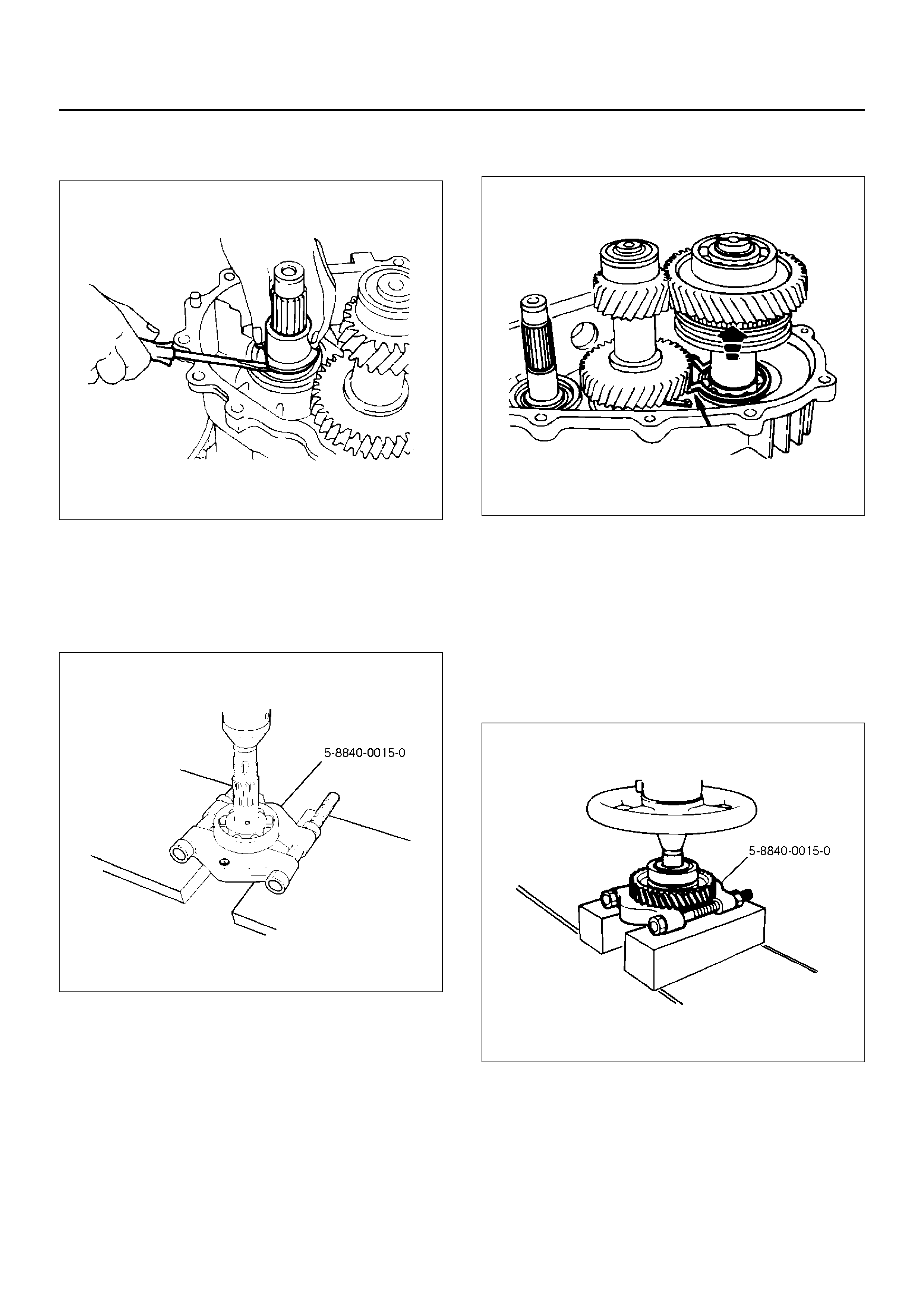
6. Remove snap ring (4). (A/T)
7. Remove the input shaft assembly (5) from the
transfer case (42). (A/T)
265RW001
8. Use the universal puller to remove the high–low
clutch hub and sleeve (6), and transfer input gear
(7).
226RS070
(32) Bearing Snap Ring
(33) Counte r Ge ar Assemb ly
(34) Snap Ring
(35) Ball Bearing
(36) Snap Ring
(37) Ball Bearing
(38) Spacer
(39) Belleville Spring
(40) Sub–Gear (anti–lash plate)
(41) Counter Gear
(42) Transfer Case (with oil seal)
9. Remove needle bearing (8).
10. Remo ve bea ring co ll ar (9).
226RS071
11. Remo ve ball (10 ).
12. Remo ve plat e (11).
13. Use a bench press and the ball bearing remover
5–8840–0015–0 to remove the ball bearing (12)
from the input shaft (13). (A/T)
265RW013
14. Use a pair of snap r ing pl iers to remo ve the bear ing
snap r ing (14).
15. Use a plastic hammer to tap the front output gear
assembly (15) free.
262RS009
16. Remove bearing snap ring (16).
17. Use a bench press and the bearing remover
5–8840–0015–0 to remove the following parts.
18. Remove ball bearing (17), and bearing collar (18).
Remove sub–gear snap ring (19), spacer (20),
belleville spring (21), and sub–gear (anti–lash plate)
(22). (M/T)
Remove front output gear (23) and needle bearing
(24).
262RW070
19. Remo ve inside ring (25).
20. Remove outside ring (26).
21. Remove block ring (27).
22. Use a bench press and bearing remover 5–8840–
0015–0 to remove 2WD–4WD clutch hub and
sleeve assembly (28) and stopper plate (29).
NOTE: Do not reuse the stopper plate.
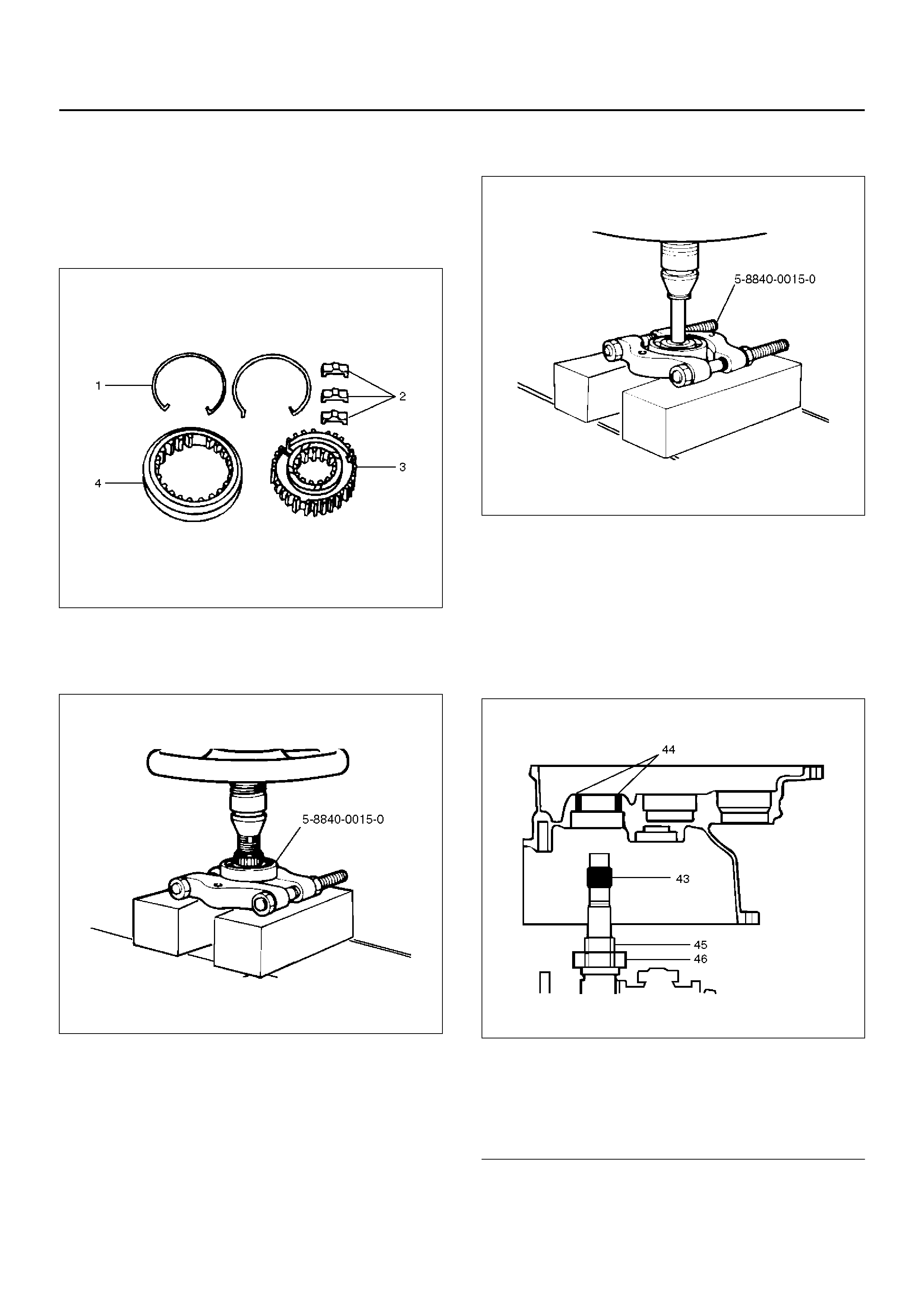
23. Disassemble the 2WD–4 WD clutch hub and sleeve
assembly (28).
• Springs (1)
• Inserts (2)
• Clutch Hub (3)
• Sleev e (4)
226RW133
24. Use a bench press and the ball bearing remover
5–8840–0015–0 to remove the ball bearing (30)
from front output shaft (31).
262RW071
25. Remo ve beari ng sn ap ring (32 ).
26. Remove the counter gear assembly (33) from the
transf er case (42).
27. Use a pair of snap ring pliers to remove the snap
ring (34).
28. Use a bench press and the bearing remover
5–8840–0015–0 to remove the ball bearing (35).
29. Use a pair of snap ring pliers to remove the snap
ring (36).
30. Use a bench press and the bearing remover
5–8840–0015–0 to remove the ball bearing (37).
226RW208
31. Remove spacer (38).
32. Remove belleville spring (39).
33. Remove sub–gear (anti–lash plate) (40).
34. Remove counter gear (41).
35. Remove transfer case (with oil seal) (42),
performing the following steps (M/T)
• Cover the shaft splines with adhesive tape (43).
A07RW022
EndOFCallout
• Remove the transfer case together with
intermediate plate with gear assembly from the
transmission case (M/T).
Legend
(43) Adhesive Tape
(44) Oil Seal Lip
(45) Oil Seal Collar
(46) Bearing
• Remove the transfer case from the intermediate
plat with gear assembly (M/T).
INSPECTION AND REPAIR
1. Make the necessary repair or parts replacement if
wear, damage or any other ab normal co nditi ons are
found during inspection.
2. Wash all parts thoroughly in clean solvent. Be sure
all old lubricant, metallic particles, dirt, or foreign
material are removed from the surfaces of every
part. Appl y c omp ress ed air to eac h oi l f eed p or t an d
channel in each case half to remove any
obstructions or cle aning solv ent residue.
Gears
1. Inspect all the gear teeth for signs of excessive
wear or damage and check all the gear splines for
burrs, nicks, wear or damage. Remove the minor
nicks or scratches on an oil s tone . Rep lac e a ny part
exhibiting excessive wear or damage.
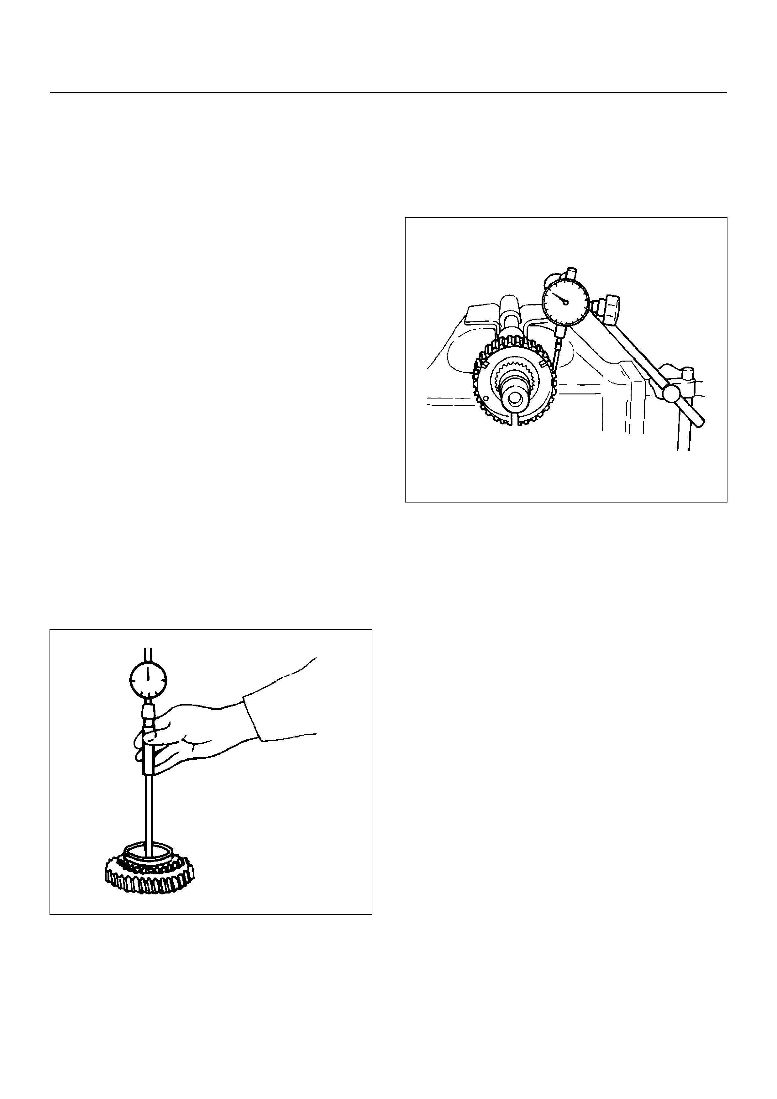
Front Output Gear Inside Diameter
1. Use an inside dial indicator to measure the gear
inside diameter.
2. If the measured value exceeds the specified limit,
the gear must be replaced.
Gear inside diameter
Standard : 48.000–48.013 mm
Limit : 48.10 mm
226RS040
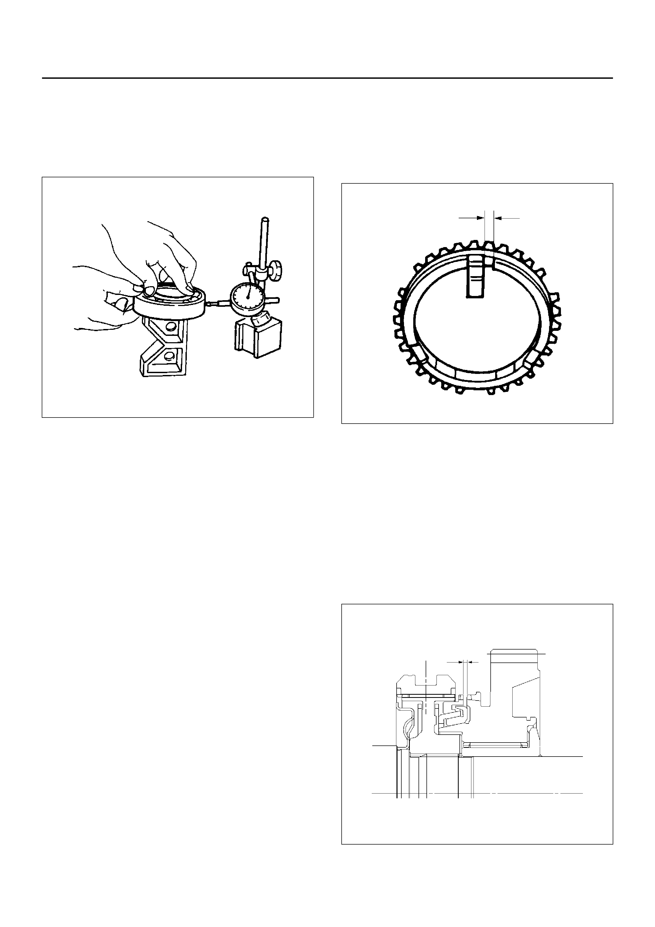
Clutch Hub Spline Play
1. Set a dial indicator to the clutch hub to be
measured.
2. Move the clutch hub as far as possible to both the
right and the lef t.
Note the dial indicator reading.
3. If the measured value exceeds the specified limit,
the clutch hub must be replaced.
Clutch hub spline play
Standard : 0–0.1 mm
Limit : 0.2 mm
226RS042
Bearings
1. Inspect the condition of all the needles and ball
bearings. Wash bearings thoroughly in a cleaning
solvent. Apply compressed air to the bearings.
NOTE: Do not allow the bearings to spin. Turn them
slowly by hand. Spinning bearings may damage the
rollers.
2. Lubricate the bearings with a light oil and check
them for roughness by slowly turning the race by
hand.
Ball Bearing Play
1. Use a dial indicator to measure the ball bearing play.
2. If the measured value exceeds the specified limit,
the ball bearing must be replaced.
Limit : 0.2 mm
226RS043
Synchronizers
The synchronizer hubs and sliding sleeves are a
selected assembly and should be kept together as
originally assembled.
Clean sy nchronizer components with clean solv ent and
air dry.
Inspect the components for the following:
• Teeth for wear, scuffs, nicks, burrs or breaks.
• Keys and springs for wear, cracks or distortion,
replace if these conditions are present.
• If scuffed, nicked or burred conditions cannot be
corrected with a soft stone or crocus cloth, replace
the component.
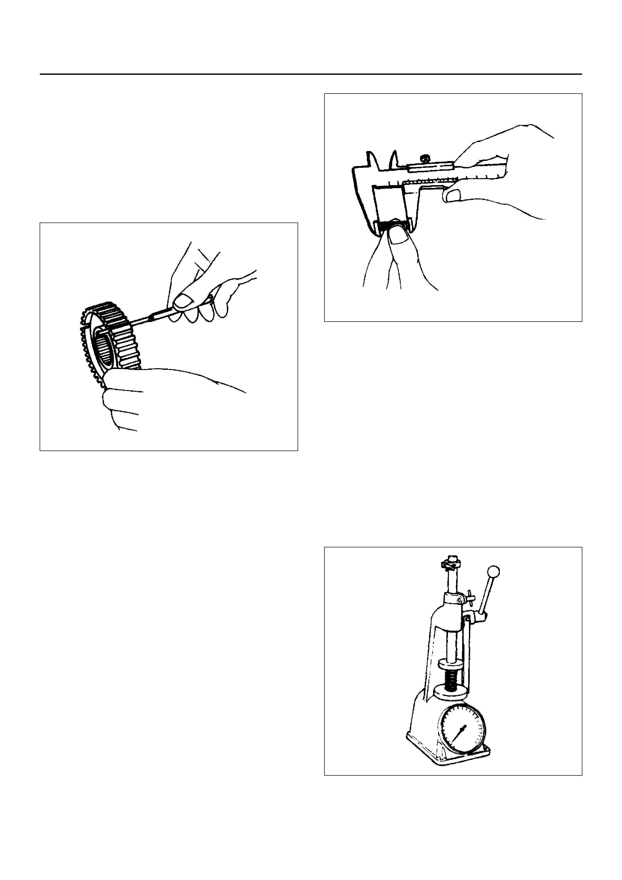
Block Ring and Insert Clearance
1. Use a vernier caliper to measure the clearance
between the block ring and the insert.
2. If the measured value exceeds the specified limit,
the block ring and the insert must be replaced.
Block ring and insert clearance
Standard : 2.46–2.74 mm
Limit : 3.0 mm
226RS037
2WD–4WD Synchronizer (3–Cone)
1. Use a thickness gauge to measure the clearance
between the block ring and the dog teeth.
2. If the measured value exceeds the specified limit,
the 2WD–4WD synchronizer assembly must be
replaced.
Block ring and insert clearance
Standard : 1.5 mm
Limit : 0.8 mm
226RW142
Clutch Hub and Insert Clearance
1. Use a thickness gauge to measure the clearance
between the clutch hub and the insert.
2. If the measured value exceeds the specified limit,
the clutch hub and the insert must be replaced.
Clutch hub and inser t clea ranc e
Standard : 0.01–0.19 mm
Limit : 0.3 mm (0.012 in)
226RS038
Detent Springs
1. Inspect the springs for distortion, cracks or wear.
Replace if these conditions are present.
Detent Spring Free Length
1. Use a vernier caliper to measure the detent spring
free length.
2. If the measured value is less than the specified limit,
the detent spring must be replaced.
Detent spring free length
Detent ball
Interlock pin
220RW035
Detent Spring Tension
1. Use a spring tester to measure the detent spring
tension.
2. If the measured value is less than the specified limit,
the detent spring must be replaced.
Detent ball
Interlock pin
220RS013
Standard : Inner 23.2 mm
Outer 26.8 mm
Limit : Inner 22.6 mm
Outer 26.2 mm
Standard : 15.9 mm
Limit : 15.3 mm
Compressed height : 19.7 mm
Standard : Inner 22.6 ∼ 32.4 N
Outer 91.2 ∼ 101.0 N
Compressed height : 11.5 mm
Standard : 9.8 N
Shift Arm
1. Inspect the shift arms for wear, distortion or scoring.
Replace if these conditions are present.
Shift Arm Thickness
1. Use a micrometer to measure the shift arm
thickness.
2. If the measured value is less than the specified limit,
the shift arm must be replaced.
Shift arm thickness
Standard : 9.60–9.85 mm
Limit : 9.0 mm
230RS006
REASSEMBLY
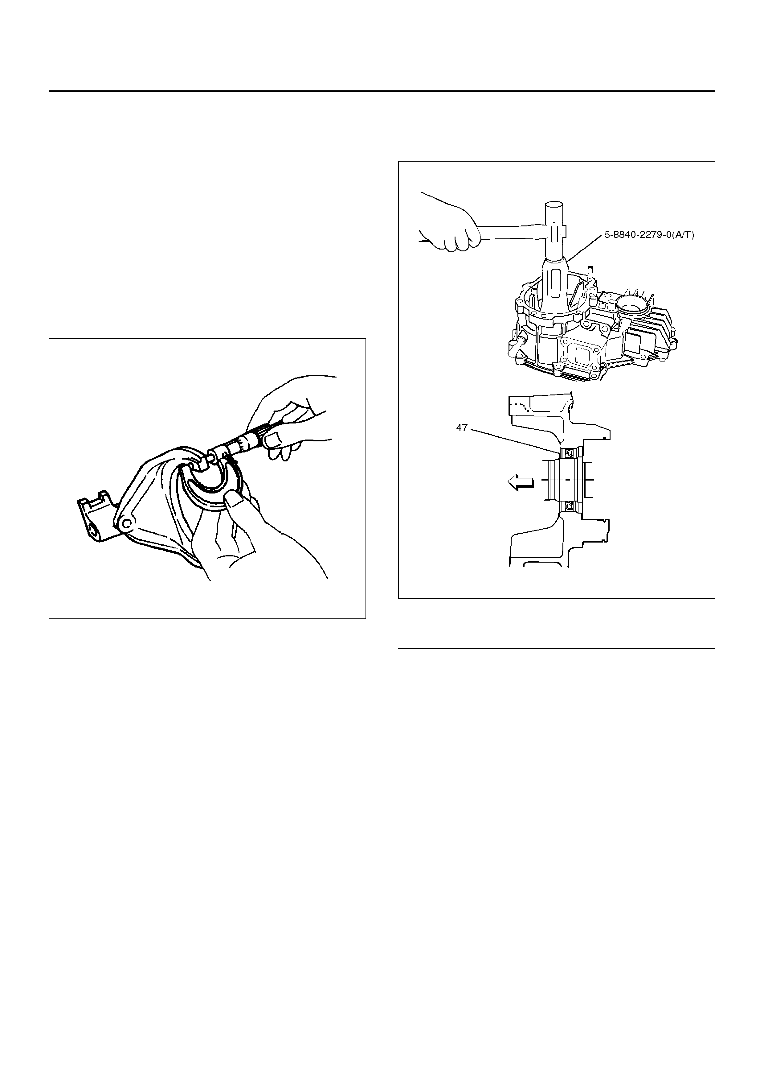
Input Shaft Oil Sea l Replace ment
1. Remove the oil seal from the transfer case.
2. Apply the engine oil to the oil seal outer surfaces.
3. Apply recommended grease (BESCO L2) or
equivalent to the oil seal lip.
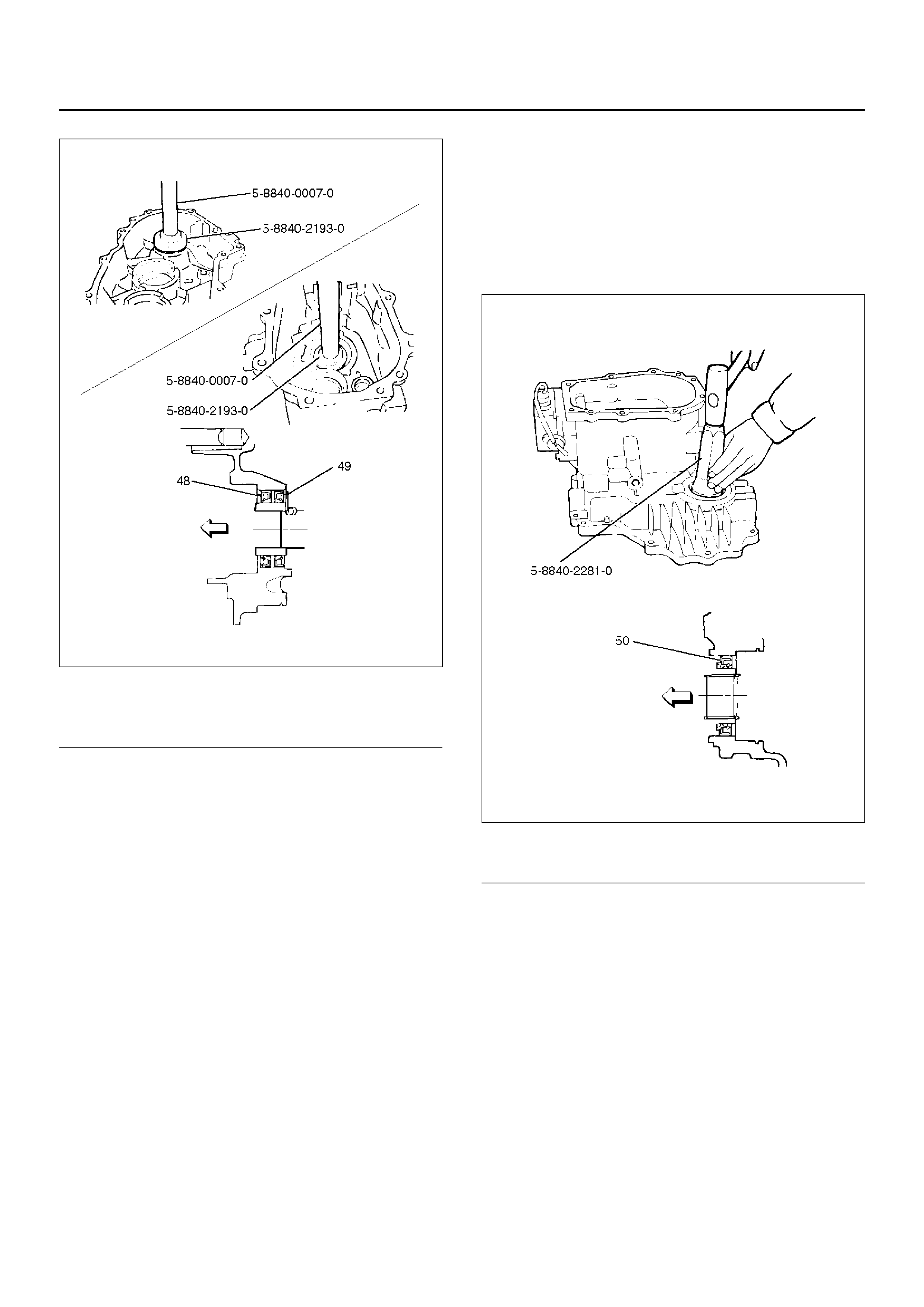
4. Use the oil seal installer 5–8840–2279–0 (A/T)
5–8840–2193–0 (M/T) and driver handle 5–8840–
0007–0 to install the oil seal to the transfer case.
A/T
220RW130
EndOFCallout
Legend
(47) Oil Seal
M/T
220RW132
EndOFCallout
Front Output Shaft Oil Seal Replacement
1. Remove the oil seal from the transfer case.
2. Apply engine oil to the oil seal outer surfaces.
3. Apply recommended grease (BESCO L2) or
equivalent to the oil seal lip.
4. Use the oil seal installer 5–8840–2281–0 to install
the oil seal to the transfer case.
220RW131
EndOFCallout
Legend
(48) Transmission Side Oil Seal
(49) Transfer Side Oil Seal
Legend
(50) Front Output Shaft Oil Seal
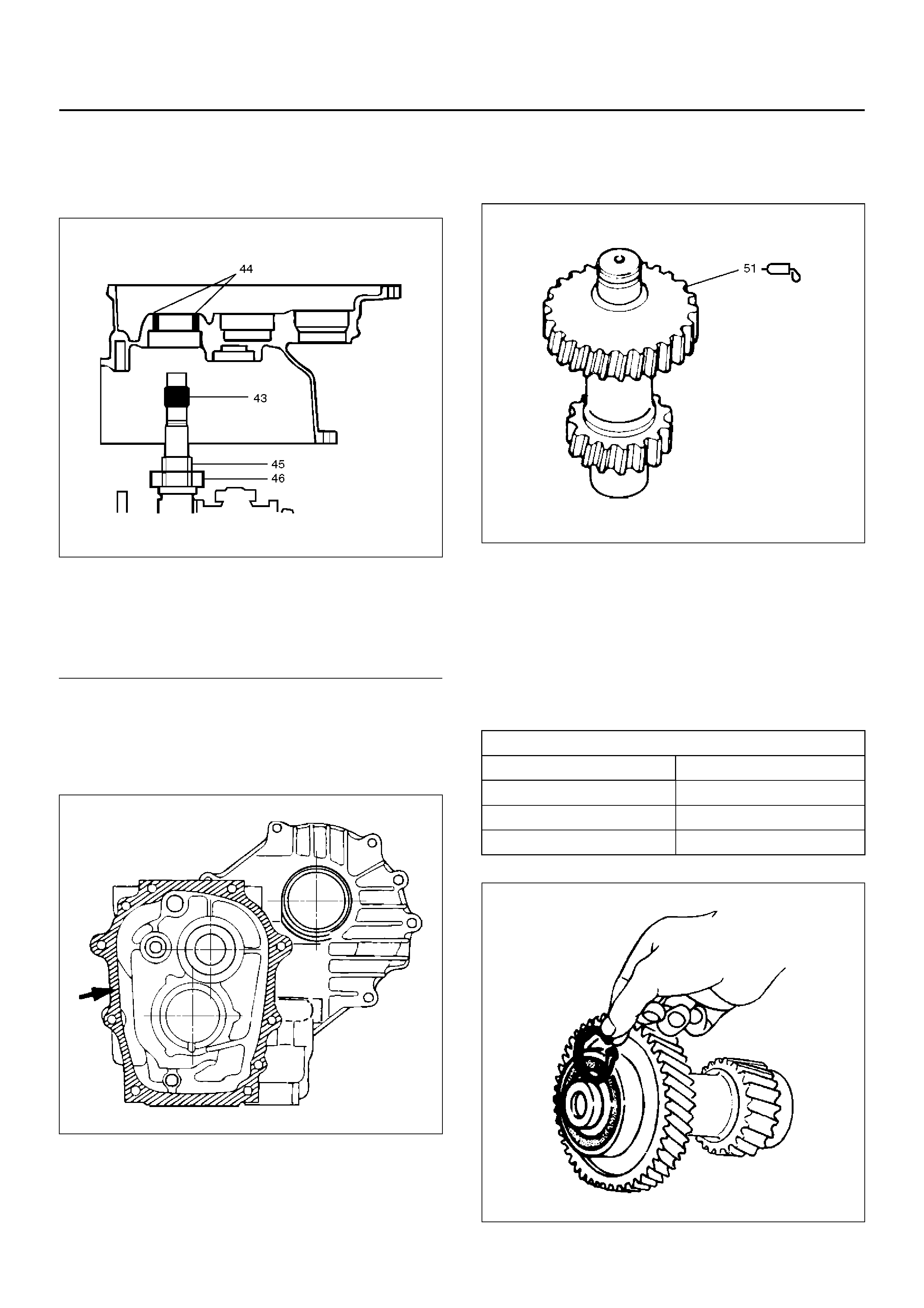
5. Install the transfer case (with oil seal) (42),
perfor ming the foll owi ng steps. (M/T)
• Cover the shaft splines with adhesive tape (43).
This will prevent damage to the oil seal lip (44).
A07RW022
EndOFCallout
• Apply recommended liquid gasket (LOCTITE
17430) or its equivalent to the transmission,
intermediate plate and transfer case fitting
surfaces (M/T).
220RS026
Install the transfe r case toge ther with intermedi ate plat e
with gear assembly to transmission case (M/T).
Tighten the t ransfer c ase bolts to the s pecifie d torque a
little at a time (M/T).
Torque : 37 N·m
6. Apply chas sis grease (51) to the sub–gea r (40) and
the counter gear (41) thrust surfaces.
226RW155
7. Install sub–gear (40) to counter gear (41).
8. Install belleville spring (39).
9. Install spacer.
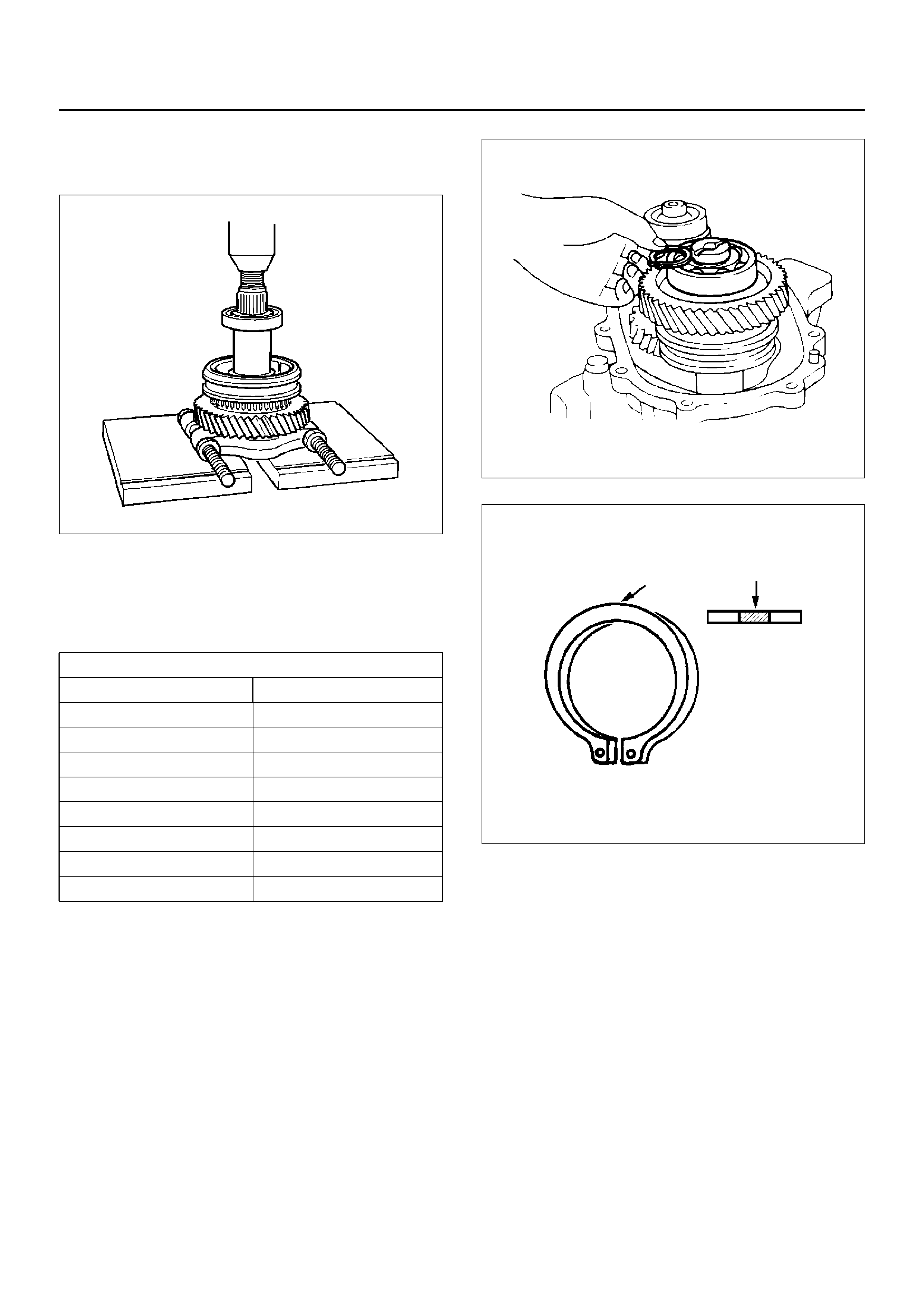
10. Install ball bearing, using a bench press.
11. Select a snap ring that will allow the minimum axial
play.
Clearance : 0–0.1 mm
226RS170
Legend
(43) Adhesive Tape
(44) Oil Seal Lip
(45) Oil Seal Collar
(46) Bearing
Snap ring availability:
Thickness Color–coding
1.50 mm White
1.55 mm Yellow
1.60 mm Blue
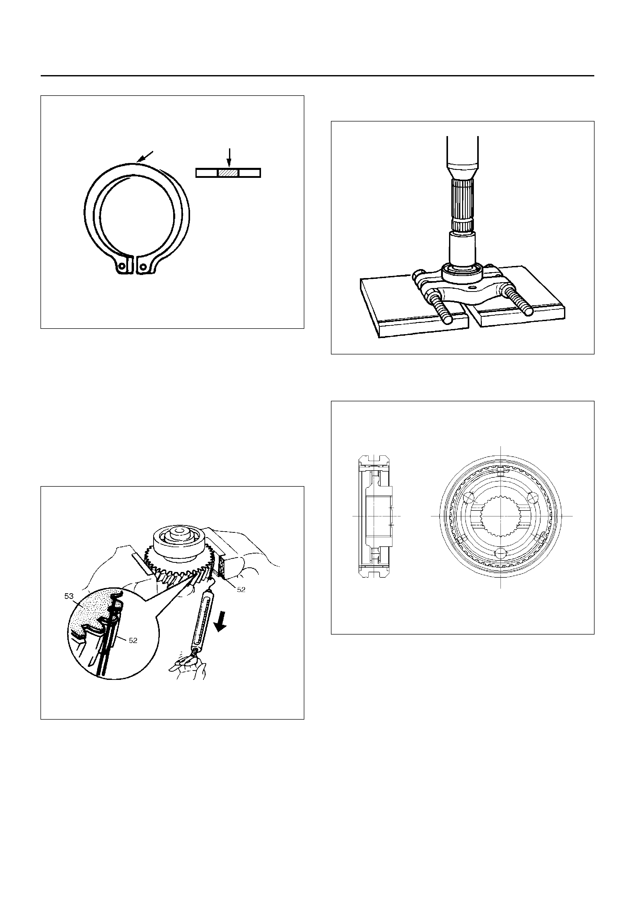
226RS021
12. Use a pair of snap ri ng pli ers to install th e sna p rin g
(36) to the counter gear (41).
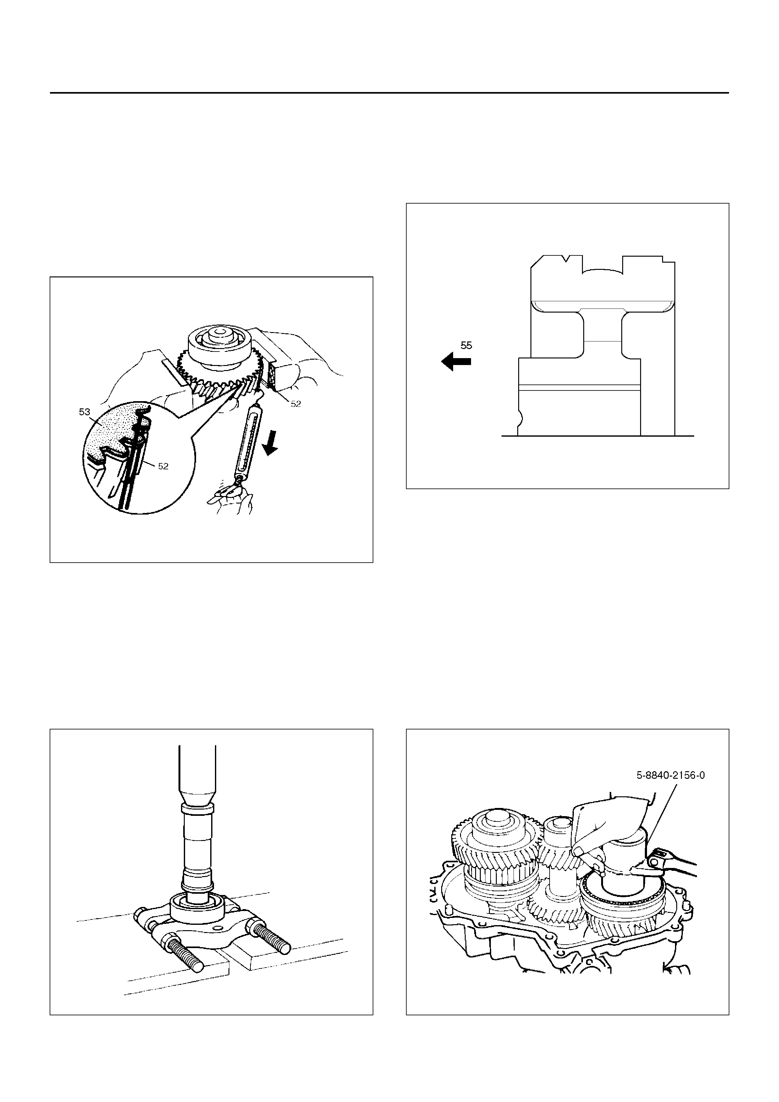
Sub–Gear (anti–lash plate) Preload
1. Hook a len gth of pi ano wire (52) o ve r on e o f th e
sub–gea r (53) teeth.
2. Attach the other end of the piano wire (52) to a
spring balancer.
3. Measure the sub–gear preload.
Preload : 59–98 N
226RW156
13. Install ball bearing (35), using a bench press.
14. Install snap ring (34).
15. Install the counter gear assembly (33) to the transfer
case (42).
16. Use a pair of snap ri ng pli ers to install th e sna p rin g
(32) to the transfer case (42).
NOTE: The snap ring must be fully inserted into the
transfer case snap ring groove.
17. Use a benc h press to in stall the ball bear ing (30) to
the front output shaft (31).
262RS012
18. Assemble the 2WD–4WD clutch hub and sleeve
assembly (28).
226RW140
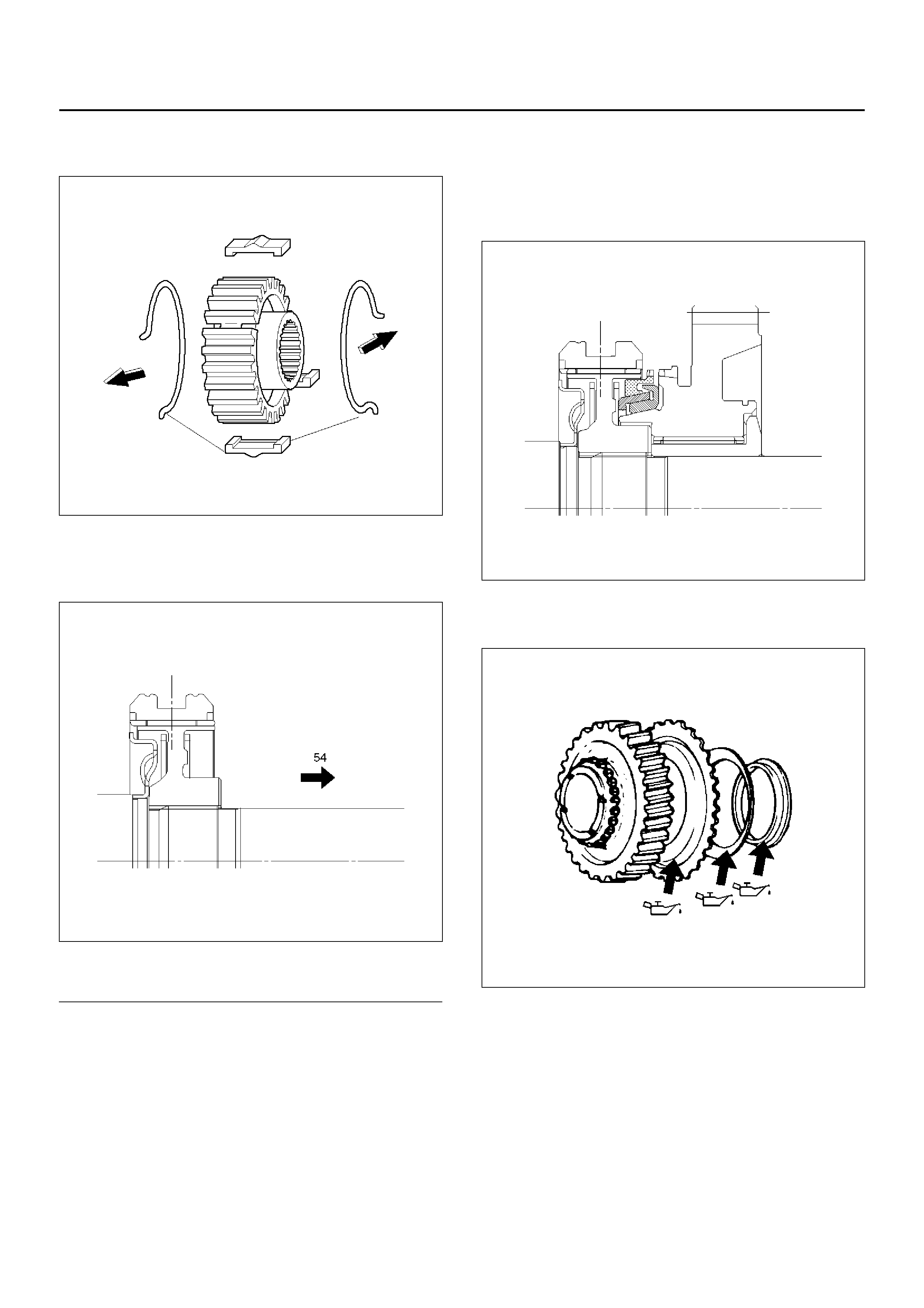
19. Engage the springs in the same insert with the open
ends away from each other.
226RW141
20. Install a new stopper plate (29) and the clutch hub
and sleeve assembly (28) to the front output shaft
(31).
226RW157
EndOFCallout
21. The clutch hub face (with the heavy boss) must be
facing the front output gear side.
22. Use a bench press to slowly force the clutch hub
and slee ve assembly ( 28) together with the s topper
plate (29) into place.
23. Align the inserts with the block ring insert grooves.
Install the block ring (27) to the clutch sleeve and
hub assembly (28).
24. Install the outside ring (26), inside ring (25) and
needle bearing (24) to the front output gear (23) and
bearing collar (18).
NOTE: Coat all parts with transmission oil before
installing them.
226RW139
25. Apply engine oil to the thrust surfaces of the sub–
gear, the belleville spring, and the spacer (M/T).
262RW014
26. Install sub–gear (anti–lash plate) (22), belleville
spring (21) and spacer (20). (M/T)
27. Install sub–gear snap ring (19). (M/T)
Legend
(54) Front Output Gear
28. Use a bench press to install the needle bearing
collar together with the front output gear assembly,
aligning inside ring claw with block ring groove.
262RS014
29. Install ball bearing (17), using a bench press.
30. Select a snap ring (16) that will allow the minimum
axial play.
Clearance : 0–0.1 mm
262RS015
226RS021
Snap ring availability:
Snap ring thickness Color coding
1.55 mm White
1.60 mm Yellow
1.65 mm Blue
1.70 mm Pink
1.75 mm Green
1.80 mm Brown
1.85 mm Red
1.90 mm Orange
31. Use a pair of snap ri ng pli ers to install th e sna p rin g
(16) to the output shaft (31).
Sub-gear (anti-lash plate) preload (M/T)
1. Hook a len gth of pi ano wire (52) o ve r on e o f th e
sub–gea r (53) teeth.
2. Attach the other end of the piano wire to (52) a
spring balancer.
3. Measure the sub–gear preload.
Preload : 59–98 N
226RW156
32. Install front output gear assembly (15) to transfer
case (42).
33. Use a pair of snap ri ng pli ers to install th e sna p rin g
(14) to the transfer case (42).
NOTE: The snap ring must be fully inserted into the
transfer case snap ring groove.
34. Use a be nch press to install the ba ll bearing (1 2) to
the input shaft (13). (A/T)
265RS003
35. Install plate (11), ball (10) and bearing collar (9).
NOTE: Put the snap ring (4) in the ball bearing side.
(A/T)
36. Install needle bearing (8) and input gear (7).
37. The clutch hub face (with the heavy boss) must be
facing the tra ns fer input gear side (5 5) .
226RW158
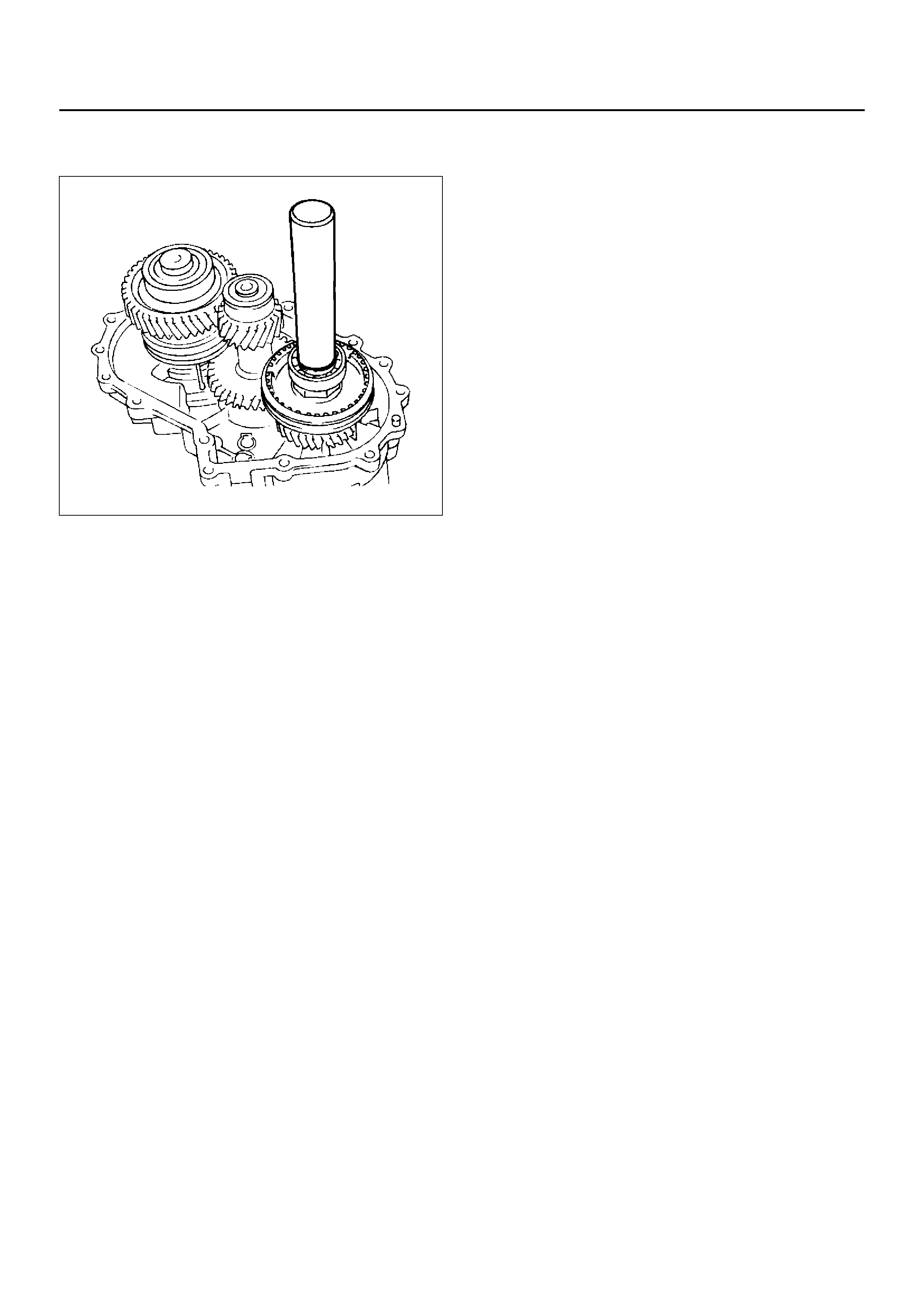
38. Install high–low clutch hub and sleeve (6), using a
bench press.
39. Install input shaft assembly (5) to transfer case (42).
(A/T)
40. Install the s nap ring ( 4) to t he tr an sfe r cas e ( 42). ( A/
T)
NOTE: The snap ring must be fully inserted into the
transfer case snap ring groove.
41. Install the front companion flange temporarily and
use the flange holder 5–8840–0133–0 and lock nut
wrench 5–8840–2156–0 to install the lock nut (3).
Torque: 137 N·m
226RW190
42. Use the punch to stake the lock nut (3) at one spot.
43. Use a suitable drift and hammer to install the ball
bearing (2).
226RS079
44. Install bearing snap ring (1).
MAIN DATA AND SPECIFICATIONS
General Specifications
Torque Specifications
E07RX012
Type Synchronized type gears shifting between the 2 and 4 wheel drive mode.
Constant mesh type gears shifting between “low" and “high".
Control method Remote (A/T) and direct (M/T) control with the gear shift lever on the floor for
gears shifting between “low" and “high".
Electric control with the button switch on the instrument panel for gears
shifting betw een the 2 and 4 wheel d rive r mode.
Gear ratio High; 1.000
Low; 2.050
Oil capacity 1.45 lit. (1.53 U.S. quart)
Type of lubricant Engine oil
Refer to chart in Section 0
E07RX021
262R100004
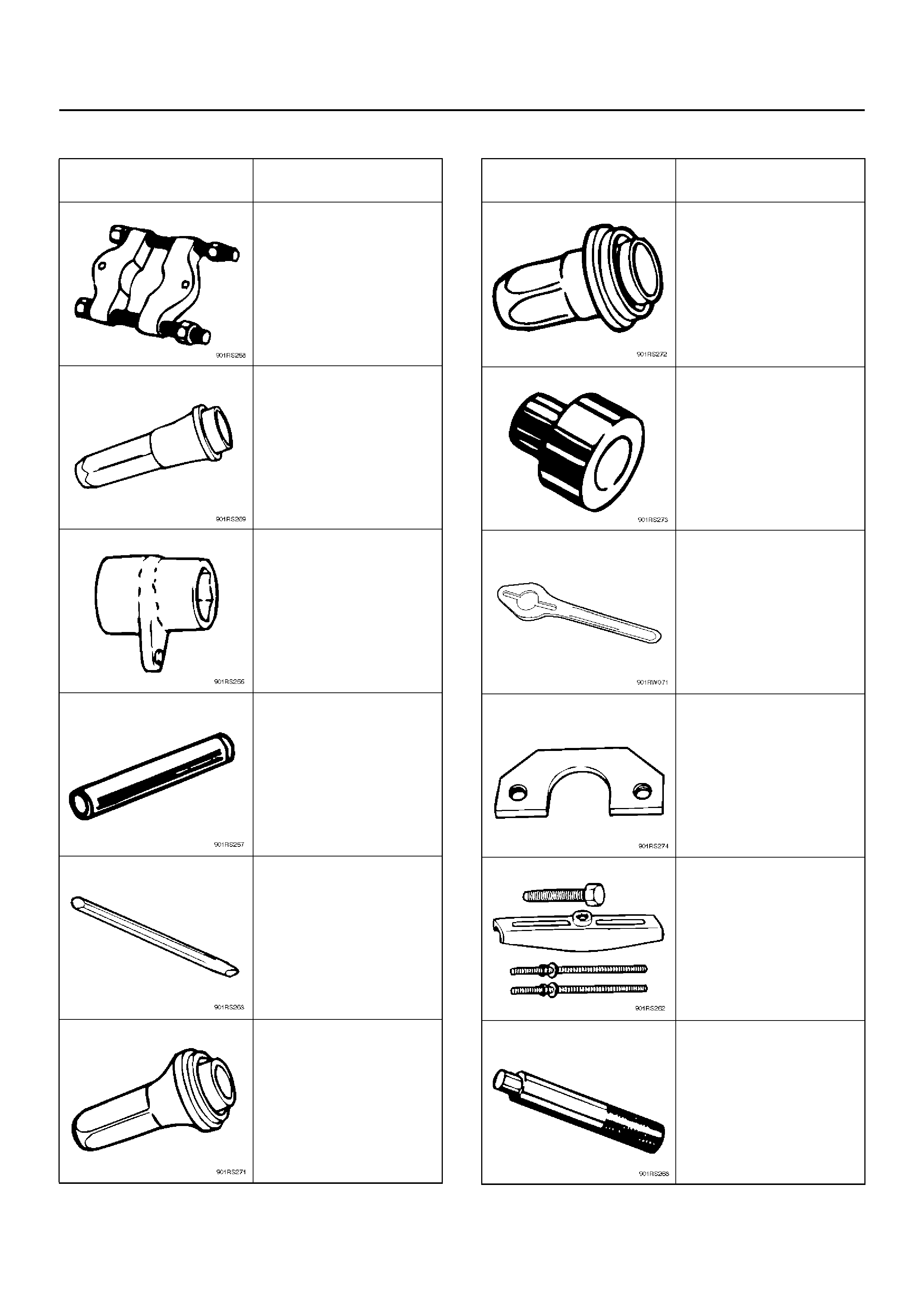
SPECIAL TOOLS
ILLUSTRATION PART NO.
PART NAME
5–8840–0015–0
Bearing remover/installer
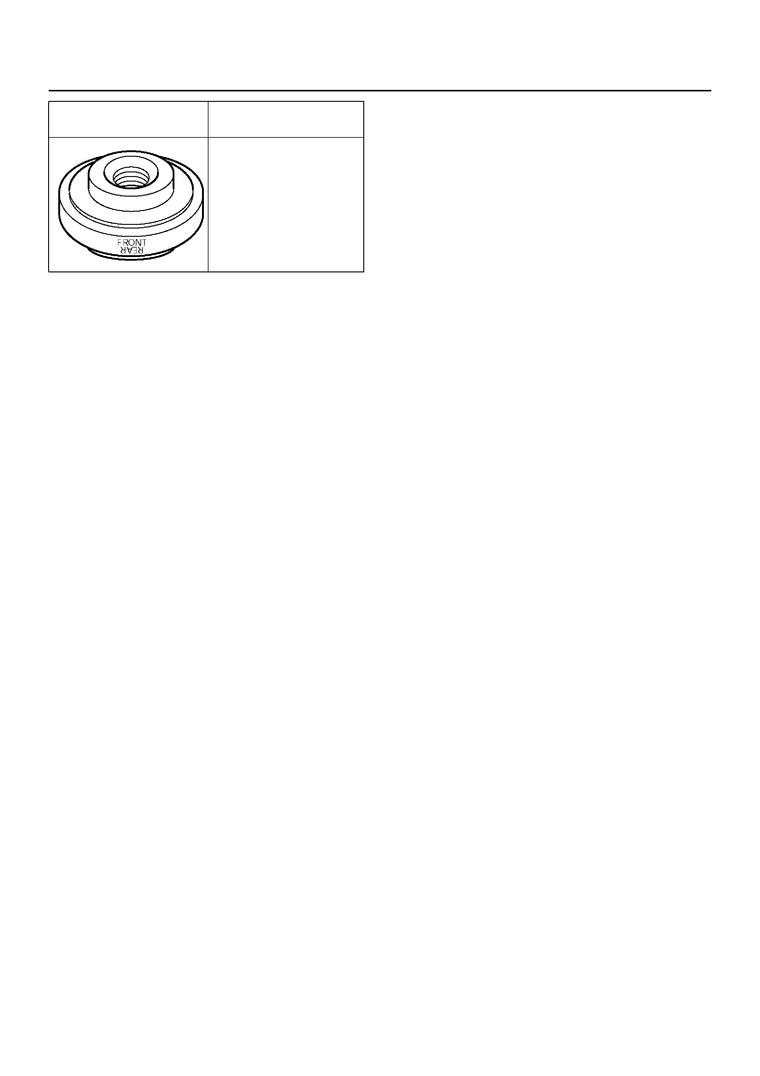
5–8840–2279–0
Transfer case oil se al
installer
5–8840–2156–0
Mainshaft nut wrench
5–8840–2159–0
Rear output shaft and
bearing ins talle r
5–8840–2293–0
Punch; end nut
5–8840–2281–0
Front output shaft oil seal
installer
5–8840–2292–0
Rear oil seal installer
5–8840–2192–1
Bearing installer adapter
5–8840–0133–0
Flange holder
5–8840–2155–0
Mainshaft end bearing
remover
5–8840–2027–0
Puller
5–8840–0007–0
Driver handle
ILLUSTRATION PART NO.
PART NAME
5–8840–2193–0
Transfer case oil se al
installer
ILLUSTRATION PART NO.
PART NAME