
SECTION 7B3 - TRANSFER CASE (TOD)
Service Precaution
General Description
Removal and Installation of Transfer Case
Assembly
Removal
Installation
Transfer Rear Oil Seal
Removal
Installation
TOD Control Unit
Removal
Installation
Unit Repair
Disassembly and Reassembly of Major
Components
Disassembly
Reassembly
Transfer Cover Assembly
Disassembly
Inspection and Repair
Reassembly
Clutch Pack and Clutch Cam (Transfer
Case Assembly)
Disassembly
Reassembly
Chain, Sprocket and Mechanical Lock
(Transfer Case Assembly)
Disassembly
Reassembly
Transfer Case Assembly
Disassembly
Reassembly
Inspection and Repair (Transfer Case
Assembly)
Main Data and Specification
General Specification
Torque Specifications
Special Tools
SERVICE PRECAUTION
WARNING: THIS VEHICLE HAS A SUPPLEMENTAL
RESTRAINT SYSTEM (SRS). REFER TO THE SRS
COMPONENT AND WIRING LOCATION VIEW IN
ORDER TO DETERMINE WHETHER YOU ARE
PERFORMING SERVICE ON OR NEAR THE SRS
COMPONENTS OR THE SRS WIRING. WHEN YOU
ARE PERFORMING SERVICE ON OR NEAR THE
SRS COMPONENTS OR THE SRS WIRING, REFER
TO THE SRS SERVICE INFORMATION. FAILURE TO
FOLLOW WARNINGS COULD RESULT IN POSSIBLE
AIR BAG DEPLOYMENT, PERSONAL INJURY, OR
OTHERWISE UNNEEDED SRS SYSTEM REPAIRS.
CAUTION: Always use the correct fastener in the
proper location. When you replace a fastener, use
ONLY the exact part number for that application.
HOLDEN will call out those fasteners that require a
replacement after removal. HOLDEN will also call
out the fasteners that require thread lockers or
thread sealant. UNLESS OTHERWISE SPECIFIED,
do not use supplemental coatings (Paints, greases,
or other corrosion inhibitors) on threaded fasteners
or fastener joint interfaces. Generally, such
coatings adversely affect the fastener torque and
the joint clamping force, and may damage the
fastener. When you install fasteners, use the correct
tightening sequence and specifications. Following
these instructions can help you avoid damage to
parts and systems.
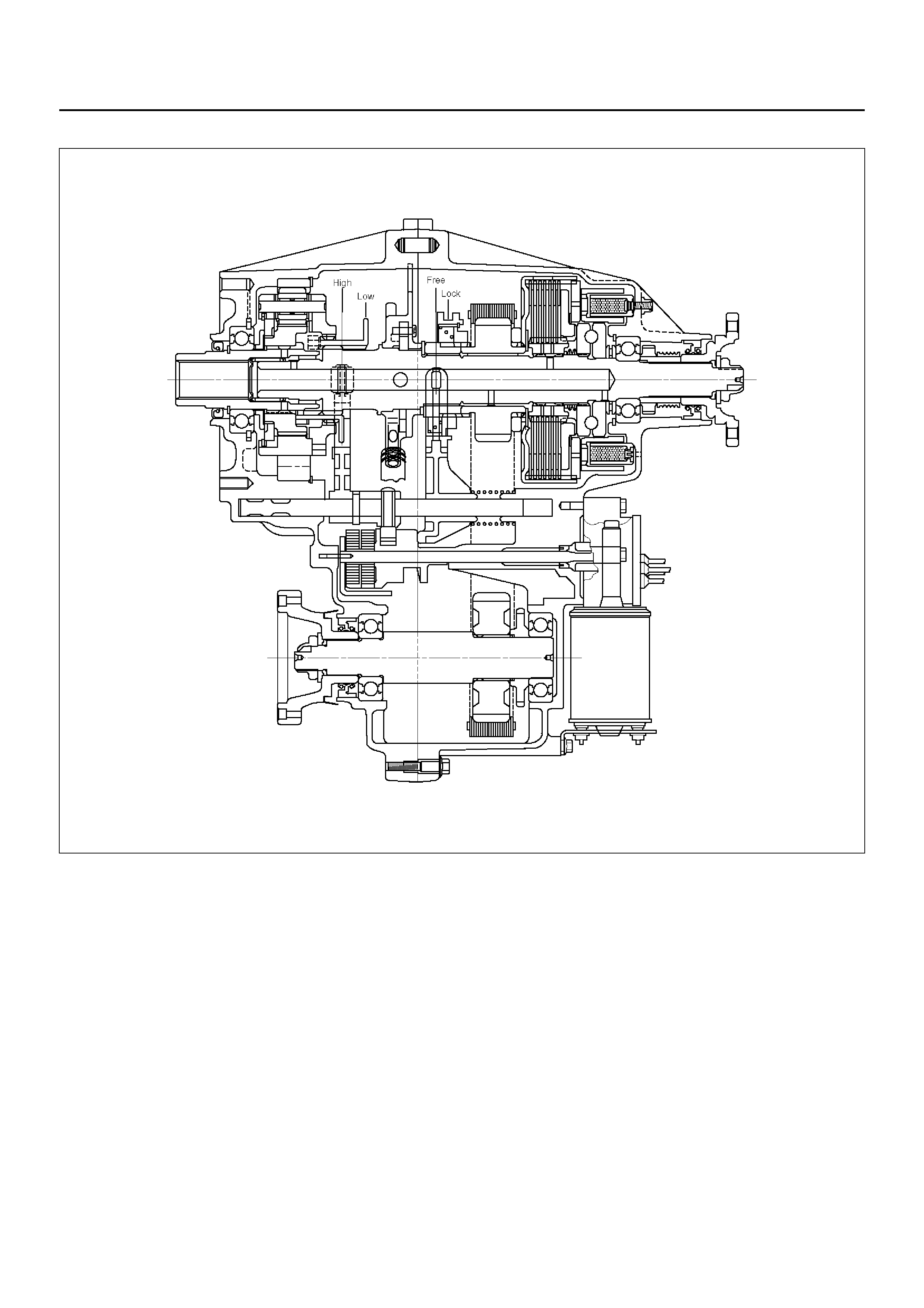
GENERAL DESCRIPTION
A04R200003
The Torque-On-Demand (TOD) is an
electronically-controlled torque-split 4-wheel drive
system with the following features.
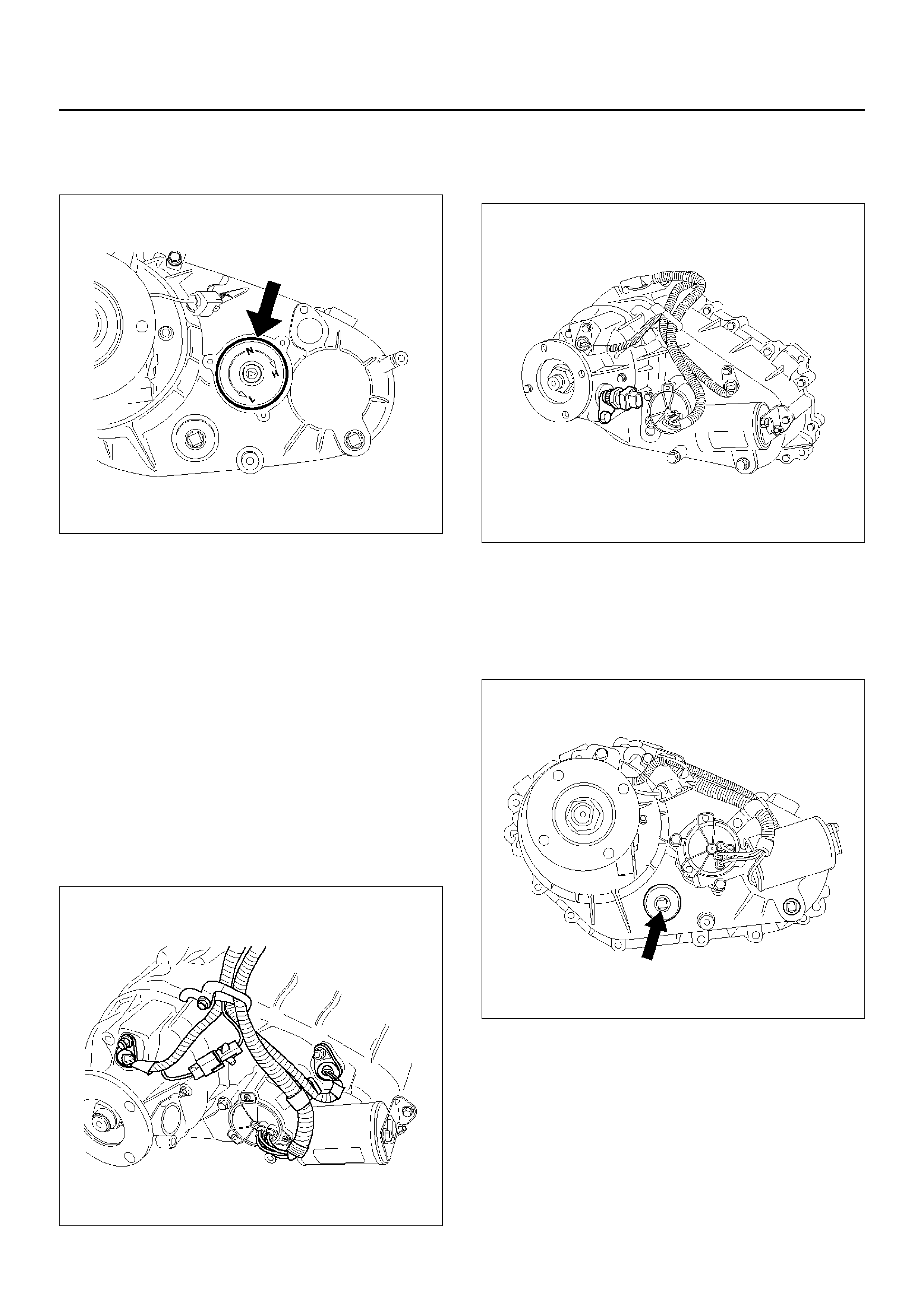
Shifting Between High and Low Ranges
The shifting mechanism consists of the cam and shaft
rail assem bly, the high/low shift moto r and the encode r.
The encoder is built-in to the motor.
The encoder sen ses high/low range shift mot or rotation
position and sends this data to the TOD control unit.
Based on this data, the TOD control unit adjusts motor
rotation speed or stops the motor.
The shifti ng betwe en the h igh an d low rang es us ing th e
TOD switch only is possible. The vehicle must be
stopped or nearly stopped (vehicle speed less than 2
km/h (1.2 mp h) and eng in e sp eed l es s than 1,50 0 rp m) ,
the aut oma tic tr an sm is si on se le ctor le vel m us t be in the
neutral (N) posi tion, and the br ak es must be applied .
Electronically-controlled Wet-type Multiple
Disc Cl u tch
The clutch automatically provides the optimum drive
power to the front wheels of the vehicle in response to
varying road surface conditions when the vehicle is
operated in the TOD mode. The delivered power ranges
from 0% to 100% of power train output. Superior
operational stability is maintained over a wide range of
operating conditions.
Front Output Drive
Front output drive is provided by a chain. This reduces
the loud noise associated with 4-wheel drive operation.
Oil Pump Lubrication
An oil pump is used to lubricate the transfer. This
ensures stable multiple-disc clutch operation and
maintains the lubricating oil at a constant temperature.
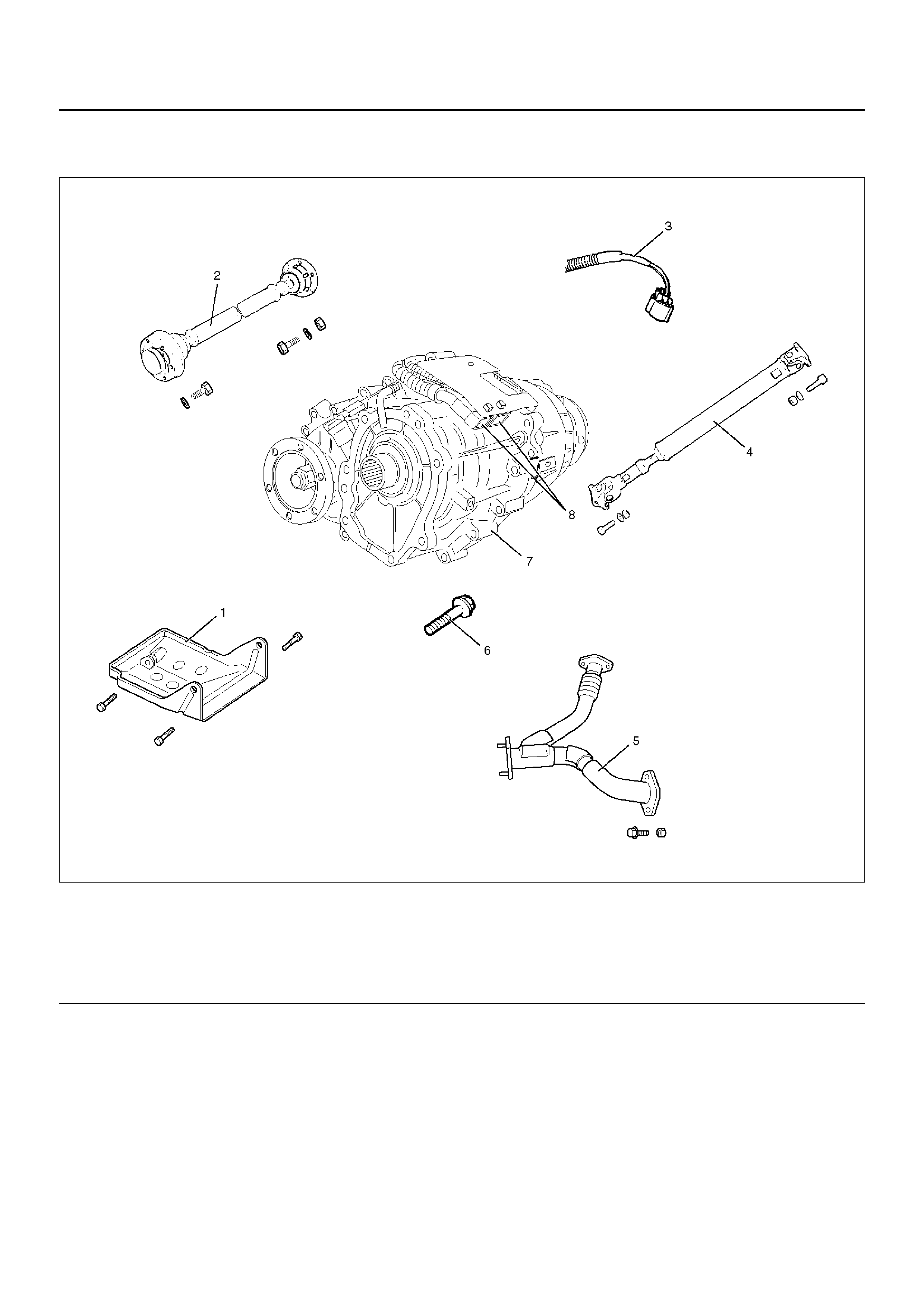
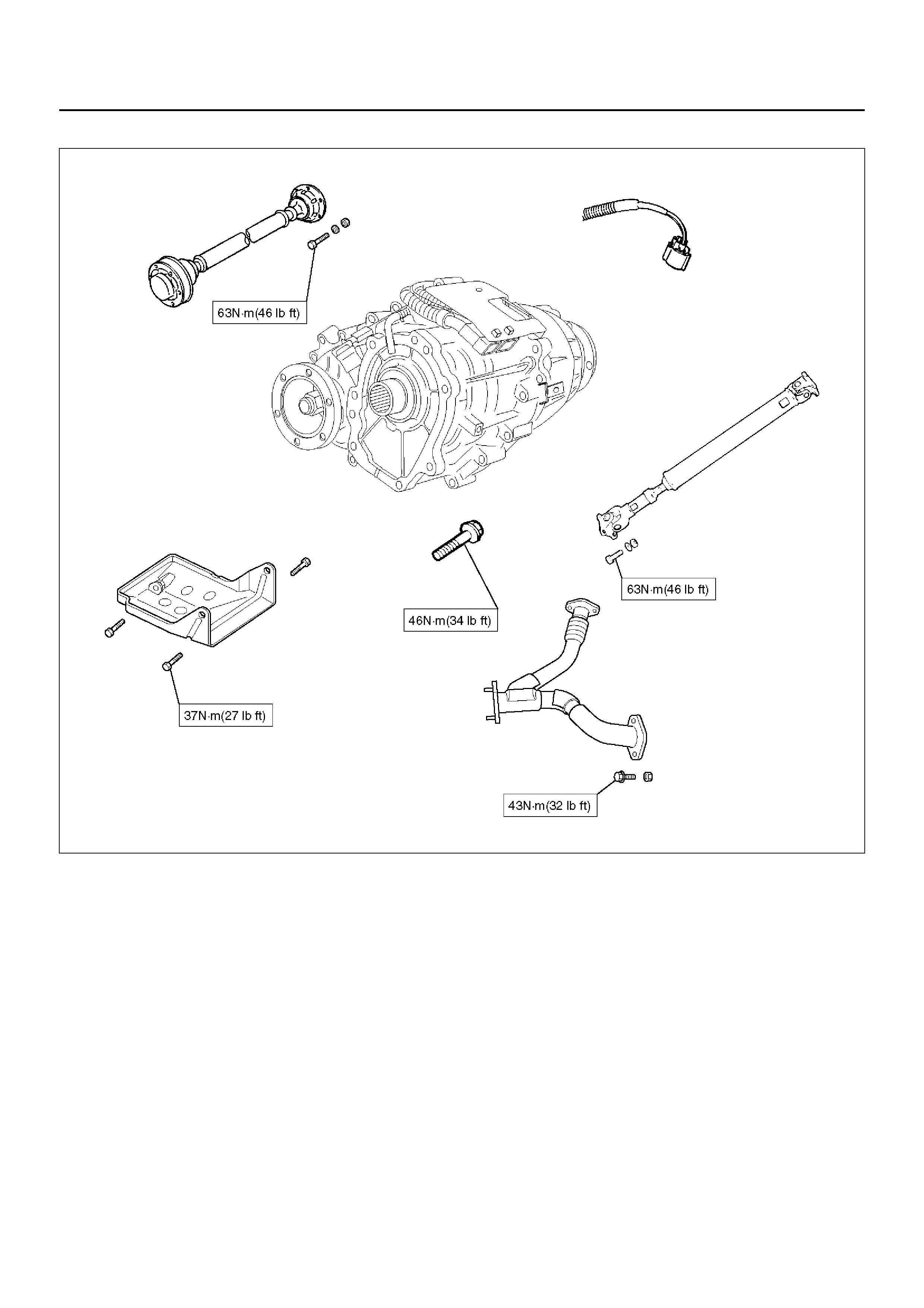
REMOVAL AND INSTALLATION OF TRANSFER CASE ASSEMBLY
F07R200001
EndOFCallout
Legend
(1) Transfer shield
(2) Front Propeller Shaft Assembly
(3) Speedometer Sensor Harness Connector
(4) Rear Propeller Shaft Assembly
(5) Center Exhaust Pipe
(6) Transfer Case Bolt
(7) Transfer Case Assembly
(8) Transfer Case Harness Connector
REMOVAL
1. Disconnect the battery ground cable.
2. Remove the transfer shield.
3. Disconnect the rear propeller shaft assembly from
the transfer case.
4. Disconnect the front propeller shaft assembly from
the transfer case.
5. Remove the center exhaust pipe.
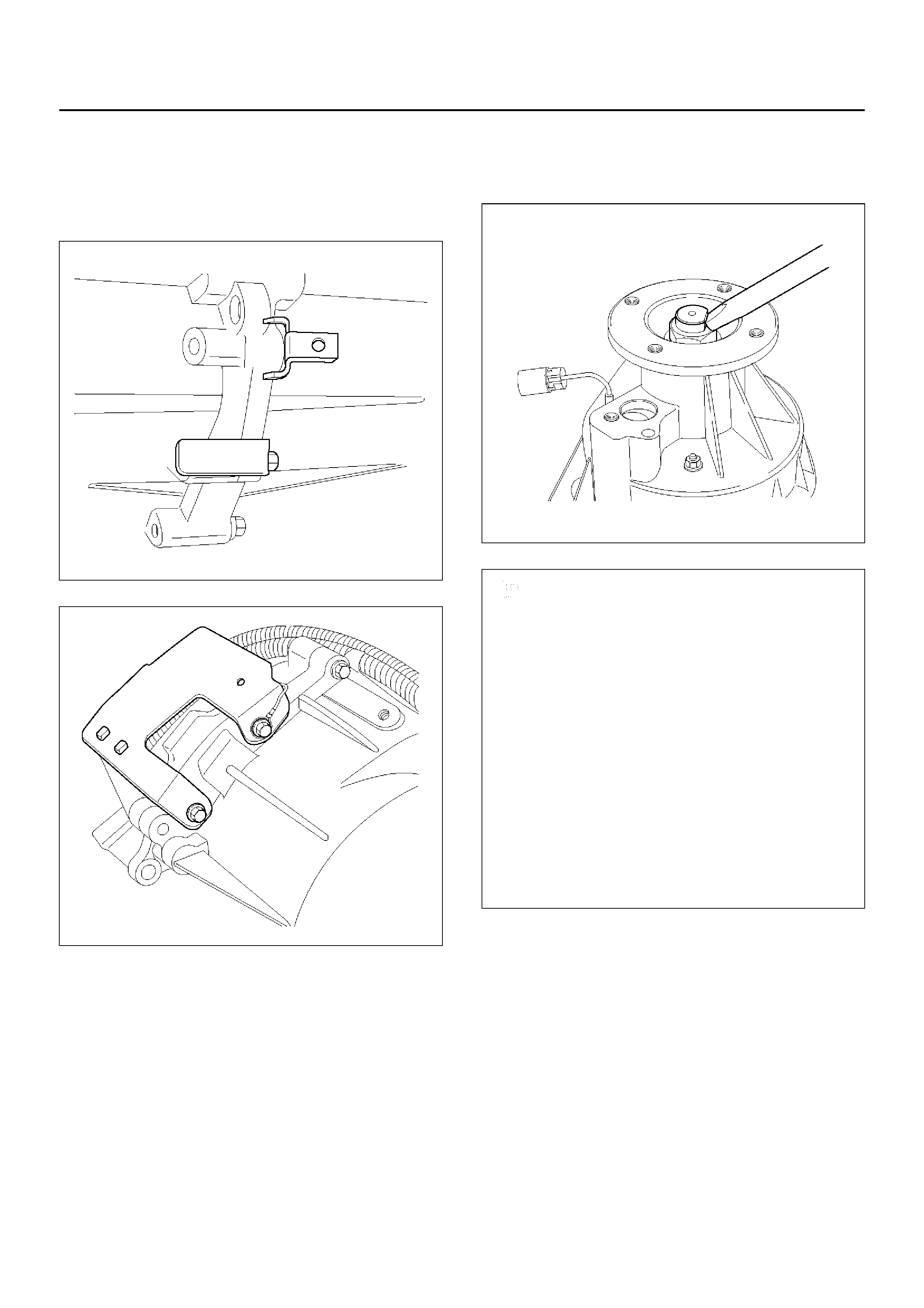
6. Disconnect the speedometer sensor harness
connector from the speedometer sensor, and
remove the harness clamp from the connector
bracket of the transfer case.
7. Disconnect the engine harness connector from the
transfer harness connector.
8. Support the transfer case with a transmission jack.
9. Remove the transfer bolts.
10. Remove the transfer case assembly.
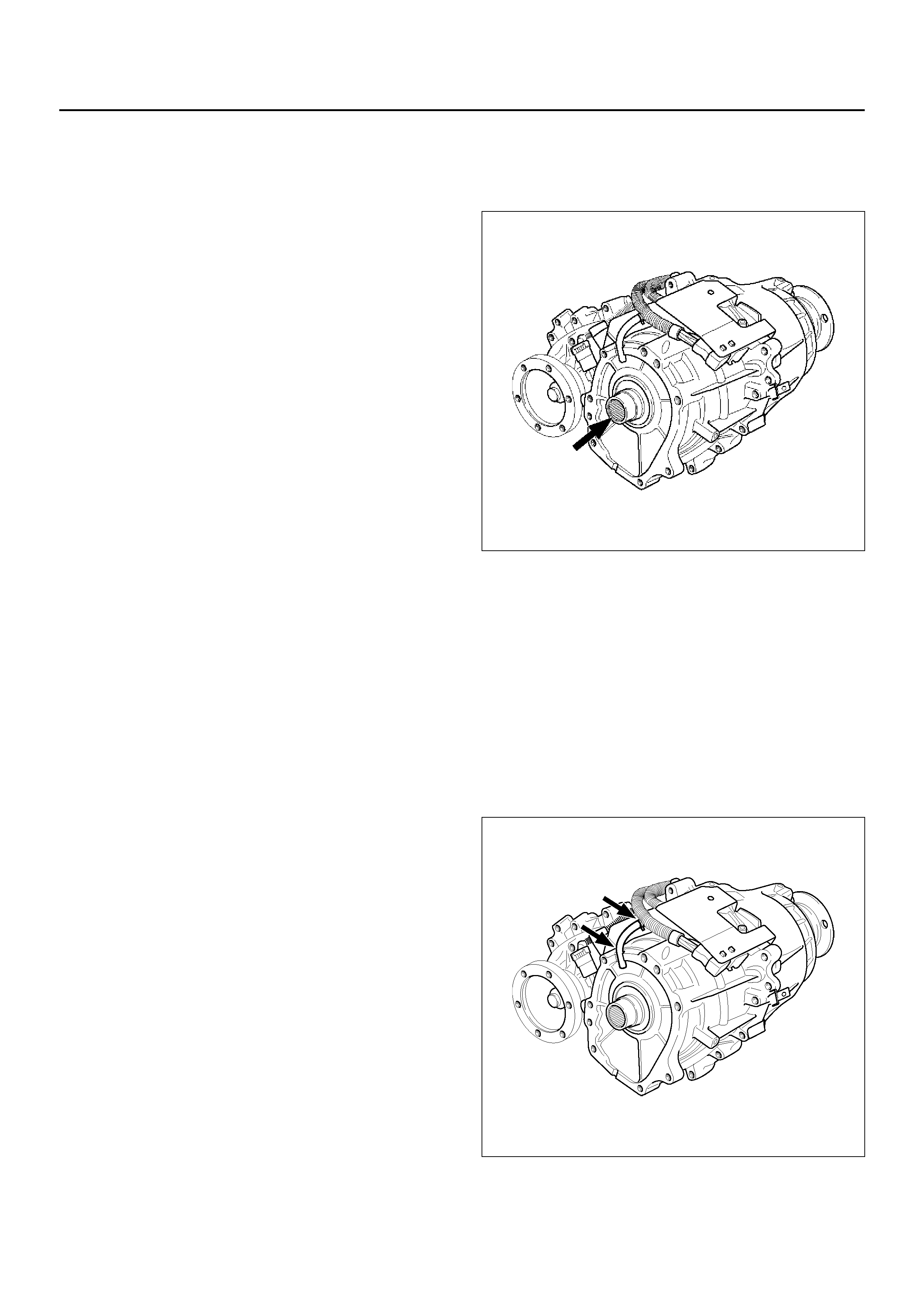
INSTALLATION
1. Apply grease (Besco L2 or its equivalent) to the
input shaft spline.
260RY00011
2. Install the transfer case assembly to the
transmission assembly.
3. Install the transfer bolts to the specified torque
(Refer to next page).
Torque: 46N·m (34lbft)
4. Connect the engine harness connector to the
transfer harness connector.
5. Install the breather hose up to bottom of the transfer
case breather and clip them firmly.
6. Securely insert the breather hose into the cutout
portio n of the transfer case.
260R200001

7. Install the speedometer harness clamp to the
connector bracket of the transfer case, and then
connect the harness connector to the speedometer
sensor.
261R200008
8. Install the center exhaust pipe.
Torque: 43N·m
9. Conne ct the fron t and rea r prope ller shaf t assemb ly
to the transfer case.
Torque: 63N·m
10. Install the transfer shield.
Torque: 37 N·m
11. Connect the battery ground cable.
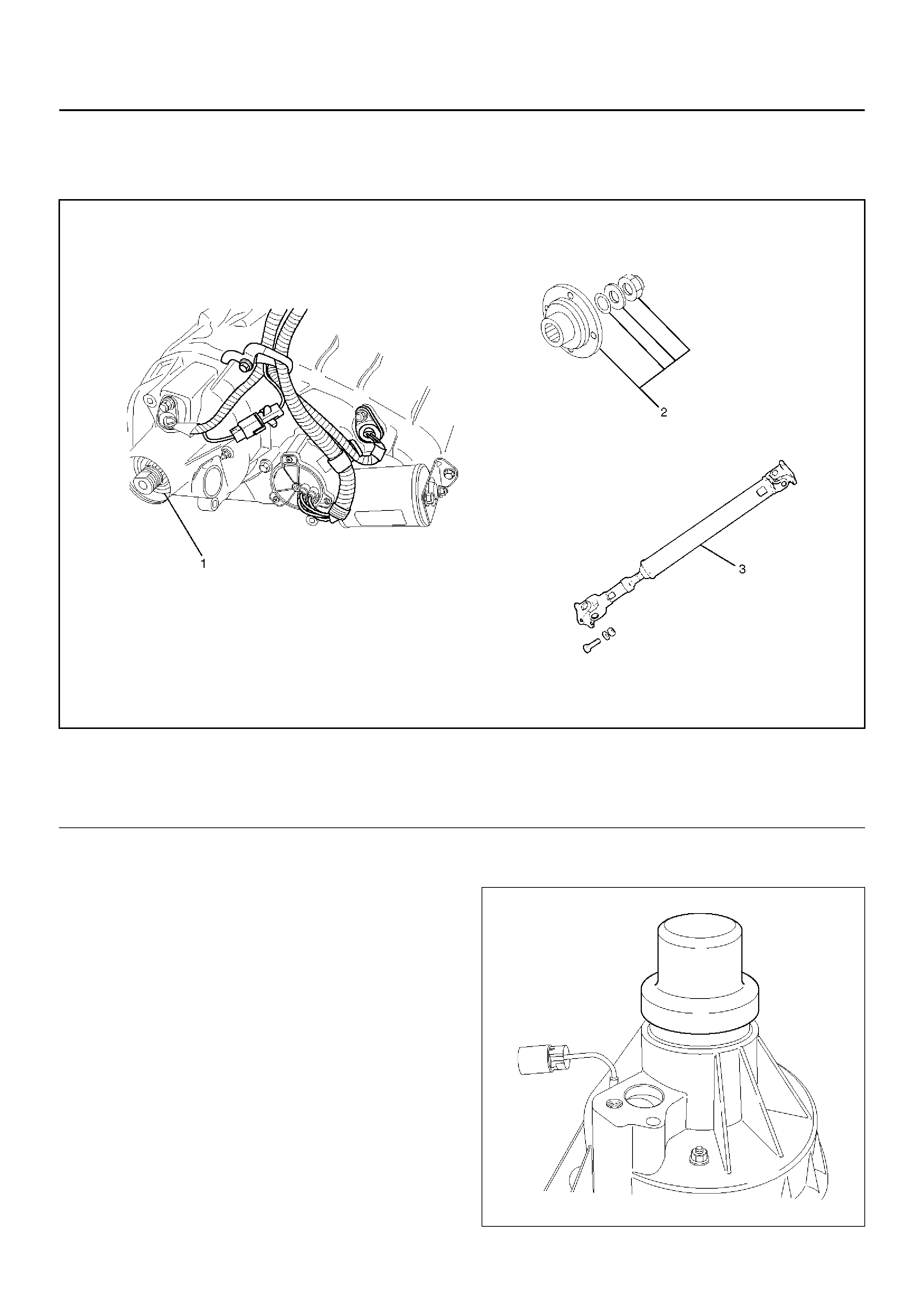
TRANSFER REAR OIL SEAL
261R200002
EndOFCallout
REMOVAL
1. Disconnect the rear propeller shaft assembly from
the transfer case.
2. Using the flange holder J–8614–11, remove the end
nut.
3. Using the universal puller, remove the companion
flange, washer and oil seal.
4. Remove the transfer rear oil seal from the transfer
case.
INSTALLATION
1. Apply oil to the circumference of the transfer rear oil
seal.Fill the oil seal lip with grease (Besco L2 or its
equivalent).
2. Using the oil seal installer J–42804, install the
transfer rear oil seal to the transfer case.
261RY00017
Legend
(1) Transfer Rear Oil Seal
(2) End Nut, Washer, Oil Seal and Rear
Companion Flange
(3) Rear Propeller Shaft Assembly
NOTE: When installing the oil seal, pay attention to the
direction.
261RW006
EndOFCallout
3. Install the companion flange.
4. Install the oil sea l and washer, and usi ng the flange
holder J–8614–11, install the new end nut to the
specified torque.
Torque: 167N·m
5. Securel y stake the end nut at one spot.
NOTE: Be sure to confirm that there is no clack at the
staked portion of the end nut after staking.
266RY00003
266R200004
6. Connect the rear propeller shaft assembly to the
transfer case.
Torque: 63N·m
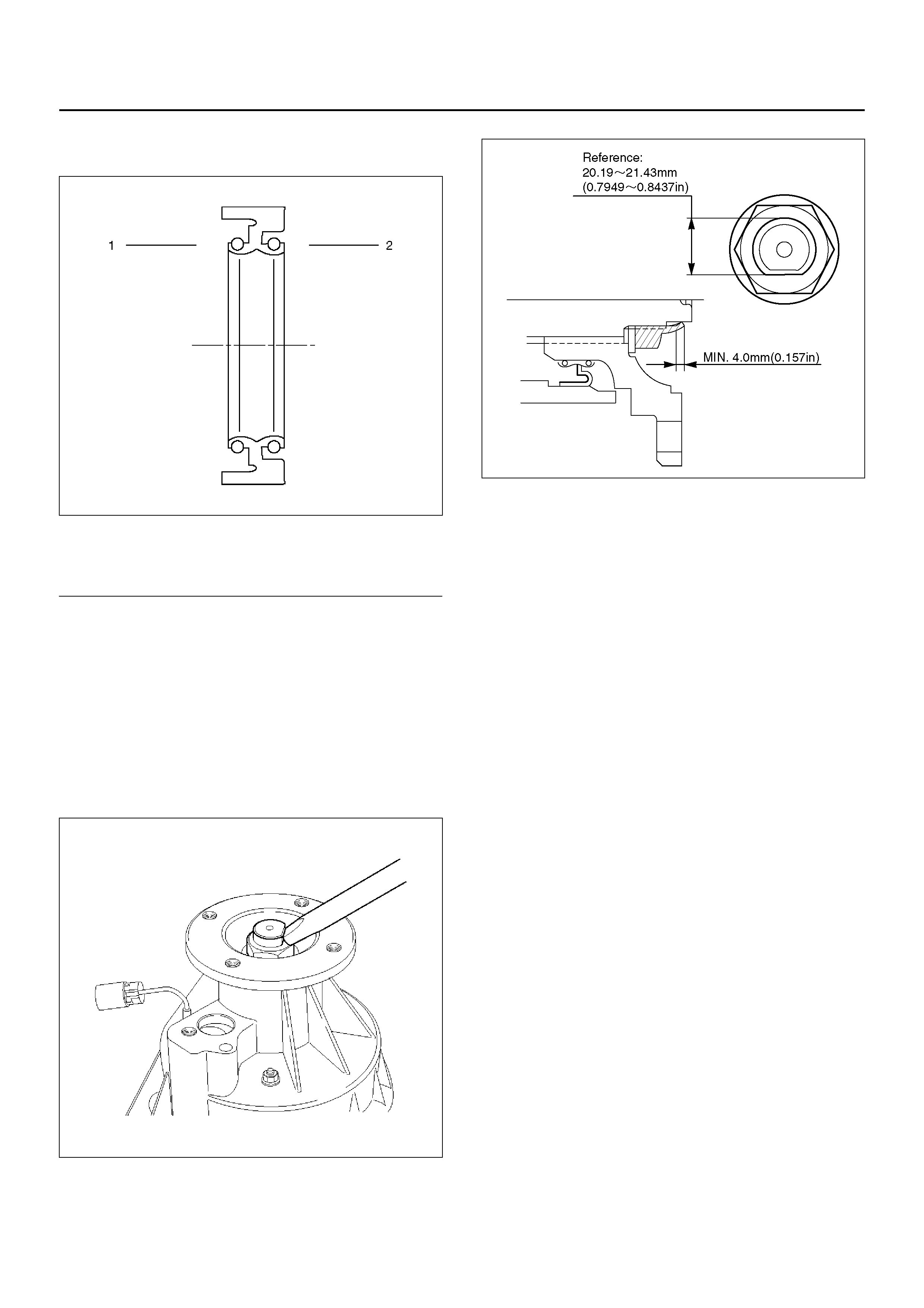
Legend
(1) Inside
(2) Outside
TOD CONTROL UNIT
826R200006
EndOFCallout
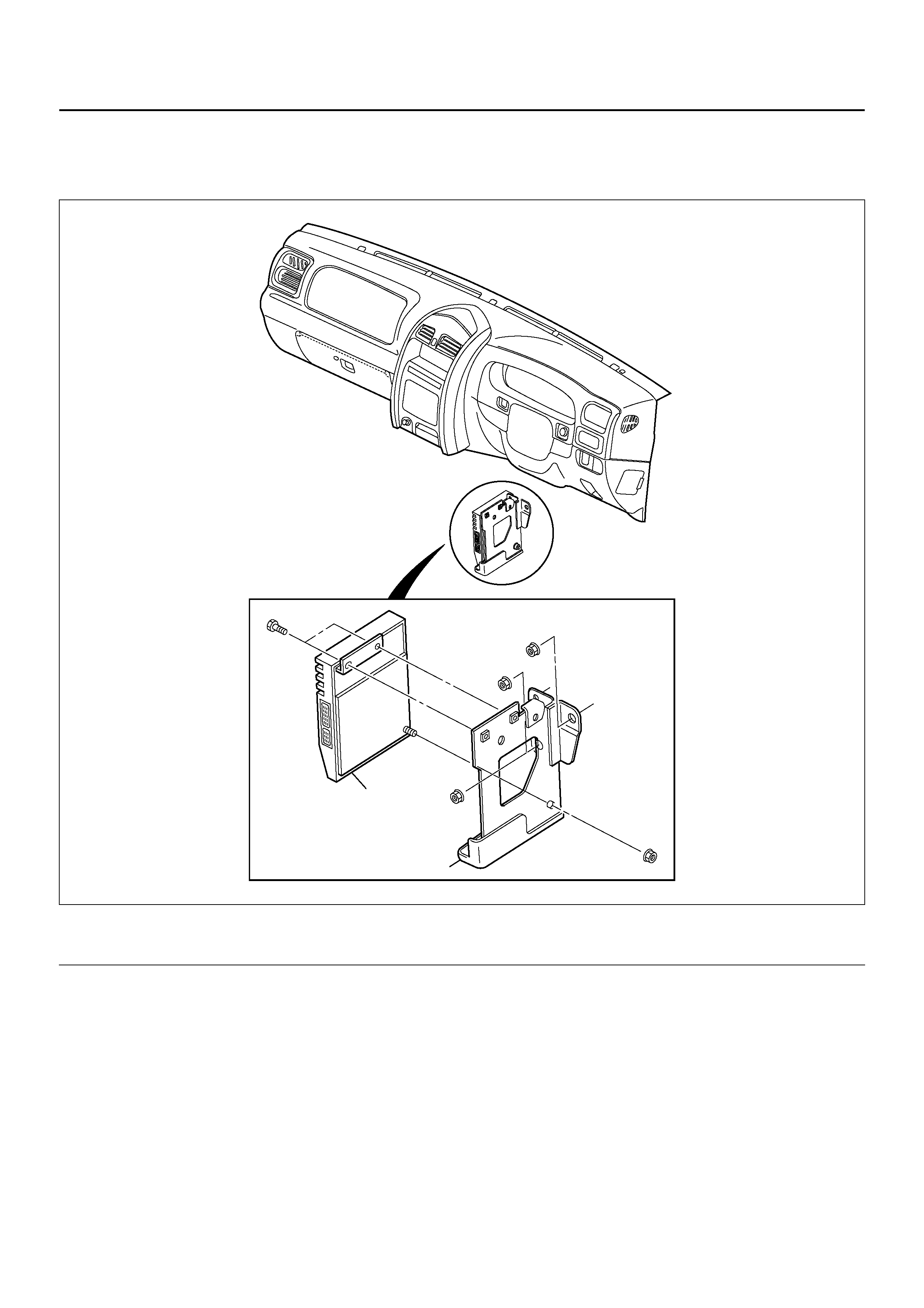
REMOVAL
1. Disconnect the battery ground cable.
2. Disconnect the harness connector from the TOD
control unit.
3. Remove the bracket retaining nuts (3 pieces) and
the bracket with TOD control unit.
4. Remove the TOD control unit from the bracket.
INSTALLATION
1. Install the TOD control unit to the bracket.
2. Install the bracket with TOD control unit to the
chassis.
3. Connect the harness connector to the TOD control
unit.
4. Connect the battery ground cable.
2
1
Legend
(1) Bracket (2) TOD Control Unit
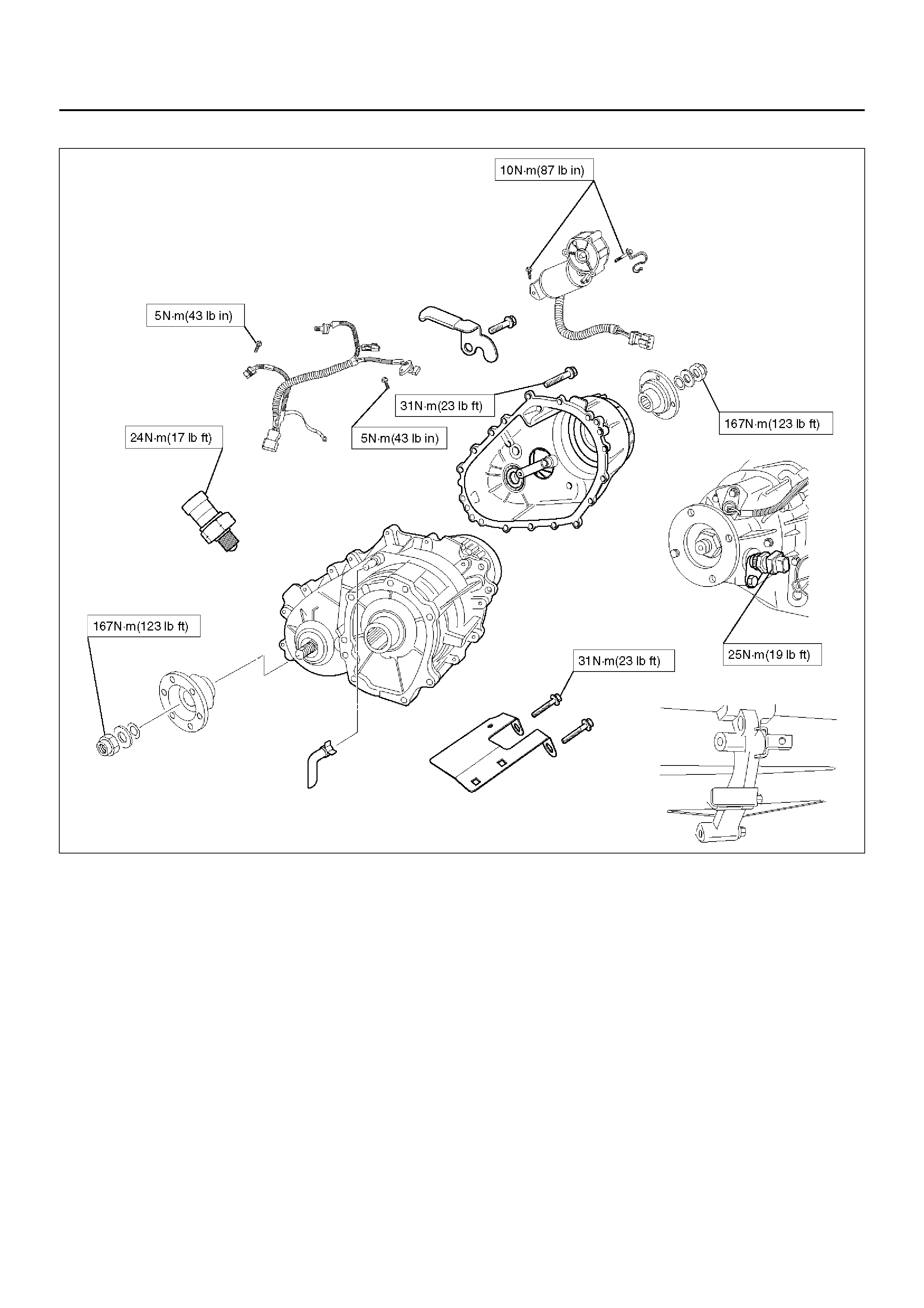
UNIT REPAIR
DISASSEMBLY AND REASSEMBLY OF MAJOR COMPONENTS
266R200002
EndOFCallout
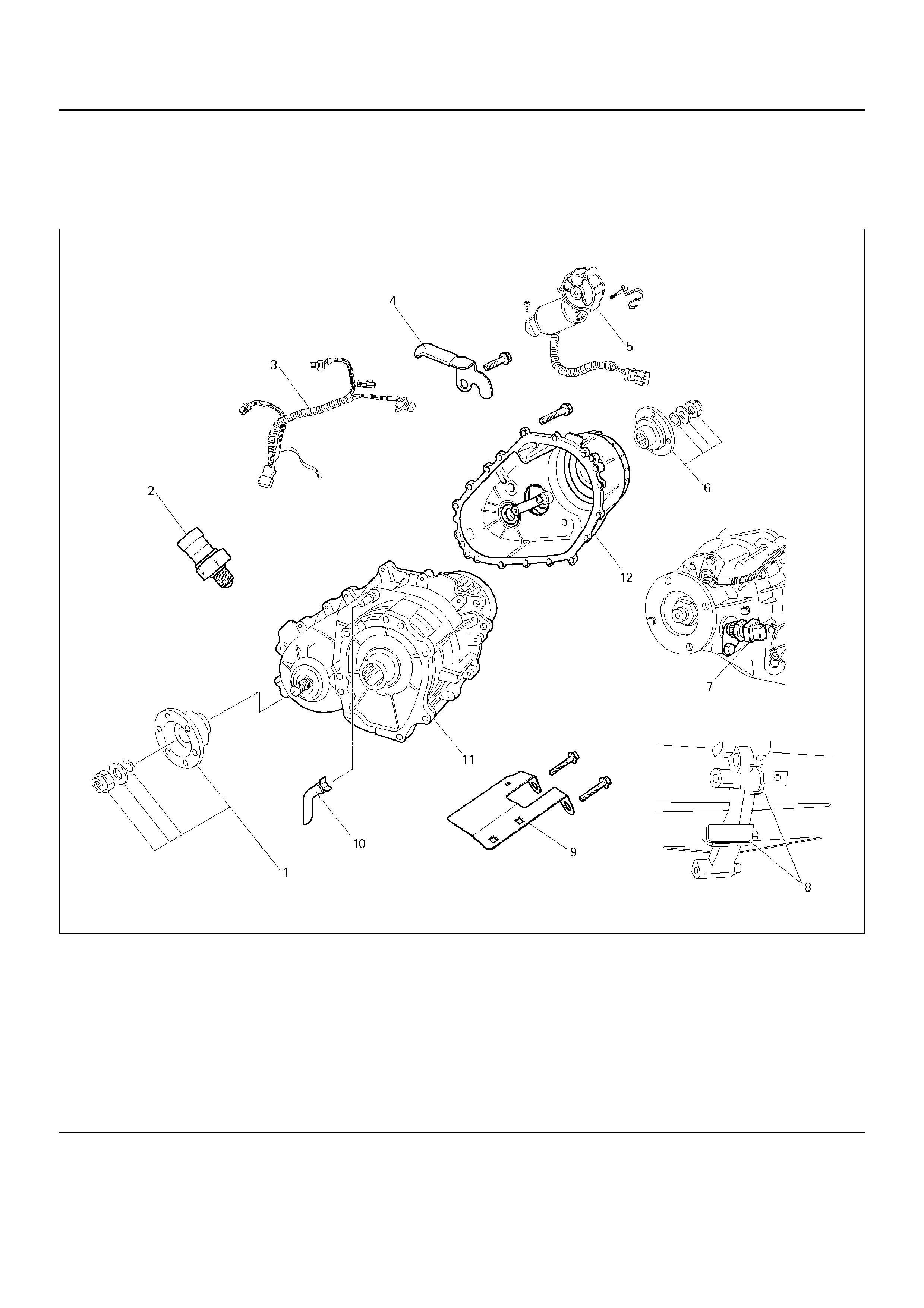
Legend
(1) F ront Companion F lange, Oi l Sea l, Washer,
and End Nut
(2) 4H and 4L Switch
(3) Harness Assembly
(4) Harness Bracket
(5) Shift Motor Assembly
(6) Rear Companion Flange, Oil Seal, Washer and
End Nut
(7) Speedometer Sensor and Driven Gear
(8) Plate and Bracket
(9) Connector Bracket
(10) Breather Hose
(11) Transfer Case Assembly
(12) Transfer Cover Assembly
DISASSEMBLY
1. Remove the drain plug from the transfer case and
drain the oil.
2. Remove the speedometer sensor and driven gear.
3. Remove the front and rear speed sensor of the
harness assembly from the transfer cover assembly.
NOTE: Use care to prevent damage to speed sensor
when removing speed sensor.
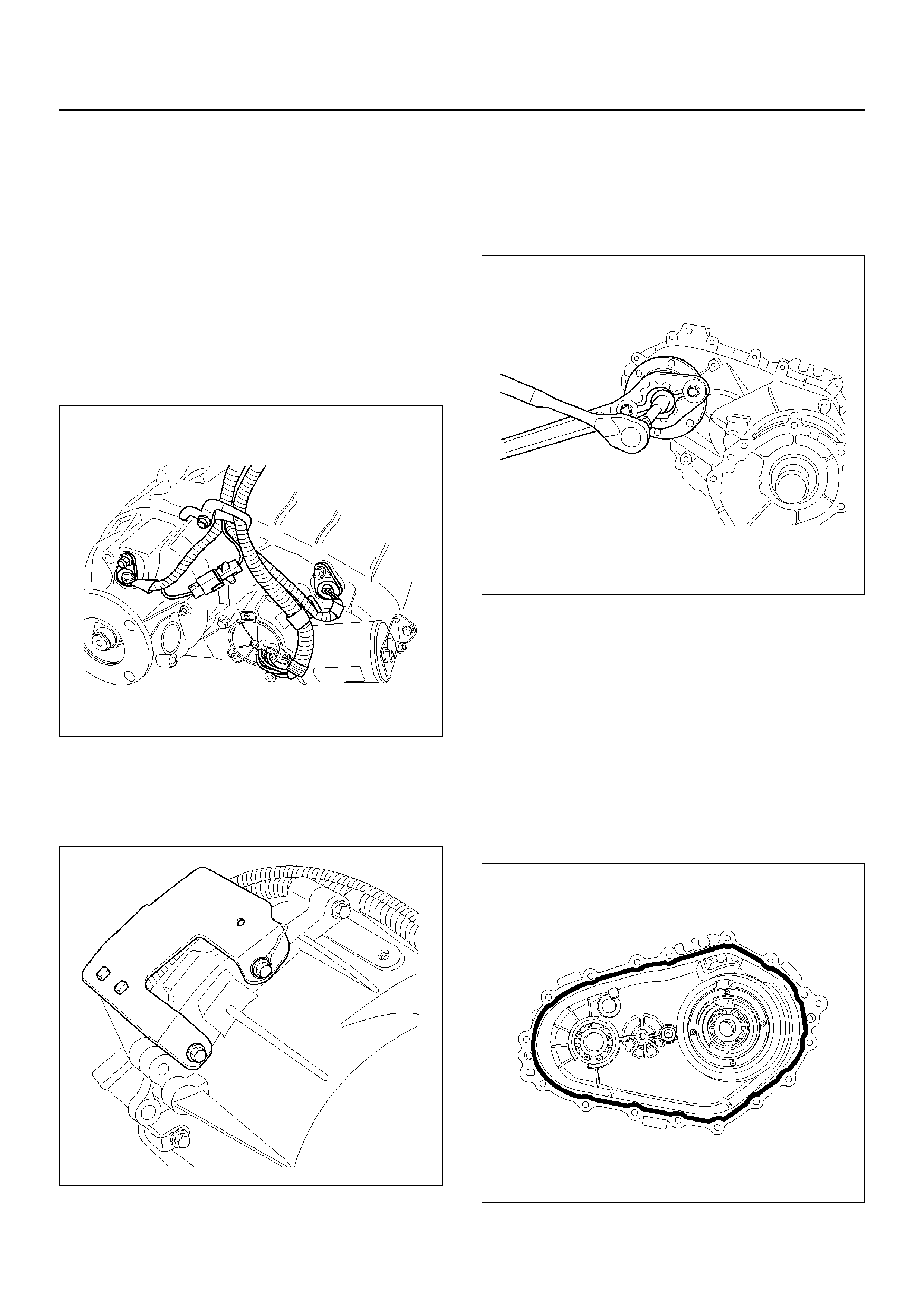
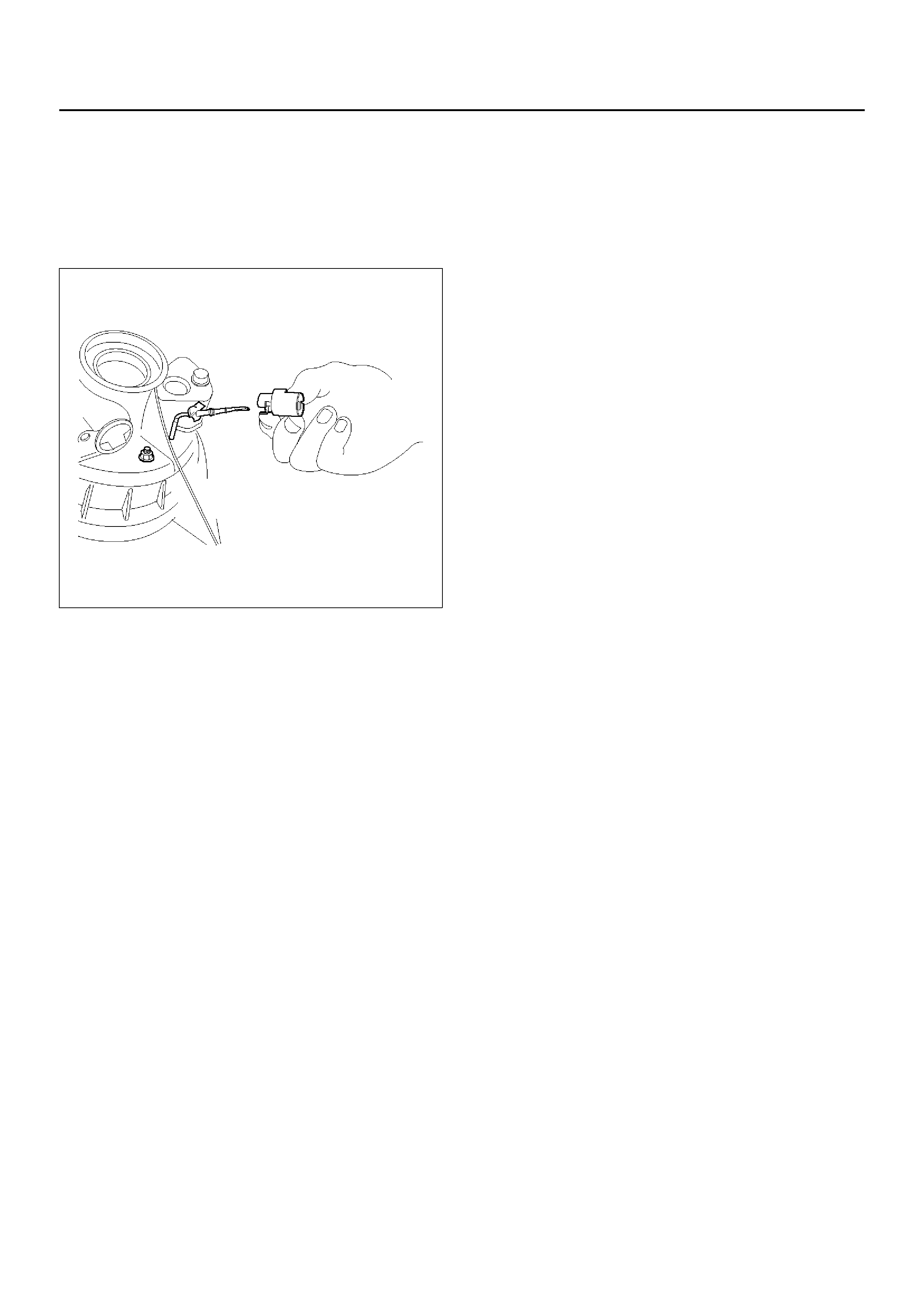
4. Disconnect the clutch solenoid coil, 4H and 4L
switch harness connector.
• Remove the harness bracket from the transfer
cover.
261RY00009
5. Remove the connector bracket from the transfer
case.
• Remove the harness assembly and shift motor
harness connector from the connector bracket.
261RY00010
6. Remove the 4H and 4L switch from the transfer
case.
7. Remove the shift motor assembly from the transfer
cover.
8. Using the flange holder J–8614–11, remove the end
nut.
Remove the washers, oil seals, front and rear
companion flange.
262RY00012
9. Remove the transfer cover retaining bolts and the
transfer cover assembly from the transfer case
assembly.
NOTE: When removing the transfer cover assembly,
use care to prevent damage to oil seal.
10. Remove the breather hose from the transfer case.
REASSEMBLY
1. Apply recommended liquid gasket (LOCTITE 598 or
its equivalent) uniformly to the transfer case and
cover fitting surface.
261RY00011
2. Install the plate, bracket, connector bracket and
ground cable of the harness assembly, and tighten
the transfer cover retaining bolts (16 pieces) to
specified torque.
Torque: 31 N·m
261RY00035
261RY00037
3. Install the front and rear companion flange.
4. Install the oil sea l and washer, and usi ng the flange
holder J–8614–11, install the new end nut to the
specified torque.
Torque: 167N·m
5. Securely stake the end nut at one spot.
NOTE: Be sure to confirm that there is no clack at the
staked portion of the end nut after staking.
266RY00003
266R200004
6. Apply recom mended liqui d gas ket (L OC TI TE 598 or
its equivalent) to the transfer cover and shift motor
assembly fitting surface.
261R200003
7. Install the shift moto r assem bly t o the transfer c over
assembly.
Torque: 10N·m (87lbin)
8. Install the 4H and 4L switch.
Torque: 24N·m (17lbft)
9. Install the harness assembly and shift motor
harness connector to the connector bracket.
10. Install the front and rear speed sensors to the
transfer cover.
Torque: 5N·m
11. Connect the harness assembly connector to the
clutch solenoid coil harness connector and 4H and
4L switch.
• Fix the harness with harness bracket.
261RY00009
12. Install the driven gear and speedometer sensor to
the transfer case.
Torque: 25N·m
261RY00034
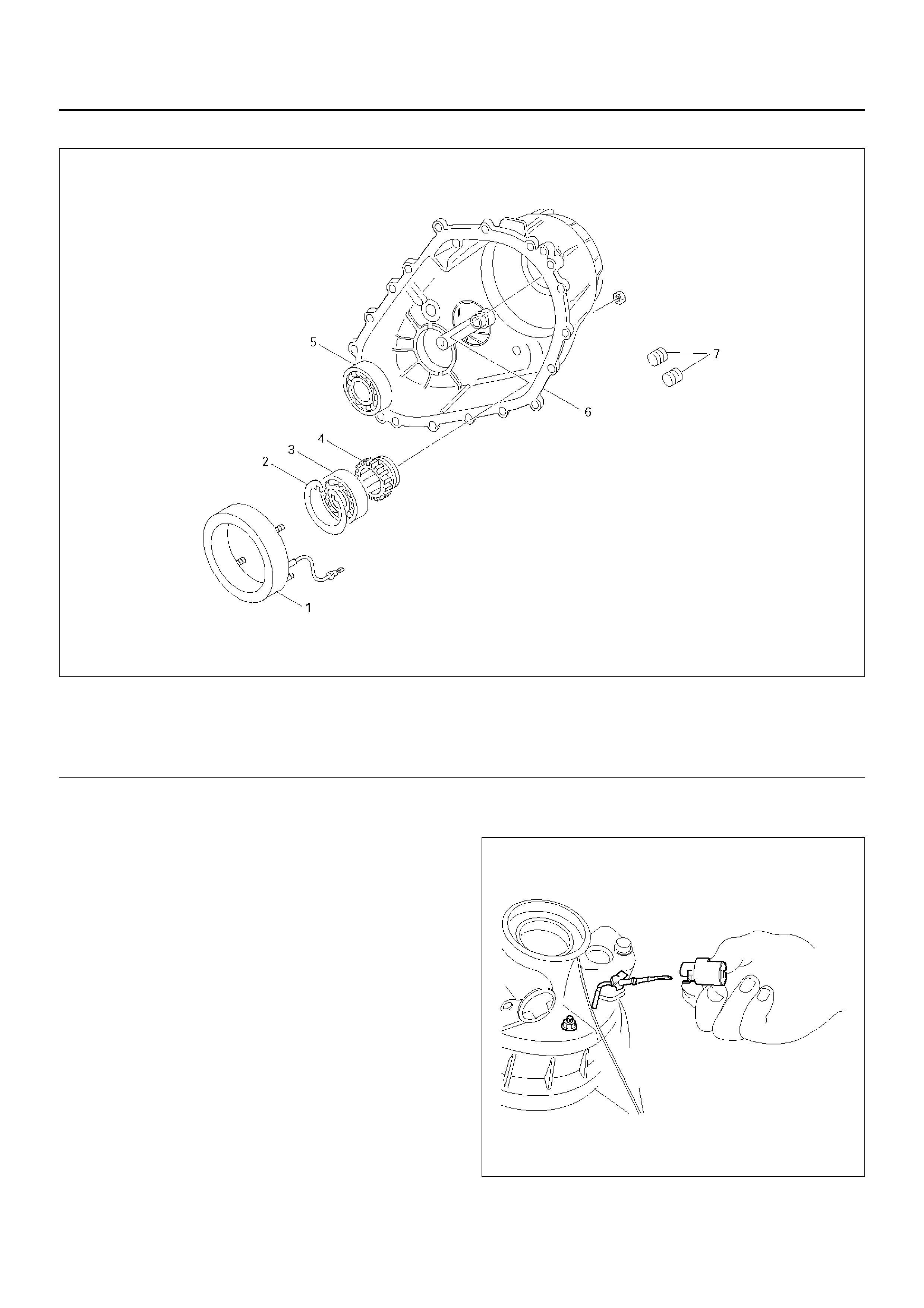
13. Remove the fill er plug and fill the t ransfer c ase with
ATF DEXRON®–II or III.
14. Wind the sealing tape around the filler plug thread
and tighten the plug to the specified torque.
Torque: 25N·m
261RY00026
15. Install the breather hose to the transfer case.
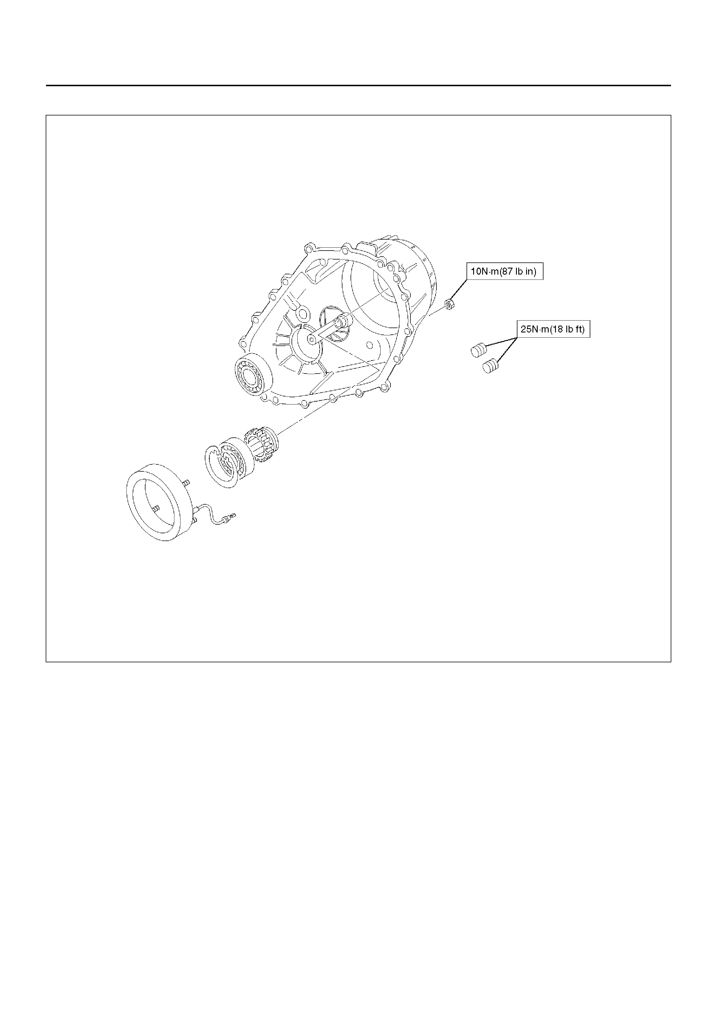
TRANSFER COVER ASSEMBLY
261RY00032
EndOFCallout
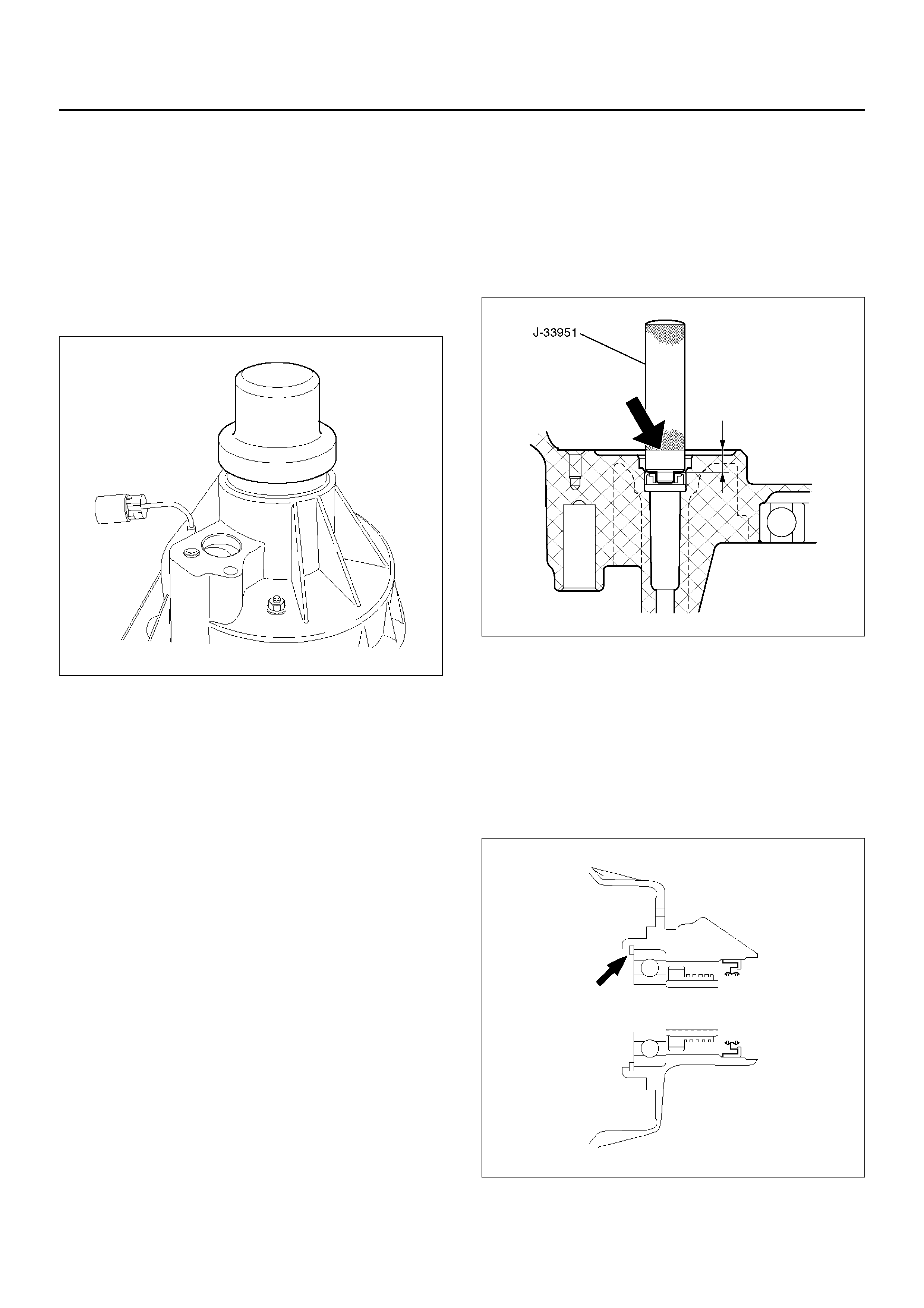
DISASSEMBLY
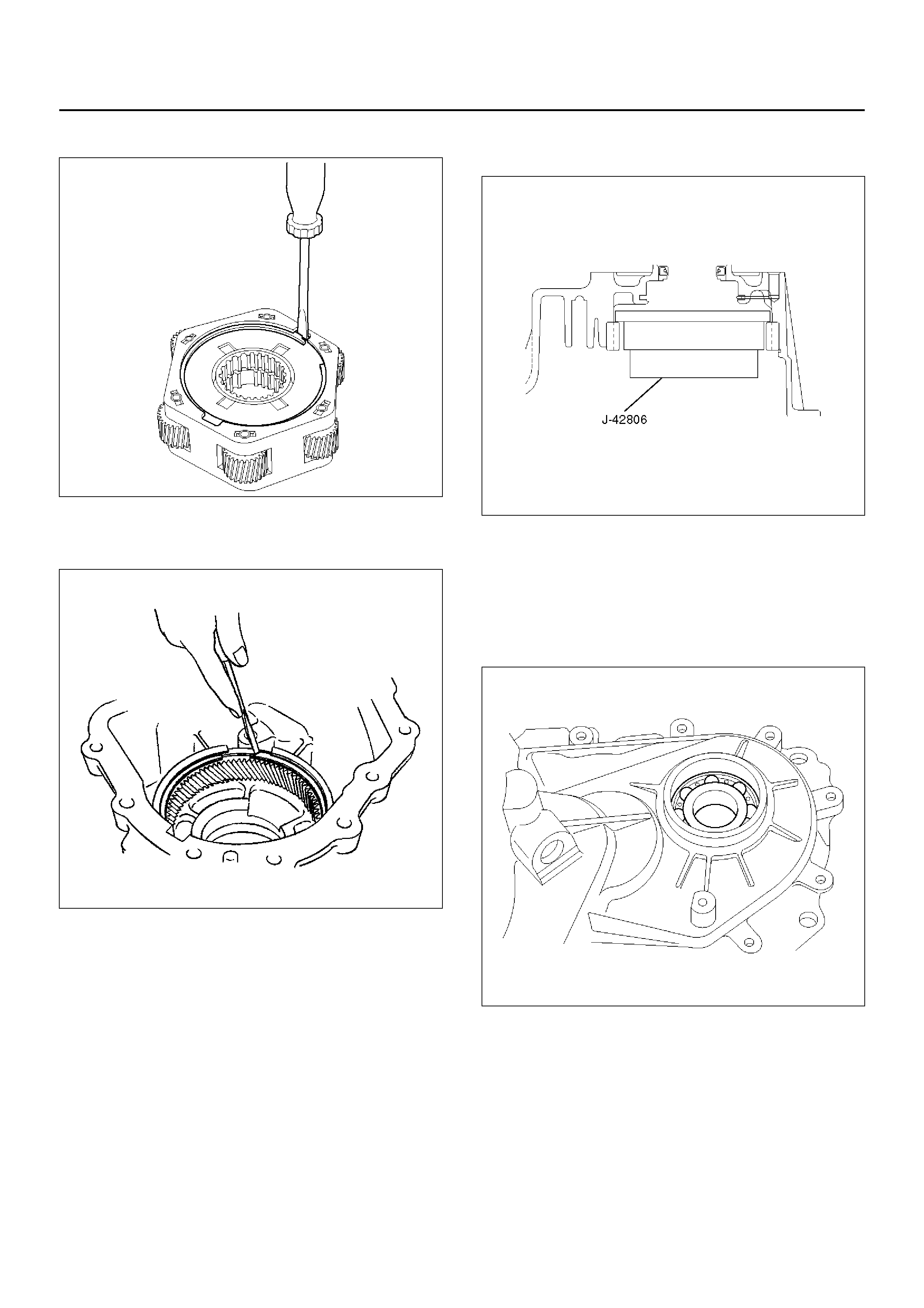
1. Using a precision screwdriver or a suitable tool,
push down the lock to unlatch the terminal for the
coil assembly, and pull the terminal out.
NOTE: Use care to prevent damage to harness
terminal and connector.
261RY00013
Legend
(1) Coil Assembly
(2) Snap Ring
(3) Ball Bearing
(4) Speed Gear and Tone Wheel
(5) Ball Bearing
(6) Transfer Cover (With Oil Seal)
(7) Oil Drain Plug and Oil Filler Plug
2. Remove the coil assembly set nuts (3 pieces) and
coil assembly from the transfer cover.
261RW030
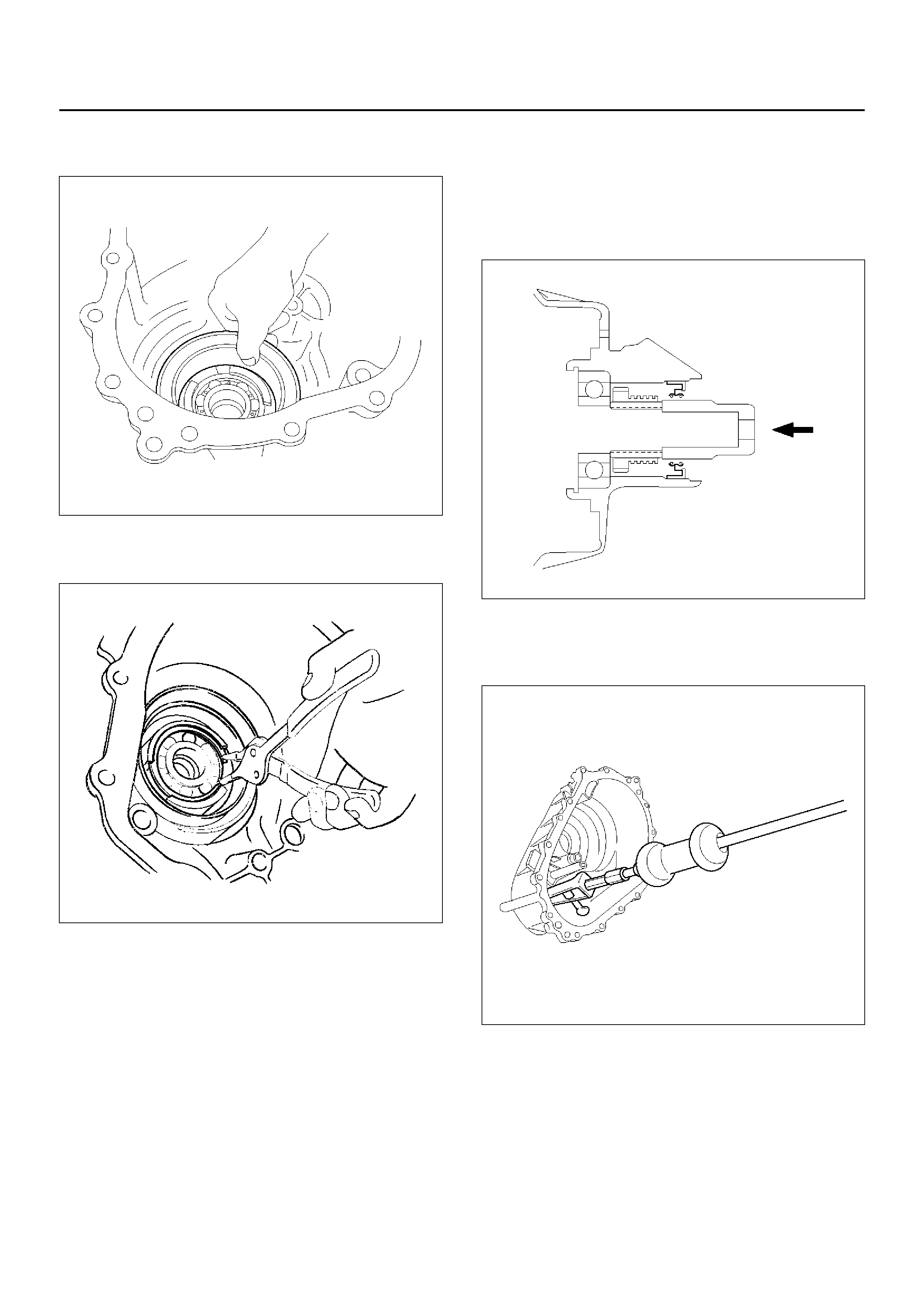
3. Using snap ring pliers, remove the snap ring from
the transfer cover.
261RW047
4. Strike the speed gear and tone wheel with a rod or
other appropriate tool from the rear side of the
transfer cover assembly, and remove the ball
bearing, speed gear and tone wheel.
NOTE: Use care to prevent damage to the speed gear
teeth.
261RY00012
5. Using the bearing remover J–42805 and slide
hammer J–2619–01, remove the ball bearing of the
front output shaft from the transfer cover.
261RY00027
INSPECTION AND REPAIR
Refer to “Inspection and Repair (Transfer Case
Assembly)" in this section.
REASSEMBLY
Transfer cover oil seal replacement
1. Remove the oil seal from the transfer cover
assembly.
2. Apply oil to the circumference of the new oil seal
and fill the lip with grease (BESCO L2 or its
equivalent).
3. Using the oil seal installer J–42804, install the oil
seal to the transfer cover assembly.
261RY00017
Shift shaft oil seal replacement
4. Remove the oil seal from the transfer cover
assembly.
5. Apply oil the circumference of the new oil seal.
6. Using the oil seal installer J–33951, install the oil
seal to the transfer cover assembly.
The dr ive in dept h must be 9.4 ∼ 1 0.4 mm (0.370 ∼
0.409 in). T he knu rled end of the installe r (indi cated
by the arrow) must be flush with the oil seal
installation surface.
NOTE: Use care to prevent tilt to oil seal when installing
oil seal to the case.
261R200009
7. Install the ball bearing of the front output shaft to the
transfer cover.
8. Install the speed gear and tone wheel.
9. Install the ball bearing to the transfer cover.
10. Using snap ring pliers, install the snap ring to the
transfer cover.
NOTE: The snap ring must be fully inserted into the
transfer cover snap ring groove.
261RY00018
11. Install the coil assembly to the transfer cover and
tighten the set nuts (3 pieces) to the specified
torque.
Torque: 10N·m
12. Install the connector to the harness terminal of the
coil assembly.
261RY00013
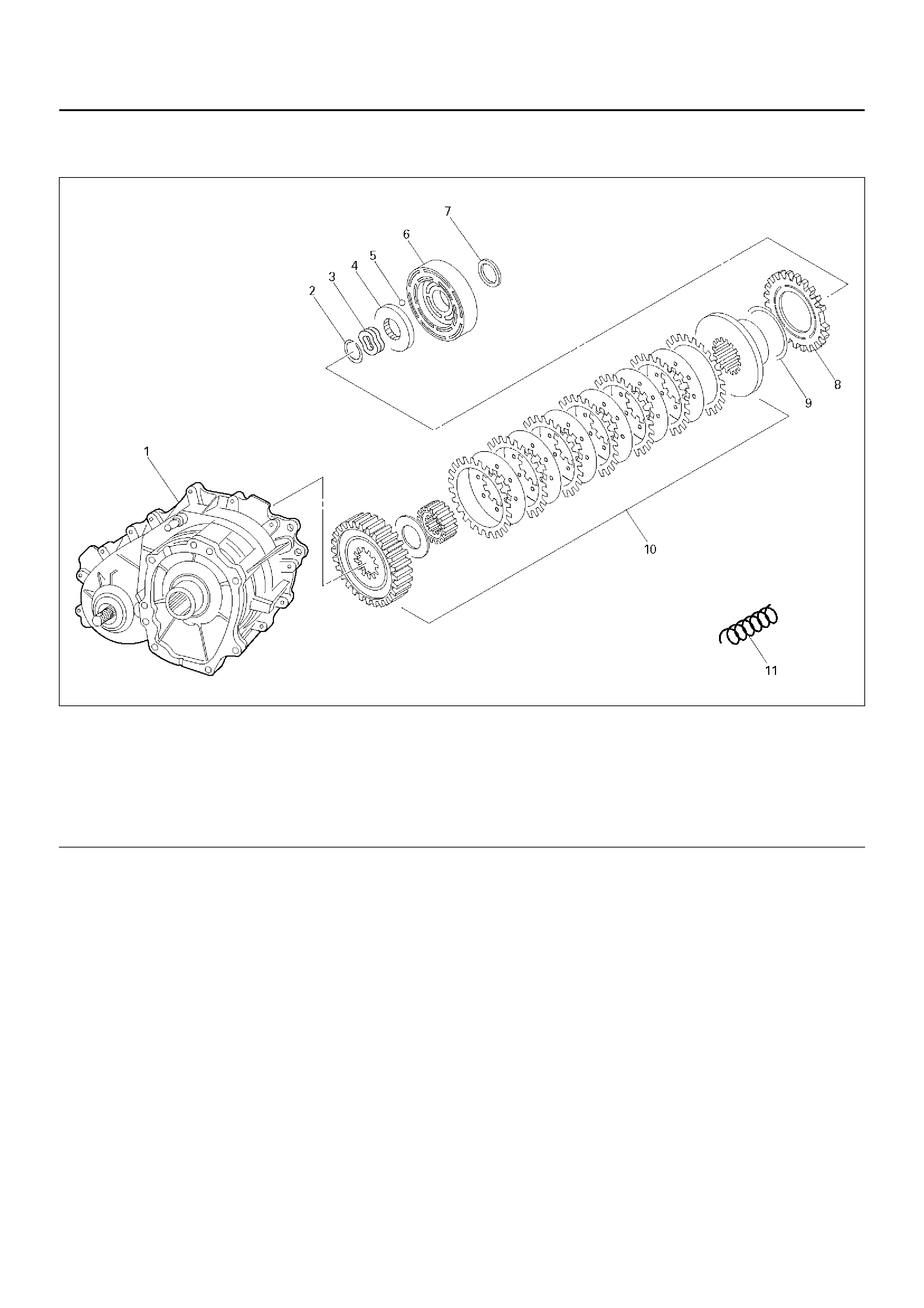
CLUTCH PACK AND CLUTCH CAM (TRANSFER CASE ASSEMBLY)
266RY00015
EndOFCallout
Legend
(1) Transfer Case Assembly
(2) Snap Ring
(3) Wave Spring
(4) Cam Pull ey
(5) Cam Ball
(6) Cam and Coil Housing Assembly
(7) Thrust Bearing
(8) Armature Plate
(9) Insulato r Washe r
(10) Clutch Pack Assembly
(11) Lockup Fork Spring
DISASSEMBLY
1. Remo ve the lock up for k spri ng.
2. Remove the thrust bearing and cam and coil
housing assembly from the output shaft.
NOTE: When the cam and coil housing assembly is
removed , the cam ba lls may be de tached together with
the housing. Take care not to lose the balls.
261RY00020
3. Remove the cam ball (3 pieces).
4. Remo ve the ca m pull ey.
266RY00005
5. Remove the wave spring.
266RY00006
6. Using snap ring pliers, remove the snap ring.
NOTE: Use care to prevent damage to snap ring.
266RY00007
7. Remove the armature plate, insulator washer and
clutch pack assembly as a package.
266RY00008
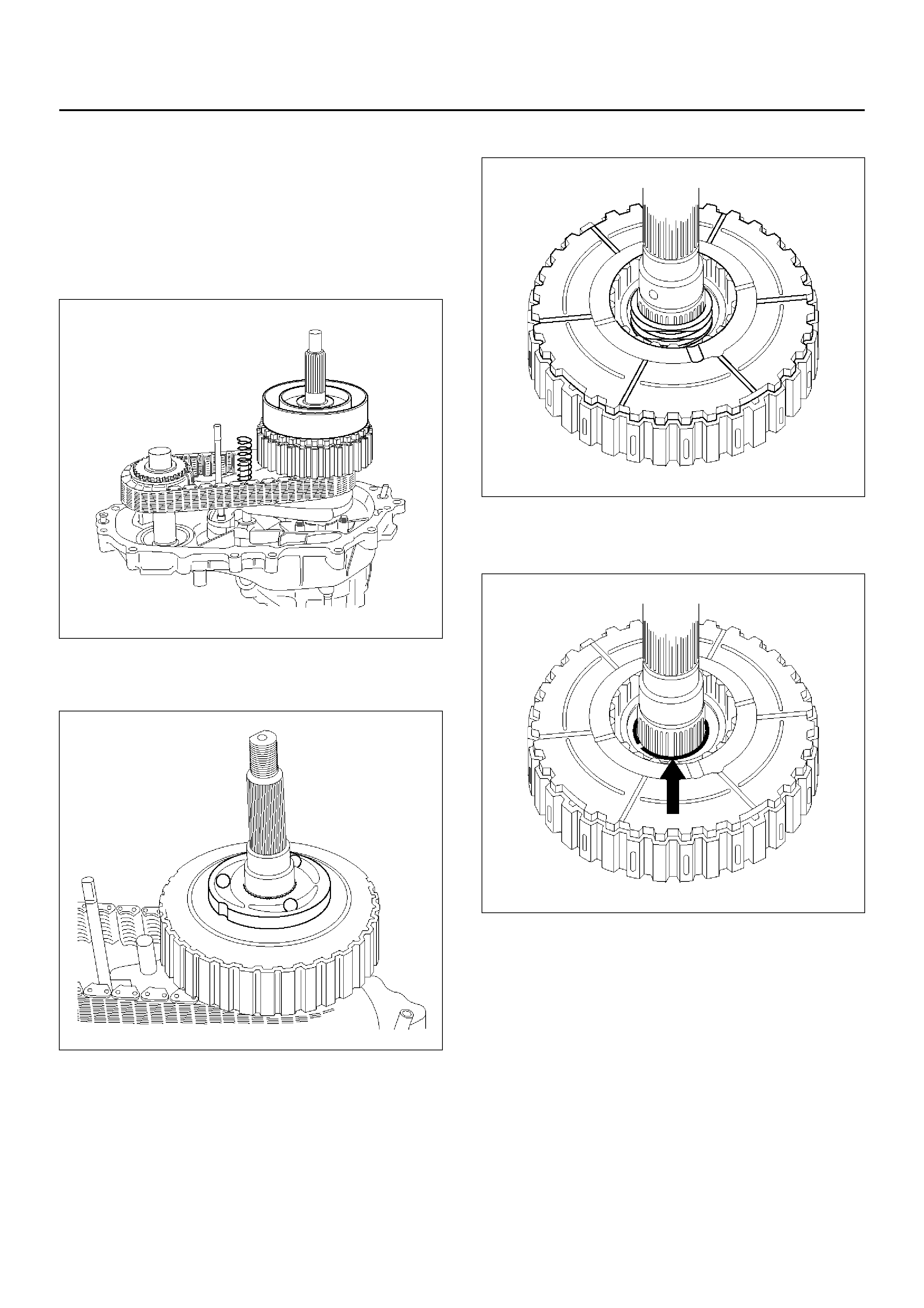
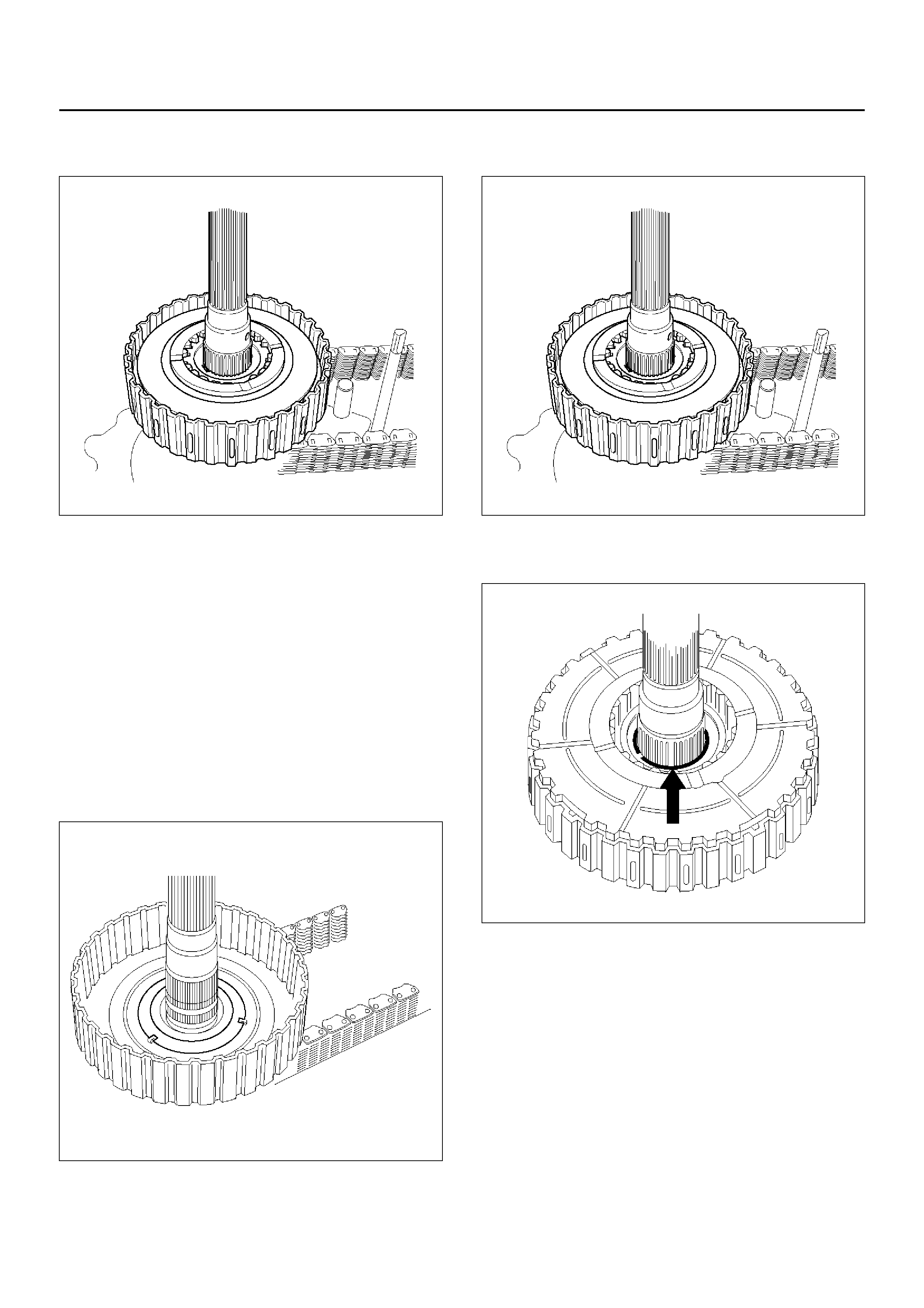
REASSEMBLY
1. Install the clutch pack assembly which the multi
clutch plate is orderly installed to the output shaft.
NOTE:
• Install the clutch pack assembly while adjusting the
phase of both the clutch housing and drive sprocket.
• During installation, the plate of the clutch pack
assembly may slide out of this fixed position (the
correct position is shown in the illustration). If this
occurs, remove all of the clutch plates of the clutch
pack assembly and reinstall them to their correct
position.
266RY00009
2. Install the insulator washer and armature plate to
the clutch pack assembly.
266RY00008
3. Using snap ring pliers, install the snap ring to the
output shaft.
266RY00007
4. Install the wave spring to the output shaft.
266RY00006
5. Install the cam pulley.
6. Place a ball on each groove of the cam pulley.
266RY00005
7. Install the cam and coil housing to the output shaft.
8. Install the thrust bearing.
9. Install the lockup fork spring.
261RY00020
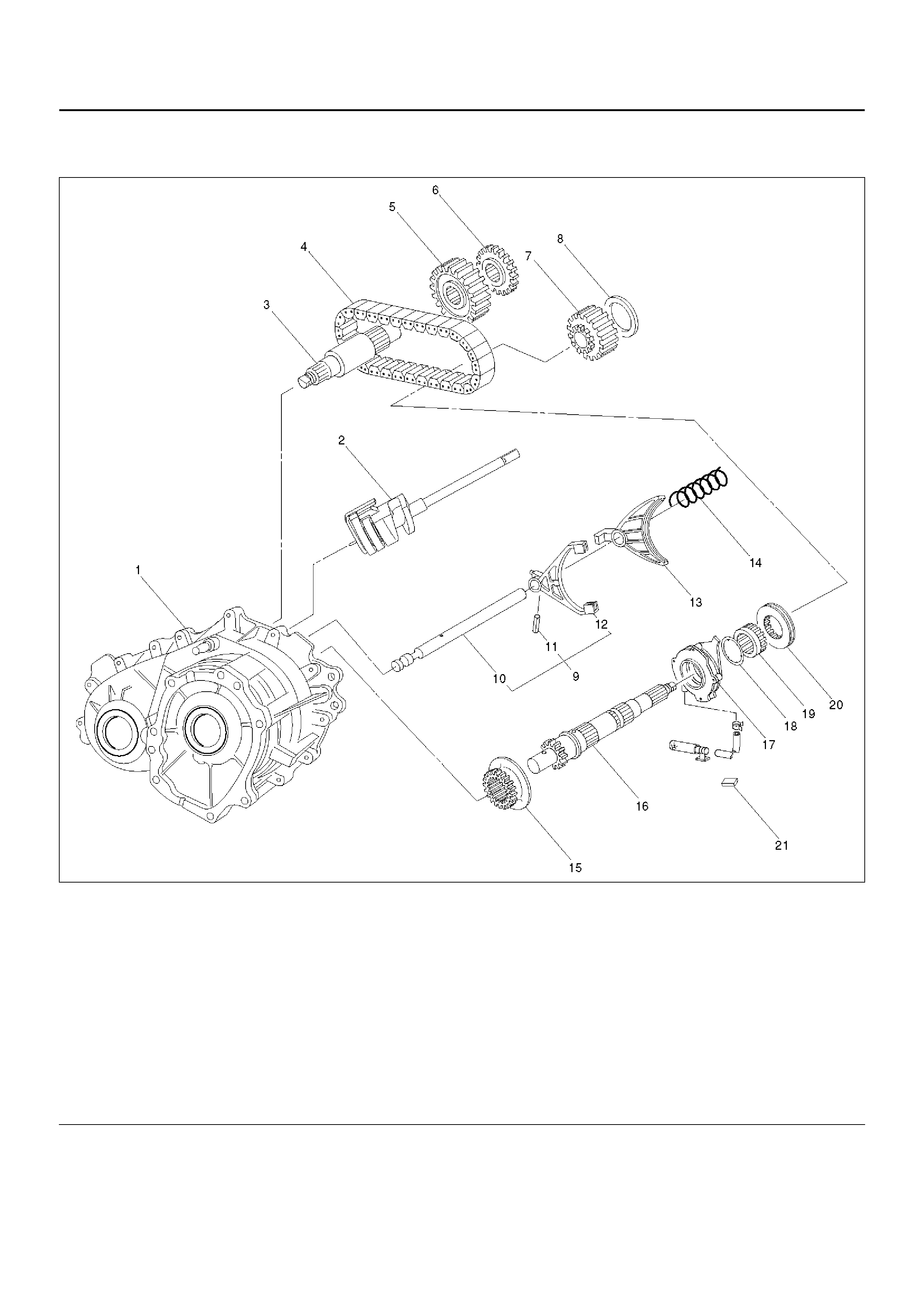
CHAIN, SPROCKET AND MECHANICAL LOCK (TRANSFER CASE ASSEMBLY)
262RY00021
EndOFCallout
Legend
(1) Transfer Case Assembly
(2) Cam and Shaft Rail Assembly
(3) Front Output Shaft
(4) Chain
(5) Lower Drive Sprocket
(6) Front Tone Wheel
(7) Drive Sprocke t
(8) Spacer
(9) Shift Fork and Rail Assembly
(10) Lockup Rail
(11) Spring Pin
(12) Shift Fork Assembly
(13) Lockup Fork
(14) Lockup Fork Spring
(15) Reduction Hub
(16) Rear Output Shaft
(17) Oil Pump Assembly (with Strainer)
(18) Thrust Washer
(19) Lockup Hub
(20) Lockup Collar Assembly
(21) Magnet
DISASSEMBLY
1. Remove the spacer.
2. Remove the front tone wheel, lower drive sprocket,
drive sprocket and chain together from the front and
rear output shaft.
266RY00010
3. Remo ve the lock up c ollar a ssem bly and lo ckup fork
together.
266RY00011
4. Remo ve the loc kup hub.
5. Remove the thrust washe r.
6. Remove the magnet from the strainer set position
together with the oil pump assembly.
266RY00012
7. Remove the output shaft.
8. Remove the cam and shaft rail assembly.
262RY00015
9. Remove the shift fork and rail assembly, and
redu ction hub.
10. Remove the spring pin from the shift fork and rail
assembly.
11. Remove the shift fork assembly from the lockup rail.
12. Remove the front output shaft from the transfer
case.
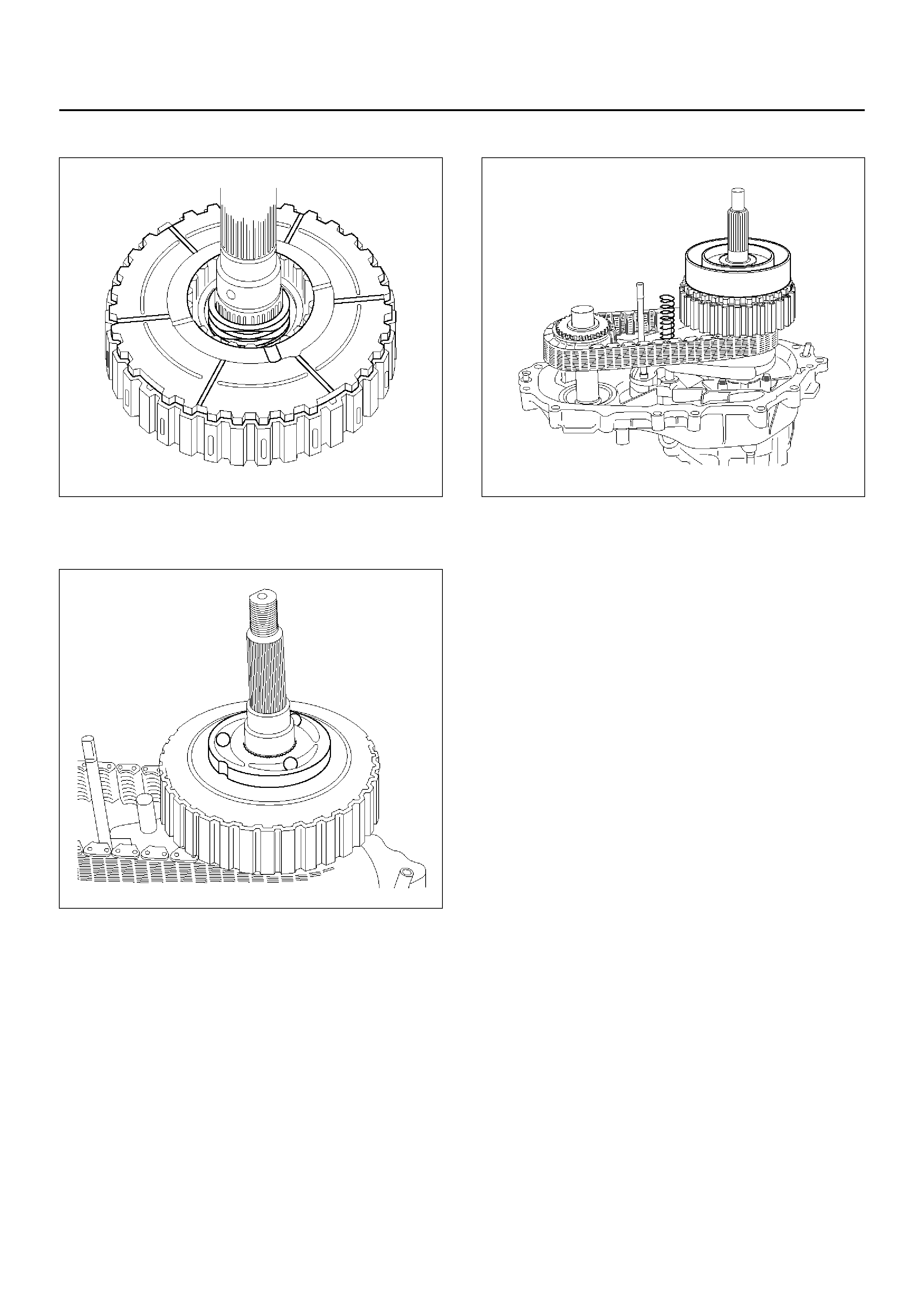
REASSEMBLY
1. Apply ATF to the inside of the ball bearing.
2. Install the front output shaft to the transfer case.
262RY00019
3. Install the shift fork assembly to the lockup rail and
fix the assembly with the snap ring.
4. Install the shaft fork and rail assembly and reduction
hub to the transfer case.
262RY00015
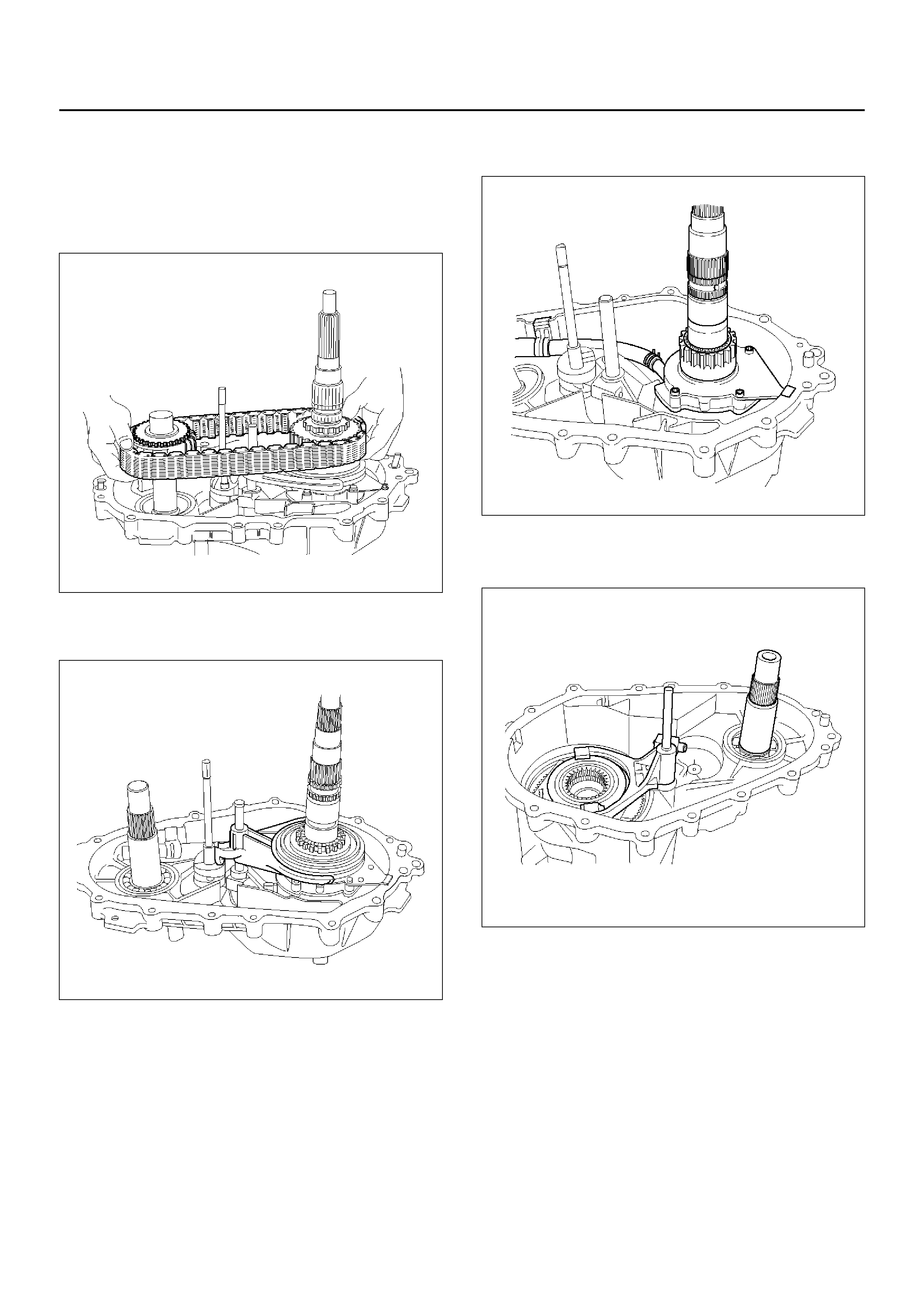
5. Install the output shaft to the transfer case.
6. Install the oil pump assembly to the output shaft and
attach the magnet to the strainer set position.
7. Install the thrust washer.
8. Install the lockup hub.
9. Install the cam and shaft rail assembly.
266RY00012
10. Install the lockup collar assembly and lockup fork
together.
266RY00011
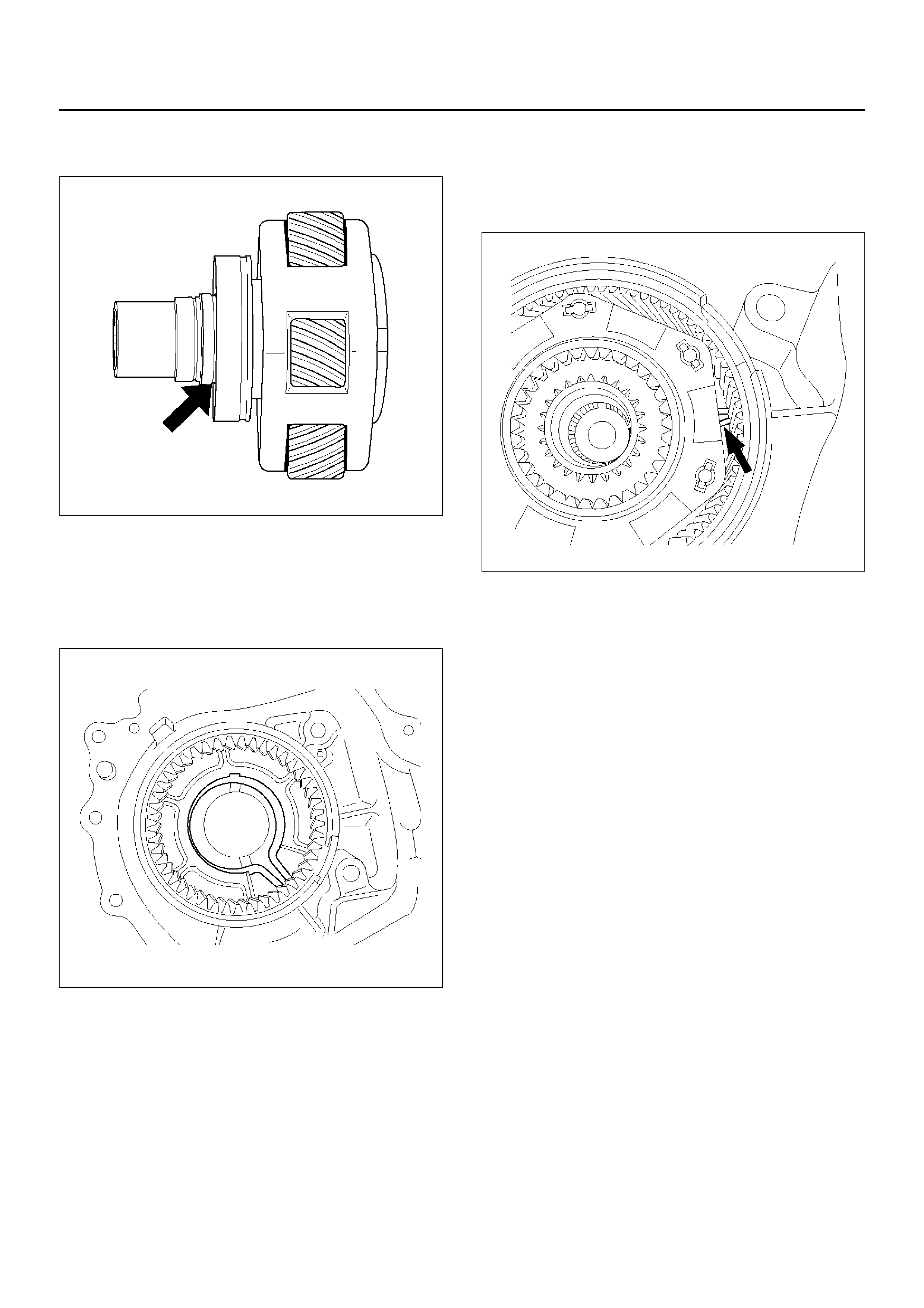
11. Apply ATF to the chain and engage it to both
sprockets.
12. Mount the chain and sprocket assembly to both
output shafts.
NOTE: When installing chain, the copper colored ring
of the chain (indicated by the arrow) to be installed in
direction of rear.
13. Install the front torn wheel to the front output shaft.
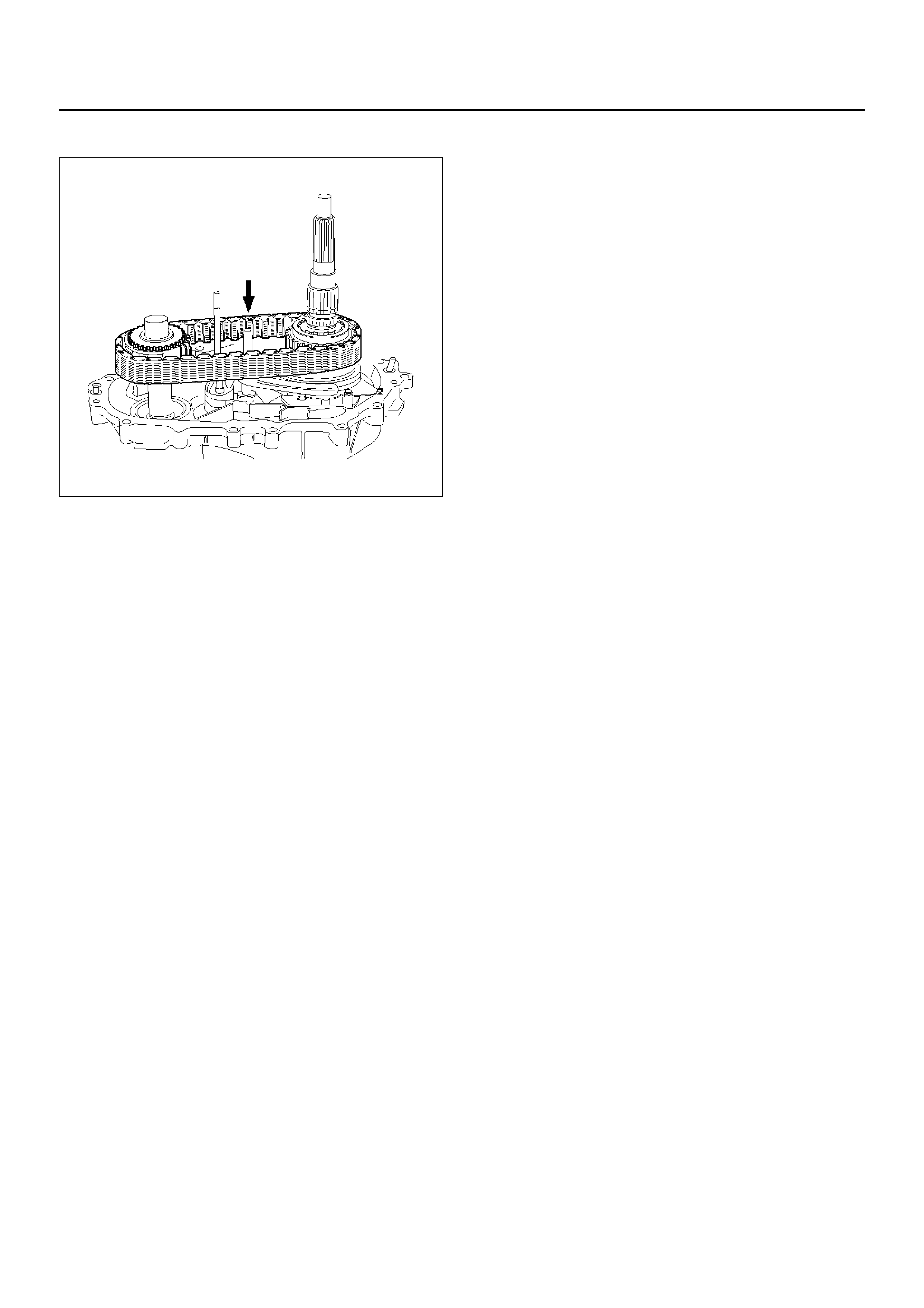
14. Install the spacer to the drive sprocket assembly.
266RY00018
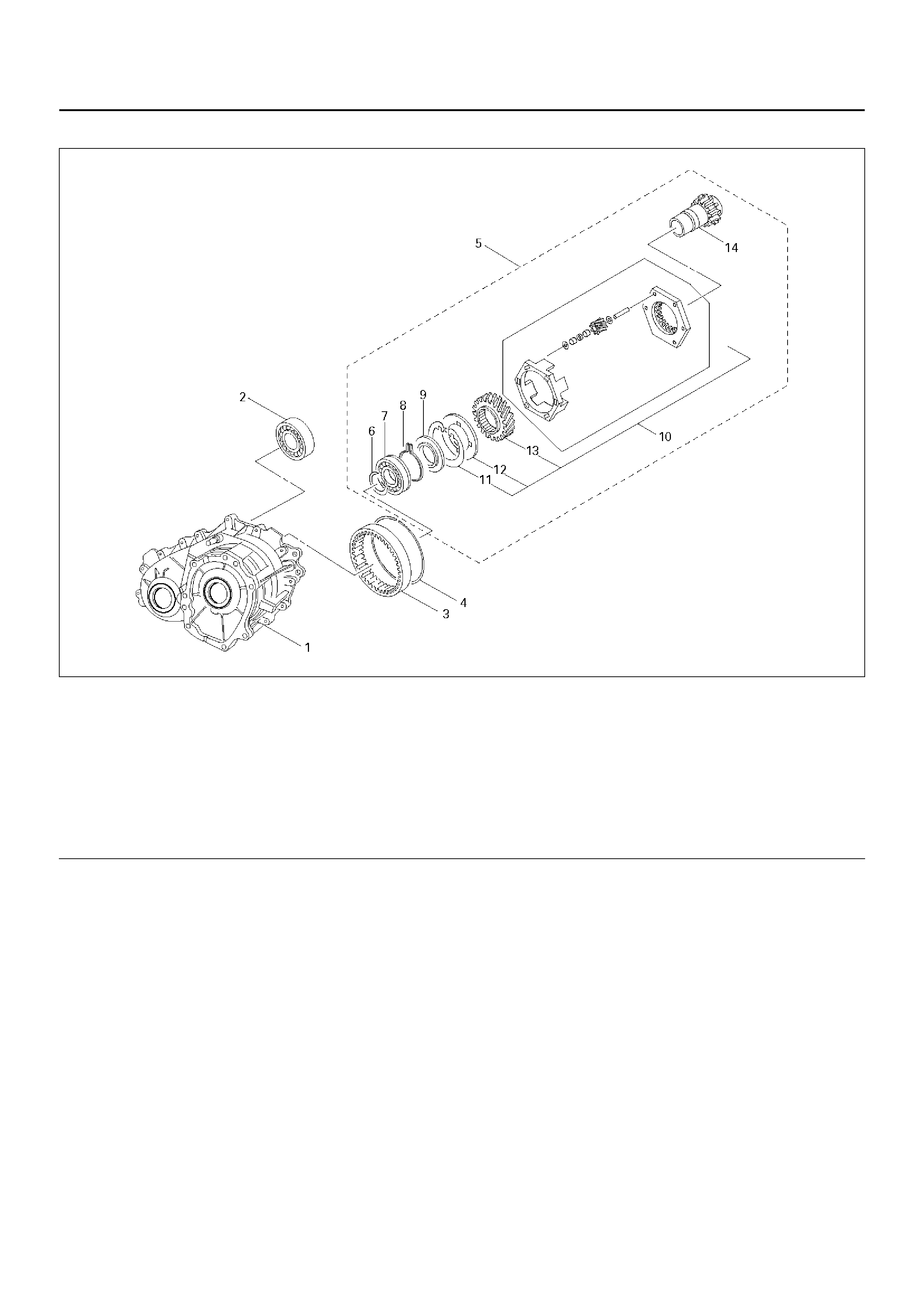
TRANSFER CASE ASSEMBLY
265RY00001
EndOFCallout
Legend
(1) Transfer Case (with Oil Seal)
(2) Ball Bearing
(3) R i ng Ge ar
(4) Snap Ring
(5) Input Shaft and Carrier Assembly
(6) Snap Ring
(7) Ball Bearing
(8) Snap Ring
(9) Circular Hub
(10) Carrier Assembly
(11) Snap Ring
(12) Thrust Plate
(13) Sun Gear
(14) Input Shaft Assembly (with Bearing and
Bushing)
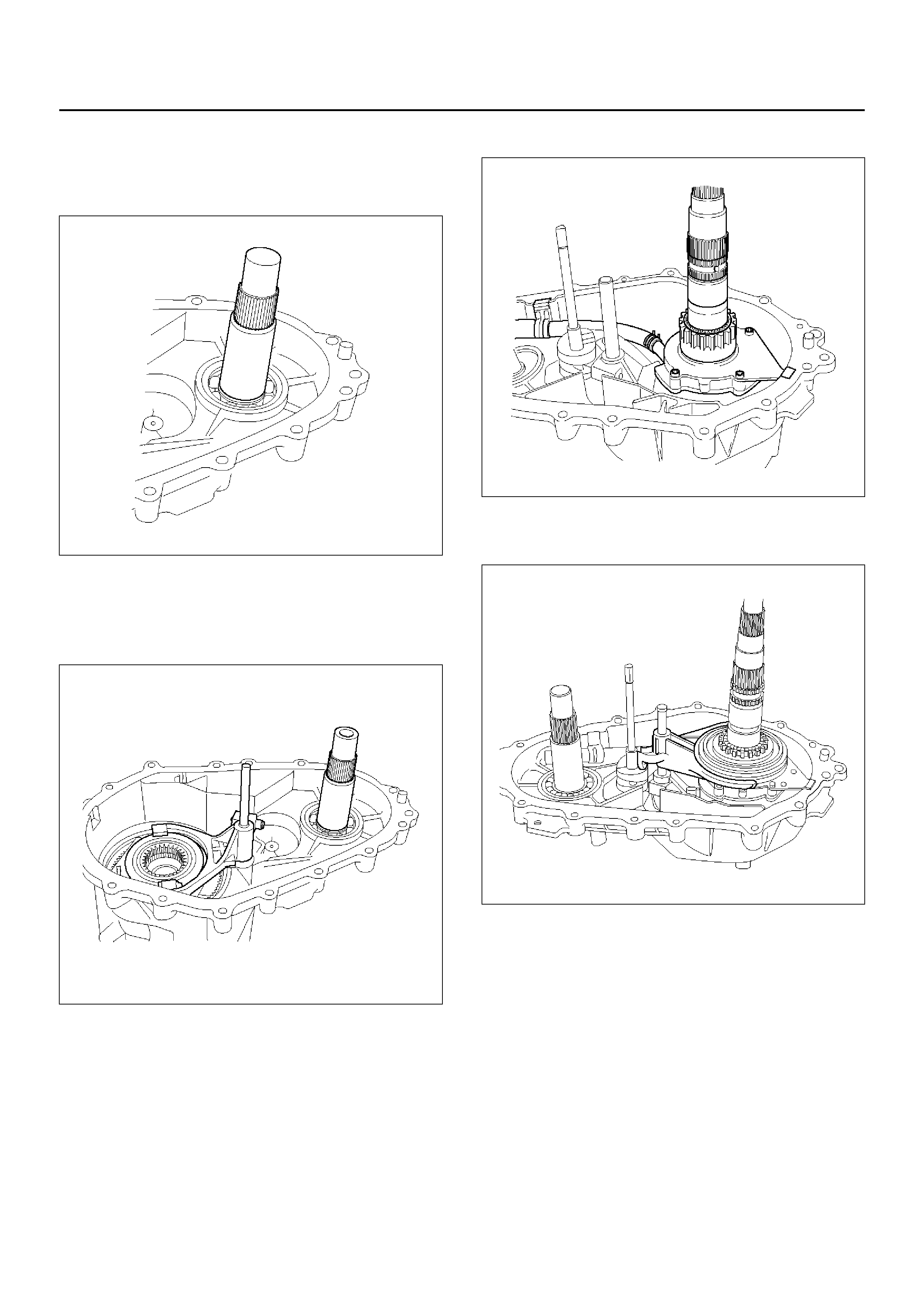
DISASSEMBLY
1. Using snap ring pliers, open the snap ring from the
gap on the carrier assembly.
While op ening the s nap r ing, r emo ve the i npu t s ha ft
assembly, carrier assembly and thrust plate
together from the transfer case.
265RY00002
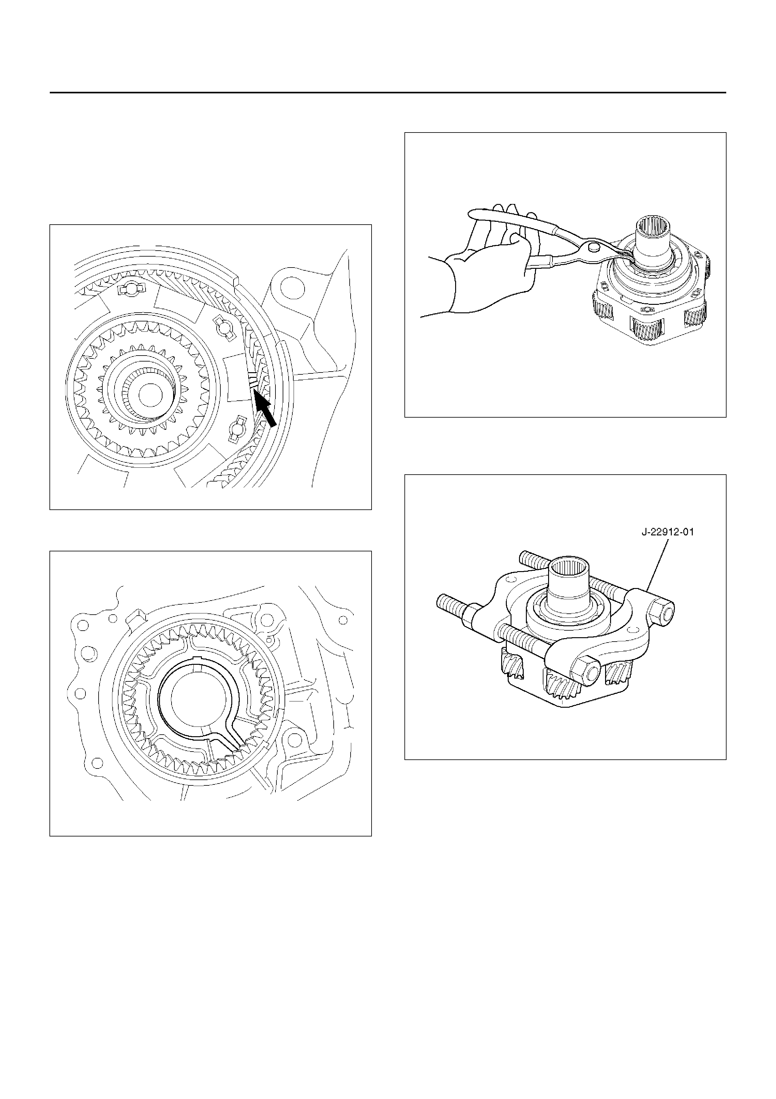
2. Remove the snap ring from the transfer case.
265RY00003
3. Using snap ring pliers, remove the snap ring.
265RW009
4. Using the bearing remover J–22912–01, remove the
ball bearing from the input shaft.
265R200001
5. Remove the circular hub.
6. Remove the snap ring from the carrier assembly.
265RW006
7. Remo ve the thrus t plate from the carrie r assem bl y.
8. Remo ve the sn ap ring befor e the ring gear.
261RW025
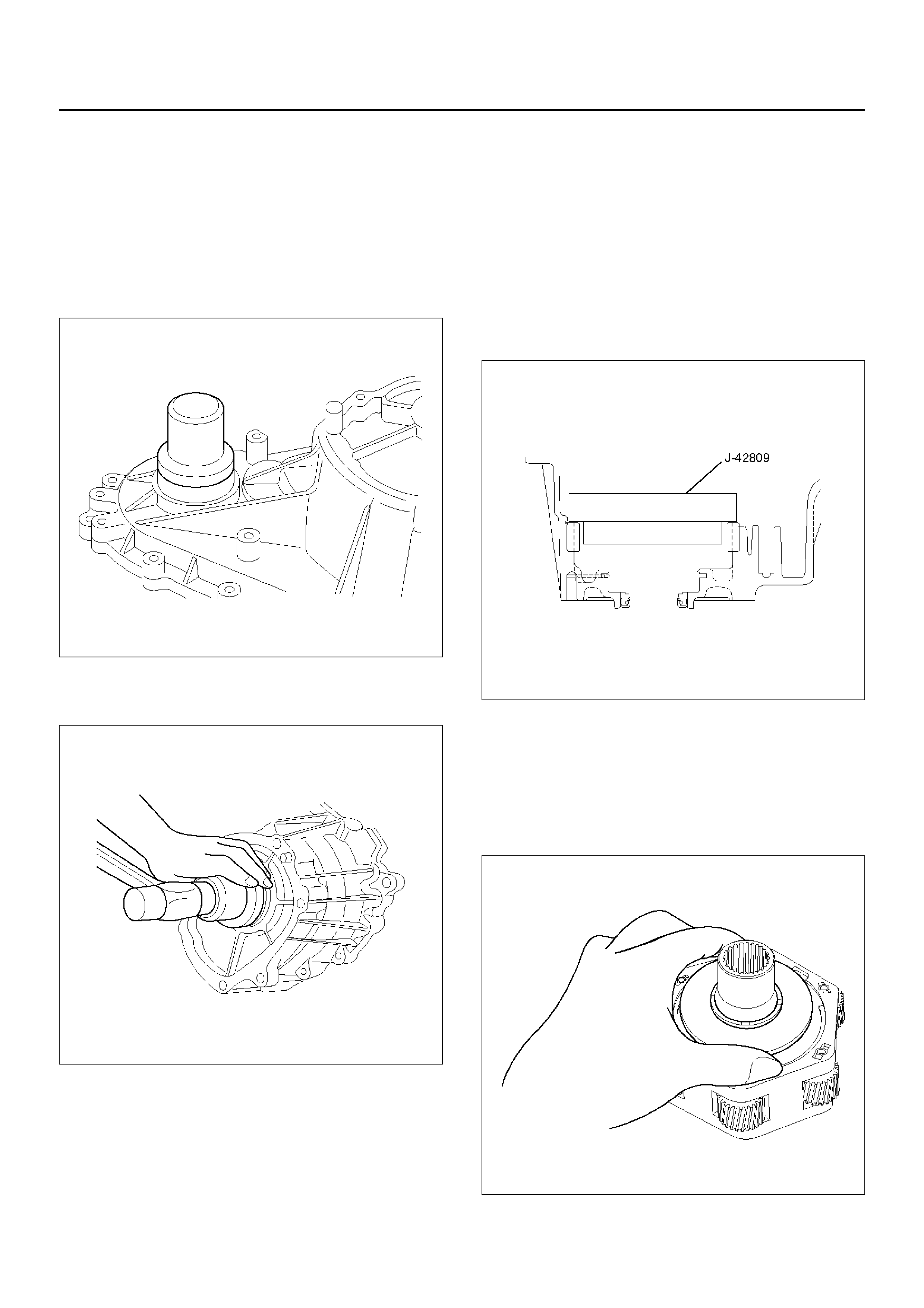
9. Using the ring gear remover J–42806 and a bench
press, remove the ring gear from the transfer case.
261R200005
NOTE: Removing ring gear needs a high-load press.
This means the transfer case may be damaged.
To remove and replace the ring gear, it is recommended
that the transfer case assembly should be replaced.
10. Remove the ball bearing of the front output shaft
from the transfer case.
261RY00021
REASSEMBLY
Oil Seal Repl ac eme nt
1. Remove the oil seal of the front output shaft and
input shaft from the transfer case.
2. Apply the circumference of the new oil seal and fill
the lip with grease (BESCO L2 or its equivalent).
3. Using the oil seal installer J–42807, install the fron t
output shaft oil seal to the transfer case.
266RY00013
4. Using the oil seal installer J–4 2808, install the inpu t
shaft oil seal to the transfer case.
261RY00031
5. Using the ring gear installer J–42809 and a bench
press, install the ring gear to the transfer case.
NOTE: Pay attention to the following points.
• Identify the correct direction of gear.
• Do not damage the gear.
• Do not press-fit the ring gear slantingly.
• Press-fit the ring gear to the innermost.
• Remove burrs generated by press-fitting.
• If the transfer case has serrations, match them
with those of the gear and press-fit the gear.
261R200007
6. Install the snap ring.
7. Install the thrust plate to the carrier assembly.
Attach the snap ring to the carrier assembly.
8. Install the carrier assembly to the input shaft.
9. With care the direction of circular hub, mount it to
the input shaft.
265RW008
10. Press the ball bearing to the input shaft so that the
snap ring will be attached to the input shaft.
265RY00004
11. Install the snap ring to the input shaft.
12. Install the ball bearing of the front output shaft to the
transfer case.
13. Install the snap ring of the input shaft bearing to the
transfer case.
265RY00003
14. Using snap ring pliers, open the snap ring from the
gap on the carrier assembly.
While opening the snap ring, securely attach the
input shaft and carrier assembly to the transfer
case.
265RY00002
INSPECTION AND REPAIR
(TRANSFER CASE ASSEMBLY)
When wear, damage, or any other defects are observed
durin g th e i nsp ec tio n, th e part or parts must be repaired
or replaced. Wash all the parts with clean detergent,
and check that old oil, metallic particles, dirt, or foreign
materials are completely removed. Blow the air into oil
holes and grooves to remove foreign materials or
residual detergent.
Chain
• Check whether the face that contacts the sprocket is
free from excessive wear or damage. If defects are
observed, replace the part.
• If the chain interference mark is found on the inside
wall of the transfe r cover or the chai n is so slack tha t
a skipped engagement occurs between the chain and
sprocket, replace the chain.
Sprocket
• Check whether the sprocket tooth surface is
excessi vely worn or damage d, and there is eviden ce
of burrs, chipping, wear, or damage on the gear
spline. Remove minor flaws or scratches with oil
stone. If excessive wear or damage is observed,
replace the part.
• If excessive wear or damage is observed on the
sprocket inside sliding surface, replace the part.
Gear
• Check whether the gear tooth surface is excessively
worn or damaged, and there is evidence of burrs,
chipping, wear, or damage on the gear spline.
Remove minor flaws or scratches with oil stone. If
excessive wear or damage is observed, replace the
part.
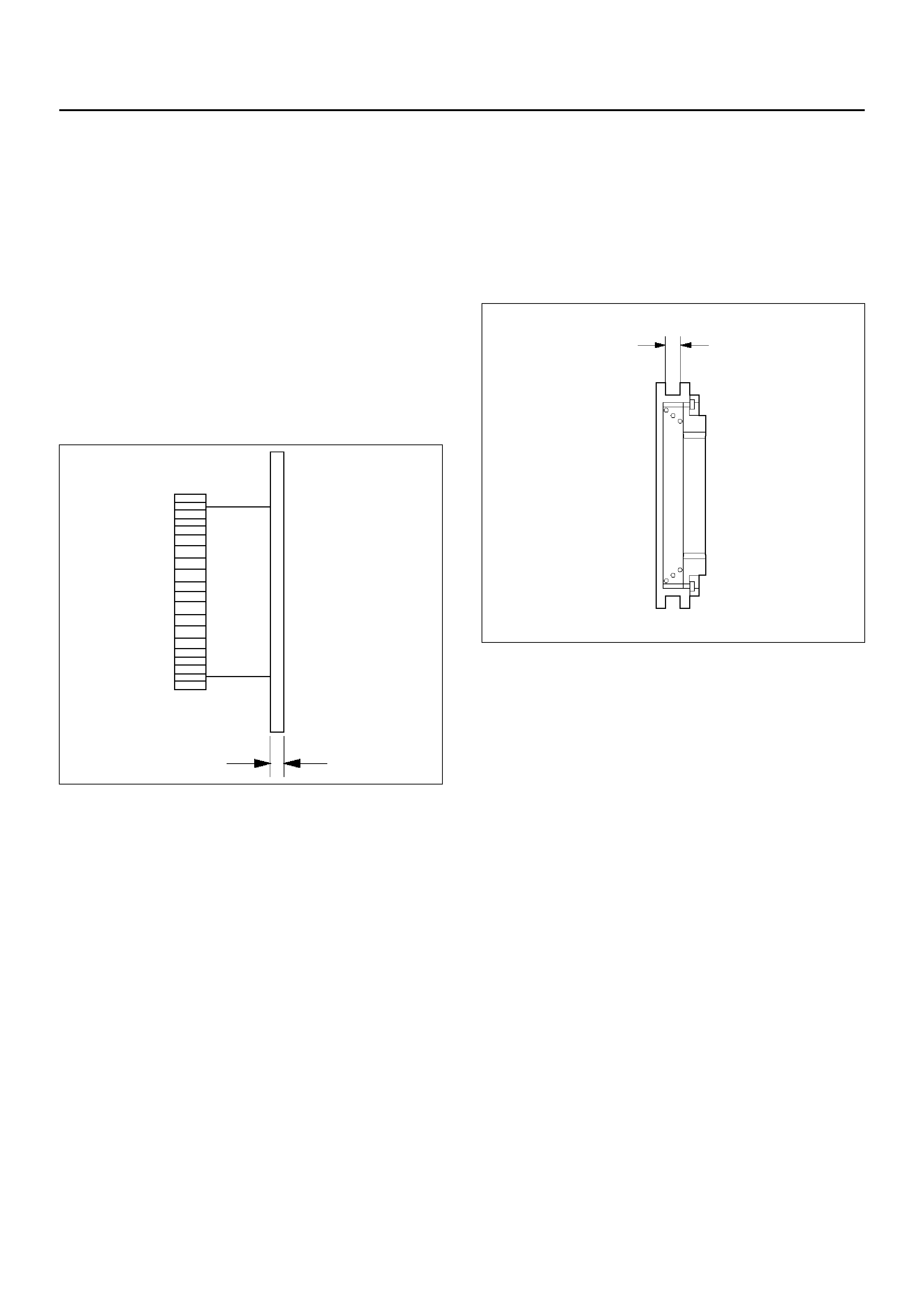
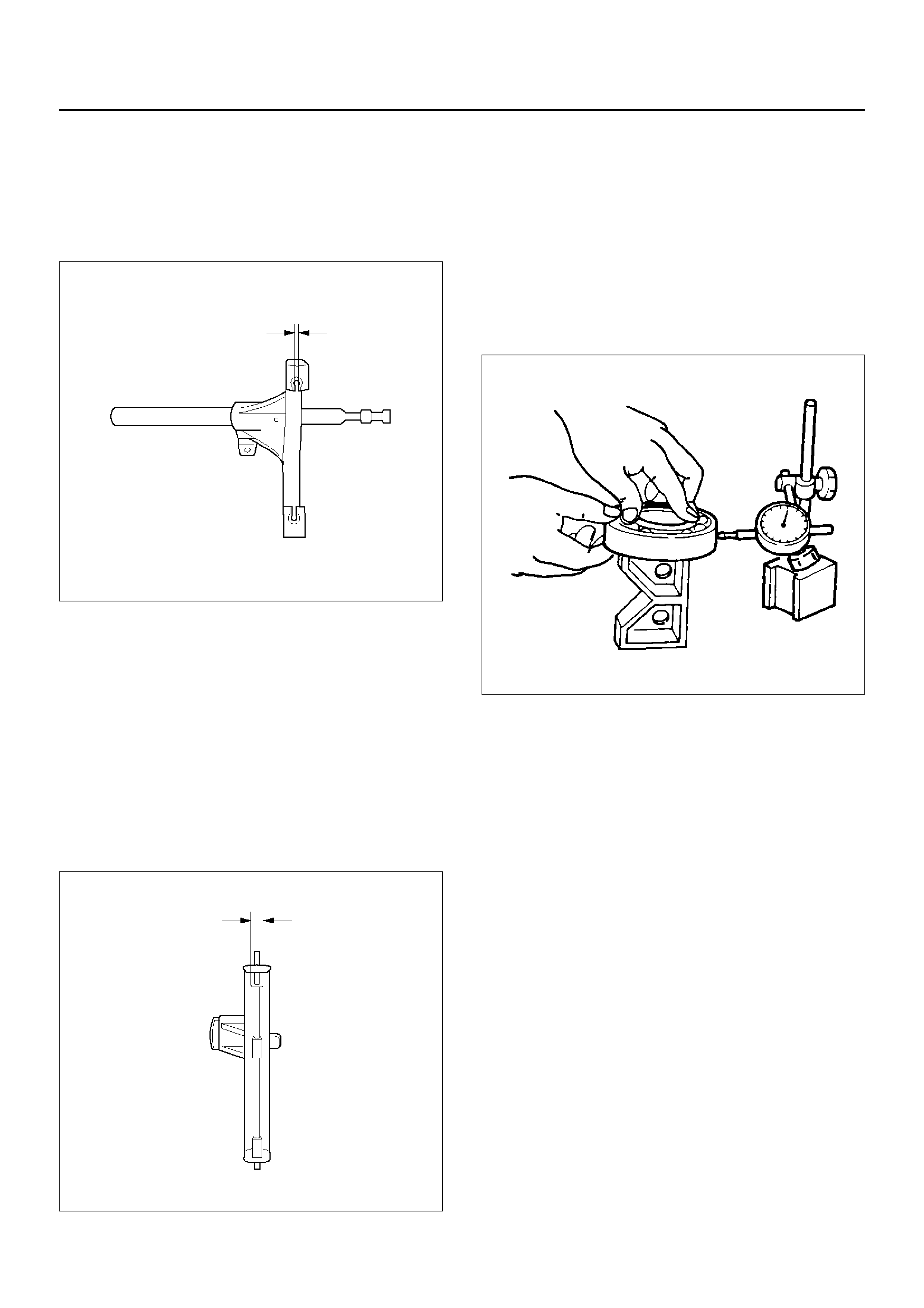
Thickness of Reduction Hub
• Measure the thickness with a micrometer.
• If the measurement exceeds the limit, replace the
reduction hub.
Standard : 3.05 –3.3 0mm
Allowable limit : 2.5mm
265RW005
Lockup Collar Assembly
• Install the lockup hub, drive sprocket assembly, and
lockup collar assembly to the output shaft.
• If the lockup collar assembly does not move
smoothly, replace the lockup collar assembly.
NOTE: Apply ATF to the rear of the gear.
Width of Lockup Collar
• Using calipers, measure the lockup collar groove for
width of wear.
• If the measurement exceeds the limit, replace the
lockup collar assembly.
Standard : 7.16–7.32mm
Allowable limit : 7.9mm
262RY00018
Shift Fork and Rail Assembly
Check the shift fork and rail for wear, distortion, and
scratches. If defects are observed, replace the parts.
Thickness of Shift Fork
• If the measurement exceeds the limit, replace the
shift fork.
Standard : 3.41 –3.7 9mm
Allowable limit : 4.4mm
262RY00016
Lockup Fork and Rail
• Check the lockup fork and rail for wear, distortion,
and scratches. If defects are observed, replace the
parts.
Thickness Lockup Fork
If the measurement exceeds the limit, replace the
lockup fork.
Standard : 6.99 –7.0 9mm
Allowable limit : 6.3mm
262RY00017
Bearing
Check the profile of the needle, roller, ball, and thrust
beari ngs. Wash the bear ings wi th clean solv ent and dry
with compressed air.
NOTE: If the bearing is rotated excessively, the rollers
may be damaged. So, rotate the bearing slowly with
your hand. Apply grease to the bearing, and check the
smoothness of the bearing while slowly rotating the race
with your hand.
Allowable limit : 0.23mm
226RW143
Lockup Fork Spring
Check the lockup fork spring for distortion, cracking,
and wear. If defects are observed, replace the part.
Multi Plate Disk Clutch
• If the burned, mirror-surfaced clutch facing, or
scraping is observed on the clutch plates, clutch
housing, armature plate, and insulator washer,
replace the parts.
266R200003
EndOFCallout
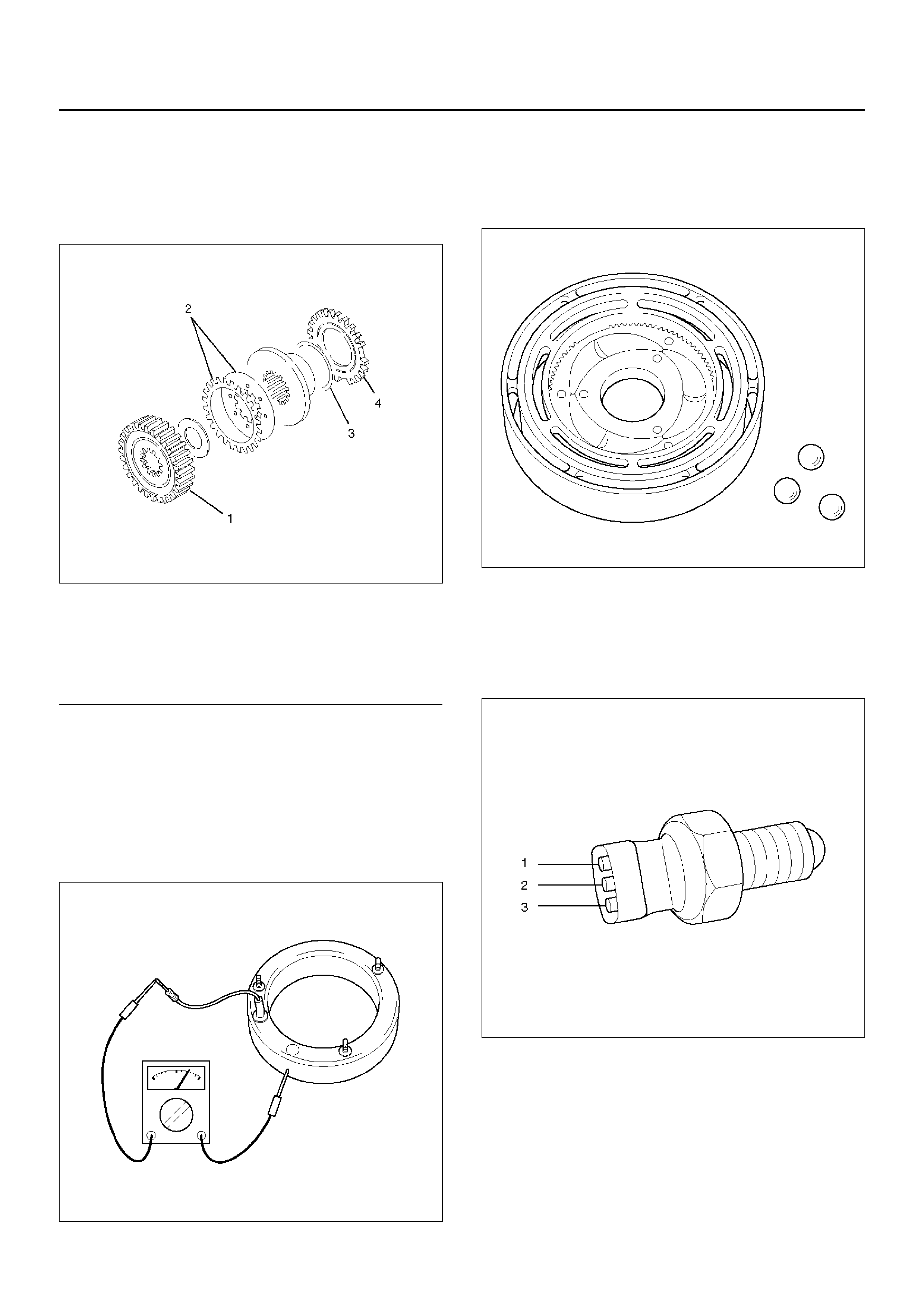
Coil Assembly
• Check the resistance of the coil with a tester. If
defects are observed, replace the coil assembly.
Standard : 1.7±0.3Ω (at room temperature)
Allowable limit : 1.0∼5.0Ω
261RY00022
Cam Pulley, Cam Ball, and Cam & Coil
Housing
• Check the cam balls and cam for excessive wear or
damage. If defective, replace the parts.
266RW016
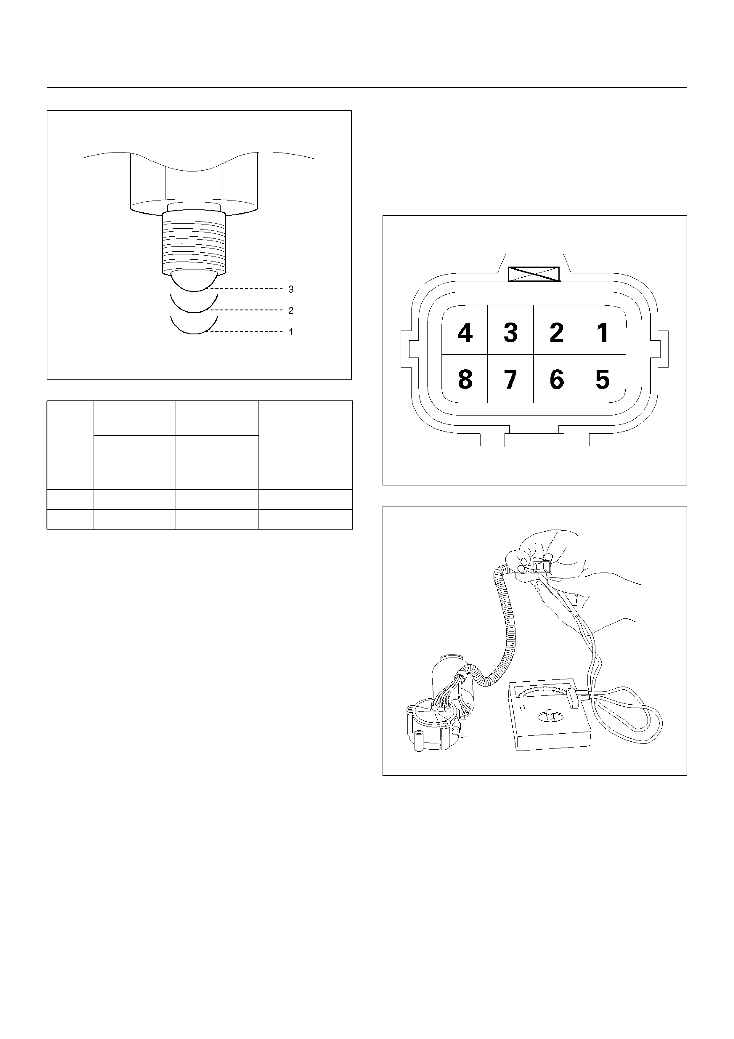
4H and 4L Switch
• Check the continuity of 4H and 4L switch.
If defects are observed, replace the 4H and 4L
switch.
261R200006
Legend
(1) Clutch Housing
(2) Clutch Plate
(3) Insulator Washer
(4) Armature Plate
261RW049
Shift Mot o r As sembly
• Check the resistance of the shift motor assembly
(between terminal 4 to 7) with a tester.
If defects are observed, replace the shift motor
assembly.
Standard : 0.63±0.2Ω (at room temperature)
8-6
261RY00023
Oil Pump
• Remove foreign materials from the strainer. If the
strainer is damaged, replace it.
• If the area into which the shaft is inserted is
excessively worn or damaged, replace the oil pump
assembly.
Switch
Stroke 4H Switch
Signal 4L Switch
Signal The
corresponding
position of
TOD switch
Terminal 2 to
Switch Body Terminal 1 to
3
1 Open Open 2H, TOD
2 Open Close 4L
3 Close Close Neutral

MAIN DATA AND SPECIFICATION
GENERAL SPECIFICATION
Type Electronically controlled torque split four wheel drive with two wheel drive.
2WD: Rear two wheel drive
TOD: Electronically controlled torque split four wheel drive.
4L: Low speed mechanical lockup four wheel drive.
Rear drive: Direct drive
Front drive: Chain drive
Low range deceleration: Planetary gear drive
Control system Switch control
Gear ratio High: 1.000
Low: 2.480
Lubric ati on sy st em Built- in oil pump
Forced lubrication
Type of lubricant ATF DEXRON®–III
Oil capacity 1.35liters
Clut ch discs number 13
Planetary gear teeth number Sun gear: 58
Pinion gear: 15
Ring gear: 86
TORQUE SPECIFICATIONS
E04R200001
TORQUE SPECIFICATIONS (CONT'D)
E04R200002
TORQUE SPECIFICATIONS (CONT'D)
E04R200003
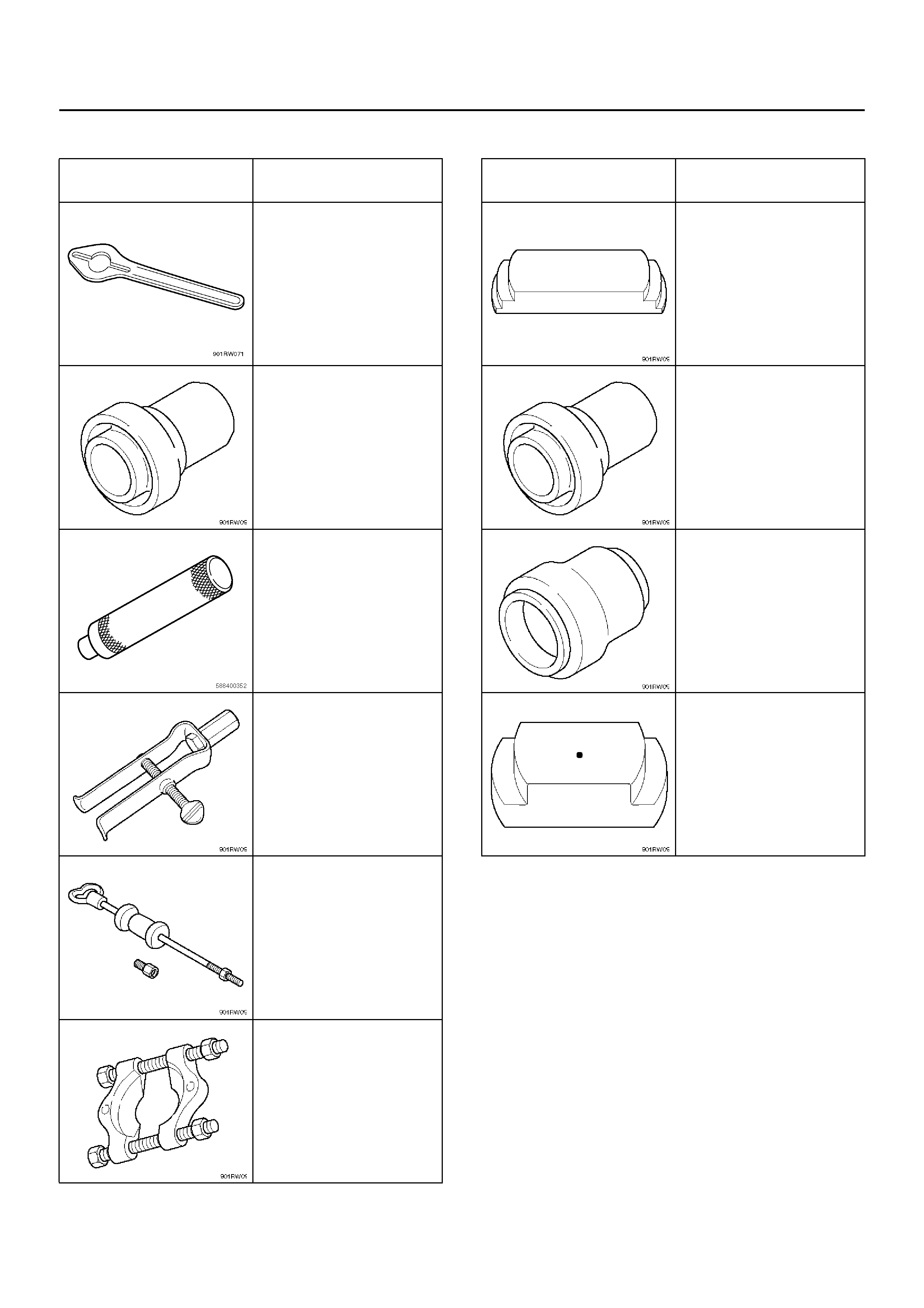
SPECIAL TOOLS
ILLUSTRATION TOOL NO.
TOOL NAME
J–8614–11
Flange Holder
J–42804
Rear Oil Seal Installer
J–33951
Shift Shaft Oil Seal
Installer
J–42805
Bearing Remover
J–2619–01
Slide Hammer
J–22912–01
Bearing Remover
ILLUSTRATION TOOL NO.
TOOL NAME
J–42806
Ring Gear Remover
J–42807
Front Output Shaft Oil
Seal Installer
J–42808
Input Shaft Oil Seal
Installer
J–42809
Ring Gear Installe r