
SECTION 7C - AUTOMATIC TRANSMISSION (4L30-E)
Service Precaution
Construction
Range Reference Chart
Normal Operation of 2001 4L30–E
Transmission
Diagnosis
Driver Information
General Diagnosis Procedure
Preliminary Inspection Chart
Checking Transmission Fluid Level and
Condition
Test Driving
Mechanical / Hydraulic Diagnosis Check
Trans Indicator Chart
Mechanical / Hydraulic Diagnosis Symptoms
Index
Stall Test
Line Pressure Test
Shift Speed Chart
Lockup Speed Chart
Changing Transmission Fluid
Selector Lever
Inspection
Removal
Installation
Select Cable
Removal
Installation
Shift Lock Cable
Removal
Installation
Mode Switch
Removal
Installation
Transmission (With Transfer Case)
Transmission and Associated Parts
Removal
Installation
Solenoid (Main Case Valve Body)
Removal
Installation
Solenoid (Adapter Case Valve Body)
Removal
Installation
Valve Body Assembly (Main Case)
Removal
Installation
Valve Body Assembly (Adapter Case)
Removal
Installation
Powertrain Control Module (PCM)
Removal
Installation
Speed Sensor (Extension Housing)
Removal
Installation
Transmission Oil Temperature Sensor
(Main Case)
Removal
Installation
Front Oil Seal (Converter Housing)
Removal
Installation
Rear Oil Seal (Extension Housing)
Removal
Installation
Transmission (4L30–E)
Disassembly
Reassembly
Converter Housing and Oil Pump Assembly
Disassembled View
Disassembly
Inspection and Repair
Reassembly
Oil Pump
Disassembled View
Disassembly
Inspection and Repair
Reassembly
Main Case Valve Body
Disassembled View
Disassembly
Inspection and Repair
Reassembly
Adapter Case Valve Body
Disassembled View
Disassembly
Inspection and Repair
Reassembly
Third Clutch and Sprag Unit
Disassembled View
Disassembly
Inspection and Repair
Reassembly
Third Clutch
Disassembled View
Disassembly

Inspection and Repair
Reassembly
Sprag Unit
Disassembled View
Disassembly
Inspection and Repair
Reassembly
Second Clutch
Disassembled View
Disassembly
Inspection and Repair
Reassembly
3–4 Accumulator Piston
Disassembled View
Disassembly
Inspection and Repair
Reassembly
Reverse Clutch Piston and Center Support
Disassembled View
Disassembly
Inspection and Repair
Reassembly
Overrun Clutch and Turbine Shaft
Disassembled View
Disassembly
Inspection and Repair
Reassembly
Main Data and Specification
Special Tools
4L30–E Parts List
SERVICE PRECAUTION
WARNING: THIS VEHICLE HAS A SUPPLEMENTAL RESTRAINT SYSTEM (SRS), REFER TO THE SRS
COMPONENT AND WIRING LOCATION VIEW IN ORDER TO DETERMINE WHETHER YOU ARE PERFORMING
SERVICE ON OR NEAR THE SRS COMPONENTS OR THE SRS WIRING. WHEN YOU ARE PERFORMING
SERVICE ON OR NEAR THE SRS COMPONENTS OR THE SRS WIRING, REFER TO THE SRS SERVICE
INFORMATION. FAILURE TO FOLLOW WARNINGS COULD RESULT IN POSSIBLE AIR BAG DEPLOYMENT,
PERSONAL INJURY, OR OTHERWISE UNNEEDED SRS SYSTEM REPAIRS.
CAUTION: Always use the correct fastener in the proper location. When you replace a fastener, use ONLY the
exact part number for that application. HOLDE N will call out those fasteners that require a repla cement after
removal. HOLDEN will also call out the fasteners that require thread lockers or thread sealant. UNLESS
OTHERWISE SPECIFIED, do not use supplemental coatings (Paints, greases, or other corrosion inhibitors)
on threaded fasteners or fastener joint interfaces. Generally, such coatings adversely affect the fastener
torque and the joint clamping force, and may damage the fastener. When you install fasteners, use the
correct tightening sequence and specifications. Following these instructions can help you avoid damage to
parts and systems.
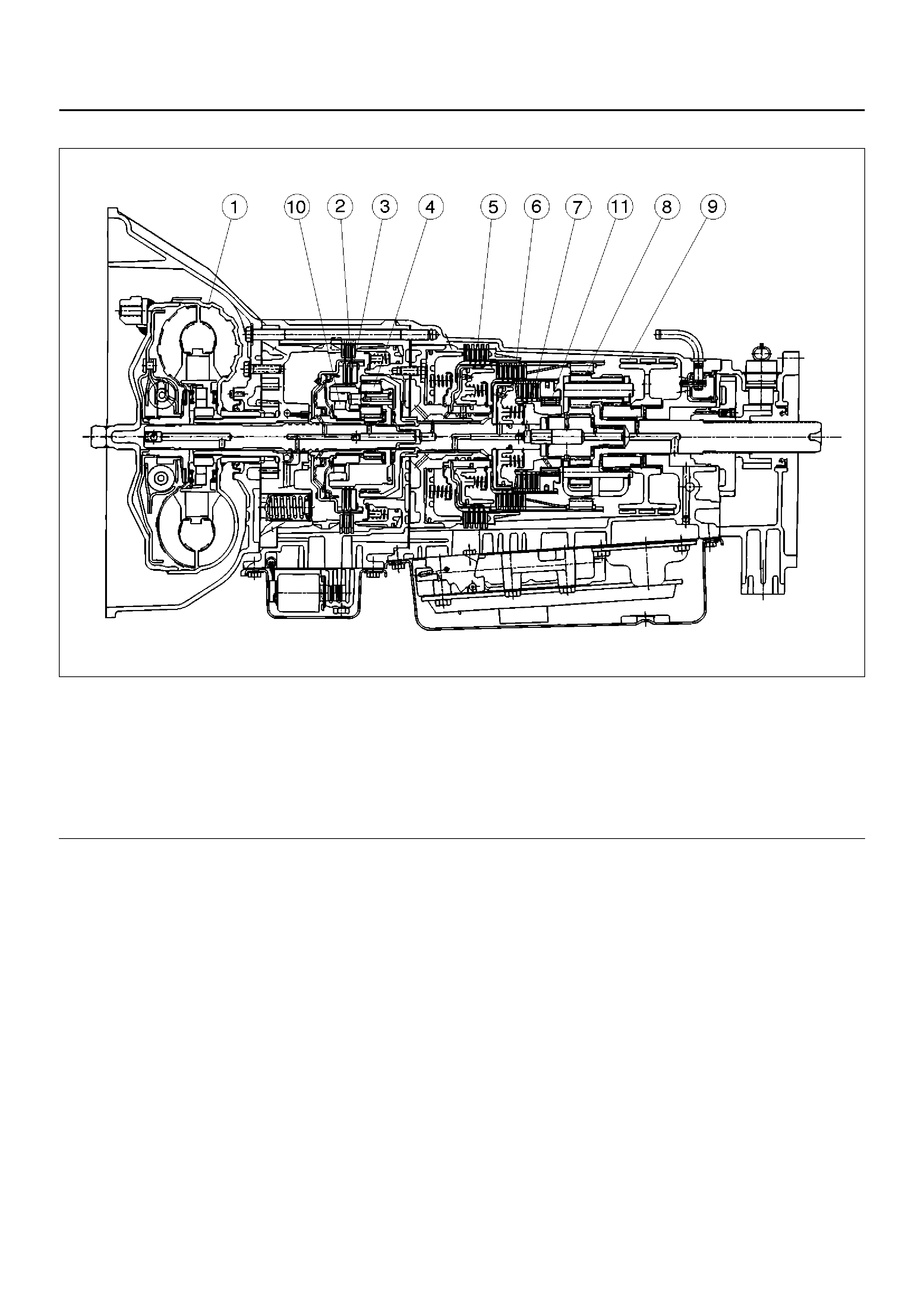
CONSTRUCTION
A07RS001
EndOFCallout
Legend
(1) Torque Converter Clutch (TCC)
(2) Fourth Clutch (C4)
(3) Overrun Clutch (OC)
(4) Overdrive Unit
(5) Reverse Clutch (RC)
(6) Second Clutch (C2)
(7) Third Clutch (C3)
(8) Ravigneaux Planetary Gear Set
(9) Brake Band (B)
(10) Overdrive Free Wheel (One Way Clutch)
(OFW)
(11) Principle Sprag Assem bly (One Way Clutch)
(PFW)
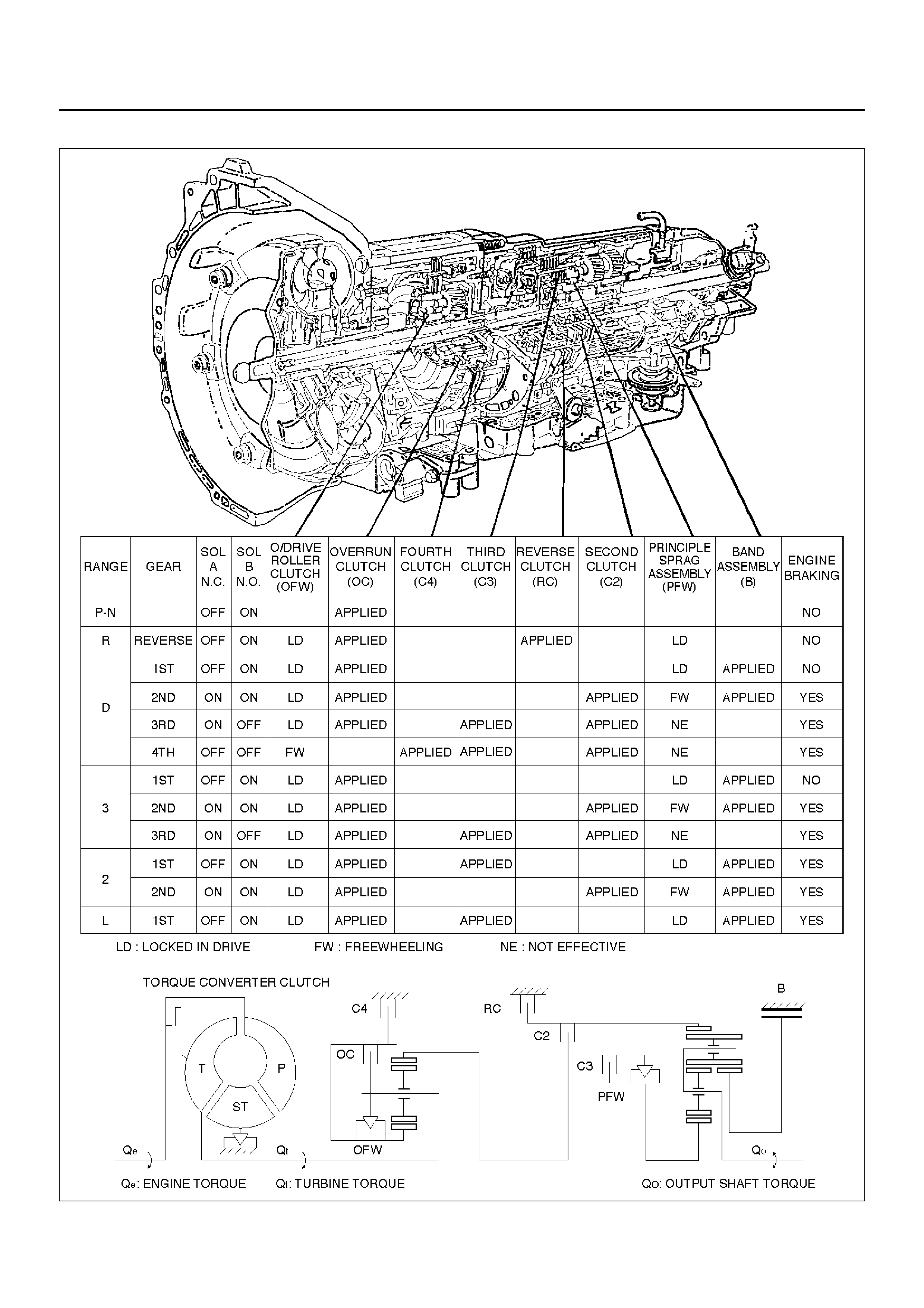
RANGE REFERENCE CHART
C07RT010

NORMAL OPERATION OF 2001 4L30-E TRANSMISSION
4L30–E Transmission - Revised Operating Modes for MY2001
Torque Converter Clutch (TCC) Application Conditions:
Normal Mode:
The TCC is normally applied in 2nd, 3rd and 4th gears only when all of the following conditions exist:
– The engine coolant temperature is above 70°C .
– The brake pedal is released.
– The shift pattern requests TCC apply.
Hot Mode:
TCC is applied in 2nd, 3rd and 4th gears when the transmission oil temperature is above 135°C.
This mode should be canceled when transmission oil temperature falls below 125°C.
ATF Warning Lamp
The ATF warning lamp will be constantly on (not flashing) if the transmission oil temperature is above 145°C .
The ATF warning lamp goes off when the transmission oil temperature is below 125°C.
Reverse Lock Out
With the selector lever in reverse position, the PCM will not close the PWM solenoid until the vehicle is below 15 km/h,
thus preventing reverse engagement above this speed.
DIAGNOSIS
Introduction
The systematic troubleshooting information covered by this Section offers a practical and systematic approach to
diagnosing 4L30–E transmission, using information that can be obtained from road tests, electrical diagnosis, oil
pressure checks or noise evaluation.
The key to correcting a complaint is to make use of all of the available symptoms and logically letting them direct you
to the cause.
When dealing with automatic transmission complaints, it is best to gather as many symptoms as possible before
making the decision to remove the transmission from the vehicle.
Frequently, the correction of the complaint does not require removal of the transmission from the vehicle.
DRIVER INFORMATION
To analyse the problem fill out a complete description of the owner's complaint.
Please draw a circle aroun d the right i nforma tion and complete th e follo wing for m. (The ne xt page is an ex ample of a
completed form.) You can draw a circle around many numbers if you are not sure.
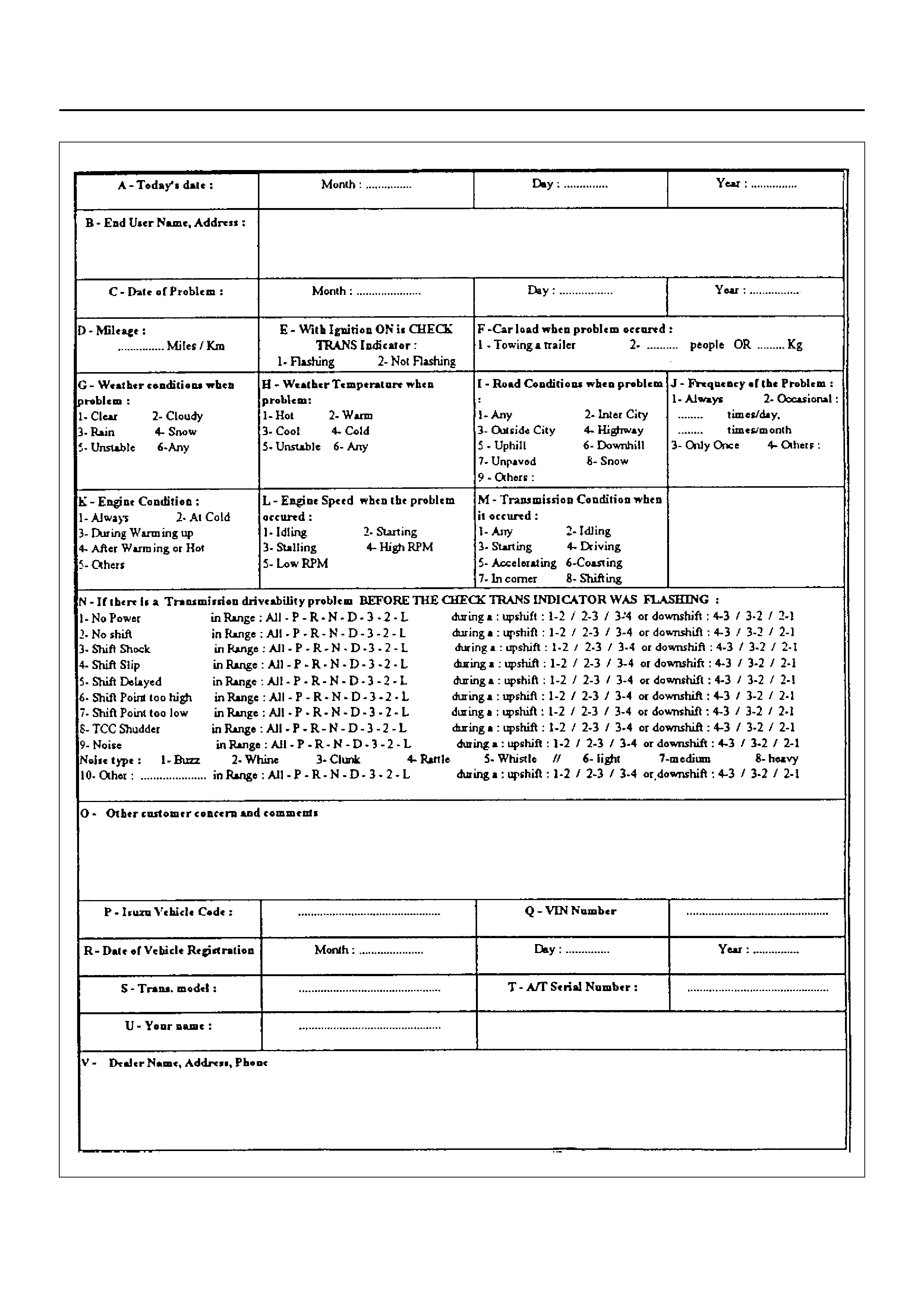
F07RT036
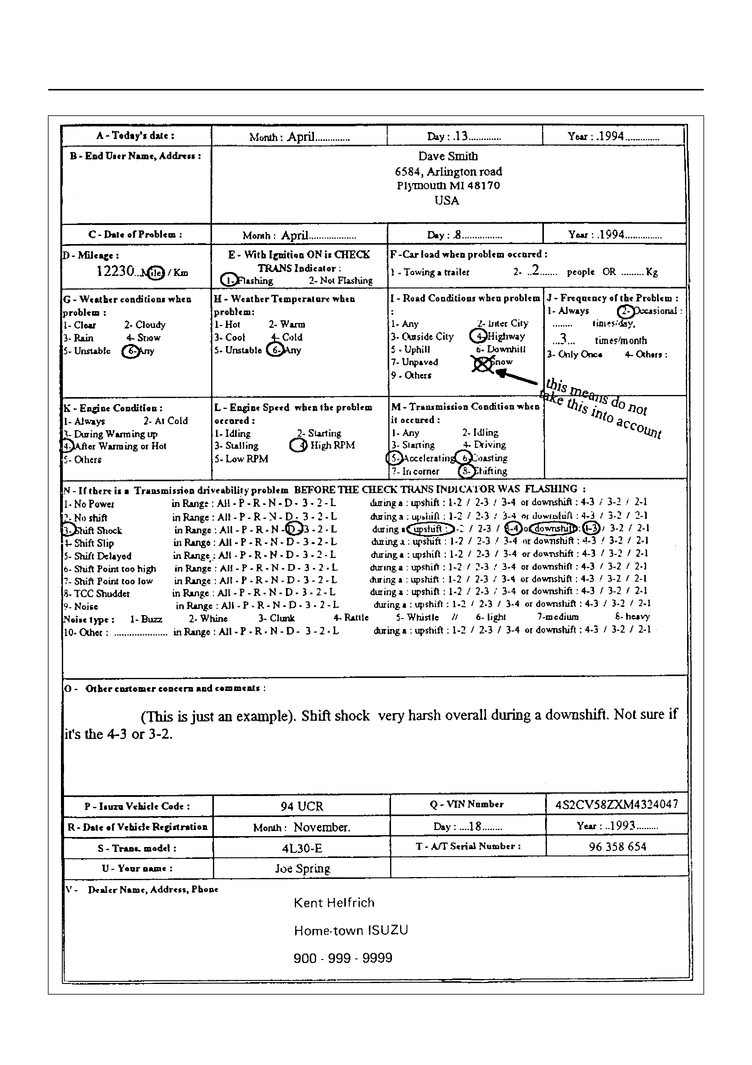
Example of a completed form.
F07RT037

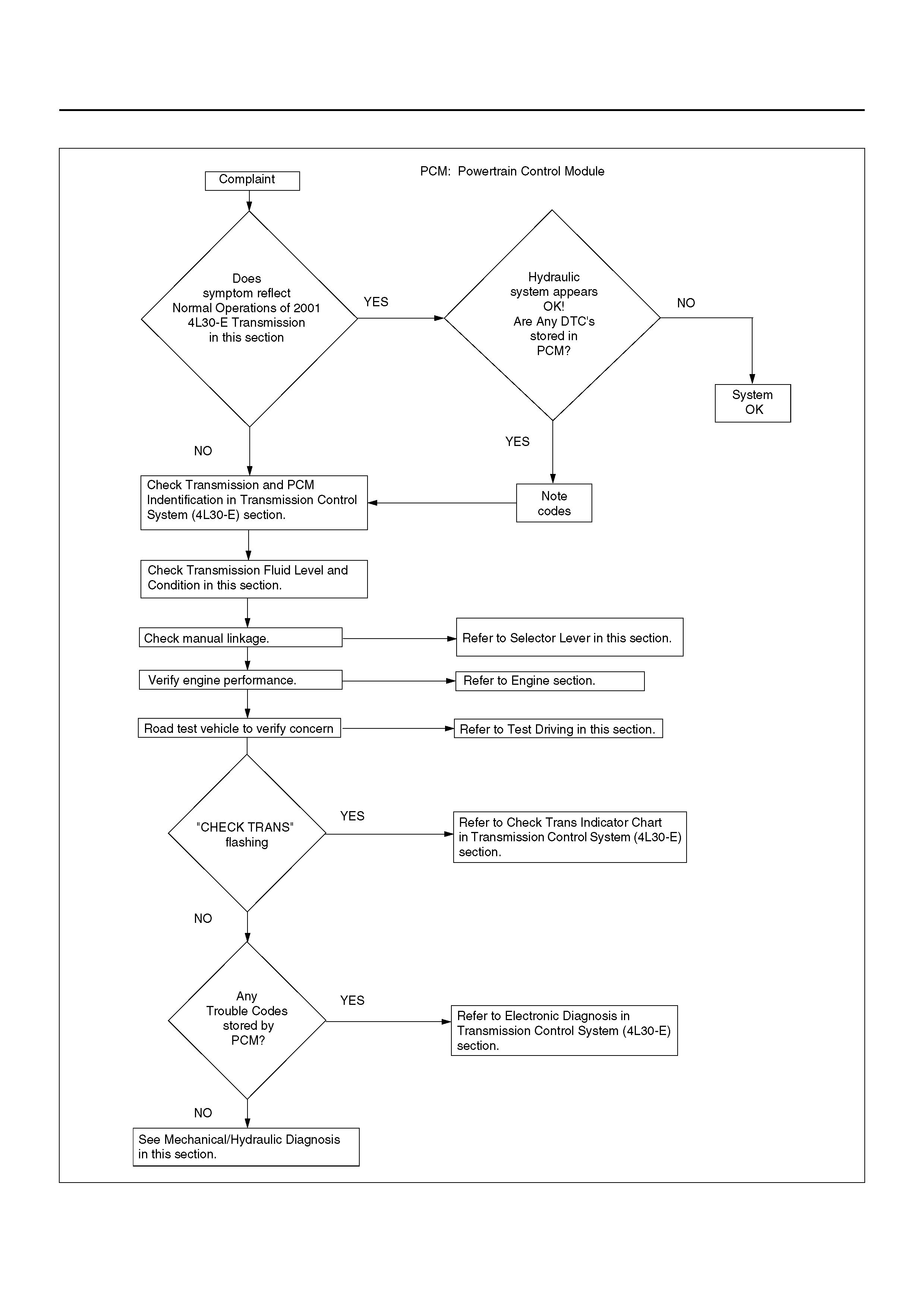
GENERAL DIAGNOSIS PROCEDURE
F07RT038
PRELIMINARY INSPECTION CHART
F07R100002
CHECKING TRANSMISSION FLUID
LEVEL AND CONDITION
Checking fluid level and condition (color and odor) at
regular intervals will provide early diagnosis
information about the transmission. This information
may be used to correct a condition that, if not detected
early, could result in major transmission repairs.
Important: When new, automatic transmission fluid is
red in color. As the vehicle is driven, the transmission
fluid will begin to look darker in color. The color may
eventually appear light brown.
A dark brown color with burnt odor may indicate
excessive fluid deterioration and signal a need for fluid
change.
Fluid Level
When adding or changing fluid, use only
DEXRON ®–III.
Refer to Section 0B Maintenance and Lubrication for
maintenance information and servicing interval.
CAUTION: DO NOT OVERFILL.
Overfilling will cause foaming, loss of fluid,
abnormal shifting and possible damage to the
transmission.
NOTE: The transmission fluid temperature must be
less than 30°C (Check with Tech 2 scan tool) before
proceeding with the level check.
1. Park the vehicle on level ground and apply the
parking brake firmly.
2. Move the selector lever through all gear ranges.
3. Move the selector lever to “Park".
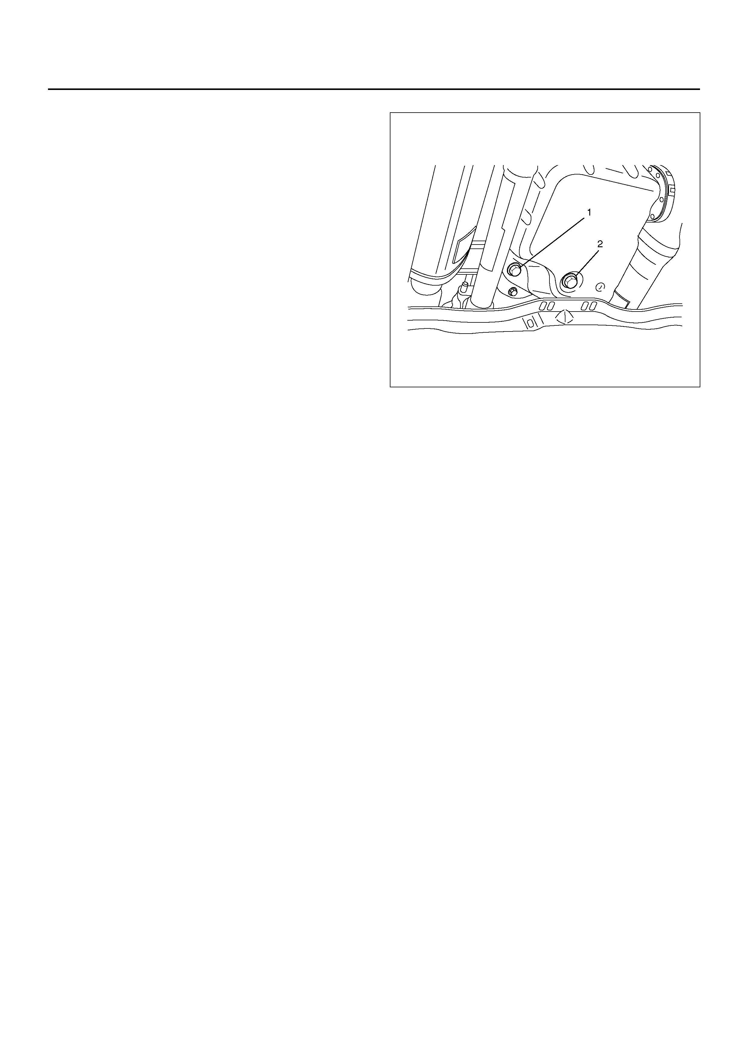
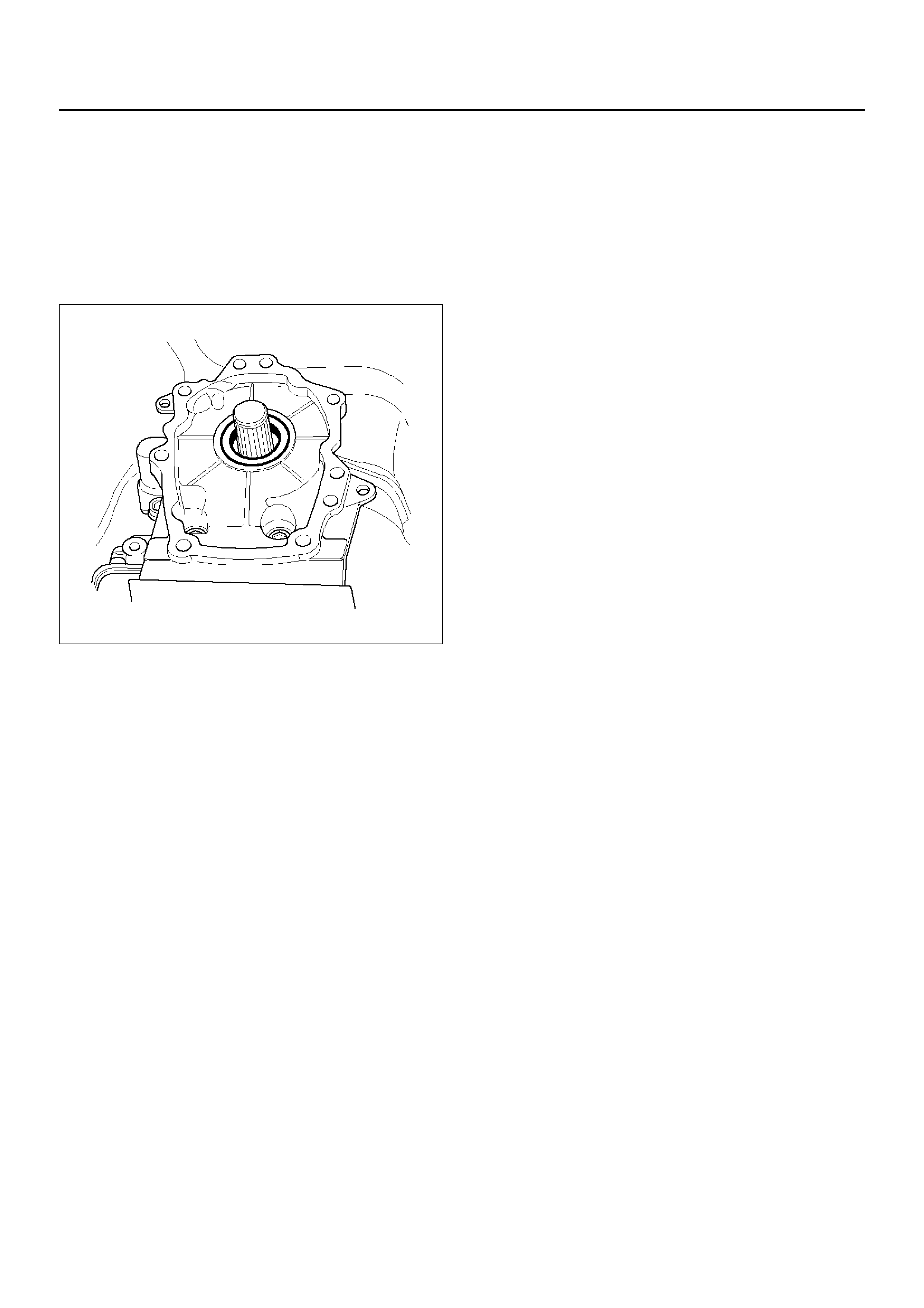
4. Let engine idle for 3 minutes and open the overfill
screw (1).
5. Add clean transmission fluid until it flows out of the
overfill screw opening.
6. Let engine idle until a fluid temperature between
32°C and 57°C is reached, then refit the overfill
screw (1).
Torque: 38Nm
NOTE: To prevent fluid leaks, the overfill screw and oil
drain screws gaskets must be replaced each time these
screws are removed.
Minimum fluid level → 57°C
Maximum fluid level → 32°C
242R200001
CAUTION: Do not open overfill screw with engine
stopped.
CAUTION: DO NOT CHECK FLUID LEVEL UNDER
THESE CONDITIONS:
• Immediately after driving at sustained highway
speeds.
• In heavy city traffic during hot weather.
• If vehicle is towing a trailer.
If the vehicle has been operated under these conditions,
shut the engine off and allow the vehicle to “cool" for
thirty (30) minutes. After the cool down period, restart
the vehicle and continue from step 2 above.

Fluid Condition
*Fluid should be changed according to maintenance schedule. Refer to Section 0B
TEST DRIVING
Some 4L30–E automatic transmission complaints will
require a test drive as a part of the diagnostic
procedure. Some codes will not set unless the vehicle is
moving. The purpose of the test drive is to duplicate the
customer's complaint condition and set a current
Powertrain Control Module (PCM) DTC. Perform this
procedure before each 4L30–E automatic transmission
repair, and again after repairs are made.
Important:
• Duplicate the condition under which the customer's
complaint was observed.
• Depending on the complaint, the line pressure gauge
and the scan tool may be required during the test
drive.
• During the test drive, it is important to record all
necessary data from the areas being monitored, for
use in diagnosis. Also listen for and note any
unusual noises.
The following procedure should be used to test drive
4L30–E automatic transmission complaint vehicles:
1. Turn the ignition ON without starting the engine.
Check that the “CHECK TRANS" lamp comes on for
approximately 2 seconds and then goes out and
remains out.
• If the lamp is flashing, GO TO Check Trans
Indicator in Transmission Control System (4L30–
E) section.
• If no serial data is present, GO TO OBD System
Check. Refer to Driveability and Emissions in
Engine section.
• If the lamp stays ON or stays OFF, GO TO
“Check Trans" Check in Transmission Control
System (4 L30 –E) sec ti on.
2. Drive the vehicle. During the test drive, be sure that
the transmission achieves normal operating
temperature (approx. 20 minutes).
Allow the transmission to go through all of its gear
ranges, checking shift timing and firmness.
Duplicate the owner's complaint condition as
closely as possible during the test drive.
3. If, during the test drive, the “CHECK TRANS" lamp
comes on, use the scan tool to check for trouble
codes.
4. If, during the test drive, a problem is felt, but the
“CHECK TRANS" lamp does not come on and no
troubl e cod es ar e pres en t, d riv e th e ve hic le with the
PCM disconnected (manually shifting the vehicle).
• In Manual L, the vehicle operates in first gear.
• In Manual 2, the vehicle operates in third gear.
• I n Manual 3 or “D", the vehicl e operates in fourth
gear.
FLUID CONDITION
NORMAL* CONTAMINATED
COLOR RED OR LIGHT
BROWN BROWN NON–TRANSPARENT
/ PINK BROWN
Drain
Required? NO YES YES YES
Contamination NONE Very small amount of
foreign material in
bottom of pan
Contamination by
coolant or other source Large pieces of metal
or other foreign
material in bottom of
pan
Correct Level
And Condition 1. LOW LEVEL:
– Add fluid to
obtain proper
level & check for
external leaks.
– Correct cause of
leak.
2. HIGH LEVEL:
– Remove excess
fluid
– Remove both pans
– Change filter
– Flush cooler
– Add new fluid
– Check level
– Repair/replace
radiator cooler
– T r ansmission
overhaul required
– Check for:
• D ama ged pla tes
and seals
• Contaminated
solenoids
– Flush cooler
– Add new fluid
–Check level
– Transmission
overhaul required
– Flush cooler and
cooler lines
– Add new fluid
– Check level

If the problem still exists with the PCM
disconnected, refer to Mechanical/Hydraulic
Diagnosis in this section.
5. I f no probl em has b een fou nd at this poi nt, ch ec k all
underhood connections that supply power to the
PCM and ignition fuses. Physically and visually
inspec t a ll t he P CM ha r nes s con nec tor s for lo os e or
corroded terminals. Inspect the PCM ground points.
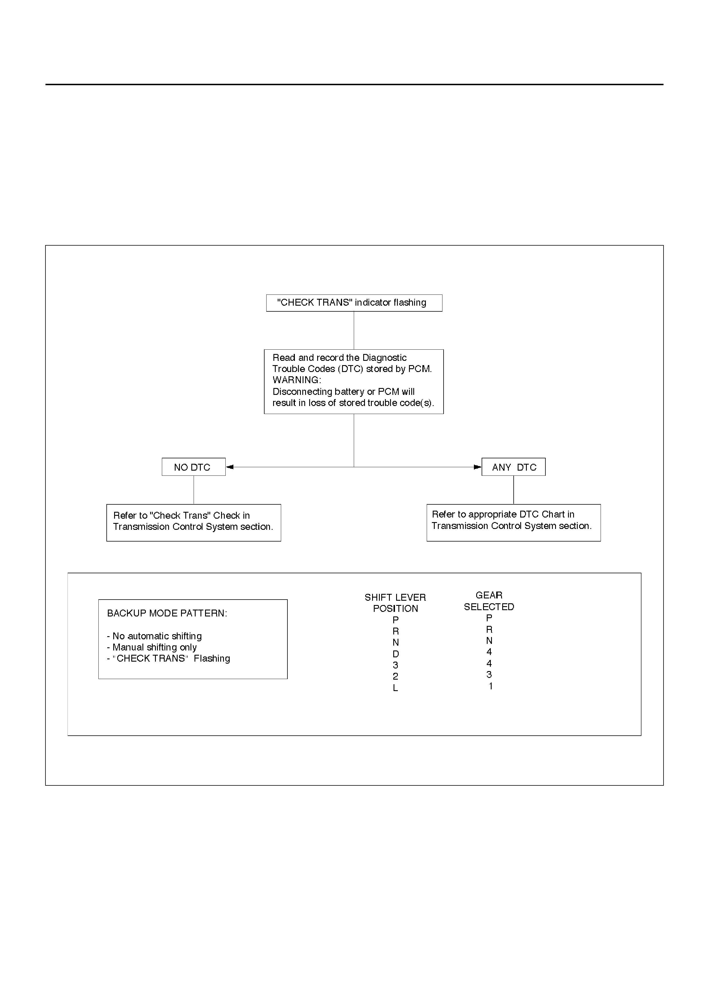
MECHANICAL / HYDRAULIC DIAGNOSIS CHECK TRANS INDICATOR CHART
Perform Preliminary Inspection First!
When the “CHECK TRANS" indicator is flashing, it indicates that a problem related to the transmission, the
Powertrain Control Module (PCM), or the vehicle harness has occurred.
The s ystem i s n ow ope ra tin g in a “ BACK U P MODE" where the r isk of fur th er d ama gin g the tr a ns miss ion h as b een
reduced. The vehicle may be shifted manually.
If the initial problem is intermittent or seldom, switching the engine OFF/ON might allow normal operation again until
the problem reoc cu rs.
F07RT013

MECHANICAL / HYDRAULIC DIAGNOSIS SYMPTOMS INDEX
Perform Preliminary Inspection First!
NOTE: Numbers with parenthesis on the following charts refer to those on Parts List at end of this section.
Chart 1: No Engine Start In Neutral Or Park
CHART SYMPTOMS
1 NO ENGINE START IN NEUTRAL OR PARK
2 NO FORWARD GEARS IN ANY RANGE/NO REVERSE
3 NO ENGINE BRAKE IN ANY RANGE
4 POOR SHIFTING IN ALL GEARS (ALL HARSH OR ALL SOFT)
5a DELAYS IN DRIVE AND REVERSE
5b DELAYS IN REVERSE ONLY
6 DIAGNOSTIC TROUBLE CODE (DTC) P0730
7 HARSH 1–2 SHIFT
8 HARSH 3–4 SHIFT
9a 3–2 DOWNSHIFT COMPLAINT
9b HARSH SHIFT WHEN SHIFTING INTO “D" OR ACCELERATING FROM STOP
9c COASTDOWN HARSH SHIFT OR CLUNK AT 3–2 DOWNSHIFT
10 INTERMITTENT 4TH TO 2ND GEAR DOWNSHIFT AT STEADY SPEED
11 ENGINE FLARE AT SHIFTING DURING TURNING ONLY (USUALLY WITH WARM ENGINE)
12 ENGINE FLARE DURING 1–2 OR 2–3 SHIFT
13 SHUDDER ONLY DURING TORQUE CONVERTER CLUTCH (TCC) APPLYING
14 POSSIBLE CAUSES OF TRANSMISSI ON NOISE
15a POSSIBLE CAUSES OF LOW LINE PRESSURE
15b POSSIBLE CAUSES OF HIGH LINE PRESSURE
16 POSSIBLE CAUSES OF TRANSMISSION FLUID LEAKS
Step Action Yes No
1 Does engine start when shift lever moved from drive to neutral
mostly in hot condition? Go to Step 2 Go to Step 3
2 Does engine start in park at any condition? Re–test vehicle Go to Step 4
3 Does engine also not start in neutral when shift lever moved from
park to neutral? Go to Step 4 Go to Step 5
4 Check mode switch (63) setting. Readjust if necessary.
Problems fixed? Re–test vehicle Go to Step 5
5 Check start circuit of mode switch (63) open in neutral.
Was open found? Locate and repair
open(s). Replace mode
switch (63).

Chart 2: No Forward Gears In Any Range/No Reverse
Chart 3: No Engine Brake In Any Ra nge
Step Action Yes No
1 Check line pressure. Refer to Li ne Pr essure Tes t in this section.
W as line pressure normal?
Go to Step 2
Use Chart 15a:
“Possible Causes of
Low Line Pressure”
in this section.
2 1. Check internal li nkage:
– Manual linkage (58) not moving manual valve (326).
2. Check for internal mechanical damage:
– Turbine shaft (506) broken loose.
– Overrun roller clutch (516) broken loose.
Was the problem found? Repair or replace —
Step Action Yes No
1 Check line pressure. Refer to Line Pressure Test in this section.
W as line pressure normal?
Go to Step 2
Use Chart 15a:
“Possible Causes of
Low Line Pressure”
in this section.
2 1. Check for overrun clutch leaks caused by:
– Damaged piston lip (513)
– Check ball defective (504)
2. Check for overrun lockout valve (705) stuck by foreign
material.
3. Check for leaks at turbine shaft (506) caused by:
– Teflon seal rings damaged (508)
– Excessive wear of turbine shaft bearing surfaces.
Was the problem found? Repair or replace —

Chart 4: Poor Shifting In All Gears (All Harsh Or All Soft)
Chart 5a: Delays In Drive and Reverse
NOTE: A sh or t delay (les s th an 3 s ec on ds ) when fi rst en gag ing drive or reverse after al low ing ve hic le to s it ov erni gh t
is normal.
Step Action Yes No
1 Check line pressure. Refer to Line Pressure Test in this section.
W as line pressure normal? Go to Step 2 Go to Step 3
2 1. Check for these conditions which could affect clutch apply
time:
– Defective band apply solenoid (323).
– Defective servo or/and accumulator piston.
– Excessive clut ch piston travel.
2. Check of possible causes of internal leaks:
– Cut or damaged sealing ring(s)
– Damaged sea li ng gas ke t(s)
– Check ball mi ssing or out of location in 2nd and 3rd clutch
pistons.
3. Check for causes of burned clutch plates or band.
Was the problem found? Repair or replace —
3 Was the line pressur e high?
Go to Step 4
Use Chart 15b:
“Possible Causes of
High Lin e Pre s sure”
in this section.
4 Were DTC P0705 set?
Diagnose those
DTC(s) first.
Use Chart 15b:
“Possible Causes of
High Lin e Pre s sure”
in this section.
Step Action Yes No
1 Check line pressure. Refer to Line Pressure Test in this section.
W as line pressure normal? More than 3
second delay in
drive and
reverse with
engine off 1
hour or less.
Teflon seals
(508) on turbine
shaft damaged.
Repair
Use Chart 15a:
“Possible Causes of
Low Line Pressure”
in this section.

Chart 5b: Delays In Reverse Only
Step Action Yes No
1 Check line pressure. Refer to Line Pressure Test in this section.
W as line pressure normal?
Go to Step 2
Use Chart 15a:
“Possible Causes of
Low Line Pressure”
in this section.
2 Main case valve body gasket (88) damaged.
– Reverse check ball (85) in valve body (84) missing or out of
location.
– Check for restrictions at valve body transfer plate orifice.
Was the problem found? Repair —

Chart 6: Diagnostic Trouble Code (DTC) P0730
Step Action Yes No
1 Check line pressure. Refer to Line Pressure Test in this section.
W as line pressure normal?
Go to Step 2
Use Chart 15b:
“Possible Causes of
High Lin e Pre s sure”
in this section.
2 1. 1st and 2nd gear missing or 3rd and 4th gear missing.
Check appropriate shift valve. If OK replace solenoid.
2. No engine brake in any range (All ranges in Drive and
Reverse are OK)
Check for suspected conditions modifying delays to clutch
apply:
– Overrun clutch seal damaged.
– Excessive overrun clutch piston travel.
– Defective 3-4 accumulator piston.
– Causes of internal leaks.
– Causes of burned clutch plates.
3. 1st and 4th gear missing or 2nd and 3rd gear missing.
Shift solenoid A stuck. Replace shift solenoid A.
4. DTC P0730 is set in D range 1st gear above 3500 rpm.
Go to Step 3.
5. DTC P0730 is set in D range 3rd gear between 55-80 mph.
NOTE: Perform this test within safe and legal limits.
Check for suspected conditions modifying delays to clutch
apply:
– 4th clutch seal damaged.
– Excessive 4th clut ch piston travel.
– Defective 3-4 accumulator piston.
– Causes of internal leaks.
– Causes of burned clutch plates.
Was the problem found? Repair or replace —
3 Check 3rd gear in “D" in winter mode.
Does ve hicl e move? Shift solenoid ‘A’
stuck. Replace
shift solenoid ‘A’. Go to Step 4
4 Check for suspected conditions modifying delays to clutch apply:
– 2nd clutch seal damaged.
– Excessive 2nd clutch piston travel.
– Defective accumulator piston.
– Causes of internal leaks.
– Check ball missing or out of location in 2nd clutch.
– Seals cut, damaged or missing.
– Gaskets defective.
– Causes of burned clutch plates.
Was the problem found? Repair or replace —

Chart 7: Harsh 1–2 Shift
Chart 8: Harsh 3–4 Shift
Chart 9a: 3–2 Downshift Complaint
Chart 9b: Harsh Shift When Shifting Into “D" Or Accelerating From Stop
Chart 9c: Coastdown Harsh Shift Or Clunk At 3–2 Downshift
Step Action Yes No
1 Check line pressure. Refer to Line Pressure Test in this section.
W as line pressure normal? Check for 1–2
accumulator valve
(320) stuck by
foreign material in
main case valve
body.
Use Chart 15b:
“Possible Causes of
High Lin e Pre s sure”
in this section.
Step Action Yes No
1 Check line pressure. Refer to Line Pressure Test in this section.
W as line pressure normal?
Go to Step 2
Use Chart 15b:
“Possible Causes of
High Lin e Pre s sure”
in this section.
2 1. Check for 3–4 acc umu lat or va lv e (4 0 7) stuck in ada pte r ca se
valve body (401).
2. Che ck for 3–4 a ccumula tor piston ( 18) stu ck in adapter case
(20).
Was the problem found? Repair or replace —
Step Action Yes No
1 Check line pressure. Refer to Line Pressure Test in this section.
W as line pressure normal?
Go to Step 2
Use Chart 15a:
“Possible Causes of
Low Line Pressure”
in this section.
2 Does DTC P1850 set? Diagnose P1850
first.
Replace ban d
apply solenoid
(PWM) (323).
Step Action Yes No
1 Check line pressure. Refer to Line Pressure Test in this section.
W as line pressure normal?
Go to Step 2
Use Chart 15b:
“Possible Causes of
High Lin e Pre s sure”
in this section.
2 Does DTC P1850 set? Diagnose P1850
first.
Replace ban d
apply solenoid
(PWM) (323).
Step Action Yes No
1 Check line pressure. Refer to Line Pressure Test in this section.
W as line pressure normal?
Go to Step 2
Use Chart 15b:
Possible Causes of
High Line Pressure
in this section.
2 Does DTC P1850 set? Diagnose P1850
first.
Replace ban d
apply solenoid
(PWM) (323).

Chart 10: Intermittent 4TH TO 2ND Gear Downshift At Steady Speed
Chart 11: Engine Flare At Shifting During Turning Only (Usually With Warm Engine)
Chart 12: Engine Flare During 1–2 Or 2–3 Shift
Step Action Yes No
1 Check for consistent speed sensor reading with scan tool.
Was the reading correct? Replace mod e
switch f or
intermittent
contact. Go to Step 2
2 1. Check for wiring harness damage or short to ground. If OK,
go to (2).
2. Check transmission speed sensor connections. If OK, go to
(3).
3. Replace transmission speed sensor.
Was the replacement complete? — Replace speed
sensor.
Step Action Yes No
1 Check for oil leaks at transmission.
Was the problem found? Replace
transmission oil
filter and gasket. —
Step Action Yes No
1 Check line pressure. Refer to Line Pressure Test in this section.
W as line pressure normal?
Go to Step 2
Use Chart 15a:
“Possible Causes of
Low Line Pressure”
in this section.
2 1. Check for a stuck 1–2 accumulator valve (320).
2. Check for servo piston (106) leaks.
3. Check for a stuck band apply solenoid (323).
Was line pressure normal? Repair or replace —

Chart 13: Shudder Only During Torque Converter Clutch (TCC) Applying
Chart 14: Possible Causes of Transmission Noise
CAUTION: Before checking transmission for what is believed to be transmission noise, ensure presence
and positioning of insulating plugs, pads etc. Also make sure that noise does not come from other
drivetrain comp onents.
Step Action Yes No
1 1. TCC shudder is one of the most commonly misdiagnosed
conditions in an automatic transmission. The key to
diagnosing TCC shudder is to note when it happens and
under wha t co ndi tio ns . O nc e the TCC ha s been full y appl ie d,
it is nearly impossible to make it shudder. TCC shudder
(short burst of noise normally less than 1 second) will only
occur during clutch applying. It is not a steady state condition.
2. Drive until whole drivetrain is at normal operating
temperature.
– On 4WD vehicles, the test must be performed with transfer
case selector lever in “2H" position.
– Shudder is a short burst of noise normally less than 1
second in duration, and can be induced by the following
maneuver:
3. F rom co ast conditi on at 80km/h in “D " rang e (No rmal mo de),
depress the throt tle to 1/4 -1 /3 thr ott le. If pres ent , shud der will
occur within 5 second s toge the r with TCC appli catio n. (The
scan tool may be used to determine the exact time of TCC
application).
Was the problem found?
Replace
transmission fluid
and filter (remove
both pans) and flush
cooler lines.
Go to Step 2
Perform mechanical
inspection of other
drivetrain
components -
Repair/replace as
required.
Verify Repair
2 Does the pr obl em still exis t? Go to Step 3 -
3 Replace converter assembly and O-ring on turbine shaft Verify repair -
Condition Possible cause Correcti on
Whine or Buzz Oil level low Fill with ATF, check for external
leaks.
Plugged or restricted oil filter Inspect oil filter.
Replace oil filter or ATF as
necessary.
Damaged oil filter gasket Replace oil filter gasket.
Knocking noise from front of
transmission. Loose bolts (Converter to flex plate) Tighten to specifications.
Cracked or broken flex plate Replace flex plate.
Converter damaged Replace converter.
Knock ing no ise whil e drivi ng, mos tly
on acceleration. Transmission mount loose or broken Tighten mount bolts or replace
transmission mount.
Cooler line mounts loose or broken Tighten or replace cooler line
mounts.
Cooler lines touching body or frame Repair or replace as necessary.
Knocking noise when vehicle is
stationary. Loose flex plate mounting bolts Tighten to specifications.
Cracked or broken flex plate Replace flex plate.
Damaged conver ter Replac e conv erter.

Chart 15a: Possible Causes of Low Line Pressure
Step Action Yes No
1 Check oil level.
Was the problem found? Fill with ATF. Go to Step 2
2 Check for defective throttle position sensor.
Was the problem found? Replace throttle
position sensor. Go to Step 3
3 Check for plugged, loose, or damaged oil filter (79).
Was the problem found? Inspect oil filter,
tighten bolts or
replace oil filte r
(79). G o to Step 4
4 Check for a stuck Pressure Control Solenoid plunger (404).
(Adapter case valve body)
Was the problem found?
Replace Pressure
Control Solenoid
plunger (404). Go to Step 5
5 Check for a stuck feed limit valve (412). (Adapter case valve
body)
Was the problem found? Replace feed limit
valve (412). Go to Step 6
6 Check for loose converter bolts (4 & 5).
Was the problem found? Tighten converter
bolts (4 & 5). Go to Step 7
7 Check for a stuck pressure regulator valve (208). (Oil pump)
Was the problem found? Replace pressure
regulator valve
(208). Go to Step 8
8 Check for a stuck boost valve (205). (Oil pump)
Was the problem found? Replace boost
valve (205). Go to Step 9
9 Check for blocked intermediate oil passages to pressure
regulator valve. (Oil pump)
Was the problem found? Replace oil pump. Go to Step 10
10 Check for defective oil pump (9, 201, 202 & 209).
Was the problem found? Replace oil pump. Go to Step 11
11 Check for internal leaks.
– Check balls missing or out of location in valve bodies
– Seals cut or damaged
– Gaskets defective, etc.
Was the problem found?
Install balls, or
correct ball
location.
Replace seals.
Replace
gaskets. —

Chart 15b: Possible Causes of High Line Pressure
NOTE: If transmission is operating in backup mode, high line pressure will be present.
Chart 16: Possible Causes of Transmission Fluid Leaks
Before atte mpting to corr ect an oil l eak, the actual sou rce of th e leak must be dete rmined. In many ca ses, th e so urce
of the leak may be difficult to determine due to “wind flow" around the engine and transmission.
The suspected area should be wiped clean before inspecting for the source of the leak.
Oil lea ks arou nd th e en gine and tr an sm is si on are ge ner al ly car ried towar d the r ea r o f the ve hi cl e by th e ai r s tream. In
determining the source of an oil leak, the following two checks should be made:
1. With the engine running, check for external line pressure leaks.
2. With the engine off, check for oil leaks due to the raised oil level caused by drainback of converter oil into the
transmission.
Step Action Yes No
1 Check for defective throttle position sensor.
Was the problem found? Replace throttle
position sensor. Go to Step 2
2 Check for a stuck Pressure Control Solenoid plunger (404).
(Open circuit/intermittent) (Adapter case valve body)
Was the problem found?
Replace Pressure
Control Solenoid
plunger (404). Go to Step 3
3 Check for a stuck feed limit valve (412). (Adapter case valve
body)
Was the problem found? Replace feed limit
valve (412). Go to Step 4
4 Check converter bolts (4 & 5).
Was the problem found? Tighten converter
bolts (4 & 5). Go to Step 5
5 Check for a stuck pressure regulator valve (208). (Oil pump)
Was the problem found? Replace pressure
regulator valve
(208). Go to Step 6
6 Check for a stuck boost valve (205). (Oil pump)
Was the problem found? Replace boost
valve (205). Go to Step 7
7 Check for internal leaks.
– Check balls missing or out of location in valve bodies
– Seals cut or missing
– Gaskets defective, etc.
Was the problem found?
Install balls, or
correct ball
location.
Replace seals.
Replace
gaskets. —
Possible Causes of Fluid Leaks Due To Sealing Malfunction
240RX008
EndOFCallout
STALL TEST
The stall test allows you to check the transmission for internal abrasion a nd the one way clutch for slippage. Torque
converter performance can also be evaluated.
The stall test results together with the road test results will identify transmission components requiring servicing or
adjustment.
Stall Test Procedure:
1. Check the level of the engine coolant, the engine oil, and the automatic transmission fluid. Replenish if necessary.
2. Block the wheels and set the parking brake.
3. Connect a tachometer to the engine.
4. Start the engine and allow it to idle until the engine coolant temperature reaches 70 – 80°C (158 – 176°F).
5. Hold the brake pedal down as far as it will go.
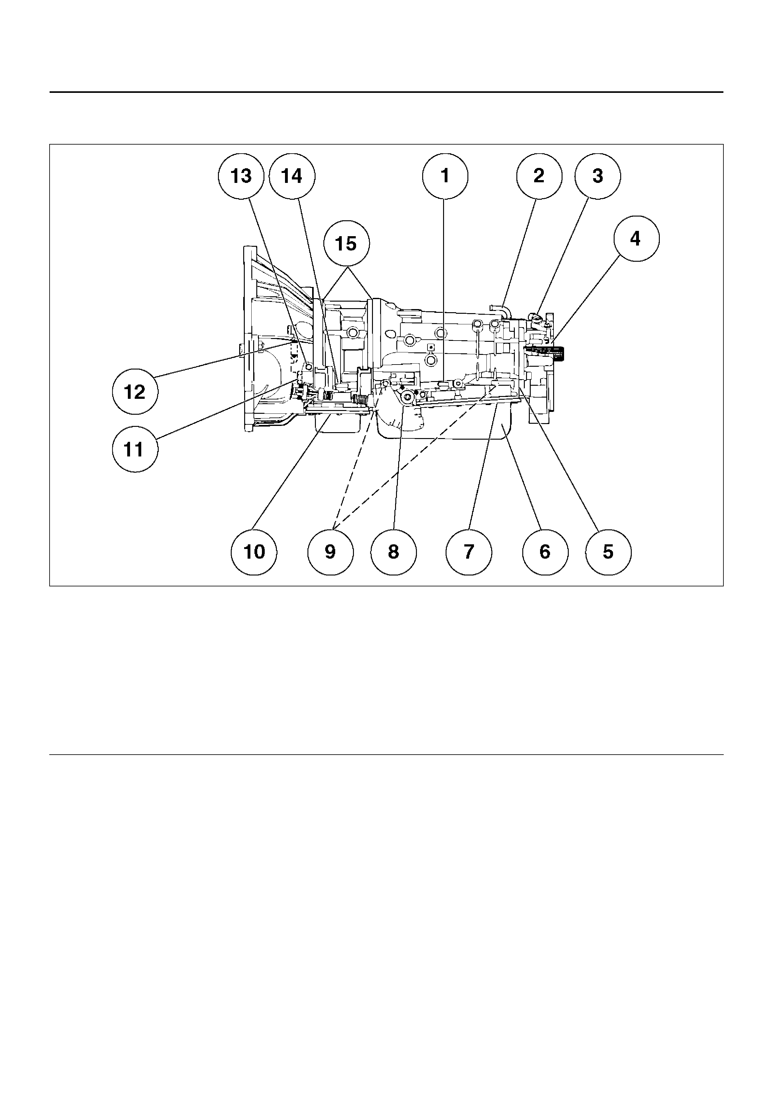
6. Place the selector in the “D" range.
Legend
(1) Electrical Connector (Main Case) Seal
(2) Transmission Vent (Breather)
(3) Speed Sensor O–ring
(4) Extension (Adapter) Lip Seal
(5) Extension (Adapter) to Main Case Gasket
(6) Overfill and Oil Drain Screws Gasket
(7) Oil Pan Gasket (Main Case)
(8) Selector Shaft Seal
(9) Oil Cooler Connectors (2)
(10) Oil Pan Gasket (Adapter Case)
(11) Converter housing attaching bolts not correctly
torqued
(12) Converter Housing Lip Seal
(13) Line Pressure Tap Plug
(14) Electrical Connector (Adapter Case) Seal
(15) Adapter Case Seal Rings (2)
7. Gradually push the accelerator pedal to the floor.
The throttle valve will be fully open.
Note the engine speed at which the tachometer needle stabilizes.
Stall Speed : 2,100 ±150 rpm
NOTE: Do not continuously run this test longer than 5 seconds.
8. Release the accelerator pedal.
9. Place the selector in the “N" range.
10. Run the engine at 1,200 rpm for one minute.
This will cool the transmission fluid.
11. Repeat Steps 7 – 10 for the “3", “2", “L" and “R" ranges.
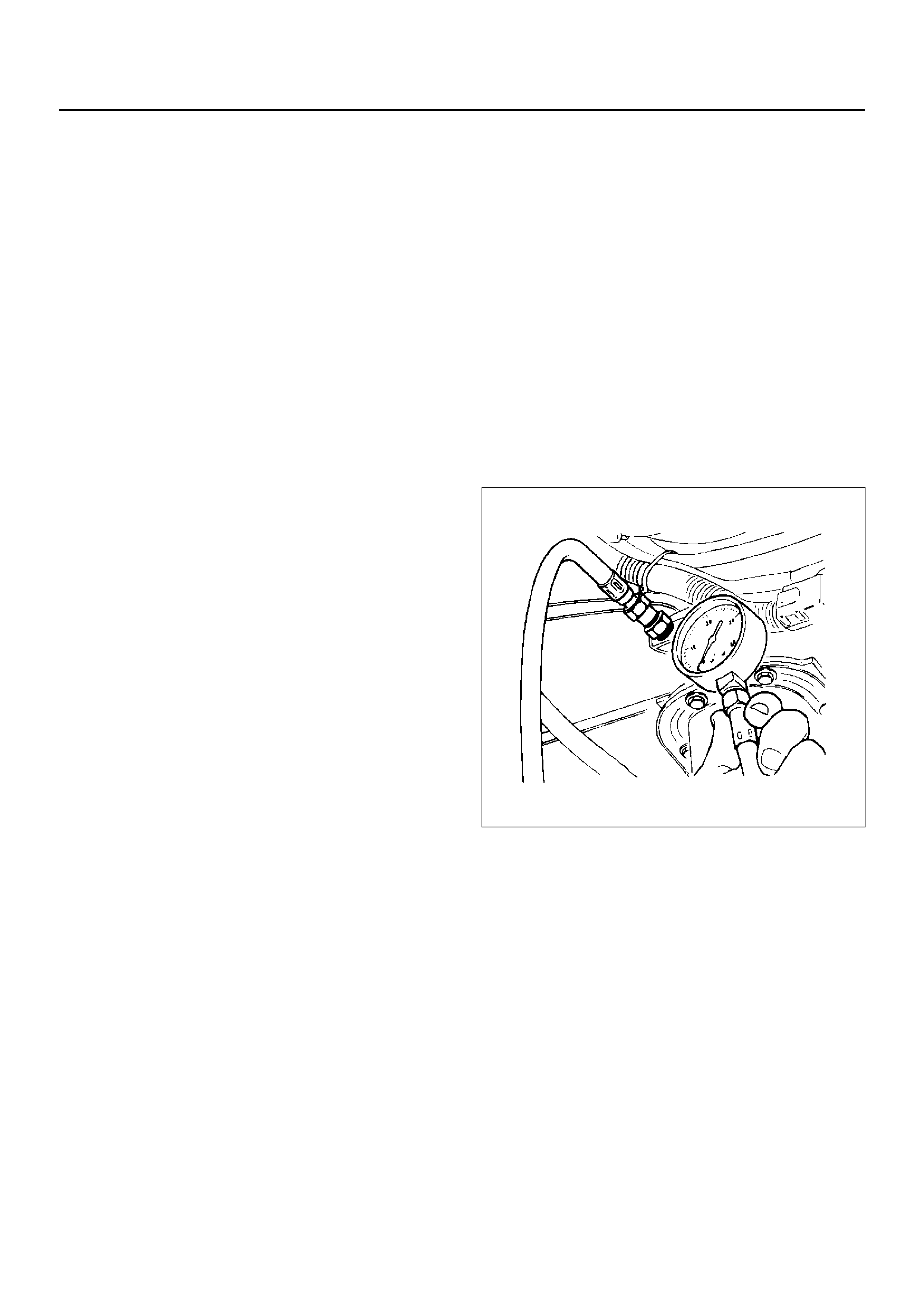
LINE PRESSURE TEST
The line pressure test checks oil pump and control valve pressure regulator valve function. It will also detect oil
leakage.
Line Pressure Test Procedure:
1. Check the level of the engine coolant, the engine oil,
and the automatic transmission fluid.
Replenish if required.
2. Block the wheels and set the parking brake.
3. R emove the pressure detection plug at the lef t side
of the transmission case.
Set J–29770–A pressure gauge and adapter to the
pressure test point.
4. Start the engine and allow it to idle until the engine
cool ant temperature reaches 70 – 80°C
5. Hold the brake pedal down as far as it will go.
6. Place the selector in the “D" range.
7. Note the pressure gauge reading with the engine
idling.
8. Gradually push the accelerator pedal to the floor.
The throttle valve will be fully open.
Note the pressure gauge reading with the
accel er ato r peda l full y depress ed .
NOTE: Do not continuously run this test longer than 5
seconds.
9. Release the accelerator pedal.
10. Place the selector in the “N" range.
11. Run the engine at 1,200 rpm for one minute.
This will cool the transmission fluid.
12. Repeat Steps 7 – 11 for the “3", “2", “L", and “R"
ranges.
13. I nstall a pre ssure dete ction plug to th e tra nsmiss ion
case, applying recommended thread locking agent
(LOCTITE 242) or its equivalent to thread of plug.
Make sure that thread is cleaned before applying
locking agents.
14. Tighten the pr essure detecti on plug to the s pecified
torque.
Torque:9–14Nm

MODE LEVER
POSITION E NG INE SP EE D
LINE PRESSURE PRESSURE
CONTROL
SOLENOID
CURRENT (mA)
kPa PSI
NORMAL/POWER D,3,2,L IDLE 590–730 86–106 680–720
WINTER D IDLE 300–390 44–57 1,020–1,060
NORMAL/POWER
WINTER REVERSE IDLE 460–630 67–91 880–920
NORMAL/POWER D, 3, 2, L STALL SPEED 1,250–1,380 181–200 70–110
WINTER D STALL SPEED 1,250–1,380 181–200 70–110
NORMAL/POWER
WINTER REVERSE STALL SPEED 1,400–1,580 203–229 340–380
SHIFT SPEED CHART
“Normal mode"
Upshift
Downshift
“Power mode"
Upshift
Downshift
“Winter mode"
Transfer gear ratio High: 1.000
Rear axle ratio 4.100
Range Throttle
opening
1 → 2
(First Gear) (Second
Gear)
km/h
2 → 3
(Second Gear) (Third
Gear)
km/h
3 → 4
(Third Gear) (Fourth
Gear)
km/h
D
(Drive) Fully opened 54 ∼ 60 111 ∼ 117 169 ∼ 175
Half throttle 34 ∼ 40 64 ∼ 70 117 ∼ 123
Range Throttle
opening
1 ← 2
(First Gear) (Second
Gear)
km/h (mph)
2 ← 3
(Second Gear) (Third
Gear)
km/h (mph)
3 ← 4
(Third Gear) (Fourth
Gear)
km/h (mph)
D
(Drive)
Fully opened 46 ∼ 52 89 ∼ 95 159 ∼ 165
Half throttle 15 ∼ 21 36 ∼ 42 74 ∼ 80
Fully closed 14 ∼ 20 21 ∼ 27 28 ∼ 34
Range Throttle
opening
1 → 2
(First Gear) (Second
Gear)
km/h
2 → 3
(Second Gear) (Third
Gear)
km/h
3 → 4
(Third Gear) (Fourth
Gear)
km/h
D
(Drive) Fully opened 54 ∼ 60 111 ∼ 117 169 ∼ 175
Half throttle 42 ∼ 48 78 ∼ 84 133 ∼ 139
Range Throttle
opening
1 ← 2
(First Gear) (Second
Gear)
km/h
2 ← 3
(Second Gear) (Third
Gear)
km/h
3 ← 4
(Third Gear) (Fourth
Gear)
km/h
D
(Drive)
Fully opened 46 ∼ 52 89 ∼ 95 159 ∼ 165
Half throttle 23 ∼ 29 59 ∼ 65 108 ∼ 114
Fully closed 14 ∼ 20 24 ∼ 30 48 ∼ 54
D range, winter mode ON → OFF 31 ∼ 37 km/h

LOCKUP SPEED CHART
Transfer gear ratio High: 1.000
Rear axle ratio 4.100
D range, Throttle
opening 6%
Mode Lockup ON Lockup OFF
2nd
km/h 3rd
km/h 4th
km/h 2nd
km/h 3rd
km/h 4th
km/h
Normal 75 ∼ 81 68 ∼ 74 76 ∼ 82 69 ∼ 75 47 ∼ 53 72 ∼ 78
Power 75 ∼ 81 80 ∼ 86 80 ∼ 86 69 ∼ 75 7 1 ∼ 77 75 ∼ 81
CHANGING TRANSMISSION FLUID
There is no need to change the transmission fluid
unless the transmission is used under one or more of
the following heavy duty conditions.
A Repeated short trips
B Driving on rough roads
C Driving on dusty roads
D Towing a trailer
If the vehicle is used under these conditions, change the
fluid every 20,000 miles (32,000 km.)
More over, the remaining life percentage of ATF can be
estimated by using Tech 2 as an auxiliary tool to judge
the right time for ATF replacement.
The remaining life percentage is calculated from ATF'S
heat history. When it is close to 0%, ATF replacement is
recommended.
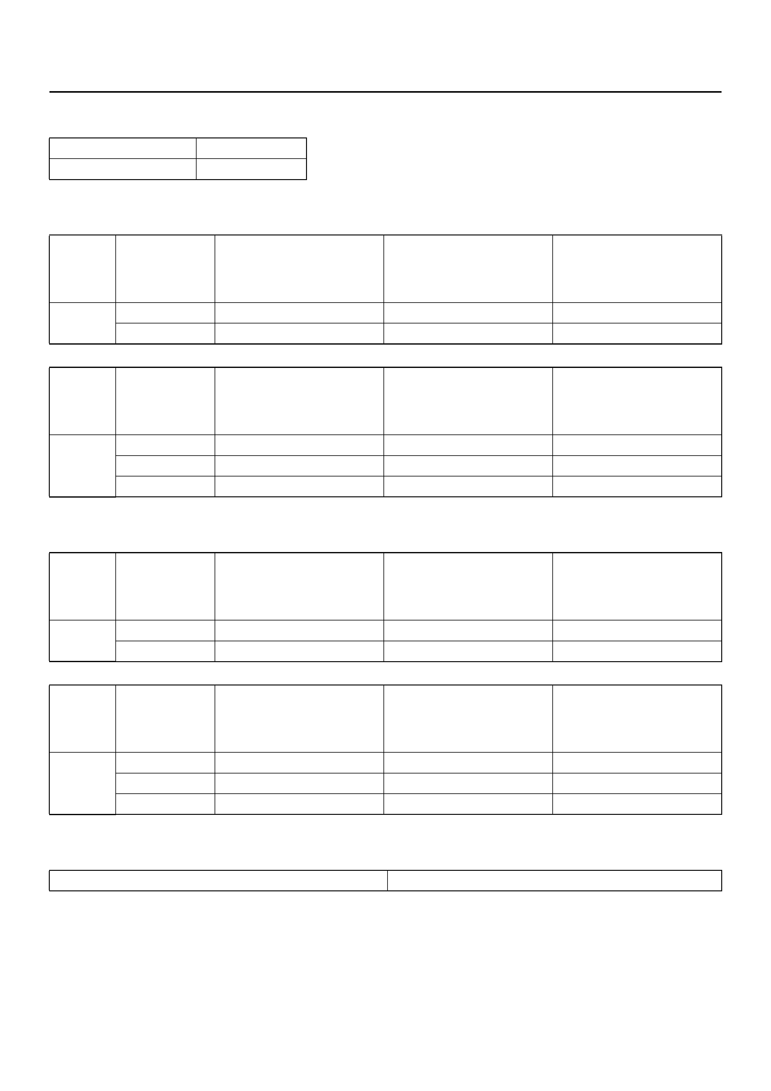
1. Place a large drain pan under the oil pan.
2. Remove the transmission oil drain screw (2) and
drain fluid.
3. Tighten drain screw (2).
Torque: 38N•m
4. Remove the transmission overfill screw (1) and fill
transmission through overfill screw opening, using
DEXRON®-III ATF.
NOTE: Add transmission fluid until it flows out over the
overfill screw opening.
5. Let engine idle until a fluid temperature between
32°C and 57°C is reached.
6. Add transmission fluid until it flows out over the
overfill screw opening, then close the overfill screw
(1).
Torque: 38N•m
NOTE: To prevent fluid leaks, the overfill screw and oil
drain screws gasket must be replaced each time these
screws are removed.
NOTE: Check transmission fluid temperature with scan
tool.
7. Reset “Oil Life Monitor" data by using Tech 2.
Refer to Tech 2 Connection in section 0C.
242R200001
SELECTOR LEVER
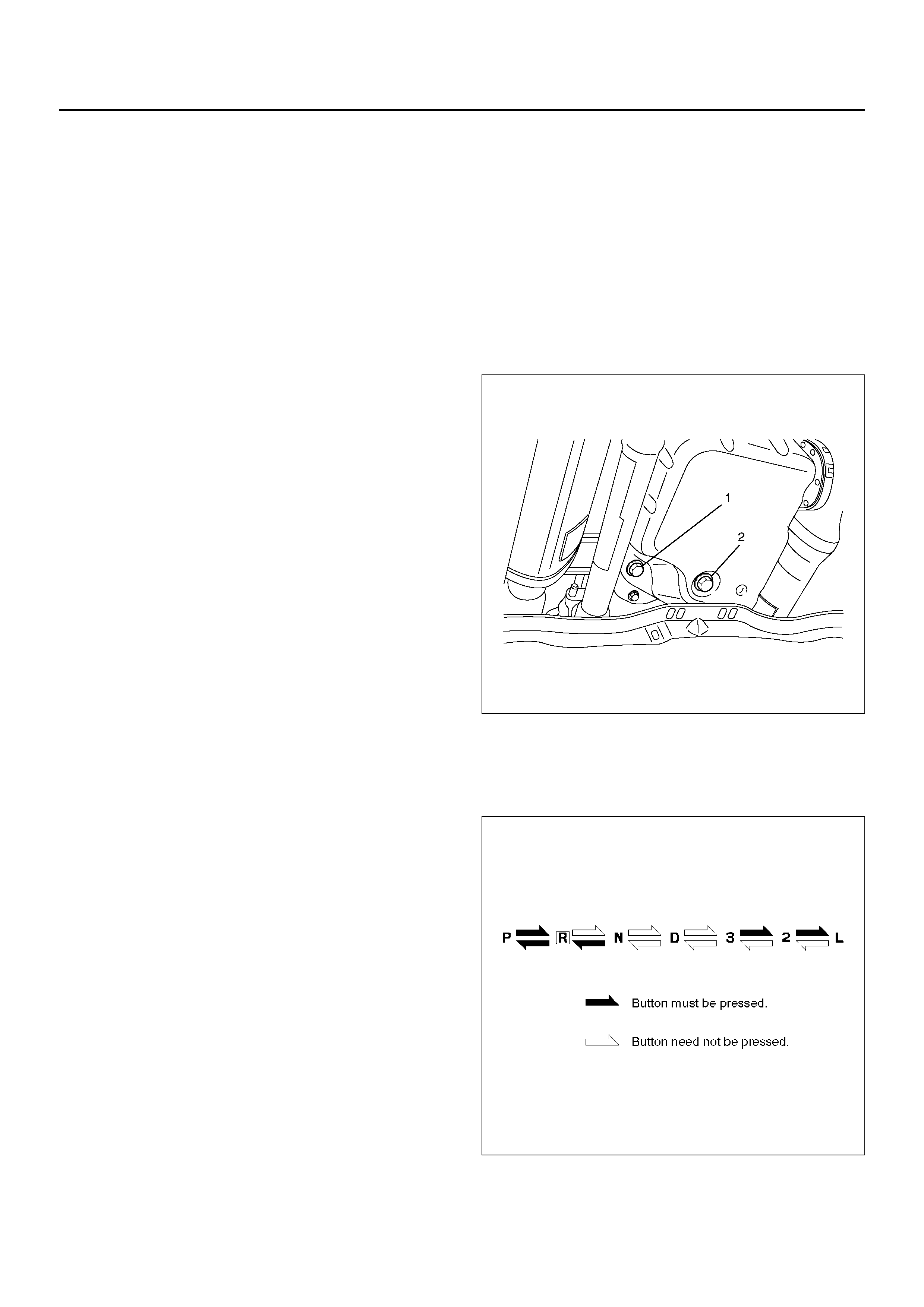
INSPECTION
1. Make sure that when the selector lever is shifted
from “P" to “L", a “clicking" can be felt at each shift
position. Make sure that the gear corresponds to
that of the position plate indicator.
2. C heck to see if the selector lever can be shifted as
shown in illustrat ion.
C07RW009
REMOVAL
1. Disconnect battery ground cable.
2. Set ignition Key in “LOCK" position and selector
lever in "P" position.
3. Remove transfer control lever knob.
4. Remove lower cluster assembly.
740RW021
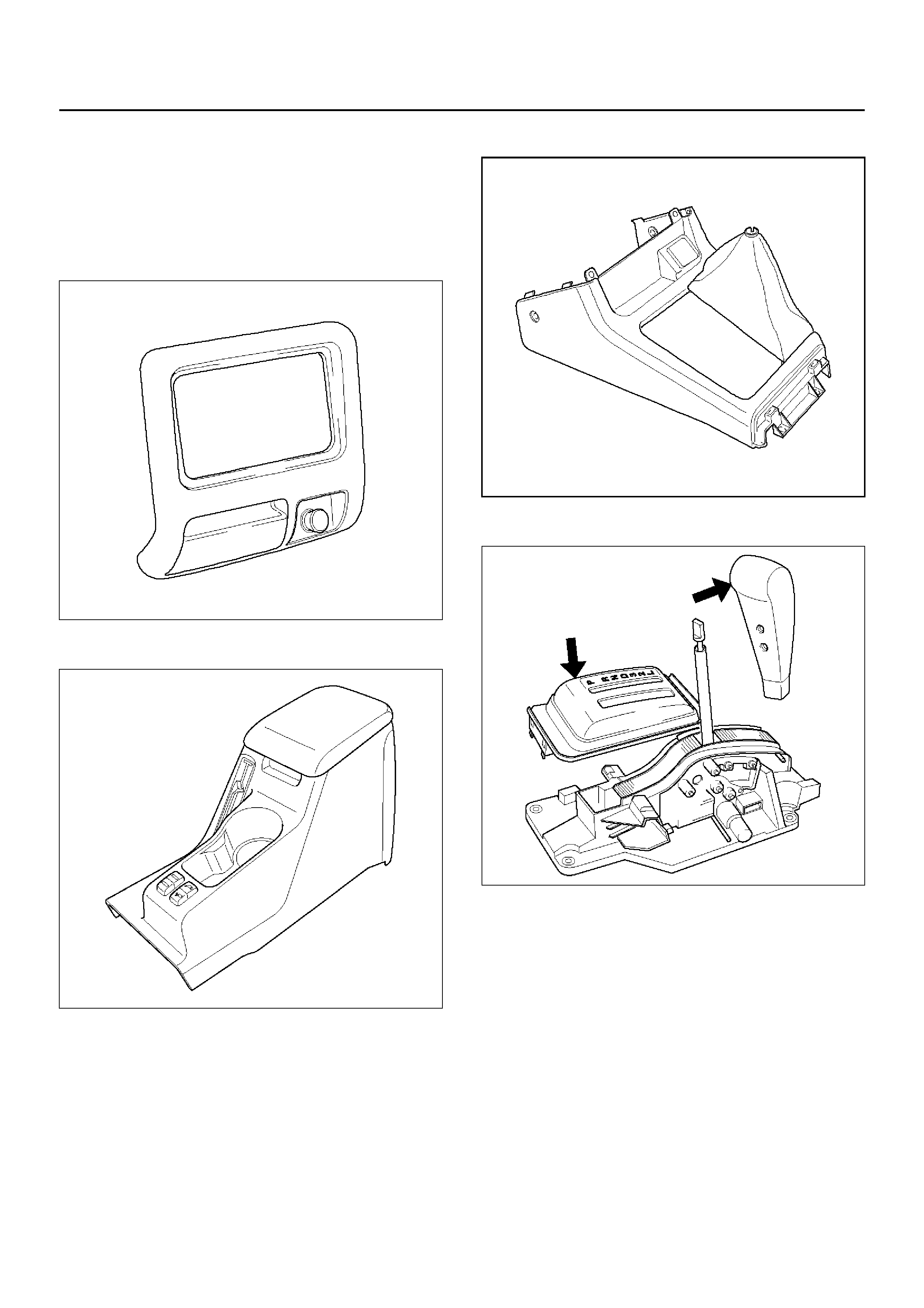
5. Remove rear console.
745RW011
6. Remove center console
256RW006
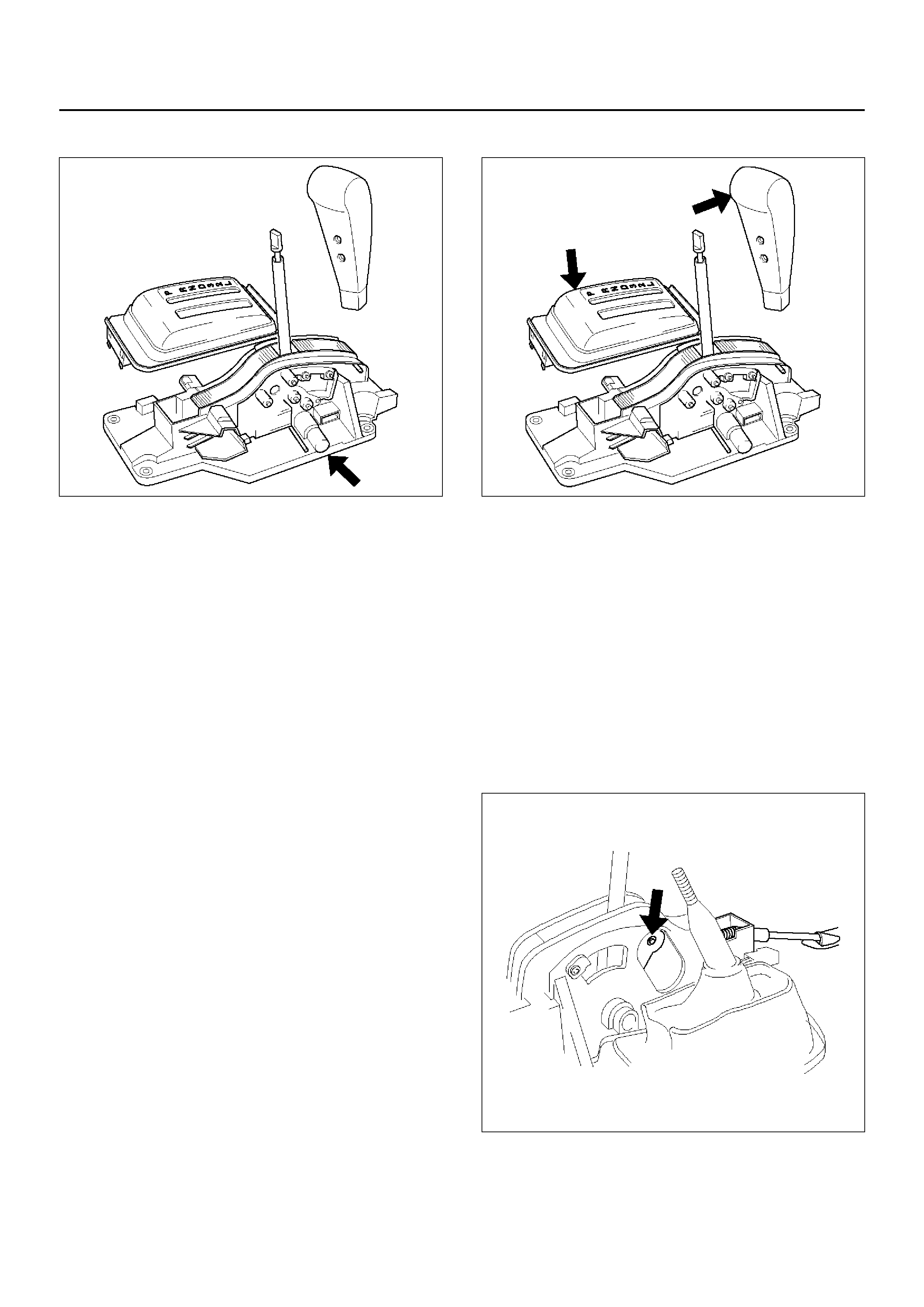
7. Remove selector lever knob and cover.
256RW043
8. Disconnect select cable.
•Refer to Select Cable in this section.
9. Disconnect shift lock cable.
•Refer to Shift Lock Cable in this section.
10. Disconnect harness connector.
11. Remove selector lever subassembly.
256RW044
INSTALLATION
1. Install selector lever subassembly.
2. Connect harness connector.
3. Connect shift lock cable.
• Refer to Shift Lock Cable in this section.
4. Connect select cable.
• Refer to Select Cable in this section.
5. Install selector lever knob and cover.
256RW043
6. Install center console.
7. Install rear console.
8. Install lower cluster assembly.
9. Install transfer control lever knob.
10. Connect negative (–) battery cable.
11. After installation, make sure that the selector lever
operates normally, and that each selector position
is properly indicated. (The red mark shows through
the window.)
SELECT CABLE
REMOVAL
1. Set selector lever in “P" position.
2. Remove transfer control lever knob, lower cluster
assembly, rear console, center console, selector
lever knob and cover.
• Refer to Selector Lever in this section.
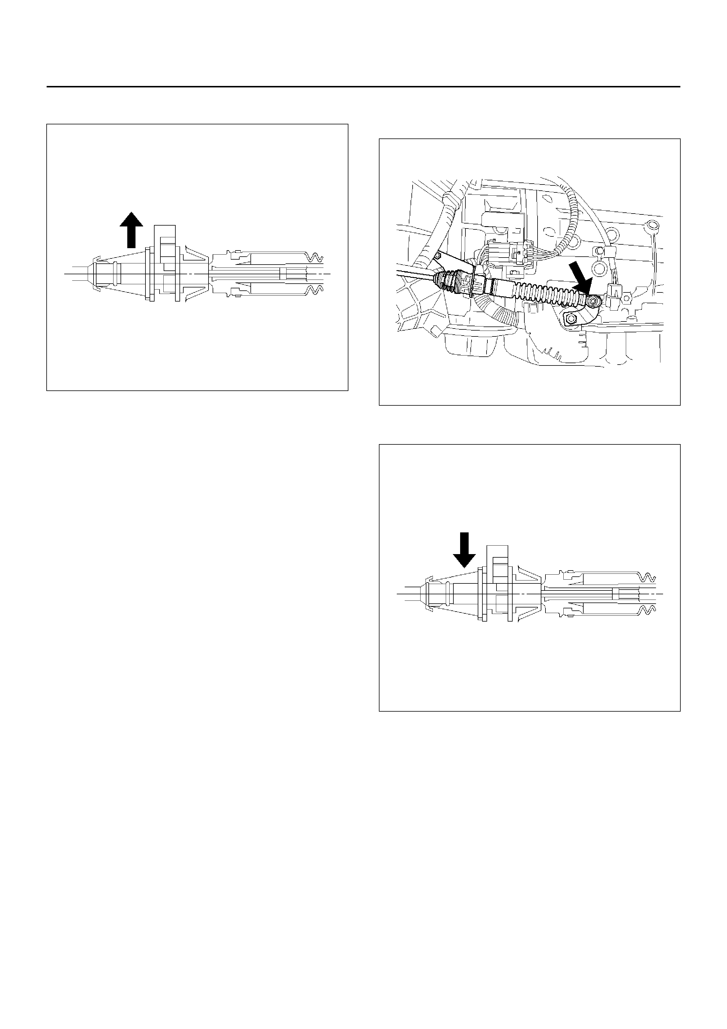
3. Disconnect inner cable by pulling projection on pin.
256RW022
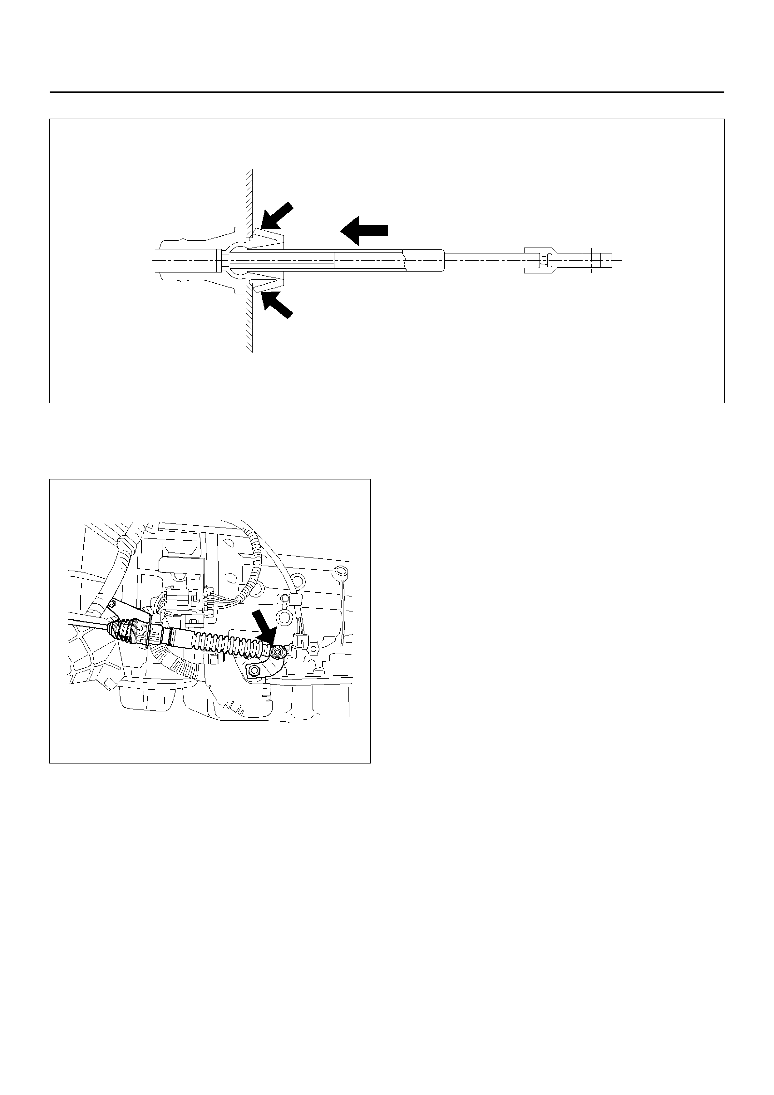
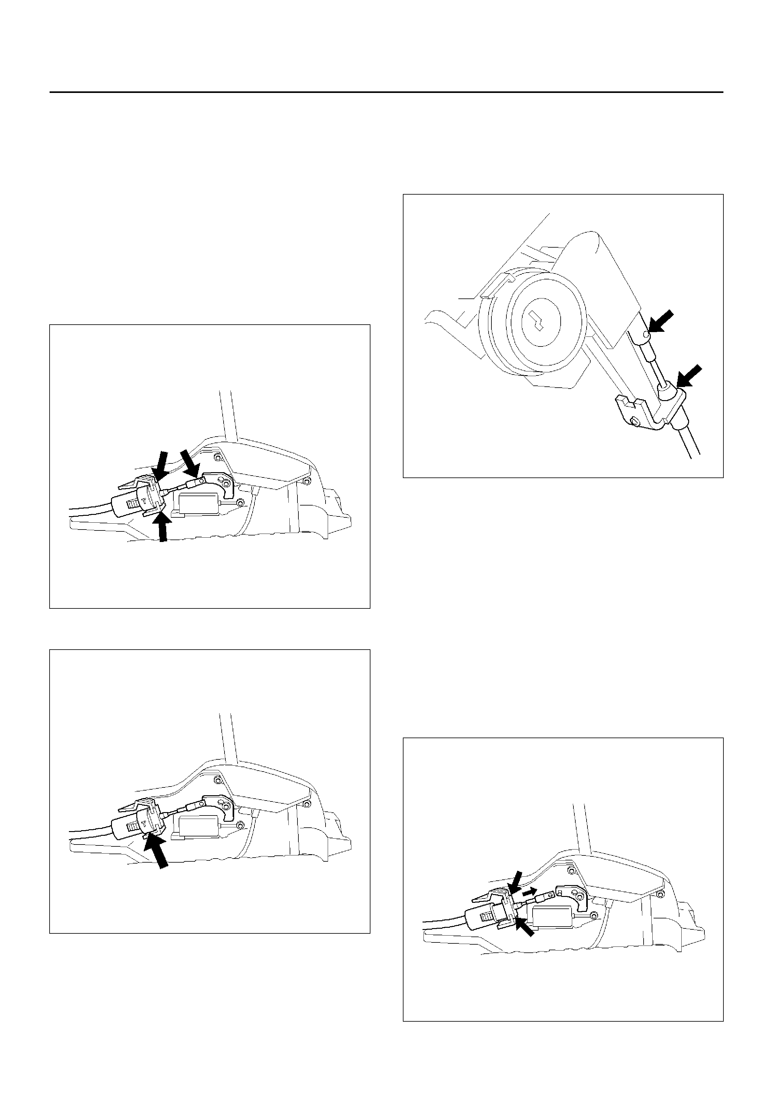
4. Press down claws and disconnect cable assembly.
A07RW017
5. Disconnect PCM harness connectors and remove
nuts that fasten grommet in select cable assembly.
6. Disco nne ct inn er cabl e.
210RW013
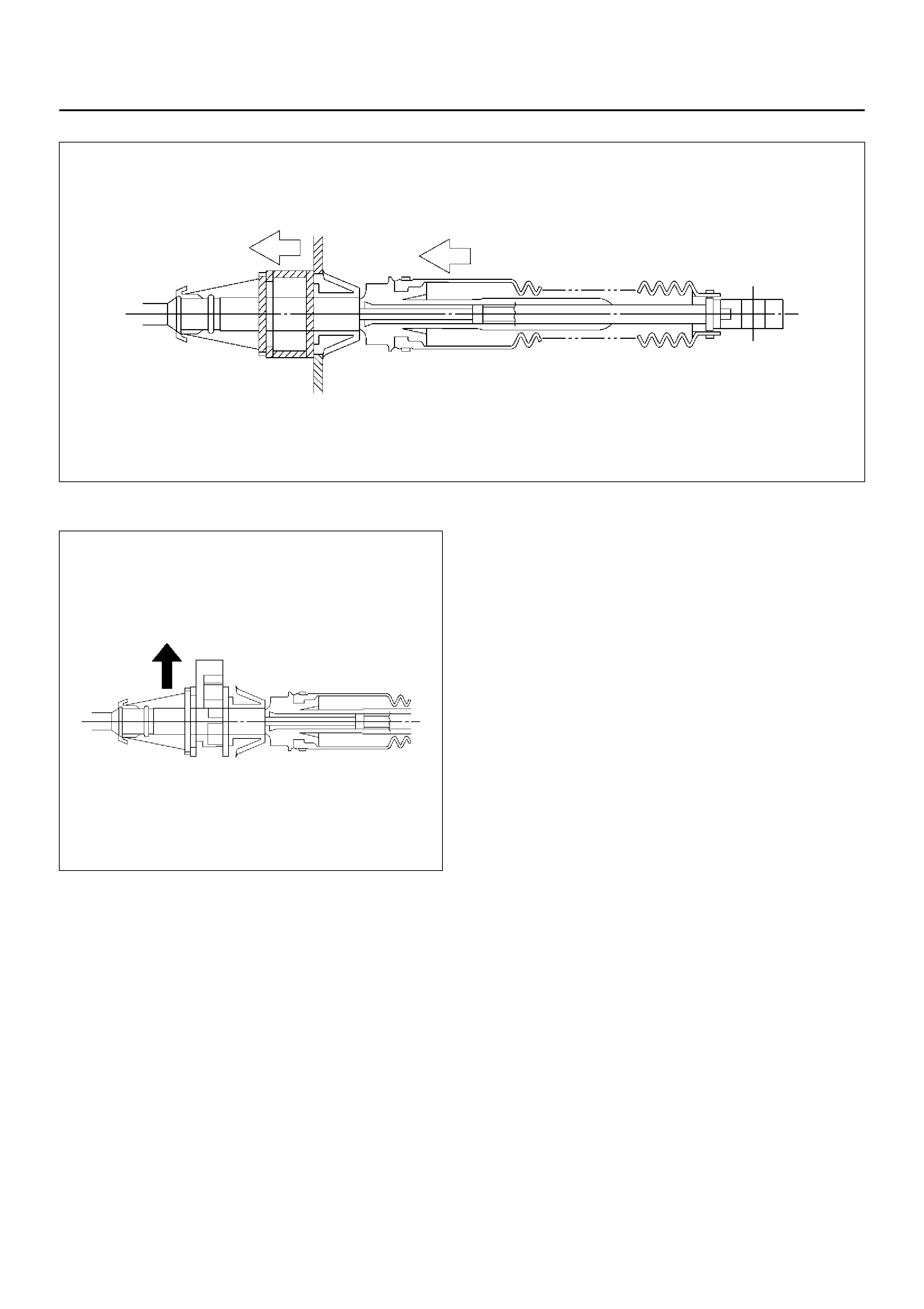
7. Slide sleeve and disconnect cable assembly.
A07RW082
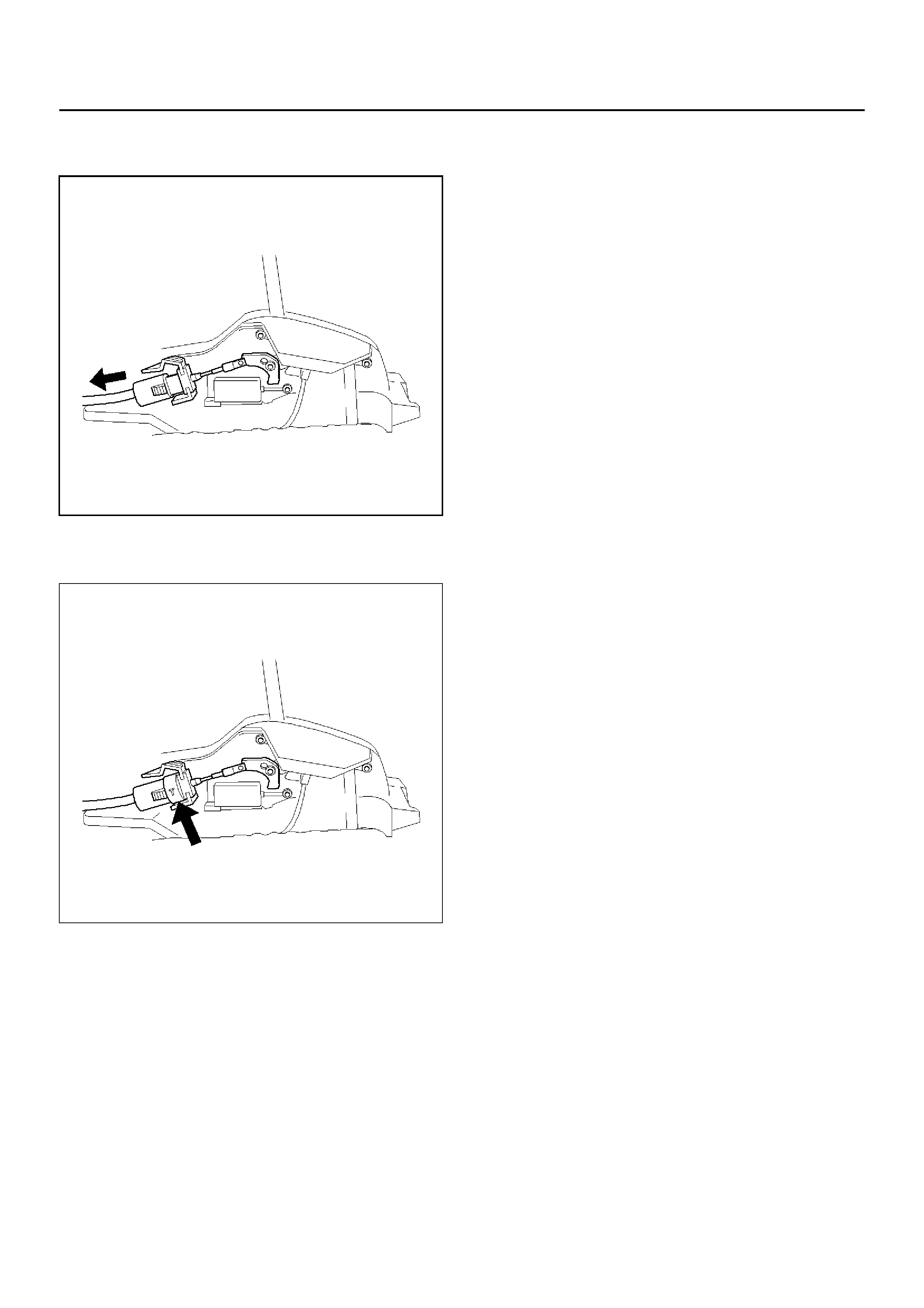
8. Pull lock.
A07RW015
9. Draw select cable assembly into the interior side.
INSTALLATION
1. Set selector lever in “P" position.
2. Let out select cable transmission side end from floor hole.
3. Fit outer cable into bracket in selector lever assembly.
A07RW016
4. Set inner cable end in selector lever and push pin into selector lever hole and inner cable end.
256RW023
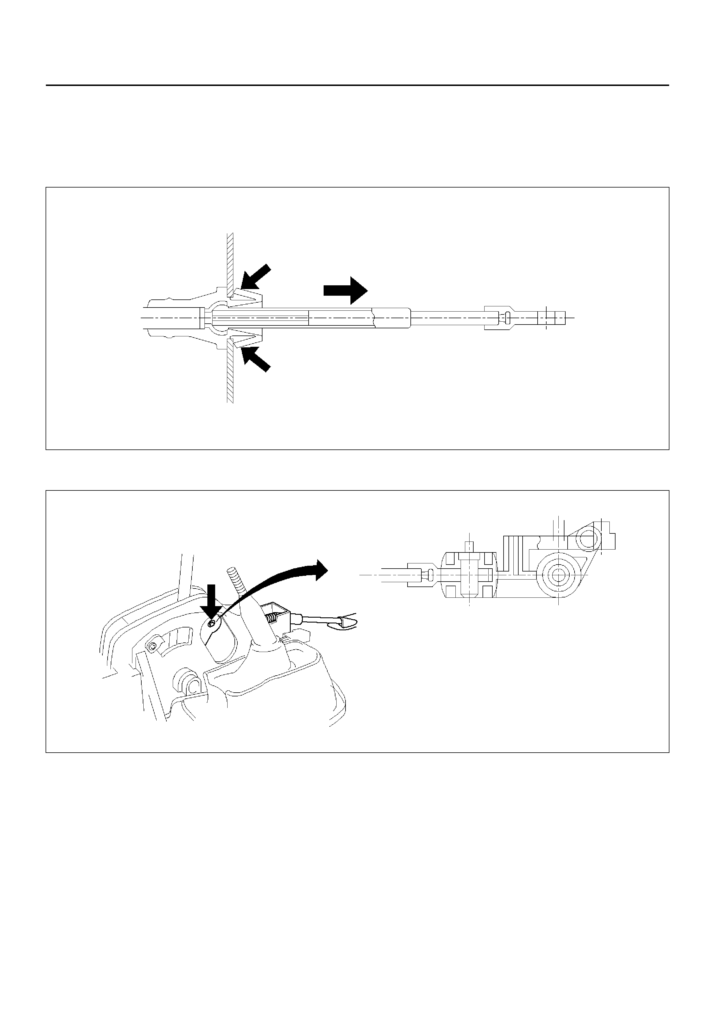
5. Check that lock projects.
A07RW015
6. Connect adjust end fitting attachment to the bracket
on transmission.
7. Set selector lever “P" position and connect inner
cable to selector lever.
210RW013
8. Push lock into adjust end fitting attachment.
A07RW014
9. Install grommet.
10. About following installation steps, refer to Selector
Lever in this section.
SHIFT LOCK CABLE
REMOVAL
1. Set ignition key in “LOCK" position and selector
lever in “P" position.
2. Remove transfer control lever knob, lower cluster
assembly, rear console, center console, selector
lever knob and cover.
• Refer to Selector Lever in this section.
3. Disconnect inner cable from selector lever assembly
then push claw and disconnect cable assembly.
256RW016
4. Disconnect lock adjust.
256RW017
5. Remove instrument panel lower cover and steering
column cover.
6. Remove spring pin and disconnect inner cable.
• Disconnect outer cable from bracket.
256RW008
INSTALLATION
1. Set ignition key in “LOCK" position and selector
lever in “P" position.
2. Connect outer cable to bracket near steering lock.
• Connect inner cable to steering lock and install
spring pin .
3. Install steering column cover and instrument lower
cover.
4. Install adjust body of cable assembly to bracket in
selector lever assembly.
• Install inner cable to lever, pulling inner cable with
outer cable.
256RW018
5. Check that cable moves smoothly, lightly pulling
outer cable rearward.
256RW019
6. Connect lock adjust, aligning “T" mark in the “Up"
position.
256RW017
7. About following installation steps, refer to Selector
Lever in this section.
8. Check the shi ft lock opera tio n:
a Selector lever should not be moved out of “P"
position with ignition key in “Lock" position.
b Select or lever can be mo ved out of “P" position
with ignition key in “ON" position only when
brake pedal is depressed.
c ignition key can be turned to “LOCK" position
only when selector lever is in “P" position (key
can be pulled out).
9. If a. and c. fail, readjust cable. If b. fails, readjust
connector wiring and brake pedal switch.
MODE SWITCH
REMOVAL
1. Place selector lever in neutral.
2. Disconnect battery ground cable.
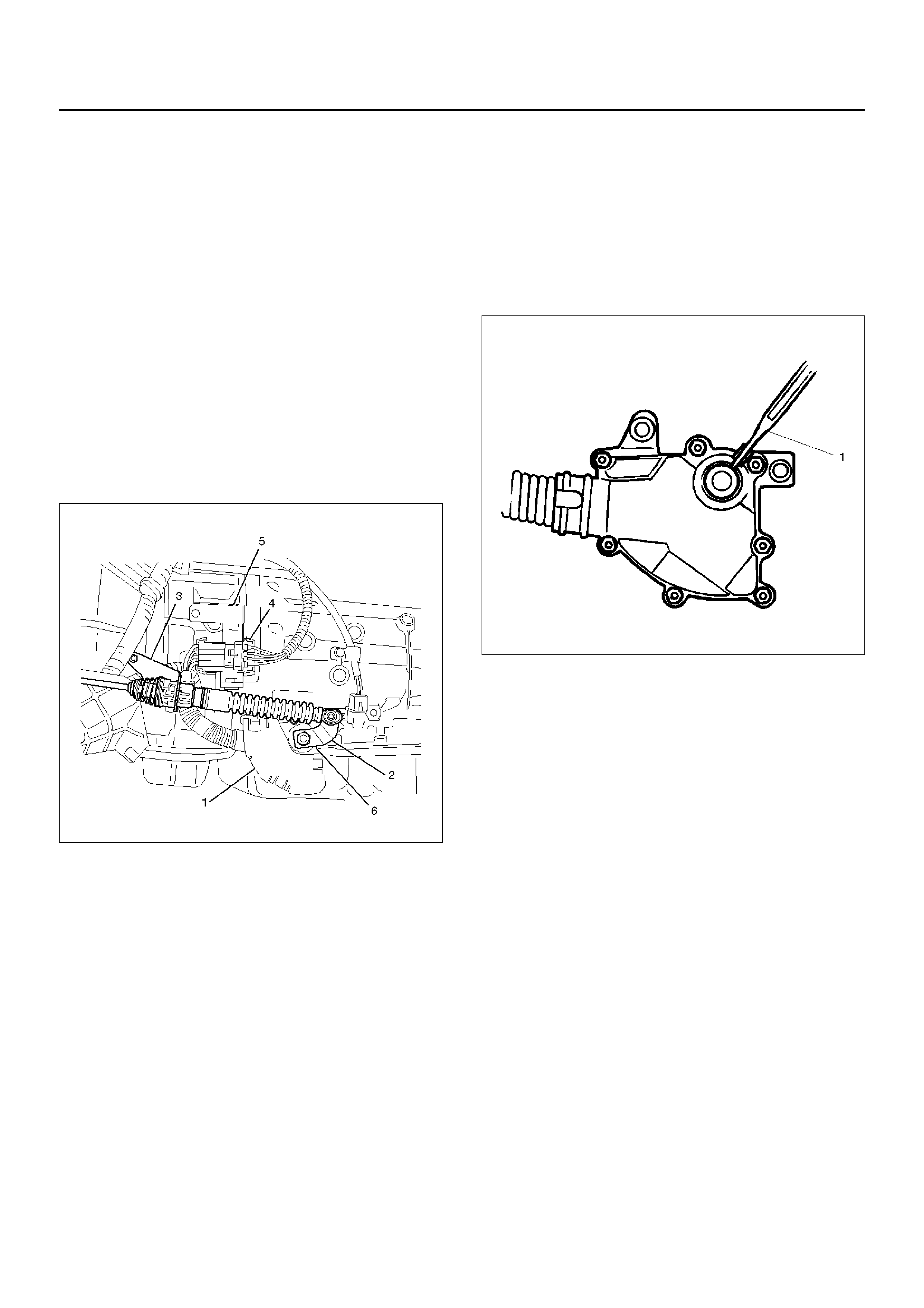
3. Remove mode switch cover (1).
4. Disconnect selector lever (2) from the mode switch.
5. Remove bracket with cable (3).
6. Disconnect transmission harness from the mode
switch connector (4).
7. Remove bracket with mode switch connector from
the transmission case.
8. Remove mode switch connector (4) from the
bracket (5).
9. Remove two mode switch bolts and nut then
remove mode switch (6).
210RW014
INSTALLATION
To install, follow the removal steps in the reverse order,
noting the following points;
1. Torque
Mode switch bolt: 13N•m
Selector lever nut: 23N•m
2. Mode switch setting procedure
Perform either of the following adjustment
procedures:
Procedure 1
a Place select or lever in neutral.
b Remove selector lever from the mode switch.
c Remove the mode switch cover.
d Loosen the two 10 mm screws.
e Rotate the mode switch until the slot in the
mode switch housing aligns with the selector
shaft bushing, and insert a 2.4 mm drill bit or
punch (1) into the slot.
f Tighten the screws to 13 N·m.
g After completing adjustment, snap the mode
switch cover into place.
h Reinstall the selector lever.
249RW001
Procedure 2
a Place selector lever in ne utral.
b Disconnect transmission harness connector
from mode switch connector.
c Remove mode switch connector with bracket
from the transmission case.
d Connect multimeter (resistance mode) to
terminals 1(E) and 4(H) on mode switch
connector.
e Loosen two mounting screws.
f Rotate mode s witch slight ly in both di rections to
determine the range (approx. 5 degrees) of
electrical contact.
g Position mode switch in middle of contact range.
h Tighten two mounting screws.
i Remove multimeter and install mode switch
harness connector with bracket to the
transmission case.
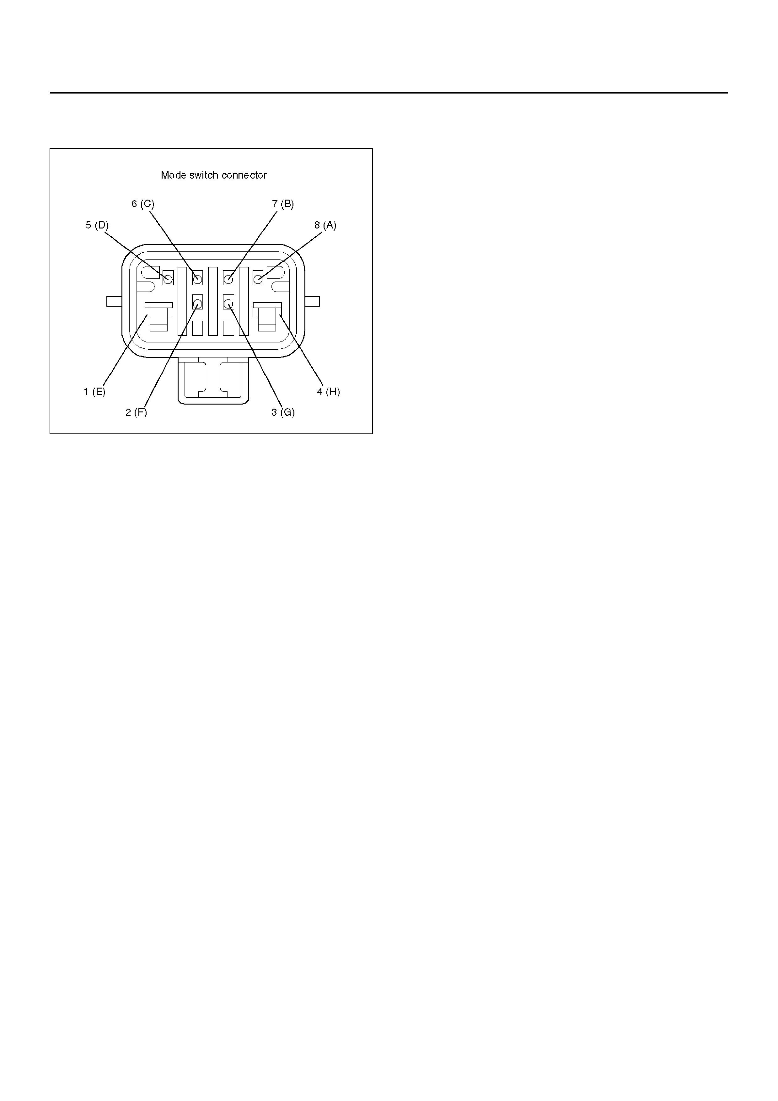
j Connect transmission harness connector to
mode switc h conn ector.
F07RW003
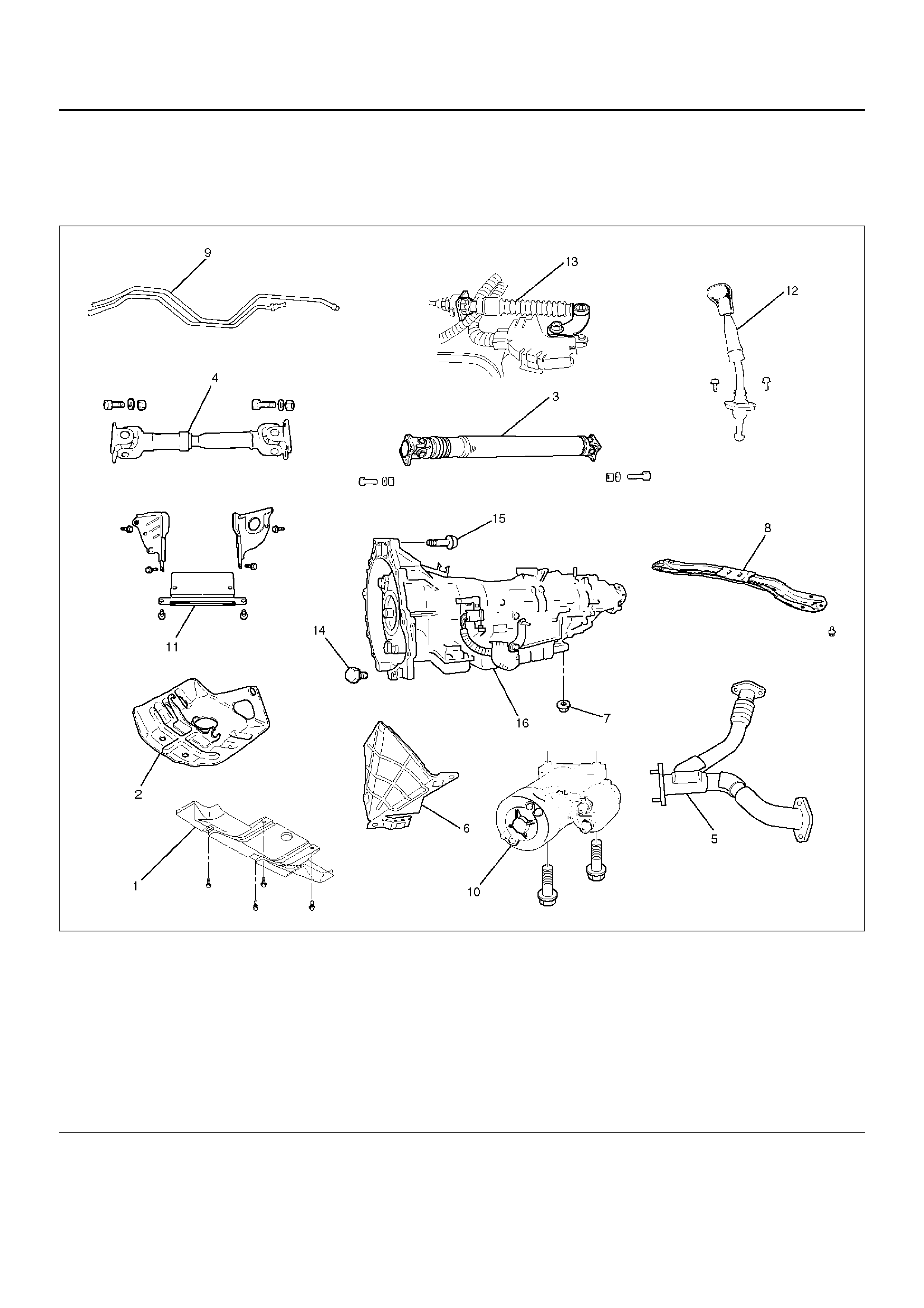
TRANSMISSION (WITH TRANSFER CASE)
TRANSMISSION AND ASSOCIATED
PARTS
240RX012
EndOFCallout
Legend
(1) Skid Plate
(2) Transfer Case Guard
(3) Rear Propeller Shaft
(4) Front Propeller Shaft
(5) Center Exhaust Pipe
(6) Harness Heat Shield
(7) Rear Mount Nut
(8) Third Crossmember
(9) Transmission Oil Cooler Pipe
(10) Starter
(11) Under Cove r
(12) Transfer Control Lever
(13) S elect Cable
(14) Torque Converter Bolt (Non – reusable part)
(15) Engine-Transmission Bolt
(16) Transmission Assembly (With Transfer Case)
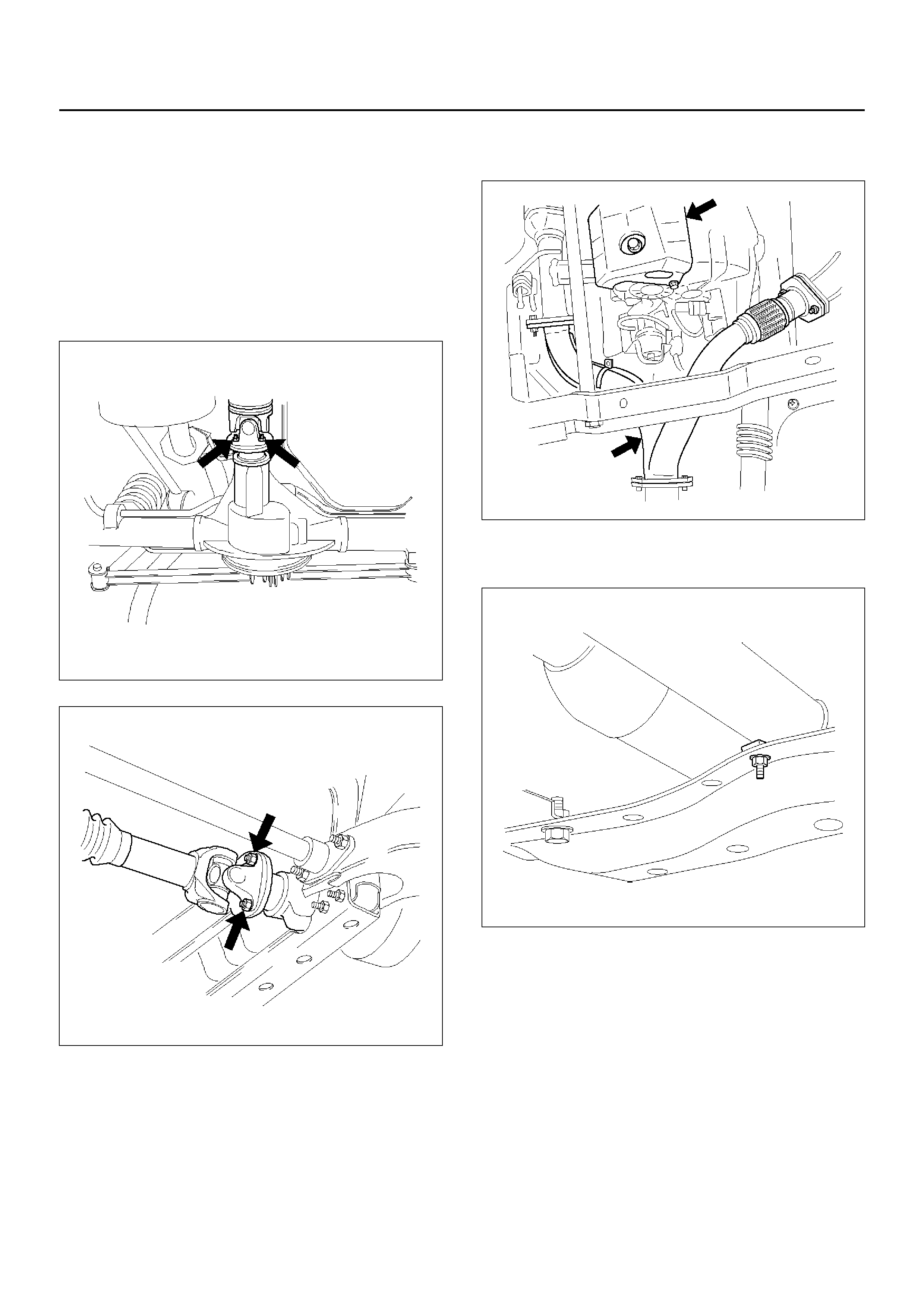
REMOVAL
Before remove transmission and transfer assembly from
vehicle, change the transfer mode to 2WD using push
button on dash panel.
1. Disconnect battery ground cable.
2. Remove rear propeller shaft and front propeller
shaft.
NOTE: Apply alignment marks on the flange at both
front and rear sides.
401RW008
401RW007
3. Remove transfer protector.
4. Remove center exhaust pipe.
150RX008
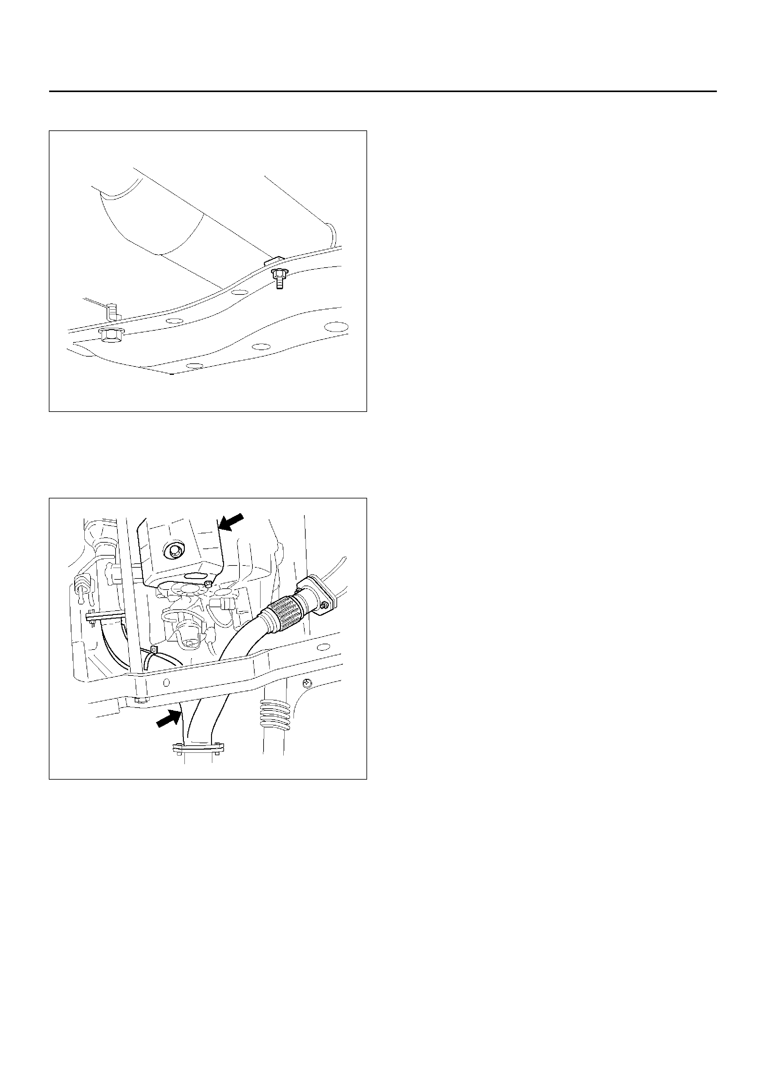
5. Remove fuel pipe bracket from the third
crossmember.
141RX004
141RY00007
240RW014
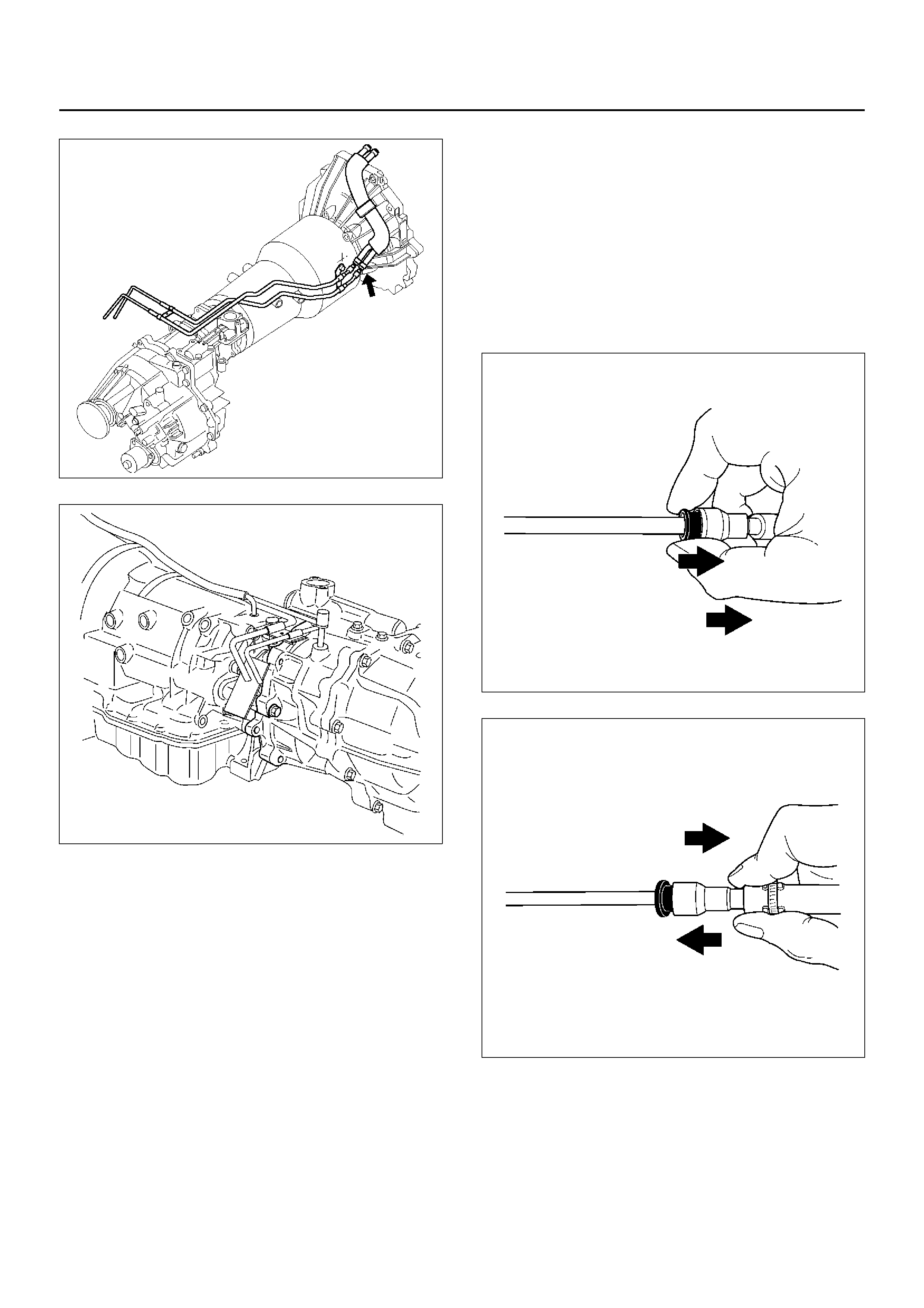
Fuel hose connector removal procedure
If remov al of the fuel ho se connector i s required for
transmission servicing and/or replacement, follow
the steps below.
NOTE:
• An O-ring is used as a seal between the fuel pipe and
the connector. Take care not to damage the contact
surfaces during the removal pro cedure. Do not allow
the serfaces to become contaminated with dirt or
other foreign material.
• Perform the entire removal procedure with your
hands. Do not use tools.
1. Separating the connector and fuel pipe
1. Clean the fuel pipe and connector to remove
mud and other dirt.
2. Pull the black plastic piece toward the
connector. Hold the piece near the
connector. Pull the connector from the fuel
pipe.
If the connector and fuel pipe are stuck
together, jiggle the conn ector bac k and forth
to loosen the connector. Do not yank the
connector from the fuel pipe.
141RY00002
141RY00003
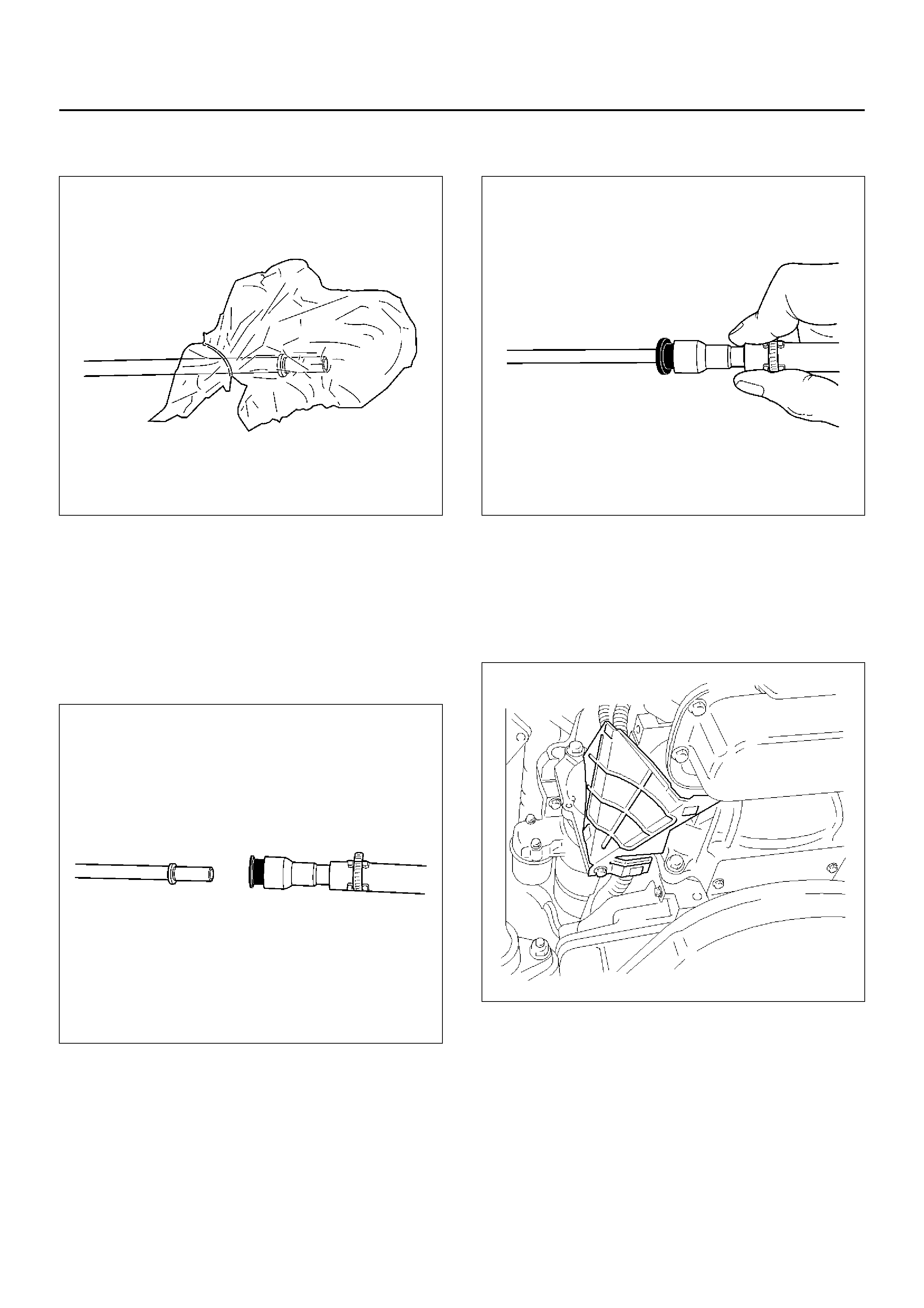
3. Tie a vinyl bag around the connector and
fuel pipe to protect them from dirt.
141RY00004
2. Joining the connector and fuel hose
1. Remove the vinyl bags from the connector
and fuel hose. Check that the contact
surfaces are undamaged and free of dirt and
other foreign material. Clean if necessary.
2. Align the axis of the fuel pipe and connector.
Push the connect or into the f uel pipe until a
distinct click is heard.
141RY00005
3. Gently pull on the c onnector to c heck that it
is securely la tched.
141RY00006
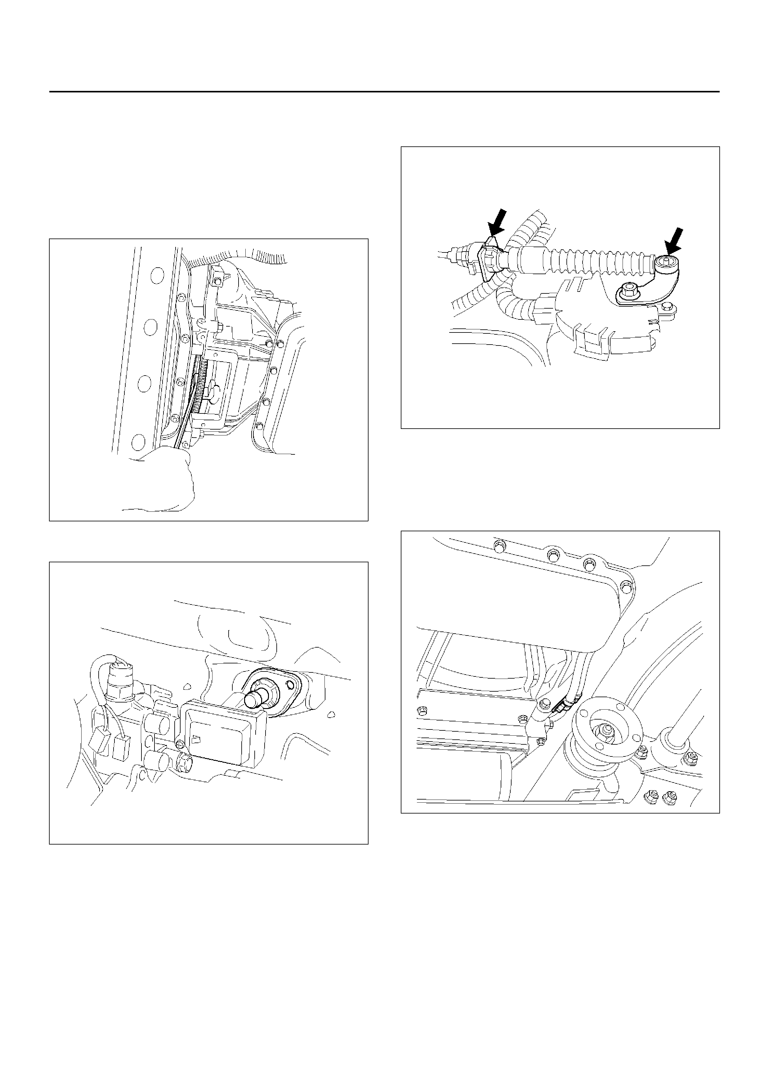
6. Disconnect transmission harness connector and
clip.
Conne ctor : Adapt er case, m ode sw itch , main ca se,
magnetic sensor, transfer switch, 2–4 actuator and
car speed sensor.
7. Remove harness heat shield.
815RW002

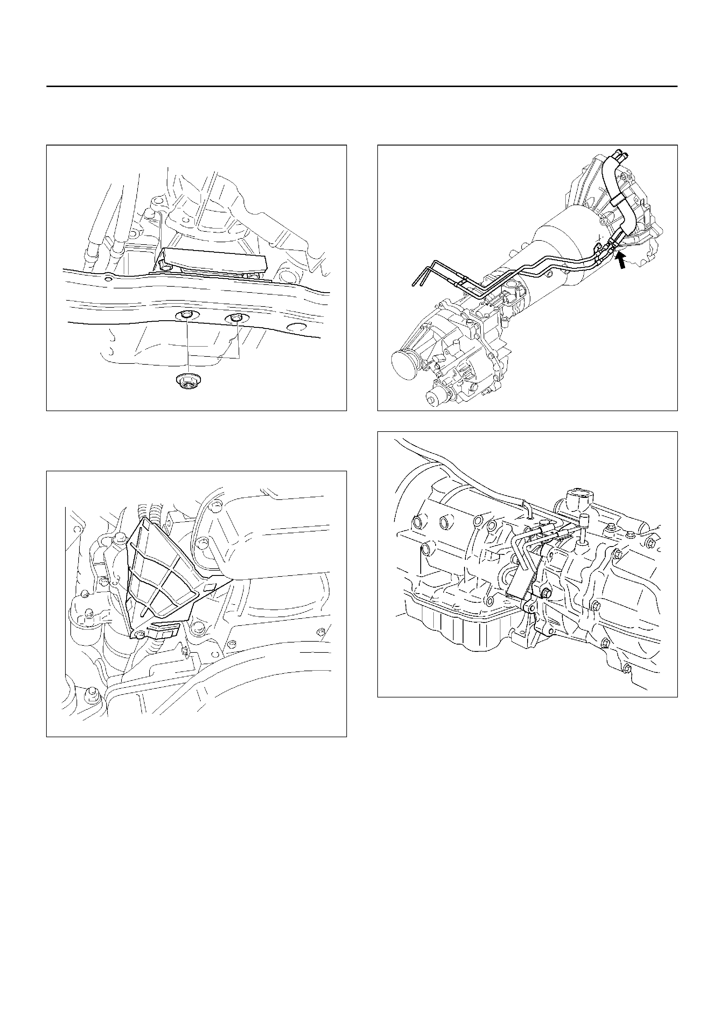
8. Support transmission with a jack.
Remove rear mount nuts from the third
crossmember.
F07RW008
9. Remove thi rd cross mem ber.
10. Disconnect transmission oil cooler pipes from A/T
side.
11. Remove oil pipe clamp and bracket from the
converter housing.
253RX002
12. R emo ve skid plate a nd loo sen oi l coo ler pipe clam p
bolt at the engine mount side.
13. Remove select cable by disconnecting inner cable
from select lever and removing outer cable with
bracket.
256RW025
14. Remove starter.
15. Remove under covers from the transmission and
engine.
16. Remove transfer control lever fixing bolts and push
up transfer control lever.
262RW015
17. Remove flex plate torque converter fixing bolts (6
pieces) by turning crankshaft.
240RX010
18. Remove engine-transmission fixing bolts.
19. Pull out transmission from the engine.
INSTALLATION
1. Slowly raise transmission jack until front of the
transm ission is aligned with rear of the engi ne. Join
the transmission to the engine.
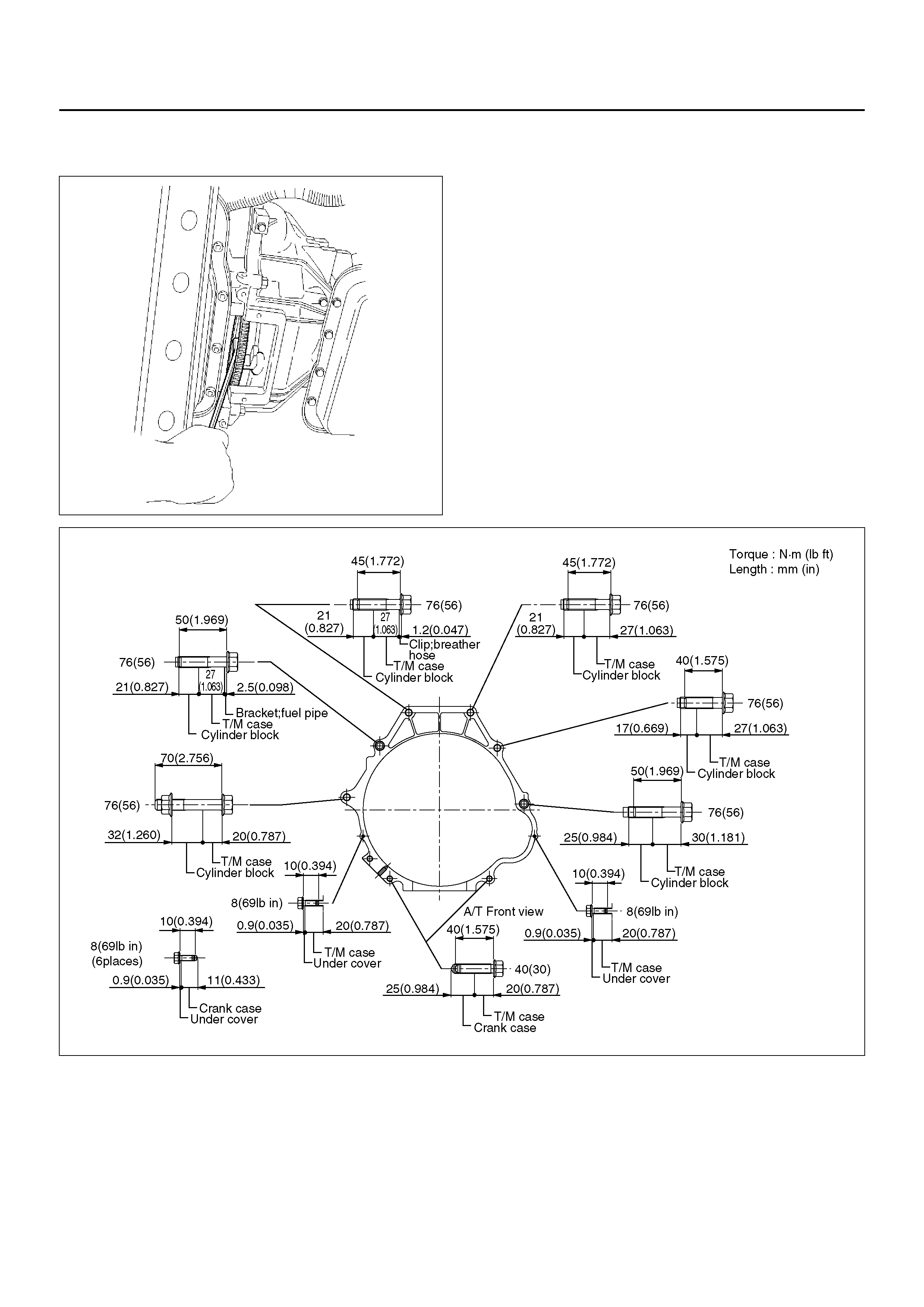
2. Tighten engine-transmission bolts as shown in the
figure.
F07R200004
3. Align the flex plate torque converter bolt boss with
flex plate hole by turning the torque converter . Install
flex plate torque converter bolts (6 pieces) by
turning the crankshaft.
Torque: 54N•m
NOTE: Do not reuse the flex plate torque converter
bolt.
240RX010
4. Install transfer control lever on the transfer case.
262RW015
5. Install under covers to the transmission and engine.
Torque: 8N•m
6. Install starter.
Torque: 40N•m
7. Install select cable by connecting inner cable to
selec t leve r and ins talli ng oute r cable with bracket.
256RW025
8. Co nne ct tra ns mi ssio n oil co ole r pip es to A/T.
Torque: 44N•m
9. Install oil cooler pipe clamp and bracket to the
converte r housi ng.
253RX002
10. Tighten oil cooler pipe clamp bolt at the engine
mount side and install skid plate.
11. Install third crossmember.
Torque: 116N•m
12. Install rear mount nuts.
Torque: 50N•m
F07RW008
13. Install harness heat shield.
Torque: 6N•m
815RW002
14. Connect transmission harness connector and clip.
Conne ctor : Adapter ca se, mode swi tch, mai n case ,
transfer switch, 2–4 actuator and vehicle speed
sensor.
15. Connect fuel pipe to transmission side.
NOTE: See “NOTE" of removal steps.
141RY00007
240RW014
16. Install fuel pipe bracket to the third crossmember.
141RX004
17. Install center exhaust pipe.
Torque: 43N•m
18. Install transfer case guard.
150RX008
19. Install front propeller shaft and rear propeller shaft.
Torque: 63N•m
20. Connect battery ground cable.
SOLENOID (MAIN CASE VALVE BODY)
REMOVAL
1. Raise the vehicle and support it on jack stands.
2. Disconnect battery ground cable.
3. Drain fluid.
4. Remove sixteen 10 mm screws, main case oil pan,
magnet, and gasket.
5. Remove three 13 mm screws, oil filter.
6. Disconnect wiring harness from band control
solenoid and shift solenoids. Pull only on
connectors, not on wiring harness.
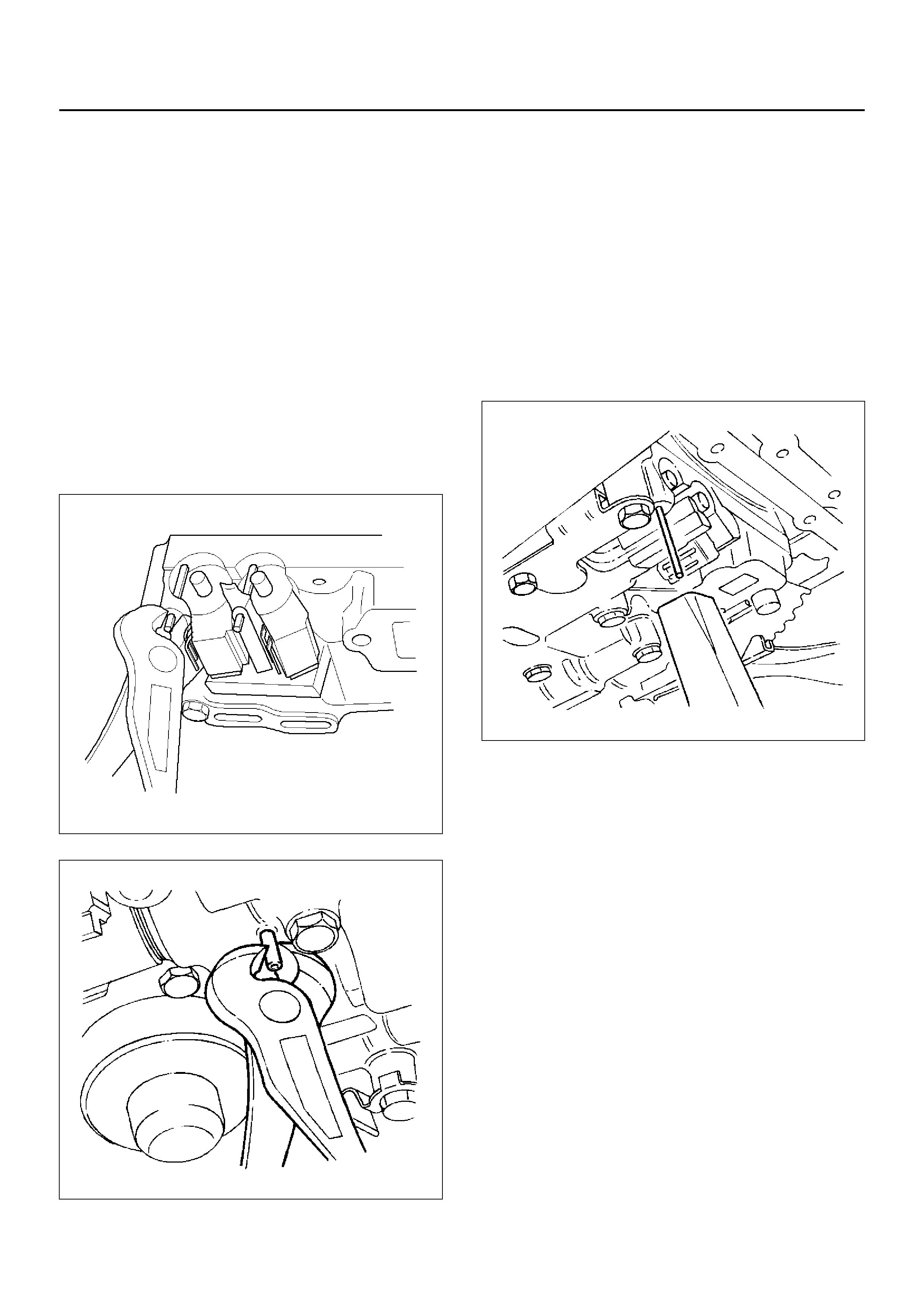
7. Remove spring pin for Shift Solenoid ‘A’, Shift
Solenoid ‘B’, and Band Control Solenoid
respectively, using suitable pliers taking care not to
damage solenoids.
210RW010
244RW003
8. Remove Shift Solenoid ‘A’, Shift Solenoid ‘B’, and
Band Control Solenoid, and gaskets from main case
valve body. Do not pull on wiring harness. Remove
solenoids by grasping the metal tip.
INSTALLATION
1. Install Shift Solenoid ‘A’, Shift Solenoid ‘B’, and
Band Control Solenoid with new gaskets to main
case valve body respectively.
2. Carefully install spring pin with hammer to avoid
damage to valve body, etc.
243RW004
3. Connect wiring harness to solenoids.
4. Install oil filter with a new gasket and the three 13
mm screws, tighten to the specified torque.
Torque: 20N•m
5. Install magnet, main case oil pan with new gasket,
and sixteen 10 mm screws. Tighten the screws to
the specified torque.
Torque: 11N•m
6. Fill transmission through the overfill screw hole of oil
pan, using ATF DEXRON®-III. Refer to Changing
Transmission Fluid in this section.
7. Connect battery ground cable.
SOLENOID (ADAPTER CASE VALVE BODY)
REMOVAL
1. Raise the vehicle and support it on jack stands.
2. Disconnect battery ground cable.
3. Drain fluid.
4. Remove adapter case oil pan twelve fixing 10 mm
screws, adapter case oil pan, and gasket.
NOTE: Oil pan still contains transmission fluid. Place a
large drain container under the oil pan and drain the
fluid carefully.
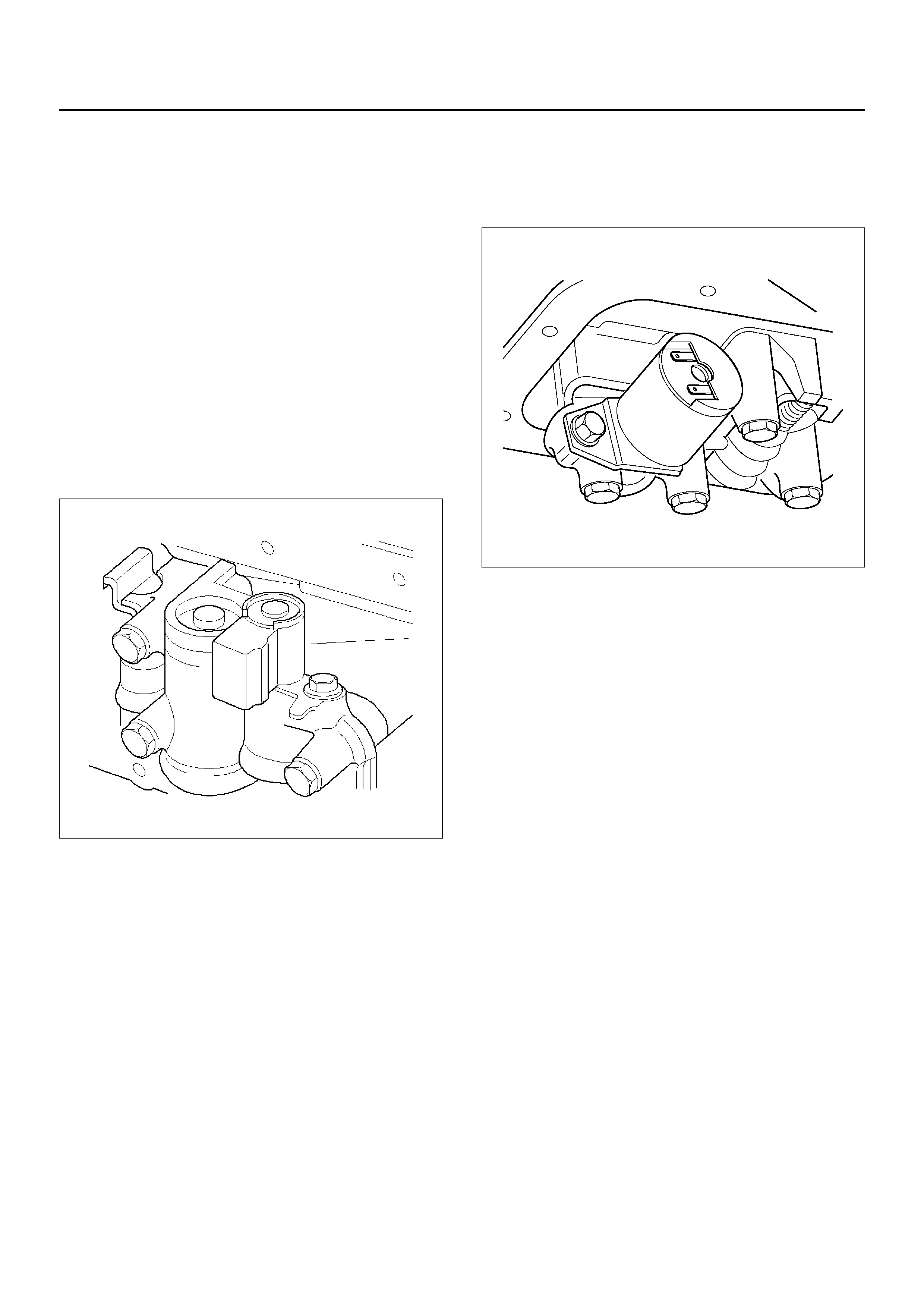
5. Disconnect wiring harness from Pressure Control
Solenoid and Converter Clutch Solenoid. Pull only
on connectors, not on wiring harness.
6. Remove 11 mm bolt and Converter Clutch Solenoid
with two O-rings.
210RW011
7. Remove 11 mm bolt, retainer, and Pressure Control
Solenoid.
210R100002
INSTALLATION
1. Install Pressure Control Solenoid, retainer, and 11
mm bolt to adapter case valve body. Tighten the bolt
to the specified torque.
Torque: 10 N•m
2. Install Converter Clutch Solenoid with two O-rings,
and 11 mm bolt to adapter case valve body. Tighten
the bolt to the specified torque.
Torque : 10N•m
3. Connect wiring harness assembly to solenoids.
4. Install adapter case oil pan, new gasket, and twelve
10 mm screws. Tighten the screws to the specified
torque.
Torque : 11N•m (96lbin)
5. Fill transmission through overfill screw hole oil pan,
using ATF DEXRON®-III. Refer to Changing
Transmission Fluid in this section.
6. Connect battery ground cable.
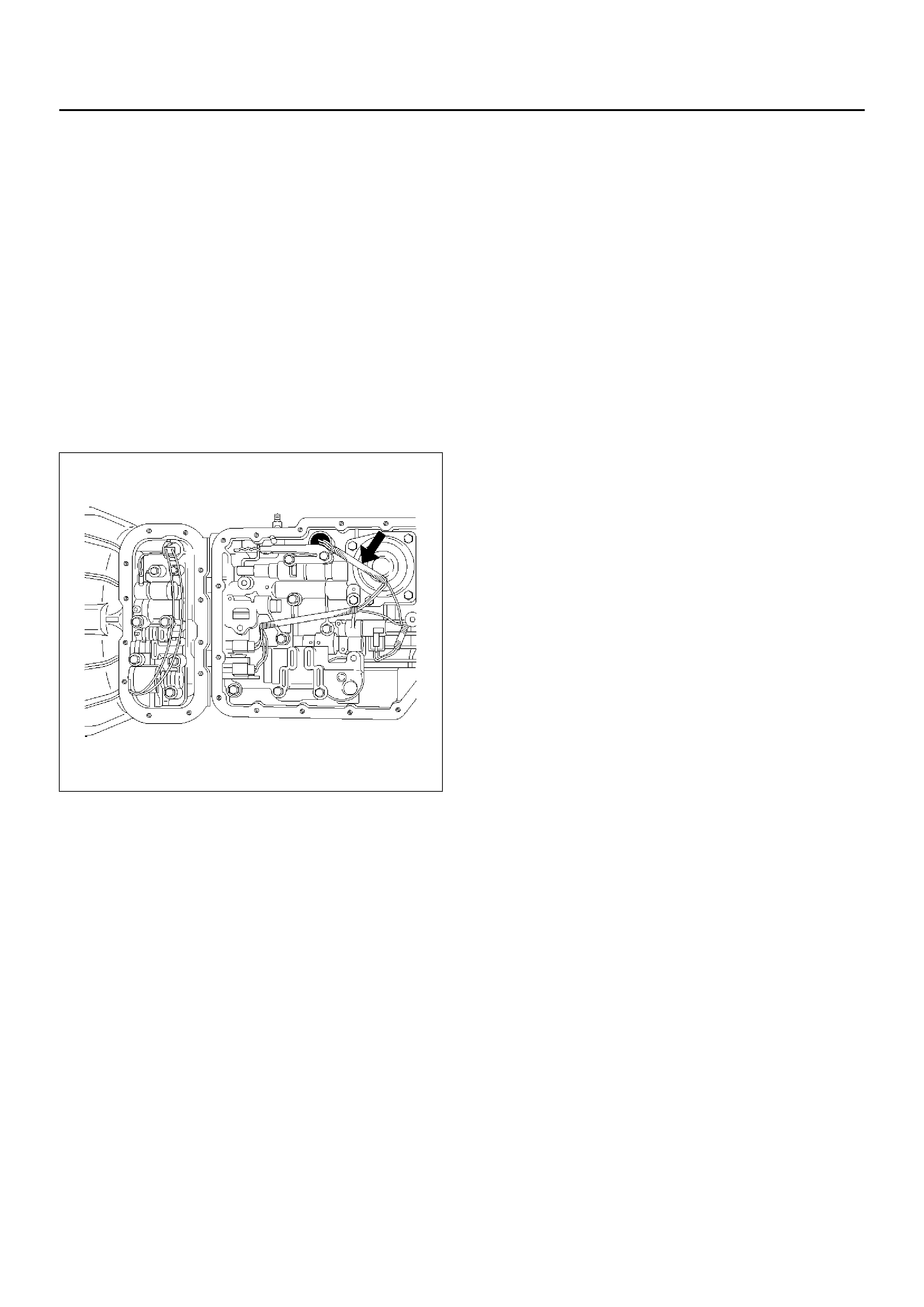
VALVE BODY ASSEMBLY (MAIN CASE)
REMOVAL
1. Raise the vehicle and support it on jack stands.
2. Disconnect battery ground cable.
3. Drain fluid.
4. Remove sixteen 10 mm screws, main case oil pan,
magnet and gasket.
5. Remove three 13 mm oil filter fixing screws, then
remove oil filter.
6. Remove two 13 mm manual detent fixing screws,
then remove roller and spring assembly.
7. Disconnect wiring harness from band control
solenoid and shift solenoids. Pull only on
connectors, not on wiring harness.
8. Remove four 13 mm servo cover fixing screws, then
remove servo cover and gasket.
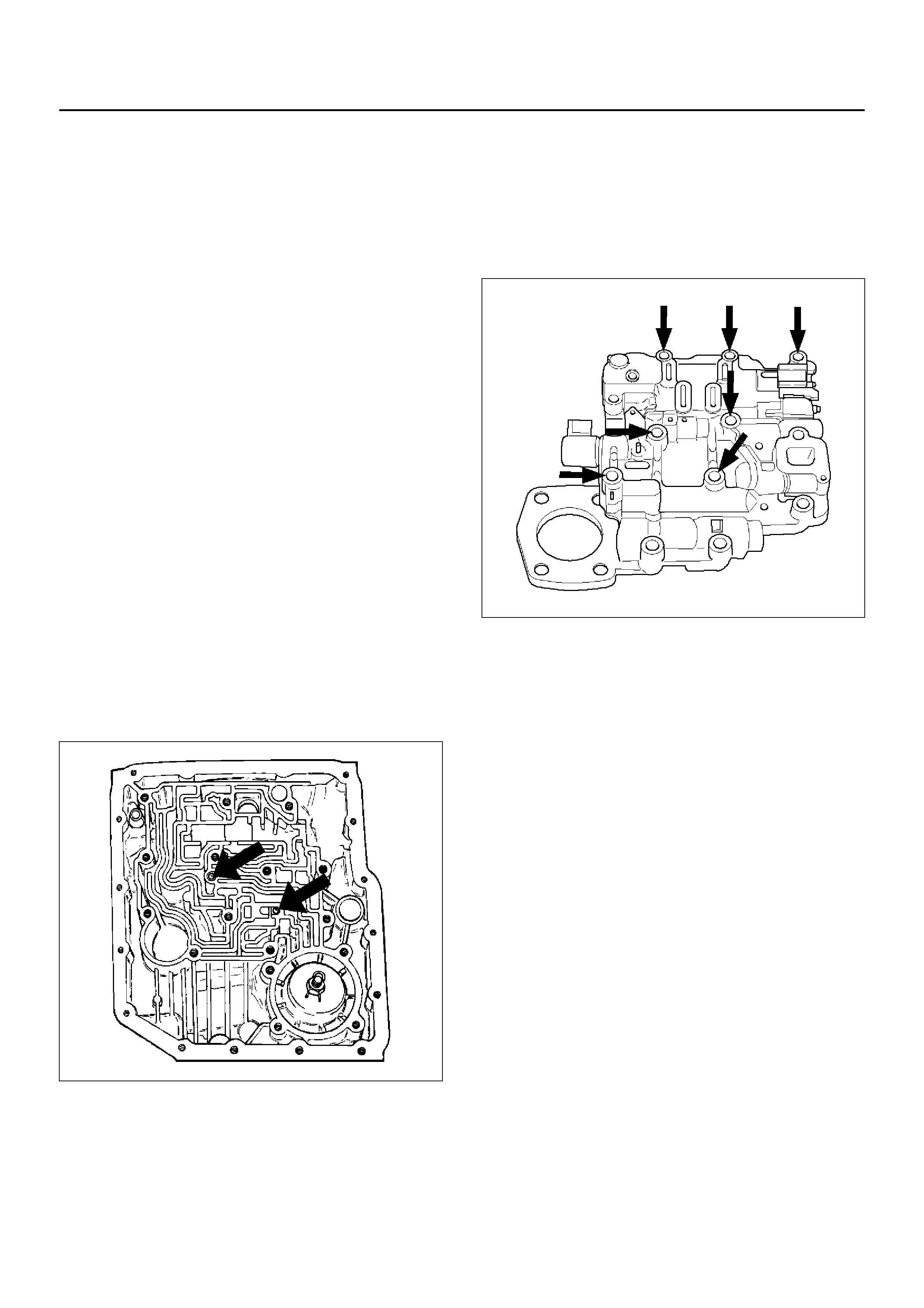
9. Remove seven 13 mm valve body fixing screws.
10. Remove main case valve body with manual valve
link and transfer plate. Note the position of the link
(long end into valve, short end into range selector
lever).
11. Remove transfer plate gasket from main case.
12. Remove two check balls from main case.
INSTALLATION
1. Install two check balls to main case.
244RW002
2. I nspect electric al 7 way connector and seal of mai n
case. Replace if necessary.
3. Use two J–25025–B guide pin to install main case.
• Install valve body complete assembly and manual
valve link.
NOTE: Valve must be extended as the short end of
manual valve link is connected to the range selector
lever. Long end of link goes into valve.
4. Install seven 13 mm screws, and tighten them to the
specified torque.
Torque: 20N•m (15lbft)
243RS008
5. Remove two guide pins from main case.
6. Install servo cover gasket, cover, and four 13 mm
screws . Tight en t he scr ews to t he spec ified to rque .
Torque: 25N•m (18lbft)
7. Connect wiring harness to band control and shift
solenoids.
8. Install roller and spring assembly to manual detent.
• Install two 13 mm screws, and tighten them to the
specifi ed tor que .
Torque: 20N•m (15lbft)
9. Install oil filter and three 13 mm screws. Tighten to
the specified torque.
Torque : 20N•m (15lbft)

10. Install oil pan gasket, magnet, oil pan and sixteen 10
mm screws. Tighten the screws to the specified
torque.
Torque: 11N•m (96lbin)
11. Fill transmission through overfill screw hole of oil
pan, using ATF DEXRON®-III. Refer to Changing
Transmission Fluid in this section.
12. Connect battery ground cable.

VALVE BODY ASSEMBLY (ADAPTER CASE)
REMOVAL
1. Raise the vehicle and support it on jack stands.
2. Disconnect battery ground cable.
3. Drain fluid.
4. Remove twelve 10 mm adapter case oil pan fixing
screws, adapter case oil pan, and gasket.
NOTE: Oil pan still contains transmission fluid. Place a
large drain container under the oil pan.
Drain the fluid carefully.
5. Disconnect wiring harness from Pressure Control
solenoid and Converter Clutch Solenoid. Pull only
on connectors, not on wiring harness.
6. Remove seven 13 mm screws from adapter case
valve body assembly, then remove transfer plate,
two gaskets, and adapter case valve body.
INSTALLATION
1. Inspect electrical 4 way connector and seal of
adapter case. Replace if necessary.
2. Install gasket, transfer plate, and gasket.
3. Install adapter case valve body and seven 13 mm
screws. Tighten the screws to the specified torque.
Torque: 20N•m
4. Connect wiring harness assembly to Converter
Clutch Solenoid and Pressure Control Solenoid.
5. Install oil pan gasket, oil pan, and twelve 10 mm
screws. Tighten the screws to the specified torque.
Torque: 11N•m
6. Fill transmission through the overfill screw hole of oil
pan, using ATF DEXRON®-III, Refer to Changing
Transmission Fluid in this section.
7. Connect battery ground cable.
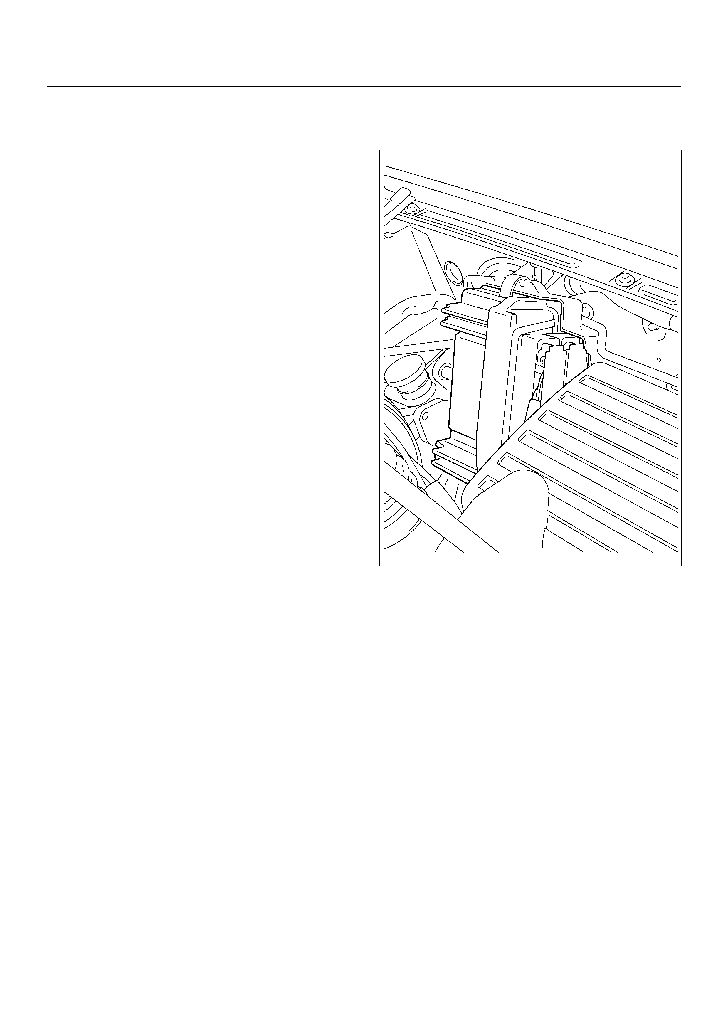
POWERTRAIN CONTROL MODULE (PCM)
REMOVAL
1. Disconnect battery ground cable.
2. Disconnect PCM wiring harness connectors from
PCM.
3. Remove PCM from bracket.
825R100018
INSTALLATION
1. Install PCM to bracket.
2. Connect PCM wiring harness connectors to PCM.
3. Connect battery ground cable.
SPEED SENSOR (EXTENSION HOUSING)
REMOVAL
1. Disconnect battery ground cable.
2. Remove front console.
3. Remove selector lever assembly.
241RW007
4. Disconnect speed sensor harness connector from
speed sensor.
5. Remove one 10 mm screw and speed sensor with
O-ring.
INSTALLATION
1. Inspect the speed sensor O-ring, and replace it if
necessary.
2. Install speed sensor assembly and 10 mm screw.
Torque: 9N•m
Connect speed sensor harness connector to speed
sensor.
3. Install selector lever assembly.
• Adjust shift lock cable.
Refer to Shift Lock Cable in this section.
4. Install front console.
5. Connect battery ground cable.
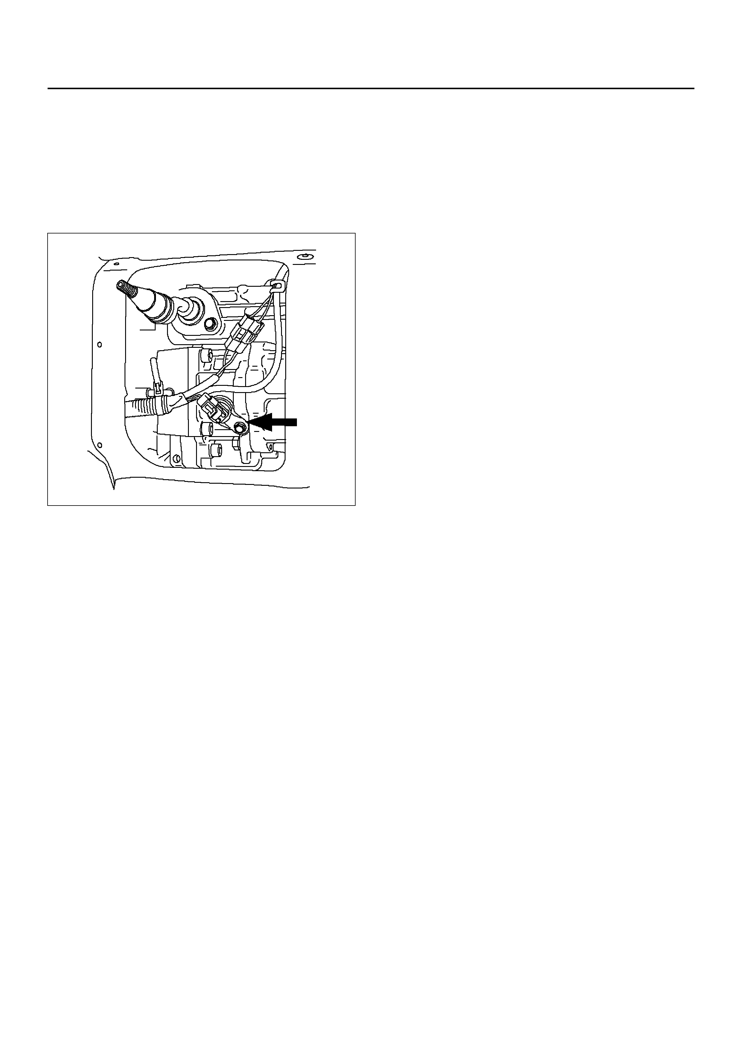
TRANSMISSION OIL TEMPERATURE SENSOR (MAIN CASE)
REMOVAL
1. Raise the vehicle and support it on jack stands.
2. Disconnect battery ground cable.
3. Drain fluid.
4. Remove sixteen 10 mm main case oil pan fixing
screws, main case oil pan, and gasket.
5. Disconnect wiring harness from shift solenoids,
band apply solenoid, and 7 way connector of main
case. Pull only on connectors, not on wiring
harness.
6. Remove wiring harness assembly with transmission
oil temperature sensor.
244RY001
INSTALLATION
1. Install wiring harness assembly with transmission oil
temperature sensor to band apply solenoid, shift
solenoids, and 7 way connector of main case.
2. Install oil pan gasket, oil pan and sixteen 10 mm
fixing screws. Tighten the screws to the specified
torque.
Torque: 11N•m
3. Fill transmission through the overfill screw hole of oil
pan, using ATF DEXRON®-III.
Refer to Changing Transmission Fluid in this
section.
4. Connect battery ground cable.
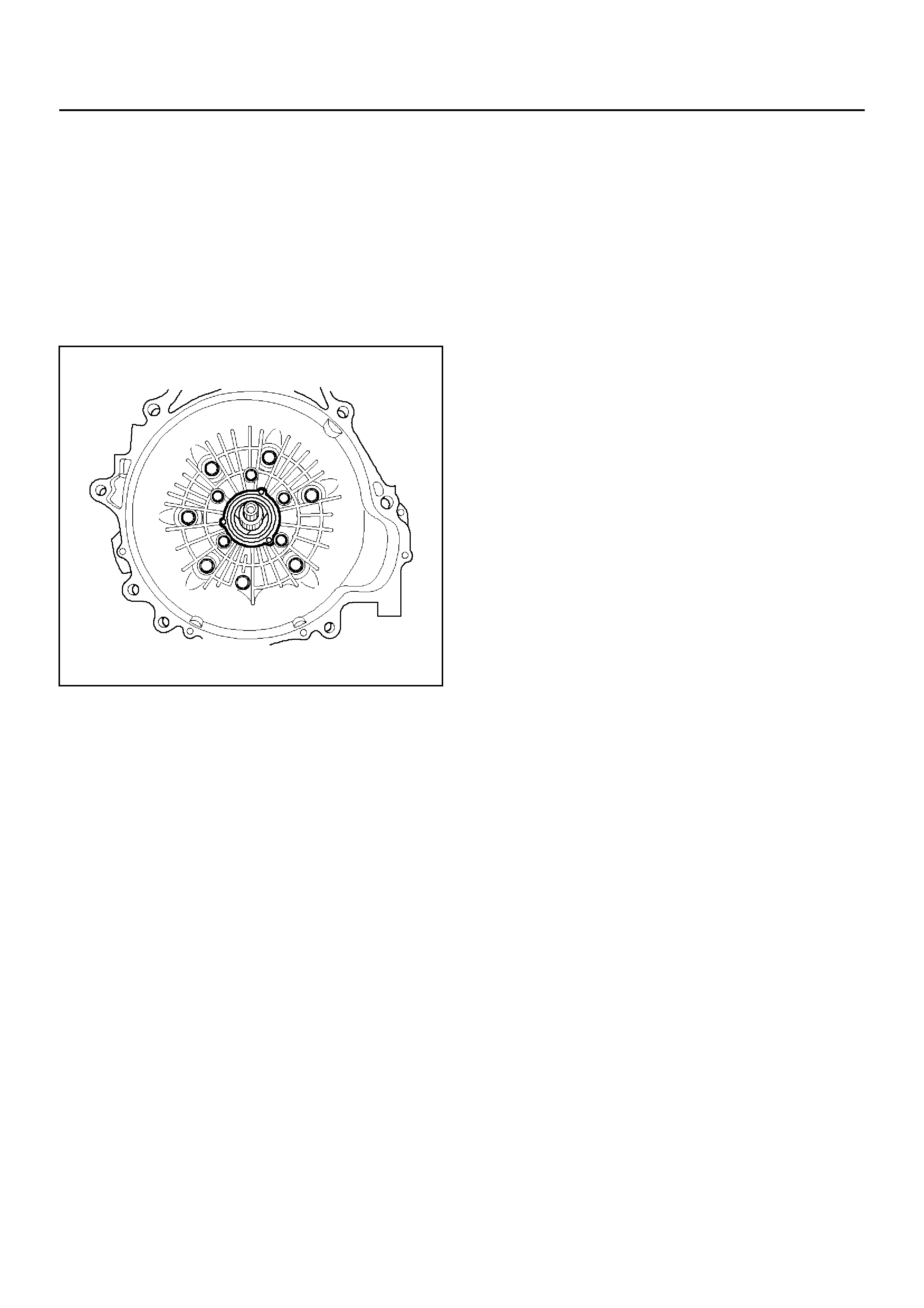
FRONT OIL SEAL (CONVERTER HOUSING)
REMOVAL
1. Remove transmission assembly from the vehicle
,refer to Transmission (With Transfer Case) in this
section.
2. Remove torque converter from converter housing.
3. Remove three screws and oil seal ring from
converter housing.
241RW008
INSTALLATION
1. Apply clean ATF to the new oil seal ring lip.
• Install oil seal ring to converter housing, tighten to
the specified torque.
Torque: 3N•m
2. Install torque converter to converter housing.
3. Install tran smissi on as se mbly to th e v eh ic le , r efer to
Transmission (With Transfer Case) in this section.
REAR OIL SEAL (EXTENSION HOUSING)
REMOVAL
1. Remove transfer case assembly from the vehicle.
Refer to Transfer Case in Drive Line/Axle section.
2. Remove rear oil seal from transmission extension
housing.
241RW005
INSTALLATION
1. Use J–36797 extension housing oil seal installer,
and install the rear oil seal to the transmission
extension housing.
2. Install the transfer case assembly to the vehicle.
Refer to Transfer Case in Drive Line/Axle section.
TRANSMISSION (4L30–E)
DISASSEMBLY
NOTE: During the disassembly and reassembly,
perform the following:
• Wash each part thoroughly, and blow air through
each oil passage and groove to eliminate blockage.
• Seal rings, roll pins, and gaskets should be replaced.
• When assembling the components, apply
DEXRON® -III Auto matic Transmission Fluid (ATF) to
each seal, rotating part, and sliding part.
• D o no t dip part faci ngs, such as clu tch o r brak e dri ve
plates, in cleaner when washing it.
Also, always coat parts with new ATF two or three
times after cleaning with solvent.
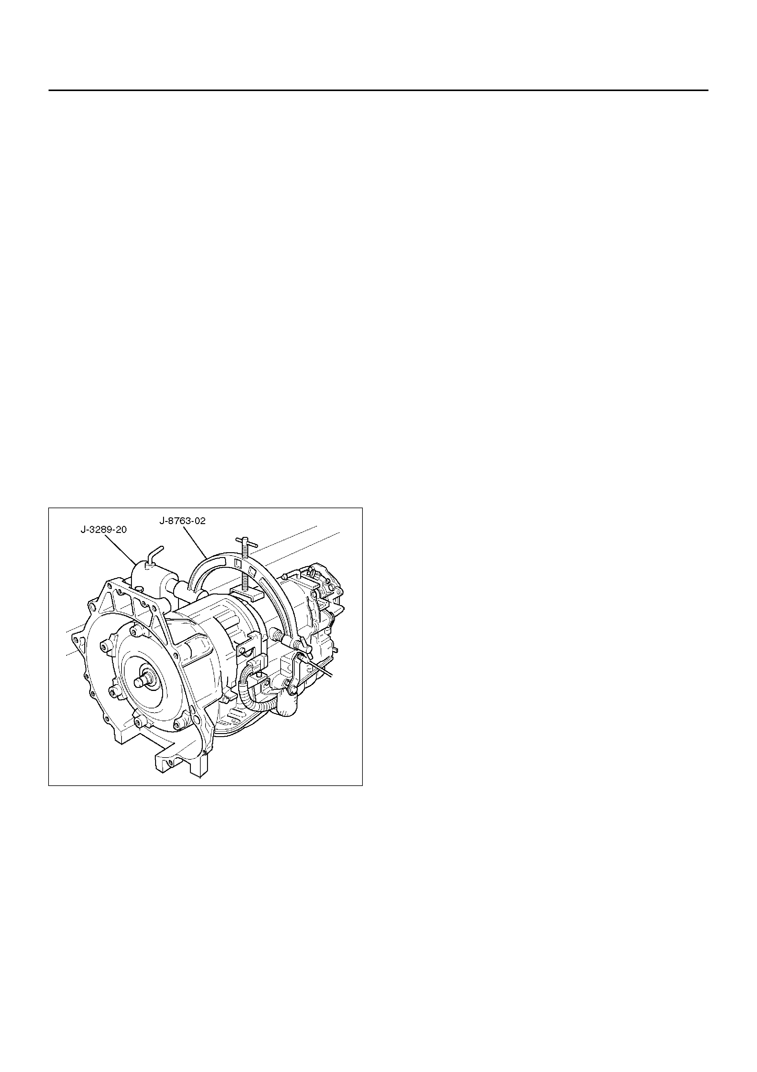
1. Remove torque converter (1).
• Drain fluid from torque converter.
• Attach J–8763–02 holding fixture to the
transmission and set it on J–3289–20 holding
fixture base.
NOTE: Do not overtighten the tool, as case damage
may result.
420RW021
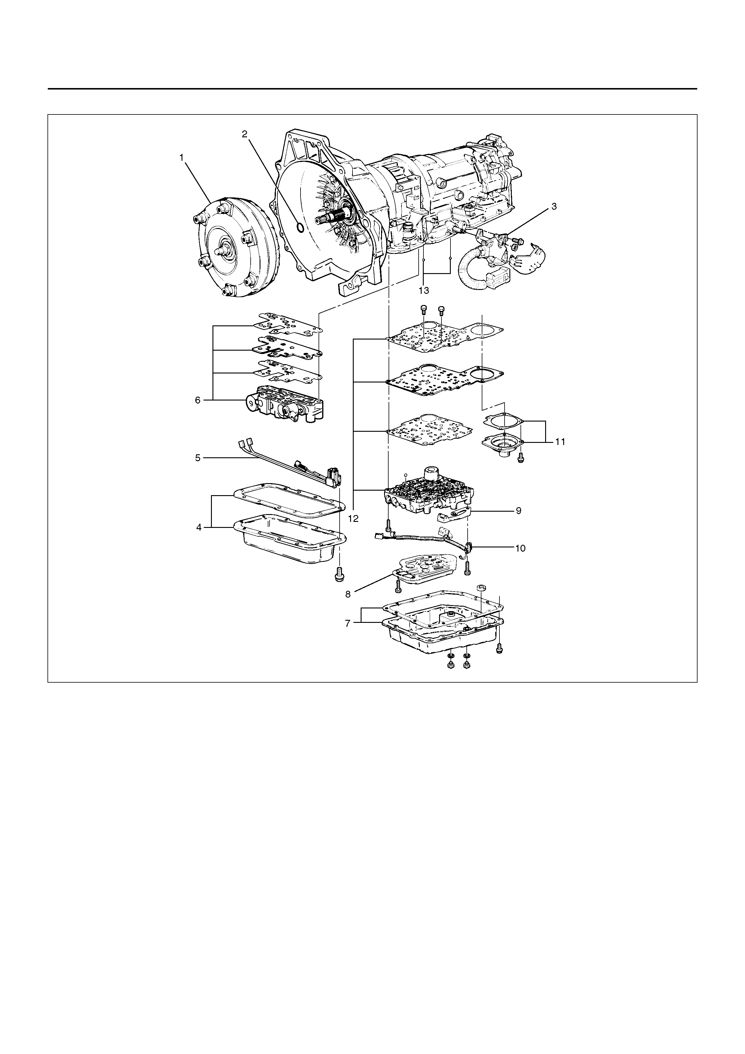
2. Remove O-ring (2) from turbine shaft.
3. Remove two 10mm mode switch screws, selector
lever nut, cover, and mode switch (3).
4. Remove twelve 10mm adapter case oil pan (4)
fixing screws, adapter oil pan, and gasket.
5. Disconnect electrical wiring connections (5) from
solenoids and 4 way connector of adapter case. Pull
on connectors only, not on wiring harness.
6. Remove seven 13mm adapter case valve body (6)
fixing screws, adapter case valve body assembly,
transfer plate, and two gaskets.
• Remove wiring harness and 4 way connector.
7. Remove sixteen 10mm main case oil pan (7) fixing
screws, main oil pan, magnet, and gasket.
8. Remove three 13mm oil filter (8) fixing screws and
oil filter.
9. Remo ve two 13mm manual detent (9) fi xing screws,
roller and spring, and manual detent.
10. Disconnect wiring harness assembly (10) from band
apply solenoid, shift solenoids, and main case 7
way connector.
Pull on connectors only, not on wiring harness.
11. Remove four 13mm servo cover (11) fixing screws,
servo cover, and gasket.
12. Remove seven 13mm valve body screws from main
case.
• Remove wiring harness assembly (5) from the
adapter case side.
• Remove main valve body assembly (12) with
manual valve link and transfer plate. Note the
position of the li nk (long end into va lve, s hort end
into range selector lever).
• Remove 7 way connector.
• Remove gasket transfer plate from main case.
13. Remove two check balls (13) from main case.
240RY001
14. Turn transmission to vertical position to drain fluid.
Return back to horizontal position when drained.
• Install J–23075 servo piston spring compressor
with offset to the rear of case.
• Compress servo piston assembly.
• Remove servo piston retaining ring (14).
• Slowly release servo piston assembly (15).
• Remove tool.
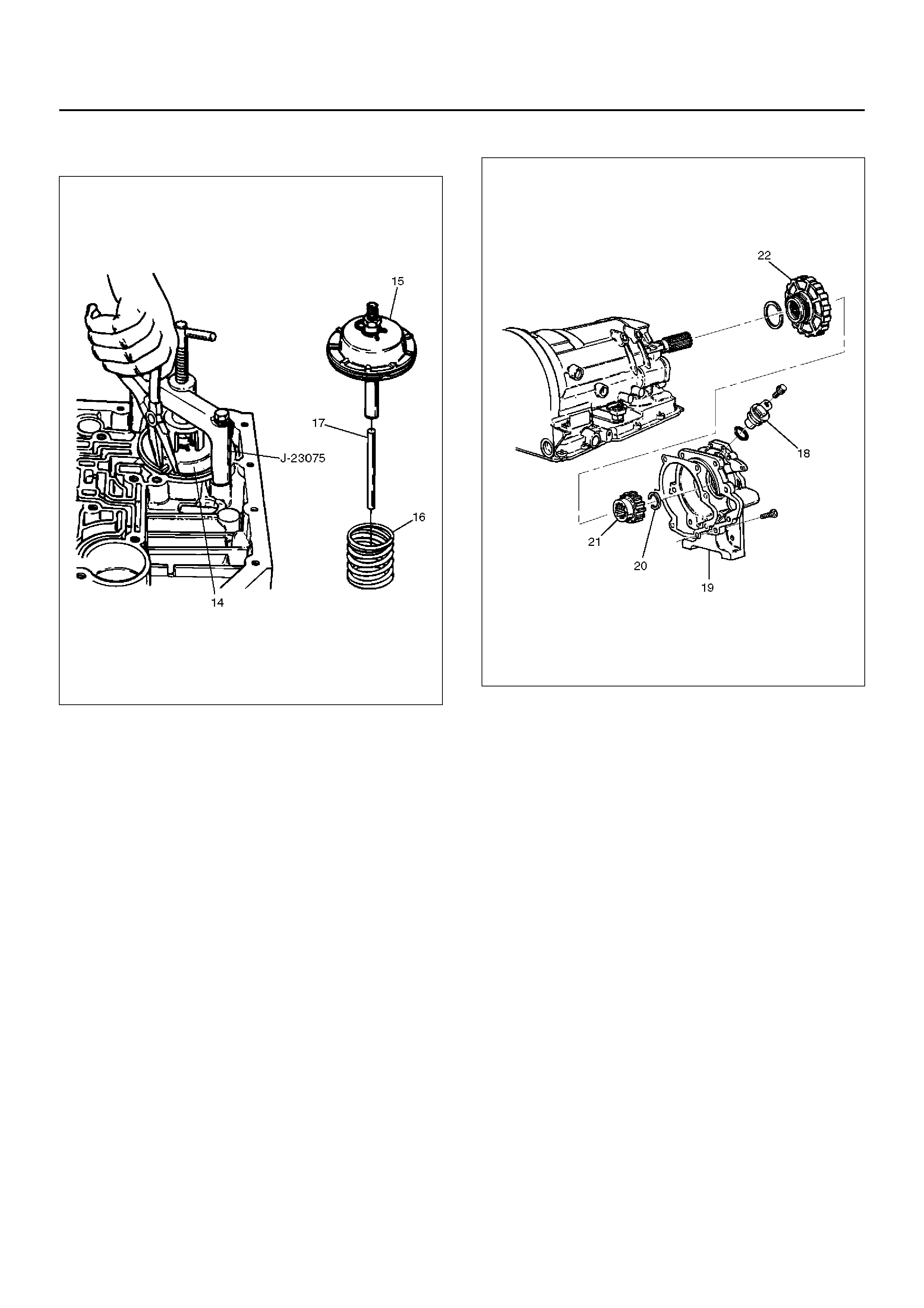
15. Remove servo piston assembly (15), return spring
(16), and servo apply rod (17).
242RS002
16. R otate transmission to horizontal position, pan side
down.
• Remove one 10mm screw, and speed sensor
(18) with “O" ring.
17. Remove seven 8mm extension housing hexagon
socket head screws, extension housing assembly
(19), and gasket.
18. Remove retaining ring (20).
NOTE: Use extra long, needle nose pliers.
19. Remove speed wheel (21).
20. Remove wheel parking lock (with seal ring) (22).
241RS002
21. Rotate transmission to vertical position, converter
housing up.
• Loosen the converter housing and oil pump
assembly fixing screws, but do not remove, the
five 13 mm inner screws unless oil pump
disassembly is required.
• Remove seven outer screws.
• Remove converter housing and oil pump
assembly (23).
22. Remove gasket (24).
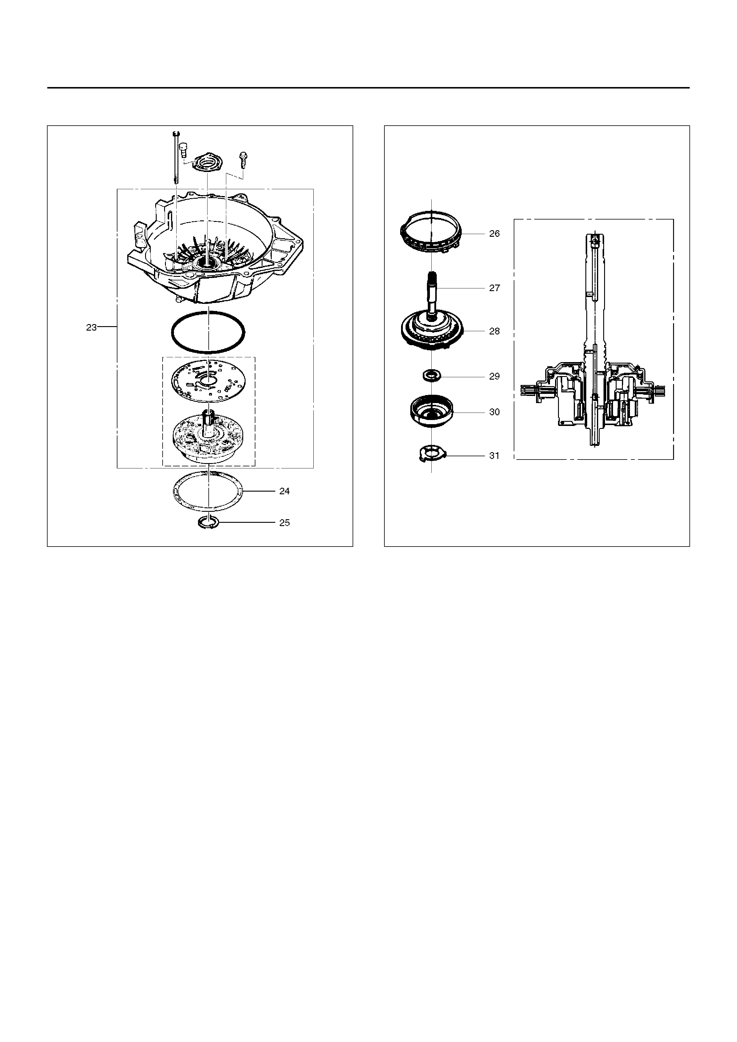
23. Remove selective thrust washer (25).
241RW004
24. Remove fourth clutch retainer (26).
25. Grasp turbine shaft and lift out the overrun clutch
housing assembly (27) and fourth clutch plates (28).
26. Remove thrust bearing assembly (29).
27. Remove overdrive internal gear (30).
28. Remove thrust washer (31).
252RS001
29. Re mov e a dap ter cas e a nd c en ter s upp or t ass emb ly
(with fourth clutch piston) (32).
30. Remove seal ring (33).
31. Remove selective thrust washer (34) and two O-ring
seals (35) from main case.
32. Use J–23327 and J–23327–90 compressor to
compress the fourth clutch spring retainer and
springs (37).
• Release snap ring (36) from groove.
• Remove clutch compressor and snap ring (36).
33. Remove retainer and spring assembly (37).
34. Insert two converter housing/main case screws to
hold adapter case while pulling out fourth clutch
piston (38).
• Remove fourth clutch piston assembly (38) from
the adapter case.
• Remove converter housing/main case screws.
35. Grasp intermediate shaft, twist and pull out the
second and third clutch drum assemblies with
reverse clutch plates while holding onto output shaft
(39).
36. Separate second (40) and third clutch (41)
assemblies.
37. Remove thrust washer (42).
38. Remove reverse clutch plates (43 and 44) and
reverse clutch pressure plate (45).
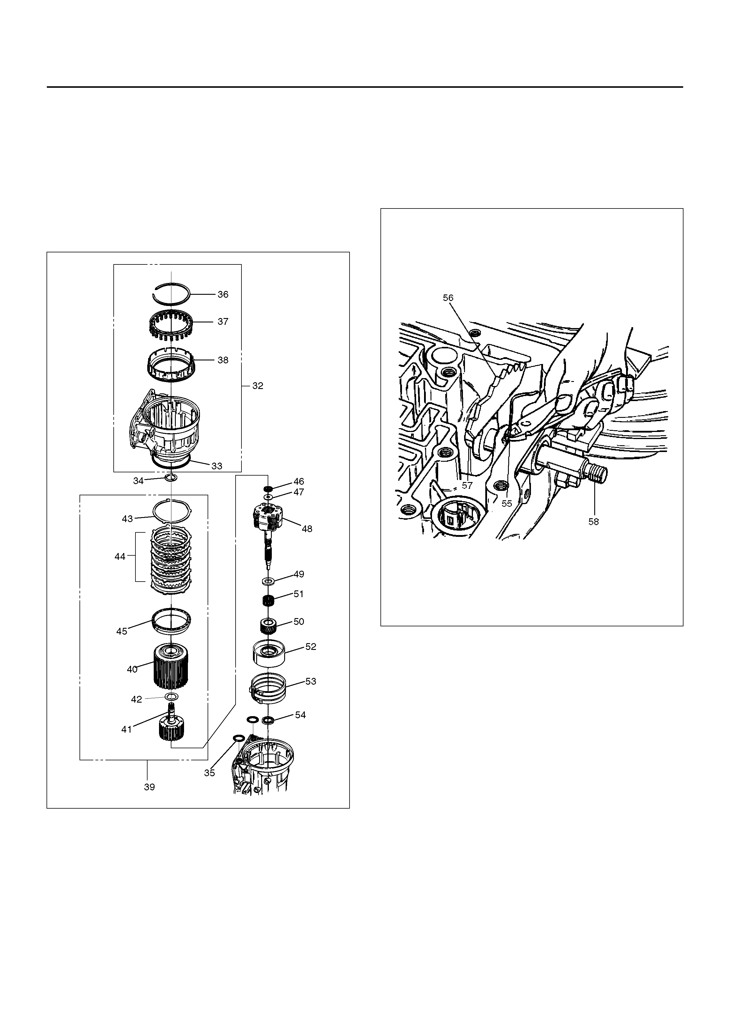
39. Remove bearing (46) and washer (47).
40. Remove planetary carrier assembly (48).
41. Remove thrust bearing (49).
42. Remove reaction sun gear (50)
43. Remove needle bearing (51).
44. Remove brake drum (52).
45. Remove brake band (53).
46. Remove thrust bearing (54).
242RS003
47. Rotate case to horizontal position, valve body side
facing up.
• Remove spring pin (55), using cutting pliers, then
remove parking lock and selector lever assembly
(56).
NOTE: Insert wire in the center of the spring pin to
prevent it from collapsing during removal. Be aware of
pin height. Protect machined face of main case.
48. Remove parking lock and range selector lever 17
mm nut (57).
49. Remove parking lock and range selector lever (56),
and actuator assembly.
50. Remove selector shaft (58).
NOTE: Inspect the shaft for burrs before removing to
prevent damaging seal. If necessary, remove burrs by
lightly sanding with an oilstone.
249RS004
REASSEMBLY
1. Inspect selector shaft seal and replace it if
necessary.
NOTE: Use a seal installer when replacing the seal.
• Install selector shaft.
NOTE: Spring pin groove must be positioned inside the
case.
2. Install spring pin. Be sure the selector shaft can
move freely. Do not push the pin flush with the
case surface. Leave enough height for removal.
3. Install actuator assembly (1).
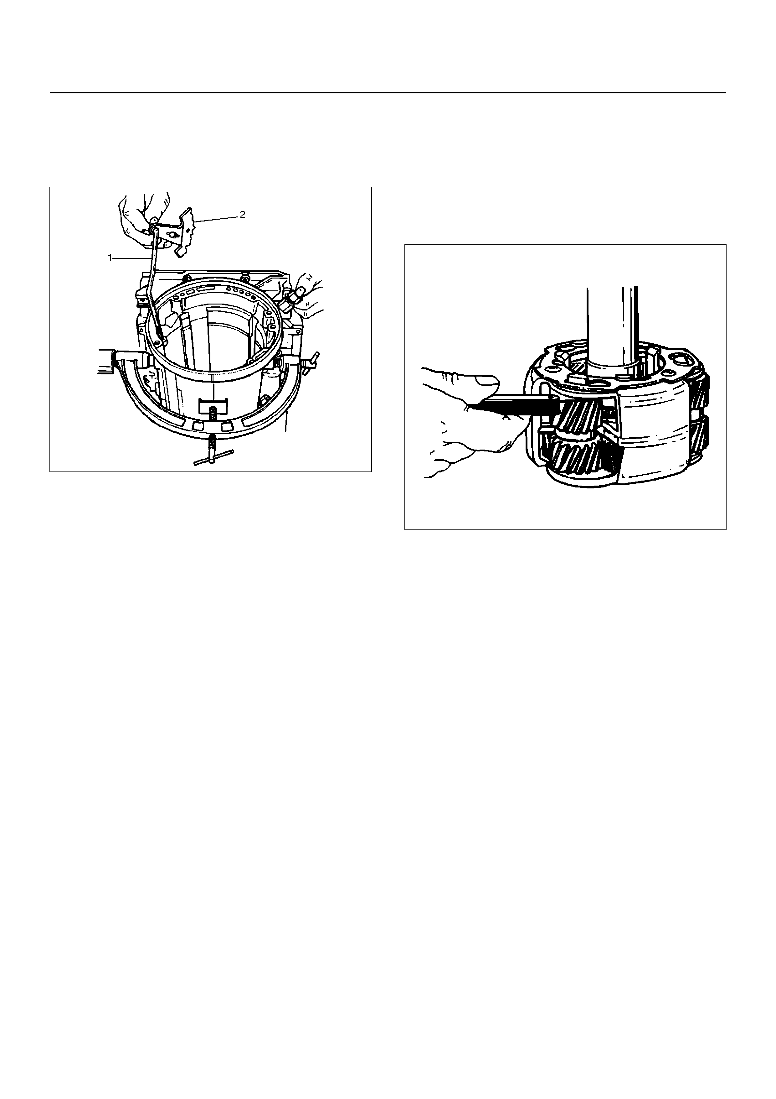
4. I nstall parki ng lock and range sel ector lever (2 ) and
new 17 mm nut. Tighten the nut to the specified
torque.
Torque: 22N•m
249RS005
5. R otate mai n case to ver tical position , extens ion en d
facing down.
• Install brake band assemb ly (3) .
NOTE: Be sure to align servo pin area with the servo
hole.
6. Install thrust bearing (4).
NOTE: The case b ushin g ac ts as a gu ide f or th e thru st
bearing.
7. Install br ake drum (5).
8. Install reaction sun gear (6).
9. Install needle bearing (7).
10. In spect planetary ca rrier assembly (8) for wear and
damage. If necessary replace it.
• Measure pinion end play clearance with a feeler
gauge.
Clearance: 0.13mm–0.89mm
If clearance is outside specified value, replace the
planetary carrier assembly.
248RS001
11. Install the thrust bearing (9) on the output shaft.
NOTE : Use petr oleum jel ly to hold the thrus t bearing in
place.
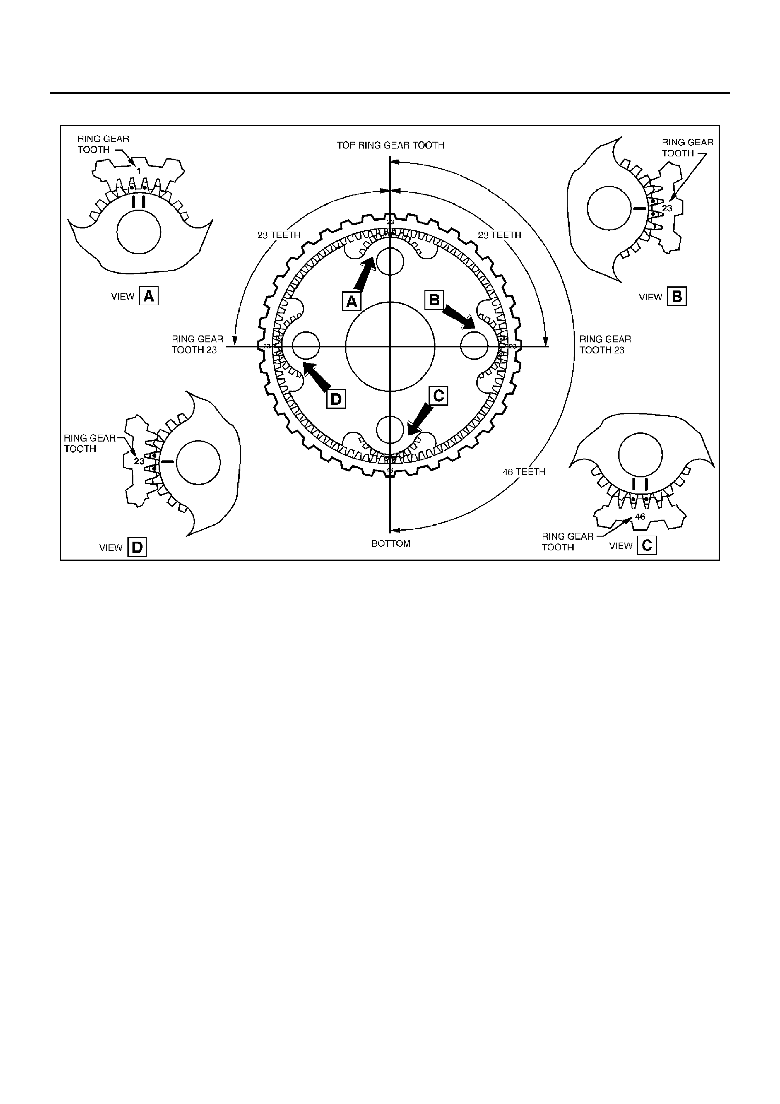
12. A lign planetary p inions. Each pinio n is marked with
double points to indicate the master tooth space and
exactly opposite with a single point to indicate the
master tooth. The markings on the planetary carrier
consist of doubl e lines which ar e to be lined up with
the double points on two opposite pinions; the single
lines ar e to be lined up with the sin gle points on the
other two pinions.
• After all four pinions are lined up, slide on the
third clutch assembly. Rotate third clutch and
check mark alignment. Considering that the ring
gear tooth between the double points of one
planetary pinion is tooth number 1, count the
teeth to check that the single points on the two
adjacent pinions are between teeth 23 and 24 of
the ring gear, and that the ring gear tooth
between the double points of the opposite pinion
is tooth number 46. If the ring gear and pinions
are not lined up, remove and realign them.
13. Install planetary carrier (8) with third clutch (12).
NOTE: Do not force. When properly aligned, the parts
will fit together easily.
14. Remove the third clutch (12). Install bearing (11)
and washer (10).
NOTE: Use petroleum jelly to hold the washer and
bearing in pla ce .
242RW002
15. Carefully align the second clutch plate inner tangs.
• Install thrust washer, tangs pointing downward,
and locating tang positioned in slot on second
clutch hub.
NOTE: Use petroleum jelly to hold thrust washer in
place.
16. Install third clutch and intermediate shaft assembly
(13) into the second clutch drum (14).

17. Install second and third clutch assemblies into the
main case. Twist output shaft and clutch
assemblies to ensure proper fit.
247RS001
18. Install pressure plate (15) with lip side up, tang
facing valve body face.
19. Install reverse clutch plates. Start with a steel plate
(17) and alternate with a lined plate (16).
20. Install waved clutch plate (18) with center tang
facing valve body side.
247RS002
21. Second clutch end play measurement
1. Install t he J–23085–A s electiv e washer gauging
tool (with spacer ring) on the case flange and
against the intermediate shaft.
2. Position the inner shaft of the gauging tool
against the thrust surface of the second clutch
hub.
3. Tighten thumb screw. Remove the tool.
4. Fit the spacer ring on the inner shaft of the tool.
5. Measur e t he gap an d s elec t a ppr op riate wa sh er
as shown in the chart.
247R100001
247RS004
Sele ctive Thrust Washer
Gap: mm(in) Color
1.53 – 1.63 Yellow
1.72 – 1.82 Red
1.91 – 2.01 Black
2.10 – 2.20 Natural
2.29 – 2.39 Green
2.48 – 2.58) Blue
FOLLOWING THE PROCEDURE SHOULD RESULT
IN FINAL END–PLAY FROM 0.36 mm TO 0.79 mm
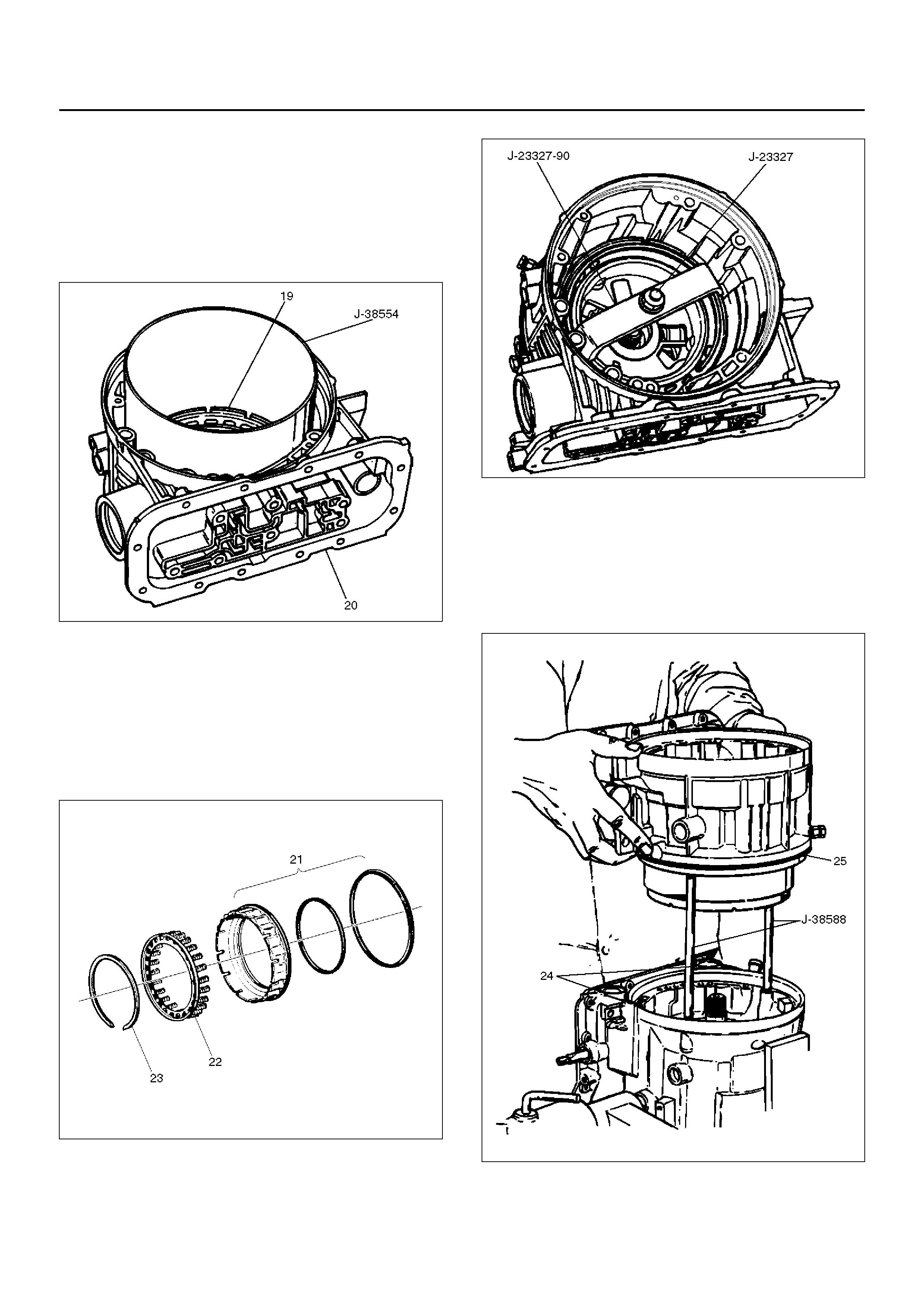
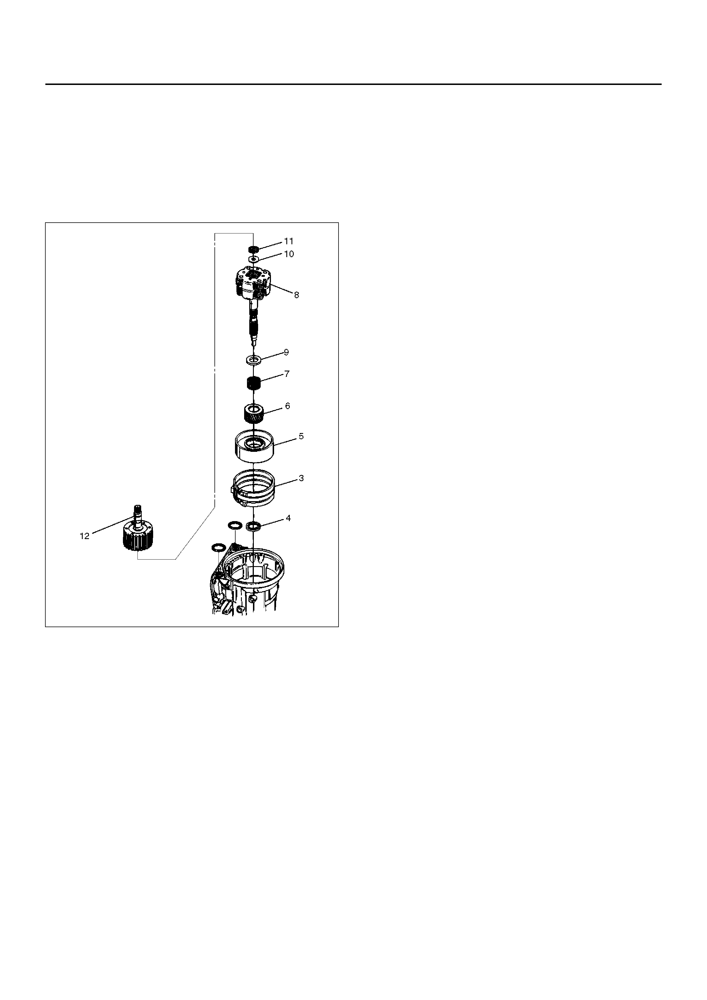
22. Inspect fourth clutch piston seals and replace if
necessary.
• Lubricate J–38554 fourth clutch piston fitter and
install it on fourth clutch piston (19).
• Install fourth clutch piston (19) in adapter case
(20).
• Remove fitter.
252RS003
23. Install retainer and spring assembly (22) into fourth
clutch piston (21).
24. Install snap ring (23) in adapter case.
• Install J–23327 and J–23327–90 fourth clutch
spring compressor.
• Seat snap ring in groove.
• Remove compressor.
252RW002
252RS004
25. Install selective washer using petroleum jelly.
26. Install two O-ring seals (24) in main case and
adapter case/main case seal ring (25).
27. Install J–38588 guide pins.
• I nstall ad apter ca se and ce nter s upp ort as s emb ly
to main case.
242RS004
28. Install thrust washer (26) into adapter case, with
tangs pointing downwards.
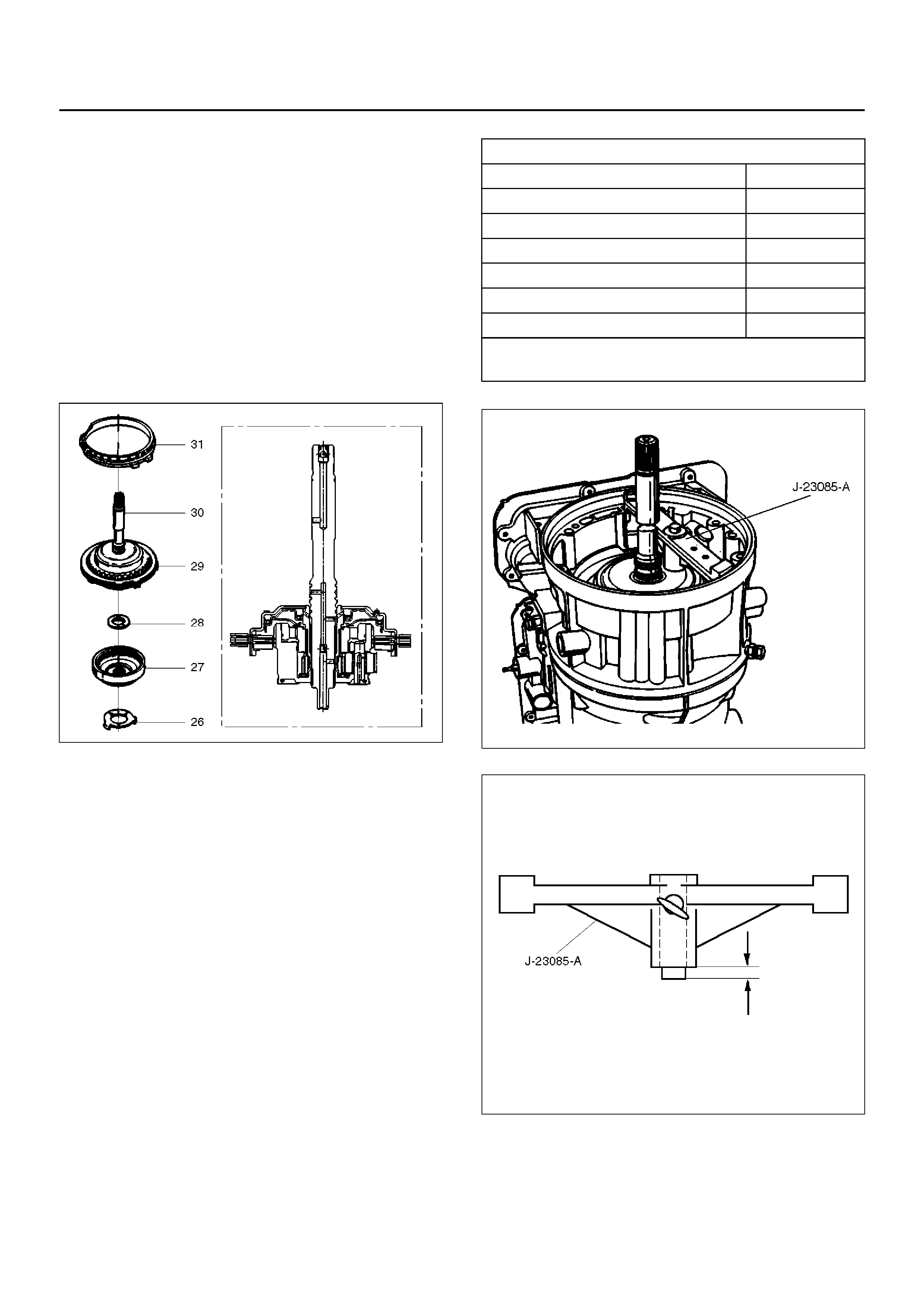
29. P reass emble o verdri ve inter nal ge ar (27) and thrus t
bearing assembly (28) onto the turbine shaft and
overrun clutch assembly.
NOTE: Install bearing assembly, black side up. Use
petroleum jelly to keep assembly in place.
30. Install overdrive carrier (30) and internal gear
assembly into adapter case.
31. Install fourth clutch plates (29) in the following order:
Steel, Lined, Steel, Steel , Lined, St eel. Steel plates
go in with short tang facing towards valve body
surface.
32. Install fourth clutch retainer(31) with the notch facing
up and positioned towards valve body surface.
252RW004
33. Overdrive clutch end play measurement
1. Install t he J–23085–A s electiv e washer gauging
tool on the adap ter case flange and again st the
input shaft.
2. Position the inner shaft of the tool against the
thrust surface of the overrun clutch housing.
3. Tighten thumb screw. Remove the tool.
4. Measure gap. Select appropriate size washer
as shown in the chart.
5. Set selective thrust washer aside.
252RS005
252RS006
34. Install selective washer (32).
NOTE: Use petroleum jelly to hold selective washer in
place.
35. Install gasket (33).
Sele ctive Thrust Washer
Gap: mm Color
1.53 – 1.63 Yellow
1.72 – 1.82 Red
1.91 – 2.01 Black
2.10 – 2.20 Natural
2.29 – 2.39 Green
2.48 – 2.58 Blue
FOLLOWING THE PROCEDURE SHOULD RESULT
IN FINAL END–PLAY FROM 0.1 mm TO 0.8 mm
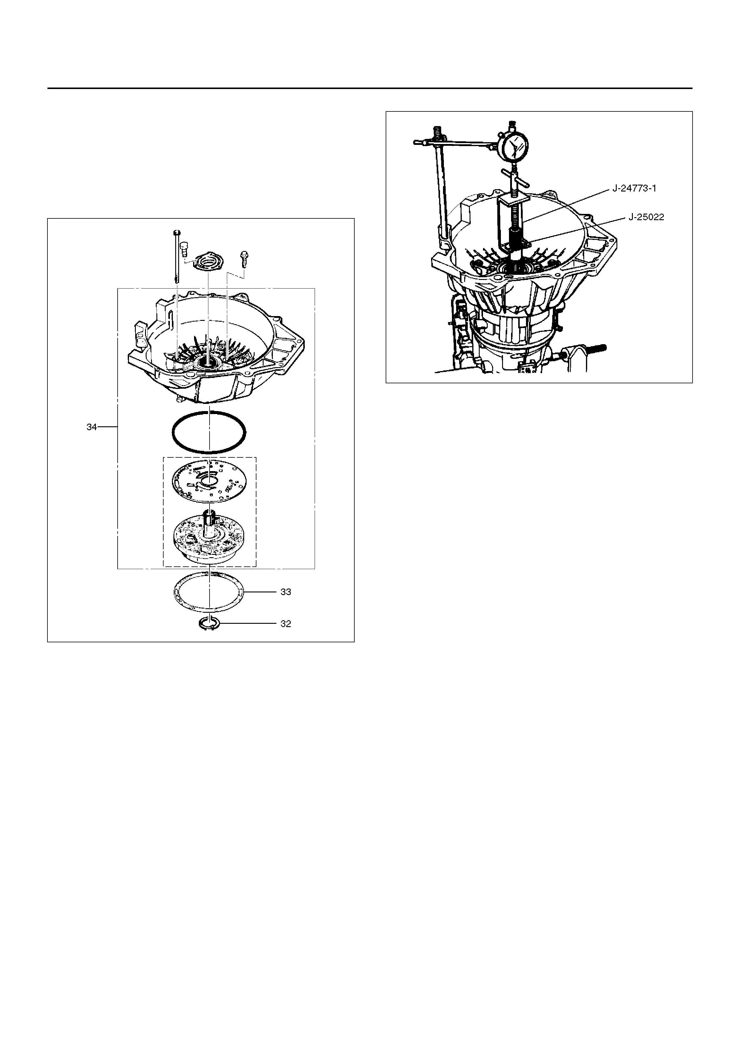
36. Install converter housing and oil pump assembly
(34) to adapter case.
• Fit and tighten seven outer 13 mm screws.
Torque: 39N•m (29lbft)
• Ensure free rotation of pump using J–23082–01
pump rotation tool.
241RW010
37. Overdrive clutch end play measurement
1. Fit J–25 022 and J–24773–1 turbin e shaft puller
on turbine shaft.
2. Position axial play checking tool on converter
housing mating face.
3. Pull turbine shaft upwards with puller until first
resistance is met. (due to weight of overdrive
assembly)
4. Maintain shaft in this position and set indicator
to zero.
5. Pull turbine shaft further upwards with puller.
Read end play shown on indicator.
End play: 0.1mm – 0.8mm Remove axial play
checking tool and puller.
NOTE: If end play is not correct, repeat selective
washer selection.
252RW001
38. Inspect extension housing oil seal and replace if
necessary, using J–36797 extension housing oil
seal installer.
• Rotate transmission to horizontal position, with
valve body side down.
• Inspect parking wheel seal ring. Replace if
necessary.
• Install wheel parking lock assembly (35).
39. Install speed wheel (36) and snap ring (37).
NOTE: Use extra long, needle nose pliers.
40. Install gasket onto extension assembly with a thin
coating of oil.
• Install extension housing assembly (38), and
align parking pawl shaft.
• Install actuator assembly into extension
assembly.
• Install seven 8 mm hexagon socket head screws.
Torque: 32N•m
Inspect speed sensor O-ring. Replace if necessary.
• Install speed sensor assembly (39) and 10 mm
screw.
Torque: 9N•m (78lbin)
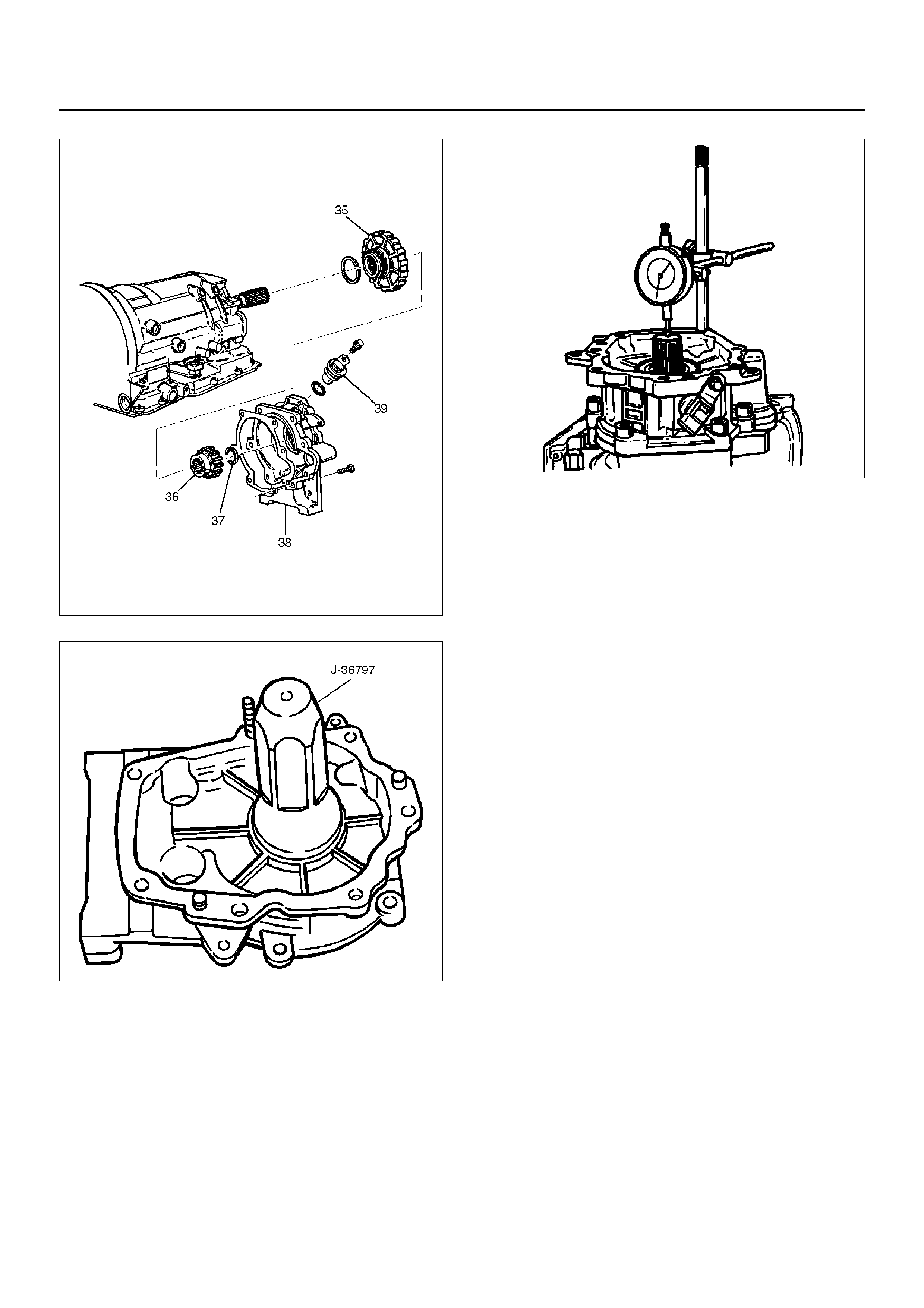
241RW009
241RS004
41. Main case end play measurement
1. Attach axi al play c hecking t ool on th e extens ion
housing and set indicator to zero on output
shaft.
2. Manually push output shaft upwards.
End play: 0.36mm – 0.80mm
Remove axial play checking tool.
3. If end play is not correct, repeat selective
washer selection.
241RS005
42. Inspect servo piston seal ring. Replace if
necessary.
• Ensure brake band is correctly positioned.
Rotate output shaft if necessary.
• Install J–38428 servo piston fitter in servo bore.
• Install apply rod (40), round end toward band,
return spring (41) and piston assembly (42).
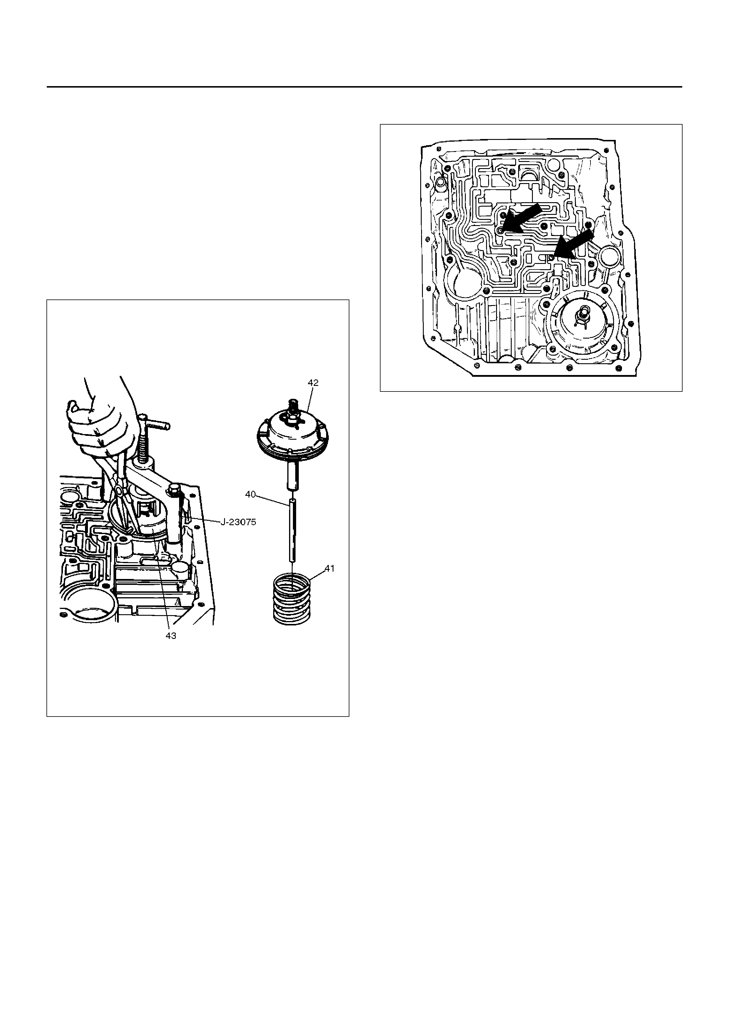
43. Install the J–23075 servo spring compressor with
offset to rear of case.
• Compress servo piston seal ring, using fitter while
tightening the tool screw.
• Install servo piston retaining ring (43).
• Remove tool.
• Adjust the brake band by tightening the servo
adjusting screw to 4.5 N·m (39.8lbin) torque. Be
certain the lock nut is loose, then back-off the
screw five turns exactly. Hold piston sleeve with
wrench and tighten lock nut to 18.5 N·m torque.
Be certain the adjusting screw does not turn.
242RW004
44. Install two check balls (44).
244RW002
45. Inspect main case electrical connector and seal,
replace if necessary.
• Install electrical 7 way connector/main case and
wiring harness.
46. Install two J–25025–B guide pins into main case.
• Install main case valve body complete assembly
(45) and manual valve link.
NOTE: Valve must be extended as the short end of
manual valve link is connected to the range selector
lever. Long end of link goes into valve.
• I nstall seve n 13 mm screw s, tighte n the spec ified
torque.
Torque: 20N•m
• Remove two guide pins.
47. Install servo cover gasket, cover (46) and four 13
mm screws.
Torque: 25N•m
48. Connect wiring harness (47) to band control, shift
solenoids, and main case 7 way connector.
49. Install manual detent roller and spring assembly
(48) with clip.
• Install two 13 mm screws.
Torque: 20N•m
50. Install oil filter (49) and three 13 mm screws.
Torque: 20N•m
51. Install oil pan gasket, magnet, main oil pan (50),
sixteen 10 mm screws.
Torque: 11N•m
52. Inspect adapter case electrical connector and seal.
Replace if necessary.
• Install electrical 4 way connector and harness
assembly (52) in bottom of adapter case.

53. Install gasket, transfer plate, and gasket.
• Install adapter case valve body (51) complete
and seven 13 mm screws.
Torque: 20N•m
54. Connect wiring harness harness assembly (52) to
Converter Clutch Solenoid, Pressure Control
Solenoid, and 4 way connector.
55. Install oil pan gasket, adapter case oil pan (53), and
twelve 10 mm screws.
Torque: 11N•m
• Rotate transmission, with bottom pan facing
down.
56. Install mode switch (54), two 10 mm screws,
selector lever nut, and cover.
10 mm screw
Torque: 13N•m
Nut
Torque: 23N•m
• Adjust using setting tool, refer to Mode Switch in
this secti on .
57. Install O-ring (55) on turbine shaft.
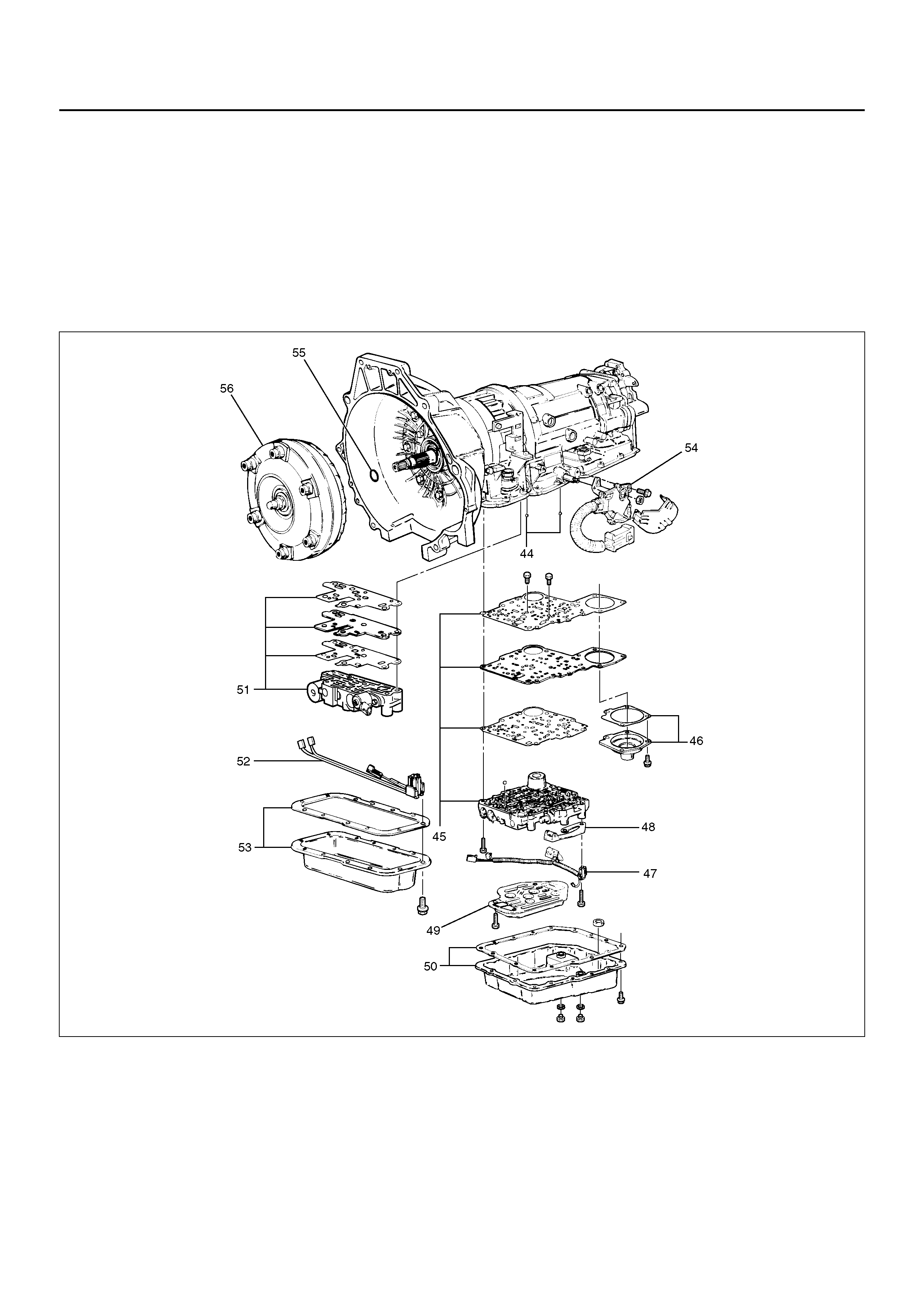
58. Install torque converter (56).
The converter assembly must be replaced under
any of the following conditions:
a Evidence of damage to the pump assembly.
b Metal particles are found after flushing the
cooler lines.
c External leaks in hub weld area.
d Converter pilot broken, damaged, or poor fit into
crankshaft.
e Converter hub scored or damaged.
f Internal failure in stator.
g Contamination from engine coolant.
h Excess end play.
• Rotate transmission, bell housing up. Spin
converter to insure proper fit.
59. Fill transmission through the overfill screw hole of oil
pan, using ATF DEXRON®-III. Refer to Changing
Transmission Fluid in this section.
240RY002
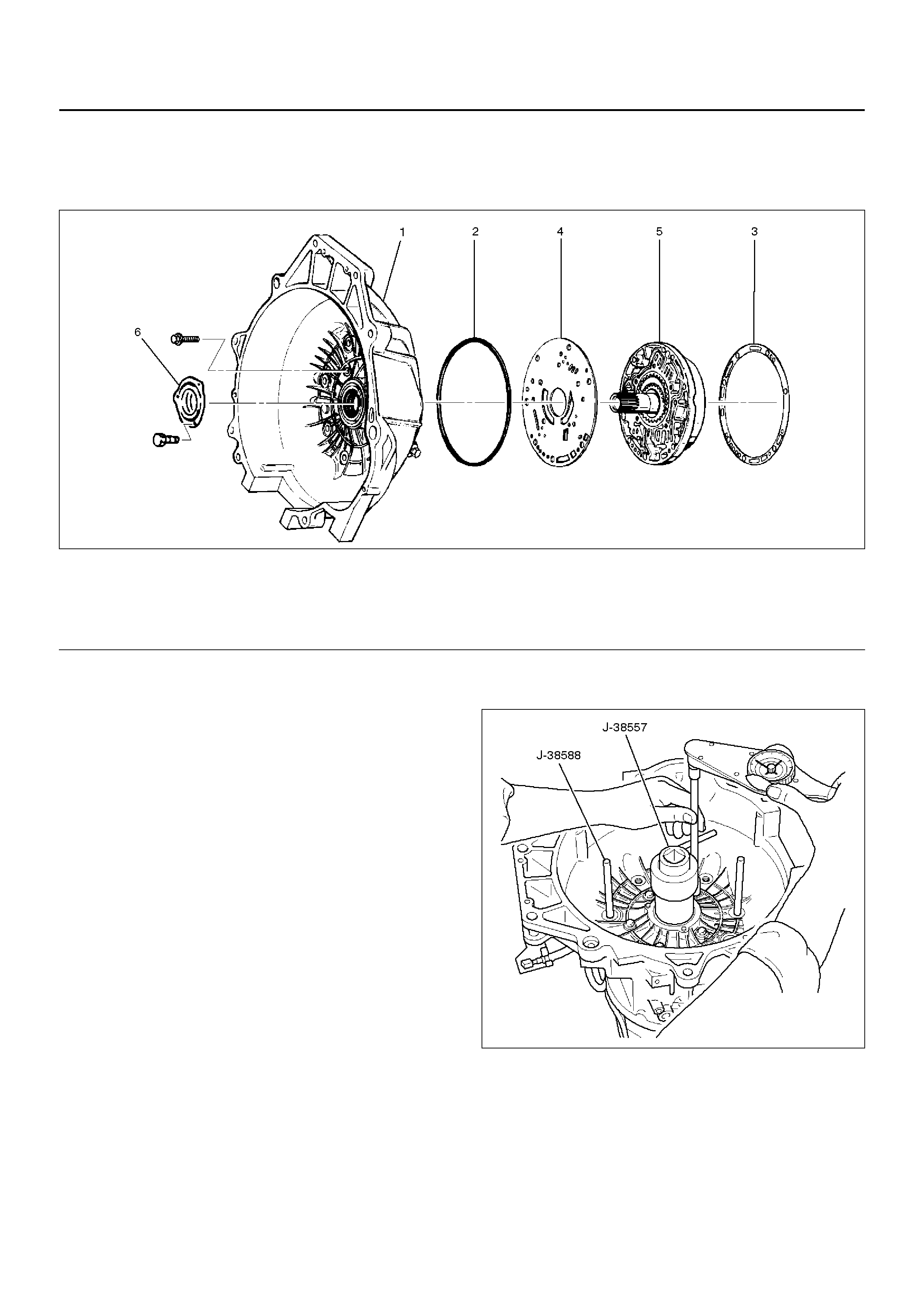
CONVERTER HOUSING AND OIL PUMP ASSEMBLY
DISASSEMBLED VIEW
241RW003
EndOFCallout
DISASSEMBLY
1. Remove oil pump assembly from converter housing.
2. Remove outer seal ring.
3. Remove gasket.
4. Remove wear plate.
5. Remove oil seal ring.
INSPECTION AND REPAIR
Visual Check:
If any damage, deformation, or local wear is found in a
converter housing, outer seal ring, wear plate, or oil seal
ring, replace it.
REASSEMBLY
1. Install wear plate onto oil pump assembly.
2. Install converter housing onto complete oil pump
assembly. Align with two short J–38588 guide pins
on outer bolt holes.
• Loosely install five 13mm bolts.
• Center converter housing using J–38557
centering tool.
• Tighten five inner 13mm bolts in an alternating
pattern.
Torque: 20N•m
241RW002
3. Install oil seal ring (3 screws).
Torque: 3N•m
4. Install gasket.
5. Install outer seal ring.
Legend
(1) Converter Housing
(2) Outer Seal Ring
(3) Gasket
(4) Wear Plate
(5) Oil Pump Assembly
(6) Oil Seal Ring
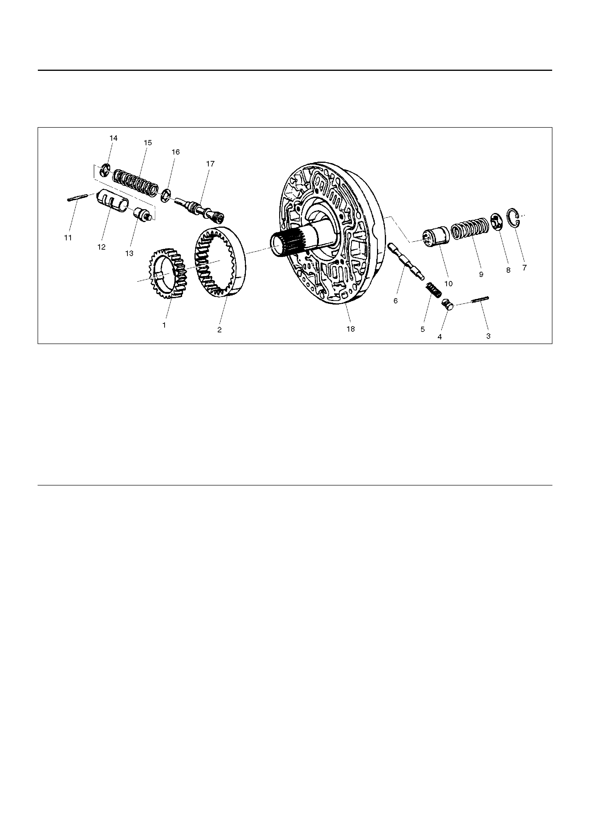
OIL PUMP
DISASSEMBLED VIEW
241RS014
EndOFCallout
DISASSEMBLY
1. Remove oil pump drive gear (1) and driven gear (2).
2. Remove pin (3) from oil pump assembly (18).
3. Remove plug (4), spring (5), and converter clutch
control valve (6).
4. Remove snap ring (7) from oil pump assembly (18).
5. Remove spring seat (8), spring (9), and throttle
signal accumulator piston (10).
6. Remove sleeve pin (11) from oil pump assembly
(18).
7. Remove sleeve (12), boost valve (13), spring seat
(14), valve spring (15), spring seat (16), and
pressure regulator valve (17).
INSPECTION AND REPAIR
Visual Check:
If any damage, deformation or wear is found, replace
the damaged part.
REASSEMBLY
1. Lubricate and preinstall pressure regulator spring
seat (16) on valve (17), with the flat side against
shoulder.
2. In stall pressure re gulator valv e (17) and spring seat
(16) assembly, valve spring (15), and spring seat
(14) with the flat side away from spring to oil pump
assembly (18).
3. Assemble boost valve (13) into sleeve (12).
4. In stall bo os t v alve an d s le ev e a ssem bl y, and s lee ve
pin (11) to oil pump assembly (18).
5. In stall thr ottle signa l accum ula tor pis ton (10 ), spr ing
(9), and s pring s eat ( 8), with t he flat side away from
the spring, and snap ring (7) to oil pump assembly
(18).
6. Install converter clutch control valve (6), spring (5),
plug (4), and pin (3) to oil pump assembly (18).
7. Install oil pump driven gear (2) and drive gear (1).
Legend
(1) Oil Pump Drive Gear
(2) Oil Pump Driven Gear
(3) Pin
(4) Plug
(5) Spring
(6) Converter Clutch Control Valve
(7) Snap Ring
(8) Spring Seat
(9) Spring
(10) Throttle Signal Accumulator Piston
(11) Sleeve Pin
(12) Sleeve
(13) Boost Valve
(14) Spring Seat
(15) Valve Spring
(16) Spring Seat
(17) Pressure Regulator valve
(18) Oil Pump Assembly
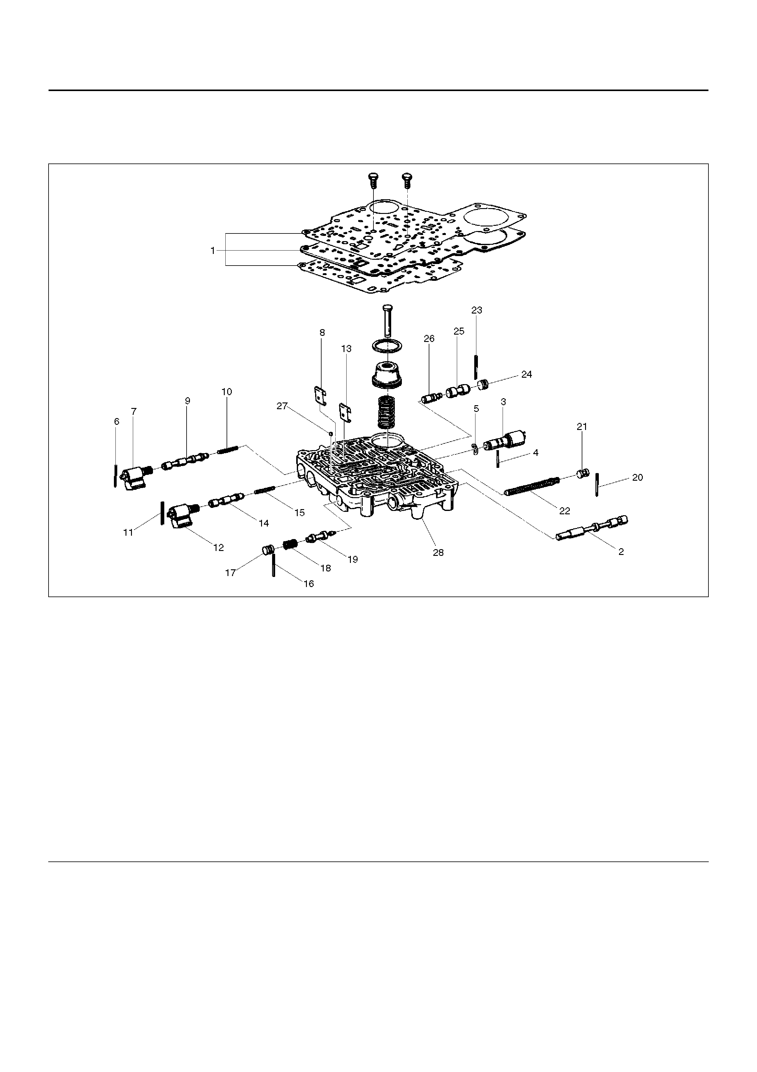
MAIN CASE VALVE BODY
DISASSEMBLED VIEW
244RS010
EndOFCallout
DISASSEMBLY
1. R emo ve two 11m m bolts from v alve b ody (28) , then
remove gaskets and transfer plate (1).
2. Remove manual valve (2).
3. Push in band control solenoid (3) to compress
waved washer (5), and remove pin (4).
4. Remove band control solenoid (3) and waved
washer (5).
5. Remove spring pin (6) with a 3 mm diameter punch.
6. Remove solenoid A (7) by grasping the metal tip. Do
not grasp the connector housing.
7. Remove retainer (8), 1–2/3–4 shift valve (9) and
spring (10).
Legend
(1) Gaskets and Transfer Plate
(2) Manual Valve
(3) Band Control Solenoid
(4) Pin
(5) Waved Washer
(6) Spring Pin
(7) Solenoid A
(8) Retainer
(9) 1–2/3–4 Shift Valve
(10) Spring
(11) Spring Pin
(12) Solenoid B
(13) Retainer
(14) 2–3 Shift Valve
(15) Spring
(16) Spring Pin
(17) Plug
(18) Spring
(19) Low Pressure Control Valve
(20) Spring Pin
(21) Plug
(22) Band Control Screen Assembly
(23) Spring Pin
(24) Plug
(25) 1–2 Accumulator Valve
(26) 1–2 Accumulator Control Valve
(27) Check ball
(28) Main Case Valve Body
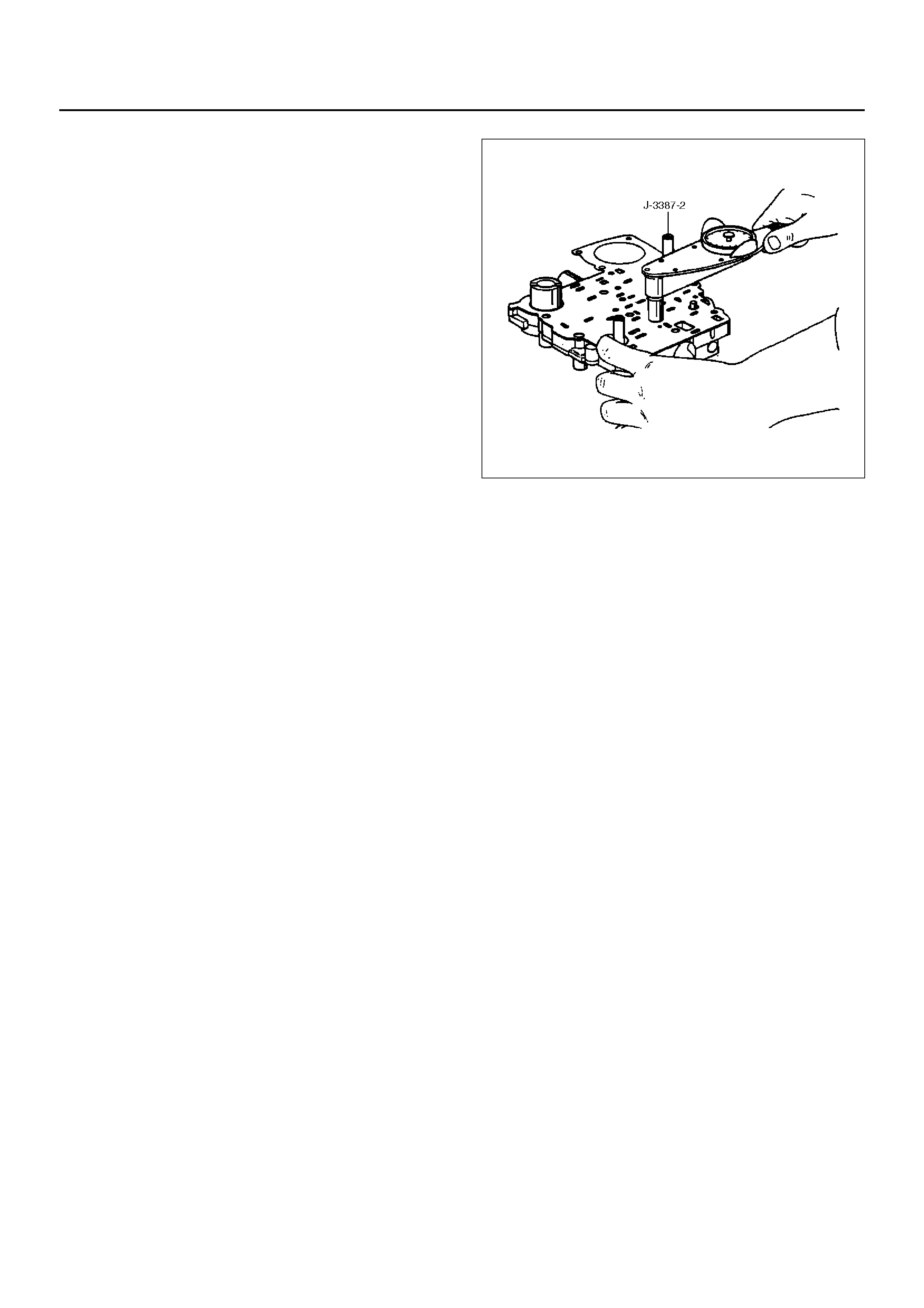
8. Remove spring pin (11) with a 3 mm diameter
punch.
9. Remove solenoid B (12) by grasping the metal tip.
Do not grasp the connector housing.
10. Remove retainer (13), 2–3 shift valve (14), and
spring (15).
11. Remove spring pin (16), plug (17), spring (18) and
low pressure control valve (19).
12. Remove spring pin (20), plug (21), and band control
screen assembly (22).
13. Remove spring pin (23), plug (24), 1–2 accumulator
valve (25), and 1–2 accumulator control valve (26).
14. Remove 1 check ball (27) from valve body (28).
INSPECTION AND REPAIR
Inspect for the following, and replace any damaged or
worn parts:
1. Damage or wear to each valve.
2. Damage in oil passeges.
3. Cracks or damage to valve body.
4. Valve operations.
5. Spring fatigue.
REASSEMBLY
1. Install 1–2 accumulator control valve (26), 1–2
accumulator valve (25), plug (24), and spring pin
(23).
2. Install band control screen assembly (22), plug (21),
and spring pin (20).
3. Install low pressure control valve (19), spring (18),
plug (17), and spring pin (16).
4. I ns tall spri ng (15) , 2–3 shift va lv e ( 14), r etainer (1 3),
solenoid B (12), and spring pin (11).
5. Install spring (10), 1–2/3–4 shift valve (9), retainer
(8), solenoid A (7), and spring pin (6).
6. I nstall waved washer (5), band co ntrol solenoid (3),
and pin (4).
7. Install manual valve (2).
8. Install check ball (27) to valve body (28).
9. Install gasket (valve body/transfer plate) and
transfer plate using two J–3387–2 guide pins.
• Install two 11mm bolts.
Torque: 13N•m
244RS004
• Install gasket (transfer plate/main case).
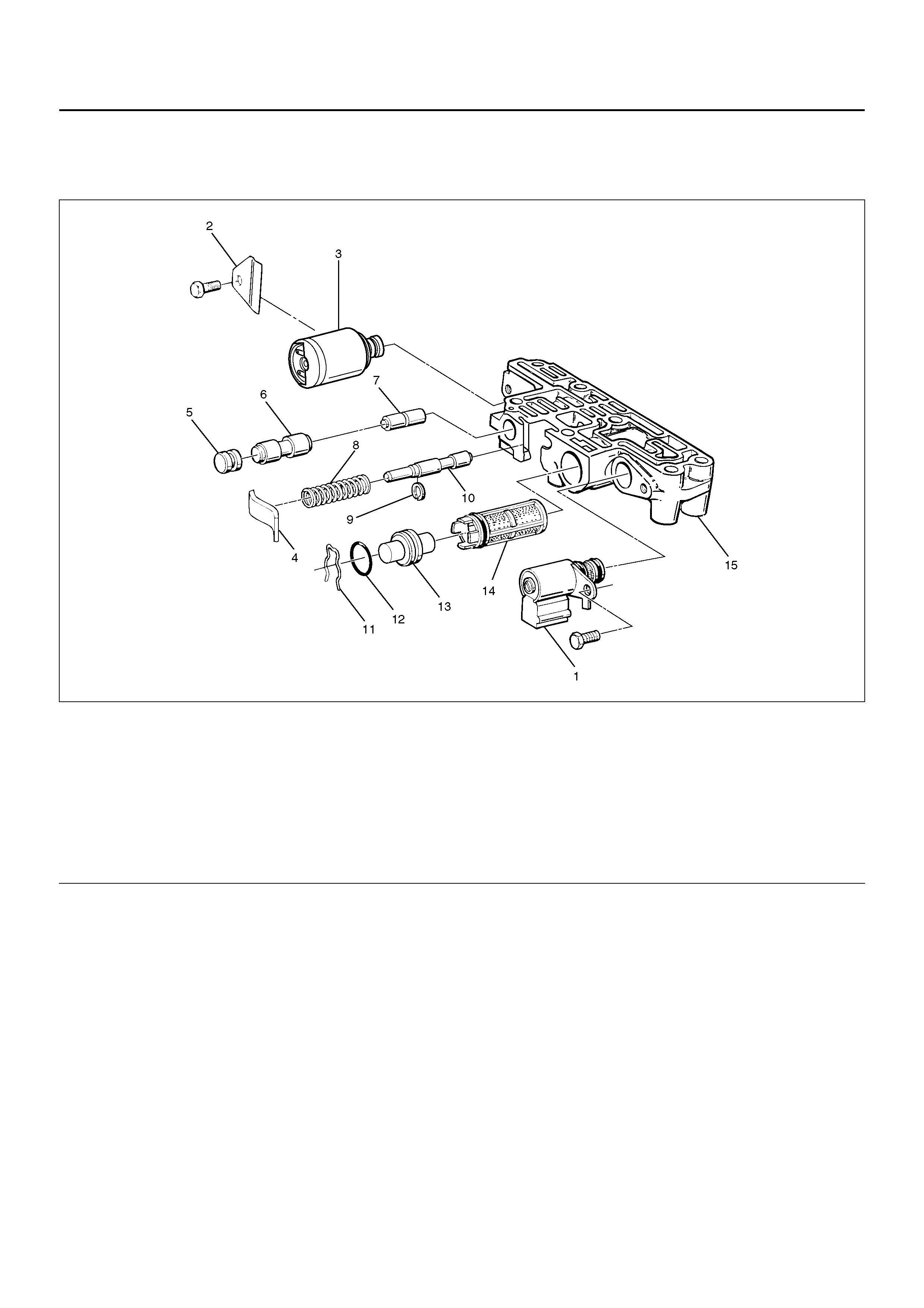
ADAPTER CASE VALVE BODY
DISASSEMBLED VIEW
243R100001
EndOFCallout
DISASSEMBLY
1. Remove 11mm bolt from valve body.
• Remove converter control solenoid assembly
(1).
2. Remove 11mm bolt and retainer (2) from valve
body.
• Remove Pressure Control Solenoid (3).
3. Remove retainer (4), plug (5), 3/4 accumulator valve
(6), and 3/4 accumulator control valve (7)
4. Remove spring (8), retaining ring (9), and feed limit
valve (10).
5. Remove plug retainer (11), O-ring (12), plug (13),
and Pressure Control Solenoid screen assembly
(14).
• Use 5 mm bolt to pull plug.
INSPECTION AND REPAIR
Inspect for the following, and replace any damaged or
worn parts:
1. Damage or wear to each valve.
2. Damage in oil passeges.
3. Cracks or damage to valve body.
4. Valve operations.
5. Spring fatigue.
Legend
(1) Converter Clutch Solenoid Assembly
(2) Retainer
(3) Pr ess ure Control Sol eno id
(4) Retainer
(5) Plug
(6) 3/4 Accumulator Valve
(7) 3/4 Accumulator Control Valve
(8) Spring
(9) Retaining Ring
(10) Feed Iimit Valve
(11) Plug Retainer
(12) O-ring
(13) Plug
(14) Pressure Control Solenoid Screen Assembly
(15) Adapter Case Valve Body

REASSEMBLY
1. Install Pressure Control Solenoid screen assembly
(14), plug (13), O-ring (12), and plug retainer (11).
2. Install feed limit valve (10), retaining ring (9), and
spring (8).
3. Install 3/4 accumulator control valve (7), 3/4
accumulator valve (6), plug (5), and retainer (4).
4. Install Pressure Control Solenoid (3).
• Pl ace solenoi d termin als pointing towards matin g
face.
• Install retainer (2) and bolt.
Torque: 10N•m
5. Install converter clutch solenoid assembly with two
O-rings (1) to valve body.
• Install bolt.
Torque: 10N•m
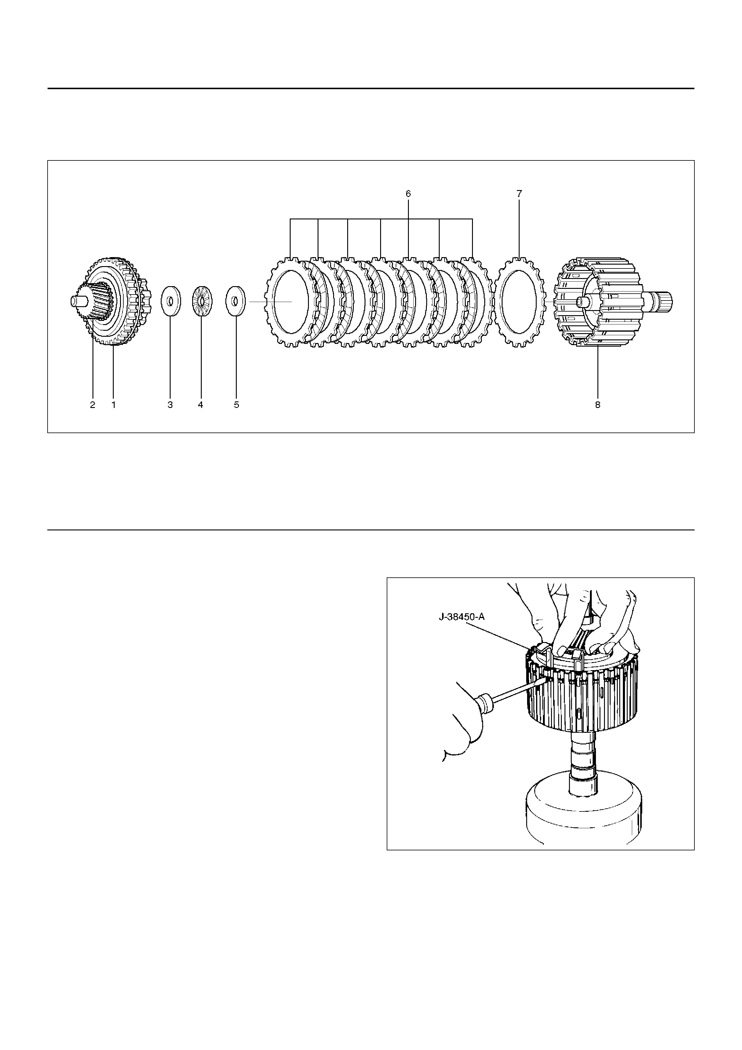
THIRD CLUTCH AND SPRAG UNIT
DISASSEMBLED VIEW
248RW001
EndOFCallout
DISASSEMBLY
1. Place the third clutch drum and intermediate shaft
assembly upright, using the overdrive internal gear
as a support.
2. Locate the ends of the retaining ring. Depress one
end of the ring u sing a small screwdriver instead of
the depressor handle provided with the tool
J-384 50-A. Slide one bl ade down between t he third
clutch drum and the retaining ring.
3. Remove a screwdriver and repeat this step for the
other end of retaining ring.
4. Install the remaining four blades approximately
(five) notches apart using a screwdriver to depress
the retaining ring.
5. Pull up on input sun gear and sprag unit assembly
(1 and 2) to release the retaining ring from third
clutch drum assembly (8).
6. Remove the tool blade s. 248RX001
7. Remove retaining washer (3), bearing (4), thrust
washer (5), and clutch plates (6 and 7) from the third
clutch drum assembly (8).
Legend
(1) Retaining Ring
(2) Input Sun Gear and Sprag Unit Assembly
(3) Retaining Washer
(4) Bearing
(5) Thrust Washer
(6) Clutch Plates
(7) Third Clutch Spring Cushion Plate
(8) Third Clutch Drum Assembly
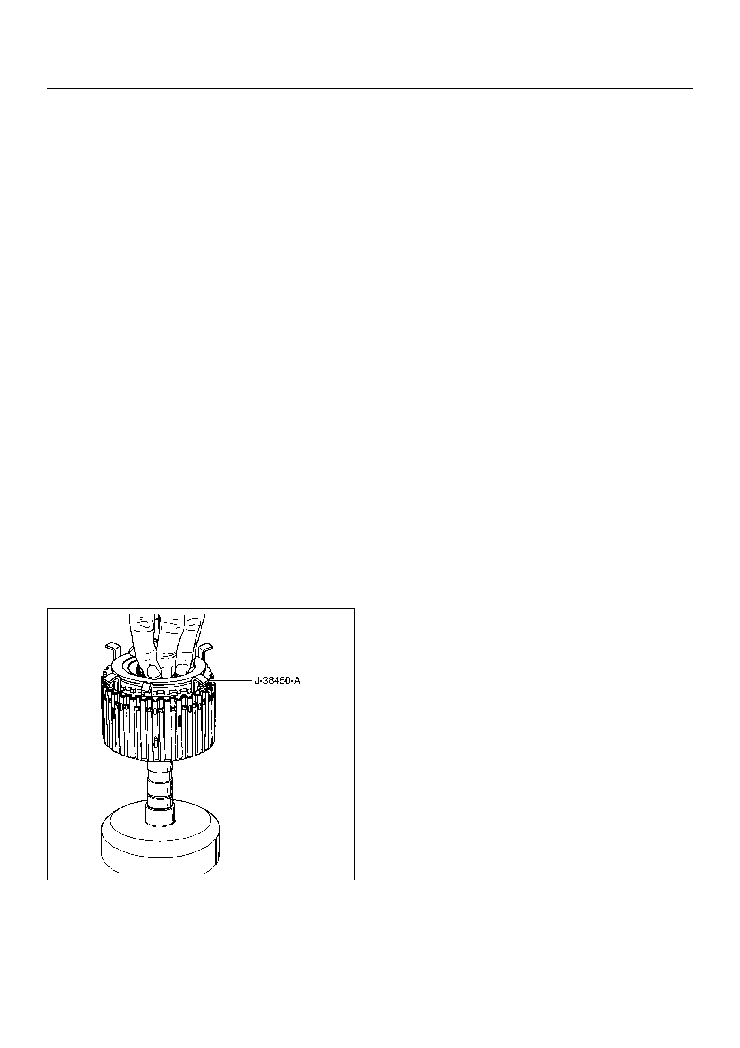
INSPECTION AND REPAIR
Visual Check:
If any damage, deformation or wear is found, replace
the damaged part.
REASSEMBLY
1. Place third clutch drum and intermediate shaft
assembly upright, using the overdrive internal gear
as a support.
2. Install third clutch spring cushion plate (7), bevel
face down.
3. Install third clutch plates (6) into third clutch drum
assembly (8). Start with the steel clutch plate and
alternate with lined plates.
4. Install thrust washer (5), bearing (4) and retaining
washer (3).
5. Fully engage the hub spline of the input sun gear
and sprag unit assembly (2) into the third clutch
inner tangs.
• Simultaneously rotate the outer sprag race to
engage into the third clutch drum assembly (8).
6. Place J-38450-A blades between the retaining ring
and the third clutch drum apporximately (five)
notches apart, and one blade at each end of the
retaining ring (1). Push down on sprag assembly
until the assembly is seated into the third clutch
drum assembly (8).
7. Remove the tool blades and engage retaining ring
into groove of third clutch drum.
248RX002
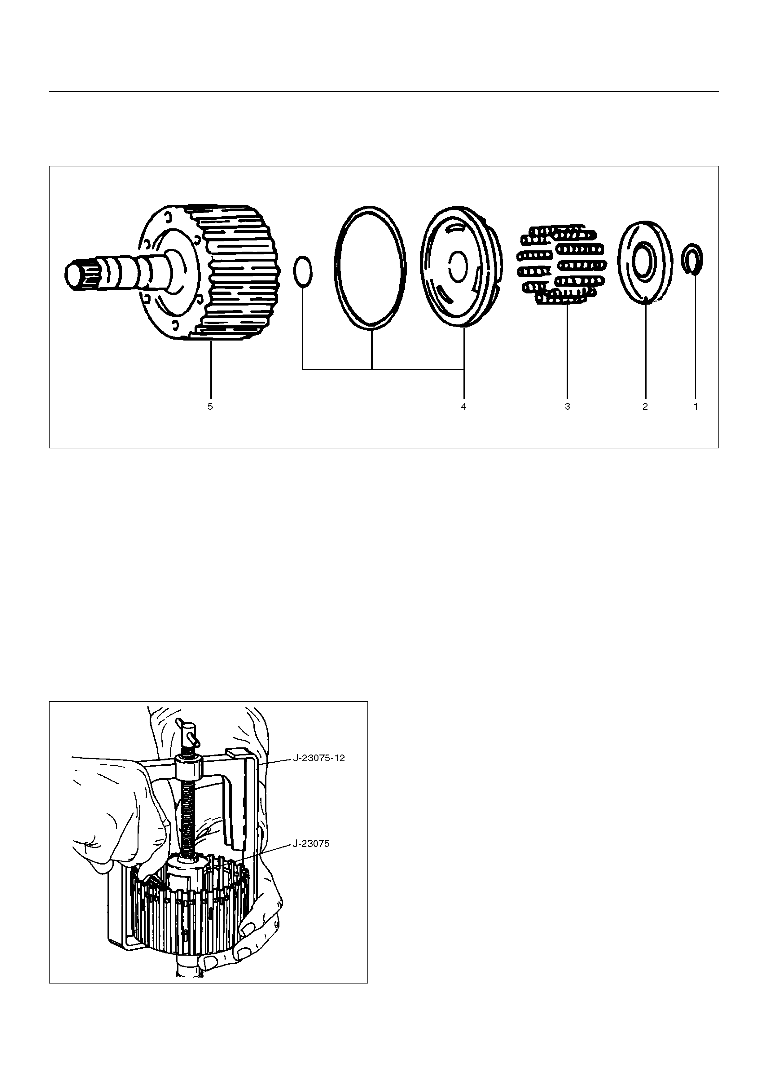
THIRD CLUTCH
DISASSEMBLED VIEW
248RS006
EndOFCallout
DISASSEMBLY
1. Compress spring seat using the J–23075 spring
compressor and J–23075–12 adapter tool.
NOTE: Do not overstress the springs and seat. This will
cause damage to the spring seat.
• Remove the tool.
• Remove retaining ring (1).
248RS007
2. Release the spring seat (2).
NOTE: Do not let the spring seat catch in the ring
groove.
• Remove spring seat (2) and springs (3).
3. Remove piston assembly (4) from third clutch drum
(5).
INSPECTION AND REPAIR
Visual check:
If any damage, deformation or wear is found, replace
the damaged part.
Operation check:
Shake the piston and listen for check ball movement.
Movement indicates proper check ball operation.
Replace the piston if the check ball is missing or falls
out.
Legend
(1) Retaining Ring
(2) Spring Seat
(3) Springs
(4) Piston As se mb ly
(5) Third Clutch Drum
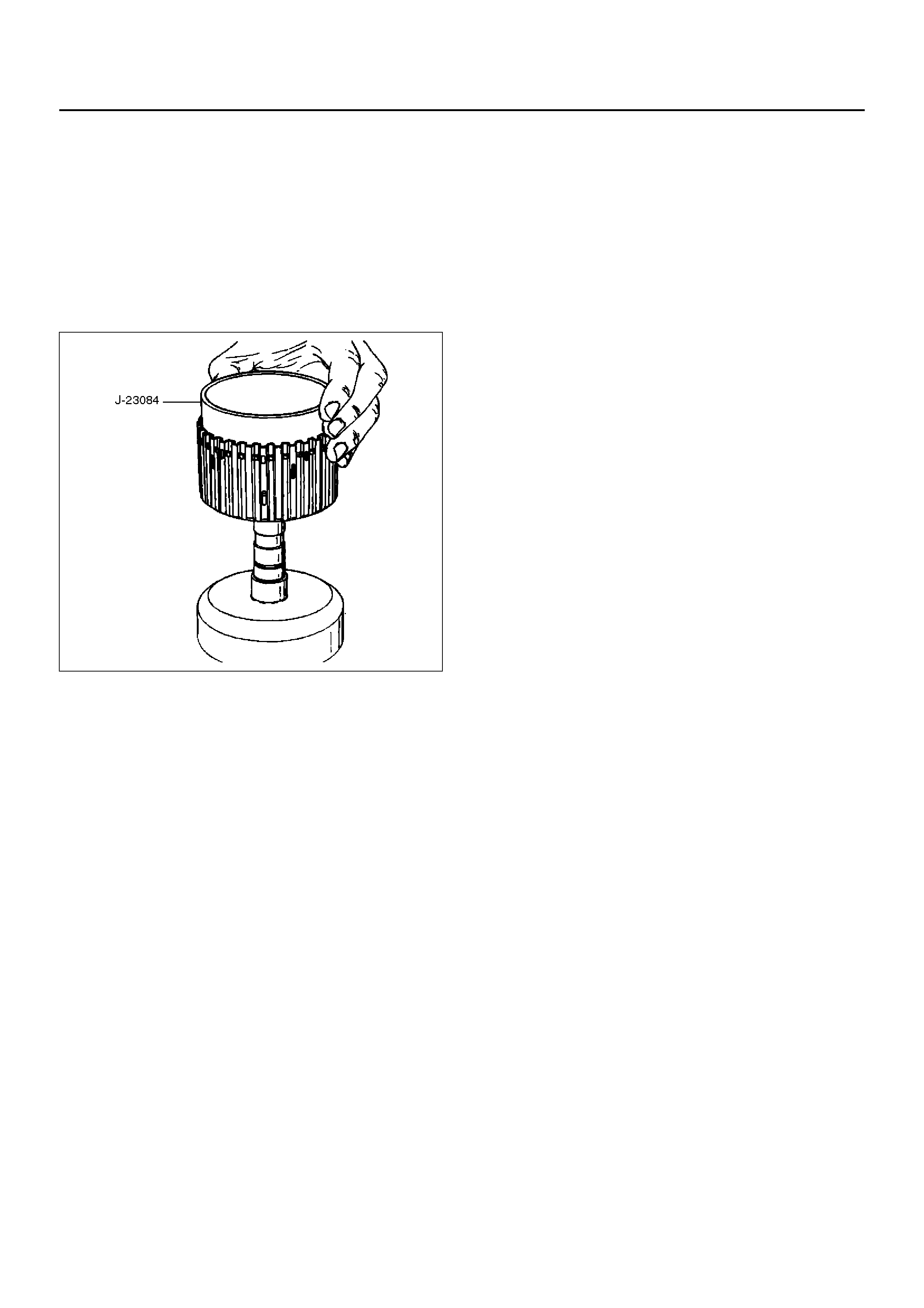
REASSEMBLY
1. The lip of the piston seal must point toward the front
of the transmission. Lubricate the seal lip with
transmission fluid.
• Install piston assembly (4) into the third clutch
drum (5). Use the J–23084 third clutch piston
installer to protect the outer seal during
installation.
• Remove the seal installer.
248RS008
2. Install twelve springs (3) and spring seat (2).
3. Place retaining ring (1) onto spring seat.
• Compress the piston springs, using the J–23075
piston spring compressor and J–23075–12
adapter.
CAUTION: Do not overstress the springs and seat.
Do not let the spring seat catch in the ring groove.
This may cause damage to the spring seat.
• Install spring seat retaining ring (1).
• Remove the piston spring compressor and
adapter.
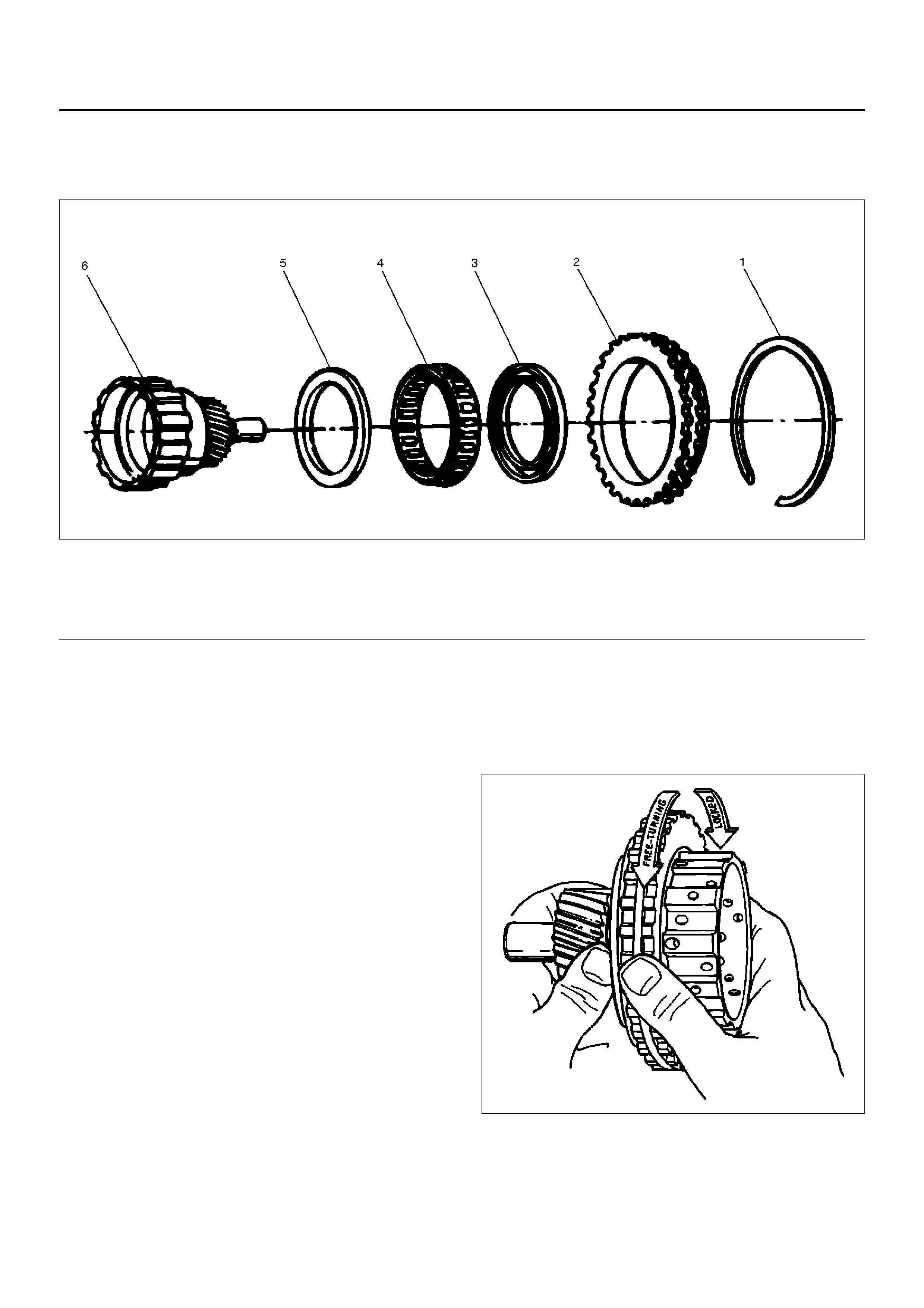
SPRAG UNIT
DISASSEMBLED VIEW
248RS009
EndOFCallout
DISASSEMBLY
1. Remove the sprag outer race, retaining ring, and
sprag assembly from the third clutch hub and sun
gear assembly.
2. Remove the rings and sprag assembly from the
sprag outer race.
INSPECTION AND REPAIR
Visual Check:
If any damage, deformation or local wear is found,
replace the damaged part.
REASSEMBLY
NOTE: Flared shoulder of the sprag cage faces the sun
gear. This procedure must be followed exactly to be
sure that the sprag assembly is installed properly.
1. Install rings and sprag assembly onto the third
clutch hub and sun gear.
2. I nstall sprag ou ter race and retaini ng ring assemb ly
over the sprag cage assembly.
• Pl ace thir d clutch hub and su n gear ass embly o n
a flat surface, sun gear facing up. Place sprag
outer race an d sprag asse mbl y ov er the sun gear
assembly, push down and turn the input sun
counterclockwise at the same time.
NOTE: Check correct rotation by holding the sun gear
in your left hand and turning the outer race. The outer
sprag race should turn freely towards you and should
lock turning away from you.
248RS010
Legend
(1) Retaining Ring
(2) Spr ag Ou ter Race
(3) Ring
(4) Sprag Assembly
(5) Ring
(6) Third Clutch Hub and Sun Gear Assembly
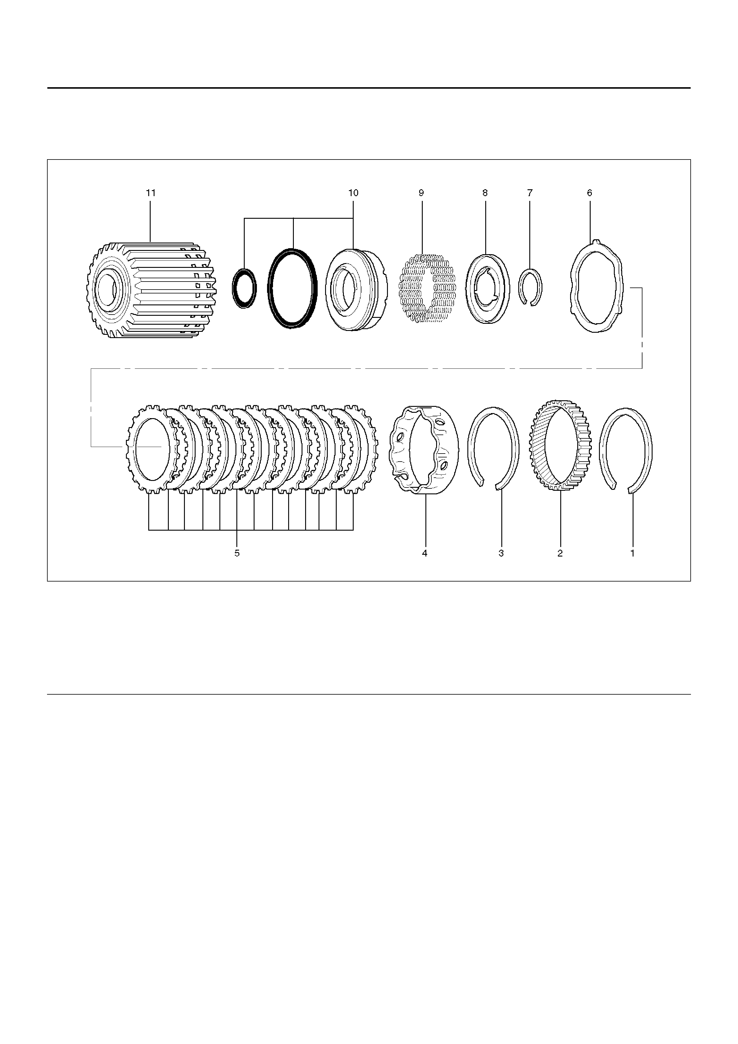
SECOND CLUTCH
DISASSEMBLED VIEW
247RW001
EndOFCallout
DISASSEMBLY
1. Remove retaining ring (1) from second clutch drum
(11).
2. R emo ve ring gear (2), retaining rin g (3), and s pacer
(4).
3. Remove clutch plates (5) and waved washer (6).
4. Remove retaining ring (7) using J–23327
compre ssor to compress the spring seat (8).
Legend
(1) Retaining Ring
(2) Ri ng Ge ar
(3) Retaining Ring
(4) Spacer
(5) Clutch Plates
(6) Waved Washer
(7) Retaining Ring
(8) Spring Seat
(9) Springs
(10) Piston Assembly
(11) Sec ond Clu tch Drum
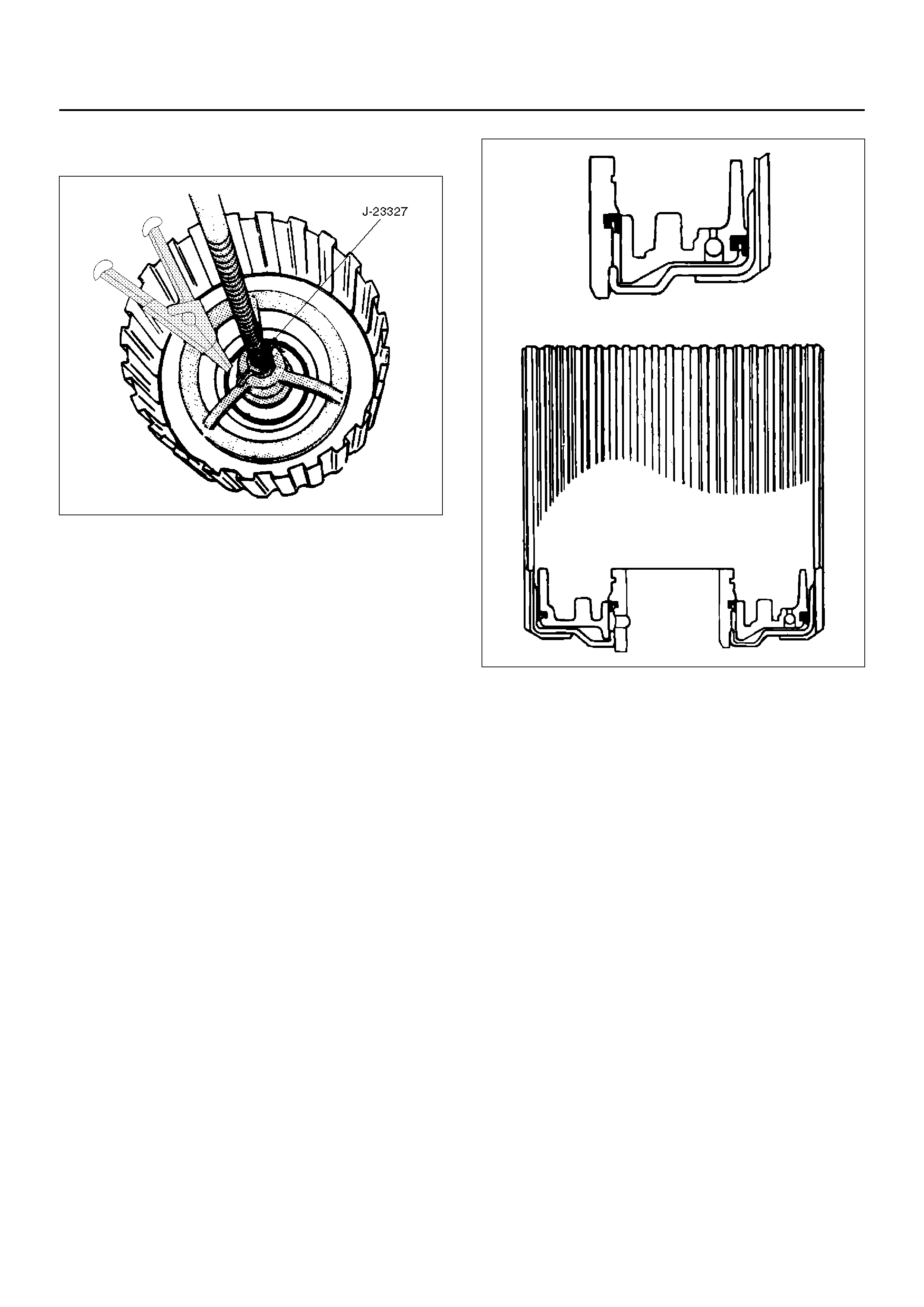
5. Remove spring seat (8), springs (9) and piston
assembly (10) from second clutch drum (11).
247RS006
INSPECTION AND REPAIR
Visual Check:
If any damage, deformation or wear is found, replace
the damaged part.
Operation Check:
Shake the piston and listen for check ball movement.
Movement indicates proper check ball operation.
Replace the piston if the check ball is missing or falls
out.
REASSEMBLY
1. Install piston assembly (10) into the second clutch
drum (11).
• Lubricate the lip seal with transmission fluid.
Use the J–23080–A second clutch piston installer
to protect the outer piston lip seal.
NOTE: Lip of the seal should point toward front of
transmission.
• Remove the installer.
247RS007
2. In stall twenty -two piston s prings ( 9) and spr ing seat
(8) on the second clutch piston (10). Place retaining
ring (7) onto spring seat.
• Use the J–23327 compressor to compress the
piston springs.
NOTE: Do not let spring seat catch in ring groove.
• Remove the compressor.
3. Install waved plate (6) and clutch plates (5). Start
with a steel plate and alternate with lined plates.
• Align second clutch inner tangs.
4. Install spacer (4), with the fluted end toward clutch
plates.
5. Install retaining ring (3), ring gear (2) and retaining
ring (1).
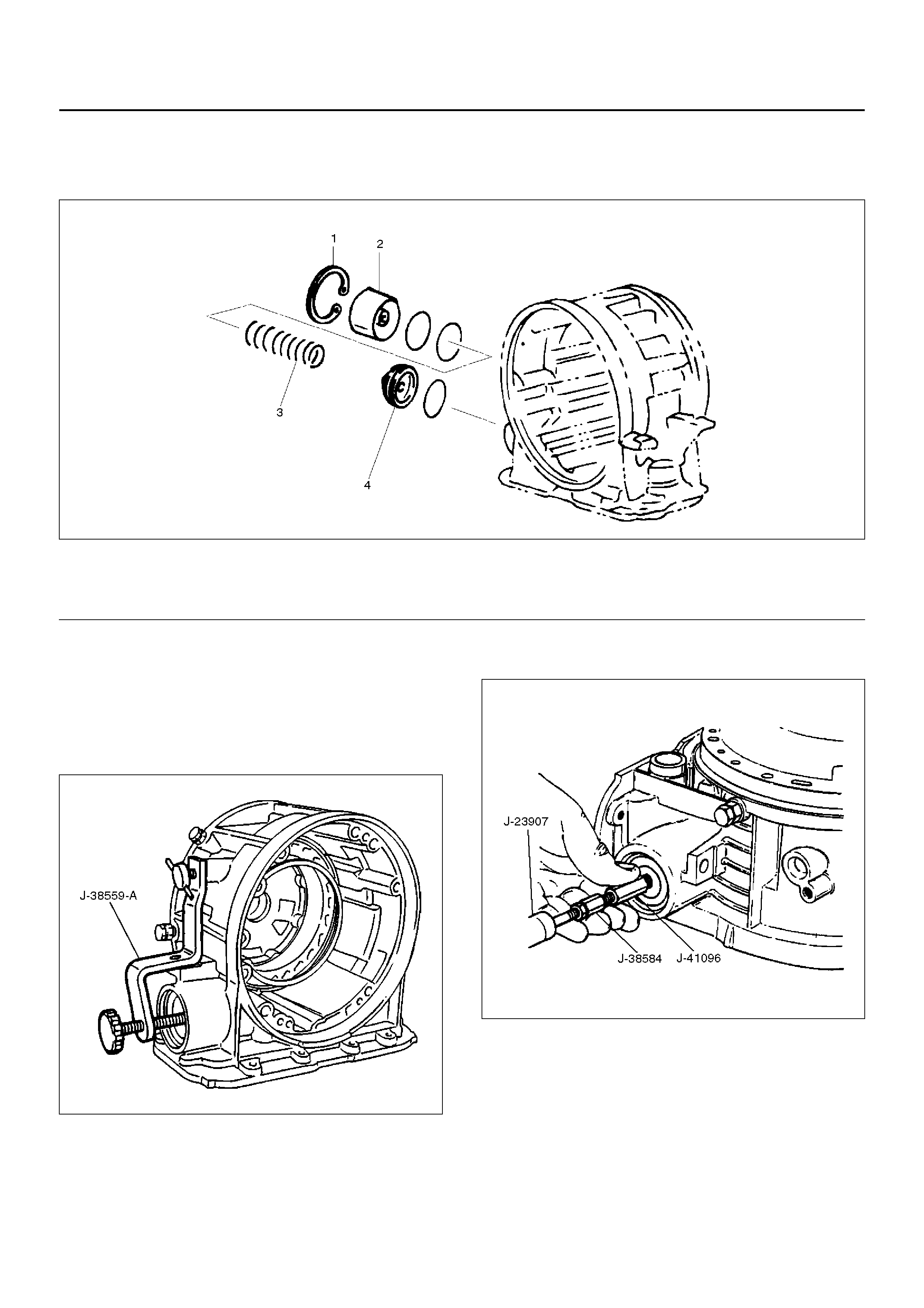
3–4 ACCUMULATOR PISTON
DISASSEMBLED VIEW
244RS005
EndOFCallout
DISASSEMBLY
1. Install the J–38559–A cover compressor on adapter
case.
• Compress piston cover then remove snap ring.
242RS007
2. Install the J–41096 cover remover and J–38584
adapter to center hole of cover.
• Use the J–23907 slide hammer to remove cover.
3. Remove spring and piston assembly.
242RW001
INSPECTION AND REPAIR
Visual Check:
If any damage, deformation or wear is found, replace
the damaged part.
Legend
(1) Snap Ring
(2) Cover
(3) Spring
(4) Piston As se mb ly
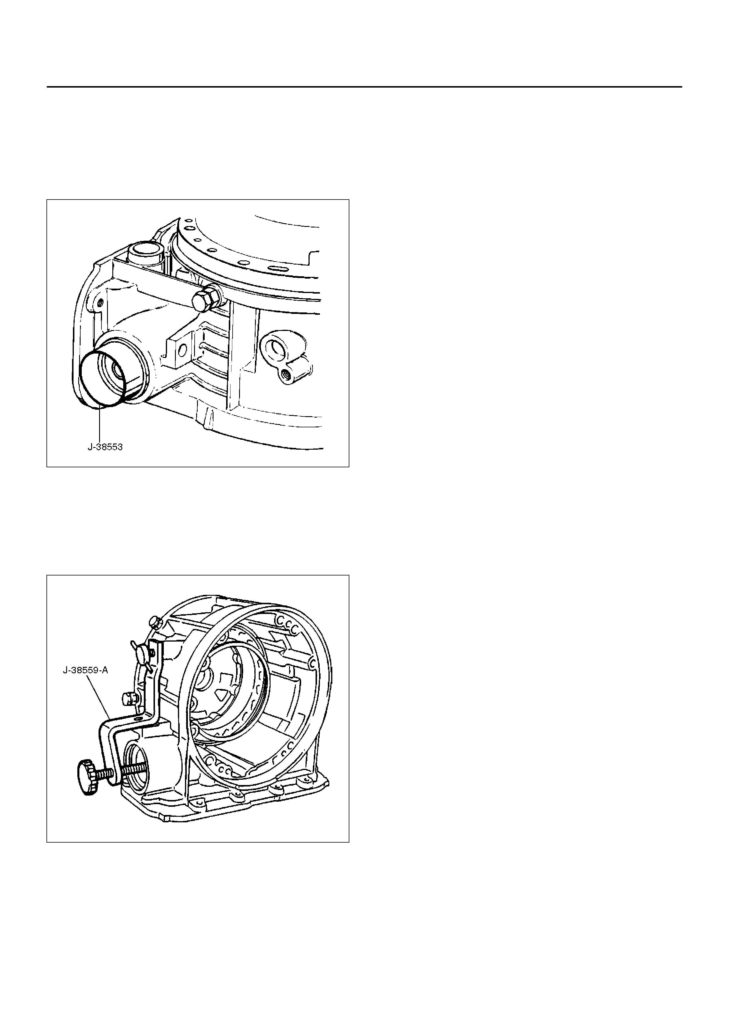
REASSEMBLY
1. Place the J–38553 piston fitter into adaptor case
and push the piston into position, using suitable
diameter tube.
• Remove the piston fitter.
244RS006
2. Install spring and cove r.
3. Install snap ring, using the J–38559–A compressor
tool.
• Install snap ring in groove.
• Remove the compressor tool.
242RS007
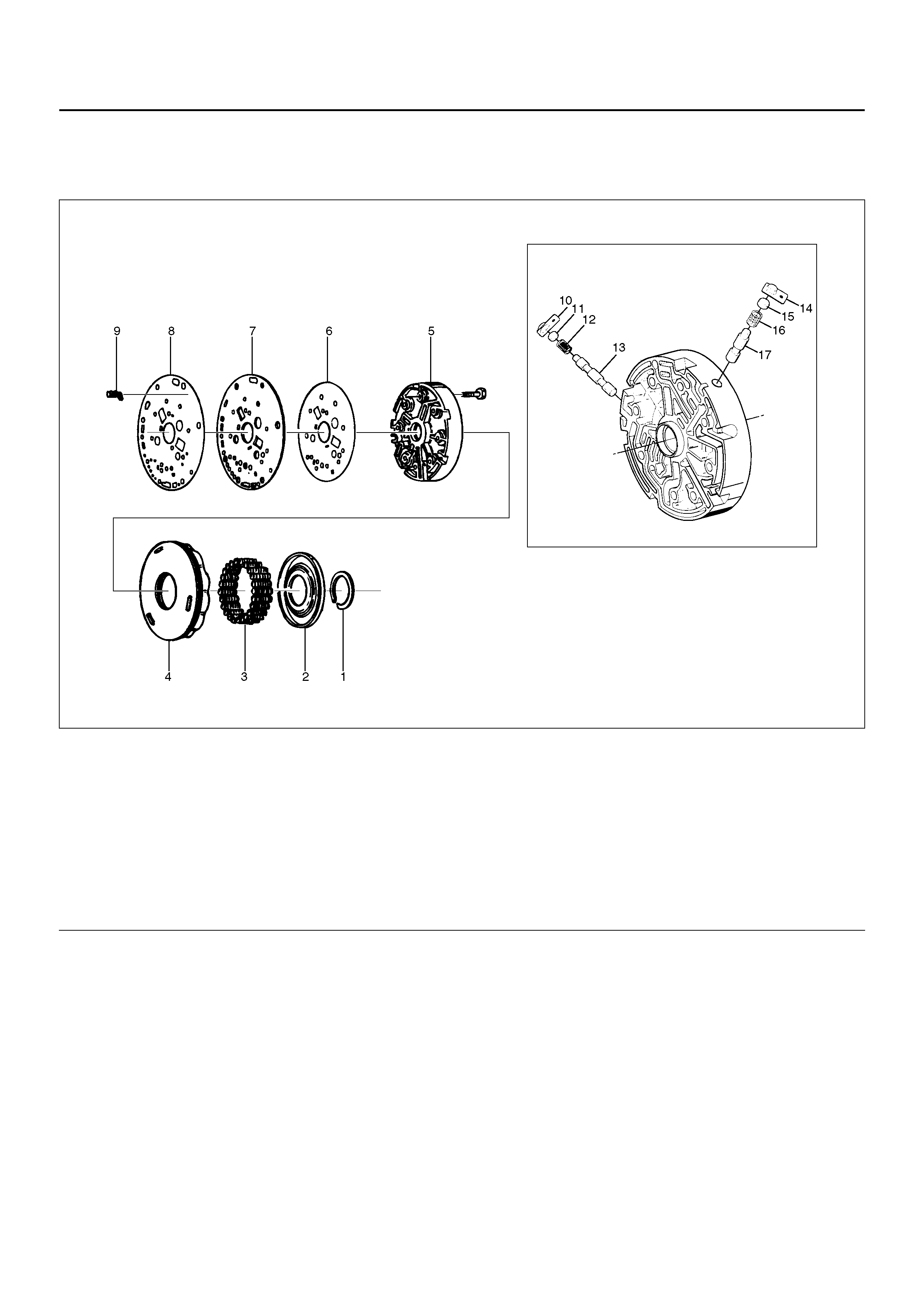
REVERSE CLUTCH PISTON AND CENTER SUPPORT
DISASSEMBLED VIEW
242RY001
EndOFCallout
Legend
(1) Retaining Ring
(2) Spring Seat
(3) Springs
(4) Piston Assembly
(5) Center Support
(6) Gasket
(7) Transfer Plate
(8) Gasket
(9) Restrictor
(10) Retainer Plate
(11) Plug
(12) Spring
(13) Overrun Lock Out Valve
(14) Retainer Plate
(15) Plug
(16) Spring
(17) Reverse Lock Out Control Valve
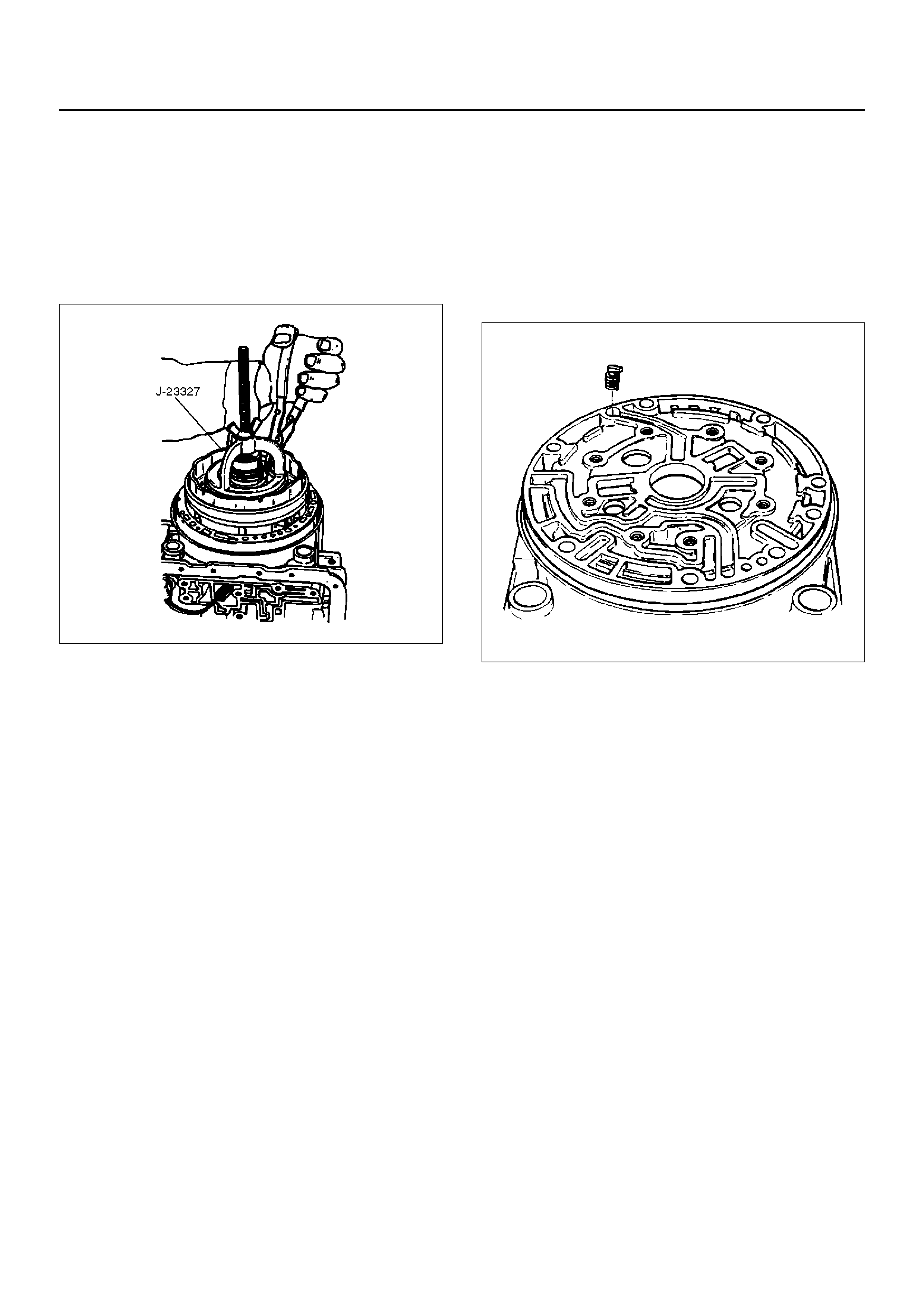
DISASSEMBLY
1. Install the J–23327 compressor tool on spring seat,
then compress the spring seat.
• Remove retaining ring (1).
NOTE: Do not over-stress the springs and seat, as this
will cause damage to the spring seat.
• Remove the compressor tool.
247RS008
2. Remove spring seat (2) and springs (3).
3. Remove piston assembly (4).
4. Remove 8 bolts from center support (5), then
remove center support (5) from adapter case.
5. Remove gasket transfer plate/outer support (6),
center support transfer plate (7), and gasket transfer
plate/adapter case (8).
6. Remove restrictor (9) from adapter case housing.
7. Remove retainer plate (10), plug (11), spring (12),
and overrun lock out valve (13) from center support
(5).
INSPECTION AND REPAIR
Visual Check:
If any damage, deformation or wear is found, replace
the damaged part.
REASSEMBLY
1. In stall ov errun lo ck ou t valv e (13 ) and spr ing ( 12) to
center support.
NOTE: Ensure correct assembly of valve. The spring
should be located over the long small diameter end.
2. Install plug (11) and retainer plate (10).
3. Place restrictor (9) in the lube overdrive channel in
the adapter case housing.
242RS005
4. In stall gas ket tran sfer plate/adap ter c ase (8), center
suppor t transf er pl ate (7) , and gaske t tran sfer pl ate/
center support (6).
5. Install center support (5) with 8 bolts.
Torque : 25N•m (18lbft)
6. Install piston assembly (4) into center support (5).
7. Install twenty four springs (3), spring seat (2), and
retaining ring (1 ).
• Install the J–23327 compressor and compress
spring seat (2) and springs (3), then seat snap
ring (1) in groove.
• Remove the tool.
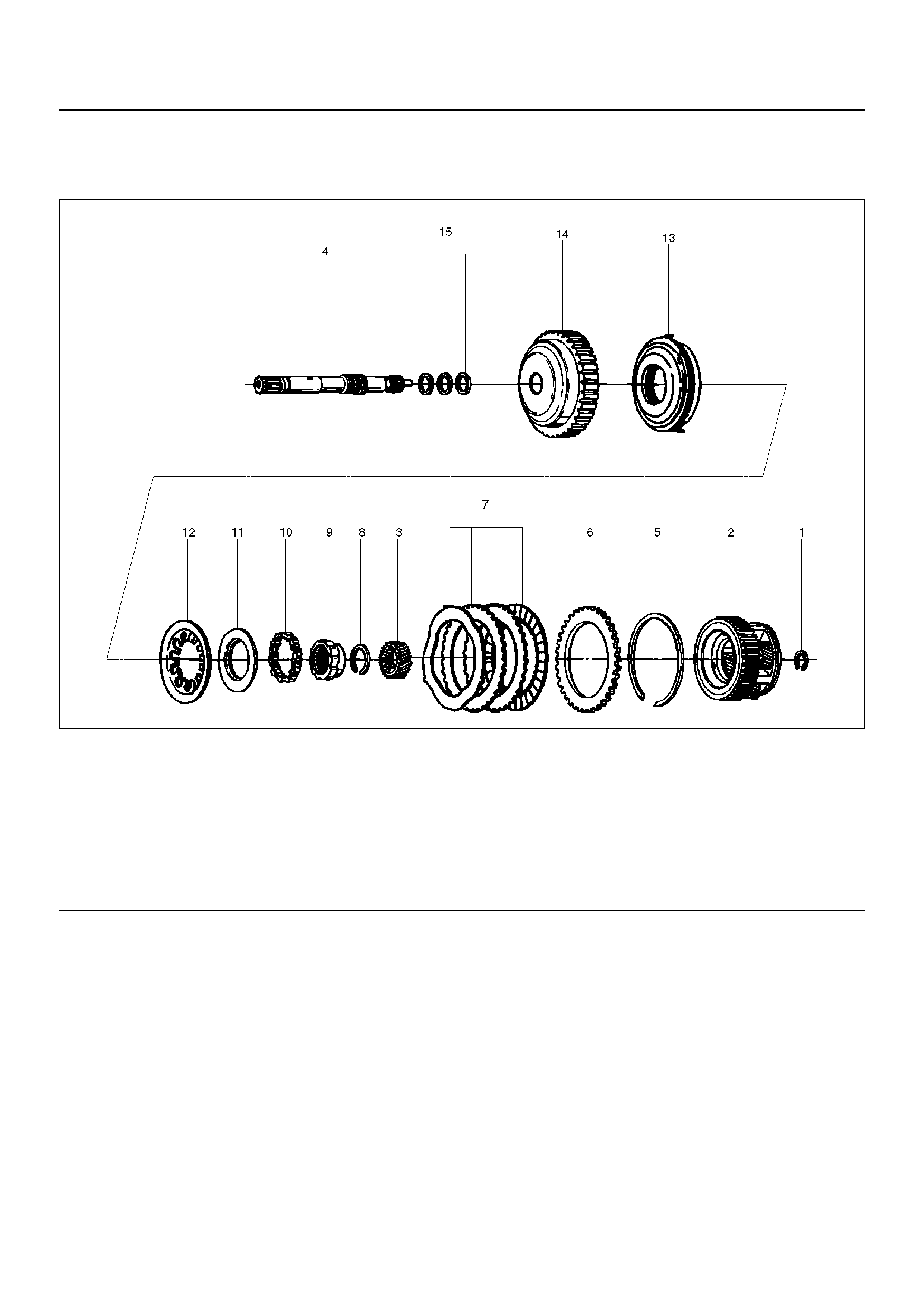
OVERRUN CLUTCH AND TURBINE SHAFT
DISASSEMBLED VIEW
252RW005
EndOFCallout
Legend
(1) Snap Ring
(2) Overdrive Carrier Assembly
(3) Sun Gear
(4) Turbine Shaft
(5) Snap Ring
(6) Bac ki ng Pl ate
(7) Clutch Plates
(8) Snap Ring
(9) Overrun Roller Clutch C am
(10) Roller Clutch Assembly
(11) Overr un Clutch Release Spring Retainer
(12) Diaphragm Spring
(13) Piston Assembly
(14) Overrun Clutch Drum
(15) Turbine Shaft Seal Rings
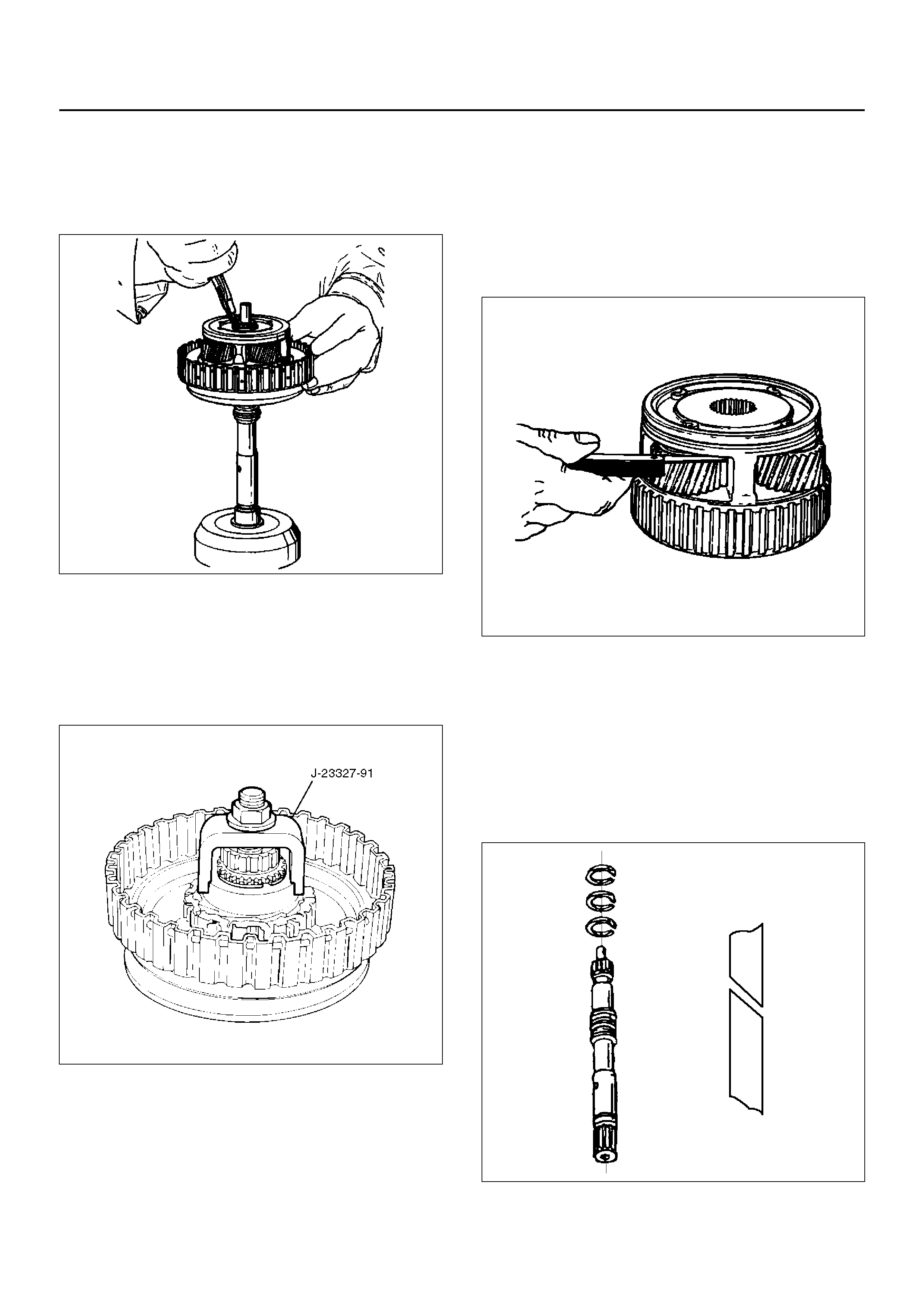
DISASSEMBLY
1. Position overrun clutch assembly upright, using the
overdrive internal gear as a support.
• Remove snap ring (1).
252RS009
2. Remove overdrive carrier assembly (2), sun gear
(3) and turbine shaft (4).
3. Remove snap ring (5), backing plate (6), and clutch
plates (7).
4. Compress diaphragm spring with the J–23327–91
compressor then remove snap ring (8).
252RS010
5. Remove overrun roller clutch cam (9) and roller
clutch assembly (10).
6. Remove overrun clutch release spring retainer (11)
and diaphragm spring (12).
7. Remove piston assembly (13) from overrun clutch
drum (14).
8. Remove turbine shaft seal rings (15).
INSPECTION AND REPAIR
Overdrive Carrier Check
• Check pinion end play with a feeler gauge.
Clearance: 0.24mm–0.64mm (0.0094in–0.025in)
If clearance is outside specified value, replace overdrive
carrier assembly.
252RS011
Visual Check:
If any damage, deformation or wear is found, replace
the damaged part.
REASSEMBLY
1. Install turbine shaft seal rings (15) with grease
(petroleum jelly).
241RS008
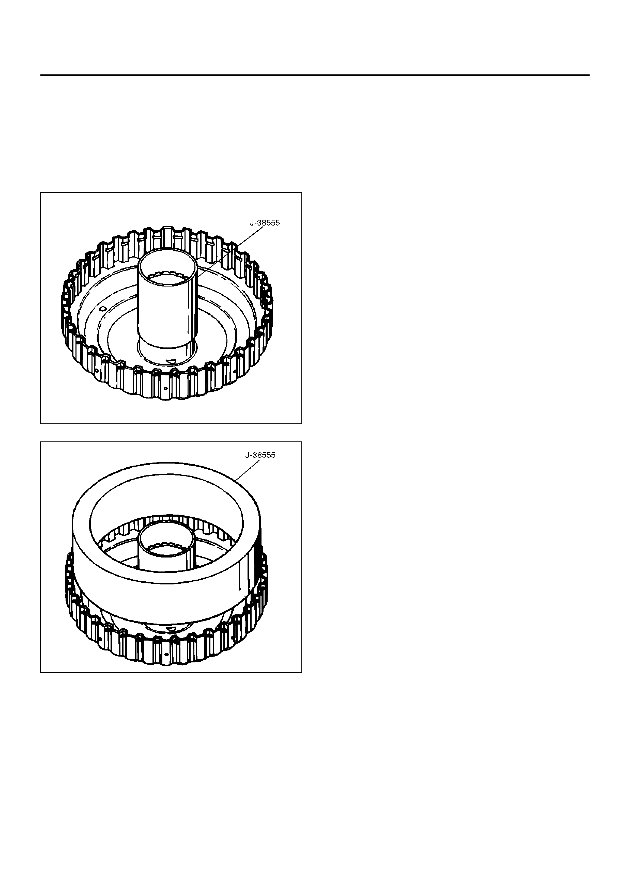
2. Instal l the J –3855 5 inne r inst all er on the dr um (14) .
• Pre-install piston assembly into J–38555 outer
installer.
• Install overrun clutch piston assembly (13). Use
the outer installe r while pushing piston into drum
(14).
• Remove the installer.
252RS012
252RS013
3. I n stall diaph ra gm sp ring (1 2).
4. Install overrun clutch release spring retainer (11) (lip
faces upw ards), overrun roller clutch assembly (10)
and cam (9).
5. Place snap ring loosely on spring retainer.
• Hold the J–23327–91 compressor in a vise and
compress piston return spring with compressor.
• Set snap ring (8) in ring groove.
• Remove the compressor.
6. Install clutch plates (7), start with steel plate and
alternate with lined plates.
7. Install backing plate (6).
8. Install snap ring (5).
9. Install overdrive sun gear with countersink pointing
downwards.
10. Install the overdrive carrier assembly (2).
NOTE: Turn the assembly in a counter-clockwise
direction only until roller clutch enters the outer race.
After Installation, rotate the assembly and listen for
loose rollers.
11. Install turbine shaft (4) and snap ring (1).
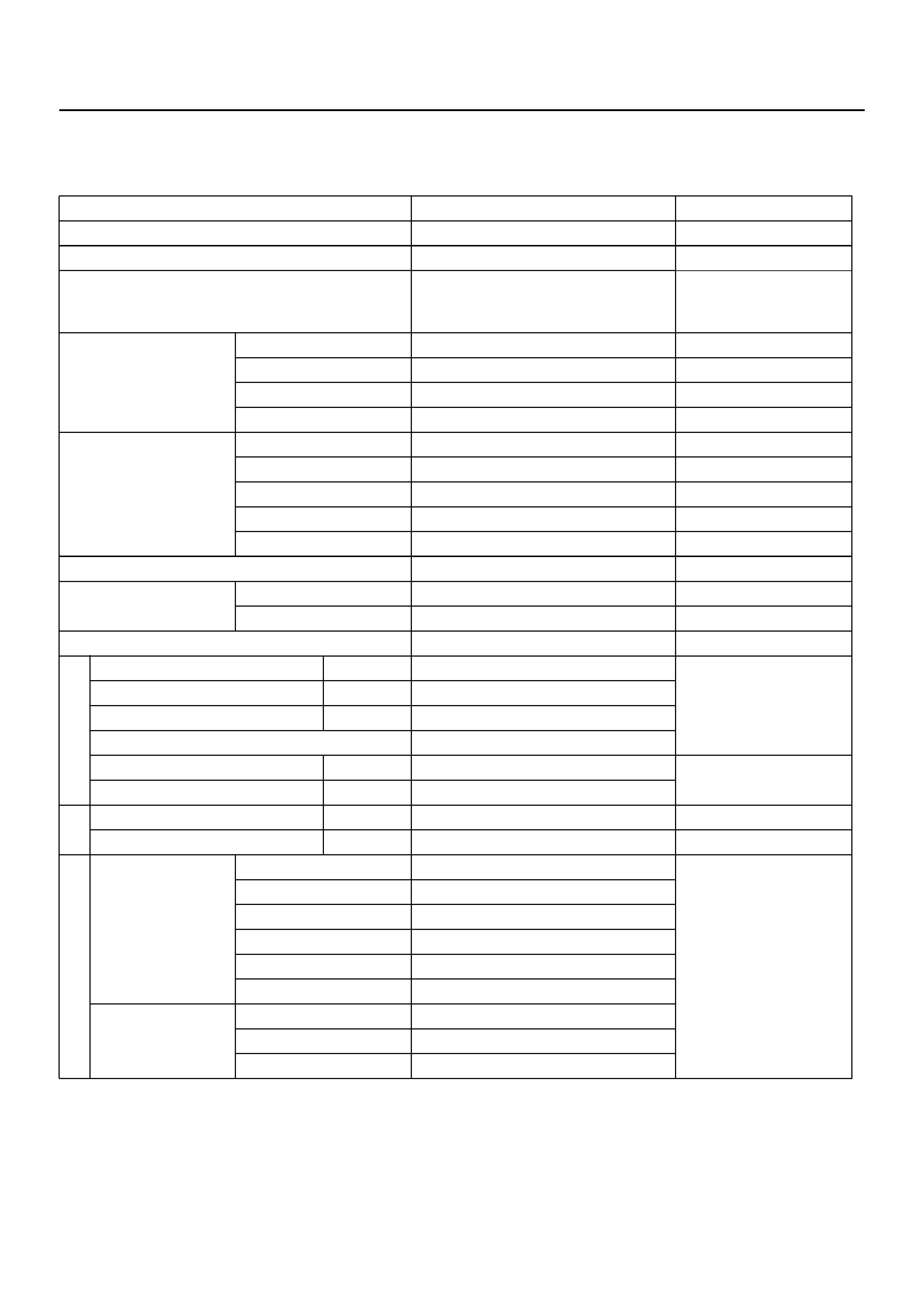
MAIN DATA AND SPECIFICATION
General Specifications
Remarks
Model THM 4L30–E
Engine V6 3.2L 6VD1
Type Automatic four speed overdrive in
4th gear lockup clutch torque
converter
Control systems
Shift control Hydraulic
Shift pattern Electronic
Shift quality Electronic
Lockup cl utc h Electronic
Gear ratio
1st 2.856
2nd 1.618
3rd 1.000
4th (O/D) 0.723
Reverse 2.000
Gear set Noiseless, high torque capability
Oil used Name ATF DEXRON®–III
Q'ty liter (qt) 8.6 (9.1)
Torque converter 2,100 ± 150 Stall speed (rpm)
Reve rs e cl ut c h RC 5
Number of discs
Second clutch C2 6
Third clutch C3 6
Brake band Double wrap
Fourth clutch C4 2 Number of discs
Overrun clutch OC 1
Overdrive roller clutch OFW 10 Number of rollers
Principle sprag assembly PFW 26 Number of sprags
Ravigneaux type
gear train
(planetary gear
set)
Input sun gear 30
Number of teeth
Pinion gear 19
Long pinion 23
Ring gear 90
Long pinion 19
Output sun gear 46
Overdrive carrier
(planetary gear
set)
Sun gear 31
Pinion gear 24
Ring gear 81
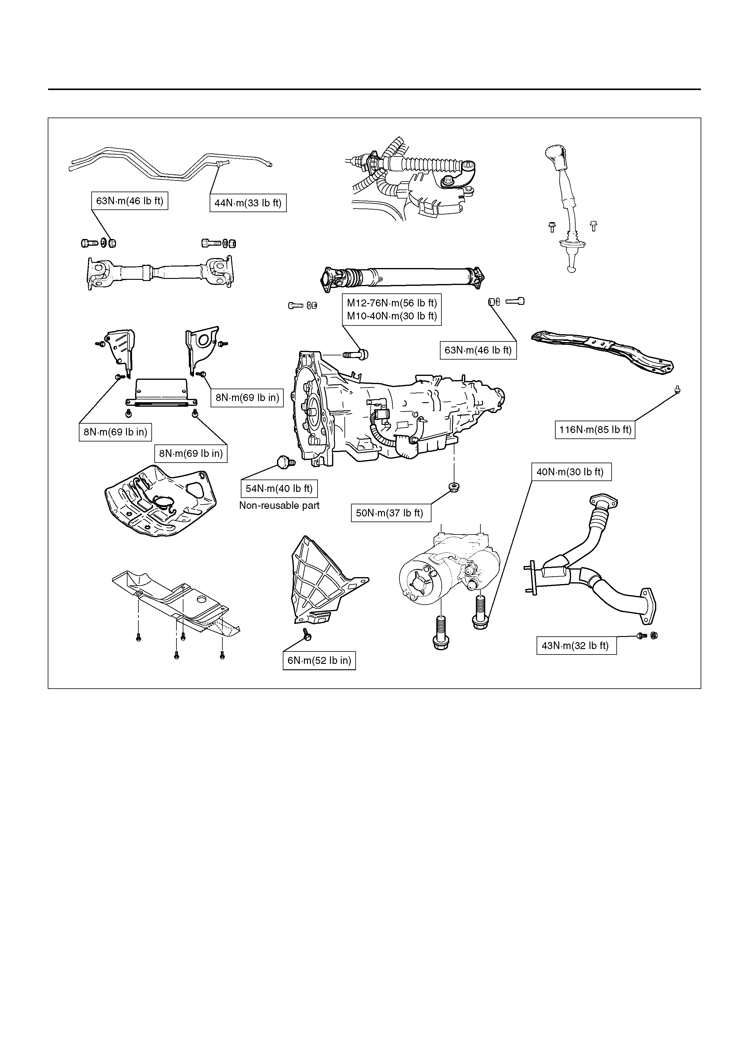
Torque Specifications
E07R100005
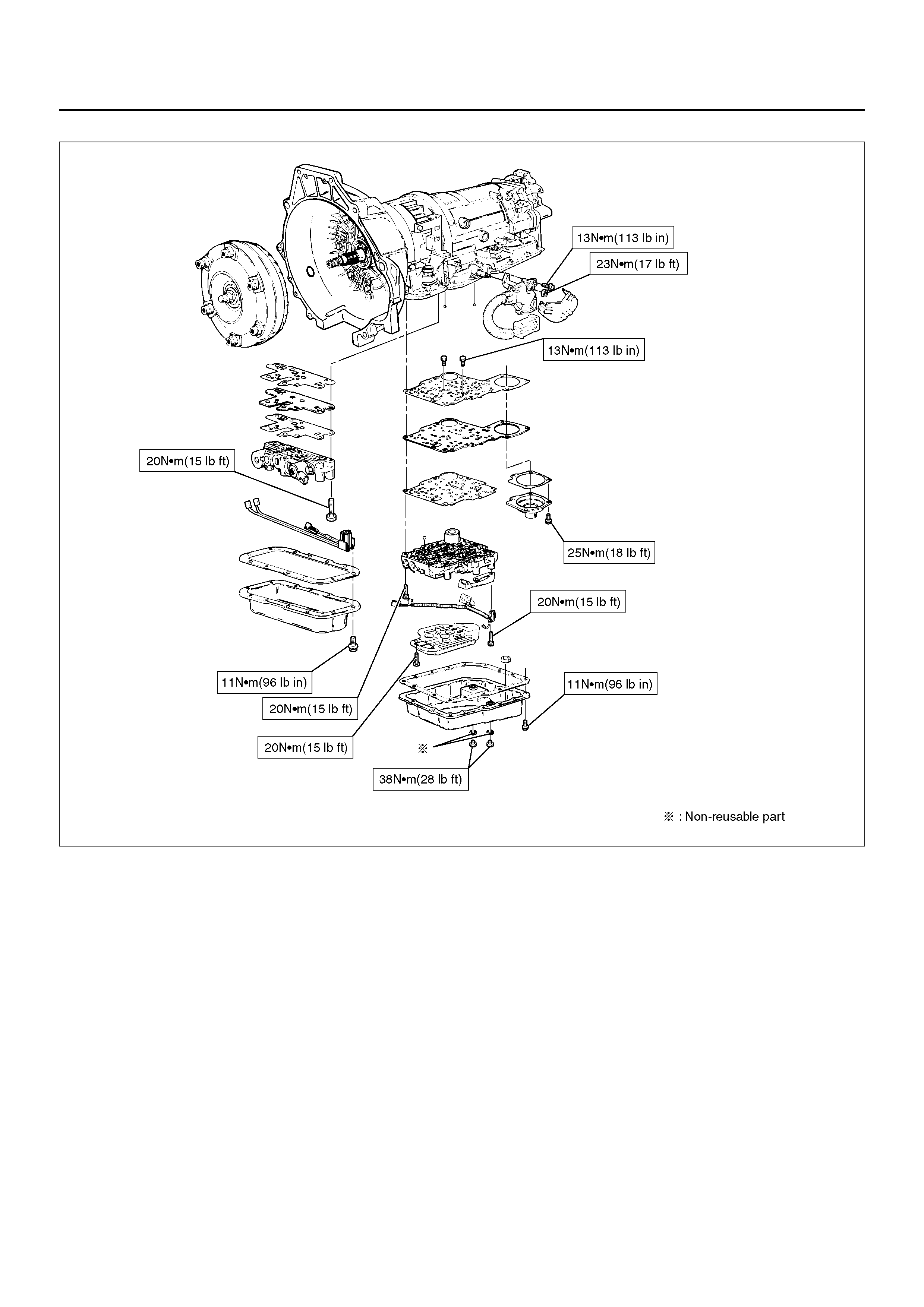
E07RY003
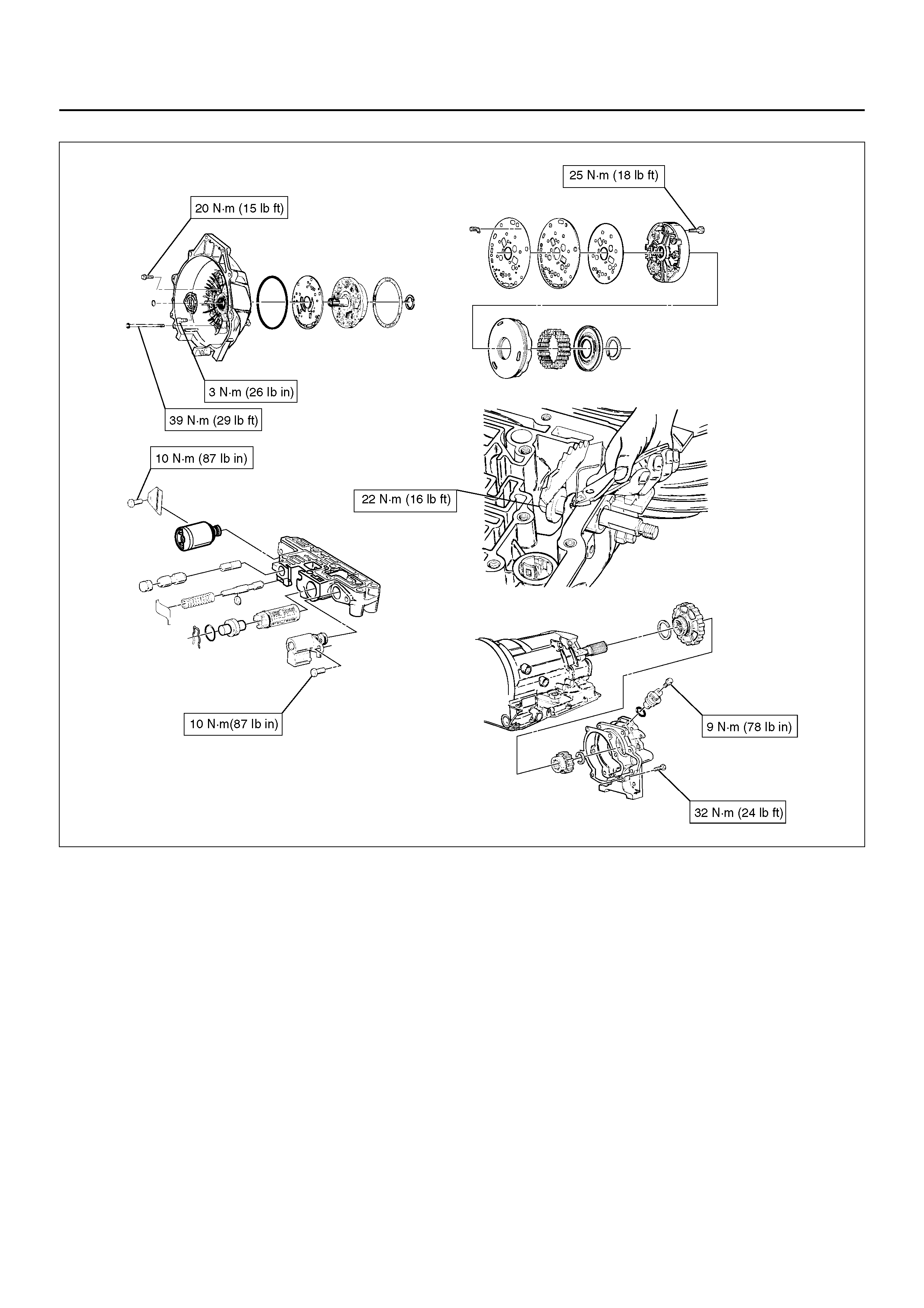
E07R100004
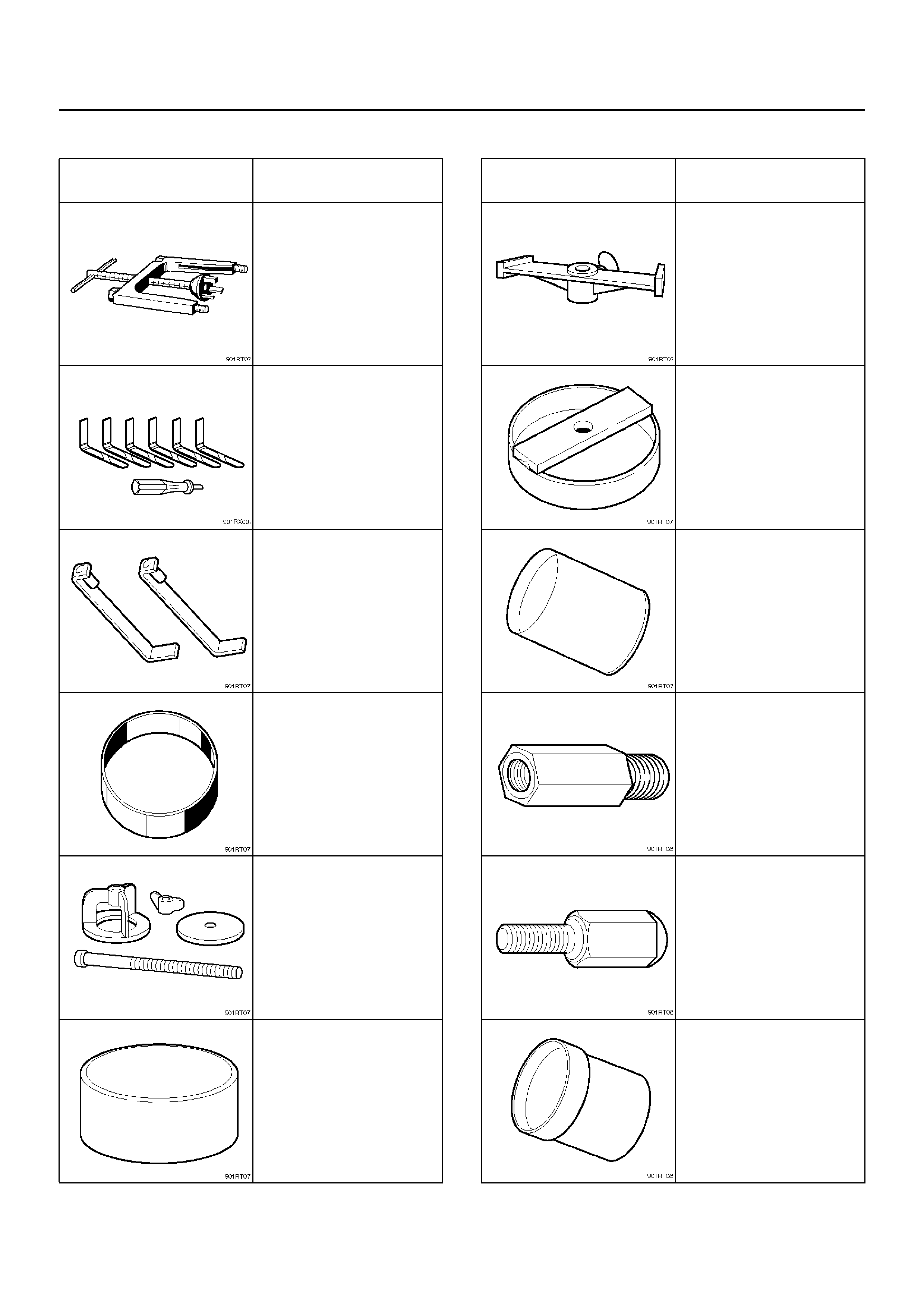
SPECIAL TOOLS
ILLUSTRATION TOOL NO.
TOOL NAME
J–23075
Spring compressor (For
servo piston)
J–38450–A
Third clutch snap ring
compressor
J–23075–12
Third clutc h spr i ng
compressor adapter (Use
with J–23075)
J–23084
Third clutch piston
installer
J–23327
Third clutc h spr i ng
compressor
J–23080–A
Second clutch piston
installer
J–23085–A
Selective washer gaging
tool
J–23327–90
Fourth clutch spring
compressor (Use with J–
23327)
J–38553
3/4 accumulator piston
fitter
J–41096
Cover remover (Use with
J–38584)
J–38584
Slide hammer adapter
(Use with J–23907)
J–38554
Fourth clutch piston fitter
ILLUSTRATION TOOL NO.
TOOL NAME
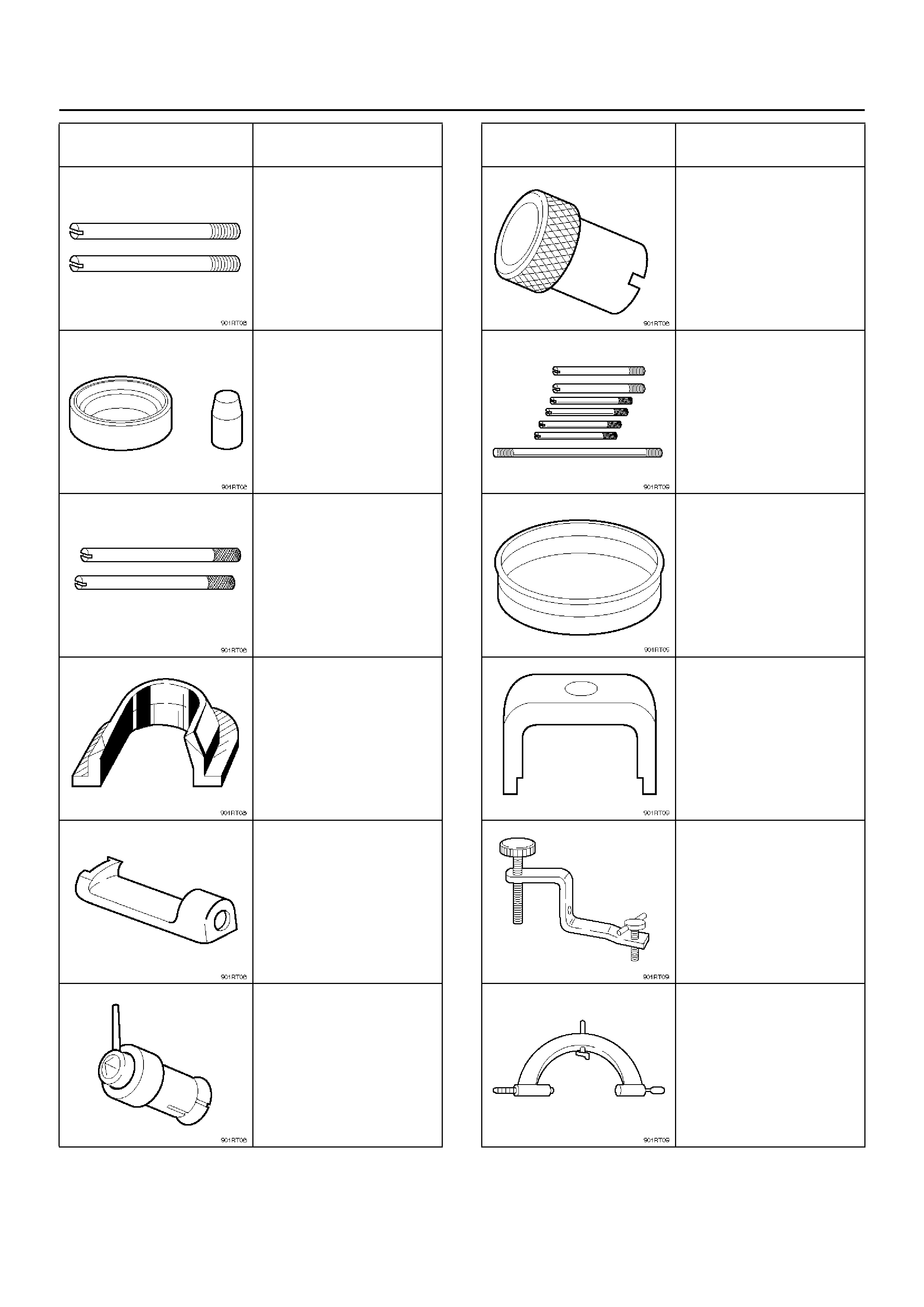
J–38588
Guide pins; adapter case
to main case
J–38555
Overrun clutch piston
seal installer set
J–3387–2
Guide pins; gasket and
transfer plate to valve
body
J–25022
Turbine shaft puller (Use
with J–24773–1)
J–23129
Oil seal remover (Use
with J–23907 and J–
38584)
J–38557
Oil pump centering tool
ILLUSTRATION TOOL NO.
TOOL NAME
J–23082–01
Oil pump rotation tool
J–25025–B
Guide pins; valve body to
main ca se
J–38428
Servo piston fitter
J–23327–91
Overrun clutch spring
compressor
J–38559–A
3/4 accumulator piston
cover compressor
J–8763–02
Holding fixture
ILLUSTRATION TOOL NO.
TOOL NAME
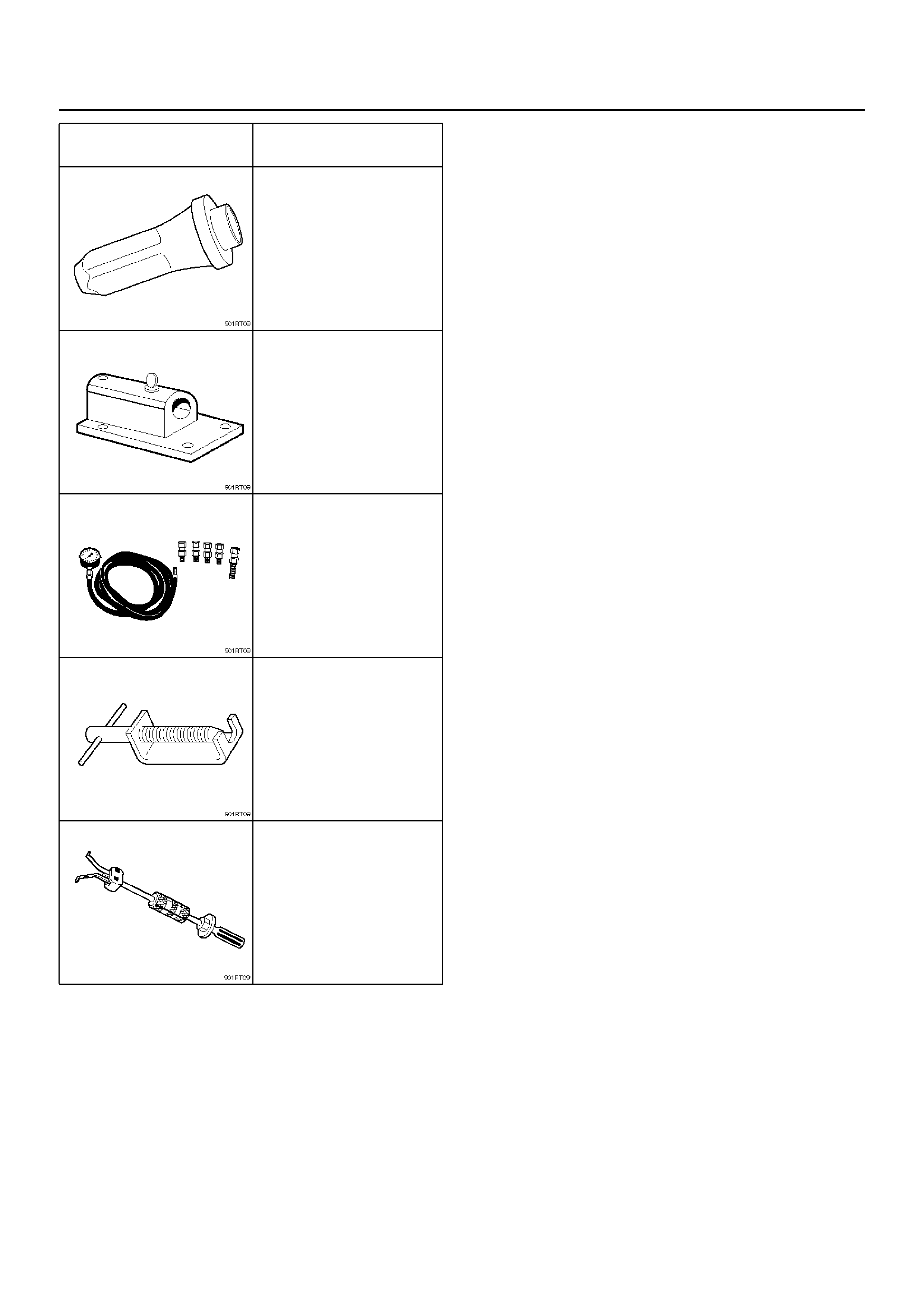
J–36797
A/T extension housing oil
seal installer (Insi de)
J–3289–20
Holding fixture base
J–29770–A
Pressure gauge
J–24773–1
End play fixture (Use with
J–25022)
J–23907
Slide hammer
ILLUSTRATION TOOL NO.
TOOL NAME

4L30–E PARTS LIST
Case and Associated Parts
241RY00001
Legend
(1) Torque Converter
(2) Screw, Seal Ring Assembly
(3) Seal Ring Assembly, Converter Housing
(4) Screw, Converter Housing/Main Case
(5) Screw, Converter Housing/Oil Pump
(6) Housing, Converter
(7) Plug, Converter Housing
(8) Seal, O-ring
(9) Wear Plate, Oil Pump Body
(10) Pump Assembly, Oil
(11) Gasket
(12) Washer, Thrust Selective
(13) Ring, Snap
(14) Cover, 3–4 Accumulator Piston
(15) Seal, O-ring, 3–4 Accumulator
(16) Spring, 3–4 Accumulator Piston
(17) Pin, 3–4 Accumulator Piston
(18) Piston, 3–4 Accumulator
(19) Ring, 3–4, Accumulator Piston
(20) Case, Adapter
(22) Connector, Electrical/Adapter Case
(23) Screw, Pan
(27) Restrictor, Oil
(28) Gasket, Transfer Plate/Adapter
(29) P la te, Transfer Adapte r/Center Support
(30) Support Assembly, Center
(31) Screw, Center Support
(32) Ring, Oil Seal
(33) Seal, O-ring Main Case
(34) Fitting, Cooler
(35) Fitting Assembly, Cooler

EndOFCallout
(36) Case, Main
(37) Br eat her, Pipe
(38 ) Seal, O-ring
(39) Reservoir
(42) Ga sk et, Exten si on Cas e
(43) Extension Assembly
(44) Seal, O-ring/Speed Sensor
(45 ) Sensor Assembly, Speed
(46) Sc rew, Speed Senso r
(50) Seal, Extension Assembly
(51) Bearing, Needle/Extension
(52) Sc rew, Extension/M ai n Case
(53) Spring, Parking Pawl Lock
(54) Pawl, Parking Lock
(55) Connector, Electrical/Main Case
(56) Actuator Assembly, Parking Lock
(57) Nut, Parking Lock Lever
(58) Link, Manual Valve
(59) Pin, Spring
(60) Lever, Parking Lock and Range Selector
(61) Shaft, Selector
(62) Seal, Selector Shaft
(63) Mode Switch Assembly
(64) Screw & Conical Washer Assembly
(65) Shield, Mode Switch
(67) Pan, Bottom/Adapter Case
(68) Gasket, Bottom Pan/Adapter Case
(69) Harness Assembly, Adapter Case
(70) Screw, Val v e Bod y
(71) Valve Body Assembly, Adapter Case
(72) Gasket, Adapter Valve Body
(73) Plate, Adapter Valve Body/Transfer
(74) Pan, Bottom/Main Case
(75) Gasket, Bottom Pan/Main Case
(76) Gasket, Oil Drain or Overfill Screw
(77) Screw, Oil Drain or Overfill
(78) Magnet, Chip Collector
(79) Fi lter Oil
(80) Harness Assembly, Main Case
(82) Roller and Spring Assembly, Manual Detent
(84) Valve Body Asse mbl y, Main Case
(85) Ball, Check
(86) Gasket, Main V.B./Transfer Plate
(87) Plate, Main V.B./Transfer
(88) Gasket, Transfer/Main Case
(89) S cre w, Tran sfer Plate on V.B .
(90) Screw, Servo Cover
(91) Cover, Servo Piston
(92) Gasket, Cover/Servo Piston
(93) Ring, Retaining Servo Piston
(94) Clip, Servo Piston
(95) Nut, Servo Screw
(96) Screw, Servo Piston
(97) Piston, Servo
(98) Seal, Ring/Servo Piston
(99) Spring, Cushion/Servo Piston
(100) Seat, Cushion Spring
(101) Sleeve, Servo Piston Adjust
(102) Rod, Apply/Servo Pis ton
(103) Spring, Return/Servo Piston
(104) Gasket, Adapter Case/Transfer Plate
(105) Powertrain Control Module
(106) Servo Piston Assembly
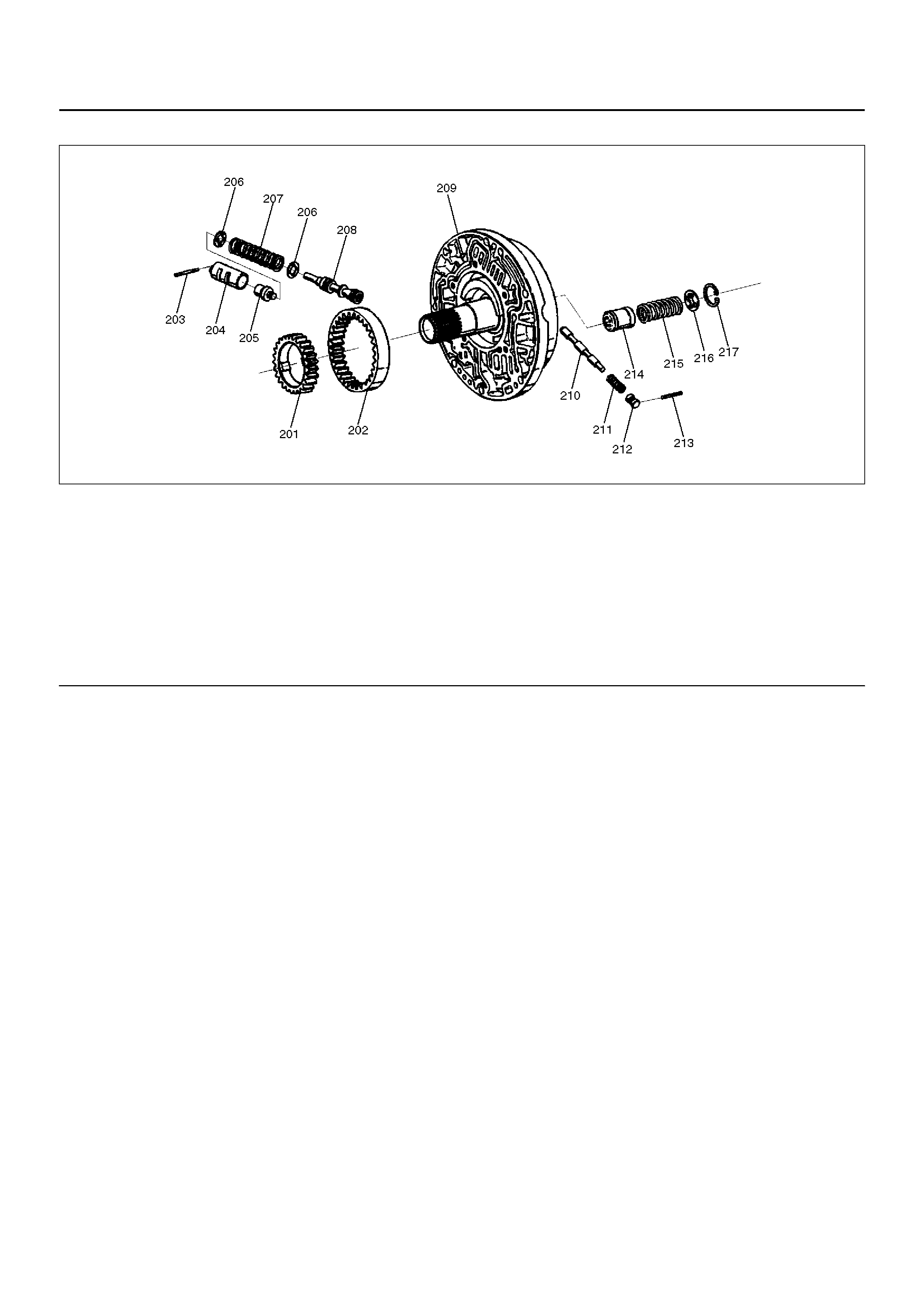
Pump Assembly
241RS019
EndOFCallout
Legend
(201) Gear, Oil Pump Drive
(202) Gear, Oil Pump Driven
(203) Pin, Boost Valve Sleeve
(204) Sleeve, Boost Valve
(205) Valve, Boost
(206) Seat, Spring/Pressure Regulator Valve
(207) Spring, Pressure Regulator Valve
(208) Valve, Pressure Regulator
(209) Pump Assembly, Oil
(210) Valve, Converter Clutch Control
(211) Spring, Converter Clutch Control Valve
(212) Plug, Converter Clutch Control Valve
(213) Pin, Spring
(214) Piston, Throttle Signal Accumulator
(215) Spring, Throttle Signal Accumulator
(216) Seat, Spring/Throttle Signal Accumulator
(217) Ring, Snap/Throttle Signal Accumulator
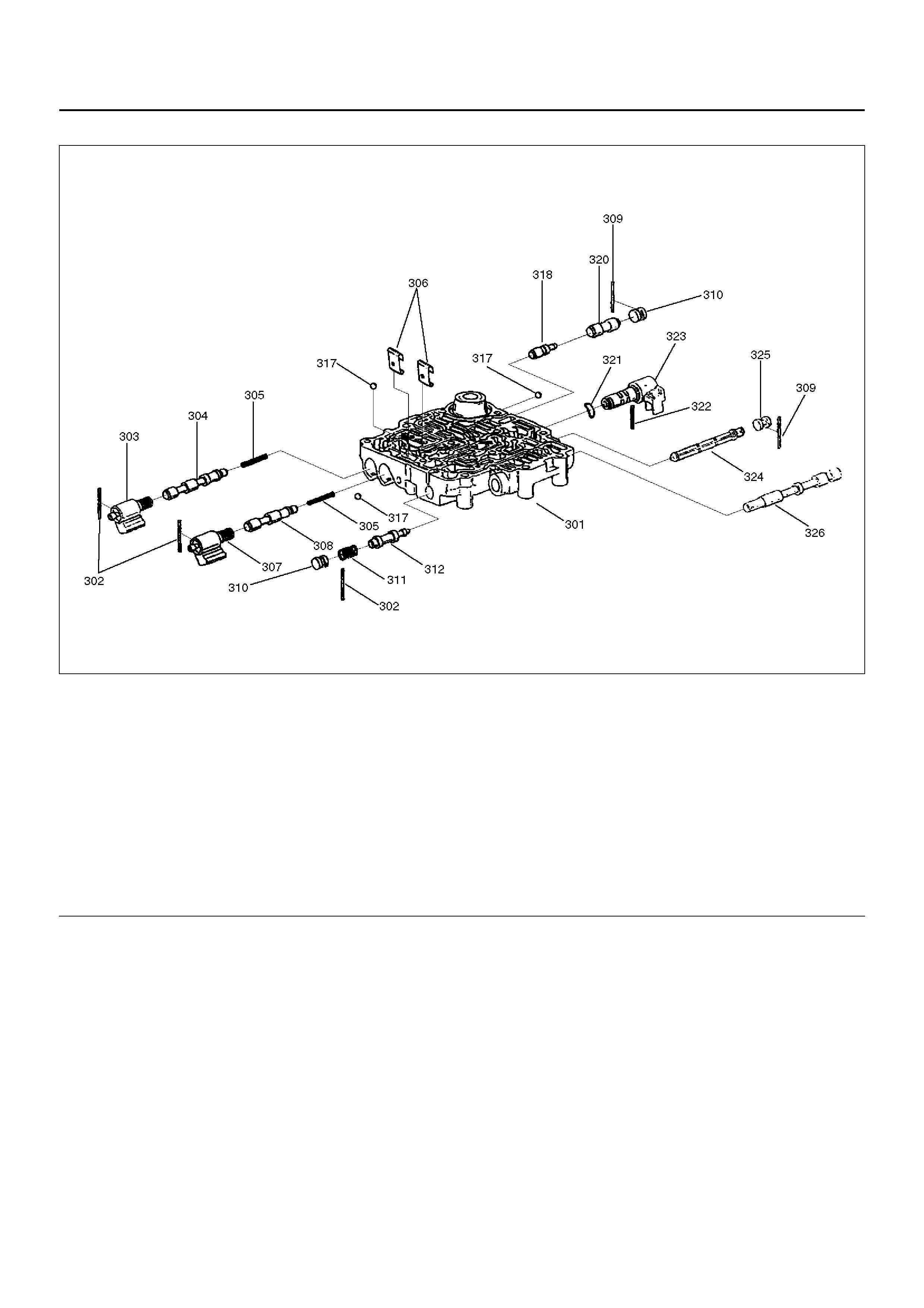
Valve Bo dy Assemblies
244RS009
EndOFCallout
Legend
(301) Body, Valve Main Case
(302) Pin, Spring
(303) Solenoid Assembly, ON/OFF N.C.
(304) Valve, 1–2 & 3–4 Shift
(305) Spring, 1–2 & 3–4 (2–3) Shift
(306) Retainer, Valve
(307) Solenoid Assembly, ON/OFF N.O.
(308) Valve, 2–3 Shift
(309) Pin, Spring
(310 ) Plug, Valve Bore
(311) S prin g, Valve Low Pr es su re Contro l
(312) Valve, Low Pressure Control
(317) Ball, Check
(318) Valve, 1–2 Accumulator Control
(320) Valve, 1–2 Accumulator
(321) Washer, Waved PWM Solenoid
(322) Pin, Solenoid PWM
(323) S ol eno id As se mbl y, Band Contr ol PWM
(324) Screen Assembly, PWM Solenoid
(325) Plug, Screen
(326) Valve, Manual

243R100002
EndOFCallout
Legend
(401) Body, Valve/Adapter Case
(402) Screw, Pressure Control Solenoid
(403) Retainer, Pressure Control Solenoid
(404) Solenoid, Pressure Control
(405) Plug, 3–4 Accumulator
(406) Plug and Spring Retainer
(407) Valve, 3–4 Accumulator
(409) Valve, 3–4 Accumulator Control
(410) Spring, Feed Limit Valve
(411) Ring, Retainer
(412) Valve, Feed Limit
(413) Seal, O-ring Plug Filter
(414) Plug, Screen
(415) Screen Assembly, Pressure Control Solenoid
(416) Solenoid, Torque Conv. Clutch ON/OFF N.C.
(417) Plug Retainer
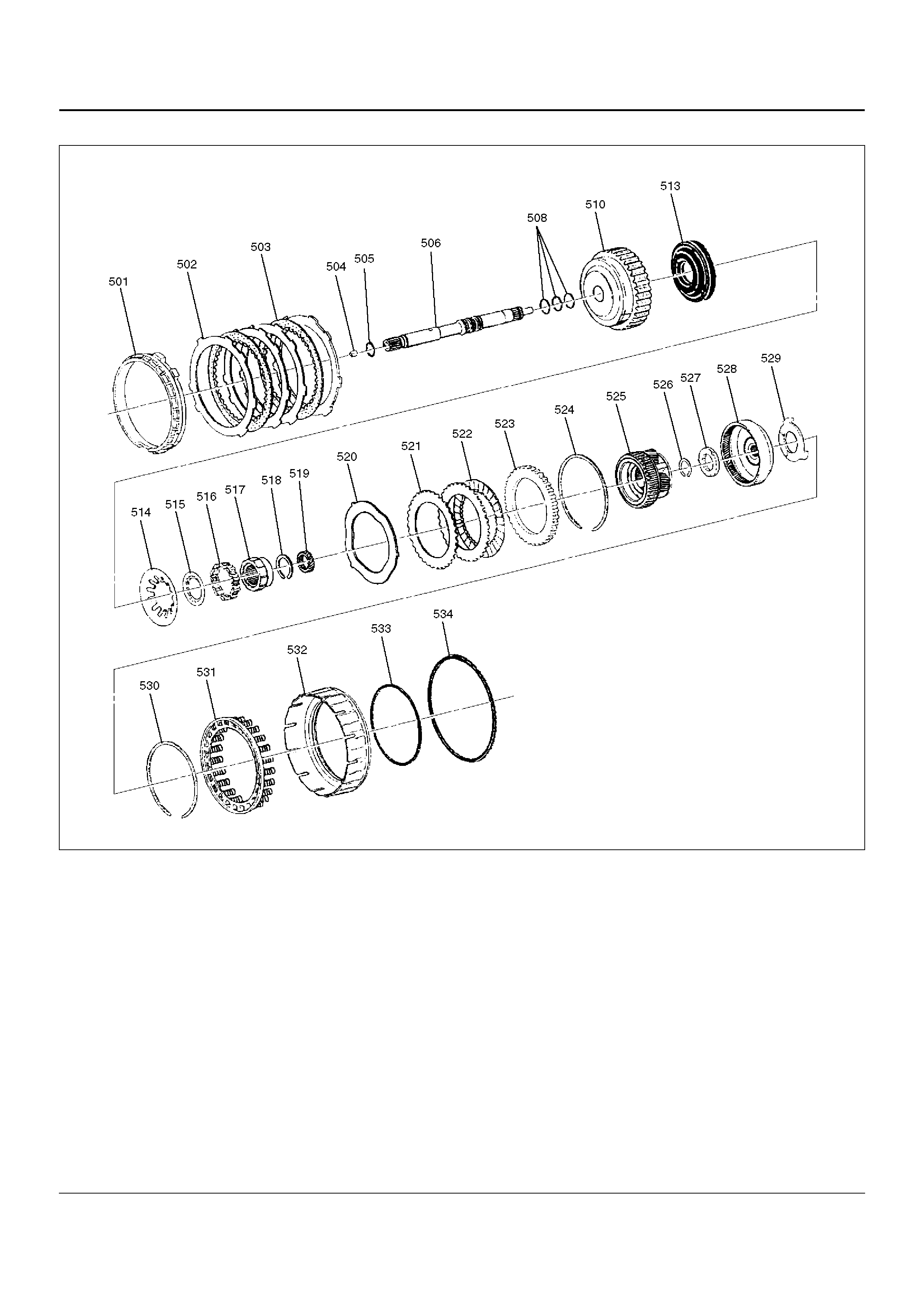
Overdrive Internal Components
252RW003
EndOFCallout
Legend
(501) Retainer, 4th Clutch
(502) Pl ate, 4th Clut ch (Steel)
(503) P l ate As se mbl y, 4th Clutch (Lin ed)
(504) Retainer and Ball Assembly, Check Valve
(505) Seal, O-ring/Turbine Shaft
(506) Shaft, Turbine
(508) Ring, Oil Seal/Turbine Shaft
(510) Housing, Overrun Clutch
(513) Piston, Overrun Clutch
(514) Spring, Overrun Clutch Release
(515) Retainer, Release Spring/Overrun Clutch
(516) Roller Assembly, Overdrive Clutch
(517) Cam, Overdrive Roller Clutch
(518) Ring, Snap/Overrun Clutch Hub
(519) Gear, Overdrive Sun
(520) Plate, Waved/Overrun Clutch
(521) Plate, Overrun Clutch (Steel)
(522) Plate Assembly, Overrun Clutch (Lined)
(523) Plate, Backing/Overrun Clutch
(524) Ring, Snap/Overrun Clutch Housing
(525) Carrier Assembly, Overdrive Complete
(526 ) Rin g, Snap/Turbine Shaft/Carrier
(527) Bearing Assembly, Thrust
(528) Gear, Overdrive Internal
(529) Washer, Thrust/Internal Gear/Support
(530) Ring, Snap/Adapter/4th Clutch Spring
(531) Retainer and spring assembly, 4th clutch
(532) Piston, 4th Clutch
(533) Seal, 4th Clutch Piston (Inner)
(534) Seal, 4th Clutch Piston (outer)
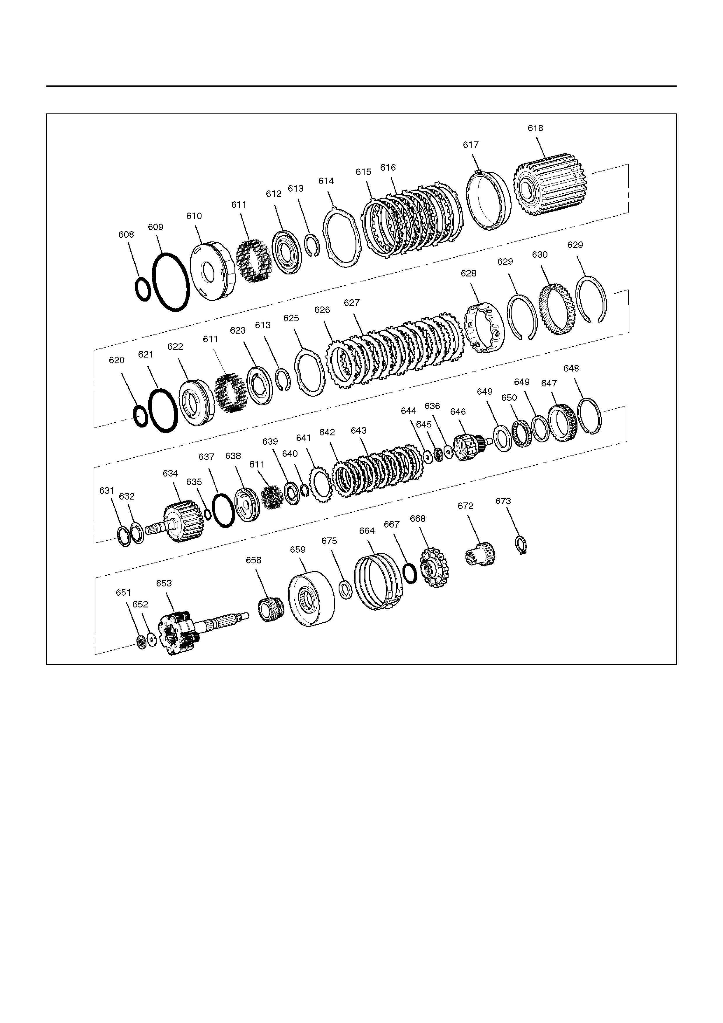
Internal Component s
247RW002
Legend
(608) Seal, Reverse Clutch Piston (Inner)
(609) Seal, Reverse Clutch Piston (Outer)
(610) Piston, Reverse Clutch
(611) Spring, Piston Clutch
(612) Seat, Spring/Reverse Clutch
(613) Ring, Retaining
(614) Plate, Waved/Reverse Clutch
(615) Plate, Reverse Clutch (Steel)
(616) Plate Assembly, Reverse Clutch (Lined)
(617) Plate, Reverse Clutch Pressure/Selective
(618) Drum Assembly, 2nd Clutch
(620) Seal, 2nd Clutch Piston (Inner)
(621) Seal, 2nd Clutch Piston (Outer)
(622) Piston, 2nd Clutch
(623) Seat, Spr ing/2nd Clutch
(625) Pl ate, Waved/2nd Clutch
(626) Plate, 2nd Clutch (Steel)
(627) Plate Assembly, 2nd Clutch (Lined)
(628) Spacer, 2nd Clutch
(629) Ring, Retaining
(630) Gear, Ring
(631) Washer, Thrust/2nd Clutch/3rd Clutch
(632) Thrust Washer, Clutch Hub
(634) Drum Assembly, 3rd Clutch
(635) Seal, 3rd clutch piston (Inner)
(636) Washer, Retaining
(637) Seal, 3rd Clutch Piston (Outer)
(638) Piston 3rd Clutch
(639) Seat, Spring/3rd Clutch
(640) Ring, Retaining
(641) Plate, Spring Cushion/3rd Clutch
(642) Plate, 3rd Clutch (Steel)
(643) Plate Assembly, 3rd Clut ch (Lined)
(644) Washer, Thrust/Input Sun
(645) Bearing, Input Shaft/Gear Assembly
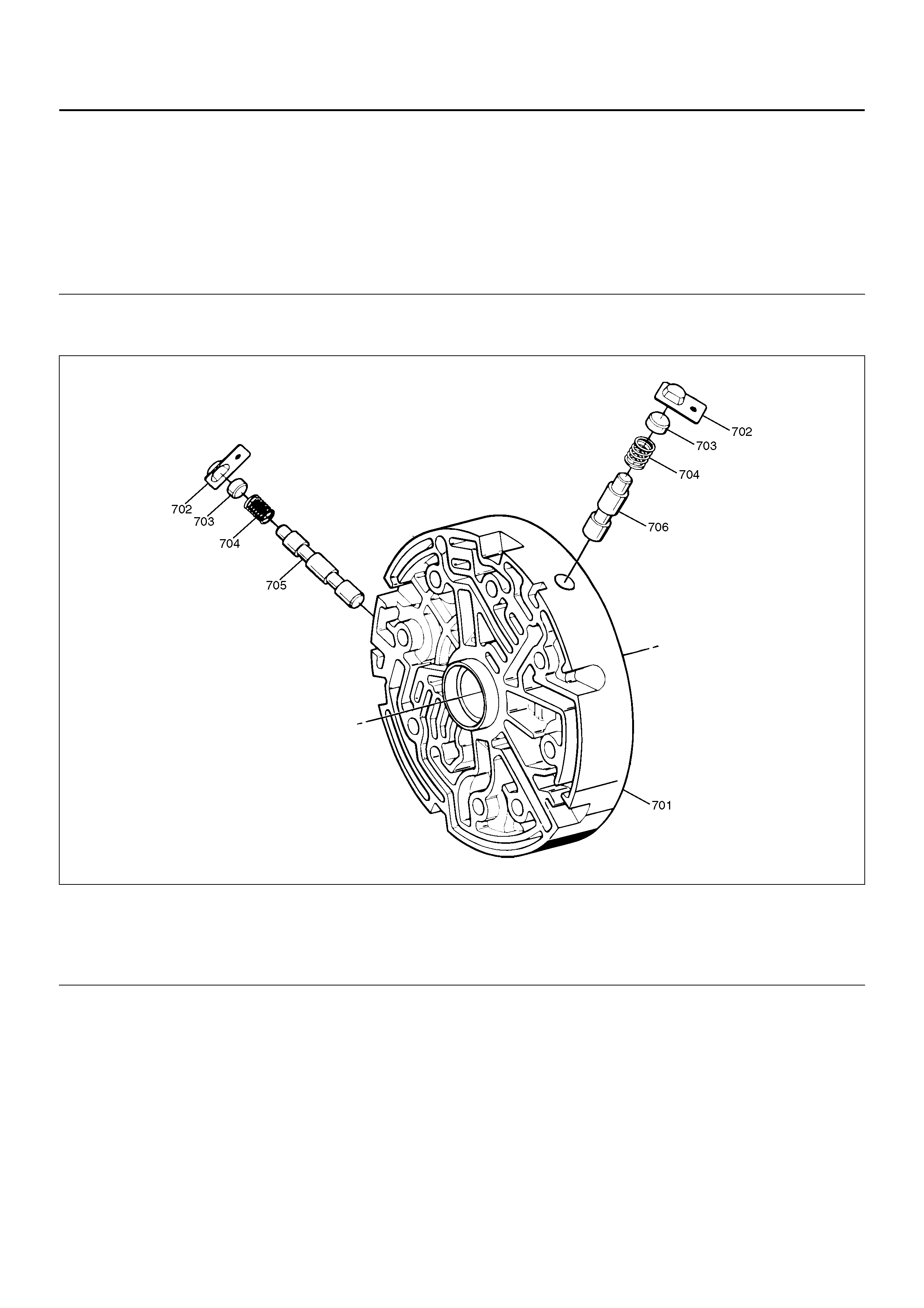
EndOFCallout
Center Support Assembly
242RY002
EndOFCallout
(646) Gear Assembly, Input Sun
(647) Race Assembly, Sprag
(648) Ring, Retaining/Sprag
(649) Ring, Retaining
(650) Cage Assembly, Sprag
(651) Bearing, Output Shaft/Input Sun
(652) Washer, Output Shaft/Input Sun
(653) Carrier Assembly, Planetary
(658) Gear, Reaction Sun
(659) Drum, Reaction Sun
(664) Band Assembly, Brake
(667) Seal, Ring/Wheel Parking Lock
(668) Wheel, Pa rkin g Lo ck
(672) W he el, Sp eed
(673) Ring, Retaining
(675) B ear i ng, Thr us t Assemb ly
Legend
(701) Center Sup port
(702) Retainer Plate
(703) Plug, Lockout
(704) Spring, Lockout
(705) Valve, Overrun Lockout
(706) Valve, Reverse Lockout Control