
SECTION 7C1 - TRANSMISSION CONTROL SYSTEM (4L30-E)
Service Precaution
General Description
Electronic Control Diagram
Powertrain Control Module (PCM)
Control System Diagram
Shift Control
Band Apply Control
Torque Converter Clutch Control
Line Pressure Control
On–Board Diagnostic System
Fail Safe Mechanism
Torque Management Control
ATF Warning Control
Reverse Lock Out Control
Downhill Control
Uphill Control
Shift Mode Control
Gear Shift Control
Winter Drive Mode
Backup Mode
Functions of Input / Output Components
Diagnosis
Electronic Diagnosis
Check Trans Indicator
Diagnostic Check
“Check Trans" Check
Tech 2 OBD II Connection
Transmission Data
Flashing Code
OBD II Diagnostic Management System
16 – Terminal Data Link Connector (DLC)
Malfunction Indicator Lamp (MIL)
DTC Types
Clear DTC
DTC Check
PCM Precaution
Information On PCM
Intermittent Conditions
Transmission and PCM Identification
Diagnostic Trouble Code (DTC)
Identification
DTC P0218/Flashing Code 71 Transmission
Fluid Over Temperature
DTC P0705/Flashing Code 73 Transmission
Range Switch (Mode Switch) Illegal Position
DTC P0706/Flashing Code 74 Transmission
Range Switch (Mode Switch) Performance
DTC P0712/Flashing Code 75 Transmission
Fluid Temperature (TFT) Sensor Circuit Low
Input
DTC P0713/Flashing Code 76 Transmission
Fluid Temperature (TFT) Sensor Circuit High
Input
DTC P0719/Flashing Code 77 TCC Brake
Switch Circuit High (Stuck On)
DTC P0722/Flashing Code 78 Transmission
Output Speed Sensor (OSS) Low Input
DTC P0723/Flashing Code 79 Transmission
Output Speed Sensor (OSS) Intermittent
DTC P0730/Flashing Code 81 Transmission
Incorrect Gear Ratio
DTC P0748/Flashing Code 82 Pressure
Control Solenoid (PCS) Circuit
Electrical
DTC P0753/Flashing Code 83 Shift Solenoid
A Electrical
DTC P0758/Flashing Code 84 Shift Solenoid
B Electrical
DTC P1850/Flashing Code 88 Brake Band
Apply Solenoid Malfunction
DTC P1860/Flashing Code 89 TCC Solenoid
Electrical
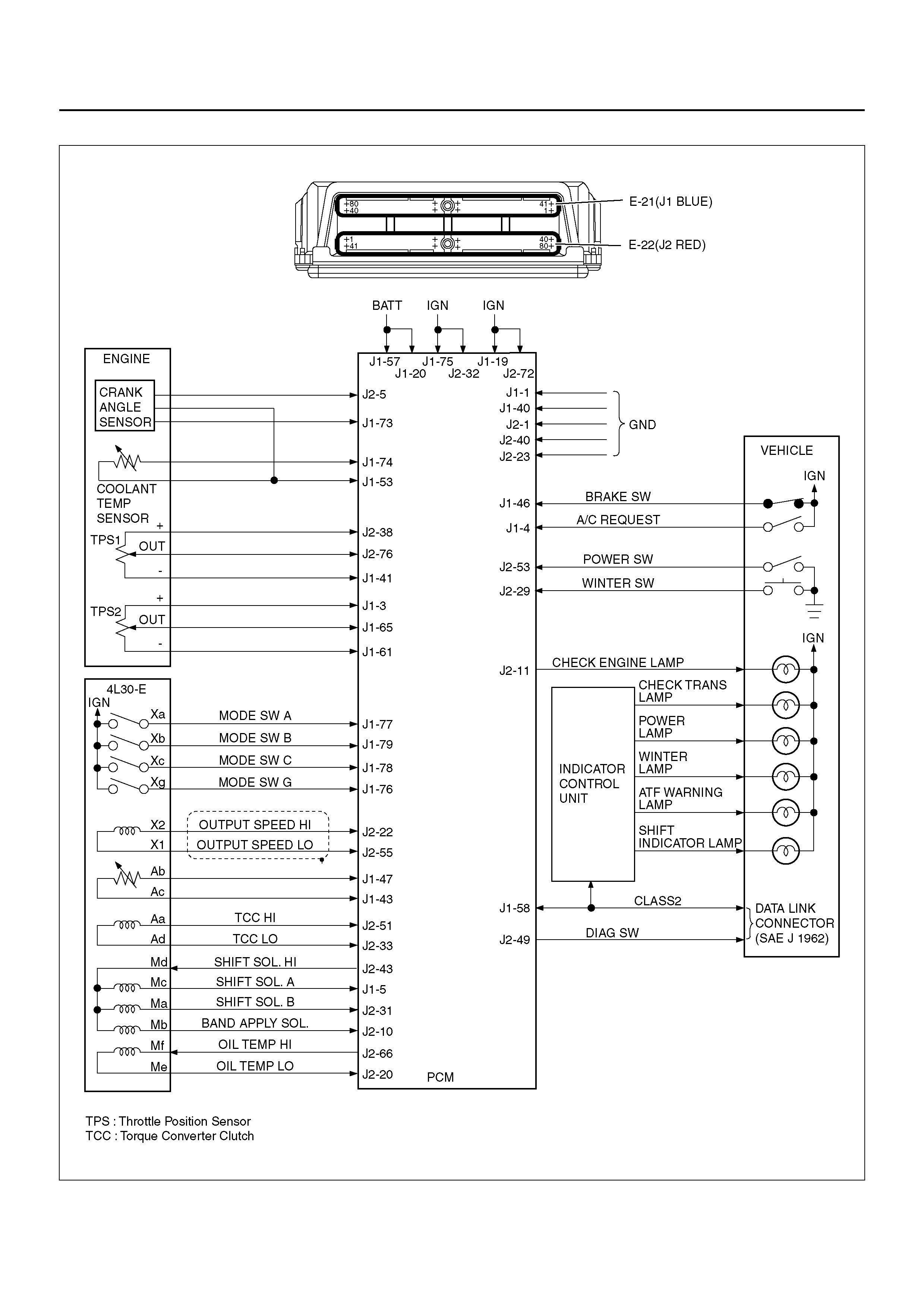
Circuit Diagram
Parts Location
Harness Connector Faces
Transmission Fluid Temperature (TFT) Sensor
Specifications

SERVICE PRECAUTION
WARNING: THIS VEHICLE HAS A SUPPLEMENTAL
RESTRAINT SYSTEM (SRS), REFER TO THE SRS
COMPONENT AND WIRING LOCATION VIEW IN
ORDER TO DETERMINE WHETHER YOU ARE
PERFORMING SERVICE ON OR NEAR THE SRS
COMPONENTS OR THE SRS WIRING. WHEN YOU
ARE PERFORMING SERVICE ON OR NEAR THE
SRS COMPONENTS OR THE SRS WIRING, REFER
TO THE SRS SERVICE INFORMATION. FAILURE TO
FOLLOW WARNINGS COULD RESULT IN
POSSIBLE AIR BAG DEPLOYMENT, PERSONAL
INJURY, OR OTHERWISE UNNEEDED SRS SYSTEM
REPAIRS.
CAUTION: Always use the correct fastener in the
proper location. When you replace a fastener, use
ONLY the exact part number for that application.
HOLDEN will call out those fasteners that require a
replacement after removal. HOLDEN will also call
out the fasteners that require thread lockers or
thread sealant. UNLESS OTHERWISE SPECIFIED,
do not use supplemental coatings (Paints, greases,
or other corrosion inhibitors) on threaded fasteners
or fastener joint interfaces. Generally, such
coatings adversely affect the fastener torque and
the joint clamping force, and may damage the
fastener. When you install fasteners, use the
correct tightening sequence and specifications.
Following these instructions can help you avoid
damage to parts and systems.
GENERAL DESCRIPTION
The 4L30–E is a 4–speed fully automatic transmission.
It uses a microcomputer as a control unit to judge
running conditions including throttle opening rate and
vehicle speed, then it sets the shifting point in the
optimum tim in g so that be st dr i ving pe rf or man ce can be
achieved.
In addition, the built–in shift mode select function can
select three shift modes according to the driver's
preference:
• Normal mode –Normal shift pattern.
• Winter mode –Starts in 3rd gear to reduce slippage
on ice or snow.
• Power mode has a delayed upshift for when more
powerful acceleration is required.
Also, the built–in fail safe function (“backup mode")
assure s driv ing pe rform ance even if the vehic le spee d
sensor, throttle signal or any solenoid fails.
Further, the self–di agnost ic fun ction co ndu cts diagnos is
in a short time when the control system fails, thus
improving serviceability.
The major features of 4L30–E are as follows:
• A compac t structure con sisting of 2 sets of planetary
gears and flat torque converter.
• Electronic control selects the optimum shift mode
according to the driving conditions.
• Electronic control maintains the optimum hydraulic
pressure for clutch, band brake as well as
transmission so that shift feeling is improved.
• Two sets of planetary gears reduce friction of power
train.
Also, a lockup mechanism in the torque converter
reduces fuel consumption.
• Wide gear ratio and high torque rate of torque
converter provide excellent starting performance.
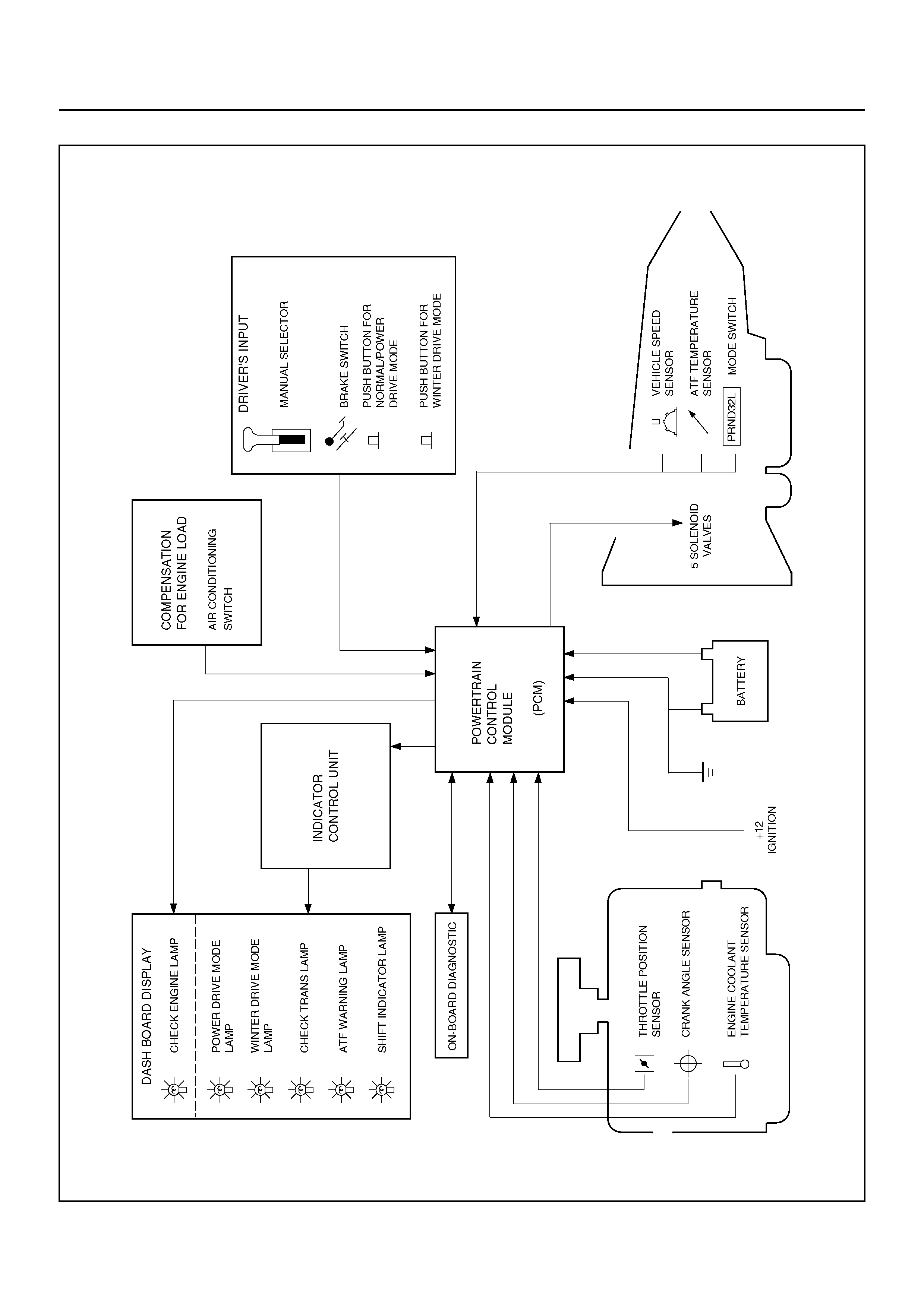
ELECTRONIC CONTROL DIAGRAM
C07R200003
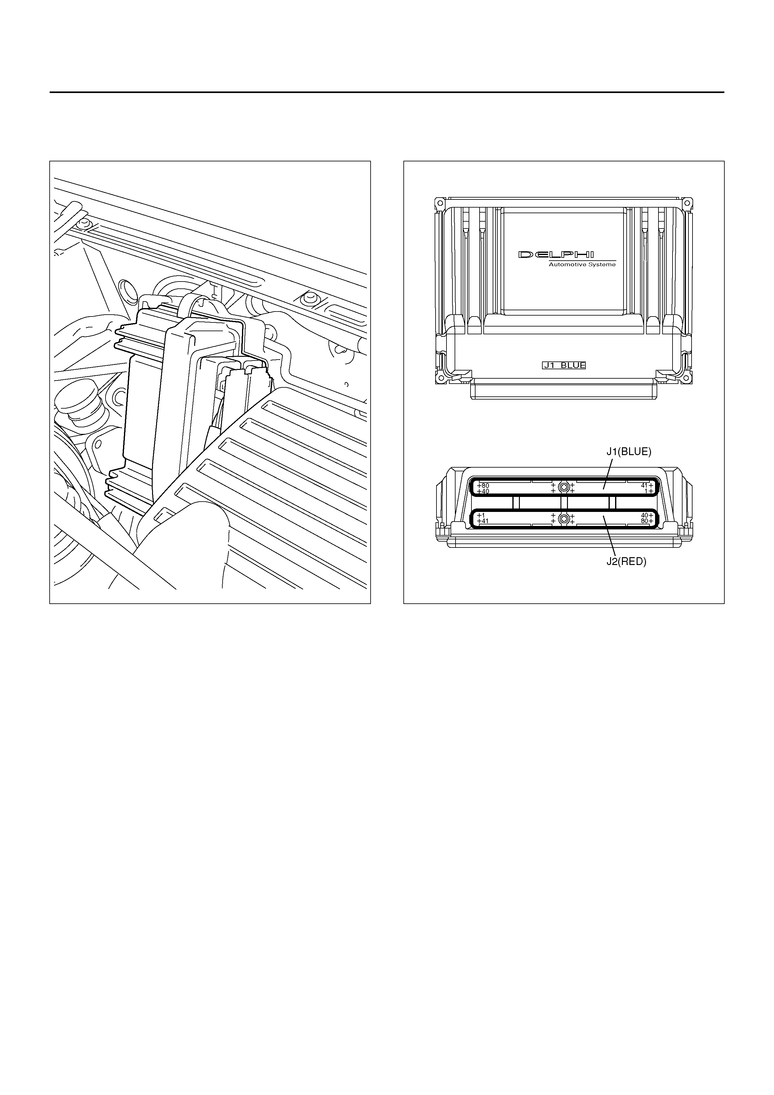
POWERTRAIN CONTROL MODULE (PCM)
C07R100004
Pressure Control Solenoid HI
Pressure Control Solenoid LO
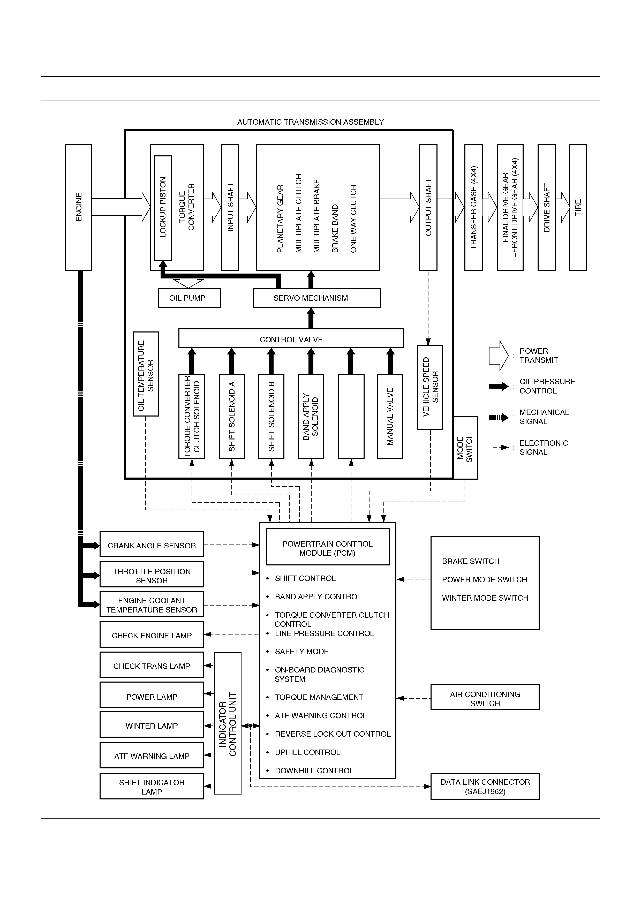
CONTROL SYSTEM DIAGRAM
C07R100005
PRESSURE CONTROL
SOLENOID

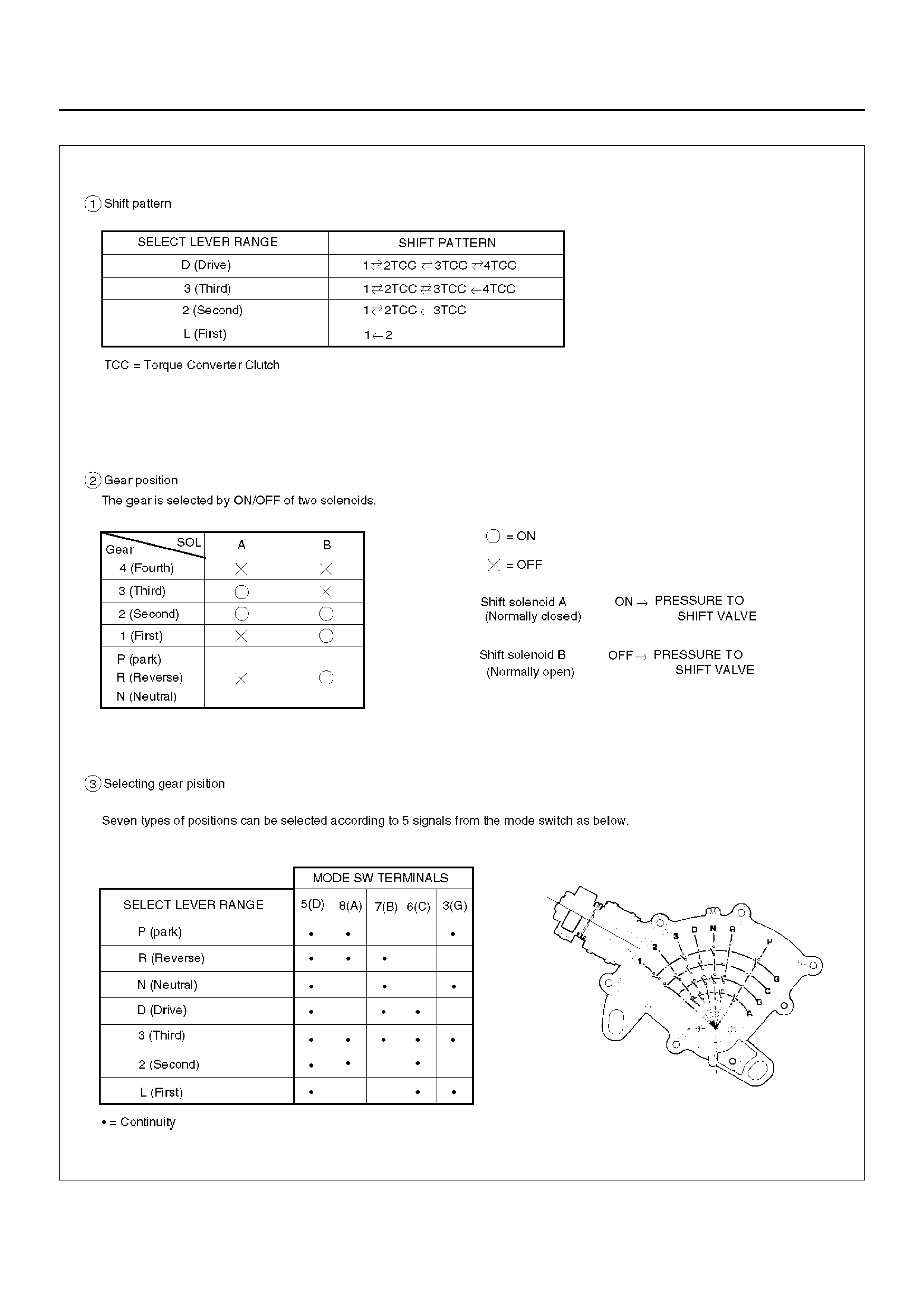
SHIFT CONTROL
The transmission gear is shifted according to the shift
pattern selected by the driver. In shifting gears, the
gear ratio is controlled by the ON/ OFF signal using the
shift solenoid A and the shift solenoid B.
BAND APPLY CONTROL
The band apply is controlled when in the 3–2 downshift
(engine overrun prevention) and the garage shift (shock
control).
The band apply solenoid is controlled by the signal from
the Pulse Width Modulation (PWM) to regulate the flow
of the oil.
TORQUE CONVERTER CLUTCH CONTROL
The clutch ON/OFF is controlled by moving the
converter clutch valve through shifting Torque Converter
Clutch (TCC) solenoid using the ON/OFF signal.
LINE PRESSURE CONTROL
The throttle signal allows the current signal to be sent to
the Pressure Control Solenoid. After receiving the
current signal, the Pressure Control Solenoid activates
the pressure regulator valve to regulate the line
pressure.
ON–BOARD DIAGNOSTIC SYSTEM
Several malfunction displays can be stored in the
Powertrain Control Module (PCM) memory, and read by
Tech 2..
The serial data lines, which are required for the testing
of the final assembly and the coupling to other
electronic modules, can be regulated by this function.
FAIL SAFE MECHANISM
If there is a problem in the transmission system, the
PCM will go into a “backup" mode.
The vehicle can still be driven, but the driver must use
the select lever to shift gears.
TORQUE MANAGEMENT CONTROL
The transmission control side sends the absolute spark
advance signal to the engine control side while the
transmission is being shifted. This controls the engine
spark timing according vehicle running condition,
improving shift quality.
ATF WARNING CONTROL
The oil temperature sensor detects the ATF oil
temperature to control the oil temperature warning, TCC
operation, and the winter mode.
REVERSE LOCK OUT CONTROL
With the selector lever in reverse position, the PCM will
not close the PWM solenoid until the vehicle is below 11
km/h, thus preventing reverse engagement above this
speed.
DOWNHILL CONTROL
This mode is automatically activated from NORMAL
mode only when downhill conditions are recognised.
The shift pattern is identical to NORMAL mode except
the 0% throttle 3-4 and 4-3 shift calibrations are
modified to provide engine braking over a greater speed
range.
UPHILL CONTROL
When uphill condition are recognized the 2-3 and 3-4
shift and TCC apply take place only when the engine
torque is sufficient to avoid shift hunting.
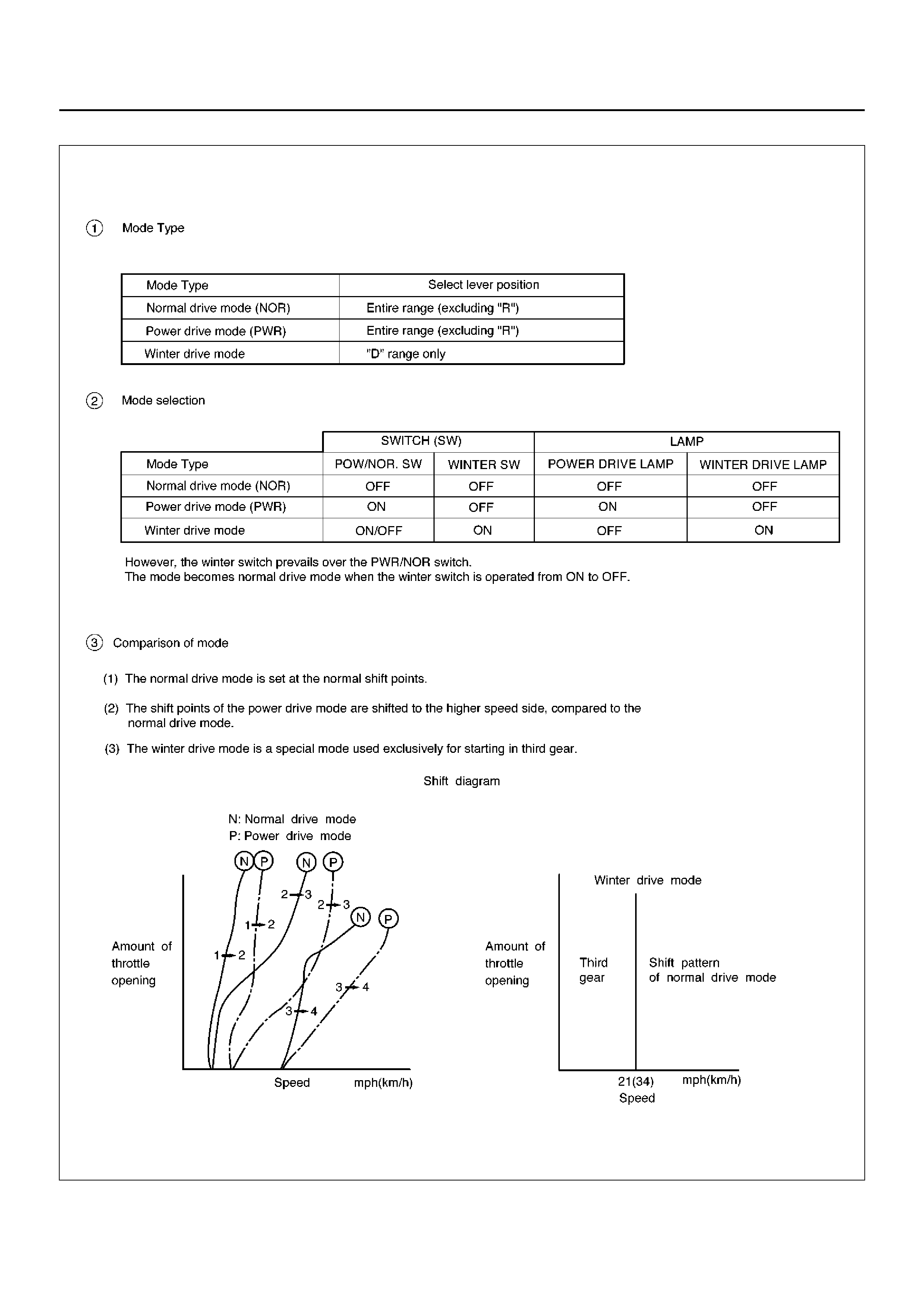
SHIFT MODE CONTROL
F07RX001
GEAR SHIFT CONTROL
F07RT034

WINTER DRIVE MODE
1. The winter switch will operate when switched on
after all of the following conditions are present:
a The gear select position is “D" range only.
b Vehicle speed is11km/h or less.
c Transmission oil temperature is 130°C or less.
d Accelerator opening is at 8% or less.
NOTE: Though the winter indicator lamp lights even on
P, R or N range except D range, the winter mode is not
activated until the winter mode activate conditions are
satisfied.
2. Cancel Release
1. Cancellation by driver
a Turning off the winter drive mode switch
b Shifting select position to “3", “2", or “L"
(Winter drive mode is not canceled by
selecting “N", “R", or “P" from “D")
c Ignition key is turned off.
2. Automatic cancellation
a When vehicle speed is greater than 34 km/h
for more for 1 second or more
b When transmission oil temperature reaches
130°C or above
NOTE: The mode returns to normal drive mode or
power drive mode after the winter drive mode is
canceled.
BACKUP MODE
If a major system failure occurs which could affect
safety or damage the transmission under normal vehicle
operation, the diagnostic system detects the fault and
overrides the Powertrain Control Module (PCM).
The “CHECK TRANS" light flashes to alert the driver,
and the transmission must be manually shifted as
follows:
Shifts are firmer to prevent clutch slip and consequent
wear. The fault should be corrected as soon as
possible.
Select lever position Gear Ratio Selected
D 4 (Fourth)
Manual 3 4 (Fourth)
Manual 2 3 (Third)
Manual L 1 (First)
RReverse
FUNCTIONS OF INPUT / OUTPUT COMPONENTS
Components Function
I
N
P
U
T
S
I
G
N
A
L
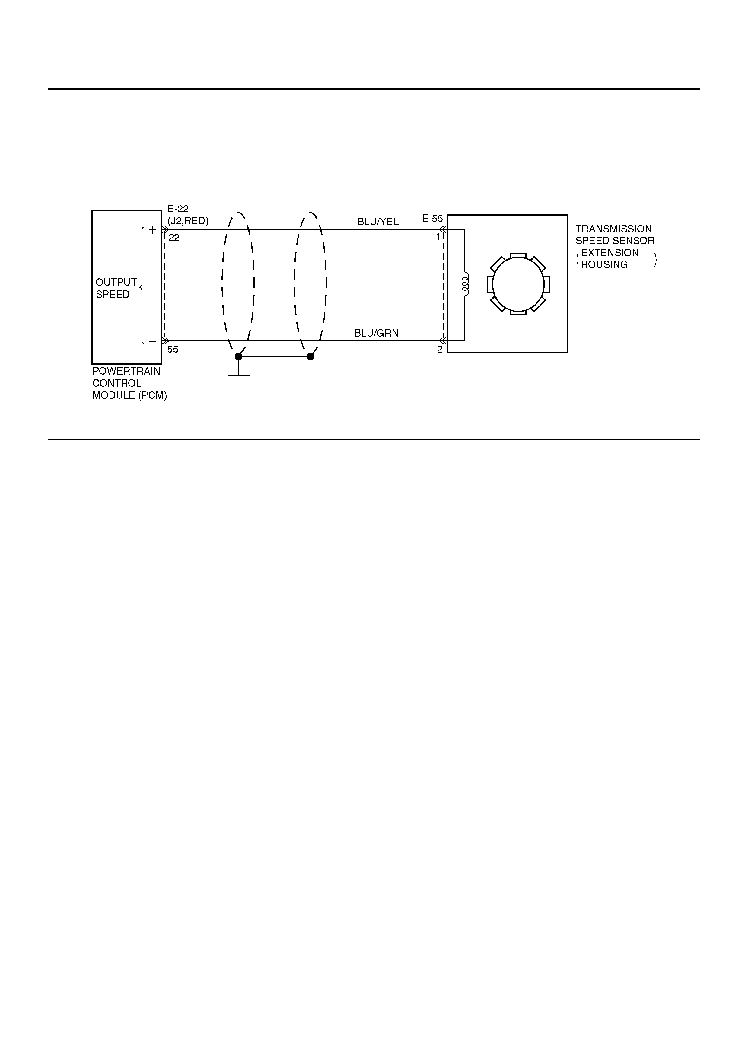
Speed sensor
(fixed to transmission (T/M)) Senses rotation of out put shaft and feeds the data to Powertrain Control Module
(PCM).
Throttle position sensor
(TPS)
(fixed to engi ne)
Senses the extent of throttle valve opening and the speed of the throttle valve
lever motion to open the valve. Feeds the data to PCM.
Brake Switch (SW)
(fixed to brake ped al) Senses whether the driver has pressed the brake pedal or not and feeds the
information to PCM.
Mode SW (fixed to T/M) Senses the select lever position, and feeds the information to PCM.
Power drive SW
(fixed to front console) Senses whether the driver has selected the power mode, and feeds the
information to PCM.
T/M oil temp. sensor Senses the T/M oil temperature and feeds the data to PCM
Engine co ol a nt tem p er at u re
sensor Senses the engine coolant temperature, and feeds the data to PCM.
Engine speed signal Feeds the signals monitoring engine speed to PCM from crank angle sensor.
Air conditioning information Senses whether the air conditioner has been switched on or not, and feeds the
information to PCM.
Winter switch (fixed to front
console) Senses whether the driver has selected the winter mode, and feeds the
information to PCM.
Cruise con tr oll er (Ove rd riv e
OFF signal) Downshift takes place when Overdrive OFF signal is received from auto cruise
control unit.
O
U
T
P
U
T
S
I
G
N
A
L
S
O
L
E
N
O
I
D
Shift soleno id A, B S elects sh ift point and gear po sitio n suite d to the vehi cle runn ing con dit ion on the
basis of PCM output.
Band apply solenoid Controls oil flow suited to the vehicle running condition on the basis of PCM
output.
Torque Converter Clutch
solenoid Controls clutch engagement/disengagement suited to the vehicle running
condition on the basis of PCM output.
Pressure Control
Solenoid
(Pressure regulator
valve)
Adjusts the oil pump delivery pressure to line pressure suited to the vehicle
running condition on the basis of PCM output.
Power drive mode lamp Informs the driver whether the vehicle is in power mode or not.
Winter drive mode lamp Informs the driver whether the vehicle is in winter mode or not.
“CHECK TRANS" lamp Informs the driver of failure in the system.
ATF warning lamp Lights when ATF oil temperature rises.
DIAGNOSIS
ELECTRONIC DIAGNOSIS
How To Diagnose The Problem
1. To avoid incorrect diagnostics, the information on
this CD needs to be followed accurately. Unless
stated, do not jump directly to a section that
could contain the solution. Some important
information may be missed.
2. The sections in CAPITALS and bold are the main
sections that can be found in the contents.
3. The GO TO “SECTION" means to continue to
check going to the “section".
4. The GO THROUGH “SECTION" means to go
through the “section" and then to go back to the
place the GO THROUGH was written.
5. BASIC ELECTRIC CIRCUITS:
You should understand the basic theory of
electricity. This includes the meaning of voltage,
amps, ohms, and what happens in a circuit with an
open or shorted wire. You should also be able to
read and understand wiring diagrams.
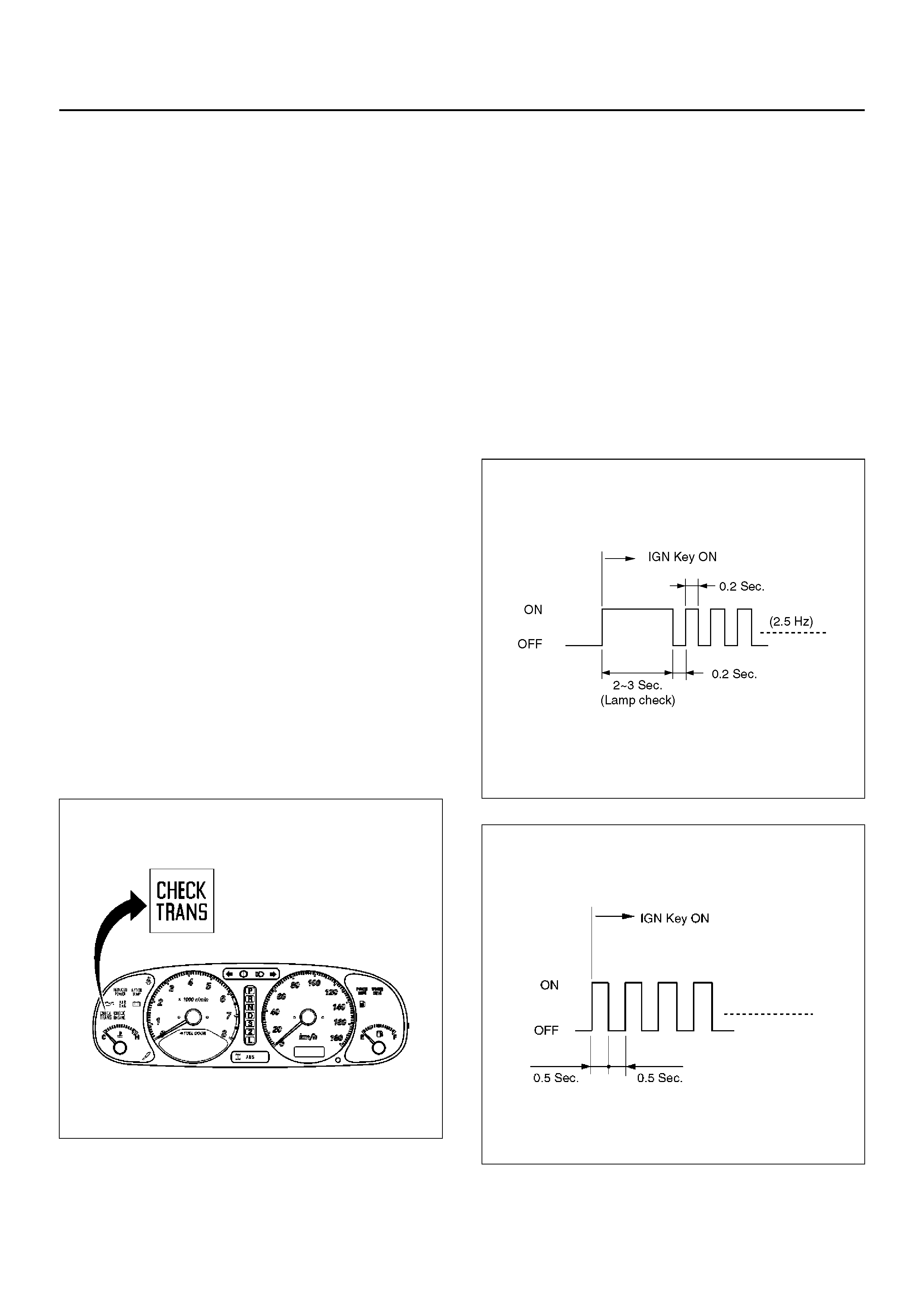
CHECK TRANS INDICATOR
Find CHECK TRANS indicator and verify if it is
A Flashing: GO TO DIAGNOSTIC CHECK.
B Staying on: GO THROUGH CHECK TRANS
CHECK.
C Is never ON when the ignition key is turned on: GO
THROUGH CHECK TRANS CHECK
D Is ON during 2 seconds at ignition but OFF after:
This is normal operation - No DTC or malfunction.
821RY00064
DIAGNOSTIC CHECK
This test determines if the transmission or its input, or
output, connections, or sensors are failing.
1. Connect t he Tech 2: G O THROU GH Tech 2 O BD II
CONNECTION.
2. Turn on the ignition but not the engine.
3. Push “F0" on Tech 2 to see the Diagnostic Trouble
Code (DTC):
4. Do you have a DTC?
YES: wr ite down all code numb ers and do the DTC
CHECK
NO: the DTC can not help you find the problem.
1. GO THROUGH “CHECK TRANS" CHECK
2. IF it is flas hing and the flash is 0.5 se conds ON
and 0.5 seconds OFF, this means that you
should have a DTC stored. Please recheck GO
TO DIAGNOSTIC CHECK and if you find the
same problem, replace the Powertrain Control
Module (PCM).
Normal
C07R200006
Abnormal
C07RY00058
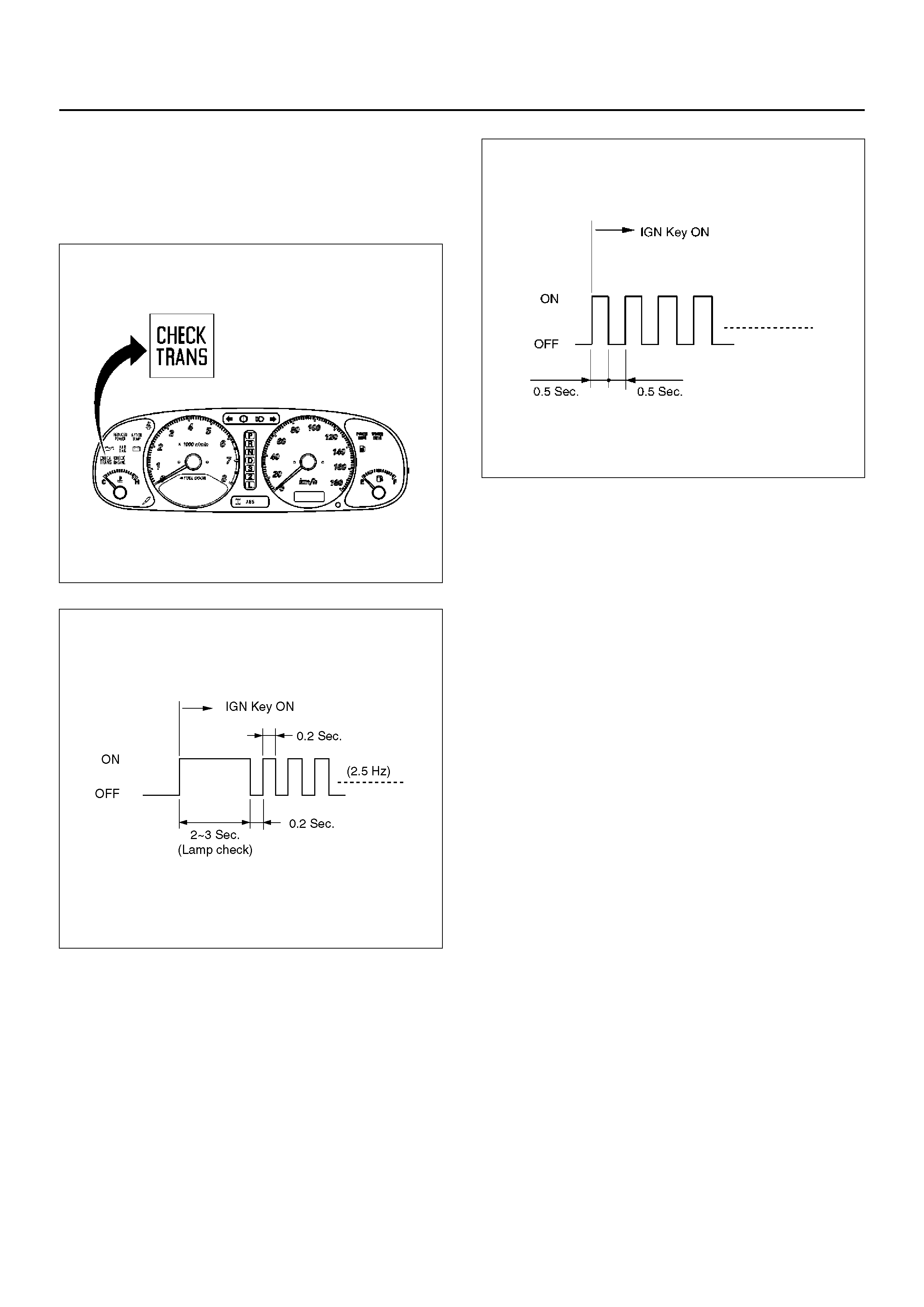
“CHECK TRANS" CHECK
1. Indicator is ON during 2 ∼ 3 seconds at ignition (or
when th e engin e is cran ked) but it is OFF afte r the
engine s tarts. The indicator is wor king normall y GO
TO DIAGNOSTIC CHECK.
821RY00064
Normal
C07R200006
2. Indicator is flashing and the flash is 0.5 seconds ON
and 0.5 seconds OFF always when ignition is on
(engine cranked or not). This means that there is a
malfunc ti on. GO TO DIAGNOSTIC CHECK.
Abnormal
C07RY00058
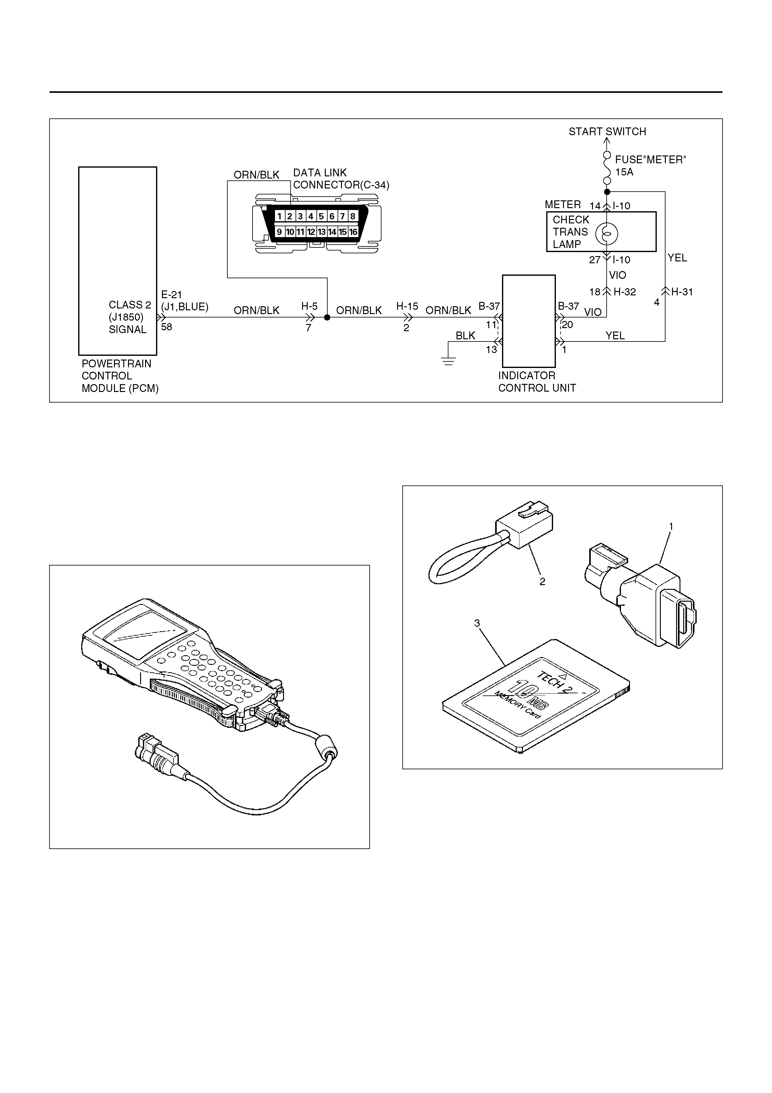
3. Indicator is staying ON always when Ignition is ON.
1. This means that connection between the lamp
and the PCM is shorted to ground.
2. Verify if instrument panel terminal 27 of
connector I–10 is shorted to ground.
3. Verify if th e in dica tor cont rol uni t co nnect or B– 37
terminal 20 is shorted to ground.
4. Verify that the instrument panel terminal 14 of
connector I–10 is connected to battery.
5. IF problem solved: GO TO CHECK TRANS
INDICATOR.
NO:Replace Powertrain Control Module (PCM).
4. Indicator is staying OFF with the ignition ON (engine
OFF).
1. This means that connection between the lamp
and the indicator control unit is shorted to
battery or opened.
2. Verify if instrument panel terminal 27 of
connector I–10 is shorted to battery or open.
3. Verify if th e in dica tor cont rol uni t co nnect or B– 37
terminal 20 is shorted to battery or open.
4. Verify that the instrument panel terminal 14 of
connector I–10 is connected to battery. If not,
check the fuses and t he connections (terminal
18 of connector H–32) voltage.
5. IF problem solved: GO TO CHECK TRANS
INDICATOR.
NO: Replace Powertrain Control Module (PCM).
D07R100031
TECH 2 OBD II CONNECTION
In order to access OBD II Powertrain Control Module
(PCM) data, use of the Tech 2 scan tool kit (7000086) is
required.
1. The electronic diagnosis equipment is composed of:
1. Tech 2 hand–held scan tool unit (700005 7) and
DLC cable (3000095).
901RW176
2. SAE 16/19 Pin Adapter (3000098)(1), RS232
Loop Back Connector (3000112)(2), and
PCMCIA Card (3000117)(3).
F07RW033
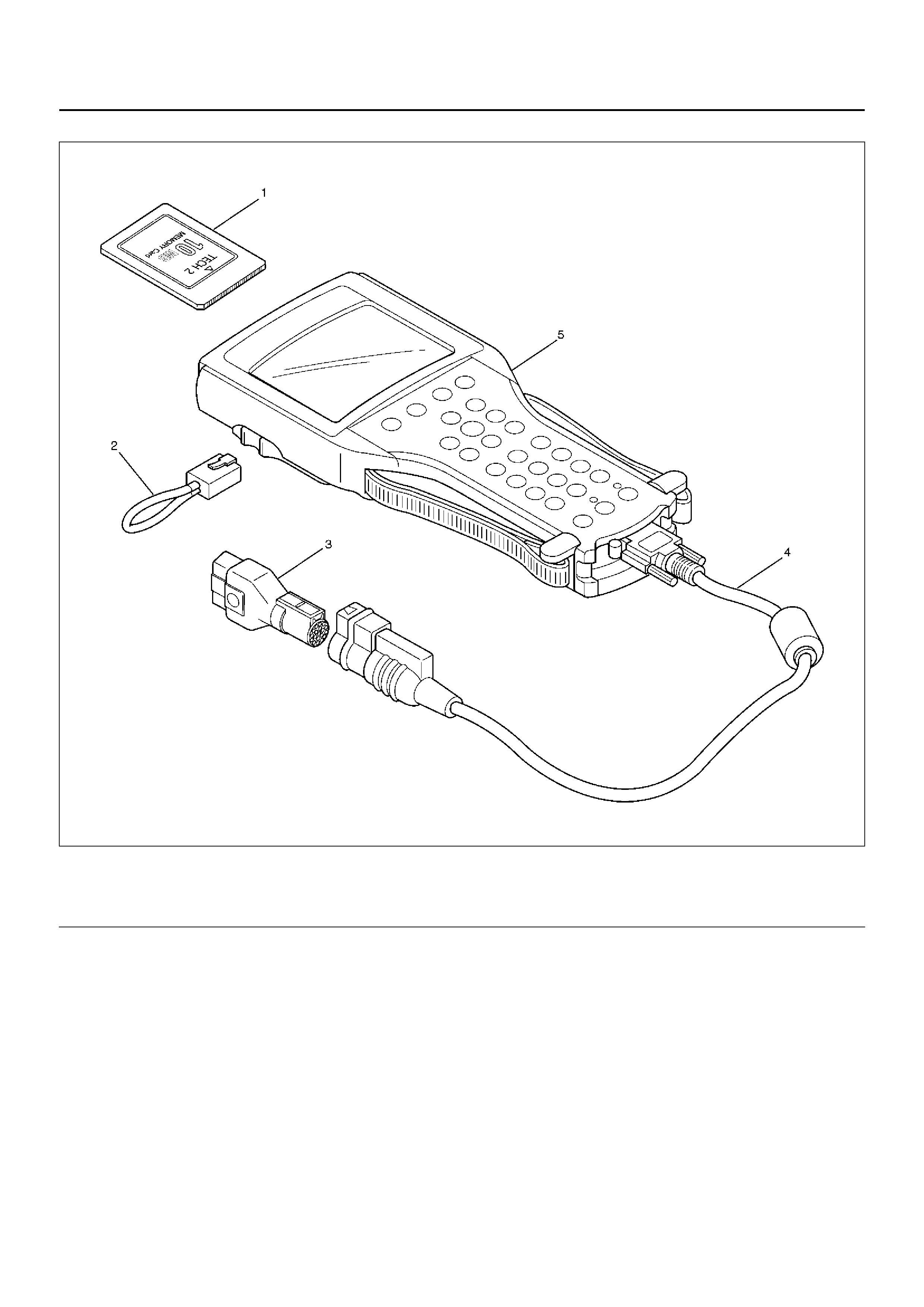
2. Connecting the Tech 2
901RW180
EndOFCallout
Legend
(1) PCMCIA Card
(2) RS 232 Loop Back Connector
(3) SAE 16/19 Adapter
(4) DLC Cable
(5) Tech 2

• Before operating the HOLDEN PCMCIA card with
the Tech 2, the following steps must be
performed:
1. The HOLDEN 2001 System PCMCIA card (1)
inserts into the Tech 2 (5).
2. Connect the SAE 16/19 adapter (3) to the DLC
cable (4).
3. Connect the DLC cable to the Tech 2 (5)
4. Mark sure the vehicle ignition is off.
5. Connect the Tech 2 SAE 16/19 adapter to the
vehicle DLC.
810RW317
6. The vehicle ignition turns on.
7. Veri fy the Tech 2 power up disp lay.
060RW009
NOTE: The RS232 Loop bac k connector is only to use
for diagnosis of Tech 2 and refer to user guide of the
Tech 2.
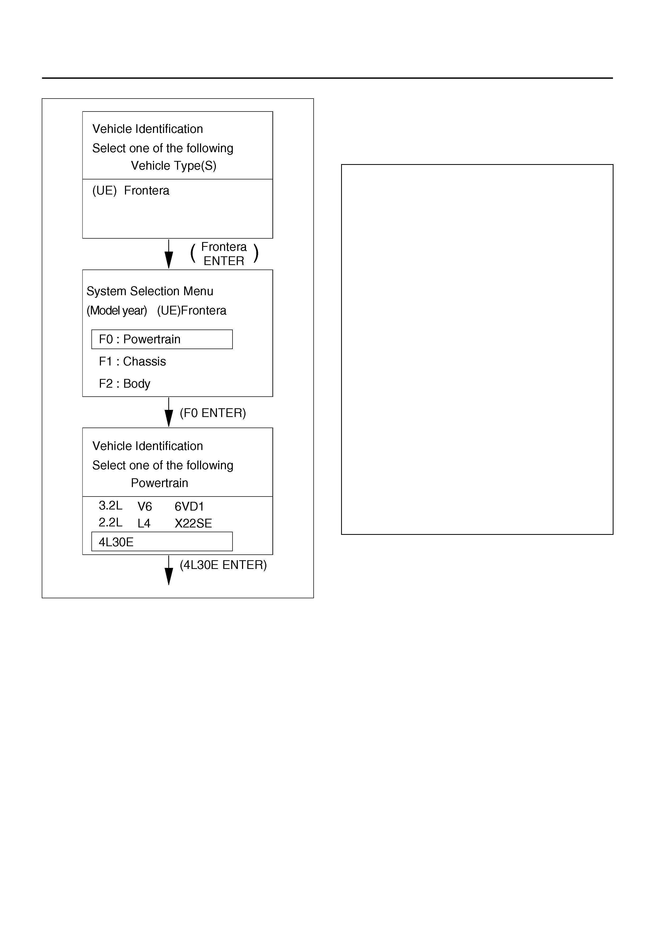
8. The power up screen is displayed when you
power up the tester with the HOLDEN systems
PCMCIA card. Follow the operating procedure
below.
060R100102
060R100104
Once the test vehicle has been identified an
“Application (Powertrain) Menu" screen appears.
Please select the appropriate application.
The following table show s, which f unctions are u sed f or
the available equipment versions.
F0: Diagnostic Trouble Codes
F0: Read DTC Info Ordered By Priority
F1: Clear DTC Information
F2: DTC Information
F1: Data Display
F0: Transmission Data
F2: Snap Shot
F3: Actuator Tests
F0: Lamps
F0: Check Light
F1: Winter Drive Lamp
F2: Power Drive Lamp
F3: AT Oil Temperature Lamp
F1: Solenoids
F0: Solenoid 1-2/3-4 Test
F1: Solenoid 2-3 Test
F2: TCC Sole noi d
F3: Band Appl y So len o id
F4: Pressure Contr ol Sol en oid (PCS)
F4: Function Tests
F0: Reset Oil Life Monitor

Diagnostic Trouble Codes
The purpose of the “Diagnostic Trouble Codes" mode is
to display stored PCM trouble codes.
When “Diagnostic Trouble Codes" is selected an
“Application Menu" screen appears.
Clear DTC Information
The purpose of the “Clear DTC Information" mode is to
command the clearing of stored PCM trouble codes.
When “Clear DTC Information" is selected, a “Clear
DTC Information", warning screen appears. This screen
informs you that by cleaning DTC's, “all stored DTC
information in controller will be erased".
Do you want to clear DTC's (Yes/No).
Press either the Yes or No key when answering.
After clearing codes, confirm system operation by test
driving the vehicle.
Allow the vehicle to shift through all four forward gears
in a manner which attempts to repeat the failure
condition.
NOTE: When the trouble has not been repaired and the
trouble code cannot be erased, check the vehicle again.
DTC Information
When “DTC Information" is selected, an “Application
Menu" appears with a list of DTC information function
keys addressing DTC specifics and their origins.
Function key selections may vary for particular vehicle
and/or system.
Data Display
The purpose of the “Data Display" mode is to
continuously monitor data parameters.
The current actual values of all important sensors and
signals in the system are display through F1 mode.
When “Data Display" is selected an “Application Menu"
appears. Please select either “Engine" or “Transmission
Data Display".
See “Transmission Data" on next page.
Snapshot
When “Snapshot" is selected an “Application Menu"
appears.
When “Transmission Snapshot" application is selected
from the “Application Menu", a “Snapshot Menu"
appears, displaying several options. “Snapshot" options
may vary from one system to another.
“Snapshot" allows a recording of all vehicle parameters.
There parameters may then be replayed at a future
point in time.
This action allows you to focus on making the condition
occur, rather than trying to view all of the data in
anticipation of the fault. The snapshot will collect
parameter information around a trigger point that you
select.
When a snapshot is taken. It is recorded onto the
PCMCIA memory card. When the Tech2 is powered
down. Snapshots are not lost.
Actuator Tests
The purpose of “Actuator Tests" mode is to check for
correct operation of electronic system actuators.
Lamps
You can operate the lamps by pressing the “ON" and
“OFF" buttons.
Preconditions: none
Solenoid
Solenoid 1-2/3-4, Solenoid 2-3, TCC Solenoid
You can operate the solenoids by pressing the “ON" and
“OFF" buttons.
Preconditions: P–N position, no vehicle speed, no
engine speed
Band Apply Solenoid
You can operate the solenoid by pressing the “ON" and
“OFF" buttons.
Preconditions: P-N position, idle engine speed, no
vehicle speed.
Pressure Control Solenoid (PCS)
You can set desired PCS Current using the “Increment"
(+20) and “Decrement" (-20) button. The PC Solenoid
Data informs about PCS Current, Pressure and Duty
Cycle.
Preconditions: P–N position, no engine speed, no
vehicle speed
Reset Oil Life Monitor
Displays parameter “Oil Life Monitor" and resets to
100% if Yes-button is pressed on Reset-question. “No"
leaves test.
NOTE:
Freeze Frame (Powertrain DTC A/B Type)
Freeze Frame is an element of the Diagnostic
Management System which stores various vehicle
information at the moment an emission-related fault
is stored in memory and when the MIL is
commanded on. These data can help to identity the
cause of a fault. Refer to Section 0C for more detailed
information.
Failure Records (Powertrain DTC C/D Ty pe)
Failure Records data is an enhancement of the OBD II
Freeze Frame feature. Failure Records store the
same vehicle information as does Freeze Frame, but
it will store that information for any fault which is
stored in on- board memory, while Freeze Frame
sotres information only for emission-related faults
that commands the MIL on.

TRANSMISSION DATAItem Unit Engine running at idle
Ignition Voltage V 12.8 ∼ 14.1 V
Engine Speed RPM 750 ∼ 900 RPM
Vehicle Speed km/h, MPH 0 MPH
AT Output Speed (Automatic Transmission) RPM 0 RPM
AT Input Speed Ratio (Automatic Transmission) 0
Throttle Posi tion % 0 %
AT Oil Temperature (Automatic Transmission) °C, °F70 ∼ 80°C (158 ∼ 176°F)
Transmission Temperature °C, °F75 ∼ 110°C (167 ∼ 230°F)
AT Oil Temperature Lamp (Automatic Transmission) On/Off Off
AT Oil Life Monitor (Automatic Transmission) % 100 %
AT Oil Life Lamp (Automatic Transmission) On/Off Not used
Commanded Gear 1
Current Gear 1
Mode Switch A Inactive/Active Active
Mode Switch B Inactive/Active Inactive
Mode Switch C Inactive/Active Inactive
Mode Switch G Inactive/Active Active
Selector Position Park
1–2 Shift Solenoid A On/Off Off
2–3 Shift Solenoid B On/Off On
Solenoid Brake Band On/Off Off
TCC Slip Speed RPM 750 ∼ 900 RPM
TCC Solenoid On/Off Off
TCC Duty Cycle % 0 %
PCS Current (Pressure Control Solenoid) A approx. 1.0 A
PCS Duty Cycle (Pressure Control Solenoid) % approx. 45 ∼ 60 %
Desired PCS Pressure (Pressure Control Solenoid) kPa 43 ∼ 52 kPa
Shift Pressure kPa 43 ∼ 52 kPa
Brake Swit ch On/Off On
Winter Switch On/Off Off
Winter Drive Lamp On/Off Off
Power Switch Normal Normal
Power Drive Lamp On/Off Off
Emergency Mode Inactive, Active Inactive
ABS Status On/Off (Not used)
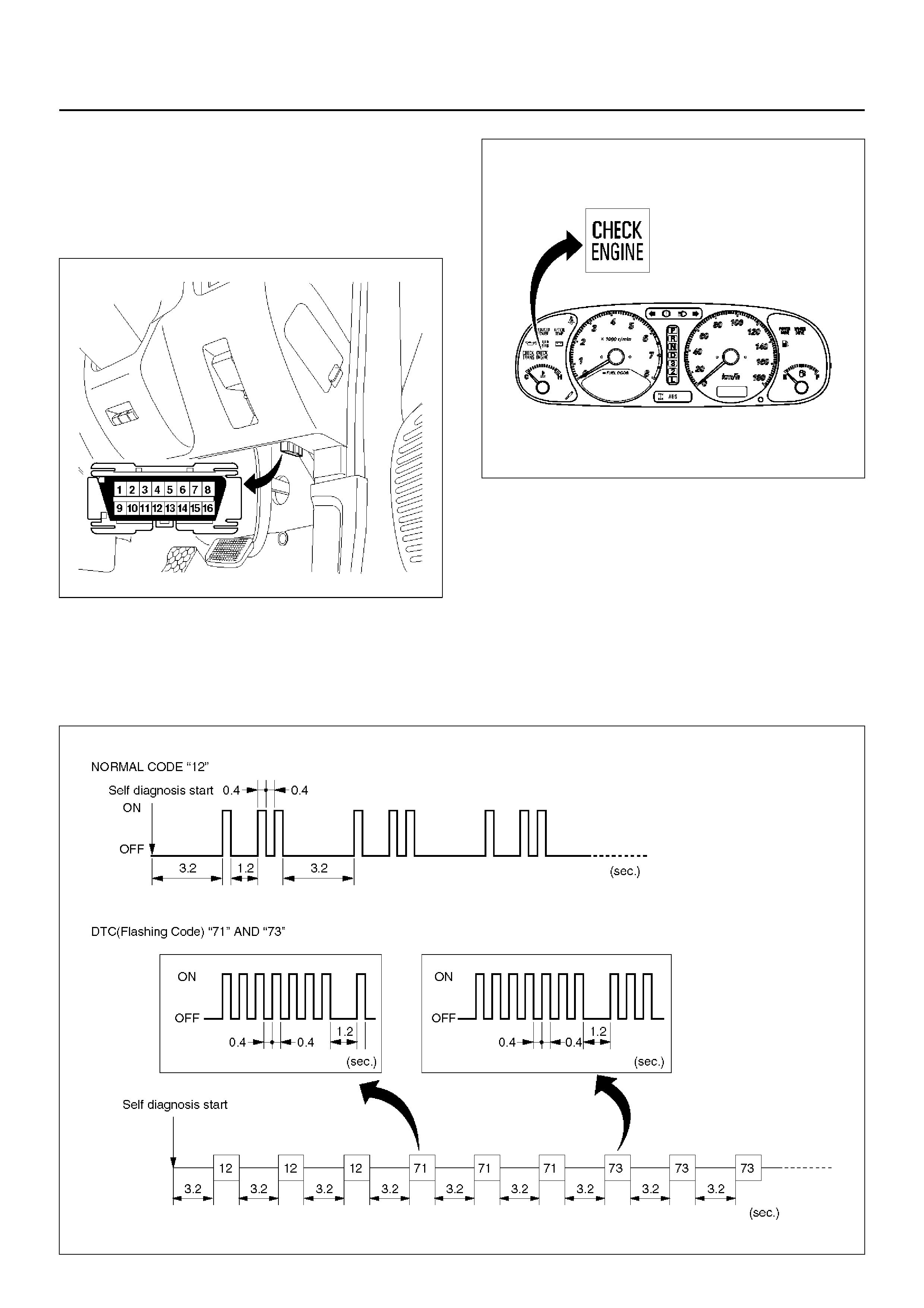
FLASHING CODE
1. A DTC (Flashing Code) can be displayed by the
Powertrain Control Module (PCM) by shorting
together terminals 6 and 4 or 5 (GND) of the Data
Link Connector (DLC) located right side of the
drivers side instrument panel.
810RW317
821RY00065
2. 1. In case there is no DTC stored in memory. The
CHECK ENGINE indicator flashes Normal Code
“12" repeatedly.
2. In case there is DTC stored in memory. First,
Normal Code “12" is displayed three times and
then any other DTC`s are displayed three times.
When all DTC`s have been displayed they are
displayed again beginning from the first one.
3. Write down all co des num bers and GO TO DTC
CHECK.
C07RX006
OBD II DIAGNOSTIC MANAGEMENT SYSTEM
Powertrain Control Module (PCM) Location
825R100018 826RY002
Class 2 Serial Data Bus
OBD II technology requires a much more sophisticated
PCM than does OBD I technology. The OBD II PCM
diagnostic management system not only monitors
systems and components that can impact emissions,
but they also run active tests on these systems and
components. The decision making functions of OBD II
PCM have also greatly increased. To accommodate
this expansion in diagnostic complexity, HOLDEN
engineers have designed the Class 2 serial data bus,
which meets SAE J1850 recommended practice for
serial data.
“Serial Data" refers to information which is transferred in
a linear fashion – over a single line, one bit at a time. A
“Data Bus" is an electronic pathway through which serial
data travels.
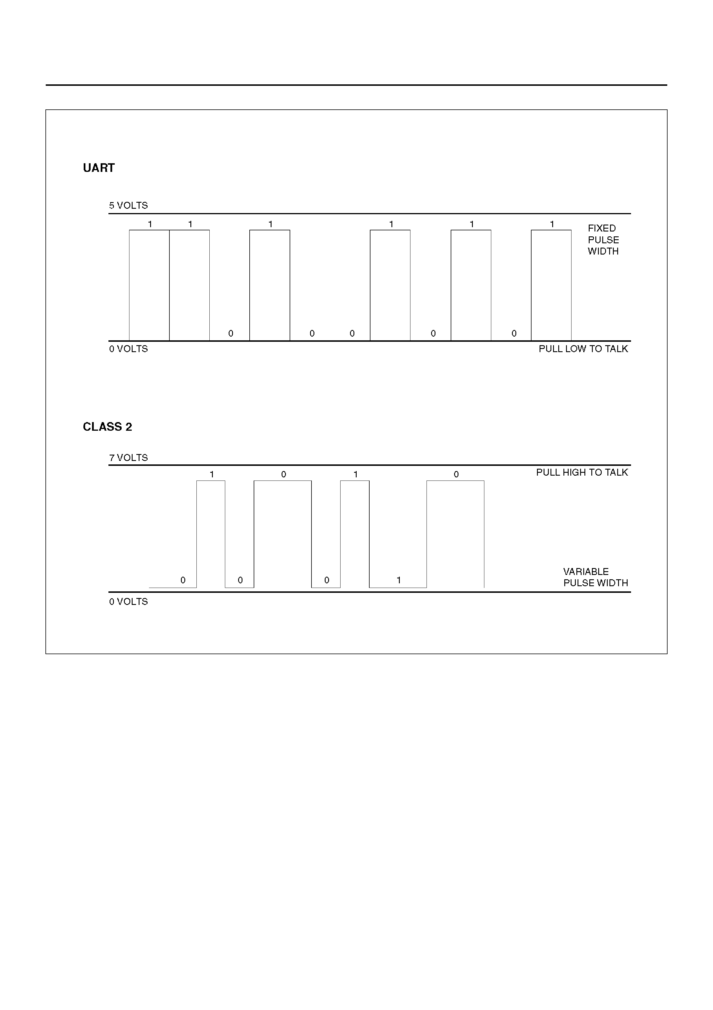
FRONTERA previously used a 5 volt data bus called
UART, which is an acronym for “Universal
Asynchronous Receive and Transmit". When neither the
vehicle's control module nor the diagnostic tool, such as
a Tech 2, are “talking," the voltage level of the bus at
rest is 5 volts. The two computers talk to each other at a
rate of 8,192 bits per se cond, by toggl ing or swit ching
the voltage on the data bus from 5 volts to ground.
Class 2 data, wh ich is used on OBD II veh icles, is quite
different. Data is transferred at a rate of 10.4 kilobits
per second, and the voltage is toggled between zero
and 7 volts.
C07RT006
Class 2 data is also pulse width modulated. Each bit of
information can have one of two lengths: long or short.
On the other hand, UART data bits come in only one
length (short). The pulse width modulation of Class 2
data allows better utilization of the data line.
The message carried on Class 2 data streams are also
prioritized. This means that if two devices try to
communication on the data line at the same time, only
the higher priority message will continue. The device
with the lower priority message must wait.
NOTE: The Class 2 data wire is always terminal 2 of
the new 16–terminal Data Link Connector (DLC).
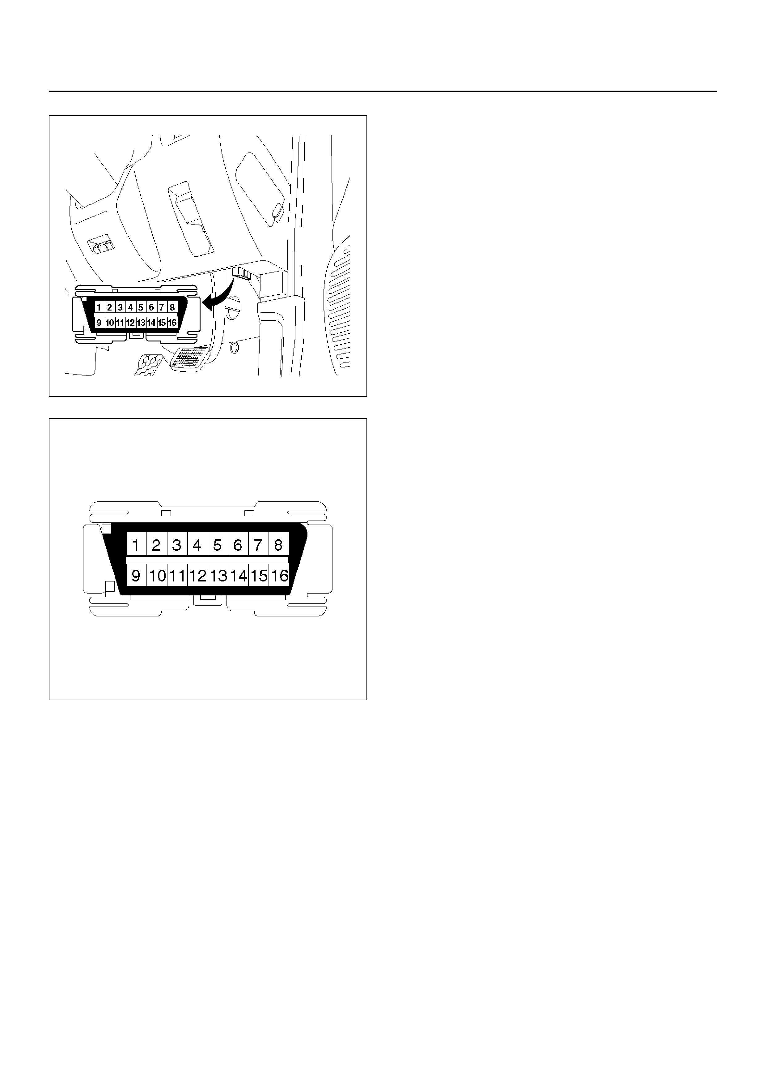
16 – TERMINAL DATA LINK CONNECTOR
(DLC)
OBD II standardizes Data Link Connector (DLC)
configurations. The DLC, formerly referred to as the
ALDL, will be a 16–terminal connector found on the
lower right side of the driver's side instrument panel. All
manufacturers must conform to this 16–terminal
standard.
810RW317
810RT022
MALFUNCTION INDICATOR LAMP (MIL)
The Malfunction Indicator Lamp (MIL) looks the same
as the MIL you are already familiar with (“CHECK
ENGINE" lamp). However, OBD II requires that it
illuminate under a strict set of guidelines. Basically, the
MIL is turned on when the PCM detects a DTC that will
impact the vehicle's emissions.
The MIL is under the control of the Diagnostic
Executive. The MIL will be turned on if a component or
system which has an impact on vehicle emissions
indicates a malfunction or fails to pass an emissions–
related diagnostic test. It will stay on until the system or
component passes the same test, for three consecutive
trips, with no emissions–related faults.
DTC TYPES
Each DTC is directly related to a diagnostic test. The
Diagnostic Management System sets DTC based on
the failure of the tests during a trip or trips. Certain
tests m ust fail two (2) co nsecutive t rips before the DTC
is set. T he fol lowing are the four (4) t yp es of DTCs and
the characteristics of those codes:
•Type A
– Emissions related
– Requests illumination of the MIL of the first trip with
a fail
– Stores a History DTC on the first trip with a fail
– Stores a Freeze Frame (if empty) (DTC
Information for 6VD1 engine)
– Stores a Fail Record
– Updates the Fail Record each time the diagnostic
test fails
•Type B
– Emissions related
– “Armed" after one (1) trip with a fail
– “Disarmed" after one (1) trip with a pass
– Requests illumination of the MIL on the second
consecutive trip with a fail
– Stores a History DTC on the second consecutive
trip with a fail (The DTC will be armed after the first
fail)
– Stores a Fr eeze F r ame on the se con d c ons ecuti ve
trip with a fail (if empty) (DTC Information for 6VD1
engine)
– Stores a Fail Record when the first test fails (not
dependent on consecutive trip fails)
– Updates the Fail Record each time the diagnostic
test fails
(Some special conditions apply to misfire and fuel trim
DTCs)
• Type C (if the vehicle is so equipped)
– Non- Em is s ion s related
– Requests illumination of the Service Lamp or the
service message on the Drive Information Center
(DIC) on the first trip with a fail
PIN 1 – (Not used)
PIN 2 – J1850 Bus + L line on 2–wire systems, or
single wire (Class 2)
PIN 3 – (Not used)
PIN 4 – Chassis ground pin
PIN 5 – Signal ground pin
PIN 6 – PCM diagnostic enable
PIN 7 – (Not used)
PIN 8 – (Not used)
PIN 9 – Primary UART
PIN 10 – (Not used)
PIN 11 – (Not used)
PIN 12 – ABS diagnostic or CCM diagnostic enable
PIN 13 – SIR diagnosti c enable
PIN 14 – (Not used)
PIN 15 – (Not used)
PIN 16 – Battery power from vehicle unswitched (4
AMP MAX.)

– Stores a History DTC on the first trip with a fail
– Does not store a Freeze Frame
– Stores Fail Record when test fails
– Updates the Fail Record each time the diagnostic
test fails
•Type D
– Non-Emissions related
– Not request illumination of any lamp
– Stores a History DTC on the first trip with a fail
– Does not store a Freeze Frame
– Stores Fail Record when test fails
– Updates the Fail Record each time the diagnostic
test fails
Important: Only four Fail Records can be stored. Each
Fail Record is for a different DTC. It is possible that
there will not be Fail Records for every DTC if multiple
DTCs are set.
CLEAR DTC
NOTE: If you clear the DTC (Diagnostic Trouble
Codes) you will not be able to read any codes recorded
during the last occurrence.
NOTE: To use the DTC again to identify a problem, you
will need to reproduce the fault or the problem. This
may require a new test drive or just turning the ignition
on (this depends on the nature of the fault).
1. IF you have a Tech 2:
1. Connect the Tech 2 if it is still not connected go
through Tech 2 OBD II CONNECTION.
2. Push “F1: Clear DTC Information" in the
Application Menu and answer “Yes" to the
question “Do you want to clear DTC's?"
a When a malfunction still exists and the Tech
2 displays “4L30E CODES NOT
CLEARED". This means that the problem
is still there or that the recovery was not
done. Please go to DTC CHECK.
b When a malfunction has been repaired and
the recovery is done the Tech 2 displays
“4L30E CODES CLEARED".
2. IF you have no Tech2, disconnect the PCM battery
feed as necessary.
DTC CHECK
1. Diagnostic Trouble Codes (DTC) have been
identified by Tech 2.
2. You have written the list of the DTCs. The order of
the malfunctions has no meanings for this PCM.
Usually only one or two malfunctions should be set
for a given problem.
3. Check directly the DTCs you identified. The DTCs
are sorted by number. Refer to Diagnostic Trouble
Code (DTC) Identification in this section.
PCM PRECAUTION
The PCM can be damaged by:
1. The electrostatic discharge
2. The short circuit of some terminals to voltage or to
ground.
Electrostatic Discharge Damage Description:
1. Electronic components used to control systems are
often designed to carry very low voltage, and are
very susceptible to damage caused by electrostatic
discharge. It is possible for less than 100 volts of
static electricity to cause damage to some electronic
components. By comparison, it takes as much as
4,000 volts for a person to even feel the zap of a
static discharge.
2. There are several ways for a person to become
statically charged. The most common methods of
charging are by friction and induction. An example
of charging by friction is a person sliding across a
car seat, in which a charge of as much as 25,000
volts can build up. Charging by induction occurs
when a person with well insulated shoes stands
near a highly charged object and momentarily
touches ground. Charges for the same polarity are
drained off, leaving the person highly charged with
the opposite polarity. Static charges of either type
can cause damage, therefore, it is important to use
care when handling and testing electronic
components.
To prevent possible electrostatic discharge damage:
1. Do not touch the PCM connector pins or soldered
components on the PCM circuit board.
2. Be sure to follow the guidelines listed below if
servicing any of these electronic components:
3. Do not open the replacement part package until it is
time to install the part.
4. Avoid touching electrical terminals of the part.
5. Before removing the part from its package, ground
the package to a known good ground on the vehicle.
6. Always touch a known good ground before handling
the part. This step should be repeated before
installing the part if the part has been handled
while sliding across the seat, while sitting down from
a standing position or while walking some distance.
INFORMATION ON PCM
1. The Powertrain Control Module (PCM) is located in
the cente r console and is the co ntrol center o f the
electronic transmission control system.
2. The PCM must be maintained at a temperature
below 85°C (185°F) at all times. This is most
essent ial if the vehicle is put throug h a paint bak ing
process. The PCM will become inoperative if its
temperature exceeds 85°C (185°F). Therefore, it is
recommended that the PCM be removed or that

temporary insulation be placed around the PCM
during the time the vehicle is in a paint oven or other
high temperature process.
3. The P CM is des igned to p rocess the various in puts
and then respond by sending the appropriate
electrical signals to control transmission upshift,
downshift, shift feel and torque converter clutch
engagement.
4. The PCM constantly interprets information from the
various sensors, and controls the systems that
affect transmission and vehicle performance. By
analyzing operational problems, the PCM is able to
perform a diagnostic function by displaying DTC(s)
and aid the technician in making repairs.

INTERMITTENT CONDITIONS
If the Tech 2 displays a diagnostic trouble code as
intermittent, or if after a test drive a DTC does not
reappear though the detection conditions for this DTC
are present, the problem is most likely a faulty
electrical connection or loose wiring. Terminals and
grounds should always be the prime suspect.
Intermitt ents rarel y occur insid e soph istic ated e lectron ic
components such as the PCM.
Use the DTC information to understand which wires and
sensors are involved.
When an intermittent problem is encountered, check
suspect circuits for:
1. Poor terminal to wire connection.
2. Terminals not fully seated in the connector body
(backed out).
3. Improperly formed or damaged terminals.
4. Loose, dirty, or corroded ground connections:
HINT: Any time you have an intermittent in more
than one circuit, check whether the circuits share a
common ground connection.
5. Pinched or damaged wires.
6. Electromagnetic Interference (EMI):
HINT: Check tha t all wi res ar e proper ly rou ted away
from spark plug wires, distributor wires, coil, and
generator. Also check for improperly installed
electrical options, such as lights, 2–way radios, etc.
Use the F2: SNAPSHOT mode of the Tech 2 to help
isolate the cau se of a n i nterm ittent faul t. Th e s napshot
mode will record information before and after the
problem occurs. Set the snapshot to “trigger" on the
suspect DTC or, if you notice the reported symptom
during the test driv e, tri gge r the snapshot man ual ly.
After the snapshot has been triggered, command the
Tech 2 to play back the flow of data recorded from
each of the various sensors. Sign of an intermittent fault
in a sensor circuit is a sudden unexplainable jump in
data values out of the normal range.

TRANSMISSION AND PCM IDENTIFICATION
The chart below contains a list of all important
information concerning rear axle ratio, Powertrain
Control Module (PCM), and transmission identification.
240R100011
VEHICLE Rr axle
Ratio PCM TRANSMISSION
Type Engine HOLDEN Parts No. Calibration
Code HOLDEN Part No. Model Code
HOLDE
N/
Frontera 3.2L V6 4.100 8–12207–159–0 I36 8–96018–555–0 FT (4×4)
DIAGNOSTIC TROUBLE CODE (DTC) IDENTIFICATION
DTC
NUMBER FLASHING
CODE DTC NAME DTC TYPE “CHECK
TRANS"
P0218 71 Transmission Fluid Over Temperature D
P0705 73 Transmission Range Switch (Mode Switch) Illegal
Position D
P0706 74 Transmission Range Switch (Mode Switch)
Performance D
P0712 75 Transmission Fluid Temperature (TFT) Sensor Circuit
Low Input D
P0713 76 Transmission Fluid Temperature (TFT) Sensor Circuit
High Input D
P0719 77 TCC Brake Switch Circuit High (Stuck ON) D
P0722 78 Transmission Output Speed Sensor (OSS) Low Input C Flash
P0723 79 Transmission Output Speed Sensor (OSS) Intermittent C Flash
P0730 81 Transmission Incorrect Gear Ratio C Flash
P0748 82 Pressure Control Solenoid (PCS) Circuit Electrical C Flash
P0753 83 Shift Solenoid A Electrical C Flash
P0758 84 Shift Solenoid B Electrical C Flash
P1850 88 Brake Band Apply Solenoid Malfunction D
P1860 89 TCC Solen oid Elec tric al C Flash
DTC TYPE DEFINITION
C Flashing Check Trans on 1st failure
DNo lamps
DTC P0218/FLASHING CODE 71 TRANSMISSION FLUID OVER TEMPERATURE
D07R100026
Circuit Description
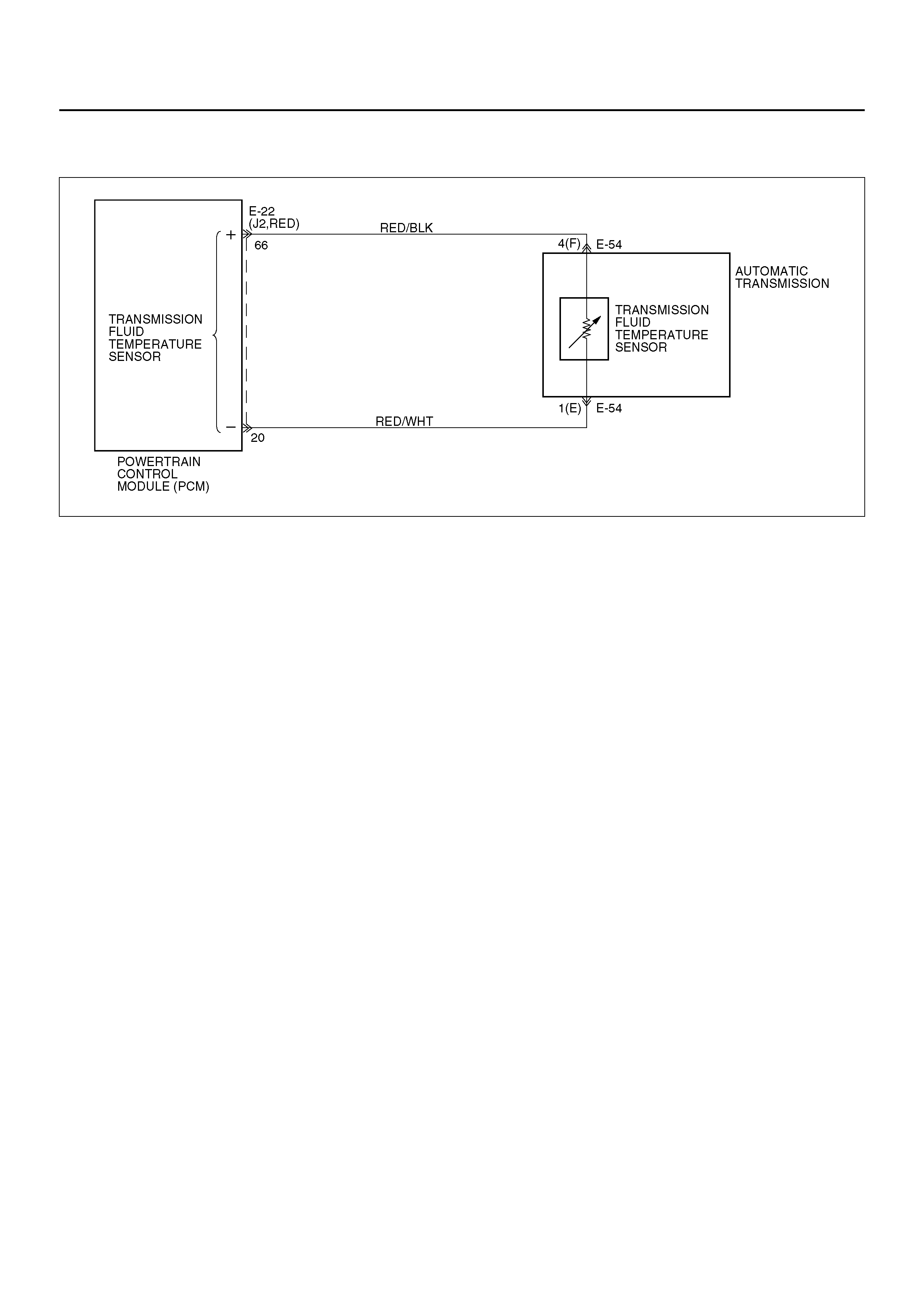
The Transmission Fluid Temperature (TFT) sensor is a
thermister that controls the signal voltage to the PCM.
The PCM supplies a 5–volt reference to the sensor on
circuit RED/ BLK . When th e t ra nsmis s ion flui d i s c old ,
the sensor resistance is high and the PCM will sense
high signal voltage. As the fluid temperature warms to a
normal transmission operating temperature of 100°C
(212°F), the sensor resistance becomes less and the
voltage decreases to 1.5 to 2.0 volts.
This DTC detects a high trans missio n temper ature for a
long period of time. This is a type “D" DTC.
Conditions For Setting The DTC
• No TFT DTCs P0712 (Flashing Code 75) or P0713
(Flashing Code 76).
• TFT is greater than 135°C (275°F).
• All conditions met for 21 seconds.
Action Taken When T h e DTC Sets
• Hot mode TCC Shift Pattern.
• The PCM will not illuminate the CHECK TRANS
Lamp.
• ATF Lamp ON. (greater than 145°C (293°F))
• Disable E–side TCC OFF request.
Conditions For Clearing The DTC
• The DTC can be cleared from the PCM history by
using a scan tool.
• The DTC will be cleared from history when the
vehicle has achieved 40 warm–up cycles without a
failure reported.
• The PCM will cancel the DTC default actions when
the fault no longer exists and the ignition is cycled
“off" long enough to power down the PCM.
Diagnostic Aids
• Inspect the wiring for poor electrical connections at
the PCM and at the transmission 7–way connector.
Look for possible bent, backed out, deformed or
damaged terminals. Check for weak terminal
tension as well.
Also check for a chafed wire that could short to bare
met a l o r o t he r w ir i ng . In s pe c t f o r a broken w i re in si d e
the insulation.
• When diagnosing for a possible intermittent short or
open condition, move the wiring harness while
observing test equipment for a change.
• Check harnes s ro uting f or a p otentia l sho rt to g round
in circuit RED/BLK.
• Scan tool TFT sensor temperature should rise
steadily to about 100°C (212°F), then stabilize.
• Check for a “skewed" (mis–scaled) sensor by
comparing the TFT sensor temperature to the
ambient temperature after a vehicle cold soak. A
“skewed" sensor can cause delayed garage shifts or
TCC complaints.
• Check for a possible torque converter stator problem.
• Verify customer driving habits, trailer towing, etc.
TEST DESCRIPTION
The numbers below refer to the step numbers on the
diagnostic chart.
2. This test checks for a “skewed" sensor or shorted
circuit.
3. This test simulates a TFT DTC P0713.

DTC P0218/Flashing Code 71 Transmission Fluid Over Temperature
Step Action Yes No
1 Perform the following checks:
• Check for possible engine system problems.
• Transmission fluid checking procedure. Refer to Checking
Transmission Fluid Level and Condition in Automatic
Transmission (4L30–E) Section.
Were the checks performed? Go to Step 2 Refer to “Engine
Manual"
2 1. Install the scan tool.
2. With the engine “of f", turn the ignition switch “on".
NOTE: Before clearing DTC(s), use the scan tool to record
“Failure Records" for reference, as data will be lost when “Clear
Info" function is used.
3. Record the DTC “Failure Records".
Is the TFT sensor signal voltage less than 1.54 volts? Go to Step 3 Go to Diagnostic
Aids
3 1. Turn the ignition “off".
2. Disconnect the transmission 7–way connector E–54
(additional DTCs may set).
3. With the engine “of f", turn the ignition switch “on".
Is the TFT sensor signal voltage greater than 4.92 volts?
Go to Internal
Wiring Harness
Check Go to S tep 4
4 Inspect/repair circuit RED/BLK for a short to ground.
Was a problem found? Go to Step 6 Go to S tep 5
5 1. Inspect the PCM for poor connections.
2. Replace the PCM if no poor connections were found.
Is the replacement complete? Go to Step 6 —
6 1. After the repair is complete, use the scan tool to select
“DTC", then “Clear Info" function and ensure the following
conditions are met:
TFT is less than 125°C (257°F) for at least 10 seconds.
2. Review the scan tool “DTC Info".
Has the last test failed or is the current DTC displayed?
Begin diagnosis
again
Go to Step 1 Repair verified
Exit DTC table

DTC P0705/FLASHING CODE 73 TRANSMISSION RANGE SWITCH (MODE
SWITCH) ILLEGAL POSITION
D07R100027
Circuit Description
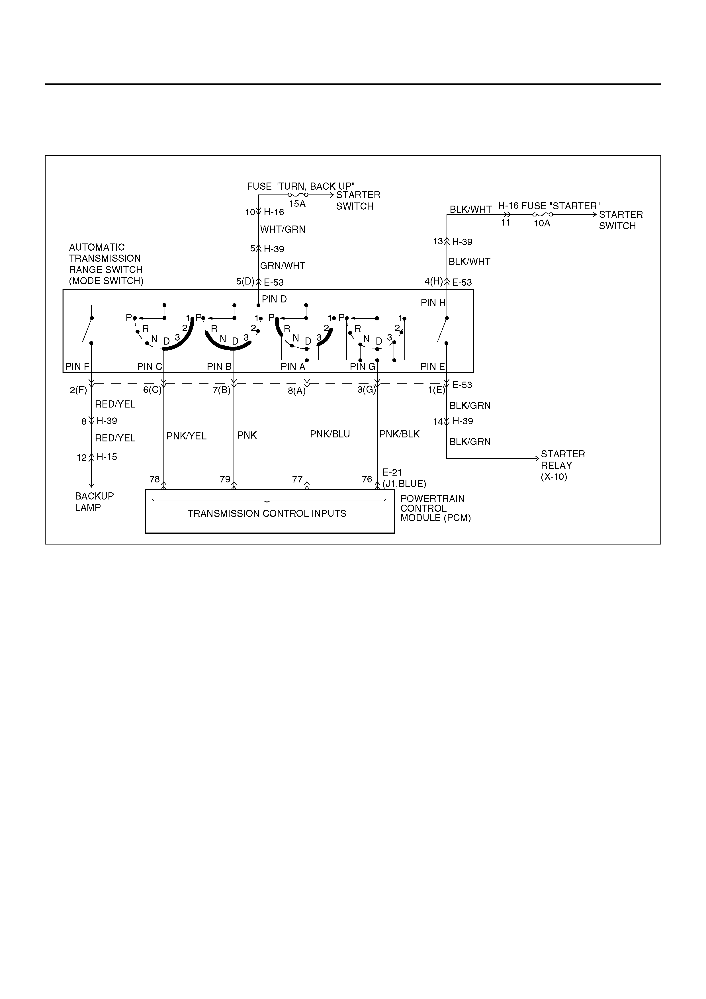
• The range switch supplies the Powertrain Control
Module (PCM) with information regarding the selector
lever position: P, R, N, D 3, 2 or L. The selector lever
position is indicated by the state of four ON/OFF
contracts. The range switch is located on one side of
the transmission. It is on the transmission manual
shaft and is fixed to the main case.
• The range switch is also used to provide the
inform ation P or N to the en gine crank wir ing. The
engine can be cranked only if connector E–53
terminal 4(H) is connected to terminal 1(E) which is
connected to ground.
• The range switch is also used to provide the backup
lamp power in reverse. This is the reason why the
range switch is supplied through a 15A fuse (TURN,
BACK UP). T his fuse can burn due to a sho rt circui t
in the back up lamp.
This DTC detects when a fuse is open or the range
switch circuit does not work. This is a type “D" DTC.
Conditions For Setting The DTC
• Range switch illegal positions met for 5 seconds.
Action Taken When The DTC Sets
• Default to D position.
• Inhibit torque management.
• Turn Pressure Control Solenoid off.
• Maximum line pressure.
• The PCM will not illuminate the CHECK TRANS
Lamp.
Conditions For Clearing The DTC
• The DTC can be cleared from the PCM history by
using a scan tool.
• The DTC will be cleared from history when the
vehicle has achieved 40 warmup cycles without a
failure reported.
• The PCM will cancel the DTC default actions when
the fault no longer exists and the ignition is cycled
“off" long enough to power down the PCM.
Diagnostic Aids
• Refer to accompanying chart for the normal range
signals and the illegal combinations.
• Inspect the wiring for poor electrical connections at

the PCM and at the transmission 8–way connector.
Look for possible bent, backed out, deformed or
damaged terminals. Check for weak terminal tension
as well. Also check for a chafed wire that could short
to bare metal or other wiring. Inspect for a broken
wire inside the insulation.
• When diagnosing for a possible intermittent short or
open condition, move the wiring harness while
observing test equipment for a change.
• Refer to the “Range Switch Logic Table" for further
information.
Test Description
The numbers below refer to the step numbers on the
diagnostic chart:
2. This test checks the indicated range signal to the
manual valve actually selected.
5. This test checks for continuity between each selected
range switch connector terminals.
Range Switch Logic Table
Range
Position Range Switch Pin
A B C P(G)
Park ON OFF OFF ON
Reverse ON ON OFF OFF
Neutral OFF ON OFF ON
D4 OFF ON ON OFF
D3 ON ON ON ON
2 ON OFF ON OFF
L OFF OFF ON ON
Illegal OFF OFF OFF OFF
Illegal OFF OFF OFF ON

DTC P0705/Flashing Code 73 Transmission Range Switch (Mode Switch) Illegal Position
Step Action Yes No
1 Perform the following checks:
• The transmission linkage from the select lever to the manual
valve is adjusted properly.
• Diagnostic circuit check.
Were the checks performed? Go to Step 2
Refer to Select
Lever, and Mode
Switch in
Automatic
Transmission
(4L30–E) section
2 1. Install the scan tool.
2. With the engine “of f", turn the ignition switch “on".
NOTE: Before clearing DTC(s), use the scan tool to record
“Failure Records" for reference, as data will be lost when the
“Clear Info" function is used.
3. Record the DTC “Failure Records".
4. Select each transmission range: DL, D2, D3, D4, N, R, and
P.
Does each selected transmission range match the scan tool
“Range Switch" display? Go to Diagnostic
Aids Go to Step 3
3 Are all range switch pin displays incorrect? Go to Step 4 Go to S tep 5
4 Check fuse and wiring to the 8–way connector terminal 5(D) for
opens.
Refer to ode Switc h i n Aut o mat ic Transmi ssi on (4 L3 0–E ) se ct i on.
If no problem was found, replace the range switch.
Is the replacement complete? Go to Step 8 —
5 1. Disconnect the 8–way range switch connector.
2. Using ohmmeter, check continuity between terminal 5(D) and
respectiv el y termi nal s 3 (G) , 6 (C), 7 (B ) and 8( A) of the 8–way
range switch connector.
3. Move shift selector lever through all positions and compare
results with “Range Switch Logic Table".
Is one range switch pin display incorrect? Go to Step 6 Go to Step 7
6 Check the affected wiring and connector, and repair.
Is the repair complete? Go to Step 8 —
7 Check the Powertrain Control Module (PCM) connectors for poor
connection.
If no problem was found, replace the PCM.
Is the replacement complete? Go to Step 8 —
8 1. After the repair is complete, use the scan tool to select
“DTC", then “Clear Info" function and road test the vehicle.
2. Review the scan tool “DTC Info".
Has the last test failed or is the current DTC displayed?
Begin diagnosis
again
Go to Step 1 Repair verified
Exit DTC table
DTC P0706/FLASHING CODE 74 TRANSMISSION RANGE SWITCH (MODE
SWITCH) PERFORMANCE
D07R100027
Circuit Description
• The range switch supplies the Powertrain Control
Module (PCM) with information regarding the selector
lever position: P, R, N, D, 3, 2 or L. The selector lever
position is indicated by the state of four ON/OFF
contracts. The range switch is located on one side of
the transmission. It is on the transmission manual
shaft and is fixed to the main case.
• The range switch is also used to provide the
information P or N to the engine crank wiring. The
engine can be cranked only if connector E–53
terminal 4(H) is connected to terminal 1(E) which is
connected to ground.
• The r ange s witch is al so used to pr ovide the ba ck u p
lamp power in reverse. This is the reason why the
mode switch is supplied through a 15A fuse (TURN,
BACK UP). T his fuse can burn due to a sho rt circui t
in the back up lamp.
• This DTC detec ts an inv alid s tate of the ran ge swi tch
or the range switch circuit by deciphering the range
switch inputs. This is a type “D" DTC.
Conditions For Setting The DTC
This DTC will set if any of the following conditions
occurs:
Condition 1 (“R" bad position):
• Engine is running.
• No output speed DTC P0722 (Flashing Code 78),
P0723 (Flashing Code 79).
• Output speed greater than 3,200 RPM.
• Range switch indicates “R".
• All conditions met for 4 seconds.
Condition 2 (“P" or “N" bad position):
• Engine is running.
• No TPS codes.
• Engine speed is less than 3,000 RPM.
• TP angle is greater than 20%.
• Range switch indicates “P" or “N".
• All conditions met for 4 seconds.
Action Taken When The DTC Sets
• Default to “D" position.
• The PCM will not illuminate the CHECK TRANS
Lamp.

Conditions For Clearing The DTC
• The DTC can be cleared from the PCM history by
using a scan tool.
• The DTC will be cleared from history when the
vehicle has achieved 40 warmup cycles without a
failure reported.
• The PCM will cancel the DTC default actions when
the fault no longer exists and the ignition is cycled
“off" long enough to power down the PCM.
Diagnostic Aids
• Refer to the accompanying chart for the normal range
signal s and the il leg al co mbi nati on s.
• Inspect the wiring for poor electrical connections at
the PCM and at the transmission 8–way connector.
Look for possible bent, backed out, deformed or
damaged terminals. Check for weak terminal
tension as well. Also check for a chafed wire that
could shor t to bare metal or other wir ing. Inspect for
a broken wire inside the insulation.
• When diagnosing for a possible intermittent short or
open condition, move the wiring harness while
observing test equipment for a change.
• Refer to the “Range Switch Logic Table" for further
information.
Test Description
The numbers below refer to the step numbers on the
diagnostic chart:
2. This test checks the indicated range signal to the
manual valve actually selected.
5. This test checks for continuity between each selected
range switch connector terminals.
Range Switch Logic Table
Range
Position Range Switch Pin
A B C P(G)
Park ON OFF OFF ON
Reverse ON ON OFF OFF
Neutral OFF ON OFF ON
D4 OFF ON ON OFF
D3 ON ON ON ON
2 ON OFF ON OFF
L OFF OFF ON ON
Illegal OFF OFF OFF OFF
Illegal OFF OFF OFF ON

DTC P0706/Flashing Code 74 Transmission Range Switch (Mode Switch) Performance
Step Action Yes No
1 Perform the following checks:
• The transmission linkage from the select lever to the manual
valve is adjusted properly.
• Diagnostic circuit check.
Were the checks performed? Go to Step 2
Refer to Select
Lever, and Mode
Switch in
Automatic
Transmission
(4L30–E) section
2 1. Install the scan tool.
2. With the engine “of f", turn the ignition switch “on".
NOTE: Before clearing DTC(s), use the scan tool to record
“Failure Records" for reference, as data will be lost when the
“Clear Info" function is used.
3. Record the DTC “Failure Records".
4. Select each transmission range: DL, D2, D3, D4, N, R, and
P.
Does each selected transmission range match the scan tool
“Range Switch" display? Go to Diagnostic
Aids Go to Step 3
3 Are all range switch pin displays incorrect? Go to Step 4 Go to S tep 5
4 Check fuse and wiring to the 8–way connector terminal 5(D) for
opens.
Refer to Mode Switch in Automatic Transmission (4L30–E)
section.
If no problem was found, replace the range switch.
Is the replacement complete? Go to Step 8 —
5 1. Disconnect the 8–way range switch connector.
2. Using ohmmeter, check continuity between terminal 5(D) and
respectiv el y termi nal s 3 (G) , 6 (C), 7 (B ) and 8( A) of the 8–way
range switch connector.
3. Move shift selector lever through all positions and compare
results with “Range Switch Logic Table".
Is one range switch pin display incorrect? Go to Step 6 Go to Step 7
6 Check the affected wiring and connector, and repair.
Is the repair complete? Go to Step 8 —
7 Check the Powertrain Control Module (PCM) connectors for poor
connection.
If no problem was found, replace the PCM.
Is the replacement complete? Go to Step 8 —
8 1. After the repair is complete, use the scan tool to select
“DTC", then “Clear Info" function and road test the vehicle.
2. Review the scan tool “DTC Info".
Has the last test failed or is the current DTC displayed?
Begin diagnosis
again
Go to Step 1 Repair verified
Exit DTC table
DTC P0712/FLASHING CODE 75 TRANSMISSION FLUID TEMPERATURE (TFT)
SENSOR CIRCUIT LOW INPUT
D07R100026
Circuit Description
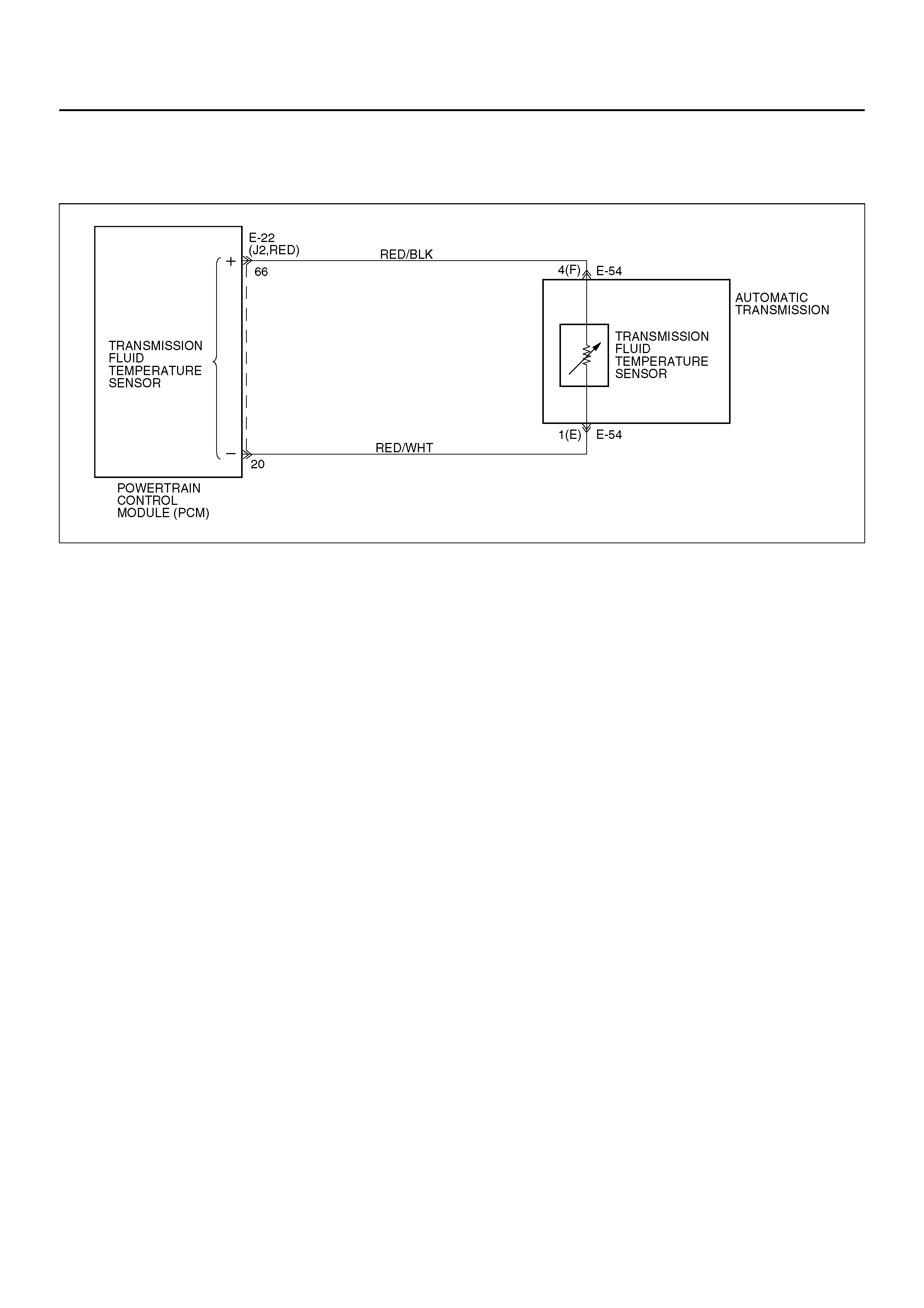
The TFT sensor is a thermister that controls the signal
voltage to the PCM. The PCM supplies a 5–volt
reference signal to the sensor on circuit RED/BLK.
When the transmission fluid is cold, the sensor
resistance is high. The PCM detects high signal
voltage. As the transmission fluid temperature
increases to the normal operating temperature of 100°C
(212°F), the sensor resistance becomes less and the
voltage decreases to 1.5 to 2 volts. With transmission
fluid over temperature and DTC P0218 (Flashing Code
71) also set, check the transmission cooling system.
This DTC detects a continuous short to ground in the
TFT sign al circuit or the TFT se nsor. This is a type “D"
DTC.
Conditions For Setting The DTC
• Battery voltage is between 10 and 16 volts.
• Ignition is “on".
• TFT sensor indicating a voltage less than 0.4 volts.
• All conditions met for 20 seconds.
Action Taken When T h e DTC Sets
• Transmission default temperature will be:
80°C (176°F) if engine temperature code is set.
100°C (212°F) if engine temperature is warm.
80°C (176°F) if engine run time is greater than 5
minutes.
21°C (69.8°F) if engine run time is less than 5
minutes.
• The PCM will not illuminate the CHECK TRANS
Lamp.
Conditions For Clearing The DTC
• The DTC can be cleared from the PCM history by
using a scan tool.
• The DTC will be cleared from history when the
vehicle has achieved 40 warmup cycles without a
failure reported.
• The PCM will cancel the DTC default actions when
the fault no longer exists and the ignition is cycled
“off" long enough to power down the PCM.
Diagnostic Aids
• Check harnes s ro uting f or a p otentia l sho rt to g round
in circuit RED/BLK. Scan tool TFT display should rise
steadily to about 100°C (212°F), then stabilize.
• Inspect the wiring for poor electrical connection at the
PCM and at the transmission 7–way connector.
Look for possible bent, backed out, deformed or
damaged terminals. Check for weak terminal tension
as well. Also check for a chafed wire that could short
to bare metal or other wiring. Inspect for a broken
wire inside the insulation.
• When diagnosing for a possible intermittent short or
open condition, move the wiring harness while
observing test equipment for a change.
• The temperature to resistance value scale may be
used to test the TFT sensor at the various
temperature levels to evaluate the possibility of a
“skewed" (mis–scaled) sensor.
A “skewed" sensor could result in delayed garage
shifts or TCC com plaints.
• Verify customer driving habits, trailer towing, etc.

Test Description
The numbers below refer to the step numbers on the
diagnostic chart:
2. This test checks for a short to ground or a “skewed"
sensor.
3. This test checks for an internal fault within the
transmission by creating an open.

DTC P0712/Flashing Code 75 Transmission Fluid Temperature (TFT) Sensor Circuit Low Input
Step Action Yes No
1 Perform the transmission fluid checking procedure. Refer to
Checking Transmission Fluid Level and Condition in Automatic
Transmission (4L30–E) section.
W as the fluid checking procedure performed?
Go to Step 2
Refer to Checking
T ransmission Fluid
Level and
Condition in
Automatic
Transmission
(4L30–E) section
2 1. Install the scan tool.
2. With the engine “of f", turn the ignition switch “on".
NOTE: Before clearing DTC(s), use the scan tool to record
“Failure Records" for reference, as data will be lost when the
“Clear Info" function is used.
3. Record the DTC “Failure Records".
Does the scan too l dis play a TFT sen sor si gnal vol tage less th an
0.4 volts? Go to Step 3 Go to Diagnostic
Aids
3 1. Turn the ignition “off".
2. Disconnect the transmission 7–way connector E–54.
3. Turn the ignition “on".
Does the TFT signal voltage change to match the voltage 4.92
volt s? Go to Step 4 Go to S tep 9
4 Using the J39200 DVOM, measure the resistance between
terminals 3(C) and 5 (D).
Is the resistance within specifications? (See Transmission Fluid
Temperature (TFT) Sensor Specifications.) Go to Diagnostic
Aids Go to Step 5
5 1. Disconnect the transmission 7–way connector E–54.
2. Using the J39200 DVOM, measure the resistance between
terminals E54–4(F) and E54–1(E).
Is the resistance within specifications? (See Transmission Fluid
Temperature (TFT) Sensor Specifications.) Go to Diagnostic
Aids Go to Step 6
6 1. Remove t he transmissio n oil pan. Refer to Transmission Oil
Temperature Sensor (Adapter Case) in Automatic
Transmission (4L30–E) section.
2. Check the internal wiring harness for a short to ground.
Was a problem found? Go to Step 8 Go to S tep 7
7 1. Disconnect the internal wiring harness at the TFT sensor.
2. Measure the resistance of the TFT sensor.
Is the resistance within specifications? (See Transmission Fluid
Temperature (TFT) Sensor Specifications.) Go to Diagnostic
Aids Go to Step 8
8 Replace the TFT Sensor.
Is the replacement complete? Go to Step 12 —
9 Check circuit RED/BLK for a short to ground.
Was a problem found? Go to Step 12 Go to Step 10
10 Check the PCM for faulty connections.
Was a problem found? Go to Step 12 Go to Step 1 1
11 Replace the PCM. Refer to Powe rtrain Control Module (PCM) in
Automatic Transmission (4L30–E) section.
Is the replacement complete? Go to Step 12 —

12 1. After the repair is complete, use the scan tool to select
“DTC", then “Clear Info" function and ensure the following
conditions are met:
TFT sensor indicates a voltage greater than 0.33 volts for 2
seconds.
2. Review the scan tool “DTC info".
Has the last test failed or is the current DTC displayed?
Begin diagnosis
again
Go to Step 1 Repair verified
Exit DTC table
Step Action Yes No

DTC P0713/FLASHING CODE 76 TRANSMISSION FLUID TEMPERATURE (TFT)
SENSOR CIRCUIT HIGH INPUT
D07R100026
Circuit Description
The TFT sensor is a thermistor that controls the signal
voltage to the PCM. The PCM supplies a 5–volt
reference signal to the sensor on circuit RED/BLK.
When the transmission fluid is cold, the sensor
resistance is high and the PCM will sense high signal
voltage. As the transmission fluid temperature warms to
the normal operating temperature of 100°C (212°F), the
sensor resistance becomes less and the voltage
decreases to about 1.5 to 2 volts.
This DTC detects a continuous open or short to power
in the TFT signal circuit or the TFT sensor. This is a
type “D" DTC.
Conditions For Setting The DTC
• Battery voltage is between 10 and 16 volts.
• Ignition is “on".
• TFT sensor indicating a voltage greater than 4.86
volts.
• All conditions met for 20 seconds.
Action Taken When T h e DTC Sets
• Transmission default temperature will be:
80°C (176°F) if engine temperature code is set.
100°C (212°F) if engine temperature is warm.
80°C (176°F) if engine run time is greater than 5
minutes.
21°C (69.8°F) if engine run time is less than 5
minutes.
• The PCM will not illuminate the CHECK TRANS
Lamp.
Conditions For Clearing The DTC
• The DTC can be cleared from the PCM history by
using a scan tool.
• The DTC will be cleared from history when the
vehicle has achieved 40 warmup cycles without a
failure reported.
• The PCM will cancel the DTC default actions when
the fault no longer exists and the ignition is cycled
“off" long enough to power down the PCM.
Diagnostic Aids
• Inspect the wiring for poor electrical connection at the
PCM and at the transmission 7–way connector . Look
for possible bent, backed out, deformed or damaged
terminals. Check for weak terminal tension as well.
Also check for a chafed wire that could short to bare
met a l o r o t he r w ir i ng . In s pe c t f o r a broken w i re in si d e
the insulation.
• When diagnosing for a possible intermittent short or
open condition, move the wiring harness while
observing test equipment for a change.
• Scan tool displays transmission fluid temperature in
degrees. After transmission is operating, the
temperature should rise steadily to about 100°C
(212°F), then stabilize.
• The temperature to resistance value scale may be
used to check the TFT sensor at the various
temperature levels to evaluate the possibility of a
“skewed" (mis–scaled) sensor.
A “skewed " sensor could r esult in hard s hifts or TC C
complaints.

Test Description
The numbers below refer to the step numbers on the
diagnostic chart:
2. This c heck verifies problem in the TFT sensor circ uit.
3. This test simulates a TFT sensor DTC P0712. If the
PCM recognizes the low signal voltage (high
temperature), and the scan tool displays 146°C
(295°F) or greater, the PCM and wiring are OK.
4. This test checks the TFT sensor and internal wiring
harness.

DTC P0713/Flashing Code 76 Transmission Fluid Temperature (TFT) Sensor Circuit High Input
Step Action Yes No
1 Perform the transmission fluid checking procedure.
Refer to Checking Transmission Fluid Level and Condition in
Automatic Transmission (4L30–E) section.
W as the fluid checking procedure performed?
Go to Step 2
Refer to Checking
T ransmission Fluid
Level and
Condition in
Automatic
Transmission
(4L30–E) section
2 1. Install the scan tool.
2. With the engine “of f", turn the ignition switch “on".
NOTE: Before clearing DTC(s), use the scan tool to record
“Failure Records" for reference, as data will be lost when the
“Clear Info" function is used.
3. Record the DTC “Failure Records".
Does the scan tool display a TFT sensor signal voltage greater
than 4.86 volts? Go to Step 3 Go to Diagnostic
Aids
3 1. Turn the ignition “off".
2. Disconnect the transmission 7–way connector E–54.
3. Install a fused jumper wire from terminal E54–4(F) to E54–
1(E) on the engine harness.
4. Turn the ignition “on".
Does the TFT signal voltage drop to less than 0.4 volts? Go to Step 4 Go to S tep 9
4 1. Turn the ignition “off".
2. Using the J39200 DVOM, measure the resistance between
terminals E54–4(F) and E54–1(E).
Is the resistance within specifications? (See Transmission Fluid
Temperature (TFT) Sensor Specifications.) Go to Diagnostic
Aids Go to Step 5
5 1. Disconnect the transmission 7–way connector E–54.
2. Using the J39200 DVOM, measure the resistance between
terminals E54–4(F) and E54–1(E).
Is the resistance within specifications? (See Transmission Fluid
Temperature (TFT) Sensor Specifications.) Go to Diagnostic
Aids Go to Step 6
6 1. Remove the transmission oil pan.
2. Check the internal wiring harness for an open. Refer to
Transmission Oil Temperature Sensor (Adapter Case) in
Automatic Transmission (4L30–E) section.
W as a problem found and corrected? Go to Step 13 Go to Step 7
7 1. Disconnect the internal wiring harness at the TFT sensor.
2. Measure the resistance of the TFT sensor.
Is the resistance within specifications? (See Transmission Fluid
Temperature (TFT) Sensor Specifications.) Go to Diagnostic
Aids Go to Step 8
8 Replace TFT sensor. Refer to Transmission Oil Temperature
Sensor (Adapter Case) in Automatic Transmission (4L30–E)
section.
Is the replacement complete? Go to Step 13 —
9 Check circuit RED/BLK for an open or short to B+.
Was a problem found? Go to Step 13 Go to Step 10
10 Check circuit RED/WHT for an open.
Was a problem found? Go to Step 13 Go to Step 1 1
11 Check the PCM for faulty or intermittent connections.
Was a problem found? Go to Step 13 Go to Step 12

12 Replace the PCM. Refer to Powertrain Contr ol Module (PCM) i n
Automatic Transmission (4L30–E) section.
Is the replacement complete? Go to Step 13 —
13 1. After the repair is complete, use the scan tool to select
“DTC", then “C lear Info " functio n and ensur e the foll owing
conditions are met:
TFT sensor indicates a voltage less than 4.92 volts for 2
seconds.
2. Review the scan tool “DTC Info".
Has the last test failed or is the current DTC displayed?
Begin diagnosis
again
Go to Step 1 Repair verified
Exit DTC table
Step Action Yes No
DTC P0719/FLASHING CODE 77 TCC BRAKE SWITCH CIRCUIT HIGH
(STUCK ON)
D07R100028
Circuit Description:
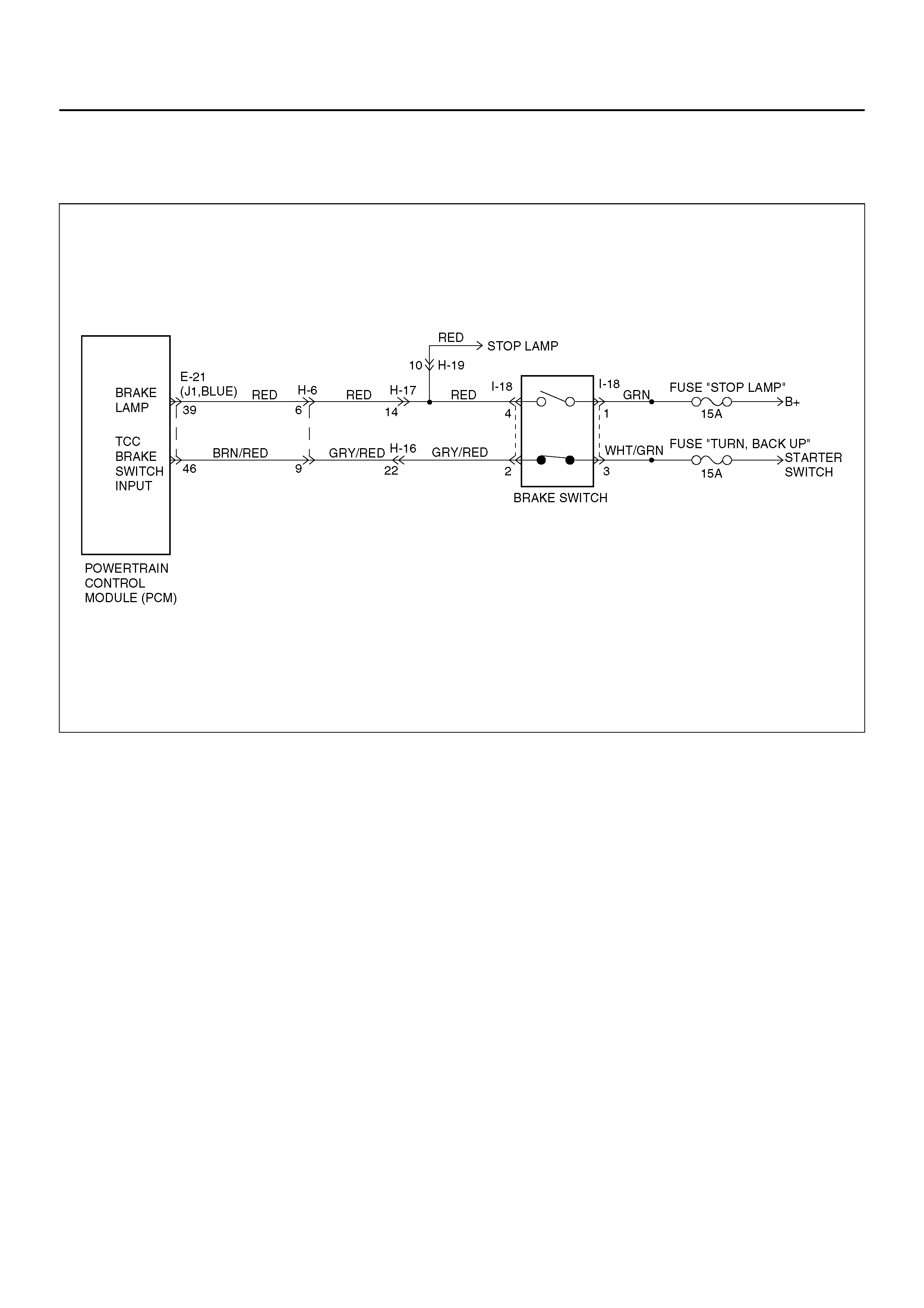
The brake switch indicates brake pedal status to the
Powertrain Control Module (PCM). The brake switch is
a normally–closed switch that supplies battery voltage
on circuit GRY/RED–BRN/RED to the PCM. Applying
the brake pedal opens the switch, interrupting voltage to
the PCM. When the brake pedal is released, the PCM
receiv es a constant v oltage signal . If the PCM receives
a zero voltage signal a t the brake switch input, and th e
Torque Converter Clutch (TCC) is engaged, the PCM
de–energizes the Torque Converter Clutch Solenoid
Val ve (TCC Sol. Valve). Th e PCM disregar ds the brake
switch input for TCC scheduling if there is a brake
switch circuit fault (Refer to Diagnos ti c Ai ds ).
When the PCM detects an open brake switch circuit (0
volts, low input) during accelerations, then DTC P0719
sets. DTC P0719 is a type D DTC.
Conditions For Setting The DTC
• No OSS Assy. DTCs P0722 (Flashing Code 78) or
P0723 (Flashing Code 79).
• The PCM detects an open brake switch or circuit (0
volts) fo r 15 mi nutes without chan ging fo r 2 sec onds ,
and the following events occur seven consecutive
times.
– The vehicle speed is less than 8 km/h (5 mph).
– then the vehicle speed is 8–32 km/h (5–20 mph)
for 4 seconds.
– then the vehi cle speed is gre ater than 32 k m/h (20
mph) for 4 seconds.
Action Taken When The DTC Sets
• The PCM does not illuminate the Malfunction
Indicator Lam p (MIL).
• DTC P0719 stores in PCM history.
Conditions For Clearing The DTC
• A scan tool can clear the DTC from the PCM history.
• The PCM clear s the DT C from the PCM h istory if the
vehicle completes 40 warm–up cycles without a
failure reported.
• The PCM cancels the DTC default actions when the
fault no longer exists and the ignition is OFF long
enough in order to power down the PCM.

Diagnostic Aids
• Inspect the wiring for poor electrical connections at
the PCM and brake switch. Look for possible bent,
backed out, deformed or damaged terminals. Check
for weak terminal tension as well. Also check for a
chafed wire that could short to bare metal or other
wiring. Inspect for a broken wire inside the insulation.
• When diagnosing for a possible intermittent short or
open condition, move the wiring harness while
observing test equipment for a change.
• Chec k cus tome r d rivi ng habi ts and/o r unus ual driv in g
conditions (i.e. stop and go, highway).
• Check brake switch for proper mounting and
adjustment.
Test Description
The numbers below refer to the step numbers on the
diagnostic chart.
2. This step isolates the brake switch as a source for
setting the DTC.

DTC P0719/Flashing Code 77 TCC Brake Switch Circuit High (Stuck On)
Step Action Yes No
1 1. Install the scan tool.
2. With the engine “off," turn the ignition switch to the “on"
position.
NOTE: Before clearing the DTC(s), use the scan tool in order to
record the “Failure Records" for reference. Using the “Clear Info"
function will erase the stored “Failure Records" from the PCM.
3. Record the “Failure Records", then clear the DTC(s).
4. Select “Brake Switch" on the scan tool.
5. Disconnect the brake switch connector from the brake switch.
6. Connect a test lamp from cavity I18–3 of the brake switch
connector to a known good ground.
Is the test lamp ON? Go to Step 2 Go to Step 3
2 Install a J36169–A Fused Jumper Wire from terminal I18–2 to
terminal I18–3 of the brake switch connector.
Did the TCC Brake Switch status change from Open to Closed? Go to Step 6 Go to Step 8
3 1. Remove the fuse “TURN, BACK UP" (15A).
2. Inspect the fuse for an open.
Is the fuse open? Go to Step 4 Go to Step 7
4 Inspect circuit WHT /GRN for a s hort to gro und condition. Repair
the circuit if necessary.
Did you find a short to ground condition? Go to Step 10 Go to Step 5
5 Inspect circuit GRY/RED–BRN/RED for a short to ground
condition. Repair the circuit if necessary.
Did you find a short to ground condition? Go to Step 10 Go to Step 9
6 Replace the brake switch.
Is the replacement complete? Go to Step 10 —
7 Inspect circuit WHT/GRN for an open condition. Repair the circuit
if necessary.
Did you find and correct an open condition? Go to Step 10 —
8 Inspect circuit GRY/RED–BRN/RED for an open.
Did you find an open condition? Go to Step 10 Go to Step 9
9 Replace the PCM.
Is the replacement complete? Go to Step 10 —
10 In order to verify your repair, perform the following procedure:
1. Select DTC.
2. Select Clear Info.
3. With the engine “off," turn the ignition switch to the “on"
position.
4. Do not depress the brake pedal.
5. Verify that the TCC Brake Switch status indicates “Closed"
(12 volts) for 2 seconds.
6. Select Specific DTC. Enter DTC P0719.
Has the test run and passed? System OK
Begin the
diagnosis
again.
Go to Step 1
DTC P0722/FLASHING CODE 78 TRANSMISSION OUTPUT SPEED SENSOR
(OSS) LOW INPUT
D07RY00032
Circuit Description
Output speed information is provided to the PCM by the
OSS, which is a permanent magnet (PM) generator.
The PM generator pr oduces a puls ing A C voltage. T he
AC voltage level and number of pulses increases as the
speed of the vehicle increases. The PCM then converts
the pulsing voltage to output speed, which is used for
calculations. The vehicle speed can be displayed with a
scan tool.
This DTC detects a low output speed when there is a
high engi ne s peed i n a d rive g ear ran ge. T his is a t ype
“C" DTC.
Conditions For Setting The DTC
• No MAP DTCs P0107 or P0108, P0106, P1106,
P1107.
• No TPS DTCs P0122 or P0123.
• Not in Park or Neutral.
• TPS angle is greater than 10%.
• Engine va cu um is betw een 0 and 70kP a.
• Engine speed is between 3000 and 7000 rpm.
• Transmission output speed is less than 0 rpm.
• All conditions met for 5 seconds.
Action Taken When T h e DTC Sets
• Fixed to 4th gear.
• Maximum line pressure.
• Inhibit TCC engagement.
• The PCM will illuminate the CHECK TRANS Lamp.
Conditions For Clearing The DTC/CHECK
TRANS Lamp
• The PCM wil l tur n o ff the CH ECK T RA NS Lam p after
three consecutive ignition cycles without a failure
reported.
• The DTC can be cleared from the PCM history by
using a scan tool. The DTC will be cleared from
history when the vehicle has achieved 40 warmup
cycles without a failure reported.
• The PCM will cancel the DTC default actions when
the fault no longer exists and the ignition is cycled
“off" long enough to power down the PCM.
Diagnostic Aids
• An OSS DTC P0722 will set when no output speed is
at detected at start off.
• Inspect the wiring for poor electrical connection at the
PCM. Look for possible bent, backed out , deformed
or damaged terminals. Check for weak terminal
tension as well. Also check for a chafed wire that
could sh ort to bare metal or other wi ring. Inspec t for
a broken wire inside the insulation.
• When diagnosing for a possible intermittent short or
open cond ition, move or mas sage t he wiring har ness
while observing test equipment for a change.
Test Description
The numbers below refer to the step numbers on the
diagnostic chart:
3. This test checks the OSS circuit.
4. This test checks the integrity of the OSS.
6. This test checks the 5–volt and ground circuit of the
PCM.

DTC P0722/Flashing Code 78 Transmission Output Speed Sensor (OSS) Low Input
Step Action Yes No
1 1. Install the scan tool.
2. With the engine “of f", turn the ignition switch “on".
NOTE: Before clearing DTC(s), use the scan tool to record
“Failure Records" for reference, as data will be lost when the
“Clear Info" function is used.
3. Record the DTC “Failure Records".
4. Raise the drive wheels.
5. Start th e engine.
6. Place the transmission in any drive range.
With the drive wheels rotating, does the “Trans Output Speed"
incr ease with the drive wheel speed? Go to Diagnostic
Aids Go to Step 2
2 Check for the most current and/or incorrect calibration.
Is the calibration current? Go to Step 15 Go to Step 3
3 1. Turn the ignition “off".
2. Disconnect the E–22 (J2, RED) PCM connector.
3. Using the J39200 DVOM, measure the resistance between
harness connector terminals E22–22 and E22–55.
Is the reading 3000 ohms? Go to Step 4 Go to S tep 5
4 1. Select AC volts.
2. Rotate the rear wheels, ensuring the driveshaft is turning.
Is the voltage greater than 0.5 volts? Go to Step 6 Go to S tep 7
5 Inspect circui ts BLU/YE L and B LU/GRN fo r a poor c onnecti on or
an open circuit.
Was a problem found? Go to Step 16 Go to Step 7
6 1. Reconnect the E–22 (J2, RED) PCM connector.
2. Disconnect the OSS harness from the OSS.
3. With the engine “of f", turn the ignition “on".
4. Using the J 39200 DVOM, measure the voltage at the OSS
harness connector terminals E55–1 and E55–2.
Is the reading between 4.0 to 5.1 volts? Go to Step 15 Go to Step 9
7 1. Remove the OSS.
2. Check the output shaft speed sensor rotor for damage or
misalignment. Refer to Speed Sens or (Ext ens io n Hous in g) in
Automatic Transmission (4L30–E) section.
Was a problem found? Go to Step 16 Go to Step 8
8 Replace the OSS.
Is the replacement complete? Go to Step 16 —
9 Was the reading in step 6 less than 4.0 volts? Go to Step 11 Go to Step 10
10 Was the reading in Step 6 greater than 5.1 volts? Go to Step 14 —
11 Using the J 39200 DVOM to chassis ground, measure the
voltage on circuit BLU/YEL.
Is the reading between 4.0 to 5.1 volts? Go to Step 12 Go to Step 13
12 Repair the open in circuit BLU/GRN.
Is the repair complete? Go to Step 16 —
13 Check circuit BLU/YEL for a short to ground or open.
W as a problem found and corrected? Go to Step 16 Go to Step 15
14 Repair the short to B+ in circuit BLU/YEL.
Is the repair complete? Go to Step 16 —

15 Replace the PCM. Refer to Powertrain Contr ol Module (PCM) i n
automatic Transmission (4L30–E) section.
Is the replacement complete? Go to Step 16 —
16 1. After the repair is complete, use the scan tool to select
“DTC", then “Clear Info" function and operate the vehicle
under the following conditions:
• Transmission output speed is greater than 101 rpm for 3
seconds.
2. Review the scan tool “DTC Info".
Has the last test failed or is the current DTC displayed?
Begin diagnosis
again
Go to Step 1 Repair verified
Exit DTC table
Step Action Yes No

DTC P0723/FLASHING CODE 79 TRANSMISSION OUTPUT SPEED SENSOR
(OSS) INTERMITTENT
D07RY00032
Circuit Description
Output speed information is provided to the PCM by the
OSS, which is a permanent magnet (PM) generator.
The PM generator pr oduces a puls ing A C voltage. T he
AC voltage level and number of pulses increases as the
speed of the vehicle increases. The PCM then converts
the pulsing voltage to output speed, which is used for
calculations. The vehicle speed can be displayed with a
scan tool.
This DTC detects a low output speed when there is a
high engi ne s peed i n a d rive g ear ran ge. T his is a t ype
“C" DTC.
Conditions For Setting The DTC
Drive range
• Transmission outpu t speed is greater than 1300 rpm
for 2 seconds.
• Engine running time is greater than 5 seconds.
• NORAW–NOLAST < 200 rpm for 2 seconds.
NORAW: Latest raw data of output shaft speed.
NOLAST: Fitered previous data of output speed.
• Transmission negative output speed change is
greater than 1300 rpm.
• Conditions met for 3 seconds.
Action Taken When T h e DTC Sets
• Fixed to 4th gear.
• Maximum line pressure.
• Inhibit TCC engagement.
• The PCM will illuminate the CHECK TRANS Lamp.
Conditions For Clearing The DTC/CHECK
TRANS Lamp
• The PCM wil l tur n o ff the CH ECK T RA NS Lam p after
three consecutive ignition cycles without a failure
reported.
• The DTC can be cleared from the PCM history by
using a scan tool.
• The DTC will be cleared from history when the
vehicle has achieved 40 warmup cycles without a
failure reported.
• The PCM will cancel the DTC default actions when
the fault no longer exists and the ignition is cycled
“off" long enough to power down the PCM.
Diagnostic Aids
• A OSS DTC P0723 will set when output speed has
been detected and is lost.
• Inspect the wiring for poor electrical connection at the
PCM. Look for possible bent, backed out , deformed
or damaged terminals. Check for weak terminal
tension as well. Also chec k for a chafed wire tha t
could sh ort to bare metal or other wi ring. Inspec t for
a broken wire inside the insulation.
• When diagnosing for a possible intermittent short or
open condition, move the wiring harness while
observing test equipment for a change.
Test Description
The numbers below refer to the step numbers on the
diagnostic chart:
3. This test checks the OSS circuit.
4. This test checks the integrity of the OSS.
6. This test checks the 5–volt and ground circuit of the
PCM.

DTC P0723/Flashing Code 79 Transmission Output Speed Sensor (OSS) Intermittent
Step Action Yes No
1 1. Install the scan tool.
2. With the engine “of f", turn the ignition switch “on".
NOTE: Before clearing DTC(s), use the scan tool to record
“Failure Records" for reference, as data will be lost when the
“Clear Info" function is used.
3. Record the DTC “Failure Records".
4. Raise the drive wheels.
5. Start th e engine.
6. Place the transmission in any drive range.
With the drive wheels rotating, does the “Trans Output Speed"
incr ease with the drive wheel speed? Go to Diagnostic
Aids Go to Step 2
2 Check for the most current and/or incorrect calibration.
Is the calibration current? Go to Step 15 Go to Step 3
3 1. Turn the ignition “off".
2. Disconnect the E–22 (J2, RED) PCM connector.
3. Using the J39200 DVOM, measure the resistance between
harness connector terminals E22–22 and E22–55.
Is the reading 3,000 ohms? Go to Step 4 Go to S tep 5
4 1. Select AC volts.
2. Rotate the rear wheels, ensuring the driveshaft is turning.
Is the voltage greater than 0.5 volts? Go to Step 6 Go to S tep 7
5 Inspect circui ts BLU/YE L and B LU/GRN fo r a poor c onnecti on or
an open circuit.
Was a problem found? Go to Step 16 Go to Step 7
6 1. Reconnect the E–22 (J2, RED) PCM connector.
2. Disconnect the OSS harness from the OSS.
3. With the engine “of f", turn the ignition “on".
4. Using the J 39200 DVOM, measure the voltage at the OSS
harness connector terminals E55–1 and E55–2.
Is the reading between 4.0 to 5.1 volts? Go to Step 15 Go to Step 9
7 1. Remove the OSS.
2. Check the output shaft speed sensor rotor for damage or
misalignment. Refer to Speed Sens or (Ext ens io n Hous in g) in
Automatic Transmission (4L30–E) section.
Was a problem found? Go to Step 16 Go to Step 8
8 Replace the OSS.
Is the replacement complete? Go to Step 16 —
9 Was the reading in step 6 less than 4.0 volts? Go to Step 11 Go to Step 10
10 Was the reading in Step 6 greater than 5.1 volts? Go to Step 14 —
11 Using the J 39200 DVOM to chassis ground, measure the
voltage on circuit BLU/YEL.
Is the reading between 4.0 to 5.1 volts? Go to Step 12 Go to Step 13
12 Repair the open in circuit BLU/GRN.
Is the repair complete? Go to Step 16 —
13 Check circuit BLU/YEL for a short to ground or open.
W as a problem found and corrected? Go to Step 16 Go to Step 15
14 Repair the short to B+ in circuit BLU/YEL.
Is the repair complete? Go to Step 16 —

15 Replace the PCM. Refer to Powertrain Contr ol Module (PCM) i n
Automatic Transmission (4L30–E) section.
Is the replacement complete? Go to Step 16 —
16 1. After the repair is complete, use the scan tool to select
“DTC", then “Clear Info" function and operate the vehicle
under the following conditions:
• Transmission output speed is greater than 101 rpm for 3
seconds.
2. Review the scan tool “DTC Info".
Has the last test failed or is the current DTC displayed?
Begin diagnosis
again
Go to Step 1 Repair verified
Exit DTC table
Step Action Yes No
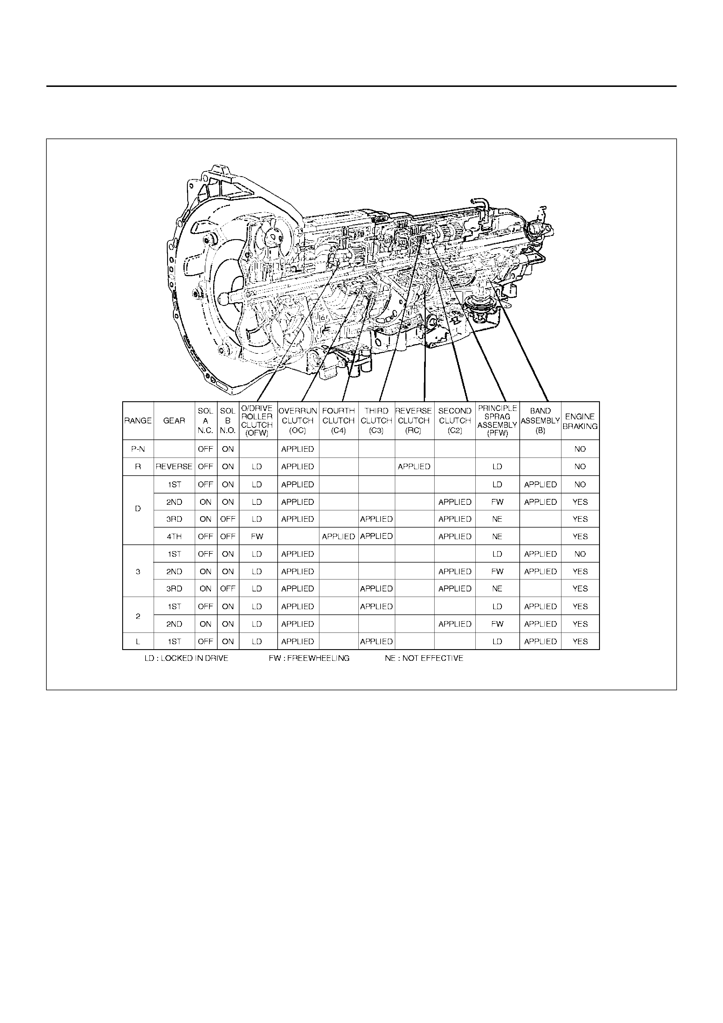
DTC P0730/FLASHING CODE 81 TRANSMISSION INCORRECT GEAR RATIO
D07RT015
Circuit Description
• The Powertrain Control Module (PCM) calculates the
slippage of the converter and transmission based
upon the engine speed, the output speed, and the
current gear rat io.
• The slippage of the converter at a high enough
engine speed is low. The transmission should not
slip more than a given value when there is no shift.
• This DTC detects a slip at each gear. This is a type
“C" DTC.
Conditions For Setting The DTC
• No Output Speed Sensor DTC(s) P0722 (Flashing
Code 78), P0723 (Flashing Code 79).
• Not in Park, Neutral or Reverse.
• Engine speed is greater than 3500 rpm.
• 3 seconds since upshift.
• 3 seconds since downshift.
• 3 seconds since garage shift (N→D).
• And one of the following conditions occur:
– Slip is greater than 720 rpm in 1st gear.
– Slip is greater than 680 rpm in 2nd gear.
– Slip is greater than 660 rpm on 3rd gear.
– Slip is greater than 650 rpm on 4th gear.
• All conditions met for 5.5 seconds.
Action Taken When The DTC Sets
• Maximum line pressure.
• The PCM will illuminate the CHECK TRANS Lamp.
• Turn Pressure Control Solenoid off.

Conditions For Clearing The DTC/CHECK
TRANS Lamp
• The PCM will turn “off" the CHECK TRANS Lamp
after three consecutive ignition cycles without a
failure reported.
• The DTC can be cleared from PCM memory by using
a scan tool. The DTC can also be cleared from
memory when the vehicle has made 40 warmup
cycles without a failure reported.
• The PCM will cancel the DTC Actions Taken items
when the fault conditions no longer exist and the
ignition is cycles “off" long enough to power down the
PCM.
Diagnostic Aids
• Check for intermittent output speed sensor circuit
problems.
• Check for possible incorrect calibration. (PCM part
No., tire specifications, and rear axle ratio)
Test Description
The numbers below refer to the step numbers on the
diagnostic chart:
2. This step checks for possible low fluid level causing
slipping resulting in an undefined gear ratio.
3. This step checks for correct gear ratios for
commanded gears.
4. This step checks for low line pressure.

DTC P0730/Flashing Code 81 Transmission Incorrect Gear Ratio
Step Action Yes No
1 Visually inspect the transmission cooling system for fluid leaks.
• Refer to Chart 16: Possible Causes of Transmission Fluid
Leaks of Mechanical/Hydraulic Diagnosis Symptoms Index in
Automatic Transmission (4L30–E) section.
Was condition found and corrected? Go to Step 6 Go to S tep 2
2Refer to Checking Transmission Fluid Level and Condition in
Automatic Transmission (4L30–E) section.
Has transmission fluid checking procedure been performed?
Go to Step 3
Go to Checking
T ransmission Fluid
Level and
Condition in
Automatic
Transmission
(4L30–E) section
3 1. Install the scan tool.
2. Turn the ignition switch to the “on" position.
3. Engine not running.
NOTE: Before clearing DTC(s) use the scan tool to record the
“Failure Records" for reference, as data will be lost when the
“Clear Info" function is used.
4. Record the Failure Record data.
5. Use the scan tool snapshot mode to record transmission gear
ratios.
6. Drive vehi cle in tran smission gear ran ges L, 2, 3, and D wi th
the engine speed is greater than 3,500 rpm for 5.5 seconds.
7. Record each transmission gear.
1st:2.73 – 2.99
2nd:1.54 – 1.71
3rd:0.93 – 1.05
4th:0.66 – 0.78
Does commanded gear ratio match ranges as shown? Refer to Diagnostic
Aids Go to Step 4
4 Perform line pressure check.
• Refer to L ine Pr e ss ure Test i n A utomatic Tran sm is sion ( 4L3 0–
E) section.
Was condition found and corrected? Go to Step 6 Go to S tep 5
5 Che ck for possible clutch slippage.
• Refer to Chart 6: Diagnostic Trouble Code (DTC) P0730 of
Mechanical/Hydraulic Diagnosis Symptoms Index in Automatic
Transmission (4L30–E) section.
Was condition found and corrected? Go to Step 6 —
6 1. After the repair is complete, use the scan tool to select
“DTC", then “Clear info" function.
2. Operate the vehicle under the following conditions:
• Drive the ve hicle in D4 with the engi ne spee d greater th an
3,500 rpm to obtain any one of the following gear ratios for
seven seconds.
1st 1:2.73 – 1:2.99
2nd 1:1.54 – 1:1.71
3rd 1:0.93 – 1:1.05
4th 1:0.66 – 1:0.78
Has the last test failed?
Begin diagnosis
again
Go to Step 1 Repair verified
Exit DTC table
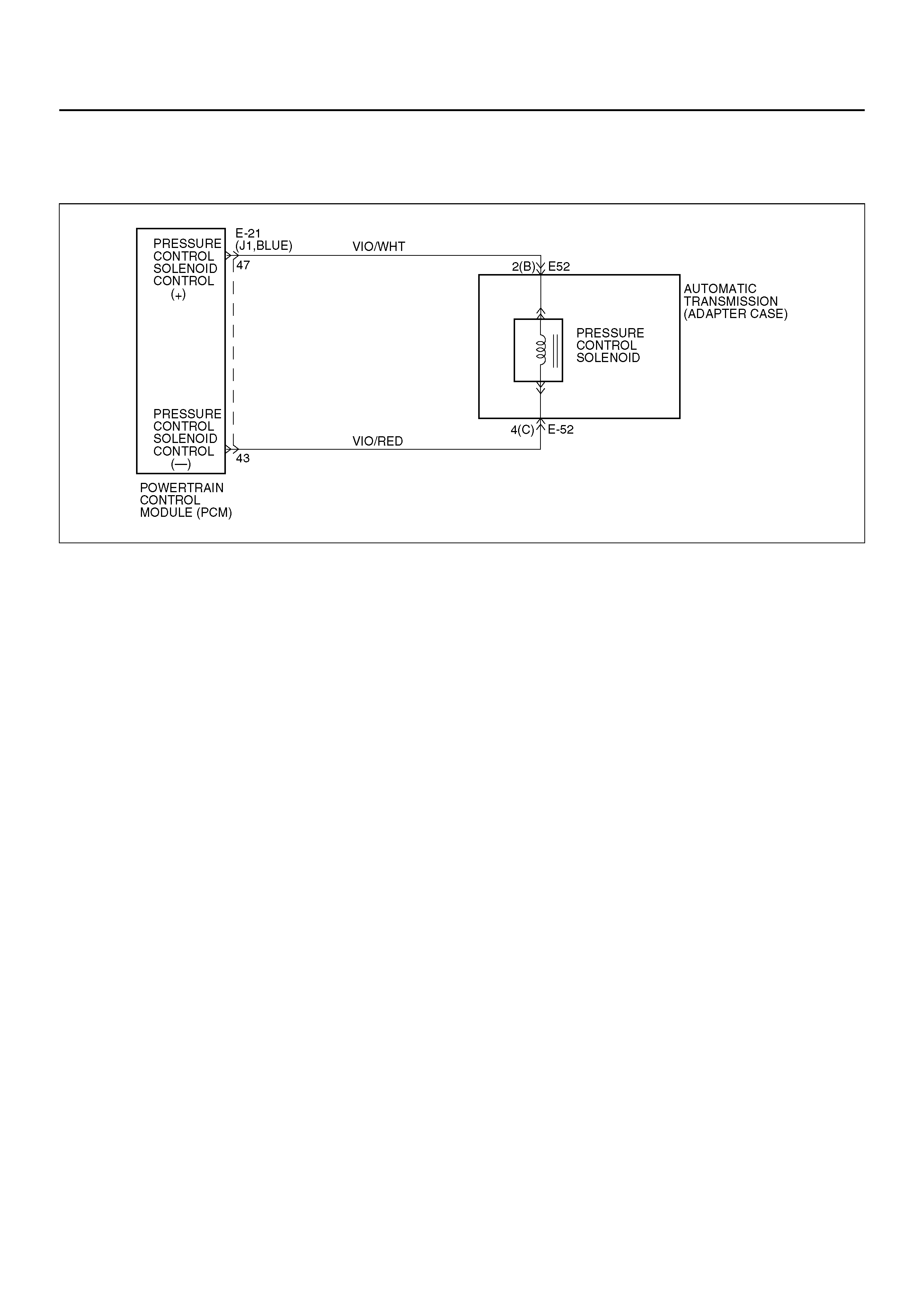
DTC P0748/FLASHING CODE 82 PRESSURE CONTROL SOLENOID (PCS)
CIRCUIT ELECTRICAL
D07RY00034
Circuit Description
The PCS is a PCM–controlled device used to regulate
transmission line pressure. The PCM compares TPS
voltage, engine rpm, and other inputs to determine the
line pressure appropriate for a given load. The PCM will
regulate the pressure by applying a varying amperage
to the PCS. The applied amperage can vary from 0.1
to 1 amp, and is monitored by the PCM.
This DTC detects a cont inuous o pen or sho rt to groun d
in the PCS circuit or the PCS. This is a type “C" DTC.
Conditions For Setting The DTC
• Battery voltage is between 10 and 16 volts.
• The PCM detects that the different between
commanded and actual current is 200 milliampere
(mA) for over 1 second.
• Engine speed is greater than 300 rpm.
Ac ti on Taken Wh en th e DT C Sets
• Maximum line pressure.
• The PCM will illuminate the CHECK TRANS Lamp.
• Turn Pressure Control Solenoid off.
Conditions For Clearing The DTC/CHECK
TRANS Lamp
• The PCM will turn “off" the CHECK TRANS Lamp
after three consecutive ignition cycles without a
failure reported.
• The DTC can be cleared from PCM history by using a
scan tool.
• The DTC will be cleared from memory when the
vehicle has achieved 40 warmup cycles without a
failure reported.
• The PCM will cancel the DTC default actions when
the fault no longer exists and the ignition is cycled
“off" long enough to power down the PCM.
Diagnostic Aids
• Inspect the wiring for poor electrical connection at the
PCM and at the transmission 4–way connector . Look
for possible bent, backed out, deformed or damaged
terminals. Check for weak terminal tension as well.
Also check for a chafed wire that could short to bare
met a l o r o t he r w ir i ng . In s pe c t f o r a broken w i re in si d e
the insulation.
• When diagnosing for a possible intermittent short or
open condition, move the wiring harness while
observing test equipment for a change.
Test Description
The numbers below refer to the step numbers on the
diagnostic chart:
1. This test checks the ability of the PCM to command
the PCS.
2. This test ch ecks t he PCS and internal wiring h arness
for incorrect resistance.

DTC P0748/Flashing Code 82 Pressure Control Solenoid (PCS) Circuit Electrical
Step Action Yes No
1 1. Install the scan tool.
2. With the engine “of f", turn the ignition switch “on".
NOTE: Before clearing DTC(s), use the scan tool to record
“Failure Records" for reference, as data will be lost when the
“Clear Info" function is used.
3. Record the DTC “Failure Records".
4. While the engine is operating, put the transmission in Park.
5. Using the scan tool, apply 0.1 amp through 1.0 amp while
observing “PC Ref. Current" and “PC Act. Current".
Is the “PC Act. Current" reading always within 0.16 amp? Go to Diagnostic
Aids Go to Step 2
2 1. Turn the ignition “off".
2. Disconnect the transmission 4–way connector E–52.
3. Using the J39200 DVOM, measure the resistance between
terminals E52–2(B) and E52–4(C).
Is the resistance within 3–7 ohms? Go to Step 6 Go to S tep 3
3 1. Remove the transmission oil pan. Refer to Solenoid (Adapter
Case Valve Body) in Automatic Transmission (4L30–E)
section.
2. Disconnect the internal wiring harness at the PCS.
3. Measure the resistance of the PCS.
Is the resistance within 3–7 ohms? Go to Step 5 Go to S tep 4
4 Replace the PCS.
Is the replacement complete? Go to Step 9 —
5 Repair the internal wiring harness for an open.
Is the repair complete? Go to Step 9 —
6 Inspect/repair circuits VIO/WHT and VIO/RED
Was a problem found? Go to Step 9 Go to S tep 7
7 Inspect/repair circuits VIO/WHT and VIO/RED for a short to
ground or poor connections.
Was a problem found? Go to Step 9 Go to S tep 8
8 Replace the PCM. Refer to Power train Control Mo dule (PCM) in
Automatic Transmission (4L30–E) section.
Is the replacement complete? Go to Step 9 —
9 1. After the repair is complete, use the scan tool to select
“DTC", then “Clear Info" function and ensure the following
conditions are met:
The PCS duty cycle is not at its electrical high or low limit.
2. Review the scan tool “DTC Info".
Has the last test failed or is the current DTC displayed?
Begin diagnosis
again
Go to Step 1 Repair verified
Exit DTC table
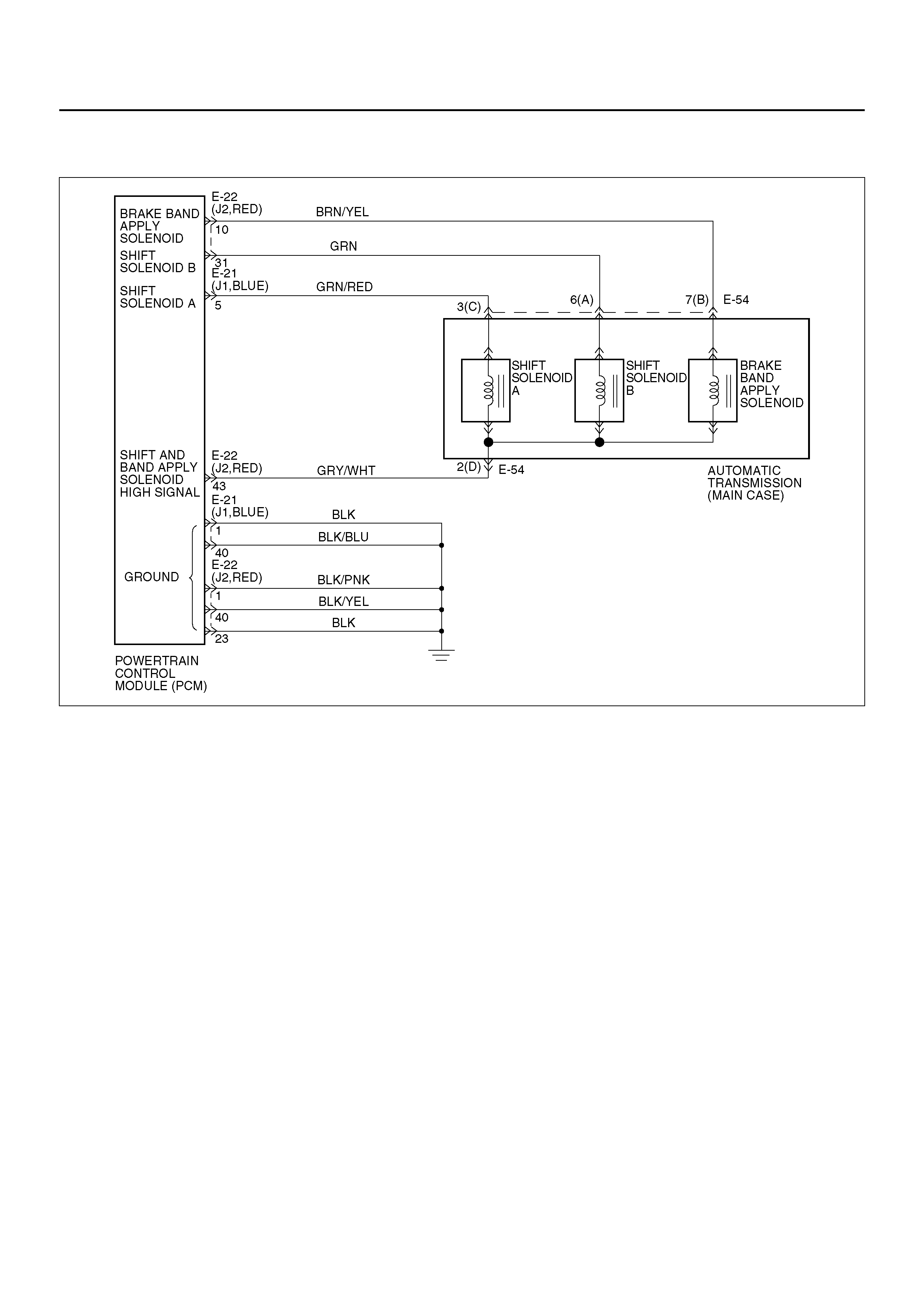
DTC P0753/FLASHING CODE 83 SHIFT SOLENOID A ELECTRICAL
D07RY00035
Circuit Description
• The shift solenoid A is a simple on/off solenoid
located in t he main case v alve body. The so lenoid is
the nor mally closed type. In se cond or thir d gear th e
Powertrain Control Module (PCM) energizes the
solenoid to open a fluid inlet port. When the port is
open, fluid pressure actuates the shift valve.
• The solenoid is activated by a current. This current is
produc ed by appl ying a v oltage to on e side ( the Hig h
side) and a ground to the other side (Low side).
• The High Side Driver (HSD) is a circuit of the PCM
that acts as a switch between the solenoids and the
supply voltage. The High side of the solenoid is
permanently supplied with voltage, except in
BACKUP MODE or when ignition is off the HSD is
turned off.
This DTC detects a cont inuous o pen or sho rt to groun d
in the shift solenoid A circuit or the shift solenoid A.
This is a type “C" DTC.
Conditions For Setting The DTC
• Ignition i s “on ", Engine “run".
• Battery voltage is between 10 and 16 volts.
• The PCM commands the solenoid “on" and the
voltage remains high (B+), or the PCM commands
the solenoid “off" and the voltage remains low (zero
volts).
• All conditions met for 0.84∼1.0 seconds.
Action Taken When The DTC Sets
• Maximum line pressure.
• Immediate landing to 4th gear.
• Inhibit TCC engagement.
• The PCM will illuminate the CHECK TRANS Lamp.
Conditions For Clearing The DTC/CHECK
TRANS Lamp
• The PCM wil l tur n o ff the CH ECK T RA NS Lam p after
three consecutive ignition cycles without a failure
reported.
• The DTC can be cleared from the PCM history by
using a scan tool.
• The DTC will be cleared from history when the
vehicle has achieved 40 warmup cycles without a
failure reported.
• The PCM will cancel the DTC default actions when
the fault no longer exists and the ignition is cycled
“off" long enough to power down the PCM.

Diagnostic Aids
• Inspect the wiring for poor electrical connection at the
PCM and at the transmission 7–way connector. Look
for possible bent, backed out, deformed or damage d
terminals. Check for weak terminal tension as well.
Also check for a chafed wi re that co uld short to bare
metal or other wiring. Inspect for a broken wire inside
the insulation.
• When diagnosing for a possible intermittent short or
open condition, move the wiring harness while
observing test equipment for a change.
• An open ignition feed circuit can cause multiple DTCs
to set.
• A shift solenoid B DTC P0758 (Flashing Code 84)
could also set with a shift solenoid A electrical failure.
Test Description
The numbers below refer to the step numbers on the
diagnostic chart:
2. This test checks for power to the shift solenoid A from
the ignition through the PCM.
4. This test measures the resistance of the component.
7. This test checks the function of the shift solenoid A
and the transmission internal wiring harness.
Shift Solenoid Status Chart
Gear Shift solenoid A Shift solenoid B
1st OFF ON
2nd ON ON
3rd ON OFF
4th OFF OFF

DTC P0753/Flashing Code 83 Shift Solenoid A Electrical
Step Action Yes No
1 1. Install the scan tool.
2. With the engine “on", turn the ign ition swi tc h “on".
NOTE: Before clearing DTC(s), use the scan tool to record
“Failure Records" for reference, as data will be lost when the
“Clear Info" function is used.
3. Record the DTC “Failure Records".
Were DTCs P0753, P0758, P1860 set? Go to Step 2 Go to Diagnostic
Aids
2 1. Turn the ignition “on".
2. Using the J39200 DVOM, measure the voltage between
PCM connector terminals E22–43 and E22–1 (GND).
Is the voltage within 10–12 volts? Go to Step 3 Go to Step 4
3 1. Turn the ignition “off".
2. Disconnect the E–21 (J1, BLUE) and E–22 (J2, RED) PCM
connector.
3. Turn the ignition “on".
4. Using the J39200 DVOM, measure the voltage between
PCM connector terminals E21–5 and ground.
Is the voltage within 10 – 12 volts? Go to Step 9 Go to Step 4
4 1. Turn the ignition “off".
2. Disconnect the E–21 (J1, BLUE) and E–22 (J2, RED) PCM
connector.
3. Using the J39200 DVOM, measure the resistance between
PCM connector terminals E22–43 and E21–5.
Is the resistance within 18 – 20 ohms? Go to Step 5 Go to Step 7
5 1. Disconnect the E–21 (J1, BLUE) and E–22 (J2, RED) PCM
connectors.
2. Using the J39200 DVOM, check a continuity between PCM
terminals E21–5 and ground.
Is there a continuity? Go to Step 10 Go to Step 6
6 Using the J39200 DVOM, check a continuity between PCM
terminal E22–43 and ground.
Is there a continuity? Go to Step 11 Go to Step 8
7 1. Disconnect the transmission main case 7–way connector E–
54.
2. Using the J39200 DVOM, measure the resistance between
terminals E54–2(D) and E54–3(C).
Is the resistance within 18–20 ohms? Go to Step 12 Go to Step 13
8 Check every connection at the PCM connector.
Was a problem found? Go to Step 15 Go to Step 14
9 The wiring harness between PCM connector terminals E21–5
and transmission harness terminal E54–3(C) is shorted to
voltage.
W as a problem found and corrected? Go to Step 16 —
10 The wiring harness between PCM connector terminal
E21–5 and transmission harness terminal E54–3(C) is shorted to
ground.
W as a problem found and corrected? Go to Step 16 —
11 The wiring harness between PCM connector terminals E22–43
and transmission harness terminal E54–2(D) is shorted to
ground.
W as a problem found and corrected? Go to Step 16 —

12 The wiring harness between PCM connector E–21 or E–22 and
transmission 7–way connector E–54 is open or poor connection.
W as a problem found and corrected? Go to Step 16 —
13 The shift solenoid A is faulty.
Replace the shift solenoid A. Refer to Solenoid (Main Case Valve
Body) in Automatic Transmission (4L30–E) section.
Is the replacement complete? Go to Step 16 —
14 The PCM may be faulty.
Replace the PCM. Refer to Powe rtrain Control Mo dule (PCM) in
Automatic Transmission (4L30–E) section.
Is the replacement complete? Go to Step 16 —
15 Repair the PCM connector connection.
W as a problem found and corrected? Go to Step 16 —
16 1. After the repair is complete, use the scan tool to select
“DTC", then “Clear Info" function and operate the vehicle
under the following conditions:
• The shift solenoid A is commanded “on" and the voltage
drops to zero.
• The shift solenoid A is commanded “off" and the voltage
increases to B+.
2. Review the scan tool “DTC Info".
Has the last test failed or is the current DTC displayed?
Begin diagnosis
again
Go to Step 1 Repair verified
Exit DTC table
Step Action Yes No

DTC P0758/FLASHING CODE 84 SHIFT SOLENOID B ELECTRICAL
D07RY00035
Circuit Description
• The shift solenoid B is a simple on/off solenoid
located in the main case valve body. It is normally
open. Whe n the por t i s open, f lui d pres s ure ac tua tes
the shift valve. In first or second gear, the Powertrain
Control Module (PCM) energizes the solenoid to
close a fluid inlet port.
• The solenoid is activated by current. This current is
produc ed by appl ying a v oltage to on e side ( the Hig h
side) and a ground to the other side (Low side).
• The High Side Driver (HSD) is a circuit of the PCM
that acts as a switch between the solenoids and the
supply voltage. The High side of the solenoid is
permanently supplied with voltage. In BACKUP
MODE or when the ignition is off, the HSD is turned
off.
This DTC detects a cont inuous o pen or sho rt to groun d
in the s hift sol enoid B circ uit or shi ft so lenoid B . Thi s is
a type “C" DTC.
Conditions For Setting The DTC
• Ignition i s “on ", Engine “run".
• Battery voltage is between 10 and 16 volts.
• The PCM commands the solenoid “on" and the
voltage remains high (B+), or the PCM commands
the solenoid “off" and the voltage remains low (zero
volts).
• All conditions met for 0.84∼1.0 seconds.
Action Taken When The DTC Sets
• Fixed to 4th gear.
• Maximum line pressure.
• Inhibit TCC engagement.
• The PCM will illuminate the CHECK TRANS Lamp.
Conditions For Clearing The DTC/CHECK
TRANS Lamp
• The PCM wil l tur n o ff the CH ECK T RA NS Lam p after
three consecutive ignition cycles without a failure
reported.
• The DTC can be cleared from the PCM history by
using a scan tool.
• The DTC will be cleared from history when the
vehicle has achieved 40 warmup cycles without a
failure reported.
• The PCM will cancel the DTC default actions when
the fault no longer exists and the ignition is cycled
“off" long enough to power down the PCM.

Diagnostic Aids
• Inspect the wiring for poor electrical connections at
the PCM and at the transmission 7–way connector.
Look for possible bent, backed out, deformed or
damaged terminals. Check for weak terminal tension
as well. Also check for a chafed wire that could short
to bare metal or other wiring. Inspect for a broken
wire inside the insulation.
• When diagnosing for a possible intermittent short or
open condition, move the wiring harness while
observing test equipment for a change.
Test Description
The numbers below refer to the step numbers on the
diagnostic chart:
4. This test measures the resistance of the component.
5. This test checks the function of the shift solenoid B
and the transmission internal wiring harness.
8.This test ch ecks fo r power to the sh ift sol eno id B from
the ignition through the PCM.
Shift Solenoid Status Chart
Gear Shift solenoid A Shift solenoid B
1st OFF ON
2nd ON ON
3rd ON OFF
4th OFF OFF

DTC P0758/Flashing Code 84 Shift Solenoid B Electrical
Step Action Yes No
1 1. Install the scan tool.
2. With the engine “on", turn the ign ition swi tc h “on".
NOTE: Before clearing DTC(s), use the scan tool to record
“Freez e Frame" and “Failur e Records" for refer ence, as data wil l
be lost when the “Clear Info" function is used.
3. Record the DTC “Freeze Frame" and “Failure Records".
Were DTCs P0753, P0758, P1860 set? Go to Step 3 Go to Step 2
2 1. The engine “on".
2. Apply brake pedal and select transmission range “D".
3. Press and hold down the winter switch and select
transmission mode “winter".
Does the scan tool display DTC P0758 at 3rd gear? Go to Step 6 Go to Diagnostic
Aids
3 1. Turn the ignition “off".
2. Disconnect the E–21 (J1, BLUE) and E–22 (J2, RED) PCM
connectors.
3. Turn the ignition “on".
4. Using the J39200 DVOM, measure the voltage between
PCM connector terminals E22–31 and E22–1.
Is the voltage within 10 – 12 volts? Go to Step 12 Go to Step 4
4 1. Turn the ignition “off".
2. Using the J39200 DVOM, measure the resistance between
PCM connector terminals E22–31 and E22–43.
Is the resistance within 18 – 20 ohms? Go to Step 13 Go to Step 5
5 1. Disconnect the transmission main case connector E–54.
2. Using the J39200 DVOM, measure the resistance between
terminals E54–6(A) and E54–2(D).
Is the resistance within 18 – 20 ohms? Go to Step 14 Go to Step 15
6 1. Turn the ignition “off".
2. Disconnect the E–21 (J1, BLUE) and E–22 (J2, RED) PCM
connectors.
3. Using the J39200 DVOM, measure the resistance between
PCM connector terminals E22–31 and E22–43.
Is the resistance within 18 – 20 ohms? Go to Step 7 Go to Step 9
7 Using the J39200 DVOM, check a continuity between PCM
connector terminal E22–31 and ground.
Is there a continuity? Go to Step 16 Go to Step 8
8 Using the J39200 DVOM, check a continuity between PCM
connector terminal E22–43 and ground.
Is there a continuity? Go to Step 17 Go to Step 10
9 1. Disconnect the transmission main case connector E–54.
2. Using the J39200 DVOM, measure the resistance between
terminals E54–6(A) and E54–2(D).
Is the resistance within 18 – 20 ohms? Go to Step 18 Go to Step 19
10 Check every connection of the PCM.
W as a problem found and corrected? Go to Step 21 Go to Step 11
11 1. Connect the E–21 (J1, BLUE) and E–22 (J2, RED) PCM
connectors to the PCM.
2. Turn the ignition “on", the engine “on".
3. Repeat Step 3.
Does the scan tool display DTC P0758 at 3rd gear? Go to Step 20 Go to Diagnostic
Aids

12 The wiring harness between PCM connector terminal
E22–31 and transmission main case terminal E54–6(A) is
shorted to voltage.
W as a problem found and corrected? Go to Step 21 —
13 The PCM internal terminal E22–31 is shorted to voltage.
Replace the PCM. Refer to Powe rtrain Control Mo dule (PCM) in
Automatic Transmission (4L30–E) section.
Is the replacement complete? Go to Step 21 —
14 The wiring harness between PCM connector and transmission
main case connector is shorted.
W as a problem found and corrected? Go to Step 21 —
15 The shift solenoid B is faulty, or the internal wiring h arness from
the shift solenoid B is shorted.
W as a problem found and corrected? Go to Step 21 —
16 The wiring harness between PCM connector terminal
J2–31 and transm ission main case connector ter minal E54–6(A)
is shorted to ground.
W as a problem found and corrected? Go to Step 21 —
17 The wiring harness between PCM connector terminal E22–43
and transmission main case connector terminal E54–2(D) is
shorted to ground.
W as a problem found and corrected? Go to Step 21 —
18 The wiring harness between PCM connector terminal E22–31
and transmission main case connector terminal E54–6(A), or
between PCM connector terminal E22–43 and main case
connector terminal E54–2(D) is open.
W as a problem found and corrected? Go to Step 21 —
19 The internal wiring harness from the shift solenoid B is open, or
the shift solenoid B is faulty.
W as a problem found and corrected? Go to Step 21 —
20 Replace the PCM.
Is the replacement complete? Go to Step 21 —
21 1. After the repair is complete, use the scan tool to select
“DTC", then “Clear Info" function and operate the vehicle
under the following conditions:
• The shift solenoid B is commanded “on" and voltage drops
to zero.
• The shift solenoid B is commanded “off" and voltage
increases to B+.
2. Review the scan tool “DTC Info".
Has the last test failed or is the current DTC displayed?
Begin diagnosis
again
Go to Step 1 Repair verified
Exit DTC table
Step Action Yes No
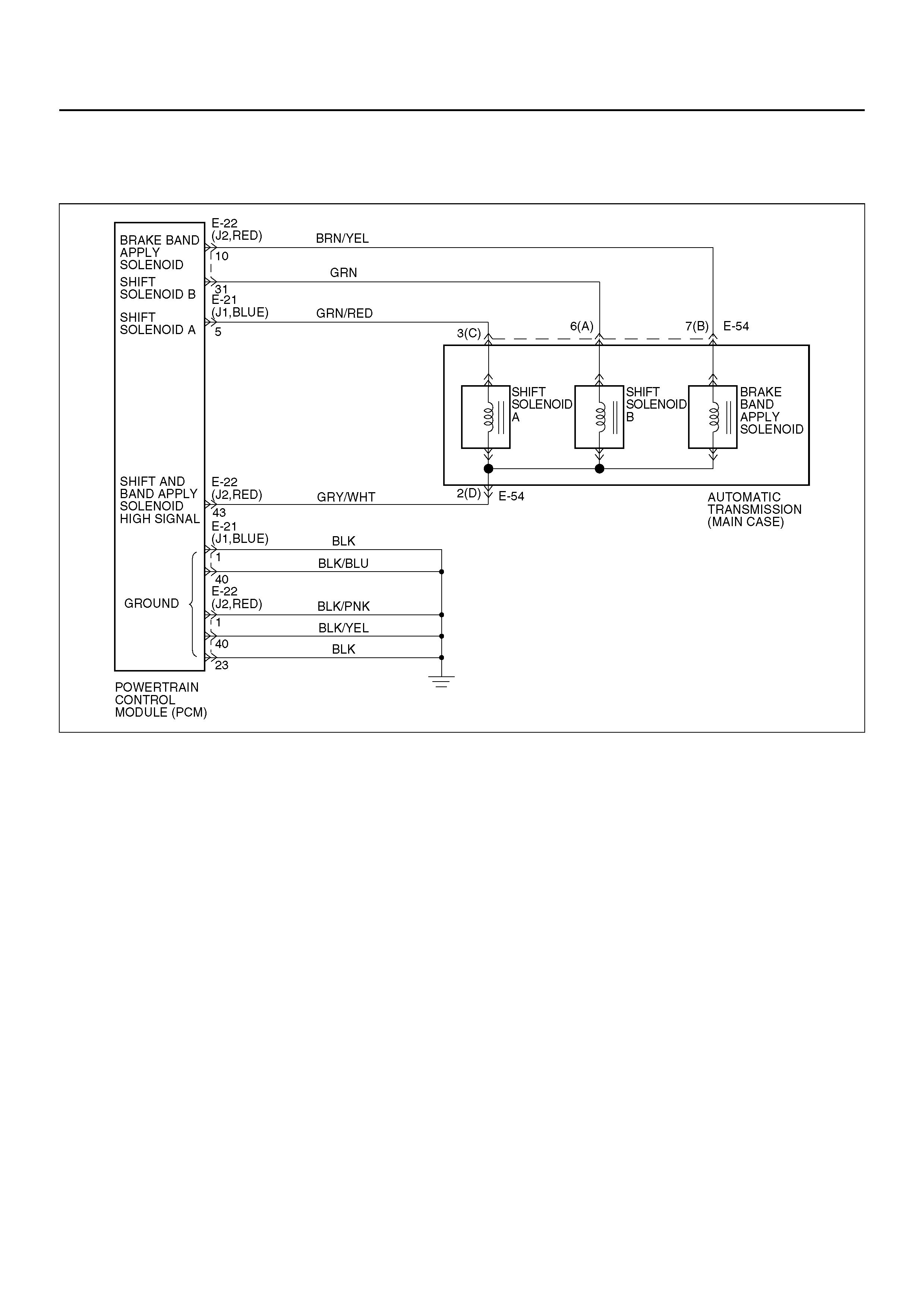
DTC P1850/FLASHING CODE 88 BRAKE BAND APPLY SOLENOID
MALFUNCTION
D07RY00035
Circuit Description
• The brake band apply solenoid is a normally open
solenoid which controls the flow of fluid for brake
band application. The Powertrain Control Module
(PCM) uses Pulse Width Modulation (PWM) and
changes the duty cycle to control the solenoid. The
PCM turns the solenoid on (energized) and off
(deenergi z ed) a t a co ns tant frequ enc y. T he l eng th o f
time the solenoid is energized during each on/off
cycle is called the pulse width. By varying or
“modulating" the pulse width, the solenoid output
pressure is changed. Since the solenoid is normally
open, increasing the pulse width increases the duty
cycle and decreases the output pressure. PWM
control provides smooth band application without an
accumulator. The band is only applied in first and
second gears.
• In the event of an electrical failure (open), the
solenoid regulates at the maximum oil flow (0% duty
cycle).
• The solenoid is activated by a current. This current is
produc ed by appl ying a v oltage to on e side ( the Hig h
side) and a ground to the other side (Low side).
• The High Side Driver (HSD) is a circuit of the PCM
that acts as a switch between the solenoids and the
supply voltage. The High side of the solenoid is
permane ntly sup plied with voltage. Whe n the ignit ion
is off, the HSD is turned off.
This DT C detects a c ontinuous op en or shor t to ground
in the brake band apply solenoid circuit or the brake
band apply solenoid. This is a type “D" DTC.
Conditions For Setting The DTC
• Battery voltage is between 10 and 16 volts.
• Ignition is “on", Engi ne “run ".
• The PCM commands the solenoid “on" and the
voltage remains high (B+), or the PCM commands
the solenoid “off" and the voltage remains low (zero
volts).
• All conditions met in 1.34∼1.56 seconds.
Action Taken When The DTC Sets
• Inhibit brake band apply solenoid.
• The PCM will not illuminate the CHECK TRANS
Lamp.

Conditions For Clearing The DTC
• The DTC can be cleared from the PCM history by
using a scan tool.
• The DTC will be cleared from history when the
vehicle has achieved 40 warmup cycles without a
failure reported.
• The PCM will cancel the DTC default actions when
the fault no longer exists and the ignition is cycled
“off" long enough to power down the PCM.
Diagnostic Aids
• Inspect the wiring for poor electrical connection at the
PCM and at the transmission 7–way connector. Look
for possible bent, backed out, deformed or damage d
terminals. Check for weak terminal tension as well.
Also check for a chafed wi re that co uld short to bare
metal or other wiring. Inspect for a broken wire inside
the insulation.
• When diagnosing for a possible intermittent short or
open condition, move the wiring harness while
observing test equipment for a change.
Test Description
The numbers below refer to the step numbers on the
diagnostic chart:
2. This test checks for power to the brake band apply
solenoid from the ignition through the PCM.
3. This test checks the resistance of the transmission
internal wiring harness and brake band apply
solenoid.
4. This test checks the ability of the PCM and wiring to
control the ground circuit.

DTC P1850/Flashing Code 88 Brake Band Apply Solenoid Malfunction
Step Action Yes No
1 1. Install the scan tool.
2. With the engine “on", turn the ign ition swi tc h “on".
NOTE: Before clearing DTC(s), use the scan tool to record
“Failure Records" for reference, as data will be lost when the
“Clear Info" function is used.
3. Record the DTC “Failure Records".
Were DTCs P0753, P0758 set? Go to Step 1 Go to Step 3
2 Using the J39200 DVOM, back probe between PCM connector
terminals E22–43 and E22–1.
Is the voltage between 10 to 12 volts? Go to Step 4 Go to Step 5
3 1. Turn the ignition “off".
2. Disconnect the E–21 (J1, BLUE) and E–22 (J2, RED) PCM
connector.
3. Using the J39200 DVOM, measure the resistance between
PCM connector terminals E22–43 and E22–10.
Is the resistance within 10–12 ohms? Go to Step 9 Go to Step 10
4 Using the J39200 DVOM, back probe between PCM connector
terminals E22–10 and E22–1.
Is the voltage between 10 to 12 volts? Go to Step 18 Go to Step 3
5 1. Turn the ignition “off".
2. Disconnect the E–21 (J1, BLUE) and E–22 (J2, RED) PCM
connector.
3. Using the J39200 DVOM, check continuity between PCM
terminal E22–43 and ground.
Is there a continuity? Go to Step 6 Go to Step 7
6 1. Disconnect the transmission main case connector E–54.
2. Using the J39200 DVOM, check continuity between the
terminal E54–7(B) and ground.
Is there continuity? Go to Step 12 Go to Step 13
7 1. Disconnect the E–21 (J1, BLUE) and E–22 (J2, RED) PCM
Connector.
2. Using the J39200 DVOM, measure the resistance between
the PCM connector terminals E22–43 and E22–10.
Is the resistance within 10–12 ohms? Go to Step 18 Go to Step 8
8 1. Disconnect the transmission main case connector E–54.
2. Using the J39200 DVOM, measure the resistance between
the terminals E54–7(B) and E54–2(D).
Is the resistance within 10–12 ohms? Go to Step 14 Go to Step 15
9 Using the J39200 DVOM, check continuity between PCM
terminal E22–10 and ground.
Is there continuity? Go to Step 11 Go to Step 18
10 1. Disconnect the transmission main case connector E–54.
2. Using the J39200 DVOM, measure the resistance between
the terminals E54–7(B) and E54–2(D).
Is the resistance within 10–12 ohms? Go to Step 17 Go to Step 15
11 1. Disconnect the transmission main case connector E–54.
2. Using the J39200 DVOM, check continuity between the
terminals E54–7(B) and ground.
Is there a continuity? Go to Step 12 Go to Step 16

12 The brake band apply solenoid is faulty, or the internal wiring
harness from the brake band apply solenoid is shorted to ground.
W as a problem found and corrected? Go to Step 19 —
13 The wiring harness between the PCM connector terminal E22–43
and the transmission main case connector terminal E54–2(D) is
shorted to ground.
W as a problem found and corrected? Go to Step 19 —
14 The wiring harness between the PCM connector terminal E22–43
and the transmission main case connector terminal E54–2(D) is
open.
W as a problem found and corrected? Go to Step 19 —
15 The brake band apply solenoid is faulty, or the internal wiring
harness from the brake band apply solenoid is open.
W as a problem found and corrected? Go to Step 19 —
16 The wiring harness between the PCM connector terminal E22–10
and the transmission main case connector terminal E54–7(B) is
shorted ground.
W as a problem found and corrected? Go to Step 19 —
17 The wiring harness between the PCM connector terminal E22–10
and the transmission main case connector terminal E54–7(B) is
open.
W as a problem found and corrected? Go to Step 19 —
18 Check every connection at the PCM.
If OK, replace the PCM. Refer to Powertrain Control Module
(PCM) in Automatic Transmission (4L30–E) section.
Is the replacement complete? Go to Step 19 —
19 1. After the repair is complete, use the scan tool to select
“DTC", then “Clear Info" function and ensure the following
conditions are met:
• The brake band apply solenoid is commanded “on" and
the volts drop to zero.
• The brake band apply solenoid is commanded “off" and
the volts increase to B+.
2. Review the scan tool “DTC Info".
Has the last test failed or is the current DTC displayed?
Begin diagnosis
again
Go to Step 1 Repair verified
Exit DTC table
Step Action Yes No
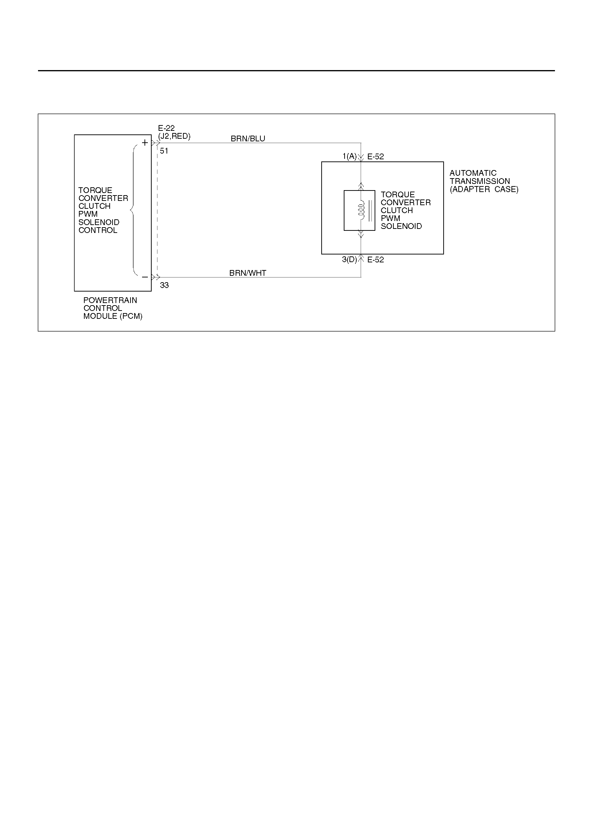
DTC P1860/FLASHING CODE 89 TCC SOLENOID ELECTRICAL
D07RY00036
Circuit Description
The PCM allows cur rent to flow through t he solenoid (0
or 12 vol ts). This c urrent flow thr ough the sole noid coil
creates a magnetic field tha t magnetiz es the solid core.
The magnetized core attracts the check ball to seat
against spring pressure. This blocks the exhaust for the
TCC signal fluid and allows solenoid feed drive fluid to
feed to TCC signal circuit. The TCC signal fluid
pressure acts on the torque converter clutch control
valve. When the TCC control valve is in the apply
position, line pressure is directed through the TCC valve
to apply the torque converter clutch . The TCC solenoid
is attached to the valve body within the transmission.
This DTC detects a cont inuous o pen or sho rt to groun d
or ignition in the TCC circuit or the T CC solenoid. Th is
is a type “C" DTC.
Conditions For Setting The DTC
• Battery voltage is between 10 and 16 volts.
• No shift solenoid A DTCs P0753 (Flashing Code 83).
• No shift solenoid B DTCs P0758 (Flashing Code 84).
• Ignition “on". Engine “run".
• The PCM commands the solenoid “on" and the
voltage remains low (zero volts).
• The PCM commands the solenoid “off" and the
voltage remains high (B+).
• All conditions met for 0.875 ∼ 1.25 seconds.
Action Taken When T h e DTC Sets
• Inhib it TCC engage men t.
• The PCM will illuminate the CHECK TRANS Lamp.
Conditions For Clearing The DTC
• The PCM wil l tur n o ff the CH ECK T RA NS Lam p after
three consecutive ignition cycles without a failure
reported.
• The DTC can be cleared from the PCM history by
using a scan tool.
• The DTC will be cleared from history when the
vehicle has achieved 40 warmup cycles without a
failure reported.
• The PCM will cancel the DTC default actions when
the fault no longer exists and the ignition is cycled
“off" long enough to power down the PCM.
Diagnostic Aids
• Inspect the wiring for poor electrical connections at
the PCM and at the transmission 4–way connector.
Look for possible bent, backed out, deformed or
damaged terminals. Check for weak terminal tension
as well. Also check for a chafed wire that could short
to bare metal or other wiring. Inspect for a broken
wire inside the insulation.
• When diagnosing for a possible intermittent short or
open condition, move the wiring harness while
observing test equipment for a change.
Test Description
The numbers below refer to the step numbers on the
diagno sti c ch ar t:
2. This test checks for voltage to the solenoid.
3. This test checks the ability of the PCM and wiring to
control the ignition ci r cuit.
7. This test checks the resistance of the TCC solenoid
and the internal wiring harness.

DTC P1860/Flashing Code 89 TCC Solenoid Electrical
Step Action Yes No
1 1. Install the scan tool.
2. With the engine “on", turn the ign ition swi tc h “on".
NOTE: Before clearing DTC(s), use the scan tool to record
“Failure Records" for reference, as data will be lost when
the“Clear Info" function is used.
3. Record the DTC “Failure Records".
Was DTC P1860 set? Go to Step 2 Go to Step 3
2 Using the J39200 DVOM, back probe between PCM connector
terminals E22–51 and E22–33.
Is the voltage 0? Go to Step 4 Go to Step 5
3 1. Apply brake pedal and select transmission range “D".
2. Do a test drive, and increase the vehicle speed to TCC “on"
at 4th.
Does the scan tool display DTC P1860 at TCC “ON"? Go to Step 8 Go to Diagnostic
Aids
4 1. Turn the ignition “off".
2. Disconnect the E–22 (J2, RED) PCM connector.
3. Using the J39200 DVOM, measure the resistance between
PCM connector terminals E22–51 and E22–33.
Is the resistance within 18 – 20 ohms? Go to Step 6 Go to Step 7
5 The wiring harness between PCM connector terminal E22–51
and transmission adapter case connector terminal E52–1(A) is
shorted to voltage.
W as a problem found and corrected? Go to Step 14 Go to Step 15
6 Intermittent condition.
Check the wiring harness and terminals between PCM connector
J2 and transmission adapter case connector E–52.
W as a problem found and corrected? Go to Step 14 Go to Step 15
7 1. Disconnect the transmission adapter case connector E–52.
2. Using the J39200 DVOM, measure the resistance between
terminal E52–1(A) and ground.
Is the resistance within 18 – 20 ohms? Go to Step 12 Go to Step 13
8 1. Turn the ignition “off".
2. Disconnect the E–22 (J2, RED) PCM connector.
3. Using the J39200 DVOM, measure the resistance between
terminals E22–51 and E22–33.
Is the resistance within 18 – 20 ohms? Go to Step 14 Go to Step 9
9 1. Disconnect the transmission adapter case connector E–52.
2. Using the J39200 DVOM, measure the resistance between
terminal E52–1(A) and ground.
Is the resistance within 18–20 ohms? Go to Step 10 Go to Step 11
10 The wiring harness between PCM connector E22 and adapter
case connector E–52 is shorted to ground.
W as a problem found and corrected? Go to Step 16 —
11 The TCC solenoid is faulty, or the internal wiring harness from the
TCC solenoid is shorted to ground.
W as a problem found and corrected? Go to Step 16 —
12 The wiring harness between PCM connector terminal E22–51
and adapter case terminal E52–1(A) is open.
W as a problem found and corrected? Go to Step 16 —

13 The TCC solenoid is faulty , or the internal wiring harness from the
TCC solenoid is open.
W as a problem found and corrected? Go to Step 16 —
14 Check every connection at the PCM.
If OK, replace the PCM. Refer to Powertrain Control Module
(PCM) in Automatic Transmission (4L30–E) section.
Is the replacement complete? Go to Step 16 —
15 Check the PCM connector terminal E22–51, and transmission
adapter case connector terminal E52–1(A).
W as a problem found and corrected? Go to Step 16 —
16 1. After the repair is complete, use the scan tool to select
“DTC", then “Clear Info" function and ensure the following
conditions are met:
• The TCC solenoid is commanded “on" and the volts
increase to B+.
• The TCC solenoid is commanded “off" and the volts drop
to zero.
2. Review the scan tool “DTC Info".
Has the last test failed or is the current DTC displayed?
Begin diagnosis
again
Go to Step 1 Repair verified
Exit DTC table
Step Action Yes No
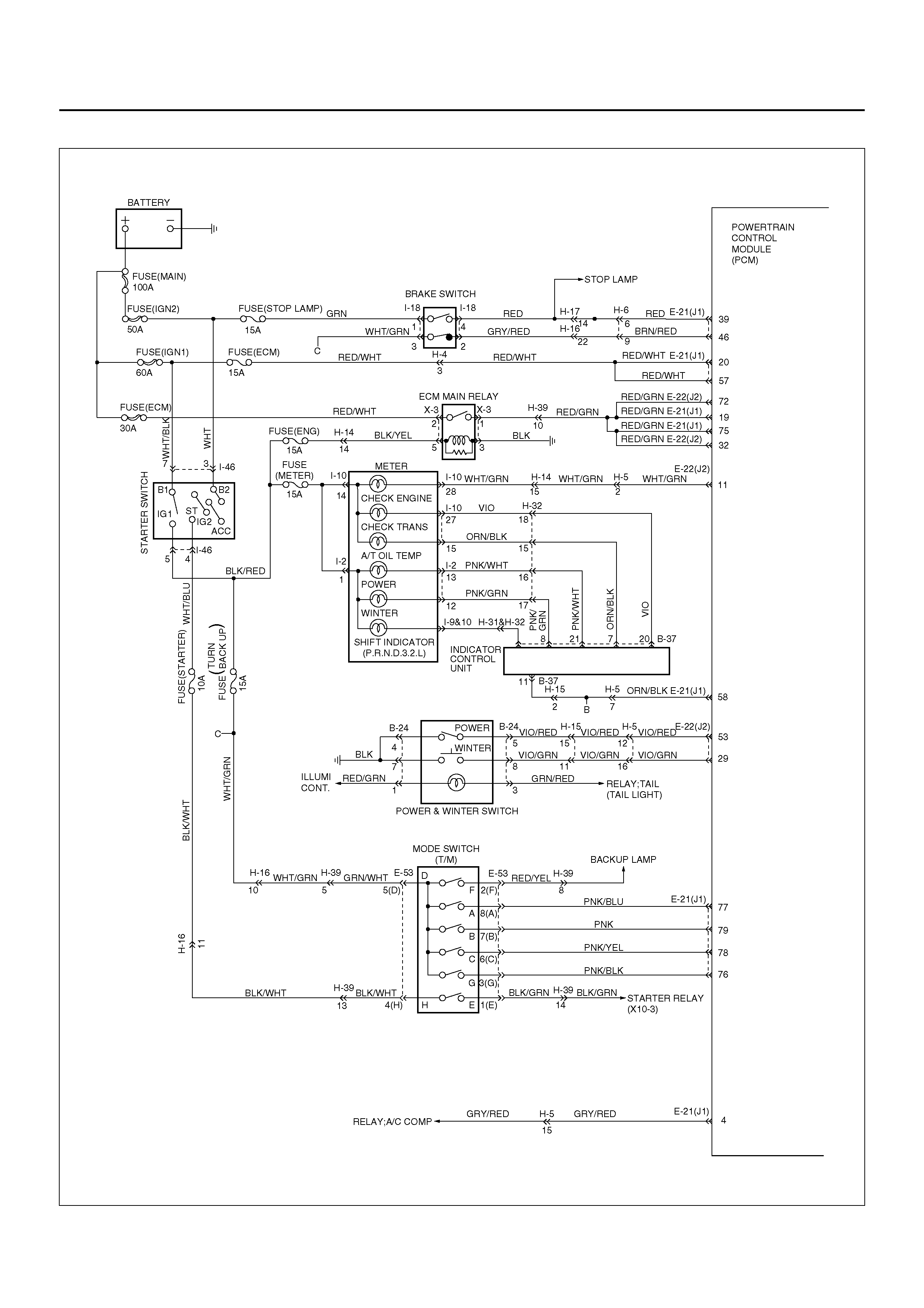
CIRCUIT DIAGRAM
D07R100036
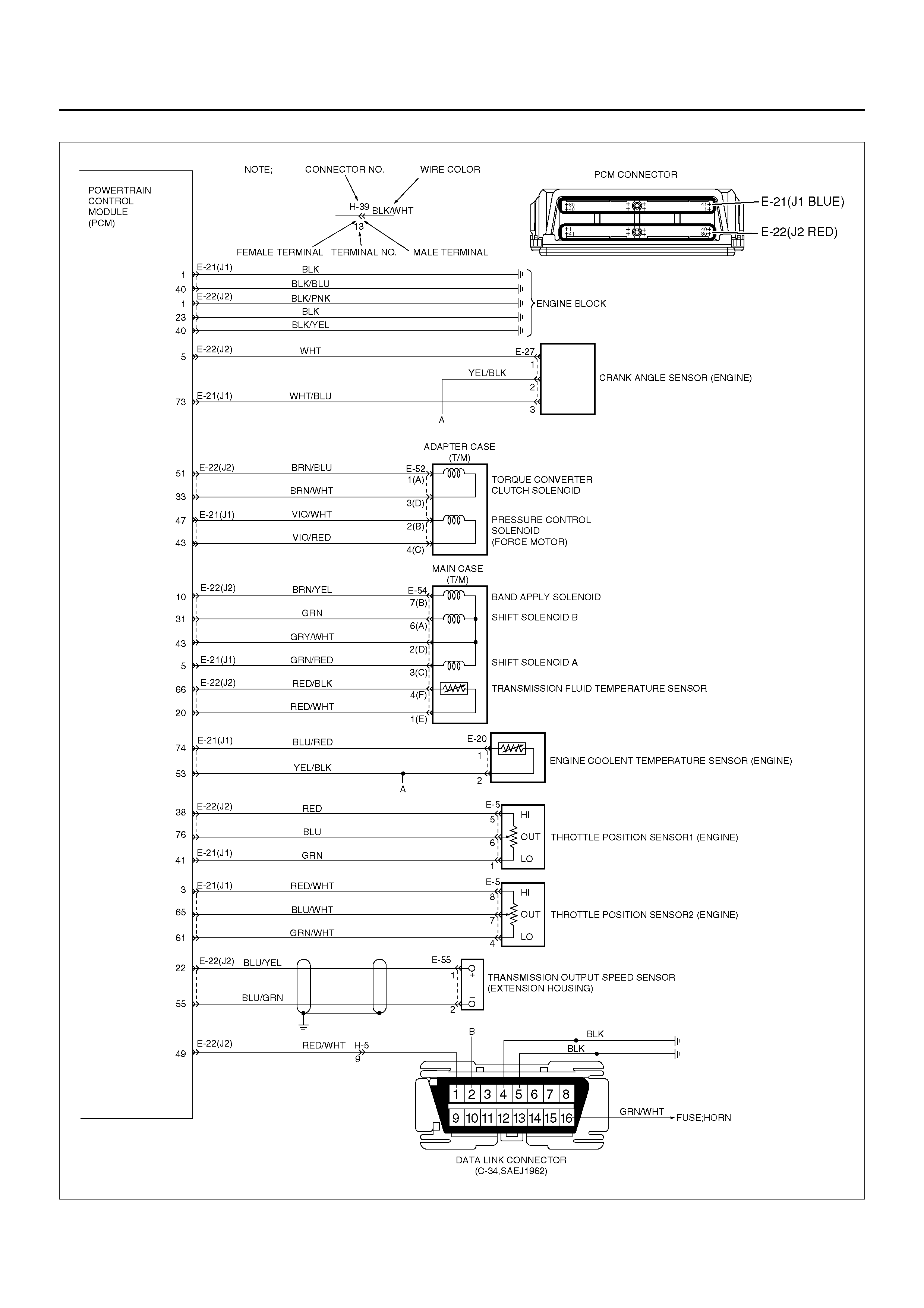
D07R100037
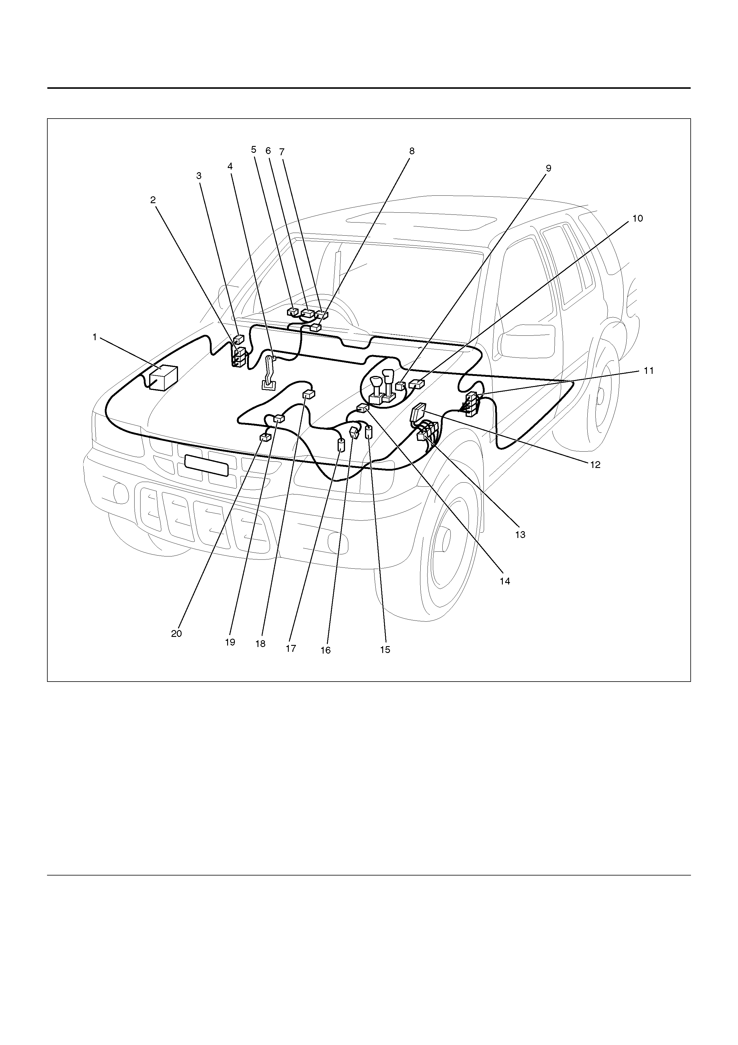
PARTS LOCATION
D07R100032
EndOFCallout
Legend
(1) Co nne cto r X- 3
(2) Connector H-14, H-19, H-32
(3) Data Link Connector C-34
(4) Connector I-18
(5) Co nne cto r I-2
(6) Co nne cto r I-9
(7) Connector I-10
(8) Connector I-46
(9) Co nne cto r B-24
(10) Co nnector B-37
(11) Connector H-15, H-16, H-17, H-19, H-31
(12) PCM Connector E-21 (J1), E-22 (J2)
(13) Connector H-4, H-5, H-6, H-39
(14) Connector E-55
(15) Connector E-54
(16) Connector E-53
(17) Connector E-52
(18) Connector E-27
(19) Conn ector E-5
(20) Connector E-20
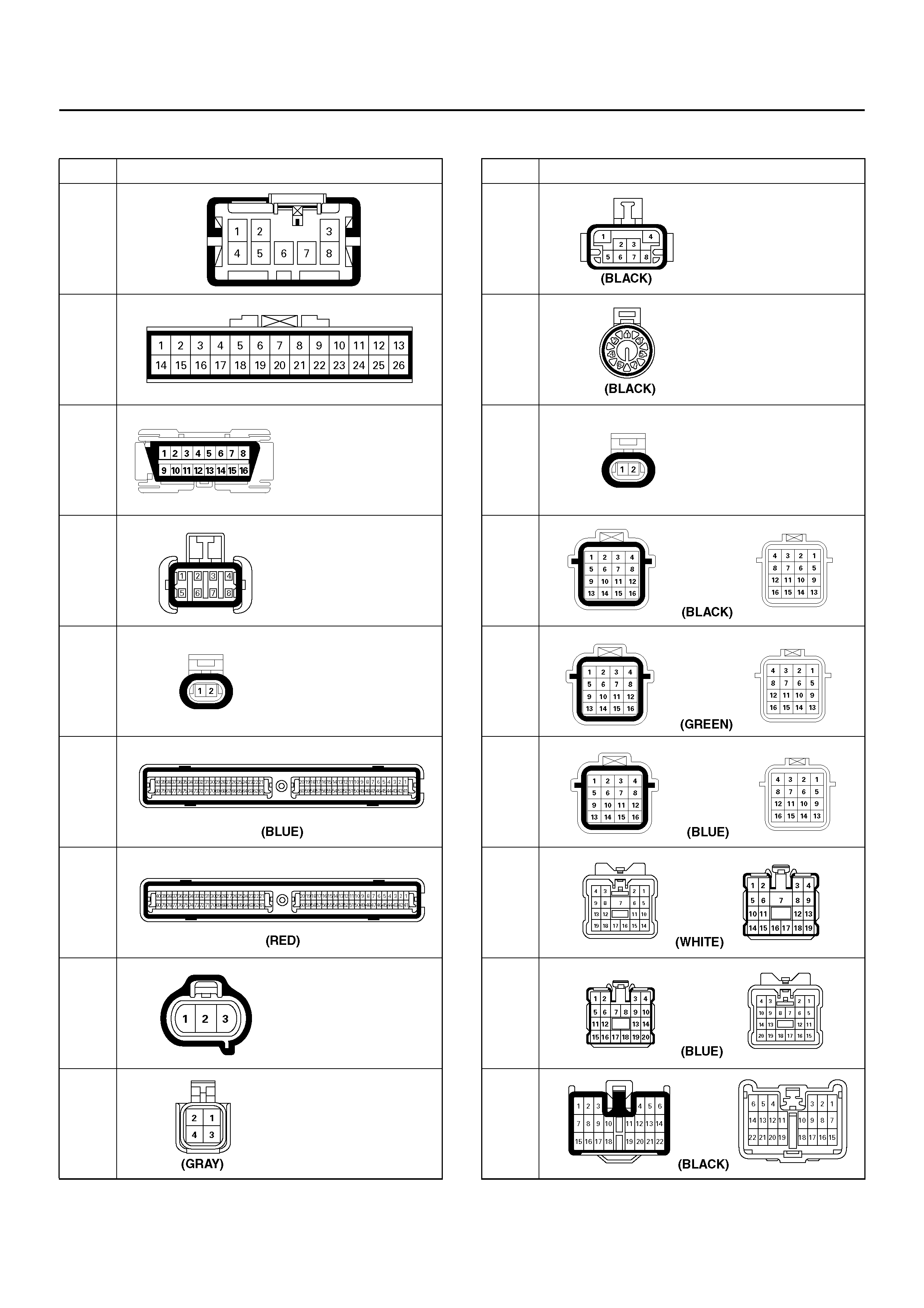
HARNESS CONNECTOR FACES
No. Connector face
B-24
B-26
C-34
E-5
E-20
E-21
(J1)
E-22
(J2)
E-27
E-52
E-53
E-54
E-55
H-4
H-5
H-6
H-14
H-15
H-16
No. Connector face
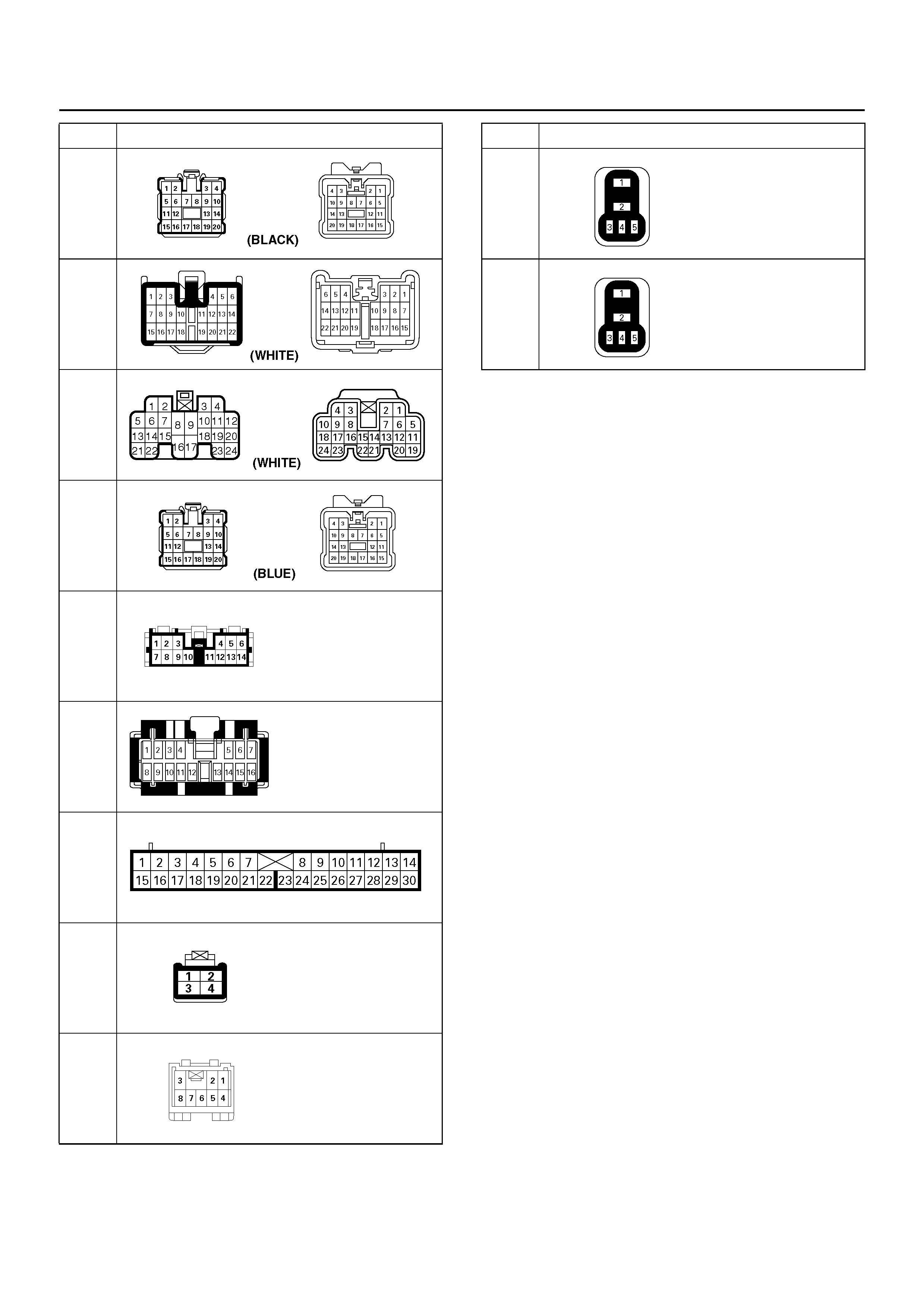
H-17
H-19
H-31
H-32
I-2
I-9
I-10
I-18
I-46
No. Connector face X-3
X-10
No. Connector face

TRANSMISSION FLUID TEMPERATURE (TFT) SENSOR SPECIFICATIONS
Temper ature Temperature Minimum
Resistance Nominal
Resistance Maximum
Resistance Signal
°F°CΩΩΩVolts
-40 -40 600500 664200 731100 5.00
-22 -30 319800 350400 382400 4.65
-4 -20 177400 192700 208600 4.41
14 -10 102200 110100 118300 4.00
32 0 60870 65110 69450 3.52
50 10 37410 39750 42120 2.98
68 20 23660 24980 26300 2.40
86 30 15270 16120 16970 1.85
104 40 10040 10660 11290 1.43
122 50 6758 7211 7673 4.29
140 60 4645 4980 5324 4.04
158 70 3255 3506 3765 3.69
176 80 2323 2513 2710 3.34
194 90 1685 1831 1982 3.04
212 100 1242 1355 1472 2.58
230 110 929 1017 1109 2.24
248 120 704 773 846 1.97
266 130 540 595 653 1.67
284 140 419 464 511 1.42
302 150 329 365 403 1.16