
SECTION 1A - HEATING, VENTILATION AND
AIR CONDITIONING (HVAC)
Service Precaution
Heating and Ventilation System
General Description
Heater and Ventilation Associated Parts
Ventilation
Circuit Diagram
Diagnosis
Individual Inspection
Heater Unit
Heater Unit and Associated Parts
Removal
Installation
Heater Core and / or Mode Door
Disassembled View
Removal
Inspection
Installation
Heater Mode Control Link Unit
Disassembled View
Removal
Installation
Heater Temperature Control Link Unit
Disassembled View
Removal
Installation
Blower Assembly
Blower Assembly and Associated Parts
Removal
Installation
Blower Link Unit and / or Mode door
Disassembled View
Removal
Installation
Blower Motor
Blower Motor and Associated Parts
Removal
Installation
Rear Heater Duct, Defroster Nozzle and
Ventilation Duct
Rear Heater Duct, Defroster Nozzle,
Ventilation Duct and Associated Parts
Removal
Installation
Control Lever Assembly and / or Control Cable
Control Lever Assembly, Control Cable
and Associated Parts
Removal
Installation
Control Panel Illumination Bulb
Control Panel Illumination Bulb and
Associated Parts
Removal
Installation
Resistor
Resistor and Associated Parts
Removal
Installation
Air Conditioning System
General Description
Circuit Diagram
Diagnosis
Individual Inspection
General Repair Procedure
Leak Check
Compressor Assembly
Compressor Assembly and Associated
Parts (6VD1)
Removal
Installation
Compressor Assembly and Associated
Parts (X22SE)
Removal
Installation
New Compressor Installation
Condenser Assembly
Condenser Assembly and Associated Parts
Removal
Installation
Condenser Fan Motor
Condenser Fan Motor and Associated Parts
Removal
Installation
Receiver / Drier
Receiver / Drier and Associated Parts
Removal
Installation
Pressure Switch
Pressure Switch and Associated Parts
Removal
Installation
Evaporator Assembly
Evaporator Assembly and Associated Parts
Removal
Installation
Techline
Techline

Electronic Thermostat, Evaporator Core
and/or Expansion Valve
Disassembled View
Removal
Installation
Refrigerant Line
Refrigerant Line and Associated Parts
Removal
Installation
Main Data And Specifications
Compressor
Service Precaution
General Description
Diagnosis
Magnetic Clutch Assembly (DKV-14G Type)
Parts Location View
Removal
Inspection and Repair
Installation
Compressor Oil
Oil Specification
Handling of Oil
Compressor Oil Check
Checking and Adjusting Oil Quantity for
Used Compressor
Checking and Adjusting for Compressor
Replacement
Contamination of Compressor Oil
Oil Return Operation
Replacement of Component Parts
Main Data and Specifications
Special Tools
Automatic Air Conditioning System
General Description
Automatic Air Conditioner Parts Configuration
Refrigerant Line and Associated Parts
Circuit Diagram
Functions and Features
Automatic Air Conditioner Block Diagram
Control Panel Layout
Air Control Functions
Operation and Functions of Control Panel
Switches
Overview of Construction, Movement and
Control of Major Parts of Automatic Air
Conditioner System
Overview of Automatic Control of
Automatic Air Conditioner
Troubleshooting
Troubleshooting, Its Overview and
Procedures
Auto Air Conditioner Control Unit Power
Supply Diagnosis
Performance and Movement checklist
for Automatic Air Conditioner Related
Parts
Troubleshooting With Self-Diagnosis
Function
Inspection By Failed Location
Inspection of the Sensors
Inspection of the Intake Actuator System
Inspection of the Mix Actuator System
Inspection of the Mode Actuator System
Inspection of the Fan Motor System
Inspection of the Magnetic Clutch System
Condenser Fan Diagnosis
Individual Inspection
On-Vehicle Service
Power Transistor
Removal
Installation
Automatic Heater/Air Conditioner
Control Unit
Removal
Installation
In Car Sensor
Removal
Installation
Ambient Sensor
Removal
Installation
Sun Sensor
Removal
Installation
Electronic Thermostat
Removal
Installation
Mode Actuator
Removal
Installation
Mix Actuator
Removal
Installation
Intake Actuator
Removal
Installation

Service Precaution
WARNING: THIS VEHICLE HAS A SUPPLEMENTAL
RESTRAINT SYSTEM (SRS). REFER TO THE SRS
COMPONENT AND WIRING LOCATION VIEW IN
ORDER TO DETERMINE WHETHER YOU ARE
PERFORMING SERVICE ON OR NEAR THE SRS
COMPONENTS OR THE SRS WIRING. WHEN YOU
ARE PERFORMING SERVICE ON OR NEAR THE
SRS COMPONENTS OR THE SRS WIRING, REFER
TO THE SRS SERVICE INFORMATION. FAILURE TO
FOLLOW WARNINGS COULD RESULT IN
POSSIBLE AIR BAG DEPLOYMENT, PERSONAL
INJURY, OR OTHERWISE UNNEEDED SRS SYSTEM
REPAIRS.
CAUTION: Always use the correct fastener in the
proper location. When you replace a fastener, use
ONLY the exact part number for that application.
ISUZU will call out those fasteners that require a
replacement after removal. ISUZU will also call out
the fasteners that require thread lockers or thread
sealant. UNLESS OTHERWISE SPECIFIED, do not
use supplemental coatings (Paints, greases, or
other corrosion inhibitors) on threaded fasteners or
fastener joint interfaces. Generally, such coatings
adversely affect the fastener torque and the joint
clamping f or ce, and may dama ge the fastener . Wh en
you install fasteners, use the correct tightening
sequence and specifications. Following these
instructions can help you avoid damage to parts
and systems.
Heating and Ventilation System
General Description
Heater
When the engine is warming up, the warmed engine
coolant is sent out into the heater core. The heater
system supplies warm air into the passenger
compartment to warm it up.
Outside air is circulated through the heater core of the
heater unit and then back into the passenger
compartment. By controlling the mixture of outside air
and heater core air, the most comfortable passenger
compartment temperature can be selected and
maintained.
The temperature of warm air sent to the passenger
compartment is controlled by the temperature control
knob . This knob acts to open and close the air mix door ,
thus controlling the amount of air passed through the
heater core.
The air selector knob, with its different modes, also
allows you to select and maintain the most comfor table
temperature.
The air source select lever is used to select either
“FRESH" for the introduction of the outside air, or
“CIRC" for the circulation of the inside air. When the
lever is s et to “FRES H", the outside air is always taken
into the passenger compartment. When setting the
lever to “CIRC" position, the circulation of air is
restricted only to the inside air with no introduction of
the outside air and the air in the passenger
compar tment gets war m quickly. However, the lever is
nor m ally s et to “FRESH" to prevent th e win dshield from
clouding.
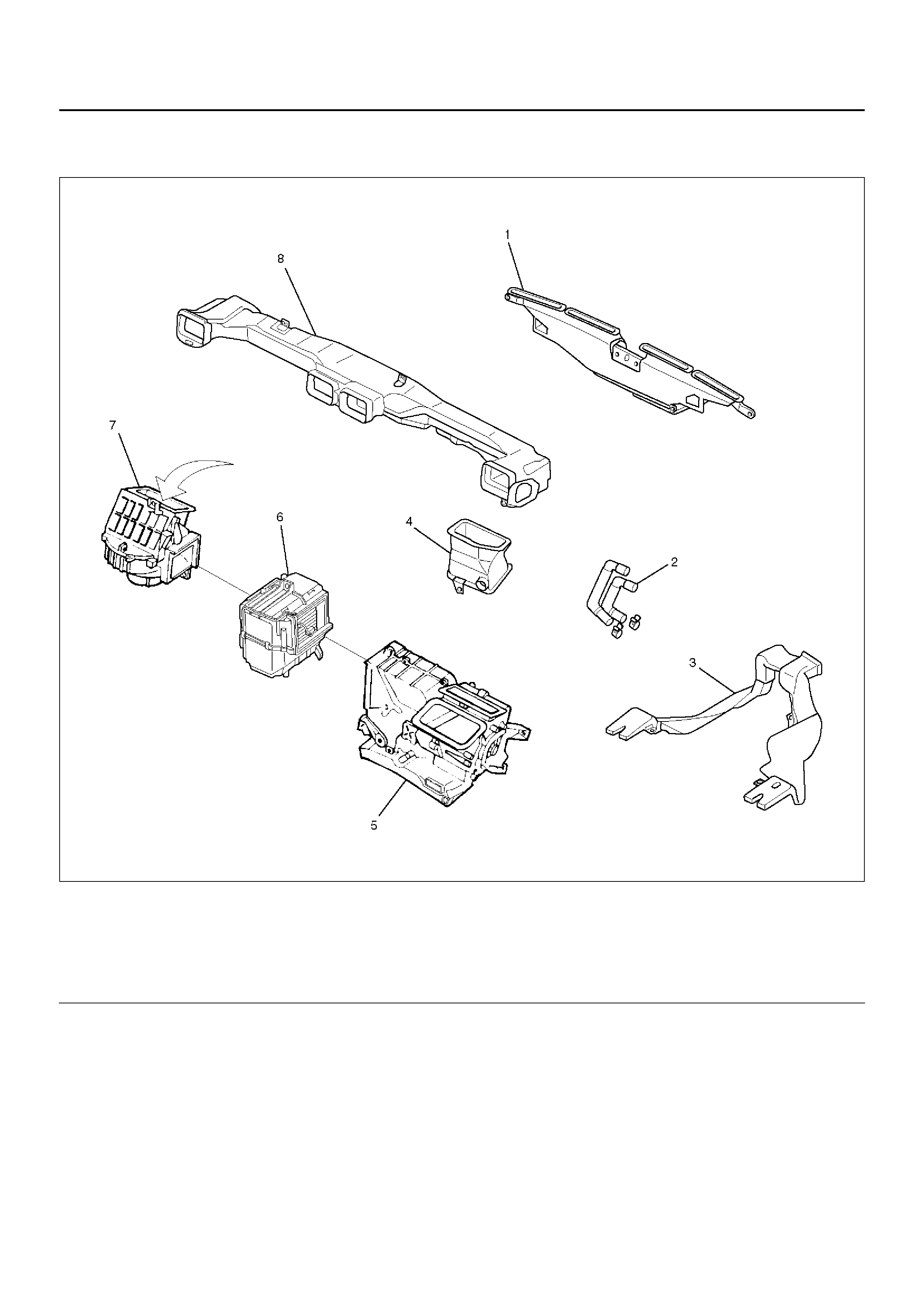
Heater and Ventilation Associated Parts
840RY00049
EndOFCallout
Legend
(1) Defroster Nozzle
(2) Heater Hose
(3) Rear Heater Duct
(4) Ventiration Lower Duct
(5) Heater Unit
(6) Evaporator Assembly
(7) Blower Assembly
(8) Ventilation Duct
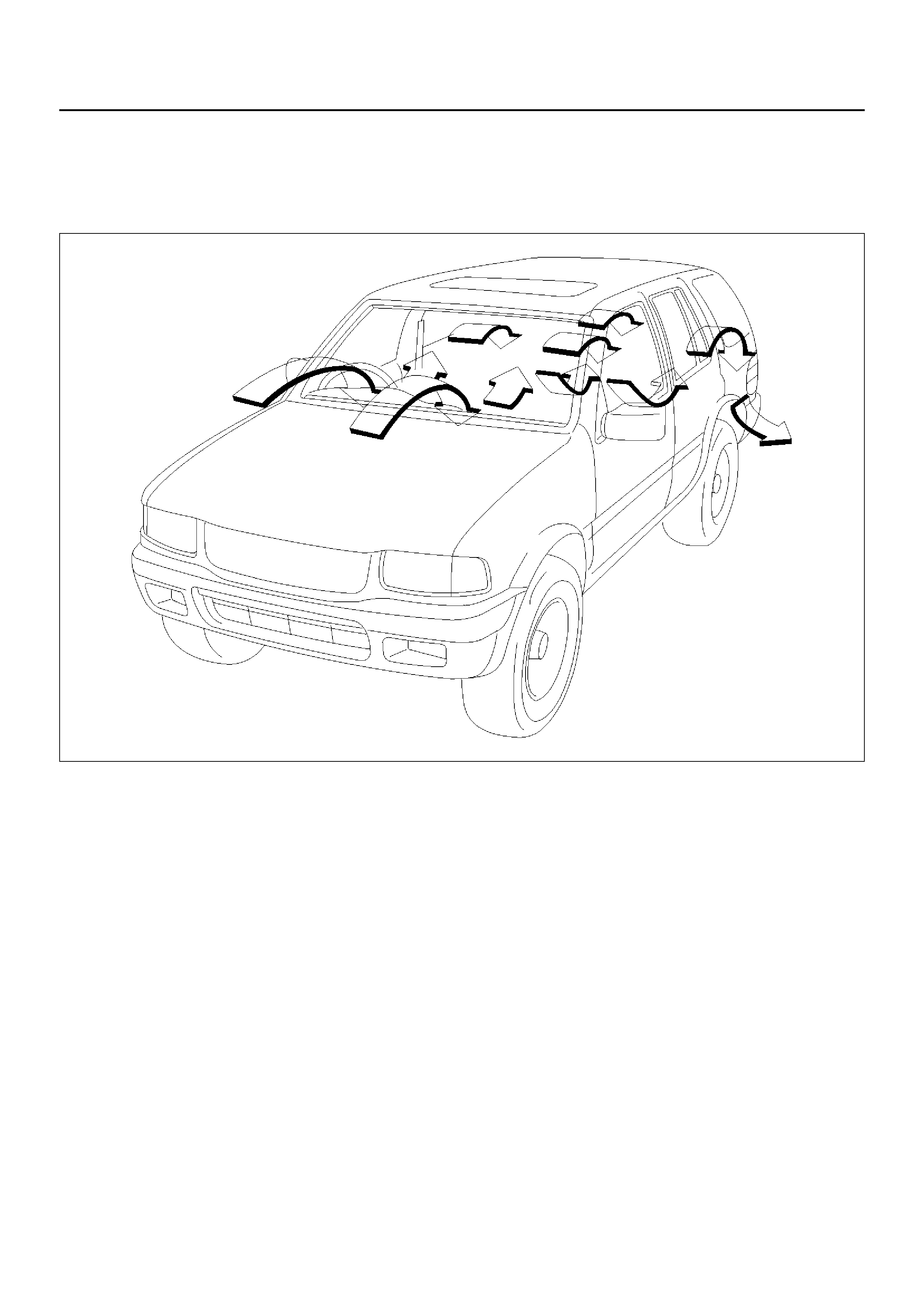
Ventilation
Setting the air source select lever to “FRESH" position
allows the heating system to work with sending the
fresh air from outside.
The blower fan also serves to deliver fresh outside air to
the passenger compartment to assure adequate
ventilation.
810RW319
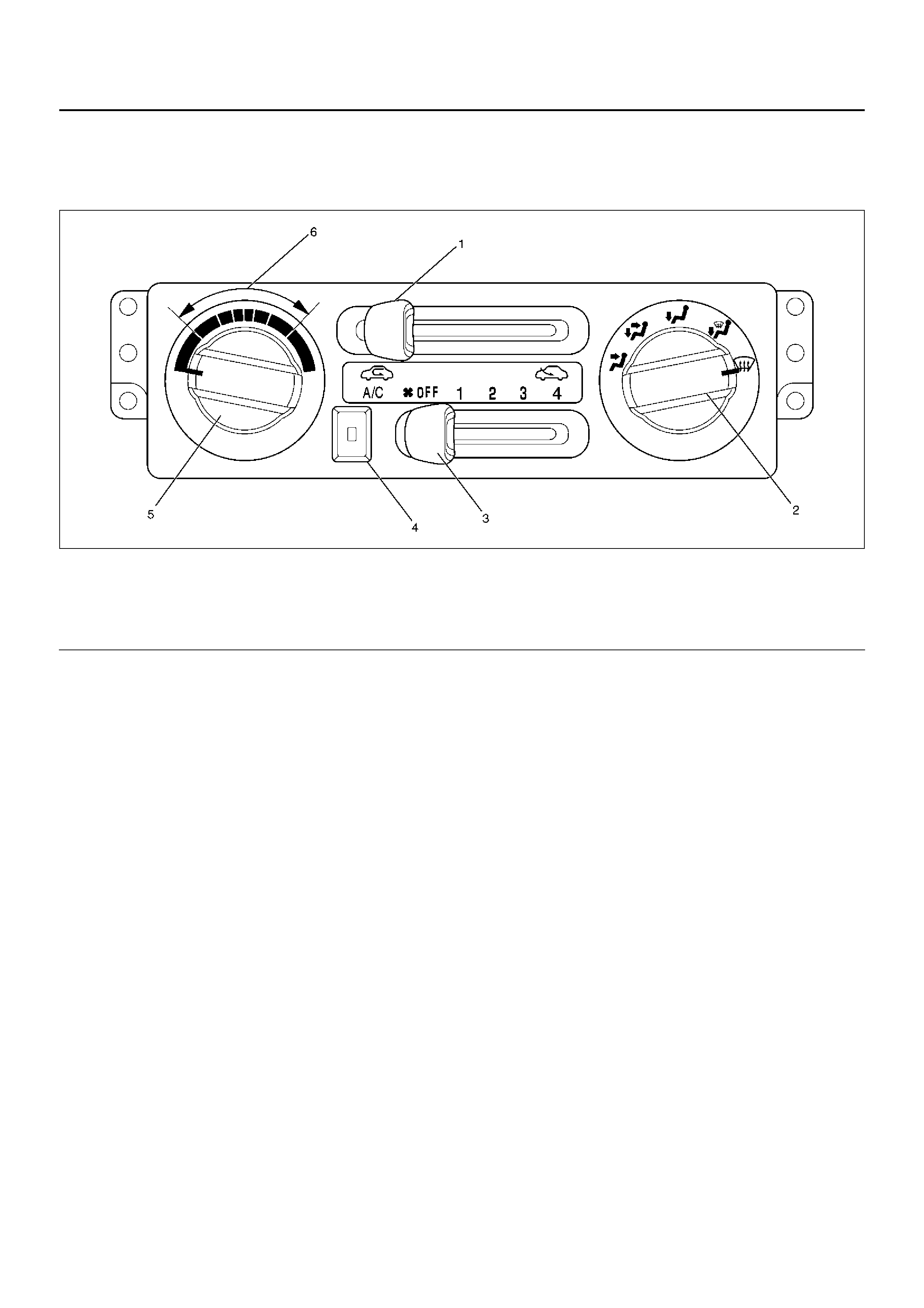
Control Lever Assembly
The control lever assembly has some cables to control
the mode and temperature of the heater unit and the
mode door for the air source of the blower assembly.
The fan control is u sed to c ontrol t he a mount of air sen t
out by the resistor at four levels from “LOW" to “HIGH".
865RW006
EndOFCallout
Air Source Select Lever
The intake of outsid e air and the circu lation of insi de air
are controlled by sliding this lever left or right.
Fan Control Lever
This lever controls the blower motor speed to regulate
the amount of air delivered to the defrost, foot, and
ventilation ducts:
1. Low
2. Medium Low
3. Medium High
4. High
Temperature Control Knob
When the temperature control knob is in the “COLD"
position, the air mix door closes to block the flow air to
the heater core.
When the temperature control knob is in the “HOT"
position, the air mix door opens to allow air to pass
through the heater core and heat the passenger
compartment.
Placi ng the knob in a interm ediate positi on will cause a
lesser or greater a mou nt a ir to r each the hea ter c ore. In
this mode the passenger compartment temperature can
be regulated.
Legend
(1) Air Source Select Lever
(2) Air Select Knob
(3) Fan Control Le ver (Fa n Switch)
(4) Air Conditioning (A/C) Switch (W/ A/C)
(5) Temperature Control Knob
(6) Middle Position
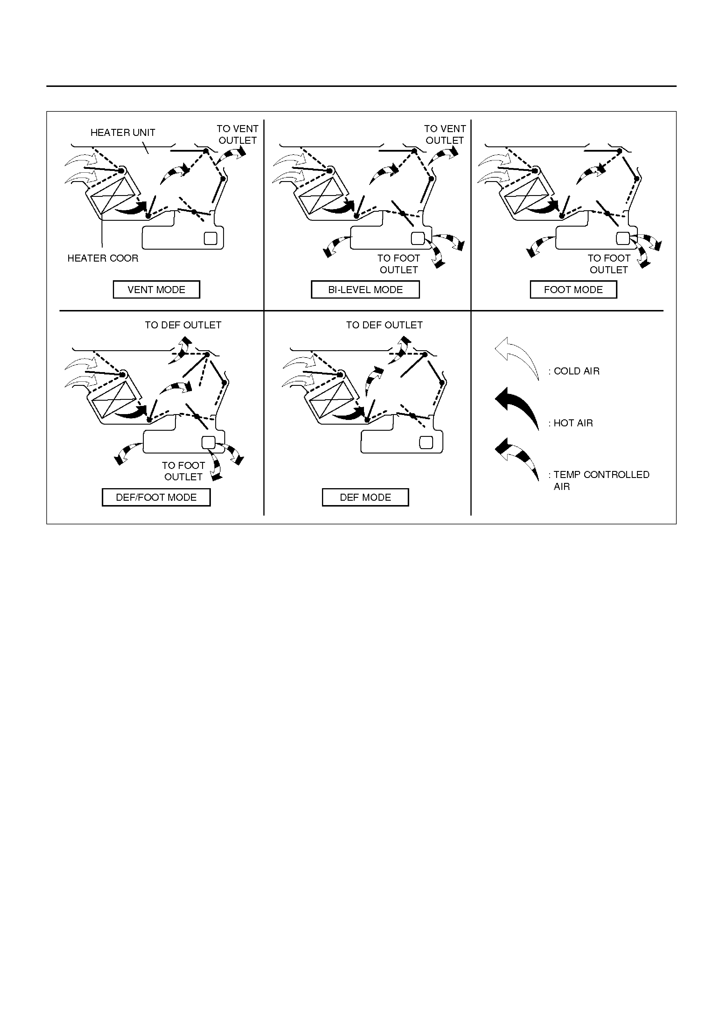
Flow of Each Position of the All Select Dials
C01RX001
Air Select Knob
The air select knob allows you to direct heated air into
the passenger compartment through different outlets.
1. Vent – In this position, air is discharged from the
upper air outl et. Ai r quantity is control led by the fan
con tr ol lever.
2. Bi-Level – In this position, air flow is divided
between the upper air outlets and the floor air
outlets, with warmer air delivered to the floor outlets
than the air delivered to the upper air outlets when
the temp lever is in middle position.
3. Foot – In this position, air flow is delivered to the
foot, while sending a small amount of air to the
windshield.
4. Def/Foot – In this position, air flow is delivered to
the foot, while send ing approx. 40% of to tal amount
of air to the windshield.
5. Defrost – In this position, most of the air is delivered
to the windshie ld and a s mal l a mou nt i s del ivered to
the side windows.
Moving the air source select lever to the “CIRC" position
provides quickest heat delivery by closing the blower
assem bly mode doo r. In this po sition, outside ai r is not
delivered to the passenger compartment.
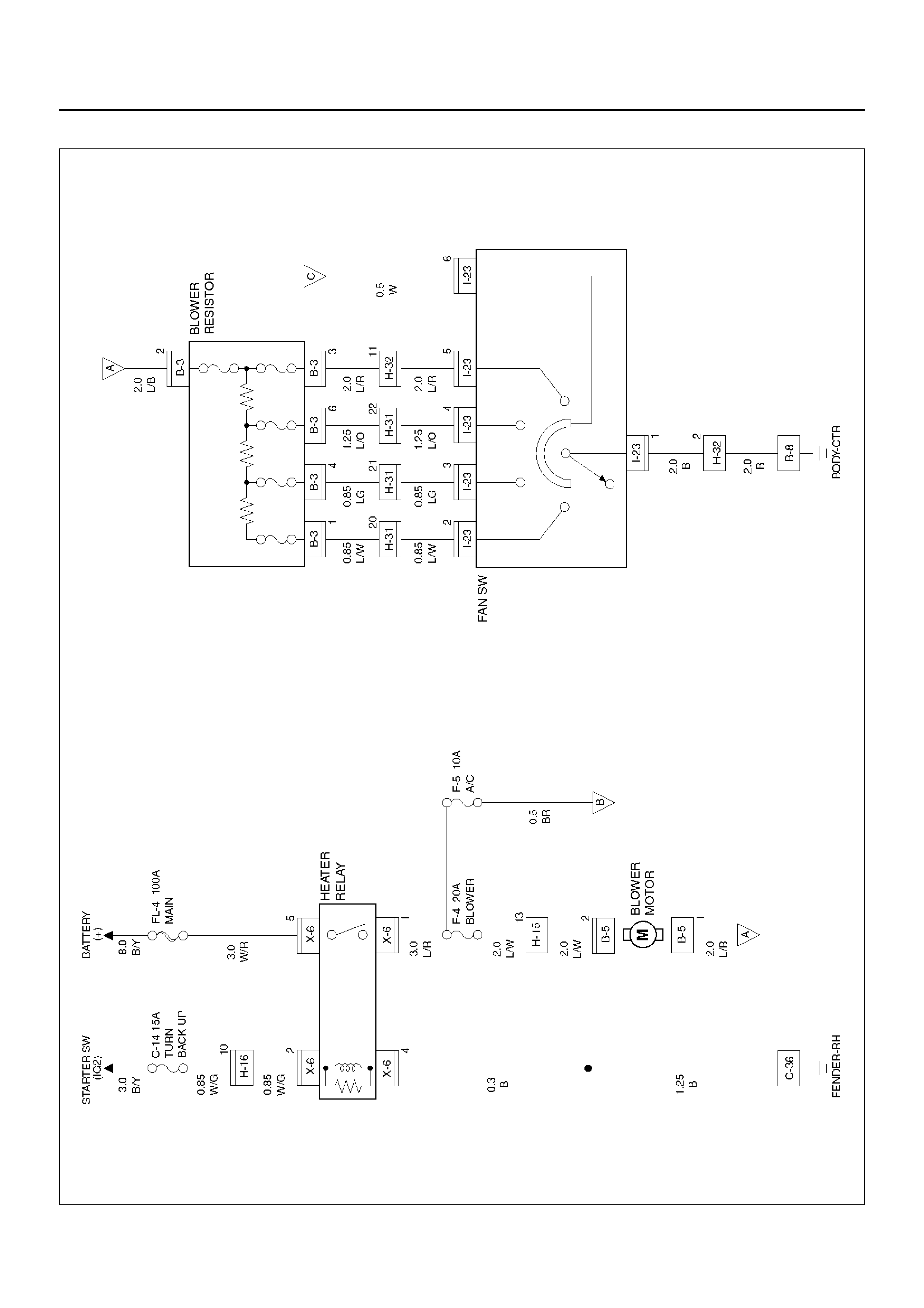
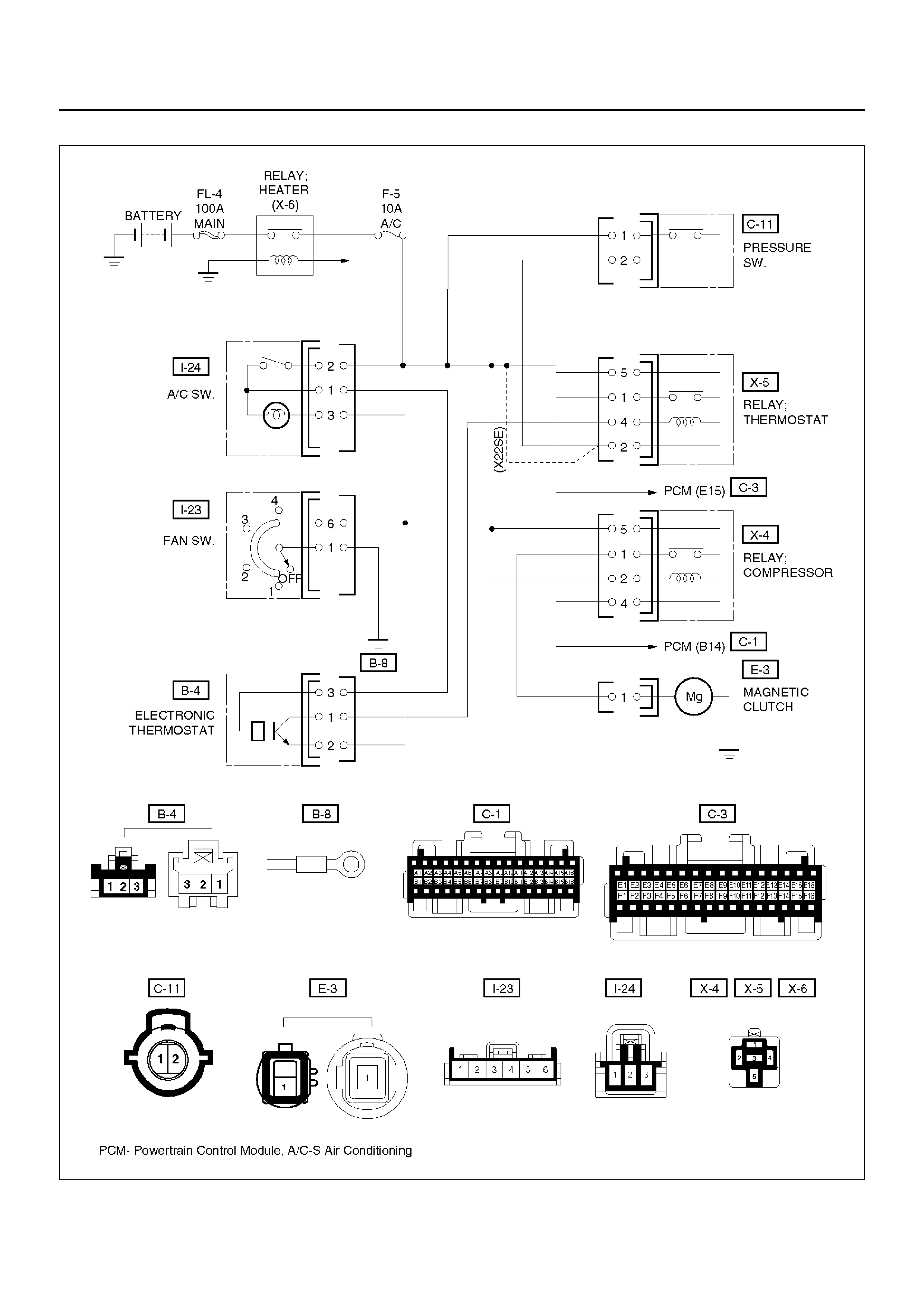
Circuit Diagram
D08RX149
Diagnosis
Heating Cycle diagnosis
Condition Possible cause Correction
No heating or insufficient heating. Blower motor does not run or runs
improperly. Refer to “FAN CONTROL LEVER
(FAN SWITCH) DIAGNOSIS".
Engine coolant temperature is low. Check the engine coolant
temperature after warming up the
engine and ch eck the th er m ostat.
Replace as necessary.
Insufficient engine coolant. Add engine coolant as required.
Circulation volume of engine coolant
is insuf f ic ie nt. Check if the water hose to the
heater core is clogged, collapsed or
twisted. Repair or replace as
necessary.
Heater core cl ogg ed or coll aps ed. Clean or replac e as neces sa ry.
The heater cores is not provided
with air sent from the blower motor. Repair the temperature control link
unit or mode doors.
Duct connections defective or
unsealing. Repair or replace as necessary.
Control lever moves but mode door
does not operate. Cable attaching clip is not correct. Repair
Link unit of heater or blower
assembly defective. Repair
The mode door can not be set to the
mode selected. Link unit of heater unit or blower
assembly defective. Repair.
Control cable is not adjusted. Adjust.
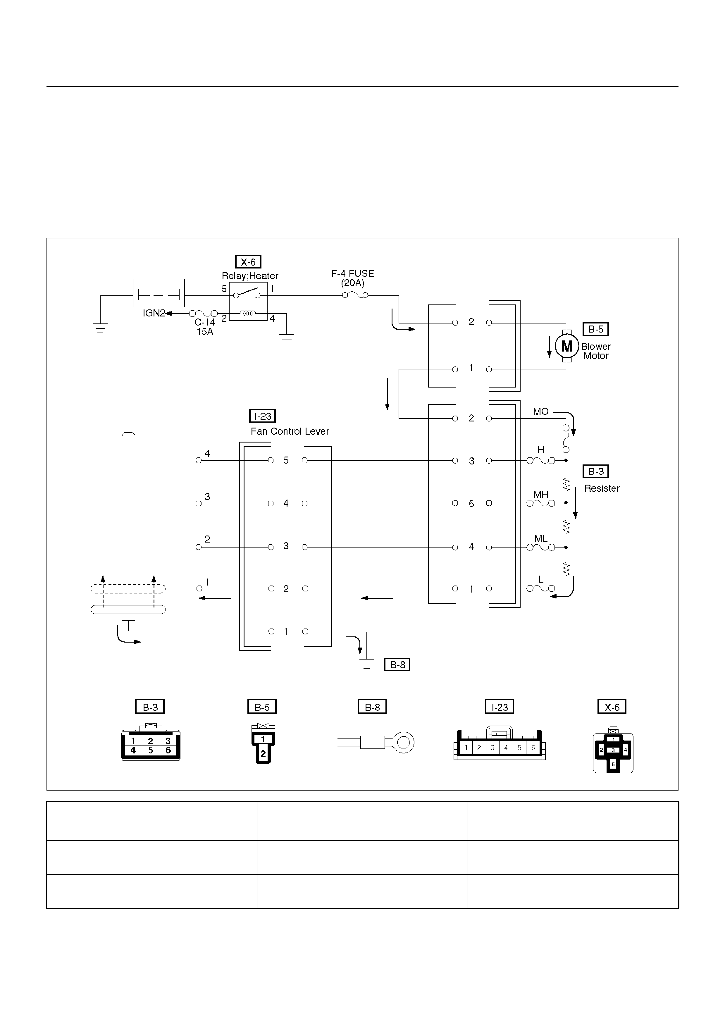
Fan Contro l Lever (Fan Switch) Diagnosi s
Current flows to the blower motor through the heater
relay (X-6) to activate the rotation of the blo w er motor b y
turning “ON" the fan control knob (fan switch). Blower
motor speed is controlled in stages by the resistor, by
operating the switch from “LOW" to “HIGH".
For the inspection of the relays, switches and units in
each table, refer to “INDIVIDUAL INSPECTION" in this
section.
D08RX250
Condition Possible cause Correction
Blower motor does not run. — Refer to Chart A
Blower motor does not run in certain
positi on (s). — Refer to Chart B, C, D and E
Blo w er moto r doe s not stop at “ OFF"
position. — Refer to Chart F
Chart “A" Blower Motor Does Not Run
Chart “B" Blower Motor Does Not Run At Low Position
Chart “C" Blower Motor Does Not Run At Medium Low Position
Chart “D" Blower Motor Does Not Run At Medium High Position
Step Action Yes No
1 Is relay (X-6) OK? Go to Step 2 Replace
2 Is fuse F-4 (20A) OK? Go to Step 3 Replace
3 Is resistor OK? Go to Step 4 Replace
4 Is fan control lever OK? Go to Step 5 Replace control
lever assembly.
5 Is blower motor OK? Go to Step 6 Replace
6 1. Turn the ignition switch “ON".
2. Turn fan control lever “ON".
3. Check to see if battery voltage is present at chassis side
connector terminal No. B5-2
Is there a battery voltage?
Poor ground or
open circuit either
between chassis
side connector
terminal No. B5-1
and No . B3-2 or
No . I23-1 and body
ground (No. B-8).
Open circui t
between No. F-4
(20A) fuse and No .
B5-2.
Step Action Yes No
1 Is resistor OK? Go to Step 2 Replace
2 Is fan control lever (Fan Switch) OK? Open circuit
between chassis
side connector
terminal No. B3-1
and No .I23-2. Replace control
lever assembly.
Step Action Yes No
1 Is resistor OK? Go to Step 2 Replace
2 Is fan control lever (Fan Switch) OK? Open circuit
between the
chassis side
connector terminal
No. B3-4 and No.
I23-3. Replace control
lever assembly.
Step Action Yes No
1 Is resistor OK? Go to Step 2 Replace
2 Is fan control lever (Fan Switch) OK? Open circuit
between chassis
side connector
terminal No. B3-6
and No. I23-4. Replace control
lever assembly.
Chart “E" Blower Motor Does Not Run At High Position
Chart “F" Blower Motor Does Not Stop In The “OFF" Position
Step Action Yes No
1 Is resistor OK? Go to Step 2 Replace
2 Is fan control lever (Fan Switch) OK? Open circuit
between Chassis
side connector
terminal No. B3-3
and No. I23-5. Replace control
lever assembly.
Step Action Yes No
1 Is the fan control lever (Fan Switch) OK? Short circuit
between chassis
side connector
terminal No.B5-1
and
No.B3-2,No.B3-3
and No.I23-5,
No.B3-6 and
No .I23-4, No.B3-4
and No .I23-3 or
No.B3-1 and
No.I23-2 Replace control
lever assembly.
Individual Inspection
Blower Motor
1. Disconnect the blower motor (B-5) connector from
the blower motor.
2. Connect the battery positive terminal to the No. 2
ter mi nal of th e blower moto r and the negative to the
No. 1.
3. Be sure to check to see if the blower motor operates
correctly.
873RW008
Resistor
1. Disconnect the resistor (B-3) connector.
2. Check for continuity and resistance between the
terminals of the resistor.
840RX013
EndOFCallout
Legend
(1) Resi st e r As sembly
(2) Connector Terminal (Resister Side)
(3) Positi on Switc h
Fan Control Lever (Fan Switch)
1. Check for continuity between the terminals of the
fan switch.
D08RX157
EndOFCallout
Heater R elay
1. Disconnect the heater relay (X-6).
• When removing the connector for relay, unfasten
the tank lock of the connector by using a
screwdriver, then pull the relay (1) out.
825RX046
2. Check for continuity between the heater relay (X-6)
terminals.
901RX071
Legend
(1) Control Lever Connector Terminal (Control
Lever Side)
(2) Position Switch
Heater Unit
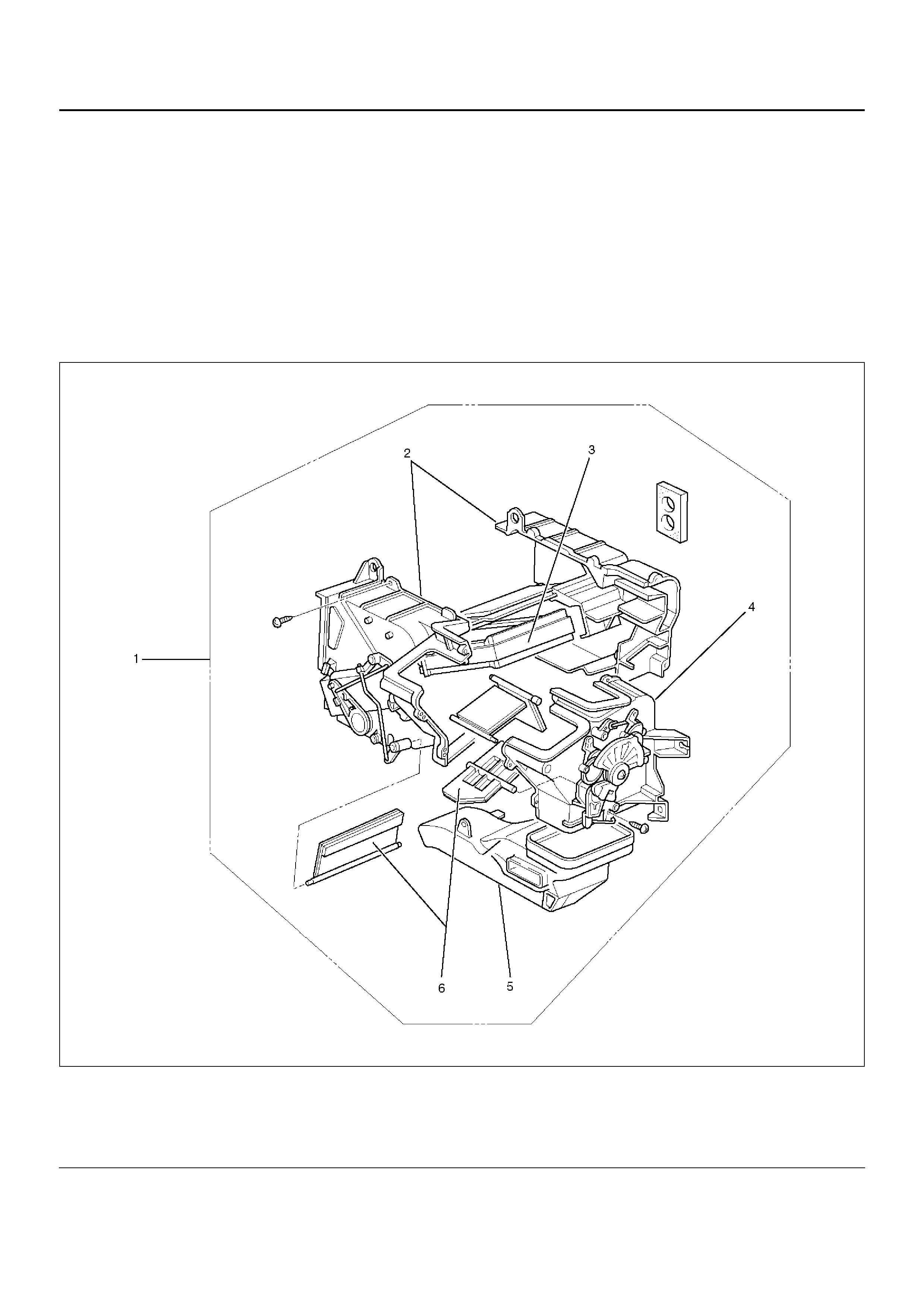
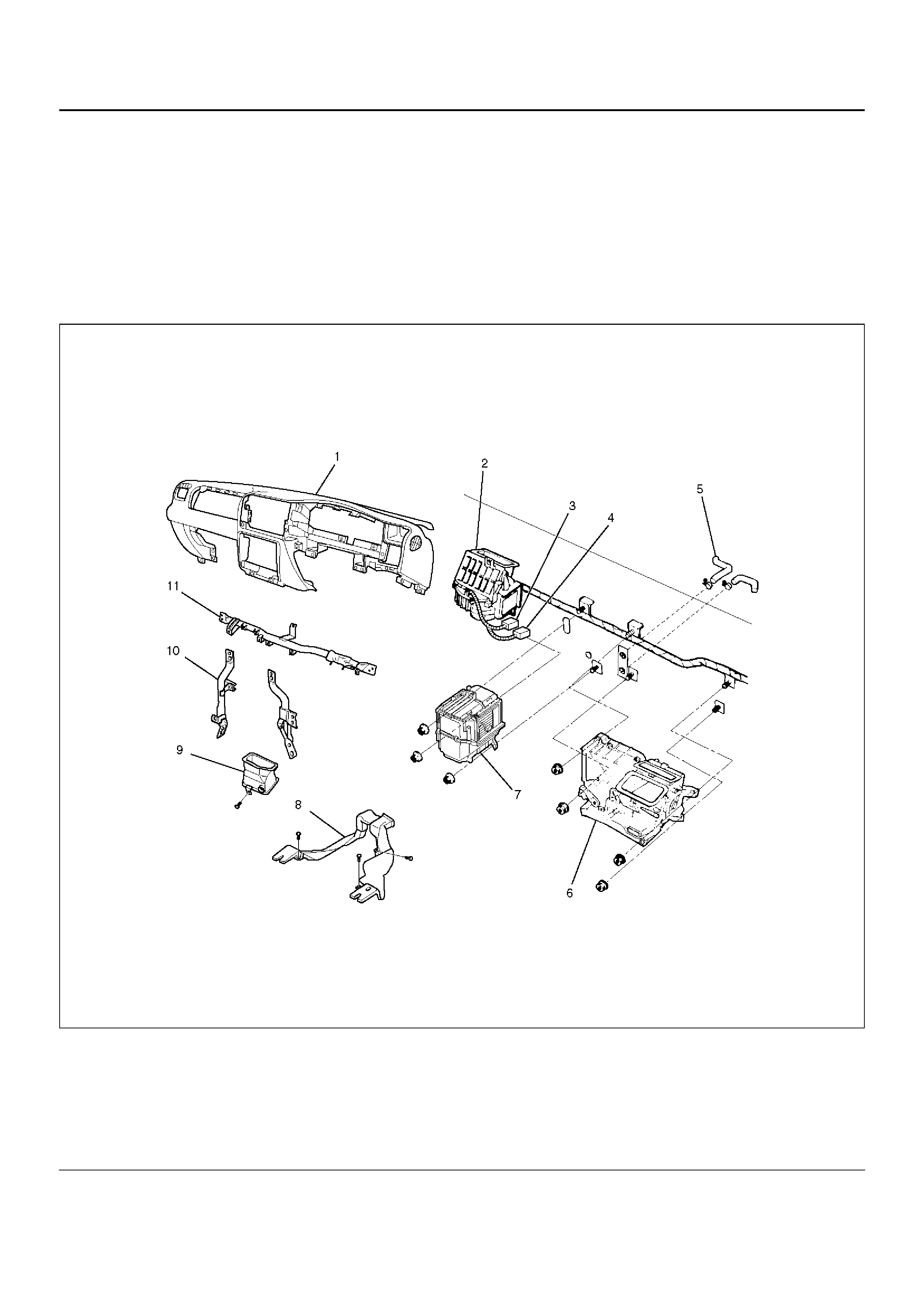
Heater Unit and Associated Parts
840RY00046
EndOFCallout
Removal
1.Disconnect the battery ground cable.
2.Drain the engine coolant.
3.Discharge and recover refrigerant (with air
conditioning).
•Refer to Refrigerant Recovery in this section.
4. Remove the Instrument panel assembly.
•Refer to Instrument Panel Assembly in Body and
Accessories sectio n.
5. Remove instrument panel stay.
6. Remove center ventilation duct and side defroster.
7. Dis co nne ct resisto r connector.
8. Remove evaporator assembly.
•Refer to Evaporator Assembly in this section.
9. Remove ventilation lower duct.
10. Remove rear heater duct.
• Remove foot rest, carpet and 3 clips.
11. Remove heater unit assembly.
• Disconnect heater hoses at heater unit.
Legend
(1) Instrument Panel Assembly
(2) Resistor Connector
(3) Heater Hose
(4) Heater Unit Assembly
(5) Evaporator Assembly
(6) Rear Heater Duct
(7) Ventilation Lower Duct
(8) Instrument Panel Stay
(9) Center Ventilation Duct and Side Defroster
Installation
To install, follow the removal steps in the reverse order,
noting the following points:
1.When handling the PCM and the control unit, be
careful not to make any improper connection of the
connectors.
2.Adjust the control cables.
•Refer to Control Lever Assembly in this section.
3. When installing the heater unit, defroster nozzle and
center vent duct, be sure that the proper seal is
made, without any gap between them.
4. After putting engine coolant in remove the air well
and confirm the quantity of coolant.
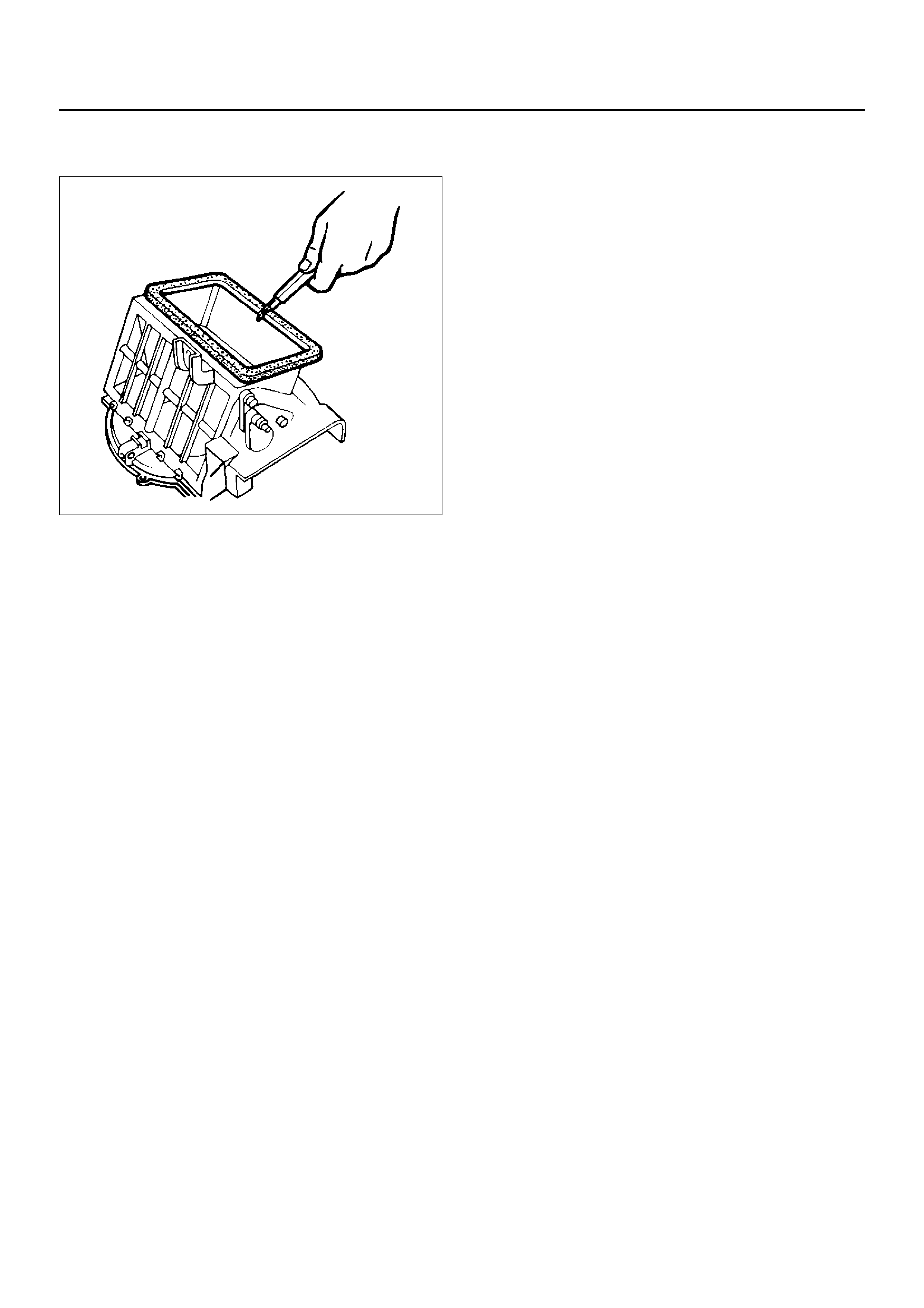
Heater Core and / or Mode Door
Disassembled View
860RX002
EndOFCallout
Removal
1. Disconnect the battery ground cable.
2. Drain the engine coolant.
Legend
(1) Heater Unit
(2) Case (Temperature Control)
(3) Heater Core
(4) Case (Mode Control)
(5) Duct
(6) Mode Door
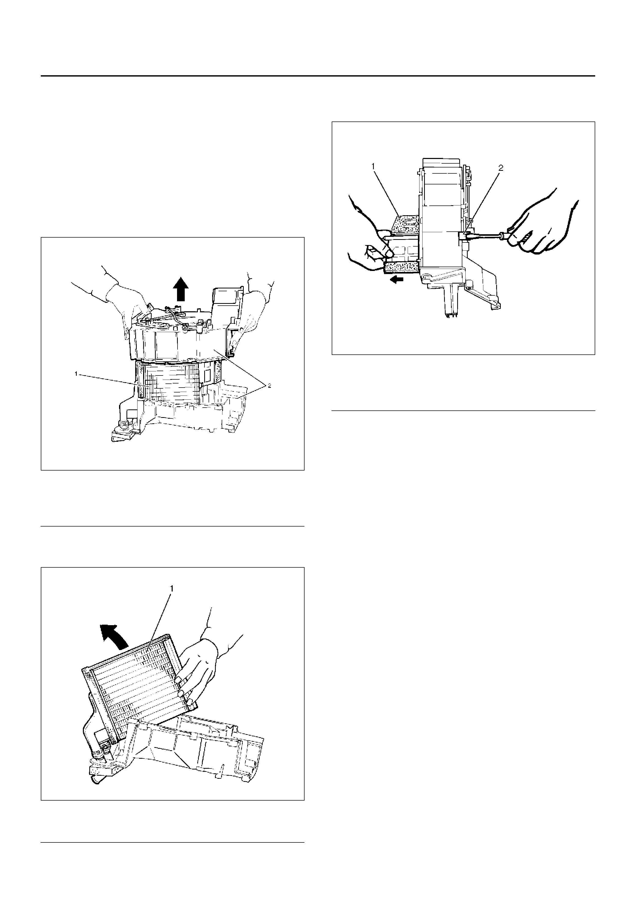
3.Discharge and recover refrigerant (with air
conditioning).
•Refer to Refrigerant Recovery in this section.
4.Remove heater unit.•Refer to Heater Unit in this section.
5. Remove duct.
6. Remove case (Mode control) and do not remov e link
unit at this step.
7. Remove case (Temperature control) and separate
two halves of core case.
860RW021
EndOFCallout
8. Remove heater core.
860RW020-1
EndOFCallout
9. Pull out the mode door whil e raising up the cat ch of
the door lever.
860RX004
EndOFCallout
Inspection
Check for foreign m atter in the he ater core, stain or the
core fin defacement.
Installation
To install, follow the removal steps in the reverse order,
noting the following point:
1. Check that each mode door operates properly.
Legend
(1) Heater Core
(2) Core Case
Legend
(1) Heater Core
Legend
(1) Mode Door
(2) Door Lever
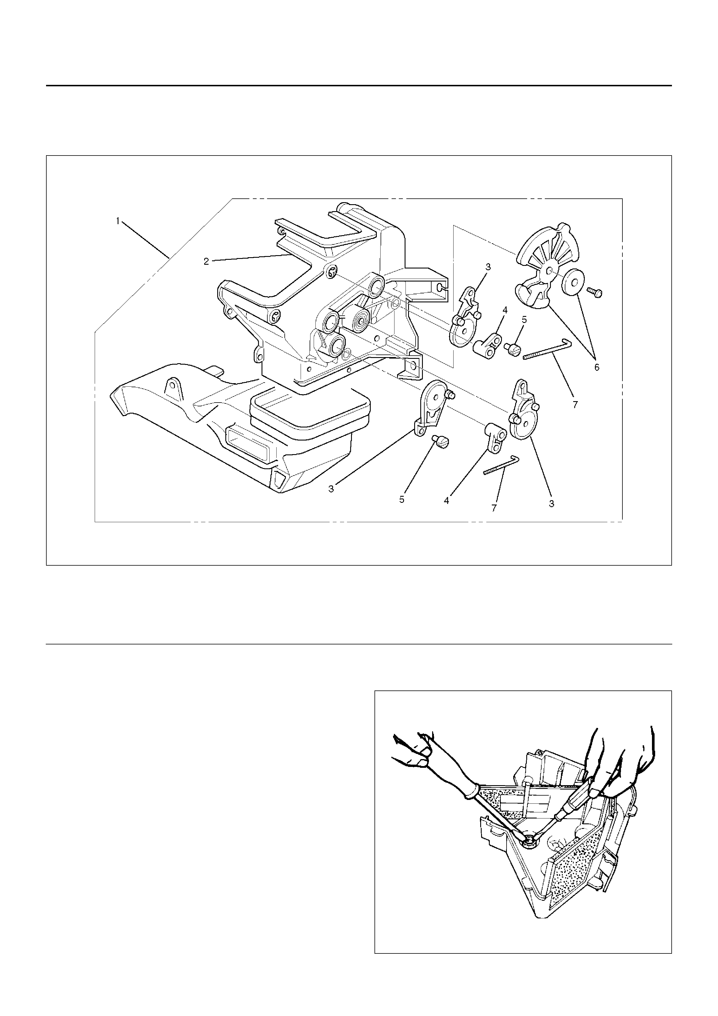
Heater Mode Control Link Unit
Disassembled View
860RY00012
EndOFCallout
Removal
1.Disconnect the battery ground cable.
2.Drain engine coolant.
3.Discharge and recover refrigerant (with air
conditioning)
•Refer to Refrigerant Recovery in this section.
4. Remove heater unit.
•Refer to Heater Unit in this section.
5.Remove the case (Mode control) from heater unit.6.Remove washer and the mode main lever.
7. Remove rod.
8. Press the tab of the sub-lever inward, and take out
the sub-lever.
860RW018
Legend
(1) Heater Unit
(2) Case (Mode Control)
(3) Mode Sub Lever
(4) Door Lever
(5) Clip
(6) Washer and Mode Main Lever
(7) Rod
9.Pull out the door lever while raising up the catch of
the door lever.
10.Remove clip.
Installation
To install, follow the remove steps in the reverse order,
noting the following points:
1.Apply grease to the mode sub-lever and to the
abrasive surface of the heater unit.
2.After installing the link unit, check to see if the link
unit operates correctly.
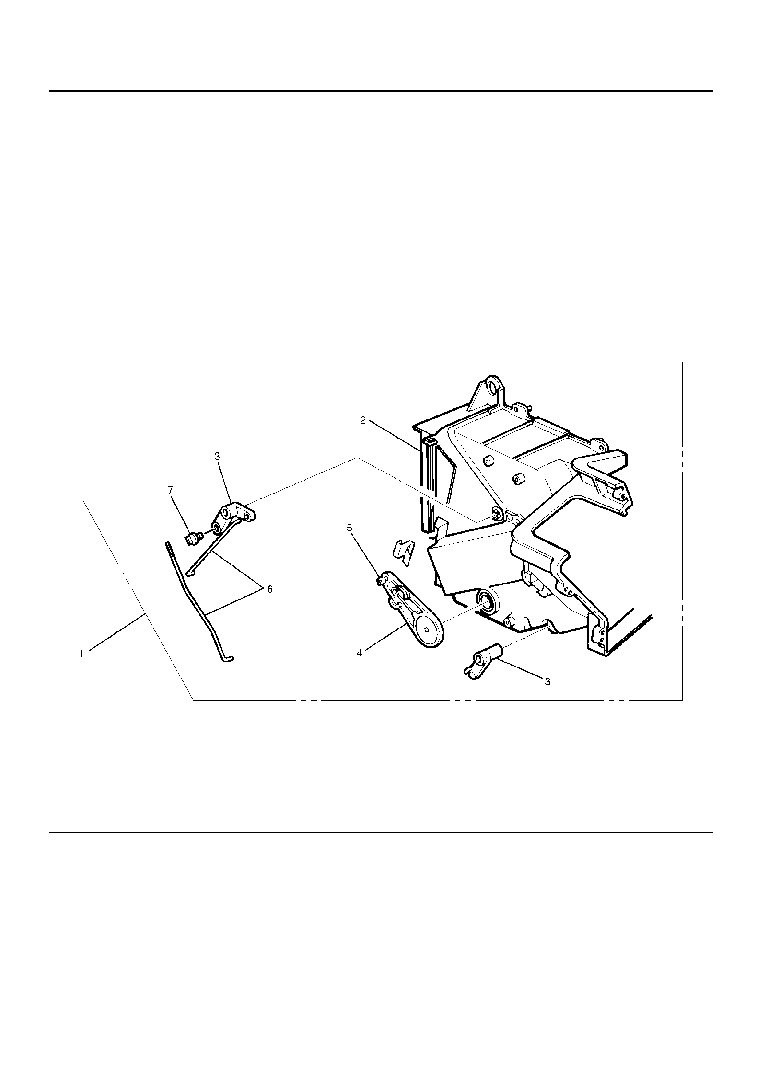
Heater Temperature Control Link Unit
Disassembled View
860RX001
EndOFCallout
Removal
1.Disconnect the battery ground cable.
2.Drain engine coolant.
3.Discharge and recover refrigerant (with air
conditioning).
•Refer to Refrigerant Recovery in this section.
4. Remove heater unit.
•Refer to Heater Unit in this section.
5. Remove the case (Temperature control) from the
heater unit.
6. Remove rod.
7. Remove sub-lever.
8. Pull out the door lever while raising up the catch of
the door lever.
9. Remove clip.
Legend
(1) Heater Unit
(2) Case (Temperature control)
(3) Door Lever
(4) Sub Lever
(5) Clip
(6) Rod
(7) Clip
Installation
To install, follow the removal steps in the reverse order,
noting the following points:
1. Apply grease to the sub-lever and to the abrasive
surface of the heater unit.
2. After installing the link unit, check to see if the link
unit operates correctly.
Blower Assembly
Blower Assembly and Associated Parts
840RY00045
EndOFCallout
Legend
(1) Instrument Panel Assembly
(2) Blower Assembly
(3) B lower Motor Harness Conne cto r
(4) Resistor Harness Connector
(5) Heater Hose
(6) Heater Unit Assembly
(7) Evaporator Assembly
(8) Rear Heater Duct
(9) Ventilation Lower Duct
(10) Instrument Panel Stay
(11) Cross Beam Assembly
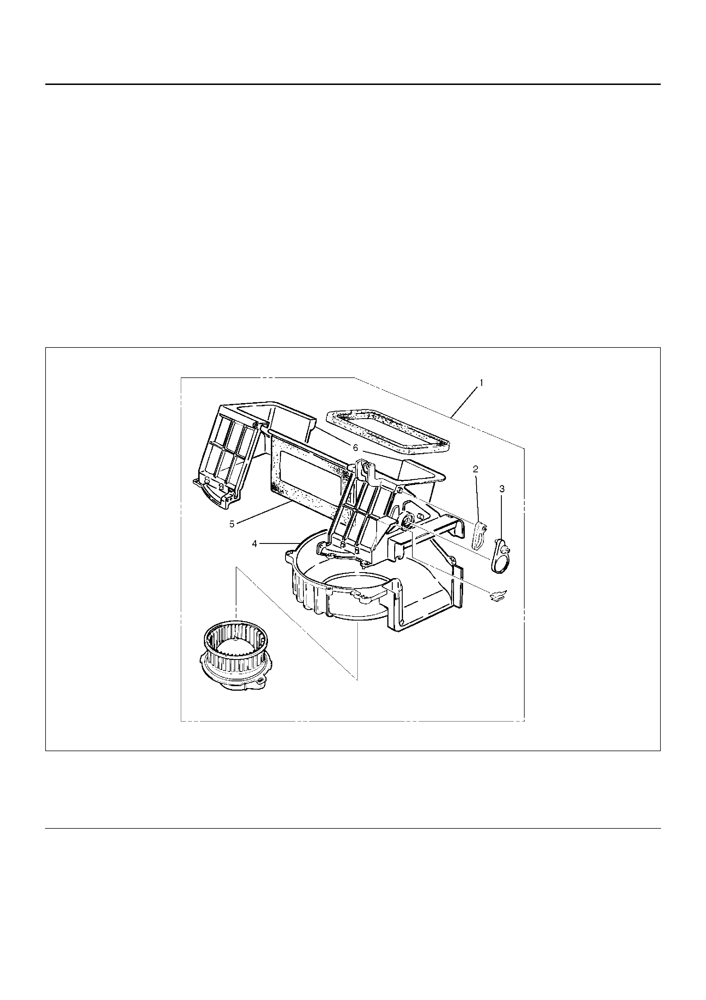
Removal
1.Disconnect the battery ground cable.
2.Discharge and recover refrigerant (with air
conditioning).
•Refer to Refrigerant Recovery in this section.
3.Remove instrument panel assembly.
•Refer to Instrument Panel Assembly in Body
structure section.
4.Disconnect resistor harness connector.
5.Remove evaporator assembly.
•Refer to Evaporator Assembly in this section.
6.Disconnect blower motor harness connector.
7.Remove blower assembly.
Installation
To install, follow the removal steps in the reverse order,
noting the following point:
1.Adjust the control cables.
•Refer to Control Lever Assembly in this section.
Blower Link Unit and / or Mode door
Disassembled View
873RX002
EndOFCallout
Removal
1.Disconnect the battery ground cable.
2.Discharge and recover refrigerant (with air
conditioning).
•Refer to Refrigerant Recovery in this section.
3. Remove blower assembl y.
•Refer to Blower Assembly in this section.
4. Remove lower case.
Legend
(1) Blower Assembly
(2) Door Lever
(3) S ub Lever
(4) Lower C as e
(5) Mode Door
(6) Upper Case
5. Separate the upper case and slit the lining parting
face with a knife.
873RW006
6. Pull ou t the mode door whil e raising up the ca tch of
door lever.
7. Remove sub-lever.
8. Remove door lever.
Installation
To install, follow the removal steps in the reverse order,
noting the following points:
1. Apply grease to the door lever and to the abrasive
surface of the upper case.
2. Apply an adhesive to the parting face of the lining
when assembling the upper case.
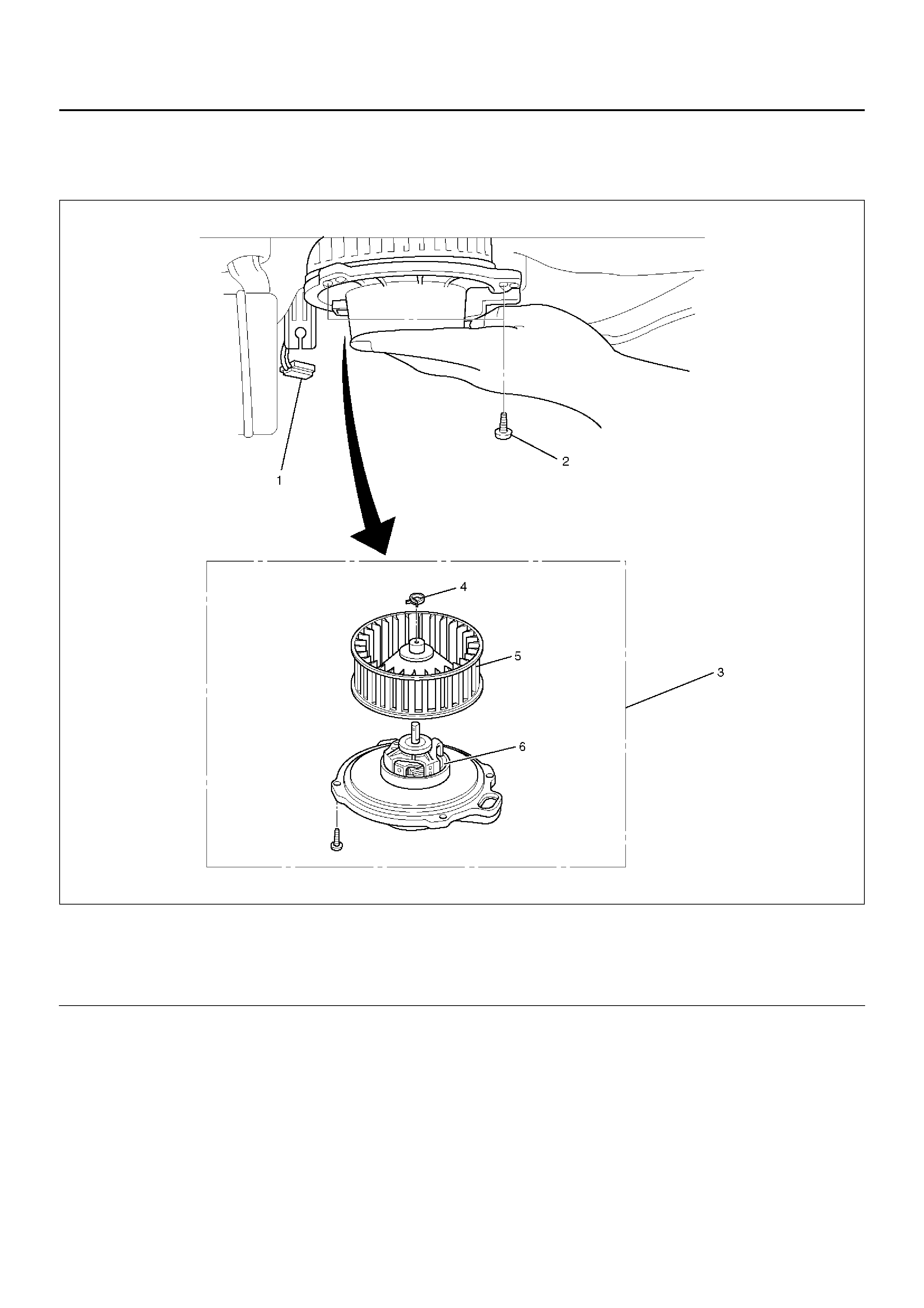
Blower Motor
Blower Motor and Associated Parts
873RX001
EndOFCallout
Removal
1. Disconnect the battery ground cable.
2. Remove blower motor connector.
3. Remove attaching screw.
4. Remove blower motor assembly.
5. Remove clip.
6. Remove fan.
7. Remove blower motor.
Installation
To install, follow the re moval steps in the reverse order.
Legend
(1) B lower Motor Connec tor
(2) Attaching Screw
(3) Blowe r Moto r As se mbly
(4) Clip
(5) Fan
(6) Blower Motor
Rear Heater Duct, Defroster Nozzle and Ventilation Duct
Rear Heater Duct, Defroster Nozzle, Ventilation Duct and Associated Parts
840RY00047
EndOFCallout
Removal
1.Disconnect the battery ground cable.
2.Remove instrument panel assembly.
•Refer to Instrument Panel Assembly in Body
Structure section.
3. Remove center ventilation duct and side defroster
duct.
• Remove 5 screws.
4. Remove instrument panel Stay.
5. Remove cross beam assembly.
6. Remove ventilation lower duct.
7. Remove rear heater duct.
Legend
(1) Cross Beam Assembly
(2) Defroster Nozzle
(3) Ventilation Lower Duct
(4) Rear Heater Duct
(5) Instrument Panel Assembly
(6) Instrument Panel Stay
(7) Center Ventilation Duct and Side Defroster
• Remove foot rest carpet and 3 clips.
8. Remove defroster nozzle.
Installation
To install, follow the removal steps in the reverse order,
noting the following point:
1. Connect each duct and nozzle securely leaving no
clearance between them and making no improper
matching.
Control Lever Assembly and / or Control Cable
Control Lever Assembly, Control Cable and Associated Parts
865RX009
EndOFCallout
Legend
(1) Control Cable
(2) Control Lever Assembly
(3) Meter Cluster Assembly
(4) Instrument Panel Driver Lower Cover Assembly
(5) Glove Box
Removal
1.Disconnect the battery ground cable.
2.Remove instrument panel driver lower cover
assembly.
3.Remove meter cluster assembly.
•Refer to Instrument Panel Assembly in Body
Structure section.
4. Remove glove box.
5. Remove the control lever attaching screws.
6. Pull the control lever assembly out and disconnect
the fan switch and air conditioning switch
connectors.
865RX012
7. Remove control lev el assembly.
8. Disconnect control cables at each unit side.
865RX010
Installation
To install, follow the removal steps in the reverse order,
noting the following points:
1. Adjust the control cable.
865RX013
• Air source control cable.
1 Slide the control lever to the left (“CIRC"
position).
2 Connect the control cable at the “CIRC"
position of the link unit of the blower assembly
and secure it with the clip.
• Temperature control cable.
1 Turn the control knob to the left (“MAX COLD"
position).
2 Connect the control cable at the “COLD"
position of the temperature control link of the
heater unit and secure it with the clip .
• Air se le ct con t ro l ca ble
1 Turn the control knob to the right
(“DEFROST" position).
2 Connect the control cable at the “DEFROST"
position of the mo de con trol lin k of the heater
unit and secure it with the clip.
2. Check the control cable operation.
Control Panel Illumination Bulb
Control Panel Illumination Bulb and
Associated Parts
865RX011
EndOFCallout
Removal
1.Disconnect the battery ground cable.
2.Remove control lever assembly.
•Refer to Control Lever Assembly in this section.
3. Pull out the bulb socket from the panel by tur ning it
counterclockwise.
4. Pull the illumination bulb from the socket.
Installation
To install, follow the re moval steps in the reverse order.
Resistor
Resistor and Associated Parts
840RX021
EndOFCallout
Removal
1. Disconnect the battery ground cable.
2. Remove glove box.
• Remove the 2 inside clips.
3. Remove passenger knee bolster reinforcement.
4. Remove re si st or harnes s co nne cto r.
5. Remove re si st or.
Installation
To install, follow the re moval steps in the reverse order.
Legend
(1) Control Lever Assembly
(2) Bulb Socket
(3) Il lu mi nation Bul b
Legend
(1) Resistor
(2) Passenger Knee Bolster Reinforcement
(3) Resistor Harness Connector
(4) Glove Box
Air Conditioning System
General Description
Air Conditioning Refrigerant Cycle Construction
C01RX004
EndOFCallout
The refrigeration cycle includes the following four
processes as the refrigerant changes repeatedly from
liquid to gas and back to liquid while circulating.
Evaporation
The refr igerant is changed from a liquid to a gas inside
Legend
(1) Electronic Thermostat
(2) Evaporator Core
(3) Evaporator Assembly
(4) Temperature Senso r
(5) Expansion Valve
(6) B lower Motor
(7) Pressure Switch or Pressure Sensor
(8) Receiver/Drier
(9) Condenser
(10) Compressor
(11) Magnetic Clutch
(12) Mode (HEAT) Control Door
(13) Temp. Control Door (Air Mix Door)
(14) Heater Core
(15) Mode (VENT) Control Door
(16) Heater Unit
(17) Mode (DEF) Control Door
the evaporator. The refrigerant mist that enters the
evaporator vaporizes readily. The liquid refrigerant
removes the required quantity of heat (latent heat of
vaporization) from the air around the evaporator core
cooling fins and rapidly vaporizes. Removing the heat
cools the air, which is then radiated from the fins and
lowers the temperature of the air inside the vehicle.
The refrigerant liquid sent from the expansion valve and
the vaporized refrigerant gas are both present inside the
evaporator as the liquid is converted to gas.
With this change from liquid to gas, the pressure inside
the evaporator must be kept low enough for vaporization
to occur at a lower temperature. Because of that, the
vaporized refrigerant is sucked into the compressor.
Compression
The refrigerant is compressed by the compressor until it
is easily liquefied at normal temperature.
The vaporized refrigerant in the evaporator is sucked
into the compressor. This action maintains the
refrigerant inside the evaporator at a low pressure so
that it can easily vaporize, even at low temperatures
close to 0°C (32°Φ).
Also, the refrigerant sucked into the compressor is
compressed inside the cylinder to increase the pressure
and temperature to values such that the refrigerant can
easily liquefy at normal ambient temperatures.
Condensation
The refrigerant inside the condenser is cooled by the
outside air and changes from gas to liquid.
The high temperature, high pressure gas coming from
the compressor is cooled and liquefied by the
condenser with outside air and accumulated in the
receiver/drier. The heat radiated to the outside air by the
high temperature, high pressure gas in the compressor
is called heat of condensation. This is the total quantity
of heat (heat of vaporization) the refrigerant removes
from the vehicle interior via the evaporator and the work
(calculated as the quantity of heat) performed for
compression.
Expansion
The expansion valve lowers the pressure of the
refrigerant liquid so that it can easily vaporize.
The process of lowering the pressure to encourage
vaporization before the liquefied refrigerant is sent to
the evaporator is called expansion. In addition, the
expansion valve controls the flow rate of the refrigerant
liquid while decreasing the pressure.
That is, the quantity of refrigerant liquid vaporized inside
the evaporator is determined by the quantity of heat
which must be removed at a prescribed vaporization
temperature. It is important that the quantity of
refrigerant be controlled to exactly the right value.
Compressor
The compressor performs two main functions:
It compresses low-pressure and low-temperature
refrigerant vapor from the evaporator into high-pressure
and high-temperature refrigerant vapor to the
condenser.
It pumps refrigerant and refrigerant oil through the air
conditioning system.
This vehicle is equipped with a five-vane rotary
compressor.
The specified amount of the compressor oil is 150cc
(5.0fl.oz.).
The oil used in the HFC-134a system compressor
differs from that used in R-12 systems.
Also, compressor oil to be used varies according to the
compressor model. Be sure to avoid mixing two or more
different types of oil.
If the wrong oil is used, lubrication will be poor and the
compressor will seize or malfunction.
The magnetic clutch connector is a waterproof type.
Magnetic Clutch
The compressor is driven by the drive belt from the
crank pulley of the engine. If the compressor is activated
each time the engine is started, this causes too much
load to the engine. The magnetic clutch transmits the
power from the engine to the compressor and activates
it when the air conditioning is ON. Also, it cuts off the
power from the engine to the compressor when the air
conditioning is OFF. Refer to Compressor in this section
for magnetic clutch repair procedure.
871RX026
EndOFCallout
Legend
(1) Magnetic Clutch
(2) Magnetic Clutch Harness Connector
(3) Compressor
Condenser
The condenser assembly is located in front of the
radiator. It provides rapid heat transfer from the
refrigerant to the cooling fins.
Also, it functions to cool and liquefy the high-pressure
and high-temperature vapor sent from the compressor
by the radiator fan or outside air.
A conde nser may malfunction i n two ways: it may leak,
or it may be restricted. A condenser restriction will
result in excessive compressor discharge pressure. If a
partial restriction is present, the refrigerant expands
after passing through the restriction.
Thus, ice or frost may form immediately after the
restriction. If air flow through the condenser or radiator
is blocked, high discharge pressures will result. During
normal condenser operation, the refrigerant outlet line
will be slightly cooler than the inlet line.
The vehicle is equipped with the parallel flow type
condenser. A larger thermal transmission area on the
inner surface of the tube allows the radiant heat to
increase and the ventilation resistance to decrease.
The refrigerant line connection has a bolt at the block
joint, for easy servicing.
875RX003
EndOFCallout
Receiver / Drier
The receiver/drier performs four functions:
• As the quantity of refrigerant circulated varies
depending on the refrigeration cycle conditions,
sufficient refrigerant is stored for the refrigeration
cycle to operate smoothly in accordance with
fluctuations in the quantity circulated.
• The liquefie d refr ige rant from the cond enser i s mixed
with refrigerant gas containing air bubbles. If
refrigerant containing air bubbles. If refrigerant
containi ng air bubbles is se nt to the expansio n valve,
the cooling capacity will decrease considerably.
Therefore, the liquid and air bubbles are separated
and only the liquid is sent to the expansion valve.
• The receiver/drier utilizes a filter and drier to remove
the dirt and water mixed in the cycling refrigerant.
• The sight glass, installed atop the receiver/drier,
show the state of the refrigerant.
A receiver/drier may fail due to a restriction inside the
body of th e unit. A rest ric tion at t he inlet to th e rece iver/
drier will cause high pressure.
Outle t restric tions will be ind icated by low press ure and
little or no cooling. An excessively cold receiver/drier
outlet may indicate a restriction.
The receiver/drier of this vehicle is made of aluminum
with a smaller tank. It has a 300cc refrigerant capacity.
The refrigerant line connection has a bolt at the block
joint , for easy servicing.
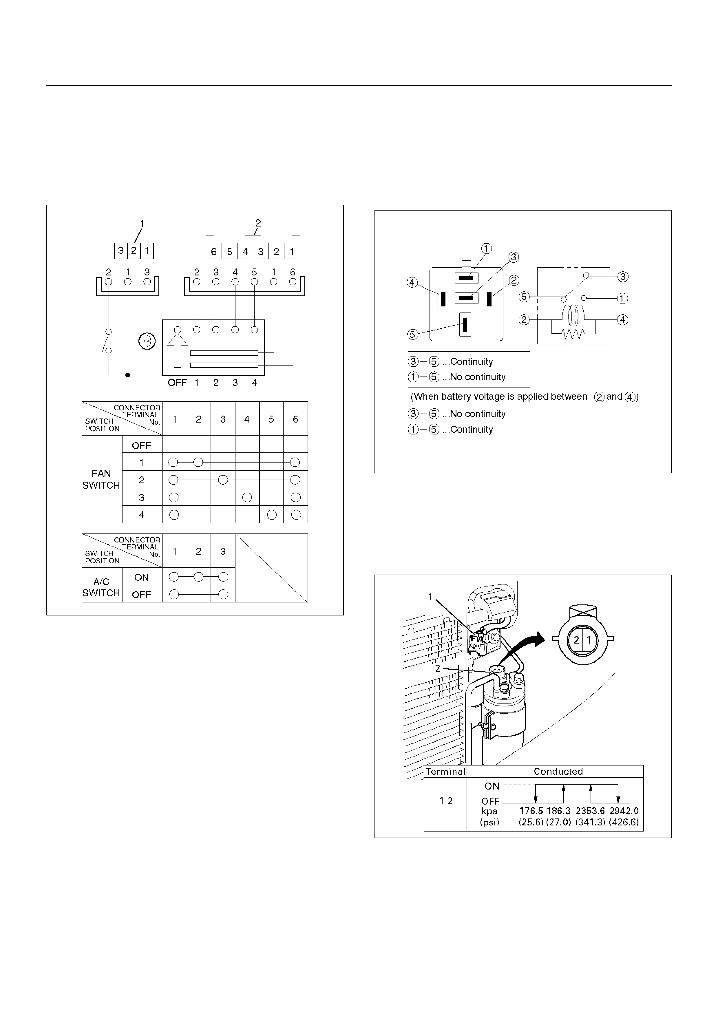
Dual Pressure Switch (V6,M/T)
The pressure switch (Dual pressure switch) is installed
on the upper part of the receiver/drier, to detect
excessively high pressure (high pressure switch) and
prevent compressor seizure due to the refrigerant
leaki ng (low pre ssure switch), so that the compr essor is
able to be turned “ON" or “OFF".
Triple Pressure Switch (V6, A/T)
Triple pressure switch is installed on the upper part of
the receiver/drier. This switch is constructed with a
unitized ty pe of two switches. One of th em is a low and
high pressure switch (Dual pressure switch) to switch
“ON" or “OFF" the magnetic clutch as a result of
irregularly high-pressure or low pressure of the
refr igerant. The other one is a medium pressure switch
(Cycli ng switch ) to sw itch “ON" or “O FF" the condens er
fan sensing the condenser high side pressure.
Legend
(1) Pressure Switch
(2) Receiver/Drier
(3) Condenser & Receiver Tank Assembly
(4) Condenser Fan (6VD1 A/T)
Compressor ON
(kPa/psi) OFF
(kPa/psi)
Low-pressure
control 186.3±29.4
(27.0±4.3) 176.5±19.6
(25.6±2.8)
High-pressure
control 2350.4±196.1
(340.7±28.4) 2942.0±196.1
(426.6±28.4)
Compressor ON
(kPa/psi) OFF
(kPa/psi)
Low-pressure
control 186.3±29.4
(27.0±4.3) 176.5±24.5
(25.6±3.6)
High-pressure
control 2353.6±196.1
(341.3±28.4) 2942.0±196.1
(426.6±28.4)
Pressure Sensor
The pressure sensor is installed on the upper part of the
receiver/drier. This sensor converts high pressure
detection of refrigerant to an electrical voltage signal
and su pplies i t to th e PCM. The PCM control s switchin g
compres sor idl e spe ed and c oolin g fa n operatio n by the
electrical voltage signal.
875RY00015
EndOFCallout
Expansion Valve
This ex pansion valve is an ex ternal pressur e type and it
is installed at the evaporator intake port.
The expansion valve converts the high pressure liquid
refrigerant sent from the receiver/drier to a low pressure
liquid refrigerant by forcing it through a tiny port before
sending it to the evaporator.
This type of expansion valve consists of a temperature
sensor, diaphragm, ball valve, ball seat, spring
adjustment screw, etc.
The temperature sensor contacts the evaporator outlet
pipe, and converts changes in temperature to pr essure.
It then transmits these to the top chamber of the
diaphragm.
The refrigerant pressure is transmitted to the
diaphragm's bottom chamber through the external
equalizing pressure tube.
The ball valve is connected to the diaphragm. The
opening angle of the expansion valve is determined by
the force acting on the diaphragm and the spring
pressure.
The expansion valve regulates the flow rate of the
refrigerant. Accordingly, when a malfunction occurs to
this expansion valve, both discharge and suction
pressure get low, resulting in insufficient cooling
capacity of the evaporator.
The calibration has been changed to match the
characteristics of HFC-134a.
874RY00023
EndOFCallout
Evaporator
The evaporator cools and dehumidifies the air before
the air enters the passenger compartment.
High-pressure liquid refrigerant flows through the
expansion valve into the low-pressure area of the
evaporator. The heat in the air passing through the
evap orator core is lost to the cooler surface of the c ore,
thereby cooling the air.
As heat is lost between the air and the evaporator core
surface, moisture in the vehicle condenses on the
outside surface of the evaporator core and is drained off
as water.
When the evaporator mal fun ction s, the trouble will show
up as an inadequate supply of cool air. The cause is
typically a partially plugged core due to dirt, or a
malfunctioning blower motor.
The evaporator core with a laminate louver fin is a
single-sided tank type where only one tank is provided
under the core.
Condenser fan ON
(kPa/psi) OFF
(kPa/psi)
Medium-pressure
control 1471.0±98.1
(213.3±14.2) 1078.7±117.7
(156.4±17.1)
Legend
(1) Pressure Switch
(2) Receiver Drier
Legend
(1) Expansion Valve
(2) Insulator
(3) Evaporator Assembly
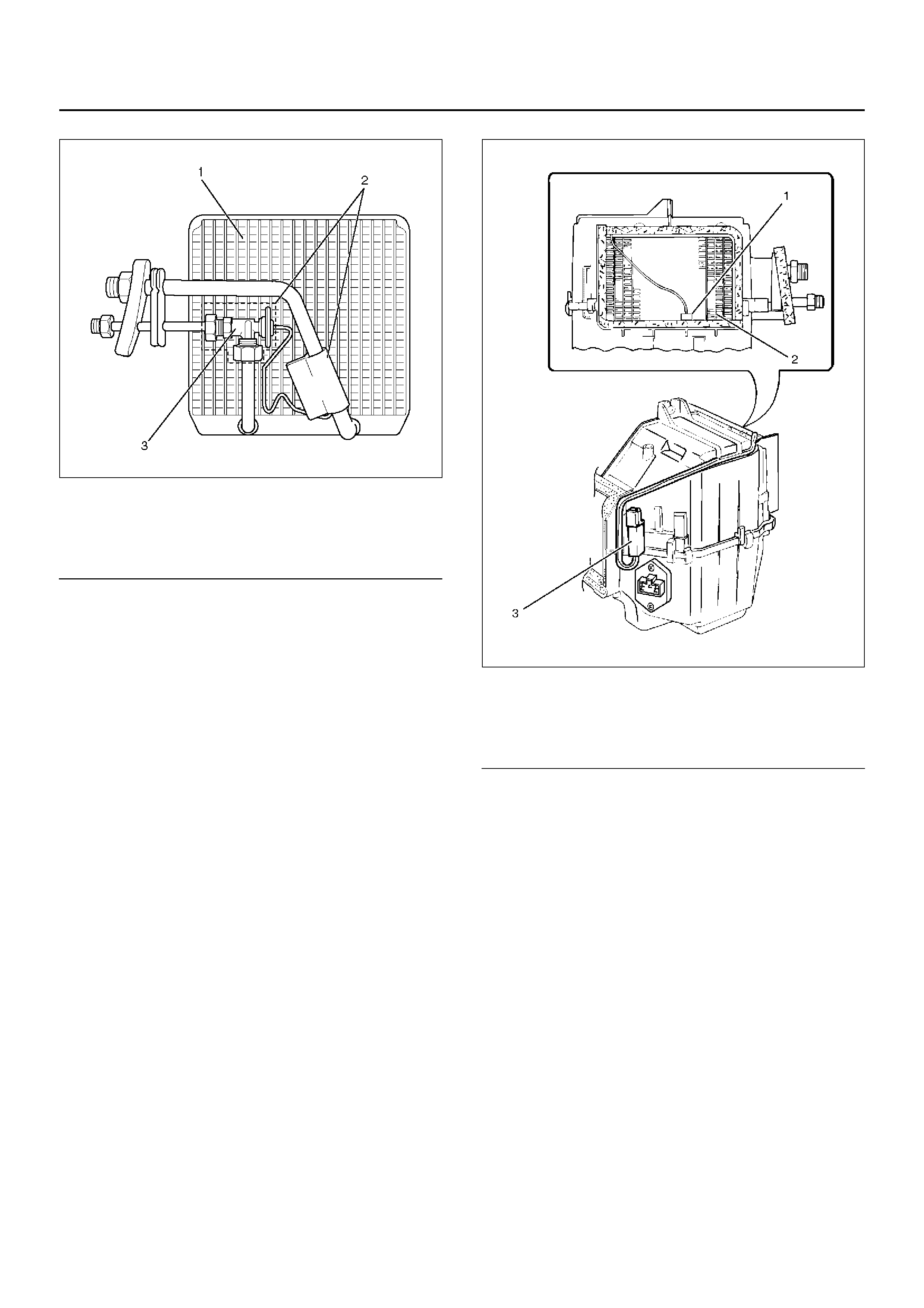
874RY00022
EndOFCallout
Electronic Thermostat (With Manual A/C)
The thermostat consists of the thermo sensor and
thermostat unit which functions electrically to reduce the
noises being generated while the system is in operation.
The electronic thermo sensor is mounted at the
evaporator core outlet and senses the surface
temperature of the evaporator core. Temperature
signals are input to the thermostat unit. This information
is compared by the thermo unit and results in the output
to operate the A/C thermostat relay and turn the
magnetic clutch ON or OFF to prevent evaporator
freeze-up.
A characteristic of the sensor is that the resistance
decreases as the temperature increases and the
resistance increases as the temperature decreases.
874RX008
EndOFCallout
Legend
(1) Evaporator Core
(2) Insulator
(3) Expansion Valve
Legend
(1) Duct Sensor
(2) Evaporator Core
(3) Thermostat Unit
Refrigerant Line
Restriction in the refrigerant line will be indicated by:
1. Suction line — A restricted suction line will cause
low suction pressure at the compressor, low
discharge pressure and little or no cooling.
2. Discharge line — A restriction in the discharge line
generally will cause the discharge line to leak.
3. Liquid line — A liquid line restriction will be
evidenced by low discharge and suction pressure
and insufficient cooling.
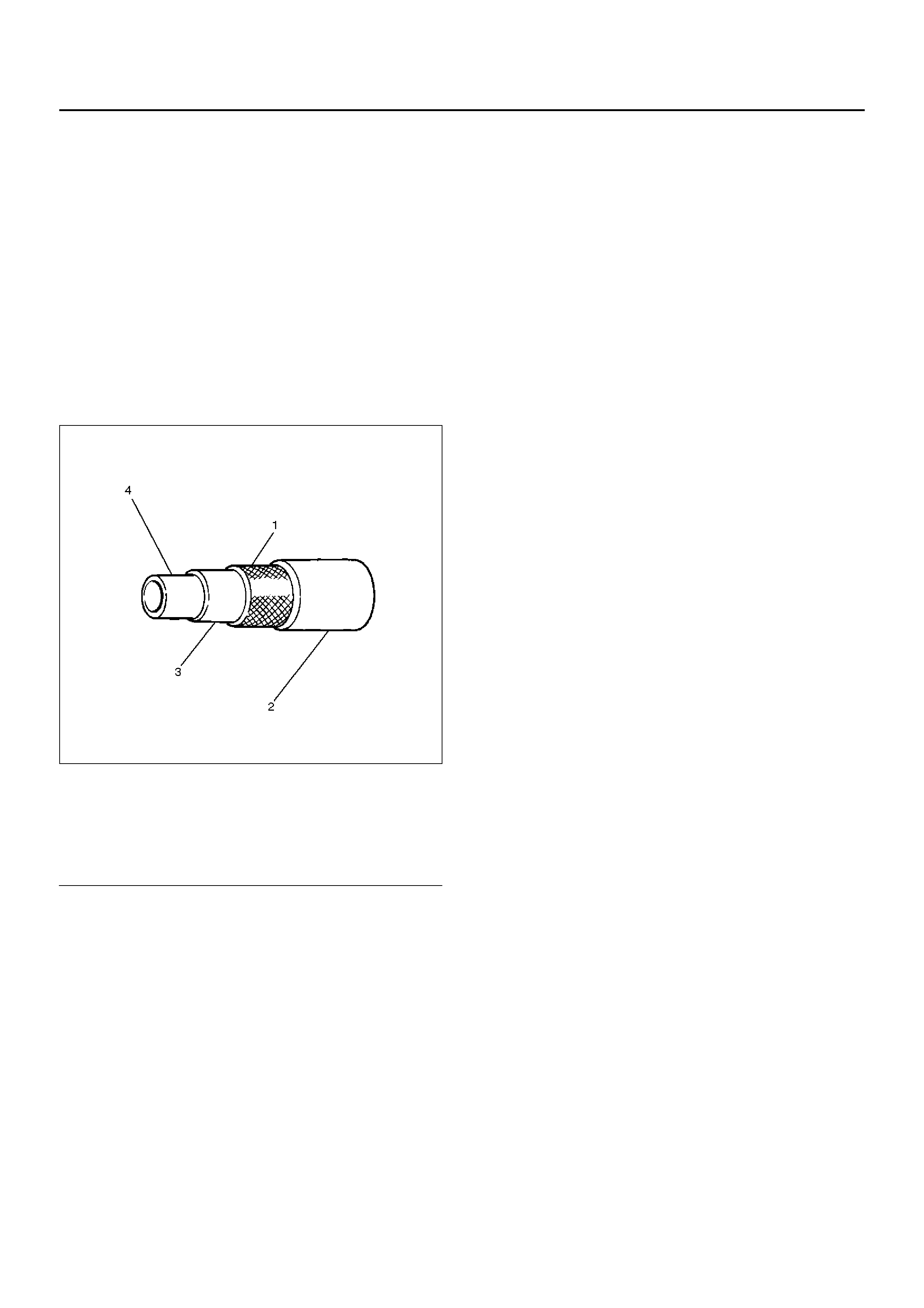
Refrigerant flexible hoses that have a low permeability
to refrigerant and moisture are used. These low
permeability hoses have a special nylon layer on the
inside.
852RS001
EndOFCallout
Legend
(1) Reinforcement Layer (Polyester)
(2) E xt ernal Rubber Layer
(3) Internal Rubber Layer
(4) Resin Layer (Nylon)
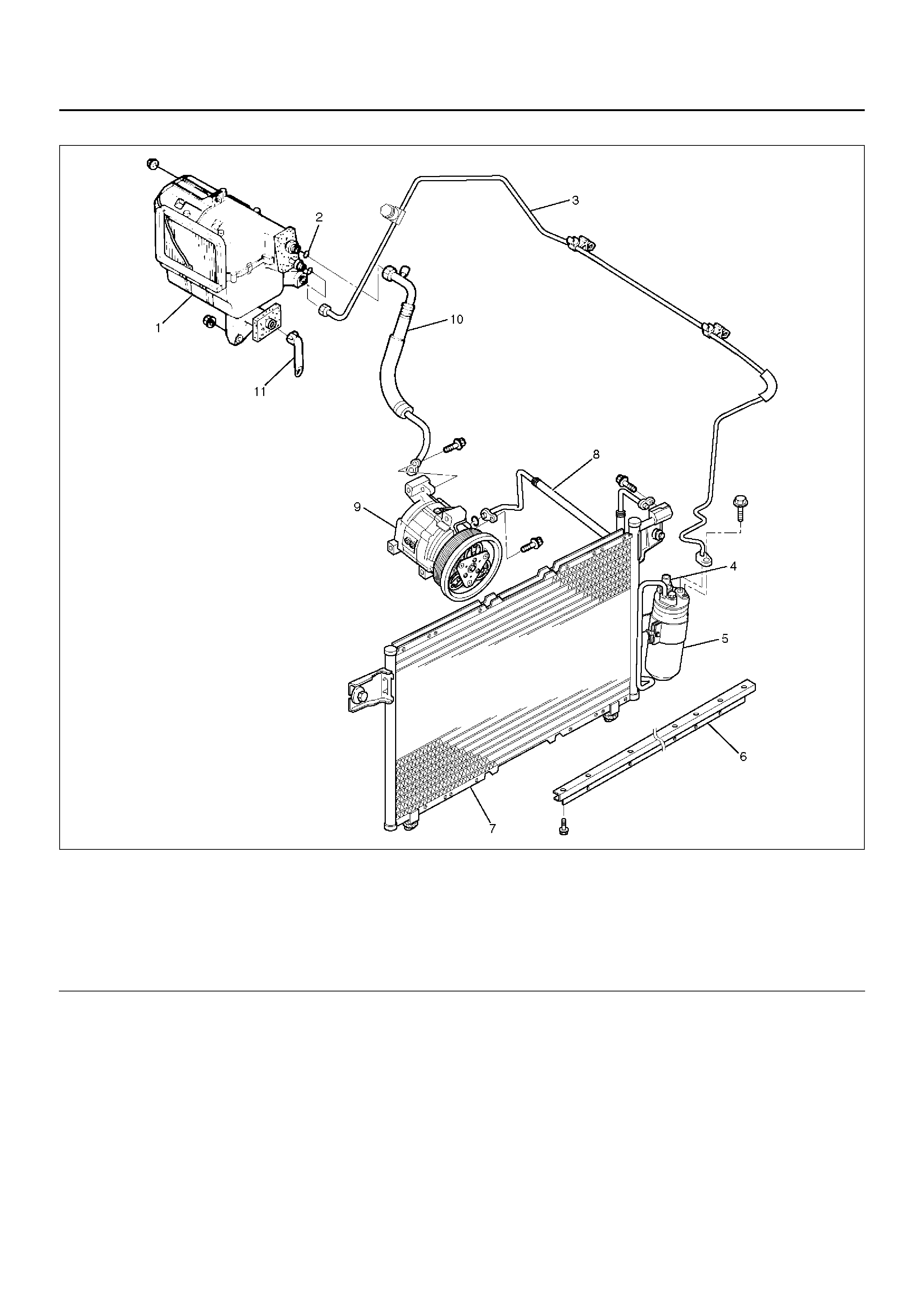
Refriger ant Line As sociat ed Part s
852RY00036
EndOFCallout
Legend
(1) Evaporator Assembly
(2) O-Ring
(3) Liquid Line (High Pressure Pipe)
(4) Pressure Switch
(5) Receiver Drier
(6) Platform Seal
(7) Condenser Asse mbly
(8) Discharge Line (High Pressure Hose)
(9) Compressor
(10) Suction Line (Low – Pressure Hose)
(11) Drain Hose
Circuit Diagram
D08RX151
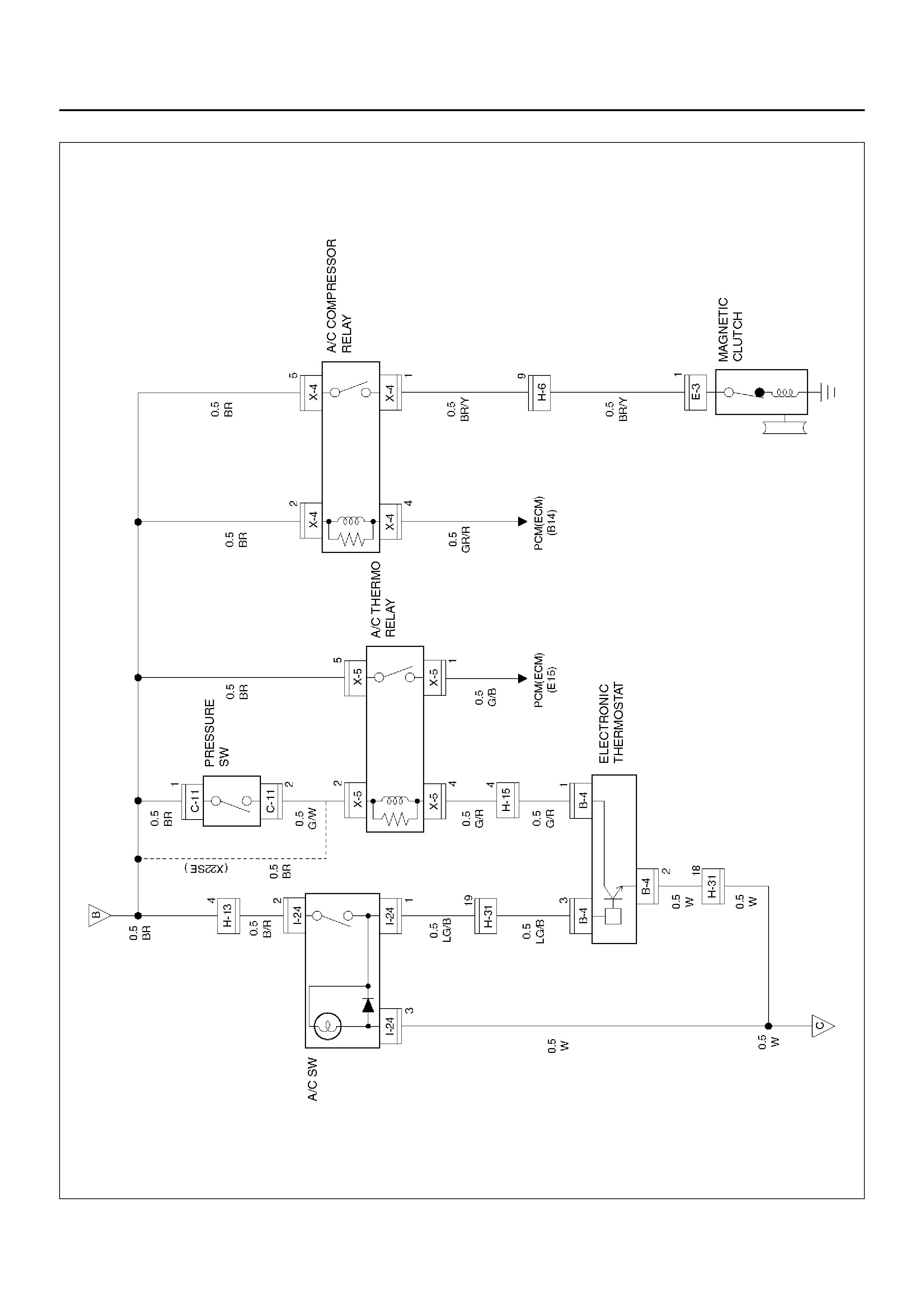
D08RX150
Diagnosis
Air Conditioning Cycle Diagnosis
*For the execution of the charging and discharging
operation in the table above, refer to Recovery,
Recycling, Evacuating and Charging in this section.
ConditionPossible causeCorrection
No cooling or insufficient cooling.Magnetic clutch does not run.Refer to “Magnetic Clutch
Diagnosis" in this section.
Compressor is not rotating properly.
Drive belt is loosened or broken.Adjust the drive belt to the specified
tension or replace the drive belt.
Compressor is not rotating properly.
Magnetic clutch face is not clean
and slips.
Clean the magnetic clutch face or
replace.
Compressor is not rotating properly.
Incorrect clearance between
magnetic drive plate and pulley.
Adjust the clearance. Refer to
Compressor in this section.
Compressor is not rotating properly.
Compressor oil leaks from the shaft
seal or shell.
Replace the compressor
Compressor is not rotating properly.
Compressor is seized.Replace the compressor
Insufficient or excessive charge of
refrigerant. Discharge and recover the
refrigerant. Recharge to the
specified amount.
Leaks in the refrigerant system.Check the refrigerant system for
leaks and repair as necessary.
Discharge and recover the
refrigerant. Recharge to the
specified amount.
Condenser is clogged or insufficient
radiation. Clean the condenser or replace as
necessary.
Temperature control link unit of the
heat unit is defective.Repair the link unit.
Unsteady operation due to a foreign
substance in the expansion valve.Replace the expansion valve.
Poor operation of the electronic
thermostat. Check the electronic thermostat and
replace as necessary.
Insufficient velocity of cooling air.Evaporator clogged or frosted.Check the evaporator core and
replace or clean the core.
Air leaking from the cooling unit or
air duct.Check the evaporator and duct
connection, then repair as
necessary.
Blower motor does not rotate
properly.Refer to Fan Control Lever (Fan
Switch) Diagnosis in this section.
Checking The Refrigerant System With Manifold Gauge
Since Refrig erant-1 34a (HFC-134a) is used in the air
conditioning system in this vehicle, be sure to
use manifold gauges, charging hoses and other air
conditioning service tools for HFC-134a when
checking the refrigerant system.
Conditions:
• Run the engine at Idling
• Air conditioning switch is “ON"
• Run the blo wer motor at “HIGH" position
• Temperature control lever set to “MAX COLD"
• Air source selector lever at “CIRC"
• Open the engine hood
• Close all the doors
• At ambient temperature: approx. 25–30°C (77–86°F).
Normal Pressure:
• At low-pressure side: approx. 147.1–294.2 kPa
(21.3–4 2.7 psi ).
• At high-pressure side: approx. 1372.9–1863.3 kPa
(199.1–270.2 psi).
Refer to the table on the refrigerant
pressu re-t emp erature re lat ion sh ip.
HFC-134a Pressure-Temperature Relationship
Pressure Temperature
(kPa) (psi) (°
°°
°C) (°
°°
°F)
36 5.3 –20 –4.4
67 9.7 –15 5
104 15 –10 14
147 21 –5 23
196 28 0 32
255 37 5 41
314 45 10 50
392 57 15 59
471 68 20 68
569 82 25 77
677 98 30 86
785 114 35 95
912 132 40 104
1059 154 45 113
1216 176 50 122
Connect The Manifold Gauge
Low-pressure hose (LOW) — Suction side
High pressure hose (HI) — Discha rge side
901RX060
EndOFCallout
Legend
(1) H i gh Side
(2) Low Side

Condition Possible cause Correction
Discharge (High Gauge) Pressure
Abnormally High Condenser clogged or dirty. Clean the condenser fins
Cooling fan does not operate
properly. Check the cooling fan operation.
Discharge (High Gauge) Pressure
Abnormally High.
Insu ffici ent cooling.
Excessive refrigerant in system. Discharge and recover refrigerant.
Recharge to specified amount.
Discharge (High Gauge) Pressure
Abnormally High.
High pressure gauge drop. (After
stopping A/C, the pressure drops
approx. 196kPa (28psi) quickly)
Air in system. Ev acuate and charge refrigerant
system.
Discharge (High Gauge) Pressure
Abnormally Low.
Insu ffici ent cooling
Insufficient refrigerant in system. Check for leaks. Discharge and
recover the refrigerant. Recharge to
the specified amount.
Discharge (High Gauge) Pressure
Abnormally Low.
Low pressure gauge indicates
vacuum.
Clogged or defective expansion
valve. Replace the expansion valve.
Discharge (High Gauge) Pressure
Abnormally Low.
Frost or dew on refrigerant line
before and after the receiver/dri er o r
expansion valve, and low pressure
gauge indicates vacuum.
Restriction caused by debris or
moisture in the receiver/drier. Check system for restriction and
replac e the receiver/drie r.
Discharge (High Gauge) Pressure
Abnormally Low.
High and low pressure gauge
bala nced quickly. (Afte r turned off A/
C)
Compressor seal defective Repair or replace the compressor.
Poor compression due to a defective
compressor gasket. Repair or replace the compressor.
Suction (Low Gauge) Pressure
Abnormally High.
Low pressure gauge (Low pressure
gauge is lowered after condenser is
cooled by water.)
Excessive refrigerant in system. Discharge and recover refrigerant
Recharge to specified amount.
Suction (Low Gauge) Pressure
Abnormally High.
Low pressure hose temperature.
(Low pressure hose temperature
around the compressor refrigerant
line connector is lower than around
evaporator.)
Unsatisfactory valve operation due
to defective temperature sensor of
expansion valve.
Replace the expansion valve.
Expansion valve opens too long. Replace the expansion valve.
Suction (Low Gauge) Pressure
Abnormally High.
High and low pressure gauge
bala nced quickly. (Afte r turned off A/
C)
Compressor gasket is defective. Repair or replace the compressor.
Suction (Low Gauge) Pressure
Abnormally Low.
Insu ffici ent cooling.
Insufficient refrigerant in system. Check for leaks. Discharge and
recover the refrigerant. Recharge to
specified amount.
Suction (Low Gauge) Pressure
Abnormally Low.
Frost on the expansion valve inlet
line
Expansion valve clogged. Replace the expansion valv e.

A/C — Air Conditioning
Suction (Low Gauge) Pressure
Abnormally Low
Receiver/drier inlet and outlet
refrigerant line temperature. (A
distinct difference in temperature
develops.)
Receiver/Drier clogged. Replace the receiver/drier.
Suction (Low Gauge) Pressure
Abnormally Low.
Expansion valve outlet refrigerant
line. (Not cold and low pressure
gauge indicates vacuum.)
Expansion valve temperature sensor
is defe ct ive. Replace the expansion valve.
Suction (Low Gauge) Pressure
Abnormally Low.
When the refrigerant line is clogged
or blocked, the low pressure
gauge reading will decrease, or a
vacuum reading may be shown.
Clogged or blocked refrigerant line. Replace refrigerant line.
Suction (Low Gauge) Pressure
Abnormally Low.
Evaporator core is frozen.
Thermo switch defective. Replace thermo s witch.
Suction (Low Gauge) and Discharge
(High Gauge) Pressure Abnormally
High.
Insu ffici ent cooling.
Excessive refrigerant in system. Discharge and recover the
refrigerant, the Recharge to the
specified amount.
Condenser clogged or dirty. Clean the condenser fin.
Suction (Low Gauge) and Discharge
(High Gauge) Pressure Abnormally
High.
Suction (Low) pressure hose (Not
cold).
Air in system. Evacuate and charge refrigerant.
Suction (Low Gauge) and Discharge
(High Gauge) Pressure Abnormally
Low.
Insu ffici ent cooling
Insufficient refrigerant in system. Check for leaks. Discharge and
recover refrigerant. Recharge to
specified amount.
Condition Possible cause Correction
Magnetic Clutc h Dia gnosis
D08RX249
When the air conditioning switch and the fan control
knob (fan switch) are turned on with the engine running, current flows through the thermostat and the
compressor relay to activate the magnetic clutch.

The air conditioning can be stopped by turning of the air
conditioning switch or the fan control knob (fan switch).
However, even when the air conditioning is in operation,
the electronic thermostat, the pressure switch or the
Powertrain Control Module (PCM;V6-3.2L)/ Engine
Control Module (ECM;L4-2.2L) is used to stop the air
conditioning temporarily by turning off the magnetic
clutch in the prearranged conditions to reduce the
engine load which is being caused by the rise in the
engine coolant temperature, and the acceleration of the
vehicle, etc.
For the inspection of the relays, switches and units in
the table, refer to “Individual Inspection" in this section.
Magnetic Clutch Does Not Run
Step Action Value(s) Yes No
1 Is the fuse No. F-5 normal? — Go to Step 2 Replace the
fuse
2 Are the relay No.X-6 (heater relay). No.X-5
(Thermostat relay) and No.X-4 (compressor relay)
normal?
— Go to Step 3 Replace the
relay
3 Is pressure switch normal? — Go to Step 4 Place the
pressure
switch.
4 Are the air conditioner switch and the fan control
switch normal? — Go to Step 5 Replace the A/
C switch and
fan control
switch
5 1. Turn the ignition switch “ON" (the engine is run).
2. Tur n the air conditioner switch and the fan control
s witch on.
Is the battery voltage applied between harness side
connector terminal No.E3-1 and ground?
Approx.12V Go to Step 6 Go to Step 7
6 Repair an open circuit between compressor side
terminal and ground or replace compressor.
Is the action complete?
—Varify repair —
7 Is there continuity between harness side connector
terminal No.X4-1 and No.E3- 1? — Go to Step 9 Go to Step 8
8 Repair an open circuit between ter minal No.X4-1 and
No.E3-1.
Is the action complete?
— Go to Step 7 —
9 Is the battery voltage applied between harness side
connec tor ter minal No.X4-2 an d grou nd, No.X4-5 and
ground?
Approx.12V Go to Step 11 Go to Step 10
10 Repair and open circuit between terminal No .X4-2 and
No.F-5 fuse, No.X4-5 and No .F-5 fuse.
Is the action complete?
— Go to Step 9 —
11 Is there continuity between harness side connector
terminal No.X4-4 and No.C1-B14? — Go to Step 13 Go to Step 12
12 Repair an open circuit between ter minal No.X4-4 and
No.C1-B14.
Is the action complete?
— Go to Step 11 —
13 Is the battery voltage applied between harness side
connector terminal No.I24-2 and ground? Approx.12V Go to Step 15 Go to Step 14
14 Repai r an open cir cuit between te rmi nal No.I24-2 an d
No.F-5 fuse.
Is the action complete?
— Go to Step 13 —
15 Is the battery voltage applied between harness side
connector terminal No.B4-3 and ground? Approx.12V Go to Step 17 Go to Step 16

Magnetic Clutch Does Not Run (Cont’s)
CAUTION: There are condition whitch air
conditioner system dose not operate except trouble
as follows.
1. The throttle is greater than 90%.
2. The ignition voltage is below 10.5 volts.
3. The engine speed is greater than 4500 RPM for 5
seconds or 5400 RPM.
4. The engine coolant temperature (ECT) is greater
than 125°C (257°F).
5. The intake air temperature (IAT) is less than 5°C
(41°F).
6. The power steering pressure switch signals a high
pressure condition.
Step Action Value(s) Yes No
16 Repair an open circuit between ter minal No.B4-3 and
No.I24-1.
Is the action complete?
— Go to Step 15 —
17 Is there continuity between harness side connector
terminal No.I23-6 and No.B-2? — Go to Step 19 Go to Step 18
18 Repai r an open cir cuit between te rmi nal No.I23-6 an d
No.B4-2.
Is the action complete?
— Go to Step 17 —
19 Is there continuity between harness side connector
terminal No.I23-1 and ground (No.B-8)? — Go to Step 21 Go to Step 20
20 Repai r an open cir cuit between te rmi nal No.I23-1 an d
No.B-8.
Is the action complete?
— Go to Step 19 —
21 Is the battery voltage applied between harness side
connector terminal No.C11-1 and ground? — Go to Step 23 Go to Step 22
22 Repair an open circuit between terminal No.C11-1
and No.F-5 fuse .
Is the action complete?
— Go to Step 21 —
23 Is the battery voltage applied between harness side
connector terminal No.X5-2 and ground? — Go to Step 25 Go to Step 24
24 Repair an open circuit between ter minal No.X5-2 and
No.C11-2.
Is the action complete?
— Go to Step 23 —
25 Is the battery voltage applied between harness side
connector terminal No.B4-1 and ground? — Go to Step 27 Go to Step 26
26 Repair an open circuit between ter minal No.B4-1 and
No.X5-4.
Is the action complete?
— Go to Step 25 —
27 Is there continuity between harness side connector
terminal No.X5-1 and No.C3-E15? — Go to Step 29 Go to Step 28
28 Repair an open circuit between ter minal No.X5-1 and
No.C3-E15.
Is the action complete?
— Verify repair —
29 Replace the PCM.
Is the action complete? — Verify repair —
Individual Inspection
Fan Control Knob (Fan Switch) And Air
Conditioning (A/C) Switch
1.Check for continuity between the fan switch and the
A/C switch side connector terminals.
D08RX254
EndOFCallout
Heater (X-6), Thermostat (X-5), Condenser
Fan (X-9) And Compressor (X-4) Relay
1.Disconnect relays and check for continuity and
resistance between relay terminals.
•For handling of these relays, refer to Heater Relay
in th is section.
901RX071
Pressure Switch
1. Disconnect pressure switch connector and check f or
continuity between pressure switch side connector
termi nal s (1) and (2 ).
875RY00024
Legend
(1) A/C Switch Connector (switch side)
(2) Fan Switch Connector (switch side)
General Repair Procedure
Precautions For Replacement or Repair of
Air Conditioning Parts
There are certain procedures, practices and
precautions that should be followed when servicing air
conditioning systems:
•Keep your work area clean.
•Always wear safety goggle and protective gloves
when working on refrigerant systems.
•Beware of the danger of carbon monoxide fumes
caused by running the engine.
•Beware of discharged refrigerant in enclosed or
improperly ventilated garages.
•Always disconnect the negative battery cable and
discharge and recover the refrigerant whenever
repairing the air conditioning system.
•When discharging and recovering the refrigerant, do
not allow refrigerant to discharge too fast; it will draw
compressor oil out of the system.
•Keep moisture and contaminants out of the system.
When disconnecting or removing any lines or parts,
use plugs or caps to close the fittings immediately.
Never remove the caps or plugs until the lines or
parts are reconnected or installed.
•When disconnecting or reconnecting the lines, use
two wrenches to support the line fitting, to prevent
from twisting or other damage.
•Always install new O-rings whenever a connection is
disassembled.
•Before connecting any hoses or lines, apply new
specified compressor oil to the O-rings.
•When removing and replacing any parts which
require discharging the refrigerant circuit, the
operations described in this section must be
performed in the following sequence:
1Use the J-39500 (ACR4: HFC-134a Refrigerant
Recovery / Recycling / Recharging / System) or
equivalent to thoroughly discharge and recover
the refrigerant.
2Remove and replace the defective part.
3After evacuation, charge the air conditioning
system and check for leaks.
Repair Of Refrigerant Leaks
Refrigerant Line Connections
Install new O-rings, if required. When disconnecting or
connecting lines, use two wrenches to prevent the
connecting portion from twisting or becoming damaged.
852RS003
When connecting the refrigerant line at a block joint,
securely insert the projecting portion of the joint portion
into the connecting hole on the unit side and secure with
a bolt. Apply the specified compressor oil to the
O-rings prior to connecting.
CAUTION: Compressor (PAG) oil to be used varies
according to the compressor model. Be sure to
apply oil specified for the model of compressor.
850RW002
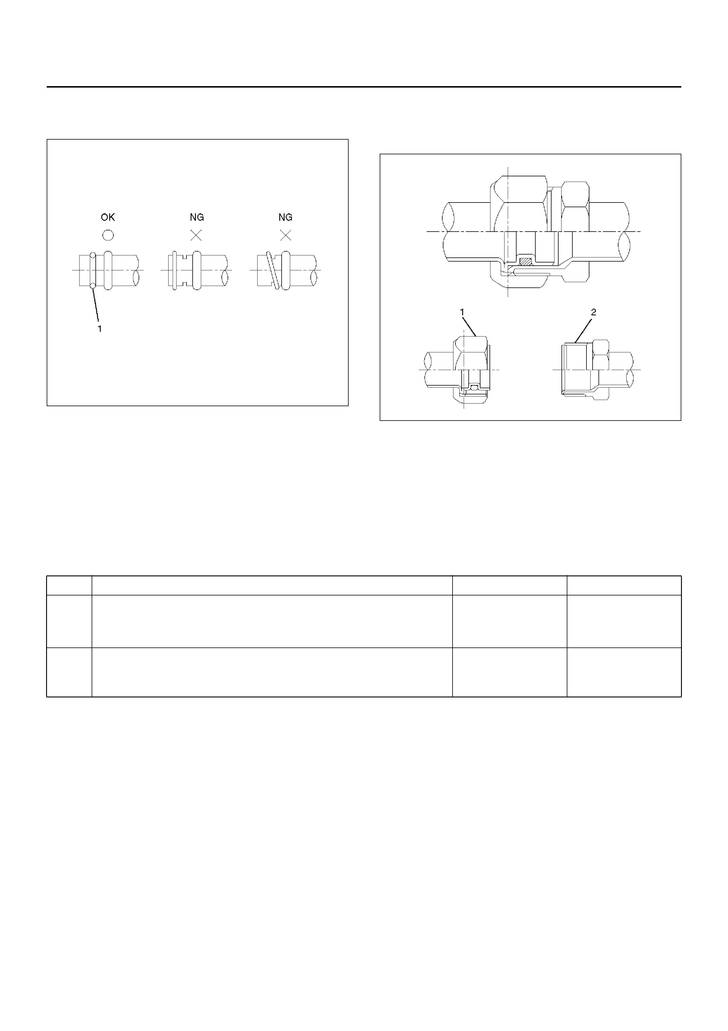
O-ri ngs (2) must be fi tted in the groove (1) of refr i gerant
line.
850RW003
Insert the nut into the union.
First, tig hten th e nut by hand as much as possible, then
tighten the nut to the specified torque.
Leak Check
Inspection of refrigerant leak
Refrigerant leak may cause an adverse effect not only
on the performance and durability of each component of
the air-conditioner, but also on the global atmosphere.
Therefore, it is most impor tant to repair refrigerant leak
when there is any leak found.
Inspection flow of refrigerant leak
Insp ec ti on St eps
Check the compon ents of air- conditioner t o see if th ere
occurs any refrigerant leak along the flow of refrigerant.
• To avoid an error in the detection of refrigerant leak,
make sure of there being no refrigerant vapor or
cigarette smok e around the vehicle before conducting
the inspection. Also, select a location where the
refrigerant vapor will not get blown off with wind.
• Inspection should be conducted chiefly on the pipe
connections and sections where a marked oil
contamination is found. When refrigerant is leaking,
oil inside is also leaking at the same time.
• It is possible to visually check the leak from inside the
cooling unit. Follow the method below when
checking. Remove the drain hose or resistor of the
coolin g unit, and insert a le ak detector to see if there
occurs any leak.
High Pressure Side
1. Discharger section of compressor.
2. Inlet/outlet section of condenser.
3. Inlet/outlet section of receiver driver.
4. Inlet section of cooling unit.
Low Pressure Side
1. Outlet section of cooling unit.
2. Intake section of compressor.
Step Action Yes No
1 1. Evacuate the refrigerant system.
2. Charge the refrigerant.
Is there any refrigerant leak? Repair refrigerant
system. Go to Step 2.
2 1. Operate the compres sor for more than 5 mi nutes to raise t he
pressure on the high pressure side.
Is there any refrigerant leak at high pressure components? Repair refrigerant
system.
Compress or
operation to be
confirmed.

Major Checking Points of Refrig erant Leak
Compressor
• Pipe connection
• Sealing section of shaft
• Mating section or cylinder
Condenser
• Pipe connection
• Welds of condenser body
Receiver driver
• Pipe connection
• Attaching section of pressure s witch
• Section around the sight glass
Evaporator unit (cooling unit)
• Pipe connections
• Connections of expansion valve
• Brazed sections of evaporator
• The evaporator and ex pansion valve are c ontained i n
the case. Remov e the drain hose or the resistor of the
coolin g uni t and insert a le ak dete cto r wh en checkin g
for any leak.
Flexible hose
• Pipe connection
• Caulking section of the hose
• Hose (cracks, pinholes, flaws)
Pipe
• Pipe connection
• Pipe (cracks, flaws)
Charge valve
• The charge valve , which is used to connect the gauge
manifold, is normally provided with a resin cap. When
the valve inside gets deteriorated, refrigerant will leak
out.
Leak at Refrigerant Line Connections
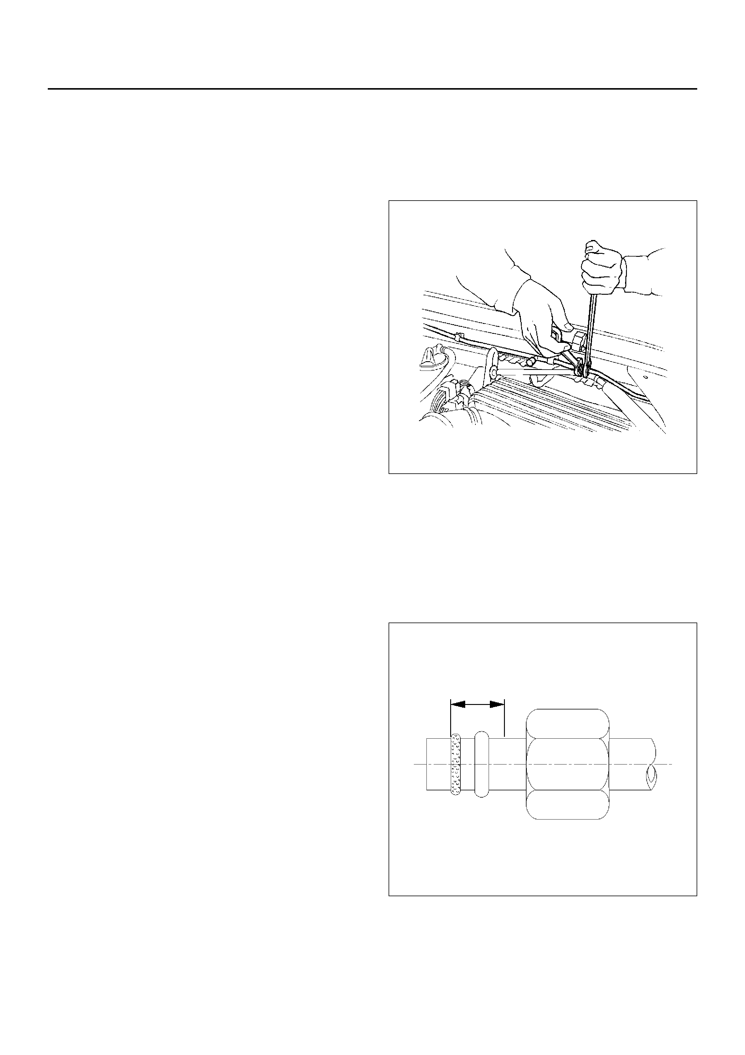
1. Check the torque on the refrigerant line fitting and, if
too loose, tighten to the specified torque.
• Use two wrenches to prevent twisting and
damage to the line.
• Do not over tighten.
2. Perform a leak test on the refrigerant line fitting.
3. If the leak i s still presen t, dis charge and rec over th e
refrigerant from the system.
4. Replace the O-rings.
• O-rings cannot be reused. Always replace with
new ones.
• Be sure to apply the specified compressor oil to
the new O-rings.
5. Retighten the refrigerant line fitting to the specified
torque.
• Use two wrenches to prevent twisting and
damage to the line.
6. Evacuate, charge and retest the system.
Leaks In The Hose
If the compressor inlet or outlet hose is leaking, the
entire hose must be replaced. The refrigerant hose must
not be cut or spliced for repair.
1. Locate the leak.
2. Discharge and recover the refrigerant.
3. Remove the hos e assem bly.
• Cap the open connections at once.
4. Connect the new hose assembly.
• Use two wrenches to prevent twisting or damage
to the hose fitting.
• Tighten the hose fitting to the specified torque.
5. Evacuate, charge and test the system.
Compressor Leaks
If leaks are located around the compressor shaft seal or
shell, replace or repair the compressor.
Recovery, Recycling, Evacuation and
Charging of HFC-134a
Air conditioning systems contain HFC-134a. This is a
chemical mixture which requires special handling
procedures to avoid personal injury.
• Alway s wear safety goggles and protecti ve gloves.
• Always work in a well-ventilated area. D o not weld or
steam clean on or near any vehicle-installed air
conditioning lines or components.
• If HFC-134a should come in cont act with any par t of
the body, flush the exposed area with co ld water and
immediately seek medical help.
• If it is necessary to transport or carry any container of
HFC-134a in a vehicle, do not carry it in the
passenger compartment.
• If it is necessary to fill a small HFC-134a container
from a large one, never fill the container completely.
Space should always be allowed above the liquid for
expansion.
• HFC-134a and R-12 should never be mixed as their
compositions are not the same.
• HFC-134a PAG oil tends to absorb moisture more
quickly than R-12 mineral oil and, therefore, should
be handled more carefully.
• Keep HFC-134a containers stored below 40°C
(100°F).
WARNING:
• SHOULD HFC-134A CONTACT YOUR EYE(S),
CONSULT A DOCTOR IMMEDIATELY.
• DO NOT RUB THE AFFECTED EYE(S). INSTEAD,
SPLASH QUANTITIES OF FRESH COLD WATER
OVER THE AFFECTED AREA TO GRADUALLY
RAISE THE TEMPERATURE OF THE
REFRIGERANT ABOVE THE FREEZING POINT.
• OBTAIN PROPER MEDICAL TREATMENT AS
SOON AS POSSIBLE. SHOULD THE HFC-134A
TOUCH THE SKIN, THE INJURY MUST BE
TREATED THE SAME AS SKIN WHICH HAS BEEN
FROSTBITTEN OR FROZEN.
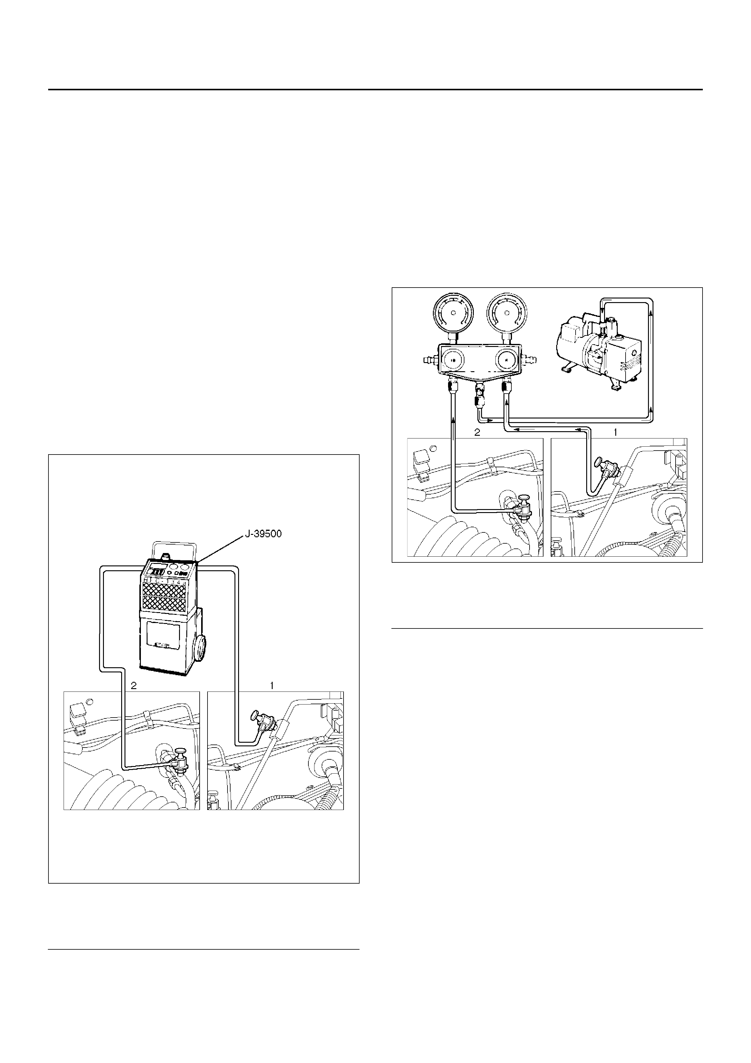
Refrigerant Recovery
The refrigerant must be discharged and recovered by
using the J-39500 (ACR4:HFC-134a Refrigerant
Recovery/Recycling/Recharging/System) or equivalent
before removing or mounting air conditioning parts.
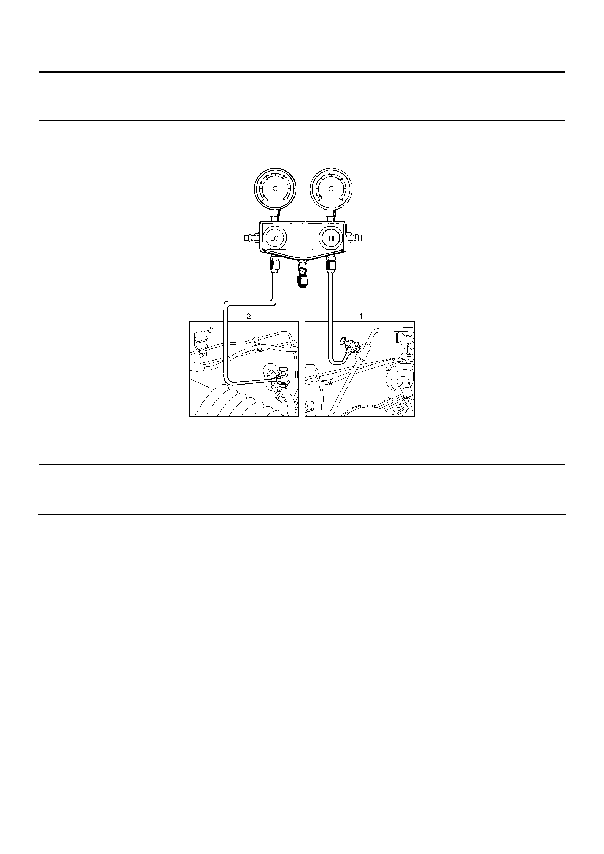
1. Connect the high and low charging hoses of the
ACR4(or equivalent) as shown below.
901RX057
EndOFCallout
2. Recover the refrigerant by following the
Manufacturer's Instructions.
3. When a par t i s removed, put a cap or a plug on the
connecting portion so that dust, dirt or moisture
cannot get into it.
Refrigerant Recycling
Recycle the refrigerant recovered by J-39500
(ACR4:HFC-134a Refrigerant Recovery / Recycling /
Recharging / System) or equivalent.
F or the details of the actual operation, f ollow the steps in
the ACR4(or equivalent) Manufacturer's Instructions.
Evacuation of The Refrigerant System
901RX058
EndOFCallout
Explained below is a method using a vacuum pump.
Refer to the ACR4(or equivalent) manufacturer's
instructions when ev acuating the system with a ACR4(or
equivalent).
Air and moisture in the refrigerant will cause problems in
the air conditioning system. Therefore, before charging
the refrigerant, be sure to evacuate air and moisture
thoroughly from the system.
1. Connect the gauge manifold.
• High-pressure valve (HI) — Discharge-side.
• Low-pressure valve (LOW) — Suction-side.
2. Discharge and recover the refrigerant.
3. Connect the center hose of the gauge manifold set
to the vacuum pump inlet.
4. Operate the vacuum pump, open shutoff valve and
then open both hand valves.
5. When the low-pressure gauge indicates
approximately 750mmHg (30inHg), continue the
evacuation for 5 minutes or more.
6. Close both hand valves and stop the vacuum pump.
Legend
(1) H i gh Side
(2) Low Side
Legend
(1) High Side
(2) Low Side
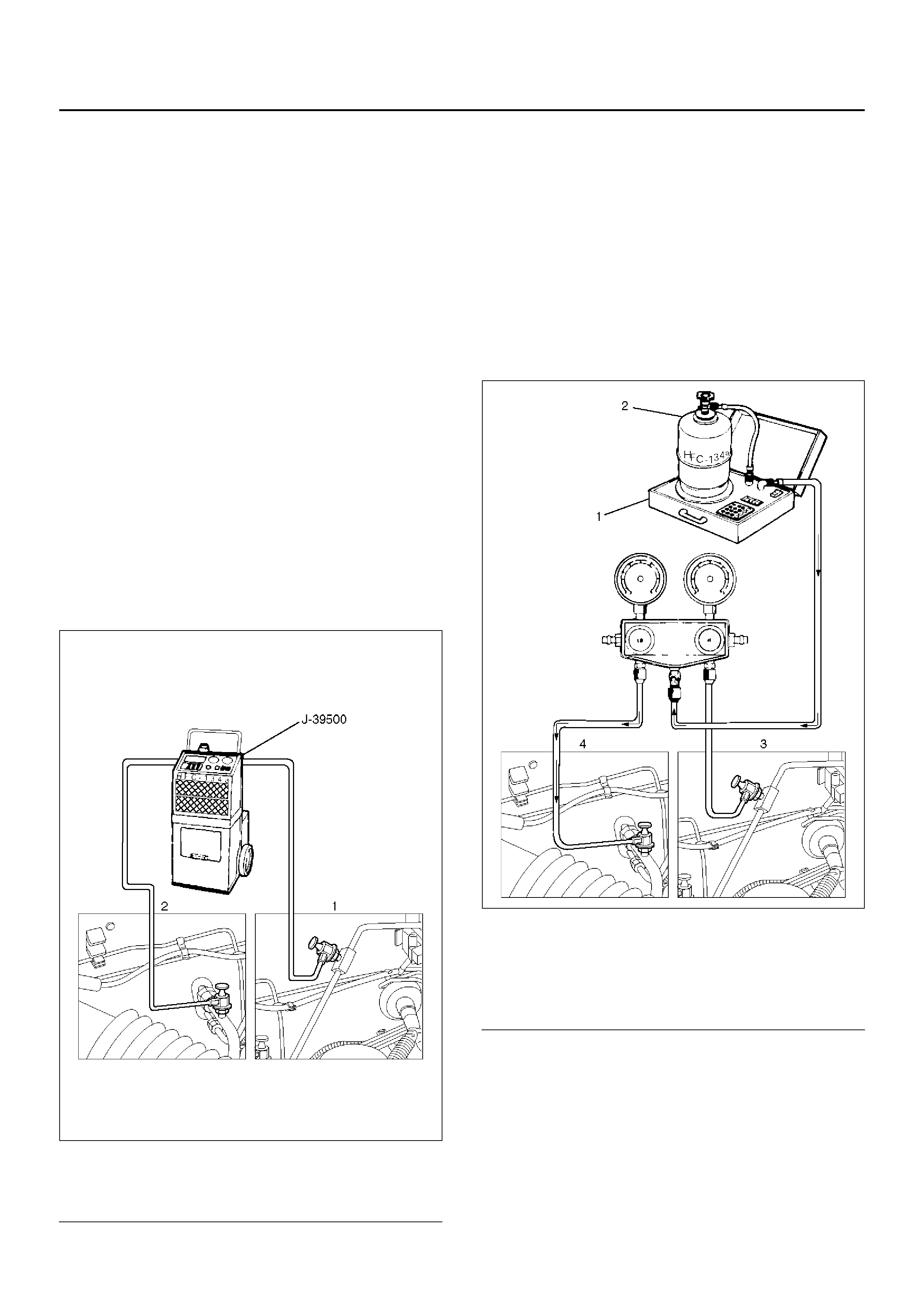
7. Check to ensure th at the pressu re does no t change
after 10 minutes or more.
• If the pressure changes, check the system for
leaks.
• If leaks occur, retighten the refrigerant line
connections and repeat the evacuation steps.
8. If no leaks are found, again operate the vacuum
pump for 20 minutes or more. After co nfirmi ng that
the gauge manifold pressure is at 750mmHg
(30inHg), close both hand valves.
9. Close p ositive shutoff valve. Stop the vacuum pump
and disconnect the center hose from the vacuum
pump.
Charging The Refrigerant System
There are various methods of charging refrigerant into
the air conditioning system.
These include using J-39500 (ACR4:HFC-134a
Refrigerant Recovery/Recyclin g/Recharging/System) or
equivalent and direct charging with a weight scale
charging station.
Charging Procedure
•ACR4(or equivalent) Method
For th e charging of r efrigerant rec overed by ACR 4(or
equivalent), follow the manufacturer's instruction.
901RX057
EndOFCallout
•Direct charging with a weight scale charging
station method
1. Make sure the evacuation process is correctly
completed.
2. Connect the center hose of the manifold gauge to
the weight scale.
3. Connect the low pressure charging hose of the
manifold gauge to the low pressure side service
valve of the vehicle.
4. Connect the high pressure charging hose of the
manifold gauge to the high pressure side service
valve of the vehicle.
901RX059
EndOFCallout
5. Place the refrigerant container up right on a weight
scale.
Note the total weight before charging the refrigerant.
a Open the refrigerant container valve.
b Open the low side vale on the manifold gauge
set. Refer to the manufacturer's instructions for
a weight scale charging station.
Legend
(1) H i gh Side
(2) Low Side
Legend
(1) Weight Scale
(2) Refrigerant Contain er
(3) High Side
(4) Low Side

6.Perform a system leak test:
•Charge the system with approximately 200g
(0.44lbs) of HFC-134a.
•Make sure the high pressure valve of the manifold
gauge is closed.
•Check to ensure that the degree of pressure does
not change.
•Check for refrigerant leaks by using a HFC-134a
leak detector.
•If a leak occurs, recover the refrigerant. Repair
the leak and start all over again from the first step
of evacuation.
7.If no leaks are found, continue charging refrigerant
to the air conditioning system.
•Charge the refrigerant until the scale reading
decreases by the amount of the charge specified.
Specified amount: 650g (1.43lbs)
•If charging the system becomes difficult:
1Run the engine at idle and close all the
vehicle doors.
2Turn A/C switch “ON".
3Set the fan switch to its highest position.
4Set the air source selector lever to “CIRC".
5Slowly open the low side valve on the
manifold gauge set.
WARNING: Be absolutely sure not to open the high
pressure valve of the manifold gauge. Should the
high pressure valve be opened, the high pressure
refrigerant would flow backward, and this may
cause the refrigerant container to burst.
8.When finished with the refrigerant charging, close
the low pressure valve of the manifold gauge and
container valve.
9.Check for refrigerant leaks.
Checking The A/C System
1.Run the engine and close all the vehicle doors.
2.Turn A/C switch “ON", set the fan switch to its
highest position.
3.Set the air source lever to “CIRC", set the
temperature lever to the full cool position.
4.Check the high and low pressure of the manifold
gauge.
•Immediately after charging refrigerant, both high
and low pressures might be slightly high, but they
settle down to the pressure guidelines shown
below:
•The ambient temperature should be between 25–
30°C (77–86°F).
•The pressure guideline for the high-pressure side
is approximately 1372.9–1863.3kPa (199.1–
270.2 psi).
•The pressure guideline for the low-pressure side
is approximately 147.1–294.2kPa (21.3–42.7
psi).
•If an abnormal pressure is found, refer to
Checking The Refrigerant System With Manifold
Gauge in this section.
5. Put your hand in front o f the air outlet an d move the
temperature control lever of the control panel to
different positions. Check if the outlet temperature
changes as selected by the control knob.
Reading Sight Glass
The sight glass provides accurate diagnosis only under
the following conditions.
If the vehicle can be tested under these conditions,
check the sight glass appearance and compare to the
chart below.
• Engine speed idle
• A/C switch “ON"
• Blower fan operating at highest speed
• Air source selector lever at “RECIRC"
• Temperature control lever at coldest position
• Ambient temperature below 30°C (86°F) and
humidity below 70% (See NOTE 1)
• High side pressure less than 1667.1 kPa (241.7 psi)
(See NOTE 2)
NOTE: 1. If the vehicle cannot be moved to a testing
location that meets these specifications, then the sight
glass cann ot be used for diagnosis. You must discharge
and recover the refrigerant, then recharge the system
with the specified amount of refrigerant.
Then continue checking the system performance.
NOTE: 2. If the high side pressure is greater than
stated, the sight glass cannot be used f or diagnosis. You
must discharge and recover the refrigerant, then
recharge the system with the specified amount of
refrigerant. Then continue checking system
performance.
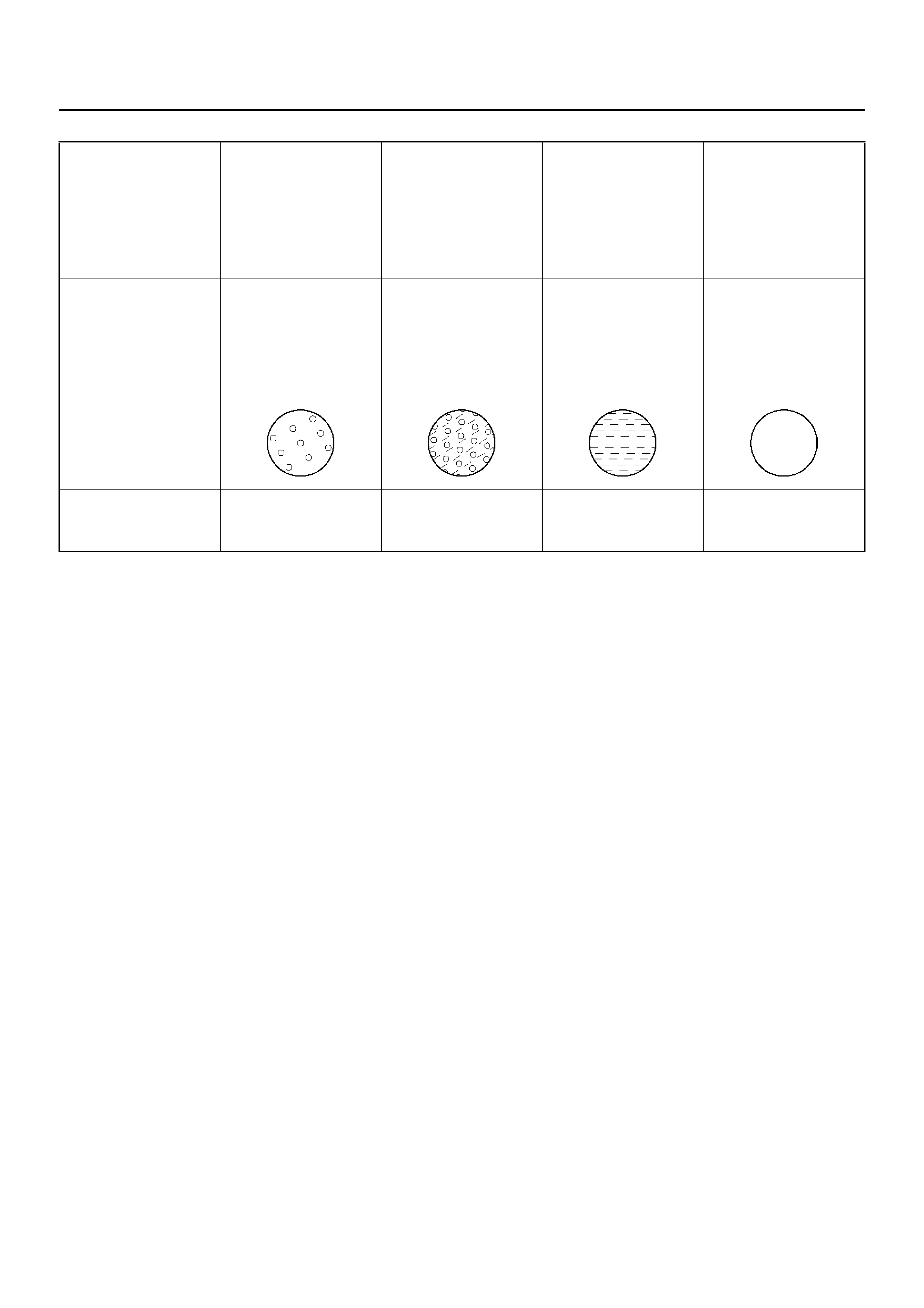
High and low
pressure pipe
temperature
The high pressure
pipe is hot and the
low pressure pipe is
cold. There is a
distinct difference in
temperature between
them.
The high pressure
pipe is warm and the
low pressure pipe is
cool. There is no
great difference in
temperature between
them.
There is litttle
difference in
temperature between
the high pressure
pipe and the low
pressure pipe.
The high pressure
pipe is hot and the
low pressure pipe is
slightly warm. There
is a defference in
temperature between
them.
Slight glass condition Almost transparent. A
flow of bubbles can
be seen, but they
disappear when the
throttle is opened.
A flow of bubbles
always can be seen.
It appears sometimes
transparent, and
sometimes frothy.
So mething like fog
faintly can be seen. Even at idle with the
fan at “HI” (with the
window fully open),
the bubbles cannnot
be seen.
Air cond iti oni ng c ycle
condition OK NG
(Not enough
refrigerant)
NG
(Almost no
refrigerant)
NG
(Too much
refrigerant)
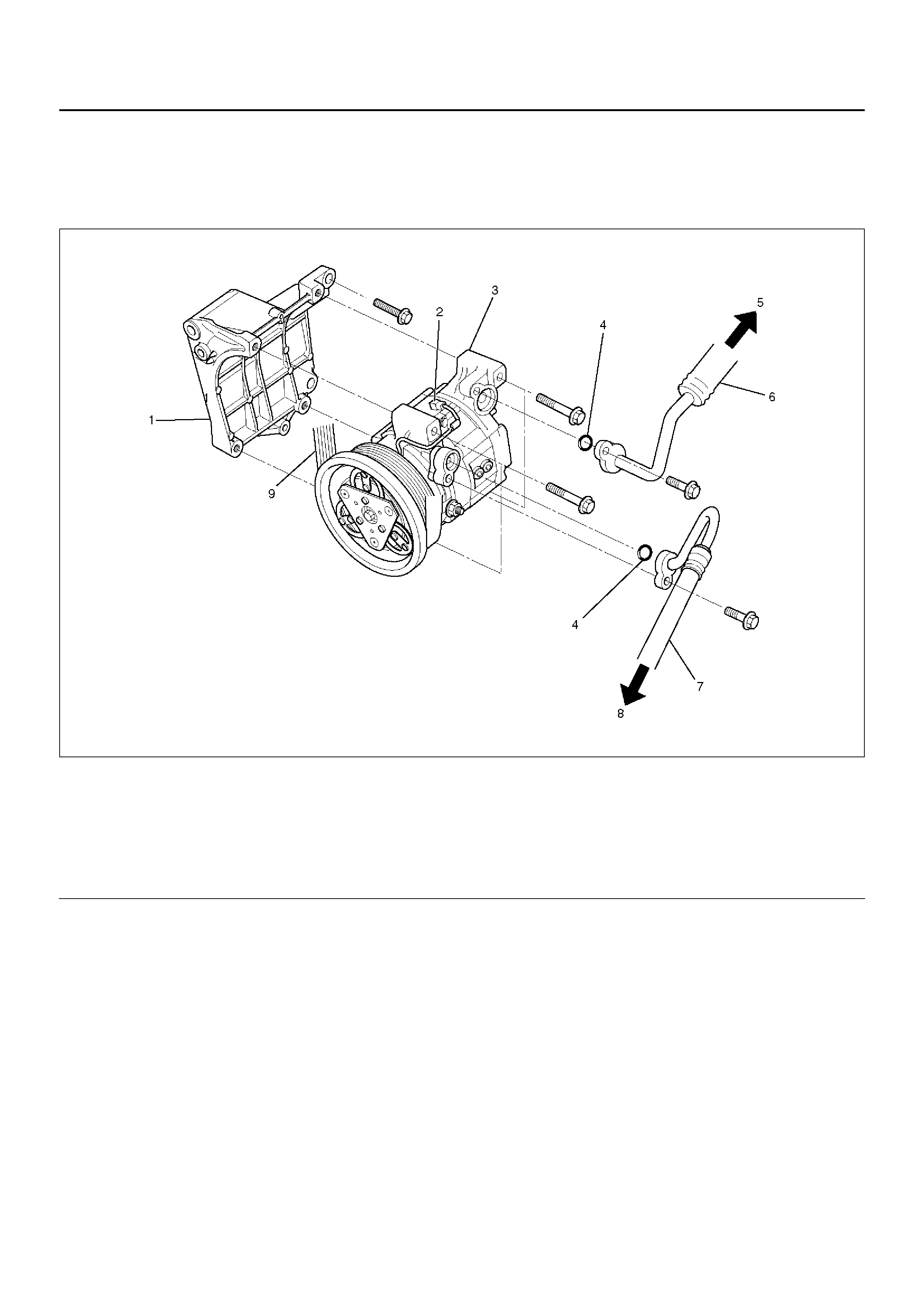
Compressor Assembly
Compressor Assembly and Associated Parts (6VD1)
852RY00018
EndOFCallout
Removal
1.Disconnect the battery ground cable.
2.Discharge and recover refrigerant
•Refer to Refrigerant Recovery in this section.
3. Disconnect magnetic clutch harness connector.
4. Remove serpentine belt.
• Move serpentine belt tensioner to loose side
using wrench then remove serpentine belt.
Legend
(1) Compressor Bracket
(2) Magnetic Clutch Harness Connector
(3) Compressor
(4) O-ring
(5) To Evapor ator
(6) Suction Line (Low-Pressure Hose)
(7) Discharge Line (Hight-Pressure Hose)
(8) To Condenser
(9) Serpentine Belt
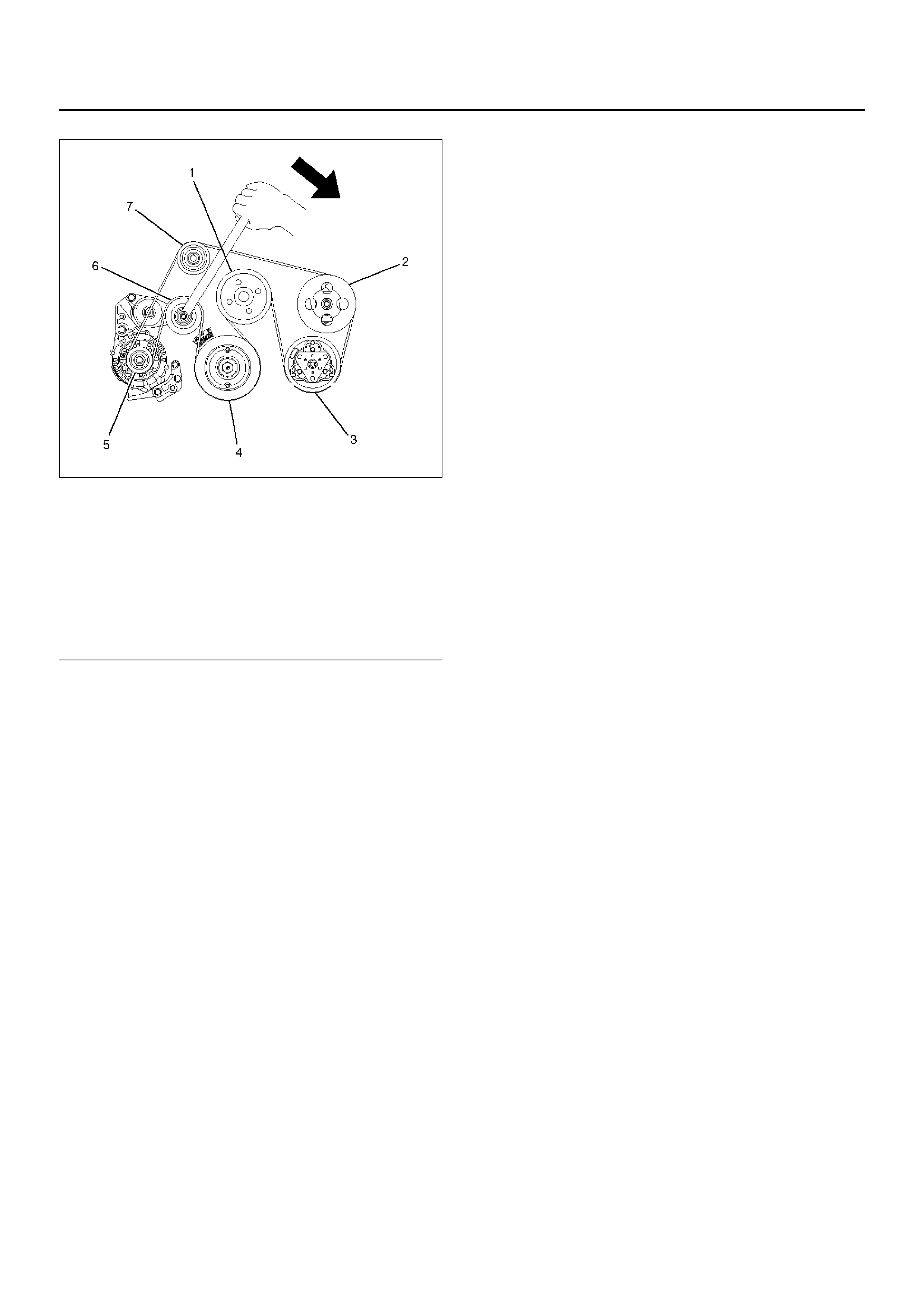
850RW009
EndOFCallout
5. Disconnect refrigerant line connector.
• When removing the line connector, the
connecting part should immediately be plugged
or capped to prevent foreign matter from being
mixed into the line.
6. Remove compressor.
Installation
1. Install compressor.
• Tighten the compressor fixing bolts to the
specifi ed tor que.
Torque: 19N•m (1.9kg•m/14lb ft)
2. Connect refrigerant line connector.
• Tighten the refrigerant line connector fixing bolts
to the specified torque.
Torque: 15N•m (1.5kg•m/11lb ft)
• O-rings cannot be reused. Always replace with
new ones.
• Be sure to apply new compressor oil to the
O-rings when connecting refrigerant lines.
3. Install serpentine belt.
• Move serpentine belt tensioner to loose side
using wrench, then install serpentine belt to
normal position.
4. Connect magnetic clutch harness connector.
Legend
(1) Cooling Fan Pulley
(2) Power Steering Oil Pump
(3) Air Conditioner Compressor
(4) Crankshaft Pulley
(5) Generator
(6) Tensioner
(7) Idler Pu lley
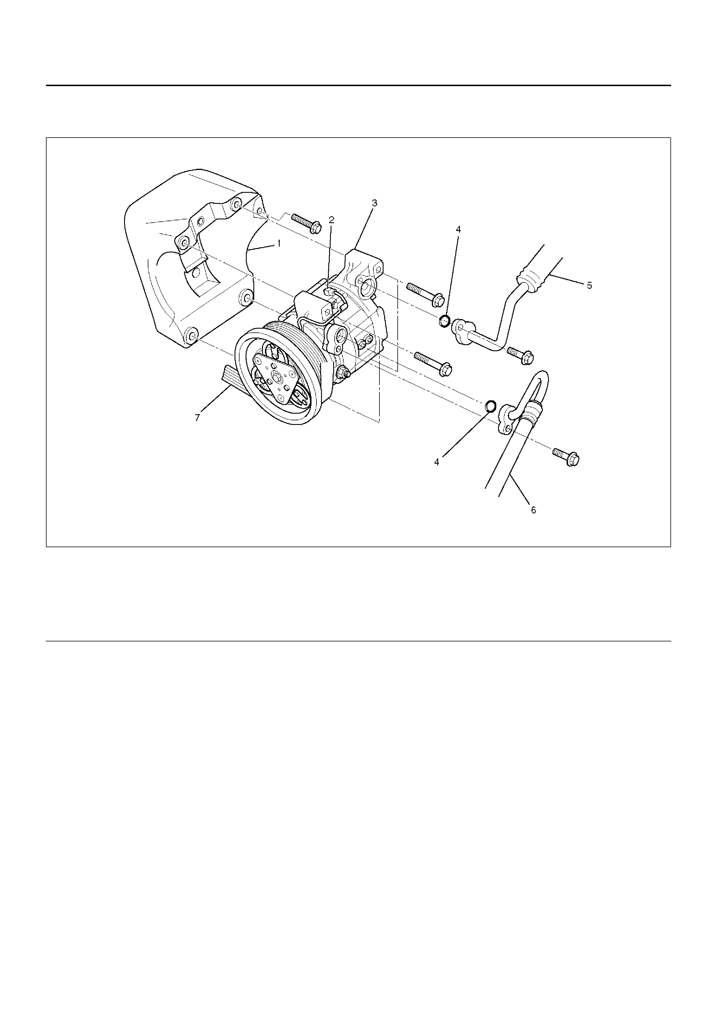
Compressor Assembly and Associated Parts (X22SE)
852RY00031
EndOFCallout
Removal
1.Disconnect the battery ground cable.
2.Discharge and recover refrigerant
•Refer to Refrigerant Recovery in this section.
3. Disconnect magnetic clutch harness connector.
Legend
(1) Compressor Bracket
(2) Magnetic Harness Connector
(3) Compressor
(4) O-ring
(5) Suction Line (Low-Pressure Hose)
(6) Discharge Line (High-Pressure Hose)
(7) Serpentine Belt
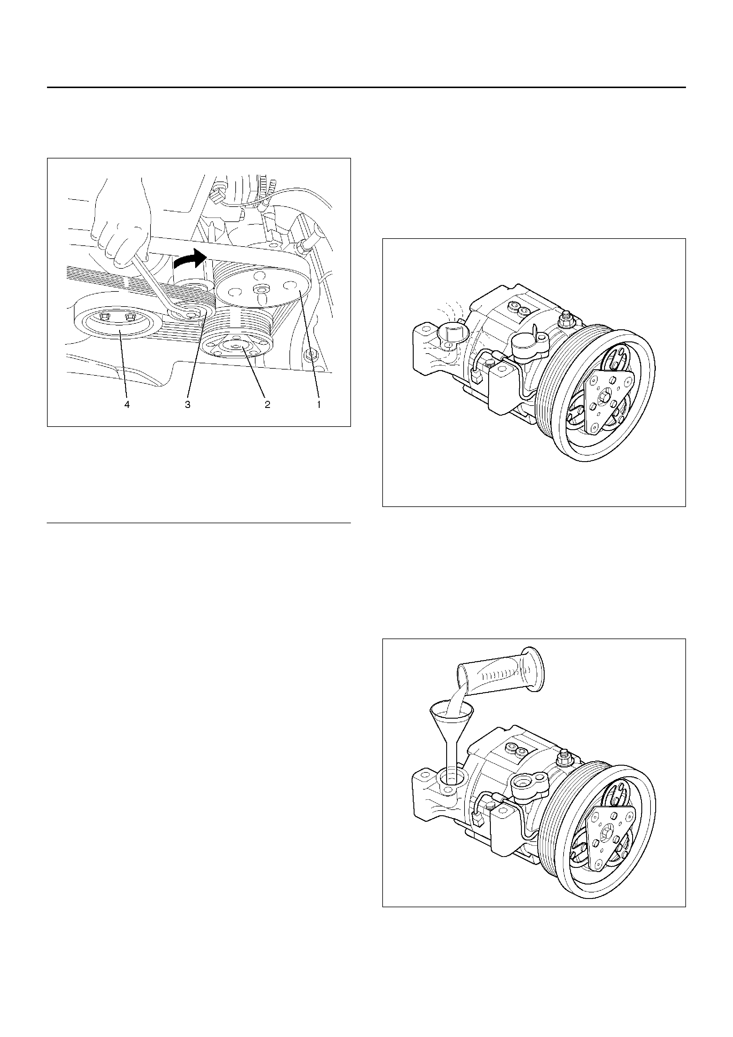
4.Remove serpentine belt.
•Move serpentine belt tensioner to loose side
using wrench then remove serpentine belt.
850RX006
EndOFCallout
5.Disconnect refrigerant line connector.
•When removing the line connector, the
connecting part should immediately be plugged
or capped to prevent foreign matter from being
mixed into the line.
6.Remove compressor.
Installation
1.Install compressor.
•Tighten the compressor fixing bolts to the
specified torque.
Torque: 19N•m (1.9kg•m/14lb ft)
2.Connect refrigerant line connector.
•Tighten the refrigerant line connector fixing bolts
to the specified torque.
Torque: 15N•m (1.5kg•m/11lb ft)
•O-rings cannot be reused. Always replace with
new ones.
•Be sure to apply new compressor oil to the
O-rings when connecting refrigerant lines.
3.Install serpentine belt.
•Move serpentine belt tensioner to loose side
using wrench, then install serpentine belt to
normal position.
4.Connect magnetic clutch harness connector.
New Compressor Installation
The new compressor is filled with 150cc (5.0fl.oz.)of
compressor oil and nitrogen gas. When mounting the
compressor on the vehicle, perform the following steps;
1.Gently release nitrogen gas from the new
compressor.
•Take care not to let the compressor oil flow out.
•Inspect O-rings and replace if necessary.
871RX033
2.Turn the compressor several times by hand and
release the compressor oil in the rotor.
3.When installing on a new system, the compressor
should installed as it is. When installing on a used
system, the compressor should be installed after
adjusting the amount of compressor oil. (Refer to
Compressor in this section)
871RX035
Legend
(1) Power Steering Oil Pump
(2) Air Conditioner Compressor
(3) Tensioner
(4) Crankshaft Pulley
Condenser Assembly
Condenser Assembly and Associated Parts
875RY00008
EndOFCallout
Removal
1.Disconnect the battery ground cable.
2.Discharge and recover refrigerant.
•Refer to Refrigerant Recovery in this section.
3. Remove radiator grille.
4. Remove engine hood front end stay.
5. Remove engine hood lock.
• Appl y setting mar k to the e ngine hood lock fixin g
position before removing it.
6. Disconnect pressure switch connector.
7. Disco nne ct re frigerant li ne.
• When removing the line connector, the
connecting part should immediately be plugged
or capped to prevent foreign matter from being
mixed into the line.
8. Remove condenser asse mbly.
• Handle with care to prevent damaging the
condenser or radiator fin.
Installation
1. Install condenser assembly.
• If installing a new condenser, be sure to add 30cc
(1.0fl.oz.) of new compressor oil to a new one.
• Tighten the condenser fixing bolts to the specified
torque.
Torque: 6N•m (0.6kg•m/52lb in)
2. Connect refrigerant line.
• Tighten the inlet line connector fixing bolt to the
specifi ed tor que.
Torque: 15 N•m (1.5kg•m/11 lb ft)
Legend
(1) Engine Hood Lock
(2) P ress ur e Swi tch Connec to r
(3) Refrigerant Line
(4) Radiator Grille
(5) Engine Hood Front End Sta y
(6) Condenser Asse mbly
•Tighten the outlet line connector fixing bolt to the
specified torque.
Torque: 6 N•m (0.6kg•m/52 lb in)
•O-rings cannot be reused. Always replace with
new ones.
•Be sure to apply new compressor oil to the
O-rings when connecting the refrigerant line.
3.Connect pressure switch connector.
4.Install engine hood lock.
5.Install engine hood front end stay.
6.Install radiator grille.
Condenser Fan Motor
Condenser Fan Motor and Associated Parts
875RY00007
EndOFCallout
Removal
1.Disconnect the battery ground cable.
2.Discharge and recover refrigerant.
•Refer to Refrigerant Recovery in this section.
3. Remove radiator grille.
4. Remove condenser fan assembly.
• Disconnect the fan motor connector and remove
the 4 fixing bolts.
5. Remove shroud.
• Remove the 3 fixing nuts.
• Loosen the condenser fixing nut and disconnect
the fan motor connector from bracket.
6. Remove fan.
• Remove the fan fixing C-ring and plate.
7. Remove condenser fan motor.
Installation
To install, follow the removal steps in the reverse order,
noting the following point.
1. Route the fan motor harness in its previous position,
and fix it securely with clip and bracket.
Legend
(1) Condenser Fan Assembly
(2) Condenser Fan Motor
(3) Radiator Grille
(4) Shroud
(5) Fan

Receiver / Drier
Receiver / Drier and Associated
Parts
875RY00012
EndOFCallout
Removal
1.Disconnect the battery ground cable.
2.Discharge and recover refrigerant.
•Refer to Refrigerant Recovery in this section.
3. Remove radiator grille.
4. Disconnect pressure switch connector.
5. Disco nne ct re frigerant li ne.
• When removing the line connected part, the
connecting part should immediately be plugged
or capped to prevent foreign matter from being
mixed into the line.
6. Remove bracket bolt.
7. Remove receiver/drier.
• Loosen the bolt, then, using care not to touch or
bend the refrigerant line, carefully pull out the
receiver/drier.
Installation
To install, follow the removal steps in the reverse order,
noting the following points:
1. If installing a new receiver/drier, be sure to add 30cc
(1.0fl.oz.) of new compressor oil to a new one.
2. Put the receiver/drier in the bracket and connect
with the refrigerant line. Check that no excessive
force is imposed on the line. Fasten the bracket bolt
to the receiver/drier.
3. Tighten the refrigerant line to the specified torque.
Torque: 6 N•m (0.6kg•m/52 lb in)
4. O-r ings cannot be re used. Always replac e with new
ones.
5. Be sure to apply new compressor oil to the O-rings
when connecting the refrigerant line.
Legend
(1) P ress ur e Swi tch Connec to r
(2) Refrigerant Line
(3) Radiator Grille
(4) Receiver / Drier
(5) Bracket Bolt
Pressure Switch
Pressure Switch and Associated
Parts
875RY00012
EndOFCallout
Removal
1.Disconnect the battery ground cable.
2.Discharge and recover refrigerant.
•Refer to “Refrigerant Recovery in this section.
3. Remove radiator grille.
4. Disconnect pressure switch connector.
5. Disco nne ct pr es sure sw itc h.
• When removing the switch connected part, the
connecting part should immediately be plugged
or capped to prevent foreign matter from being
mixed into the line.
Installation
To install, follow the removal steps in the reverse order,
noting the following point:
1. O-ring cannot be reused. Alwa ys replace with a new
one.
2. Be sure to apply new compressor oil to the O-ring
when connecting pressure switch.
3. Tighten the pressure switch to the specified torque.
Torque: 13 N•m (1.3kg•m/113 lb in)
Legend
(1) P ress ur e Swi tch Connec to r
(2) Refrigerant Line
(3) Radiator Grille
(4) Receiver / Drier
(5) Bracket Bolt
Evaporator Assembly
Evaporator Assembly and Associated Parts
874RY00024
EndOFCallout
Removal
1.Disconnect the battery ground cable.
2.Discharge and recover refrigerant.
•Refer to Refrigerant Recovery in this section.
3. Remove glove box.
Legend
(1) Refrigerant Line
(2) Drain Hose
(3) Resistor and Electronic Thermostat Connector
(4) Electronic Thermostat
(5) Evaporator Assembly
(6) Glove Box
(7) Sill Plate
(8) Dash Side Trim Pad
(9) Inst Panel Lower Reinforcement
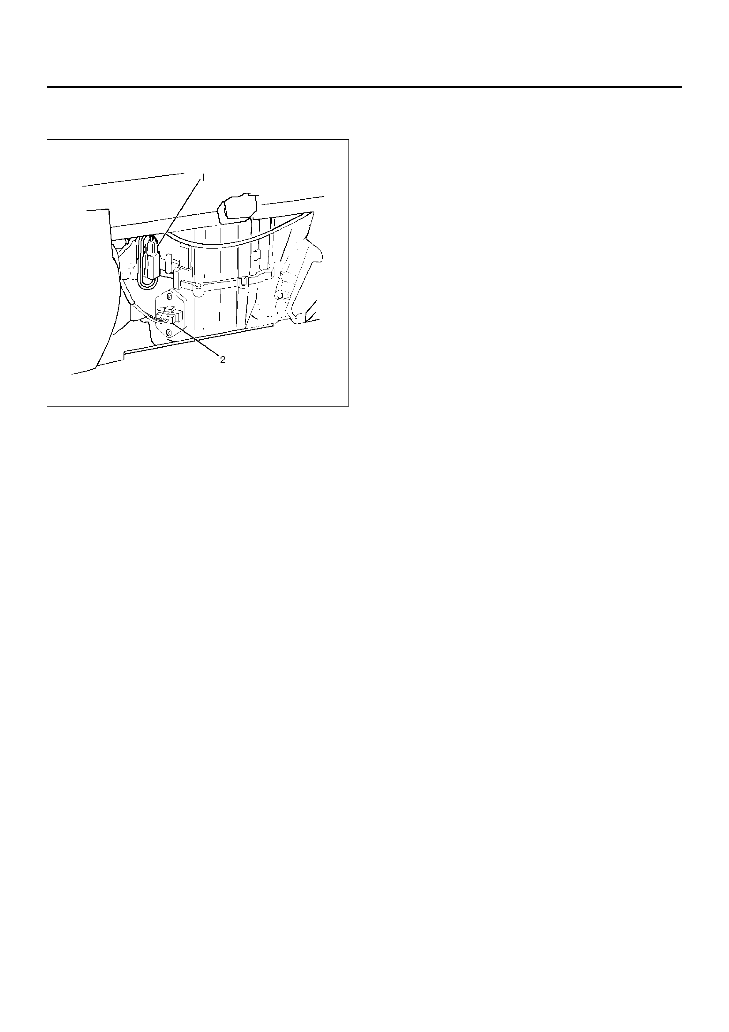
4. Disconnect resistor (2) and electronic thermostat
connector (1).
874RY00025
5. Disco nnect drain hose.
6. Disco nnect refrigerant li ne.
• Use a back-up wrench when disconnecting and
reconnecting the refrigerant lines.
• When removing the refrigerant line connected
part, the connecting part should immediately be
plugged or cap ped to p reven t foreign matt er from
being mixed into the line.
7. Remove evaporator assembly.
Installation
To install, follow the removal steps in the reverse order,
noting the following points:
1. To install a new evaporator assembly, add 50cc
(1.7fl.oz.) of new compressor oil to the new core.
2. Tighten the refrigerant outlet line to the specified
torque.
Torque: 25 N•m (2.5kg•m/18 lb ft)
3. Tighten the refrigerant inlet line to the specified
torque.
Torque: 15 N•m (1.5kg•m/11 lb ft)
4. O-r ings cannot be re used. Always replac e with new
ones.
5. Be sure to apply new compressor oil to the O-rings
when connecting lines.
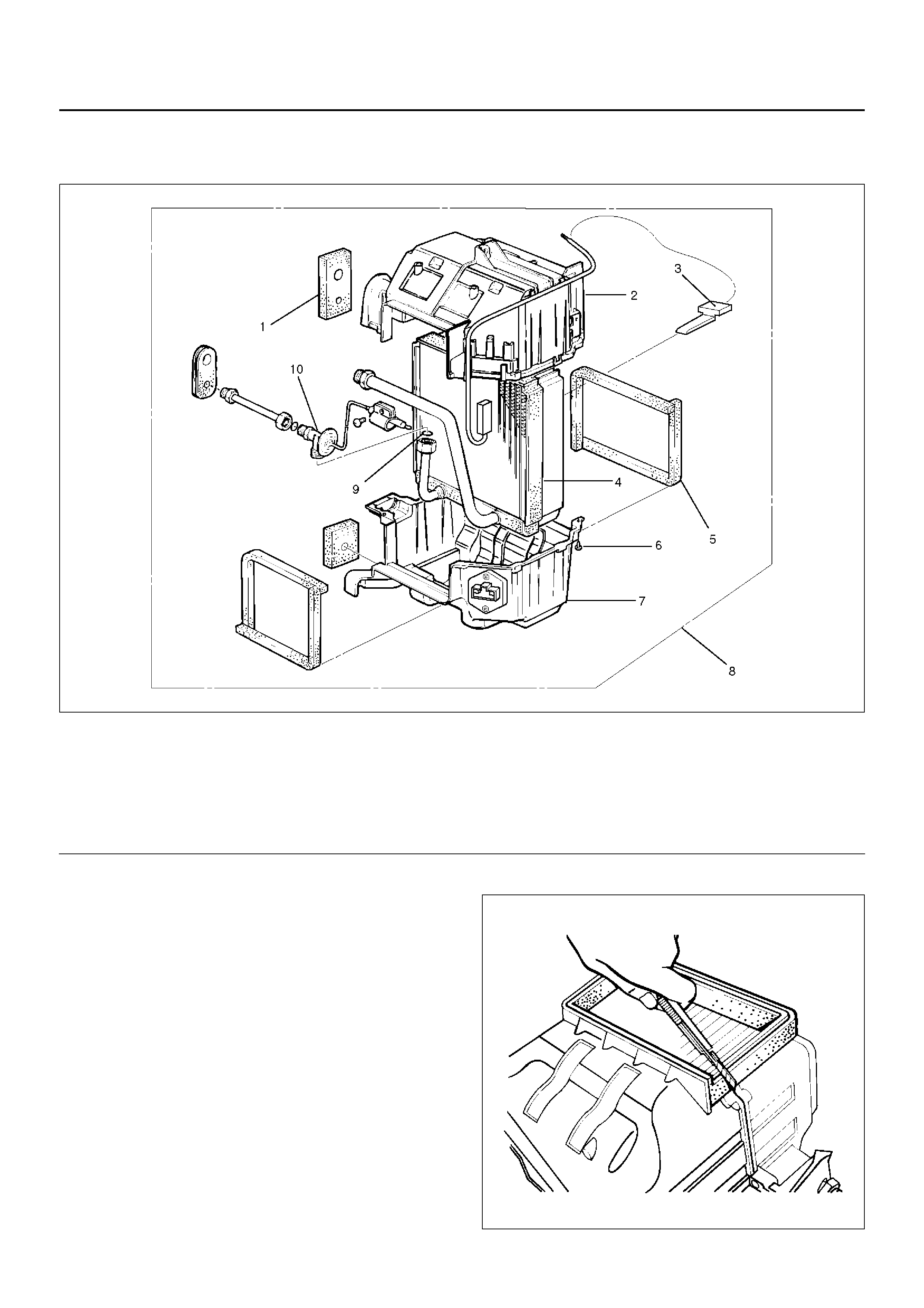
Electronic Thermostat, Evaporator Core and/or Expansion Valve
Disassembled View
874RY00026
EndOFCallout
Removal
1.Disconnect the battery ground cable.
2.Discharge and recover refrigerant.
•Refer to Refrigerant Recovery in this section.
3. Remove evaporator assembly.
•Refer to Evaporator Assembly in this section.
4. Remove the electronic thermostat sensor fixing clip.
Pull the sensor from the evaporator assembly.
5. Remove attaching screw.
6. Remove upper case.
7. Remove lower case.
• Slit the case parting face with a knife since the
lining is separated when removing the ev aporator.
874RW034
Legend
(1) Lining
(2) Upper Case
(3) Electronic Thermostat
(4) Evaporator Core
(5) Lining: Case
(6) Attaching Screw
(7) Lower C as e
(8) Evaporator Assembly
(9) O-ring
(10) Expansion Valve
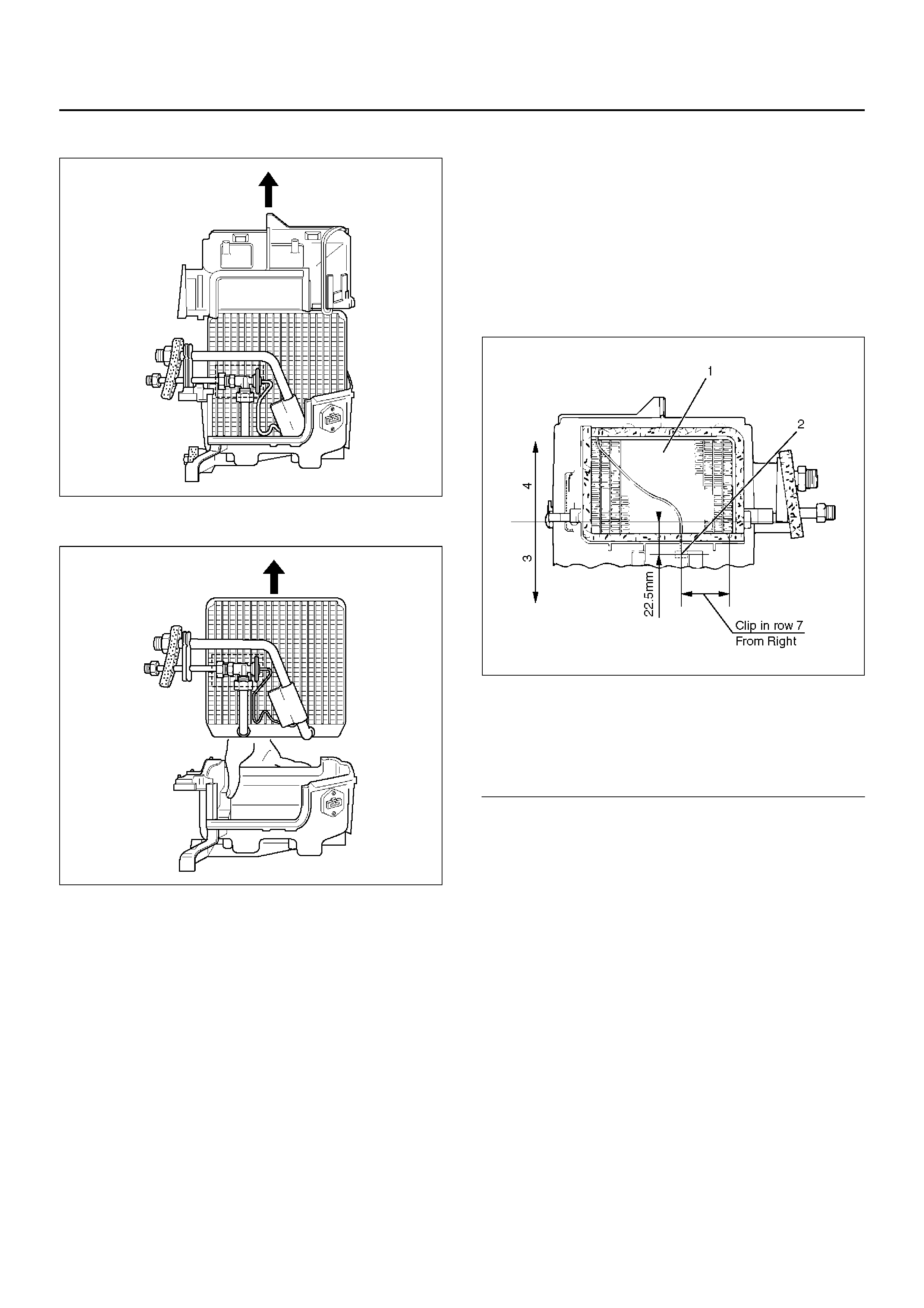
•Lift to remove the upper case.
874RY00027
8.Remove evaporator core.
874RY00028
9.Remove expansion valve.
•Tear off the insulator carefully.
•Remove the sensor fixing clip.
•Use a back-up wrench when disconnecting all
refrigerant pipes.
Installation
To install, follow the removal steps in the reverse order,
noting the following points:
1.The sensor is installed on the core with the clip.
2.The sensor must not interfere with the evaporator
core.
3.When installing the new evaporator core, install the
thermo sensor to the evaporator core specified
position with the clip in the illustration.
874RX014
EndOFCallout
4.O-rings cannot be reused. Always replace with new
ones.
5.Be sure to apply new compressor oil to the O-rings
when connecting lines.
6.Be sure to install the sensor and the insulator on the
place where they were before.
7.To install a new evaporator core, add 50cc (1.7 fl.
oz.) of new compressor oil to the new core.
8.Tighten the refrigerant lines to the specified torque.
Refer to Main Data and Specifications for Torque
Specifications in this section.
9. Apply an adhesive to the parting face of the lining
when assembling the evaporator assembly.
Legend
(1) Evaporator Core
(2) Ther mo Sen so r
(3) Lower C as e
(4) Upper Case
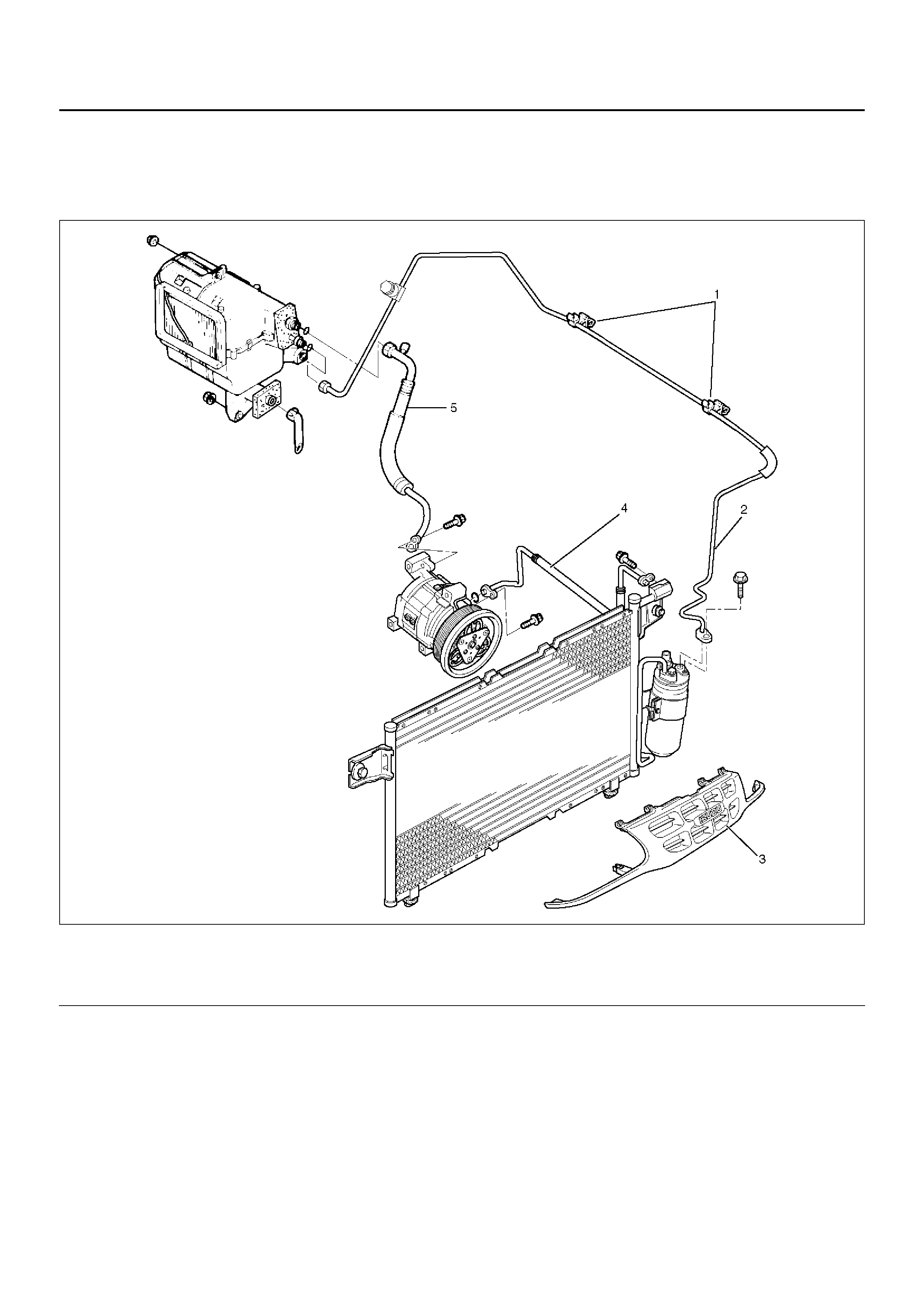
Refrigerant Line
Refrigerant Line and Associated Parts
852RY00032
EndOFCallout
Removal
1.Disconnect the battery ground cable.
2.Discharge and recover refrigerant.
•Refer to Refrigerant Recovery in this section.
3. Remove radiator grille.
4. Remove clip and clamp.
5. Disconnect liquid line (High-pressure pipe).
6. Disconnect suction line (Low-pressure pipe) using a
back-up wrench.
7. Disconnect suction line (Low-pressure hose) using
a back-up wrench.
8. Disconnect discharge line (High-pressure hose)
using a back-up wrench.
• Use a backup wrench when disconnecting and
reconnecting the refrigerant lines.
• When removing the refrigerant line connecting
part, the connecting part should immediately be
Legend
(1) Clip and Clamp
(2) Liquid Line (High-Pressure Pipe)
(3) Radiator Grille
(4) Discharge Line (High-Pressure Hose)
(5) Suction Line (Low-Pressure Pipe)

plugged or capped to prevent foreign matter from
being mixed into the line.
Installation
To install, follow the removal steps in the reverse order,
noting the following point:
1.O-rings cannot be reused. Always replace with new
ones.
2.Be sure to apply new compressor oil to the O-rings
when connecting lines.
3.Tighten the refrigerant line to the specified torque.
Refer to Main Data and Specifications for Torque
Specifications in this section.
Main Data And Specifications
General Specifications
Heater Unit
Temperature control Reheat air mix system
Capacity 3,700 Kcal./hr.
Air flow 280 m3/h
HEATER CORE
Type AUTO A/C Plate and corrugate-fin type
MANU A/C Fin and tube type
Element dimension MANU A/C 161 mm (6.3) × 163 mm (6.4 in.) × 45 mm (1.8 in.)
AUTO A/C 171 mm (6.7) × 161 mm (6.3 in.) × 25 mm (1 in.)
Radiating area MANU A/C Approx. 2.1 m2
AU TO A/C Approx. 1.3 m 2
EVAPORATOR ASSEMBLY
Capacity AUTO A/C 4,100 Kcal./hr.
MANU A/C 4,200 Kcal./hr.
Air flow AUTO A/C 430 m3/hr
MANU A/C 470 m3/hr
EVAPORATOR CORE
Type Al-laminate louver fin type
Element dimension 235 mm (9.3 in.) × 224 mm (8.8 in.) × 60 mm (2.4 in.)
EXPANSION VALVE
Type Internal pressure equalizer type
THERMOSTAT SWITCH
Type Electronic thermostat
OFF: Below 0.5 ± 0.5 °C (32.9 ± 0.9 °F)
ON: Above 4.5 ± 0.5 °C (40.1 ± 0.9 °F)
CONDENSER
Type Parallel flow type
Radiation performance 9,400 Kcal./hr
RECEIVER/DRIER
Type Assembly includes sight glass with dual (triple) pressure
switch (V6) or pressure sensor (L4)
Internal volume 300 cc (10 fl.oz.)
PRESSURE SWITCH
Type Dual pressure switch
Low pressure control
ON: 186.3±29.4 kPa (27.0±4.3 psi)
OFF: 176.5±24.5 kPa (25.6±3.6 psi)
High pressure control
ON: 2353.6±196.1 kPa (341.3±28.4 psi)
OFF: 2942.0±196.1 kPa (426.6±28.4 psi)
Triple pressure switch (V6, A/T)
Low pressure control
ON: 196.3±29.4 kPa (27.0±4.3 psi)
OFF: 176.5±19.6 kPa (25.6±2.8 psi)
Medium pressure control
ON: 1471.0±98.1 kPa (213.3±14.2 psi)
OFF: 1078.7±117.7 kPa (156.4±17.7 psi)
High pressure control
ON: 2353.6±196.1 kPa (341.3±28.4 psi)
OFF: 2942.0±196.1 kPa (426.6±28.4 psi)
REFRIGERANT
Type HFC-134a
Specified amount 650 g (1.43 lbs.)
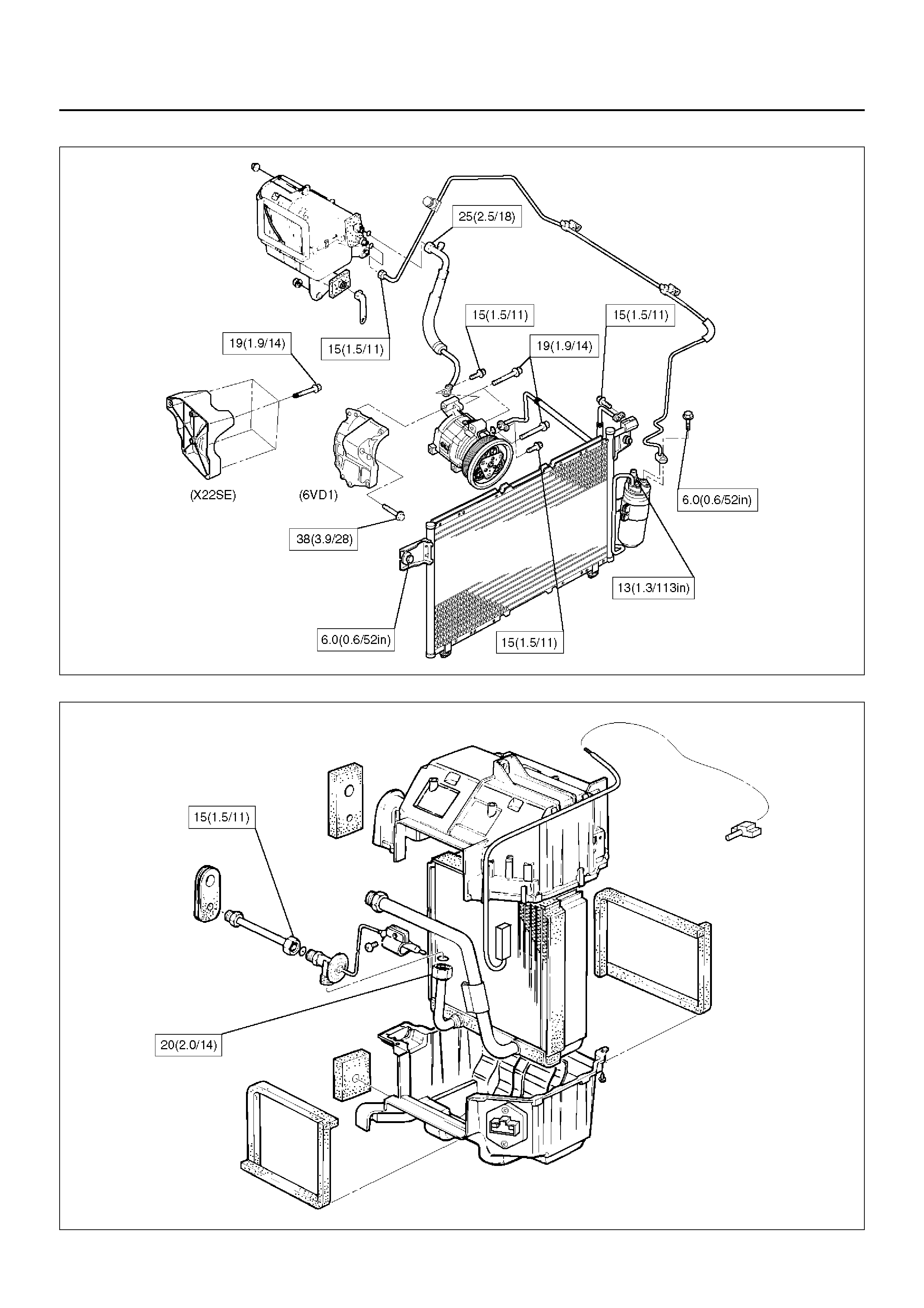
Torque Specifications N•m (kg•m/lb ft)
E06RY00007
E06RY00008
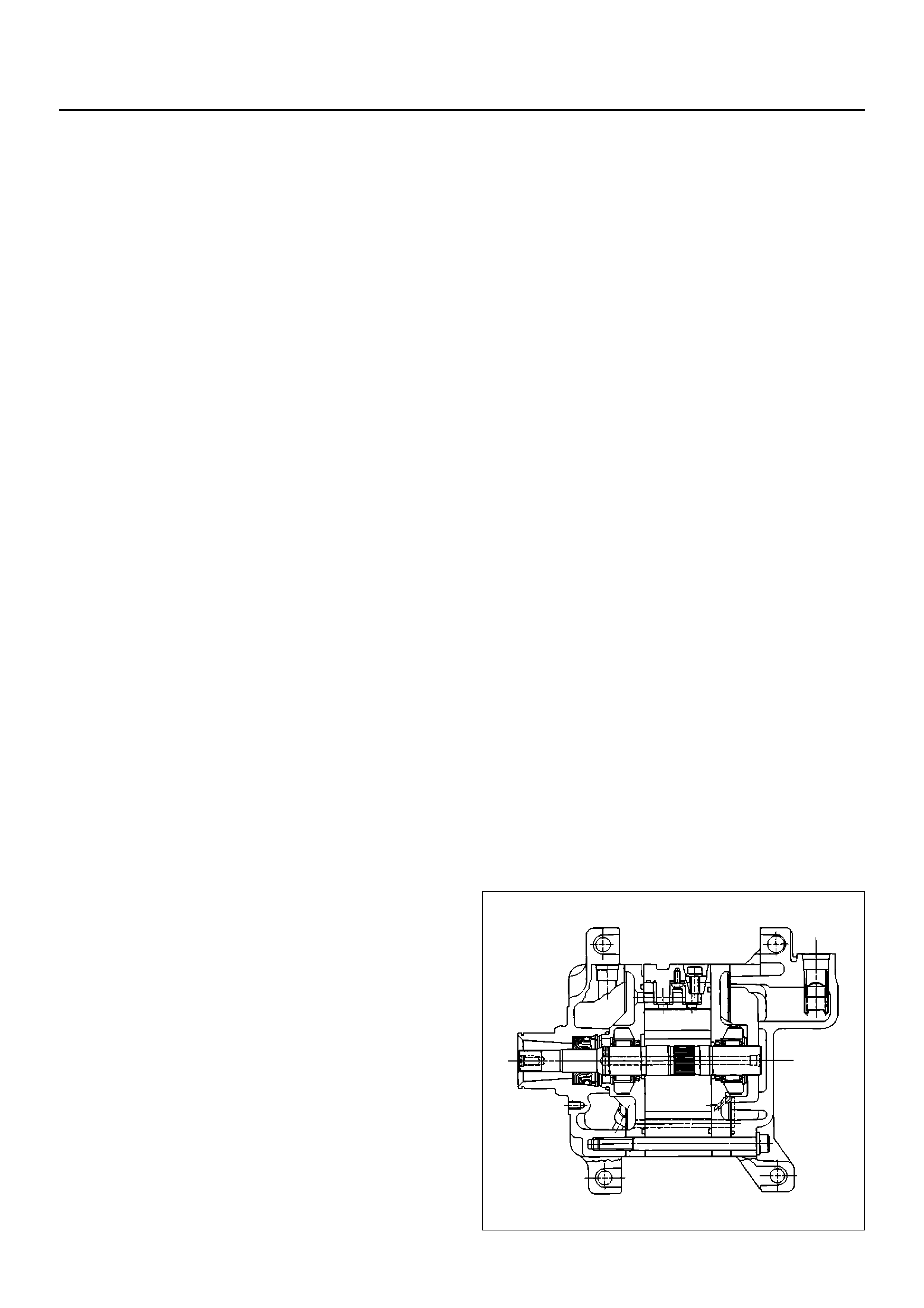
Compressor
Service Precaution
WARNING: This vehicle has a Supplemental
Restraint System (SRS). Refer to the SRSComponent Location View in order to determinewhether you are performing service on or near theSRS components or the SRS wiring. When you areperforming service on or near the SRS componentsor the SRS wiring, refer to the SRS On-Vehicle
Service Information. Failure to follow CAUTIONScould result in possible air bag deployment,personal injury, or otherwise unneeded SRS systemrepairs.
CAUTION: Always use the correct fastener in the
proper location. When you replace a fastener, use
ONLY the exact part number for that application.
ISUZU will call out those fasteners that require a
replacement after removal. ISUZU will also call out
the fasteners that require thread lockers or thread
sealant. UNLESS OTHERWISE SPECIFIED, do not
use supplemental coatings (paints, greases, or
other corrosion inhibitors) on threaded fas teners or
fastener joint interfaces. Generally, such coatings
adversely affect the fastener torque and the joint
c lamping for ce, and may damage the fastener . When
you install fasteners, use the correct tightening
sequence and specifications. Following these
instructions can help you avoid damage to parts
and systems.
General Description
When servicing the compressor, keep dirt or foreign
material from getting on or into the compressor parts
and system. Clean tools and a clean work area are
important for proper service. The compressor
connections and the outside of the compressor should
be cleaned before any "On-Vehicle" repair, or before
removal of the compressor. The parts must be kept
clean at all times and any parts to be reassembled
should be cleaned with Trichloroethane, naphtha,
kerosene, or equivalent solvent, and dried with dry air.
Use only lint free cloths to wipe parts.
The operations described below are based on bench
overhaul with compressor removed from the vehicle,
except as noted. They have been prepared in order of
access ibility of the comp onents. When th e compre ssor
is removed from the vehicle for servicing, the oil
remaining in the compressor should be discarded and
new compressor oil added to the compressor.
Compressor malfunction will appear in one of four ways:
noise, seizure, leakage or low discharge pressure.
Resonant compressor noises are not cause for alarm;
however, irregular noise or rattles may indicate broken
parts or excessive clearances due to wear. To check
seizure, de-energize the magnetic clutch and check to
see if the drive plate can be rotated. If rotation is
impossible, the compressor is seized. Low discharge
pressure may be due to a faulty internal seal of the
compressor, or a restriction in the compressor. Low
discharge pressure may also be due to an insufficient
refrigerant charge or a restriction elsewhere in the
system. These possibilities should be checked prior to
servicing the compressor. If the compressor is
inoperative, but is not seized, check to see if current is
being supplied to the magnetic clutch coil terminals.
The compressor oil used in the HFC-134a system
compressor differs from that used in R-12 systems.
Also, compressor oil to be used varies acco rding to the
compressor model. Be sure to av oid mixing two or more
different types of oil.
If the wrong oil is used, lubrication will be p oor and the
compressor will seize or malfunction.
DKV -1 4G Type Co m pressor
DKV-14G is equipped with five-vane rotary compressor.
These vanes are built into a rotor which is mounted on a
shaft.
When the shaft rotates, the vanes bui lt into the cylinder
block assembly are operated by centrifugal force.
This changes the volume of the spare formed by the
rotor and cylinder, resulting in the intake and
compression of the refrigerant gas. The discharge v alve
and the valve stopper, which protects the discharge
valve, are built into the cylinder block assembly. There
is no suction valve but a shaft seal is insta lled between
the shaft and head; a trigger valve, which applies back
pressure to the vanes, is installed in the cylinder block
and a refrig erant gas temperature sensor is installed in
the front head.
The spec ified quantity of compress or oil is con tained in
the compressor to lubricate the various par ts using the
refrigerant gas discharge pressure.
A01RS003
Diagnosis
Condition Possible cause Correction
Noise from compression Defective rotor/piston Replace compressor/cylinder and
shaft assembly
Defective shaft Replace compressor/cylinder and
shaft assembly
Noise from magnetic clutch Defective bearing Replace magnetic clutch
Defective clutch Replace magnetic clutch
Clearance between drive plate and
pulley not standard Adjust the clearance or replace
magnetic clutch
Insufficient cooling Defective gasket Replace compressor/gasket
Defective rotor/reed valve Replace compressor/valve plate
Defective trigger valve/suction valve Replace compressor/suction valve
Not rotating Defective rotor/piston Replace compressor/cylinder and
shaft assembly
Defective shaft Replace compressor/cylinder and
shaft assembly
Rotating parts seized due to
insufficient oil Replace compressor
Oil and/or gas leakage Defective seal Replace compressor/shaft seal
Defe ctive O-ring Replace
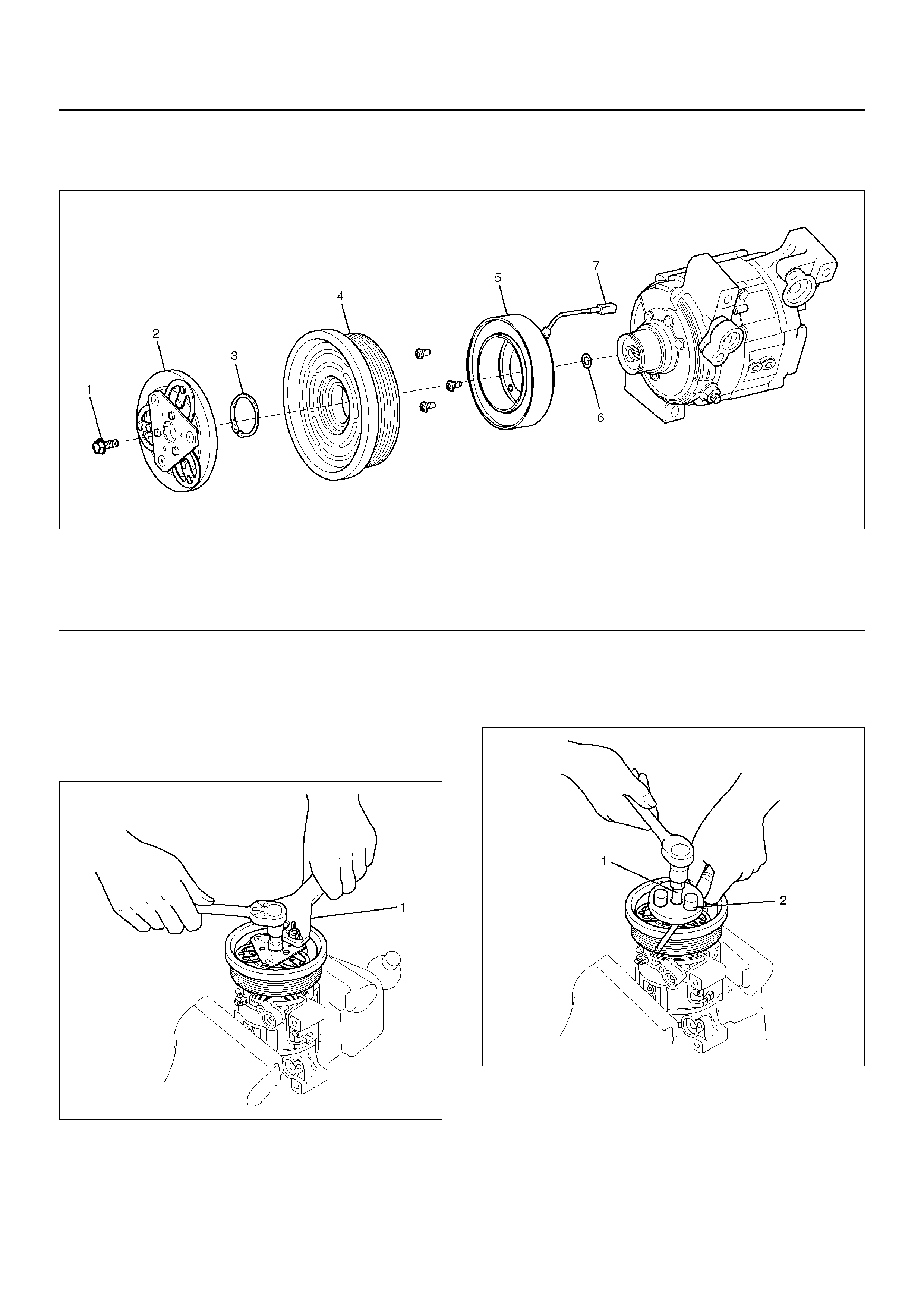
Magnetic Clutch Assembly (DKV-14G Type)
Parts Location View
871RX025
EndOFCallout
Removal
1. Using drive plate holder J-33939 (1) to prevent the
drive plate from rotating, then remove the drive plate
bolt.
871RX029
2. Remove drive plate by using drive plate puller
J-339 44-A (2 ) and forcing screw J-33944-4 (1 ).
871RX023
Legend
(1) Drive Plate bolt
(2) Drive Plate
(3) Snap Ring
(4) Pulley Assembly
(5) Field Coil
(6) Shim (s)
(7) Lead Wire
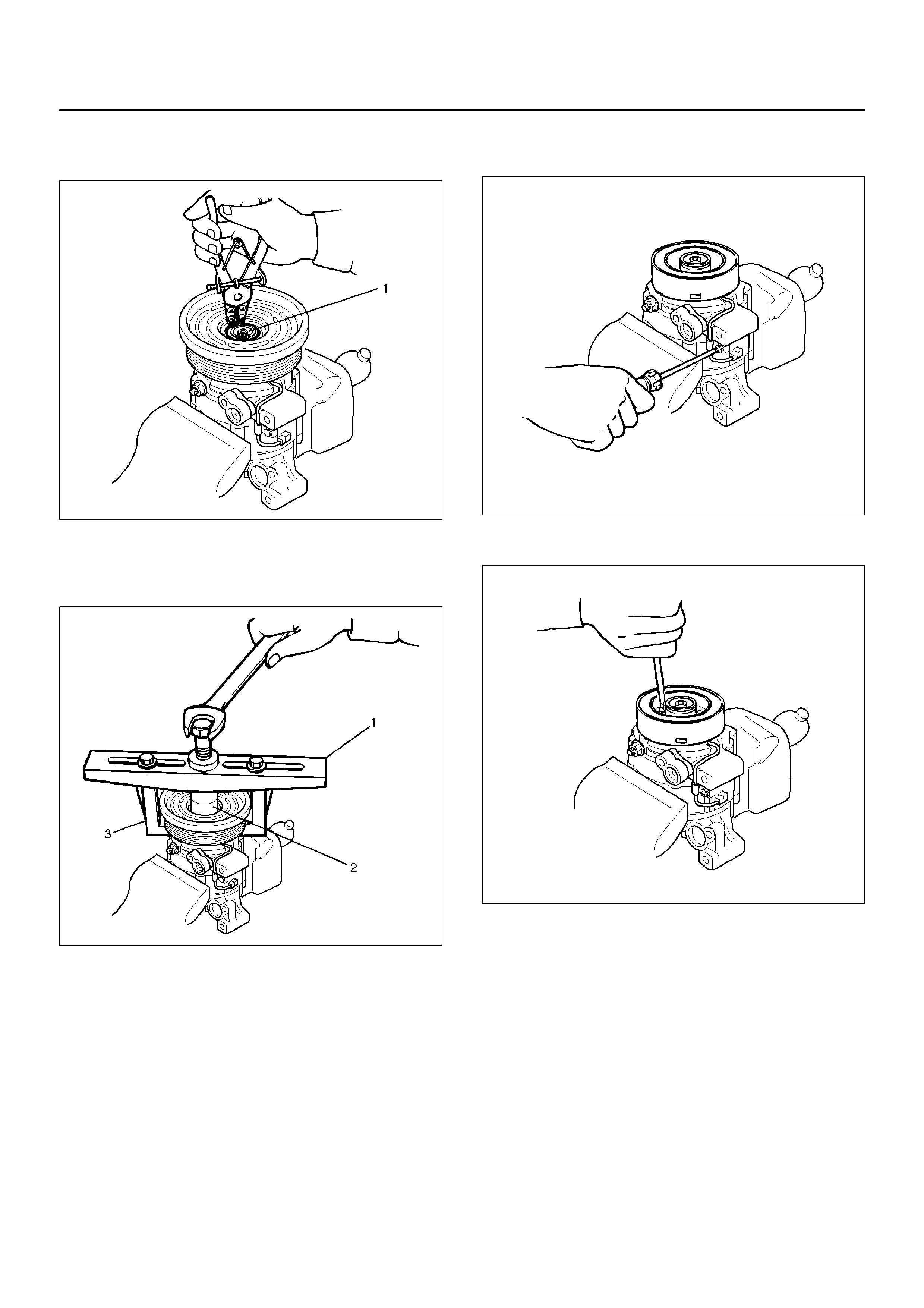
3. Remove shim (s).
4. Remove snap ring (1) by using snap ring pliers.
871RY00029
5. Remove pulley assembly by using pull ey pu ller pi lot
J-384 24(2), pulley pu ller J -843 3(1) a nd pu lley pull er
leg J-24092-2(3).
871RY00033
6. Loosen screw and disconnect the field coil wire
connector.
871RY00030
7. Loosen three screws and remove the field coil.
871RY00034
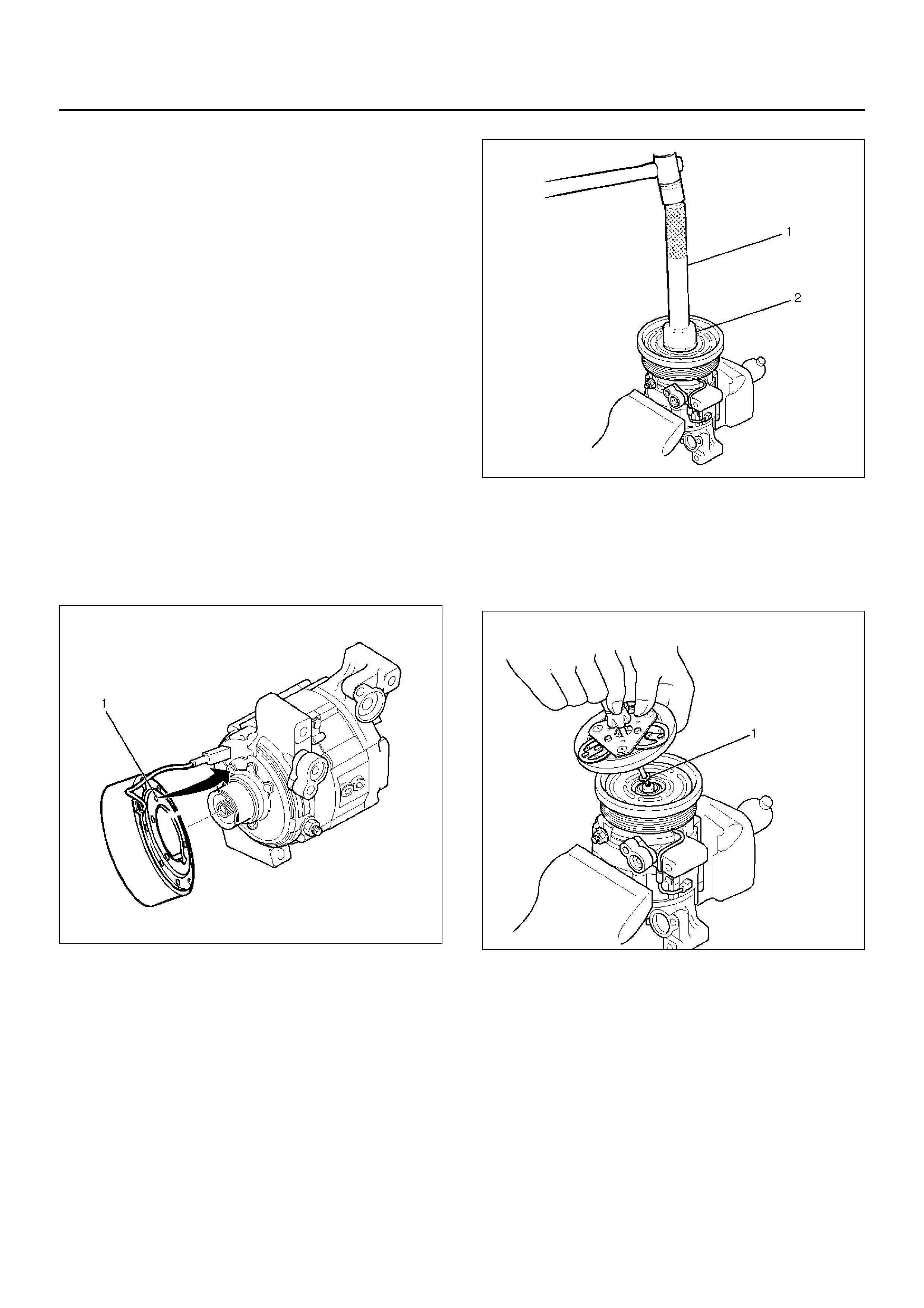
Inspection and Repair
Drive Pla te
If the frictional surface shows signs of damage due to
excessive heat, the drive plate and pulley should be
replaced.
Pulley Asse mbly
Check the appearance of the pulley assembly. If the
fric tional surface of the pulley shows signs o f excess ive
grooving due to slippage, both the pulley and drive plate
should be replaced. The frictional surfaces of the pulley
assembly should be cleaned with a suitable solvent
before reinstallation.
Coil
Check coil for loose connector or cracked insulation.
Installation
1. Install field coil.
• Align the located portion (1) of the field coil and
compressor.
871RY00035
• Tighten the mounting screw to the specified
torque.
Torque: 5N·m (0.5kg·m/44 lb in)
2. Connect the lead wire connector with the rubber
hold and tighten the screw.
3. Install pulley assembly by using pulley installer
J-339 40-A (2 ) and dr ive handle J-8092( 1).
871RY00032
4. Install snap ring.
5. Install shim (s).
6. Install the drive plate to the compressor drive shaft
together with the original shim(s)(1). Press the drive
plate by hand.
871RY00031
7. Install drive plate bolt by using drive plate holder
J-33939 (1) to prevent the drive plate from rotating.
871RX029
• Tighten the drive plate bolt to the specified
torque.
Torque: 13 N·m (1.3kg·m/113 lb in)
• After tightening the drive plate bolt, check to be
sure the pulley rotates smoothly.
• Check to be sure that the clutch clearance is
between 0.3-0.6 mm (0.01-0.02 in.)
871RY00028
EndOFCallout
• If necessary, install adjusting shim(s).
• Adjusting shims are available in the following
thickness.
Thickness
•0.1 mm (0.0039 in.)
•0.3 mm (0.0118 in.)
•0.5 mm (0.0197 in.)
Legend
(1) Dial Gauge
(2) Pulley Assembly
(3) Field Coil Wire Connector
Compressor Oil
Oil Specification
•The HFC-134a system requires a synthetic (PAG)
compressor oil whereas the R-12 system requires a
mineral compressor oil. The two oils must never be
mixed.
•Compressor (PAG) oil varies according to
compressor model. Be sure to use oil specified for
the model of compressor.
•Always use HFC-134a Vane Rotary Type
Compressor Oil (AIPDN Part No.2-90188-301-0)
Handling of Oil
•The oil should be free from moisture, dust, metal
powder, etc.
•Do not mix with other oil.
•The water content in the oil increases when exposed
to the air. After use, seal oil from air immediately.
(HFC-134a Vane Rotary Compressor Oil absorbs
moisture very easily.)
•The compressor oil must be stored in steel
containers, not in plastic containers.
Compressor Oil Check
The oil used to lubricate the compressor is circulating
with the refrigerant.
Whenever replacing any component of the system or a
large amount of gas leakage occurs, add oil to maintain
the original amount of oil.
Oil Capacity
Capacity total in system: 150cc (5.0 fl.oz)
Compressor (Service parts) charging amount:
150 cc (5.0 fl.oz)
Checking and Adjusting Oil Quantity
for Used Compressor
1.Perform oil return operation. Refer to Oil Return
Operation in this section.
2.Discharge and recover refrigerant and remove the
compressor.
3.Drain the compressor oil and measure the extracted
oil with a measuring cylinder.
871RX020
4.If the amount of oil drained is much less than 90 cc
(3.0 fl. oz.), some refrigerant may have leaked out.
Conduct a leak tests on the connections of each
system, and if necessary, repair or replace faulty
parts.
5.Check the compressor oil contamination. (Refer to
Contamination of Compressor Oil in this section.)
6. Adjust the oil level following the next procedure
below.
7. Install the compressor, then evacuate, charge and
perform the oil return operation.
8. Check system operation.
When it is impossible to preform oil return
operation, the compressor oil should be checked in
the following order:
1. Discharge and recover refrigerant and remove the
compressor.
2. Drain the compressor oil and measure the extracted
oil with a measuring cylinder.
3. Check the oil for contamination.
4. If more than 90 cc (3.0 fl. oz.) of oil is e xtracted from
the compressor, supply the same amount of oil to
the compressor to be installed.
5. If the amount of oi l extracted is le ss than 90 cc (3.0
fl. oz.), recheck the compressor oil in the following
order.
6. Supply 90 cc (3.0 fl. oz.) of oil to the compressor
and install it onto the vehicle.
(Charging Amount) (Collected Amount)
more than 90cc (3.0 fl.oz) same as collected
amount
less than 90 cc (3.0 fl.oz) 90cc (3.0 fl.oz)
7. Evacuate and recharge with the proper amount of
refrigerant.
8. Perform the oil return operation.
9. Remove the compressor and recheck the amount of
oil.
10. Adjust the compressor oil, if necessary.
Checking and Adjusting for
Compressor Replacement
150 cc (5.0 fl.oz.) of oil is charged in compressor
(service parts). So it is necessary to drain the proper
amount of oil from the new compressor.
1. Perform oil return operation.
2. Discharge and recover the refrigerant and remove
the compressor.
3. Drain the compressor oil and measure the extracted
oil.
4. Check the compressor oil for contamination.
5. Adjust the oil level as required.
6. Evacuate, charge and perform the oil return
operation.
7. Check the system operation .
Contamination of Compressor Oil
Unlike engine oil, no cleaning agent is added to the
compressor oil. Even if the compressor runs for a long
peri od of ti me (ap pr oximately one sea so n) , the oil never
becomes contaminated as long as there is nothing
wrong with the compressor or its method of use.
Inspect the extracted oil for any of the following
conditions:
• The capacity of the oil has increased.
• The oil has changed to red.
• Foreign substances, metal powder, etc., are present
in the oil.
If any of these conditions exists, the compressor oil
is contaminated. Whenever contaminated
compressor oil is discovered, the receiver/drier
must be replaced.
Oil Return Operation
There is close affinity between the oil and the
refrigerant. During normal operation, part of the oil
recirculates with the refrigerant in the system. When
checking the amount of oil in the system, or replacing
any compone nt of the system, th e compressor must be
run in advance for oil return operation. The procedure is
as follows:
1. Open all the doors and the engine hood.
2. Start the eng ine a nd air co nditionin g swi tch to “O N"
and set the fan control knob at its highest position.
3. Run the compressor for more than 20 minutes
between 800 and 1,000 r pm in order to ope ra te the
system.
4. Stop the engine.
Replacement of Component Parts
When replacing the system component parts, supply
the following amoun t of oil to the com pon ent parts to be
installed.
(Collected Amount) (Charging Amount)
more than 90 cc (3.0 fl.oz) same as collected
amount
less than 90 cc (3.0 fl.oz) 90 cc (3.0 fl.oz)
(Amount of oil drained
from used compressor) (Draining amount of oil
from new compressor)
less than 90 cc (3.0 fl.oz) Same as drained amount
more than 90 cc (3.0 fl.oz) 90 cc (3.0 fl.oz)
(Component parts to be
installed) (Amount of Oil)
Evaporator 50 cc (1.7 fl. oz.)
Condenser 30 cc (1.0 fl. oz.)
Receiver/dryer 30 cc (1.0 fl. oz.)
Refrigerant line (on e
piece) 10 cc (0.3 fl. oz.)

Main Data and Specifications
General Specifications
COMPRESSOR
Model DKV-14G
Type Vane rotary type
Number of vanes 5
Rotor diameter 64 mm (2.52 in.)
Stroke 8.75 mm (0.34 in.)
Displacement 140 cc (47.3 fl.oz.)
Maximum speed 7,000 rpm (up to 8,400 rpm)
Direction of rotation Clockwise (Front-side view)
Lubrication system Pressure differential type
Lubricant HFC-134a Vane Rotary Type Compressor Oil
Be Equivalent to ZXL 200 PG
150 cc (5.0 fl.oz.)
Refrigerant HFC-134a, 650 g (1.43 lbs.)
Shaft seal Lip type
W eight 3.6 kg
MAGNETIC CL UTCH
Type Electromagnetic single-plate dry clutch
Rated voltage 12 Volts D.C.
Current consumption 3.7 A
Starting torque 49 N·m (36 lb·ft)
Direction of rotation Clockwise (Front-side view)
W eight 2.4 kg (5.3 lbs.)
Torque Specifications
N·m (kg·m/lb in)
871RY00038
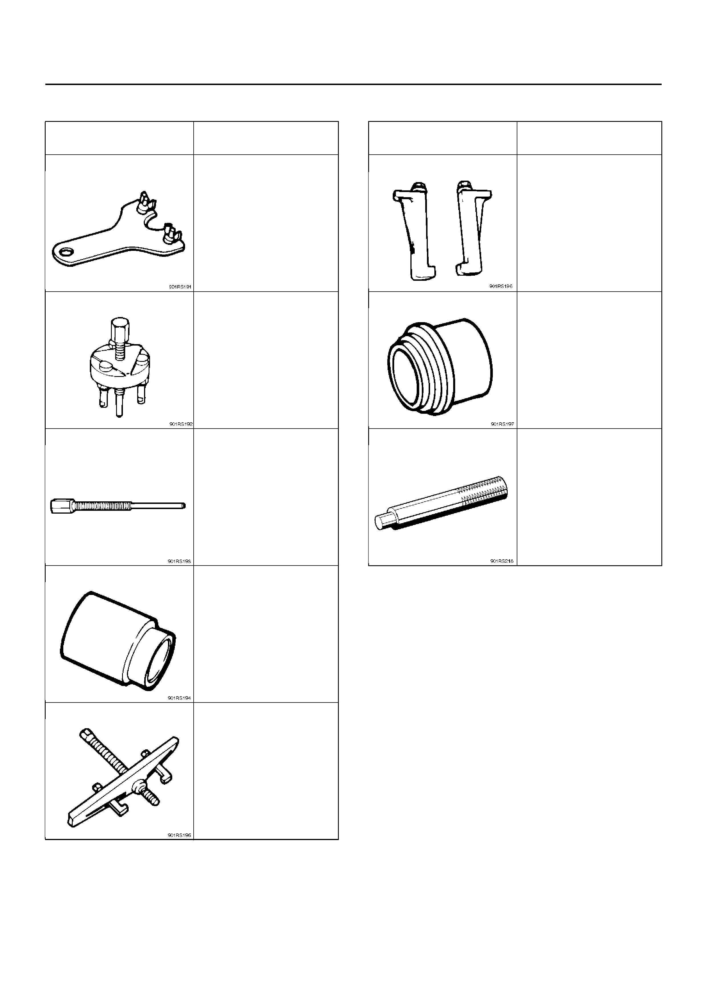
Special Tools
ILLUSTRATION TOOL NO.
TOOL NAME
J-33939
Dri ve plate holder
J-33944-A
Dri ve plate puller
J-33944-4
Forcing screw
J-38424
Pulley puller pilot
J-8433
Pulley puller
J-24092-2
Pulley puller leg
J-33940-A
Pulley inst aller
J-8092
Drive handle
ILLUSTRATION TOOL NO.
TOOL NAME
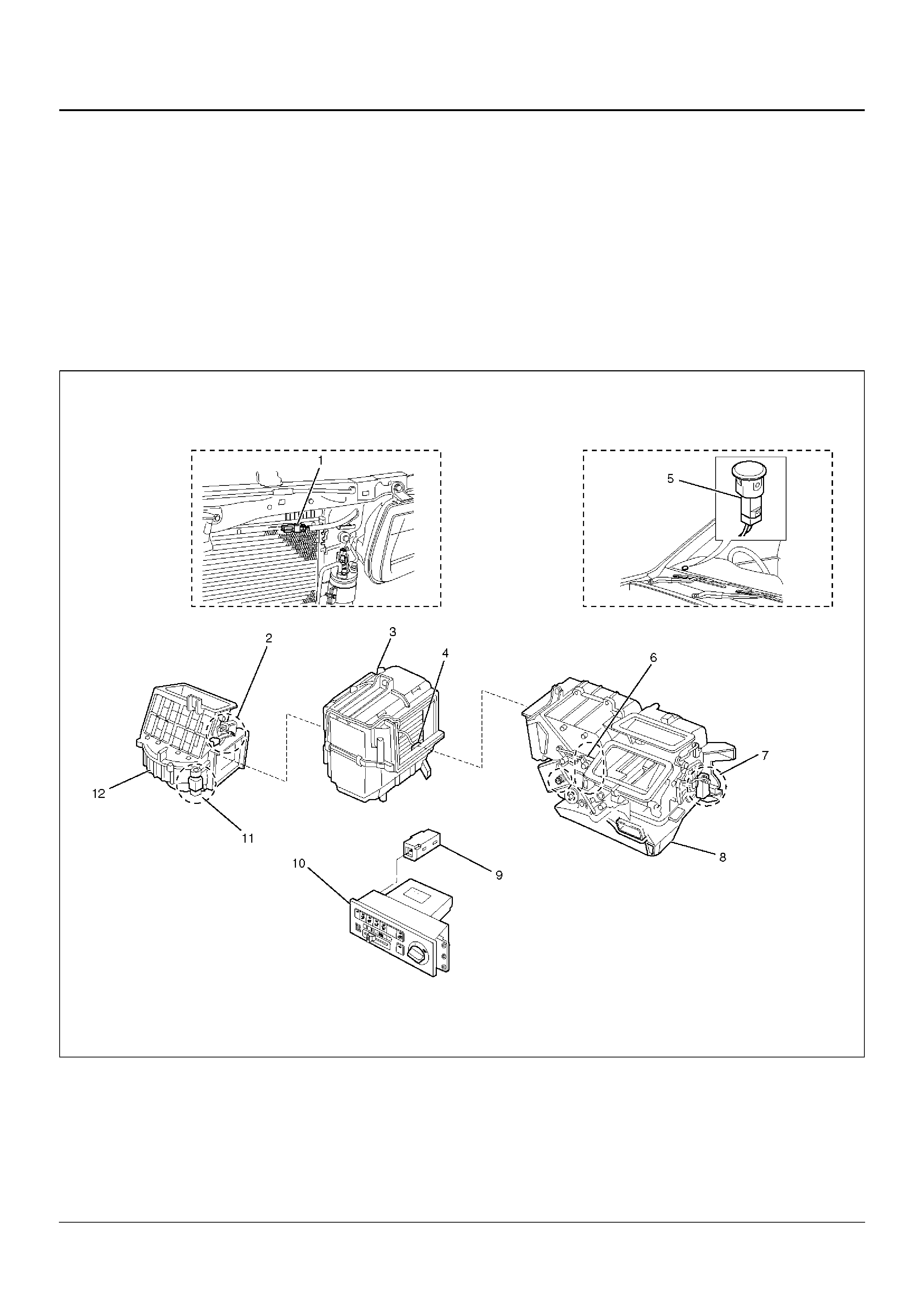
Automatic Air Conditioning System
General Description
Using a variety of sensors, this automatic heater and air
conditioner accurately senses outside air temperature,
solar radiation quantity, evaporator's blowing
temperature, and interior temperature, then enters
these data to the automatic heater/air conditioner
control unit (equippe d with the built-in micro-co mputer).
The data provided to the control unit enables to
automatically control blow temperature and blow air
quantity, turn on or off the compressor and switch the
blow port as well as switching between the fresh air
intake and interior air circulation.
Resetti ng the automati c function allows you to switch to
the manual control mode.
The sel f-di agno is is f unc ti on of t he auto mat ic he ate r and
air conditioner control unit (with the built-in micro-
computer) allows the unit to access and diagnose a
failed part easier and quicker.
Automatic Air Conditioner Parts Configuration
865RY00025
EndOFCallout
Legend
(1) Ambient Sensor
(2) Intake Actuator
(3) Evaporator Assembly
(4) Duct Sensor
(5) Sun Sensor
(6) Mix Actuator
(7) Mode Actuator
(8) Heater Unit
(9) In Car Sensor
(10) Automatic Air Conditioner Control Unit
(11) Max – High Relay
(12) Blower Unit
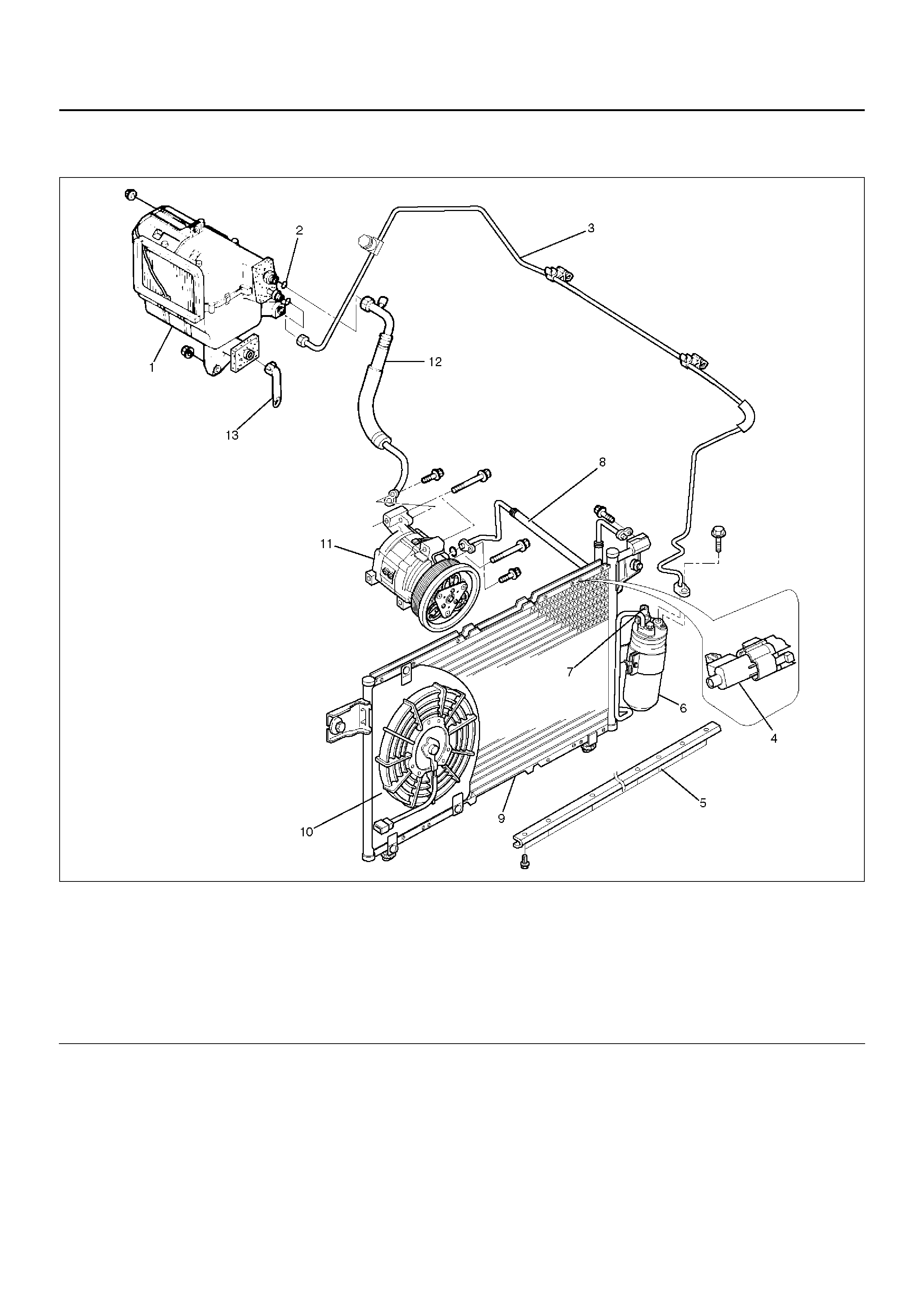
Refrigerant Line and Associated Parts
852RY00035
EndOFCallout
Legend
(1) Evapolator Assembly
(2) O – Ring
(3) Liquid Line (High Pressure Pipe)
(4) Ambient Sensor
(5) Engine Hood Seal
(6) Receiver Dr yer
(7) Pressure Switch
(8) High Pressure Hose
(9) Condenser Asse mbly
(10) Condenser Fan
(11) Compressor
(12) Suction Line (Low Pressure Hose)
(13) Drain Hose

Circuit Diagram
6VD1 Engine
D08RX145
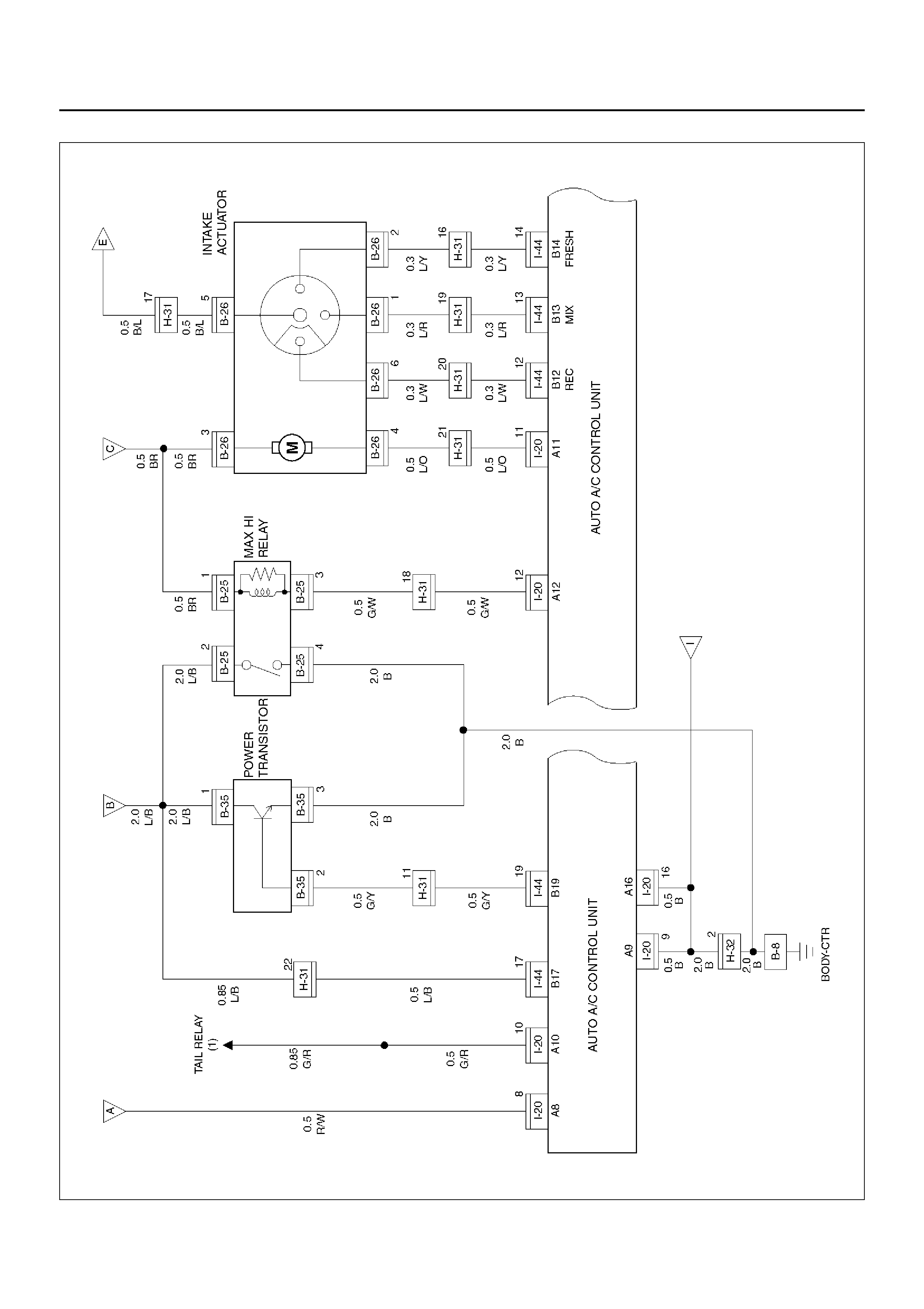
D08RX146
D08RY00885
D08RX148
D08RX144

D08RX143

Functions and Features
Automatic interior temperature control
This function enables to maintain the interior
temperature at the level specified from the
temperature control switch despite of changes in
factors such as vehicle speeds, outside air
temperature and number of passengers.
Maximum cooling and heating function
You can select FC (Full cool, namely maximum cooling
temperature) or FH (Full heat, maximum heating
temperature) from the temperature control lever.
Automatic air flow control
Air flow is automatically and consecutively fine tuned
according to the specified interior temperature and
changes in aperture of the heater unit mix door.
Mode (blow port) control
This function automatically selects either one of the
VENT, BI-LEVEL, FOOT or DEF mode for the blow
port according to changes of temperature on the
blow port. Using the mode switch allows you to
select a desired blow port manually.
Intake (switching between the fresh air intake and
circulation of interior air) control
The intake (switching between fresh air intake and
circulation of interior air) mode automatically selects
either FRESH (fresh air intake), MIX or RECIRC
(interior air circulation) according to changes of the
blow port temperature. Using the intake switch
allows you to select a desired intake port manually
(in the manual operation, FRESH and RECIRC
modes alone are available). Pressing the DEF
(defrost) mode switch selects the FRESH (fresh air
intake).
Cooler start-up timing control
This function is used for maintaining the air flow at
“LOW" level until the evaporator is sufficiently cooled
down. It is intended to prevent a large volume of hot
air being blowing into inside of a vehicle when the
cooler is turned on in hot summer season.
Heater start-up timing control
This function is used for maintained the air flow at
“LOW" level and also for maintaining the defrost
mode until temperature of coolant in the heater core
is sufficiently heated. It is intended to prevent a large
volume of cool air being blown into inside of a vehicle
when the heater is turned on in cold winter season.
Solar radiation quantity offset control
The photodiode on the solar radiation sensor
determines solar radiation quantity accurately to
offset interior temperature quickly.
Switch position storing function
This function is used for storing switch positions being
selected in the immediately preceding operation,
namely the last time the ignition has been turned off.
It simplifies the setup procedures when restarting the
system.
Self-diagnosis function
The self-diagnosis function turned on from the panel
switch makes your troubleshooting easier (for detail
of this function, refer to the section titled
“Self-Diagnosis").
Automatic Air Conditioner Block Diagram
F01RY00006
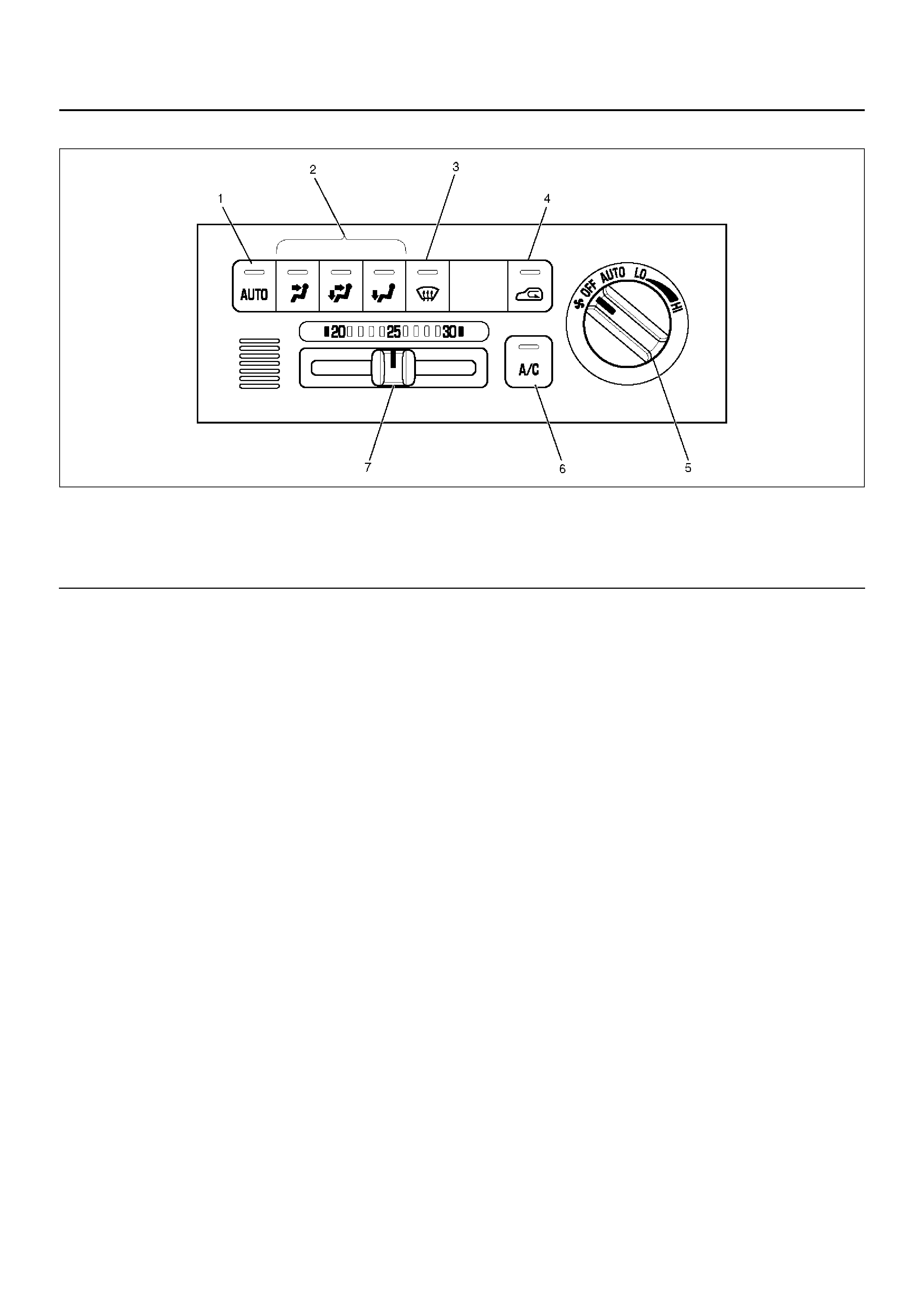
Control Panel Layout
C01RW007
EndOFCallout
Legend
(1) Auto Switch
(2) Mode Switch
(3) DEF Switch
(4) Intake Switch
(5) Fan Switch
(6) Air Conditioning Switch
(7) Temperature Control Knob

Air Control Functions
C01RX002
EndOFCallout
Legend
(1) Interior Air Intake
(2) Fresh Air Intake
(3) Evaporator Core
(4) Air Mix Door
(5) DEF Door
(6) VENT Door
(7) Foot Door
(8) Sub Air Mix Door
(9) Heater Unit
(10) Heater Core
(11) Evaporator Unit
(12) Blower Unit
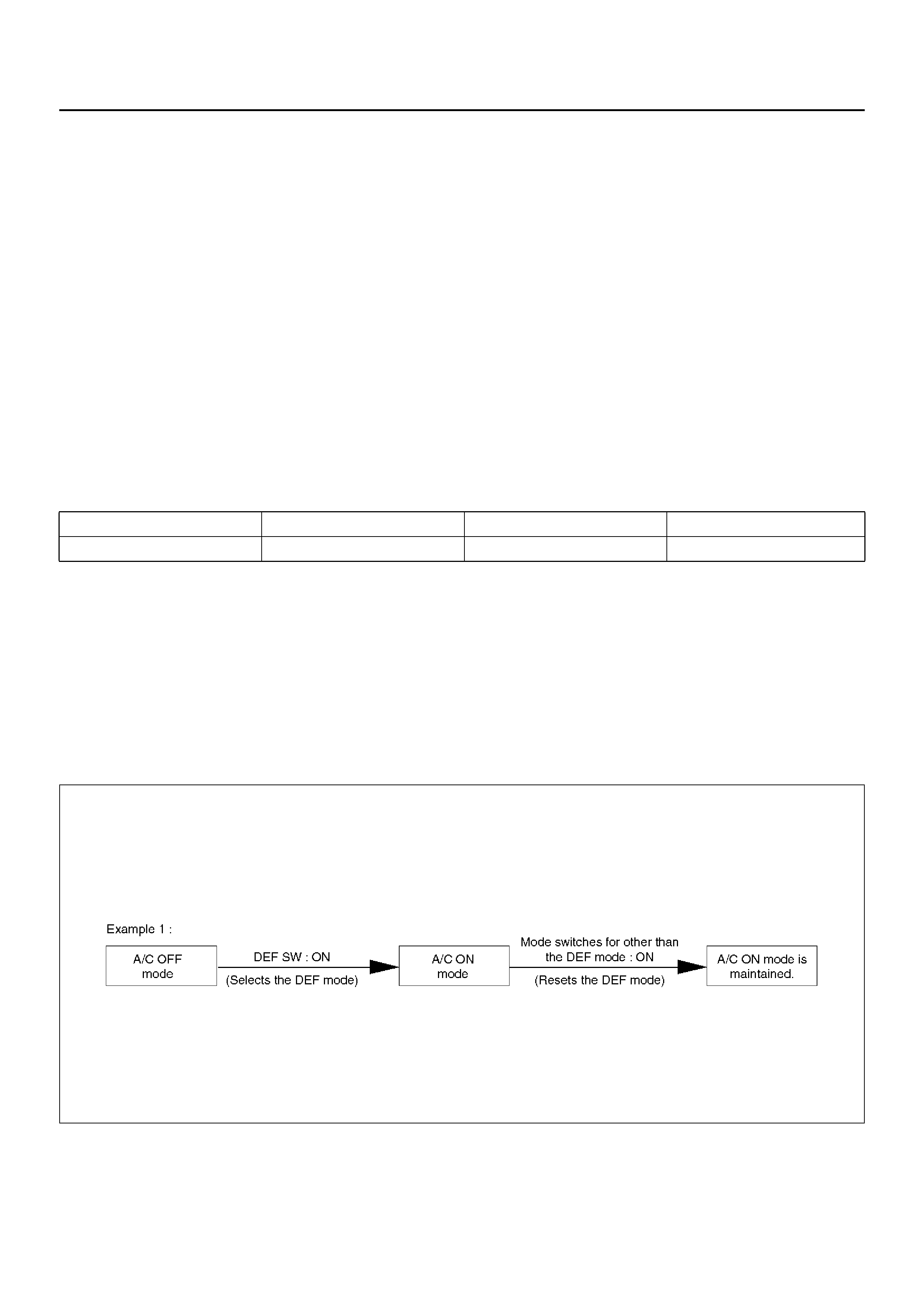
Operation and Functions of Control Panel Switches
Auto Switch
1. Pressing this switch turns on the automatic control
mode. It resets all manual switches except that for
the fan control. However, when the Manual REC is
selected for the intake or the Manual Open is
selected, the modes are maintained.
2. It causes the A/C (air conditioner) to the ON mode
(this function, however, available only when the fan
is turned on and also the compressor is turned on
because of the given outside air temperature level).
Indication
• The AUTO LED comes on.
• Curren tly s elected mod e fo r the Mod e and In take are
respecti vely indicate d.
• The A/C LED remains turned on even if the
compressor has been turned off because of the given
outside air temperature level. Pressing the air
conditioning switch in this state turns off the A/C LED .
Mode Switch
1. Pressi ng the VE NT, B/L or FO OT switc h selects the
corresponding mode.
2. When th e Auto is selec ted for the Mode and Intake,
pressing the mode switch fixes the Intake to the
immedi atel y prec edi ng sta tus.
Indication
• Turns off the Auto LED.
• Currently selected blow port is indicated.
DEF Switch
Press this switch to select the DEF mode.
*1: When the manual REC is selected for the Intake, the
manual REC is maintained.
*2: The ON mode is enabled only when the fun is turned
on, and also the compressor is turned on because of
the given outside air temperature level.
Indication
• The Auto LED is turned off.
• DEF is indi cat ed for the b lo w port, A/C LED come s on
(only when the fan is turned on), and status display is
provided for the Intake and Cold Air Bypass.
F01RX006
Blow port Intake port A/C MIX
DEF Auto FRESH *1 ON mode *2 Auto
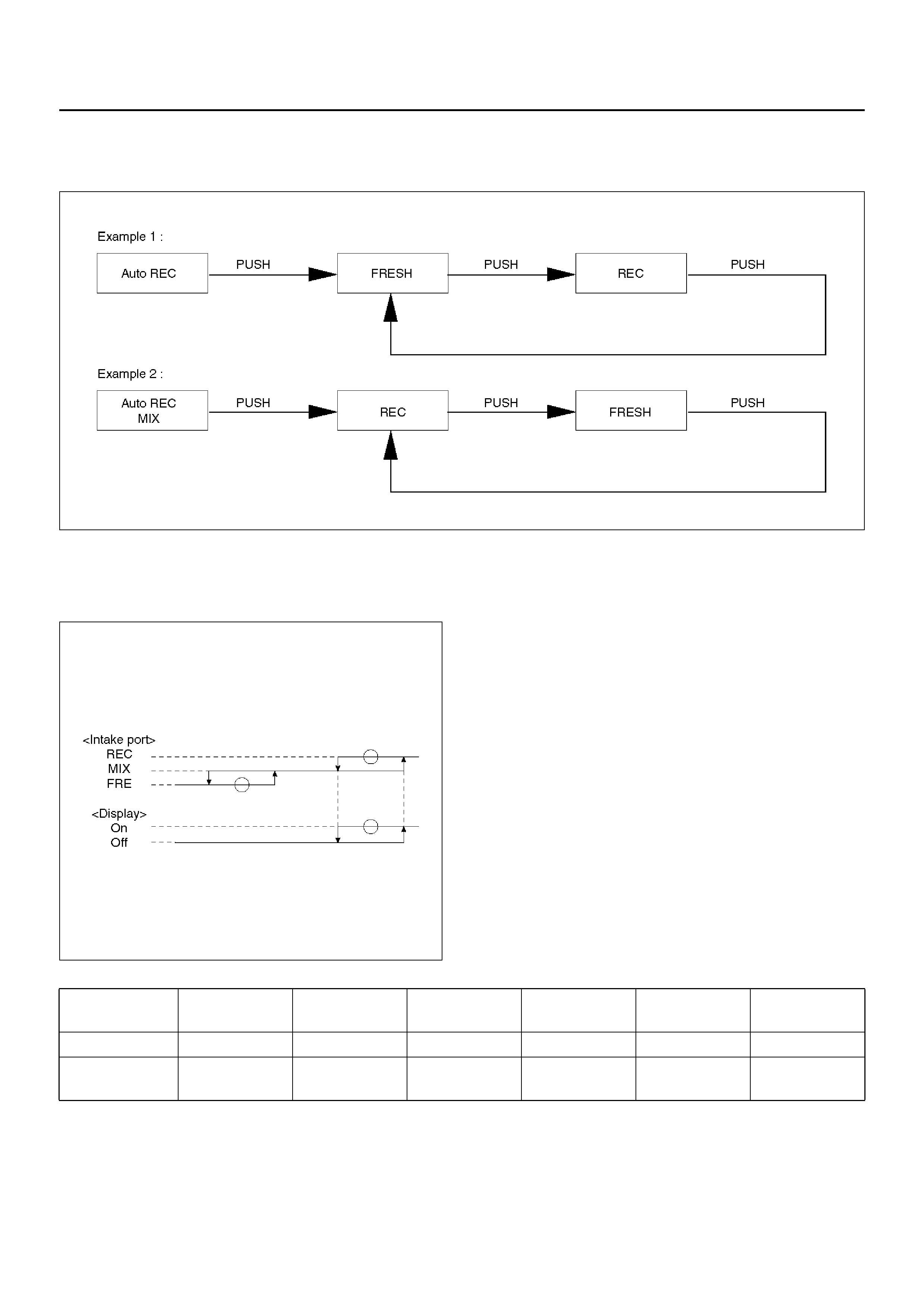
Intake Swit ch
Pressing this switch sequentially selects a different
intake port in the followi ng ord er.
F01RX005
Indication
• The Auto LED maintains unaffected.
• Currently selected intake port is indicated.
F01RX007
Fa n Switch
1. Sets the fan to the specified mode.
2. Even when the fan switch is turned off, status
display for the Mode, Intake and Cold Air Bypass is
maintained.
Temperature Control Knob
1. This knob is operable only when the fan is turned
on. It may be used for the MAX control of each
block except the fan.
2. When the manual mode is selected for the fan
control, this manual mode is maintained.
MAX Control Mix Fan Mode Intake Cold air
bypass A/C
MAX/COOL Full cool MAX/HI VENT REC*1 OPEN*2 ON mode*3
MAX/HEAT Full hot AUTO/HI FOOT*4 FRESH CLOSE Current status
is maintaine d
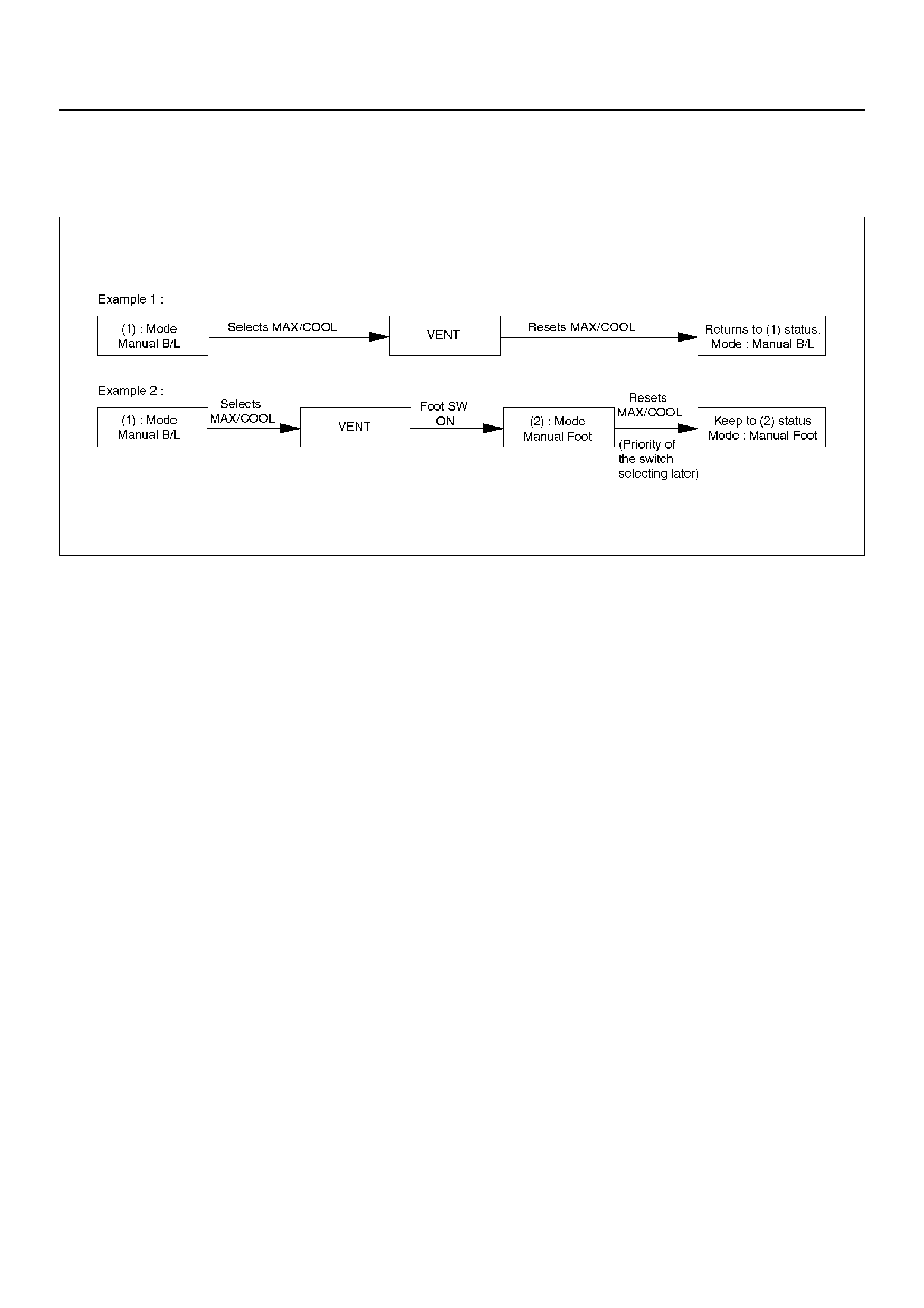
*1: In the A/C: OFF mode, FRESH shall be selected.
*2: When the fan is turned ON, CLOSE shall be
selected.
*3: The ON mo de is avail able only when ON is se lecte d
for the fan as well as for the cold outside air ON/OFF
selection.
*4: When the MAX control is selected from the DEF
mode, this DEF mode shall be maintained.
F01RX008
Indication
• As long as the MAX control is selected, the
immedi ately preced ing indica tio n sh all b e mai ntaine d
for the AUTO.
• Status display is provided for others.
Air Conditioning Switch
Pressing this switch turns on or off the A/C (air
conditio ning) control. (The compressor rema ins tur ned
off if the fan is turned off and also the compressor has
been turned off because of the given outside air
temperature level.)
Indication
1. The A/C LED remains turned on even if the
compressor has been turned off because of the
given outside air temperature level. In this case,
however, the AUTO or DEF switch must be turned
on and the A/C ON mode must also be turned on
(by the MAX/C mode).
2. Pressing the A/C switch from the above state (1)
turns off the A/C LED.
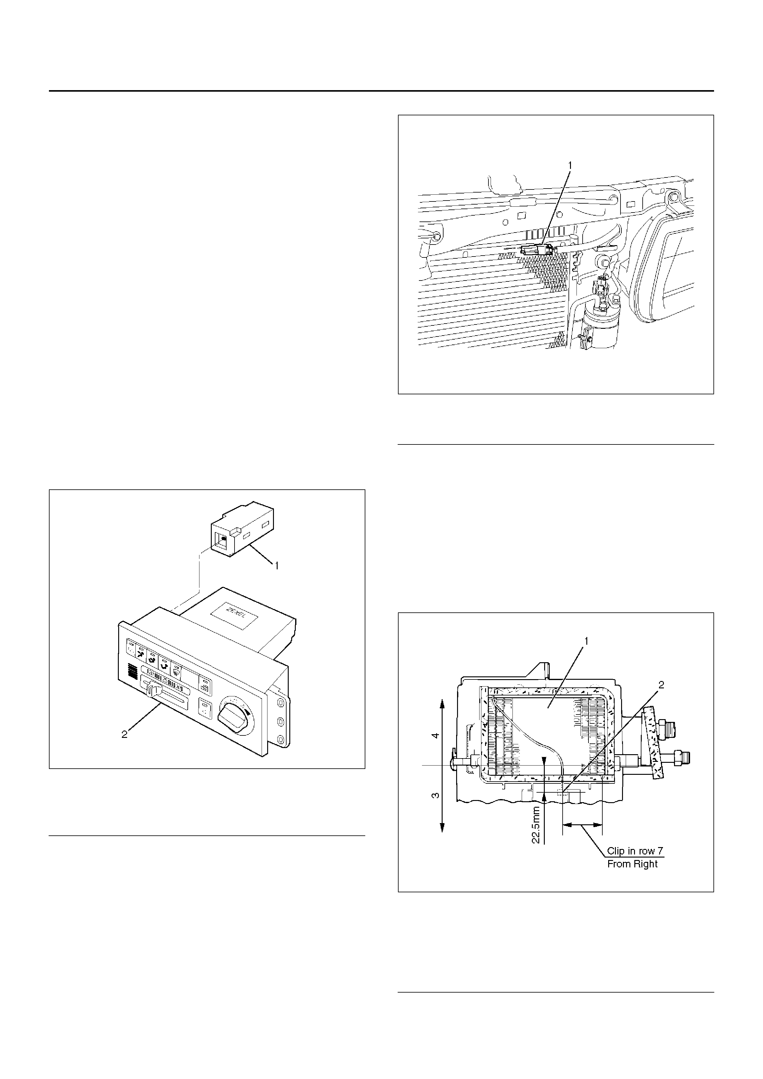
Overview of Construction, Movement
and Control of Major Parts of
Automatic Air Conditioner System
Automatic Heater/Air Conditioner Control
Unit
Equipped with the built-in micro-computer, this control
unit operate s on sig nals from s ensors and input si gnals
from switches to offer total control of the blower fan, and
actuators used for the mode door, intake door and air
mix door.
Its self-diagnosis function enables quicker access to a
failed part and its more accurate troubleshooting.
In Car Sensor
It is a sensor used for detecting room temperature of a
v ehicle. This sensor converts a given room temperature
into a resistance value before entering the data to the
automatic heater/air conditioner control unit.
This in car s ensor un ite s t he p ower dri ven aspirator an d
the motor fan so that a small amount of room air ma y be
constantly fed to the sensor.
This sensor is provided on the control panel.
865RX015
EndOFCallout
Ambient Sensor
This sensor is used for detecting temperature outside
the vehicle. It conver ts a given outside air temperature
into a resistance value before entering the data to the
automatic heater/air conditioner control unit.
Ther mal effects from the conden ser and radiator durin g
idling after a run can be measured and offset the
automatic amplifier.
This sensor is provided on the side plate situated at
upper right side of the condenser.
875RY00021
EndOFCallout
Duct Sensor
The duct sensor is the sensor to detect temperature
change of the side of evaporator blower coming by fresh
recirculation of intake door or “on" “off" of compressor.
The temperature is converted to resistant rate.
And it works as thermostat to control to prevent freezing
of evaporator.
This sensor is installed in the upper case of evaporator.
874RX014
EndOFCallout
Legend
(1) In Car Sensor
(2) Automatic Air Conditioner Control Unit
Legend
(1) Ambient Sensor
Legend
(1) Evaporator Core
(2) Duct Sensor
(3) Lower C as e
(4) Upper Case
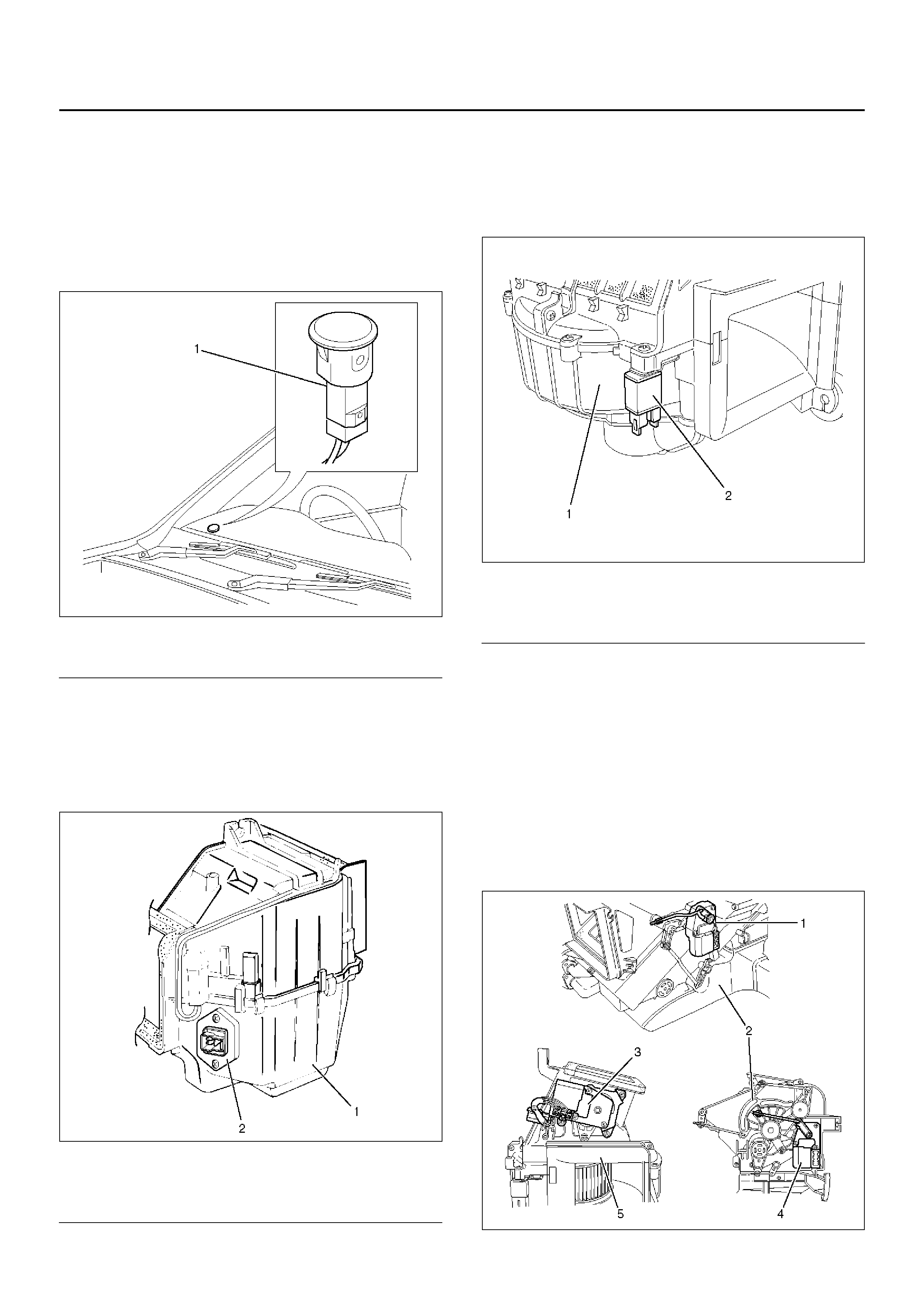
Sun Sensor
It is a photodiode used for detecting quantity of solar
radiation. This sensor converts the offset signal
generated by changes in the interior temperature (which
results from fluctuations in solar radiation) into
photoelectric current to ente r into the automatic heater/
air conditioner control unit.
This sensor is provided at top of the defroster grill.
865RW009
EndOFCallout
Power Transistor
Receiving base current from the automatic heater/air
conditioner control unit, the power transistor implements
stage-less speed change of the blower fan motor. This
transistor is provided on the evaporator.
874RX015
EndOFCallout
Max Hi Relay
This relay turned on or off by the signal from the
automatic heater/air conditioner control unit. As the
Max Hi relay is tur ned on, supply voltage is directly fed
to the blower fan motor to select the Max Hi mode.
860RW028
EndOFCallout
Actuator
The ac tuators are power driven type cont aining a s mall
motor. Receiving output current from the automatic
heater/air conditioner control unit, actuators drive the
heater and blower unit mode doors.
Actuators consist of the mode actuator used for
switching the mode (blow port selection), the mix
actuato r used for chang ing aperture of t he air mi x door,
the intake actuator used for switching the intake
mode(fresh air/interior air) and the cold air bypassing
actuator.
860RW029
Legend
(1) Sun Sensor
Legend
(1) Evaporator Assembly
(2) Power Transistor
Legend
(1) Blower Unit
(2) Max High Relay
EndOFCallout
The actuator changes the motor speed using the gear
and drives each door rotating the output axis united with
the sliding contact.
860RW026
EndOFCallout
The mode and mix actuators are common actuators
with the built-in potentiometer. For the intake actuator,
the contact switch type is selected.
The potentiometer is a register assembled to the printed
circuit board of the mix and mode actuators. It detects
the air mix door position specified by rotation of the
output axis as a ratio of the variable terminal (VM)
voltage against the reference voltage (VDD: 5V), then
signals the value to the automat ic h eater/ air con ditio ner
control unit.
C01RX016
Movement of Mix Actuator
Position of the air mix door is determined by the
controller on the automatic heater/air conditioner control
unit.
As the heat or cool side of the controller is grounded,
the transistor on the driver is activated and, thus, the
motor rotation is turned on. The sliding contact
connected to the motor sends the position detection
signal from the potentiometer to the automatic heater/air
conditioner control unit. As the set temperature and
inter io r temperature a re bal anced , the co ntroller r eturns
to the neutral and the motor rotation is stopped.
C01RX005
Legend
(1) Mix Actuator
(2) Heater Unit
(3) Intake Actuator
(4) Mode Actuator
(5) Blower Unit
Legend
(1) Output Axis
(2) Motor
(3) Printed Circuit Board
(4) Sliding Contact
C-45 Rotation
direction Remarks
(+) side (-) side
8 6 Clockwise Full heat side
68Counter
clockwise Full cool side
Movement of Mode Actuator
As target position of the mode door is decided on the
controller of the control unit, the control unit reads the
position detection signal from the actu ator to select the
clockwise or counter clockwise motor rotation direction.
Grounding the controller VENT or DEF side after the
direction selection activates the transistor on the driver,
thus turning on the motor rotation. Accompanying the
motor rotation, the sliding contact rotates, too. When
the target position is reached, the controller on the
control unit returns to the neutral and the motor stops.
C01RX017
Movement of Intake Actuator
The controller on the automatic heater/air conditioner
control unit selects an intake mode to be used.
As the Terminal No.5 B-26 is grounded via the sliding
contact on the terminal plate, the transistor on the driver
is activated, thus turning on the motor rotation. Then,
accompanying move of the motor, the sliding contact
rotates until grounding of the Terminal No.5 B-26 is
removed, thus stopping the motor.
C01RX006
Overview of Automatic Control of
Automatic Air Conditioner
The automati c heate r and air con ditio ner on this vehicle
has the following features:
• Interior temperature control.
• Air flow control.
• Mode (blow port) control.
• Intake (switching between fresh air and interior air)
control.
• Heater start timing control.
• Cooler start timing control.
• Compressor ON/OFF function according to outside
air temperature level.
• Evaporator anti-freeze control.
Interior Temperature Control
The automatic heater/air conditioner control unit
operates on the setup temperature signal from the
temperature control switch and other sensor signals to
der ive the total si gnal. Then , the contro l unit c ompares
this signal against the signal from the potentiometer to
determine rotation direction of the mix actuator. The
mix actuator moves the air mix door to the aperture
specif ied by the total signal so that the specifie d inter i or
temperature is achi eved.
If the compressor is turned off in the A/C (air
conditioning) mode, aperture of the air mix door is offset
Conduction pin Rotation
direction Remarks
(+) side (-) side
5 1 Clock wise VENT to DEF
direction
1 5 Counter
clockwise DEF to VENT
direction
Grounding
terminal Rotation
direction Remarks
No.5 B-26 Clockwise RE-CIRCULATI
ON→MIX→FRE
SH

according to the outside air temperature or the specified
interior temperature. This function removes the
difference in the blowing temperature in this state and
that of when the compressor is turned on.
When FH or FC is selected for the setup temperature,
the air mix door is accordingly fixed to the Full Heat or
Full Cool mode.
When the VENT mode is selected, aperture of the air
mix door is controlled so that excessiv ely heated air ma y
not be blown from the VENT blow port.
C01RY00015
Air Flow Control
In the Auto Mode
• The automatic heater/air conditioner control unit
operates on the setup temperature signal and other
sensor signals to derive the total signal. Then, the
control unit adjusts base potential of the power
transistor to match it to the voltage pattern of the
target fan so that stage-less fa n spe ed c ontrol can be
achieved.
When solar radiation quantity is detected in the VENT
or B/L mode, the control unit increases the minimum
fan voltage to offset.
When FH or FC is selected from the temperature
contro l switch, air flow is accordi ngly fixed to MAX HI
or AUTO HI.
In the Manual Mode
• Air flow specified from the fan switch is entered to the
automatic heater/air conditioner control unit as the
manual signa l. The s ignal modifie s the air flow to the
level specified from the fan switch so that the required
fan voltage is attained.
C01RY00008
Mode (Blow Port) Control
The automatic heater/air conditioner control unit
operates on the setup temperature from the control
switch, and temperature and solar radiation quantify
from the sensors to determine the total mode control
signal. According to the pattern specified by this signal,
the control unit selects either one of the VENT,
BI-LEVEL, FOOT or DEF/FOOT mode.
The mode actuator determines the rotation direction
comparing the target position against the current
position being determined by the position detection
signal.
When FH or FC is selected fo r the temperature from the
temp erature c on tro l switch, mode is a cc or di ng ly f ixed to
the VENT or FOOT.
• In the manual operation of th e mode switch, you can
select a desired blow port mode pressing the
corresponding mode switch.
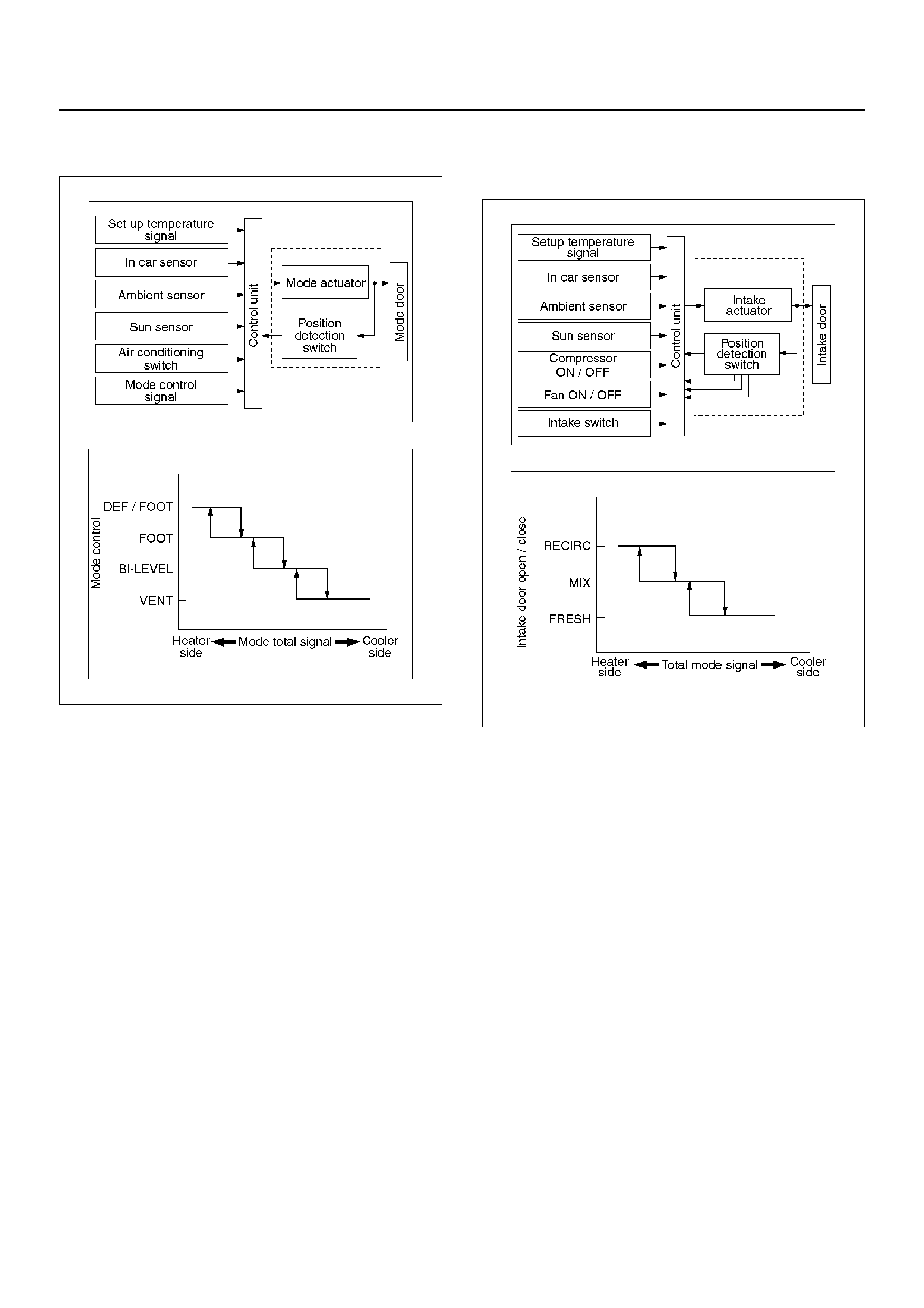
• Operating the DEF mode switch selects the DEF for
the blow port mode.
C01RY00009
Intake (Fresh air/interior air switching)
Control
In the Full Auto mode, the automatic heater/air
conditioner control unit operates on the setup
temperature signal and other sensor input signals to
derive the total signal. According to the pattern
specified by this signal, the control unit provides the
intake control.
When the fan is turned off or the A/C (air conditioning) is
turned off, the intake is fixed to the FRESH mode.
When FC or FH is selected from the contro l switch, th e
intake mode is accordingly fixed to the RECIRC or
FRESH.
In the Manual Operation
• Pressing the FRESH (fresh air intake) or the RECIRC
(room air circulation) accordingly selects the FRESH
or RECIRC mode.
When the DEF Mode Switch is depressed
• The intake mode is fixed to the FRESH. When the
MANU REC is selected, however, the mode is fixed
the RECIRC.
When the Mode Switch is depressed
• If the automatic intake control is selected, the intake
is fixed to the currently selected mode.
C01RY00012
Compressor Control
In the automatic control mode, the automatic heater/air
conditioner control unit turns on or off the compressor
with the evaporator anti-freeze mechanism using the
evaporation sensor. And, when outside air is detected
to be low through the outside air temperature sensor
signal, the control unit turns off the compressor using
the compressor control function.
Ma nu al C o nt ro l
• In the automatic control mode, pressing the A/C (air
conditioning) switch turns off the compressor.
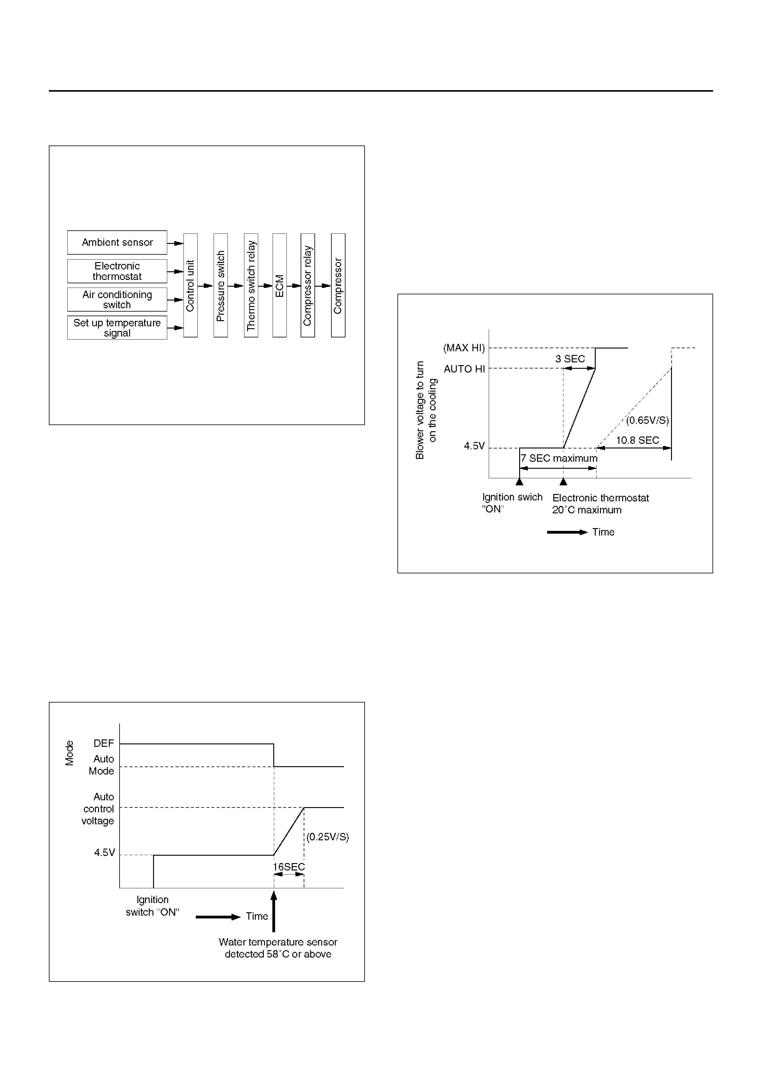
• Pressing the DEF mode switch automatically turns on
the compressor.
C01RY00010
Heating Start Timing Control
When the automatic heater/air conditioner is started,
heating is tur ned on only whe n the coola nt temperature
detected by the coolant temperature sensor is 18°C or
less and total signal derived from the sensor signals has
detected that the heating condition is met.
If the coolant temperature detected by the sensor is
18°C or less, 4.5V is set for the blower fan motor
terminal voltage and the DEF is selected for the blow
port mode.
When the temperature detected by the sensor is above
18°C, the blow port mode is switched to the Auto
Control and the voltage across the blower fan motor
terminal is linearly increased from 4.5V to auto control
voltage (auto airflow).
840RX015
Cooling Star t Timing Control
When the automatic heater/air conditioner is started,
cooling is turned on only when the temperature
detected by the interior temperature sensor is 30°C or
above and the total signal derived from the sensor
signals has detected that the cooling condition is met.
When the cooling condition has been met, the fan
voltage across the blower fan motor terminal is set to
4.5V for 7 seconds maximum, then it is linearly
increased up to the auto airflow level at the rate of 0.6V/
sec.
C06RX003
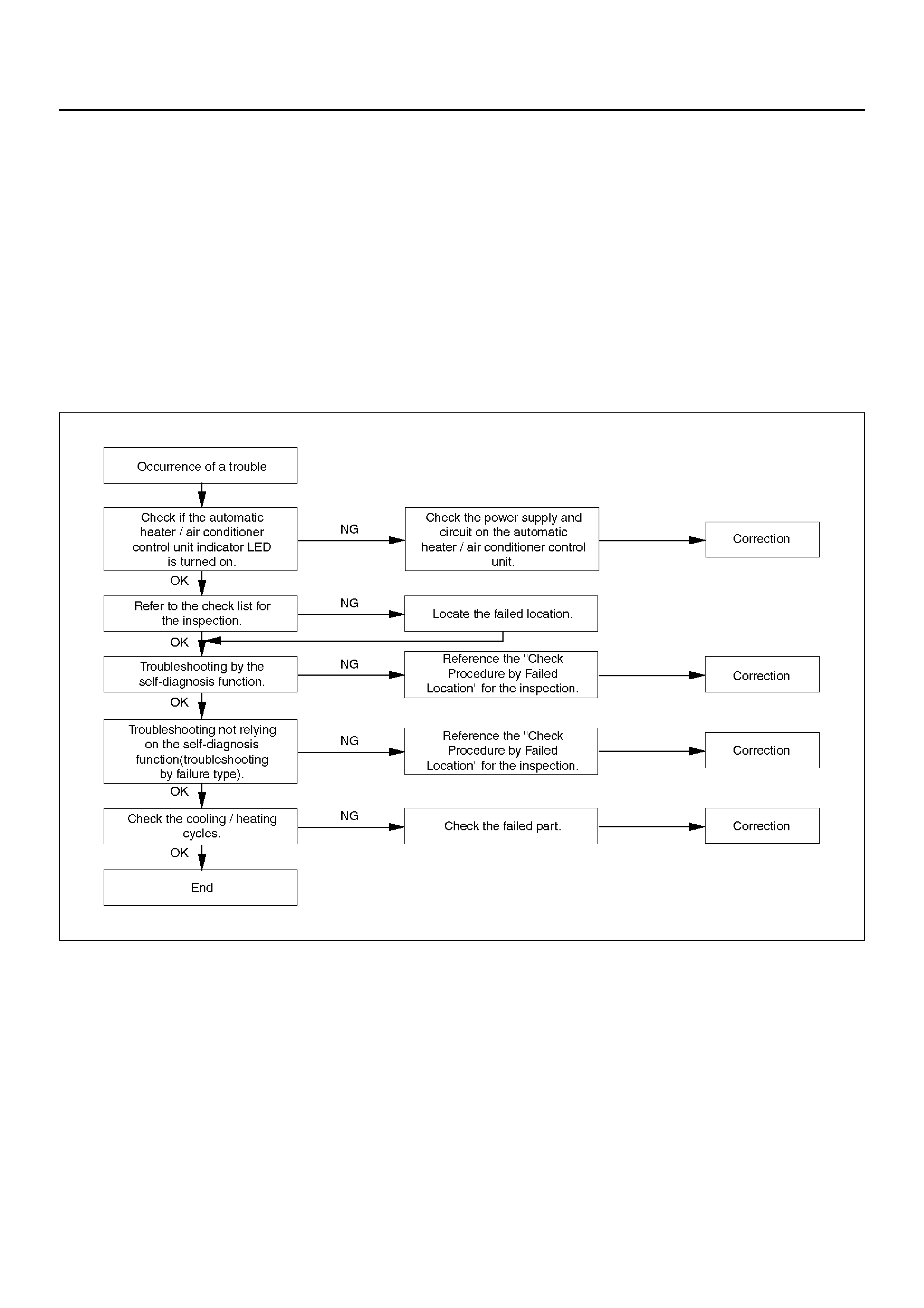
Troubleshooting
Troubleshooting, Its Overview and Procedures
The automatic heater and air conditioner equips with
the “Self-Diagnosis Function" to check its major
components.
This function makes access to the sensors, actuators
and blower fan motor system easier when checking
them up an d, when a failed part is l ocated, th is fu nctio n
restores its original performance.
When implementing the troubleshooting, this
self-diagnosis function narrows the range to be
searche d a t the fir st s tep, then check relevant p arts one
by one according to the “Checking Procedures by Failed
Location". As for a location this function is
unappreciable, the system accurately determines
characteristics of a given trouble and checks relevant
par ts according to the “Checking Procedures by Failed
Location".
The following illustrates basic troubleshooting flow.
Basic Troubleshooting Flow
F01RX009
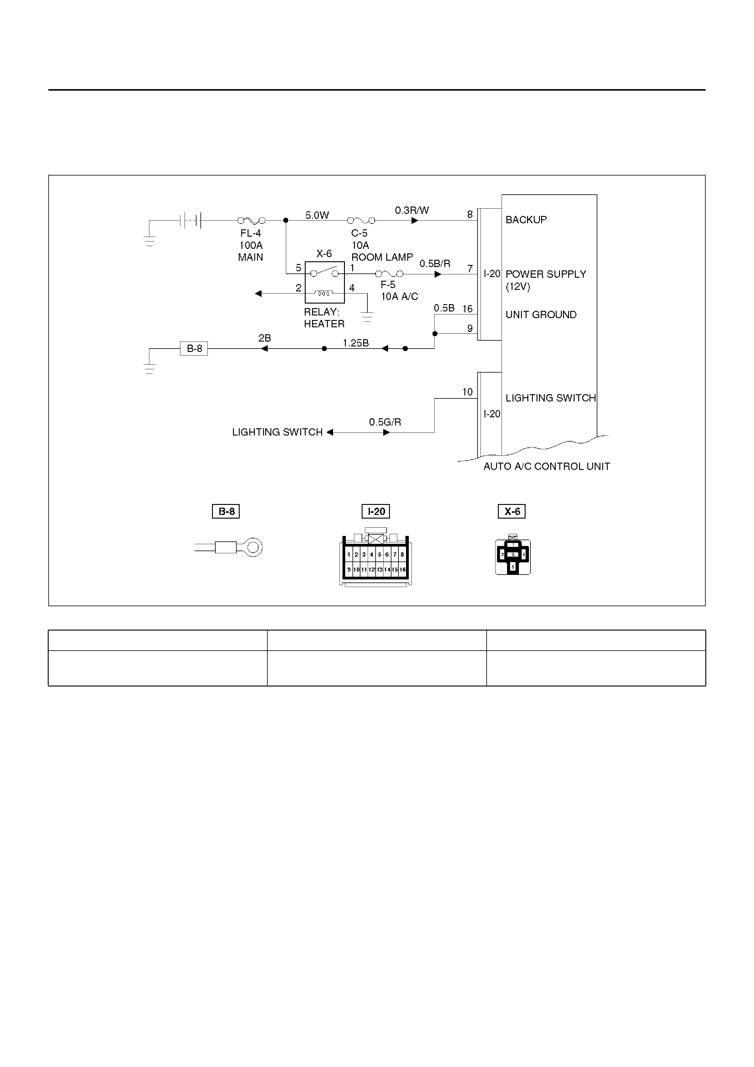
Auto Air Conditioner Control Unit Power Supply Diagnosis
This check is required because a trouble on the auto
amplifie r (contr ol un it) power sup ply cir cuit or gr oundin g
circuit prevents accurate troubleshooting.
D08RX284
Condition Possible cause Correction
P o wer source does not supply to auto
air conditioner control unit. — Refer to Chart A

Chart “A": Check of Auto Amplifier Power Supply System
Step Action Value(s) Yes No
1 Is the fuse C–5 normal? — Go to Step 2 Replace the
fuse
2 Is the fuse F–5 normal? — Go to Step 3 Replace the
fuse
3 Disconnect the auto A/C control unit connector I–20.
Is the battery voltage applied between the harness
side connector terminal No.I20–8 and the ground? Approx. 12V Go to Step 5 Go to Step 4
4 Repair an open circuit between the fuse C–5 and
terminal No.I20–8.
Is the action complete? — Go to Step 4 —
5 Is there continuity between the harness side
connector terminal No.I20–16 and the ground? — Go to Step 7 Go to Step 6
6 Repair an open circuit between terminal No.I20–16
and the ground No.B–8.
Is the action complete? — Go to Step 5 —
7 Is there continuity between the harness side
connector terminal No.I20–9 and the ground? — Go to Step 9 Go to Step 8
8 Repair an open circuit between terminal No.I20–9 and
the ground No.B–8.
Is the action complete? — Go to Step 7 —
9 Tur n the lig hti ng switch on.
Is the battery voltage applied between the harness
side connector terminal No.I20–10 and the ground? Approx. 12V Go to Step 11 Go to Step 10
10 Repair an open circuit between the lighting switch and
terminal No.I20–10.
Is the action complete? — Go to Step 9 —
11 Turn the starter switch on.
Is the battery voltage applied between the harness
side connector terminal No.I20–7 and the ground? Approx. 12V — Go to Step 12
12 Repair an open circuit between the fuse F–5 and
terminal No.I20–7.
Is the action complete? — Verify repair —

Performance and Movement checklist for Automatic Air Conditioner Related
Parts
Star t the eng ine, a nd when the engine coolant reache d
50°C check performance and movement of the related
parts according the following checklist.
Performance Ch eck Using the Manual Switch
No. Item Checki ng Approach Acceptance criteria
Condition Operation
1
Blowing
temperature (check
movement of air
mix door)
Auto switch must be
turned on (FAN-AUTO
MODE-AUTO)
1. Select FC for the
setup temperature.
2. Select FH for the
setup temperature.
→ Then, select the
MAX Control.
1. Cold air shall be blown out.
2. Hot air shall be blown out.
2
Airflow volume
(check movement
of the mode door)
Set temperature to
25.0°C. 1. Turn the fan knob
off.
2. Turn the fan knob
from LOW to HI.
1. The fan shall be stopped, thus
stopping air blow, too.
2. Airflow v olume shall change from
LOW to HI.
3
Blowing
temperature
(check movement
of the mode door)
Set temperature to
25.0°C. Set the fan
knob to HI.
Press the mode switch
to change the blow port
mode sequentially from
the VENT through
BI-LEVEL, FOOT up to
DEF.
LED corresponding to each mode
shall be tur ned on and th e blow por t
mode shall be switched smoothly.
4
The in terior /ou tsi de
air switching mode
(check movement
of intake door)
Set temperature to
25.0°C. Turn the LED off using
the interior/outside air
switch (this introduces
the outside air intake
mode). Then, the set
fan knob to HI and
press the interior/
outside switch to turn
on the LED.
The LED indication shall be s witched
from OFF to ON accompanying a
change in air blowing sound.
5
Compressor Set the temperature to
18.0°C (FC). (Outside
air temperature is 0°C
or above and interior
temperature at ordinary
temperature.)
Press the “OFF" switch.
1. Press the Auto
switch.
2. Press the Air
Conditioner switch.
1. As the fan knob is set to the Auto
position, the A/C switch LED
shall come on and the
compressor shall be t urned on.
2. As the A/C LED comes off, the
compressor shall be t urned off.
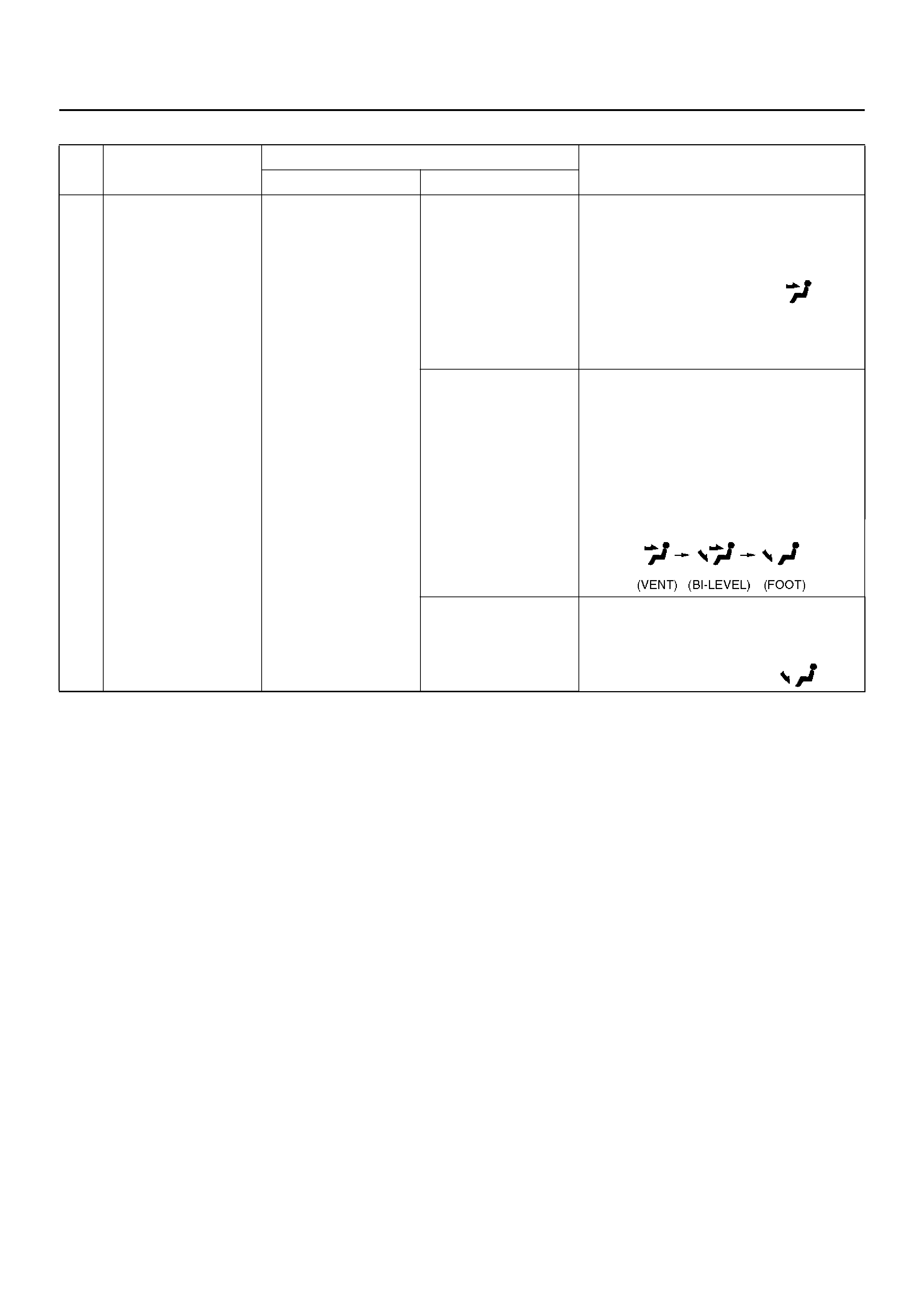
Check of Auto Function
No. Item Checking Approach Acceptance criteria
Condition Operation
1 A uto function FAN KNOB “AUTO"
MODE SW “AUTO"
Select FC for the
temperature.
The LED shall come on.
Cold air shall be blown out.
The following LEDs shall come on:
• Blow port mode:
• Intake mode
• Fan speed: MAX
Hi
•A/C
Change the
temperature
gradually starting
with 18°C up to
32°C.
The following phenomena shall be
recognized.
• Temperature of blown air: Cold air is
changed to hot air.
• Change in the air flow volume.
• The blow port mode LED indication
changes in the following sequence:
Select FH for the
temperature.
Cold air shall be blown out. The
following LEDs shall come on.
• Blow port mode:
• Fan speed: Max.

Troubleshooting With Self-Diagnosis Function
Overview of Self-Diagnosis Function
The self-diagnosis is implemented in 3 steps for each
target. For detail of check procedure contained in each
step, refer to the relevant section of “Check Procedure
by Failed Location" listed in the Self-Diagnosis
Operation Procedure.
For turning on the self-diagnosis function and switching
of the check step, refer to the flow chart given below.
You can reset the self-diagno sis function by tur ning the
ignition switch off or turning the DEF switch on for 5
seconds.
Self-Diagnosis Operation Pr ocedure
Step Action Value(s) Yes No
1 1. Set the IG to the OFF position.
2. Apply 60W bulb light to the solar radiation sensor.
3. Set the tem perat ure s etti ng l ever on the aut oma tic
heater/air conditioner panel to the center position
(25°C).
4. Set the fan switch on the same panel to the Auto
position.
Is the action complete? — Go to Step 2 —
2 While holding both the Auto switch and the DEF
switch on the automatic heater/air conditioner panel,
turn the IG off and then on.
Is the current trouble diagnosing function turned on
approximately in 10 seconds? — Go to Step 3 —
3 Does the A/C LED flash every 0.5 second interval? — Go to Step 4 Refer to *1.
4 Press the A/C switch once.
Does the A/C LED flash every 0.5 second interval? — Go to Step 5 Refer to *2.
5 Refer to *3 chart “Check of Output Equipment".
Does each output equipment function normally
according to operation of the temperature setting
level?
— Go to Step 6
Repair or
replace the
output
equipment or
repair the
harness
6 Press the DEF switch for 5 seconds consecutively or
turn on and off the IG.
Is the action complete? — Go to Step 1 —
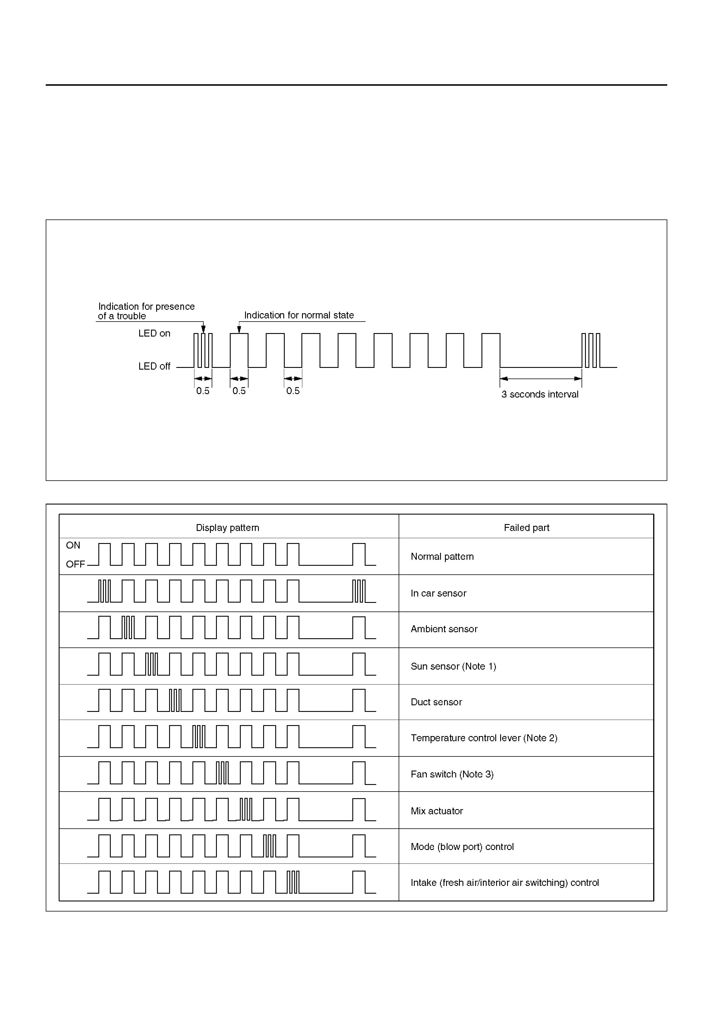
*1Displaying the Current Trouble Diagnosing Table
Start the engine while holding down both the Auto
switch and the DEF switch on the control panel, and the
table will appear in approximately 10 seconds to the
indicator lamp (LED) of the air conditioning switch.
Result of the diagnosis along the following 9 items will
be shown on e by one in 0.5 se con d i nte rval irre sp ec tive
of presence or absence of a trouble for a given item.
When the display 9 items is completed, it is repeated
with 3 seconds of interval in between. A failed item is
indicated by flashing of the LED that is repeated 3 times
within 0.5 seconds. If a trouble is indicated, you can
locate the failed section by knowing when in the total
sequence it has been displayed.
F01RX010
Item for Current Trouble Diagnosis
F01RY00008
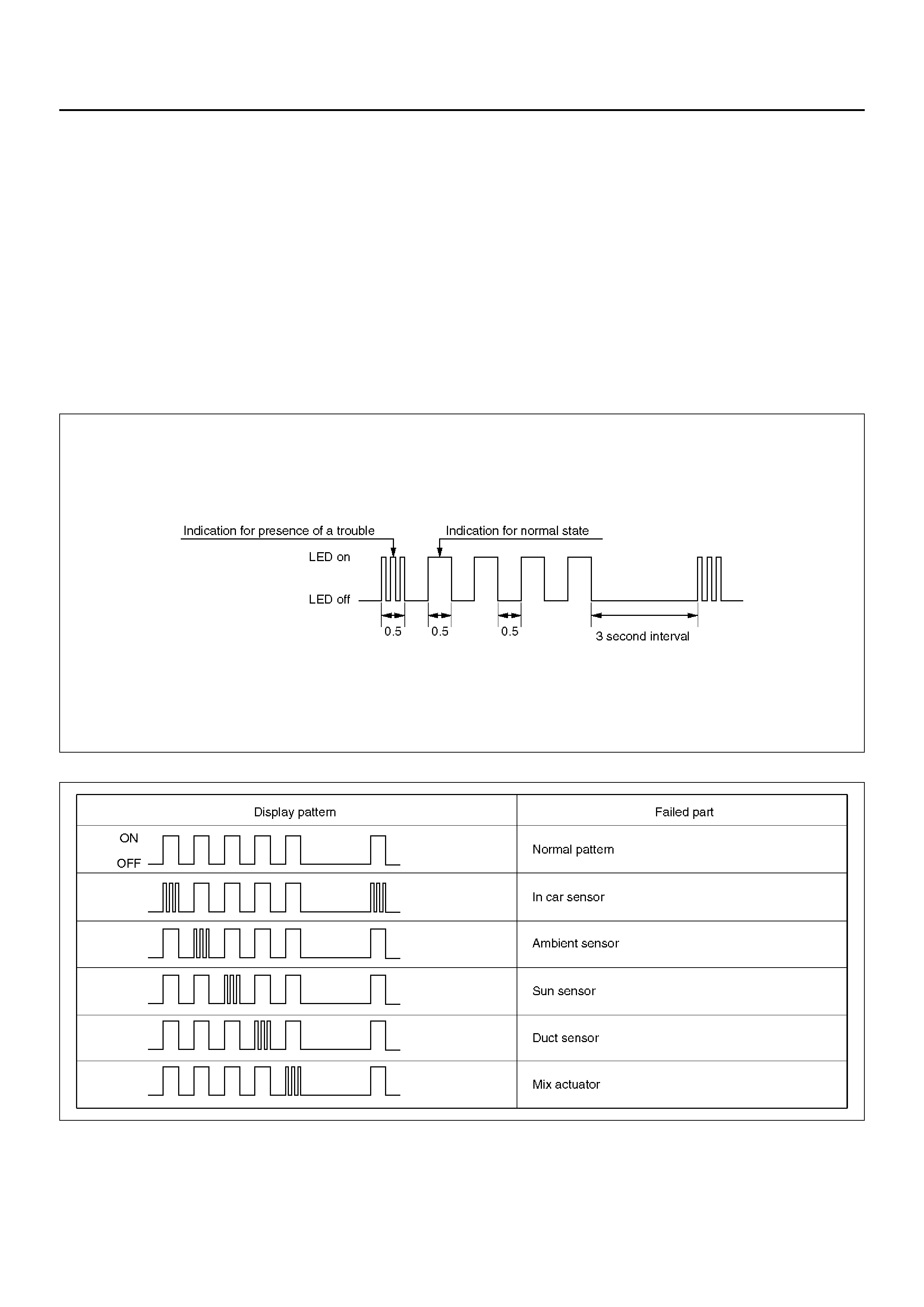
As shown above, display of result along nine items is
repeated with 3-seco nd inte rval in between.
Note 1: When checking the solar radiation sensor, apply
sufficient light using a 60W bulb. Otherwise, it can be
diagnosed as failed.
Note 2: If the temperature setting lever is set on both
ends (one set to 18°C, blue scale = Full cool and the
other to 31°C, red scale = Full hot), they can be
diagnosed as failed.
Note 3: Likewise, the fan switch can be diagnosed as
failed if set on both ends.
*2Displaying the Past Trouble Diagnosing Table
The past trouble diagnosis displays only the items on
which trouble has recurred 16 times in the past.
If you press the air conditioning switch once while the
current trouble diagnosis is taking place, display of the
past trouble dia gnosis will appear on the indic ator lamp
(LED) of the air conditioning switch.
Results of the diagnosis along the following five items
are displayed one by one in 0.5 second interval
irres pect iv e of pres ence or abs enc e of a t r oub le . A failed
item i s indi cated by flash ing o f the LED that i s repe ated
3 times within 0.5 seconds. You can locate the failed
section by counting in what sequence it has been
displayed.
F01RX011
F01RY00007
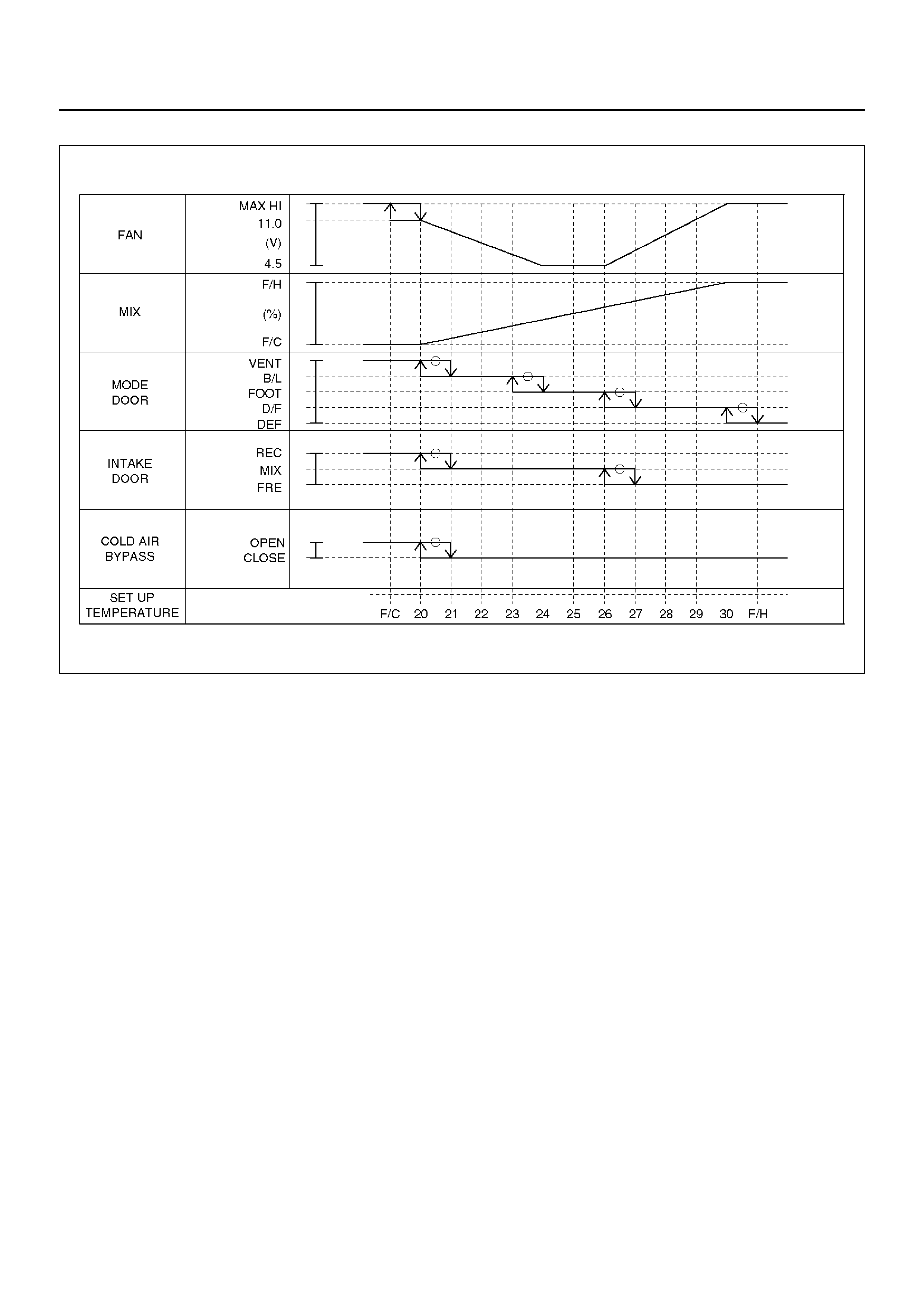
*3Check of Output Equipment
F01RX015
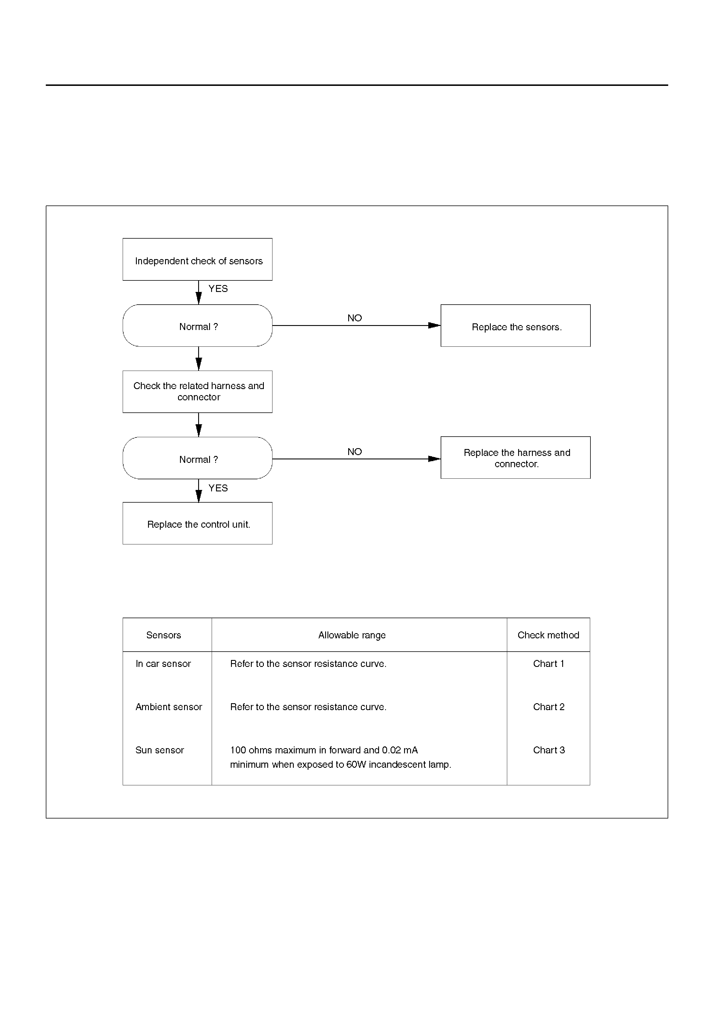
Inspection By Failed Location
Inspection of the Sensors
When the self-diagnosis function has determined that
trouble is present on the sensors, check them according
to the following flow chart.
F01RY00005
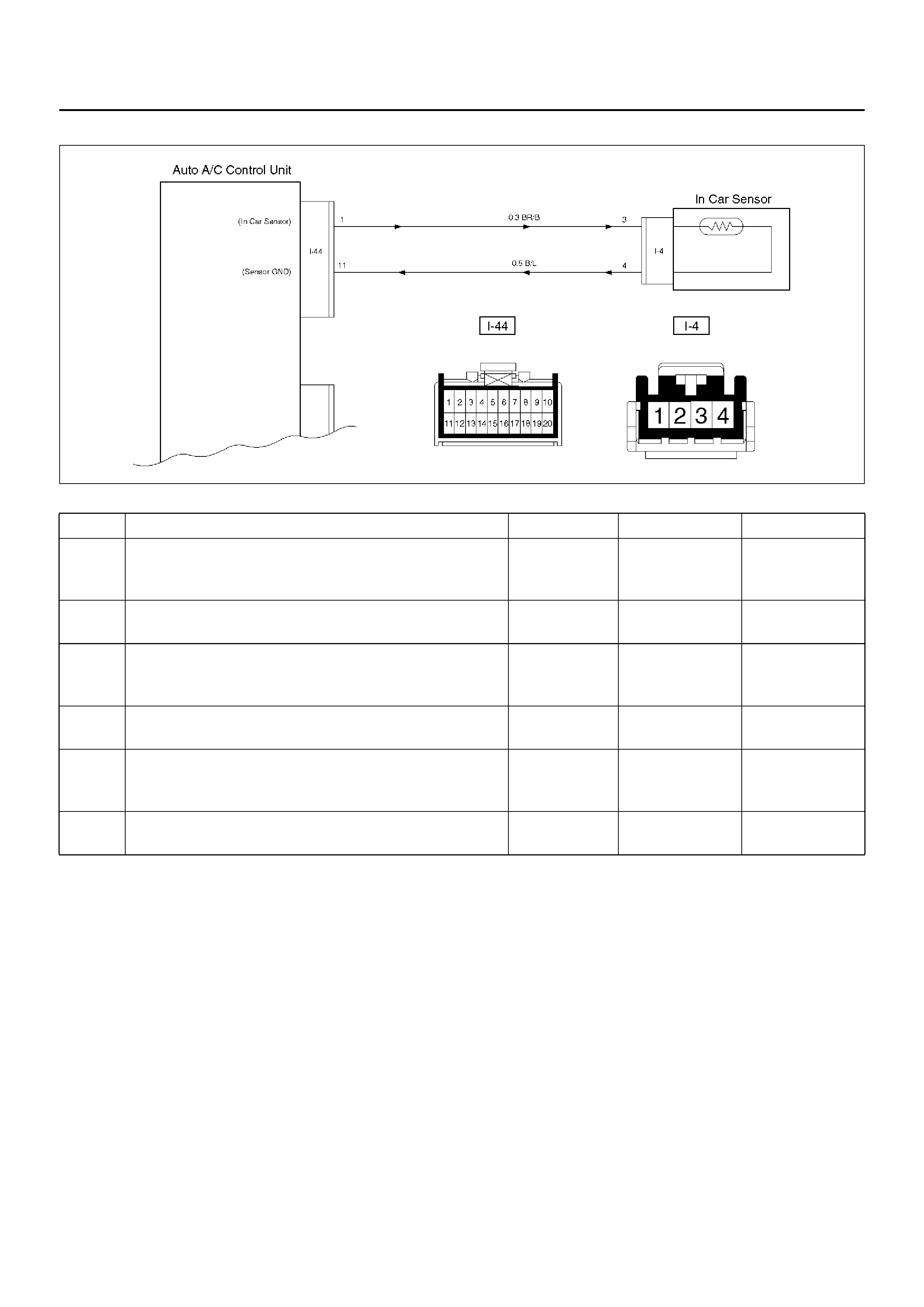
Chart 1: In Car Sensor
D08RY00888
Step Action Value(s) Yes No
1 Disconnect the in car sensor connector. (No.I-4)
Is performance of the sensor normal? (Refer to the
later section on “Individual Inspection") — Go to Step 2 Replace the in
ca r sensor
2 Is there continuity between the harness side
connector No.I44–1 and No.I4–3? — Go to Step 4 Go to Step 3
3 Re pair an open cir cuit betwee n ter minal N o.44–1 an d
No.I4–3.
Is the action complete? — Go to Step 2 —
4 Is there continuity between the harness side
connector No.I44–11 and No.I4–4? — Go to Step 6 Go to Step 5
5 Repair an open circuit between terminal No.I44–11
and No.I4–4.
Is the action complete? — Verify repair —
6 Replace the auto air conditioner control unit.
Is the action complete? — Verify repair —
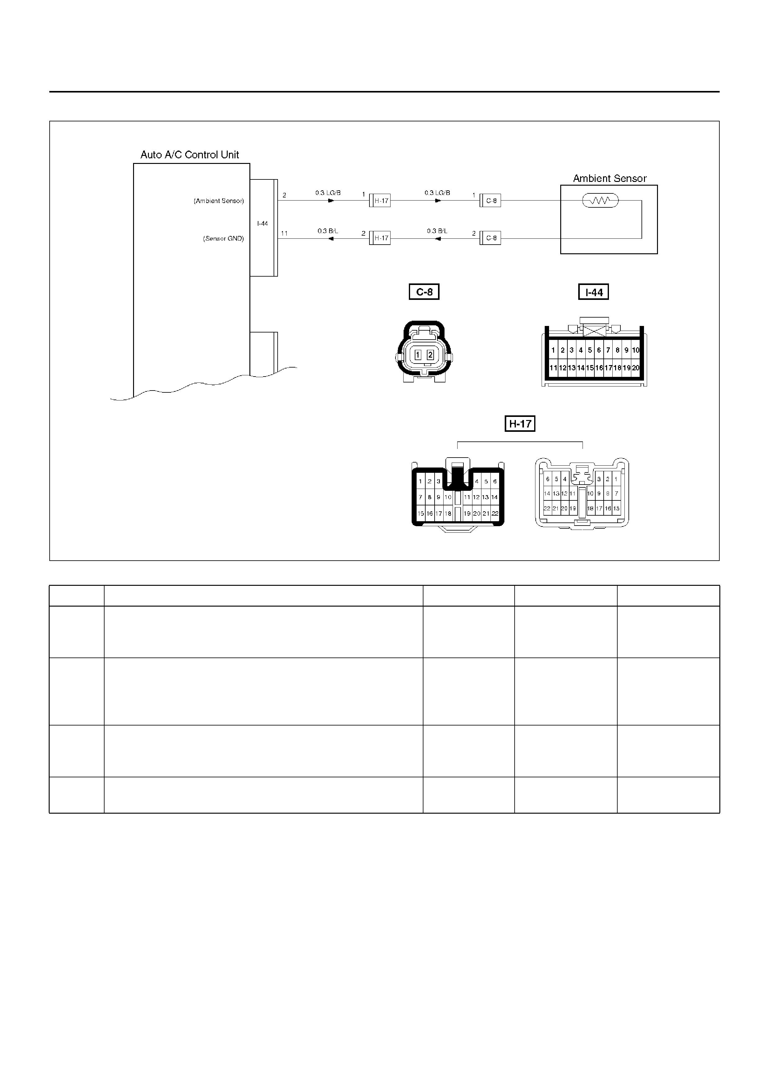
Chart 2: Ambient Sensor
D08RY00886
Step Action Value(s) Yes No
1 Disconnect ambient sensor connector. (No .C–8)
Is performance of the ambient sensor nor mal? (Refer
to the later section on “Individual inspection") — Go to Step 2 Replace the
ambient sensor
2 Connect the ambient sensor connector.
Is resistance between the harness side connector
No.I44–2 and No.I44–11 normal?
Refer to the
later section
on “Individual
inspection" Go to Step 4 Go to Step 3
3 Repair an open circuit between terminal No.I44–2 and
No.C8–1 or No.I44–11 and No.C8–2.
Is the action complete? — Verify repair —
4 Replace the auto air conditioner control unit.
Is the action complete? — Verify repair —
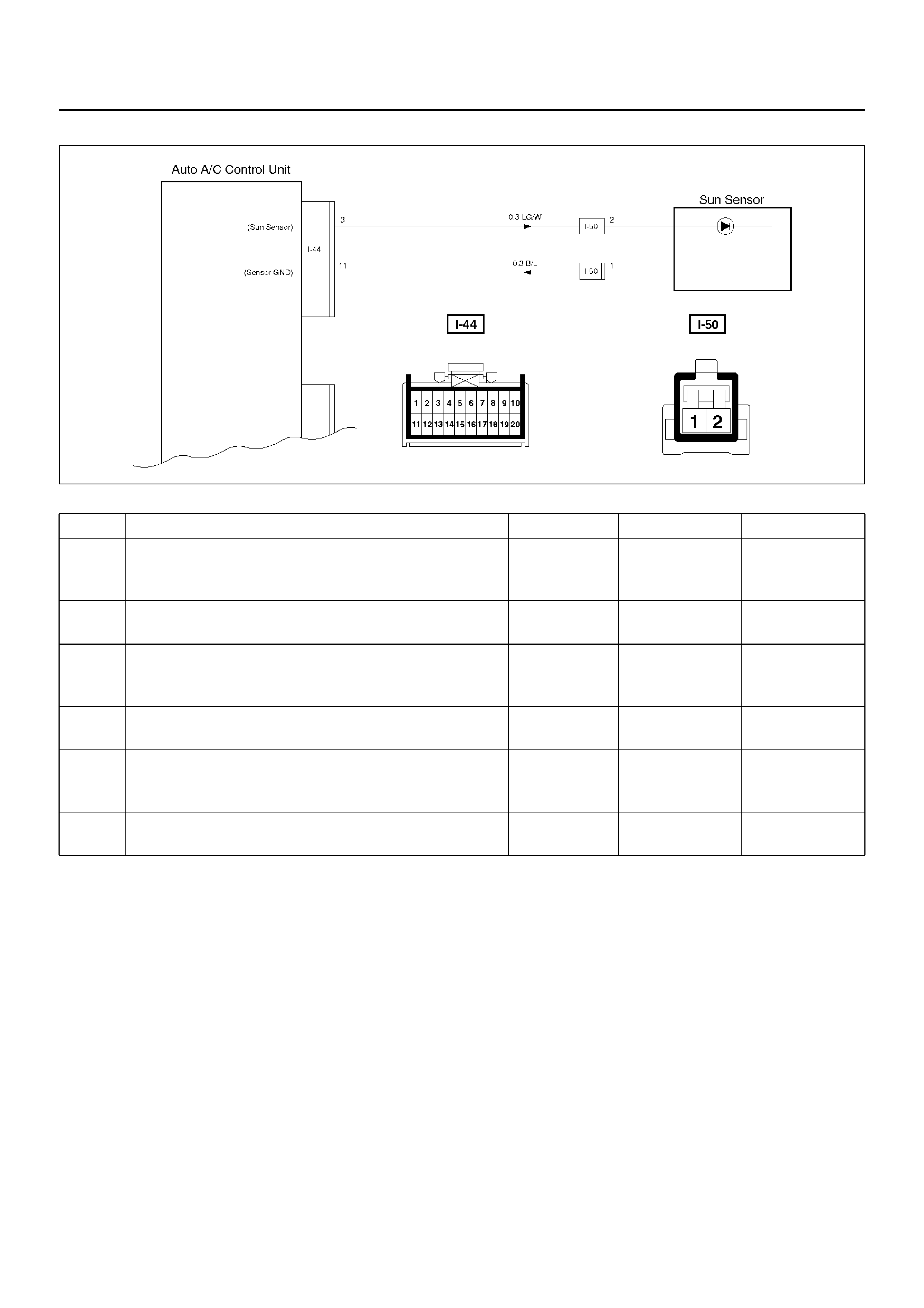
Chart 3: Sun Sensor
D08RY00887
Step Action Value(s) Yes No
1 Disconnect the sun sensor connector. (No.I–50)
Is performance of the sun sensor normal? (Refer to
the later section on individual inspection) — Go to Step 2 Replace the
sun sensor.
2 Is there continuity between the harness side
connector terminal No.I44–3 and No.I50–2? — Go to Step 4 Go to Step 4
3 Repair an open circuit between terminal No.I44–3 and
No.50–2.
Is the action complete? — Go to Step 2 —
4 Is there continuity between the harness side
connector terminal No.I44–11 and No.I50–1? — Go to Step 6 Go to Step 5
5 Repair an open circuit between terminal No.I44–11
and I50–1.
Is the action complete? — Go to Step 4 —
6 Replace the auto air conditioner control unit.
Is the action complete? — Verify repair —
Inspection of the Intake Actuator System
D08RX230

Chart A: Does Not Work At All
Condition Possible cause Correction
Does not work at all — Refer to Chart A
Control failure — Ref er to Chart B
Step Action Value(s) Yes No
1 Is the fuse C–14 normal? — Go to Step 2 Replace the
fuse
2 Is the fuse F–5 normal? — Go to Step 3 Replace the
fuse
3 Is the relay X–6 normal? — Go to Step 4 Replace the
relay
4 Turn on the ignition switch. (the engine is run.)
Is the battery voltage applied between the harness
side connector terminal No.B26–3 and ground? Approx 12V Go to Step 6 Go to Step 5
5 Repair an open circuit between terminal No.B26–3
and No.X6–1.
Is the action complete? — Go to Step 4 —
6 Is the battery voltage applied between the harness
side connector terminal No.B26–4 and ground? Approx 12V Go to Step 8 Go to Step 7
7 Replace the intake actuator motor.
Is the action complete? — Go to Step 6 —
8 Is there continuity between the harness side
connector terminal No.I20–11 and No.B26–4? — Go to Step 10 Go to Step 9
9 Repair an open circuit between No .I20–11 and B26–4.
Is the action complete? — Verify repair —
10 Replace the auto air conditioner control unit.
Is the action complete? — Verify repair —

Chart B: Failure on the Intake Control
Step Action Value(s) Yes No
1 Is the fuse No.C–14 normal? — Go to Step 2 Replace the
fuse
2 Is the fuse No.F–5 normal? — Go to Step 3 Replace the
fuse
3 Is the relay No.X–6 normal? — Go to Step 4 Replace the
relay
4 Turn on the ignition switch. (the engine is run.)
Is the intake actuator stopped? — Go to Step 6 Go to Step 5
5 Replace or repair the auto air conditioner control unit.
Is the action complete? — Verify repair —
6 Is there continuity between the harness side
connector terminal No.B26–5 and No.I44–11? — Go to Step 8 Go to Step 7
7 Repair an open circuit between terminal No.B26–5
and No.I44–11.
Is the action complete? — Go to Step 6 —
8 Is there continuity between the harness side
connector terminal No.B26–6 and No.I44–12? — Go to Step 10 Go to Step 9
9 Repair an open circuit between terminal No.B26–6
and No.I44–12.
Is the action complete? — Go to Step 8 —
10 Is there continuity between the harness side
connector terminal No.B26–1 and No.I44–13? — Go to Step 12 Go to Step 11
11 Repair an open circuit between terminal No.B26–1
and I44-13.
Is the action complete? — Go to Step 10 –
12 Is there continuity between the harness side
connector terminal No.B26–2 and No.I44–14? — Go to Step 14 Go to Step 13
13 Repair an open circuit between harness No.B26–2
and No.I44–14.
Is the action complete? — Go to Step 12 —
14 1. Disconnect the intake actuator connector No.B–
26.
2. Is the battery voltage applied between harness
side connector terminal
No.B26–6 and ground?
No.B26–2 and ground?
No.B26–1 and ground?
— Go to Step 15 Go to Step 16
15 Replace or repair the intake actuator.
Is the action complete? — Verify repair —
16 Replace or repair the air conditioner control unit.
Is the action complete? — Verify repair —
Inspection of the Mix Actuator System
D08RX229
Condition Possible cause Correction
Does not work at all — Refer to Chart A
Control failure — Ref er to Chart B

Chart A: Does Not work At All
Step Action Value(s) Yes No
1 1. Turn on the ignition switch (the engine is run).
2. Disconnect the mix actuator connector (C–45).
3. Short-circuit the chassis harness side connector
terminal No.C45–2 and No.C45–7.
4. Using the temperature control lever, select FH for
the temperature.
Is the battery voltage applied on a regular interval
basis between the harness side connector terminal
No.C45–8 (-) and No.C45–6 (+)? — Go to Step 3 Go to Step 2
2 Replace the auto air conditioner control unit.
—Varify repair —
3 Using the temperature control lever, select FC for the
temperature.
Is the battery voltage applied on a regular interval
basis between the harness side connector terminal
No.C45–8 (+) and No.C45–6 (-)? — Go to Step 5 Go to Step 4
4 Replace the auto air conditioner control unit.
— Verify repair —
5 Is there continuity between the harness side
connector terminal No.I20–6 and No.C45–8? — Go to Step 7 Go to Step 6
6 Repair an open circuit between terminal No.I20–6 and
No.C45–8.
Is the action complete? — Go to Step 5 —
7 Is there continuity between the harness side
connector terminal No.I20–5 and No.C45–6? — Go to Step 9 Go to Step 8
8 Repair an open circuit between terminal No.I20–5 and
No.C45–6.
Is the action complete? — Verify repair —
9 Replace the mix actuator.
Is the action complete? — Verify repair —

Chart B: Mix Actuator Control Failure
Step Action Value(s) Yes No
1 Turn the ignition switch (the engine is run).
Dose th e mix ac tuat or fu ll y stroke when FH a nd FC of
the temperature control lever? — Go to Step 3 Go to Step 2
2 Repair or replace the air mix door or the link unit.
Is the action complete? — Varify repair —
3 Is there continuity between the harness side
connector terminal No.C45–2 and No.I44–11? — Go to Step 5 Go to Step 4
4 Repair an open circuit between terminal No.C45–2
and No.I44–11.
Is the action complete? — Go to Step 3 —
5 Is there continuity between harness side connector
terminal No.C45–7 and No.I44–5? — Go to Step 7 Go to Step 6
6 Repair an open circuit between terminal No.C45–7
and No.I44–5.
Is the action complete? — Go to Step 5 —
7 Is there continuity between the harness side
connector terminal No.C45–3 and No.I44–15? — Go to Step 9 Go to Step 8
8 Repair an open circuit between terminal No.C45–3
and No.I44–15.
Is the action complete? — Go to Step 7 —
9 Is sum of the voltage between the following chassis
harness side connector terminals approximately 5V?
No.I44–15 and No.I52–5, No.I44–5 and No.I44–11 — Go to Step 11 Go to Step 10
10 Replace the actuator.
Is the action complete? — Verify repair —
11 Replace the auto air conditioner control unit.
Is the action complete? — Verify repair —
Inspection of the Mode Actuator System
D08RX228
Condition Possible cause Correction
Does not work at all — Refer to Chart A
Control failure — Ref er to Chart B

Chart A: Does Not Work At All
Step Action Value(s) Yes No
1 1. Turn on the ignition switch (the engine is run).
2. Disconnect the mode actuator connector (C–48)
3. Select VENT pressing the mode actuator.
Is the battery voltage provided on a regular interval
between the harness side connector terminal
No.C48–1 (+) and No.C48–5 (-)? — Go to Step 3 Go to Step 2
2 Replace the auto air conditioner control unit.
Is the action complete? — Varify repair —
3 Turn on the DEF mode switch.
Is the battery voltage provided on a regular interval
between the chassis side connector terminal No.C48–
5 (+) and No.C48–1 (-)? — Go to Step 5 Go to Step 4
4 Replace the auto air conditioner control unit.
—Varify repair —
5 Is there continuity between the harness side
connector terminal No.C48–1 and No.I20–4? — Go to Step 7 Go to Step 6
6 Repair an open circuit between terminal No.C48–1
and No.I20–4.
Is the action complete? — Go to Step 5 —
7 Is there continuity between the harness side
connector terminal No.C48–5 and No.I20–3? — Go to Step 9 Go to Step 8
8 Repair an open circuit between terminal No.C48–5
and No.I20–3.
Is the action complete? — Verify repair —
9 Replace the mode actuator.
— Verify repair —

Chart B: Mode Actuator Control Failure
Step Action Value(s) Yes No
1 Turn on the ignition switch (the engine is run).
Dose th e mode actuator fully stroke when the defrost
mode and the vent mode are selected? — Go to Step 3 Go to Step 2
2 Repair or replace the mode door or the link unit.
Is the action complete? — Go to Step 1 —
3 Is there continuity between the harness side
connector terminal No.C48–9 and No.I44–11? — Go to Step 5 Go to Step 4
4 Repair an open circuit between terminal No.C48–9
and No.I44–11.
Is the action complete? — Go to Step 3 —
5 Is there continuity between the harness side
connector terminal No.C48–3 and No.I44–10? — Go to Step 7 Go to Step 6
6 Repair an open circuit between terminal No.C48–3
and No.I44–10.
Is the action complete? — Go to Step 5 —
7 Is there continuity between harness side connector
terminal No.C48–4 and No.I44–8? — Go to Step 9 Go to Step 8
8 Repair an open circuit between terminal No.C48–4
and No.I44–8.
Is the action complete? — Go to Step 7 —
9 Is sum of the voltage between the following harness
side connector terminal approximately 5V? Voltage
between No.I44–8 and No.I44–10 plus voltage
between No.I44–8 and No.I44–11 5V Go to Step 11 Go to Step 10
10 Replace the actuator.
Is the action complete? — Verify repair —
11 Dose the mode actuator work normally through
manual operation? — Go to Step 13 Go to Step 12
12 Replace the sensor.
Is the action complete? — Verify repair —
13 Replace the auto air conditioner control unit.
Is the action complete? — Verify repair —
Inspection of the Fan Motor System
D08RX227
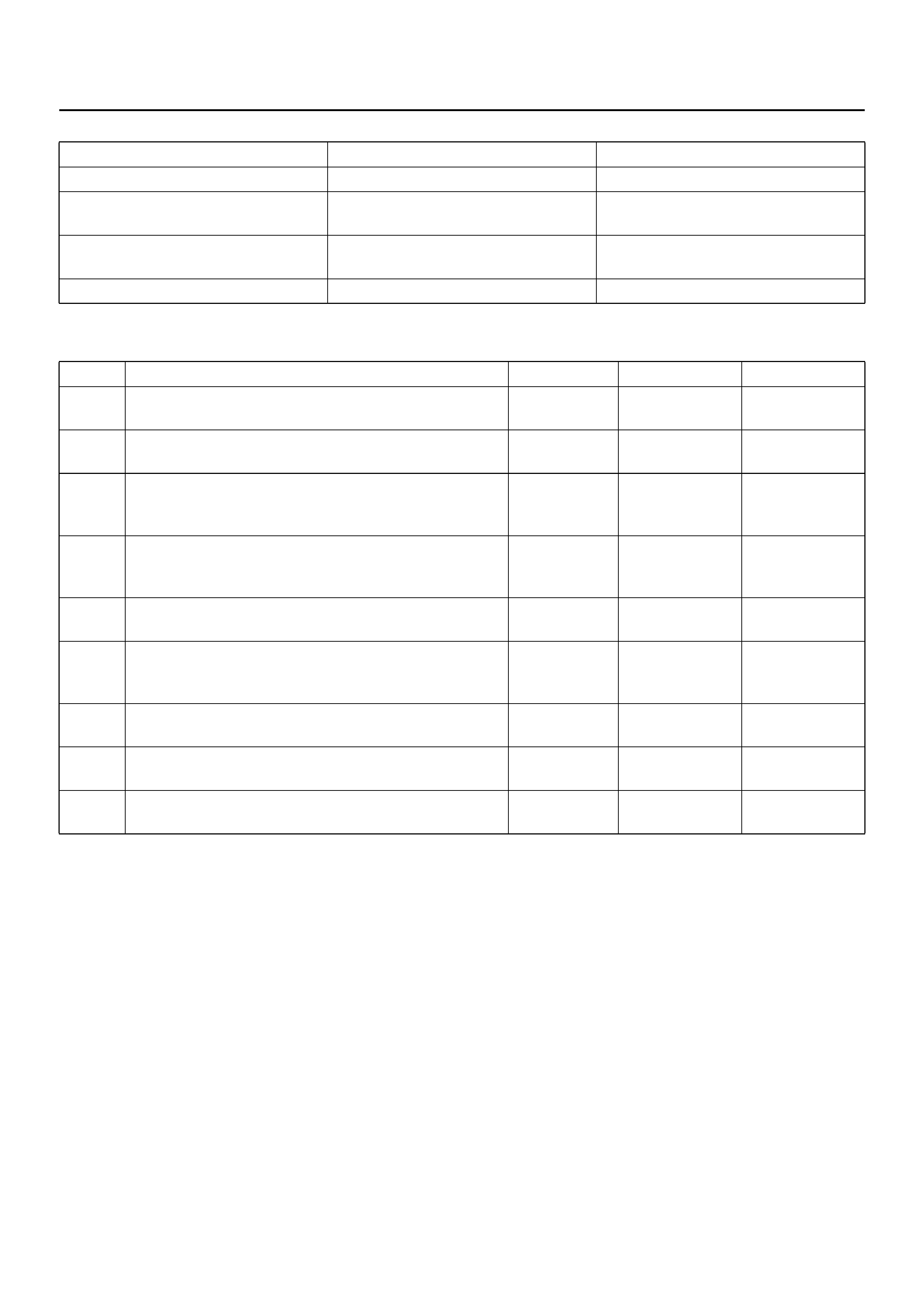
Chart A: Fan Does Not Rotate At All
Condition Possible cause Correction
The fa n dose not rotate at all — Refer to Chart A
The fan dose not rotate in the MAX–
HI mode — Refer to Chart B
The fan dose not rotate in any mode
other than MAX–HI — Refer to Chart C
The fa n dose not stop — Refer to Chart D
Step Action Value(s) Yes No
1 Are the fuse No.F–4 and No.F–5 normal? — Go to Step 2 Replace the
fuse
2 Are the relay No.X–6 and No.B–25 normal? — Go to Step 3 Replace the
relay
3 Turn on the ignition switch (the engine is run).
Is the battery voltage applied between the harness
side connector terminal No.B5–2 and ground? — Go to Step 5 Go to Step 4
4 Repair an ope n circuit between terminal No.B5–2 and
No.F–4 fuse.
Is the action complete? — Go to Step 3 —
5 Is there continuity between the harness side
connector terminal No.B5–1 and ground (No.B–8)? — Go to Step 7 Go to Step 6
6 Repair an ope n circuit between terminal No.B5–1 and
ground.
Is the action complete? —
7 Is the battery voltage applied between the harness
side connector terminal No.B5–1 and No.B5–2? — Go to Step 8 Go to Step 9
8 Replace the blower motor.
Is the action complete? — Verify repair —
9 Refer to chart B and C.
Is the action complete? — Verify repair —

Chart B: Fan Does Not Rotate in MAX HI Mode
Step Action Value(s) Yes No
1 Is the MAX-HI relay (B–25) normal? — Go to Step 2 Replace the
relay
2 1. Turn on the ignition switch (the engine is run).
2. Set the fan switch to the MAX-HI.
Is there continuity between the harness side
connector terminal No.B5–1 and No.B25–2? — Go to Step 4 Go to Step 3
3 Repair an ope n circuit between terminal No.B5–1 and
No.B25–2.
Is the action complete? — Go to Step 3 —
4 Is there continuity between the harness side
connector terminal No.B25–4 and ground (No.B–8)? — Go to Step 6 Go to Step 5
5 Repair an open circuit between terminal No.B25–4
and ground (No.B–8).
Is the action complete? — Go to Step 4 —
6 Is the battery voltage applied between the harness
side connector terminal No.B25–1 and ground? — Go to Step 8 Go to Step 7
7 Repair an open circuit between terminal No.B25–1
and No.F–5 fuse.
Is the action complete? — Go to Step 6 —
8 Is the battery voltage applied between the harness
side connector terminal No.I20–12 and ground? — Go to Step 10 Go to Step 9
9 Repair an open circuit between terminal No.B25–3
and No.I20–12.
Is the action complete? — Verify repair —
10 Replace the auto air conditioner control unit.
Is the action complete? — Verify repair —

Chart C: Fan Does Not Rotate In Any Mode Other Than MAX HI
Chart D: Fan Does Not Stop
Step Action Value(s) Yes No
1 Is the power transistor performanc e normal ? (Refer to
the later section on “individual inspection") — Go to Step 2 Replace the
power transistor
2 Is there continuity between the harness side
connector terminal No.B5–1 and No.B35–1, No.B5–1
and No.I44–17? — Go to Step 4 Go to Step 3
3 Repair an open circuit between terminal.
No.B5–1 and B35–1
No.B5–1 and I44–17
— Go to Step 2 —
4 Is there continuity between the harness side
connector terminal No.B35–3 and ground (No.B–8)? — Go to Step 6 Go to Step 5
5 Repair an open circuit between terminal No.B35–3
and ground.
Is the action complete? — Go to Step 4 —
6 Is there continuity between the harness side
connector terminal No.B35–2 and No.I44–19? — Go to Step 8 Go to Step 7
7 Repair an open circuit between terminal No.B35–2
and No.I44–19.
Is the action complete? — Go to Step 6 —
8 Replace the auto air conditioner control unit.
Is the action complete? — Verify repair —
Step Action Value(s) Yes No
1 1. Disconnect the max high relay, the power
transistor connector B–35 and the auto A/C
control unit connector I–44.
2. Turn on the ignition switch.
Does the blower motor stop? — Go to Step 3 Go to Step 2
2 Repair a short circuit between connector No .B5–1 and
No.B25–2, No.B5–1 and No.B35–1, or No.B5–1 and
I44–17.
Is the action complete? — Verify repair —
3 Is the max high relay normal? (Refer to the later
section on “individual inspection".) — Go to Step 4 Replace the
relay
4 Reinstall the max high relay.
Does the blower motor start operating? — Go to Step 6 Go to Step 5
5 Repair a short circuit between connector No.B25–3
and No.I20–12.
Is the action complete? — Go to Step 4 —
6 Is the power transistor normal? (Refer to the later
section on “individual inspection".) — Go to Step 7 Replace the
power transistor
7 Reinstall the power transistor.
Does the blower motor start operating? —
Replace the
auto A/C control
unit —
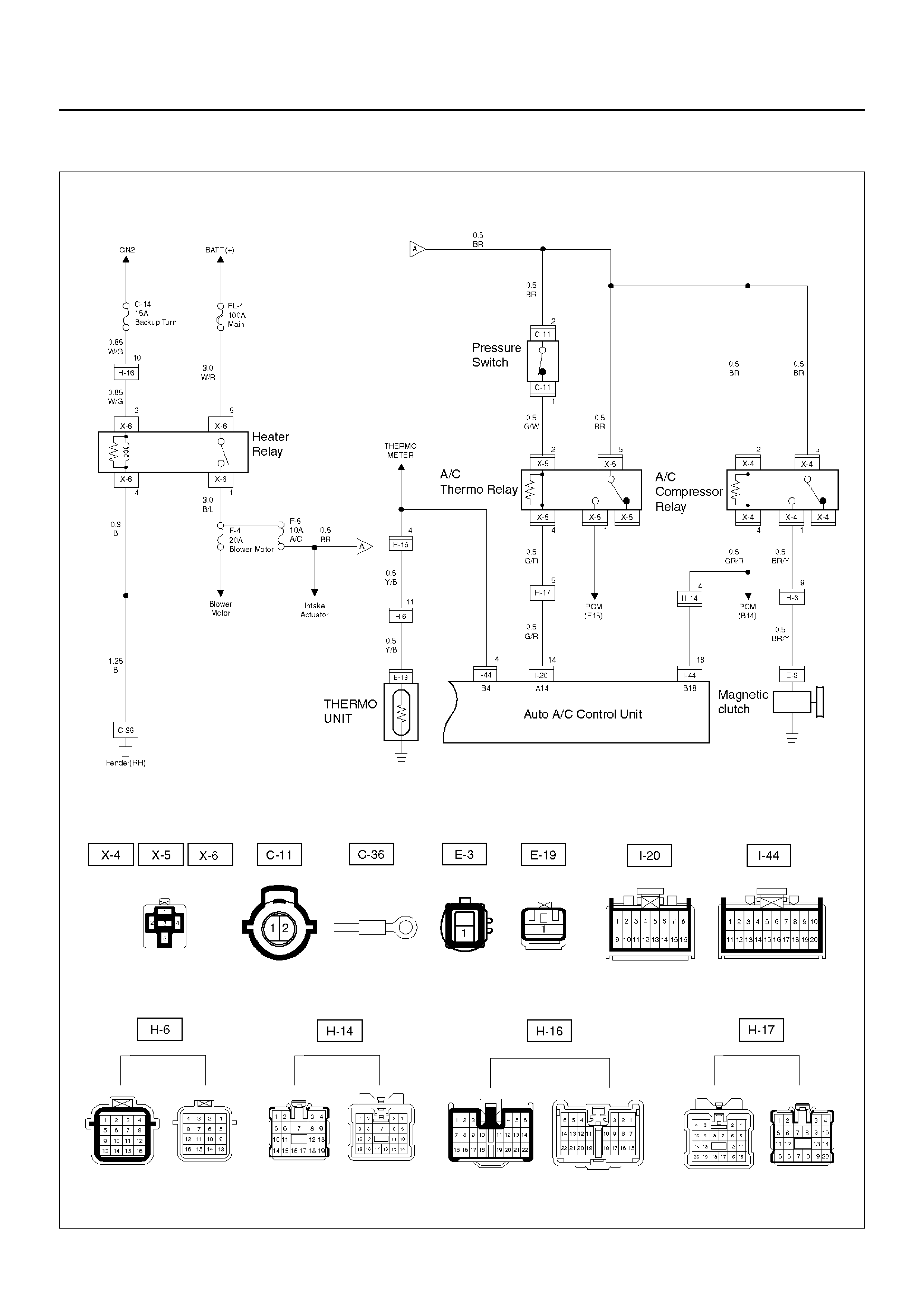
Inspection of the Magnetic Clutch System
6VD1 Engine
D08RX226

Chart A: Magnetic Clutch Does Not work
Condition Possible cause Correction
Magnetic clutch does not work — Refer to Chart A
Step Action Value(s) Yes No
1 Is the fuse No.F–5 normal? — Go to Step 2 Replace the
fuse
2 Is the relay No.X–4 (compressor relay) No.X–5 (A/C
thermo relay) and No.X–6 (heater relay) normal? — Go to Step 3 Replace the
fuse
3 Is the thermo unit normal? — Go to Step 4 Replace the
thermo unit
4 Is the pressure switch normal? — Go to Step 5 Replace the
pressure switch
5 1. Turn the ignition switch on. (the engine is run.)
2. Push the air conditioner switch on.
Is the battery voltage applied between the harness
side connector terminal No.E3–1 and the ground? — Go to Step 6 Go to Step 7
6 Repair or replace the magnetic clutch.
Is the action complete? — Verify repair —
7 Is there continuity between the harness side
connector terminal No.X4–1 and No.E3–1? — Go to Step 9 Go to Step 8
8 Repair an ope n circuit between terminal No.X4–1 and
No.E3–1.
Is the action complete? — Go to Step 7 —
9 Is the battery voltage applied between the harness
side con nector ter minal No. X4–5 and ground , No.X4–
2 and ground? — Go to Step 11 Go to Step 10
10 Re pair an ope n circuit between ter min al No.X4–5 and
fuse No.F–5, No.X4–2 and fuse No.F–5.
Is the action complete? — Go to Step 9 –
11 Is the battery voltage applied between the harness
side connector terminal No.I44–18 and ground? — Go to Step 13 Go to Step 12
12 Repair an open circuit between terminal No.I44–18
and No.X4–4.
Is the action complete? — Go to Step 11 —
13 Is the battery voltage applied between the harness
side connector terminal No.C11–2 and ground? — Go to Step 15 Go to Step 14
14 Repair an open circuit between terminal No.C11–2
and fuse No.F–5.
Is the action complete? — Go to Step 13 —
15 Is the battery voltage applied between the harness
side con nector ter minal No. X5–2 and ground , No.X5–
5 and ground? — Go to Step 17 Go to Step 16
16 Re pair an ope n circuit between ter min al No.X5–2 and
No.C11–1, No.X5–5 and fuse No.F–5.
Is the action complete? — Go to Step 15 —
17 Is the battery voltage applied between the harness
side connector terminal No.I20–14 and ground? — Go to Step 19 Go to Step 18
18 Re pair an ope n circuit between ter min al No.X5–4 and
I20–14.
Is the action complete? — Go to Step 17 —

Chart A: Magnetic Clutch Does Not work (Cont’d)
CAUTION: There are conditions which air
conditioner system dose not operate except trouble
as follows.
1. The throttle is griater than 90%.
2. The ignition voltage is below 10.5 volts.
3. The engine speed greater than 4500 RPM for 5
seconds or 5400 RPM.
4. The engine coolant temperature (ECT) is greater
than 125°
°°
°C (257°
°°
°F).
5. The intake air temperature (IAT) is less than 5°
°°
°C
(41°
°°
°F).
6. The power steering pressure switch signals a high
pressure condition.
Step Action Value(s) Yes No
19 Is there continuity between the harness side
connector terminal No.I44–4 and ground? — Go to Step 21 Go to Step 20
20 Repair an open circuit between terminal No.I44–4 and
No.E19–1.
Is the action complete? — Go to Step 20 —
21 Dose the the rmo relay “ON" when connecting ground
to the harness connector terminal No.H17–5? — Go to Step 23 Go to Step 22
22 Failure on the auto air conditioner control unit.
Is the action complete? — Verify repair —
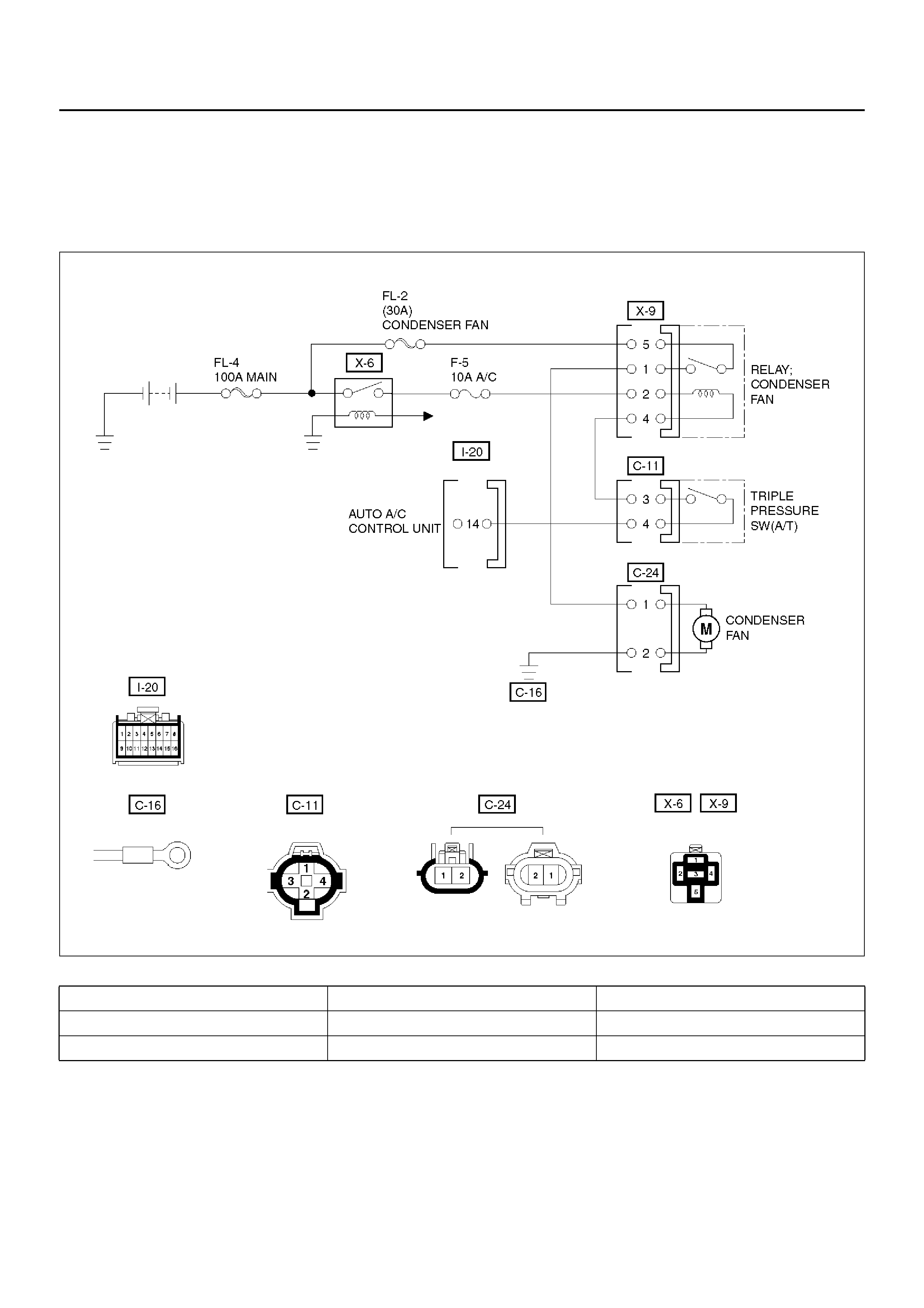
Condenser Fan Diagnosis
While the air conditioning is ON, the cycling switch in
the triple pressure switch senses the refrigerant
pressure, and activates the condenser fan to improve
the cooling capacity of the condenser when the
refri gerant pressure exceeds a set pressure value. The
conden ser fan stops when the air co nditionin g is tur ned
“OFF" or when the pressure goes down below the set
pressure value.
D08RX255
Condition Possible cause Correction
Condenser fan does not run. — Refer to Chart A
Condenser fan does not stop. — Refer to Chart B

Chart “A" Condenser Fan Does Not Run
Step Action Value(s) Yes No
1 Is the fusible link No.FL–2 normal? — G o to Step 2 Replace the
fusible link wire
2 Is the fuse No.F–5 normal? — Go to Step 3 Replace the
fuse
3 Is the heater relay (No.X–6) and condenser fan relay
(No.X–9) normal? — Go to Step 4 Replace the
relay
4 1. Disconnect the condenser fan motor connector
No.C–24.
2. Connect the motor side connector terminal
No.C24–1 to the battery positive terminal and
No.C24–2 to the battery negative terminal.
Dose the f an operate? — Go to Step 6 Go to Step 5
5 Repair or replace the condenser fan motor.
Is the action complete? — Go to Step 4 —
6 Is there continuity between the harness side
connector terminal No.C24–2 and ground (C–16)? — Go to Step 8 Go to Step 7
7 Repair an open circuit between terminal No.C24–2
and No.C–16.
Is the action complete? — Go to Step 6 —
8 Is there continuity between the harness side
connector terminal No.C24–1 and No.X9–1? — Go to Step 10 Go to Step 9
9 Repair an open circuit between terminal No.C24–1
and No.X9–1.
Is the action complete? — Verify repair —
10 Is the battery voltage applied between the harness
side connector terminal No.X9–5 and ground? — Go to Step 12 Go to Step 11
11 Re pair an ope n circuit between ter min al No.X9–5 and
No.FL–2.
Is the action complete? — Go to Step 10 —
12 Is the battery voltage applied between the harness
side connector terminal No.C11–3 and ground? — Go to Step 14 Go to Step 13
13 Re pair an ope n circuit between ter min al No.X9–4 and
No.C11–3.
Is the action complete? — Go to Step 12 —
14 Is there continuity between the harness side
connector terminal No.C11–4 and No.I20–14? — Go to Step 16 Go to Step 15
15 Repair an open circuit between terminal No.C11–4
and No.I20–14.
Is the action complete? — Verify repair —
16 Connect the harness side connector terminal
No.C24–1 to the battery terminal and No.C24–2 to the
battery negative terminal.
Is the battery voltage between the pressure switch
side connector terminal No.C24–4 and ground? — Go to Step 18 Go to Step 17
17 Replace the triple pressure switch.
Is the action complete? — Verify repair —
18 Replace the auto air conditioner control unit.
Is the action complete? — Verify repair —

Chart “B" Condenser Fan Does Not Stop
Step Action Value(s) Yes No
1 1. Turn on the ignition switch “ON" (the engine is
run).
2. Air conditioning switch “OFF".
3. Disconnect the triple pressure switch.
Does the condenser fan stop? — Go to Step 2 Go to Step 3
2 Replace the triple pressure switch.
Is the action complete? — Verify repair —
3 Disconnect the relay.
Is there continuity between the harness side
connector terminal No.X9–4 and ground? — Go to Step 4 Go to Step 5
4 Repair short circuit between terminal No.X9–4 and
No.C11–3.
Is the action complete? — Verify repair —
5 Replace the relay condenser fan.
Is the action complete? — Verify repair —
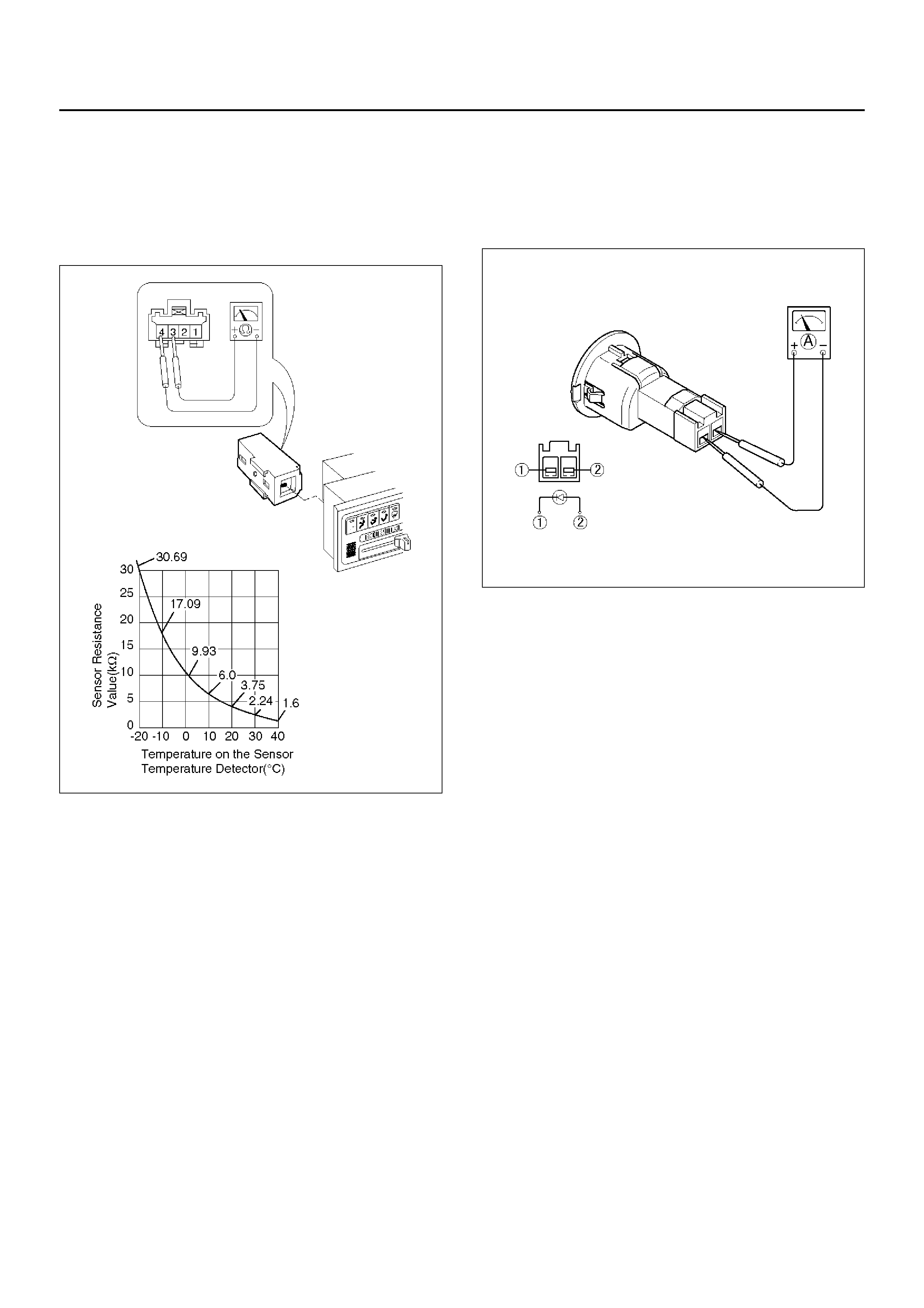
Individual Inspection
In Car Sensor
1. Disconnect the in car sensor connector (I–4).
2. Measure resistance between the in car sensor side
terminal No.I4–3 and No.I4–4.
865RX007
Sun Sensor
1. Disconnect the sun sensor connector (I–50).
2. Measure the current value on the sun sensor when
placed it approximately 15 cm away from 60W
incandescent lamp.
C01RX013
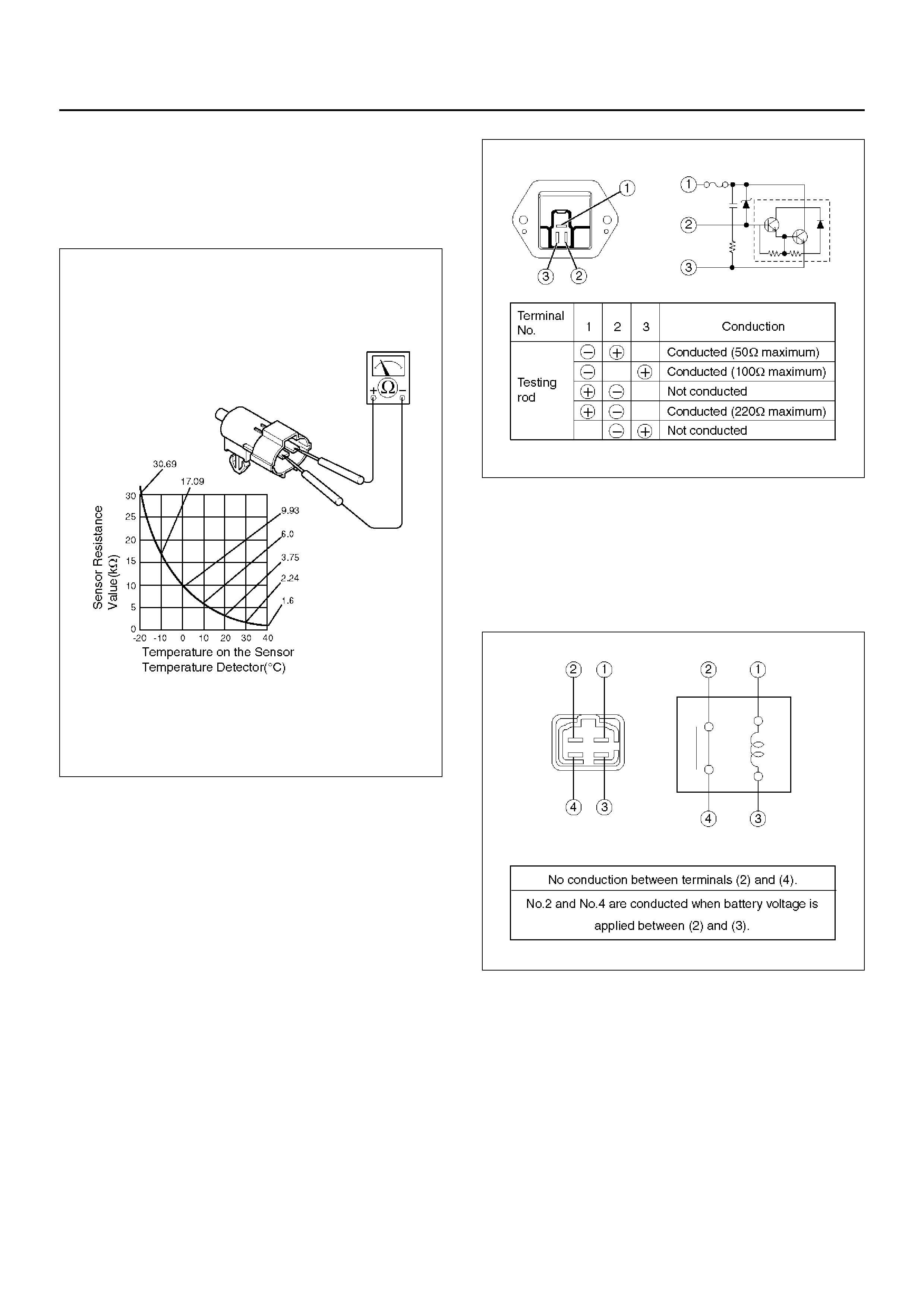
Ambient Sensor
1. Disconnect the connector (C–8) on the ambient
sensor.
2. Measure resistance between the ambient sensor
side terminals.
C01RX012
Power Transistor
1. Remove the power t ransistor co nne ct or (B–35 ) from
the evaporator assembly.
2. Check the c onduction bet ween the power transistor
side terminals.
C01RX015
MAX HI Relay
1. Remove the MAX – HI relay connector (B–25) from
the blower assembly.
2. Check the conduction between the MAX – HI relay
side terminals.
C01RX014
In Car Sensor
1. Turn on the ignition switch (the engine is started).
Start the air conditioner in “Full Auto".
2. Make sure that the interior sensor suctions cigarette
smokes an d such.
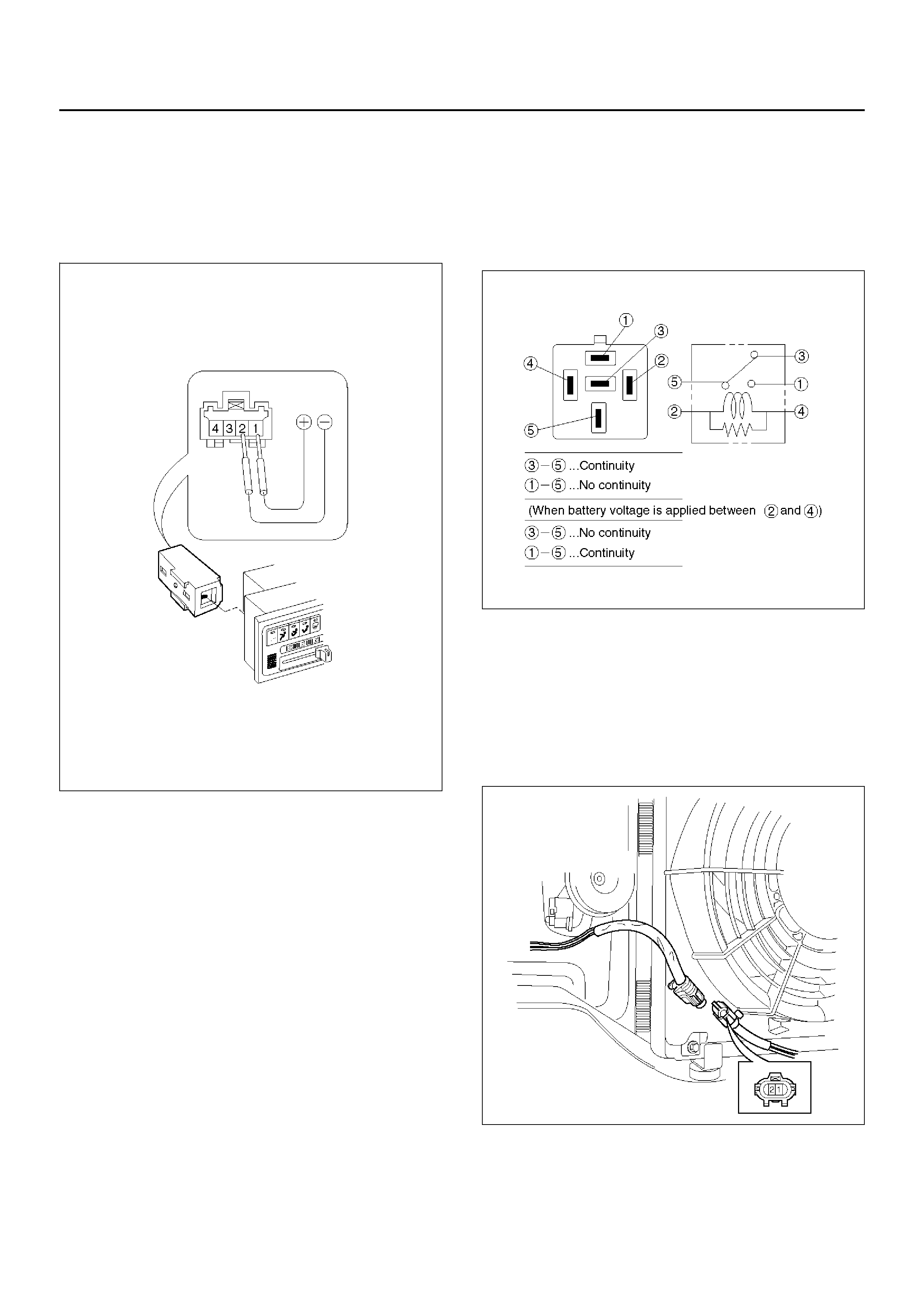
In Car Sensor
1.Dismount the in car sensor from the automatic
heater/air conditioner control unit. Connect (+)
end and (-) end of the battery to the aspirator motor
side terminals No.I4–1 and No.I4–2, respectively,
then check if the motor runs normally.
C01RW020
Heater (X–6), Thermostat (X–5), Condenser
Fan (X–9) And Compressor (X–4) Relay
1.Disconnect relays and check for continuity and
resistance between relay terminals.
•For handling of these relays, refer to Heater Relay
in this section.
901RX071
Condenser Fan
1. Disconnect the condenser fan connector.
2. Connect the battery positive terminal to the
condens er fan side c onnector ter minal No.C24 -2
and negative to the No.C24-1.
3. Check that conden se r fan is r otat ing corre ctl y.
875RW010
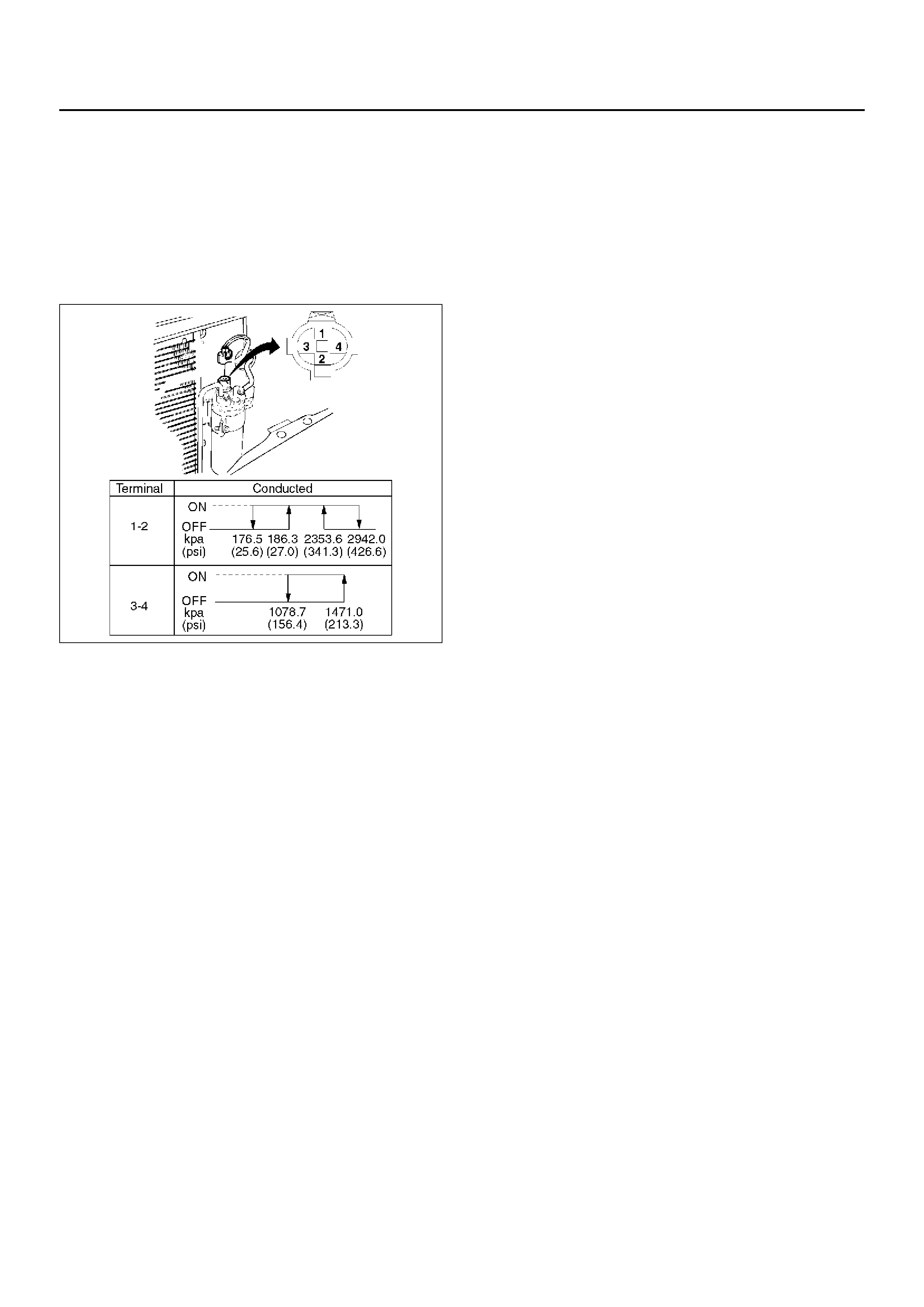
Triple Pressure Switch (V6, A /T)
1. Disconnect the connector and check for continuity
between pressure s witch side connector terminals
(1) and (2).
2. Reco nnect the conne ct or to activate the A/C switch,
and check to see if there is continuity between the
chassis side connector ter minal (3) and (4) and the
fan operates.
875RX009
On-Vehicle Service
Power Transistor
874RY00029
EndOFCallout
Removal
1.Remove glove box.
2.Remove passenger knee bolster reinforcement.
3.Disconnect the power transistor connector.
4.Remove power transistor.
Installation
To install, follow the removal step in the reverse order.
Automatic Heater/Air Conditioner
Control Unit
865RW016
EndOFCallout
Removal
1.Disconnect the battery ground cable.
2.Remove instrument lower cover.
3.Remove meter cluster assembly.
•Refer to Instrument Panel Assembly in Body
Structure section.
4. Remove the auto ma tic he ater /a ir c ond iti one r co ntrol
unit attaching screws.
5. Pull the automatic heater/air conditioner unit out and
disconnect the connectors.
Installation
To install, follow the removal step in the reverse order.
Legend
(1) Power Transistor
(2) Passenger knee bolster Reinforcement
(3) Power Transistor Connector
(4) Glove Box
Legend
(1) Connector
(2) Automatic Ai r Control Unit
(3) Meter Cluster Assembly
(4) Instrument Center Cluster
(5) Instrument Lower Cover
In Car Sensor
865RW014
EndOFCallout
Removal
1.Disconnect the battery ground cable.
2.Remove the automatic heater/air conditioner control
unit.
•Refer to the automatic heater/air conditioner
control unit section.
3.Remove in car sensor.
Installation
To install, follow the removal step in the reverse order.
Ambient Sensor
875RY00022
EndOFCallout
Removal
1.Disconnect the battery ground cable.
2.Remove radiator grille.
•Refer to Radiator Grille in Body Structure section.
3. Disconnect the ambient sensor connector.
4. Remove the amb ien t sensor.
Installation
To install, follow the removal step in the reverse order.
Legend
(1) In Car Sensor
(2) Automatic Air Control Unit
Legend
(1) Ambient Sensor
(2) Radiator Grille
Sun Sensor
865RW009
EndOFCallout
Removal
1.Disconnect the battery ground cable.
2.Remove the sun sensor.
3.Disconnect the sun sensor connector.
Installation
To install, follow the removal step in the reverse order.
Electronic Thermostat
874RW027
EndOFCallout
Removal
1.Disconnect the battery ground cable.
2.Remove evaporator assembly.
•Refer to Evaporator Assembly section.
3. Remove ele ct ronic thermo stat.
Installation
To install, follow the removal step in the reverse order.
Legend
(1) Sun Sensor
Legend
(1) Duct Sensor
(2) Evapolator Assembly
(3) Thermostat Assembly
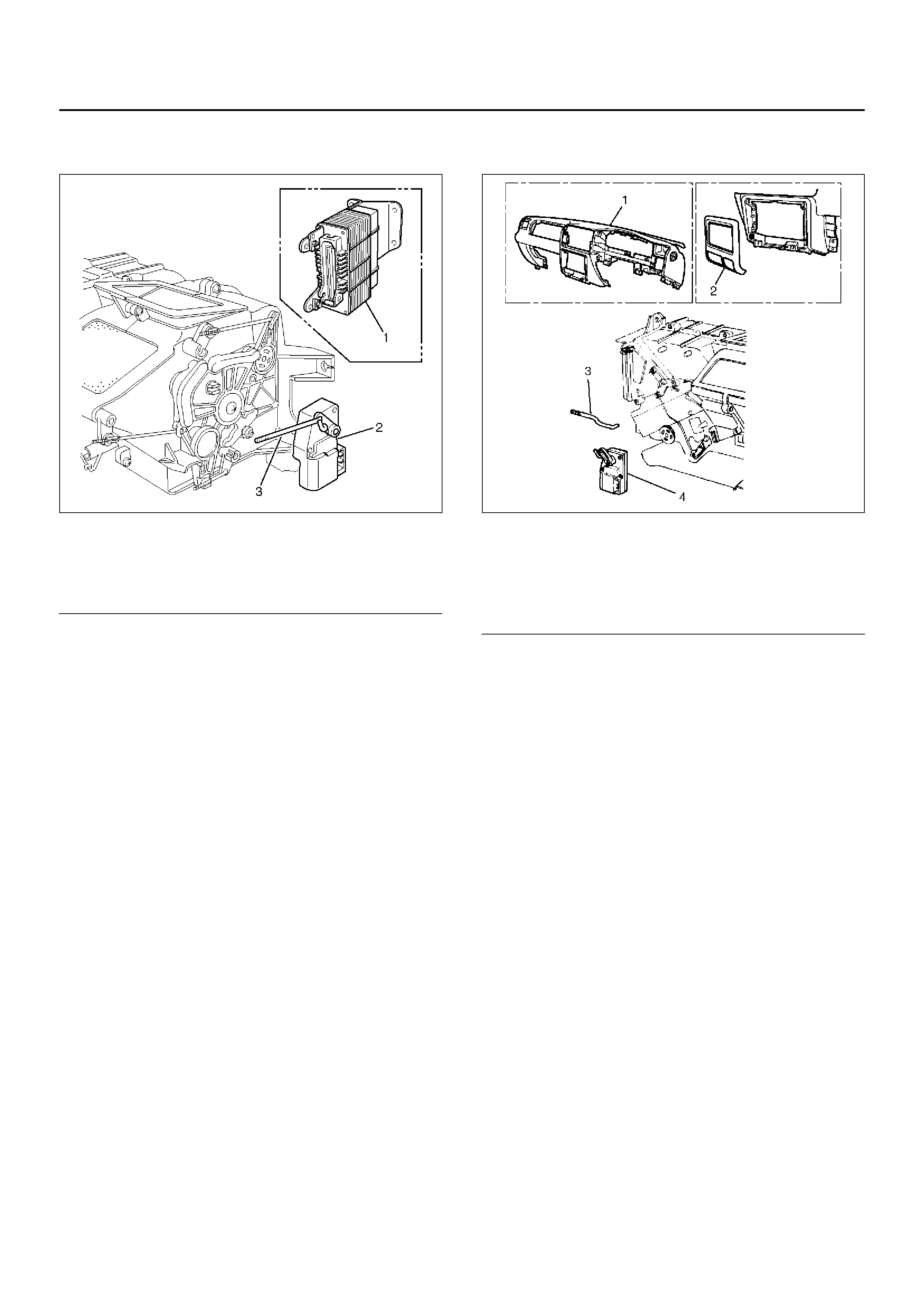
Mode Actuator
860RW030
EndOFCallout
Removal
1.Disconnect the battery ground cable.
2.Remove the A/T control unit.
•The connector shall remain connected.
3.Remove the actuator rod.
4.Remove the mode actuator.
Installation
To install, follow the remove step in the reverse order.
Mix Actuator
860RW033
EndOFCallout
Removal
1.Disconnect the battery ground cable.
2.Remove the instrument panel assembly.
•Refer to the Instrument Panel Assembly in Body
Structure section.
3. Remove the instrument panel center cluster.
4. Remove the ac tuato r rod.
5. Remove the mix actuator.
Installation
To install, follow the remove step in the reverse order.
Legend
(1) A/T Control Unit
(2) Mode Actuator
(3) A ct uato r Rod
Legend
(1)Instrument Panel Assembly
(2) Instrument Panel Center Cluster
(3) Actuator Rod
(4) Mix Actuator
Intake Actuator
860RX018
EndOFCallout
Removal
1.Disconnect the battery ground cable.
2.Remove the blower assembly.
•Refer to Blower Assembly section.
3. Disconnect the intake actuator connector.
4. Remove the intake actuator.
Installation
To install, follo w the remove step in the reverse order.
Legend
(1) Evaporator Assembly
(2) Intake Actuator
(3) Intake Actuator Connector