SECTION 10A - CRUISE CONTROL SYSTEM
Service Precaution
General Description
Diagnosis
Brake Switch
Removal and Installation
Adjustment
Clutch Switch
Removal and Installation
Adjustment
Cruise Control Unit
Removal
Installation
Cruise Actuator
Actuator Cable Diagram
Removal
Installation
Adjustment
Mode Switch
Removal and Installation
Cruise Control Main Switch
Removal
Installation
Cruise Control Switch (Combination Switch)
Removal and Installation
Service Precaution
WARNING: THIS VEHICLE HAS A SUPPLEMENTAL
RESTRAINT SYSTEM (SRS). REFER TO THE SRS
COMPONENT AND WIRING LOCATION VIEW IN
ORDER TO DETERMINE WHETHER YOU ARE
PERFORMING SERVICE ON OR NEAR THE SRS
COMPONENTS OR THE SRS WIRING. WHEN YOU
ARE PERFORMING SERVICE ON OR NEAR THE
SRS COMPONENTS OR THE SRS WIRING, REFER
TO THE SRS SERVICE INFORMATION. FAILURE TO
FOLLOW WARNINGS COULD RESULT IN POSSIBLE
AIR BAG DEPLOYMENT, PERSONAL INJURY, OR
OTHERWISE UNNEEDED SRS SYSTEM REPAIRS.
CAUTION: Always use the correct fastener in the
proper location. When you replace a fastener, use
ONLY the exact part number for that application.
ISUZU will call out those fasteners that require a
replacement after removal. ISUZU will also call out
the fasteners that require thread lockers or thread
sealant. UNLESS OTHERWISE SPECIFIED, do not
use supplemental coatings (Paints, greases, or
other corrosion inhibitors) on threade d fasteners or
fastener joint interfaces. Generally, such coatings
adversely affect the fastener torque and the joint
clamping force, and may damage the fastener.
When you install fasteners, use the correct
tightening sequence and specifications. Following
these instructions can help you avoid damage to
parts and systems.

General Description
The cruise control keeps the vehicle running at a fixed
speed until a signal canceling this fixed speed is
received.
When the main switch “AUTO CRUISE" is turned on
with the vehicle in the running mode, the battery voltage
is applied to the control unit. When a signal from the
control switch is input to the control unit while the
vehicle is in this state, the cruise control actuator is
activated to operate the system. Also, while the system
is operating, the “AUTO CRUISE" indicator light in the
meter assembly lights up.
1 . SET/COAST Switch Function
1. Set Function: When the SET/COAST switch is
pressed and released with the main switch on, the
speed at which the vehicle is running at that
moment is stored in the memory, and the vehicle
automatically runs at the speed stored.
2. Coast-Down Function: When the SET/C OAST
switch is kept on while the vehicle is running, the
vehicle decelerates during that time. The speed at
which vehicle is running when the control switch is
turned off is stored in the memory, and the vehicle
automatically returns to the stored speed.
3. Tap-Down Function: When the SET/COAST switch
is turned on and off instantaneously while the
vehicle is running, the vehicle decelerates a mile for
each on/off operation. The vehicle speed at which
the vehicle was running when the SET/COAST was
turned off last is stored in the memory, and the
vehicle automatically returns to this stored speed.
2 . RESUME/ACCEL Switch Function
1. Resume Function: When the RESUME, ACCEL
switch is turned on/off after the system is
temporarily deactivated by pressing the brake or
clutch pedal while the v ehicle is running, the vehicle
resumes, the speed stored before the system was
released.
2. Accelerate Function: When the RESUME/ACCEL
switch is kept on after the system is released
completely, the vehicle accelerates its speed during
that time. The vehicle speed at which the vehicle
was running when the switch was turned off is
stored in the memory, and the vehicle automatically
returns to this speed.
3. Tap-Up Function: When the RESUME/ACCEL
s witch is turned on and off instantaneously while the
vehicle is running, the vehicle accelerates a mile for
each on/off operation. The vehicle speed at which
the vehicle was running when the switch was turned
off last is stored in the memory, and the vehicle
automatically returns to this stored speed.
3 . CANCEL Function
1. Temporary Cancellation:
• When the brake pedal is pressed.
• When the clutch pedal is pressed. (M/T)
• When the select lever is shifted to any position
other than “D", “3", “2" or “L". (A/T)
• When the vehicle speed has decreased about 20
km/h or more than the stored speed.
2. Complete Cancellation:
• When the starter switch or the main switch is
turned off.
• When the failsafe function is activated.
Diagnosis
Refer to the Cruise Control System Diagnosis in Wiring
System section.
Brake Switch
Removal and Installation
Refer to the Stoplight Switch Replacement in Brake
section.
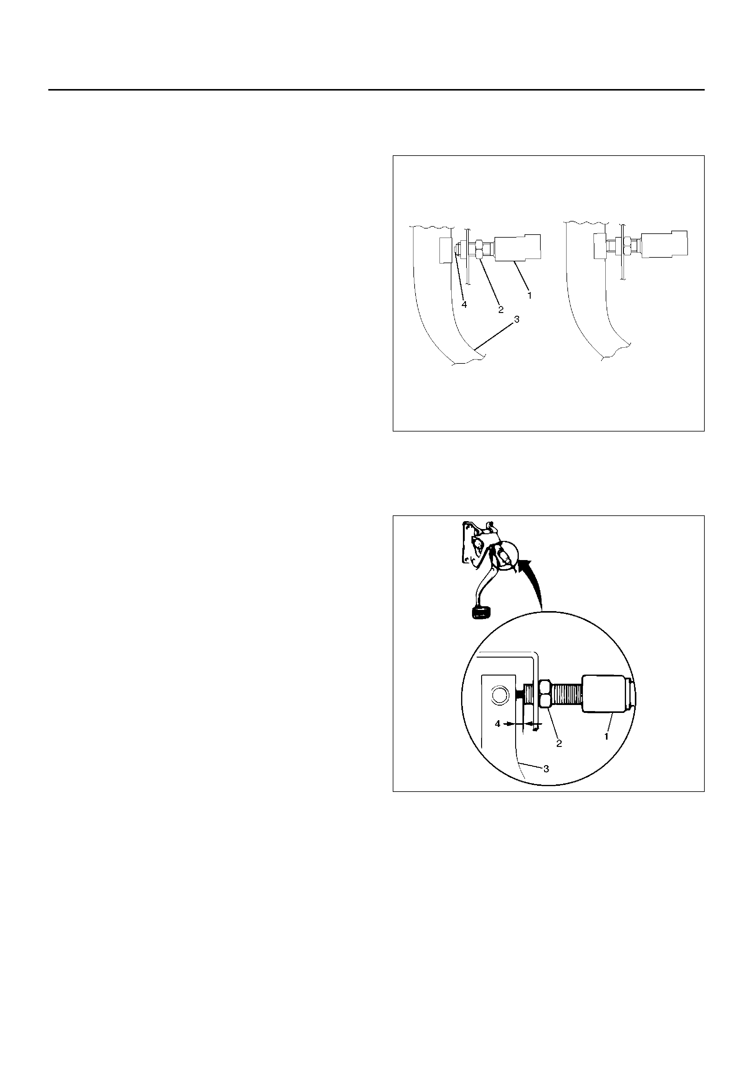
Adjustment
1.Check that the brake pedal (3) is fully returned by
pedal return spring.
2.Disconnect the switch connector.
3.Loosen the lock nut (2).
4.Rotate the brake switch (1) by hand until push rod
disappears from brake switch tip (4).
5.Return the brake switch by a half turn.
6.Tighten the lock nut.
7.Connect the switch connector.
310RS028
Clutch Switch
Removal and Installation
Refer to the Clutch Control in Clutch section.
Adjustment
1. Turn the clutch switch (1) until the switch plunger is
fully retracted against the clutch pedal arm.
2. Adjust clutch switch by bac king it out half a turn and
measure the clearance (4) between the clutch pedal
arm (3) and the clutch switch.
3. Lock the lock nut(2).
4. Connect clutch switch connector.
Clutch Switch (bolt) and Clutch Pedal Clearance
0.5 – 1.5 mm (0.020 – 0.059 in)
203RS016-1
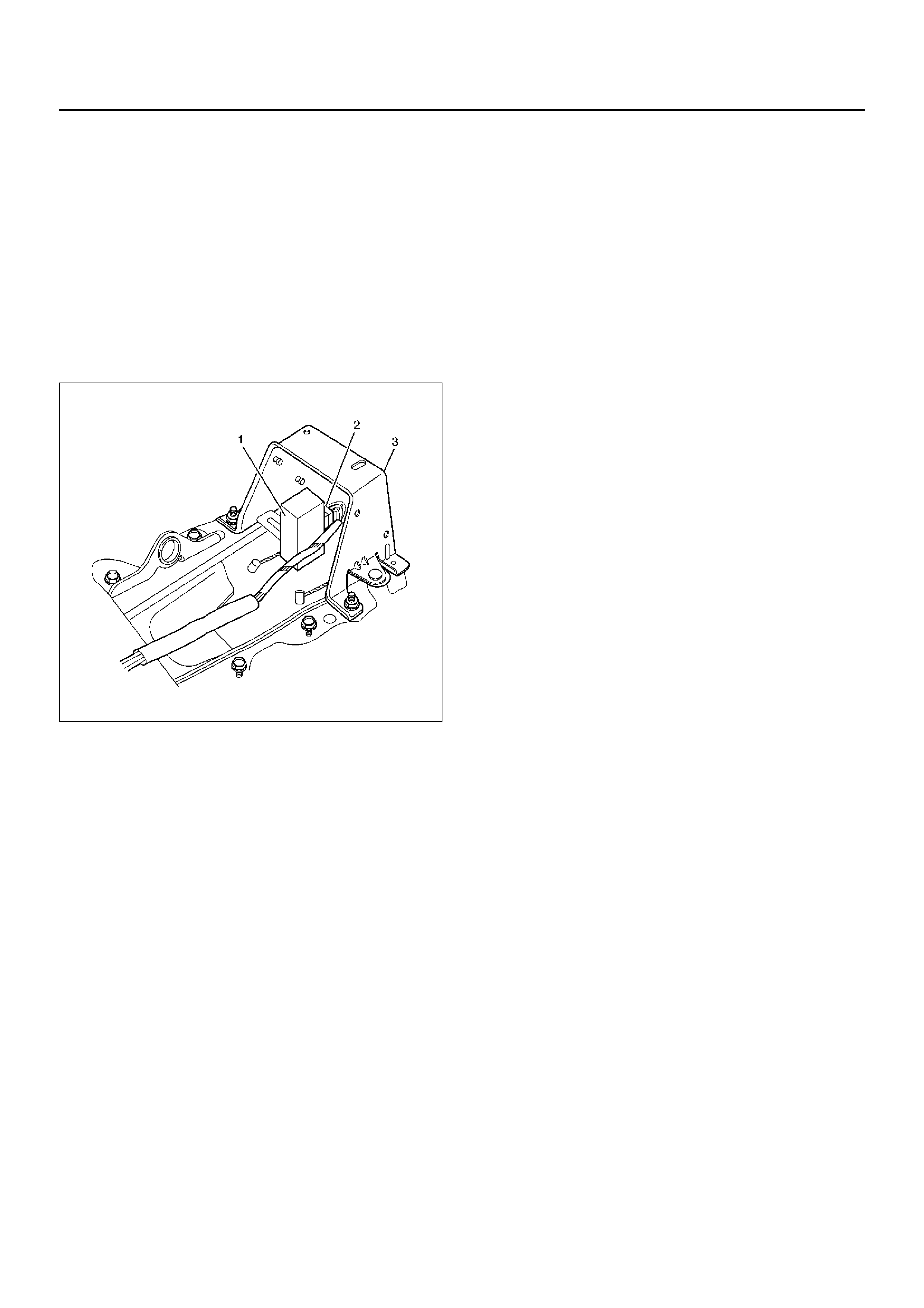
Cruise Control Unit
Removal
1. Disconnect the battery ground cable.
2. Remove the rear console box assembly.
• Remove four screws.
3. Remove the cover (3).
• Remove four nuts.
4. Remove the cruise control unit (1).
• Disconnect the connector (2).
825RX017
Installation
To install, follow the removal steps in the reverse order.
Cruise Actuator
Actuator Cable Diagram
825RW093
Legend
EndOFCallout
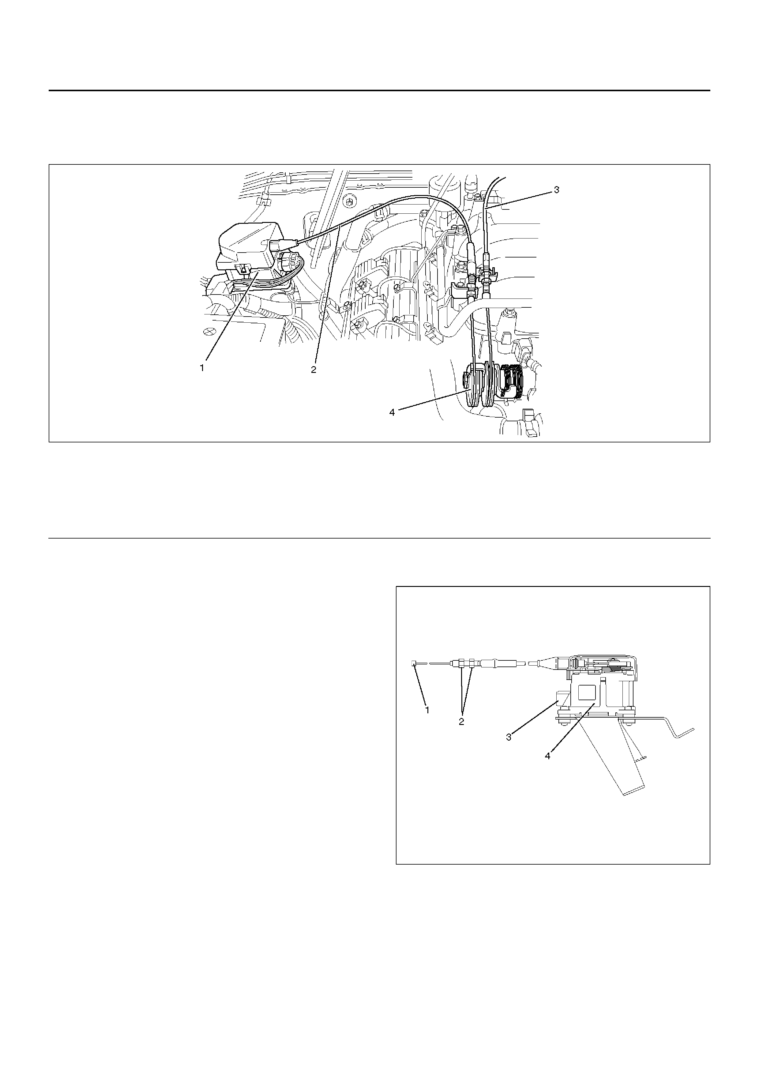
Removal
1.Disconnect the battery ground cable.
2. Remove the cruise actuator assembly (4).
• Disconnect the connector (3).
• Remove the cable end (1) from the throttle link
(cruise control side).
• Loosen two fixing nuts (2).
• Remove three actuator assembly fixing screws.
825RW049
Installation
To install, follow the removal steps in the reverse order,
noting the following point:
1. Take care not to bend the cable excessively.
(1) Cruise Actuator Assembly
(2) Cruise Control Cable
(3) Acc el erator Cable
(4) Throttle Link (Cruise Control Side)
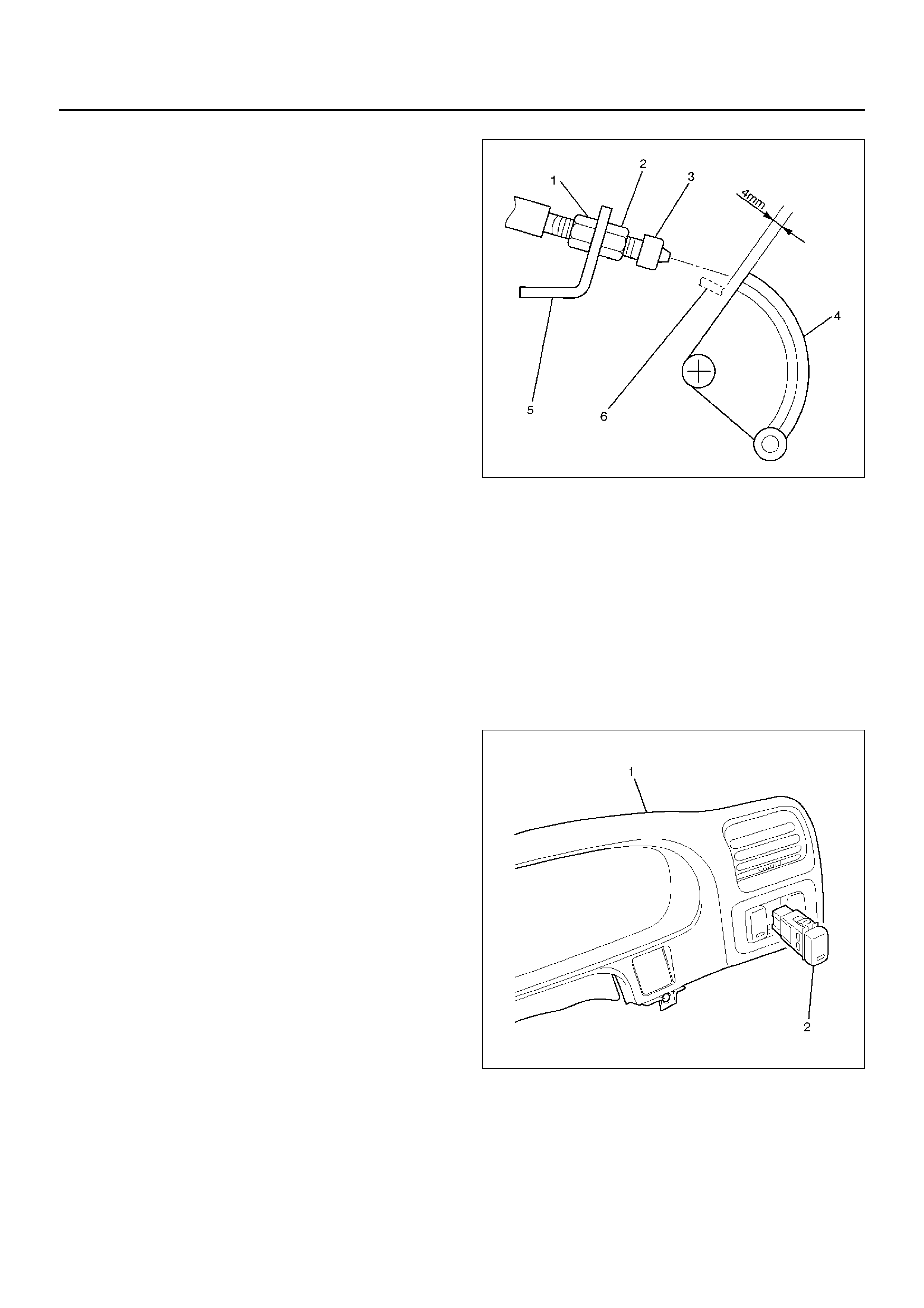
Adjustment
After installing the cruise actuator, the following steps
must be carried out for cruise control cable adjustment.
1.Install the cruise control cable end (3) to the throttle
link (4).
2.Put the screw portion of the cable in the bracket (5).
3.Put the nut (1) to the bracket and then tighten the
nut (2).
•If the distance between the throttle link (4) and
the throttle link lever (6) is out of the specified
range, loosen the nut (2) to adjust it.
035RW140
Mode Switch
Removal and Installation
Refer to Mode Switch in Automatic Transmission
section.
Cruise Control Main Switch
Removal
1.Disconnect the battery ground cable.
2.Remove the meter cluster assembly (1).
•Refer to the Instrument Panel Assembly in Body
Structure section.
3. Remove the cruise control main switch (2).
• Disconnect the switch connector.
• To remove the switch, push the lock from the back
side of the instrument panel cluster assembly.
825RX035
Installation
To install, follow the removal steps in the reverse order.