
SECTION 2A - POWER-ASSISTED STEERING SYSTEM
Service Precaution
Diagnosis
General Description
Power Steering System Test
Maintenance
Fluid Level
Bleeding The Power Steering System
Bleeding Procedure
Flushing The Power Steering System
Steering Wheel Free Play Inspection
Front End Alignment Inspection
and Adjustment
Main Data and Specifications
Special Tools
Power Steering Unit
Power Steering Unit and Associated Parts
Removal
Installation
Power Steering Unit Disassembled View
Disassembly
Inspection and Repair
Reassembly
Main Data and Specifications
Special Tools
Power Steering Pump
Power Steering Pump and
Associated Parts
Removal
Installation
Power Steering Pump Disassembled View
Disassembly
Inspection and Repair
Reassembly
Main Data and Specifications
Transfer Gear Assembly
Transfer Gear Assembly
and Associated Parts
Removal
Inspection and Repair
Installation
Supplemental Restraint System Steering
Wheel & Column
Service Precaution
SRS Connectors
Inflator Module
Inflator Module and Associated Parts
Removal
Inspection and Repair
Installation
Steering Wheel
Steering Wheel and Associated Parts
Removal
Installation
Combination Switch
Combination Switch and Associated Parts
Removal
Installation
Lock Cylinder
Lock Cylinder and Associated Parts
Removal
Installation
System Inspection
Steering Column
Steering Column and Associated Parts
Removal
Insepction
Installation
System Inspection
Supplemental Restraint System Steering
Wheel & Column and Associated Parts
Main Data and Specifications
Special Tools
Service Precaution
WARNING: THIS VEHICLE HAS A SUPPLEMENTAL
RESTRAINT SYSTEM (SRS). REFER TO THE SRS
COMPONENT AND WIRING LOCATION VIEW IN
ORDER TO DETERMINE WHETHER YOU ARE
PERFORMING SERVICE ON OR NEAR THE SRS
COMPONENTS OR THE SRS WIRING. WHEN YOU
ARE PERFORMING SERVICE ON OR NEAR THE
SRS COMPONENTS OR THE SRS WIRING, REFER
TO THE SRS SERVICE INFORMATION. FAILURE TO
FOLLOW WARNINGS COULD RESULT IN
POSSIBLE AIR BAG DEPLOYMENT, PERSONAL
INJURY, OR OTHERWISE UNNEEDED SRS SYSTEM
REPAIRS.
CAUTION: Always use the correct fastener in the
proper location. When you replace a fastener, use
ONLY the exact part number for that application.
ISUZU will call out those fasteners that require a
replacement after removal. ISUZU will also call out
the fasteners that require thread lockers or thread
sealant. UNLESS OTHERWISE SPECIFIED, do not
use supplemental coatings (Paints, greases, or
other corrosion inhibitors) on threaded fasteners or
fastener joint interfaces. Generally, such coatings
adversely affect the fastener torque and the joint
clamping f or ce, and may dama ge the fastener . Wh en
you install fasteners, use the correct tightening
sequence and specifications. Following these
instructions can help you avoid damage to parts
and systems.
Diagnosis
Since the problems in steering, suspension, wheels and
tires involve several systems, they must all be
considered when diagnosing a complaint. To identify
the symptom, always road test the vehicle first.
Proceed with the f ollowing preliminary inspections and
correct any defects which are found.
1. Inspect tires for proper pressure and uneven wear.
2. Raise vehicle on a hoist, then inspect front and rear
suspen si on and steering li nk age for loose or
damaged parts.
3. Spin the front wheels. Inspect for out-of-round tires,
out-of-balance tires, loose and/or rough wheel
bearings.
General Diagnosis
Condition Possible cause Correction
Vehicle Pulls Mismatched or uneven tires. Replace tire.
Tires not adequately inflated. Adjust tire pressure.
Broken or sagging springs. Replace spring.
Radial tire lateral force. Replace tire.
Improper wheel alignment. Adjust wheel alignment.
Brake dragging in one wheel. Repair brake.
Loose, bent or broken front or rear
suspension parts. Tighten or replace the appropriate
suspension part(s).
Faulty shock absorbers. Replace shock absorber.
Parts in p ower steering valve
defective. Replace power steering unit.
Abnormal or Excessive Tire Wear Sagging or broken spring. Replace spring.
Tire out of balance. Balance or replace tire.
Improper wheel alignment. Check front end alignment.
Faulty shock absorber. Replace shock absorber.
Hard driving. Replace tire.
Overloaded vehicle. Replace tire and reduce load.
Tires not rotated periodically. Replace or rotate tire.
W orn or loose road wheel bearings. Replace wheel bearing.
Wobbly wheel or tires. Replace wheel or tire.
Tires not adequately inflated. Adjust the pressure.
Wheel Hop Blister or bump on tire. Replace tire.
Improper shock absorber operation. Replace shock absorber.
Techline
Shimmy, Shake or Vibration Tire or wheel out of balance. Balance wheels or replace tire/or
wheel.
Loose wheel bearings. Replace wheel bearing.
Worn steering linkage ball joints. Replace ball joints.
Worn upper or lower end ball joints. Replace ball joints.
Excessive wheel run–out. Repair or replace wheel and/or tire.
Blister or bump on tire. Replace tire.
Excessive loaded radial run–out of
tire/wheel assembly. Replace tire or wheel.
Improper wheel alignment. Check wheel alignment.
Loose or worn steering linkage. Tighten or replace steering linkage.
Loose steering unit. Tighten steering unit.
Tires not adequately inflated. Adjust tire pressure.
Loose, bent or broken front or rear
suspension parts. Tighten or replace the appropriate
suspension parts.
Faulty shock absorber. Replace shock absorber.
Hub bearing preload misadjustment. Adjust preload.
Parts in p ower steering valve
defective. Replace power steering unit.
Hard Steering Bind in steering linkage ball studs,
upper or lower end ball joint. Replace ball joint.
Improper wheel alignment. Check wheel alignment.
Tire not adequately inflated. Inflate tires to proper pressure.
Bind in steering column or shaft. Repair or replace.
Improper power steering system
operation. Repair or replace.
Refer to “Pow er steering system
diagnosis"
Too Much Play In Steering Wheel bearings worn. Replace wheel bearings.
Loose steering unit or linkage. Retighten or repair.
W orn or loose steering shaft
universal joint. Retighten or replace steering shaft.
Worn steering linkage ball joints. Replace ball joints.
Worn upper or lower end ball joints. Replace ball joints.
Poor Steering Wheel Returnability Bind in steering linkage ball joints. Replace ball joints.
Bind in upper or lower end ball
joints. Replace ball joints.
Bind in steering column and shaft. Repair or replace.
Bind in steering gear. Check and repair steering gear.
Improper wheel alignment. Adjust wheel alignment.
Tires not adequately inflated. Adjust tire pressure.
Loose steering wheel nut. Retighten.
Worn wheel bearing . Replace.
Condition Possible cause Correction

Abnormal Noise W orn, sticky or loose upper or lower
ball joint, steering linkage ball joints
or drive axle joints.
Replace.
Faulty shock absorbers. Replace.
W orn upper or lower control arm
bushing. Replace.
Loose stabilizer bar. Retighten bolts or replace bushings.
Loose wheel nuts. Tighten nuts. Check for elongated
wheel nut holes.
Replace wheel if required.
Loose suspension bolts or nuts. Retighten suspension bolts or nuts.
Broken or otherwise damaged wheel
bearings. Replace wheel bearing.
Broken suspension springs. Replace spring.
Loose steering unit. Retighten mounting bolt.
Faulty steering unit. Replace steering unit.
Wandering or Poor Steering Stability Mismatched or unevenly worn tires. Replace tire or inflate tires to proper
pressure.
Loose steering linkage ball joints. Replace ball joints.
Faulty shock absorbers. Replace shock absorber.
Loose stabilizer bar. Tighten or replace stabilizer bar or
bushings.
Broken or sagging springs. Replace spring (pairs).
Improper wheel alignment. Adjust wheel alignment.
Erratic Steering When Braking W orn wheel bearings. Replace wheel bearings.
Broken or sagging springs. Replace spring (pairs).
Leaking caliper. Repair or replace caliper.
Warped discs. Replace brake disc.
Badly worn brake pads. Replace brake pads.
Tires are inflated unequally. Inflate tires to proper pressure.
Condition Possible cause Correction
Power Steering System
There is some noise in all power steering systems. One
of the most common is a hissing sound when the
steering wheel is fully turned and the car is not moving.
This noise will be most evident when the steering wheel
is operated while the brakes are applied. There is no
relationship between this noise and steering
performance. Do not replace the valve unless the
“hissing" noise is extremely objectionable. A
replacement valve will also have a slight noise, and is
not always a cu re for the condition.
Condition Possible cause Correction
Rattle or Chucking Noise Pressure hose touching other parts
of vehicl e. Adjust hose position. Do not bend
tubing by hand.
Tie rod ends loose. Tighten or replace tie rod end.
Loose steering unit mounting. Tighten steering unit mounting.
Poor Return of S teering Wheel to
Center Improper front wheel alignment. Adjust front wheel alignment.
Wheel bearing worn. Replace front wheel bearing.
Tie rod end binding. Replace tie rod end.
Ball joint binding. Replace ball joint.
Tight or frozen steering shaft
bearing. Replace steering assembly.
Sticky or plugged steering unit valv e. Flush or replace steering unit.
Entry of air in the power steering
system. Bleed the system.
Momentary Increase In Effort When
Turning Wheel Fast To Right or Left High internal leakage. Repair steering gear.
Power steering fluid level low. Replenish fluid.
Steering Wheel Surges or Jerks
When Turning Especially During
Parking
Insufficient pump pressure. Repair pump assembly.
Sticky steering unit valv e. Flush or replace steering unit.
Power steering fluid level low. Replenish fluid.
Excessive Wheel Kick Back or
Loose Steering Air in system. Bleed hydraulic system.
Tie rod end loose. Tighten tie rod end.
Wheel bearing worn. Replace wheel bearing.
Hard Steering or Lack or Power
Assist Sticky steering unit valve. Flush or replace steering unit.
Insufficient pump pressure. Repair pump assembly.
Excessive internal pump leakage. Repair pump assembly.
Excessive internal steering gear
leakage. Repair steering gear.
Power steering fluid level low. Replenish fluid.
Unstable Engine Idling or Stalling
When Turning Pressure switch of the power
steering pump or its harness is
faulty.
Repair or replace.
Power Steering Pump
Foaming milky power steering fluid, low fluid level, and
possible low pressure can be caused by air in the fluid,
or loss of fluid due to internal pump leakage. Check for
leak and correct. Bleed the system. Extremely cold
temperatures will cause air bubbles in the system if the
fluid le vel is low. If the fluid lev el is correct and the pump
still foams, remove the pump from the vehicle and
check housing for cracks. If the housing is cracked,
replace the pump housing.
Steering Column Lock System
Column
Condition Possible cause Correction
Low Pressure Due to Steering Pump Relief valve stic king or inoperative. Replace relief valve.
Side plate not flat against cam ring. Replace side plate.
Extreme wear of cam ring. Replace cam ring.
Scored side plate or rotor. Replace side plate or rotor.
Vanes sticking in rotor slots. Repair or replace vanes and rotor.
Cracked or broken side plate. Replace side plate.
High internal leakage. Repair internal leakage.
Low Pressure Due to Steering Gear Scored housing bore. Replace housing.
Growling Noise In Steering Pump Excessive back pressure in hoses or
steering unit caused by restriction. Repair steering unit or pump.
Scored side plate or rotor. Replace side plate or rotor.
W orn cam ring. Replace cam ring.
Groaning Noise In Steering Pump Air in the fluid. Bleed hydraulic system.
Low fluid level. Replenish fluid.
Pump mounting loose. Tighten mounting bolt.
Rattling Noise In Steering Pump Vanes sticking in rotor slots. Repair or replace vanes and rotor.
Vane improperly installed. Repair rotor and vane.
Swishing Noise In Steering Pump Damaged relief valve. Replace relief valve.
Whining Noise In Steering Pump Scored side plate and vanes. Replace side plate and vanes.
Condition Possible cause Correction
Will Not Unlock Damaged lock cylinder. Replace lock cylinder.
Damaged park lock cable. Replace park lock cable.
Will Not Lock Lock spring broken or worn. Replace lock cylinder.
Damaged lock cylinder. Replace lock cylinder.
Ignition switch stuck. Repair or replace ignition switch.
Park lock cable damaged. Replace park lock cable.
Key Cannot be Removed in
“OFF-LOCK" Ignition switch is not set correctly. Correct ignition switch.
Damaged lock cylinder. Replace lock cylinder.
Faulty shift lock mechanism. Repair or replace the shift lock
mechanism.
Condition Possible cause Correction
Noise in Column Universal joint loose. Tighten joint.
Shaft lock snap ring not seated. Place snap ring in proper position.

Turn Signal Switch
This diagnosis covers mechanical problems only. Refer
to Turn Signal Switch in Electrical section for electrical
diagnosis.
Condition Possible cause Correction
Turn Signal Will Not Stay In Turn
Position Foreign material or loose parts
preventing movement of yoke. Repair or replace signal switch.
Broken or missing detent or
canceling spring. Replace signal switch.
Turn Signal Will Not Cancel Loose switch mounting screws. Tighten mounting screws.
Switch or anchor bosses broken. Replace turn signal switch.
Broken, missing or out of position
detent, return or canceling spring. Replace turn signal switch.
W orn canceling cam. Replace turn signal switch.
Turn Signal Difficult To Operate Turn signal switch arm loose. Tighten arm screw.
Broken or distorted yoke. Replace turn signal switch.
Loose or misplaced springs. Replace turn signal switch.
Foreign parts and/or material. Repair turn signal switch.
Loose turn signal switch mounting
screws. Tighten mounting screws.
Turn Signal Will Not Indicate Lane
Change Broken lane change pressure pad or
spring hanger. Replace turn signal switch.
Broken, missing or misplaced lane
change spring. Replace turn signal switch.
Base of wire damaged. Replace turn signal switch.
Hazard Switch Cannot Be Turned
Off Foreign material between hazard
switch to turn signal switch body. Repair or replace hazard switch.
No Turn Signal Lights Electrical failure in chassis harness. Refer to Electrical section.
Inoperative turn signal flasher unit. Replace flasher unit.
Loose chassis harness connector. Repair loose connector.
Front or Rear Turn Signal Lights Not
Flashing Burned-out or damaged turn signal
bulb. Replace bulb.
High resistance connection to
ground at bulb socket. Repair bulb socket.
Loose chassis harness connector. Repair loose connector.
General Description
The hydraulic power steering system consists of a
pump, an oil reserv oir, a steering unit, a pressure hose
and a return hose.
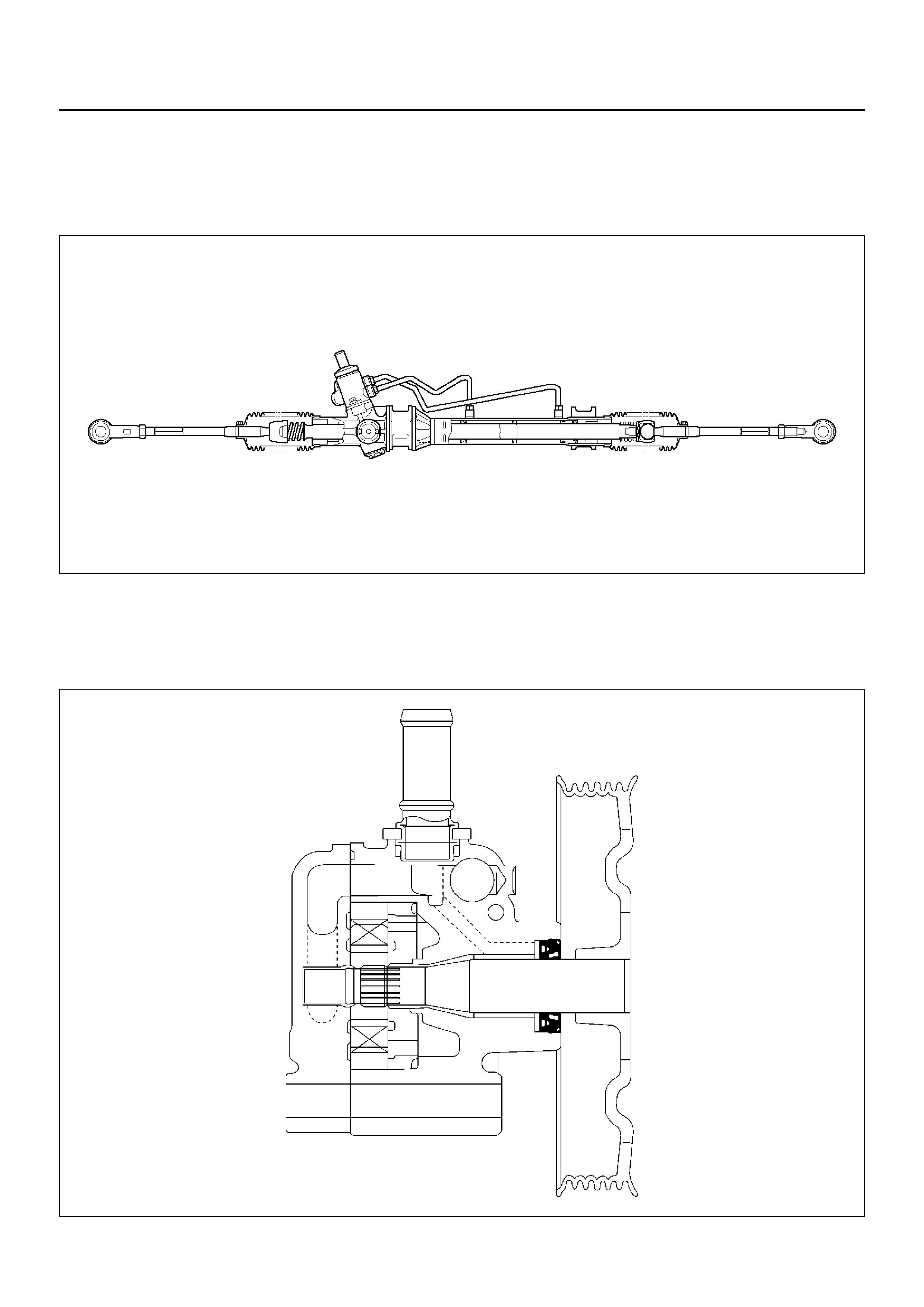
Power Steering Unit
A02RW007
The power steering unit is rack and pinion type.
The toe–in angle can be adjusted by turning the rod on
each side.
The steering housing cannot be disassembled.
Hydraulic Pump
A02RX002

The hydraulic pump is vane-type design. The
submerged pump has housing and internal parts that
are inside the reservoir and operate submerged in oil.
There are two bore openings at the rear of the pump
housing. The larger opening contains the cam ring,
pressure plate, thrust plate, rotor and vane assembly,
and end plate. The smaller opening contains the
pressure line union, flow control valve and spring.
The flow control orifice is part of the pressure line union.
The pressure relief valve inside the flow control valve
limits the pump pressure.
Pressure Switch
When hydraulic pressure reaches 3430 kPa (35 kg/cm2/
500 psi), the pressure switch of the power steering
pump closes causing the Engine Control Module (ECM)
to actuate the idle air control valve, which increases the
engine rpm to prevent the overload-induced engine
speed slow down. The switch opens when hydraulic
pressure drops to 2940 kPa (30 kg/cm2/430 psi).
Steering Column
431RY00009
WARNING: TO AVOID DEPLOYMENT WHEN
TROUBLE-SHOOTING THE SRS SYSTEM, DO NOT
USE ELECTRICAL TEST EQUIPMENT, SUCH AS
BATTERY-POWERED OR A/C-POWERED
VOLT-METER, OHMMETER, ETC., OR ANY TYPE
OF ELECTRICAL EQUIPMENT OTHER THAN
SPECIFIED IN THIS MANUAL. DO NOT USE A
NON-POWERED PROBE-TYPE TESTER.
INSTRUCTION IN THIS MANUAL MUST BE
FOLLOWED CAREFULLY, OTHERWISE PERSONAL
INJURY MAY RESULT.
When servicing a vehicle equipped with Supplemental
Restraint System, pay close attention to all WARNINGS
and CAUTIONS.
For detailed explanation about SRS, refer to Restraints
section.
The steering column has three important features in
addition to the steering function:
1.The column is energy absorbing, designed to
compress in a front-end collision to minimize the
possibility of injury to the driver of the vehicle.
2.The ignition switch and lock are mounted
conveniently on the column.
3.With the column mounted lock, the ignition and
steering operation can be locked to prevent theft of
the vehicle.
The column can be disassembled and reassembled.
However, to insure the energy absorbing action, use
only the specified screws, bolts and nuts as designated,
and tighten them to the specified torque.
Handle the column with care when it is removed from
the vehicle. A sharp blow on the end of steering shaft or
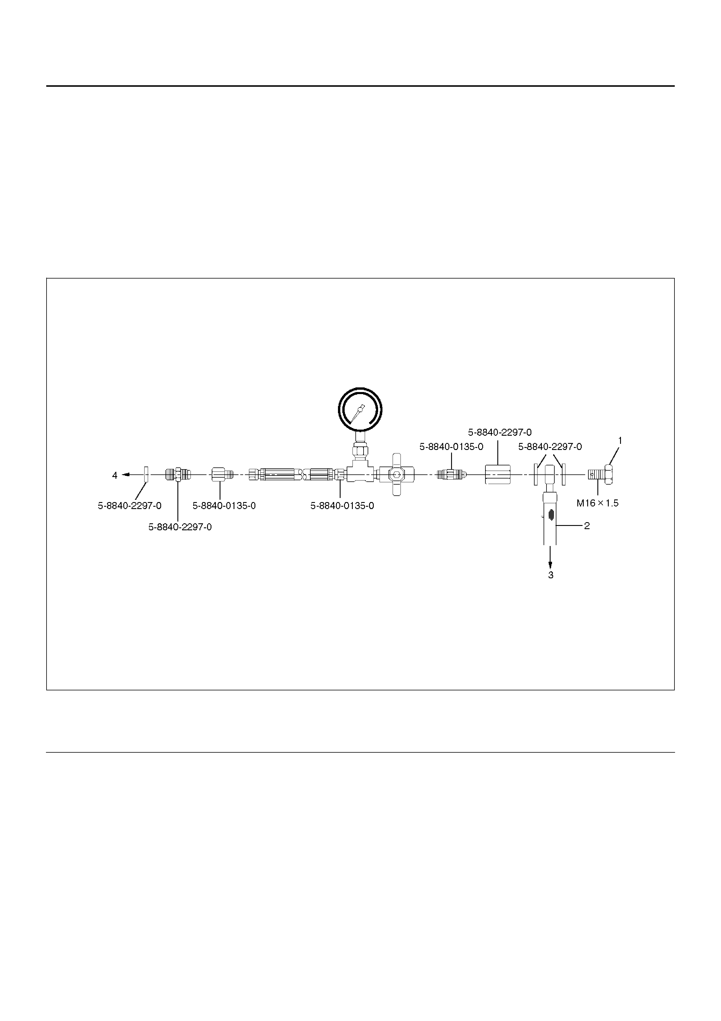
Power Steering System Test
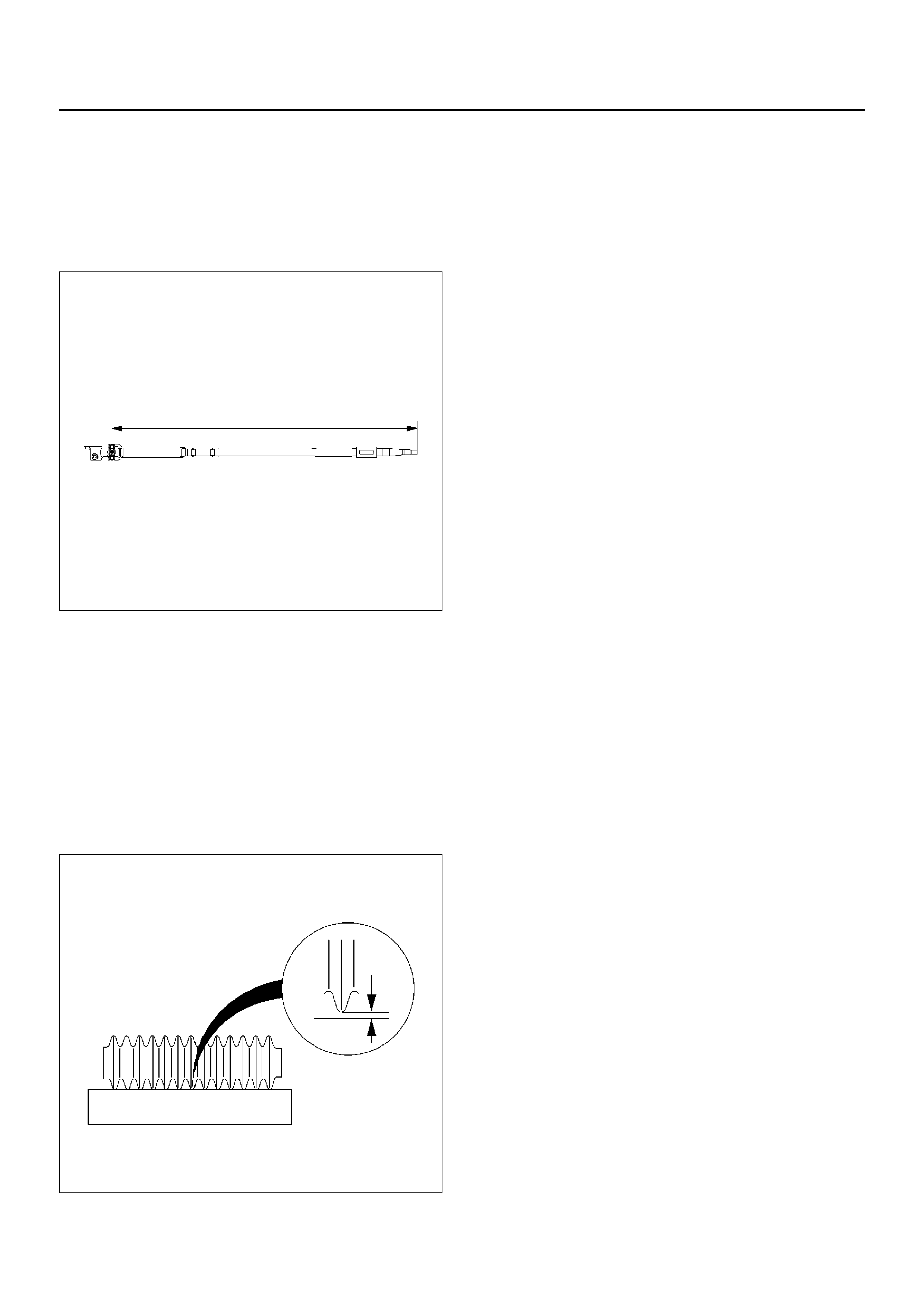
Test Procedure
F02RX002
Legend
Test of fluid pressure in the power steering system is
perf ormed to determine whether or not the oil pump and
power steering unit are functioning normally.
The power steering system test is used to identify and
isolate hydraulic circuit difficulties. Prior to performing
this test, the following inspections and corrections, if
necessary, must be made.
• Inspect pump reservoir for proper fluid level.
• Inspect pump belt for proper tension.
• Inspect pump driver pulley condition.
1. Place a container under the pump to catch the fluid
when disconnecting or connecting the hoses.
2. With the engine NOT running, disconnect the
pressure hose at the power steering pump and
install power steering tester 5–8840–0135–0 as
shown in the illustration. The gage must be
between the shutoff valve and pump. Open the
shutoff valve.
3. Check the fluid level. Fill the reservoir with power
steering fluid, to the “Full" mark. Start the engine,
then turn the steering wheel and momentarily hold it
against a stop (right or left). Turn the engine off and
check the connections at tester for leakage.
(1) Bolt
(2) Hose (3) Power Steering Unit
(4) Power Steering Pump

4.Bleed the system. Refer to Bleeding the Power
Steering System in this section.
5.Start the engine and check the fluid level. Add
power steering fluid if required. When the engine is
at normal operating temperature, increase engine
speed to 1500 rpm.
CAUTION: Do not leave shutoff valve fully closed
for more than 5 seconds, as the pump could
become damaged internally.
6.Fully close the shutoff valve. Record the highest
pressures.
•If the pressure recorded is within 9300–9800 kPa
(95–100 kg/cm2/1350–1420 psi), the pump is
functioning within its specifications.
•If the pressure recorded is higher than 9800 kPa
(100 kg/cm2/1420 psi), the valve in the pump is
defective.
•If the pressure recorded is lower than 9300 kPa
(95 kg/cm2/1350 psi), the valve or the rotating
group in the pump is defective.
7.If the pump pressures are within specifications,
leave the valve open and turn (or have someone
else turn) the steering wheel fully in both directions.
Record the highest pressures and compare with the
maximum pump pressure recorded in step 6. If this
pressure cannot be built in either side of the power
steering unit, the power steering unit is leaking
internally and must be replaced.
8.Shut the engine off, remove the testing gauge.
9.Reconnect the pressure hose, check the fluid level
and make the needed repairs.
10.If the problem still exists, the steering and front
suspension must be thoroughly examined.
Maintenance
The hydraulic system should be kept clean and fluid
level in the reservoir should be checked at regular
intervals and fluid added when required. Refer to
Recommended Fluids and Lubricants in General
Information section for the type of fluid to be used and
the intervals for filling.
If the system contains some dirt, flush it as described in
this section. If it is exceptionally dirty, the pump must
be completely disassembled before further usage. (The
steering unit cannot be disassembled.)
All tubes, hoses, and fittings should be inspected for
leakage at regular intervals. Fittings must be tight.
Make sure the clips, clamps and supporting tubes and
hoses are in place and properly secured.
Power steering hoses and lines must not be twisted,
kinked or tightly bent. Air in the system will cause
spongy action and noisy operation. When a hose is
disconnected or when fluid is lost, for any reason, the
system must be bled after refilling. Refer to Bleeding
the Power Steering System in this section.
•Inspect belt for tightness.
•Inspect pulley for looseness or damage. The pulley
should not wobble with the engine running.
•Inspect hoses so they are not touching any other
parts of the vehicle.
•Inspect fluid level and fill to the proper level.
Fluid Level
1.Run the engine until the power steering fluid
reaches normal operating temperature, about 55°C
(130°F), then shut the engine off.
2.Check the level of fluid in the reservoir.
3.If the fluid level is low, add power steering fluid as
specified in General Information to the proper level
and install the receiver cap.
4.When checking the fluid level after the steering
system has been serviced, air must be bled from the
system. Refer to Bleeding the Power Steering
System in this section.
Bleeding The Power Steering System
When a power steering pump or unit has been installed,
or an oil line has been disconnected, the air that has
entered the system must be bled out before the vehicle
is operated. If air is allowed to remain in the power
steering fluid system, noisy and unsatisfactory
operation of the system may result.
Bleeding Procedure
When bleeding the system, and any time fluid is added
to the power steering system, be sure to use only
power steering fluid as specified in General Information.
1. Fill the pump fluid reservoir to the proper level and
let the fluid settle for at least two minutes.
2. Start the engine and let it run for a f e w seconds. Do
not turn the steering wheel. Then turn the engine
off.
3. Add fluid if necessary.
4. Repeat the above procedure until the fluid level
remain s constant after running the engine.
5. Raise and support the front end of the vehicle so
that the wheels are off the ground.
6. Start the engine. Slowly turn the steering wheel
right and left, lightly contacting the wheel stops.
7. Add power steering fluid if necessary.
8. Lower the vehicle, set the steering wh eel at the
straight forward position after turning it to its full
steer positions 2 or 3 times, and stop the engine.
9. Check the fluid level and refill as required.
10. If the fluid is extremely foamy, allow the vehicle to
set a f e w minutes, then repeat the abov e procedure.
Flushing The Power Steering System
1. Raise and support the front end of the vehicle off
the ground until the wheels are free to turn.
2. Remove the fluid return line at the pump inlet
connector and plug the connector port on the pump.
Position the line toward a large container to catch
the draining fluid.
3. While running the engine at idle, fill the reservoir
with new power steering fluid. Turn the steering
wheel in both directions. Do not contact or hold the
steering wheel to the wheel stops. This will cause
the pump to go to pressure relief mode, which may
cause a sudden fluid overflow at the reservoir.
4. Install all the lines and hoses. Fill the system with
new power steering fluid and bleed the system as
described in Bleeding The P ow er Steering System.
Operate the engine for about 15 minutes.
Remove the pump return line at the pump inlet and
plug the connection on the pump. While refilling the
reservoir , check the draining fluid f or contamination.
If foreign material is still evident, replace all lines,
disassemble and clean or replace the power
steering system components. Do not re-use any
drained power steering fluid.
Steering Wheel Free Play Inspection
430RW020
1. With the tires in the straight-ahead position, check
the amount of steering wheel play by turning the
wheel in both directions until the tires begin to mov e.
NOTE: The wheel free play should be checked with the
engine running.
Free play: 0 – 30mm (0 – 1.18in)
2. Also check the steering wheel for pla y and
looseness in the mount by moving it back and forth
and sideways. When test driving, check for hard
steering, steering shimmy and tendency to pull to
one side.
Front End Alignment Inspection and
Adjustment
General Description
“Front End Alignment" refers to the angular relationship
between the front wheels, the front suspension
attaching parts and the ground.
Proper front end alignment must be maintained in order
to insure efficient steering, good directional stability and
to prevent abnormal tire wear.
The most important factors of front end alignment are
whee l toe-in, wheel cam ber and axle cas te r.
Camber:
This illustration shows view from the front of the vehicle.
480RS004
Camber is the vertical tilting inward or outward of the
front wheels. When the wheels tilt outward at the top,
the ca mbe r is po sit ive (+). Wh en t he wh eel s til t i nw ard
at the top , the camber is negative (-). The amount of tilt
measured in degrees from the vertical is called the
camber angle (1). If camber is ex treme or unequal
between the wheels, improper steering and excessive
tire wear will result. Negative camber causes wear on
the inside of the tire, while positive camber causes wear
to the outside.
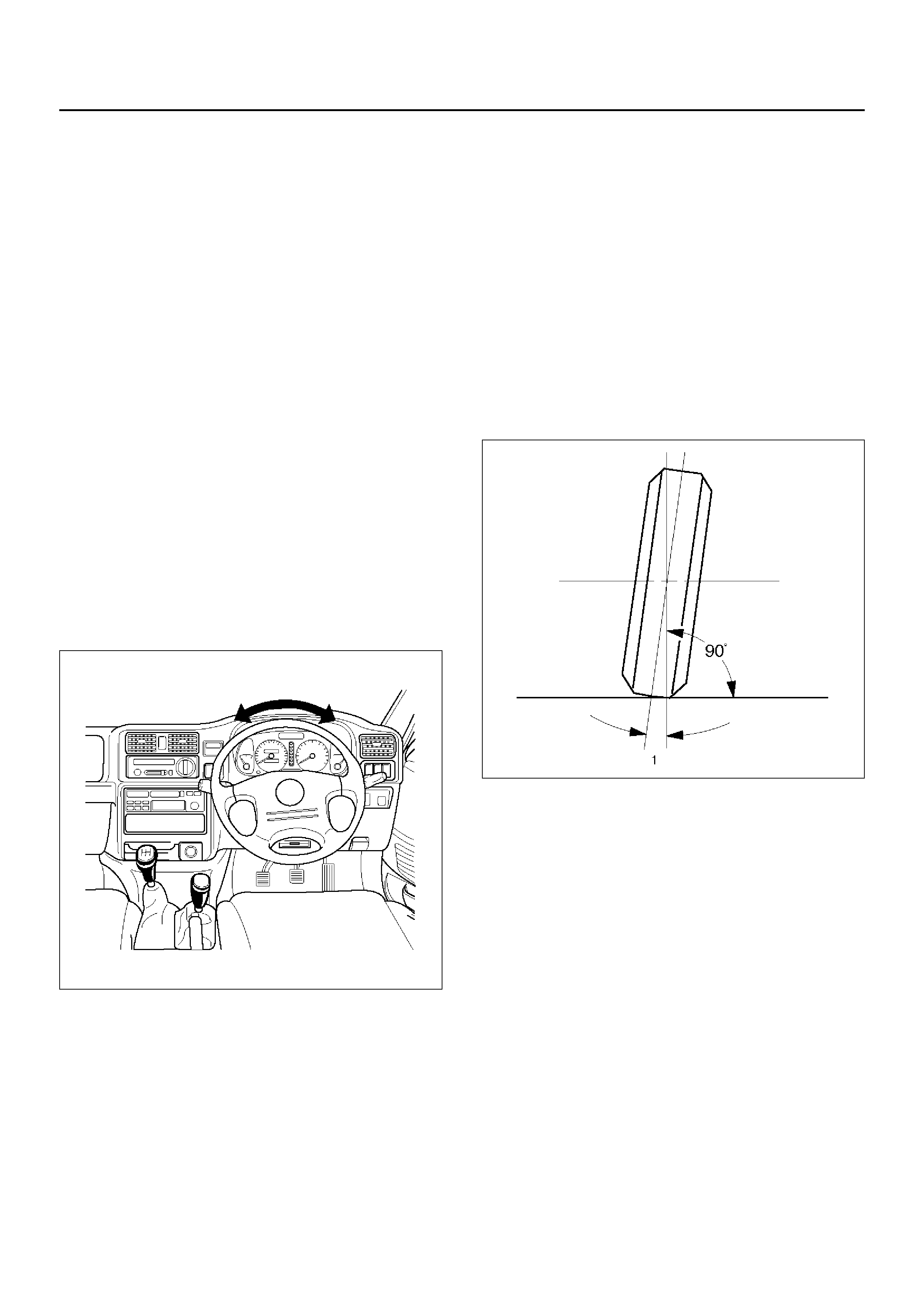
Caster:
This illustration shows view from the side of the vehicle.
480RS005
Caster (1) is the vertical tilting of the wheel axis either
forward or backward (when viewed from the side of the
vehicle). A backward tilt is positive (+) and a forward tilt
is negative (-). On the short and long arm type
suspension you cannot see a caster angle without a
special instrument, but if you look straight down from the
top of the upper control arm to the ground, the ball
joints do not line up (fore and aft) when a caster angle
other than 0 degree is present. With a positive angle,
the lower ball joint would be slightly ahead (toward the
front of the vehicle) of the upper ball joint center line.
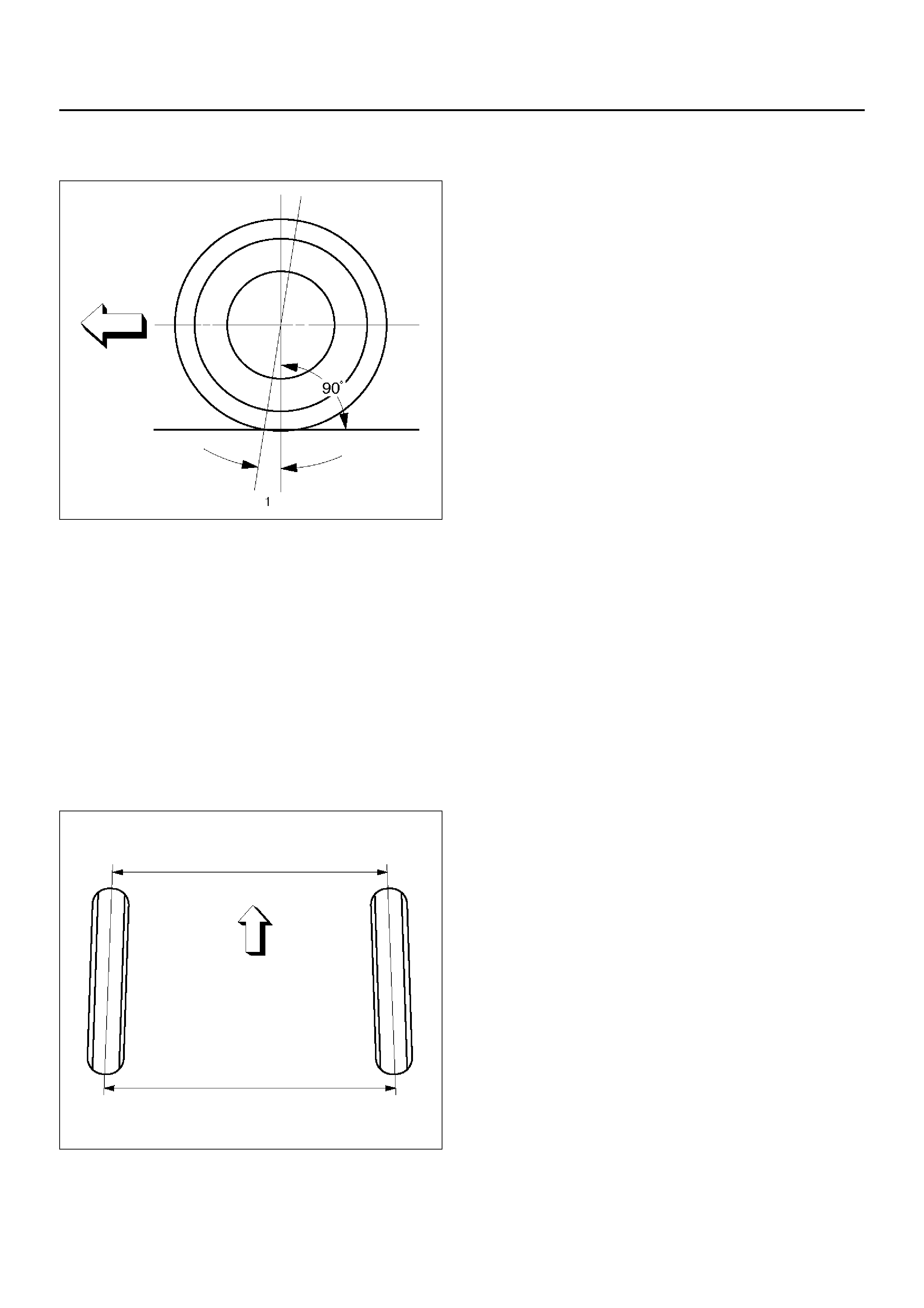
Toe-in:
This illustration shows view from the top of the vehicle.
480RS003
Toe-in is the measured amount the front wheels are turn
in. The actual amount of toe-in is normally a fraction of
a degree. Toe-in is measured from the center of the tire
treads or from the inside of the tires. The purpose of
toe-in is to insure parallel rolling of the front wheels and
to offset any small deflections of the wheel support
system which occurs when the vehicle is rolling forward.
Incorrect toe-in results in excessive toe-in and unstable
steering. Toe-in is the last alignment to be set in the
front end alignment procedure.
Inspection
Before making any adjustments affecting caster, camber
or toe-in, the following front end inspection should be
made.
1.Inspect the tires for proper inflation pressure. Refer
to Main Data and Specifications in Wheel and Tire
System section.
2.Make sure that the vehicle is unladen condition
(With no passenger or loading).
3.Make sure that the spare tire is installed at the
normal position.
4.Inspect the front wheel bearings for proper
adjustment. Refer to Front Hub and Disc in
Driveline section.
5. Inspect the ball joints and tie rod ends. If excessive
looseness is noted, correct before adjusting. Refer
to Steering Linkage in this section.
6. Inspect the wheel and tires for run-out. Refer to
Wheel Replacement in Wheel and Tire System
section.
7. Inspect the trim height. If not within specifications,
the correction must be made before adjusting
caster.
8. Inspect the steering unit for looseness at the frame.
9. Inspect shock absorbers for leaks or any noticeable
noise. Refer to Shock Absorber in Suspension
section.
10. Inspect the control arms or stabilizer bar attachment
for looseness. Refer to Suspension section .
11. Inspect the front end alignment using alignment
equipment. Follow the manufacturer's instructions.
12. Park the vehicle must be on a level surface.
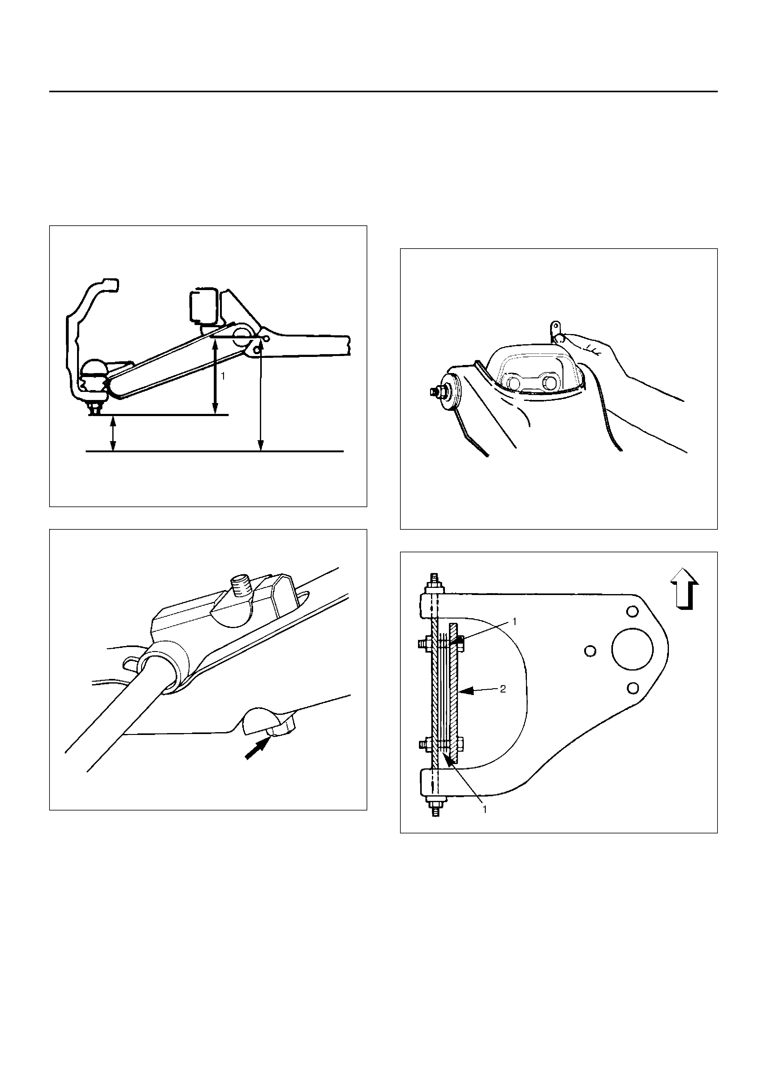
Trim Height Adjustment
Adjust the trim height (1) by means of the adjusting bolt
on the height control arms.
CAUTION: When adjusting front end alignment, be
sure to begin with trim height first, as it may change
other adjusted alignments.
450RS003
410RS001
1.Check and adjust the tire inflation pressures.
2.Park the vehicle on a level ground and move the
front of the vehicle up and down several times to
settle the suspension.
3.Make necessary adjustment with the adjusting bolt
on the height control arms.
Trim height: 119 ± ± ± ± 5mm (4.69 ±±±± 0.2in)
Caster Adjustment
The caster angle can be adjusted by means of the
caster shims (1) installed between the chassis frame
(2) and fulcrum pins.
Caster angle: 2°°°°30' ±±±± 1°°°°
CAUTION: Left and right side must be equal within
30'.
450RW006
450RS002
NOTE: Difference of the caster shim front/rear
thickness should be 3.6mm (0.142in) or less. Overall
thickness of caster shim and camber shim should be
10.8mm (0.425in) or less.
Tighten the fulcrum pin bolt to the specified torque.
Torque: 152N·m (15.5kg·m/112lbft)
Camber Adjustment
The camber angle can be adjusted by means of the
camber shims (2) installed in position between the
chassis frame (1) and fulcrum pins
Camber angle: 0°°°° ±±±± 30'
King pin inclination: 12°°°°30' ±±±± 30'
CAUTION: Left and right side must be equal within
30'.
450RW007
450RS005
NOTE: Overall thickness of caster shim and camber
shim should be 10.8mm (0.425in) or less.
Tighten the fulcrum pin bolt to the specified torque.
Torque: 152N·m (15.5kg·m/112lbft)
Position of shims Camber angle Caster angle
Front side Rear side
Caster shim
When added When removed Decreas es Decreases
When remov ed When added Increases Increases
— When removed Unchanged Decreases
— When added Unchanged Increases
Camber shim When added Decreases Unchanged
When removed Increases Unchanged
Toe-in Adjustment
1. To adjust the toe-in angle, loosen the lock nuts (2)
on the tie rod (1) and turn the tie rod. Turn both rods
the same amount, to keep the steering wheel
center ed .
Toe-in: 0 to +2mm (0 to +0.08in)
433RW006
2. Tighten the lock nut to the specified torque.
Torque: 98N·m (10.0kg·m/72lbft)
Main Data and Specifications
General Specification
Caster 2°30' ± 1°
Camber 0° ± 30'
King pin inclination 12°30' ± 30'
Toe-in 0 to +2mm (0 to +0.08in)
Max. ste er i ng angl e i nside 32.6° (+0°30' to –2°30' )
outside 31.8°
Torque Specification
E02RX006
Special Tools
ILLUSTRATION TOOL NO.
TOOL NAME
5–8840–0135–0
(J–29877–A)
Tester;
Power steering
5–8840–2297–0
(J–39213)
Adapter;
Power steering tester
ILLUSTRATION TOOL NO.
TOOL NAME

Power Steering Unit
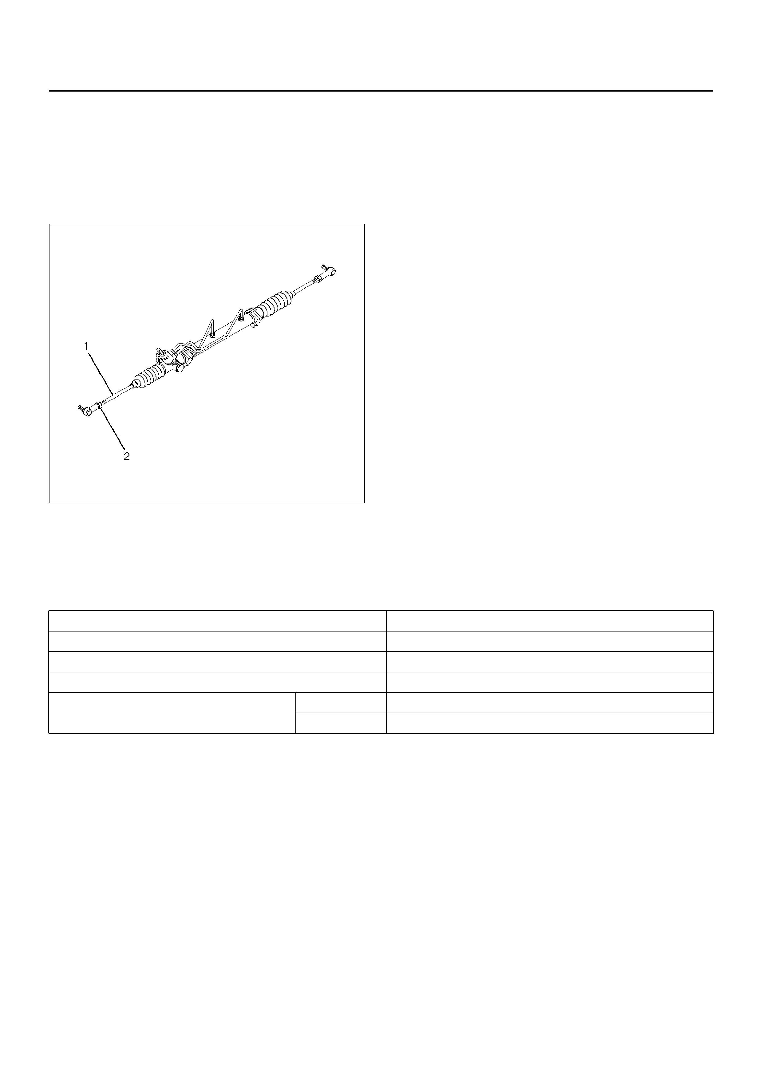
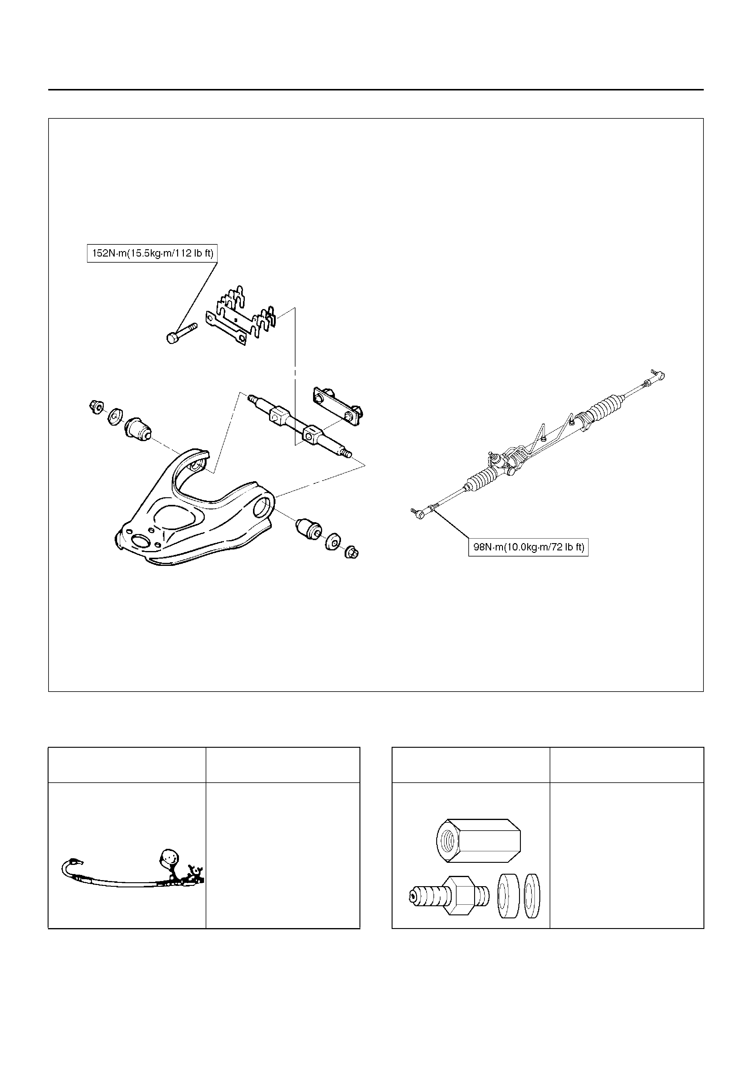
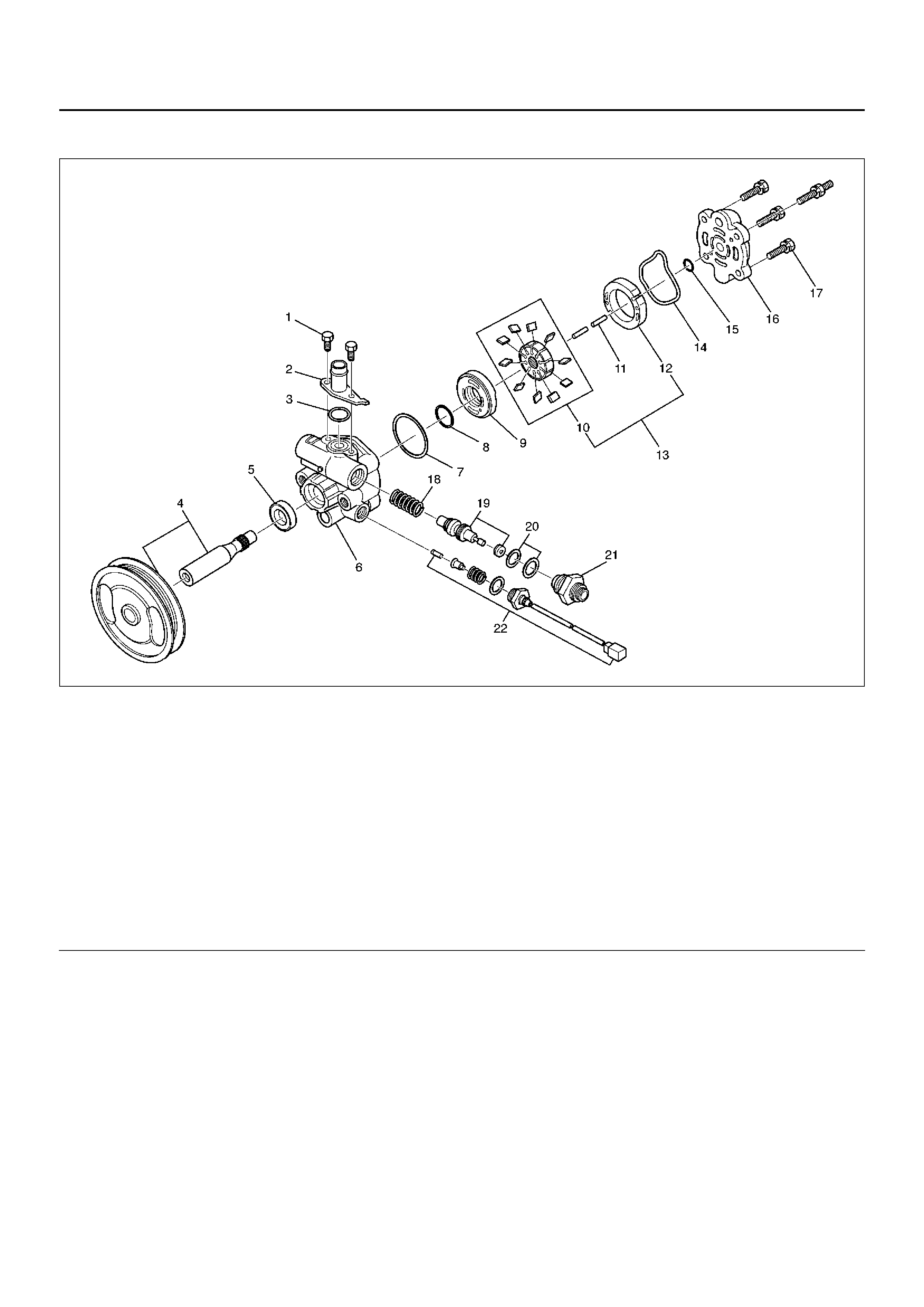
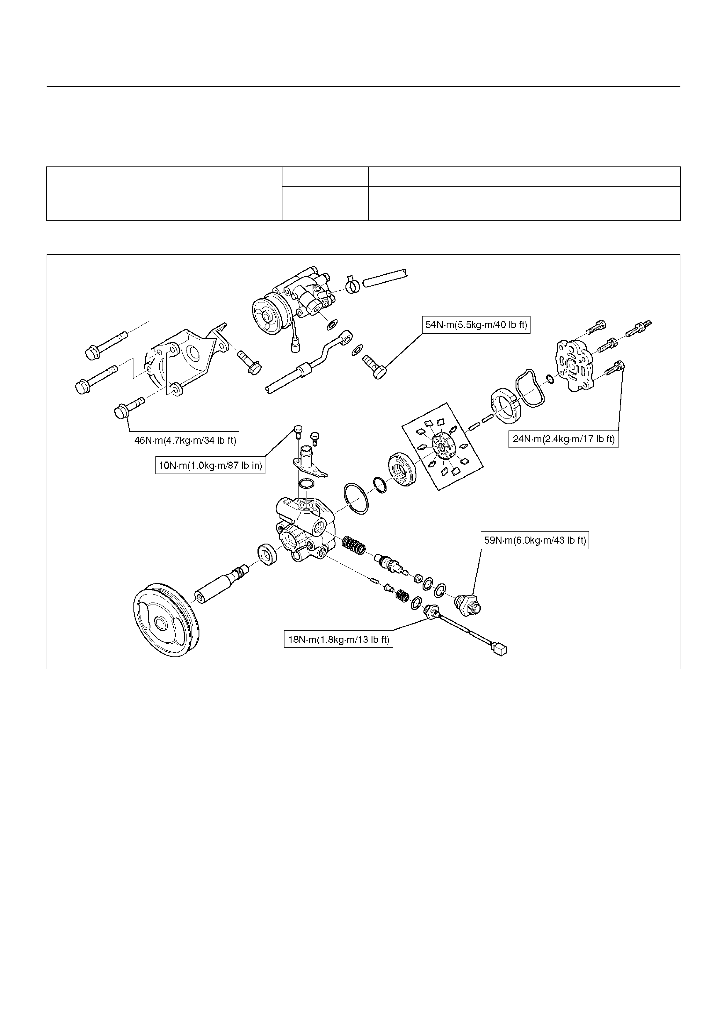
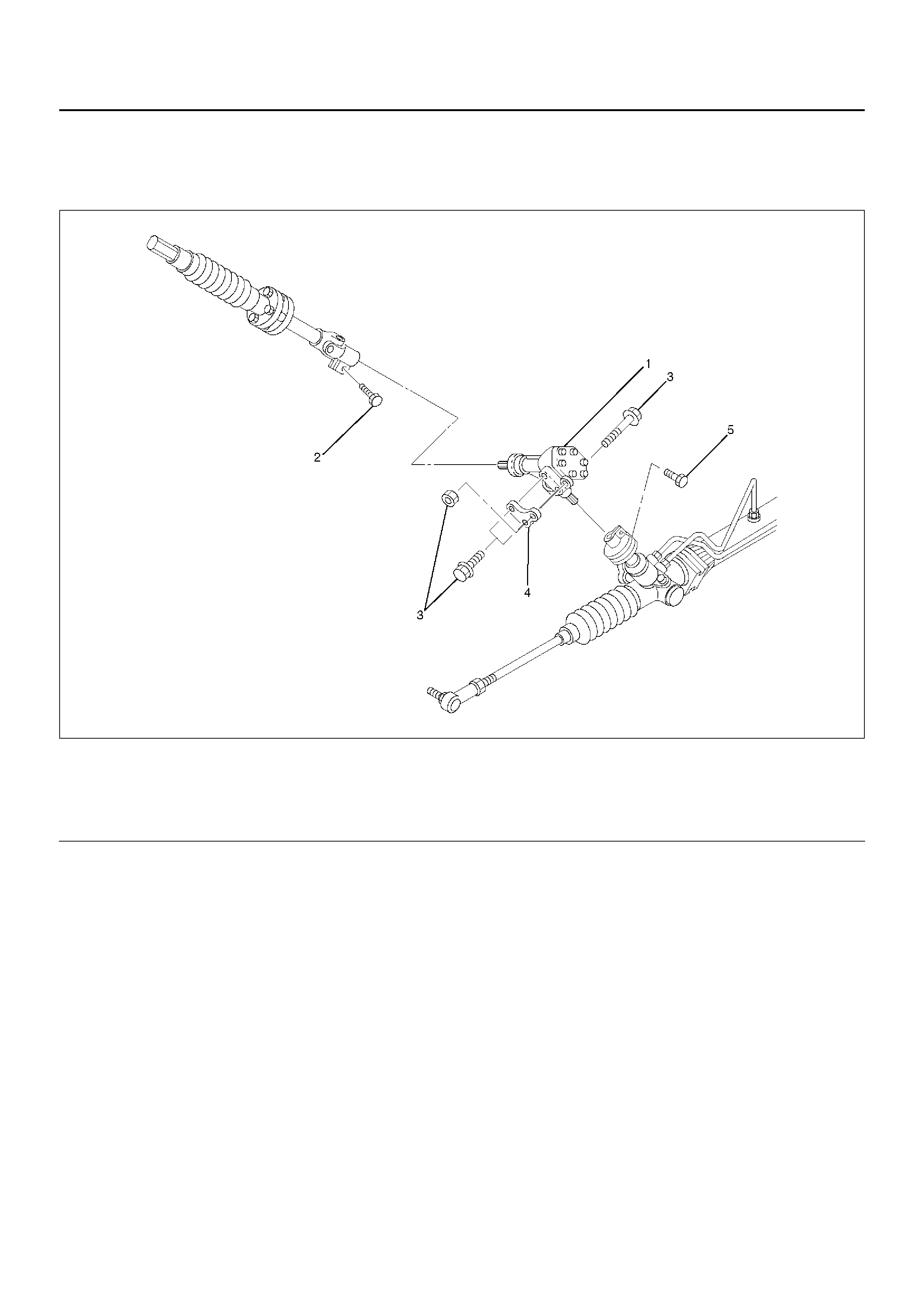
Power Steering Unit and Associated Parts
431RW026Legend
out
Removal
1.Remove the stone guard.
2. Remove the transfer gear assembly.
Make a setting mark across the coupling flange and
steering unit to ensure reassembly of the parts in
the original position.
3. Drain power steering fluid.
4. Remove the tie rod end assembly from knuckle.
Use tie rod end remover 5–8840–2005–0.
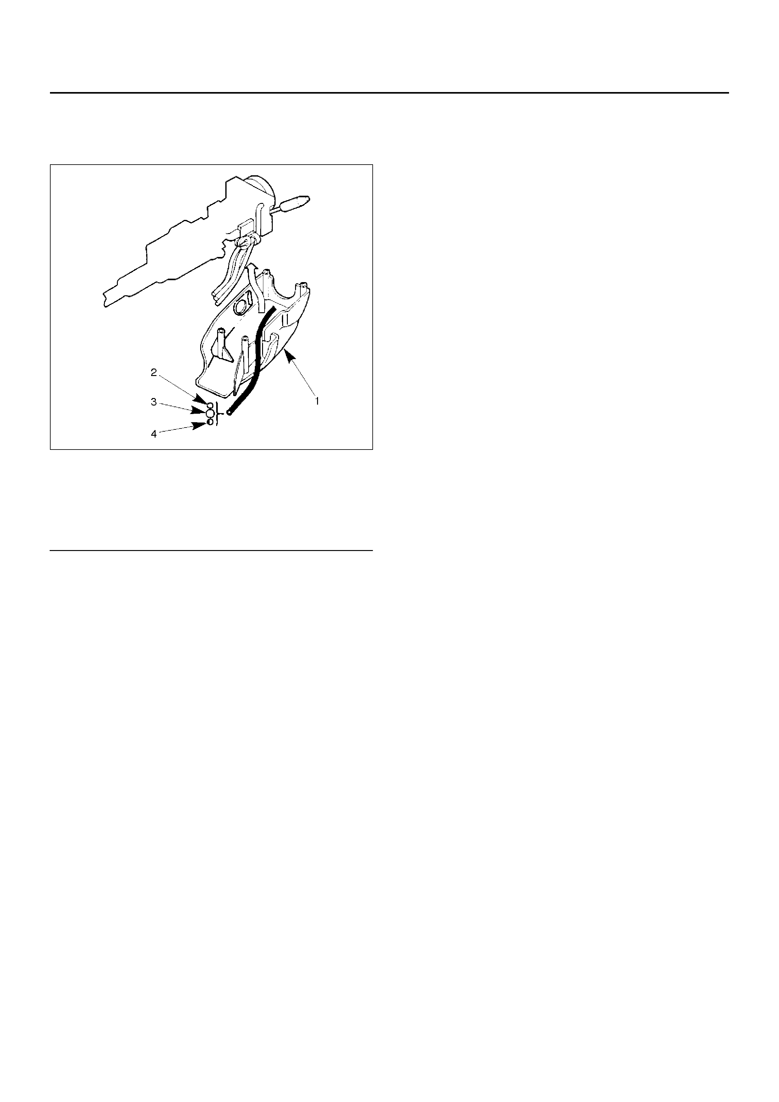
901RW270
(1) Bracket
(2) Transfer Gear Assembly (3) Power Steering Unit Assembly
(4) Crossmember
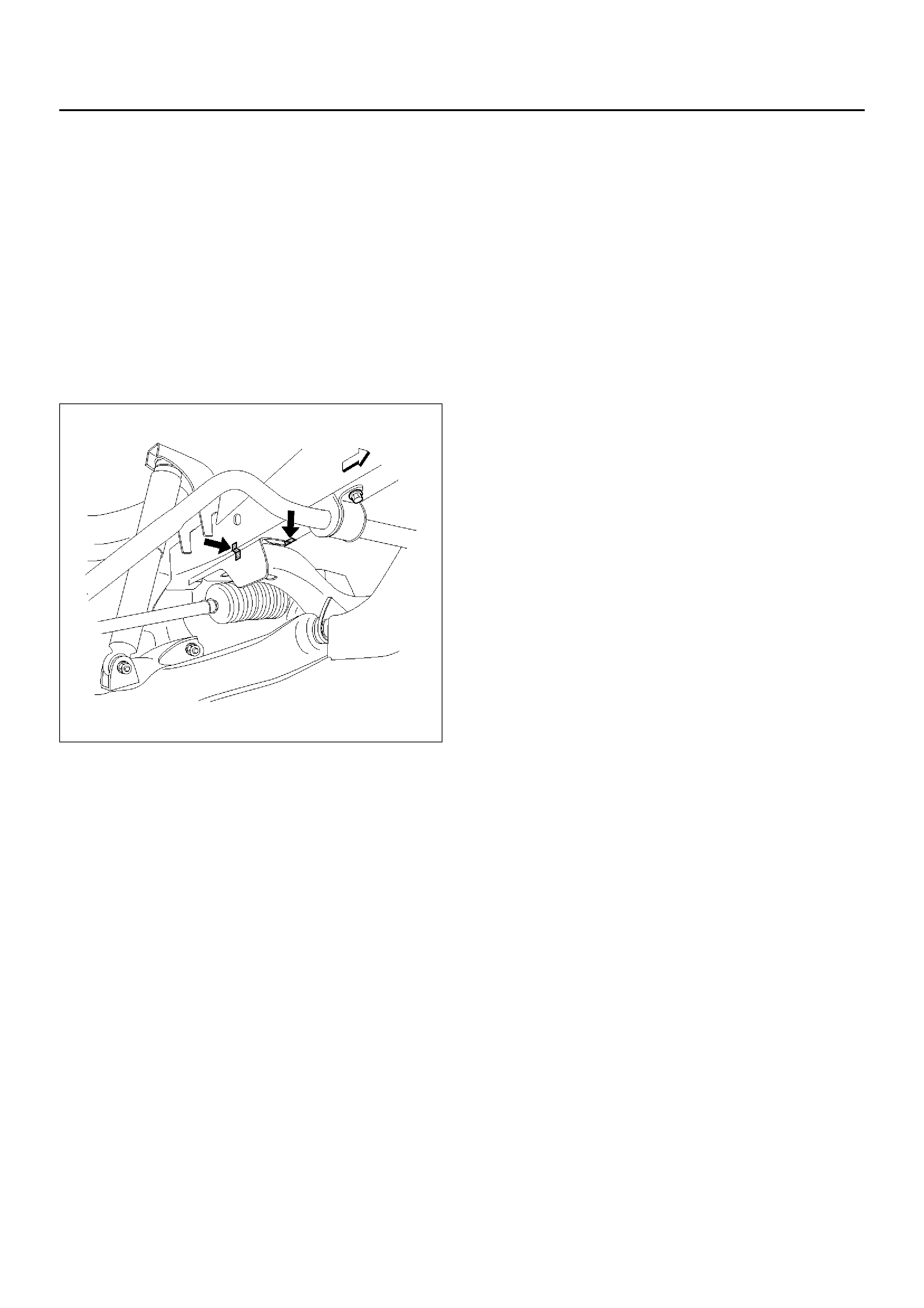
5.Disconnect the feed line and return line from
steering unit.
Remove the clips on the crossmember and frame.
Wire the power steering line to frame.
NOTE: Take care to prevent foreign matter from entry
when disconnect the power steering line.
6.Remove the torsion bar. Refer to Front Suspension
in Suspension section.
7.Remove the lower control arm bolt (Frame side).
Refer to Front Suspension in Suspension section.
8.Apply a setting mark across the crossmember and
frame so parts can be reassembled in their original
position.
431RX013
9.Remove the crossmember fixing bolt.
10.Remove the power steering unit with the
crossmember.
11.Remove the power steering unit.
Installation
1.Install power steering unit to crossmember.
Tighten fixing bolt to specified torque.
Torque: 116N·m (11.8kg·m/85lbft)
2.Install power steering unit with crossmember to
frame by aligning the setting marks made when
removing.
Tighten crossmember mounting bolt to specified
torque.
Torque: 190N·m (19.4kg·m/140lbft)
3.Install lower control arm bolt.
Refer to Front Suspension in Suspension section.
4.Install torsion bar.
Refer to Front Suspension in Suspension section.
5.Connect the feed line and return line.
Torque: 25N·m (2.5kg·m/18lbft)
6.Install tie-rod end assembly to knuckle.
Torque: 118N·m (12.0kg·m/87lbft)
7.Install transfer gear assembly.
Align the setting marks made at removal.
Torque: 31N·m (3.2kg·m/23lbft)
8.Install the stone guard.
9.Bleed the system.
Refer to Bleeding the Power Steering System in this
section.
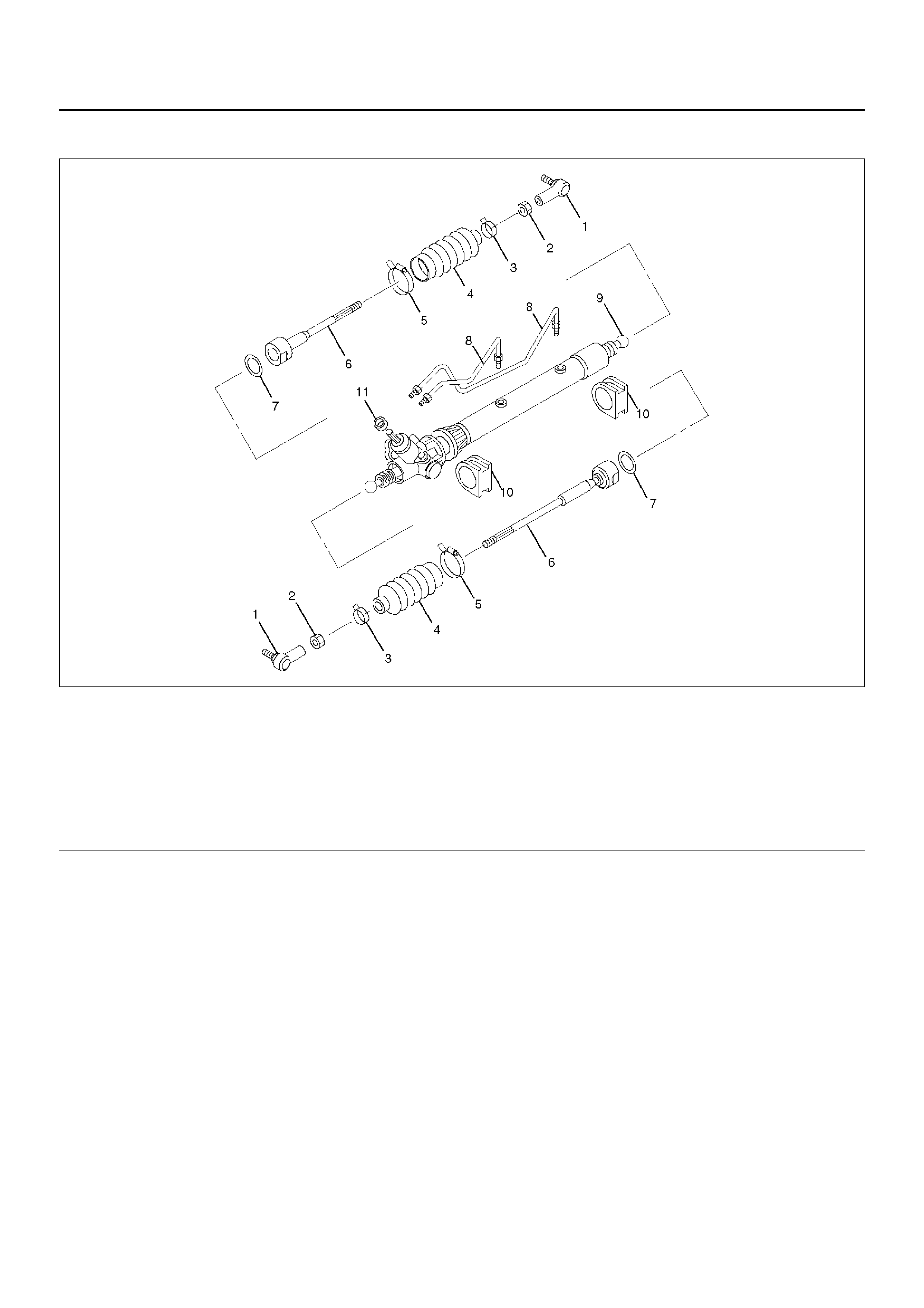
Power Steering Unit Disassembled View
440RW005
Legend
EndOFCallout
Disassembly
NOTE: The valve housing is made of aluminum and
care should be exercised when clamping in a vise, etc.
to prevent distortion or damage.
1. Loosen lock nut and remove tie–rod end.
2. Remove clip and band, then remove bellows.
3. Remove tie-rod assembly.
To remove, move the boot toward the tie-rod end,
then remove tab washer.
4. Remove oil line, mounting rubber and dust cover.
Inspection and Repair
Inspect the following parts for wear, damage or any
abnormal conditions.
Tie-rod End
If looseness or play is found when checked by moving
the end of ball joint at tie-rod end, replace tie-rod end.
Tie-rod Assembly
If the resistance is insufficient or play is felt when
checked by moving the ball on the tie-rod, replace the
tie-rod assembly.
Rubber Parts
If wear or damage is f ound through inspection, replace
with new ones.
Reassembly
1. Install mounting rubber and dust cover (If removed).
2. Install oil line.
Torque: 13N·m (1.3kg·m/113lbin)
3. Install tie-rod assembly with tab washer.
Apply grease to ball joint, install tie-rod and tab
washer, then tighten to specified torque.
Torque: 83N·m (8.5kg·m/61lbft)
After tightening, bend tab washer against width
across flat of inne r ball joint.
(1) Tie-rod End
(2) Lock Nut
(3) Clip
(4) Bellows
(5) Band
(6) Tie-rod Assembly
(7) Tab Washer
(8) Oil Line
(9) Valve Housing Assembly
(10) Mounting Rubber
(11) Dust Cover
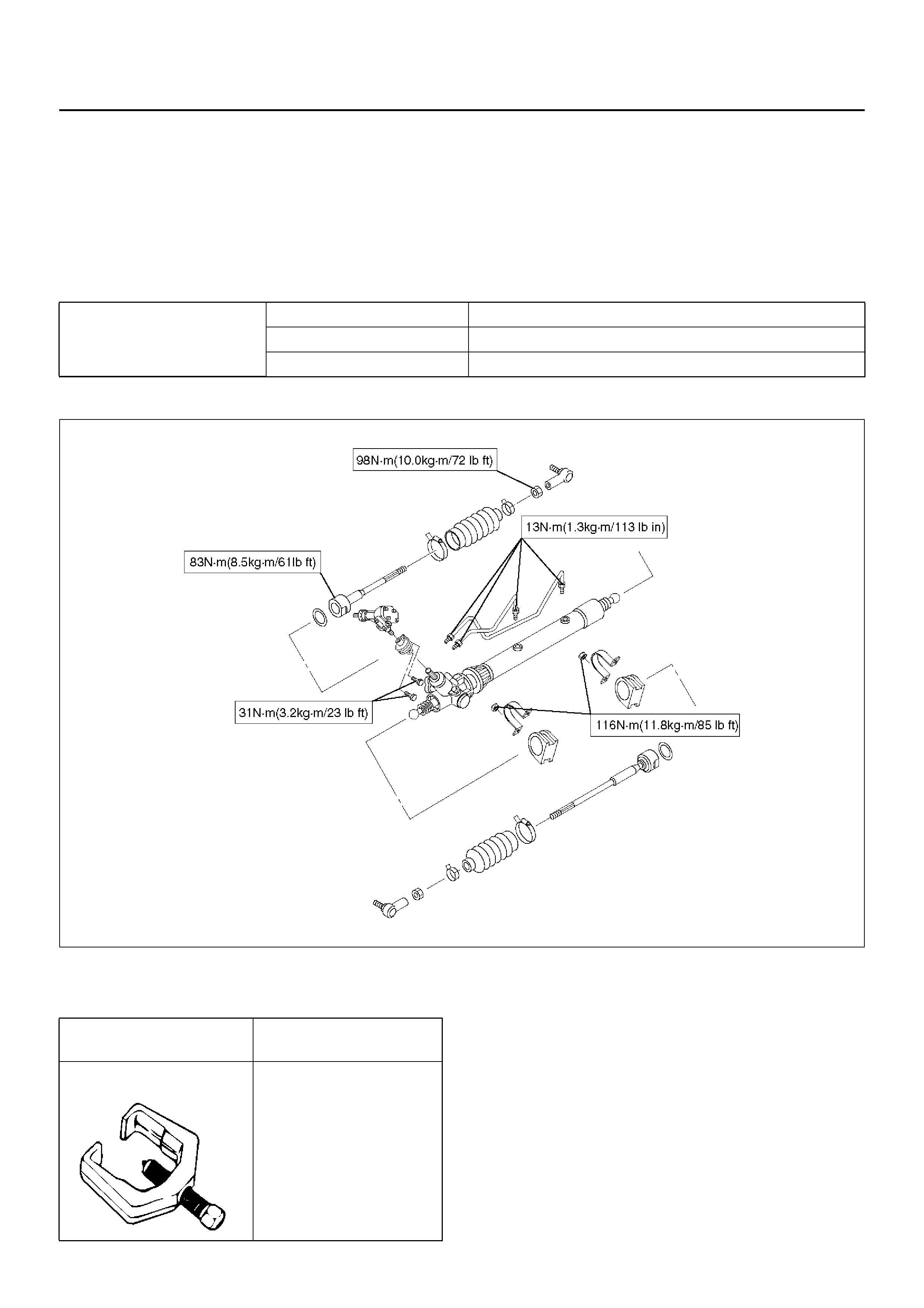
4. Apply a thin coat of grease to the shaft for smooth
installation. Then install bellows.
5. Ins tall band and clip.
6. Install tie-rod end and tighten lock nut.
Torque: 98N·m (10.0kg·m/72lbft)
Main Data and Specifications
General Specifications
Torque Specifications
E02RX007
Special Tools
Power Steering unit Type Rack and pinion
Rack stroke 152mm (5.98in)
Lock to lock 3.64
ILLUSTRATION TOOL NO.
TOOL NAME
5–8840–2005–0
(J–29107)
Tie rod end remover
Power Steering Pump
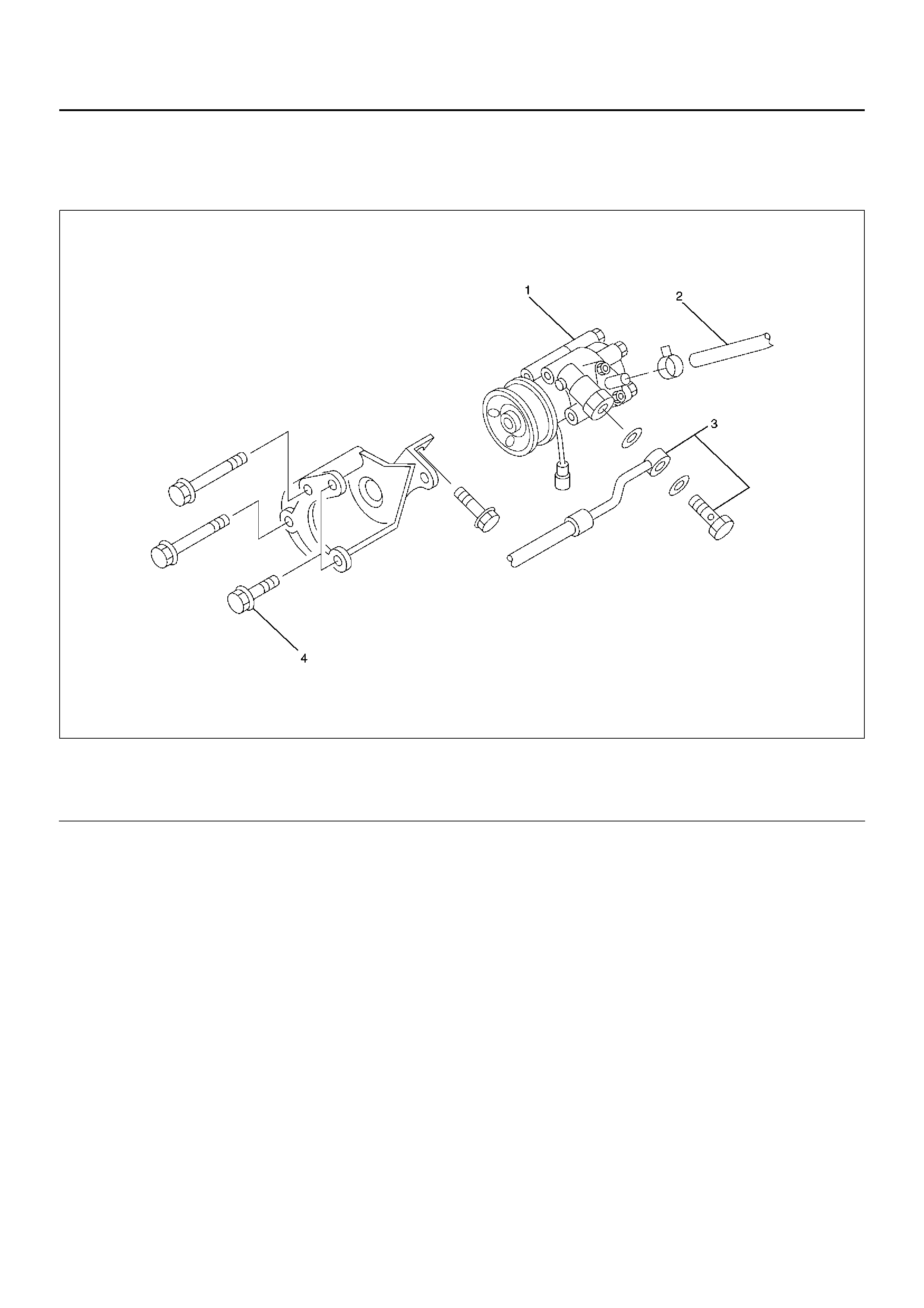
Power Steering Pump and Associated Parts
436RX001
Legend
EndOFCallout
Removal
1.Remove the drive belt.
2.Place a drain pan below the pump.
3.Disconnect the suction hose.
4.Disconnect the flexible hose.
5.Remove the power steering fixing bolt and remove
the pump assembly.
Installation
1.Install the pump assembly to the pump braket,
tighten the fixing bolt to the specified torque.
Torque: 46N·m (4.7kg·m/34lbft)
2.Install the flexible hose.
Tighten the eye bolt to specified torque.
Torque: 54N·m (5.5kg·m/40lbft)
3.Install the drive belt.
4.Connect the suction hose, then fill and bleed
system.
Refer to Bleeding the Power Steering System in this
section.
(1) Pump Assembly
(2) Hose, Suction (3) Hose, Flexible
(4) Bolt
Power Steering Pump Disassembled View
442RX001
Legend
EndOFCallout
Disassembly
1.Clean the oil pump with solvent (plug the discharge
and suction ports to prevent the entry of solvent).
Be careful not to expose the oil seal of shaft
assembly to solvent.
2.Remove the bolt, suction pipe and O-ring.
3.Remove the connector, O-ring, relief valve and
spring.
4.Remove the pressure switch assembly.
5.Remove the bolt, rear housing and O-ring.
6.Remove the snap ring.
7.Remove the shaft assembly.
8.Remove the oil seal.
CAUTION: When removing the oil seal, be careful
not to damage the housing.
9. Remov e the pump cartridge assembly from the front
housing.
10. Remove two O-rings.
(1) Bolt
(2) Suction Pipe
(3) O-ring
(4) Shaft Assembly
(5) Oil Seal
(6) Front Housing
(7) O-ring
(8) O-ring
(9) Side Plate
(10) Rotor and Vane
(11) Pin
(12) Cam
(13) Pump Cartridge Assembly
(14) O-ring
(15) Snap Ring
(16) Rear Housing
(17) Bolt
(18) Spring
(19) Reli ef Valve
(20) O-ring
(21) Connector
(22) Pressure Switch A ssembly
Inspection and Repair
Make all necessary adjustments, repairs, and part
replacements if wear, damage, or other problems are
discovered during inspection.
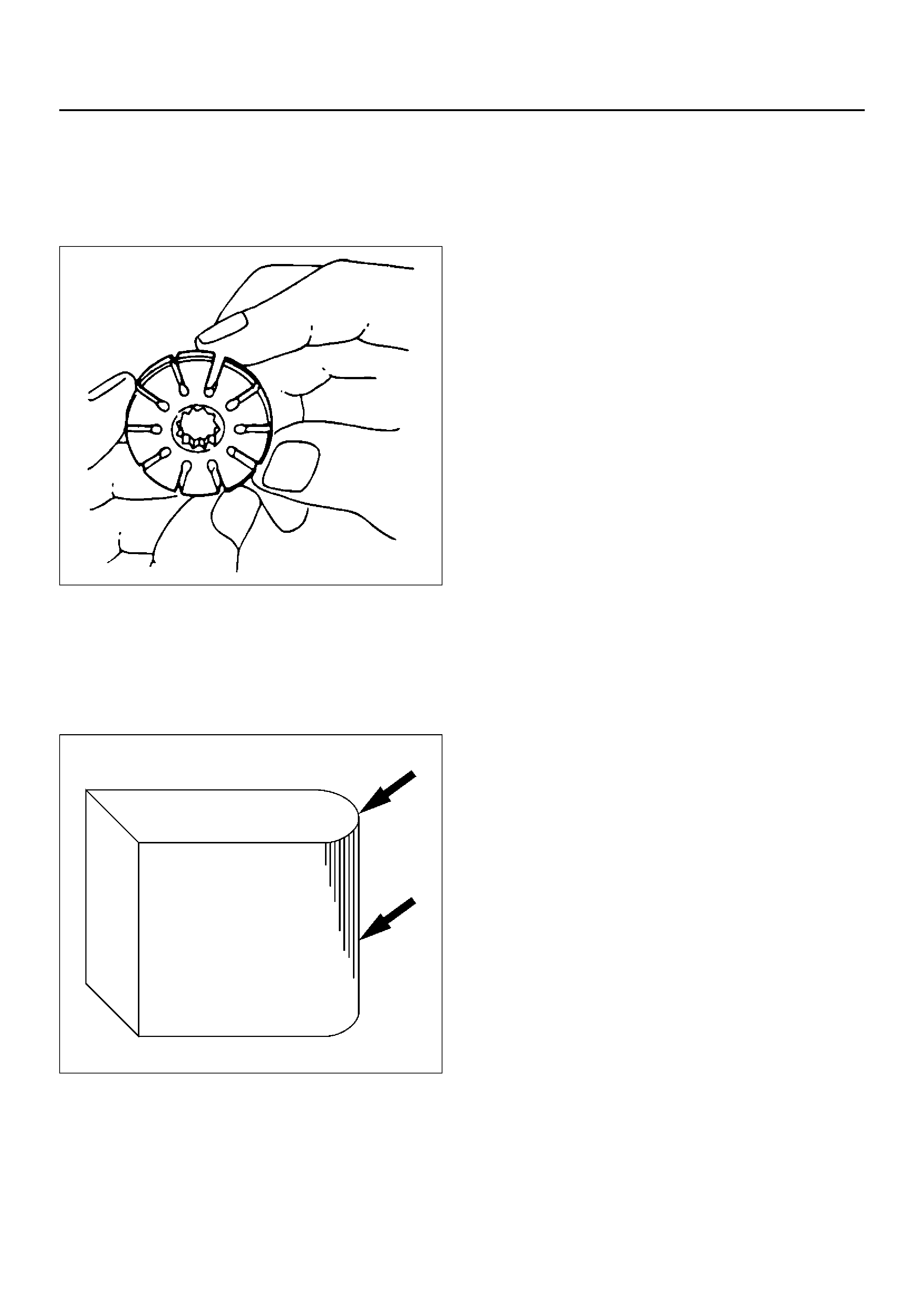
Rotor
442RS002
Check that the groove in the vane is free from excessive
wear and that the vane slides smoothly. When part
replacement becomes necessary, the pump cartridge
should be replaced as a subassembly.
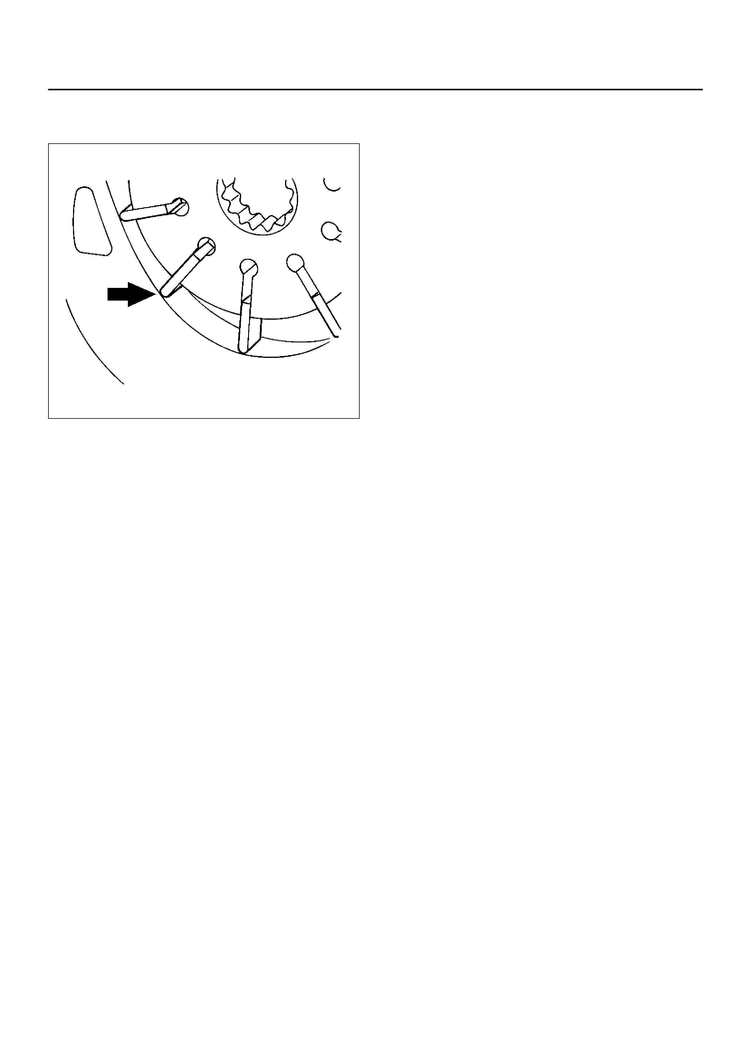
Vane
442RS003
Sliding faces of the vane should be free from wear.
(Particularly the curved face at the tip that contact with
the cam should be free from wear and distortion). When
part replacement becomes necessary, the pump
cartridge should be replaced as a subassembly.
Cam
The inner face of the arm should have a uniform contact
pattern without a sign of step wear. When part
replacement becomes necessary, the pump cartridge
should be replaced as a subassembly.
Side Plate
The sliding faces of parts must be free from step wear
(more than 0.01 mm), which can be felt by the finger
nail.
The parts with minor scores may be reused after
lapping the face.
Relief Valve
The sliding face of the valve must be free from burrs and
damage. The parts with minor scores may be reused
after smoothing with emery cloth (#800 or finer).
Shaft
Oil seal sliding faces must be free from a step wear
which can be felt by the finger nail. Bushing fitting face
must be free from damage and wear.
O-ring, Oil Seal, Snap Ring
Be sure to discard used parts, and always use new
parts for installation. Prior to installation, lubricate all
seals and rings with power steering fluid.
Pressure Switch
Check the switch operation as follows:
With engine idling and A/C on, turn the steering wheel
fully to the left; compressor should interrupt and engine
idle speed will increase. Shut off A/C and again turn
steering fully to the left; engine idle will increase. If
system fails to function properly, disconnect connector
at the pressure switch and repeat system check while
testing continuity across disconnected SW connector.
Reassembly
1.Install oil seal to front housing. Be sure to discard
used oil seal, and always use new parts for
installation.
CAUTION: When installing the oil seal, be careful
not to damage the oil seal contacting surface of the
housing.
2. Install shaft assembly.
3.Install the vanes to roter with curved face in contact
with the inner wall of cam.
442RS005
4.Install roter and vanes to cam.
5.Install pin to front housing.
6.Install two new O-rings to front housing. Be sure to
discard used O-ring.
7.Install side plate.
CAUTION: When installing side plate, be careful not
to damage its inner surface. Damaged side plate
may cause poor pump performance, pump seizure
or oil leakage.
8. Install pump cartridge assembly to front housing.
9. Install snap ring to shaft end.
10. Install rear housing with a new O-ring. Be sure to
discard used O-ring. Then install bolt and tighten it
to specified torque.
Torque: 24N·m (2.4kg·m/17lbft)
11. Install suction pipe with a new O-ring. Be sure to
discard used O-ring. Then install bolt and tighten it
to specified torque.
Torque: 10N·m (1.0kg·m/87lbin)
12. Install relief valve and spring.
13. Install connector with a new O-ring. Be sure to
discard used O-ring. Tight en the connector to
specified torque.
Torque: 59N·m (6.0kg·m/43lbft)
14. Install pressure switch assembly and tighten it to
specified torque.
Torque: 18N·m (1.8kg·m/13lbft)
Main Data and Specifications
General Specifications
Torque Specifications
E02RX008
Oil pump Type Vane
Operating
fluid ATF DEXRON®–III
Transfer Gear Assembly
Transfer Gear Assembly and Associated Parts
441RW002
Legend
EndOFCallout
Removal
1. Apply a setting mark across the universal joint and
transfer gear so parts can be reassembled in their
original position.
2. Remove universal joint bolt (steering shaft side).
3. Remove universal joint bolt (steering unit side).
4. Loosen fixing bolt and nut and remov e transf er gear
asse mbly with shim.
Inspection and Repair
The transfer gear assembly cannot be disassembled. If
damage or abnormal condition are found, replace to
new ones.
Installation
1. Install transfer gear assembly with shim by aligning
the setting marks made when removing.
2. Tighten bolt and nut to the specified torque.
Torque: 54N·m (5.5kg·m/40lbft)
3. Connect universal joint (both side) and tighten the
bolt to the specified torque.
Torque: 31N·m (3.2kg·m/23lbft)
(1) Transfer Gear Assembly
(2) Bolt, Univ ersal Joint (Steering Shaft Side)
(3) Fix ing Bolt Nut
(4) Shim
(5) Bolt, Universal Joint (Steering Unit Side)

Supplemental Restraint System Steering Wheel & Column
Service Precaution
This steering wheel and column repair section covers
the Supplemental Restraint System (SRS) steering
column. The following repair procedures are specific to
SRS components. When servicing a vehicle equipped
with Supplemental Restraint System, pay close
attention to all WARNINGS and CAUTIONS.
For detailed explanation about SRS, refer to Restraints
section.
WARNING: THIS VEHICLE HAS A SUPPLEMENTAL
RESTRAINT SYSTEM (SRS). REFER TO THE SRS
COMPONENT AND WIRING LOCATION VIEW IN
ORDER TO DETERMINE WHETHER YOU ARE
PERFORMING SERVICE ON OR NEAR THE SRS
COMPONENTS OR THE SRS WIRING. WHEN YOU
ARE PERFORMING SERVICE ON OR NEAR THE
SRS COMPONENTS OR THE SRS WIRING, REFER
TO THE SRS SERVICE INFORMATION. FAILURE TO
FOLLOW WARNINGS COULD RESULT IN POSSIBLE
AIR BAG DEPLOYMENT, PERSONAL INJURY, OR
OTHERWISE UNNEEDED SRS SYSTEM REPAIRS.
SAFE HANDLING OF INFLATOR MODULES
REQUIRES FOLLOWING THE PROCEDURES
DESCRIBED BELOW FOR BOTH LIVE AND
DEPLOYED MODULES.
SAFETY PRECAUTIONS MUST BE FOLLOWED
WHEN HANDLING A DEPLOYED AIR BAG
ASSEMBLY (AIR BAG). AFTER DEPLOYMENT, THE
AIR BAG ASSEMBLY (AIR BAG) SURFACE MAY
CONTAIN A SMALL AMOUNT OF SODIUM
HYDROXIDE, A BY-PRODUCT OF THE
DEPLOYMENT REACTION, THAT IS IRRITATING TO
THE SKIN AND EYES. MOST OF THE POWDER ON
THE AIR BAG ASSEMBLY (AIR BAG) IS HARMLESS.
AS A PRECAUTION, WEAR GLOVES AND SAFETY
GLASSES WHEN HANDLING A DEPLOYED AIR BAG
ASSEMBLY, AND WASH YOUR HANDS WITH MILD
SOAP AND WATER AFTERWARDS.
WHEN CARRYING A LIVE AIR BAG ASSEMBLY,
MAKE SURE THE BAG AND TRIM COVER ARE
POINTED AWAY FROM YOU. NEVER CARRY AN
AIR BAG ASSEMBLY BY THE WIRES OR
CONNECTOR ON THE UNDERSIDE OF MODULE.
IN THE CASE OF AN ACCIDENTAL DEPLOYMENT,
THE BAG WILL THEN DEPLOY WITH MINIMAL
CHANCE OF INJURY. WHEN PLACING A LIVE AIR
BAG ASSEMBLY ON A BENCH OR OTHER
SURFACE, ALWAYS FACE THE BAG AND TRIM
COVER UP, AWAY FROM THE SURFACE.
NEVER REST A STEERING COLUMN ASSEMBLY
ON THE STEERING WHEEL WITH THE AIR BAG
ASSEMBLY FACE DOWN AND COLUMN VERTICAL.
THIS IS NECESSARY SO THAT A FREE SPACE IS
PROVIDED TO ALLOW THE AIR BAG ASSEMBLY TO
EXPAND IN THE UNLIKELY EVENT OF ACCIDENTAL
DEPLOYMENT. OTHERWISE, PERSONAL INJURY
COULD RESULT.
TO AVOID DEPLOYMENT WHEN
TROUBLESHOOTING THE SRS SYSTEM, DO NOT
USE ELECTRICAL TEST EQUIPMENT, SUCH AS
BATTERY-POWERED OR A/C-POWERED
VOLT-METER, OHMMETER, ETC., OR ANY TYPE OF
ELECTRICAL EQUIPMENT OTHER THAN
SPECIFIED IN THIS MANUAL. DO NOT USE A
NON-POWERED PROBE-TYPE TESTER.
INSTRUCTIONS IN THIS MANUAL MUST BE
FOLLOWED CAREFULLY, OTHERWISE PERSONAL
INJURY MAY RESULT.
SRS Connectors
CAUTION: The special yellow color connectors are
used for supplemental restraint system-air bag
circuit.
When removing the cable harness, do not pull the
cables. Otherwise, cable disconnection may occur.
When connect the SRS connector, insert the
connector completely. Imperfect loc king ma y cause
malfunction of SRS cir cuit.
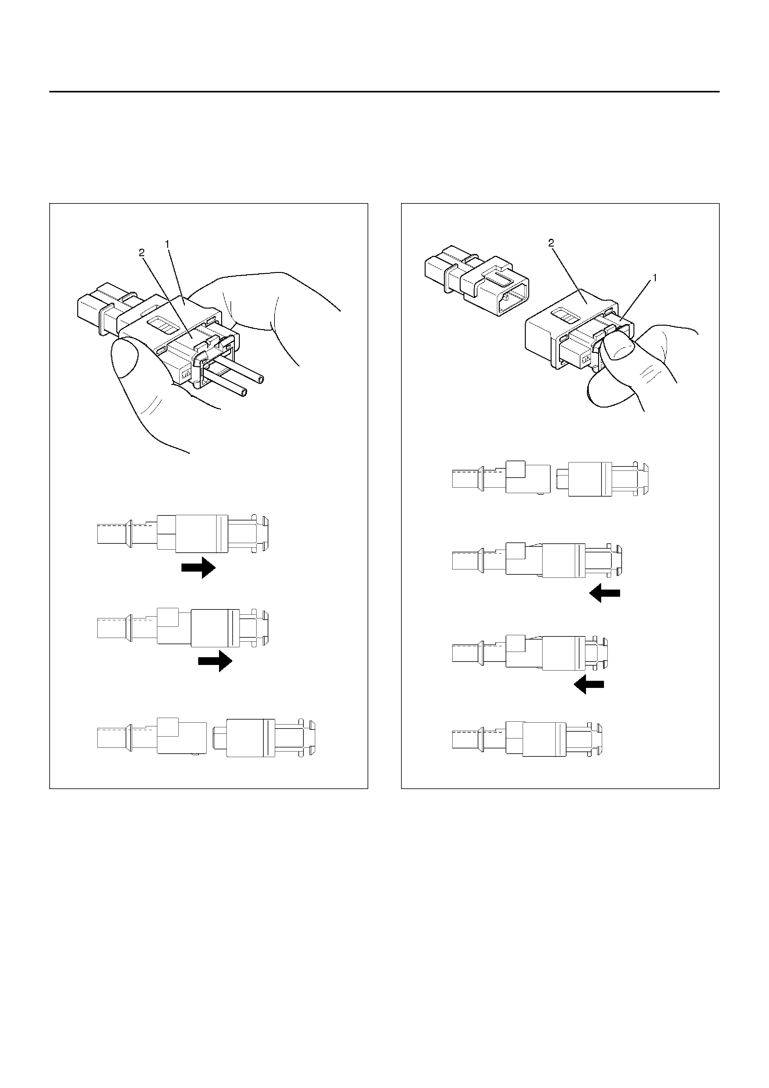
Removal
To remove the connector , hold the cover insulator(1) and
pull it. The cover insulator slides and lock will be
released.
Do not hold the socket insulator(2).
827RW028
Installation
To install the connector, hold the soket insulator(1) and
insert it. The cover insulator slides and connector will be
locked.
Do not hold the cover insulator(2).
827RW027
Inflator Module
Inflator Module and Associated Parts
827RW071
Legend
EndOFCallout
Removal
1. Turn the steering wheel so th at the vehicle's wheels
are pointing straight ahead.
2. Turn the ignition switch to “LOCK".
3. Disconnect the battery “–" terminal cable, and wait
at least 5 minutes.
4. Disconnect the yellow 2-wa y SRS connector located
under the steering column.
5. Loosen the inflator module fixing bolt from behind
the steering wheel assembly using a TORX® driver
or equivalent until the inflator module can be
released from steering assembly .
827RW070
(1) Horn Lead
(2) SRS Conn ec tor (3) Fixing Bolt
(4) Inflator Module
6.Disconnect the yellow 2-way SRS connector and
horn lead located behind the inflator module.
827RW073
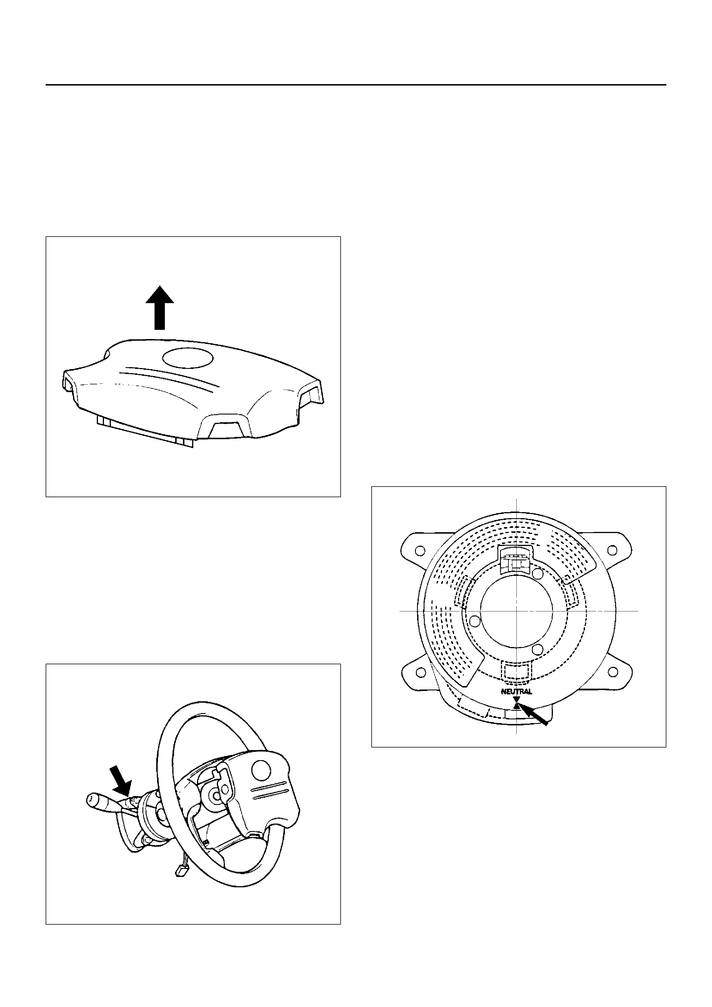
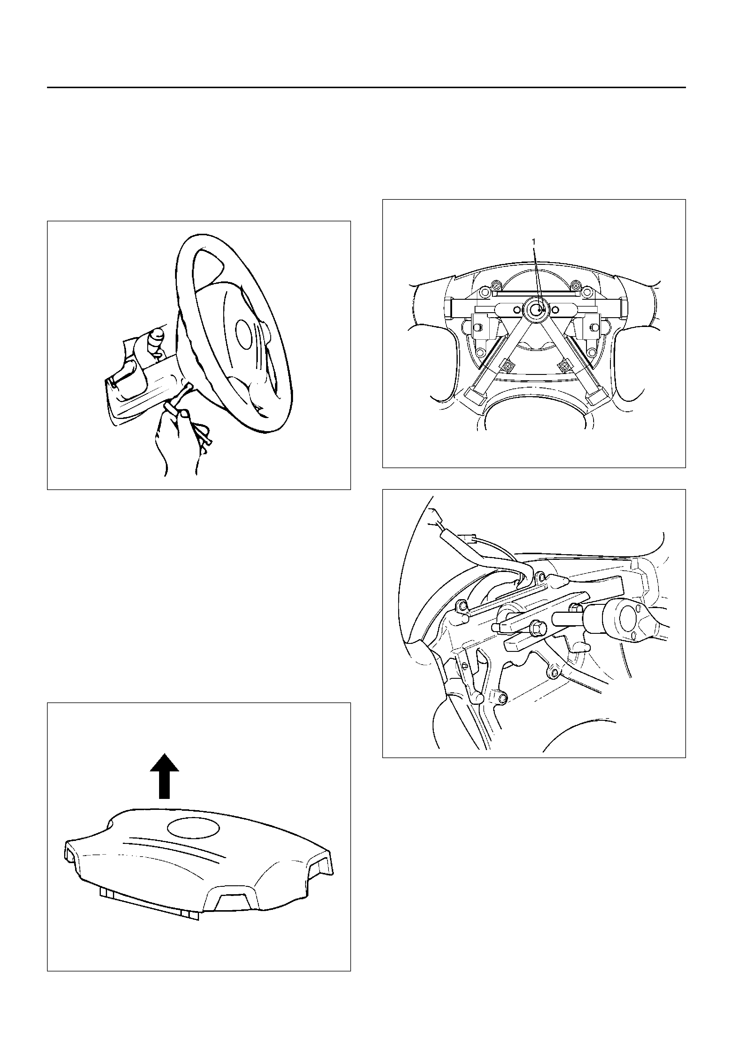
7.Remove inflator module.
Inspection and Repair
WARNING: THE INFLATOR MODULE SHOULD
ALWAYS BE CARRIED WITH THE URETHANE
COVER AWAY FROM YOUR BODY AND SHOULD
ALWAYS BE LAID ON A FLAT SURFACE WITH THE
URETHANE SIDE UP. THIS IS NECESSARY
BECAUSE A FREE SPACE IS PROVIDED TO ALLOW
THE AIR CUSHION TO EXPAND IN THE UNLIKELY
EVENT OF ACCIDENTAL DEPLOYMENT.
OTHERWISE, PERSONAL INJURY MAY RESULT .
827RW072
The inflator module consists of a cover, air bag, inflator,
and retainer. Inspect the inflator module mainly for the
following:
•Check for holes, cracks, severe blemishes and
deformation on the cover.
•Check that the retainer is not deformed.
•Check for defects such as damage and breakage in
the lead wire for the igniter.
If an abnormality is found as the result of the inspection,
replace the inflator module with a new one.
Installation
1.Install inflator module.
2.Support the module and carefully connect the
module connector and horn lead.
NOTE: Pass the lead wire through the tabs on the
plastic cover (wire protector) of inflator to prevent lead
wire from being pinched.
3.Tighten bolts to specified torque.
Torque: 9N·m (0.9kg·m/78lbin)
4.Connect the yellow 2-way SRS connector located
under the steering column.
5.Connect the battery “–" terminal cable.
6.Set ignition to “ON" while watching warning light.
Light should flash 7 times and then go off. If lamp
does not operate correctly, refer to Restraints
section.
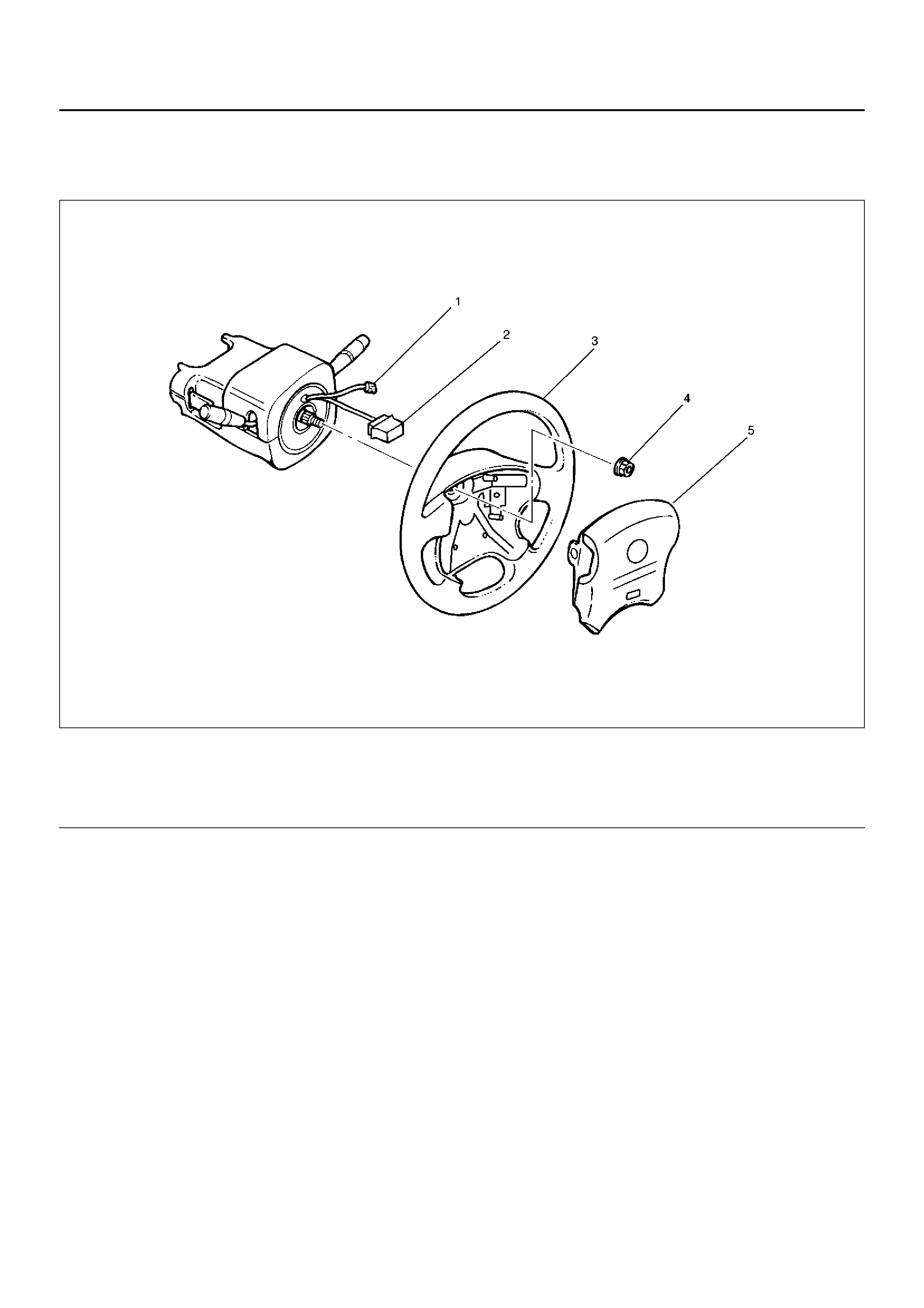
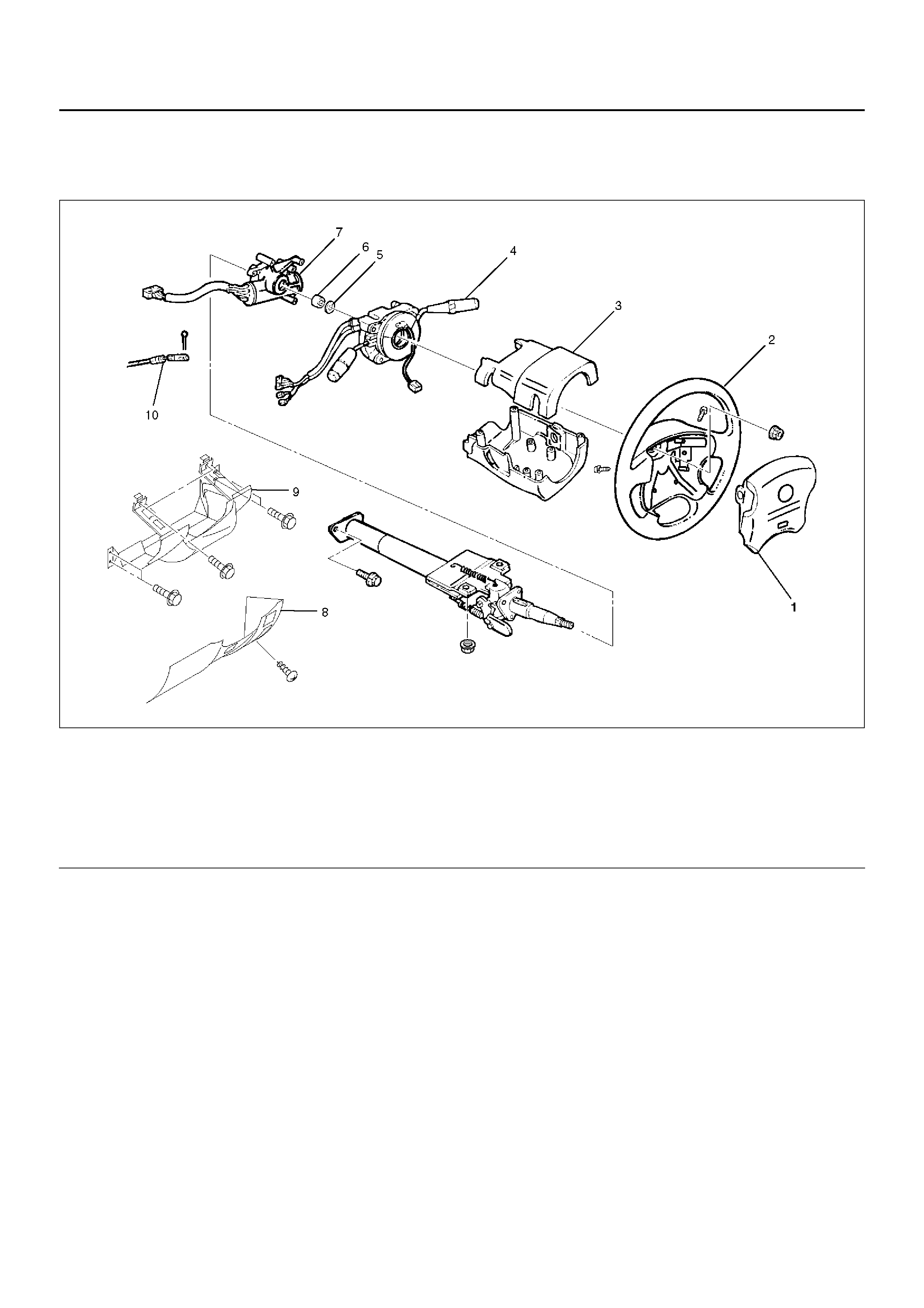
Steering Wheel
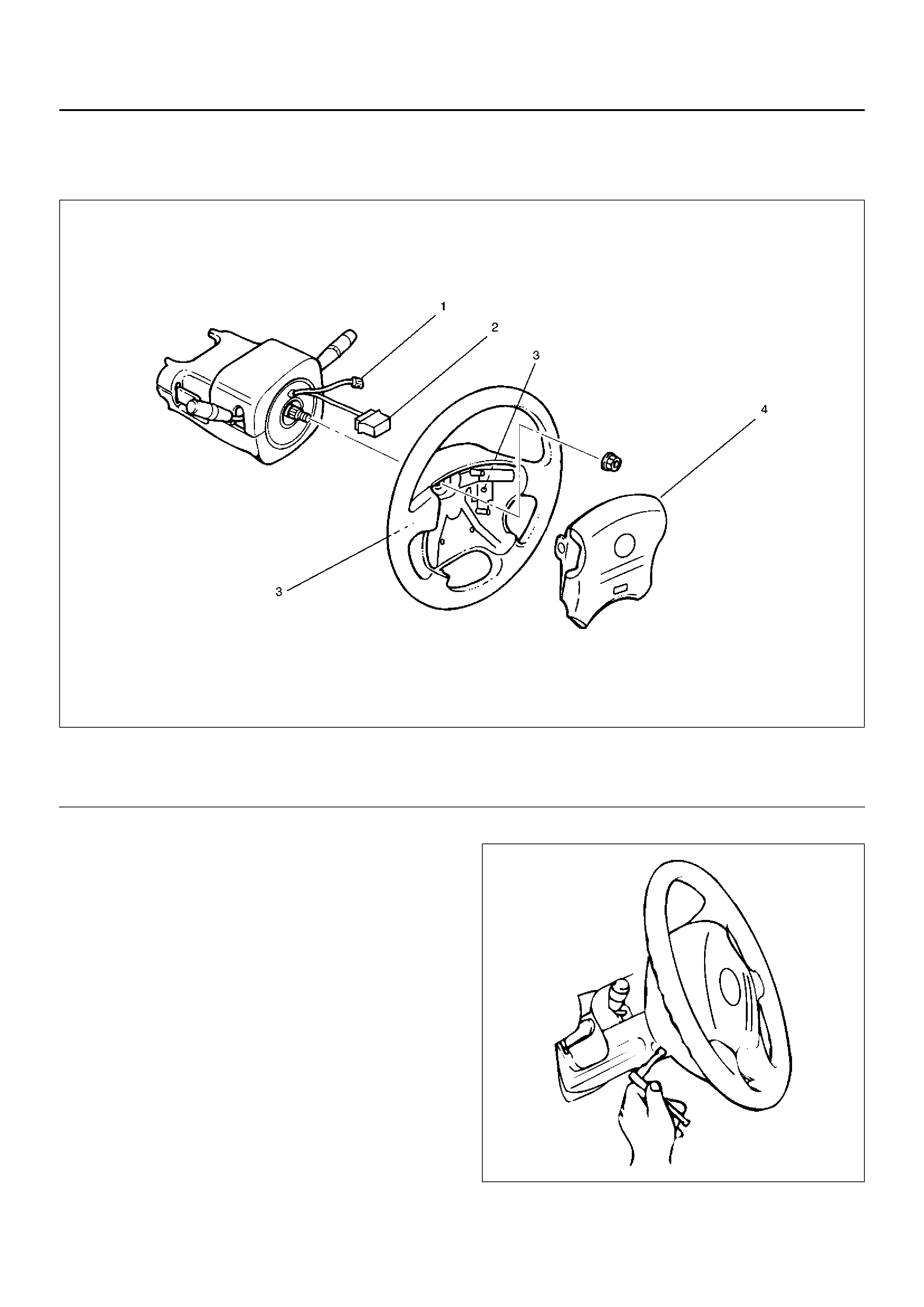
Steering Wheel and Associated Parts
827RW069
Legend
CAUTION: Once the steering column is removed
fr om the veh icle, the column is extremely
susceptible to damage. Dropping the column
assembly on its end could collapse the steering
shaft or loosen the slide block which maintains
column rigidity. Leaning on the column assembly
could cause the jacket to bend or deform. Any of
the above damage could impair the column's
collapsible design. If it is necessary to remove the
steering wheel, use only the specified steering
wheel puller . Under no conditions should the end of
the shaft be hammered upon, as hammering could
loosen slide block which maintains column rigidity.
Removal
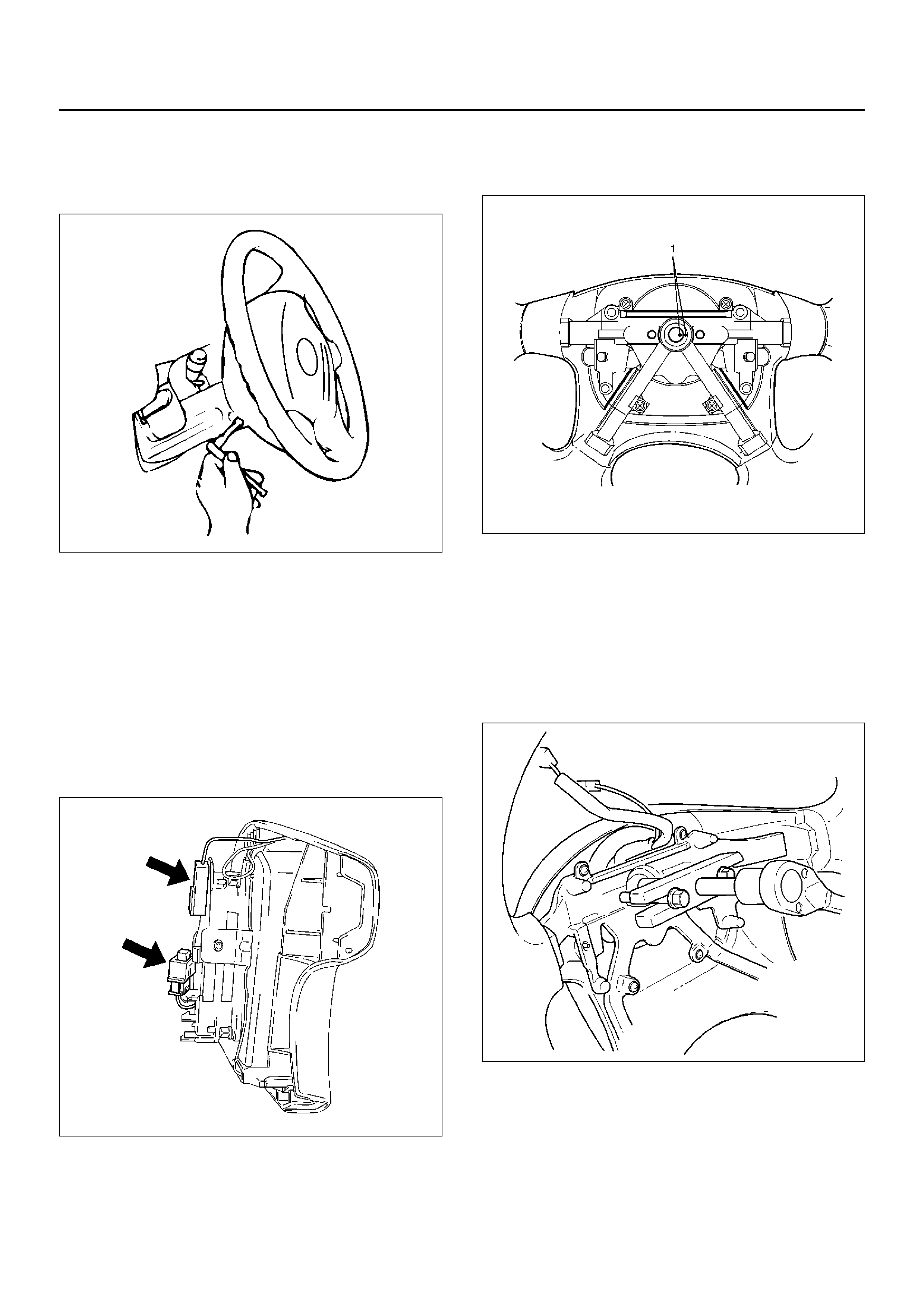
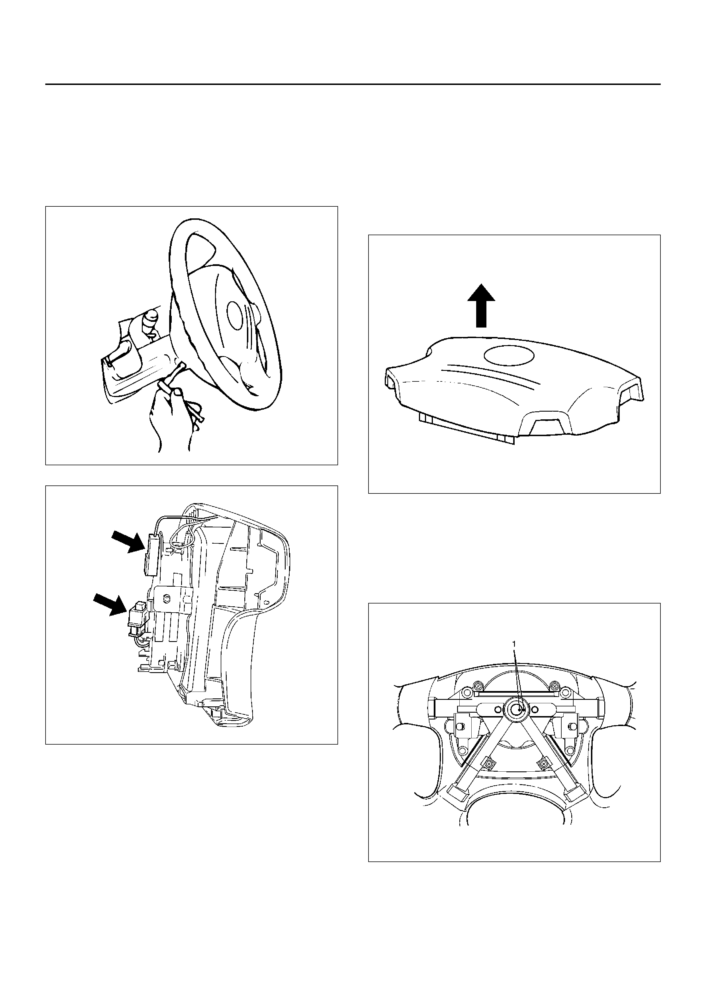
1. Turn the steeri ng wh eel so that t he vehicle's wheels
are pointing straight ahead.
2. Turn the ignition switch to “LOCK".
3. Disconnect the battery “–" terminal cable, and wait
at least 5 minutes.
4. Disconnect the yellow 2-wa y SRS connector located
under the steering column.
(1) Horn Lead
(2) SRS Conn ec tor
(3) Steering Wheel
(4) Steering Wheel Fixing Nut
(5) Inflator Module
5.Loosen the inflator module fixing bolt from behind
the steering wheel assembly using a TORX® driver
or equivalent until the inflator module can be
released from steering assembly.
827RW070
6.Disconnect the yellow 2-way SRS connector located
behind the inflator module.
WARNING: THE INFLATOR MODULE SHOULD
ALWAYS BE CARRIED WITH THE URETHANE
COVER AWAY FROM YOUR BODY AND SHOULD
ALWAYS BE LAID ON A FLAT SURFACE WITH THE
URETHANE SIDE UP. THIS IS NECESSARY
BECAUSE A FREE SPACE IS PROVIDED TO ALLOW
THE AIR CUSHION TO EXPAND IN THE UNLIKELY
EVENT OF ACCIDENTAL DEPLOYMENT.
OTHERWISE, PERSONAL INJURY MAY RESULT.
827RW073
7.Disconnect horn lead.
8.Remove steering wheel fixing nut.
9.Apply a setting mark (1) across the steering wheel
and shaft so parts can be reassembled in their
original position, then remove steering wheel.
430RW021
10.Move the front wheels to the straight ahead position,
then use steering wheel remover 5–8521–0016–0 to
remove the steering wheel.
CAUTION: Never apply force to the steering wheel
in direction of the shaft by using a hammer or other
impact tools in an attempt to remove the steering
wheel. The steering shaft is designed as an energy
absorbing unit.
430RX005

Installation
1.Install steering wheel by aligning the setting marks
made when removing.
CAUTION: Never apply force to the steering wheel
in direction of the shaft by using a hammer or other
impact tools in an attempt to remove the steering
wheel. The steering shaft is designed as an energy
absorbing unit.
2. Tighten the steering wheel fixing nut to the specified
torque.
Torque: 34N·m (3.5kg·m/25lbft)
3. Connect horn lead.
4. Support the module and carefully connect the SRS
connector.
NOTE: Pass the lead wire through the tabs on the
plastic cover (wire protector) of inflator to prevent lead
wire from being pinches.
5. Tighten bolts to specified torque.
Torque: 9N·m (0.9kg·m/78lbin)
6. Connect the yellow 2-way SRS connector located
under the steering column.
7. Connect the battery “–" terminal cable.
8. Turn the ignition switch to “ON" while watching
warning light. Light should flash 7 times and then go
off. If lamp does not operate correctly, refer to
Restraints section.
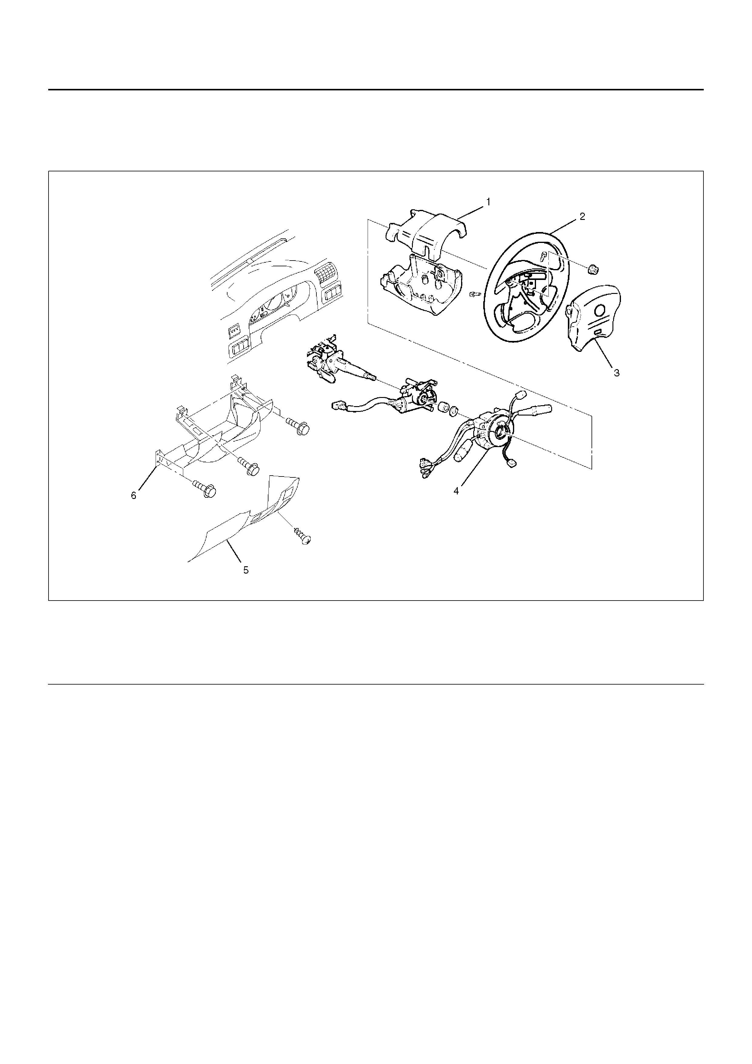
Combination Switch
Combination Switch and Associated Parts
431RW028
Legend
EndOFCallout
Removal
1.Turn the steering wheel so that the vehicle's wheels
are pointing straight ahead.
2.Turn the ignition switch to “LOCK".
3.Disconnect the battery “–" terminal cable, and wait
at least 5 minutes.
4.Disconnect the yellow 2-way SRS connector located
under the steering column.
CAUTION: The wheels of the vehicle must be
straight ahead and the steering column in the
“LOCK" position bef ore disconnecting the steering
wheel. Failure to do so will cause the coil assembly
to become uncentered which will cause damage to
the coil assembly.
5. Remove the engine hood openi ng lever, then
remove instrument panel lower cover.
6. Remove the driver knee bolster (reinforcement).
(1) Steering Column Cover
(2) Steering Wheel
(3) Inflator Module
(4) Combination Switch and SRS Coil Assembly
(5) Instrument Panel Lower Cover
(6) Driver Knee Bolster (reinforcement)
7.Loosen the inflator module fixing bolt from behind
the steering wheel assembly using a TORX® driver
or equivalent until the inflator module can be
released from steering assembly. Disconnect the
yellow 2-way SRS connector and horn lead located
behind the inflator module, then remove inflator
module.
827RW070
827RW073
WARNING: The INFLATOR MODULE SHOULD
ALWAYS BE CARRIED WITH THE URETHANE
COVER AWAY FROM YOUR BODY AND SHOULD
ALWAYS BE LAID ON A FLAT SURFACE WITH THE
URETHANE SIDE UP. THIS IS NECESSARY
BECAUSE A FREE SPACE IS PROVIDED TO ALLOW
THE AIR CUSHION TO EXPAND IN THE UNLIKELY
EVENT OF ACCIDENTAL DEPLOYMENT.
OTHERWISE, PERSONAL INJURY MAY RESULT.
827RW072
8. Apply a setting mark (1) across the steering wheel
and shaft so parts can be reassembled in their
original position. Move the front wheels to the
straight ahead position, then use steering wheel
remover 5–8521–0016–0 to remove the steering
wheel.
430RW021
CAUTION: Never apply force to the steering wheel
in direction of the shaft by using a hammer or other
impact tools in an attempt to remove the steering
wheel. The steering shaft is designed as an energy
absorbing unit.
430RX005
9.Remove steering column cover.
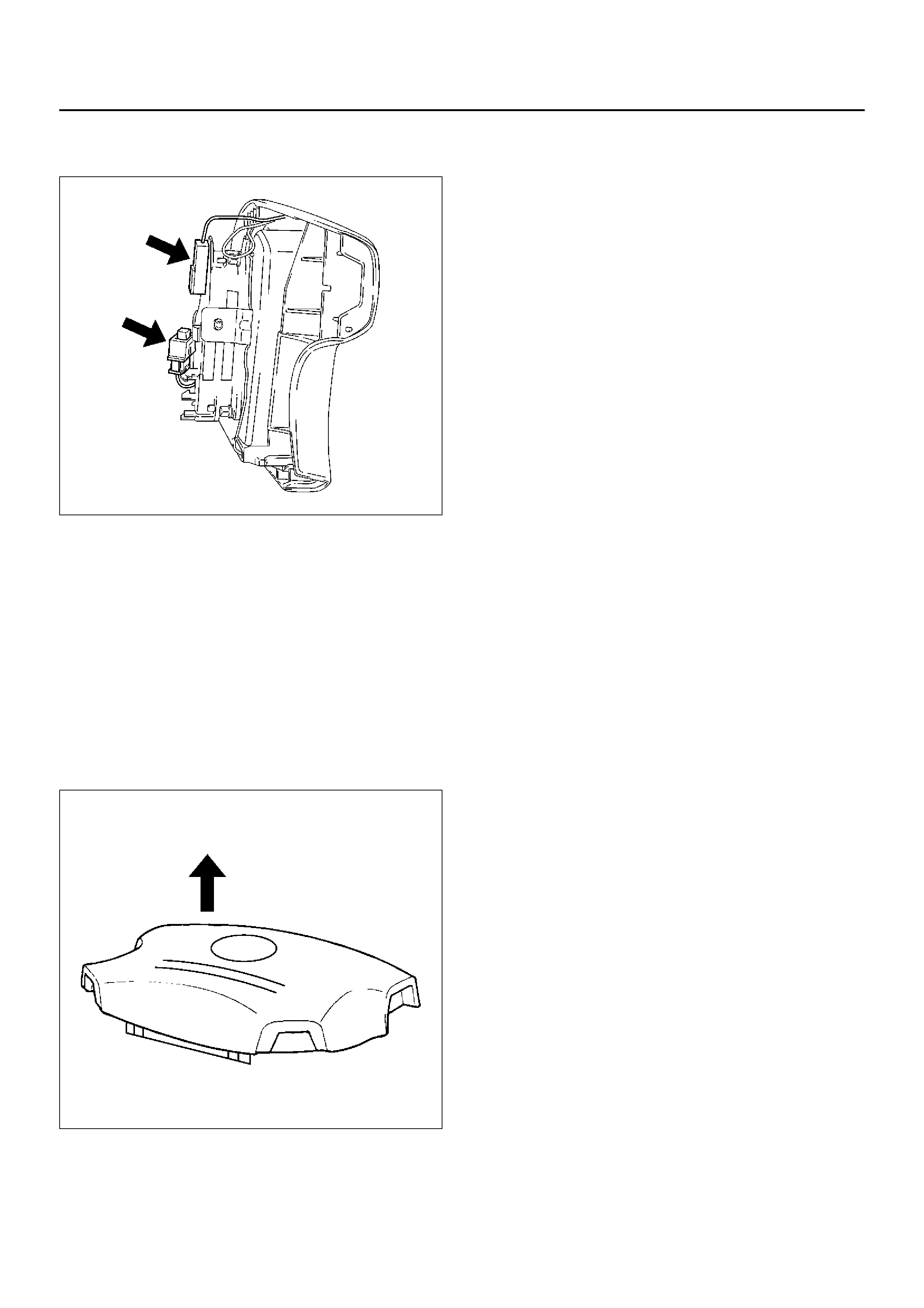
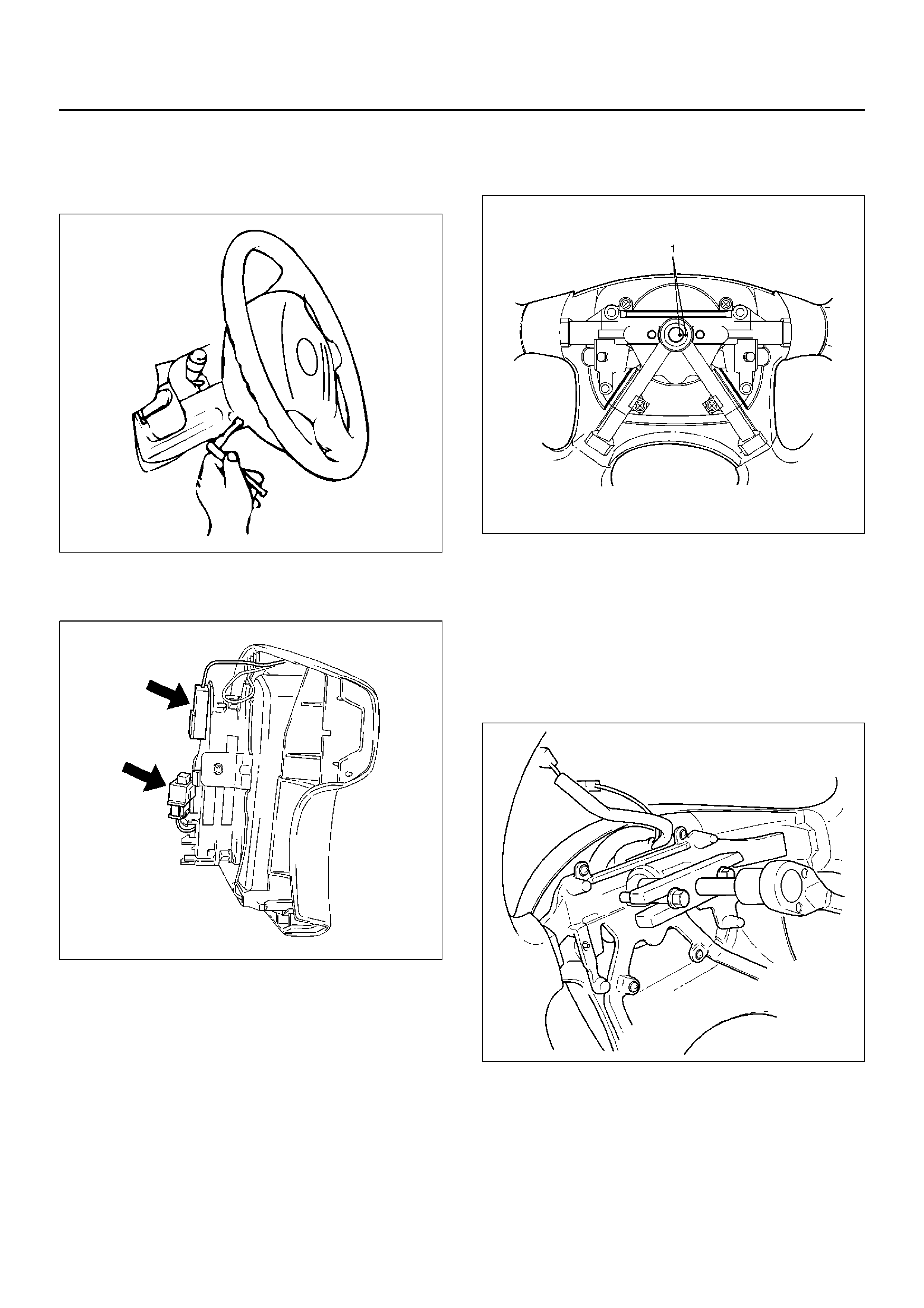
10.Disconnect the wiring harness connectors located
under the steering column then remove combination
switch and SRS coil assembly.
NOTE: The SRS coil is a part of the combination switch
assembly, which can not be replaced separately.
Therefore, be sure not to remove the SRS coil from the
combination switch assembly.
825RW288
Installation
1.Install combination switch and SRS coil assembly.
After installation of combination switch assembly,
connect the combination switch wiring harness
connector and the SRS 2-way connector located
under the steering column. Then turn the SRS coil
counter clockwise to full, return about 3 turns and
align the neutral mark.
CAUTION: When turning the SRS coil counter
clockwise to full, stop turning if resistance is felt.
Forced further turning may damage to the cable in
the SRS coil.
825RW016
2.When installing the steering column cover, be sure
to route each wire harness as illustrated so that the
harnesses do not catch on any moving parts.
825RW017
Legend
EndOFCallout
3.Align the setting marks made when removing then
install steering wheel.
CAUTION: Never apply force to the steering wheel
in direction of the shaft by using a hammer or other
impact tools in an attempt to remove the steering
wheel. The steering shaft is designed as an energy
absorbing unit.
4.Tighten the steering wheel fixing nut to the specified
torque.
Torque: 34N·m (3.5kg·m/25lbft)
5.Support the inflator module and carefully connect
the SRS connector and horn lead.
NOTE: Pass the lead wire through the tabs on the
plastic cover (wire protector) of inflator to prevent lead
wire from being pinched.
6.Tighten bolts to specified torque.
Torque: 9N·m (0.9kg·m/78lbin)
7.Install driver knee bolster (reinforcement).
8.Install instrument panel lower cover then Install the
engine hood opening lever.
9.Connect the SRS connector.
10.Connect the battery “-" terminal cable.
11.Turn the ignition switch to “ON" while watching
warning light and check the light should flash 7
times and then go off. If lamp does not operate
correctly, refer to Restraints section.
(1) Steering Column Cover
(2) Starter Switch Harness
(3) Combination Switch Harness
(4) Inflator Module Harness
Lock Cylinder
Lock Cylinder and Associated Parts
431RW027
Legend
EndOFCallout
Removal
1.Turn the steering wheel so that the vehicle's wheels
are pointing straight ahead.
2.Turn the ignition switch to “LOCK".
3.Disconnect the battery “–" terminal cable, and wait
at least 5 minutes.
4.Disconnect the yellow 2-way SRS connector located
under the steering column.
CAUTION: The wheels of the vehicle must be
straight ahead and the steering column in the
"LOCK" position before disconnecting the steering
wheel. Failure to do so will cause the coil assembly
to become uncentered which will cause damage to
the coil assembly.
5. Remove the engine hood opening lev er and steering
lower cover.
6. Remove driver knee bolster (reinf orcement).
(1) Inflator Module
(2) Steering Wheel
(3) Steering Column Cover
(4) Combination Switch and SRS Coil Assembly
(5) Snap Ring
(6) Cushion Rubber
(7) Lock Cylinder Assembly
(8) Instrument Panel Lower Cover
(9) Driver Knee Bolster (reinforcement)
(10) Shift Lock Cable (for A/T)
7.Loosen the inflator module fixing bolt from behind
the steering wheel assembly using a TORX® driver
or equivalent until the inflator module can be
released from steering assembly.
827RW070
8.Disconnect the yellow 2-way SRS connector and
horn lead located behind the inflator module.
827RW073
9.Apply a setting mark (1) across the steering wheel
and shaft so parts can be reassembled in their
original position.
430RW021
10.Move the front wheels to the straight ahead position,
then use steering wheel remover 5–8521–0016–0
to remove the steering wheel.
CAUTION: Never apply force to the steering wheel
in direction of the shaft by using a hammer or other
impact tools in an attempt to remove the steering
wheel. The steering shaft is designed as an energy
absorbing unit.
430RX005
WARNING: THE INFLATOR MODULE SHOULD
ALWAYS BE CARRIED WITH THE URETHANE
COVER AWAY FROM YOUR BODY AND SHOULD
ALWAYS BE LAID ON A FLAT SURFACE WITH THE
URETHANE SIDE UP. THIS IS NECESSARY
BECAUSE A FREE SPACE IS PROVIDED TO ALLOW
THE AIR CUSHION TO EXPAND IN THE UNLIKELY
EVENT OF ACCIDENTAL DEPLOYMENT.
OTHERWISE, PERSONAL INJURY MAY RESULT.
827RW072
11.Remove steering column cover.
12.Disconnect the wiring harness connectors located
under the steering column.
13.Remove the combination switch assembly with SRS
coil.
NOTE: The SRS coil is a part of the combination switch
assembly, which can not be replaced separately.
Therefore, be sure not to remove the SRS coil from the
combination switch assembly.
825RW288
14.Remove snap ring.
15.Remove cushion rubber.
16.Remove shift lock cable (for A/T).
17.Disconnect the starter switch harness connector
located under the steering column then remove lock
cylinder assembly.
Installation
1.Install lock cylinder assembly.
2.Install shift lock cable (for A/T).
3.Install cushion rubber.
4.Install snap ring.
5.Install Combination switch and SRS coil assembly.
After installation of combination switch assembly,
connect the combination switch wiring harness
connector and the SRS 2-way connector located
under the steering column.
6.Turn the SRS coil counter clockwise to full, return
about 3 turns and align the neutral mark.
CAUTION: When turning the SRS coil counter
clockwise to full, stop turning if resistance is felt.
Forced further turning may damage the cable in the
SRS coil.
825RW016
7.When installing the steering column cover, be sure
to wire (through each harness) as illustrated so that
the harnesses starter switch, combination switch
and SRS coil may not catch wiring.
825RW017
Legend
EndOFCallout
8.Install steering wheel by aligning the setting marks
made during removal.
CAUTION: Never apply force to the steering wheel
in direction of the shaft by using a hammer or other
impact tools in an attempt to remove the steering
wheel. The steering shaft is designed as an energy
absorbing unit.
9.Tighten the steering wheel fixing nut to the specified
torque.
Torque: 34N·m (2.5kg·m/25lbft)
10.Support inflator module and carefully connect the
SRS connector and horn lead, then install inflator
module.
NOTE: Pass the lead wire through the tabs on the
plastic cover (wire protector) of inflator to prevent lead
wire from being pinched.
11.Tighten fixing bolts to specified torque.
Torque: 9N·m (0.9kg·m/78lbin)
12.Install driver knee bolster (reinforcement).
13.Install instrument panel lower cover, then install the
engine hood opening lever.
14.Connect the yellow 2-way SRS connector located
under the steering column.
15.Connect the battery “–" terminal cable.
System Inspection
Turn the ignition switch to “ON" while watching warning
light.
The light should flash 7 times and then go off. If lamp
does not operate correctly, refer to Restraints section.
(1) Steering Column Cover
(2) Starter Switch Harness
(3) Combination Switch Harness
(4) Inflator Module Harness
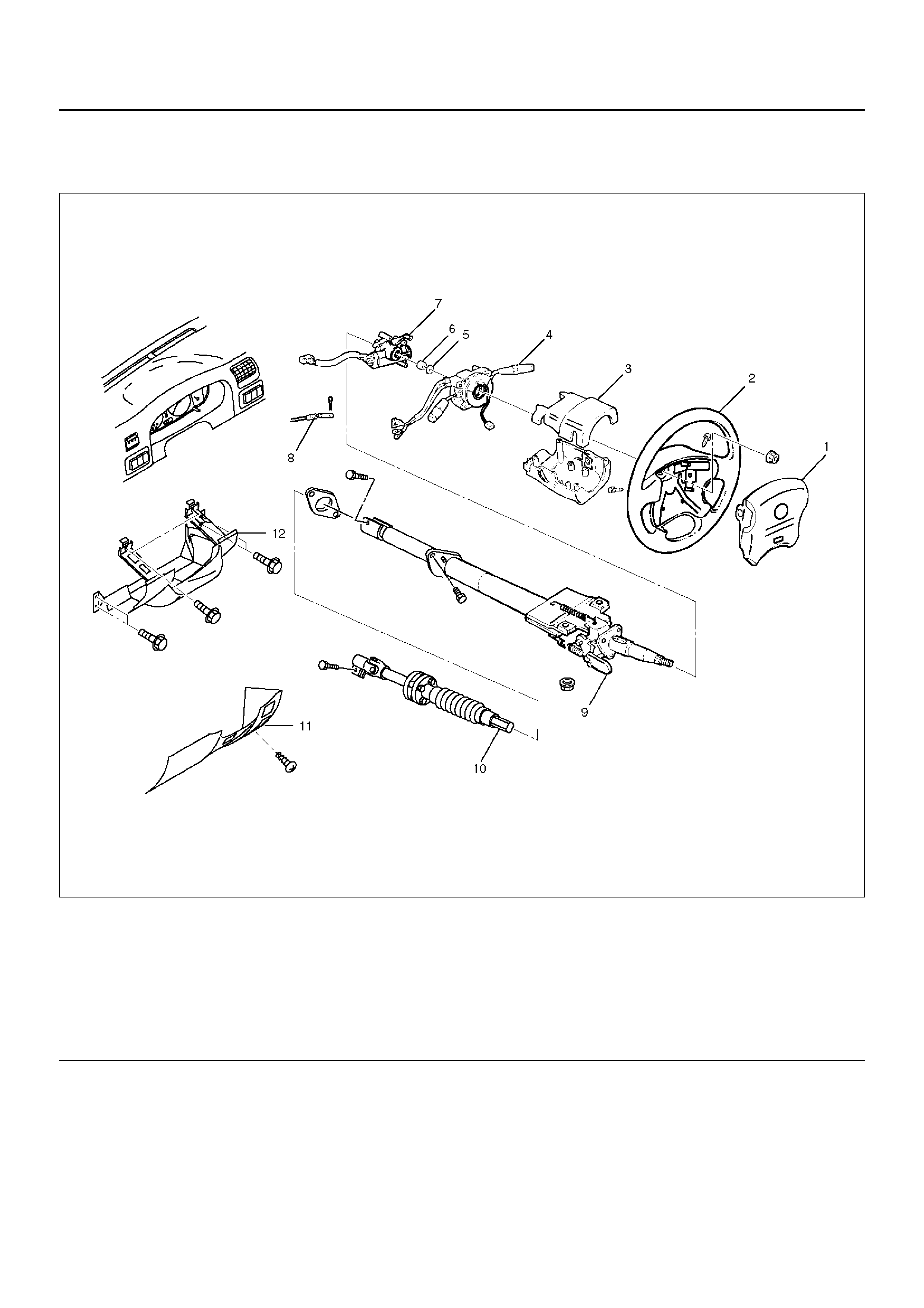
Steering Column
Steering Column and Associated Parts
431RW029
Legend
EndOFCallout
Removal
1.Turn the steering wheel so that the vehicle's wheels
are pointing straight ahead.
2.Turn the ignition switch to “LOCK".
3.Disconnect the battery “–" terminal cable, and wait
at least 5 minutes.
4.Disconnect the yellow 2-way SRS connector located
under the steering column.
CAUTION: The wheel of the vehicle must be straight
ahead and the steering column in the “LOCK"
position before disconnecting the steering column
from the steering gear. Failure to do so will cause
the SRS coil assembly to become uncentered which
will cause damage to the SRS coil assembly.
(1) Inflator Module
(2) Steering Wheel
(3) Steering Column Cover
(4) Combination Switch and SRS Coil Assembly
(5) Snap Ring
(6) Cushion Rubber
(7) Lock Cylinder Assembly
(8) Shift Lock Cable (For A/T)
(9) Steering Column Assembly
(10) S ec ond Ste ering Sha ft
(11) Instrument Panel Lower Cover
(12) Driver Knee Bolster (reinforcement)
5.Remove the engine hood opening lever, then
remove instrument panel lower cover.
6.Remove driver knee bolster (reinforcement).
7.Loosen the inflator module fixing bolt from behind
the steering wheel assembly using a TORX® driver
or equivalent until the inflator module can be
released from steering assembly.
827RW070
8.Disconnect the yellow 2-way SRS connector and
horn lead located behind the inflator module.
9.Remove inflator module.
WARNING: THE INFLATOR MODULE SHOULD
ALWAYS BE CARRIED WITH THE URETHANE
COVER AWAY FROM YOUR BODY AND SHOULD
ALWAYS BE LAID ON A FLAT SURFACE WITH THE
URETHANE SIDE UP. THIS IS NECESSARY
BECAUSE A FREE SPACE IS PROVIDED TO ALLOW
THE AIR CUSHION TO EXPAND IN THE UNLIKELY
EVENT OF ACCIDENTAL DEPLOYMENT.
OTHERWISE, PERSONAL INJURY MAY RESULT.
827RW072
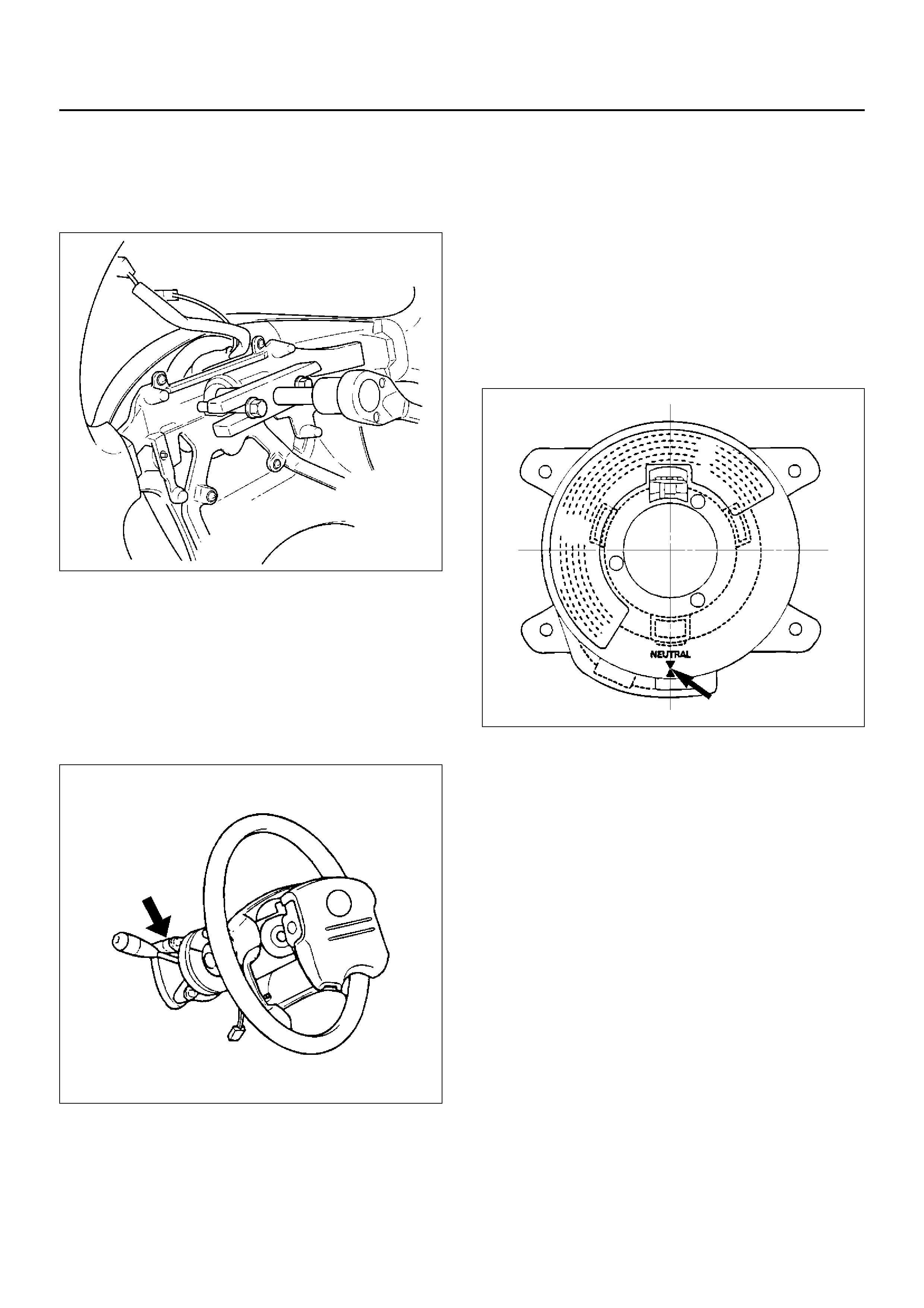
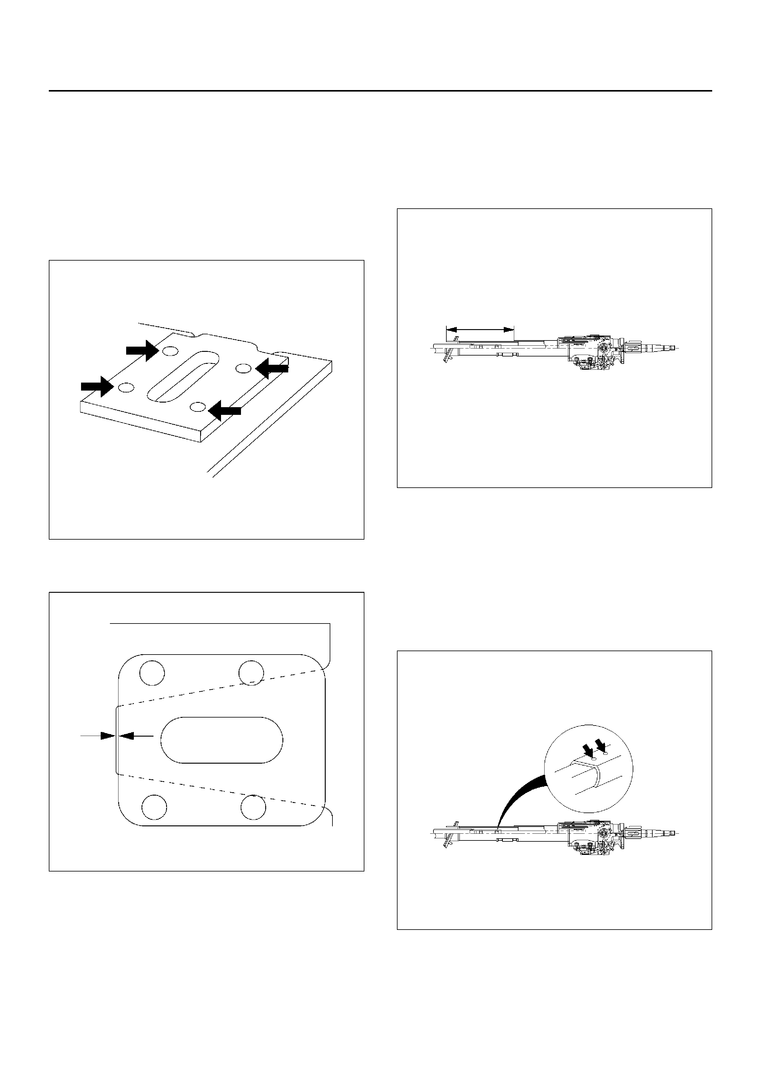
10. Apply a setting mark (1) across the steering wheel
and shaft so parts can be reassembled in their
original position. Move the front wheels to the
straight ahead position, then use steering wheel
remover 5–8521–0016–0 to remove the steering
wheel.
430RW021
430RX005
11. Remove steering column cover.
12. Disconnect the wiring harness connectors located
under the steering column.

13. Remove the combination switch assembly with SRS
coil.
NOTE: SRS coil is a part of combination switch
assembly, which can not be replaced singly. Therefore,
be sure not to remove the SRS coil from the
combination switch assembly.
825RW288
14. Remove snap ring.
15. Remove cushion rubber.
16. Remove shift lock cable (For A/T).
17. Disconnect the starter switch harness connector
located under the steering column, then remov e
lock cylinder assembly.
18. Apply a setting mark (1) across the universal joint
and transfer gear to reassemble the parts in their
original position, then remove steering column
assembly and second shaft.
NOT E: A setting mark can be easily made if the shaft is
withdrawn a little by loosening the steering shaft
universal jo int.
431RW009
Insepction
If the abnormal conditions are f ound through inspection,
replac e the steering column assembly.
Column Capsule
Check capsules on steering column bracket assembly;
all must be securely seated in brack et slots and check ed
f or any loose conditions when pushed or pulled by hand.
431RW030
Check clearance between capsule and bracket. If must
be within 1mm (0.039 in).
431RW031
Column Tube
Check for collapes by measuring the distance as shown
in the figure.
Standard distance: 162.2-165.8 mm (6.386-6.528
in)
431RY00010
Column Universal Joint for Tilt Mechanism
If the resistance is felt when checked b y rotate the joint,
replace the steering column assembly.
She ared Injected Plastic Pin
Check the sheared injected plastic pins for any loose
condi tion s or damage.
431RY00011
Shaft Length
Check the shaft length from the center of the universal
joint to the end of the shaft. If column length is not in
specifications, steering column should be replaced.
Standard length: 662.2-664.2 mm (26.149-26.228
in)
431RY00012
Shaft U nive r s al Joint (Lower End)
If the resistance is felt when checked by rotate the joint,
replac e the steering column assembly.
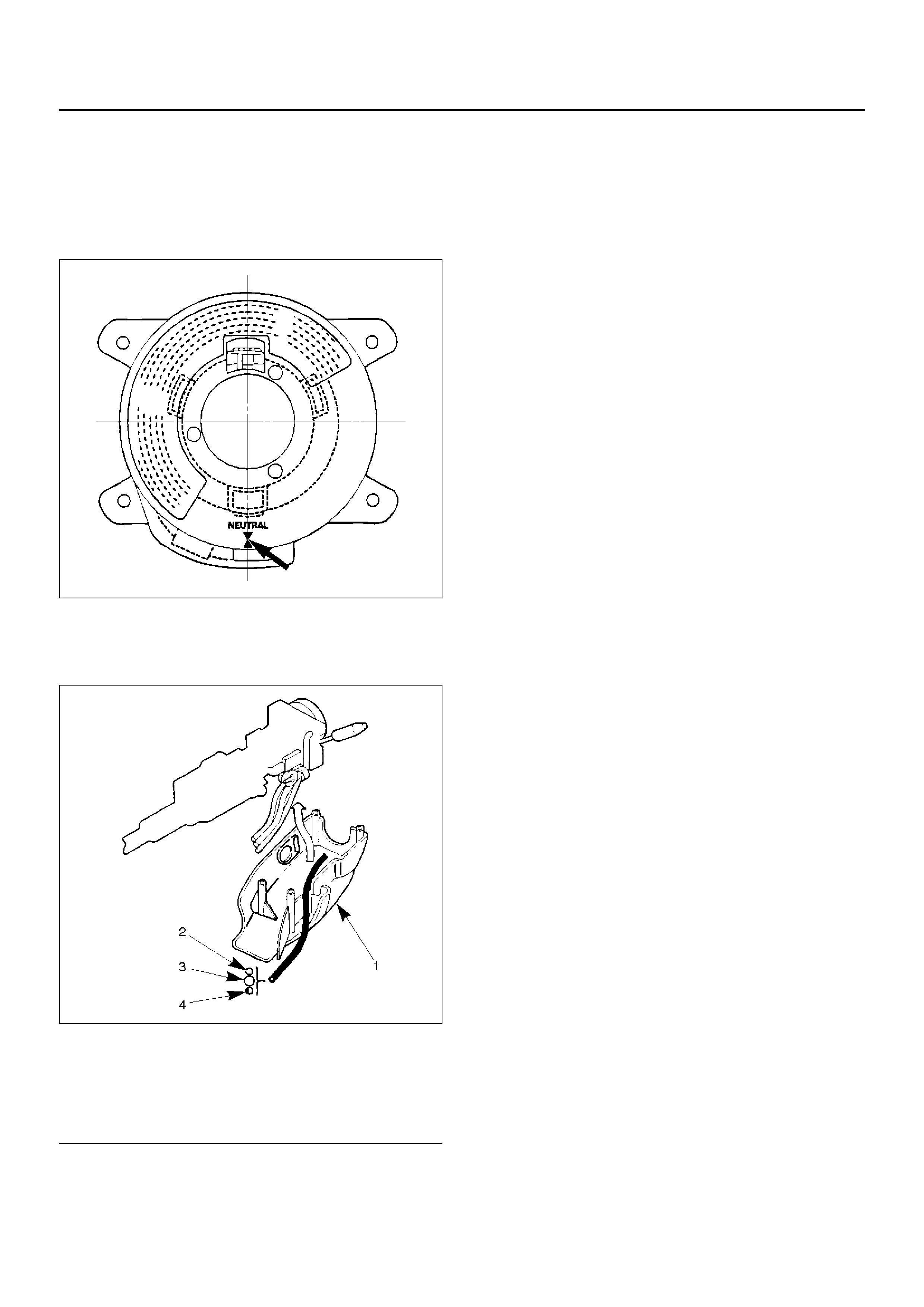
Shaft Bellows Pipe
Check the shaft bellows pipe for bend by using straight
edge. Measure the clearance between the bellows pipe
and the straight edge (at center of the bellows pipe).
Standard: Less than 1mm (0.039 in)
431RW035
Tilt Mechanism
Tilt mecha nis m sh oul d moves smoothly.
While locked the tilt mechanism, be sure the steering
column latch securely by pushing the steering wheel
upward and downward.
Installation
1. Install steering column assembly and second
steering shaft.
2. Align the setting marks on the universal joint and
transfer gear made during removal.
3. Tighten the steering column fixing bolt (dash panel)
to the specified torque.
Torque: 20N·m (2.0kg·m/14lbft)
4. Tighten the steering column fixing nuts (cross
beam) to the specifie d torque.
Torque: 17N·m (1.7kg·m/12lbft)
5. Tighten the universal joint to the specified torque.
Torque: 31N·m (3.2kg·m/23lbft)
6. Install lock cylinder assembly.
7. Install shift lock cable (For A/T).
8. Install cushion rubber.
9. Install snap ring.
10. Install combination switch and SRS coil assembly.
After installation of combination switch assembly,
connect the combination switch wiring harness
connector and the SRS 2-way connector located
under the steering column.
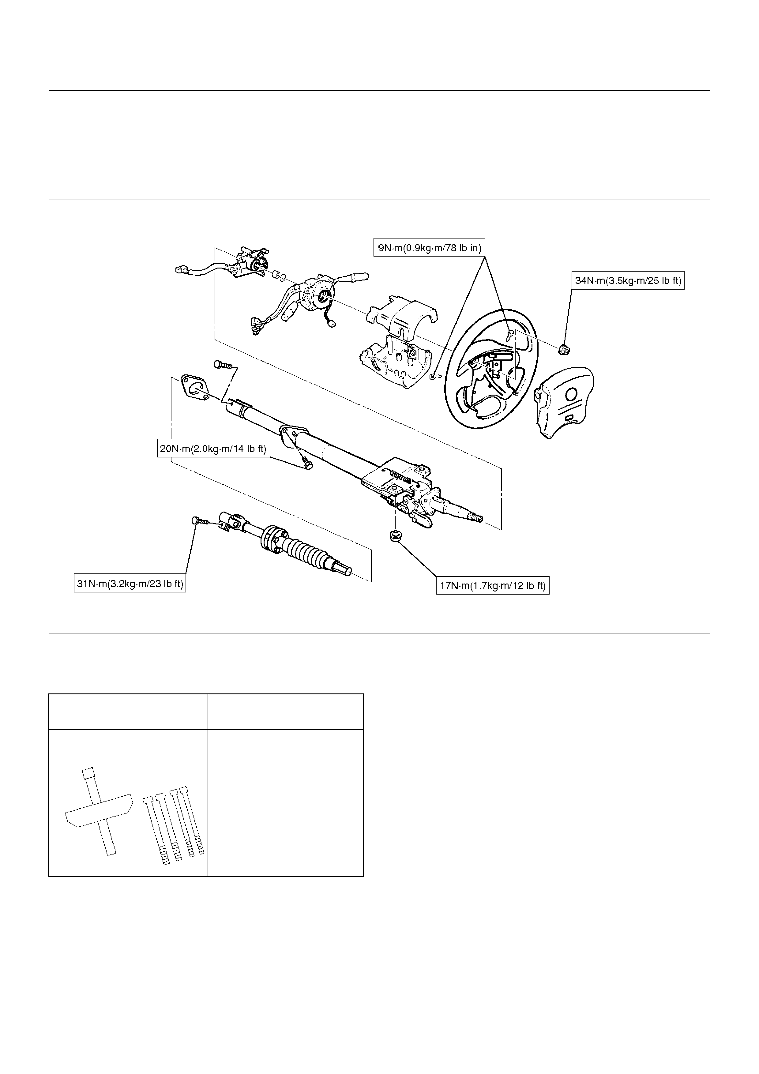
11.Turn the SRS coil counter clockwise to full, return
about 3 turns and align the neutral mark.
CAUTION: When turning the SRS coil counter
clockwise to full, stop turning if resistance is felt.
Forced further turning may damage to the cable in
the SRS coil.
825RW016
12.When installing the steering column cover, be sure
to route each wire harness as illustrated so that the
harnesses do not catch any moving parts.
825RW017
Legend
EndOFCallout
13.Install steering wheel and align the setting marks
made when removing.
CAUTION: Never apply force to the steering wheel
in direction of the shaft by using a hammer or other
impact tools in an attempt to remove the steering
wheel. The steering shaft is designed as an energy
absorbing unit.
14.Tighten the steering wheel fixing nut to the specified
torque.
Torque: 34N·m (3.5kg·m/25lbft)
15.Support the module and carefully connect the
module connector and horn lead, then install inflator
module.
NOTE: Pass the lead wire through the tabs on the
plastic cover (wire protector) of inflator to prevent lead
wire from being pinched.
16.Tighten bolts to specified torque.
Torque: 9N·m (0.9kg·m/78lbin)
17.Install driver knee bolster (reinforcement).
18.Install instrument panel lower cover.
19.Install the engine hood opening lever.
20.Connect the yellow 2-way SRS connector and horn
lead located under the steering column.
21.Connect the battery “–" terminal cable.
System Inspection
Turn the ignition switch to “ON" while watching warning
light.
The light should flash 7 times and then go off. If lamp
does not operate correctly, refer to Restraints section.
(1) Steering Column Cover
(2) Starter Switch Harness
(3) Combination Switch Harness
(4) Inflator Module Harness
Supplemental Restraint System Steering Wheel & Column and
Associated Parts
Main Data and Specifications
Torque Specifications
430RY00006
Special Tools
ILLUSTRATION TOOL NO.
TOOL NAME
5–8521–0016–0
(J–29752)
Steering wheel remover