
SECTION 3E - WHEEL AND TIRE SYSTEM
Service Precaution
General Description
Diagnosis
Wheel
Wheel and Associated Parts
Removal
Installation
Tire
Tire Replacement
General Balance Procedure
Balancing Wheel and Tire
Main Data and Specifications
Service Precaution
WARNING: THIS VEHICLE HAS A SUPPLEMENTAL
RESTRAINT SYSTEM (SRS). REFER TO THE SRS
COMPONENT AND WIRING LOCATION VIEW IN
ORDER TO DETERMINE WHETHER YOU ARE
PERFORMING SERVICE ON OR NEAR THE SRS
COMPONENTS OR THE SRS WIRING. WHEN YOU
ARE PERFORMING SERVICE ON OR NEAR THE
SRS COMPONENTS OR THE SRS WIRING, REFER
TO THE SRS SERVICE INFORMATION. FAILURE TO
FOLLOW WARNINGS COULD RESULT IN
POSSIBLE AIR BAG DEPLOYMENT, PERSONAL
INJURY, OR OTHERWISE UNNEEDED SRS SYSTEM
REPAIRS.
CAUTION: Always use the correct fastener in the
proper location. When you replace a fastener, use
ONLY the exact part number for that application.
ISUZU will call out those fasteners that require a
replacement after removal. ISUZU will also call out
the fasteners that require thread lockers or thread
sealant. UNLESS OTHERWISE SPECIFIED, do not
use supplemental coatings (Paints, greases, or
other corrosion inhibitors) on threaded fasteners or
fastener joint interfaces. Generally, such coatings
adversely affect the fastener torque and the joint
clamping f or ce, and may dama ge the fastener . Wh en
you install fasteners, use the correct tightening
sequence and specifications. Following these
instructions can help you avoid damage to parts
and systems.
Techline
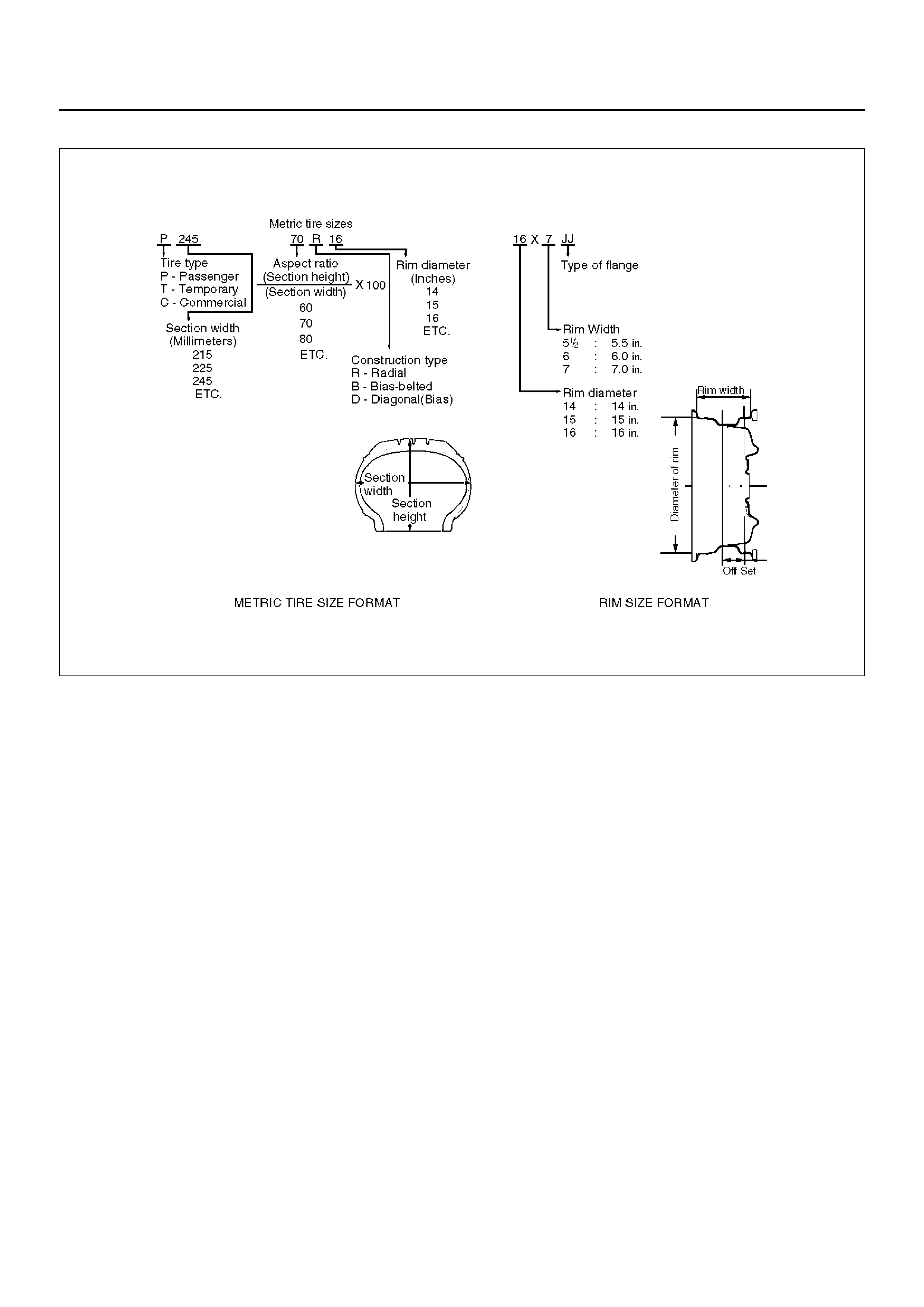
General Description
480RS008
Replacement wheels or tires must be equivalent to the
originals in load capacity, specified dimension and
mounting configuration. Improper size or type may
affect bearing life, brake perf ormance, speedometer/
odometer calibration, v ehicle ground clearance and tire
clearance to the body and chassis. All model are
equipped with metric sized tubeless steel belted radial
tires. Correct tire pressures and driving habits have an
important influence on tire life. Heavy cornering,
excessively rapid acceleration and unnecessary sharp
braking increase prem atur e and uneven wear.
Diagnosis
Condition Possible cause Correction
Vehicle Pulls Mismatched or uneven tires. Replace tire.
Tires not adequately inflated. Adjust tire pressure.
Broken or sagging springs. Replace spring.
Radial tire lateral force. Replace tire.
Improper wheel alignment. Adjust wheel alignment.
Brake dragging in one wheel. Repair brake.
Loose, bent or broken front or rear
suspension parts. Tighten or replace the appropriate
suspension part(s).
Faulty shock absorbers. Replace shock absorber.
Parts in power steering valve
defective. Replace power steering unit.
Abnormal or Excessive Tire Wear Sagging or broken spring. Replace spring.
Tire out of balance. Balance or replace tire.
Improper wheel alignment. Check front end alignment.
Faulty shock absorber. Replace shock absorber.
Hard driving. Replace tire.
Overloaded vehicle. Replace tire and reduce load.
Tires not rotated periodically. Replace or rotate tire.
W orn or loose road wheel bearings. Replace wheel bearing.
Wobbly wheel or tires. Replace wheel or tire.
Tires not adequately inflated. Adjust the pressure.
Wheel Hop Blister or bump on tire. Replace tire.
Improper shock absorber operation. Replace shock absorber.
Shimmy, Shake or Vibration Tire or wheel out of balance. Balance wheels or replace tire/or
wheel.
Loose wheel bearings. Replace wheel bearing.
Worn steering linkage ball joints. Replace ball joints.
Worn upper or lower end ball joints. Replace ball joints.
Excessive wheel runout. Repair or replace wheel and/or tire.
Blister or bump on tire. Replace tire.
Excessive loaded radial runout of
tire/wheel assembly. Replace tire or wheel.
Improper wheel alignment. Check wheel alignment.
Loose or worn steering linkage. Tighten or replace steering linkage.
Loose steering unit. Tighten steering unit.
Tires not adequately inflated. Adjust tire pressure.
Loose, bent or broken front or rear
suspension parts. Tighten or replace the appropriate
suspension parts.
Faulty shock absorber. Replace shock absorber.
Hub bearing preload misadjustment. Adjust preload.
Parts in power steering valve
defective. Replace power steering unit.
Hard Steering Bind in steering linkage ball studs,
upper or lower ball joint. Replace ball joint.
Improper wheel alignment. Check wheel alignment.
Tire not adequately inflated. Inflate tires to proper pressure.
Bind in steering column or shaft. Repair or replace.
Improper power steering system
operation. Repair or replace. Refer to Steering
section.
Too Much Play In Steering Wheel bearings worn. Replace wheel bearings.
Loose steering unit or linkage. Retighten or repair.
W orn or loose steering shaft
universal joint. Retighten or replace steering shaft.
Worn steering linkage ball joints. Replace ball joints.
Worn upper or lower end ball joints. Replace ball joints.
Poor Steering Wheel Returnability Bind in steering linkage ball joints. Replace ball joints.
Bind in upper or lower ball joints. Replace ball joints.
Bind in steering column and shaft. Repair or replace.
Bind in steering gear. Check and repair steering gear.
Improper wheel alignment. Adjust wheel alignment.
Tires not adequately inflated. Adjust pressure.
Loose steering wheel nut. Retighten.
Worn wheel bearing. Replace.
Abnormal Noise W orn, sticky or loose upper or lower
ball joint, steering linkage ball joi nts
or drive axle joints.
Replace.
Faulty shock absorbers. Replace.
W orn upper or lower control arm
bushing. Replace.
Loose stabilizer bar. Retighten bolts or replace bushings.
Loose wheel nuts. Tighten nuts. Check for elongated
wheel nut holes. Replace wheel if
required.
Loose suspension bolts or nuts. Retighten suspension bolts or nuts.
Broken or otherwise damaged wheel
bearings. Replace wheel bearing.
Broken suspension springs. Replace spring.
Loose steering unit. Retighten mounting bolt.
Faulty steering unit. Replace steering unit.
Wandering or Poor Steering Stability Mismatched or unevenly worn tires. Replace tire or inflate tires to proper
pressure.
Loose steering linkage ball joints. Replace ball joints.
Faulty shock absorbers. Replace shock absorber.
Loose stabilizer bar. Tighten or replace stabilizer bar or
bushings.
Broken or sagging springs. Replace spring (pairs).
Improper wheel alignment. Adjust wheel alignment.
Condition Possible cause Correction
Erratic Steering When Braking W orn wheel bearings. Replace wheel bearings.
Broken or sagging springs. Replace spring (pairs).
Leaking caliper. Repair or replace caliper.
Warped discs. Replace brake disc.
Badly worn brake pads. Replace brake pads.
Tires are inflated unequally. Inflate tires to proper pressure.
Low or Uneven Trim Height Broken or sagging springs. Replace springs (In pairs).
Vehicle overloaded. Reduce load.
Incorrect springs. Adjust or replace torsion bar.
Suspension Bottoms Vehicle overloaded. Reduce load.
Faulty shock absorber. Replace shock absorber.
Incorrect, broken or sagging springs. Replace springs.
Body Leans Loose stabilizer bar. Tighten stabilizer bar bolts or
replac e bushings.
Faulty shock absorb er, struts or
mounting. Replace shock absorber.
Broken or sagging springs. Replace springs (In pairs).
Vehicle overloaded. Reduce load.
Cupped Tires Worn wheel bearings. Replace wheel bearing.
Excessive tire or wheel run out. Replace tire or wheel.
Worn ball joints. Replace ball joints.
Tire out of balance. Adjust tire balance.
Condition Possible cause Correction
Irregular and Premature Wear
480RS001
Irregular and/or premature wear has many causes.
Some of them are incorrect inflation pressures, lack of
tire rotation, poor driving habits or improper wheel
alignment. Incorrect inflation is common cause of tire
premature wear.
NOTE: Due to their design, radial tires tend to wear
faster in the shoulder area, particularly on the front tires.
Thi s ma kes regu lar ro t ati on es pe ci al l y nece ss ary. After
rotation, be sure to check wheel nut torque, and set tire
pressures.
Tire Rotation
Tire rotation is recommended to equalize wear for
longer tire life.
480RS002
Legend
EndOFCallout
If the following conditions are noted, rotate the tires:
• Front tire wear is different from rear.
• Uneven wear exists across the tread of any tire.
• Left and right front tire wear is unequal.
• Left and right rear tire wear is unequal.
Check wheel alignment if the following conditions are
noted:
• Left and right front tire wear is unequal.
• Wear is uneven across the tread of any front tire.
• Front tire treads have a scuffed appearance with
“feather" edges on one side of the tread ribs or
blocks.
Tread Wear Indicators
480RS006
The original equipment tires have built-in tread wear
indicators(1) to show when tires need replacement.
These indicators may appear as wide bands. When the
indicators appear in two or more grooves at three
locations, tire replacement is recommended.
(1) Spar e Tire
Inflation of Tires
710RX004
Tire pressure, in cold condition (after vehicle has set for
three hours or more, and driv en less than one mile),
should be checked monthly or bef ore any extended trip.
Tire pressure increases appro ximately 15% when the
tires become hot during driving. Tire pressure
specification is shown on the label located on the left
door lock pillar.
NO TE: Check the tire pressure whene ver irregular wear
is f ound. Tire inflation greatly affects tire wear. If the
alignment check does not re veal any alignment
problems, check the condition of the shock absorbers
and wheel/tire balance.
Diagnosis List
If the following conditions are noted, rotation is required.
1. Front tire wear is different from rear.
2. Une ven wear exists across the tread of any tire.
3. Left and right front tire wear is unequal.
4. Left and right rear tire wear is unequal.
If the follo wing conditions are noted, check the wheel
alignment.
1. Left and right front tire wear is unequal.
2. Une ven wear exists across the tread of any tire.
3. Front tire treads have scuffed appearance with
“feather" edges on one side of tread ribs or blocks.
4. There is cupping, flat spotting etc.
Higher than recommended pressure can cause:
1. Hard ride.
2. Poor steering stability.
3. Rapid and uneven wear at center of the tread.
Lower than recommended pressure can cause:
1. Tire squeal on turns.
2. Hard steerin g.
3. Rapid and uneven wear on the edges of the tread.
4. Tire rim bruises and rupture.
5. Tire cord breakage.
6. High tire temperatures.
7. Reduced handling.
8. Reduced fuel economy.
Unequal pressure on same axle can cause:
1. Uneven braking.
2. Steering lead.
3. Reduced handling.
4. Swerve on acceleration.
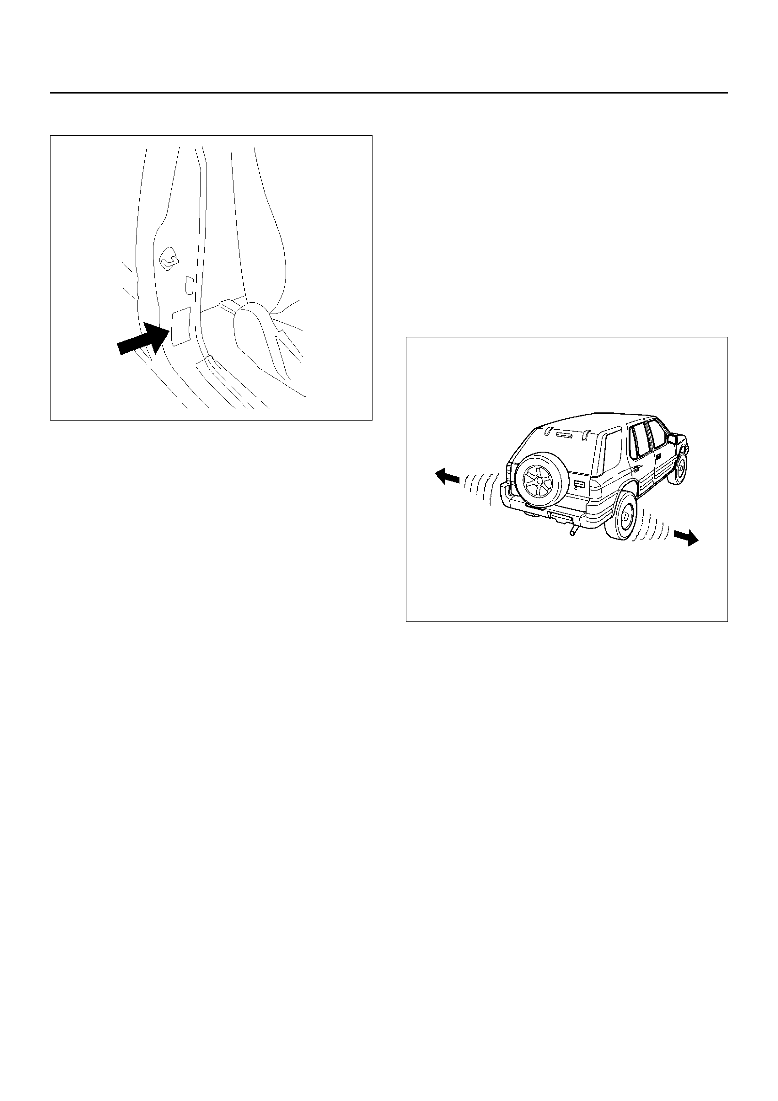
Radial Tire Waddle
480RW011
Waddle is side-to-side mov ement at the front and/or
rear of the car. It can be caused by the steel belt not
being straight within the tire, or by excessive lateral
runout of the tire or wheel. It is most noticeable at low
speed, about 8 to 48 km/h (5 to 30 mph). It may also
cause rough ride at 80 to 113 km/h (50 to 70 mph).
The car can be road tested to see which end of the car
has the faulty tire. If the tire causing the waddle is on
the rear, the rear end of the car will “waddle". From the
driver's seat, it feels as if someone is pushing on the
side of the car.
If the faulty tire is on the front, the waddle is more easily
seen. The front sh eet metal appears to be moving back
and forth. It f eels as if the driver's seat is the pivot point
in the car.
Another more time-consuming method of determining
the faulty tire is substituting tire and wheel assemblies
that are known to be good. Follow these steps:
1. Drive the car to determine if the waddle is coming
from the front or rear.
2. Install tire and wheel assemblies known to be good
(from a similar car) in place of those on the end of
the car which is waddling. If the waddle cannot be
isolated to front or rear, start with the rear tires.
3.Road test again. If improvement is noted, install the
original tire and wheel assemblies one at a time
until the faulty tire is found. If no improvement is
noted, install tires known to be good in place of all
four. Then, install the originals one at a time until the
faulty tire is found.
Radial Tire Lead/Pull
“Lead/Pull" is vehicle deviation from a straight path, on a
level road with no pressure on the steering wheel.
Lead is usually caused by:
1.Poorly manufactured radial tires.
2.Uneven brake adjustment.
3.Wheel alignment.
The way in which a tire is built can produce lead in a car.
An example of this is placement of the belt. Off-center
belts on radial tires can cause the tire to develop a side
force while rolling straight down the road and the tire will
tend to roll like a cone.
The “Radial Tire Lead/Pull Correction" chart should be
used to make sure that front wheel alignment is not
mistaken for tire lead.
Rear tires will not cause lead/pull.
Radial Tire Lead/Pull Correction Chart
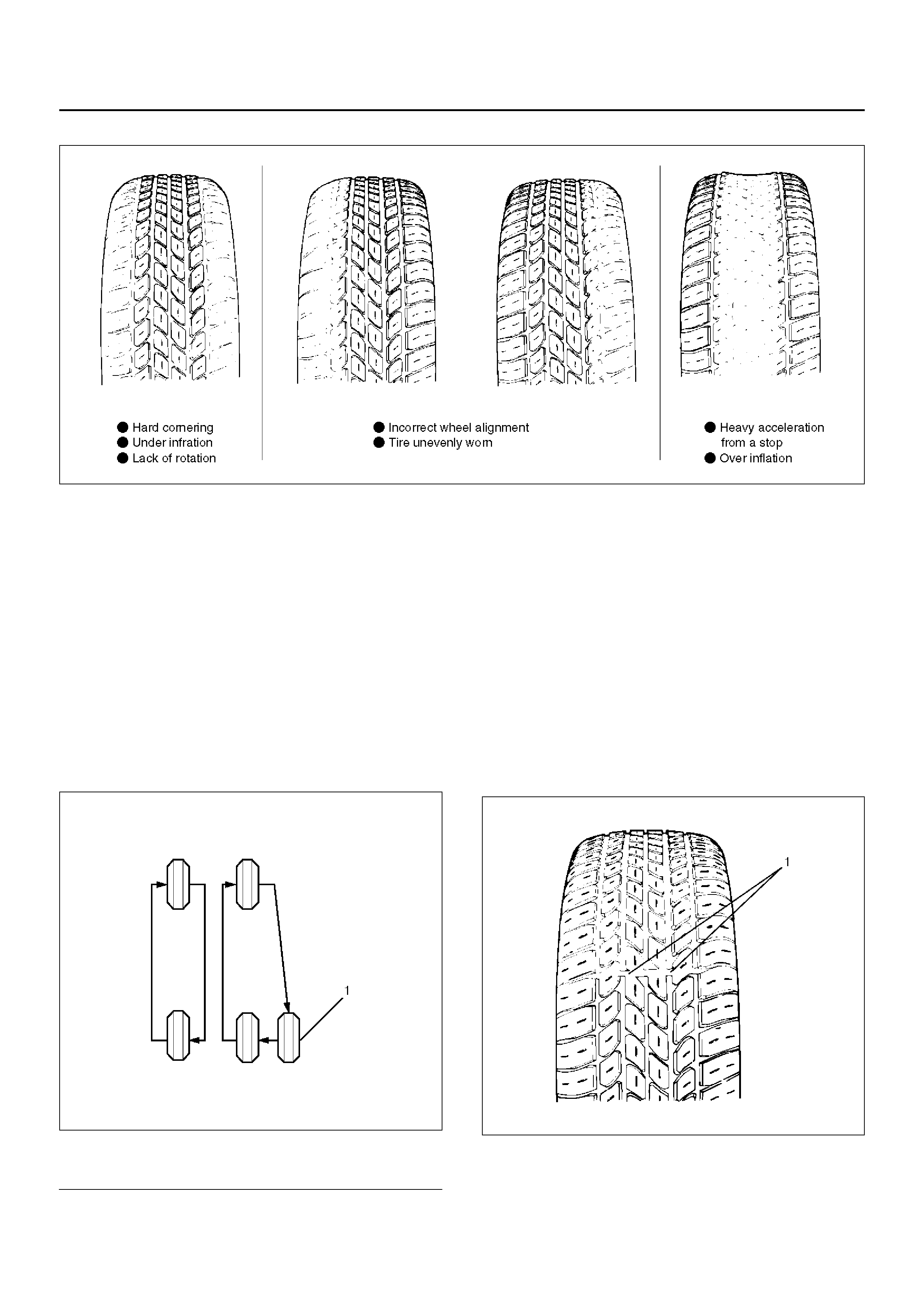
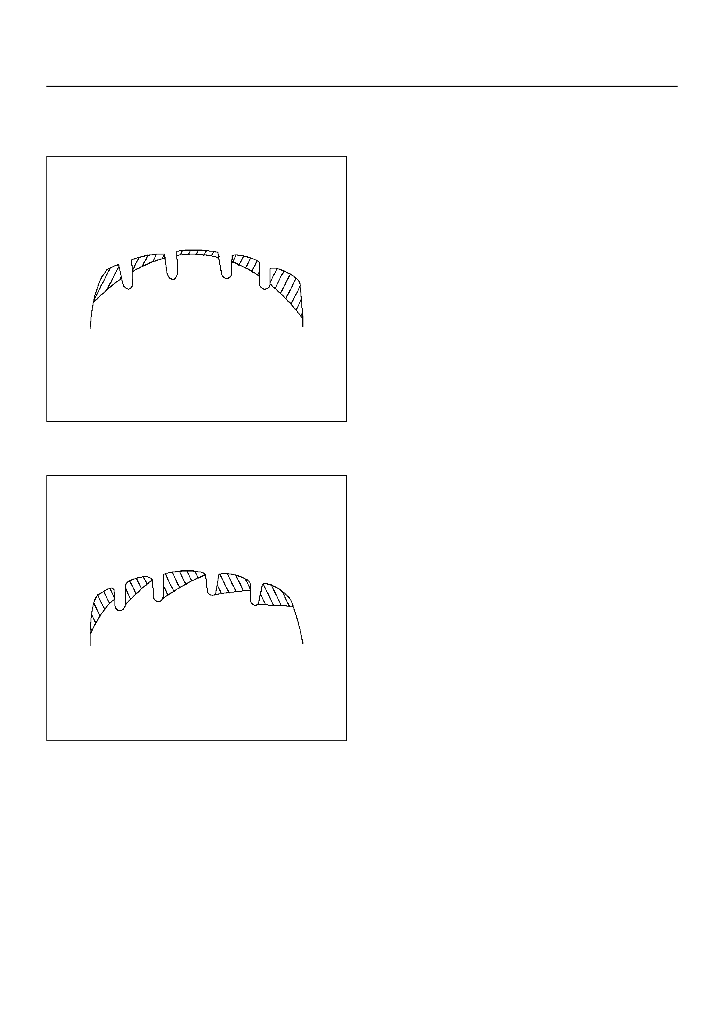
Typical examples of abnormal tire ahead wear and
major causes:
CAUTION: Similar wear patterns can be caused by
worn suspension parts, misalignment of wheels and
tires, and other suspension related problems.
Spotty wear – wear localized on shoulder sections, and
in an extreme cases, the tire becomes polygonal in
shape.
480RW002
Step Action Yes No
1 1. Inflate tires to recommended pressure.
2. Road test vehicle on level uncrowned road.
Was a problem corrected? End. Go to Step 2
2 Switch front tires side to side and road test again.
Was a problem corrected? If roughnes s
results,replace
tires. Go to Step 3
3 Did the vehicle lead in same direction? Go to Step 4 Go to Step 5
4 Put tires back in original position and check alignment.
Was a problem corrected? End. Go to Step 5
5 Install known good tire on one front side.
Was a problem corrected?
Replace tire.
Install a known
good tire in
place of other
front tire.
If lead
corrected,
replace tire.
1. Tire or wheel out of round or distorted.
2. Hub or knuckle out of round or distorted.
3. Play in hub bearings or ball joint.
4. Rotating parts out of balance.
Tread wear one-sided.
480RW003
1. Rotating parts out of balance.
2. Tire or wheel out of round.
3. Hub or knuckle out of round or distorted.
Localized tread wear.
480RW004
1. Once spotty wear develops in tread due to hard
braking or abrupt starting, localized wear tends to
be promoted.
Shoulder wear (generally wear develops in outer
shoulder):
480RW005
1. Camber or toe-in incorrect.
2. Shoulder wear caused by repeated hard-cornering.
W ear in shoulders at points opposed to each other.
480RW006
1. Tire or wheel out of round or distorted.
2. Play in bearings or ball joi nt.
Premature wear in shoulders.
480RW007
1. Flexing of tire excessive due to under-inflation.
One sided feather edging.
480RW008
1. Wear caused by repeated hard cornering.
2. Camber or toe-in incorrect.
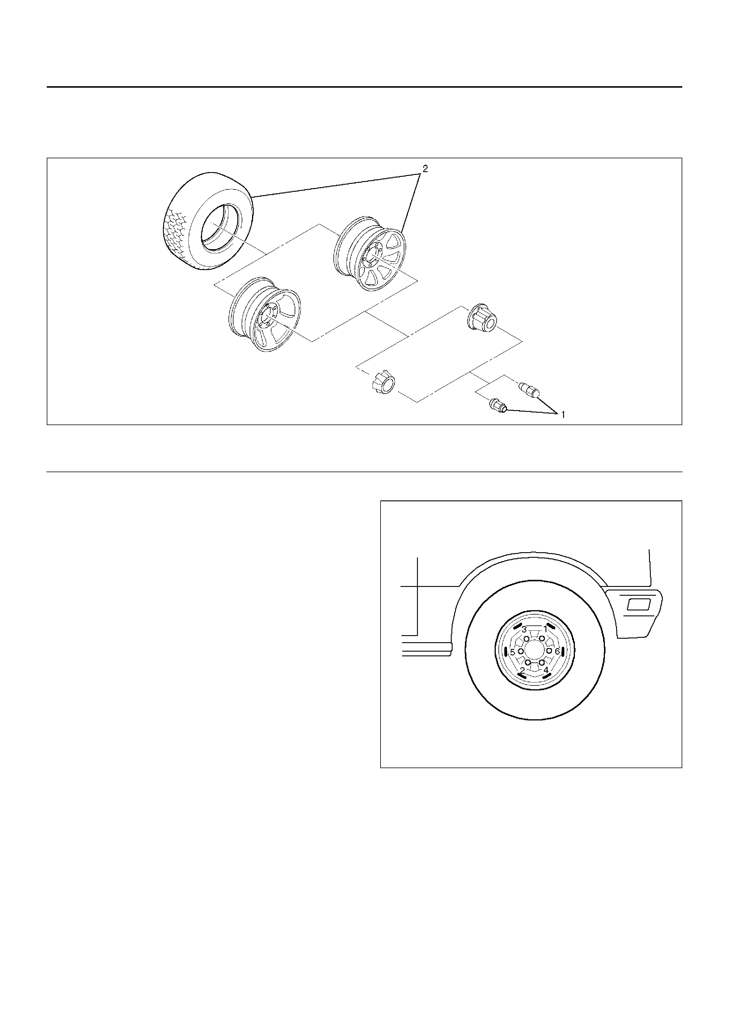
Wheel
Wheel and Associated Parts
480RX008
Legend
EndOFCallout
Removal
1.Loosen wheel lug nut by approximately 180° (half a
rotation), then raise the vehicle and remove the
nuts.
2.Remove wheel and tire.
NOTE: Never use heat to loosen a tight wheel lug nut.
The application of heat to the hub can shorten the life of
the wheel and may cause damage to wheel bearings.
Installation
1.Install wheel and tire.
2.Install wheel lug nut, and lower the vehicle. Tighten
the wheel lug nuts to the specified torque in
numerical order.
Torque: 118N·m (12.0kg·m/87lbft)
CAUTION: Before installing wheels, remove any
build-up of corrosion on the wheel mounting
surface and brake disc mounting surface by
scraping and wire brushing. Installing wheels
without good metal-to-metal contact at mounting
surfaces can cause wheel nuts to loosen, which
can later allow a wheel to come off while the vehic le
is moving.
NOTE: Valve caps should be on the valve stems to
keep dust and water out.
480RS020
(1)Wheel Lug Nut(2)Wheel and Tire
Tire
Tire Replacement
When replacement is necessary, the original metric the
size should be used. Most metric tire sizes do not have
exact corresponding alphanumeric tire sizes. It is
recommended that new tires be installed in pairs on the
same axle. If necessary to replace only one tire, it
should be paired with tire having the most tread, to
equalize braking traction.
CAUTION: Do not mix different types of tires such
as radial, bias and bias-belted tires except in
emergencies, because vehicle handling may be
seriously affected and may result in loss of control.
Tire Dismounting
Remove valve cap on valve step and deflate the tire.
Then use a tire changing machine to mount or dismount
tires.
Follow the equipment manufacturer's instruction. Do
not use hand tools or tire lever alone to change tires as
they may damage the tire beads or wheel rim.
Tire Mounting
Rim bead seats should be cleaned with a wire brush or
coarse steel wool to remove lubricants, and light rust.
Before mounting a tire, the bead area should be well
lubricated with an approved tire lubricant.
After mounting, inflate the tire to 200kPa (2.0kg/cm2, 28
psi) so that beads are completely seated. Inflate the air
to specified pressure and install valve cap to the stem.
WARNING: NEVER STAND OVER TIRE WHEN
INFLATING. BEAD MAY BREAK WHEN BEAD
SNAPS OVER RIM'S SAFETY HUMP AND CAUSE
SERIOUS PERSONAL INJURY.
NEVER EXCEED 240 KPA (2.4kg/cm2, 35 PSI)
PRESSURE WHEN INFLATING. IF 240 KPA (2.4kg/
cm2, 35 PSI) PRESSURE WILL NOT SEAT BEADS,
DEFLATE, RE-LUBRICATE AND RE-INFLATE. O VER
INFLATION MAY CA USE THE BEAD T O BREAK AND
CAUSE SERIOUS PErSONAL INJURY.
Tire Repair
There are many different materials on the market used
to repair tires.
Manufacturers have published detailed instructions on
how and when to repair tires. These instructions can
be obtained from the tire manufacturer if they are not
included with the repair kit.
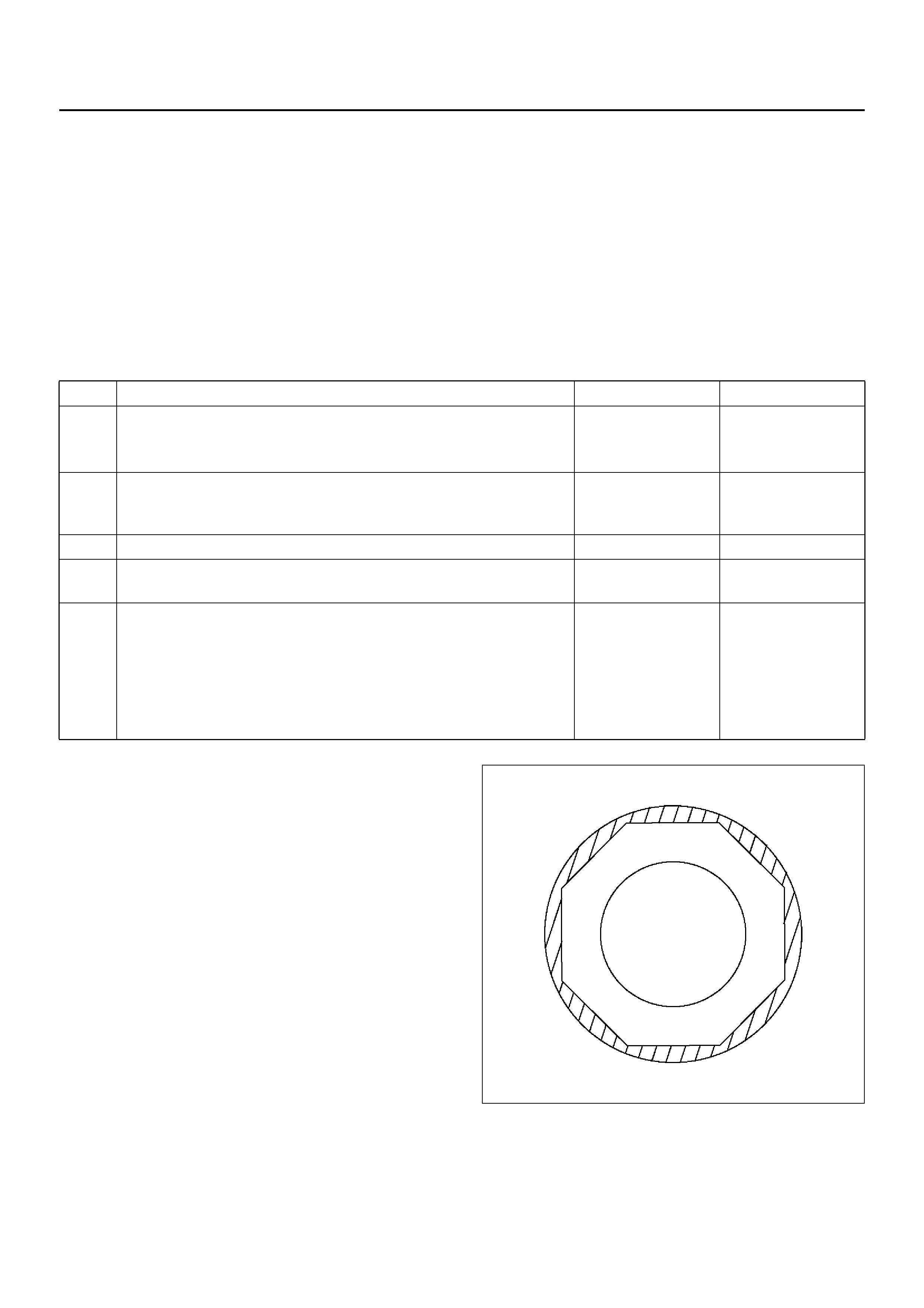
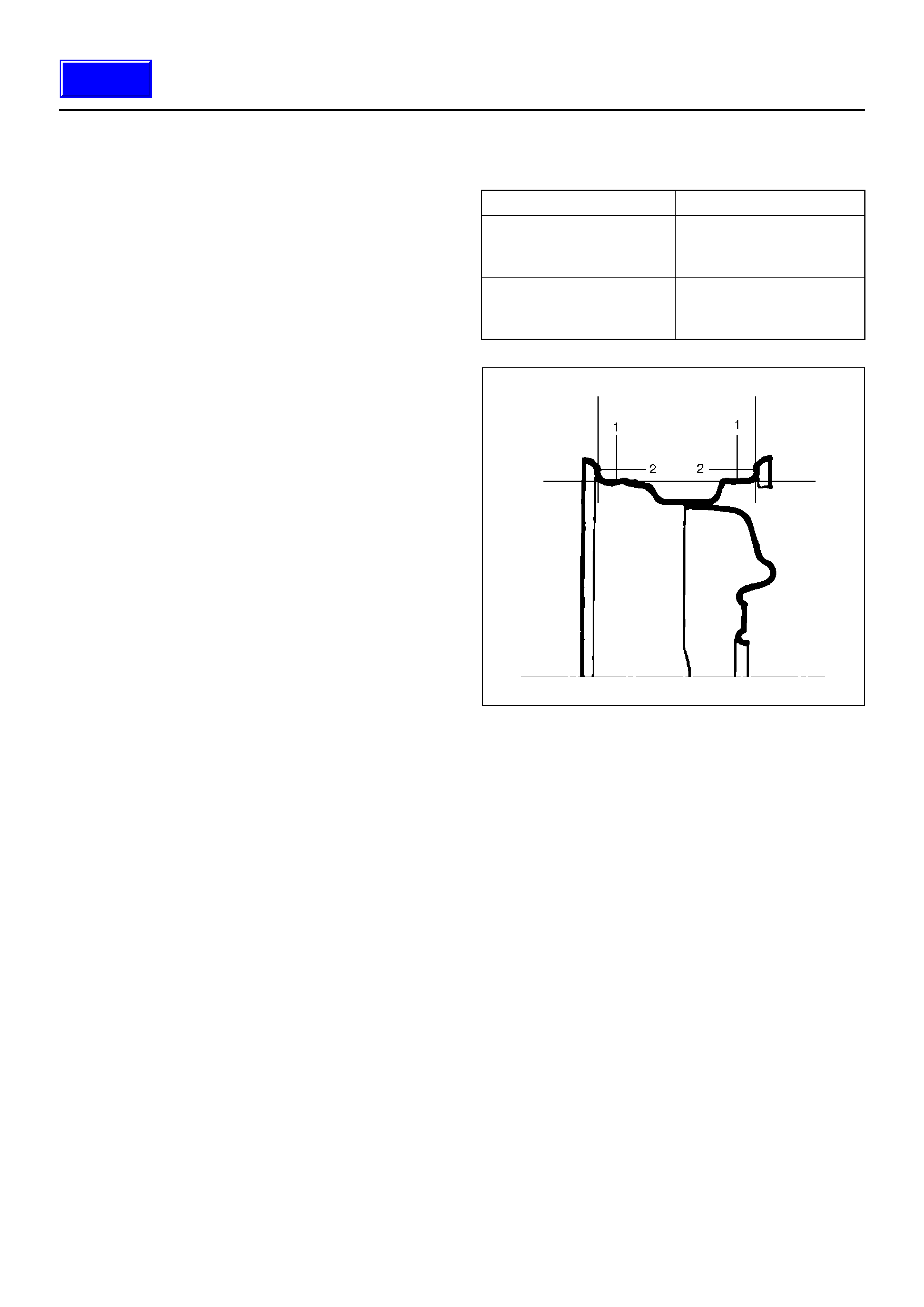
Wheel Inspection
Damaged wheels and wheels with excessive run-out
must be replaced.
Wheel run out at rim (Base on hub Bore):
480RS012
General Balance Procedure
Deposits of mud, etc. must be cleaned from the inside of
the rim.
The tire should be inspected for the following: match
mount paint marks, bent rims, bulges, irregular tire
wear, proper wheel size and inflation pressure. Then
balance according to the equipment manufacturer's
recommendations.
There are two types of wheel and tire balance.
Static balance is the equal distribution of weight around
the wheel.
Asse mblies that are statica lly unb ala nc ed cau se a
bouncing action called tramp. This condition will
eventually cause uneven tire wear.
Steel Aluminum
1– Vertical play:
Less than
1.5mm (0.059in)
1– Vertical play:
Less than
0.7mm (0.028in)
2– Hori zontal play:
Less than
1.5mm (0.059in)
2– Horizontal play:
Less than
0.7mm (0.028in)
Techline
480RS013
Legend
EndOFCallout
Dynamic balance is the equal distribution of weight on
each side of the wheel center-line so that when the tire
spins there is no tendency for the assembly to move
from side to side. Assemblies that are dynamically
unbalanced may cause shimmy.
480RS014
Legend
EndOFCallout
WARNING: STONES SHOULD BE REMOVED FROM
THE TREAD TO AVOID OPERATOR INJURY DURING
SPIN BALANCING AND TO OBTAIN A GOOD
BALANCE.
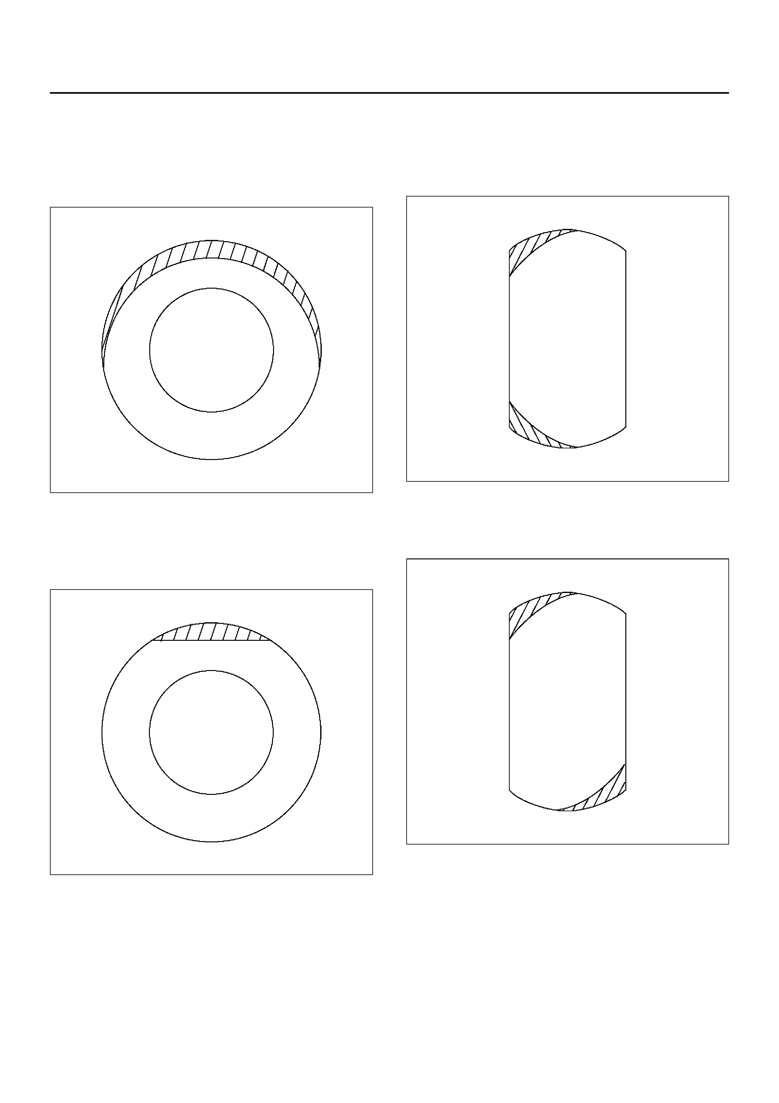
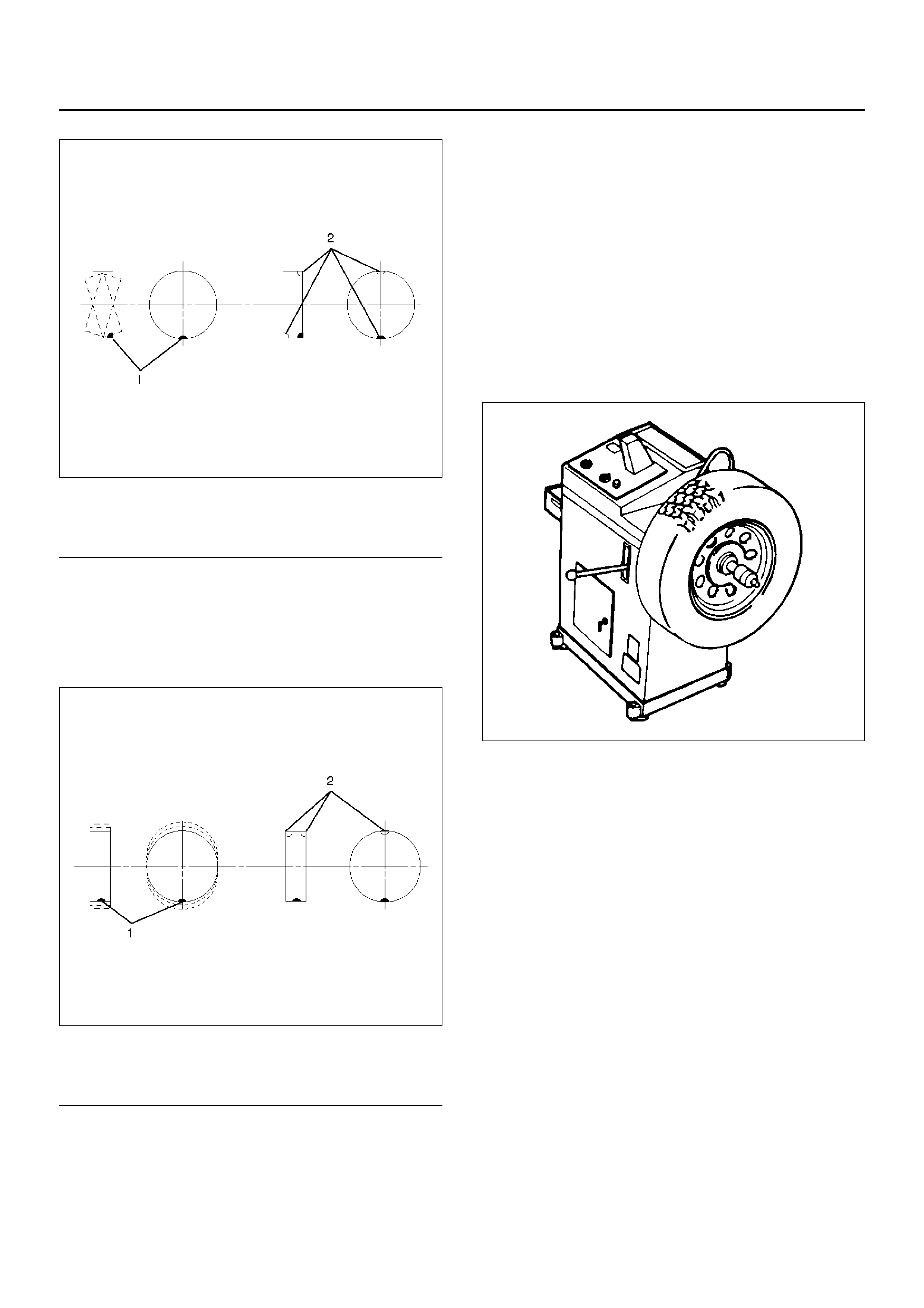
Balancing Wheel and Tire
On-vehicle Balancing
On-Vehicle balancing methods vary with equipment and
tool manufacturers. Be sure to follow each
manufacturer's instructions during balancing operation.
Off-vehicle Balancing
Most electronic off-vehicle balancers are more accurate
than the on-vehicle spin balancers. They are easy to
use and give a dynamic balance. Although they do not
correct for drum or disc unbalance (as on- vehicle spin
balancing does), they are very accurate.
480RS015
(1) Heavy Spot Wh eel Shimmy
(2) Add Bal an ce Weights Here
(1) Heavy Spot Wheel Hop
(2) Add Bal an ce Weights Here

Main Data and Specifications
General Specifications
Torque Specifications
E03RX008
Wheels Size 15 x 6.5JJ
Offset 38.0mm (1.50in)
P.C.D., wheel studs 139.7mm (5.50in)
Standard tire Size P235/75R15
Pressure(Front) 200kPa (2.0kg/cm2,26psi)
Pressure(Rear) 200kPa (2.0kg/cm2,26psi)