
SECTION 4B - DRIVELINE CONTROL SYSTEM
Service Precaution
Shift On The Fly System
Outline of Shift on The Fly System
Functions of Indicator Lamp
Diagnosis
Shift On The Fly Vacuum Piping and
Electrical Equipment
Vacuum Piping Diagram
Actuator Assembly
Vacuum Tank
Inspection and Repair
4WD Control Unit
4WD Control Unit Associated Parts
Removal
Installation
Service Precaution
WARNING: THIS VEHICLE HAS A SUPPLEMENTAL
RESTRAINT SYSTEM (SRS). REFER TO THE SRS
COMPONENT AND WIRING LOCATION VIEW IN
ORDER TO DETERMINE WHETHER YOU ARE
PERFORMING SERVICE ON OR NEAR THE SRS
COMPONENTS OR THE SRS WIRING. WHEN YOU
ARE PERFORMING SERVICE ON OR NEAR THE
SRS COMPONENTS OR THE SRS WIRING, REFER
TO THE SRS SERVICE INFORMATION. FAILURE TO
FOLLOW WARNINGS COULD RESULT IN POSSIBLE
AIR BAG DEPLOYMENT, PERSONAL INJURY, OR
OTHERWISE UNNEEDED SRS SYSTEM REPAIRS.
CAUTION: Always use the correct fastener in the
proper location. When you replace a fastener, use
ONLY the exact part number for that application.
ISUZU will call out those fasteners that require a
replacement after removal. ISUZU will also call out
the fasteners that require thread lockers or thread
sealant. UNLESS OTHERWISE SPECIFIED, do not
use supplemental coatings (Paints, greases, or
other corrosion inhibitors) on threaded fasteners or
fastener joint interfaces. Generally, such coatings
adversely affect the fastener torque and the joint
clamping f or ce, and may dama ge the fastener . Wh en
you install fasteners, use the correct tightening
sequence and specifications. Following these
instructions can help you avoid damage to parts
and systems.
Shift On The Fly System
Outline of Shift on The Fly System
The shift on the fly system switches between 2 wheel
drive (2WD) and 4 wheel drive (4WD) electrically by
driver's pressing the 4WD switch (push button type) on
instrument panel.
This system controls below operations. (Shifting
between “4H" and “4L" must be performed by transfer
control lever on the floor.)
1. Shifting the transfer front output gear (Connecting
to, and disconnecting from, front propeller shaft by
motor actuator).
2. Retrial of shifting the transfer front output gear.
3. Connecting front wheels to , and disconnecting them
from, the front axles by vacuum actuator.
4. Indicator on instrument panel.
5. 4WD out signal to other Electronic Hydraulic Control
Unit.
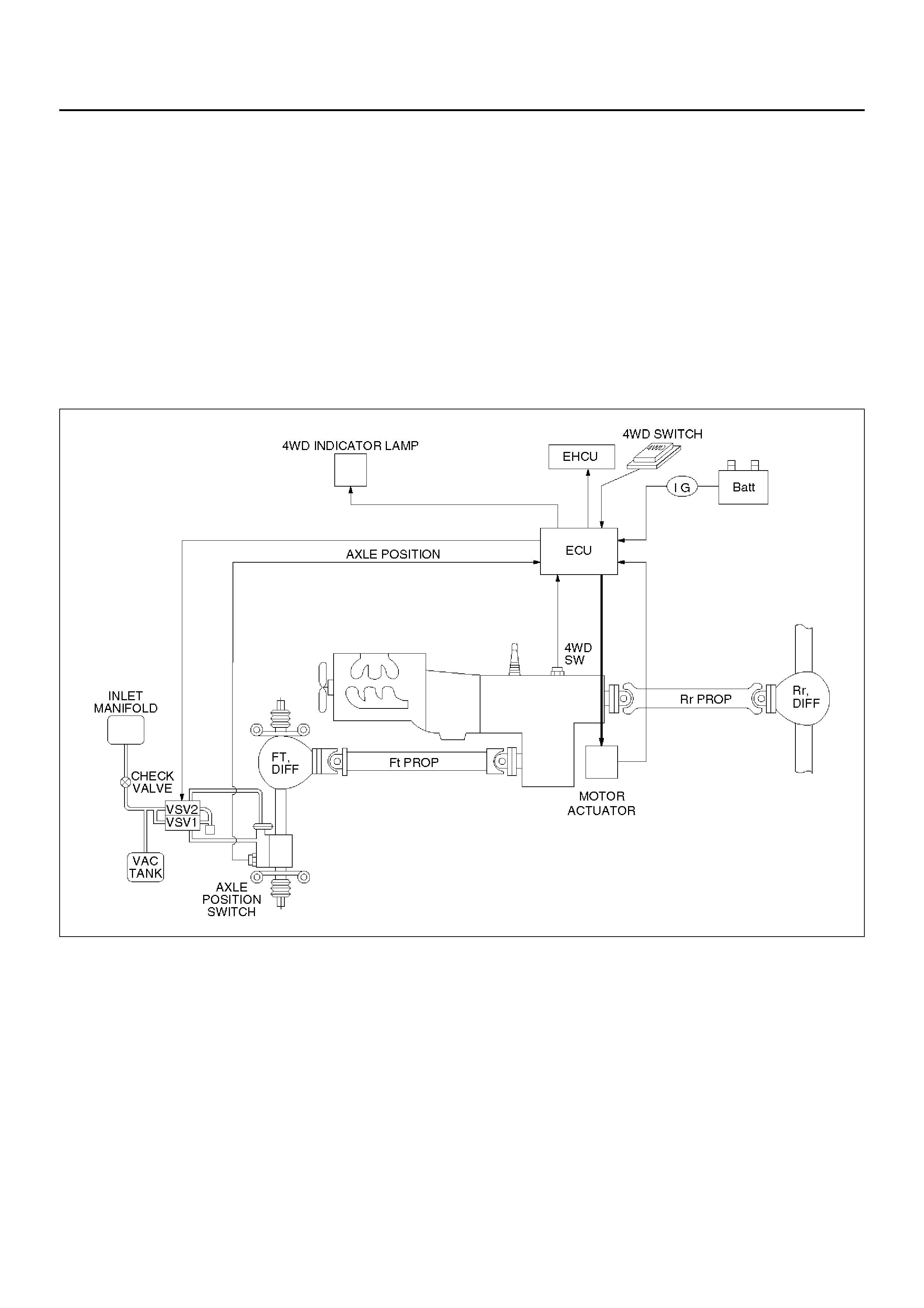
Syst em Diagram s
412RX009

Normal Operation
The motor actuator mounted on transfer rear case is
driven by signal from 4WD switch on instrument panel.
After complete the connecting transfer front output gear
to, or disconnecting it from, front propeller shaft,
condition of the transfer position switch changes. The
vacuum solenoid valve (VSV) is driven by the signal
from transfer position switch and the vacuum actuator
connects front wheels to, or disconnect them from, front
axles.
Time Chart of Shifting Under Normal Condition
F04RW002
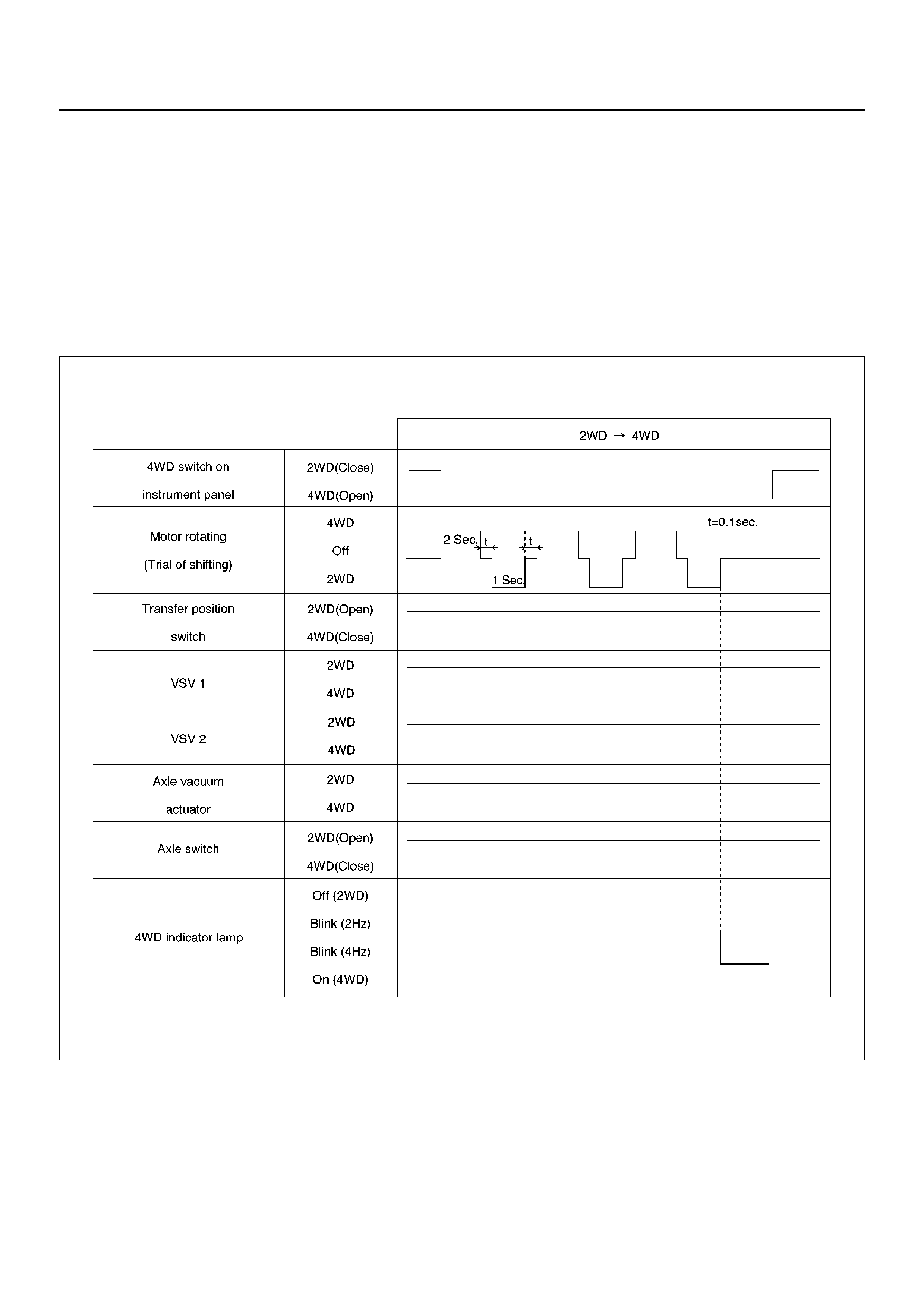
Retrial
The motor actuator starts transfer gear shifting after
signal from 4WD switch on instrument panel has been
received. But the shifting may be impossible in cold
weather or under high speed condition. When 2
seconds have passed since transfer gear shifting
started and the transf er position switch dose not turn on
(the gear engagement is not completed), the motor
reverses its rotation for 1.2 seconds and tries again to
shift transfer gear. This procedure is repeated 3 times
in maximum. While this procedure, 4WD indicator lamp
blinks by 2 Hz.
If the transfer position switch does not turn on after
aforementioned procedure has been repeated 3 times,
the gear shifting is stopped and 4WD indicator lamp's
blinking changes from 2Hz to 4Hz to notify driver that
the gear shifting is stopped. This blinking of indicator
lamp continues until 4WD switch is returned from 4WD
to 2 WD.
Time Chart of Shifting Under Severe Condition (retrial)
F04RX004
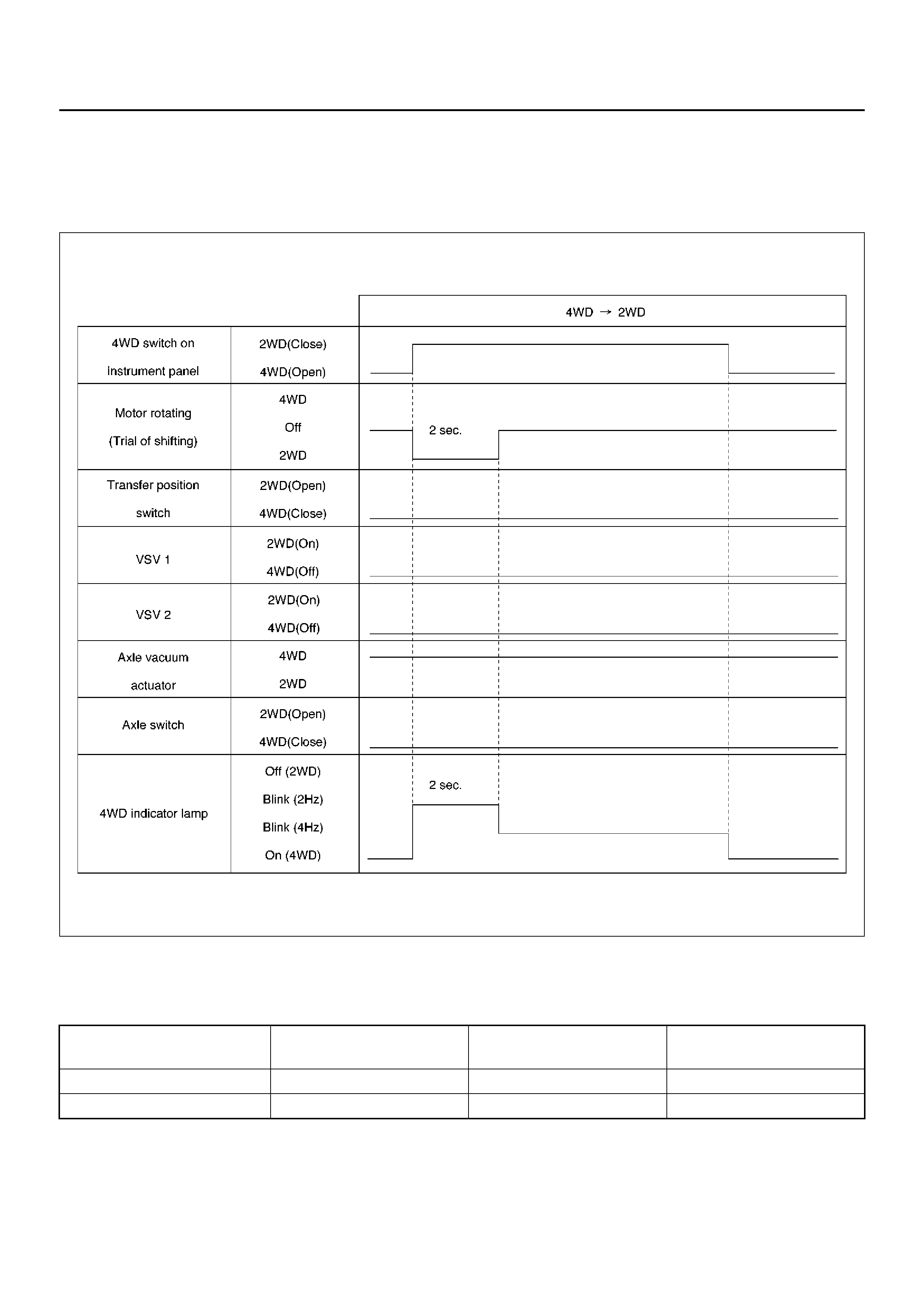
Warning at “4L" position :In view of the shifting
mechanism of transfer, the gear shifting from 4WD to
2WD at “4L" condition is impossible. Therefore, the
transfer position switch can not be turned off by 4WD
s witch when vehicle is in “4L" condition. In the case this
condition continues for 2 seconds, the shifting to 2WD is
stopped and the indicator lamp's blinking changes from
2Hz to 4Hz to notify driver of wrong operation.
Time Chart of Shifting from 4WD to 2WD at “4L" Condition
F04RX005
4WD out signal to other Electronic Hydraulic
Control Unit : ECU of shift on the fly sends 4WD out
signal to other Electronic Hydraulic Control Unit as
below. 4WD out signal
(Period) Vehicle Condition Transfer position switch Front axle switch
120 ms 2WD 2WD (Open) 2WD (Op en)
240 ms 4WD 4WD (Close) 4WD (Close)
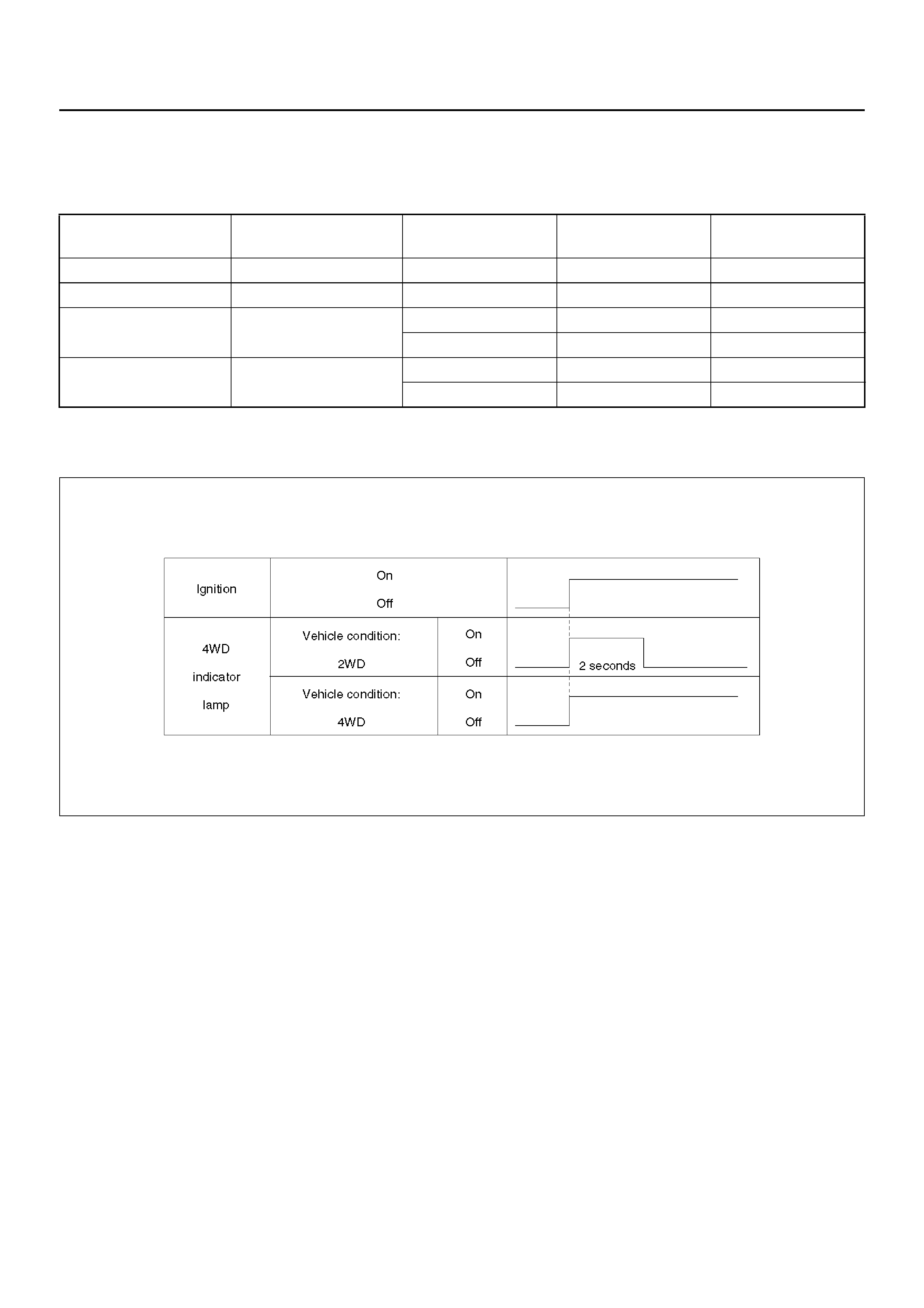
Functions of Indicator Lamp
Indication of vehicle condition : Indicator lamp is
controlled by ECU of shift on the fly and shows vehicle
conditions as below.
Bulb chec k :The bulb of indicator lamp is checked for 2
seconds when ignition ke y is turned on.
Time Chart of Bulb Checking
F04RW004
Retrials from 2WD to 4WD :In cold weather or under
high speed condition, the gear shifting (engagement)
some t imes dose no t comp l et e by 3 trials . I n su ch ca se,
the indicator lamp inform driver of this incident as
aforementioned chart (shown at Retrial in Outline of
shift on the fly system.)
Indicator Vehicle condition 4WD switc h Transfer position
switch Front axle switch
Off 2WD Off (Close) 2WD (Open) 2WD (Open)
On 4WD On (Open) 4WD (Close) 4WD (Close)
Blink (2Hz) Operating On (Open) 4WD (Close) 2WD (Open)
Off (Close) 2WD (Open) 4WD (Close)
Blink (4Hz) Stop operating On (Open) 2WD (Open) 2WD (Open)
Off (Close) 4WD (Clo se) 4WD (Clo se)

Diagnosis
Before Judging That Troubles Occur
(Unfaulty mode)
When Switching from 2WD to 4WD
1. In case that blinking frequency of the 4WD
indicator changes from 2Hz to 4Hz.
When heavy synchronization load is needed, the
motor actuator tries the shifting transfer gear three
times including the activation shifting. While the
motor actuator tries shifting, the indicator blinks by
2Hz. If the third shifting f ails, the indicator's blinking
changes from 2Hz to 4Hz at the same time that the
motor actuator shifted back to 2WD.
Heavy synchronization load occurs by
• extremely lower temperature.
• higher speed.rotation difference of wheels during
cornering.
Solution 1: Operate again after stop the vehicle
or slow down.
2. In case that the 4WD indicator continues
blinking by 2Hz for more than 11.5 seconds.
When there is rotation difference of wheels or there
is phase difference between front wheels and axles,
it is difficult to connect front wheels to front axles.
The blinking by 2Hz shows that shifting the transfer
gear or connecting the front wheels is in the middle
of operating. In above case, the indicator's blinking
by 2Hz shows that connecting the front wheels is
not completed (because the indicator's blinking
changes to 4Hz when the shifting transfer gear is
impossible.). And removal of rotation or phase
difference make connecting the front wheels
possible.
Solution 2: When vehicle is running, drive
straight ahead while accelerating and
decelerating. When vehicle is at a stop, move
the vehicle forward and backward from 2 to 3
meters.
When Switching from 4WD to 2WD
1. In case that the 4WD indicator continues
blinking by 2Hz .
The 4WD indicator continues blinking by 2Hz until
both shifting the transf er gear and disconnecting the
front wheels are completed when switching 4WD to
2WD. When driv e line is loaded with torsional
torque, the shifting transfer gear and disconnecting
front wheels are impossible. In this case, removal of
torsional torque on drive line make the shifting
transfer gear and disconnecting front wheels
possible.
Solution 3: When vehicle is running, drive
straight ahead while accelerating and
decelerating. When vehicle is at a stop, move
the vehicle forward and backward from 2 to 3
meters.
2. In case that the 4WD indicator's blinking changes
from 2Hz to 4Hz.
Check the position of transfer lever. Is it at “4L"
position? In view of the shifting mechanism of
transfer, the gear shifting from 4WD to 2WD at “4L"
condition is impossible.
Solution 4: Push the 4WD switch to 4WD, shift
the transfer lever to “High" position and re-
operate the 4WD switc h to 2WD.
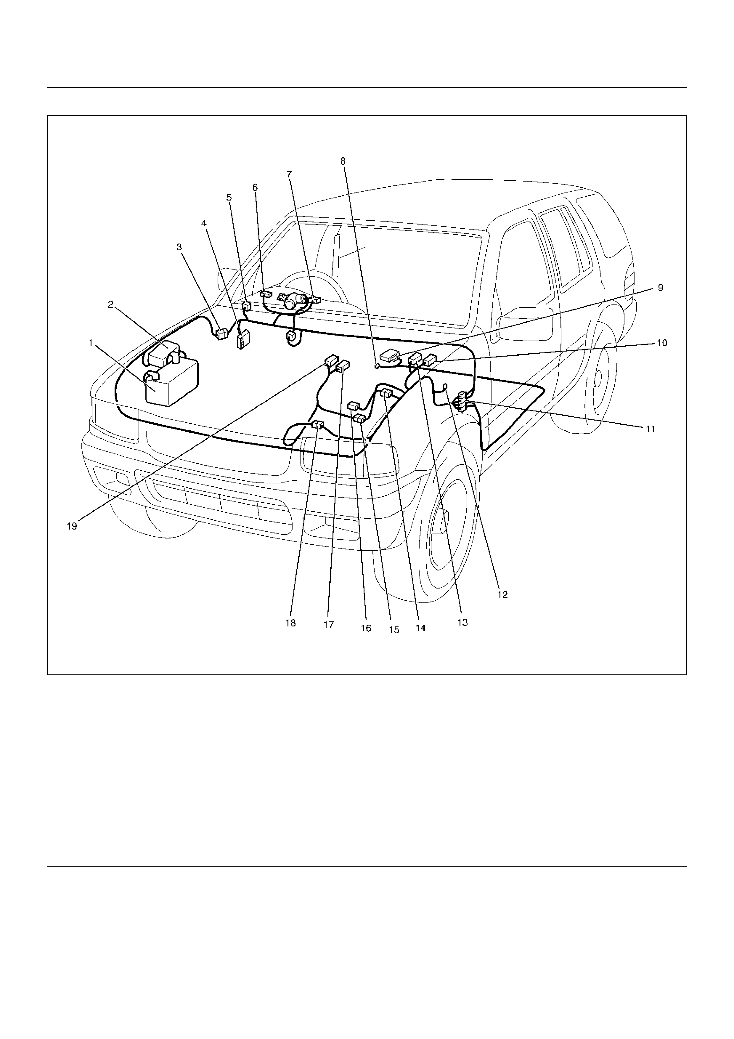
Parts Location
D08RX290
Legend
EndOFCallout
(1) Battery
(2) Relay & Fuse Bo x (Engine Room)
(3) H–32
(4) Relay & Fuse Box (Instrument Panel)
(5) I–19
(6) I–1
(7) I–2
(8) B–8
(9) B–19
(10) C–32
(11) H–15
(12) C–16
(13) C–31
(14) H–18
(15) H–9 ( X22SE)
(16) C–15
(17) M–21
(18) H–9 ( 6VD1), H–10
(19) M– 11, M–1 2
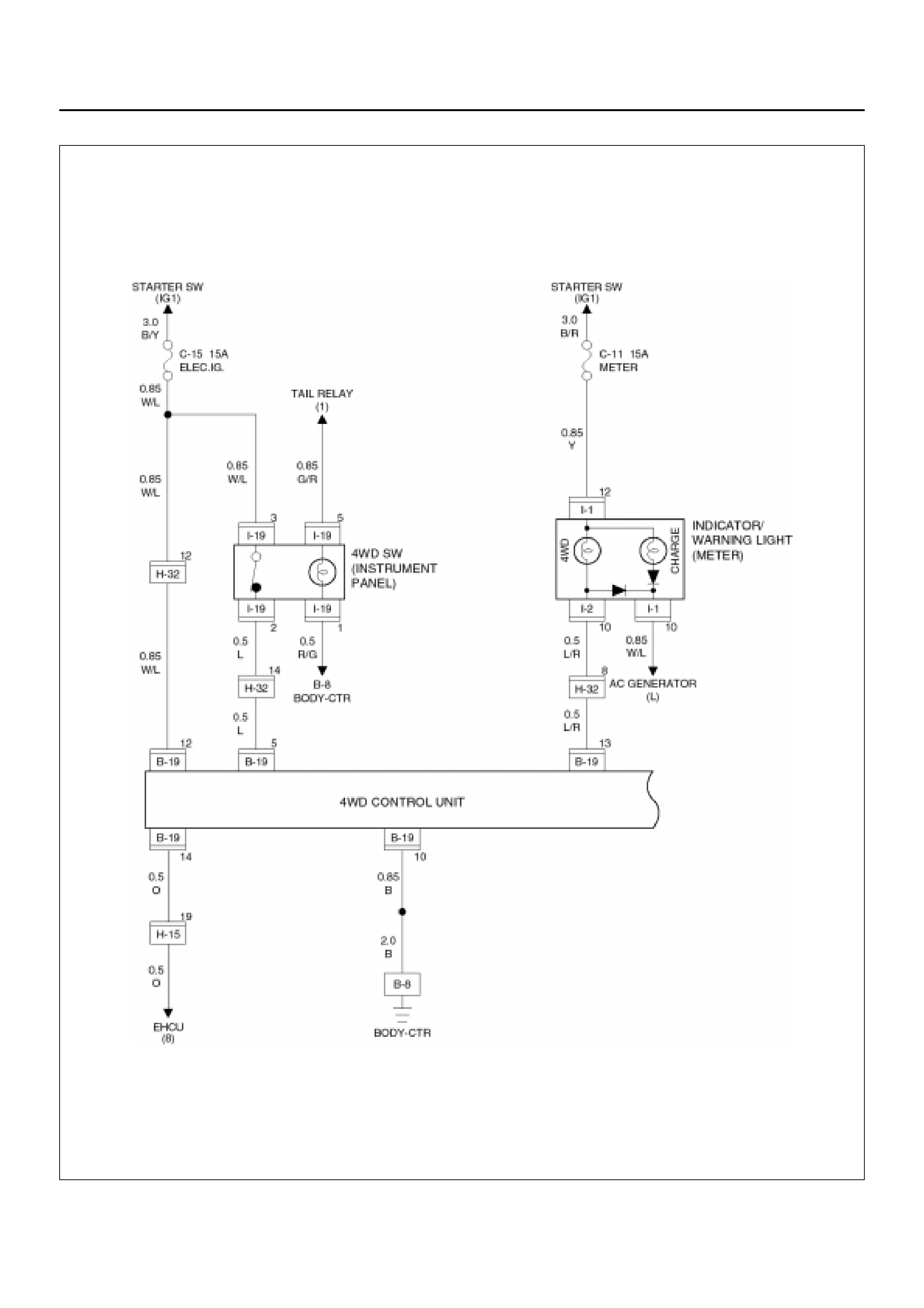
Wiring Diagra m – 1
D08RX272

Wiring Diagram – 2 (6VD1)
D08RX274
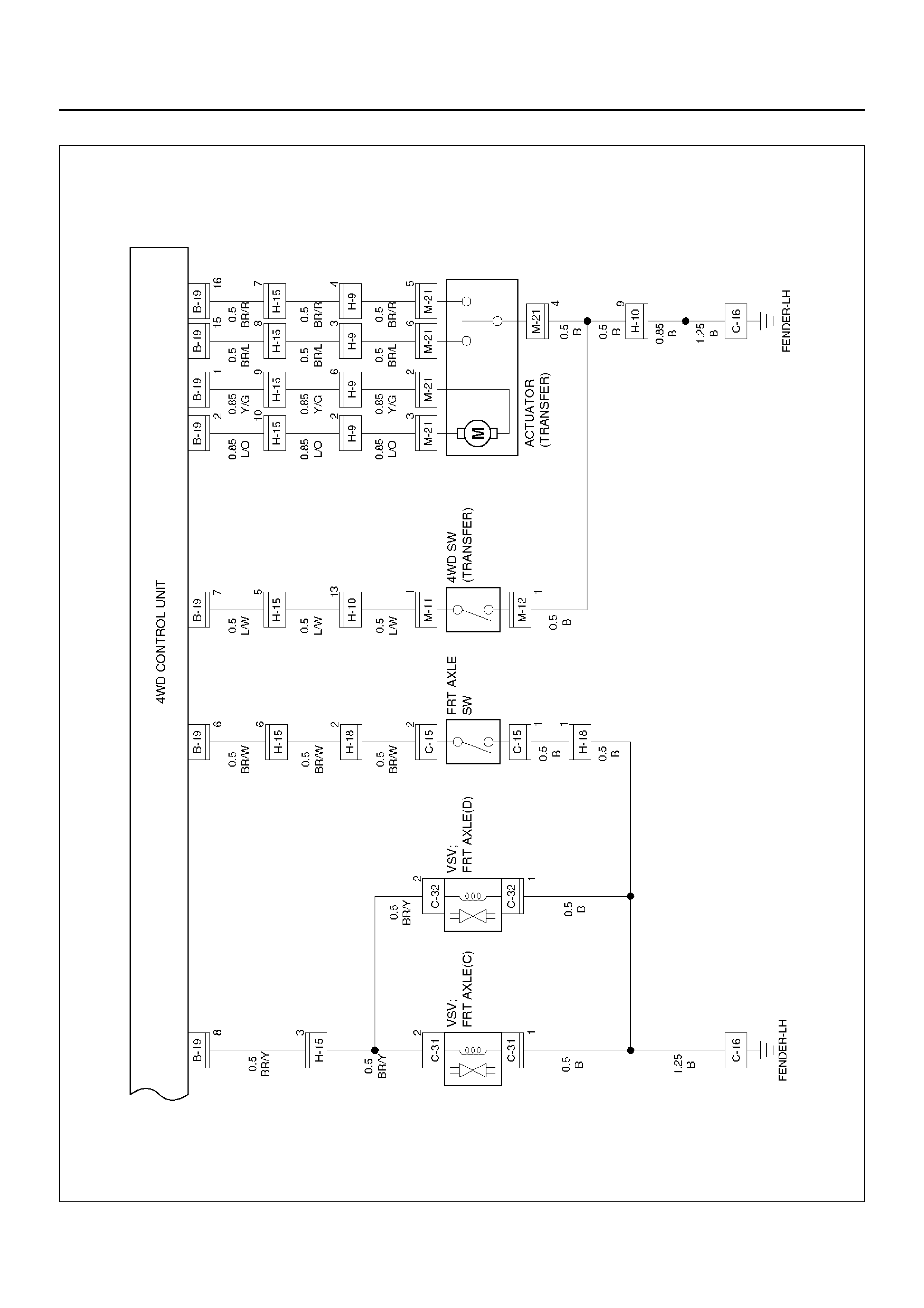
Wiring Diagram – 2 (X22SE)
D08RX273
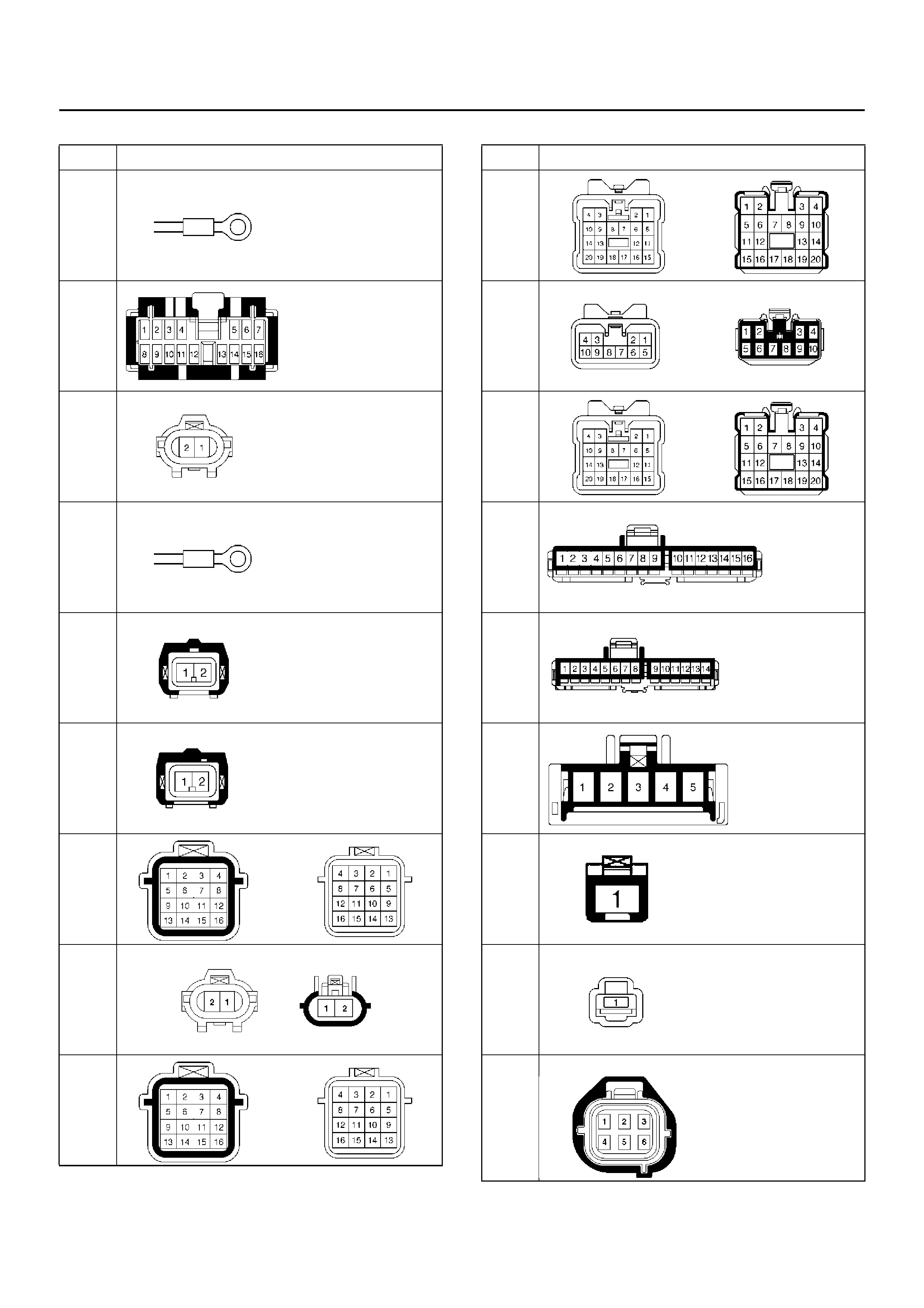
Connector List
No. Connector face
B-8
B-19
C-15
C-16
C-31
C-32
H-9
H-10
(6VD1
)
H-10
(X22S
E)
H-15
H-18
H-32
I-1
I-2
I-19
M-11
M-12
M-21
No. Connector face

Diagnosis of The Faults Based on the
Status of 4WD Indicator Lamp, 4WD Switch
and T/F Change Lever
Diagnosis charts are shown on below. If troubles can
not be solved after e v ery chart was traced, troubles may
occur in the ECU . In this case, replace the ECU and
trace every chart again.
Fault on Switching from 2WD to 4WD
1. In case that 4WD indicator's blinking changes
from 2Hz to 4Hz after Solution 1 is carried out.
Faults occur in the motor actuator or the transfer
case assembly. Remove the motor actuator and
check function. If problem was found and it was
repaired, try Solution 1 again. After that,
disassemble the transfer case assembly for check
and repair or replace. If incident is not improved
after above mentioned actions were taken, replace
the ECU.
2. In case that 4WD indicator does not blink nor
light, when switching from 2WD to 4WD.
Step Action Yes No
1 Is ignition turned on? Go to Step 2
Turn on the ignition
and trace this chart
from start.
2 Does the indicator light during two seconds initialization after
ignition is turned on?
Go to Step 3
Burning out of
indicator lamp or
disconnection of
harness wire.
Trace this chart
from the start after
repair or replace.
3 Is the 4WD switch turned from 2WD to 4WD? Short-circuit
(body short) on
harness of the
4WD switch.
Fault of the
4WD switch
(holding the
closed
condition).
Trace this chart
from the start
after repair or
replace. Push the 4WD
switch to 4WD.

3. Case that the indicator keeps blinking by 2Hz
after aforementioned Solu tion 2 is carried out.
Step Action Yes No
1 Check the air pressure and wear of all tires.
W ere problems found? Try Solution 2
after adjust the air
pressure and
replace worn tires. Go to Step 2
2 Can the transfer lever be operated from High to 4L or vice versa?
Go to Step 3
Disconnection
of the motor
actuator
harness wiring.
Trac e this ch art
from the start
after repair or
replace.
Faults on the
motor actuator.
Trac e this ch art
from the start
after replace.
Internal faults of
transfer case.
Disassemble
the transfer
case f or check.
Trac e this ch art
from the start
after repair or
replace.
3 Pull out the hoses from vacuum actuator and operate 4WD
switch.
Is there negative pressure on either of hoses?
Go to Step 4
Faults on the
transfer position
switch or its
harness. Trace
this chart from
the start after
repair or
replace.
Faults on the
VSV main body,
its harness or
vacuuming
system. Trace
the diagnosis
chart in Front
Axle ASM
section. After
that, trace this
chart from the
start.

Fault on Switching from 4WD to 2WD
1. Case that indicator dose not blink nor turn out.
4 Check the axle switch.
W ere problems found?
Internal faults on
axle switch. Trace
this chart from the
start after replace.
Disconnection
on the axle
harness. Trace
this chart from
the start after
repair or
replace.
Faults on Front
Axle ASM.
Trace the
diagnosis chart
in Front Axle
ASM section.
Af ter that , trac e
this chart from
the start.
Step Action Yes No
Step Action Yes No
1 Does the indicator turn out by ignition off? Go to Step 2 Short circuit of the
indicato r harn es s.
2 Is the 4WD switch on 2WD position? Disconnection on
the 4WD switch
harness or
breakdown of the
4WD switch in
open state. Trace
this chart from the
start after repair or
replace.
Turn the 4WD
switch to 2WD
position. Trace this
chart from the
start.

2. Case that indicator keeps 2Hz blinking after aforementioned Solution 3 is carried out.
Step Action Yes No
1 Check the air pressure and wear of all tires.
W ere problems found? Try Solution 3
after adjust the air
pressure and
replace worn tires. Go to Step 2
2 Can the transfer lever be operated from High to 4L or vice versa? Faults on the
harness wiring
of motor
actu ator. Tr ac e
this chart from
the start after
repair or
replace.
Internal faults
on transfer
case.
Disassemble
the transfer
case for check.
Trace this chart
from the start
after repair or
replace.
Faults on the
motor actuator.
Trace this chart
from the start
after or replace. Go to Step 3
3 Pull out the hoses from vacuum actuator and operate 4WD
switch.
Is there negative pressure on either of hoses?
Go to Step 4
Faults on the
transfer position
switch or its
harness. Trace
this chart from
the start after
repair or
replace.
Faults on the
VSV main body,
its harness or
vacuuming
system. Trace
the diagnosis
chart in Front
Axle ASM
section. After
that, trace this
chart from the
start.

3. Case that indicator's blinking changes to 4Hz
after aforementioned Solu tion 4 is carried out.
4 Check the axle switch.
W ere problems found? Internal faults
on axle switch.
Trace this chart
from the start
after replace.
Faults on Front
Axle ASM.
Trace the
diagnosis chart
in Front Axle
ASM section.
After that, trace
this chart from
the start.
Short circuit (bod y
short) or
disconnection of
the ax le ha rness .
Trace this chart
from the start after
repair or replace.
Step Action Yes No
Step Action Yes No
1 Can the transfer lever be operated from High to 4L or vice versa? Faults on the
harness wiring
of motor
actu ator. Tr ac e
this chart from
the start after
repair or
replace.
Faults on the
motor actuator.
Trace this chart
from the start
after replace.
Internal faults
on transfer
case.
Disassemble
the transfer
case for check.
Trace this chart
from the start
after repair or
replace.
Faults on the ECU.
Trace this chart
from the start after
replace.
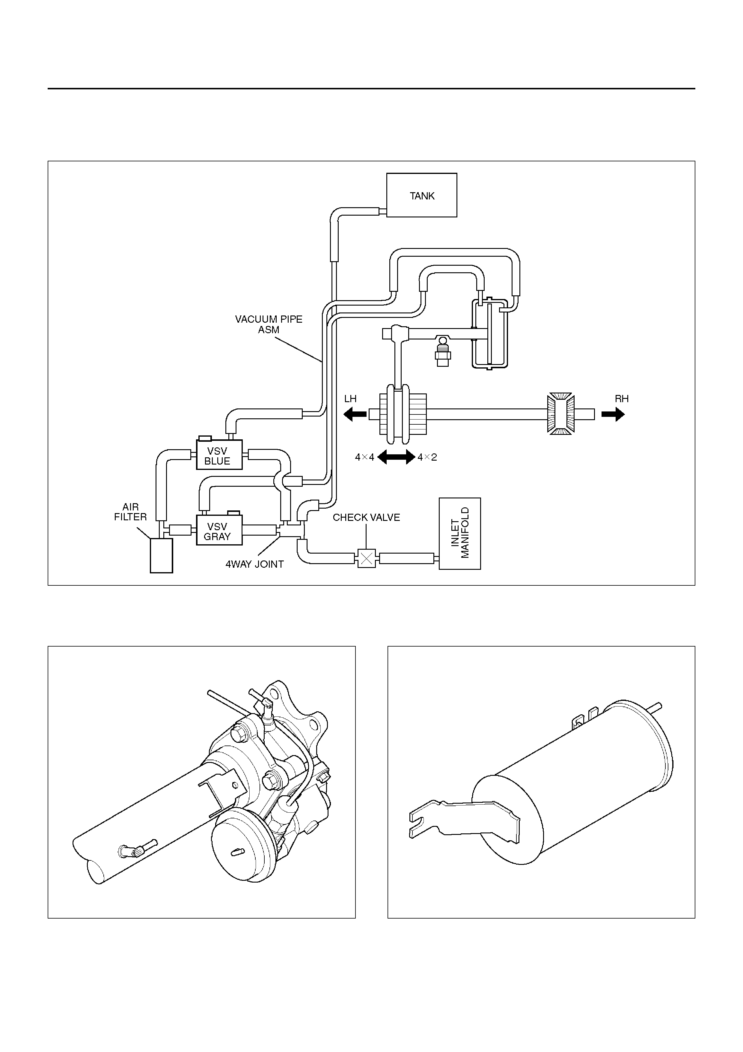
Shift On The Fly Vacuum Piping and Electrical Equipment
Vacuum Piping Diagram
C04RX001
Actuator Assembly
412RW024
Vacuum Tank
412RW025
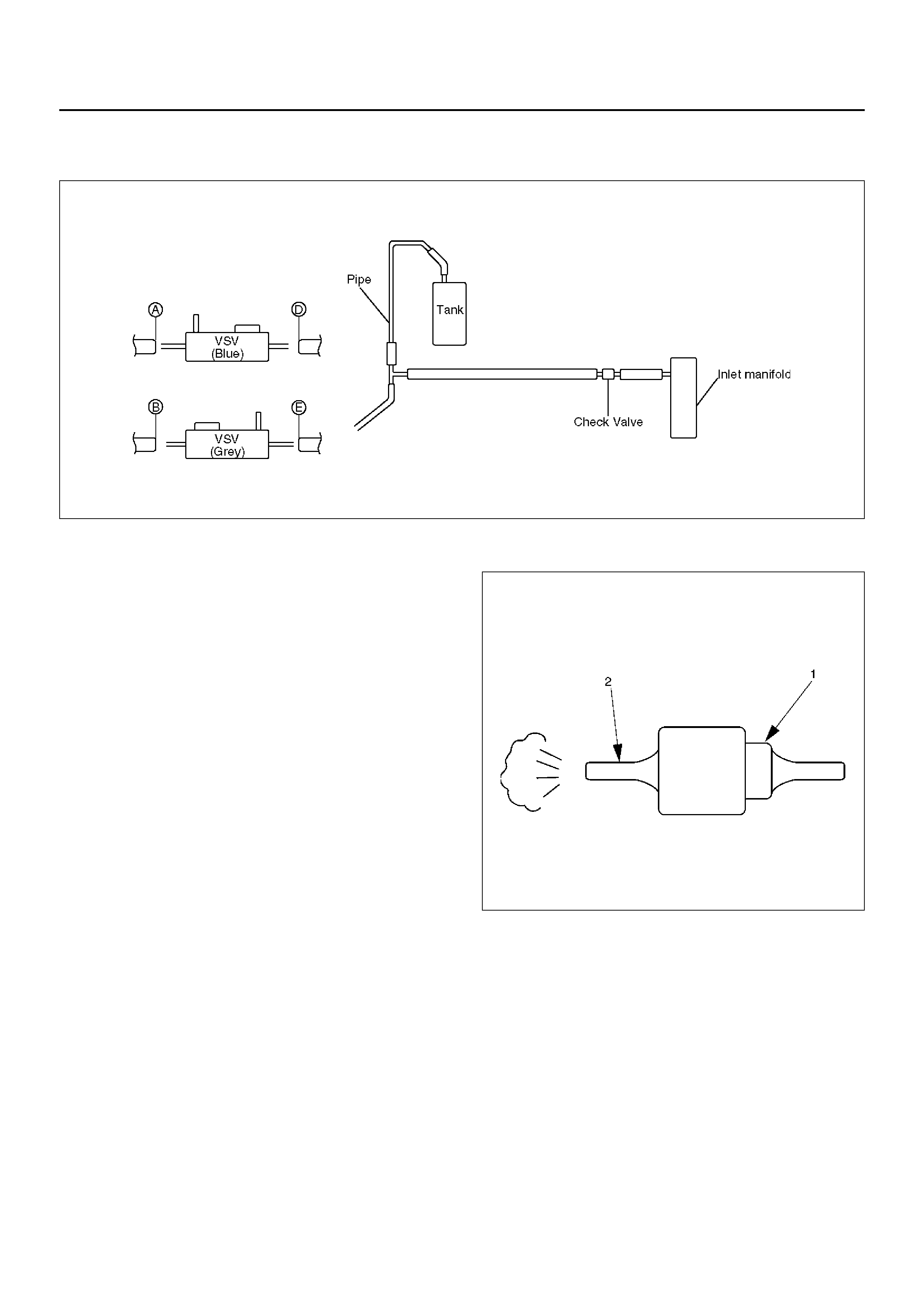
Inspection and Repair
Vacuum Piping
C04RW004
1. Pull out the Hose A in figure and install a vacuum
gauge.
2. Plug up Hose B in figure to prevent the leak of
vacuum.
3. Start the engine and measure vacuum 2 or 3
minutes afterward.
4. Repeat 1) and 2) but with Hose A plugged and Hose
B pulled out.
5. If vacuum measures –400mmHg, or if it shows a
sudden drop immediately after engine stop, inspect
the hose, tank, and pipe for damage.
NOTE: Be careful not to permit the entry of dust and
water during inspection.
6. Pull out Hose D in above illustration.
7. Plug Hose E in ab ove illustrat ion.
8. Make sure that Hose D in above illustration is under
atmo sp heric pres su re.
9. Pull out Hose E and plug Hose D, and make sure
that Hose E is under atmospheric pressure.
10. If Check 8) or 9) has revealed stoppage, check and
see that there is no bend, foreign matter in the hose
or in the filter. If there is trouble, repair or replace.
Check Valve
C04RS004
1. Apply vacuum from the orange colored side(1).
Vacuum:–400mmHg
2. Check leakage of vacuum.
3. Make sure that vacuum cannot be applied from the
black colored side(2).
4. If vacuum is not applicable as much as –400mmHg,
and if there is resistance on the intake side, replace
with a new check v a lve.
VSV As se mbly
Inspect the vehicle side harness as follows:
412RX008
Legend
EndOFCallout
1. Remove connector.
2. Shift transfer lever to 2H and start the engine.
NOTE: The vehicle should not be started, with the
engine idling.
3. Make sure that there is continuity in the vehicle side
of harness. If there is no continuity, check transfer
shift switch and wiring.
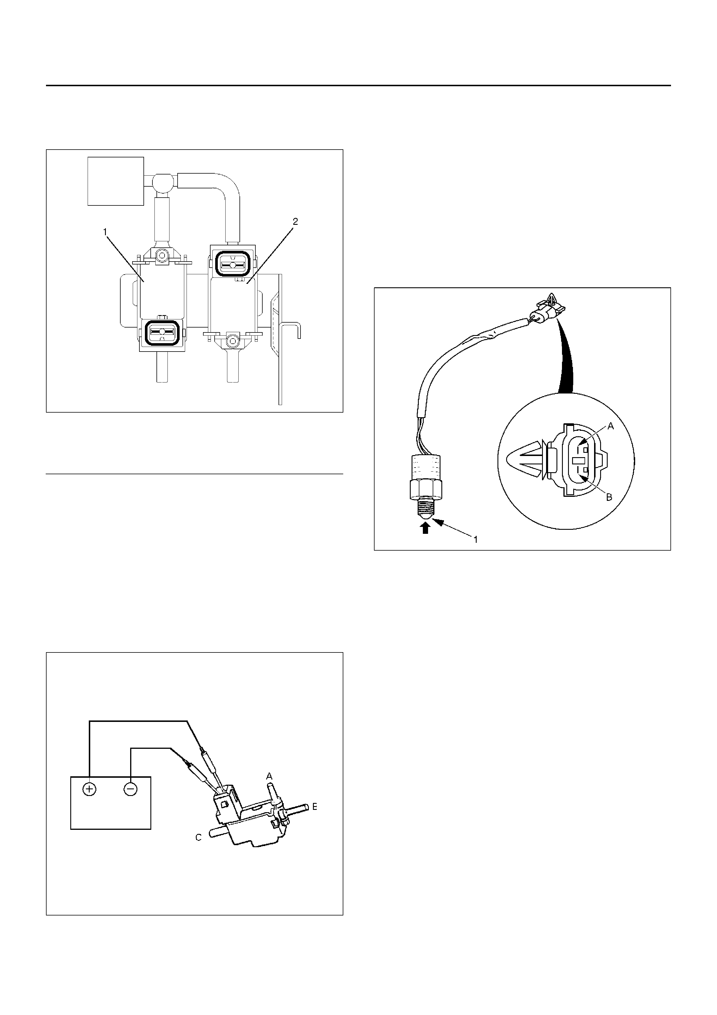
Inspect the both VSVs as follows
F04RS004
1. With battery not connecte d (Usual ).
A–C:There is continuity
B:Closed
2. With battery connected
A – B:There is continuity
C:Closed
3. If 1) and 2) fail, replace with a new VSV.
Functional Detective Switch
412RW067
1. With ball (1) being free
A–B:There is continuity
2. With ball forced into the switch
A–B:No continuity
3. If 1) and 2) fail, replace with a new switch.
Motor Actuator Assembly
Inspect the function of the motor actuator assembly as
follows:
1. Disassemble the motor actuator from transfer rear
case.
(1) Grey
(2) Blue

412RW037
Legend
EndOFCallout
2. Connect the terminals as shown in figure.
Shift rod of the motor actuator moves and stops
at 4WD position.
412RX001
Legend
EndOFCallout
3. Connect the terminals as shown in figure.
Shift rod of the motor actuator moves and stops
at 2WD position.
412RX002
Legend
EndOFCallout
4. If 2) and 3) fail, replace with a new motor actuator.
Transfer Positi on Switch
412RW040
Legend
EndOFCallout
1. With ball being free.
A–B : There is continuity.
2. With ball forced into the switch.
A–B : No continuity.
3. If 1) and 2) fail, replace with a new switch.
(3) Shift Rod
(4) Connector
(1) 2WD
(2) 4WD
(3) Shift Rod
(4) Connector
(1) 2WD
(2) 4WD
(3) Shift Rod
(4) Connector
(1) Ball
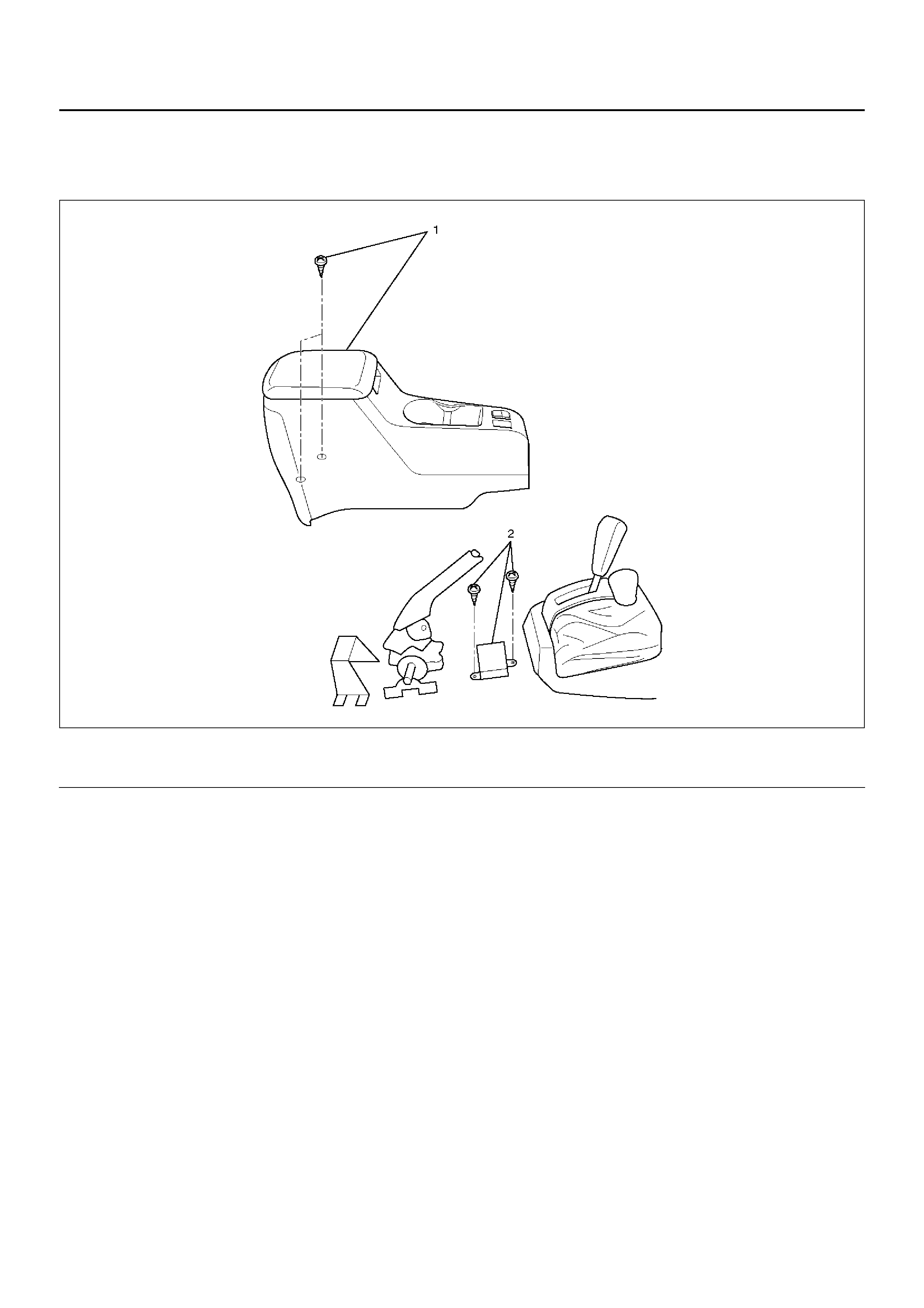
4WD Control Unit
4WD Control Unit Associated Parts
412RW042
Legend
EndOFCallout
(1) Center Console Assembly (2) 4WD Control Unit
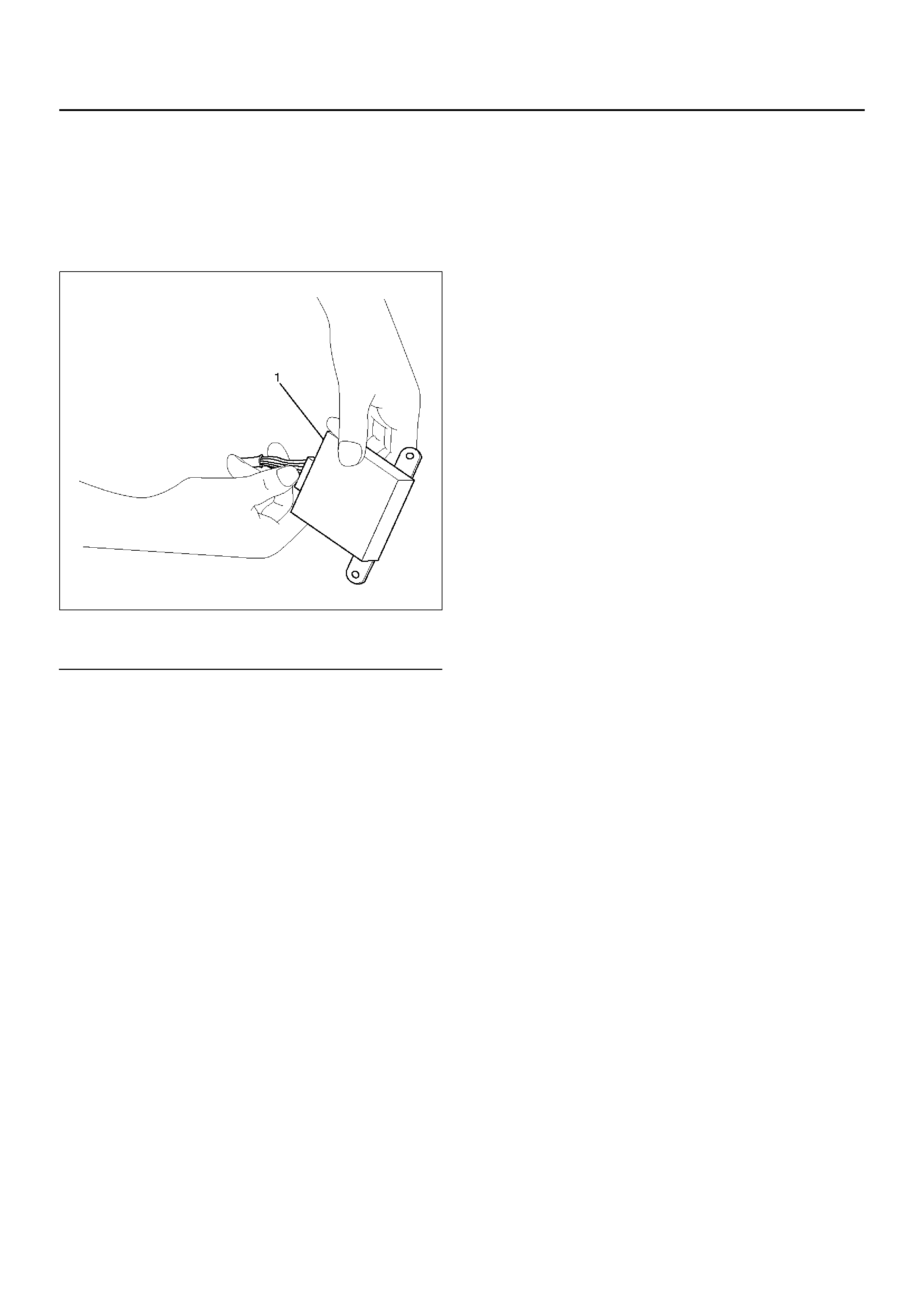
Removal
1.Remove center console assembly.
Refer to Interior Trim in Body and Accessories
section.
2. Remove two screws and harness connector (1) from
4WD control unit.
412RW041
Legend
EndOFCallout
Installation
1. Connect harness connector, then install 4WD
contr ol uni t.
2. Install center console assembly.
(1) Harness Connector