
SECTION 4C - DRIVE SHAFT SYSTEM
Service Precaution
General Description
Diagnosis
Front Hub and Disc
Disassembled View
Disassembly
Inspection and Repair
Reassembly
Front Drive Shaft Joint
Front Drive Shaft Joints Replacement
Front Axle Drive Shaft
Front Axle Drive Shaft and
Associated Parts
Disassembly
Inspection And Repair
Bushing Replacement
Reassembly
Shift On The Fly System
Shift On The Fly System and
Associated Parts
Disassembly
Inspection And Repair
Reassembly
Main Data and Specifications
Special Tools
Propeller Shaft
General Description
Universal Joint
Diagnosis of Propeller Shaft and
Universal Joint
Front Propeller Shaft
Front Propeller Shaft and
Associated Parts
Removal
Installation
Slip Joint Disassembly
Universal Joint Disassembly
(Single Cardan Type)
Universal Joint Disassembly
(Double Cardan Type)
Inspection and Repair
Universal Joint Reassembly
(Single Cardan Type)
Universal Joint Reassembly
(Double Cardan Type)
Slip Joint Reassembly
Main Data and Specifications
Rear Propeller Shaft
Rear Propeller Shaft and
Associated Parts
Removal
Installation
Slip Joint Disassembly
Universal Joint Disassembly
Inspection
Universal Joint Reassembly
Slip Joint Reassembly
Main Data and Specifications
Service Precaution
WARNING: THIS VEHICLE HAS A SUPPLEMENTAL
RESTRAINT SYSTEM(SRS). REFER TO THE SRS
COMPONENT AND WIRING LOCATION VIEW IN
ORDER TO DETERMINE WHETHER YOU ARE
PERFORMING SERVICE ON OR NEAR THE SRS
COMPONENTS OR THE SRS WIRING. WHEN YOU
ARE PERFORMING SERVICE ON OR NEAR THE
SRS COMPONENTS OR THE SRS WIRING, REFER
TO THE SRS SERVICE INFORMATION. FAILURE TO
FOLLOW WARNINGS COULD RESULT IN POSSIBLE
AIR BAG DEPLOYMENT, PERSONAL INJURY, OR
OTHERWISE UNNEEDED SRS SYSTEM REPAIRS.
CAUTION: Always use the correct fastener in the
proper location. When you replace a fastener, use
ONLY the exact part number for that application.
ISUZU will call out those fasteners that require a
replacement after removal. ISUZU will also call out
the fasteners that require thread lockers or thread
sealant. UNLESS OTHERWISE SPECIFIED , do not
use supplemental coatings (Paints, greases, or
other corrosion inhibitors) on threaded fasteners or
fastener joint interfaces. Generally, such coatings
adversely affect the fastener torque and the joint
clamping f or ce, and may dama ge the fastener . Wh en
you install fasteners, use the correct tightening
sequence and specifications. Following these
instructions can help you avoid damage to parts
and systems.
General Description
This publication contains essential removal, installation,
adjustment and maintenance procedures.
The front axle utilizes a central disconnect type front
axle/transfer case system.
The drive axles are completely flexible assemblies,
consisting of inner and outer constant velocity (CV)
drive shaft joints connected by an axle shaft.
For description of front propeller shaft and universal
joint, refer to Front Propeller Shaft in this section.
Diagnosis
Condition Possible cause Correction
Oil Leak At Front Axle W orn or defective oil seal. Replace the oil seal.
Front axle housing cracked. Repair or replace.
Oil Leak At Pinion Shaft Too much gear oil. Correct the oil level.
Oil seal worn or defective. Repla ce the oil seal.
Pinion flange loose or damaged. Tighten or replace.
Noises In Front Axle Drive Shaft
Joint Broken or worn drive shaft joints and
bellows (BJ and DOJ). Replace the driv e shaft joints and
bellows.
“Clank" When Accelerating From
“Coast" Loose drive shaft joint to output
shaft bolts. Tighten.
Damaged inner drive shaft joint. Replace.
Shudder or Vibration During
Acceleration Excessive drive shaft joint angle. Repair.
W orn or damaged drive shaft joints. Replace.
Sticking spider assembly (inner
drive shaft joint). Lubricate or replace.
Sticking joint assembly (outer drive
shaft joint). Lubricate or replace.
Vibration At Highway Speeds Out of balance or out of round tires. Balance or replace.
Front end out of alig nme nt. Align.
Noises in Front Axle Insufficient gear oil. Replenish the gear oil.
Wrong or poor grade gear oil. Replace the gear oil.
Drive pinion to ring gear backlash
incorrect. Adjust the backlash.
W orn or chipped ring gear, pinion
gear or side gear. Replace the ring gear , pinion gear or
side gear.
Pinion shaft bearing worn. Replace the pinion shaft bearing.
Wheel bearing worn. Replace the wheel bearing.
Diff erential bearing loose or worn. Tighten or replace.
Wanders and Pulls Wheel bearing preload too tight. Adjust the wheel bearing preload.
Incorrect front alignment. Adjust the front alignment.
Steering unit loose or worn. Tighten or replace.
Tire worn or improperly inflated. Adjust the inflation or replace.
F ront or rear suspension parts loose
or broken. Tighten or replace.
Front Wheel Shimmy Wheel bearing worn or improperly
adjusted. Adjust or replace.
Incorrect front alignment. Adjust the front alignment.
W orn ball joint or bush. Replace the ball joint or bush.
Steering unit loose or worn. Tighten or replace.
Tire worn or improperly inflated. Replace or adjust the inflation.
Shock absorber worn. Replace the shock absorber.
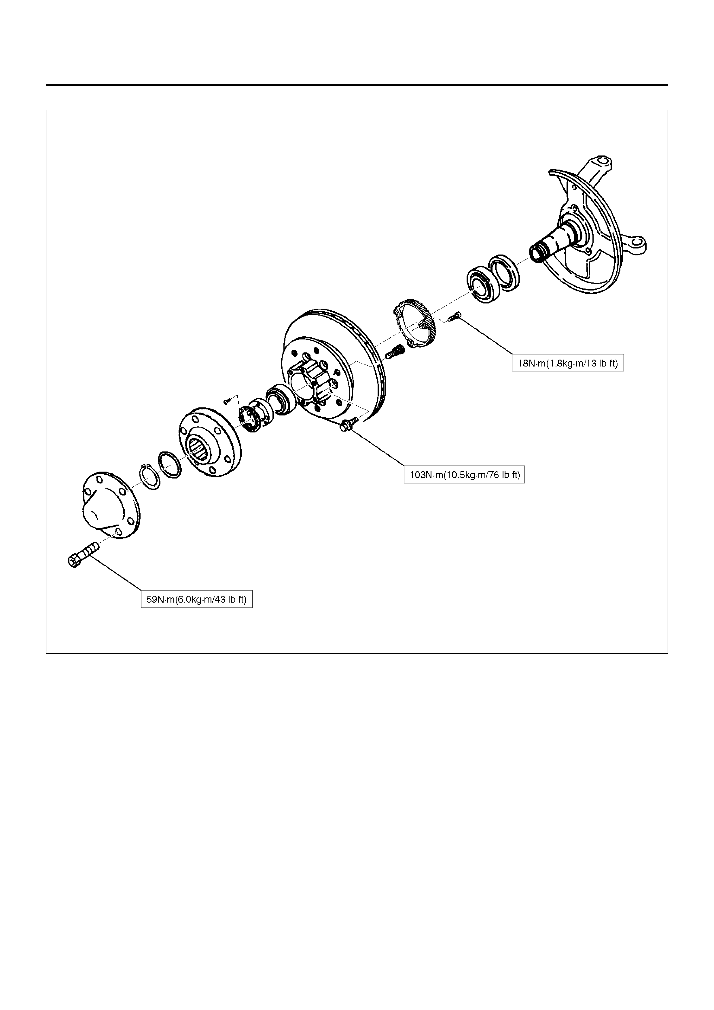
Front Hub and Disc
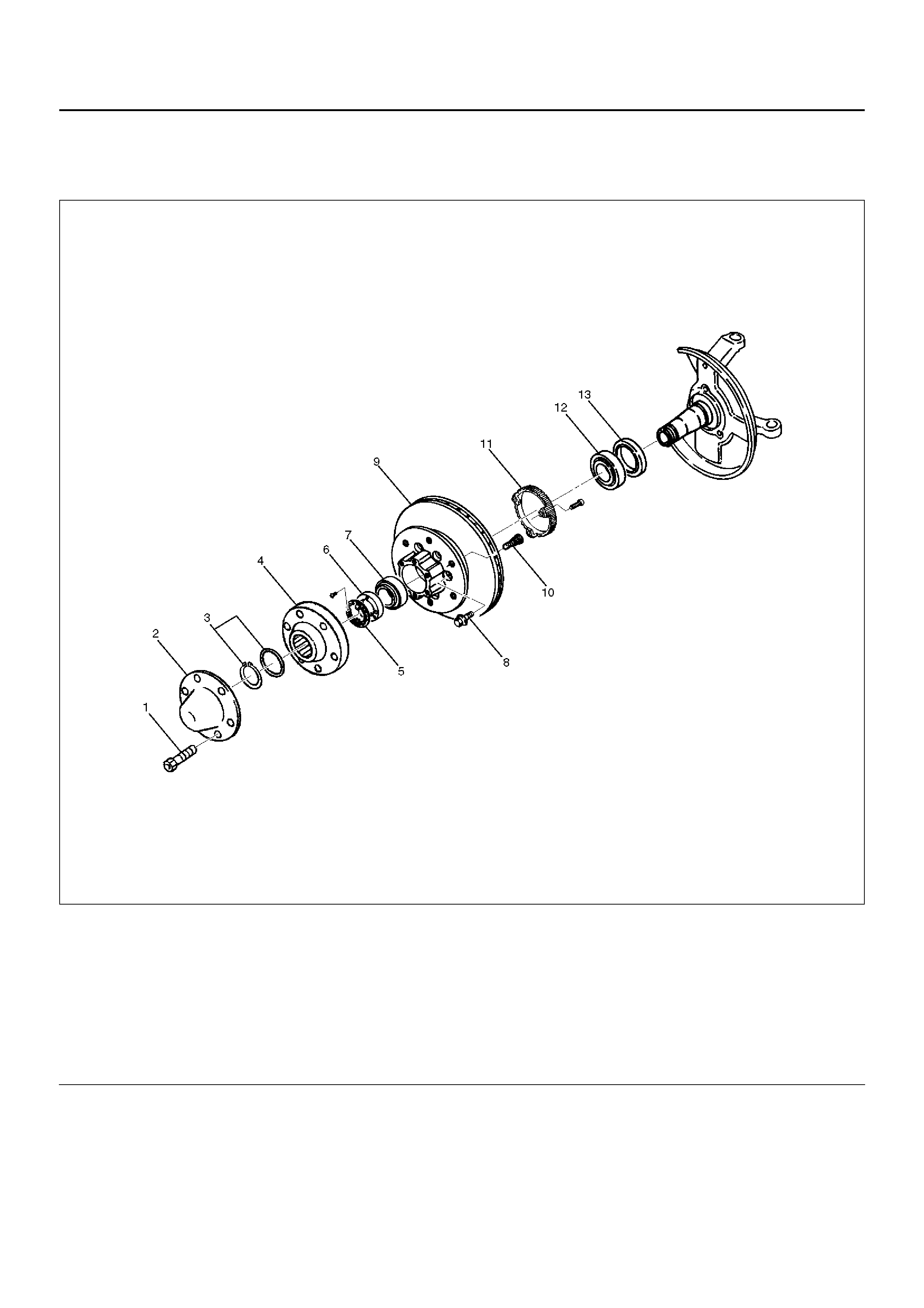
Disassembled View
411RW001
Legend
EndOFCallout
Disassembly
1.Before disassembly, select the 2WD position with
the 4WD switch.
2.Jack up the front of vehicle and support frame with
jack stands.
3.Remove the disc brake caliper assembly and hang it
on the frame with wires. Refer to Disk Brakes in
Brak e section.
4. Remove Bolt.
5. Remove cap.
6. Remove snap ring and shim.
(1) Bolt
(2) Cap
(3) Snap Ring and Shim
(4) Hub Flange
(5) Lock Washer and Lock Screw
(6) Hub Nut
(7) Outer Bearing
(8) Bolt
(9) Hub and Disc Assembly
(10) Wheel Pin
(11) ABS Sensor Ring
(12) Inner Bearing
(13) Oil Seal
7.Remove hub flange.
8.Remove lock washer and lock screw.
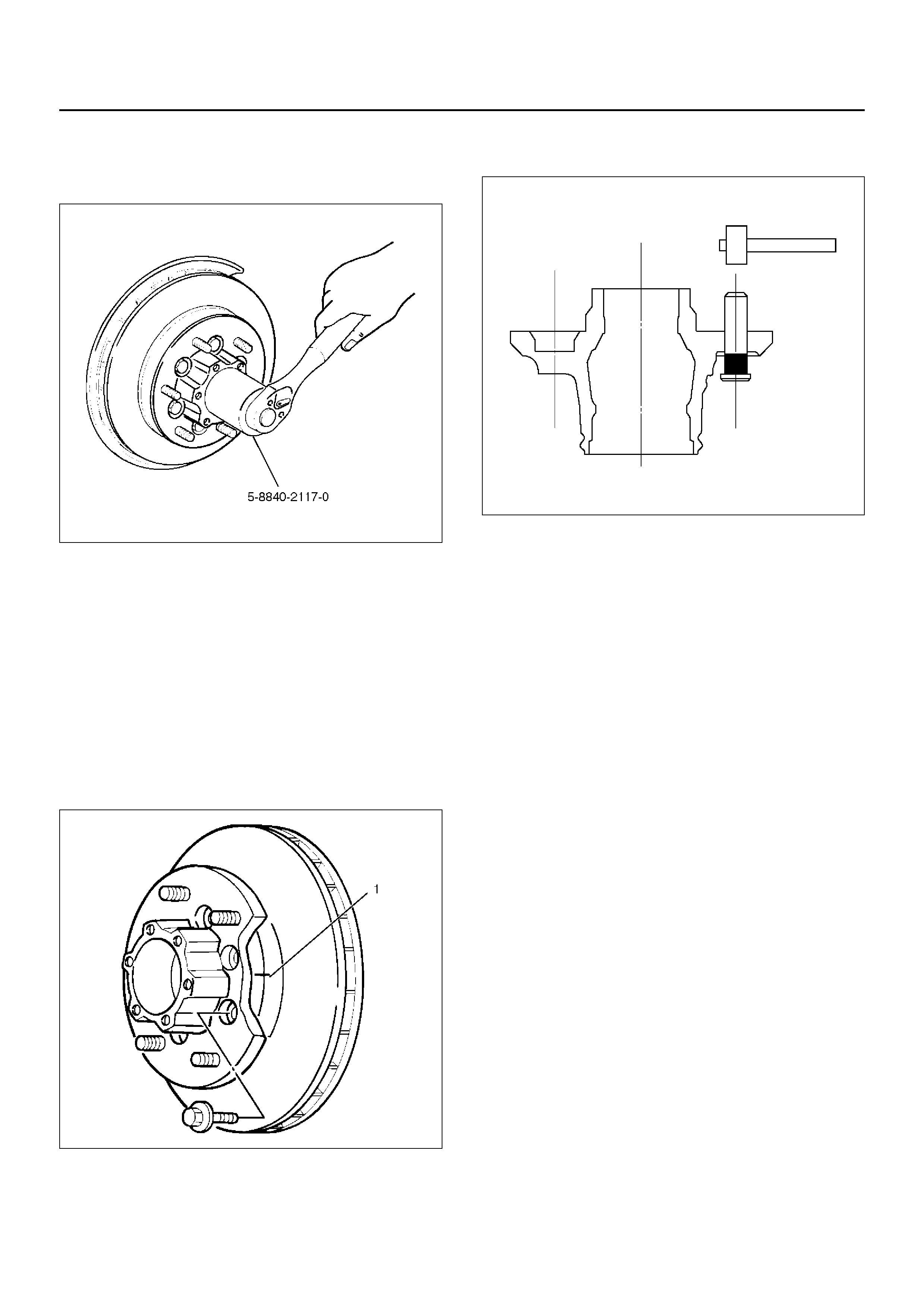
9.Use wrench 5–8840–2117–0, remove hub nut.
411RW005
10.Remove hub and disc assembly.
11.Remove ABS sensor ring.
12.Remove outer bearing.
13.Remove oil seal.
14.Remove inner bearing.
15.Remove bolt , if necessary, replace the wheel pin in
the following manner.
•Apply a scribe mark(1) to disc to hub.
•Clamp the hub and disc assembly in a vise, using
protective pads. Remove the 6 disc–to–hub
retaining bolts.
411RS003
•Place hub on a suitable work surface and remove
the studs by using a hammer.
411RS004
Inspection and Repair
Make necessary correction or parts replacement if
wear, damage, corrosion or any other abnormal
condition are found through inspection.
Check the following parts.
•Hub
•Hub bearing oil seal
•Knuckle spindle
•Disc
•Caliper
•Shift on the fly system parts (Cap, Hub flange, Shim,
Snap ring)
•ABS sensor ring
For inspection and servicing of disc caliper and related
parts, refer to Disc Brakes in Brake section.
Reassembly
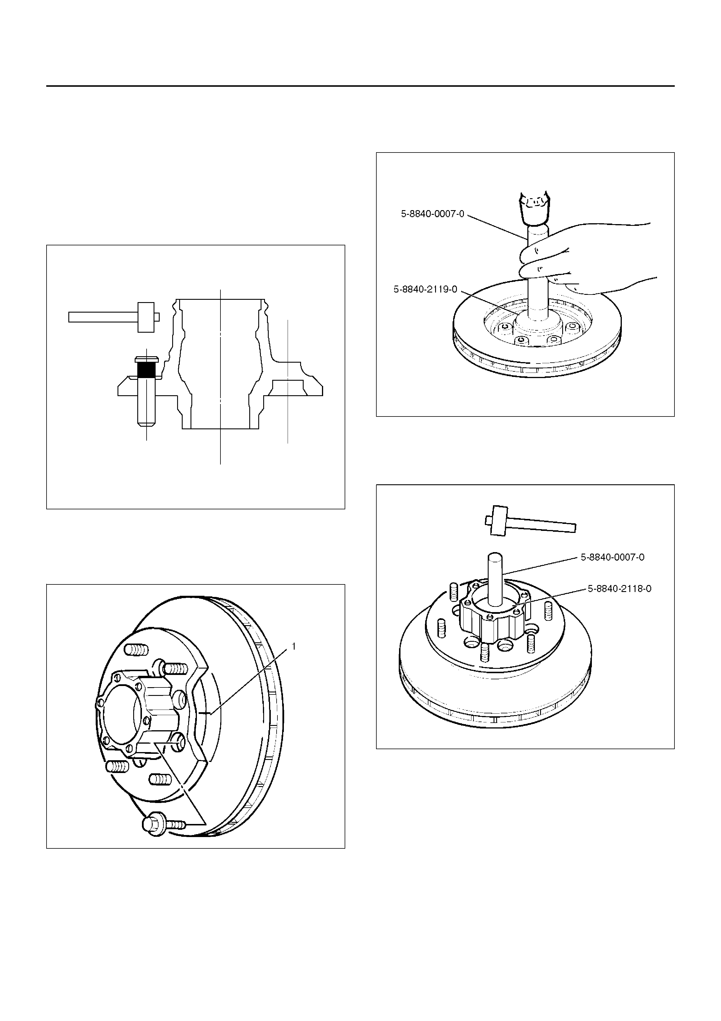
1. Install wheel pin.
• Place the hub on a wood workbench or a bloc k of
wood approx. 6" by 6 " to protect the wheel stud
ends and threads.
• Insert a wheel stud using a hammer.
Be sure the wheel stud is started squarely and
seats completely.
411RS005
2. Align scribe marks(1) and attach the hub to the disc,
then tighten the bolts to the specified torque.
Torque: 103N·m (10.5kg·m/76lbft)
411RS003
3. Use installer 5–8840–2119–0 and grip 5–8840–
0007–0, then install the inner bearing by driving it
into the hub.
411RW006
4. Use installer 5–8840–2118–0 and grip 5–8840–
0007–0 then install the outer bearing by driving it
into the hub.
411RW007
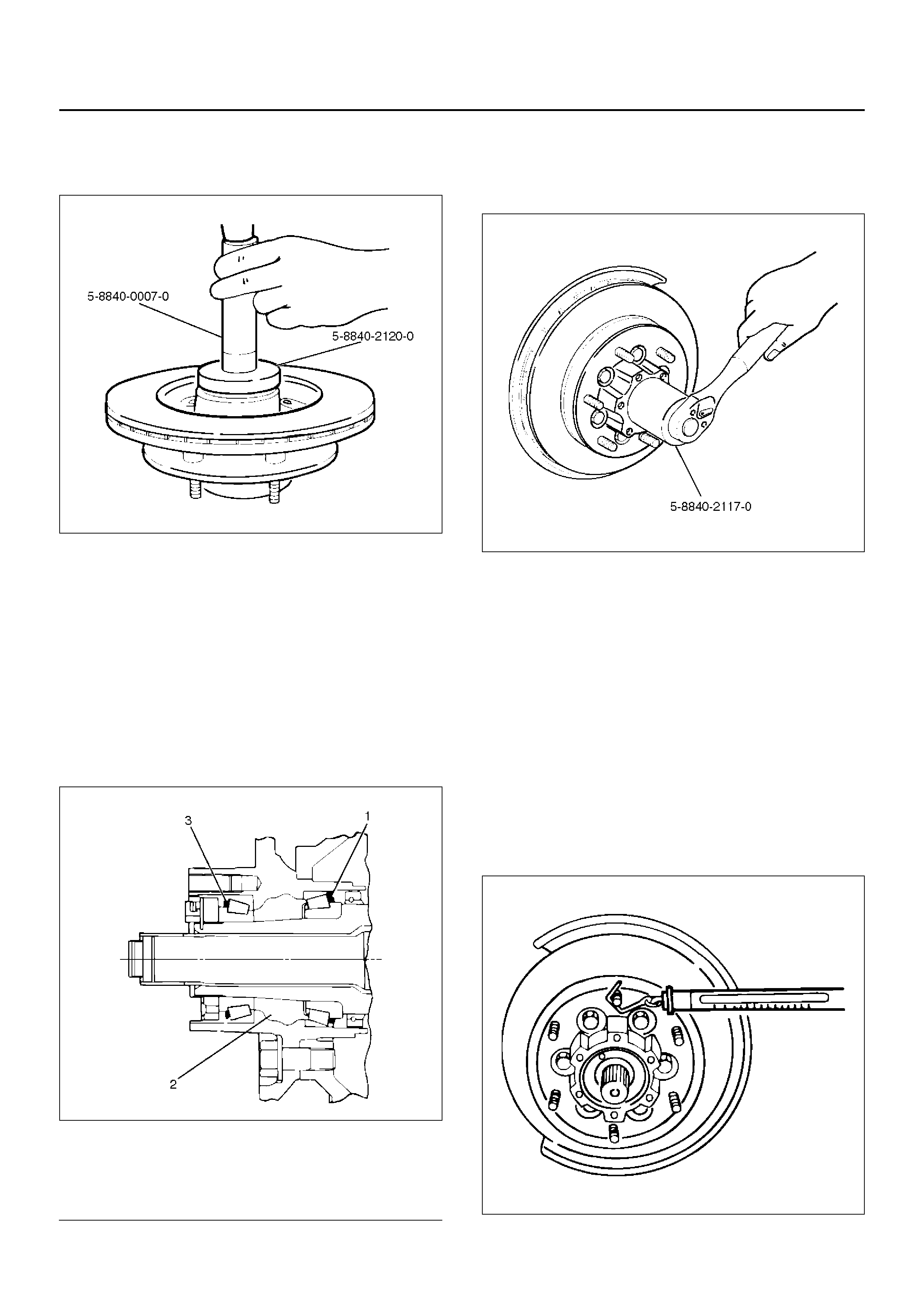
5. Apply grease (NLGI No.2 or equivalent) to the lip
portion, then install oil seal by using installer 5–
8840–2120–0 and grip 5–8840–0007–0.
411RW008
6. Install ABS sensor ring, then tighten the bolts to the
specified torque.
Torque: 18N·m (1.8kg·m/13lbft)
7. Ins tall hub and dis c assem bly.
• Apply grease in the hub.
• Apply wheel bearing type grease NLGI No. 2 or
equivalent to the outer and inner bearing.
Grease Amount
Hub: 35g (1.23oz)
Outer bearing: 10g (0.35oz)
Inner bearing: 15g (0.53oz)
411RS009
Legend
EndOFCallout
8. Install hub nut.
Turn to the place where there is a chamfer in the
tapped hole to the outer side, then attach the nut by
using front hub nut wrench 5–8840–2117–0.
411RW005
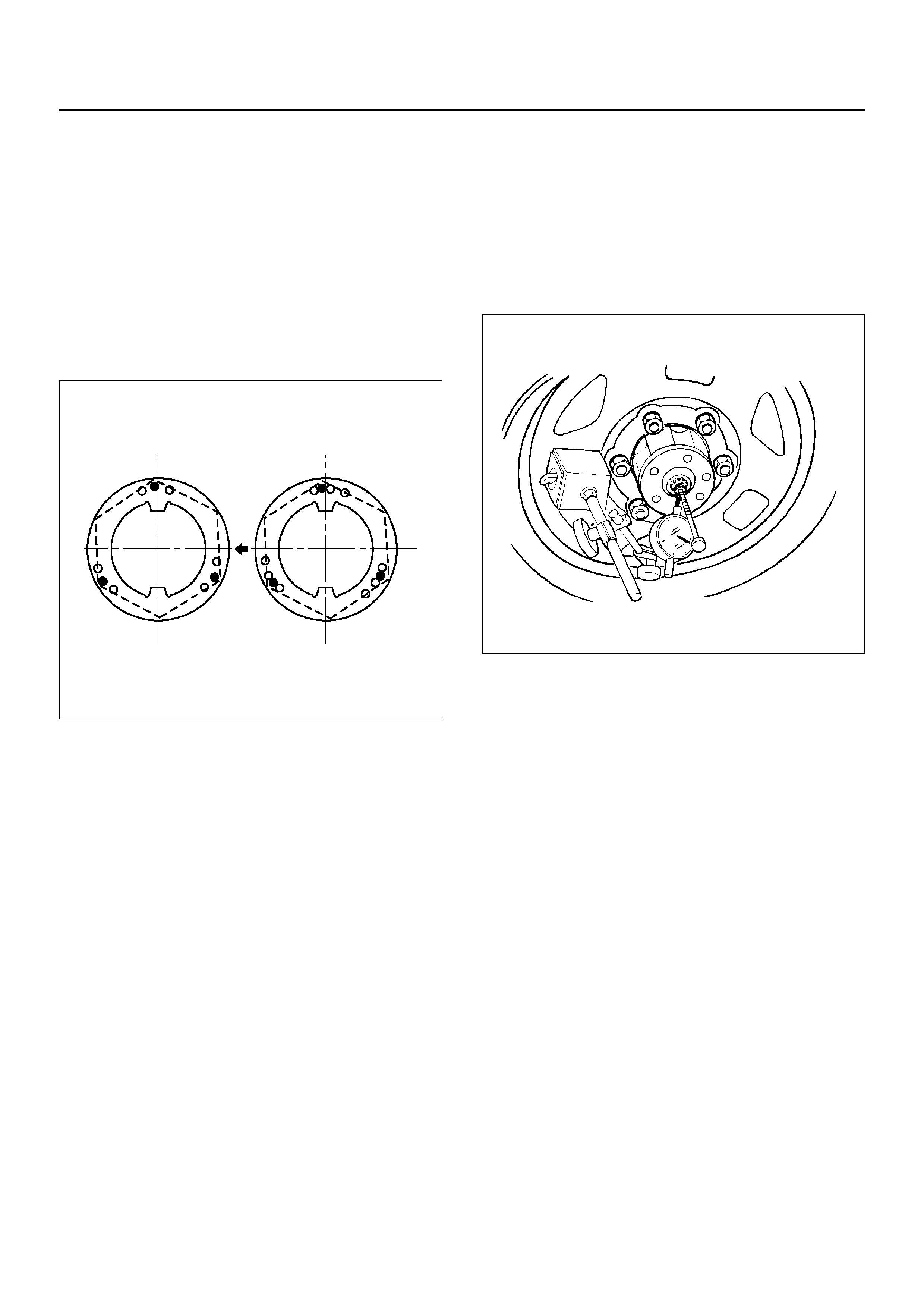
Preload Adjustment
1. Tighten the hub nut to 29 N·m (3.0kg·m/22lbft),
then fully loosen the nut.
2. Tighten the hub nut to the value given below,
using a spring scale on the wheel pin.
New bearing and New oil seal
Bearing Preload: 20– 25N (2.0– 2.5kg·m/4.4–
5.5lb)
Used bearing and New oil seal
Bearing Preload: 12– 18N (1.2– 1.8kg·m/2.6–
4.0lb)
If the measured bearing preload is outside the
specifications, adjust it by loosening or tightening
the bearing nut.
411RS011
(1) Inner Bearing
(2) Hub
(3) Outer Bearing
9. Install lock washer and lock screw in the following
manner.
• Turn the side with larger diameter of the tapered
bore to the vehicle outer side, then attach the
washer.
• If the bolt holes in the lock plate are not aligned
with the corresponding holes in the nut, reverse
the lock plate.
• If the bolt holes are still out of alignment, turn in
the nut just enough to obtain alignment.
• Screw is to be fastened tightly so its head may
come lower than the surface of the washer.
411RS012
10. Apply adhesive (LOCTITE 515 or equivalent) to
both joining flange faces then install hub flange.
11. Install snap ring and shim.
• Adjust the clearance between the free wheeling
hub body and the snap r i ng .
Clearance: 0mm–0.3mm (0in–0.012in)
Shims Available: 0.2mm, 0.3mm, 0.5mm, 1.0mm
(0.008in, 0.012in, 0.020in, 0.039in)
411RW002
12. Install hub cap.
13. Tighten the bolts to the specified torque.
Torque: 59N·m (6.0kg·m/43lbft)
Front Drive Shaft Joint
Front Drive Shaft Joints
Replacement
•Refer to Front Drive Axle Assembly Replacement in
this section, and refer to Front Hub and Disc Overhaul.
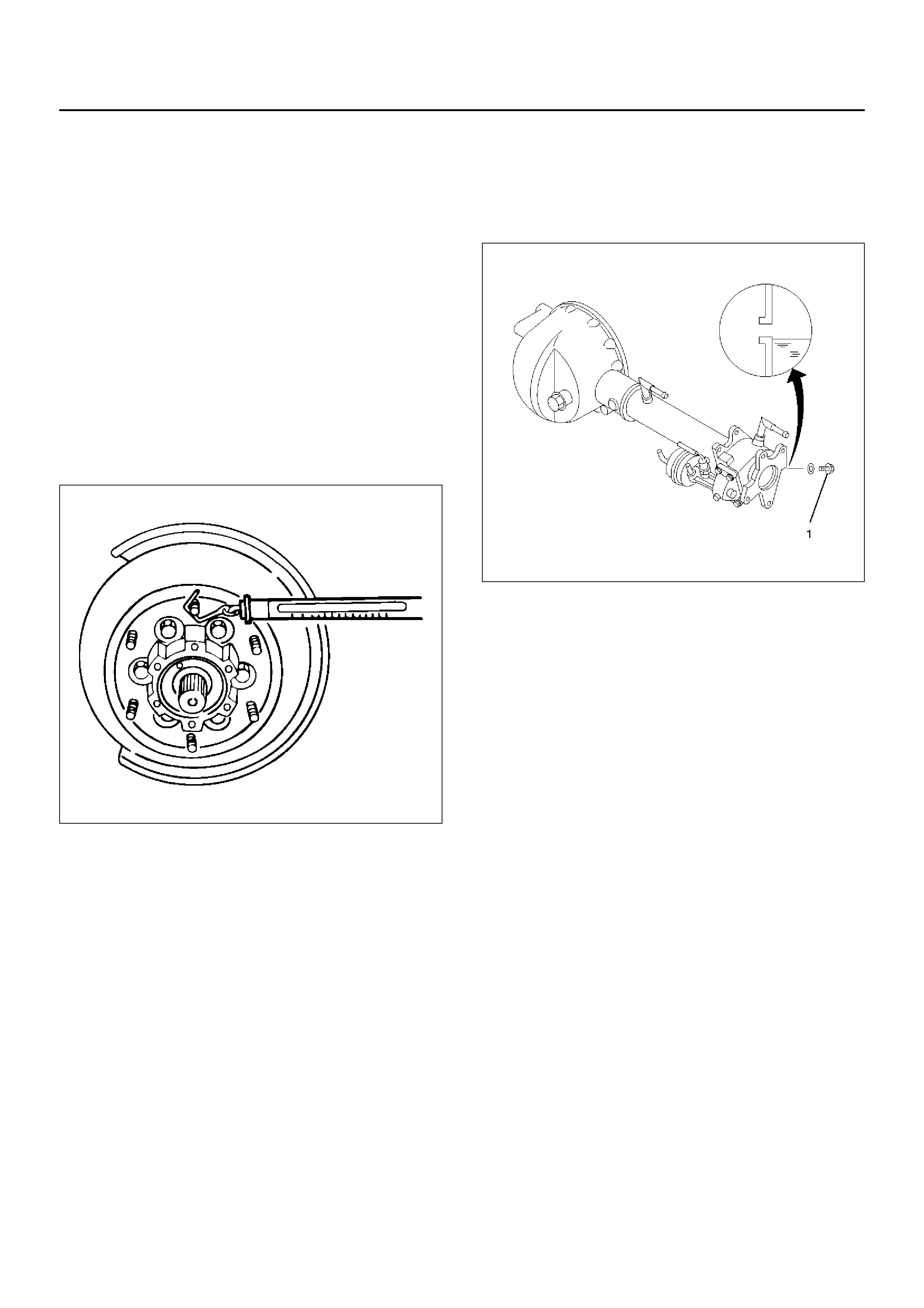
Front Hub Bearing Preload Check
Check the hub bearing preload at the wheel pin.
New bearing and New oil seal:
20 – 25N (2.0 – 2.5kg·m/4.4 – 5.5lb)
Used bearing and New oil seal:
12 – 18N (1.2 – 1.8kg·m/2.6 – 4.0lb)
411RS011
Inspection Of Shift On The Fly System Gear
Oil
412RW035
1. Open filler plug and make sure that the oil up to the
plug port.
If the oil is short, replenish with gear oil GL–5 grade.
2. Tighten the filler plug to specified torque.
Torque:78N·m (8.0kg·m/58lbft)
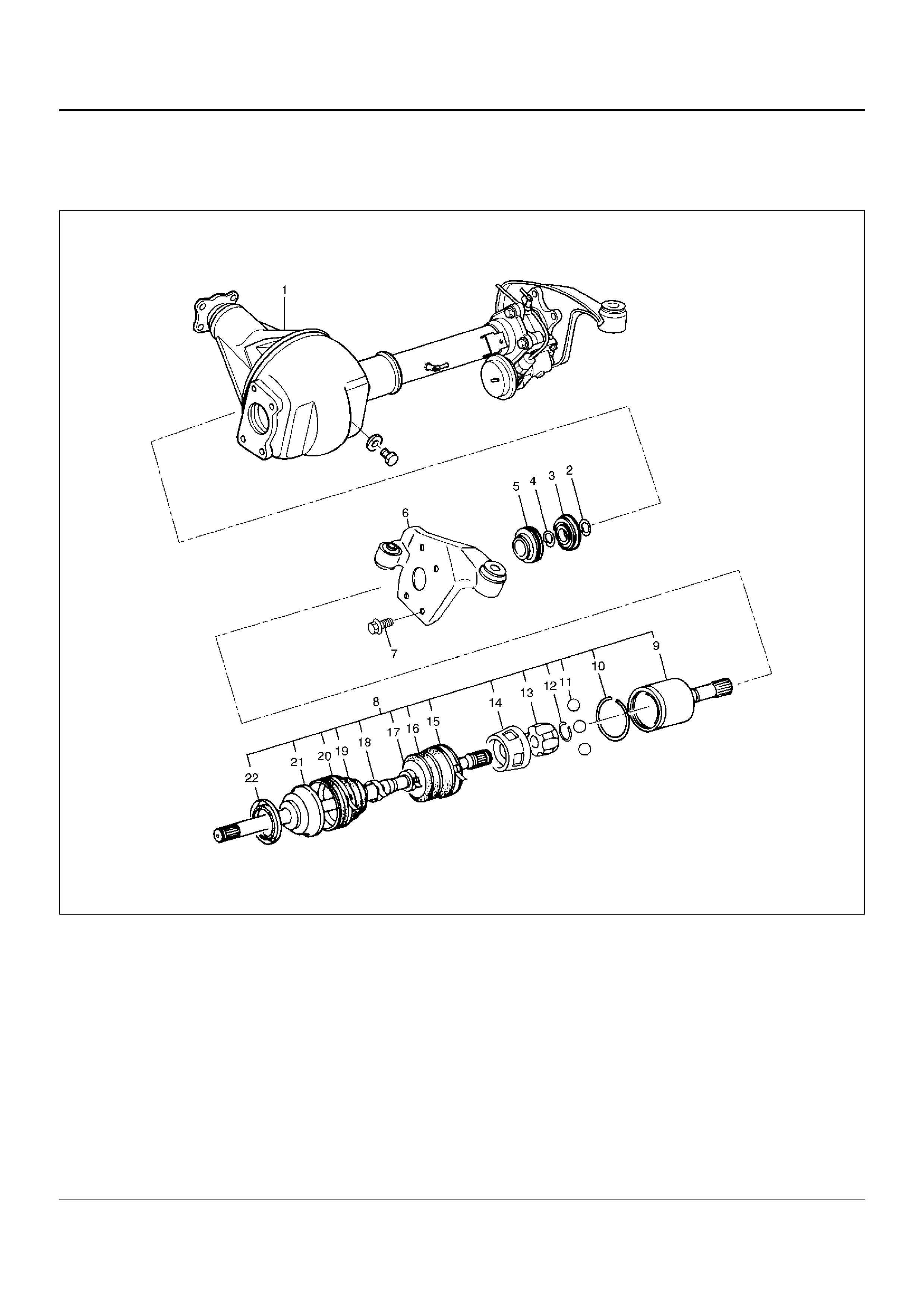
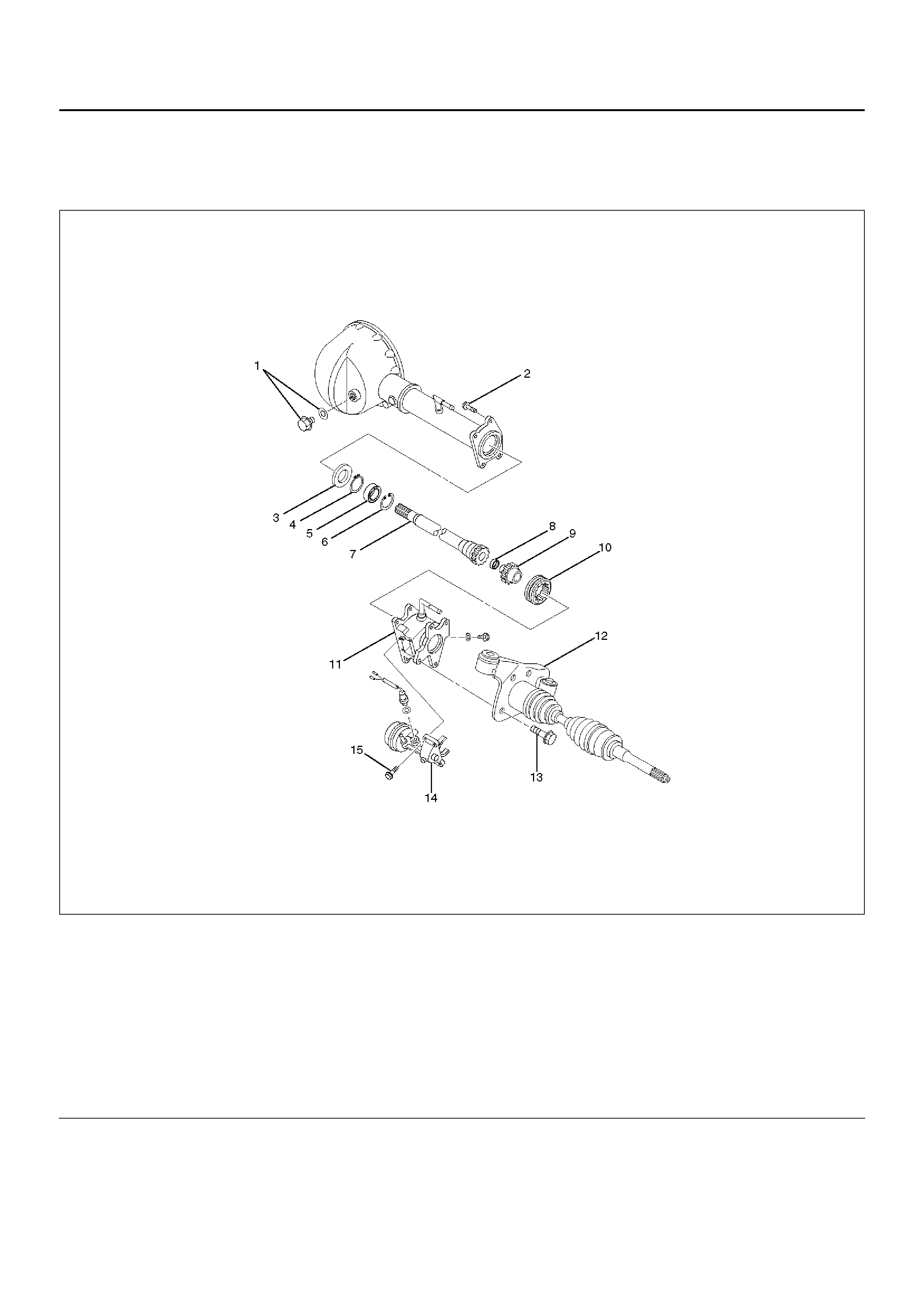
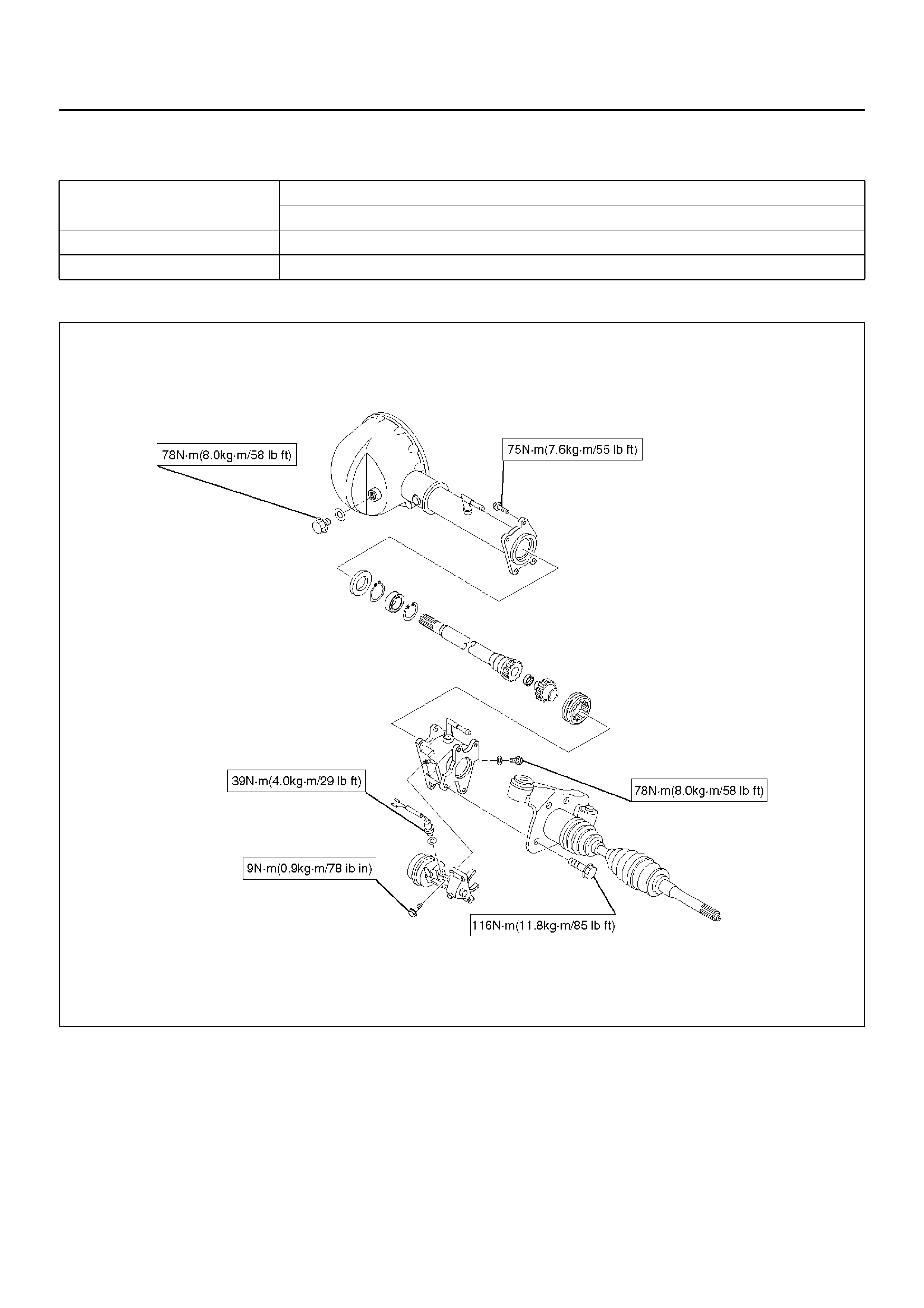
Front Axle Drive Shaft
Front Axle Drive Shaft and Associated Parts
412RX012
Legend
EndOFCallout
(1) Axle Case and Differential
(2) Snap Ring
(3) Bearing
(4) Snap Ring
(5) Oil Seal
(6) Bracket
(7) Bolt
(8) Drive Shaft Joint Assembly
(9) DOJ Case
(10) Circlip
(11) Ball
(12) Snap Ring
(13) Ball Retainer
(14) Ball Guide
(15) Band
(16) Bellows
(17) Band
(18) Band
(19) Bellows
(20) Band
(21) BJ Shaf t
(22) Dust Seal
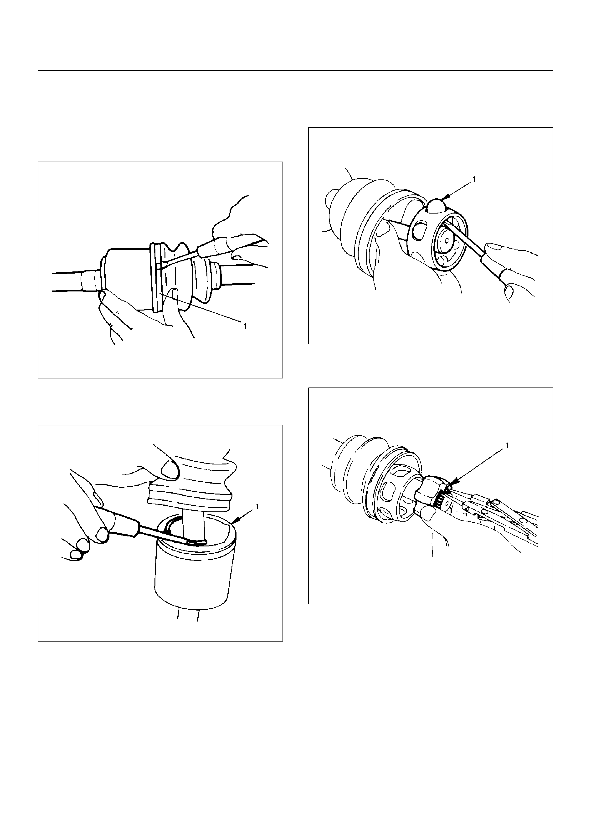
Disassembly
NOTE: For the left side, follow the same steps as right
side.
1. Raise the hooked end of the band with a
screwdriver or equivalent.
412RS009
2. Remove band(1).
3. Pry off circlip (1) with a screwdriver or equivalent.
412RS010
4. Remove drive shaft joint assembly.
5. Remove the six balls (1) with a screwdriver or
equivalent.
412RS012
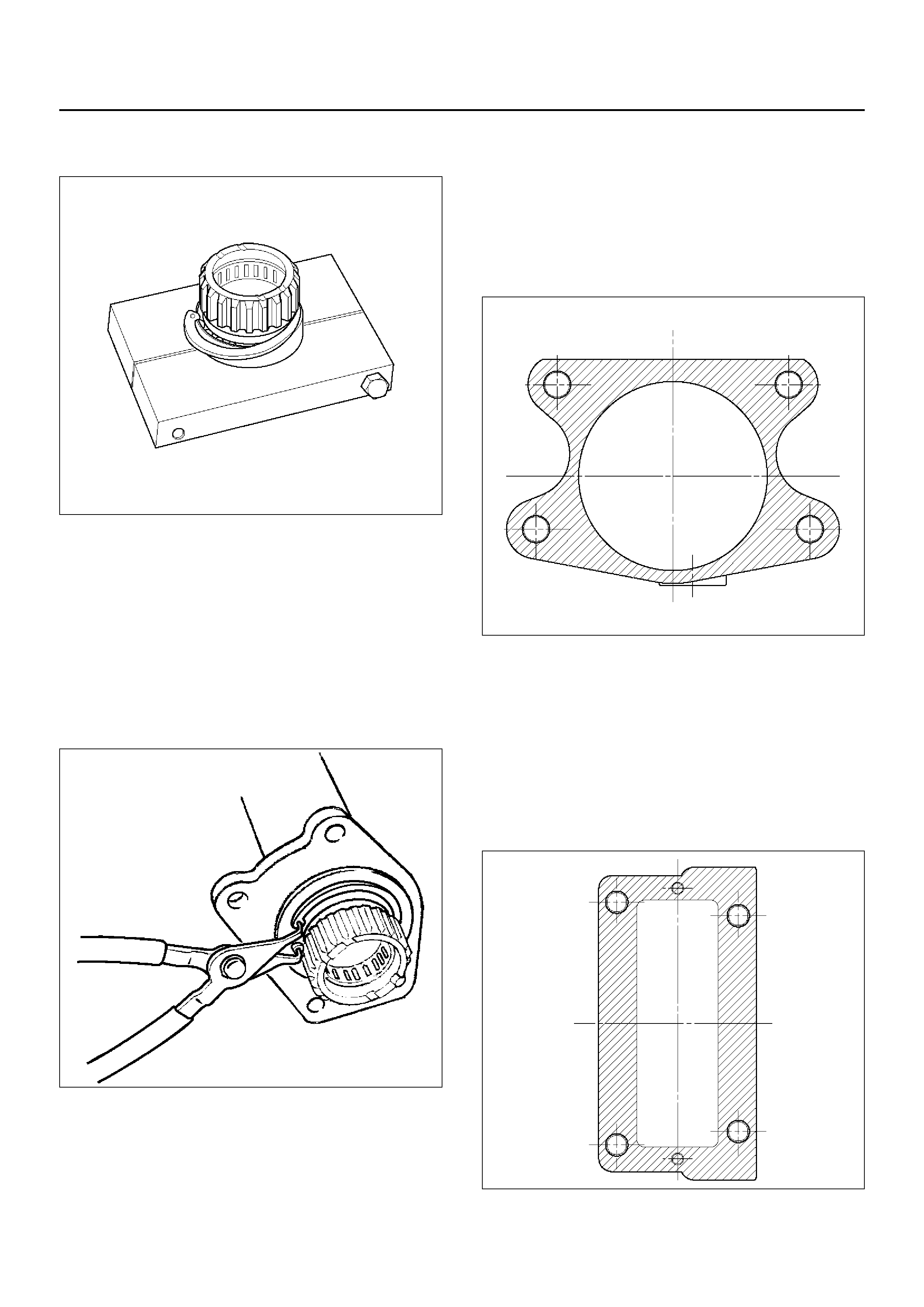
6. Using snap ring pliers, remove the snap ring (1)
fastening the ball retainer to the center shaft.
412RS013
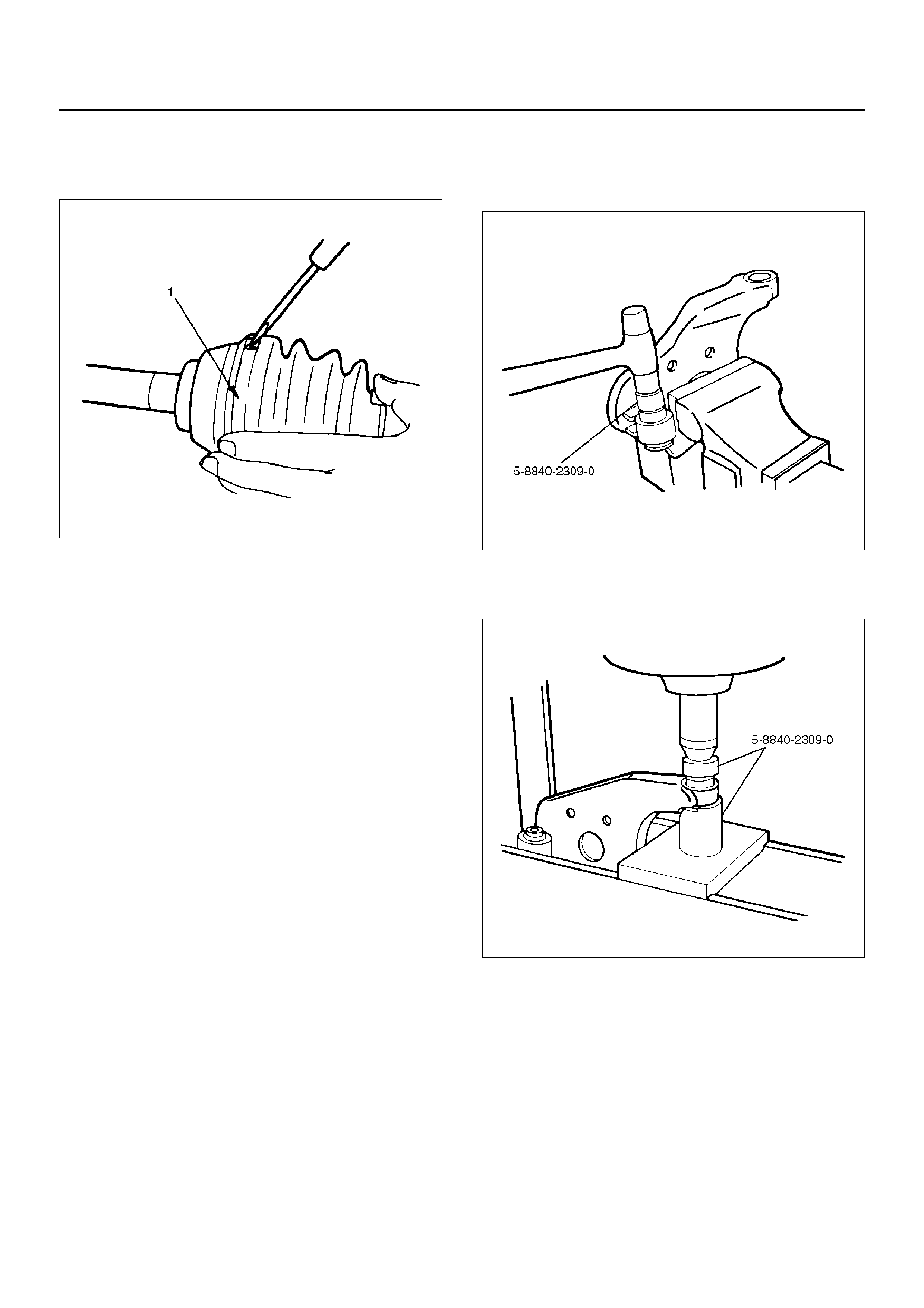
7. Remove ball retainer, ball guide and bellows.
8. Raise the hooked end of the band with a
screwdriver or equivalent.
412RS014
9. Remove band(1).
10. Remove bellows.
11. Remove dust seal.
12. Remove BJ shaft assembly.
13. Remove the mounting bracket fixing bolts, and then
remove DOJ case assembly from the axle case.
14. Remove snap ring and bearing.
15. Remove snap ring and oil seal.
16. Remove bracket.
Inspection And Repair
Make necessary correction or parts replacement if
wear, damage, corrosion or any other abnormal
condition are found through inspection.
Check the following parts.
1. Drive shaft joint assembly
2. DOJ case, ball, ball guide, ball retainer
3. Bellows
4. Bearing
5. Dust seal, oil seal
Bushing Replacement
• Remove the bushings using a remover 5–8840–
2309–0 and hammer.
412RW051
• By using installer and base 5–8840–2309–0, press
fit the bushings into the brac ket.
412RW052
Reassembly
1. Install DOJ case to bracket.
2. Install oil seal and fix snap ring.
3. Install bearing and fix snap ring.
4. Install bracket to axle case. Tighten the brac ket bolt
to the specified torque.
Torque:116N·m (11.8kg·m/85lbft)
5. Apply 150g of the specified grease in BJ.
6. Install dust seal.
7. Apply a thin coat of grease to the shaft for smooth
installation then install bellows.
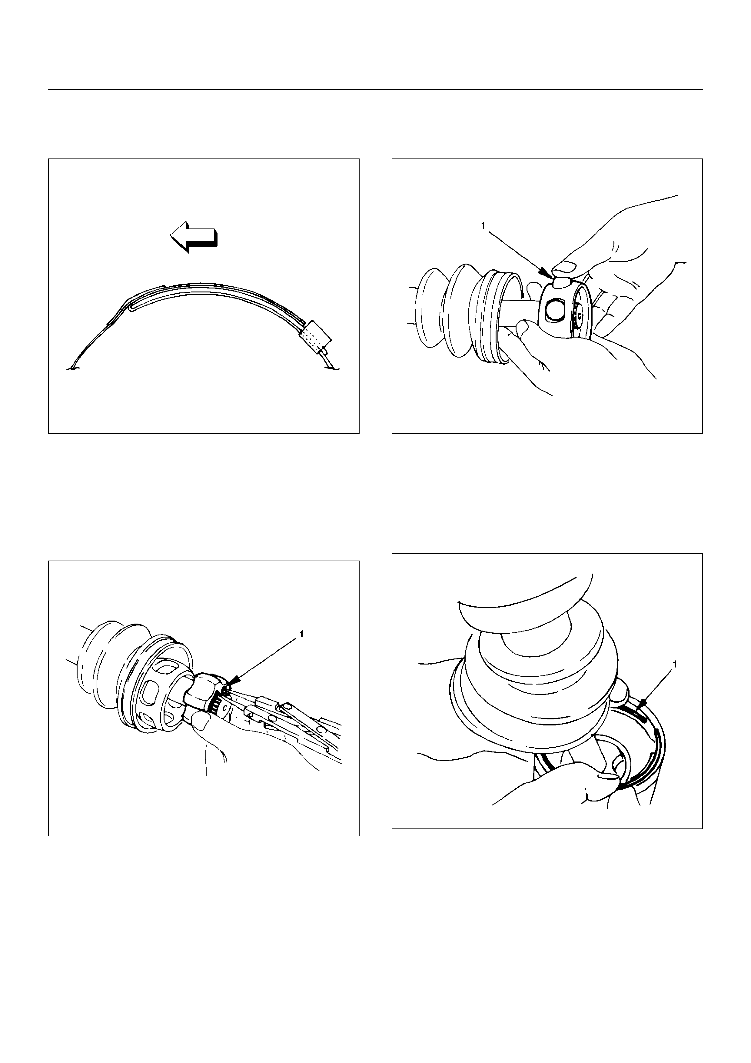
8. Install band. Note the setting direction. After
installation, check that the bello ws is free from
distortion.
412RS017
9. Install another bellows and fix band.
10. Install the ball guide with the smaller diameter side
ahead onto the shaft.
11. Install ball retainer.
12. Using snap ring pliers, install the snap ring (1)
securing the ball retainer to the shaft.
412RS013
13. Align the trac k on the ball (1) retainer with the
window in the cage, and install the six balls into
position.
412RS018
14. P ack 150g of the specified grease in DOJ case, then
install drive shaft joint assembly. After reassembly,
move the DOJ longitudinally several times to get to
fit.
15. Install the circlip (1) so that open ends are
positioned away from the ball groove.
412RS019
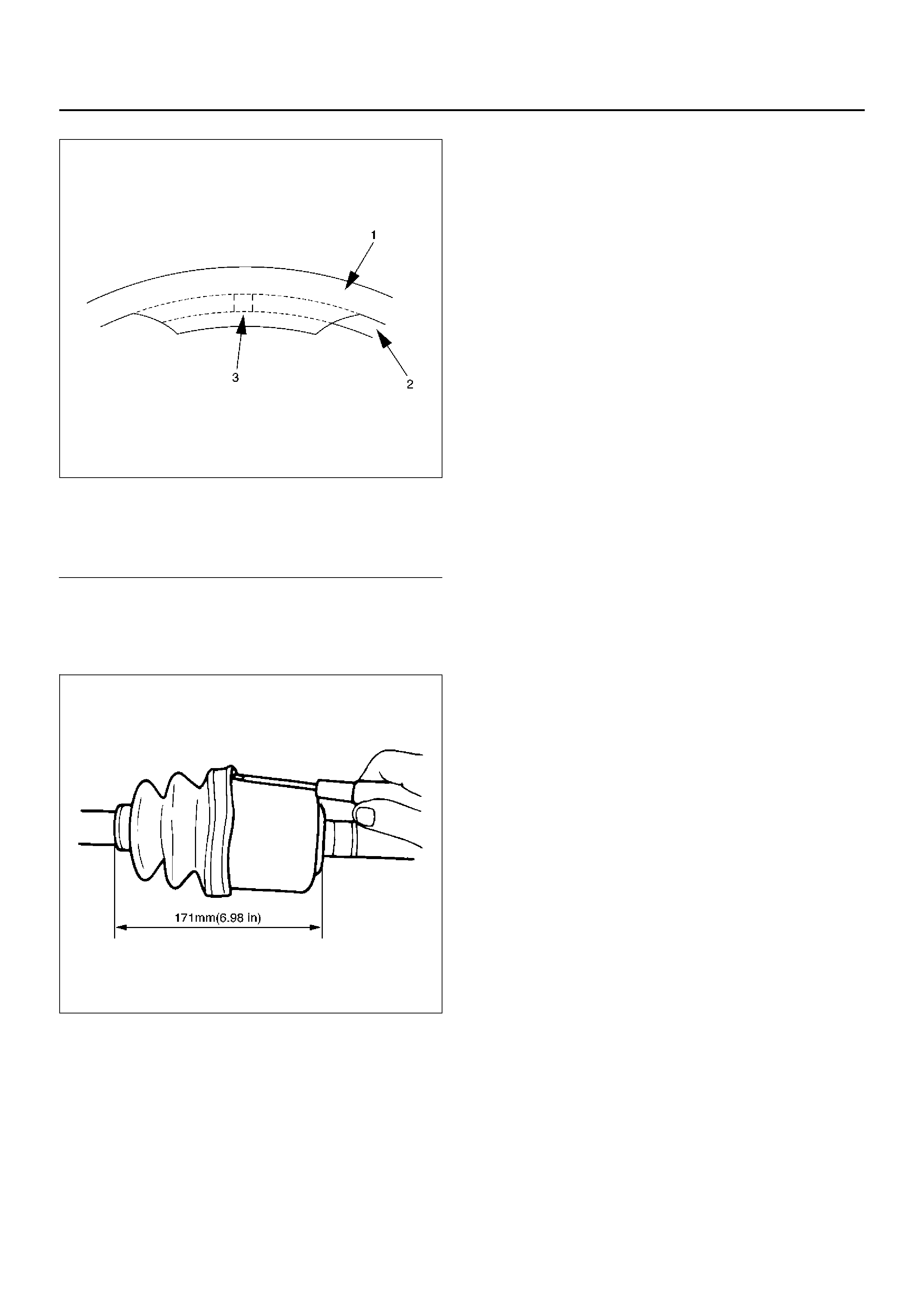
412RS020
Legend
EndOFCallout
16. Install bellows. Adjust the air pressure within the
bellows by inserting a screwdriver or equivalent, so
that it equals atmospheric pressure.
412RS021
17. Install band. After installation, check that the bellows
is free from distortion.
(1) Outer Case
(2) Circlip
(3) Open Ends
Shift On The Fly System
Shift On The Fly System and Associated Parts
412RW031
Legend
EndOFCallout
Disassembly
1. Remove filler plug and gasket, drain oil.
2. Loosen mounting bracket fitting bolts and remove
front axle drive shaft from front axle case.
3. Remove actuator assembly and draw out actuator
ASM.
4. Remove housing.
5. Remove sleeve.
(1) Filler Plug
(2) Bolt
(3) Oil Seal
(4) Snap Ring(External)
(5) Inner Shaft Bearing
(6) Snap Ring(Internal)
(7) Inner Shaft
(8) Needle Bearing
(9) Clutch Gear
(10) Sleeve
(11) Housing
(12) Front Axle Drive Shaft(LH side) with Bracket
(13) Bolt
(14) Actuator Assembly
(15) Bolt

6. Remove clutch gear.
7. Remove snap ring from front axle case by using
snap ring pliers.
412RW017
8. Take out inner shaft from front axle case.
9. Remove snap ring from inner shaft by using snap
ring pliers.
412RW016
10. Remove inner shaft bear in g.
NO TE: Be careful not to damage the shaft.
412RW015
11. Remove needle bearing from inner shaft by using a
remover 5–8840–0027–0 and sliding hammer 5–
8840–0084–0.
412RS045
12. Remove oil seal from front axle case.
NO TE: Be careful not to damage the front axle case.
Inspection And Repair
Inspect the removed parts. If there are abnormalities
such as wear and damage, take corrective action or
replace.
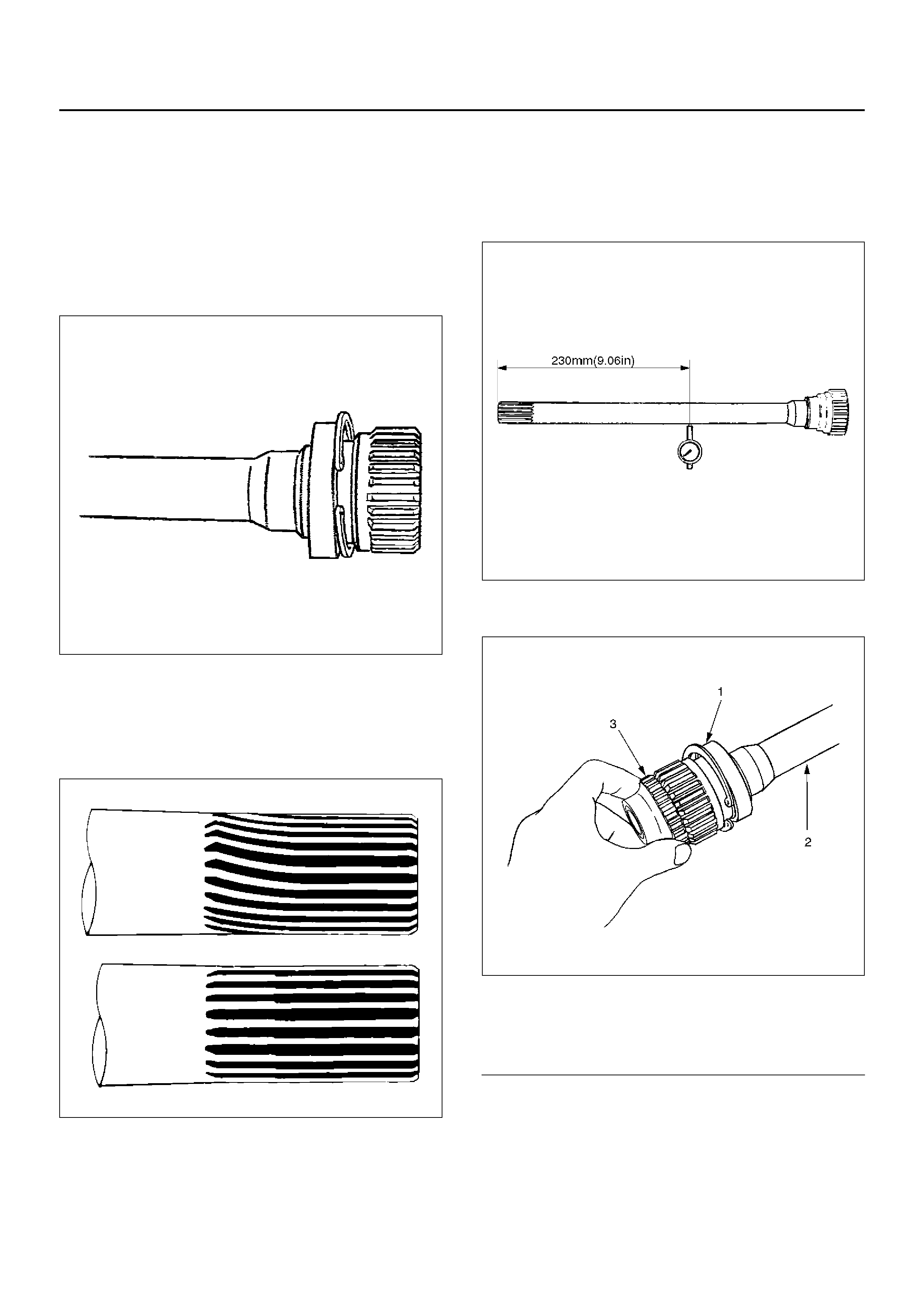
Visual Check
1. Check and see if the inner shaft has such
abnormalities as wear and damage.
412RW014
2. When inspecting the inner shaft, be sure to check
and see if its splined part is twisted, worn, or
cracked. If so, replace with a new shaft. In case
such an abnormality in its gear part (a slide with
sleeve), replace the shaft.
420RS008
Inner Shaft Run–Out
With both end centers supported, rotate the shaft slowly
and measure deflection with a dial gauge.
Limit:0.5mm (0.02in)
NO TE: Do not heat the shaft to correct its bend.
412RS026
Inner Shaft Bearing
412RW006
Legend
EndOFCallout
1. Inspect the state of inner shaft bearing. If any
abnormality such as smoothlessness is found,
replace with a new inner shaft bearing.
2. Insert a clutch gear and check the state of needle
bearing.
3. If there is an abnormality such as smoothlessness,
replace the need le bearing .
(1) Inner Shaft Bearing
(2) Inner Shaft
(3) Clutch Gear

Sleeve Condition
Check and see that there is not wear damage, or
cracking in the sleeve.
NOTE: Close inspection of the groove and inner gear
are required because those are important parts.
Sleeve Function
412RW011
Operate the sleeve with the inner shaft combined with
the clutch gear and if smoothlessness is f elt, replace the
sleeve.
NOTE: Gear oil should be applied to the contact
surface of gear.
Check the width of slee ve center groove.
Limit:7.1mm (1.28in)
412RW022
Clutch Gear Condition
Check and see that there is not wear, damage, crack, or
any other abnormality in the clutch gear.
Clutch Gear Function
412RW066
If there is an abnormality such as roughness when
operated in combination with sleeve, replace the clutch
gear.
NO TE: When inspecting, gear oil should be applied to
the contact surface of gear.
Clutch Gear Journal Diameter
Make sure of the size illustrated.
Limit:36.98mm (1.456in)
412RW065
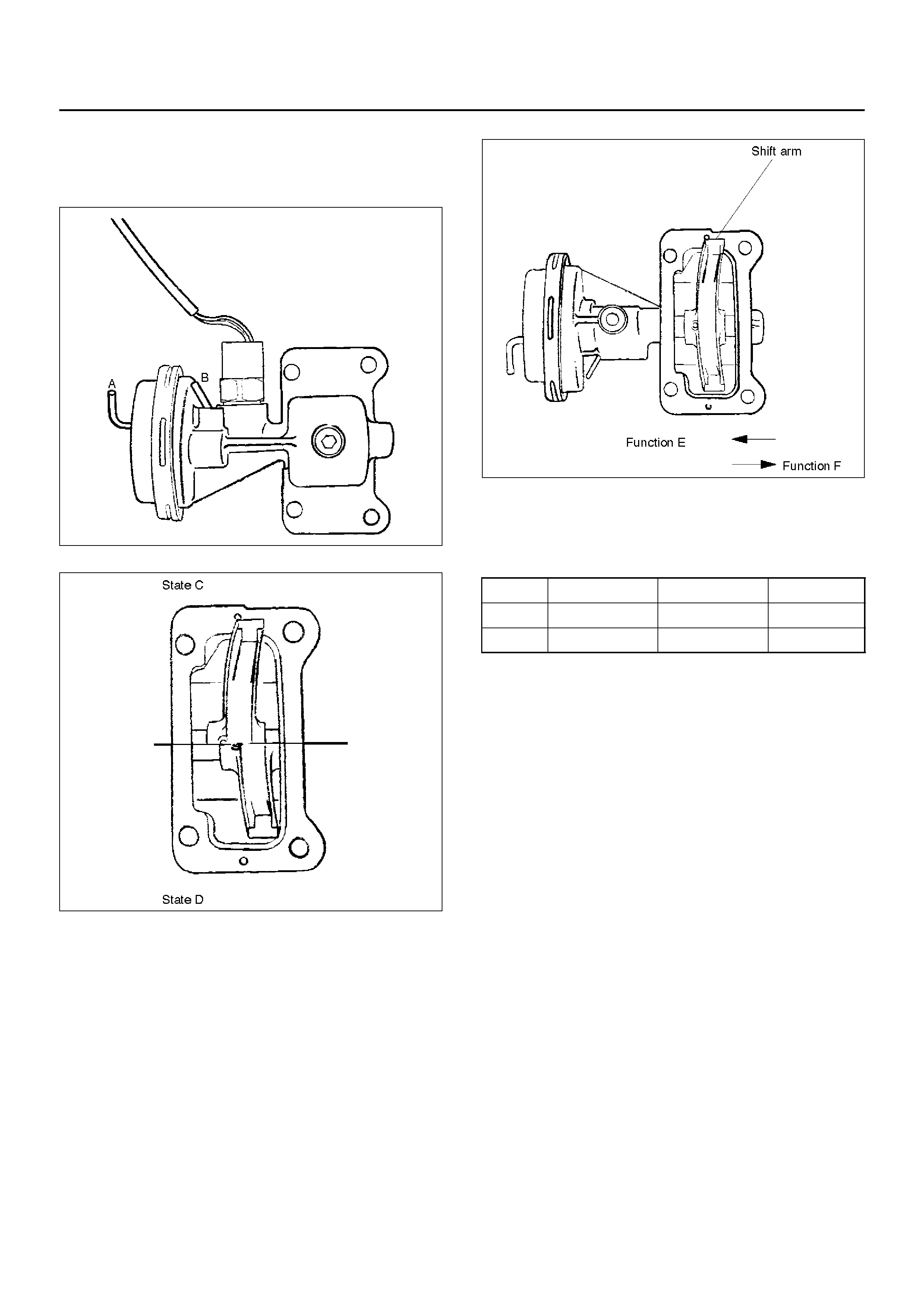
Actuator
Check and see that there is no damage, cracking, or
other abnorma lity.
Functional Check
412RW021
412RW013
412RW007
Disconnect the shift position switch and make sure of
function with a vacuum of –400 mmHg applied to Ports
A and B, in accordance with the table below.
If there is an abnormality, replace the actuator as an
assembly.
NOTE:
1. If the actuator works under –400mmHg or less,
there is no functional problem.
2. Be careful not to permit the entry of water or dust
into the ports of the actuator.
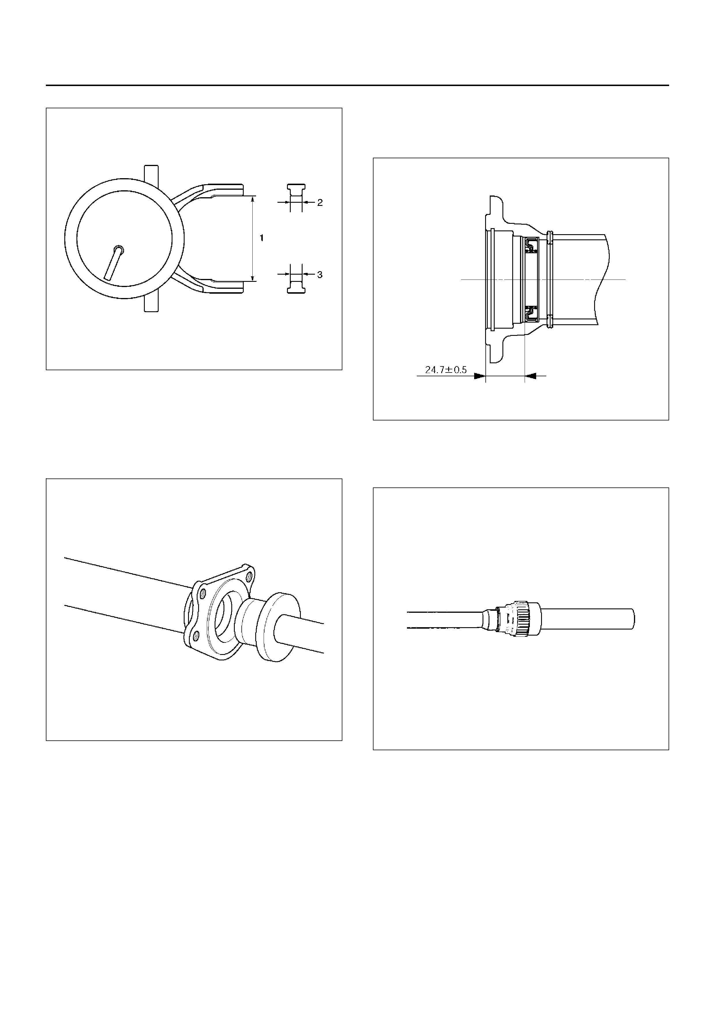
Dimentional Check
Measure illustrated sizes 1, 2, and 3.
Limit
1=64.1mm (2.52in)
2=6.7mm (0.26in)
3=6.7mm (0.26in)
State Port A Port B Function
C –400 mmHg A/P E
D A/P –400 mmHg F
412RS037
Reassembly
1. Install the new oil seal which has been immersed in
differential gear oil, by using an oil seal installer 5–
8840–2407–0 and grip 5–8840–0007–0.
412RW034
2. Check the oil seal installation position (from shaft
end to oil seal).
Depth:24.2–25.2mm(0.95–0.99in)
412RS052
3. F orce a new needle bearing into inner shaft by using
a Installer 5–8840–2408–0 and grip 5–8840–0007–
0.
412RS051
4. Place a new snap ring(internal) in inner shaft.
Force a new inner shaft bearing into the inner shaft.
412RS044
5. Install snap ring(external).
NOTE: Be careful not to damage the inner shaft.
6. Clean the housing contact surface of the front axle
case and insert inner shaft assembly into the front
axle case.
NOTE: Be careful not to damage seal.
7. Install snap ring internal in the groove of front axle
case.
NOTE: Be sure to install the snap ring properly.
412RW017
8. Apply differential gear oil to clutch gear, then install
clutch gear.
9. Apply differential gear oil to sleeve, then install
sleeve.
10. Clean contact surface with the front axle and
actuator mounting surface. Apply liquid gasket to
the contact surface on the front axle case, then
install in the housing.
412RW023
11. Tighten bolts to specified torque.
Torque:75N·m(7.6kg·m/55lbft)
12. Clean the actuator contact surface with the housing
then Install and tighten shift position switch to
specified torque.
Torque:39N·m (4.0kg·m/29lbft)
13. Apply liquid gasket to the contact surface on the
actuator side.
412RW012

14. Align shift arm with the groove of sleeve and install
the actuator.
15. Tighten bolts to specified torque.
Torque:9N·m(0.9kg·m/78lbin)
16. Install front axle drive shaft and mounting bracket.
Tighten fitting bolts to specified torque.
Torque:116N·m (11.8kg·m/85lbft)
17. Pour specified amount of differential gear oil to filler
plug.
Front Differential
Oil Capacity:1.4lit (1.48USqt)
Actuator Housing
Oil Capacity:0.12lit(0.13USqt)
18. Install filler plug through gasket and tighten to
specified torque.
Torque:78N·m (8.0kg·m/58lbft)
Main Data and Specifications
General Specifications
Torque Specifications
E04RX011
Front drive axle oil capacity 1.4 liter (1.48 US qt)(Differential)
0.12 liter (0.13 US qt)(Actuator Housing:Shift on the fly)
Type of lubricant GL–5 (75W–90) Refer to chart in General Information
Axle shaft type Constant velocity joint(Birfield joint type and double offset joint)
E04RX012
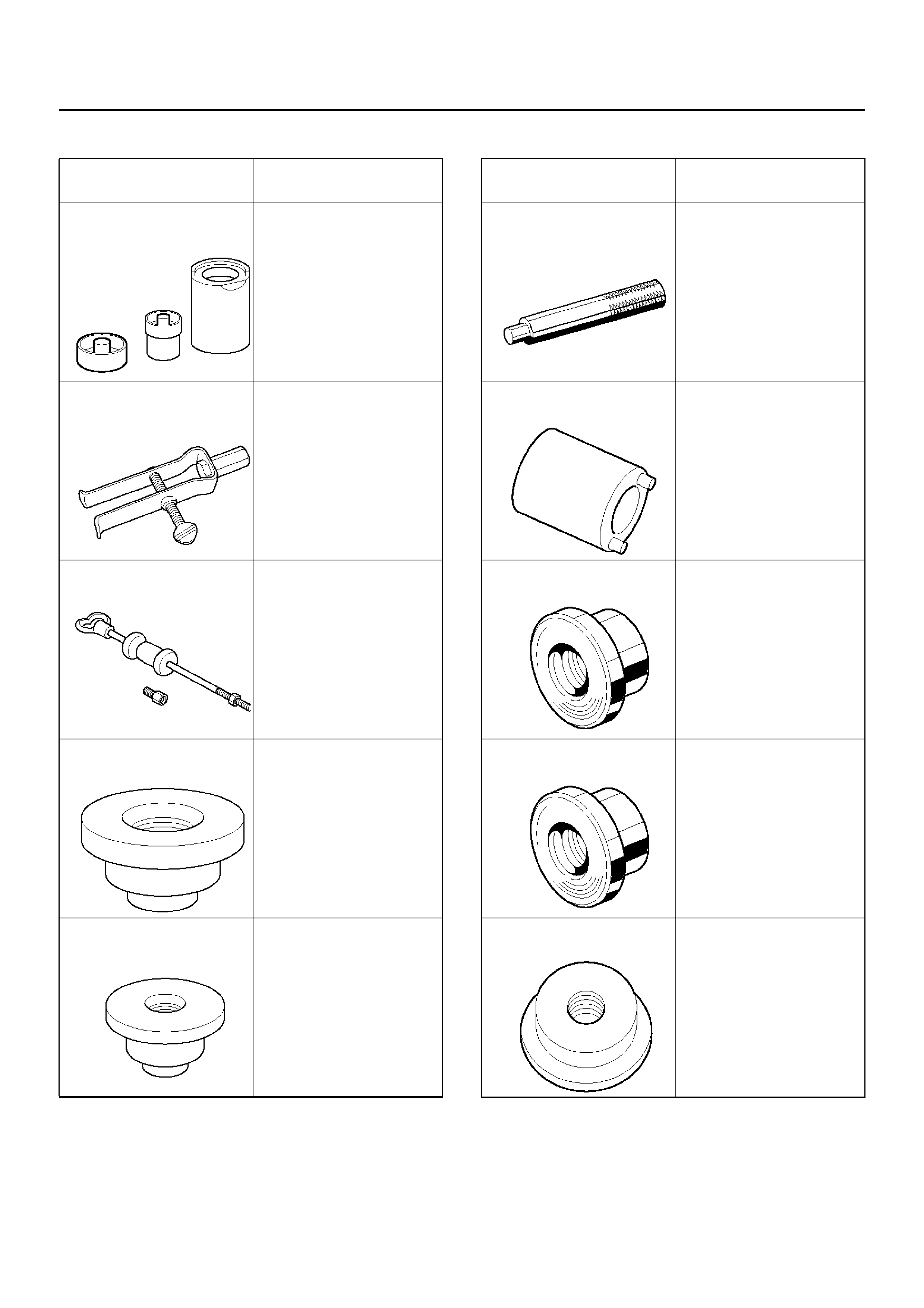
Special Tools
ILLUSTRATION TOOL NO.
TOOL NAME
5–8840–2309–0
(J–39378)
Remover and Installer;
Front Axle mount bushing
5–8840–0027–0
(J– 26941)
Remover; Bearing needle
5–8840–0084–0
(J–2619–01)
Hammer; Sliding
5–8840–2407–0
(J–41693)
Installer; Oil seal
5–8840–2408–0
(J–41694)
Installer; Bea ring needle
5–8840–0007–0
(J–8092)
Grip
5–8840–2117–0
(J–36827)
Wrench; Hub nut
5–8840–2119–0
(J–36829)
Installer; Inner bearing
5–8840–2118–0
(J–36828)
Installer; Outer bearing
5–8840–2120–0
(J–36830)
Installer; Oil seal
ILLUSTRATION TOOL NO.
TOOL NAME
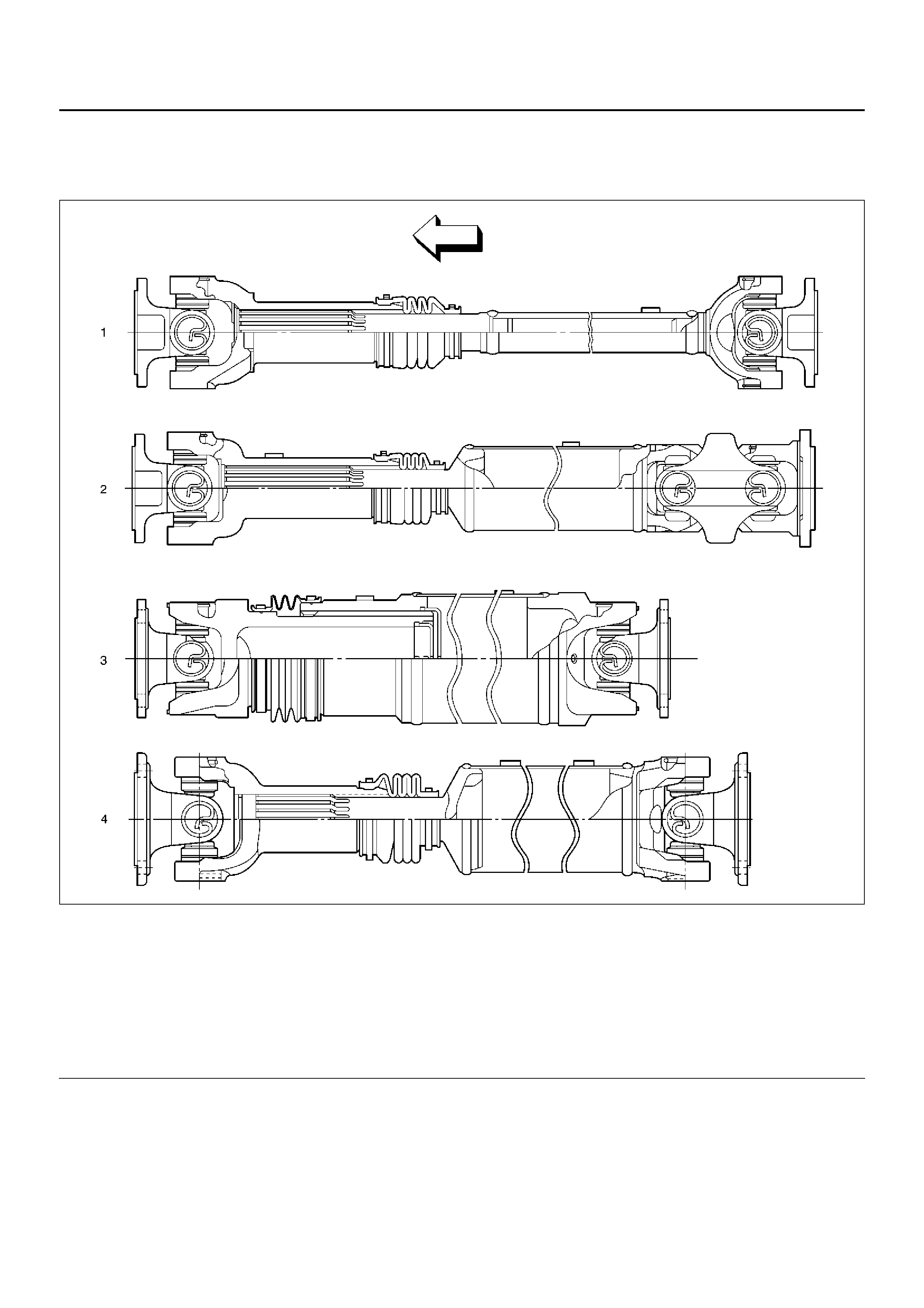
Propeller Shaft
General Description
401RX026
Legend
EndOFCallout
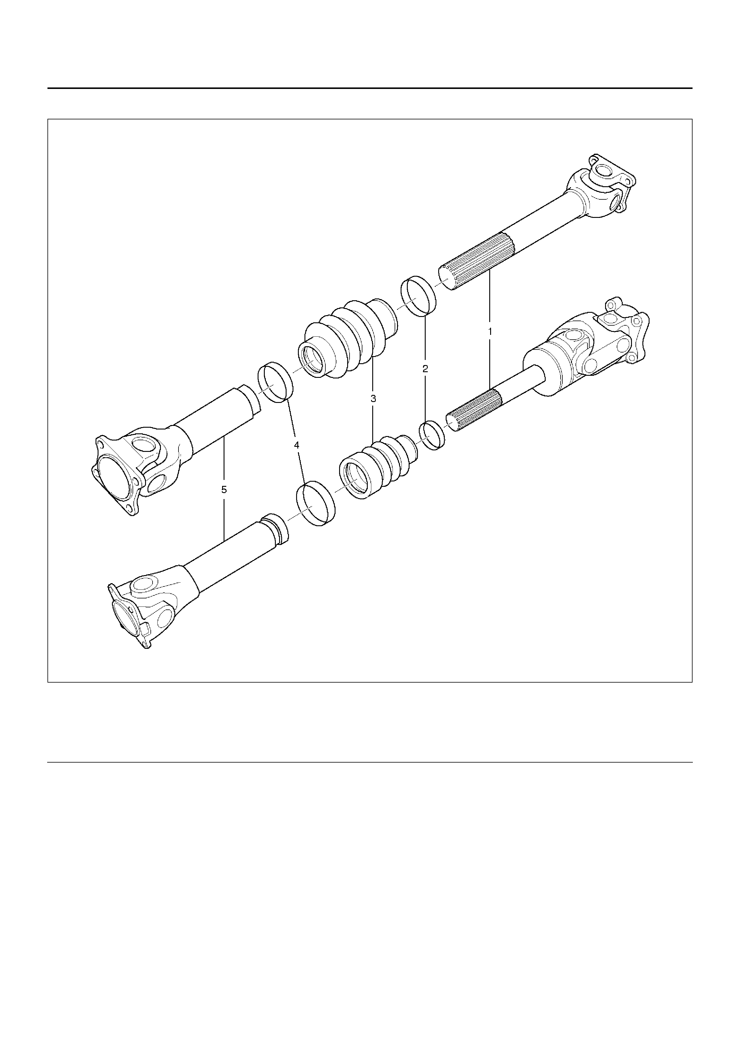
(1) Front Propeller Shaft (for 6VD1)
(2) Front Propeller Shaft (for X22SE)
(3) Rear Propeller Shaft;
Aluminum Tub e Type
(for 6VD1, M/T model)
(4) Rear Propeller Shaft;
Steel Tube Type
(for X22SE, M/T model and 6VD1, A/T model)
Torque is transmitted from the transmission to the axle
through propeller shaft and universal joint assembles.
All propeller shafts are the balanced tubular type. A
splined slip joint is provided in some drivelines.
• Since the propeller shaft is total balanced carefully,
welding or any other modification are not permitted.
• Alignment marks should be applied to each propeller
shaft before remov al.
• Be sure vehicle is stopped, engine is not running,
brake is secured and vehicle is secured to prevent
injury.
• Be careful not to grip the propeller shaft tube too
tightly in the bise as this will be cause deformation.
Phasing
The propeller shaft is designed and built with the yoke
lugs (ears) in line with each other . This design produces
the smoothest running shaft possible, called phasing.
Vibration can be caused by an out-of-phase propeller
shaft. The propeller shaft will absorb vibrations from
speeding up and slowing down each time the universal
joint goes around. This vibration would be the same as
a person snapping rope and watching the "wave"
reaction flow to the end. A propeller shaft working in
phase would be similar to two persons snapping a rope
at the same time, and watching the "waves" meet and
cancel each other out. In comparison, this would be the
same as the universal joints on a propeller shaft. A total
cancellation of vibration produces a smooth flow of
power in the driveline. It is very important to apply a
reference mark to the propeller shaft before removal, to
assure installation alignment.
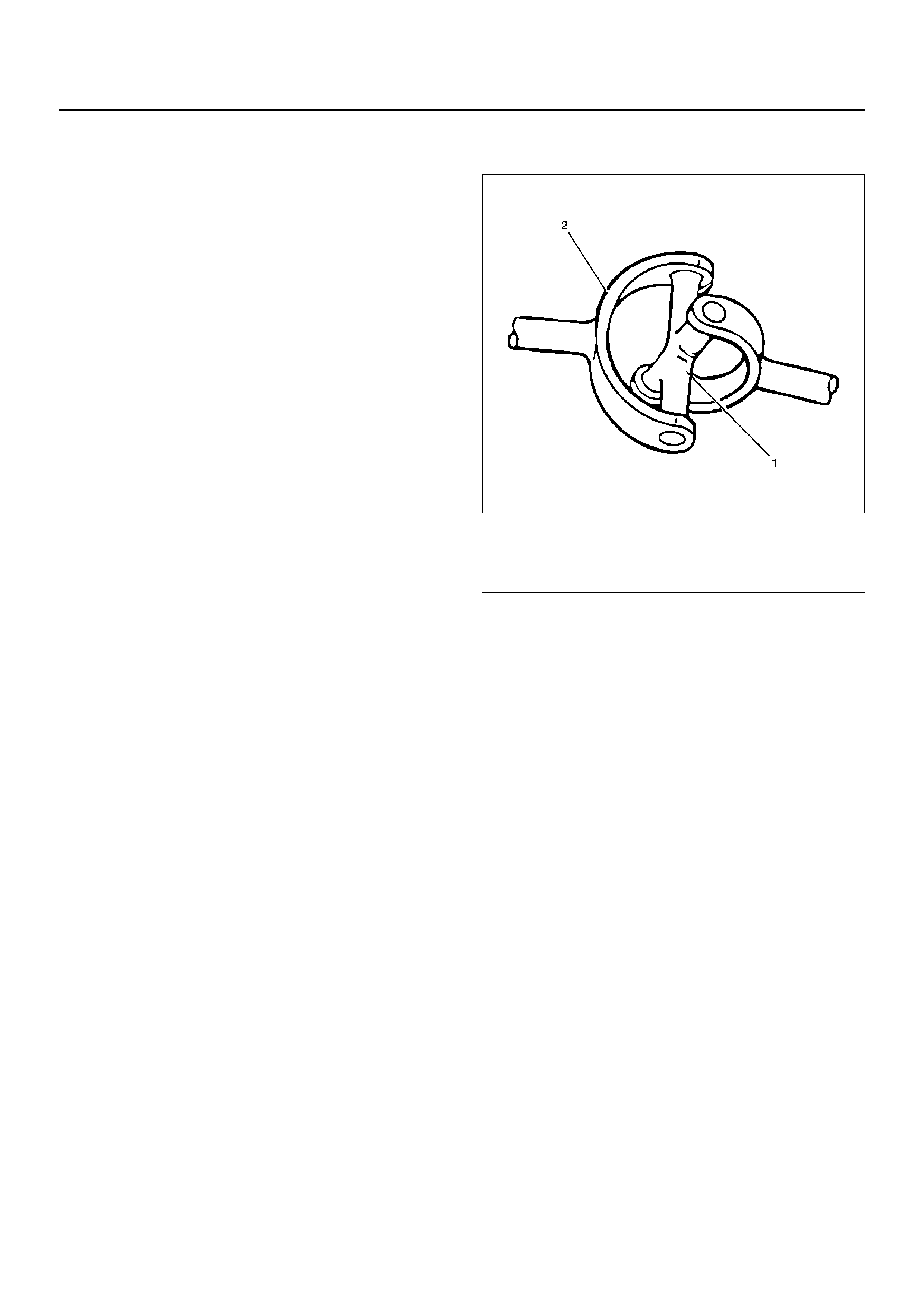
Universal Joint
401RW015
Legend
EndOFCallout
A universal joint consists of two Y-shaped yokes
connected by a crossmember called a spider.
The spider is shaped like a cross. Universal joints are
designed to handle the effects of various loadings and
fron t or rear ax le wi ndu p du ring a cce le r a t io n . Wit h i n t h e
designed angle variations, the universal joint will
operate efficiently and safely. When the design angle is
changed or exceeded the operationallife of the joint ma y
decrease.
The bearings used in universal joints are of the needle
roller type. The needle rollers are held in place on the
trunnions by round bearing cups. The bearing cups are
held in the yokes by snap rings.
(1) Spider
(2) Yoke

Diagnosis of Propeller Shaft and Universal Joint
Condition Possible cause Correction
Universal Joint Noise. Worn universal joint bearings. Replace.
Improper lubrication. Lubricate as directed.
Loose flange bolts. Tighten to specifications.
Ping, Snap, or Click in Drive Line
(Usually Heard on Initial Load after
the Transmission is in Forward or
Reverse Gear)
Loose bushing bolts on the rear
springs or upper and lower control
arms.
Tighten the bolts to specified torque.
Loose or out-of-phase end yoke. Remove end yoke, turn 180 degrees
from its original position, lubricate
the splines and reinstall. Tighten the
bolts and pinion nut to specified
torque.
Knocking or Clanking Noise in the
Driveline when in High or Neutral
Gear at 16km/h(10mph)
Worn or damaged universal joint Replace the universal joint.
Squeak Lack of lubricant. Lubricate joints and splines. Also
check for worn or brinelled parts.
Shudder on Acceleration (Low
Speed) Loose or missing bolts at the
flanges. Replace or tighten bolts to specified
torque.
Incorrectly set front joint angle. Install shim under the transmission
support mount to change the front
joint angle.
Worn universal joint. Replace.
Vibration Incorrect shaft runout. Replace.
Shaft out of balance. Adjust.
Transmission rear housing bushing,
transfer case housing bushing worn. Replace.
Yoke spline jammed. Replace.
Excessive Leak at the Front Spline
Yoke of Rear Propeller Shaft Rough surface on splined yoke;
burred nicked or worn. Replace the seal. Minor burrs can
be Smoothed by careful use of
crocus cloth or fine stone honing.
Replace the yoke if badly burred.
Defective transmission rear oil seal. Replace the transmission rear oil
seal and replenish the transmission
oil.
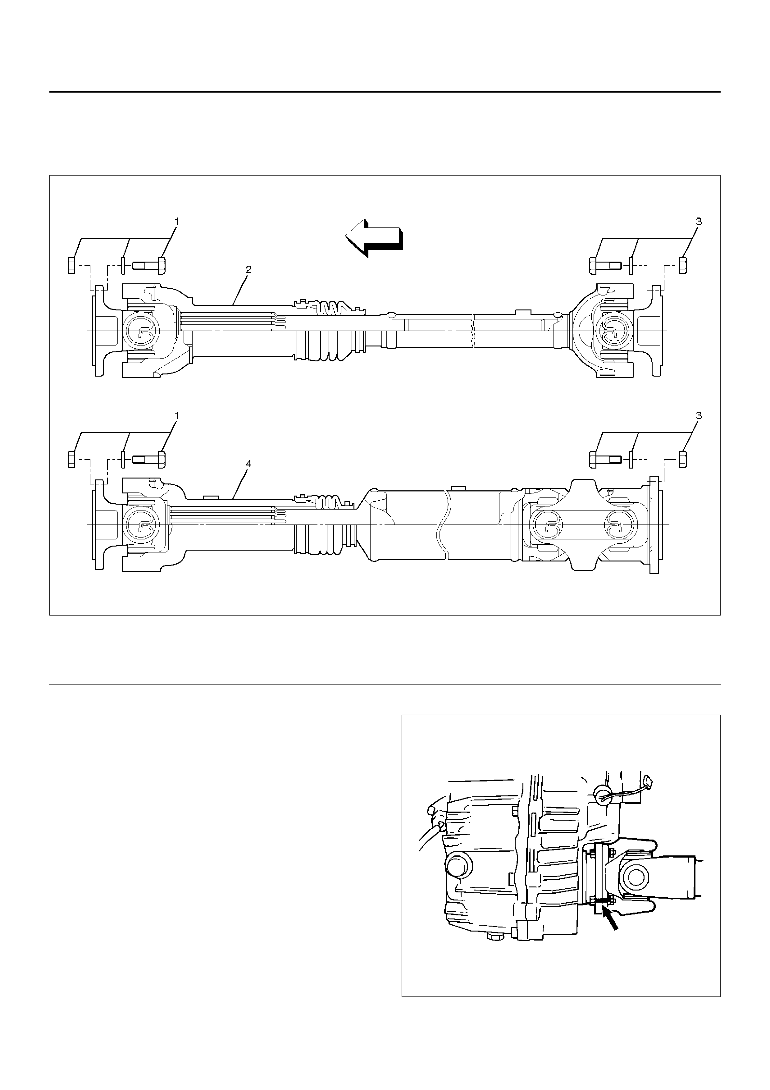
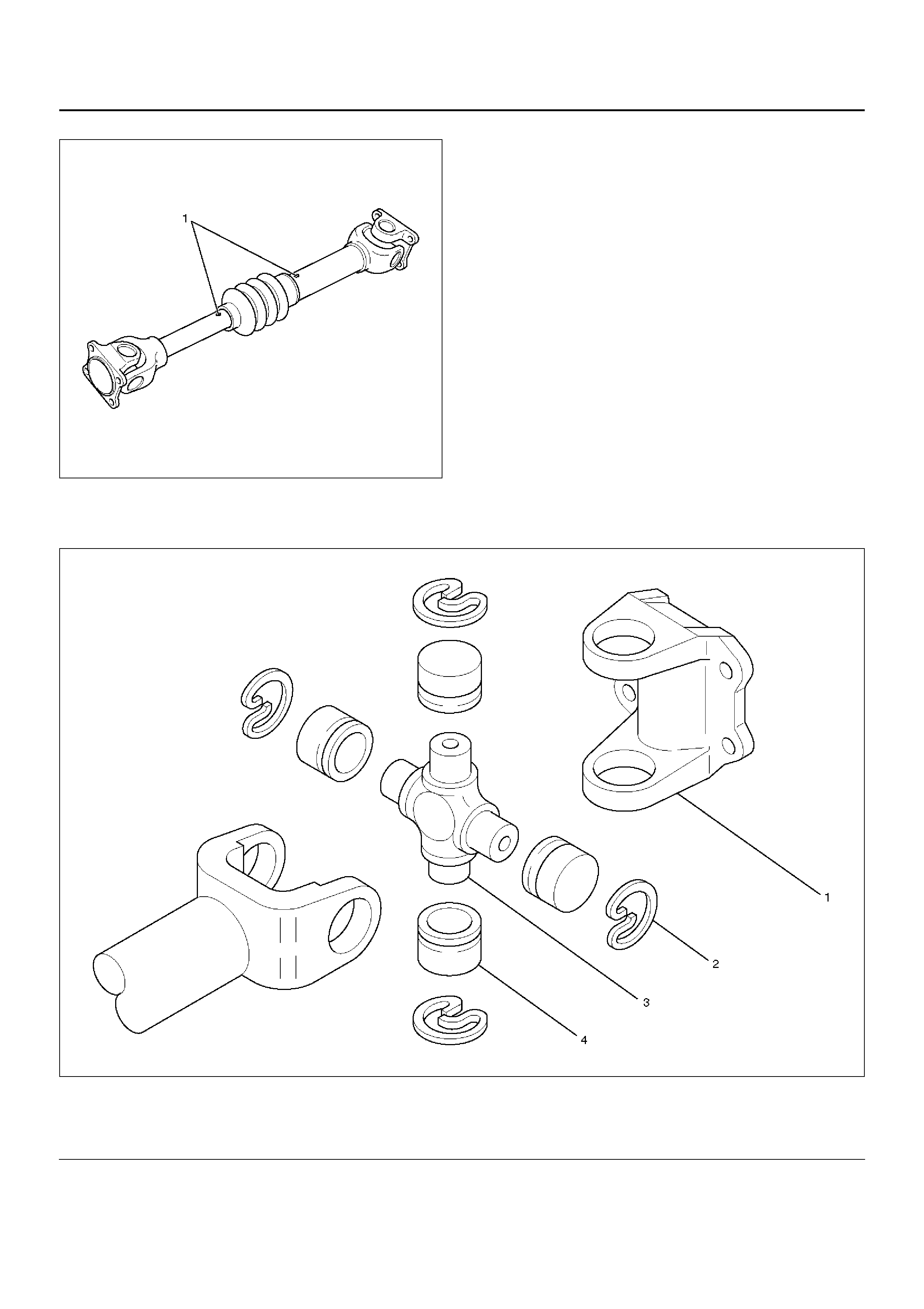
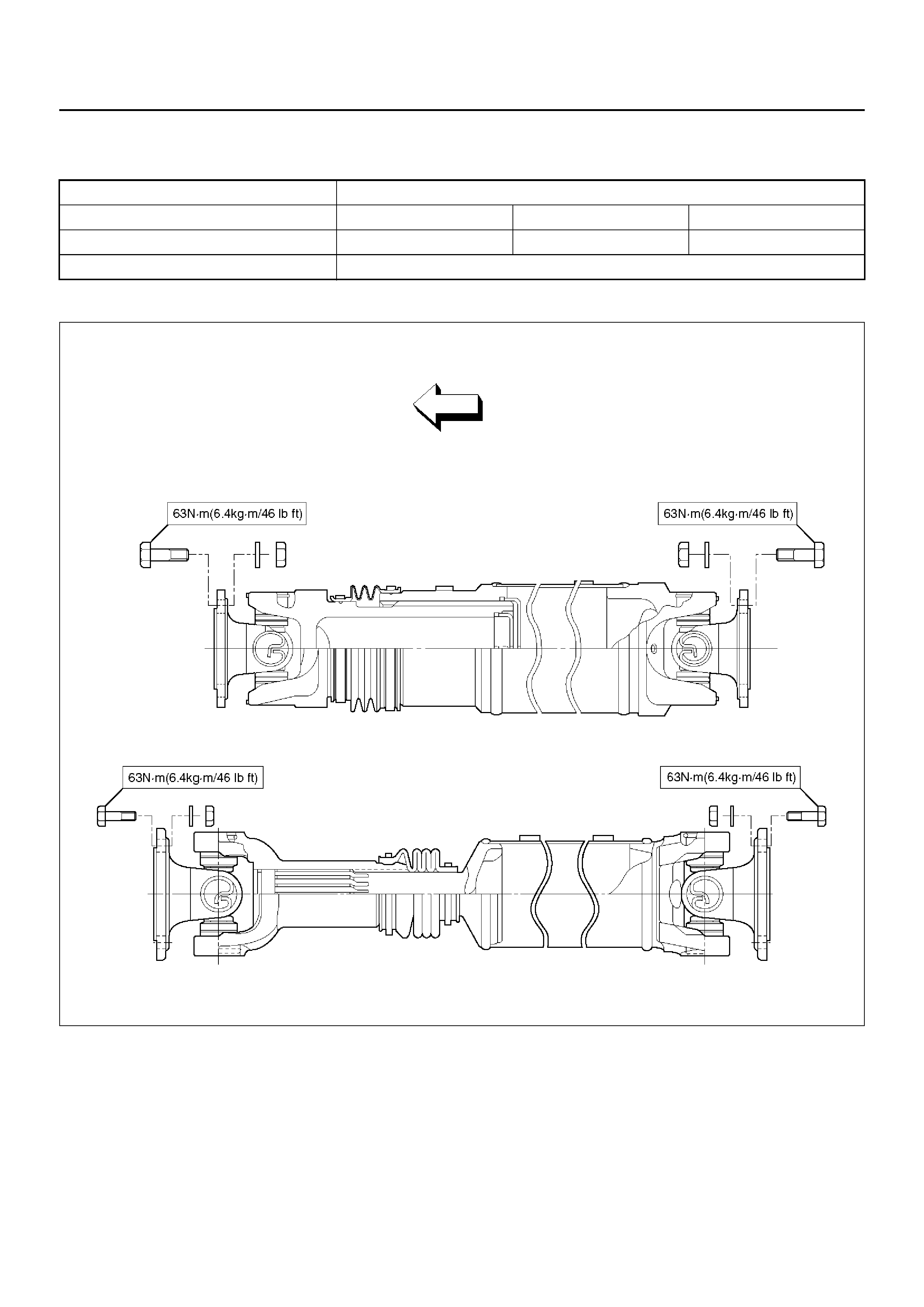
Front Propeller Shaft
Front Propeller Shaft and Associated Parts
401RW063
Legend
EndOFCallout
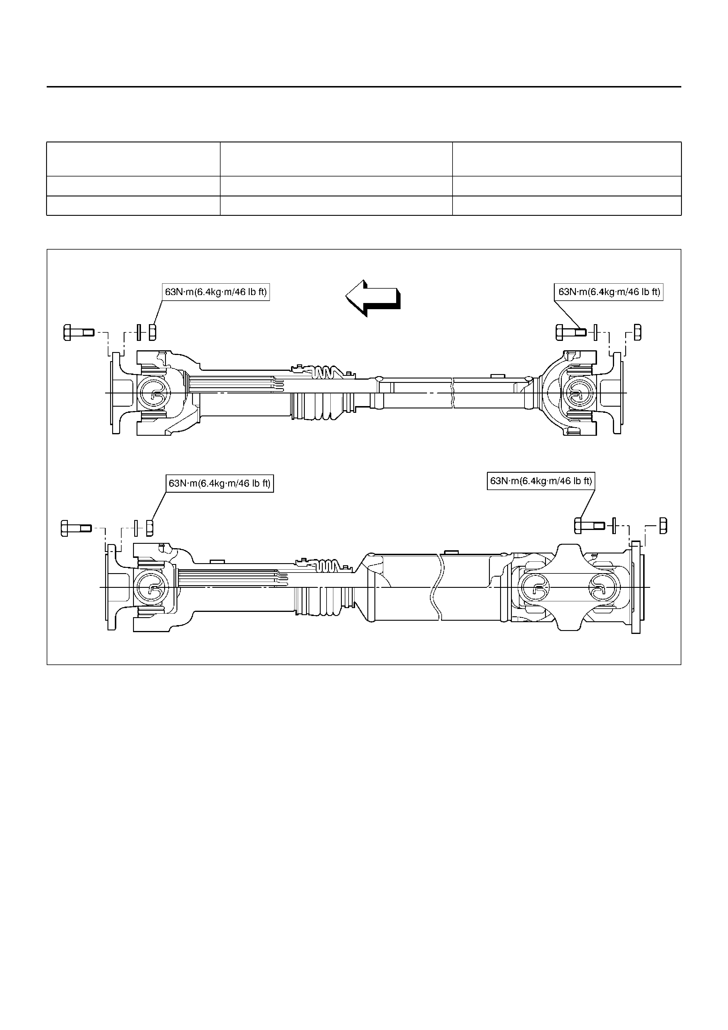
Removal
1. Raise the vehicle on a hoist.
NO TE: Apply alignment marks on the flange at the front
propeller shaft both front and rear side.
401RS020
(1) Bolt, Nut and Washer (Front Axle Side)
(2) Front Propeller Shaft (Single Cardan Type) (3) Bolt, Nut and Washer (Transfer Side)
(4) Front Propeller Shaft (Double Cardan Type)
2. Remove bolt, nut and washer (Front axle side).
3. Remove bolt, nut and washer (Transf er side).
4. Remove front propeller shaft.
Installation
NOTE: Never install the shaft assembly backwards.
Never insert bar between yoke lugs when tightening or
removing bolts. Completely remov e the blac k paint from
the connecting surface of flange coupling on each end
of propeller shaft. Clean so that no foreign matter will be
caught in between.
1. Align the mark which is applied at removal. Install
front propeller shaft and tighten the bolts to the
specified torque.
Torque:63N·m (6.4kg·m/46lbft)
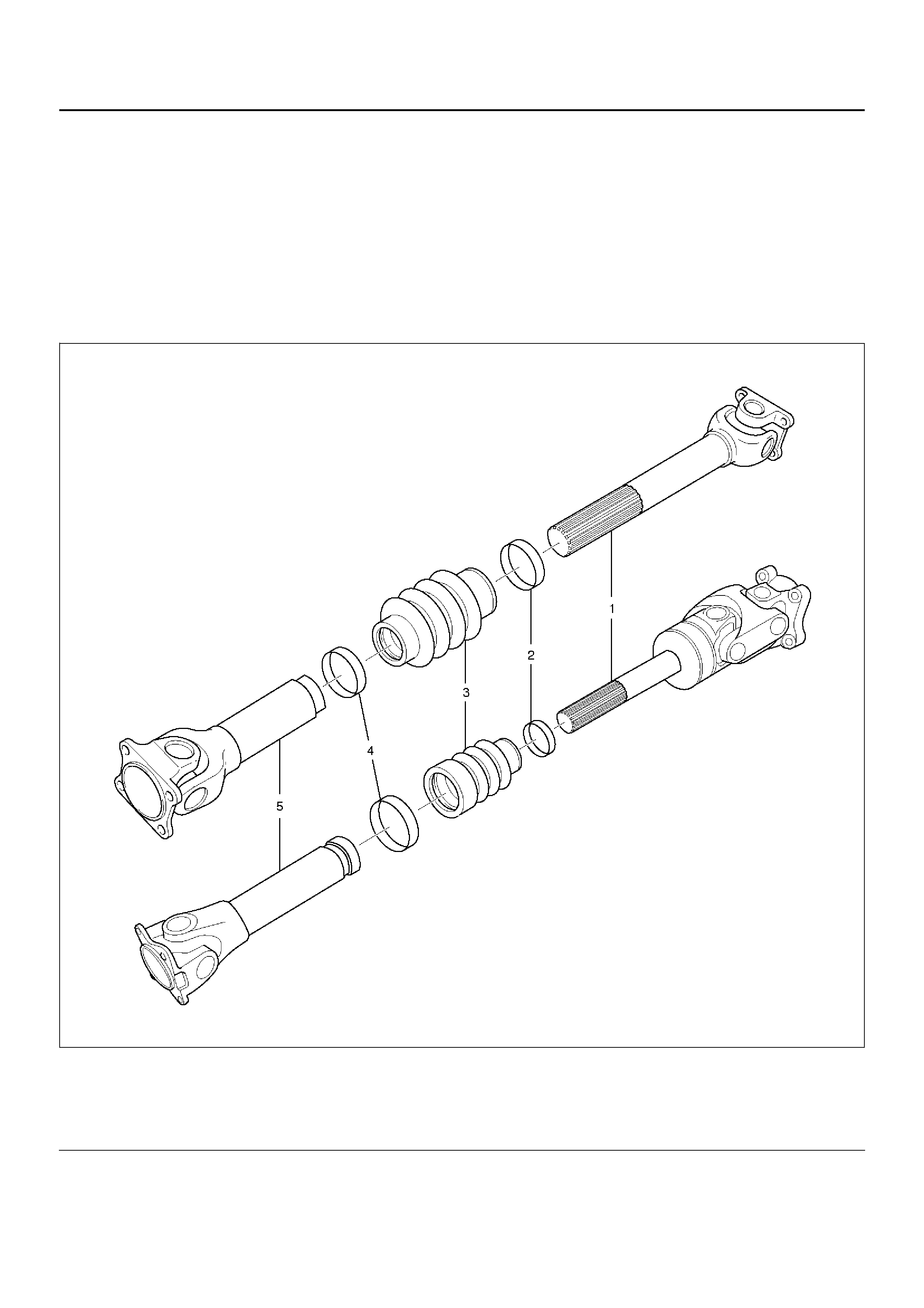
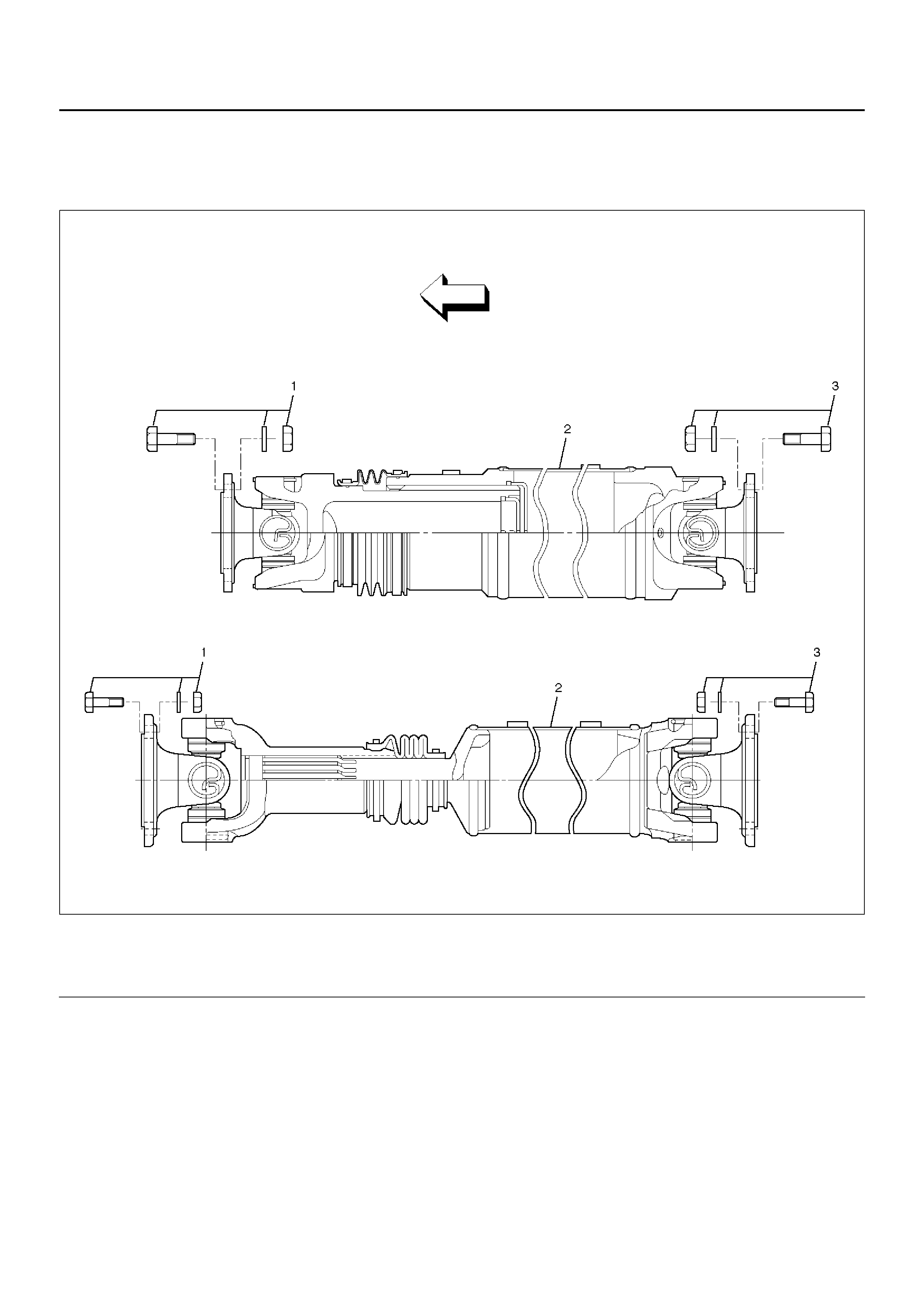
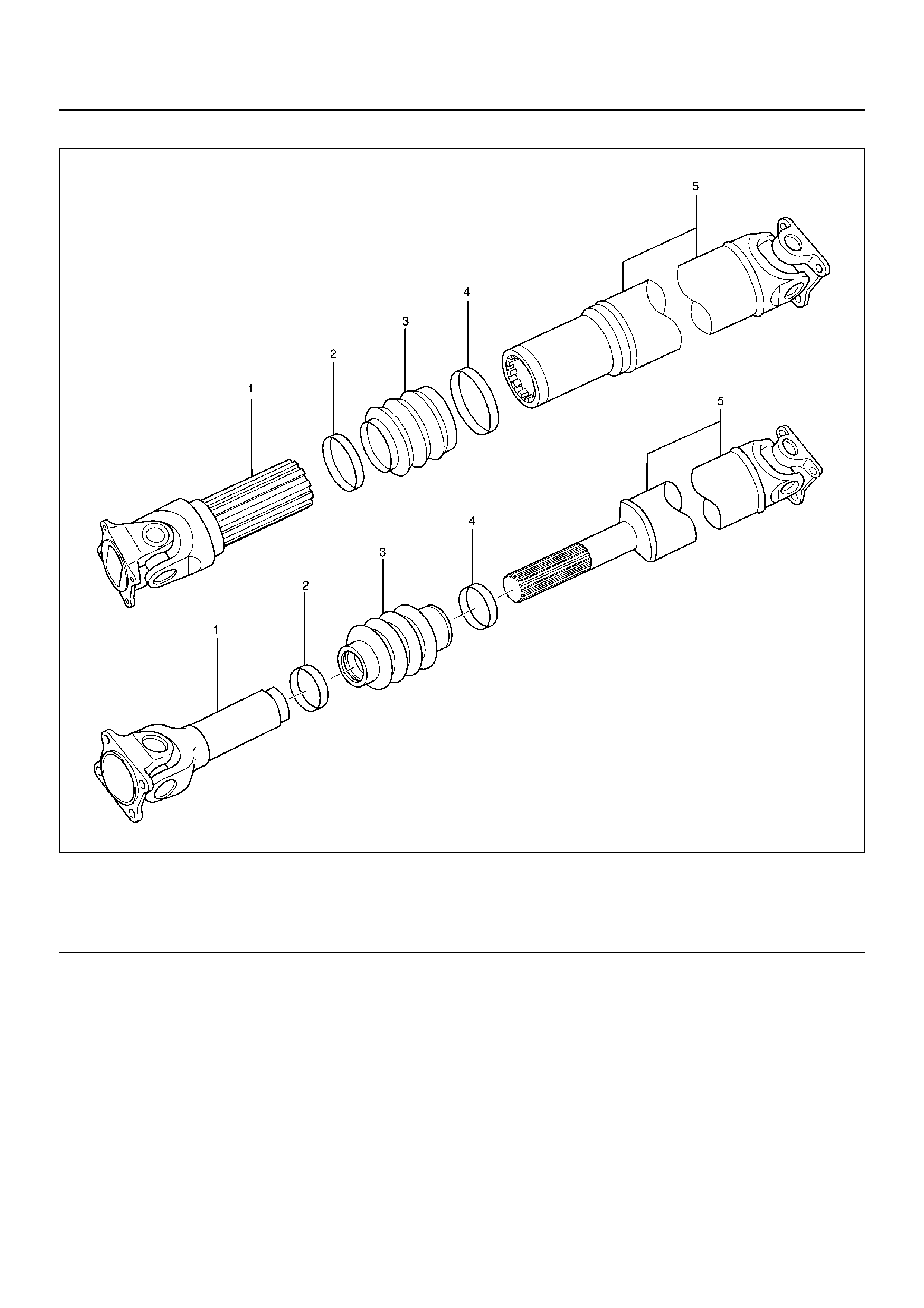
Slip Joint Disassembly
401RW075
Legend
EndOFCallout
1. Lay the shaft horizontally on a bench and secure. 2. Indicate the original assembled position (1) by
marking the phasing of the shaft prior to
disassembly.
(1) Spline Yoke Assembly
(2) Clamp
(3) Boot
(4) Clamp
(5) Tube Assembly
401RW037
3. Using the flat blade of a screwdriver, pry the loose
end of the boot clamp upwards and away from the
propeller shaft boot. Be careful not to damage the
boot.
4. When boot clamps becomes loose, remove by
hand.
5. Repeat for the other boot clamp.
6. Remove the spline yoke assembly from the tube
assembly, by securing the boot with one hand and
pulling on the spline yoke.
7. Remove the boot from the tube asse mbly.
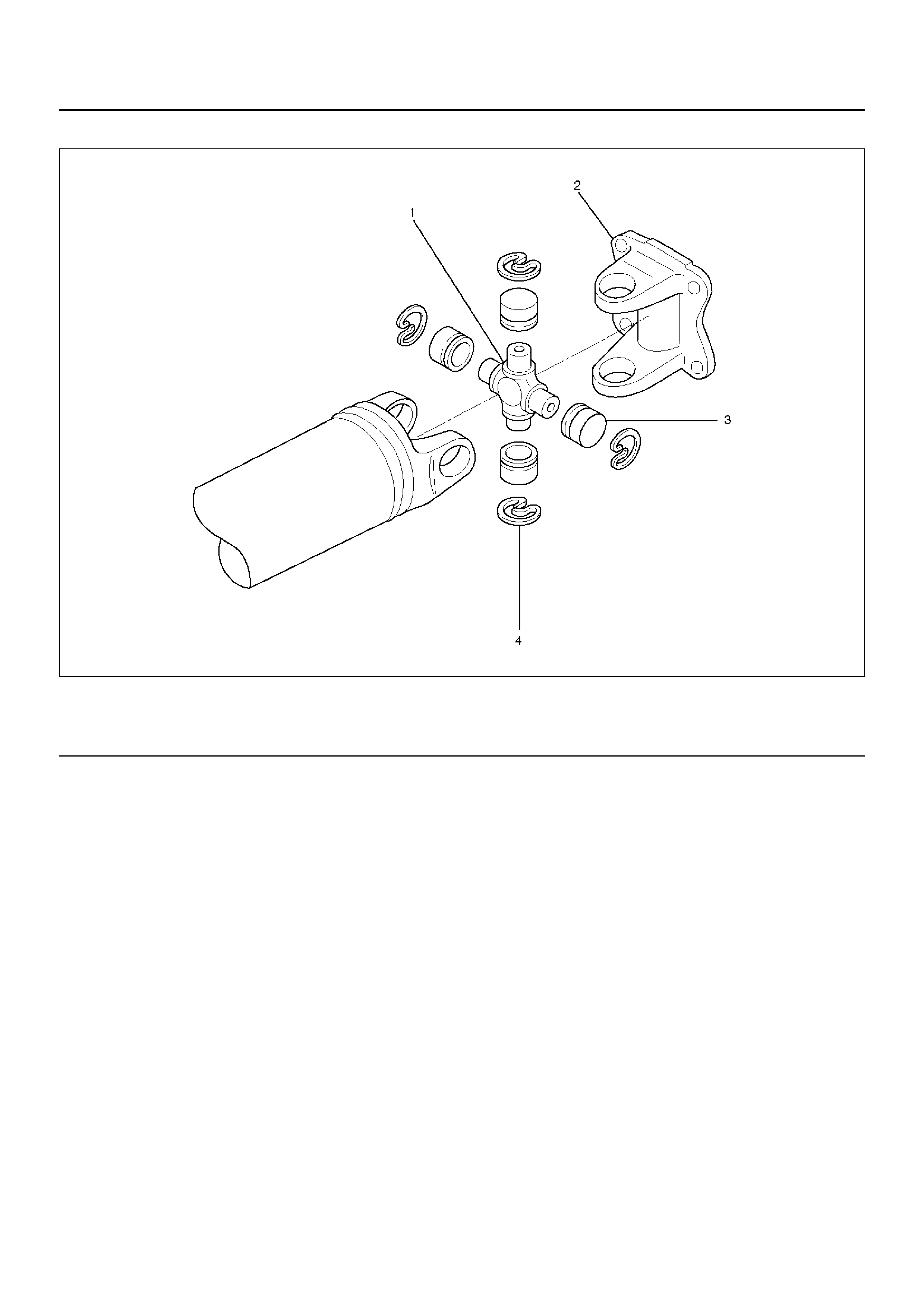
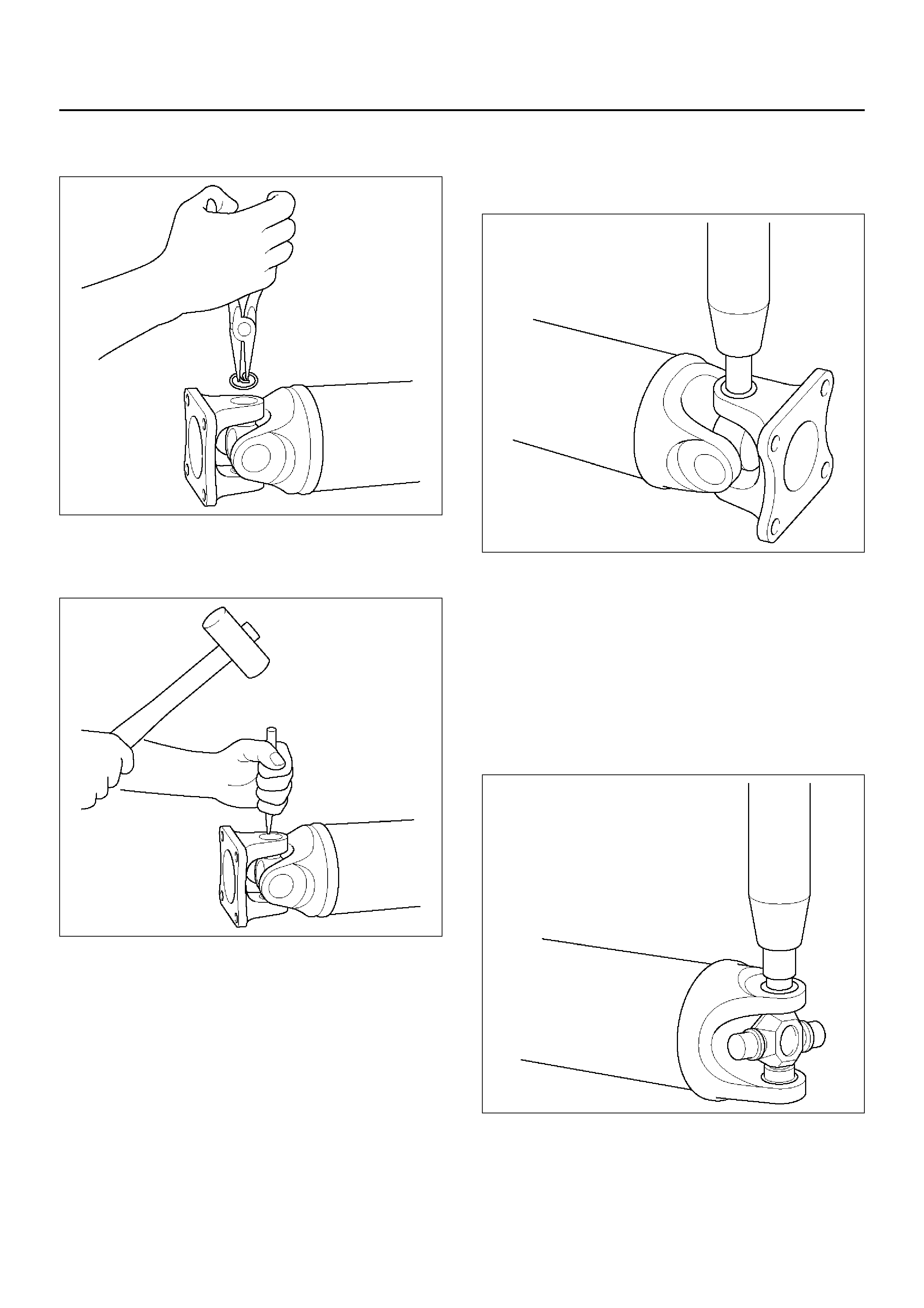
Universal Joint Disassembly (Single Cardan Type)
401RW031
Legend
EndOFCallout
(1) Flange Yoke
(2) Snap Ring (3) Spider
(4) Needle Roller Bearing
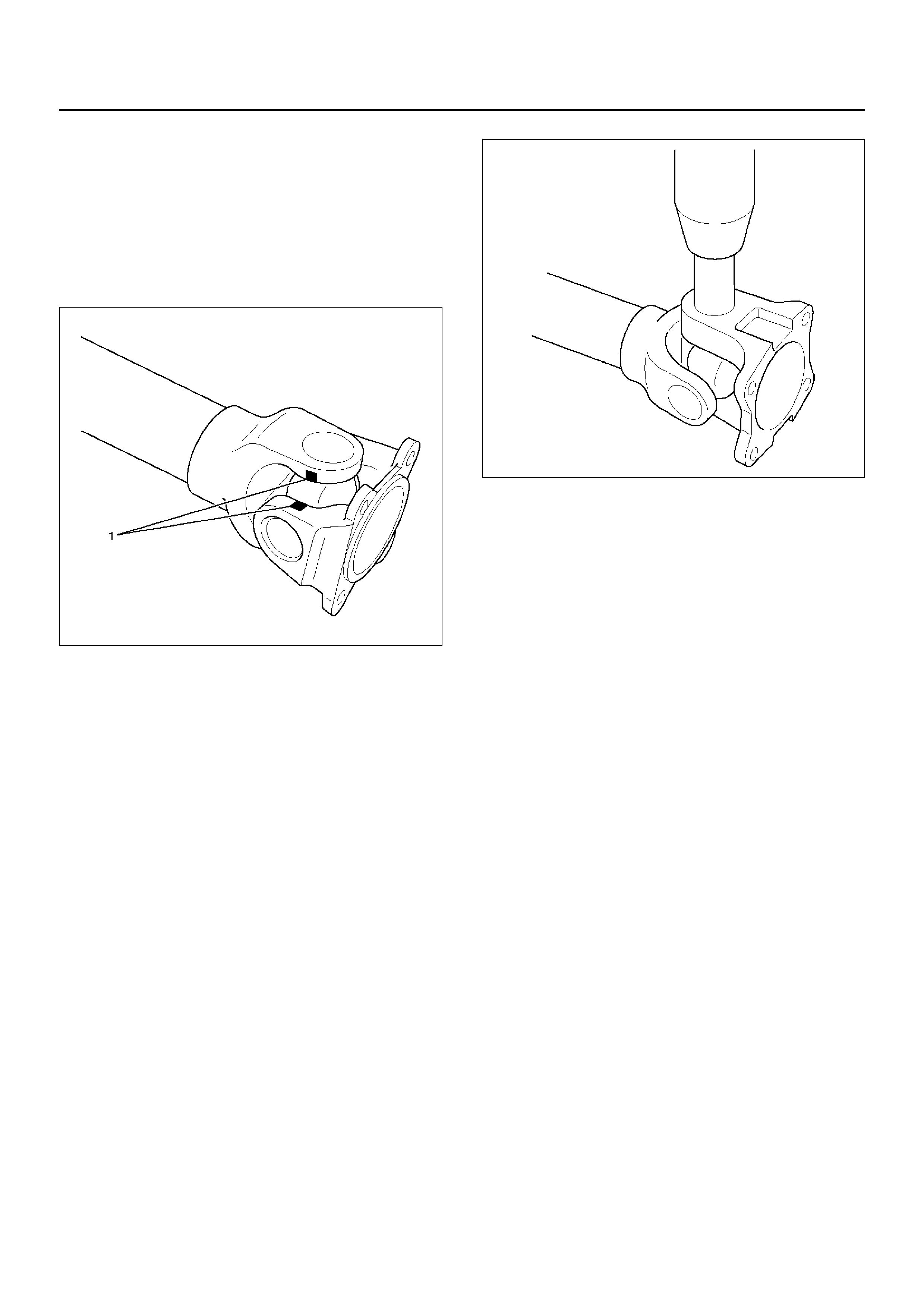
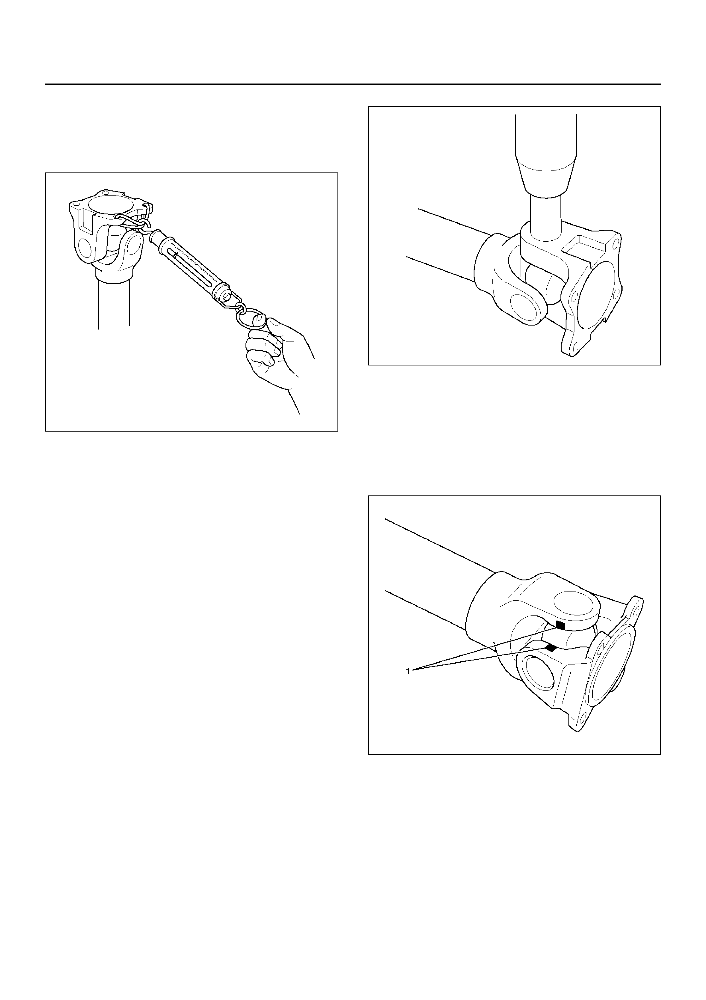
1. Using a soft drift, tap the outside of the bearing cup
assembly to loosen snap ring. Tap bearing only
hard enough to break assembly away from snap
ring.
Remove snap ring from yoke. Turn joint over, tap
bearing away from snap ring, then remove opposite
snap ring.
Apply alignment marks (1) on the yokes of the
universal joint, then remove snap ring.
401RW018
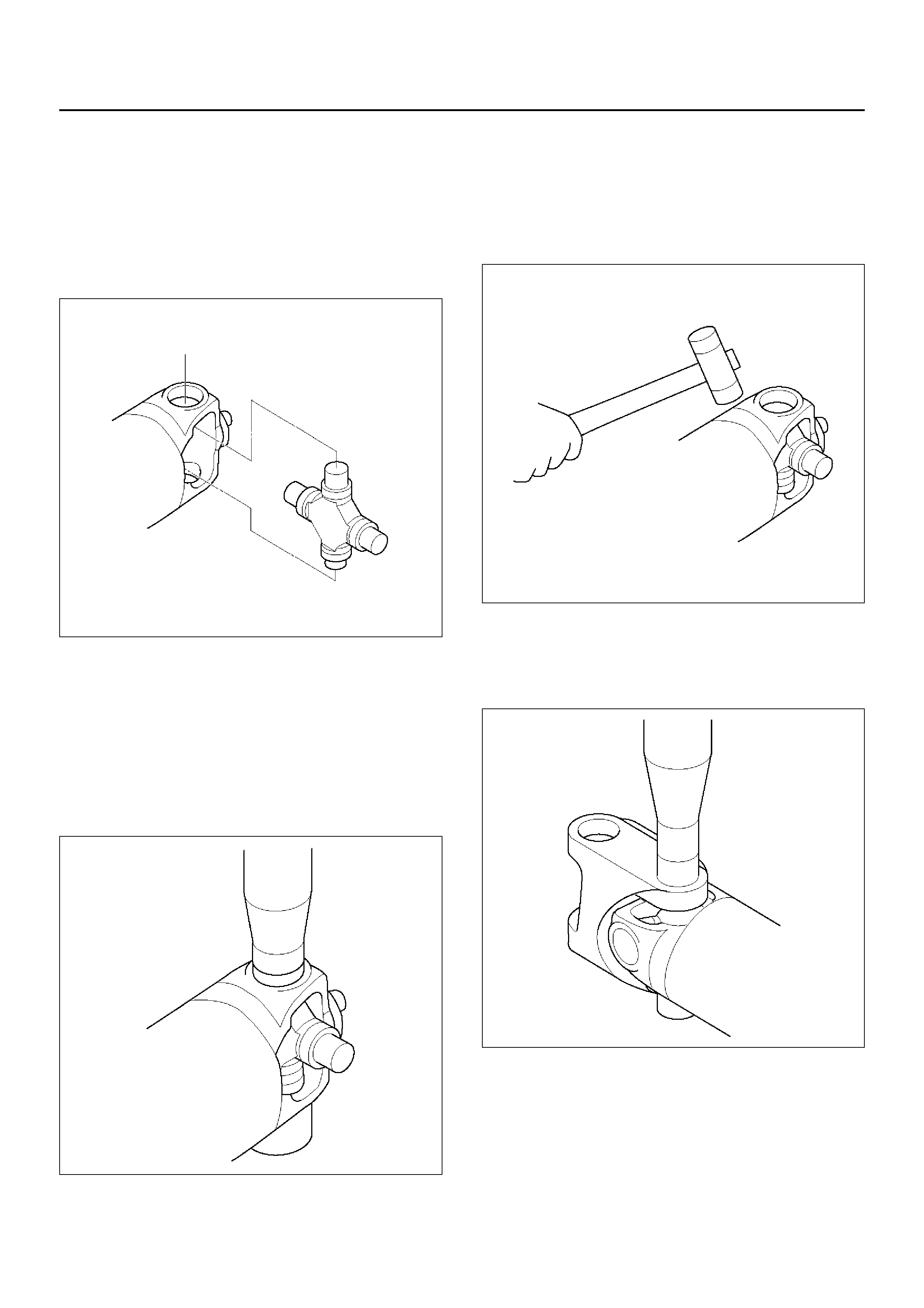
2. Set the yoke in the arbor press with a piece of tube
stock beneath it.
Place a solid plug on the upper bearing assembly
and press it through to release the lower bearing
assembly.
401RW020
3. If the bearing assembly will not pull out by hand
after pressing, tap the base of the lug near the
bearing assembly to dislodge it.
4. To remove the opposite bearing, turn the yoke over
and straighten the spider in the open hole. Then
carefully press on the end of the spider so the
remaining bearing moves straight out of the bearing
spide r ho l e. If the sp id er or be aring are cocked, th e
bearing will score the walls of the spider hole and
ruin t he yoke.
5. Repeat this procedure on the remaining bearing to
remove the spider from the yoke.
6. Make sure of proper position for reinstallation by
applying setting marks, then remove spider .
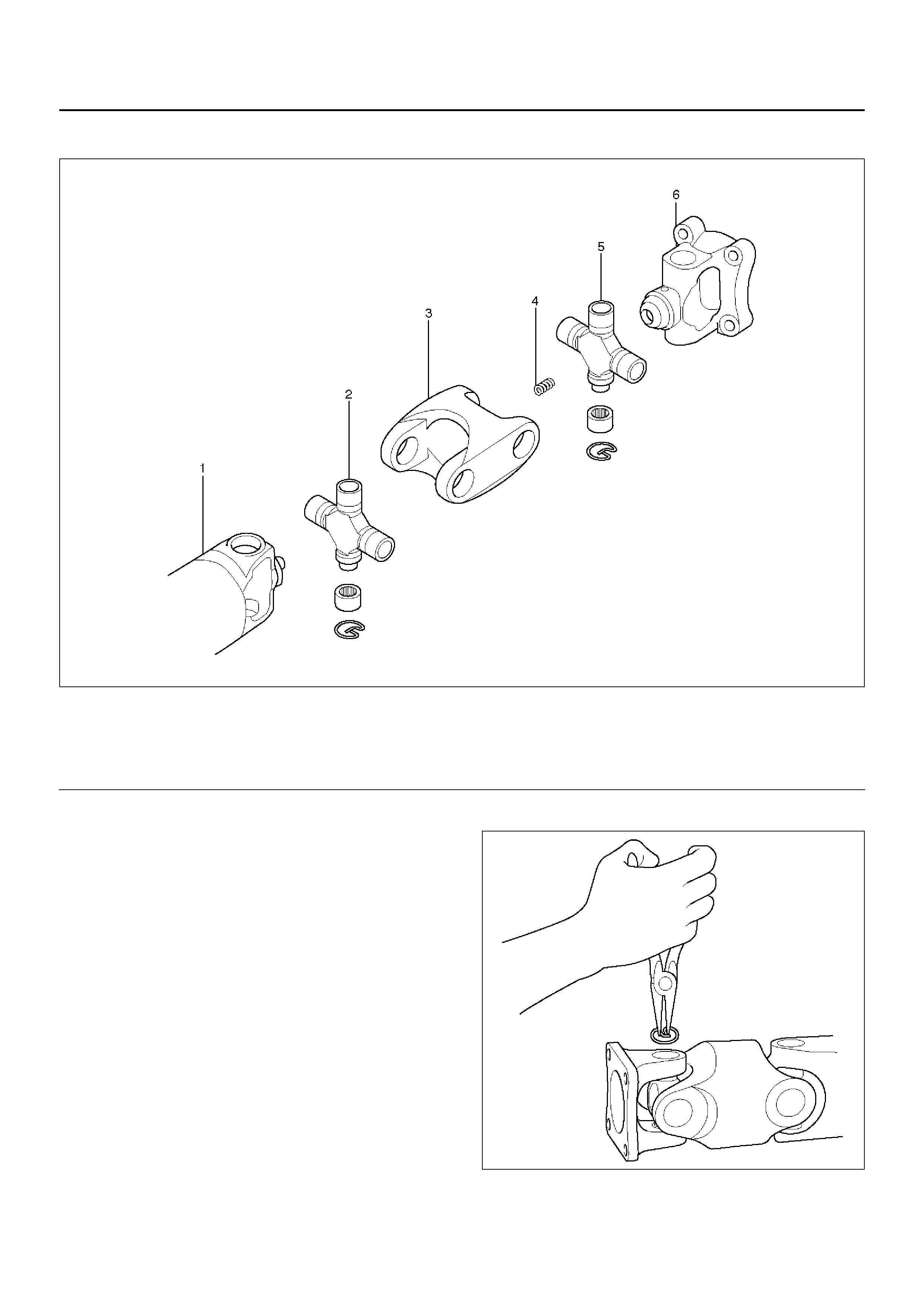
Universal Joint Disassembly (Double Cardan Type)
401RW073
Legend
EndOFCallout
1. Using a soft drift, tap the outside of the bearing cup
assemb ly to loosen snap ring. Tap bearing only hard
enough to break assembly away from snap ring.
2. Remove snap ring from yoke. Turn joint over, tap
bearing away from snap ring, then remove opposite
snap ring.
401RW084
(1) Ball Stud Tube Yoke
(2) Cross and Bearing Kit
(3) Coupling Yoke
(4) Spring
(5) Cross and Bearing Kit
(6) Flange Yoke
3. Remove all snap rings from the yoke in similar
manner.
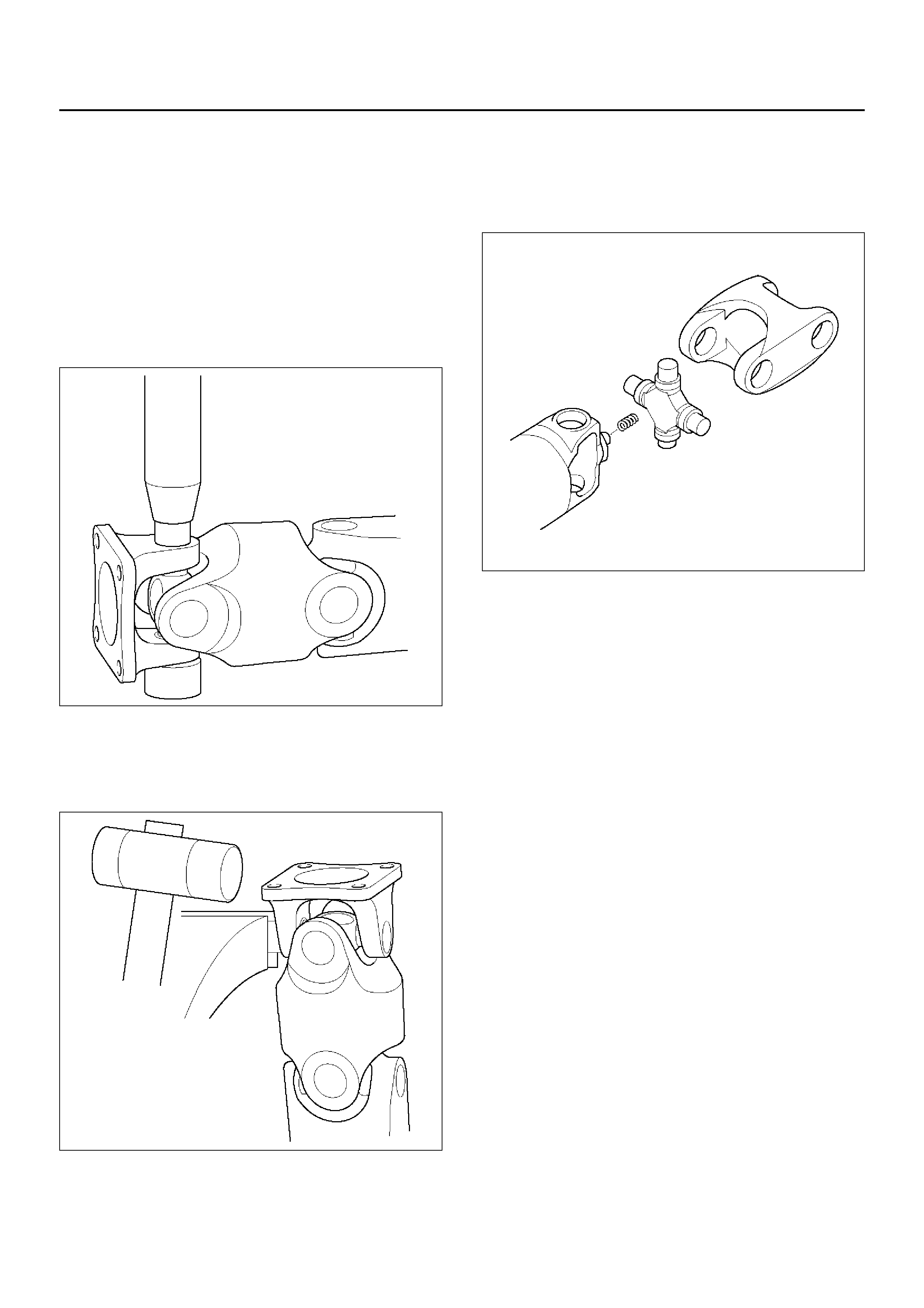
4. Set the outboard side of the center yok e in the arbor
press with a piece of tube stock beneath it. Place a
solid plug on the upper bearing cup assembly and
press it through to release the lower bearing cup
assembly.
Press the center bearing cup assembly partially
from the outboard side of the center yoke - enough
to grasp the bearing cup by vise jaws.
Do not press the bearing cup assembly completely
through.
401RW083
5. Grasp the protruding bearing cup assembly by vise
jaws. Tap the tube yoke with a mallet and drift to
dislodge the bearing cup assembly from the yoke
hole.
401RW082
6. Flip the assembly and repeat steps 4 and 5 for
removing the opposite side bearing cup assembly.
This will allow removal of the cross centering kit
assembly and spring.
Do not disassemble centering kit.
401RW068
7. Press the remaining bearing cup assemblies out on
the other cross as described above to complete
disassembly.
NO TE: Tap in the center of the “H" yoke. Never strike
the yokes at the bearing cup assembly holes because
the snap ring grooves may collapse and make
reassembly impossible.
Inspection and Repair
Make necessary correction or parts replacement if
wear, damage, corrosion or any other abnormal
condition is found through inspection.
NO TE: When any part of the journal assembly (spider,
needle roller bearing) requires replacement, be sure to
replace the entire assembly.
Check the following parts for wear, damage, noise or
any other abnormal conditions.
1. Spider
2. Needle roller bearing
3. Yoke
4. Flange
5. Boot
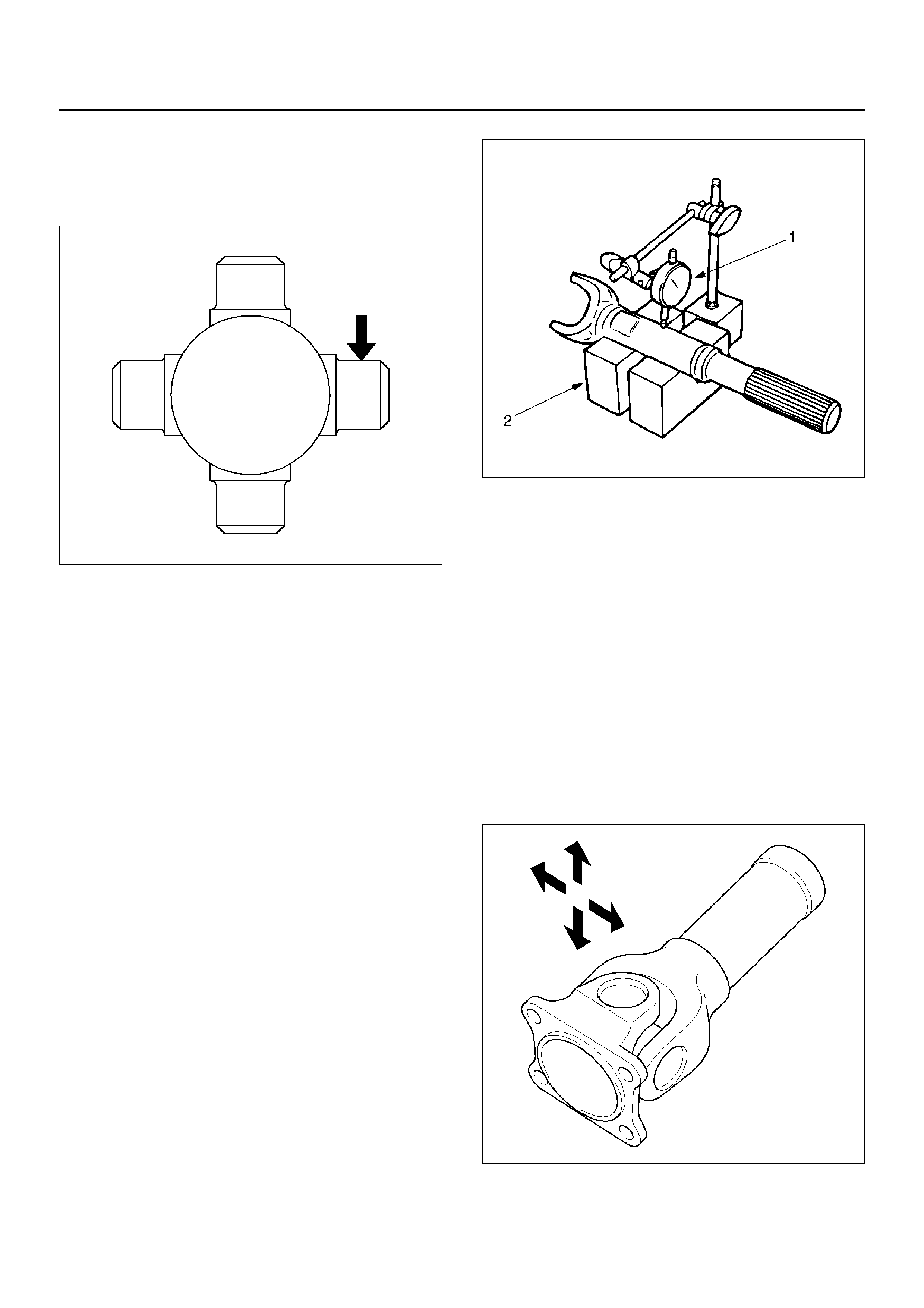
Spider pin for wear
Spider pin should be smooth and free from fretting or
galling. Visible signs of needle presence is normal, but
wear should not be felt.
401RW038
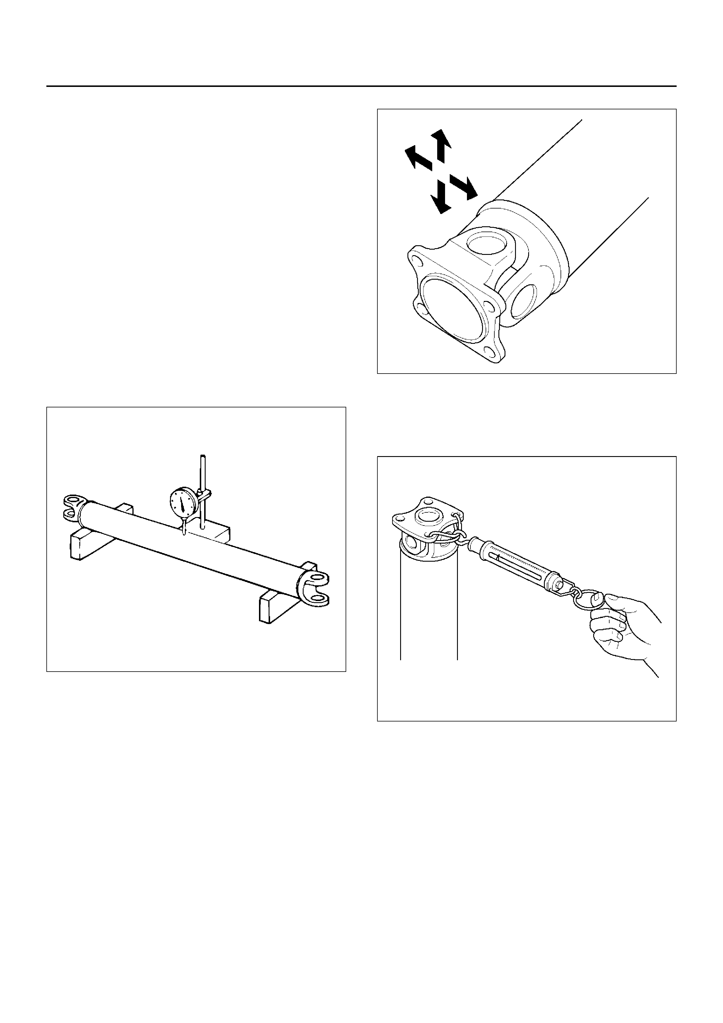
Pr opel ler shaft runout
Support the propeller shaft on V-blocks (2) and check
for runout by holding the probe of a dial indicator (1) in
contact with the shaft.
Static runout limit:
0.13mm (0.005in)
TIR on the neck of the slip tube shaft (with a
boot).
0.25mm (0.010in)
TIR on the ends of the tubing 3 inch from the
welds.
0.38mm (0.015in)
TIR at the linear center of the tube.
0.38mm (0.015in)
TIR for the full length of tube with 30" or less of
tubing.
(TIR : Total Indicator Reading)
401RS027
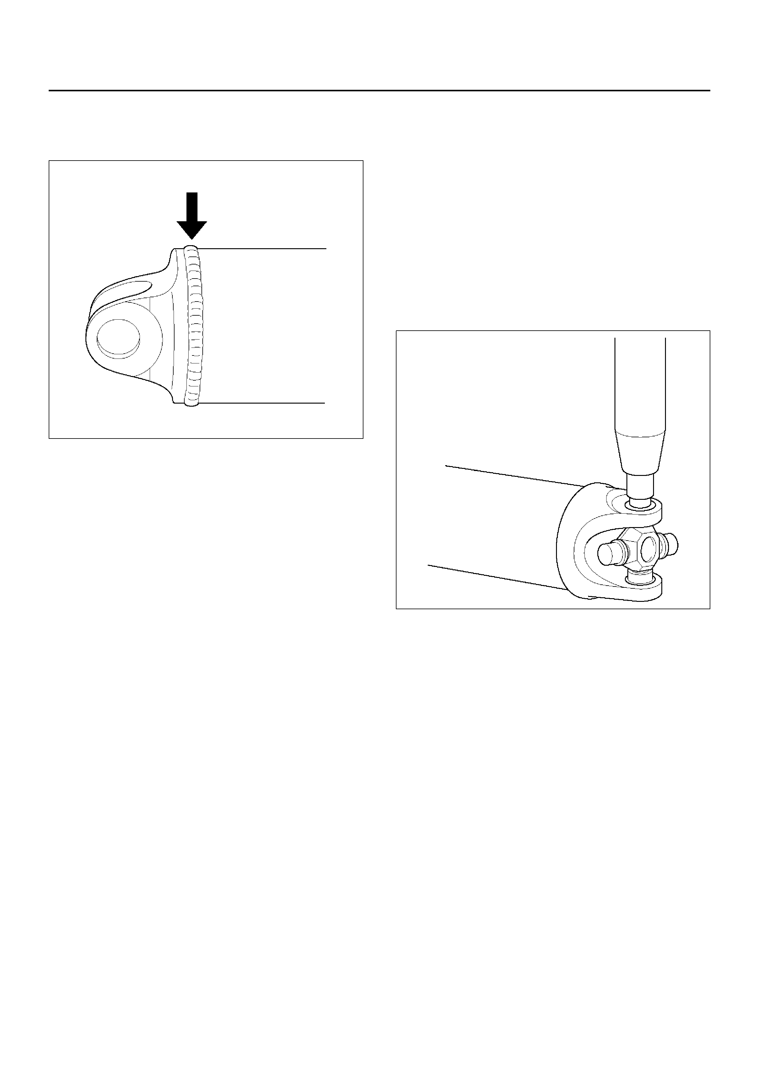
Spline
The nylon-coated spline should be free from nicks and
dings and the underlying steel spline should not be
visible.
After cleaning the nylon coating spline, the coating
should exhibit only a slight indication of wear.
Grease volume is approximately 10 grams of grease in
total. Grease should be evenly applied to both the
female and the male slip splines using a small brush.
After assembly of the slip joint, the sliding joint should
be fully worked from the full collapsed to the full
extended position.
Play in the universal joint
Limit:Less than0.15mm (0.006in)
401RW023
Preload of the universal joint
Preload should be 0 to 24.9 kg(0 to11.3 lb). Joints
should rotate smoothly and freely and should exhibit no
rough or ratchety movement.
401RW085
Boot
Check the boot for crack or damage. If necessary,
replace the boot.
If abnormal condition are found on the boot, inspect the
grease for mixing of foreign material.
If the grease is good condition, and slip joint works well,
replace the boot, replenish grease, and reassemble the
slip joint.
If the foreign material is found in the grease, check the
spline for wear and damage.
Universal Joint Reassembly (Single
Cardan Type)
1. Install spider to flange yok e. Be sure to install the
spider by aligning the setting marks made during
disassembly.
2. Pack the four grease cavities of the spider wi th a
high quality, extreme pressure N.L.G.I. Grade 2
grease. Do not add additional grease to the bearing
cup assembly.
3. Move one end of the spider to cause a trunnion to
project through the spider hole beyond the outer
machined f ace of the yok e lug. Place a bearing ov er
the trunnion diameter and align it to the spider hole.
Using an arbor press, hold the trunnion in alignment
with the spider hole and place a solid plug on the
upper bearing. Press the bearing into the spider
hole enough to install a snap ring.
401RW020
4. Install a snap ring.
Be sure the snap rings are properly seated in the
grooves.
5. Repeat steps 3 and 4 to install the opposite bearing.
If the joint is stiff, strike the yoke ears with a soft
hammer to seat needle bearings.
6. Align setting marks (1) and join the yokes.
401RW018
7. Install snap ring.
Universal Joint Reassembly (Double
Cardan Type)
1. P ack the four grease cavities of the cross with a high
quality, extreme pressure N.L.G.I. Grade 2 grease.
Do not add additional grease to bearing cup
assembly.
2. Fit a cross into the tube yoke.
401RW069
3. Move an end of the cross to cause a trunnion to
project through the cross hole beyond the outer
machined face of the yoke lug. Place a bearing cup
assembly over the trunnion diameter and align it to
the cross hole. Using an arbor press, hold the
trunnion in alignment with the cross hole and place
a solid plug on the upper bearing cup assembly.
Press the bearing cup assembly into the cross hole
enough to install a snap ring.
401RW070
4. Install a snap ring.
5. Repeat steps 3 and 4 to install the opposite bearing
cup assembly. If the joint is stiff, strike the yok e ears
with a soft hammer to seat the needle bearing.
NOTE: Be sure the snap rings are properly seated in
the grooves.
401RW071
6. Fit the center yoke (“H” Yoke) on the remaining two
trunnions and press bearing assemblies in place,
both sides as in steps 3 and 4 above. Install snap
rings.
401RW086

7. Install the journal onto the flange as per steps 3 and
4 above.
8. Install the centering kit assemb ly inside the center
yoke making sure the spring in the tube yok e is in
place.
401RW072
9. Fit the open trunnions of the flange assembly in to
the center yoke holes and the bearing assemblies
into t he centering kit assembly.
10. Install bearings as per steps 3 and 4.
11. Check for proper assembly. Flex the double cardan
joint beyond center. The joint should snap over
cener in both directions when all needle rollers and
components are correctly assembled.
Slip Joint Reassembly
401RW075
Legend
EndOFCallout
1.Apply grease evenly to both the female and male
splines.
2.Apply a small amount of grease by finger to the
outer lips of the boot.
3.Slide the boot (smaller diameter side) onto the
spline yoke shaft being careful not to damage the
spline coating or boot.
4.Insert the spline yoke shaft into the tube assembly
being careful to maintain proper phasing. The
spider holes should be in line and as per originally
marked prior to disassembly.
5.Position boot onto tube and yoke shaft in final
position over boot grooves.
6.Attach boot clamps and secure using pliers.
7.Be sure clamp is properly seated and secure.
CAUTION: Use new clamp which is the same parts
as original. Do not use other clamp to avoid bad
balancing of shaft or the grease leakage.
(1) Spline Yo ke shaf t
(2) Clamp
(3) Boot
(4) Clamp
(5) Tube Assembly
Main Data and Specifications
General Specifications
Torque Specifications
401RX027
Length (between two spiders
center) M/T A/T
6VD1 376 mm (14.80 in) 542 mm (21.34 in)
X2 2SE 294 mm (11.57 in) —
Rear Propeller Shaft
Rear Propeller Shaft and Associated Parts
401RX028
Legend
EndOFCallout
Removal
1. Raise the vehicle on a hoist.
NO TE: Apply alignment marks on the flange at the rear
propeller shaft both front and rear side.
2. Remove transfer side bolt, nut and washer.
3. Remove rear axle side bolt, nut and washer.
4. Remove rear propeller shaft.
Installation
NO TE: Never install the shaft assembly backwards.
Never insert bar between yoke lugs when tightening or
removing bolts.
Completely remove the dust or foreign matter from the
connecting surface of flange coupling on each end of
the propeller shaft.
1. Align the mark which is applied at removal.
2. Install rear propeller shaft and tighten the bolts to
the specified torque.
Torque:63N·m(6.4kg·m/46lbft)
(1) Bolt, Nut and Washer (Transfer Side)
(2) Rear Propeller Shaft (3) Bolt, Nut and Washer (Rear Axle Side)
Slip Joint Disassembly
401RX004
Legend
EndOFCallout
1. Lay the shaft horizontally on a bench and secure.
2. Indicate the original assembled position by marking
the phasing of the shaft prior to disassembly.
3. Using the flat blade of a screwdriver, pry the loose
end of the boot clamp upwards and away from the
propeller shaft boot. Be careful not to damage the
boot.
4. When boot clamps becomes loose, remove by
hand.
5. Repeat for the other boot clamp.
6. Remov e the slip yoke assembly from the driveshaft,
by securing the boot with one hand and pulling on
the slip yoke.
7. Remove the boot from the shaft assembly.
(1) Spline Yoke and Universal Joint Assembly
(2) Clamp
(3) Boot
(4) Clamp
(5) Tube and Universal Joint Assembly
Universal Joint Disassembly
401RX022
Legend
EndOFCallout
NOTE: Aluminum is softer than steel. Care must be
taken not to remove excessive material or damage
bearing holes.
If the vehicle has aluminum tube type propeller shaft,
flange yoke , boot kit, journal kit can be replaced. If other
parts are damaged, replace propeller shaft as assembly.
(1) Spider
(2) Flange Yoke (3) Bearing
(4) Snap Ring
1. Apply alignment marks on the yokes of the universal
joint, then remove the snap ring.
401RW024
If the snap ring is stuck in position, remove paint
from the hole in the yoke or tap around the edge of
the bearing lightly with a soft drift.
401RW025
2. Set the yoke in the arbor press with a piece of tube
stock beneath it.
Place a solid plug on the upper bearing and press it
through to release the lower bearing.
401RW027
3. If the bearing will not pull out by hand after pressing,
tap the base of the lug near the bearing to dislodge
it.
4. To remove the opposite bearing, turn the yoke over
and straighten the spider in the open spider hole.
Then carefully press on the end of the spider so the
remaining bearing moves straight out of the bearing
spide r ho l e. If the sp id er or be aring are cocked, th e
bearing will score the walls of the spider hole and
ru in it.
401RW026
5. Repeat this procedure on the remaining bearing to
remove the spider from the yoke.
Inspection
• Propeller shaft for run-out Aluminum tube type.
Static run-out limit :1.0mm(0.04in)
TIR full length of tubing maximum.
(TIR : Total Indicator Reading)
• Propeller shaft for runout (Steel tube type).
Static runout limit :0.13mm(0.005in)
TIR on the neck of the slip tube shaft (with a
boot).
0.25mm(0.010in)
TIR on the ends of the tubing 3 inch from the
welds.
0.38mm(0.015in)
TIR at the linear center of the tube.
0.38mm(0.015in)
TIR for the full length of tube with 30" or less of
tubing.
(TIR: Total Indicator Reading)
401RW017
• Play in universal joint.
Limit: Less than0.15mm(0.006in)
• Spider pin should be smooth and free from fretting or
galling.
Visible signs of needle presence is normal, but wear
should not be felt.
401RW028
• Preload of the universal joint.
Preload should be 0 to 49 N (0 to 5.0 kg/0 to 11.0 lb).
Joints should rotate smoothly and freely and should
exhibit no rough or ratchety movement.
401RW019
• Inspect splines of slip joint for wear.
The nylon-coated spline should be free from nicks
and dings and the underlying steel spline should not
be visib le .
After cleaning the nylon coating spline, the coating
should exhibit only slight indicator of wear.
Grease volume is approximately 10 grams of grease
in total. Grease should be evenly applied to both the
female and the male slip splines using a small brush.
After assembly of the slip joint, the sliding joint should
be fully worked from the full collapsed to the full
extended position.
• Aluminum tube type only: Inspect the aluminum
tubing for surface scratches and dents. These
scratches ma y not e xceed 0.2 mm (0.008 in) in depth.
401RW022
• Aluminum tube type only: Visually inspect the circle
welds and fittings for any signs of cracks or signs of
deterioration. If there are any cracks that exceed 0.2
mm (0.008 in) in depth, the assembly must be
replaced.
• Aluminum tube type only: Check to be sure there are
no missing balance weights. If balance weights are
missing and void has occurred in the aluminum
tubing greater than 0.2 mm (0.008 in), the assembly
must be replace d.
Universal Joint Reassembly
1. Pack the four grease cavities of the spider with a
high quality, extreme pressure N.L.G.I. Grade 2
grease. Do not add additional grease to bearing
cup asse mbly.
2. Move one end of the spider to cause a trunnion to
project through the spider hole beyond the outer
machined f ace of the yoke lug. Place a bearing ov er
the trunnion diameter and align it to the spider hole.
Using an arbor press, hold the trunnion in alignment
with the spider hole and place a solid plug on the
upper bearing. Press the bearing into the spider
hole enough to install snap ring.
401RW026
3. Install a snap ring.
NOTE: Be sure the snap rings are properly seated in
the grooves.
4. Repeat steps 2 and 3 to install the opposite bearing.
If the joint is stiff, strike the yoke ears with a soft
hammer to seat the bearing.
5. Align the setting marks and join the yok es.

Slip Joint Reassembly
401RX004
Legend
EndOFCallout
1.Apply grease evenly to both the female and male
splines.
2.Apply a small amount of grease by finger to the
outer lips of the boot.
3.Slide the boot (smaller diameter side) onto the
spline yoke shaft being careful not to damage the
spline coating or boot.
4.Insert the spline yoke shaft spline into the tube
assembly being careful to maintain proper phasing.
The spider holes should be in line and as per
originally marked prior to disassembly.
5.Position boot onto tube and yoke shaft in final
position.
6.Attach boot clamps and secure using pliers.
7.Be sure clamp is properly seated and secure.
CAUTION: Use new clamp which is the same parts
as original. Do not use other clamp to avoid bad
balancing of shaft or the grease leakage.
(1) Spline Yoke and Universal Joint Assembly
(2) Clamp
(3) Boot
(4) Clamp
(5) Tube and Universal Joint Assembly
Main Data and Specifications
General Specifications
Torque Specifications
E04RX013
4WD Model
Engine X22SE 6VD1 (M/T) 6VD1 (A/T)
Length (between two spiders center) 989.0mm (38.94in) 1212.5mm (47.73in) 1043.0mm (41.06in)
Universal joint type Cardan type