
SECTION 6A - ENGINE MECHANICAL (X22SE 2.2L)
Service Precaution
General Description
Engine Diagnosis
Cylinder Head Cover
Removal
Installation
Exhaust Manifold
Removal
Installation
Crankshaft Pulley
Removal
Installation
Intake Manifold
Removal
Installation
Cylinder Head Assembly
Removal
Installation
Timing Belt
Removal
Installation
Camshaft
Removal
Installation
Engine Assembly
Engine and Associated Parts
Removal
Installation
Cylinder Head
Cylinder Head and Associated Parts
Disassembly
Inspection and Repair
Reassembly
Valve Spring, Valve, Valve Guide
Valve Spring, Valve, Valve Guide and
Associated Parts
Disassembly
Inspection and Repair
Reassembly
Camshaft
Camshaft and Associated Parts
Disassembly
Reassembly
Crankshaft
Crankshaft and Associated Parts
Disassembly
Inspection and Repair
Inspection and Repair
Reassembly
Piston and Connecting Rod
Piston, Connecting Rod and
Associate Parts
Disassembly
Inspection and Repair
Reassembly
Cylinder Block
Cylinder Block and Associated Parts
Disassembly
Inspection and Repair
Reassembly
Cylinder Head Cover
Cylinder Head Cover and
Associated parts
Removal
Installation
Balance Unit Assembly
Balance Unit Assembly Associated Parts
Disassembly
Adjustment
Reassembly
Main Data and Specifications
Special Tools

Service Precaution
WARNING: THIS VEHICLE HAS A SUPPLEMENTAL
RESTRAINT SYSTEM (SRS). REFER TO THE SRS
COMPONENT AND WIRING LOCATION VIEW IN
ORDER TO DETERMINE WHETHER YOU ARE
PERFORMING SERVICE ON OR NEAR THE SRS
COMPONENTS OR THE SRS WIRING. WHEN YOU
ARE PERFORMING SERVICE ON OR NEAR THE
SRS COMPONENTS OR THE SRS WIRING, REFER
TO THE SRS SERVICE INFORMATION. FAILURE TO
FOLLOW WARNINGS COULD RESULT IN
POSSIBLE AIR BAG DEPLOYMENT, PERSONAL
INJURY, OR OTHERWISE UNNEEDED SRS SYSTEM
REPAIRS.
CAUTION: Always use the correct fastener in the
proper location. When you replace a fastener, use
ONLY the exact part number for that application.
ISUZU will call out those fasteners that require a
replacement after removal. ISUZU will a lso call out
the fasteners that require thread lockers or thread
sealant. UNLESS OTHERWISE SPECIFIED, do not
use supplemental coatings (Paints, greases, or
other corrosion inhibitors) on threaded fasteners or
fastener joint interfaces. Generally, such coatings
adversely affect the fastener torque and the joint
c lamping for ce, and may damage the fastener . When
you install fasteners, use the correct tightening
sequence and specifications. Following these
instructions can help you avoid damage to parts
and systems.
General Description
Engine Cleanliness And Care
An automobile engine is a combination of many
machined, honed, polished and lapped surfaces with
tolerances that are measured in the thousandths of a
millimeter (ten thousandths of an inch). Accordingly,
when any internal engine parts are serviced, care and
cleanliness are important. Throughout this section, it
should be understood that proper cleaning and
protection of machined surfaces and friction areas is
part of the repair procedure. This is considered
standard shop practice even if not specifically stated.
• A liberal coating of engine oil should be applied to all
friction areas during assembly to protect and
lubricate the surfaces on initial operation.
• Whenever valve train components, pistons, piston
rings, connecting rods, rod bearings, and crankshaft
journal bearings are removed f or service, the y should
be retained in order.
• At the time of installation, they should be installed in
the same locations and with the same mating
surfaces as when removed.
• Battery cables should be disconnected before any
major work is perf ormed on the engine. Failure to
disconnect cables may result in damage to wire
harness or other electrical parts.
• The four cylinders of this engine are identified by
numbers; cylinders 1, 2, 3 and 4, as counted from
crankshaft pulley.
General Information on Engine Service
The following information on engine service should be
noted carefully, as it is important in preventing damage
and contributing to reliable engine performance:
• When raising or supporting the engine for any
reason, do not use a jack under the oil pan. Due to
the small clearance between the oil pan and the oil
pump strainer, jacking against the oil pan may cause
damage to the oil pick up unit.
• The 12–v olt electrical system is capable of damaging
circuits. When performing any work where electrical
terminals could possibly be grounded, the ground
cable of the battery should be disconnected at the
battery.
• Any time the intake air duct or air cleaner is removed,
the inta ke opening should be covered. This will
protect against accidental entrance of foreign
material into the cylinder which could cause
extensive damage when the engine is started.
Cylinder Block
The cylinder block is made of cast iron. The crankshaft
is supported by five bearings. The bearing cap is made
of nodular cast iron.
Cylinder Head
The cylinder head is made of aluminum alloy casting
with a spark plug in the center.
Valve Train
Valv e system is direct–acting inv ertered bucket tappet.
The valves clearance adjustment are hydraulic.
Hydraulic v alve lash adjustment, no adjustment
necessary.
Intake Manifold
The intake manifold is made of aluminum alloy.
Exhaust Manifold
The exhaust manifold is made of high Si–Mo nodular
iron.
Pistons and Connecting Rods
Aluminum pistons are used after selecting the grade
that meets the cylinder bore diameter. Each piston has
two compression rings and one oil ring. The piston pin is
made of case–harded steel. The connecting rods are
made of cast iron. The connecting rod bearings are
made of steel backed with babbitt metal.

Crankshaft and Bearings
The crankshaft is made of nodular cast iron. Pins and
journals are graded for correct size selection for their
bearing.
Balance Shaft
Type is lanchester (twin counter–rotating shafts). The
balance shafts are made of cast iron and gears are hard
faced. The housing is made of cast iron. Backlash
adjustment method is shim–balancer housing to block
(selective fit).
Engine Diagnosis
Hard Starting
1. Starting Motor Does Not Turn Over
Trouble Shooting Procedure
Turn on headlights and starter switch.
2. Ignition Trouble — Starting Motor Turns Over But
Engine Does Not Start
Spark Test
Disconnect a high tension cable from any spark plug.
Connect the spark plug tester J–26792 (ST–125), crank
the engine, and check if a spark is generated in the
spark plug tester. Before cranking the engine, make
sure that the spark plug tester is properly grounded. To
avoid electrical shock, do not touch the high tension
cable while the engine is running.
3. Troub l e In Fuel System
Condition Possible cause Correction
Headlights go out or dim
considerably Battery run down or under charged Recharge or replace battery
Terminals poorly connected Clean battery posts and terminals
and connect properly
Starting motor coil circuit shorted Overhaul or replace
Starting motor defective Overhaul or replace
Condition Possible cause Correction
Spark jumps across gap Spark plug defective Clean, adjust spark gap or replace
Ignition timing incorrect Refer to Ignition System
Fuel not reaching fuel injector(s) or
engine Refer to item 3 (Trouble in fuel
system)
Valve timing incorrect Adjust
Engine lacks compression Refer to item 4 (Engine lacks
compression)
No sparking takes place Ignition coil disconnected or broken Connect properly or replace
Electronic Ignition System with
module Replace
Poor connections in engine harness Correct
Powertrain Control Module cable
disconnected or defective Correct or replace
Condition Possible cause Correction
Starting motor turns over and spark
occurs b ut engine does not start. Fuel tank empty Fill
Water in fuel system Clean
Fuel filter clogged Replace filter
Fuel pipe clogged Clean or replace
Fuel pump defectiv e Replace
Fuel pump circuit open Correct or replace
Evaporative Emission Control
System circuit clogged Correct or replace
Multiport Fuel Injection System
faulty Refer to “Electronic Fuel Injection"
section

4. Engine Lacks Compression
Engine Compression Test Procedure
1. Start and run the engine until the engine reaches
normal operat ing temperat ure.
2. Turn the engine off.
3. Remove all the spark plugs.
4. Remove ignition coil fuse (15A) and disable the
ignition system.
5. Remove the fuel pump rela y from the rela y and fuse
box.
6. Engage the starter and check that the cranking
speed is approximately 300 rpm.
7. Install cylinder compression gauge into spark plug
hole.
8. With the throttle valve opened fully, keep the starter
engaged until the compression gage needle
reaches the maximum level. Note the reading.
9. Repeat the test with each cylinder.
The pressure difference between the individual
cylinders should not exceed 100kPa (14.5psi).
Condition Possible cause Correction
Engine lacks compression Spark plug loosely fitted or spark
plug gasket defective Tighten to specified torque or
replace gas ket
Valve timing incorrect Adjust
Cylinder head gasket defective Replace gasket
Valve incorrectly seated Lap valve
Valve stem seized Replace valve and valve guide
Valve spring weakened Replace
Cylinder or piston rings worn Overhaul engine
Piston ring seized Overhaul engine.

Rough Engine Idling or Engine Stalling
Condition Possible cause Correction
Trouble in fuel injection sys tem Idle air control valve defective Replace
Throttle shutting off incomplete Correct or replace
Throttle position sensor circuit open
or shorted Correct or replace
Fuel injector circuits open or shorted Correct or replace
Fuel injectors damaged Replace
Fuel pump relay defective Replace
Manifold Absolute Pressure Sensor
cable disconnected or broken Correct or replace
Manifold Absolute Pressure Sensor
defective Replace
Engine Coolant Temperature Sensor
cable disconnected or broken Correct or replace
Engine Coolant Temperature Sensor
defective Replace
Intake Air Temperature sensor cable
disconnected or broken Correct or replace
Intake Air Temperature sensor
defective Replace
Knock Sensor (KS) circuits open or
shorted Correct or replace
KS defective Replac e
KS Module circuits open or ground Correct or replace
KS Module defective Replace
Vehicle Speed Sensor circuit open
or shorted Correct or replace
Vehicle Speed Sensor defective Replace
Trouble in emission control system Powertrain Control Module defective Replace
Exhaust Gas Recirculation Valve
faulty Replace
Canister purge solenoid circuit open Correct
Canister purge solenoid defective Replace
Evaporative Emission Canister
Purge contr ol valve defe ct ive Replace
Trouble in ignition system Refer to Hard Start Troubleshooting
Guide
Others Engine lacks compression Refer to Hard Start Troubleshooting
Guide
Valve incorrectly seated Lap valve
Air Cleaner Filter clogged Replace filter element
Valve timing incorrect Readjust
Idle air control valve broken Replace

Rough Engine Running
Condition Possible cause Correction
Engine misfires regularly Ignition coil layer shorted Replace
Spark plugs fouling Clean or install hotter type plug
Spark plug(s) insulator nose leaki ng Replace
Fuel injector(s) defective Replace
Engine control module faulty Replace
Engine knocks regularly Spark plugs running too hot Install colder type spark plugs
Powertrain control module faulty Replace
Engine lacks power Spark plugs fouled Clean
Fuel injectors defective Replace
Manifold Absolute Pressure (MAP)
Sensor or Manifold Absolute
Pressure Sensor circuit defective
Correct or replace
Engine Coolant Temperature Sensor
or Engine Coolant Temperature
Sensor circuit defective
Correct or replace
Engine Control Module faulty Replace
Intake Air Temperature Sensor or
Intake Air Temperature Sensor
circuit defective
Correct or replace
Throttle Position Sensor or Throttle
Position Sensor circuit defective Correct or replace
Knock Sensor or Knock Sensor
circui ts defective Correct or replace
Knock Sensor Module or Knock
Sensor Module circuits defective Correct or replace

Hesitation
Condition Possible cause Correction
Hesitation on acceleration Throttle Position Sensor adjustment
incorrect Replace throttle valve assembly
Throttle P osition Sensor circuit open
or shorted Correct or replace
Excessiv e play in accelerator
linkage Adjust or replace
Manifold Absolute Pressure (MAP)
Sensor circuit open or shorted Correct or replace
MAP Sensor defective Replace
Intake Air Temperature (IAT) Sensor
circuit open or shorted Correct or replace
Knock Sensor (KS) Circuit open or
shorted Correct or replace
KS defective Replac e
KS Module circuits open or shorted Correct or replace
KS Module defective Replace
IAT Sensor defective Replace
Hesitation at high speeds
(Fuel pressure too low) Fuel tank strainer clogged Clean or replace
Fuel pipe clogged Clean or replace
Fuel filter clogged Replace
Defective fuel pump system Check and replace
Fuel Pressure Control Valve leaking Replace
Hesitation at high speeds
(Fuel injector not working normally) Power supply or ground circuit for
Multiport Fuel Injection System
shorted or open
Check and correct or replace
Cable of Multiport Fuel Injection
System disconnected or defective Correct or replace
Hesitation at high speeds Engine Control Module defective Replace
Throttle P osition Sensor circuit open
or shorted Correct or replace
Throt tle Position Sens or defect ive Replace
Engine Coolant Temperature Sensor
circuit open or shorted Correct or replace
Engine Coolant Temperature Sensor
defective Replace
MAP Sensor cable open or shorted Correct or replace
MAP Sensor defective Replace
IAT Sensor circuit open or shorted Correct or replace
IAT Sensor defective Replace
KS Circuit open or shorted Correct or replace
KS defective Replac e
KS Module circuit open or shorted Correct or replace
KS Module defective Replace
Throttle valve not wide opened Check and correct or replace
Air Cleaner Filter clogged Replace filter element
Power supply voltage too low Check and correct or replace

Engine Lac ks Power
Condition Possible cause Correction
Trouble in fuel system Fuel Pressure Control Valve not
working normally Replace
Fuel injector clogged Clean or replace
Fuel pipe clogged Clean
Fuel filter clogged or fouled Replace
Fuel pump drive circuit not working
normally Correct or replace
Fuel tank not sufficiently breathing
due to clogged Evaporative
Emission Control System circuit
Clean or replace
Water in fuel system Clean
Inferior quality fuel in fuel system Use fuel of specified octane rating
Engine Control Module supplied
poor voltage Correct circuit
Throttl e Position Sensor cable
disconnected or broken Correct or replace
Throt tle Position Sens or defect ive Replace
Manifold Absolute Pressure Sensor
not working normally Replace
Intake Air Temperature Sensor not
working normally Replace
Engine Coolant Temperature Sensor
circuit open or shorted Correct or replace
Engine Coolant Temperature Sensor
defective Replace
Engine Contro l Modu le defective Replac e
Trouble in intake or exhaust system Air Cleaner Filter clogged Replace filter element
Air duct kinked or flattened Correct or replace
Ignition failure ———— Refer to Hard Start Troubleshooting
Guide
Heat range of spark plug inadequate Install spark plugs of adequate heat
range
Electronic Ignition System with
module Replace
Engine Noisy
Abnormal engine noise often consists of various noises
originating in rotating parts, sliding parts and other
moving parts of the engine. It is, therefore, advisable to
locate the source of noise systematically.
Engine overheating Level of Engine Coolant too low Replenish
Thermo switch or fan motor
defective Replace
Thermostat defective Replace
Engine Coolant pump defective Correct or replace
Radiator clogged Clean or replace
Radiator filler cap defective Replace
Level of oil in engine crankcase too
low or wrong oil in engine Change or replenish
Resistance in exhaust system
increased Clean exhaust system or replace
defective parts
Throt tle Position Sens or adjustment
incorrect Adjust Wide Open Throttle switch
setting
Throttle P osition Sensor circuit open
or shorted Correct or replace
Cylinder head gasket damaged Replace
Engine overcooling Thermostat defective Replace (Use a thermostat set to
open at 92°C (197.6°F))
Engine lacks compression ———— Refer to Hard Start
Others Tire inflation pressure abnormal Adjust to recommend pressures
Brake drag Adjust
Clutch slipping Adjust or replace
Level of oil in engine crankcase too
high Correct level of engine oil
Exhaust Gas Recirculation Valve
defective Replace
Condition Possible cause Correction
Condition Possible cause Correction
Noise from crank journals or from
crank bearings
(Faulty crank journals and crank
bearings usually make dull noise
that becomes more e vident when
accelerating)
Oil clearance increased due to worn
crank journals or crank bearings Replace crank bearings and
crankshaft or regrind crankshaft and
install the over size bearing
Crankshaft out of round Replace crank bearings and
crankshaft or regrind crankshaft and
install the over size bearing
Crank bearing seized Crank bearing seized Replace crank
bearings and crankshaft or regrind
crankshaft and install the over size
bearing
Troubleshooting Procedure
Short out each spark plug in sequence using insulated
spark plug wire removers . Locate cylinder with defective
bearing by listening for abnormal noise that stops when
spark plug is shorted out.
Troubleshooting Procedure
Abnormal noise stops when the spark plug on the
cylinder with defective part is shorted out.
Troubleshooting Procedure
Short out each spark plug and listen for change in
engine noise.
Condition Possible cause Correction
Noise from connecting rods or from
connecting rod bearings
(Faulty connecting rods or
connecting rod bearings usually
make an abnormal noise slightly
higher than the crank bearing noise,
which becomes more evident when
engine is accelerated)
Bearing or crankshaft pin worn Replace connecting rod bearings
and crankshaft or regrind crankshaft
and install the under size bearing
Crankpin out of round Replace connecting rod bearings
and crankshaft or regrind crankshaft
and install the under size bearing
Connecting rod bent Correct or replace
Connecting rod bearing seized Replace connecting rod bearings
and crankshaft or regrind crankshaft
and install the under size bearing
Condition Possible cause Correction
Piston and cylinder
(Faulty piston or cylinder usually
makes a combined mechanical
thumping noise which increases
when engine is suddenly
accelerated but diminishes gradually
as the engine warms up)
Piston clearance increased due to
cylinder wear Replace piston and cylinder body
Piston seized Replace piston and cylinder body
Piston ring broken Replace piston and cylinder body
Piston defective Replace pistons and others
Condition Possible cause Correction
Piston pin noise
(Piston makes noise each time it
goes up and down)
Piston pin or piston pin hole worn Replace piston, piston pin and
connecting rod assy

Troubleshooting Procedure
The slapping sound stops when spark plug on bad
cylinder is shorted out.
Condition Possible cause Correction
Timing belt noise Timing belt tension is incorrect Replace pusher or adjust the
tension pulley or replace timing belt
Tensio ner bear i ng defective Repl ace
Timing belt defective Replace
Timing wheels defective Replace
Timing belt comes in contact with
timing cover Replace timing belt and timing cover
Valve noise Valve and valv e guide seized Replace valve and valve guide
Valve spring broken Replace
Valve seat off–posi ti oned Correct
Crankshaft noise Cranksh aft end play excessive
(noise occurs wh en clutc h is
engaged)
Replace thrust bearing
Engine knocking Preignition due to use of spark plugs
of inadequate heat range Install Spark Plugs of adequate heat
range
Fuel too low in octane rating Replace fuel
Wide Open Throttle enrichment
system failure Refer to Section 6E
Selection of transmission gear
incorrect Caution operator of incorrect gear
selection
Engine overheating Refer to “Engine Lacks Power"
Others Water pump defective Replace
Drive belt slipping Adjust tension of drive belt or
replac e dr i ve belt

Abnormal Combustion
Condition Possible cause Correction
Trouble in fuel injection system Fuel pressure control valve defective Replace
Fuel filter clogged Replace
Fuel pump clogged Clean or replace
Fuel tank or fuel pipe clogged Clean or replace
Fuel injector clogged Clean or replace
Fuel pump relay defective Replace
Power supply cable for fuel pump
loosely connected or defective Reconnect, correct or replace
Manifold Absolute Pressure Sensor
circuit open or shorted Correct or replace
Manifold Absolute Pressure Sensor
defective Replace
Engine Coolant Temperature (ECT)
Sensor circuit open or shorted Correct or replace
ECT Sensor defe ctive Replace
Throt tle Position Sens or adjustment
incorrect Reconnect
Throt tle Position Sens or defect ive Replace
Throttle Position Sensor connector
loosely connected Reconnect
Vehicle Speed Sensor cable loosely
connected or defective Correct or replace
Vehicle Speed Sensor loosely fixed Fix tightly
Vehicle Speed Sensor in wrong
contact or defective Replace
Engine Control Module cable loosely
connected or defective Correct or replace
Trouble in emission control system Heated Oxygen Sensor circuit open Correct or replace
Heated Oxygen Sensor defective Replace
Signa l vacuum h ose l oos el y fitt ed or
defective Correct or replace
Exhaust Gas Recirculation Valve
defective Replace
ECT Sensor circuit open or shorted Correct or replace
ECT Sensor defe ctive Replace
Evaporator system Refer to Section 6E
Trouble in ignition system ———— Refer to “Engine Lacks Power"
Trouble in cylinder head parts Carbon deposits in combustion
chamber Remove carbon
Carbon deposit on valve, valve seat
and valve guide Remove carbon

Engine Oil Consumption Excessive
Condition Possible cause Correction
Oil leaking Oil pan drain plug loose Retighten or replace gasket
Oil pan setting bolts loosened Retighten
Oil pan gasket broken Replace gasket
Front cover retaining bolts loose or
gasket broken Retighten or replace gasket
Head cover retaining bolts loose or
gasket broken Retighten or replace gasket
Oil filter adapter cracked Replace
Oil filter attachings bolt loose or
rubber gasket broken Retighten or replace oil filter
Crankshaft front or rear oil seal
defective Replace oil seal
Oil pressure un it loose o r broken Retighten or replace
Blow–by gas hose broken Replace hose
Engine/Transmission coupling area Replace oil seal
Oil leaking into combustion
chambers due to poor seal in valve
system
Valve stem oil seal defective Replac e
Valve stem or valve guide worn Replace valve and valve guide
Oil leaking into combustion
chambers due to poor seal in
cylinder parts
Cylind ers and pis to ns wor n
excessively Rebore cylinder and replace pistons
and others
Piston ring gaps incorrectly
positioned Correct
Piston rings set with wrong side up Correct
Piston ring sticking Rebore cylinder and replace pistons
and others
Piston ring and ring groove worn Replace pistons and others
Return ports in oil rings clogged Clean piston and replace rings
Crank case ventilation, Positive
Crankcase Ve nti lat ion Sys tem
malfunctioning
Positiv e Crankcase Ventilation Hose
clogged Clean
Others Improper oil viscosity Use oil of recommended S.A.E.
viscosity
Continuous high speed driving and/
or severe usage such as trailer
towing
Continuous high speed operation
and/or severe usage will normally
caus e increased oil consumption

Fuel Consumption Excessive
Oil Problems
Engine Oil Pressure Check
1. Check for dirt, gasoline or water in the engine oil.
a Check the viscosity of the oil.
b Change the oil if the viscosity is outside the
specified standard.
cRefer to the “Maintenance and Lubrication"
section of this manual.
2. Check the engine oil level.
The lev el should fall somewhere between the “ADD"
and the “FULL" marks on the oil level dipstick.
If the oil level does not reach the “ADD" mark on the
oil level dipstick, engine oil must be added.
3. Remove the oil pressure unit.
4. Install an oil pressure gauge.
5. Start the engine and allow the engine to reach
normal operating temperature (About 80°C).
6. Measure the oil pressure.
Oil pressure should be:
150 kPa (21.8 psi) at idle speed.
7. Stop the engine.
8. Remove the oil pressure gauge.
9. Install the oil pressure unit.
10. Start the engine and check for leaks.
Condition Possible cause Correction
Trouble in fuel system Mixture too rich or too lean due to
trouble in fuel injection system Refer to “Abnormal Combustion"
Fuel cut function does not act Refer to “Abnormal Combustion"
Trouble in ignition system Misfiring or abnormal combustion
due to trouble in ignition system Refer to Hard Start or Abnormal
Combustion Troubleshooting Guide
Others Engine idle speed too high Reset Idle Air Control Valve
Returning of accelerator contr ol
sluggish Correct
Fuel system leakage Correct or replace
Clutch slipping Correct
Brake drag Correct
Selection of transmission gear
incorrect Caution operator of incorrect gear
selection
Excessiv e Exhaust Gas
Recirculation flow due to trouble in
Exhaust Gas Recirculation system
Refe r to Abnormal Combustion
Condition Possible cause Correction
Oil pressure too low Wrong oil in use Replace with correct engine oil
Relief valve sticking Replace
Oil pump not operating properly Correct or replace
Oil pump strainer clogged Clean or replace strainer
Oil pump worn Replace
Oil pressure gauge defective Correct or replace
Crankshaft bearing or connecting
rod bearing w orn Replace
Oil contamination Wrong oil in use Replace with new engine oil
Oil filter clogged Replace oil filter
Cylinder head gasket damage Replace gasket
Burned gases leaking Replace piston and piston rings or
rebore cylinders
Oil not reaching valve system Oil passage in cylinder head or
cylinder body clogged Clean or correct
Malfunction Indicator Lamp
The instrument panel “CHECK ENGINE" Malfunction
Indicator Lamp (MIL) illuminates by self diagnostic
system when the system checks the starting of engine,
or senses malfunctions.
Condition Possible cause Correction
“CHECK ENGINE" MIL does not
illuminate at the starting of engine Bulb defective Replace
MIL circuit open Correct or replace
Command signal circuit to operate
self diagnostic system shorted Correct or replace
Powertrain Control Module (PCM)
cable loosely connected,
disconnected or defective
Correct or replace
PCM defective Replac e
“CHECK ENGINE" MIL illuminates,
and stays on Deterioration heated oxygen sensor
of internal element Replace
Heated oxygen sensor connector
terminal improper contact Reconnect prope r ly
Heated oxygen sensor lead wire
shorted Correct
Heated oxygen sensor circuit open Correct or replace
Deterioration engine coolant
temperature sensor of internal
element
Replace
Engine coolant temperature sensor
connector terminal improper contact Reconnect prope rly
Engine coolant temperature sensor
lead wire shorted Correct
Engine coolant temperature sensor
circuit open Correct or replace
Throttle position sensor open or
shorted circuits Correct or replace
Deterioration of crankshaft position
sensor Replace
Crankshaft position sens or circuit
open or shorted Correct or replace
Vehicle speed sensor circuit open Correct or replace
Manifold absolute pressure sensor
circuit open or shorted Correct or replace
Intake air temperature sensor circuit
open or shorted Correct or replace
Fuel injector circuit open or shorted Correct or replace
PCM driver transistor defective Replace PCM
Malfunctioning of PCM RAM
(Random Access Memory) or ROM
(Read Only Memory)
Replace PCM
Cylinder Head Cover
Removal
1. Disco nne ct batte ry ground ca ble.
2. Disconnect PCV hose from cylinder head cover.
3. Remove intake duct.
4. Remove left side ground cable from cylinder head
cov er and disconnect ground cab le connector on the
left side wheel arch. Remo ve right side ground
cable from generator stay and disconnect ground
cable connector on the right side wheel arch.
5. Disconnect three(black, green and blue colors)
engine wire harness connectors from chassis
harness of left rear side of compartment.
6. Disconnect cooling fan wire harness connector from
cooling fan on left side top of fan shroud.
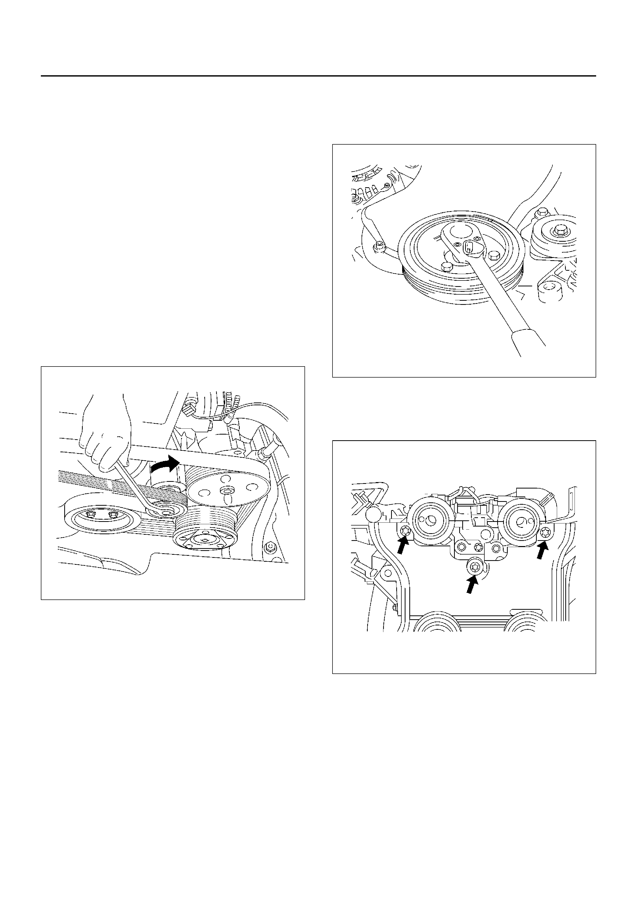
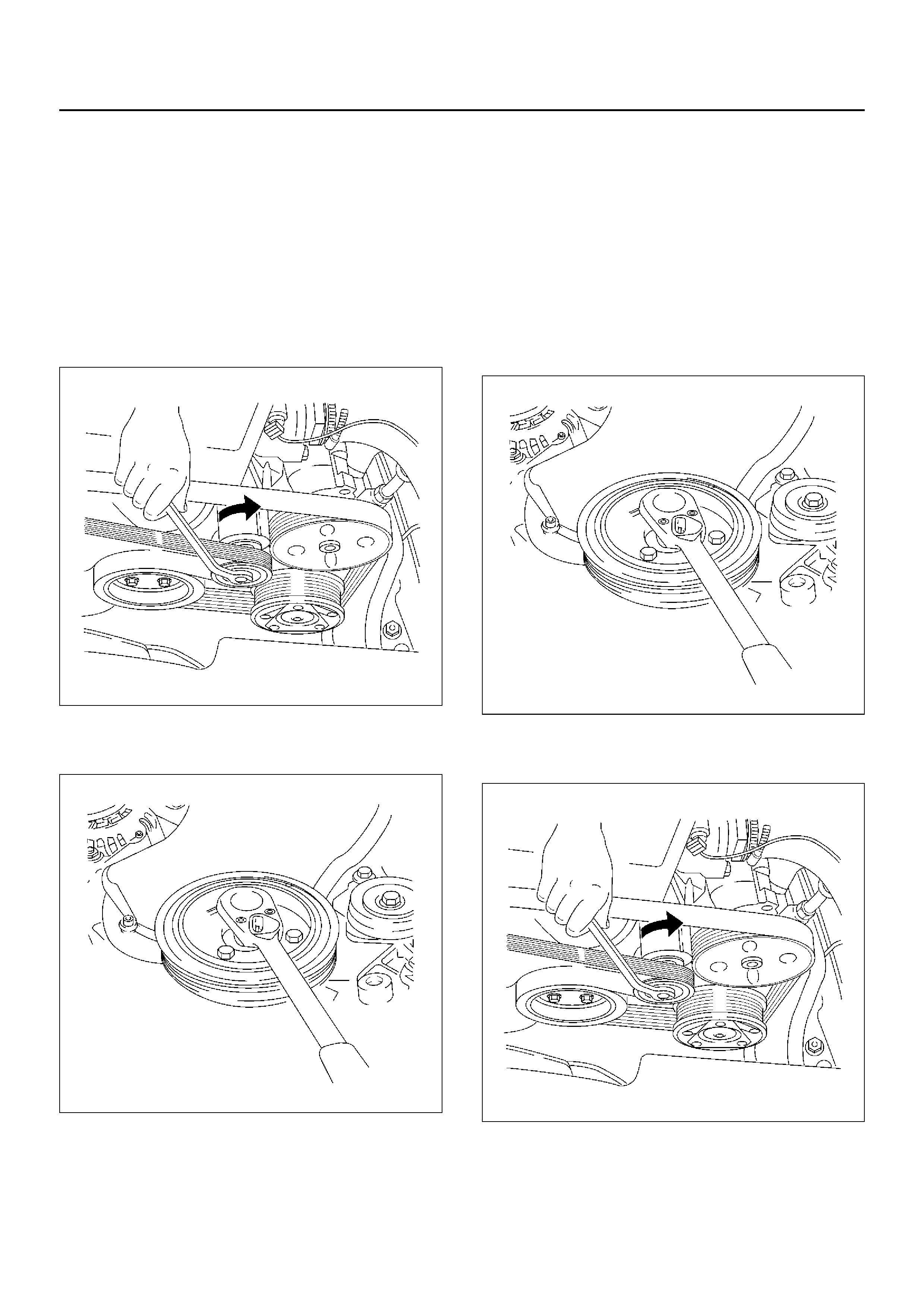
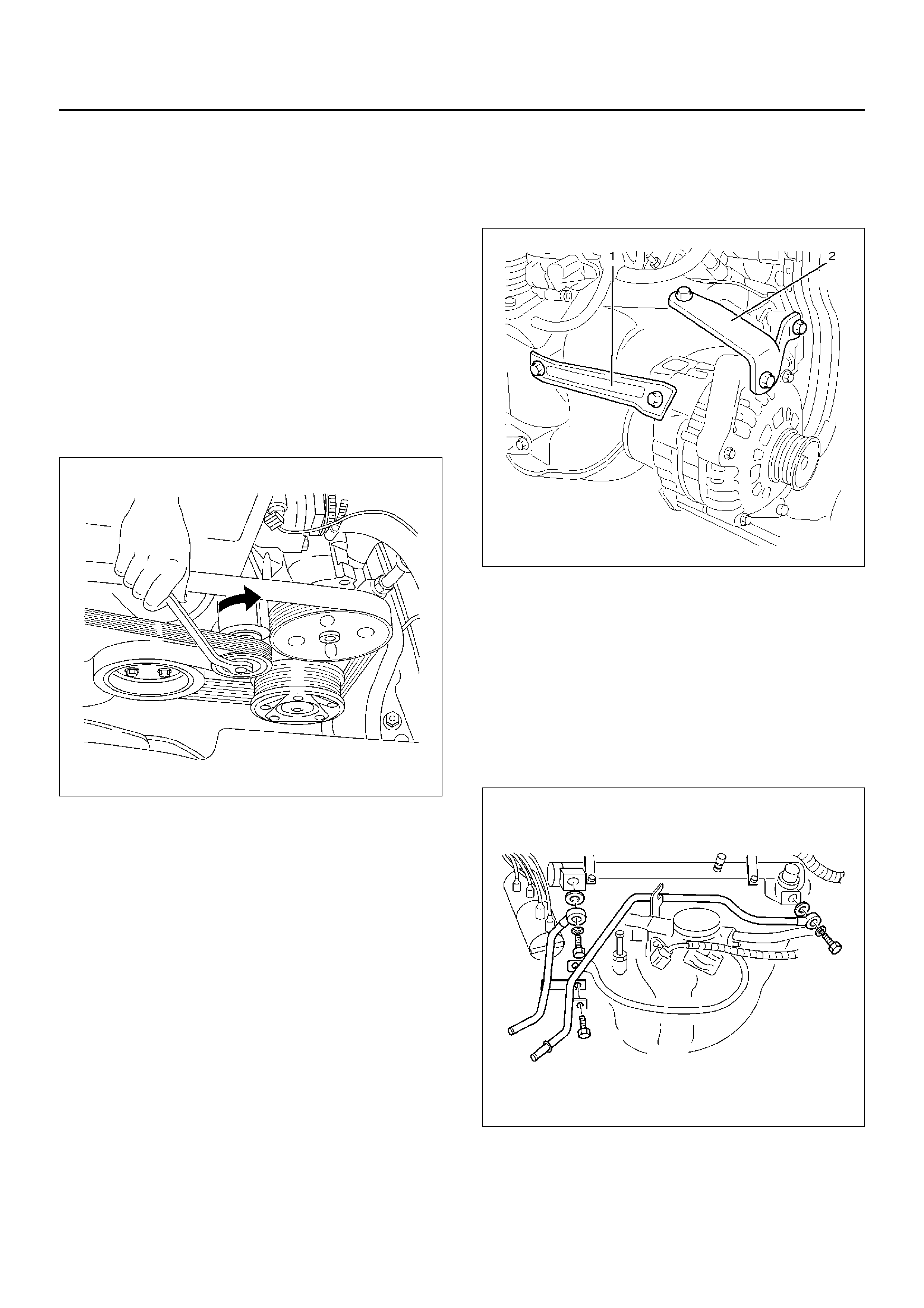
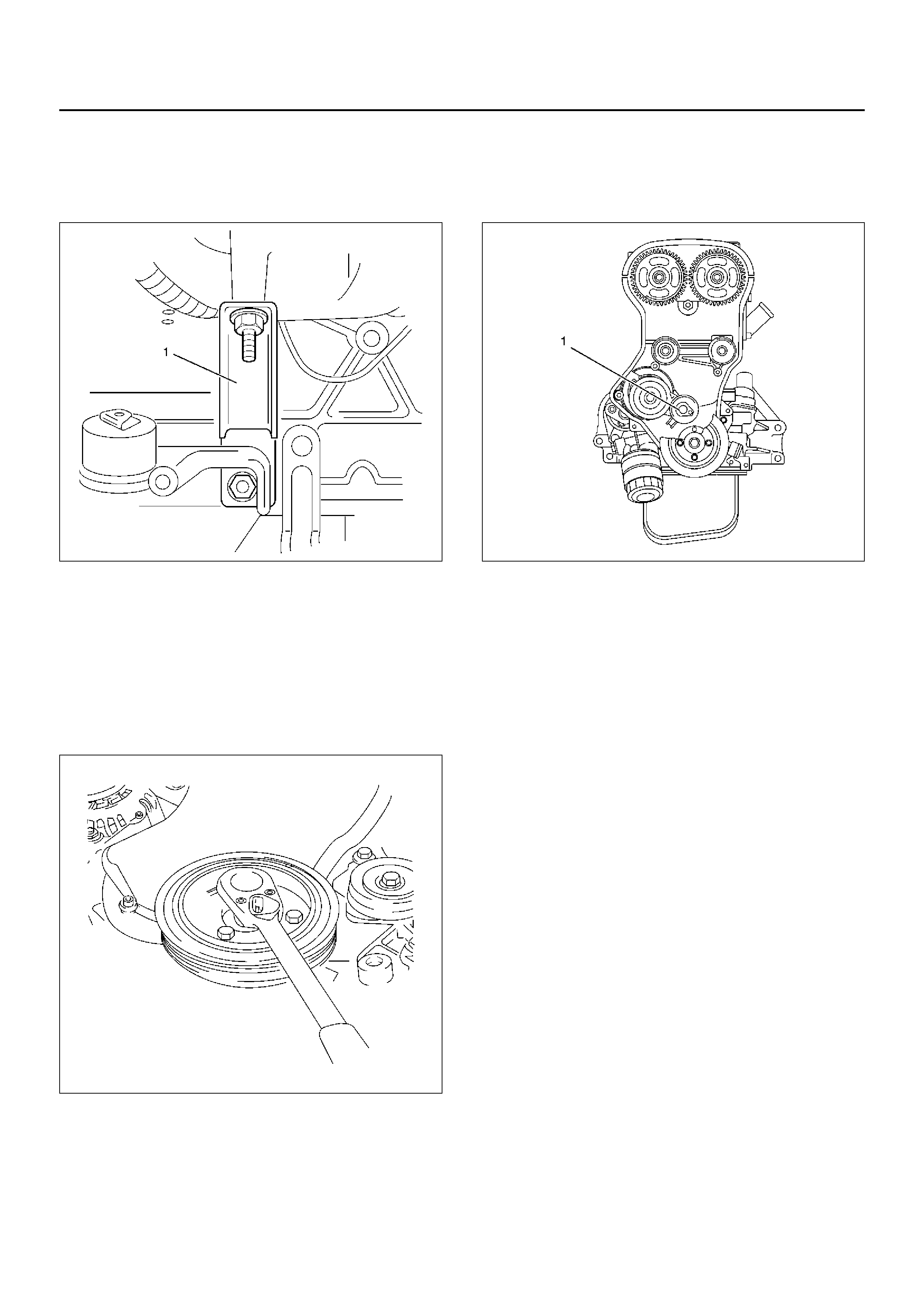
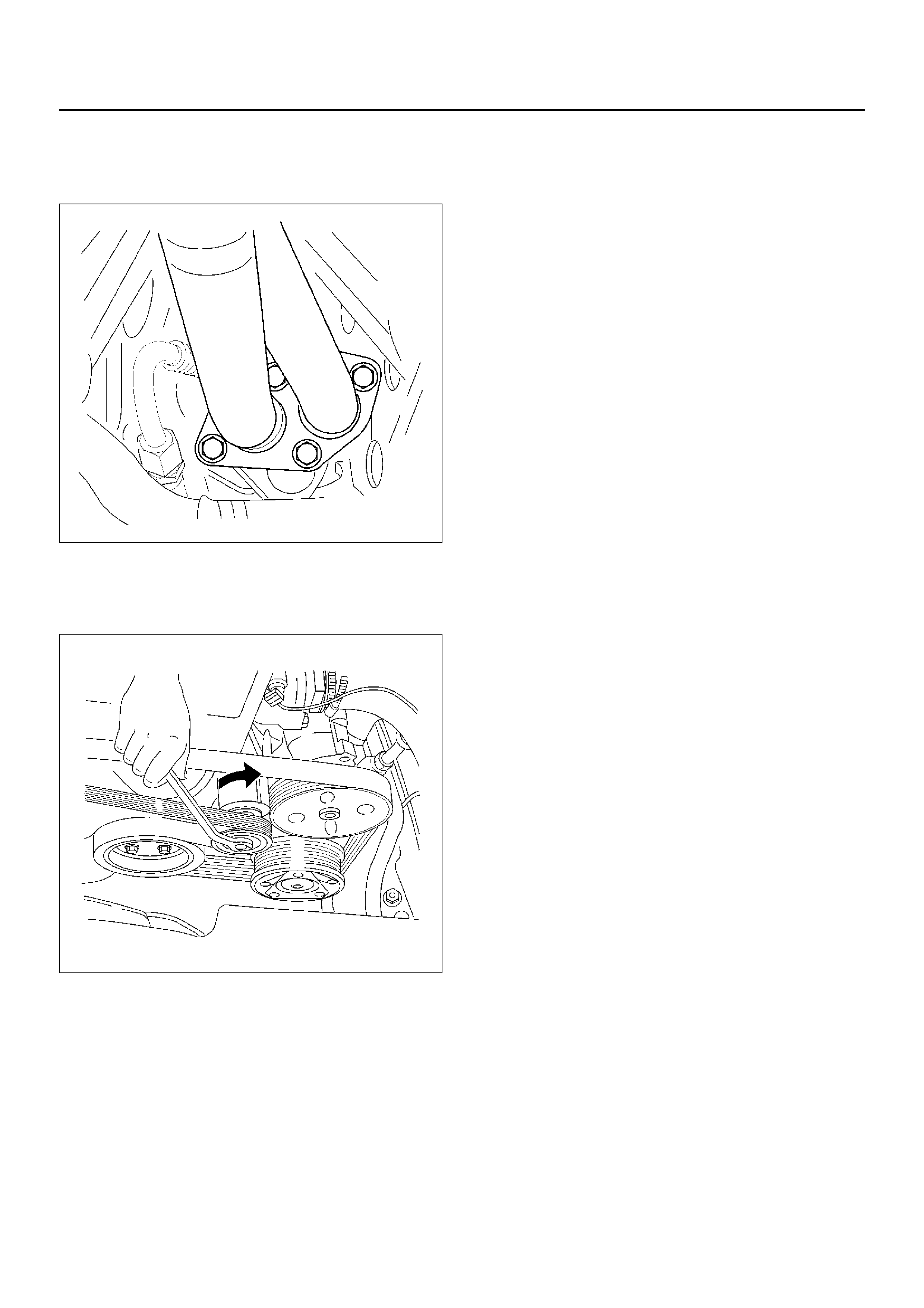
7. Mov e drive belt tensioner to loose side using wrench
then remove drive belt.
033RW001
8. Remove PCV hose from cylinder block.
9. Remove intake duct stay from cylinder head.
10. Remove two bolts for remove ignition cable cover
from cylinder head cover.
11. Disconnect ignition cable from ignition plug.
12. Disconnect camshaft position sensor harness and
crankshaft angle sensor harness from behind
generator.
13. Remov e f our bolts and remove the cr ankshaft pulley
020RW014
14. Remove timing belt front cover.
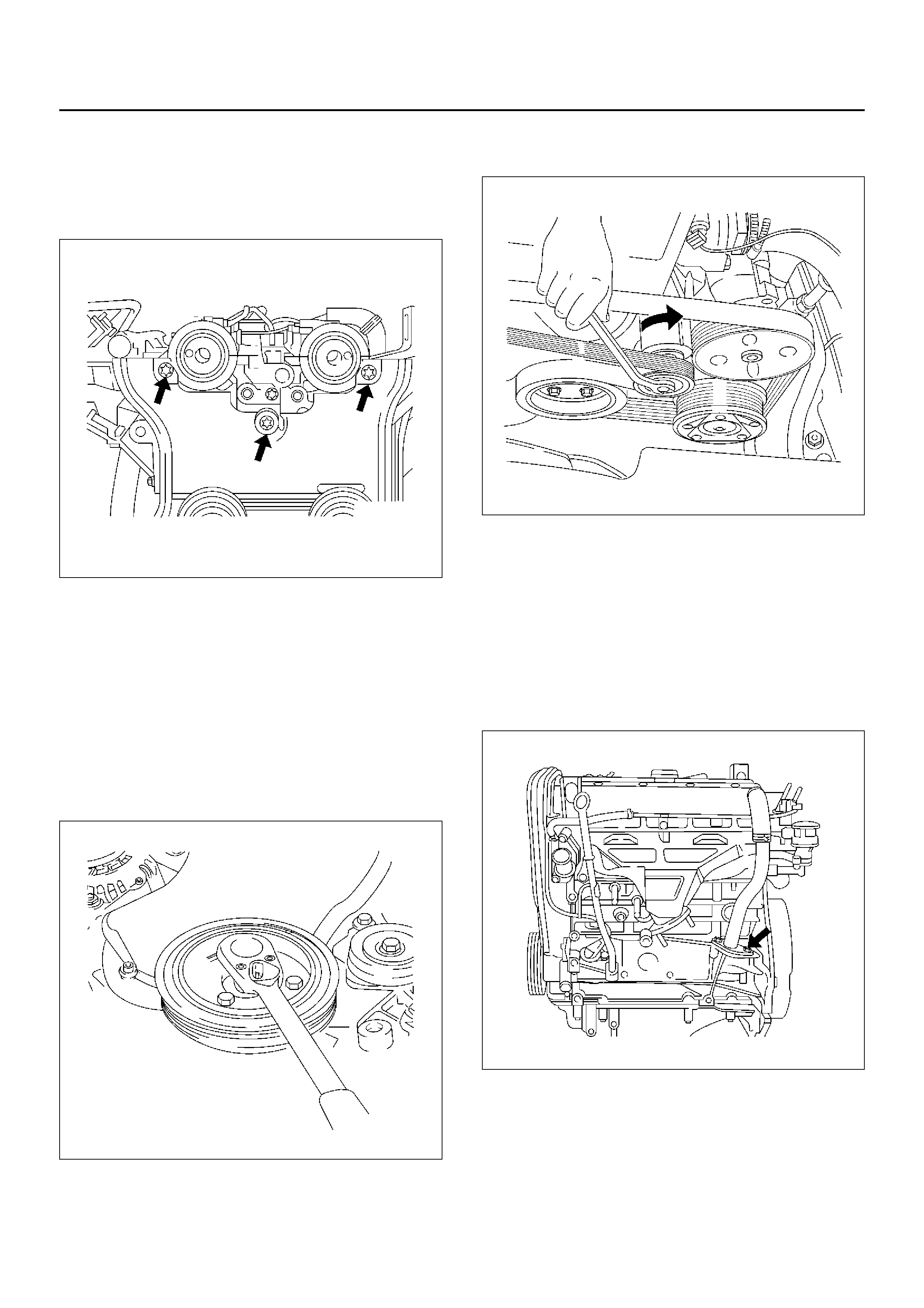
15. Loose fixing bolt of timing belt rear cover then
remove the camshaft angle sensor.
020RW012
16. Remove ten cylinder head cover fixing bolts and
remove the cylinder head cover.
Installation
1. Install the camshaft position sensor and tighten
timing rear cover bolt.
Torque: 8 N·m (0.8Kg·m/5.9 lbft)
020RW012
2. Install the cylinder head cover and tighten bolts to
the specified torque.
Torque: 8 N·m (0.8Kg·m/5.9lbft)
3. Install the timing belt front cover then tighten fixing
bolts to the specified torque.
Torque: 6 N·m (0.6Kg·m/4.4lbft)
4. Insta ll the cr ankshaft pulley, tighten fixing bolts to
the specified torque.
Torque: 20 N·m (1.4Kg·m/14lbft)
020RW014
5. Mo v e driv e bel t tensio ner to loose si de usi ng wren ch
then install the drive belt to normal position.
033RW001
6. Connect ignition cable to ignition plug.
7. Install ignition cable cover to cylinder head cover
and tighten two bolt to the specified torque.
Torque: 3 N·m (0.3Kg·m/2lbft)
8. Install intake duct bracket to cylinder block.
9. Install PCV hose flange to cylinder bloc k to the
specified torque.
Torque: 25 N·m (2.5Kg·m/18lbft)
020RW015
10. Connect cooling fan wire harness connector to
cooling fan on left side top of fan shroud.
11. Connect left side ground cable to cylinder head
cover and connect other side connector to left side
wheel arch terminal.
Connect right side ground cable to generator stay
and connect other side connector to right side wheel
arch terminal.
12. Connect three(black, green and blue colors) engine
wire harness connector to chassis harness of left
rear side of engine compartment.
13. Install intake duct.
14. Connect PCV hose to cylinder head cover.
15. Connect battery ground cable.
Exhaust Manifold
Removal
1. Disco nne ct batte ry ground ca ble.
2. Disconnect PCV hose from air intake duct.
3. Remove a nut from air intake duct bracket and
loosen hose clamp on throttle body. Remove air
intake duct assembly with air cleaner cover.
4. Remove air intake duct bracket with ground cable.
5. Remove four fixing bolts on exhaust manifold heat
protector.
6. Remove fixing f our nuts from flange of front exhaust
pipe and remove fixing bolts from silencer side.
027RW005
7. Remove ten exhaust manifold fixing nuts then
remove exhaust manifold.
Installation
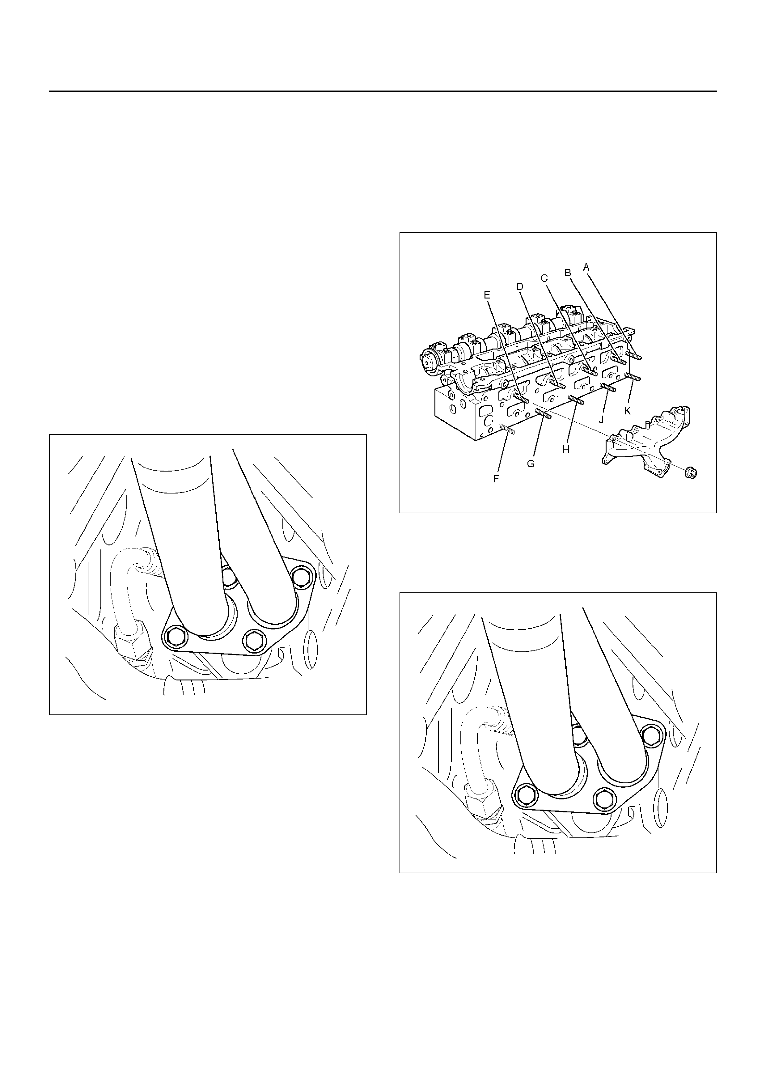
1. Install e x haust manifold and tighten fixing nuts to be
tightened in three steps.
•Tightening sequence:
Step1: J G H B D C J G B D
Step2: A B C D E F G H J K
Step3: A B C D E F G H J K
•Tightening torque:
Step1: 14 N·m (10 Ibft)
Step2: 20 N·m (14 Ibft)
Step3: 20 N·m (14 Ibft)
011RW029
2. Install front exhaust pipe to exhaust manifold and
tighten fixing nut to the specified torque.
Torque: 25 N·m (2.6Kg·m/18 lbft)
027RW005
3. Tighten silencer side bolt to the specified torque.
Torque: 68 N·m (6.9Kg·m/50lbft)
4. Install exhaust manifold heat protector and tighten
bolt.
Torque: 8 N·m (0.8Kg·m/5.9lbft)
5. Install intake duct bracket with ground cable.
6. Install intake duct assembly to throttle body and air
cleaner then tighten nut to the intake duct bracket
and clamp on the throttle body side, also clamp air
cleaner cover.
7. Connect PCV hose to air intake duct.
8. Connect battery ground cable.
Crankshaft Pulley
Removal
1. Disco nne ct batte ry ground ca ble.
2. Move drive belt tensioner to loose side by using
wrench then remove drive belt.
033RW001
3. Remove four crankshaft pulley fixing bolts, remove
crankshaft pulley.
020RW014
Installation
1. Install the crankshaft pulley to crankshaft flange.
2. Tighten four bolt to the specified torque.
Torque: 20 N·m (2.0Kg·m/14lbft)
020RW014
3. Move drive belt tensioner to loose side by using
wrench, then install drive belt to normal position.
033RW001
4. Connect battery ground cable.
Intake Manifold
Removal
1. Disco nne ct batte ry ground ca ble.
2. Remove PCV hose from air intake duct.
3. Remove a nut from air intake duct bracket and
loosen hose clamp on throttle body. Remove air
intake duct assembly with air cleaner cover.
4. Drain engine coola n t.
5. Remove water hoses from throttle body.
6. Disconnect the connector for throttle position
sensor, idle air control valve sensor from throttle
body.
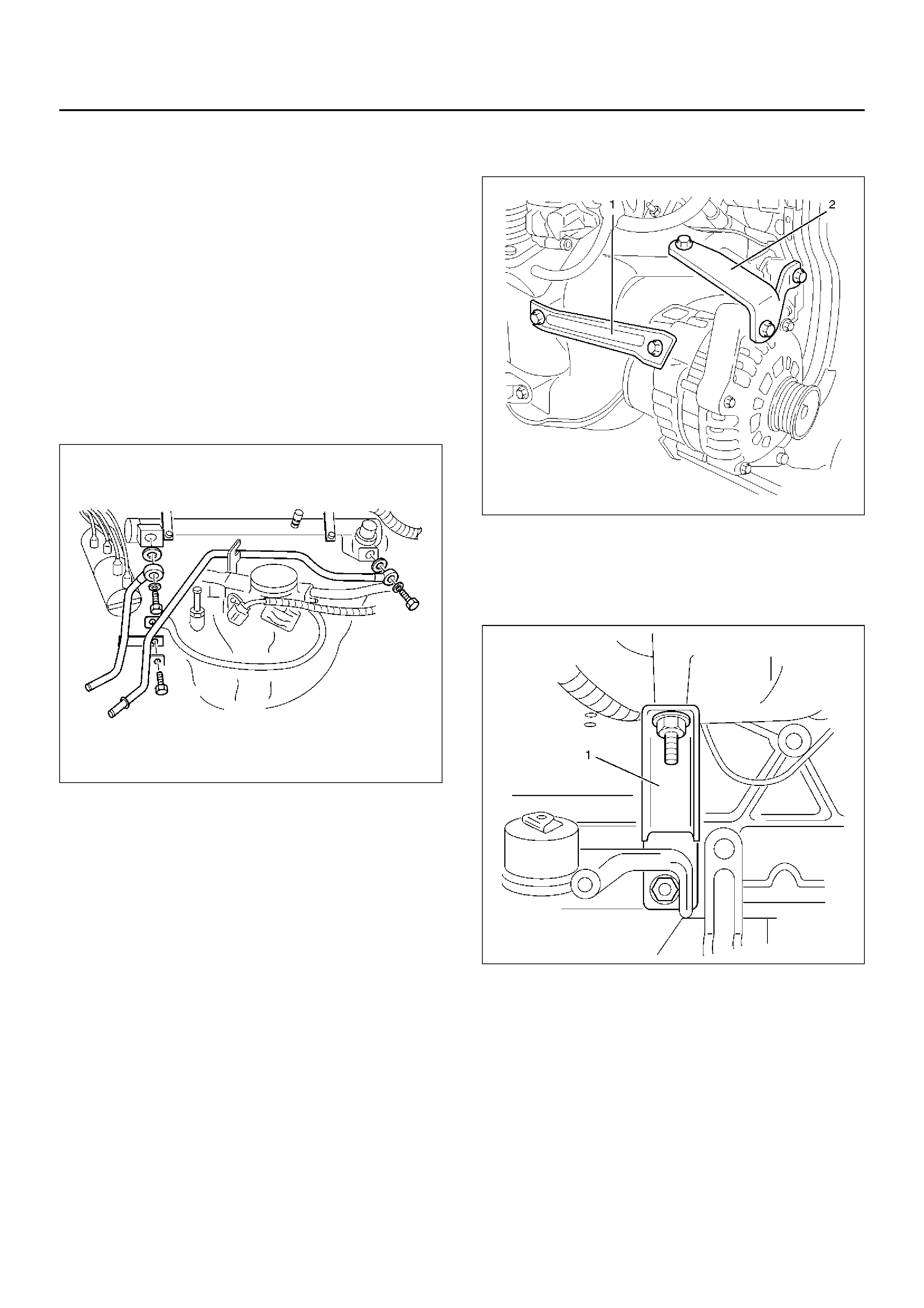
7. Remove fuel pipe joint eye bolts from fuel rail and
disconnect wire harness from fuel injector.
042RW001
8. Disconnect hose from fuel pressure regulator then
remove fuel rail assembly.
9. Remove throttle valve control cable from throttle
body.
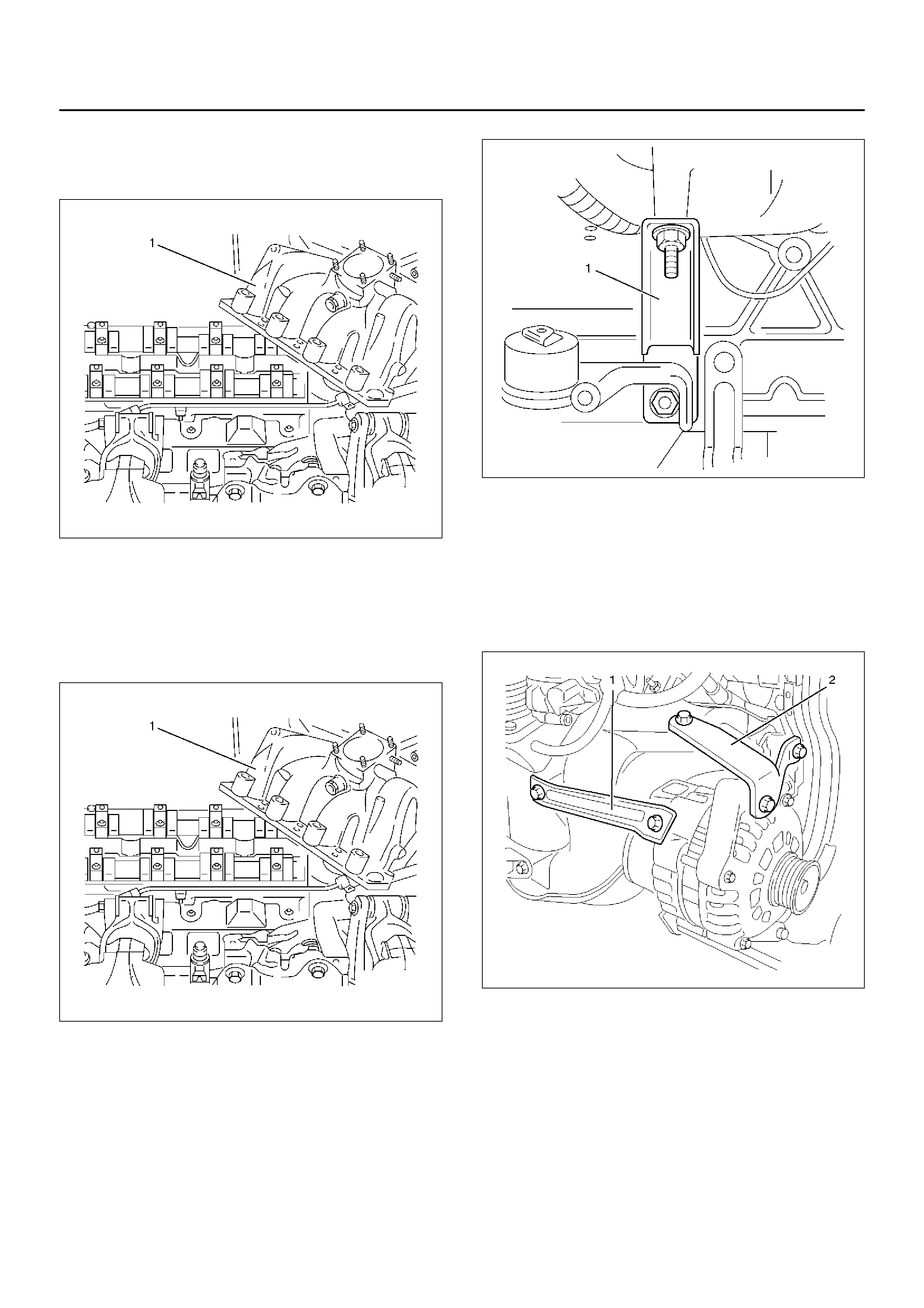
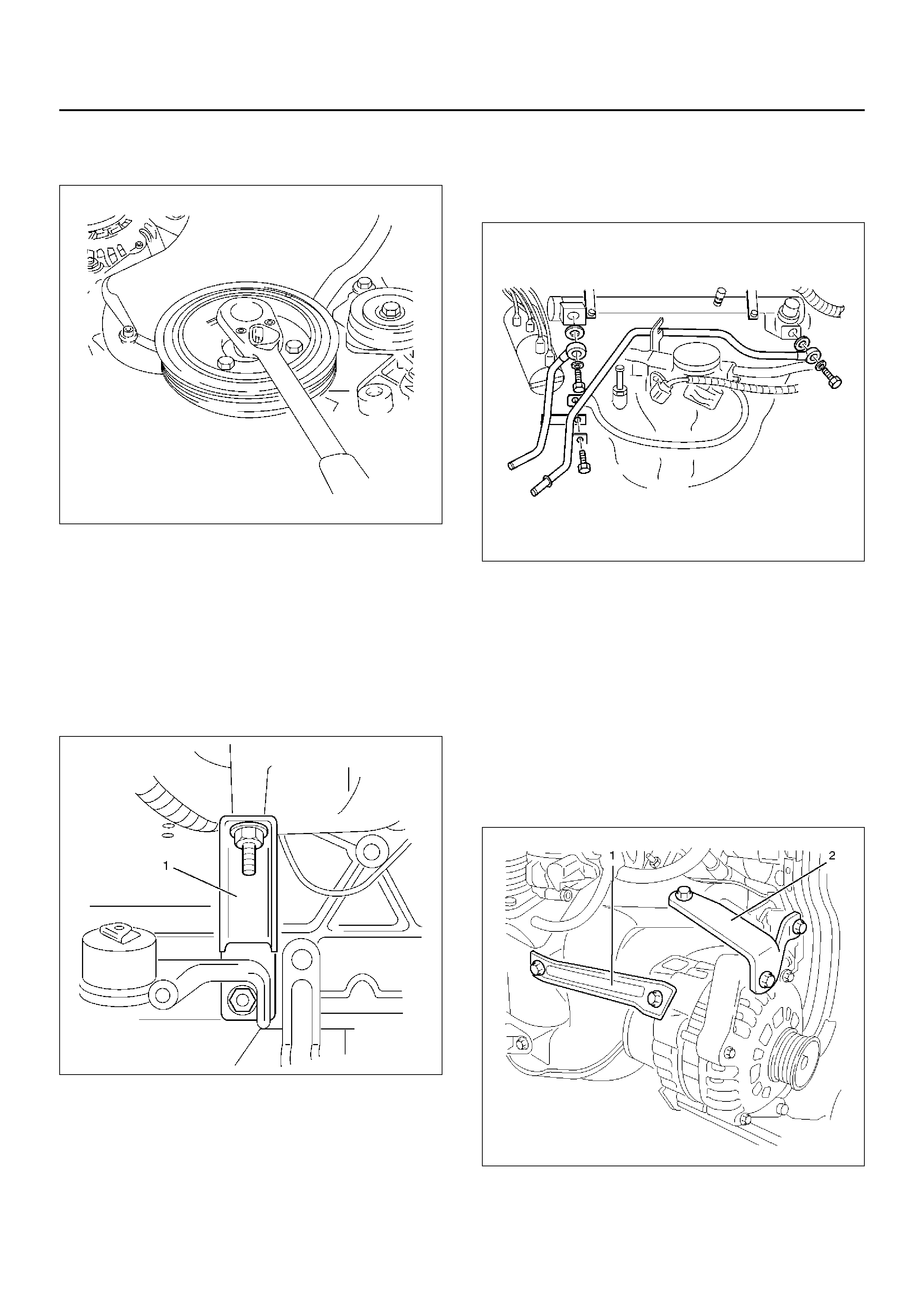
10. Remove fixing bolts f or generator bracket.
065RW025
11. Remove water pipe fixing bolt then remove water
pipe.
12. Remove fixing bolt from brac ket (Between cylinder
block and intake manifold) of intake manifold side.
025RW002
13. Remove ignition coil bracket fixing bolt.
14. Remove bolt and seven nuts, and remove intake
manifold.
027RW002
Installation
1. Install intake manifold with gasket to cylinder head,
tighten bolt and nuts to the specified torque.
Torque: 22 N·m (2.2Kg·m/16lbft)
027RW002
2. Insta ll ignition coil bracket fixing bolt.
3. Install intake manifold bracket, tighten bolt.
Torque: 22 N·m (2.2Kg·m/16lbft)
025RW002
4. Install water pipe to intake manifold.
5. Install generator bracket and tighten generator
bracket bolts.
Torque
Long bolts: 35 N·m (3.6Kg·m/25lbft)
Short bolts: 20 N·m (2.0Kg·m/14lbft)
065RW025
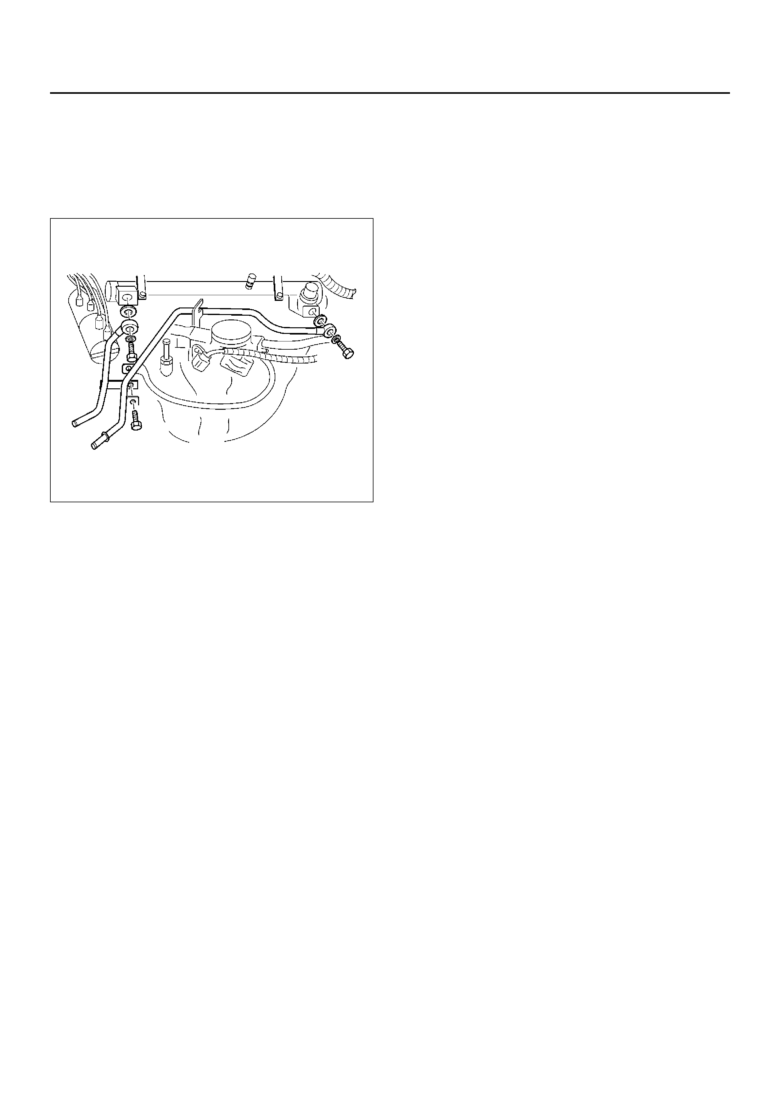
6. Install fuel rail assembly to intake manifold and
connect hose between fuel pressure regulator and
throttle body.
7. Install fuel pipe and tighten joint eye bolt and
connect fuel injector harness.
Torque: 25 N·m (2.5Kg·m/18lbft)
042RW001
8. Connect the connector f or throttle position sensor
and idle air control valve sensor to throttle body.
9. Install water hoses to throttle body.
10. Install intake duct assembly to throttle body and air
cleaner then tighten nut to the intake duct bracket
and clamp on the throttle body side and air cleaner
side.
Torque: 7 N·m (0.7Kg·m/5.1lbft)
11. Install PCV hose to air intake duct.
12. Install throttle valve control cable to throttle body.
13. Confirm the free play of throttle valve control cable.
Free play: 5.7 to 6.3 mm
14. Fill engine coolant to full lev el from radiator filler
neck.
15. Connect battery ground cable.
Cylinder Head Assembly
Removal
1. Disco nne ct batte ry ground ca ble.
2. Disconnect connector of intake air temperature
sens or from intake air duct.
3. Remove PCV hose from air intake duct.
4. Remove nut from air intake duct bracket and loosen
hose clamp on throttle body. Remove air intake duct
assembly with air cleaner cover.
5. Remove intake air duct bracket from cylinder head.
6. Drain engine coola n t.
7. Mov e drive belt tensioner to loose side using wrench
then remove drive belt.
033RW001
8. Remove radiator upper hose from engine side.
9. Remove four nuts of exhaust front pipe.
10. Remove three bolts from generator bracket then
remove the generator with brac kets.
065RW025
11. Disconnect crankshaft angle sensor connector.
12. Disconnect knock sensor connector.
13. Remove heater hose from adapter side.
14. Remove heater hose from water pipe side.
15. Remov e water hose between water pipe and throttle
body.
16. Remove fuel pipe joint eye bolts from fuel rail
assembly and remov e fuel pipe brac ket with electric
ground cable.
042RW001
17.Disconnect connector for evaporation valve.
18.Remove canister hose.
19.Remove fixing nut of intake manifold stay from
cylinder block side.
025RW002
20.Remove two bolts from intake manifold for water
pipe support and remove cylinder head assembly.
21.Remove engine harness cover and disconnect three
connectors from chassis harness on left rear side
engine compartment.
22.Disconnect connector for power steering pump
pressure switch.
23.Remove four bolts and remove crankshaft pulley.
020RW014
24.Remove two bolts and nut then remove timing belt
front cover.
25.Remove ventilation hose from cylinder block side
and from cylinder head side.
26.Remove two bolts, ignition cable cover and remove
ignition cables from spark plug.
27.Disconnect camshaft angle sensor connector.
28.Remove ten bolts and remove cylinder head cover.
29.Remove fixing bolt of timing belt tensioner then
remove timing belt tensioner.
020RW010
30.Remove timing belt.
CAUTION:
• Do not bend or twist belt, otherwise its core could
be damaged. The belt should not be bent at a
radius less than 30 mm.
• Timing belt drive gear counterhold with 5–8840–
2598–0.
• Do not allow oil or other chemical substances to
come in contact with the belt. They will shorten
the life.
• Do not attempt to pry or stretch the belt with a
screw driver or any other tool during installation.
• Store timing belt in cool and dark place. Never
expose the belt direct sunlight or heat.
31. Remove tw o idle pulleys, the left side with idle pulley
bracket.
32. Remove two bolts and stud bolt and remove timing
belt rear cover.
33. Remove camshaft angle se nso r

34. Disconnect engine oil pressure switch connector.
050RW005
35. Remove camshaft assembly exhaust side.
36. Use 5–8840–2600–0 to remove ten cylinder head
fixing bolts
012RW007
Installation
1. Put cylinder head gasket on the cylinder block.
012RW011
2. Install the cylinder head assembly, tighten cylinder
head bolts by four steps tightening method in the
following sequence to the specified torque.(use 5–
8840–2600–0)
Torque: 25 N·m (2.5Kg·m/18lbft) + 90°
°°
° + 90°
°°
° + 90°
°°
°
012RW006
3. Install camshaft assembly exhaust side and tighten
camshaft bracket bolts in the sequence to the
specified torque.
Torque: 8 N·m (0.8Kg·m/5.9lbft)
015RW014
4. Connect engine oil pressure switch connector.
5. Install camshaft angle sensor.
6. Install the timing belt rear cover and tighten three
bolts to the specified torque.
Torque
M6 bolt: 6 N·m (0.6Kg·m/4.4lbft)
M8 bolt: 8 N·m (0.8Kg·m/5.8lbft)
020RW012
7. Install left side idle pulley with idle pulley bracket,
tighten to the specified torque and install right side
idle pulley and tighten to the specified torque.
Torque: 25 N·m (2.5Kg·m/18lbft)
020RW016
8. Install timing belt tensioner then tighten it
temporarily until make alignment timing belt.
9. Install the cylinder head cov er and tighten fixing bolt
temporally.
10. Install the timing belt and perform timing belt setting
procedure as follows.
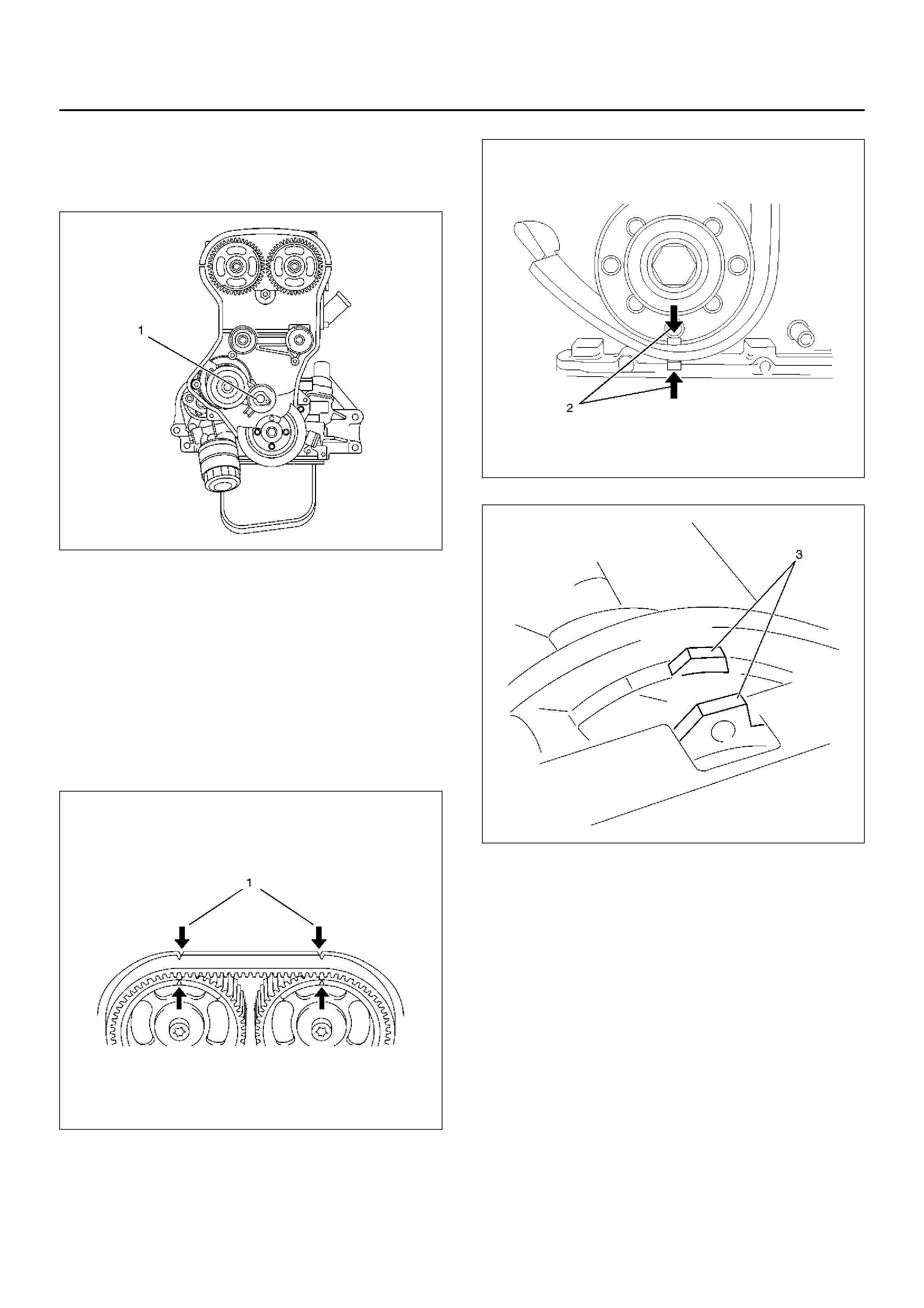
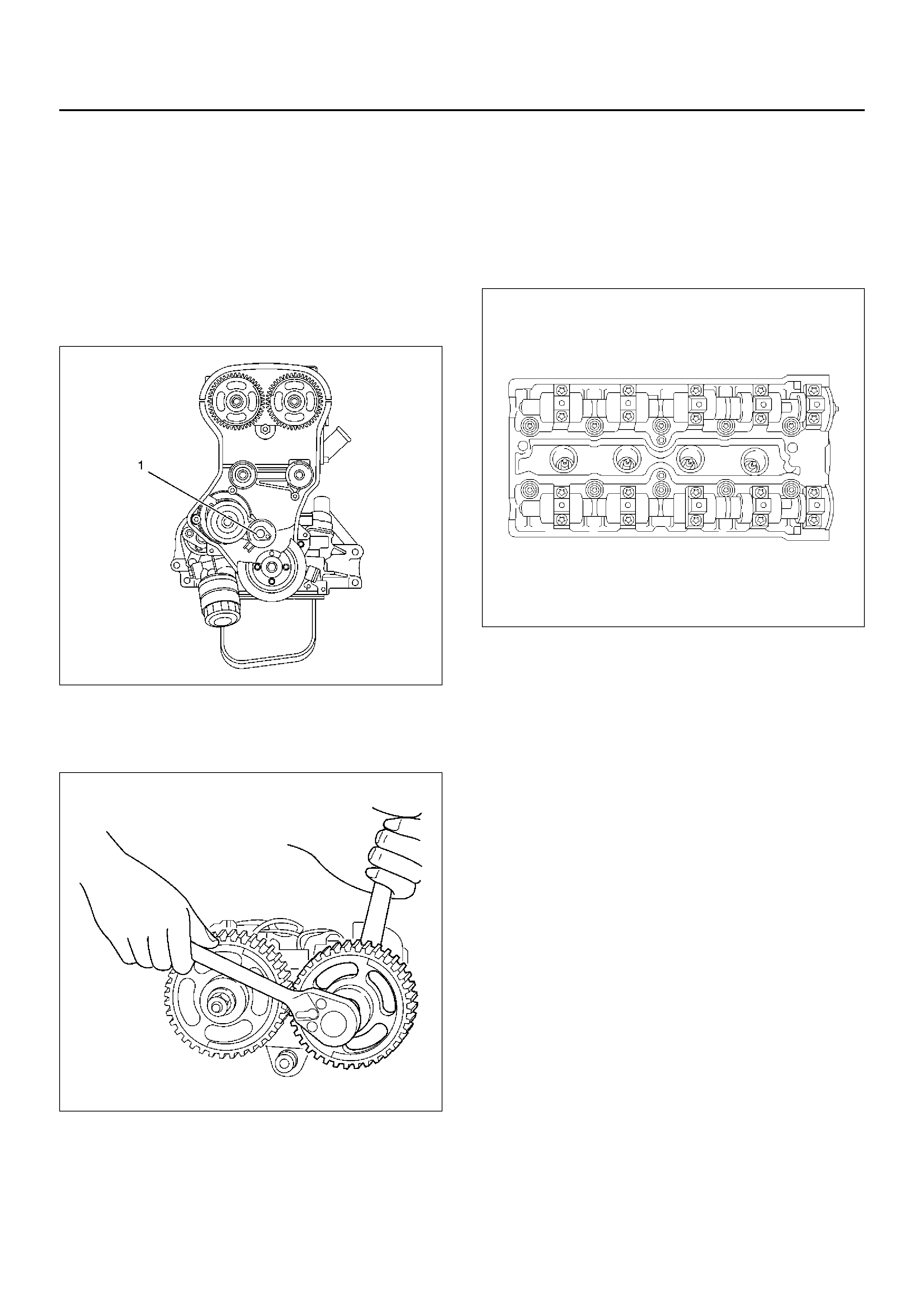
1. Bring the engine top dead center No.1 cylinder
compression stroke b y rotating the engine in the
direction of normal operation.
The engine is in this position when the notches
on the camshaft pulleys align with the marks on
the cylinder head cover(1), Check the
crankshaft pulley timing mark is aligned (2) also
check for water pump positioning ensure tabs
are aligned (3).
• Rotate the engine two full turns in the
direction of normal operation until the engine
is again at top dead centre, No.1 cylinder
firing being careful that all movement is in a
clockwise direction.

• If the engine is turned too far, do not turn
backwards, but continue to turn in the same
direction until the marks are again in line.
014RW067
014RW066
014RW063
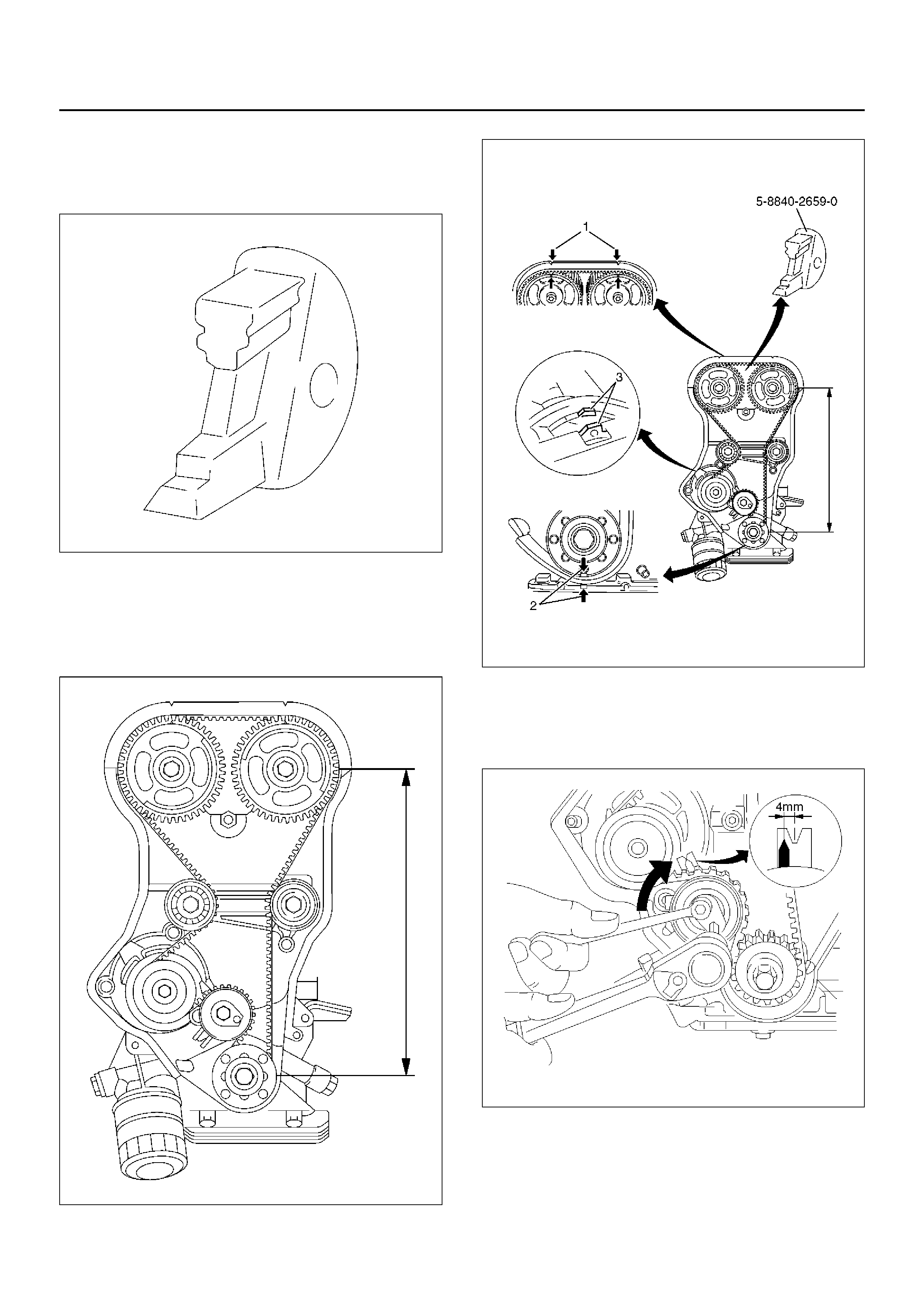
2. Place 5–8840–2659–0 to between intake and
exhaust of camshaft drive gear to prevent
camshaft drive gear movement during timing
belt setting.
014RW065
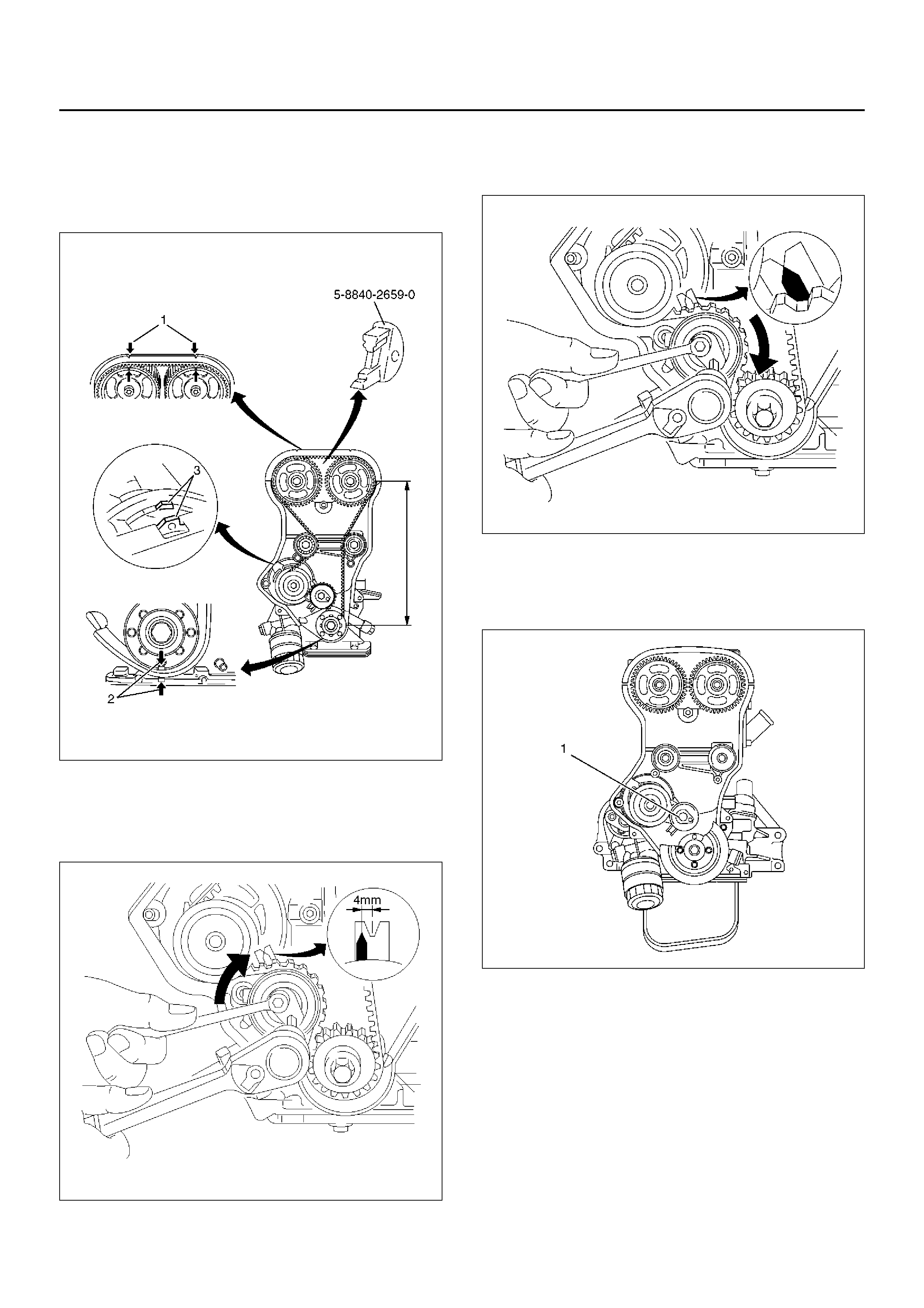
3. Set the timing belt shown in the illustration,
ensure that tension side of the timing belt is taut
and move the timing belt tension adjustment
le v er clockwise, until the pointer of the tensioner
is flowing.
014RX061
F or used timing belt(ov er 60 minutes from ne w):
the pointer will be approx. 4 mm(0.16 in) to the
left of the center of the “V" notch when viewed
from the front of the engine.
014RW069
For new timing belt: The pointer must be at the
center of “V" notch when viewed from the front
of the engine.
014RW062
4. Tighten fixing bolt of timing belt tensioner to the
specified torque.
Torque: 25 N·m (2.5Kg·m/18lbft)
020RW010
11. Tighten cylinder head cover to the specified torque.
Torque: 8 N·m (0.8Kg·m/5.9lbft)
12. Connect cam s haft ang le sen so r connec to r.
13. Install the ignition cable to spark plug.
14. Install ignition cable cover and tighten two bolts.
Torque: 3 N·m (0.3Kg·m/2lbft)
15. Install ventilation hoses to cylinder b lock side and
cylinder head side.
16. Install timing belt front cover and tighten two bolts to
the specified torque.
Torque: 6 N·m (0.6Kg·m/4.4lbft)
17. Install crankshaft pulley and tighten four bolts.
Torque: 20 N·m (2.0Kg·m/14lbft)
020RW014
18. Connect connector for power steering pump
pressure switch.
19. Connect engine harness connector to chassis
harness of the left rear of engine compartment and
install engine harness cover.
20. Install two bolts to intake manifold for water pipe
support.
21. Install fixing nut of intake manifold stay to cylinder
block.
025RW002
22. Install canister hose.
23. Connect connector for evaporation valve.
24. Install fuel pipe joint eye bolts to fuel rail assembly
and install fuel pipe bracket with electric ground
cable.
Torque: 25 N·m (2.5Kg·m/18lbft)
042RW001
25. Install water hose between water pipe and throttle
body.
26. Install heater hose to water pipe side.
27. Install heater hose to adapter side.
28. Connect knock sensor connector.
29. Connect crankshaft angle sensor connector.
30. Install generator with brack et and tighten three bolts.
Torque
35 N·m (3.6Kg·m/25lbft) for Long bolt
20 N·m (2.0Kg·m/14lbft) for Short bolt
065RW025
31. Install e xhaust front pipe to exhaust manifold and
tighten four nuts to the specified torque.
Torque: 25 N·m (2.5Kg·m/18lbft)
027RW005
32. Install radiator upper hose to engine.
33. Mov e drive belt tensioner to loose side using wrench
then install the drive belt to normal position.
033RW001
34. Install intake air duct bracket to cylinder head.
35. Install air intake duct assembly with air cleaner
cover to throttle body and tighten nut to the air
intake duct bracket then tighten hose clamp.
Torque
7 N·m (0.7Kg·m/5.1lbft) for nut
3 N·m (0.3Kg·m/2.2lbft) for hose clamp bolt
36. Install PCV hose to air intak e duct.
37. Connect connector of intake air temperature sensor
on intake air duct.
38. Connect battery ground cable.
39. Fill engine coolant to full level in the engine coolant
reservoir tank.

Timing Belt
Removal
1.Disconnect battery ground cable.
2.Move drive belt tensioner to loose side using wrench
then remove drive belt.
033RW001
3.Remove engine harness cover and disconnect three
connectors from left rear side of engine
compartment.
4.Remove four bolts and remove crankshaft pulley.
020RW014
5.Disconnect three connectors of engine harness
from chassis harness of left rear side of engine
compartment.
6.Remove nut and remove engine harness cover from
front of engine.
7.Remove two bolts then remove timing belt front
cover.
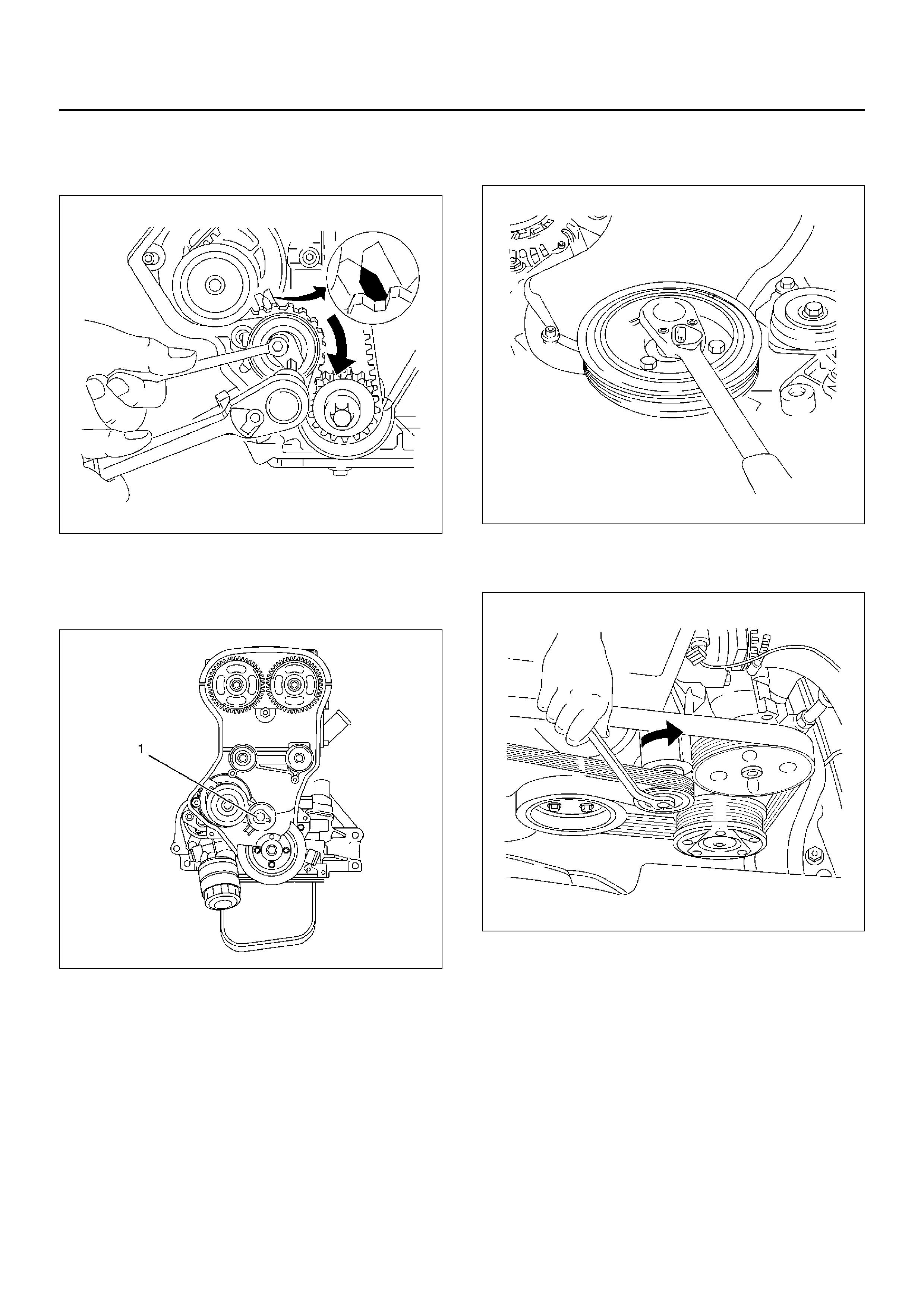
8.Remove fixing bolt of timing belt tensioner then
remove timing belt tensioner (1).
020RW010
9.Remove timing belt.
CAUTION:
• Do not bend or twist belt, otherwise its core could
be damaged. The belt should not be bent at a
radius less than 30 mm.
• Timing belt drive gear counterhold with 5–8840–
2598–0.
• Do not allow oil or other chemical substances to
come in contact with the belt. They will shorten
the life.
• Do not attempt to pry or stretch the belt with a
screw driver or any other tool during installation.
• Store timing belt in cool and dark place. Never
expose the belt direct sunlight or heat.
Installation
1. Install timing belt tensioner then tighten it
temporarily until make alignment timing belt.
020RW010
2. Install the timing belt and perform timing belt setting
proce dur e as follows:
1. Bring the engine top dead center No.1 cylinder
compression stroke by rotating the engine in the
direction of normal operation.
The engine is in this position when the notches
on the camshaft pulleys align with the marks on
the cylinder head cover(1), Check the
crankshaft pulley timing mark is aligned (2) also
check for water pump positioning ensure tabs
are align ed (3).
014RW067
014RW066
014RW063
2. Place 5–8840–2659–0 between intake and
exhaust of camshaft drive gear for prevent to
camshaft drive gear movement during timing
belt se ttin g.
014RW065
3. Set the timing belt shown in the illustration,
ensure that tension side of the timing belt is taut
and move the timing belt t ension adjustment
le v er clockwise, until the pointer of the tensioner
is flowing.
014RW064
014RX061
F or used timing belt(ov er 60 minutes from new):
The pointer will be approx. 4 mm(0.16 in) to the
left of the center of the “V" notch when viewed
from the front of the engine.
014RW069
For new timing belt: The pointer must be at the
center of “V" notch when viewed from the front
of the engine.
014RW062
3. Tighten fixing bolt (1) of timing belt tensioner to the
specified torque.
Torque: 25 N·m (2.5Kg·m/18lbft)
020RW010
4. Install timing belt front cov er and tighten two bolts to
the specified torque.
Torque: 6 N·m (0.6Kg·m/4.4lbft)
5. Install engine harness cover to front top of engine
and tighten nut to the specified torque.
Torque: 6 N·m (0.6Kg·m/4.4lbft)
6. Install crankshaft pulley and tighten four bolts.
Torque: 20 N·m (2.0Kg·m/14lbft)
020RW014
7. Mo v e driv e bel t tensio ner to loose si de usi ng wren ch
then install drive belt to normal position.
033RW001
8. Connect engine harness three connector to chassis
harness of left rear side of engine compartment.
9. Connect battery ground cable.
Camshaft
Removal
1.Disconnect battery ground cable.
2.Remove cylinder head cover.
Refer to removal procedure for Cylinder Head Cover
in this manual.
3.Remove timing belt tensioner and remove timing
belt.
020RW010
4.Use adjustable wrench to hexagonal portion of
camshaft, and remove fixing bolt from front end of
camshaft.
014RW074
5.Remove camshaft drive gear from intake and
exhaust camshaft.
6.Remove twenty fixing bolts from intake and exhaust
camshaft bracket on the cylinder head, then remove
camshafts.
011RW015
CAUTION:
• Do not damage camshaft lobe and journal.
• Do not damage hydraulic lash adjuster(HLA) and
do not allow into foreign materials into cylinder
head.
7. Remove oil seal from camshaft.
Installation
1. Clean surface of camshaft bracket and HLA.
2. Apply engine oil to journal surface of camshaft
bracket and HLA.
3. Install camshaft to cylinder head.
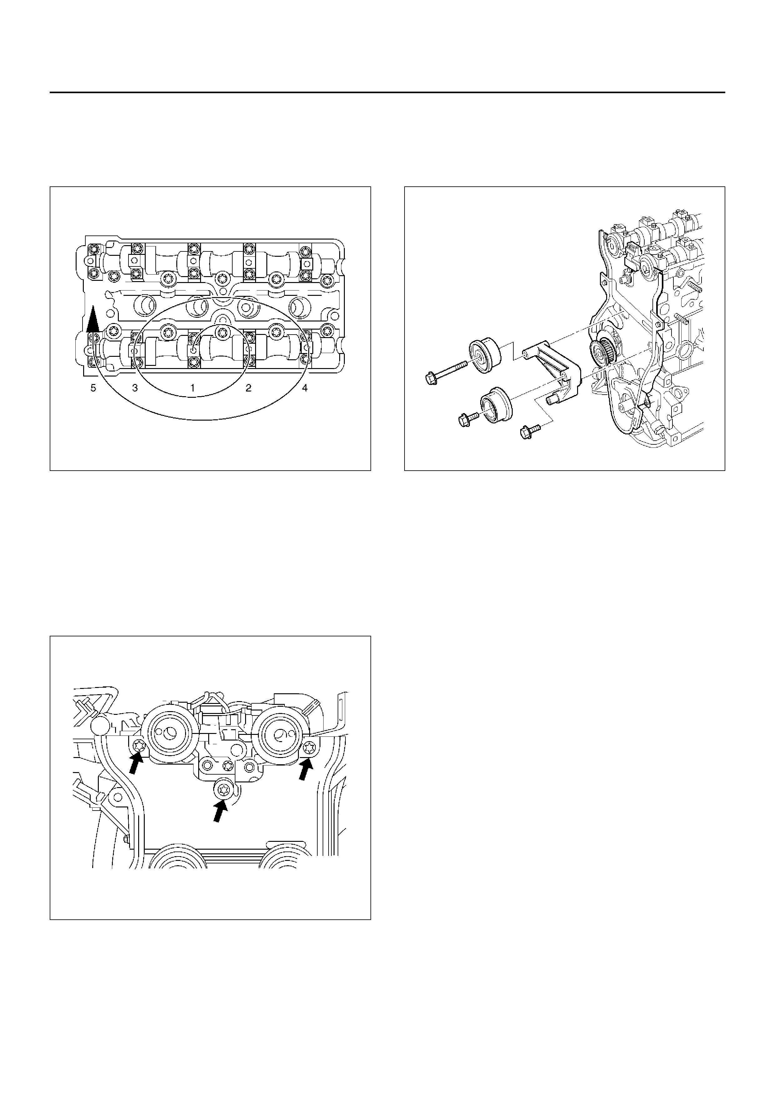
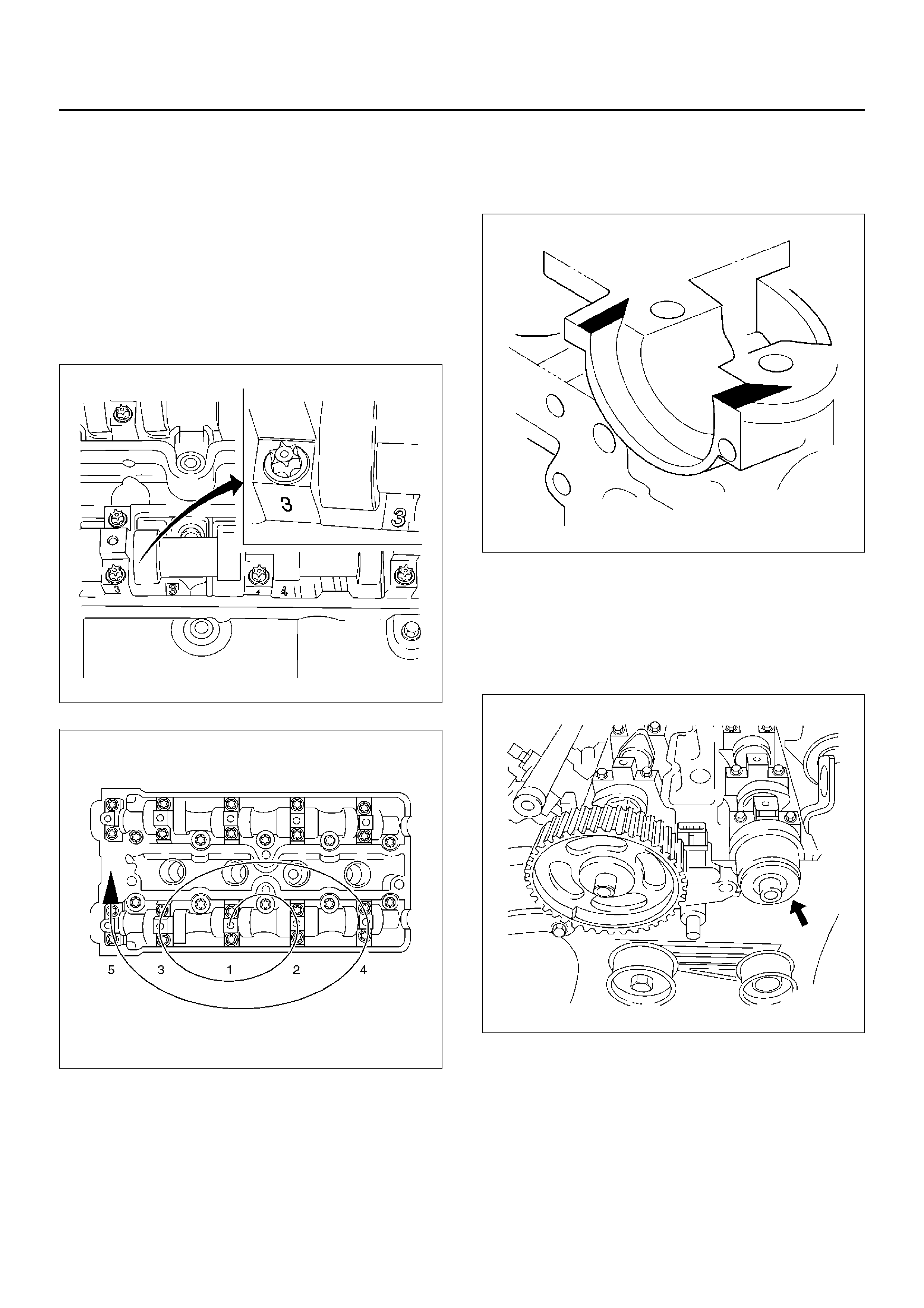
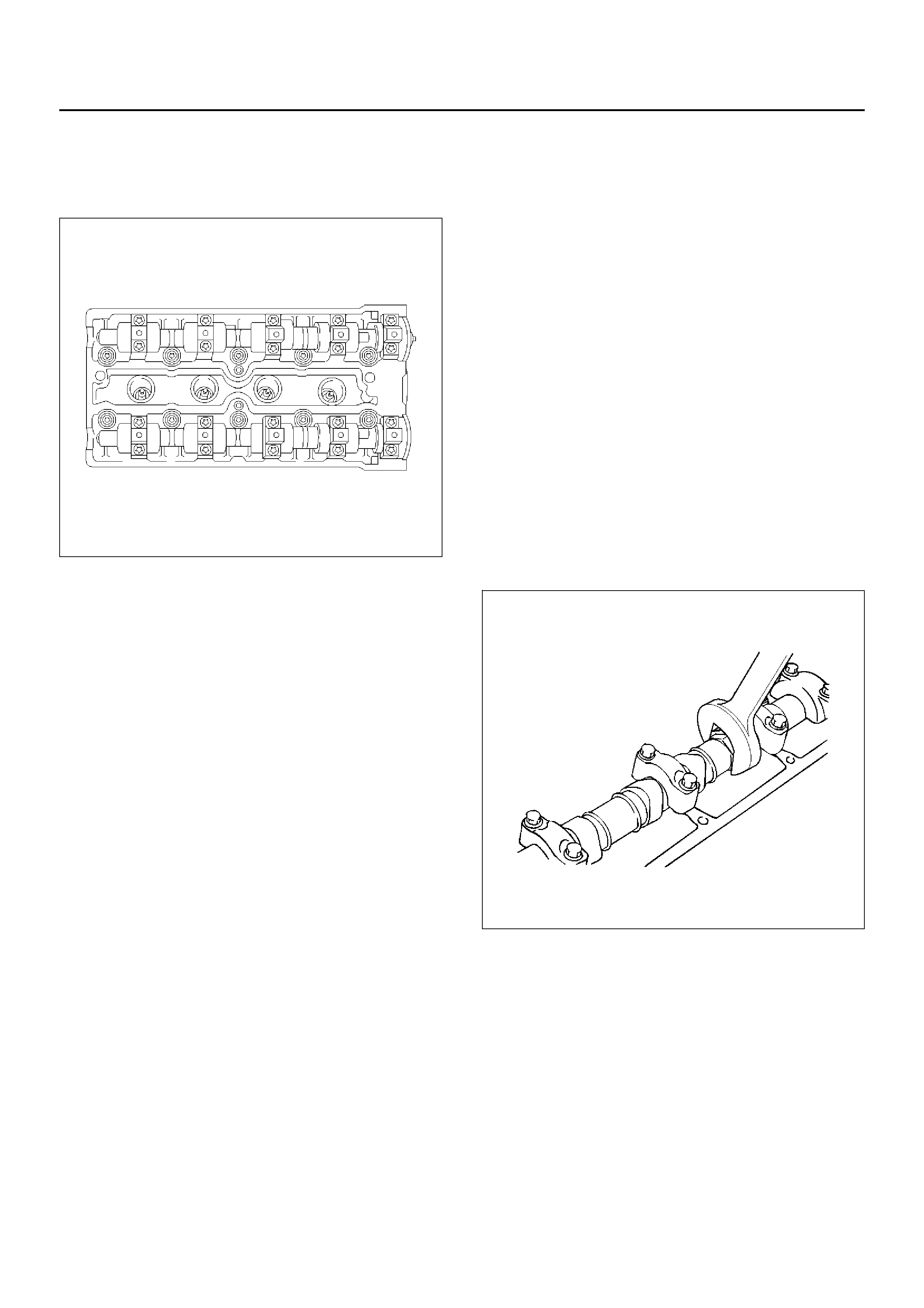
4. Install camshaft bracket according to numerical as
shown in the illustration.
The bracket number is:
• Exhaust: 1 to 5 from front
• Intake: 6 to 10 from front.
014RW052
015RW014
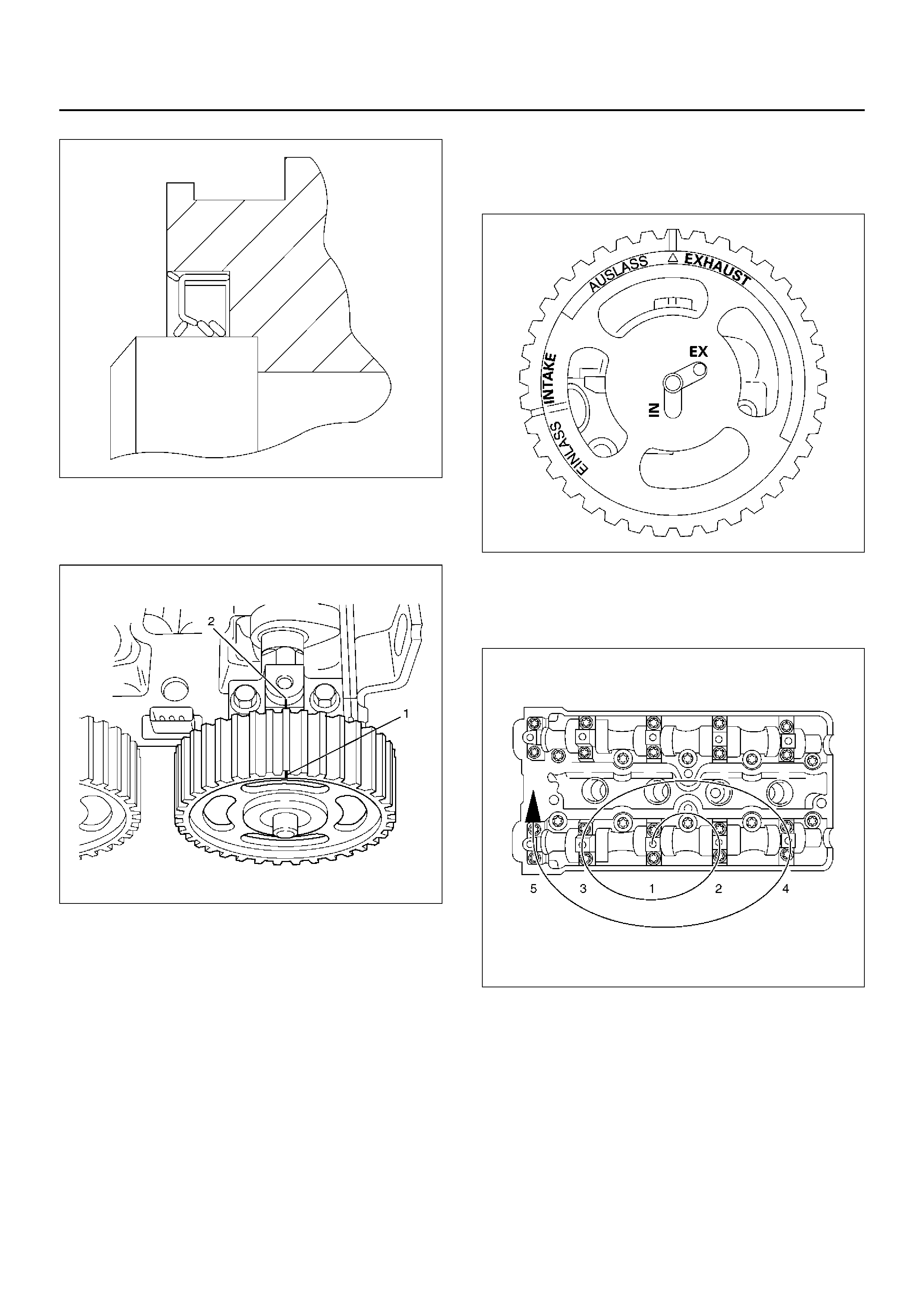
Camshaft oil seal installation area on the cylinder
body of No.1, No.6 and camshaft bracket rear side
plug portion must be applied HN1023 or equivalent
as in the illustration.
014RW073
5. Tighten camshaft bracket bolts to the specified
torque by sequence in the illustration.
Torque: 8 N·m (0.8Kg·m/5.9lbft)
6. Use 5–8840–2658–0 for installation camshaft oil
seal.
014RW075
014RW071
7.Install the camshaft drive gear. Align the timing mark
between notch on the camshaft drive gear(1) and
lug on the camshaft bracket(2).
014RW076
Also align a guide hole on the camshaft drive gear
marked “IN" for intake and “EX" for exhaust to guide
pin on the camshaft when instaling the camshaft
drive gear.
014RW072
8.Tighten camshaft bracket fixing bolt to the specified
torque.
Torque: 50 N·m (5.1Kg·m/36lbft)
015RW014
9.Install timing belt.
Refer to installation procedure for Timing Belt in this
manual.
10. Install cylinder head cov er.
Refer to installation procedure for Cylinder Head
Cover in this manual.
11. Connect battery ground cable.
Engine Assembly
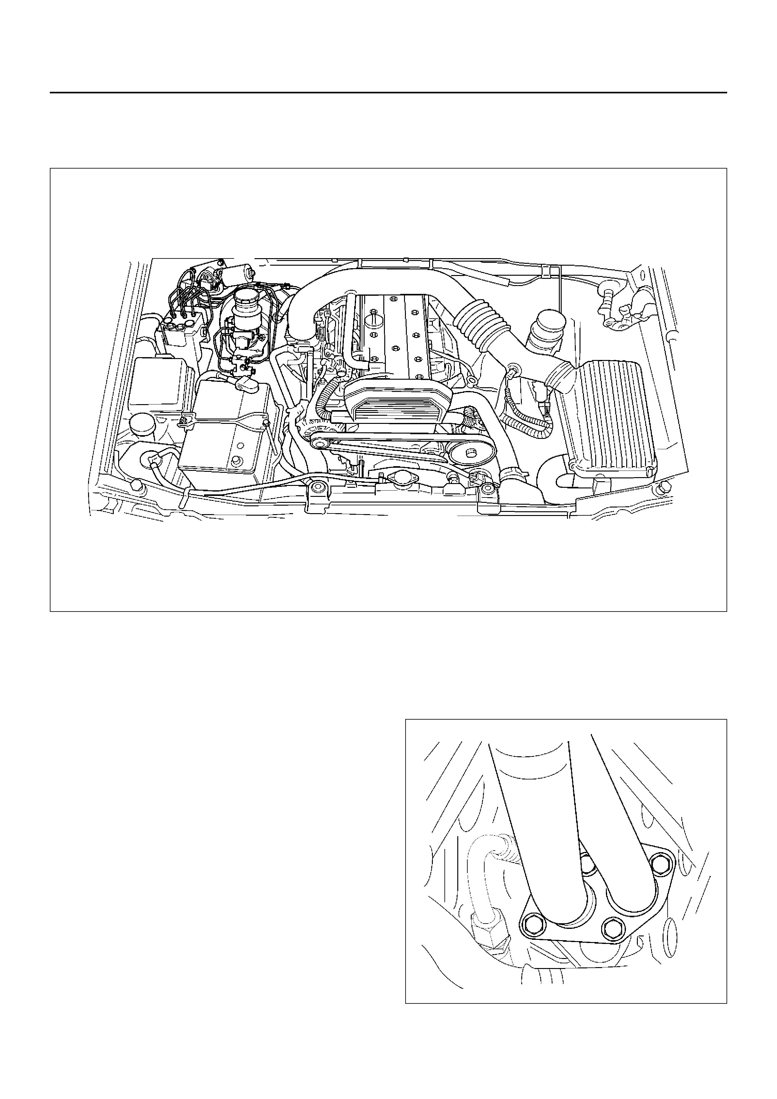
Engine and Associated Parts
755RX032
Removal
1. Disconnect battery ground and positive cable.
2. Remove battery.
3. Make alignment mark on the engine hood and
hinges bef ore remov al in order to return the hood to
original position exactly.
4. Remove engine hood.
5. Drain engine coolant from radiator.
6. Disconnect throttle valve control cable from throttle
valve on intake manifold.
7. Remove air duct with air cleaner cover.
8. Remove air cleaner assembly.
9. Disconnect three engine harness connectors from
chassis harness of left rear side engine
compartment.
10. Disconnect v acuum hose on the brake booster.
11. Disconnect cooling fan harness connector on the
left of fan shroud.
12. Disconnect ground cable connector from left and
right of front wheel arch upper side.
13. Remove clutch piping bracket from right side of
clutch housing.
14. Remove fuel piping bracket from transmission.
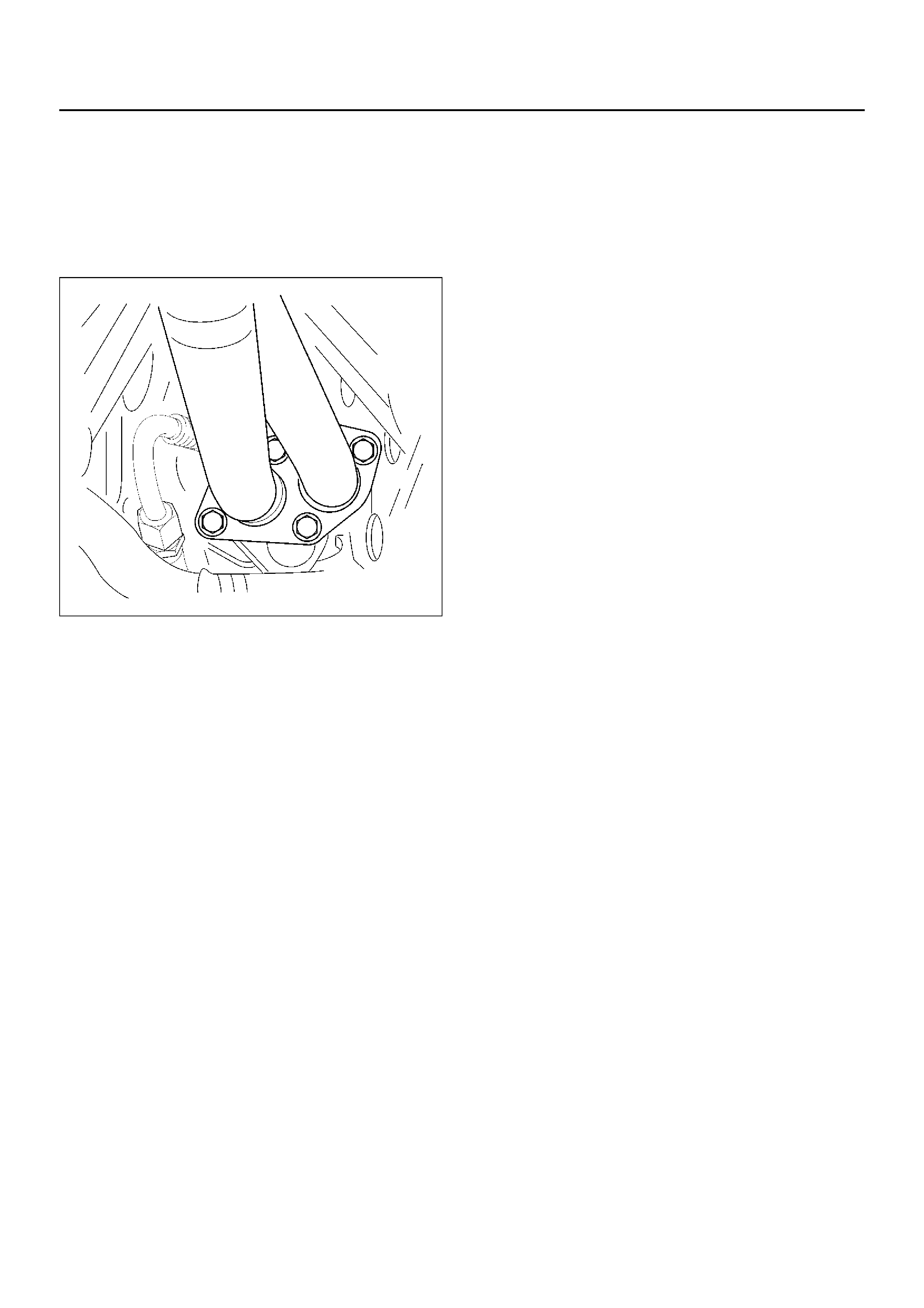
15. Remove four nuts from e xhaust front pipe exhaust
manifold side and remove two bolts from rear side of
exhaust front pipe. Remove exhaust front pipe.
027RW005
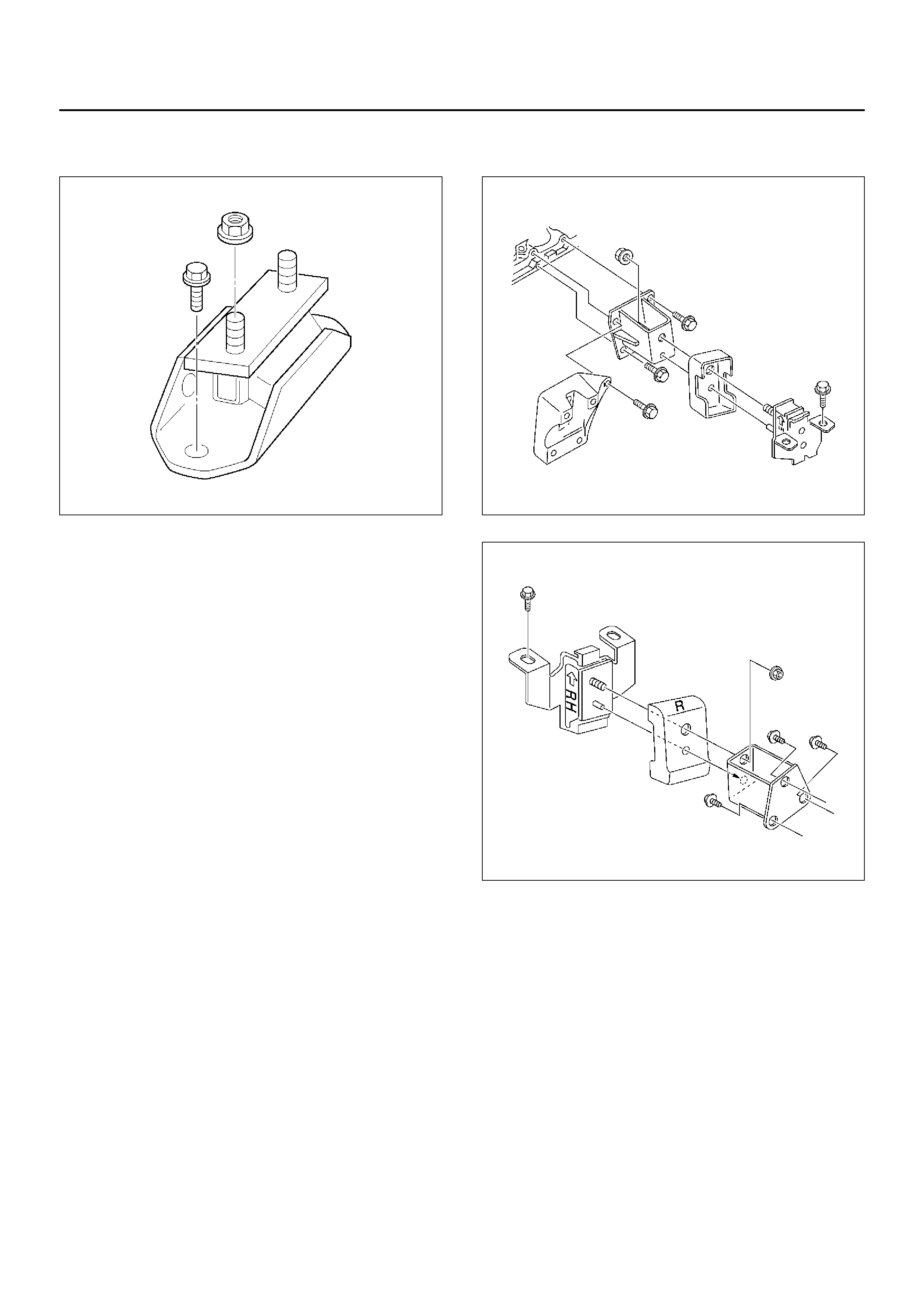
16.Remove transmission mounting fixing bolts and nut
from cross member.
022RW014
17.Remove transmission front under cover from front
portion of clutch housing.
18.Disconnect two fuel pipes at right side of
transmission by quick type fuel hose connector.
CAUTION: Plug fuel pipe on engine side and fuel
hose from fuel tank.
19. Disconnect canister hose next to fuel piping
connector.
20. Remove propeller shaft fixing bolt from rear side
transmission.
21. Remove fixing bolts between clutch housing and
transmission , then move transmission.
22. Remove power steering pump assembly then place
the power steering pump along with piping.
23. Disconnect two chassis harness connectors from
right rear side engine compartment (under fuse box)
and remove two harness clips.
24. Remove engine ground cable from chassis frame.
25. Remove radiator lower hose from engine side.
26. Remove two heater hoses from right side panel.
27. Remove radiator grille.
28. Remove harness clip from behind right horn.
29. Remove engine mounting bolt from chassis frame
side.
022RW005
022RW006
30. Lift up the engine assembly.
Installation
CAUTION: When assembling the engine and
transmission, confirm that dowels have been
mounted in the specified positions at the engine
side. If assembled in the condition that dowels
have not been mounted in the specified position,
transmission damage can result.
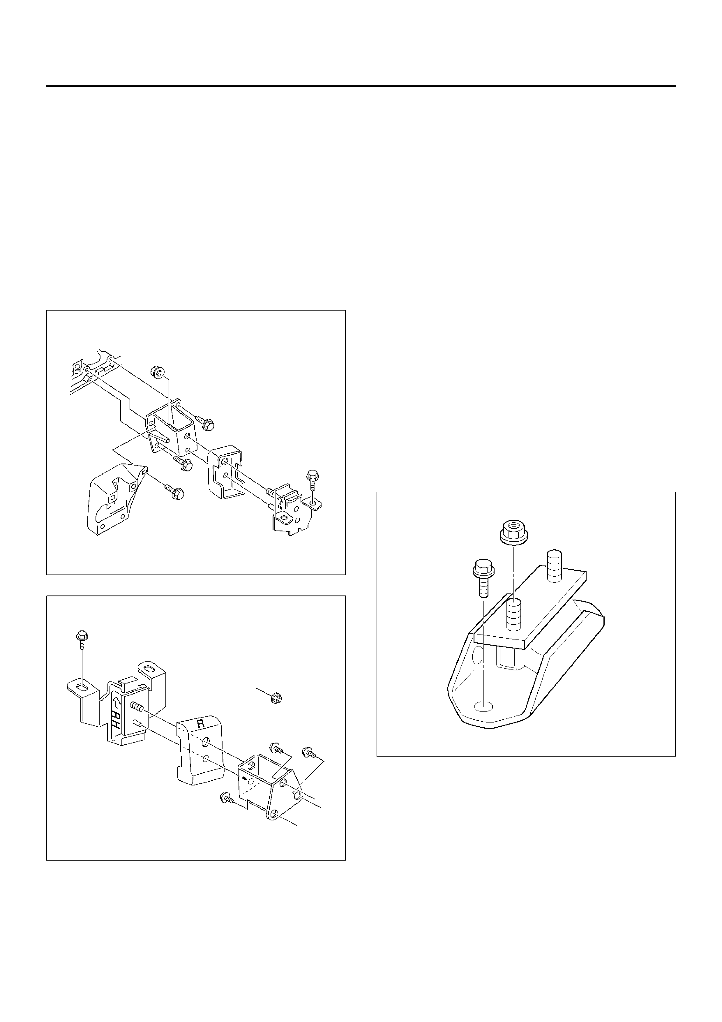
1. positi on the engine asse mbly in the engine
compartment.
2. Tighten engine mounting bolt to frame side to the
specified torque.
Torque: 41 N·m (4.2Kg·m/30lbft)
022RW005
022RW006
3. Install harness clip behind right horn.
4. Install the radiator grille and install flasher lamp
assembly.
5. Install two heater hoses to right side panel.
6. Install radiator lower hose to engine.
7. Install engine ground cable to chassis frame.
8. Connect two chassis harness connectors to right
rear side engine room(under fuse box) and install
two harness clips.
9. Install power steering pump assembly and tighten
fixing bolts.
10. Install transmission assembly, refer to installation
procedure for Transmission section in this manual.
11. Install propeller shaft, refer to installation procedure
for Propeller section in this manual.
12. Connect canister hose next to fuel piping connector.
13. Connect two fuel pipes at right side transmission by
quick type connector.
14. Install transmission front under cov er to front portion
of clutch housing.
15. Install transmission mounting fixing bolts and nuts to
cross member.
Torque: 50 N·m (5.1Kg·m/36lbft)
022RW014
16.Install exhaust front pipe to exhaust manifold and
silencer, then tighten fixing nuts and bolts to the
specified torque.
Torque
25 N·m (2.5Kg·m/18lbft) for nut
68 N·m (6.9Kg·m/50lbft) for bolt
027RW005
17.Install fuel piping bracket to transmission.
18.Install clutch piping bracket to right side of clutch
housing.
19.Connect ground cable connector to left and right of
front wheel arch upper side.
20.Connect cooling fan harness connector on the left of
fan shroud.
21.Connect vacuum hose to the brake booster.
22.Connect three engine harness connectors to
chassis harness of left rear side of engine
compartment.
23.Install air cleaner assembly.
24.Install air duct with air cleaner cover to specified
torque.
Torque
7 N·m (0.7Kg·m/5.1lbft) for air duct fixing
3 N·m (0.3Kg·m/2.2lbft) for air duct clamp bolt
25.Connect throttle valve control cable to throttle valve
on the intake manifold.
Confirm the free play of throttle valve control cable.
Free play: 5.7 to 6.3 mm
26.Install engine hood to original position.
Refer to installation procedure for Body section in
this manual.
27. Install battery, connect positive cable and ground
cable.
28. Fill engine coolant to full level in the coolant
reservoir tank.
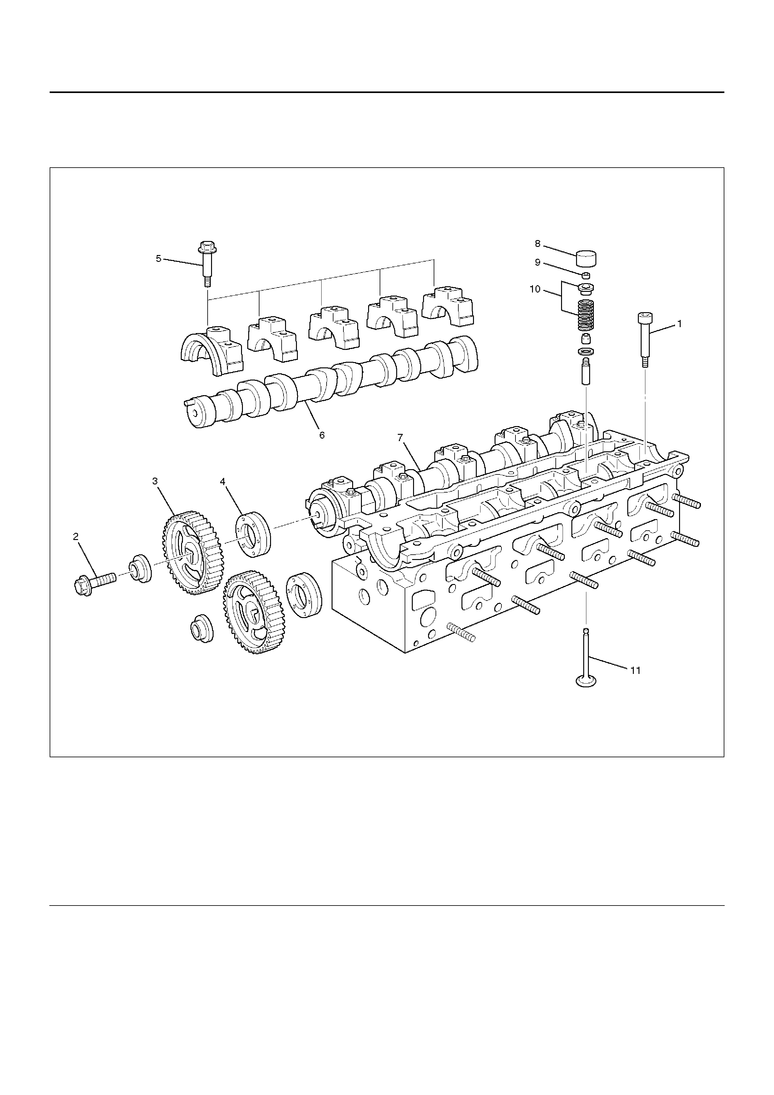
Cylinder Head
Cylinder Head and Associated Parts
011RW010
Legend
EndOFCallout
Disassembly
NOTE:
• During disassembly, be sure that the valve train
components are kept together and identified so that
they can be reinstalled in their original locations.
• Bef ore removing the cylinder head from the engine
and before disassembling the valve mechanism,
perform a compression test and note the results.
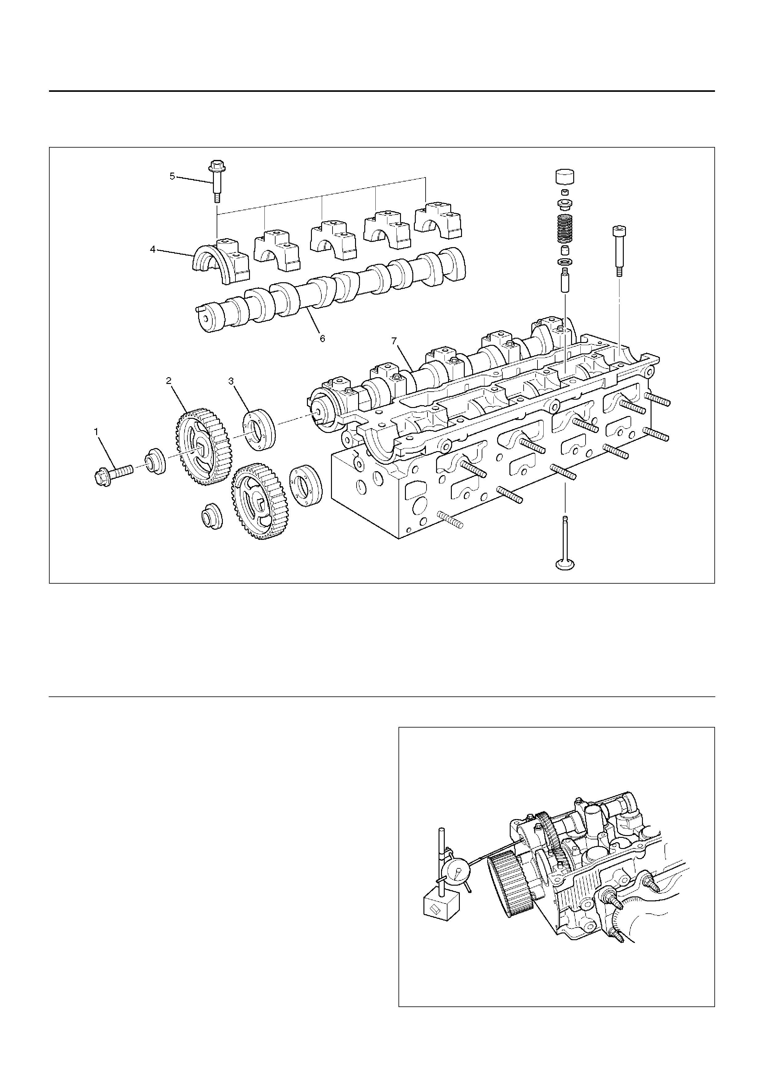
1. Remove camshaft pulley fixing bolt (2), then pulley
(3).
2. Remove camshaft bracket fixing bolt (5), camshaft
bracket, then camshaft exhaust (6), and intake side
(7).
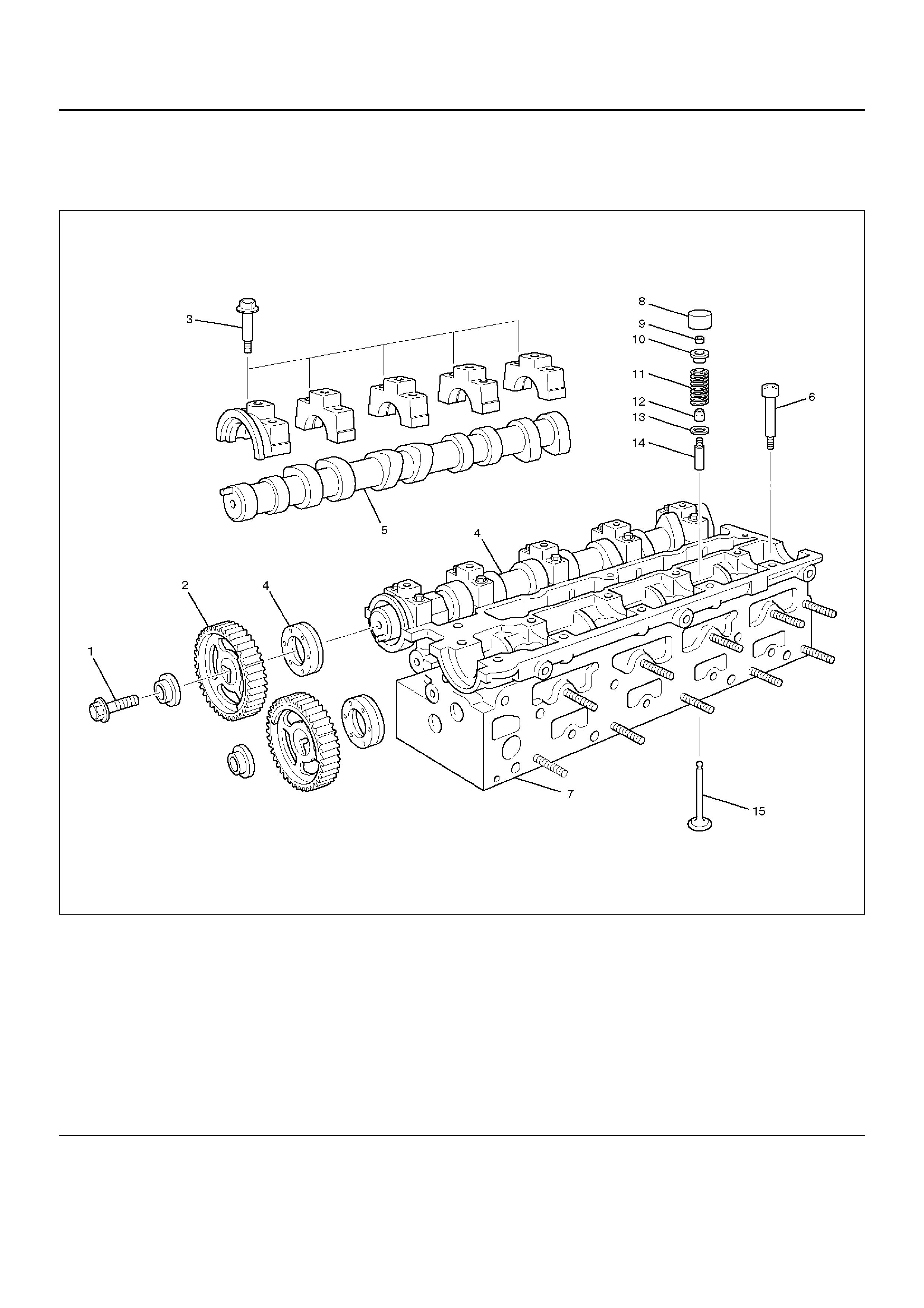
(1) Cylinder Head Bolt
(2) Camshaft Pulley Fixing Bolt
(3) Camshaft Pulley
(4) Camshaft Oil Seal
(5) Camshaft Bracket Bolt
(6) Camshaft Exhaust
(7) Cam s haft Inta ke
(8) Tappet (HLA)
(9) Split Collar
(10) Valve Spring and Spring Upper Seat
(11) Valve
3. Remove cylinder head.
Use 5–8840 –260 0–0.
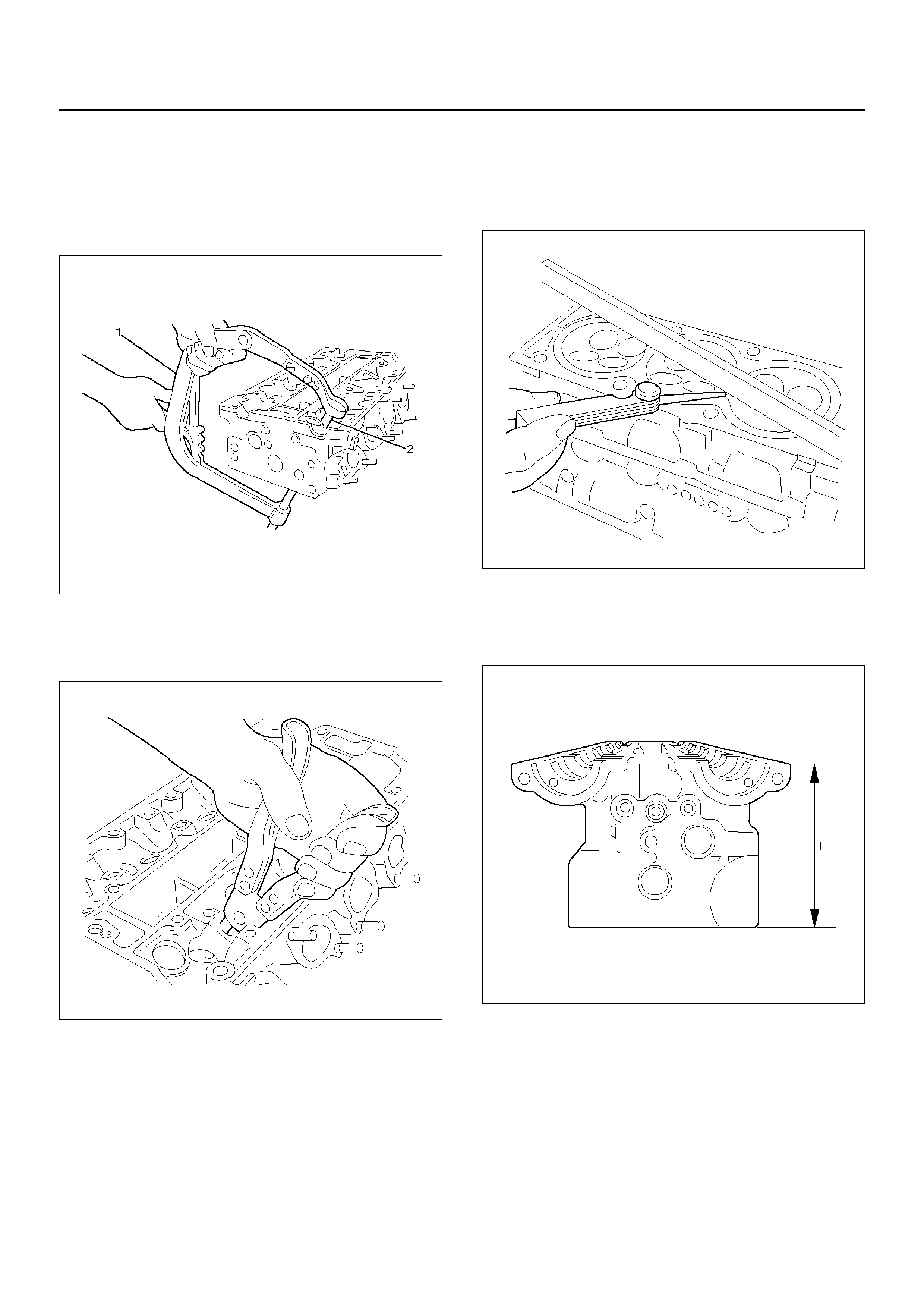
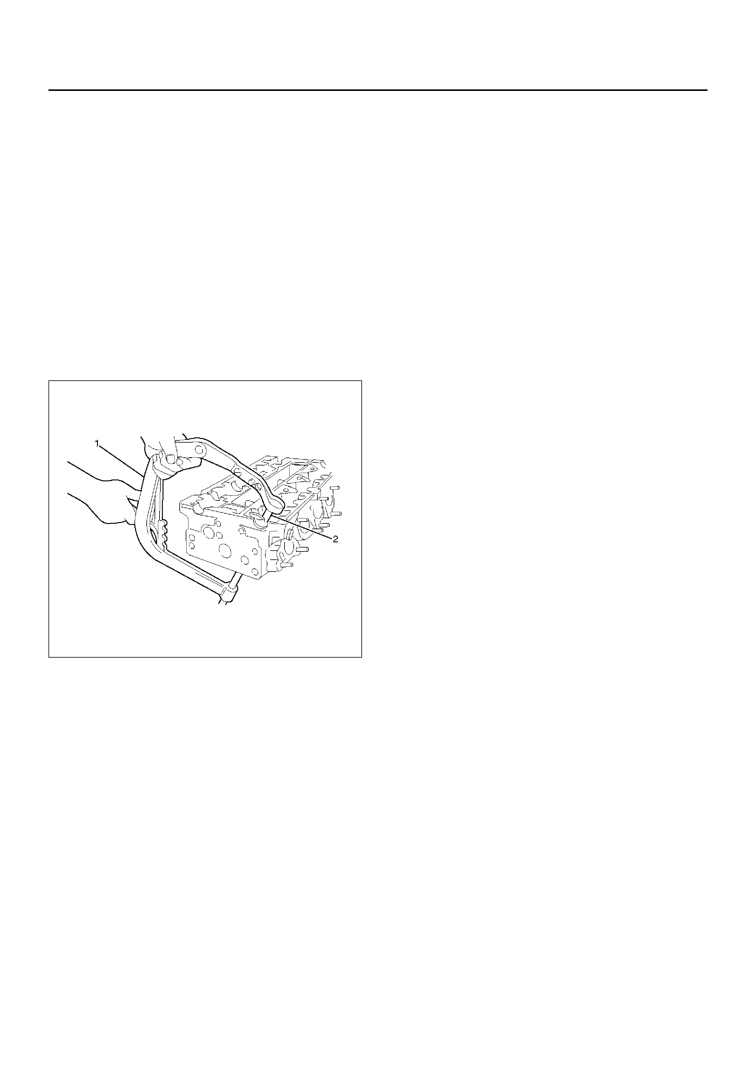
4. Valve spring, valve spring caps, compress valve
spring — use 5–8840–2546–0 (1) and Adapter 5–
8840–2662–0 (2).
Valve keepers.
011RW014
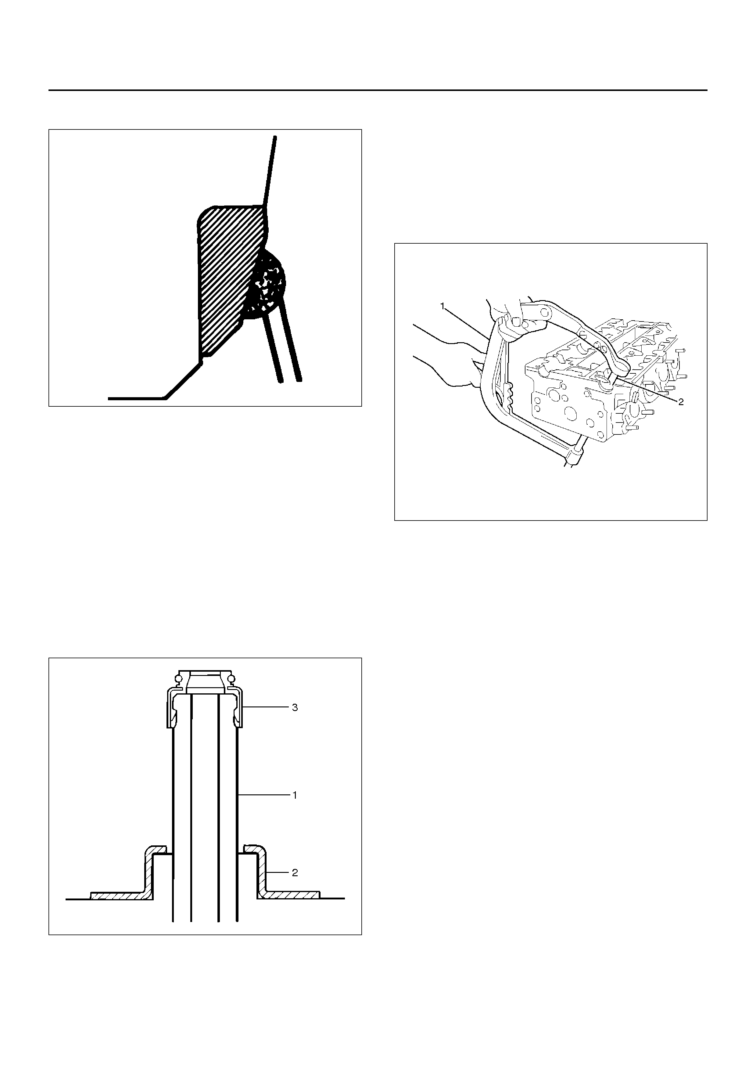
5. Valves, valve stem seals — use commercially
available remover pliers. Valv e spring seats from
cylinder head.
011RW013
Inspection and Repair
1. Check length and width of cylinder head sealing
surfaces f or def ormation and diagonals for warpage
— use straight edge and feeler gauge.
011RW011
2. Height of cylinder head (sealing surface to sealing
surface).
Dimension (I) – 134 mm
011RW012
Reassembly
1.Valves, valve stem seals. Refer to Valve Spring, Oil
Controller, Valve, Valve Guide in this section.
2.Valve spring, valve spring caps. Refer to Valve
Spring, Oil Controller, Valve, Valve Guide in this
section.
3.Install tappet (HLA).
4.Cylinder head with new cylinder head bolts to
cylinder block.
Tighten the bolts in 4 steps.
1st step: 25 N·m (2.5Kg·m/18lbft)
2nd step: 90°°°°
3rd step: 90°°°°
4th step: 90°°°°
011RW014
5.Camshaft in cylinder head. Refer to Camshaft in this
section.
6.Camshaft pulley. Refer to Camshaft in this section.
Valve Spring, Valve, Valve Guide
Valve Spring, Valve, Valve Guide and Associated Parts
011RW024
Legend
EndOFCallout
(1) Camshaft Pulley Fixing Bolts
(2) Camshaft Pulley
(3) Camshaft Bracket Fixing Bolt
(4) Camshaft Assembly Intake
(5) Camshaft Assembly Exhaust
(6) Cylinder Head Bolt
(7) Cylin der Head
(8) Tappet
(9) Split Collar
(10) Spring Upper Seat
(11) Valve Spring
(12) Oil Seal
(13) Spring Lower Seat
(14) Valve Guide
(15) Valve

Disassembly
1.Remove camshaft pulley (1), (2).
2.Remove camshaft assembly (Intake) (3), (4).
3.Remove camshaft assembly (Exhaust side) (5).
4.Remove cylinder head (6), (7).
5.Remove tappet (8).
6.Use 5–8840–2546–0 valve spring compressor and
5–8840–2662–0 adapter to remove split collar (9).
011RW014
7.Remove spring upper seat and valve spring (10),
(11).
8.Valve, valve guide – use commercially available
remover pliers.
Valve spring lower seat from cylinder head.
011RW013
Inspection and Repair
1.Use a internal micrometer to measure the diameter
valve guide.
Valve stem play
Intake : 0.03 to 0.057 mm (0.0012 to 0.0022in)
Exhaust : 0.04 to 0.067 mm (0.0016 to 0.0026in)
011RW020
Valve Guide
CAUTION: Taking care not to damage the valve seat
contact surface, when removing carbon adhering to
the valve head. Carefully inspect the valve stem for
scratching or abnormal wear . If these conditions are
present, the valve and the valve guide must be
replaced as a set.
Valve Seat
Valve seat width in cylinder head
Intake: 1.0 to 1.5 mm (0.039 to 0.0585 in)
Exhaust: 1.7 to 2.2 mm (0.0663 to 0.0858 in)
Valve Seat Insert Correction
Remove the carbon from the valve seat insert surface .
Valve Seat Insert Replacement
1. Arc weld the rod at several points. Be careful not to
damage the aluminum section.
2. Allow the rod to cool for a few minutes. This will
cause the valve seat to shrink.
3.Strike the rod and pull it out.
014RS015
4.Carefully clean the valve seat press–fit section on
the cylinder head side.
5.Heat the press–fit section with steam or some other
means to cause expansion. Cool the valve seat with
dry ice or some other means.
6.Insert the press–fit section into the valve seat
horizontally.
7.Lap the valve and the seat.
Reassembly
1.Install oil controller (3) and spring lower seat (2).
Using oil controller replacer 5–8840–2663–0, drive
in a new oil controller.
014RS019
2.Install valve to valve guide. Before install valve guide
apply engine oil to the outside of the valve stem.
3.Install valve spring to cylinder head. Attach the valve
spring to the lower spring seat.
4.Install lower valve spring seat, valve spring and
upper valve spring seat then put split collars on the
upper spring seat, using 5–8840–2546–0 valve
spring compressor for install the split collars.
011RW014
5.Install tappet.
6.Install camshaft assembly.
•Refer to installation procedure for Camshaft in
this manual.
Camshaft
Camshaft and Associated Parts
011RW023
Legend
EndOFCallout
Disassembly
1. Remove fixing bolt (1) for camshaft pulley (2).
2. Remove oil seal (3).
014RW035
(1) Camshaft Pulley Fixing Bolt
(2) Camshaft Pulley
(3) Oil Seal
(4) Camshaft Bracket
(5) Camshaft Bracket Fixing Bolt
(6) Camshaft Assembly Exhaust
(7) Camshaft Assembly Intake
3. Remove oil seal (3).
4. Remove twenty fixing bolts (5) from inlet and
exhaust camshaft bracket, then camshaft brackets
(4).
011RW015
5. Remove camshaft assembly (6), (7).
Reassembly
1. Install camshaft drive gear assembly and tighten
three bolts to specified torque.
Torque: 50 N·m (5.1Kg·m/37lbft) + 60°
°°
° + 15°
°°
°
2. Install camshaft assembly and camshaft brackets,
tighten twenty bolts on one side bank to the
specified torque.
1. Apply engine oil to camshaft journal and bearing
surface of camshaft brac ket.
2. Align timing mark on intake camshaft and
exhaust camshaft to timing mark on camshaft
drive gear (one dot).
3. Tighten twenty bolts on numerical order one
side bank shown in the illustration.
Torque: 8 N·m (0.8Kg·m/6lbft)
4. If it required to replace oil seal of camshaft driv e
gear, use 5–8840–2658–0 for install the oil seal.
5. Tighten bolt for camshaft drive gear assemb ly
pulley to the specified torque.
Torque: 50 N·m (5.1Kg·m/37lbft) + 60°
°°
° + 15°
°°
°
014RW036
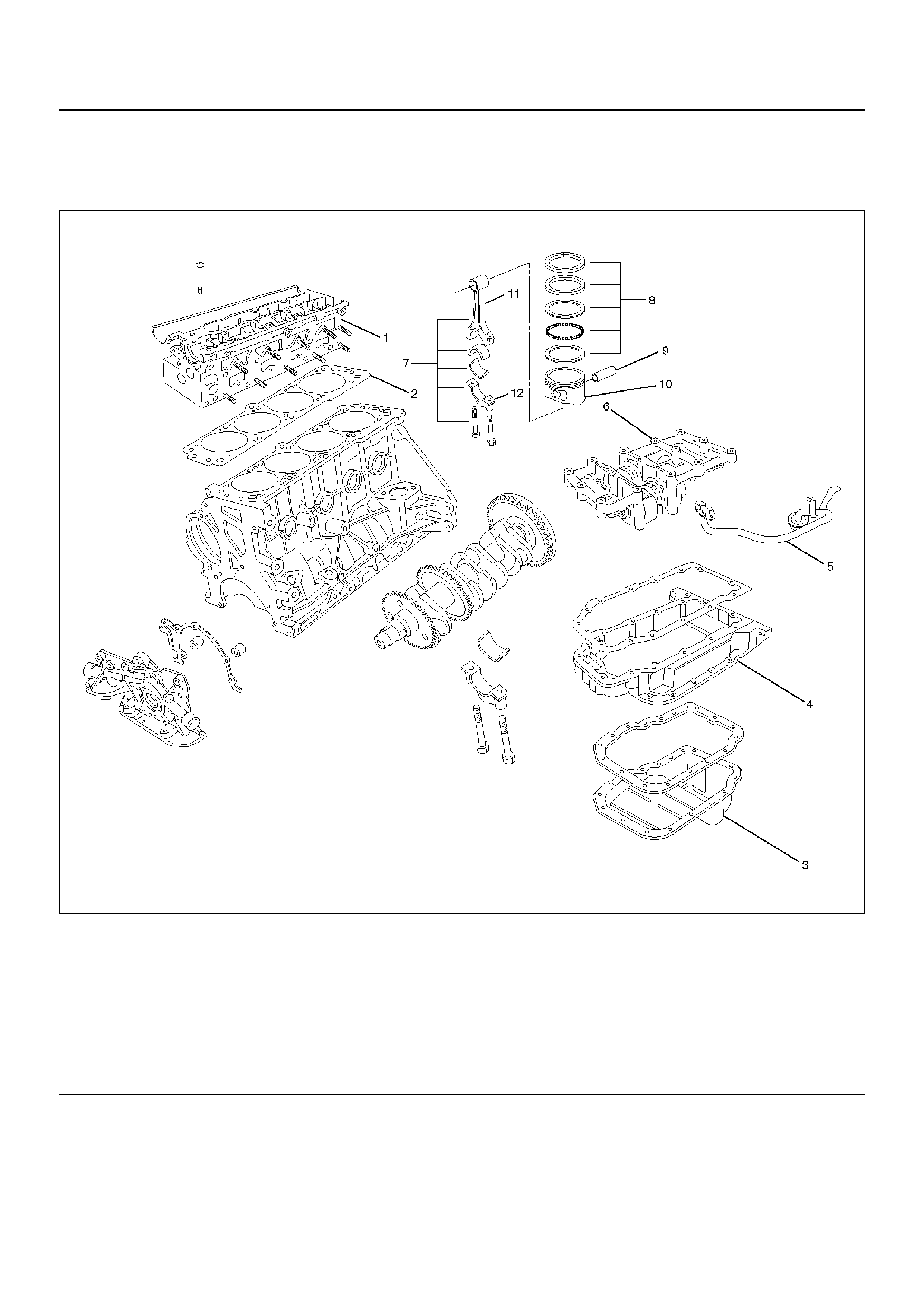
Crankshaft
Crankshaft and Associated Parts
015RW008
Legend
EndOFCallout
Disassembly
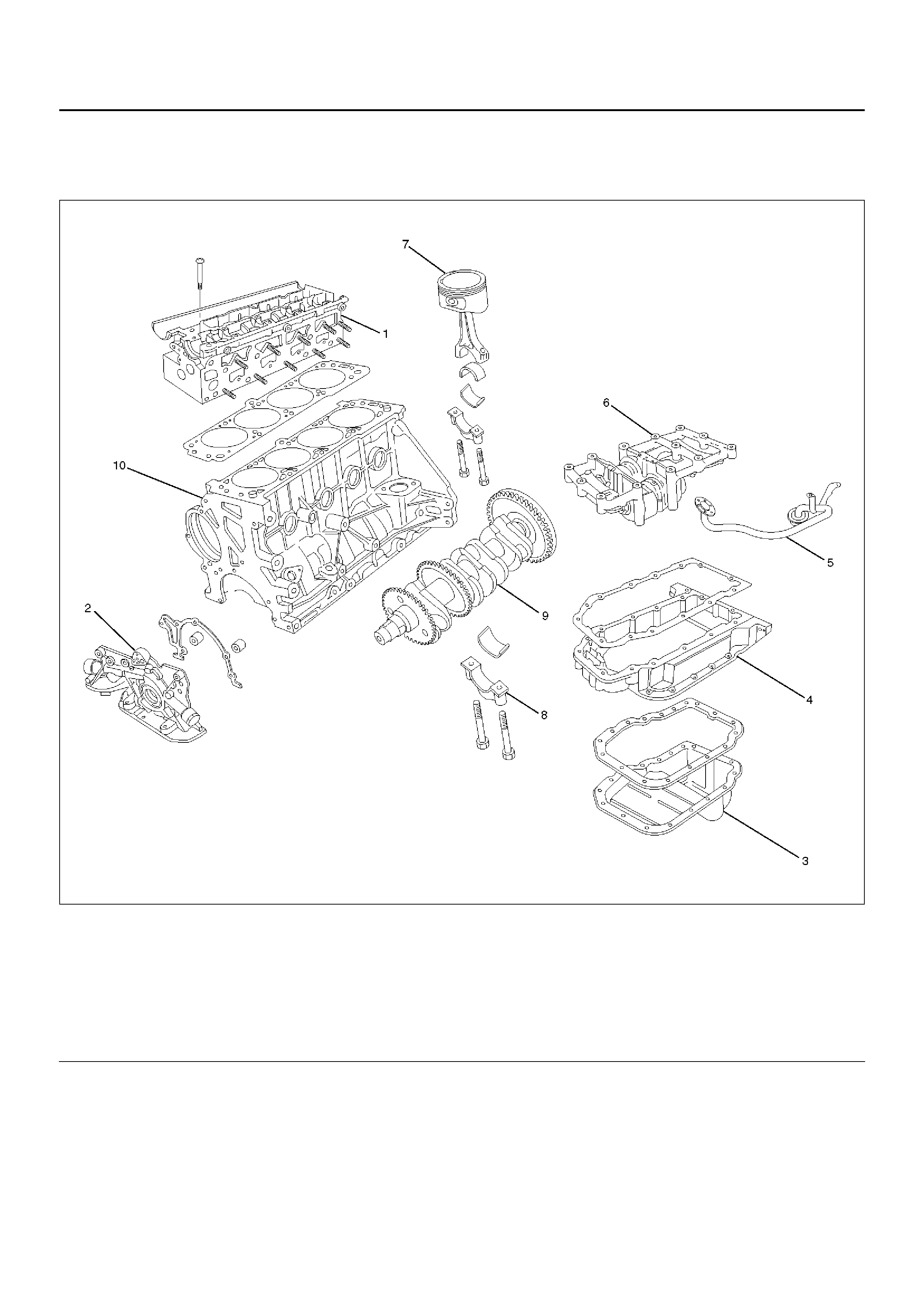
1.Remove cylinder head assembly (1). Refer to
“Cylinder head" in this manual.
2.Remove oil pan (3).
CAUTION: Take care not to damage or deform the
sealing flange surface of crankcase.
3.Remove oil pan support (4).
4.Remove oil strainer (5).
5.Remove oil pump assembly (5).
6.Balance unit assembly.
7.Remove piston and connecting rod assembly (7).
Refer to “Piston, Piston Ring and Connecting Rod"
in this manual.
(1) Cylinder Head Assembly
(2) Oil Pump Assembly
(3) Pan
(4) Pan Support
(5) Oil Strainer
(6) Balance Unit Assemb ly
(7) Piston and Connecting Rod Assembly
(8) M ain Bearing Cap
(9) Crankshaft
(10) Cylinde r Bl ock Assembly
8. Remove flywheel.
9. Remove rear oil seal and oil baffle plate.
10. Remove main bearing cap (8).
11. Remove crankshaft (9).
12. Remove crankshaft pulse pickup sensor disc.
Inspection and Repair
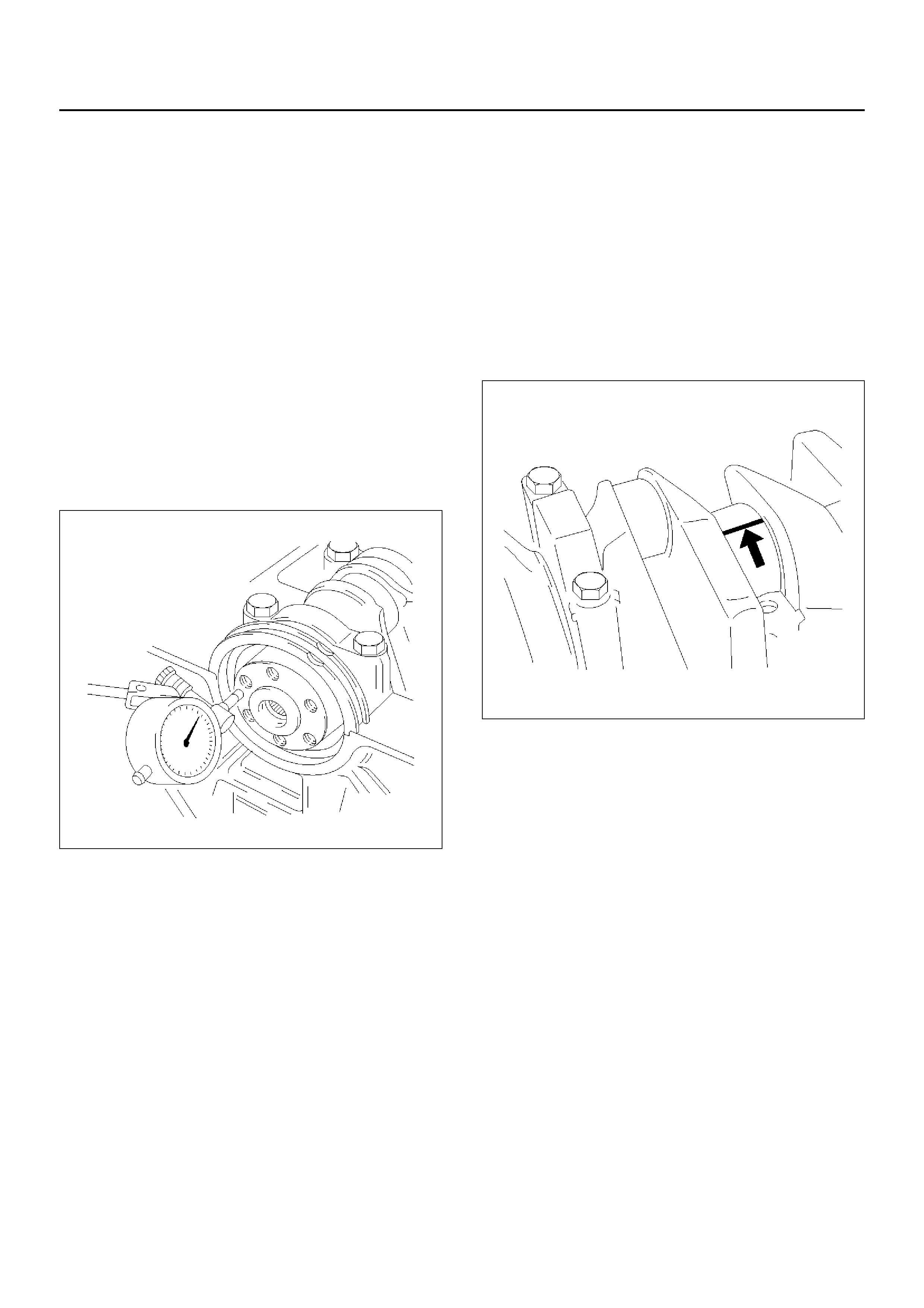
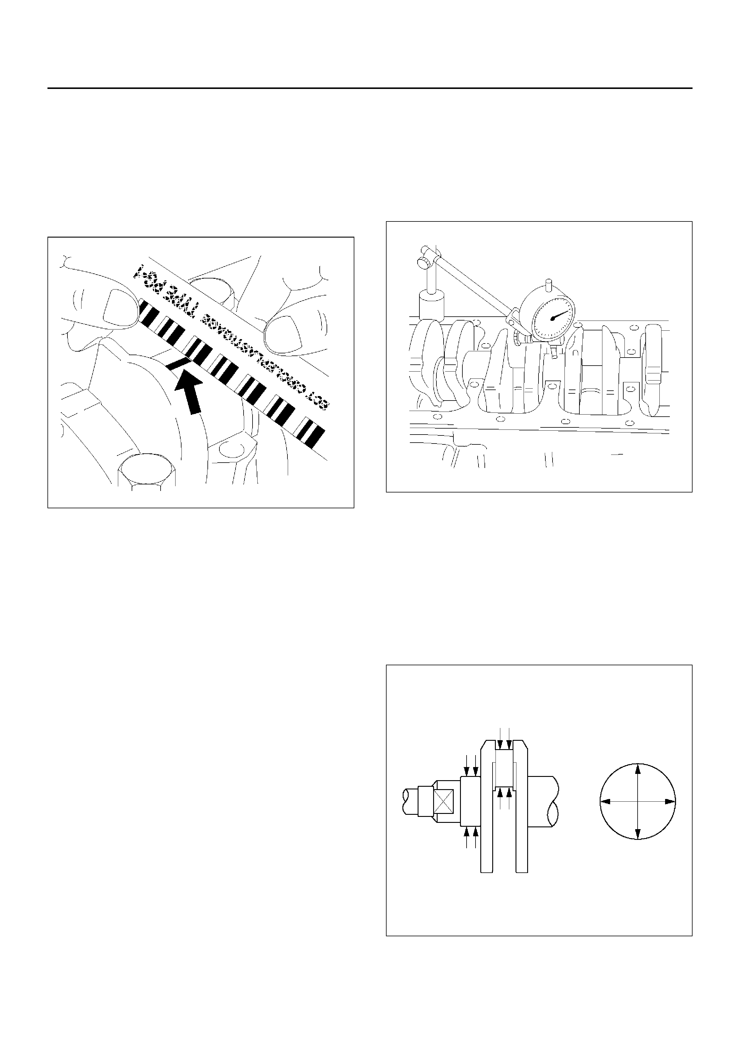
1. Crankshaft
Set the dial indicator as shown in the illustration and
measure the crankshaft thrust clearance. If the
thrust clearance exceeds the specified limit, replace
the thrust bearings as a set.
Thrust Clearance
Standard : 0.01 mm–0.02 mm
(0.0004 in–0.0008 in)
Limit : 0.21 mm (0.0118 in)
014RW079
Main Bearing Clearance
1. Remove the bearing caps and measure the oil
clearance.
2. Remove the main bearing cap fixing bolts.
Arrange the removed main bearing caps in the
cylinder number order.
Remove the main bearings.
3. Remove the crankshaft.
Remove the main bearings.
4. Clean the upper and lower bearings as well as the
crankshaft main journal.
5. Check the bearings for damage or excessive wear.
The bearings must be replaced as a set if damage
or excessive wear is discovered during inspection.
6. Set the upper bearings and the thrust washers to
their original position s.
Carefully install the crankshaft.
7. Set the lower bearings to the bearing cap original
position.
8. Apply plastigage to the crankshaft journal unit as
shown in the illustration.
014RW055
9. Install main bearing caps, and tighten each bolt to
the specified torque.
Main bearing caps bolts.
Torque:
1st step: 50 N·m (5.1Kg·m/37lbft)
2nd step: 45°
°°
°
3rd step: 15°
°°
°
Torque : 39 N·m (4.0Kg·m/29lbft)
10. Measure the plastigage width and determine the oil
clearance. If the oil clearance e xceeds the specified
limit, replace the main bearings as a set and/or
replace the crankshaft.
Standard : 0.015 mm–0.04 mm
(0.0007 in–0.0016 in)
Limit : 0.12 mm (0.0047 in)
014RW077
11. Clean the plastigage from the bearings and the
crankshaft.
Remove the crankshaft and the bearings.
Crankshaft (12) Inspection
Inspect the surface of the crankshaft journal and crank
pins for excessive wear and damage. Inspect the oil
seal fitting surfaces for excessive wear and damage.
Inspect the oil ports f or obstructions.
Inspection and Repair
1. Carefully set the crankshaft. Slowly rotate the
crankshaft and measure the runout. If the
crankshaft runout exceeds the specified limit, the
crankshaft must be replaced.
Runout : 0.03 mm (0.0012 in)
014RW078
2. Measure the diameter and the unev en wear of main
journal and crank pin. If the crankshaft wear
exceeds the specified limit, crankshaft must be
replaced.
Main journal diameter : 57.934 mm–57.980 mm
(2.259 in–2.261 in)
Crank pin diameter : 48.939 mm–48.982 mm
(1.909 in.–1.91 in.)
015RS009
Cran ks ha f t Be aring Selection
When installing new crankshaft bearings or replacing
bearings, refer to the selection table below. Select and
install the new crankshaft bearings.
NO TE: Take care to ensure the bearings are positioned
correctly.
Crankshaft pulse pickup sensor disc inspection and
repair.
Inspect the crankshaft pulse pickup sensor disc for
excessive wear and damage.
Replace the crankshaft pulse pickup sensor disc if the
inspection exceeds wear and damage.
015RW039
Reassembly
1. Crankshaft (12).
• Install the crankshaft pulse pickup sensor disc.
Torque: 13 N·m (1.3Kg·m/10lbft)
• Install the main bearings to the cylinder block and
the main bearing caps.
• Be sure that they are positioned correctly.
• Apply ne w engine oil to the upper and lower main
bearing faces.
NO TE: Do not apply engine oil to the main bearing
b a ck face s.
• Carefully mount the crankshaft.
• Apply engine oil to the thrust washer.
• Assemble the thrust washer to the No.3 bearing
journal. The oil grooves must face the crankshaft.
• Tighten the crankshaft baring cap bolts in 3
steps:
1st step: 50 N·m (5.1Kg·m/36lbft)
2nd step: 45°
°°
°
3rd step: 15°
°°
°
Crankshaft grinding dimensions mm (in)
Production and Service
Crankshaft bearing journal dia.
Stan dard si ze
white 57.974 to 57.981 (2.260–2.261)
green 57.981 to 57.988 (2.261–2.2615)
brown 57.988 to 57.995 (2.2615–2.2618)
Undersize 0.25 (0.0097)
green/blue 57.732 to 57.738 (2.2515–2.2517)
brown/blue 57.738 to 57.745 (2.2517–2.252)
Undersize 0.5 (0.0195)
green/white 57.482 to 57.488 (2.2418–2.242)
brown/white 57.488 to 57.495 (2.242–2.2423)
Guide bearing width
Standard size 25.950 to 26.002 (1.012–1.014)
Undersize 0.25 (0.0097) 26.150 to 26.202 (1.019–1.021)
Undersize 0.5 (0.0195) 26.350 to 26.402 (1.027–1.029)
2. Rear oil seal (10).
• Coat lip of seal rings thinly with protective grease.
• Install seal ring into cylinder bl ock, use 5–8840–
2660–0 (1) and 5–8840–2597–0 (2).
015RW009
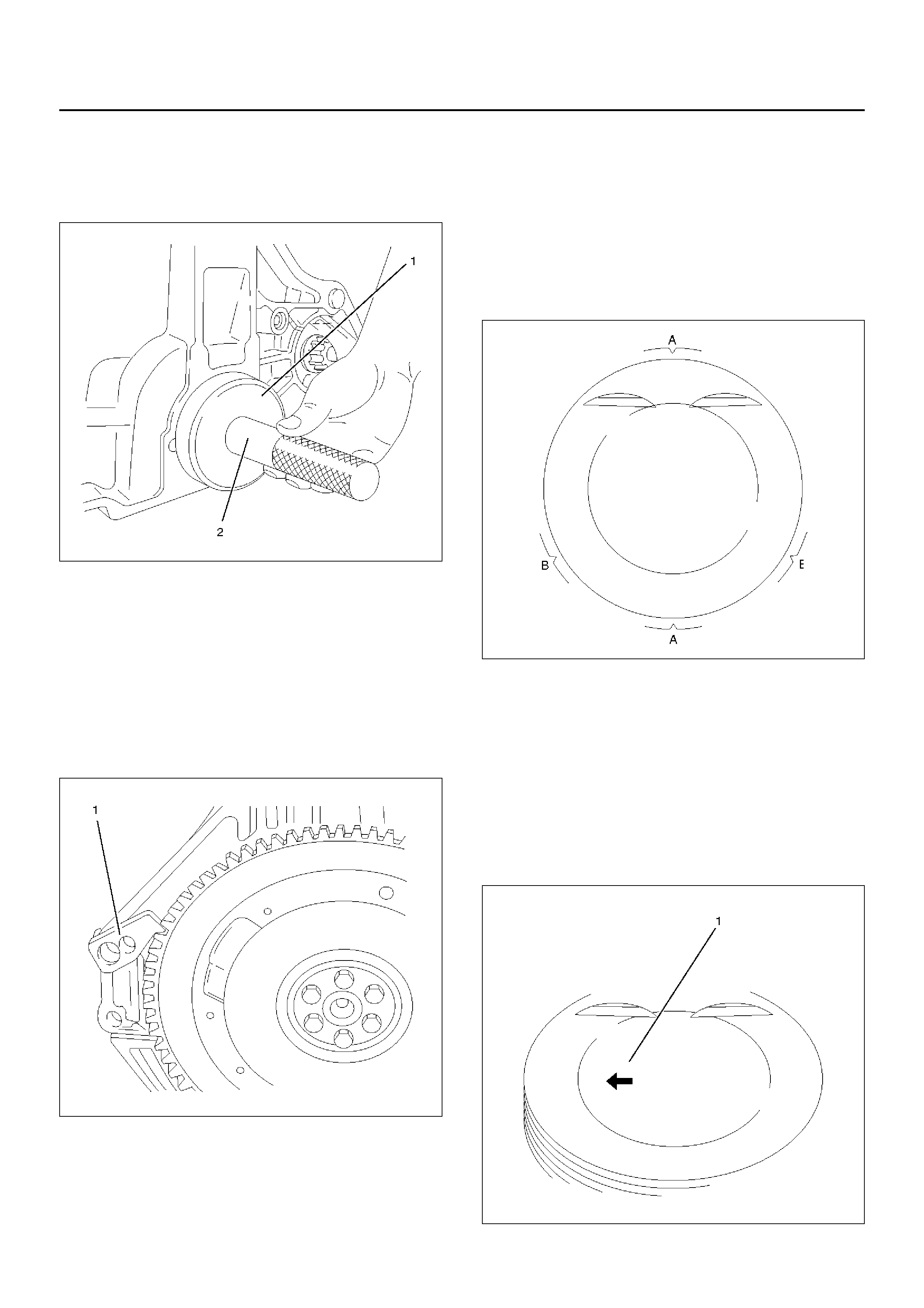
3. Flywheel (9).
1. Thoroughly clean and remove the oil from the
threads of crankshaft.
2. Remov e the oil from the crankshaft and flywheel
mounting faces.
3. Mount the flywheel on the crankshaft and then
install the washer.
4. Use stopper (5–8840–2661–0) to hold the
crankshaft.
015RW010
5. Prevent from rotating.
Tighten the flywheel bolts in 3 steps:
1st step: 65 N·m (6.6Kg·m/48lbft)
2nd step: 30°
3rd step: 15°
NO TE: Do not reuse the bolt.
4. Piston and connecting rod assembly (8)
• Apply engine oil to the cylinder bores, the
connecting rod bearings and the crankshaft pins.
Check to see that the piston ring end gaps are
correctl y pos iti on ed.
• Piston rings position (A) every 180°.
Oil scraper rings (B) — offset 25 to 50 mm/1 to 2
in. to left and right from gap of intermediate ring.
015RW026
• Insert the piston/connecting rod assemblies into
each cylinder with the piston ring compressor.
The front marks must be facing the front of the
engine.
• Match the numbered caps with the numbers on
the connecting rods. Align the punched marks on
the connecting rods and caps.
• Arrow (1) on piston head points to engine timing
side, bead on connecting rod points to flywheel
side.
015RW038

•Tighten the bolts in 3 steps:
1st step: 35 N·m (3.6Kg·m/25lbft)
2nd step: 45°°°°
3rd step: 15°°°°
5.Install the balance unit assembly and tighten the
bolts in 2 steps:
1st step: 20 N·m (2.0Kg·m/14lbft)
2nd step: 45°°°°
Refer to the “Balance Unit Assembly" section of this
manual.
6.Install oil pump assembly (5), refer to “Oil Pump" in
this manual.
7.Install oil strainer.
Torque: 8 N·m (0.8Kg·m/5.8lbft)
8.Install oil pan support and tighten the bolts to the
specified torque.
Torque: 20 N·m (2.0Kg·m/14lbft)
9.Install oil pan.
1.Completely remove all residual sealant,
lubricant and moisture from the sealing
surfaces. The surfaces must be perfectly dry.
2.Apply a correct width bead of sealant (TB–
1207C or its equivalent) to the contact surfaces
of the oil pan. There must be no gaps in the
bead.
3.The oil pan support must be installed within 5
minutes after sealant application.
4.Tighten the bolts in to steps.
1st step: 8 N·m (0.8Kg·m/5.8lbft)
2nd step: 30°°°°
10.Install cylinder head assembly, refer to “Cylinder
Head" in this manual.
Piston and Connecting Rod
Piston, Connecting Rod and Associate Parts
015RW037
Legend
EndOFCallout
Disassembly
1.Remove cylinder head assembly (1), refer to
“Cylinder Head Removal" in this manual.
2.Remove cylinder head gasket (2).
3.Remove oil pan assembly and oil pan support (3)
4. Remove oil strainer.
5. Remove balance unit assembly.
6. Remove connecting rod cap with connecting rod
lower.
(1) Cylinder Head Assembly
(2) Cylin der Head Gasket
(3) Oil Pan Assembly
(4) Pan Support
(5) Oil Strainer
(6) Bal anc e Unit Asse mbly
(7) Piston and Connecting Rod Assembly
(8) P is ton Rin g
(9) P is ton Pi n
(10) Piston
(11) Connecting Rod
(12) Connecting Rod Cap

7. Remove piston and connecting rod assembly (7).
NOTE: Before removing piston and connecting rod
assembly, measure thrust clearance.
• Remov e any ridge or carbon build up from the top
end of the cylinde r.
8. Remove the piston rings (8) with a piston ring
expander. Arrange the removed piston rings in the
cylinder number order.
015RW024
9. Remove the piston pin (9).
• Heat the connecting rod and the piston pin with
oil heater, when it temperature is keep at 280°Χ–
320°C.
• Push the piston pin with brass bar.
NOTE: Keep the parts removed from each cylinder
separate. All parts must be reinstalled in their original
positions.
10. Piston (10).
11. Connecting rod (11).
Inspection and Repair
Pistons (10)
Carefully clean away all the carbon adhering to the
piston head and the piston ring grooves.
NOTE: Never use a wire brush to clean the pistons.
Damage will result. Visually check each piston for
cracking, scoring, and other signs of excessive wear. If
any of the above conditions are found, the piston must
be replaced.
Piston Rings (8)
Any worn or damaged part discovered during engine
overhaul must be replaced with a new one.
1. Ring end gap measurement
• Insert the piston ring into the bore.
• Push the ring by the piston, at a right angle to the
wall, into the point at which the cylinder bore
diameter is the smallest.
• Measure the ring end gap.
2. Measure the clearance between the piston ring
groov e and the piston ring with a feeler gauge. If the
piston ring groove / piston ring clearance exceeds
the specified limit, the piston must be replaced.
Compression Ring Clearance
Standard : 0.02 mm–0.04 mm
(0.0008 in.–0.0016 in)
015RW025
Compression Ring
1st ring
Standard: 0.30 mm–0.50 mm
(0.0118 in–0.0195 in)
2nd ring
Standard: 0.30 mm–0.50 mm
(0.0118 in–0.0195 in)
Oil ring
Standard: 0.40 mm–1.40 mm
(0.0156 in–0.0546 in)
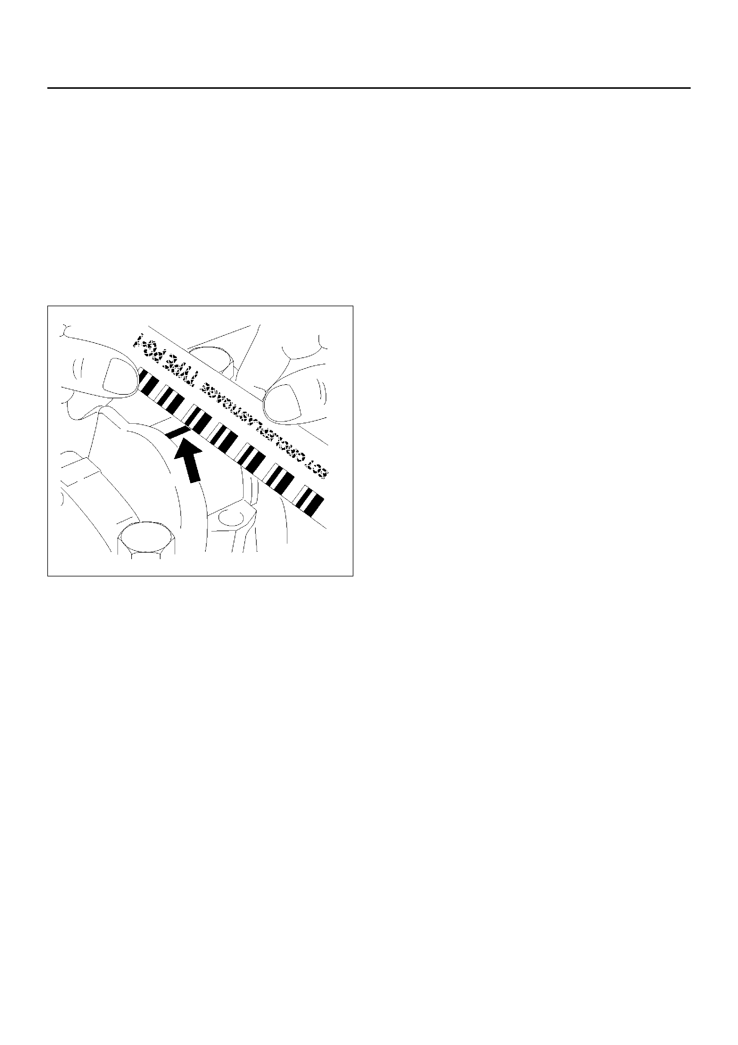
Piston Pin (9)
NOTE: Do not reuse the old piston pin.
1. Use a micrometer to measure the new piston pin
outside diameter in both di rections a t three different
positions.
2. Measure the inside diameter of the connecting rod
small end. If the fitting interference between the
small end and pin does not conform to the specified
value, the connecting rod must be replaced.
Standard : 0.02 mm–0.041 mm
(0.0008 in–0.0016 in)
014RW077
3. Insert the new pin into the piston and rotate it. If the
pin rotates smoothly with no backlash, the clearance
is normal. If there is backlash or roughness,
measure the clearance. If the clearance exceeds the
specified limit, the piston must be replaced.
Clearance
Standard : 0.011 mm–0.014 mm
(0.0004 in.–0.0005 in)
Connecting Rods (11)
1. Measure the oil clearance between the connecting
rod and the crankshaft.
1. Remove the connecting rod cap nuts and the
rod caps (12).
Arrange the removed rod caps in the cylinder
number order.
2. Clean the rod bearings and the crankshaft pins.
3. Carefully check the rod bearings. If even one
bearing is found to be damaged or badly worn,
the entire bearing assembly must be replaced
as a set. Reinstall the bearings in their original
positions. Apply plastigage to the crank pin.
4. Reinstall the rod caps (12) to their original
positions.
Tighten the rod cap nuts.
1st step: 35 N·m (3.6Kg·m/26lbft)
2nd step: 45°
°°
°
3rd step: 15°
°°
°
NO TE: Do not allow the crankshaft to rotate.
5. Remove the rod caps.
6. Measure the width of the plastigage and
determine the oil clearance. If the oil clearance
exceeds the limit, replace the rod bearing as a
set.
Standard : 0.006 mm–0.031 mm
(0.0002 in–0.0012 in)
Limit : 0.12 mm (0.0047 in)
7. Clean the plastigage from the bearings and the
crankshaft pins.
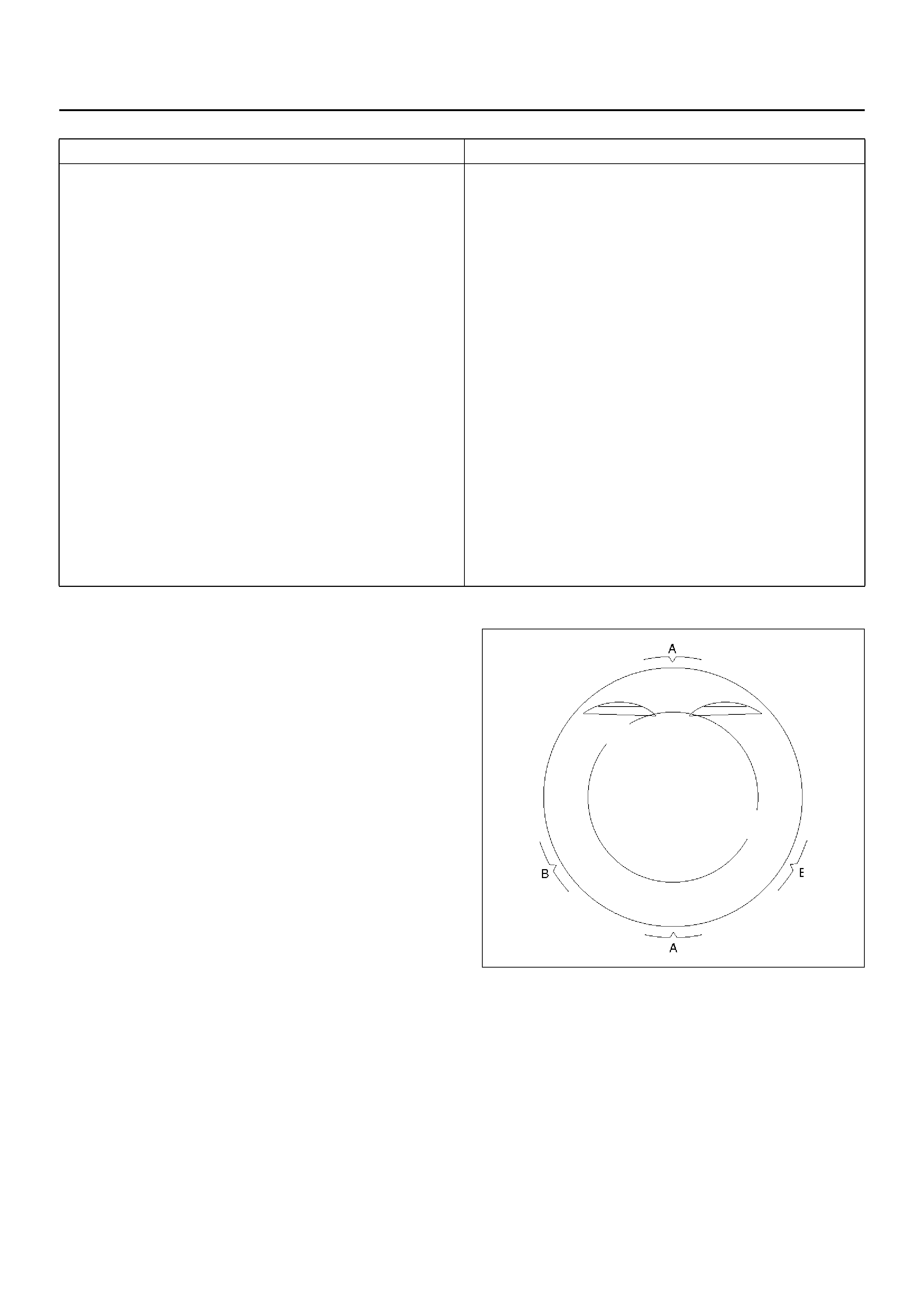
Reassembly
1. Install connecting rod
2. Install piston
3. Install piston pin
• Apply a thin coat of engine oil to the piston pin.
Try to insert the piston pin into the piston pin hole
with normal finger pressure.
NOTE: When changing piston / connecting rod
combinations, do not change the piston / piston pin
combination and do not reuse the old piston pin.
• Attach the piston to the connecting rod with the
piston front mark and the connecting rod front
mark on the same side.
• Heat the connecting rod small end to a suitable
temperature to ensure smooth installation.
4. Install piston ring with the piston ring expander.
• New piston rings with “Top" uppermost — use
commercially available pliers.
• Position ring gaps:
1 — Compression rings 180°to each other as
illustrated.
2 — Offset oil control rings 25 to 50 mm/1 to 2 in.
from gap of second compression ring.
015RW026
• After installation, apply engine oil to the entire
circumference of the piston rings. Check to see
that all the rings rotate smoothly.
5. Install piston and connecting rod assembly.
• Insert the bearings into the connecting rods and
caps. Apply new engine oil to the bearing faces
and nuts.
• Tighten the connecting rod cap nuts in 3 steps:
1st step : 35 N·m (3.6Kg·m/26lbft)
2nd step: 45°
°°
°
3rd step: 15°
°°
°
Crankshaft grinding dimensions mm (in)
(continued)
Production and Service
Con–rod bearing journal dia.
Stan dard si ze
(no color code) 48.970 to 48.988 (1.9098–1.9105)
Undersize 0.25 (0.0097)
blue 48.720 to 48.738 (1.9001–1.9008)
Undersize 0.5 (0.0195)
white 48.470 to 48.488 (1.8903–1.891)
Con–rod bearing journal width
Stan dard si ze
(no color code) 26.460 to 26.580 (1.0319–1.036)
Undersize 0.25 (0.0097)
blue 26.460 to 26.580 (1.0319–1.036)
Undersize 0.5 (0.0195)
white 26.460 to 26.580 (1.0319–1.036)
Con–rod width 26.338 to 26.390 (1.0271–1.0292)
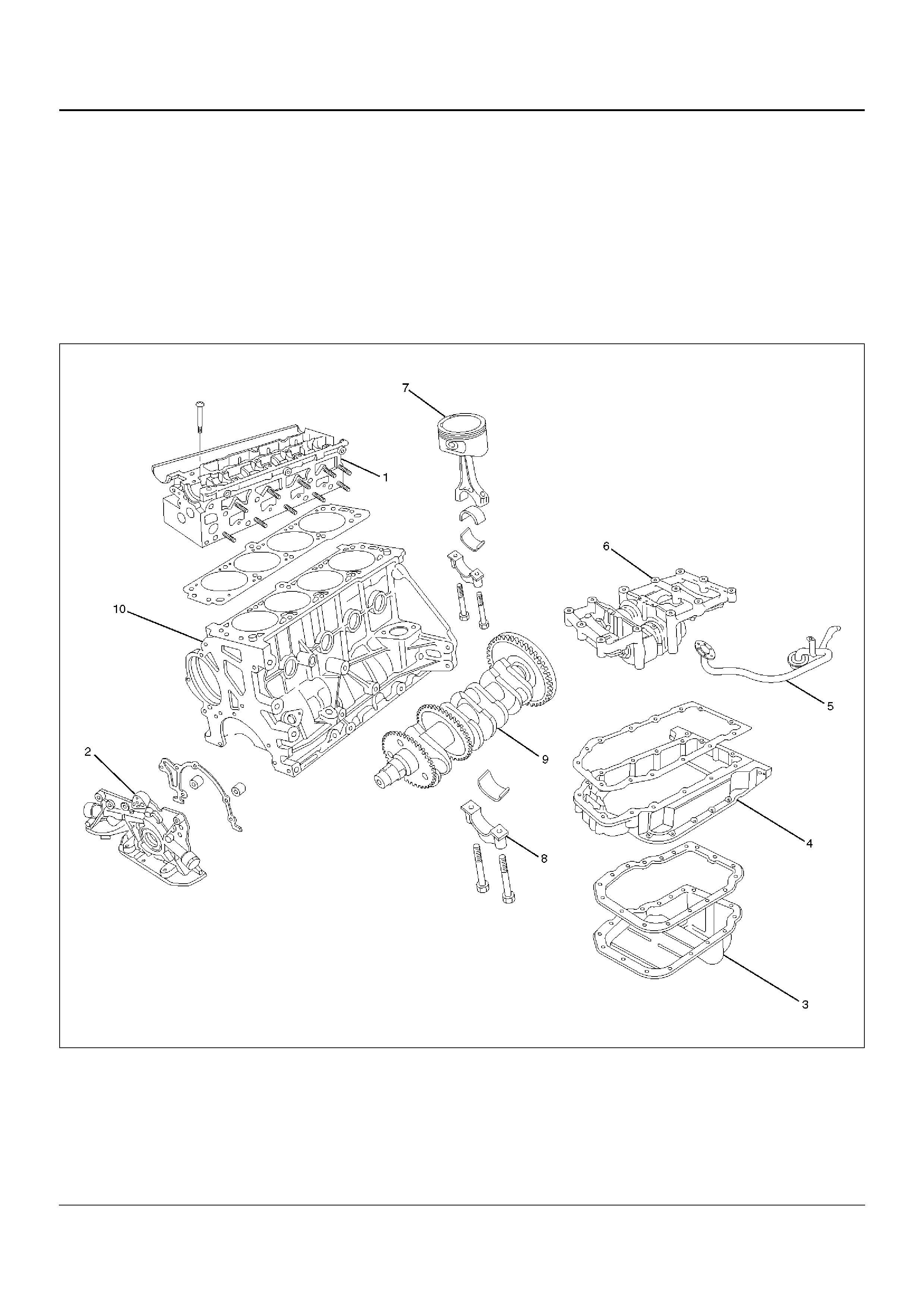
NOTE: Do not apply engine oil to the bearing back
faces.
6.Oil gallery, refer to “Crankshaft and Main Bearing" in
this manual.
7.Oil strainer and O-ring.
8.Install balance unit assembly, refer to “Balance Unit
Assembly: in this manual.
9.Install oil pan support assembly,
10. Install cylinder head gasket.
11. Install cylinder head assembly.
•Refer to “Cylinder Head" in this manual.
Cylinder Block
Cylinder Block and Associated Parts
015RW008
Legend
EndOFCallout
(1) Cylinder Head Assembly
(2) Oil Pump Assembly
(3) Oil Pan
(4) Oil Pan Support
(5) Oil Strainer
(6) Balance Unit Assemb ly
(7) Piston and Connecting Rod Assembly
(8) M ain Bearing Cap
(9) Crankshaft
(10) Cy li nde r Block
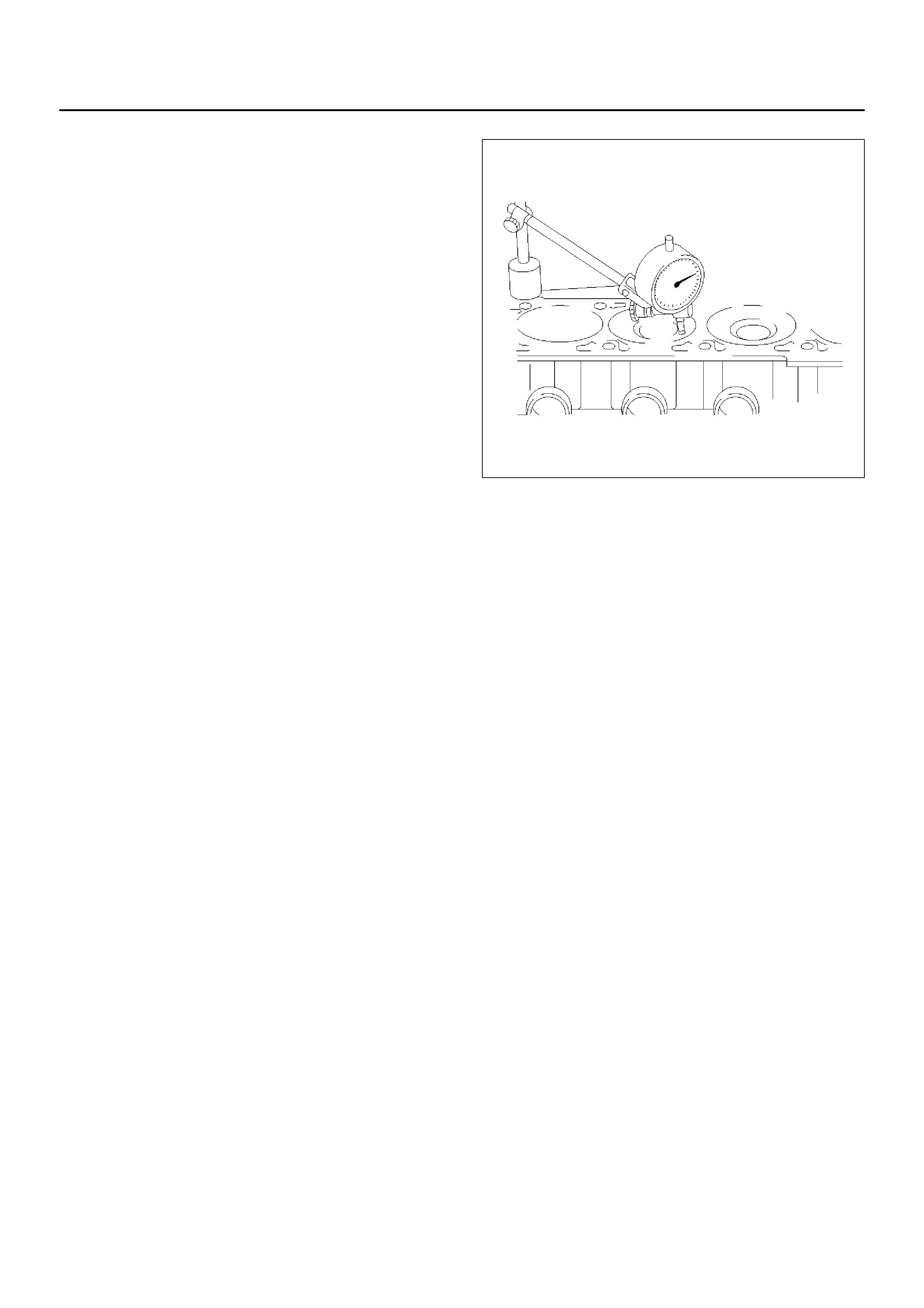
Disassembly
1.Remove cylinder head assembly.
2.Remove cylinder head gasket.
3.Remove oil pan assembly.
4.Remove oil pan support.
5.Remove oil strainer.
6.Remove oil pump assembly.
7.Remove balance unit assembly.
8.Remove piston and connecting rod assembly.
9.Remove flywheel.
10.Remove rear oil seal retainer assembly.
11.Remove main bearing cap.
12.Remove crankshaft.
13.Remove cylinder block.
Inspection and Repair
1.Remove the cylinder head gasket and any other
material adhering to the upper surface of the
cylinder block. Be very careful not to allow any
material to accidentally drop into the cylinder block.
Be very careful not to scratch the cylinder block.
2.Carefully remove the oil pump, rear oil seal retainer,
and crankcase assembly installation surface seal.
3.Wipe the cylinder block clean.
4.Visually inspect the cylinder block. If necessary, use
a flaw detector to perform a dye penetrate and
hydraulic (or air pressure) test. If cracking or other
damage is discovered, the cylinder block must either
be repaired or replaced.
Flatness
1.Using a straight edge and feeler gauge, check that
the upper surface of the cylinder block is not
warped.
CAUTION: Be very careful not to allow any material
to accidentally drop into the upper surface of the
cylinder block. Be very careful not to scratch the
upper surface of the cylinder block.
2.The cylinder block must be reground or replaced if
the warpage exceeds the limit.
Warpage
Limit : 0.40 mm (0.0156 in)
Maximum repairable limit: 0.40 mm (0.0156 in)
012RW013
Cylinder Bore
Use a cylinder gauge to measure the cylinder bore
diameter in both the axial and thrust directions. Each
measurement should be made at six points.
CAUTION: Be very careful not to allow any material
to accidentally drop into the upper surface of the
cylinder block. Be very careful not to scratch the
upper surface of the cylinder block.
If the measurement exceeds the specified limit, the
cylinder block must be replaced.
Diameter
Grade 1 : 85.975 mm–85.985 mm
(3.3530 in–3.3534 in)
Grade 2 : 85.985 mm–86.025 mm
(3.3534 in–3.3550 in)
Oversize : 0.5 mm (0.0195 in)
NOTE: For information on piston diameter, please refer
to the section “Inspection of the Piston and Connecting
Rod Assembly" in this manual.
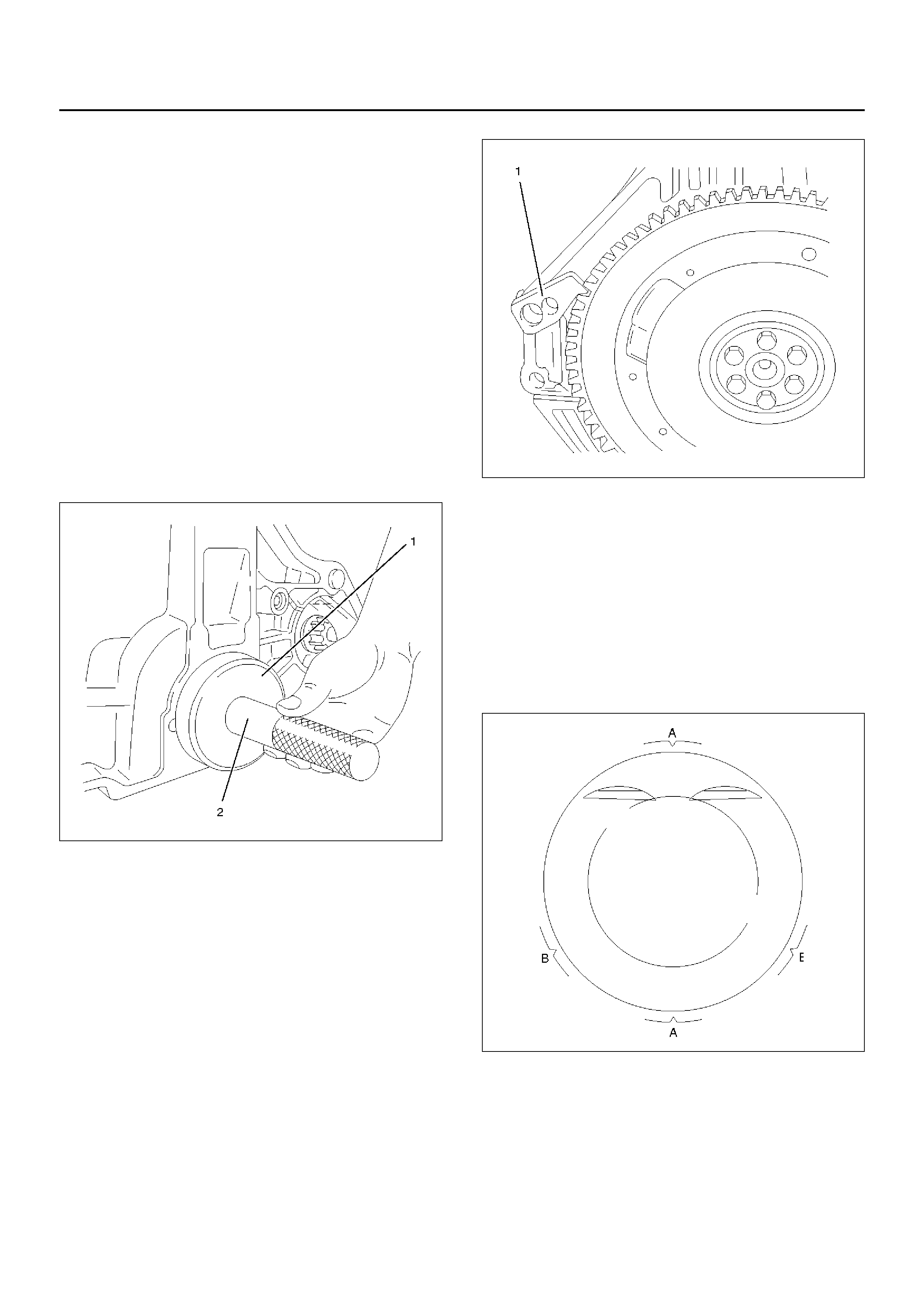
Reassembly
1.Install cylinder block.
2.Install crankshaft.
•Install the main bearings to the cylinder block and
the main bearing caps.
•Be sure that they are positioned correctly.
•Apply new engine oil to the upper and lower main
bearing faces.
NOTE: Do not apply engine oil to the bearing back
faces.
•Carefully mount the crankshaft.
•Apply engine oil to the thrust washer.
3.Install rear oil seal.
•Coat lip of seal rings thinly with protective grease.
•Install seal ring into cylinder block, use 5–8840–
2660–0 (1) and 5–8840–2597–0 (2).
015RW009
4.Install flywheel
1.Thoroughly clean and remove the oil from the
threads of crankshaft.
2.Remove the oil from the crankshaft and flywheel
mounting faces.
3.Mount the flywheel on the crankshaft and then
install the washer.
4.Use stopper (5–8840–2661–0) to hold the
crankshaft.
Prevent from rotating.
Tighten the flywheel bolts in 3 steps:
1st step: 65 N·m (6.6Kg·m/48lbft)
2nd step: 30°
3rd step: 15°
NOTE: Do not reuse the bolt.
015RW010
5.Install piston and connecting rod assembly.
•Apply engine oil to the cylinder bores, the
connecting rod bearings and the crankshaft pins.
NOTE: Do not apply engine oil to the bearing back
faces.
•Position ring gaps:
1 — Compression rings 180° to each other as
illustrated (A).
2 — Offset oil control rings 25 to 50 mm/1 to 2 in.
from gap of second compression ring (B).
015RW026
6.Install balance unit assembly and tighten the bolts in
2 steps in the order shown:
1st step : 20 N·m (2.0Kg·m/14lbft)
2nd step : 45°°°°
7.Install oil pump assembly, refer to “Oil Pump" in this
manual.
8. Install oil strainer.
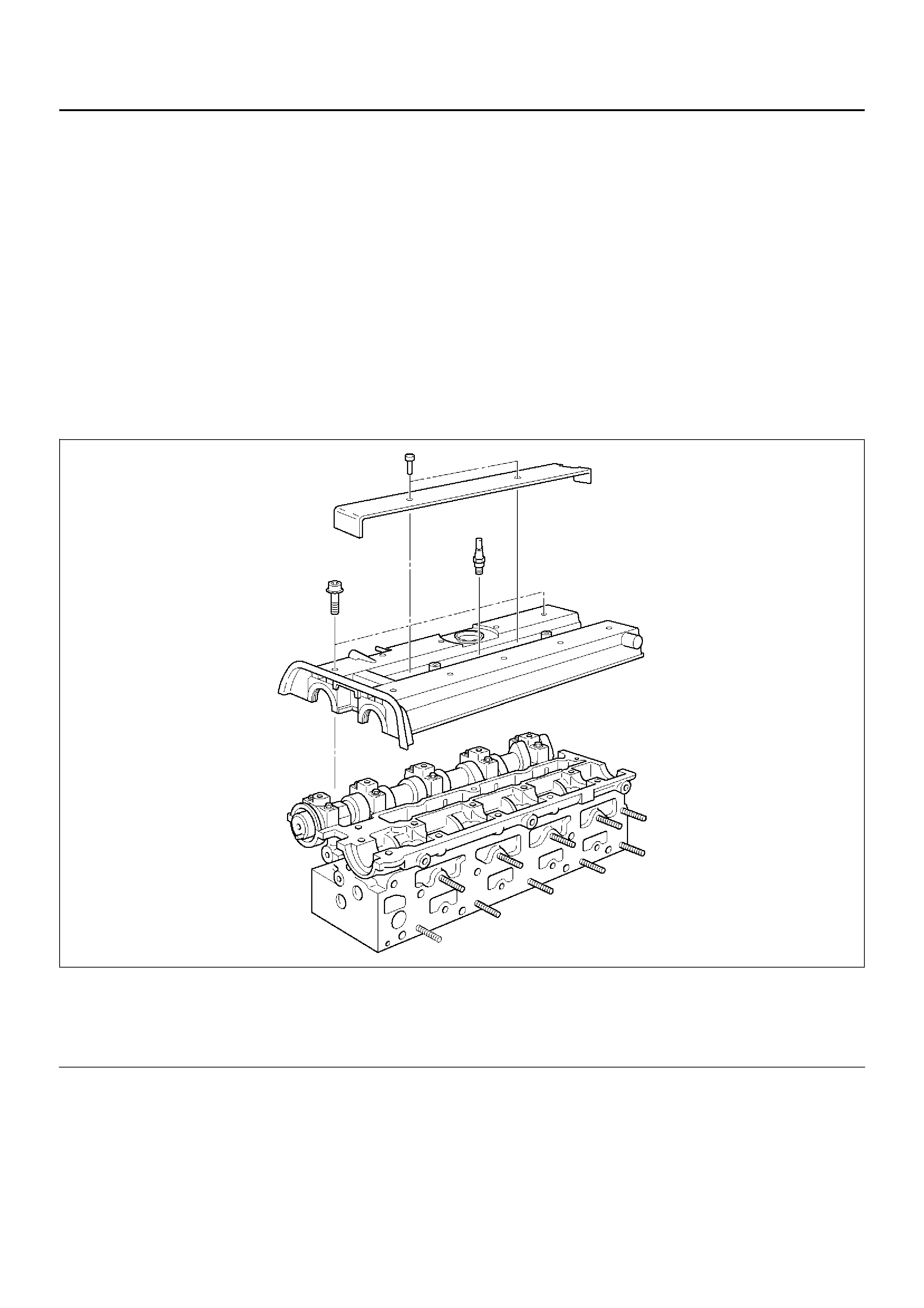
9.Install oil pan support.
10.Install oil pan assembly.
1.Completely remove all residual sealant,
lubricant and moisture from the sealing
surfaces. The surfaces must be perfectly dry.
2.Apply a correct width bead of sealant (TB–
1207C or its equivalent) to the contact surfaces
of the crankcase. There must be no gaps in the
bead.
3.The oil pan must be installed within 5 minutes
after sealant application.
4.Tighten the bolts and nuts to the specified
torque in 2 steps:
1st step : 8 N·m (0.8Kg·m/5.8lbft)
2nd step : 30°°°°
11.Install cylinder head gasket.
12.Install cylinder head assembly, refer to “Cylinder
Head" in this manual.
Cylinder Head Cover
Cylinder Head Cover and Associated parts
010RW004
Legend
EndOFCallout
(1) Ignition Cable Cover
(2) Spark Plug (3) Cylinder Head Cover
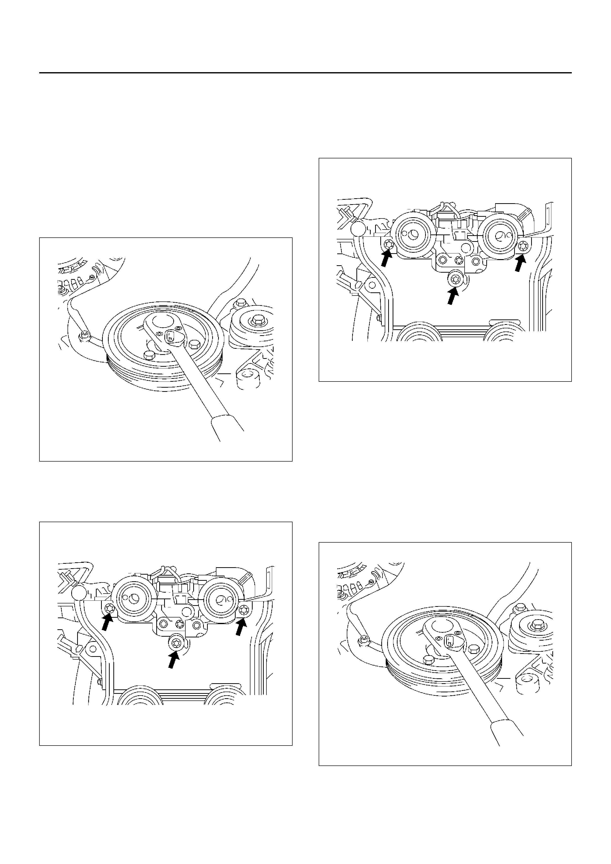
Removal
1. Remove two bolts and remove ignition cable cover
(1) from cylinder head cover (3).
2. Disconnect ignition cable and remove spark plag
(2).
3. Disconnect ignition cable from ignition plug.
4. Disconnec t camshaft angle sensor harness and
crankshaft angle sensor harness from behind
generator.
5. Remove f our bolts and remov e the crankshaft pulle y.
020RW014
6. Remove timing belt front cover.
7. Loose fixing bolt of timing belt rear cover, then
remove the camshaft angle sensor.
020RW012
8. Remove ten cylinder head cover fixing bolts and
remove the cylinder head cover.
Installation
1. Install the camshaft angle sensor and tighten timing
rear cover bolt.
Torque: 8 N·m (0.8Kg·m/5.9lbft)
020RW012
2. Install the cylinder head cover and tighten bolts to
the specified torque.
Torque: 8 N·m (0.8Kg·m/5.9lbft)
3. Install the timing belt front cover then tighten fixing
bolts to the specified torque.
Torque: 6 N·m (0.6Kg·m/4.4lbft)
4. Install the crankshaft pulley, tighten fixing bolts to
the specified torque.
Torque: 20 N·m (2.0Kg·m/14lbft)
020RW014
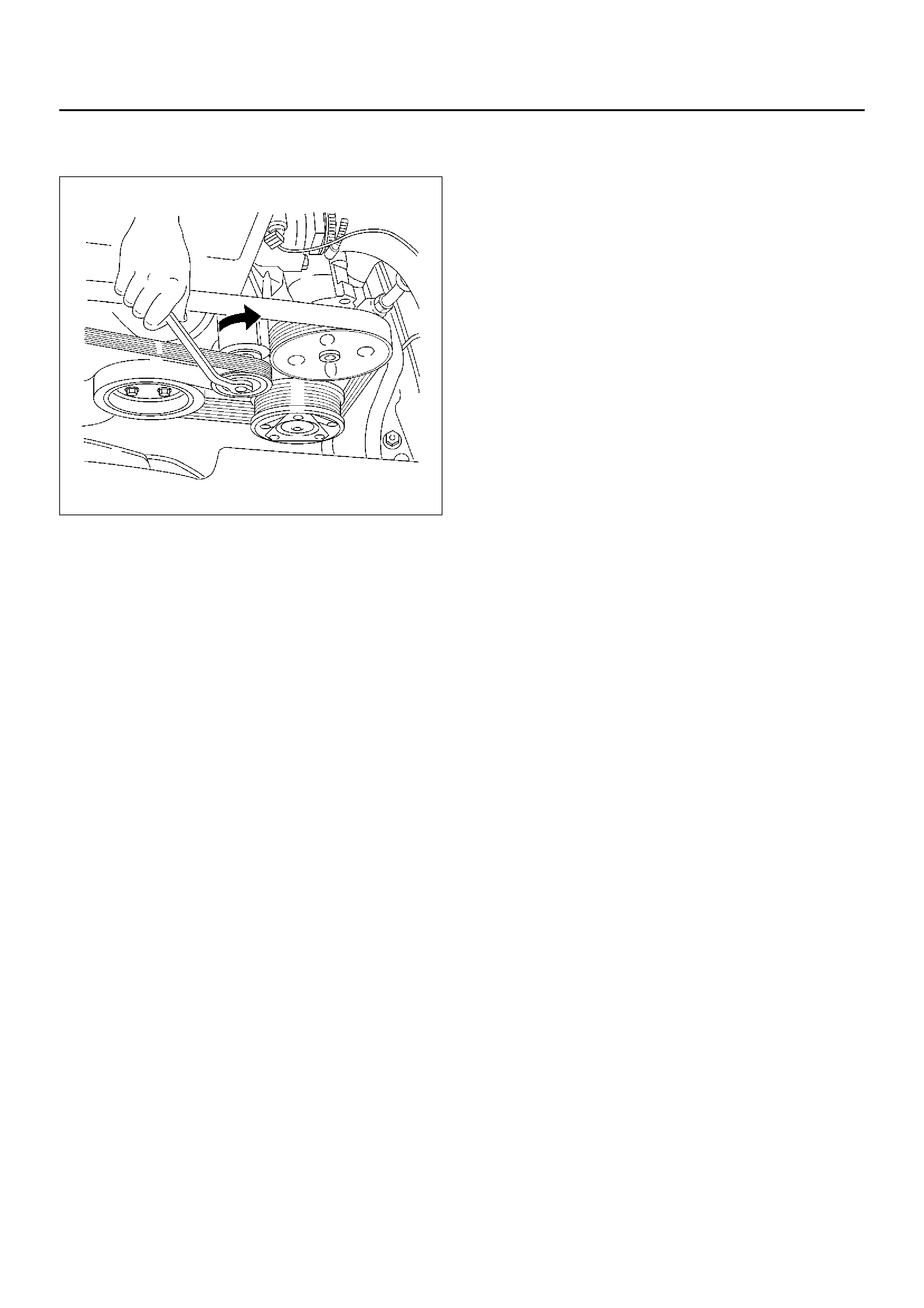
5. Mov e drive belt tensioner to loose side using wrench
then install the drive belt to normal position.
033RW001
6. Connect ignition cable to ignition plug.
7. Install ignition cable cover to cylinder head cover
and tighten two bolts to the specified torque.
Torque: 3 N·m (0.3Kg·m/2lbft)
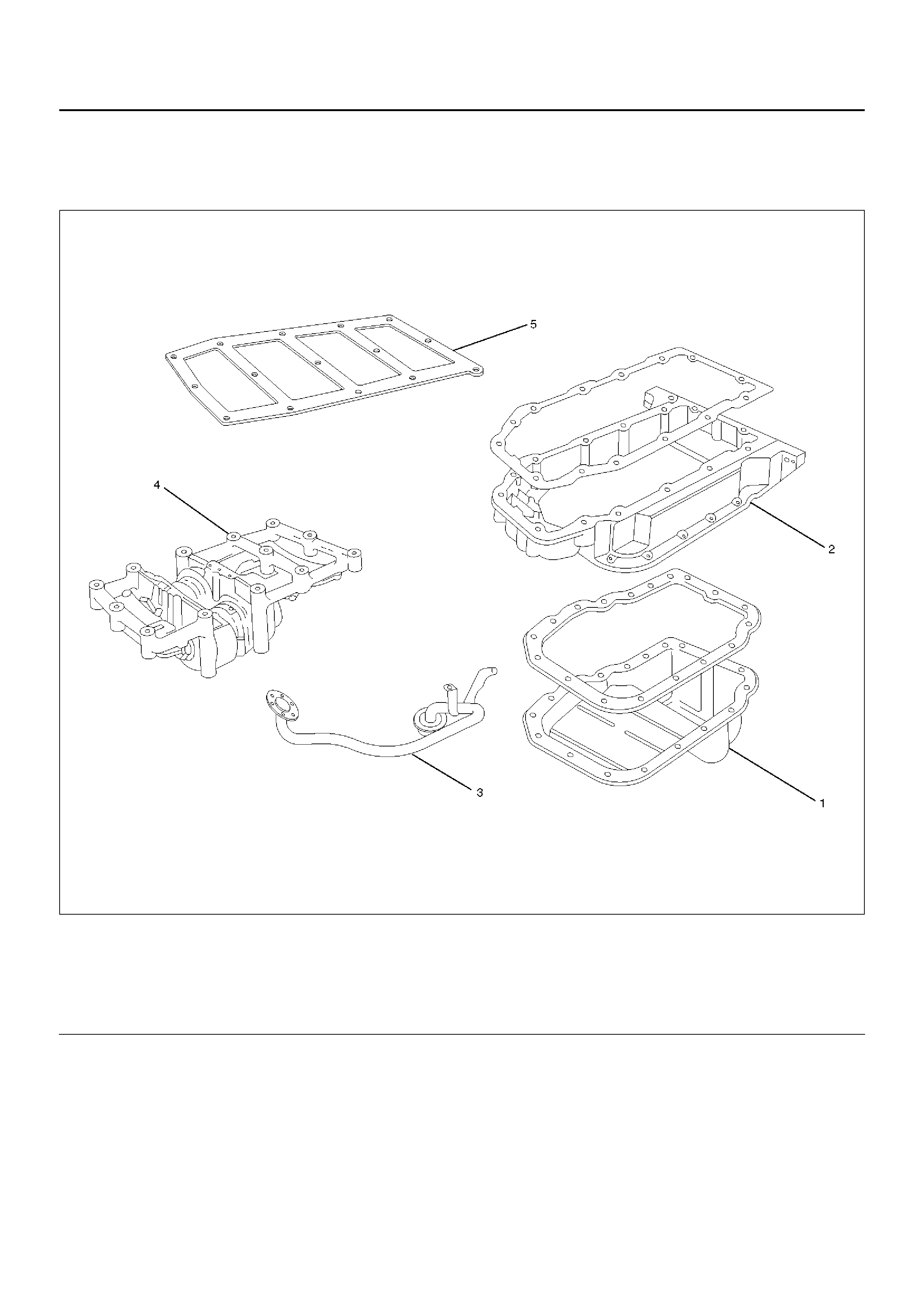
Balance Unit Assembly
Balance Unit Assembly Associated Parts
051RW012
Legend
EndOFCallout
(1) Oil Pan
(2) Oil Pan Support
(3) Oil Strainer
(4) Balance Unit Assemb ly
(5) Shim
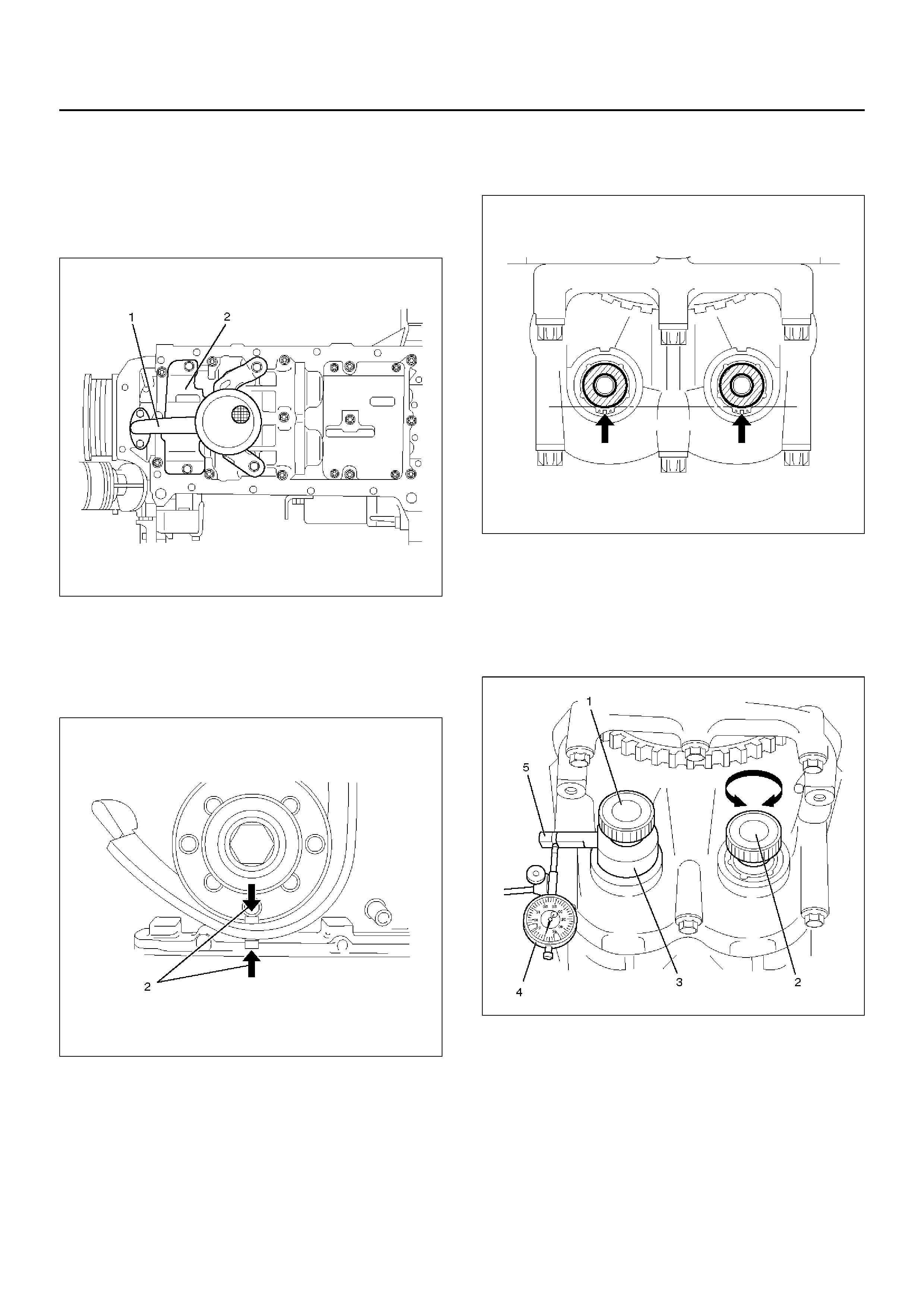
Disassembly
1. Remove the oil pan.
2. Remove the oil pan support.
3. Remove the oil strainer (1) from oil pump and the oil
baffle plate (2).
051RW009
Adjustment
1. Turn crankshaft in engine rotational direction to
alignment mark (2) 1st cylinder “TDC".
014RW066
2. In this crankshaft position, the flattened side
(arrows) of both balancer shafts must face
downward and must be on a horizontal line.
051RW010
3. Screw measuring device 5–8840–2671–0 (3) with
long knurled bolt (1) into 1st balancer shaft (intake
side) and tighter hard–tight measuring arm (5) must
point in “9 o'clock" direction shown in this illustration.
Install dial gauge holder with dial gauge (4) on
cylinder block.
051RW007
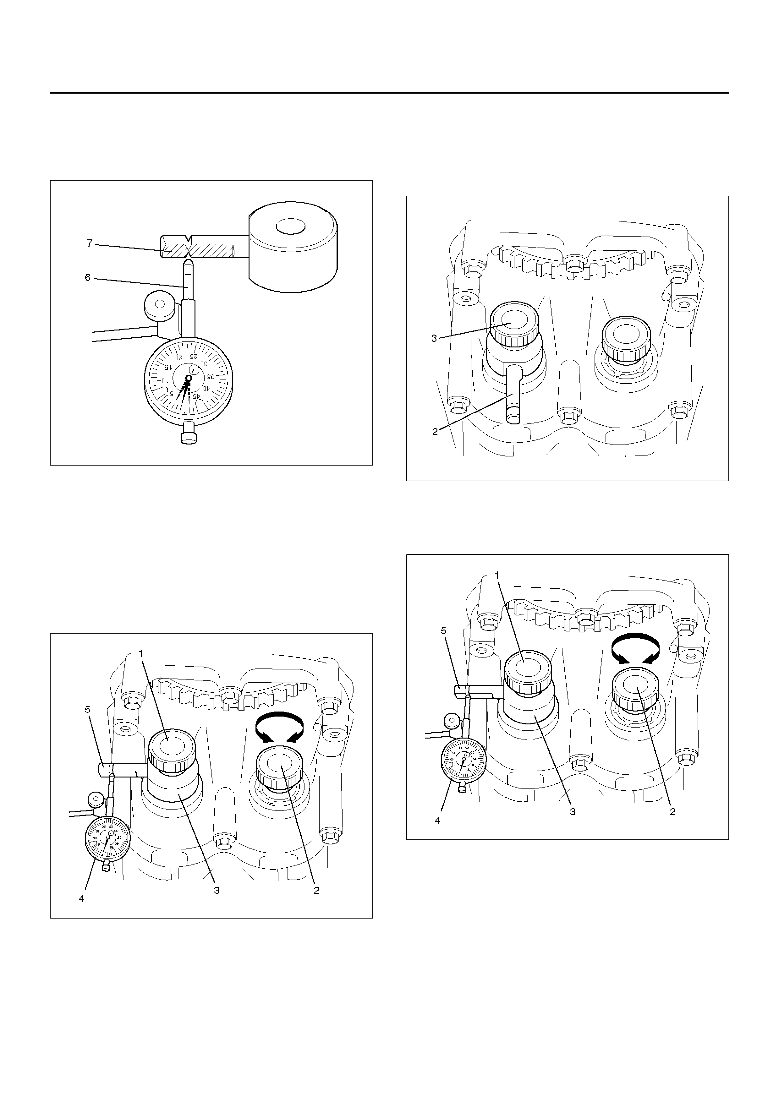
4. Place pre tensioned probe (6) of gauge on
measuring arm of measuring device 5–8840–2671–
0. The probe must be set precisely between the
notch marks, square to th e plane surface (7).
051RW006
5. Determine the left and right stops by turning the
knur le d bolt (2 ).
Set the dial of the gauge to zero.
Use the knurled bolt (2) to move the 2nd balancer
shaft (exhaust sid e) back and forth. A gain —
simultaneously read off the tooth backlash from the
gauge.
The permissible tooth backlash is: 0.02 mm to
0.06mm (0.0008 to 0.0024in).
051RW007
6. The tooth backlash must be measured in 4 different
positions — turn the crankshaft further at the
fastening bolt of the timing belt drive gear by 45° in
the engine rotational direction until the measuring
arm (2) is at “6 o'clock".
051RW008
7. Then loosen the knurled bolt (3) fix the measuring
arm at “9 o'clock" again and repeat the
measurement.
051RW007
8. If the value determi ned in one of the 4
measurements lies outside the tolerance 0.02mm to
0.06mm (0.00 08 to 0.0024in), the tooth backlash
must be adjusted.
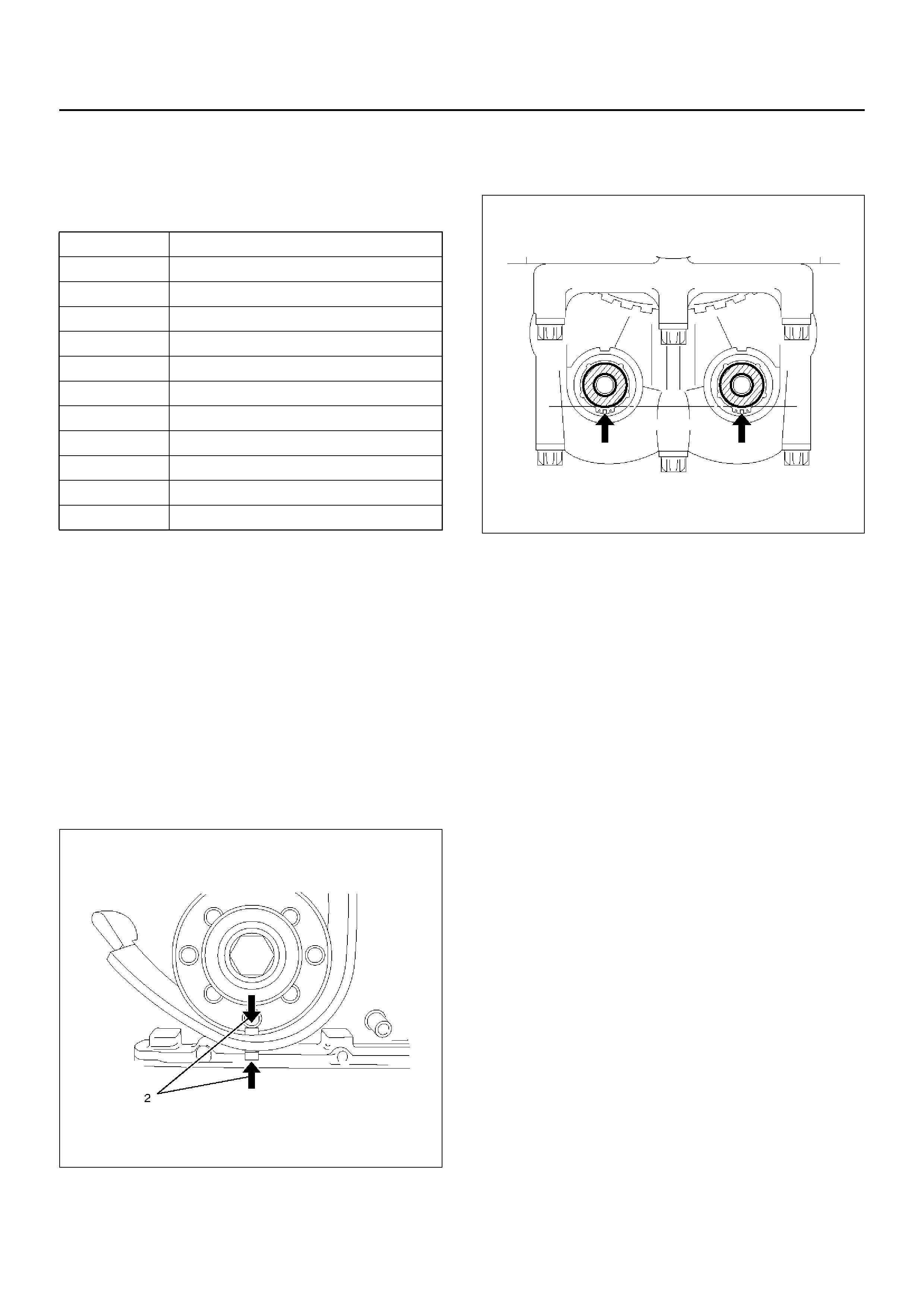
9.Remove balance unit from cylinder block/crankshaft
bearing caps and remove with balancer piece. The
balancer piece has a number (code), for easy
assignment. The tooth backlash can be adjusted by
using a balancer piece with a different thickness.
CAUTION: The next larger or smaller balancer
alters the tooth backlash by 0.02mm (0.0008in).
Example of selection of balancer piece: The
installed balancer piece with the code “70" gave a
tooth backlash of 0.08mm (0.0031in).
If a balancer piece with the code “67" is now
installed, the tooth backlash will be approx. 0.06mm
(0.0024in).
NOTE: Only one balancer piece may be installed.
Reassembly
1.Turn crankshaft in engine rotational direction to
alignment mark (2) 1st cylinder “TDC".
014RW066
2.Turn balancer shafts until the flattened sides
(arrows) of both balancer shafts face downward and
are on a horizontal line.
051RW010
3.Install selected balancer piece (2) with balancer
shaft unit to cylinder block/crankshaft bearing cap —
tighten all fixing bolts to the specified torque.
Torque: 20 N·m (2.0Kg·m/15lbft)
4.After installing the balancer shaft unit, recheck the
tooth backlash and readjust if necessary.
CAUTION: If the balancer shaft unit has to be
replaced, use the thickest balancer piece with the
code “85" for the initial assembl y — this guarantees
tooth backlash in all conditions.
5. Install oil strainer to oil pump with new seal ring and
insert fixing bolts with locking agent to the specified
torque.
Torque: 8 N·m (0.8Kg·m/6lbft)
Code Thic kness of balancer piece in mm
55 0.535 to 0.565
58 0.565 to 0.595
61 0.595 to 0.625
64 0.625 to 0.655
67 0.655 to 0.685
70 0.685 to 0.715
73 0.715 to 0.745
76 0.745 to 0.775
79 0.775 to 0.805
82 0.805 to 0.835
85 0.835 to 0.865
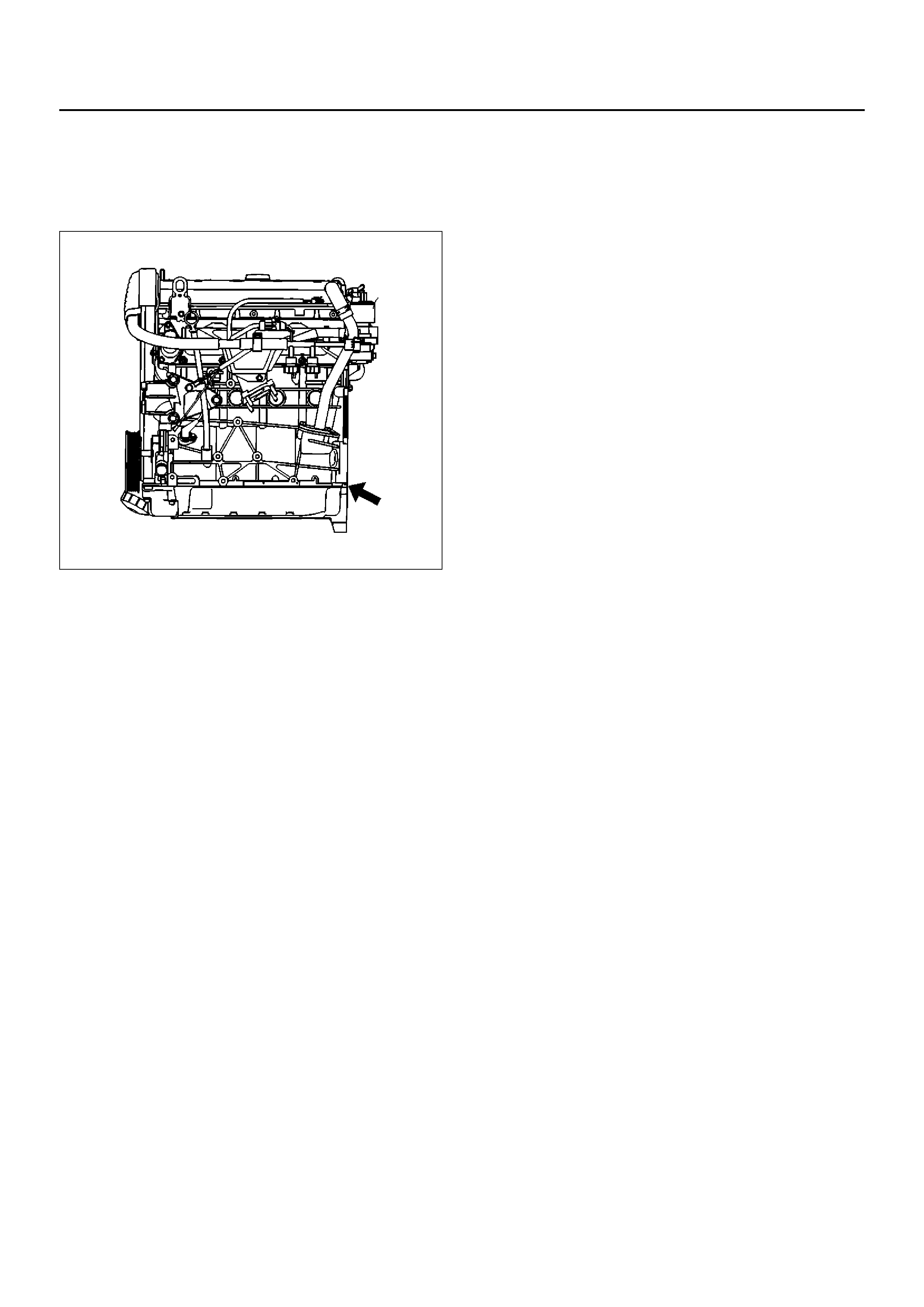
6. Ins tall oil pan su ppo rt.
Torque: 20 N·m (2.0Kg·m/14lbft)
• Adjust surfaces of the cylinder block and the oil
pan support.
035RW026
7. Install oil pan.
1st step: 8 N·m (0.8Kg·m/5.8lbft)
2nd step: 30°
°°
°
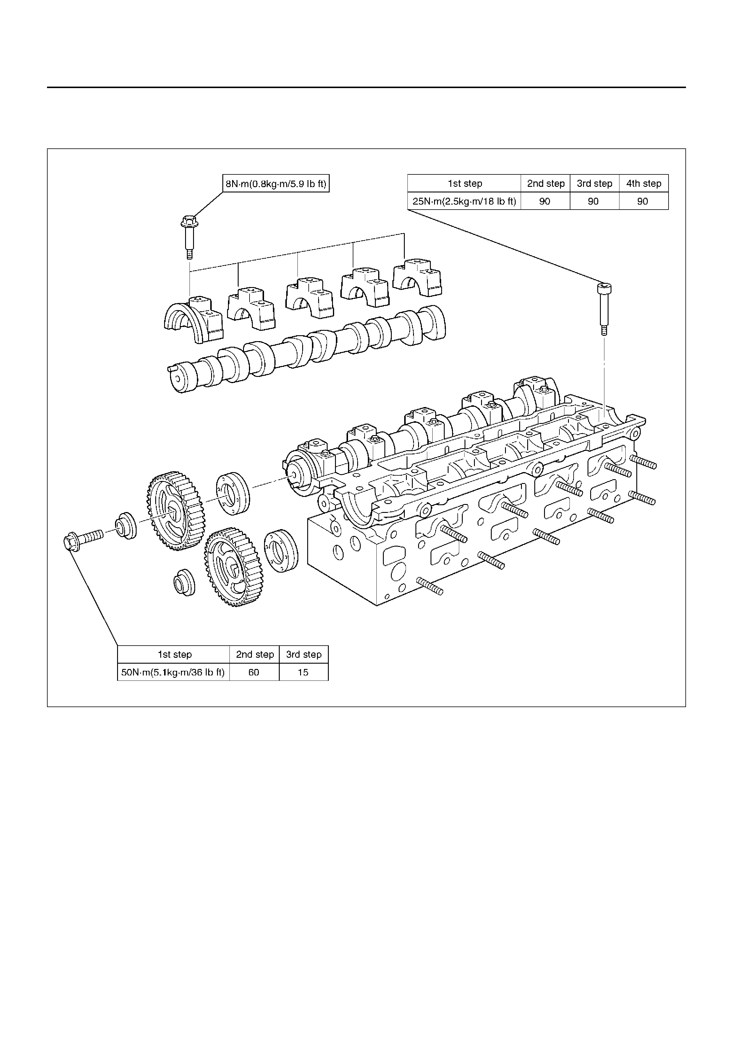
Main Data and Specifications
Torque Specifications
Camshaft bracket, Timing gear camshaft side, Cylinder head
011RX001
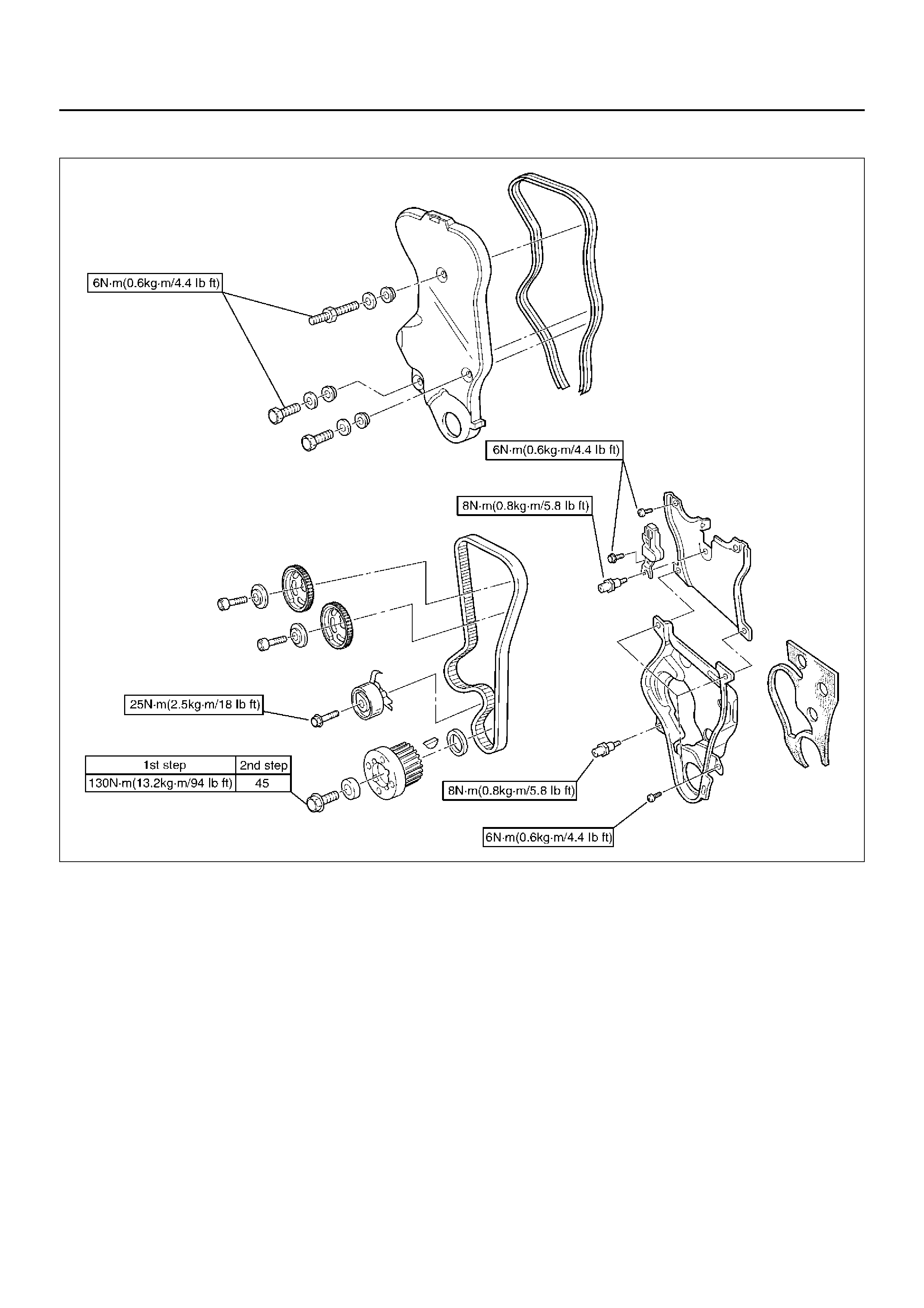
Timing gear crankshaft (center bolt), Timing belt cover front, Timing belt cover rear, Timing belt tensioner,
Camshaft angle sensor
020RX001
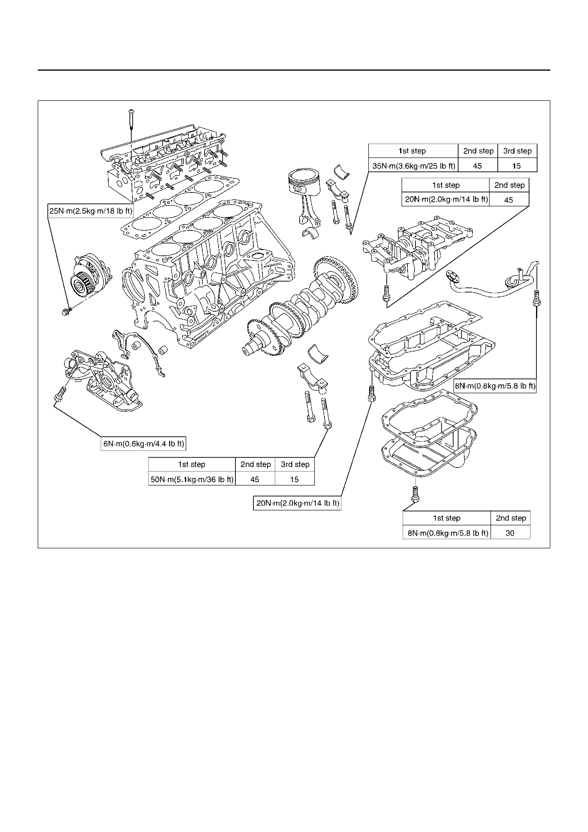
Crankshaft main bearing, Oil pan support, Oil pan, Balance unit assembly, Connrod Cap, Oil pump, Oil
strainer
015RX004
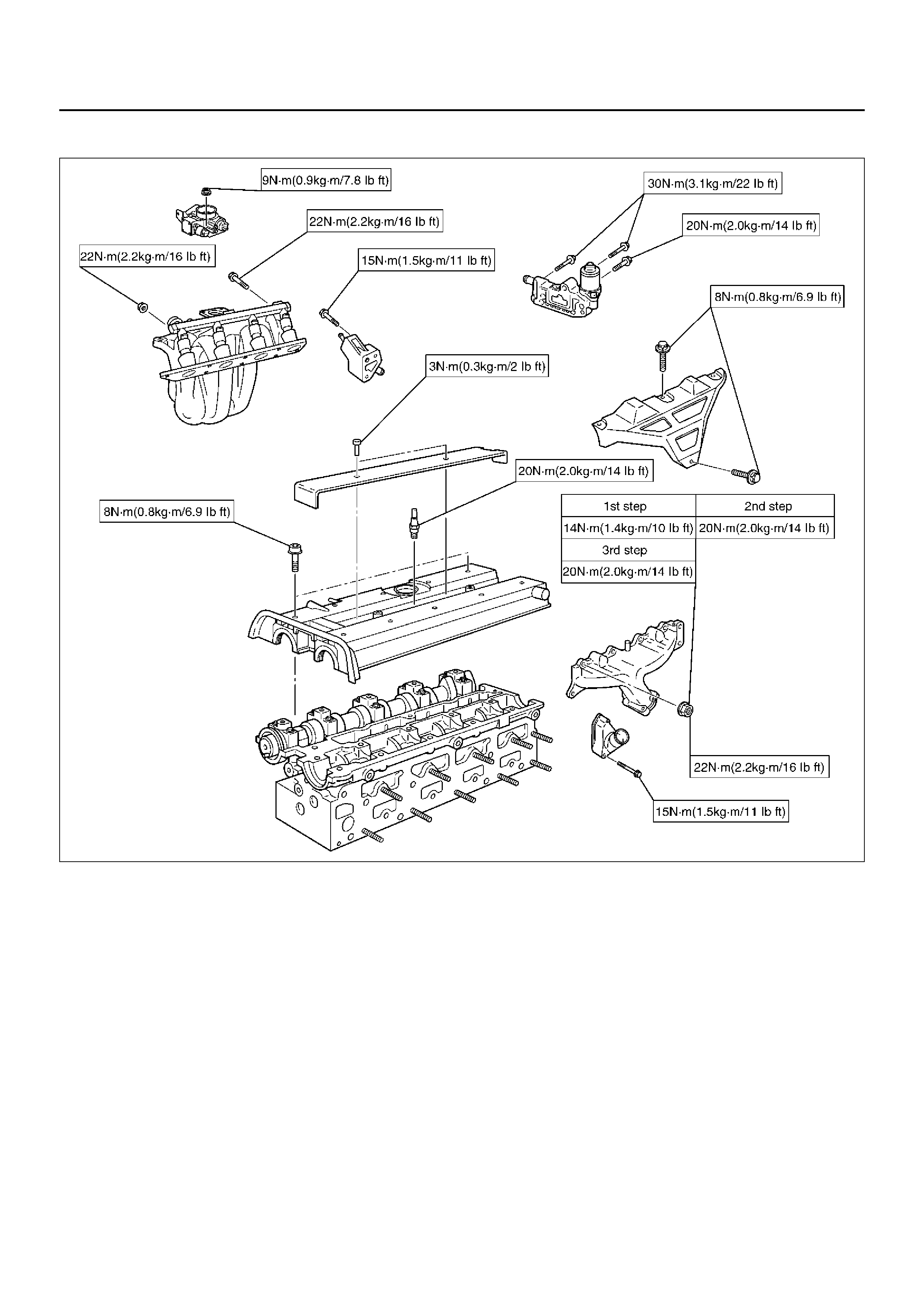
Spark plug, Throttle body, EGR valve adaptor assembly, Bypass housing assembly, Thermostat assembly,
inlet manifold assembly, Exhaust manifold assembly, heat shield, Ignition cable co ver
011RX002
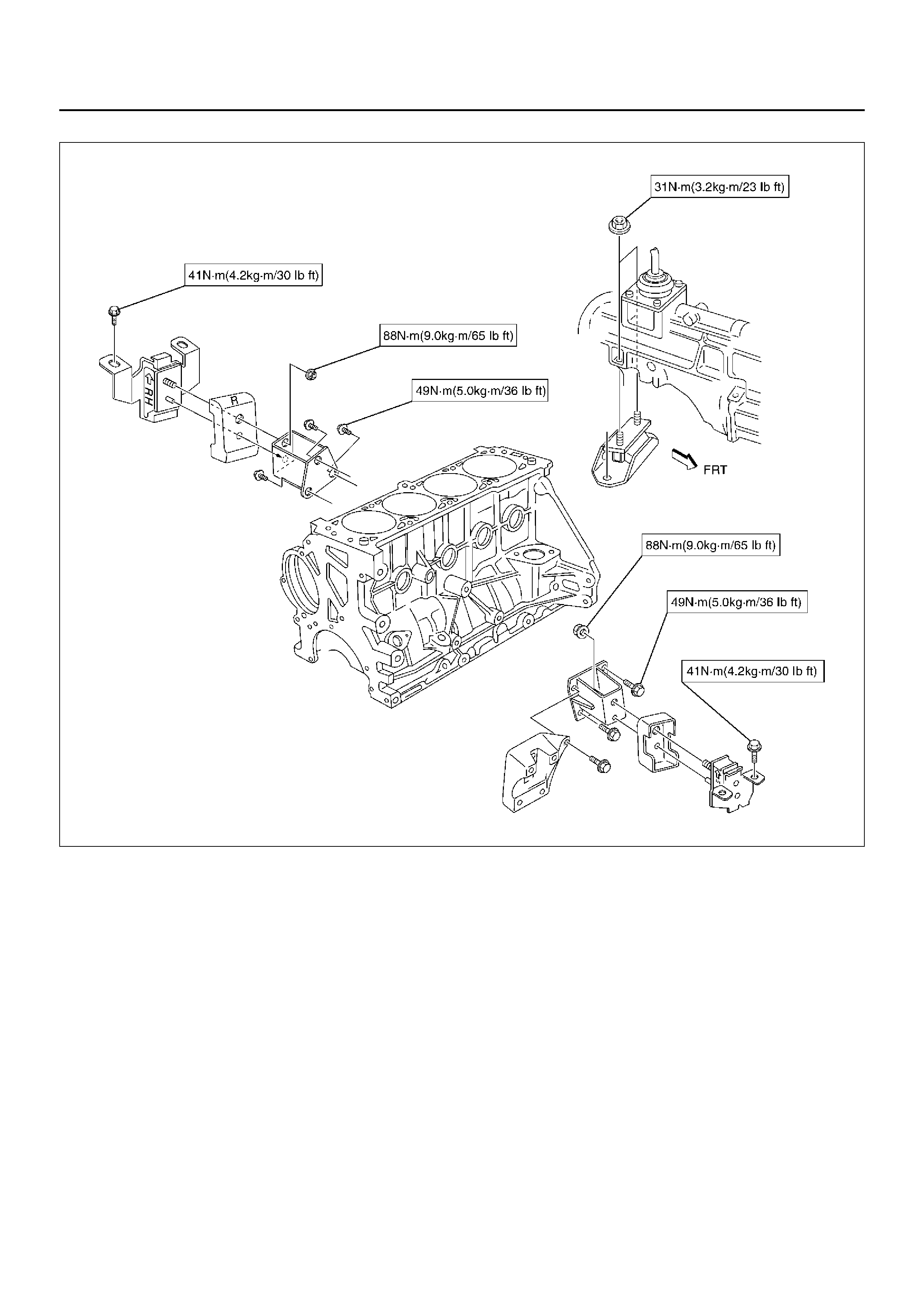
Engine mount
022RX003
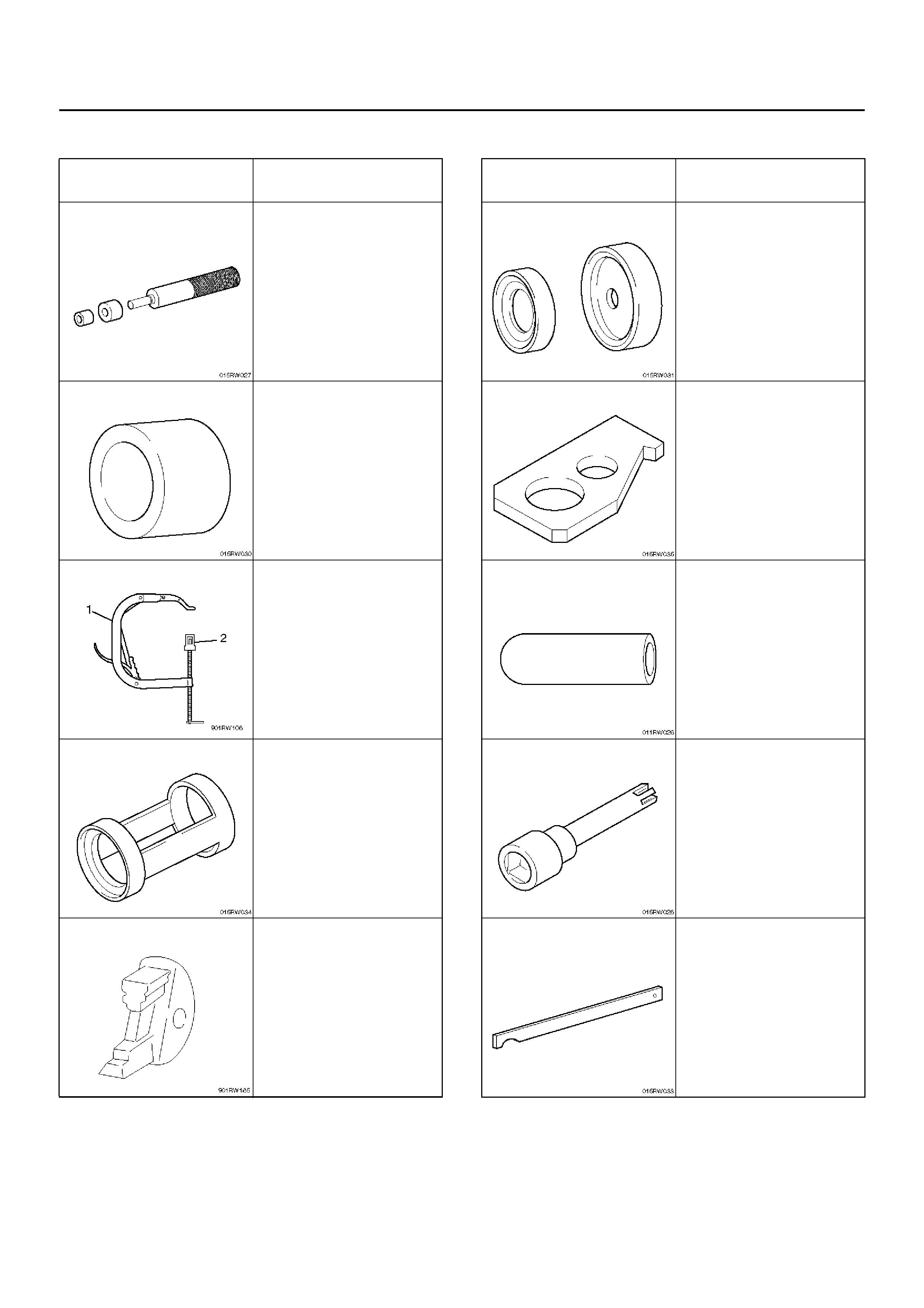
Special Tools
ILLUSTRATION TOOL NO.
TOOL NAME
5–8840–2597–0
Installer; Rear crankshaft
seal ring
5–8840–2658–0
Remover/Installer;
Crankshaft carrier seal
5–8840–2546–0
Compressor; Valve
spring (1)
(Use w it h
5–8840–2 662– 0 (2) )
5–8840–2662–0
Adapter; Compressor
Valve spring
5–8840–2659–0
Locking tool camshaft
gear
5–8840–2660–0
Instal ler; Rear cr anksha ft
seal
5–8840–2661–0
Locking device; Flywhee l
5–8840–2663–0
Installer sleeve; Valve
stem seal
5–8840–2600–0
Socket wrench; Cylind er
head bolt
5–8840–2598–0
Holding wrench; Driven
gear fix
ILLUSTRATION TOOL NO.
TOOL NAME
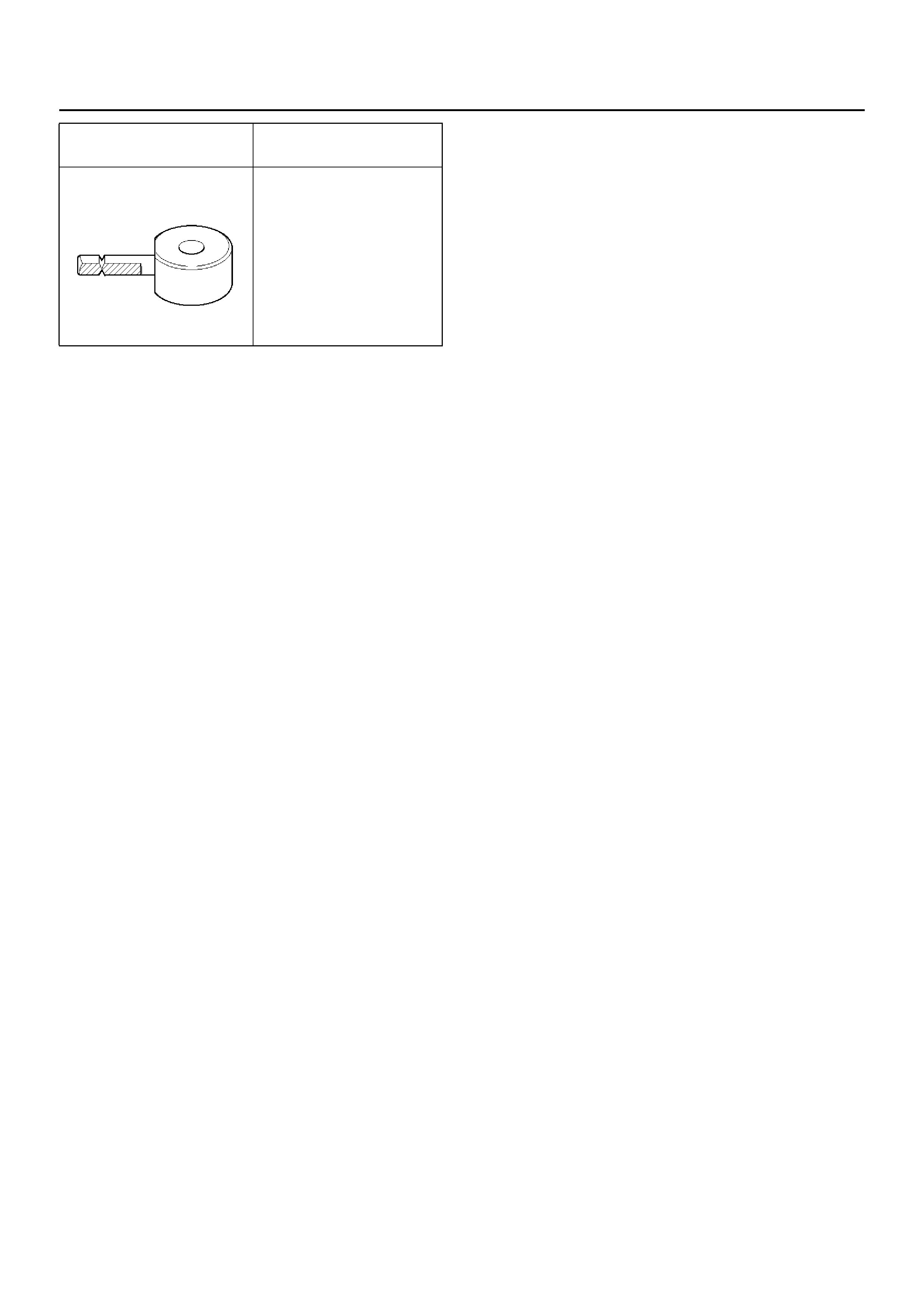
5–8840–2671–0
Screw measuring device
ILLUSTRATION TOOL NO.
TOOL NAME