
SECTION 6D2 - IGNITION SYSTEM (X22SE 2.2L)
Service Precaution
General Description
Diagnosis
Ignition Module
Removal
Installation
Spark Plug
Removal
Inspection and Repair
Installation
Crankshaft Angle Sensor
Removal
Installation
Main Data and Specifications
Service Precaution
WARNING: THIS VEHICLE HAS A SUPPLEMENTAL
RESTRAINT SYSTEM (SRS). REFER TO THE SRS
COMPONENT AND WIRING LOCATION VIEW IN
ORDER TO DETERMINE WHETHER YOU ARE
PERFORMING SERVICE ON OR NEAR THE SRS
COMPONENTS OR THE SRS WIRING. WHEN YOU
ARE PERFORMING SERVICE ON OR NEAR THE
SRS COMPONENTS OR THE SRS WIRING, REFER
TO THE SRS SERVICE INFORMATION. FAILURE TO
FOLLOW WARNINGS COULD RESULT IN
POSSIBLE AIR BAG DEPLOYMENT, PERSONAL
INJURY, OR OTHERWISE UNNEEDED SRS SYSTEM
REPAIRS.
CAUTION: Always use the correct fastener in the
proper location. When you replace a fastener, use
ONLY the exact part number for that application.
ISUZU will call out those fasteners that require a
replacement after removal. ISUZU will also call out
the fasteners that require thread lockers or thread
sealant. UNLESS OTHERWISE SPECIFIED, do not
use supplemental coatings (Paints, greases, or
other corrosion inhibitors) on threaded fasteners or
fastener joint interfaces. Generally, such coatings
adversely affect the fastener torque and the joint
clamping force, and may damage the fastener. When
you install fasteners, use the correct tightening
sequence and specifications. Following these
instructions can help you avoid damage to parts
and systems.
General Description
Ignition is done by the Ignition Module that fires.
Since the cylinder on exhaust stroke requires less
energy to fire its spark plug, energy from the ignition
coils can be utilized to fire the mating cylinder on
compression stroke.
A notch in the timing disc on the crankshaft activates the
crank angle sensor which then sends information such
as firing order and starting timing of ignition coil to the
PCM.
By receiving signals such as crank position,engine
speed,water temperature and Manifold Absolute
Pressure (MAP),the PCM controls the ignition timing.
Diagnosis
Refer to Section Drivability and Emissions for the
diagnosis to electronic ignition system (El system).
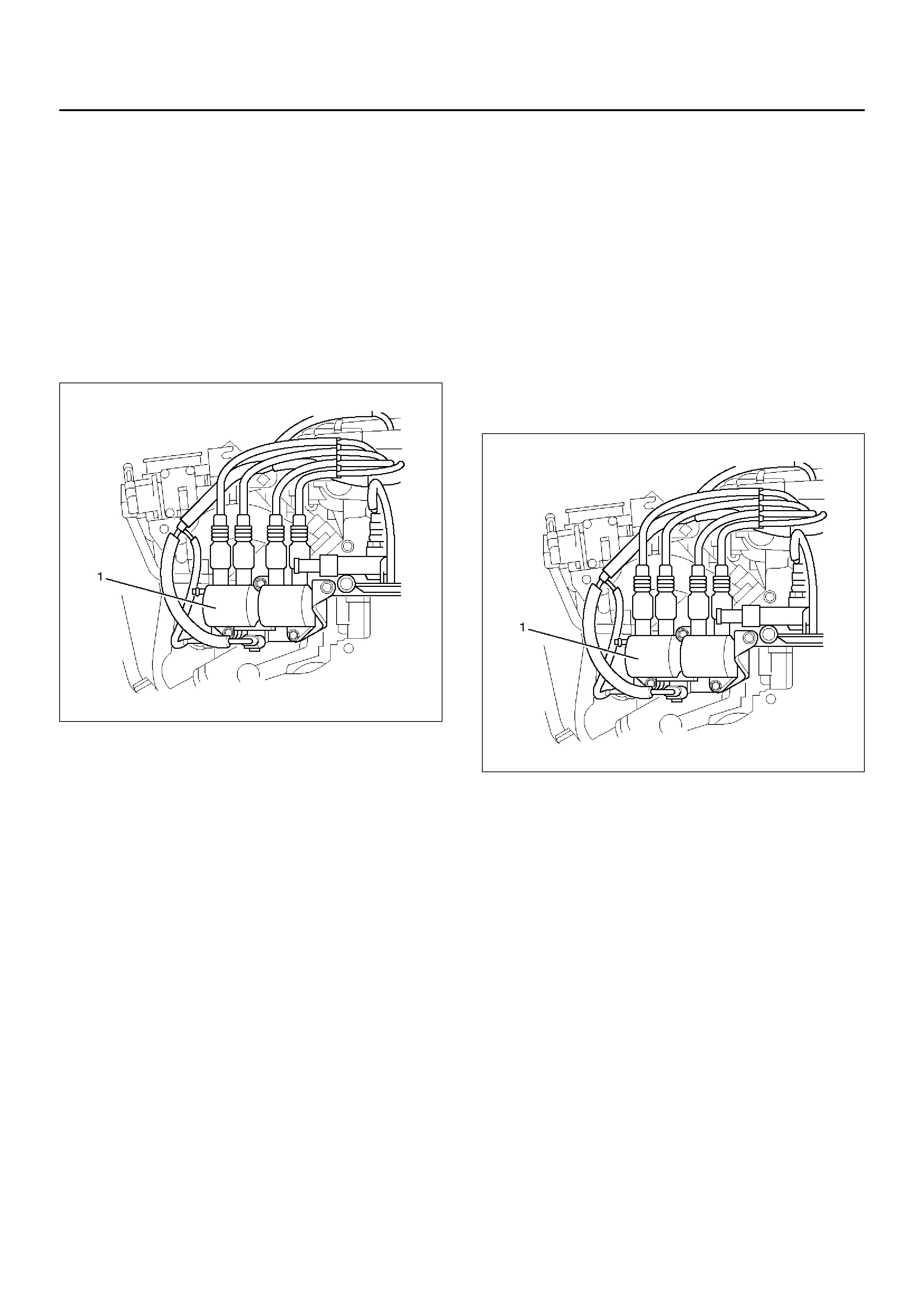
Ignition Module
Removal
1. Disco nne ct batte ry ground ca ble.
2. Remove ABS hydraulic unit assembly.
3. Remove master Vac and brake booster assembly.
4. Remove heater hoses from water rail.
5. Disconnect ignition coil cabl e from ignition module.
6. Remove connector from ignition module.
7. Remove ignition module assembly with bracket (1).
080RW001
Installation
1. Install the ignition module assemb ly with brac k et (1).
2. Connect ignition module connector and ignition
coil,then tighten bolt to the specified torque.
Torque: 20 N·m (2.0 kg·m/15 lb ft)
3. Conne ct ign iti on co il ca ble.
4. Install heater hoses.
5. Insta ll master Va c and brake booster assembly.
6. Install ABS hydraulic unit assembly.
7. Bleed Air, brake system.
080RW001
8. Connect battery ground cable.
Spark Plug
Removal
1. Remove spark plugs.
Inspection and Repair
The spark plug affects entire engine performance and
therefore its inspection is very important.
• Check electrode and insulator for presence of
cracks,and replace if any.
• Check electrode for wear,and replace if necessary.
• Check gasket for damage,and replace if necessary.
• Measure insulation resistance with an ohmmeter,and
replace if faulty.
• Adjust spark plug gap to 0.7 mm (0.027 in) ∼ 0.8 µµ
(0.031 ιν).
• Check fuel and electrical systems if spark plug is
extremely dirty.
• Use spark plugs ha ving low heat value (hot type plug)
if fuel and electrical systems are normal.
• Use spark plugs having high heat value (cold type
plug) if insulator and electrode are ex tremely burned.
Sooty Spark Plugs
Much deposit of carbon or oil on the electrode and
insulator of spark plug reduces the engine performance.
Possible causes:
• Too rich mixture
• Presence of oil in combustion chamber
• Incorrectly adjusted spark plug gap
Burning Electrodes
This fault is characterized by scorched or heavily
oxidized electrode or blistered insulator nose.
Possible causes:
• Too lean mixture
• Improper heat value
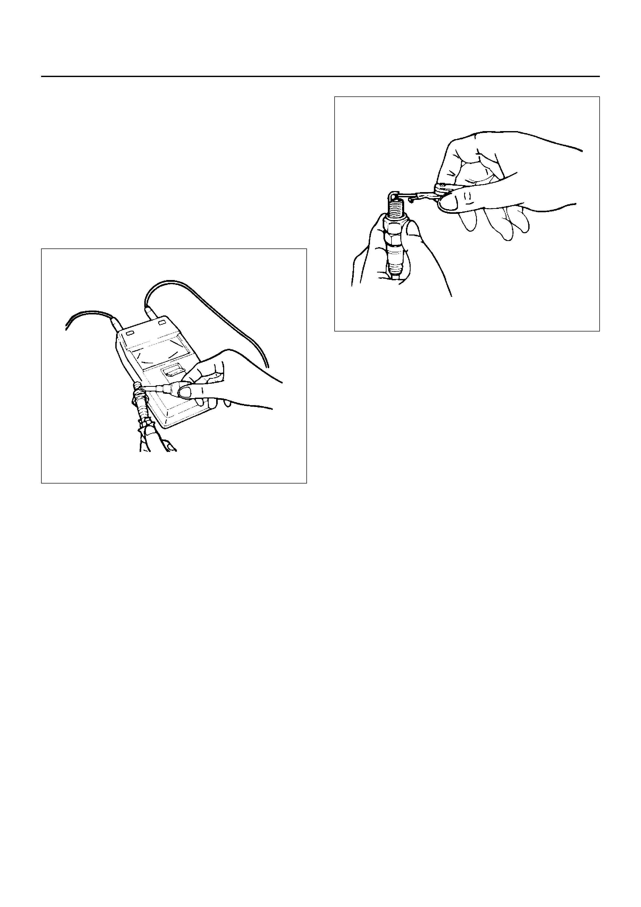
Measuring Insulation Resistance
• Measure insulation resistance using a 500 volt
megaohm mete r.
• Replace spark plugs if measured value is out of
standard.
Insulation resistance: 50 MΩ
ΩΩ
Ω or more
011RS010
Cleaning Spark Plugs
• Clean spark plugs with a spark plug cleaner.
• Raise the ground electrode to an angle of 45 to 60
degrees. if electrode is wet,dry it before cleaning.
• After spark plug is thoroughly cleaned,check insulator
for presence of cracks.
• Clean threads and metal body with a wire brush.
• File the electrode tip if electrode is e xtremely worn.
• Bend the ground electrode to adjust the spark plug
gap.
011RS011
Installation
1. Spark plugs
• Tighten spark plugs to the specified torque.
Torque: 25 N·m (2.5 kg·m/18 lb ft)
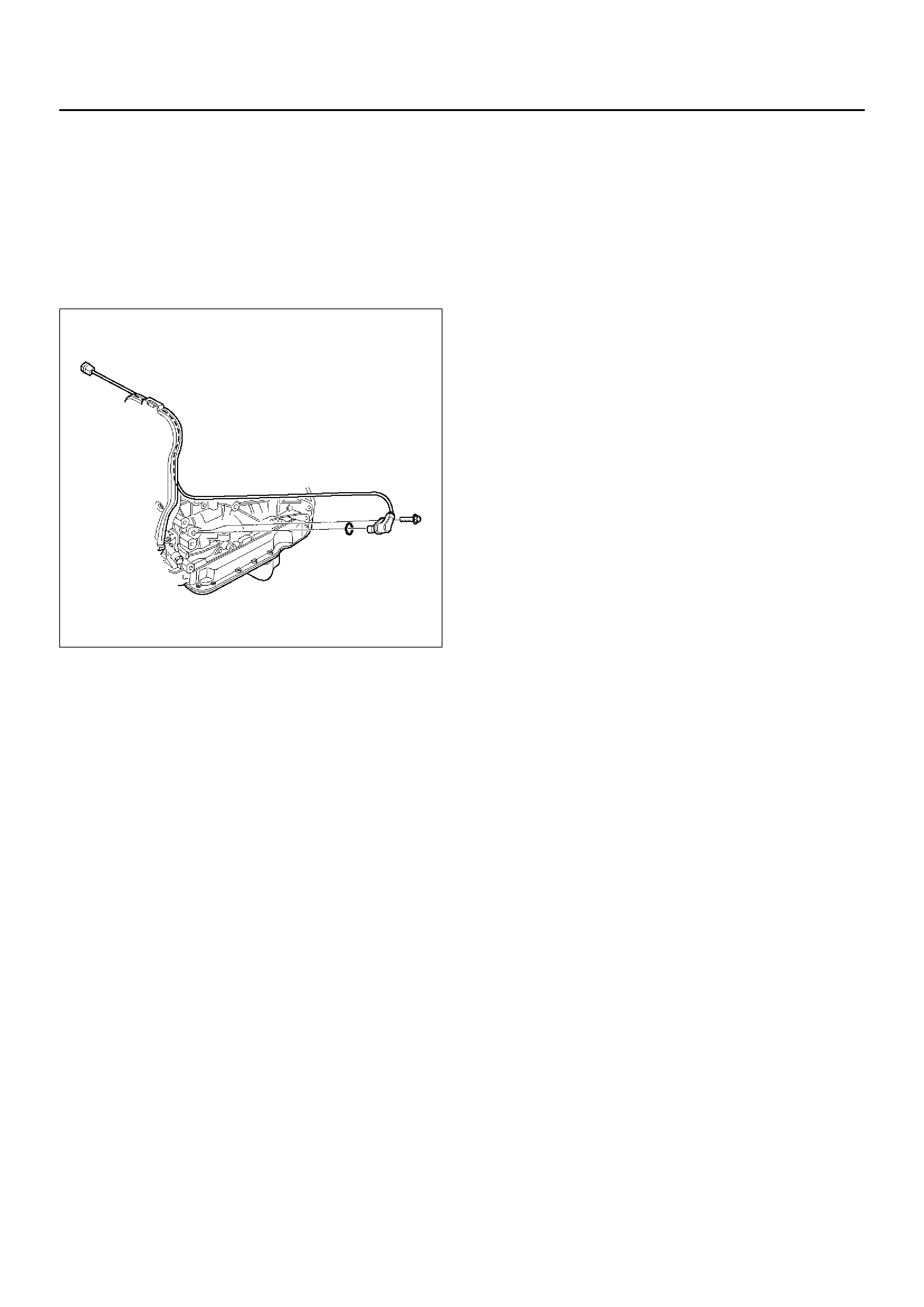
Crankshaft Angle Sensor
Removal
1.Disconnect battery ground cable
2. Wiring connector from crankshaft angle sensor.
3. Remove crankshaft angle sensor from cylinder
block.
015RW021
Installation
1. Install cr anksha ft angle sensor into the cylinder
block.
Before installation,apply small amount of engine oil
to the O–ring.
Torque: 6 N·m (0.6 kg·m/4 lb ft)
2. Reconnect wiring connector to crankshaft angle
sensor.

Main Data and Specifications
General Specifications
Ignition System
Ignition Form Electronic Ignition System (El system) with Crankshaft angle Sensor
Spark Plug Type Electronic Spark Control
No. of Coils and Type 2 Solid State
Coil Location Engine–mounted
Torque 20 N·m (2.0 kg·m/14 lb ft)