
SECTION 6D3 - STARTING AND CHARGING SYSTEM (X22SE 2.2L)
Service Precaution
Starting System
General Description
Diagnosis
Starter
Removal
Installation
Disassembled View
Inspection and Repair
Characteristic Test
Charging System
General Description
General On–Vehicle Inspection
Generator
Removal
Inspection
Installation
Disassembly
Inspection and Repair
Reassembly
Main Data and Specifications
Service Precaution
WARNING: THIS VEHICLE HAS A SUPPLEMENTAL
RESTRAINT SYSTEM (SRS). REFER TO THE SRS
COMPONENT AND WIRING LOCATION VIEW IN
ORDER TO DETERMINE WHETHER YOU ARE
PERFORMING SERVICE ON OR NEAR THE SRS
COMPONENTS OR THE SRS WIRING. WHEN YOU
ARE PERFORMING SERVICE ON OR NEAR THE
SRS COMPONENTS OR THE SRS WIRING, REFER
TO THE SRS SERVICE INFORMATION. FAILURE TO
FOLLOW WARNINGS COULD RESULT IN
POSSIBLE AIR BAG DEPLOYMENT, PERSONAL
INJURY, OR OTHERWISE UNNEEDED SRS SYSTEM
REPAIRS.
CAUTION: Always use the correct fastener in the
proper location. When you replace a fastener, use
ONLY the exact part number for that application.
ISUZU will call out those fasteners that require a
replacement after removal. ISUZU will also call out
the fasteners that require thread lockers or thread
sealant. UNLESS OTHERWISE SPECIFIED, do not
use supplemental coatings (Paints, greases, or
other corrosion inhibitors) on threaded fasteners or
fastener joint interfaces. Generally, such coatings
adversely affect the fastener torque and the joint
clamping f or ce, and may dama ge the fastener . Wh en
you install fasteners, use the correct tightening
sequence and specifications. Following these
instructions can help you avoid damage to parts
and systems.
Starting System
General Description
Cranking Circuit
The cranking system consists of a battery, starter,
starter switch, starter relay, etc. These main
components are connected.
Starter
The cranking system employs a magnetic type
reduction starter in which the motor shaft is also used
as a pinion shaft. When the starter switch is turned on,
the contacts of magnetic switch are closed, and the
armature rotates. At the same time, the plunger is
attracted, and the pinion is pushed forward by the shift
lever to mesh with the ring gear.
Then, the ring gear runs to start the engine. When the
engine starts and the starter switch is turned off, the
plunger returns, the pinion is disengaged from the ring
gear, and the armature stops rotation. When the engine
speed is higher than the pinion, the pinion idles, so that
the armature is not driven.
Diagnosis
Condition Possible cause Correction
Starter does not run Charging failure Repair charging system
Battery Failure Replace Battery
Terminal connection failure Repair or replace terminal connector
and/or wir i ng harn ess
Starter switch failure Repair or replace starter switch
Starter failure Repair or replace starter
Starter
Removal
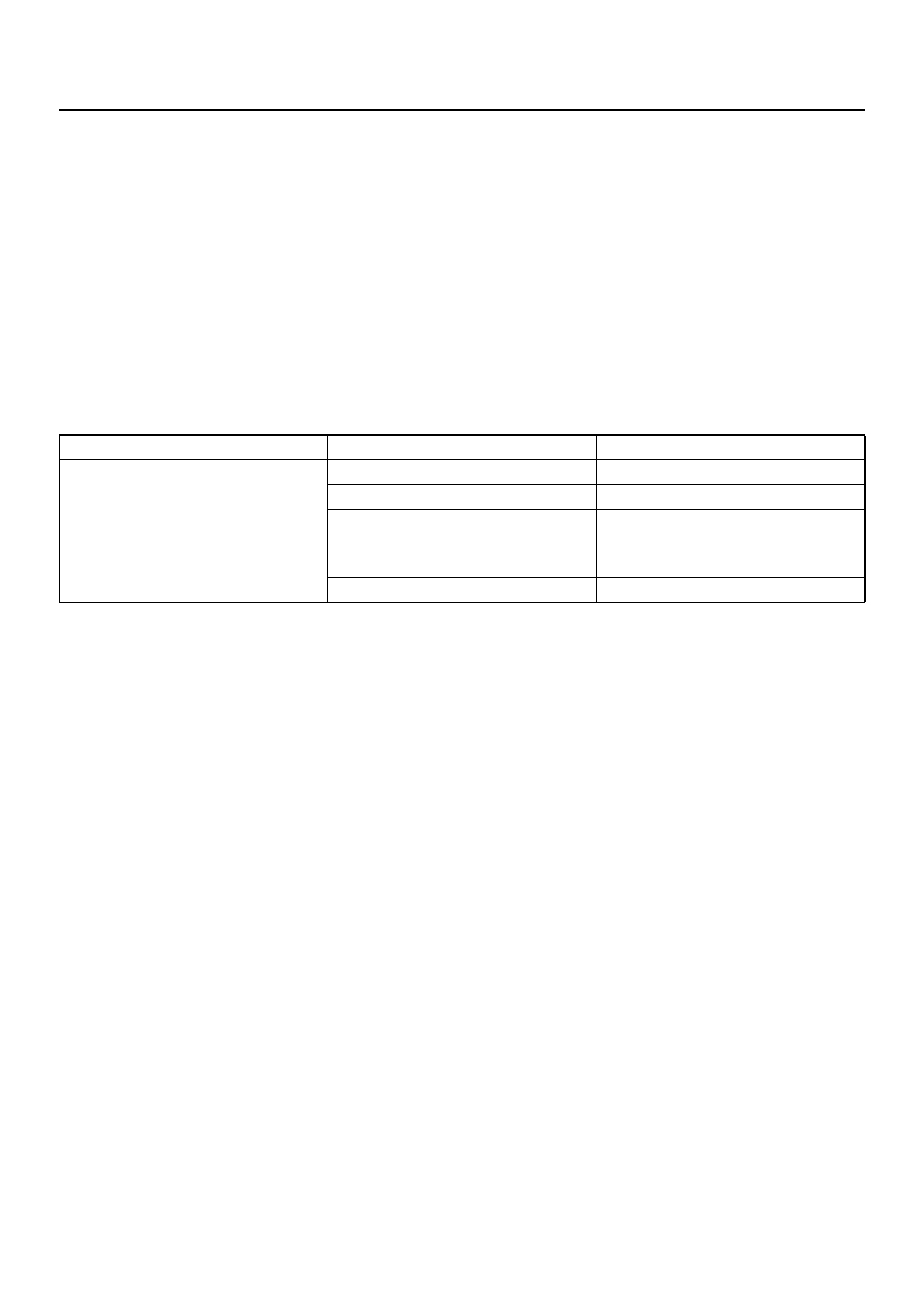
1. Battery ground cable.
2. Remove harness connectors (1) and (2).
065RW022
3. Remove bolts from starter (1), (2).
065RW024
Installation
1. Install starter assembly(6).
2. Install mounting bolts and tighten bolts to specified
torque (1), (2).
Torque: 25 N·m (2.5 kg·m/18 lb ft)
065RW024
3. Connect harness.
4. Reconnect the battery ground cable.
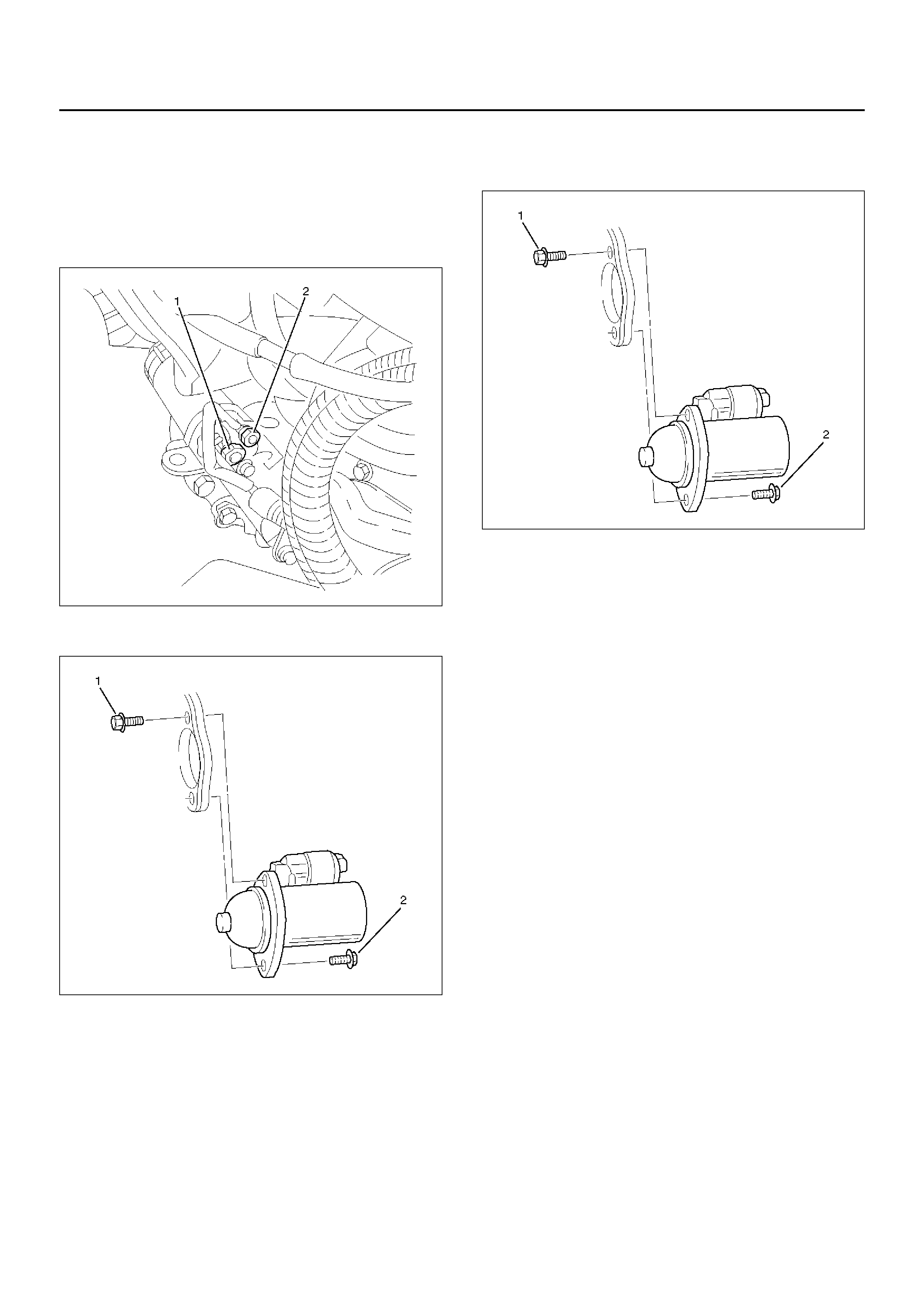
Disassembled View
065RW023
Legend
EndOFCallout
(1) Bolt
(2) Magnetic Switch
(3) Gear Case
(4) Piston
(5) Piston Shaft
(6) Center Bracket
(7) Armature
(8) Yoke Assembly
(9) Brush and Brush Holder
(10) Washer
(11) Rear Cover
(12) Through Bolt
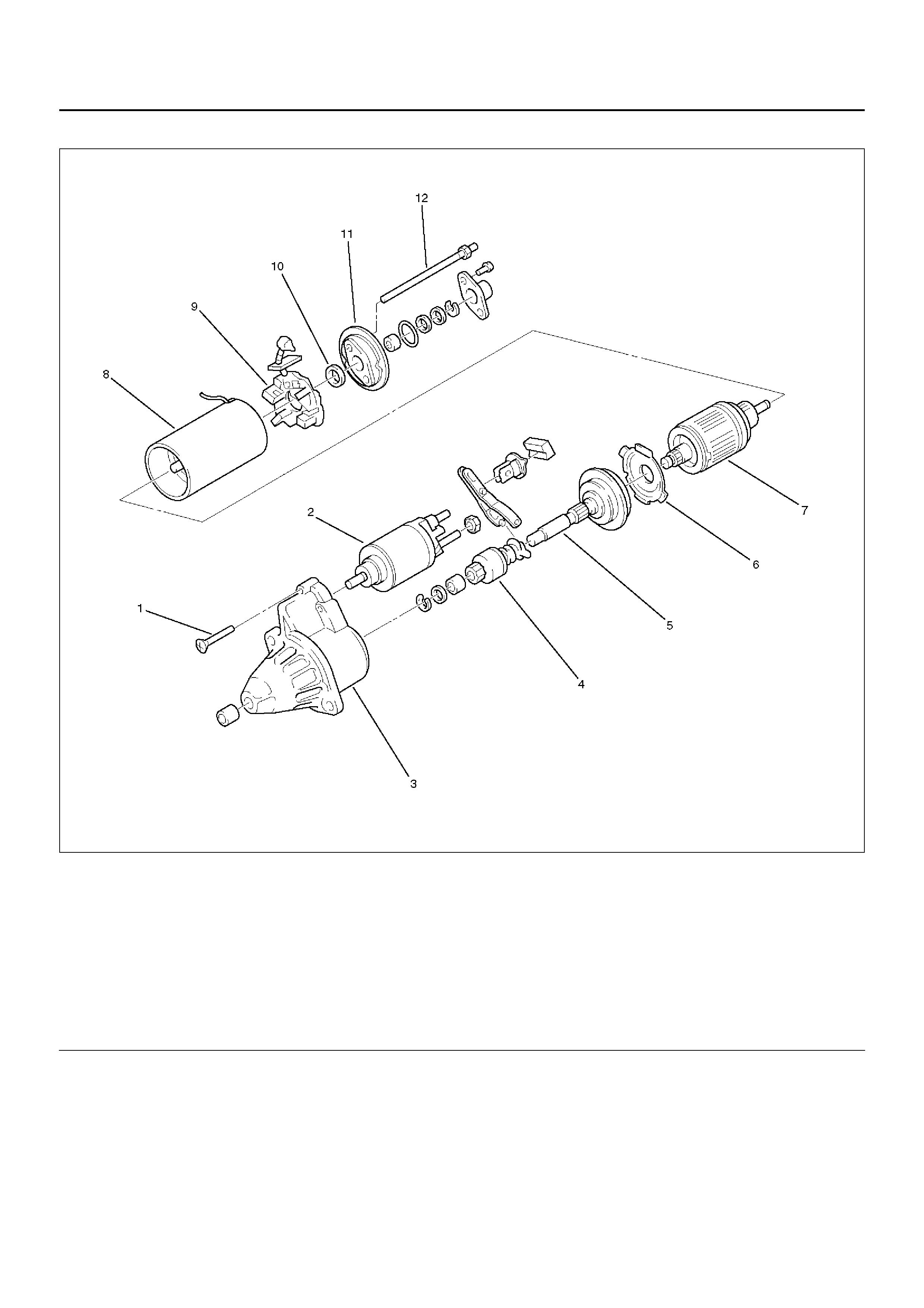
Inspection and Repair
Repair or replace necessary parts if extreme wear or
damage is found during inspection.
Armature
Check f or continuity between commutator and segment.
Replace commutator if there is no continuity (i.e.,
disconnected).
065RS015
Check for continuity between commutator and shaft.
Also, check for continuity between commutator and
armature core,armature core and shaft. Replace
commutator if there is continuity (i.e., internally
grounded).
065RS016
Brush
Measure the length of brush.
Replace with a new one, if it is below the limit.
Brush Holder
Check for continuity between brush holder (+) (4) and
base (–). Replace, if there is continuity (i.e., insulation is
broken).
065RW015
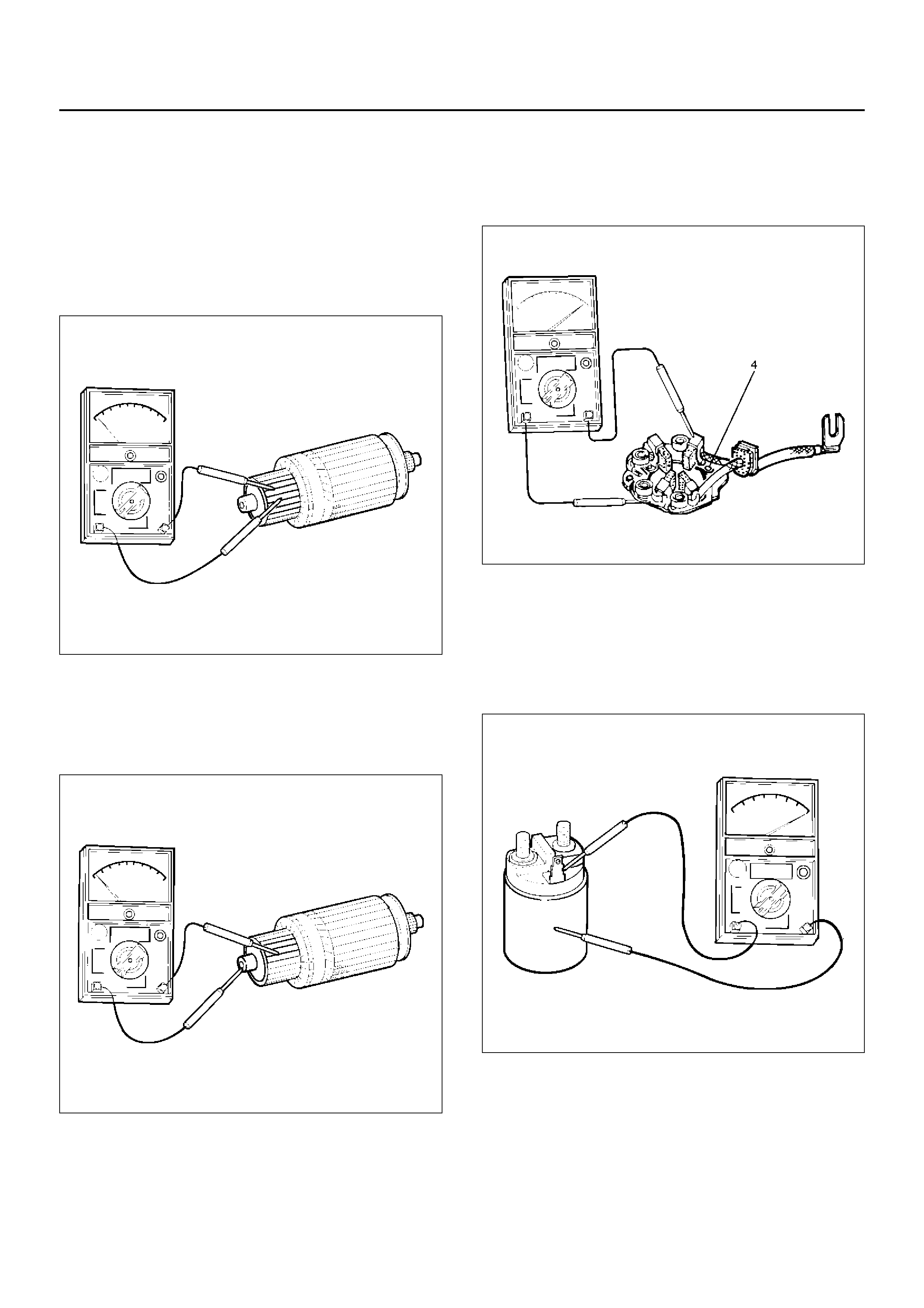
Magnetic Switch
Check for continuity of shunt coil between terminals S
and M.
Replace, if there is no continuity (i.e., coil is
disconnected).
065RW016
Continuity of Series Coil
Check for continuity between terminals S and M.
Replace, if there is no continuity (i.e., coil is
disconnected).
065RW017
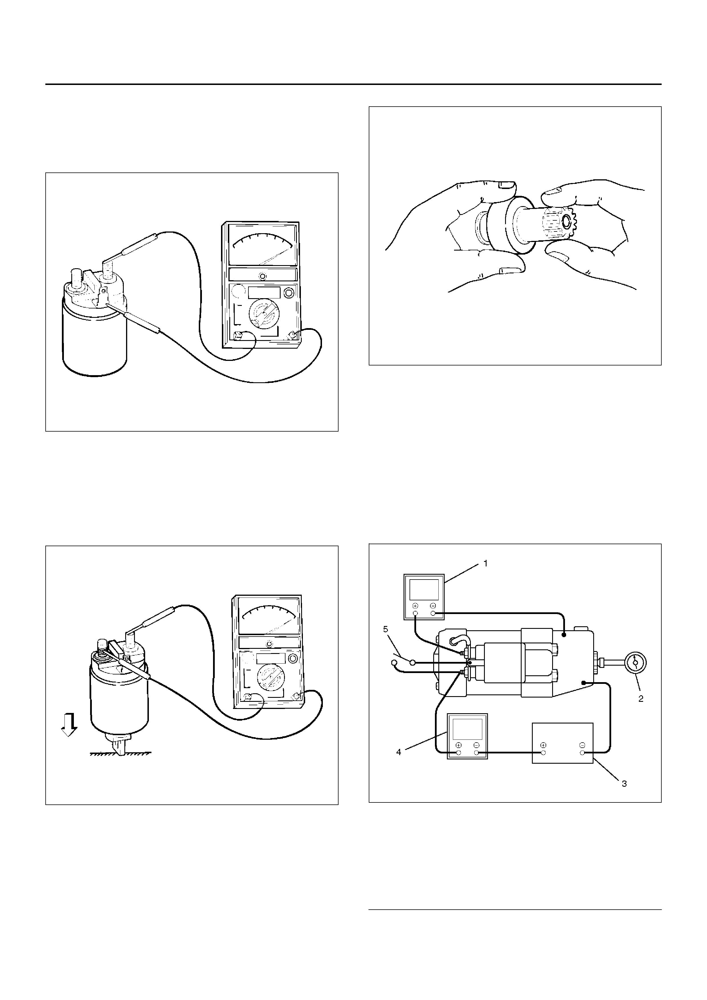
Continuity of Contacts
With the plunger faced downward, push down the
magnetic switch. In this state, check for continuity
between terminals B and M. Replace, if there is no
continuity (i.e., contacts are faulty).
065RW018
Pinion
Check if the pinion rotates smoothly in drive direction by
hand, or if it is locked when it is rotated in re v erse. If not,
replace the pinion.
065RS025
Characteristic Test
For easily confirming the characteristics, conduct the
noload test as follows:
Rating as short as 30 seconds requires rapid testing.
Fix the starter on the test bench, and wire as shown in
illustration. When the s witch is closed, the current flows
and the starter runs under no load. At this time,
measure current, voltage and speed to check if they
satisfy the standard.
065RW020
Legend
EndOFCallout
(1) Volt Meter
(2) Revolution Indicator
(3) Battery
(4) Ammeter
(5) Switch

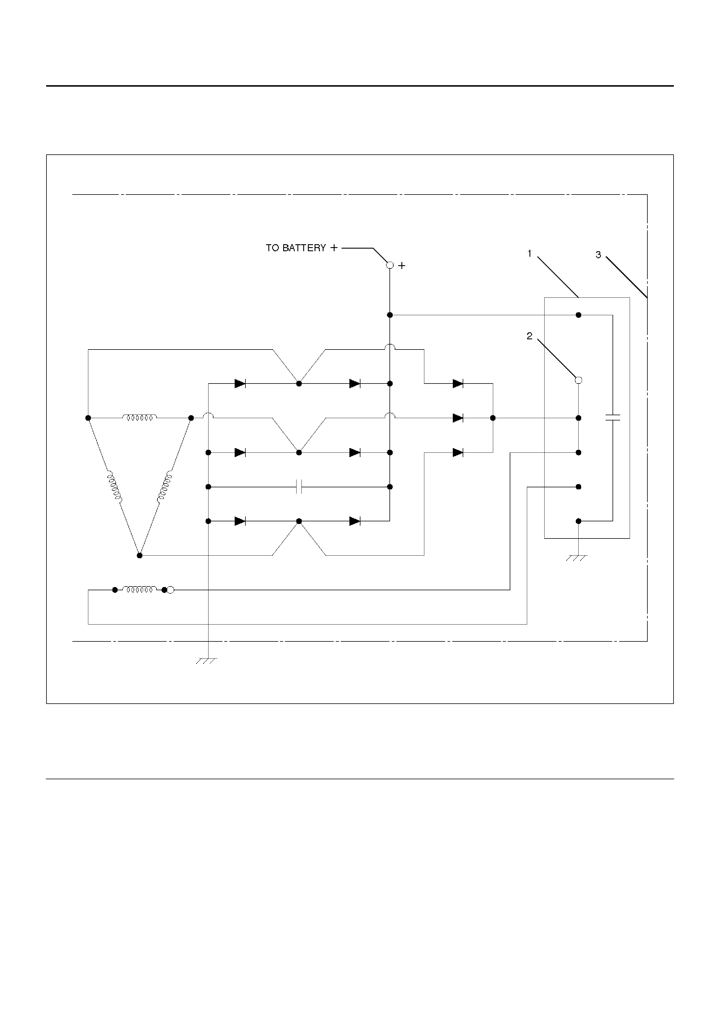
Charging System
General Description
The charging system is an IC integral regulator charging
system and its main components are connected as
shown in illustration.
The regulator is a solid state type and it is mounted
along with the brush holder assembly inside the
generator installed on the rear end cover.
The generator does not require particular maintenance
such as voltage adjustment. The rectifier connected to
the stator coil has eight diodes to transform AC voltage
into DC voltage.
This DC voltage is connected to the output terminal of
generator.
General On–Vehicle Inspection
The operating condition of charging system is indicated
by the charge warning lamp. The warning lamp comes
on when the starter switch is turned to “ON" position.
The charging system operates normally if the lamp goes
off when the engine starts.
If the warning lamp shows abnormality or if
undercharged or overcharged battery condition is
suspected, perform diagnosis by checking the charging
system as follows:
1. Check visually the belt and wiring connector.
2. With the engine stopped, turn the stator switch to
“ON" position and observe the warning lamp.
If lamp does not come on:
Disconnect wiring connector from generator, and
ground the terminal “L" on connector side.
If lamp comes on:
Repair or replace the generator.
066RW021
Legend
EndOFCallout
(1) Regulator
(2) Indicator Lamp (3) Generator Assembly
Generator
Removal
1. Disco nne ct batte ry ground cable.
2. Mov e drive belt tensioner to loose side using wrench
then remove drive belt.
3. Disconnect terminal “B" wiring connector and
connector.
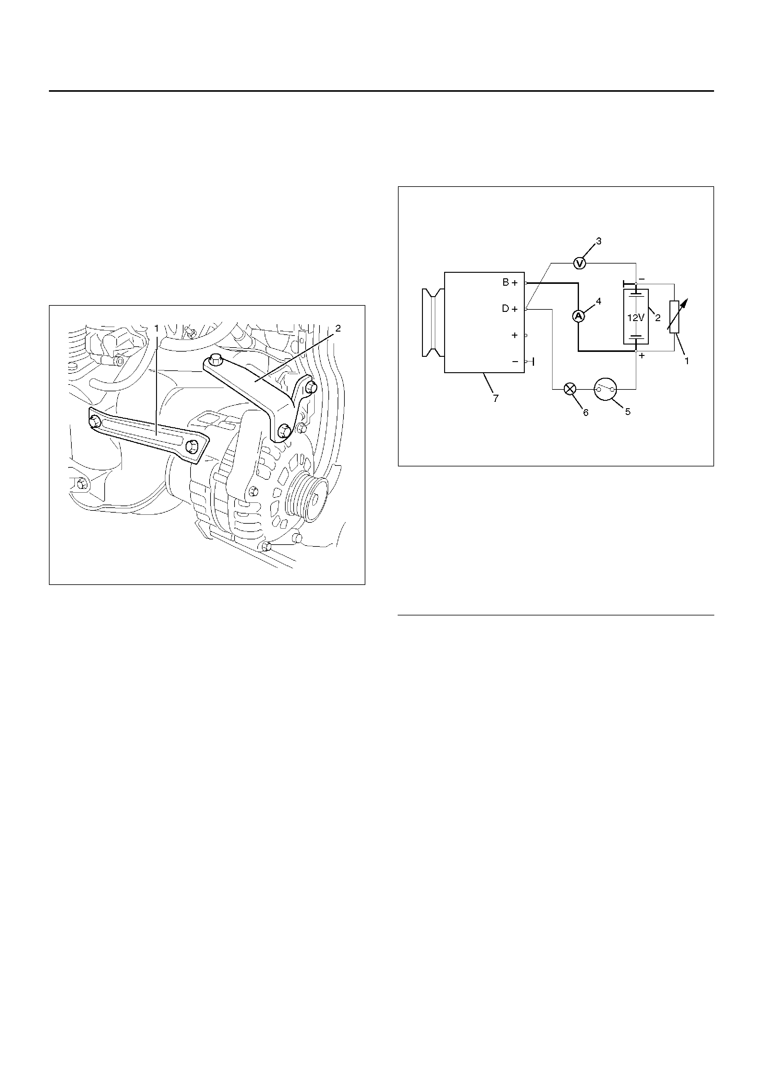
4. Remove generator bracket (1), (2) and remove
generator assembly.
065RW025
Inspection
Generator Power and Circuit Diagram
066RW020
Legend
EndOFCallout
1. Disconnect battery.
2. Close off connecting cable from alternator terminal
“B+".
3. Set ammeter (measuring range 100A) in
disconnected line.
4. Connect controllable load resistor to battery
terminal.
5. Set resistor in front of connection to “0"; connect first
to battery, then to resistor.
6. Connect tac hom eter.
7. Connect oscilloscope according to manufacturer's
instructions.
8. Connect batte ry.
9. Start engine and read off resulting current at various
engine speeds.
(1) Load resistor, set parallel to battery
(2) Battery
(3) Voltmeter
(4) Ammeter
(5) Ignition Lock
(6) Charge Telltale
(7) Generator
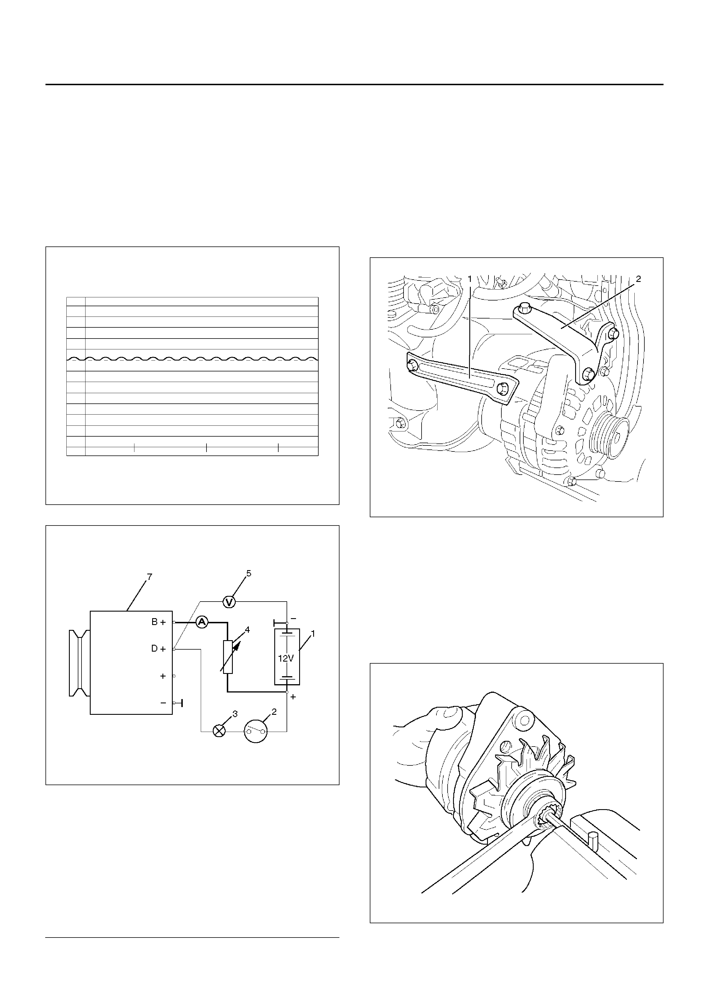
Generator Power
1. Adjust load resistor , if the required load currents are
not attained.
2. The shape of the voltage curves on oscilloscope
curve should be regular.
3. Test value: 5 to 7A.
4. If the required minimum current intensity is not
attained, or if the oscilloscope picture shows
variations, the alterna tor shou ld be overh auled.
066RW018
Regulated Voltage Circuit Diagram
066RW019
Legend
EndOFCallout
Installation
1. Install generator assembly and bring gene rator
assembly to the position to be installed.
2. Install generator bracket (1), (2) and tighten to the
specified torque.
Torque:
Long bolt: 35 N·m (3.6 kg·m/26 lb ft)
Short bolt: 20 N·m (2.0 kg·m/15 lb ft)
065RW025
3. Connect wiring harness connector.
4. Move drive belt tensioner to loose side using
wrench, then install drive belt to normal position.
5. Reconnect battery ground cable.
Disassembly
1.Belt pulley nut.
066RW016
(1) Battery
(2) Ignition Lock
(3) Charge Telltale
(4) Resistor, for attainment of load current with the
battery set in series
(5) Voltmeter
(6) Ammeter
(7) Generator
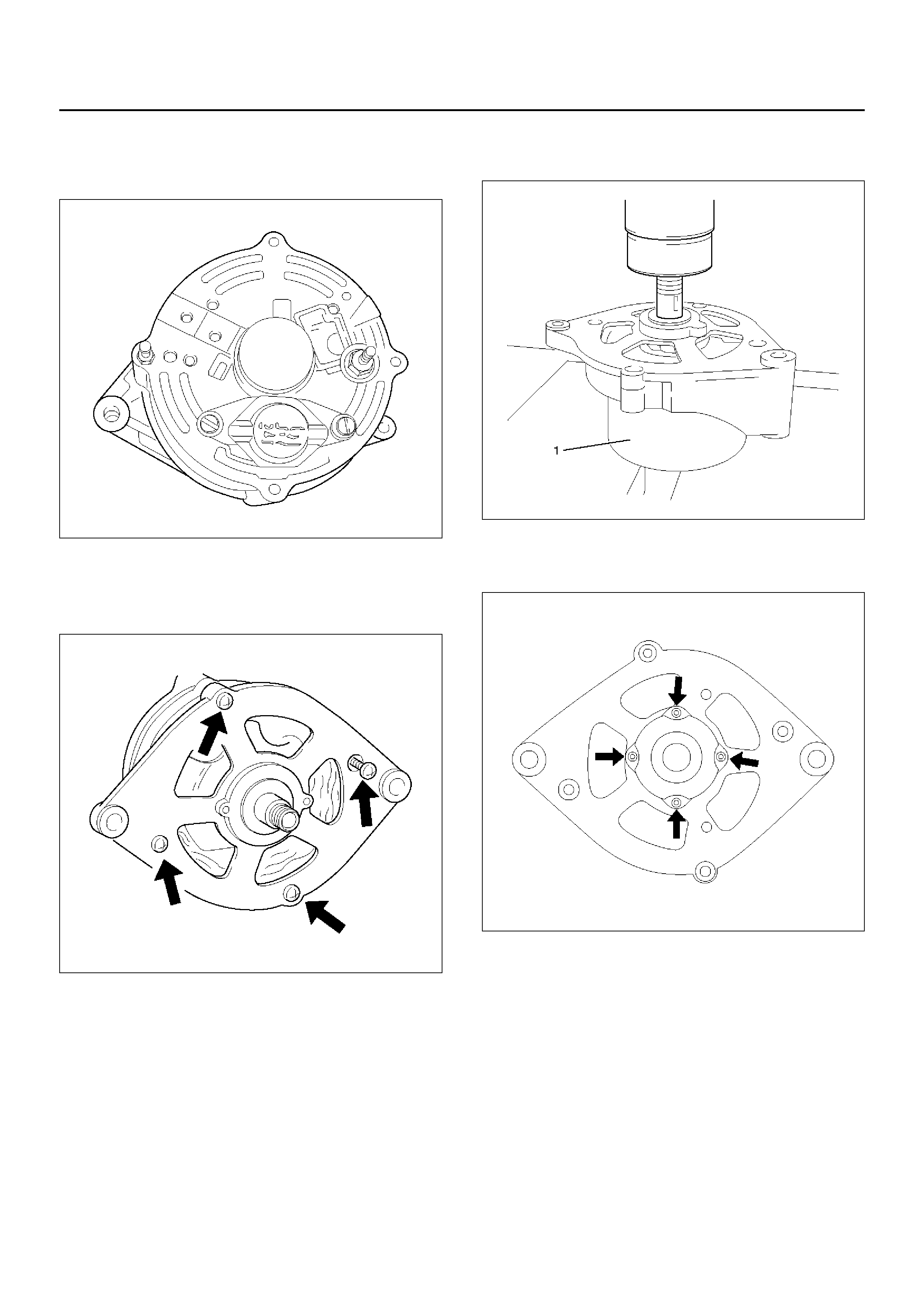
2. Spring ring, washer , belt pulley halves, spacing ring,
fan pinion, pulley spring.
3. Voltage regulator with brush holder.
066RW014
4. Drive bearing with clawpole armature.
5. Mark housing halves.
6. 4 fastening bolts.
066RW015
7. Clawpole armature from drive bearing.
8. Lay suitable pipe piece (1) underneath.
066RW013
9. Bearing cover of drive bearing.
10. Ball bearing from drive bearing.
066RW017
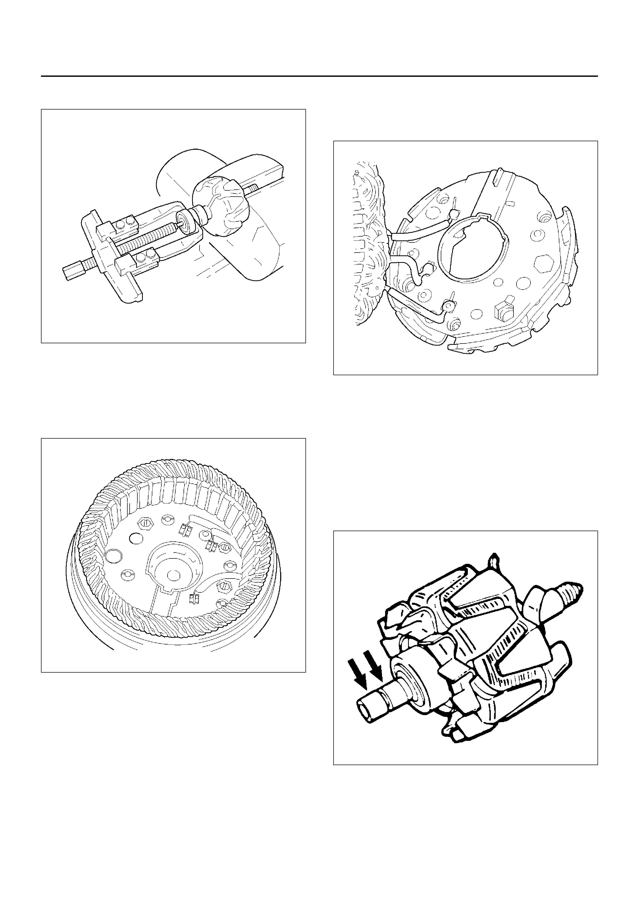
11. Ball bearing from armature shaft.
066RW012
12. Nut from connecting pins “B+" and “D+".
13. Washers and insulating material.
14. Diode plate.
15. Remove together with stator winding from slip ring
bearing.
066RW008
16. Spray sleeve (if present).
17. Carefully bend off diode plate.
18. Unsolder stator winding from diode plate.
066RW010
Inspection and Repair
Repair or replace necessary parts if extreme wear or
damage is found during inspection.
Rotor Assembly
1. Check the rotor slip ring surfaces for contamination
and roughness. If rough, polish with #500–600
sandpaper.
066RS014
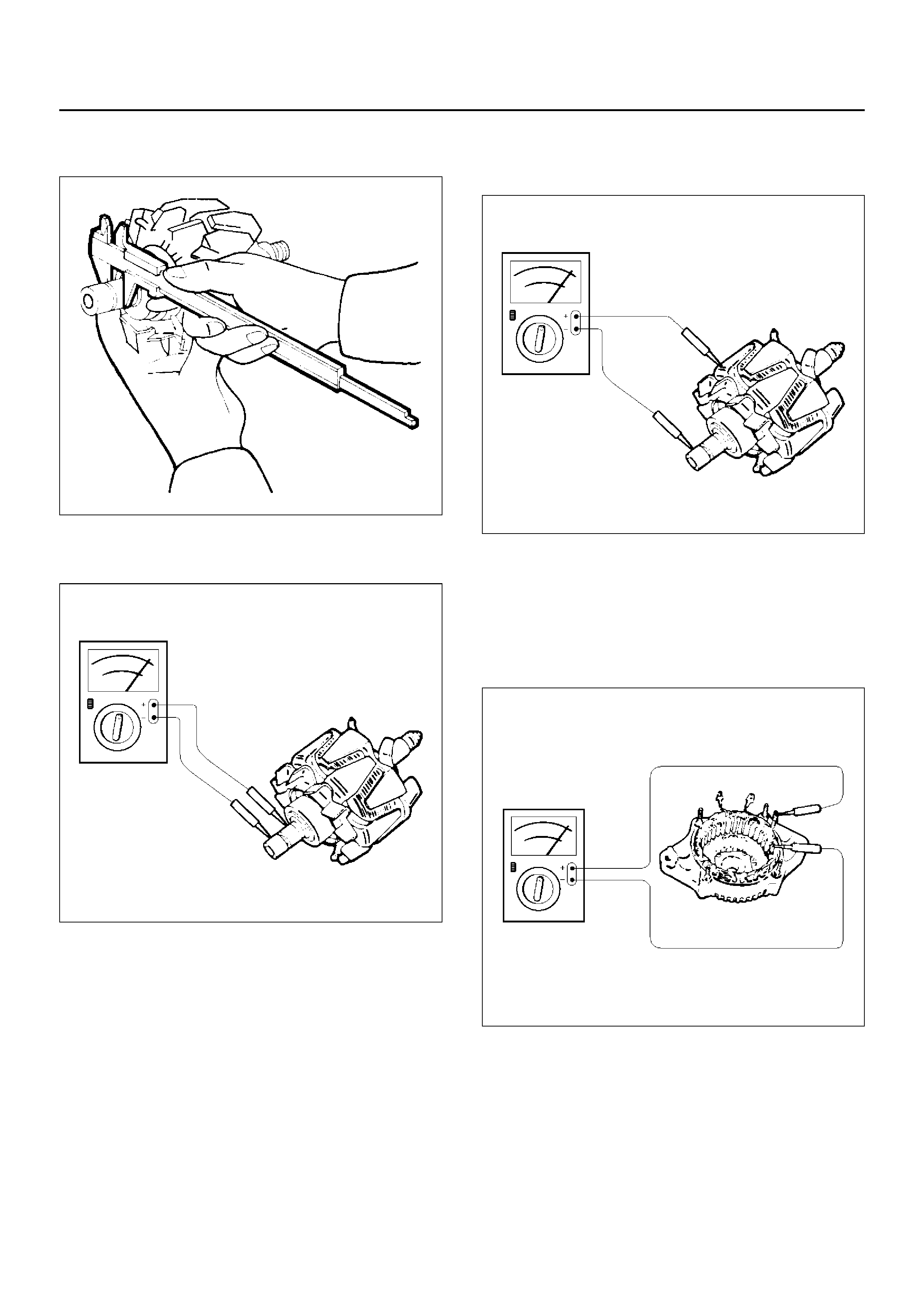
2. Measure the slip ring diameter, and replace if it
exceeds the limit.
066RS015
3. Check resistance between slip rings, and replace if
there is no continuity.
066RS016
4. Check for continuity between slip ring and rotor
core.
In case of continuity, replace the rotor assembly.
066RS017
Stator Coil
1. Measure resistance between respective phases.
2. Measure insulation resistance between stator coil
and core with a mega–ohmmeter.
If less than standard, replace the coil.
066RS018
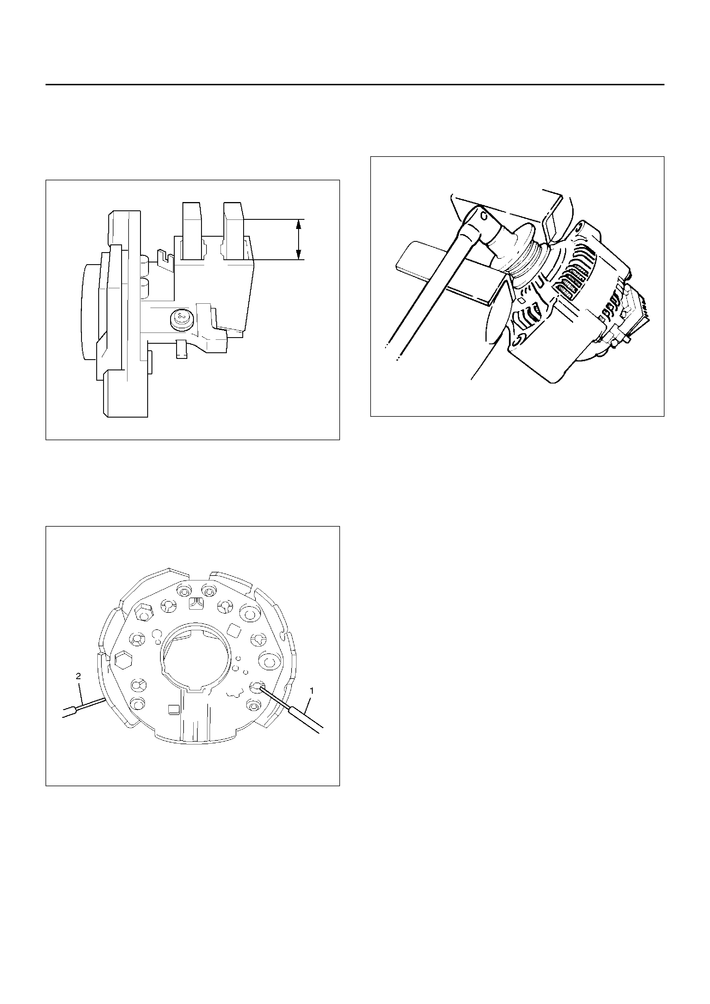
Brush
Measure the brush length.
If more than limit, replace the brush.
Standard: 5 mm (0.20in)
066RW009
Rectifier Assemb ly
Check for continuity across “1" and “2" in the × 100W
range of multimeter.
066RW011
Change polarity, and make sure that there is continuity
in one direction, and not in the reverse direction. In
case of continuity in both directions, replace the rectifier
assembly.
Reassembly
To reassemble, follow the disassembly steps in the
reverse order, noting the following points:
1. Install pulley on the rotor.
Clamp pulley to the vise, and tighten nut to the
specified torque.
Torque: 40 N·m (4.1 kg·m/30 lbft)
066RS010

Main Data and Specifications
General Specifications
Battery voltage V 12
Rated output A 100
Direction of rotation
(as viewed from pulley side) Clockwise
Maximum speed rpm 18000