
SECTION 6G - ENGINE LUBRICATION (X22SE 2.2L)
Service Precaution
General Description
Oil Pump
Oil Pump and Associated Parts
Disassembly
Inspection and Repair
Reassembly
Service Precaution
WARNING: THIS VEHICLE HAS A SUPPLEMENTAL
RESTRAINT SYSTEM (SRS). REFER TO THE SRS
COMPONENT AND WIRING LOCATION VIEW IN
ORDER TO DETERMINE WHETHER YOU ARE
PERFORMING SERVICE ON OR NEAR THE SRS
COMPONENTS OR THE SRS WIRING. WHEN YOU
ARE PERFORMING SERVICE ON OR NEAR THE
SRS COMPONENTS OR THE SRS WIRING, REFER
TO THE SRS SERVICE INFORMATION. FAILURE TO
FOLLOW WARNINGS COULD RESULT IN
POSSIBLE AIR BAG DEPLOYMENT, PERSONAL
INJURY, OR OTHERWISE UNNEEDED SRS SYSTEM
REPAIRS.
CAUTION: Always use the correct fastener in the
proper location. When you replace a fastener, use
ONLY the exact part number for that application.
ISUZU will call out those fasteners that require a
replacement after removal. ISUZU will also call out
the fasteners that require thread lockers or thread
sealant. UNLESS OTHERWISE SPECIFIED, do not
use supplemental coatings (Paints, greases, or
other corrosion inhibitors) on threade d fasteners or
fastener joint interfaces. Generally, such coatings
adversely affect the fastener torque and the joint
clamping f or ce, and may dama ge the fastener . Wh en
you install fasteners, use the correct tightening
sequence and specifications. Following these
instructions can help you avoid damage to parts
and systems.
Techline
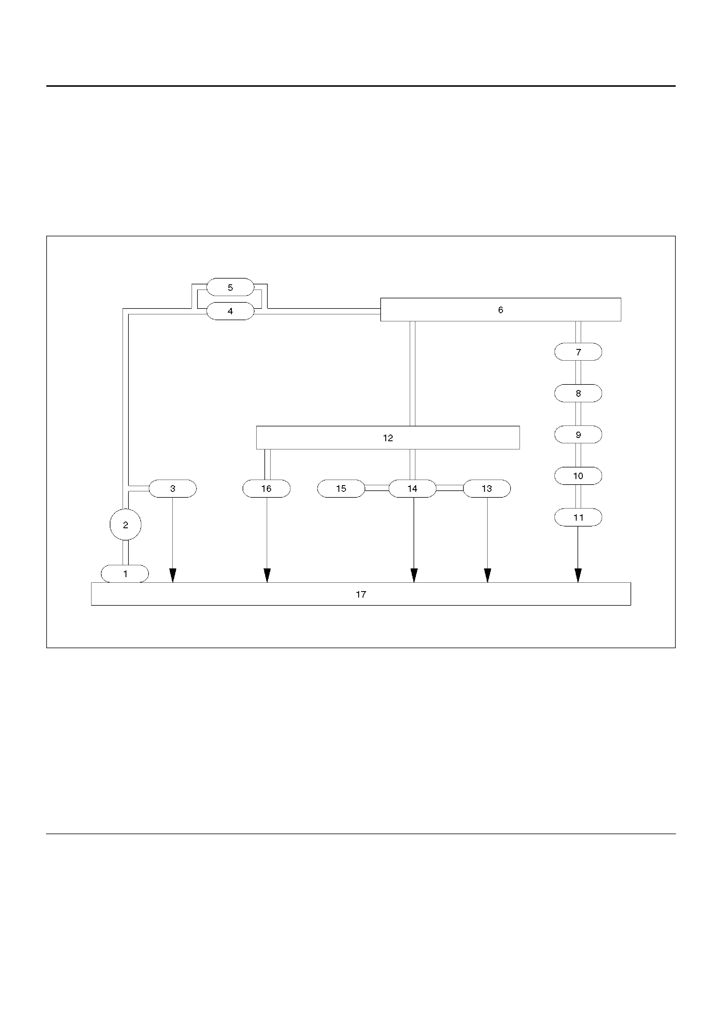
General Description
A gear-type oil pump is directly driven by the crankshaft
and draws oil from the oil pan, via the suction pipe. If
then passes the pressured oil through a full-flow
disposable oil filter, to the main oil gallery in the cylinder
Block. An oil pump pressure relief valve and oil filter
bypass valve are incorporated in the system.
From the main oil gallery in the cylinder block, the
cylinder head and crankshaft main bearings are
supplied with oil. The camshaft bearings and hydraulic
tappets are supplied through the main feed galleries in
the cylinder head. Vent valves allow air to be expelled
from the oil galleries in the cylinder head. The balance
shaft journals are directly fed from the crankshaft main
bearings. The connecting rod bearings are fed via
passages in the crankshaft. the oil returns to the oil pan
via passages in the cylinder block.
C06RW004
Legend
EndOFCallout
(1) Oil Stra iner
(2) Oil Pump
(3) Relief Valve
(4) Oil Filter
(5) Safety Valve
(6) Oil Gallery
(7) Crankshaft Bearing
(8) Crankshaft
(9) Connecting Rod Bearing
(10) Connecting Rod
(11) Piston
(12) Oil Gallery; Cylinder Head
(13) Camshaft
(14) Camshaft Jo urna l
(15) HLV
(16) Vent Valve
(17) Oil Pan
Oil Pump
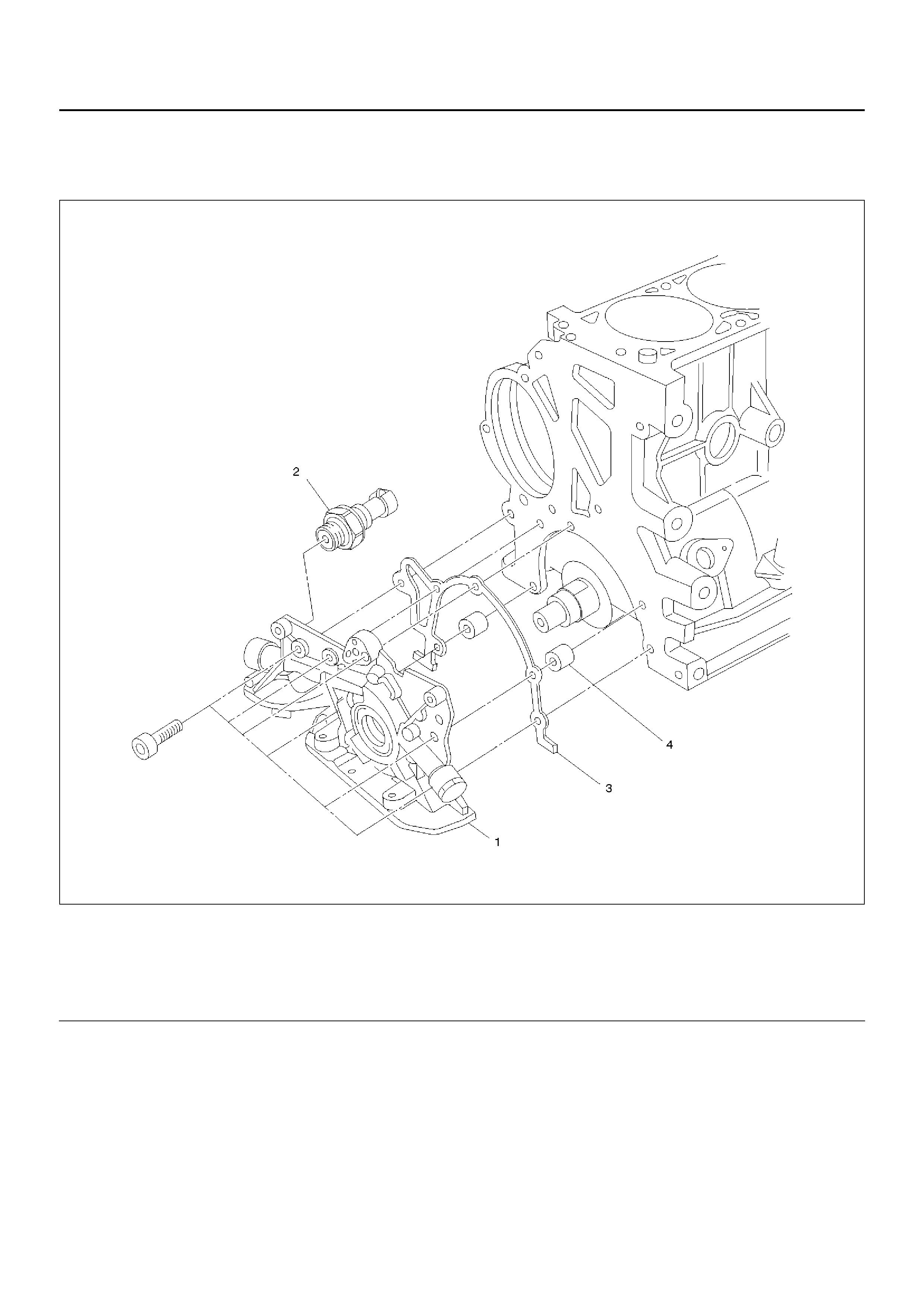
Oil Pump and Associated Parts
051RW004
Legend
EndOFCallout
(1) Oil Pump Assembly
(2) Oil Pressure Switch
(3) Gasket
(4) Sleeve
Disassembly
1.Remove crankshaft timing pulley.
2.Remove oil pan.
3.Remove oil pan support.
4.Remove oil strainer.
5.Remove oil pump assembly.
6.Remove oil pressure switch.
7.Remove gasket.
8.Remove sleeve.
Inspection and Repair
CAUTION: Make necessary correction or parts
replacement if wear, damage or any other abnormal
conditions are found through inspection.
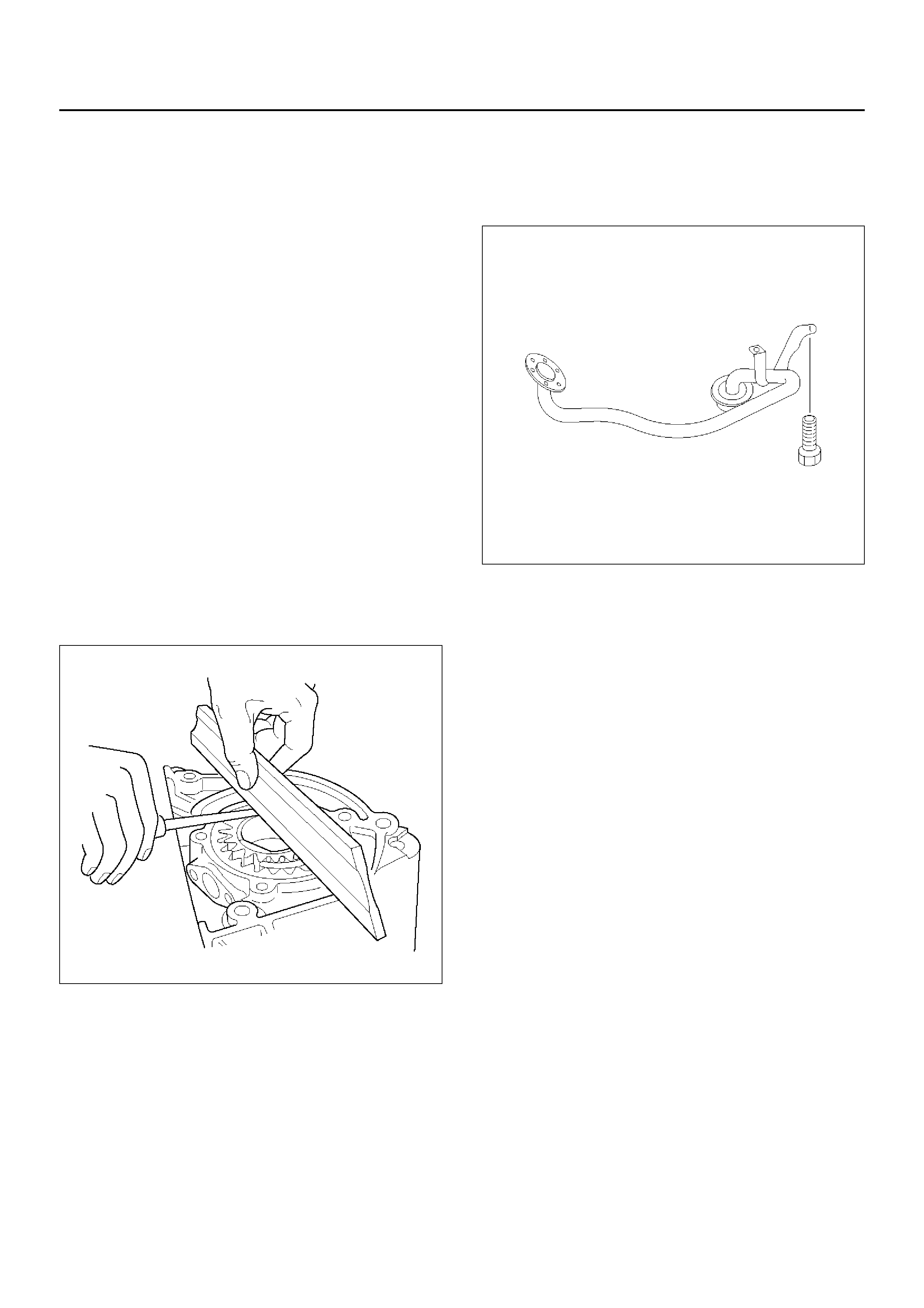
Body and Gears
The pump assembly must be replaced if one or more of
the conditions below is discovered during inspection:
Indentation of gear pair — use feeler strip and straight
edge.
Dimension : 0.03 mm to 0.10 mm
(0.0012 to 0.0039 in)
051RW014
Oil Strainer
Check the oil strainer for cracking and scoring. If
cracking and scoring are found, the oil strainer must be
replaced.
051RW013
Reassembly
1. Install oil pressure switch to the oil pump.
Torque : 40 N·m (4.1 kg·m/37 lbft)
2. Install the oil pump with the sleeve and the gasket.
Torque : 6 N·m (0.6 kg·m/4.4 lbft)
3. Install oil strainer.
Torque : 8 N·m (0.8 kg·m/5.8 lbft)
4. Install Oil pan support.
Torque : 20 N·m (2.0 kg·m/14 lbft)
5. Install the oil pan.
Tighten the bolts in 2 steps:
1st step: 8 N·m (0.8 kg·m/5.8 lbft)
2nd step: 30°
°°
°
6. Install crankshaft timing pulley.
Tighten the bolts in 2 steps:
1st step: 130 N·m (13.2 kg·m/94 lbft)
2nd step: 45°
°°
°