
SECTION 6H - ENGINE SPEED CONTROL SYSTEM (X22SE 2.2L)
Service Precaution
Accelerator Pedal Control Cable
Removal
Inspection
Installation
Adjustment
Accelerator Pedal
Accelerator Pedal and Associated Parts
Removal
Installation
Adjustment
Service Precaution
WARNING: THIS VEHICLE HAS A SUPPLEMENTAL
RESTRAINT SYSTEM (SRS). REFER TO THE SRS
COMPONENT AND WIRING LOCATION VIEW IN
ORDER TO DETERMINE WHETHER YOU ARE
PERFORMING SERVICE ON OR NEAR THE SRS
COMPONENTS OR THE SRS WIRING. WHEN YOU
ARE PERFORMING SERVICE ON OR NEAR THE
SRS COMPONENTS OR THE SRS WIRING, REFER
TO THE SRS SERVICE INFORMATION. FAILURE TO
FOLLOW WARNINGS COULD RESULT IN
POSSIBLE AIR BAG DEPLOYMENT, PERSONAL
INJURY, OR OTHERWISE UNNEEDED SRS SYSTEM
REPAIRS.
CAUTION: Always use the correct fastener in the
proper location. When you replace a fastener, use
ONLY the exact part number for that application.
ISUZU will call out those fasteners that require a
replacement after removal. ISUZU will also call out
the fasteners that require thread lockers or thread
sealant. UNLESS OTHERWISE SPECIFIED, do not
use supplemental coatings (Paints, greases, or
other corrosion inhibitors) on threaded fasteners or
fastener joint interfaces. Generally, such coatings
adversely affect the fastener torque and the joint
clamping f or ce, and may dama ge the fastener . Wh en
you install fasteners, use the correct tightening
sequence and specifications. Following these
instructions can help you avoid damage to parts
and systems.
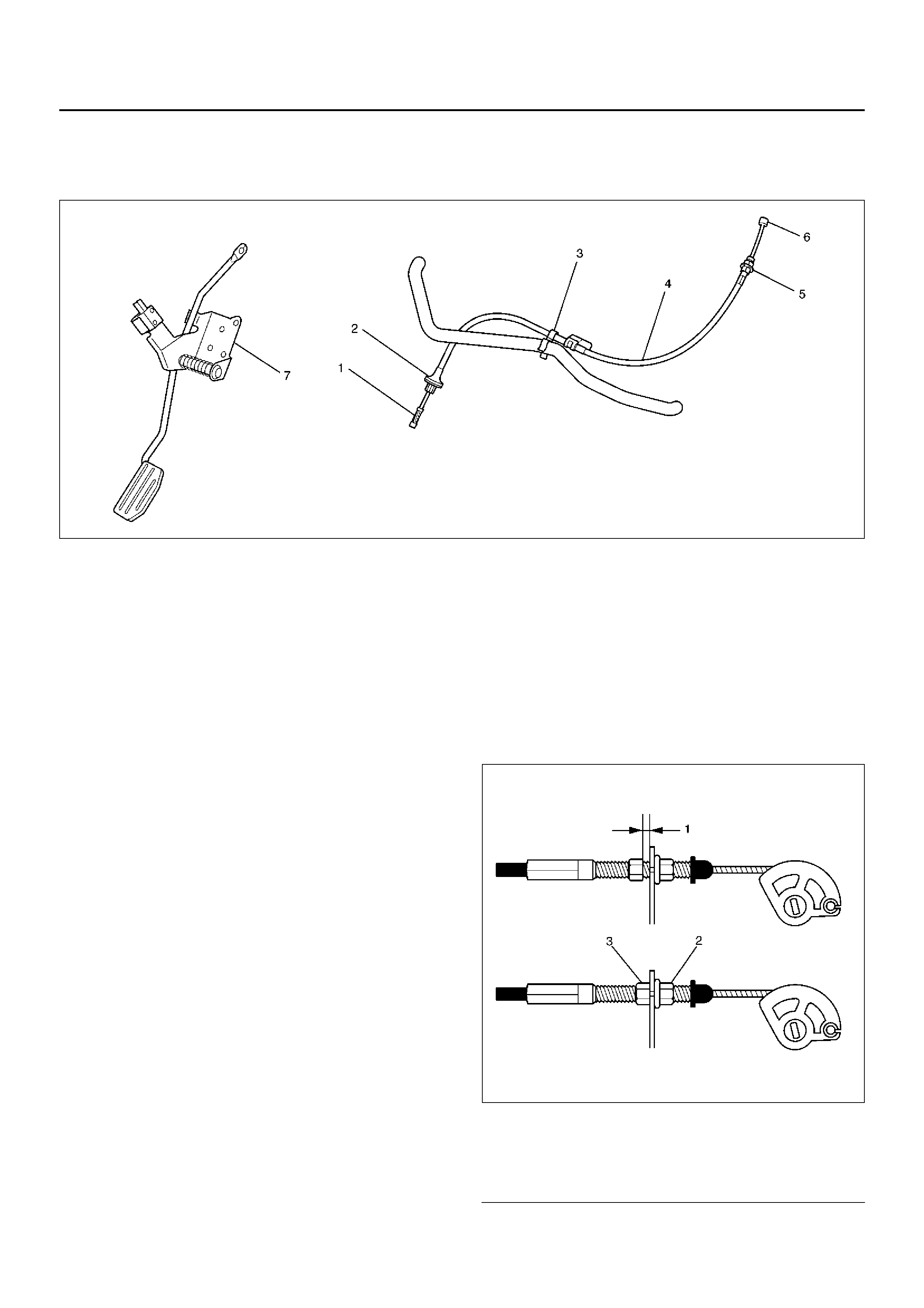
Accelerator Pedal Control Cable
035RX004
Removal
1. Loosen the nut(5) on the cable bracket mounted.
2. Remove cable clip(3).
3. Disconnect accelerator pedal (AP) control cable(6).
(on throttle valve side)
4. Disconnect AP control cable(1). (on AP pedal(7)
side)
5. Remove grommet(2).
6. Remove AP control cable(4).
Inspection
Che c k th e f o llo w ing items, and repl ace t he cont rol cab l e
if any abnormality is found:
• The control cable should move smoothly.
• The control cable should not be bent or kinked.
• The control cable should be free of damage and
corrosion.
Installation
1. Install AP control cable(4).
2. Install grommet(2).
3. Connect AP control cable(1). (on AP pedal(7) side)
4. Connect AP control cable(6). (on throttle valve side)
5. Install cable cli p(3).
6. Install nut(5).
Adjustment
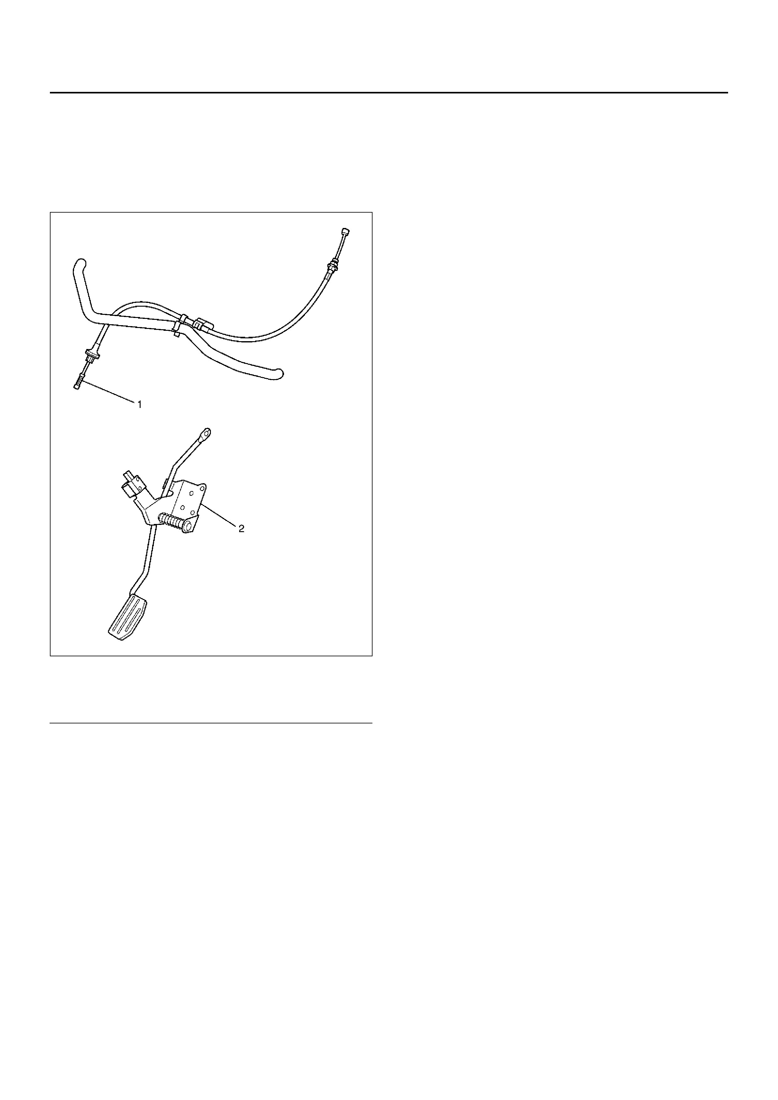
1. Loosen adjusting nut and lock nut.
2. Pull outer cable while closing fully the throttle valve.
3. Tighten adju sti ng nut and lock nut temporarily.
4. Loosen adjusting nut by three turns and tighten lock
nut.
Then, manually operating the throttle valve, make
sure that the valve lever returns up to the stopper
screw.
If it does not reach the stopper screw, repeat from
step 1.
035RX014
Legend
EndOFCallout
(1) Clearance (2 – 3.5 mm)
(2) Lock Nut
(3) Adjusting Nut
Accelerator Pedal
Accelerator Pedal and Associated
Parts
035RX002
Legend
EndOFCallout
Removal
1. Ac ce lerat or pedal co ntr ol cable(1) .
2. Acce lerat or pedal as se mbly(2).
Installation
1. Acce lerat or pedal as se mbly (2).
2. Ac ce lerat or pedal co ntr ol cable (1).
Adjustment
Man ual Transmis sion:
• Rotate counterclockwise to loosen the lock nut and
screw the stopper bolt in sufficiently.
• Fully depress the pedal and hold it there by hand.
Ne xt, rotate the stopper bolt until it hits the stopper of
pedal bracket. Then, lock the stopper bolt there.
(1) Accelerator Pedal Control Cable
(2) Acc el erato r Pedal Assembly