
SECTION 6B - ENGINE COOLING
Service Precaution
General Description
Diagnosis
Draining and Refilling Cooling System
Engine coolant change
Water Pump
Water Pump and Associated Parts
Removal
Inspection
Installation
Thermostat
Thermostat and Associated Parts
Removal
Inspection
Installation
Radiator
Radiator and Associated Parts
Removal
Inspection
Installation
Drive Belt and Cooling Fan
Drive Belt and Associated Parts
Inspection
Installation
Main Data and Specifications
Special Tool
Service Precaution
WARNING:THIS VEHICLE HAS A SUPPLEMENTAL
RESTRAINT SYSTEM (SRS), REFER TO THE SRS
COMPONENT AND WIRING LOCATION VIEW IN
ORDER TO DETERMINE WHETHER YOU ARE
PERFORMING SERVICE ON OR NEAR THE SRS
COMPONENTS OR THE SRS WIRING. WHEN YOU
ARE PERFORMING SERVICE ON OR NEAR THE SRS
COMPONENTS OR THE SRS WIRING, REFER TO
THE SRS SERVICE INFORMATION. FAILURE TO
FOLLOW WARNINGS COULD RESULT IN POSSIBLE
AIR BAG DEPLOYMENT, PERSONAL INJURY, OR
OTHERWISE UNNEEDED SRS SYSTEM REPAIRS.
CAUTION:Always use the correct fastener in the
proper location. When you replace a fastener, use
ONLY the exact part number for that application.
ISUZU will call out those fasteners that require a
replacement after removal. ISUZU will also call out
the fasteners that require thread lockers or thread
sealant. UNLESS OTHERWISE SPECIFIED, do not
use supplemental coatings (Paints, greases, or other
corrosion inhibitors) on threaded fasteners or
fastener joint interfaces. Generally, such coatings
adversely affect the fastener torque and the joint
clamping force, and may damage the fastener . When
you install fasteners, use the correct tightening
sequence and specifications. Following these
instructions can help you avoid damage to parts and
systems.
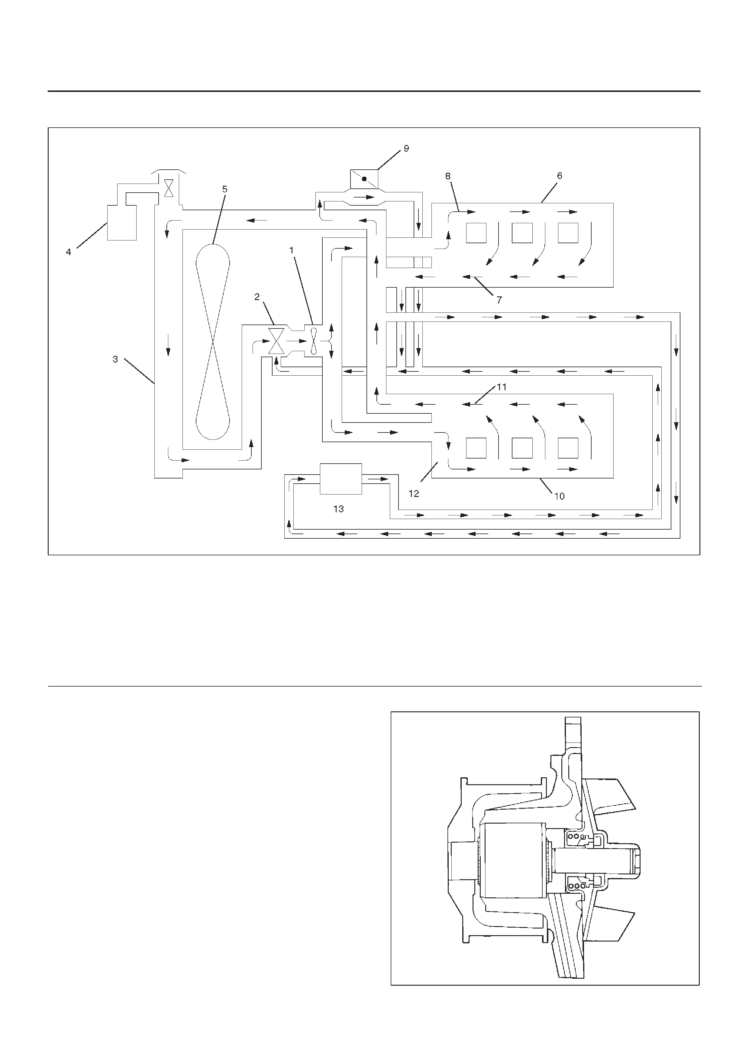
General Description
030RW001
Legend
(1) Water Pump
(2) Thermostat
(3) Radiator
(4) Reserve Tank
(5) Cooling Fan
(6) Cylinder Block
(7) Cylinder Head
(8) Right Bank
(9) Throttle Body
(10) Cylinder Block
(11) Cylinder Head
(12) Left Bank
(13) Heater
The cooling system is a pressurized Engine Coolant (EC)
forced circulation type which consists of a water pump,
thermostat cooling fan, radiator and other components.
The automatic transmission fluid is cooled by the EC in
radiator.
Water Pump
The EC pump is a centrifugal impeller type and is driven
by a timing belt.
030RS001
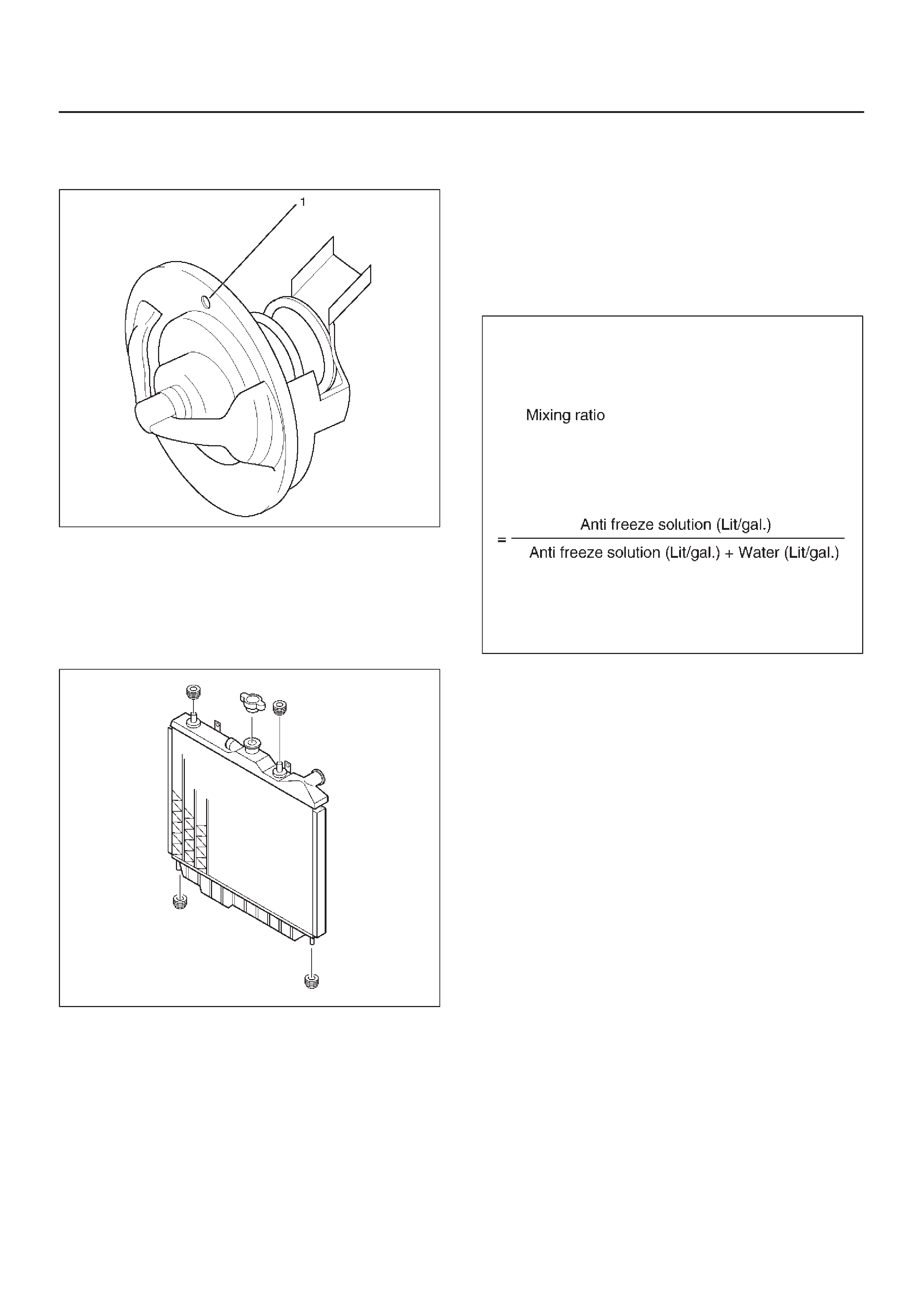
Thermostat
The thermostat is a wax pellet type with a air hole(1) and is
installed in the thermostat housing.
031RW002
Radiator
The radiator is a tube type with corrugated fins. In order to
raise the boiling point of the coolant, the radiator is fitted
with a cap in which the valve is operated at 88.2 ∼ 117.6
kPa (12.8 ∼ 17.0 psi) pressure. (No oil cooler provided for
M/T)
110RW023
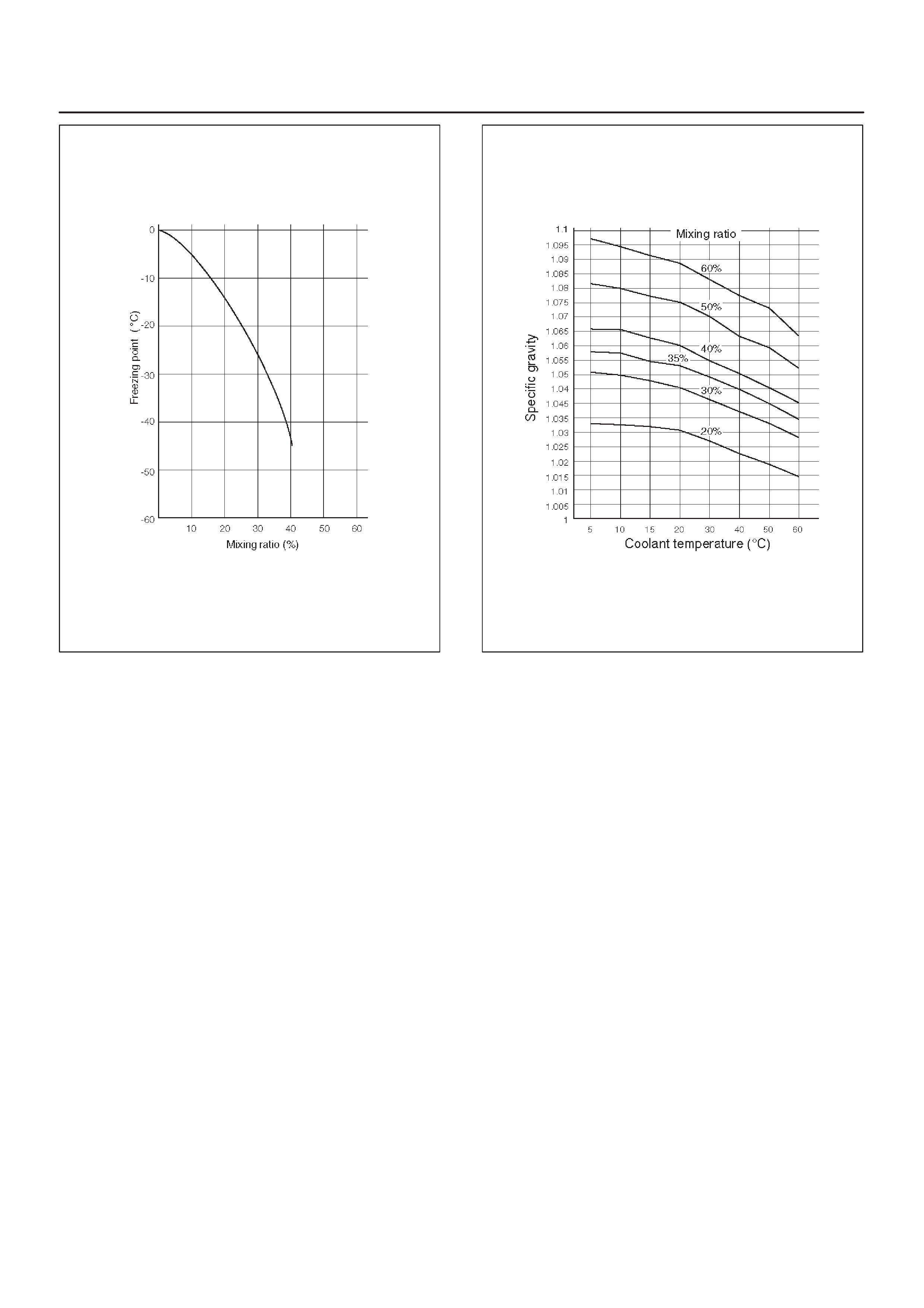
Anti Freeze Solution
DRelation between the mixing ratio and freezing
temperature of the Engine Coolant varies with the
ratio of anti–freeze solution in water. Proper mixing
ratio can be determined by referring to the chart.
Supplemental inhibitors or additives claiming to
increase cooling capability that have not been
specifically approved by Isuzu are not recommended
for addition to the cooling system.
DCalculating mixing ratio
F06RW005
NOTE: Antifreeze solution + Water = Total cooling
system capacity.
DTotal Cooling System Capacity
DM/T 8.8Lit (2.32Us gal)
DA/T 8.4Lit (2.22Us gal)
B06RW002
DMixing ratio
Check the specific gravity of engine coolant in the
cooling system temperature ranges from 0°C to 50°C
using a suction type hydrometer, then determine the
density of the engine coolant by referring to the table.
NOTE:
1.Even in the areas where the atmospheric
temperature is higher than 0°C, be sure not to use
antifreeze solution at a mixing ratio lower than 20% so
that the inside of the engine may not be corroded.
2.If antifreeze solution is used at a mixing ratio higher
than 60%, the specific heat of the coolant falls and the
engine may be overheated. Moreover, antifreeze
performance drop and the coolant may be frozen.
The density of the solution must be adjusted as
occasion calls.
Antifreeze solution lower than 20% may not have
sufficient anticorrosive performance, and therefore,
please never fail to adjust as occasion demands within
the range of 20% to 60%.
B06RW003
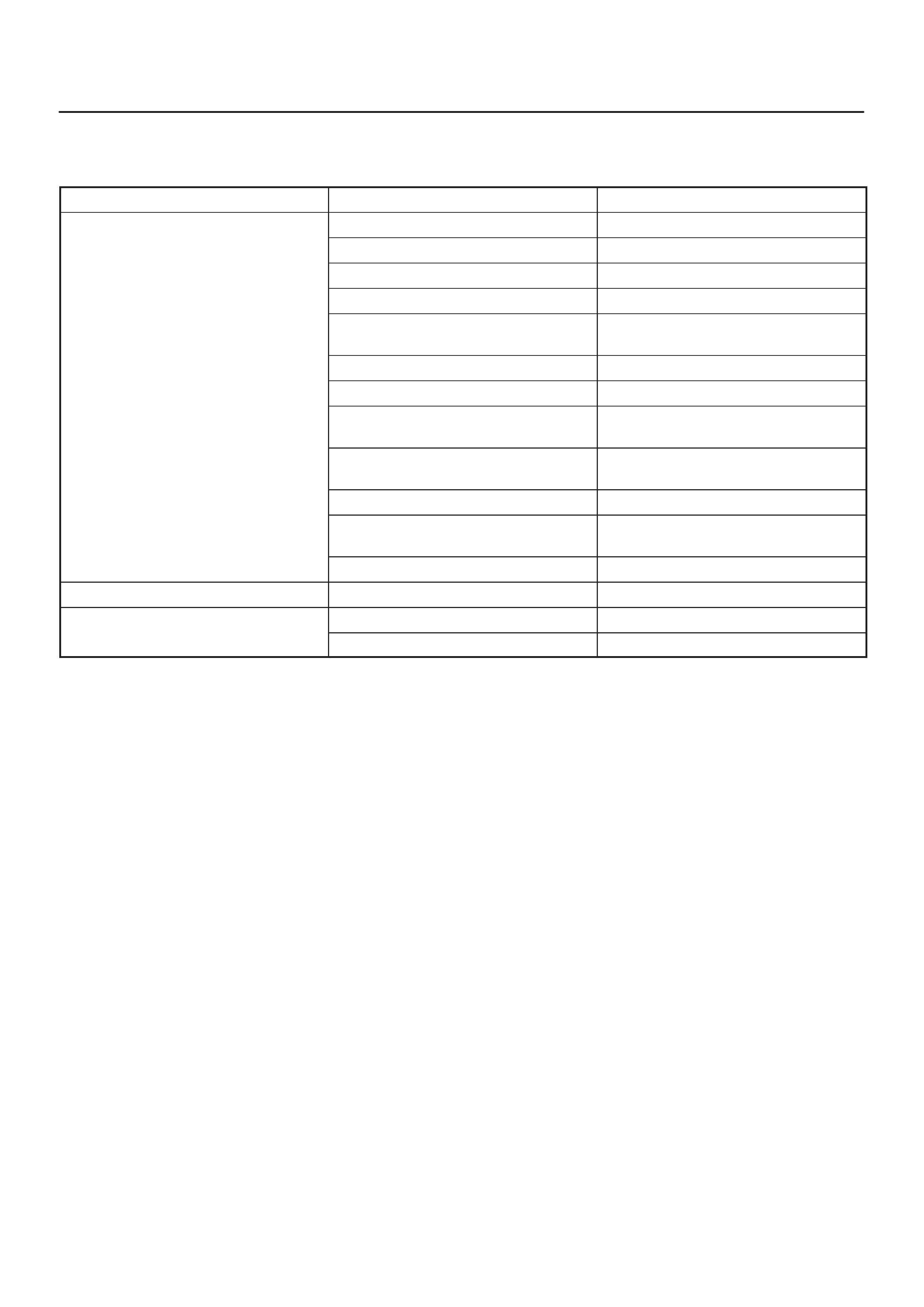
Diagnosis
Engine Cooling Trouble
Engine overheating Low Engine Coolant level Replenish
Incorrect fan installed Replace
Thermo meter unit faulty Replace
Faulty thermostat Replace
Faulty Engine Coolant temperature
sensor Repair or replace
Clogged radiator Clean or replace
Faulty radiator cap Replace
Low engine oil level or use of
improper engine oil Replenish or change oil
Clogged exhaust system Clean exhaust system or replace
faulty parts
Faulty Throttle Position sensor Replace throttle valve assembly
Open or shorted Throttle Position
sensor circuit Repair or replace
Damaged cylinder head gasket Replace
Engine overcooling Faulty thermostat Replace
Engine slow to warm–up Faulty thermostat Replace
Thermo unit faulty Replace

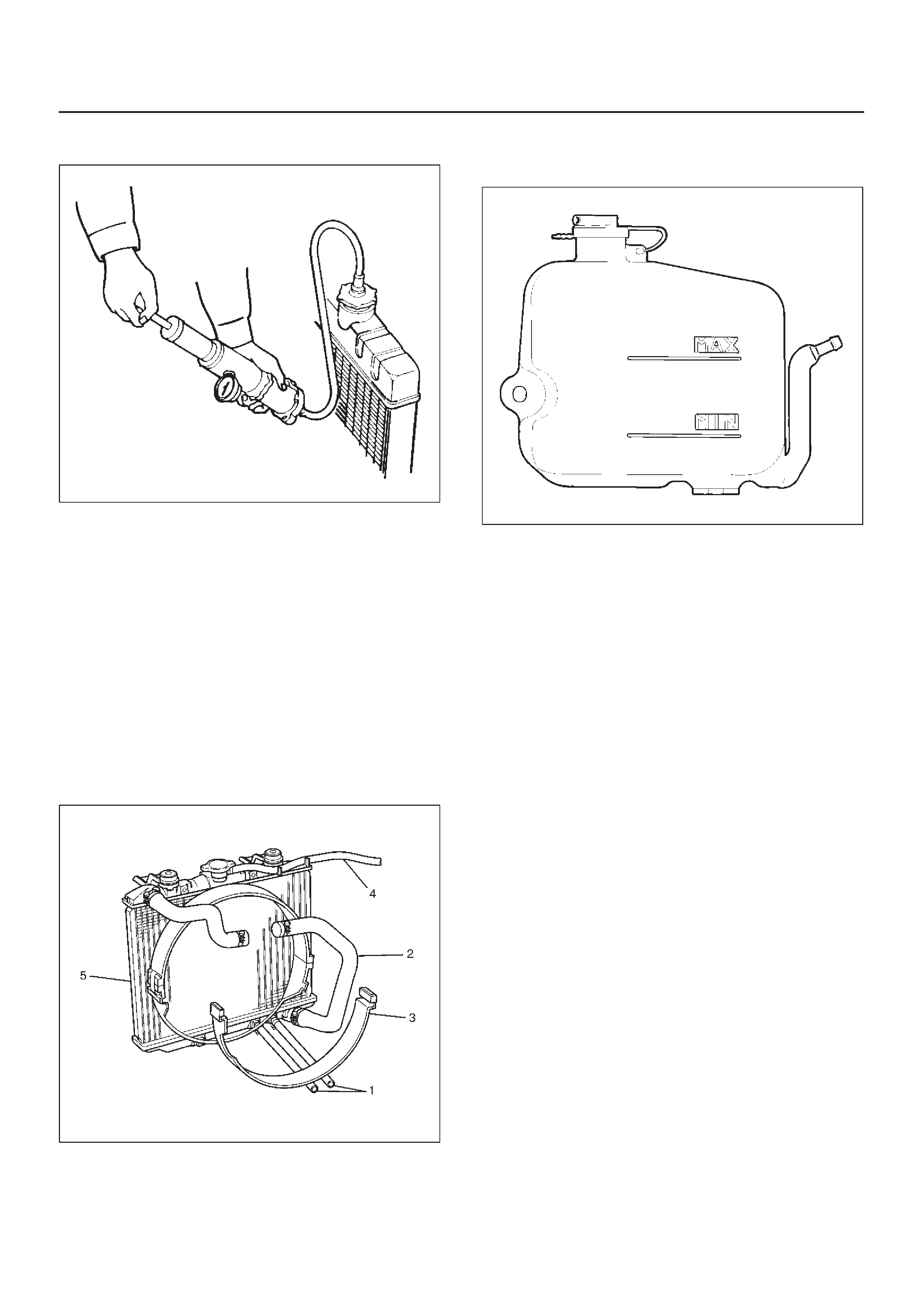
Draining and Refilling Cooling
System
Before draining the cooling system, inspect the system
and perform any necessary service to ensure that it is
clean, does not leak and is in proper working order. The
engine coolant (EC) level should be between the “MIN”
and “MAX” lines of reserve tank when the engine is cold.
If low, check for leakage and add EC up to the “MAX” line.
There should not be any excessive deposit of rust or
scales around the radiator cap or radiator filler hole, and
the EC should also be free from oil.
Replace the EC if excessively dirty.
Engine coolant change
1.To change engine coolant, make sure that the engine
is cool.
WARNING:WHEN THE COOLANT IS HEATED TO A
HIGH TEMPERATURE, BE SURE NOT TO LOOSEN
OR REMOVE THE RADIATOR CAP. OTHERWISE YOU
MIGHT GET SCALDED BY HOT VAPOR OR BOILING
WATER. TO OPEN THE RADIATOR CAP, PUT A
PIECE OF THICK CLOTH ON THE CAP AND LOOSEN
THE CAP SLOWLY TO REDUCE THE PRESSURE
WHEN THE COOLANT HAS BECOME COOLER.
2.Open radiator cap and drain the cooling system by
loosening the drain valve on the radiator and on the
cylinder body.
NOTE:For best result it is suggested that the engine
cooling system be flushed at least once a year. It is
advisable to flash the interior of the cooling system
including the radiator before using anti-freeze
(ethylene-glycol based).
Replace damaged rubber hoses as the engine anti-freeze
coolant is liable to leak out even minor cracks.
Isuzu recommends to use Isuzu genuine anti-freeze (eth-
ylene-glycol based) or equivalent, for the cooling system
and not add any inhibitors or additives.
CAUTION:A failure to correctly fill the engine
cooling system in changing or topping up coolant
may sometimes cause the coolant to overflow from
the filler neck even before the engine and radiator are
completely full.
If the engine runs under this condition, shortage of
coolant may possibly result in engine overheating.
To avoid such trouble, the following precautions
should be taken in filling the system.
3.To refill engine coolant, pour coolant up to filler neck
using a filling hose which is smaller in outside
diameter of the filler neck. Otherwise air between the
filler neck and the filling hose will block entry,
preventing the system from completely filling up.
4.Keep a filling rate of 9 liter/min. or less. Filling over this
maximum rate may force air inside the engine and
radiator.
And also, the coolant overflow will increase, making
it difficult to determine whether or not the system is
completely full.
5.After filling the system to the full, pull out the filling
hose and check to see if air trapped in the system is
disclodged and the coolant level goes down. Should
the coolant level go down, repeat topping-up until
there is no more drop in the coolant level.
6.After directly filling the radiator, fill the reservoir to the
maximum level.
7.Install and tighten radiator cap and start the engine.
After idling for 2 to 3 minutes, stop the engine and
reopen radiator cap. If the water level is lower,
replenish.
WARNING:WHEN THE COOLANT IS HEATED TO A
HIGH TEMPERATURE, BE SURE NOT TO LOOSEN
OR REMOVE THE RADIA TOR CAP. OTHERWISE YOU
MIGHT GET SCALDED BY HOT VAPOR OR BOILING
WATER. TO OPEN THE RADIATOR CAP, PUT A
PIECE OF THICK CLOTH ON THE CAP AND LOOSEN
THE CAP SLOWLY TO REDUCE THE PRESSURE
WHEN THE COOLANT HAS BECOME COOLER.
8.After tightening radiator cap, warm up the engine at
about 2,000 rpm.
Set heater adjustment to the highest temperature
position, and let the coolant circulate also into heater
water system.
9.Check to see the thermostat has opened through the
needle position of water thermometer, conduct a
5-minute idling again and stop the engine.
10.When the engine has been cooled, check filler neck
for water level and replenish if required. Should
extreme shortage of coolant is found, check the
coolant system and reservoir tank hose for leakage.
11.Fill the coolant into the reservoir tank up to “MAX” line.
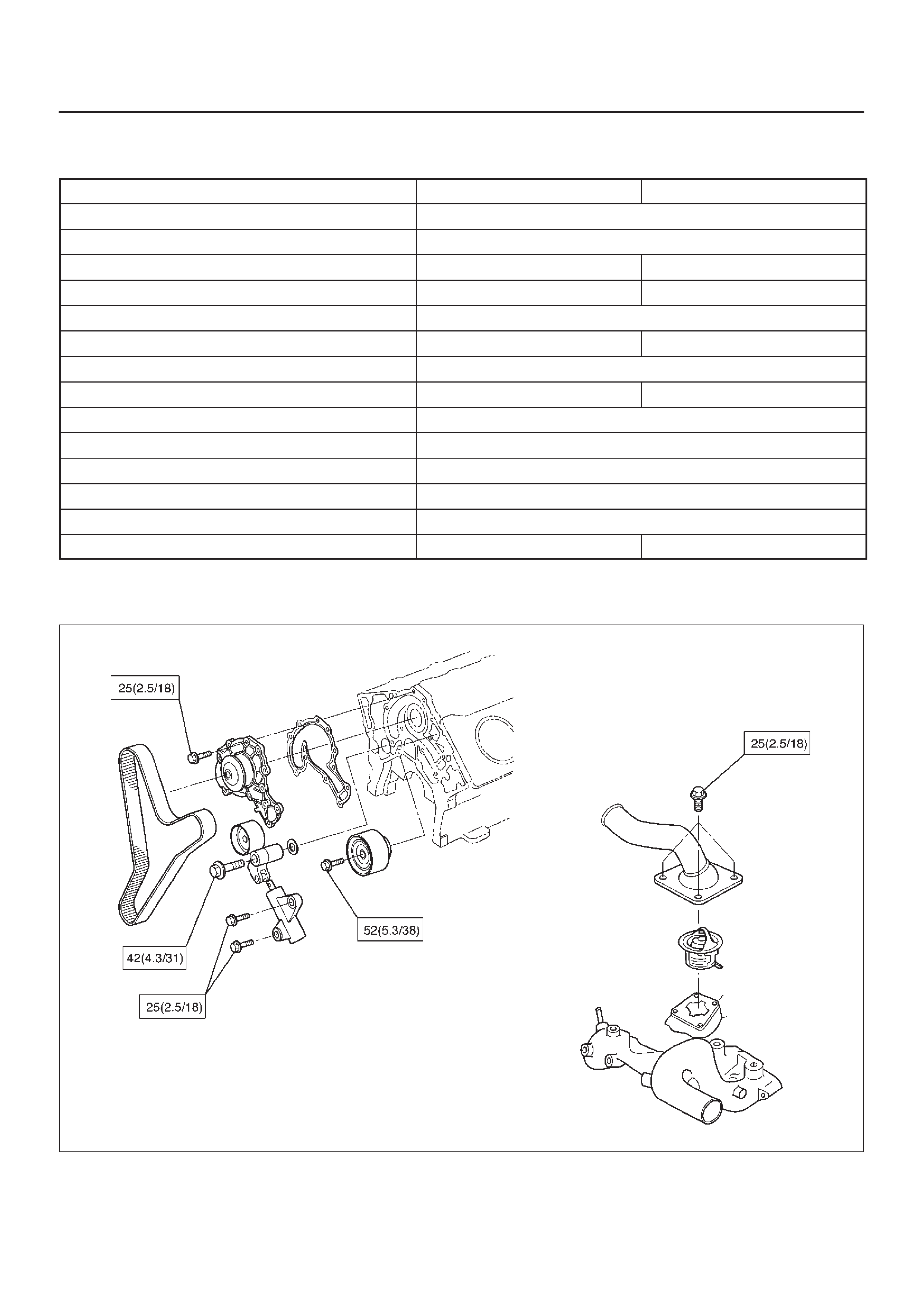
Water Pump
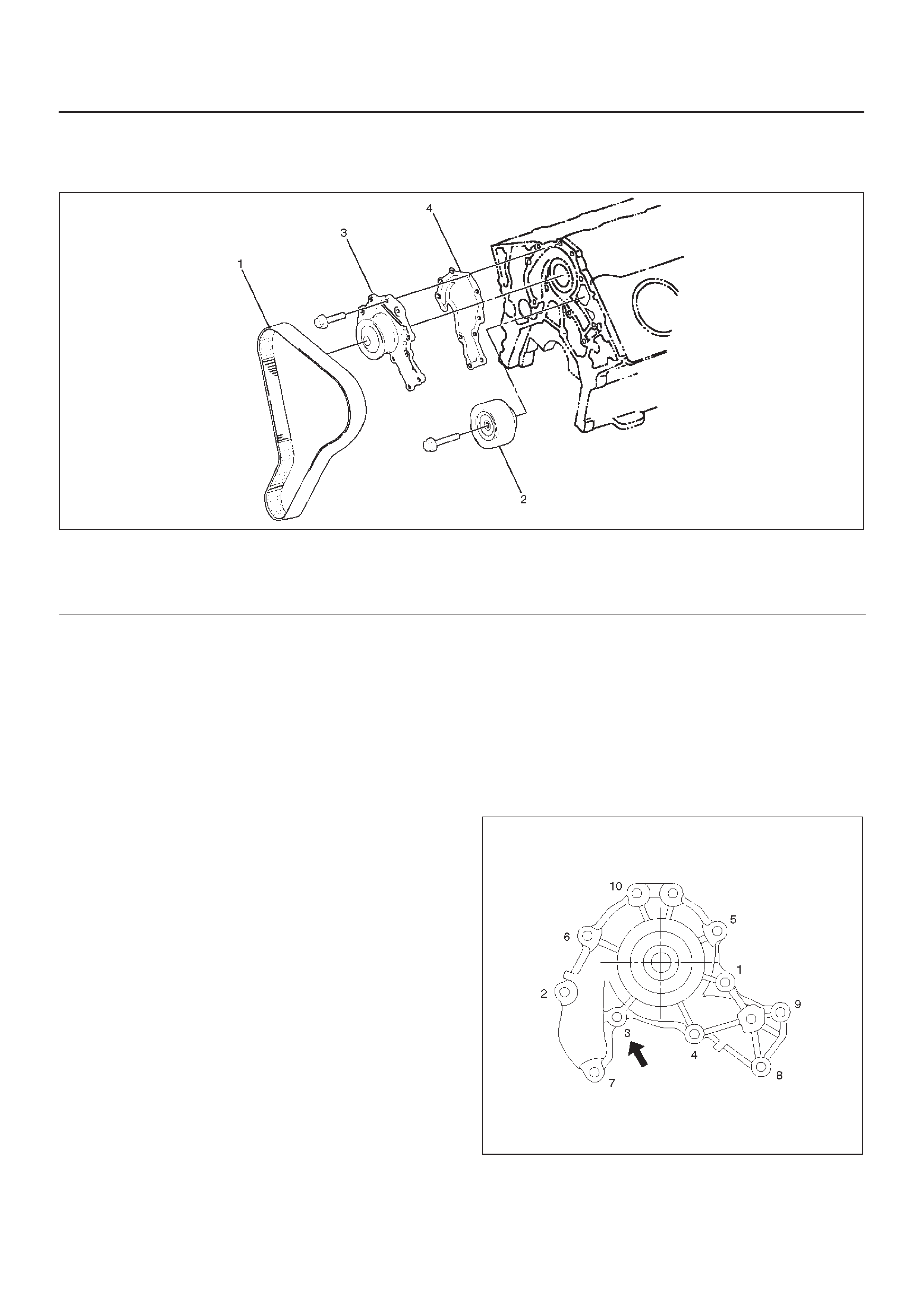
Water Pump and Associated Parts
030RS002
Legend
(1)Timing Belt
(2)Idle Pulley
(3)Water Pump Assembly
(4)Gasket
Removal
1.Disconnect battery ground cable.
2.Drain coolant.
3.Radiator hose (on inlet pipe side).
4.Remove timing belt. Refer to “Timing Belt” in this
manual.
5.Remove Idle pulley.
6.Remove water pump assembly.
7.Remove gasket.
Inspection
Make necessary repair and parts replacement if extreme
wear or damage is found during inspection. Should any of
the following problems occur, the entire water pump
assembly must be replaced:
DCrack in the water pump body
DEC leakage from the seal unit
DPlay or abnormal noise in the bearing
DCracks or corrosion in the impeller.
Installation
1.Install gasket, clean the mating surface of gasket
before installation.
2.Install water pump assembly and tighten bolts to the
specified torque.
Torque: 25 N·m (2.5 Kg·m/18 lb ft)
DTightening order
The tightening order are in the illustrate.
NOTE: To prevent the oil leakage, apply the LOCTITE
262 or an equivalent, to the arrow marked fixing bolt
thread.
030RW008
3.Idle pulley
DInstall idle pulley and tighten bolt to the specified
torque.
Torque: 52 N·m (5.3 Kg·m/38 lb ft)
4.Timing belt
DInstall timing belt. Refer to timing belt installation
step in “Timing Belt” in this manual.
5.Connect radiator inlet hose and replenish EC.
6.Connect battery ground cable.
Thermostat
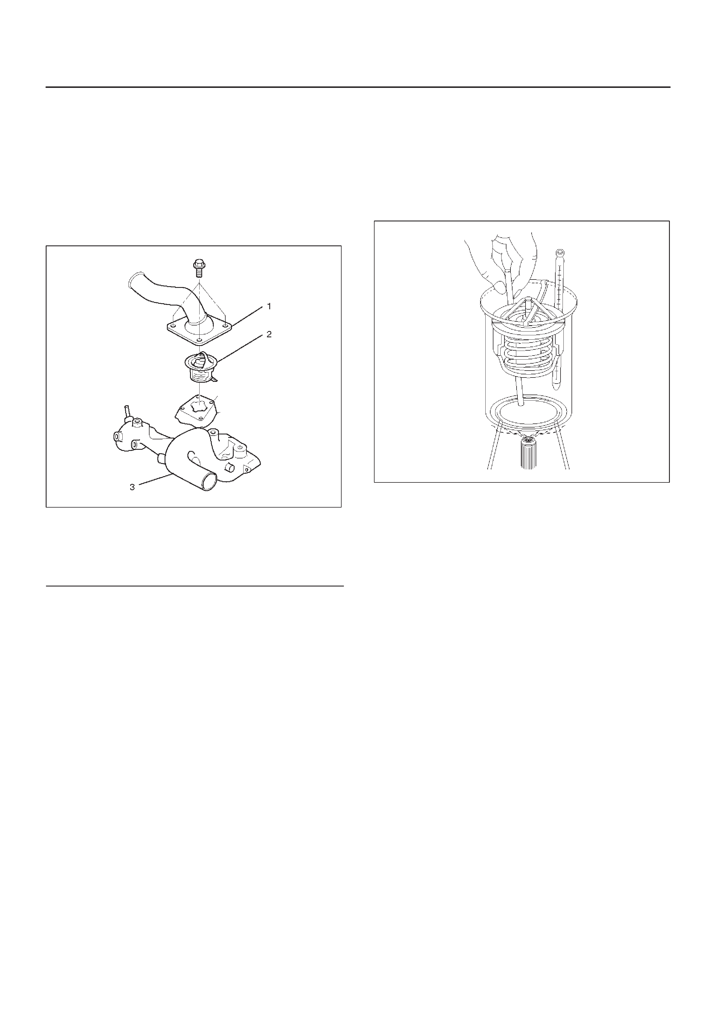
Thermostat and Associated Parts
031RW001
Legend
(1) Thermostat Housing
(2) Thermostat
(3) Outlet Pipe
Removal
1.Disconnect battery ground cable.
2.Drain engine coolant from the radiator and engine.
3.Disconnect radiator hose from the inlet pipe.
4.Remove thermostat housing.
5.Remove thermostat(2).
Inspection
Suspend the thermostat in a water–filled container using
thin wire. Place a thermometer next to the thermostat.
Do not directly heat the thermostat.
Gradually increase the water temperature. Stir the water
so that the entire water is same temperature.
031RS003
Confirm the temperature when the valve first begins to
open.
Valve opening temperature 74.5C ∼ 78.5°C
(166.1°F ∼ 173.3°F)
Confirm the temperature when the valve is fully opened.
Valve full open temperature and lift More than
8.5mm (0.33 in) at 90°C (194°F)
Make necessary repair and parts replacement if extreme
wear or damage is found during inspection.
Installation
1.Install thermostat into the outlet pipe(4) making sure
that the air hole is in the up position.
2.Install thermostat housing and tighten bolts to the
specified torque.
Torque: 25 N·m (2.5 Kg·m/18 lb ft)
3.Installation rubber hose.
4.Replenish engine coolant (EC).
5.Start engine and check for EC leakage.
Radiator
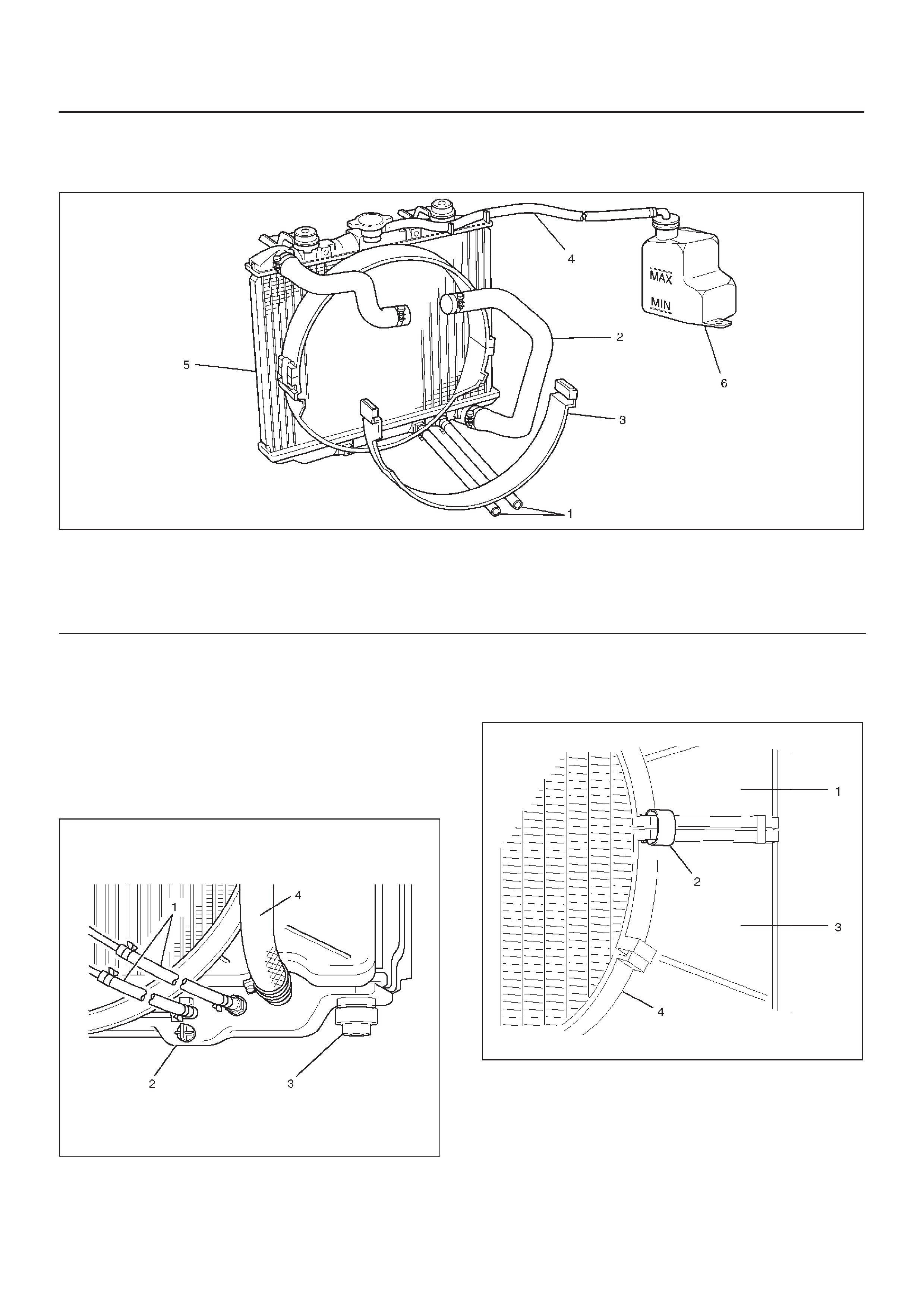
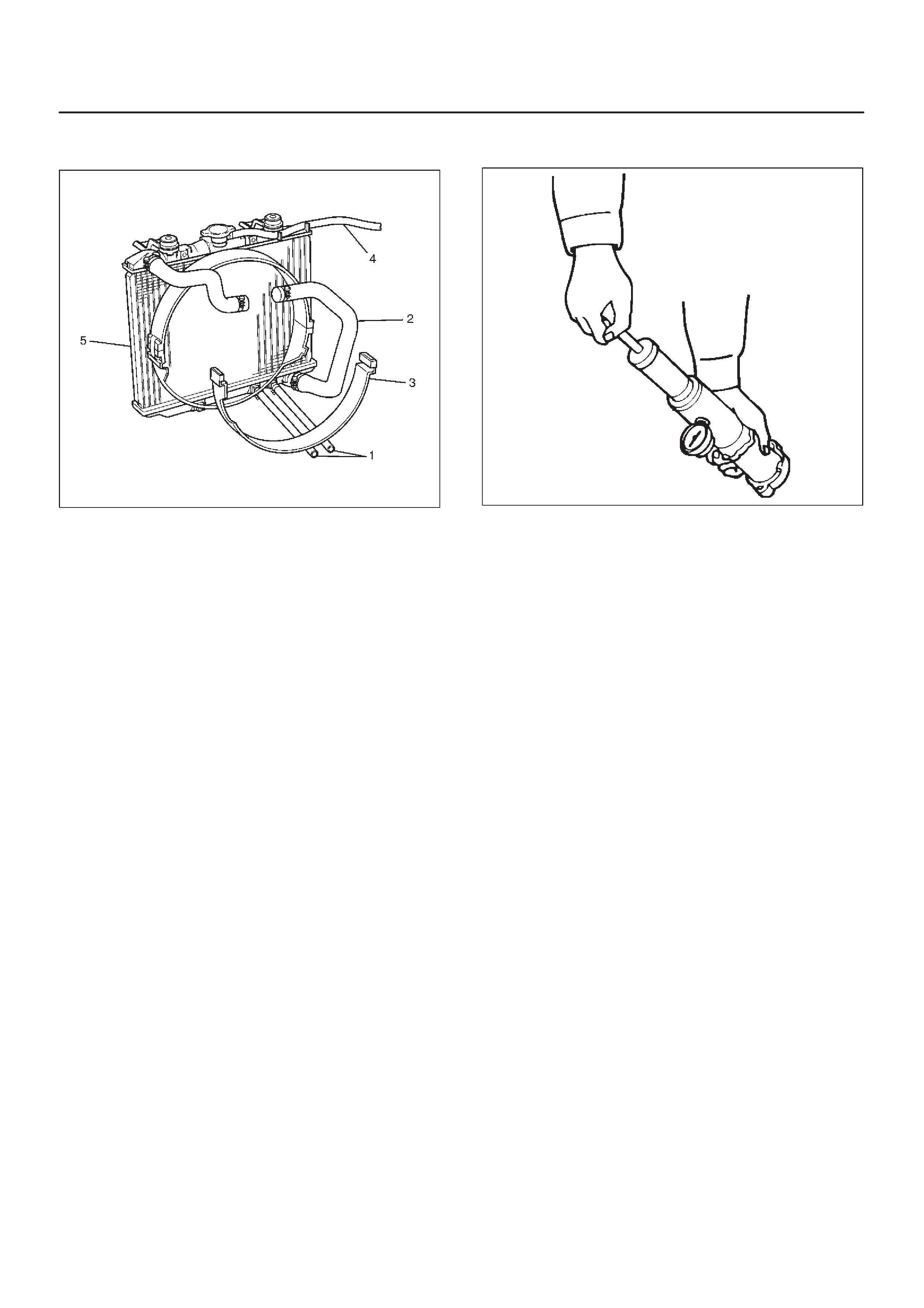
Radiator and Associated Parts
110RW010
Legend
(1) Oil Cooler Hose For Automatic Transmission
(2) Radiator Hose
(3) Fan Guide, Lower
(4) Reserve Tank Hose
(5) Radiator Assembly
(6) Reserve Tank
Removal
1.Disconnect battery ground cable.
2.Loosen a drain plug (2) to drain Engine Coolant.
3.Disconnect oil cooler hose(1) on automatic
transmission (A/T).
4.Disconnect radiator inlet hose and outlet hose from
the engine.
110RW002
5.Remove fan guide(1), clips (2) on both sides and the
bottom lock, then remove lower fan guide(3) with fan
shroud(4).
110RW001
6.Disconnect the reserve tank hose(4) from radiator.
7.Remove bracket.
110RX001
8.Lift up and remove the radiator assembly with hose,
taking care not to damage the radiator core with a fan
blade.
9.Remove rubber cushions on both sides at the bottom.
Inspection
Radiator Cap
Measure the valve opening pressure of the pressurizing
valve with a radiator filler cap tester.
Replace the cap if the valve opening pressure is outside
the standard range.
Valve opening pressure kPa (psi) 88.3 ∼ 117.7
(12.8 ∼17.1)
Cap tester: 5–8840–0277–0
Adapter: 5–8840–2603–0
Check the condition of the vacuum valve in the center of
the valve seat side of the cap. If considerable rust or dirt is
found, or if the valve seat cannot be moved by hand, clean
or replace the cap.
Valve opening vacuum kPa (psi) 1.96 ∼ 4.91
(0.28 ∼ 0.71)
110RS006
Radiator Core
1.A bent fin may result in reduced ventilation and
overheating may occur. All bent fins must be
straightened. Pay close attention to the base of the fin
when it is being straightened.
2.Remove all dust, bugs and other foreign material.
Flushing the Radiator
Thoroughly wash the inside of the radiator and the engine
coolant passages with cold water and mild detergent.
Remove all signs of scale and rust.
Cooling System Leakage Check
Use a radiator cap tester to force air into the radiator
through the filler neck at the specified pressure of 196 kPa
(28.5 psi) with a cap tester:
DLeakage from the radiator
DLeakage from the coolant pump
DLeakage from the water hoses
DCheck the rubber hoses for swelling.
Cap tester: 5–8840–0277–0
Adapter: 5–8840–2603–0
110RS005
Installation
1.Install rubber cushions on both sides of radiator
bottom.
2.Install radiator assembly with hose, taking care not to
damage the radiator core with a fan blade.
3.Install bracket and support the radiator upper tank
with the bracket and secure the radiator.
4.Connect reserve tank hose (4).
5.Install lower fan guide (3).
6.Connect radiator inlet hose and outlet hose to the
engine.
7.Connect oil cooler hose (1) to automatic
transmission.
110RX001
8.Connect battery ground cable.
9.Pour engine coolant up to filler neck of radiator, and
up to MAX mark of reserve tank.
111RS001
Important operation (in case of 100% engine coolant
change) procedure for filling with engine coolant.
1.Make sure that the engine is cool.
2.Open radiator cap pour coolant up to filler neck.
3.Pour coolant into reservoir tank up to “MAX” line.
4.Tighten radiator cap and start the engine. After
idling for 2 to 3 minutes, stop the engine and
reopen radiator cap. If the water level is lower,
replenish.
WARNING:WHEN THE COOLANT IS HEATED TO A
HIGH TEMPERATURE, BE SURE NOT TO LOOSEN
OR REMOVE THE RADIA TOR CAP. OTHERWISE YOU
MIGHT GET SCALDED BY HOT VAPOR OR BOILING
WATER. TO OPEN THE RADIATOR CAP, PUT A
PIECE OF THICK CLOTH ON THE CAP AND LOOSEN
THE CAP SLOWLY TO REDUCE THE PRESSURE
WHEN THE COOLANT HAS BECOME COOLER.
5. After tightening radiator cap, warm up the engine
at about 2000 rpm. Set heater adjustment to the
highest temperature position, and let the coolant
circulate also into heater water system.
6. Check to see the thermostat has opened through
the needle position of water thermometer,
conduct a 5–minute idling again and stop the
engine.
7. When the engine has been cooled, check filler
neck for water level and replenish if required.
Should extreme shortage of coolant is found,
check the cooling system and reservoir tank hose
for leakage.
8. Pour coolant into reservoir tank up tp “MAX” line.
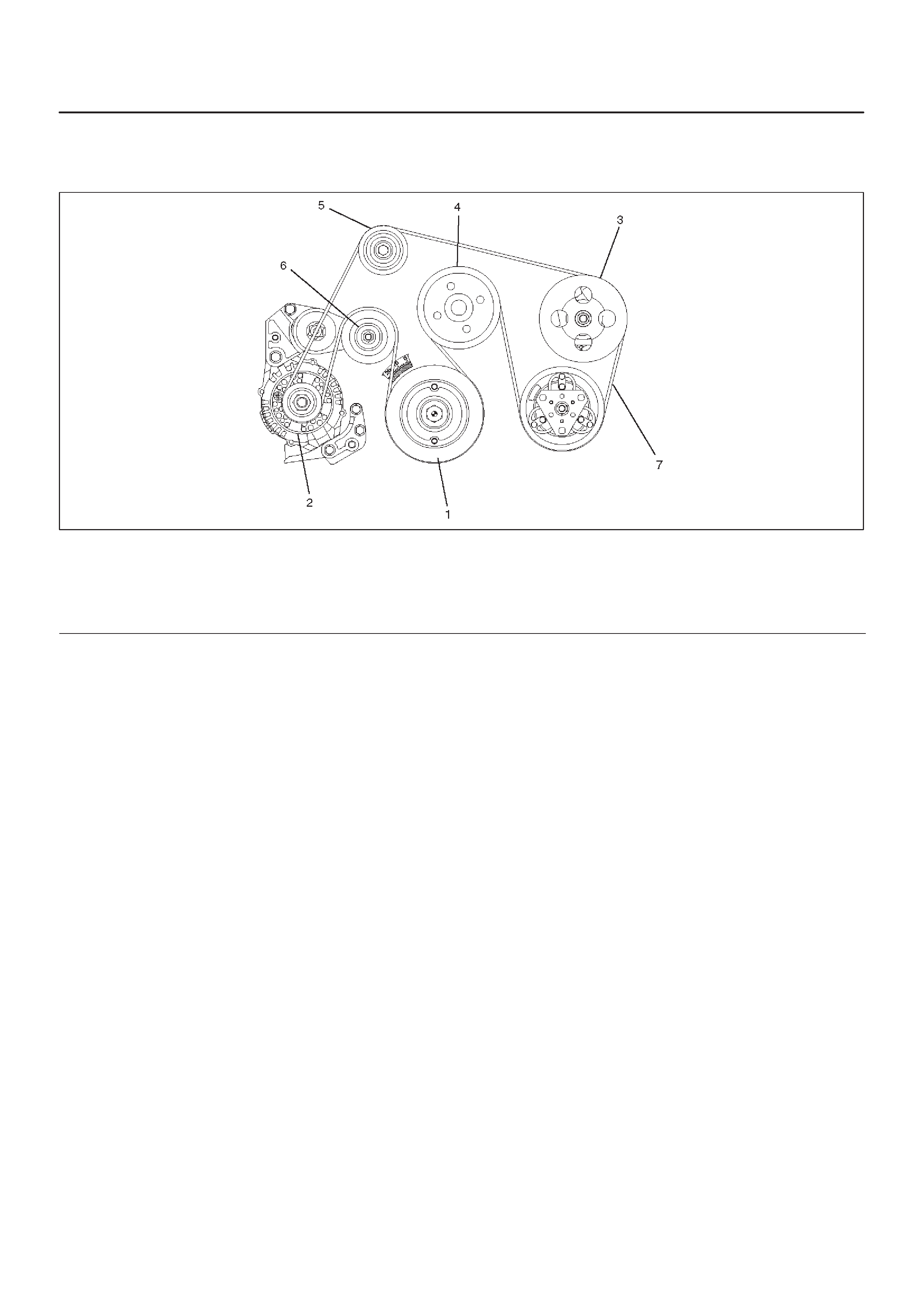
Drive Belt and Cooling Fan
Drive Belt and Associated Parts
015RW005
Legend
(1) Crankshaft Pulley
(2) Generator
(3) Power Steering Pump
(4) Water Pump and Cooling Fan Pulley
(5) Idle Pulley
(6) Tension Pulley
(7) Drive Belt
The drive belt adjustment is not required as automatic
drive belt tensioner is equipped.
Inspection
Check drive belt for wear or damage, and replace with a
new one as necessary.
Installation
Install cooling fan assembly and tighten bolts/nuts to the
specified torque.
Torque : 22 N·m (2.2 Kg·m/16 lb ft) for fan pulley
and fan bracket.
Torque : 10 N·m (1.0 Kg·m/88.5 lb in) for fan and
clutch assembly.
Main Data and Specifications
General Specifications
M/T A/T
Cooling system Engine coolant forced circulation
Radiator Tube type corrugated (2 tube in row)
Heat radiation capacity 70,000 kcal/h 77,800 kcal/h
Heat radiation area 9.74m@ (104.8ft@) 11.74m@ (126.4ft@)
Radiator front area 0.263m@ (2.83ft@)
Radiator dry weight 42N (9.4lb) 45N (10.1lb)
Radiator cap valve opening pressure 93.3 ∼ 122.7kpa (13.5 ∼ 17.8psi)
Engine coolant capacity 2.5lit (2.6U.S q.t.) 2.4lit (2.5U.S q.t.)
Engine coolant pump Centrifugal impeller type
Delivery 300 (317) or more
Pump speed 5000 ± 50 rpm
Thermostat Wax pellet type with air hole
Valve opening temperature 74.5 ∼ 78.5°C (166.1 ∼ 173.3°F)
Engine coolant total capacity 11.1lit (2.93U.S qt) 10.0lit (2.64U.S qt)
Torque Specifications N·m (Kg·m/lb ft)
E06RW041
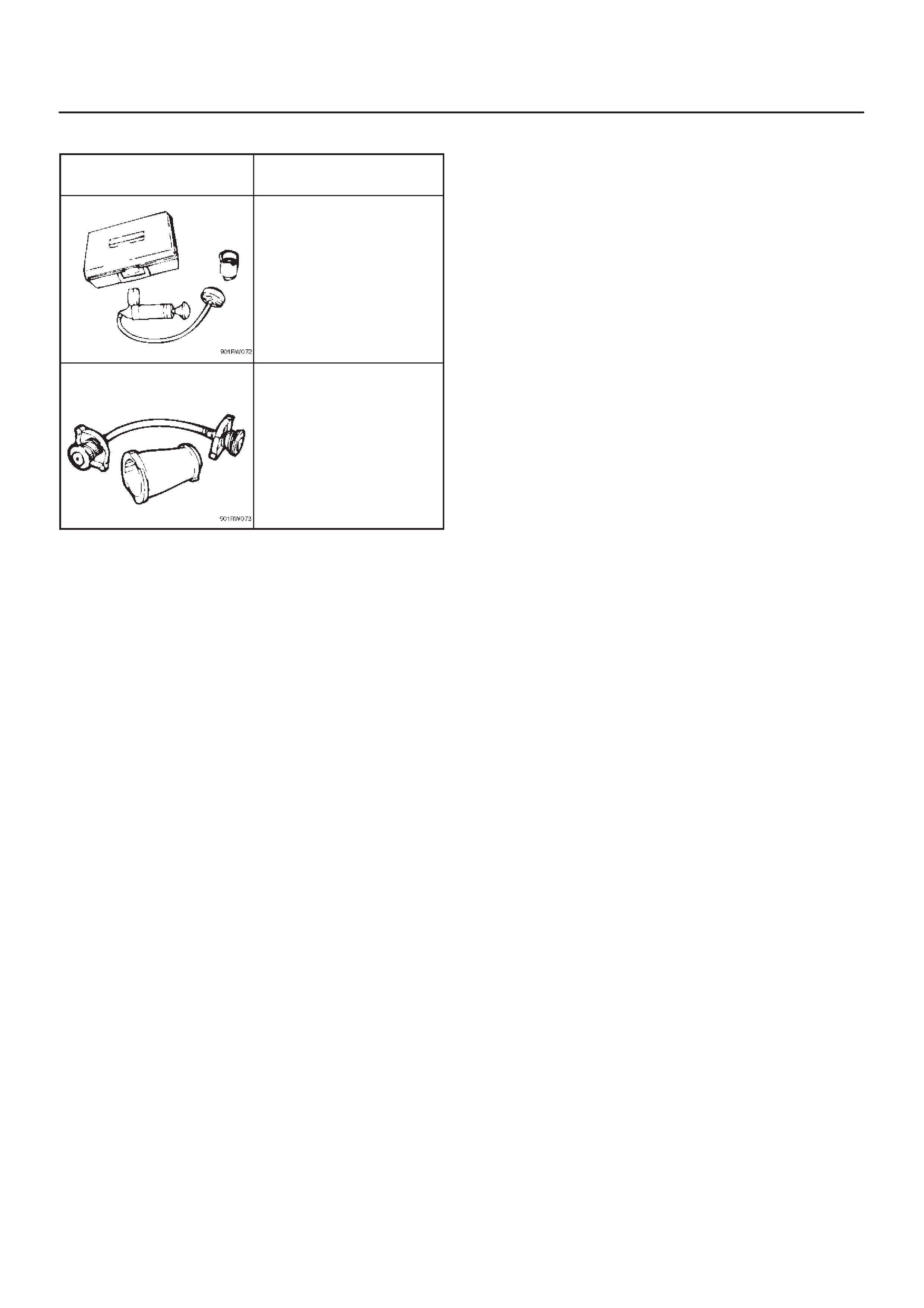
Special Tool
ILLUSTRATION TOOL NO.
TOOL NAME
5–8840–0277–0
(J–24460–01)
Tester; radiator cap
5–8840–2603–0
(J–33984–A)
Adapter; radiator cap