
SECTION 6D2 - IGNITION SYSTEM
Service Precaution
General Description
Diagnosis
Ignition Coil
Removal
Inspection and Repair
Installation
Spark Plug
Removal
Inspection and Repair
Installation
Crankshaft Position Sensor
Removal
Installation
Main Data and Specifications
Service Precaution
WARNING:THIS VEHICLE HAS A SUPPLEMENTAL
RESTRAINT SYSTEM (SRS), REFER TO THE SRS
COMPONENT AND WIRING LOCATION VIEW IN
ORDER TO DETERMINE WHETHER YOU ARE
PERFORMING SERVICE ON OR NEAR THE SRS
COMPONENTS OR THE SRS WIRING. WHEN YOU
ARE PERFORMING SER VICE ON OR NEAR THE SRS
COMPONENTS OR THE SRS WIRING, REFER TO
THE SRS SERVICE INFORMATION. FAILURE TO
FOLLOW WARNINGS COULD RESULT IN POSSIBLE
AIR BAG DEPLOYMENT, PERSONAL INJURY, OR
OTHER WISE UNNEEDED SRS SYSTEM REPAIRS.
CAUTION:Always use the correct fastener in the
proper location. When you replace a fastener, use
ONLY the exact part number for that application.
ISUZU will call out those fasteners that require a
replacement after removal. ISUZU will also call out
the fasteners that require thread lockers or thread
sealant. UNLESS OTHERWISE SPECIFIED, do not
use supplemental coatings (Paints, greases, or other
corrosion inhibitors) on threaded fasteners or
fastener joint interfaces. Generally, such coatings
adversely affect the fastener torque and the joint
clamping force, and may damage the fastener . When
you install fasteners, use the correct tightening
sequence and specifications. Following these
instructions can help you avoid damage to parts and
systems.
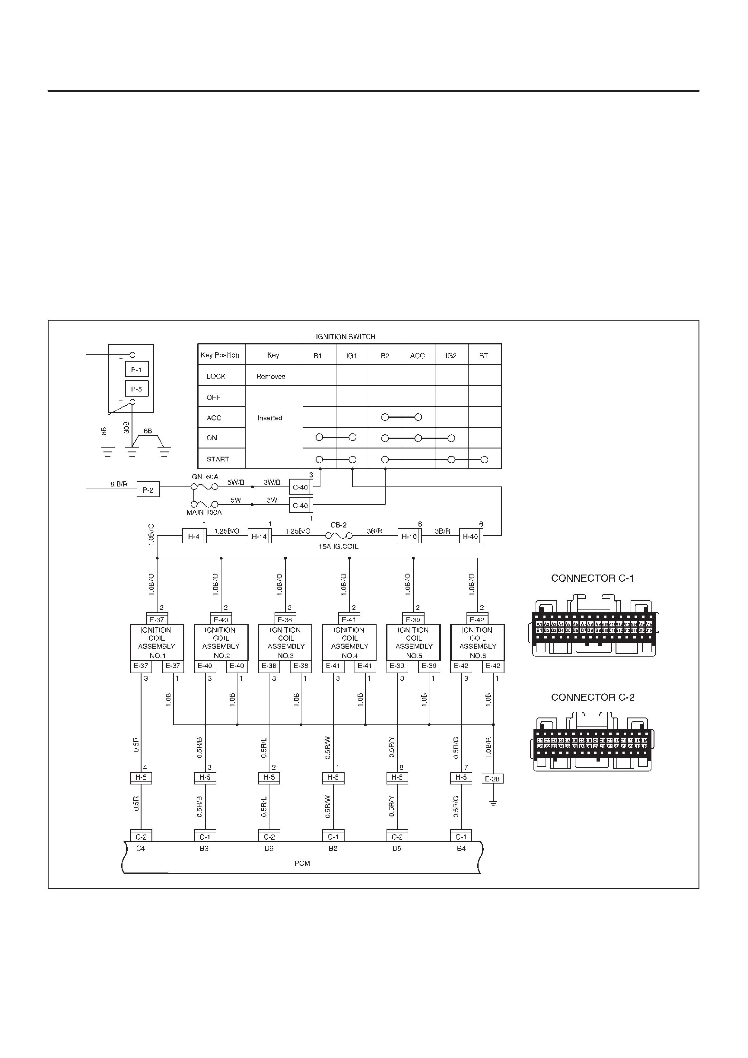
General Description
Ignition is done by the electronic ignition (El) that directly
fires the spark plugs from ignition coils through spark plug
wires without using a distributor. A pair of ignition coils for
the cylinders having different phases by 360° (No.1 and
No.4,No.2 and No.5,No.3 and No.6) are fired
simultaneously.
Since the cylinder on exhaust stroke requires less energy
to fire its ignition plug, energy from the ignition coils can be
utilized to fire the mating cylinder on compression stroke.
After additional 360° rotation, respective cylinder strokes
are reversed.
The EI consists of six ignition coils,ignition control
module, crank angle sensor, powertrain control module
(PCM) and other components.
The ignition coils are connected with the PCM by means
of a 32 pin connector.
The ignition control module turns on/off the primary circuit
of ignition coils, and also it controls the ignition timing at
the engine speed below 538 rpm.
A notch in the timing disc on the crankshaft activates the
crank angle sensor which then sends information such as
firing order and starting timing of each ignition coil to the
PCM.
Further, the El employs ignition control (IC) to control
similar to a distributor system.
By receiving signals such as crank position,engine
speed, water temperature and Manifold Absolute
Pressure (MAP), the PCM controls the ignition timing.
D06RX096
Diagnosis
Refer to Section Drivability and Emissions for the
diagnosis to electronic ignition system (El system).
Ignition Coil
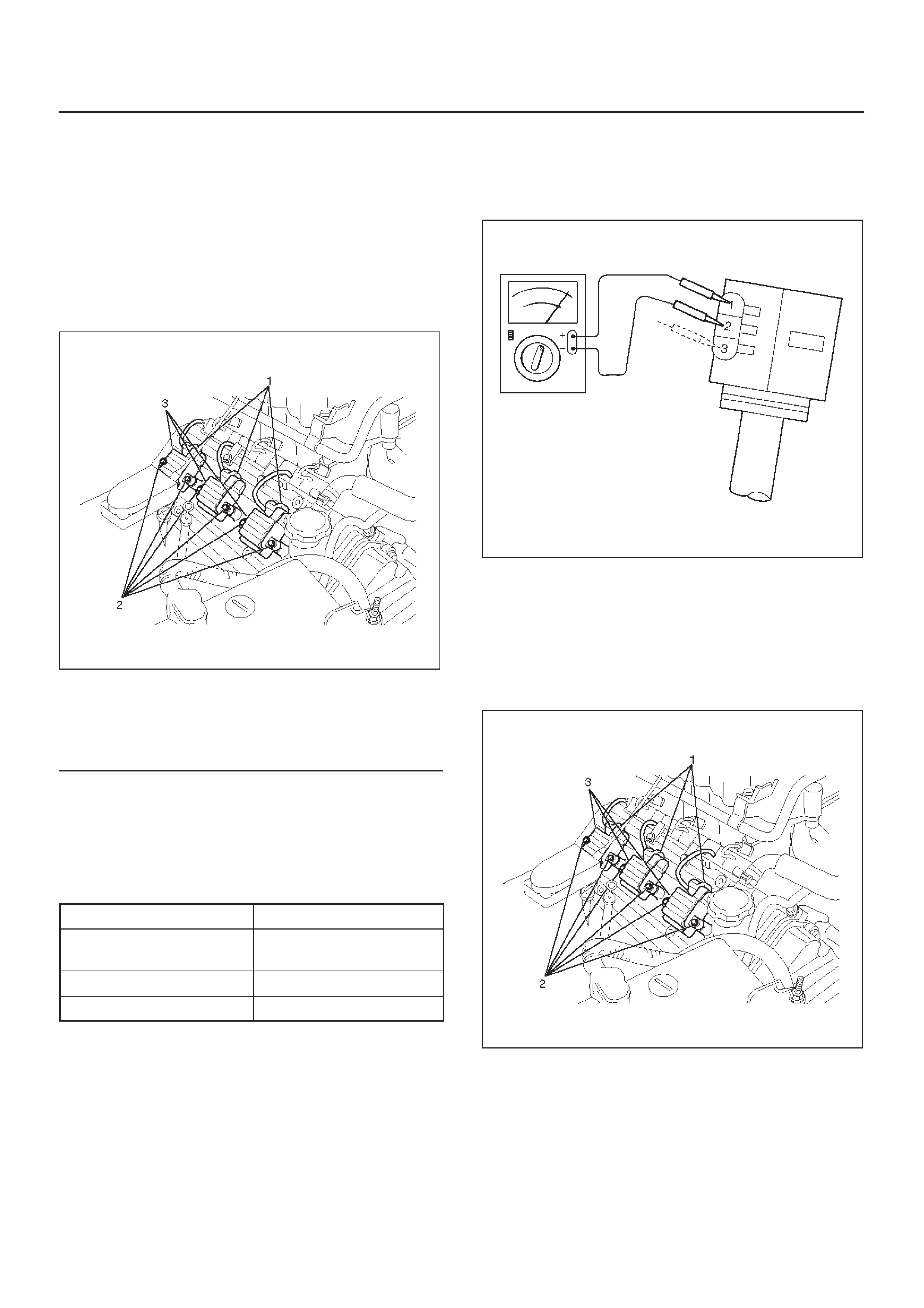
Removal
1.Disconnect battery ground cable.
2.Ignition coil connector and ignition coil.
DDisconnect three connector from ignition coil.
DRemove harness bracket bolt on cylinder head
cover.
DRemove fixing bolts on ignition coil.
060RW121
Legend
(1) Ignition Coil Connector
(2) Bolt
(3) Ignition Coil Assembly
Inspection and Repair
Check the ignition coil assembly for insulation. Check
terminals for corrosion or damage, and replace as
necessary.
Measuring resistance of ignition coil assembly.
Terminal No. Limit
1 to 2 Without 0 ohm or infinity
maximum ohm.
1 to 3 Same as above
2 to 3 Same as above
Measure resistance of ignition coil assembly , and replace
the ignition coil assembly if its value exceeds the
standard.
060RW006
Installation
1.Install the ignition coil assembly (3).
Connect ignition coil connector (1) and ignition coil
(3), then tighten bolt (2) to the specified torque.
Torque: 4 N·m (0.4 Kg·m/35 lb in)
060RW121
2.Connect battery ground cable.
Spark Plug
Removal
1.Remove spark plugs.
Inspection and Repair
The spark plug affects entire engine performance and
therefore its inspection is very important.
DCheck electrode and insulator for presence of cracks,
and replace if any.
DCheck electrode for wear, and replace if necessary.
DCheck gasket for damage, and replace if necessary.
DMeasure insulation resistance with an ohmmeter, and
replace if faulty.
DAdjust spark plug gap to 1.0 mm (0.04 in) ∼ 1.1 mm
(0.043 in).
DCheck fuel and electrical systems if spark plug is
extremely dirty.
DUse spark plugs having low heat value (hot type plug)
if fuel and electrical systems are normal.
DUse spark plugs having high heat value (cold type
plug) if insulator and electrode are extremely burned.
Sooty Spark Plugs
Much deposit of carbon or oil on the electrode and
insulator of spark plug reduces the engine performance.
Possible causes:
DToo rich mixture
DPresence of oil in combustion chamber
DIncorrectly adjusted spark plug gap
Burning Electrodes
This fault is characterized by scorched or heavily oxidized
electrode or blistered insulator nose.
Possible causes:
DToo lean mixture
DImproper heat value
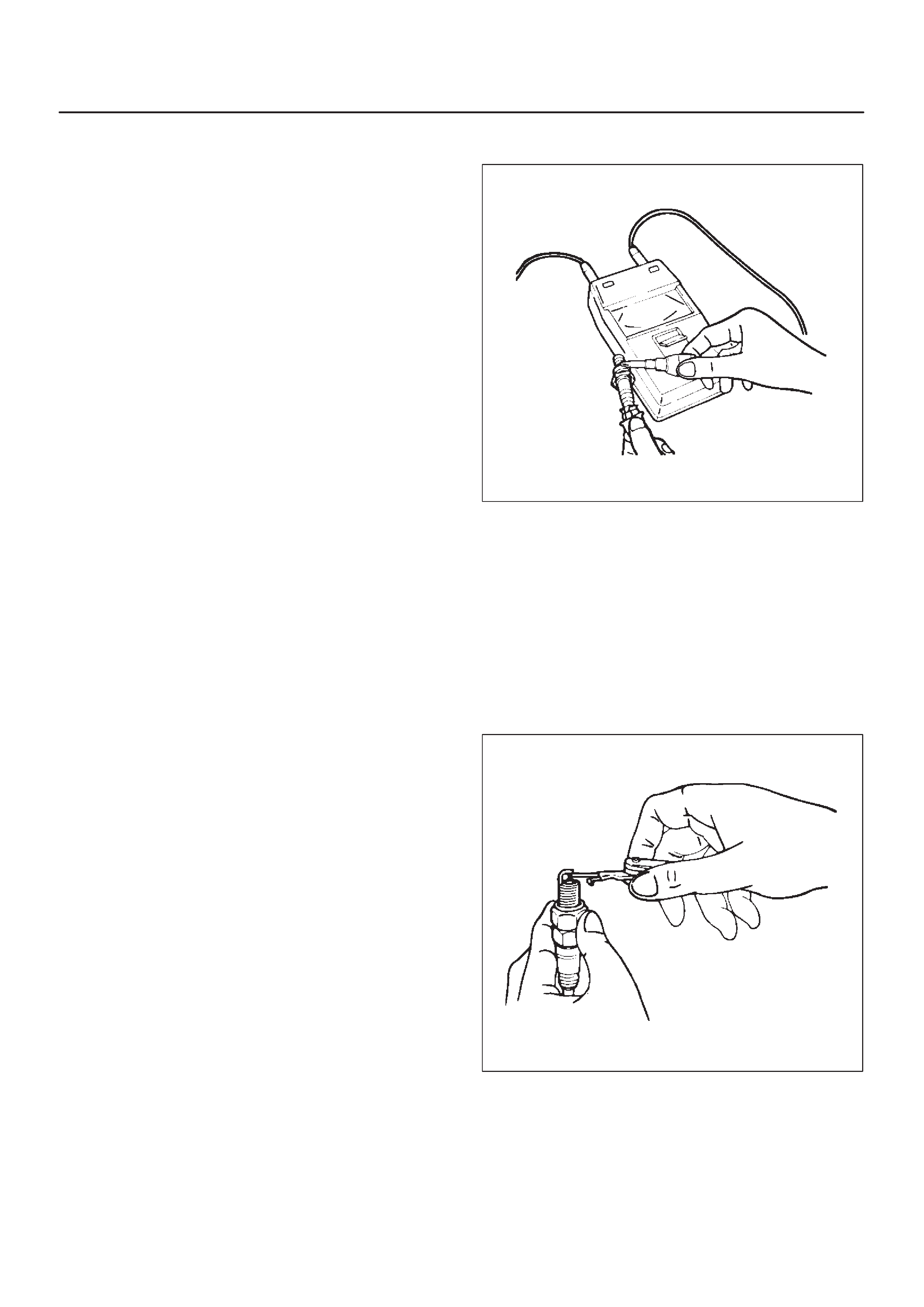
Measuring Insulation Resistance
DMeasure insulation resistance using a 500 volt
megaohm meter.
DReplace spark plugs if measured value is out of
standard.
Insulation resistance: 50 MW or more
011RS010
Cleaning Spark Plugs
DClean spark plugs with a spark plug cleaner.
DRaise the ground electrode to an angle of 45 to 60
degrees. If electrode is wet, dry it before cleaning.
DAfter spark plug is thoroughly cleaned, check
insulator for presence of cracks.
DClean threads and metal body with a wire brush.
DFile the electrode tip if electrode is extremely worn.
DBend the ground electrode to adjust the spark plug
gap.
011RS011
Installation
1.Spark plugs
DTighten spark plugs to the specified torque.
Torque: 18 N·m (1.8 Kg·m/13 lb ft)
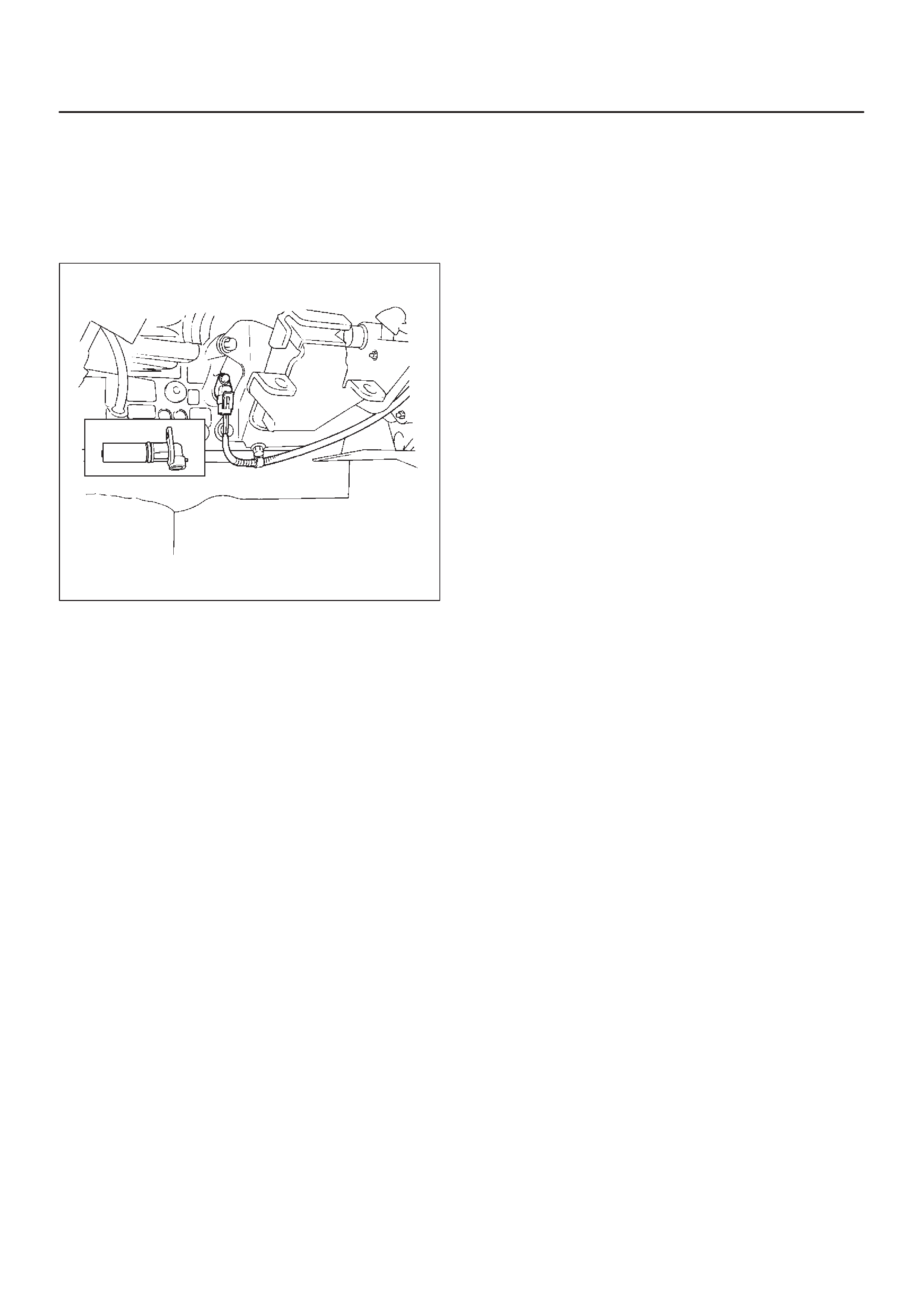
Crankshaft Position Sensor
Removal
1.Disconnect battery ground cable
2.Wiring connector from crankshaft angle sensor.
3.Remove crankshaft angle sensor from cylinder block.
012RS008
Installation
1.Install crankshaft angle sensor into the cylinder block.
Before installation,apply small amount of engine oil to
the O–ring.
Torque: 10 N·m (1.0 Kg·m/89 lb in)
2.Reconnect wiring connector to crankshaft position
sensor.
Main Data and Specifications
General Specifications
Ignition System
Ignition Form Electronic Ignition System (El system) with Crankshaft angle Sensor
Spark Plug Type K16PR–P11
RC10PYP4
PK16PR11
Plug gap 1.0 mm (0.04 in) – 1.1 mm (0.043 in)
Torque 18 N·m (1.8 Kg·m/13 lb ft)
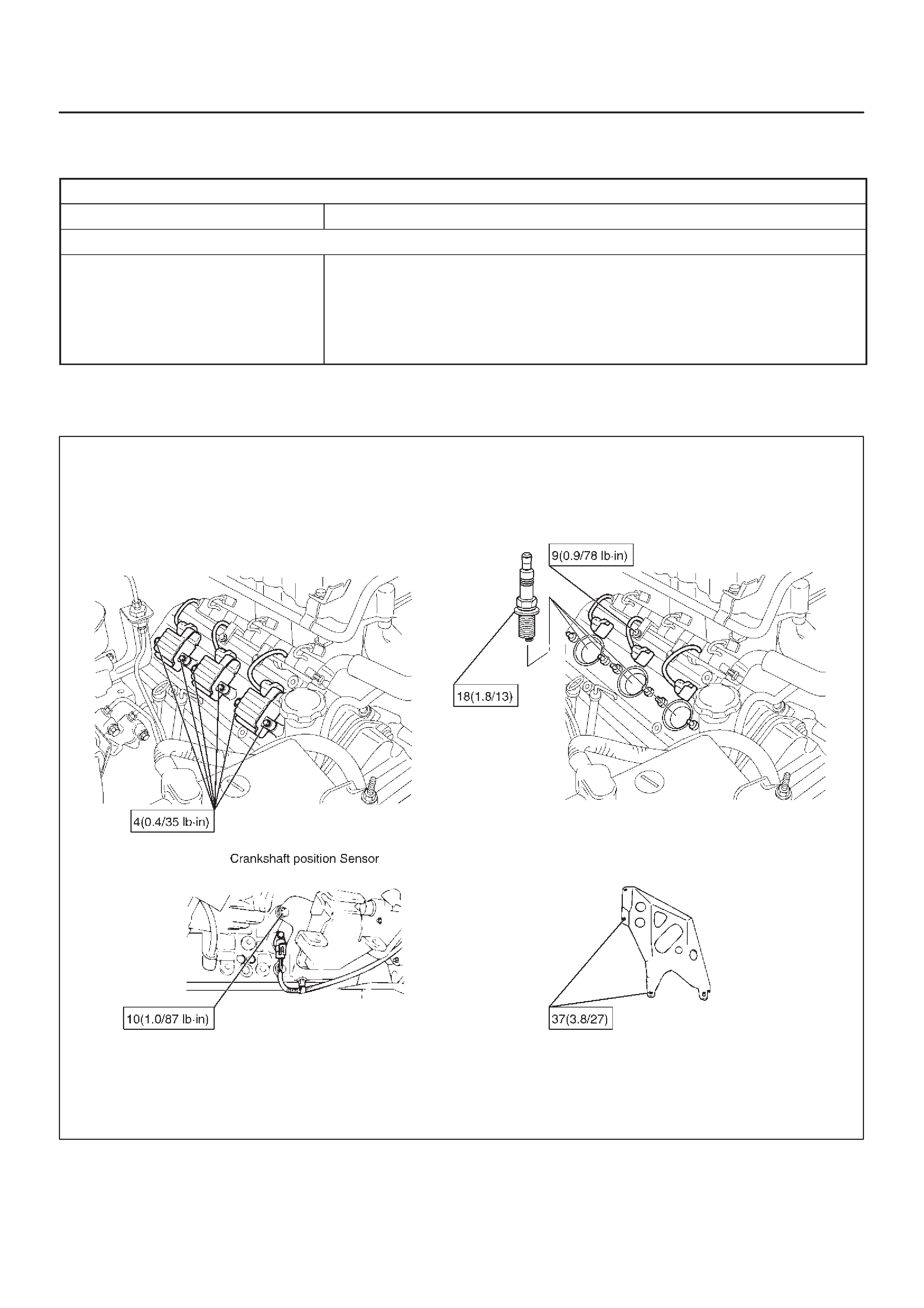
Torque Specifications
N·m (Kg·m/lb ft)
E06RX008