
SECTION 6D3 - STARTING AND CHARGING SYSTEM
Service Precaution
Starting System
General Description
Diagnosis
Starter
Removal
Installation
Disassembled View
Disassembly
Inspection and Repair
Reassemble
Main Data and Specification
Charging System
General Description
General On–Vehicle Inspection
Generator
Removal
Inspection
Installation
Disassembled View
Disassembly
Inspection and Repair
Reassembly
Bench Test
Main Data and Specification
Service Precaution
WARNING:THIS VEHICLE HAS A SUPPLEMENTAL
RESTRAINT SYSTEM (SRS), REFER TO THE SRS
COMPONENT AND WIRING LOCATION VIEW IN
ORDER TO DETERMINE WHETHER YOU ARE
PERFORMING SERVICE ON OR NEAR THE SRS
COMPONENTS OR THE SRS WIRING. WHEN YOU
ARE PERFORMING SERVICE ON OR NEAR THE SRS
COMPONENTS OR THE SRS WIRING, REFER TO
THE SRS SERVICE INFORMATION. FAILURE TO
FOLLOW WARNINGS COULD RESULT IN POSSIBLE
AIR BAG DEPLOYMENT, PERSONAL INJURY, OR
OTHERWISE UNNEEDED SRS SYSTEM REPAIRS.
CAUTION:Always use the correct fastener in the
proper location. When you replace a fastener, use
ONLY the exact part number for that application.
ISUZU will call out those fasteners that require a
replacement after removal. ISUZU will also call out
the fasteners that require thread lockers or thread
sealant. UNLESS OTHERWISE SPECIFIED, do not
use supplemental coatings (Paints, greases, or other
corrosion inhibitors) on threaded fasteners or
fastener joint interfaces. Generally, such coatings
adversely affect the fastener torque and the joint
clamping force, and may damage the fastener . When
you install fasteners, use the correct tightening
sequence and specifications. Following these
instructions can help you avoid damage to parts and
systems.

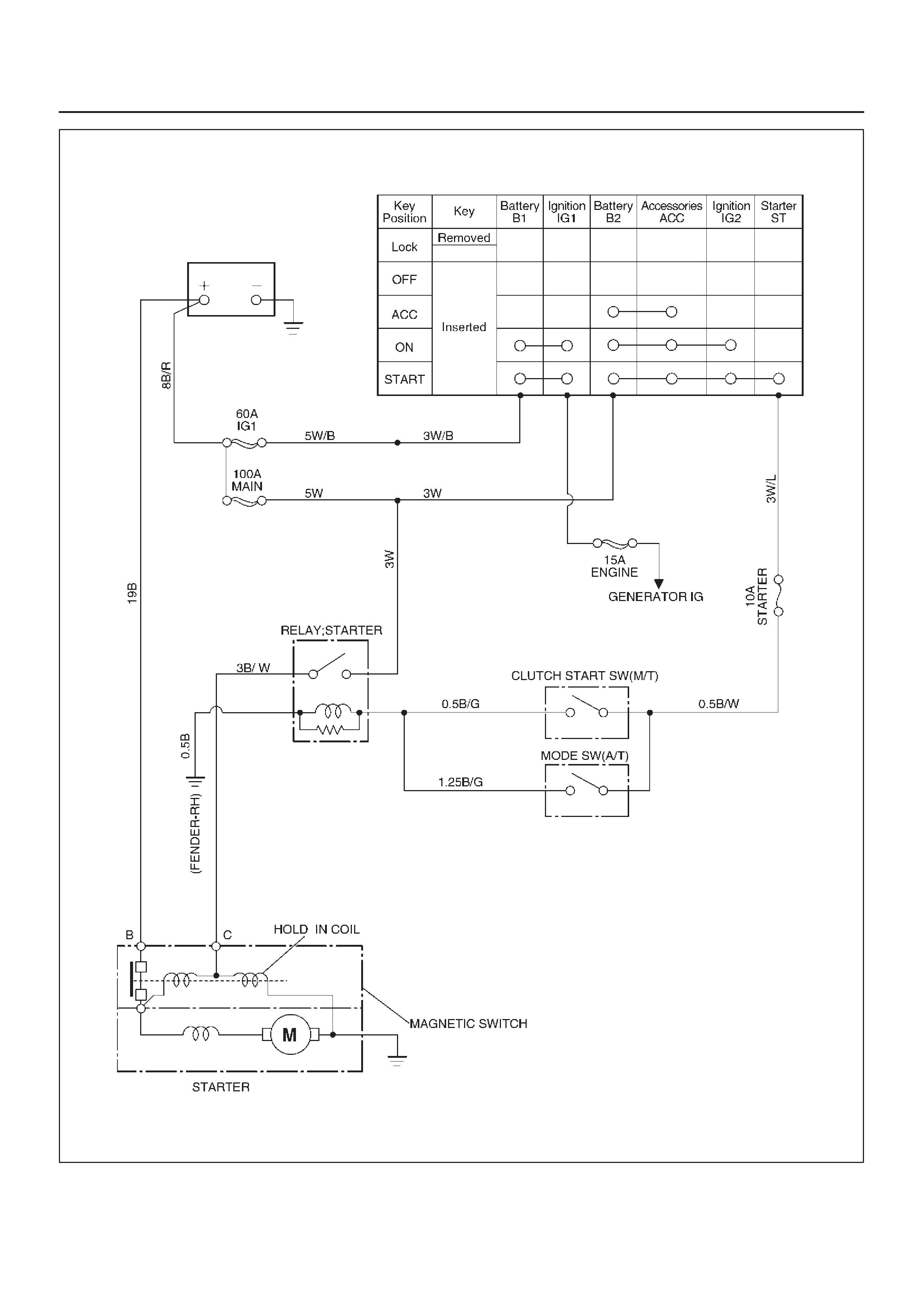
Starting System
General Description
Cranking Circuit
The cranking system consists of a battery, starter , starter
switch, starter relay, etc. These main components are
connected.
Starter
The cranking system employs a magnetic type reduction
starter in which the motor shaft is also used as a pinion
shaft. When the starter switch is turned on, the contacts of
magnetic switch are closed, and the armature rotates. At
the same time, the plunger is attracted, and the pinion is
pushed forward by the shift lever to mesh with the ring
gear.
Then, the ring gear runs to start the engine. When the
engine starts and the starter switch is turned off, the
plunger returns, the pinion is disengaged from the ring
gear, and the armature stops rotation. When the engine
speed is higher than the pinion, the pinion idles, so that
the armature is not driven.
C06RX004

Diagnosis
Starter does not run Charging failure Repair charging system
Battery Failure Replace Battery
Terminal connection failure Repair or replace terminal connector
and/or wiring harness
Starter switch failure Repair or replace starter switch
Starter failure Repair or replace starter
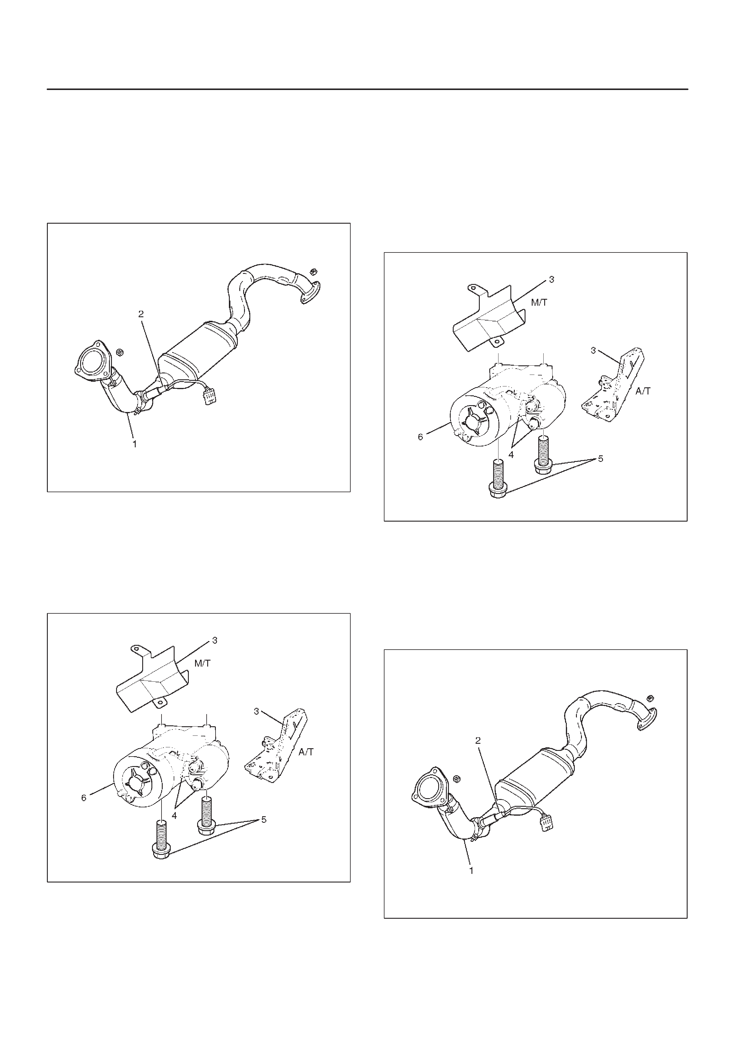
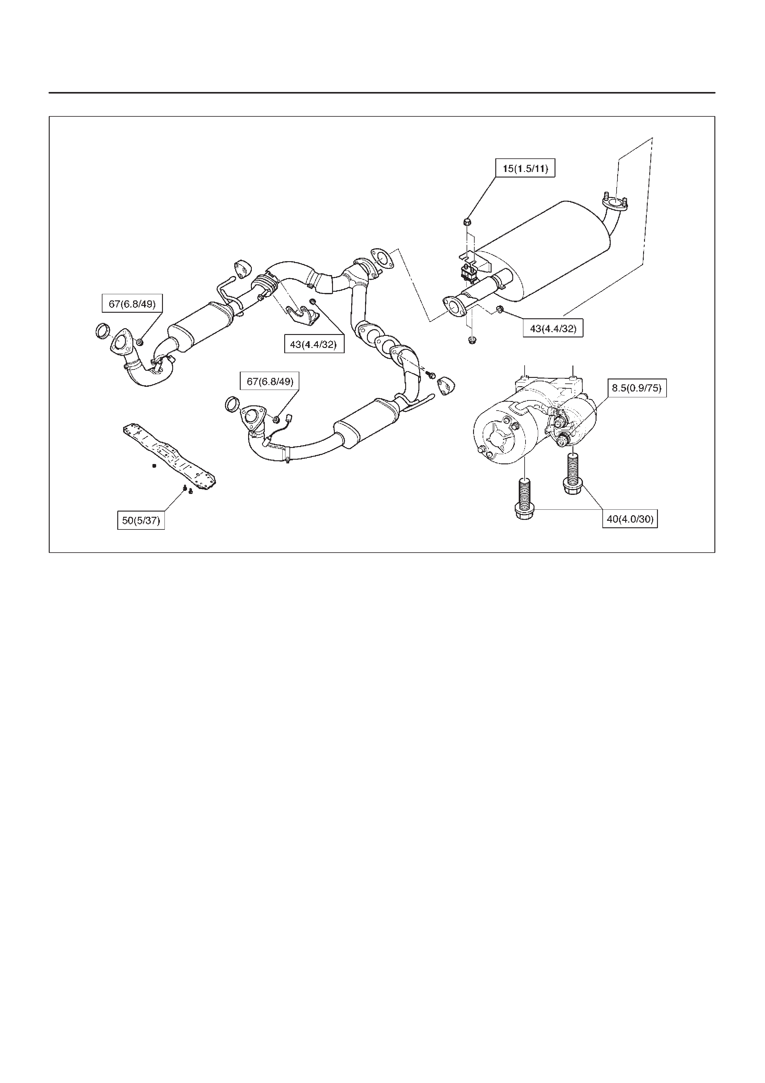
Starter
Removal
1.Battery ground cable.
2.Disconnect heated oxygen (O2) sensor connector
(1).
3.Remove exhaust front left pipe(2).
150RX015
4.Remove heat protector(3).
5. Disconnect starter wiring connector from terminals
“B” and “S”(4).
6.Remove starter assembly mounting bolts on inside
and outside(5).
7.Remove starter assembly toward the bottom of
engine(6).
065RW027
Installation
1.Install starter assembly(6).
2.Install mounting bolts and tighten bolts to specified
torque(5).
Torque: 40 N·m (4.1 Kg·m/30 lb ft)
3.Reconnect the connectors to terminals “B” and “S”
and tighten Terminals “B” to specified torque.
Torque: 9 N·m (0.9 Kg·m/80 lb in)
4.Install heat protector(3).
065RW027
5. Install exhaust front left pipe and tighten bolts and
nuts to specified torque(2).
Stud Nuts
Torque: 67 N·m (6.8 Kg·m/49 lb ft)
Nuts
Torque: 43 N·m (4.4 Kg·m/32 lb ft)
6.Connect O2 sensor connector (2).
150RX015
7.Reconnect the battery ground cable.
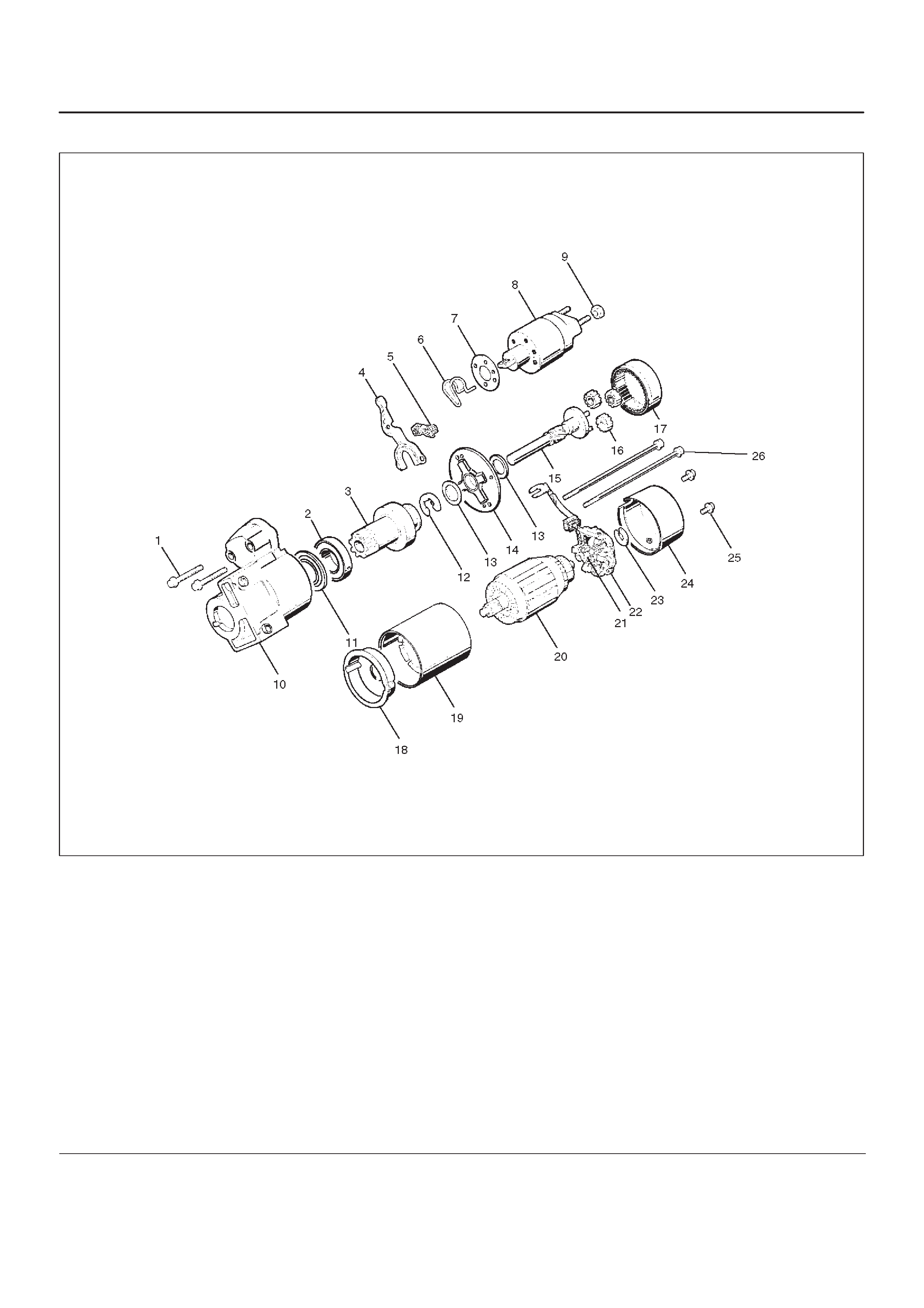
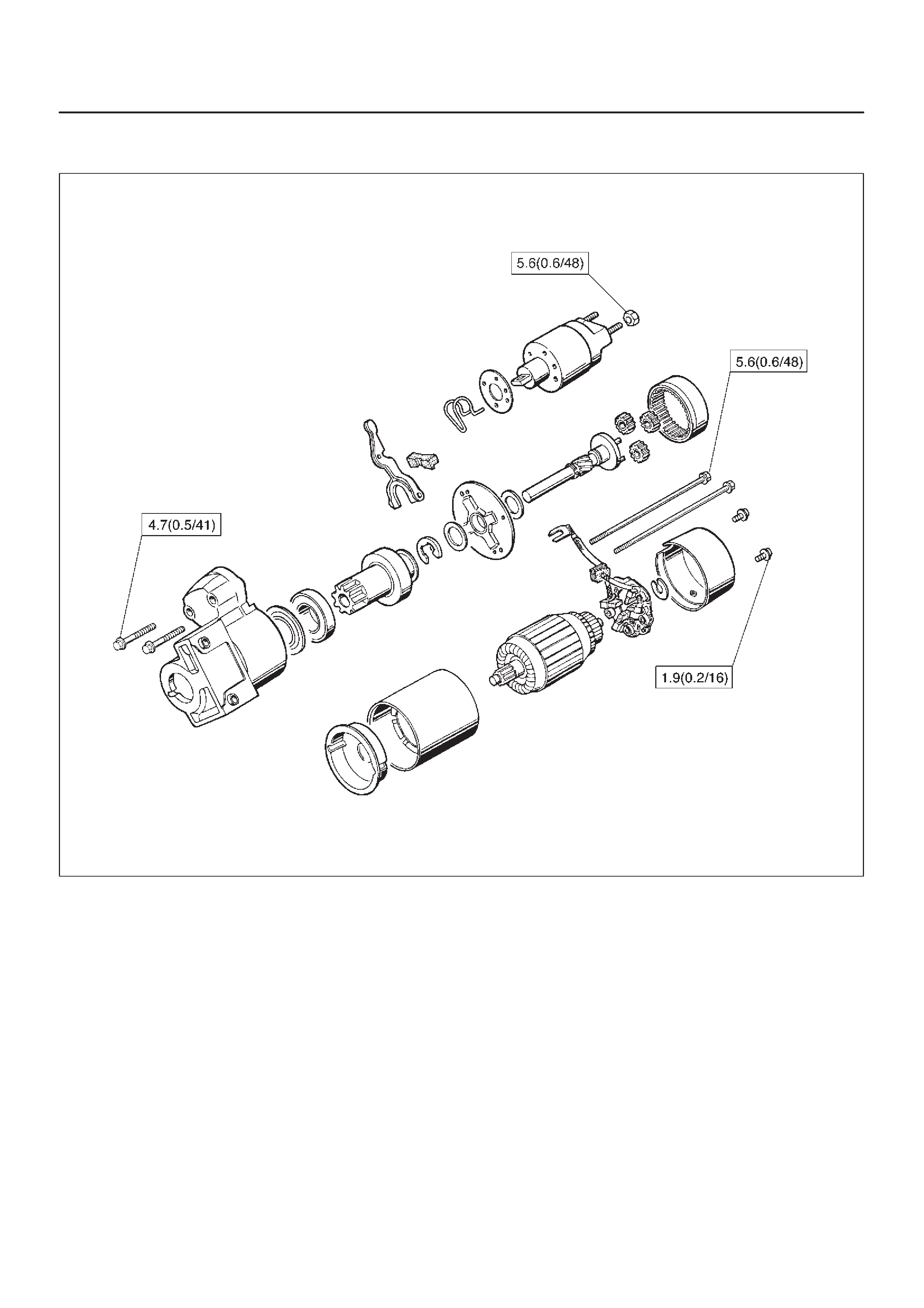
Disassembled View
065RW002
Legend
(1) Bolt (2 pcs)
(2) Ball Bearing
(3) Pinion
(4) Shift Lever
(5) Dust Cover
(6) Torsion Spring
(7) Dust Cover
(8) Magnetic Switch
(9) Nut
(10) Gear Case
(11) Bearing Cover
(12) E–Ring
(13) Thrust Washer (2)
(14) Center Bracket
(15) Pinion Shaft
(16) Planet Gear (3)
(17) Internal Gear
(18) Center Bracket (A)
(19) Yoke Assembly
(20) Armature
(21) Brush
(22) Brush Holder
(23) Thrust Washer
(24) Rear Cover
(25) Screw (2 pcs)
(26) Through Bolt (2 pcs)
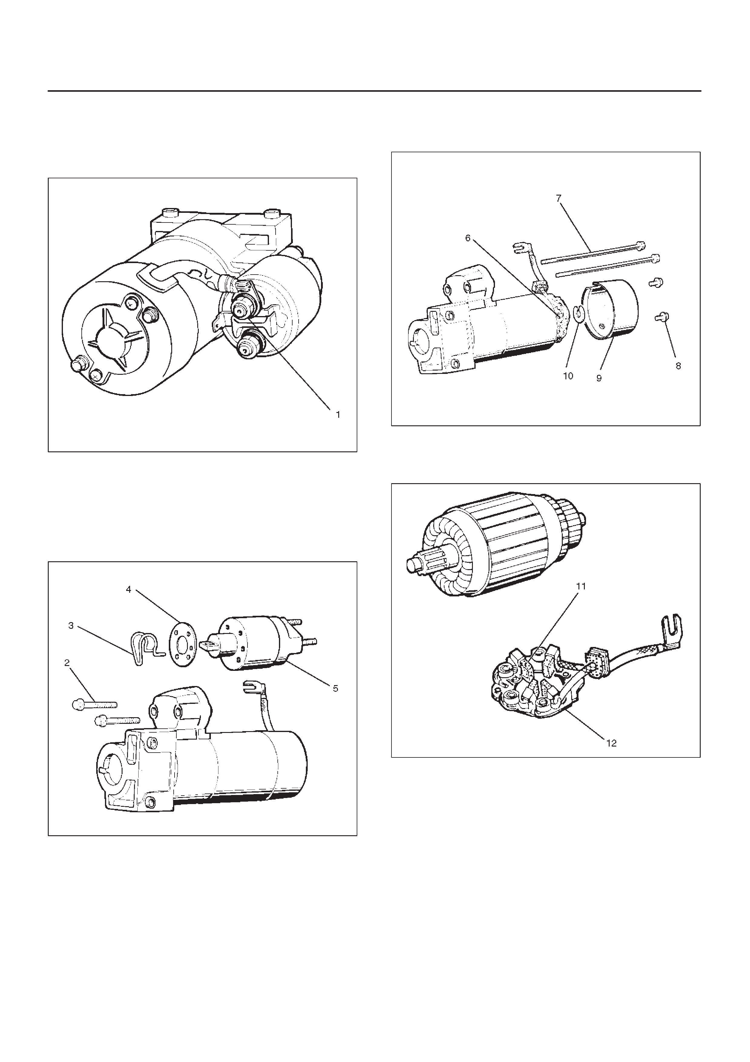
Disassembly
1.Loosen the nut(1) on terminal “M” of magnetic switch
and disconnect the connector cable.
2.Remove bolt (2 pcs) (2).
065RW003
3.Remove magnetic switch(5).
4.Remove dust cover(4).
5.Remove torsion spring bolts, then the magnetic
switch assembly.
6.Remove torsion spring(3) from magnetic switch
assembly(5).
065RW004
7.Remove screw (2 pcs) (8).
8.Remove through bolt (2 pcs) (7).
9.Remove screws and through bolts, then the rear
cover(9) then remove thrust washer(10).
10.Remove brush holder(6).
065RW005
11.Raise a brush spring to detach brushes (4 pcs) from
the commutator face and pull off the brush holder(12)
and brush(11).
065RW006
12.Remove yoke assembly(14).
13.Remove armature(15).
14.Pull off the yoke assembly, then remove armature,
washer and center bracket.(A) (13).
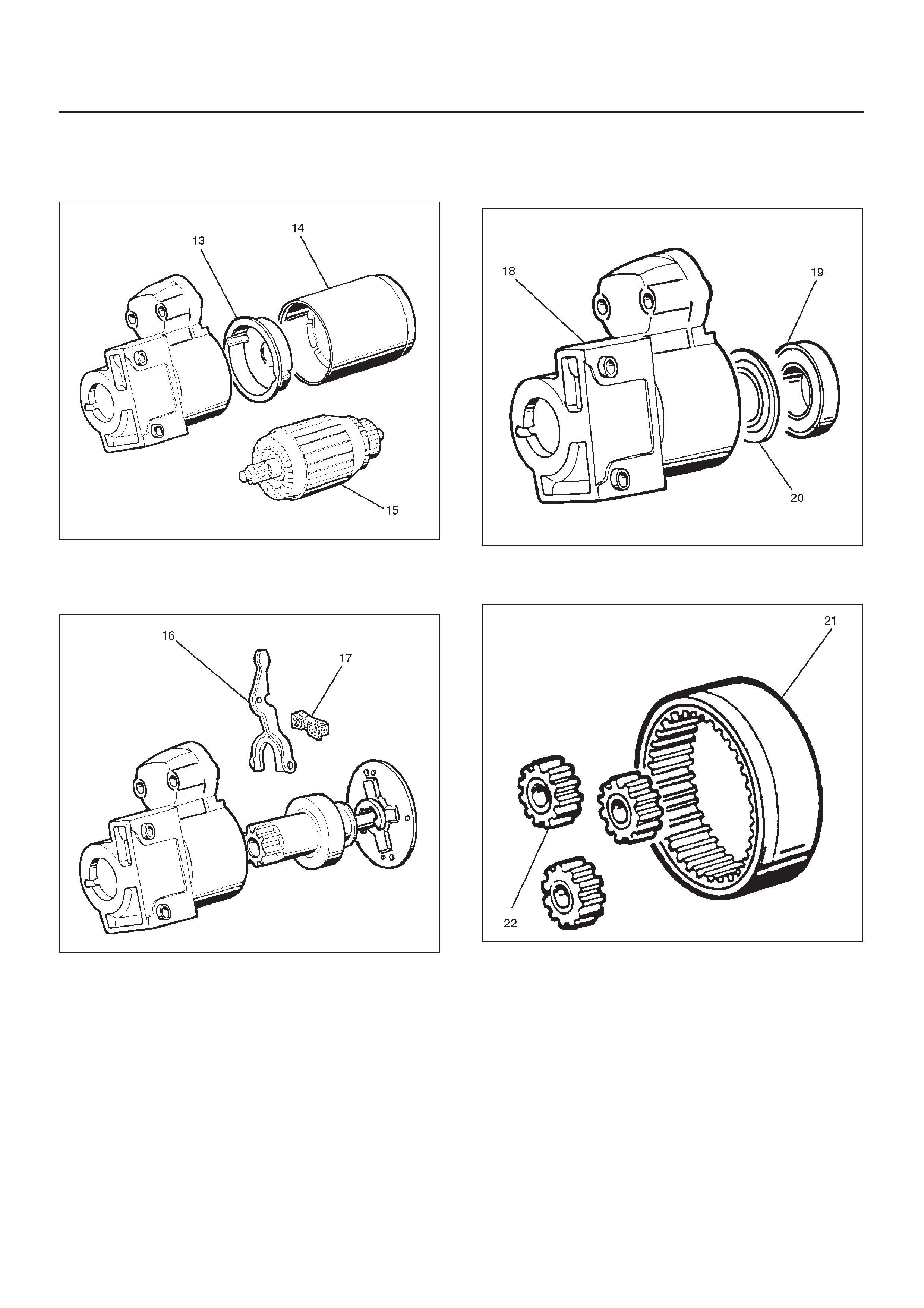
NOTE: In disassembling the yoke assembly, hold the
armature and pull off slowly the yoke assembly. Because
of strong magnetic force, avoid placing a metallic part
near armature.
065RW007
15.Remove dust cover(17).
16.Remove a dust cover and shift lever(16) from the gear
case.
065RW008
17.Remove ball bearing(19).
18.Remove bearing cover(20).
19.Remove a ball bearing and bearing cover from the
gear case(18).
065RW021
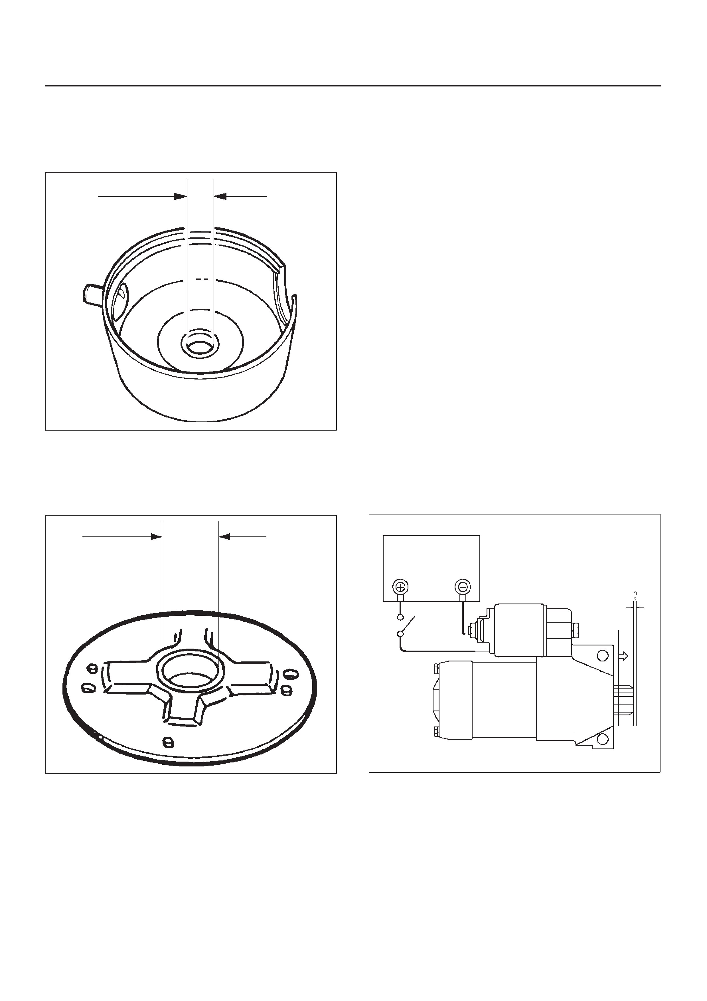
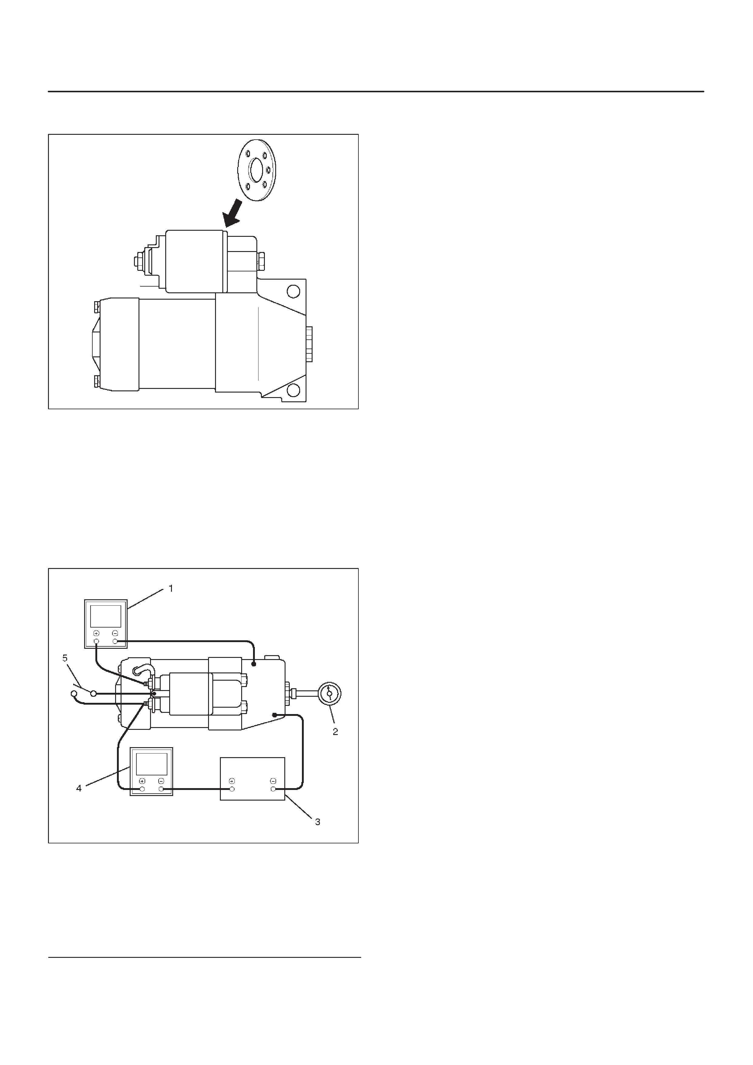
20.Internal gear(21).
21.Remove internal gear and planet gear(3) (22).
065RW009
22.Remove an E–ring(23) from the pinion shaft using a
flat blade screwdriver.
065RW010
23.Holding the pinion shaft, push pinion toward the
center bracket. and turn the pinion clockwise or
counterclockwise by one tooth of spline, then pull of f
the pinion.
24.Remove thrust washer(24).
25.Remove center bracket
26.Remove pinion shaft.
065RW011
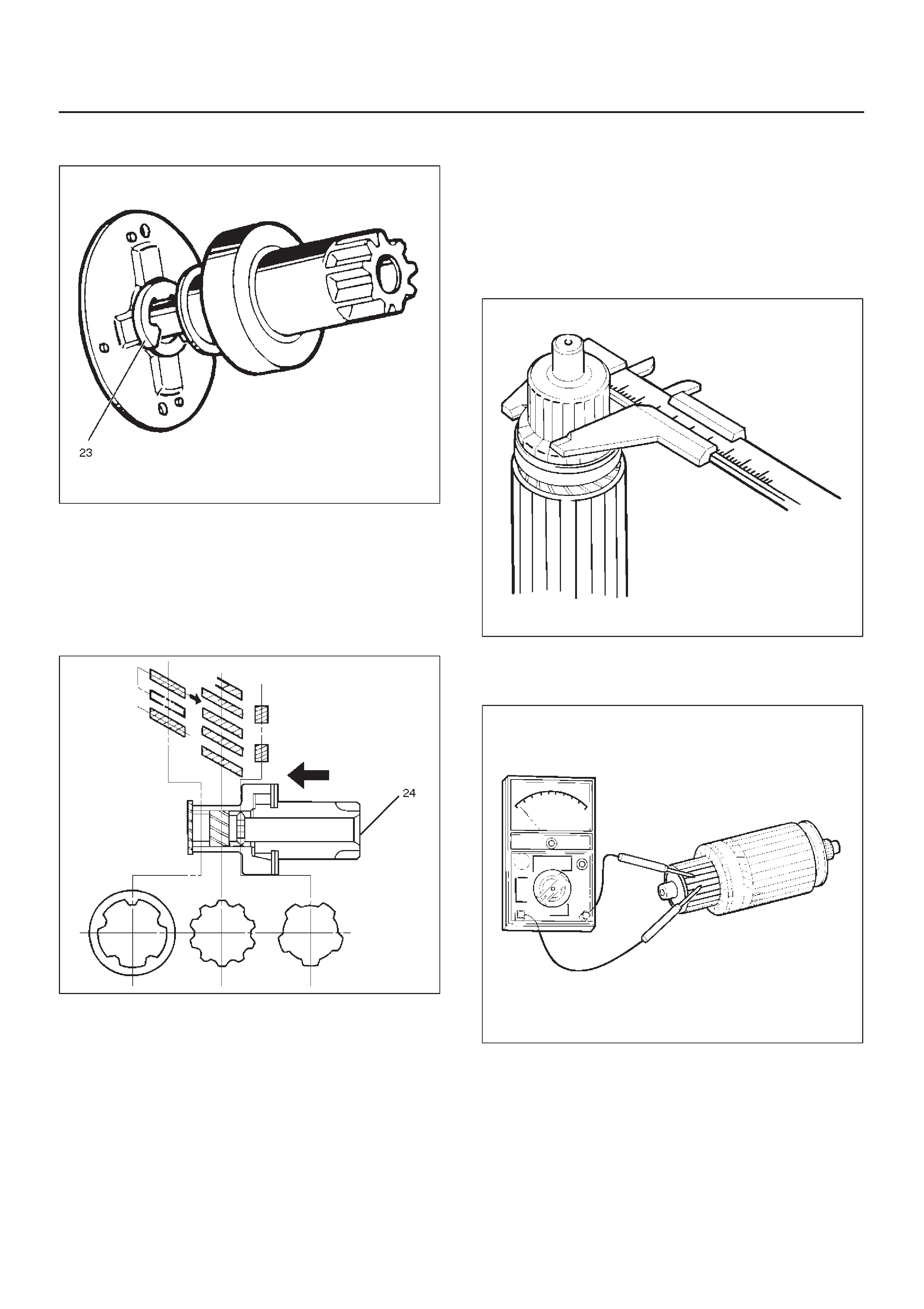
Inspection and Repair
Repair or replace necessary parts if extreme wear or
damage is found during inspection.
Armature
Measure the outer diameter of commutator, and replace
with a new one if it is out of the limit.
Standard: 33.0 mm (1.30 in)
Limit: 32.0 mm (1.26 in)
065RS014
Check for continuity between commutator and segment.
Replace commutator if there is no continuity (i.e.,
disconnected).
065RS015
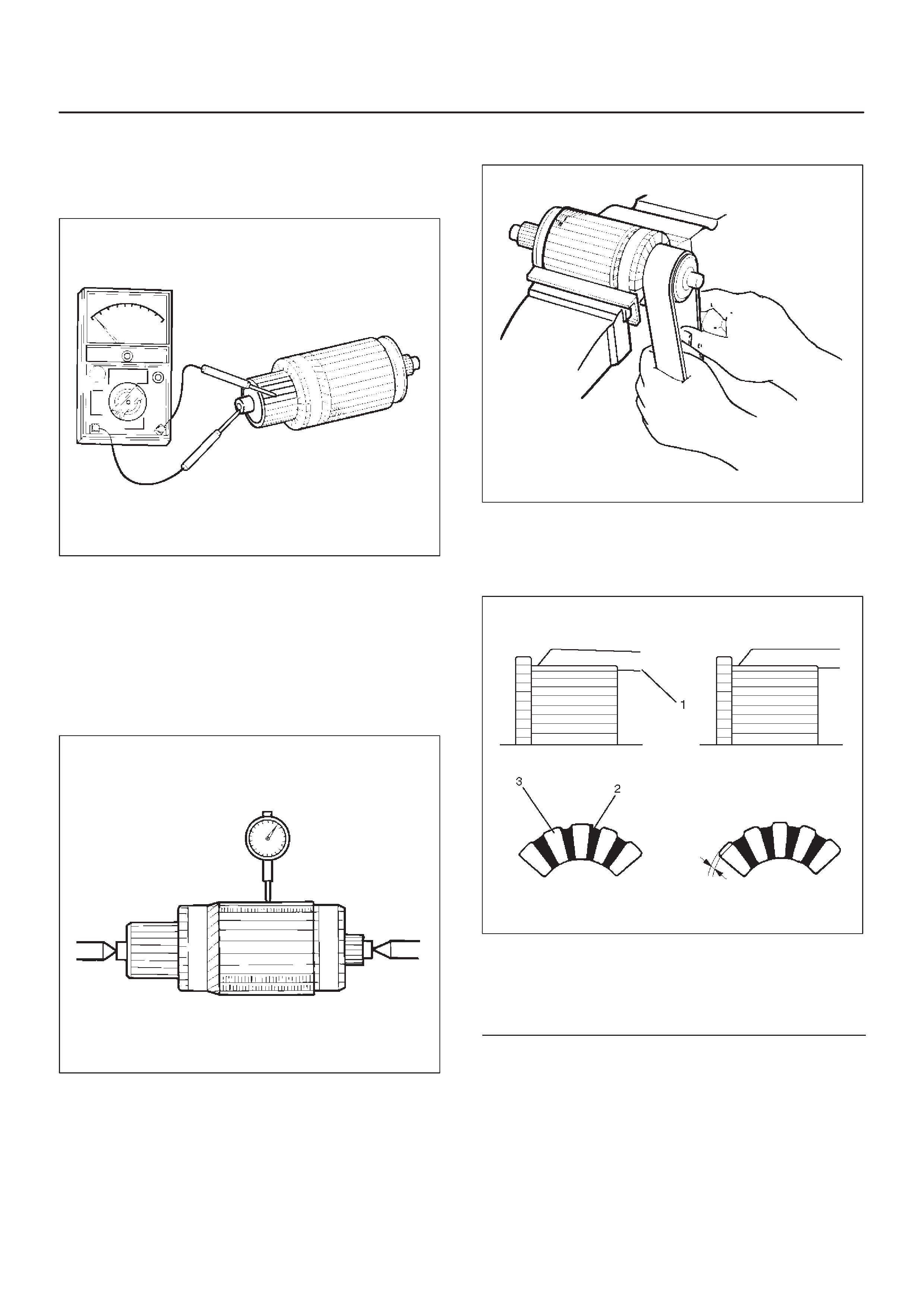
Check for continuity between commutator and shaft.
Also, check for continuity between commutator and
armature core,armature core and shaft. Replace
commutator if there is continuity (i.e., internally
grounded).
065RS016
Measure runout of armature core and commutator with a
dial gauge. Repair or replace, if it exceeds the limit.
Armature
Standard: 0.05 mm (0.002 in) Max.
Limit: 0.10 mm (0.004 in)
Commutator
Standard: 0.05 mm (0.002 in) Max.
Limit: 0.10 mm (0.004 in)
065RS017
Polish the commutator surface with sandpaper #500 to
#600 if it is rough.
065RW012
Measure the depth of insulator in commutator. Repair, if it
is below the limit.
Standard: 0.05 mm to 0.8 mm (0.02 in to 0.03 in)
Limit: 0.2 mm (0.008 in)
065RW013
Legend
(1) Steel Saw
(2) Insulator
(3) Commutator Segments
Brush
Measure the length of brush.
Replace with a new one, if it is below the limit.
Standard: 16 mm (0.63 in)
Limit: 11 mm (0.43 in)
065RW014
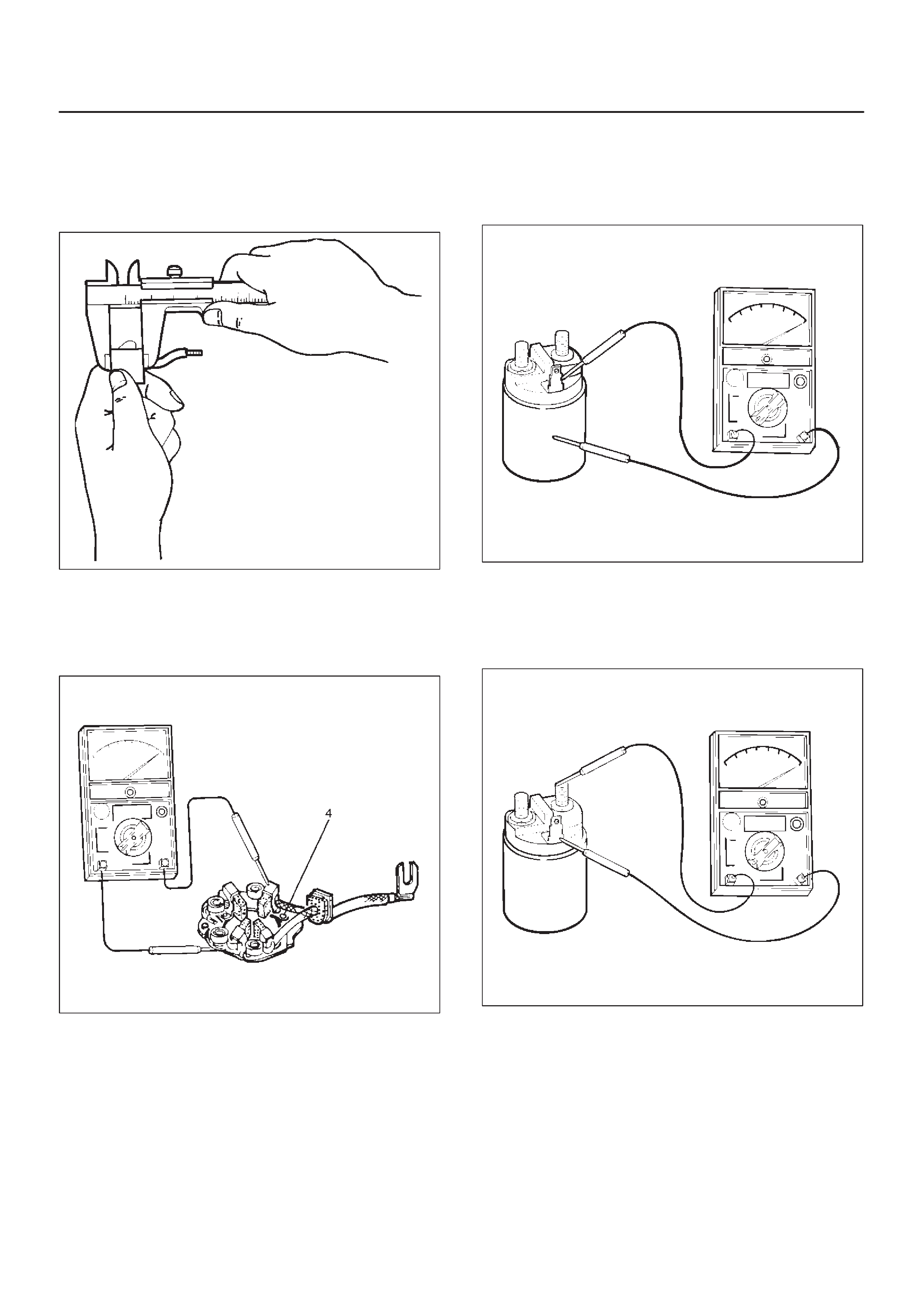
Brush Holder
Check for continuity between brush holder (+) (4) and
base (–). Replace, if there is continuity (i.e., insulation is
broken).
065RW015
Magnetic Switch
Check for continuity of shunt coil between terminals S and
M.
Replace, if there is no continuity (i.e., coil is
disconnected).
065RW016
Continuity of Series Coil
Check for continuity between terminals S and M.
Replace, if there is no continuity (i.e., coil is
disconnected).
065RW017
Continuity of Contacts
With the plunger faced downward, push down the
magnetic switch. In this state, check for continuity
between terminals B and M. Replace, if there is no
continuity (i.e., contacts are faulty).
065RW018
Pinion
Check if the pinion rotates smoothly in drive direction by
hand, or if it is locked when it is rotated in reverse. If not,
replace the pinion.
065RS025
Yoke Assembly
Check a magnet inside the yoke.
Replace the yoke assembly if it is broken.
065RS026
Ball Bearing
Clamp the inner race of the ball bearing with your finger,
and check for sticking or play when rotating the outer
race.
Replace, if abnormality is found.
065RS027
Measure inner diameter of bushing in the rear cover , and
replace if it exceeds the limit.
Standard: 12.50 mm to 12.527 mm (0.492 in to
0.4932 in)
Limit: 12.60 mm (0.4961 in)
065RS028
Measure inner diameter of bushing in the center bracket
(P), and replace if it exceeds the limit.
Standard: 18.01 mm to 18.127 mm (0.7091 in to
0.7137 in)
Limit: 18.15 mm (0.7146 in)
065RS029
Reassembly
To install, follow the removal steps in the reverse order,
noting the following points:
Grease application places
DBushing in rear cover and center bracket
DGears in reduction gear
DShift lever operating portion
DSliding portion of pinion
DPlunger sliding portion of magnetic switch
Reassembling Yoke Assembly
Before reassembly, make sure that no metallic parts
attach to the yoke assembly . Because of strong magnetic
force, hold the yoke assembly and insert it slowly into the
armature.
Torque
Torque for each part (See Torque Specifications in
this section)
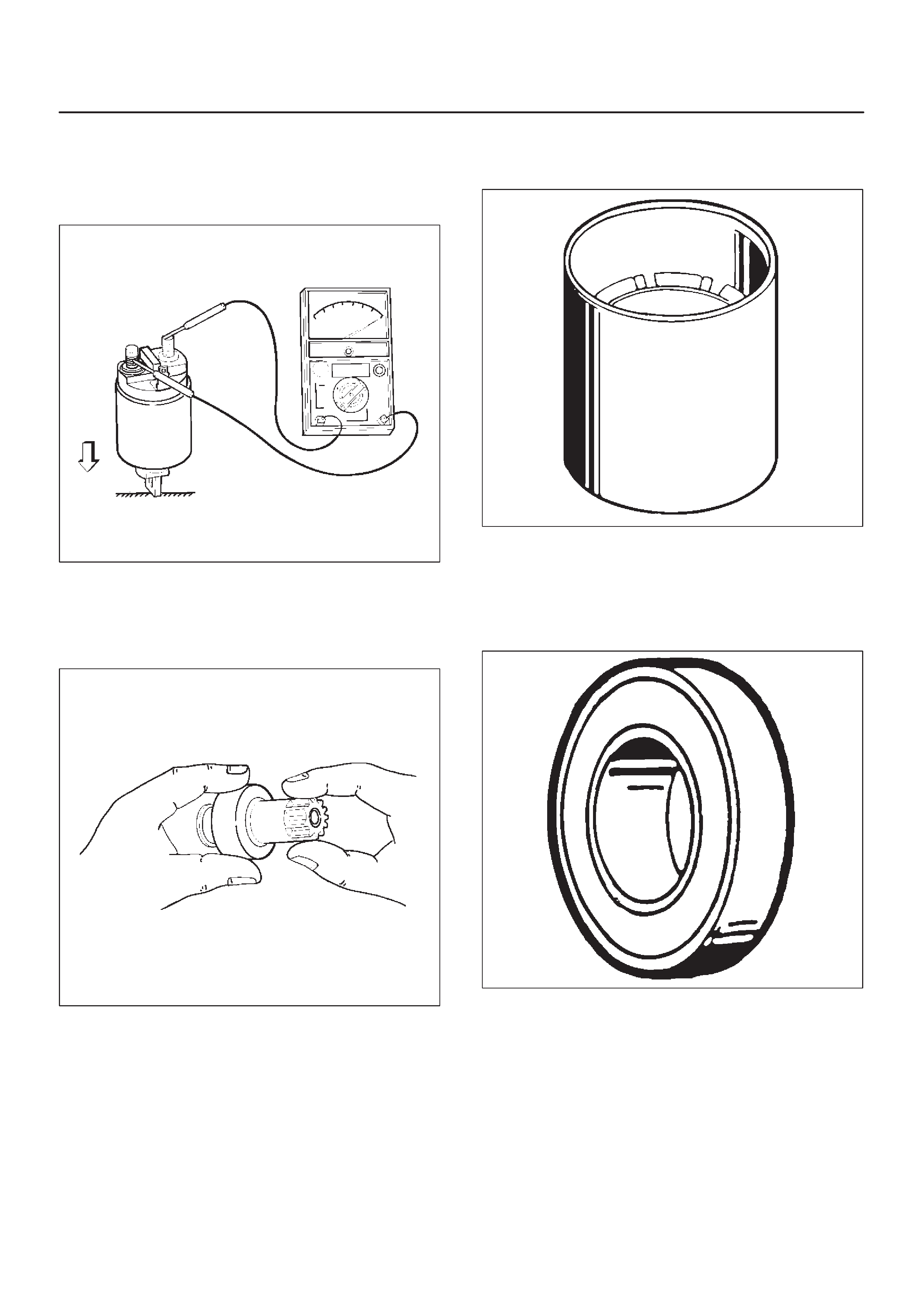
Pinion Jump–out Dimension
Connect the “+” cable of battery to terminal S and the “–”
cable to terminal M. Turn the switch on, and measure
pinion travel dimension in thrust direction from the
jump–out position.
In measuring the dimension, pull the pinion out a little in
the arrow direction.
Dimension(L): 0.05 mm to 1.5 mm (0.002 in to
0.06 in)
065RS030
If the measured value is out of standard, insert dust cover,
or disassemble and adjust.
065RW019
Characteristic Test
For easily confirming the characteristics, conduct the no
load test as follows:
Rating as short as 30 seconds requires rapid testing.
Fix the starter on the test bench, and wire as shown in
illustration. When the switch is closed, the current flows
and the starter runs under no load. At this time, measure
current, voltage and speed to check if they satisfy the
standard.
065RW020
Legend
(1) Volt Meter
(2) Tachometer
(3) Battery
(4) Ammeter
(5) Switch
Main Data and Specifications
General Specifications
Model Specification
Rating
Voltage 12 V
Output 1.4 Kw
Time 30 sec
Number of teeth of pinion 9
Rotating direction(as viewed from pinion) Clockwise
Weight(approx.) 37 N
No load characteristics
Voltage /Current 11.5V/90A or less
Speed 3000rpm or more
Load characteristics
Voltage/current 8.5V/350A or more
Torque 13.2N·m(117lb·in.) or more
Speed 1000rpm or more
Locking characteristics
Voltage/current 2.4V/500A or less
Torque 11.8N·m(104lb·in) or more
Torque Specifications
N·m (Kg·m/lb ft)
E06RW044
N·m (Kg·m/lb ft)
150RX016
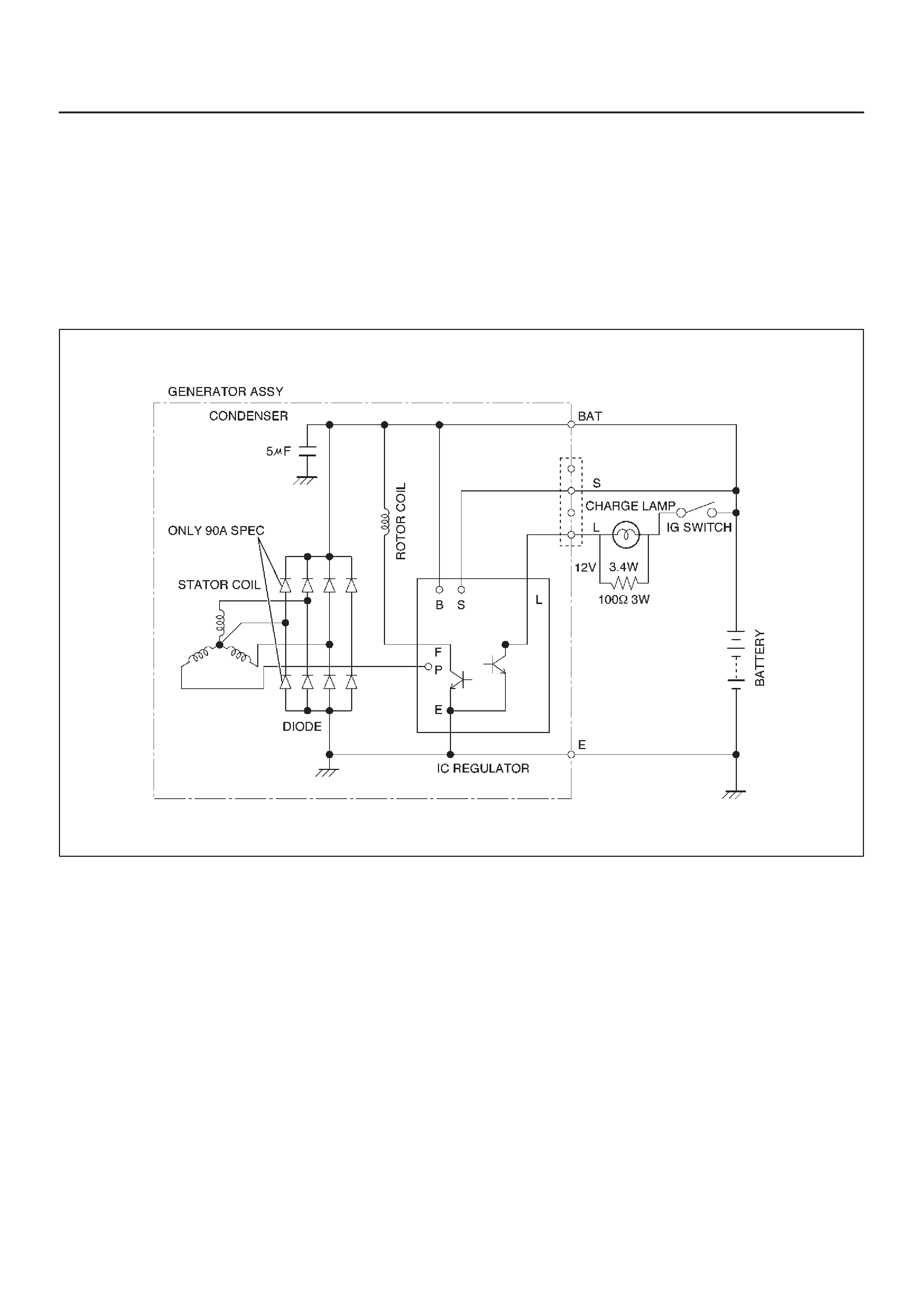
Charging System
General Description
The IC integral regulator charging system and its main
components are connected as shown in illustration.
The regulator is a solid state type and it is mounted along
with the brush holder assembly inside the generator
installed on the rear end cover.
The generator does not require particular maintenance
such as voltage adjustment.
The rectifier connected to the stator coil has diodes to
transform AC voltage into DC voltage.
This DC voltage is connected to the output terminal of
generator.
F06RX002
General On–Vehicle Inspection
A basic wiring diagram is shown in the illustration. When
operating normally, the indicator bulb will come on when
the switch is turned on, and will then go out when the
engine starts. If the indicator operates abnormally , or if an
undercharged or overcharged battery condition occurs,
the following procedure may be used to diagnose the
charging system. Remember that an undercharged
battery is often caused by accessories being left on
overnight, or by a defective switch which allows a bulb,
such as a trunk or glove box light, to stay on.
OBSERVE THE FOLLOWING PROCEDURE:
1.Visually check belt and wiring.
2. Go to step 5. for vehicles without charge indicator
light.
3.Switch on, engine stopped, light should be on. If not,
detach harness at generator, ground “L” terminal
lead.
a. Lamp lights, replace or repair generator.
b. Lamp dose not light, locate open circuit between
grounding lead and ignition switch. Bulb may be
open.
4.Switch on, engine running at moderate speed. Light
should be off. If not, detach wiring harness at
generator.
a. If light goes off, replace or repair generator.
b. If light stays on, check for grounded “L” terminal
wire in harness.
5.Battery undercharged or overcharged.
a. Detach wiring harness connector from generator.
b. With switch on, engine not running connect
voltmeter from ground to “L” terminal in wiring
harness, and to “IG” terminal. If used. Wiring
harness may connect to either “L” or “IG” or both.
c. Zero reading indicates open circuit between
terminal and battery. Connect as required.
d. Re-connect harness connector to generator, run
engine at moderate speed, with electrical
accessories turned off.
e. Measure voltage across battery. If above 16.0V,
replace or repair generator.
f. Connect ammeter at generator output terminal.
T urn on accessories, load battery with carbon pile
to obtain maximum amperes output.
Maintain voltage at 13.0V or above.
1. If within 15 amperes of rated output, generator is
OK.
2. If not within 15 amperes of rated output, replace or
repair generator.
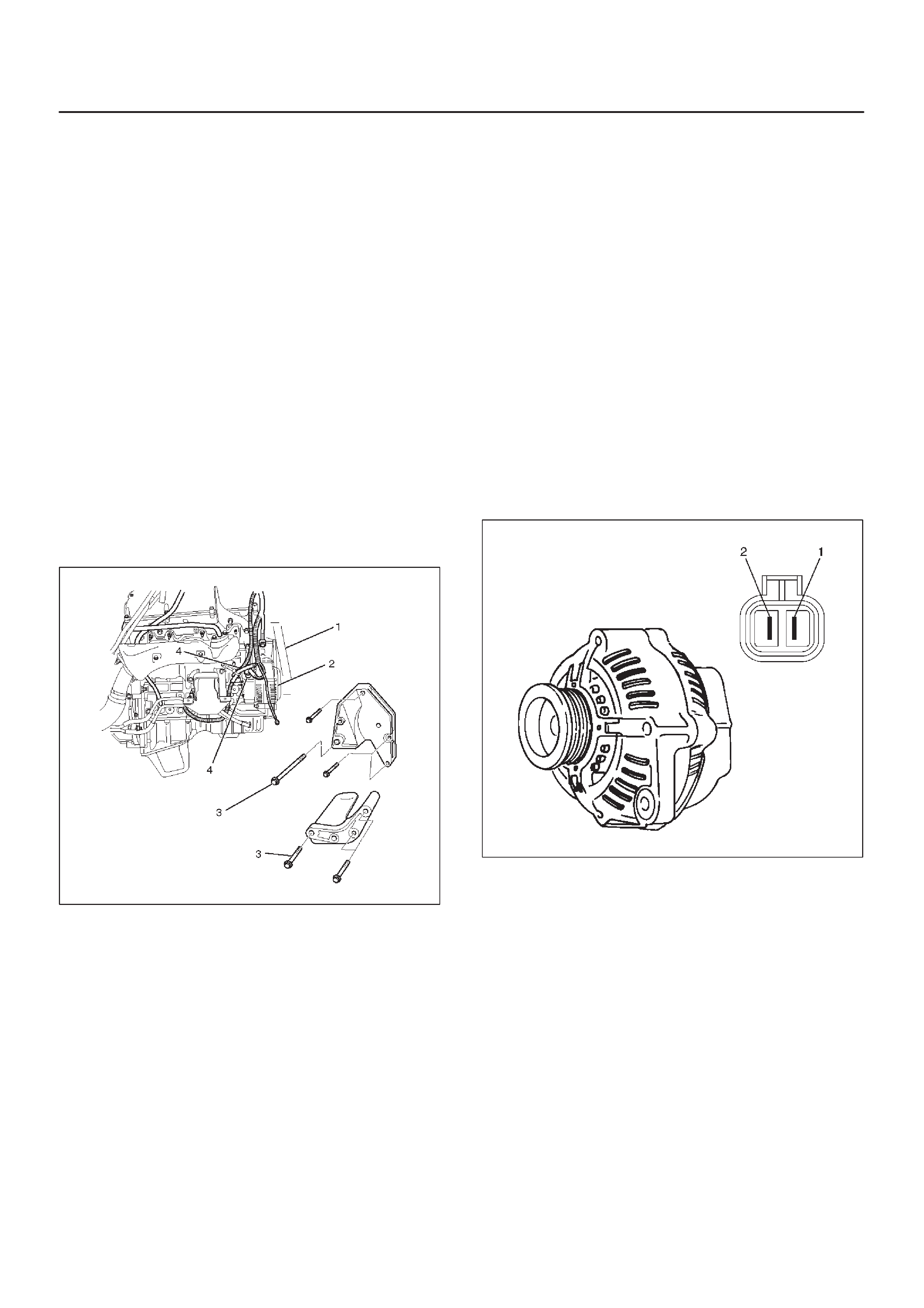
Generator
Removal
1.Disconnect battery ground cable.
2.Move drive belt tensioner to loose side using wrench
then remove drive belt (1).
3.Disconnect the wire from terminal “B” and disconnect
the connector (4).
4.Remove generator fixing bolt (3).
5.Remove generator assembly (2).
060RW002
Inspection
1.Disconnect the wiring connector from generator.
2.With the engine stopped, turn starter switch to “on”
and connect a voltmeter between connector terminal
L (1) and ground or between terminal IG (2) and
ground.
066RX002
If voltage is not present, the line between battery and
connector is disconnected and so requires repair.
3.Reconnect the wiring connector to the generator , run
the engine at middle speed, and turn off all electrical
devices other than engine.
4.Measure battery voltage. If it exceeds 16V, repair or
replace the generator.
5.Connect an ammeter to output terminal of generator ,
and measure output current under load by turning on
the other electrical devices (eg., headlights). At this
time the amperes must not be less than 15A and the
voltage must not be less than 13V.
Installation
1.Install generator assembly to the position.
2.Install generator assembly and tighten the fixing bolts
to the specified torque.
Torque:
M10 bolt: 41 N·m (30 Ib ft)
M8 bolt: 21 N·m (15 Ib ft)
3.Connect wiring harness connector and direct terminal
“B”.
4.Move drive belt tensioner to loose side using wrench,
then install drive belt to normal position.
5.Reconnect battery ground cable.
Disassembled View
066RW022
Legend
(1) Pulley Nut
(2) Pulley
(3) Front Cover Assembly
(4) Rotor Assembly
(5) Stator Assembly
(6) Through Bolt
(7) Nut
(8) Terminal Insulator
(9) Rear Cover Assembly
(10) Rectifier
(11) Brush Holder Assembly
(12) Regulator Assembly
Disassembly
1.Remove the through bolt.
Insert the tip of a pry bar into the gaps between the
front cover and the stator core.
Pry apart and separate the front cover , rotor, the rear
cover and stator.
NOTE: Take care not to scratch or otherwise damage the
stator coil with pry bar.
F06RT021
2.Clamp the rotor in a vise and then remove the nut and
pulley.
3.Remove the rotor assembly from front cover.
F06RT022
4.Remove screws with bearing retainer from front cover
and remove bearing.
F06RT023
5.Remove the mounting nuts holding the “B” terminal,
the diode, and the brush holder.
6.Separate the rear cover from the stator.
F06RT024
7.Remove bolts which secure stator terminal to rectifier
terminal, and remove stator.
066RS030
8. Remove Bolts which secure regulator, rectifier and
brush-holder, and separate these parts.
NOTE: Do not apply a shock or load to regulator , rectifier
and brush holder.
066RW025
Inspection and Repair
Repair or replace necessary parts if extreme wear or
damage is found during inspection.
Rotor Assembly
1.Check the face of the slip rings for contamination and
roughness. If found to be scored, dress with a fine
sandpaper (#500 –600). If found to be contaminated,
clean with a cloth saturated with alcohol.
2.Measure the outside diameter of the slip rings.
Standard: 27mm (1.06in)
Limit: 26mm (1.02in)
066RS032
3.Check resistance between slip rings, and replace if
there is no continuity.
Standard: 3.75W or less
066RS033
4.Check for continuity between slip ring and rotor core.
In case of continuity, replace the rotor assembly.
066RS017
Stator Coil
1. Check for continuity across the stator coils. If no
continuity exists, replace the coils.
Resistance value at 20°C.
Standard: Approx. 0.07W
066RS034
2.Check for continuity across one of the stator coils and
stator core. If a continuity exists, replace the coil.
Standard: More than 1MW
066RS035
Brush
Measure the brush length.
If more than limit, replace the brush.
Standard: 18.0mm (0.709in)
Limit: 5.5mm (0.217in)
066RW024
Rectifier Assembly
1.Measure the resistance between each diode terminal
and aluminum diode fin in forward and reverse
directions with the connection of the tester leads
switched. The diodes are normal if resistance is
nearly zero ohms in one direction and is infinitely high
in the other direction.
2.If a diode has no resistance or equal resistance in
both directions, it is defective and should be replaced
together with the holder.
066RS036
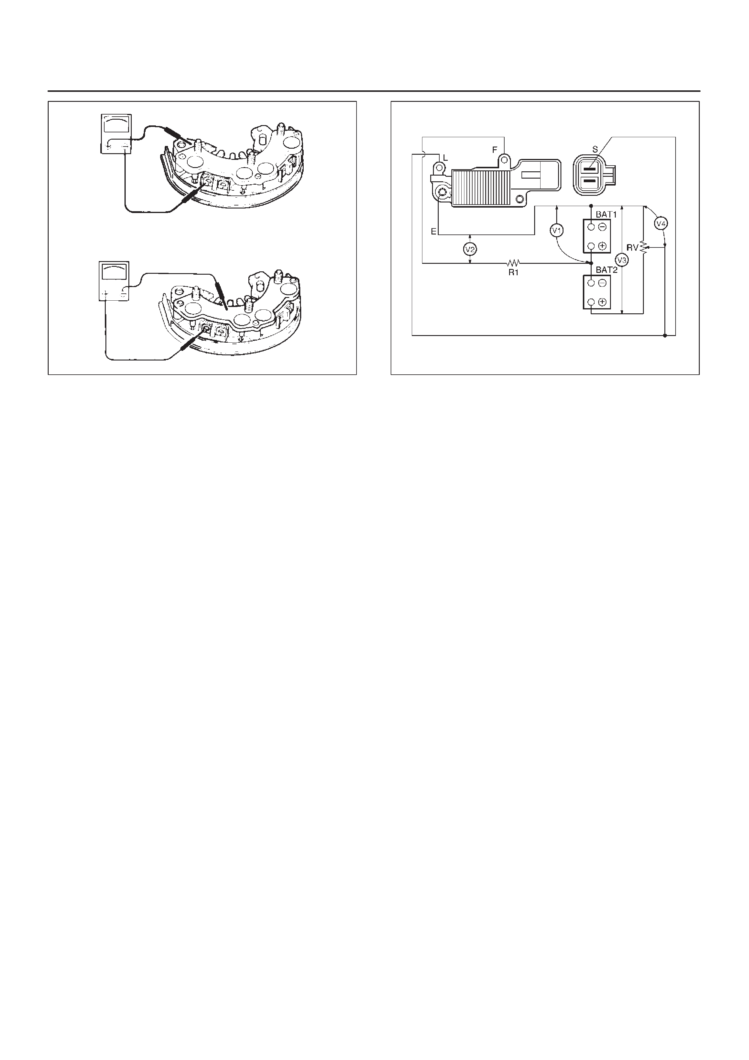
IC Regulator Assembly
Connect a variable resistor, two 12V batteries, a fixed
resistor, and a voltmeter to the IC regulator as shown in
illustration.
a. Measuring equipment specifications
1. Fixed resistor (R1) : 10 Ohms /3W
2. Variable resistor (Rv) : 0-300 Ohms/12W
3. Batteries (BAT1, BAT2) : 12V (2 Batteries)
4. DC voltmeter : 0-50V/0.5 steps (4 Check points)
b. Measuring procedure
1. Measure the voltage “V1” across the first battery
(BAT1). If the reading is between 10 and 13 volts,
the battery is normal.
2. Measure the voltage “V3” across both the batteries
(BAT1, BAT2). If the reading is between 20 and 26
bolts, the batteries are normal.
3. Gradually increase the resistance of the variable
resistor from zero. Measure the voltage “V2” (the
voltage across the F and E terminals).
Check to see that the voltage across “V1” changes at
this time. If there is no change, the voltage regulator
is faulty and must be replaced.
4. Measure the voltage at “V4” (the voltage across the
variable resistor center tap and terminal E with the
variable resistor resistance held constant). The
measure voltage should be within the specified
(14.4±0.3 volts) limits. If it is not, the regulator must
be replaced.
066RX003
Reassembly
To reassemble, follow the disassembly steps in the
reverse order, noting the following points:
NOTE:
DNever make battery connections with polarities
reversed, or battery will be shorted via the diodes.
This will cause damage to the diodes.
DDo not connect generator B terminal to ground; it is
connected directly to the battery.
This cable will burn if it is connected to ground.
DMake sure to disconnect the positive (+) terminal of
the battery when quick-charging battery .
Diodes may be damaged due to abnormal pulse
voltage generated bye the quick charger.
DWhen reassembling the front section to rear section,
insert a stiff wire into hole in the rear face of the rear
cover from the outboard side to support the brush in
raised position, then insert the front section to which
rotor is assembled.
DReassemble parts carefully to be sure they fit into
their original position, paying attention to the
insulated portions.
DWipe insulating tubes, washers and plates clean and
install them in position carefully to avoid getting oil or
grease on them.
1.Using a press with a socket wrench attached,
reassemble rotor and rear end cover assembly in the
front cover.
066RS022
2.Install pulley on the rotor.
Secure the pulley directly in the vise between two
copper plates, and tighten nut to the specified torque.
Torque: 111 N·m (82 lb ft)
066RS010
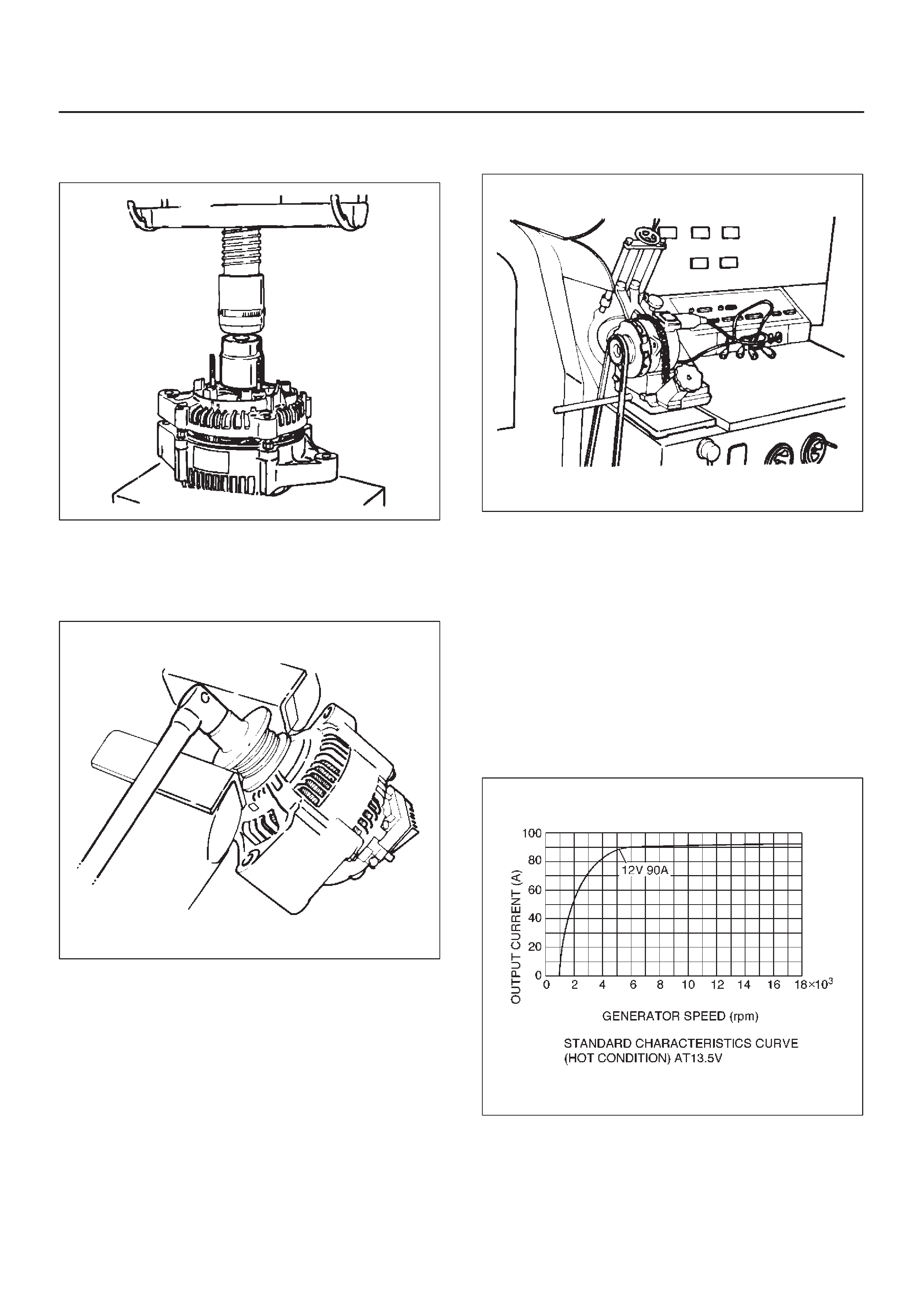
Bench Test
Conduct a bench test of the generator.
066RS023
Preparation
Remove generator from the vehicle (see “Generator
removal”).
1.Secure generator to the bench test equipment and
connect wires.
Terminal “IG” for energization
Terminal “L” for neutral (warning lamp)
Terminal “B” for output
2.Conduct the generator characteristic test.
Characteristics of generator are shown in illustration.
Repair or replace the generator if its outputs are
abnormal.
066RX001

Main Data and Specifications
General Specifications
Battery voltage V 12
Rated output A90
Direction of rotation
(as viewed from pulley side) Clockwise
Rated rotation speed rpm 5000
Maximum speed rpm 18000