
SECTION 7A - AUTOMATIC TRANSMISSION (4L30–E)
Service Precaution
Construction
Range Reference Chart
Normal Operation of 2000 4L30–E
Transmission
Diagnosis
Driver Information
General Diagnosis Procedure
Preliminary Inspection Chart
Checking Transmission Fluid Level and
Condition
Test Driving
Mechanical / Hydraulic Diagnosis Check
Trans Indicator Chart
Mechanical / Hydraulic Diagnosis Symptoms
Index
Stall Test
Line Pressure Test
Shift Speed Chart
Lockup Speed Chart
Changing Transmission Fluid
Selector Lever
Inspection
Removal
Installation
Select Cable
Removal
Installation
Shift Lock Cable
Removal
Installation
Mode Switch
Removal
Installation
Transmission (With Transfer Case)
Transmission and Associated Parts
Removal
Installation
Solenoid (Main Case Valve Body)
Removal
Installation
Solenoid (Adapter Case Valve Body)
Removal
Installation
Valve Body Assembly (Main Case)
Removal
Installation
Valve Body Assembly (Adapter Case)
Removal
Installation
Powertrain Control Module (PCM)
Removal
Installation
Speed Sensor (Extension Housing)
Removal
Installation
Transmission Oil Temperature Sensor
(Adapter Case)
Removal
Installation
Front Oil Seal (Converter Housing)
Removal
Installation
Rear Oil Seal (Extension Housing)
Removal
Installation
Transmission (4L30–E)
Disassembly
Reassembly
Converter Housing and Oil Pump Assembly
Disassembled View
Disassembly
Inspection and Repair
Reassembly
Oil Pump

Disassembled View
Disassembly
Inspection and Repair
Reassembly
Main Case Valve Body
Disassembled View
Disassembly
Inspection and Repair
Reassembly
Adapter Case Valve Body
Disassembled View
Disassembly
Inspection and Repair
Reassembly
Third Clutch and Sprag Unit
Disassembled View
Disassembly
Inspection and Repair
Reassembly
Third Clutch
Disassembled View
Disassemble
Inspection and Repair
Reassembly
Sprag Unit
Disassembled View
Disassembly
Inspection and Repair
Reassembly
Second Clutch
Disassembled View
Disassembly
Inspection and Repair
Reassembly
3–4 Accumulator Piston
Disassembled View
Disassembly
Inspection and Repair
Reassembly
Reverse Clutch Piston and Center Support
Disassembled View
Disassembly
Inspection and Repair
Reassembly
Overrun Clutch and Turbine Shaft
Disassembled View
Disassembly
Inspection and Repair
Reassembly
Main Data and Specification
Special Tools
4L30–E Parts List
Service Precaution
WARNING:IF SO EQUIPPED WITH A
SUPPLEMENTAL RESTRAINT SYSTEM (SRS),
REFER TO THE SRS COMPONENT AND WIRING
LOCATION VIEW IN ORDER TO DETERMINE
WHETHER YOU ARE PERFORMING SERVICE ON OR
NEAR THE SRS COMPONENTS OR THE SRS
WIRING. WHEN YOU ARE PERFORMING SERVICE
ON OR NEAR THE SRS COMPONENTS OR THE SRS
WIRING, REFER TO THE SRS SERVICE
INFORMATION. FAILURE TO FOLLOW WARNINGS
COULD RESULT IN POSSIBLE AIR BAG
DEPLOYMENT, PERSONAL INJURY, OR
OTHERWISE UNNEEDED SRS SYSTEM REPAIRS.
CAUTION:Always use the correct fastener in the
proper location. When you replace a fastener, use
ONLY the exact part number for that application.
ISUZU will call out those fasteners that require a
replacement after removal. ISUZU will also call out
the fasteners that require thread lockers or thread
sealant. UNLESS OTHERWISE SPECIFIED, do not
use supplemental coatings (Paints, greases, or other
corrosion inhibitors) on threaded fasteners or
fastener joint interfaces. Generally, such coatings
adversely affect the fastener torque and the joint
clamping force, and may damage the fastener . When
you install fasteners, use the correct tightening
sequence and specifications. Following these
instructions can help you avoid damage to parts and
systems.
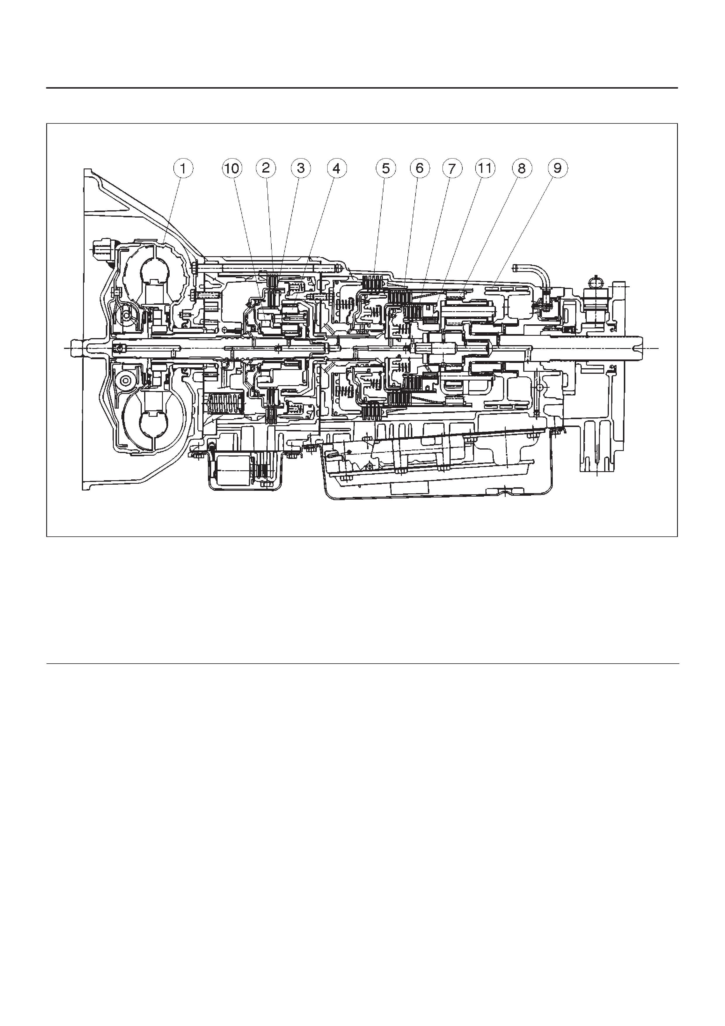
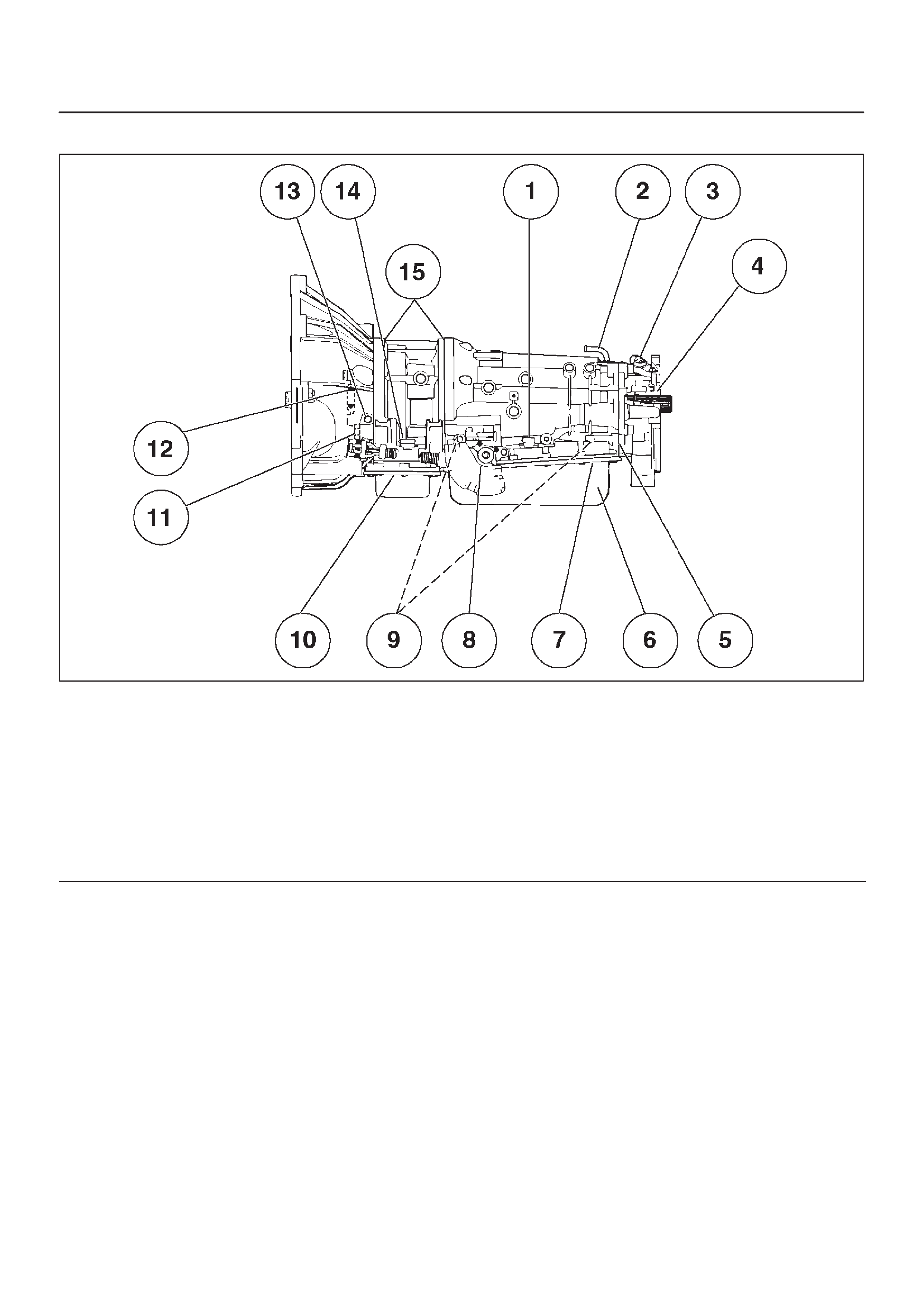
Construction
A07RS001
Legend
(1) Torque Converter Clutch (TCC)
(2) Fourth Clutch (C4)
(3) Overrun Clutch (OC)
(4) Overdrive Unit
(5) Reverse Clutch (RC)
(6) Second Clutch (C2)
(7) Third Clutch (C3)
(8) Ravigneaux Planetary Gear Set
(9) Brake Band (B)
(10) Overdrive Free Wheel (One Way Clutch)
(OFW)
(11) Principle Sprag Assembly (One W ay Clutch)
(PFW)
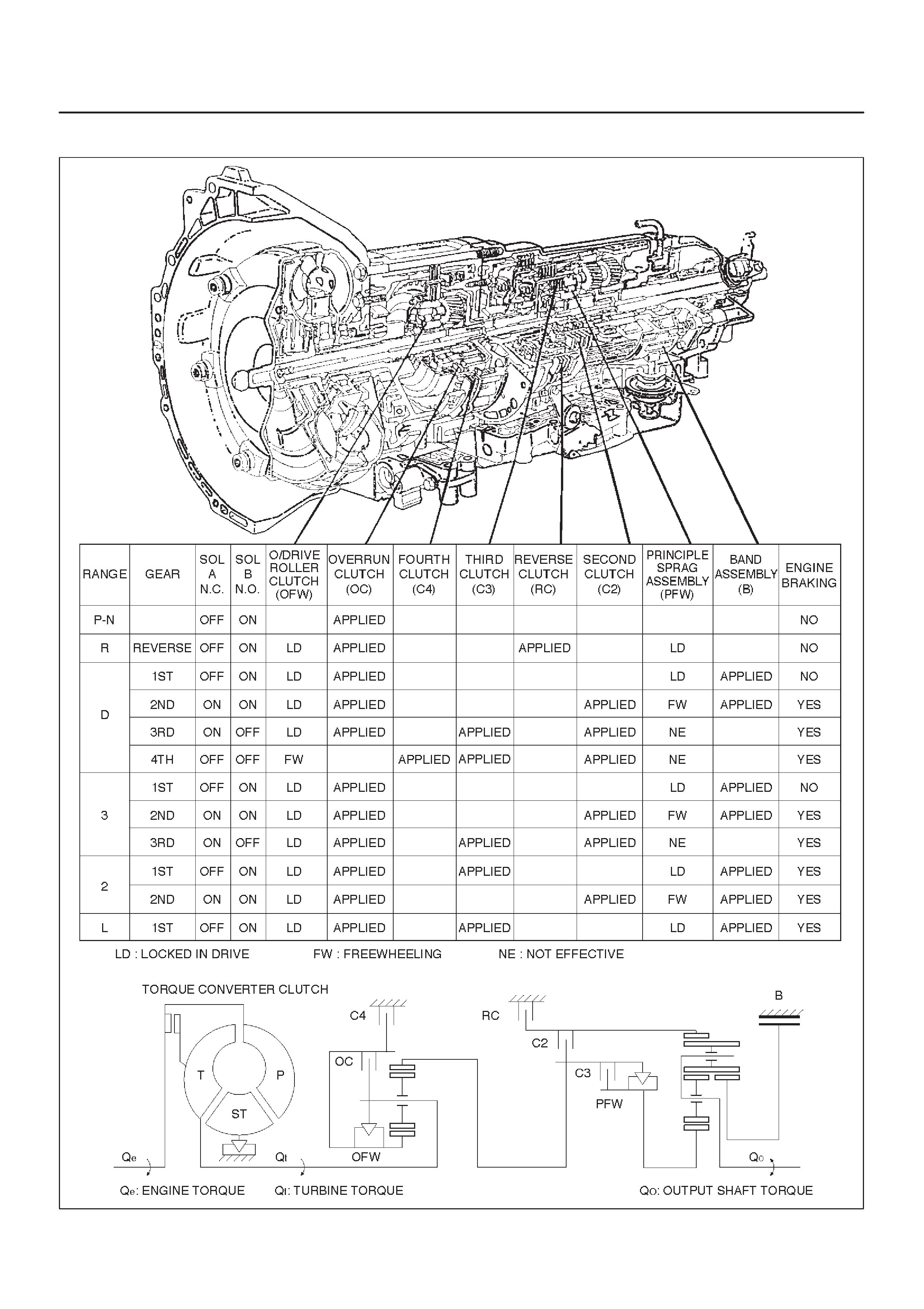
Range Reference Chart
C07RT010

Normal Operation of 2000 4L30–E
Transmission
Torque Converter Clutch (TCC)
Application Conditions:
The TCC is normally applied in 2nd, 3rd and 4th gears
only when all of the following conditions exist:
— The engine coolant temperature is above 70°C
(158°F).
— The brake pedal is released.
— The shift pattern requests TCC apply.
Moreover, TCC is always applied in 2nd, 3rd and 4th
gears when the transmission oil temperature is above
135°C (275°F).
This mode should be canceled at 125°C (257°F).
ATF Warning Lamp
The A TF warning lamp will be constantly on (not flashing)
if the transmission oil temperature is above 145°C
(293°F).
The ATF warning lamp goes off again when the
transmission oil temperature is below 125°C (257°F).
Diagnosis
Introduction
The systematic troubleshooting information covered by
this Section offers a practical and systematic approach to
diagnosing 4L30–E transmission, using information that
can be obtained from road tests, electrical diagnosis, oil
pressure checks or noise evaluation.
The key to correcting a complaint is to make use of all of
the available symptoms and logically letting them direct
you to the cause.
When dealing with automatic transmission complaints, it
is best to gather as many symptoms as possible before
making the decision to remove the transmission from the
vehicle.
Frequently, the correction of the complaint does not
require removal of the transmission from the vehicle.
Driver Information
To analyze the problem fill out a complete description of
the owner’s complaint.
Please draw a circle around the right information and
complete the following form. (The next page is an
example of a completed form.)You can draw a circle
around many numbers if you are not sure.
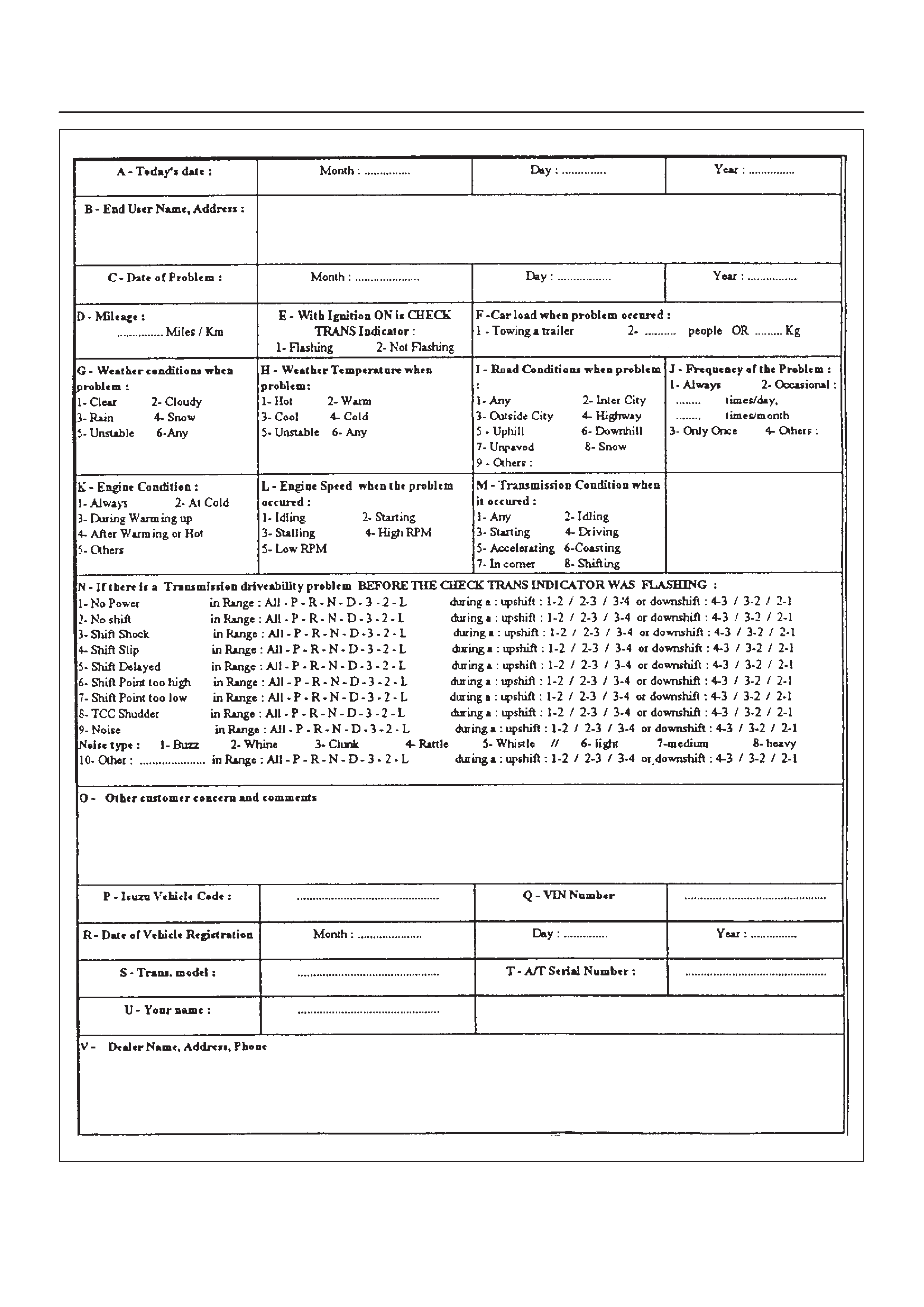
F07RT036
Example of form completed.
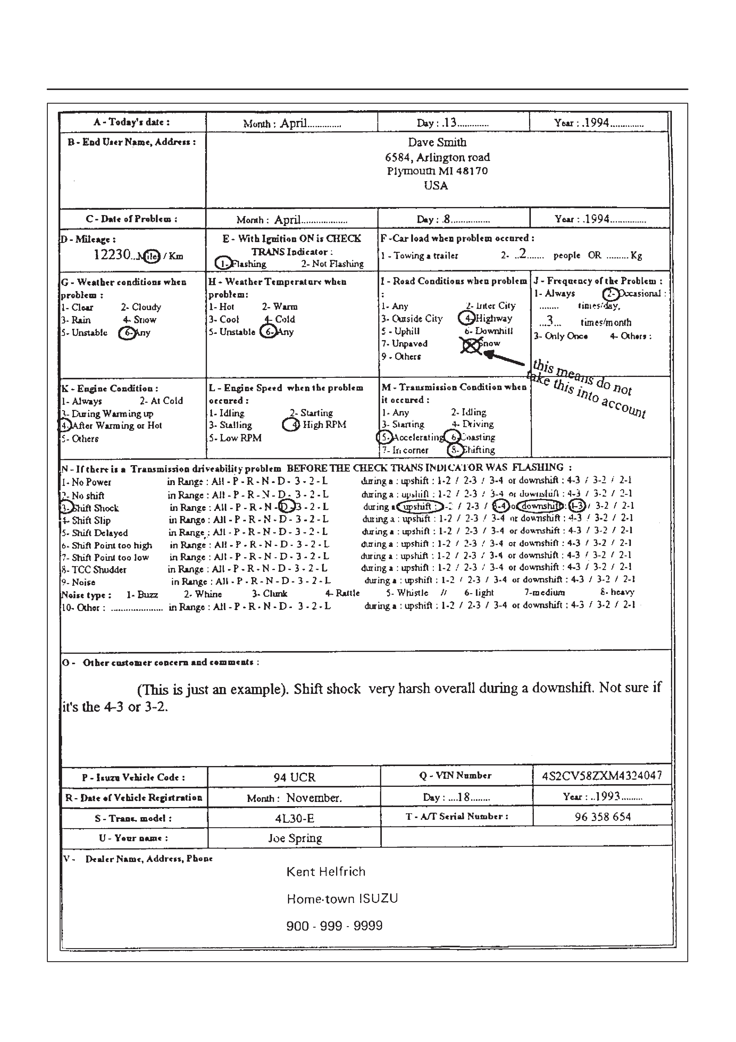
F07RT037
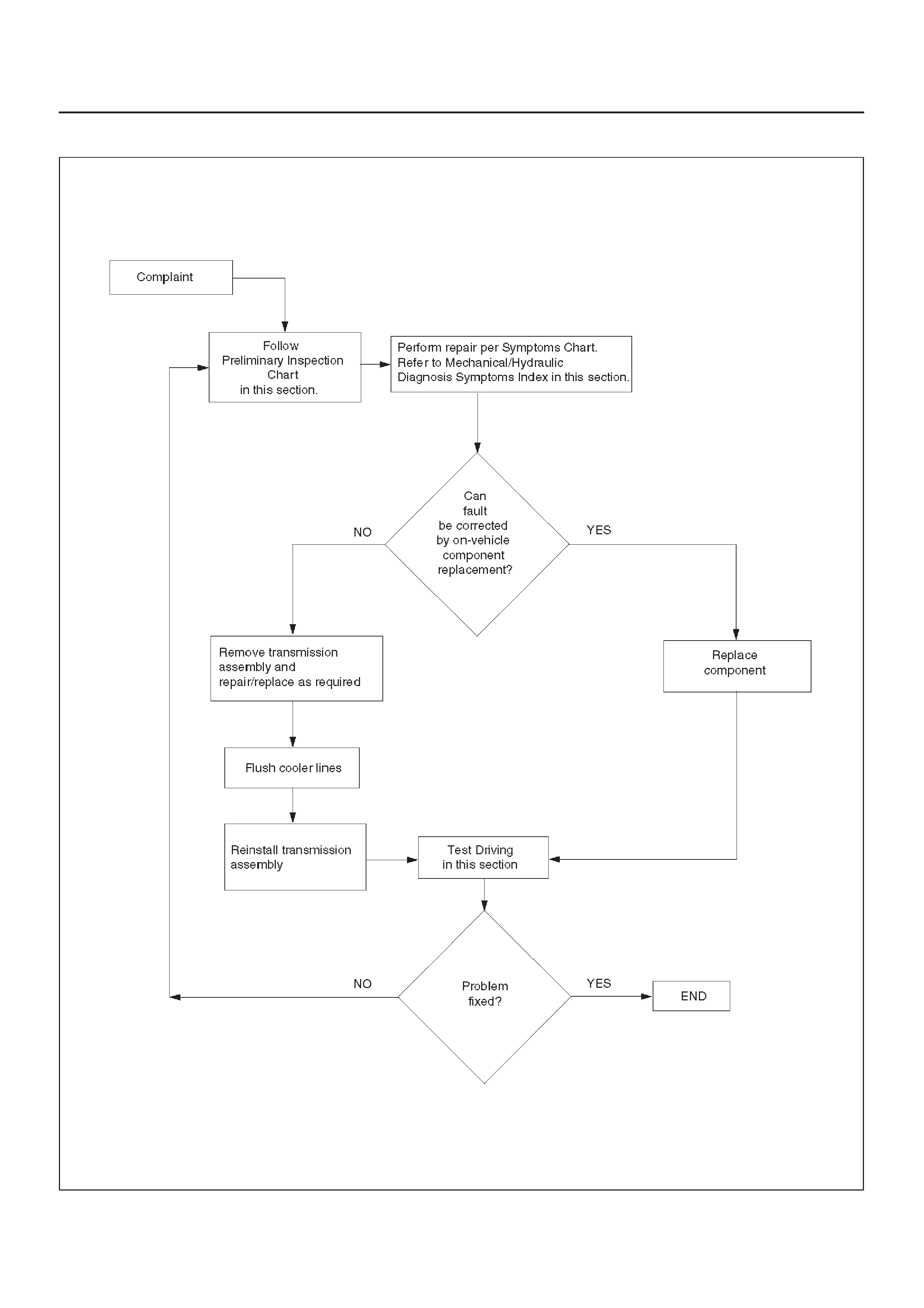
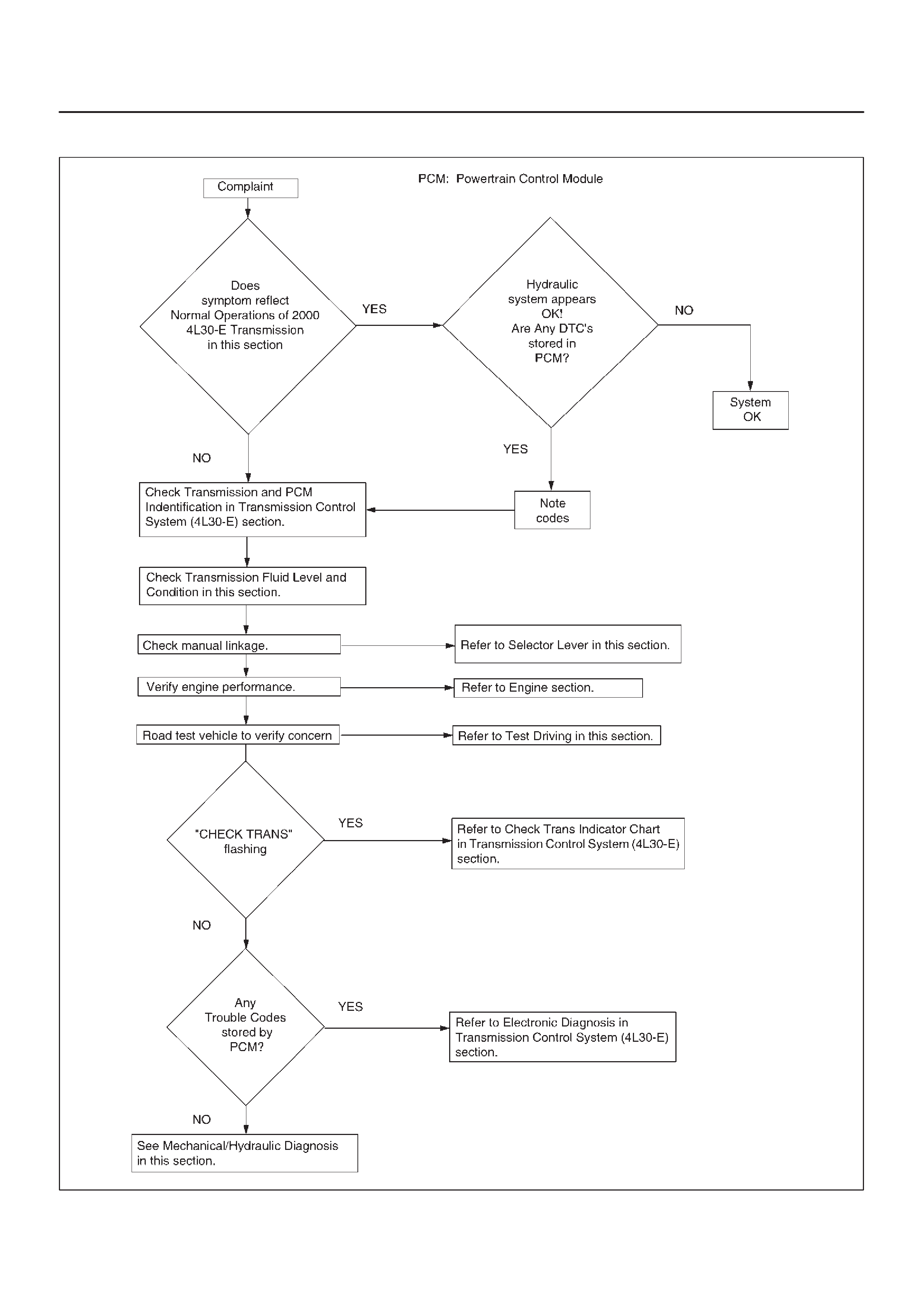
General Diagnosis Procedure
F07RT038
Preliminary Inspection Chart
F07RY00001
Checking Transmission Fluid Level
and Condition
Checking fluid level and condition (color and odor) at
regular intervals will provide early diagnosis information
about the transmission. This information may be used to
correct a condition that, if not detected early, could result
in major transmission repairs.
IMPORTANT:When new, automatic transmission fluid
is red in color. As the vehicle is driven, the transmission
fluid will begin to look darker in color. The color may
eventually appear light brown.
A dark brown color with burnt odor may indicate
excessive fluid deterioration and signal a need for fluid
change.
Fluid Level
When adding or changing fluid, use only DEXRON –III.
Refer to Maintenance and Lubrication in General
Information section for maintenance information and
servicing interval.
CAUTION:DO NOT OVERFILL.
Overfilling will cause foaming, loss of fluid, abnor-
mal shifting and possible damage to the transmis-
sion.
1.Park the vehicle on level ground and apply the parking
brake firmly.
2.Check fluid level with engine running at idle.
NOTE:Be sure that transmission fluid temperature is
below 30°C (86°F).
3.Move the selector lever through all gear ranges.
4.Move the selector lever to “Park”.
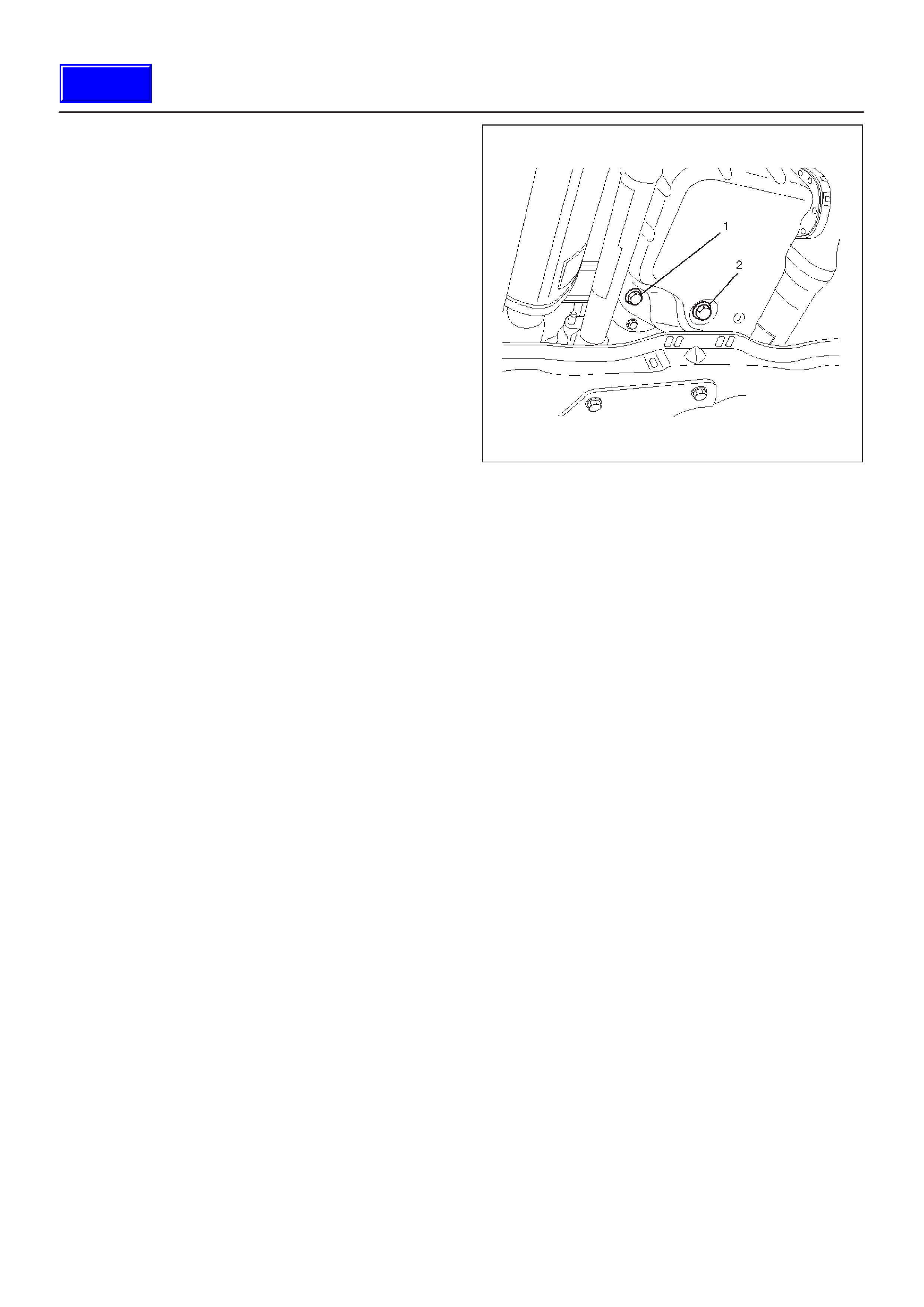
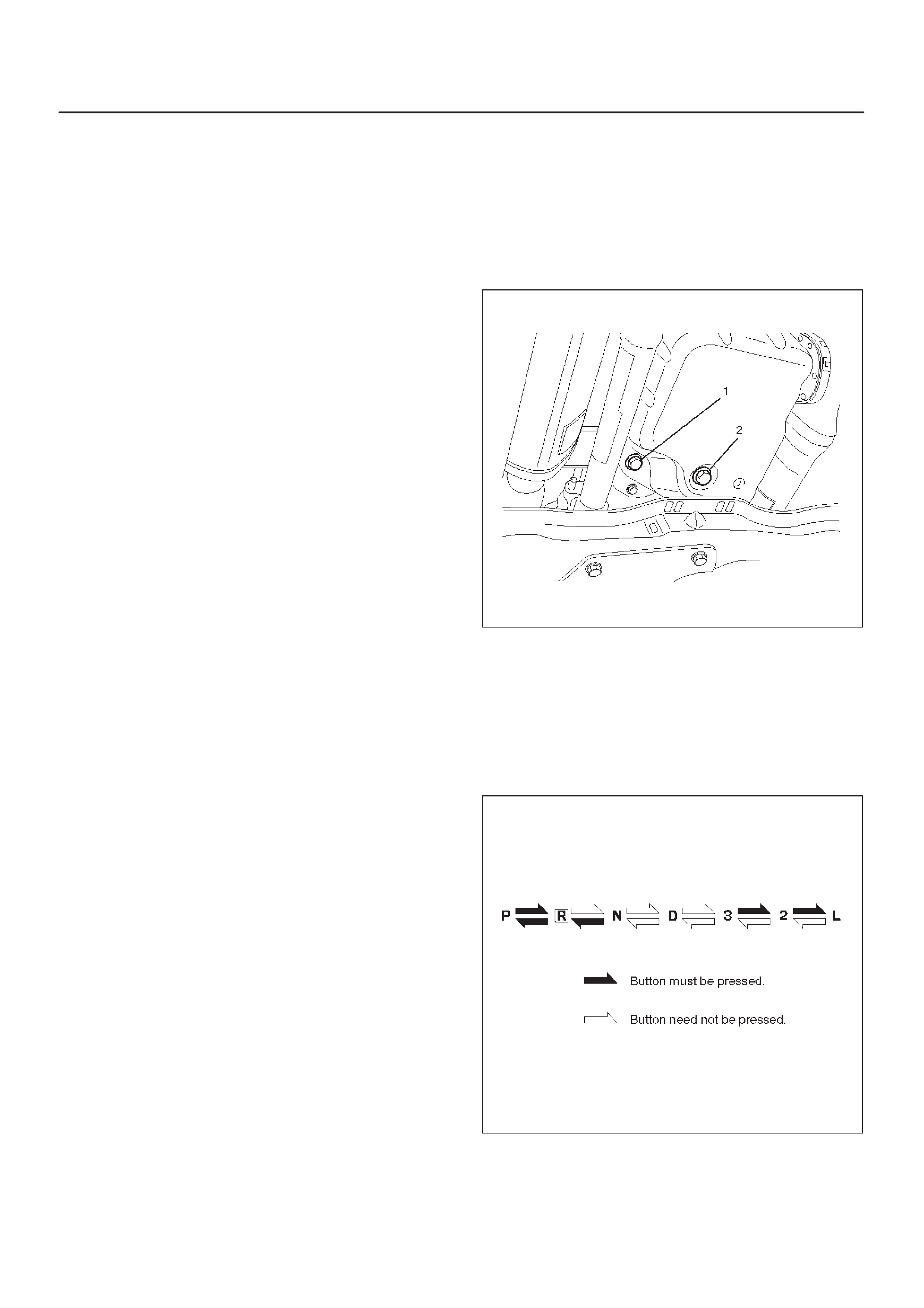
5.Let engine idle for 3 minutes and open the overfill
screw (1).
6.Add released transmission fluid until it flows out over
the overfill screw opening.
7.Let engine idle until a fluid temperature between 32°C
(90°F) and 57°C (135°F) is reached, then close the
overfill screw (1).
Torque: 38N•m(28lbft)
NOTE:To prevent fluid leaks, the overfill screw and oil
drain screws gasket must be replaced each time these
screws are removed.
NOTE:Check transmission fluid temperature with scan
tool.Minimum fluid level → 57°C (135°F)
Maximum fluid level → 32°C (90°F)
242RW003
CAUTION:Do not open overfill screw with engine
stopped.
CAUTION:DO NOT CHECK FLUID LEVEL UNDER
THESE CONDITIONS:
DImmediately after driving at sustained highway
speeds.
DIn heavy city traffic during hot weather.
DIf vehicle is towing a trailer.
If the vehicle has been operated under these conditions,
shut the engine off and allow the vehicle to “cool” for thirty
(30) minutes. After the cool down period, restart the
vehicle and continue from step 2 above.
Techline

Fluid Condition
FLUID CONDITION
NORMAL* CONTAMINATED
COLOR RED OR LIGHT
BROWN BROWN NON–TRANSPARENT
/ PINK BROWN
DRAIN
REQUIRED? NO YES YES YES
CONTAMI-
NATION NONE Very small amount of
foreign material in
bottom of pan
Contamination by
coolant or other source Large pieces of metal
or other foreign
material in bottom of
pan
CORRECT
LEVEL AND
CONDITION
1.LOW LEVEL:
A.Add fluid to
obtain proper
level & check for
external leaks.
B.Correct cause of
leak.
2.HIGH LEVEL:
–Remove excess
fluid
–Remove both pans
–Change filter
–Flush cooler
–Add new fluid
–Check level
–Repair/replace
radiator cooler
–Transmission
overhaul required
–Check for:
DDamaged plates
and seals
DContaminated
solenoids
–Flush cooler
–Add new fluid
–Check level
–Transmission
overhaul required
–Flush cooler and
cooler lines
–Add new fluid
–Check level
*Fluid should be changed according to maintenance
schedule.
Test Driving
Some 4L30–E automatic transmission complaints will
require a test drive as a part of the diagnostic procedure.
Some codes will not set unless the vehicle is moving. The
purpose of the test drive is to duplicate the customer’s
complaint condition and set a current Powertrain Control
Module (PCM) trouble code. Perform this procedure
before each 4L30–E automatic transmission repair, and
again after repairs are made.
IMPORTANT:
DDuplicate the condition under which the customer’s
complaint was observed.
DDepending on the complaint, the line pressure gauge
and the scan tool may be required during the test
drive.
DDuring the test drive, it is important to record all
necessary data from the areas being monitored, for
use in diagnosis. Also listen for and note any unusual
noises.
The following procedure should be used to test drive
4L30–E automatic transmission complaint vehicles:
1.Turn the ignition ON without starting the engine.
Check that the “CHECK TRANS” lamp comes on for
approximately 2 seconds and then goes out and
remains out.
DIf the lamp is flashing, GOTO Check Trans Indicator
in Transmission Control System (4L30–E) section.
DIf no serial data is present, GOTO OBD System
Check. Refer to Driveability and Emissions in
Engine section.
DIf the lamp stays ON or stays OFF, GOTO “Check
Trans” Check in Transmission Control System
(4L30–E) section.
2.Drive the vehicle. During the test drive, be sure that
the transmission achieves normal operating
temperature (approx. 20 minutes).
Allow the transmission to go through all of its gear
ranges, checking shift timing and firmness. Duplicate
the owner’s complaint condition as closely as
possible during the test drive.
3.If, during the test drive, the “CHECK TRANS” lamp
comes on, use the scan tool to check for trouble
codes.
4.If, during the test drive, a problem is felt, but the
“CHECK TRANS” lamp does not come on and no
trouble codes are present, drive the vehicle with the
PCM disconnected (manually shifting the vehicle).
DIn Manual L, the vehicle operates in first gear.
DIn Manual 2, the vehicle operates in third gear.
DIn Manual 3 or “D”, the vehicle operates in fourth
gear.
If the problem still exists with the PCM disconnected,
refer to Mechanical/Hydraulic Diagnosis in this
section.
5.If no problem has been found at this point, check all
underhood connections that supply power to the PCM
and ignition fuses. Physically and visually inspect all
the PCM harness connectors for loose or corroded
terminals. Inspect the PCM ground points.
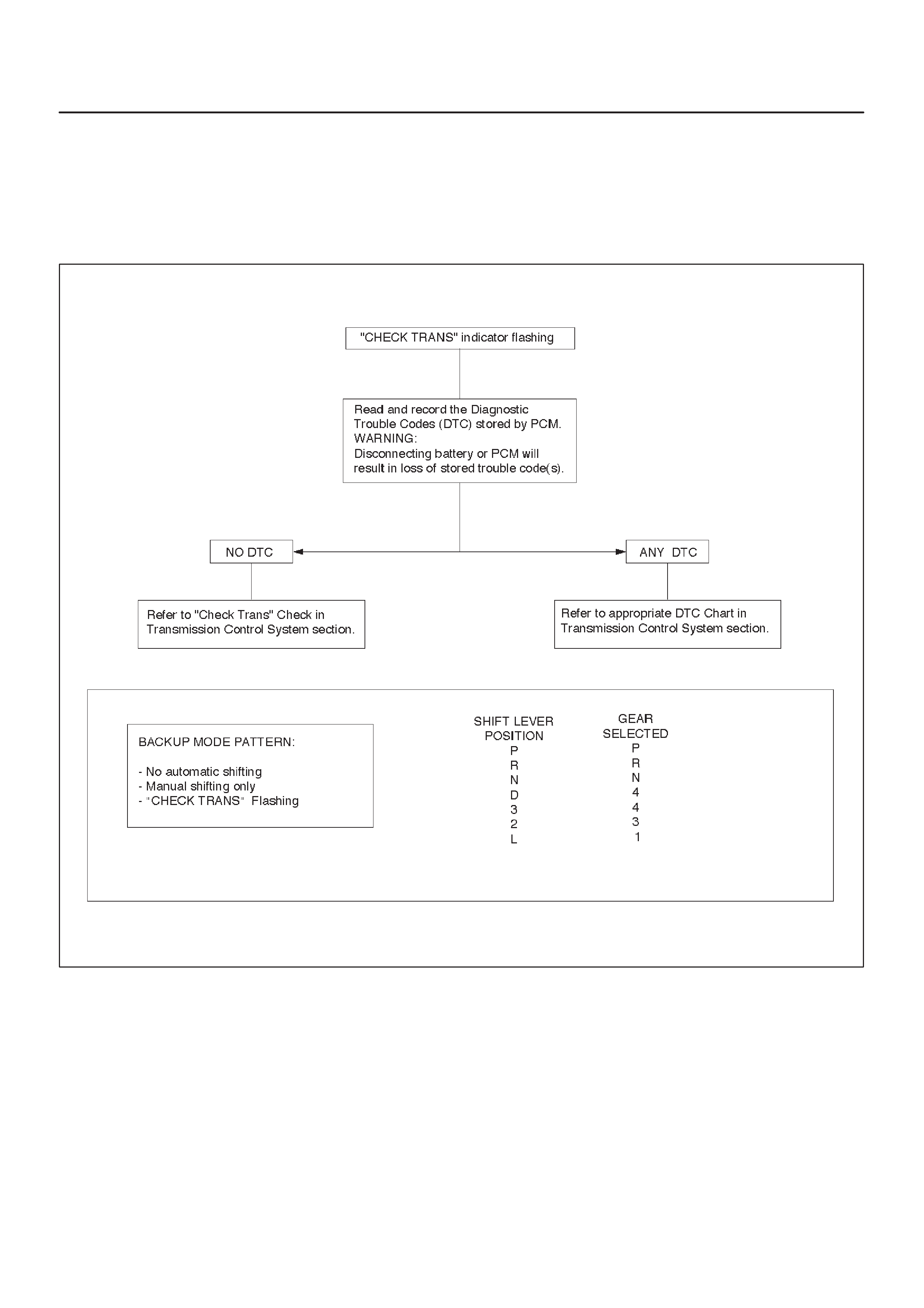
Mechanical / Hydraulic Diagnosis Check Trans Indicator Chart
Perform Preliminary Inspection First!
When the “CHECK TRANS” indicator is flashing, it
indicates that a problem related to the transmission, the
Powertrain Control Module (PCM), or the vehicle harness
has occurred.
The system is now operating in a “BACKUP MODE”
where the risk of further damaging the transmission has
been reduced. The vehicle may be shifted manually.
If the initial problem is intermittent or seldom, switching
the engine OFF/ON might allow normal operation again
until the problem reoccurs.
F07RT013

Mechanical / Hydraulic Diagnosis Symptoms Index
Perform Preliminary Inspection First!
CHART SYMPTOMS
1NO ENGINE START IN NEUTRAL OR PARK
2NO FORWARD GEARS IN ANY RANGE/NO REVERSE
3NO ENGINE BRAKE IN ANY RANGE
4POOR SHIFTING IN ALL GEARS (ALL HARSH OR ALL SOFT)
5a DELAYS IN DRIVE AND REVERSE
5b DELAYS IN REVERSE ONLY
6DIAGNOSTIC TROUBLE CODE (DTC) P0730
7HARSH 1–2 SHIFT
8HARSH 3–4 SHIFT
9a 3–2 DOWNSHIFT COMPLAINT
9b HARSH SHIFT WHEN SHIFTING INTO “D” OR ACCELERATING FROM STOP
9c COASTDOWN HARSH SHIFT OR CLUNK AT 3–2 DOWNSHIFT
10 INTERMITTENT 4TH TO 2ND GEAR DOWNSHIFT AT STEADY SPEED
11 ENGINE FLARE AT SHIFTING DURING TURNING ONLY (USUALLY WITH WARM ENGINE)
12 ENGINE FLARE DURING 1–2 OR 2–3 SHIFT
13 SHUDDER ONLY DURING TORQUE CONVERTER CLUTCH (TCC) APPLYING
14 POSSIBLE CAUSES OF TRANSMISSION NOISE
15a POSSIBLE CAUSES OF LOW LINE PRESSURE
15b POSSIBLE CAUSES OF HIGH LINE PRESSURE
16 POSSIBLE CAUSES OF TRANSMISSION FLUID LEAKS
NOTE:Numbers with parenthesis on the following charts
refer to Parts List at end of this section.
Chart 1: No Engine Start In Neutral Or Park
Step Action Yes No
1Does engine start when shift lever moved from drive to neutral
mostly in hot condition? Go to Step 2 Go to Step 3
2Does engine start in park at any condition? Re–test vehicle Go to Step 4
3Does engine also not start in neutral when shift lever moved from
park to neutral? Go to Step 4 Go to Step 5
4Check mode switch (63) setting. Readjust if necessary.
Problems fixed? Re–test vehicle Go to Step 5
5Check start circuit of mode switch (63) open in neutral.
Was open found? Locate and repair
open(s). Replace mode
switch (63).

Chart 2: No Forward Gears In Any Range/No Reverse
Step Action Yes No
1Check line pressure. Refer to Line Pressure Test in this section.
Was line pressure normal?
Go to Step 2
Use Chart 15a:
Possible Causes
of Low Line
Pressure in this
section.
21. Check internal linkage:
– Manual linkage (58) not moving manual valve (326).
2. Check for internal mechanical damage:
– Turbine shaft (506) broken loose.
– Overrun roller clutch (516) broken loose.
Was the problem found? Repair or replace —
Chart 3: No Engine Brake In Any Range
Step Action Yes No
1Check line pressure. Refer to Line Pressure Test in this section.
Was line pressure normal?
Go to Step 2
Use Chart 15a:
Possible Causes
of Low Line
Pressure in this
section.
21. Check for overrun clutch leaks caused by:
– Damaged piston lip (513)
– Check ball defective (504)
2. Check for overrun lockout valve (705) stuck by foreign
material.
3. Check for leaks at turbine shaft (506) caused by:
– Teflon seal rings damaged (508)
– Excessive wear of turbine shaft bearing surfaces.
Was the problem found? Repair or replace —

Chart 4: Poor Shifting In All Gears (All Harsh Or All Soft)
Step Action Yes No
1Check line pressure. Refer to Line Pressure Test in this section.
Was line pressure normal? Go to Step 2 Go to Step 3
21. Check for these conditions which could affect clutch apply
time:
– Defective band apply solenoid (323).
– Defective servo or/and accumulator piston.
– Excessive clutch piston travel.
2. Check of possible causes of internal leaks:
– Cut or damaged sealing ring(s)
– Damaged sealing gasket(s)
– Check ball missing or out of location in 2nd and 3rd clutch
pistons.
3. Check for causes of burned clutch plates or band.
Was the problem found? Repair or replace —
3Was the line pressure high?
Go to Step 4
Use Chart 15a:
Possible Causes
of Low Line
Pressure in this
section.
4Were DTCs P0560 and P0705 set?
Diagnose those
DTC(s) first.
Use Chart 15b:
Possible Causes
of High Line
Pressure in this
section.
Chart 5a: Delays In Drive and Reverse
NOTE: A short delay (less than 3 seconds) when first
engaging drive or reverse after allowing vehicle to sit
overnight is normal.
Step Action Yes No
1Check line pressure. Refer to Line Pressure Test in this section.
Was line pressure normal? More than 3
second delay in
drive and reverse
with engine off 1
hour or less.
Teflon seals (508)
on turbine shaft
damaged. Repair
Use Chart 15a:
Possible Causes
of Low Line
Pressure in this
section.
Chart 5b: Delays In Reverse Only
Step Action Yes No
1Check line pressure. Refer to Line Pressure Test in this section.
Was line pressure normal?
Go to Step 2
Use Chart 15a:
Possible Causes
of Low Line
Pressure in this
section.
2Main case valve body gasket (88) damaged.
– Reverse check ball (85) in valve body (84) missing or out of
location.
– Check for restrictions at valve body transfer plate orifice.
Was the problem found? Repair —

Chart 6: Diagnostic Trouble Code (DTC) P0730
Step Action Yes No
1Check line pressure. Refer to Line Pressure Test in this section.
Was line pressure normal?
Go to Step 2
Use Chart 15b:
Possible Causes
of High Line
Pressure in this
section.
21. 1st and 2nd gear missing or 3rd and 4th gear missing.
Check appropriate shift valve. If OK replace solenoid.
2. No engine brake in any range (All ranges in Drive and Reverse
are OK)
Check for suspected conditions modifying delays to clutch
apply:
– Overrun clutch seal damaged.
– Excessive overrun clutch piston travel.
– Defective 3–4 accumulator piston.
– Causes of internal leaks.
– Causes of burned clutch plates.
3. 1st and 4th gear missing or 2nd and 3rd gear missing.
Shift solenoid A stuck. Replace shift solenoid A.
4. DTC P0730 is set in D range 1st gear above 3500 rpm.
Go to Step 3.
5. DTC P0730 is set in D range 3rd gear between 55-80 mph.
NOTE: Perform this test within safe and legal limits.
Check for suspected conditions modifying delays to clutch
apply:
– 4th clutch seal damaged.
– Excessive 4th clutch piston travel.
– Defective 3–4 accumulator piston.
– Causes of internal leaks.
– Causes of burned clutch plates.
Was the problem found? Repair or replace —
3Check 3rd gear in “D” in winter mode.
Does vehicle move? Shift solenoid A
stuck. Replace
shift solenoid A. Go to Step 4
4Check for suspected conditions modifying delays to clutch apply:
– 2nd clutch seal damaged.
– Excessive 2nd clutch piston travel.
– Defective accumulator piston.
– Causes of internal leaks.
– Check ball missing or out of location in 2nd clutch.
– Seals cut, damaged or missing.
– Gaskets defective.
– Causes of burned clutch plates.
Was the problem found? Repair or replace —

Chart 7: Harsh 1–2 Shift
Step Action Yes No
1Check line pressure. Refer to Line Pressure Test in this section.
Was line pressure normal? Check for 1–2
accumulator
valve (320) stuck
by foreign
material in main
case valve body.
Use Chart 15b:
Possible Causes
of High Line
Pressure in this
section.
Chart 8: Harsh 3–4 Shift
Step Action Yes No
1Check line pressure. Refer to Line Pressure Test in this section.
Was line pressure normal?
Go to Step 2
Use Chart 15b:
Possible Causes
of High Line
Pressure in this
section.
21. Check for 3–4 accumulator valve (407) stuck in adapter case
valve body (401).
2. Check for 3–4 accumulator piston (18) stuck in adapter case
(20).
Was the problem found? Repair or replace —
Chart 9a: 3–2 Downshift Complaint
Step Action Yes No
1Check line pressure. Refer to Line Pressure Test in this section.
Was line pressure normal?
Go to Step 2
Use Chart 15a:
Possible Causes
of Low Line
Pressure in this
section.
2Does DTC P1850 set? Diagnose P1850
first.
Replace band
apply solenoid
(PWM) (323).
Chart 9b: Harsh Shift When Shifting Into “D” Or Accelerating From Stop
Step Action Yes No
1Check line pressure. Refer to Line Pressure Test in this section.
Was line pressure normal?
Go to Step 2
Use Chart 15b:
Possible Causes
of High Line
Pressure in this
section.
2Does DTC P1850 set? Diagnose P1850
first.
Replace band
apply solenoid
(PWM) (323).

Chart 9c: Coastdown Harsh Shift Or Clunk At 3–2 Downshift
Step Action Yes No
1Check line pressure. Refer to Line Pressure Test in this section.
Was line pressure normal?
Go to Step 2
Use Chart 15b:
Possible Causes
of High Line
Pressure in this
section.
2Does DTC P1850 set? Diagnose P1850
first.
Replace band
apply solenoid
(PWM) (323).
Chart 10: Intermittent 4TH TO 2ND Gear Downshift At Steady Speed
Step Action Yes No
1Check for consistent speed sensor reading with scan tool.
Was the reading correct? Replace mode
switch for
intermittent
contact. Go to Step 2
21. Check for wiring harness damage or short to ground. If OK, go
to (2).
2. Check transmission speed sensor connections. If OK, go to
(3).
3. Replace transmission speed sensor.
Was the replacement complete? —Replace speed
sensor.
Chart 11: Engine Flare At Shifting During Turning Only (Usually With Warm Engine)
Step Action Yes No
1Check for oil leaks at transmission.
Was the problem found? Replace
transmission oil
filter and gasket. —
Chart 12: Engine Flare During 1–2 Or 2–3 Shift
Step Action Yes No
1Check line pressure. Refer to Line Pressure Test in this section.
Was line pressure normal?
Go to Step 2
Use Chart 15a:
Possible Causes
of Low Line
Pressure in this
section.
21. Check for a stuck 1–2 accumulator valve (320).
2. Check for servo piston (106) leaks.
3. Check for a stuck band apply solenoid (323).
Was line pressure normal? Repair or replace —

Chart 13: Shudder Only During Torque Converter Clutch (TCC) Applying
Step Action YesNo
11.TCC shudder is one of the most commonly misdiagnosed
conditions in an automatic transmission. The key to
diagnosing TCC shudder is to note when it happens and under
what conditions. Once the TCC has been fully applied, it is
nearly impossible to make it shudder. TCC shudder (short
burst of noise normally less than 1 second) will only occur
during clutch applying. It is not a steady state condition.
2.Drive until whole drivetrain is at normal operating temperature.
–On 4WD vehicles, the test must be performed with transfer
case selector lever in “2H” position.
–Shudder is a short burst of noise normally less than 1 second
in duration, and can be induced by the following maneuver:
3.From coast condition at 50 mph in “D” range (Normal mode),
depress the throttle to 1/4-1/3 throttle. If present, shudder will
occur within 5 seconds together with TCC application.(The
scan tool may be used to determine the exact time of TCC).
Was the problem found?
Replace
transmission fluid
and filter (remove
both pans) and
flush cooler lines.
Replace
converter
assembly and
O-ring on turbine
shaft
Perform
mechanical
inspection of
other drivetrain
components.
Chart 14: Possible Causes of Transmission Noise
CAUTION:Before checking transmission for what
is believed to be transmission noise, ensure
presence and positioning of insulating plugs, pads
etc. Also make sure that noise does not come from
other drivetrain components.
Condition Possible cause Correction
Whine or Buzz Oil level low Fill with ATF, check for external
leaks.
Plugged or restricted oil filter Inspect oil filter.
Replace oil filter or ATF as necessary.
Damaged oil filter gasket Replace oil filter gasket.
Knocking noise from front of
transmission
Loose bolts (Converter to flex plate) Tighten to specifications.
t
ransm
i
ss
i
on. Cracked or broken flex plate Replace flex plate.
Converter damaged Replace converter.
Knocking noise while driving, mostly
on acceleration. T ransmission mount loose or broken Tighten mount bolts or replace
transmission mount.
Cooler line mounts loose or broken Tighten or replace cooler line
mounts.
Cooler lines touching body or frame Repair or replace as necessary.
Knocking noise when vehicle is
stationary
Loose flex plate mounting bolts Tighten to specifications.
s
t
a
ti
onary. Cracked or broken flex plate Replace flex plate.
Damaged converter Replace converter.

Chart 15a: Possible Causes of Low Line Pressure
Step Action Yes No
1Check oil level.
Was the problem found? Fill with ATF. Go to Step 2
2Check for defective throttle position sensor.
Was the problem found? Replace throttle
position sensor. Go to Step 3
3Check for plugged, loose, or damaged oil filter (79).
Was the problem found? Inspect oil filter,
tighten bolts or
replace oil filter
(79). Go to Step 4
4Check for a stuck force motor plunger (404). (Adapter case valve
body)
Was the problem found?
Replace force
motor plunger
(404). Go to Step 5
5Check for a stuck feed limit valve (412). (Adapter case valve body)
Was the problem found? Replace feed limit
valve (412). Go to Step 6
6Check for loose converter bolts (4 & 5).
Was the problem found? Tighten converter
bolts (4 & 5). Go to Step 7
7Check for a stuck pressure regulator valve (208). (Oil pump)
Was the problem found? Replace pressure
regulator valve
(208). Go to Step 8
8Check for a stuck boost valve (205). (Oil pump)
Was the problem found? Replace boost
valve (205). Go to Step 9
9Check for blocked intermediate oil passages to pressure
regulator valve. (Oil pump)
Was the problem found? Replace oil
pump. Go to Step 10
10 Check for defective oil pump (9, 201, 202 & 209).
Was the problem found? Replace oil
pump. Go to Step 11
11 Check for internal leaks.
– Check balls missing or out of location in valve bodies
– Seals cut or damaged
– Gaskets defective, etc.
Was the problem found?
Install balls, or
correct ball
location.
Replace seals.
Replace gaskets. —

Chart 15b: Possible Causes of High Line Pressure
NOTE: If transmission is operating in backup mode, high
line pressure will be present.
Step Action Yes No
1Check for defective throttle position sensor.
Was the problem found? Replace throttle
position sensor. Go to Step 2
2Check for a stuck force motor plunger (404). (Open
circuit/intermittent) (Adapter case valve body)
Was the problem found?
Replace force
motor plunger
(404). Go to Step 3
3Check for a stuck feed limit valve (412). (Adapter case valve body)
Was the problem found? Replace feed limit
valve (412). Go to Step 4
4Check converter bolts (4 & 5).
Was the problem found? Tighten converter
bolts (4 & 5). Go to Step 5
5Check for a stuck pressure regulator valve (208). (Oil pump)
Was the problem found? Replace pressure
regulator valve
(208). Go to Step 6
6Check for a stuck boost valve (205). (Oil pump)
Was the problem found? Replace boost
valve (205). Go to Step 7
7Check for internal leaks.
– Check balls missing or out of location in valve bodies
– Seals cut or missing
– Gaskets defective, etc.
Was the problem found?
Install balls, or
correct ball
location.
Replace seals.
Replace gaskets. —
Chart 16: Possible Causes of
Transmission Fluid Leaks
Before attempting to correct an oil leak, the actual source
of the leak must be determined. In many cases, the
source of the leak may be difficult to determine due to
“wind flow” around the engine and transmission.
The suspected area should be wiped clean before in-
specting for the source of the leak.
Oil leaks around the engine and transmission are gener-
ally carried toward the rear of the vehicle by the air
stream. In determining the source of an oil leak, the fol-
lowing two checks should be made:
1.With the engine running, check for external line
pressure leaks.
2. With the engine off, check for oil leaks due to the
raised oil level caused by drainback of converter oil
into the transmission.
Possible Causes of Fluid Leaks Due To Sealing Malfunction
240RX008
Legend
(1) Electrical Connector (Main Case) Seal
(2) Transmission Vent (Breather)
(3) Speed Sensor O–ring
(4) Extension (Adapter) Lip Seal
(5) Extension (Adapter) to Main Case Gasket
(6) Overfill and Oil Drain Screws Gasket
(7) Oil Pan Gasket (Main Case)
(8) Selector Shaft Seal
(9) Oil Cooler Connectors (2)
(10) Oil Pan Gasket (Adapter Case)
(11) Converter housing attaching bolts not correctly
torqued
(12) Converter Housing Lip Seal
(13) Line Pressure Tap Plug
(14) Electrical Connector (Adapter Case) Seal
(15) Adapter Case Seal Rings (2)
Stall Test
The stall test allows you to check the transmission for
internal abrasion and the one way clutch for slippage.
Torque converter performance can also be evaluated.
The stall test results together with the road test results will
identify transmission components requiring servicing or
adjustment.
Stall Test Procedure:
1.Check the level of the engine coolant, the engine oil,
and the automatic transmission fluid. Replenish if
necessary.
2.Block the wheels and set the parking brake.
3.Connect a tachometer to the engine.
4.Start the engine and allow it to idle until the engine
coolant temperature reaches 70 – 80°C (158 –
176°F).
5.Hold the brake pedal down as far as it will go.
6.Place the selector in the “D” range.
7.Gradually push the accelerator pedal to the floor.
The throttle valve will be fully open.
Note the engine speed at which the tachometer
needle stabilizes.
Stall Speed : 2,200 ±150 rpm
NOTE: Do not continuously run this test longer than 5
seconds.
8.Release the accelerator pedal.
9.Place the selector in the “N” range.
10.Run the engine at 1,200 rpm for one minute.
This will cool the transmission fluid.
11.Repeat Steps 7 – 10 for the “3”, “2”, “L” and “R”
ranges.
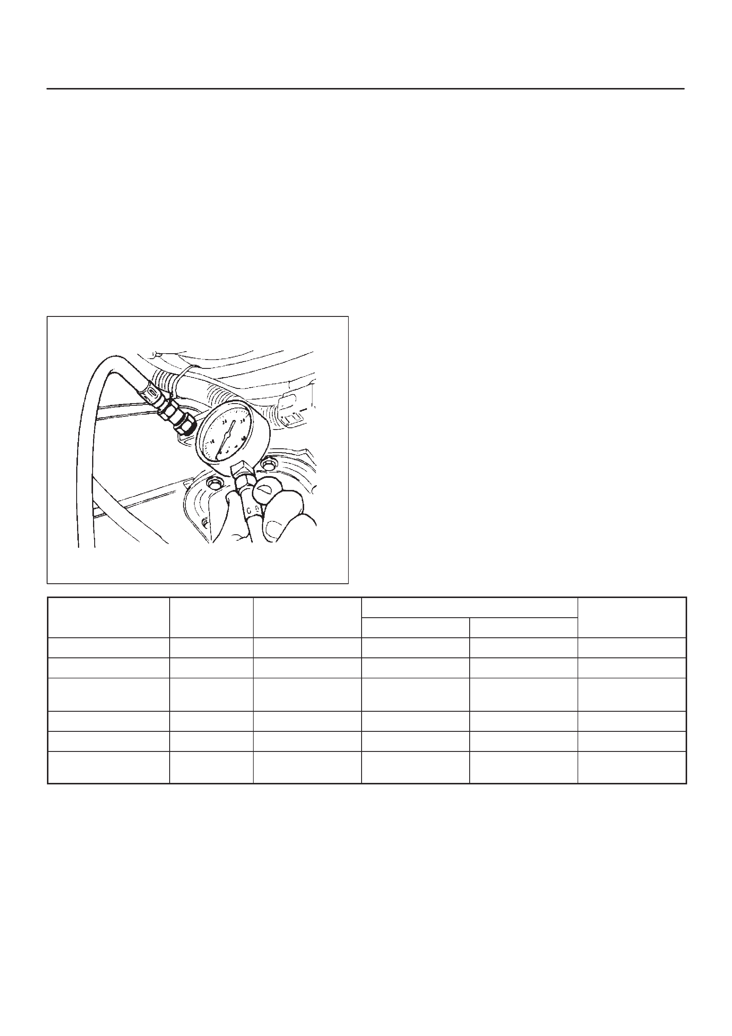
Line Pressure Test
The line pressure test checks oil pump and control valve
pressure regulator valve function. It will also detect oil
leakage.
Line Pressure Test Procedure:
1.Check the level of the engine coolant, the engine oil,
and the automatic transmission fluid.
Replenish if required.
2.Block the wheels and set the parking brake.
3.Remove the pressure detection plug at the left side of
the transmission case.
Set J–29770–A pressure gauge and adapter to the
pressure detection plug hole.
241RS001
4.Start the engine and allow it to idle until the engine
coolant temperature reaches 70 – 80°C (158 –
176°F).
5.Hold the brake pedal down as far as it will go.
6.Place the selector in the “D” range.
7.Note the pressure gauge reading with the engine
idling.
8.Gradually push the accelerator pedal to the floor . The
throttle valve will be fully open.
Note the pressure gauge reading with the accelerator
pedal fully depressed.
NOTE: Do not continuously run this test longer than 5
seconds.
9.Release the accelerator pedal.
10.Place the selector in the “N” range.
11.Run the engine at 1,200 rpm for one minute.
This will cool the transmission fluid.
12.Repeat Steps 7 – 11 for the “3”, “2”, “L”, and “R”
ranges.
13.Install a pressure detection plug to the transmission
case, applying recommended thread locking agent
(LOCTITE 242) or its equivalent to thread of plug.
Make sure that thread is cleaned before applying
locking agents.
14.Tighten the pressure detection plug to the specified
torque.
Torque: 9 – 14N·m (7 – 10lb ft)
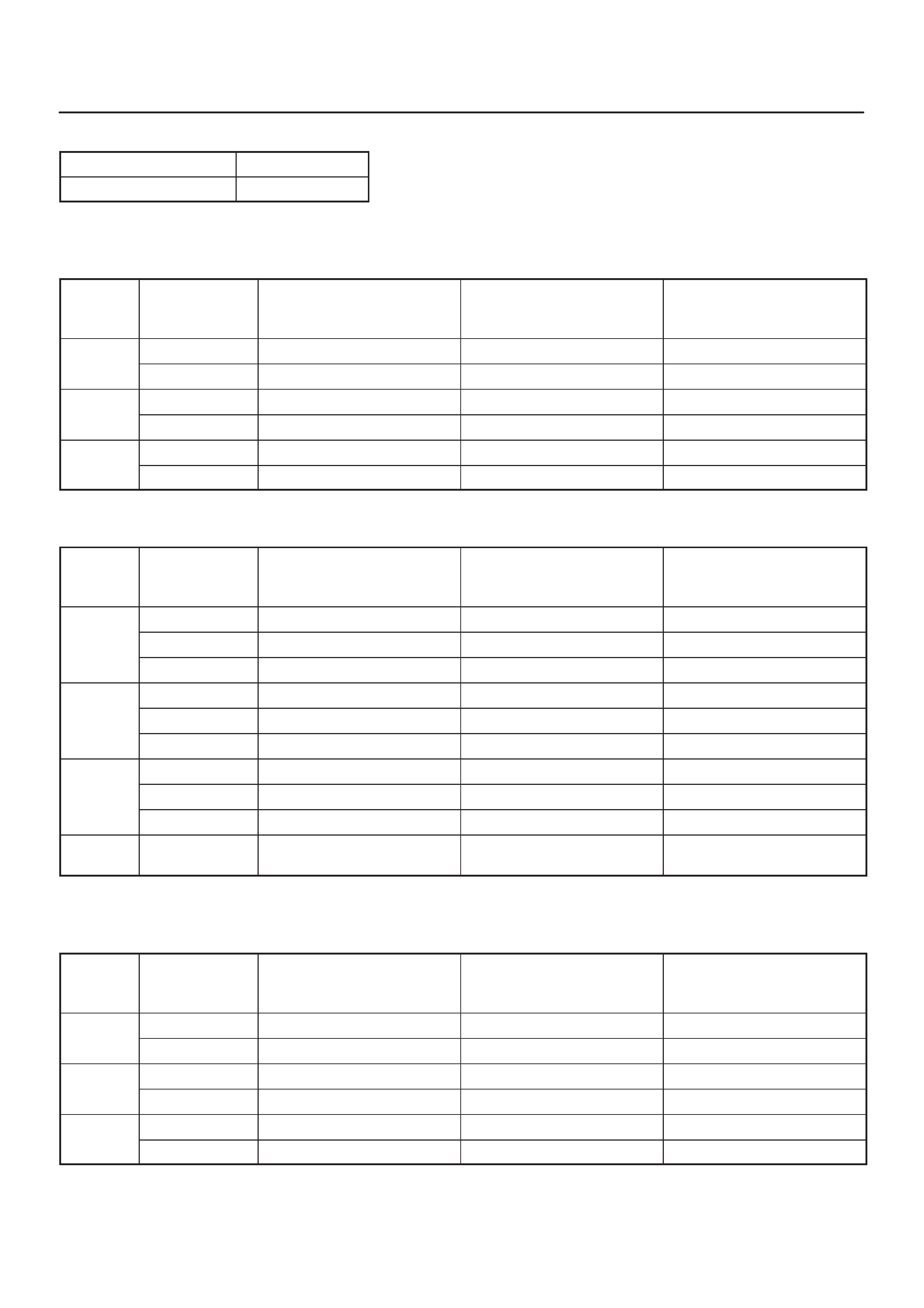
MODE
LEVER
ENGINE SPEED
LINE PRESSURE FORCE MOTOR
MODE
POSITION
ENGINE
SPEED
kPa PSI CURRENT
NORMAL/POWER D,3,2,L IDLE 312–363 45.2–52.6 VARIABLE
WINTER D IDLE 312 – 363 45.2 – 52.6 0.9 – 1.0A
NORMAL/POWER
WINTER REVERSE IDLE 419 – 486 60.7 – 70.5 0.9 – 1.0A
NORMAL/POWER D, 3, 2, L STALL SPEED 1,236 – 1320 179.3 – 191.4 0.1 – 0.2A
WINTER DSTALL SPEED 1,236 – 1320 179.3 – 191.4 0.1 – 0.2A
NORMAL/POWER
WINTER REVERSE STALL SPEED 1,634 – 1743 236.9 – 252.8 0.1 – 0.2A
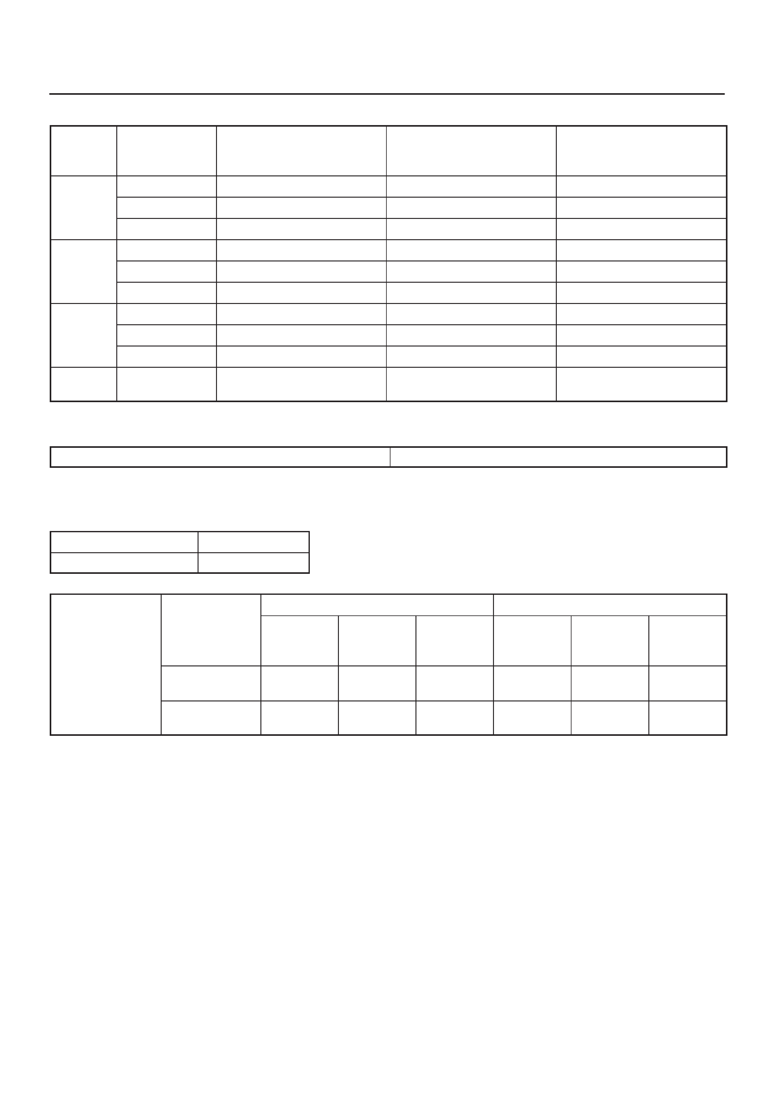
Shift Speed Chart
Transfer gear ratio High: 1.000
Rear axle ratio 4.100
“Normal mode”
Upshift
Range Throttle
opening 1 → 2
(First Gear) (Second Gear)
km/h (mph)
2 → 3
(Second Gear) (Third Gear)
km/h (mph)
3 → 4
(Third Gear) (Fourth Gear)
km/h (mph)
DFully opened 52 ∼ 58 (33 ∼ 36) 105 ∼ 111 (66 ∼ 69) 158 ∼ 164 (99 ∼ 102)
(Drive) Half throttle 33 ∼ 39 (21 ∼ 24) 60 ∼ 66 (37 ∼ 41) 100 ∼ 106 (62 ∼ 66)
3Fully opened 52 ∼ 58 (33 ∼ 36) 105 ∼ 111 (66 ∼ 69) —
(Third) Half throttle 33 ∼ 39 (21 ∼ 24) 60 ∼ 66 (37 ∼ 41) —
2Fully opened 52 ∼ 58 (33 ∼ 36) — —
(Second) Half throttle 33 ∼ 39 (21 ∼ 24) — —
Downshift
Range Throttle
opening 1 ← 2
(First Gear) (Second Gear)
km/h (mph)
2 ← 3
(Second Gear) (Third Gear)
km/h (mph)
3 ← 4
(Third Gear) (Fourth Gear)
km/h (mph)
D
Fully opened 42 ∼ 48 (26 ∼ 30) 93 ∼ 99 (58 ∼ 62) 149 ∼ 155 (93 ∼ 97)
D
(Drive)
Half throttle 16 ∼ 22 (10 ∼ 14) 35 ∼ 42 (22 ∼ 26) 70 ∼ 76 (43 ∼ 47)
(Drive)
Fully closed 13 ∼ 20 (8 ∼ 12) 16 ∼ 22 (10 ∼ 14) 28 ∼ 34 (17 ∼ 21)
3
Fully opened 42 ∼ 48 (26 ∼ 30) 93 ∼ 99 (58 ∼ 62) —
3
(Third)
Half throttle 16 ∼ 22 (10 ∼ 14) 35 ∼ 42 (22 ∼ 26) —
(Third)
Fully closed 13 ∼ 20 (8 ∼ 12) 16 ∼ 22 (10 ∼ 14) —
2
Fully opened 43 ∼ 49 (27 ∼ 31) 101 ∼ 107 (63 ∼ 67) —
2
(Second)
Half throttle 16 ∼ 22 (9 ∼ 13) 98 ∼ 104 (61 ∼ 65) —
(Second)
Fully closed 13 ∼ 20 (8 ∼ 12) 85 ∼ 91 (53 ∼ 57) —
L
(First) — 53 ∼ 59 (33 ∼ 37) — —
“Power mode”
Upshift
Range Throttle
opening 1 → 2
(First Gear) (Second Gear)
km/h (mph)
2 → 3
(Second Gear) (Third Gear)
km/h (mph)
3 → 4
(Third Gear) (Fourth Gear)
km/h (mph)
DFully opened 52 ∼ 58 (33 ∼ 36) 105 ∼ 111 (66 ∼ 69) 180 ∼ 186 (113 ∼ 116)
(Drive) Half throttle 38 ∼ 45 (24 ∼ 28) 77 ∼ 83 (48 ∼ 52) 129 ∼ 133 (80 ∼ 84)
3Fully opened 52 ∼ 58 (33 ∼ 36) 105 ∼ 111 (66 ∼ 69) —
(Third) Half throttle 38 ∼ 45 (24 ∼ 28) 77 ∼ 83 (48 ∼ 52) —
2Fully opened 52 ∼ 58 (33 ∼ 36) — —
(Second) Half throttle 38 ∼ 45 (24 ∼ 28) — —
Downshift
Range Throttle
opening 1 ← 2
(First Gear) (Second Gear)
km/h (mph)
2 ← 3
(Second Gear) (Third Gear)
km/h (mph)
3 ← 4
(Third Gear) (Fourth Gear)
km/h (mph)
D
Fully opened 43 ∼ 49 (27 ∼ 31) 96 ∼ 102 (60 ∼ 64) 170 ∼ 176 (106 ∼ 110)
D
(Drive)
Half throttle 22 ∼ 28 (14 ∼ 17) 55 ∼ 61 (34 ∼ 38) 102 ∼ 108 (63 ∼ 67)
(Drive)
Fully closed 13 ∼ 20 (8 ∼ 12) 25 ∼ 31 (16 ∼ 19) 48 ∼ 54 (30 ∼ 33)
3
Fully opened 43 ∼ 49 (27 ∼ 31) 96 ∼ 102 (60 ∼ 64) —
3
(Third)
Half throttle 22 ∼ 28 (14 ∼ 17) 55 ∼ 61 (34 ∼ 38) —
(Third)
Fully closed 13 ∼ 20 (8 ∼ 12) 25 ∼ 31 (16 ∼ 19) —
2
Fully opened 43 ∼ 49 (27 ∼ 31) 101 ∼ 107 (63 ∼ 67) —
2
(Second)
Half throttle 22 ∼ 28 (14 ∼ 17) 98 ∼ 104 (61 ∼ 65) —
(Second)
Fully closed 13 ∼ 20 (8 ∼ 12) 85 ∼ 91 (53 ∼ 57) —
L
(First) — 53 ∼ 59 (33 ∼ 37) — —
“Winter mode”
D range, winter mode ON → OFF 32 ∼ 38 km/h (20 ∼ 24 mph)
Lockup Speed Chart
Transfer gear ratio High: 1.000
Rear axle ratio 4.100
Lockup ON Lockup OFF
D range,
Throttle o
p
ening
Mode 2nd
km/h
(mph)
3rd
km/h
(mph)
4th
km/h
(mph)
2nd
km/h
(mph)
3rd
km/h
(mph)
4th
km/h
(mph)
Throttle
o ening
6% Normal 79 ∼ 85
(49 ∼ 53) 58 ∼ 64
(36 ∼ 40) 69 ∼ 75
(43 ∼ 47) 74 ∼ 80
(46 ∼ 50) 49 ∼ 55
(30 ∼ 34) 65 ∼ 71
(40 ∼ 44)
Power 79 ∼ 85
(49 ∼ 53) 84 ∼ 90
(52 ∼ 56) 84 ∼ 90
(52 ∼ 56) 74 ∼ 80
(46 ∼ 50) 76 ∼ 82
(47 ∼ 51) 81 ∼ 87
(50 ∼ 54)
Changing Transmission Fluid
There is no need to change the transmission fluid unless
the transmission is used under one or more of the
following heavy duty conditions.
A.Repeated short trips
B.Driving on rough roads
C.Driving on dusty roads
D.Towing a trailer
If the vehicle is used under these conditions, change the
fluid every 20,000 miles (32,000 km.)
More over, the remaining life percentage of ATF can be
estimated by using Tech 2 as an auxiliary tool to judge the
right time for ATF replacement.
The remaining life percentage is calculated from ATF’S
heat history. When it is close to 0%, ATF replacement is
recommended.
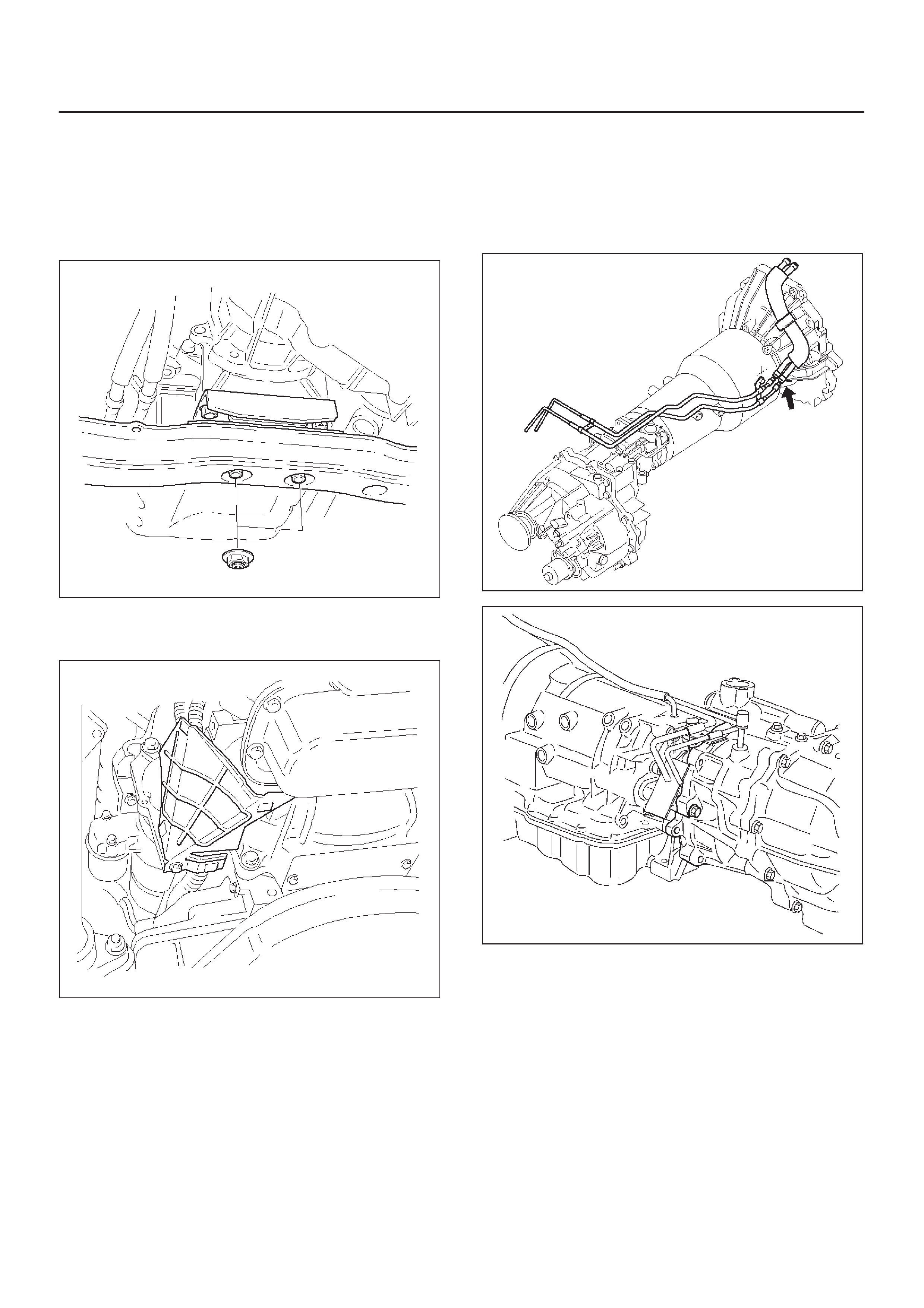
1.Place a large drain pan under the oil pan.
2.Remove the transmission oil drain screw (2) and drain
fluid.
3.Tighten drain screw (2).
Torque: 38N•m (28lbft)
4.Remove the transmission overfill screw (1) and fill
transmission through overfill screw opening, using
DEXRON–III ATF.
NOTE:Add transmission fluid until it flows out over the
overfill screw opening.
5.Let engine idle until a fluid temperature between 32°C
(90°F) and 57°C (135°F) is reached.
6.Add transmission fluid until it flows out over the overfill
screw opening, then close the overfill screw (1).
Torque: 38N•m (28lbft)
NOTE:To prevent fluid leaks, the overfill screw and oil
drain screws gasket must be replaced each time these
screws are removed.
NOTE:Check transmission fluid temperature with scan
tool.
7.Reset “Oil Life Monitor” data by using Tech 2.
Refer to Tech 2 OBD II Connection in Transmission
Control System (4L30-E) section.
242RW003
Selector Lever
Inspection
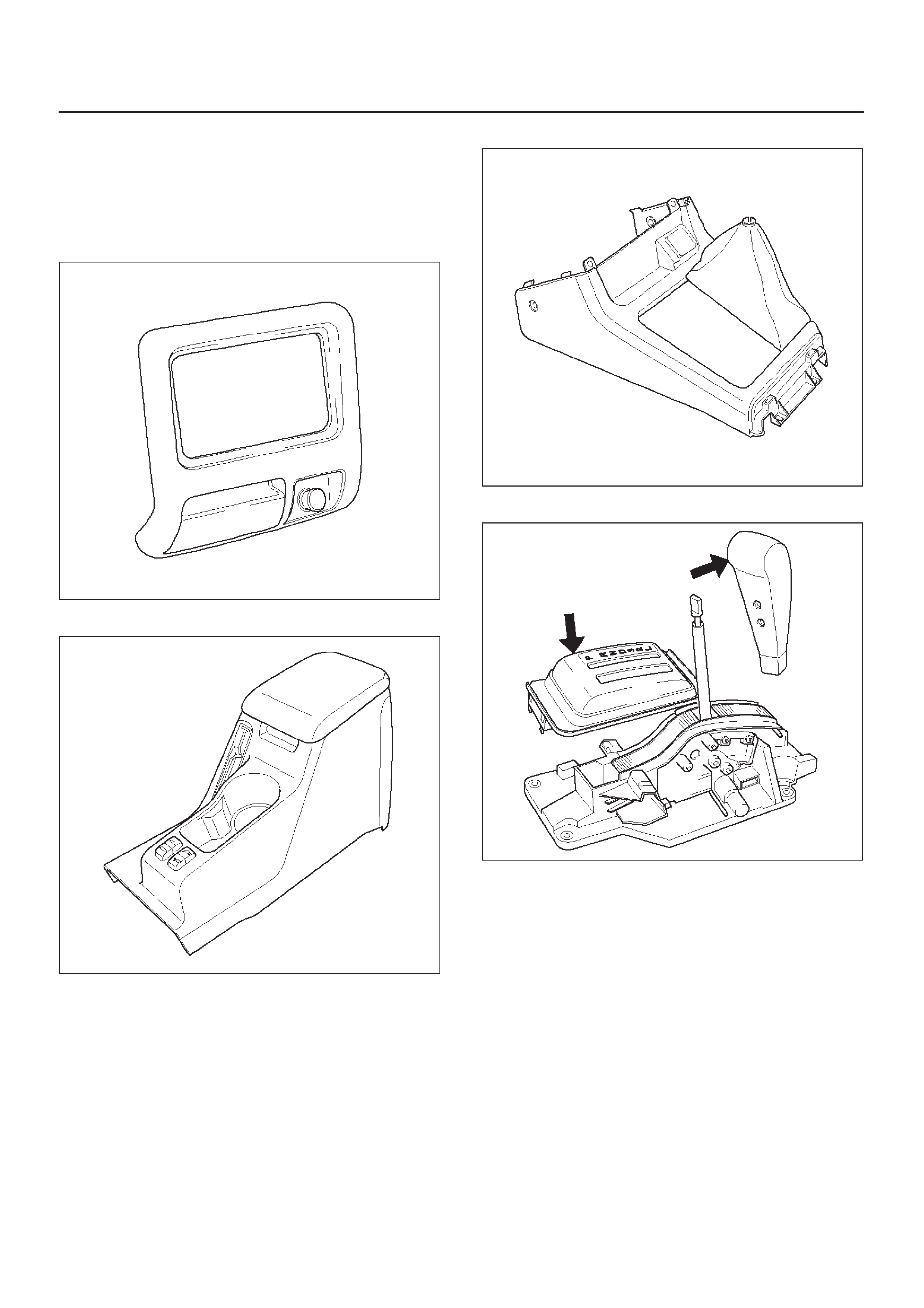
1.Make sure that when the selector lever is shifted from
“P” to “L”, a “clicking” can be felt at each shift position.
Make sure that the gear corresponds to that of the
position plate indicator.
2.Check to see if the selector lever can be shifted as
shown in illustration.
C07RW009
Removal
1.Disconnect battery ground cable.
2.Set ignition Key in “LOCK” position and selector lever
in ”P” position.
3.Remove transfer control lever knob.
4.Remove lower cluster assembly.
740RW021
5.Remove rear console.
745RW011
6.Remove center console.
256RW006
7.Remove selector lever knob and cover.
256RW043
8.Disconnect select cable.
DRefer to Select Cable in this section.
9.Disconnect shift lock cable.
DRefer to Shift Lock Cable in this section.
10.Disconnect harness connector.
11.Remove selector lever subassembly.
256RW044
Installation
1.Install selector lever subassembly.
2.Connect harness connector.
3.Connect shift lock cable.
DRefer to Shift Lock Cable in this section.
4.Connect select cable.
DRefer to Select Cable in this section.
5.Install selector lever knob and cover.
256RW043
6.Install center console.
7.Install rear console.
8.Install lower cluster assembly.
9.Install transfer control lever knob.
10.Connect negative (–) battery cable.
11.After installation, make sure that the selector lever
operates normally, and that each selector position is
properly indicated. (The red mark shows through the
window.)
Select Cable
Removal
1.Set selector lever in “P” position.
2.Remove transfer control lever knob, lower cluster
assembly, rear console, center console, selector
lever knob and cover.
DRefer to Selector Lever in this section.
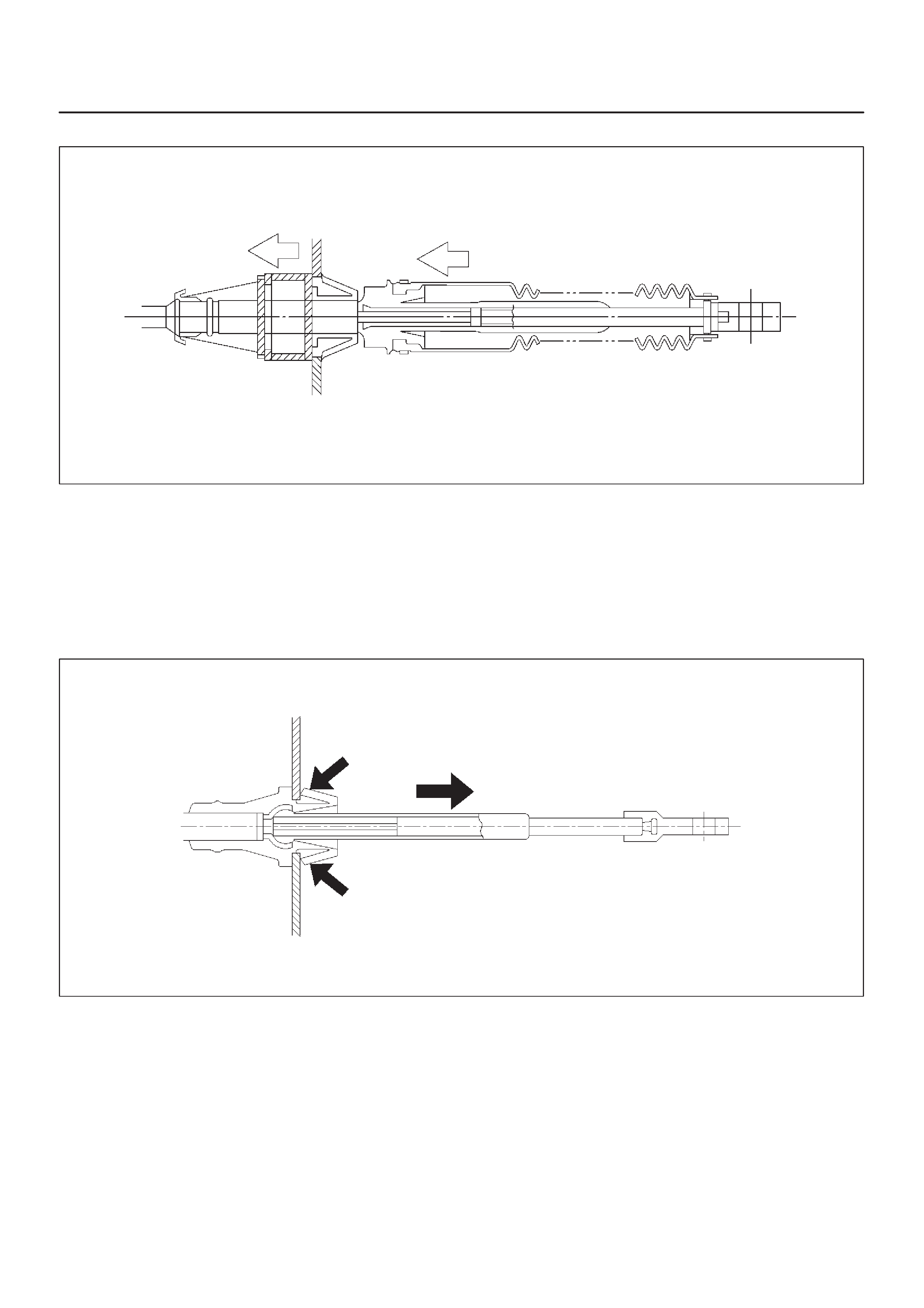
3.Disconnect inner cable by pulling projection on pin.
256RW022
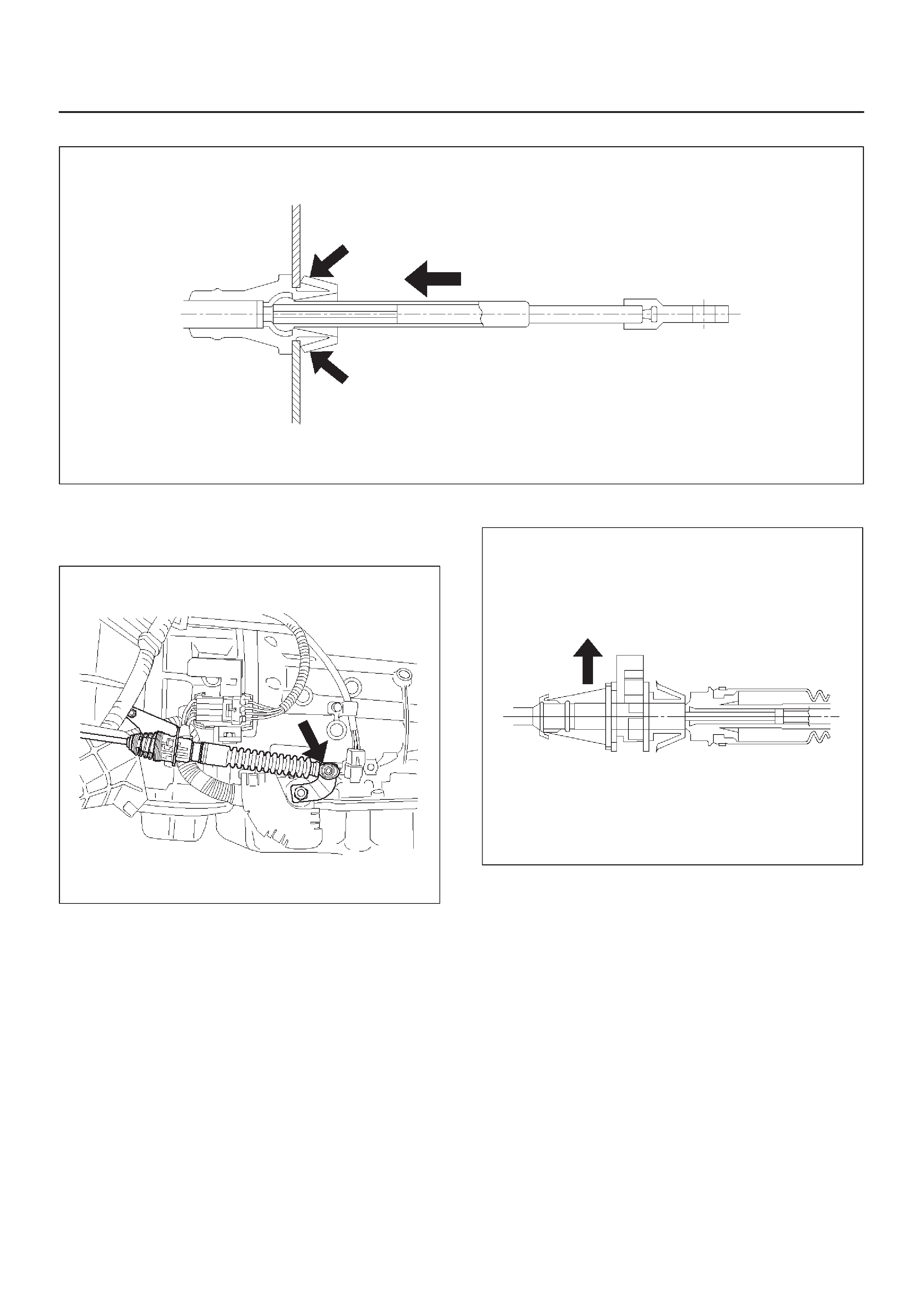
4.Press down claws and disconnect cable assembly.
A07RW017
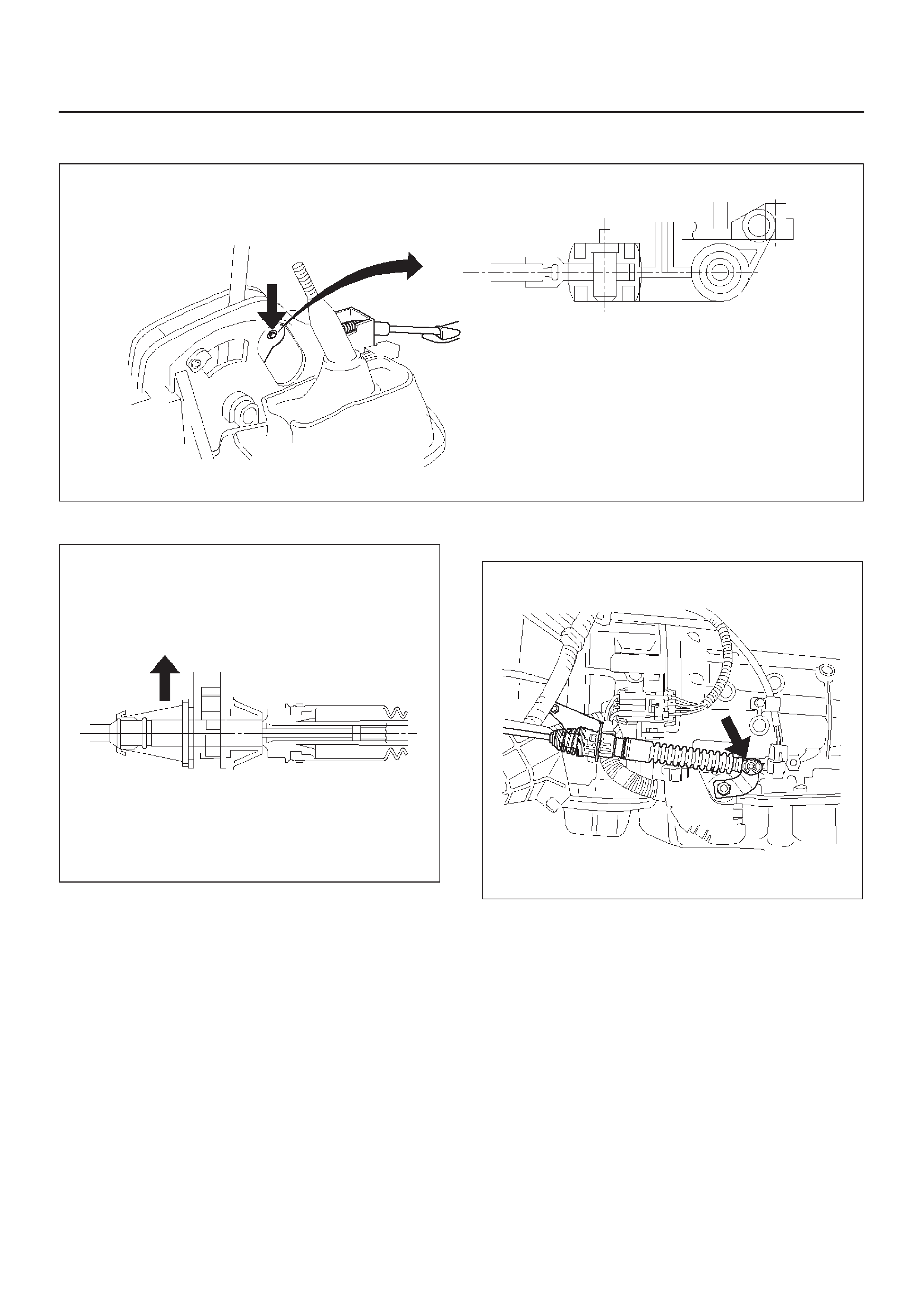
5.Disconnect PCM harness connectors and remove
nuts that fasten grommet in select cable assembly.
6.Disconnect inner cable.
210RW013
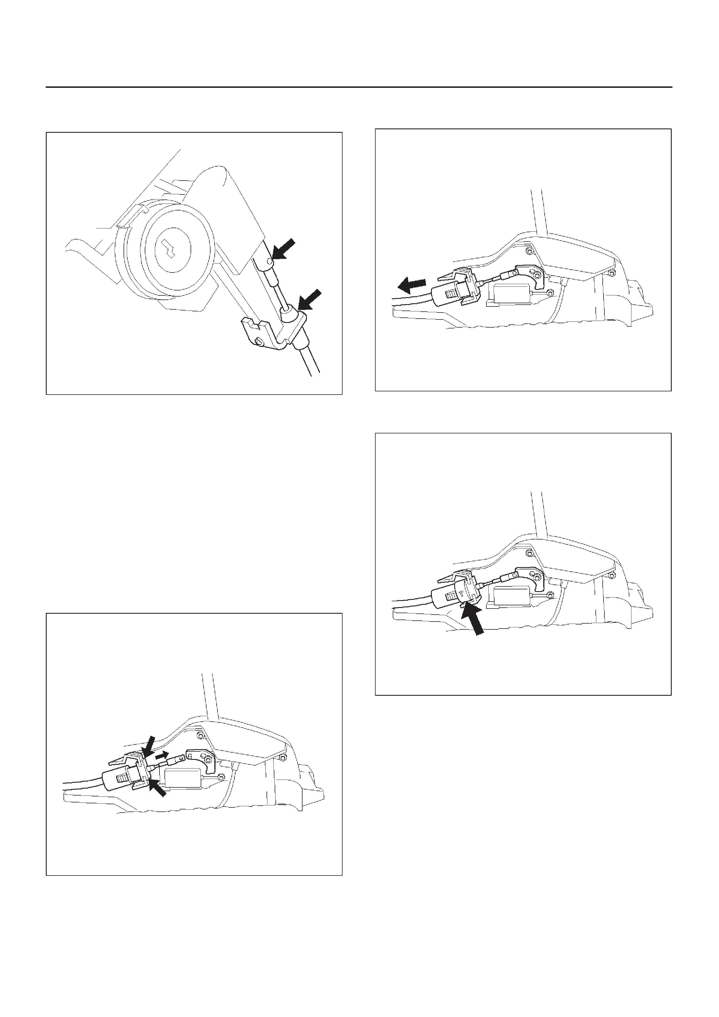
7.Pull lock.
A07RW015
8.Slide sleeve and disconnect cable assembly.
A07RW082
9.Draw select cable assembly into the interior side.
Installation
1.Set selector lever in “P” position.
2.Let out select cable transmission side end from floor
hole.
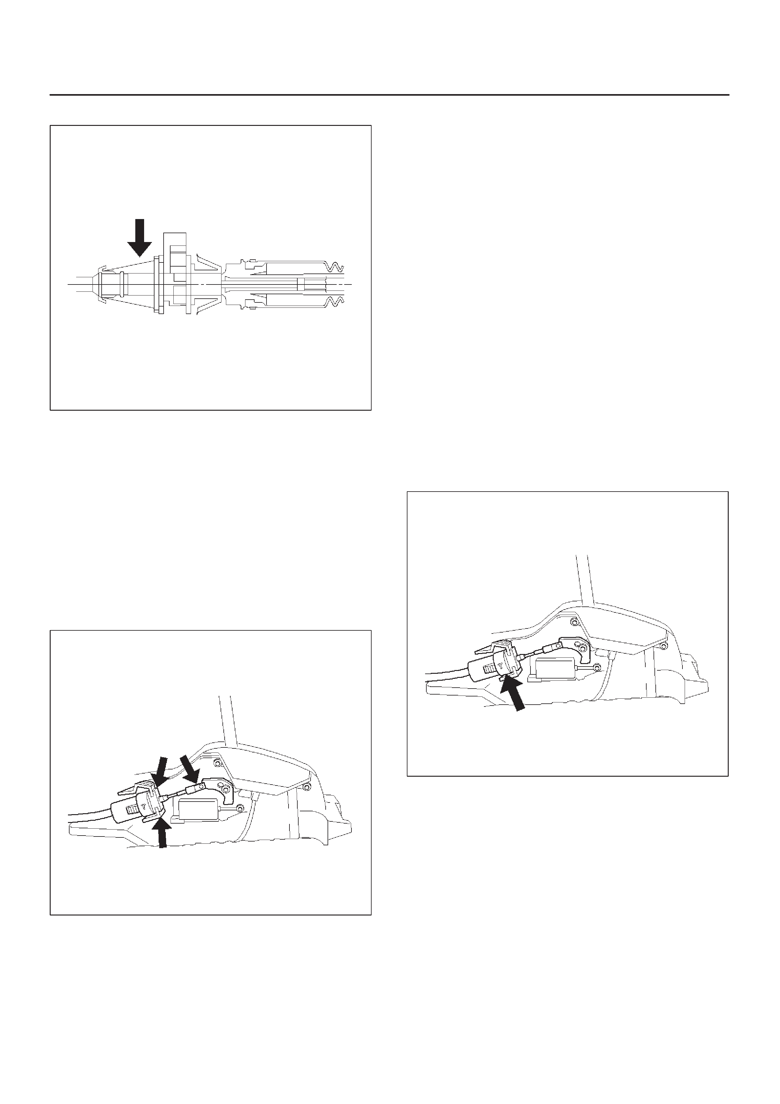
3.Fit outer cable into bracket in selector lever assembly .
A07RW016
4.Set inner cable end in selector lever and push pin into
selector lever hole and inner cable end.
256RW023
5.Check that lock projects.
A07RW015
6.Connect adjust end fitting attachment to the bracket
on transmission.
7.Set selector lever “P” position and connect inner
cable to selector lever.
210RW013
8.Push lock into adjust end fitting attachment.
A07RW014
9.Install grommet.
10.About following installation steps, refer to Selector
Lever in this section.
Shift Lock Cable
Removal
1.Set ignition key in “LOCK” position and selector lever
in “P” position.
2.Remove transfer control lever knob, lower cluster
assembly, rear console, center console, selector
lever knob and cover.
DRefer to Selector Lever in this section.
3.Disconnect inner cable from selector lever assembly
then push claw and disconnect cable assembly.
256RW016
4.Disconnect lock adjust.
256RW017
5.Remove instrument panel lower cover and steering
column cover.
6.Remove spring pin and disconnect inner cable.
DDisconnect outer cable from bracket.
256RW008
Installation
1.Set ignition key in “LOCK” position and selector lever
in “P” position.
2.Connect outer cable to bracket near steering lock.
DConnect inner cable to steering lock and install
spring pin.
3.Install steering column cover and instrument lower
cover.
4.Install adjust body of cable assembly to bracket in
selector lever assembly.
DInstall inner cable to lever, pulling inner cable with
outer cable.
256RW018
5.Check that cable moves smoothly, lightly pulling outer
cable rearward.
256RW019
6.Connect lock adjust, aligning “T” mark in the “Up”
position.
256RW017
7.About following installation steps, refer to Selector
Lever in this section.
8.Check the shift lock operation:
a. Selector lever should not be moved out of “P”
position with ignition key in “Lock” position.
b. Selector lever can be moved out of “P” position with
ignition key in “ON”position only when brake pedal
is depressed.
c. ignition key can be turned to “LOCK” position only
when selector lever is in “P” position (key can be
pulled out).
9. If a. and c. fail, readjust cable. If b. fails, readjust
connector wiring and brake pedal switch.
Mode Switch
Removal
1.Place selector lever in neutral.
2.Disconnect battery ground cable.
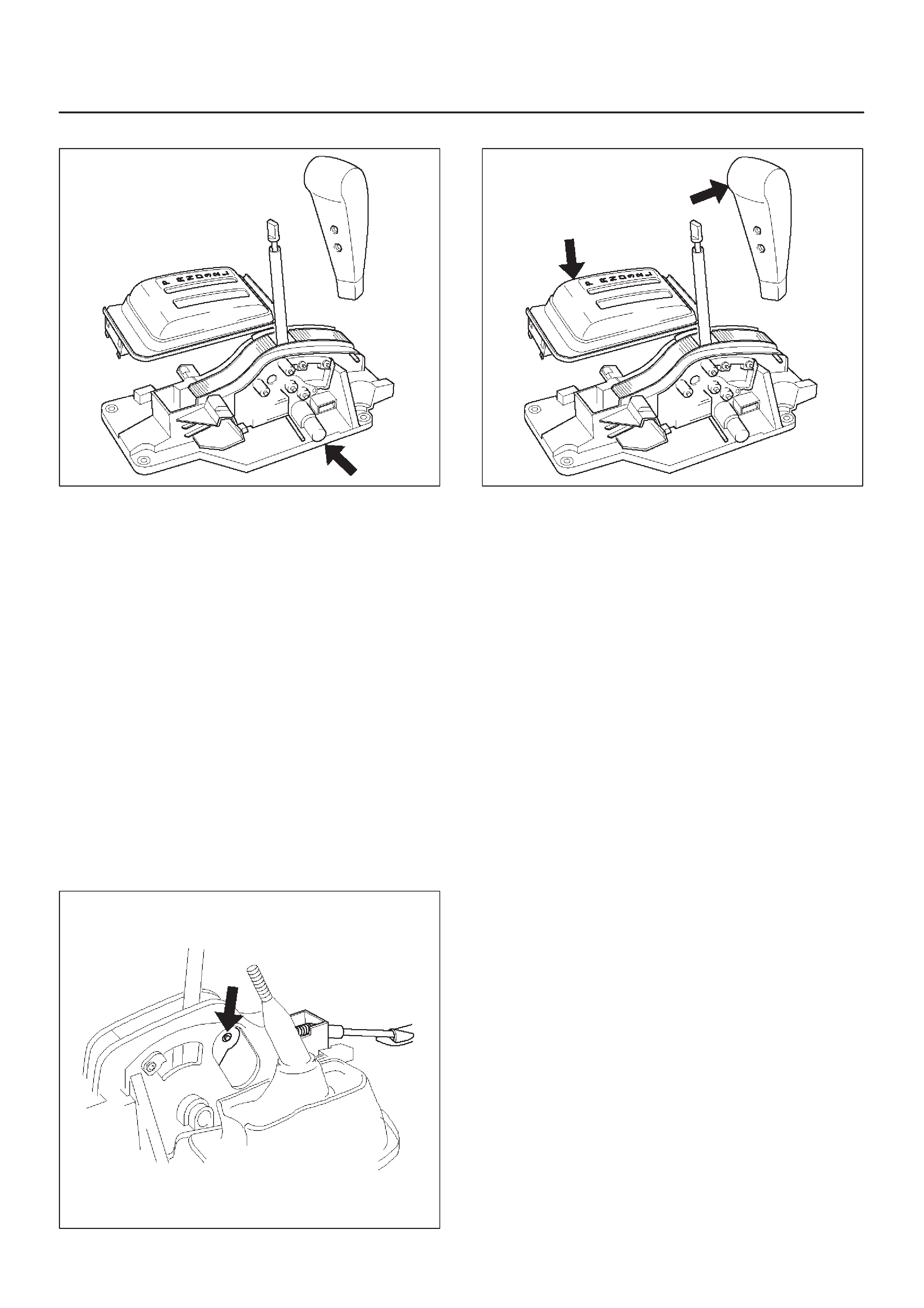
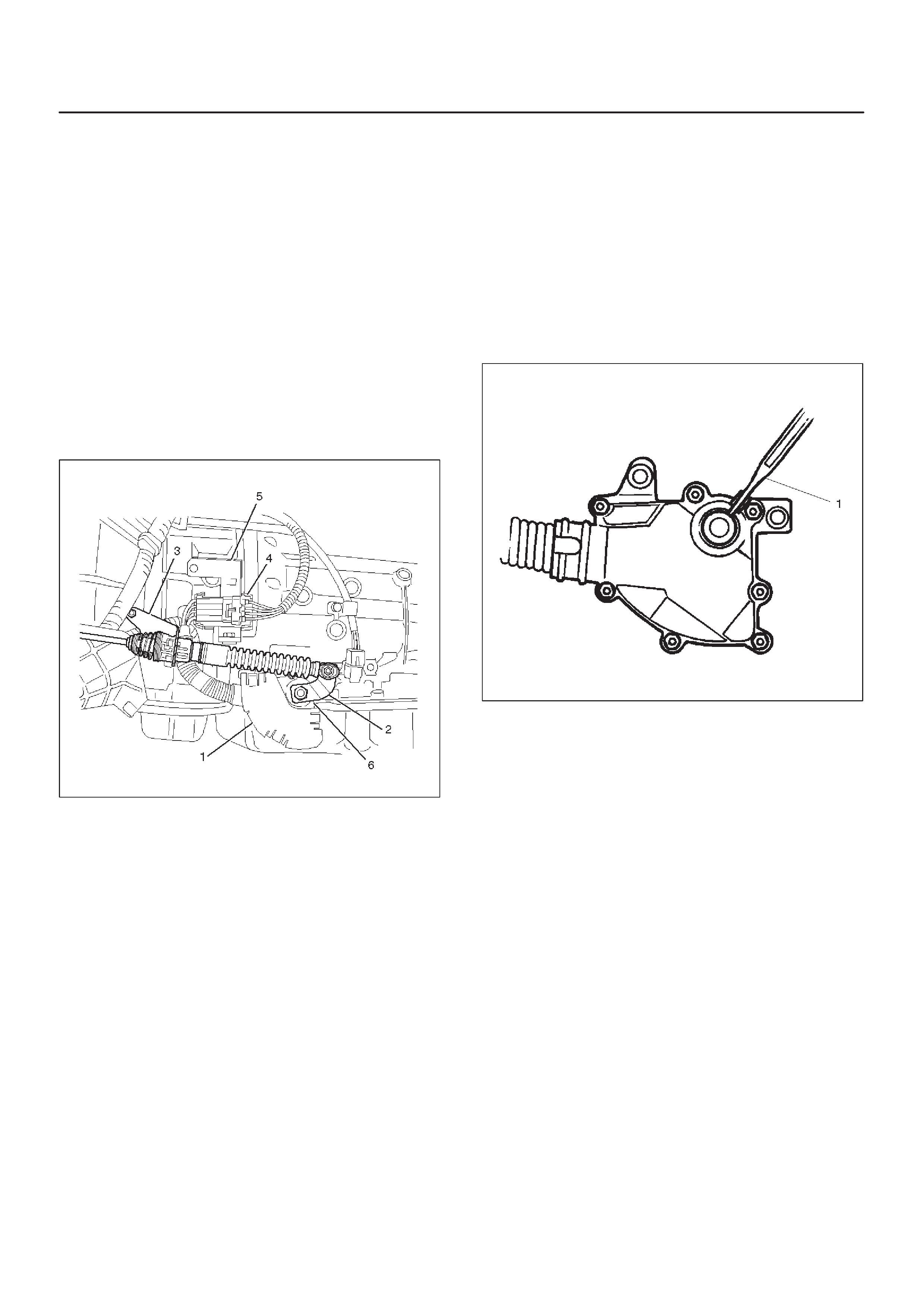
3.Remove mode switch cover (1).
4.Disconnect selector lever (2) from the mode switch.
5.Remove bracket with cable (3).
6.Disconnect transmission harness from the mode
switch connector (4).
7. Remove bracket with mode switch connector from
the transmission case.
8.Remove mode switch connector (4) from the bracket
(5).
9.Remove two mode switch bolts and nut then remove
mode switch (6).
210RW014
Installation
To install, follow the removal steps in the reverse order,
noting the following points;
1.Torque
Mode switch bolt: 13 N•m (113 lb in)
Selector lever nut: 23 N•m (17 lb ft)
2.Mode switch setting procedure
Perform either of the following adjustment
procedures:
Procedure 1
a. Place selector lever in neutral.
b. Remove selector lever from the mode switch.
c. Remove the mode switch cover.
d. Loosen the two 10 mm screws.
e. Rotate the mode switch until the slot in the mode
switch housing aligns with the selector shaft
bushing, and insert a 3/32 in. (2.4 mm) drill bit or
punch (1) into the slot.
f. Tighten the screws to 13 N·m (113 lb in).
g. After completing adjustment, snap the mode
switch cover into place.
h. Reinstall the selector lever.
249RW001
Procedure 2
a. Place selector lever in neutral.
b. Disconnect transmission harness connector from
mode switch connector.
c. Remove mode switch connector with bracket from
the transmission case.
d. Connect multimeter (resistance mode) to
terminals 1(E) and 4(H) on mode switch connector .
e. Loosen two mounting screws.
f. Rotate mode switch slightly in both directions to
determine the range (approx. 5 degrees) of
electrical contact.
g. Position mode switch in middle of contact range.
h. Tighten two mounting screws.
i. Remove multimeter and install mode switch
harness connector with bracket to the
transmission case.
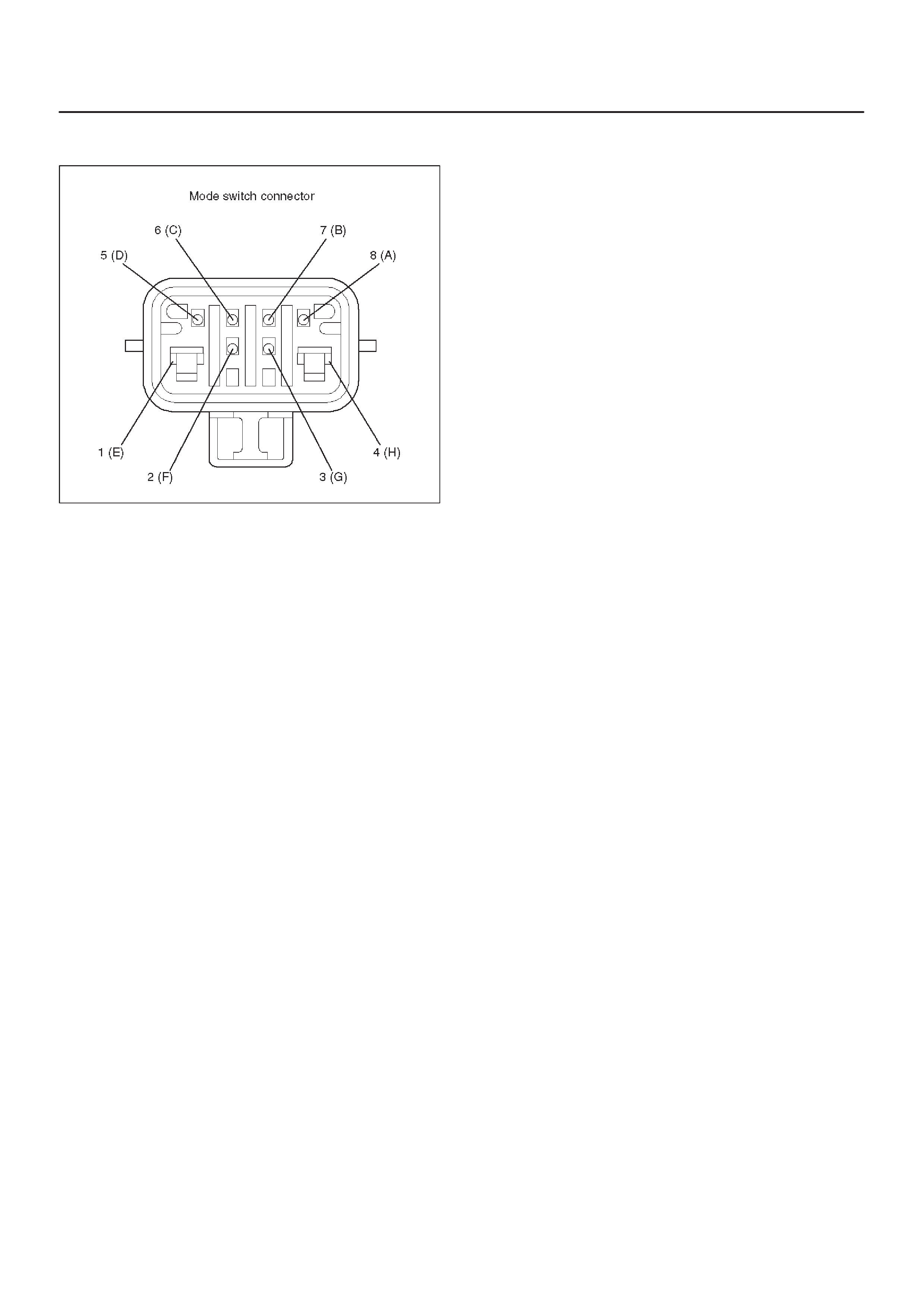
j. Connect transmission harness connector to mode
switch connector.
F07RW003
Transmission (With Transfer Case)
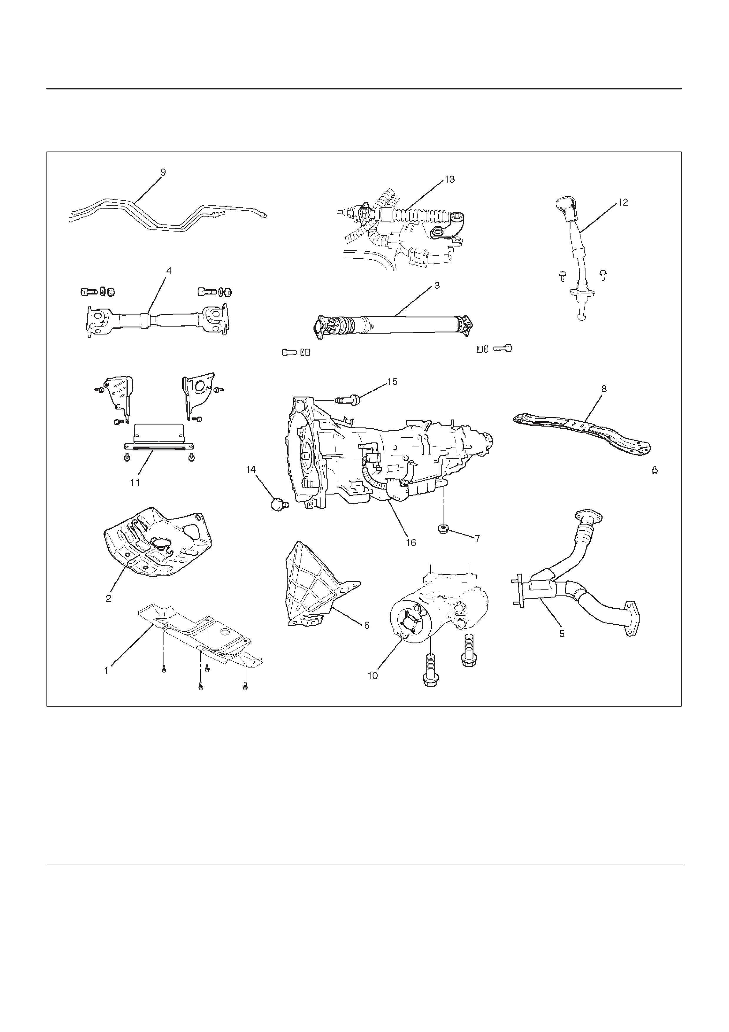
Transmission and Associated Parts
240RX012
Legend
(1) Skid Plate
(2) Transfer Protector
(3) Rear Propeller Shaft
(4) Front Propeller Shaft
(5) Center Exhaust Pipe
(6) Harness Heat Protector
(7) Rear Mount Nut
(8) Third Crossmember
(9) Transmission Oil Cooler Pipe
(10) Starter
(11) Under Cover
(12) Transfer Control Lever
(13) Select Cable
(14) Torque Converter Bolt (Non – reusable part)
(15) Engine-Transmission Bolt
(16) Transmission Assembly (With Transfer Case)
Removal
NOTE: Before remove transmission and transfer
assembly from vehicle, change the transfer mode to 2WD
using push button on dash panel.
1.Disconnect battery ground cable.
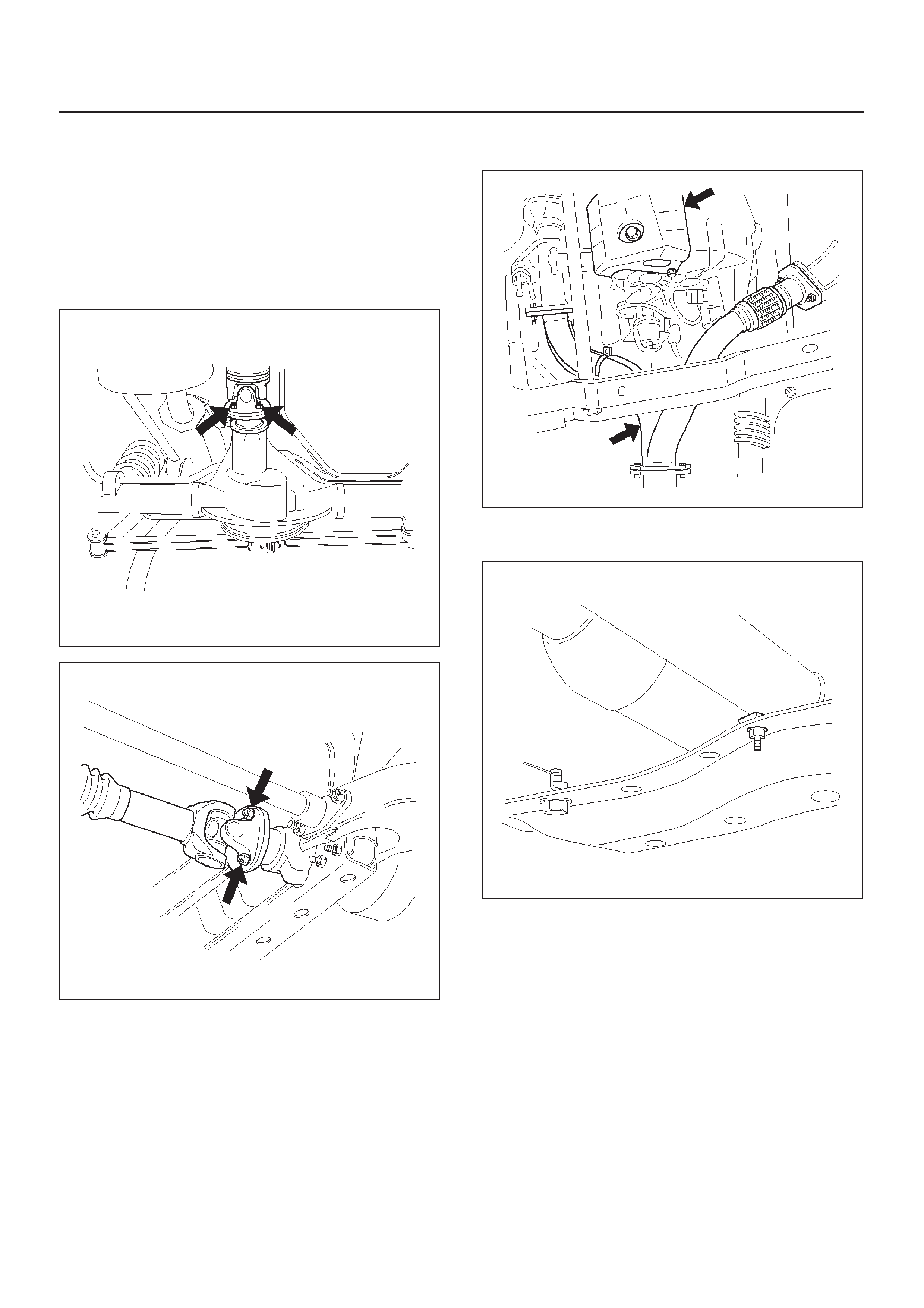
2.Remove rear propeller shaft and front propeller shaft.
NOTE: Apply alignment marks on the flange at both front
and rear sides.
401RW008
401RW007
3.Remove transfer protector.
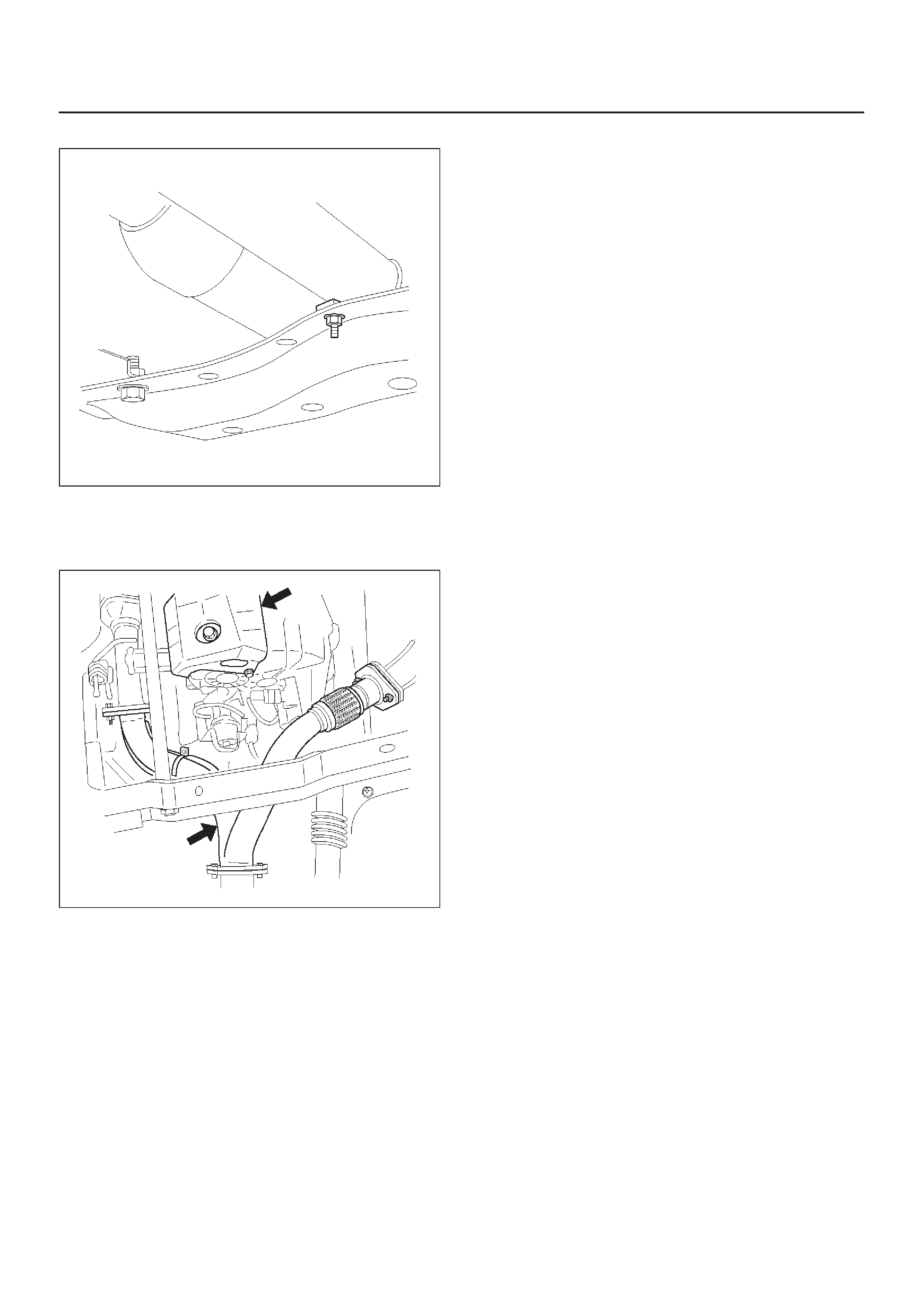
4.Remove center exhaust pipe.
150RX008
5.Remove fuel pipe bracket from the third
crossmember.
141RX004
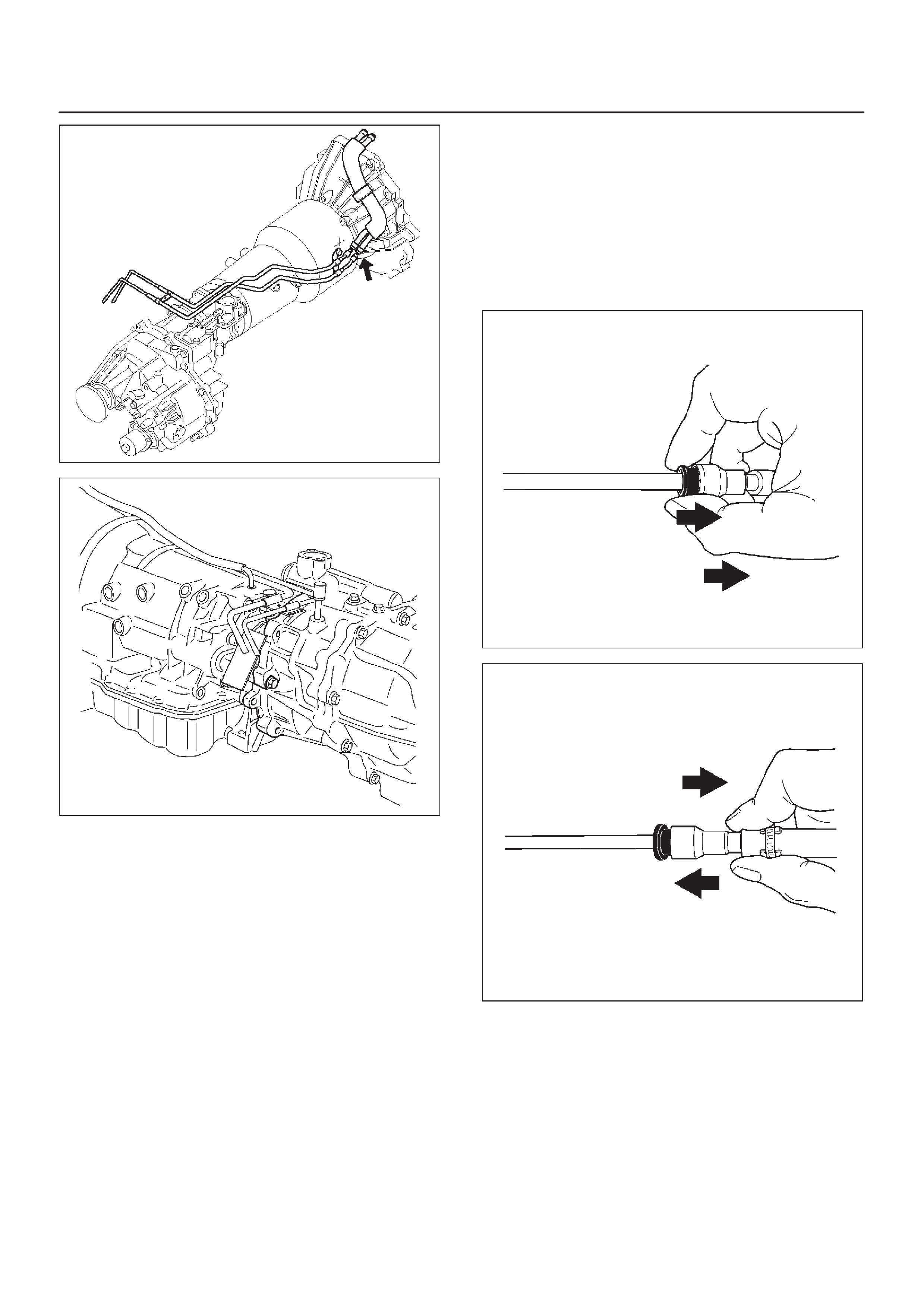
141RY00007
240RW014
Fuel hose connector removal procedure
If removal of the fuel hose connector is required for
transmission servicing and/or replacement, follow the
steps below.
NOTE:
DAn O-ring is used as a seal between the fuel pipe and
the connector. Take care not to damage the contact
surfaces during the removal procedure. Do not allow
the serfaces to become contaminated with dirt or
other foreign material.
DPerform the entire removal procedure with your
hands. Do not use tools.
1. Separating the connector and fuel pipe
1. Clean the fuel pipe and connector to remove
mud and other dirt.
2. Pull the black plastic piece toward the
connector. Hold the piece near the connector.
Pull the connector from the fuel pipe.
If the connector and fuel pipe are stuck togeth-
er , jiggle the connector back and forth to loosen
the connector. Do not yank the connector from
the fuel pipe.
141RY00002
141RY00003
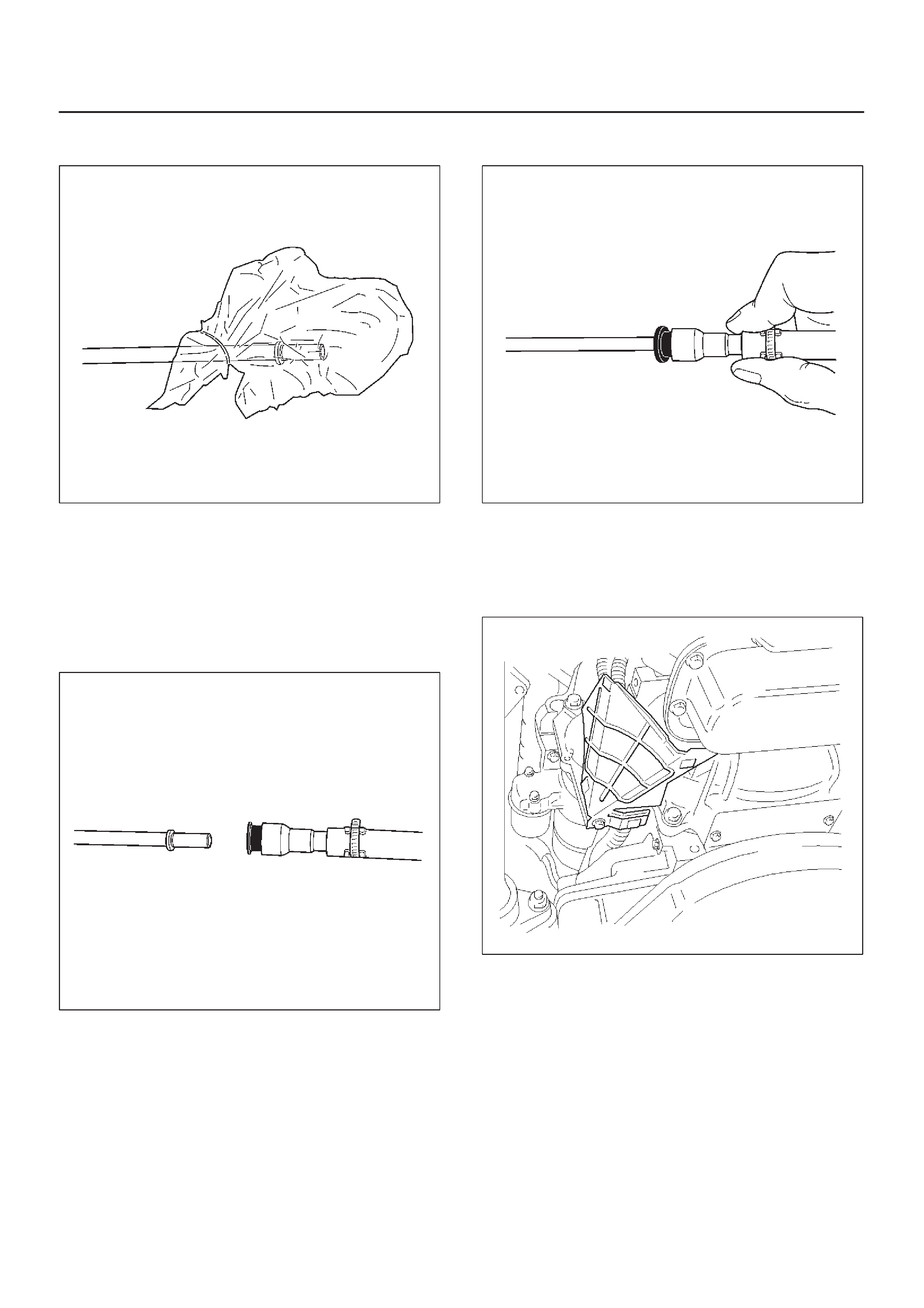
3. Tie a vinyl bag around the connector and fuel
pipe to protect them from dirt.
141RY00004
2. Joining the connector and fuel hose
1. Remove the vinyl bags from the connector and
fuel hose. Check that the contact surfaces are
undamaged and free of dirt and other foreign
material. Clean if necessary.
2. Align the axis of the fuel pipe and connector.
Push the connector into the fuel pipe until a
distinct click is heard.
141RY00005
3. Gently pull on the connector to check that it is
securely latched.
141RY00006
6.Disconnect transmission harness connector and clip.
Connector : Adapter case, mode switch, main case,
magnetic sensor, transfer switch, 2–4 actuator and
car speed sensor.
7.Remove harness heat protector.
815RW002
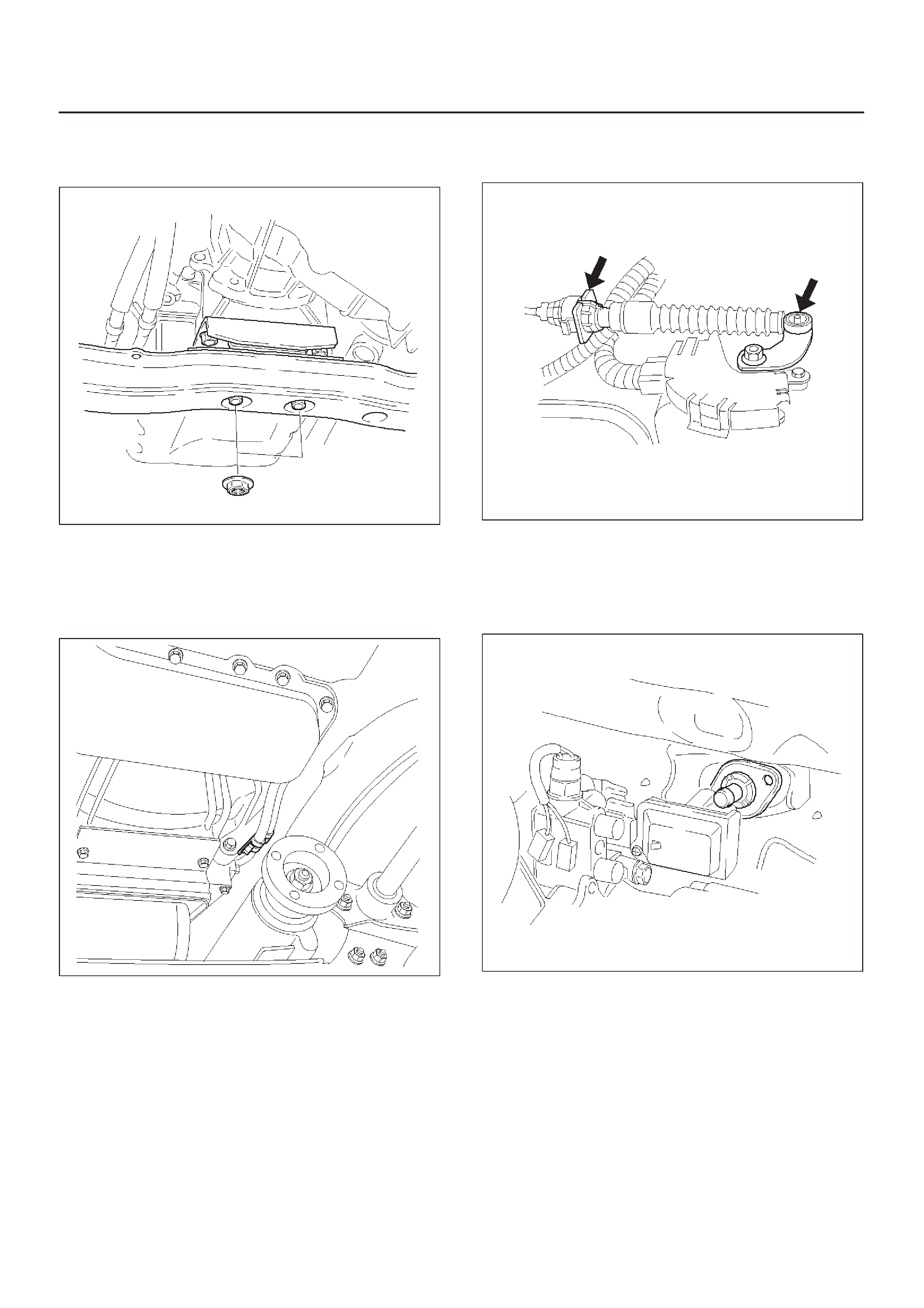
8.Support transmission with a jack.
Remove rear mount nuts from the third
crossmember.
F07RW008
9.Remove third crossmember.
10.Disconnect transmission oil cooler pipes from A/T
side.
11.Remove oil pipe clamp and bracket from the
converter housing.
253RX002
12.Remove skid plate and loosen oil cooler pipe clamp
bolt at the engine mount side.
13. Remove select cable by disconnecting inner cable
from select lever and removing outer cable with
bracket.
256RW025
14.Remove starter.
15.Remove under covers from the transmission and
engine.
16.Remove transfer control lever fixing bolts and push up
transfer control lever.
262RW015
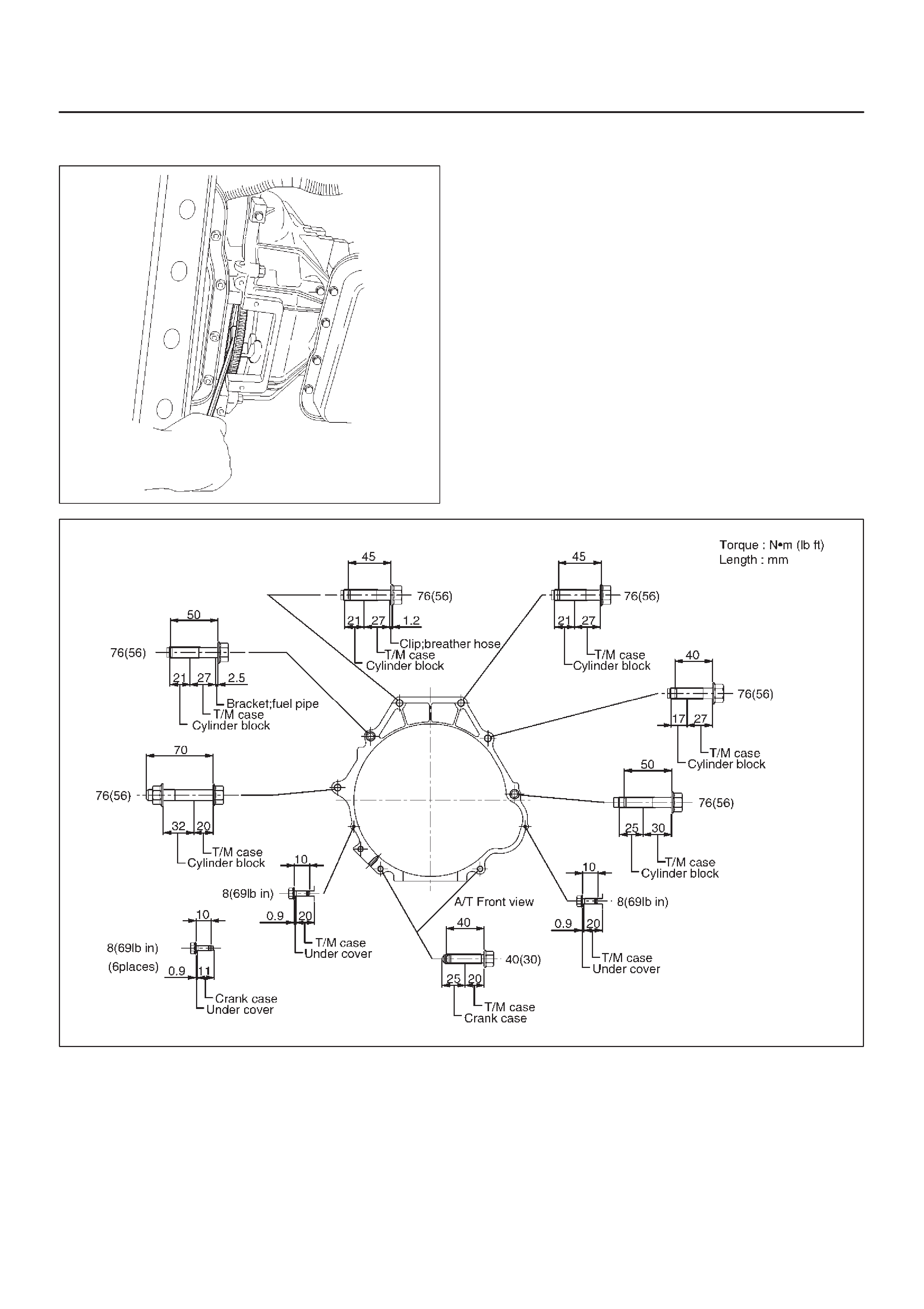
17.Remove flex plate torque converter fixing bolts (6
pieces) by turning crankshaft.
240RX010
18.Remove engine-transmission fixing bolts.
19.Pull out transmission from the engine.
Installation
1.Slowly raise transmission jack until front of the
transmission is aligned with rear of the engine. Join
the transmission to the engine.
2. Tighten engine-transmission bolts as shown in the
figure.
F07RY001

3.Align the flex plate torque converter bolt boss with flex
plate hole by turning the torque converter. Install flex
plate torque converter bolts (6 pieces) by turning the
crankshaft.
Torque: 54 N•m (40 lb ft)
NOTE: Do not reuse the flex plate torque converter bolt.
240RX010
4.Install transfer control lever on the transfer case.
262RW015
5.Install under covers to the transmission and engine.
Torque: 8 N•m (69 lb in)
6.Install starter.
Torque: 40 N•m (30 lb ft)
7.Install select cable by connecting inner cable to select
lever and installing outer cable with bracket.
256RW025
8.Connect transmission oil cooler pipes to A/T.
Torque: 44 N•m (33 lb ft)
9.Install oil cooler pipe clamp and bracket to the
converter housing.
253RX002
10.Tighten oil cooler pipe clamp bolt at the engine mount
side and install skid plate.
11.Install third crossmember.
Torque: 76 N•m (56 lb ft)
12.Install rear mount nuts.
Torque: 50 N•m (37 lb ft)
F07RW008
13.Install harness heat protector.
Torque: 6 N•m (52 lb in)
815RW002
14.Connect transmission harness connector and clip.
Connector : Adapter case, mode switch, main case,
magnetic sensor, transfer switch, 2–4 actuator and
car speed sensor.
15.Connect fuel pipe to transmission side.
NOTE: See “NOTE” of removal steps.
141RY00007
240RW014
16.Install fuel pipe bracket to the third crossmember.
141RX004
17.Install center exhaust pipe.
Torque: 43 N•m (32 lb ft)
18.Install transfer protector.
150RX008
19.Install front propeller shaft and rear propeller shaft.
Torque: 63 N•m (46 lb ft)
20.Connect battery ground cable.
Solenoid (Main Case Valve Body)
Removal
1.Raise the vehicle and support it on jack stands.
2.Disconnect battery ground cable.
3.Drain fluid.
4.Remove sixteen 10 mm screws, main case oil pan,
magnet, and gasket.
5.Remove three 13 mm screws, oil filter.
6.Disconnect wiring harness from band control
solenoid and shift solenoids. Pull only on connectors,
not on wiring harness.
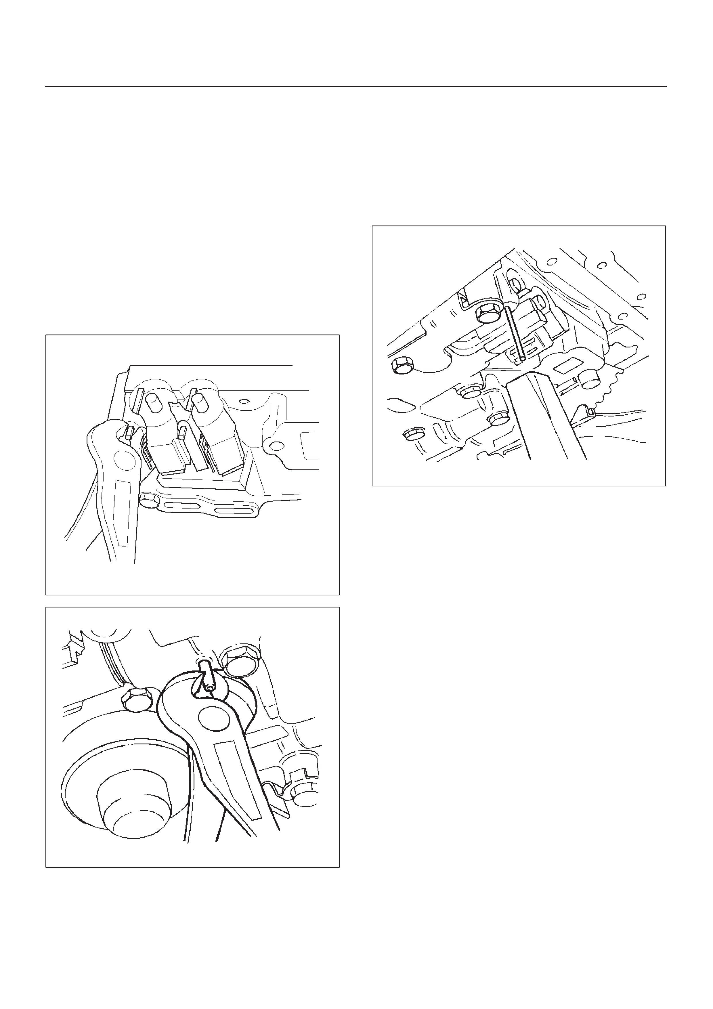
7.Remove spring pin for shift solenoid A, shift solenoid
B, and band control solenoid respectively, using
suitable pliers taking care not to damage solenoids.
210RW010
244RW003
8.Remove shift solenoid A, shift solenoid B, band
control solenoid, and gaskets from main case valve
body. Do not pull on wiring harness. Remove
solenoids by grasping the metal tip.
Installation
1.Install shift solenoid A, shift solenoid B, band control
solenoid with new gaskets to main case valve body
respectively.
2.Carefully install spring pin with hammer to avoid
damage to valve body, etc.
243RW004
3.Connect wiring harness to solenoids.
4.Install oil filter with a new gasket and the three 13 mm
screws, tighten to the specified torque.
Torque: 20N•m (15lbft)
5.Install magnet, main case oil pan with new gasket,
and sixteen 10 mm screws. Tighten the screws to the
specified torque.
Torque: 11N•m (96lbin)
6.Fill transmission through the overfill screw hole of oil
pan, using ATF DEXRON–III. Refer to Changing
Transmission Fluid in this section.
7.Connect battery ground cable.
Solenoid (Adapter Case Valve Body)
Removal
1.Raise the vehicle and support it on jack stands.
2.Disconnect battery ground cable.
3.Drain fluid.
4.Remove adapter case oil pan twelve fixing 10 mm
screws, adapter case oil pan, and gasket.
NOTE:Oil pan still contains transmission fluid. Place a
large drain container under the oil pan and drain the fluid
carefully.
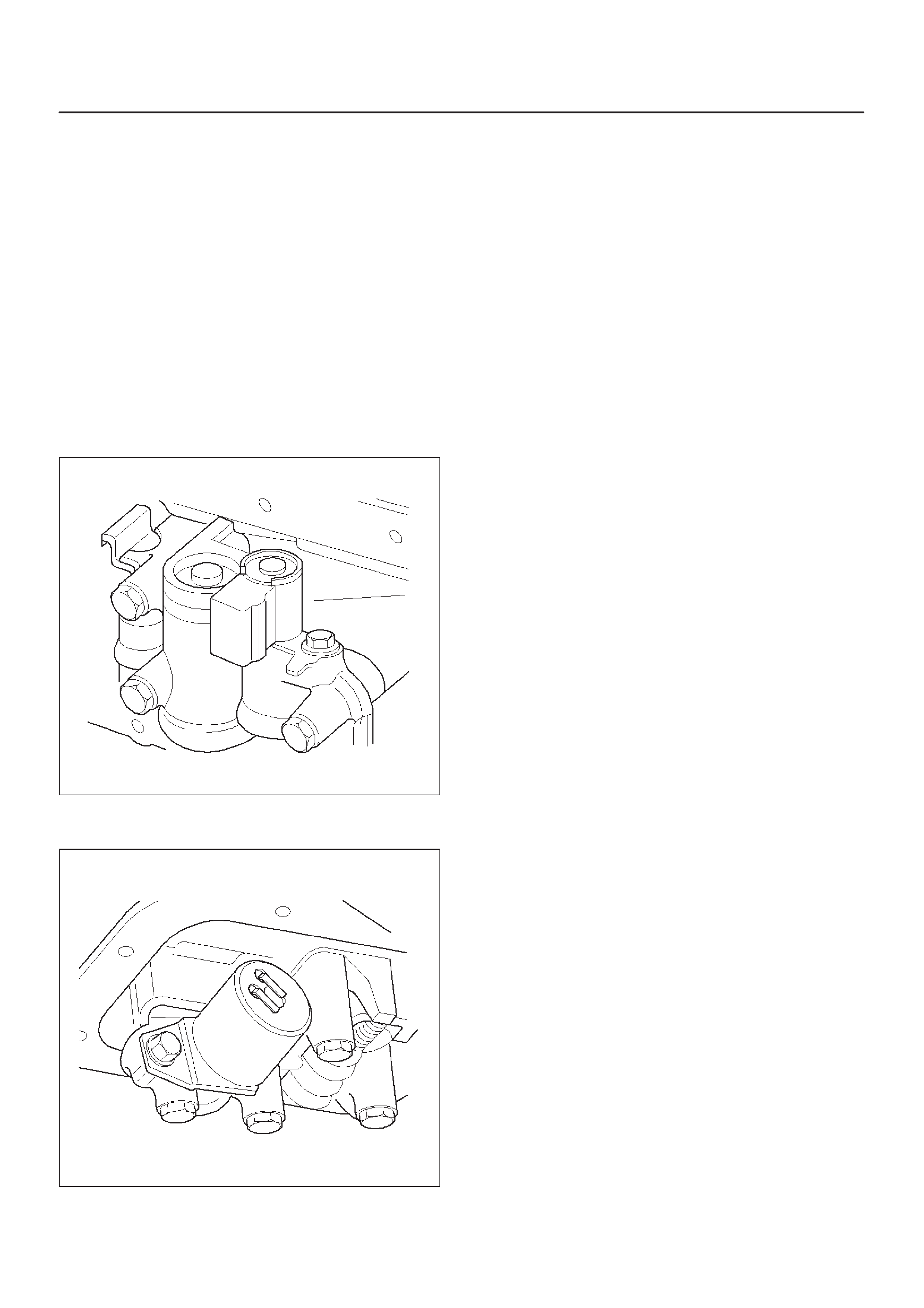
5.Disconnect wiring harness from force motor solenoid
and converter clutch solenoid. Pull only on
connectors, not on wiring harness.
6.Remove 11 mm bolt and converter clutch solenoid
with two O-rings.
210RW011
7.Remove 11 mm bolt, retainer, and force motor
solenoid.
210RW009
Installation
1.Install force motor solenoid, retainer, and 11 mm bolt
to adapter case valve body. Tighten the bolt to the
specified torque.
Torque: 10 N•m (87lbin)
2.Install converter clutch solenoid with two O-rings, and
11 mm bolt to adapter case valve body. Tighten the
bolt to the specified torque.
Torque : 10N•m (87lbin)
3.Connect wiring harness assembly to solenoids.
4.Install adapter case oil pan, new gasket, and twelve
10 mm screws. Tighten the screws to the specified
torque.
Torque : 11N•m (96lbin)
5.Fill transmission through overfill screw hole oil pan,
using ATF DEXRON–III. Refer to Changing
Transmission Fluid in this section.
6.Connect battery ground cable.
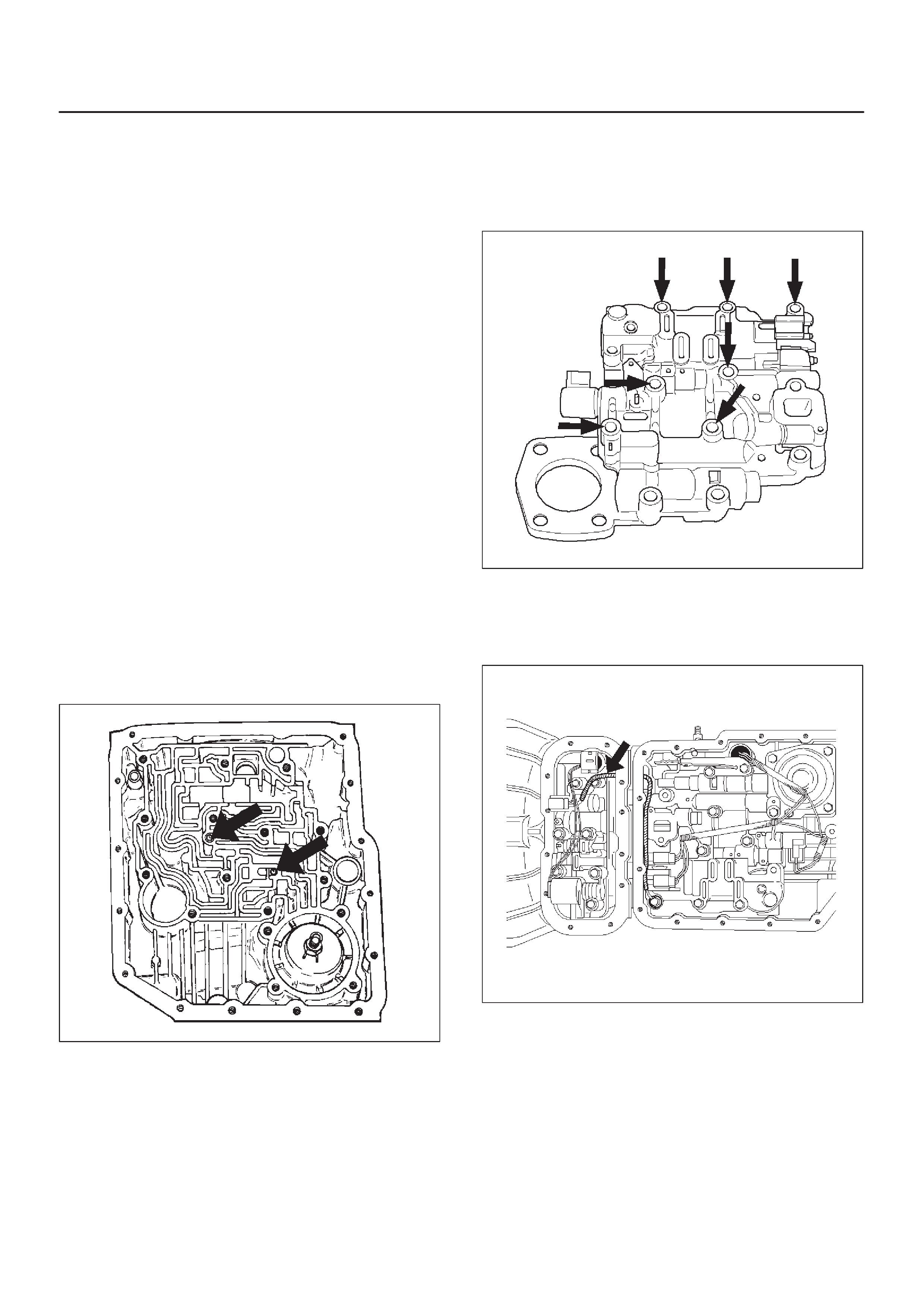
Valve Body Assembly (Main Case)
Removal
1.Raise the vehicle and support it on jack stands.
2.Disconnect battery ground cable.
3.Drain fluid.
4.Remove sixteen 10 mm screws, main case oil pan,
magnet and gasket.
5.Remove three 13 mm oil filter fixing screws, then
remove oil filter.
6.Remove two 13 mm manual detent fixing screws,
then remove roller and spring assembly.
7.Disconnect wiring harness from band control
solenoid and shift solenoids. Pull only on connectors,
not on wiring harness.
8.Remove four 13 mm servo cover fixing screws, then
remove servo cover and gasket.
9.Remove seven 13 mm valve body fixing screws.
DDisconnect ground wire from the main case valve
body.
10.Remove main case valve body with manual valve link
and transfer plate. Note the position of the link (long
end into valve, short end into range selector lever).
11.Remove transfer plate gasket from main case.
12.Remove two check balls from main case.
Installation
1.Install two check balls to main case.
244RW002
2.Inspect electrical 4 pin connector and seal of main
case. Replace if necessary.
3.Use two J–25025–B guide pin to install main case.
DInstall valve body complete assembly and manual
valve link.
NOTE: Valve must be extended as the short end of
manual valve link is connected to the range selector lever.
Long end of link goes into valve.
4.Install seven 13 mm screws, and tighten them to the
specified torque.
Torque: 20 N•m (15 lb ft)
243RS008
5. Install 8.5 mm connector of ground wire under the
head of this valve body bolt and reinstall it. Tighten the
bolt to the specified torque.
Torque: 20 N•m (15 lb ft)
244RW001
6.Remove two guide pins from main case.
7. Install servo cover gasket, cover, and four 13 mm
screws. Tighten the screws to the specified torque.
Torque: 25 N•m (18 lb ft)
8.Connect wiring harness to band control and shift
solenoids.
9.Install roller and spring assembly to manual detent.
DInstall two 13 mm screws, and tighten them to the
specified torque.
Torque: 20 N•m (15 lb ft)

10.Install oil filter and three 13 mm screws. Tighten to the
specified torque.
Torque : 20N•m (15lbft)
11.Install oil pan gasket, magnet, oil pan and sixteen 10
mm screws. Tighten the screws to the specified
torque.
Torque: 11N•m (96lbin)
12.Fill transmission through overfill screw hole of oil pan,
using ATF DEXRON–III. Refer to Changing
Transmission Fluid in this section.
13.Connect battery ground cable.
Valve Body Assembly (Adapter Case)
Removal
1.Raise the vehicle and support it on jack stands.
2.Disconnect battery ground cable.
3.Drain fluid.
4.Remove twelve 10 mm adapter case oil pan fixing
screws, adapter case oil pan, and gasket.
NOTE:Oil pan still contains transmission fluid. Place a
large drain container under the oil pan.
Drain the fluid carefully.
5.Disconnect wiring harness from force motor solenoid
and converter clutch solenoid. Pull only on
connectors, not on wiring harness.
6.Remove seven 13 mm screws from adapter case
valve body assembly, then remove transfer plate, two
gaskets, and adapter case valve body.
Installation
1.Inspect electrical 5 pin connector and seal of adapter
case. Replace if necessary.
2.Install gasket, transfer plate, and gasket.
3.Install adapter case valve body and seven 13 mm
screws. Tighten the screws to the specified torque.
Torque: 20N•m (15lbft)
4.Connect wiring harness assembly to converter clutch
solenoid and force motor.
5.Install oil pan gasket, oil pan, and twelve 10 mm
screws. Tighten the screws to the specified torque.
Torque: 11N•m (96lbin)
6.Fill transmission through the overfill screw hole of oil
pan, using ATF DEXRON–III, Refer to Changing
Transmission Fluid in this section.
7.Connect battery ground cable.
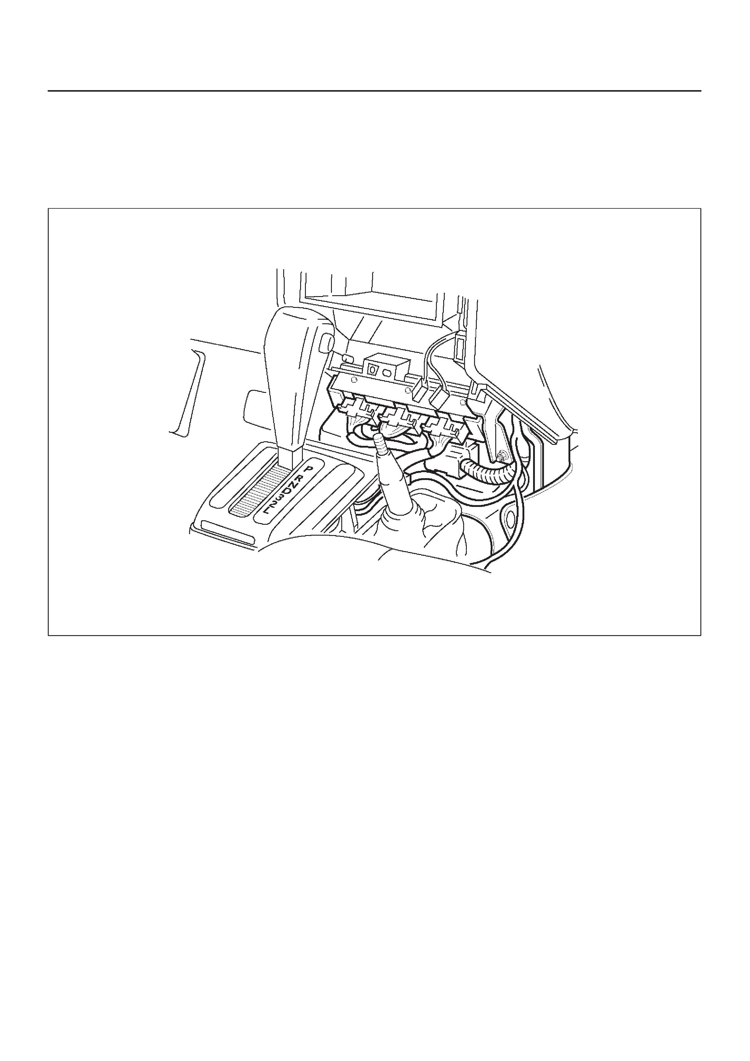
Powertrain Control Module (PCM)
Removal
1.Disconnect battery ground cable.
2.Remove transfer control lever knob, lower cluster
assembly, center console and rear console.
3.Disconnect PCM wiring harness connectors from
PCM.
4.Remove four PCM retaining screws.
5.Remove two brackets from PCM.
014RW221
Installation
1.Install two brackets to PCM.
2.Install four PCM retaining screws.
3.Connect PCM wiring harness connectors to PCM.
4.Install center console, rear console, lower cluster
assembly and transfer control lever knob.
5.Connect battery ground cable.
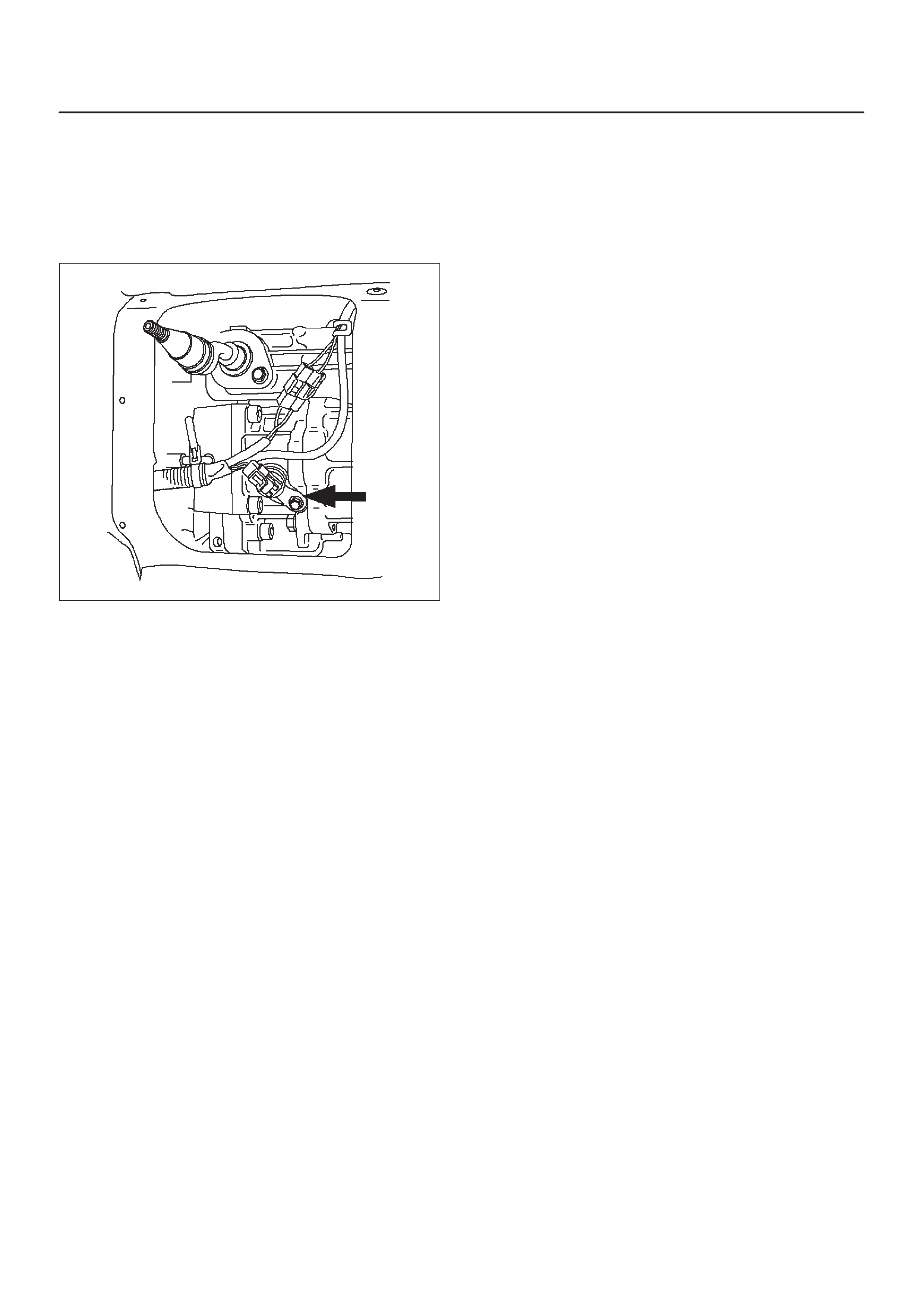
Speed Sensor (Extension Housing)
Removal
1.Disconnect battery ground cable.
2.Remove front console.
3.Remove selector lever assembly.
241RW007
4.Disconnect speed sensor harness connector from
speed sensor.
5.Remove one 10 mm screw and speed sensor with
O-ring.
Installation
1.Inspect the speed sensor O-ring, and replace it if
necessary.
2.Install speed sensor assembly and 10 mm screw.
Torque: 9N•m (78lbin)
3.Connect speed sensor harness connector to speed
sensor.
4.Install selector lever assembly.
DAdjust shift lock cable.
Refer to Shift Lock Cable in this section.
5.Install front console.
6.Connect battery ground cable.
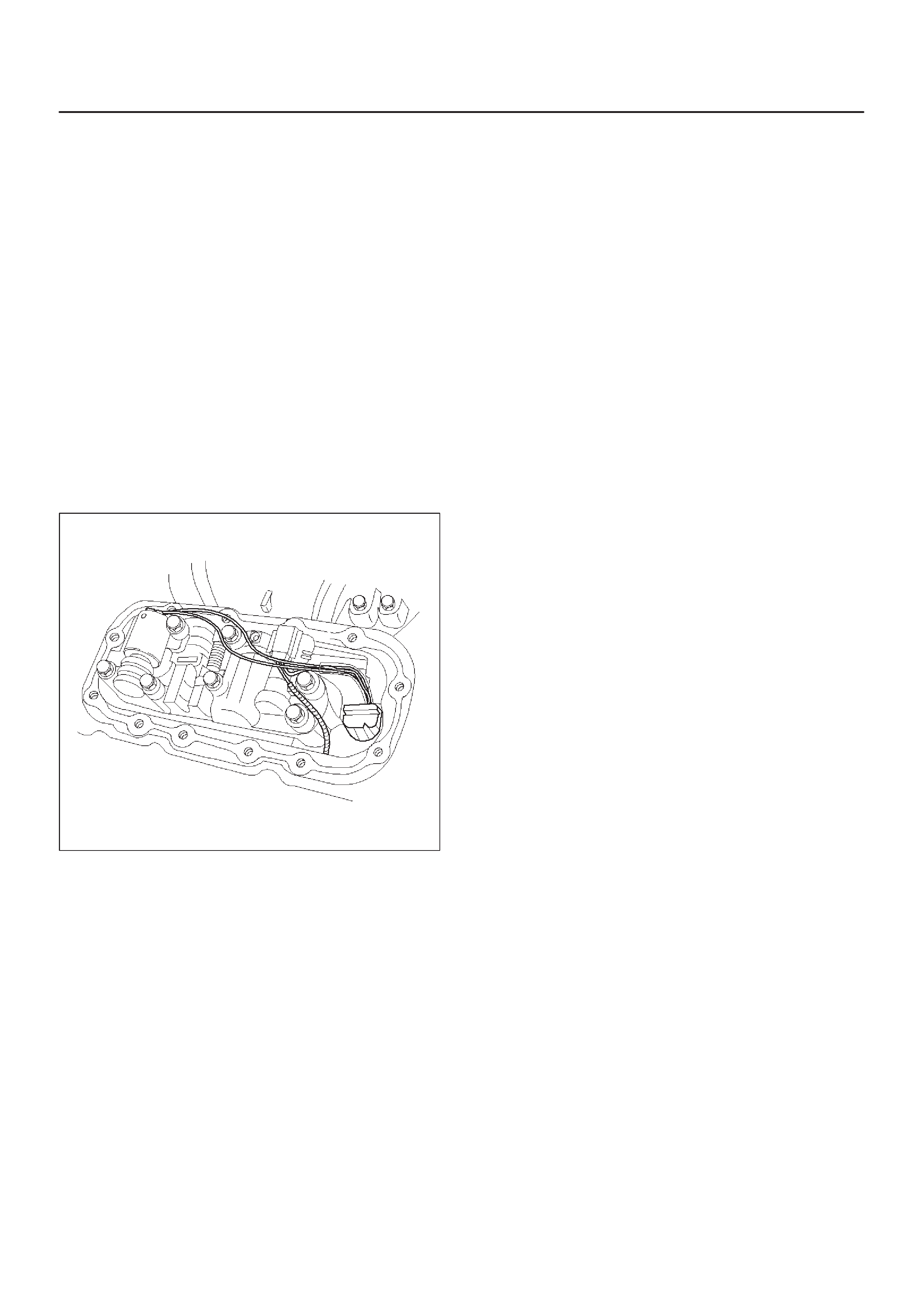
Transmission Oil Temperature Sensor (Adapter Case)
Removal
1.Raise the vehicle and support it on jack stands.
2.Disconnect battery ground cable.
3.Drain fluid.
4.Remove twelve 10 mm adapter case oil pan fixing
screws, adapter case oil pan, and gasket.
NOTE:Oil pan still contains transmission fluid. Place a
large drain container under the oil pan and drain the fluid
carefully.
5.Disconnect wiring harness from force motor solenoid,
converter clutch solenoid, and 5 pin connector of
adapter case. Pull only on connectors, not on wiring
harness.
6.Disconnect ground wire from converter clutch
solenoid wiring harness connector.
7.Remove wiring harness assembly (transmission oil
temperature sensor).
243RW002
Installation
1.Connect ground wire to converter clutch solenoid
wiring harness connector of the wiring harness
assembly.
2.Install wiring harness assembly to converter clutch
solenoid, force motor, and 5 pin connector of adapter
case.
3.Install oil pan gasket, oil pan and twelve 10 mm fixing
screws. Tighten the screws to the specified torque.
Torque: 11N•m (96lbin)
4.Fill transmission through the overfill screw hole of oil
pan, using ATF DEXRON–III.
Refer to Changing Transmission Fluid in this section.
5.Connect battery ground cable.
Front Oil Seal (Converter Housing)
Removal
1.Remove transmission assembly from the vehicle
,refer to Transmission (With Transfer Case) in this
section.
2.Remove torque converter from converter housing.
3.Remove three screws and oil seal ring from converter
housing.
241RW008
Installation
1.Apply clean ATF to the new oil seal ring lip.
DInstall oil seal ring to converter housing, tighten to
the specified torque.
Torque: 3N•m (26lbin)
2.Install torque converter to converter housing.
3.Install transmission assembly to the vehicle, refer to
Transmission (With Transfer Case) in this section.
Rear Oil Seal (Extension Housing)
Removal
1.Remove transfer case assembly from the vehicle.
Refer to Transfer Case in Drive Line/Axle section.
2.Remove rear oil seal from transmission extension
housing.
241RW005
Installation
1.Use J–36797 extension housing oil seal installer , and
install the rear oil seal to the transmission extension
housing.
2.Install the transfer case assembly to the vehicle.
Refer to Transfer Case in Drive Line/Axle section.
Transmission (4L30–E)
Disassembly
NOTE: During the disassembly and reassembly , perform
the following:
DWash each part thoroughly, and blow air through each
oil passage and groove to eliminate blockage.
DSeal rings, roll pins, and gaskets should be replaced.
DWhen assembling the components, apply
DEXRON–III Automatic Transmission Fluid (ATF)
to each seal, rotating part, and sliding part.
DDo not dip part facings, such as clutch or brake drive
plates, in cleaner when washing it.
Also, always coat parts with new ATF two or three
times after cleaning with solvent.
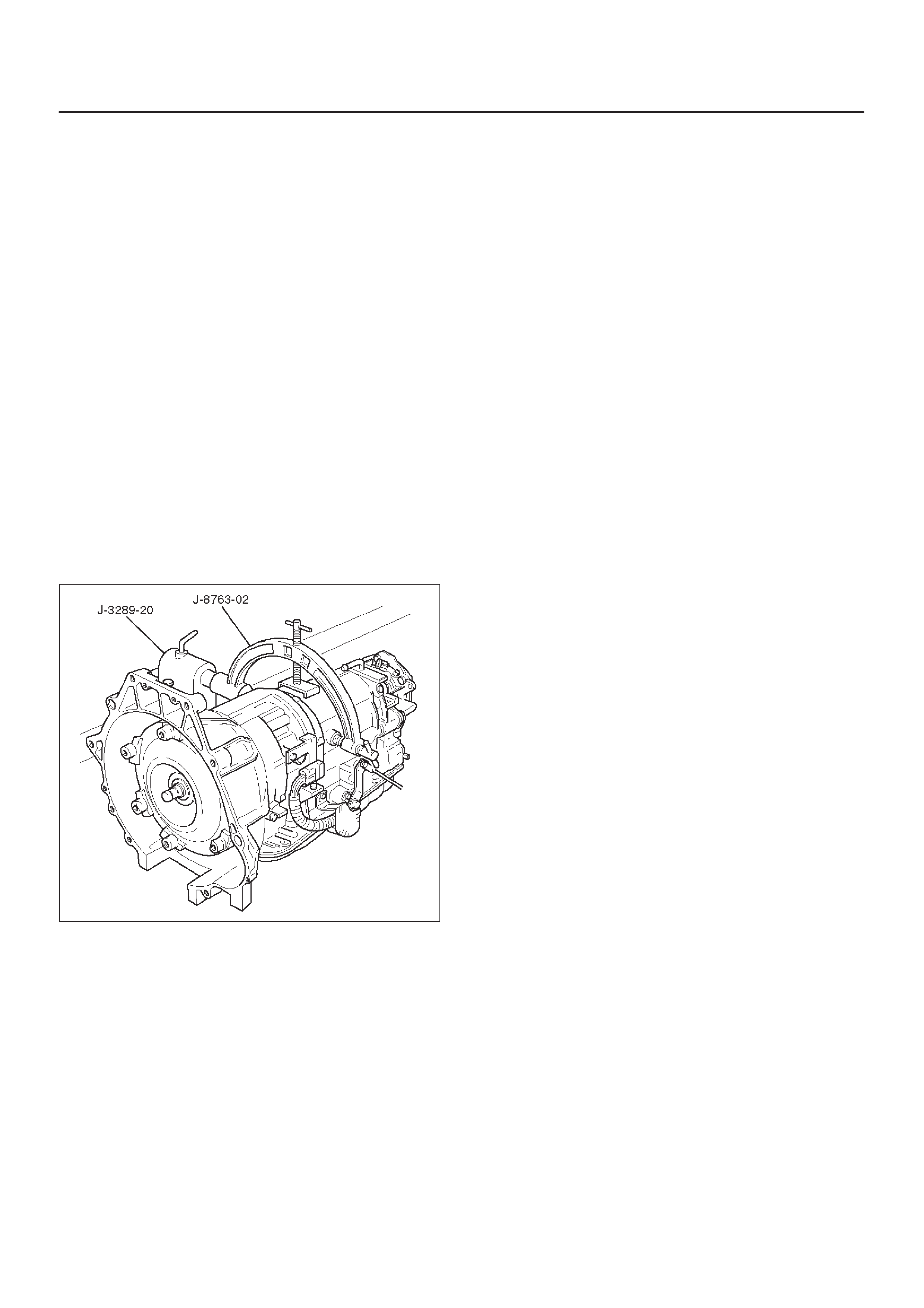
1.Remove torque converter (1).
DDrain fluid from torque converter.
DAttach J–8763–02 holding fixture to the
transmission and set it on J–3289–20 holding
fixture base.
NOTE: Do not overtighten the tool, as case damage may
result.
420RW021
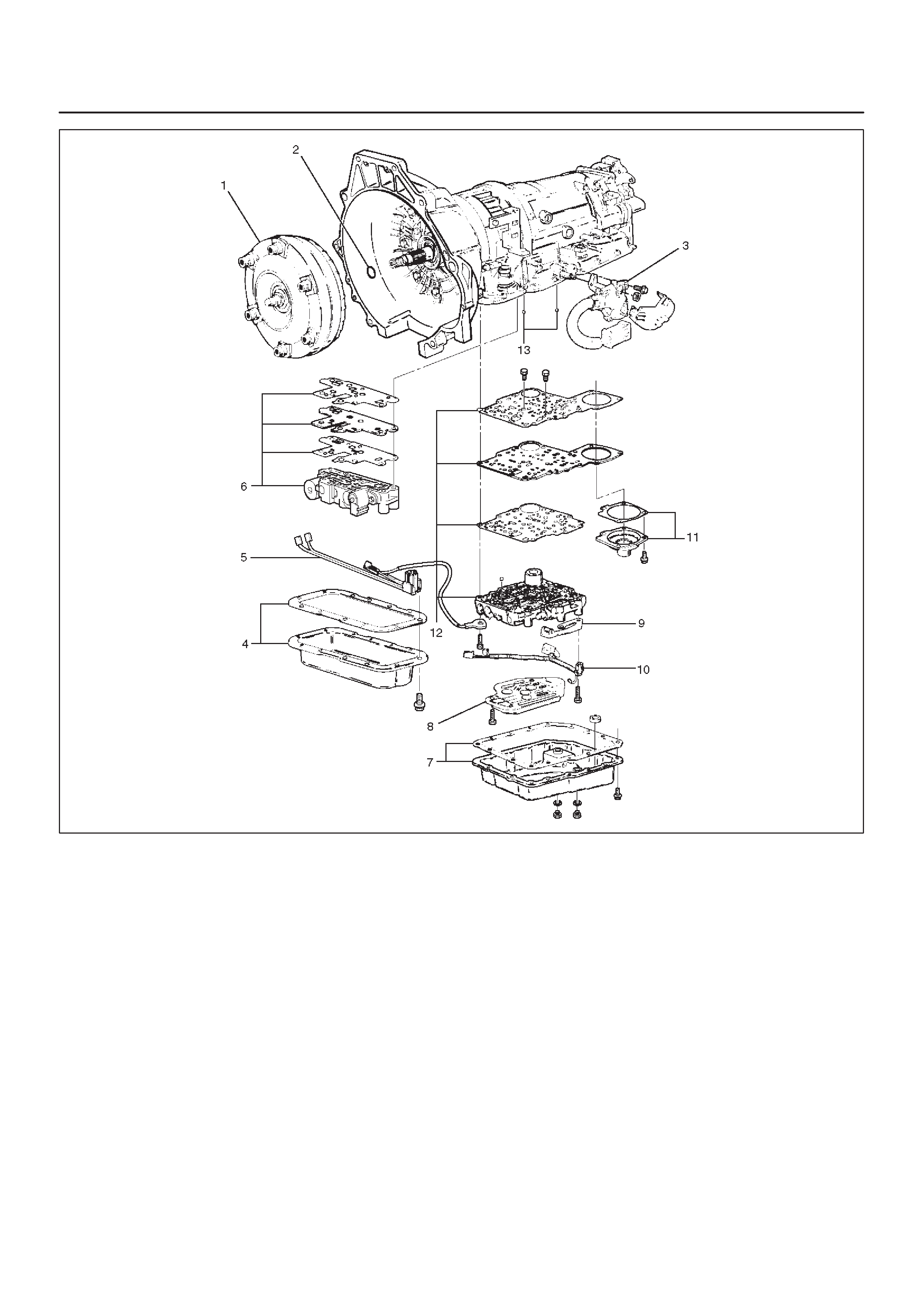
2.Remove O-ring (2) from turbine shaft.
3.Remove two 10mm mode switch screws, selector
lever nut, cover, and mode switch (3).
4.Remove twelve 10mm adapter case oil pan (4) fixing
screws, adapter oil pan, and gasket.
5.Disconnect electrical wiring connections (5) from
solenoids and 5 pin connector of adapter case. Pull
on connectors only, not on wiring harness.
6.Remove seven 13mm adapter case valve body (6)
fixing screws, adapter case valve body assembly,
transfer plate, and two gaskets.
DRemove wiring harness and 5 pin connector.
7.Remove sixteen 10mm main case oil pan (7) fixing
screws, main oil pan, magnet, and gasket.
8.Remove three 13mm oil filter (8) fixing screws and oil
filter.
9.Remove two 13mm manual detent (9) fixing screws,
roller and spring, and manual detent.
10.Disconnect wiring harness assembly (10) from band
apply solenoid, shift solenoids, and main case 4 pin
connector.
Pull on connectors only, not on wiring harness.
11.Remove four 13mm servo cover (11) fixing screws,
servo cover, and gasket.
12.Remove seven 13mm valve body screws and ground
wire from main case.
DRemove wiring harness assembly (5) from the
adapter case side.
DRemove main valve body assembly (12) with
manual valve link and transfer plate. Note the
position of the link (long end into valve, short end
into range selector lever).
DRemove 4 pin connector.
DRemove gasket transfer plate from main case.
13.Remove two check balls (13) from main case.
240RW022
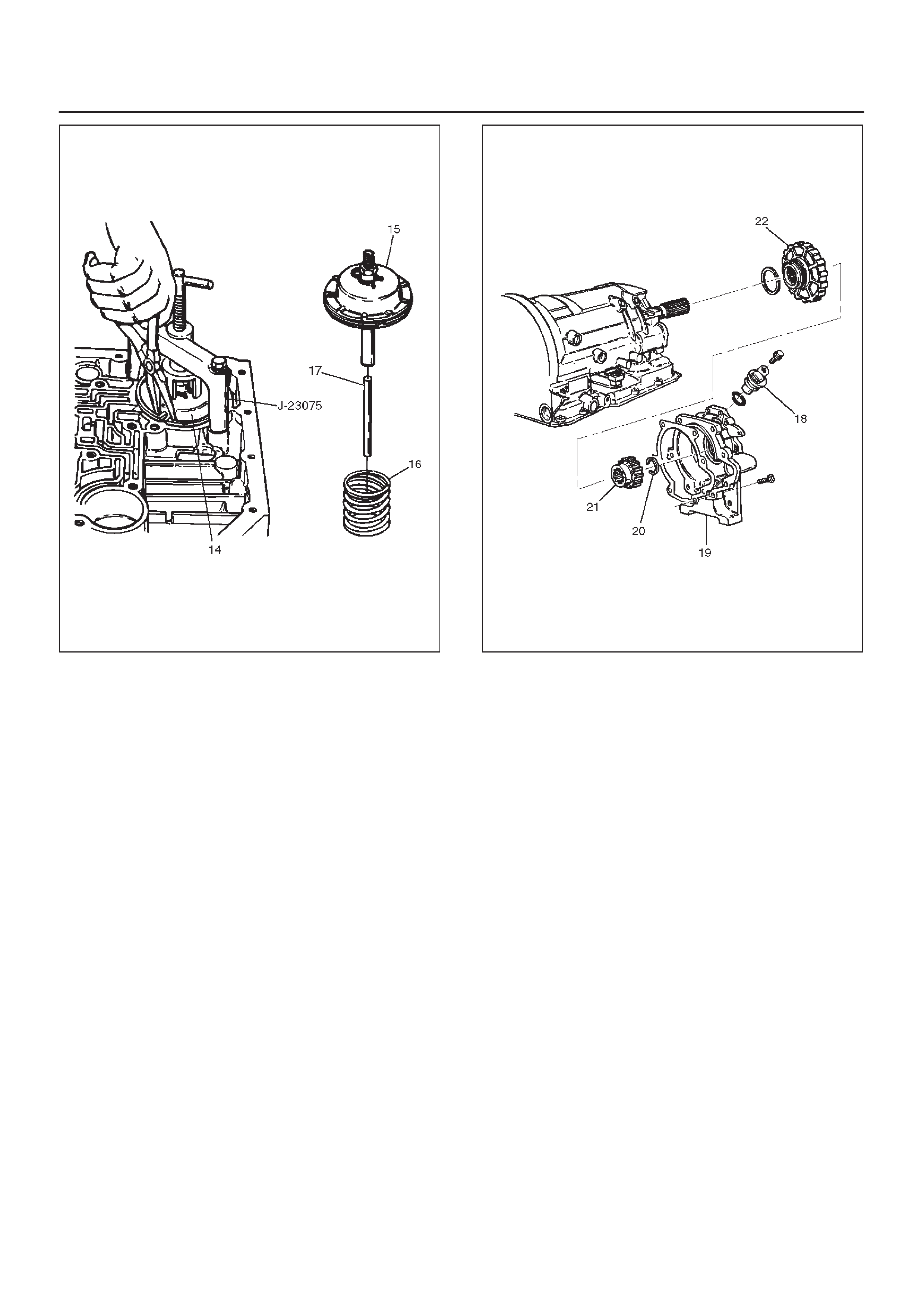
14.Turn transmission to vertical position to drain fluid.
Return back to horizontal position when drained.
DInstall J–23075 servo piston spring compressor
with offset to the rear of case.
DCompress servo piston assembly.
DRemove servo piston retaining ring (14).
DSlowly release servo piston assembly (15).
DRemove tool.
15. Remove servo piston assembly (15), return spring
(16), and servo apply rod (17).
242RS002
16.Rotate transmission to horizontal position, pan side
down.
DRemove one 10mm screw, and speed sensor (18)
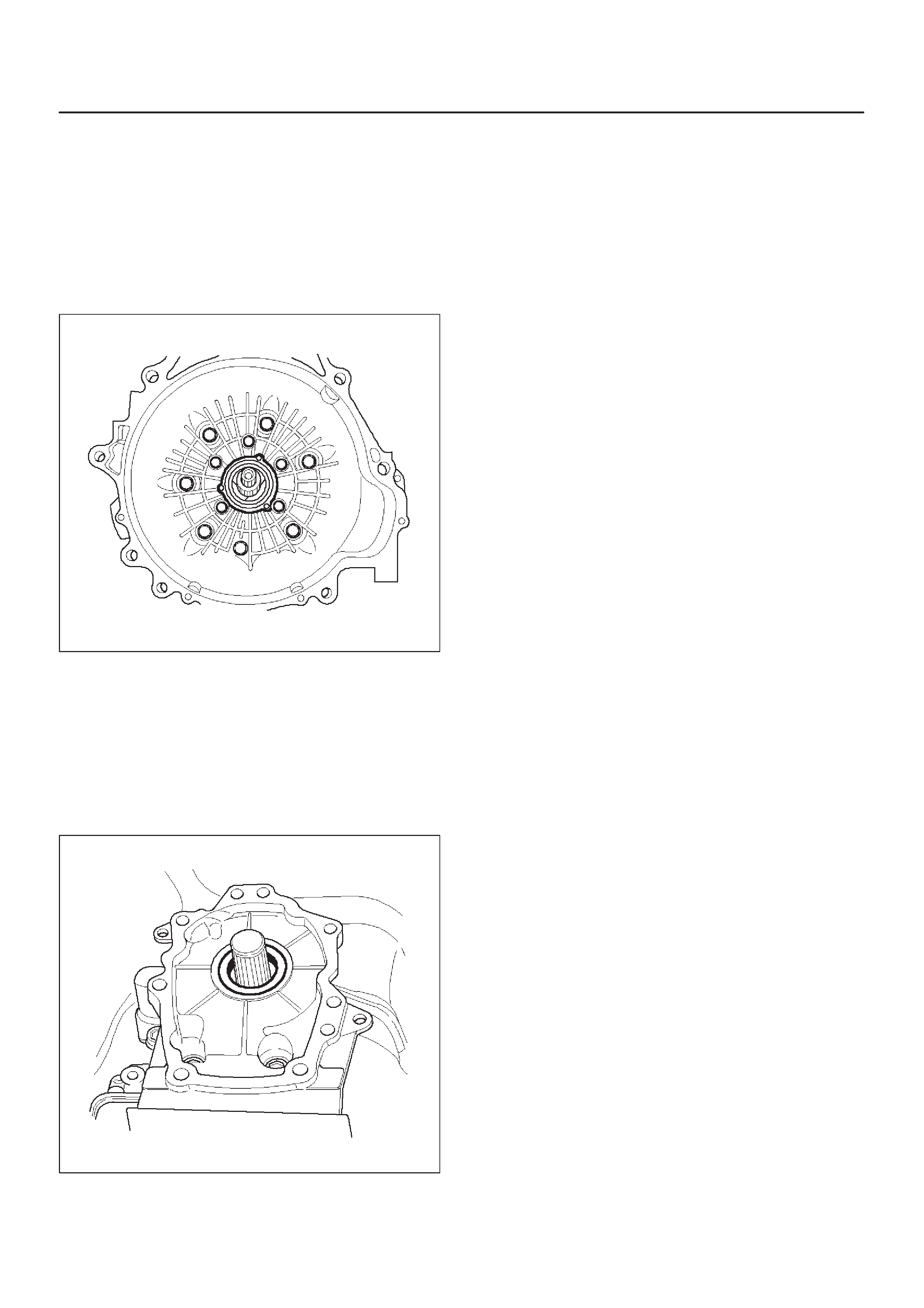
with “O” ring.
17.Remove seven 8mm extension housing hexagon
socket head screws, extension housing assembly
(19), and gasket.
18.Remove retaining ring (20).
NOTE: Use extra long, needle nose pliers.
19.Remove speed wheel (21).
20.Remove wheel parking lock (with seal ring) (22).
241RS002
21.Rotate transmission to vertical position, converter
housing up.
DLoosen the converter housing and oil pump
assembly fixing screws, but do not remove, the five
13 mm inner screws unless oil pump disassembly is
required.
DRemove seven outer screws.
DRemove converter housing and oil pump assembly
(23).
22.Remove gasket (24).
23.Remove selective thrust washer (25).
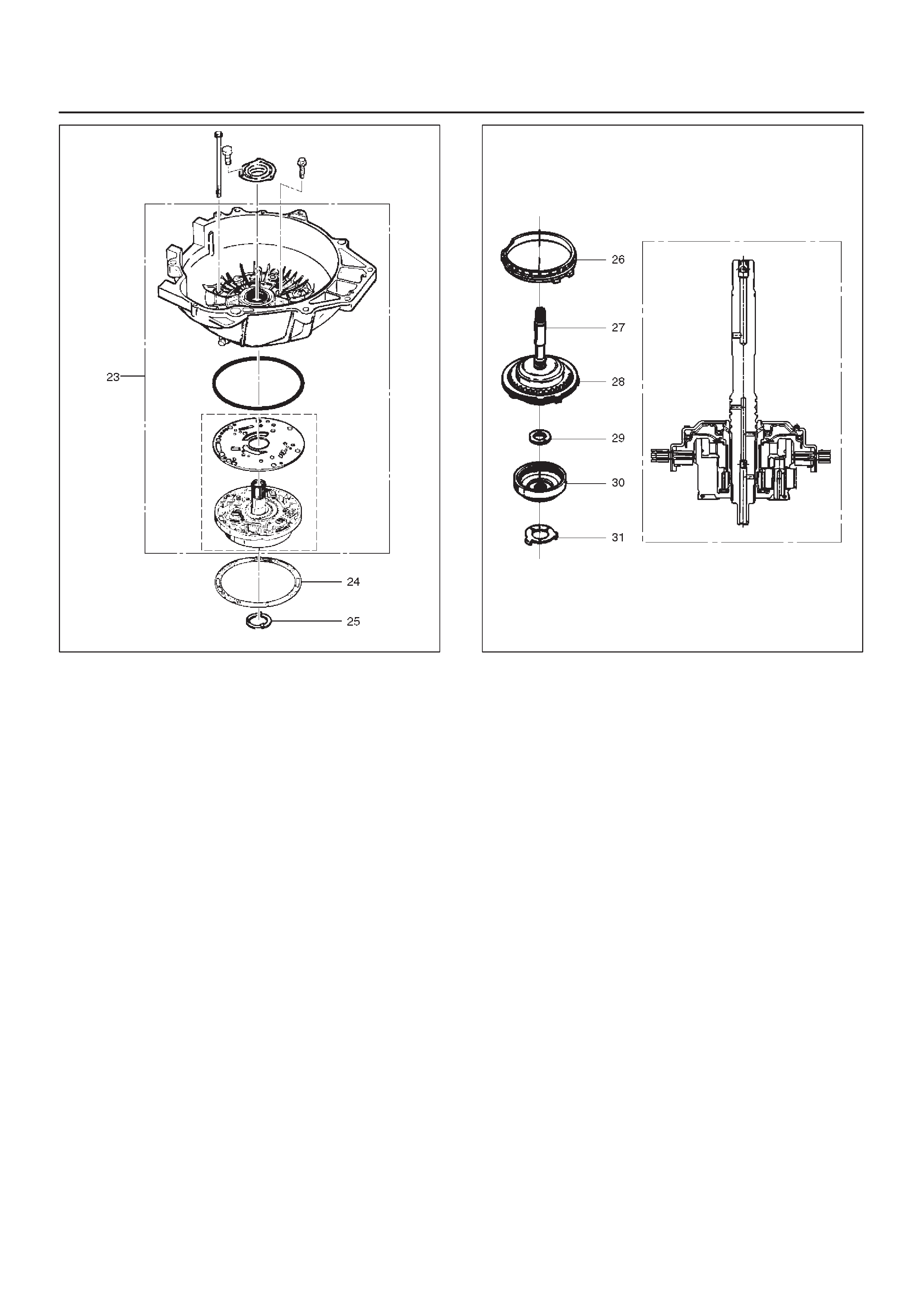
241RW004
24.Remove fourth clutch retainer (26).
25.Grasp turbine shaft and lift out the overrun clutch
housing assembly (27) and fourth clutch plates (28).
26.Remove thrust bearing assembly (29).
27.Remove overdrive internal gear (30).
28.Remove thrust washer (31).
252RS001
29.Remove adapter case and center support assembly
(with fourth clutch piston) (32).
30.Remove seal ring (33).
31.Remove selective thrust washer (34) and two O-ring
seals (35) from main case.
32.Use J–23327 and J–23327–90 compressor to
compress the fourth clutch spring retainer and
springs (37).
DRelease snap ring (36) from groove.
DRemove clutch compressor and snap ring (36).
33.Remove retainer and spring assembly (37).
34.Insert two converter housing/main case screws to
hold adapter case while pulling out fourth clutch
piston (38).
DRemove fourth clutch piston assembly (38) from the
adapter case.
DRemove converter housing/main case screws.
35.Grasp intermediate shaft, twist and pull out the
second and third clutch drum assemblies with reverse
clutch plates while holding onto output shaft (39).
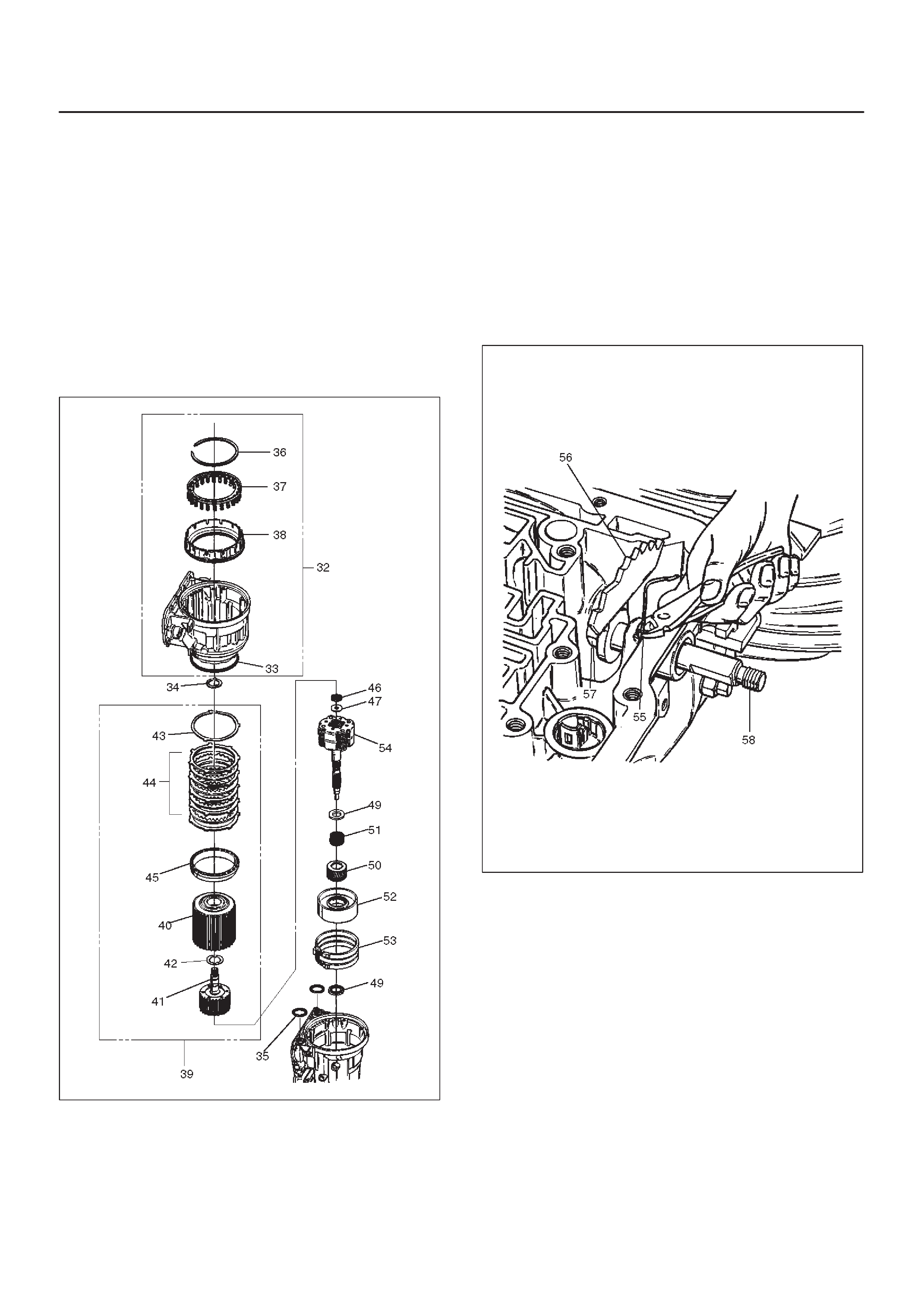
36.Separate second (40) and third clutch (41)
assemblies.
37.Remove thrust washer (42).
38.Remove reverse clutch plates (43 and 44) and
reverse clutch pressure plate (45).
39.Remove bearing (46) and washer (47).
40.Remove planetary carrier assembly (48).
41.Remove thrust bearing (49).
42.Remove reaction sun gear (50)
43.Remove needle bearing (51).
44.Remove brake drum (52).
45.Remove brake band (53).
46.Remove thrust bearing (54).
242RW005
47.Rotate case to horizontal position, valve body side
facing up.
DRemove spring pin (55), using cutting pliers, then
remove parking lock and selector lever assembly
(56).
NOTE: Insert wire in the center of the spring pin to
prevent it from collapsing during removal. Be aware of pin
height. Protect machined face of main case.
48.Remove parking lock and range selector lever 17 mm
nut (57).
49.Remove parking lock and range selector lever (56),
and actuator assembly.
50.Remove selector shaft (58).
NOTE: Inspect the shaft for burrs before removing to
prevent damaging seal. If necessary, remove burrs by
lightly sanding with an oilstone.
249RS004
Reassembly
1.Inspect selector shaft seal and replace it if necessary .
NOTE: Use a seal installer when replacing the seal.
DInstall selector shaft.
NOTE: Spring pin groove must be positioned inside the
case.
2.Install spring pin. Be sure the selector shaft can move
freely .Do not push the pin flush with the case surface.
Leave enough height for removal.
3.Install actuator assembly (1).
4.Install parking lock and range selector lever (2) and
new 17 mm nut. Tighten the nut to the specified
torque.
Torque: 22 N•m (16 lb ft)
249RS005
5.Rotate main case to vertical position, extension end
facing down.
DInstall brake band assembly (3).
NOTE: Be sure to align servo pin area with the servo hole.
6.Install thrust bearing (4).
NOTE: The case bushing acts as a guide for the thrust
bearing.
7.Install brake drum (5).
8.Install reaction sun gear (6).
9.Install needle bearing (7).
10.Inspect planetary carrier assembly (8) for wear and
damage. If necessary replace it.
DMeasure pinion end play clearance with a feeler
gauge.
Clearance: 0.13mm–0.89mm (0.005 in–0.035 in)
If clearance is outside specified value, replace the
planetary carrier assembly.
248RS001
11.Install the thrust bearing (9) on the output shaft.
NOTE: Use petroleum jelly to hold the thrust bearing in
place.
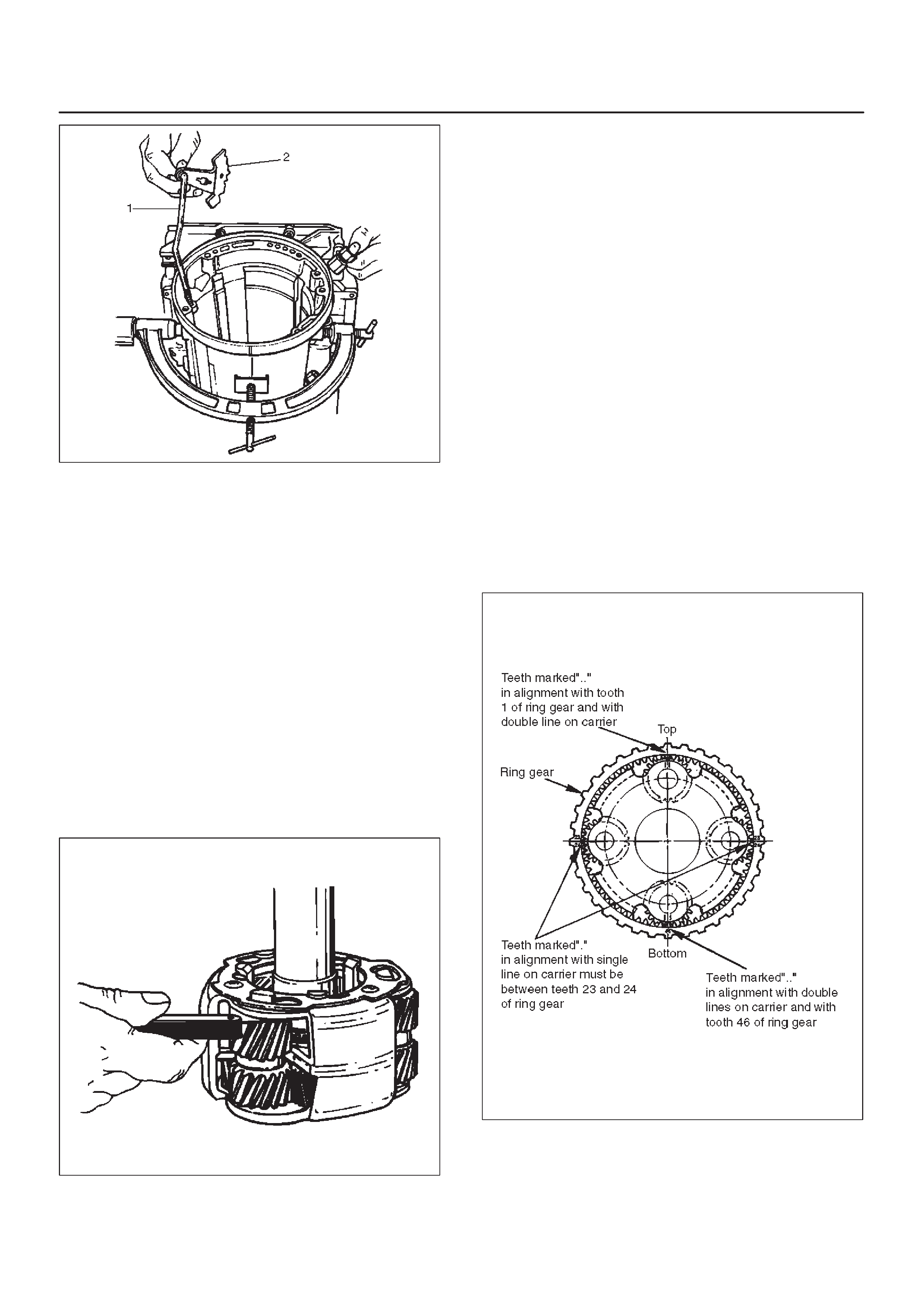
12.Align planetary pinions. Each pinion is marked with
double points to indicate the master tooth space and
exactly opposite with a single point to indicate the
master tooth. The markings on the planetary carrier
consist of double lines which are to be lined up with
the double points on two opposite pinions; the single
lines are to be lined up with the single points on the
other two pinions.
DAfter all four pinions are lined up, slide on the third
clutch assembly. Rotate third clutch and check
mark alignment. Considering that the ring gear
tooth between the double points of one planetary
pinion is tooth number 1, count the teeth to check
that the single points on the two adjacent pinions
are between teeth 23 and 24 of the ring gear, and
that the ring gear tooth between the double points of
the opposite pinion is tooth number 46. If the ring
gear and pinions are not lined up, remove and
realign them.
13.Install planetary carrier (8) with third clutch (12).
NOTE: Do not force. When properly aligned, the parts will
fit together easily.
248RS002
14.Remove the third clutch (12).
15.Install bearing (11) and washer (10).
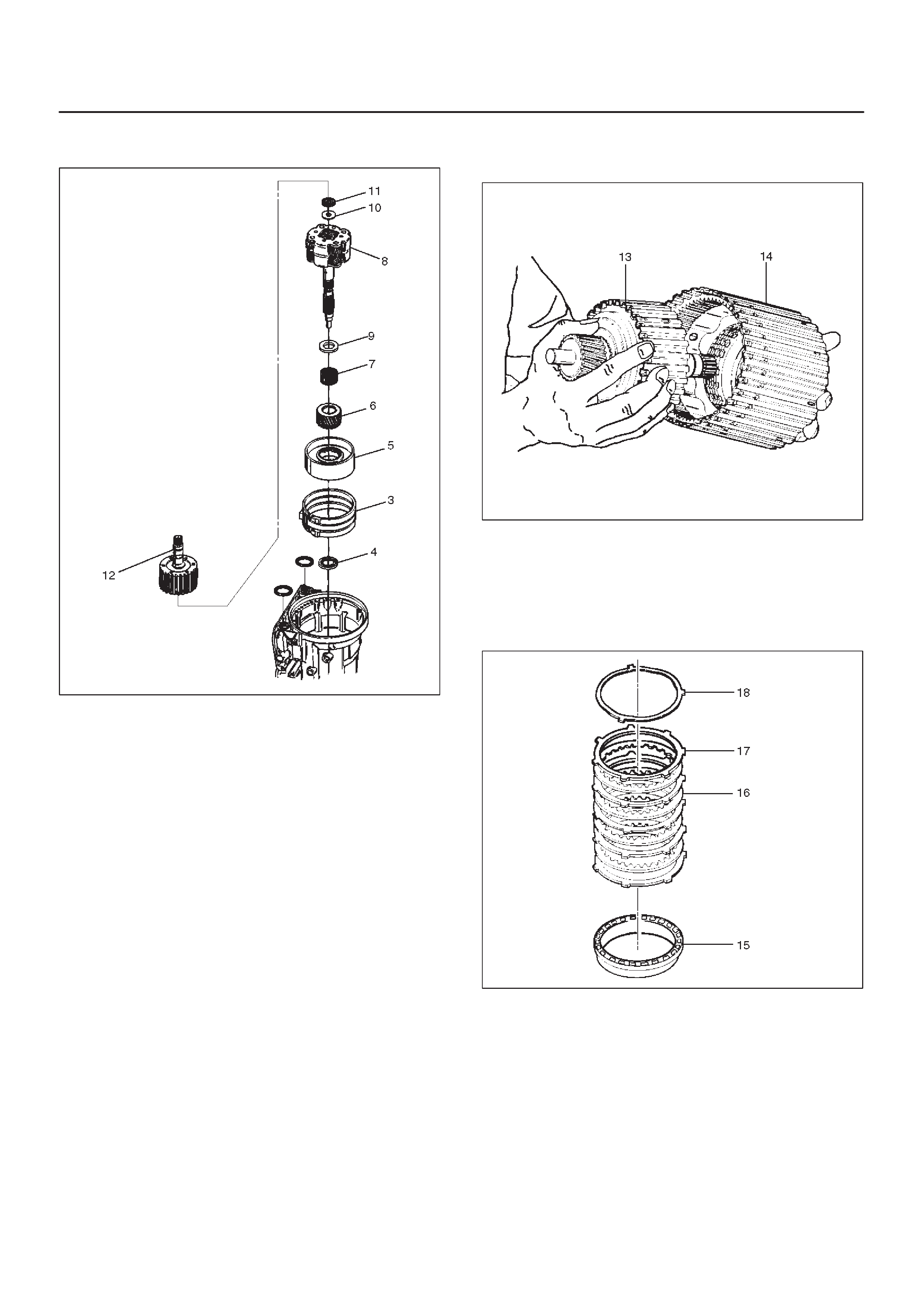
NOTE: Use petroleum jelly to hold the washer and
bearing in place.
242RW002
16.Carefully align the second clutch plate inner tangs.
DInstall thrust washer, tangs pointing downward, and
locating tang positioned in slot on second clutch
hub.
NOTE: Use petroleum jelly to hold thrust washer in place.
17.Install third clutch and intermediate shaft assembly
(13) into the second clutch drum (14).
18. Install second and third clutch assemblies into the
main case. T wist output shaft and clutch assemblies
to ensure proper fit.
247RS001
19.Install pressure plate (15) with lip side up, tang facing
valve body face.
20.Install reverse clutch plates. Start with a steel plate
(17) and alternate with a lined plate (16).
21.Install waved clutch plate (18) with center tang facing
valve body side.
247RS002

22.Second clutch end play measurement
1. Install the J–23085–A selective washer gauging
tool (with spacer ring) on the case flange and
against the intermediate shaft.
2. Position the inner shaft of the gauging tool against
the thrust surface of the second clutch hub.
3. Tighten thumb screw. Remove the tool.
4. Fit the spacer ring on the inner shaft of the tool.
5. Measure the gap and select appropriate washer
as shown in the chart.
Selective Thrust Washer
Gap: mm(in) Color
1.53 – 1.63 (0.060 – 0.064) Yellow
1.72 – 1.82 (0.068 – 0.072) Red
1.91 – 2.01 (0.075 – 0.079) Black
2.10 – 2.20 (0.083 – 0.087) Natural
2.29 – 2.39 (0.090 – 0.094) Green
2.48 – 2.58 (0.098 – 0.102) Blue
FOLLOWING THE PROCEDURE SHOULD
RESULT IN FINAL END–PLAY FROM 0.36 mm TO
0.79 mm (0.014 in TO 0.031 in)
247RS003
247RS004
23.Inspect fourth clutch piston seals and replace if
necessary.
DLubricate J–38554 fourth clutch piston fitter and
install it on fourth clutch piston (19).
DInstall fourth clutch piston (19) in adapter case (20).
DRemove fitter.
252RS003
24.Install retainer and spring assembly (22) into fourth
clutch piston (21).
25.Install snap ring (23) in adapter case.
DInstall J–23327 and J–23327–90 fourth clutch
spring compressor.
DSeat snap ring in groove.
DRemove compressor.
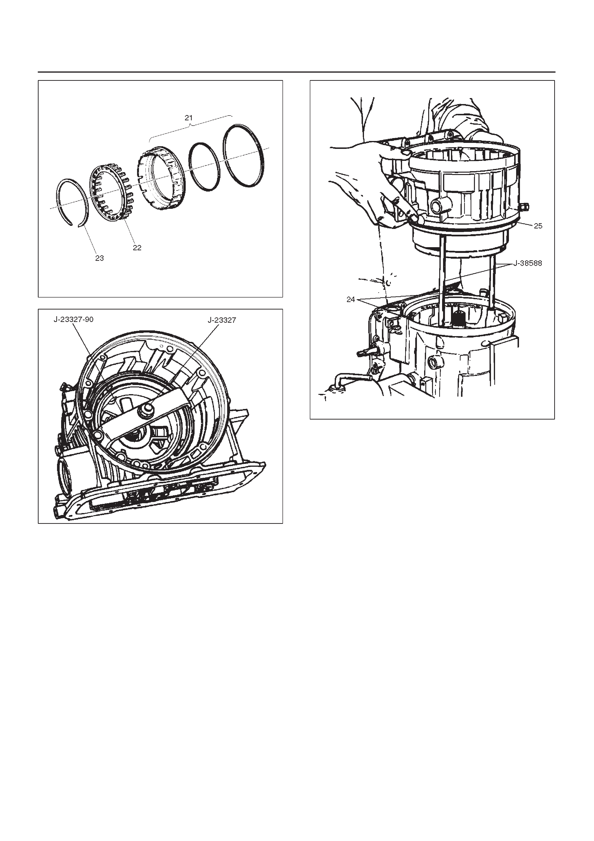
252RW002
252RS004
26.Install selective washer using petroleum jelly.
27.Install two O-ring seals (24) in main case and adapter
case/main case seal ring (25).
28.Install J–38588 guide pins.
DInstall adapter case and center support assembly to
main case.
242RS004
29.Install thrust washer (26) into adapter case, with
tangs pointing downwards.
30.Preassemble overdrive internal gear (27) and thrust
bearing assembly (28) onto the turbine shaft and
overrun clutch assembly.
NOTE: Install bearing assembly, black side up. Use
petroleum jelly to keep assembly in place.
31.Install overdrive carrier (30) and internal gear
assembly into adapter case.
32.Install fourth clutch plates (29) in the following order:
Steel, Lined, Steel, Steel, Lined, Steel. Steel plates
go in with short tang facing towards valve body
surface.
33.Install fourth clutch retainer(31) with the notch facing
up and positioned towards valve body surface.
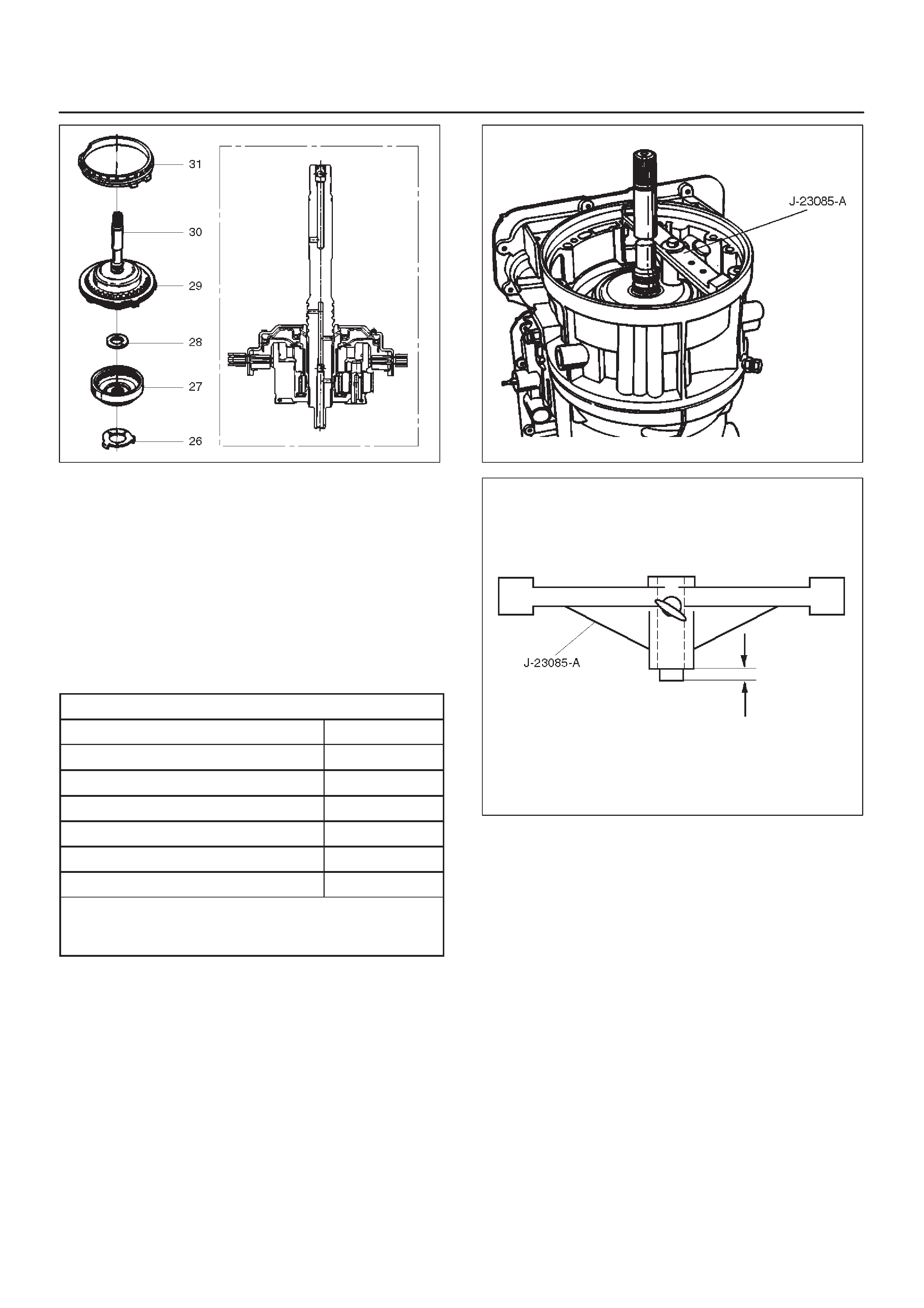
252RW004
34.Overdrive clutch end play measurement
1. Install the J–23085–A selective washer gauging
tool on the adapter case flange and against the
input shaft.
2. Position the inner shaft of the tool against the
thrust surface of the overrun clutch housing.
3. Tighten thumb screw. Remove the tool.
4. Measure gap. Select appropriate size washer as
shown in the chart.
5. Set selective thrust washer aside.
Selective Thrust Washer
Gap: mm(in) Color
1.53 – 1.63 (0.060 – 0.064) Yellow
1.72 – 1.82 (0.068 – 0.072) Red
1.91 – 2.01 (0.075 – 0.079) Black
2.10 – 2.20 (0.083 – 0.087) Natural
2.29 – 2.39 (0.090 – 0.094) Green
2.48 – 2.58 (0.098 – 0.102) Blue
FOLLOWING THE PROCEDURE SHOULD
RESULT IN FINAL END–PLAY FROM 0.1 mm TO
0.8 mm (0.004 in TO 0.03 in)
252RS005
252RS006
35.Install selective washer (32).
NOTE: Use petroleum jelly to hold selective washer in
place.
36.Install gasket (33).
37.Install converter housing and oil pump assembly (34)
to adapter case.
DFit and tighten seven outer 13 mm screws.
Torque: 39 N•m (29 lb ft)
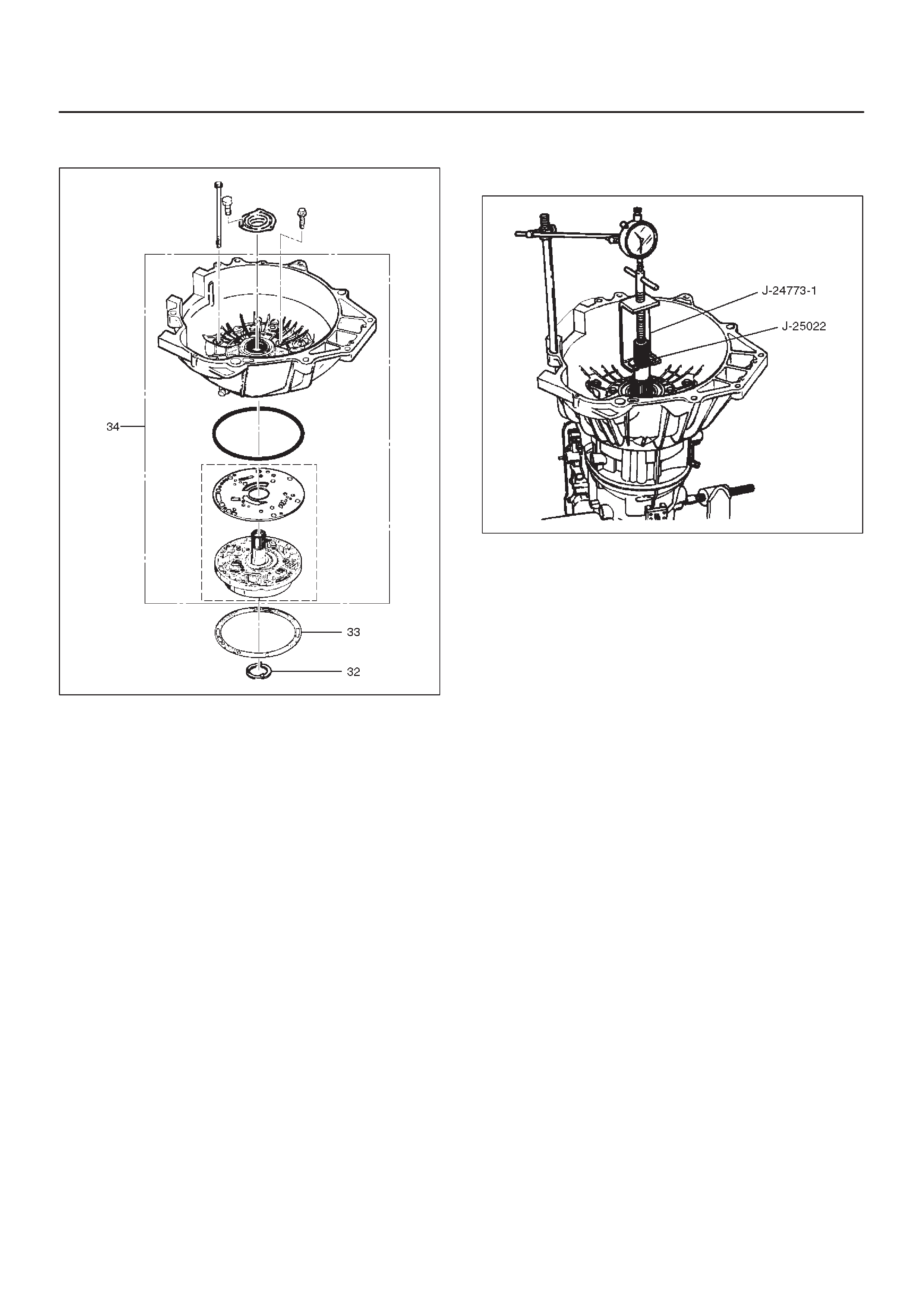
DEnsure free rotation of pump using J–23082–01
pump rotation tool.
241RW010
38.Overdrive clutch end play measurement
1. Fit J–25022 and J–24773–1 turbine shaft puller
on turbine shaft.
2. Position axial play checking tool on converter
housing mating face.
3. Pull turbine shaft upwards with puller until first
resistance is met. (due to weight of overdrive
assembly)
4. Maintain shaft in this position and set indicator to
zero.
5. Pull turbine shaft further upwards with puller.
Read end play shown on indicator.
End play: 0.1mm – 0.8mm (0.004 in – 0.031in)
6. Remove axial play checking tool and puller.
NOTE: If end play is not correct, repeat selective washer
selection.
252RW001
39.Inspect extension housing oil seal and replace if
necessary, using J–36797 extension housing oil seal
installer.
DRotate transmission to horizontal position, with
valve body side down.
DInspect parking wheel seal ring. Replace if
necessary.
DInstall wheel parking lock assembly (35).
40.Install speed wheel (36) and snap ring (37).
NOTE: Use extra long, needle nose pliers.
41. Install gasket onto extension assembly with a thin
coating of oil.
DInstall extension housing assembly (38), and align
parking pawl shaft.
DInstall actuator assembly into extension assembly.
DInstall seven 8 mm hexagon socket head screws.
Torque: 32 N•m (24 lb ft)
42.Inspect speed sensor O-ring. Replace if necessary.
DInstall speed sensor assembly (39) and 10 mm
screw.
Torque: 9 N•m (78 lb in)
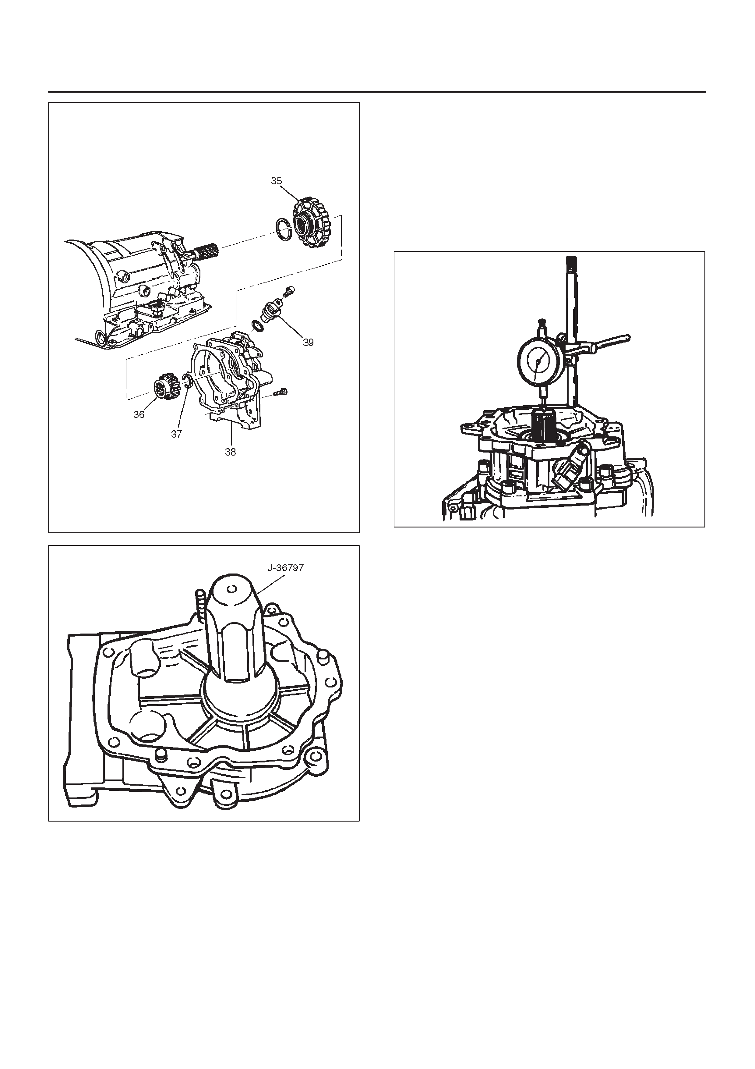
241RW009
241RS004
43.Main case end play measurement
1. Attach axial play checking tool on the extension
housing and set indicator to zero on output shaft.
2. Manually push output shaft upwards.
End play: 0.36mm – 0.80mm (0.014 in – 0.031in)
3. Remove axial play checking tool.
4. If end play is not correct, repeat selective washer
selection.
241RS005
44.Inspect servo piston seal ring. Replace if necessary.
DEnsure brake band is correctly positioned. Rotate
output shaft if necessary.
DInstall J–38428 servo piston fitter in servo bore.
DInstall apply rod (40), round end toward band, return
spring (41) and piston assembly (42).
45.Install the J–23075 servo spring compressor with
offset to rear of case.
DCompress servo piston seal ring, using fitter while
tightening the tool screw.
DInstall servo piston retaining ring (43).
DRemove tool.
DAdjust the brake band by tightening the servo
adjusting screw to 4.5 N·m torque. Be certain the
lock nut is loose, then back-off the screw five turns
exactly . Hold piston sleeve with wrench and tighten
lock nut to 18.5 N·m torque. Be certain the adjusting
screw does not turn.
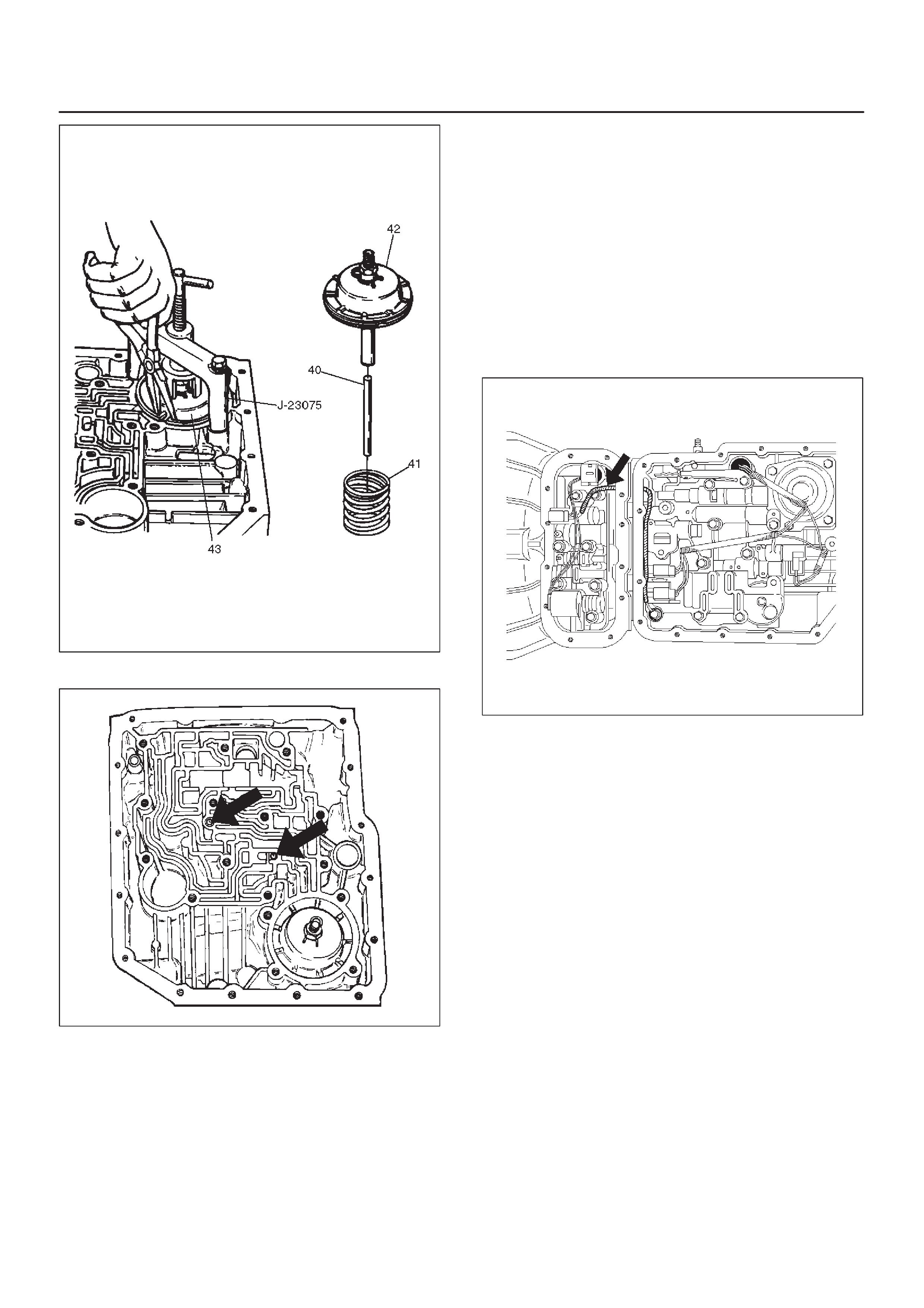
242RW004
46.Install two check balls (44).
244RW002
47.Inspect main case electrical connector and seal,
replace if necessary.
DInstall electrical 4 pin connector/main case and
wiring harness.
48.Install two J–25025–B guide pins into main case.
DInstall main case valve body complete assembly
(45) and manual valve link.
NOTE: Valve must be extended as the short end of
manual valve link is connected to the range selector lever.
Long end of link goes into valve.
DInstall seven 13 mm screws, tighten the specified
torque.
Torque: 20 N•m (15 lb ft)
DPass ground wire of adapter case wiring harness
assembly through the hole joining adapter fluid area
and main case fluid area.
DAssemble 8.5 mm connector of ground wire under
the head of this valve body bolt and reinstall it.
DRemove two guide pins.
244RW001
49.Install servo cover gasket, cover (46) and four 13 mm
screws.
Torque: 25 N•m (18 lb ft)
50.Connect wiring harness (47) to band control, shift
solenoids, and main case 4 pin connector.
51.Install manual detent roller and spring assembly (48)
with clip.
DInstall two 13 mm screws.
Torque: 20 N•m (15 lb ft)
52.Install oil filter (49) and three 13 mm screws.
Torque: 20 N•m (15 lb ft)
53.Install oil pan gasket, magnet, main oil pan (50),
sixteen 10 mm screws.
Torque: 11 N•m (96 lb in)
54.Inspect adapter case electrical connector and seal.
Replace if necessary.
DInstall electrical five pin connector and harness
assembly (52) in bottom of adapter case.
55.Install gasket, transfer plate, and gasket.
DInstall adapter case valve body (51) complete and
seven 13 mm screws.
Torque: 20 N•m (15 lb ft)
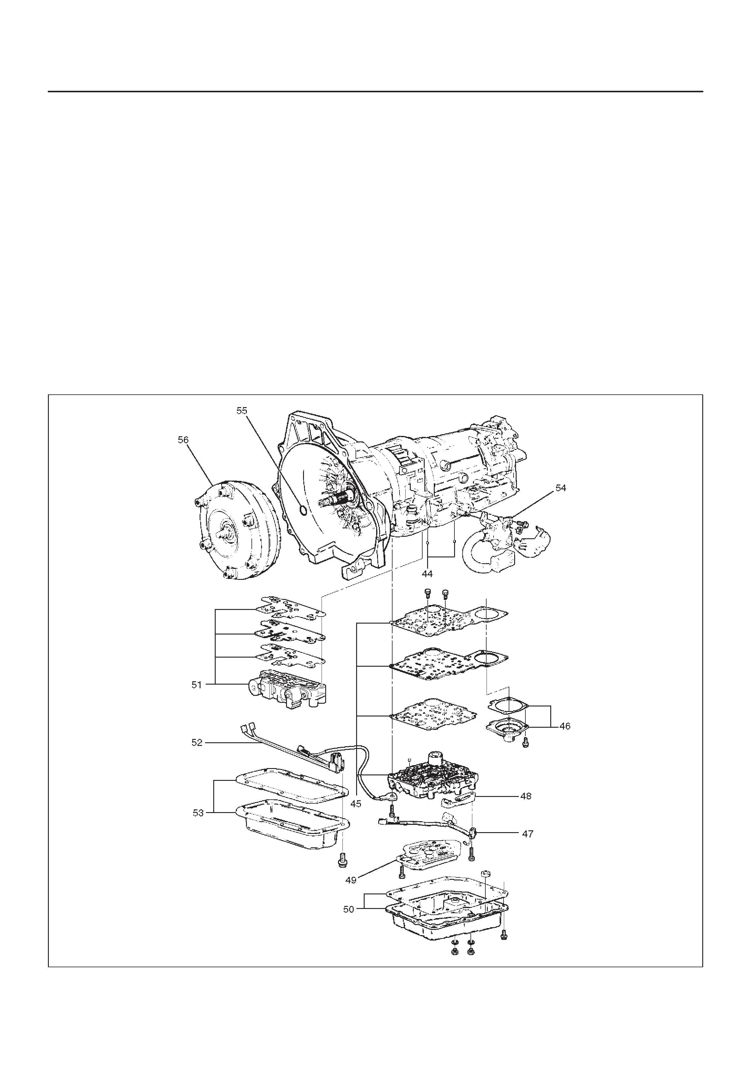
56.Connect wiring harness harness assembly (52) to
converter clutch solenoid, force motor, and 5 pin
connector.
57.Install oil pan gasket, adapter case oil pan (53), and
twelve 10 mm screws.
Torque: 11N•m (96lbin)
DRotate transmission, with bottom pan facing down.
58.Install mode switch (54), two 10 mm screws, selector
lever nut, and cover.
10 mm screw
Torque: 13N•m (113lbin)
Nut
Torque: 23N•m (17lbft)
DAdjust using setting tool, refer to Mode Switch in
this section.
59.Install O-ring (55) on turbine shaft.
60.Install torque converter (56).
The converter assembly must be replaced under any
of the following conditions:
a.Evidence of damage to the pump assembly.
b.Metal particles are found after flushing the cooler
lines.
c.External leaks in hub weld area.
d.Converter pilot broken, damaged, or poor fit into
crankshaft.
e.Converter hub scored or damaged.
f.Internal failure in stator.
g.Contamination from engine coolant.
h.Excess end play.
DRotate transmission, bell housing up. Spin
converter to insure proper fit.
61.Fill transmission through the overfill screw hole of oil
pan, using ATF DEXRON–III. Refer to Changing
Transmission Fluid in this section.
241RW016
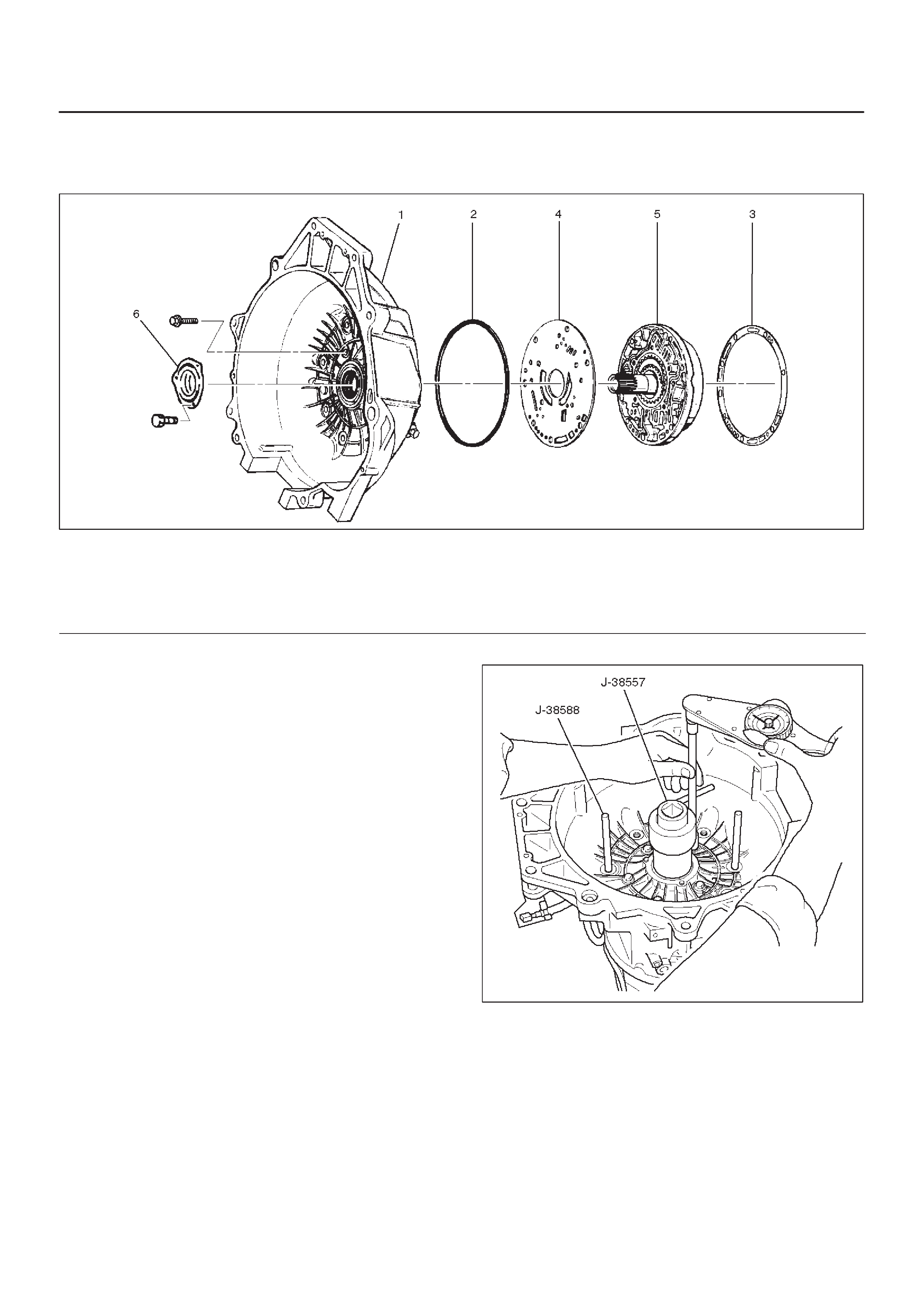
Converter Housing and Oil Pump Assembly
Disassembled View
241RW003
Legend
(1) Converter Housing
(2) Outer Seal Ring
(3) Gasket
(4) Wear Plate
(5) Oil Pump Assembly
(6) Oil Seal Ring
Disassembly
1.Remove oil pump assembly from converter housing.
2.Remove outer seal ring.
3.Remove gasket.
4.Remove wear plate.
5.Remove oil seal ring.
Inspection and Repair
Visual Check:
If any damage, deformation, or local wear is found in a
converter housing, outer seal ring, wear plate, or oil seal
ring, replace it.
Reassembly
1.Install wear plate onto oil pump assembly.
2.Install converter housing onto complete oil pump
assembly . Align with two short J–38588 guide pins on
outer bolt holes.
DLoosely install five 13mm bolts.
DCenter converter housing using J–38557 centering
tool.
DTighten five inner 13mm bolts in an alternating
pattern.
Torque: 20 N•m (15 lb ft)
241RW002
3.Install oil seal ring (3 screws).
Torque: 3 N•m (26 lb in)
4.Install gasket.
5.Install outer seal ring.
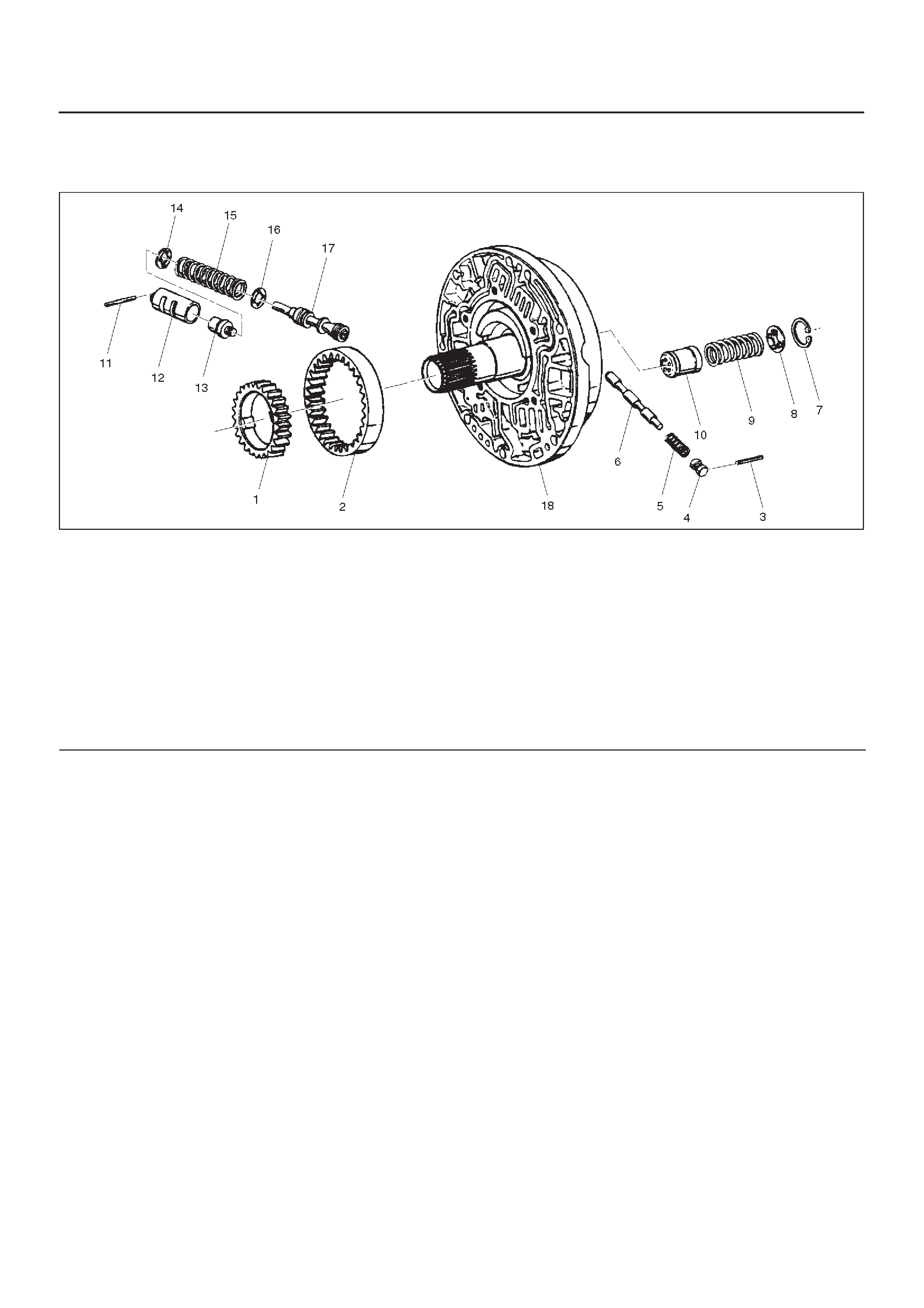
Oil Pump
Disassembled View
241RS014
Legend
(1) Oil Pump Drive Gear
(2) Oil Pump Driven Gear
(3) Pin
(4) Plug
(5) Spring
(6) Converter Clutch Control Valve
(7) Snap Ring
(8) Spring Seat
(9) Spring
(10) Throttle Signal Accumulator Piston
(11) Sleeve Pin
(12) Sleeve
(13) Boost Valve
(14) Spring Seat
(15) Valve Spring
(16) Spring Seat
(17) Pressure Regulator valve
(18) Oil Pump Assembly
Disassembly
1.Remove oil pump drive gear (1) and driven gear (2).
2.Remove pin (3) from oil pump assembly (18).
3.Remove plug (4), spring (5), and converter clutch
control valve (6).
4.Remove snap ring (7) from oil pump assembly (18).
5.Remove spring seat (8), spring (9), and throttle signal
accumulator piston (10).
6.Remove sleeve pin (11) from oil pump assembly (18).
7. Remove sleeve (12), boost valve (13), spring seat
(14), valve spring (15), spring seat (16), and pressure
regulator valve (17).
Inspection and Repair
Visual Check:
If any damage, deformation or wear is found, replace the
damaged part.
Reassembly
1.Lubricate and preinstall pressure regulator spring
seat (16) on valve (17), with the flat side against
shoulder.
2.Install pressure regulator valve (17) and spring seat
(16) assembly , valve spring (15), and spring seat (14)
with the flat side away from spring to oil pump
assembly (18).
3.Assemble boost valve (13) into sleeve (12).
4.Install boost valve and sleeve assembly, and sleeve
pin (11) to oil pump assembly (18).
5.Install throttle signal accumulator piston (10), spring
(9), and spring seat (8), with the flat side away from
the spring, and snap ring (7) to oil pump assembly
(18).
6.Install converter clutch control valve (6), spring (5),
plug (4), and pin (3) to oil pump assembly (18).
7.Install oil pump driven gear (2) and drive gear (1).
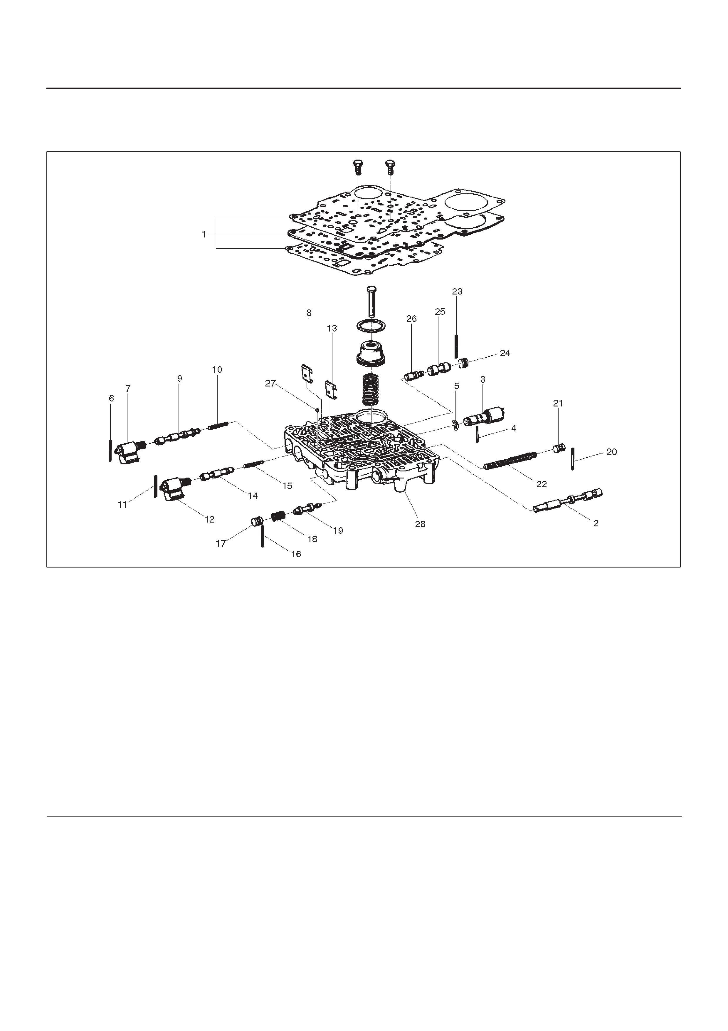
Main Case Valve Body
Disassembled View
244RS010
Legend
(1) Gaskets and Transfer Plate
(2) Manual Valve
(3) Band Control Solenoid
(4) Pin
(5) Waved W asher
(6) Spring Pin
(7) Solenoid A
(8) Retainer
(9) 1–2/3–4 Shift Valve
(10) Spring
(11) Spring Pin
(12) Solenoid B
(13) Retainer
(14) 2–3 Shift Valve
(15) Spring
(16) Spring Pin
(17) Plug
(18) Spring
(19) Low Pressure Control Valve
(20) Spring Pin
(21) Plug
(22) Band Control Screen Assembly
(23) Spring Pin
(24) Plug
(25) 1–2 Accumulator Valve
(26) 1–2 Accumulator Control Valve
(27) Check ball
(28) Main Case Valve Body
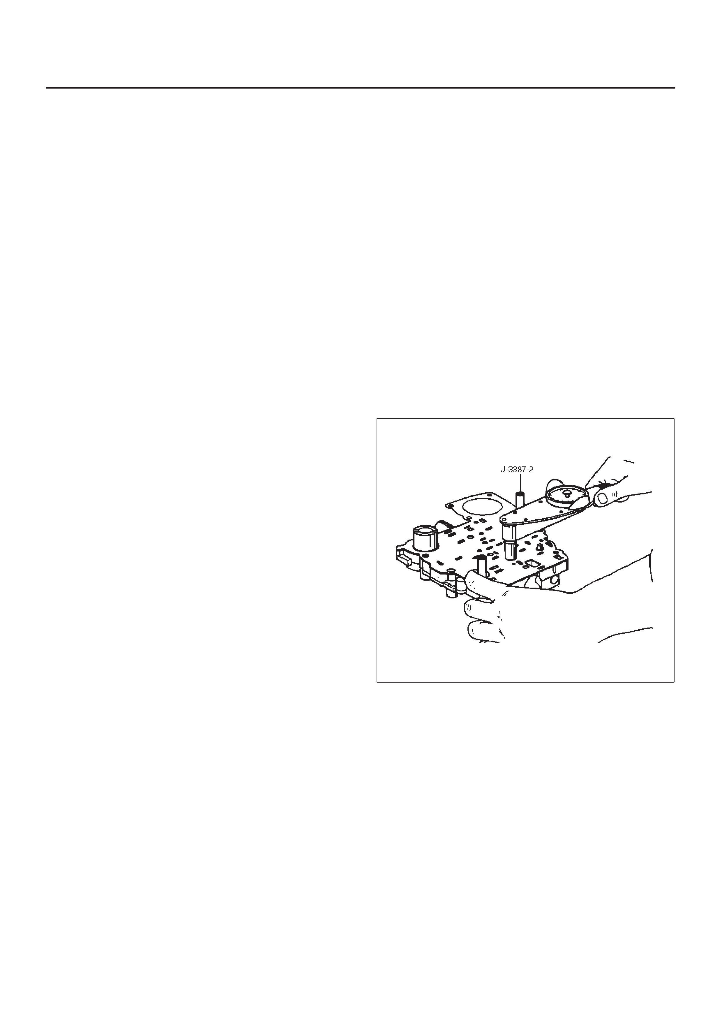
Disassembly
1.Remove two 11mm bolts from valve body (28), then
remove gaskets and transfer plate (1).
2.Remove manual valve (2).
3.Push in band control solenoid (3) to compress waved
washer (5), and remove pin (4).
4.Remove band control solenoid (3) and waved washer
(5).
5.Remove spring pin (6) with a 3 mm diameter punch.
6.Remove solenoid A (7) by grasping the metal tip. Do
not grasp the connector housing.
7.Remove retainer (8), 1–2/3–4 shift valve (9) and
spring (10).
8.Remove spring pin (1 1) with a 3 mm diameter punch.
9.Remove solenoid B (12) by grasping the metal tip. Do
not grasp the connector housing.
10.Remove retainer (13), 2–3 shift valve (14), and spring
(15).
11.Remove spring pin (16), plug (17), spring (18) and low
pressure control valve (19).
12.Remove spring pin (20), plug (21), and band control
screen assembly (22).
13.Remove spring pin (23), plug (24), 1–2 accumulator
valve (25), and 1–2 accumulator control valve (26).
14.Remove 1 check ball (27) from valve body (28).
Inspection and Repair
Inspect for the following, and replace any damaged or
worn parts:
1.Damage or wear to each valve.
2.Damage in oil passeges.
3.Cracks or damage to valve body.
4.Valve operations.
5.Spring fatigue.
Reassembly
1.Install 1–2 accumulator control valve (26), 1–2
accumulator valve (25), plug (24), and spring pin (23).
2.Install band control screen assembly (22), plug (21),
and spring pin (20).
3. Install low pressure control valve (19), spring (18),
plug (17), and spring pin (16).
4.Install spring (15), 2–3 shift valve (14), retainer (13),
solenoid B (12), and spring pin (11).
5.Install spring (10), 1–2/3–4 shift valve (9), retainer (8),
solenoid A (7), and spring pin (6).
6.Install waved washer (5), band control solenoid (3),
and pin (4).
7.Install manual valve (2).
8.Install check ball (27) to valve body (28).
9.Install gasket (valve body/transfer plate) and transfer
plate using two J–3387–2 guide pins.
DInstall two 11mm bolts.
Torque: 13 N•m (113 lb in)
244RS004
DInstall gasket (transfer plate/main case).

Adapter Case Valve Body
Disassembled View
243RW001
Legend
(1) Converter Clutch Solenoid Assembly
(2) Retainer
(3) Force Motor Solenoid
(4) Retainer
(5) Plug
(6) 3/4 Accumulator Valve
(7) 3/4 Accumulator Control Valve
(8) Spring
(9) Retaining Ring
(10) Feed Iimit Valve
(11) Plug Retainer
(12) O-ring
(13) Plug
(14) Force Motor Screen Assembly
(15) Adapter Case Valve Body
Disassembly
1.Remove 11mm bolt from valve body.
DRemove converter control solenoid assembly (1).
2.Remove 11mm bolt and retainer (2) from valve body.
DRemove force motor solenoid (3).
3.Remove retainer (4), plug (5), 3/4 accumulator valve
(6), and 3/4 accumulator control valve (7)
4.Remove spring (8), retaining ring (9), and feed limit
valve (10).
5.Remove plug retainer (1 1), O-ring (12), plug (13), and
force motor screen assembly (14).
DUse 5 mm bolt to pull plug.
Inspection and Repair
Inspect for the following, and replace any damaged or
worn parts:
1.Damage or wear to each valve.
2.Damage in oil passeges.
3.Cracks or damage to valve body.
4.Valve operations.
5.Spring fatigue.
Reassembly
1.Install force motor screen assembly (14), plug (13),
O-ring (12), and plug retainer (11).
2.Install feed limit valve (10), retaining ring (9), and
spring (8).

3.Install 3/4 accumulator control valve (7), 3/4
accumulator valve (6), plug (5), and retainer (4).
4.Install force motor solenoid (3).
DPlace solenoid terminals pointing towards mating
face.
DInstall retainer (2) and bolt.
Torque: 10 N•m (87 lb in)
5.Install converter clutch solenoid assembly with two
O-rings (1) to valve body.
DInstall bolt.
Torque: 10 N•m (87 lb in)
Third Clutch and Sprag Unit
Disassembled View
248RW001
Legend
(1) Retaining Ring
(2) Input Sun Gear and Sprag Unit Assembly
(3) Retaining Washer
(4) Bearing
(5) Thrust Washer
(6) Clutch Plates
(7) Third Clutch Spring Cushion Plate
(8) Third Clutch Drum Assembly
Disassembly
1. Place the third clutch drum and intermediate shaft
assembly upright, using the overdrive internal gear as
a support.
2.Locate the ends of the retaining ring. Depress one
end of the ring using a small screwdriver instead of
the depressor handle provided with the tool
J-38450-A. Slide one blade down between the third
clutch drum and the retaining ring.
3.Remove a screwdriver and repeat this step for the
other end of retaining ring.
4.Install the remaining four blades approximately (five)
notches apart using a screwdriver to depress the
retaining ring.
5.Pull up on input sun gear and sprag unit assembly (1
and 2) to release the retaining ring from third clutch
drum assembly (8).
6.Remove the tool blades. 248RX001
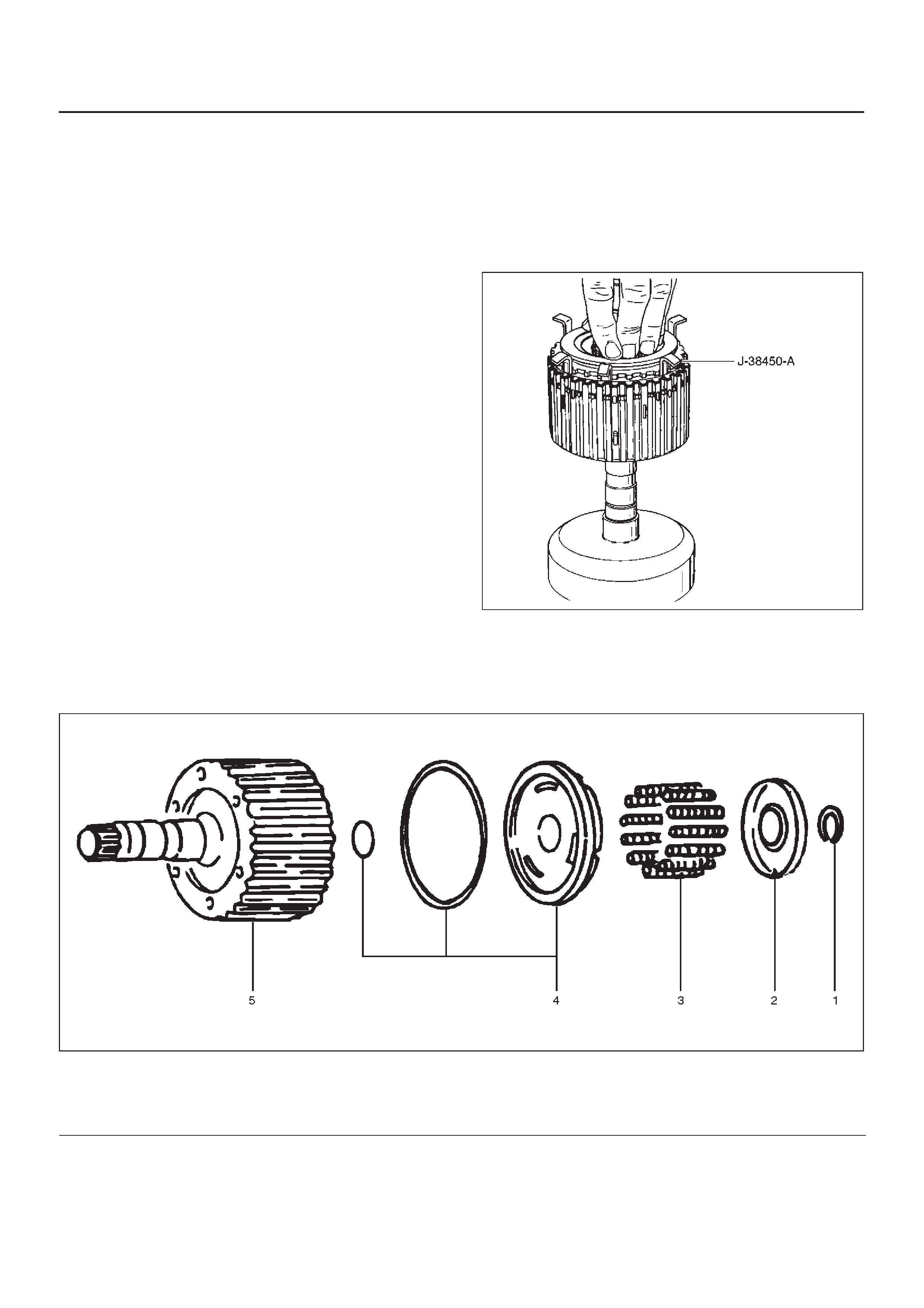
7.Remove retaining washer (3), bearing (4), thrust
washer (5), and clutch plates (6 and 7) from the third
clutch drum assembly (8).
Inspection and Repair
Visual Check:
If any damage, deformation or wear is found, replace the
damaged part.
Reassembly
1.Place third clutch drum and intermediate shaft
assembly upright, using the overdrive internal gear as
a support.
2.Install third clutch spring cushion plate (7), bevel face
down.
3. Install third clutch plates (6) into third clutch drum
assembly (8). Start with the steel clutch plate and
alternate with lined plates.
4. Install thrust washer (5), bearing (4) and retaining
washer (3).
5.Fully engage the hub spline of the input sun gear and
sprag unit assembly (2) into the third clutch inner
tangs.
DSimultaneously rotate the outer sprag race to
engage into the third clutch drum assembly (8).
6.Place J-38450-A blades between the retaining ring
and the third clutch drum apporximately (five)
notches apart, and one blade at each end of the
retaining ring (1). Push down on sprag assembly until
the assembly is seated into the third clutch drum
assembly (8).
7. Remove the tool blades and engage retaining ring
into groove of third clutch drum.
248RX002
Third Clutch
Disassembled View
248RS006
Legend
(1) Retaining Ring
(2) Spring Seat
(3) Springs
(4) Piston Assembly
(5) Third Clutch Drum
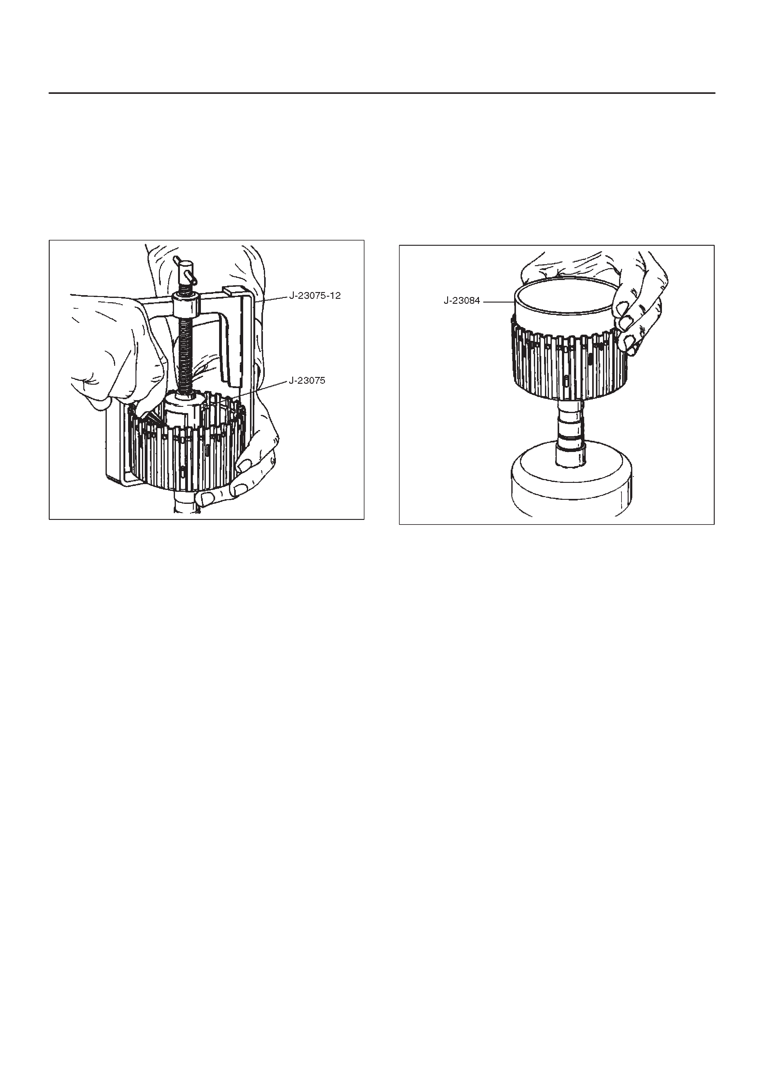
Disassemble
1.Compress spring seat using the J–23075 spring
compressor and J–23075–12 adapter tool.
NOTE:Do not overstress the springs and seat. This will
cause damage to the spring seat.
DRemove the tool.
DRemove retaining ring (1).
248RS007
2.Release the spring seat (2).
NOTE:Do not let the spring seat catch in the ring groove.
DRemove spring seat (2) and springs (3).
3.Remove piston assembly (4) from third clutch drum
(5).
Inspection and Repair
Visual check:
If any damage, deformation or wear is found, replace the
damaged part.
Operation check:
Shake the piston and listen for check ball movement.
Movement indicates proper check ball operation.
Replace the piston if the check ball is missing or falls out.
Reassembly
1.The lip of the piston seal must point toward the front of
the transmission. Lubricate the seal lip with
transmission fluid.
DInstall piston assembly (4) into the third clutch drum
(5). Use the J–23084 third clutch piston installer to
protect the outer seal during installation.
DRemove the seal installer.
248RS008
2.Install twelve springs (3) and spring seat (2).
3.Place retaining ring (1) onto spring seat.
DCompress the piston springs, using the J–23075
piston spring compressor and J–23075–12
adapter.
CAUTION:Do not overstress the springs and seat.
Do not let the spring seat catch in the ring groove.
This may cause damage to the spring seat.
DInstall spring seat retaining ring (1).
DRemove the piston spring compressor and adapter.
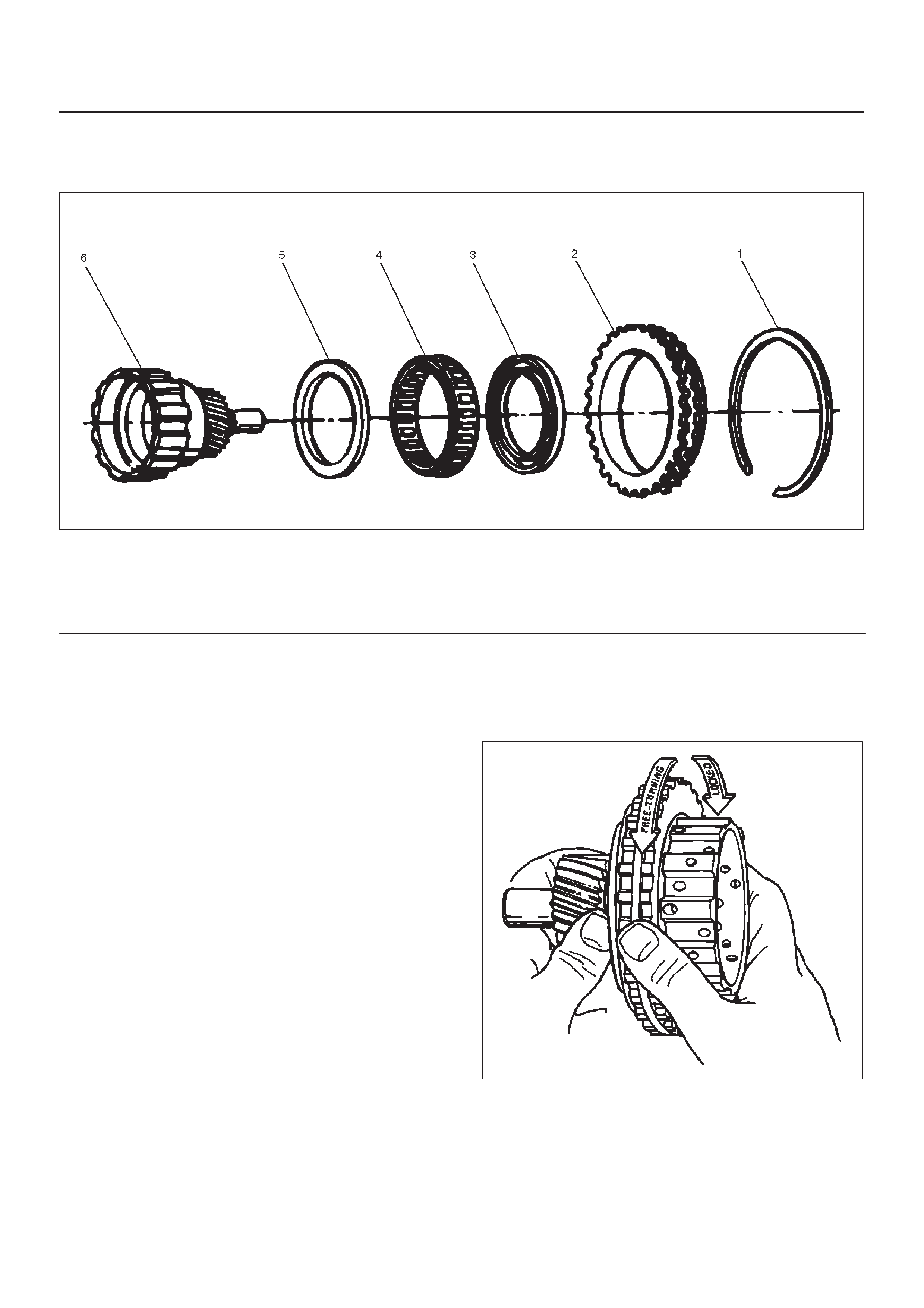
Sprag Unit
Disassembled View
248RS009
Legend
(1) Retaining Ring
(2) Sprag Outer Race
(3) Ring
(4) Sprag Assembly
(5) Ring
(6) Third Clutch Hub and Sun Gear Assembly
Disassembly
1.Remove the sprag outer race, retaining ring, and
sprag assembly from the third clutch hub and sun
gear assembly.
2.Remove the rings and sprag assembly from the sprag
outer race.
Inspection and Repair
Visual Check:
If any damage, deformation or local wear is found,
replace the damaged part.
Reassembly
NOTE: Flared shoulder of the sprag cage faces the sun
gear . This procedure must be followed exactly to be sure
that the sprag assembly is installed properly.
1.Install rings and sprag assembly onto the third clutch
hub and sun gear.
2.Install sprag outer race and retaining ring assembly
over the sprag cage assembly.
DPlace third clutch hub and sun gear assembly on a
flat surface, sun gear facing up. Place sprag outer
race and sprag assembly over the sun gear
assembly, push down and turn the input sun
counterclockwise at the same time.
NOTE: Check correct rotation by holding the sun gear in
your left hand and turning the outer race. The outer sprag
race should turn freely towards you and should lock
turning away from you.
248RS010

Second Clutch
Disassembled View
247RW001
Legend
(1) Retaining Ring
(2) Ring Gear
(3) Retaining Ring
(4) Spacer
(5) Clutch Plates
(6) Waved W asher
(7) Retaining Ring
(8) Spring Seat
(9) Springs
(10) Piston Assembly
(11) Second Clutch Drum
Disassembly
1.Remove retaining ring (1) from second clutch drum
(11).
2.Remove ring gear (2), retaining ring (3), and spacer
(4).
3.Remove clutch plates (5) and waved washer (6).
4.Remove retaining ring (7) using J–23327 compressor
to compress the spring seat (8).
5.Remove spring seat (8), springs (9) and piston
assembly (10) from second clutch drum (11).
247RS006
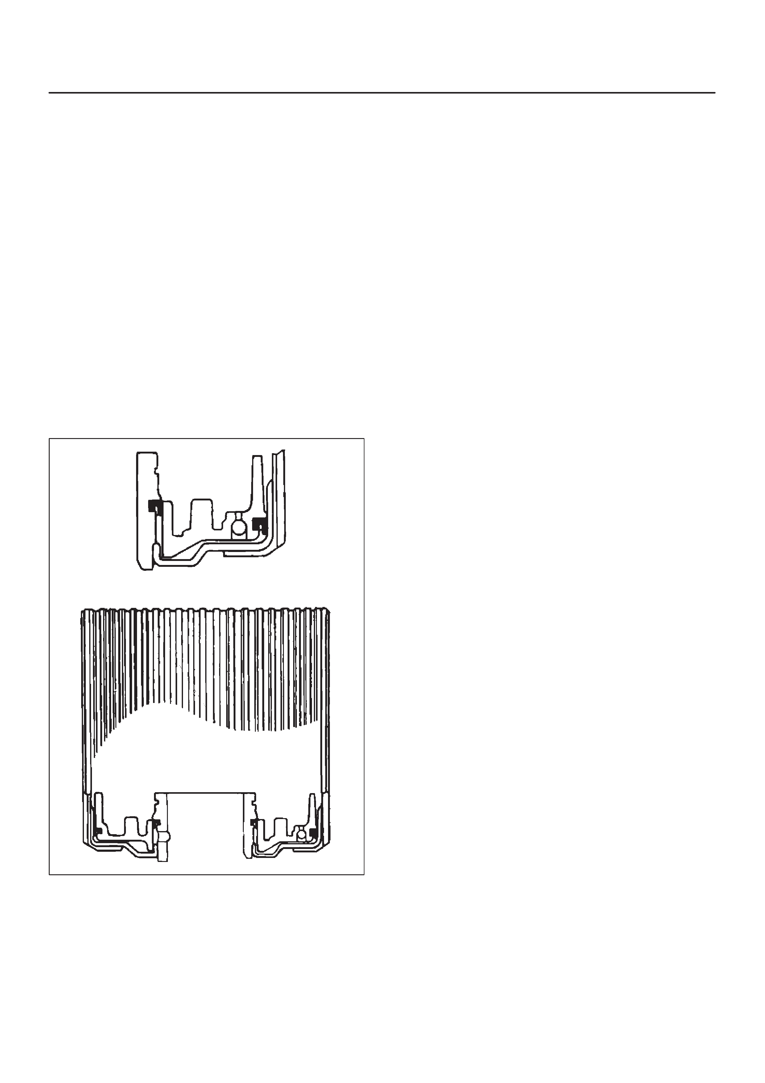
Inspection and Repair
Visual Check:
If any damage, deformation or wear is found, replace the
damaged part.
Operation Check:
Shake the piston and listen for check ball movement.
Movement indicates proper check ball operation.
Replace the piston if the check ball is missing or falls out.
Reassembly
1. Install piston assembly (10) into the second clutch
drum (11).
DLubricate the lip seal with transmission fluid. Use
the J–23080–A second clutch piston installer to
protect the outer piston lip seal.
NOTE: Lip of the seal should point toward front of
transmission.
DRemove the installer.
247RS007
2.Install twenty-two piston springs (9) and spring seat
(8) on the second clutch piston (10). Place retaining
ring (7) onto spring seat.
DUse the J–23327 compressor to compress the
piston springs.
NOTE: Do not let spring seat catch in ring groove.
DRemove the compressor.
3.Install waved plate (6) and clutch plates (5). Start with
a steel plate and alternate with lined plates.
DAlign second clutch inner tangs.
4.Install spacer (4), with the fluted end toward clutch
plates.
5.Install retaining ring (3), ring gear (2) and retaining
ring (1).
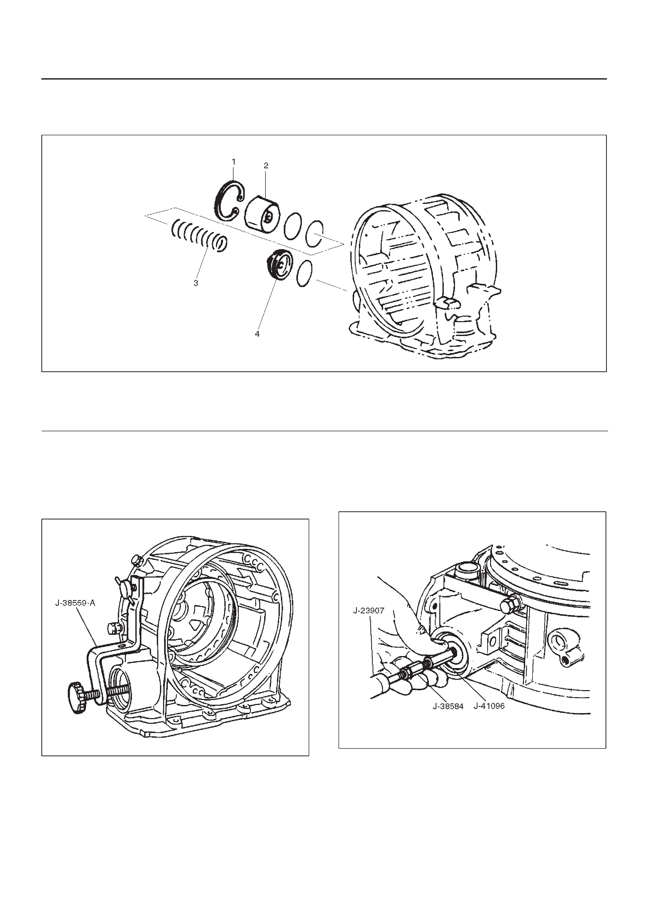
3–4 Accumulator Piston
Disassembled View
244RS005
Legend
(1) Snap Ring
(2) Cover
(3) Spring
(4) Piston Assembly
Disassembly
1.Install the J–38559–A cover compressor on adapter
case.
DCompress piston cover then remove snap ring.
242RS007
2.Install the J–41096 cover remover and J–38584
adapter to center hole of cover.
DUse the J–23907 slide hammer to remove cover.
3.Remove spring and piston assembly.
242RW001
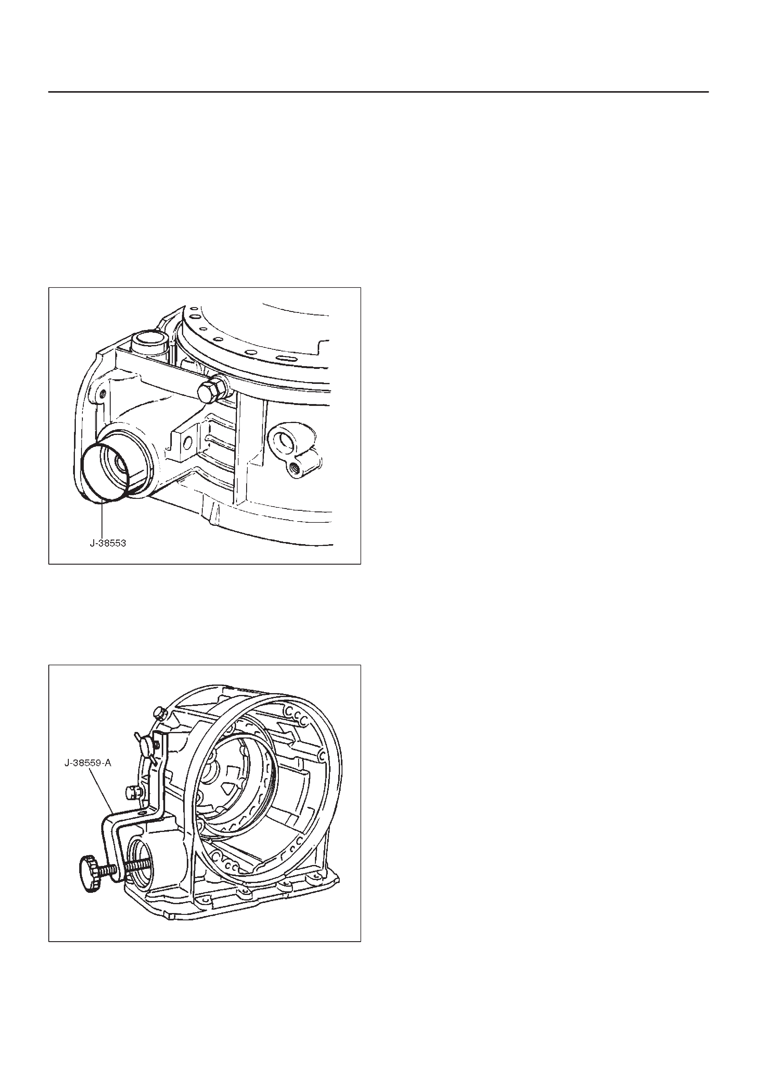
Inspection and Repair
Visual Check:
If any damage, deformation or wear is found, replace the
damaged part.
Reassembly
1.Place the J–38553 piston fitter into adaptor case and
push the piston into position, using suitable diameter
tube.
DRemove the piston fitter.
244RS006
2.Install spring and cover.
3.Install snap ring, using the J–38559–A compressor
tool.
DInstall snap ring in groove.
DRemove the compressor tool.
242RS007
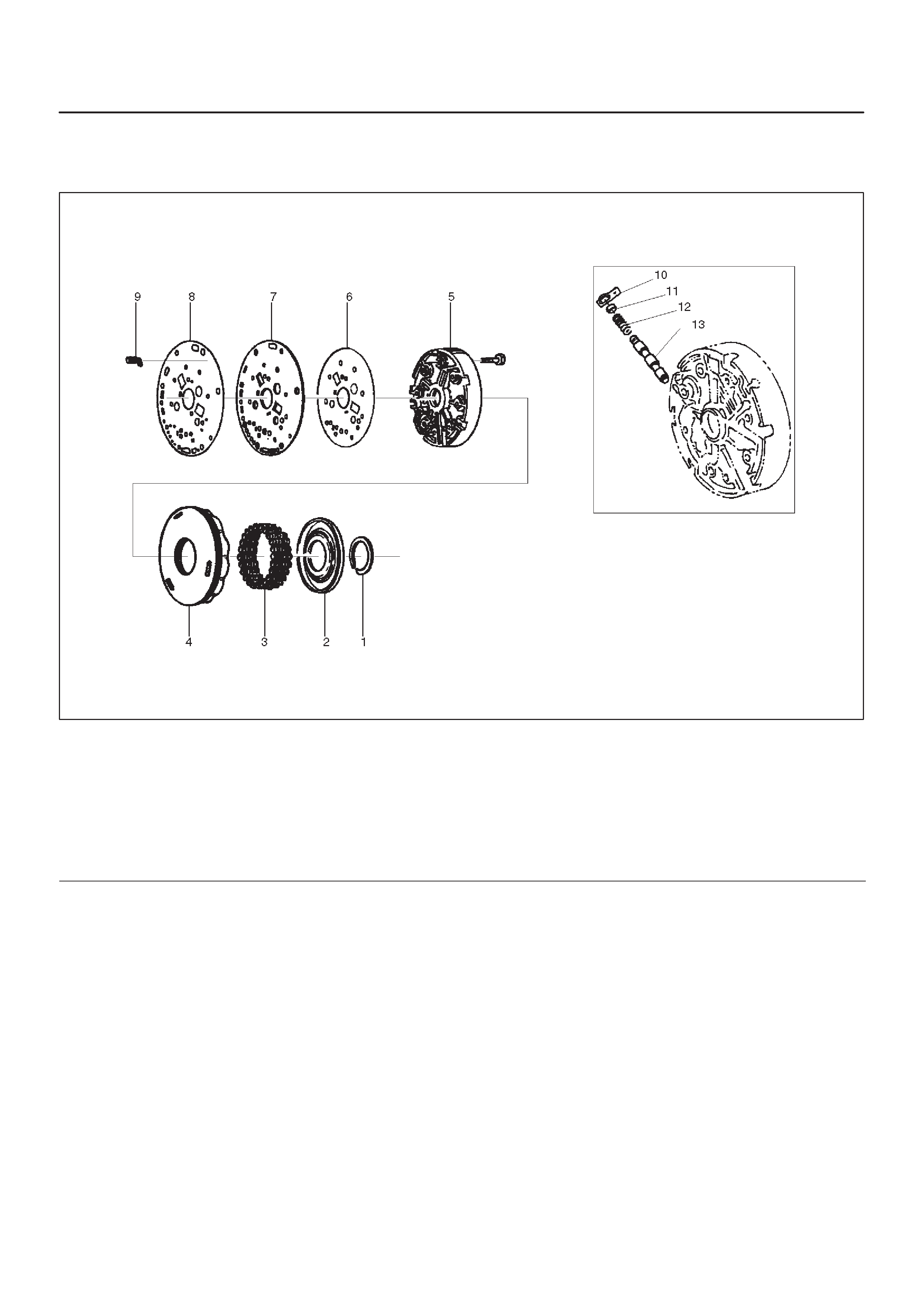
Reverse Clutch Piston and Center Support
Disassembled View
242RS006
Legend
(1) Retaining Ring
(2) Spring Seat
(3) Springs
(4) Piston Assembly
(5) Center Support
(6) Gasket
(7) Transfer Plate
(8) Gasket
(9) Restrictor
(10) Retainer Plate
(11) Plug
(12) Spring
(13) Overrun Lock Out Valve
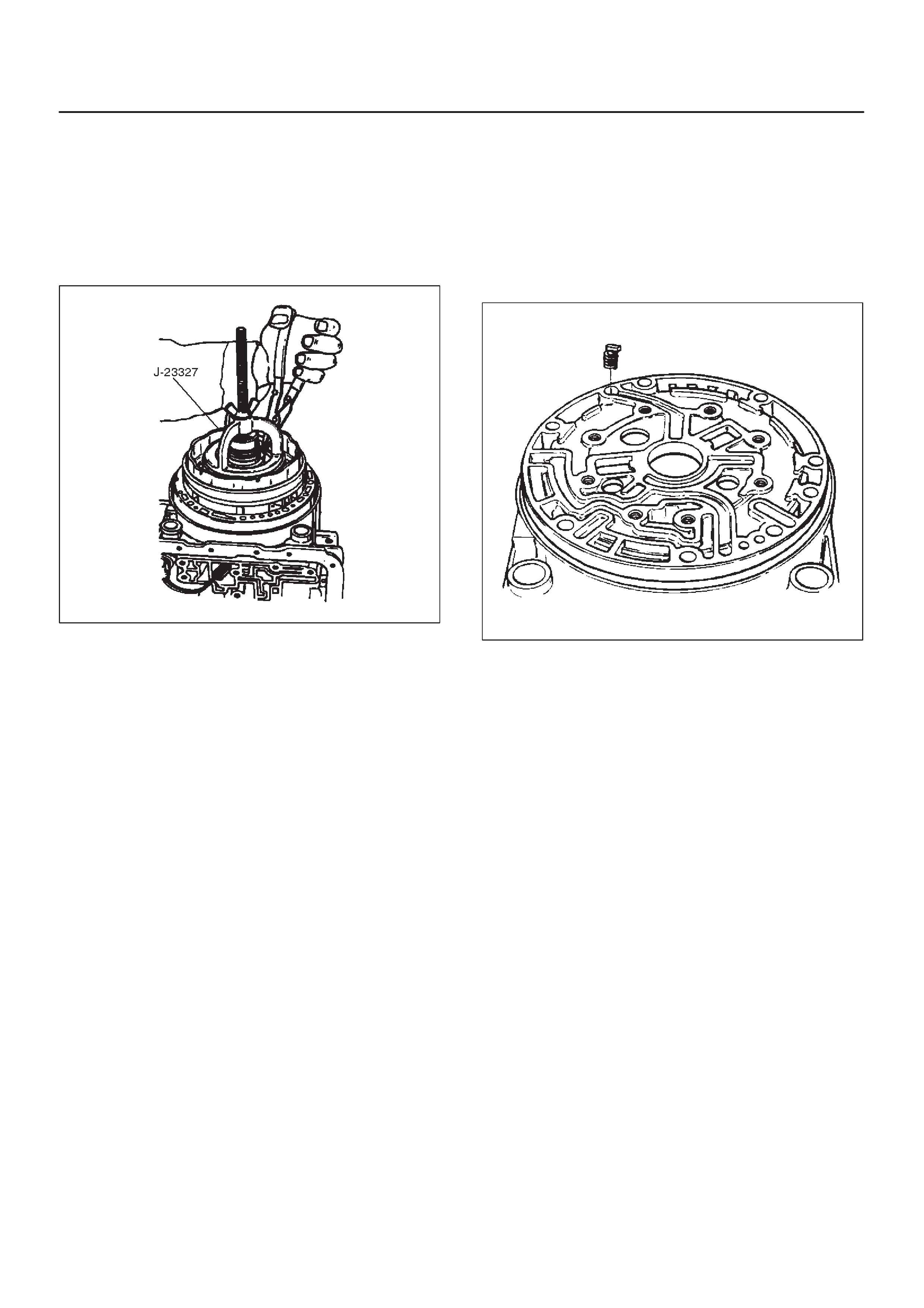
Disassembly
1.Install the J–23327 compressor tool on spring seat,
then compress the spring seat.
DRemove retaining ring (1).
NOTE: Do not over-stress the springs and seat, as this
will cause damage to the spring seat.
DRemove the compressor tool.
247RS008
2.Remove spring seat (2) and springs (3).
3.Remove piston assembly (4).
4.Remove 8 bolts from center support (5), then remove
center support (5) from adapter case.
5.Remove gasket transfer plate/outer support (6),
center support transfer plate (7), and gasket transfer
plate/adapter case (8).
6.Remove restrictor (9) from adapter case housing.
7.Remove retainer plate (10), plug (11), spring (12), and
overrun lock out valve (13) from center support (5).
Inspection and Repair
Visual Check:
If any damage, deformation or wear is found, replace the
damaged part.
Reassembly
1.Install overrun lock out valve (13) and spring (12) to
center support.
NOTE: Ensure correct assembly of valve. The spring
should be located over the long small diameter end.
2.Install plug (11) and retainer plate (10).
3.Place restrictor (9) in the lube overdrive channel in the
adapter case housing.
242RS005
4.Install gasket transfer plate/adapter case (8), center
support transfer plate (7), and gasket transfer
plate/center support (6).
5.Install center support (5) with 8 bolts.
Torque : 25 N•m (18 lb ft)
6.Install piston assembly (4) into center support (5).
7. Install twenty four springs (3), spring seat (2), and
retaining ring (1).
DInstall the J–23327 compressor and compress
spring seat (2) and springs (3), then seat snap ring
(1) in groove.
DRemove the tool.
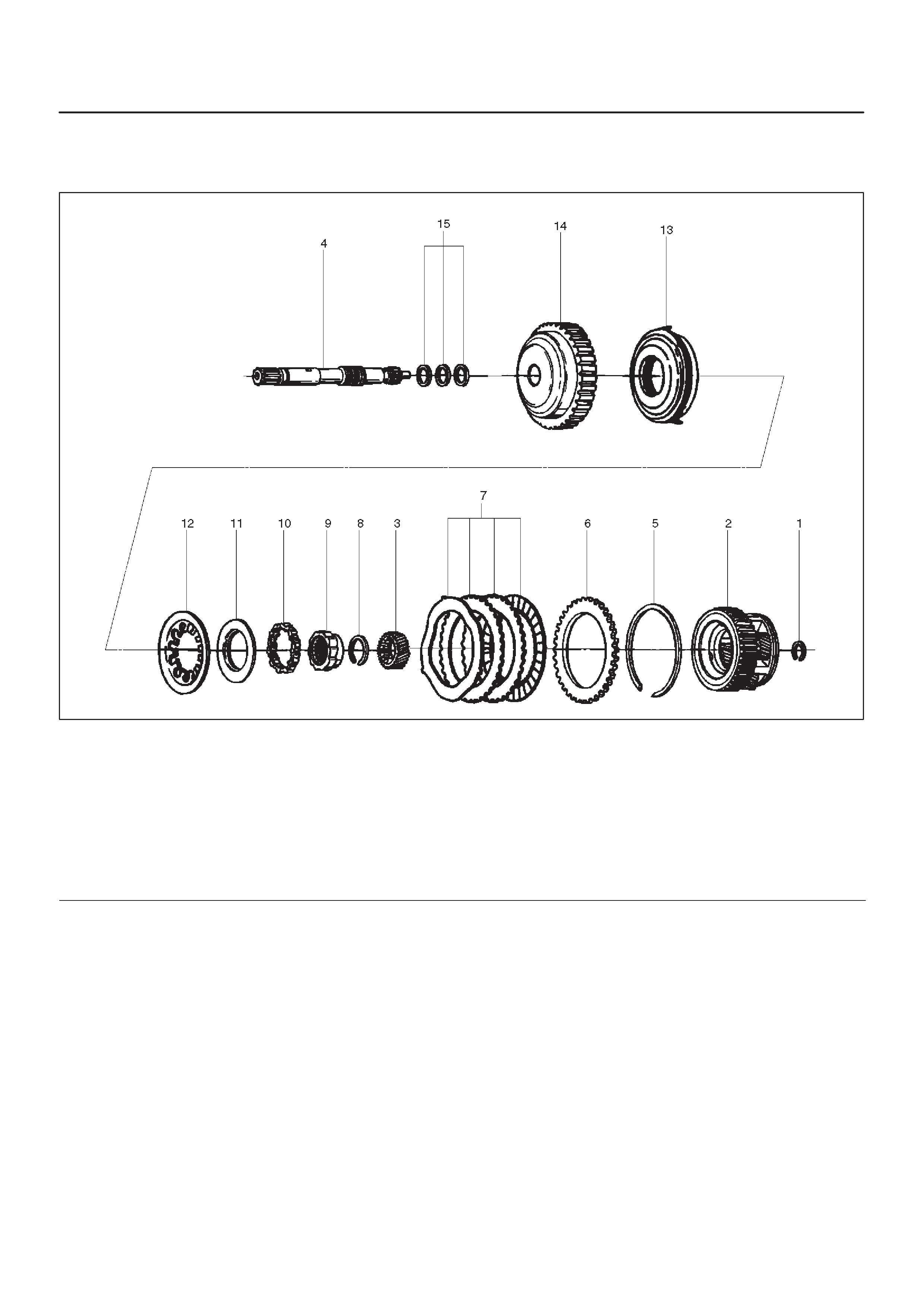
Overrun Clutch and Turbine Shaft
Disassembled View
252RW005
Legend
(1) Snap Ring
(2) Overdrive Carrier Assembly
(3) Sun Gear
(4) Turbine Shaft
(5) Snap Ring
(6) Backing Plate
(7) Clutch Plates
(8) Snap Ring
(9) Overrun Roller Clutch Cam
(10) Roller Clutch Assembly
(11) Overrun Clutch Release Spring Retainer
(12) Diaphragm Spring
(13) Piston Assembly
(14) Overrun Clutch Drum
(15) Turbine Shaft Seal Rings
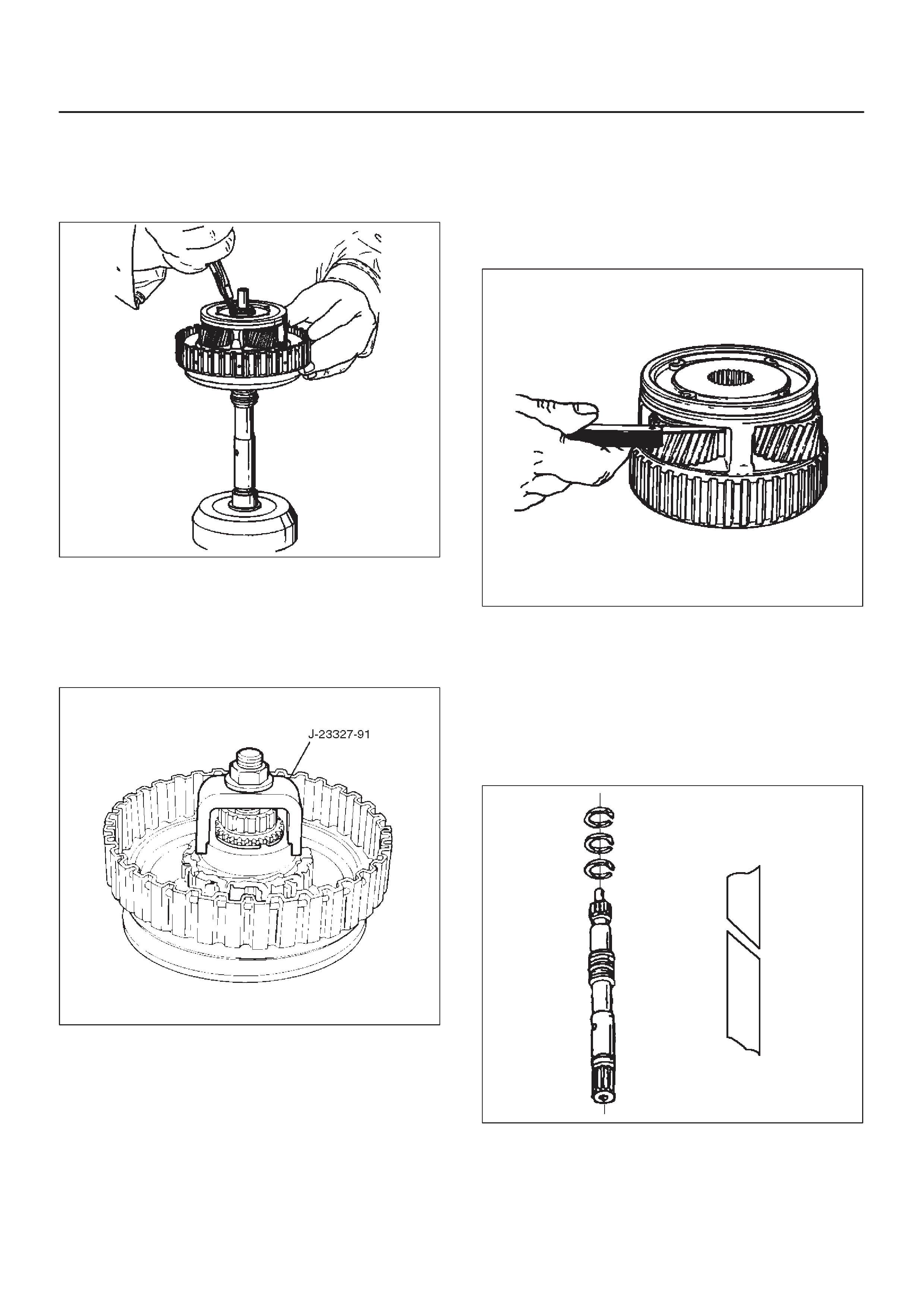
Disassembly
1.Position overrun clutch assembly upright, using the
overdrive internal gear as a support.
DRemove snap ring (1).
252RS009
2.Remove overdrive carrier assembly (2), sun gear (3)
and turbine shaft (4).
3.Remove snap ring (5), backing plate (6), and clutch
plates (7).
4.Compress diaphragm spring with the J–23327–91
compressor then remove snap ring (8).
252RS010
5.Remove overrun roller clutch cam (9) and roller clutch
assembly (10).
6.Remove overrun clutch release spring retainer (11)
and diaphragm spring (12).
7. Remove piston assembly (13) from overrun clutch
drum (14).
8.Remove turbine shaft seal rings (15).
Inspection and Repair
Overdrive Carrier Check
DCheck pinion end play with a feeler gauge.
Clearance: 0.24mm–0.64mm (0.0094in–0.025in)
If clearance is outside specified value, replace overdrive
carrier assembly.
252RS011
Visual Check:
If any damage, deformation or wear is found, replace the
damaged part.
Reassembly
1.Install turbine shaft seal rings (15) with grease
(petroleum jelly).
241RS008
2.Install the J–38555 inner installer on the drum (14).
DPre-install piston assembly into J–38555 outer
installer.
DInstall overrun clutch piston assembly (13). Use the
outer installer while pushing piston into drum (14).
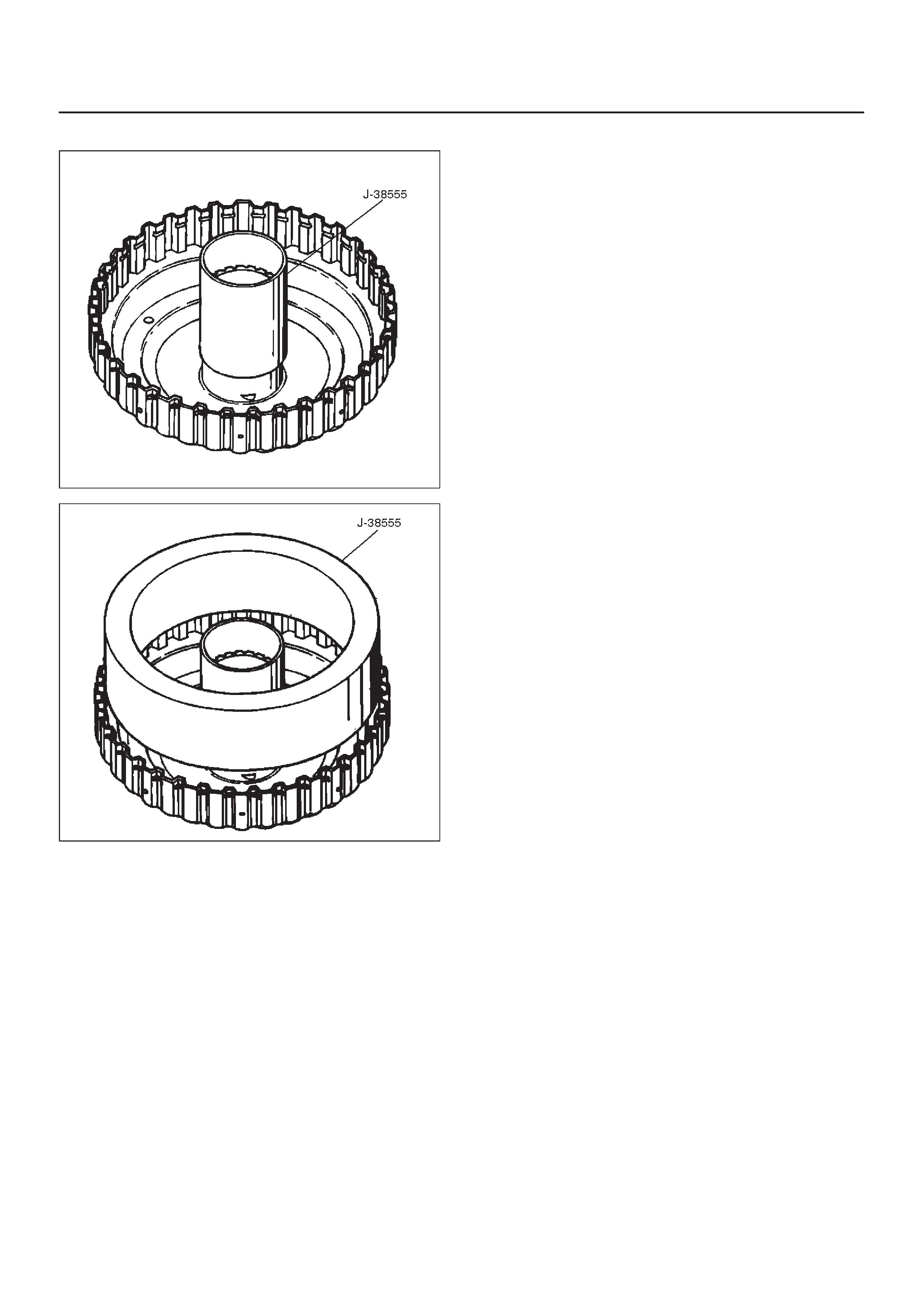
DRemove the installer.
252RS012
252RS013
3.Install diaphragm spring (12).
4.Install overrun clutch release spring retainer (11) (lip
faces upwards), overrun roller clutch assembly (10)
and cam (9).
5.Place snap ring loosely on spring retainer.
DHold the J–23327–91 compressor in a vise and
compress piston return spring with compressor.
DSet snap ring (8) in ring groove.
DRemove the compressor.
6.Install clutch plates (7), start with steel plate and
alternate with lined plates.
7.Install backing plate (6).
8.Install snap ring (5).
9.Install overdrive sun gear with countersink pointing
downwards.
10.Install the overdrive carrier assembly (2).
NOTE: Turn the assembly in a counter-clockwise
direction only until roller clutch enters the outer race.
After Installation, rotate the assembly and listen for loose
rollers.
11.Install turbine shaft (4) and snap ring (1).
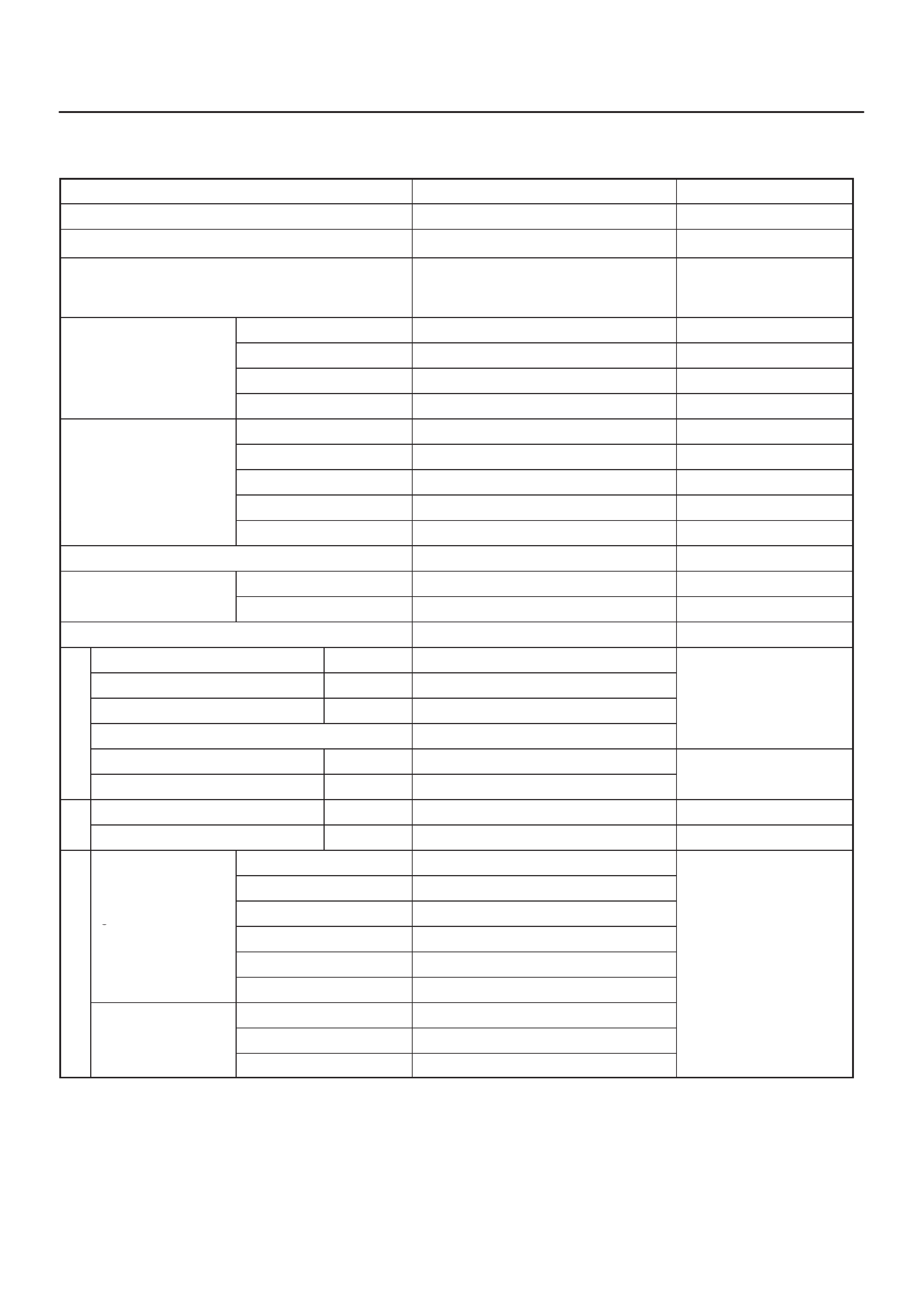
Main Data and Specification
General Specifications
Remarks
Model THM 4L30–E
Engine V6 3.2L 6VD1
Type Automatic four speed overdrive in
4th gear lockup clutch torque
converter
Shift control Hydraulic
Control systems
Shift pattern Electronic
Control
systems
Shift quality Electronic
Lockup clutch Electronic
1st 2.856
2nd 1.618
Gear ratio 3rd 1.000
4th (O/D) 0.723
Reverse 2.000
Gear set Noiseless, high torque capability
Oil used
Name ATF DEXRON–III
Oil
used
Q’ty liter (qt) 8.6 (9.1)
Torque converter 2,200 ± 150 Stall speed (rpm)
Reverse clutch RC 4
Second clutch C2 6
Number of discs
Third clutch C3 6
Number
of
discs
Brake band Double wrap
Fourth clutch C4 2
Number of discs
Overrun clutch OC 1
Number
of
discs
Overdrive roller clutch OFW 10 Number of rollers
Principle sprag assembly PFW 26 Number of sprags
Input sun gear 30
Ravigneaux ty
p
e
Pinion gear 19
Ravigneaux
ty e
gear train Long pinion 23
g
(planetary gear
set)
Ring gear 90
set)
Long pinion 19 Number of teeth
Output sun gear 46
Overdrive carrier Sun gear 31
Overdrive
carrier
(planetary gear
t)
Pinion gear 24
se
t)
Ring gear 81
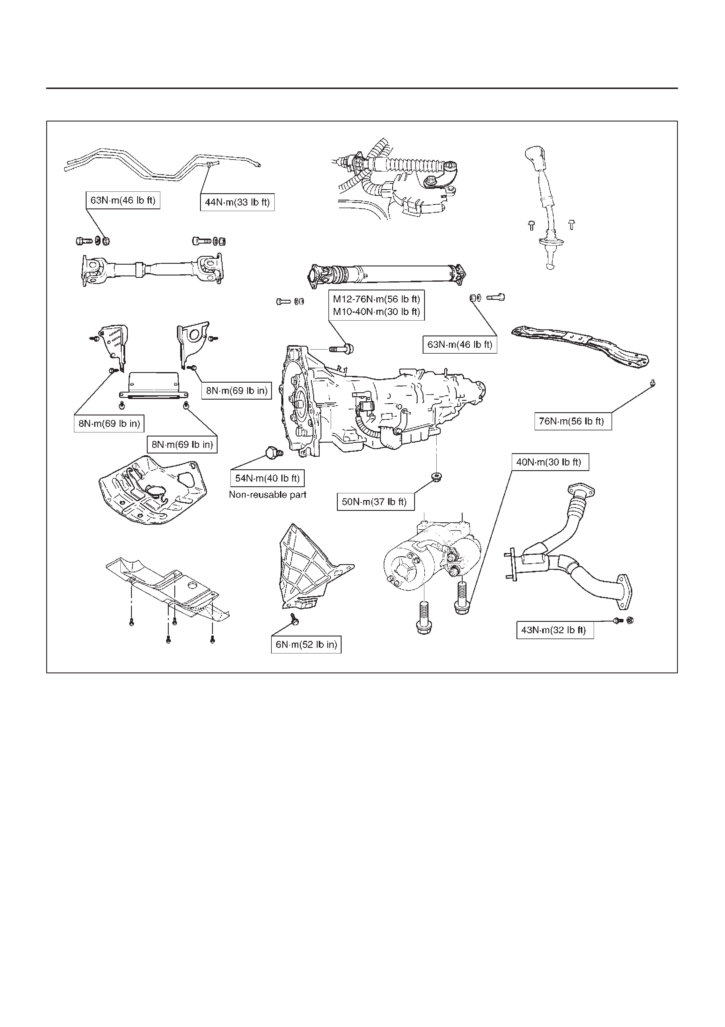
Torque Specifications
E07RY00019
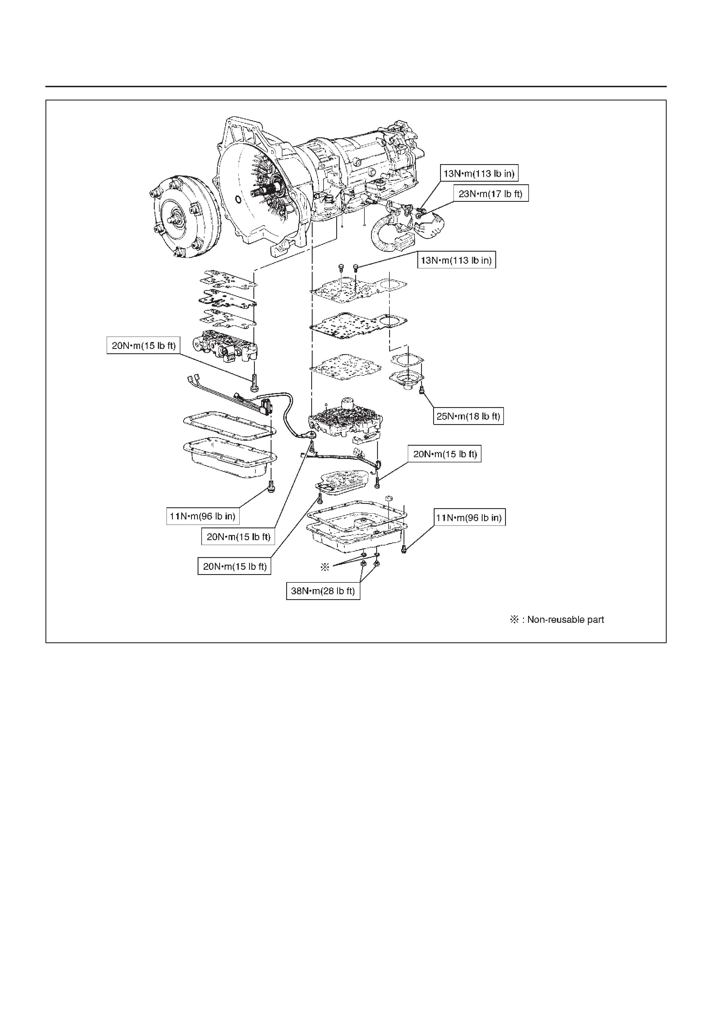
E07RX008
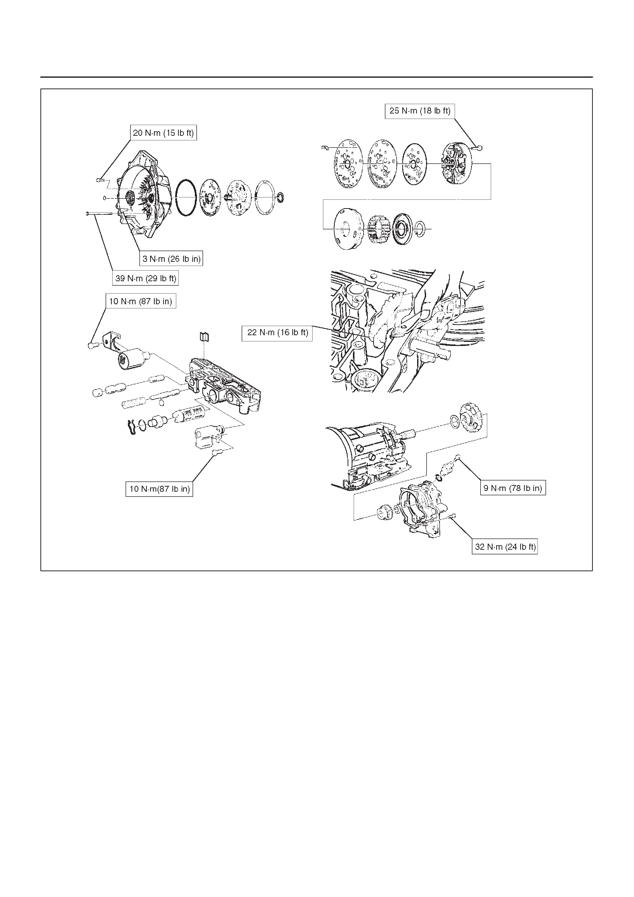
E07RW003
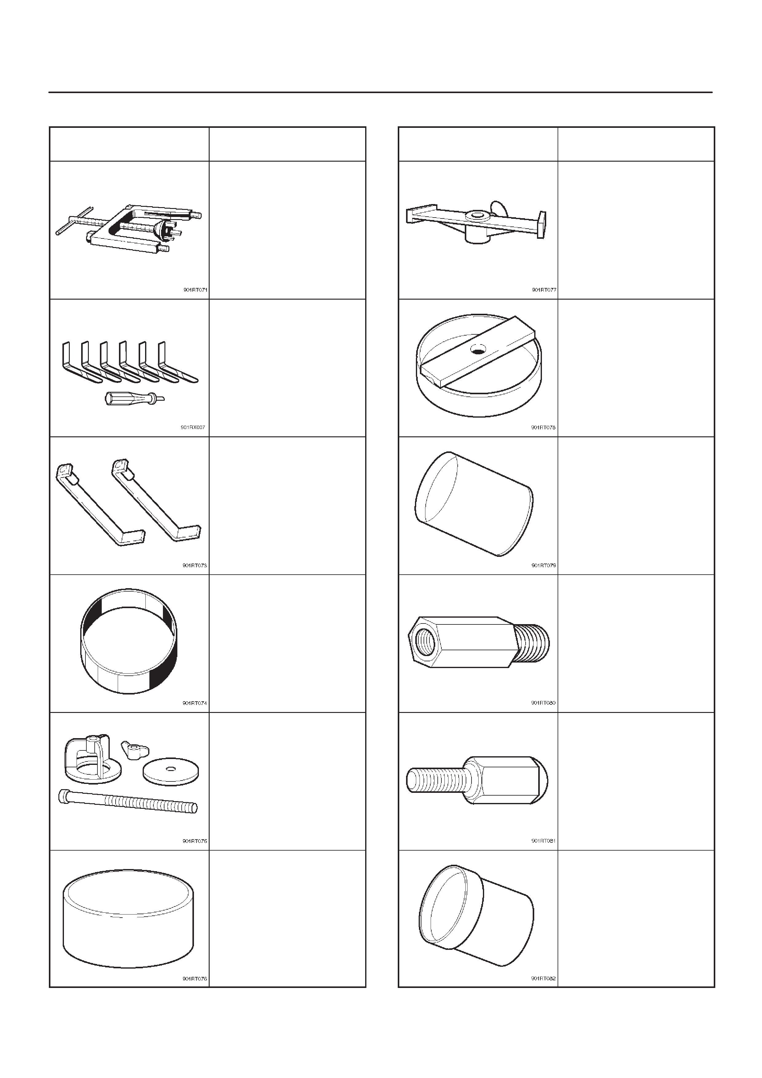
Special Tools
ILLUSTRATION TOOL NO.
TOOL NAME
J–23075
Spring compressor (For
servo piston)
J–38450–A
Third clutch snap ring
compressor
J–23075–12
Third clutch spring
compressor adapter
(Use with J–23075)
J–23084
Third clutch piston
installer
J–23327
Third clutch spring
compressor
J–23080–A
Second clutch piston
installer
ILLUSTRATION TOOL NO.
TOOL NAME
J–23085–A
Selective washer gaging
tool
J–23327–90
Fourth clutch spring
compressor (Use with
J–23327)
J–38553
3/4 accumulator piston
fitter
J–41096
Cover remover (Use
with J–38584)
J–38584
Slide hammer adapter
(Use with J–23907)
J–38554
Fourth clutch piston fitter
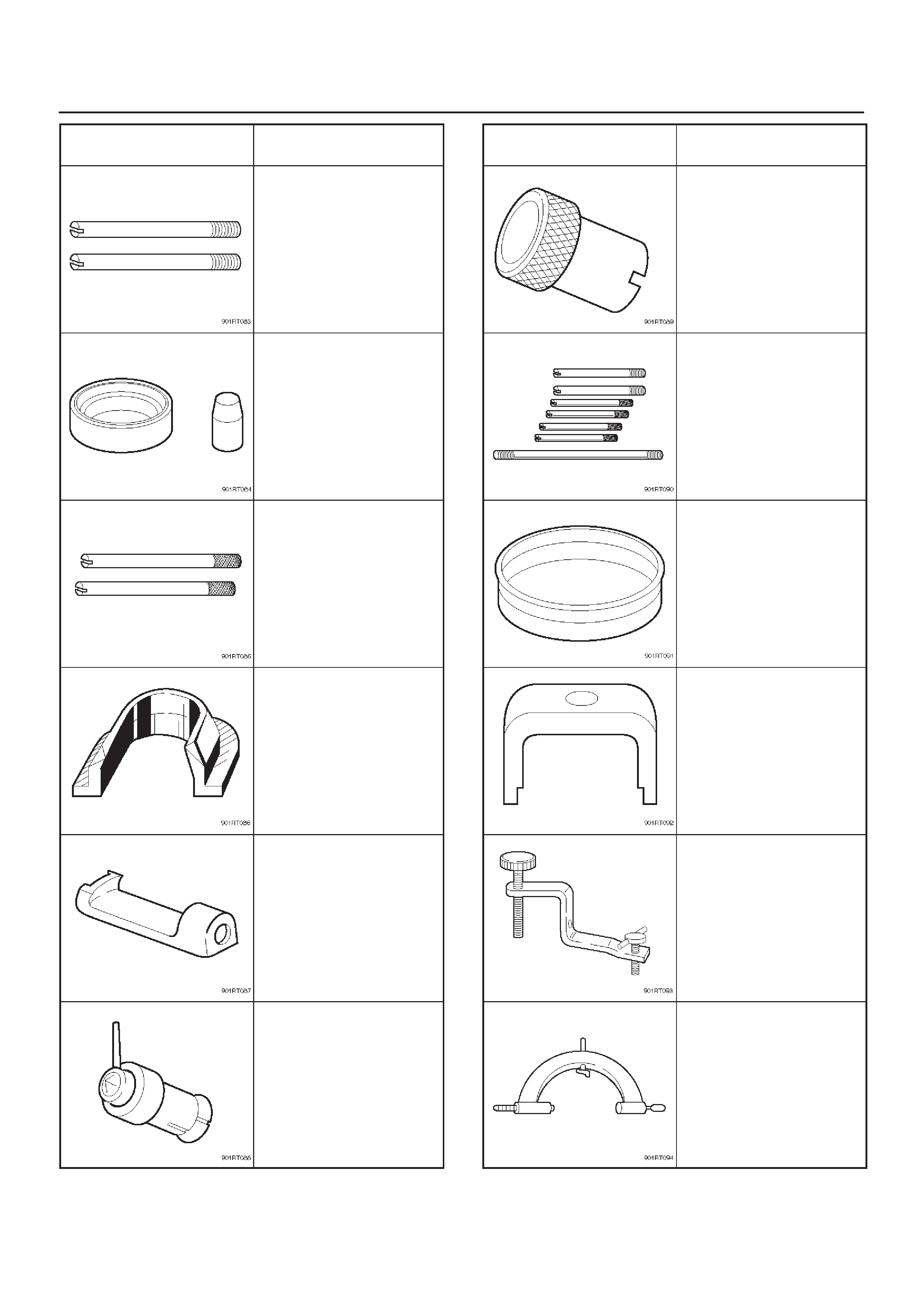
ILLUSTRATION TOOL NO.
TOOL NAME
J–38588
Guide pins; adapter
case to main case
J–38555
Overrun clutch piston
seal installer set
J–3387–2
Guide pins; gasket and
transfer plate to valve
body
J–25022
Turbine shaft puller (Use
with J–24773–1)
J–23129
Oil seal remover (Use
with J–23907 and
J–38584)
J–38557
Oil pump centering tool
ILLUSTRATION TOOL NO.
TOOL NAME
J–23082–01
Oil pump rotation tool
J–25025–B
Guide pins; valve body
to main case
J–38428
Servo piston fitter
J–23327–91
Overrun clutch spring
compressor
J–38559–A
3/4 accumulator piston
cover compressor
J–8763–02
Holding fixture
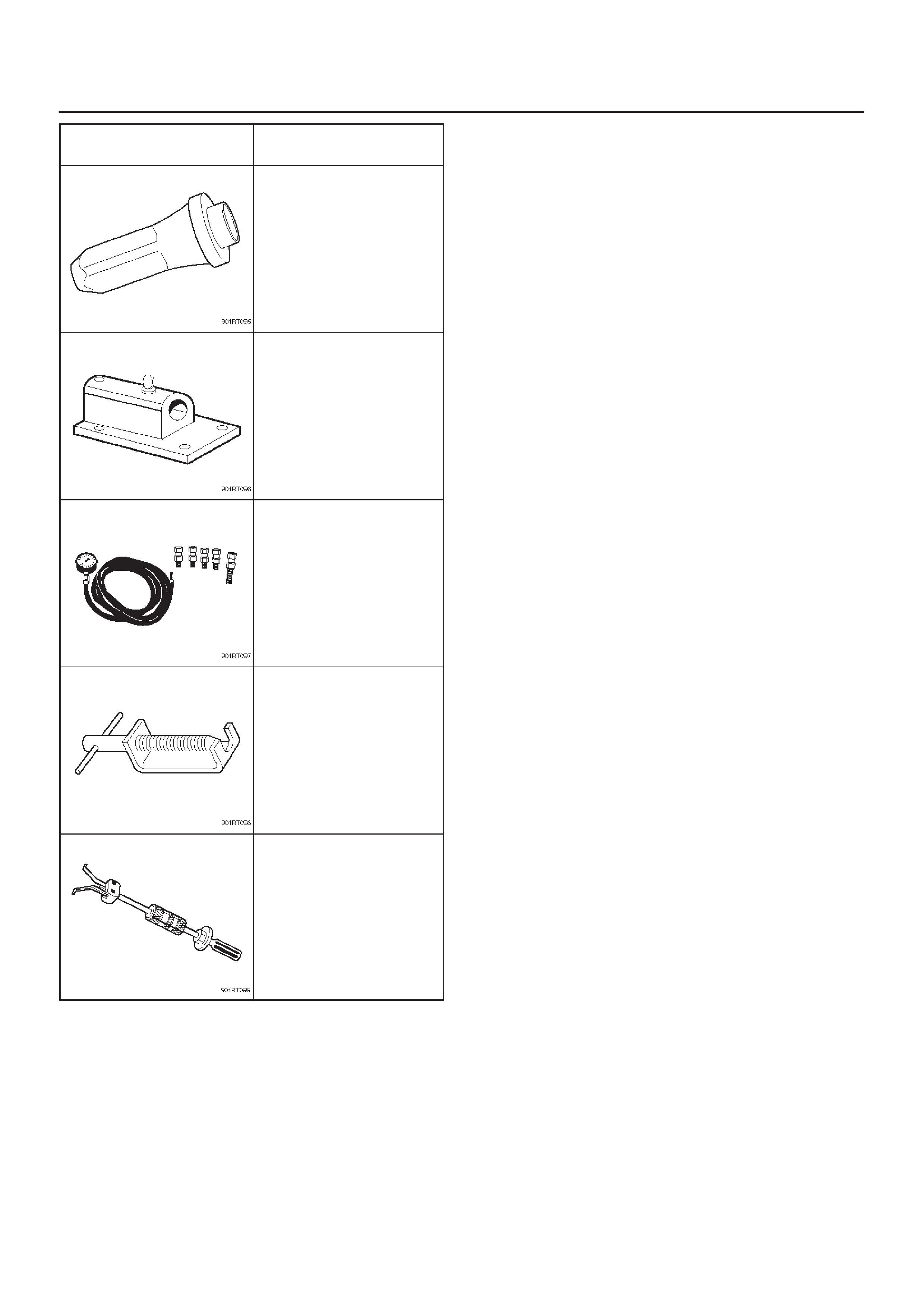
ILLUSTRATION TOOL NO.
TOOL NAME
J–36797
A/T extension housing
oil seal installer (Inside)
J–3289–20
Holding fixture base
J–29770–A
Pressure gauge
J–24773–1
End play fixture (Use
with J–25022)
J–23907
Slide hammer
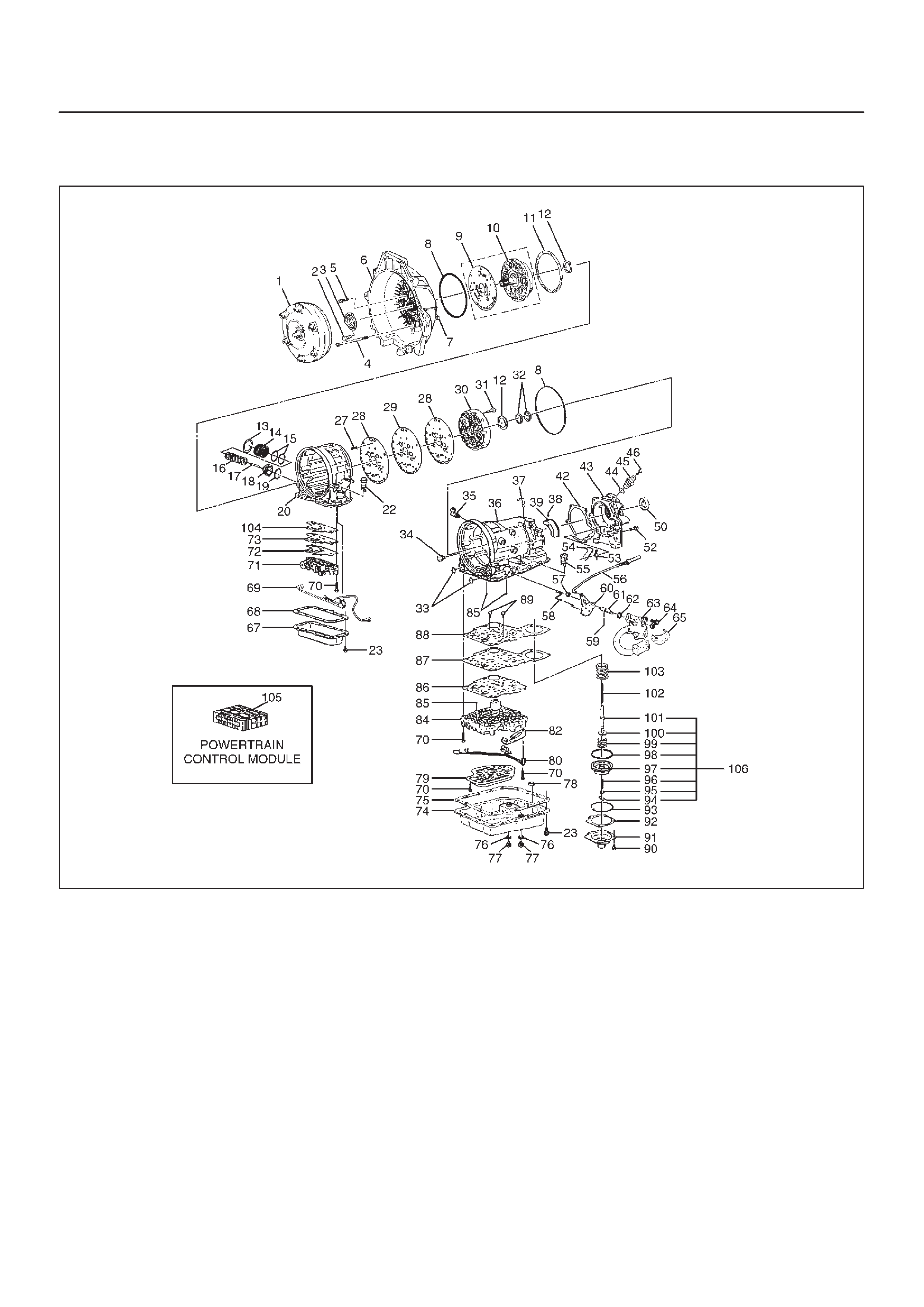
4L30–E Parts List
Case and Associated Parts
241RY00022
Legend
(1) Torque Converter
(2) Screw, Seal Ring Assembly
(3) Seal Ring Assembly, Converter Housing
(4) Screw, Converter Housing/Main Case
(5) Screw, Converter Housing/Oil Pump
(6) Housing, Converter
(7) Plug, Converter Housing
(8) Seal, O-ring
(9) W ear Plate, Oil Pump Body
(10) Pump Assembly, Oil
(11) Gasket
(12) Washer, Thrust Selective
(13) Ring, Snap
(14) Cover, 3–4 Accumulator Piston
(15) Seal, O-ring, 3–4 Accumulator
(16) Spring, 3–4 Accumulator Piston
(17) Pin, 3–4 Accumulator Piston
(18) Piston, 3–4 Accumulator
(19) Ring, 3–4, Accumulator Piston
(20) Case, Adapter
(22) Connector, Electrical/Adapter Case
(23) Screw, Pan
(27) Restrictor, Oil
(28) Gasket, Transfer Plate/Adapter
(29) Plate, Transfer Adapter/Center Support
(30) Support Assembly, Center
(31) Screw, Center Support
(32) Ring, Oil Seal
(33) Seal, O-ring Main Case
(34) Fitting, Cooler
(35) Fitting Assembly, Cooler
(36) Case, Main
(37) Breather, Pipe

(38) Seal, O-ring
(39) Reservoir
(42) Gasket, Extension Case
(43) Extension Assembly
(44) Seal, O-ring/Speed Sensor
(45) Sensor Assembly, Speed
(46) Screw, Speed Sensor
(50) Seal, Extension Assembly
(51) Bearing, Needle/Extension
(52) Screw, Extension/Main Case
(53) Spring, Parking Pawl Lock
(54) Pawl, Parking Lock
(55) Connector, Electrical/Main Case
(56) Actuator Assembly, Parking Lock
(57) Nut, Parking Lock Lever
(58) Link, Manual Valve
(59) Pin, Spring
(60) Lever, Parking Lock and Range Selector
(61) Shaft, Selector
(62) Seal, Selector Shaft
(63) Mode Switch Assembly
(64) Screw & Conical Washer Assembly
(65) Shield, Mode Switch
(67) Pan, Bottom/Adapter Case
(68) Gasket, Bottom Pan/Adapter Case
(69) Harness Assembly, Adapter Case
(70) Screw, Valve Body
(71) Valve Body Assembly, Adapter Case
(72) Gasket, Adapter Valve Body
(73) Plate, Adapter Valve Body/T ransfer
(74) Pan, Bottom/Main Case
(75) Gasket, Bottom Pan/Main Case
(76) Gasket, Oil Drain or Overfill Screw
(77) Screw, Oil Drain or Overfill
(78) Magnet, Chip Collector
(79) Filter Oil
(80) Harness Assembly, Main Case
(82) Roller and Spring Assembly, Manual Detent
(84) Valve Body Assembly, Main Case
(85) Ball, Check
(86) Gasket, Main V.B./Transfer Plate
(87) Plate, Main V.B./Transfer
(88) Gasket, Transfer/Main Case
(89) Screw, Transfer Plate on V.B.
(90) Screw, Servo Cover
(91) Cover, Servo Piston
(92) Gasket, Cover/Servo Piston
(93) Ring, Retaining Servo Piston
(94) Clip, Servo Piston
(95) Nut, Servo Screw
(96) Screw, Servo Piston
(97) Piston, Servo
(98) Seal, Ring/Servo Piston
(99) Spring, Cushion/Servo Piston
(100) Seat, Cushion Spring
(101) Sleeve, Servo Piston Adjust
(102) Rod, Apply/Servo Piston
(103) Spring, Return/Servo Piston
(104) Gasket, Adapter Case/Transfer Plate
(105) Powertrain Control Module
(106) Servo Piston Assembly
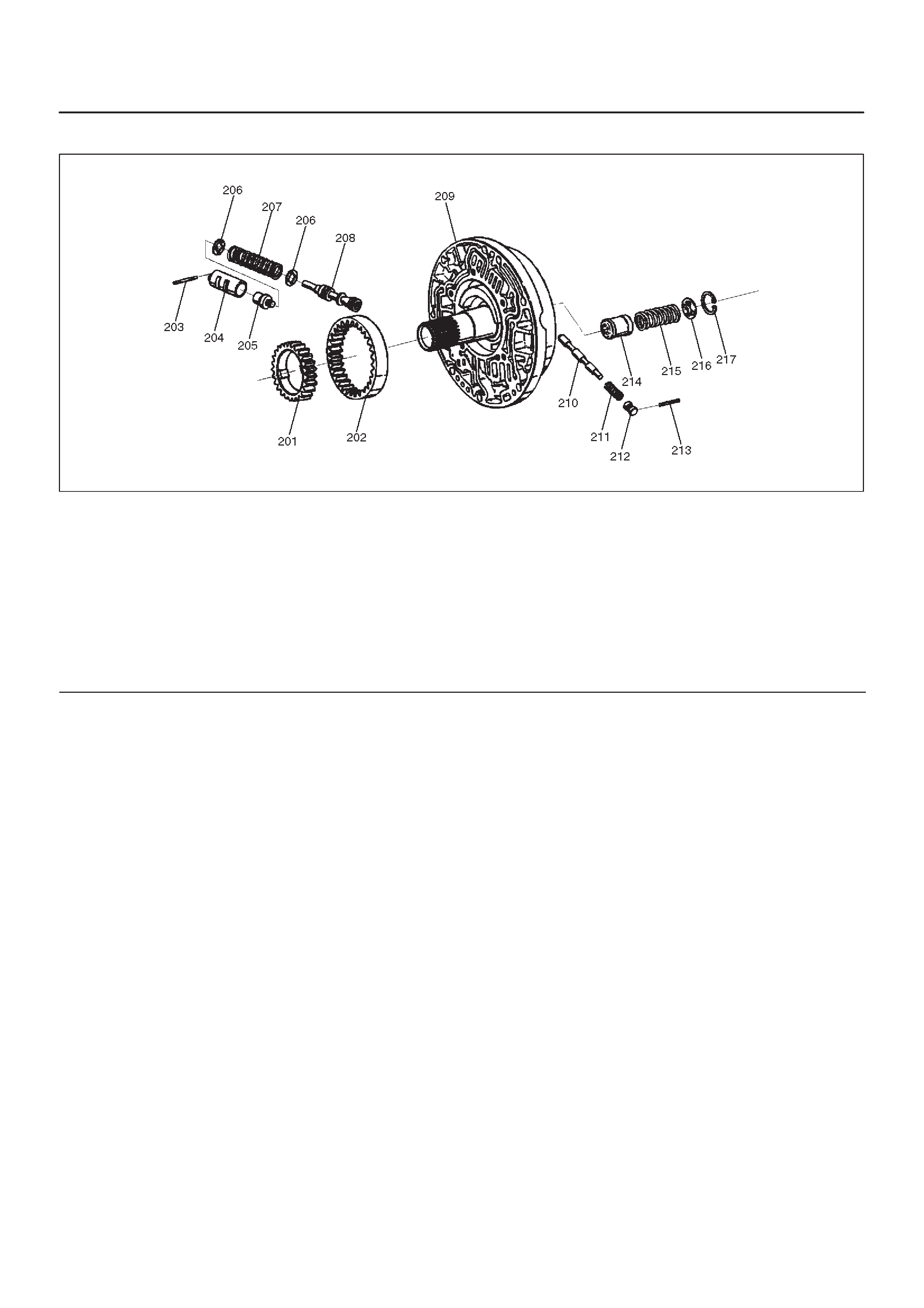
Pump Assembly
241RS019
Legend
(201) Gear, Oil Pump Drive
(202) Gear, Oil Pump Driven
(203) Pin, Boost Valve Sleeve
(204) Sleeve, Boost Valve
(205) Valve, Boost
(206) Seat, Spring/Pressure Regulator Valve
(207) Spring, Pressure Regulator Valve
(208) Valve, Pressure Regulator
(209) Pump Assembly, Oil
(210) Valve, Converter Clutch Control
(211) Spring, Converter Clutch Control Valve
(212) Plug, Converter Clutch Control Valve
(213) Pin, Spring
(214) Piston, Throttle Signal Accumulator
(215) Spring, Throttle Signal Accumulator
(216) Seat, Spring/Throttle Signal Accumulator
(217) Ring, Snap/Throttle Signal Accumulator
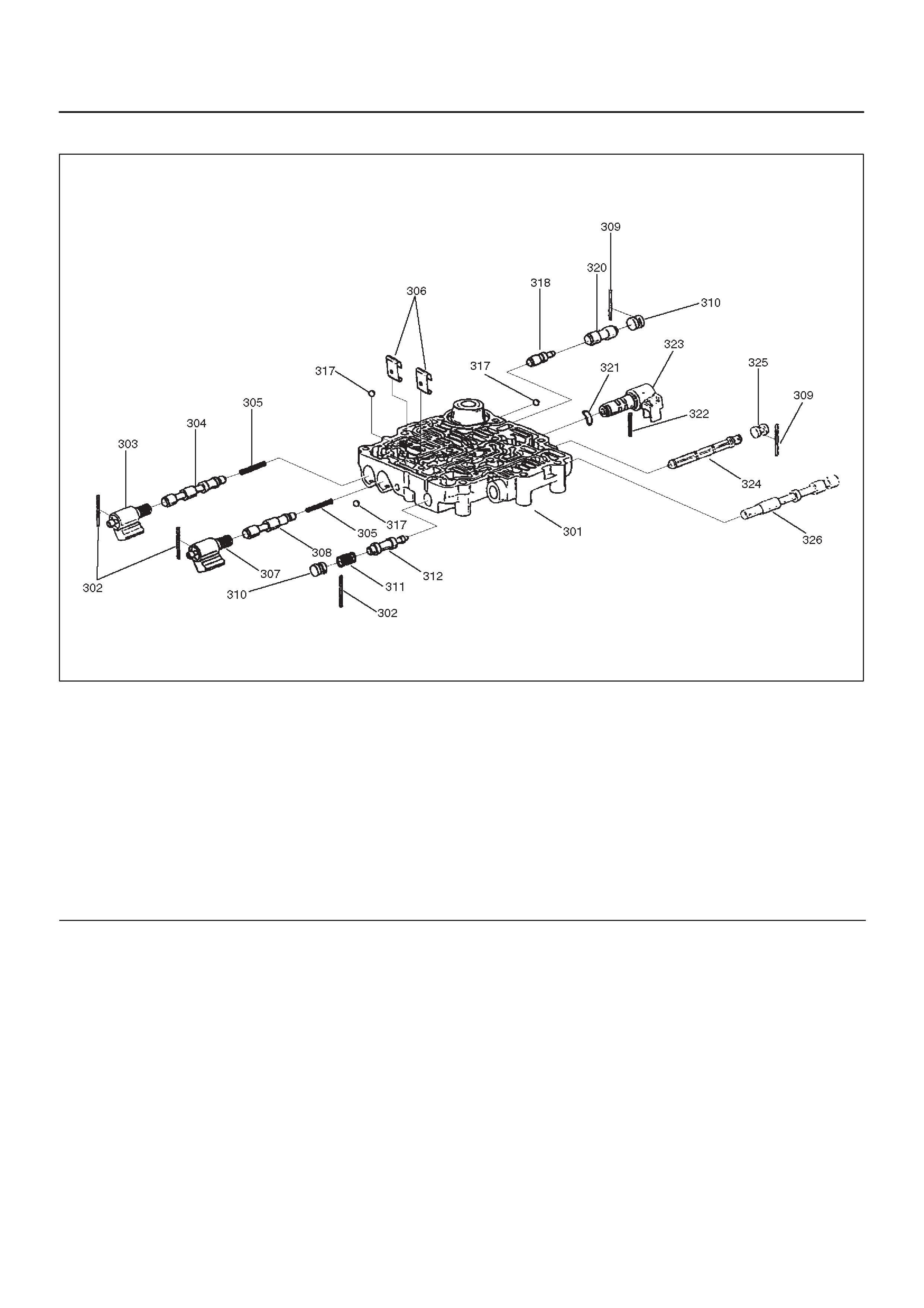
Valve Body Assemblies
244RS009
Legend
(301) Body, Valve Main Case
(302) Pin, Spring
(303) Solenoid Assembly, ON/OFF N.C.
(304) Valve, 1–2 & 3–4 Shift
(305) Spring, 1–2 & 3–4 (2–3) Shift
(306) Retainer, Valve
(307) Solenoid Assembly, ON/OFF N.O.
(308) Valve, 2–3 Shift
(309) Pin, Spring
(310) Plug, Valve Bore
(311) Spring, Valve Low Pressure Control
(312) Valve, Low Pressure Control
(317) Ball, Check
(318) Valve, 1–2 Accumulator Control
(320) Valve, 1–2 Accumulator
(321) Washer, Waved PWM Solenoid
(322) Pin, Solenoid PWM
(323) Solenoid Assembly, Band Control PWM
(324) Screen Assembly, PWM Solenoid
(325) Plug, Screen
(326) Valve, Manual
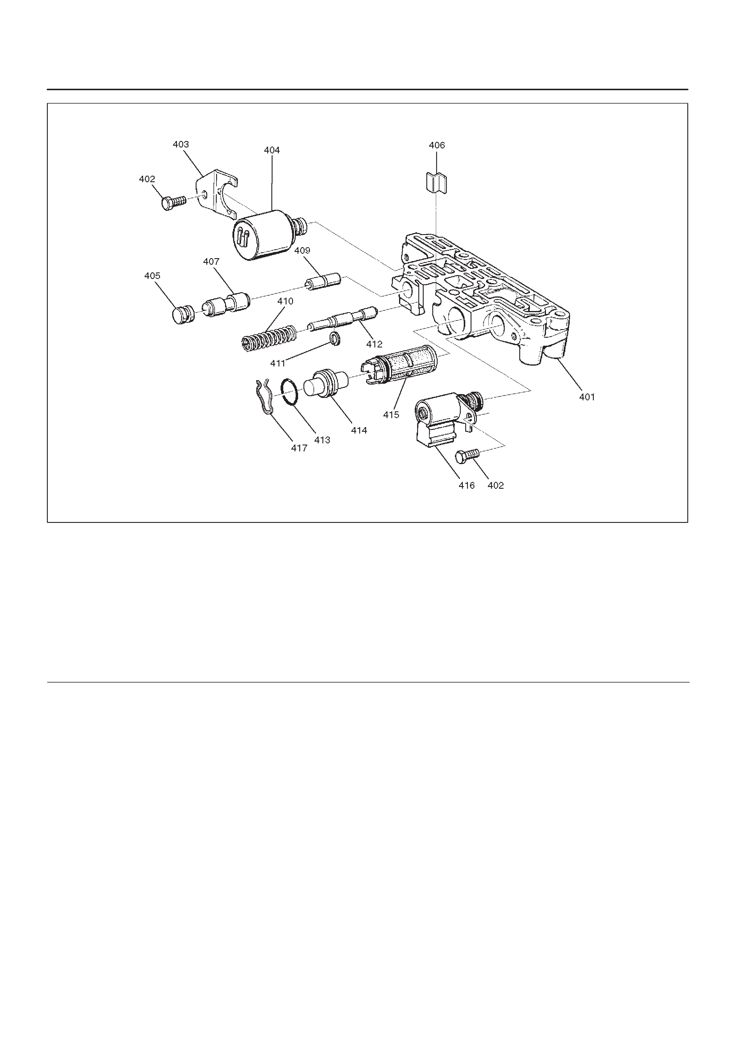
243RW003
Legend
(401) Body, Valve/Adapter Case
(402) Screw, Solenoid Force Motor
(403) Retainer, Force Motor
(404) Solenoid, Force Motor
(405) Plug, 3–4 Accumulator
(406) Plug and Spring Retainer
(407) Valve, 3–4 Accumulator
(409) Valve, 3–4 Accumulator Control
(410) Spring, Feed Limit Valve
(411) Ring, Retainer
(412) Valve, Feed Limit
(413) Seal, O-ring Plug Filter
(414) Plug, Screen
(415) Screen Assembly, Force Motor
(416) Solenoid, Torque Conv. Clutch ON/OFF N.C.
(417) Plug Retainer
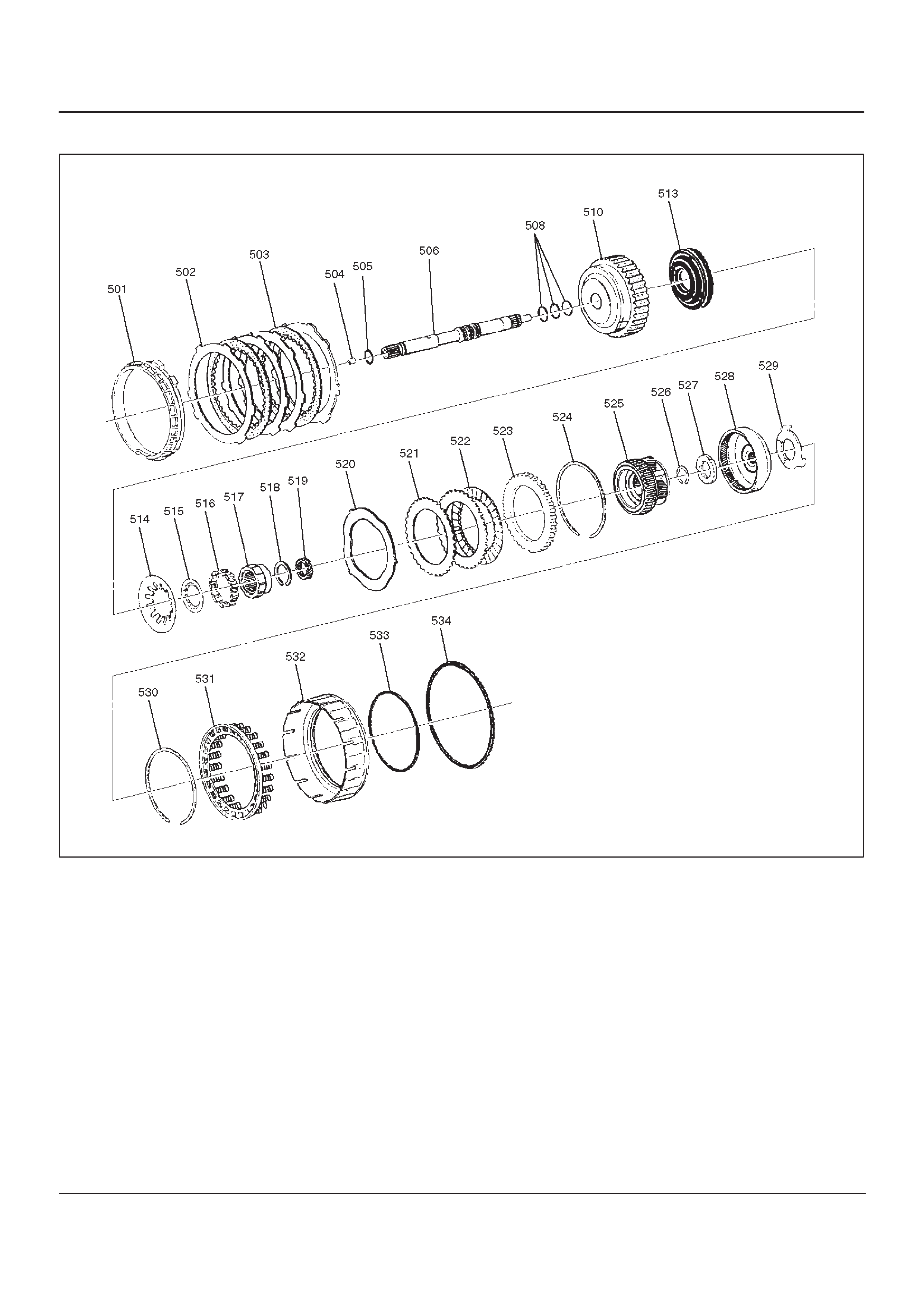
Overdrive Internal Components
252RW003
Legend
(501) Retainer, 4th Clutch
(502) Plate, 4th Clutch (Steel)
(503) Plate Assembly, 4th Clutch (Lined)
(504) Retainer and Ball Assembly, Check Valve
(505) Seal, O-ring/Turbine Shaft
(506) Shaft, Turbine
(508) Ring, Oil Seal/Turbine Shaft
(510) Housing, Overrun Clutch
(513) Piston, Overrun Clutch
(514) Spring, Overrun Clutch Release
(515) Retainer, Release Spring/Overrun Clutch
(516) Roller Assembly, Overdrive Clutch
(517) Cam, Overdrive Roller Clutch
(518) Ring, Snap/Overrun Clutch Hub
(519) Gear, Overdrive Sun
(520) Plate, Waved/Overrun Clutch
(521) Plate, Overrun Clutch (Steel)
(522) Plate Assembly, Overrun Clutch (Lined)
(523) Plate, Backing/Overrun Clutch
(524) Ring, Snap/Overrun Clutch Housing
(525) Carrier Assembly, Overdrive Complete
(526) Ring, Snap/Turbine Shaft/Carrier
(527) Bearing Assembly, Thrust
(528) Gear, Overdrive Internal
(529) Washer, Thrust/Internal Gear/Support
(530) Ring, Snap/Adapter/4th Clutch Spring
(531) Retainer and spring assembly, 4th clutch
(532) Piston, 4th Clutch
(533) Seal, 4th Clutch Piston (Inner)
(534) Seal, 4th Clutch Piston (outer)
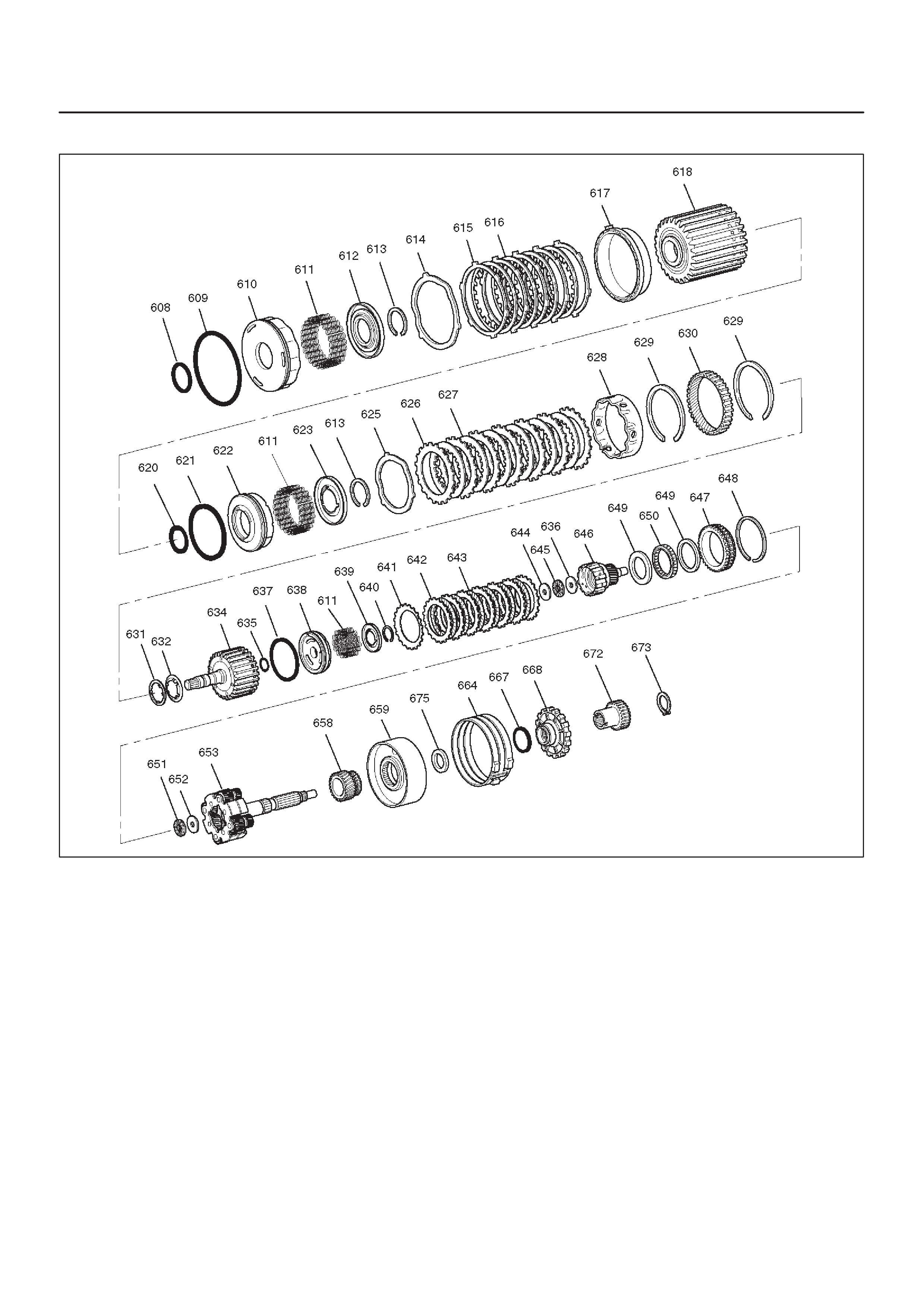
Internal Components
247RW002
Legend
(608) Seal, Reverse Clutch Piston (Inner)
(609) Seal, Reverse Clutch Piston (Outer)
(610) Piston, Reverse Clutch
(611) Spring, Piston Clutch
(612) Seat, Spring/Reverse Clutch
(613) Ring, Retaining
(614) Plate, Waved/Reverse Clutch
(615) Plate, Reverse Clutch (Steel)
(616) Plate Assembly, Reverse Clutch (Lined)
(617) Plate, Reverse Clutch Pressure/Selective
(618) Drum Assembly, 2nd Clutch
(620) Seal, 2nd Clutch Piston (Inner)
(621) Seal, 2nd Clutch Piston (Outer)
(622) Piston, 2nd Clutch
(623) Seat, Spring/2nd Clutch
(625) Plate, Waved/2nd Clutch
(626) Plate, 2nd Clutch (Steel)
(627) Plate Assembly, 2nd Clutch (Lined)
(628) Spacer, 2nd Clutch
(629) Ring, Retaining
(630) Gear, Ring
(631) Washer, Thrust/2nd Clutch/3rd Clutch
(632) Thrust Washer, Clutch Hub
(634) Drum Assembly, 3rd Clutch
(635) Seal, 3rd clutch piston (Inner)
(636) Washer, Retaining
(637) Seal, 3rd Clutch Piston (Outer)
(638) Piston 3rd Clutch
(639) Seat, Spring/3rd Clutch
(640) Ring, Retaining
(641) Plate, Spring Cushion/3rd Clutch
(642) Plate, 3rd Clutch (Steel)
(643) Plate Assembly, 3rd Clutch (Lined)
(644) Washer, Thrust/Input Sun
(645) Bearing, Input Shaft/Gear Assembly
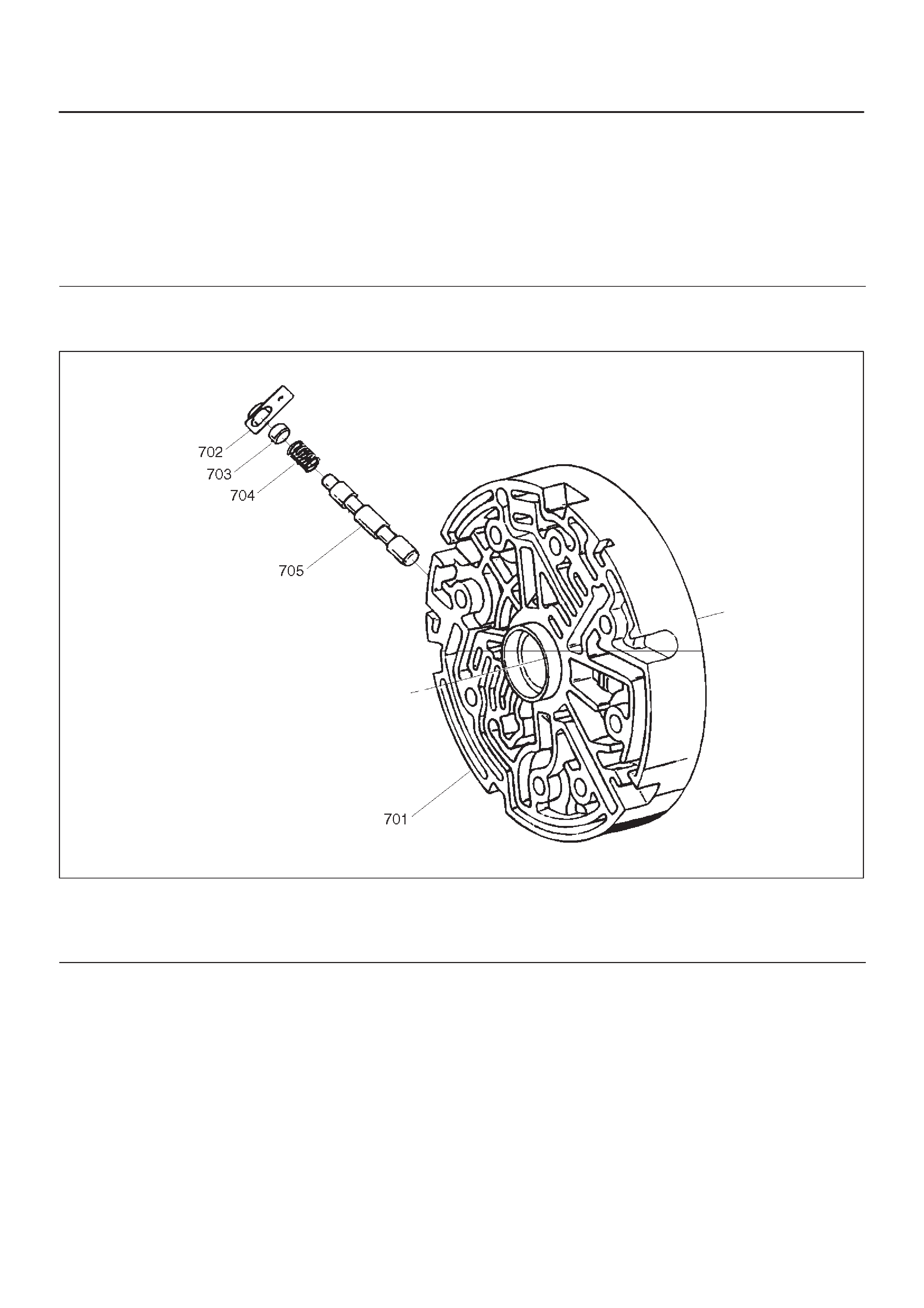
(646) Gear Assembly, Input Sun
(647) Race Assembly, Sprag
(648) Ring, Retaining/Sprag
(649) Ring, Retaining
(650) Cage Assembly, Sprag
(651) Bearing, Output Shaft/Input Sun
(652) Washer, Output Shaft/Input Sun
(653) Carrier Assembly, Planetary
(658) Gear, Reaction Sun
(659) Drum, Reaction Sun
(664) Band Assembly, Brake
(667) Seal, Ring/Wheel Parking Lock
(668) Wheel, Parking Lock
(672) Wheel, Speed
(673) Ring, Retaining
(675) Bearing, Thrust Assembly
Center Support Assembly
241RS010
Legend
(701) Center Support
(702) Retainer Plate
(703) Plug, Lockout
(704) Spring, Overrun Lockout
(705) Valve, Overrun Lockout