
SECTION 7A1 - TRANSMISSION CONTROL SYSTEM (4L30–E)
Service Precaution
General Description
Electronic Control Diagram
Powertrain Control Module (PCM)
Control System Diagram
Shift Control
Band Apply Control
Torque Converter Clutch Control
Line Pressure Control
On–Board Diagnostic System
Fail Safe Mechanism
Torque Management Control
ATF Warning Control
Shift Mode Control
Gear Shift Control
Winter Drive Mode
Backup Mode
Functions of Input / Output Components
Diagnosis
Electronic Diagnosis
Check Trans Indicator
Diagnostic Check
“Check Trans” Check
Tech 2 OBD II Connection
F0: Transmission Data
F1: PC Solenoid Data
Flashing Code
OBD II Diagnostic Management System
16 – Terminal Data Link Connector (DLC)
Malfunction Indicator Lamp (MIL)
Types Of Diagnostic Trouble Code (DTCs)
Clear DTC
DTC Check
PCM Precaution
Information On PCM
Intermittent Conditions
Transmission and PCM Identification
Isuzu Frontera
Diagnostic Trouble Code (DTC)
Identification
DTC P0218/Flashing Code 71 Transmission
Fluid Over Temperature
DTC P0560/Flashing Code 72 System
Voltage Malfunction
DTC P0705/Flashing Code 73 Transmission
Range Switch (Mode Switch) Illegal Position
DTC P0706/Flashing Code 74 Transmission
Range Switch (Mode Switch) Performance
DTC P0712/Flashing Code 75 Transmission
Fluid Temperature (TFT) Sensor Circuit
Low Input
DTC P0713/Flashing Code 76 Transmission
Fluid Temperature (TFT) Sensor Circuit
High Input
DTC P0719/Flashing Code 77 TCC Brake
Switch Circuit High (Stuck On)
DTC P0722/Flashing Code 78 Transmission
Output Speed Sensor (OSS) Low Input
DTC P0723/Flashing Code 79 Transmission
Output Speed Sensor (OSS) Intermittent
DTC P0730/Flashing Code 81 Transmission
Incorrect Gear Ratio
DTC P0748/Flashing Code 82 Pressure
Control Solenoid (PCS) (Force Motor)
Circuit Electrical
DTC P0753/Flashing Code 83 Shift Solenoid
A Electrical
DTC P0758/Flashing Code 84 Shift Solenoid
B Electrical
DTC P1790/Flashing Code 85 ROM
Transmission Side Bad Check Sum
DTC P1792/Flashing Code 86 EEPROM
Transmission Side Bad Check Sum
DTC P1835/Flashing Code 87 Kickdown
Switch Always On
DTC P1850/Flashing Code 88 Brake Band
Apply Solenoid Malfunction
DTC P1860/Flashing Code 89 TCC
Solenoid Electrical
Circuit Diagram
Parts Location
Harness Connector Faces

Service Precaution
WARNING:IF SO EQUIPPED WITH A
SUPPLEMENTAL RESTRAINT SYSTEM (SRS).
REFER TO THE SRS COMPONENT AND WIRING
LOCATION VIEW IN ORDER TO DETERMINE
WHETHER YOU ARE PERFORMING SERVICE ON OR
NEAR THE SRS COMPONENTS OR THE SRS
WIRING. WHEN YOU ARE PERFORMING SERVICE
ON OR NEAR THE SRS COMPONENTS OR THE SRS
WIRING, REFER TO THE SRS SERVICE
INFORMATION. FAILURE TO FOLLOW WARNINGS
COULD RESULT IN POSSIBLE AIR BAG
DEPLOYMENT, PERSONAL INJURY, OR
OTHERWISE UNNEEDED SRS SYSTEM REPAIRS.
CAUTION:Always use the correct fastener in the
proper location. When you replace a fastener, use
ONLY the exact part number for that application.
ISUZU will call out those fasteners that require a
replacement after removal. ISUZU will also call out
the fasteners that require thread lockers or thread
sealant. UNLESS OTHERWISE SPECIFIED, do not
use supplemental coatings (Paints, greases, or other
corrosion inhibitors) on threaded fasteners or
fastener joint interfaces. Generally, such coatings
adversely affect the fastener torque and the joint
clamping force, and may damage the fastener . When
you install fasteners, use the correct tightening
sequence and specifications. Following these
instructions can help you avoid damage to parts and
systems.
General Description
The 4L30–E is a 4–speed fully automatic transmission. It
uses a microcomputer as a control unit to judge running
conditions including throttle opening rate and vehicle
speed, then it sets the shifting point in the optimum timing
so that best driving performance can be achieved.
In addition, the built–in shift mode select function can
select three shift modes according to the driver’s
preference:
DNormal mode –Normal shift pattern.
DWinter mode –Starts in 3rd gear to reduce slippage on
ice or snow.
DPower mode has a delayed upshift for when more
powerful acceleration is required.
Also, the built–in fail safe function (“backup mode”)
assures driving performance even if the vehicle speed
sensor, throttle signal or any solenoid fails.
Further, the self–diagnostic function conducts diagnosis
in a short time when the control system fails, thus
improving serviceability.
The major features of 4L30–E are as follows:
DA compact structure consisting of 2 sets of planetary
gears and flat torque converter.
DElectronic control selects the optimum shift mode
according to the driving conditions.
DElectronic control maintains the optimum hydraulic
pressure for clutch, band brake as well as
transmission so that shift feeling is improved.
DTwo sets of planetary gears reduce friction of power
train.
Also, a lockup mechanism in the torque converter
reduces fuel consumption.
DWide gear ratio and high torque rate of torque
converter provide excellent starting performance.
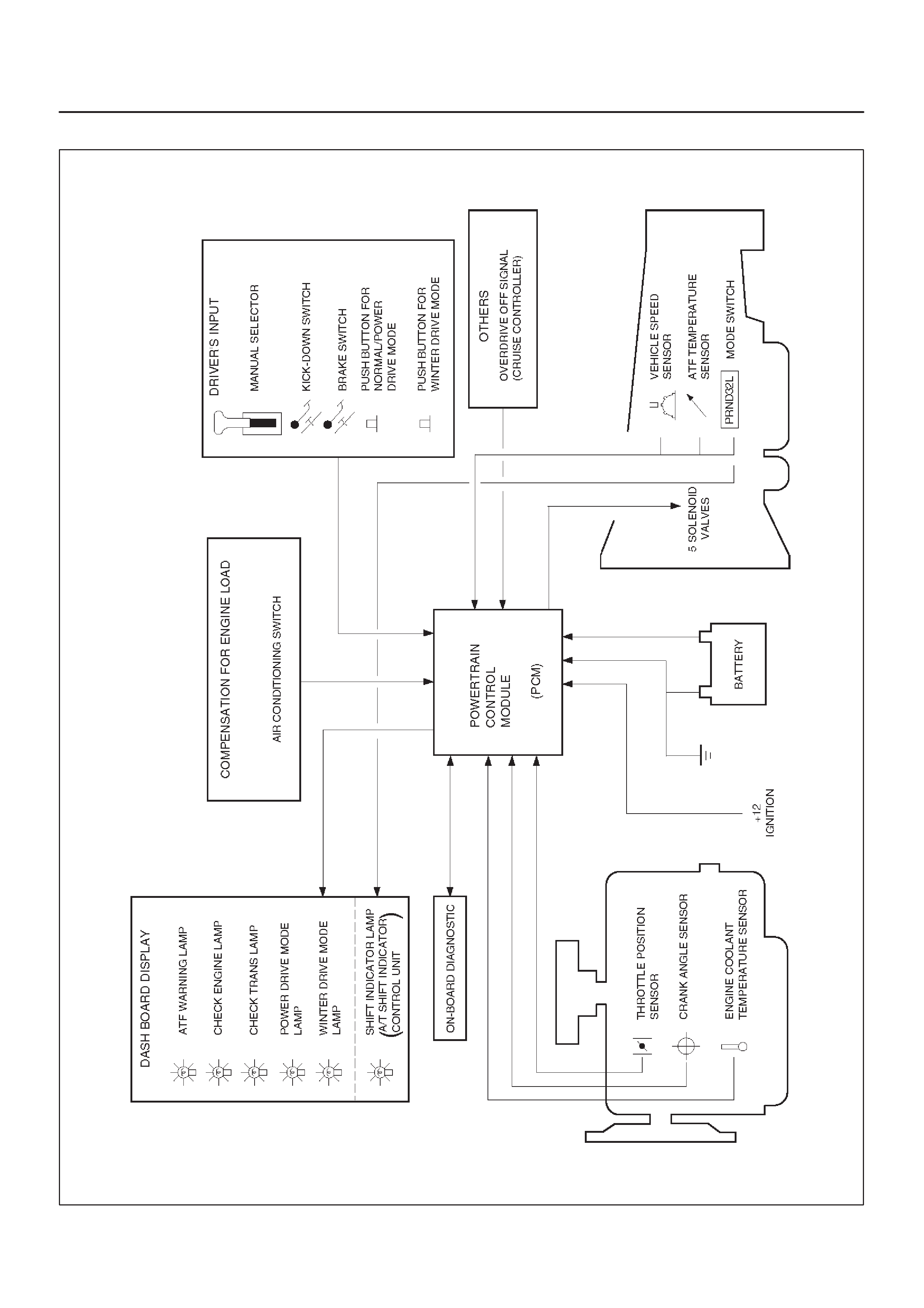
Electronic Control Diagram
C07RX008
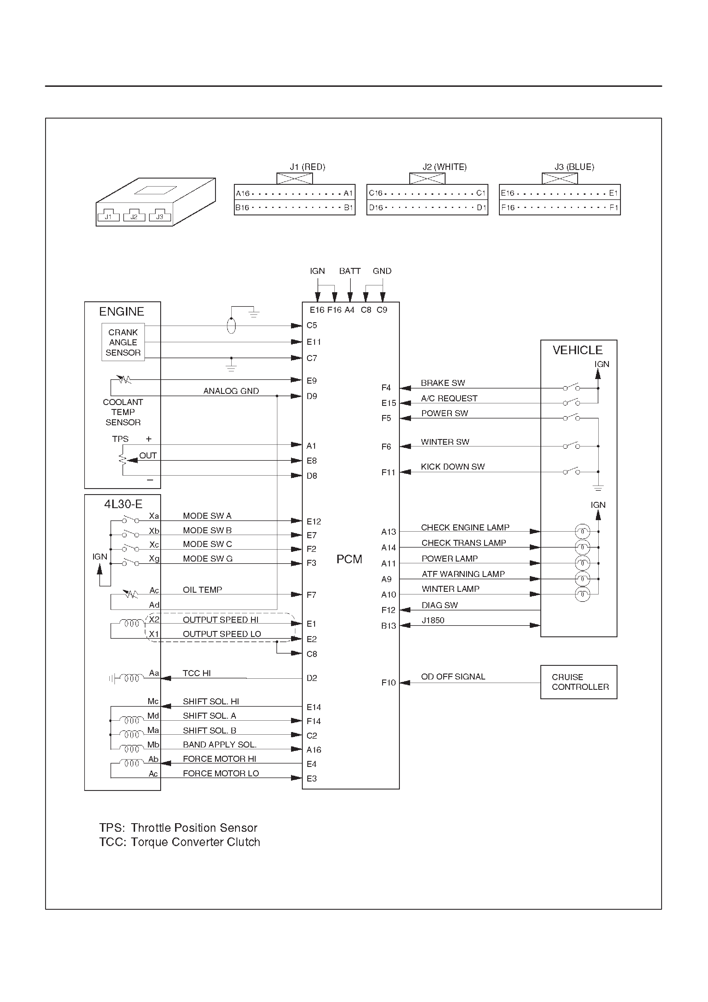
Powertrain Control Module (PCM)
C07RW026
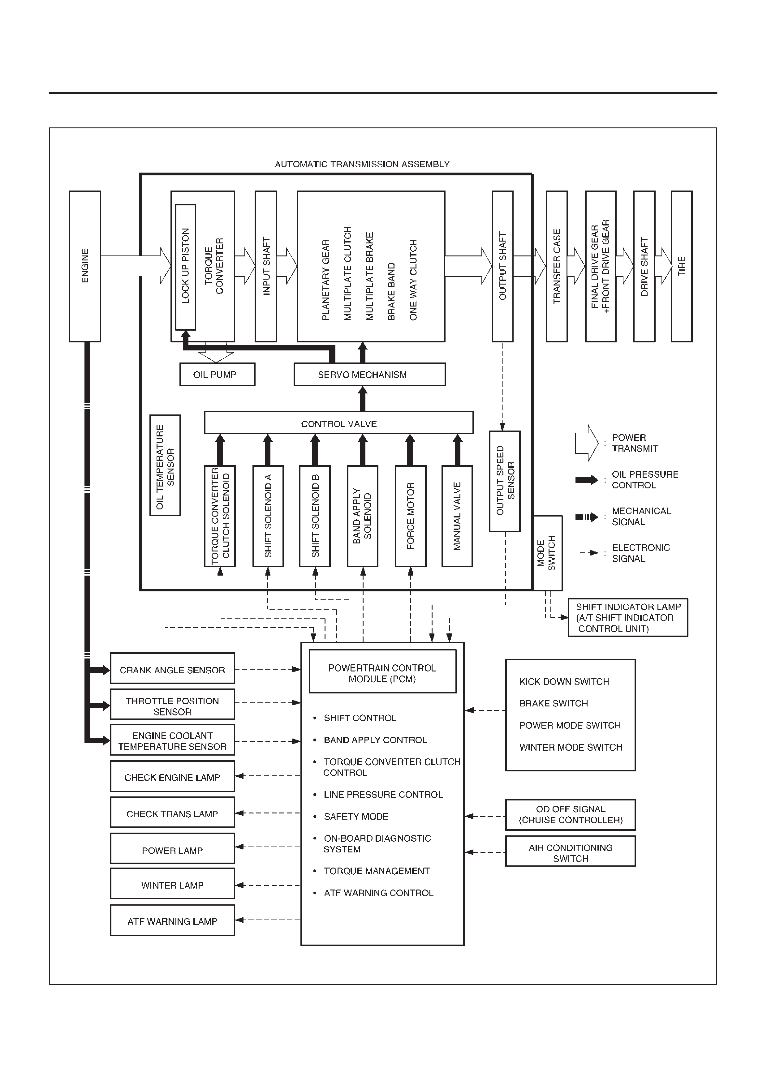
Control System Diagram
C07RY00059

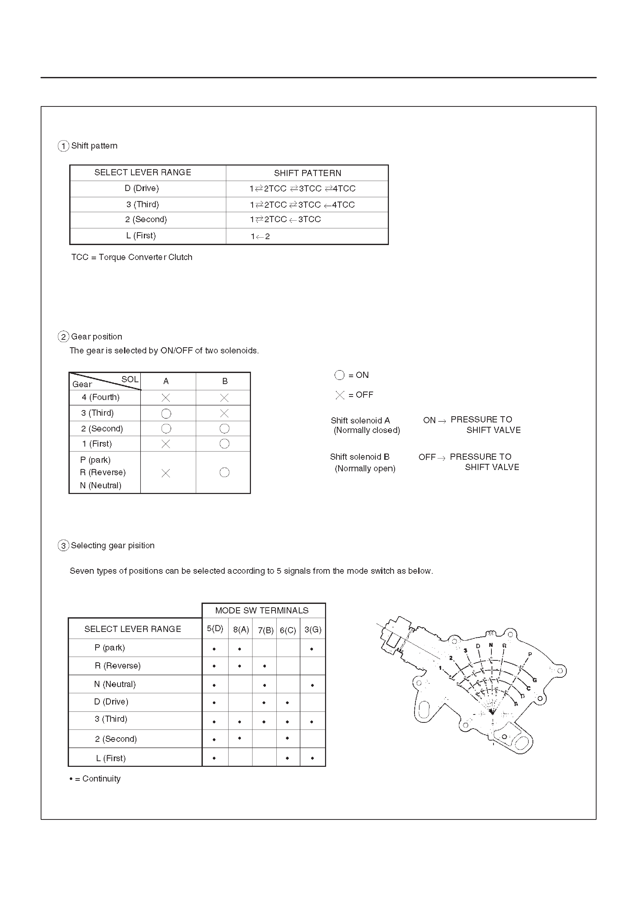
Shift Control
The transmission gear is shifted according to the shift
pattern selected by the driver. In shifting gears, the gear
ratio is controlled by the ON/ OFF signal using the shift
solenoid A and the shift solenoid B.
Band Apply Control
The band apply is controlled when in the 3–2 downshift
(engine overrun prevention) and the garage shift (shock
control).
The band apply solenoid is controlled by the signal from
the Pulse Width Modulation (PWM) to regulate the flow of
the oil.
Torque Converter Clutch Control
The clutch ON/OFF is controlled by moving the converter
clutch valve through shifting Torque Converter Clutch
(TCC) solenoid using the ON/OFF signal.
Line Pressure Control
The throttle signal allows the current signal to be sent to
the force motor. After receiving the current signal, the
force motor activates the pressure regulator valve to
regulate the line pressure.
On–Board Diagnostic System
Several malfunction displays can be stored in the
Powertrain Control Module (PCM) memory, and read out
of it afterward.
The serial data lines, which are required for the testing of
the final assembly and the coupling to other electronic
modules, can be regulated by this function.
Fail Safe Mechanism
If there is a problem in the transmission system, the PCM
will go into a “backup” mode.
The vehicle can still be driven, but the driver must use the
select lever to shift gears.
Torque Management Control
The transmission control side sends the absolute spark
advance signal to the engine control side while the
transmission is being shifted. This controls the engine
spark timing in compliance with the vehicle running
condition to reduce the shocks caused by the change of
speed.
ATF Warning Control
The oil temperature sensor detects the ATF oil
temperature to control the oil temperature warning, TCC,
and the winter mode.
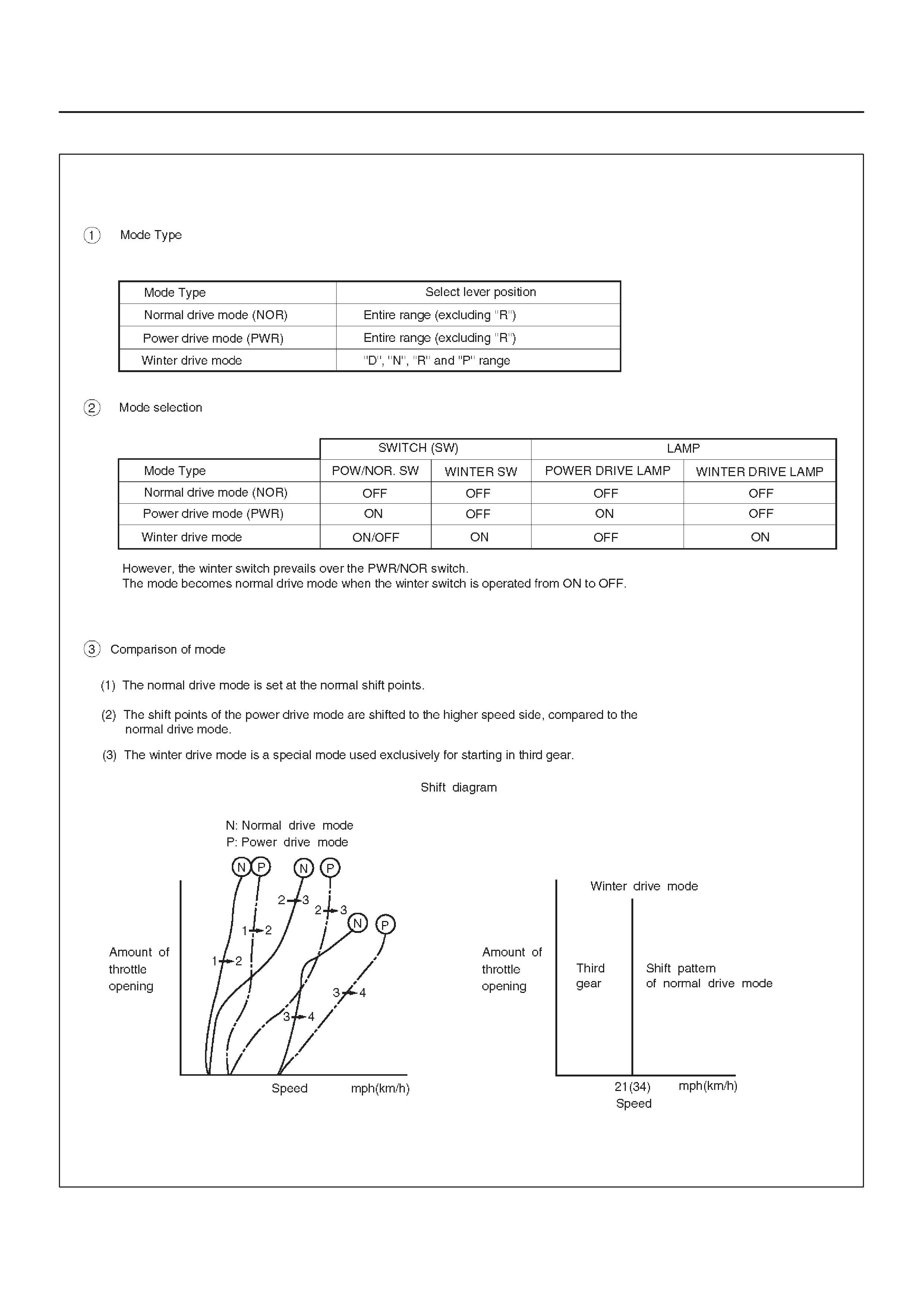
Shift Mode Control
F07RT035
Gear Shift Control
F07RT034

Winter Drive Mode
1.The winter switch will operate when switched on after
all of the following conditions are present:
a. The gear select position is “D”, “N”, “R” and “P”
range.
b. Vehicle speed is 7 mph (11 km/h) or less.
c. Transmission oil temperature is 120°C (248°F) or
less.
d. Kickdown switch is of f.
e. Accelerator opening is at 8% or less.
2.Cancel Release
1. Cancellation by driver
a. Turning off the winter drive mode switch
b. Shifting select position to “3”, “2”, or “L” (Winter
drive mode is not canceled by selecting “N”, “R”,
or “P” from “D”)
c. Ignition key is turned off.
2. Automatic cancellation
a. When vehicle runs at 21mph (34 km/h) or more
for 1 second or more
b. When transmission oil temperature reaches
140°C (284°F) or above
NOTE: The mode returns to normal drive mode or power
drive mode after the winter drive mode is canceled.
Backup Mode
If a major system failure occurs which could affect safety
or damage the transmission under normal vehicle
operation, the diagnostic system detects the fault and
overrides the Powertrain Control Module (PCM).
The “CHECK TRANS” light flashes to alert the driver , and
the transmission must be manually shifted as follows:
Select lever position Gear Ratio Selected
D4 (Fourth)
Manual 3 4 (Fourth)
Manual 2 3 (Third)
Manual L 1 (First)
R Reverse
Shifts are firmer to prevent clutch slip and consequent
wear. The fault should be corrected as soon as possible.
Functions of Input / Output Components
Components Function
Speed sensor
(fixed to transmission
(T/M))
Senses rotation of output shaft and feeds the data to Powertrain Control Module
(PCM).
Throttle position sensor
(TPS)
(fixed to engine)
Senses the extent of throttle valve opening and the speed of the throttle valve
lever motion to open the valve. Feeds the data to PCM.
I
N
Brake Switch (SW)
(fixed to brake pedal) Senses whether the driver has pressed the brake pedal or not and feeds the
information to PCM.
N
P
U
Kickdown SW
(fixed to accelerator pedal) Senses whether the driver has pushed the accelerator pedal fully or not, and
feeds the information to PCM.
U
TMode SW (fixed to T/M) Senses the select lever position, and feeds the information to PCM.
S
I
Power drive SW
(fixed to front console) Senses whether the driver has selected the power mode, and feeds the
information to PCM.
I
GT/M oil temp. sensor Senses the T/M oil temperature and feeds the data to PCM
N
A
L
Engine coolant
temperature sensor Senses the engine coolant temperature, and feeds the data to PCM.
L
Engine speed signal Feeds the signals monitoring engine speed to PCM from crank angle sensor.
Air conditioning information Senses whether the air conditioner has been switched on or not, and feeds the
information to PCM.
Winter switch (fixed to front
console) Senses whether the driver has selected the winter mode, and feeds the
information to PCM.
Cruise controller
(Overdrive OFF signal) Downshift takes place when Overdrive OFF signal is received from auto cruise
control unit.
SShift solenoid A, B Selects shift point and gear position suited to the vehicle running condition on
the basis of PCM output.
O
U
T
O
L
E
Band apply solenoid Controls oil flow suited to the vehicle running condition on the basis of PCM
output.
T
P
U
E
N
OTorque Converter
Clutch solenoid Controls clutch engagement/disengagement suited to the vehicle running
condition on the basis of PCM output.
T
S
I
I
DForce motor
(Pressure regulator
valve)
Adjusts the oil pump delivery pressure to line pressure suited to the vehicle
running condition on the basis of PCM output.
I
GPower drive mode lamp Informs the driver whether the vehicle is in power mode or not.
N
A
Winter drive mode lamp Informs the driver whether the vehicle is in winter mode or not.
A
LT/M monitor lamp
(“CHECK TRANS”) Informs the driver of failure in the system.
ATF warning lamp Lights when ATF oil temperature rises.
Diagnosis
Electronic Diagnosis
How To Diagnose The Problem
1.To avoid incorrect diagnostics, this book needs to be
followed accurately. Unless stated, do not jump
directly to a section that could contain the
solution. Some important information may be
missed.
2. The sections in CAPITALS and bold are the main
sections that can be found in the contents.
3.The GOTO “SECTION” means to continue to check
going to the “section”.
4.The GOTHROUGH “SECTION” means to go
through the “section” and then to go back to the place
the GOTHROUGH was written.
5.BASIC ELECTRIC CIRCUITS:
You should understand the basic theory of electricity.
This includes the meaning of voltage, amps, ohms,
and what happens in a circuit with an open or shorted
wire. You should also be able to read and understand
wiring diagrams.
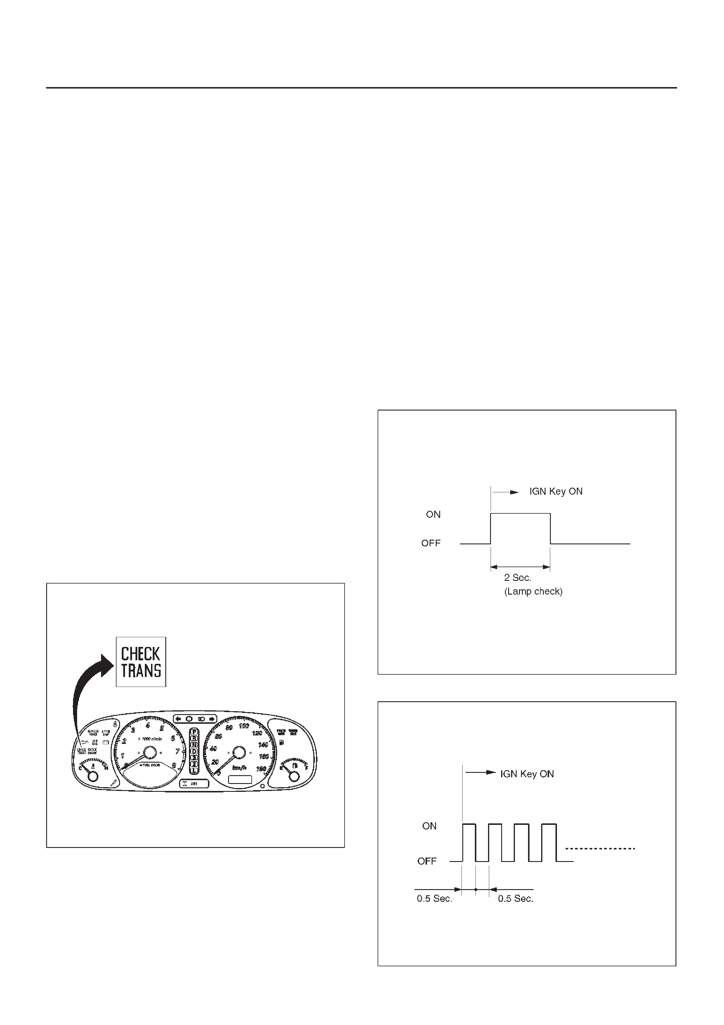
Check Trans Indicator
Find CHECK TRANS indicator and verify if it is
A. Flashing: GOTO DIAGNOSTIC CHECK.
B. Staying on: GOTHROUGH CHECK TRANS
CHECK.
C. Is never ON when the ignition key is turned on:
GOTHROUGH CHECK TRANS CHECK
D. Is ON during 2 seconds at ignition but OFF after:
Normal operation. No DTC or malfunction.
821RY00064
Diagnostic Check
This test determines if the transmission or its input, or
output, connections, or sensors are failing.
1.Connect the Tech 2: GOTHROUGH Tech 2 OBD II
CONNECTION.
2.Turn on the ignition but not the engine.
3.Push “F0” on Tech 2 to see the Diagnostic Trouble
Code (DTC):
4.Do you have a DTC?
YES: write down all code numbers and do the DTC
CHECK
NO: the DTC can not help you find the problem.
1. GOTHROUGH “CHECK TRANS” CHECK
2. IF it is flashing and the flash is 0.5 seconds ON
and 0.5 seconds OFF, this means that you should
have a DTC stored. Please recheck GOTO
DIAGNOSTIC CHECK and if you find the same
problem, replace the Powertrain Control Module
(PCM).
Normal
C07RW047
Abnormal
C07RY00058
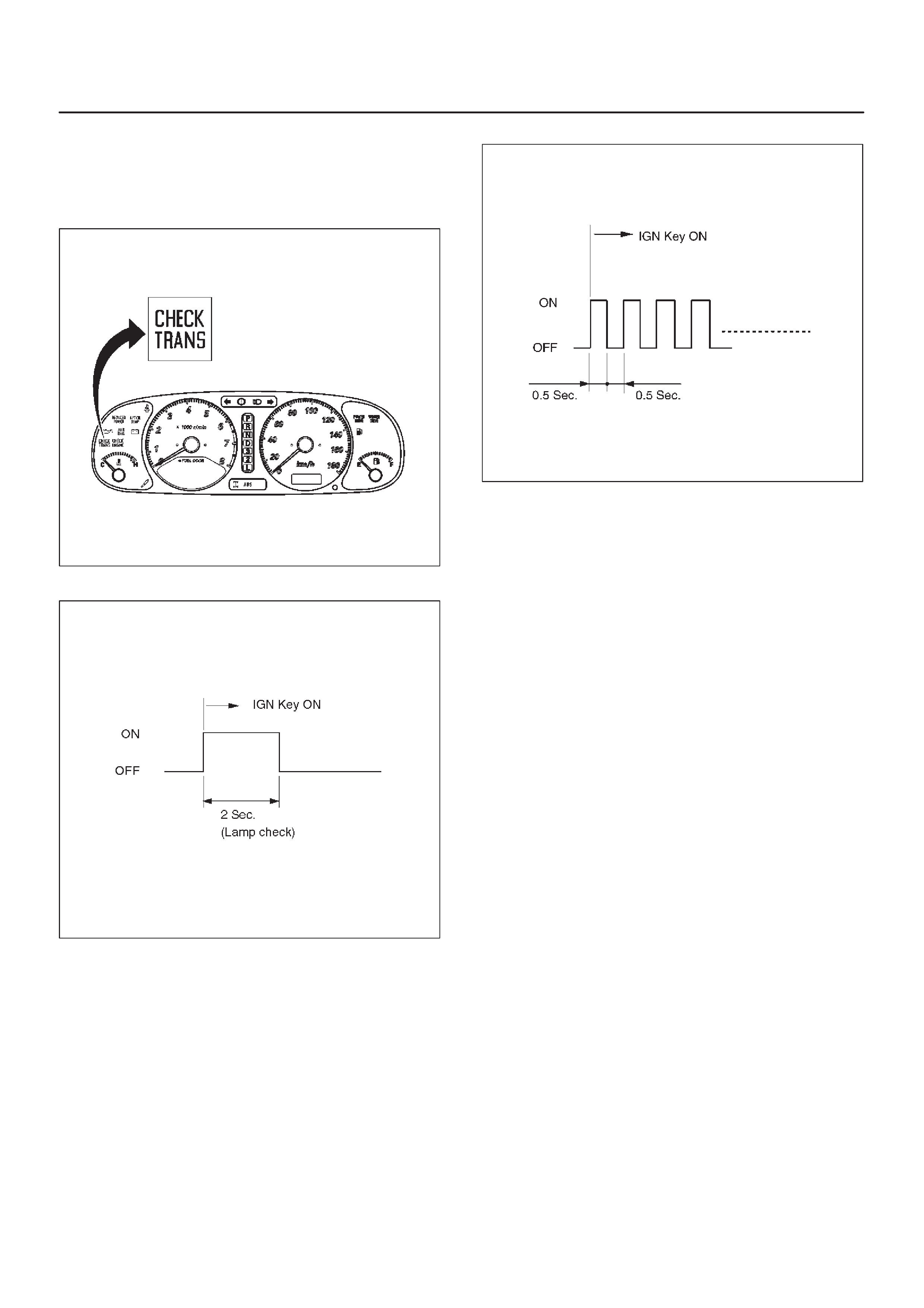
“Check Trans” Check
1.Indicator is ON during 2 seconds at ignition (or when
the engine is cranked) but it is OFF after the engine
starts. The indicator is working normally GOTO
DIAGNOSTIC CHECK.
821RY00064
Normal
C07RW047
2.Indicator is flashing and the flash is 0.5 seconds ON
and 0.5 seconds OFF always when ignition is on
(engine cranked or not). This means that there is a
malfunction. GOTO DIAGNOSTIC CHECK.
Abnormal
C07RY00058
3.Indicator is staying ON always when Ignition is ON.
1. This means that connection between the lamp
and the PCM is shorted to ground.
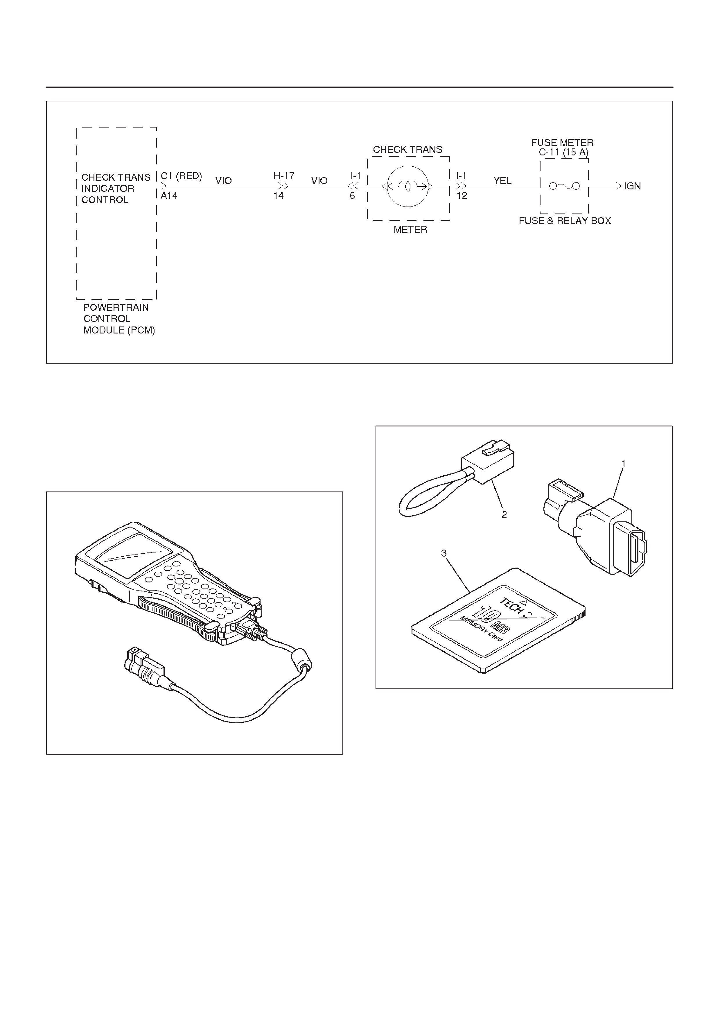
2. Verify if instrument panel terminal 6 of connector
I–1 is shorted to ground.
3. Verify if the PCM connector C1 (RED) terminal
A14 is shorted to ground.
4. Verify that the instrument panel terminal 12 of
connector I–1 is connected to battery.
5. IF problem solved: GOTO CHECK TRANS
INDICATOR.
NO:Replace Powertrain Control Module (PCM).
4.Indicator is staying OFF with the ignition ON (engine
OFF).
1. This means that connection between the lamp
and the PCM is shorted to battery or opened.
2. Verify if instrument panel terminal 6 of connector
I–1 is shorted to battery or open.
3. Verify if the PCM connector C1 (RED) terminal
A14 is shorted to battery or open.
4. Verify that the instrument panel terminal 12 of
connector I–1 is connected to battery. If not,
check the fuses and the connections voltage.
5. IF problem solved: GOTO CHECK TRANS
INDICATOR.
NO: Replace Powertrain Control Module (PCM).
D07RX015
Tech 2 OBD II Connection
In order to access OBD II Powertrain Control Module
(PCM) data, use of the Tech 2 scan tool kit (7000086) is
required.
1.The electronic diagnosis equipment is composed of:
1. Tech 2 hand–held scan tool unit (7000057) and
DLC cable (3000095).
901RW176
2. SAE 16/19 Pin Adapter (3000098)(1), RS232
Loop Back Connector (3000112)(2), and
PCMCIA Card (3000117)(3).
F07RW033
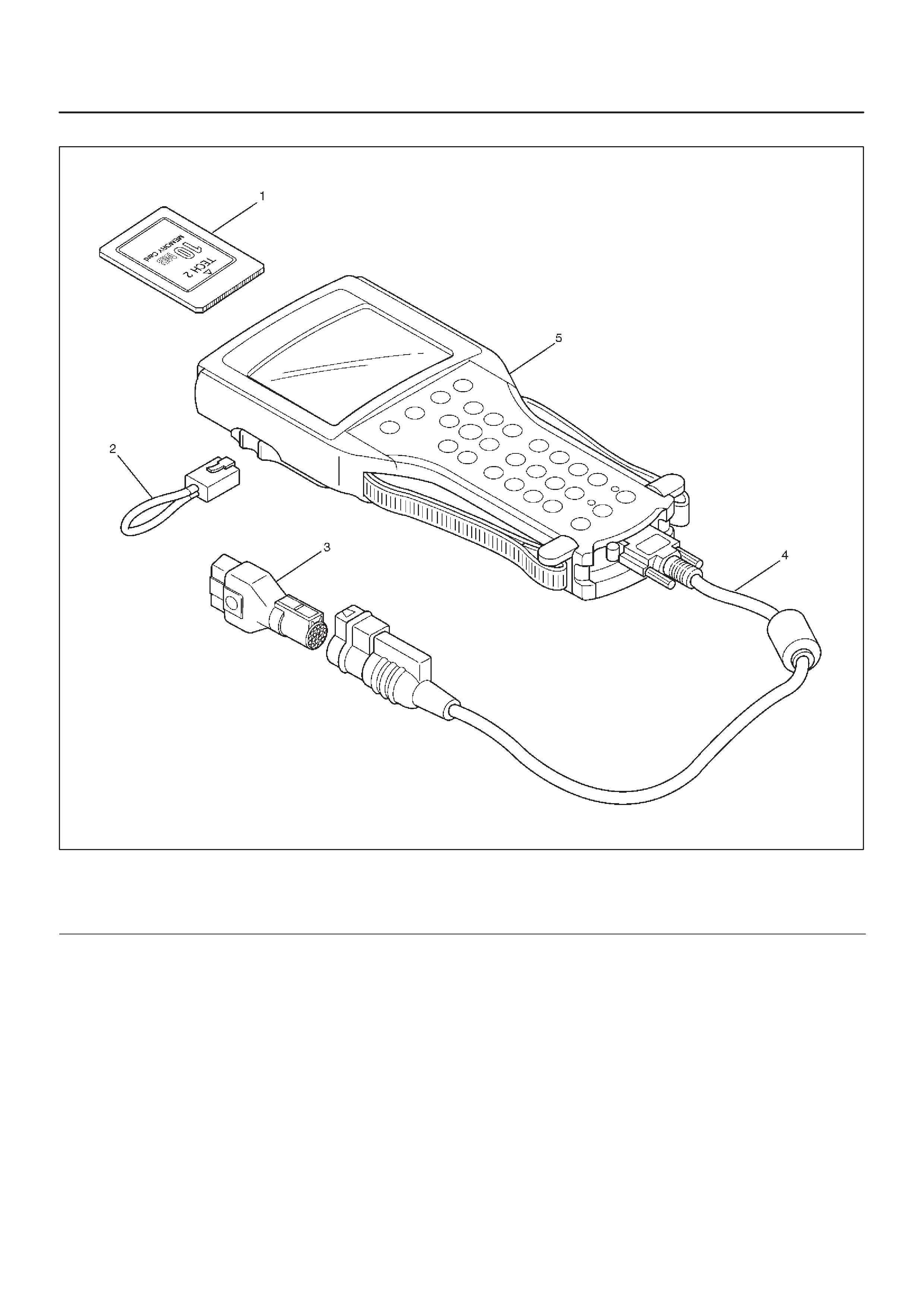
2.Connecting the Tech 2
901RW180
Legend
(1) PCMCIA Card
(2) RS 232 Loop Back Connector
(3) SAE 16/19 Adapter
(4) DLC Cable
(5) Tech 2
DBefore operating the Isuzu PCMCIA card with the
Tech 2, the following steps must be performed:
1. The Isuzu 2000 System PCMCIA card (1) inserts
into the Tech 2 (5).
2. Connect the SAE 16/19 adapter (3) to the DLC
cable (4).
3. Connect the DLC cable to the Tech 2 (5)
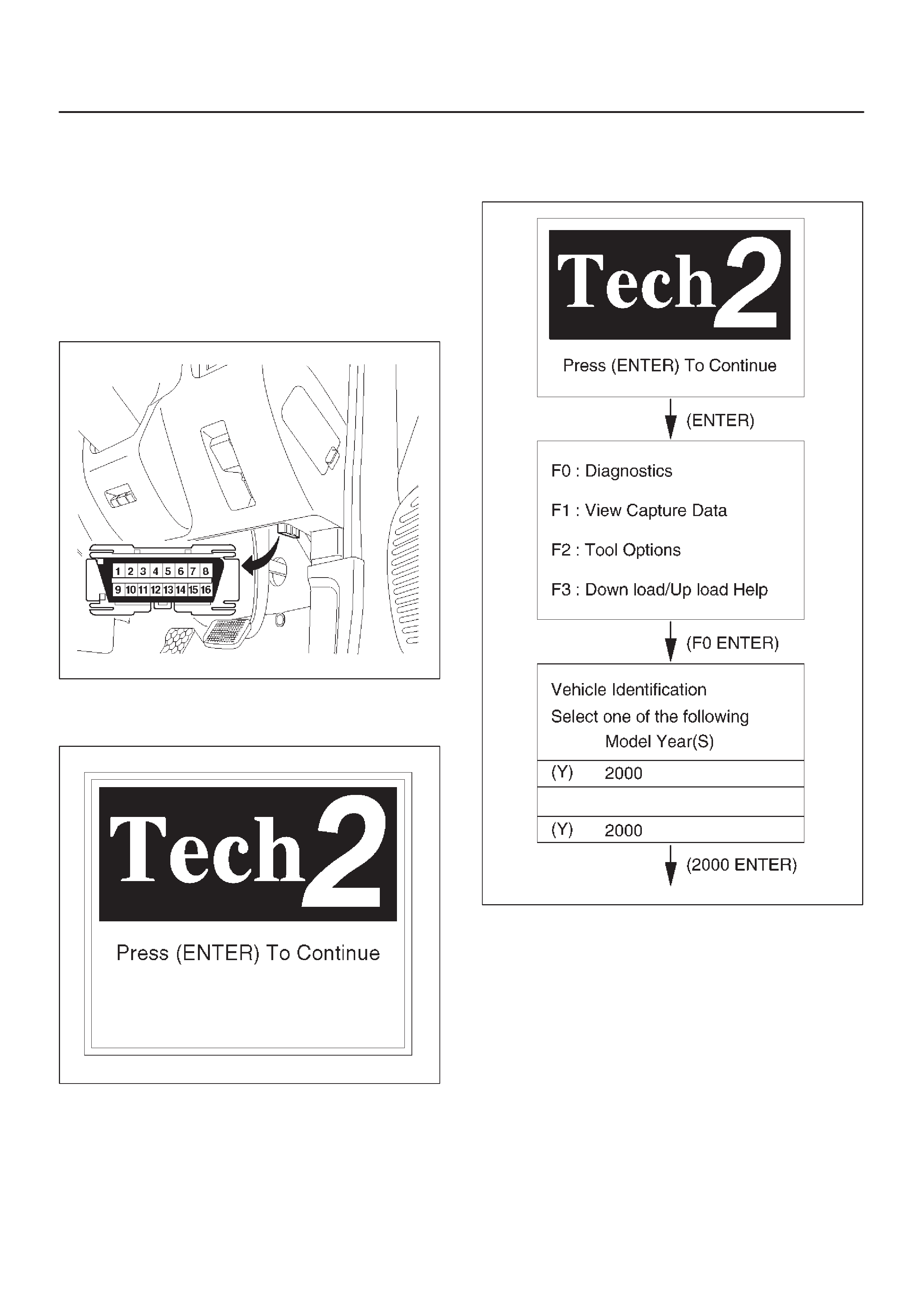
4. Mark sure the vehicle ignition is off.
5. Connect the Tech 2 SAE 16/19 adapter to the
vehicle DLC.
810RW317
6. The vehicle ignition turns on.
7. Verify the Tech 2 power up display.
060RW009
NOTE: The RS232 Loop back connector is only to use for
diagnosis of Tech 2 and refer to user guide of the Tech 2.
8. The power up screen is displayed when you
power up the tester with the Isuzu systems
PCMCIA card. Follow the operating procedure
below.
060RY027
060RY00169
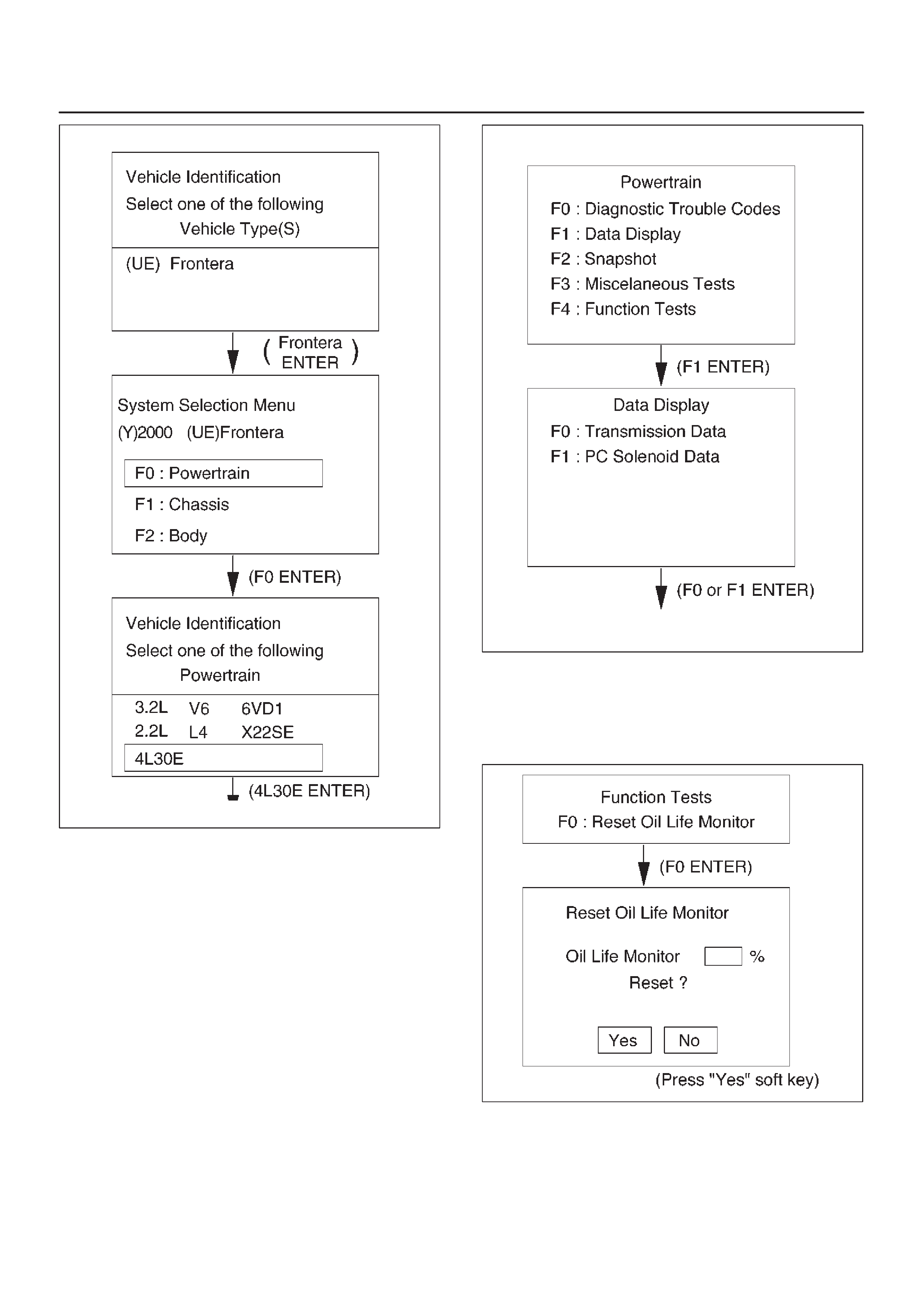
Once the test vehicle has been identified an “Application
(Powertrain) Menu” screen appears. Please select the
appropriate application.
Data Display
When F1: Data Display is selected, a “Data Display
Menu” screen appears.
Please select either “Transmission Data” or “PC Solenoid
Data”.
060RX009
Function Tests (Reset Oil Life Monitor)
When F4: Function T ests is selected from the “Powertrain
Menu”, a “Reset Oil Life Monitor Menu” screen appears.
When the ATF has been replaced, select “F0” and reset
“Oil Life Monitor” data.
060RX056

F0: Transmission Data
Item Unit Engine running at idle
Engine Speed RPM 750 ∼ 900 RPM
Vehicle Speed km/h, MPH 0 MPH
Throttle Position %0 %
Throttle Position Sensor V 0.5 ∼ 1.0 V
Manifold Absolute Pressure kPa approx. 40 kPa
Barometric Pressure kPa approx. 102 kPa
AT Output Speed (Automatic T ransmission) RPM 0 RPM
AT Input Speed Ratio (Automatic T ransmission) 0.0
Ignition Voltage V 12.8 ∼ 14.1 V
AT Oil Temperature (Automatic Transmission) °C, °F 70 ∼ 80°C (158 ∼ 176°F)
AT Oil Life Monitor (Automatic Transmission) %100 %
Commanded Gear 1
Current Gear 1
Mode Switch C Inactive, Active Inactive
Mode Switch B Inactive, Active Inactive
Mode Switch A Inactive, Active Active
Mode Switch G Inactive, Active Active
Actual Gear Park
1–2 Shift Solenoid A Off, On Off
2–3 Shift Solenoid B Off, On On
Brake Switch Off, On Off
Solenoid Brake Band Off, On Off
TCC Slip Speed RPM 750 ∼ 900 RPM
TCC Status Disabled, Enabled Enabled
TCC Solenoid Off, On Off
TCC Duty Cycle %0 %
TCC Apply Mode No Apply, In Apply No Apply
TCC Release Mode No, Yes No
TCC On Mode No, Yes No
TCC Off Mode No, Yes Yes
Default Gear No, Yes No
Engine Warm No, Yes Yes
A/C Request Yes, No Yes
A/C Clutch Relay Off, On On
Winter Switch Off, On Off
Winter Drive Lamp Off, On Off
Kickdown Switch Off, On Off
ATF Lamp (Automatic Transmission) Off, On Off
Power Switch Normal, Power Normal
Power Drive Lamp Off, On Off
ABS Status On, Off (Not used)

F1: PC Solenoid Data
Item Unit Engine running at idle
Engine Speed RPM 750 ∼ 900 RPM
Vehicle Speed km/h, MPH 0 MPH
Throttle Position %0 %
Throttle Position Sensor V 0.5 ∼ 1.0 V
Manifold Absolute Pressure kPa approx. 40 kPa
Barometric Pressure kPa approx. 102 kPa
PCS Current (Pressure Control Solenoid) Aapprox. 1.0 A
PCS Actual Current (Pressure Control Solenoid) Aapprox. 1.0 A
PCS Duty Cycle (Pressure Control Solenoid) %approx. 45 %
Desired PCS Pressure (Pressure Control Solenoid) kPa 43 ∼ 52 kPa
Shift Pressure (Line Pressure) kPa 43 ∼ 52 kPa
Transmission Temperature °C, °F 75 ∼ 110°C (167 ∼ 230°F)
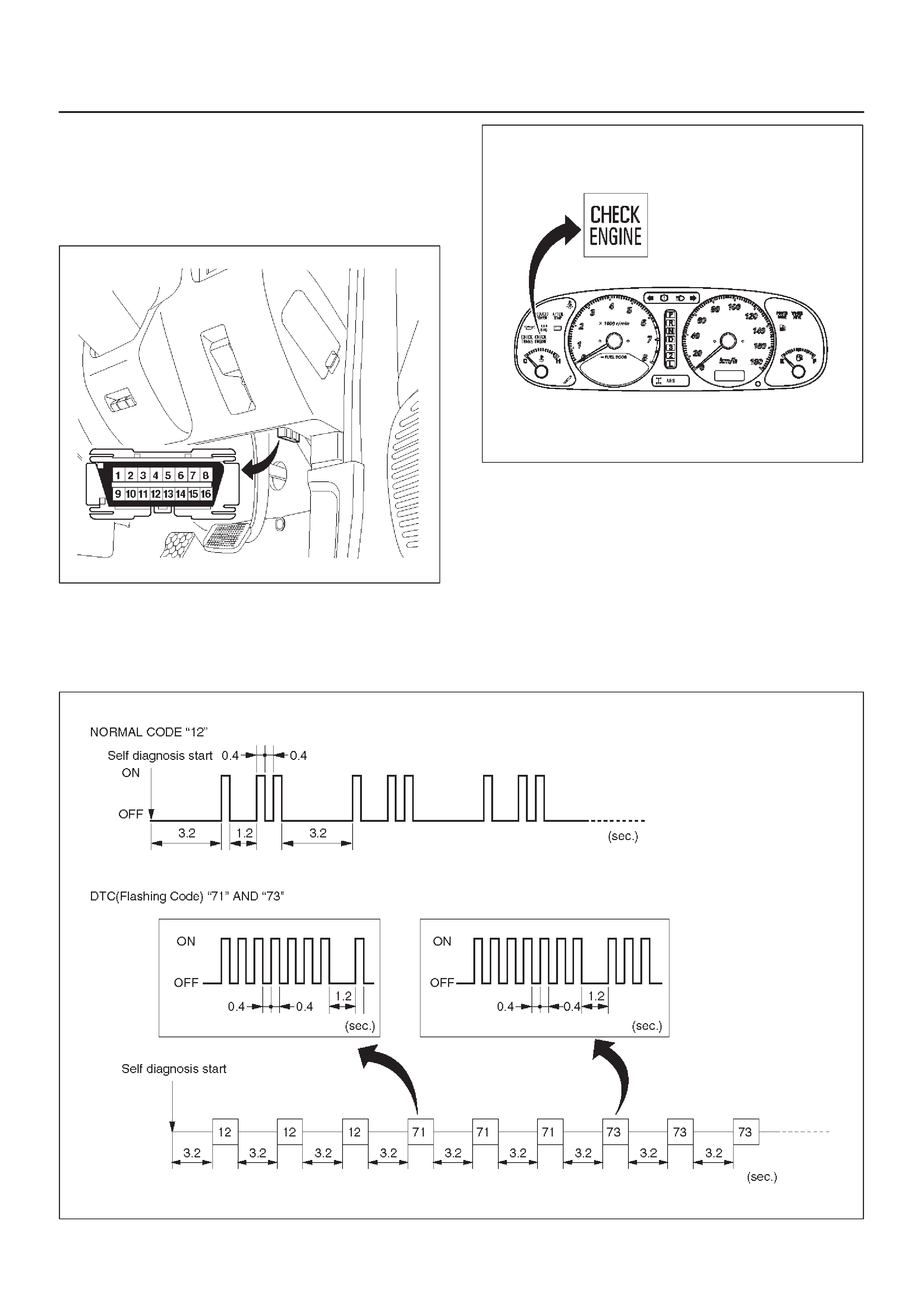
Flashing Code
1.A DTC (Flashing Code) can be displayed by the
Powertrain Control Module (PCM) by shorting
together terminals 6 and 4 or 5 (GND) of the Data Link
Connector (DLC) located right side of the drivers side
instrument panel.
810RW317
821RY00065
2.1. In case there is no DTC stored in memory. The
CHECK ENGINE indicator flashes Normal Code
“12” repeatedly.
2. In case there is DTC stored in memory. First,
Normal Code “12” is displayed three times and
then any other DTC‘s are displayed three times.
When all DTC‘s have been displayed they are
displayed again beginning from the first one.
3. Write down all codes numbers and GOTO DTC
CHECK.
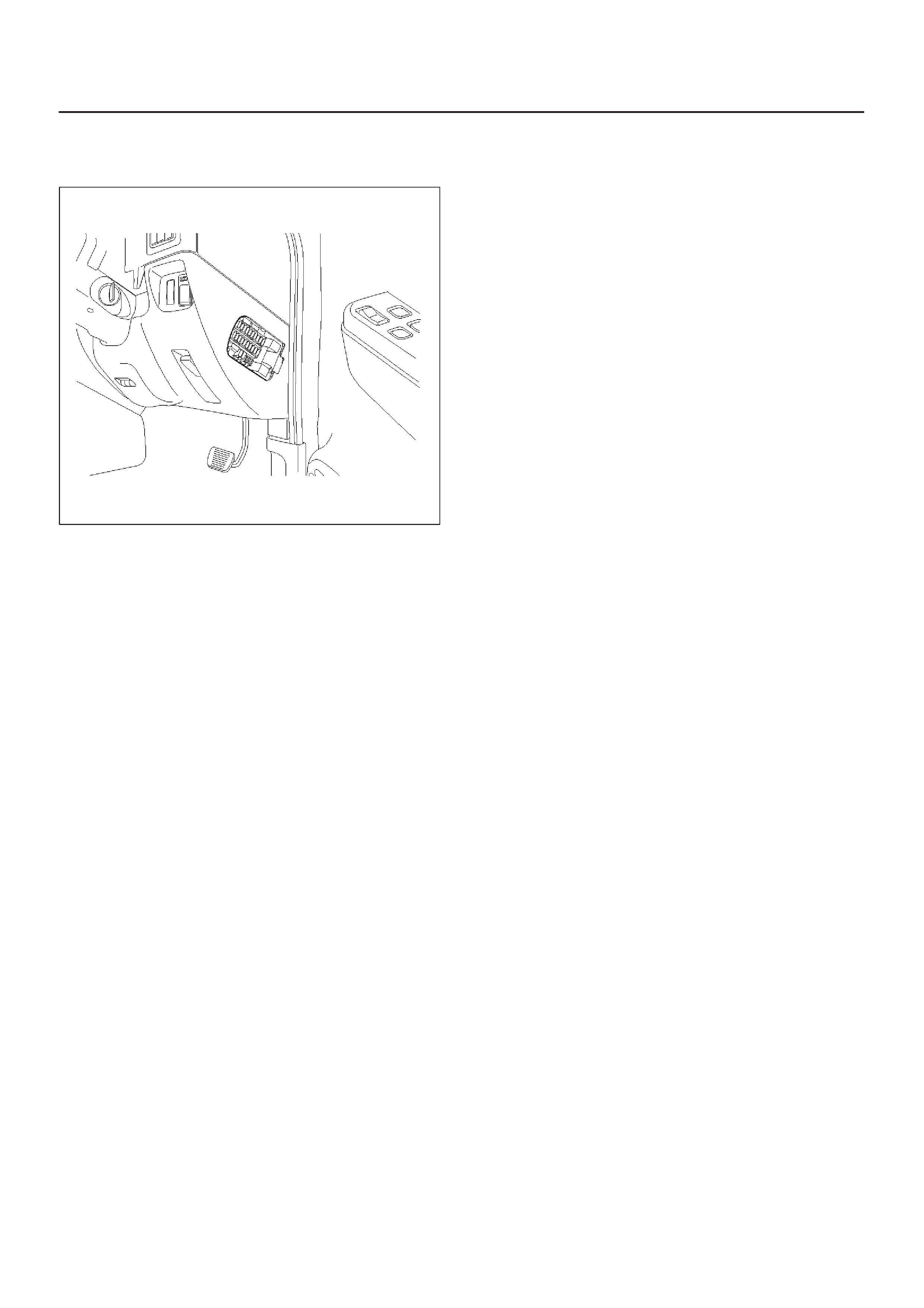
C07RX006
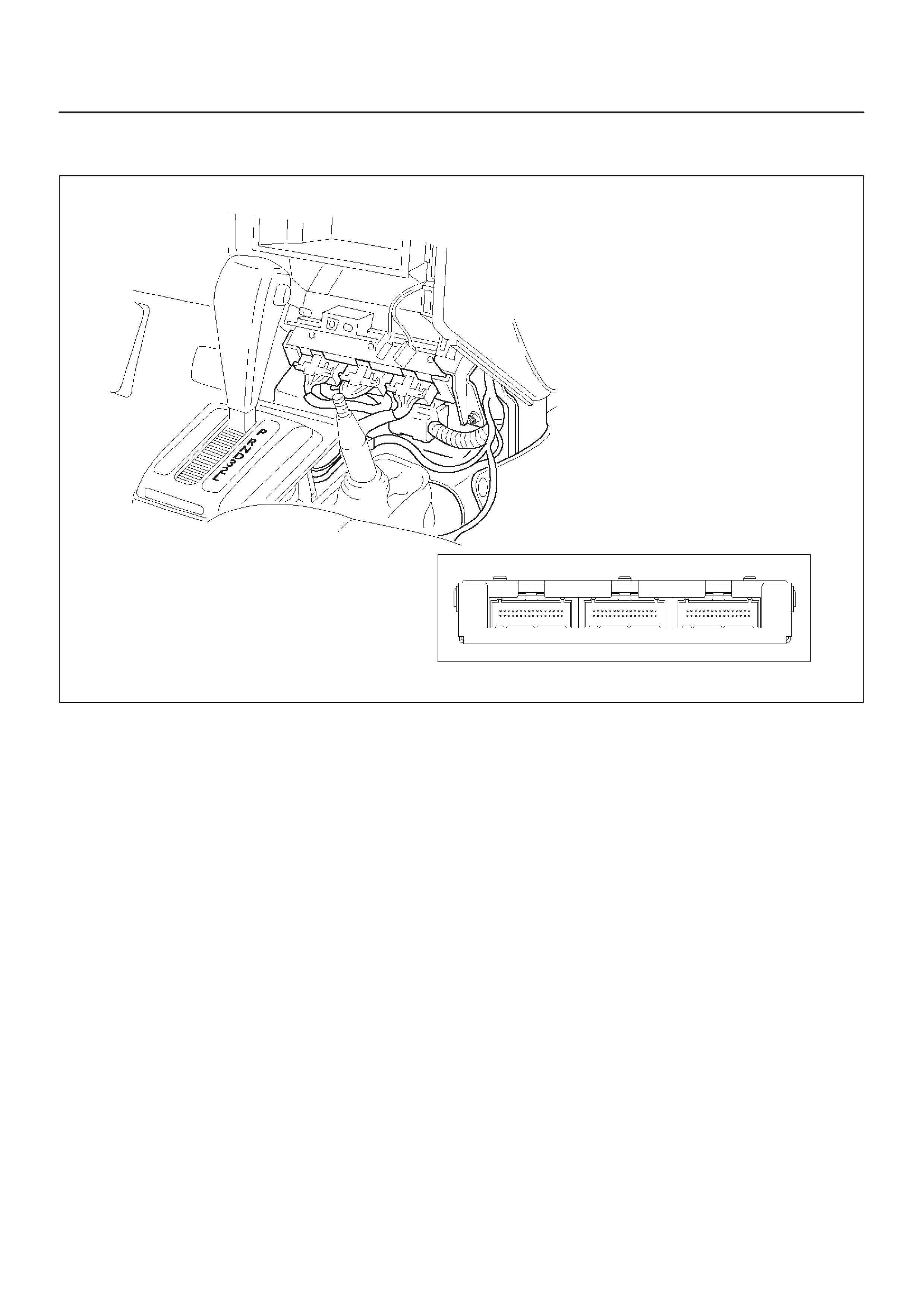
OBD II Diagnostic Management System
Powertrain Control Module (PCM) Location
828RX004
Class 2 Serial Data Bus
OBD II technology requires a much more sophisticated
PCM than does OBD I technology. The OBD II PCM
diagnostic management system not only monitors
systems and components that can impact emissions, but
they also run active tests on these systems and
components. The decision making functions of OBD II
PCM have also greatly increased. To accommodate this
expansion in diagnostic complexity, Isuzu engineers have
designed the Class 2 serial data bus, which meets SAE
J1850 recommended practice for serial data.
“Serial Data” refers to information which is transferred in a
linear fashion – over a single line, one bit at a time. A “Data
Bus” is an electronic pathway through which serial data
travels.
FRONTERA previously used a 5 volt data bus called
UART, which is an acronym for “Universal Asynchronous
Receive and Transmit”. When neither the vehicle’s
control module nor the diagnostic tool, such as a Tech 2,
are “talking,” the voltage level of the bus at rest is 5 volts.
The two computers talk to each other at a rate of 8,192
bits per second, by toggling or switching the voltage on
the data bus from 5 volts to ground.
Class 2 data, which is used on OBD II vehicles, is quite
different. Data is transferred at a rate of 10.4 kilobits per
second, and the voltage is toggled between zero and 7
volts.
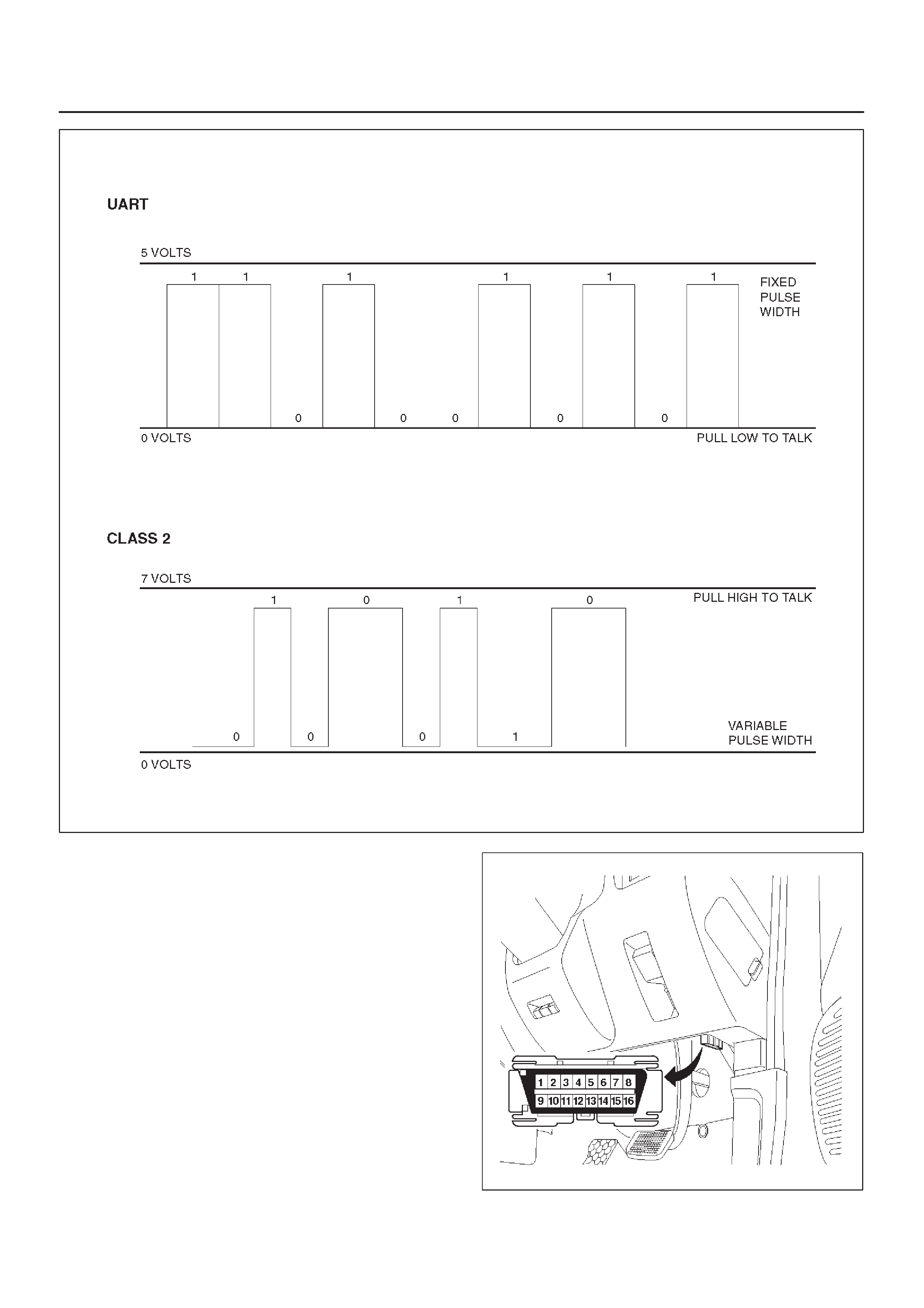
C07RT006
Class 2 data is also pulse width modulated. Each bit of
information can have one of two lengths: long or short. On
the other hand, UART data bits come in only one length
(short). The pulse width modulation of Class 2 data allows
better utilization of the data line.
The message carried on Class 2 data streams are also
prioritized. This means that if two devices try to
communication on the data line at the same time, only the
higher priority message will continue. The device with the
lower priority message must wait.
NOTE: The Class 2 data wire is always terminal 2 of the
new 16–terminal Data Link Connector (DLC).
16 – Terminal Data Link Connector (DLC)
OBD II standardizes Data Link Connector (DLC)
configurations. The DLC, formerly referred to as the
ALDL, will be a 16–terminal connector found on the lower
right side of the driver’s side instrument panel. All
manufacturers must conform to this 16–terminal
standard. 810RW317
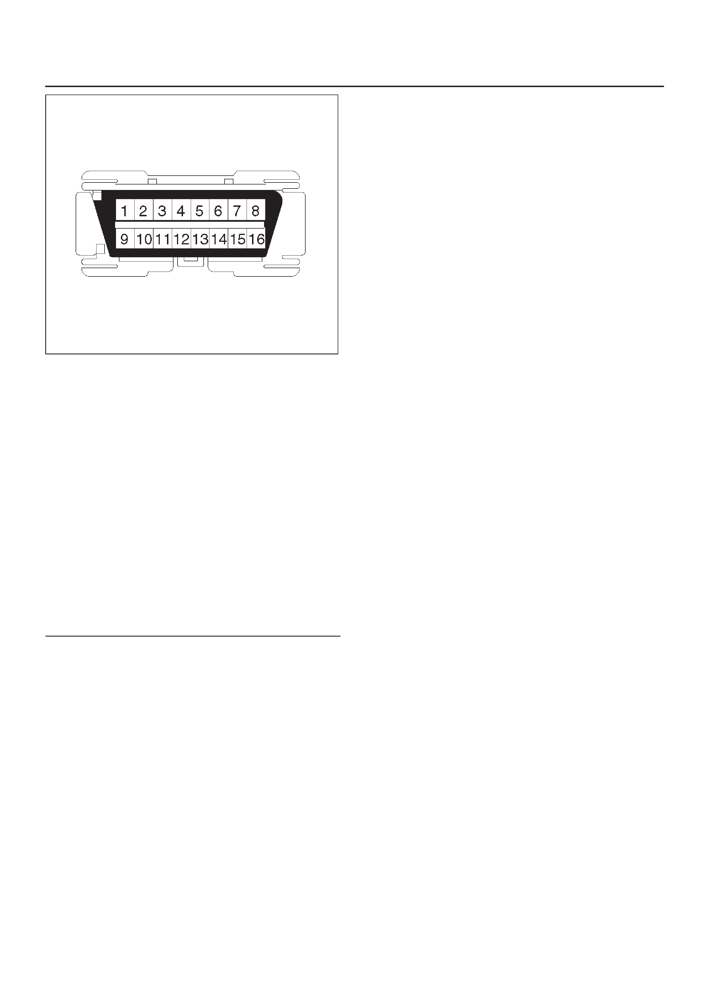
810RT022
PIN 1 – (Not used)
PIN 2 – J1850 Bus + L line on 2–wire systems, or
single wire (Class 2)
PIN 3 – (Not used)
PIN 4 – Chassis ground pin
PIN 5 – Signal ground pin
PIN 6 – PCM diagnostic enable
PIN 7 – (Not used)
PIN 8 – (Not used)
PIN 9 – Primary UART
PIN 10 – (Not used)
PIN 11 – (Not used)
PIN 12 – ABS diagnostic or CCM diagnostic enable
PIN 13 – SIR diagnostic enable
PIN 14 – (Not used)
PIN 15 – (Not used)
PIN 16 – Battery power from vehicle unswitched (4
AMP MAX.)
Malfunction Indicator Lamp (MIL)
The Malfunction Indicator Lamp (MIL) looks the same as
the MIL you are already familiar with (“CHECK ENGINE”
lamp). However , OBD II requires that it illuminate under a
strict set of guidelines. Basically, the MIL is turned on
when the PCM detects a DTC that will impact the vehicle’s
emissions.
The MIL is under the control of the Diagnostic Executive.
The MIL will be turned on if a component or system which
has an impact on vehicle emissions indicates a
malfunction or fails to pass an emissions–related
diagnostic test. It will stay on until the system or
component passes the same test, for three consecutive
trips, with no emissions–related faults.
Types Of Diagnostic Trouble Codes (DTCs)
The Diagnostic Executive classifies Diagnostic Trouble
Codes (DTCs) into certain categories. Each type has
different requirements to set the code, and the Diagnostic
Executive will only illuminate the Malfunction Indicator
Lamp (MIL) for emissions–related DTCs. DTCs fall into
four categories: A, B, C, and D; only types A and B are
emission related The following descriptions define these
categories:
TYPE A
Will store the DTC and turn on the MIL (“Check Engine”
lamp) on the first trip in which an emission–related
diagnostic test has run and reported a “test failed” to the
Diagnostic Executive.
TYPE B
Will store the DTC and turn on the MIL on the second
consecutive trip in which an emission–related diagnostic
test has run and reported a “test failed” to the Diagnostic
Executive. After one failure, the type B DTC is “armed,”
or prepared to store a history code and turn on the MIL if
a second failure occurs. One passed test will disarm a
type B DTC. Some special conditions apply to misfire and
fuel trim DTCs. For a type B DTC to store and turn on the
MIL, two ignition cycles are required.
TYPE C
Will store the DTC and turn on a “SERVICE” lamp
(“Check Trans” lamp) on the first trip that a
non–emission–related diagnostic test has run and
reported a “test failed” to the Diagnostic Executive. This
type of DTC will be used in future applications.
TYPE D
Will store a DTC but will not turn on the MIL on the first
trip that a non–emission–related diagnostic test has run
and reported a “test failed” to the Diagnostic Executive.
These codes can be very helpful for vehicle service when
the driver may comment about a condition, but the MIL did
not turn on.
Clear DTC
NOTE: If you clear the DTC (Diagnostic Trouble Codes)
you will not be able to read any codes recorded during the
last occurrence.
NOTE: To use the DTC again to identify a problem, you
will need to reproduce the fault or the problem. This may
require a new test drive or just turning the ignition on (this
depends on the nature of the fault).
1.IF you have a Tech 2:
1. Connect the Tech 2 if it is still not connected
GOTHROUGH Tech 2 OBD II CONNECTION.
2. Push “F1: Clear DTC Info” in the Application
Menu and answer “Yes” to the question “Do you
want to clear DTC’s?”
a. When a malfunction remains as it is the Tech 2
displays “4L30E CODES NOT CLEARED”. This
means that the problem is still there or that the
recovery was not done. Please GOTO DTC
CHECK.
b. When a malfunction has been repaired and the
recovery is done the Tech 2 displays “4L30E
CODES CLEARED”.
2.IF you have no Tech 2:
To clear the DTC, remove Fuse “ECM” (F–13, 15A)
for at least 10 seconds.
826RX017
DTC Check
1.Diagnostic Trouble Codes (DTC) have been identified
by Tech 2.
2.You have written the list of the DTCs. The order of the
malfunctions has no meanings for this PCM. Usually
only one or two malfunctions should be set for a given
problem.
3.Check directly the DTCs you identified. The DTCs are
sorted by number. Refer to Diagnostic Trouble Code
(DTC) Identification in this section.
PCM Precaution
The PCM can be damaged by:
1.The electrostatic discharge
2.The short circuit of some terminals to voltage or to
ground.
Electrostatic Discharge Damage Description:
1.Electronic components used to control systems are
often designed to carry very low voltage, and are very
susceptible to damage caused by electrostatic
discharge. It is possible for less than 100 volts of
static electricity to cause damage to some electronic
components. By comparison, it takes as much as
4,000 volts for a person to even feel the zap of a static
discharge.
2.There are several ways for a person to become
statically charged. The most common methods of
charging are by friction and induction. An example of
charging by friction is a person sliding across a car
seat, in which a charge of as much as 25,000 volts
can build up. Charging by induction occurs when a
person with well insulated shoes stands near a highly
charged object and momentarily touches ground.
Charges for the same polarity are drained off, leaving
the person highly charged with the opposite polarity.
Static charges of either type can cause damage,
therefore, it is important to use care when handling
and testing electronic components.
NOTICE: To prevent possible electrostatic
discharge damage:
1. Do not touch the PCM connector pins or soldered
components on the PCM circuit board.
2.Be sure to follow the guidelines listed below if
servicing any of these electronic components:
3.Do not open the replacement part package until it is
time to install the part.
4.Avoid touching electrical terminals of the part.
5.Before removing the part from its package, ground
the package to a known good ground on the vehicle.
6.Always touch a known good ground before handling
the part. This step should be repeated before
installing the part if the part has been handled while
sliding across the seat, while sitting down from a
standing position or while walking some distance.
Information On PCM
1.The Powertrain Control Module (PCM) is located in
the center console and is the control center of the
electronic transmission control system.
2.The PCM must be maintained at a temperature below
85°F (185°C) at all times. This is most essential if the
vehicle is put through a paint baking process. The
PCM will become inoperative if its temperature
exceeds 85°C (185°F). Therefore, it is
recommended that the PCM be removed or that
temporary insulation be placed around the PCM
during the time the vehicle is in a paint oven or other
high temperature process.
3.The PCM is designed to process the various inputs
and then respond by sending the appropriate
electrical signals to control transmission upshift,
downshift, shift feel and torque converter clutch
engagement.
4.The PCM constantly interprets information from the
various sensors, and controls the systems that affect
transmission and vehicle performance. By analyzing
operational problems, the PCM is able to perform a
diagnostic function by displaying DTC(s) and aid the
technician in making repairs.

Intermittent Conditions
If the Tech 2 displays a diagnostic trouble code as
intermittent, or if after a test drive a DTC does not
reappear though the detection conditions for this DTC are
present, the problem is most likely a faulty electrical
connection or loose wiring. T erminals and grounds should
always be the prime suspect. Intermittents rarely occur
inside sophisticated electronic components such as the
PCM.
Use the DTC information to understand which wires and
sensors are involved.
When an intermittent problem is encountered, check
suspect circuits for:
1.Poor terminal to wire connection.
2.Terminals not fully seated in the connector body
(backed out).
3.Improperly formed or damaged terminals.
4.Loose, dirty, or corroded ground connections:
HINT: Any time you have an intermittent in more than
one circuit, check whether the circuits share a
common ground connection.
5.Pinched or damaged wires.
6.Electromagnetic Interference (EMI):
HINT: Check that all wires are properly routed away
from spark plug wires, distributor wires, coil, and
generator. Also check for improperly installed
electrical options, such as lights, 2–way radios, etc.
Use the F2: SNAPSHOT mode of the Tech 2 to help
isolate the cause of an intermittent fault. The snapshot
mode will record information before and after the problem
occurs. Set the snapshot to “trigger” on the suspect DTC
or, if you notice the reported symptom during the test
drive, trigger the snapshot manually.
After the snapshot has been triggered, command the
Tech 2 to play back the flow of data recorded from each of
the various sensors. Sign of an intermittent fault in a
sensor circuit is a sudden unexplainable jump in data
values out of the normal range.
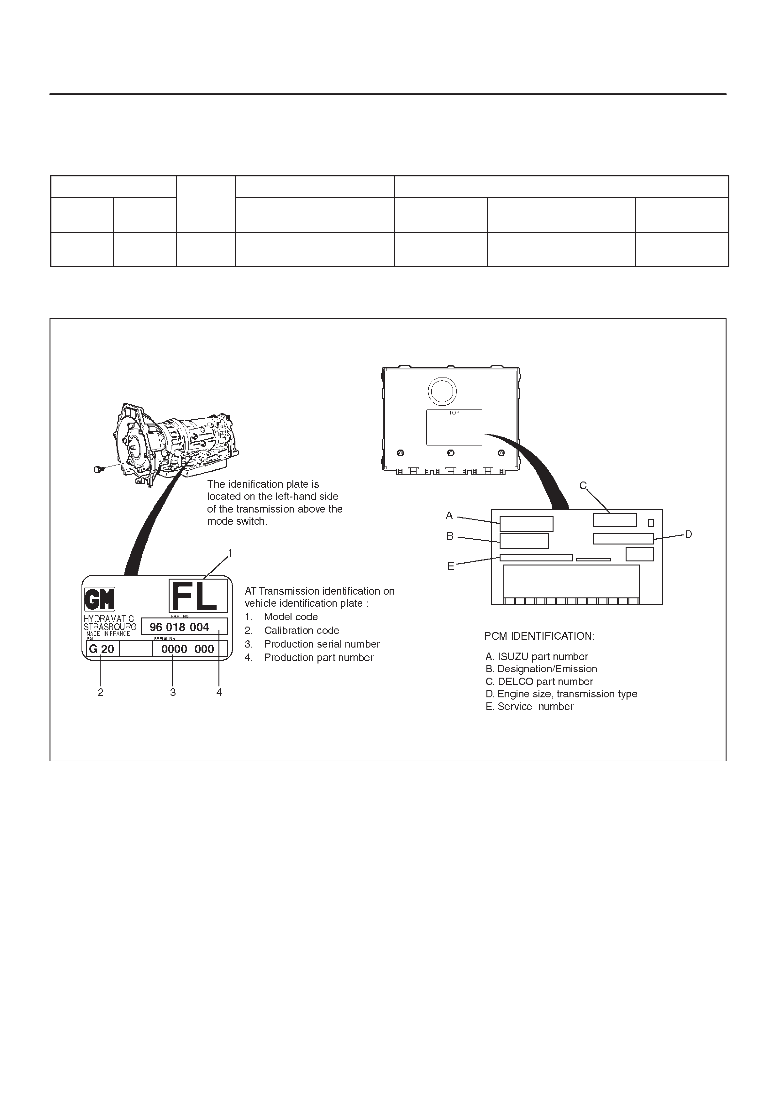
Transmission and PCM Identification
The chart below contains a list of all important information
concerning rear axle ratio, Powertrain Control Module
(PCM), and transmission identification.
VEHICLE Rr axle
Ratio
PCM TRANSMISSION
Type Engine
R
a
ti
oISUZU Parts No. Calibration
Code Isuzu Part No. Model Code
Isuzu/
Frontera 3.2L V6 4.100 8–09356–159–0 G20 8–96018–004–3 FL (4×4)
Isuzu Frontera
240RX011
Diagnostic Trouble Code (DTC)
Identification
DTC
NUMBER FLASHING
CODE DTC NAME DTC TYPE “CHECK
TRANS”
P0218 71 Transmission Fluid Over Temperature D
P0560 72 System Voltage Malfunction C Flash
P0705 73 Transmission Range Switch (Mode Switch) Illegal
Position D
P0706 74 Transmission Range Switch (Mode Switch)
Performance D
P0712 75 Transmission Fluid Temperature (TFT) Sensor Circuit
Low Input D
P0713 76 Transmission Fluid Temperature (TFT) Sensor Circuit
High Input D
P0719 77 TCC Brake Switch Circuit High (Stuck ON) D
P0722 78 Transmission Output Speed Sensor (OSS) Low Input C Flash
P0723 79 Transmission Output Speed Sensor (OSS)
Intermittent C Flash
P0730 81 Transmission Incorrect Gear Ratio C Flash
P0748 82 Pressure Control Solenoid (PCS) (Force Motor)
Circuit Electrical C Flash
P0753 83 Shift Solenoid A Electrical C Flash
P0758 84 Shift Solenoid B Electrical C Flash
P1790 85 ROM Transmission Side Bad Check Sum C Flash
P1792 86 EEPROM Transmission Side Bad Check Sum C Flash
P1835 87 Kick Down Switch Always ON D
P1850 88 Brake Band Apply Solenoid Malfunction D
P1860 89 TCC Solenoid Electrical D
DTC TYPE DEFINITION
CFlashing Check Trans on 1st failure
DNo lamps
NOTE:On the following charts, refer to Powertrain
Control Module (PCM) section for Wiring System and the
Body and Accessories section for circuit diagram details,
parts location, and connector configuration.
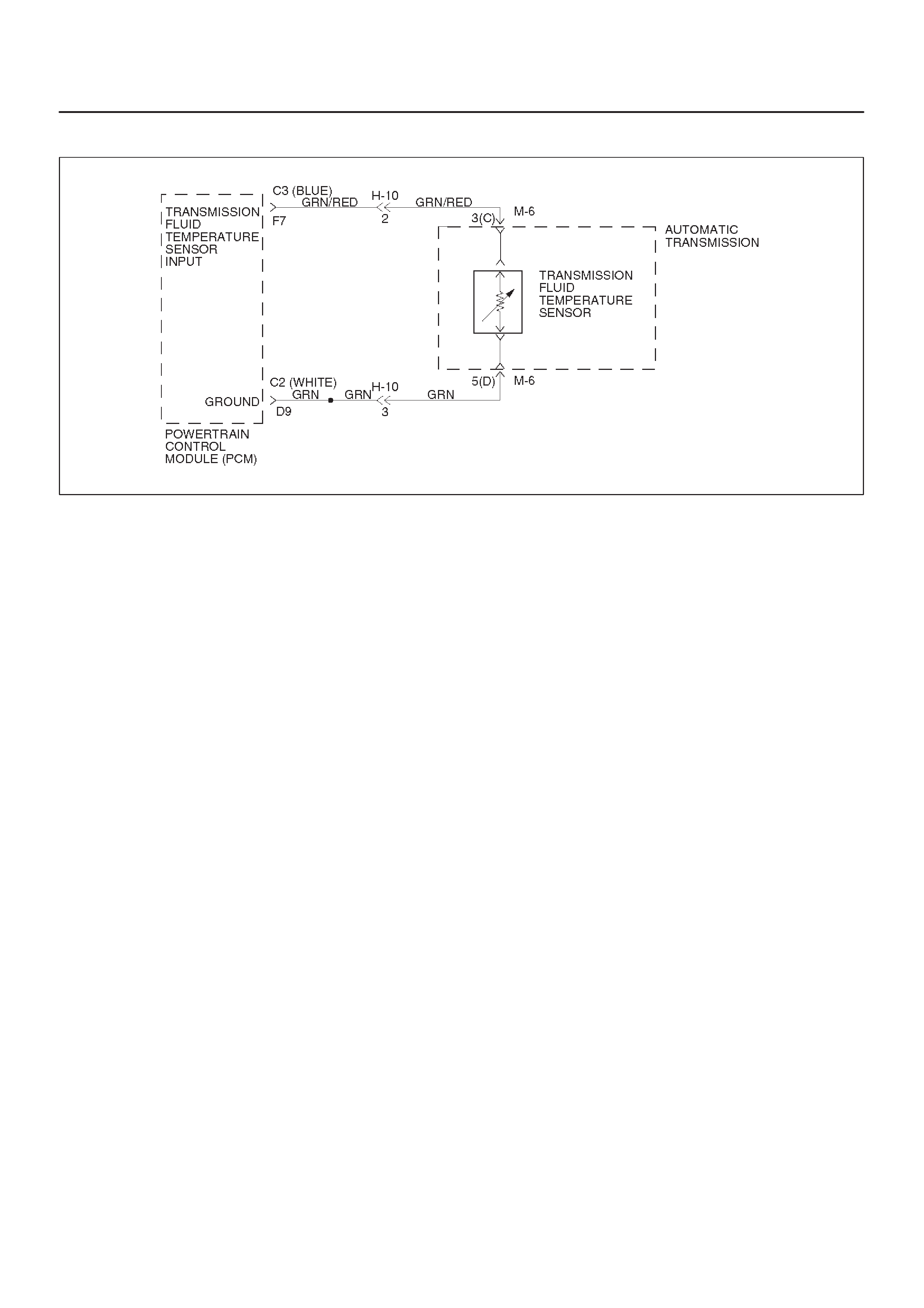
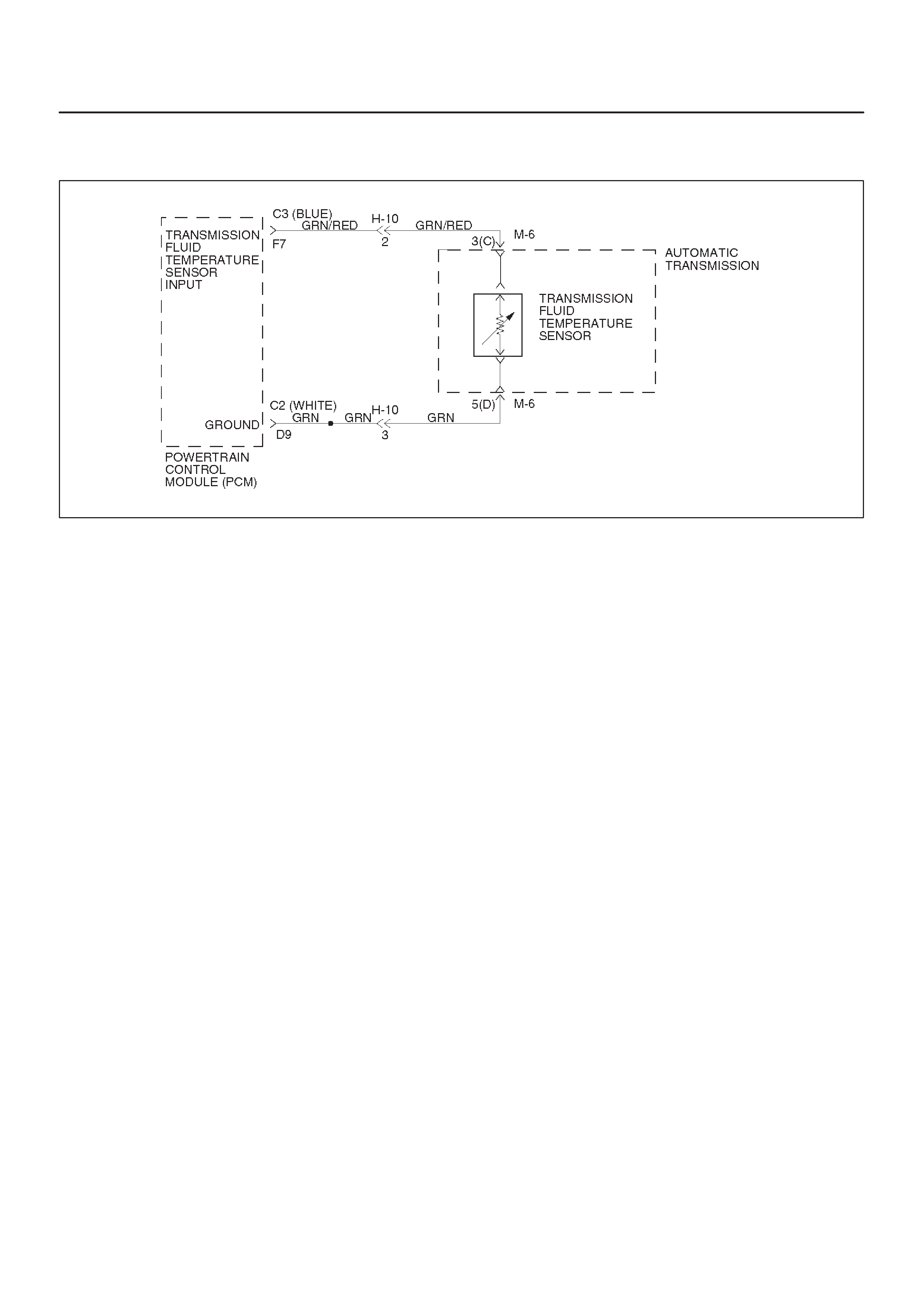
DTC P0218/Flashing Code 71 Transmission Fluid Over Temperature
D07RX016
Circuit Description
The Transmission Fluid Temperature (TFT) sensor is a
thermister that controls the signal voltage to the PCM.
The PCM supplies a 5–volt reference to the sensor on
circuit GRN/RED. When the transmission fluid is cold, the
sensor resistance is high and the PCM will sense high
signal voltage. As the fluid temperature warms to a
normal transmission operating temperature of 100°C
(212°F), the sensor resistance becomes less and the
voltage decreases to 1.5 to 2.0 volts.
This DTC detects a high transmission temperature for a
long period of time. This is a type “D” DTC.
Conditions For Setting The DTC
DNo TFT DTCs P0712 or P0713.
DTFT is greater than 135°C (275°F).
DAll conditions met for 21 seconds.
Action Taken When The DTC Sets
DHot mode TCC Shift Pattern.
DThe PCM will not illuminate the CHECK TRANS
Lamp.
DATF Lamp ON. (greater than 145°C (293°F))
DDisable E–side TCC OFF request.
Conditions For Clearing The DTC
DThe DTC can be cleared from the PCM history by
using a scan tool.
DThe DTC will be cleared from history when the vehicle
has achieved 40 warm–up cycles without a failure
reported.
DThe PCM will cancel the DTC default actions when
the fault no longer exists and the ignition is cycled “off”
long enough to power down the PCM.
Diagnostic Aids
DInspect the wiring for poor electrical connections at
the PCM and at the transmission 16–way connector.
Look for possible bent, backed out, deformed or
damaged terminals. Check for weak terminal tension
as well.
Also check for a chafed wire that could short to bare
metal or other wiring. Inspect for a broken wire inside
the insulation.
DWhen diagnosing for a possible intermittent short or
open condition, move the wiring harness while
observing test equipment for a change.
DCheck harness routing for a potential short to ground
in circuit GRN/RED.
DScan tool TFT sensor temperature should rise
steadily to about 100°C (212°F), then stabilize.
DCheck for a “skewed” (mis–scaled) sensor by
comparing the TFT sensor temperature to the
ambient temperature after a vehicle cold soak. A
“skewed” sensor can cause delayed garage shifts or
TCC complaints.
DCheck for a possible torque converter stator problem.
DVerify customer driving habits, trailer towing, etc.
Test Description
The numbers below refer to the step numbers on the
diagnostic chart.
2. This test checks for a “skewed” sensor or shorted
circuit.
3. This test simulates a TFT DTC P0713.

DTC P0218/Flashing Code 71 Transmission Fluid Over Temperature
Step Action Yes No
1Perform the following checks:
DCheck for possible engine system problems.
DTransmission fluid checking procedure. Refer to Checking
Transmission Fluid Level and Condition in Automatic
Transmission (4L30–E) Section.
Were the checks performed? Go to Step 2 —
21. Install the scan tool.
2. With the engine “off”, turn the ignition switch “on”.
NOTE: Before clearing DTC(s), use the scan tool to record “Failure
Records” for reference, as data will be lost when “Clear Info”
function is used.
3. Record the DTC “Failure Records”.
Is the TFT sensor signal voltage less than 0.33 volts? Go to Step 3 Go to Diagnostic
Aids
31. Turn the ignition “off”.
2. Disconnect the transmission 16–way connector H–10
(additional DTCs may set).
Is the TFT sensor signal voltage greater than 4.92 volts?
Go to Internal
Wiring Harness
Check Go to Step 4
4Inspect/repair circuit GRN/RED for a short to ground.
Was a problem found? Go to Step 6 Go to Step 5
51. Inspect the PCM for poor connections.
2. Replace the PCM if no poor connections were found.
Is the replacement complete? Go to Step 6 —
61. After the repair is complete, use the scan tool to select “DTC”,
then “Clear Info” function and ensure the following conditions
are met:
TFT is less than 125°C (257°F) for at least 10 seconds.
2. Review the scan tool “DTC Info”.
Has the last test failed or is the current DTC displayed?
Begin diagnosis
again
Go to Step 1 Repair verified
Exit DTC table
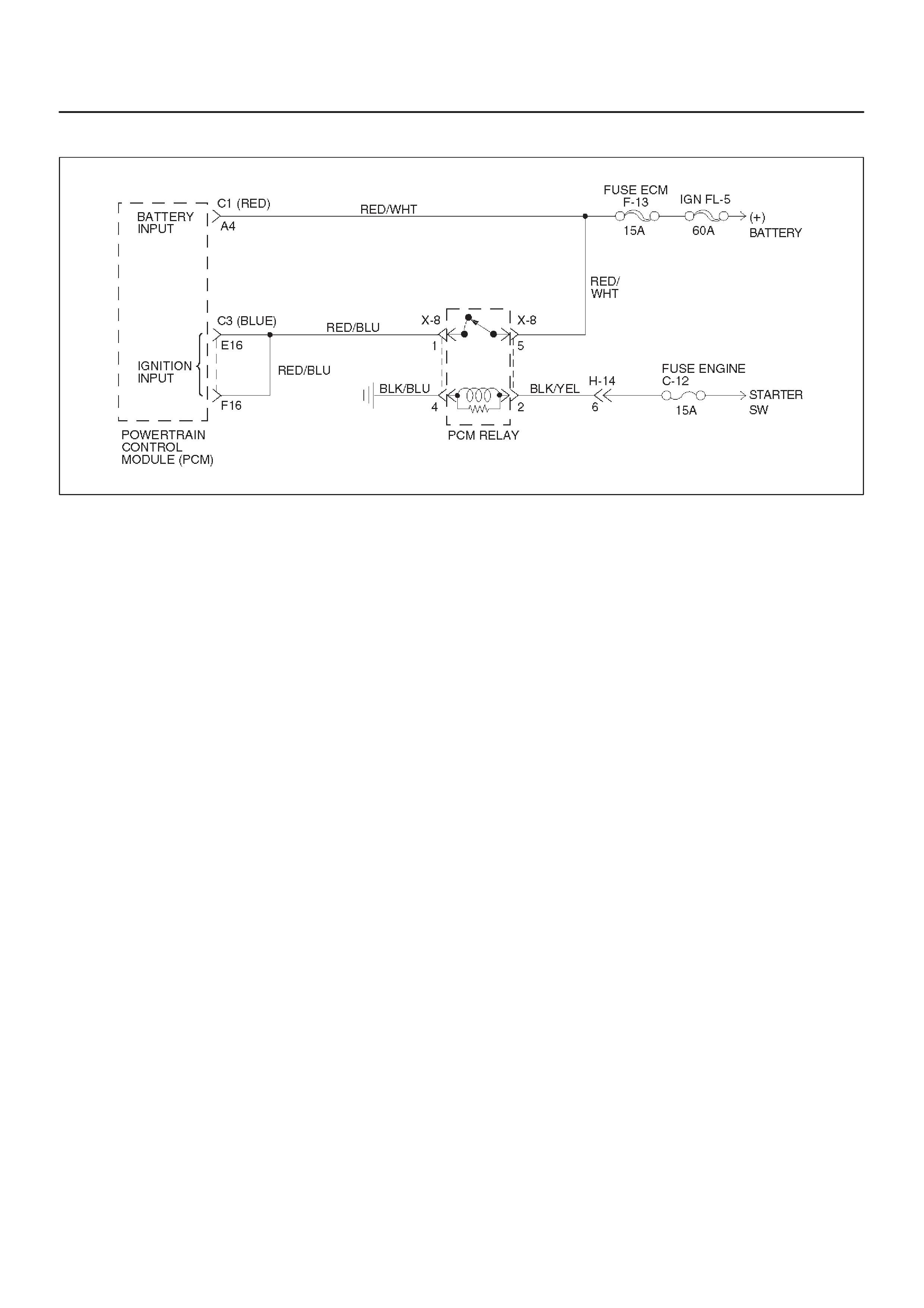
DTC P0560/Flashing Code 72 System Voltage Malfunction
D07RX017
Circuit Description
Circuit RED/WHT is the battery voltage feed for the PCM.
Circuit RED/BLU is the ignition voltage feed for the PCM.
This DTC detects a low voltage or a high voltage. This is a
type “C” DTC.
Conditions For Clearing The DTC
System Voltage Low:
DEngine speed is greater than 1,000 rpm.
DSystem voltage is less than 10 volts at a maximum
transmission temperature of 150°C (302°F).
DSystem voltage is less than 7.3 volts at a minimum
transmission temperature of –40°C (–40°F).
DAll conditions met for 4 seconds.
System Voltage High:
DSystem voltage is greater than 16 volts for 2 seconds.
Action Taken When The DTC Sets
DFixed to 4th gear.
DMaximum line pressure.
DInhibit TCC engagement.
DThe PCM will illuminate the CHECK TRANS Lamp.
Conditions For Clearing The DTC/CHECK
TRANS Lamp
DThe PCM will turn off the CHECK TRANS lamp after
three consecutive ignition cycles without a failure
reported.
DThe DTC can be cleared from the PCM history by
using a scan tool.
DThe DTC will be cleared from history when the vehicle
has achieved 40 warmup cycles without a failure
reported.
DThe PCM will cancel the DTC default actions when
the fault no longer exists and the ignition is cycled “off”
long enough to power down the PCM.
Diagnostic Aids
DCharging the battery with a battery charger and jump
starting an engine may set DTC(s). If DTC(s) set
when an accessory is operated, check for faulty
connections or excessive current draw.
DCheck for faulty connections at the starter solenoid or
fusible link.
DCheck for loose/damaged terminals at generator.
DCheck belt wear/tension.
Test Description
The numbers below refer to the step numbers on the
diagnostic chart:
3. This test checks charging system voltage.
4. This test checks battery voltage input at the PCM.
6. This test checks ignition voltage input at the PCM.

DTC P0560/Flashing Code 72 System Voltage Malfunction
Step Action Yes No
11. Install the scan tool.
2. With the engine “off”, turn the ignition switch “on”.
NOTE: Before clearing DTC(s), use the scan tool to record “Failure
Records” for reference, as data will be lost when the “Clear Info”
function is used.
3. Record the DTC “Failure Records”. Note: If any other DTCs
are present, refer to their applicable diagnostic charts before
continuing.
4. Using the J–39200 DVOM, measure the battery voltage
across the battery terminals. Record the measurement for
future reference.
Is the voltage higher than 10.5 volts? Go to Step 2
Go to Engine
Electrical in
Engine section
2Start the engine and warm to normal operating temperature.
Is the generator/check engine light “on”? Go to Starting
and Charging
System in Engine
section Go to Step 3
31. Increase the engine speed to 1,000–1,500 rpm.
2. Observe scan tool system voltage.
Is the system voltage within 13–15 volts. Go to Step 4
Go to Starting
and Charging
System in Engine
section
41. Turn the ignition switch “off”.
2. Disconnect the C1(RED) and C3 (BLUE) PCM connector
(additional DTCs will set).
3. With the engine “off”, turn the ignition switch “on”.
4. Using the J39200 DVOM, measure the battery voltage input at
PCM connector terminals C1–A4 and C3–E16.
Is there a voltage variance between the voltage measured at the
battery (taken in Step 1) and at terminals C1–A4 and C3–E16 that
is greater than 0.5 volts? Go to Step 5 Go to Step 6
5Repair the high resistance condition in circuit RED/WHT.
Was the circuit repaired? Go to Step 10 —
61. Disconnect the C3 (BLUE) PCM connector.
2. Measure the ignition voltage input at PCM connector terminals
C3–E16 and C3–F16.
Is there a voltage variance between the voltage measured at the
battery (taken in Step 1) and at terminals C3–E16 and C3–F16
that is greater than 0.5 volts? Go to Step 7 Go to Step 8
7Repair the high resistance condition is circuit RED/BLU.
Was the circuit repaired? Go to Step 10 —
8Check PCM connector terminals C1–A4, C3–E16 and C3–F16 for
bent, damaged, or backed out connector pins. Also check for
weak terminal tension.
Was a problem found? Go to Step 10 Go to Step 9

DTC P0560/Flashing Code 72 System Voltage Malfunction (Cont’d)
Step NoYesAction
9Replace the PCM.
Is the replacement complete? Go to Step 10 —
10 1. After the repair is complete, use the scan tool to select “DTC”,
then “Clear Info” function and operate the vehicle under the
following conditions:
Start the vehicle and warm to normal operating temperature.
The PCM must see a system voltage between 10 and 16 volts.
2. Review the scan tool “DTC Info”.
Has the last test failed or is the current DTC displayed?
Begin diagnosis
again
Go to Step 1 Repair verified
Exit DTC table
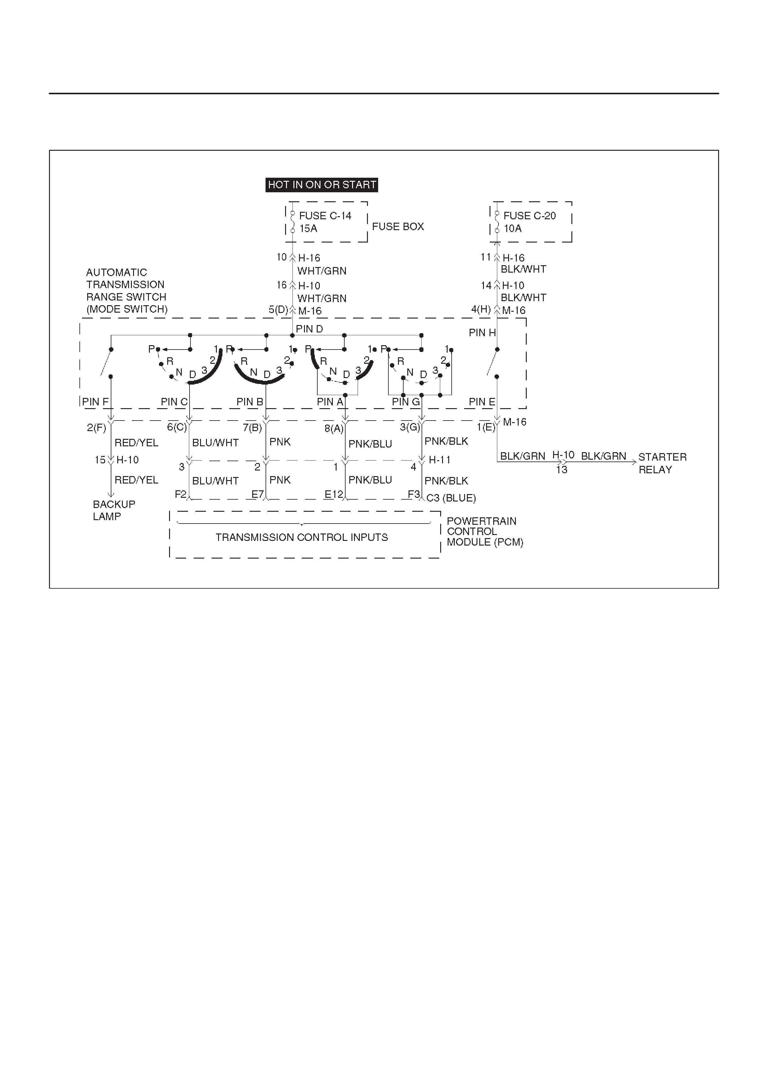
DTC P0705/Flashing Code 73 Transmission Range Switch (Mode Switch) Illegal
Position
D07RX018
Circuit Description
DThe range switch supplies the Powertrain Control
Module (PCM) with information regarding the selector
lever position: P, R, N, D 3, 2 or L. The selector lever
position is indicated by the state of four ON/OFF
contracts. The range switch is located on one side of
the transmission. It is on the transmission manual
shaft and is fixed to the main case.
DThe range switch is also used to provide the
information P or N to the engine crank wiring. The
engine can be cranked only if connector M–16
terminal 4(H) is connected to terminal 1(E) which is
connected to ground.
DThe range switch is also used to provide the backup
lamp power in reverse. This is the reason why the
range switch is supplied through a 15A fuse (C–14).
This fuse can burn due to a short circuit in the back up
lamp.
This DTC detects when a fuse is open or the range switch
circuit does not work. This is a type “D” DTC.
Conditions For Setting The DTC
DRange switch illegal positions met for 5 seconds.
Action Taken When The DTC Sets
DDefault to D position.
DInhibit torque management.
DMaximum line pressure.
DThe PCM will not illuminate the CHECK TRANS
Lamp.
Conditions For Clearing The DTC
DThe DTC can be cleared from the PCM history by
using a scan tool.
DThe DTC will be cleared from history when the vehicle
has achieved 40 warmup cycles without a failure
reported.
DThe PCM will cancel the DTC default actions when
the fault no longer exists and the ignition is cycled “off”
long enough to power down the PCM.
Diagnostic Aids
DRefer to accompanying chart for the normal range
signals and the illegal combinations.
DInspect the wiring for poor electrical connections at
the PCM and at the transmission 8–way connector.
Look for possible bent, backed out, deformed or
damaged terminals. Check for weak terminal tension
as well. Also check for a chafed wire that could short
to bare metal or other wiring. Inspect for a broken wire
inside the insulation.
DWhen diagnosing for a possible intermittent short or
open condition, move the wiring harness while
observing test equipment for a change.

DRefer to the “Range Switch Logic Table”.
Test Description
The numbers below refer to the step numbers on the
diagnostic chart:
2. This test checks the indicated range signal to the
manual valve actually selected.
5. This test checks for continuity between each
selected range switch connector terminals.
Range Switch Logic Table
Range Range Switch Pin
g
Position A B C P(G)
Park ON OFF OFF ON
Reverse ON ON OFF OFF
Neutral OFF ON OFF ON
D4 OFF ON ON OFF
D3 ON ON ON ON
2 ON OFF ON OFF
L OFF OFF ON ON
Illegal OFF OFF OFF OFF
Illegal OFF OFF OFF ON

DTC P0705/Flashing Code 73 Transmission Range Switch (Mode Switch) Illegal
Position
Step Action Yes No
1Perform the following checks:
DThe transmission linkage from the select lever to the manual
valve is adjusted properly.
DDiagnostic circuit check.
Were the checks performed? Go to Step 2 —
21. Install the scan tool.
2. With the engine “off”, turn the ignition switch “on”.
NOTE: Before clearing DTC(s), use the scan tool to record “Failure
Records” for reference, as data will be lost when the “Clear Info”
function is used.
3. Record the DTC “Failure Records”.
4. Select each transmission range: D1, D2, D3, D4, N, R, and P.
Does each selected transmission range match the scan tool
“Range Switch” display? Go to Diagnostic
Aids Go to Step 3
3Are all range switch pin displays incorrect? Go to Step 4 Go to Step 5
4Check fuse and wiring to the 8–way connector terminal 5(D) for
opens.
Refer to Mode Switch in Automatic Transmission (4L30–E)
section.
If no problem was found, replace the range switch.
Is the replacement complete? Go to Step 8 —
51. Disconnect the 8–way range switch connector.
2. Using ohmmeter , check continuity between terminal 5(D) and
respectively terminals 3(G), 6(C), 7(B) and 8(A) of the 8–way
range switch connector.
3. Move shift selector lever through all positions and compare
results with “Range Switch Logic Table”.
Is one range switch pin display incorrect? Go to Step 6 Go to Step 7
6Check the affected wiring and connector, and repair.
Is the repair complete? Go to Step 8 —
7Check the Powertrain Control Module (PCM) connectors for poor
connection.
If no problem was found, replace the PCM.
Is the replacement complete? Go to Step 8 —
81. After the repair is complete, use the scan tool to select “DTC”,
then “Clear Info” function and road test the vehicle.
2. Review the scan tool “DTC Info”.
Has the last test failed or is the current DTC displayed?
Begin diagnosis
again
Go to Step 1 Repair verified
Exit DTC table

DTC P0706/Flashing Code 74 Transmission Range Switch (Mode Switch)
Performance
D07RX018
Circuit Description
DThe range switch supplies the Powertrain Control
Module (PCM) with information regarding the selector
lever position: P, R, N, D, 3, 2 or L. The selector lever
position is indicated by the state of four ON/OFF
contracts. The range switch is located on one side of
the transmission. It is on the transmission manual
shaft and is fixed to the main case.
DThe range switch is also used to provide the
information P or N to the engine crank wiring. The
engine can be cranked only if connector M–16
terminal 4(H) is connected to terminal 1(E) which is
connected to ground.
DThe range switch is also used to provide the back up
lamp power in reverse. This is the reason why the
mode switch is supplied through a 15A fuse (C–14).
This fuse can burn due to a short circuit in the back up
lamp.
DThis DTC detects an invalid state of the range switch
or the range switch circuit by deciphering the range
switch inputs. This is a type “D” DTC.
Conditions For Setting The DTC
This DTC will set if any of the following conditions occurs:
Condition 1 (“R” bad position):
DEngine is running.
DNo output speed DTCP0722, P0723.
DOutput speed greater than 3,200 RPM.
DRange switch indicates “R”.
DAll conditions met for 4 seconds.
Condition 2 (“P” or “N” bad position):
DEngine is running.
DNo TPS codes.
DEngine speed is less than 3,000 RPM.
DTP angle is greater than 20%.
DRange switch indicates “P” or “N”.
DAll conditions met for 4 seconds.
Action Taken When The DTC Sets
DDefault to “D” position.
DThe PCM will not illuminate the CHECK TRANS
Lamp.
Conditions For Clearing The DTC
DThe DTC can be cleared from the PCM history by
using a scan tool.
DThe DTC will be cleared from history when the vehicle
has achieved 40 warmup cycles without a failure
reported.
DThe PCM will cancel the DTC default actions when
the fault no longer exists and the ignition is cycled “off”
long enough to power down the PCM.

Diagnostic Aids
DRefer to the accompanying chart for the normal range
signals and the illegal combinations.
DInspect the wiring for poor electrical connections at
the PCM and at the transmission 8–way connector.
Look for possible bent, backed out, deformed or
damaged terminals. Check for weak terminal tension
as well. Also check for a chafed wire that could short
to bare metal or other wiring. Inspect for a broken wire
inside the insulation.
DWhen diagnosing for a possible intermittent short or
open condition, move the wiring harness while
observing test equipment for a change.
DRefer to the “Range Switch Logic Table”.
Test Description
The numbers below refer to the step numbers on the
diagnostic chart:
2. This test checks the indicated range signal to the
manual valve actually selected.
5. This test checks for continuity between each
selected range switch connector terminals.
Range Switch Logic Table
Range Range Switch Pin
g
Position A B C P(G)
Park ON OFF OFF ON
Reverse ON ON OFF OFF
Neutral OFF ON OFF ON
D4 OFF ON ON OFF
D3 ON ON ON ON
2 ON OFF ON OFF
L OFF OFF ON ON
Illegal OFF OFF OFF OFF
Illegal OFF OFF OFF ON

DTC P0706/Flashing Code 74 Transmission Range Switch (Mode Switch)
Performance
Step Action Yes No
1Perform the following checks:
DThe transmission linkage from the select lever to the manual
valve is adjusted properly.
DDiagnostic circuit check.
Were the checks performed? Go to Step 2 —
21. Install the scan tool.
2. With the engine “off”, turn the ignition switch “on”.
NOTE: Before clearing DTC(s), use the scan tool to record “Failure
Records” for reference, as data will be lost when the “Clear Info”
function is used.
3. Record the DTC “Failure Records”.
4. Select each transmission range: D1, D2, D3, D4, N, R, and P.
Does each selected transmission range match the scan tool
“Range Switch” display? Go to Diagnostic
Aids Go to Step 3
3Are all range switch pin displays incorrect? Go to Step 4 Go to Step 5
4Check fuse and wiring to the 8–way connector terminal 5(D) for
opens.
Refer to Mode Switch in Automatic Transmission (4L30–E)
section.
If no problem was found, replace the range switch.
Is the replacement complete? Go to Step 8 —
51. Disconnect the 8–way range switch connector.
2. Using ohmmeter , check continuity between terminal 5(D) and
respectively terminals 3(G), 6(C), 7(B) and 8(A) of the 8–way
range switch connector.
3. Move shift selector lever through all positions and compare
results with “Range Switch Logic Table”.
Is one range switch pin display incorrect? Go to Step 6 Go to Step 7
6Check the affected wiring and connector, and repair.
Is the repair complete? Go to Step 8 —
7Check the Powertrain Control Module (PCM) connectors for poor
connection.
If no problem was found, replace the PCM.
Is the replacement complete? Go to Step 8 —
81. After the repair is complete, use the scan tool to select “DTC”,
then “Clear Info” function and road test the vehicle.
2. Review the scan tool “DTC Info”.
Has the last test failed or is the current DTC displayed?
Begin diagnosis
again
Go to Step 1 Repair verified
Exit DTC table
DTC P0712/Flashing Code 75 Transmission Fluid Temperature (TFT) Sensor
Circuit Low Input
D07RX016
Circuit Description
The TFT sensor is a thermister that controls the signal
voltage to the PCM. The PCM supplies a 5–volt reference
signal to the sensor on circuit GRN/RED. When the
transmission fluid is cold, the sensor resistance is high.
The PCM detects high signal voltage. As the
transmission fluid temperature increases to the normal
operating temperature of 100°C (212°F), the sensor
resistance becomes less and the voltage decreases to
1.5 to 2 volts. With transmission fluid over temperature
and DTC P0218 also set, check the transmission cooling
system.
This DTC detects a continuous short to ground in the TFT
signal circuit or the TFT sensor. This is a type “D” DTC.
Conditions For Setting The DTC
DBattery voltage is between 10 and 16 volts.
DIgnition is “on”.
DTFT sensor indicating a voltage less than 0.4 volts.
DAll conditions met for 20 seconds.
Action Taken When The DTC Sets
DTransmission default temperature will be:
80°C (176°F) if engine temperature code is set.
100°C (212°F) if engine temperature is warm.
80°C (176°F) if engine run time is greater than 5
minutes.
21°C (69.8°F) if engine run time is less than 5
minutes.
DThe PCM will not illuminate the CHECK TRANS
Lamp.
Conditions For Clearing The DTC
DThe DTC can be cleared from the PCM history by
using a scan tool.
DThe DTC will be cleared from history when the vehicle
has achieved 40 warmup cycles without a failure
reported.
DThe PCM will cancel the DTC default actions when
the fault no longer exists and the ignition is cycled “off”
long enough to power down the PCM.
Diagnostic Aids
DCheck harness routing for a potential short to ground
in circuit GRN/RED. Scan tool TFT display should
rise steadily to about 100°C (212°F), then stabilize.
DInspect the wiring for poor electrical connection at the
PCM and at the transmission 16–way connector.
Look for possible bent, backed out, deformed or
damaged terminals. Check for weak terminal tension
as well. Also check for a chafed wire that could short
to bare metal or other wiring. Inspect for a broken wire
inside the insulation.
DWhen diagnosing for a possible intermittent short or
open condition, move the wiring harness while
observing test equipment for a change.
DThe temperature to resistance value scale may be
used to test the TFT sensor at the various
temperature levels to evaluate the possibility of a
“skewed” (mis–scaled) sensor.
A “skewed” sensor could result in delayed garage
shifts or TCC complaints.
DVerify customer driving habits, trailer towing, etc.

Test Description
The numbers below refer to the step numbers on the
diagnostic chart:
2. This test checks for a short to ground or a “skewed”
sensor.
3. This test checks for an internal fault within the
transmission by creating an open.
Resistance Chart
°C°FResistance (kW)
–40 –40 672
0 32 65
20 68 25
80 176 2.5
120 248 0.78
150 304 0.37
DTC P0712/Flashing Code 75 Transmission Fluid Temperature (TFT) Sensor Circuit Low
Input
Step Action Yes No
1Perform the transmission fluid checking procedure. Refer to
Checking Transmission Fluid Level and Condition in Automatic
Transmission (4L30–E) section.
Was the fluid checking procedure performed?
Go to Step 2
Refer to
Checking
Transmission
Fluid Level and
Condition in
Automatic
Transmission
(4L30–E) section
21. Install the scan tool.
2. With the engine “off”, turn the ignition switch “on”.
NOTE: Before clearing DTC(s), use the scan tool to record “Failure
Records” for reference, as data will be lost when the “Clear Info”
function is used.
3. Record the DTC “Failure Records”.
Does the scan tool display a TFT sensor signal voltage less than
0.4 volts? Go to Step 3 Go to Diagnostic
Aids
31. Turn the ignition “off”.
2. Disconnect the transmission 16–way connector H–10.
3. Turn the ignition “on”.
Does the TFT signal voltage change to match the voltage 4.92
volts? Go to Step 4 Go to Step 9
4Using the J39200 DVOM, measure the resistance between
terminals 3(C) and 5 (D).
Is the resistance within specifications? (See Resistance Chart.) Go to Diagnostic
Aids Go to Step 5
51. Disconnect the transmission 5–way connector M–6.
2. Using the J39200 DVOM, measure the resistance between
terminals 3(C) and 5(D).
Is the resistance within specifications? (See Resistance Chart.) Go to Diagnostic
Aids Go to Step 6
61. Remove the transmission oil pan. Refer to Transmission Oil
Temperature Sensor (Adapter Case) in Automatic
Transmission (4L30–E) section.
2. Check the internal wiring harness for a short to ground.
Was a problem found? Go to Step 8 Go to Step 7
71. Disconnect the internal wiring harness at the TFT sensor.
2. Measure the resistance of the TFT sensor.
Is the resistance within specifications? (See Resistance Chart.) Go to Diagnostic
Aids Go to Step 8
8Replace the TFT Sensor.
Is the replacement complete? Go to Step 12 —

DTC P0712/Flashing Code 75 Transmission Fluid Temperature (TFT) Sensor Circuit Low
Input (Cont’d)
Step NoYesAction
9Check circuit GRN/RED for a short to ground.
Was a problem found? Go to Step 12 Go to Step 10
10 Check the PCM for faulty connections.
Was a problem found? Go to Step 12 Go to Step 11
11 Replace the PCM. Refer to Powertrain Control Module (PCM) in
Automatic Transmission (4L30–E) section.
Is the replacement complete? Go to Step 12 —
12 1. After the repair is complete, use the scan tool to select “DTC”,
then “Clear Info” function and ensure the following conditions
are met:
TFT sensor indicates a voltage greater than 0.33 volts for 2
seconds.
2. Review the scan tool “DTC info”.
Has the last test failed or is the current DTC displayed?
Begin diagnosis
again
Go to Step 1 Repair verified
Exit DTC table

DTC P0713/Flashing Code 76 Transmission Fluid Temperature (TFT) Sensor
Circuit High Input
D07RX016
Circuit Description
The TFT sensor is a thermistor that controls the signal
voltage to the PCM. The PCM supplies a 5–volt reference
signal to the sensor on circuit GRN/RED. When the
transmission fluid is cold, the sensor resistance is high
and the PCM will sense high signal voltage. As the
transmission fluid temperature warms to the normal
operating temperature of 100°C (212°F), the sensor
resistance becomes less and the voltage decreases to
about 1.5 to 2 volts.
This DTC detects a continuous open or short to power in
the TFT signal circuit or the TFT sensor. This is a type “D”
DTC.
Conditions For Setting The DTC
DBattery voltage is between 10 and 16 volts.
DIgnition is “on”.
DTFT sensor indicating a voltage greater than 4.86
volts.
DAll conditions met for 20 seconds.
Action Taken When The DTC Sets
DTransmission default temperature will be:
80°C (176°F) if engine temperature code is set.
100°C (212°F) if engine temperature is warm.
80°C (176°F) if engine run time is greater than 5
minutes.
21°C (69.8°F) if engine run time is less than 5
minutes.
DThe PCM will not illuminate the CHECK TRANS
Lamp.
Conditions For Clearing The DTC
DThe DTC can be cleared from the PCM history by
using a scan tool.
DThe DTC will be cleared from history when the vehicle
has achieved 40 warmup cycles without a failure
reported.
DThe PCM will cancel the DTC default actions when
the fault no longer exists and the ignition is cycled “off”
long enough to power down the PCM.
Diagnostic Aids
DInspect the wiring for poor electrical connection at the
PCM and at the transmission 16–way connector.
Look for possible bent, backed out, deformed or
damaged terminals. Check for weak terminal tension
as well. Also check for a chafed wire that could short
to bare metal or other wiring. Inspect for a broken wire
inside the insulation.
DWhen diagnosing for a possible intermittent short or
open condition, move the wiring harness while
observing test equipment for a change.
DScan tool displays transmission fluid temperature in
degrees. After transmission is operating, the
temperature should rise steadily to about 100°C
(212°F), then stabilize.
DThe temperature to resistance value scale may be
used to check the TFT sensor at the various
temperature levels to evaluate the possibility of a
“skewed” (mis–scaled) sensor.
A “skewed” sensor could result in hard shifts or TCC
complaints.

Test Description
The numbers below refer to the step numbers on the
diagnostic chart:
2. This check verifies problem in the TFT sensor circuit.
3. This test simulates a TFT sensor DTC P0712. If the
PCM recognizes the low signal voltage (high
temperature), and the scan tool displays 146°C
(295°F) or greater, the PCM and wiring are OK.
4. This test checks the TFT sensor and internal wiring
harness.
Resistance Chart
°C°FResistance (kW)
–40 –40 672
0 32 65
20 68 25
80 176 2.5
120 248 0.78
150 304 0.37
DTC P0713/Flashing Code 76 Transmission Fluid Temperature (TFT) Sensor Circuit High
Input
Step Action Yes No
1Perform the transmission fluid checking procedure.
Refer to Checking Transmission Fluid Level and Condition in
Automatic Transmission (4L30–E) section.
Was the fluid checking procedure performed?
Go to Step 2
Refer to
Checking
Transmission
Fluid Level and
Condition in
Automatic
Transmission
(4L30–E) section
21. Install the scan tool.
2. With the engine “off”, turn the ignition switch “on”.
NOTE: Before clearing DTC(s), use the scan tool to record “Failure
Records” for reference, as data will be lost when the “Clear Info”
function is used.
3. Record the DTC “Failure Records”.
Does the scan tool display a TFT sensor signal voltage greater
than 4.86 volts? Go to Step 3 Go to Diagnostic
Aids
31. Turn the ignition “off”.
2. Disconnect the transmission 16–way connector H–10.
3. Install a fused jumper wire from terminal 3(C) to 5(D) on the
engine harness.
4. Turn the ignition “on”.
Does the TFT signal voltage drop to less than 0.4 volts? Go to Step 4 Go to Step 9
41. Turn the ignition “off”.
2. Using the J39200 DVOM, measure the resistance between
terminals 3(C) and 5(D).
Is the resistance within specifications? (See Resistance Chart.) Go to Diagnostic
Aids Go to Step 5
51. Disconnect the transmission 5–way connector M–6.
2. Using the J39200 DVOM, measure the resistance between
terminals 3(C) and 5(D).
Is the resistance within specifications? (See Resistance Chart.) Go to Diagnostic
Aids Go to Step 6
61. Remove the transmission oil pan.
2. Check the internal wiring harness for an open. Refer to
Transmission Oil Temperature Sensor (Adapter Case) in
Automatic Transmission (4L30–E) section.
Was a problem found and corrected? Go to Step 13 Go to Step 7
71. Disconnect the internal wiring harness at the TFT sensor.
2. Measure the resistance of the TFT sensor.
Is the resistance within specifications? (See Resistance Chart.) Go to Diagnostic
Aids Go to Step 8

DTC P0713/Flashing Code 76 Transmission Fluid Temperature (TFT) Sensor Circuit High
Input (Cont’d)
Step NoYesAction
8Replace TFT sensor. Refer to Transmission Oil Temperature
Sensor (Adapter Case) in Automatic Transmission (4L30–E)
section.
Is the replacement complete? Go to Step 13 —
9Check circuit GRN/RED for an open or short to B+.
Was a problem found? Go to Step 13 Go to Step 10
10 Check circuit GRN for an open.
Was a problem found? Go to Step 13 Go to Step 11
11 Check the PCM for faulty or intermittent connections.
Was a problem found? Go to Step 13 Go to Step 12
12 Replace the PCM. Refer to Powertrain Control Module (PCM) in
Automatic Transmission (4L30–E) section.
Is the replacement complete? Go to Step 13 —
13 1. After the repair is complete, use the scan tool to select “DTC”,
then “Clear Info” function and ensure the following conditions
are met:
TFT sensor indicates a voltage less than 4.92 volts for 2
seconds.
2. Review the scan tool “DTC Info”.
Has the last test failed or is the current DTC displayed?
Begin diagnosis
again
Go to Step 1 Repair verified
Exit DTC table
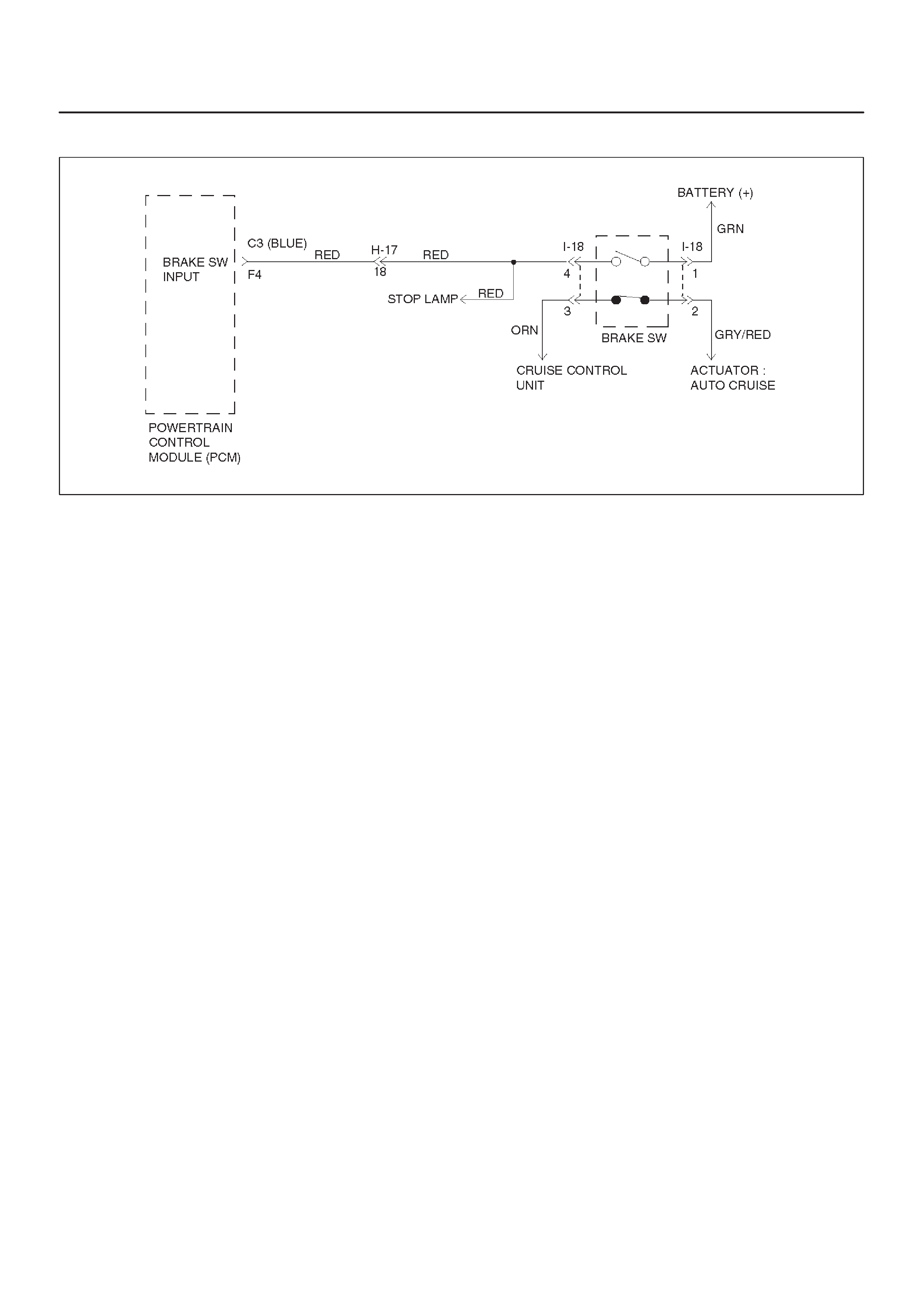
DTC P0719/Flashing Code 77 TCC Brake Switch Circuit High (Stuck On)
D07RX019
Circuit Description
The brake switch is used to indicate brake pedal status.
The normally opened brake switch signal voltage circuit is
opened.
Brake switch supplies a B+ signal on circuit RED to the
PCM, when the brakes are applied. The PCM uses this
signal to deenergize the TCC solenoid when the brakes
are applied.
This DTC detects a closed brake switch during
accelerations. This is a type “D” DTC.
Conditions For Setting The DTC
DNo OSS DTCs P0722 or P0723.
DThe PCM detects a closed brake switch/circuit (12
volts) for 2 seconds, and the following events occur
seven consecutive times: vehicle speed is less than 8
km/h (5 mph); then vehicle speed is between 8 and 32
km/h (5 and 20 mph) for 4 seconds; then vehicle
speed is greater than 32 km/h (20 mph) for 4 seconds.
Action Taken When The DTC Sets
DIf throttle opening is greater than 10% and vehicle
speed is greater than 45 km/h (28 mph), then
disregard brake switch contingency for TCC off
mode.
DThe PCM will not illuminate CHECK TRANS Lamp.
Conditions For Clearing The DTC
DThe DTC can be cleared from the PCM history by
using a scan tool.
DThe DTC will be cleared from history when the vehicle
has achieved 40 warm–up cycles without a failure
reported.
DThe PCM will cancel the DTC default actions when
the fault no longer exists and the ignition is cycled “off”
long enough to power down the PCM.
Diagnostic Aids
DInspect the wiring for poor electrical connections at
the PCM and brake switch. Look for possible bent,
backed out, deformed or damaged terminals. Check
for weak terminal tension as well. Also check for a
chafed wire that could short to bare metal or other
wiring. Inspect for a broken wire inside the insulation.
DWhen diagnosing for a possible intermittent short or
open condition, move or massage the wiring harness
while observing test equipment for a change.
DCheck customer driving habits and/or unusual driving
conditions (i.e. stop and go, highway).
DCheck brake switch for proper mounting and
adjustment.
Test Description
The numbers below refer to the step numbers on the
diagnostic chart:
2. This test checks for voltage at the brake switch.
5. This test checks the brake switch.
8. This test checks circuit RED at the PCM.

DTC P0719/Flashing Code 77 TCC Brake Switch Circuit High (Stuck On)
Step Action Yes No
11. Install the scan tool.
2. With the engine “off”, turn the ignition switch “on”. If ABS code
is set, check applicable fuse.
NOTE: Before clearing DTC(s), use the scan tool to record “Failure
Records” for reference, as data will be lost when the “Clear Info”
function is used.
3. Record the DTC “Failure Records”.
4. Apply then release the brake pedal.
Does the scan tool display “Brake Switch” as “closed” with the
brake pedal applied, and then display “open” when the brake
pedal is released? Go to Diagnostic
Aids Go to Step 2
21. Connect the test light to ground.
2. Back probe ignition feed circuit terminal I18–1 at the brake
switch.
Is the test light “on”? Go to Step 3 Go to Step 4
31. Connect the test light to ground.
2. Back probe circuit terminal I18–4 at the brake switch.
Is the test light “off”? Go to Step 7 Go to Step 5
4Repair the open in battery feed circuit terminal I18–1 to the brake
switch.
If fuse is open, check circuit terminal I18–4 for a short to ground.
Is the repair complete? Go to Step 13 —
5Disconnect brake switch connector I–18 and ignition switch “on”.
Is the test light “on”? Go to Step 8 Go to Step 6
6Check the brake switch short (I18–1 and I18–4).
Was a problem found? Go to Step 9 Go to Step 10
7Check circuit terminal I18–4 for a short to voltage.
Ignition switch “on”.
Is the test light “on”? Go to Step 8 Go to Step 10
81. Disconnect the C3 (BLUE) PCM connector.
2. Check circuit terminal I18–4 for a short to voltage.
Was a problem found? Go to Step 13 Go to Step 10
9Replace the brake switch.
Is the replacement complete? Go to Step 13 —
10 1. Turn the ignition “off”.
2. Reconnect the C3 (BLUE) PCM connector.
3. Turn the ignition “on”.
Does the scan tool display “Brake Switch” as “open” with the
brake applied, then display “closed” with the brake pedal
released? Go to Diagnostic
Aids Go to Step 11
11 Check the PCM for faulty or intermittent connections.
Was a problem found and corrected? Go to Step 13 Go to Step 12

DTC P0719/Flashing Code 77 TCC Brake Switch Circuit High (Stuck On) (Cont’d)
Step NoYesAction
12 Replace the PCM. Refer to Powertrain Control Module (PCM) in
Automatic Transmission (4L30–E) section.
Is the replacement complete? Go to Step 13 —
13 1. After the repair is complete, use the scan tool to select “DTC”,
then “Clear Info” function and ensure the following conditions
are met:
The PCM brake switch signal must indicate 12 volts for 1
seconds with the brake pedal applied.
2. Review the scan tool “DTC Info”.
Has the last test failed or is the current DTC displayed?
Begin diagnosis
again
Go to Step 1 Repair verified
Exit DTC table
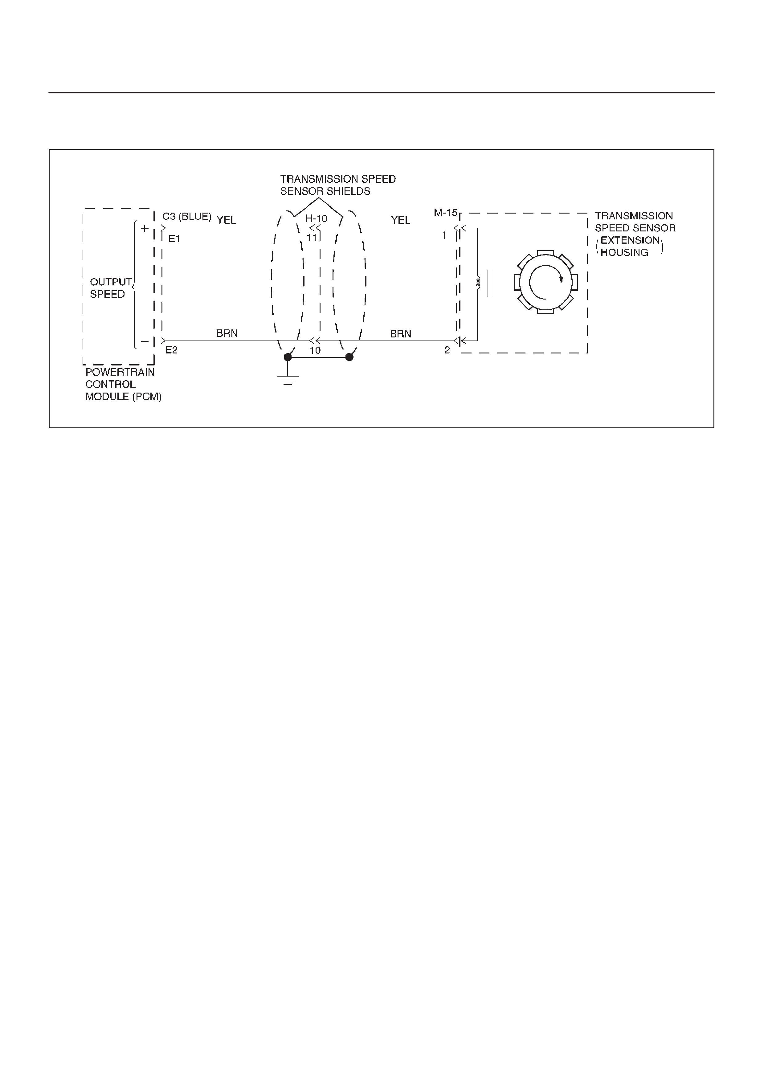
DTC P0722/Flashing Code 78 Transmission Output Speed Sensor (OSS) Low
Input
D07RW022
Circuit Description
Output speed information is provided to the PCM by the
OSS, which is a permanent magnet (PM) generator . The
PM generator produces a pulsing AC voltage. The AC
voltage level and number of pulses increases as the
speed of the vehicle increases. The PCM then converts
the pulsing voltage to output speed, which is used for
calculations. The vehicle speed can be displayed with a
scan tool.
This DTC detects a low output speed when there is a high
engine speed in a drive gear range. This is a type “C”
DTC.
Conditions For Setting The DTC
DNo MAP DTCs P0107 or P0108, P0106, P1106,
P1107.
DNo TP DTCs P0122 or P0123.
DNot in Park or Neutral.
DTP angle is greater than 10%.
DEngine vacuum is between 0 and 70kPa.
DEngine speed is between 3000 and 7000 rpm.
DTransmission output speed is less than 0 rpm.
DAll conditions met for 5 seconds.
Action Taken When The DTC Sets
DFixed to 4th gear.
DMaximum line pressure.
DInhibit TCC engagement.
DThe PCM will illuminate the CHECK TRANS Lamp.
Conditions For Clearing The DTC/CHECK
TRANS Lamp
DThe PCM will turn off the CHECK TRANS Lamp after
three consecutive ignition cycles without a failure
reported.
DThe DTC can be cleared from the PCM history by
using a scan tool. The DTC will be cleared from
history when the vehicle has achieved 40 warmup
cycles without a failure reported.
DThe PCM will cancel the DTC default actions when
the fault no longer exists and the ignition is cycled “off”
long enough to power down the PCM.
Diagnostic Aids
DAn OSS DTC P0722 will set when no output speed is
at detected at start off.
DInspect the wiring for poor electrical connection at the
PCM. Look for possible bent, backed out, deformed
or damaged terminals. Check for weak terminal
tension as well. Also check for a chafed wire that
could short to bare metal or other wiring. Inspect for a
broken wire inside the insulation.
DWhen diagnosing for a possible intermittent short or
open condition, move or massage the wiring harness
while observing test equipment for a change.
Test Description
The numbers below refer to the step numbers on the
diagnostic chart:
3. This test checks the OSS circuit.
4. This test checks the integrity of the OSS.
6. This test checks the 5–volt and ground circuit of the
PCM.

DTC P0722/Flashing Code 78 Transmission Output Speed Sensor (OSS) Low
Input
Step Action Yes No
11. Install the scan tool.
2. With the engine “off”, turn the ignition switch “on”.
NOTE: Before clearing DTC(s), use the scan tool to record “Failure
Records” for reference, as data will be lost when the “Clear Info”
function is used.
3. Record the DTC “Failure Records”.
4. Raise the drive wheels.
5. Start the engine.
6. Place the transmission in any drive range.
With the drive wheels rotating, does the “Trans Output Speed”
increase with the drive wheel speed? Go to Diagnostic
Aids Go to Step 2
2Check for the most current and/or incorrect calibration.
Is the calibration current? Go to Step 15 Go to Step 3
31. Turn the ignition “off”.
2. Disconnect the C3 (BLUE) PCM connector.
3. Using the J39200 DVOM, measure the resistance between
harness connector terminals C3–E1 and C3–E2.
Is the reading 3000 ohms? Go to Step 4 Go to Step 5
41. Select AC volts.
2. Rotate the rear wheels, ensuring the driveshaft is turning.
Is the voltage greater than 0.5 volts? Go to Step 6 Go to Step 7
5Inspect circuits YEL and BRN for a poor connection or an open
circuit.
Was a problem found? Go to Step 16 Go to Step 7
61. Reconnect the C3 (BLUE) PCM connector.
2. Disconnect the OSS harness from the OSS.
3. With the engine “off”, turn the ignition “on”.
4. Using the J 39200 DVOM, measure the voltage at the OSS
harness connector terminals M15–1 and M15–2.
Is the reading between 4.0 to 5.1 volts? Go to Step 15 Go to Step 9
71. Remove the OSS.
2. Check the output shaft speed sensor rotor for damage or
misalignment. Refer to Speed Sensor (Extension Housing) in
Automatic Transmission (4L30–E) section.
Was a problem found? Go to Step 16 Go to Step 8
8Replace the OSS.
Is the replacement complete? Go to Step 16 —
9Was the reading in step 6 less than 4.0 volts? Go to Step 11 Go to Step 10
10 Was the reading in Step 6 greater than 5.1 volts? Go to Step 14 —
11 Using the J 39200 DVOM to chassis ground, measure the voltage
on circuit RED.
Is the reading between 4.0 to 5.1 volts? Go to Step 12 Go to Step 13
12 Repair the open in circuit BRN.
Is the repair complete? Go to Step 16 —
13 Check circuit YEL for a short to ground or open.
Was a problem found and corrected? Go to Step 16 Go to Step 15

DTC P0722/Flashing Code 78 Transmission Output Speed Sensor (OSS) Low
Input (Cont’d)
Step NoYesAction
14 Repair the short to B+ in circuit YEL.
Is the repair complete? Go to Step 16 —
15 Replace the PCM. Refer to Powertrain Control Module (PCM) in
automatic Transmission (4L30–E) section.
Is the replacement complete? Go to Step 16 —
16 1. After the repair is complete, use the scan tool to select “DTC”,
then “Clear Info” function and operate the vehicle under the
following conditions:
DDrive the vehicle under steady acceleration above 10% TP
angle.
DTransmission output speed is greater than 101 rpm for 3
seconds.
2. Review the scan tool “DTC Info”.
Has the last test failed or is the current DTC displayed?
Begin diagnosis
again
Go to Step 1 Repair verified
Exit DTC table

DTC P0723/Flashing Code 79 Transmission Output Speed Sensor (OSS)
Intermittent
D07RW022
Circuit Description
Output speed information is provided to the PCM by the
OSS, which is a permanent magnet (PM) generator . The
PM generator produces a pulsing AC voltage. The AC
voltage level and number of pulses increases as the
speed of the vehicle increases. The PCM then converts
the pulsing voltage to output speed, which is used for
calculations. The vehicle speed can be displayed with a
scan tool.
This DTC detects a low output speed when there is a high
engine speed in a drive gear range. This is a type “C”
DTC.
Conditions For Setting The DTC
In Park or Neutral:
DTransmission output speed change is greater than
10000 rpm.
DConditions met for 6 seconds.
DEngine running time is greater than 2 seconds.
Not in Park or Neutral:
DTransmission output speed change is greater than
512 rpm.
DConditions met for 0.075 seconds
DEngine running time is greater than 2 seconds.
DEngine vacuum is less than 70 kPa.
DOutput speed is greater than 1380 rpm for 1 second.
DNORAW–NOLAST < 60 rpm for 6 seconds.
DNORAW: Latest raw data of output shaft speed.
DNOLAST: Fitered previous data of output speed.
Action Taken When The DTC Sets
DFixed to 4th gear.
DMaximum line pressure.
DInhibit TCC engagement.
DThe PCM will illuminate the CHECK TRANS Lamp.
Conditions For Clearing The DTC/CHECK
TRANS Lamp
DThe PCM will turn off the CHECK TRANS Lamp after
three consecutive ignition cycles without a failure
reported.
DThe DTC can be cleared from the PCM history by
using a scan tool.
DThe DTC will be cleared from history when the vehicle
has achieved 40 warmup cycles without a failure
reported.
DThe PCM will cancel the DTC default actions when
the fault no longer exists and the ignition is cycled “off”
long enough to power down the PCM.
Diagnostic Aids
DA OSS DTC P0723 will set when output speed has
been detected and is lost.
DInspect the wiring for poor electrical connection at the
PCM. Look for possible bent, backed out, deformed
or damaged terminals. Check for weak terminal
tension as well. Also check for a chafed wire that
could short to bare metal or other wiring. Inspect for a
broken wire inside the insulation.
DWhen diagnosing for a possible intermittent short or
open condition, move the wiring harness while
observing test equipment for a change.
Test Description
The numbers below refer to the step numbers on the
diagnostic chart:
3. This test checks the OSS circuit.
4. This test checks the integrity of the OSS.
6. This test checks the 5–volt and ground circuit of the
PCM.

DTC P0723/Flashing Code 79 Transmission Output Speed Sensor (OSS)
Intermittent
Step Action Yes No
11. Install the scan tool.
2. With the engine “off”, turn the ignition switch “on”.
NOTE: Before clearing DTC(s), use the scan tool to record “Failure
Records” for reference, as data will be lost when the “Clear Info”
function is used.
3. Record the DTC “Failure Records”.
4. Raise the drive wheels.
5. Start the engine.
6. Place the transmission in any drive range.
With the drive wheels rotating, does the “Trans Output Speed”
increase with the drive wheel speed? Go to Diagnostic
Aids Go to Step 2
2Check for the most current and/or incorrect calibration.
Is the calibration current? Go to Step 15 Go to Step 3
31. Turn the ignition “off”.
2. Disconnect the C3 (BLUE) PCM connector.
3. Using the J39200 DVOM, measure the resistance between
harness connector terminals C3–E1 and C3–E2.
Is the reading 3,000 ohms? Go to Step 4 Go to Step 5
41. Select AC volts.
2. Rotate the rear wheels, ensuring the driveshaft is turning.
Is the voltage greater than 0.5 volts? Go to Step 6 Go to Step 7
5Inspect circuits YEL and BRN for a poor connection or an open
circuit.
Was a problem found? Go to Step 16 Go to Step 7
61. Reconnect the C3 (BLUE) PCM connector.
2. Disconnect the OSS harness from the OSS.
3. With the engine “off”, turn the ignition “on”.
4. Using the J 39200 DVOM, measure the voltage at the OSS
harness connector terminals M15–1 and M15–2.
Is the reading between 4.0 to 5.1 volts? Go to Step 15 Go to Step 9
71. Remove the OSS.
2. Check the output shaft speed sensor rotor for damage or
misalignment. Refer to Speed Sensor (Extension Housing) in
Automatic Transmission (4L30–E) section.
Was a problem found? Go to Step 16 Go to Step 8
8Replace the OSS.
Is the replacement complete? Go to Step 16 —
9Was the reading in step 6 less than 4.0 volts? Go to Step 11 Go to Step 10
10 Was the reading in Step 6 greater than 5.1 volts? Go to Step 14 —
11 Using the J 39200 DVOM to chassis ground, measure the voltage
on circuit YEL.
Is the reading between 4.0 to 5.1 volts? Go to Step 12 Go to Step 13
12 Repair the open in circuit BRN.
Is the repair complete? Go to Step 16 —
13 Check circuit YEL for a short to ground or open.
Was a problem found and corrected? Go to Step 16 Go to Step 15

DTC P0723/Flashing Code 79 Transmission Output Speed Sensor (OSS)
Intermittent (Cont’d)
Step NoYesAction
14 Repair the short to B+ in circuit YEL.
Is the repair complete? Go to Step 16 —
15 Replace the PCM. Refer to Powertrain Control Module (PCM) in
Automatic Transmission (4L30–E) section.
Is the replacement complete? Go to Step 16 —
16 1. After the repair is complete, use the scan tool to select “DTC”,
then “Clear Info” function and operate the vehicle under the
following conditions:
DDrive the vehicle under steady acceleration above 10% TP
angle.
DTransmission output speed is greater than 101 rpm for 3
seconds.
2. Review the scan tool “DTC Info”.
Has the last test failed or is the current DTC displayed?
Begin diagnosis
again
Go to Step 1 Repair verified
Exit DTC table
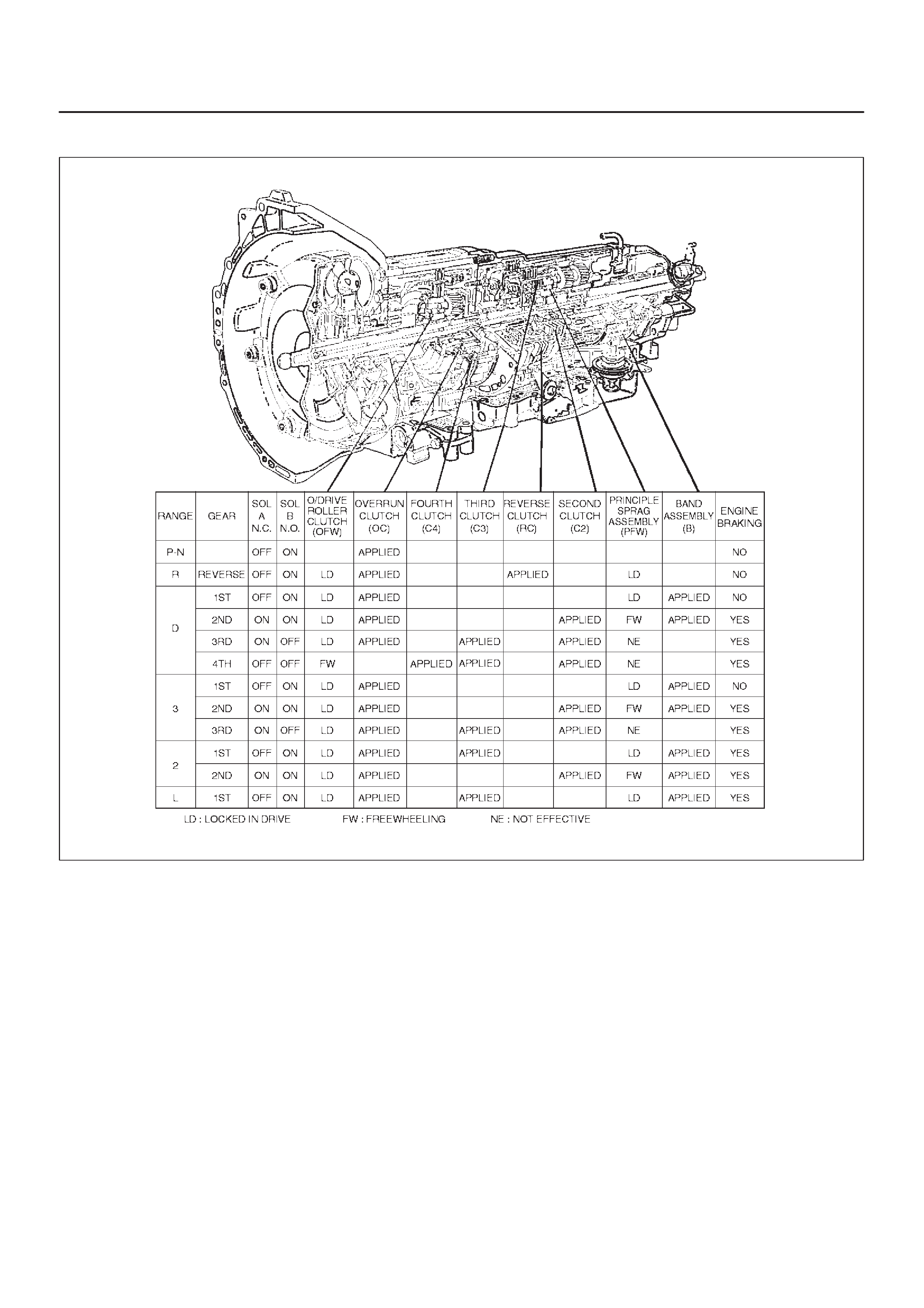
DTC P0730/Flashing Code 81 Transmission Incorrect Gear Ratio
D07RT015
Circuit Description
DThe Powertrain Control Module (PCM) calculates the
slippage of the converter and transmission based
upon the engine speed, the output speed, and the
current gear ratio.
DThe slippage of the converter at a high enough engine
speed is low. The transmission should not slip more
than a given value when there is no shift.
DThis DTC detects a slip at each gear. This is a type
“C” DTC.
Conditions For Setting The DTC
DNo Output Speed Sensor DTC(s) P0722, P0723.
DNot in Park, Neutral or Reverse.
DEngine speed is greater than 3500 rpm.
D3 seconds since upshift.
D3 seconds since downshift.
D3 seconds since garage shift (N→D).
DAnd one of the following conditions occur:
– Slip is greater than 753 rpm in 1st gear.
– Slip is greater than 713 rpm in 2nd gear.
– Slip is greater than 694 rpm on 3rd gear.
– Slip is greater than 685 rpm on 4th gear.
DAll conditions met for 5.5 seconds.
Action Taken When The DTC Sets
DMaximum line pressure.
DThe PCM will illuminate the CHECK TRANS Lamp.

Conditions For Clearing The DTC/CHECK
TRANS Lamp
DThe PCM will turn “off” the CHECK TRANS Lamp
after three consecutive ignition cycles without a
failure reported.
DThe DTC can be cleared from PCM memory by using
a scan tool. The DTC can also be cleared from
memory when the vehicle has made 40 warmup
cycles without a failure reported.
DThe PCM will cancel the DTC Actions Taken items
when the fault conditions no longer exist and the
ignition is cycles “off” long enough to power down the
PCM.
Diagnostic Aids
DCheck for intermittent output speed sensor circuit
problems.
DCheck for possible incorrect calibration. (PCM part
No., tire specifications, and rear axle ratio)
Test Description
The numbers below refer to the step numbers on the
diagnostic chart:
2. This step checks for possible low fluid level causing
slipping resulting in an undefined gear ratio.
3. This step checks for correct gear ratios for
commanded gears.
4. This step checks for low line pressure.

DTC P0730/Flashing Code 81 Transmission Incorrect Gear Ratio
Step Action Yes No
1Visually inspect the transmission cooling system for fluid leaks.
DRefer to Chart 16: Possible Causes of Transmission Fluid
Leaks of Mechanical/Hydraulic Diagnosis Symptoms Index in
Automatic Transmission (4L30–E) section.
Was condition found and corrected? Go to Step 6 Go to Step 2
2Refer to Checking Transmission Fluid Level and Condition in
Automatic Transmission (4L30–E) section.
Has transmission fluid checking procedure been performed?
Go to Step 3
Go to Checking
Transmission
Fluid Level and
Condition in
Automatic
Transmission
(4L30–E) section
31. Install the scan tool.
2. Turn the ignition switch to the “on” position.
3. Engine not running.
NOTE: Before clearing DTC(s) use the scan tool to record the
“Failure Records” for reference, as data will be lost when the “Clear
Info” function is used.
4. Record the Failure Record data.
5. Use the scan tool snapshot mode to record transmission gear
ratios.
6. Drive vehicle in transmission gear ranges 1, 2, 3, and D with
the engine speed is greater than 3,500 rpm for 5.5 seconds.
7. Record each transmission gear.
1st:2.73 – 2.99
2nd:1.54 – 1.71
3rd:0.93 – 1.05
4th:0.66 – 0.78
Does commanded gear ratio match ranges as shown? Refer to
Diagnostic Aids Go to Step 4
4Perform line pressure check.
DRefer to Line Pressure Test in Automatic Transmission
(4L30–E) section.
Was condition found and corrected? Go to Step 6 Go to Step 5
5Check for possible clutch slippage.
DRefer to Chart 6: Diagnostic Trouble Code (DTC) P0730 of
Mechanical/Hydraulic Diagnosis Symptoms Index in
Automatic Transmission (4L30–E) section.
Was condition found and corrected? Go to Step 6 —
61. After the repair is complete, use the scan tool to select “DTC”,
then “Clear info” function.
2. Operate the vehicle under the following conditions:
DDrive the vehicle in D4 with the engine speed greater than
3,500 rpm to obtain any one of the following gear ratios for
seven seconds.
1st 1:2.73 – 1:2.99
2nd 1:1.54 – 1:1.71
3rd 1:0.93 – 1:1.05
4th 1:0.66 – 1:0.78
Has the last test failed?
Begin diagnosis
again
Go to Step 1 Repair verified
Exit DTC table
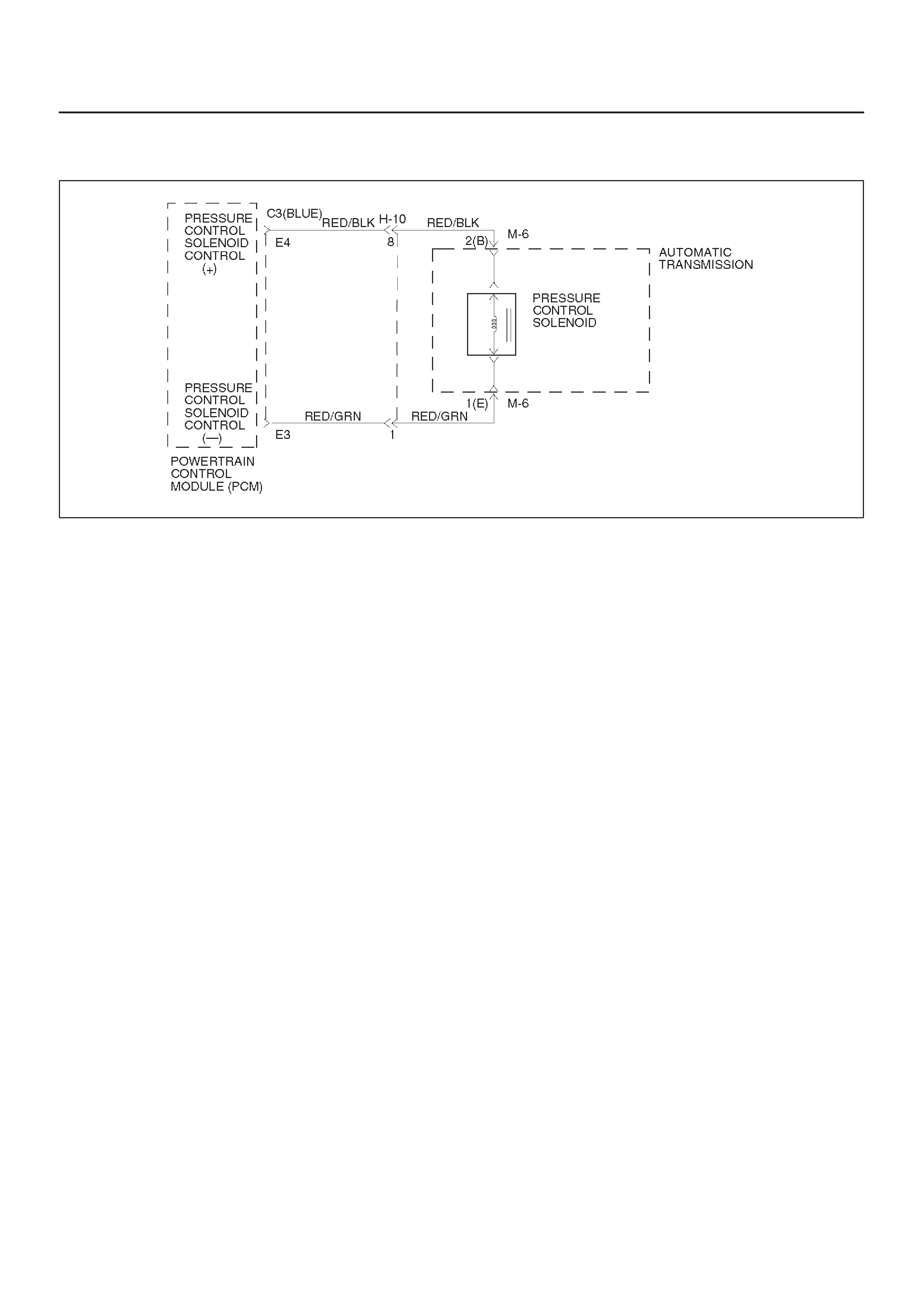
DTC P0748/Flashing Code 82 Pressure Control Solenoid (PCS) (Force Motor)
Circuit Electrical
D07RX020
Circuit Description
The PCS is a PCM–controlled device used to regulate
transmission line pressure. The PCM compares TPS
voltage, engine rpm, and other inputs to determine the
line pressure appropriate for a given load. The PCM will
regulate the pressure by applying a varying amperage to
the PCS. The applied amperage can vary from 0.1 to 1
amp, and is monitored by the PCM.
This DTC detects a continuous open or short to ground in
the PCS circuit or the PCS. This is a type “C” DTC.
Conditions For Setting The DTC
DBattery voltage is between 10 and 16 volts.
DThe PCM detects that the different between
commanded and actual current is 200 milliampere
(mA) for over 1 second.
Action Taken When the DTC Sets
DMaximum line pressure.
DThe PCM will illuminate the CHECK TRANS Lamp.
Conditions For Clearing The DTC/CHECK
TRANS Lamp
DThe PCM will turn “off” the CHECK TRANS Lamp
after three consecutive ignition cycles without a
failure reported.
DThe DTC can be cleared from PCM history by using a
scan tool.
DThe DTC will be cleared from memory when the
vehicle has achieved 40 warmup cycles without a
failure reported.
DThe PCM will cancel the DTC default actions when
the fault no longer exists and the ignition is cycled “off”
long enough to power down the PCM.
Diagnostic Aids
DInspect the wiring for poor electrical connection at the
PCM and at the transmission 5–way connector . Look
for possible bent, backed out, deformed or damaged
terminals. Check for weak terminal tension as well.
Also check for a chafed wire that could short to bare
metal or other wiring. Inspect for a broken wire inside
the insulation.
DWhen diagnosing for a possible intermittent short or
open condition, move the wiring harness while
observing test equipment for a change.
Test Description
The numbers below refer to the step numbers on the
diagnostic chart:
1. This test checks the ability of the PCM to command
the PCS.
2. This test checks the PCS and internal wiring harness
for incorrect resistance.

DTC P0748/Flashing Code 82 Pressure Control Solenoid (PCS) (Force Motor) Circuit
Electrical
Step Action Yes No
11. Install the scan tool.
2. With the engine “off”, turn the ignition switch “on”.
NOTE: Before clearing DTC(s), use the scan tool to record “Failure
Records” for reference, as data will be lost when the “Clear Info”
function is used.
3. Record the DTC “Failure Records”.
4. While the engine is operating, put the transmission in Park.
5. Using the scan tool, apply 0.1 amp through 1.0 amp while
observing “PC Ref. Current” and “PC Act. Current”.
Is the “PC Act. Current” reading always within 0.16 amp? Go to Diagnostic
Aids Go to Step 2
21. Turn the ignition “off”.
2. Disconnect the transmission 5–way connector M–6.
3. Using the J39200 DVOM, measure the resistance between
terminals M6–2(B) and M6–1(E).
Is the resistance within 3–7 ohms? Go to Step 6 Go to Step 3
31. Remove the transmission oil pan. Refer to Solenoid (Adapter
Case Valve Body) in Automatic Transmission (4L30–E)
section.
2. Disconnect the internal wiring harness at the PCS.
3. Measure the resistance of the PCS.
Is the resistance within 3–7 ohms? Go to Step 5 Go to Step 4
4Replace the PCS.
Is the replacement complete? Go to Step 9 —
5Repair the internal wiring harness for an open.
Is the repair complete? Go to Step 9 —
6Inspect/repair circuits C3–E4, M6–2(B), C3–E3, M6–1(E).
Was a problem found? Go to Step 9 Go to Step 7
7Inspect/repair circuits C3–E4, M6–2(B), C3–E3, M6–1(E) for a
short to ground or poor connections.
Was a problem found? Go to Step 9 Go to Step 8
8Replace the PCM. Refer to Powertrain Control Module (PCM) in
Automatic Transmission (4L30–E) section.
Is the replacement complete? Go to Step 9 —
91. After the repair is complete, use the scan tool to select “DTC”,
then “Clear Info” function and ensure the following conditions
are met:
The PCS duty cycle is not at its electrical high or low limit.
2. Review the scan tool “DTC Info”.
Has the last test failed or is the current DTC displayed?
Begin diagnosis
again
Go to Step 1 Repair verified
Exit DTC table

DTC P0753/Flashing Code 83 Shift Solenoid A Electrical
D07RW014
Circuit Description
DThe shift solenoid A is a simple on/off solenoid
located in the main case valve body. The solenoid is
the normally closed type. In second or third gear the
Powertrain Control Module (PCM) energizes the
solenoid to open a fluid inlet port. When the port is
open, fluid pressure actuates the shift valve.
DThe solenoid is activated by a current. This current is
produced by applying a voltage to one side (the High
side) and a ground to the other side (Low side).
DThe High Side Driver (HSD) is a circuit of the PCM
that acts as a switch between the solenoids and the
supply voltage. The High side of the solenoid is
permanently supplied with voltage, except in
BACKUP MODE or when ignition is off the HSD is
turned off.
This DTC detects a continuous open or short to ground in
the shift solenoid A circuit or the shift solenoid A. This is a
type “C” DTC.
Conditions For Setting The DTC
DIgnition is “on”, Engine “run”.
DBattery voltage is between 10 and 16 volts.
DThe PCM commands the solenoid “on” and the
voltage remains high (B+), or the PCM commands
the solenoid “off” and the voltage remains low (zero
volts).
DAll conditions met for 0.33 seconds.
Action Taken When The DTC Sets
DMaximum line pressure.
DImmediate landing to 4th gear.
DInhibit TCC engagement.
DThe PCM will illuminate the CHECK TRANS Lamp.
Conditions For Clearing The DTC/CHECK
TRANS Lamp
DThe PCM will turn off the CHECK TRANS Lamp after
three consecutive ignition cycles without a failure
reported.
DThe DTC can be cleared from the PCM history by
using a scan tool.
DThe DTC will be cleared from history when the vehicle
has achieved 40 warmup cycles without a failure
reported.
DThe PCM will cancel the DTC default actions when
the fault no longer exists and the ignition is cycled “off”
long enough to power down the PCM.
Diagnostic Aids
DInspect the wiring for poor electrical connection at the
PCM and at the transmission 16–way connector.
Look for possible bent, backed out, deformed or
damaged terminals. Check for weak terminal tension
as well. Also check for a chafed wire that could short
to bare metal or other wiring. Inspect for a broken wire
inside the insulation.

DWhen diagnosing for a possible intermittent short or
open condition, move the wiring harness while
observing test equipment for a change.
DAn open ignition feed circuit can cause multiple DTCs
to set.
DA shift solenoid B DTC P0756 could also set with a
shift solenoid A electrical failure.
Test Description
The numbers below refer to the step numbers on the
diagnostic chart:
2. This test checks for power to the shift solenoid A
from the ignition through the PCM.
4. This test measures the resistance of the component.
8. This test checks the function of the shift solenoid A
and the transmission internal wiring harness.
Shift Solenoid Status Chart
Gear Shift solenoid A Shift solenoid B
1st OFF ON
2nd ON ON
3rd ON OFF
4th OFF OFF
DTC P0753/Flashing Code 83 Shift Solenoid A Electrical
Step Action Yes No
11. Install the scan tool.
2. With the engine “on”, turn the ignition switch “on”.
NOTE: Before clearing DTC(s), use the scan tool to record “Failure
Records” for reference, as data will be lost when the “Clear Info”
function is used.
3. Record the DTC “Failure Records”.
Were DTCs P0753, P0758, P1860 set? Go to Step 2 Go to Diagnostic
Aids
21. Turn the ignition “on”.
2. Using the J39200 DVOM, measure the voltage between PCM
connector terminals C3–E14 and C2–C8 (GND).
Is the voltage within 10–12 volts? Go to Step 3 Go to Step 4
31. Turn the ignition “off”.
2. Disconnect the C3 (BLUE) PCM connector.
3. Turn the ignition “on”.
4. Using the J39200 DVOM, measure the voltage between PCM
connector terminals C3–F14 and ground.
Is the voltage within 10 – 12 volts? Go to Step 10 Go to Step 4
41. Turn the ignition “off”.
2. Disconnect the C3 (BLUE) PCM connector.
3. Using the J39200 DVOM, measure the resistance between
PCM connector terminals C3–E14 and C3–F14.
Is the resistance within 18 – 20 ohms? Go to Step 5 Go to Step 6
51. Disconnect the C1 (RED) and C2 (WHITE) PCM connectors.
2. Using the J39200 DVOM, check a continuity between PCM
terminals C3–F14 and ground.
Is there a continuity? Go to Step 11 Go to Step 7
61. Disconnect the 16–way harness connector H–10.
2. Using the J39200 DVOM, measure the resistance between
terminals H10–6 and H10–5.
Is the resistance within 18–20 ohms? Go to Step 13 Go to Step 8
7Using the J39200 DVOM, check a continuity between C3 (BLUE)
PCM terminal E14 and ground.
Is there a continuity? Go to Step 12 Go to Step 9
81. Disconnect the transmission main case 4 pin connector M–7.
2. Using the J39200 DVOM, measure the resistance between
terminals M7–3(D) and M7–4(C).
Is the resistance within 18–20 ohms? Go to Step 14 Go to Step 15

DTC P0753/Flashing Code 83 Shift Solenoid A Electrical (Cont’d)
Step NoYesAction
9Check every connection at the PCM connector.
Was a problem found? Go to Step 17 Go to Step 16
10 The wiring harness between PCM connector terminals C3–F14
and transmission harness terminal M7–3(D) is shorted to voltage.
Was a problem found and corrected? Go to Step 18 —
11 The wiring harness between PCM connector terminal
J3–F14 and transmission harness terminal M7–3(D) is shorted to
ground.
Was a problem found and corrected? Go to Step 18 —
12 The wiring harness between PCM connector terminals C3–E14
and transmission harness terminal M7–4(C) is shorted to ground.
Was a problem found and corrected? Go to Step 18 —
13 The wiring harness between PCM connector C3 and transmission
16–way connector H–10 is open or poor connection.
Was a problem found and corrected? Go to Step 18 —
14 The wiring harness between transmission 16–way connector
H–10 and transmission main case connector M–7 is open or has a
poor connection.
Was a problem found and corrected? Go to Step 18 —
15 The shift solenoid A is faulty.
Replace the shift solenoid A. Refer to Solenoid (Main Case V alve
Body) in Automatic Transmission (4L30–E) section.
Is the replacement complete? Go to Step 18 —
16 The PCM may be faulty.
Replace the PCM. Refer to Powertrain Control Module (PCM) in
Automatic Transmission (4L30–E) section.
Is the replacement complete? Go to Step 18 —
17 Repair the PCM connector connection.
Was a problem found and corrected? Go to Step 18 —
18 1. After the repair is complete, use the scan tool to select “DTC”,
then “Clear Info” function and operate the vehicle under the
following conditions:
DThe shift solenoid A is commanded “on” and the voltage
drops to zero.
DThe shift solenoid A is commanded “off” and the voltage
increases to B+.
2. Review the scan tool “DTC Info”.
Has the last test failed or is the current DTC displayed?
Begin diagnosis
again
Go to Step 1 Repair verified
Exit DTC table
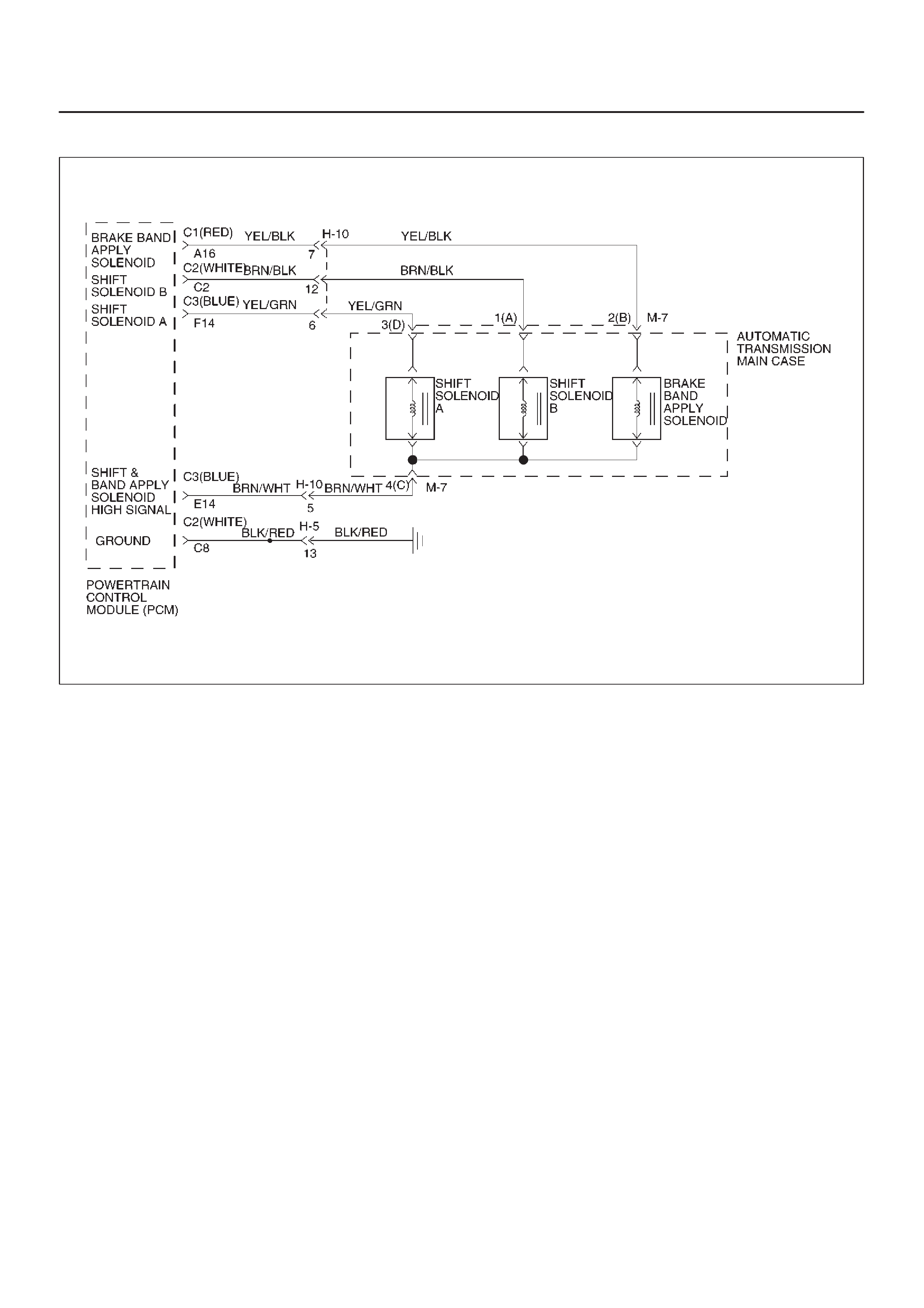
DTC P0758/Flashing Code 84 Shift Solenoid B Electrical
D07RW014
Circuit Description
DThe shift solenoid B is a simple on/off solenoid
located in the main case valve body. It is normally
open. When the port is open, fluid pressure actuates
the shift valve. In first or second gear , the Powertrain
Control Module (PCM) energizes the solenoid to
close a fluid inlet port.
DThe solenoid is activated by current. This current is
produced by applying a voltage to one side (the High
side) and a ground to the other side (Low side).
DThe High Side Driver (HSD) is a circuit of the PCM
that acts as a switch between the solenoids and the
supply voltage. The High side of the solenoid is
permanently supplied with voltage. In BACKUP
MODE or when the ignition is off, the HSD is turned
off.
This DTC detects a continuous open or short to ground in
the shift solenoid B circuit or shift solenoid B. This is a
type “C” DTC.
Conditions For Setting The DTC
DIgnition is “on”, Engine “run”.
DBattery voltage is between 10 and 16 volts.
DThe PCM commands the solenoid “on” and the
voltage remains high (B+), or the PCM commands
the solenoid “off” and the voltage remains low (zero
volts).
DAll conditions met for 0.33 seconds.
Action Taken When The DTC Sets
DFixed to 4th gear.
DMaximum line pressure.
DInhibit TCC engagement.
DThe PCM will illuminate the CHECK TRANS Lamp.
Conditions For Clearing The DTC/CHECK
TRANS Lamp
DThe PCM will turn off the CHECK TRANS Lamp after
three consecutive ignition cycles without a failure
reported.
DThe DTC can be cleared from the PCM history by
using a scan tool.
DThe DTC will be cleared from history when the vehicle
has achieved 40 warmup cycles without a failure
reported.
DThe PCM will cancel the DTC default actions when
the fault no longer exists and the ignition is cycled “off”
long enough to power down the PCM.
Diagnostic Aids
DInspect the wiring for poor electrical connections at
the PCM and at the transmission 16–way connector.
Look for possible bent, backed out, deformed or
damaged terminals. Check for weak terminal tension
as well. Also check for a chafed wire that could short
to bare metal or other wiring. Inspect for a broken wire
inside the insulation.

DWhen diagnosing for a possible intermittent short or
open condition, move the wiring harness while
observing test equipment for a change.
Test Description
The numbers below refer to the step numbers on the
diagnostic chart:
4. This test measures the resistance of the component.
6. This test checks the function of the shift solenoid B
and the transmission internal wiring harness.
10.This test checks for power to the shift solenoid B
from the ignition through the PCM.
Shift Solenoid Status Chart
Gear Shift solenoid A Shift solenoid B
1st OFF ON
2nd ON ON
3rd ON OFF
4th OFF OFF
DTC P0758/Flashing Code 84 Shift Solenoid B Electrical
Step Action Yes No
11. Install the scan tool.
2. With the engine “on”, turn the ignition switch “on”.
NOTE: Before clearing DTC(s), use the scan tool to record “Failure
Records” for reference, as data will be lost when the “Clear Info”
function is used.
3. Record the DTC “Failure Records”.
Were DTCs P0753, P0758, P1860 set? Go to Step 3 Go to Step 2
2 1. The engine “on”.
2. Apply brake pedal and select transmission range “D”.
3. Press and hold down the winter switch and select transmission
mode “winter”.
Does the scan tool display DTC P0758 at 3rd gear? Go to Step 7 Go to Diagnostic
Aids
31. Turn the ignition “off”.
2. Disconnect the C2 (WHITE) and C3 (BLUE) PCM connectors.
3. Turn the ignition “on”.
4. Using the J39200 DVOM, measure the voltage between PCM
connector terminals C2–C2 and C2–C8.
Is the voltage within 10 – 12 volts? Go to Step 14 Go to Step 4
41. Turn the ignition “off”.
2. Using the J39200 DVOM, measure the resistance between
PCM connector terminals C2–C2 and C3–E14.
Is the resistance within 18 – 20 ohms? Go to Step 15 Go to Step 5
51. Disconnect the transmission 16–way connector H–10.
2. Using the J39200 DVOM, measure the resistance between
terminals H10–12 and H10–5.
Is the resistance within 18 – 20 ohms? Go to Step 16 Go to Step 6
61. Disconnect the transmission main case connector M–7.
2. Using the J39200 DVOM, measure the resistance between
terminals M7–1(A) and M7–4(C).
Is the resistance within 18 – 20 ohms? Go to Step 17 Go to Step 18
71. Turn the ignition “off”.
2. Disconnect the C2 (WHITE) and C3 (BLUE) PCM connectors.
3. Using the J39200 DVOM, measure the resistance between
PCM connector terminals C2–C2 and C3–E14.
Is the resistance within 18 – 20 ohms? Go to Step 8 Go to Step 9
8Using the J39200 DVOM, check a continuity between PCM
connector terminal C2–C2 and ground.
Is there a continuity? Go to Step 19 Go to Step 10

DTC P0758/Flashing Code 84 Shift Solenoid B Electrical (Cont’d)
Step NoYesAction
91. Disconnect the transmission 16–way connector H–10.
2. Using the J39200 DVOM, measure the resistance between
terminals H10–12 and H10–5.
Is the resistance within 18–20 ohms? Go to Step 20 Go to Step 11
10 Using the J39200 DVOM, check a continuity between PCM
connector terminal C3–E14 and ground.
Is there a continuity? Go to Step 21 Go to Step 12
11 1. Disconnect the transmission main case connector M–7.
2. Using the J39200 DVOM, measure the resistance between
terminals M7–1(A) and M7–4(C).
Is the resistance within 18 – 20 ohms? Go to Step 22 Go to Step 23
12 Check every connection of the PCM and transmission 16–way
connector H–10.
Was a problem found and corrected? Go to Step 25 Go to Step 13
13 1. Connect the C2 (WHITE) and C3 (BLUE) PCM connectors to
the PCM.
2. Turn the ignition “on”, the engine “on”.
3. Repeat Step 2.
Does the scan tool display DTC P0758 at 3rd gear? Go to Step 24 Go to Diagnostic
Aids
14 The wiring harness between PCM connector terminal
C2–C2 and transmission main case terminal M7–1(A) is shorted
to voltage.
Was a problem found and corrected? Go to Step 25 —
15 The PCM internal terminal C2–C2 is shorted to voltage.
Replace the PCM. Refer to Powertrain Control Module (PCM) in
Automatic Transmission (4L30–E) section.
Is the replacement complete? Go to Step 25 —
16 The wiring harness between PCM connector and transmission
16–way connector is shorted.
Was a problem found and corrected? Go to Step 25 —
17 The wiring harness between transmission 16–way connector and
transmission main case connector is shorted.
Was a problem found and corrected? Go to Step 25 —
18 The shift solenoid B is faulty, or the internal wiring harness from
the shift solenoid B is shorted.
Was a problem found and corrected? Go to Step 25 —
19 The wiring harness between PCM connector terminal
C2–C2 and transmission main case connector terminal M7–1(A)
is shorted to ground.
Was a problem found and corrected? Go to Step 25 —
20 The wiring harness between PCM connector terminal C2–C2 and
transmission 16–way connector terminal H10–12, or between
PCM connector terminal C3–E14 and 16–way connector terminal
H10–5 is open.
Was a problem found and corrected? Go to Step 25 —

DTC P0758/Flashing Code 84 Shift Solenoid B Electrical (Cont’d)
Step NoYesAction
21 The wiring harness between PCM connector terminal C3–E14
and transmission main case connector terminal M7–4(C) is
shorted to ground.
Was a problem found and corrected? Go to Step 25 —
22 The wiring harness between transmission 16–way connector
terminal H10–12 and transmission main case connector terminal
M7–1(A), or between H10–5 and M7–4(C) is open.
Was a problem found and corrected? Go to Step 25 —
23 The internal wiring harness from the shift solenoid B is open, or
the shift solenoid B is faulty.
Was a problem found and corrected? Go to Step 25 —
24 Replace the PCM.
Is the replacement complete? Go to Step 25 —
25 1. After the repair is complete, use the scan tool to select “DTC”,
then “Clear Info” function and operate the vehicle under the
following conditions:
DThe shift solenoid B is commanded “on” and voltage drops to
zero.
DThe shift solenoid B is commanded “off” and voltage
increases to B+.
2. Review the scan tool “DTC Info”.
Has the last test failed or is the current DTC displayed?
Begin diagnosis
again
Go to Step 1 Repair verified
Exit DTC table

DTC P1790/Flashing Code 85 ROM Transmission Side Bad Check Sum
Circuit Description
Transmission Side Read Only Memory (ROM) and
Electronically Erasable Programmable Read Only
Memory (EEPROM) is an electronic circuit that controls
the transmission controls in the Powertrain Control
Module (PCM).
This DTC detects a check sum error. This is a type “C”
DTC.
Conditions For Setting The DTC
DDetects check sum error for 1 second.
Action Taken When The DTC Sets
DMaximum line pressure.
DImmediate landing to 4th gear.
DInhibit TCC engagement.
DThe PCM will illuminate the CHECK TRANS Lamp.
Conditions For Clearing The DTC/CHECK
TRANS Lamp
DThe PCM will turn off the CHECK TRANS Lamp after
three consecutive ignition cycles without a failure
reported.
DThe DTC can be cleared from the PCM history by
using a scan tool.
DThe DTC will be cleared from history when the vehicle
has achieved 40 warmup cycles without a failure
reported.
DThe PCM will cancel the DTC default actions when
the fault no longer exists and the ignition is cycled “off”
long enough to power down the PCM.
DTC P1790/Flashing Code 85 ROM Transmission Side Bad Check Sum
Step Action Yes No
11. Install the scan tool.
2. With the engine “off”, turn the ignition switch “on”.
NOTE: Before clearing DTC(s), use the scan tool to record “Failure
Records” for reference, as data will be lost when the “Clear Info”
function is used.
3. Record the DTC “Failure Records”.
Was DTC P1790 set? Go to Step 4 Go to Step 2
2Was DTC P1792 set? Go to Step 3 —
31. Remove the PCM. Refer to Powertrain Control Module (PCM)
in Automatic Transmission (4L30–E) section.
2. Using the ITCS reprogram the transmission EEPROM.
Was the reprogramming complete? Go to Step 5 —
4Replace the PCM.
Is the replacement complete? Go to Step 5 —
51. After the repair is complete, use the scan tool to select “DTC”,
then “Clear Info” function and operate the vehicle.
2. Review the scan tool “DTC Info”.
Has the last test failed or is the current DTC displayed?
Begin diagnosis
again
Go to Step 1 Repair verified
Exit DTC table

DTC P1792/Flashing Code 86 EEPROM Transmission Side Bad Check Sum
Circuit Description
Transmission Side Read Only Memory (ROM) and
Electronically Erasable Programmable Read Only
Memory (EEPROM) is an electronic circuit that controls
the transmission controls in the Powertrain Control
Module (PCM).
This DTC detects a check sum error. This is a type “C”
DTC.
Conditions For Setting The DTC
DDetects check sum error for 1 second.
Action Taken When The DTC Sets
DMaximum line pressure.
DImmediate landing to 4th gear.
DInhibit TCC engagement.
DThe PCM will illuminate the CHECK TRANS Lamp.
Conditions For Clearing The DTC/CHECK
TRANS Lamp
DThe PCM will turn off the CHECK TRANS Lamp after
three consecutive ignition cycles without a failure
reported.
DThe DTC can be cleared from the PCM history by
using a scan tool.
DThe DTC will be cleared from history when the vehicle
has achieved 40 warmup cycles without a failure
reported.
DThe PCM will cancel the DTC default actions when
the fault no longer exists and the ignition is cycled “off”
long enough to power down the PCM.
DTC P1792/Flashing Code 86 EEPROM Transmission Side Bad Sum
Step Action Yes No
11. Install the scan tool.
2. With the engine “off”, turn the ignition switch “on”.
NOTE: Before clearing DTC(s), use the scan tool to record “Failure
Records” for reference, as data will be lost when the “Clear Info”
function is used.
3. Record the DTC “Failure Records”.
Was DTC P1790 set? Go to Step 4 Go to Step 2
2Was DTC P1792 set? Go to Step 3 —
31. Remove the PCM. Refer to Powertrain Control Module (PCM)
in Automatic Transmission (4L30–E) section.
2. Using the ITCS reprogram the transmission EEPROM.
Was the reprogramming complete? Go to Step 5 —
4Replace the PCM.
Is the replacement complete? Go to Step 5 —
51. After the repair is complete, use the scan tool to select “DTC”,
then “Clear Info” function and operate the vehicle.
2. Review the scan tool “DTC Info”.
Has the last test failed or is the current DTC displayed?
Begin diagnosis
again
Go to Step 1 Repair verified
Exit DTC table
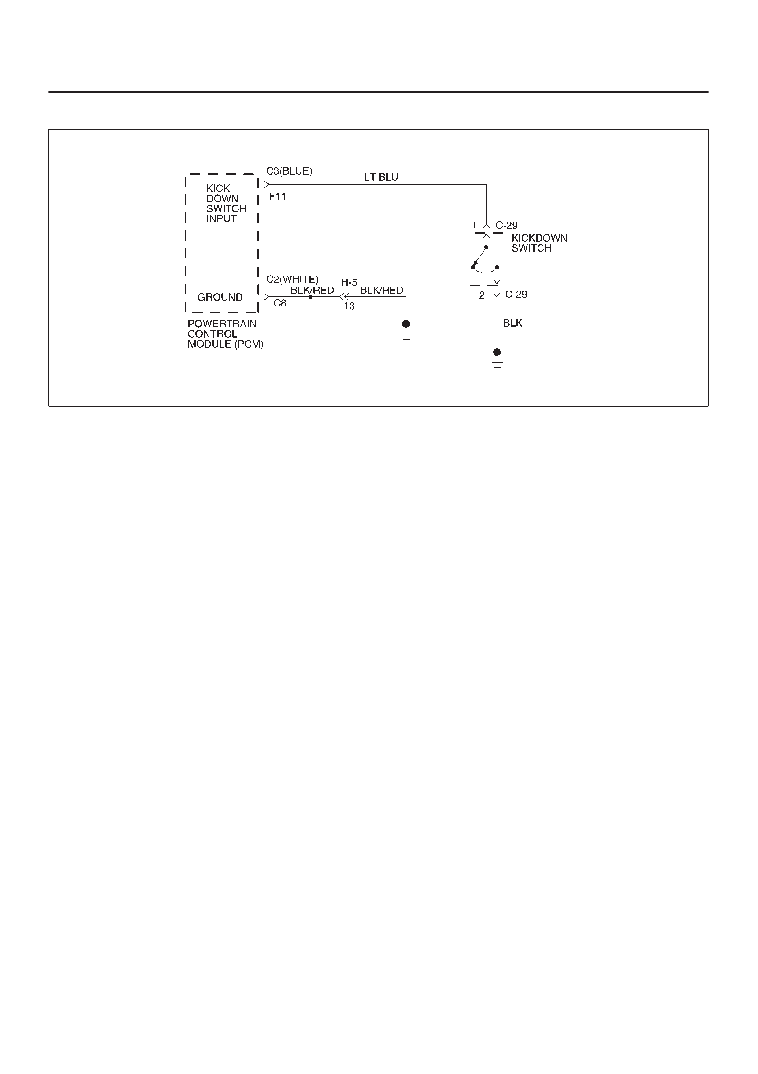
DTC P1835/Flashing Code 87 Kickdown Switch Always On
D07RW015
Circuit Description
DWhen the driver presses the accelerator pedal down
fully, the kickdown switch closes, sending a ground
signal to the Powertrain Control Module (PCM).
DThis information is used to perform shifts at high
engine speed.
DWhen the kickdown switch is closed, the Throttle
Position Sensor (TPS) is already at 100%.
DThis DTC detects a closed kickdown switch when TP
angle is less than 70%.
DThis is a type “D” DTC.
Conditions For Setting The DTC
DNo TP DTCs P0122 or P0123.
DTP angle is less than 70%.
DKickdown switch is “on”.
DAll conditions met for 1 second.
Action Taken When The DTC Sets.
DKickdown mode control is off.
DThe PCM will not illuminate the CHECK TRANS
Lamp.
Conditions For Clearing The DTC
DThe DTC can be cleared from the PCM history by
using a scan tool.
DThe DTC will be cleared from history when the vehicle
has achieved 40 warmup cycles without a failure
reported.
DThe PCM will cancel the DTC default actions when
the fault no longer exists and the ignition is cycled “off”
long enough to power down the PCM.
Diagnostic Aids
DCheck the wiring harness for a short to ground
between the PCM and kickdown switch.
DCheck the kickdown switch for failure.
DCheck kickdown adjustment.
Test Description
The numbers below refer to the step numbers on the
diagnostic chart:
1. This test checks for short to ground or kickdown
switch failure.
3. This test checks for regulation kickdown switch.

DTC P1835/Flashing Code 87 Kickdown Switch Always On
Step Action Yes No
11. Install the scan tool.
2. With the engine “on”, turn the ignition switch “on”.
NOTE: Before clearing DTC(s), use the scan tool to record “Failure
Records” for reference, as data will be lost when the “Clear Info”
function is used.
3. Record the DTC “Failure Records”.
Does the scan tool display “Kickdown switch” “low” (closed
switch)? Go to Step 2 Go to Step 3
21. Turn the ignition “off”.
2. Disconnect the C3 (BLUE) PCM connector.
3. Using the J39200 DVOM, check a continuity between PCM
connector terminal C3–F11 and ground.
Is there a continuity? Go to Step 4 Go to Step 7
3The TP angle goes from 0% to 100% with the accelerator pedal
depressed.
Does the kickdown switch “on” when TP angle is below 70%? Go to Step 5 Go to Diagnostic
Aids
41. Disconnect the kickdown switch connector C–29.
2. Using the J39200 DVOM, check a continuity between
terminals C29–1 and C29–2.
Is there a continuity? Go to Step 6 Go to Step 8
5Adjust the kickdown switch.
Does the kickdown switch “on” when TP angle is above 95%? Go to Step 9 —
6Replace the kickdown switch.
Is the replacement complete? Go to Step 9 —
7Replace the PCM. Refer to Powertrain Control Module (PCM) in
Automatic Transmission (4L30–E) section.
Is the replacement complete? Go to Step 9 —
8Repair the short to ground in circuit LT BLUE.
Is the repair complete? Go to Step 9 —
91. After the repair is complete, use the scan tool to select “DTC”,
then “Clear Info” function and ensure the following condition is
met:
The torque converter stator temperature switch circuit does not
indicate a hot mode when the transmission fluid temperature is
less than 60°C (140°F) for at least 5 seconds.
2. Review the scan tool “DTC Info”.
Has the last test failed or is the current DTC displayed?
Begin diagnosis
again
Go to Step 1 Repair verified
Exit DTC table

DTC P1850/Flashing Code 88 Brake Band Apply Solenoid Malfunction
D07RW014
Circuit Description
DThe brake band apply solenoid is a normally open
solenoid which controls the flow of fluid for brake band
application. The Powertrain Control Module (PCM)
uses Pulse Width Modulation (PWM) and changes
the duty cycle to control the solenoid. The PCM turns
the solenoid on (energized) and off (deenergized) at a
constant frequency. The length of time the solenoid is
energized during each on/off cycle is called the pulse
width. By varying or “modulating” the pulse width, the
solenoid output pressure is changed. Since the
solenoid is normally open, increasing the pulse width
increases the duty cycle and decreases the output
pressure. PWM control provides smooth band
application without an accumulator . The band is only
applied in first and second gears.
DIn the event of an electrical failure (open), the
solenoid regulates at the maximum oil flow (0% duty
cycle).
DThe solenoid is activated by a current. This current is
produced by applying a voltage to one side (the High
side) and a ground to the other side (Low side).
DThe High Side Driver (HSD) is a circuit of the PCM
that acts as a switch between the solenoids and the
supply voltage. The High side of the solenoid is
permanently supplied with voltage. When the ignition
is off, the HSD is turned off.
This DTC detects a continuous open or short to ground in
the brake band apply solenoid circuit or the brake band
apply solenoid. This is a type “D” DTC.
Conditions For Setting The DTC
DBattery voltage is between 10 and 16 volts.
DIgnition is “on”, Engine “run”.
DThe PCM commands the solenoid “on” and the
voltage remains high (B+), or the PCM commands
the solenoid “off” and the voltage remains low (zero
volts).
DAll conditions met in 1.3 seconds.
Action Taken When The DTC Sets
DInhibit brake band apply solenoid.
DThe PCM will not illuminate the CHECK TRANS
Lamp.
Conditions For Clearing The DTC
DThe DTC can be cleared from the PCM history by
using a scan tool.
DThe DTC will be cleared from history when the vehicle
has achieved 40 warmup cycles without a failure
reported.
DThe PCM will cancel the DTC default actions when
the fault no longer exists and the ignition is cycled “off”
long enough to power down the PCM.

Diagnostic Aids
DInspect the wiring for poor electrical connection at the
PCM and at the transmission 16–way connector.
Look for possible bent, backed out, deformed or
damaged terminals. Check for weak terminal tension
as well. Also check for a chafed wire that could short
to bare metal or other wiring. Inspect for a broken wire
inside the insulation.
DWhen diagnosing for a possible intermittent short or
open condition, move the wiring harness while
observing test equipment for a change.
Test Description
The numbers below refer to the step numbers on the
diagnostic chart:
2. This test checks for power to the brake band apply
solenoid from the ignition through the PCM.
3. This test checks the resistance of the transmission
internal wiring harness and brake band apply
solenoid.
4. This test checks the ability of the PCM and wiring to
control the ground circuit.
DTC P1850/Flashing Code 88 Brake Band Apply Solenoid Malfunction
Step Action Yes No
11. Install the scan tool.
2. With the engine “on”, turn the ignition switch “on”.
NOTE: Before clearing DTC(s), use the scan tool to record “Failure
Records” for reference, as data will be lost when the “Clear Info”
function is used.
3. Record the DTC “Failure Records”.
Were DTCs P0753, P0758 set? Go to Step 2 Go to Step 3
2Using the J39200 DVOM, back probe between PCM connector
terminals C3–E14 and C2–C8.
Is the voltage between 10 to 12 volts? Go to Step 4 Go to Step 5
31. Turn the ignition “off”.
2. Disconnect the C1 (RED) and C3 (BLUE) PCM connectors.
3. Using the J39200 DVOM, measure the resistance between
PCM connector terminals C1–A16 and C3–E14.
Is the resistance within 10–12 ohms? Go to Step 11 Go to Step 12
4Using the J39200 DVOM, back probe between PCM connector
terminals C1–A16 and C2–C8.
Is the voltage between 10 to 12 volts? Go to Step 25 Go to Step 3
51. Turn the ignition “off”.
2. Disconnect the C1 (RED) and C3 (BLUE) PCM connectors.
3. Using the J39200 DVOM, check continuity between PCM
terminal C3–E14 and ground.
Is there a continuity? Go to Step 6 Go to Step 8
61. Disconnect the transmission 16–way connector H–10.
2. Using the J39200 DVOM, check continuity between connector
H10–7 and ground.
Is there a continuity? Go to Step 7 Go to Step 16
71. Disconnect the transmission main case connector M–7.
2. Using the J39200 DVOM, check continuity between the
terminal M7–2(B) and ground.
Is there a continuity? Go to Step 17 Go to Step 18
81. Disconnect the J1 (RED) PCM Connector.
2. Using the J39200 DVOM, measure the resistance between
the PCM connector terminals C1–A16 and C3–E14.
Is the resistance within 10–12 ohms? Go to Step 25 Go to Step 9
91. Disconnect the transmission 16–way connector H–10.
2. Using the J39200 DVOM, measure the resistance between
the terminal H10–7 and H10–5.
Is the resistance within 10–12 ohms? Go to Step 16 Go to Step 10

DTC P1850/Flashing Code 88 Brake Band Apply Solenoid Malfunction (Cont’d)
Step NoYesAction
10 1. Disconnect the transmission main case connector M–7.
2. Using the J39200 DVOM, measure the resistance between
the terminals M7–2(B) and M7–4(C).
Is the resistance within 10–12 ohms? Go to Step 19 Go to Step 20
11 Using the J39200 DVOM, check continuity between PCM
terminal C1–A16 and ground.
Is there a continuity? Go to Step 13 Go to Step 25
12 1. Disconnect the transmission 16–way connector H–10.
2. Using the J39200 DVOM, measure the resistance between
the terminal H10–7 and H10–5.
Is the resistance within 10–12 ohms? Go to Step 23 Go to Step 14
13 1. Disconnect the transmission 16–way connector H–10.
2. Using the J39200 DVOM, check continuity between terminal
H10–7 and ground.
Is there a continuity? Go to Step 15 Go to Step 21
14 1. Disconnect the transmission main case connector M–7.
2. Using the J39200 DVOM, measure the resistance between
the terminals M7–2(B) and M7–4(C).
Is the resistance within 10–12 ohms? Go to Step 24 Go to Step 20
15 1. Disconnect the transmission main case connector M–7.
2. Using the J39200 DVOM, check continuity between terminal
M7–2(B) and ground.
Is there a continuity? Go to Step 17 Go to Step 22
16 The wiring harness between PCM terminal C3–E14 and
transmission 16–way connector terminal H10–5 is open.
Was a problem found and corrected? Go to Step 26 —
17 The brake band apply solenoid is faulty, or the internal wiring
harness from the brake band apply solenoid is shorted to ground.
Was a problem found and corrected? Go to Step 26 —
18 The wiring harness between the transmission 16–way connector
terminal H10–5 and the transmission main case connector
terminal M7–4(C) is shorted to ground.
Was a problem found and corrected? Go to Step 26 —
19 The wiring harness between the transmission 16–way connector
terminal H10–5 and the transmission main case connector
terminal M7–4(C) is open.
Was a problem found and corrected? Go to Step 26 —
20 The brake band apply solenoid is faulty, or the internal wiring
harness from the brake band apply solenoid is open.
Was a problem found and corrected? Go to Step 26 —
21 The wiring harness between the PCM connector terminal C1–A16
and transmission 16–way connector terminal H10–7 is shorted to
ground.
Was a problem found and corrected? Go to Step 26 —
22 The wiring harness between the transmission 16–way connector
terminal H10–7 and the transmission main case connector
terminal M7–2(B) is shorted to ground.
Was a problem found and corrected? Go to Step 26 —

DTC P1850/Flashing Code 88 Brake Band Apply Solenoid Malfunction (Cont’d)
Step NoYesAction
23 The wiring harness between the PCM connector terminal C1–A16
and the 16–way connector terminal H10–7 is open.
Was a problem found and corrected? Go to Step 26 —
24 The wiring harness between the transmission 16–way connector
terminal H10–7 and the transmission main case connector
terminal M7–2(B) is open.
Was a problem found and corrected? Go to Step 26 —
25 Check every connection at the PCM.
If OK, replace the PCM. Refer to Powertrain Control Module
(PCM) in Automatic Transmission (4L30–E) section.
Is the replacement complete? Go to Step 26 —
26 1. After the repair is complete, use the scan tool to select “DTC”,
then “Clear Info” function and ensure the following conditions
are met:
DThe brake band apply solenoid is commanded “on” and the
volts drop to zero.
DThe brake band apply solenoid is commanded “off” and the
volts increase to B+.
2. Review the scan tool “DTC Info”.
Has the last test failed or is the current DTC displayed?
Begin diagnosis
again
Go to Step 1 Repair verified
Exit DTC table
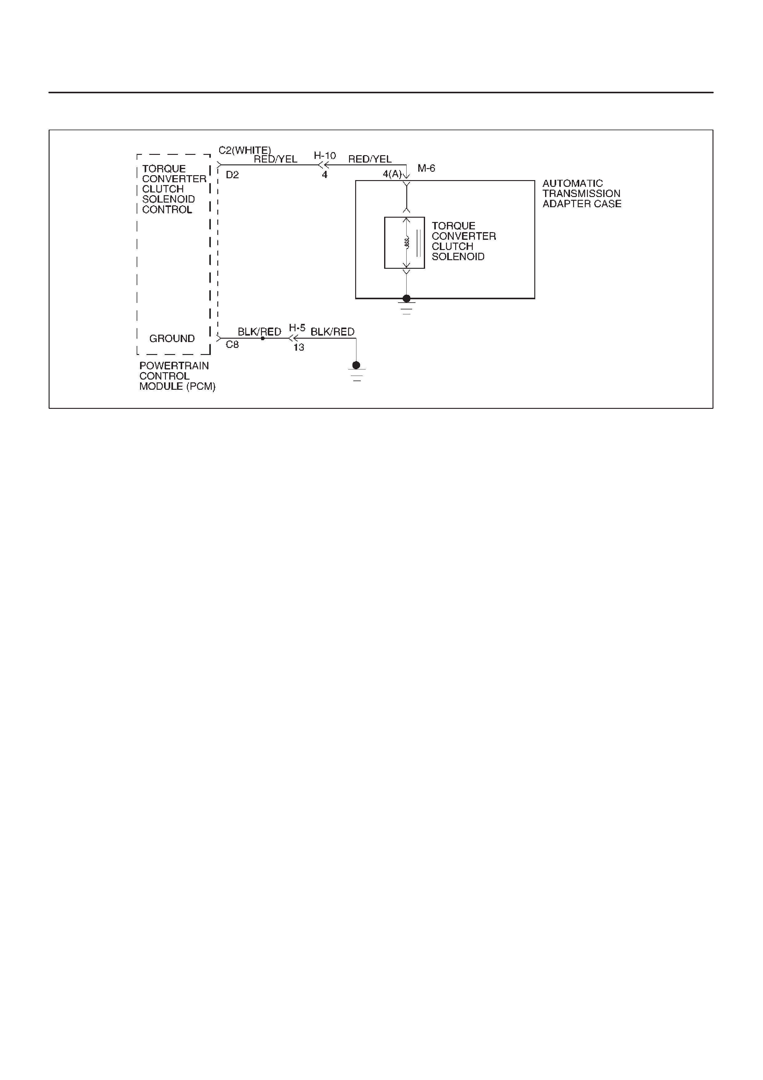
DTC P1860/Flashing Code 89 TCC Solenoid Electrical
D07RW016
Circuit Description
The PCM allows current to flow through the solenoid coil.
This current flow through the solenoid coil creates a
magnetic field that magnetizes the solid core. The
magnetized core attracts the check ball to seat against
spring pressure. This blocks the exhaust for the TCC
signal fluid and allows 2–3 drive fluid to feed to TCC signal
circuit. The TCC signal fluid pressure acts on the TCC
regulator valve to regulate line pressure and to apply fluid
pressure to the torque converter clutch shift valve. When
the TCC shift valve is in the apply position, regulated
apply fluid pressure is directed through the TCC valve to
apply the torque converter clutch. The TCC solenoid is
used in conjunction with the TCC solenoid to regulate fluid
to the torque converter . The TCC solenoid is attached to
the valve body within the transmission.
This DTC detects a continuous open or short to ground or
ignition in the TCC circuit or the TCC solenoid. This is a
type “D” DTC.
Conditions For Setting The DTC
DBattery voltage is between 10 and 16 volts.
DNo shift solenoid A DTCs P0753.
DNo shift solenoid B DTCs P0758.
DIgnition “on”. Engine “run”.
DThe PCM commands the solenoid “on” and the
voltage remains low (zero volts).
DThe PCM commands the solenoid “off” and the
voltage remains high (B+).
DAll conditions met for 0.25 seconds.
Action Taken When The DTC Sets
DInhibit TCC engagement.
DThe PCM will not illuminate the CHECK TRANS
Lamp.
Conditions For Clearing The DTC
DThe DTC can be cleared from the PCM history by
using a scan tool.
DThe DTC will be cleared from history when the vehicle
has achieved 40 warmup cycles without a failure
reported.
DThe PCM will cancel the DTC default actions when
the fault no longer exists and the ignition is cycled “off”
long enough to power down the PCM.
Diagnostic Aids
DInspect the wiring for poor electrical connections at
the PCM and at the transmission 16–way connector.
Look for possible bent, backed out, deformed or
damaged terminals. Check for weak terminal tension
as well. Also check for a chafed wire that could short
to bare metal or other wiring. Inspect for a broken wire
inside the insulation.
DWhen diagnosing for a possible intermittent short or
open condition, move the wiring harness while
observing test equipment for a change.
Test Description
The numbers below refer to the step numbers on the
diagnostic chart:
2. This test checks for voltage to the solenoid.
3. This test checks the ability of the PCM and wiring to
control the ignition circuit.
8. This test checks the resistance of the TCC solenoid
and the internal wiring harness.

DTC P1860/Flashing Code 89 TCC Solenoid Electrical
Step Action Yes No
11. Install the scan tool.
2. With the engine “on”, turn the ignition switch “on”.
NOTE: Before clearing DTC(s), use the scan tool to record “Failure
Records” for reference, as data will be lost when the“Clear Info”
function is used.
3. Record the DTC “Failure Records”. Go to Step 2 Go to Step 3
2Using the J39200 DVOM, back probe between PCM connector
terminals C2–D2 and C2–C8.
Is the voltage 0? Go to Step 4 Go to Step 5
31. Apply brake pedal and select transmission range “D”.
2. Do a test drive, and increase the vehicle speed to TCC “on” at
4th.
Does the scan tool display DTC P1860 at TCC “ON”? Go to Step 9 Go to Diagnostic
Aids
41. Turn the ignition “off”.
2. Disconnect the C2 (WHITE) PCM connector.
3. Using the J39200 DVOM, measure the resistance between
PCM connector terminals C2–D2 and C2–C8.
Is the resistance within 18 – 20 ohms? Go to Step 6 Go to Step 7
5The wiring harness between PCM connector terminal C2–D2 and
transmission adapter case connector terminal M6–4(A) is shorted
to voltage.
Was a problem found and corrected? Go to Step 18 Go to Step 19
6Intermittent condition.
Check the wiring harness and terminals between PCM connector
J2 and transmission adapter case connector M–6.
Was a problem found and corrected? Go to Step 18 Go to Step 19
71. Disconnect the transmission 16–way connector H–10.
2. Using the J39200 DVOM, measure the resistance between
terminal H10–4 and ground.
Is the resistance within 18 – 20 ohms? Go to Step 15 Go to Step 8
81. Disconnect the transmission adapter case connector M–6.
2. Using the J39200 DVOM, measure the resistance between
terminal M6–4(A) and ground.
Is the resistance within 18 – 20 ohms? Go to Step 16 Go to Step 17
91. Turn the ignition “off”.
2. Disconnect the C2 (WHITE) PCM connector.
3. Using the J39200 DVOM, measure the resistance between
terminals C2–D2 and C2–C8.
Is the resistance within 18 – 20 ohms? Go to Step 18 Go to Step 10
10 1. Disconnect the transmission 16–way connector H–10.
2. Using the J39200 DVOM, measure the resistance between
terminal H10–4 and ground.
Is the resistance within 18–20 ohms? Go to Step 12 Go to Step 11
11 1. Disconnect the transmission adapter case connector M–6.
2. Using the J39200 DVOM, measure the resistance between
terminal M6–4(A) and ground.
Is the resistance within 18–20 ohms? Go to Step 13 Go to Step 14

DTC P1860/Flashing Code 89 TCC Solenoid Electrical (Cont’d)
Step NoYesAction
12 The wiring harness between PCM connector terminal C2–D2 and
transmission 16–way connector terminal H10–4 is shorted to
ground.
Was a problem found and corrected? Go to Step 20 —
13 The wiring harness between transmission 16–way connector
H–10 and adapter case connector M–6 is shorted to ground.
Was a problem found and corrected? Go to Step 20 —
14 The TCC solenoid is faulty , or the internal wiring harness from the
TCC solenoid is shorted to ground.
Was a problem found and corrected? Go to Step 20 —
15 The wiring harness between PCM connector terminal C2–D2 and
transmission 16–way connector terminal H10–4 is open.
Was a problem found and corrected? Go to Step 20 —
16 The wiring harness between transmission 16–way connector
terminal H10–4 and adapter case terminal M6–4(A) is open.
Was a problem found and corrected? Go to Step 20 —
17 The TCC solenoid is faulty , or the internal wiring harness from the
TCC solenoid is open.
Was a problem found and corrected? Go to Step 20 —
18 Check every connection at the PCM.
If OK, replace the PCM. Refer to Powertrain Control Module
(PCM) in Automatic Transmission (4L30–E) section.
Is the replacement complete? Go to Step 20 —
19 Check the PCM connector terminal C2–D2, transmission 16–way
connector terminal H10–4 and transmission adapter case
connector terminal M6–4(A).
Was a problem found and corrected? Go to Step 20 —
20 1. After the repair is complete, use the scan tool to select “DTC”,
then “Clear Info” function and ensure the following conditions
are met:
DThe TCC solenoid is commanded “on” and the volts increase
to B+.
DThe TCC solenoid is commanded “off” and the volts drop to
zero.
2. Review the scan tool “DTC Info”.
Has the last test failed or is the current DTC displayed?
Begin diagnosis
again
Go to Step 1 Repair verified
Exit DTC table
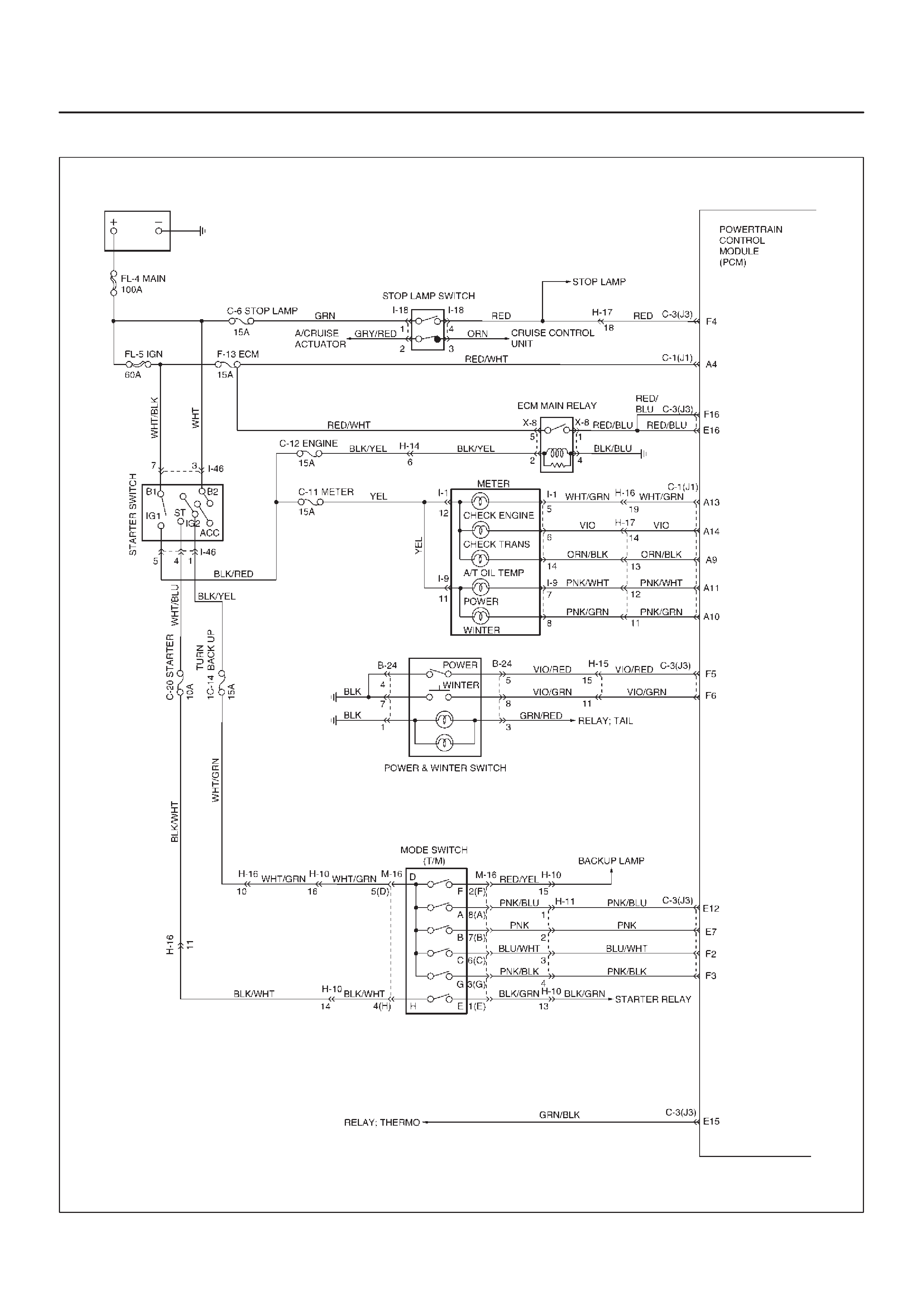
Circuit Diagram
D07RY00075
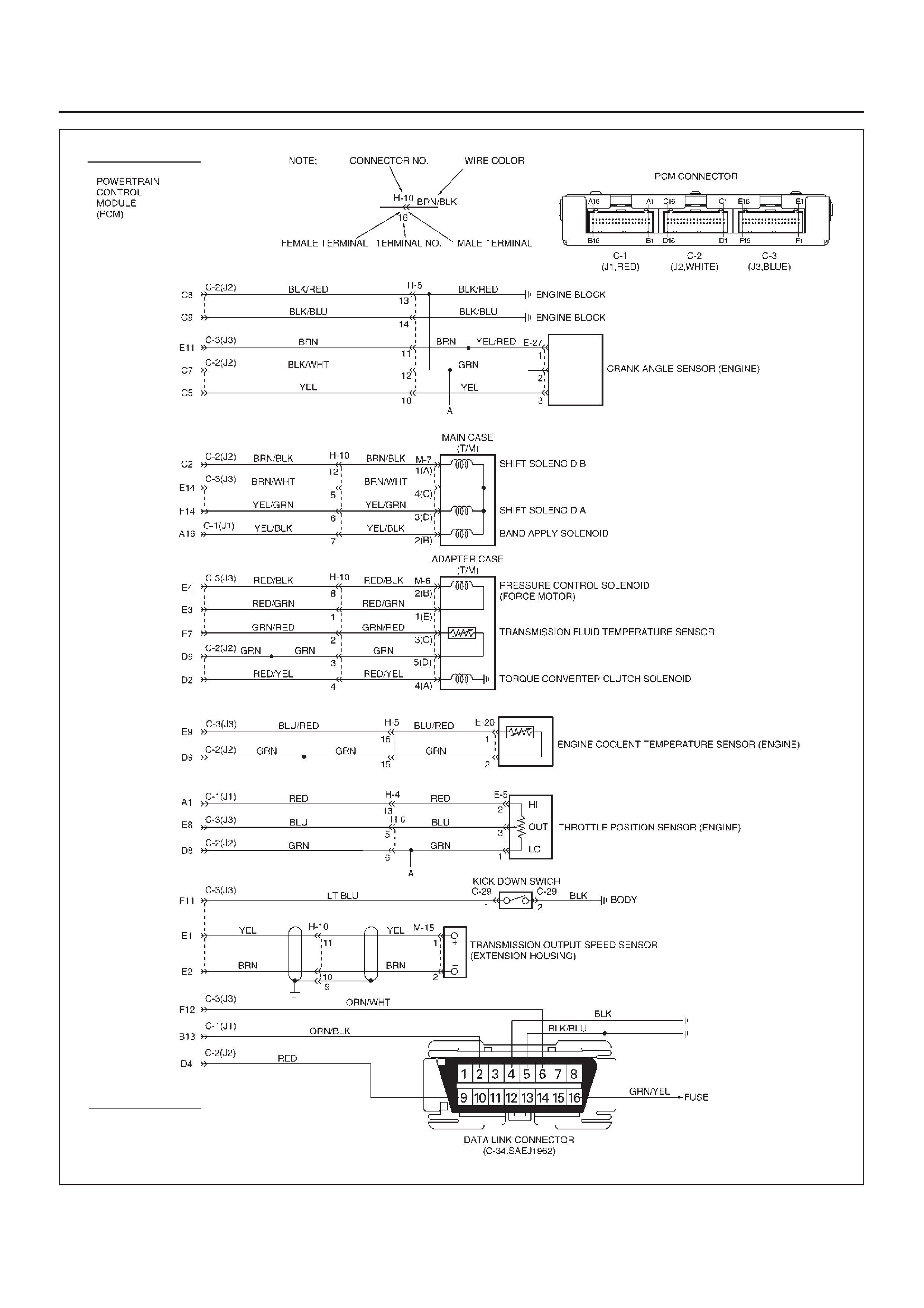
D07RY00076
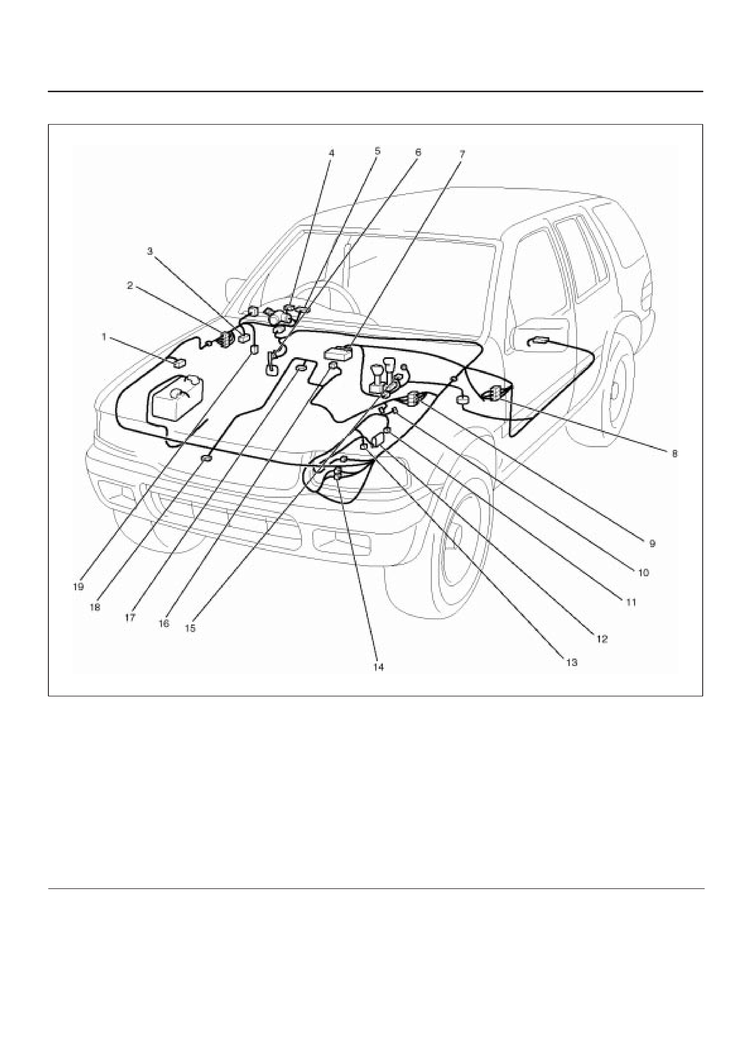
Parts Location
D07RW075
Legend
(1) Connector X-8
(2) Connector X-13, X-14
(3) Data Link Connector C-34
(4) Connector I-1
(5) Connector I-9
(6) Connector I-18
(7) Powertrain Control Module (PCM) connector
C-1 (J1), C-2 (J2), C-3 (J3)
(8) Connector H-15, H-16, H-17
(9) Connector H-4, H-5, H-6
(10) Connector M-15
(11) Connector M-7
(12) Connector M-16
(13) Connector M-6
(14) Connector H-10, H-11
(15) Connector B-24
(16) Connector E-5
(17) Connector E-20
(18) Connector E-27
(19) Connector C-29
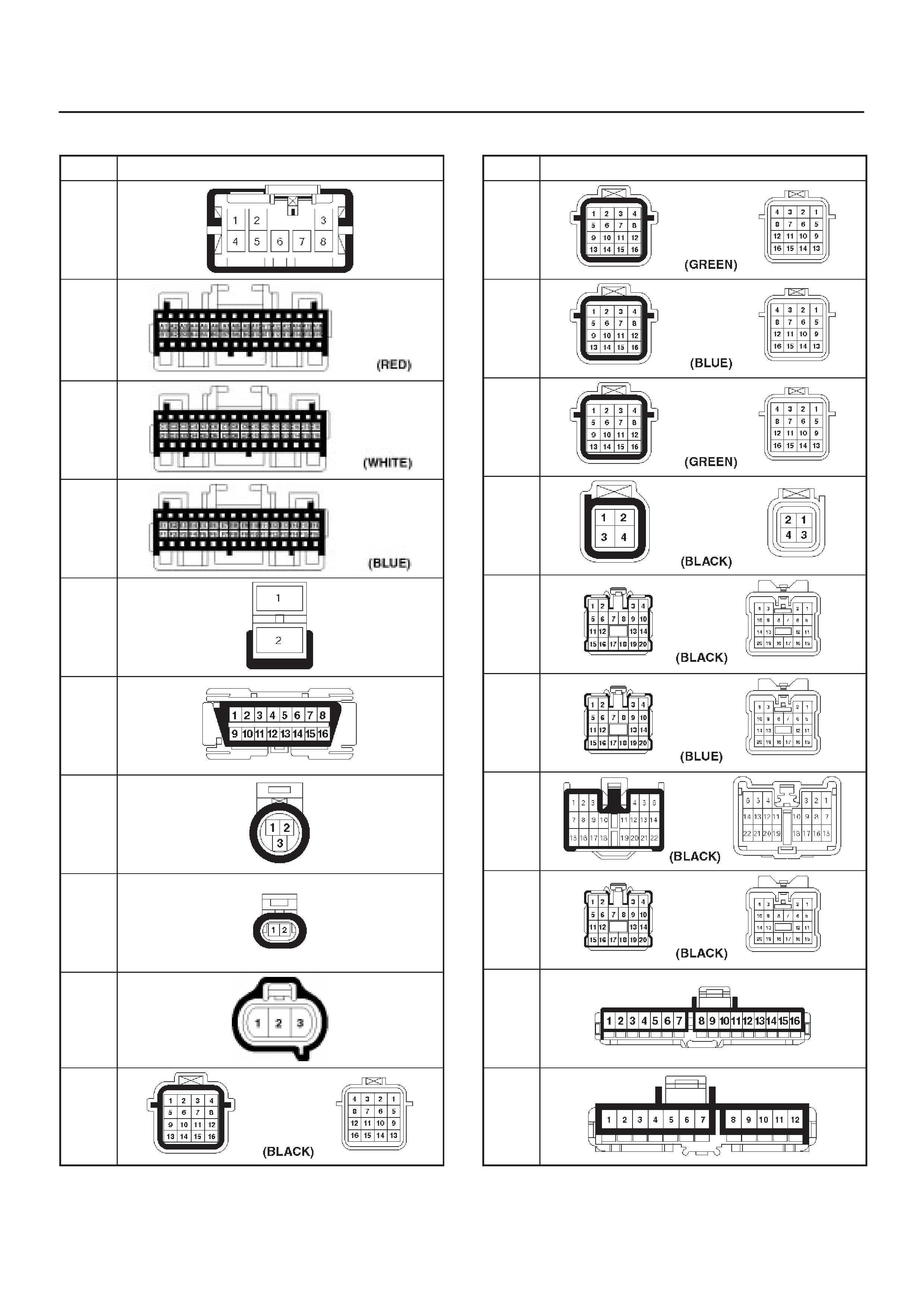
Harness Connector Faces
No. Connector face
B-24
C-1
(J1)
C-2
(J2)
C-3
(J3)
C-29
C-34
E-5
E-20
E-27
H-4
No. Connector face
H-5
H-6
H-10
H-11
H-14
H-15
H-16
H-17
I-1
I-9
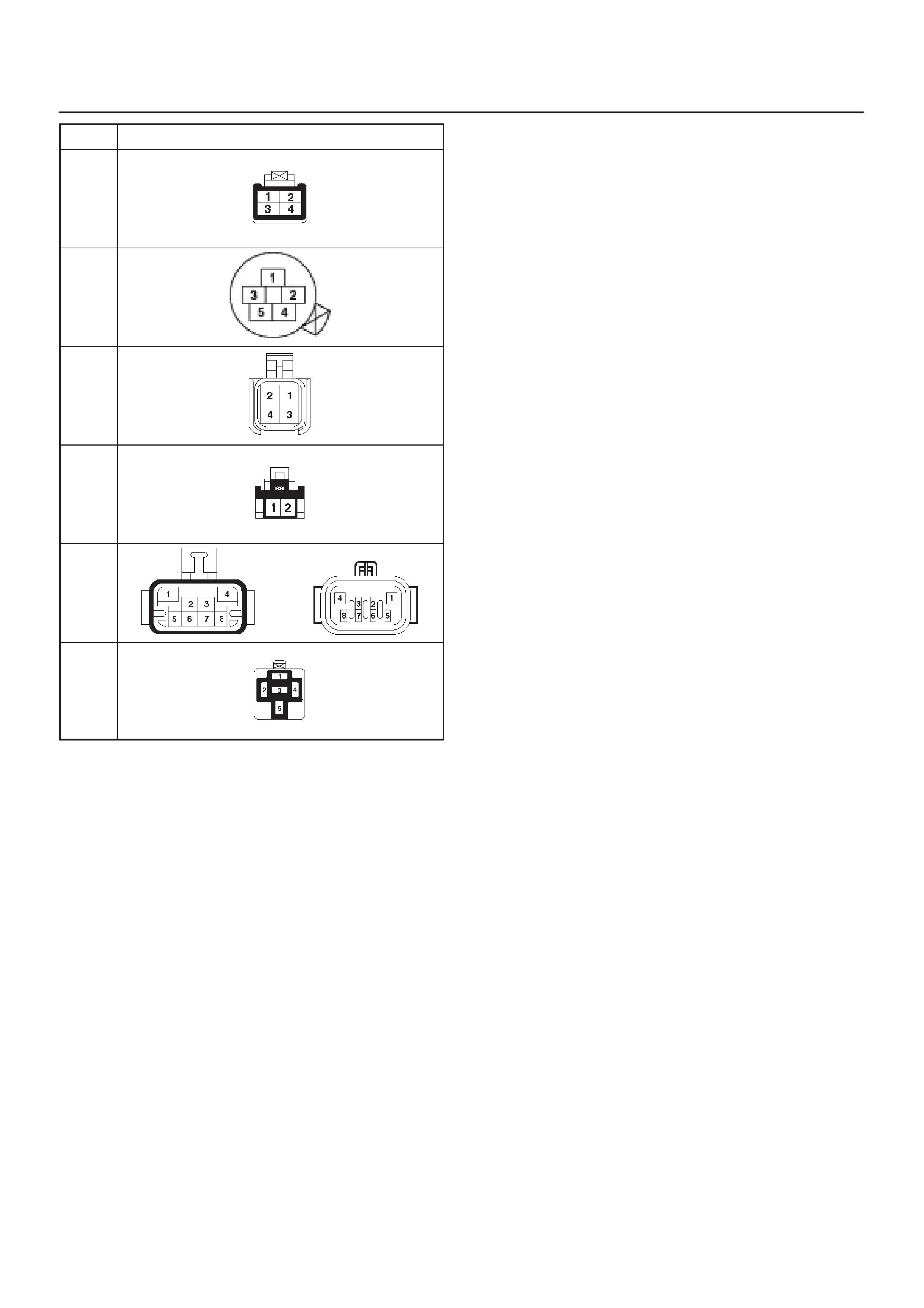
No. Connector face
I-18
M-6
M-7
M-15
M-16
X-8