
SECTION 7C - CLUTCH
Service Precaution
General Description
Diagnosis
Clutch Assembly (X22SE, MUA)
Clutch Assembly (X22SE, MUA) and
Associated Parts
Removal
Inspection and Repair
Installation
Clutch Assembly (6VD1, MUA)
Clutch Assembly (6VD1, MUA) and
Associated Parts
Removal
Inspection and Repair
Installation
Clutch Control
Parts Location View
Removal
Inspection and Repair
Installation
Master Cylinder
Disassembly
Inspection and Repair
Reassembly
Slave Cylinder
Disassembled View
Disassembly
Inspection and Repair
Reassembly
Damper Cylinder
Disassembled View
Disassembly
Inspection and Repair
Reassembly
Main Data and Specifications
Special Tools
Service Precaution
WARNING:THIS VEHICLE HAS A SUPPLEMENTAL
RESTRAINT SYSTEM (SRS). REFER TO THE SRS
COMPONENT AND WIRING LOCATION VIEW IN
ORDER TO DETERMINE WHETHER YOU ARE
PERFORMING SERVICE ON OR NEAR THE SRS
COMPONENTS OR THE SRS WIRING. WHEN YOU
ARE PERFORMING SERVICE ON OR NEAR THE SRS
COMPONENTS OR THE SRS WIRING, REFER TO
THE SRS SERVICE INFORMATION. FAILURE TO
FOLLOW WARNINGS COULD RESULT IN POSSIBLE
AIR BAG DEPLOYMENT, PERSONAL INJURY, OR
OTHERWISE UNNEEDED SRS SYSTEM REPAIRS.
CAUTION:Always use the correct fastener in the
proper location. When you replace a fastener, use
ONLY the exact part number for that application.
ISUZU will call out those fasteners that require a
replacement after removal. ISUZU will also call out
the fasteners that require thread lockers or thread
sealant. UNLESS OTHERWISE SPECIFIED, do not
use supplemental coatings (Paints, greases, or other
corrosion inhibitors) on threaded fasteners or
fastener joint interfaces. Generally, such coatings
adversely affect the fastener torque and the joint
clamping force, and may damage the fastener . When
you install fasteners, use the correct tightening
sequence and specifications. Following these
instructions can help you avoid damage to parts and
systems.
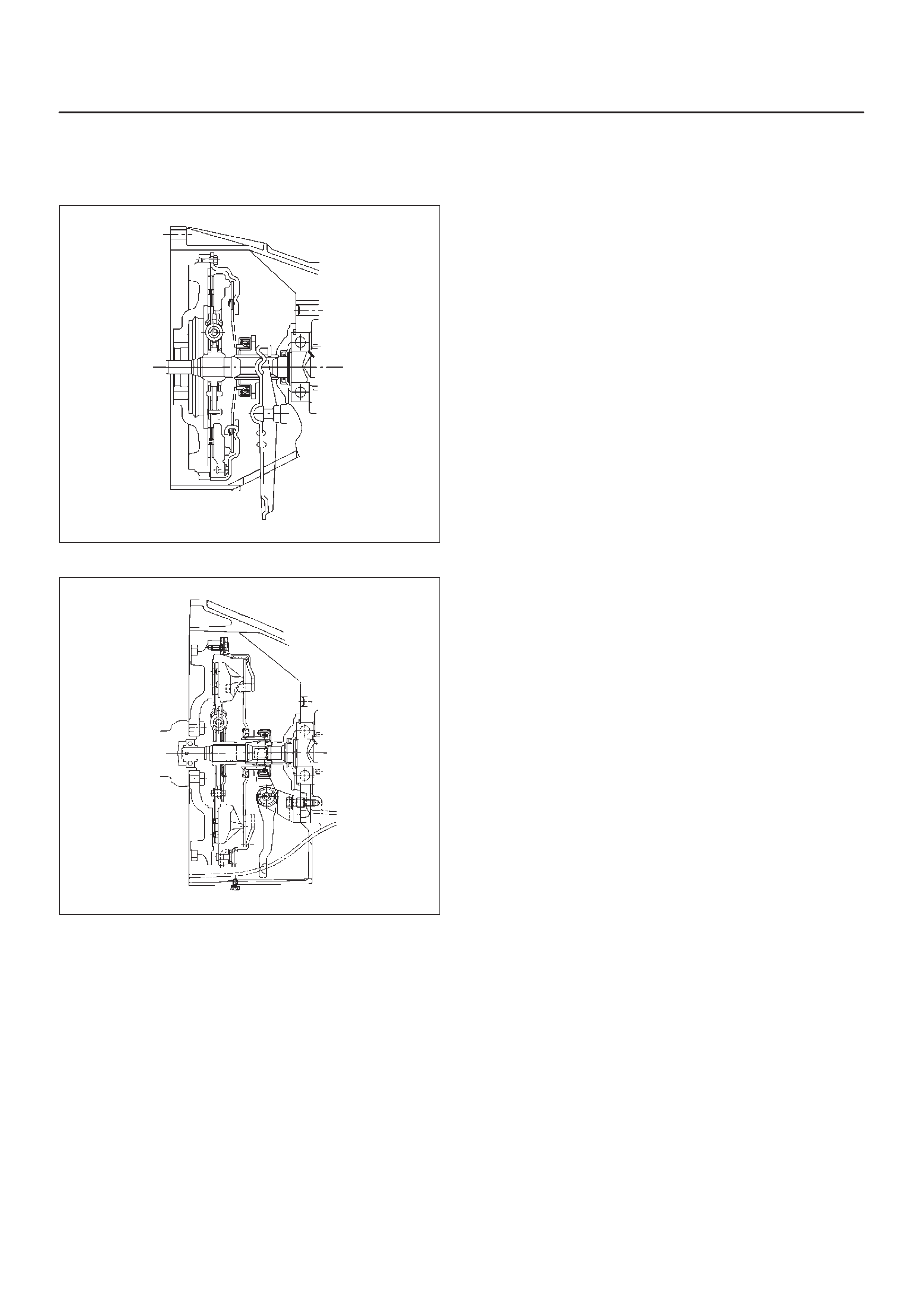
General Description
Clutch
X22SE, MUA
A07RW035
6VD1, MUA
A07RW031
The clutch assembly consists of the pressure plate
assembly and the driven plate assembly.
The clutch pedal is connected to the release bearing
through the shift fork.
The driven plate assembly is installed between the
flywheel and the pressure plate. Diaphragm spring
pressure holds the driven plate against the flywheel and
the pressure plate to provide the friction necessary to
engage the clutch.
Depressing the clutch pedal moves the shift fork against
the release bearing. The release bearing force
overcomes the force of the diaphragm spring and
separates the driven plate from the flywheel and pressure
plate to disengage the clutch.
For 6VD1 (3.2L) engine model, the pull–type clutch is
employed.
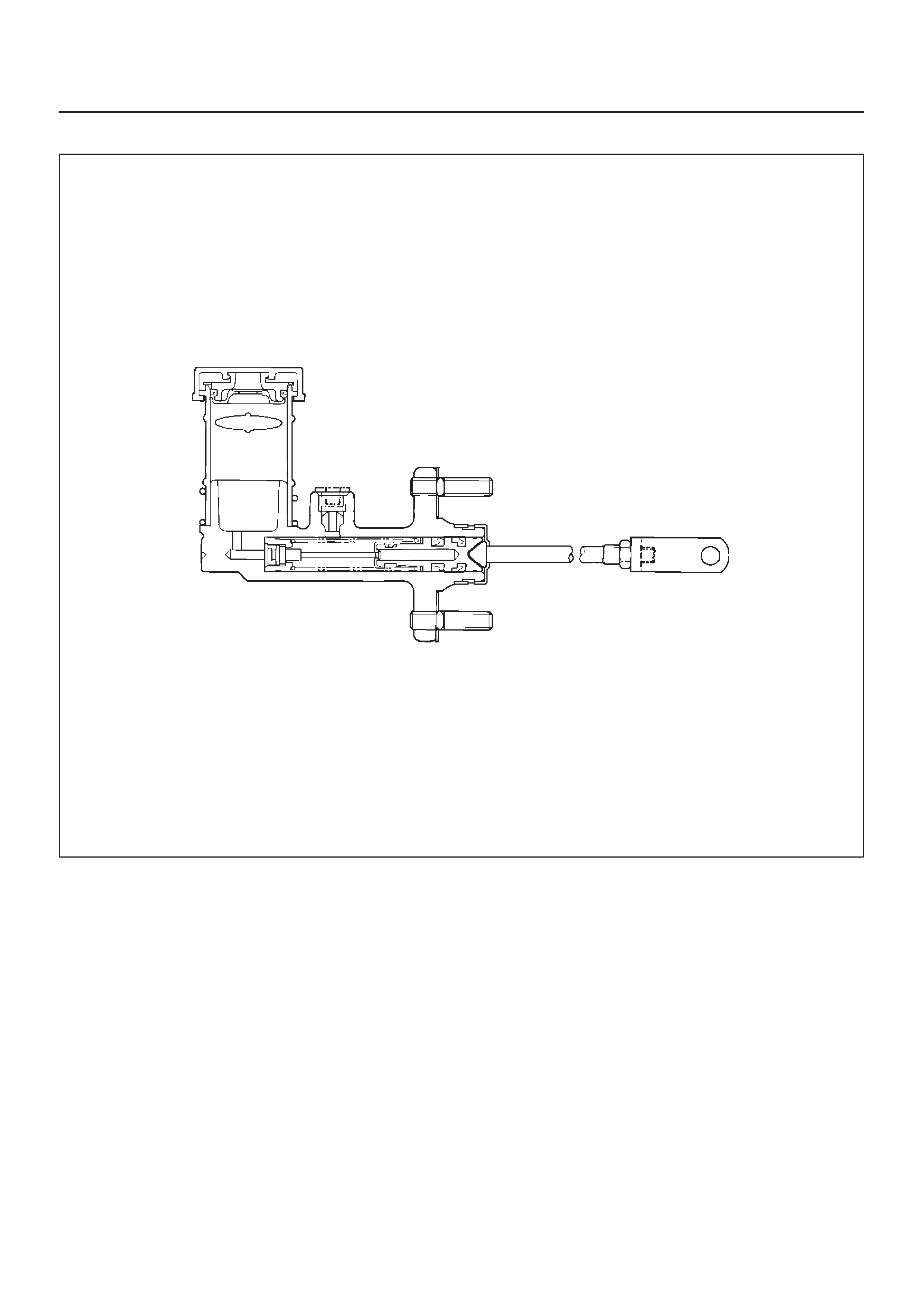
Master Cylinder
A07RW071
The master cylinder converts mechanical energy into
hydraulic energy.
Depressing the clutch pedal causes the push rod to move
against the piston to close the return port.
Clutch fluid is forced out of the master cylinder.
Releasing the clutch pedal causes the return spring to
force the piston back to its original position.
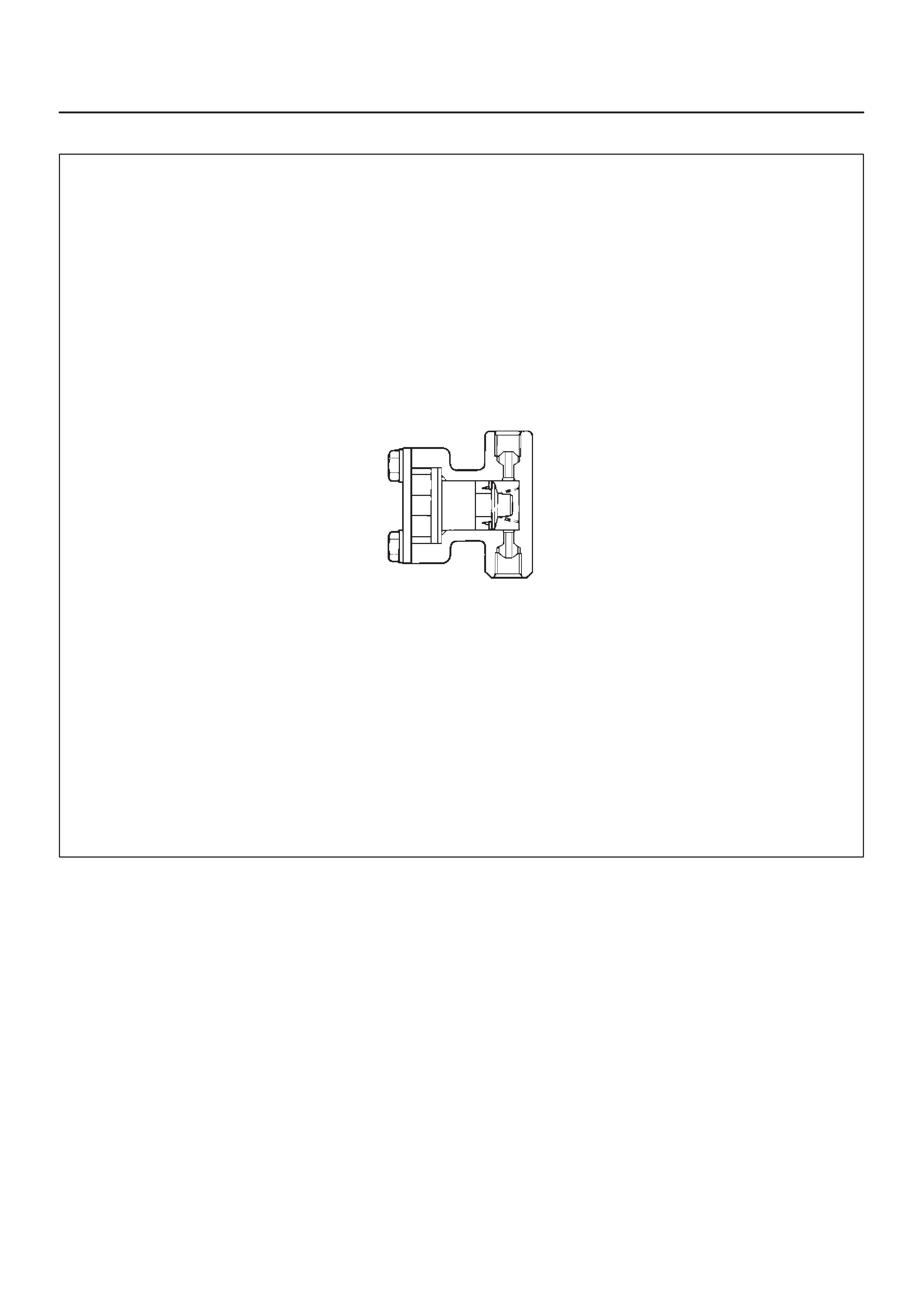
Damper Cylinder
A07RS004
In order to reduce the occurrence of noises at the clutch
hydraulic system, the damper cylinder is used in the clutch hydraulic line between the master cylinder and
slave cylinder.
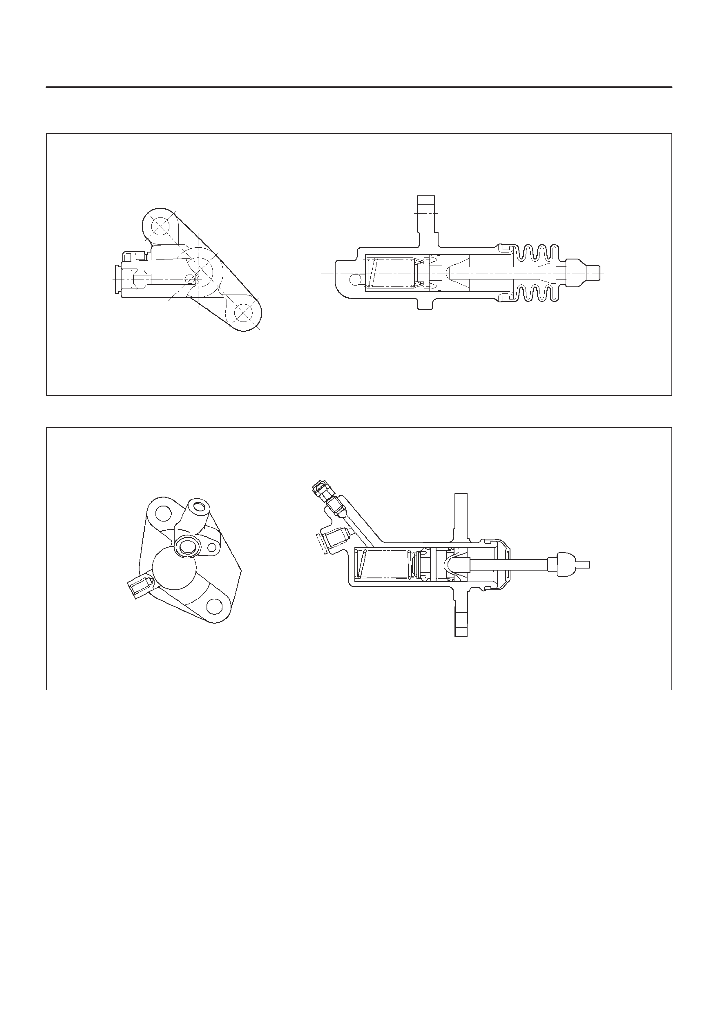
Slave Cylinder
X22SE, MUA
A07RW028
6VD1, MUA
A07RW037
The slave cylinder converts hydraulic energy into
mechanical energy. Hydraulic fluid supplied by the
master cylinder moves the slave cylinder piston to
actuate the shift fork. The mechanical energy produced
by the slave cylinder is directly proportional to the
diameters of the master cylinder and the slave cylinder.

Pressure Plate Assembly
X22SE, MUA
A07RW024
6VD1, MUA
A07RW025
The pressure plate assembly consists of the clutch cover,
the pressure plate with diaphragm spring. Operating the clutch pedal causes the pressure plate to
move in an axial direction to engage and disengage the
clutch.
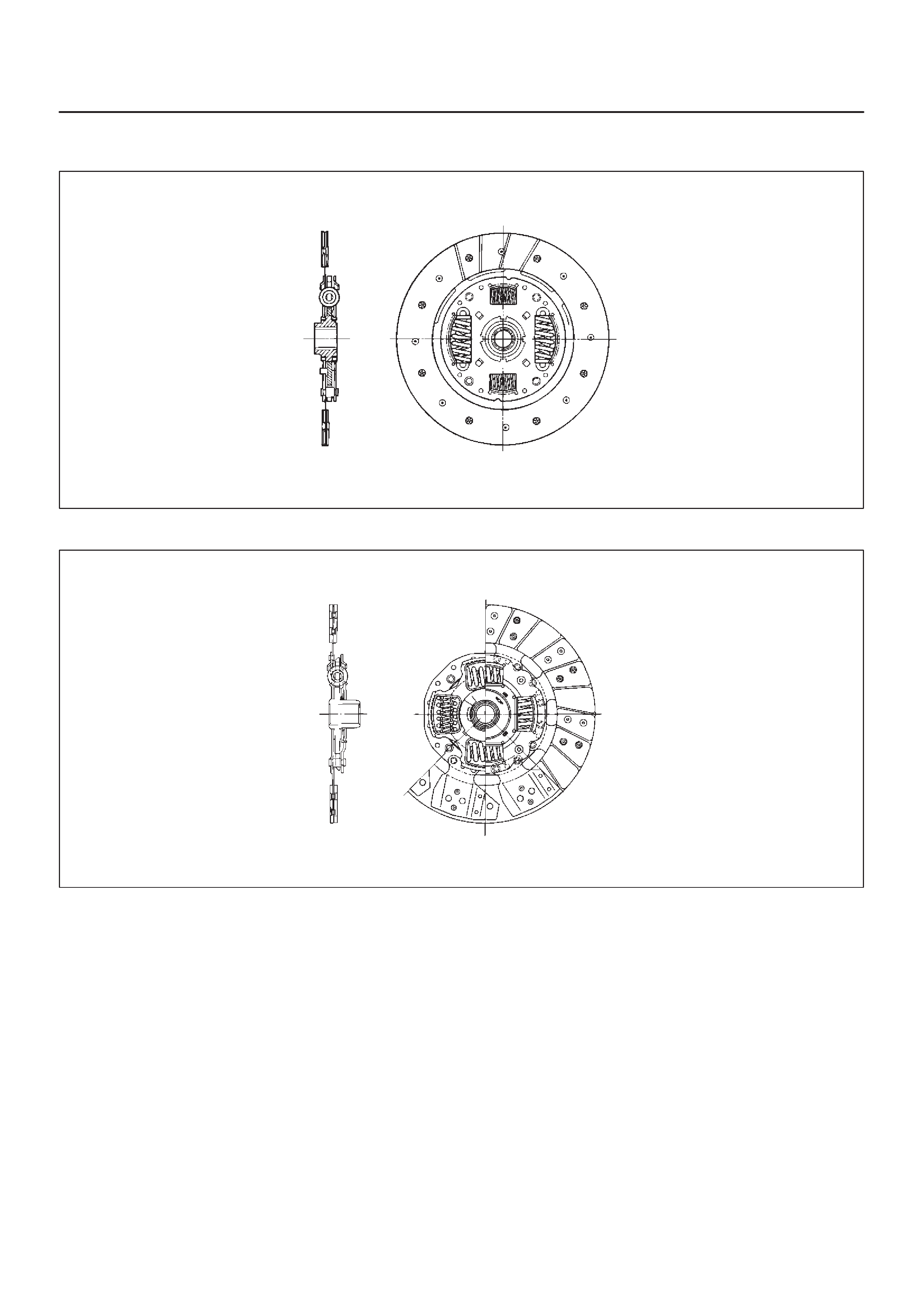
Driven Plate Assembly
X22SE, MUA
A07RW026
6VD1, MUA
A07RW027
The driven plate assembly consists of the plate and the
facing.
The plate consists of the clutch center, the cushioning
plate, and the torsion springs.
The facing is riveted to both sides of the cushioning plate.
The cushioning plate provides a longer service life by
minimizing wear and vibration at the clutch contact
surfaces.

Diagnosis
Condition Possible cause Correction
Dragging Air in circuit. Bleed and check for damage.
Driven plate worn or warped. Replace.
Clutch fork off the ball stud. Install correctly and lubricate.
Diaphragm spring weak or tip of
fingers worn. Replace.
Driven plate sticking on splines. Clean and free splines and lubricate
with grease.
Pilot bearing worn or damaged. Replace.
Master cylinder and slave cylinder
seals worn. Replace.
Slipping Clutch facing worn. Replace.
Driven plate friction pads worn or
oilsoaked. Replace and check for leaks as
needed.
Diaphragm spring weak. Replace pressure plate.
Pressure plate or flywheel warped. Replace.
Master cylinder and slave cylinder
seals worn. Replace as needed.
Chattering Clutch facing in poor contact or
facing warped. Replace.
Surface of facing hardened. Replace.
Driven plate friction pads oil soaked. Replace and check for leaks.
Damper springs weakened or
broken. Replace.
Rivets on clutch plate loosened. Replace.
Pressure plate or flywheel warped. Replace as needed.
Rattling Diaphragm spring weak. Replace the pressure plate.
Clutch fork loose or off the ball stud. Replace the retaining spring or install
the fork correctly.
Driven plate springs weak or oil in the
damper. Replace and check for leaks as
needed.
Release bearing noisy with the clutch
engaged Release bearing binding. Clean, or replace if damaged, and
lubricate.
Clutch fork off the ball stud or loose
spring tension. Install correctly, and lubricate.
Linkage return springs weak. Replace.
Noisy Release bearing worn or damaged. Replace.
Clutch fork off the ball stud. Install correctly and lubricate.
Pilot bearing loose. Replace.
Pedal stays on the floor when
disengaged
Replace bearing binding. Free up, or replace, and lubricate.
di
sengage
d
Diaphragm spring weak. Replace the pressure plate.
Pedal is hard to push Hydraulic line blocked or crimped. Clean out or replace.
Master or slave cylinders bindinig. Repair or replace as needed.
Driven plate worn. Replace.
Squeaking Ball stud not lubricated or incorrectly
lubricated. Lubricate with high temperature
grease.
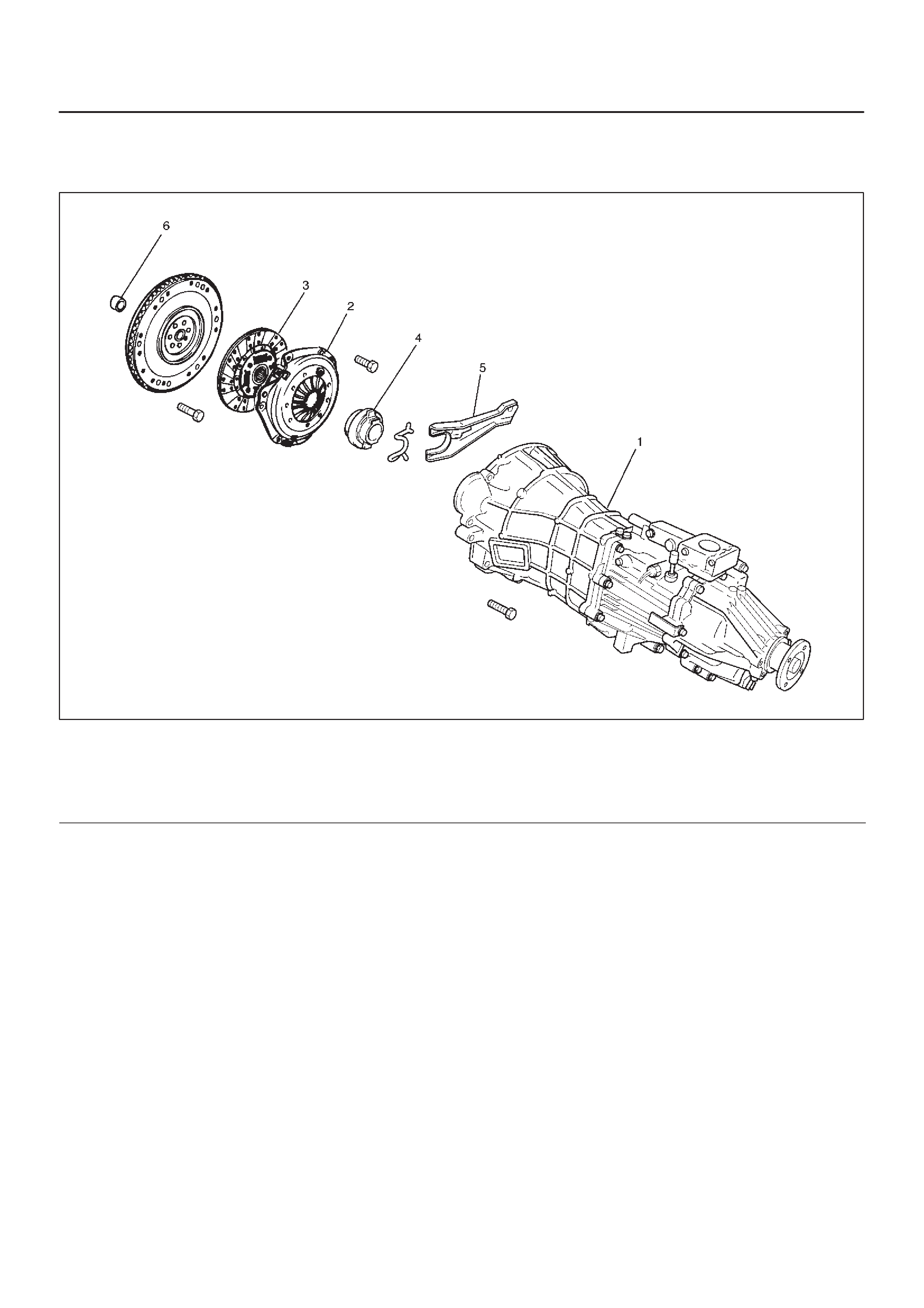
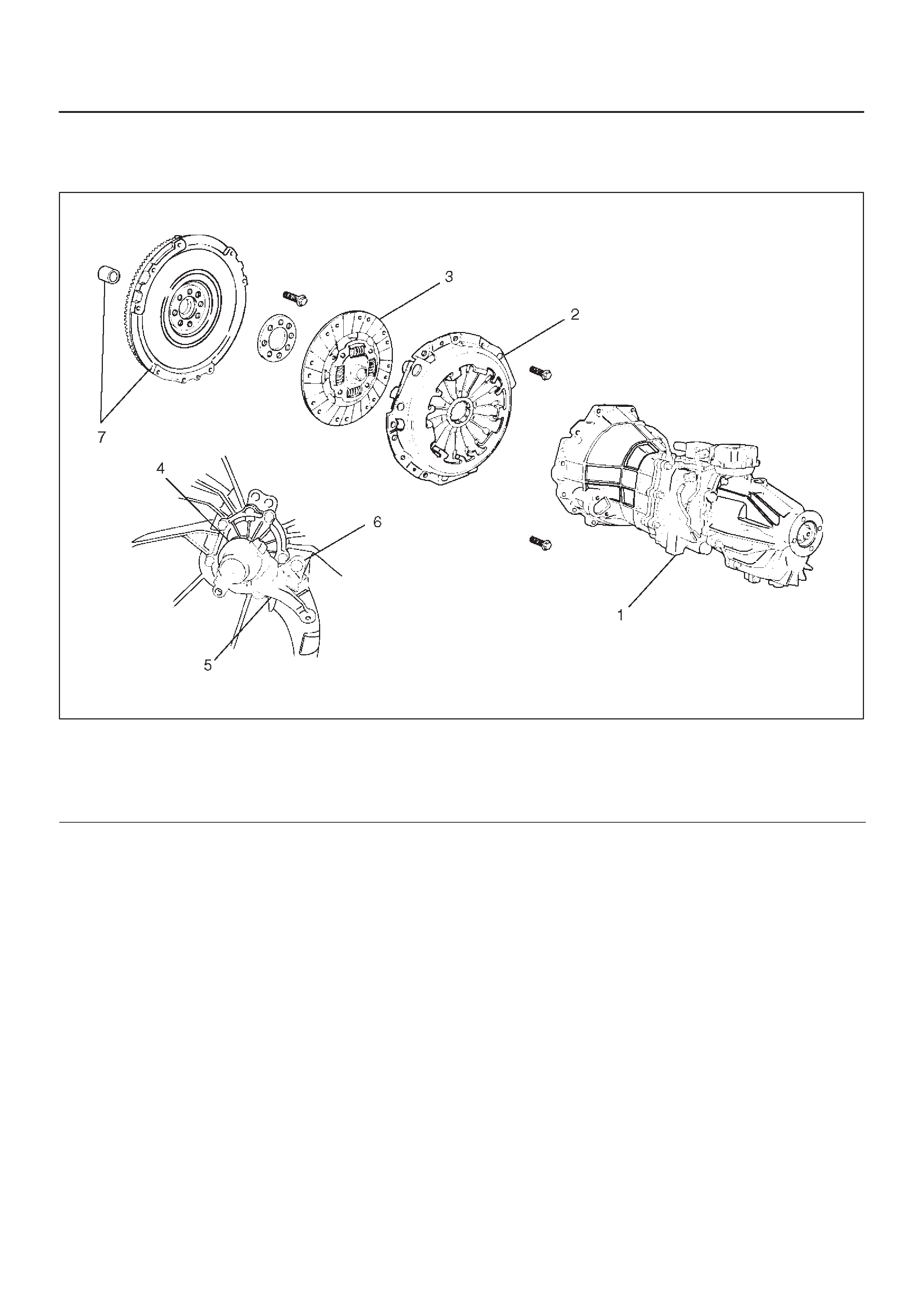
Clutch Assembly (X22SE, MUA)
Clutch Assembly (X22SE, MUA) and Associated Parts
201RX003
Legend
(1)Transmission Assembly
(2)Pressure Plate Assembly
(3)Driven Plate Assembly
(4)Release Bearing
(5)Shift Fork
(6)Crank Shaft Bearing
Removal
1.Remove transmission assembly, refer to “MANUAL
TRANSMISSION” of Section 7B for “REMOVAL AND
INSTALLATION” procedure.

2.Use the clutch pilot aligner (7) J–42877 (MUA) to
prevent the driven plate assembly from falling free.
201RX002
Legend
(3) Driven Plate Assembly
(2) Pressure Plate Assembly
(7) Pilot Aligner
3.Mark the flywheel, clutch cover and pressure plate (2)
lug for alignment when installing.
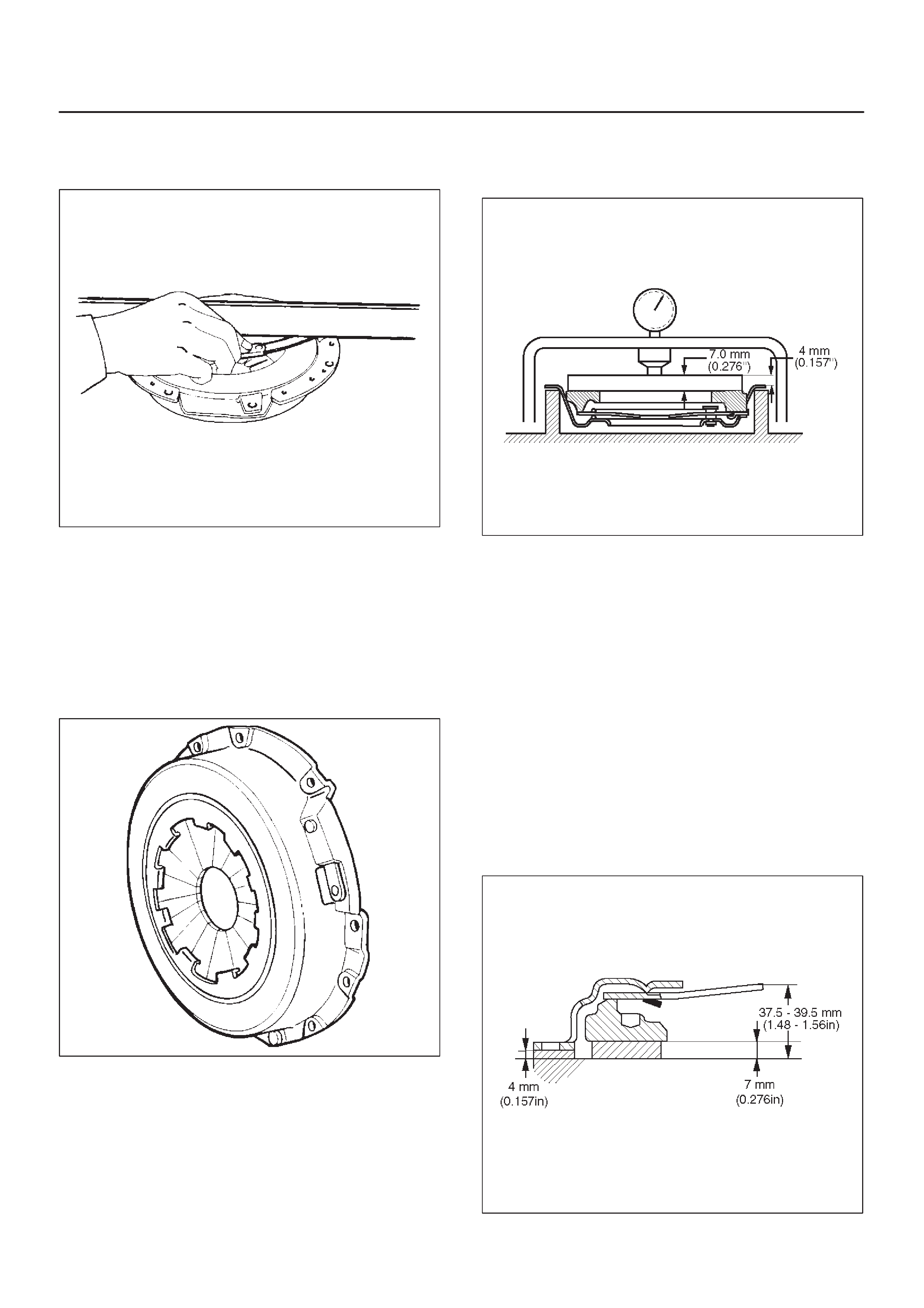
4.Loosen the clutch cover bolts in the numerical order
shown in the illustration.
201RS036
5.Remove pressure plate assembly (2) and driven plate
assembly (3).
6.Remove release bearing (4).
NOTE: The release bearing is permanently packed with
lubricant and should not be soaked in cleaning solvent, as
this will dissolve the lubricant.
7.Remove shift fork.
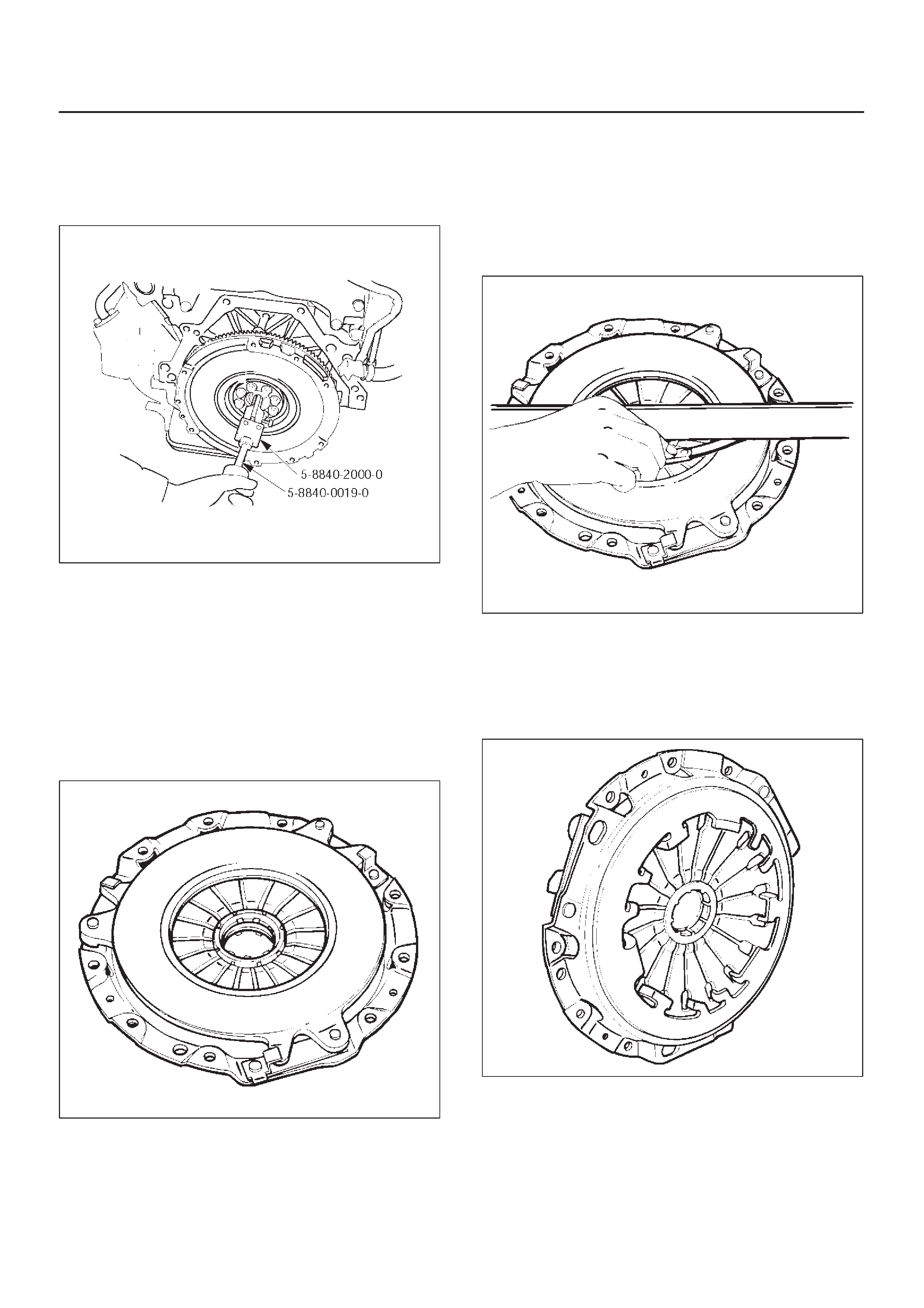
DDo not remove crank shaft bearing (6) except for
replacement.
Remove the crank shaft bearing (6) using remover
5–8840–2000–0 and sliding hammer
5–8840–0019–0.
015RW107
Inspection and Repair
Make necessary adjustments, repairs, and part
replacements if wear, damage, or other problems are
discovered during inspection.
Pressure Plate Assembly
Visually inspect the pressure plate friction surface for
excessive wear and heat cracks. If excessive wear or
deep heat cracks are present, the pressure plate must be
replaced.
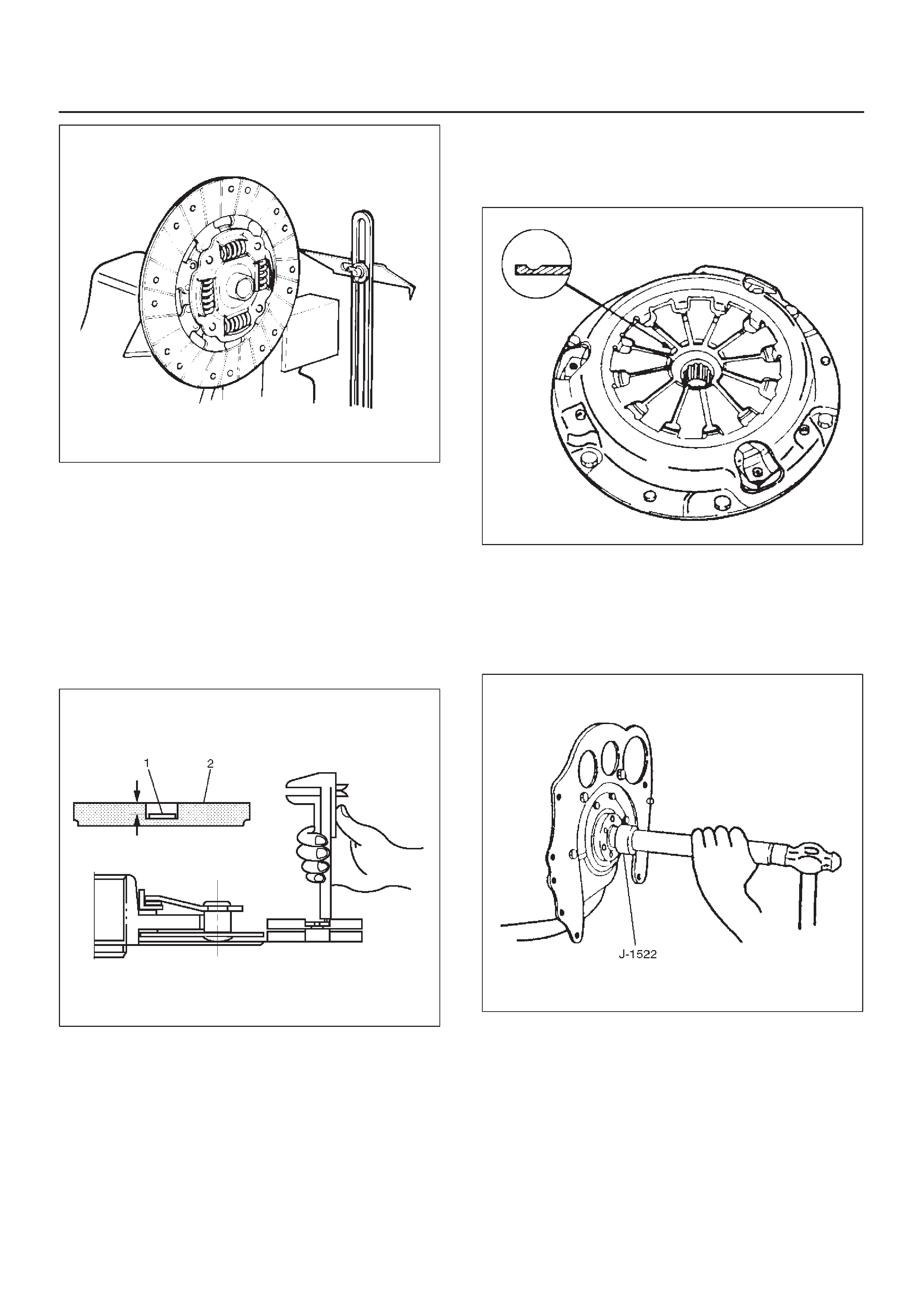
Pressure Plate Warpage
Use a straight edge and a feeler gauge to measure the
pressure plate friction surface flatness in four directions.
201RS038
If any of the measured values exceed the specified limit,
the pressure plate must be replaced.
Pressure Plate Warpage
Limit: 0.3mm (0.012in)
Clutch Cover
Visually inspect the entire clutch cover for excessive
wear, cracking, and other damage. The clutch cover must
be replaced if any of these conditions are present.
201RS039
Clutch Set Force
1.Invert the pressure plate assembly.
2.Place a new driven plate over the pressure plate. A
metal sheet with thickness of 7.0mm (0.276in) may
be used in place of the driven plate.
3.Compress the pressure plate assembly until the
distance becomes 4mm (0.157in).
4.Note the pressure gauge reading.
Clutch Set Force
Standard: 5488N (559 kg/1235lb)
201RY00003
Diaphragm Spring Finger Height
1.Place a 7.0mm (0.276in) spacer beneath the
pressure plate.
2.Fully compress the pressure plate and diaphragm
spring.
There are two ways to do this:
a. Use a bench press to press down on the assembly
from the top.
b. Tighten the fixing bolts.
3.Measure the spring finger height from base to spring
tip.
If the measured value exceeds the specified limit, the
pressure plate assembly must be replaced.
Spring Finger Height
Standard: 37.5 mm – 39.5 mm (1.48 in – 1.56 in)
201RY00001
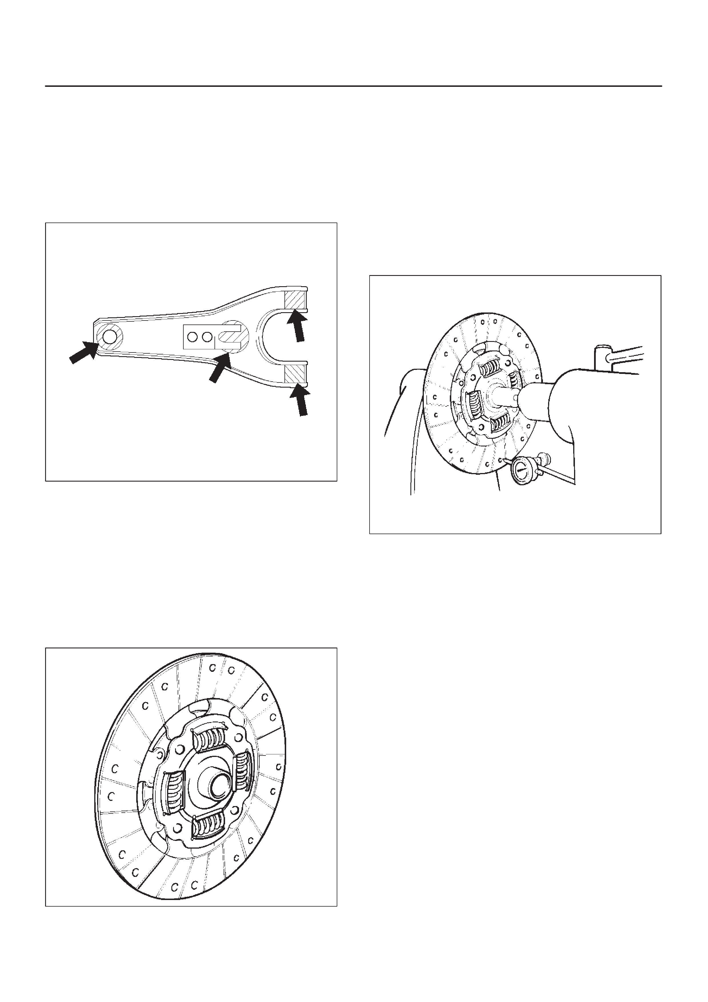
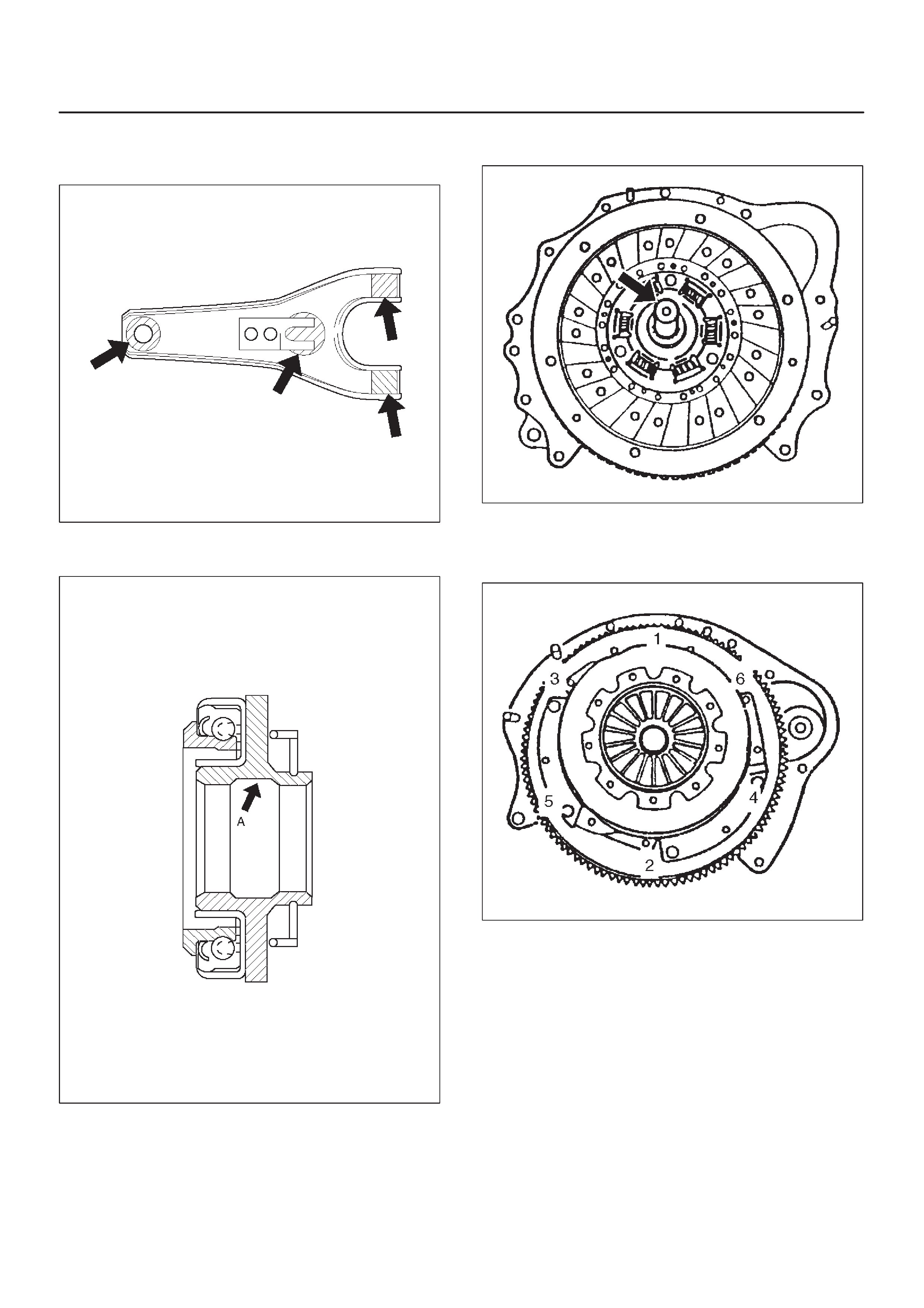
Shift Fork
1.Visually inspect the surfaces of the shift fork making
contact with the shift block.
2.Remove any minor stepping or abrasion from the shift
block with an oil stone.
3.Apply molybdenum disulfide type grease to the areas
as shown in the figure.
MUA
F07RW030
Driven Plate Assembly
1.Visually inspect the torsion spring for looseness,
breakage, and weakening. If any of these conditions
are discovered, the driven plate assembly must be
replaced.
2.Visually inspect the facing surfaces for cracking and
excessive scorching. Visually inspect the facing
surfaces for the presence of oil or grease. If any of
these conditions are discovered, the facing must be
cleaned or replaced.
201RS007
3.Check that the driven plate moves smoothly on the
transmission top gear shaft spline.
Minor ridges on the top gear shaft spline may be
removed with an oil stone.
Driven Plate Warpage
1.Insert the clutch pilot aligner J–42877 (MUA) into the
driven plate splined hub.
The clutch pilot aligner must be held perfectly
horizontal.
2.Set a dial indicator to the driven plate outside
circumference.
201RS008
3.Slowly turn the driven plate. Read the dial indicator as
you turn the driven plate.
If the measured value exceeds the specified limit, the
driven plate assembly must be replaced.
Driven Plate Warpage
Standard: 0.7 mm (0.028 in)
Limit: 1.0 mm (0.039 in)
Driven Plate Splined Hub Spline Wear
1.Clean the driven plate splined hub.
2.Install the driven plate to the transmission top gear
shaft spline.
3.Set a surface gauge to the driven plate outside
circumference.
4.Slowly turn the driven plate counterclockwise.
Measure the spline rotation play as you turn the
driven plate.
Driven Plate Splined Hub Spline Wear
Standard: 0.5 mm (0.020 in)
Limit: 1.0 mm (0.039 in)
201RS009
Rivet Head Depression
Use a depth gauge or a straight edge with steel rule to
measure the rivet head depression (1) from the facing
surface (2).
Be sure to measure the rivet head depression on both
sides of the driven plate. If the measured value is less
than the specified limit, the facing must be replaced.
Rivet Head Depression
Standard: MIN 1.3 mm (0.051 in)
Limit: 0.2 mm (0.008 in)
201RS010
Pressure Plate Assembly
Check the cover for cracks and distortion, and the
diaphragm spring for heat distortion, loosened rivets.
Check the diaphragm spring for wear.
201RS047
Installation
1.Clean and lubricate with grease.
2.Use installer J–1522 to install crankshaft bearing (6).
X22SE
015RS078
3.Apply molybdenum disulfide type grease to the areas
as shown in the figure and install shift fork (5).
MUA
F07RW030
4.Pack the inside recess (A) of the release bearing with
grease as shown in the figure.
201RY00004
5.Install driven plate assembly by using aligner
J–42877 (MUA).
201RS049
6.Tighten the bolts holding the pressure plate assembly
(2) in the order shown in the figure.
Torque: 18N·m (1.8kg·m/13 lb ft)
201RS050
7.Remove the aligner.
NOTE:Do not strike the aligner with a hammer to remove
it.8.Install transmission assembly (1) to the engine. Refer
to Transmission Installation in Manual Transmission
section.
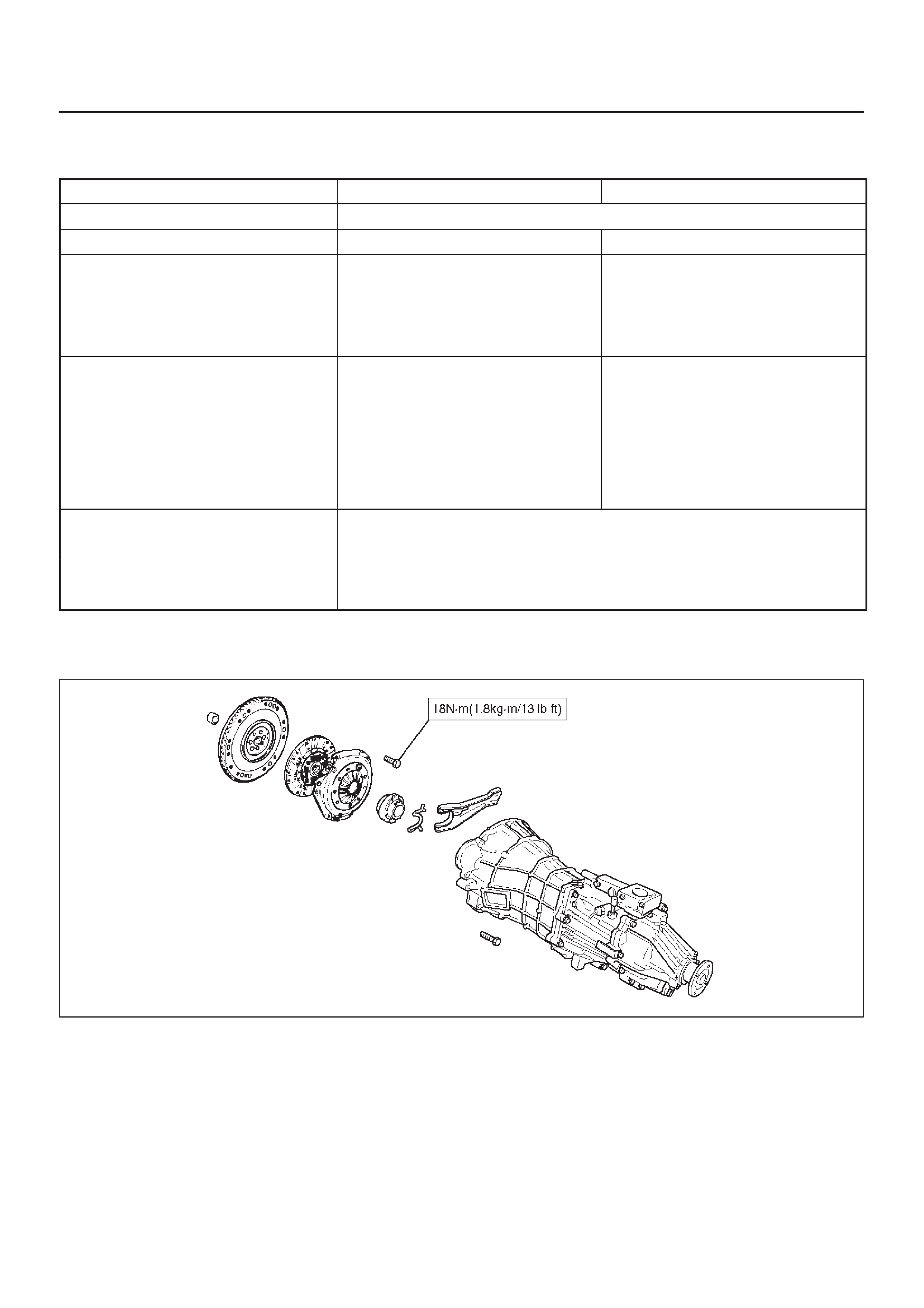
Clutch Assembly (6VD1, MUA)
Clutch Assembly (6VD1, MUA) and Associated Parts
201RS023
Legend
(1)Transmission Assembly
(2)Pressure Plate Assembly
(3)Driven Plate Assembly
(4)Release Bearing
(5)Shift Fork
(6)Fulcrum Bridge
(7)Flywheel Assembly and Crankshaft Bearing
Removal
1.Refer to “MANUAL TRANSMISSION” of Section 7B
for “REMOVAL AND INSTALLATION” procedure of
transmission assembly (1).
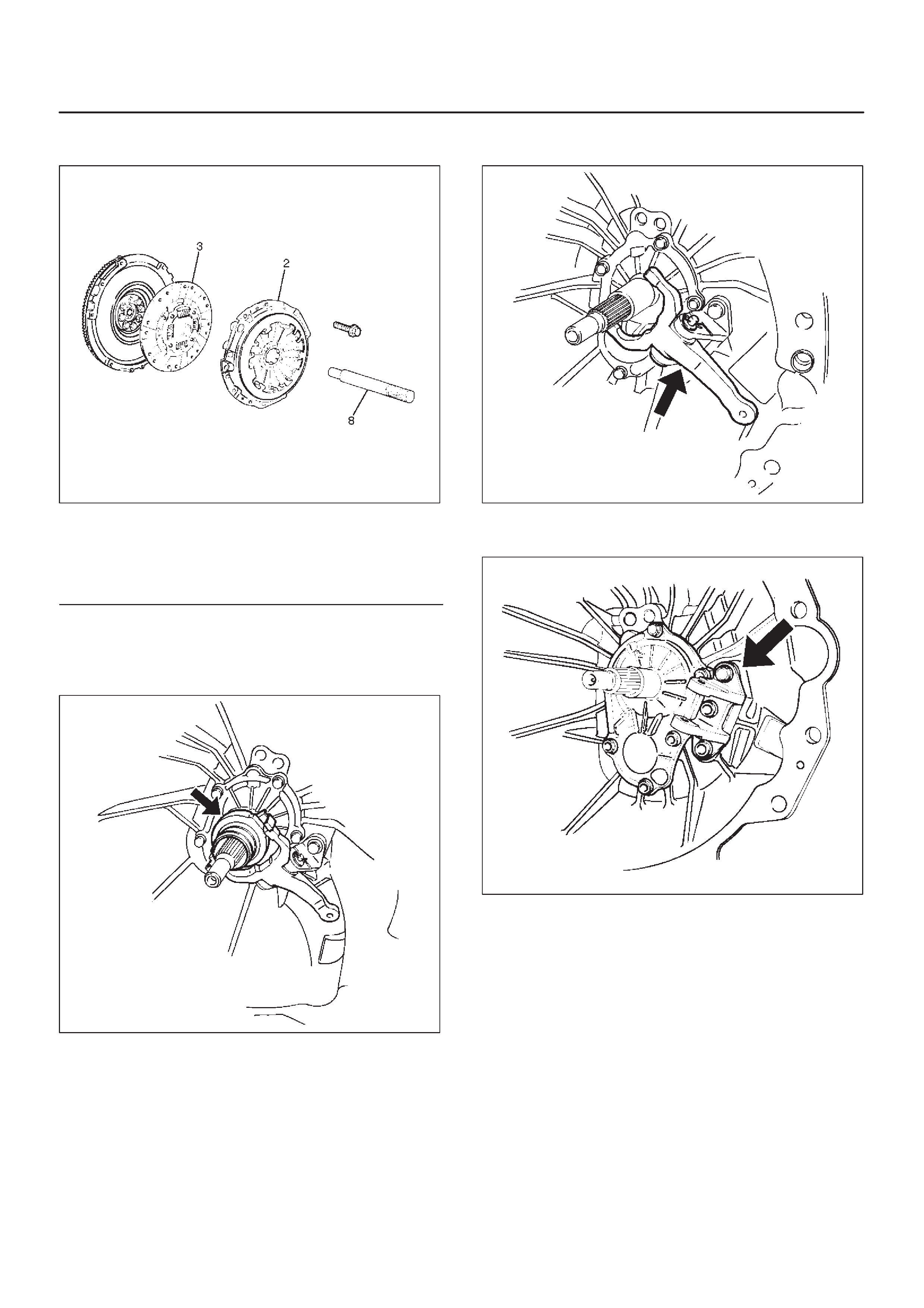
2. Use the pilot aligner J24547 to prevent the driven
plate assembly (3) from falling free.
201RS001
Legend
(2) Pressure Plate Assembly
(3) Driven Plate Assembly
(8) Pilot Aligner
3.Mark the flywheel, clutch cover and pressure plate lug
for alignment when installing.
4.Remove the release bearing (4) from the
transmission case.
201RS024
5.Remove the snap pin. Remove the shift fork pin and
shift fork from the fulcrum bridge.
201RS025
6.Remove the fulcrum bridge bolts. Remove the
fulcrum bridge (6) from the transmission case.
201RS026
DDo not remove crankshaft bearing (7) except for
replacement.
DUse the remover 5–8840–2000–0 and sliding
hammer 5–8840–0019–0 to remove the crankshaft
bearing.
015RW053
Inspection and Repair
Make necessary correction or parts replacement if wear,
damage, or any other abnormal condition are found
through inspection.
Pressure Plate Assembly
DVisually check the pressure plate friction surface for
excessive wear and heat cracks. If excessive wear or
deep heat cracks are present, the pressure plate
must be replaced.
201RS002
Pressure Plate Warpage
DUse a straight edge and a feeler gauge to measure
the pressure plate friction surface flatness in four
directions. If any of the measured values exceed the
specified limit, the pressure plate must be replaced.
Pressure Plate Warpage
Limit: 0.3 mm (0.012 in)
201RS003
Clutch Cover
DVisually check the entire clutch cover for excessive
wear , cracking, and other damage. The clutch cover
must be replaced if any of these conditions are
present.
201RS004
Clutch Set Force
1.Invert the pressure plate assembly.
2.Place a new driven plate over the pressure plate. A
metal sheet with thickness of 8.0mm (0.315in) may
be used in place of the driven plate.
3.Compress the pressure plate assembly until the
distance becomes 12mm (0.472in).
4.Note the pressure gauge reading. If the measured
value is less than the specified limit, the pressure
plate assembly must be replaced.
Clutch Set Force
Standard: 7208N (735 kg/1621lb)
Limit: 6669N (980 kg/1499lb)
201RW014
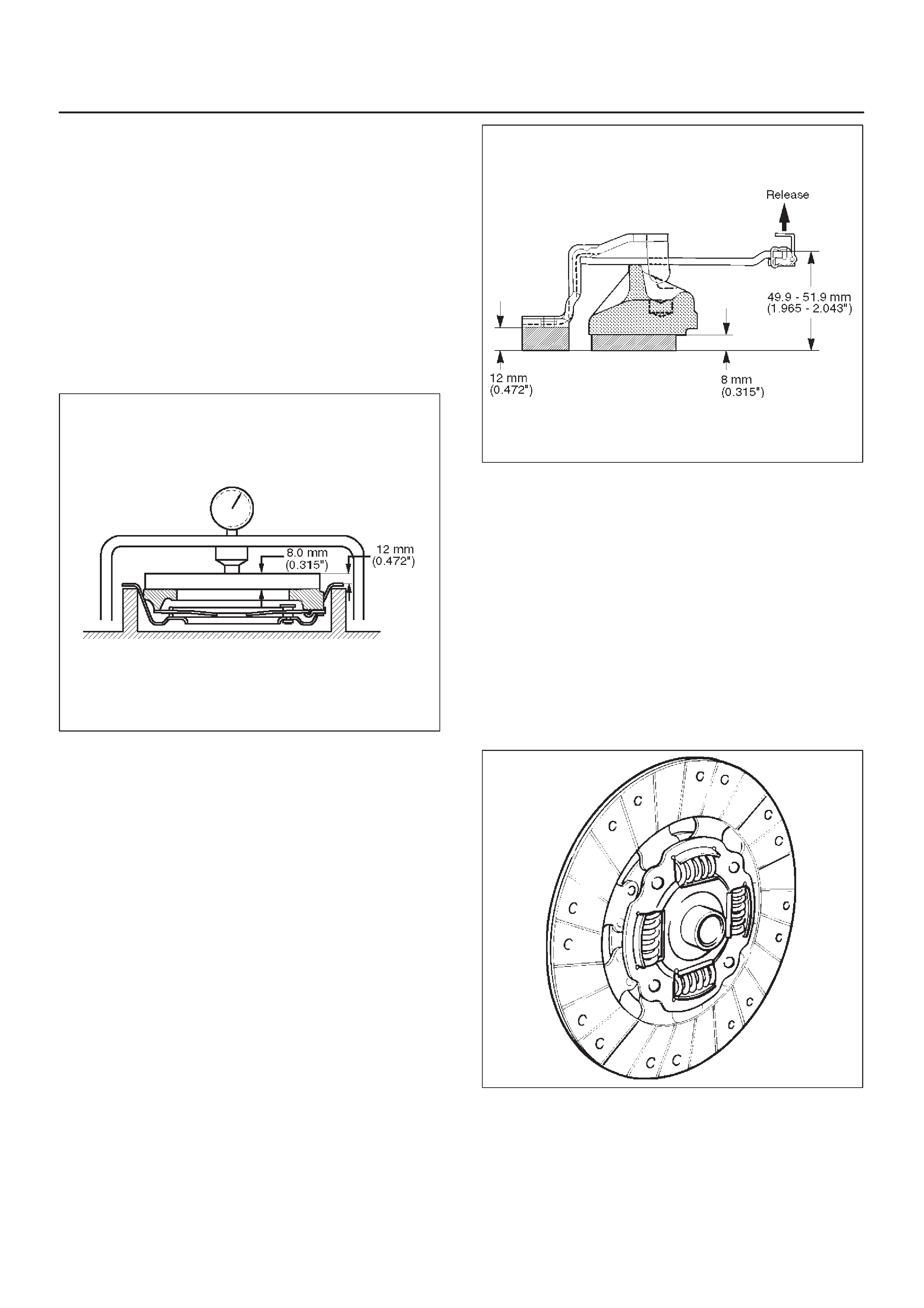
Diaphragm Spring Finger Height
1.Place a new driven plate or a 8.0mm (0.315in) spacer
beneath the pressure plate.
2.Fully compress the pressure plate and diaphragm
spring.
There are two ways to do this:
a. Use a bench press to press down on the assembly
from the top.
b. Tighten the fixing bolts.
NOTE: Preload on diaphragm spring finger must be
4998N (510 kg/1122lb) in direction of release, when
clutch cover assembly is bolted to the flywheel.
3.Measure the spring height from base to spring tip. If
the measured value exceeds the specified limit, the
pressure plate assembly must be replaced.
Spring Finger Height
Standard: 49.9 – 51.9 mm (1.965– 2.043 in)
201RW016
Driven Plate Assembly
DVisually check the torsion spring for looseness,
breakage, and weakening. If any of these conditions
are discovered, the driven plate assembly must be
replaced.
DVisually check the facing surfaces for cracking and
excessive scorching. Visually inspect the facing
surfaces for the presence of oil or grease. If any of
these conditions are discovered, the facing must be
cleaned or replaced.
DCheck that the driven plate moves smoothly on the
transmission top gear shaft spline. Minor ridges on
the top gear shaft spline may be removed with an oil
stone.
201RS007
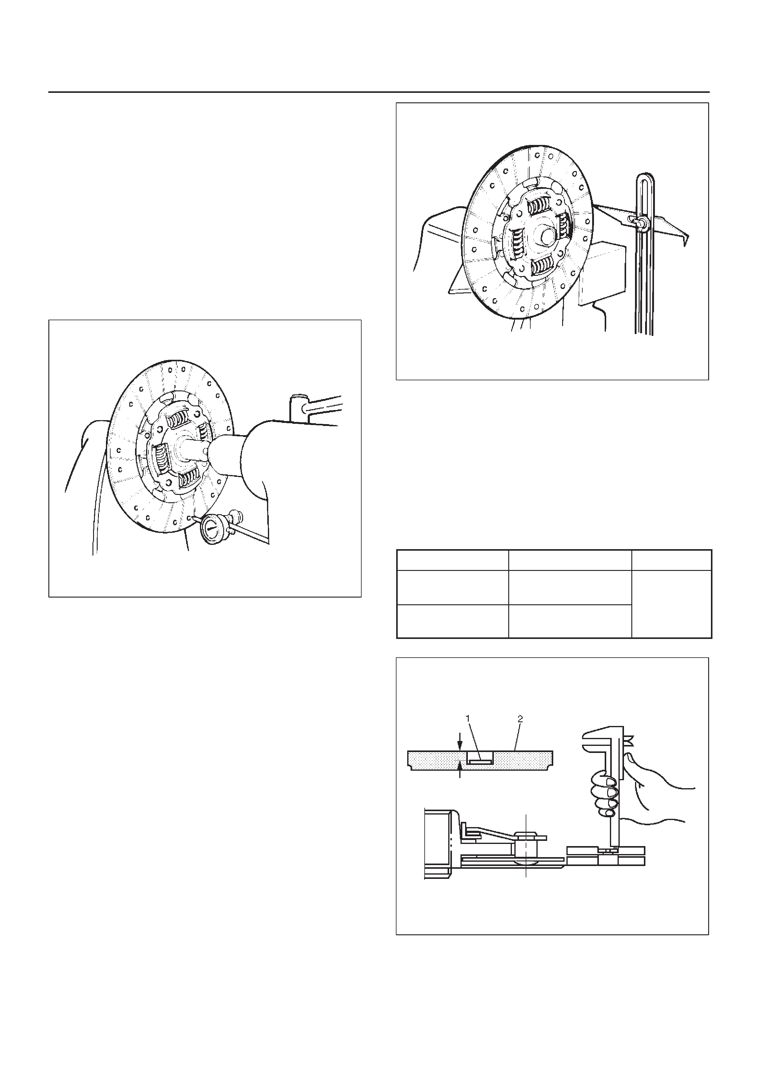
Driven Plate Warpage
1.Insert the clutch pilot aligner J–24547 into the driven
plate splined hub. The clutch pilot aligner must be
held perfectly horizontal.
2.Set a dial indicator to the driven plate outside
circumference.
3.Slowly turn the driven plate. Read the dial indicator as
you turn the driven plate. If the measured value
exceeds the specified limit, the driven plate assembly
must be replaced.
Driven Plate Warpage
Standard: 0.7mm (0.028in)
Limit: 1.0mm (0.039in)
201RS008
Driven Plate Splined Hub Spline Wear
1.Clean the driven plate splined hub.
2.Install the driven plate to the transmission top gear
shaft spline.
3.Set a surface gauge to the driven plate outside
circumference.
4.Slowly turn the driven plate counterclockwise.
Measure the spline rotation play as you turn the
driven plate. If the measured value exceeds the
specified limit, the driven plate assembly must be
replaced.
Driven Plate Warpage
Standard: 0.5mm (0.020in)
Limit: 1.0mm (0.039in)
201RS009
Rivet Head Depression
DUse a depth gauge or a straight edge with steel rule to
measure the rivet head depression (1) from the facing
surface (2).
DBe sure to measure the rivet head depression on both
sides of the driven plate. If the measured value is less
than the specified limit, the driven plate assembly
must be replaced.
Rivet Head Depression
Standard Limit
Fly wheel side 1.2–1.8mm
(0.047–0.071in) 0.2mm
Pressure plate
side 1.6–2.2mm
(0.062–0.087in) (0.008in)
201RS010
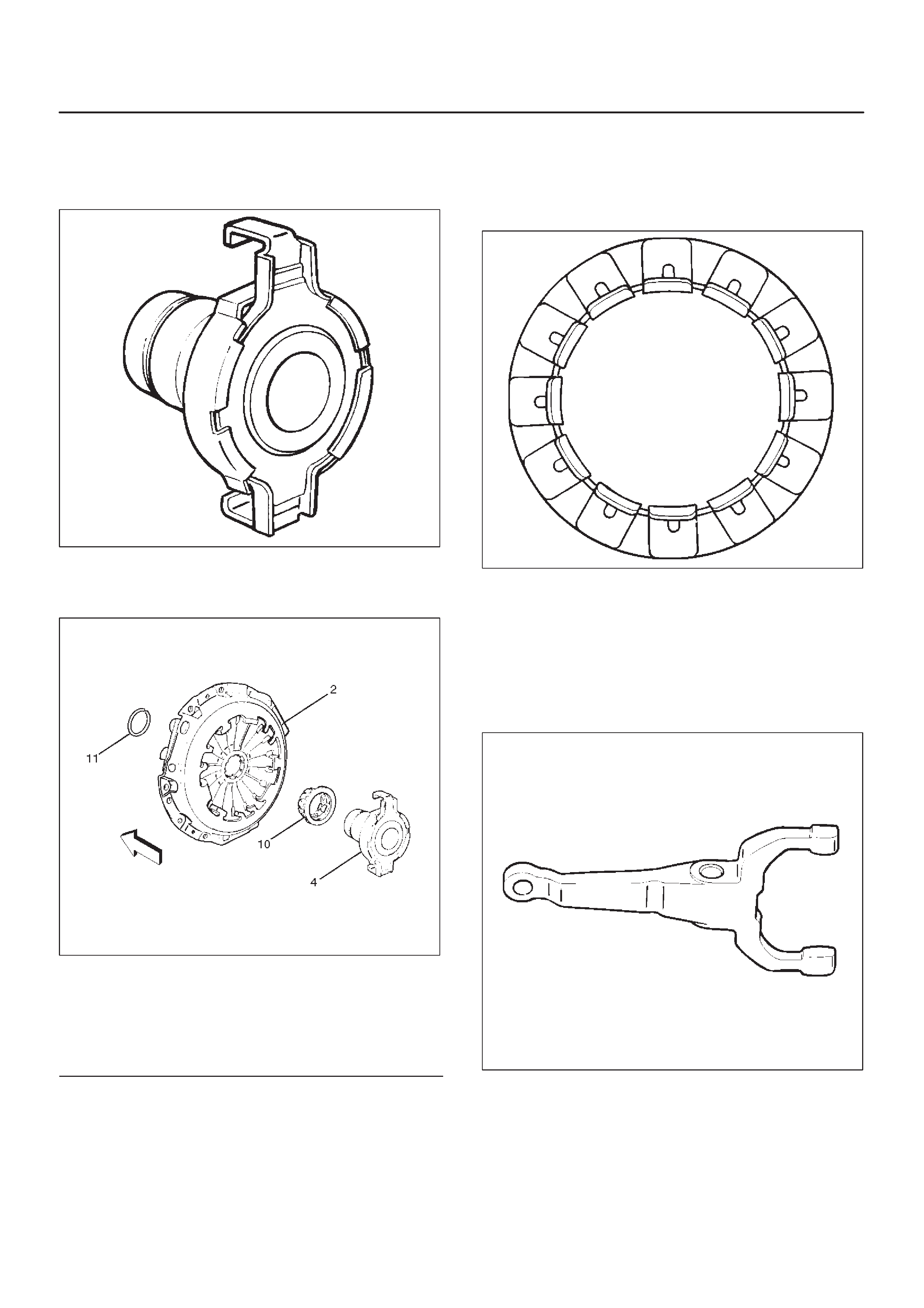
Release Bearing
DVisually check the release bearing for excessive play ,
noise and breakage. If any of these conditions are
discovered, the release bearing must be replaced.
201RS011
DWhen replacing the release bearing (4), replace both
the wedge collar (10) and wire ring (11) at the same
time.
201RS012
Legend
(2) Pressure Plate Assembly
(4) Release Bearing
(10) Wedge collar
(11) Wire Ring
Wedge Collar (10)
DVisually check the surfaces of the wedge collar
making contact with the release bearing for excessive
wear and damage.
DReplace exhibiting excessive wear or damage.
201RS013
Shift Fork
DVisually check the surfaces of the shift fork making
contact with the release bearing for excessive wear
and damage.
DRemove any minor stepping or abrasion from shift
fork with an oil stone. Replace exhibiting excessive
wear or damage.
201RS014
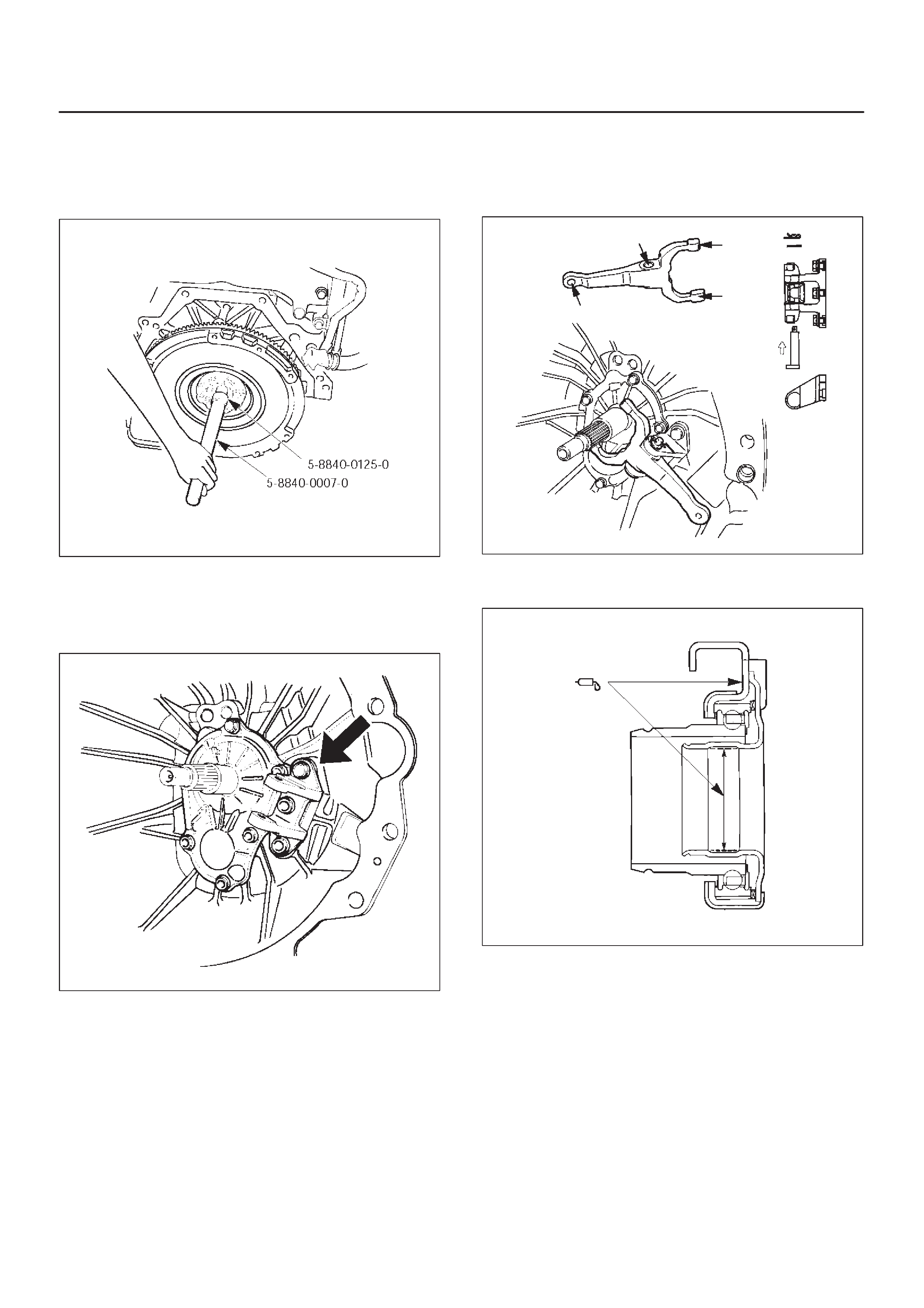
Installation
1.Clean and lubricate with grease.
2.Use the installer 5–8840–0125–0 and driver handle
5–8840–0007–0 to install the crankshaft bearing (7).
015RW054
3.Install the fulcrum bridge (6) to the transmission case.
Tighten three fulcrum bridge bolts to the specified
torque.
Torque: 38 N·m (28 lb ft)
201RS026
4.Apply molybdenum disulfide type grease to the pin
hole inner circumferences and thrust surfaces.
Attach the shift fork (5) to the fulcrum bridge (6) and
insert the pin from below of the fulcrum bridge. Install
the washer and snap pin.
201RS018
5.Apply molybdenum disulfide type grease to the areas
shown in the figure.
201RW012

Install the release bearing (4) in the proper direction.
NOTE: Ensure release bearing is properly positioned
during installation, as shown in the figure.
201RS019
6. Use the pilot aligner 5–85253–001–0 to install the
driven plate assembly (3).
201RX004
7.Tighten the bolts holding the pressure plate assembly
(2) in the order shown in the figure.
201RS017
Torque: 18 N·m (1.8 kg·m/13 lb ft)
8.Remove the aligner.
NOTE: Do not strike the aligner with a hammer to remove
it.9.Install transmission assembly to the engine.
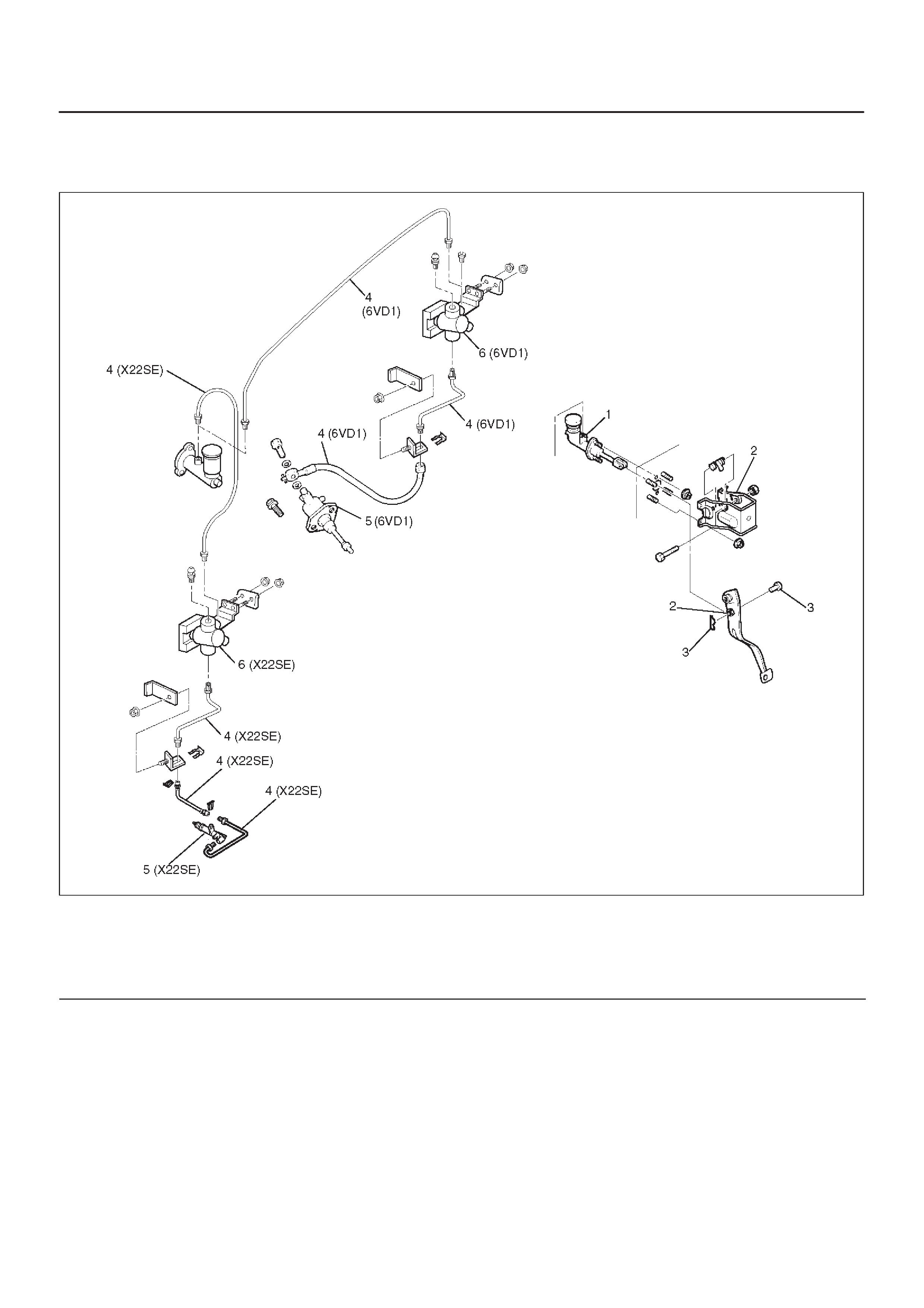
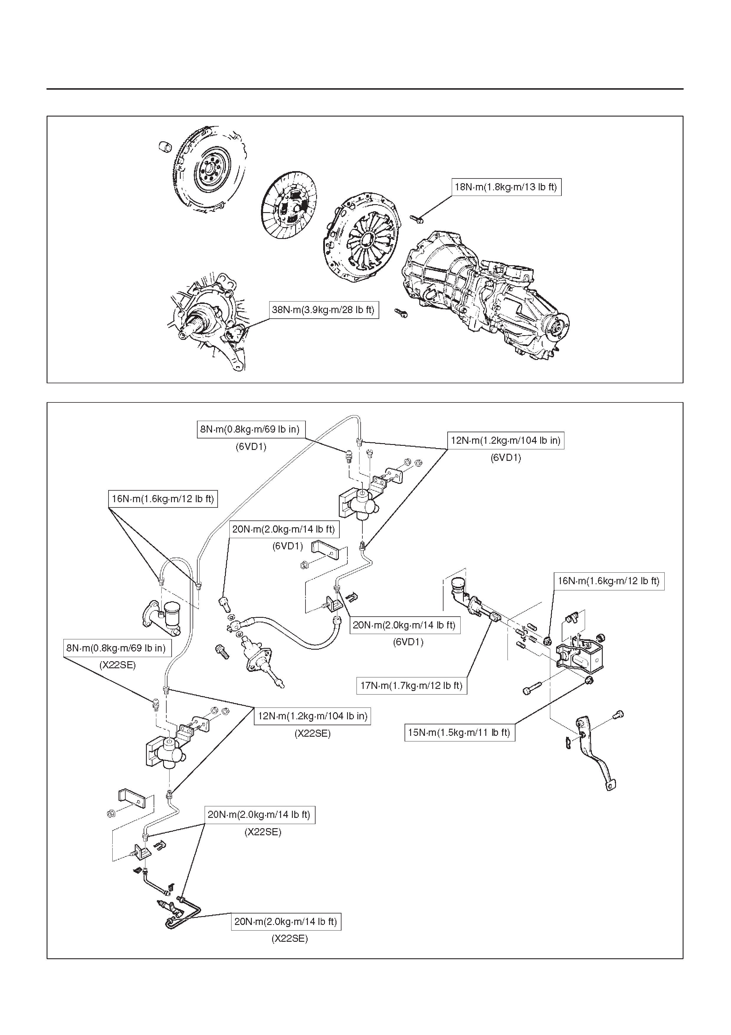
Clutch Control
Parts Location View
203RX001
Legend
(1) Master Cylinder Assembly
(2) Pedal Assembly
(3) Pin and Jaw Joint Pin
(4) Oil Line Pipe and Hose
(5) Slave Cylinder Assembly
(6) Damper Cylinder Assembly
Removal
1.Disconnect the ground battery cable.
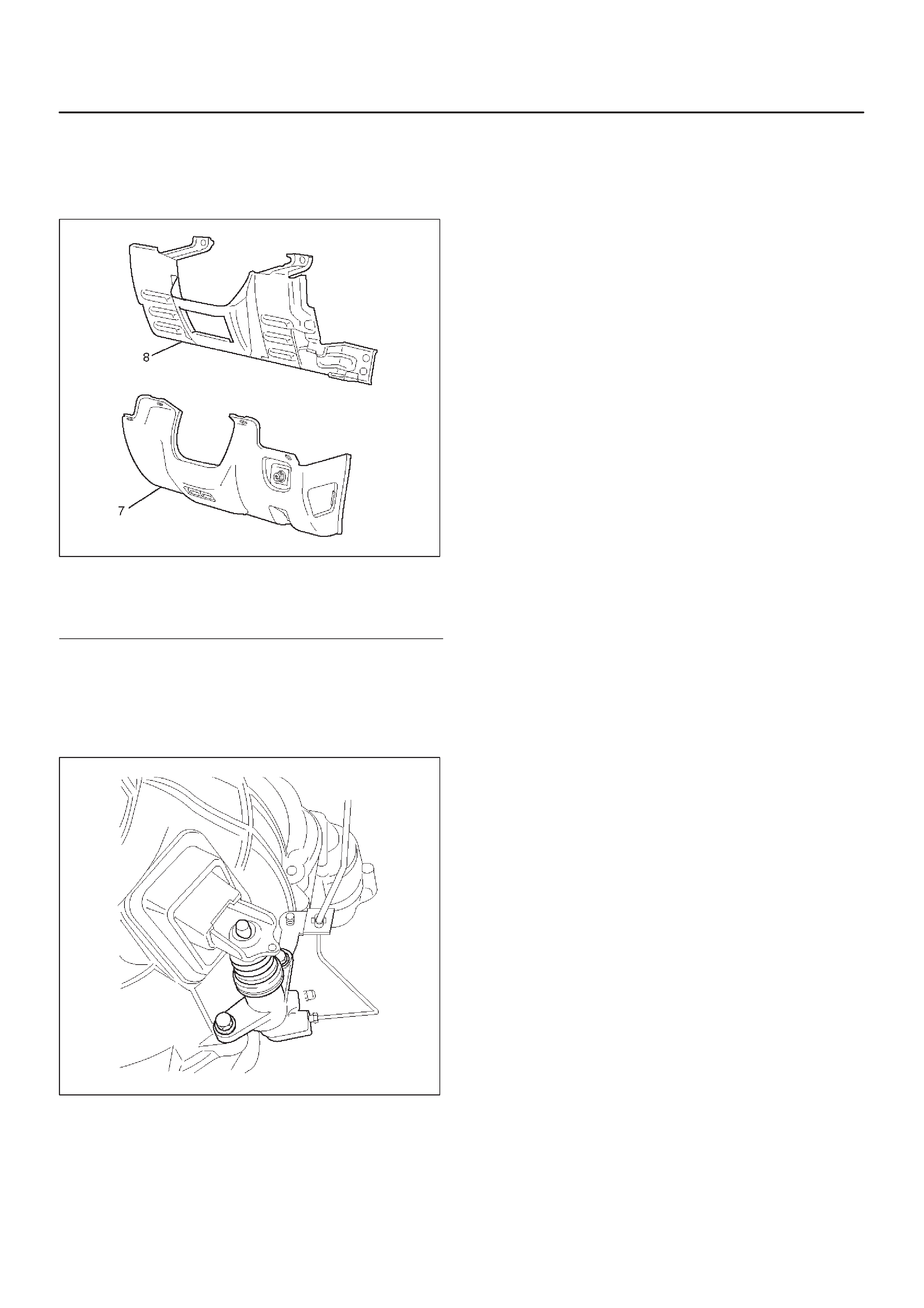
2. Remove the instrument panel lower cover (7) and
driver knee bolster panel assembly (8).
740RW162
Legend
(7) Driver Lower Cover
(8) Driver Knee Bolster Panel
3.Remove pin and jaw joint pin (3).
4.Remove pedal assembly (2).
5.Remove oil line pipe (4).
6.Remove slave cylinder assembly (5).
X22SE MUA
205RW001
7.Remove master cylinder assembly (1).
8.Remove damper cylinder assembly (6).
9.Remove oil line hose (5).
Inspection and Repair
Make necessary adjustments, repairs, and part
replacements if wear, damage or other problems are
discovered during inspection.
Installation
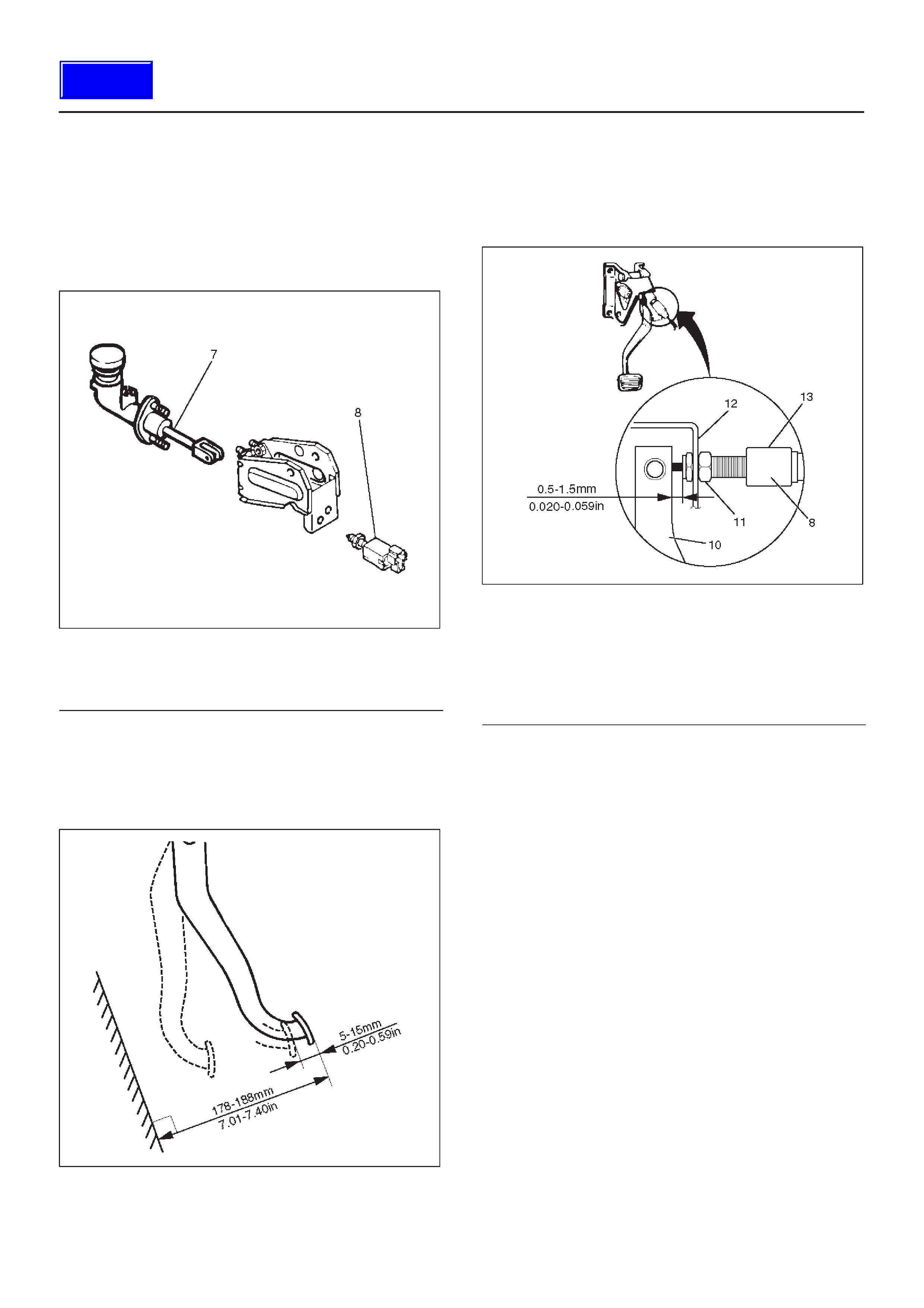
Clutch Pedal Adjustment
1.With clutch switch.
1. Disconnect clutch switch connector.
2. Loosen lock nut, then turn switch out until there is
a gap between the switch plunger and clutch
pedal.
208RX004
Legend
(7) Push Rod
(8) Clutch Switch
2.Loosen clutch master cylinder push rod lock nut. Turn
push rod by hand to set clutch pedal height to within
specification. Tighten push rod lock nut.
Clutch Pedal Height
178 – 188 mm (7.01 – 7.40 in)
F07RW026
3.With clutch switch.
1. Turn the clutch switch until the switch bolt just
touches the clutch pedal arm.
2. Adjust clutch switch by backing it out half a turn,
and measure the clearance between the clutch
pedal arm and the clutch switch bolt end.
F07RW027
Legend
(8) Clutch Switch
(10) Clutch Pedal Arm
(11) Lock Nut
(12) Bracket
(13) Back Out Switch 1/2 Turn
3. Lock the lock nut.
4. Connect clutch switch connector.
Clutch Switch and Clutch Pedal Clearance
0.5 – 1.5 mm (0.020 – 0.059 in)
4.After adjusting the clutch pedal height, push the
clutch pedal by hand to ensure the clutch pedal free
play is within specification.
Pedal Free Play
5 – 15 mm (0.20 – 0.59 in)
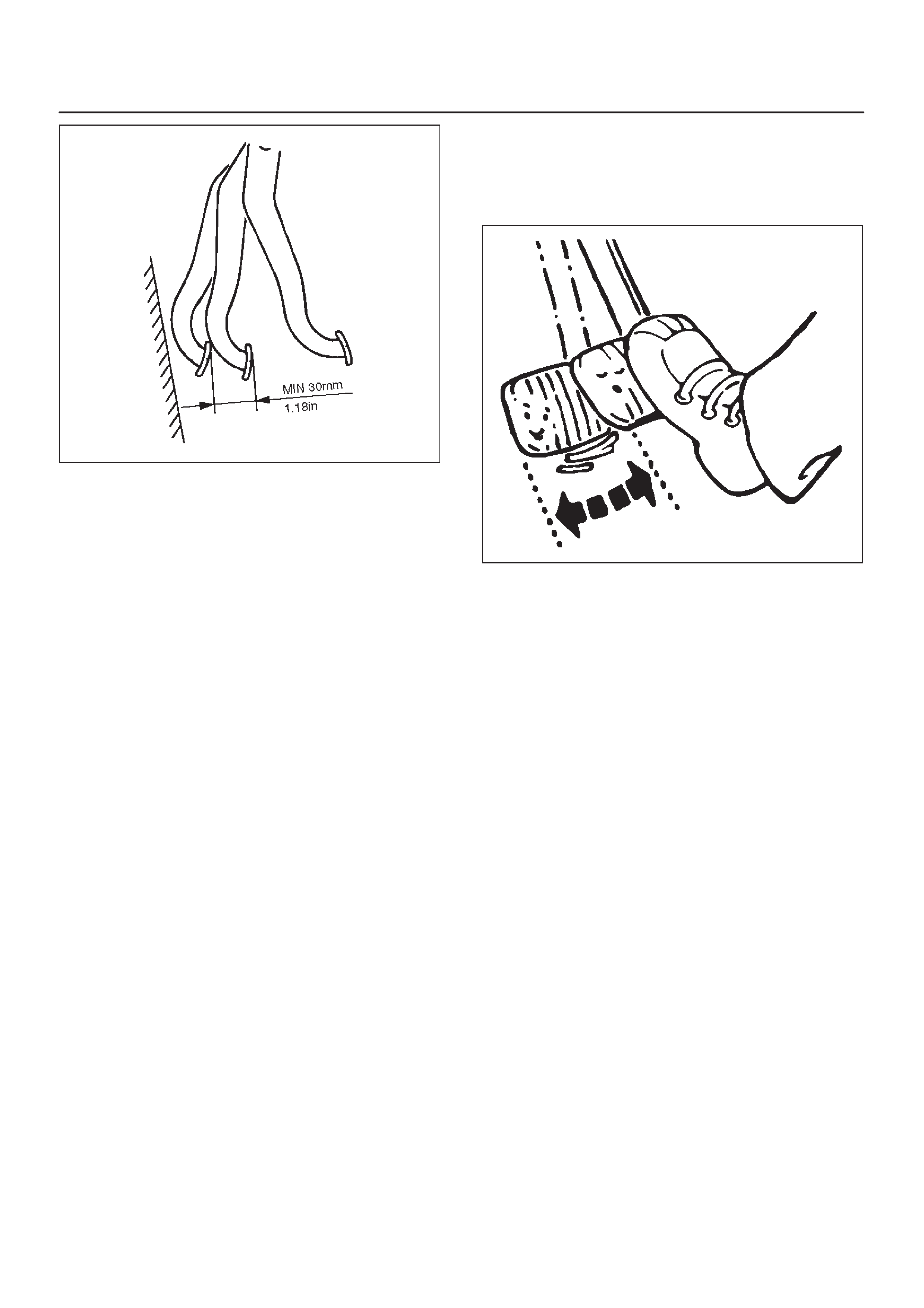
5.Perform clutch pedal engagement height inspection:
1. Operate the parking brake lever and block the
wheels.
2. Start the engine, fully step on the clutch pedal
slowly and move the shift lever 1st position.
3. With the engine idling, release the clutch pedal
slowly and measure its stroke – just prior to its
clutching position.
Clutch Pedal Engagement Height (H3)
MIN. 30 mm (1.18 in)
Techline
F07RW028
6. If the measured value exceeds the specified limit,
check the following points and repair if necessary:
DHydraulic circuit for fluid leakage or air in circuit.
DClutch disc warped.
DDiaphragm spring weakened or tip of fingers worn.
DDriven plate sticking on sprines.
DRelease bearing worn or damaged.
DMaster cylinder and slave cylinder worn.
Torque
DMaster cylinder to dash panel
16 N·m (1.6 kg·m/12 lb ft)
DClutch pedal to dash panel
15 N·m (1.5 kg·m/11 lb ft)
DMaster cylinder push rod to yoke
17 N·m (1.7 kg·m/12 lb ft)
DClutch pipe to master cylinder
20 N·m (2.0 kg·m/14 lb ft)
DClutch pipe to damper cylinder
12 N·m (1.2 kg·m/104 lb in)
DClutch pipe to flex, hose
20 N·m (2.0 kg·m/14 lb ft)
DFlexible hose to slave cylinder (6VD1)
20 N·m (2.0 kg·m/14 lb ft)
DSlave cylinder to case
40 N·m (4.1 kg·m/30 lb ft)
DSlave cylinder bleeder screw
8 N·m (0.8 kg·m/69 lb in)
DClutch pipe to slave cylinder (X22SE)
20 N·m (2.0 kg·m/14 lb ft)
Bleeding
1. Check the level of clutch fluid in the reservoir and
replenish if necessary.
2.Bleeding the slave cylinder.
1. Remove the rubber cap from the bleeder screw
and wipe clean the bleeder screw. Connect a
vinyl tube to the bleeder screw and insert the
other end of the vinyl tube into a transparent
container.
2. Pump the clutch pedal repeatedly and hold it
depressed.
203RS005
3. Loosen the bleeder screw to release clutch fluid
with air bubbles into the container, then tighten
the bleeder screw immediately.
4. Release the clutch pedal carefully. Repeat the
above operation until air bubbles disappear from
the clutch fluid being pumped out into the
container. During the bleeding operation, keep
the clutch fluid reservoir filled to the specified
level. Reinstall the rubber cap.
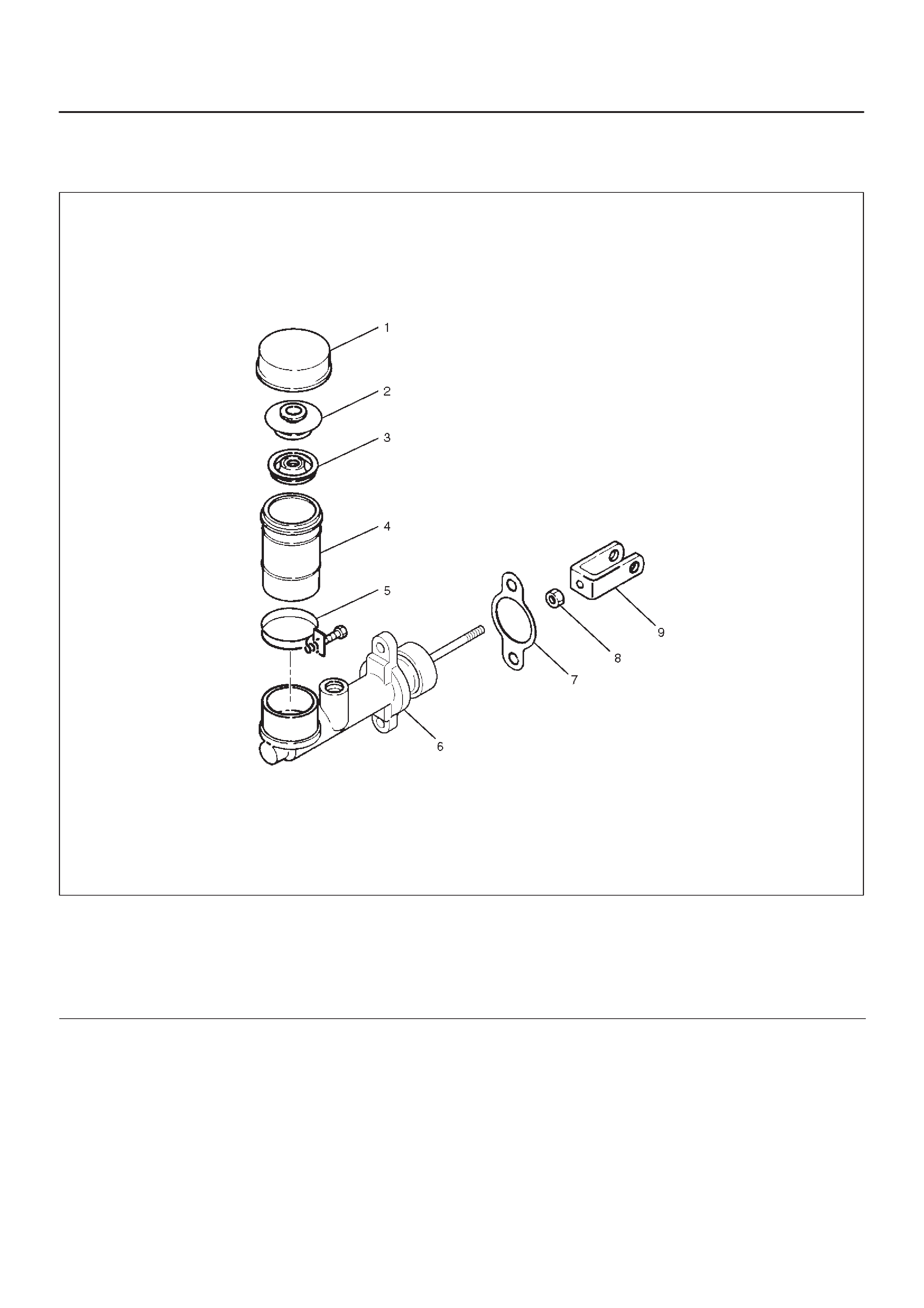
Master Cylinder
208RX003
Legend
(1) Reservoir Cap
(2) Inner Cap
(3) Seal
(4) Reservoir
(5) Clip
(6) Body Sub Assembly
(7) Gasket
(8) Nut
(9) Yoke
Disassembly
1.Disassemble reservoir cap (1), inner cap (2), seal (3),
clip (5), and reservoir (4).
2.Disassembly gasket (7), yoke (9), nut (8) and body
sub assembly.
Inspection and Repair
Make the necessary adjustments, repair, and part
replacements if excessive wear or damage is discovered
during inspection.
Reassembly
To reassemble, follow the disassembly steps in the
reverse order.
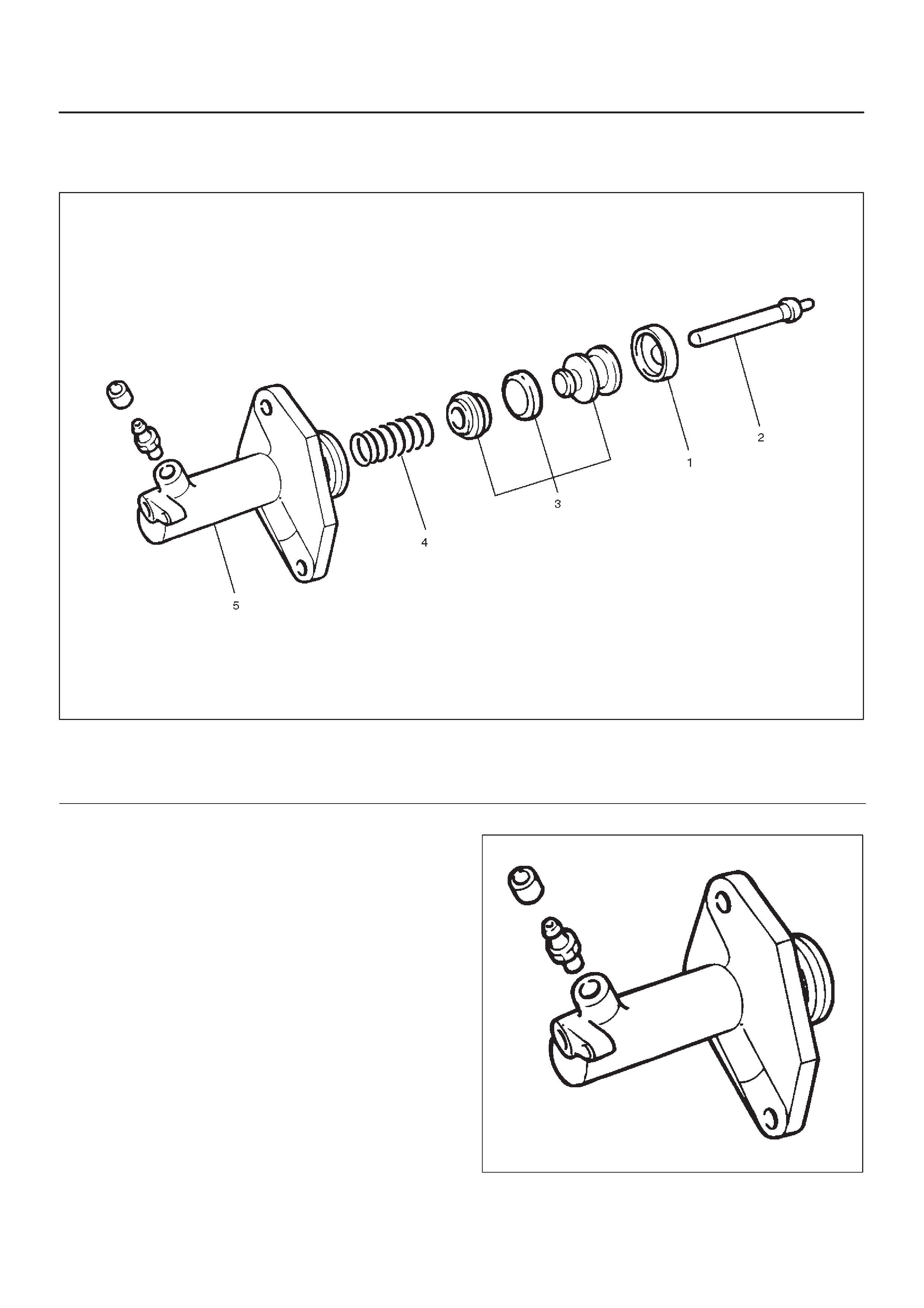
Slave Cylinder
Disassembled View
206RS002
Legend
(1) Push Rod
(2) Boot
(3) Piston and Piston Cup
(4) Spring
(5) Cylinder Body
Disassembly
1.Disassemble boot (1), push rod (2), piston and piston
cup (3), and spring (4) from cylinder body (5).
Inspection and Repair
Make the necessary adjustments, repairs, and part
replacements if excessive wear or damage is discovered
during inspection.
Cylinder Body
1.Clean the cylinder body.
2.Check the fluid return port for restrictions and clean it
if necessary.
206RS003
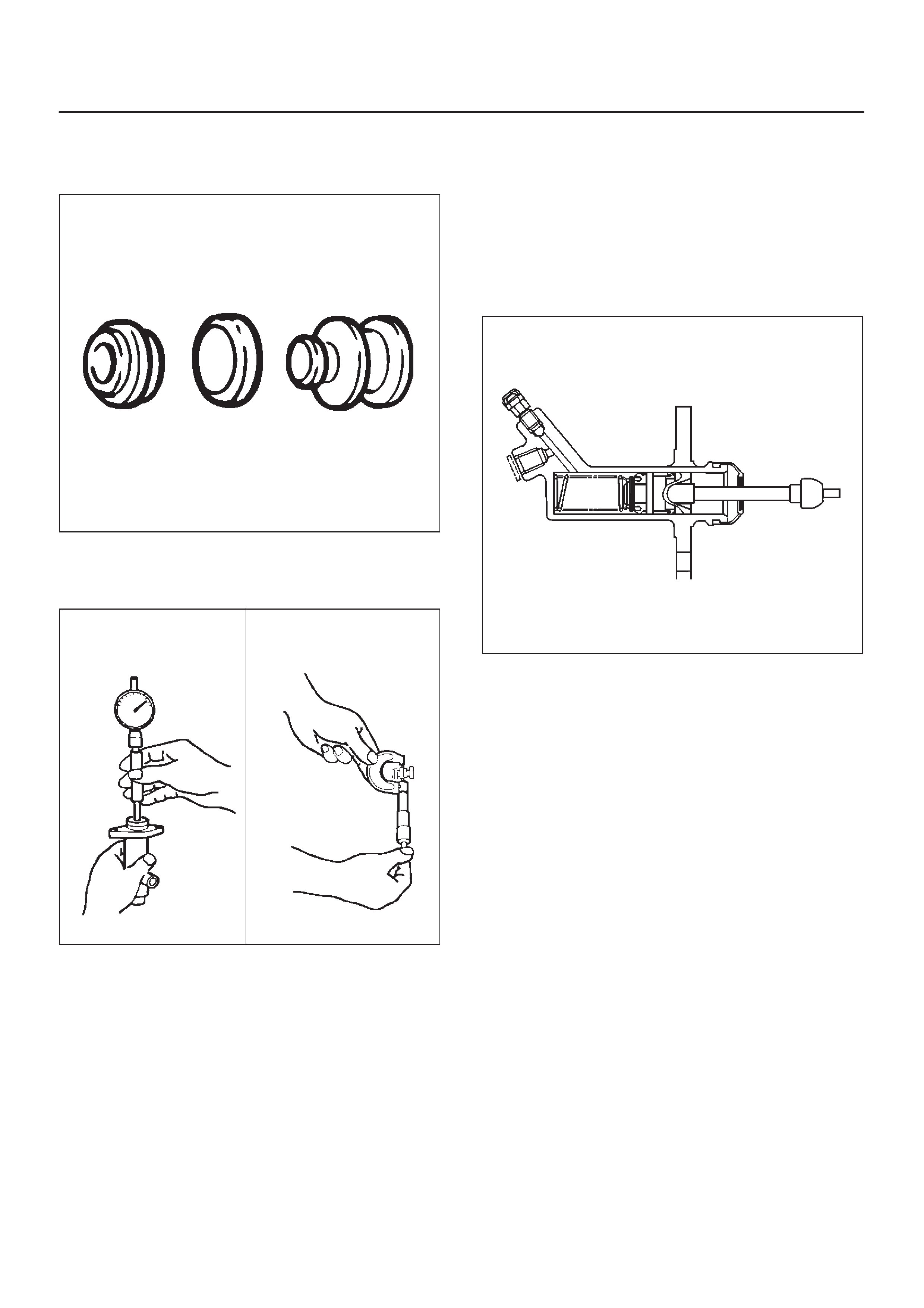
Piston and Piston Cup
1.Visually inspect the disassembled piston and piston
cup for excessive wear and damage.
206RS004
Replace the inner parts with new parts if necessary.
2.Measure the clearance between slave cylinder wall
and piston.
206RS005
If the measured value exceeds the specified limit, the
slave cylinder assembly must be replaced.
Standard: 0.07 mm (0.0028 in)
Limit: 0.15 mm (0.0059 in)
Reassembly
To reassemble, follow the disassembly steps in the
reverse order, noting the following points:
Piston Assembly
1.Before installing the parts, apply a thin coat of rubber
grease.
2.Install cup in groove in piston with the lip turned to the
front of cylinder. Use care so as not to scratch the
cylinder.
206RS006
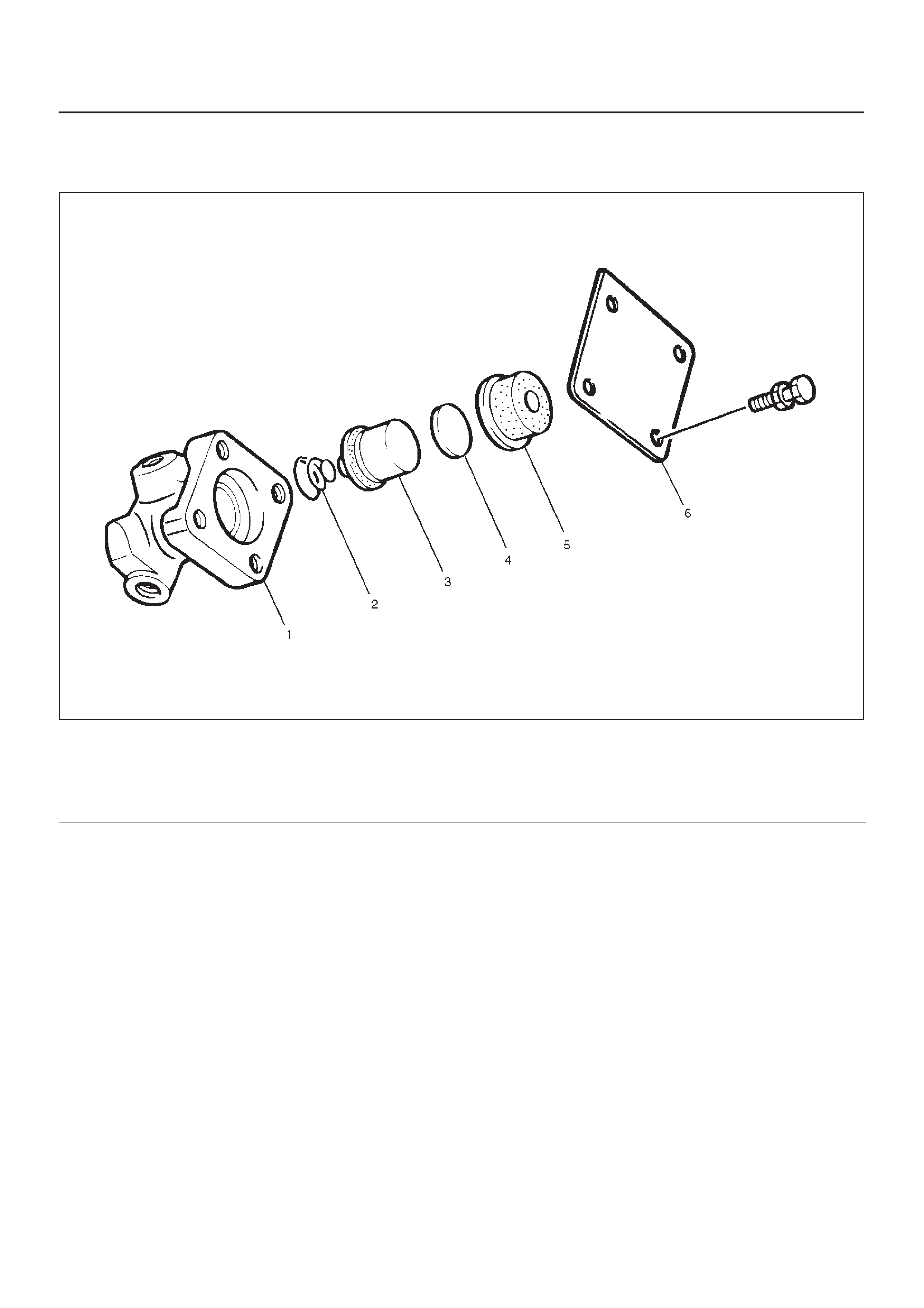
Damper Cylinder
Disassembled View
205RW005
Legend
(1) Cylinder Body
(2) Spring
(3) Piston Assembly
(4) Spacer
(5) Damper Rubber
(6) Cover and Gasket
Disassembly
1.Disassembly cover and gasket (6).
2.Disassembly damper rubber (5).
3.Disassembly spacer (4).
4.Disassembly piston assembly (3).
5.Disassembly spring (2).
6.Disassembly cylinder body (1).
Inspection and Repair
Check damper rubber and piston cup for cracks,
deformation or damage.
Replace the damper cylinder assembly if necessary.
Reassembly
To assemble, follow the disassembly steps in the reverse
order.
Main Data and Specifications
General Specifications
Engine X22SE 6VD1
Type Dry single plate type with diaphragm spring
Size 240 mm (9.45 in) 260 mm (10.24 in)
Pressure plate
Outside diameter 299 mm (11.77 in) 332 mm (13.07 in)
Clamping force 5488 N (1235 lb) 7208 N (1621 lb)
Spring finger height 37.5 – 39.5 mm (1.476 – 1.555 in) 49.9 – 51.9 mm (1.965 – 2.043 in)
Driven plate
Outside diameter × inside diameter 240 × 160 mm (9.45 × 6.30 in) 260 × 170 mm (10.24 × 6.70 in)
Thickness
Clutch disengaged 7.3 mm (0.287 in) 8.6 mm (0.339 in)
Clutch engaged 7.0 mm (0.276 in) 8.0 mm (0.315 in)
Total friction area 251 × 2 cm@ (39 × 2 in@) 304 × 2 cm@ (47 × 2 in@)
Clutch control type Hydraulic
Clutch pedal free play 5 – 15 mm (0.20 – 0.59 in)
Clutch pedal stroke 165.5 –175.5 mm (6.52 – 6.91 in)
Clutch pedal height 178 – 188 mm (7.01 – 7.40 in)
Torque Specifications
X22SE, MUA
E07RX019
6VD1, MUA
E07RX020
205RY00001
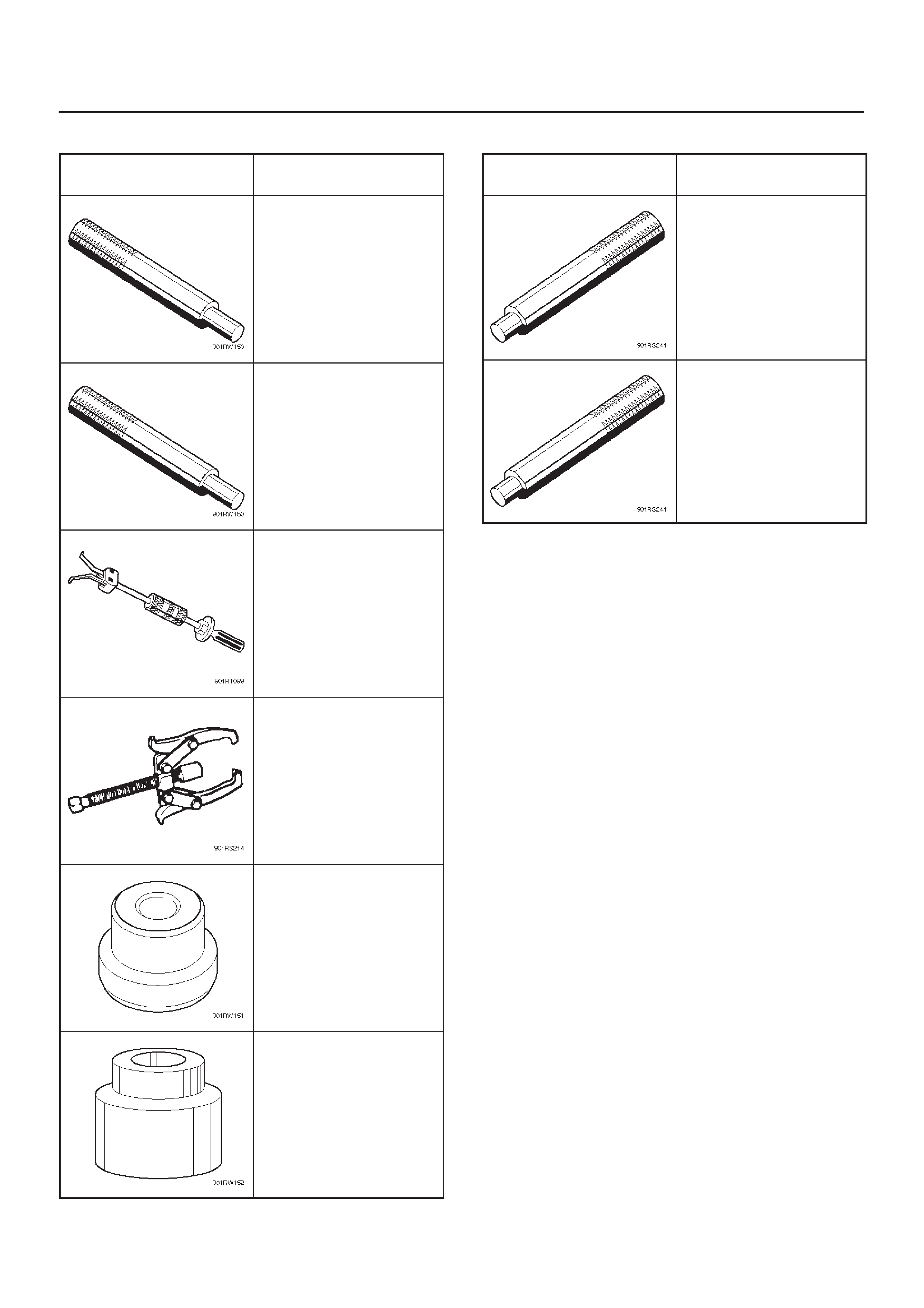
Special Tools
ILLUSTRATION PART NO.
PART NAME
5–85253–001–0
Driven plate aligner
(6VD1)
J–42877
Driven plate aligner
(X22SE MUA)
5–8840–2000–0
5–8840–0019–0
Pilot bearing remover
and Sliding hammer
5–8840–0013–0
Bearing puller
5–8840–0124–0
Adapter
5–8840–0007–0
Crankshaft pilot bearing
installer (6VD1)
ILLUSTRATION PART NO.
PART NAME
J–1522
Crankshaft pilot bearing
installer (X22SE)
5–8840–0007–0
Driver handle