
SECTION 8D - WIRING SYSTEM
Service Precaution
General Description
Main Data and Specifications
Fuse, Fusible Link and Circuit Breaker
Location
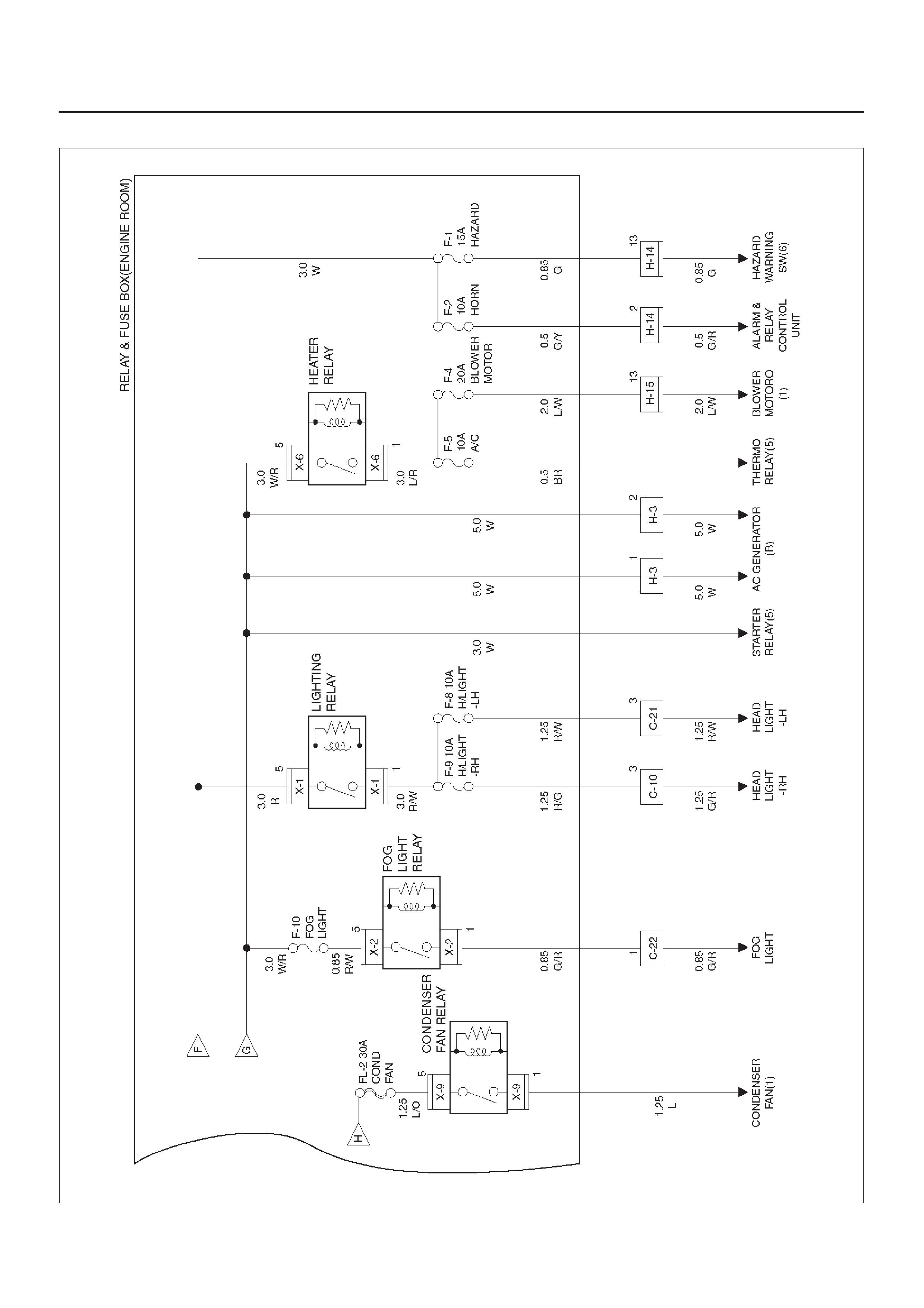
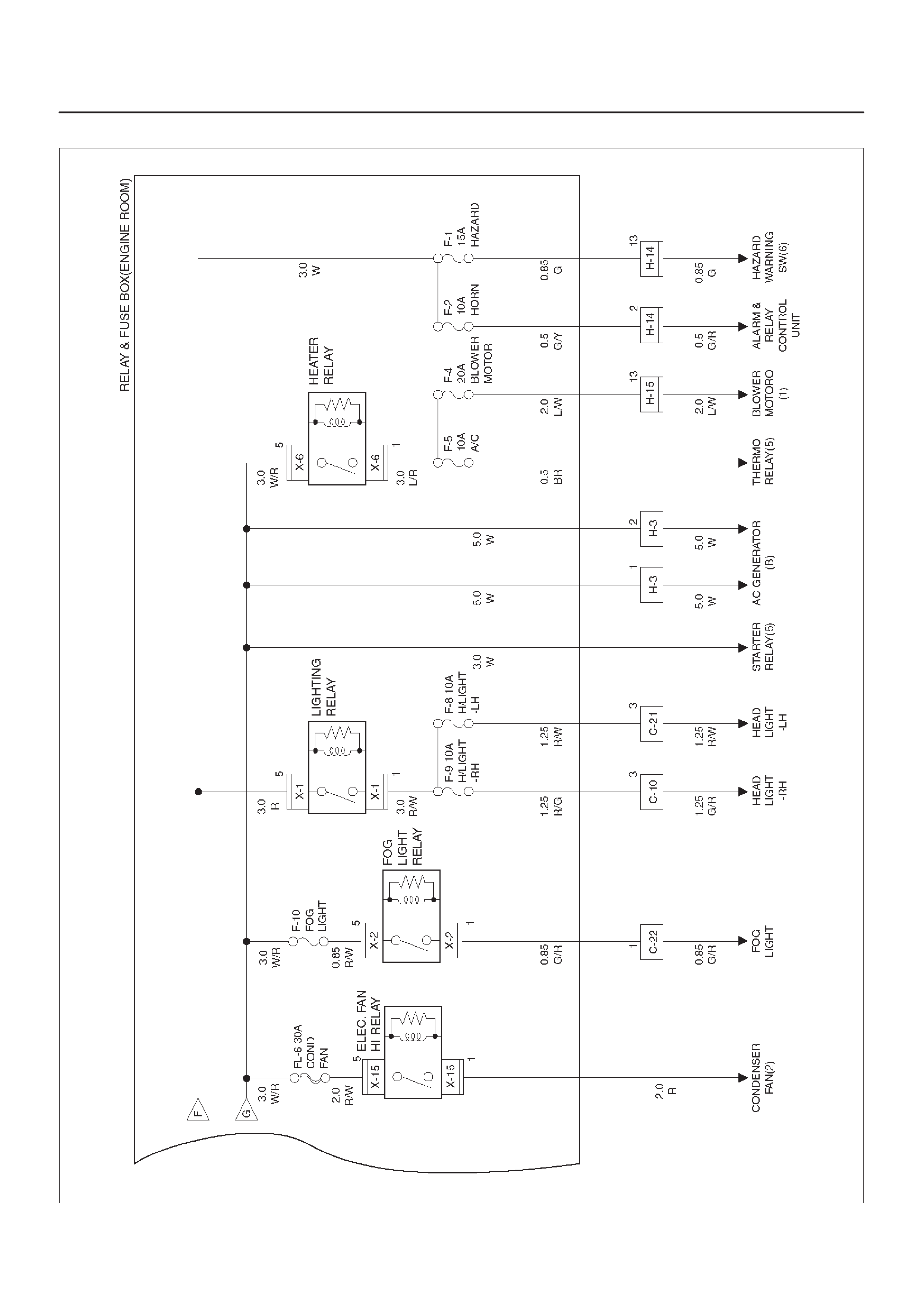
Relay & Fuse Box (Engine Room)
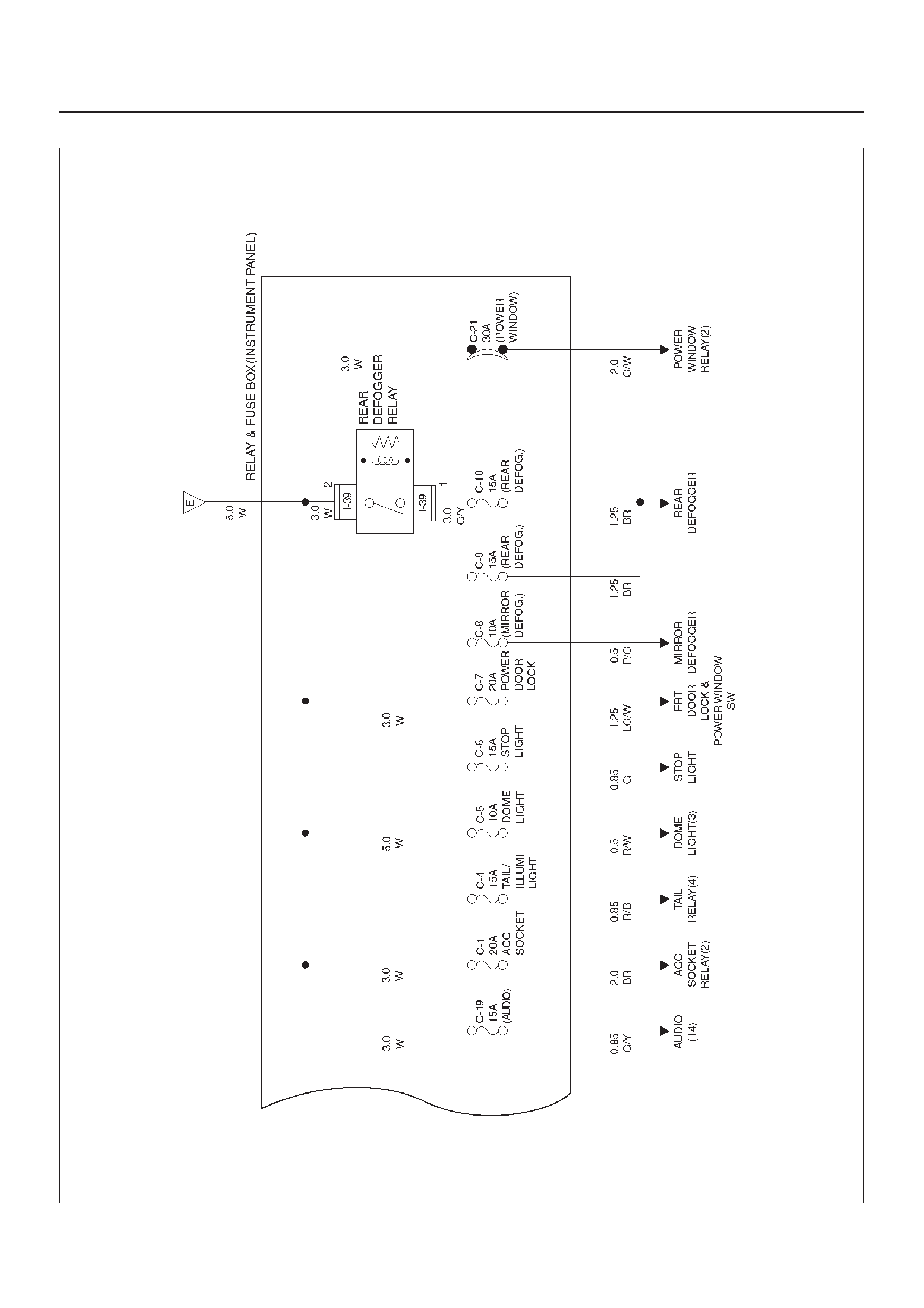
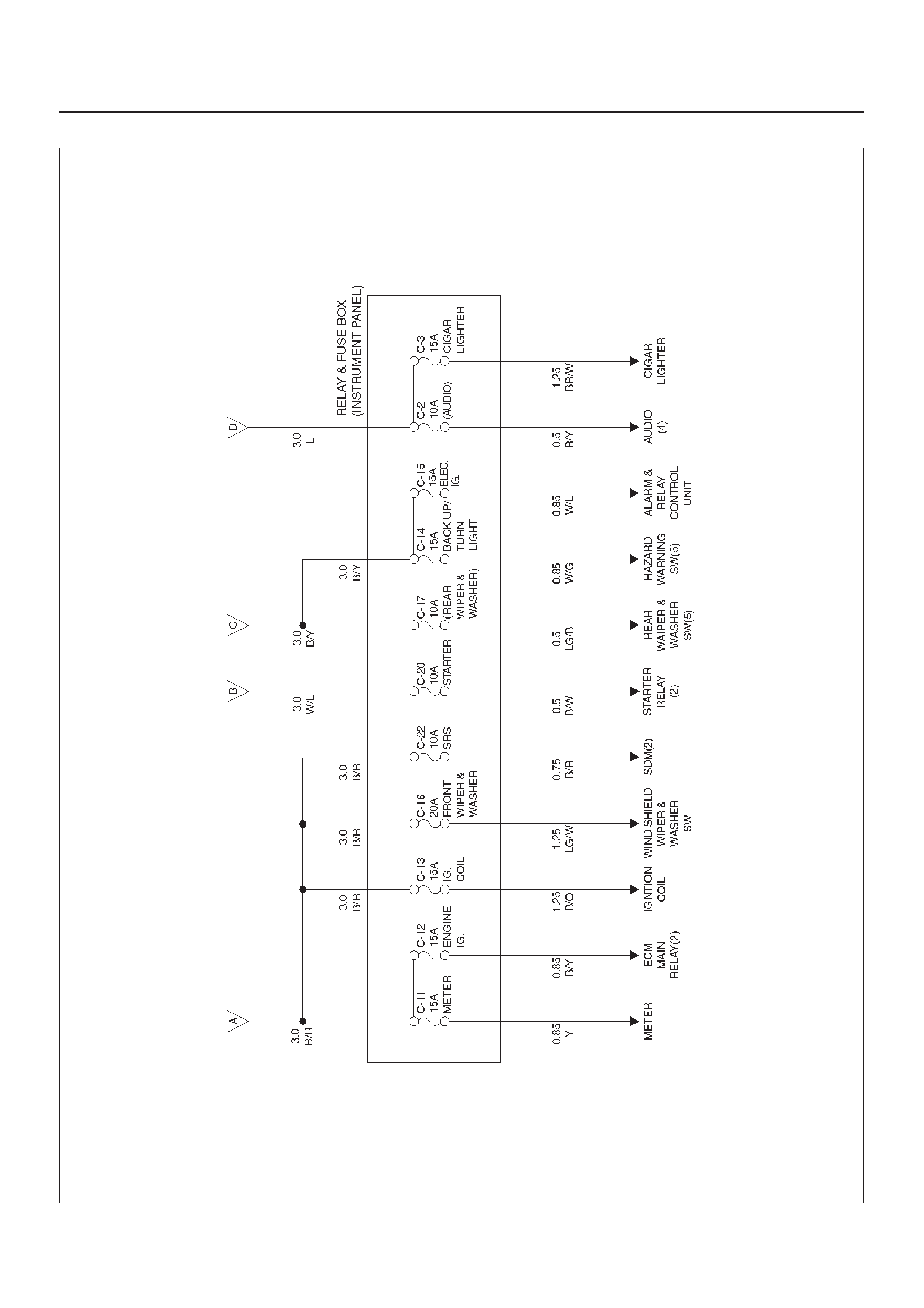
Relay & Fuse Box (Instrument panel)
Fuse Block Circuit
Reference Table of Fuse, Fusible Link and
Circuit Breaker
Relay Location
Diode Location
Grounding Point
Cable Harness Routing
Start and Charging
General Description
Circuit Diagram
Parts Location
Powertrain Control Module (PCM)
General Description
Circuit Diagram
Parts Location
Circuit Diagram
Parts Location
Headlight and Fog Light
General Description
Circuit Diagram
Parts Location
Diagnosis
Clearance Light, Tail Light and License
Plate Light
General Description
Circuit Diagram
Parts Location
Diagnosis
Interior Illumination Light
General Description
Circuit Diagram
Parts Location
Diagnosis
Turn Signal Light, Hazard Warning Light
General Description
Circuit Diagram
Parts Location
Diagnosis
Stoplight
General Description
Circuit Diagram
Parts Location
Diagnosis
Backup Light
General Description
Circuit Diagram
Parts Location
Diagnosis
Horn
General Description
Circuit Diagram
Parts Location
Diagnosis
Dome Light, Luggage Room Light, Courtesy
Light, Map Light, Seat Belt Switch and
Warning Buzzer
General Description
Circuit Diagram
Parts Location
Diagnosis
Power Door Lock
General Description
Circuit Diagram
Parts Location
Diagnosis
Power Window
General Description
Circuit Diagram
Parts Location
Diagnosis
Cruise Control
General Description
Circuit Diagram
Parts Location
Diagnosis
Anti–Lock Brake System (ABS)
General Description
Circuit Diagram
Parts Location
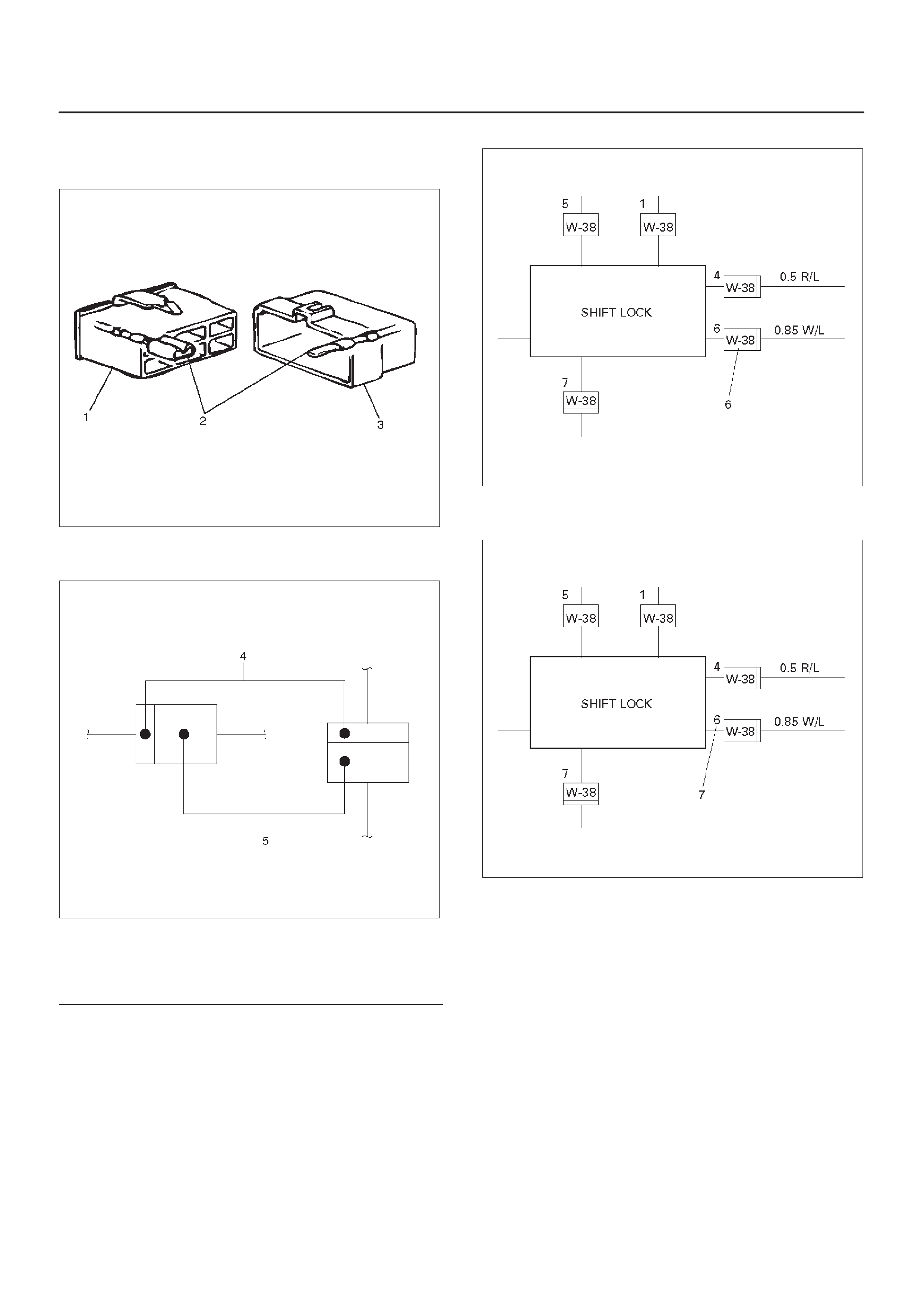
A/T Shift Lock
General Description
Circuit Diagram
Parts Location
Windshield Wiper and Washer

General Description
Circuit Diagram
Parts Location
Diagnosis
Rear Wiper/Washer
General Description
Circuit Diagram
Parts Location
Diagnosis
Rear Defogger/Mirror Defogger
General Description
Circuit Diagram
Diagnosis
Audio
General Description
Circuit Diagram
Parts Location
Cigarette Lighter, Digital Clock and
Accessory Socket
General Description
Circuit Diagram
Parts Location
Diagnosis
Power Door Mirror
General Description
Circuit Diagram
Parts Location
Diagnosis
Keyless Entry
General Description
Circuit Diagram
Parts Location
Keyless Entry System
Meter and Warning/Indicator Light
General Description
Circuit Diagram
Parts Location
Diagnosis
A/T Shift Indicator
General Description
Circuit Diagram
Parts Location
Heater and Air Conditioning
General Description
Circuit Diagram
Parts Location
Heater and Air Conditioning
General Description
Circuit Diagram
Parts Location
Sunroof
General Description
Circuit Diagram
Parts Location
Diagnosis
Supplemental Restraint System (SRS)
– Air Bag
General Description
Circuit Diagram
Parts Location
Shift on the Fly System
General Description
Circuit Diagram
Parts Location
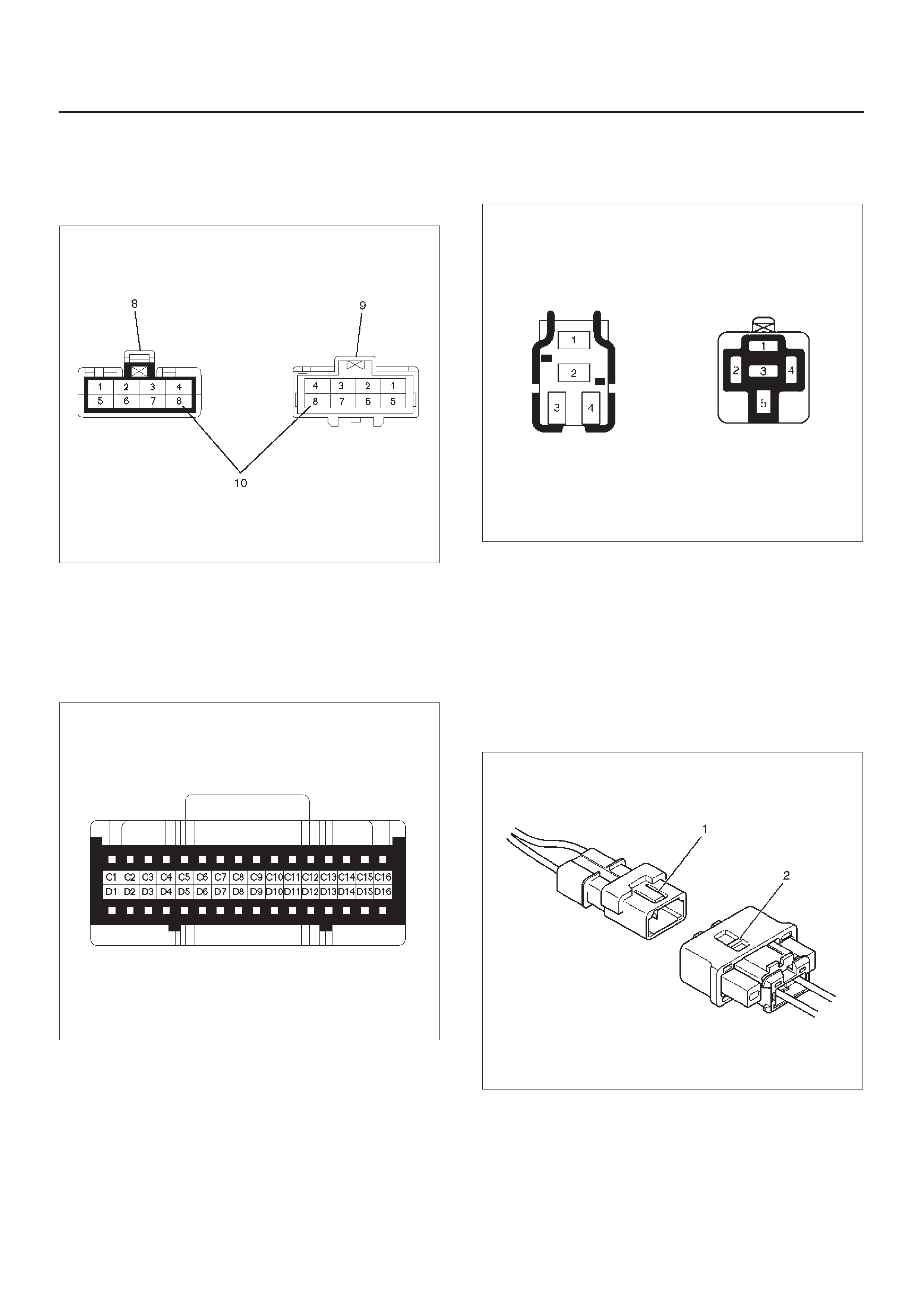
Harness Connector Faces
Service Precaution
WARNING:THIS VEHICLE HAS A SUPPLEMENTAL
RESTRAINT SYSTEM (SRS). REFER TO THE SRS
COMPONENT AND WIRING LOCATION VIEW IN
ORDER TO DETERMINE WHETHER YOU ARE
PERFORMING SERVICE ON OR NEAR THE SRS
COMPONENTS OR THE SRS WIRING. WHEN YOU
ARE PERFORMING SER VICE ON OR NEAR THE SRS
COMPONENTS OR THE SRS WIRING, REFER TO
THE SRS SERVICE INFORMATION. FAILURE TO
FOLLOW WARNINGS COULD RESULT IN POSSIBLE
AIR BAG DEPLOYMENT, PERSONAL INJURY, OR
OTHER WISE UNNEEDED SRS SYSTEM REPAIRS.
CAUTION:Always use the correct fastener in the
proper location. When you replace a fastener, use
ONLY the exact part number for that application.
ISUZU will call out those fasteners that require a
replacement after removal. ISUZU will also call out
the fasteners that require thread lockers or thread
sealant. UNLESS OTHERWISE SPECIFIED, do not
use supplemental coatings (Paints, greases, or other
corrosion inhibitors) on threaded fasteners or
fasteners joint interfaces. Generally, such coatings
adversely affect the fastener torque and the joint
clamping force, and may damage the fasteners.
When you install fasteners, use the correct
tightening sequence and specifications. Following
these instructions can help you avoid damage to
parts and systems.
General Description
The chassis electrical system is a 12–volt system with a
negative ground polarity.
Wire size are appropriate to respective circuits, and
classified by color. (The classification of harnesses by
color is shown on the circuit diagram for ease of harness
identification.)
The wire size is determined by load capacity and the
length of wire required.
The vehicle harness are: body harness, chassis harness,
engine room harness, instrument harness, transmission
harness, engine ECGI harness, dome light harness, door
harness, rear body harness, tailgate harness, SRS
harness and battery cables.
The harnesses are protected either by tape or corrugated
tube, depending on harness location.
The circuit for each system consists of the power source,
wire, fuse, relay, switch, load parts and ground, all of
which are shown on the circuit diagram.
In this section, each electrical device is classified by
system.
For major parts shown on the circuit based on the circuit
diagram for each system, a summary, diagnosis of
troubles and inspection procedures are detailed.
Notes for Working on Electrical Items
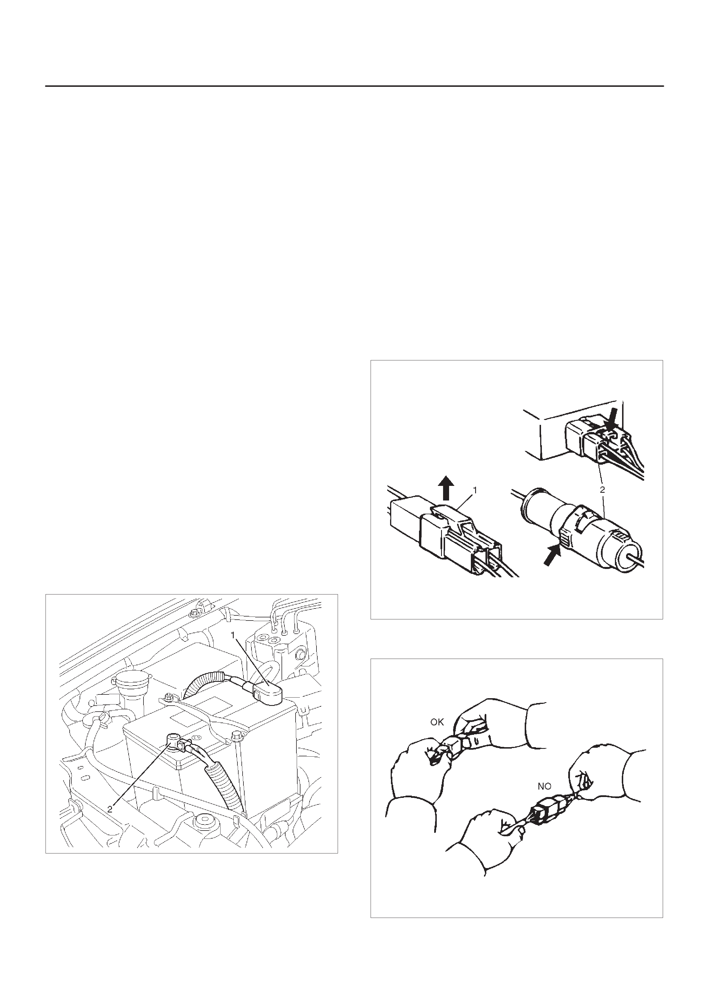
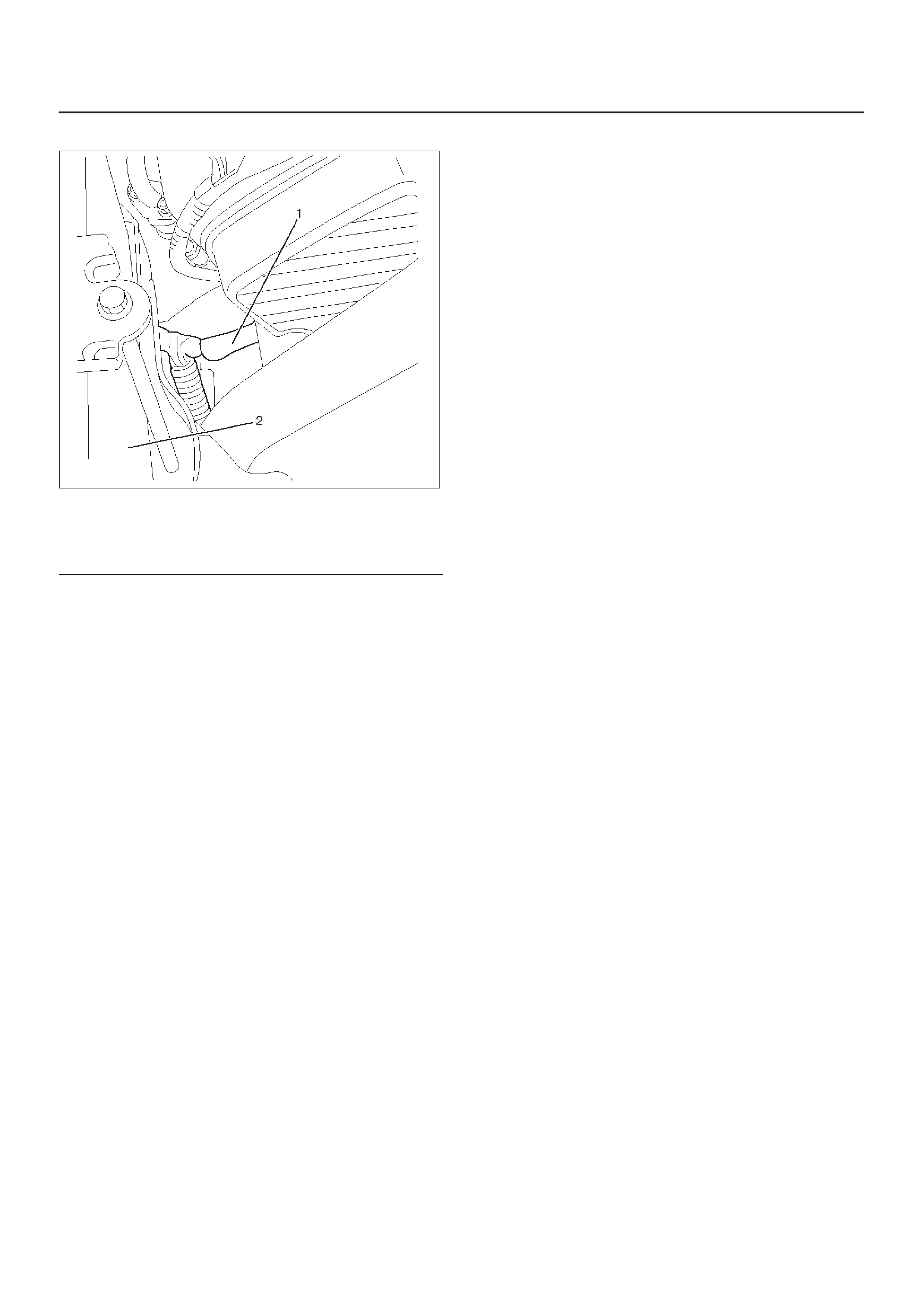
Disconnecting the Battery Cable
1.All switches should be in the “OFF” position.
2.Disconnect the battery ground cable (2).
3.Disconnect the battery positive cable (1).
CAUTION:It is important that the battery ground
cable be disconnected first. Disconnecting the
battery positive cable first can result in a short
circuit.
061RW002
Connecting the Battery Cable
Follow the disconnecting procedure in the reverse order.
CAUTION:Clean the battery terminal and apply a
light coat of grease to prevent terminal corrosion.
Disconnecting the Connector
Some connectors have a tang lock to hold the connectors
together during vehicle operation.
Some tang locks are released by pulling them towards
you (1).
Other tang locks are released by pressing them forward
(2).
Determine which type of tang lock is on the connector
being handled.
Firmly grasp both sides (male and female) of the
connector.
Release the tang lock and carefully pull the two halves of
the connector apart.
D08RW128
Never pull on the wires to separate the connectors. This
will result in wire breakage as shown in the figure.
D08RW129
When removing the connector for relay (MR5B type) (3),
unfasten the tang lock of the connector by using a
screwdriver , then pull the relay out as shown in the figure.
D08RW131
Connecting the Connector
Firmly grasp both sides (male and female) of the
connector. Be sure that the connector pins and pin holes
match, Be sure that both sides of the connector are
aligned with each other.
Firmly but carefully push the two sides of the connector
together until a distinct click is heard.
D08RW130
Connector Inspection
Use a circuit tester to check the connector for continuity.
Insert the test probes (1) from the connector wire side.
D08RW132
Never insert the circuit tester test probes (2) into the
connector open end to test the continuity.
Broken or open connector terminals will result.
D08RW133
Waterproof Connector Inspection
It is not possible to insert the test probes (2) into the
connector wire side of a waterproof connector.
Use one side of a connector (1) with its wires cut to make
the test. Connect the test connector (3) to the connector
to be tested. Connect the test probes to the cut wires to
check the connector continuity.
D08RW134
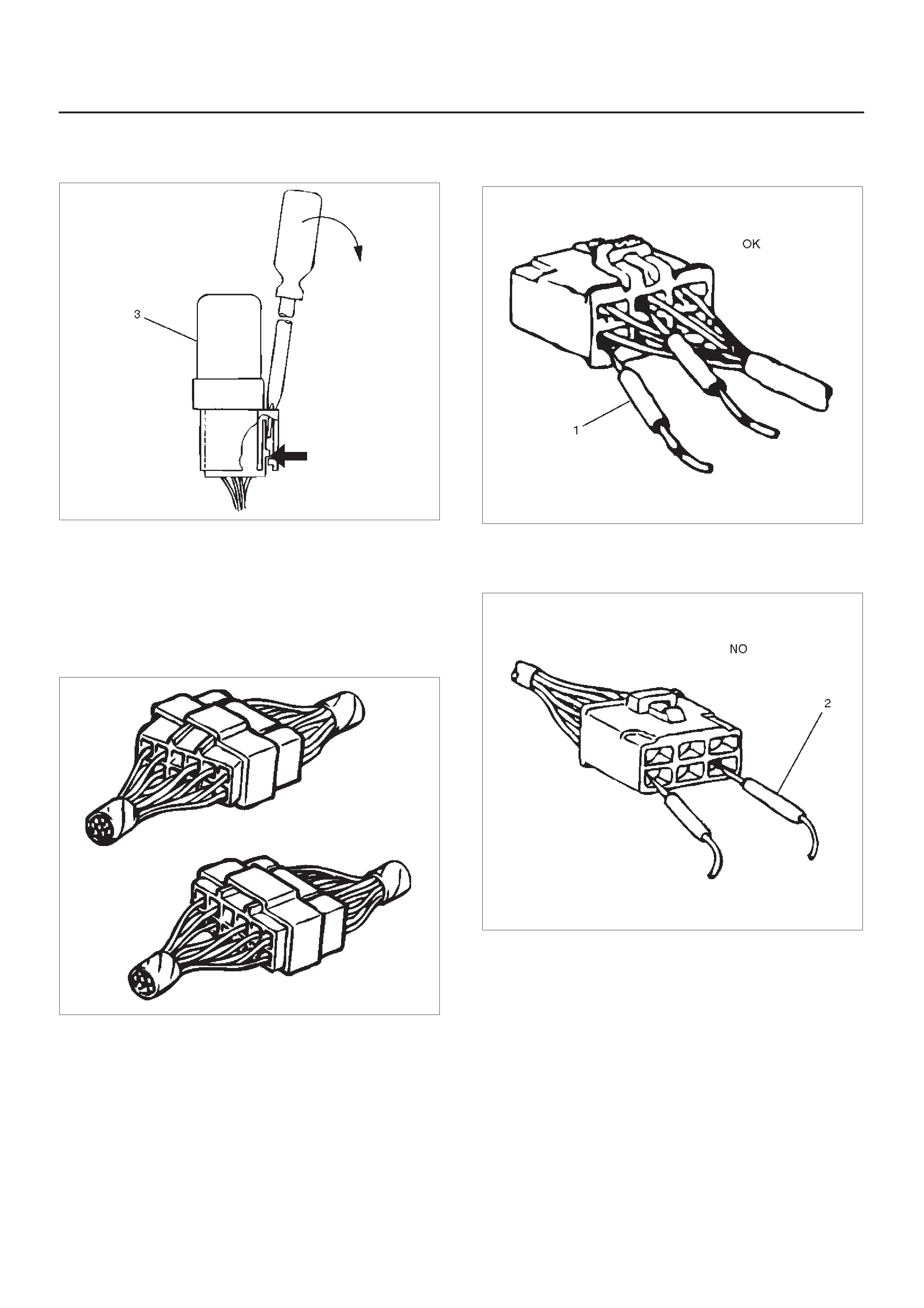
Connector Pin Removal – Connector Housing Tang
Lock Type
1.Insert a slender shaft (1) into the connector housing
open end (5).
2.Push the tang lock (2) up (in the direction of the arrow
in the illustration).
Pull the wire (3) with pin (4) free from the wire side of
the connector.
D08RW135
Connector Pin Removal – Pin Tang Lock Type
1.Insert a slender shaft (1) into the connector housing
open end (5).
2.Push the tang lock (2) flat (toward the wire (3) side of
the connector.
Pull the wire with pin (4) free from the wire side of the
connector.
D08RW136
Connector Pin Insertion
1.Check that the tang lock (1) is fully up.
2.Insert the pin (3) from the connector wire (2) side.
Push the pin in until the tang lock closes firmly.
3.Gently pull on the wires to make sure that the
connector pin is firmly set in place.
D08RW137
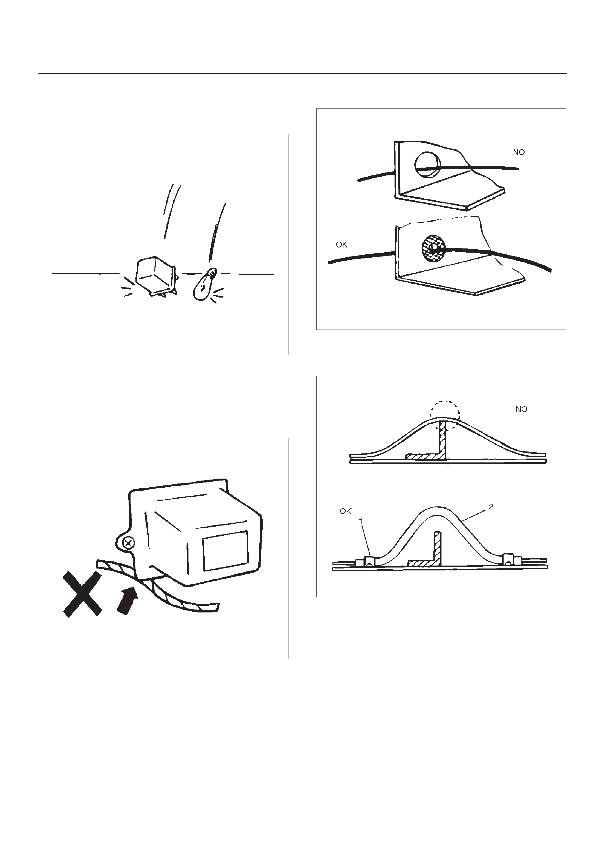
Parts Handling
Be careful when handling electrical parts. They should not
be dropped or thrown, because short circuiting or other
damage may result.
D08RW138
Cable Harness
1.When installing the parts, be careful not to pinch or
wedge the wiring harness.
2.All electrical connections must be kept clean and
tight.
D08RW139
3.Use a grommet or guard tube to protect the wiring
harness from contacting a sharp edge or surface.
D08RW139
4. Position the wiring harness with enough clearance
from the other parts and guard the wiring harness with
a vinyl tube (2) and clips (1) to avoid direct contact.
D08RW141
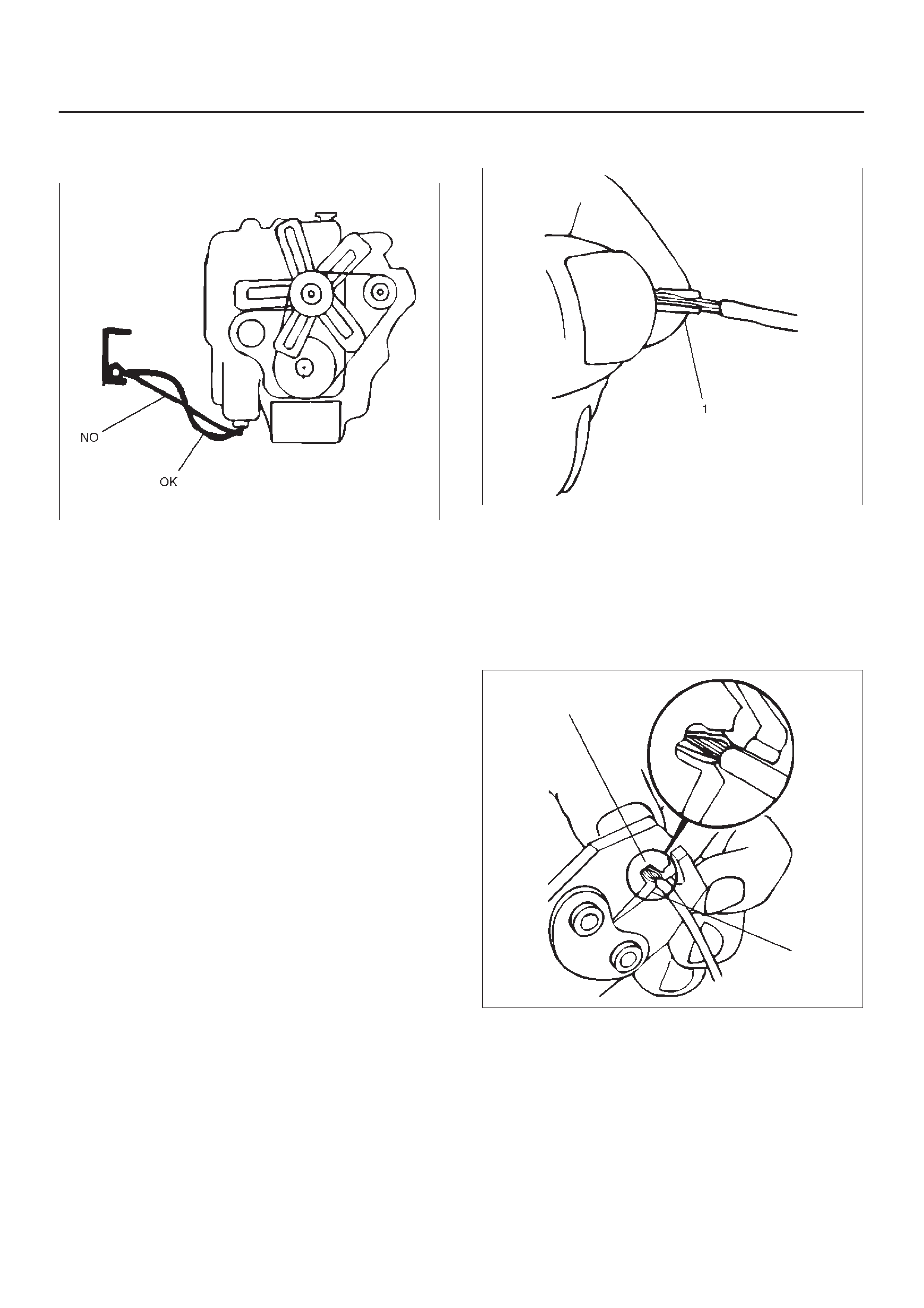
5.The wiring harness between engine and chassis
should be long enough to prevent chafing or damage
due to various vibrations.
D08RW142
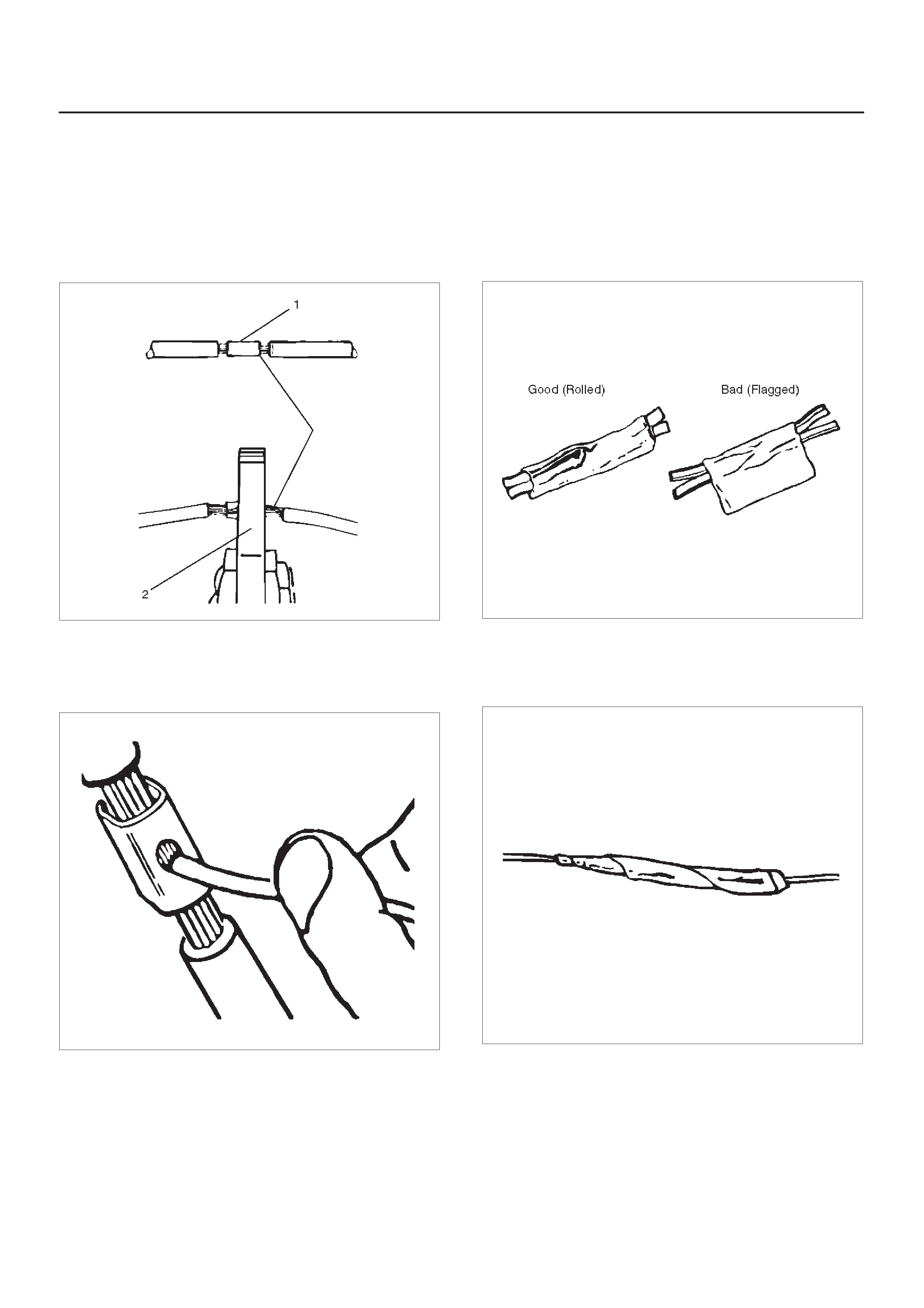
Splicing Wire
1.If the harness is taped, remove the tape. T o avoid wire
insulation damage, use a sewing “seam ripper”
(available from sewing supply stores) to cut open the
harness.
If the harness has a black plastic conduit, simply pull
out the desired wire.
2.Begin by cutting as little wire off the harness as
possible. Y ou may need the extra length of wire later if
you decide to cut more wire off to change the location
of a splice. You may have to adjust splice locations to
make certain that each splice is at least 1–1/2” (40
mm) away from other splices, harness branches, or
connectors.
3.When replacing a wire, use a wire of the same size as
the original wire.
Check the stripped wire for nicks or cut stands. If the
wire is damaged, repeat the procedure on a new
section of wire. The two stripped wire ends should be
equal in length.
4.Select the proper clip to secure the splice.
To determine the proper clip size for the wire being
spliced, follow the directions included with your clips.
Select the correct anvil on the crimper. (On most
crimpers your choice is limited to either a small or
large anvil.)
Overlap the two stripped wire ends and hold them
between your thumb and forefinger as shown in the
figure.
The center the spline clip (1) under the stripped wires
and hold it in place.
D08RW143
fOpen the crimping tool to its full width and rest one
handle on a firm flat surface.
fCenter the back of the splice clip on the proper anvil
and close the crimping tool to the point where the
back of the splice clip touches the wings of the clip.
fMake sure that the clip and wires are still in the correct
position. Then, apply steady pressure until the
crimping tool closes as shown in the figure.
D08RW144
Before crimping the ends of the clip (1), be sure that:
fThe wires extend beyond the clip in each direction.
fNo strands of wire are cut loose, and
fNo insulation is caught under the clip.
Crimp the splice again, once on each end.
Does not let the crimping tool (2) extend beyond the edge
of the clip or you may damage or nick the wires as shown
in the figure.
D08RW145
5.Apply 60/40 resin core solder to the opening in the
back of the clip as shown in the figure.
Follow the manufacturer’s instructions for the solder
equipment you are using.
D08RW146
6.Center and roll the splicing tape.
The tape should cover the entire splice.
Roll on enough tape to duplicate the thickness of the
insulation on the existing wires.
Does not flag the tape. Flagged tape may not provide
enough insulation, and the flagged ends will tangle
with the other wires in the harness as shown in the
figure.
D08RW147
If the wire does not belong in a conduit or other
harness covering, tape the wire again. use a winding
motion to cover the first piece of tape as shown in the
figure.
D08RW148
Symbols and Abbreviations
Symbols
Symbol Meaning of Symbol
Fuse
Fusible link
Fusible link wire
Switch
Switch
Switch
(Normal close type)
Symbol Meaning of Symbol
Contact wiring
Battery
Diode
Electronic parts
Resistor
Speaker
Symbol Meaning of Symbol
Buzzer
Circuit breaker
Bulb
Double filament bulb
Motor
Variable register Rheo-
stat
Symbol Meaning of Symbol
Coil (inductor), solenoid,
magnetic valve
Relay
Connector
Light emitting diode
Reed switch
Condenser
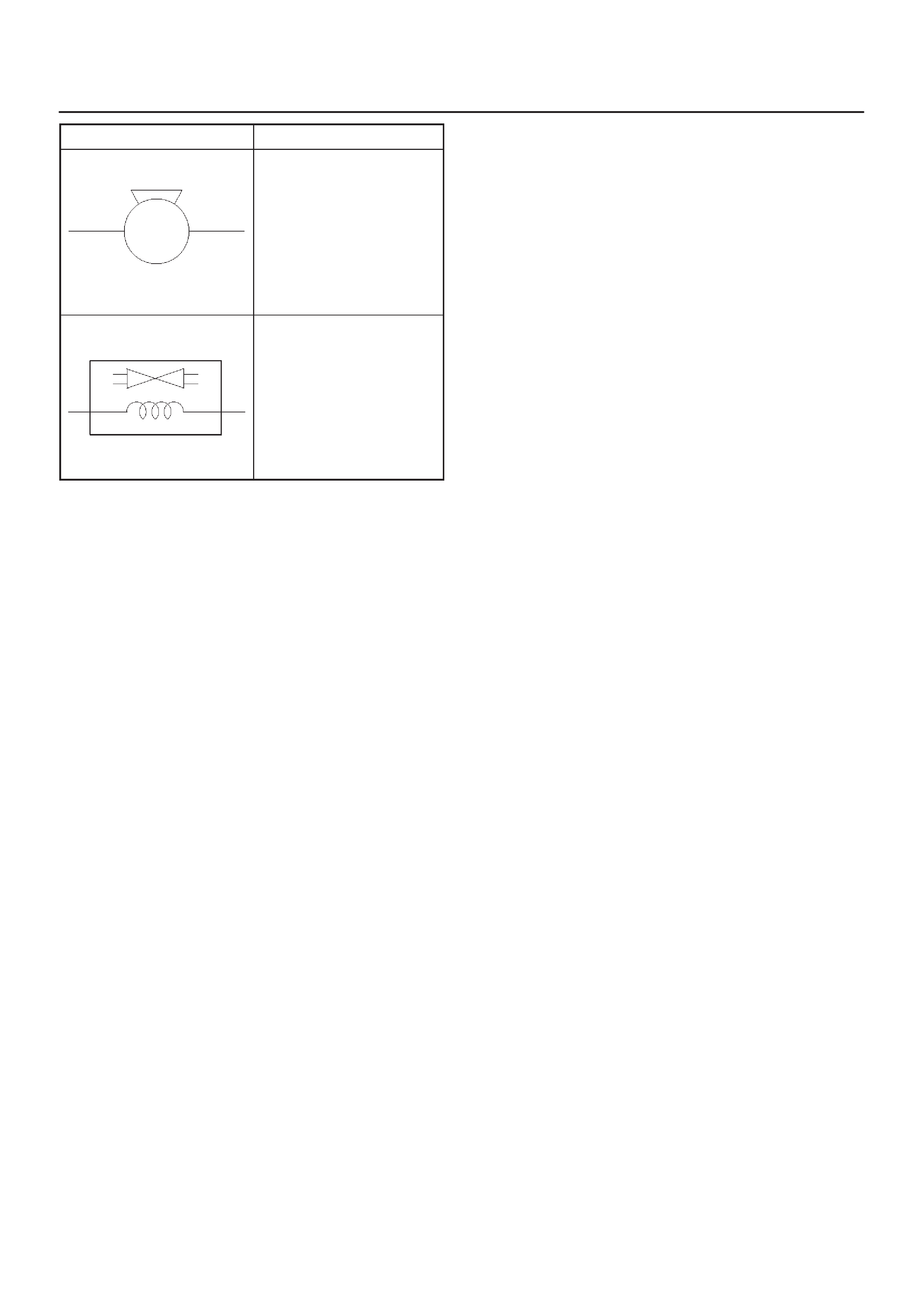
Symbol Meaning of Symbol
Horn
Vacuum switching valve

Abbreviations
Abbreviation Meaning of Abbreviation
AAmpere (S)
ABS Anti-lock brake system
ASM Assembly
AC Alternating current
A/C Air conditioner
ACC Accessories
A/T Automatic transmission
C/B Circuit breaker
CSD Cold start device
DIS Direct ignition system
EBCM Electronic brake control module
ECGI Electronic control gasoline injection
ECM Engine control module
ECU Electronic control unit
EFE Early fuel evaporation
EGR Exhaust gas recirculation
4A/T 4-speed automatic transmission
4WD Four-wheel drive
FL Fusible link
FRT Front
H/L Headlight
IC Integrated circuit
IG Ignition
Abbreviation Meaning of Abbreviation
kW Kilowatt
LH Left hand
LWB Long wheel base
M/T Manual transmission
OD Over drive
OPT Option
PCM Powertrain control module
QOS Quick on start
RH Right hand
RR Rear
SDM Sensing and diagnostic module
SRS Supplemental restraint system
ST Start
STD Standard
SW Switch
SWB Short wheel base
3A/T 3-speed automatic transmission
V Volt
VSV Vacuum switching valve
WWatt (S)
WOT Wide open throttle
W/ With
W/O Without
Parts for Electrical Circuit
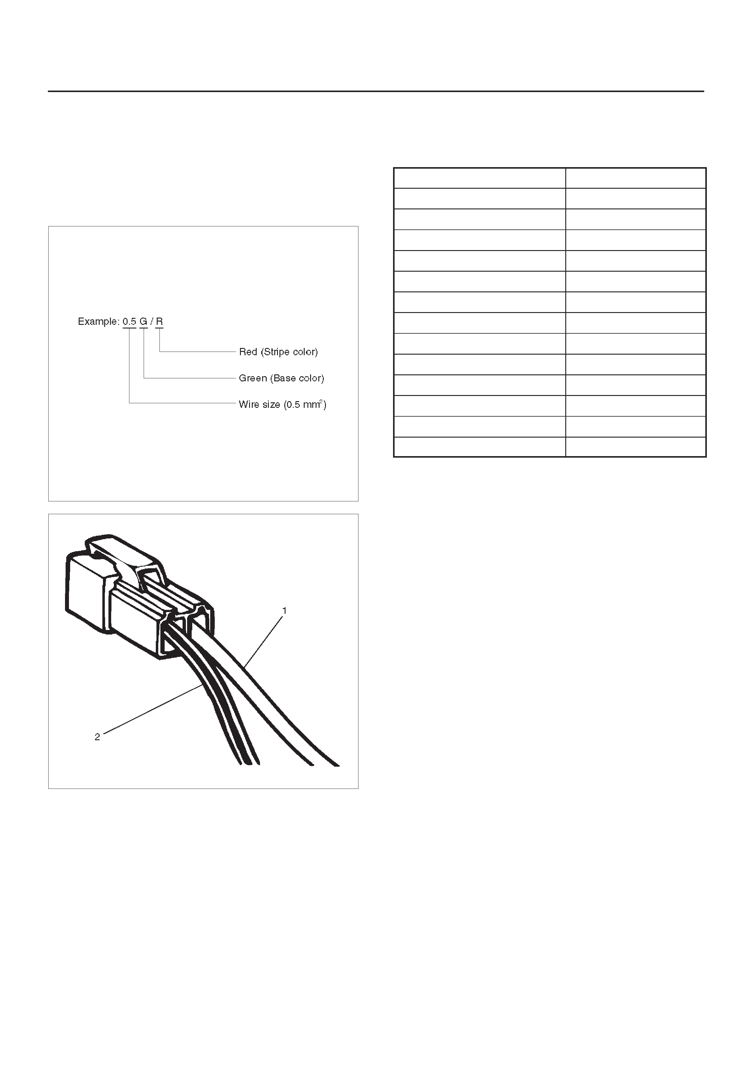
Wiring – Wire color
All wires have color–coded insulation.
Wires belonging to a system’s main harness will have a
single color (1). Wires belonging to a system’s subcircuits
will have a colored stripe (2). Striped wires use the
following code to show wire size and colors.
F08RW001
D08RW150
Wiring – Wire Color Coding
Abbreviations are used to indicate wire color within a
circuit diagram.
Refer to the following table.
Color–coding Meaning
B Black
W White
R Red
G Green
Y Yellow
L Blue
O Orange
BR Brown
LG Light green
GR Grey
P Pink
LB Light blue
V Violet
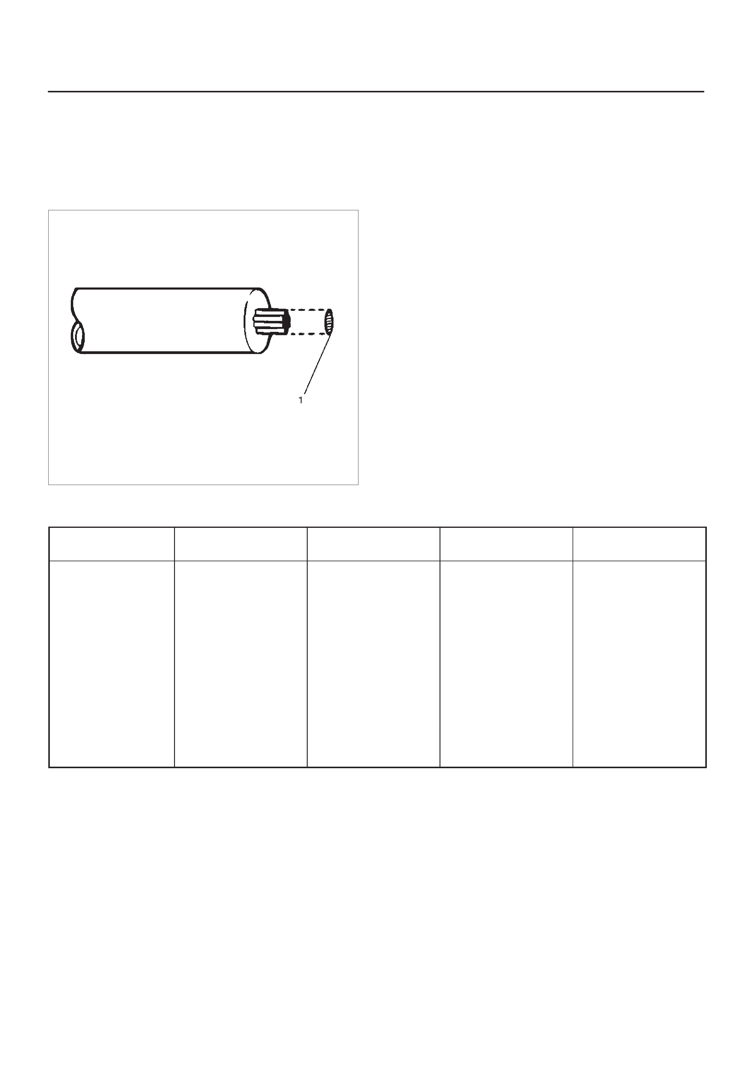
Wiring – Wire Size
The size of wire used in a circuit is determined by the
amount of current (amperage), the length of the circuit,
and the voltage drop allowed. The following wire size and
load capacity, shown below, are specified by AWG
(American Wire Gauge) (Nominal size means
approximate cross sectional area (1).)
D08RW151
Wiring – Wire Size Table
Nominal size Cross sectional area
(mm@)Outside diameter
(mm) Allowable current (A) AWG size
(cross reference)
0.3 0.372 1.5 9 22
0.5 0.563 1.7 12 20
0.85 0.885 1.9 16 18
1.25 1.287 2.2 21 16
2 2.091 2.7 28 14
3 3.296 3.6 37.5 12
5 5.227 4.4 53 10
8 7.952 5.5 67 8
15 13.36 7.0 75 6
20 20.61 8.2 97 4
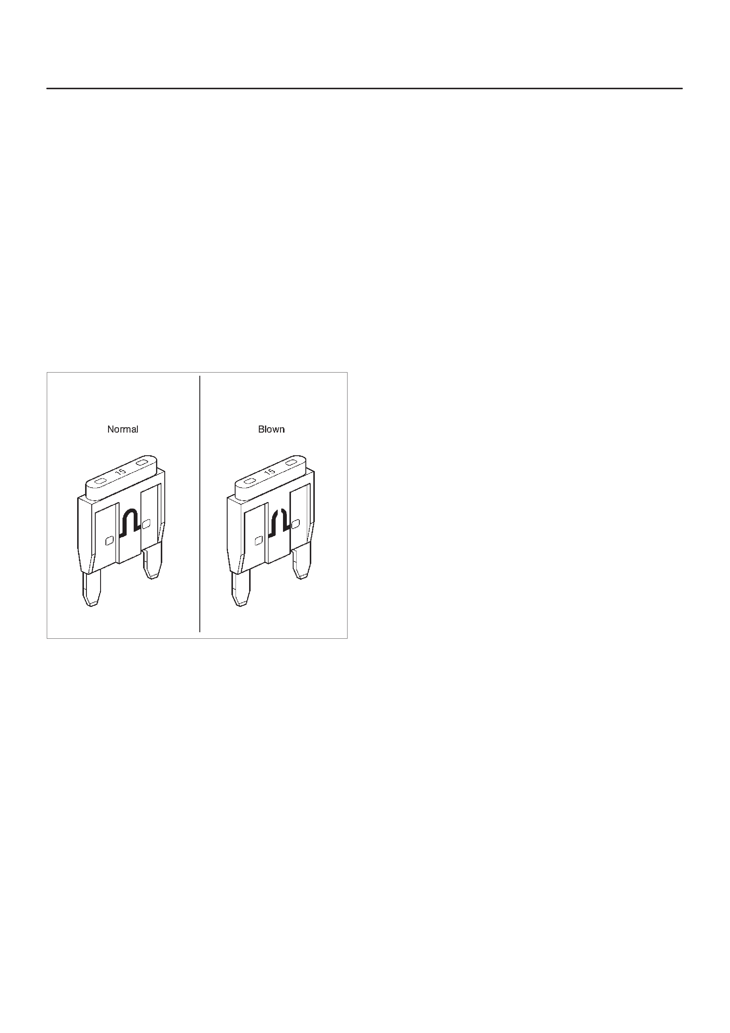
Fuse
Fuses are the most common form of circuit protection
used in vehicle wiring. A fuse is a thin piece of wire or strip
of metal encased in a glass it or plastic housing. It is wired
in series with the circuit in protects. When there is an
overload of current in a circuit, such as a short of a
ground, the metal strip is designed to burn out and
interrupt the flow of current. This prevents a surge of high
current from reaching and damaging other components in
the circuit.
Determine the cause of the overloaded before replacing
the fuse.
The replacement fuse must have the same amperage
specification as the original fuse.
Never replace a blown fuse with a fuse of a different
amperage specification.
Doing so can result in an electrical fire or other serious
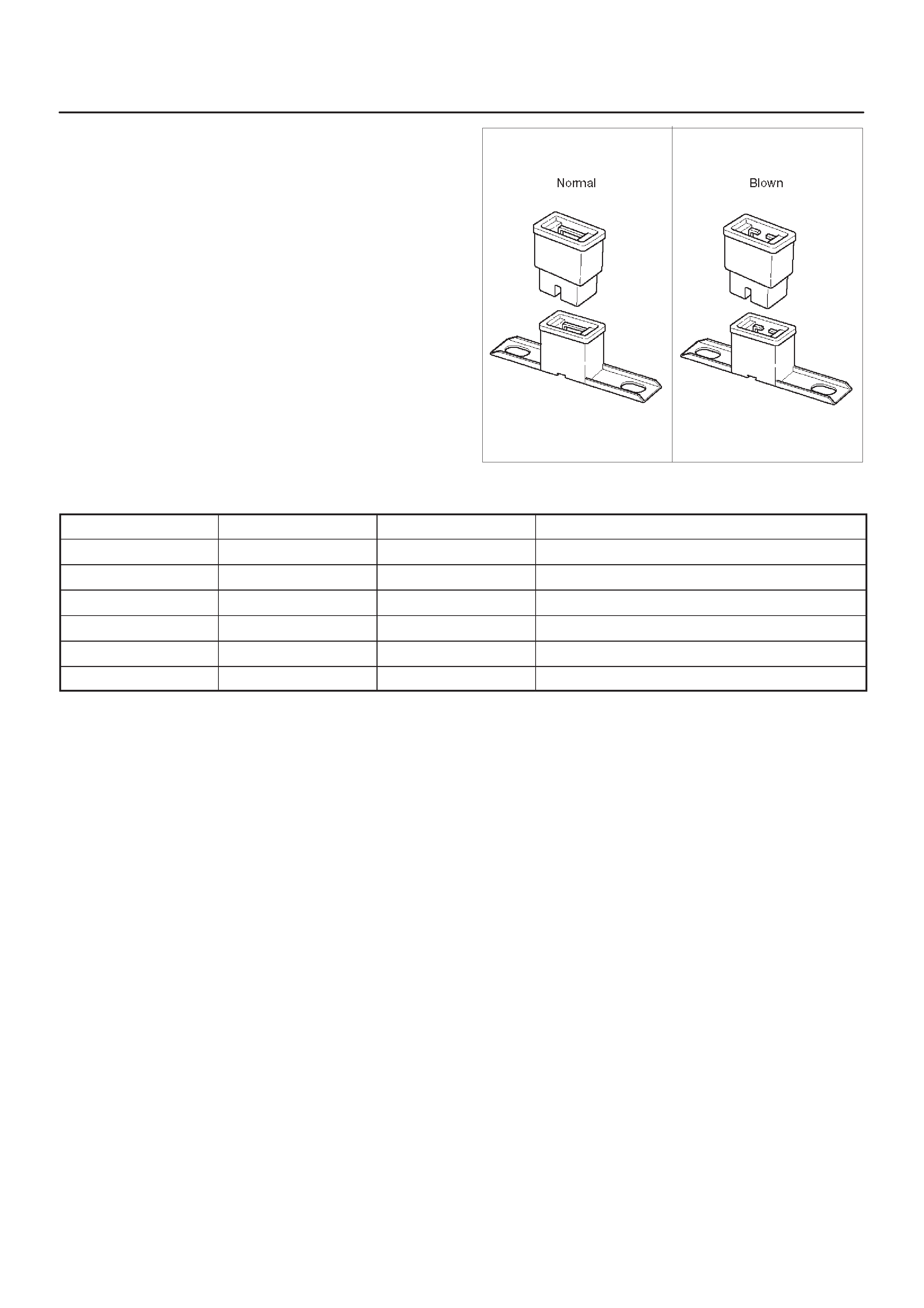
circuit damage. A blown fuse is easily identified as shown
in the figure.
810RX001
Fusible Link
The fusible link is primarily used to protect circuits where
high amounts of current flow and where it would not be
practical to use a fuse. For example, the starter circuit.
When a current overload occurs, the fusible link melts
open and interrupts the flow of current so as to prevent the
rest of the wiring harness from burning.
Determine the cause of the overload before replacing the
fusible link. the replacement fusible link must have the
same amperage specification as the original fusible link.
Never replace a blown fusible link with fusible link of a
different amperage specification. Doing so can result in
an electrical fire or other serious circuit damage.
A blown fusible link is easily identified as shown in the
figure.
D08RW154
Fusible Link Specifications
Type Rating Case Color Maximum Circuit Current (A)
Connector 30A Pink 15
Connector 40A Green 20
Bolted 50A Red 25
Bolted/Connector 60A Yellow 30
Bolted 80A Black 40
Bolted 100A Blue 50
Circuit Breaker
The circuit breaker is a protective device designed to
open the circuit when a current load is in excess of rated
breaker capacity. If there is a short or other type of
overload condition in the circuit, the excessive current will
open the circuit between the circuit breaker terminals.
The reset knob (1) pops out when the circuit is open. Push
the reset knob in place to restore the circuit after repairing
it.
D08RW155
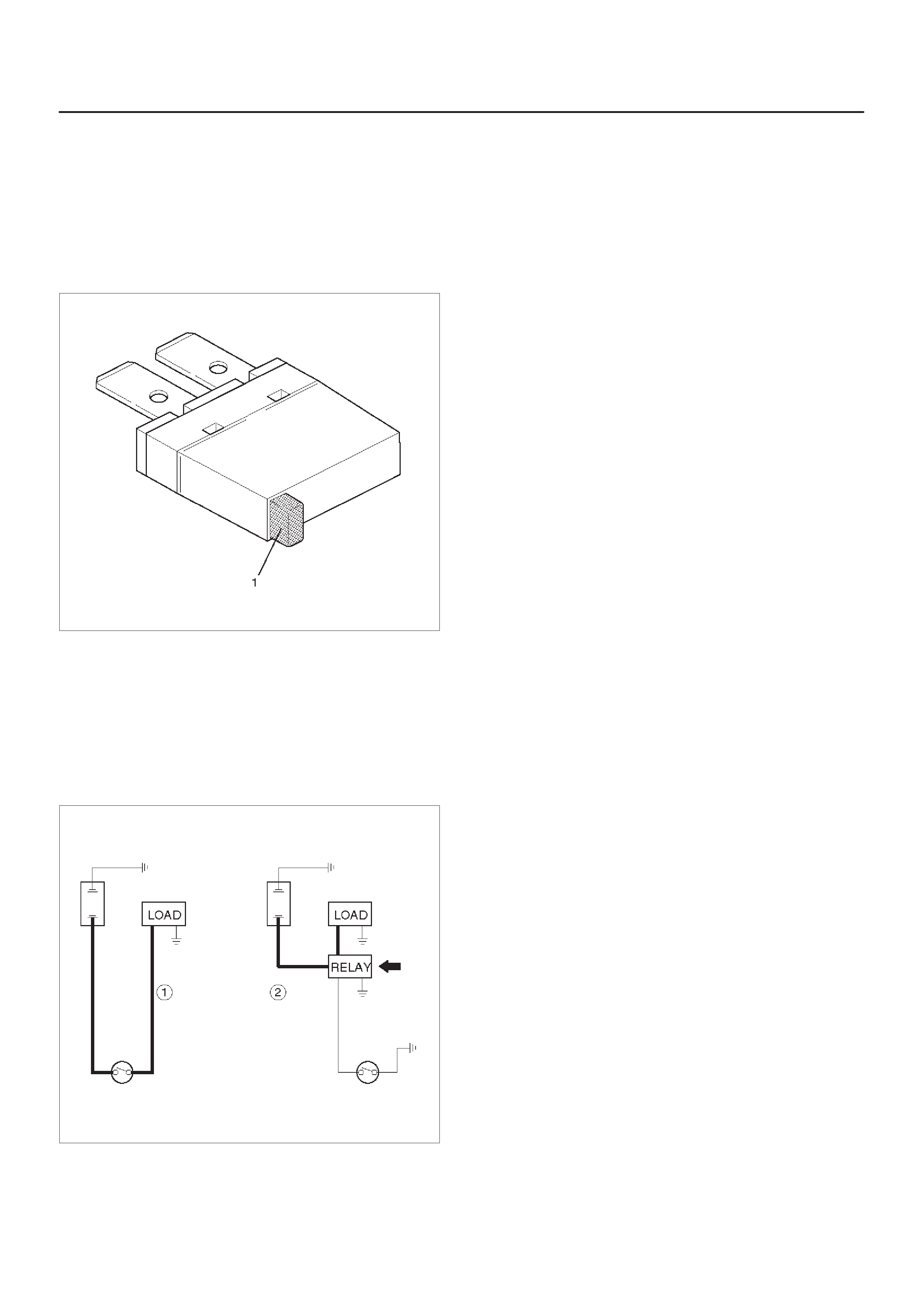
Relay
Battery and load location may require that a switch be
placed some distance from either component. This
means a longer wire and a higher voltage drop (1).
The installation of a relay between the battery and the
load reduces the voltage drop (2).
Because the switch controls the relay , amperage through
the switch can be reduced.
D08RW156
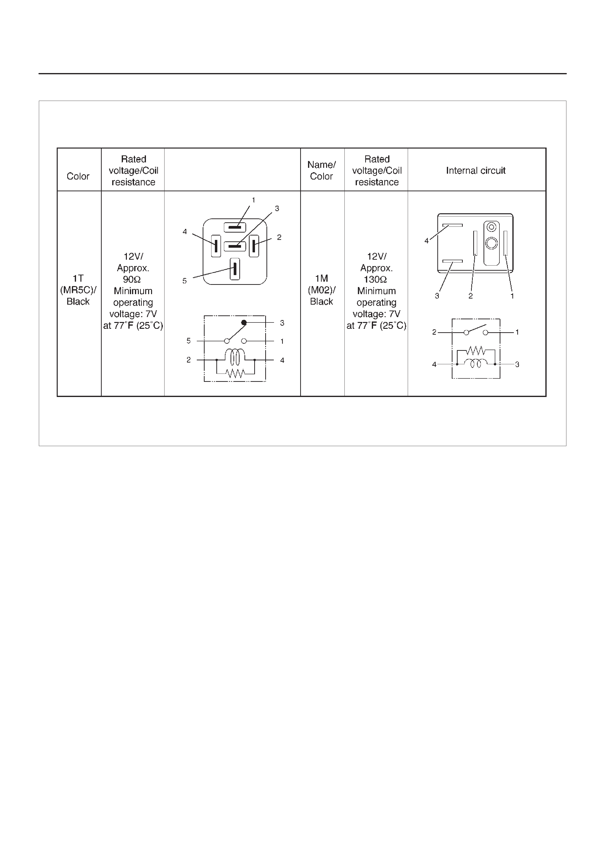
Relay Specifications and Configurations
F00RX012
*Relay contact shown in the wiring diagram indicates
condition before actuation.
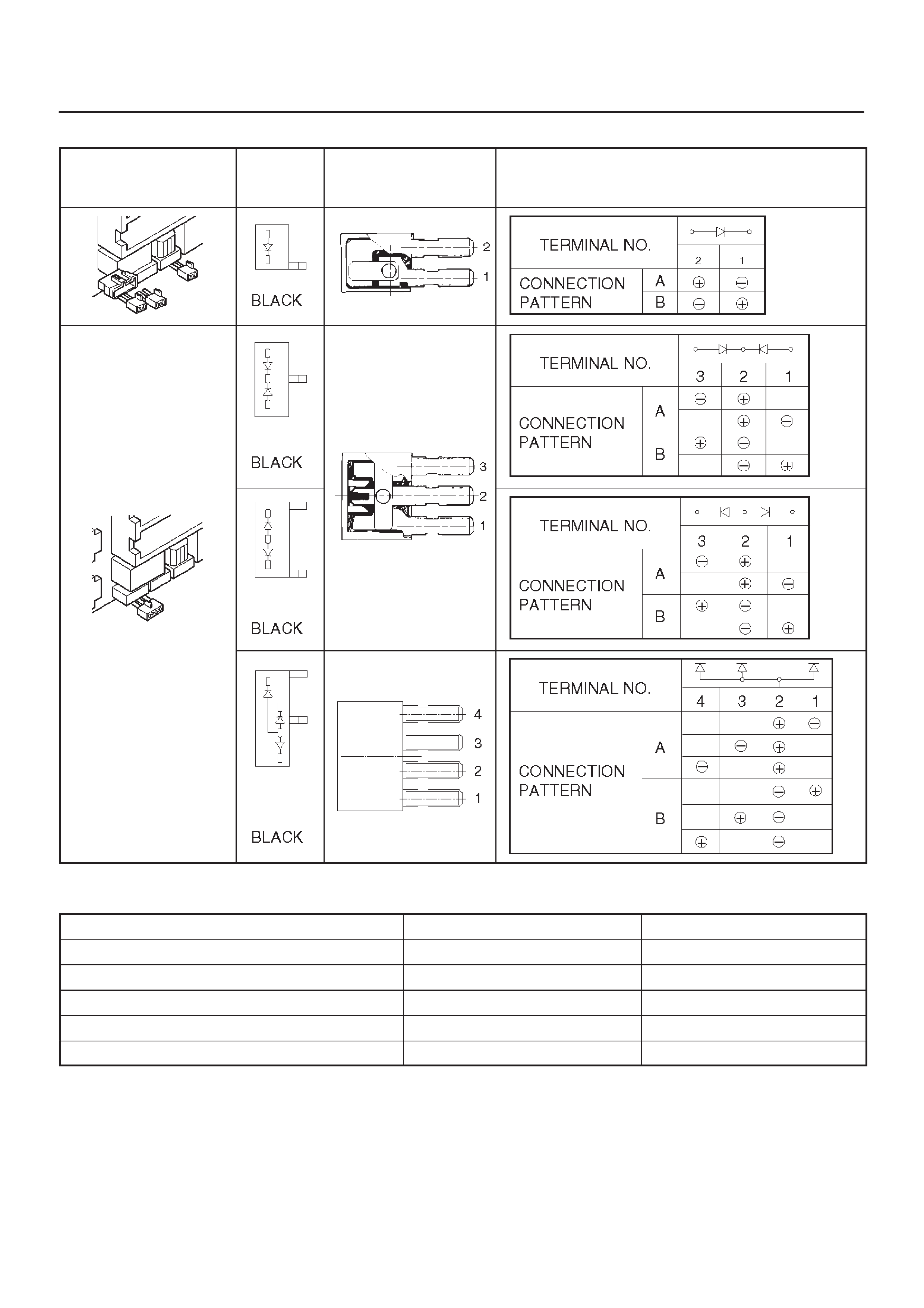
Diode – Diode Specifications and Configurations
SHAPE MARK /
COLOR CONSTRUCTION CHECKING: THERE SHOULD BE CONTINUITY
IN EITHER A OR B WHEN A CIRCUIT TESTER
IS CONNECTED WITH DIODE TERMINAL
Diode – Maximum Rating (Temp. = 77°F (25°C)
Items Rating Remarks
Peak reverse voltage 400V
Transient peak reverse voltage 500V
Average output current 1.5A Temp. = 104°F (40°C)
Working ambient temperature –22°F∼176°F (–30°C∼80°C)
Storage temperature –40°F∼212°F (–40°C∼100°C)
Connector
fThe connector pin shape (2) determines whether the
connector is male (3) or female (1).
D08RW159
fThe symbol illustrated in the figure is used as
connector, in the circuit of this section.
D08RW160
Legend
(4) Female Side Connector
(5) Male Side Connector
fConnector is identified with a connector number (6)
D08RW161
fThe applicable terminal number (7) is shown for each
connector.
D08RW162
fConnector terminal numbers (10) are clearly shown.
Make side connector (9) terminal numbers are in
sequence from upper right to lower left.
Female side connector (8) terminal numbers are in
sequence from upper left to lower right.
D08RW163
NOTE:
1. For those connectors on which specific terminal
numbers or symbols are shown (such as PCM), the
terminal numbers or symbols are used in the circuit
diagram, irrespective of the above rule.
Refer to the following figure.
D08RW164
2. The connectors used for relays have their own
terminal number assignment, irrespective of the
above rule.
Refer to the following figure.
Double Lock Type Connector
Doublelock type yellow color connectors are used for
supplemental restraint system–air bag circuit. When
removing the cable harness, disconnect the connector by
unlocking at two places, outside (1) and inside (2). In such
a case, do not pull the cables. Otherwise, cable
disconnection may occur.
When connecting the connector, insert the connector
completely and lock at outside. Imperfect locking may
cause malfunction of SRS system circuit.
F00RX010
Reading the Circuit Diagram
In this section, each system has its own parts location
illustration and circuit diagram. And harness connector
faces used in the circuit diagram are shown at the end of
this section.
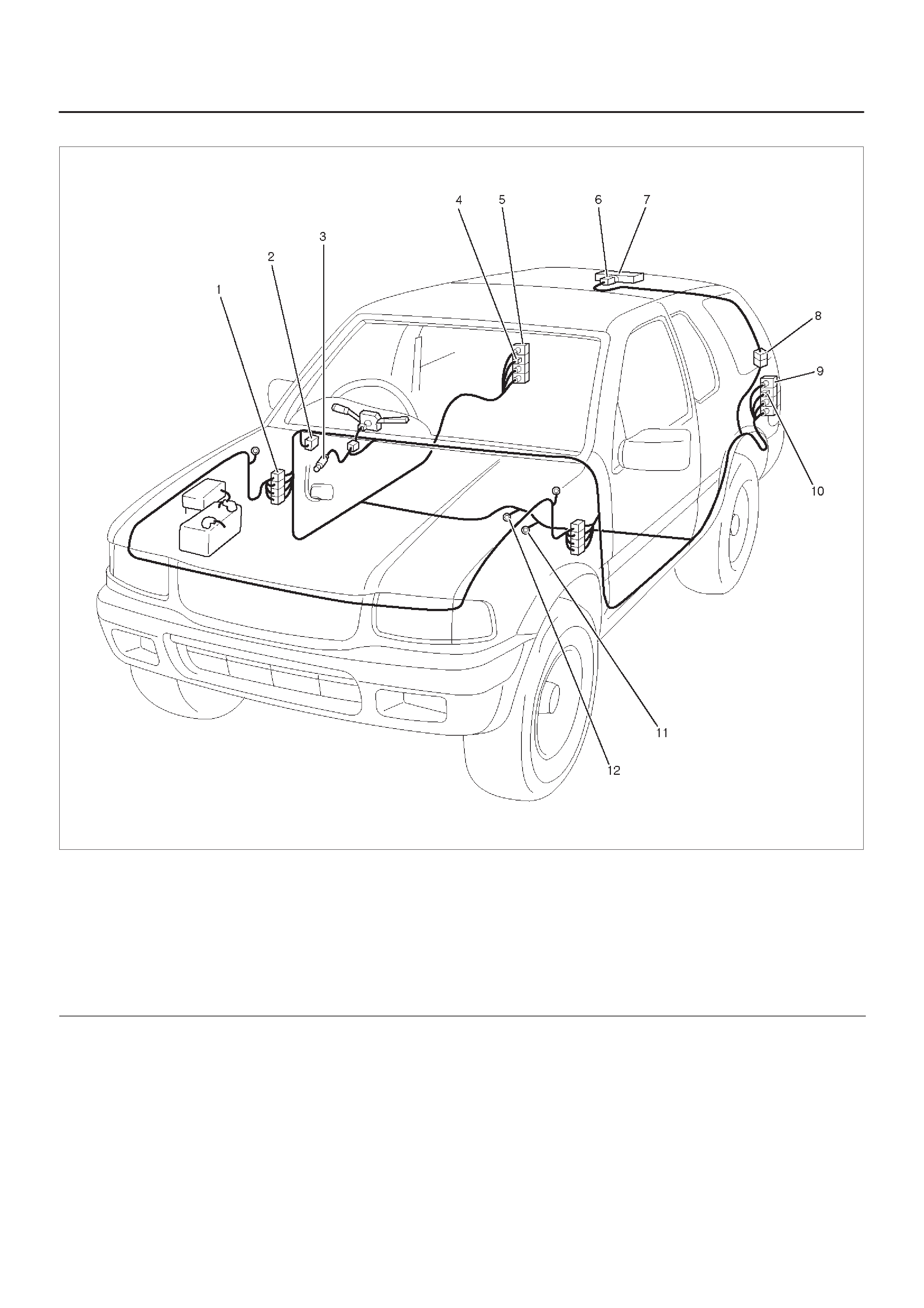
Parts Location
The parts location shows the location of the connectors
(1) and the harness (2) used in each harness routing.
D08RWD38
Circuit Diagram
The circuit diagram shows the power supply (1) the load
or loads (2) and the grounding point(s) (3).
D08RX124
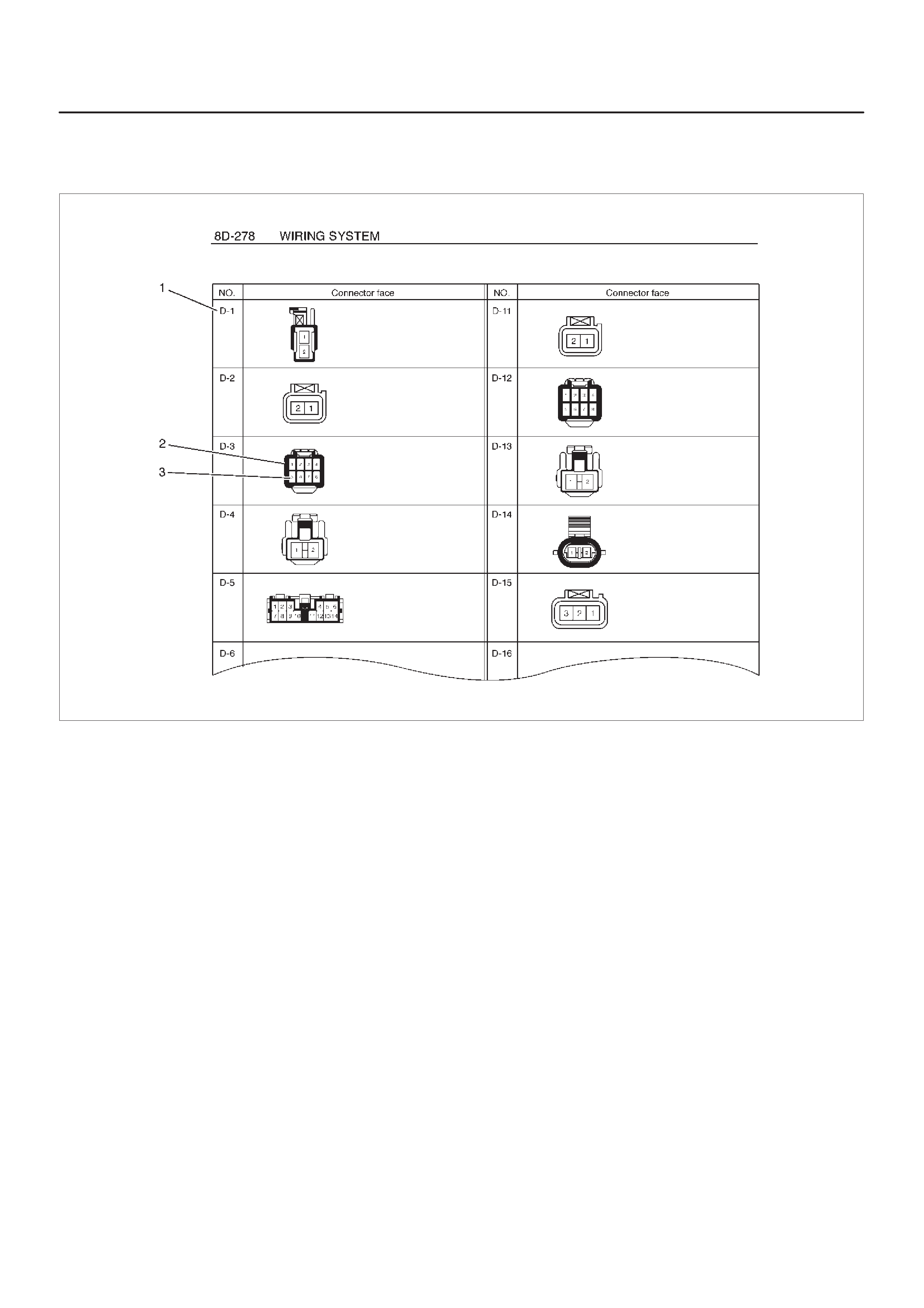
Harness Connector Faces
The harness connector faces show each connector’s
number (1), configuration (2) and the pin number (3).
F00RX011
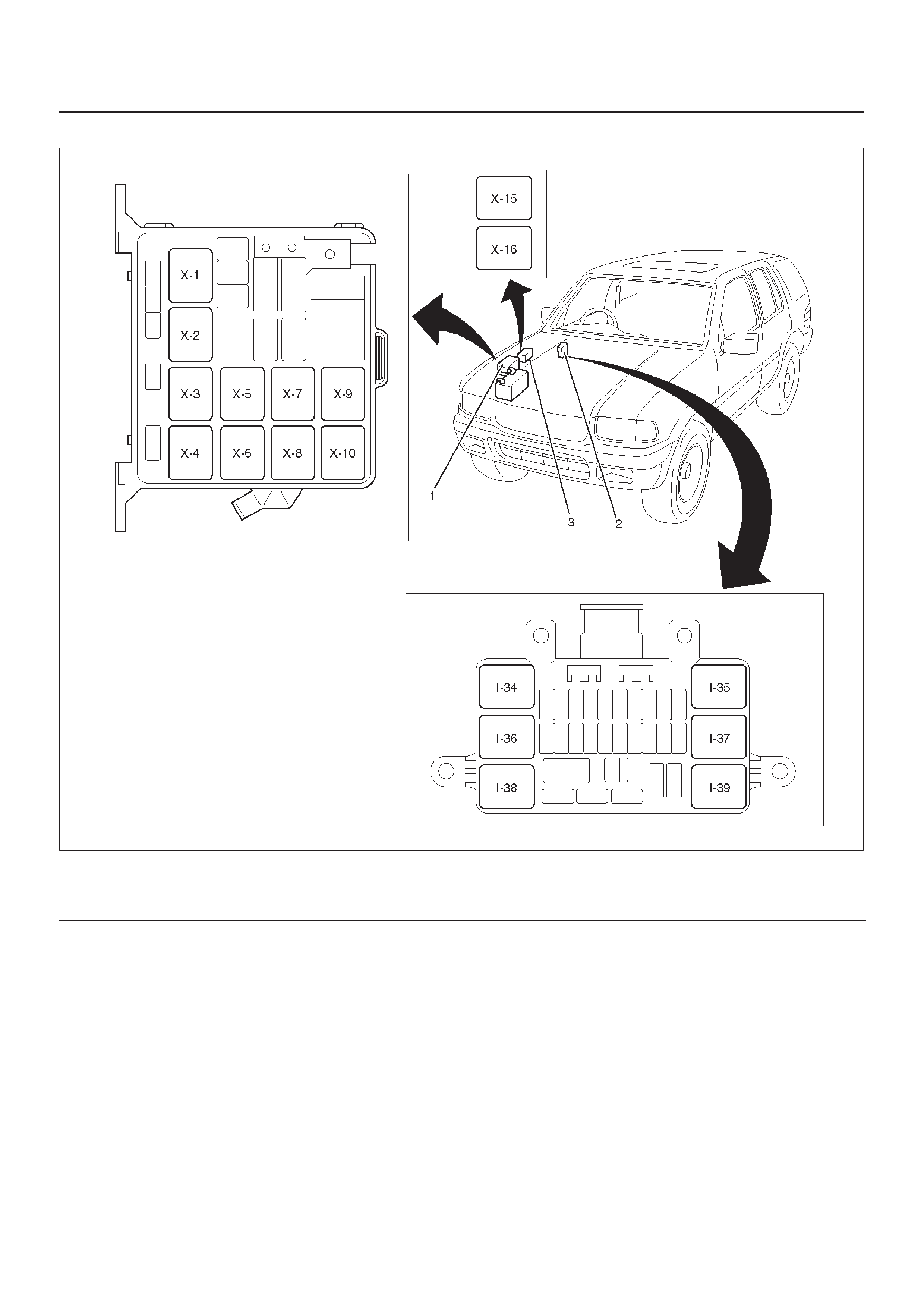
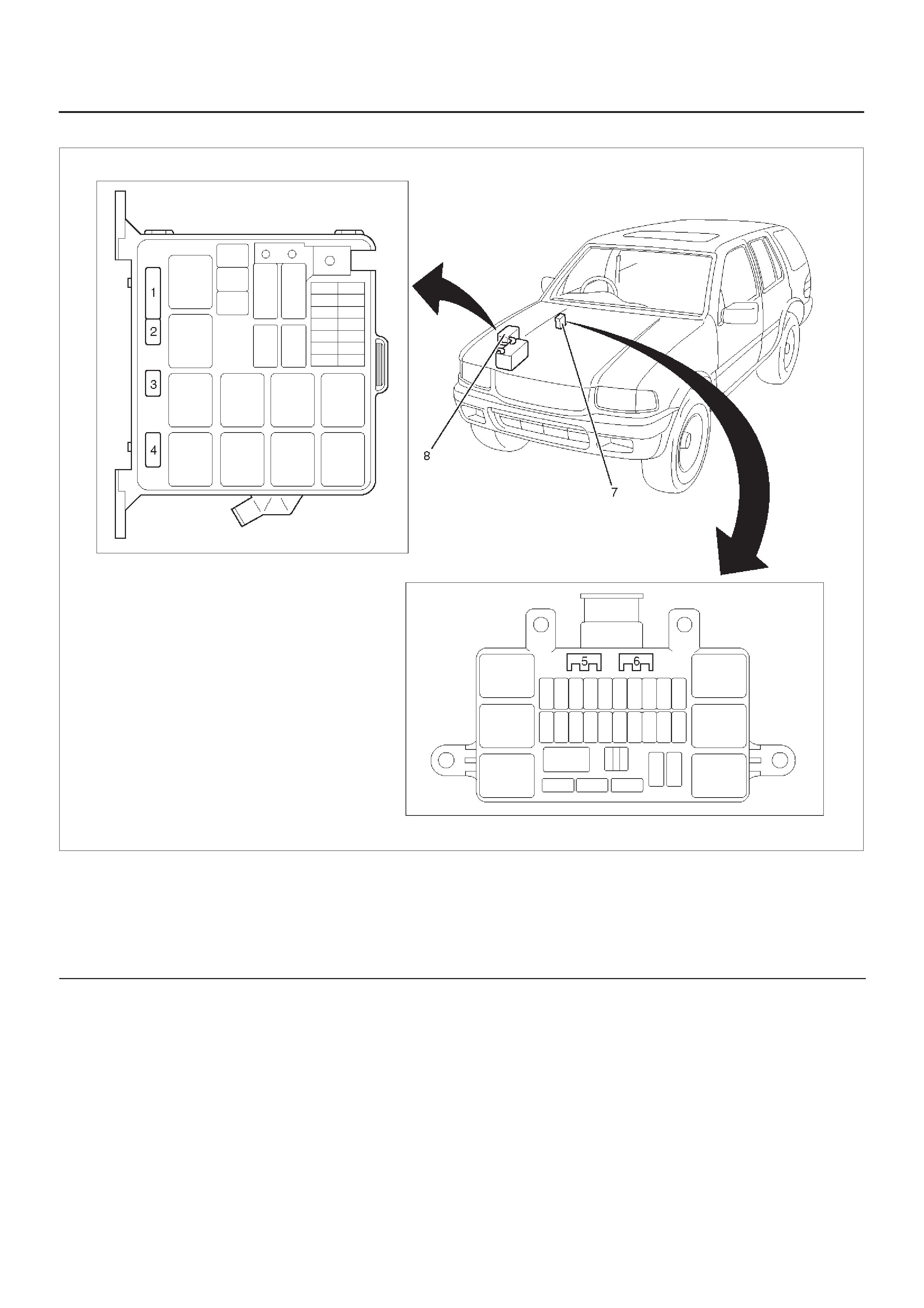
Main Data and Specifications
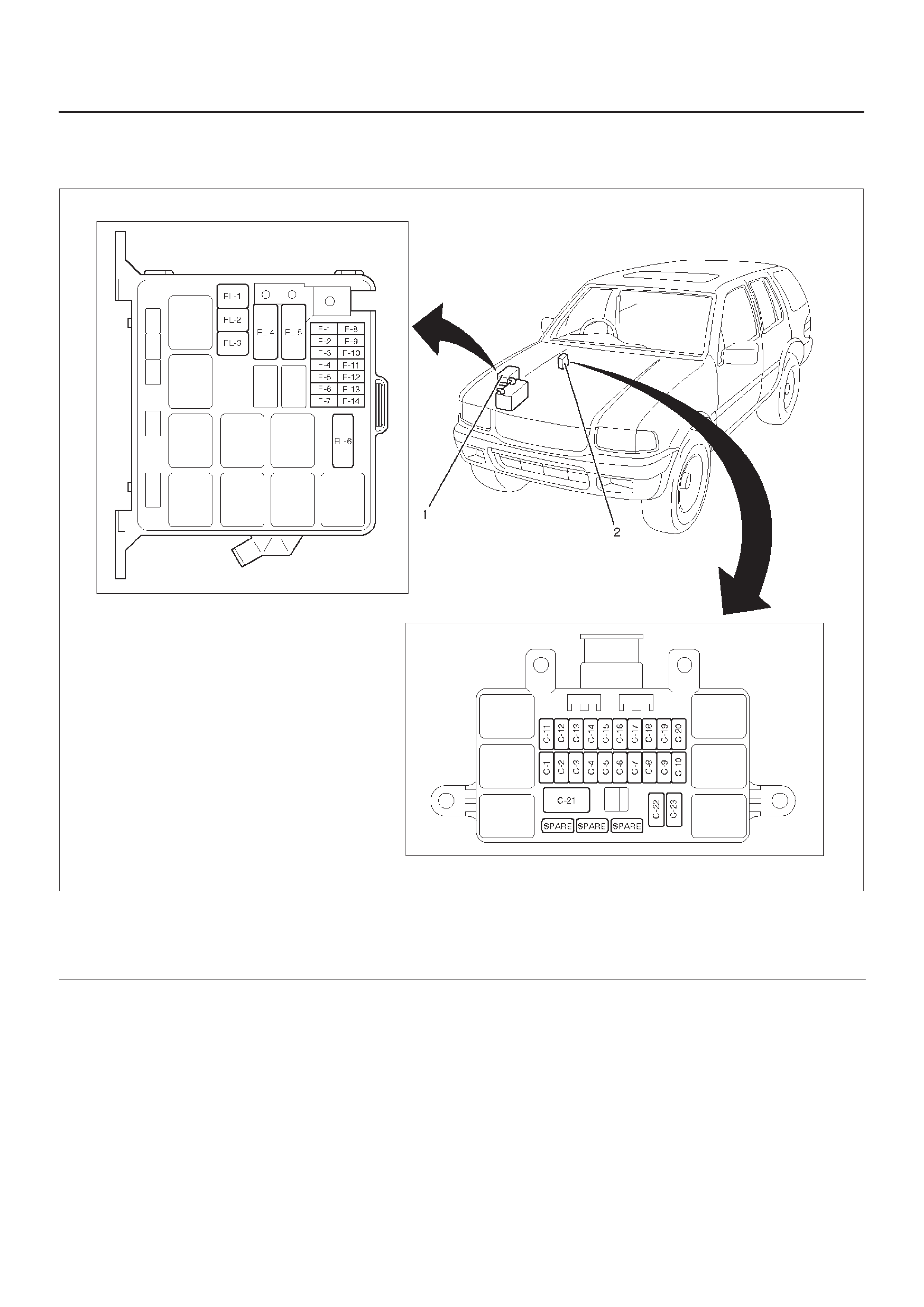
Fuse, Fusible Link and Circuit Breaker Location
810RX013
Legend
(1) Relay & Fuse Box (Engine Room)
(2) Relay & Fuse Box (Instrument panel)

Relay & Fuse Box (Engine Room)
Fuse
No. Capacity Indication on label
F-1 15A HAZARD
F-2 10A HORN
F-3 – –
F-4 20A BLOWER
F-5 10A A/C
F-6 – –
F-7 – –
F-8 10A H/L LIGHT-LH
F-9 10A H/L LIGHT-RH
F-10 15A FOG LIGHT
F-11 20A O2 SENSOR
F-12 20A FUEL PUMP
F-13 15A ECM
F-14 – –
FL-1 60A ABS
FL-2 30A (COND.FAN)
FL-3 – –
FL-4 100A MAIN
FL-5 60A IGN.
FL-6 30A ELEC. FAN
Relay & Fuse Box (Instrument panel)
Fuse
No. Capacity Indication on label
C-1 20A ACC. SOCKET
C-2 10A (AUDIO)
C-3 15A CIGAR LIGHTER
C-4 15A TAIL/ILLUMI. LIGHT
C-5 10A DOME LIGHT
C-6 15A STOP LIGHT
C-7 20A (POWER DOOR LOCK)
C-8 10A (MIRROR DEFOG)
C-9 15A (REAR DEFOG)
C-10 15A (REAR DEFOG)
C-11 15A METER
C-12 15A ENGINE IG.
C-13 15A IG. COIL
C-14 15A BACK UP/TURN LIGHT
C-15 15A ELEC. IG.
C-16 20A FRONT WIPER & W ASHER
C-17 10A (REAR WIPER & W ASHER)
C-18 – –
C-19 15A (AUDIO)
C-20 10A STARTER
C-21 30A (POWER WINDOW)
C-22 10A SRS
C-23 – –
Fuse Block Circuit–1 (6VD1)
D08RX278
Fuse Block Circuit–1 (X22SE)
D08RX279
Fuse Block Circuit–2 (6VD1)
D08RX280
Fuse Block Circuit–2 (X22SE)
D08RX281
Fuse Block Circuit–3
D08RX282
Fuse Block Circuit–4
D08RX283

Reference Table of Fuse, Fusible Link and Circuit Breaker
Fuse (Relay and Fuse Box · Engine Room)
Fuse No. Capacity Indication on label Parts (Load)
F-1 15A HAZARD Hazard warning light
F-2 10A HORN Alarm & relay control unit, Horn, Anti - theft horn
F-4 20A BLOWER Blower motor, Blower resistor
F-5 10A A/C A/C thermostat relay, Electronic thermostat,
A/C compressor relay, Magnetic clutch
F-8 10A H/L LIGHT - LH Headlight - LH, High beam indicator light, Fog light relay
F-9 10A H/L LIGHT - RH Headlight - RH
F-10 15A FOG LIGHT Fog light
F-11 20A O2SENSOR Oxygen sensor
F-12 20A FUEL PUMP Fuel pump
F-13 15A ECM Engine control module
F-14 – – –
FL-1 60A ABS EHCU
FL-2 30A COND.FAN (6VD1) Condenser fan unit
FL-4 100A MAIN
FL-5 60A IGN.
FL-6 30A ELEC. FAN (X22SE) Electric fan relay, Electric fan
Fuse (Relay & Fuse Box · Instrument Panel)
Fuse No. Capacity Indication on label Parts (Load)
C-1 20A ACC. SOCKET Acc socket relay, Acc socket
C-2 10A (AUDIO) Audio
C-3 15A CIGAR LIGHTER Cigarette Lighter
C-4 15A TAIL/ILLUMI. LIGHT Tail relay, Parking light & Side marker light, Tail light
License plate light, Illumination controller, Illumination
light, A/T shift indicator control unit
C-5 10A DOME LIGHT Stop light, Dome light, Courtesy light - LH, Courtesy light
- RH, Courtesy light RR - LH, Courtesy light RR - RH,
Luggage room light, Alarm & relay control unit, Digital
clock, Audio
C-6 15A STOP LIGHT Stop light switch, Rear combination light - LH, Rear
combination light - RH, High mounted stop light
C-7 20A (POWER DOOR
LOCK) FRT door lock & Power window SW, Door lock actuator,
Anti- theft indicator light
C-8 10A (MIRROR DEFOG) Mirror defogger
C-9 15A (REAR DEFOG) Rear defogger
C-10 15A (REAR DEFOG) Rear defogger
C-11 15A METER Indicator and warning lights (meter), Meter gauge,
Vehicle speed sensor
C-12 15A ENGINE IG. Generator, ECM main relay, VSV; purge solenoid, Coil
drive, PCM, EGR valve

Fuse (Relay & Fuse Box · Instrument Panel)
Fuse No. Capacity Indication on label Parts (Load)
C-13 15A IG. COIL Ignition coil
C-14 15A BACKUP/TURN
LIGHT Mode SW, PCM, Turn signal light, Backup light, Cruise
control unit, A/T shift indicator control unit
C-15 15A ELEC. IG. Alarm & relay control unit, Rear defogger relay, Mirror
defogger - LH, Mirror defogger - RH, Rear defogger SW,
Power window relay, Cruise control unit, Shift lock relay,
4WD control unit, VSV; FRT axle (c), VSV; FRT axle (d)
C-16 20A FRONT WIPER &
WASHER Windshield wiper motor, Windshield washer motor,
Alarm & relay control unit
C-17 10A (REAR WIPER &
WASHER Rear wiper motor, Rear washer motor, Alarm & relay &
control unit
C-19 15A (AUDIO) Audio
C-20 10A STARTER Starter, Starter relay, Anti - theft cotroller
C-22 10A SRS SRS warning light, SDM
PCM: Power train module, VSV : V acuum switching valve
Fusible Link (Relay and Fuse Box · Engine Room)
Fuse Link No. Capacity Indication on label
FL-1 60A ABS
FL-2 30A COND. FAN
FL-4 100A MAIN
FL-5 60A IGN.
FL-6 30A ELEC. FAN
ABS: Anti - lock Brake System
Circuit Breaker (Relay & Fuse Box · Instrument Panel)
Fuse No. Capacity Indication on label Parts (Load)
C-21 30A (POWER WINDOW) Power window relay, Power window SW, Power window
motor, Sun roof motor, Sun roof control unit, Sun roof
SW, Safety stop SW, Limit SW, Power seat switch, Front
tilt motor & SW, Rear tilt motor & SW, Slide motor, Re-
cliner moror & SW
Relay Location
810RX014
Legend
(1) Relay & Fuse Box (Engine Room) (2) Relay & Fuse Box (Instrument panel)
(3) Relay Box (Engine Room)

Relay List
Connector No. X–1 X–2 X–3 X–4 X–5 X–6 X–7 X–8 X–9
Usage Head
light Fog
light Starter A/C
comp. Thermo Heater Fuel
pump ECM COND
FAN
Engine 6VD1 f f f f f f f f f
X22SE f f f f f f f f –
Connector No. X–10 X–15 X–16 I–34 I–35 I–36 I–37 I–38 I–39
Usage – Elec-
fan-hi Elecfan-
lo Taillight Power
window – – ACC
socket Rear de-
fogger
Engine 6VD1 – – – f f – – f f
X22SE – f f f f – – f f
Diode Location
810RW320–1
Legend
(1) X–11
(2) X–12
(3) X–13
(4) X–14
(5) I–51
(6) I–45
(7) Relay & Fuse Box (Instrument panel)
(8) Relay & Fuse Box (Engine Room)

Diode List
Connector No. X–11 X–12 X–13 X–14 I–51 I–45
Usage Brake – – – Tailgate SW,
Door SW.
Doom light
Alarm &
relay control
unit
Engine 6VD1 f– – – f f
X22SE f– – – f f

Grounding Point
Reference Table
Connector No. Cable harness Location Parts (Load)
B–6 Vanity mirror illumination, RR turn signal light - RH, Sun
roof control unit, Sun roof motor, Spot light, Taillight - RH,
Stoplight - RH
B–8
Body harness Body–Center
Vanity mirror illumination, Rear defogger relay, Rear
defogger SW, FRT door lock & power window SW – RH,
Cruise control unit, Digital clock, Cigarette lighter, Mirror
defogger – RH, Blower motor, Blower resistor, Electronic
thermostat, A/T shift lock, Flasher unit, Audio
Door lock actuator, FRT power window & door lock SW –
LH, RR wiper intermittent relay, Mirror defogger – LH,
Seat belt SW, Stoplight – LH
Anti – theft controller, Heater & A/C relay, Tail relay,
PCM, Headlight, High beam indicator light, Lighting relay,
Fog light relay, Illumination controller, Flasher unit,
Cornering relay, Power window relay, Headlight wiper
motor, Turn signal indicator light, Luggage room light,
Map light, Alarm & relay control unit
Fuel pump, RR door lock & power window SW, Shift lock
controller, Power door mirror motor, Mirror defogger SW,
Seat belt warning light
Fuel tank unit, Fuel warning light.
C–16 Engine room
harness Fender–LH
FRT combination light – LH, FRT turn signal light – LH,
Cornering light – LH, Vehicle speed snsor
Windshield washer motor (FRT)
Brake warning light, PCM
Data link connector
FRT combination light – RH, Cornering light – RH, FRT
turn signal light – RH
Fog light, EHCU
Kick down SW
Oxygen sensor, FRT-LH, FRT-RH, RR-LH, RR-RH, 4WD
indicator light, VSV; FRT axle
C–36 Engine room
harness Fender–RH Windshield wiper motor
Engine hood SW
Windshield washer motor, Windshield washer motor
E–28 Engine ECGI
harness
Common
chamber
Ignition coil, Coil driver, EGR valve, I.A.T.S., T.P.S.
PCM, ECM main relay, Fuel pump relay, Cam position
sensor
E–30
harness
chamber
Crank position sensor, Knock sensor, PCM, Mass air flow
sensor, Data link connector
I–43 Instrument
harness Body-FRT SDM
Location – 1
D08RW050 D08RW054
Legend
(1) B–6, B–7, B–8
(2) 2–4WD Control Unit
(3) C–36
(4) EHCU
Location – 2
D08RW048
D08RW052
D08RWD07
D08RW053
Legend
(1) E–28
(2) I–43
(3) H–15
(4) P–6
(5) Cruise Control Actuator
(6) P–7
(7) Frame
Location – 3
D08RW051
Legend
(1) P–10
(2) Battery
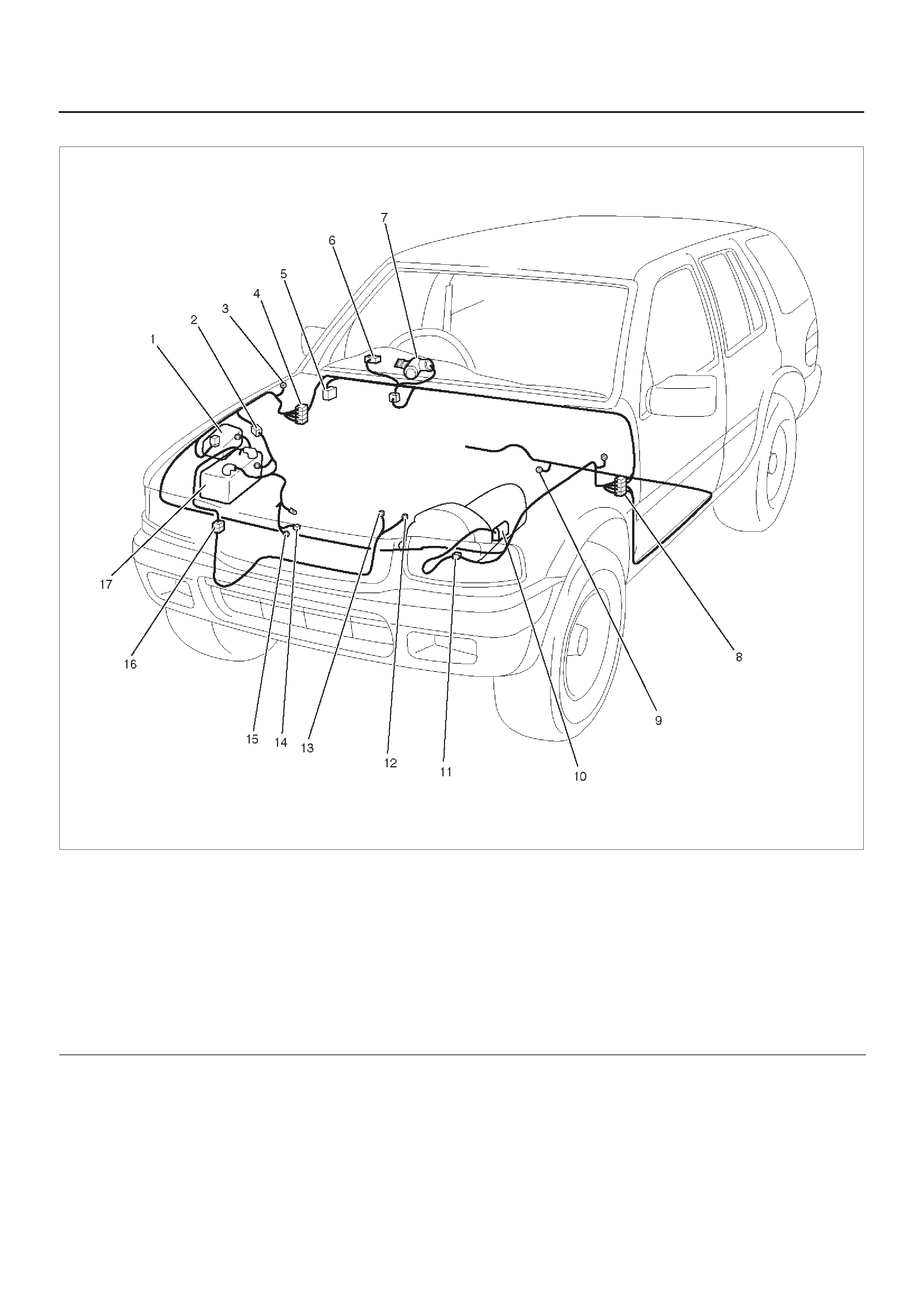
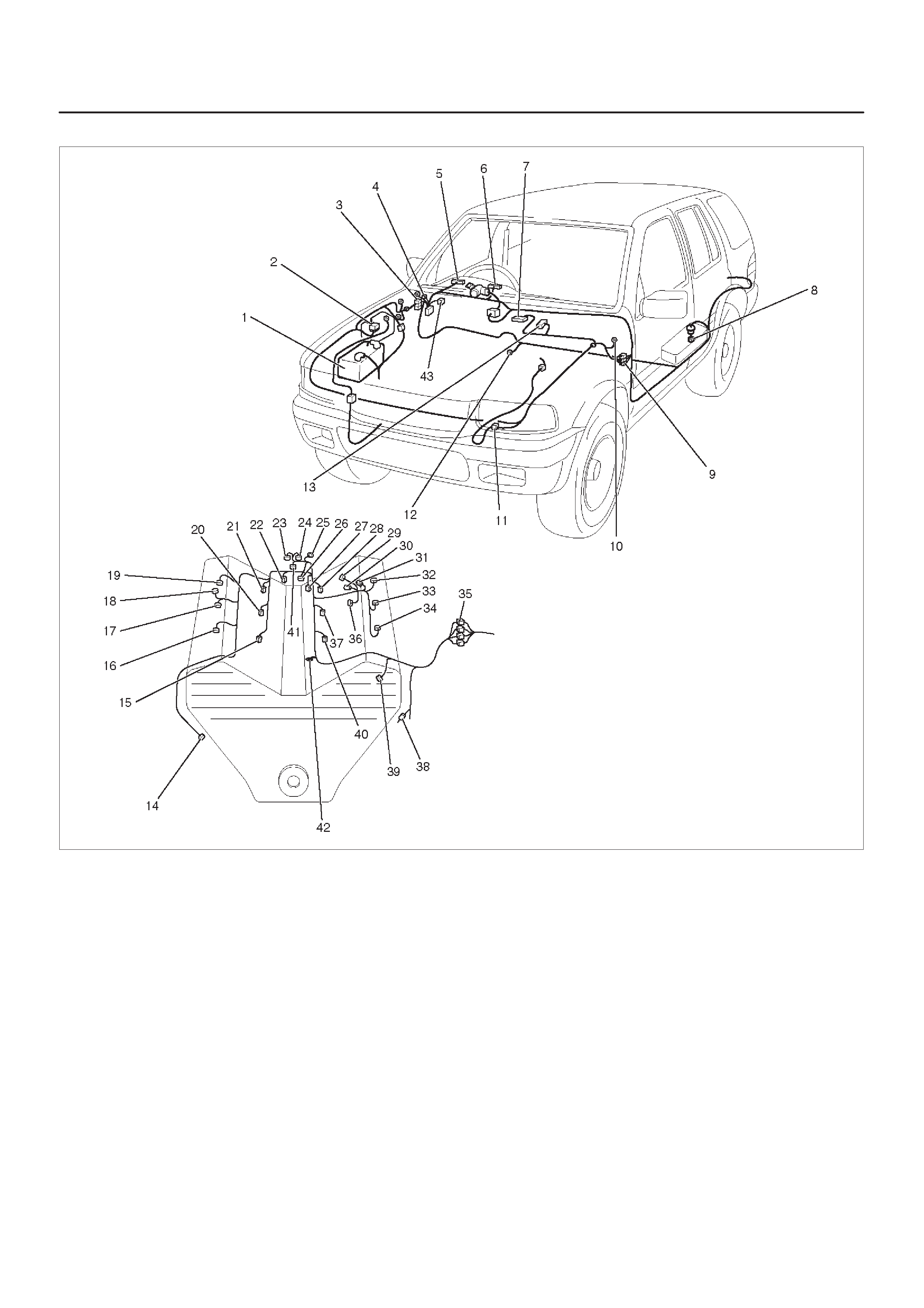
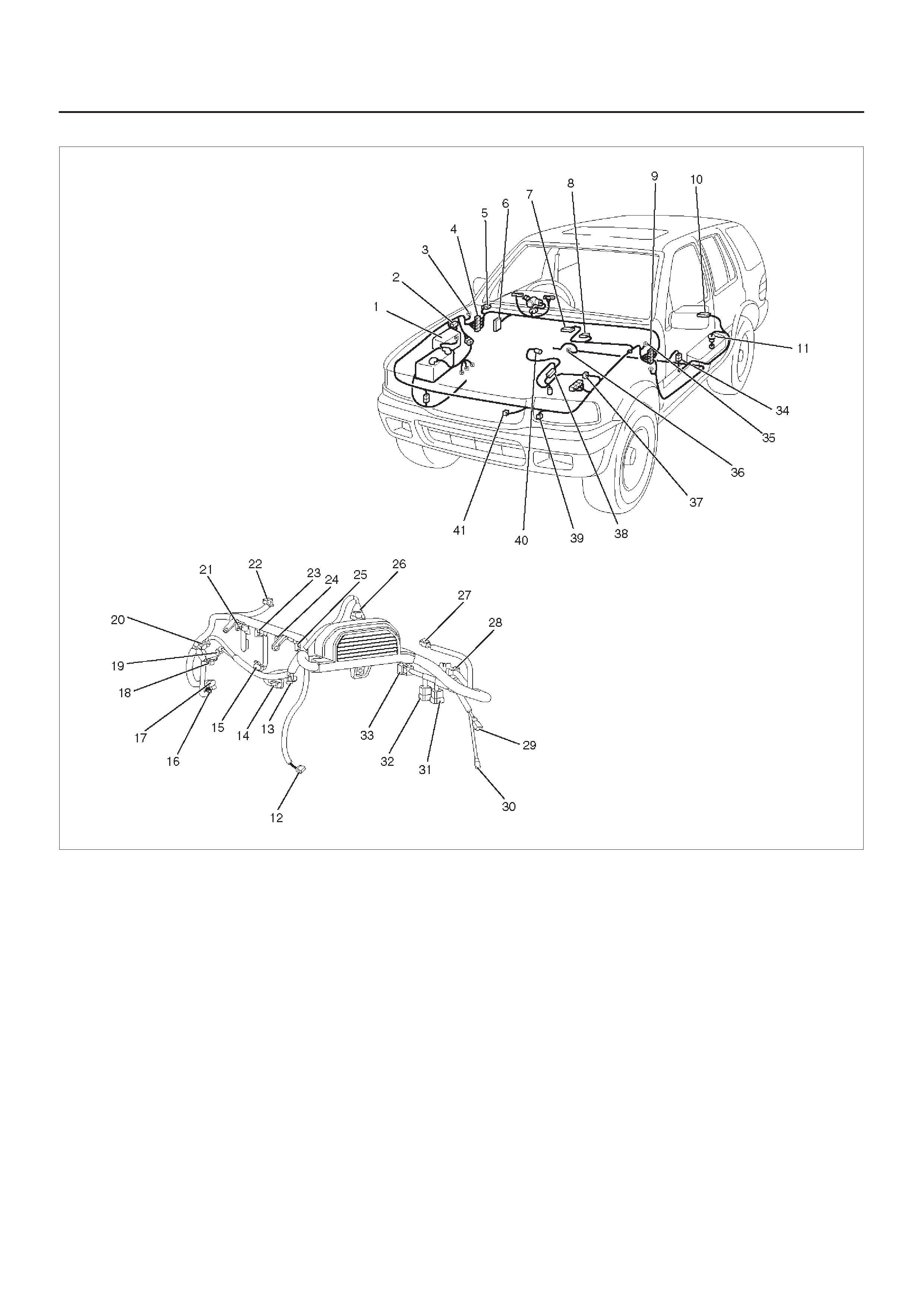
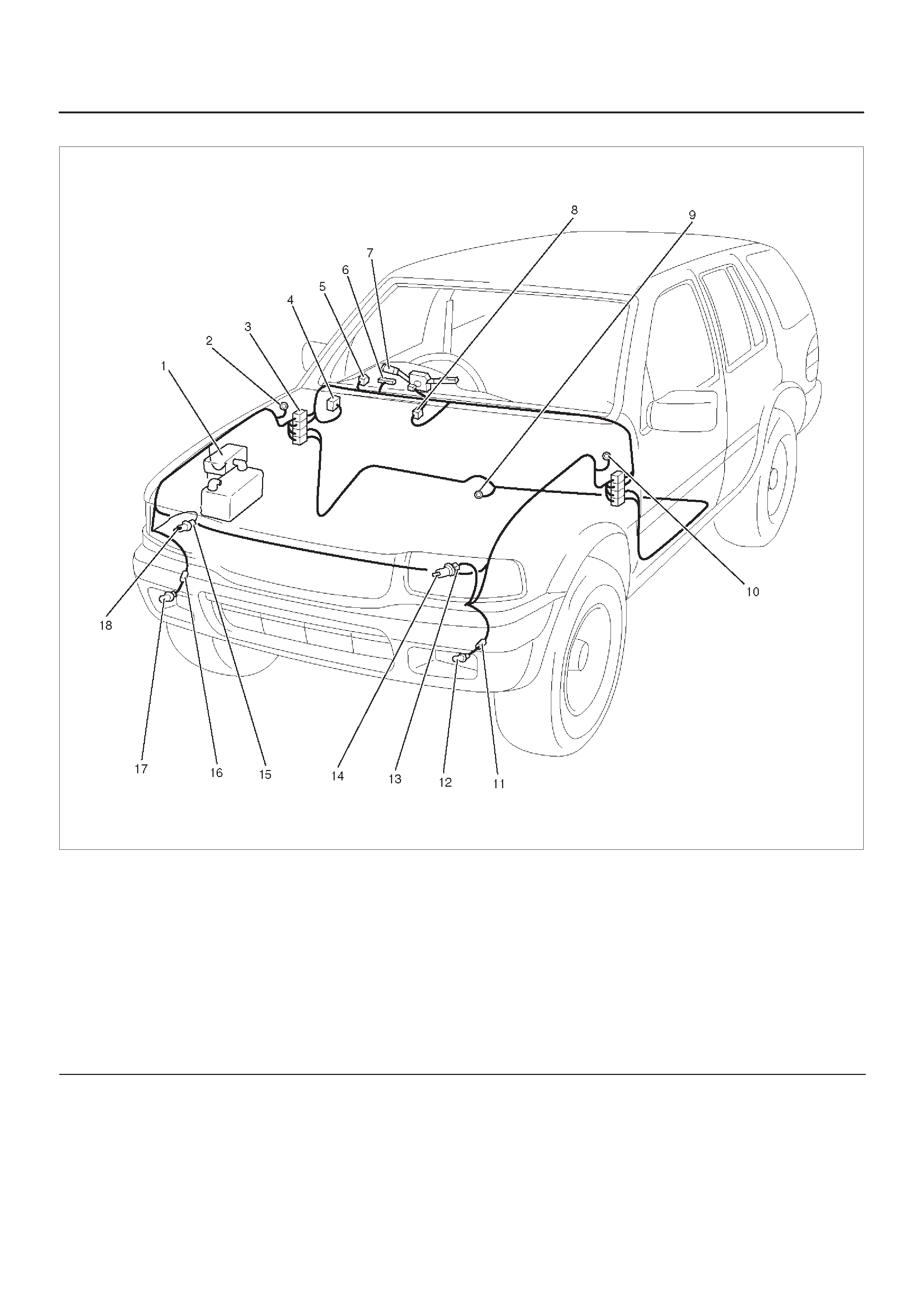
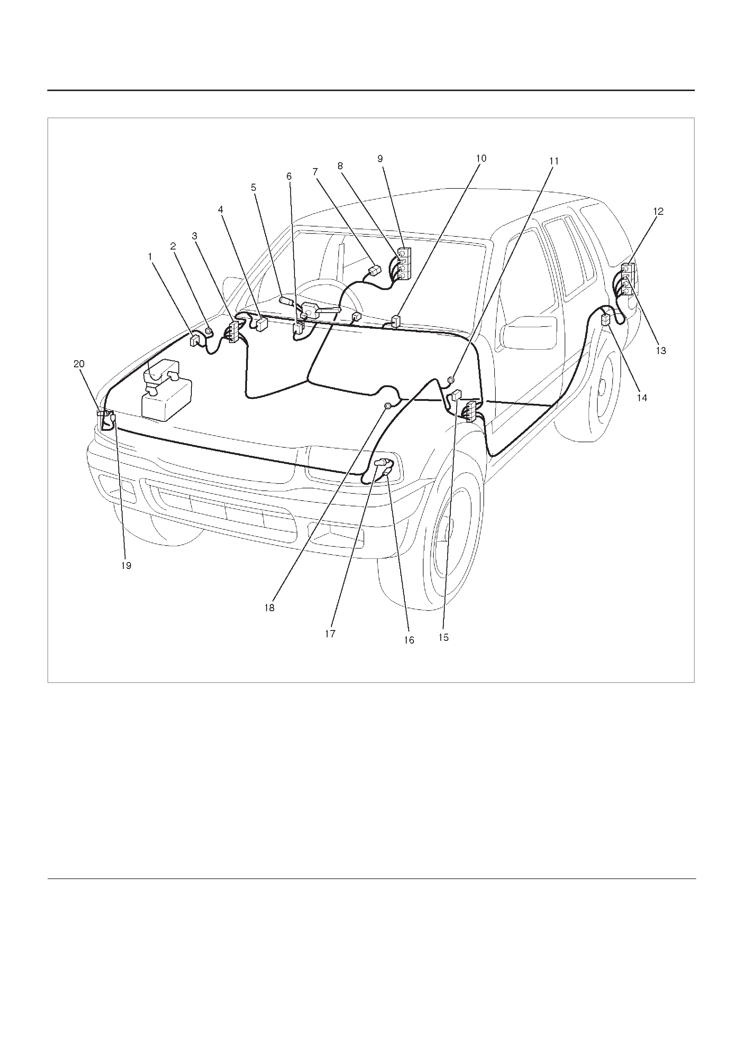
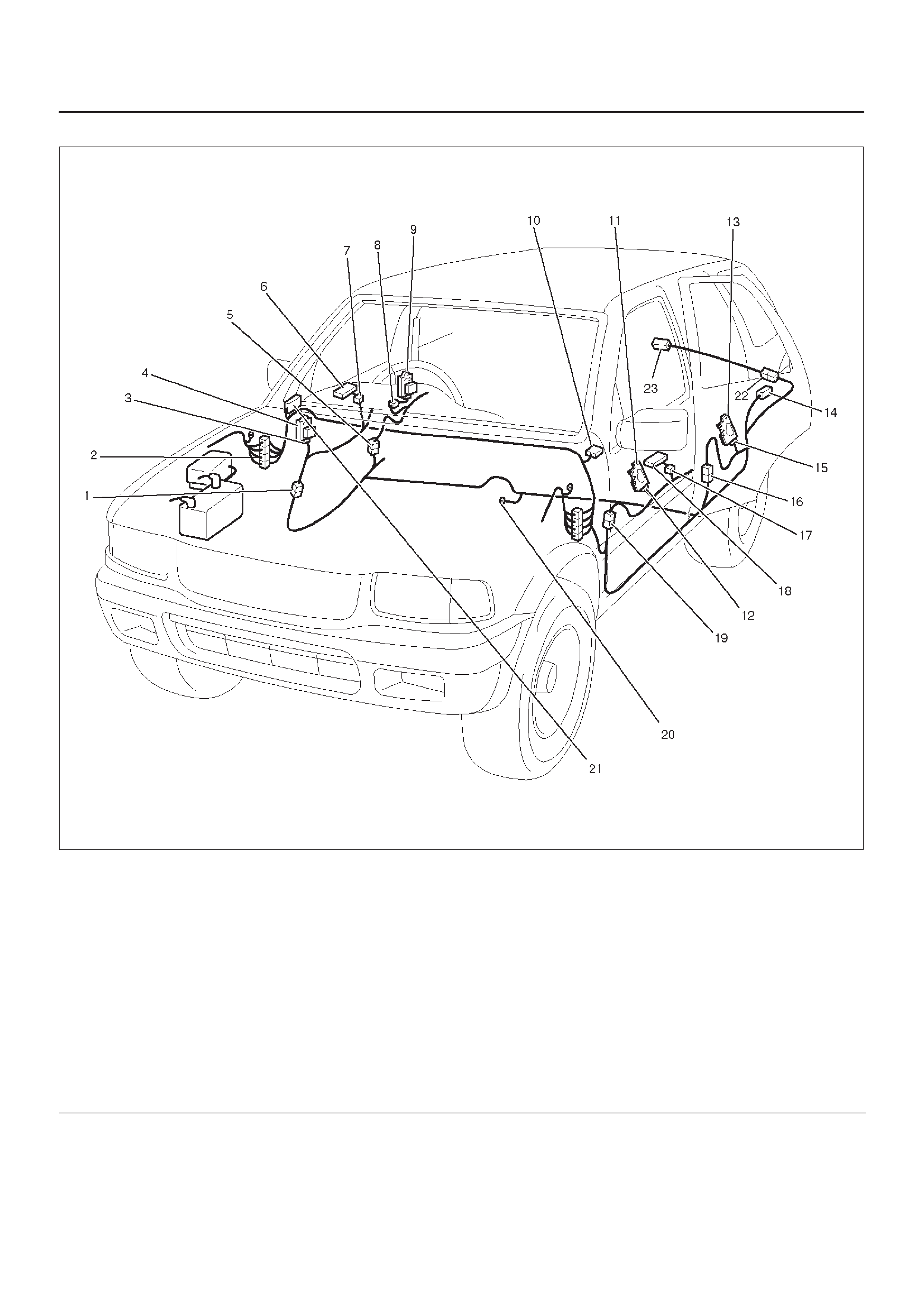
Cable Harness Routing
D08RX275
Legend
(1) Battery (–) Cable
(2) Battery (+) Cable
(3) H–2, H–3
(4) Battery Cable Harness
(5) C–36
(6) H–13, H–14, H–19, H–32
(7) Instrument Harness
(8) H–24
(9) RR Door Harness – RH
(10) Transmission Harness (X22SE)
(11) L–2 (Map Light)
(12) H–21
(13) Hatch Galss Harness
(14) Roof Harness
(15) Tair Gate Harness
(16) RR Door Harness – LH
(17) Chassis Harness
(18) FRT Door Harness – LH
(19) H–33
(20) H–15, H–16, H–17, H–31
(21) C–16
(22) B–8
(23) Body Harness
(24) Engine Harness
(25) H–4, H–5, H–6
(26) H–9, H–10, H–11 (6VD1)
(27) Transmission Harness (6VD1)
(28) Engine Room Harness
(29) P–7
(30) P–9
(31) P–1
(32) H–1
(33) Battery
(34) P–5
(2Door Model)
D08RX277
Legend
(1) Engine Room Harness
(2) C–36
(3) Instrument Harness
(4) Body Harness
(5) B–11
(6) Hight Mounted Stoplight (G–4)
(7) Tailer Connector
(8) H–34 (Tail Gate Harness Connector)
(9) B–20
(10) H–37
(11) Resin Harness
(12) B–8
(13) Instrument Harness
(14) Body Harness & Engine Room Harness
Connector
(15) I–43
(16) C–16
(4Door Model)
D08RX276
Legend
(1) Instrument Harness
(2) Engine Room Harness & Body Harness
Connector
(3) Relay & Fuse Box (Instrument Panel)
(4) FRT Door Harness – RH
(5) H–28
(6) Body Harness
(7) H–20
(8) H–21
(9) Hatch Glass Harness
(10) Tail Gate Harness
(11) G–11
(12) TRAILER Connector
(13) B–8
(14) Body Harness & Engine Room Harness
Connector
(15) H–33

Start and Charging
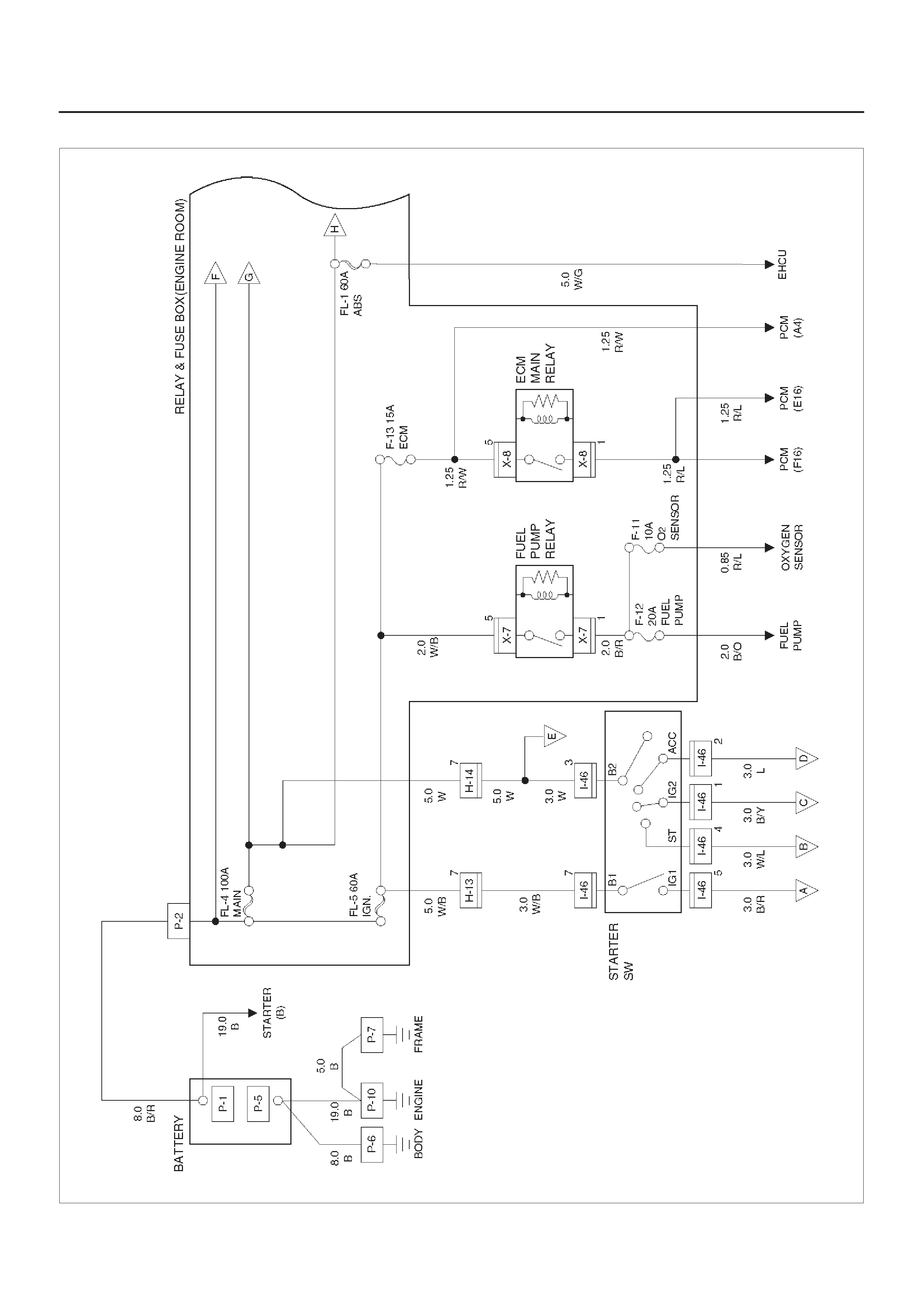
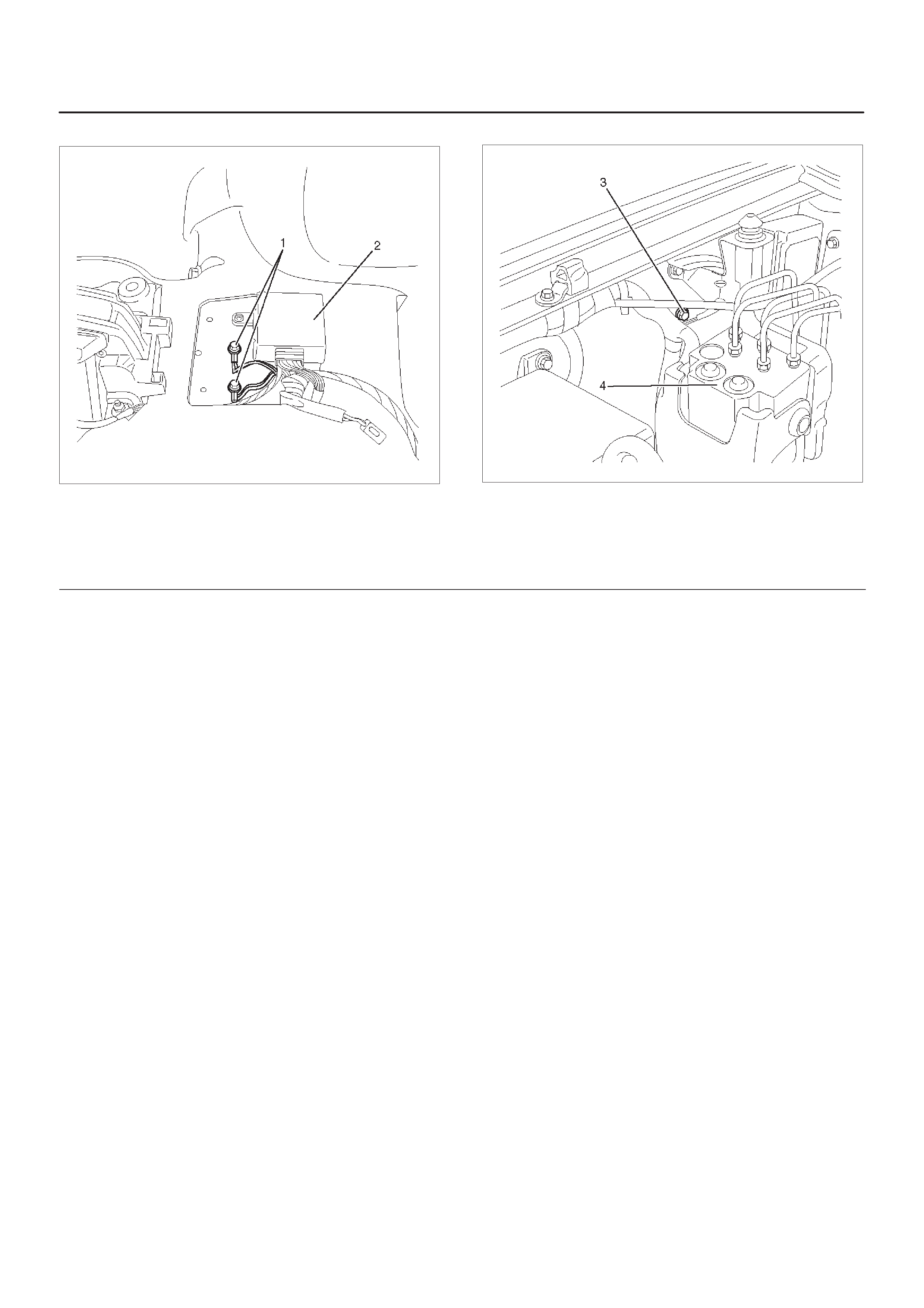
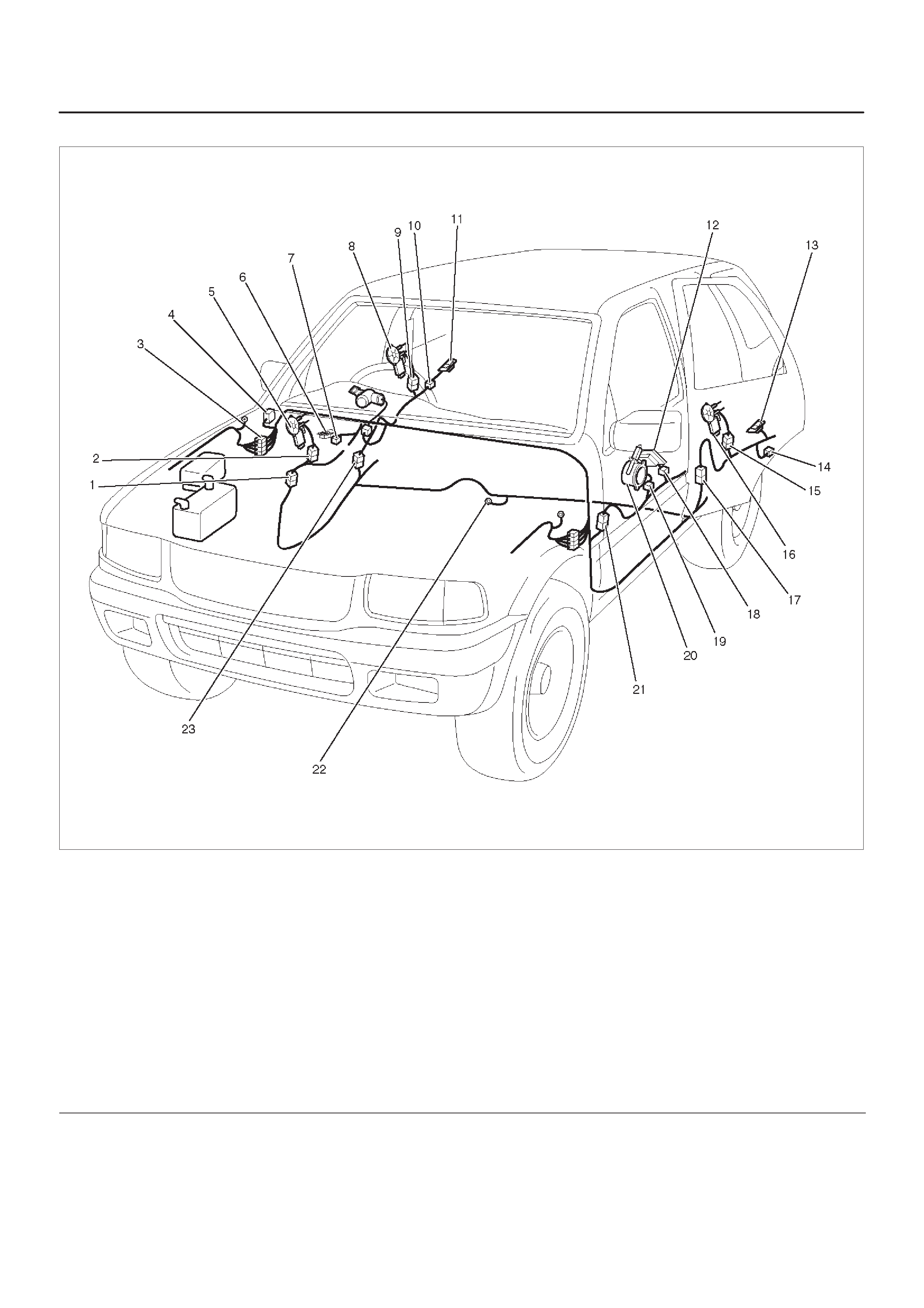
General Description
This system consists of starter, AC generator, starter
relay , clutch start SW (M/T), mode SW (A/T) and heater &
A/C relay.
When starter SW is set to “ST” position with A/T select
lever at “P” (Parking) or “N” (Neutral) position (Mode SW
“ON”), or clutch pedal depressed (Clutch start SW “ON”),
battery positive voltage is applied to starter solenoid coil
through starter relay to start starter. At the some time,
starter relay cuts off blower motor and A/C circuit.
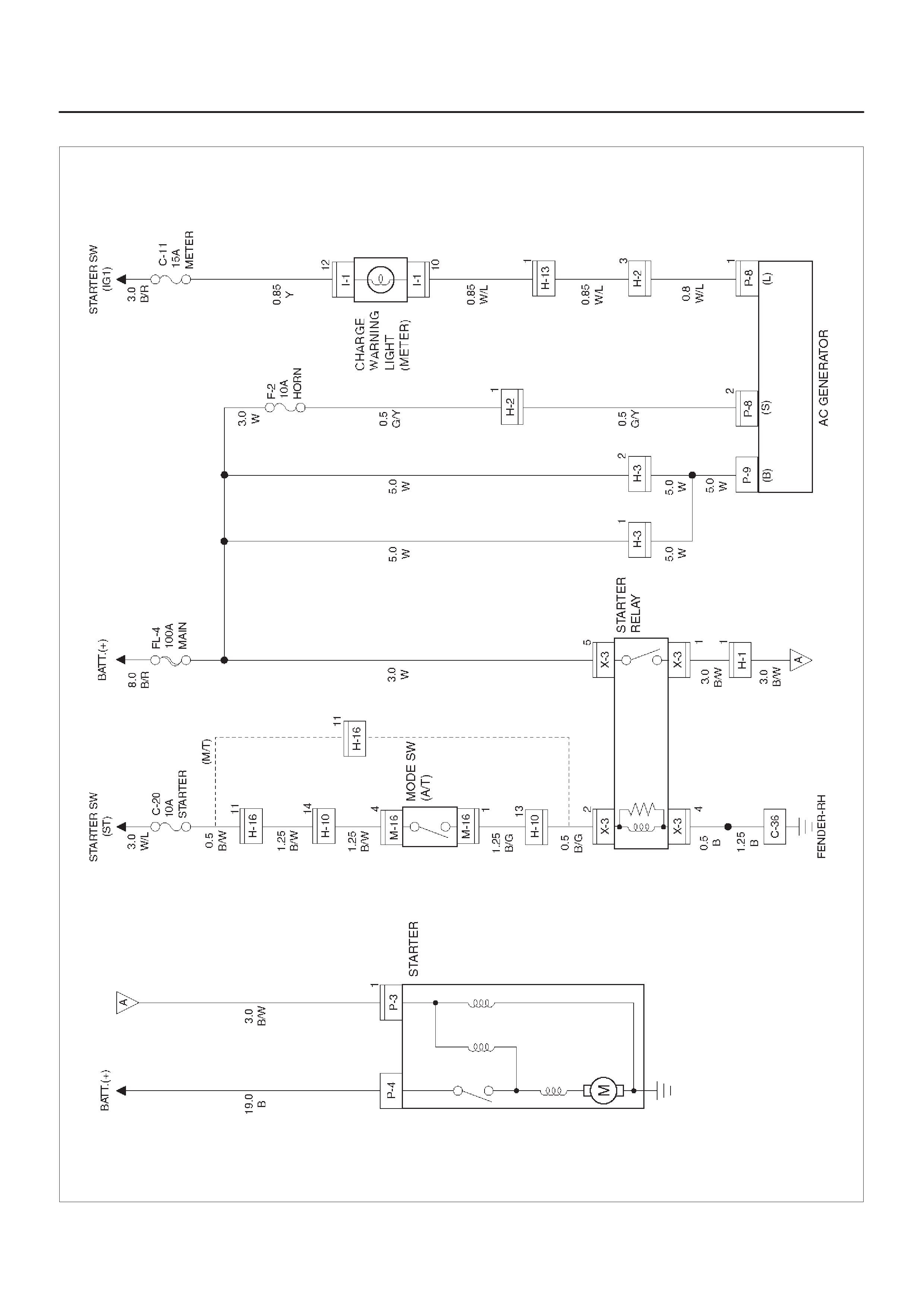
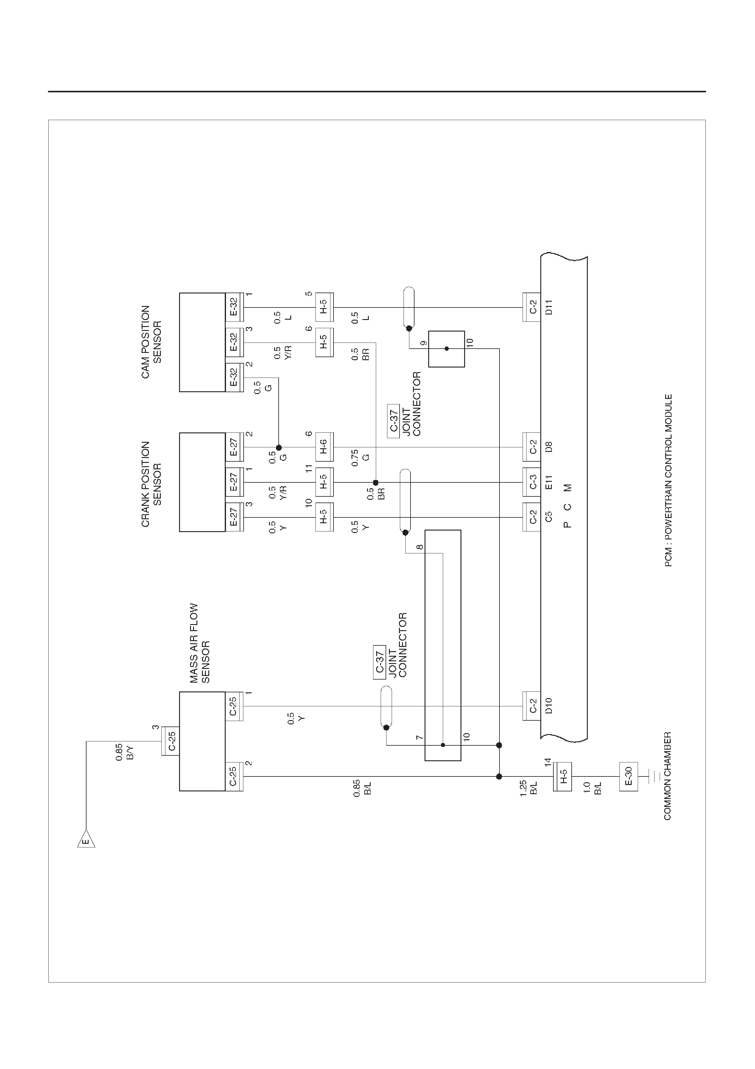
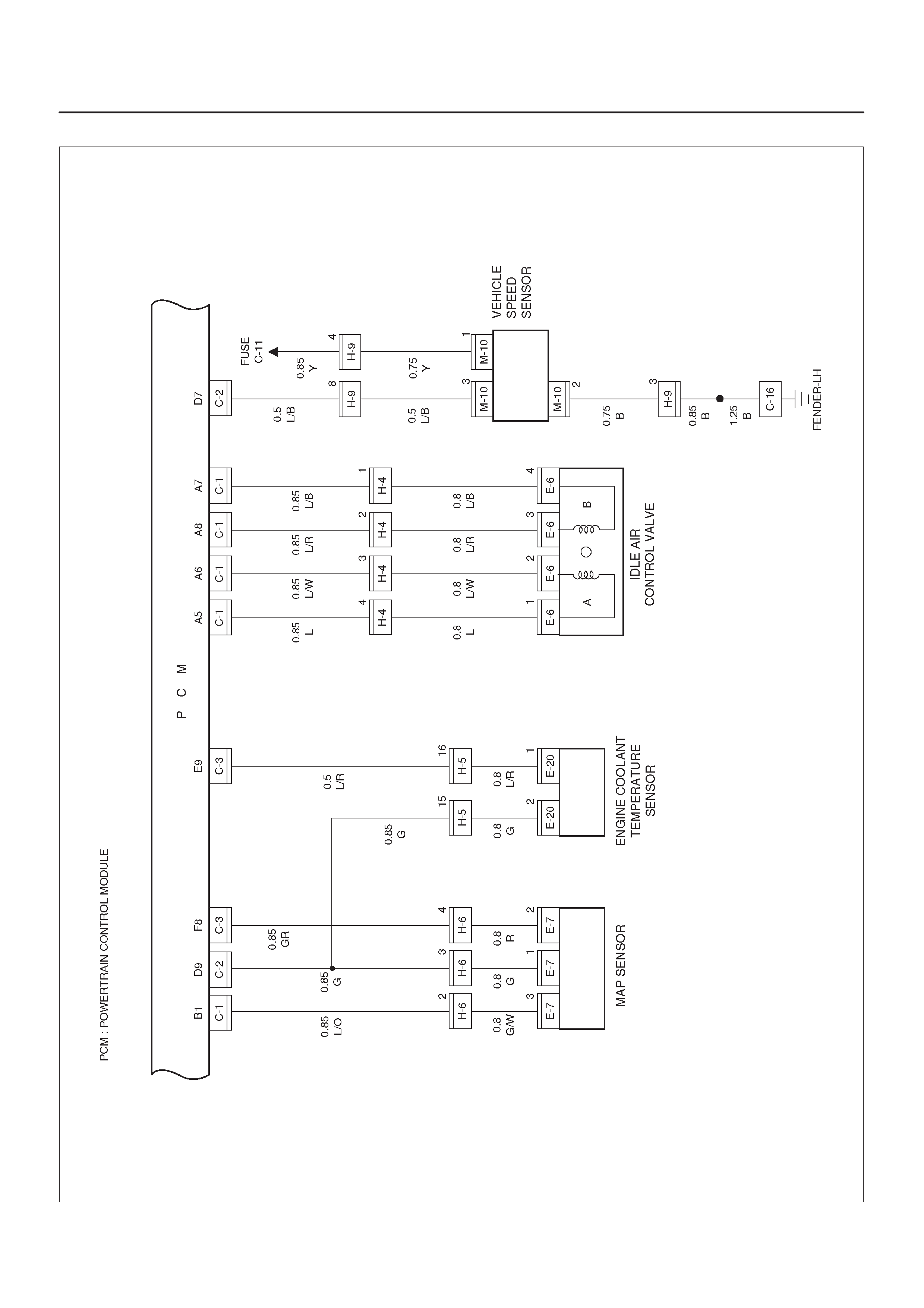
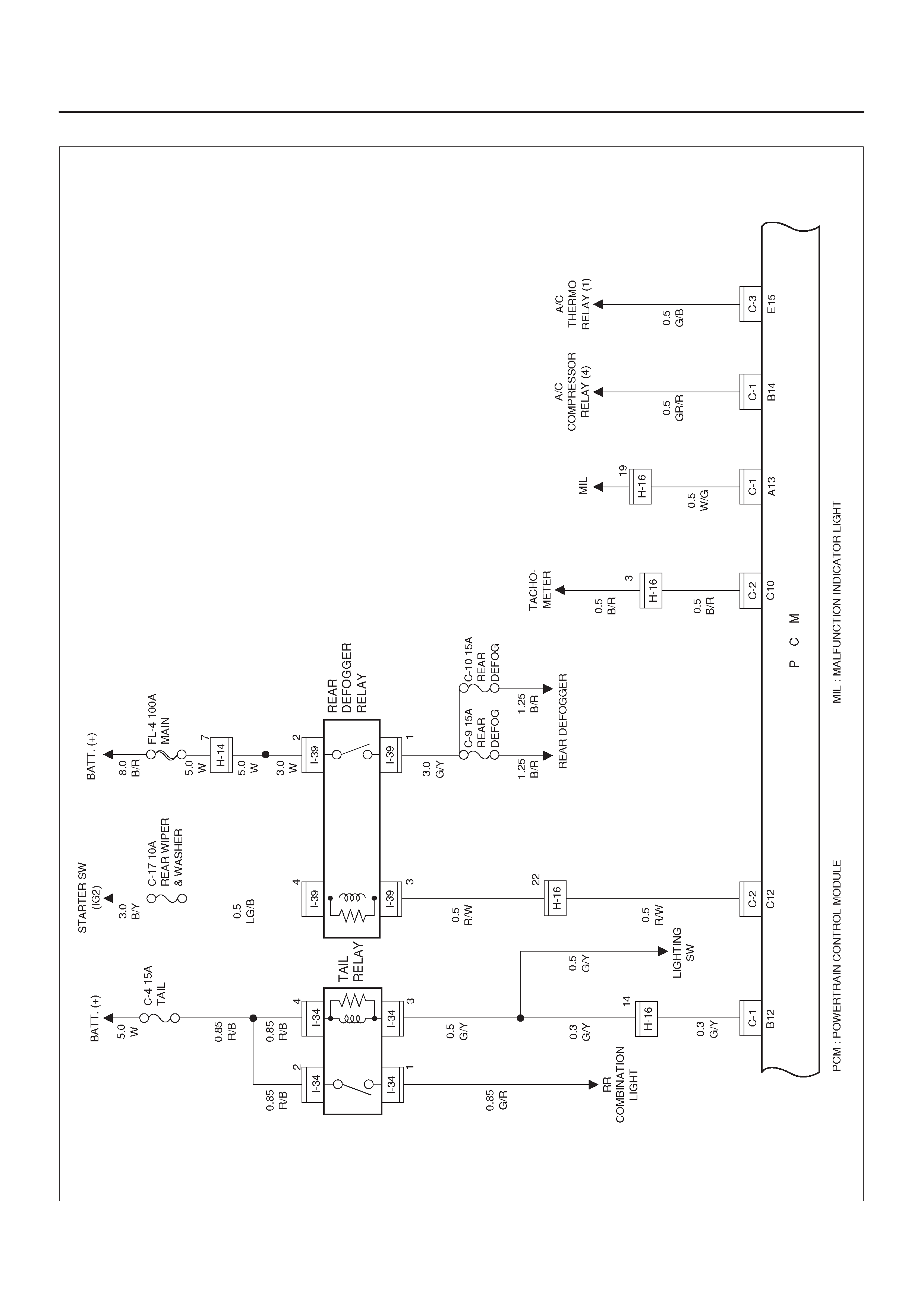
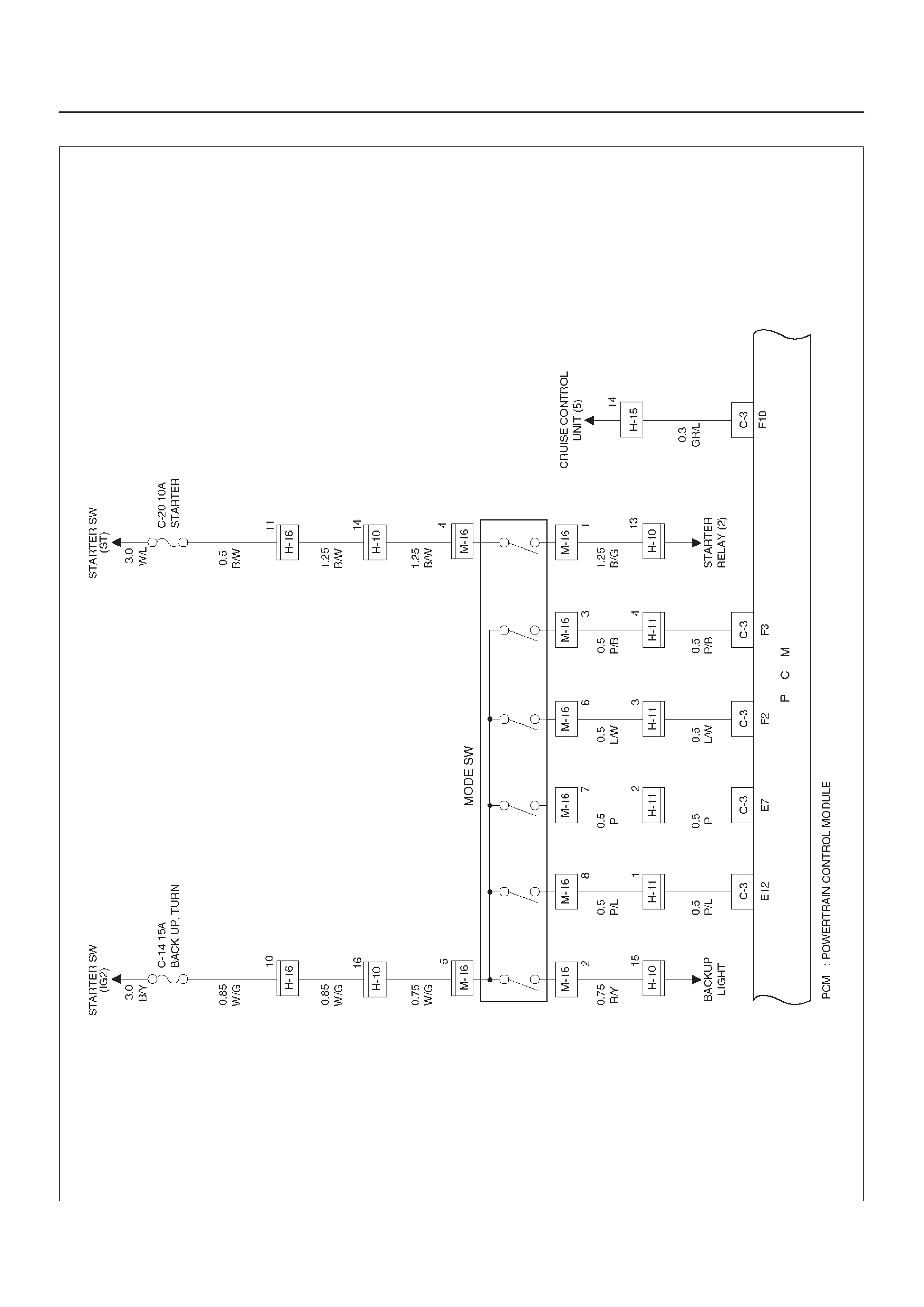
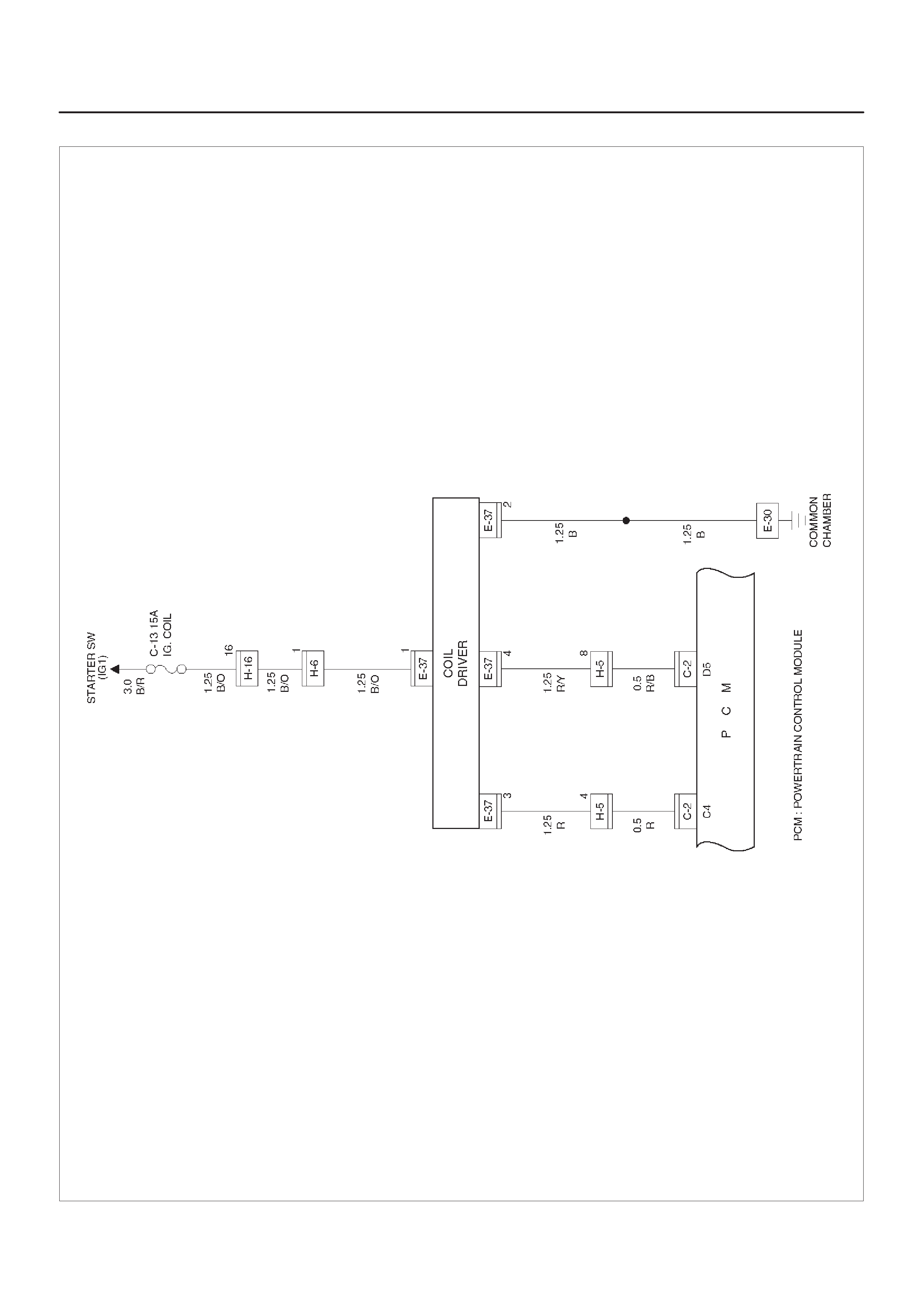
Circuit Diagram–1 (6VD1)
D08RX189
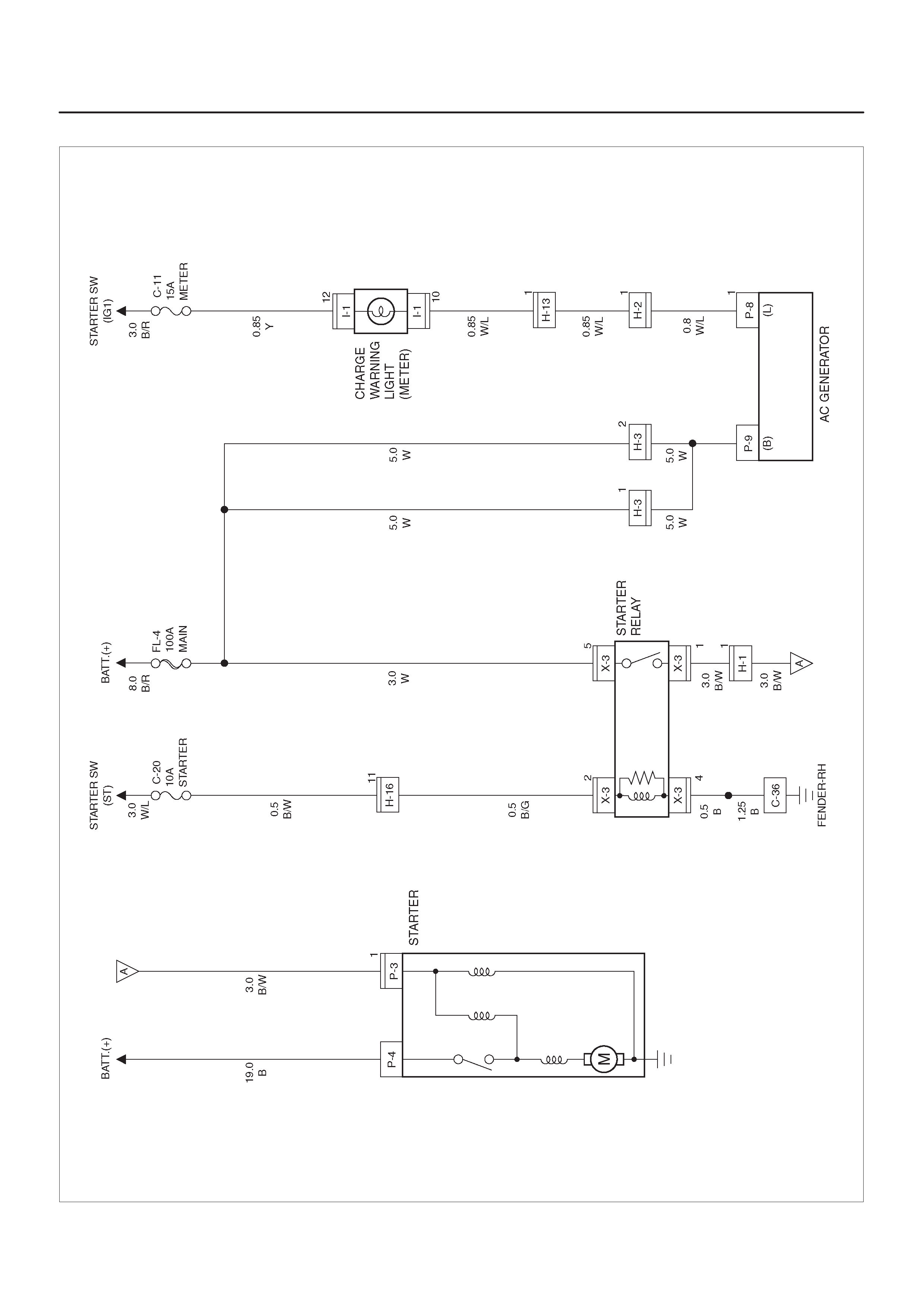
Circuit Diagram–1 (X22SE)
D08RY00936
Parts Location
D08RX190
Legend
(1) X–3
(2) H–2, H–3
(3) C–36
(4) H–13
(5) Relay & Fuse Box (C–11, C–20)
(6) I–1
(7) Starter Switch
(8) H–16
(9) B–8
(10) Mode Switch (M–16)
(11) H–10
(12) P–4
(13) P–3
(14) P–8
(15) P–9
(16) H–1
(17) Battery

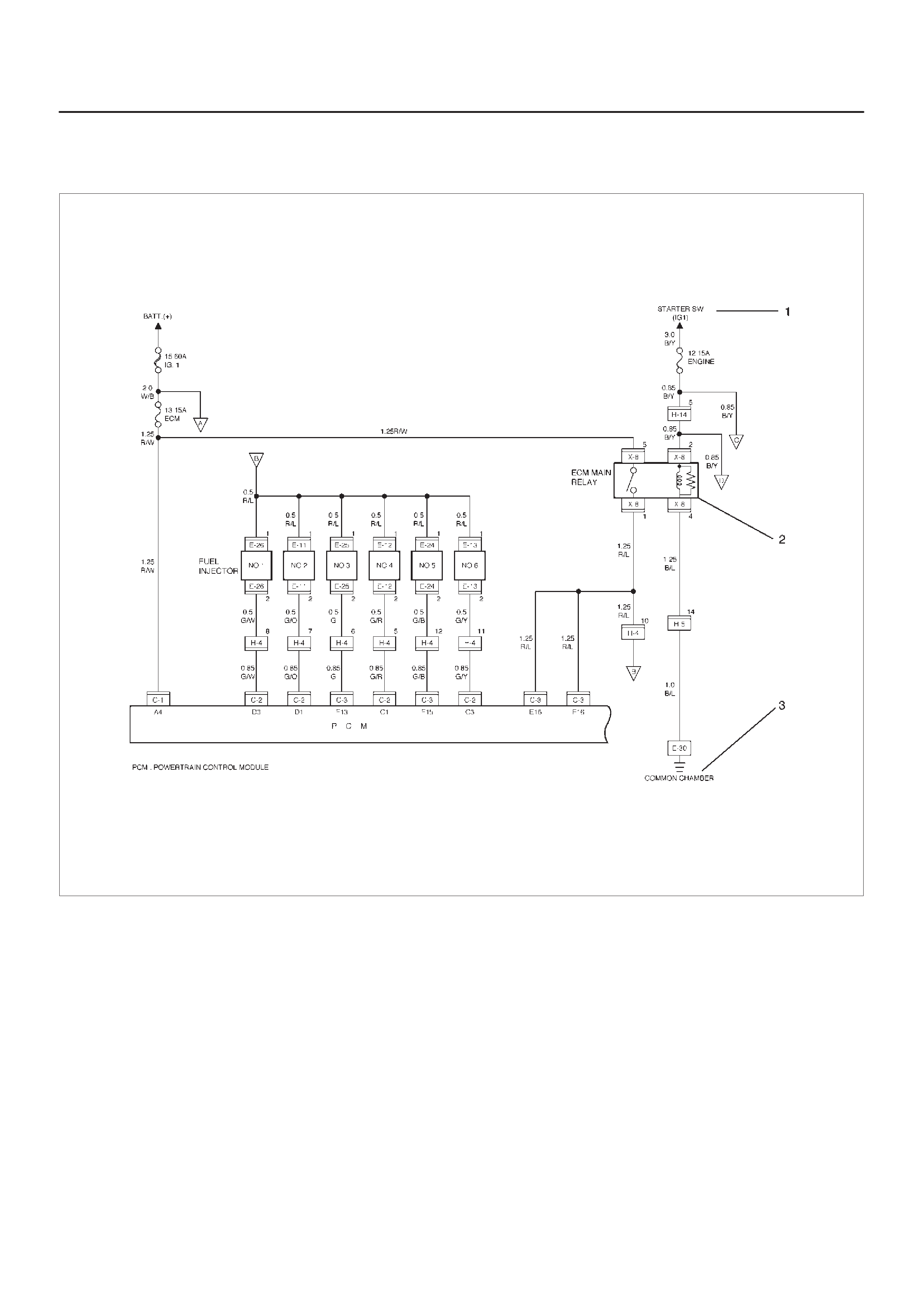
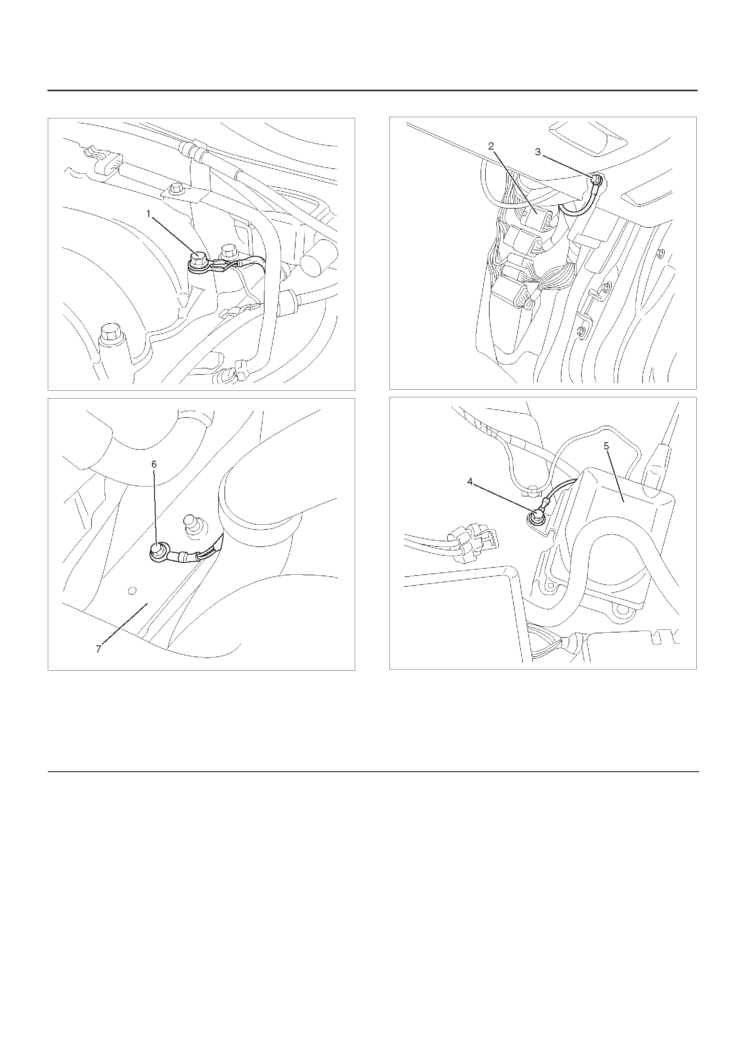
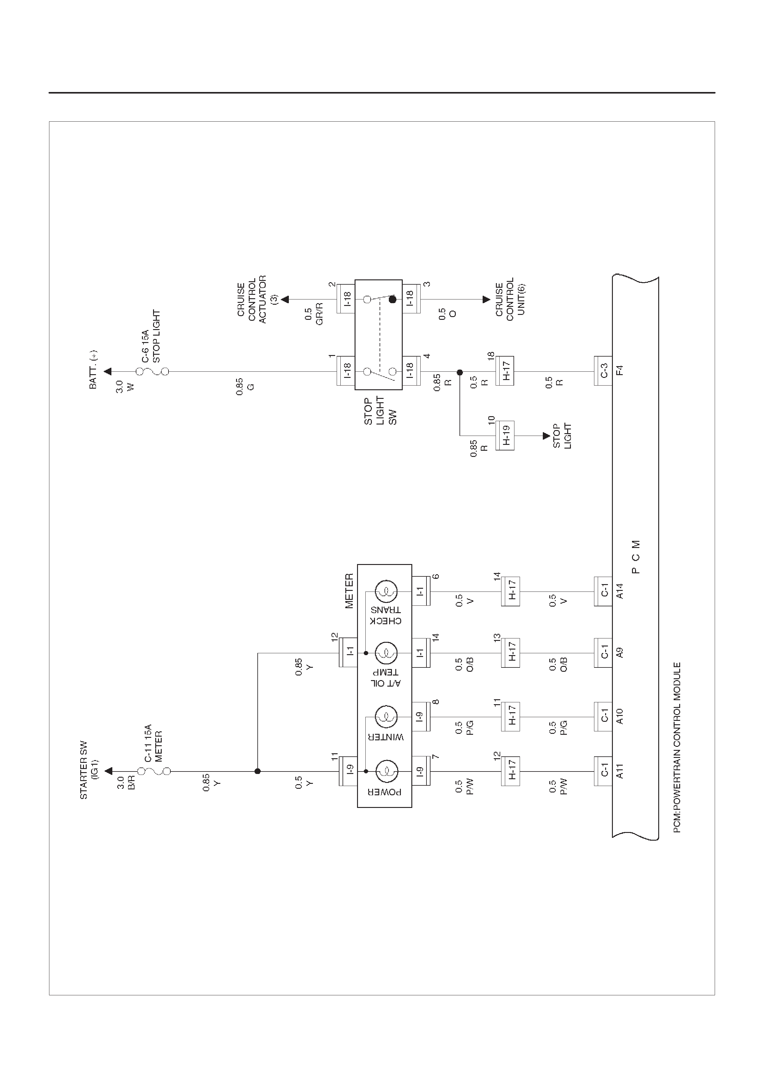
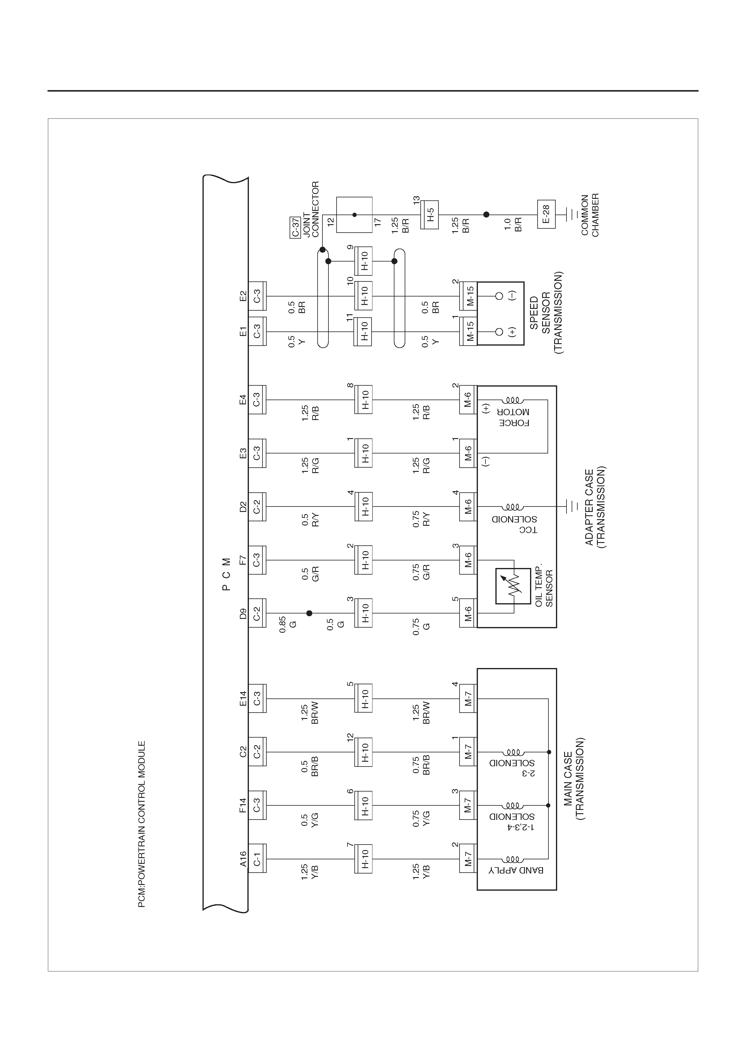
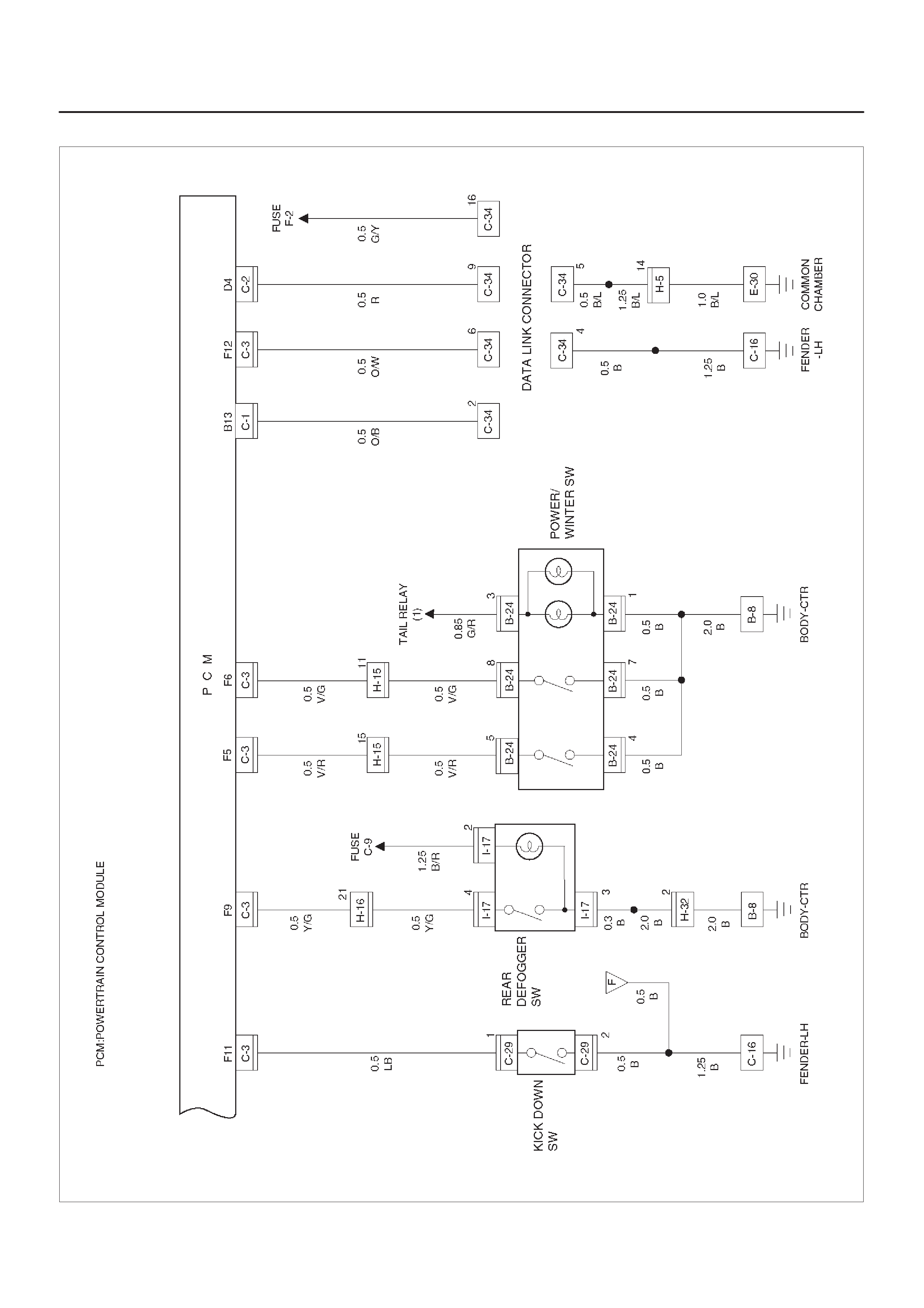
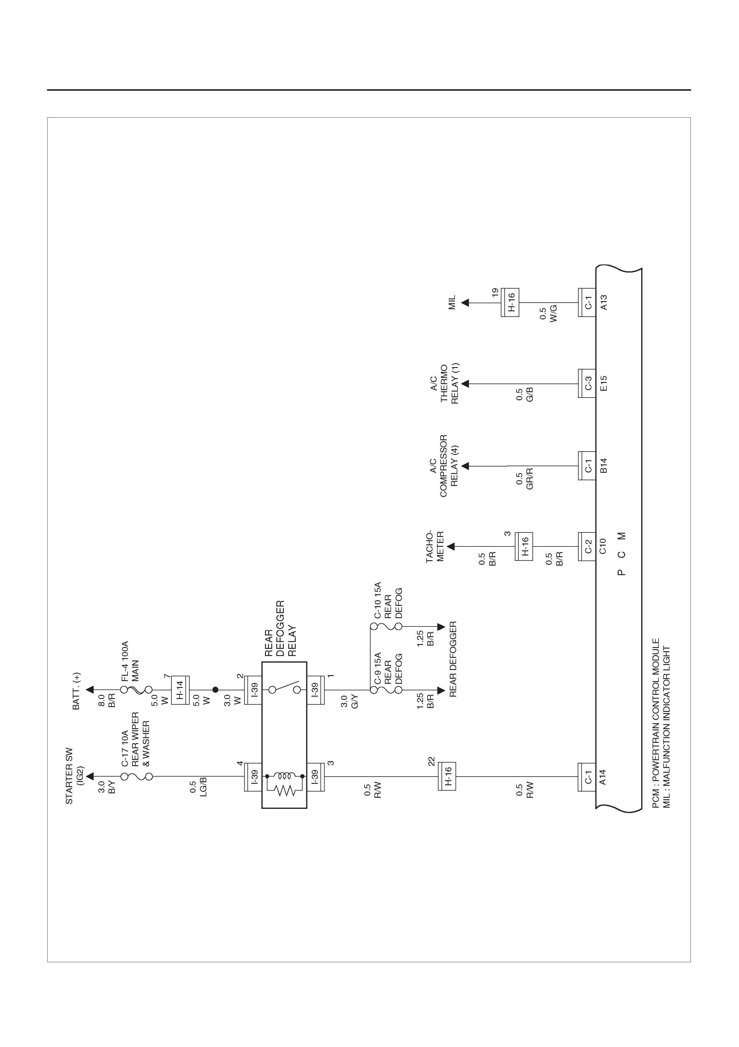
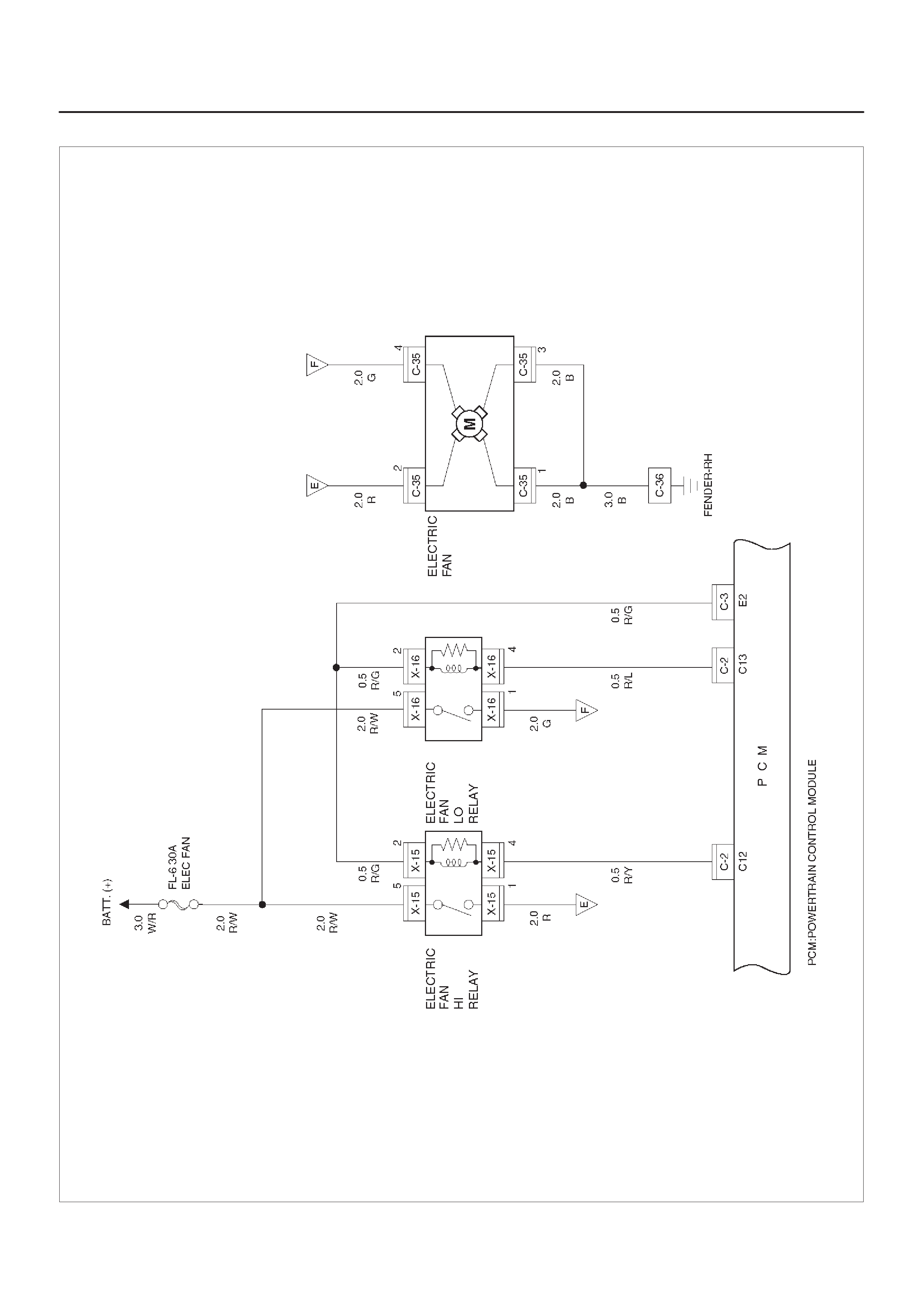
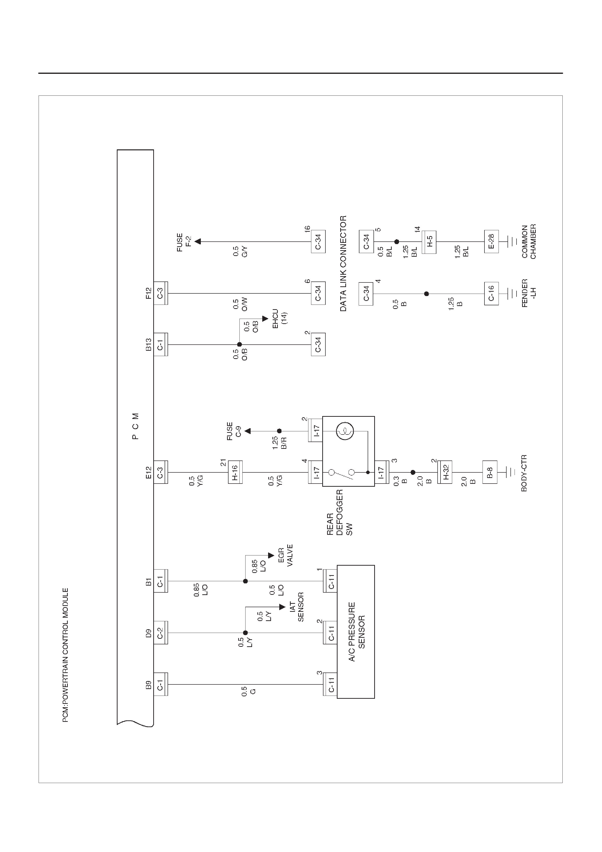
Powertrain Control Module (PCM)
General Description
The Powertrain Control Module (PCM) is located in the
passenger compartment.
The PCM constantly monitors the information from
various sensors, and controls the systems that affect
vehicle performance.
The PCM performs the diagnostic function of the system.
It can recognize operational problems, alert the driver
through the Malfunction Indicator Light (MIL) and store a
Diagnostic Trouble Code (DTC) or DTC(s) which identify
the problem areas to aid the technician in making repairs.
The PCM is designed to process the various input
informations and then send the necessary electrical
responses to control fuel delivery, spark timing and other
emission control systems. The input information has an
interrelation to more than one output therefore, if the one
input failed, it could affect more than one system
operation.
Refer to Driveability and Emission in Engine Section and
Automatic Transmission in Transmission section.
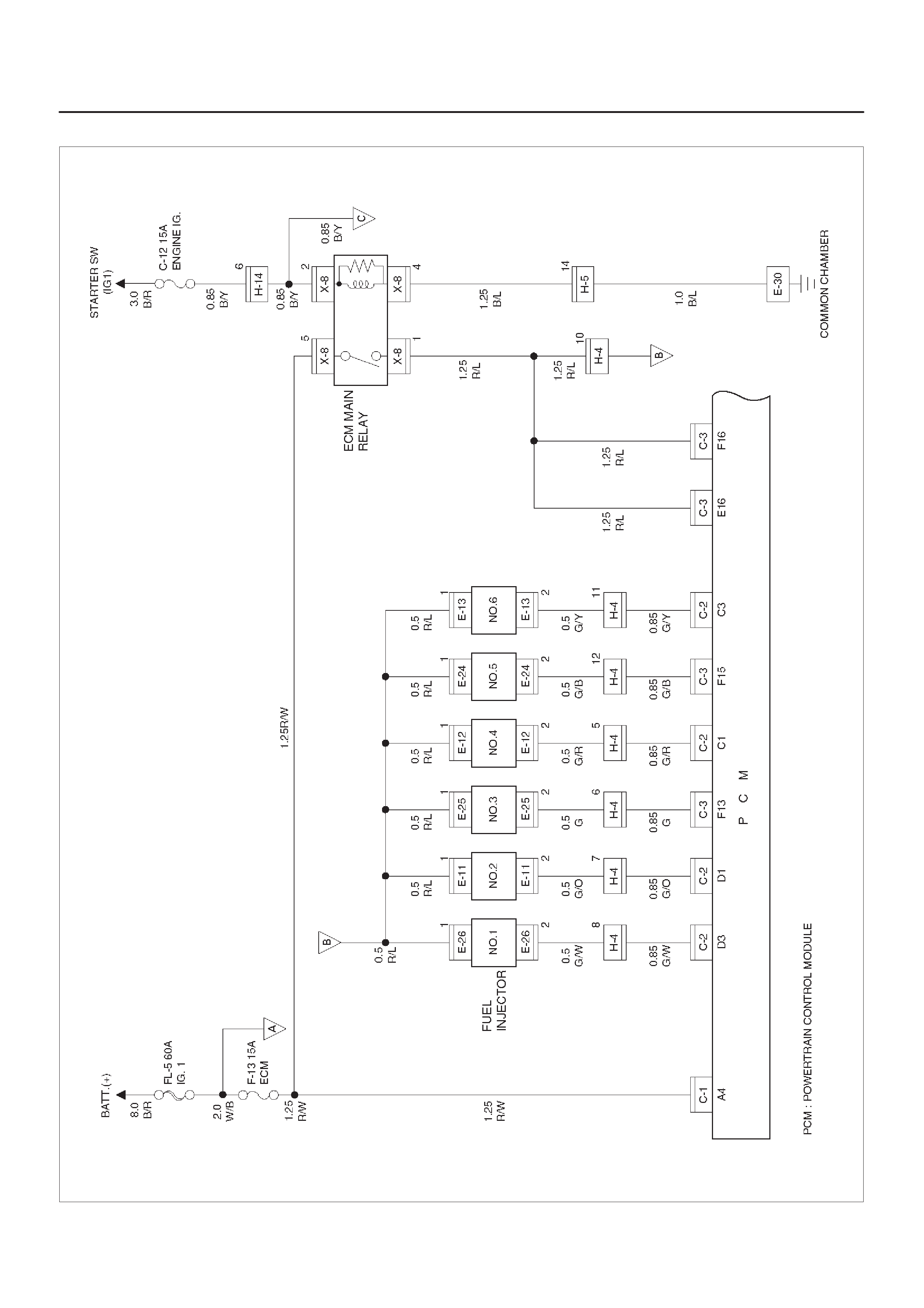
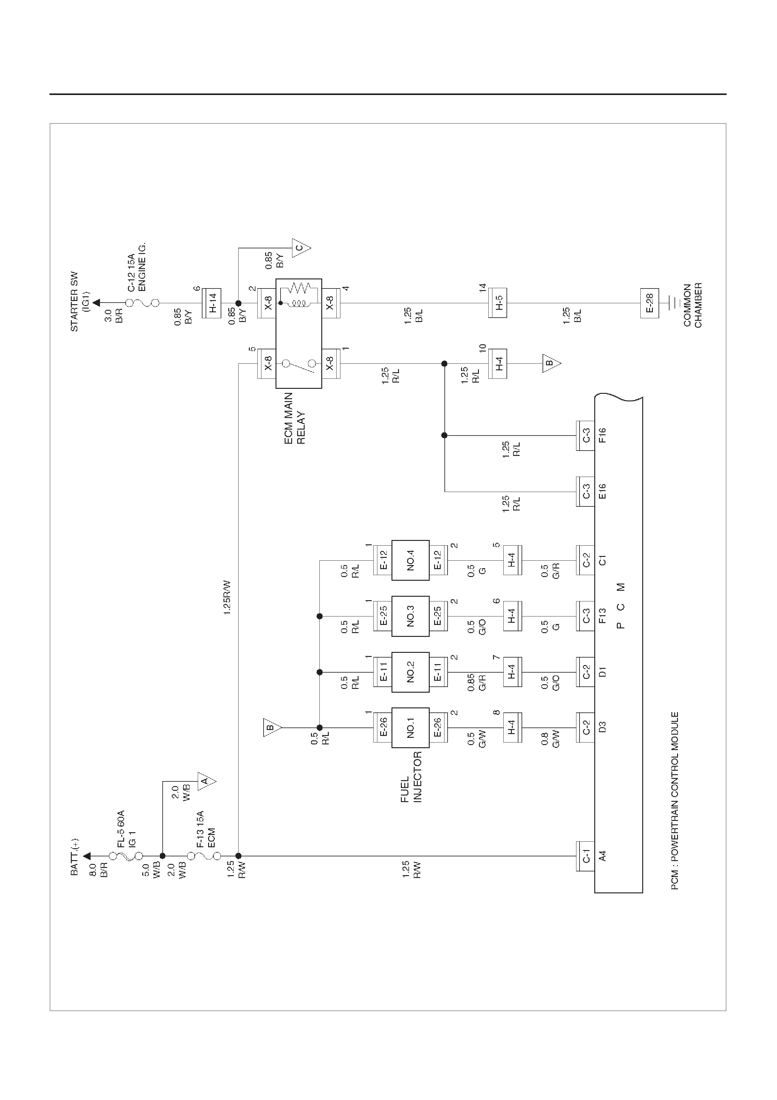
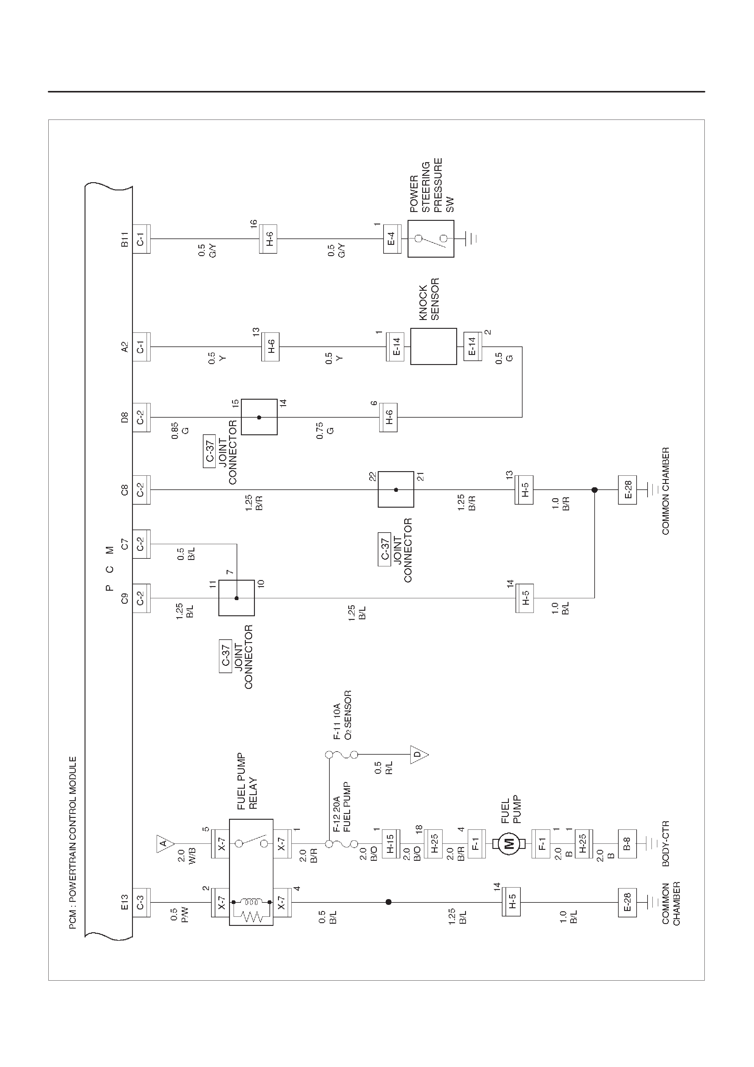
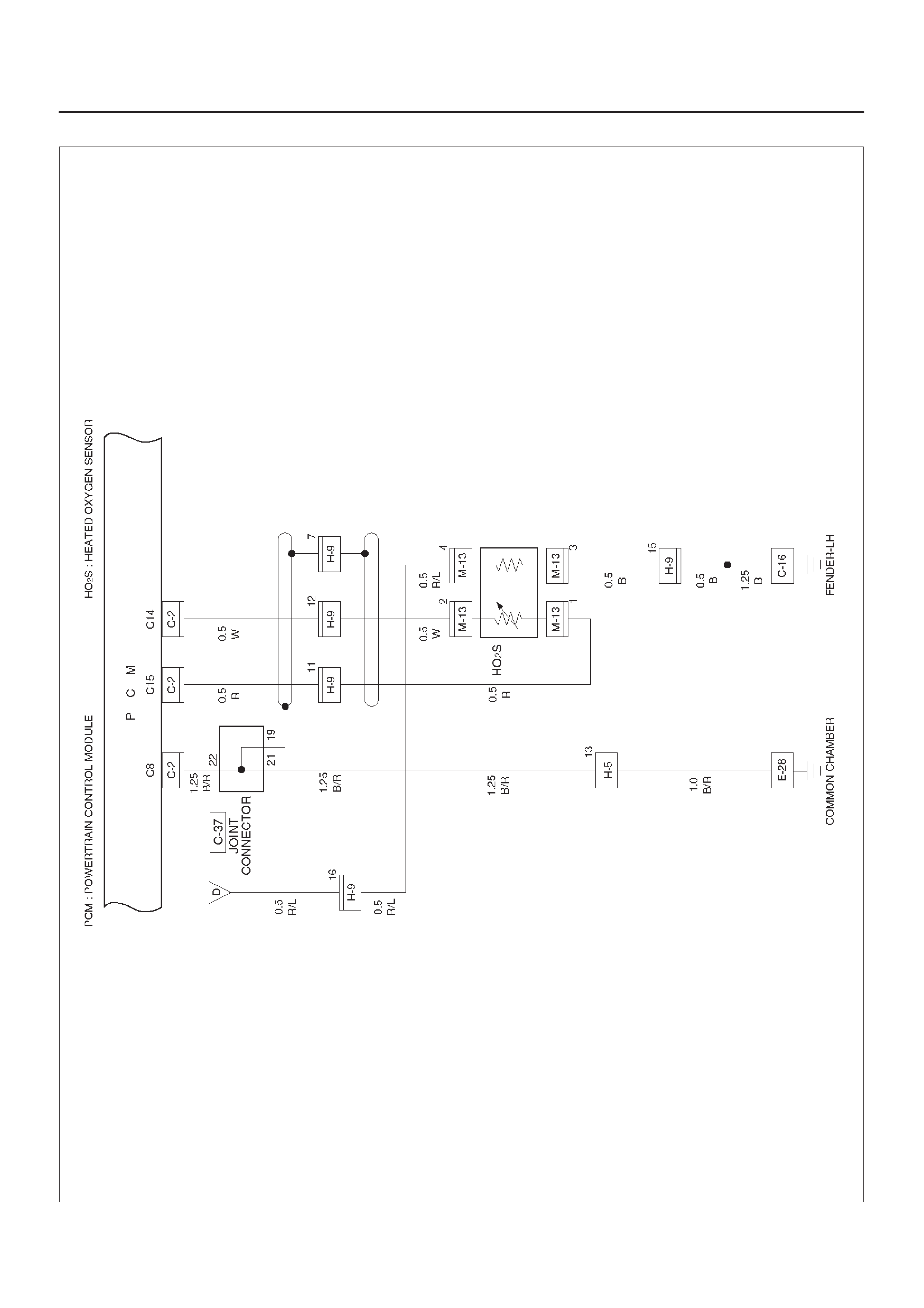
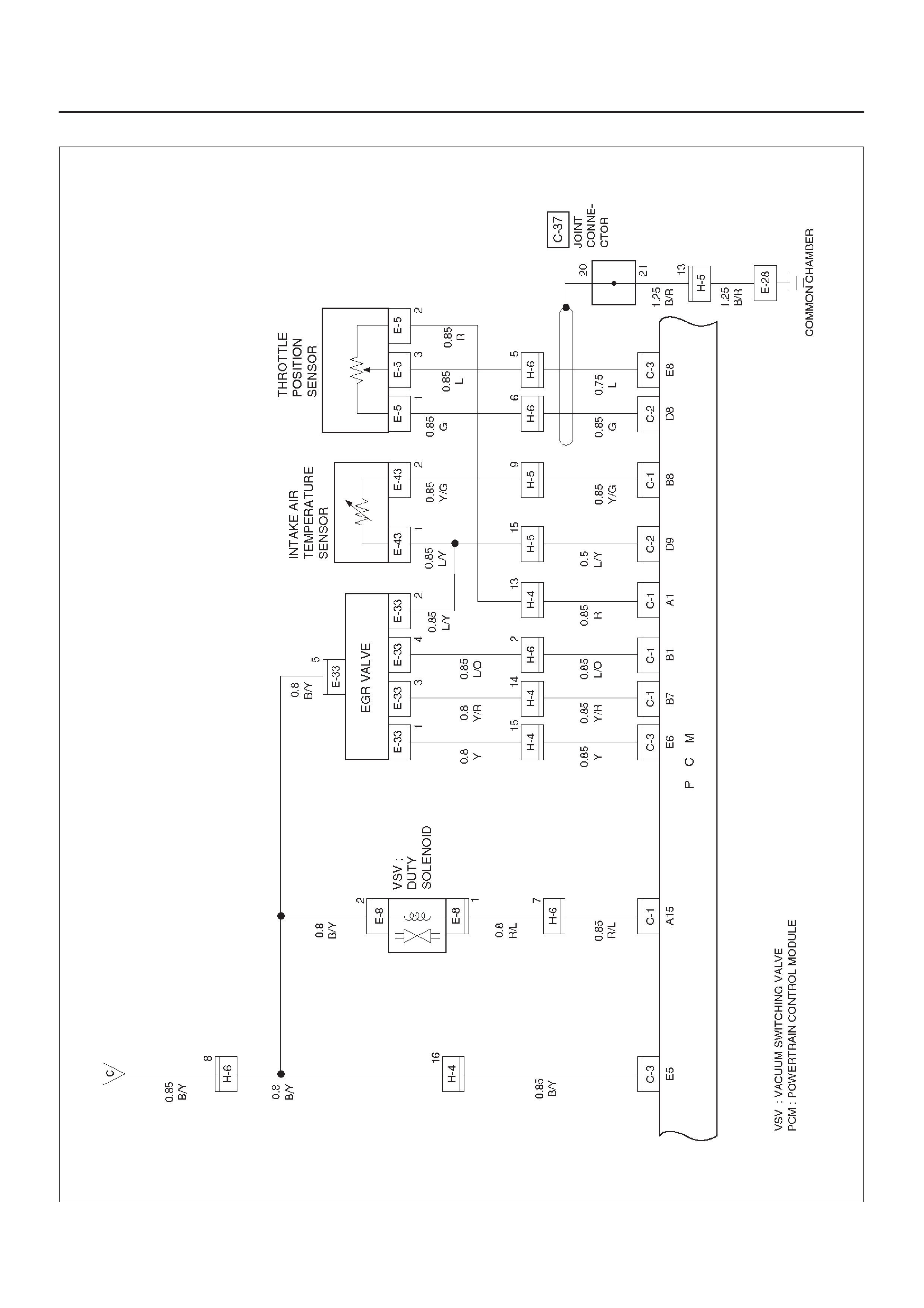
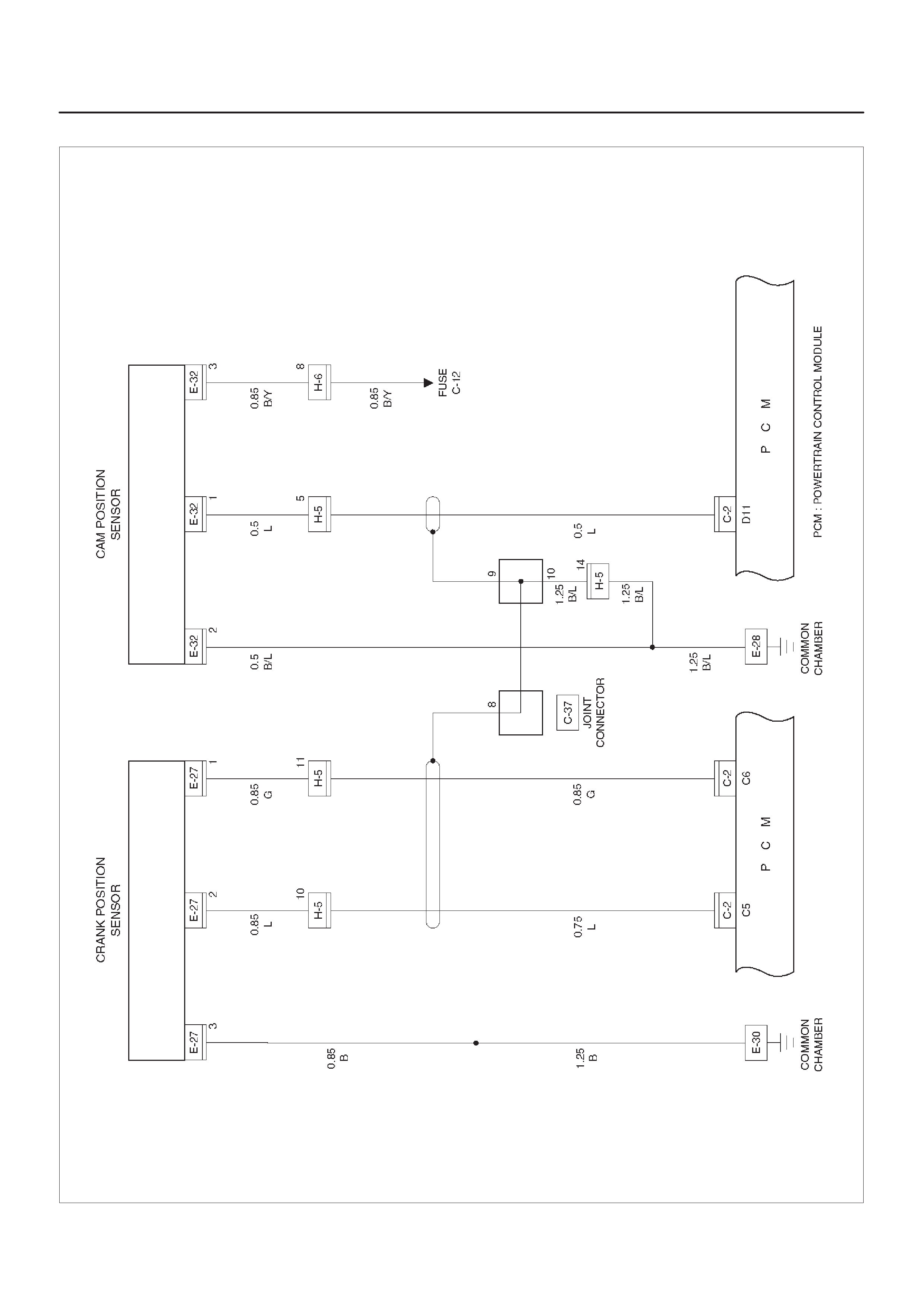
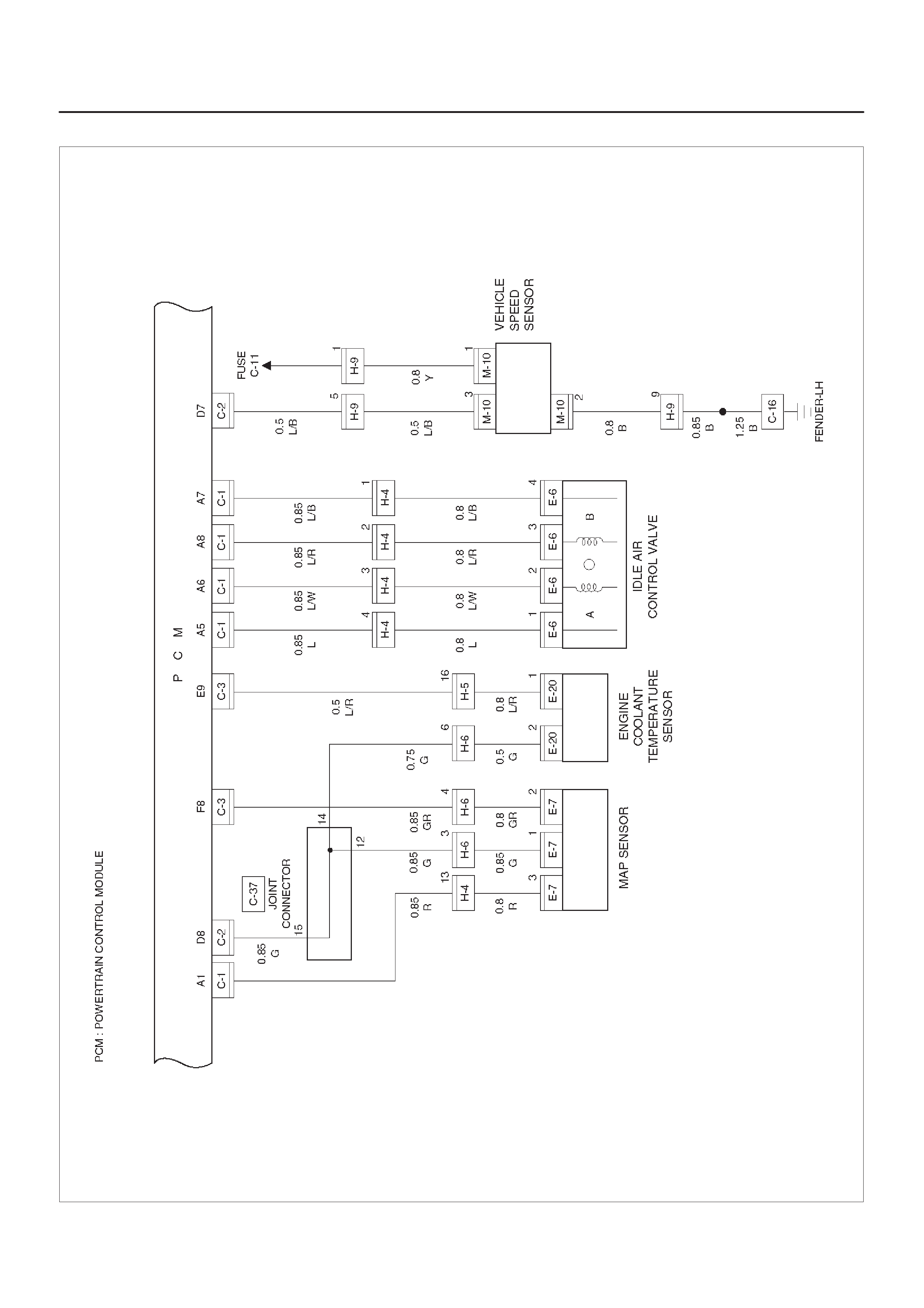
Circuit Diagram–1 (6VD1)
D08RX158
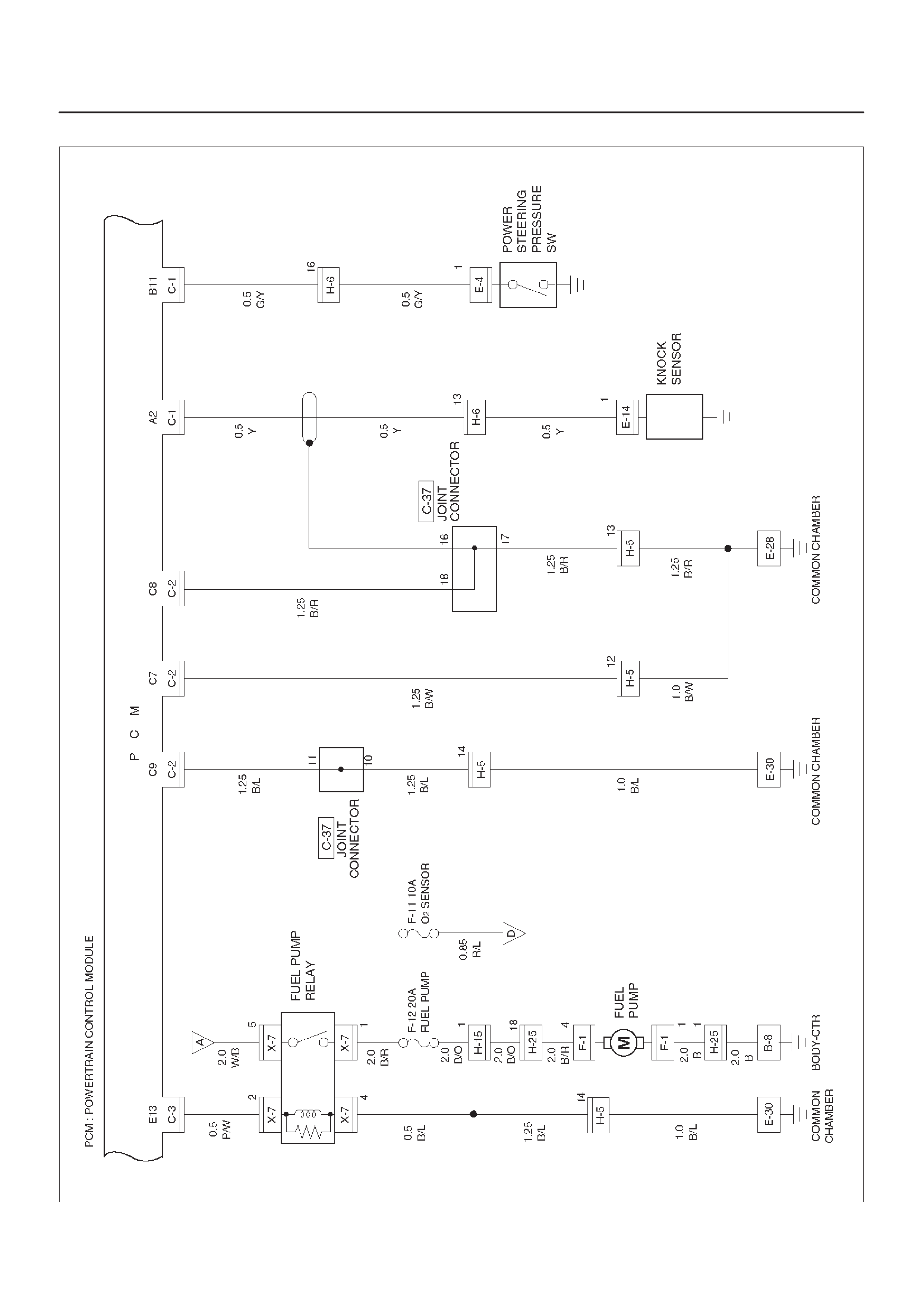
Circuit Diagram–2 (6VD1)
D08RX159
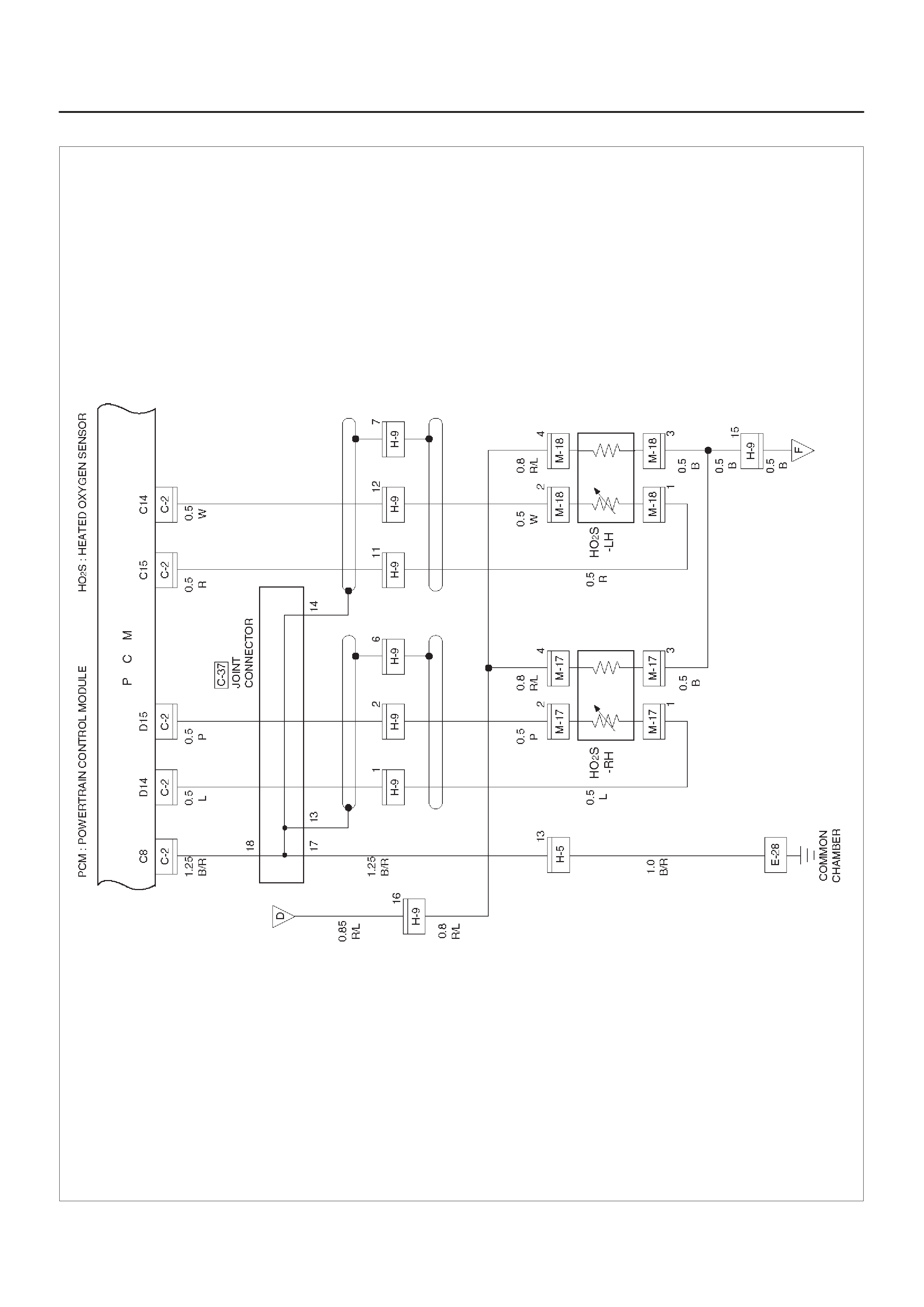
Circuit Diagram–3 (6VD1 M/T)
D08RX176

Circuit Diagram–3 (6VD1 A/T)
D08RX160
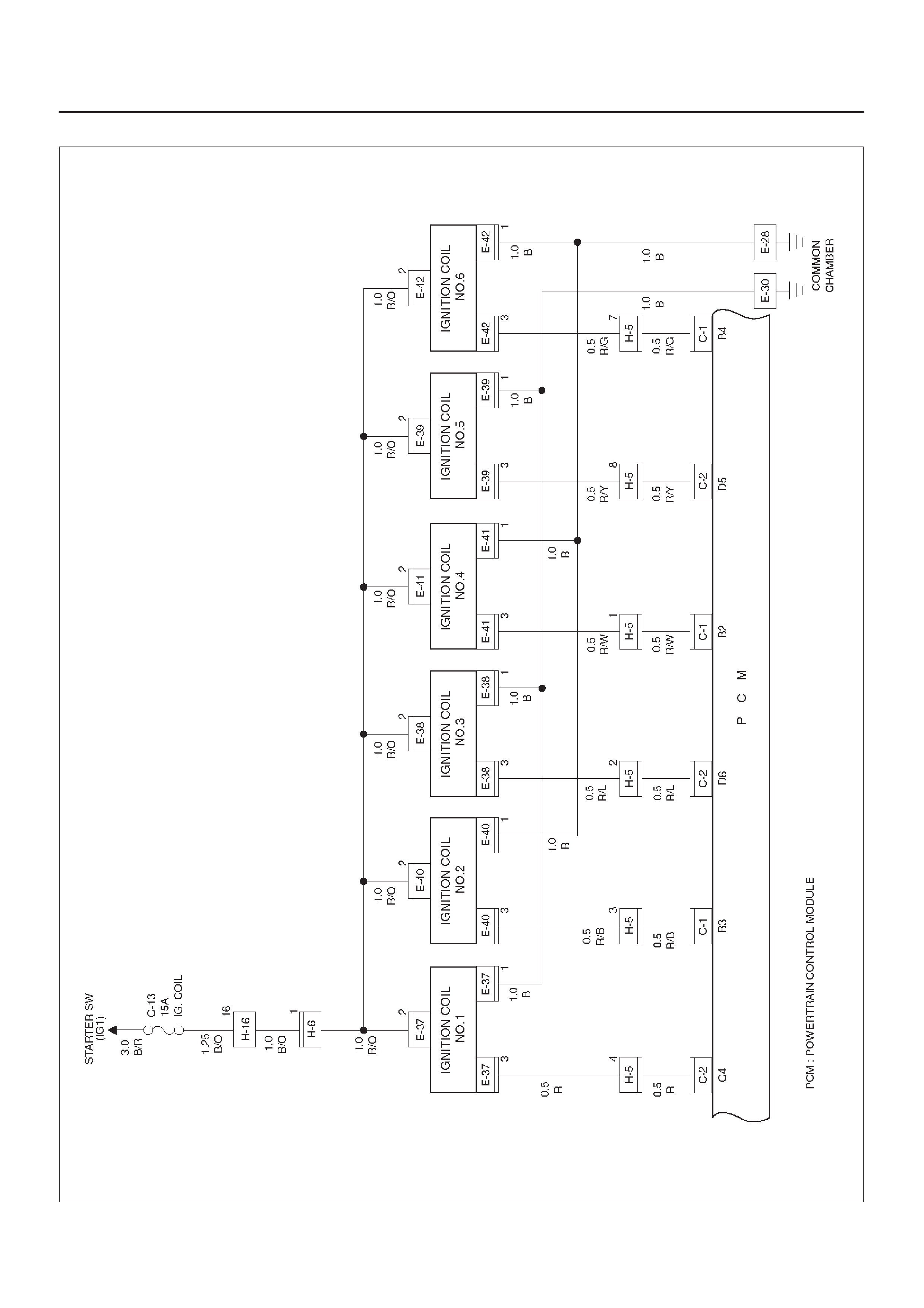
Circuit Diagram–4 (6VD1)
D08RX161
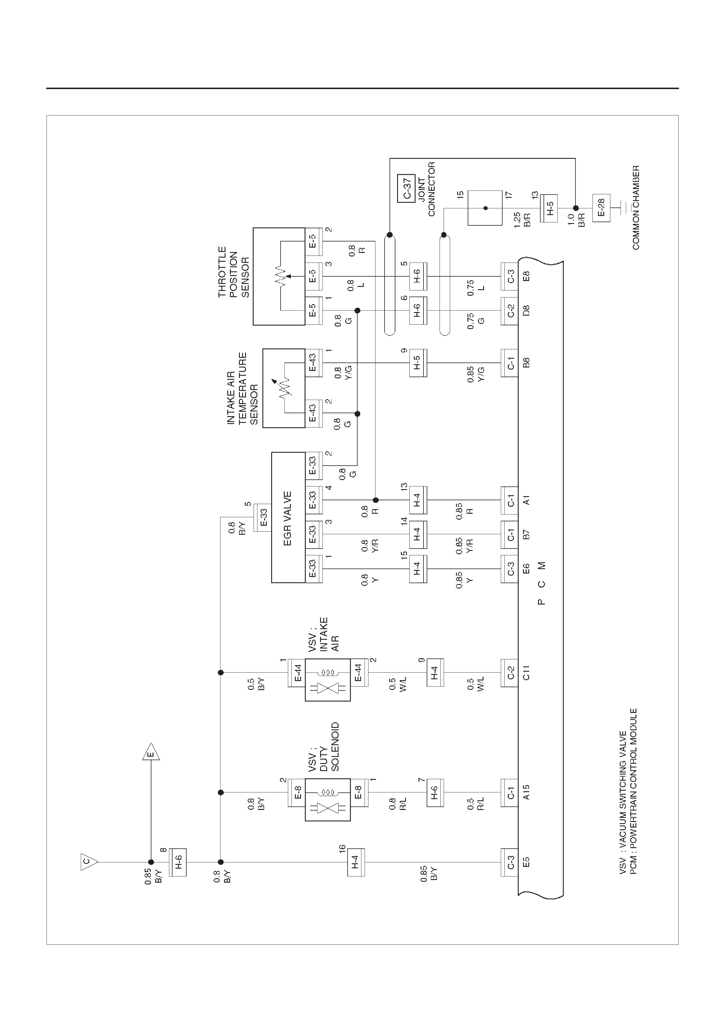
Circuit Diagram–5 (6VD1)
D08RX162
Circuit Diagram–6 (6VD1)
D08RX163
Circuit Diagram–7 (6VD1)
D08RY00926
Circuit Diagram–8 (6VD1)
D08RY00927
Circuit Diagram–9 (6VD1)
D08RX166
Circuit Diagram–10 (6VD1)
D08RX167
Circuit Diagram–11 (6VD1)
D08RY00928
Circuit Diagram–12 (6VD1)
D08RX169
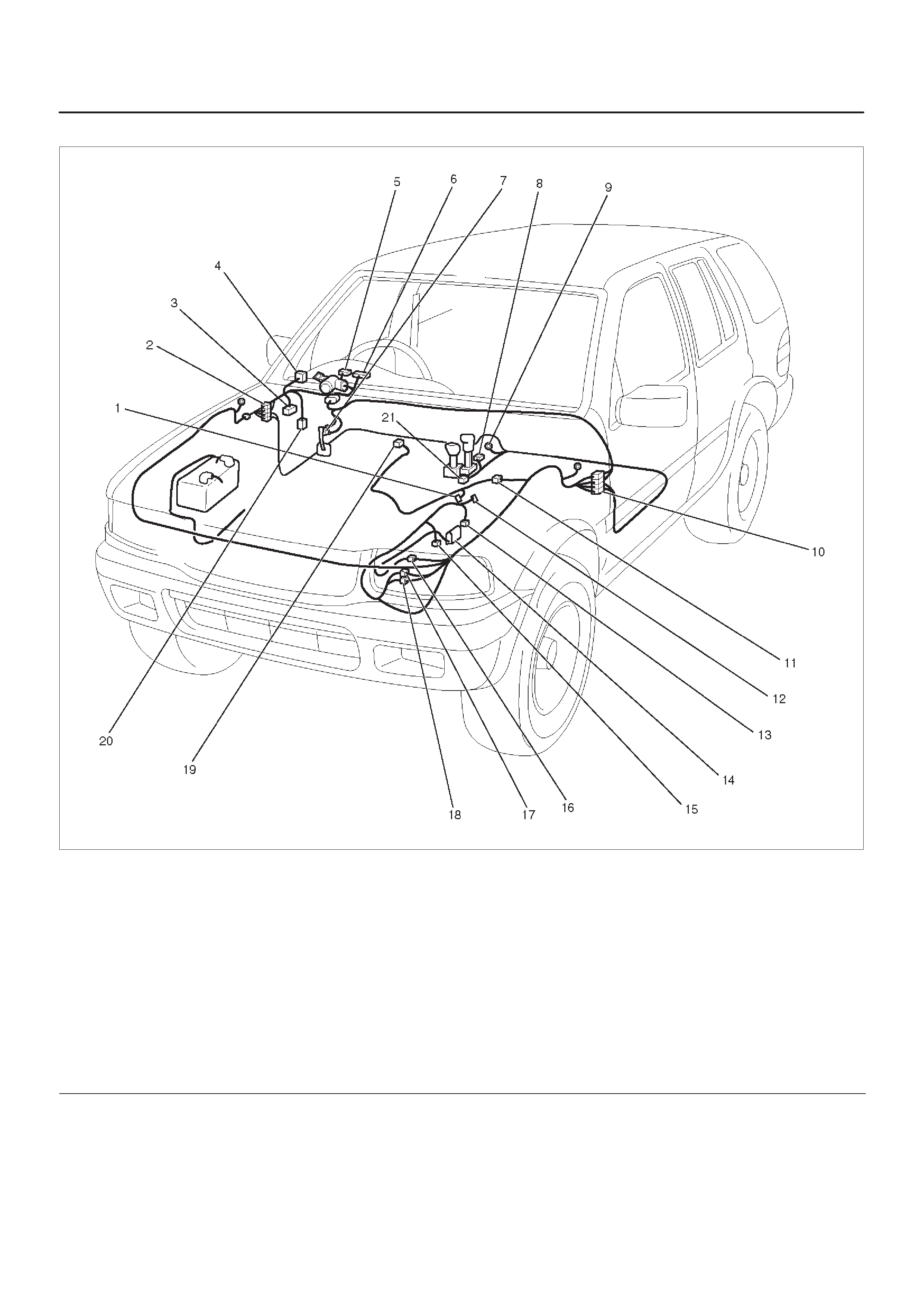
Parts Location – 1 (6VD1)
D08RX170
Legend
(1) Battery
(2) X–7, X–8
(3) H–12, H–13, H–14, H–19, H–32
(4) Relay & Fuse Box (I–34, I–39)
(5) I–1
(6) I–9
(7) PCM (C–1, C–2, C–3)
(8) F–1
(9) H–15, H–16, H–17
(10) C–16
(11) H–9, H–10, H–11
(12) B–8
(13) C–37
(14) E–27
(15) E–26
(16) E–37
(17) E–38
(18) E–7
(19) E–39
(20) E–25
(21) E–24
(22) E–20
(23) E–34
(24) E–35
(25) E–30
(26) E–8
(27) E–14
(28) E–13
(29) E–33
(30) E–5
(31) E–43
(32) E–42
(33) E–41
(34) E–40
(35) H–4, H–5, H–6
(36) E–6
(37) E–12

(38) E–4
(39) E–32
(40) E–11
(41) E–36
(42) E–28
(43) C–34
Parts Location – 2 (Transmission control)
D08RX171
Legend
(1) M–10
(2) H–12, H–13, H–14, H–19, H–32
(3) C–34
(4) I–17
(5) I–1
(6) I–9
(7) I–18
(8) B–19
(9) B–8
(10) H–15, H–16, H–17
(11) M–10
(12) M–15
(13) M–7
(14) M–16
(15) M–6
(16) M–17
(17) M–18
(18) H–9, H–10, H–11
(19) E–5
(20) C–29
(21) B–24
Circuit Diagram–1 (X22SE)
D08RX177
Circuit Diagram–2 (X22SE)
D08RX178
Circuit Diagram–3 (X22SE)
D08RX179
Circuit Diagram–4 (X22SE)
D08RX180
Circuit Diagram–5 (X22SE)
D08RX181
Circuit Diagram–6 (X22SE)
D08RX182
Circuit Diagram–7 (X22SE)
D08RX183
Circuit Diagram–8 (X22SE)
D08RY00929
Circuit Diagram–9 (X22SE)
D08RX185
Circuit Diagram–10 (X22SE)
D08RX186
Parts Location
D08RX187
Legend
(1) X–7, X–8
(2) X–15, X–16
(3) C–36
(4) H–32
(5) I–41, I–42
(6) Relay & Fuse Box
(7) C–1, C–2, C–3 (PCM)
(8) C–37
(9) H–16
(10) F–3
(11) F–1
(12) E–1
(13) E–14
(14) E–27
(15) E–7
(16) E–28, E–30
(17) E–37
(18) E–8
(19) E–5
(20) E–6
(21) E–12
(22) E–33
(23) E–25
(24) E–11
(25) E–26
(26) E–32
(27) E–43
(28) E–9
(29) E–4
(30) E–3
(31) H–6
(32) H–5
(33) H–4
(34) H–25
(35) C–16
(36) B–8
(37) H–9

(38) M–13
(39) C–11 (40) M–10
(41) C–35

Headlight and Fog Light
General Description
The circuit consists of headlight, fog light, lighting switch,
dimmer·passing switch, fog light switch, high beam
indicator, lighting relay and fog light relay. When starter
switch is turned on by setting it at headlight position,
lighting relay is activated to turn on headlight. Optical axis
of headlight can be turned up or down by operating
dimmer switch while headlight is on. Passing switch is
independent of lighting switch, and optical axis of passing
light can be turned up only while switch lever is pulled up
and held in this state.
When fog light switch is turned on while headlight on at
low–beam, fog light relay is activated to turn on fog light.
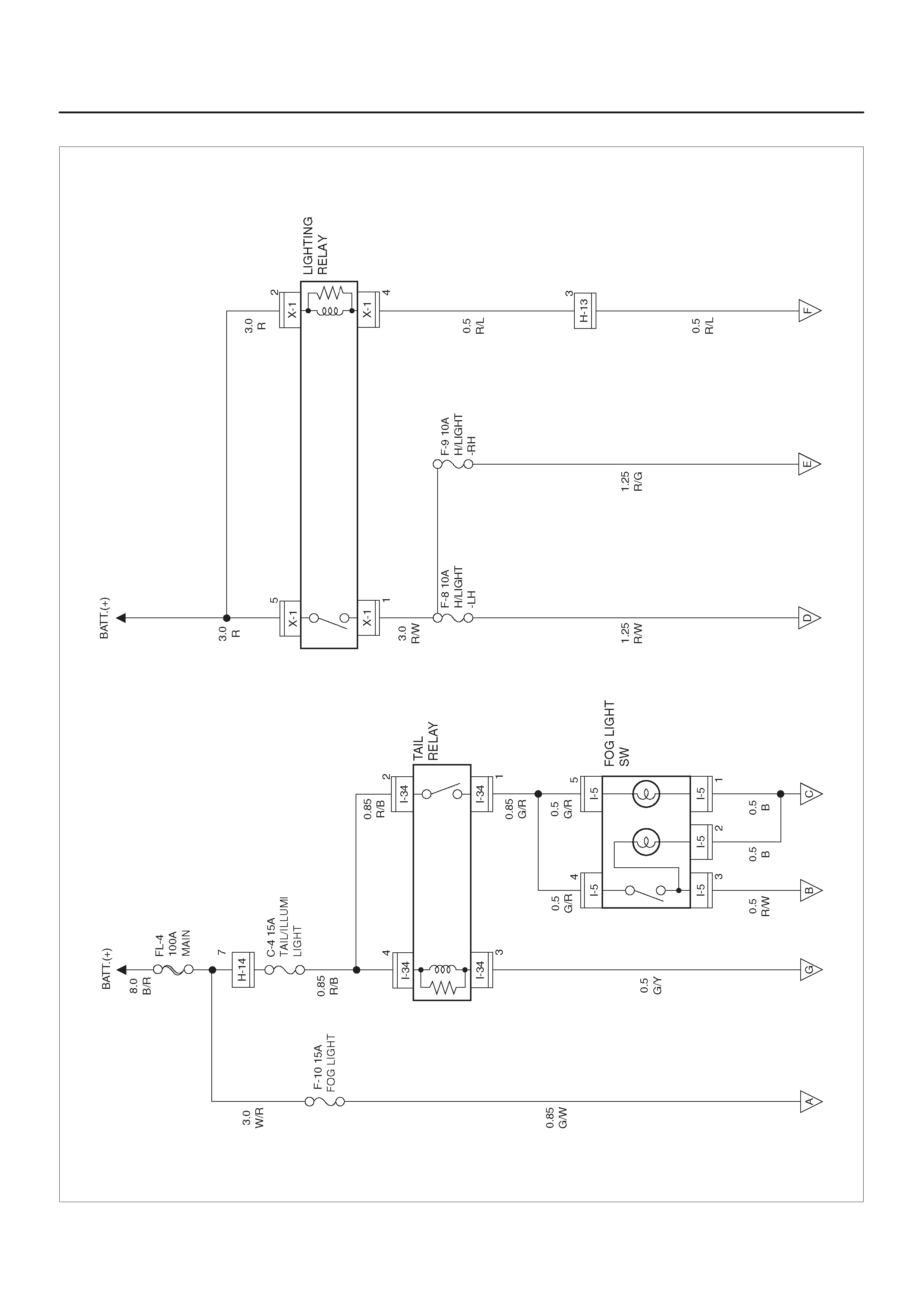
Circuit Diagram–1
D08RY00930
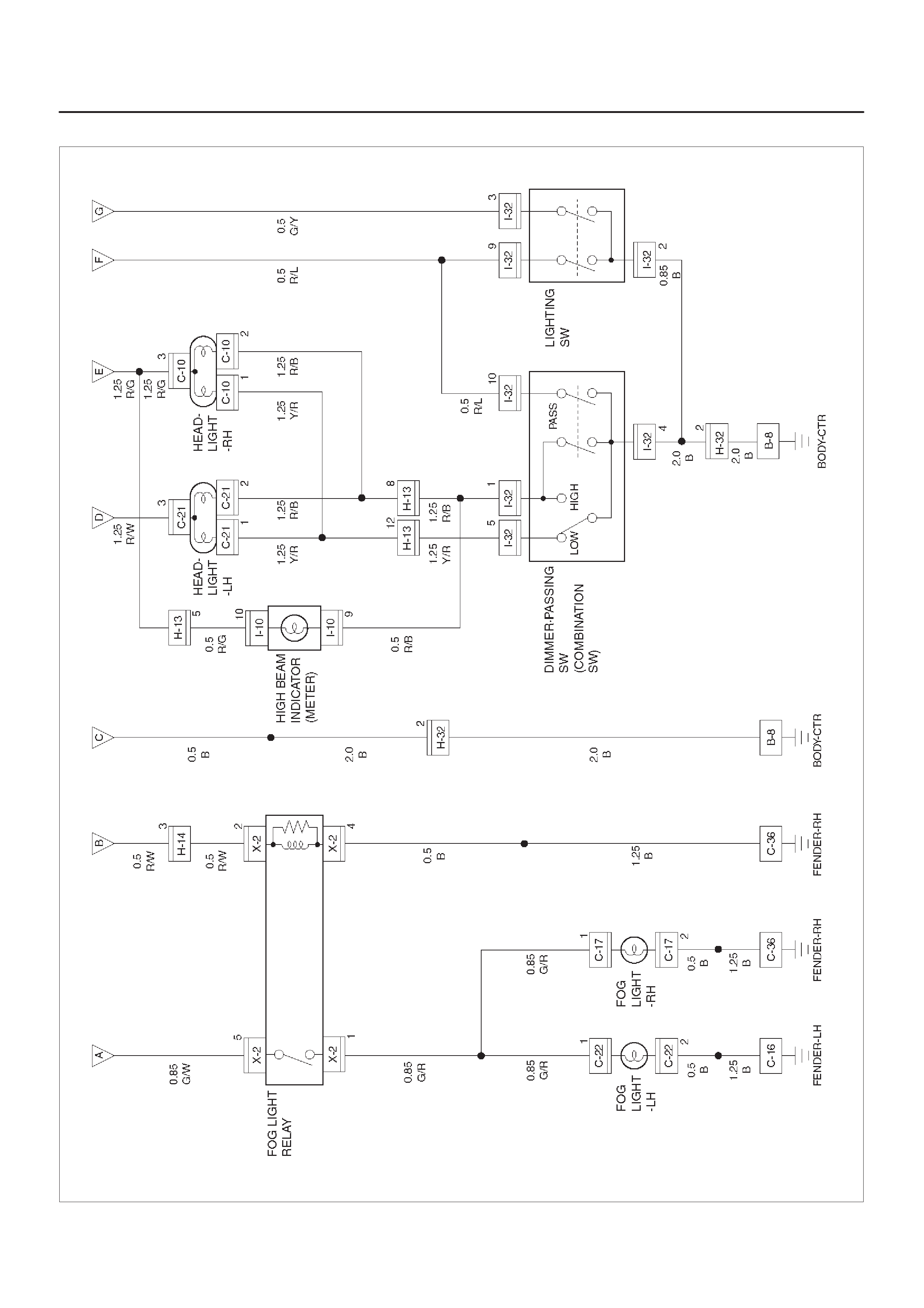
Circuit Diagram–2
D08RX191
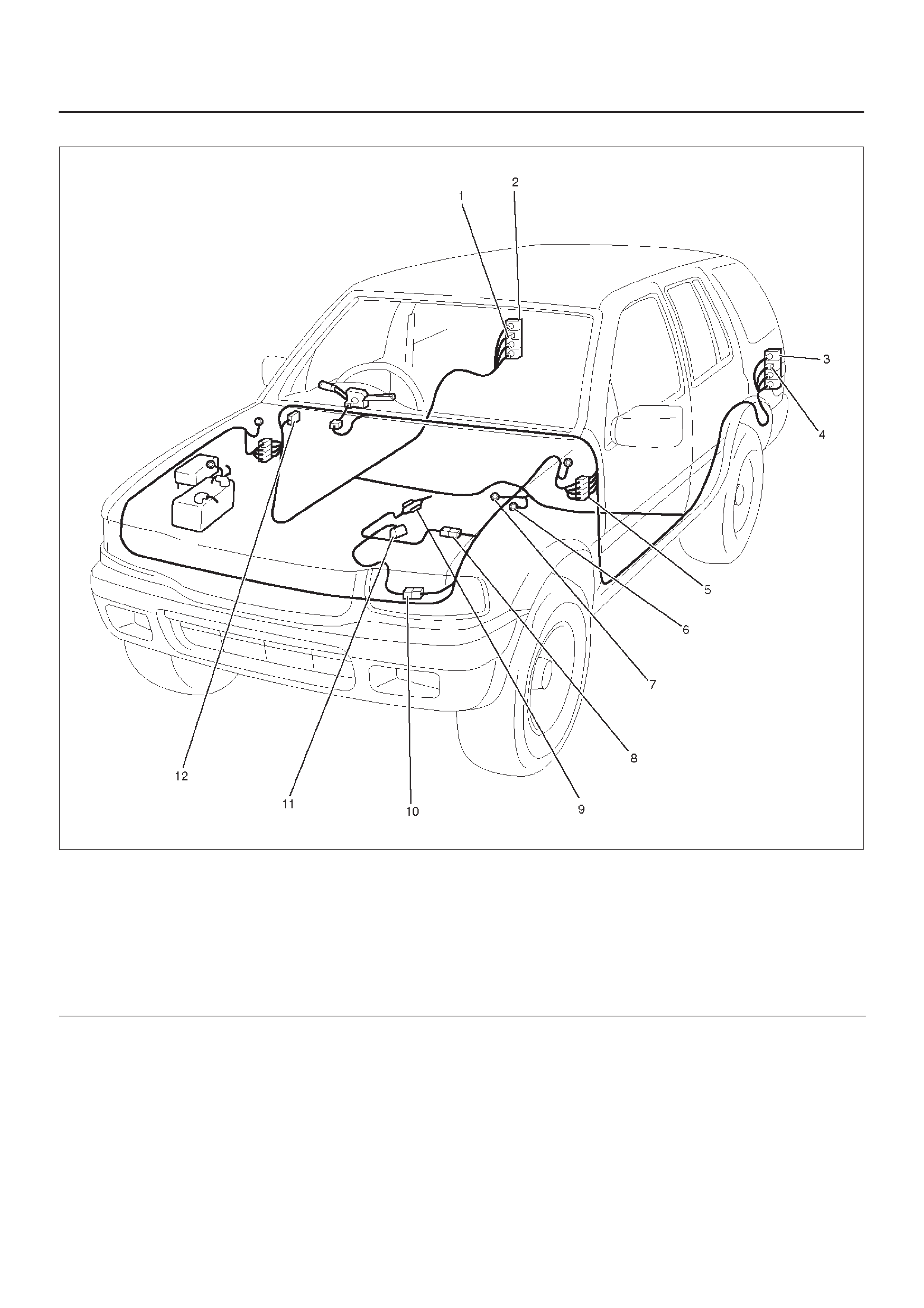
Parts Location
D08RWD00–1
Legend
(1) X–1, X–2
(2) C–36
(3) H–13, H–14, H–32
(4) Relay & Fuse Box
(5) I–5
(6) I–10
(7) Lighting Switch
(8) I–32 (Combination Switch)
(9) B–8
(10) C–16
(11) C–22
(12) Fog Light – LH
(13) C–21
(14) Head Light – LH
(15) C–10
(16) C–17
(17) Fog Light – RH
(18) Head Light – RH

Diagnosis
Both Headlights Inoperative
Step Action Value(s) Yes No
1Check the ground terminal B–8.
Is B–8 grounded securely? —Go to Step 2 Ground it
securely
2Disconnect the combination switch connector I–32.
Is there continuity between switch side connector I–32
terminals 9 and 2 with the switch turned to headlight
position? —Go to Step 2 Replace the
switch
3Check continuity of dimmer-passing switch.
Is there continuity between switch side connector I–32
terminal 5 and 4 with the switch turned to low position,
and terminal 1 and 4 with the switch turned to high
position? —Go to Step 3 Replace the
switch
4Check continuity between the lighting switch and the
ground B–8.
Is there continuity between harness side connector
I–32 terminal 2 and the ground? —Go to Step 5 Repair an
open circuit
5Remove the lighting relay from the relay and fuse box.
Is the battery voltage applied between harness side
connector X–1 terminal 5 and the ground, X–1 terminal
2 and the ground? Approx. 12V Go to Step 6
Repair an
open circuit
between
battery and
the lighting
relay
6Check continuity between the lighting relay and the
lighting switch.
Is there continuity between harness side connector
X–1 terminal 4 and I–32 terminal 9? —Go to Step 7 Go to Step 6
7Check continuity between the lighting relay and fuse
F–8 or F–9.
Is there continuity between harness side connector
X–1 terminal 3 and fuse F–8 or F–9? —Go to Step 8 Repair an
open circuit
8Check continuity between the dimmer-passing switch
and the ground.
Is there continuity between switch side connector I–32
terminal 4 and the ground B–8? —Repair an
open circuit —
Headlight On The Left (or Right) Side Inoperative
Step Action Value(s) Yes No
1 Is the fuse F–8 or F–9 normal? —Go to Step 2 Replace the
fuse
2Remove the headlight bulb on the left or right side.
Is the bulb normal? —Go to Step 3 Replace the
bulb
31. Reinstall the bulb.
2. Turn the lighting switch to headlight position.
Is the battery voltage applied between harness side
connector C–21 terminal 3 and the ground or C–10
terminal 3 and the ground? Approx. 12V
Reconnect
the headlight
connector
securely
Repair an
open circuit
between the
fuse and
headlight

Headlights In Low–Beam Inoperative
Step Action Value(s) Yes No
1Disconnect the combination switch connector I–32.
Is there continuity between switch side connector I–32
terminal 5 and 4 with the switch at low-beam position? —Go to Step 2
Repair or
replace the
switch
2Repair an open circuit between connector H-13
terminal 15 and connector I-32 terminal 5.
Is the action complete? — Verify repair —
Headlight In High–Beam Inoperative
Step Action Value(s) Yes No
1Disconnect the combination switch connector I–32.
Is there continuity between switch side connector I–32
terminal 1 and 4 with the switch at high-beam position? —Go to Step 2
Repair or
replace the
switch
2Repair an open circuit between connector H–13
terminal 14 and connector I–32 terminal 1.
Is the action complete? — Verify repair —
Headlights Remain On When Lighting Switch Turned Off
Step Action Value(s) Yes No
11. Turn the lighting switch to off position.
2. Disconnect the combination switch connector I–32.
Do the headlights still remain on? —Go to Step 3 Go to Step 2
2Repair or replace the lighting switch.
NOTE: There should be no continuity between switch
side connector I–32 terminal 9 and 2.
Is the action complete? —Go to Step 1 —
3Remove the lighting relay.
Is there continuity between the relay side connector
X–1 terminal 1 and 5? —Replace the
relay Go to Step 4
4Repair short circuit between the lighting relay and the
lighting switch.
Is the action complete? — Verity repair —
Headlight Comes On With Lighting Switch At Parking Light Position
Step Action Value(s) Yes No
1Repair or replace the lighting switch.
NOTE: There should be no continuity between switch
side connector I–32 terminal 9 and 2 when the switch is
turned to parking light position.
Is the action complete? — Verify repair —

(While Headlight Is On In Low–Beam) Both Fog Lights Inoperative
Step Action Value(s) Yes No
1Are the fuse F–10 and C–4 normal? —Go to Step 2 Replace the
fuse(s)
2Is C–36 grounded securely? —Go to Step 3 Ground it
securely
3Remove the foglight relay.
Is the battery voltage applied between harness side
connector X–2 terminal 5 and the ground? Approx. 12V Go to Step 5 Go to Step 4
4Repair an open circuit between Fuse F–10 connector
X–2 terminal 5.
Is there action complete? —Go to Step 3 —
5Is there continuity between harness side connector
X–2 terminal 4 and the ground? —Go to Step 7 Go to Step 6
6Repair an open circuit between connector X–2 terminal
4 and the ground C–36.
Is the action complete? —Go to Step 5 —
71. Turn the lighting switch to clearance light position.
2. Turn the fog light switch on.
Is the battery voltage applied between harness side
connector X–2 terminal 2 and the ground? Approx. 12V Replace the
fog light relay Go to Step 8
8Disconnect the lighting switch connector I–32.
Is there continuity between the switch side connector
terminal 2 and 3? —Go to Step 9
Repair or
replace the
switch.
9Disconnect the tail relay.
Is there continuity between harness side connector
I–32 terminal 3 and I–32 terminal 3? —Go to Step 10 Repair an
open circuit
10 Is the battery voltage applied between harness side
connector I–34 terminal 2, 4 and the ground? Approx. 12V Go to Step 12 Go to Step 11
11 Repair an open circuit between the fuse C–4 and
connector I–34 terminal 2 or 4.
Is the action complete? —Go to Step 10 —
12 1. Disconnect the fog light switch.
2. Turn the switch on.
Is there continuity between the switch terminal 3 and 4? —Go to Step 13
Repair or
replace the
switch
13 Is there continuity between harness side connector I–5
terminal 4 and connector I–34 terminal 1? —Go to Step 14 Repair an
open circuit
14 Is there continuity between harness side connector I–5
terminal 3 and connector X–2 terminal 2? —Replace the
tail relay Repair an
open circuit

(While Headlight Is On In Low–Beam) Fog Light On the Left (or Right) Side Inoperative
Step Action Value(s) Yes No
1Is the fog light bulb on the left or right side normal? —Go to Step 2 Replace the
bulb
2Is C–16 or C–36 grounder securely? —Go to Step 3 Ground it
Securely
3Disconnect the fog light connector C–22 or C–17.
Is there continuity between the fog light harness side
connector terminal 2 and the ground? —Go to Step 4 Repair an
open circuit
4Repair an open circuit between fog light relay
connector X–2 terminal 1 and fog light connector
terminal 1.
Is the action complete? — Verify repair —

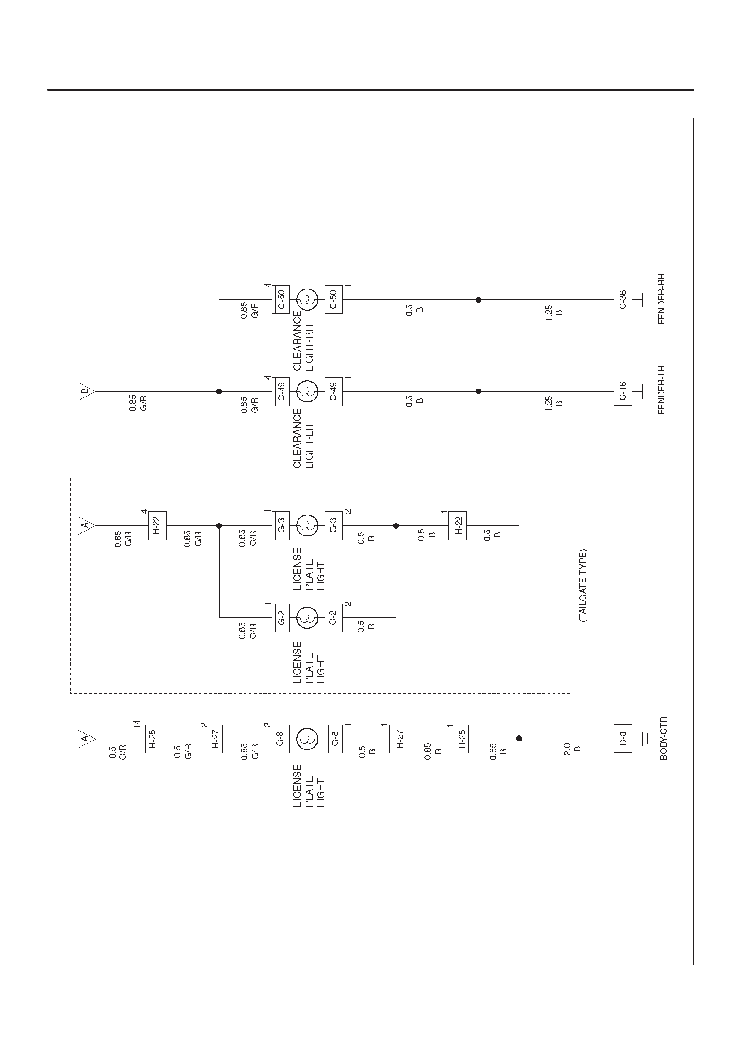
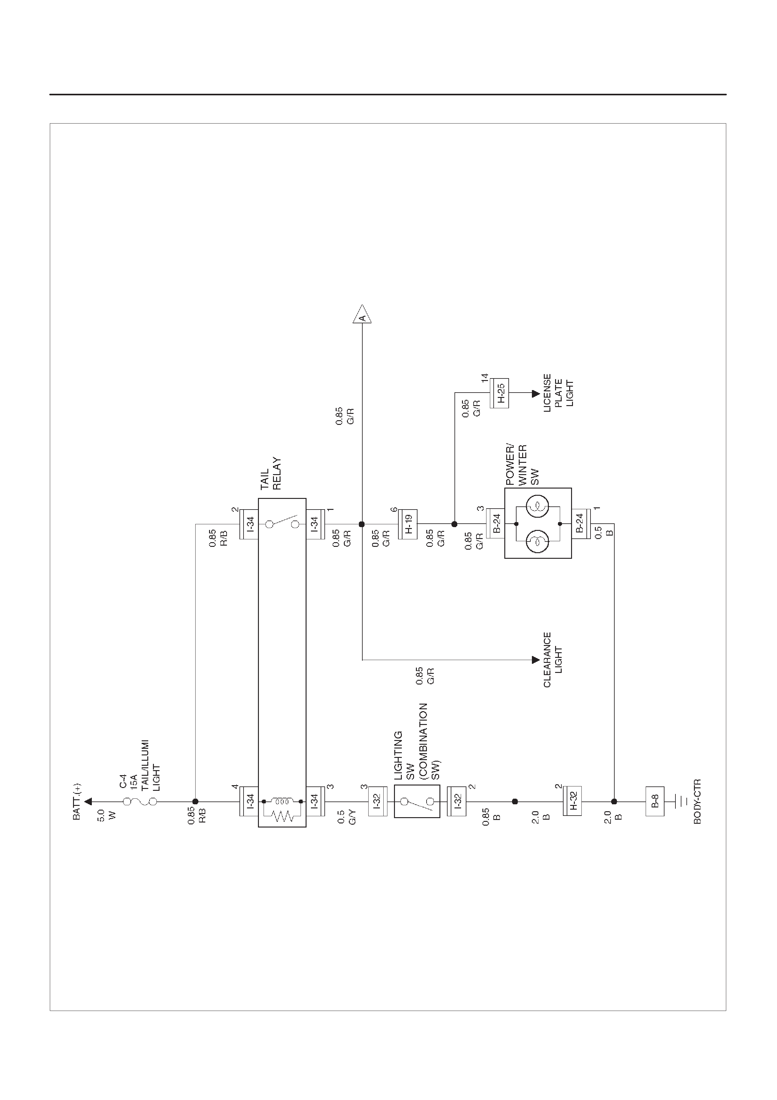
Clearance Light, Tail Light and License Plate Light
General Description
The circuit consists of lighting switch, clearance light, tail
light and license plate light.
All these lights come on when lighting switch is turned on
with the switch to either parking or headlight position.
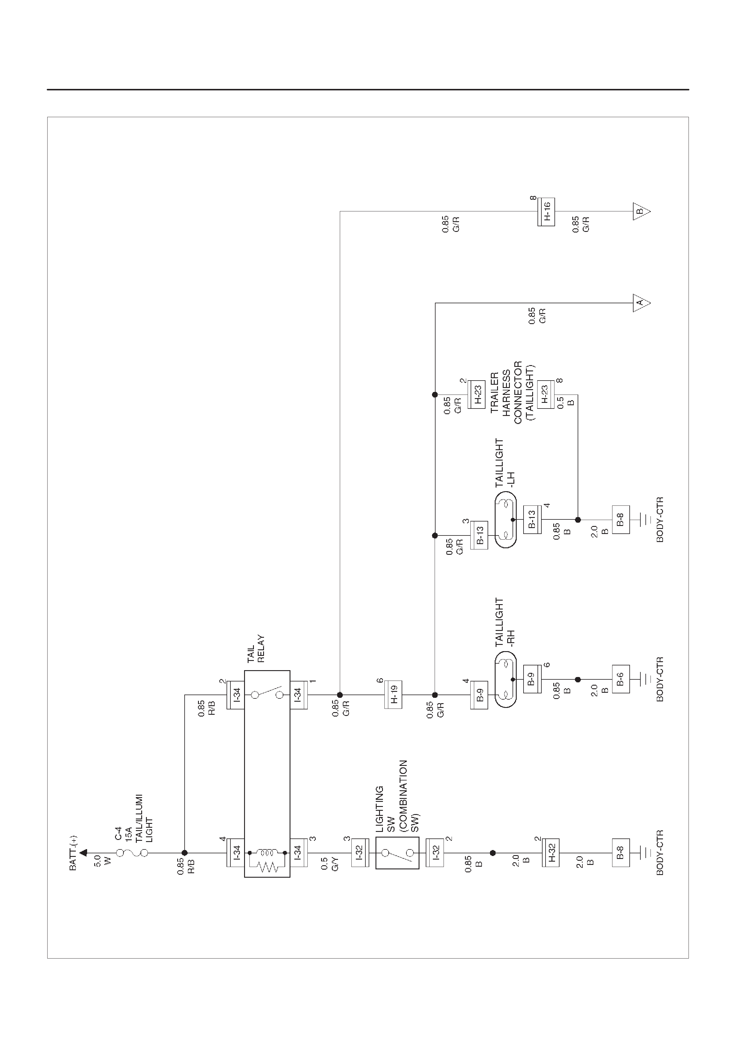
Circuit Diagram–1
D08RX193
Circuit Diagram–2
D08RX194
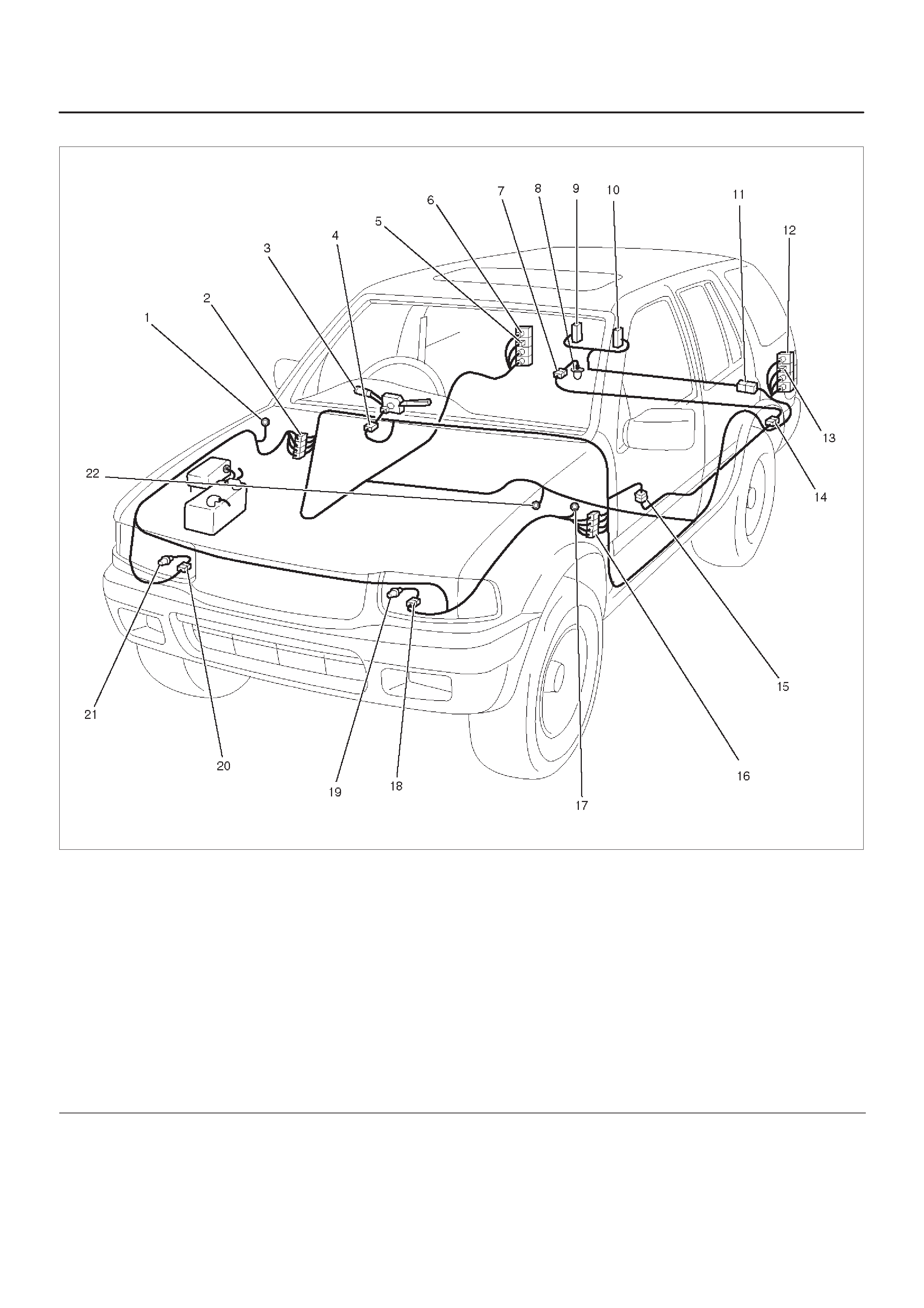
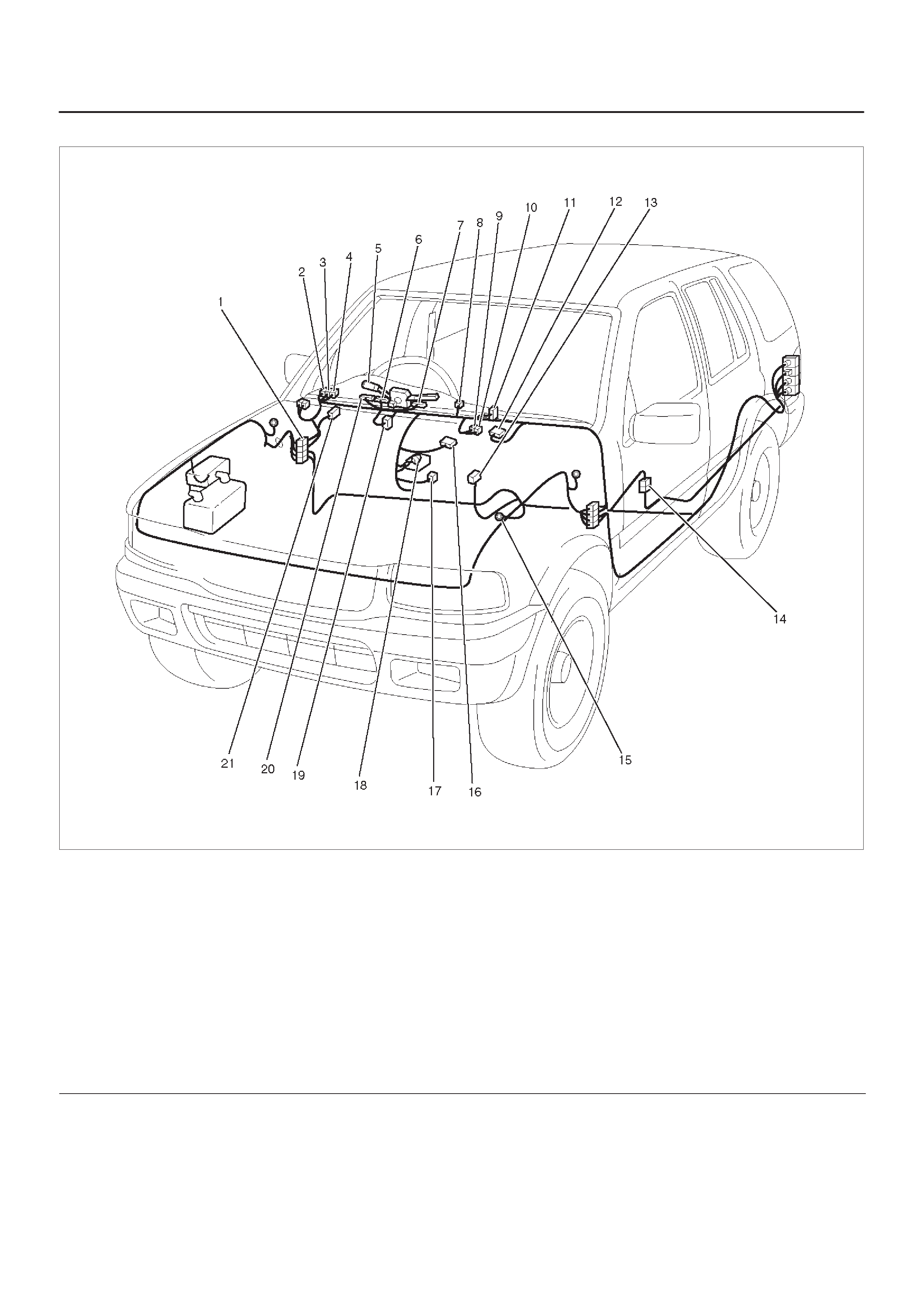
Parts Location
D08RWD04
Legend
(1) C–36
(2) H–19, H–32
(3) Lighting Switch
(4) I–32
(5) B–9
(6) Tail Light – RH
(7) G–8
(8) License Plate Light (Bumper Type)
(9) G–3 (Tailgate Type)
(10) G–2 (Tailgate Type)
(11) H–22
(12) Tail Light – LH
(13) B–13
(14) H–27
(15) H–25
(16) H–16
(17) C–16
(18) C– 49
(19) Clearance Light – LH
(20) C–20
(21) Clearance Light – RH
(22) B–6, B–8

Diagnosis
Both Tail Lights Inoperative
Step Action Value(s) Yes No
1Repair an open circuit between the tail relay and the
taillights.
Is the action complete? — Verify repair —
Tail Light On The Left (or Right) Side Inoperative
Step Action Value(s) Yes No
1Remove the taillight bulb on the left or right side.
Is the bulb normal? —Go to Step 2 Replace the
bulb
2Disconnect the taillight connector B–9 or B–13.
Is the battery voltage applied between harness side
connector B–9 or B–13 terminal 4 or 3 and the ground? Approx. 12V Go to Step 4 Go to Step 3
3Repair an open circuit between the tail relay and the
taillight on the left or right side.
Is the action complete? — Verify repair —
4Repair an open circuit between the taillight on the left or
right side and the ground.
Is the action complete? — Verify repair —
Clearance Light Inoperative
Step Action Value(s) Yes No
1Repair an open circuit between the tail relay and the
taillights.
Is the action complete? — Verify repair —
Clearance Light On The Left (or Right) Side Inoperative
Step Action Value(s) Yes No
1Remove the clearance light bulb on the left or right side.
Is the bulb normal? —Go to Step 2 Replace the
bulb
2Disconnect the clearance light connector C–49 or
C–50.
Is the battery voltage applied between harness side
connector C–49, or C–50 terminal 4 and the ground? Approx. 12V Go to Step 4 Go to Step 3
3Repair an open circuit between the tail relay and the
clearance light on the left or right side.
Is the action complete? — Verify repair —
4Repair an open circuit between the clearance light and
the ground?
Is the action complete? — Verify repair —

License Plate Light Inoperative
Step Action Value(s) Yes No
1Do the taillights come on? —Go to Step 2 Go to Step 6
2Remove the license plate light bulb.
Is the bulb normal? —Go to Step 3 Replace bulb
31. Disconnect the license plate light connector G–8.
2. Turn the lighting switch on.
Is the battery voltage applied between harness side
connector G–8 terminal 1 and the ground? Approx. 12V Go to Step 5 Go to Step 4
4Repair an open circuit between connector H–19
terminal 6 and the license plate light.
Is the action complete? — Verify repair —
5Repair an open circuit between the license plate light
and the ground B–8.
Is the action complete? — Verify repair —
6Refer to the diagnosis procedure for “Both Taillight
Inoperative” in this section.
Is the action complete? — Verify repair —

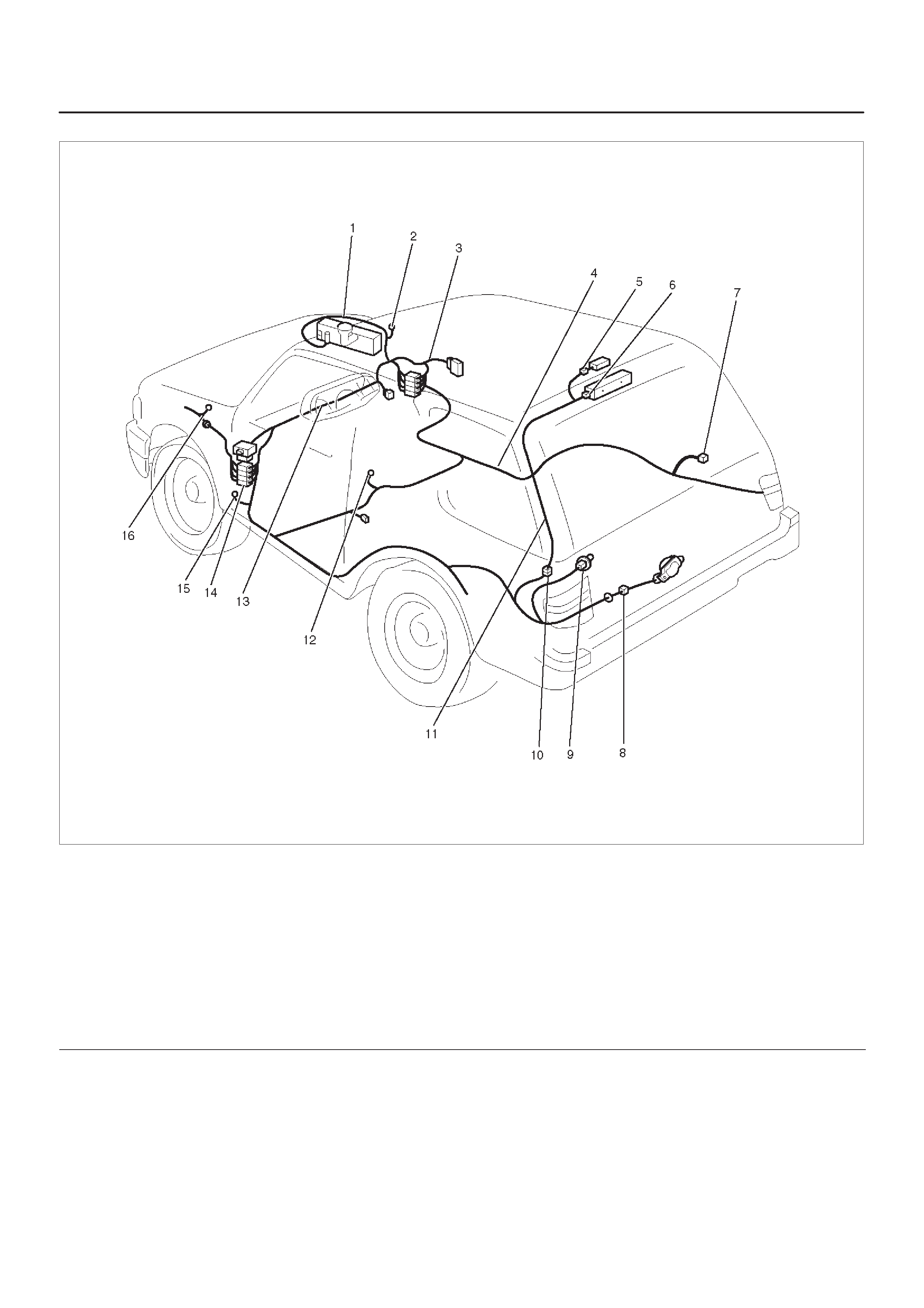
Interior Illumination Light
General Description
The circuit consists of lighting switch, tail relay, and
illumination lights.
All these lights come on when lighting switch is turned on
with the switch to either parking or headlight position.
Circuit Diagram–1
D08RX195

Circuit Diagram–2
D08RX196

Circuit Diagram–3
D08RX197
Parts Location
D08RX198
Legend
(1) H–19, H–32
(2) I–19
(3) I–6
(4) I–5
(5) Lighting Switch
(6) I–2
(7) I–9
(8) I–27
(9) I–16
(10) I–17
(11) I–11
(12) I–33
(13) B–24
(14) H–25
(15) B–8
(16) I–15
(17) I–40
(18) I–3
(19) I–32
(20) I–1
(21) Relay & Fuse Box (I–34)

Diagnosis
Interior Illumination Lights Inoperative
Step Action Value(s) Yes No
1Turn the light switch to clearance light position.
Do the exterior light come on? —Go to Step 3 Go to Step 2
2Refer to the diagnosis procedure in Clearance Light,
Taillight and License Plate Light section.
Is the action complete? — Verify repair —
3Repair an open circuit between tail relay harness side
connector I–34 terminal 1 and interior lights.
Is the action complete? — Verify repair —

Turn Signal Light, Hazard Warning Light
General Description
The circuit consists of turn signal/light switch
(combination switch) turn signal light, hazard warning
switch and flasher unit. When turn signal light switch is
turned on with starter switch on, turn signal light will
operate. When turn signal light is flashing, indicator light
in meter also starts flashing. When hazard warning switch
is turned on, current flows to flasher unit through hazard
warning switch to cause hazard warning light to flash
independent of position of starter switch. At the same
time, indicator lights in meter also start flashing.
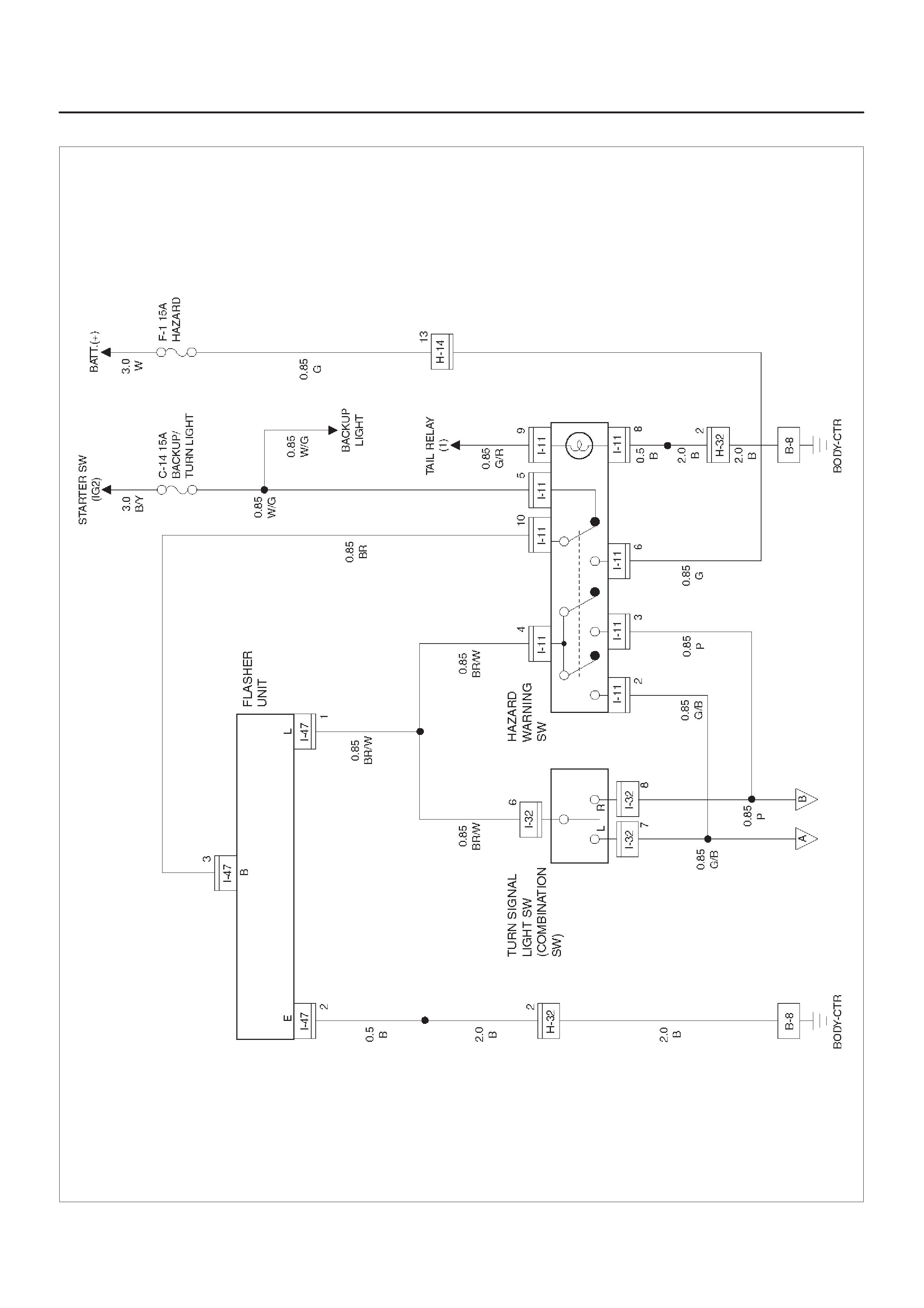
Circuit Diagram–1
D08RX199
Circuit Diagram–2
D08RX200
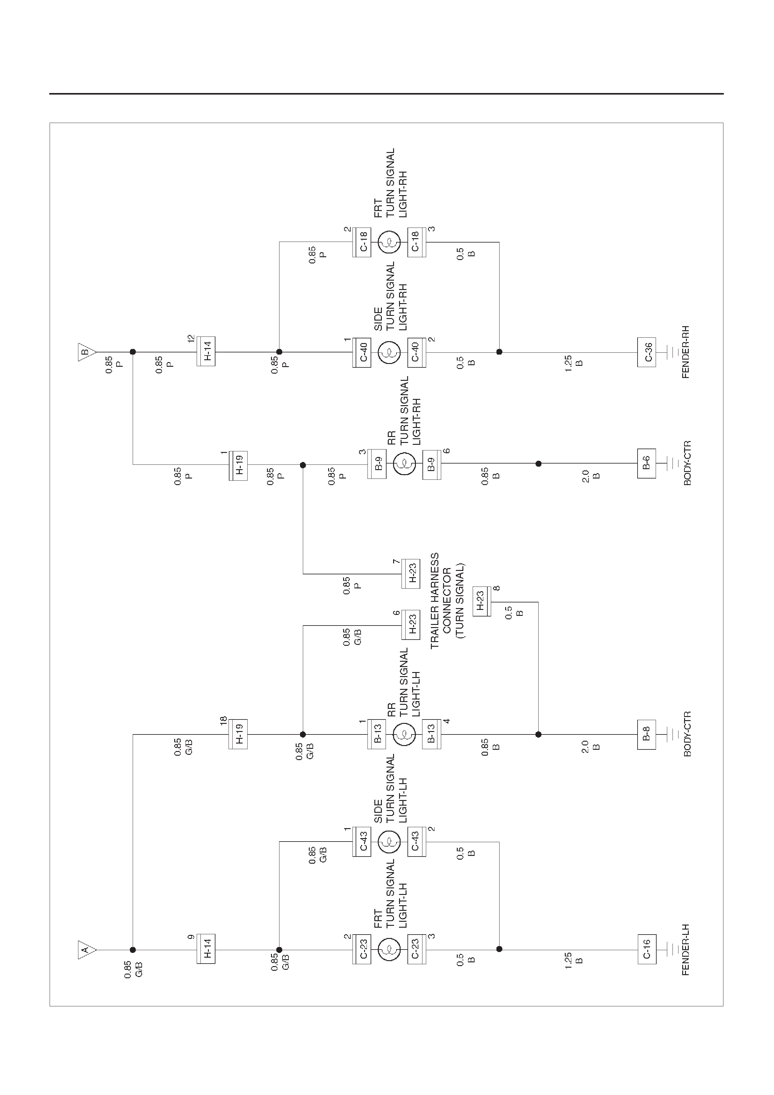
Parts Location
D08RX201
Legend
(1) C–40
(2) C–36
(3) H–14, H–19, H–32
(4) Relay & Fuse Box
(5) Turn Signal light Switch
(6) I–32, I–47
(7) H– 23 (2Door Model)
(8) B–9
(9) Rear Turn Signallight – RH
(10) I–11
(11) C–16
(12) Rear Turn Signallight – LH
(13) B–13
(14) H–23 (4Door Model)
(15) C– 43
(16) C–23
(17) Front Turn Signallight – LH
(18) B– 8
(19) C–18
(20) Front Turn Signallight – RH

Diagnosis
Turn Signal Light Does Not Flash
Step Action Value(s) Yes No
1Is fuse C–14 normal? —Go to Step 2 Replace the
fuse
21. Turn the hazard warning switch off.
2. Disconnect the switch connector I–11.
Is there continuity between switch side connector I–11
terminal 5 and 10? —Go to Step 3
Replace or
replace the
switch
3Turn the starter switch on.
Is the battery voltage applied between harness side
connector I–11 terminal 5 and the ground? Approx. 12V Go to Step 5 Go to Step 4
4Repair an open circuit between the fuse C–14 and the
hazard warning switch.
Is the action complete? —Go to Step 3 —
51. Reconnect the connector I–11 with the hazard
warning switch.
2. Disconnect the flasher unit connector I–47.
Is the battery voltage applied between harness side
connector I-47 terminal 3 and the ground? Approx. 12V Go to Step 7 Go to Step 6
6Repair an open circuit between connector I–11 terminal
10 and connector I–47 terminal 3.
Is the action complete? —Go to Step 5 —
7Is there continuity between harness side connector
I-47 terminal 2 and the ground B–8? —Go to Step 9 Go to Step 8
8Repair an open circuit between connector I–47
terminal 2 and the ground B–8.
Is the action complete? —Go to Step 7 —
91. Reconnect the flasher unit connector I–47.
2. Disconnect the turn signal light switch connector
I–32.
Is there continuity between switch side connector
terminal 6 and 7 with the switch turned to the left
position, and terminal 6 and 8 with the switch turned to
the right position? —Go to Step 10
Repair or
replace the
switch
10 Is there continuity between harness side connector
I–47 terminal 1 and harness side connector I–32
terminal 6? —Go to Step 12 Go to Step 11
11 Repair an open circuit between connector I–47
terminal 1 and connector I–32 terminal 6.
Is the action complete? — Verify repair —
12 Replace the flasher unit.
Is the action complete? — Verify repair —

Turn Signal Light Flashes Too Quickly
Step Action Value(s) Yes No
1Do all of turn signal lights flash? —Go to Step 2 Go to Step 3
2Replace the flasher unit.
Is the action complete? — Verify repair —
3Is the bulb of turn signal light that does not work
normal? —Go to Step 4 Replace the
bulb
4Repair an open circuit between the turn signal light
switch and the turn signal light.
Is the action complete? — Verify repair —

Stoplight
General Description
The circuit consists of stoplight, high mounted stoplight
and stoplight switch.
With brake pedal depressed, stoplight switch is turned to
on to illuminate stoplight.
Stoplight switch controls not only the operation of
stoplight but also the input of cruise cancel signals to
cruise control unit.
Circuit Diagram
D08RX202
Parts Location (2Door Model)
D08RX203
Legend
(1) H–19
(2) Relay & Fuse Box
(3) I–18
(4) B–9
(5) Stoplight – RH
(6) G–4
(7) High Mounted Stoplight
(8) H–37
(9) Stoplight – LH
(10) B–13
(11) B–8
(12) B–6

Parts Location (4Door Model)
D08RX203
Legend
(1) H–19
(2) Relay & Fuse Box
(3) I–18
(4) B–9
(5) Stoplight – RH
(6) H–21
(7) G–10, G–11
(8) High Mounted Stoplight
(9) Stoplight – LH
(10) B–13
(11) B–8
(12) B–6

Diagnosis
Both Stoplights Inoperative
Step Action Value(s) Yes No
1Is the fuse C–6 normal? —Go to Step 2 Replace the
fuse
2Dieconnect the stoplight switch connector I–18.
Is there continuity between connector I–18 terminal 1
and 4 with the brake pedal depressed? —Go to Step 3
Replace or
replace the
switch
3Is the battery voltage applied between harness side
connector I–18 terminal 1 and the ground? Approx. 12V Go to Step 5 Go to Step 4
4Repair an open circuit between the fuse C–6 and
connector I–18 terminal 1.
Is the action complete? — Verify repair —
5Repair an open circuit between stoplight switch and the
stoplight.
Is the action complete? — Verify repair —
Stoplight On The Left (or Right) Side Inoperative
Step Action Value(s) Yes No
11. Disconnect the stoplight connector B–9 or B–13.
2. Depress the brake pedal.
Is the battery voltage applied between stoplight
harness side connector terminal 2 and the ground? Approc. 12V Go to Step 2 Go to Step 3
2Repair an open circuit between the stoplight and the
ground.
Is the action complete? — Verify repair —
3Repair an open circuit between the stoplight switch and
the stoplight.
Is the action complete? — Verify repair —

High Mounted Stoplight Inoperative
Step Action Value(s) Yes No
1Depress the brake pedal.
Do the stoplight come on? —Go to Step 3 Go to Step 2
2Refer to the diagnosis procedure for “Both Stoplights
inoperative” in this section.
Is the action complete? — Verify repair —
3Is B–6 grounded securely? —Go to Step 4 Ground it
securely
41. Disconnect the high mounted stoplight connector.
2. Depress the brake pedal.
Is the battery voltage applied between harness side
connector G–1 1 terminal 1 or connector G–4 terminal 2
and the ground? Appprox. 12V Go to Step 6 Go to Step 5
5Repair an open circuit between connector H–19
terminal 10 and the high mounted stoplight.
Is the action complete? —Go to Step 4 —
6Is there continuity between high mounted stoplight side
connector terminals? —Go to Step 7
Repair or
replace the
light
7Repair an open circuit between the high mounted
stoplight and the ground B–6.
Is the action complete? — Verify repair —

Backup Light
General Description
The circuit consists of backup light switch (M/T), mode
switch (A/T) and backup light.
When shift lever is set to “R” position, backup light switch
(M/T) or mode switch (A/T) is activated to illuminate
backup light.
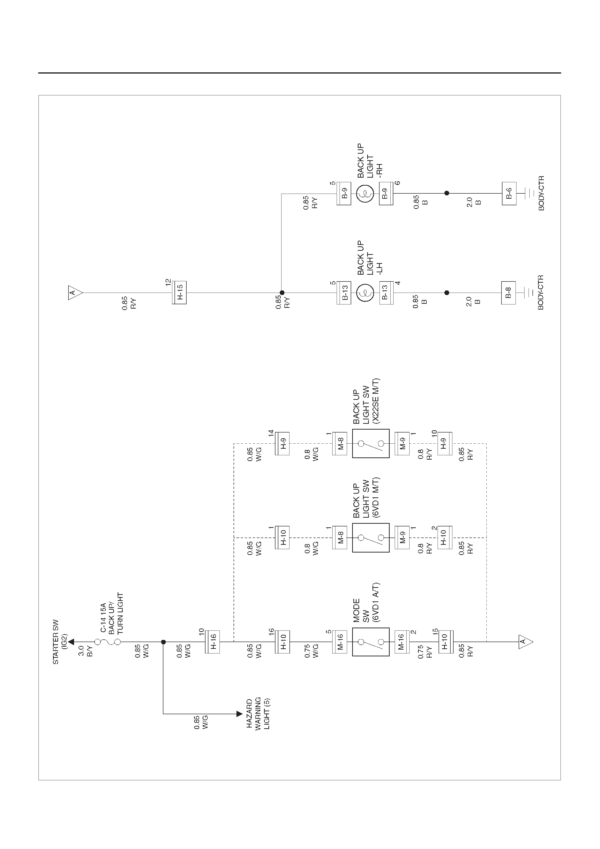
Circuit Diagram
D08RX204
Parts Location
D08RWD19
Legend
(1) B–9
(2) Backup Light – RH
(3) Backup Light – LH
(4) B–13
(5) H–15, H–16
(6) B–8
(7) B–6
(8) H–9, H–10, (6VD1 M/T)
(9) M–8, M–9 (X22SE)
(10) H–10, (6VD1 A/T)
(11) M–16
(12) Relay & Fuse Box

Diagnosis
Both Backup Lights Inoperative
Step Action Value(s) Yes No
1Is the fuse C–14 normal? —Go to Step 2 Replace the
fuse
2Are B–6 and B–8 ground securely? —Go to Step 3 Ground then
securely
31. Disconnect the mode switch connector M–16 or
backup light switch connector M–8 and M–9.
2. Turn the starter switch on.
Is the battery voltage applied between harness side
connector M-16 terminal 5 and the ground, or harness
side connector M–8 terminal 1 and the ground? Approx. 12V Go to Step 5 Go to Step 4
4Repair an open circuit between the fuse C–14 and
connector M–16 terminal 5 or connector M–8 terminal
1.
Is the action complete? —Go to Step 3 —
5Set the transmission gear to the reverse position.
Is there continuity between mode switch side
connector terminal 2 and 5, or backup light switch side
connector terminals? —Go to Step 6
Repair or
replace the
switch
61. Reconnect the mode switch connector M–16 or
backup light switch connector M–8 and M–9.
2. Disconnect the backup light connector B–9 or B–13.
Is the battery voltage applied between the backup light
harness side connector terminal 5 and the ground? Approx. 12V Go to Step 8 Go to Step 7
7Repair an open circuit between the mode switch or
backup light switch and the backup lights.
Is the action complete? — Verify repair —
8Repair an open circuit between backup lights and the
ground.
Is the action complete? — Verify repair —
Backup Light On The Left (or Right) Side Inoperative
Step Action Value(s) Yes No
1Remove the backup light bulb on the left or right side.
Is the bulb normal? —Go to Step 2 Replace the
bulb
21. Set the transmission gear to the reverse position.
2. Turn the starter switch on.
Is the battery voltage applied between backup light
harness side connector B–9 or B–13 terminal 5 and the
ground? Approx. 12V Go to Step 4 Go to Step 3
3Repair an open circuit between connector H–15
terminal 12 and the backup light on the left or right side.
Is the action complete? — Verify repair —
4Repair an open circuit between the backup light on the
left or right side and the ground.
Is the action complete? — Verify repair —

Backup Lights Remain On
Step Action Value(s) Yes No
1Repair or replace the mode switch or the backup light
switch.
Is the action complete? — Verify repair —

Horn
General Description
The circuit consists of horn (high note), horn (low note),
horn relay (alarm & relay control unit) and horn switch.
When horn switch is pushed, (independent of position of
starter switch) horn relay is activated to sound horns.
Circuit Diagram
D08RX205
Parts Location
D08RWD18
Legend
(1) H–14
(2) SRS Coil ASM
(3) Horn Switch
(4) I–41, I–42
(5) I–32
(6) Horn (Low note)
(7) C–14
(8) C–12
(9) Horn (High note)

Diagnosis
Horn Do Not Sound
Step Action Value(s) Yes No
1Is the fuse F–2 normal? —Go to Step 2 Replace the
fuse
2Disconnect the alarm & relay control unit connector
I–41 and I–42.
Is the battery voltage applied between harness side
connector I–41 terminal 2 or 3 (6VD1), connector I–42
terminal 12 (X22SE) and the ground? Approx. 12V Go to Step 4 Go to Step 3
3Repair an open circuit between the fuse F–2 and the
alarm & relay control unit.
Is the action complete? — Verify repair —
4Disconnect the horn switch connector.
Is there continuity between harness side connector
I–32 terminal 12 and connector I–42 terminal 20, 23 or
14? —Go to Step 6 Go to Step 5
5Repair an open circuit between the alarm & relay
control unit and the horn switch.
Is the action complete? — Verify repair —
6Press the horn switch.
Is there continuity between switch side connector I–32
terminal 12 and the ground? —Go to Step 7
Repair or
replace the
switch
71. Disconnect the horn connector.
2. Connect the battery positive terminal to the horn
side connector terminal 1.
Does the horn work? —Go to Step 8 Replace the
horn
8Is there continuity between harness side connector
terminal between the horn and the alarm & relay control
unit? —Go to Step 9 Go to Step 10
9Replace the alarm & relay control unit.
Is the action complete? — Verify repair —
10 Repair an open circuit between the horn and the alarm
& relay control unit.
Is the action complete? — Verify repair —
Horn Do Not Stop Sounding
Step Action Value(s) Yes No
1Disconnect the horn switch connector I–32.
Do the horn stop sounding? —
Repair or
replace the
horn switch Go to Step 2
2Disconnect the alarm & relay control unit connector
I–42.
Is there continuity between harness side connector
terminal 20 (23 or 14) and the ground? —Repair short
circuit
Replace the
alarm & relay
control unit

Dome Light, Luggage Room Light, Courtesy Light, Map Light, Seat
Belt Switch and Warning Buzzer
General Description
The circuit consists of door switch, dome light, luggage
room light, courtesy light, map light tail relay , key cylinder
switch and alarm & relay control unit.
Dome light comes on with dome light switch turned to
door position and any door open.
The buzzer sounds when starter switch is turned to either
“ACC” or “OFF” position and FRT door–RH, is opened
with lighting switch on.
The buzzer also sounds when FRT door–RH is opened
with starter key left in starter switch key cylinder.
These functions are controlled by alarm & relay control
unit.
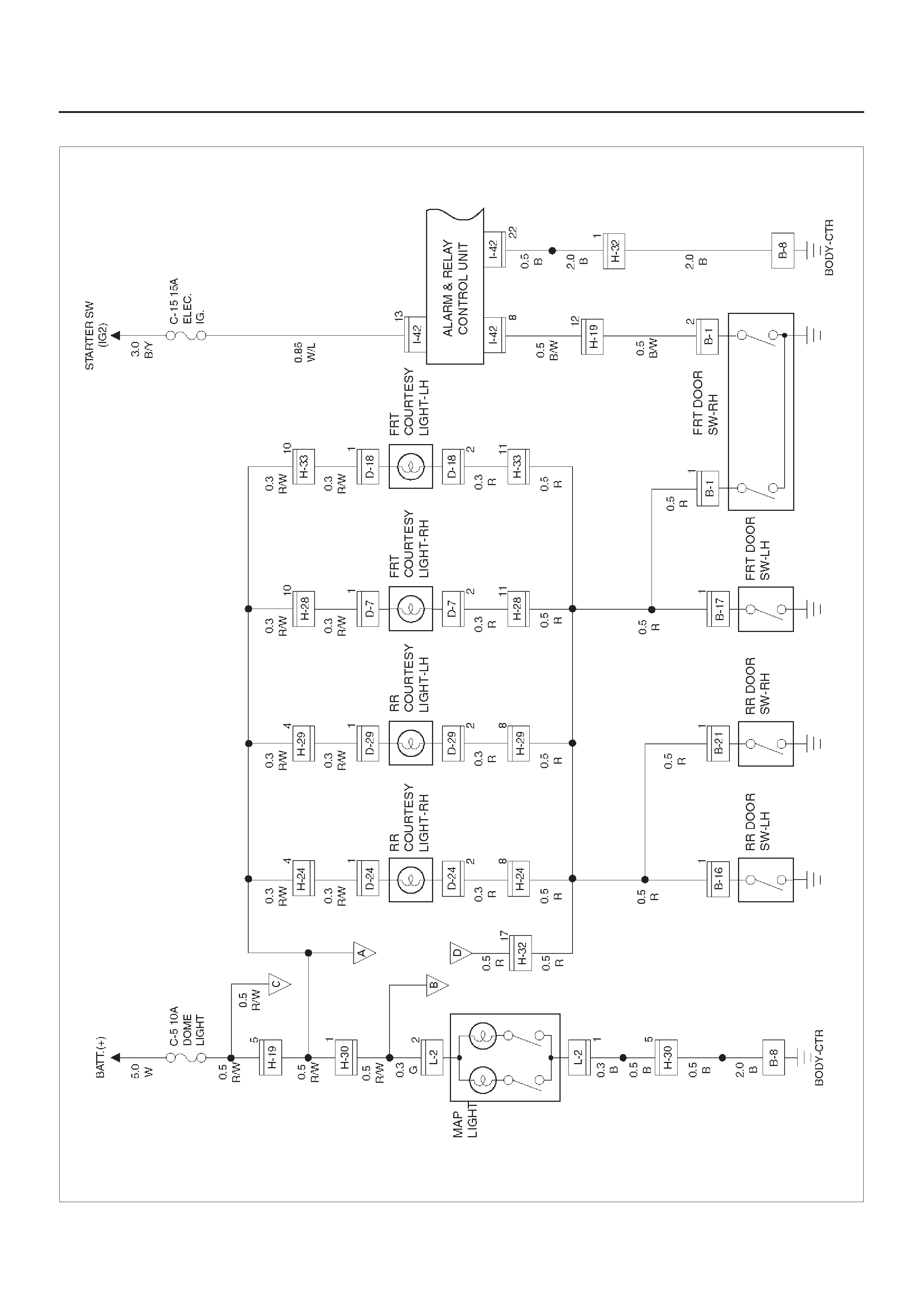
Circuit Diagram–1 (6VD1 M/T)
D08RX208
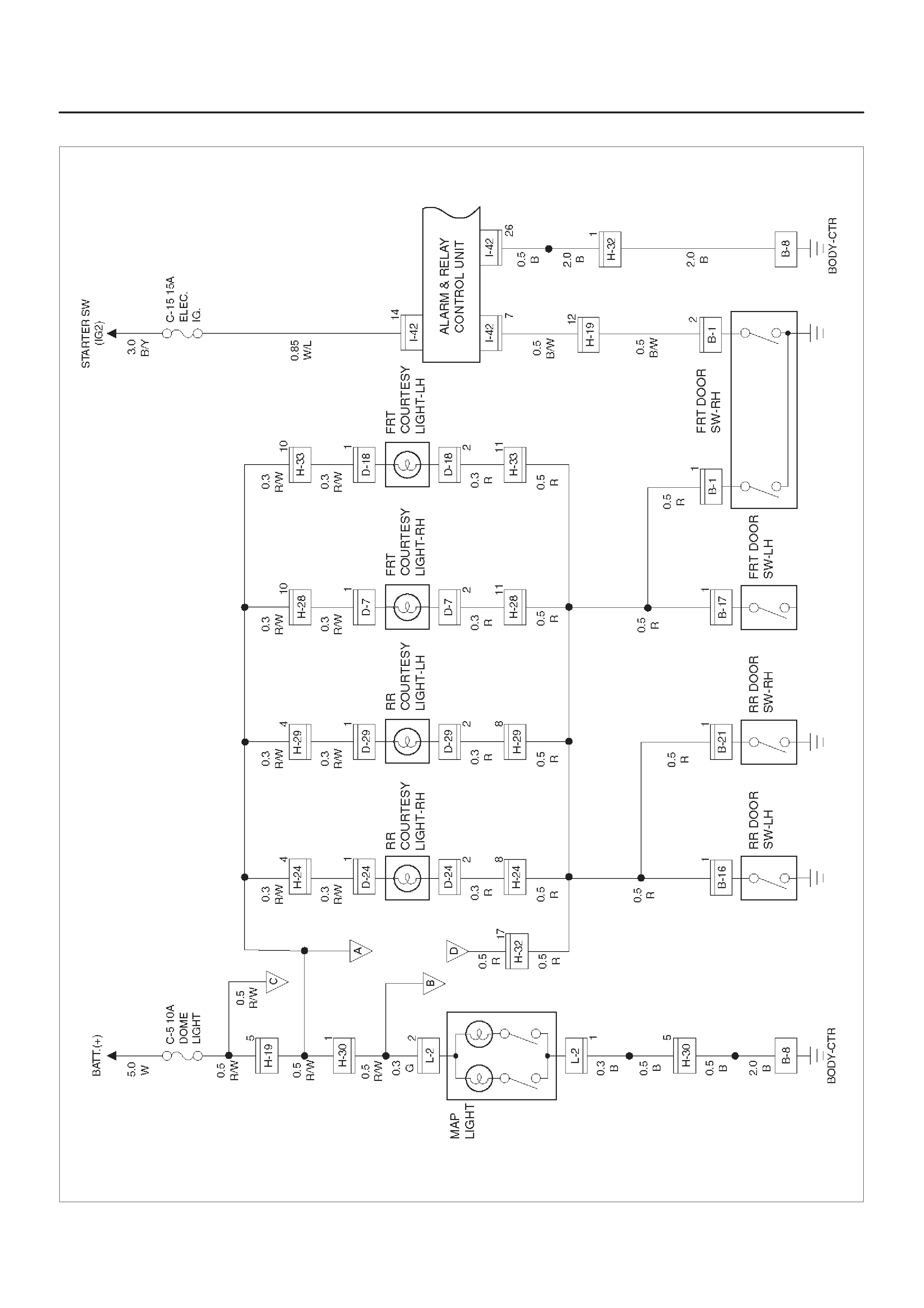
Circuit Diagram–1 (6VD1 A/T)
D08RX210
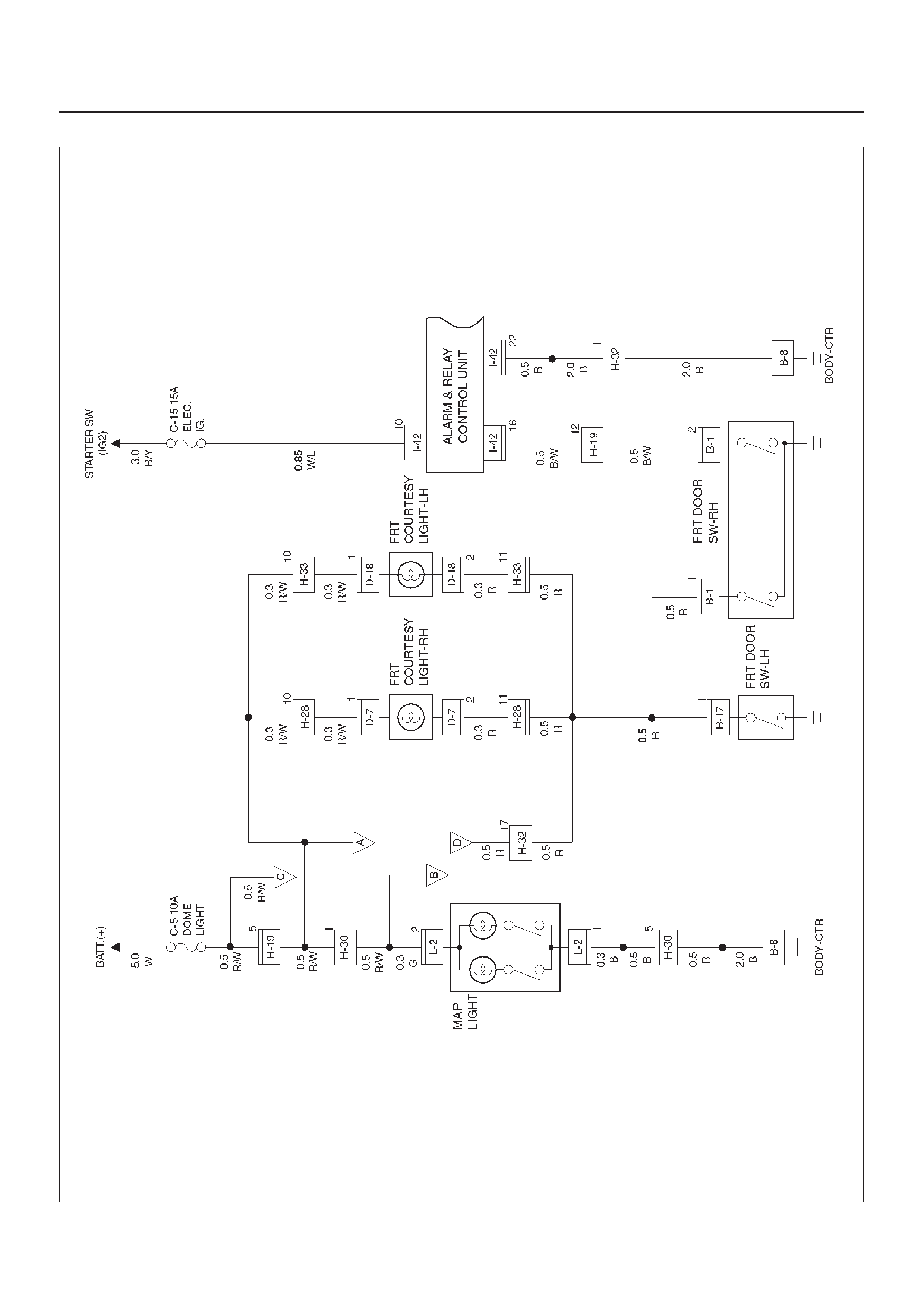
Circuit Diagram–1 (X22SE)
D08RX206
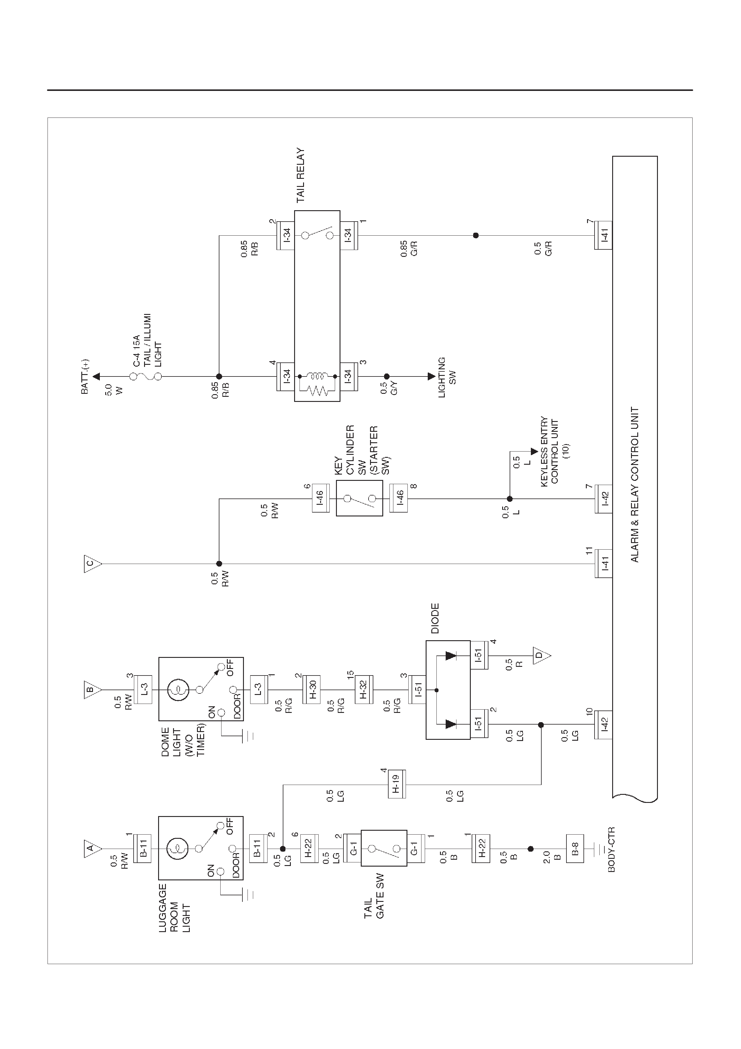
Circuit Diagram–2 (6VD1 M/T)
D08RX209

Circuit Diagram–2 (6VD1 A/T)
D08RX211
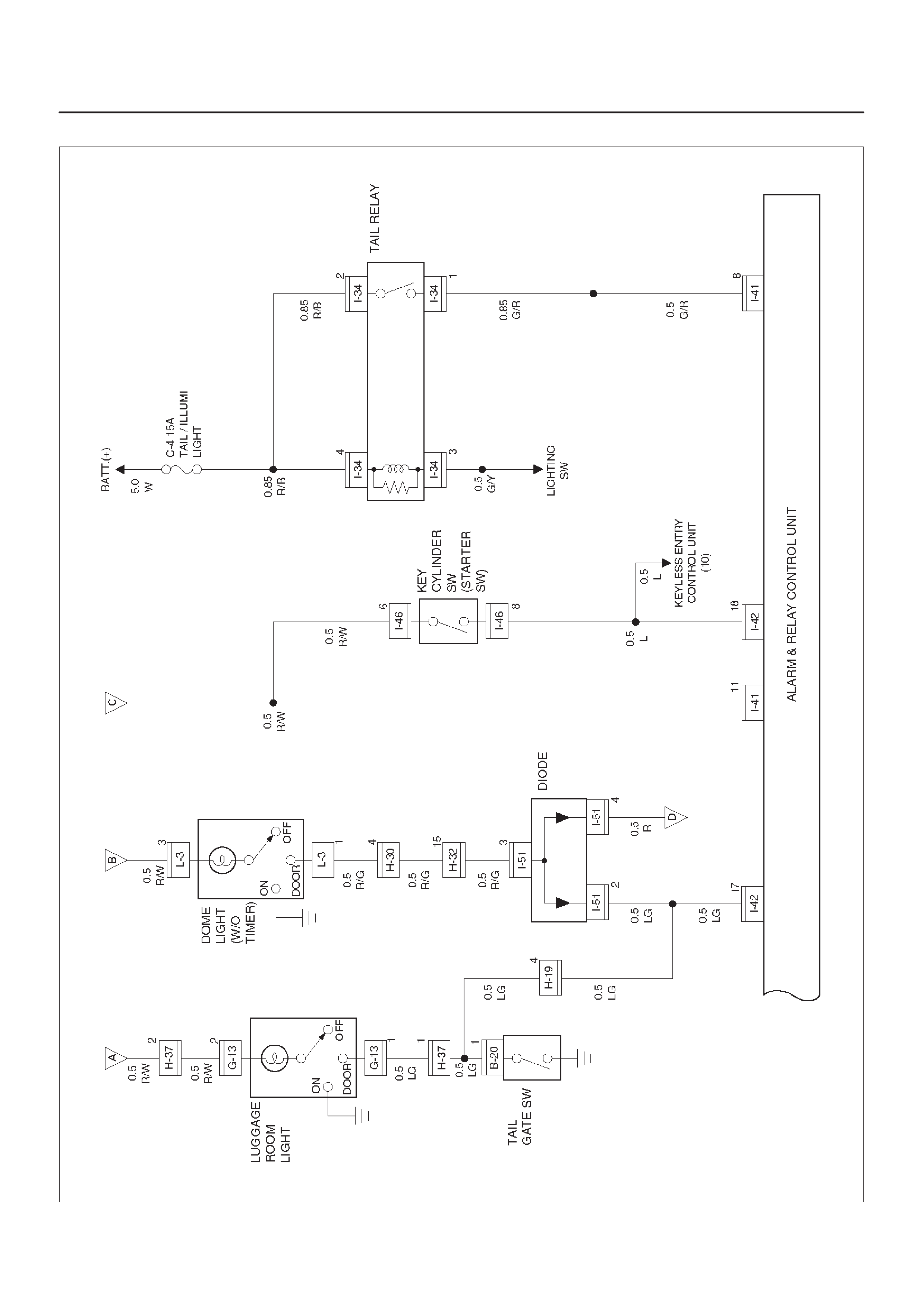
Circuit Diagram–2 (X22SE)
D08RX207
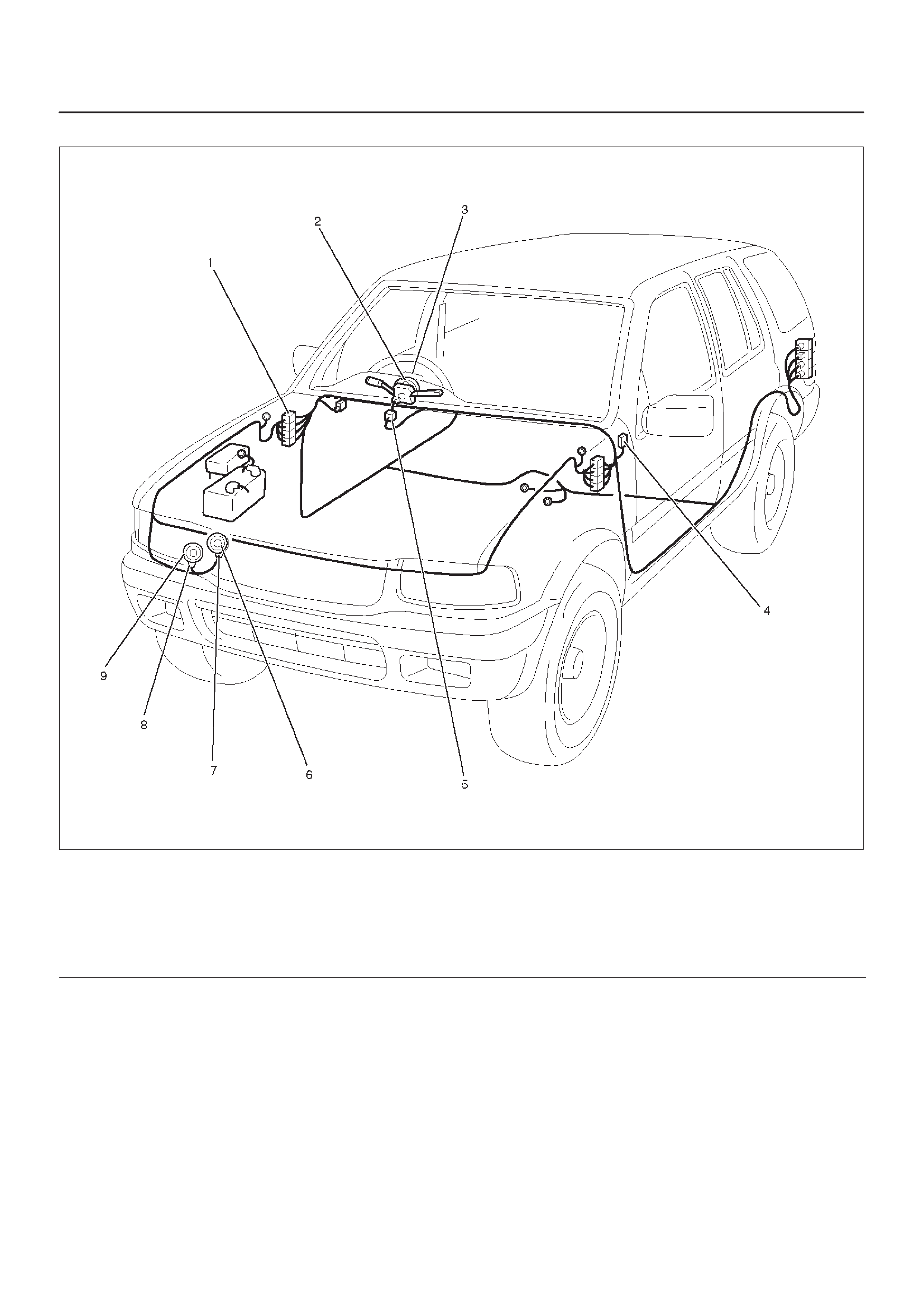
Parts Location
D08RWD17
Legend
(1) Relay & Fuse Box
(2) FRT Door SW–RH
(3) B–1
(4) D–24
(5) RR Courtesy–Light–RH
(6) B–21
(7) RR Door SW–RH
(8) Map Light
(9) L–2
(10) Dome Light
(11) L–3
(12) B–11 (4Door Model)
(13) Luggage Room Light
(14) G–13 (2Door Model)
(15) G–1
(16) H–37
(17) Tailgate Switch
(18) B–20
(19) H–22
(20) RR Door SW–LH
(21) B–16
(22) RR Courtesy–Light–LH
(23) H–29
(24) FRT Door SW–LH
(25) H–30
(26) FRT Courtesy–Light–LH
(27) D–18
(28) H–33
(29) I–26
(30) I–41, I–42
(31) B–8
(32) H–24
(33) FRT Courtesy–Light–RH
(34) D–7
(35) H–28
(36) I–46
(37) H–19, H–32

Diagnosis
Dome Light Inoperative
Step Action Value(s) Yes No
1Remove the dome light bulb.
Is the bulb normal? —Go to Step 2 Replace the
bulb
21. Reinstall the bulb.
2. Disconnect the dome light connector L–3.
3. Set the dome light switch to door position.
Is there continuity between the dome light side
connector terminal 1 and 3? —Go to Step 3
Repair or
replace the
dome light
3Is the battery voltage applied between harness side
connector L–3 terminal 3 and the ground? Approx. 12V Go to Step 4 Go to Step 5
4Repair an open circuit between the fuse C–5 and the
dome light.
Is the action complete? — Verify repair —
5Repair an open circuit between the dome light and the
door switch or the tail gate switch.
Is the action complete? — Verify repair —

Power Door Lock
General Description
The door lock system consists of door lock switch keyless
entry control unit and door lock actuator . Door lock switch
on driver’s side can actuate the door lock mechanism.
Locking or unlocking the lock switch on the driver side
causes the door lock mechanism to be locked or
unlocked.
At this time, the current flows for approx. 1 second from
door lock switch on driver’s side to door lock actuator to
run the motor.
When the key is in the key cylinder , Door Lock can not be
done.
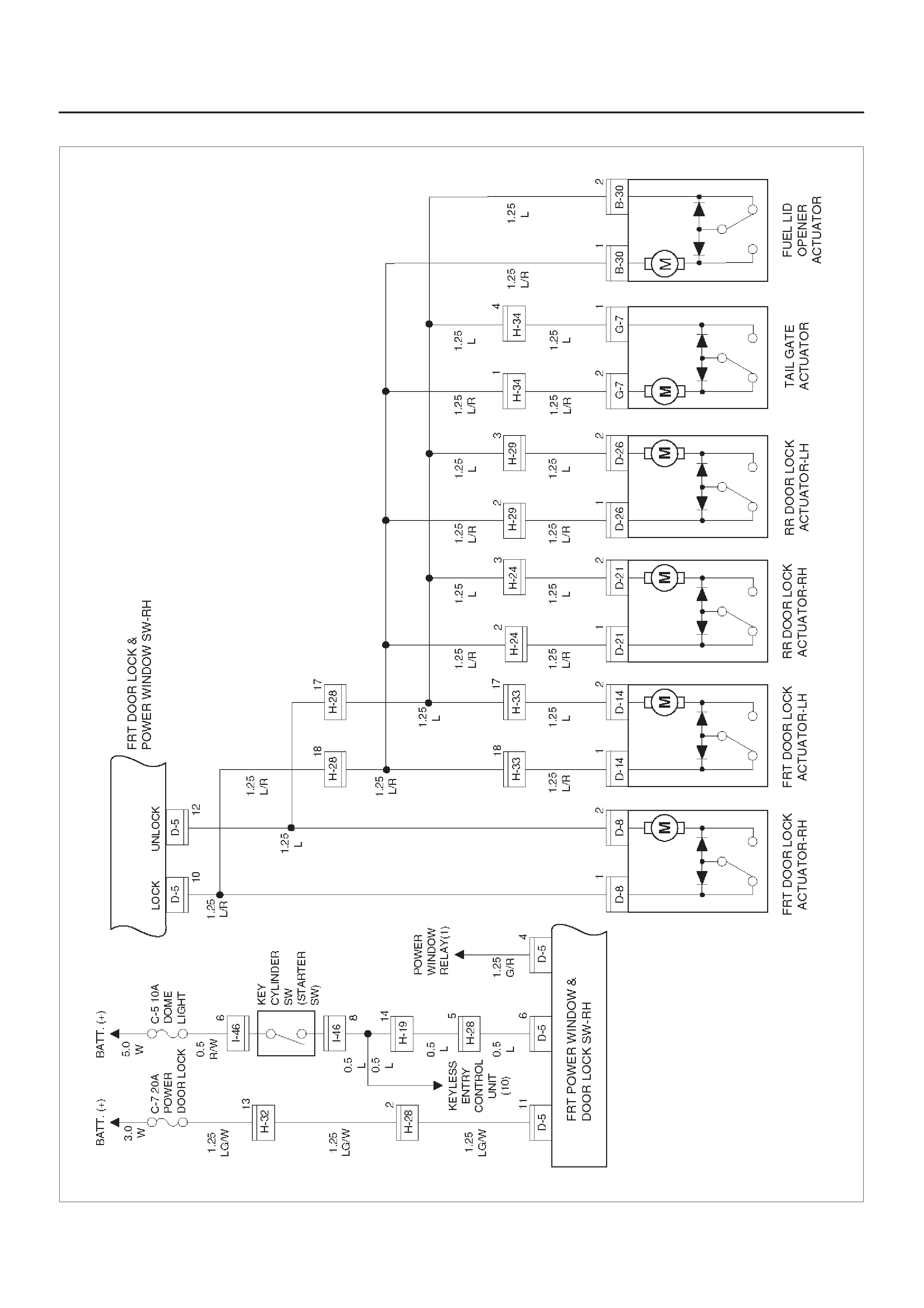
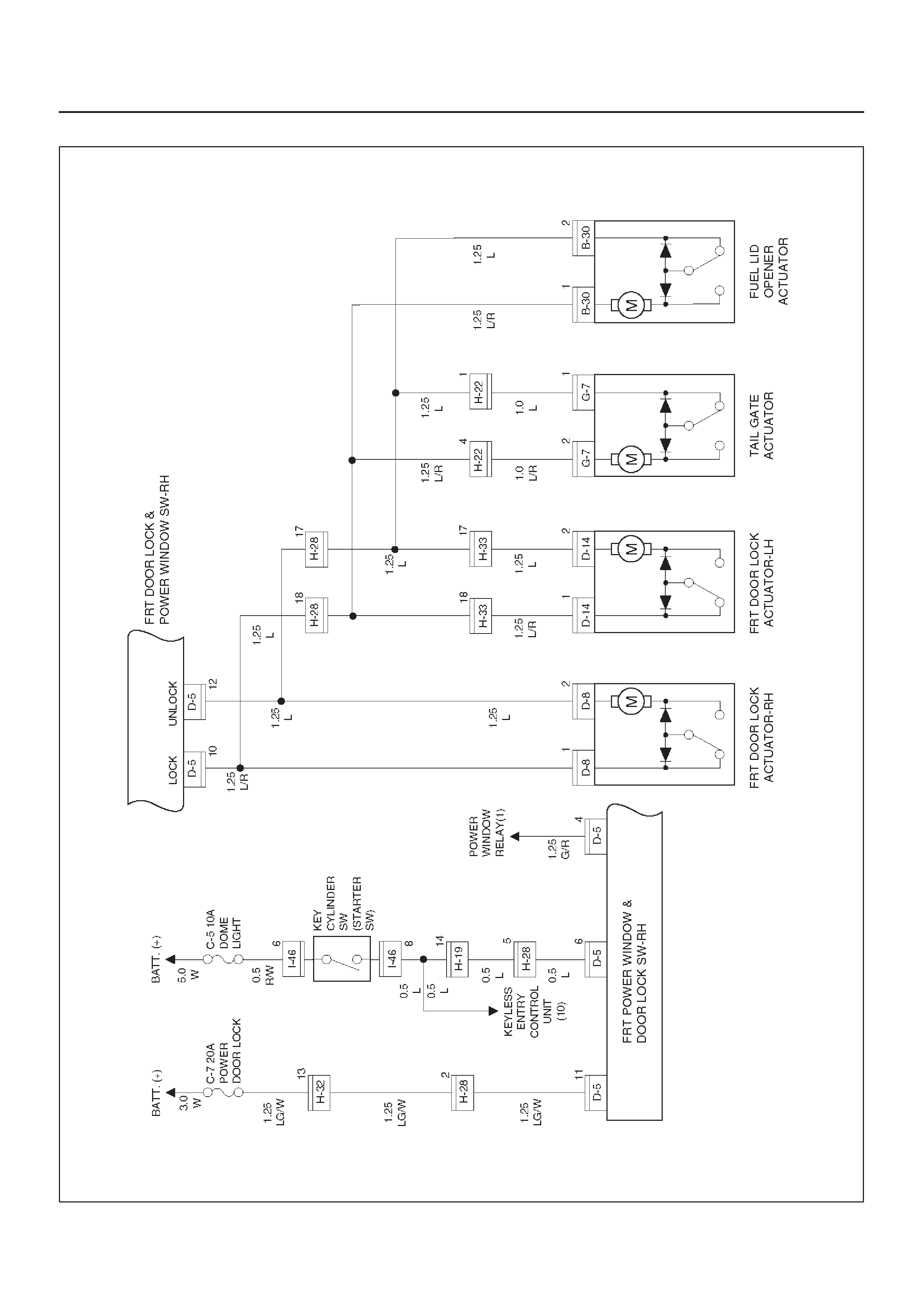
Circuit Diagram–1 (4Door Model)
D08RX243
Circuit Diagram–1 (2Door Model)
D08RX295
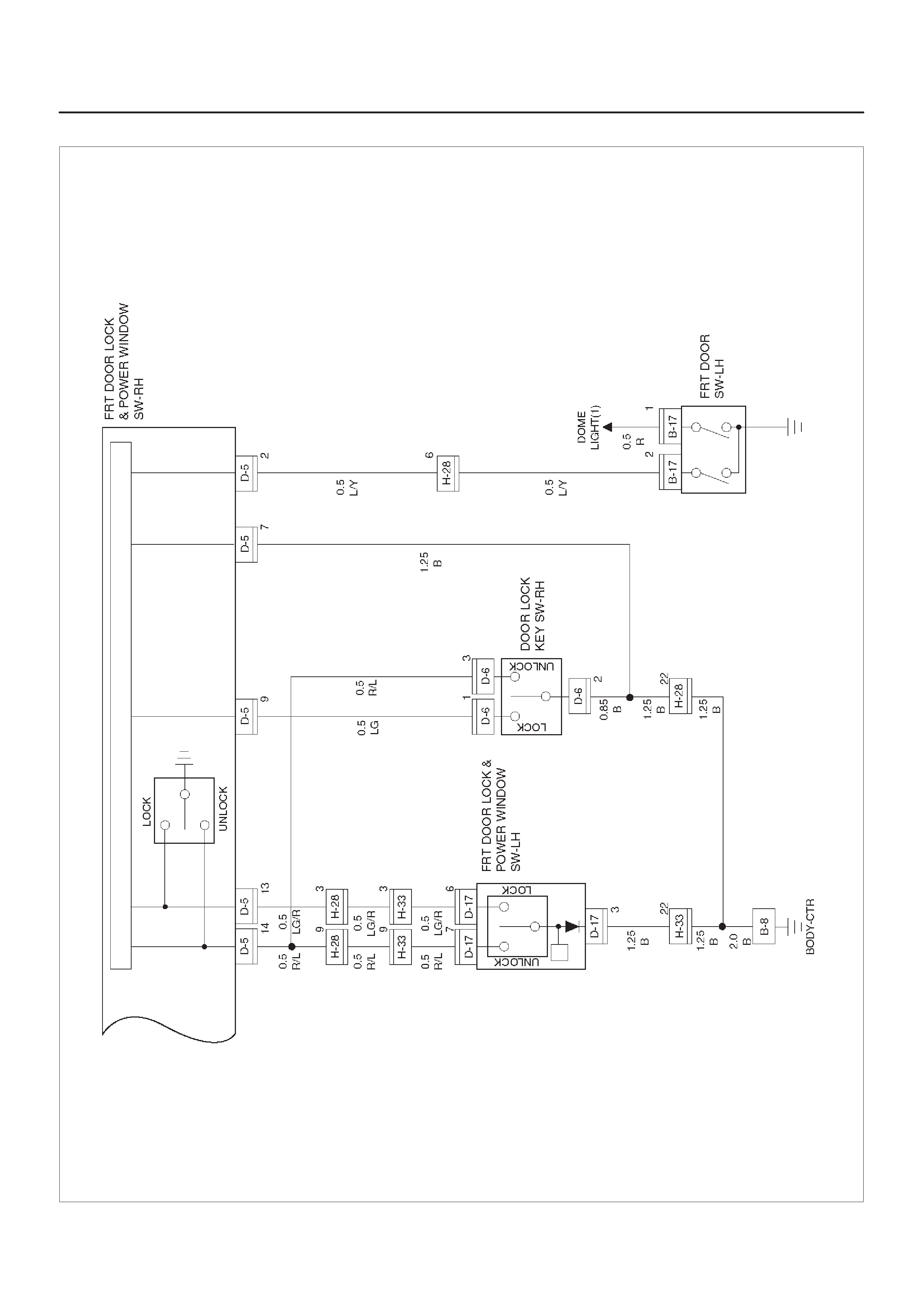
Circuit Diagram–2
D08RX242
Parts Location
D08RWD15
Legend
(1) H–28
(2) H–19, H–32
(3) D–8
(4) FRT Door Lock Actuator–RH
(5) H–24
(6) FRT Door Lock Switch–RH
(7) D–6, D–5
(8) D–23
(9) RR Door Lock Actuator–RH
(10) I–26
(11) FRT Door Lock Actuator–LH
(12) D–14
(13) RR Door Lock Actuator–LH
(14) B –30
(15) D–28
(16) H–29
(17) D–17
(18) FRT Door Lock Switch–LH
(19) H–33
(20) B–8
(21) Relay & Fuse Box (Instrument Panel)
(22) H–34, H–22 (2Door Model)
(23) G–7

Diagnosis
All The Doors Do Not Lock And Unlock By Door Lock SW–RH
Step Action Value(s) Yes No
1Is the fuse C–7 normal? —Go to Step 2 Replace the
fuse
2Disconnect the front power window & door lock
SW–RH connector D–5.
Is the battery voltage applied between harness side
connector D–5 terminal 11 and the ground? Approx. 12V Go to Step 4 Go to Step 3
3Repair an open circuit between the fuse C–7 and the
switch.
Is the action complete? — Verify repair —
4Disconnect the FRT door lock actuator–RH connector
D–8.
Is there continuity between harness side connector
D–5 terminal 10 and connector D–8 terminal 1 (or
connector D–5 terminal 12 and connector D–8 terminal
2)? —Go to Step 5 Go to Step 6
5Replace the FRT power window & door lock SW–RH.
Is the action complete? — Verify repair —
6Repair an open circuit between the FRT power window
& door lock SW–RH and door lock actuator.
Is the action complete? — Verify repair —
All The Doors Do Not Lock and Unlock by FRT Door Lock SW–LH
Step Action Value(s) Yes No
1Disconnect the FRT power window & door lock
SW–RH and –LH connector D–5 and D–17.
Is there continuity between harness side connector
D–5 terminal 13 and connector D–17 terminal 6 (or
connector D–5 terminal 14 and connector D–17
terminal 7)? —Go to Step 2 Go to Step 3
2Replace the FRT power window & door lock SW–LH.
Is the action complete? — Verify repair —
3Repair an open circuit between the FRT power window
& door lock SW–RH and –LH.
Is the action complete? — Verify repair —

All the Doors Do Not Not Lock and Unlock by Door Lock Key SW
Step Action Value(s) Yes No
1Is B–8 grounded securely? —Go to Step 2 Ground it
securely
2Disconnect the door lock key SW connector D–6.
Is there continuity between harness side connector
D–6 terminal 2 and the ground? —Go to Step 4 Go to Step 3
3Repair an open circuit between connector D–6 terminal
2 and the ground B–8.
Is the action complete? — Verify repair —
4Is there continuity between the switch side connector
terminal 1 and 2 when the switch is turned to lock
position, and terminal 2 and 3 when the switch is turned
to unlock position? —Go to Step 5
Repair or
replace the
switch
5Repair an open circuit between the door lock key SW
and FRT power window & door lock SW–RH.
Is the action complete? — Verify repair —

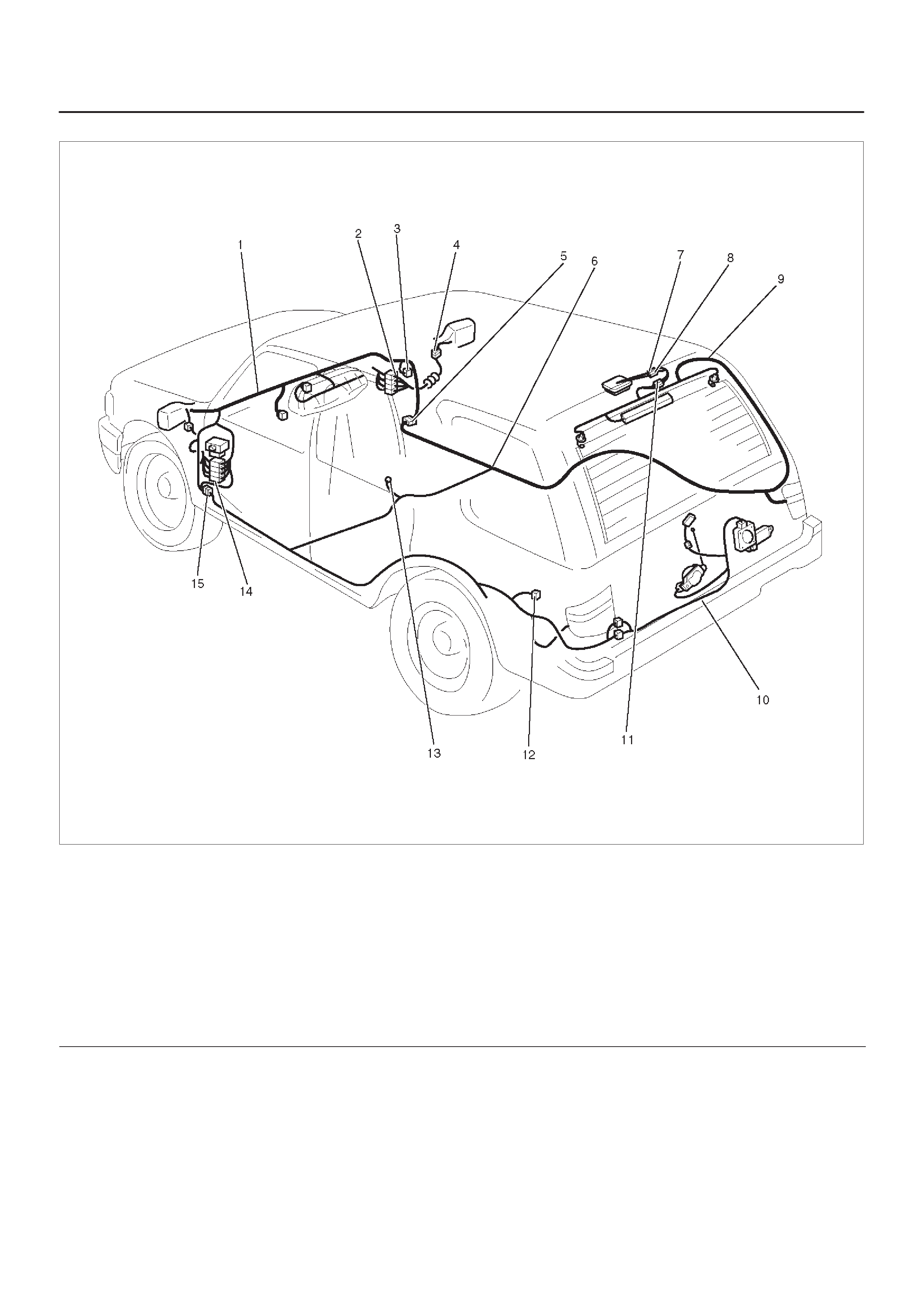
Power Window
General Description
The power window system consists of power window
switches, power window motors and power window relay .
With the starter switch in “ON” position, the battery
voltage is supplied through power window relay to the
power window switches Selection of up or down switch
changes over the motor rotating direction to open or close
the window.
When the lock switch on the switch panel on the driver
side is pressed, the power window switch is in open state.
As a result, the power source to the other switches are cut
off, and the power window motors do not run.
Circuit Diagram–1
D08RX213
Parts Location
D08RWD14
Legend
(1) H–28
(2) D–2
(3) H–32
(4) Relay & Fuse Box
(5) Power Window Motor (FRT RH)
(6) Power Window SW (FRT RH)
(7) D–5
(8) Power Window Motor (RR RH)
(9) D–20
(10) D–22
(11) Power Window SW (RR RH)
(12) Power Window SW (FRT LH)
(13) Power Window SW (RR LH)
(14) D–27
(15) D–25
(16) Power Window Motor (RR LH)
(17) H–29
(18) D–17
(19) D–11
(20) Power Window Motor (FRT LH)
(21) H–33
(22) B–8
(23) H–24

Diagnosis
All Window Do Not Operate
Step Action Value(s) Yes No
1Is the fuse C–15 normal? —Go to Step 2 Replace the
fuse
2Is the circuit breaker C–21 normal?
—Go to Step 3
Replace the
circuit
breaker
3Is B–8 grounded securely? —Go to Step 4 Ground it
securely
4Disconnect the power window relay connector I–35.
Is the battery voltage applied between harness side
connector I–35 terminal 2 and the ground? Approx. 12V Go to Step 6 Go to Step 5
5Repair an open circuit between the circuit breaker
C–21 and connector I–35 terminal 2.
Is the action complete? —Go to Step 4 —
6Turn the starter switch on.
Is the battery voltage applied between harness side
connector I-35 terminal 4 and the ground? Approx. 12V Go to Step 8 Go to Step 7
7Repair an open circuit between the fuse C–15 and
connector I–35 terminal 4.
Is the action complete? —Go to Step 6 —
8Is there continuity between harness side connector
I–35 terminal 3 and the ground B–8? —Replace the
relay Go to Step 9
9Repair an open circuit between connector I–35
terminal 3 and the ground B–8.
Is the action complete? — Verify repair —

Window On The Driver’s Side Does Not Operate
Step Action Value(s) Yes No
1Turn the starter switch on.
Is the battery voltage applied between harness side
connector D–5 terminal 4 and the ground? Approx. 12V Go to Step 3 Go to Step 2
2Repair an open circuit between connector I–35
terminal 1 and connector D–5 terminal 4.
Is the action complete? —Go to Step 1 —
3Connect the battery position terminal with harness side
connector D–5 terminal 3 or 5, and the negative
terminal with harness side connector D–5 terminal 5 or
3.
Does the motor operate? —
Replace the
front power
window &
door lock
switch–RH Go to Step 4
41. Disconnect the front power window motor–RH
connector D–2.
2. Connect the battery position terminal with the motor
side connector D–2 terminal 1 or 2, and connect the
battery negative terminal with the motor side
connector D–2 terminal 2 or 1.
Does the motor operate? —Go to Step 5 Replace the
motor
5Repair an open circuit between the front power window
and door lock switch–Rh and the front power window
motor–RH.
Is the action complete? — Verify repair —

Window On The Front Passenger’s Side Does Not Operate
Step Action Value(s) Yes No
1Is B–8 grounded securely? —Go to Step 2 Ground it
securely
2Disconnect the front power window and door lock
switch–LH connector D–17.
Is there continuity between harness side connector
D–17 terminal 3 and the ground B–8? —Go to Step 4 Go to Step 3
3Repair an open circuit between connector D–17
terminal 3 and the ground B–8.
Is the action complete? —Go to Step 2 —
4Turn the starter switch on.
Is the battery voltage applied between harness side
connector D–17 terminal 2 and the ground? Approx. 12V Go to Step 6 Go to Step 5
5Repair an open circuit between connector I–35
terminal 1 and connector D–17 terminal 2.
Is the action complete? —Go to Step 4 —
6Connector the battery positive terminal with harness
side connector D–17 terminal 1 or 4, and connect the
battery negative terminal with harness side connector
D–17 terminal 4 or 1.
Does the motor operate? —
Replace the
front power
window and
door lock
switch–LH Go to Step 7
71. Disconnect the front power window motor–RH
connector D–11.
2. Connector the battery positive terminal with the
motor side connector D–11 terminal 1 or 2, and
connect the battery negative terminal with the motor
side connector D–11 terminal 2 or 1.
Does the motor operate? —Go to Step 8 Replace the
motor
8Repair an open circuit between the front power window
and door lock switch–LH and the front power window
motor–LH.
Is the action complete? — Verify repair —

Rear Window On The Left (or Right) Side Does Not Operate
Step Action Value(s) Yes No
11. Disconnect the rear power window switch–RH
connector D–22 or the rear power window and door
lock switch–LH connector D–27.
2. Turn the starter switch on.
Is the battery voltage applied between harness side
connector D–22 terminal 4 and the ground, or harness
side connector D–27 terminal 4 and the ground? Approx. 12V Go to Step 3 Go to Step 2
2Repair an open circuit between connector I–35
terminal 1 and connector D–22 terminal 4 or connector
D–27 terminal 4.
Is the action complete? —Go to Step 1 —
3Is there continuity between harness side connector
D–22 terminal 3 and the ground B–6, or harness side
connector D–27 terminal 3 and the ground B–6 or 8? —Go to Step 5 Go to Step 4
4Repair an open circuit between connector D–22
terminal 3 or connector D–27 terminal 3 and the ground
B–6 or 8.
Is the action complete? —Go to Step 3 —
5Connect the battery positive terminal with harness side
connector D–22 terminals 5 or harness side connector
D–27 terminal 5, and connect the battery negative
terminal with harness side connector D–22 terminal 6
or harness side connector D–27 terminal 6.
Does the motor operate? —
Replace the
rear power
window
switch–LH or
–RH Go to Step 6
61. Disconnect the rear power window motor connector
D–20 or D–25.
2. Connect the battery positive terminal with motor
side connector D–20 or D–25 terminal 1 or 2, and
connect the battery negative terminal with the motor
side connector D–20 or D–25 terminal 2 or 1.
Does the motor operate? —Go to Step 7 Replace the
motor
7Repair an open circuit between the rear power window
switch and the rear power window motor.
Is the action complete? — Verify repair —
Window On The Front Passenger’s Side Does Not Operate by the Front Power Window
and Door Lock Switch–RH
Step Action Value(s) Yes No
1Disconnect the front power window and door lock
switch–RH connector D–5 and the front power window
and door lock switch–LH connector D–17.
Is there continuity between harness side connector
D–5 terminal 8 and harness side connector D–17
terminal 5? —
Replace the
front power
window and
door lock
switch–LH Go to Step 2
2Repair an open circuit between connector D–5 terminal
8 and connector D–17 terminal 5.
Is the action complete? — Verify repair —

Lock SW Does Not Function
Step Action Value(s) Yes No
1Repair or replace the front power window and door lock
switch–RH.
Is the action complete? — Verify repair —

Cruise Control
General Description
The circuit consists of cruise control unit, cruise main
switch, combination switch clutch switch (M/T), mode
switch (A/T), stoplight switch, actuator and indicator
lights. Cruise control system keeps the vehicle running at
a fix speed until a signal canceling this fixed speed is
received.When the cruise main switch is turned on with
the vehicle in the running mode, the battery voltage is
applied to the control unit.
When a signal from the combination switch is input to the
control unit while vehicle is in this state, the actuator is
activated to operate the system. Also, while the system is
operating, the cruise indicator light in the meter panel
lights up.
Set Function
When the cruise main switch turned on and the set switch
is depressed with the vehicle speed within the set limit
and cancel operation is refused the vehicle speed when
the set switch is released is stored in the control unit as
the set speed. But in case of the vehicle speed is over
maximum limit speed of cruise control, maximum limit
speed in the control unit is stored as the set speed.
Resume Function
Unless the vehicle speed falls below the minimum speed
limit after canceling the set speed by the cancel switch,
pushing the resume switch causes the vehicle to resume
the speed before cancellation.
Acceleration Function
During cruise control driving, pushing the acceleration
switch (on time is more than 0.6 sec.) causes an increase
in cruise speed and vehicle accelerates at a controlled
rate until acceleration switch released. Vehicle speed at
the acceleration switch released plus 1.0 km/h is stored in
the control unit as the set speed.
Top Up Function
During cruise control driving, the set speed can be
increased 1.6 km/h each time by operating the
accelerator switch quickly within 0.6 sec.
Coast Function
During cruise control driving, pushing the coast switch (on
time is more than 0.6 sec.) causes a decrease in cruise
speed and the vehicle decelerate at a controlled rate until
coast switch released. Vehicle speed at the coast switch
released ,minus 1.0 km/h is stored in the control unit as
the set speed.
Top down Function
During cruise control driving, the set speed can be
lowered 1.6 km/h each time by operating the coast switch
quickly within 0.6 sec.
Cancel Function
During cruise control driving, the cruise control is
released if the control unit receives a signal from the
cancel switch, mode switch, clutch switch or brake
switch. But the set speed is not erased.
Down Cancel Function
The cruise control is canceled when the vehicle speed
becomes the set speed minus 20 km/h during the cruise
control working and the set speed is erased.
Over Drive (OD) Cancel Function
OD cancel function is required when the vehicle speed
becomes the set speed minus 3 km/h during the cruise
control working. OD cancel function is enabled when the
acceleration function and/or resume function are working
except the vehicle speed is in more than 120 km/h.
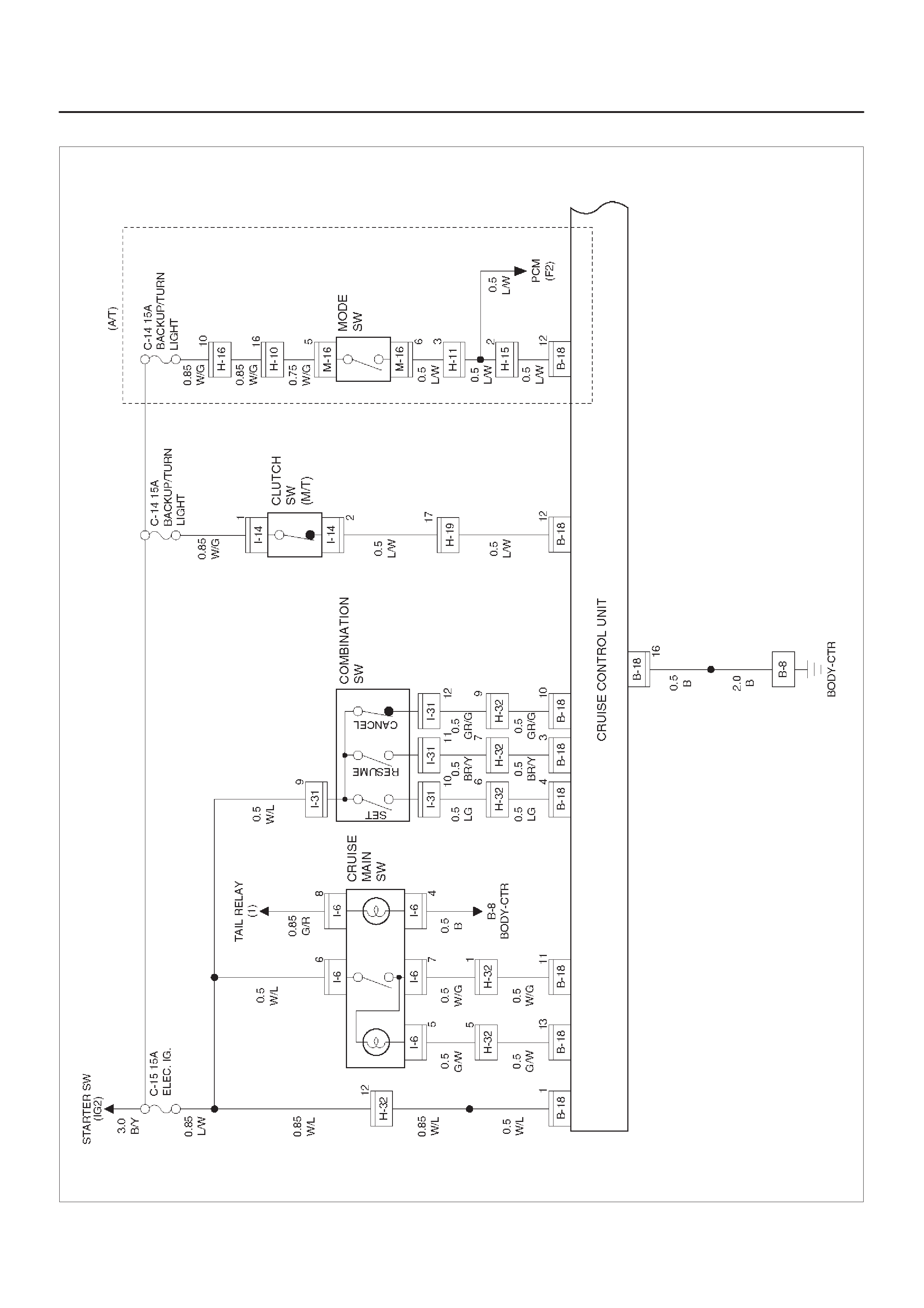
Circuit Diagram–1
D08RX154
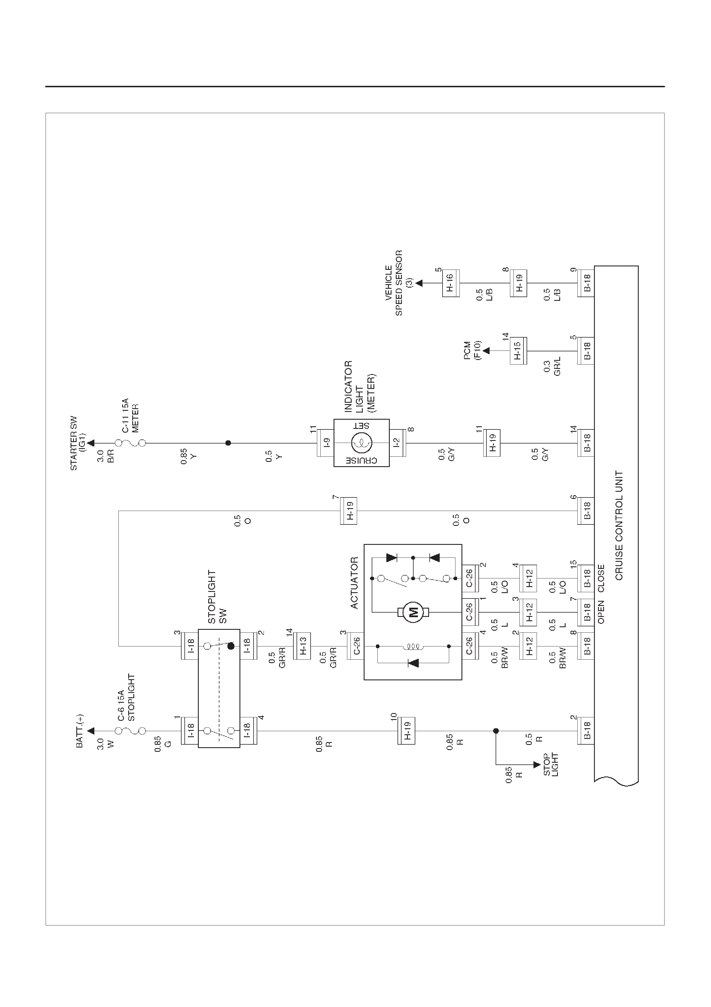
Circuit Diagram–2
D08RX155
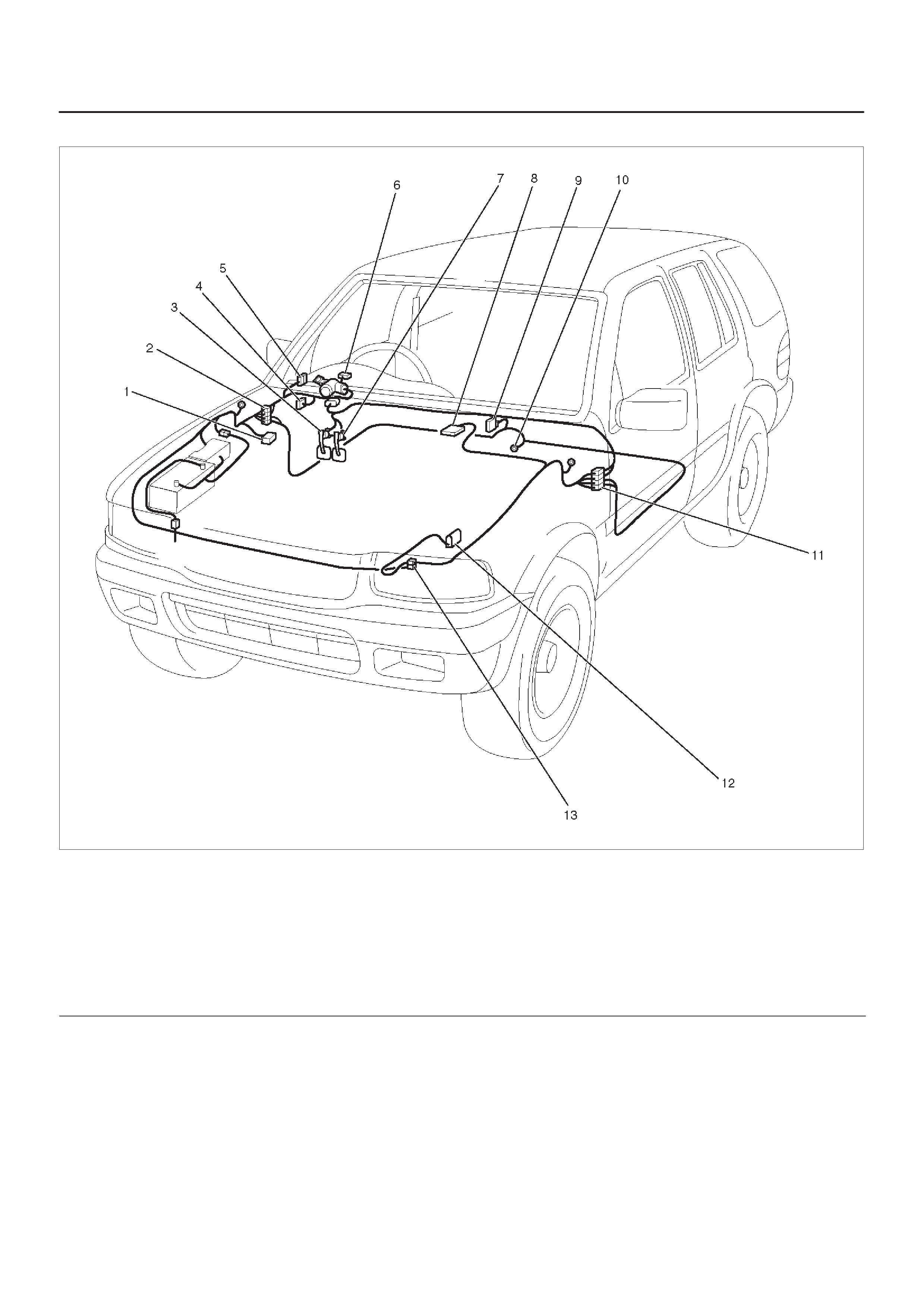
Parts Location
D08RX156
Legend
(1) C–26
(2) H–12, H–13, H–19, H–32
(3) Stoplight Switch (I–18)
(4) Relay & Fuse Box
(5) I–6
(6) I–9
(7) Clutch Switch (I–14)
(8) PCM
(9) Cruise Control Unit (B–18)
(10) B–8
(11) H–15
(12) Mode Switch (M–16)
(13) H–10, H–11

Diagnosis
The cruise control unit uses the cruise main indicator light
and diagnosis the failure, when the control unit detects
abnormality on the table below.
PART POSSIBLE CAUSE DETECTION PERIOD DTC
Motor system short circuit Energizing motor 1-1
Clutch system open circuit Energizing clutch 1-2
Actuator Clutch system open circuit Energizing clutch 1-2
Mechanical defect Cruise controlling 1-3
Close side of motor system open circuit Cruise controlling 1-1
Cruise control unit Open side of motor system continuously
energizing While starter SW on 1-4
Clutch output abnormality While starter SW on 1-4
Vehicle s
p
eed sensor
Signal of vehicle speed disconnection Cruise controlling 2-1
Vehicle
s eed
sensor
Signal of vehicle speed abnormality Cruise controlling 2-1
Switch
Turning on switch at all times While starter SW on 3-1
Switch
Turning on switch at the same time While starter SW on 3-1
DTC : Diagnostic Trouble Code
DTC Display Condition
1.While starter switch on and vehicle speed is 0 km/h,
the DTC output begins in top priority by cancel switch
turn on and off being repeated three times for 2 sec.
while cruise main switch pushing on, and stops the
DTC output whether vehicle speed is more than 10
km/h or the resume switch is turned on.
2.The cruise control unit outputs the DTC(s) in order
from small figure of the code.
3.The header of display of DTC(s) is assumed 4 sec.,
and it is 2 sec. between different king of codes.
4.The DTC(s) are erased with the starter switch turned
off.
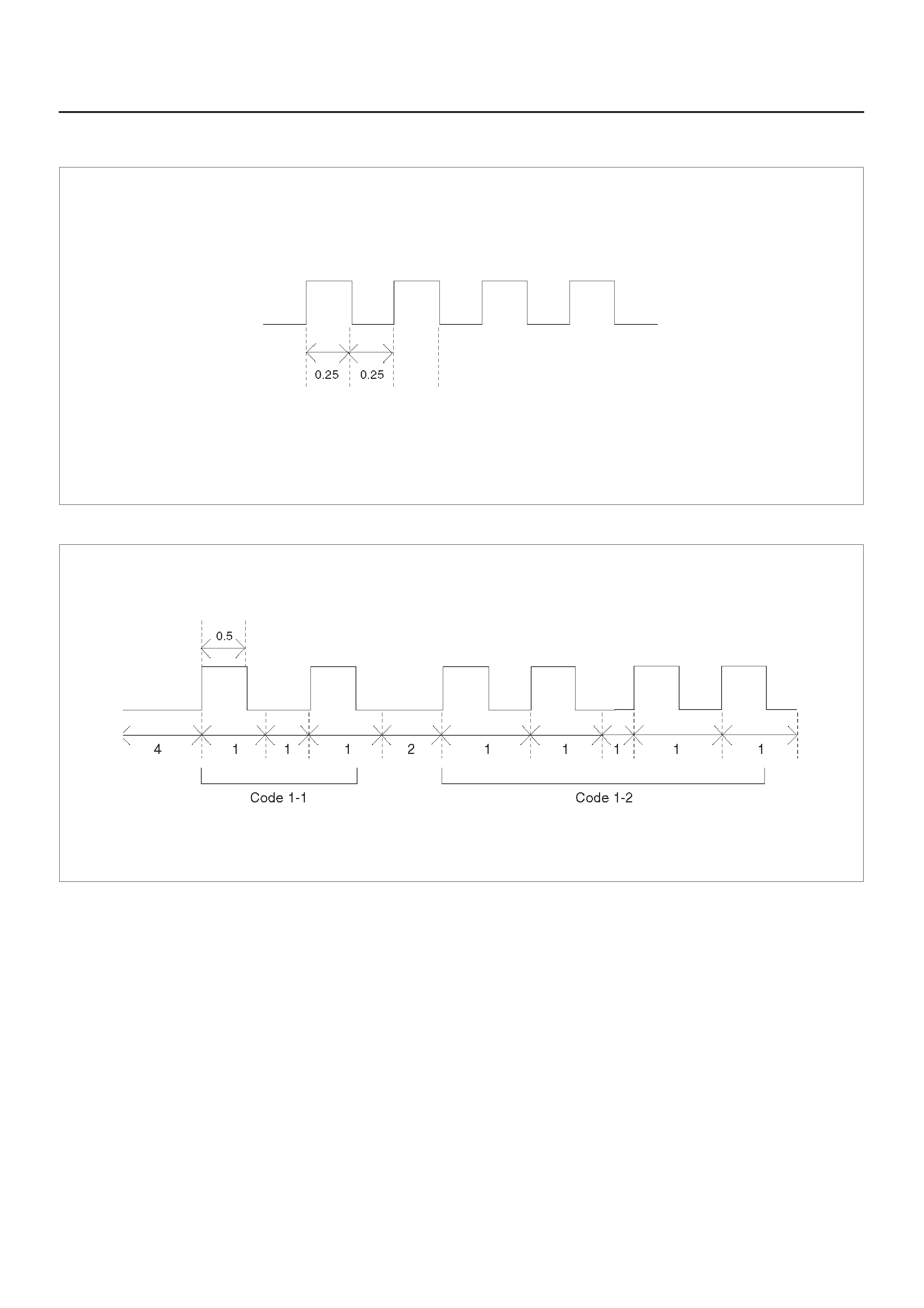
DTC Display Format
1.When no DTCs are detected. (The unit : sec.)
F08RW003
2.When two or more DTCs are detected. (The unit : sec.)
F08RW004

Diagnosis
DTC 1–1 Motor System Short Circuit
Step Action Value(s) Yes No
11. Turn the starter switch off.
2. Disconnect the actuator connector C-26.
3. Measure resistance between actuator side
connector terminal 1 and 2.
NOTE: If the control plate position is fully opened or
fully closed, resistance can not be measured.
Is the resistance within range specified in the value(s)
column? More than
4.2WGo to Step 2 Replace the
actuator
2Measure continuity between harness side connector
C-26 terminal 1 and the ground, terminal 2 and the
ground, and terminals 1 and 2.
Are the result same as specified in the value(s)
column? No continuity Replace the
control unit
Repair or
replace the
harness
DTC 1–2 Clutch System Open or Short Circuit
Step Action Value(s) Yes No
11. Turn the starter switch off.
2. Disconnect the actuator connector C-26.
3. Measure resistance between actuator side
connector terminal 3 and 4.
Is the resistance within range specified in the value(s)
column? 34.7 – 42.4WGo to Step 2 Replace the
actuator
21. Disconnect the stoplight switch connector I-18.
2. Check continuity between switch side connector
terminal 2 and 3.
Is there continuity between terminals? —Go to Step 3
Adjust or
replace the
switch
31. Reconnect the stoplight switch connector I-18
2. Check continuity between harness side connector
B-18 terminal 6 and I-18 terminal 3, C-26 terminal 4
and B-18 terminal 8.
Is there continuity between terminals? —Go to Step 4 Repair open
circuit
4Check continuity between harness side connector
C-26 terminal 3 and ground, C-26 terminal 4 and
ground, B-18 terminals 6 and the ground.
Are the results same as specified in the value(s)
column? No continuity Replace the
control unit Repair short
circuit

DTC 1–3 Mechanical Defect
Step Action Value(s) Yes No
11. Turn the starter switch off.
2. Disconnect the actuator connector C-26.
3. Connect the battery positive terminal to the actuator
side connector terminal 3 and the battery negative
terminal to terminal 4.
Does the control plate move by hand? —Replace the
actuator Go to Step 2
2Connect the battery positive terminal to the actuator
side connector terminal 1 and 3, and the battery
negative terminal to terminal 2 and 4.
Do the control plate move to full open side? —Go to Step 3 Replace the
actuator
3Connect the battery positive terminal to the actuator
side connector terminal 2 and 3, and the battery
negative terminal to terminal 1 and 4.
Does the control plate move to full close side? —Go to Step 4 Replace the
actuator
4Check continuity between harness side connector
C-26 terminal 1 and B-18 terminal 7, C-26 terminal 2
and B-18 terminal 15.
Is there continuity between terminals? —Replace the
control unit
Repair or
replace
harness
DTC 1–4 Close Side of Motor System Continuously Energizing
Step Action Value(s) Yes No
11. Turn the starter switch off.
2. Disconnect the actuator connector C-26.
3. Measure resistance between actuator side
connector terminal 1 and 2.
NOTE: If the control plate position is fully opened or
fully closed, resistance can not be measured.
Is the resistance within range specified in the value(s)
column? More than
4.2WGo to Step 2 Replace the
actuator
2Measure continuity between harness side connector
C-26 terminal 2 and B-18 terminal 15, C-26 terminal 1
and B-18 terminal 7.
Is there continuity between terminals? —Replace the
control unit
Repair or
replace the
harness

Anti–Lock Brake System (ABS)
General Description
The circuit consists of the starter switch, stoplight switch
EHCU wheel speed sensor, ABS warning light, BRAKE
warning light, and data link connector.
When the service brake is applied while in the running
mode, the EHCU (Electronic Hydraulic Control Unit)
judges which wheel is about to lock by using the wheel
rotation speed signals sent from the three wheel speed
sensors at the front wheels and rear differential. And the
brake fluid pressure applied to the four wheels is
controlled by the EHCU to prevent the wheels from
locking.
Refer to Brake Control System in Brakes section in detail.
Circuit Diagram–1
D08RY00925
Circuit Diagram–2
D08RX215
Parts Location
D08RX217
Legend
(1) C–36
(2) C–5
(3) C–4
(4) H–14, H–19
(5) Relay & Fuse Box
(6) I–1
(7) I–2
(8) B–23
(9) B–19
(10) F–4
(11) H–26
(12) H–15
(13) H–25
(14) C–16
(15) C–13
(16) H–5
(17) E–30 (6VD1)
(18) E–28 (X22SE)
(19) I–18
(20) C–34
(21) C–6
(22) C–33

A/T Shift Lock
General Description
With the starter switch in the “ON” position and the shift
lever in “P” position, the shift lever cannot be shifted from
“P” to another position unless the brake pedal is
depressed. This is because, unless the brake pedal is
depressed, the solenoid pin underneath the shift lever
retracts and the link lever then locks the shift lever cam.
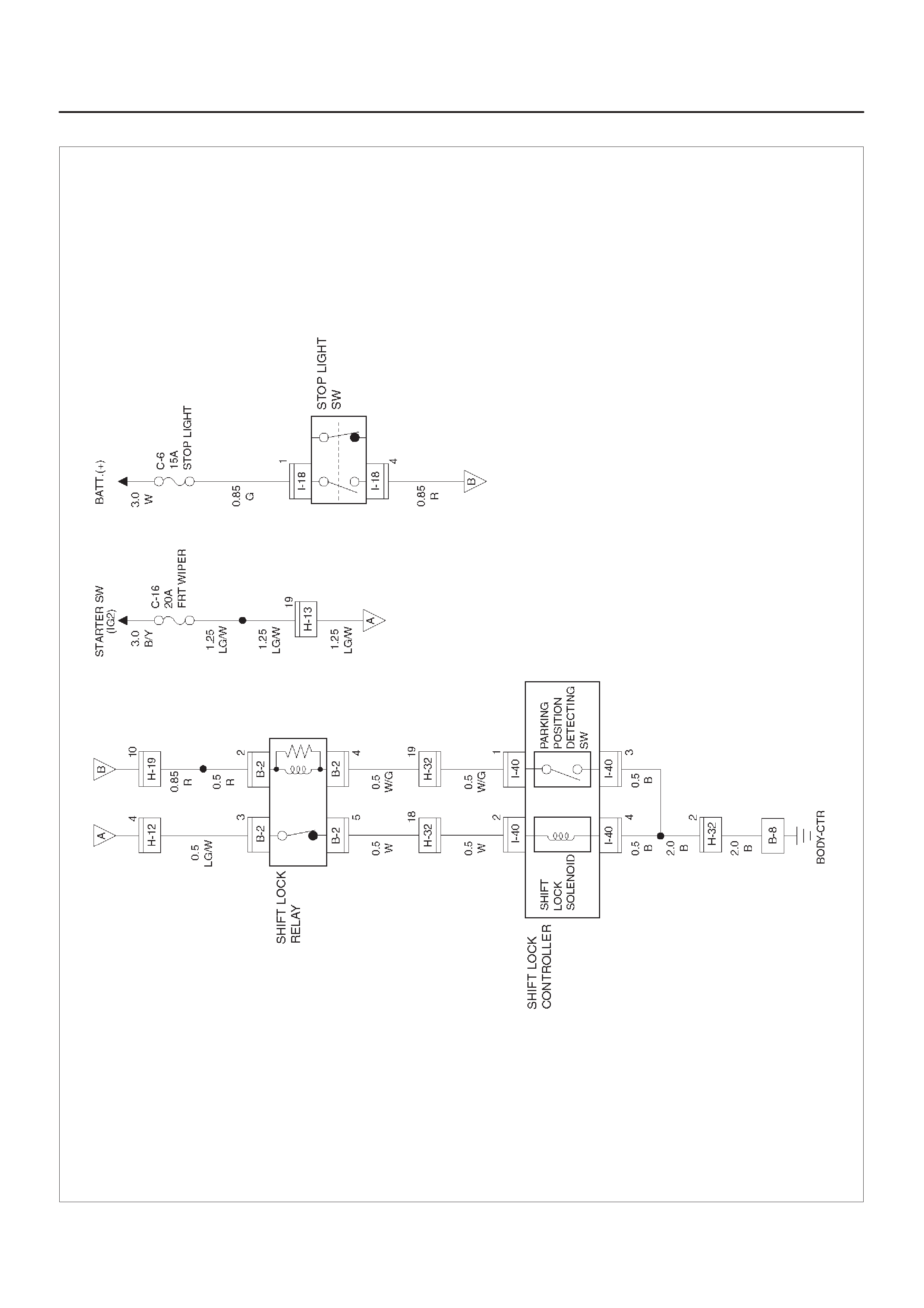
Circuit Diagram–1
D08RY00882
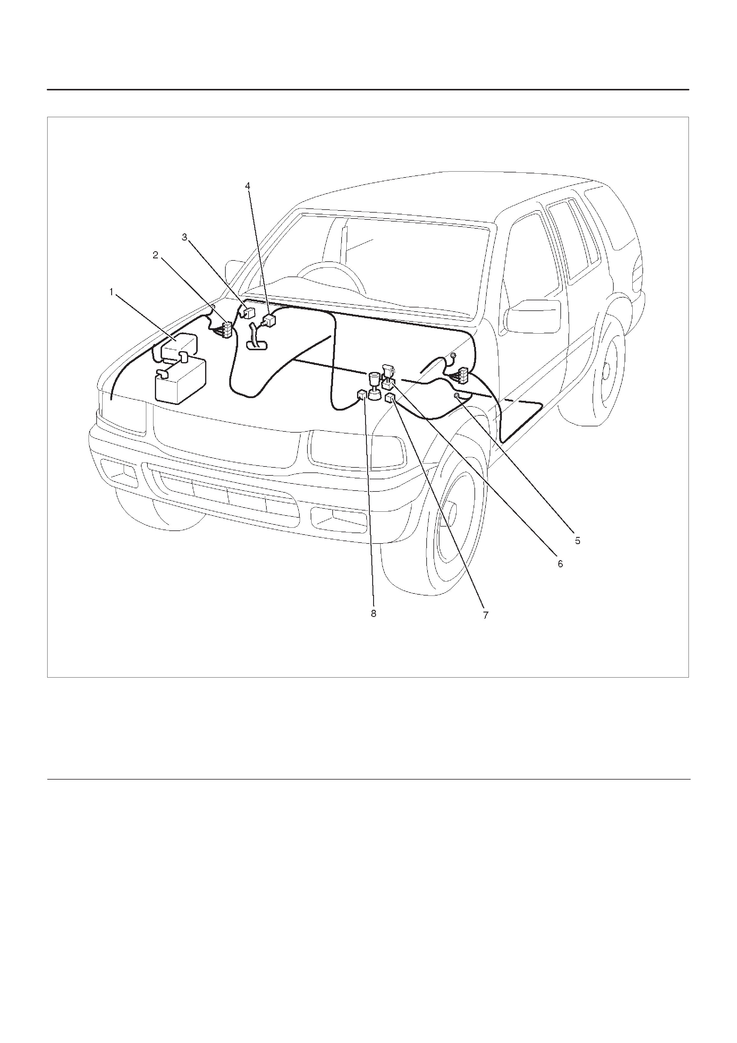
Parts Location
D08RWD16
Legend
(1) Relay & Fuse Box (Engine Room)
(2) H–19, H–32, H–12
(3) Relay & Fuse Box (Instrument Panel)
(4) I–18
(5) B–8
(6) A/T Shift Lever
(7) B–2
(8) I–40

Windshield Wiper and Washer
General Description
The system consists of a windshield wiper and washer
switch, alarm & relay control unit, windshield wiper motor
and windshield washer motor. With the starter switch in
the “ON” position, when the windshield wiper switch is
turned on (“ON” or “HI”) the battery voltage is applied to
the windshield wiper motor to operate the wipers.
When the “INT” switch is turned on, the operation of the
wipers is controlled by the alarm & relay control unit.
When the “WASHER” switch is turned on, the operation of
the wipers is also controlled by the alarm & relay control
unit and the windshield washer motor operates to squirt
the washing solution when the washer switch is pressed.
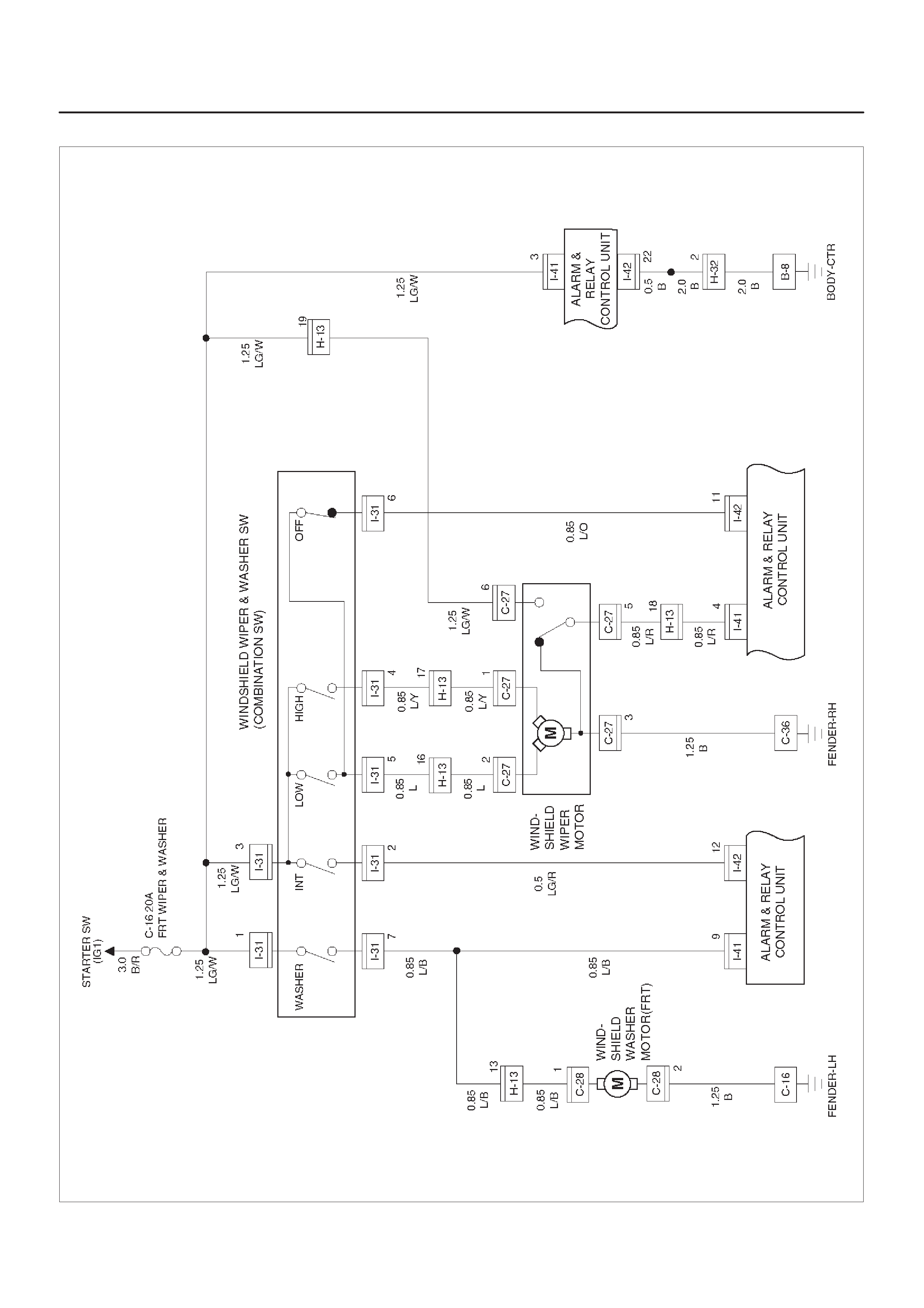
Circuit Diagram (6VD1 M/T)
D08RX220
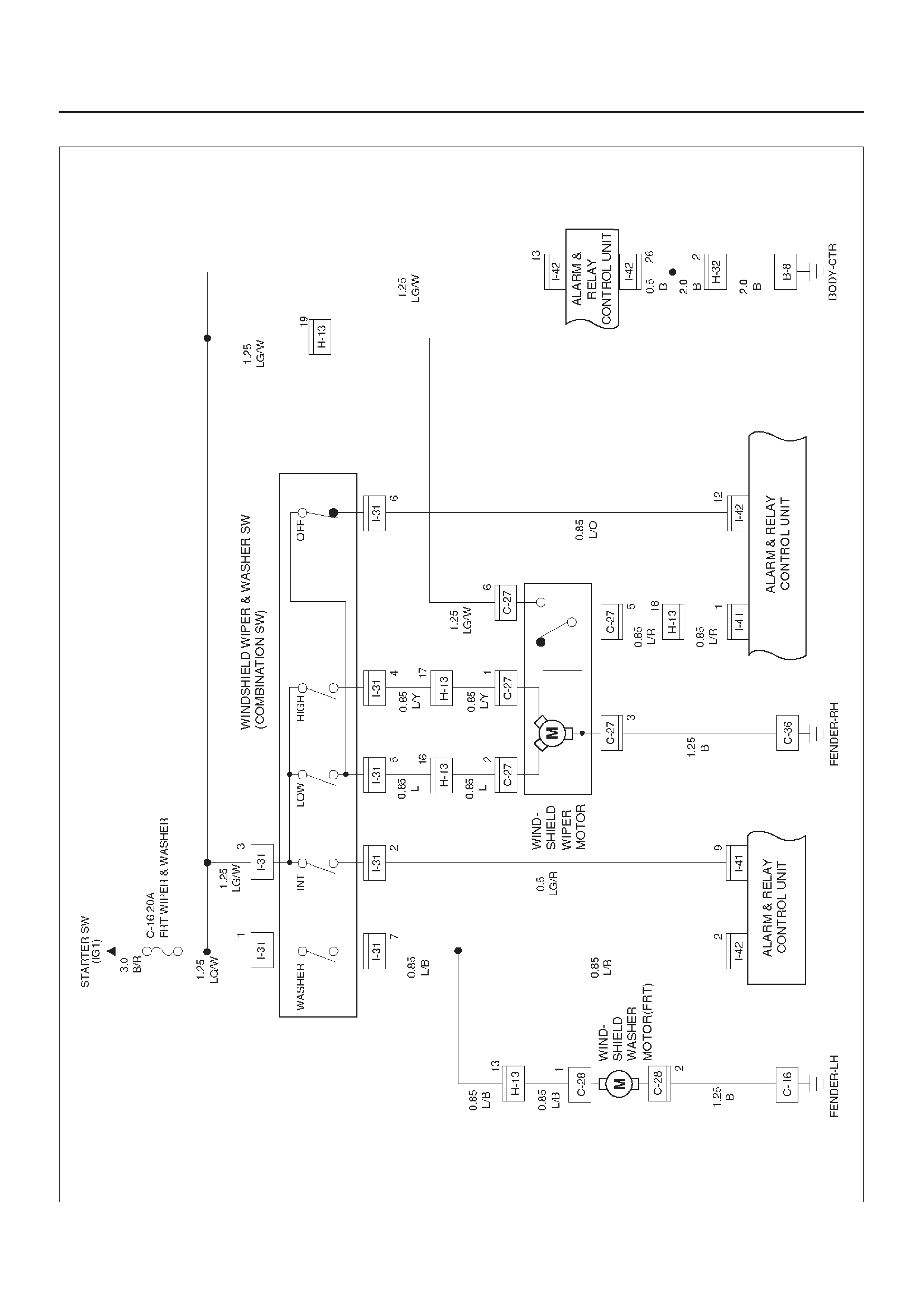
Circuit Diagram (6VD1 A/T)
D08RX218

Circuit Diagram (X22SE)
D08RX219
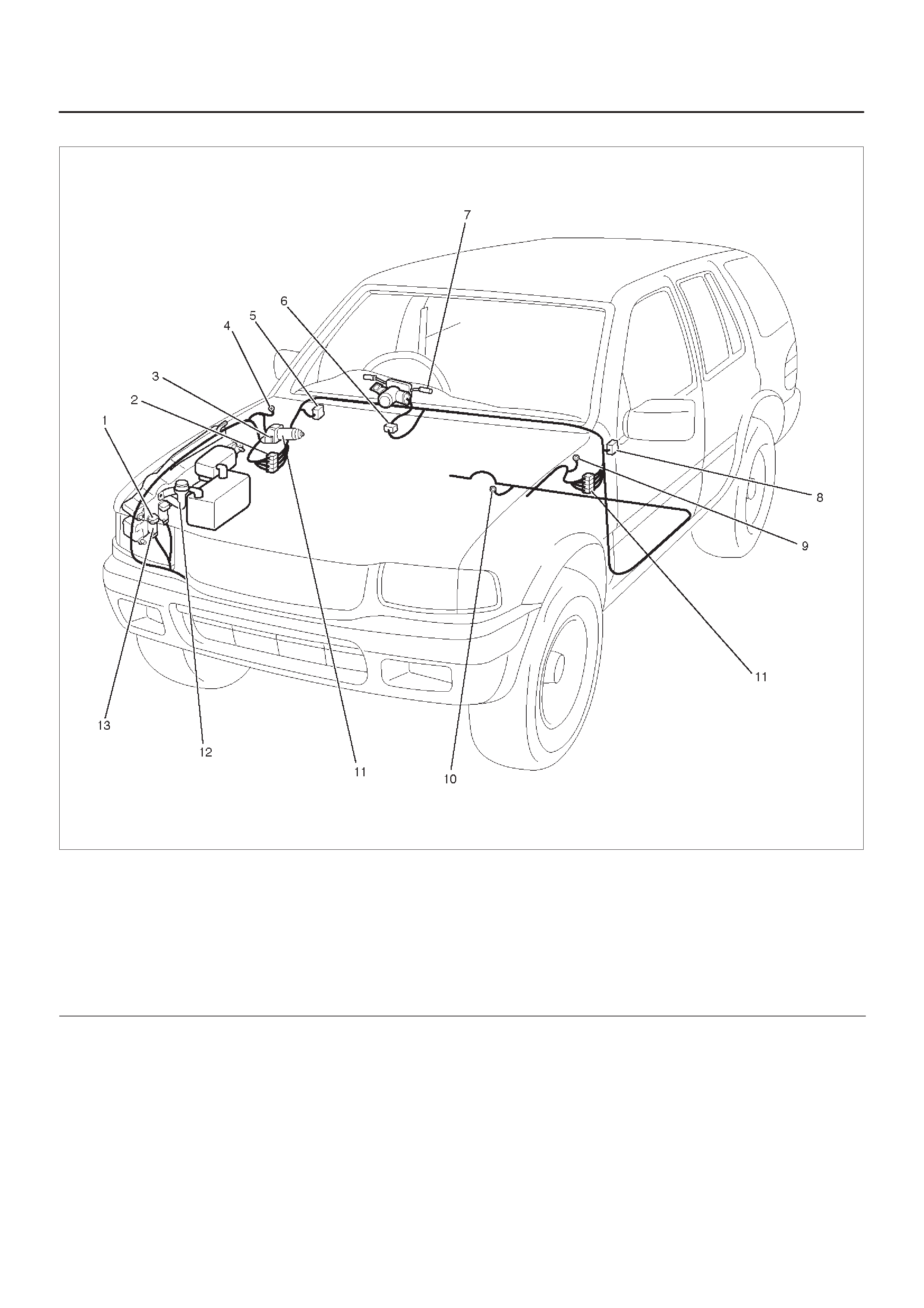
Parts Location
D08RWD12
Legend
(1) C–28
(2) H–13, H–32
(3) C–27
(4) C–36
(5) Relay & Fuse Box (Instrument Panel)
(6) Combination Switch Box
(7) FRT Windshield Wiper, Washer Switch
(8) I–41, I–42
(9) C–16
(10) B–8
(11) FRT Windshield Wiper Motor
(12) Windshield Washer Tank
(13) Windshield Washer Motor

Diagnosis
Windshield Wiper Does Not Operate At Any Switch Position
Step Action Value(s) Yes No
1Is the fuse C–16 normal? —Go to Step 2 Replace the
fuse
2Is C–36 grounded securely? —Go to Step 3 Ground it
securely
3Disconnect the windshield wiper motor connector
C–27.
Is there continuity between harness side connector
C–27 terminal 3 and the ground? —Go to Step 5 Go to Step 4
4Repair an open circuit between connector C–27
terminal 3 and the ground C–36.
Is the action complete? —Go to Step 3 —
51. Disconnect the windshield wiper & washer switch
connector I–31.
2. Turn the starter switch on.
Is the battery voltage applied between harness side
connector I–31 terminal 3 and the ground? Approx. 12V Go to Step 7 Go to Step 6
6Repair an open circuit between the fuse C–16 and
connector I–31 terminal 3.
Is the action complete? —Go to Step 5 —
7Is the continuity between the windshield wiper and
washer switch terminal normal?
—
Repair or
replace the
windshield
wiper motor
Repair or
replace the
switch

Windshield Wiper Does Not Operate At “INT” Position
Step Action Value(s) Yes No
11. Disconnect the windshield wiper and washer switch
connector I–31.
2. Turn the windshield wiper and washer switch to INT
position.
Is there continuity between switch side connector I–31
terminal 2 and 3, 5 and 6? —Go to Step 2
Repair or
replace the
switch
2Is B–8 grounded securely? —Go to Step 3 Ground it
securely
31. Reconnect the windshield wiper and washer switch
connector I–31.
2. Disconnect the alarm and relay control unit
connector I–41 and I–42.
3. Turn the starter switch on.
Is the battery voltage applied between harness side
connector I–42 terminal 12 (connector I–41 terminal 7
or 9) and the ground? Approx. 12V Go to Step 5 Go to Step 4
4Repair an open circuit between connector I–31
terminal 2 and the alarm & relay control unit.
Is the action complete? — Verify repair —
5Is the battery voltage applied between harness side
connector I–41 terminal 3 or connector I–42 terminal 13
and the ground? Approx. 12V
Replace the
alarm and
relay control
unit Go to Step 6
6Repair an open circuit between the fuse C–16 and the
alarm & relay control unit.
Is the action complete? — Verify repair —
Windshield Wiper Does Not Operate At “LO” Position
Step Action Value(s) Yes No
1Repair or replace the windshield wiper and washer
switch.
NOTE: There should be continuity between switch
side connector I–31 terminal 3 and 5 with the switch
turned to the LOW position.
Is the action complete? — Verify repair —

Windshield Wiper Does Not Operate At “HI” Position
Step Action Value(s) Yes No
11. Disconnect the windshield wiper and washer switch
connector I–31.
2. T urn the windshield wiper and washer switch to the
HIGH position.
Is there continuity between switch side connector I–31
terminal 3 and 4? —Go to Step 2
Repair or
replace the
switch
21. Reconnect the windshield wiper and washer switch
connector I–31.
2. Disconnect the windshield wiper motor connector
C–27.
3. Turn the starter switch on.
Is the battery voltage applied between harness side
connector C–27 terminal 1 and the ground? Approx. 12V
Repair or
replace the
windshield
wiper motor Go to Step 3
3Repair an open circuit between connector I–31
terminal 4 and connector C–27 terminal 1.
Is the action complete? — Verify repair —

Auto–Stop Function Of The Windshield Wiper Motor Does Not Operate
Step Action Value(s) Yes No
1Disconnect the windshield wiper and washer switch
connector I–31.
Turn the windshield wiper and washer switch off.
Is there continuity between switch side connector I–31
terminal 5 and 6? —Go to Step 2
Repair or
replace the
switch
2Disconnect the windshield wiper motor connector
C–27.
Turn the starter switch on.
Is the battery voltage applied between harness side
connector C–27 terminal 6 and the ground? Approx. 12V Go to Step 4 Go to Step 3
3Repair an open circuit between the fuse C–16 and
connector C–27 terminal 6.
Is the action complete? —Go to Step 2 —
41. Connect the battery positive terminal with motor
side connector C–27 terminal 2 and the battery
negative terminal with terminal 3.
2. While the motor is operating at low speed,
disconnect the battery positive terminal from
terminal 2 and then connect it with terminal 6 again.
3. Under this condition, connect motor side connector
terminal 5 with terminal 2.
Does the motor stop at the correct position? —Go to Step 5
Repair or
replace the
motor
5Disconnect the alarm and relay control unit connector
I–41 and I–42.
Is the battery voltage applied between harness side
connector I–41 terminal 3 or connector I–42 terminal 13
and the ground? Approx. 12V Go to Step 7 Go to Step 6
6Repair an open circuit between the fuse C–16 and
connector I–41 terminal 3 or connector I–42 terminal
13.
Is the action complete? —Go to Step 5 —
71. Reconnect the windshield wiper and washer switch
connector I–31 and windshield wiper motor
connector C–27.
2. T urn the windshield wiper and washer switch to the
low position.
Is the battery voltage applied between harness side
connector I–41 terminal 4 (1 or 2) and the ground? Approx. 12V
intermittently Go to Step 9 Go to Step 8
8Repair an open circuit between connector C–27
terminal 5 and connector I–41 terminal 4 (1 or 2).
Is the action complete? —Go to Step 7 —

Step NoYesValue(s)Action
91. Connect the alarm and relay control unit harness
side connector I–41 terminal 4 and connector I–42
terminal 11 (connector I–41 terminal 1 and
connector I–42 terminal 12/connector I–41 terminal
1 and 2).
2. T urn the windshield wiper and washer switch to the
off position.
Does the motor stop at the correct position? —
Replace the
alarm and
relay control
unit Go to Step 10
10 Repair an open circuit between connector I–31
terminal 6 and the alarm & relay control unit.
Is the action complete? — Verify repair —

Windshield Wiper Motor Does Not Stop
Step Action Value(s) Yes No
11. Disconnect the windshield wiper and washer switch
connector I–31.
2. Turn the switch off.
NOTE: When the switch is turned of OFF position,
there is no continuity between the switch terminals
except terminal 5 and 6.
Is the continuity between the switch terminal normal? —Go to Step 2
Repair or
replace the
switch
2Repair or replace the windshield motor.
Is the action complete? — Verify repair —
Windshield Washer Motor Does Not Operate
Step Action Value(s) Yes No
1Does the windshield wiper motor operate? —Go to Step 6 Go to Step 2
2Is the fuse C–16 normal? —Go to Step 3 Replace the
fuse
31. Disconnect the windshield wiper and washer switch
connector I–31.
2. Turn the starter switch on.
Is the battery voltage applied between harness side
connector I–31 terminal 1 and the ground? Approx. 12V Go to Step 5 Go to Step 4
4Repair an open circuit between the fuse C–16 and
connector I–31 terminal 1.
Is the action complete? —Go to Step 3 —
5Is C–16 grounded securely? —Go to Step 6 Ground it
securely
6Turn the windshield wiper and washer switch to the
washer position.
Is there continuity between switch side connector I–31
terminal 1 and 7? —Go to Step 7
Repair or
replace the
switch
71. Disconnect the windshield washer motor connector
C–28.
2. Connect the battery positive terminal with the motor
side connector C–28 terminal 1 and connect the
battery negative terminal with terminal 2.
Does the motor operate? —Go to Step 8
Repair or
replace the
motor
81. Reconnect the windshield wiper and washer switch
connector I–31.
2. Turn the starter switch on.
Is the battery voltage applied between harness side
connector C–28 terminal 1 and the ground? Approx. 12V Go to Step 10 Go to Step 9
9Repair an open circuit between connector I–31
terminal 7 and connector C–28 terminal 1.
Is the action complete? — Verify repair —
10 Repair an open circuit between connector C–28
terminal 2 and the ground C–16.
Is the action complete? — Verify repair —

Rear Wiper/Washer
General Description
The system consists of the rear wiper and washer switch,
the rear wiper motor, the rear washer motor and the alarm
& relay control unit. The rear wiper provides intermittent
and riseup functions and is controlled by the alarm & relay
control unit. When the hatch gate is open, the rear wiper
does not operate. The hatch gate actuator does not
operate while the rear wiper is operating.
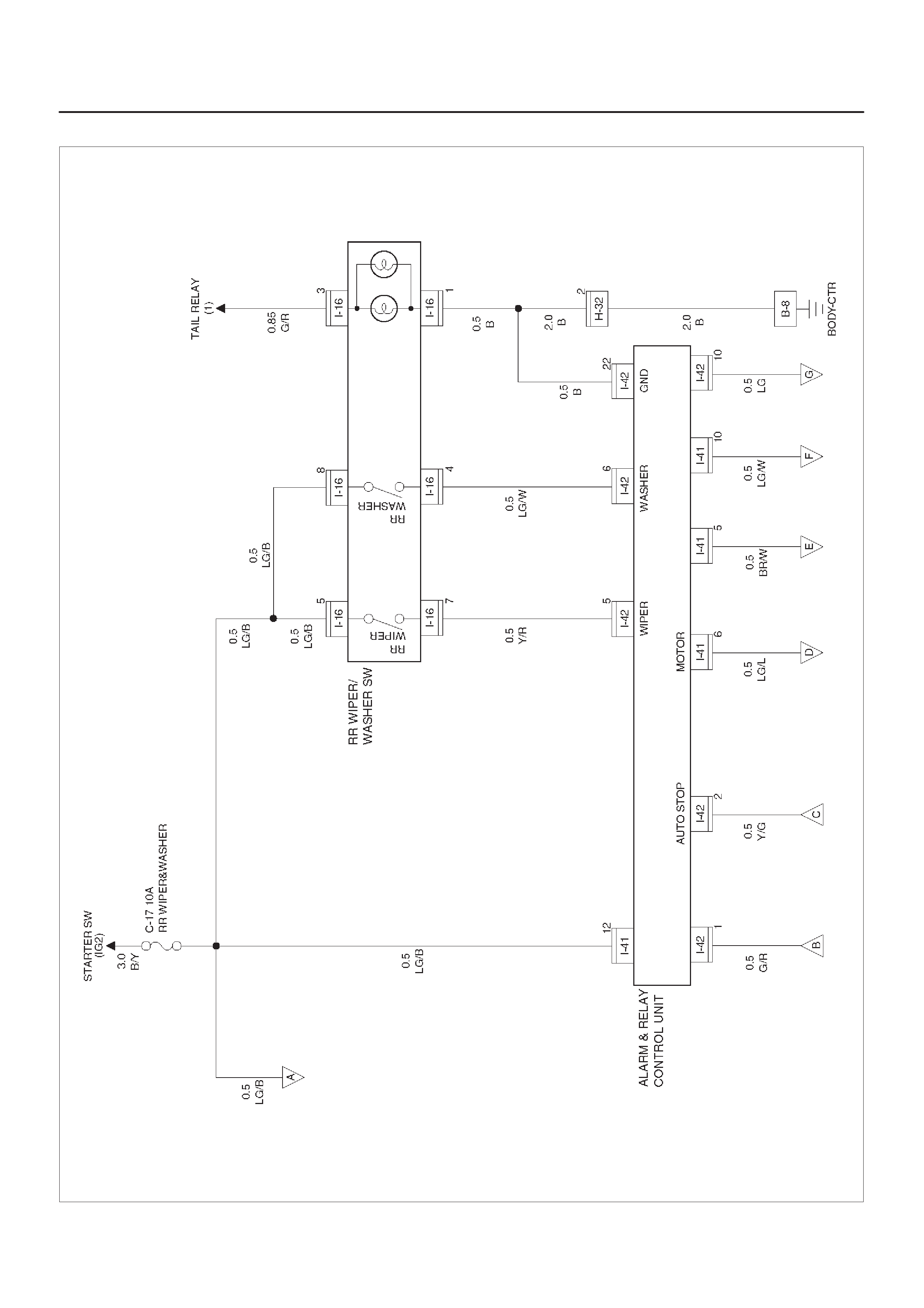
Circuit Diagram–1 (6VD1 M/T)
D08RX221
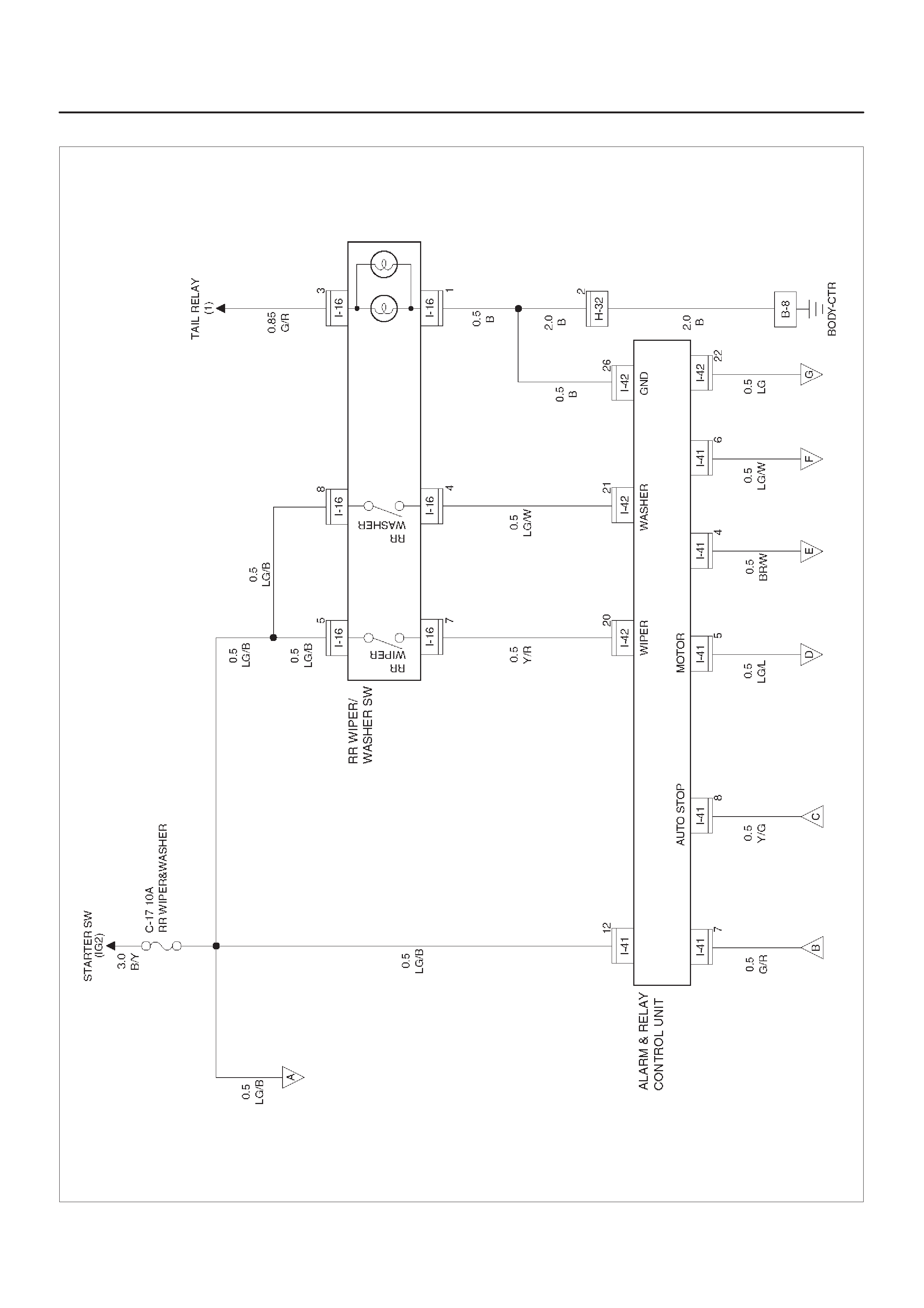
Circuit Diagram–1 (6VD1 A/T)
D08RX222
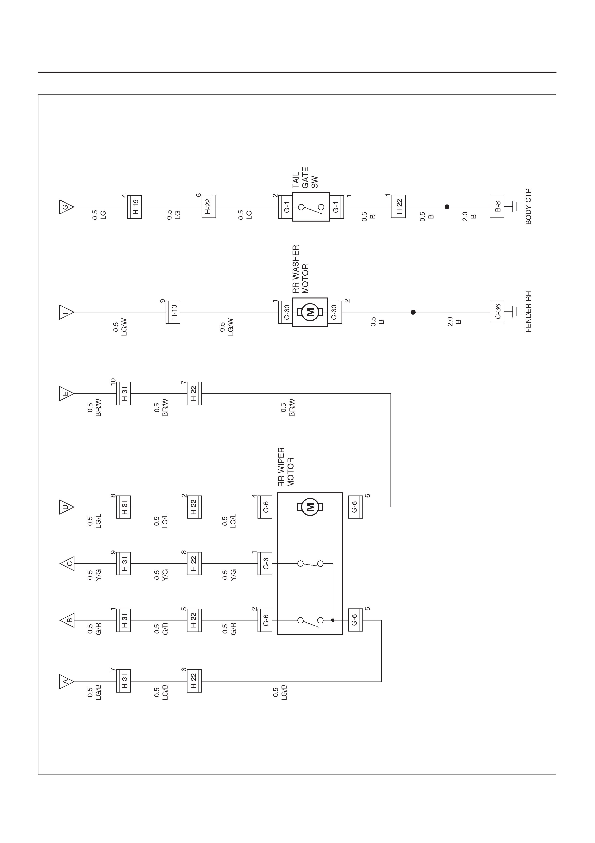
Circuit Diagram–2 (6VD1)
D08RY00933
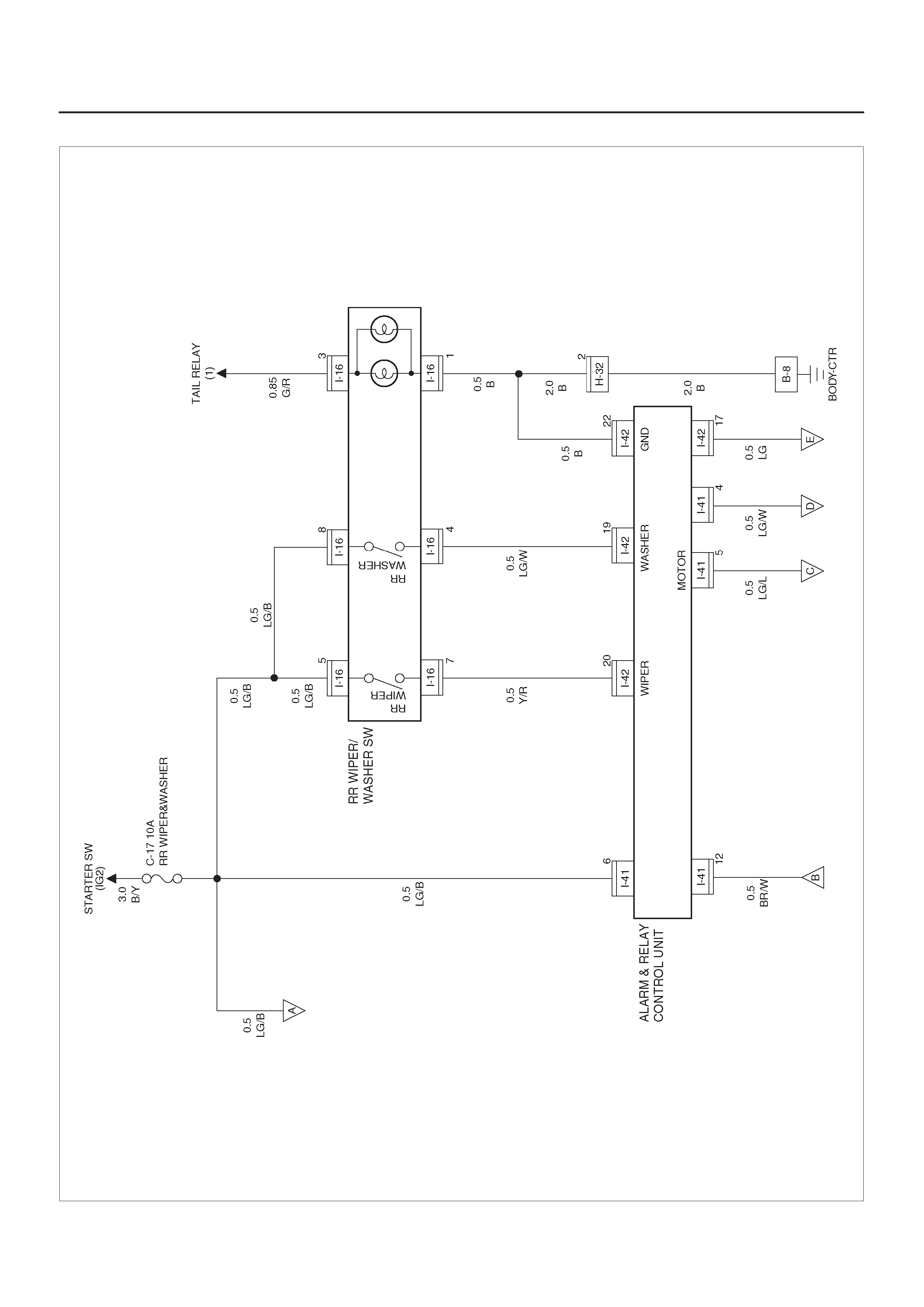
Circuit Diagram–1 (X22SE)
D08RY00934
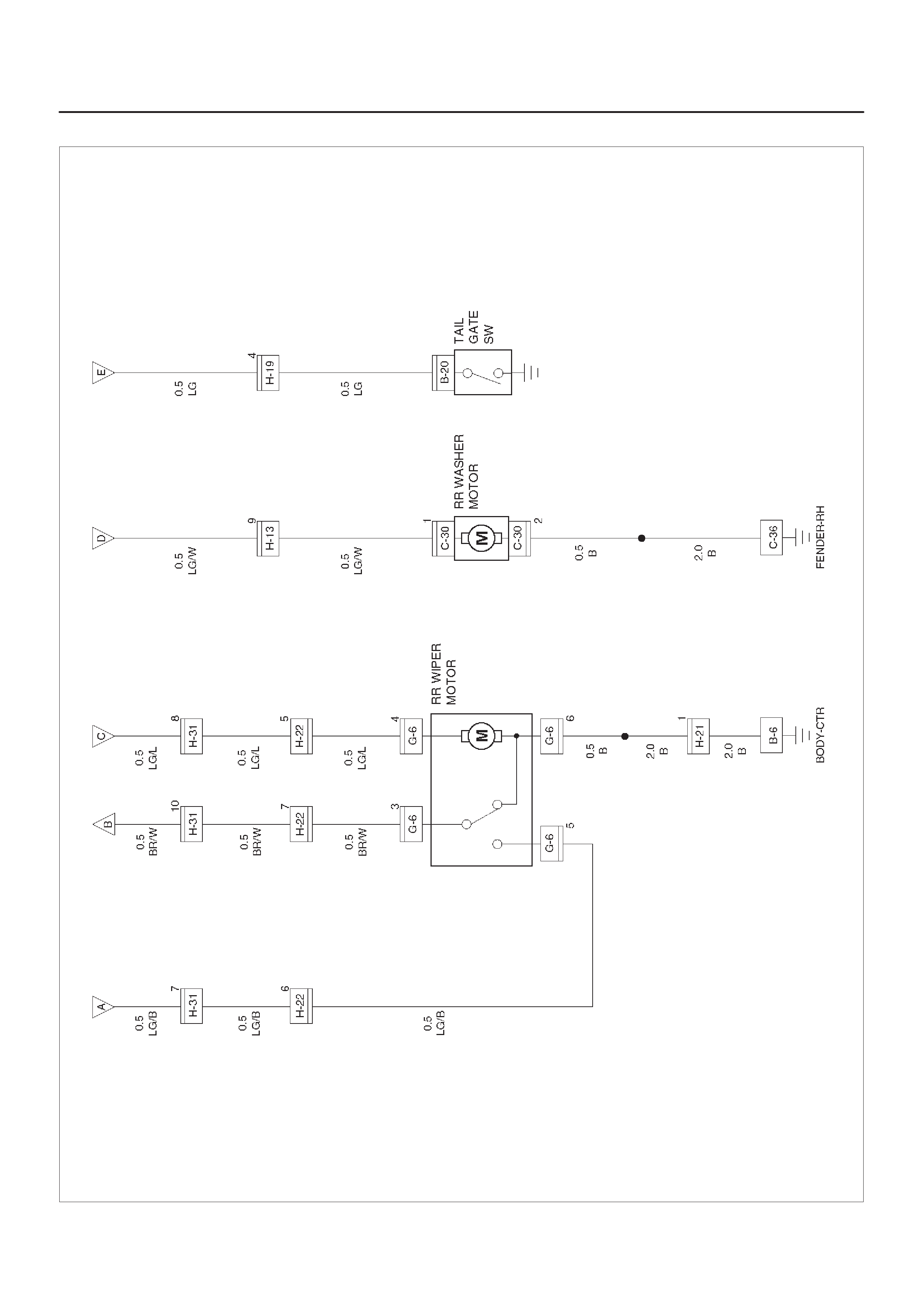
Circuit Diagram–2 (X22SE)
D08RX225
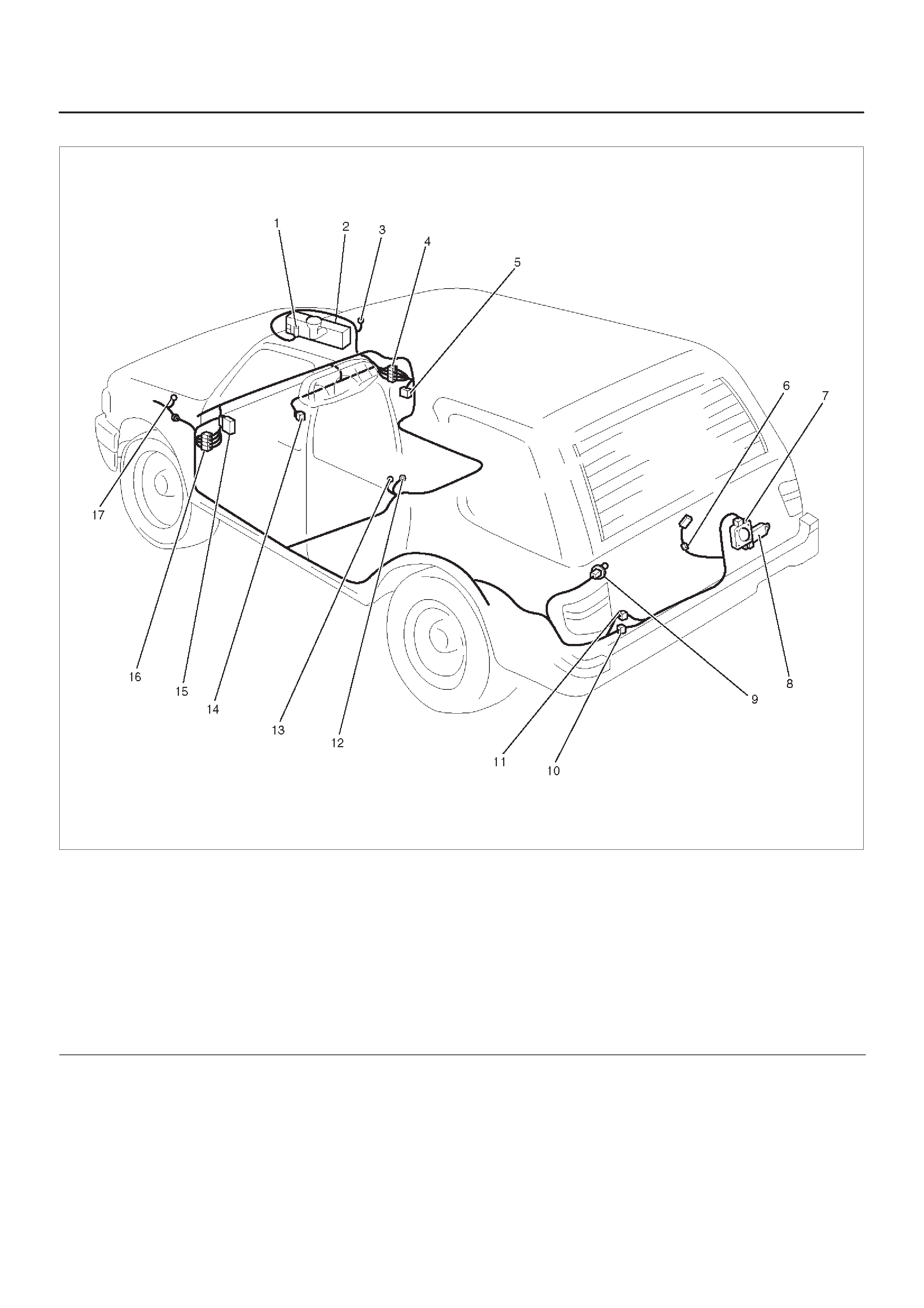
Parts Location
D08RWD11–1
Legend
(1) C–30
(2) FRT & Rear Washer Tank
(3) C–36
(4) H–13
(5) Relay & Fuse Box (Instrument Panel)
(6) G–1
(7) G–6
(8) Rear Wiper Motor
(9) B–20 (2Door Model)
(10) H–22
(11) H–21 (2Door Model)
(12) B–6 (2Door Model)
(13) B–8
(14) I–16
(15) I–41, I–42
(16) H–31
(17) C–16

Diagnosis
Rear Wiper Motor Does Not Operate
Step Action Value(s) Yes No
1Is the fuse C–17 normal? —Go to Step 2 Replace the
fuse
21. Disconnect the rear wiper/washer switch connector
I–16.
2. Turn the rear wiper switch on.
Is there continuity between switch side connector I–16
terminal 5 and 7? —Go to Step 3
Repair or
replace the
switch
3Turn the starter switch on
Is the battery voltage applied between harness side
connector I–16 terminal 5 and the ground? Approx. 12V Go to Step 5 Go to Step 4
4Repair an open circuit between the fuse C–17 and
connector I–16 terminal 5.
Is the action complete? —Go to Step 3 —
5Disconnect the alarm & relay control unit connector
I–41 and I–42.
Is the battery voltage applied between harness side
connector I–41 terminal 12 or connector I–42 terminal 6
and the ground? Approx. 12V Go to Step 7 Go to Step 6
6Repair an open circuit between the fuse C–17 and
connector I–41 terminal 12 or connector I–42 terminal
6.
Is the action complete? —Go to Step 5 —
7Is there continuity between harness side connector
I–16 terminal 7 and harness side connector I–42
terminal 5 or connector I–42 terminal 20? —Go to Step 9 Go to Step 8
8Repair an open circuit between connector I–16
terminal 7 and connector I–42 terminal 5 or connector
I–42 terminal 20.
Is the action complete? —Go to Step 7 —
91. Disconnect the rear wiper motor connector G–6.
2. Connect the battery positive terminal with the motor
side connector G–6 terminal 4 and the battery
negative terminal with the motor side connector
G–6 terminal 6.
Does the motor operate? —Go to Step 10
Repair or
replace the
motor
10 Is there continuity between harness side connector
I–41 terminal 6 or terminal 5 and harness side
connector G–6 terminal 4? —Go to Step 12 Go to Step 11
11 Repair an open circuit between connector I–41
terminal 6 or terminal 5 and connector G–6 terminal 4.
Is the action complete? —Go to Step 10 —
12 Is there continuity between harness side connector
I–41 terminal 5 (or terminal 4) or the ground and
harness side connector G–6 terminal 6? —
Replace the
alarm & relay
control unit Go to Step 13
13 Repair an open circuit between connector G–6 terminal
6 and connector I–41 terminal 5 (or terminal 4) or the
ground B–6.
Is the action complete? — Verify repair —

Auto-Stop Function Of The Rear Wiper Motor Does Not Operate (X22SE Model)
Step Action Value(s) Yes No
11. Disconnect the rear wiper motor connector G–6
2. Connect the battery positive terminal with the motor
side connector G–6 terminal 4 and the battery
negative terminal with terminal 6.
3. While the motor is operating, disconnect the battery
positive terminal from terminal 4 and then connect it
with terminal 5 again.
4. Under this condition, connect the motor side
connector terminal 3 with terminal 4.
Does the motor stop at the correct position? —Go to Step 2
Repair or
replace the
motor
2Turn the start switch on
Is the battery voltage applied between harness side
connector G–6 terminal 5 and the ground? Adpprox. 12V Go to Step 4 Go to Step 3
3Repair an open circuit between the fuse C–17 and
connector G–6 terminal 5.
Is the action complete? —Go to Step 2 —
4Disconnect the alarm & relay control unit connector
I–41 and I–42.
Is there continuity between harness side connector
G–6 terminal 3 and harness side connector I–41
terminal 12? —
Replace the
alarm & relay
control unit Go to Step 5
5Repair an open circuit between connector G–6 terminal
3 and connector I–41 terminal 12.
Is the action complete? — Verify repair —
Rear Wiper Motor Does Not Operate With Rear Wiper/Washer Switch At Wiper Position
Step Action Value(s) Yes No
11. Disconnect the rear wiper/washer switch connector
I–16.
2. Turn the switch to rear wiper position.
Is there continuity between the switch side connector
I–16 terminal 5 and 7? —Go to Step 2
Repair or
replace the
switch
21. Reconnect the rear wiper/washer switch connector
I–16.
2. Disconnect the alarm & relay control unit connector
I–41 and I–42.
3. Turn the starter switch on.
Is the battery voltage applied between harness side
connector I–42 terminal 5 or terminal 20 and the
ground? Approx. 12V
Replace the
alarm & relay
control unit Go to Step 3
3Repair an open circuit between connector I–16
terminal 7 and connector I–42 terminal 5 or terminal 20.
Is the action complete? — Verify repair —

Rear Wiper Motor Does Not Operate With Rear Wiper/Washer Switch At Washer Position
Step Action Value(s) Yes No
11. Disconnect the rear wiper/washer switch connector
I–16.
2. Turn the switch to the washer position.
Is there continuity between the switch side connector
I–16 terminal 8 and 4? —Go to Step 2
Repair or
replace the
switch
21. Reconnect the rear wiper/washer switch connector
I–16.
2. Disconnect the alarm & relay control unit connector
I–41 and I–42.
3. Turn the starter switch on.
Is the battery voltage applied between harness side
connector I–42 terminal 6 (21 or 19) and the ground? Approx. 12V
Replace the
alarm & relay
control unit Go to Step 3
3Repair an open circuit between connector I–16
terminal 4 and connector I–42 terminal 6 (21 or 19).
Is the action complete? — Verify repair —
Rear Wiper Motor Does Not Stop Operating
Step Action Value(s) Yes No
11. Disconnect the rear wiper/washer switch connector
I–16.
2. Turn the switch to the off position.
NOTE: There should be no continuity.
Is there continuity between the switch side connector
I–16 terminal 5 and 7? —
Repair or
replace the
switch
Replace the
alarm& relay
control unit

Rear Washer Motor Does Not Operate
Step Action Value(s) Yes No
1 Does the rear wiper motor operate? — Go to Step 6 Go to Step 2
2Is the fuse C–17 normal? —Go to Step 3 Replace the
fuse
31. Disconnect the rear wiper/washer switch connector
I–16.
2. Turn the switch to the rear washer position.
Is there continuity between the switch side connector
I–16 terminal 8 and 4? —Go to Step 4 Replace the
switch
4Turn the starter switch on.
Is the battery voltage applied between harness side
connector I–16 terminal 8 and the ground? Approx. 12V Go to Step 6 Go to Step 5
5Repair an open circuit between the fuse C–17 and
connector I–16 terminal 8.
Is the action complete? —Go to Step 4 —
61. Disconnect the rear wiper motor connector C–30.
2. Connect the battery positive terminal with the motor
side connector C–30 terminal 1 and the battery
negative terminal with terminal 2.
Does the motor operate? —Go to Step 7
Repair or
replace the
motor
7Reconnect the rear wiper/washer switch connector
I–16.
Is the battery voltage applied between harness side
connector C–30 terminal 1 and the ground? Approx. 12V Go to Step 9 Go to Step 8
8Repair an open circuit between the rear wiper/washer
motor and the alarm & relay control unit.
Is the action complete? — Verify repair —
9Repair an open circuit between connector C–30
terminal 2 and the ground C–36.
Is the action complete? — Verify repair —

Rear Defogger/Mirror Defogger
General Description
The system consists of the rear defogger and mirror
defogger switch, the rear defogger & mirror defogger
relay, the rear defogger & mirror defogger and the
Powertrain Control Module (PCM).
When the rear defogger and mirror defogger switch is
turned on with the starter switch on, the rear defogger and
mirror defogger relay is activated and the battery voltage
is applied to the rear defogger and mirror defogger.
The PCM is provided with the timer. When the operation
time of the timer elapses which has been set in advance,
the rear defogger and mirror defogger relay is
automatically deactivated and the rear defogger and
mirror defogger is turned off.
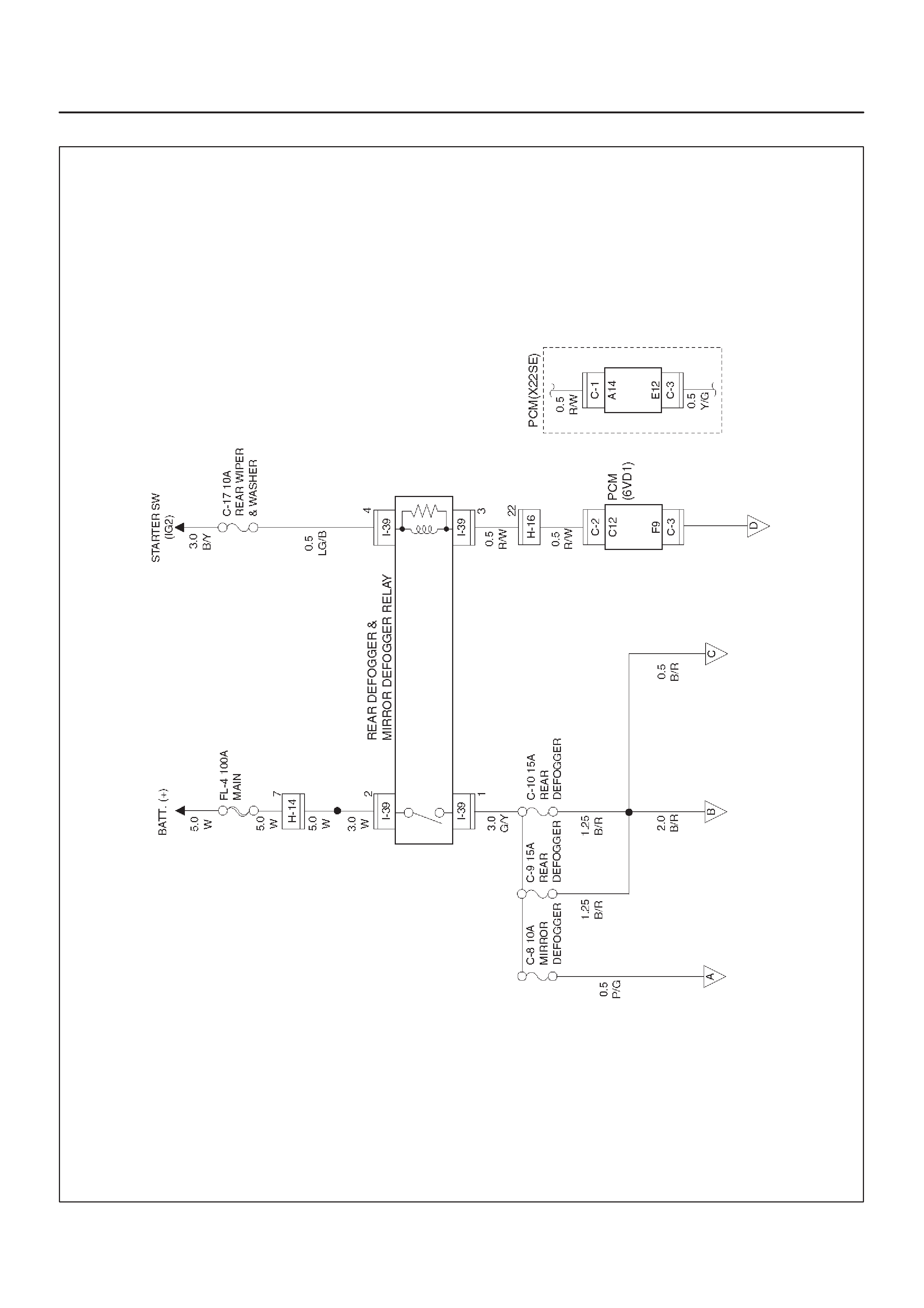
Circuit Diagram–1
D08RX240
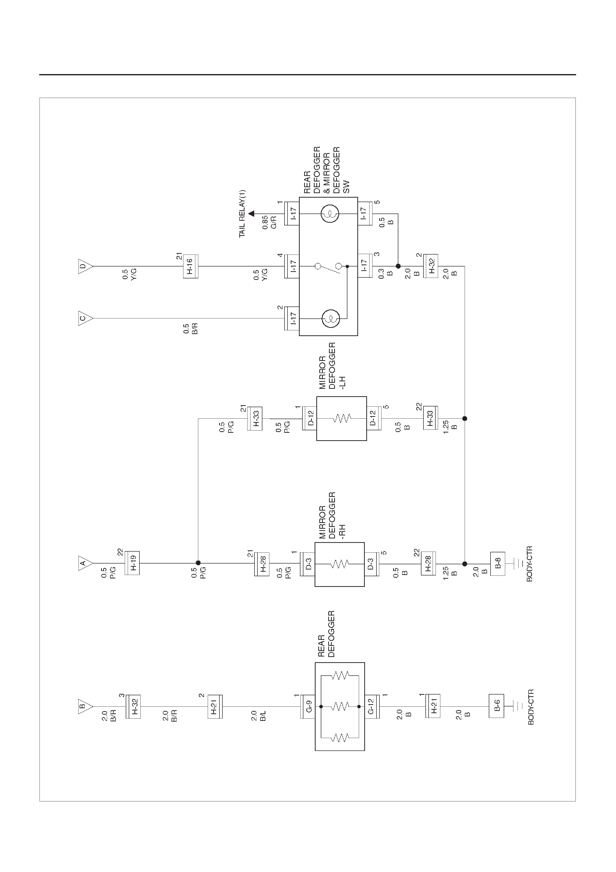
Circuit Diagram–2 (2Door Model)
D08RX238

Circuit Diagram–2 (4Door Model)
D08RX241
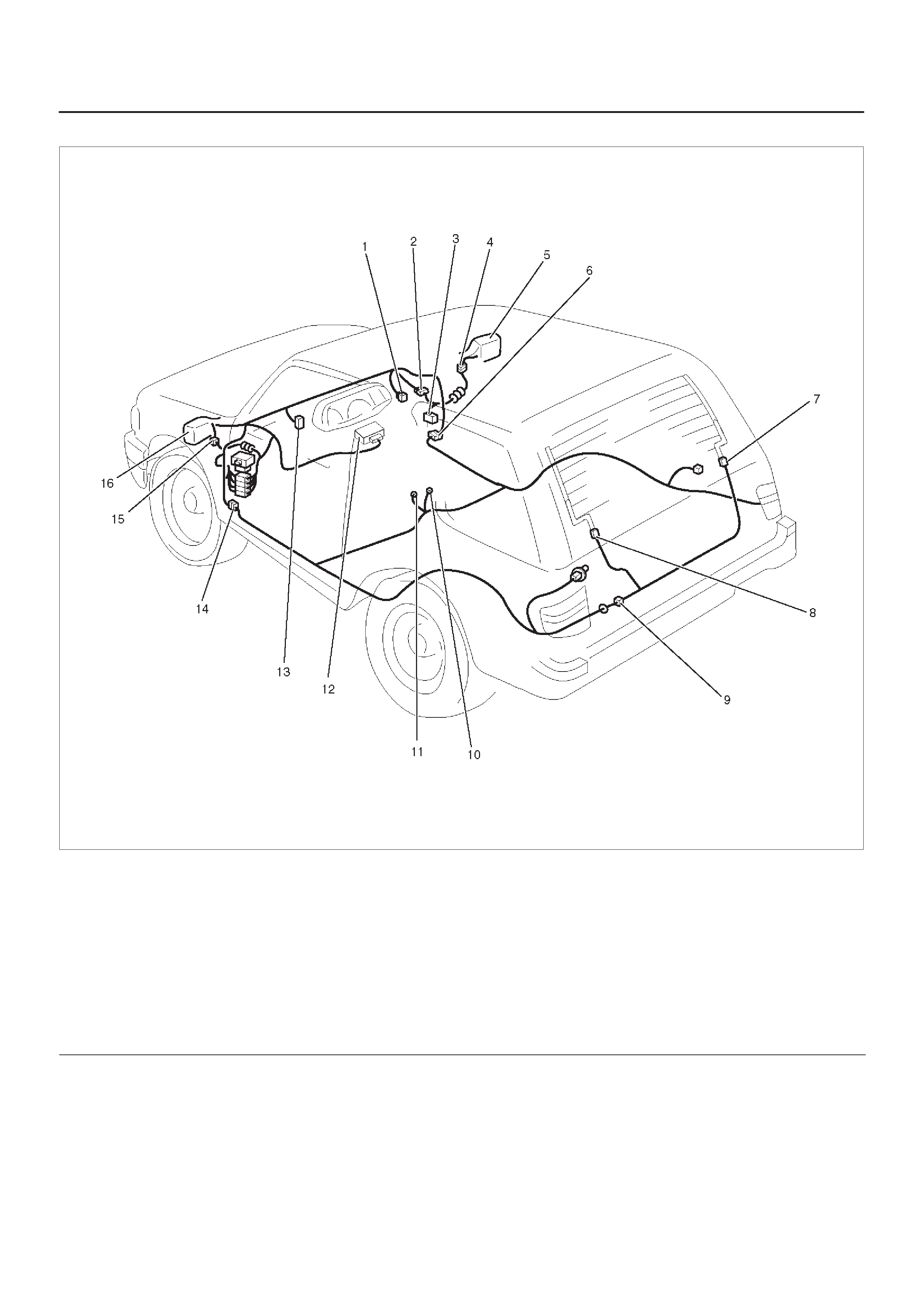
Parts Location (2Door Model)
D08RX239
Legend
(1) Rear Defogger & Mirror Defogger Switch
(2) H–19, H–32
(3) Relay & Fuse Box (Instrument Panel)
(4) D–3
(5) Door Mirror – RH
(6) H–28
(7) G–12
(8) G–9
(9) H–21
(10) B–8
(11) B–6
(12) PCM
(13) I–17
(14) H–33
(15) D–12
(16) Door Mirror – LH
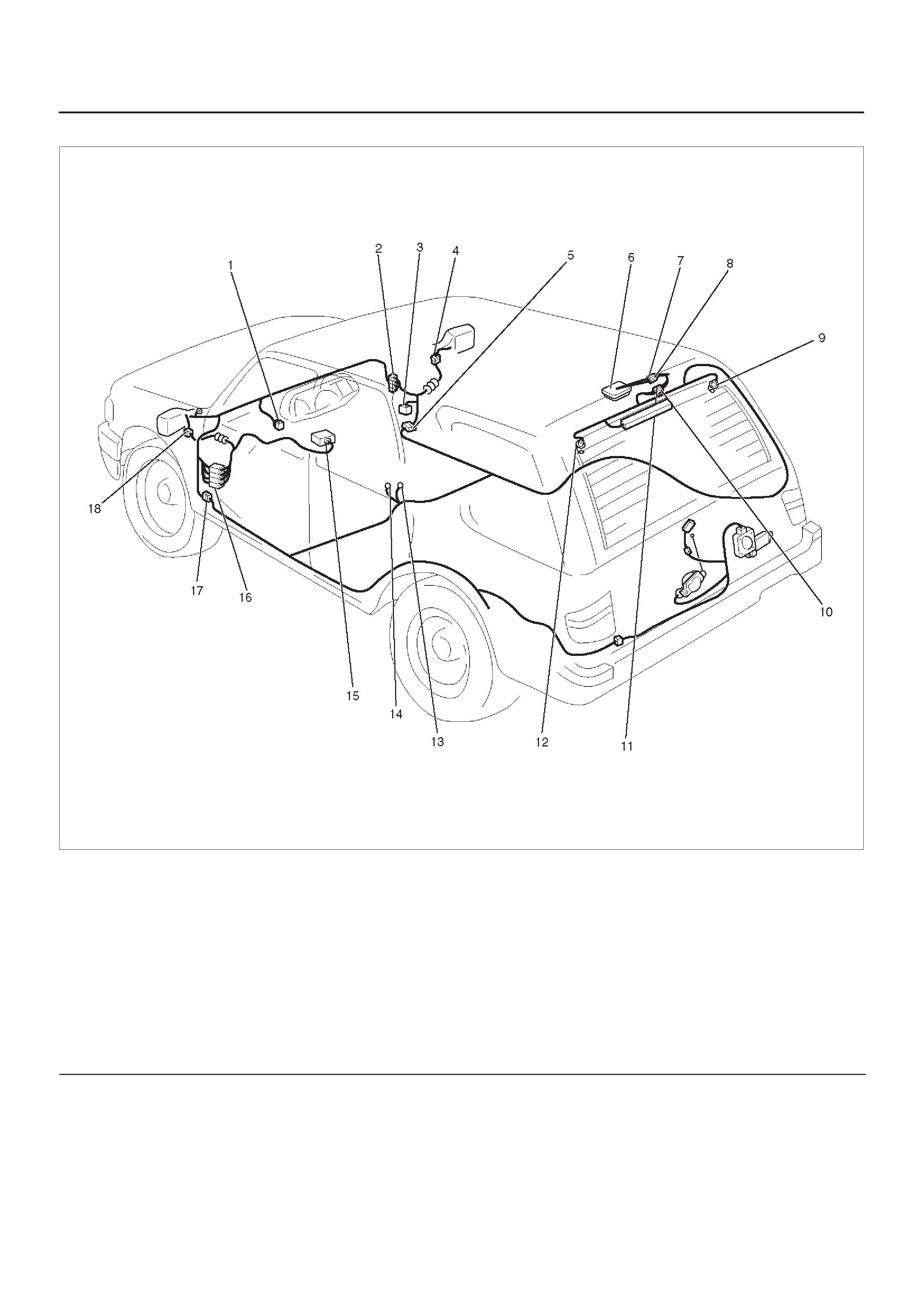
Parts Location (4Door Model)
D08RWD10
Legend
(1) RR Defogger & Mirror Defogger Switch
(2) H–19, H–32
(3) Relay & Fuse Box (Instrument Panel)
(4) D–3
(5) H–28
(6) Luggage Room Light
(7) H–10
(8) H–21
(9) G–9
(10) G–10
(11) G–11
(12) G–12
(13) B–8
(14) B–6
(15) PCM
(16) H–31
(17) H–33
(18) D–12

Diagnosis
Rear Defogger Does Not Operate
Step Action Value(s) Yes No
1Are the fuse C–9, C–10 and C–17 normal? —Go to Step 2 Replace the
fuse(s)
2Are B–6 and/or B–8 grounded securely?
—Go to Step 3
Ground it
(them)
securely
3Remove the rear defogger relay.
Is the battery voltage applied between the rear
defogger relay harness side connector I–39 terminal 2
and the ground? Approx. 12V Go to Step 5 Go to Step 4
4Repair an open circuit between the battery and
connector I–39 terminal 2.
Is the action complete? —Go to Step 3 —
5Turn the starter switch on.
Is the battery voltage applied between harness side
connector I–39 terminal 4 and the ground? Approx. 12V Go to Step 7 Go to Step 6
6Repair an open circuit between the fuse C–17 and
connector I–39 terminal 4.
Is the action complete? —Go to Step 5 —
7Disconnect the PCM connector C–1, C–2 and C–3.
Is there continuity between harness side connector
I–39 terminal 3 and harness side connector C–2
terminal C12 or connector C–1 terminal A14? —Go to Step 9 Go to Step 8
8Repair an open circuit between connector I–39
terminal 3 and connector C–2 terminal C12 or
connector C–1 terminal A14.
Is the action complete? —Go to Step 7 —
9Is there continuity between harness side connector
I–17 terminal 4 and connector C–3 terminal F9 or
connector C–3 terminal E12? —Go to Step 11 Go to Step 10
10 Repair an open circuit between connector I–17
terminal 4 and connector C–3 terminal F9 or connector
C–3 terminal E12.
Is the action complete? —Go to Step 9 —
11 Is there continuity between harness side connector
I–17 terminal 3 and the ground? —Go to Step 13 Go to Step 12
12 Repair an open circuit between connector I–17
terminal 3 and the ground B–8.
Is the action complete? —Go to Step 11 —
13 1. Reconnect the rear defogger relay.
2. Ground the PCM harness side connector C–2
terminal C12 or connector C–1 terminal A14.
Is the battery voltage applied between the rear
defogger harness side connector G–9 terminal 1 and
the ground? Approx. 12V Go to Step 14
Repair an
open circuit
between the
fuse C–9 or
C–10 and the
rear defogger
14 Is there continuity between the rear defogger harness
side connector G–12 terminal 1 and the ground? —Go to Step 16 Go to Step 15

Step NoYesValue(s)Action
15 Repair an open circuit between connector G–12
terminal 1 and the ground B–6.
Is the action complete? —Go to Step 14 —
16 1. Reconnect the PCM connector C–2 and C–3 or
C–1.
2. Turn the rear defogger switch on.
Is the battery voltage applied between the rear
defogger harness side connector G–9 terminal 1 and
the ground? Approx. 12V Go to Step 18 Go to Step 17
17 Replace the PCM.
Is the action complete? — Verify repair –
18 Repair broken heat wire or connector poor contact of
the rear defogger.
Is the action complete? — Verify repair —

Rear Defogger Timer Does Not Function
Step Action Value(s) Yes No
1Replace the PCM.
Is the action complete? — Verify repair —

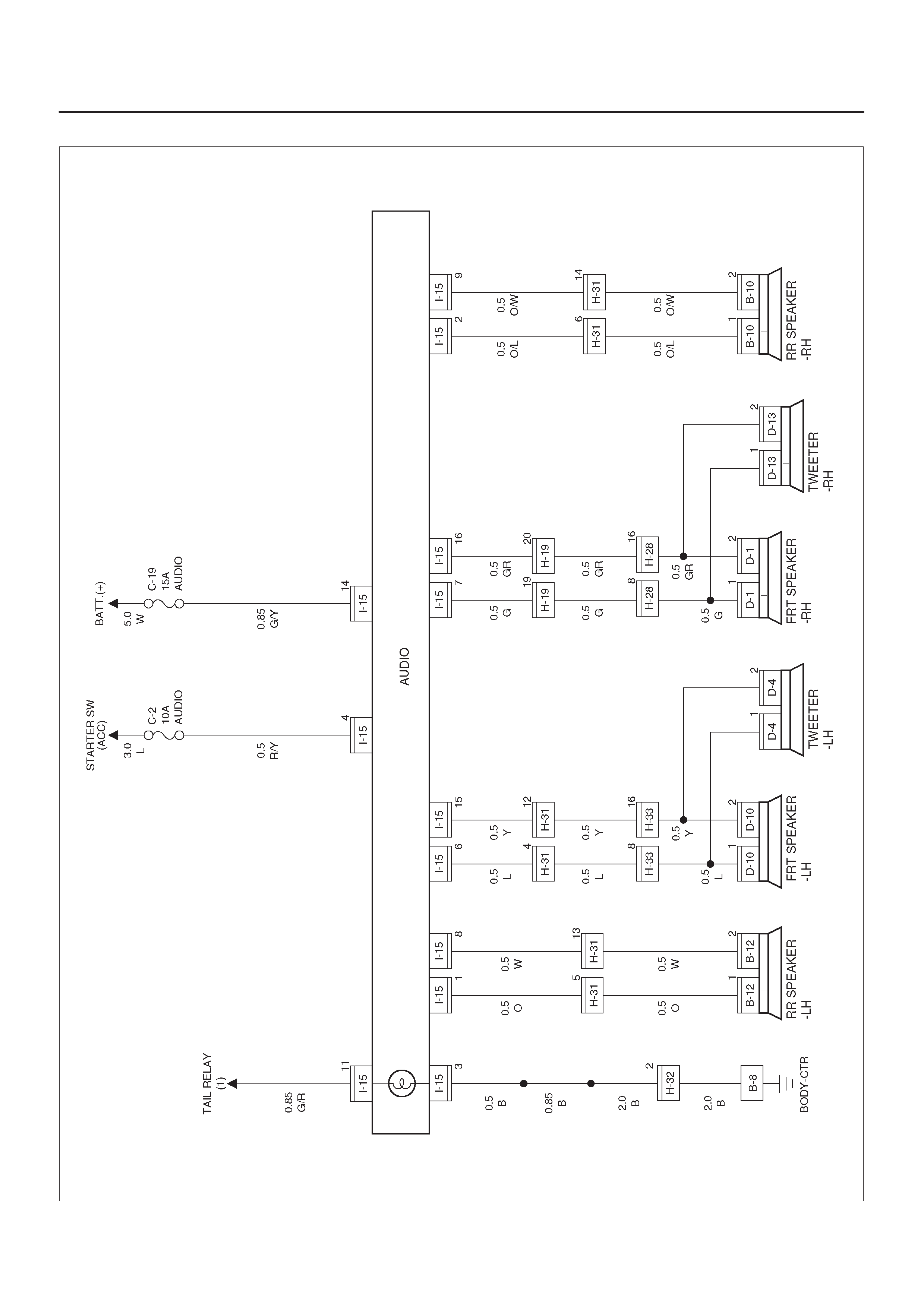
Circuit Diagram–1
D08RY00931
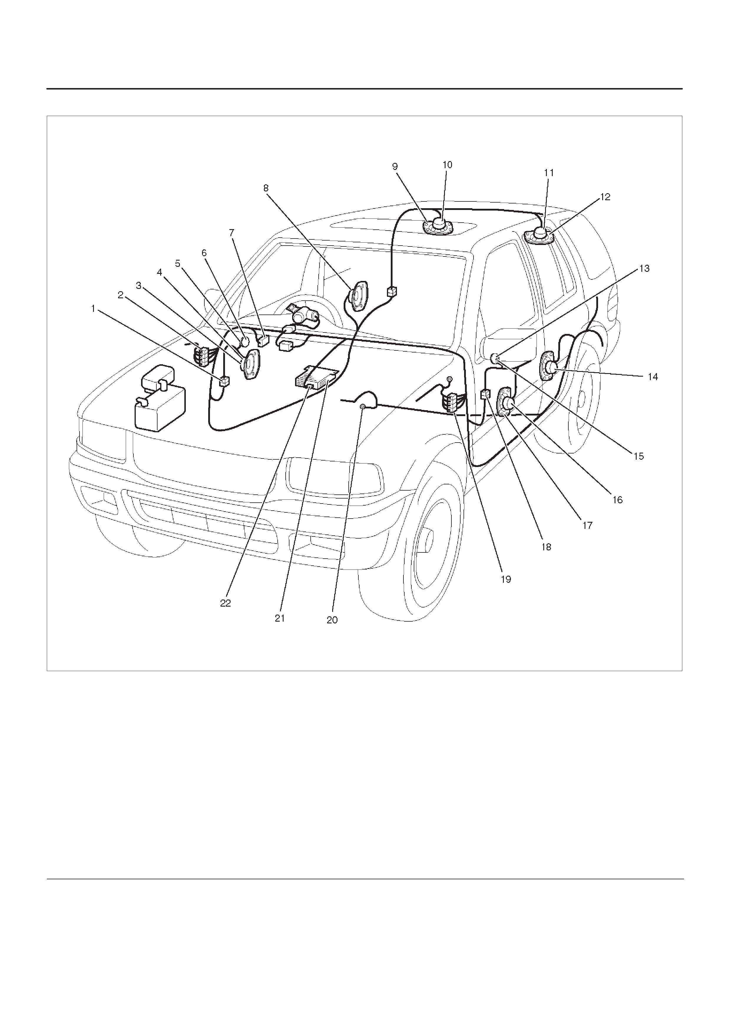
Parts Location
D08RWD13
Legend
(1) H–28
(2) H–19, H–32
(3) FRT Speaker – RH
(4) D–10
(5) D–13
(6) Tweeter – RH
(7) Relay & Fuse Box (Instrument Panel)
(8) RR Speaker – RH (2Door model)
(9) RR Speaker – RH (4Door model)
(10) B–10
(11) B–12
(12) RR Speaker – LH (4Door model)
(13) Tweeter – LH
(14) RR Speaker – LH (2Door model)
(15) D–4
(16) D–1
(17) FRT Speaker – LH
(18) H–33
(19) H–31
(20) B–8
(21) Audio
(22) I–15

Cigarette Lighter, Digital Clock and Accessory Socket
General Description
When the cigarette lighter is pushed in with the starter
switch at either “ACC” or “ON” position, a circuit is formed
in the cigarette lighter case to heat the lighter coil.
The cigarette lighter is sprung back to its original position
after the lighter coil is heated.
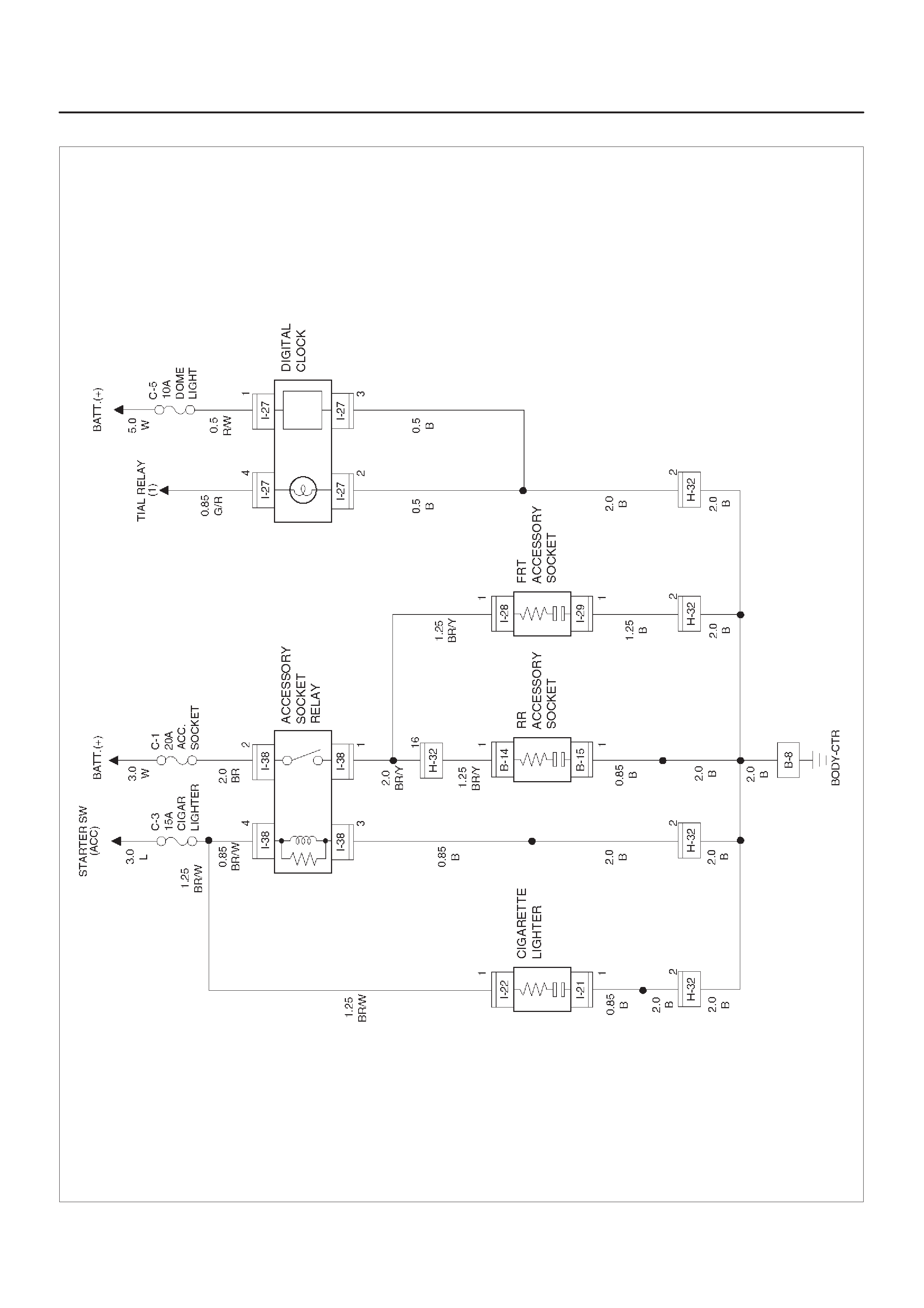
Circuit Diagram
D08RX245

Parts Location
D08RWD08–1
Legend
(1) H–32
(2) Relay & Fuse Box (Instrument Panel)
(3) I–27
(4) Digital Clock
(5) Rear Accessory Socket
(6) B–14, B–15
(7) B–8
(8) Cigarette Lighter
(9) Front Accessory Socket
(10) I–28, I–29
(11) I–21, I–22

Diagnosis
Cigarette Lighter Does Not Work
Step Action Value(s) Yes No
1Is the fuse C–3 normal? —Go to Step 2 Replace the
fuse
2Is B–8 grounded securely? —Go to Step 3 Ground it
securely
31. Disconnect the cigarette lighter connector I–22.
2. Turn the starter switch to the ACC or ON position.
Is the battery voltage applied between harness side
connector I–22 terminal 1 and the ground? Approx. 12V Go to Step 5 Go to Step 4
4Repair an open circuit between the fuse C–3 and
connector I–22 terminal 1.
Is the action complete? —Go to Step 3 —
5Disconnect the cigarette lighter connector I–21.
Is there continuity between harness side connector
I–21 terminal 1 and the ground B–8? —
Repair or
replace the
cigarette
lighter
assembly Go to Step 6
6Repair an open circuit between connector I–21
terminal 1 and the ground B–8.
Is the action complete? — Verify repair —
Cigarette Lighter Does Not Spring Out After Being Heated
Step Action Value(s) Yes No
1Repair or replace the cigarette lighter.
Is the action complete? — Verify repair —

Power Door Mirror
General Description
The system consists of the starter switch, the mirror
control switch, and door mirrors on both sides.
When the mirror control switch is operated with the starter
switch at either “ACC” or “ON” position, the motor in the
door mirror (on either side) rotates to allow the horizontal
and vertical adjustment of mirror angles.
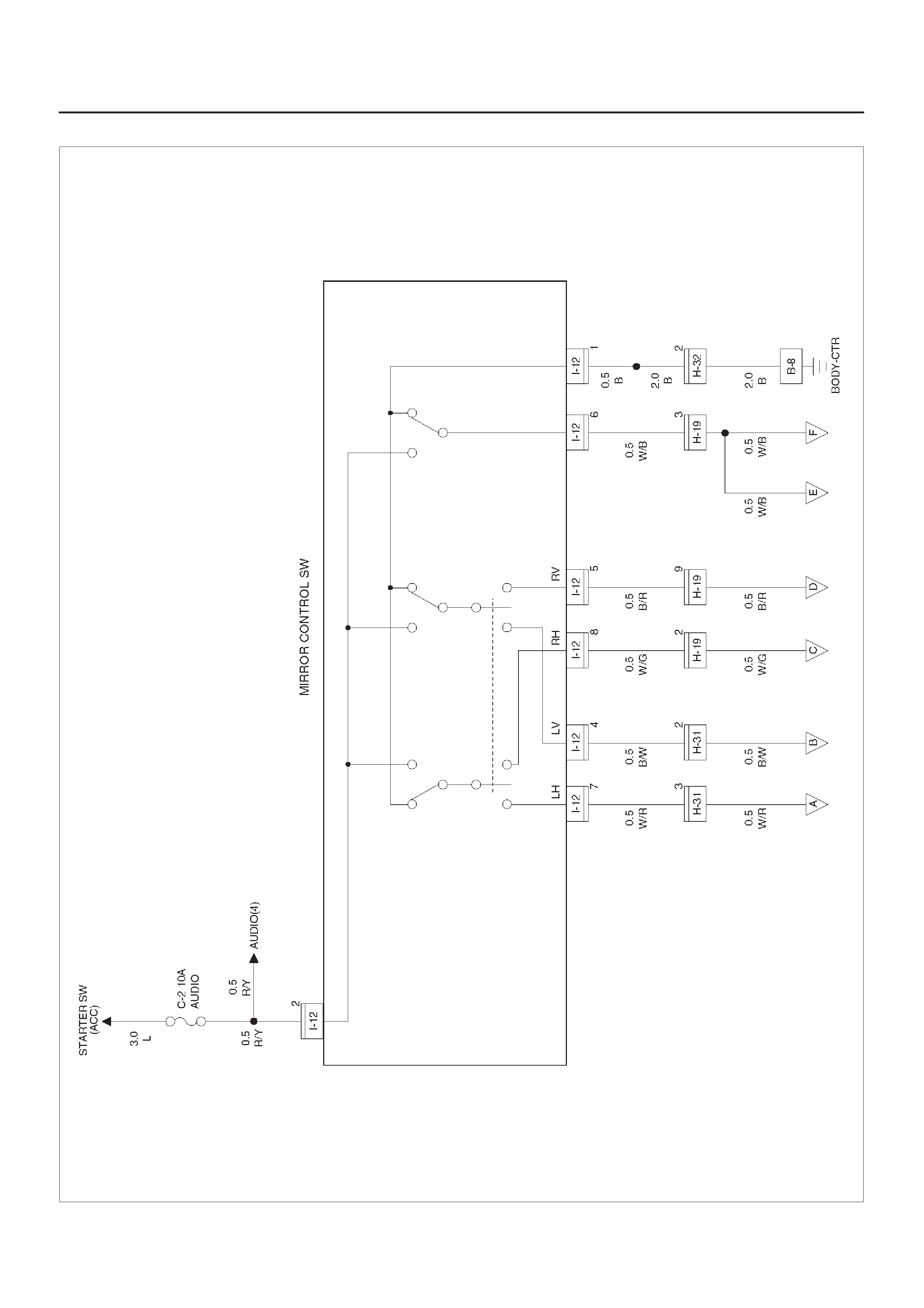
Circuit Diagram–1
D08RW246
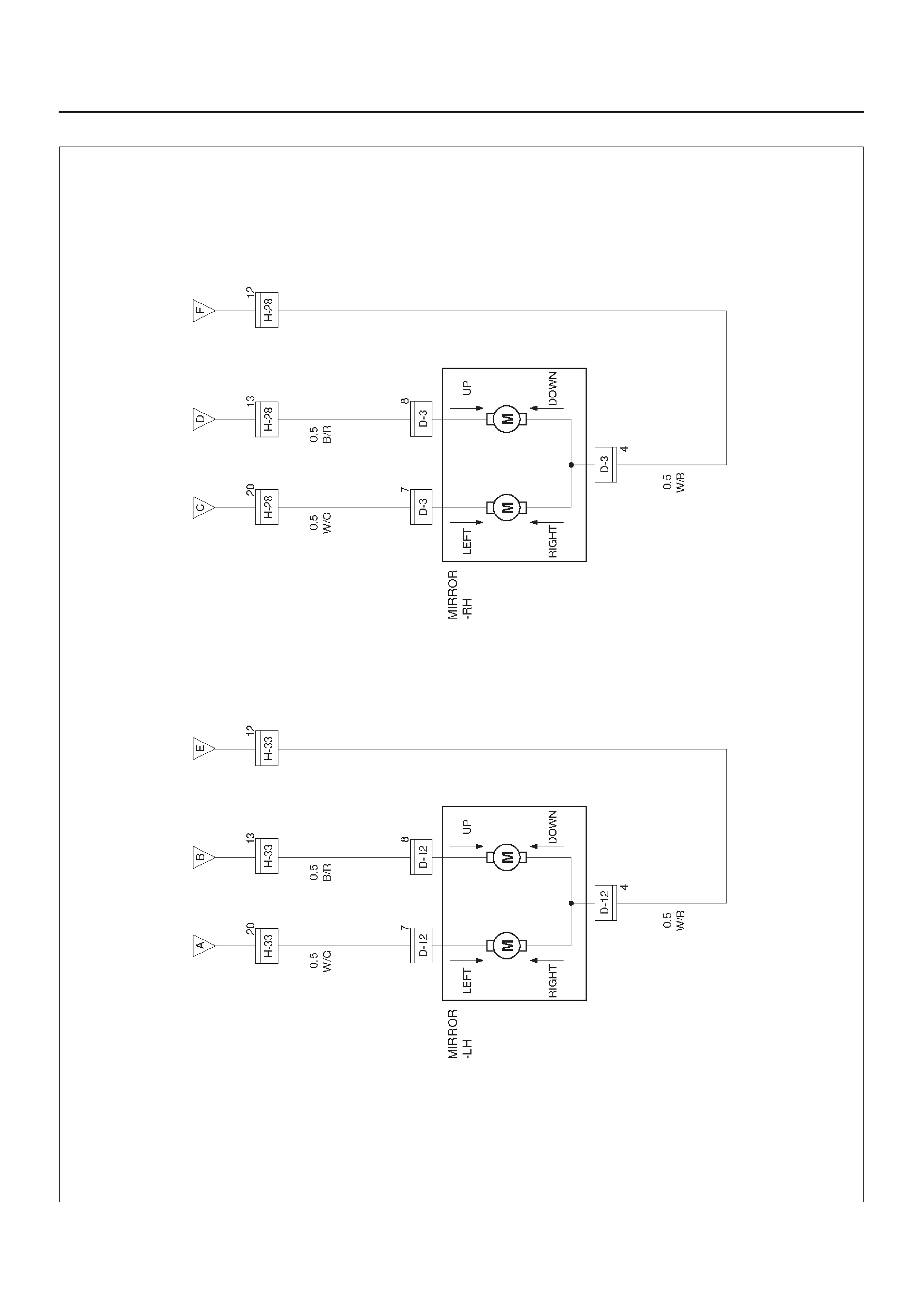
Circuit Diagram–2
D08RX247
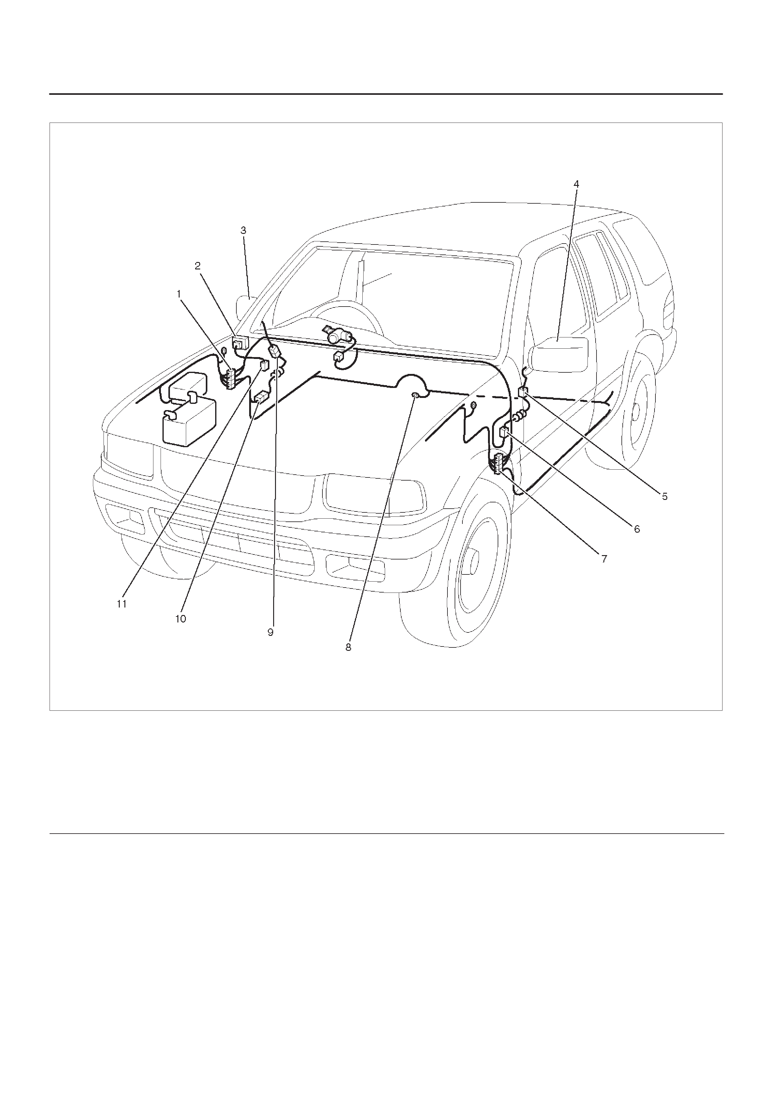
Parts Location
D08RX248
Legend
(1) H–19
(2) I–12
(3) Door Mirror – RH
(4) Door Mirror – LH
(5) D–12
(6) H–33
(7) H–31
(8) B–8
(9) D–3
(10) H–28
(11) Relay & Fuse Box (Instrument Panel)

Diagnosis
Mirrors On Both Sides Do Not Operate
Step Action Value(s) Yes No
1Is the fuse C–2 normal? —Go to Step 2 Replace the
fuse
2Is the B–8 ground securely? —Go to Step 3 Ground it
securely
3Disconnect the mirror control switch connector I–12.
Is the battery voltage applied between the harness side
connector I–12 terminal 2 and the ground? Approx. 12V Go to Step 5 Go to Step 4
4Repair an open circuit between the fuse C–2 and
connector I–12 terminal 2.
Is the action complete? —Go to Step 3 —
5Is there continuity between the harness side connector
I–12 terminal 6 and the ground? —Go to Step 7 Go to Step 6
6Repair an open circuit between connector I–12
terminal 6 and mirror.
Is the action complete? — Verify repair —
7Repair or replace the mirror control switch.
Is the action complete? — Verify repair —
Mirrors On the Left (or Right) Side Does Not Operate
Step Action Value(s) Yes No
1Disconnect the mirror control switch connector I–12
and mirror connector D–12 or D–3.
Is there continuity between the harness side connector
I–12 terminal 6 and connector D–12 or D–3 terminal 4? —Go to Step 3 Go to Step 2
2Repair an open circuit between connector I–12
terminal 6 and connector D–12 or D–3 terminal 4?
Is the action complete? —Go to Step 1 —
3Connect the battery positive terminal to the mirror side
connector terminal 4, and the battery negative terminal
to the mirror side connector terminal 7 or 8.
Dose the mirror operate? —
Repair or
replace the
mirror control
switch Replace the
mirror
Mirrors On Both Sides Operate Only In The Vertical (Or Horizontal) Direction
Step Action Value(s) Yes No
1Repair or replace the door mirror control switch.
Is the action complete? — Verify repair –

Mirror On Left (or Right) Sides Operate Only In The Vertical (Or Horizontal) Direction
Step Action Value(s) Yes No
11. Disconnect the mirror connector D–12 or D–3.
2. Connector the battery positive terminal to the mirror
connector terminal 4, and the battery negative
terminal to the mirror connector terminal 7 or 8.
Does the mirror operate? —Go to Step 2 Replace the
mirror
2Is there continuity between the harness side connector
I–12 terminal 7 and connector D–12 terminal 7
(connector I–12 terminal 4 and connector D–12
terminal 8, connector I–12 terminal 8 and connector
D–3 terminal 7, connector I–12 terminal 5 and
connector D–3 terminal 8)? —Go to Step 4 Go to Step 3
3Repair an open circuit between the mirror control
switch and the mirror –LH or –RH
Is the action complete? — Verify repair
4Repair or replace the mirror control switch.
Is the action complete? — Verify repair

Keyless Entry
General Description
This circuit consists of the keyless entry control unit, the
front door lock, & power window switch (RH), the starter
switch, the dome light, the door switch and the tail gate
switch and possible to lock/unlock each door by operation
of transmitter. Basic function of system is as follows.
1.Lock/unlock function
When the Keyless entry control unit receives the
signal from the transmitter, the control unit sends the
locker unlock signal to the front door lock and power
window switch (RH).
Function code (lock or unlock) and proper ID code for
each vehicle are added to the signal. But, when
starter switch is on or any of the doors opens,
lock/unlock function is not unable to work.
2.Answer back function
When receiving the signal from the transmitter, the
keyless entry control unit responds by using the dome
light. In case of being locked, the keyless entry control
unit turns on the dome light at two times (about 0.5
second at each time). In case of being unlocked, it
turns on the dome light at one time (about 3 seconds).
3.Autolock function
After unlock function is done, in case of effecting one
of following conditions within about 30 seconds, the
keyless entry control unit automatically sends the
lock signal to lock each door.
1. The doors are closed.
2. Starter key is not inserted
3. The lock operation is not done by transmitter.
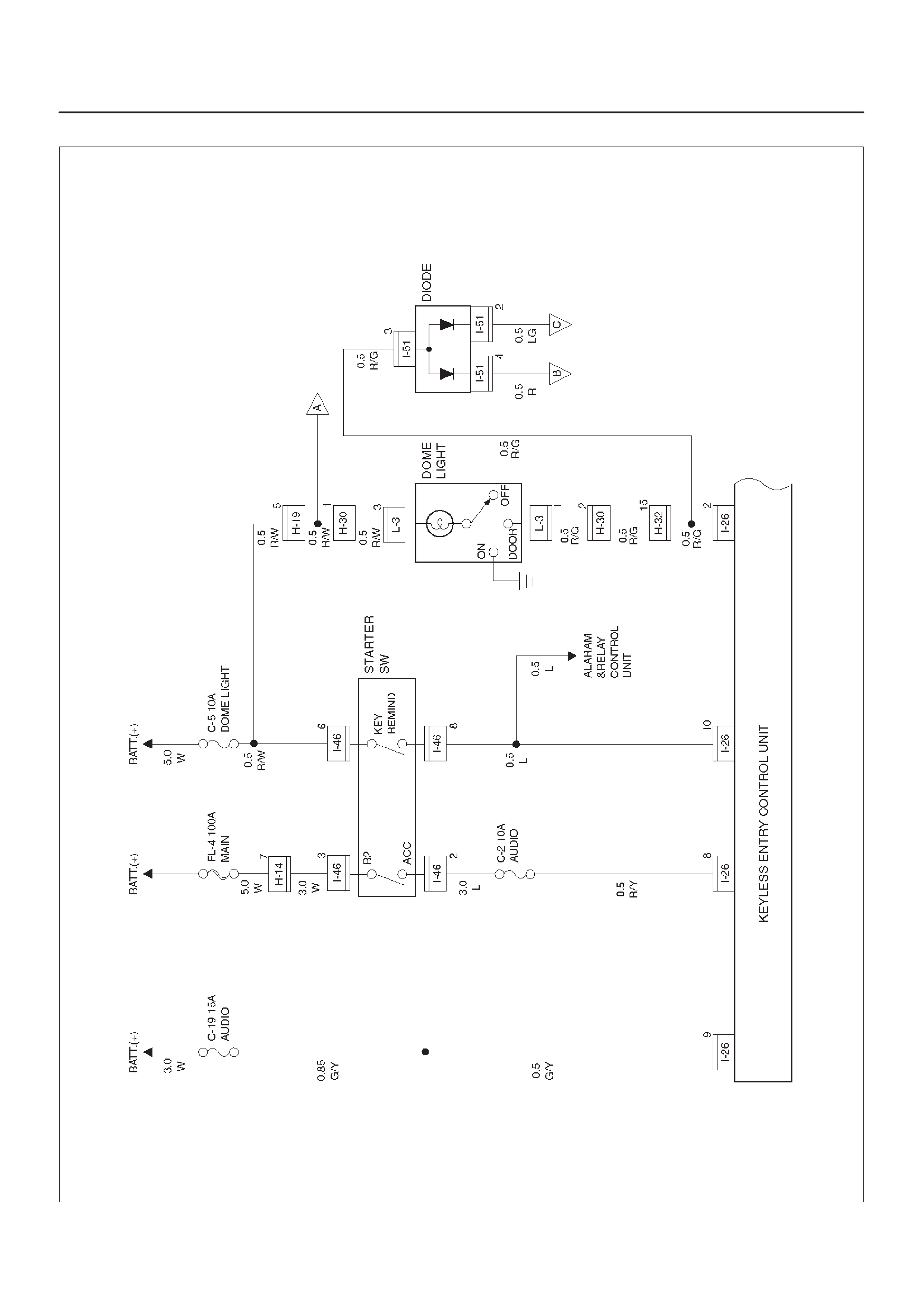
Circuit Diagram–1 (4Door Model)
D08RX251
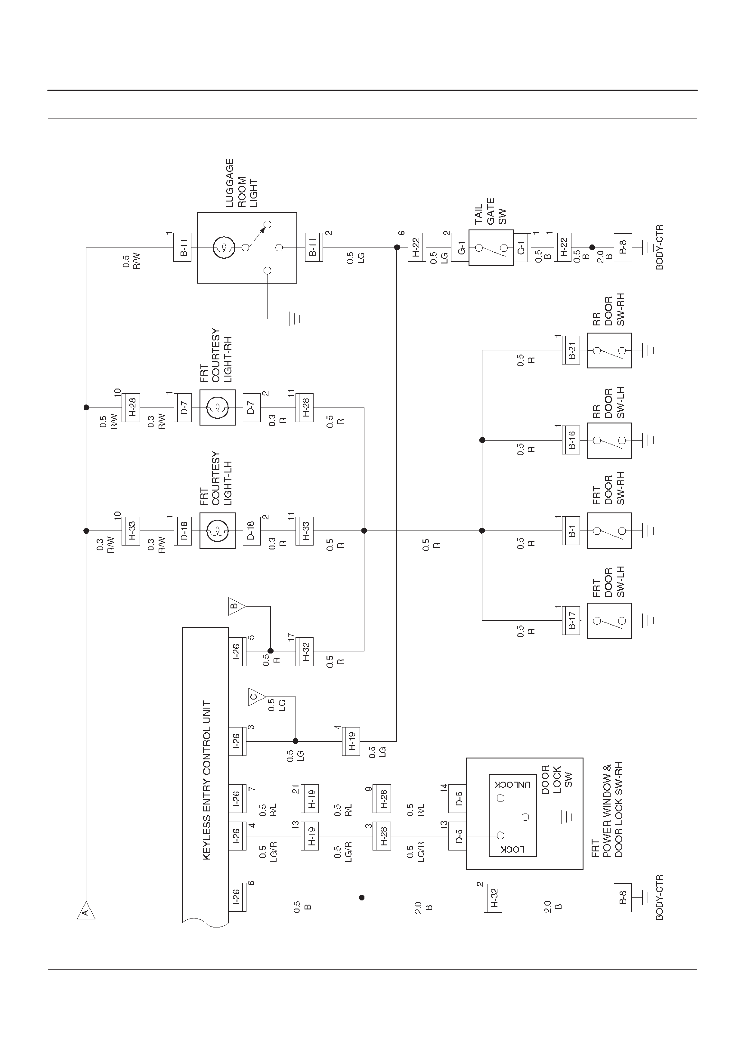
Circuit Diagram–2 (4Door Model)
D08RX252
Circuit Diagram–1 (2Door Model)
D08RX361

Circuit Diagram–2 (2Door Model)
D08RX252
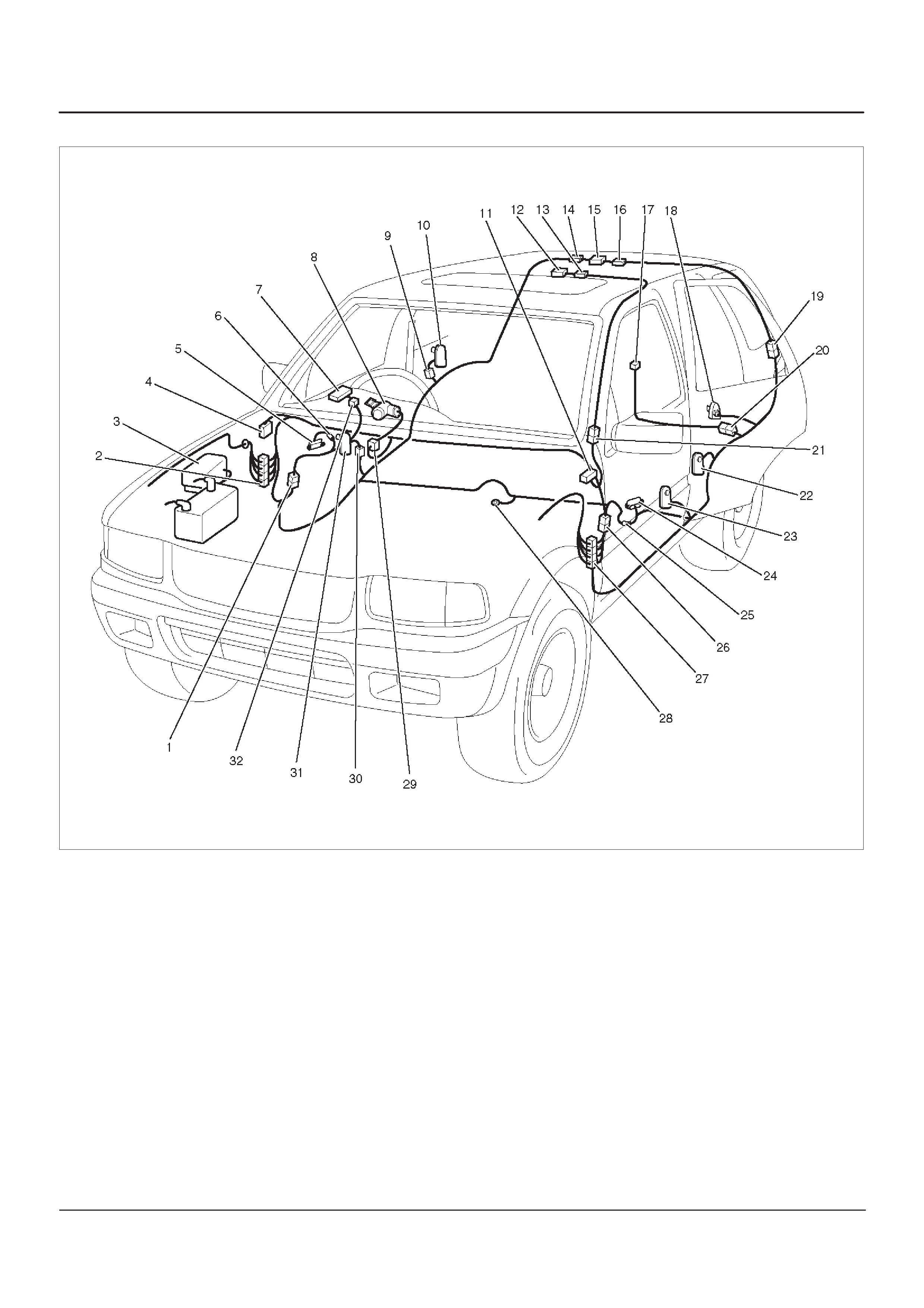
Parts Location
D08RWD27
Legend
(1) H–28
(2) H–14, H–19, H–32
(3) Relay & Fuse Box (Engine Room)
(4) Relay & Fuse Box (Instrument Panel)
(5) Courtesy Light – RH
(6) D–7
(7) FRT Door Lock Switch – RH
(8) Starter Switch
(9) B–27
(10) RR Door Switch – RH
(11) I–26
(12) Dome Light
(13) L–3
(14) B–11 (4Door Model)
(15) Luggage Room Light
(16) G–13 (2Door Model)
(17) G–1
(18) B–20
(19) H–37
(20) H–22
(21) H–30
(22) B–16
(23) B–17 (FRT Door Switch – LH)
(24) Courtesy Light – LH
(25) D–18
(26) H–33
(27) H–31
(28) B–8
(29) I–46
(30) B–1
(31) FRT Door Switch – RH
(32) D–5

Keyless Entry System
ID Code Registration
This procedure registers a new ID code. When total
number of registered ID codes and newly registered ID
code exceed four, they are erased in order of older one.
Step Action Value(s) Yes No
11. Confirm that all the doors are closed and unlocked.
2. Open the driver’s side door.
3. Insert the key into the starter switch.
Is the action complete? —Go to Step 2 Go to Step 1
2Turn the starter switch to ACC position and then to OFF
position three times.
NOTE: This step must be carried out within five
seconds after step 1.
Is the action complete? —Go to Step 3 Go to Step 1
3Close the driver’s side door and then open it two times.
NOTE: This step must be carried out within ten
seconds after step 2.
Is the action complete? —Go to Step 4 Go to Step 1
41. T urn the starter switch to ACC position and then to
OFF position three times.
2. Close the driver’s side door and then open it.
NOTE: This step must be carried out within ten
seconds after step 3.
Is the action complete? —Go to Step 5 Go to Step 1
5The control unit lock and unlocks the doors one times.
Does the control unit work normally? —Go to Step 6 Go to Step 1
6Operate the lock or unlock button of the transmitter.
NOTE: This step must be carried out within twenty
seconds after step 5.
Is the action complete? —Go to Step 7 Go to Step 1
7The control unit locks and unlock the doors one times.
Does the control unit work normally? —Go to Step 8 Go to Step 1
8Operate the lock or unlock button of the transmitter.
NOTE: This step must be carried out within twenty
seconds after step 7.
Is the action complete? —Go to Step 9 Go to Step 1
9The control unit compares the two codes sent from the
transmitter.
If the code succeeds in registration, the control unit
locks and unlocks the doors one time.
If the two codes are different from each other or fails in
registration, the control unit locks and unlocks the
doors three times.
NOTE: In any case, this procedure is finished.
—Go to Step 1 Go to Step 1

Meter and Warning/Indicator Light
General Description
The circuit consists of the starter switch, meter assembly ,
vehicle speed sensor, alarm & relay control unit, lighting
switch, turn signal switch, engine coolant temperature
unit, oil pressure unit, Powertrain Control Module, fuel
tank unit, 4WD control unit, oil pressure switch, parking
brake switch, brake fluid switch, seat belt switch,
illumination controller.
The meter ASM contains the speedometer, tachometer,
voltmeter, engine coolant temperature gauge, oil
pressure gauge, fuel gauge and warning/indicator lights.
The meter warning/indicator lights and their bulb sockets
are a unit, they are installed from the back of the
speedometer assembly.
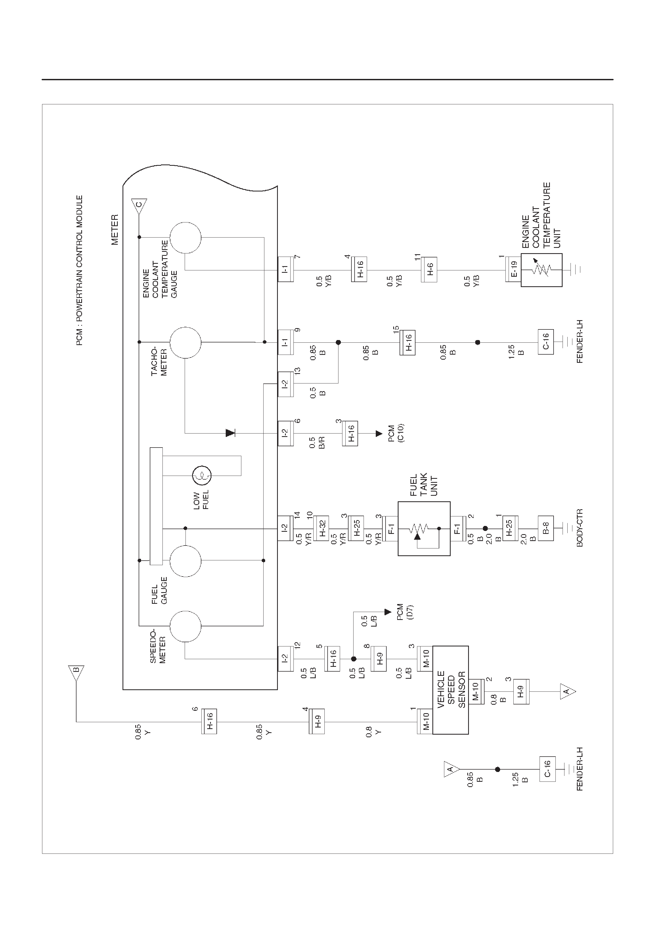
Circuit Diagram – 1 (6VD1 M/T)
D08RX257
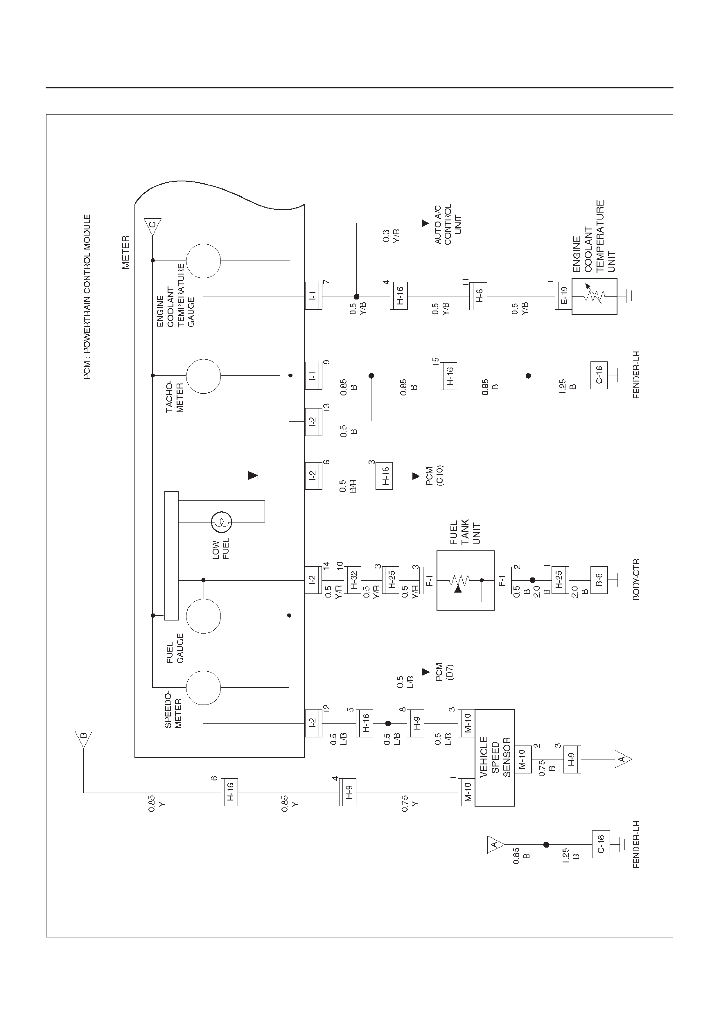
Circuit Diagram – 1 (6VD1 A/T)
D08RX256
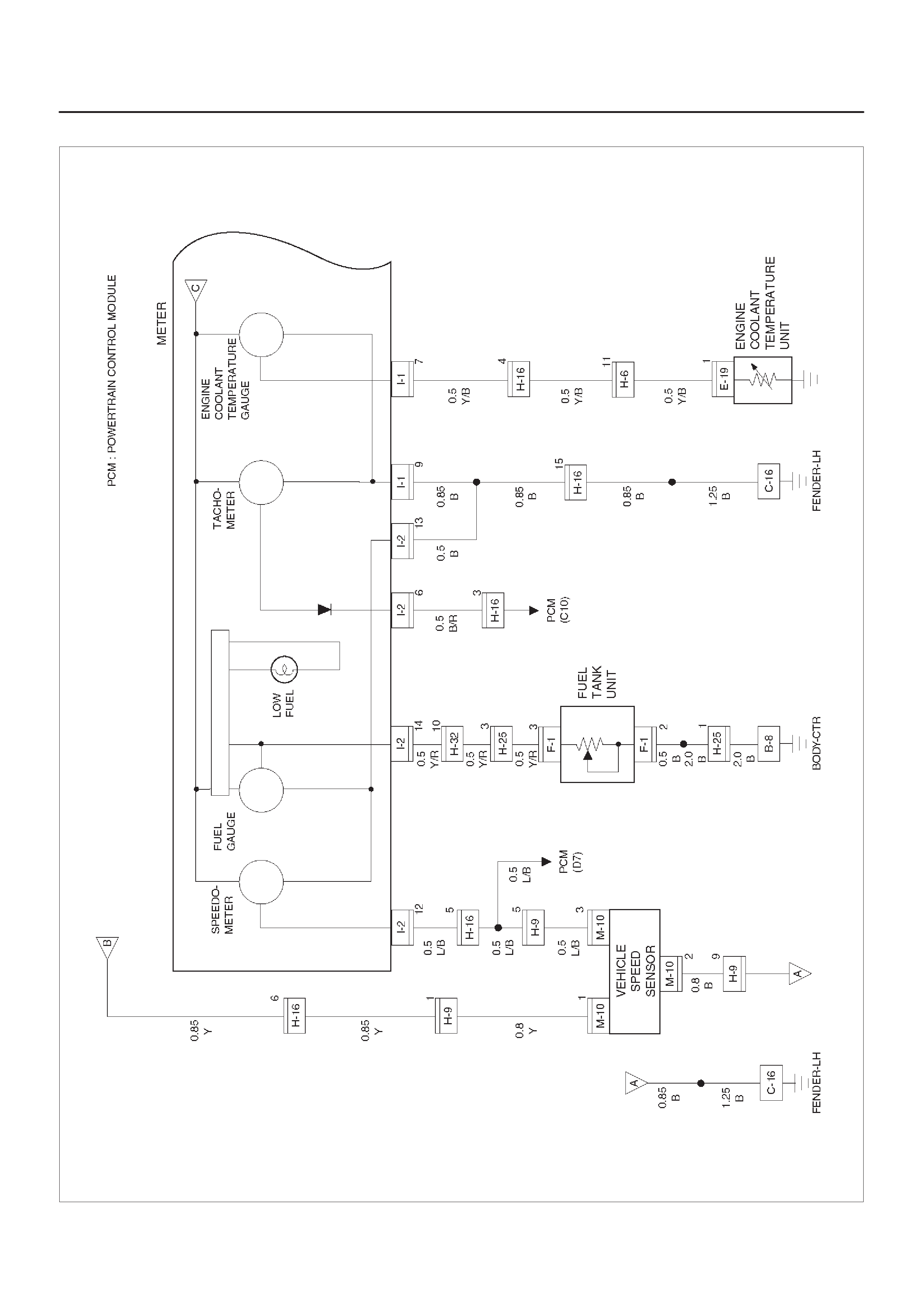
Circuit Diagram – 1 (X22SE)
D08RX258
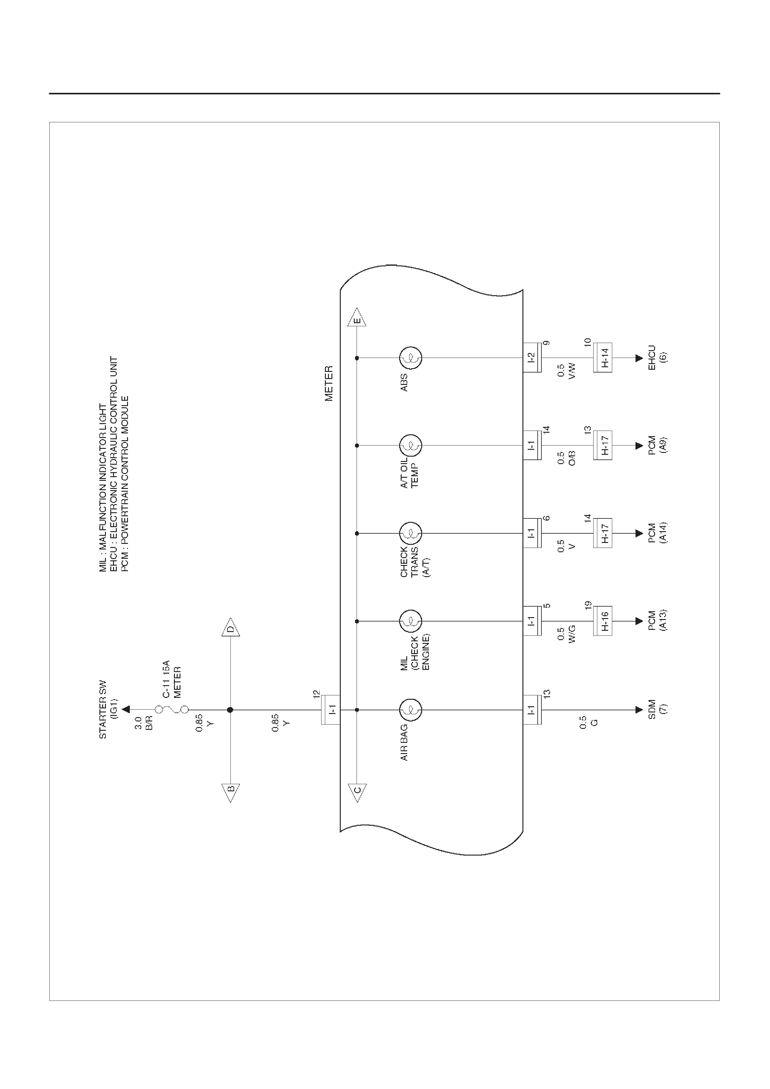
Circuit Diagram – 2
D08RX259
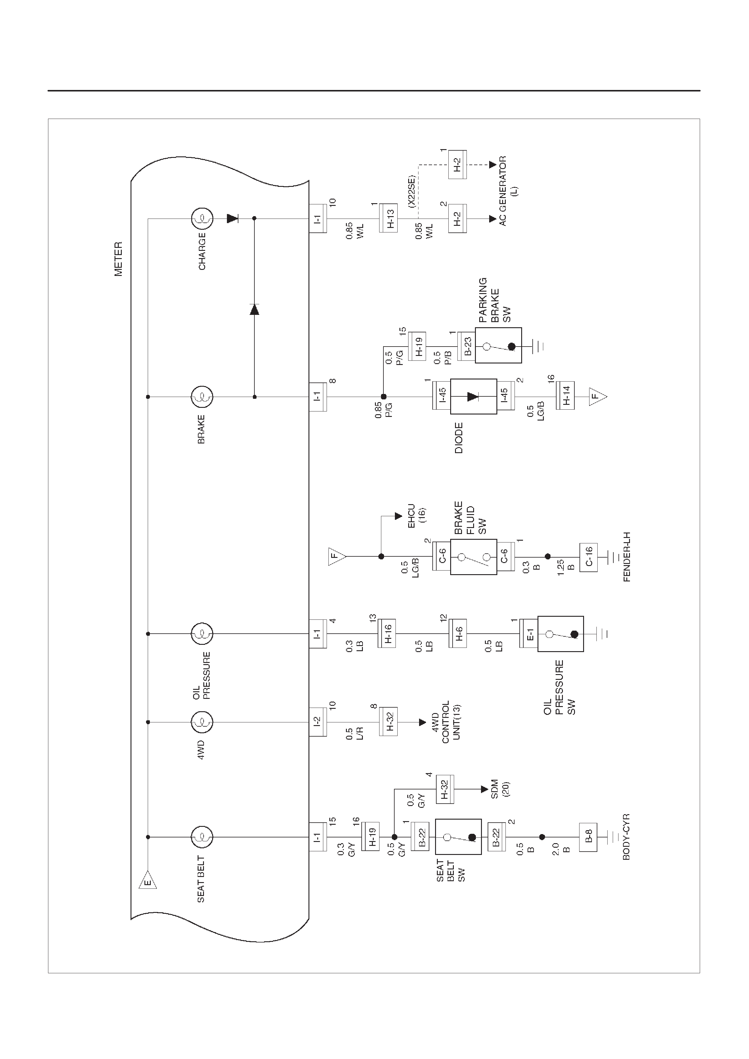
Circuit Diagram – 3
D08RX260
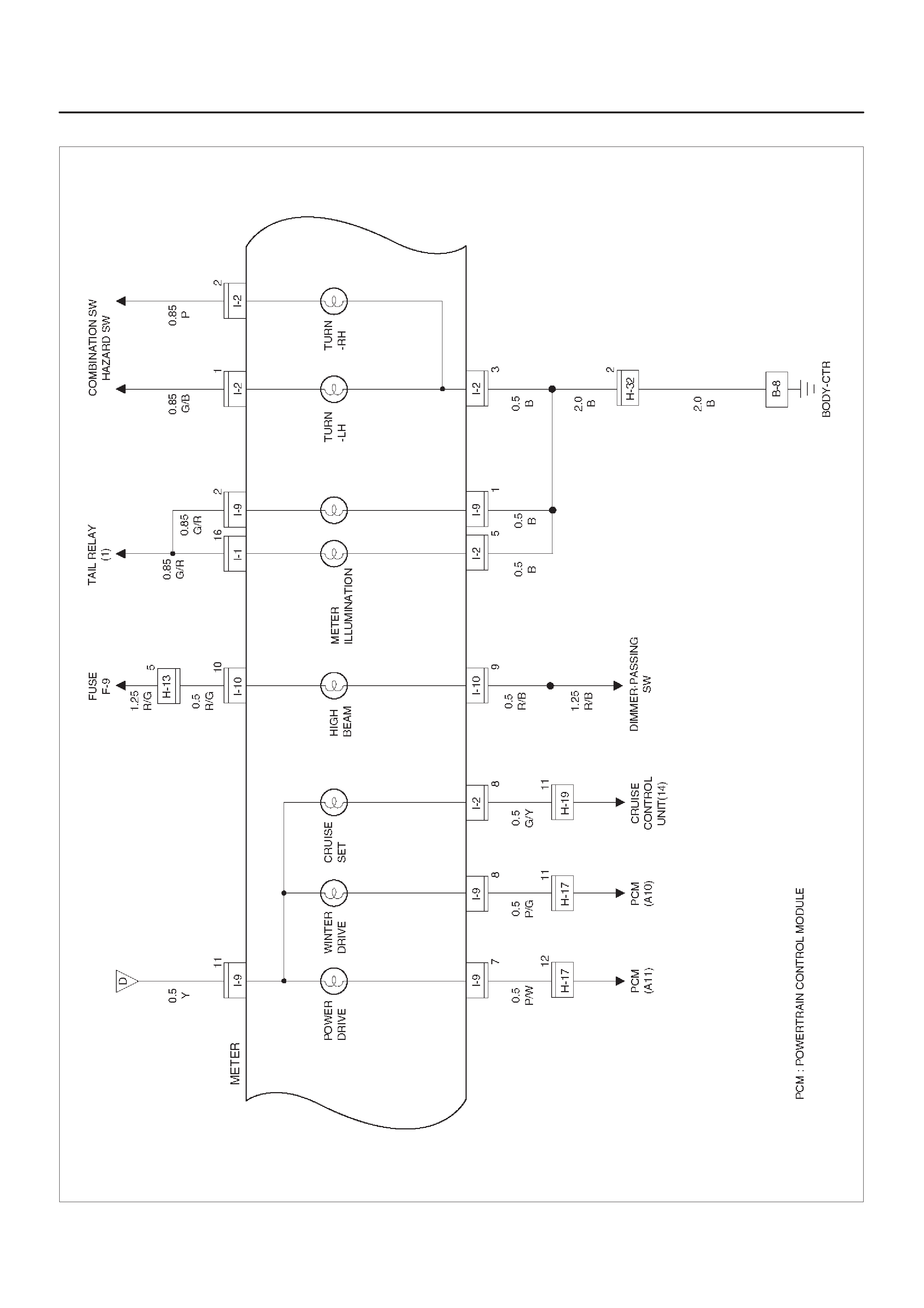
Circuit Diagram – 4
D08RX261
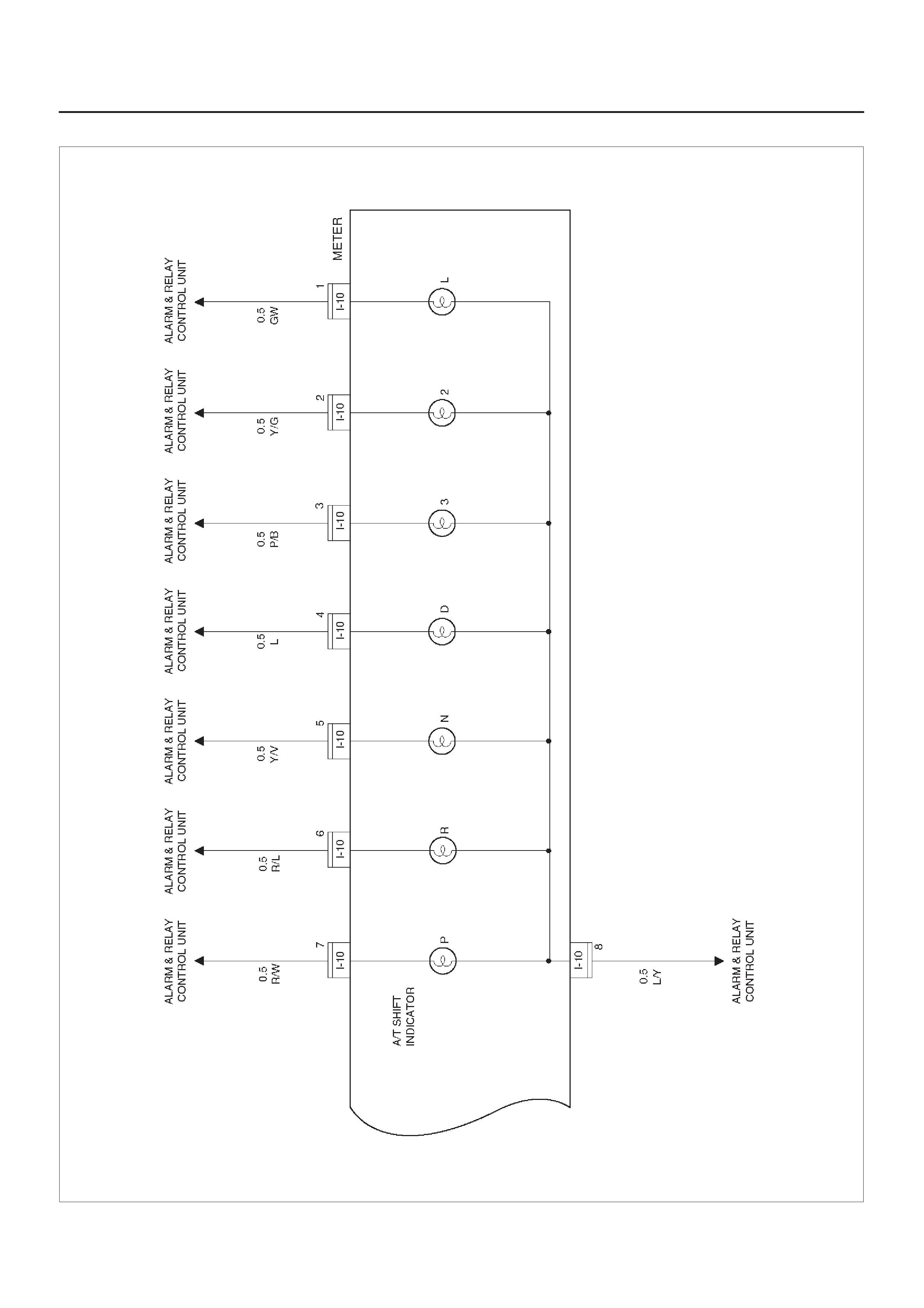
Circuit Diagram – 5
D08RX262
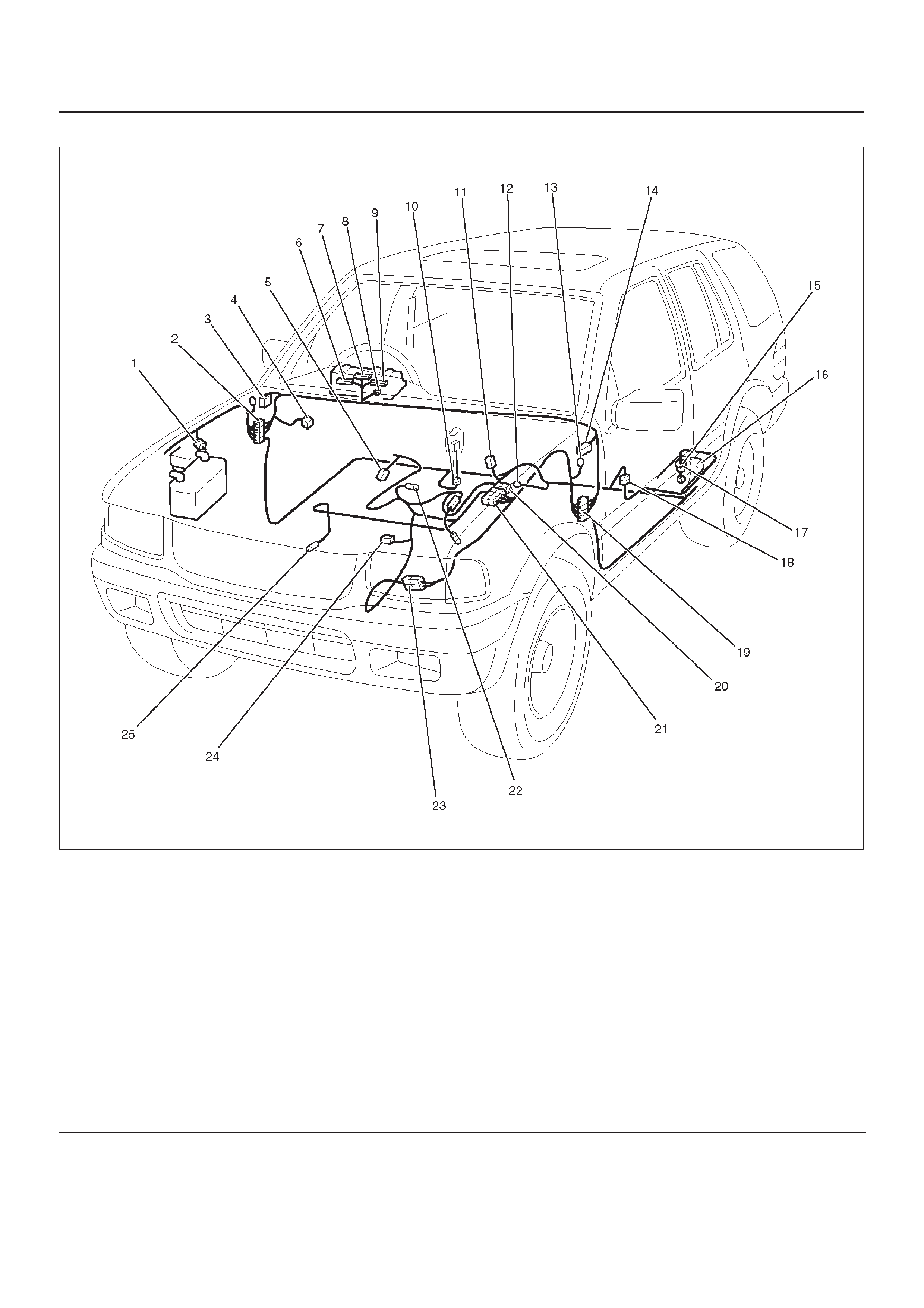
Parts Location
D08RX265
Legend
(1) H–2
(2) H–13, H–14, H–19, H–32
(3) Relay & Fuse Box (Instrument Panel)
(4) C–6
(5) E–19
(6) I–9
(7) I–2
(8) I–10
(9) I–1
(10) B–22
(11) B–23
(12) B–8
(13) C–16
(14) Alarm & Relay Control Unit
(15) Fuel Tank Unit
(16) Fuel Tank
(17) F–1
(18) H–25
(19) H–15, H–16, H–17, H–31
(20) H–9 (X22SE)
(21) H–5, H–6
(22) M–10
(23) H–9 (6VD1)
(24) E–1 (6VD1)
(25) E–1 (X22SE)

Diagnosis
Speedometer and Odometer Do Not Function
Step Action Value(s) Yes No
1Is C–16 grounded securely? —Go to Step 2 Ground it
securely
2Disconnect the vehicle speed sensor connector M–10.
Is there continuity between harness side connector
M–10 terminal 2 and the ground? —Go to Step 4 Go to Step 3
3Repair an open circuit between connector M–10
terminal 2 and the ground C–16.
Is the action complete? —Go to Step 2 —
4Turn the starter switch on.
Is the battery voltage applied between harness side
connector M–10 terminal 1 and the ground? Approx. 12V Go to Step 6 Go to Step 5
5Repair an open circuit between the fuse C–11 and
connector M–10 terminal 1.
Is the action complete? —Go to Step 4 —
6Disconnect the meter connector I–2.
Is there continuity between harness side connector I–2
terminal 12 and harness side connector M–10 terminal
3? —Go to Step 8 Go to Step 7
7Repair an open circuit between connector I–2 terminal
12 and connector M–10 terminal 3.
Is the action complete? — Verify repair —
81. Disconnect the meter connector I–1.
2. Connector a resistance of 1.3 to 5K ohm (1.4W or
more) between harness side connector I–1 terminal
12 and harness side connector I–2 terminal 12.
3. Install a speedometer tester.
4. Check the waveform at the time when the vehicle
speed is 60 Km/h with a oscilloscope.
NOTE: Normal waveform shows between approx. 12V
and 2V and its cycle is 23.6msec
Is the waveform normal? —
Replace the
meter
assembly
Replace the
vehicle speed
sensor
Speedometer Does Not Function (Odometer is Normal)
Step Action Value(s) Yes No
1Replace the meter assembly.
Is the action complete? — Verify repair —
Odometer Does Not Function (Speedometer is Normal)
Step Action Value(s) Yes No
1Replace the meter assembly.
Is the action complete? — Verify repair —

Speedometer Pointer Fluctuates (May be Wide Fluctuation)
Step Action Value(s) Yes No
1NOTE: Refer to the step 8 of diagnosis procedure for
Speedometer and Odometer Does Not Function is this
section.
Is the vehicle speed sensor signal normal? —
Replace the
meter
assembly Go to step 2
2Repair a poor connections of the connectors or a failure
in the circuit between connector 1–2 terminal 12 and
connector M–10 terminal 3.
Is the action complete? — Verify repair —
Speedometer Pointer Jumps Erratically
Step Action Value(s) Yes No
1NOTE: Refer to the step 8 of diagnosis procedure for
Speedometer and Odometer Does Not Function is this
section.
Is the vehicle speed sensor signal normal? —
Replace the
meter
assembly Go to step 2
2Repair a poor connections of the connectors or a failure
in the circuit between connector 1–2 terminal 12 and
connector M–10 terminal 3.
Is the action complete? — Verify repair —
Tachometer Does Not Function
Step Action Value(s) Yes No
11. Disconnect the meter connector I–2.
2. Check the waveform of terminal 6 when the engine
revolution is 3000 rpm with a oscilloscope.
NOTE: Normal waveform shows between 4.3V and
0.4V and its cycle is 6.7m sec.
Is the waveform normal? —
Replace the
meter
assembly Go to step 2
2Is the circuit between connector I–2 terminal 6 and the
PCM connector C–2 terminal C10 normal? —Replace the
PCM Repair the
circuit
Tachometer Pointer Fluctuates (May Be Wide Fluctuation)
Step Action Value(s) Yes No
1NOTE: Refer to the step 1 of diagnosis procedure for
Tachometer Does Not Function in this section.
Is the waveform normal? —
Replace the
meter
assembly Go to step 2
2Is the circuit between connector I–2 terminal 6 and the
PCM connector C–2 terminal C–10 normal? —Replace the
PCM Repair the
circuit

Tachometer Pointer Jumps Erratically
Step Action Value(s) Yes No
1NOTE: Refer to the step 1 of diagnosis procedure for
Tachometer Does Not Function in this section.
Is the waveform normal? —
Replace the
meter
assembly Go to step 2
2Is the circuit between connector I–2 terminal 6 and the
PCM connector C–2 terminal C–10 normal? —Replace the
PCM Repair the
circuit
Engine Coolant Temperature (ECT) Gauge Pointer Does Not Move
Step Action Value(s) Yes No
1Is the engine coolant temperature (ECT) unit connector
E–19 connected securely? —Go to step 2 Connect it
securely
21. Disconnect the ECT unit connector E–19.
2. Connect a 3.4W bulb between harness side
connector E–19 terminal 1 and the ECT unit ground.
3. Turn the starter switch on.
Does the ECT gauge pointer move about 10 seconds
after that? —Replace the
ECT unit Go to step 3
3Is there continuity between harness side connector I–1
terminal 7 and connector E–19 terminal 1? —
Replace the
meter
assembly Repair the
circuit
Engine Coolant Temperature (ECT) Gauge Reading is Too Low
Step Action Value(s) Yes No
11. Disconnect the ECT unit connector E–19.
2. Turn the starter switch on.
3. Connect harness side connector E–19 terminal 1
with the ground.
Does the indication of the ECT gauge vary? —Replace the
ECT unit Go to step 2
21. Disconnect the meter connector I–1.
2. Connect meter side connector I–1 terminal 7 with
the ground.
Does the indication of the ECT gauge vary? —Go to step 3
Replace the
meter
assembly
3Repair an open circuit between connector I–1 terminal
7 and connector E–19 terminal 1.
Is the action complete? — Verify repair —

Engine Coolant Temperature (ECT) Gauge Pointer Overshoots (or Goes Up To the “H”
Range)
Step Action Value(s) Yes No
11. Disconnect the ECT unit connector E–19.
2. Turn the starter switch on.
3. Connect harness side connector E–19 terminal 1
with the ground.
Does the indication of the ECT gauge vary? —Replace the
ECT unit Go to step 2
2Disconnect the meter connector I–1.
Does the indication of the ECT gauge vary? —Go to step 3
Replace the
meter
assembly
3Repair an open circuit between connector I–1 terminal
7 and connector E–19 terminal 1.
Is the action complete? — Verify repair —
Fuel Gauge Needle Does Not Move
Step Action Value(s) Yes No
1Is B–8 grounded securely? —Go to step 2 Ground it
securely
2Disconnect the fuel tank unit connector F–1.
Is there continuity between the harness side connector
F–1 terminal 2 and the ground? —Go to step 4 Go to step 3
3Repair an open circuit between connector F–1 terminal
2 and the ground B–8.
Is the action complete? — Verify repair —
41. Connect a 3.4W bulb between the harness side
connector F–1 terminal 3 and the ground.
2. Turn the starter switch on.
Does the fuel gauge needle fluctuate after about 90
seconds? —Replace the
fuel tank unit Go to step 5
5Disconnect the meter connector I–2.
Is there continuity between the harness side connector
I–2 terminal 14 and connector F–1 terminal 3? —
Replace the
meter
assembly Go to step 6
6Repair an open circuit between the meter assembly
and the fuel tank unit.
Is the action complete? — Verify repair —

Even the Tank is Filled Up With Fuel, The Needle Does Not Reach “F”
Step Action Value(s) Yes No
1Disconnect and connect the fuel tank unit connector
F–1 several times.
Does the indication of the fuel gauge vary? —Go to step 2 Go to step 3
2Repair a poor connection of the fuel tank unit connector
F–1.
Is the action complete? — Verify repair —
31. Disconnect the fuel tank unit connector F–1.
2. Connect the harness side connector F–1 terminal 2
and 3 with a lead wire.
3. Turn the starter switch on.
Does the fuel gauge needle overshoot to “F” after about
5 minutes? —
Repair or
replace the
fuel tank unit
Replace the
meter
assembly
Even When The Tank Is Not Filled With Fuel, The Needle Overshoots To “F”
Step Action Value(s) Yes No
11. Disconnect the fuel tank unit connector F–1.
2. Turn the starter switch on.
Does the needle point to “E”? —Replace the
fuel tank unit Go to step 2
2Is there a short circuit between the meter connector I–2
terminal 14 and the fuel tank unit connector F–1
terminal 3? —Repair a
short circuit
Replace the
meter
assembly

A/T Shift Indicator
General Description
The circuit consists of the starter switch, mode switch,
alarm & relay control unit and A/T shift indicator (meter).
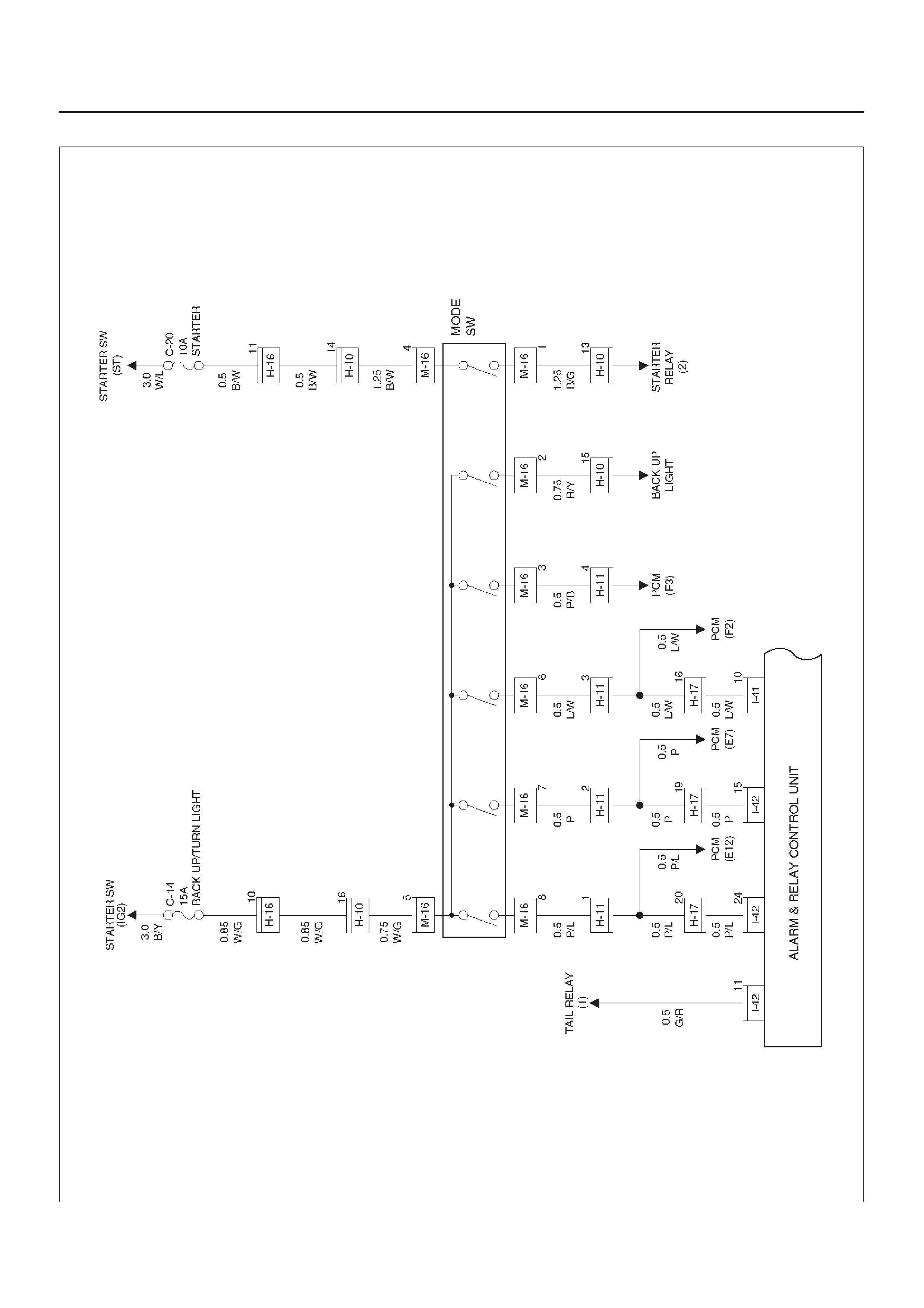
Circuit Diagram–1
D08RX263
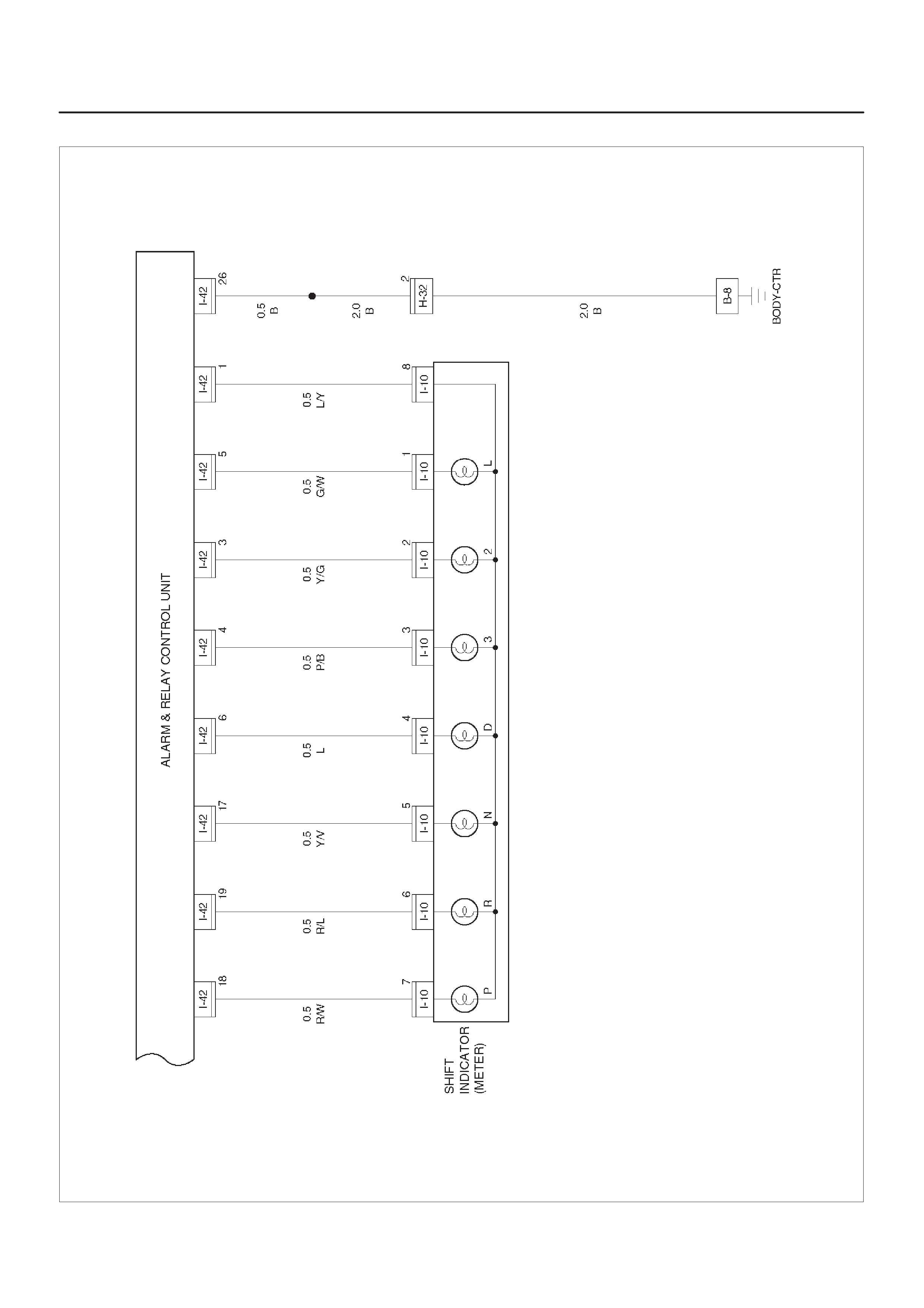
Circuit Diagram–2
D08RX264

Parts Location
D08RX266
Legend
(1) Battery
(2) Relay & Fuse Box (Engine Room)
(3) H–32
(4) C–36
(5) I–10
(6) Starter Switch
(7) B–8
(8) Alarm & Relay Control Unit
(9) H–16, H–17
(10) M–16
(11) H–10
(12) H–11

Heater and Air Conditioning
General Description
The heater and air conditioning system consists of
pressure switch, A/C switch, electronic thermostat,
blower motor, fan switch, magnetic clutch for A/C
compressor, blower resistor, relays and PCM (or ECM).
Basically the air conditioning system works while the A/C
switch and the fan switch are turned on, and stops
working when the pressure switch turns off or the
electronic thermostat cuts off the circuit.
The PCM (or the ECM) also stops working of the air
conditioning system to reduce the engine load.
Refer to Heating and Ventilation System, and Air
Conditioning System in HVAC System.
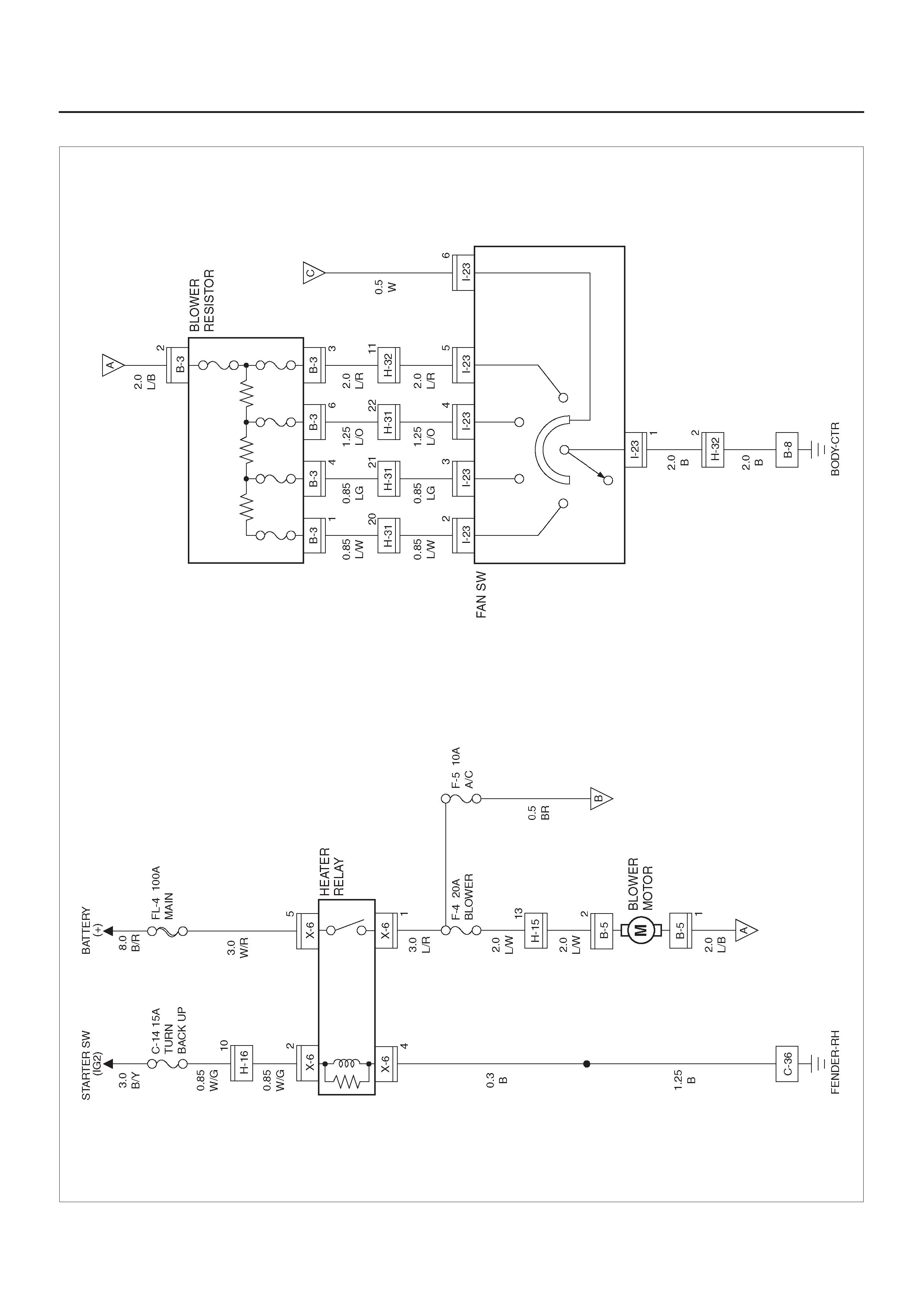
Circuit Diagram–1
D08RY00932
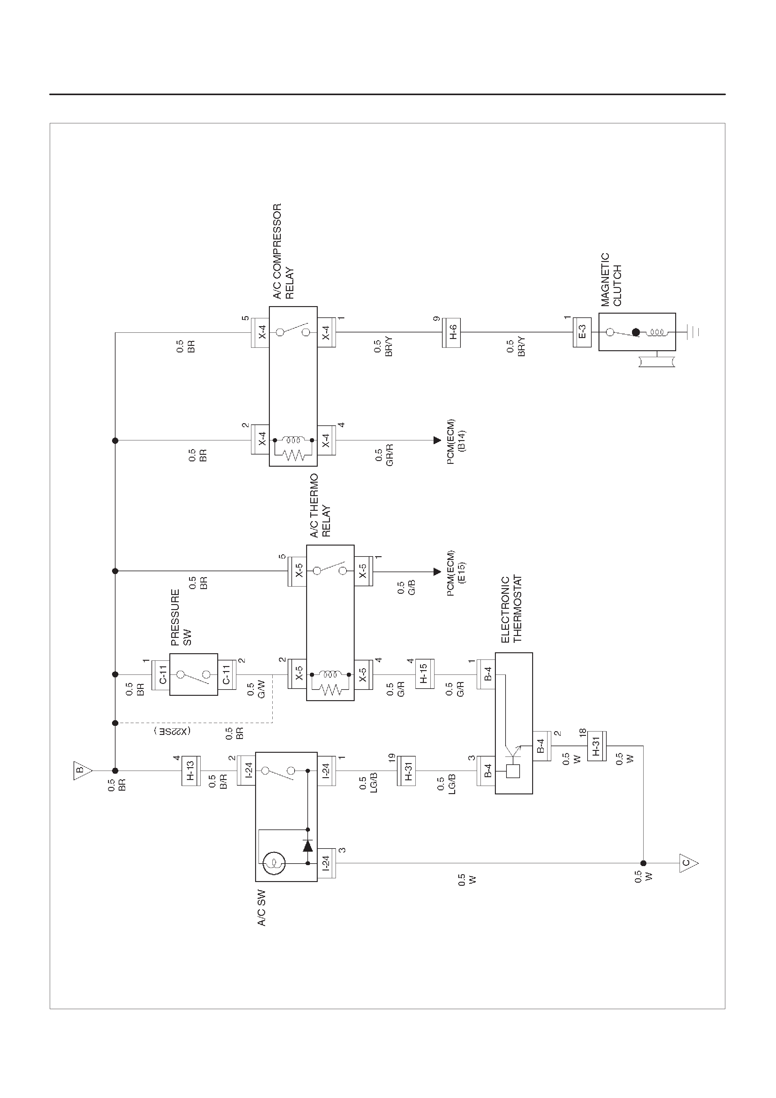
Circuit Diagram–2
D08RX150
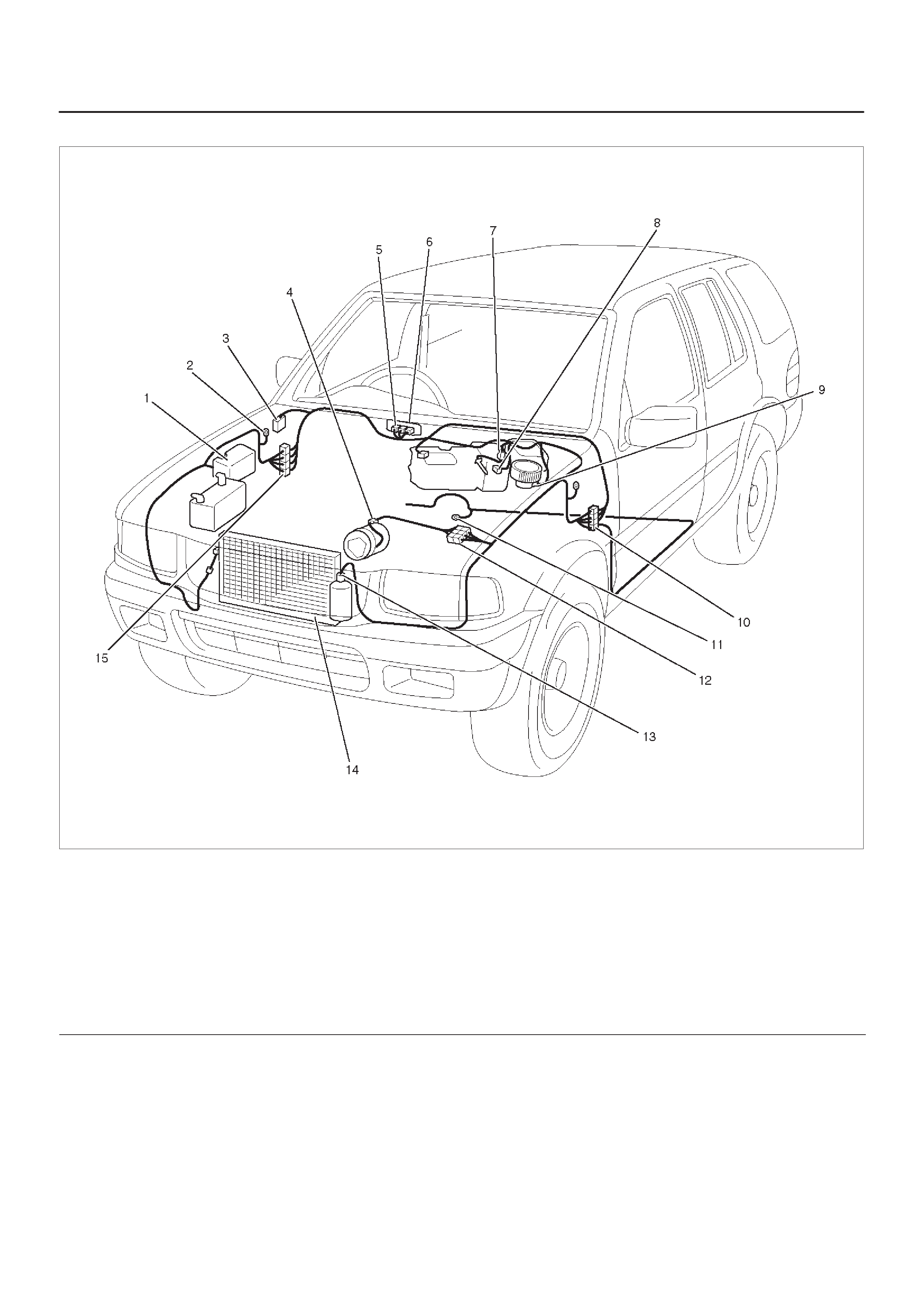
Parts Location
D08RX271
Legend
(1) Relay & Fuse Box (Engine Room)
(2) C–36
(3) Relay & Fuse Box (Instrument Panel)
(4) E–3
(5) I–23
(6) I–24
(7) B–4
(8) B–3
(9) B–5
(10) H–15, H–16, H–31
(11) B–8
(12) H–6
(13) C–11
(14) Condenser
(15) H–13, H–32

Heater and Air Conditioning
General Description
Using the signals from a variety of sensors, the full
automatic heater and air conditioning system accurately
senses outside air temperature, solar radiation quantity,
evaporator’s blowing temperature, heater core water
temperature and interior temperature. These signals
enable the control unit to automatically control blow
temperature and air blow quantity, turn on or off the
compressor and switch the blow port as well as switching
between the fresh air intake and interior air circulation.
Resetting the automatic function allows the system to
switch to the manual control mode.
The self-diagnosis function of the control unit allows the
unit to access and diagnose failed parts easier and
quicker.
Refer to Air Conditioning System in HVAC System.
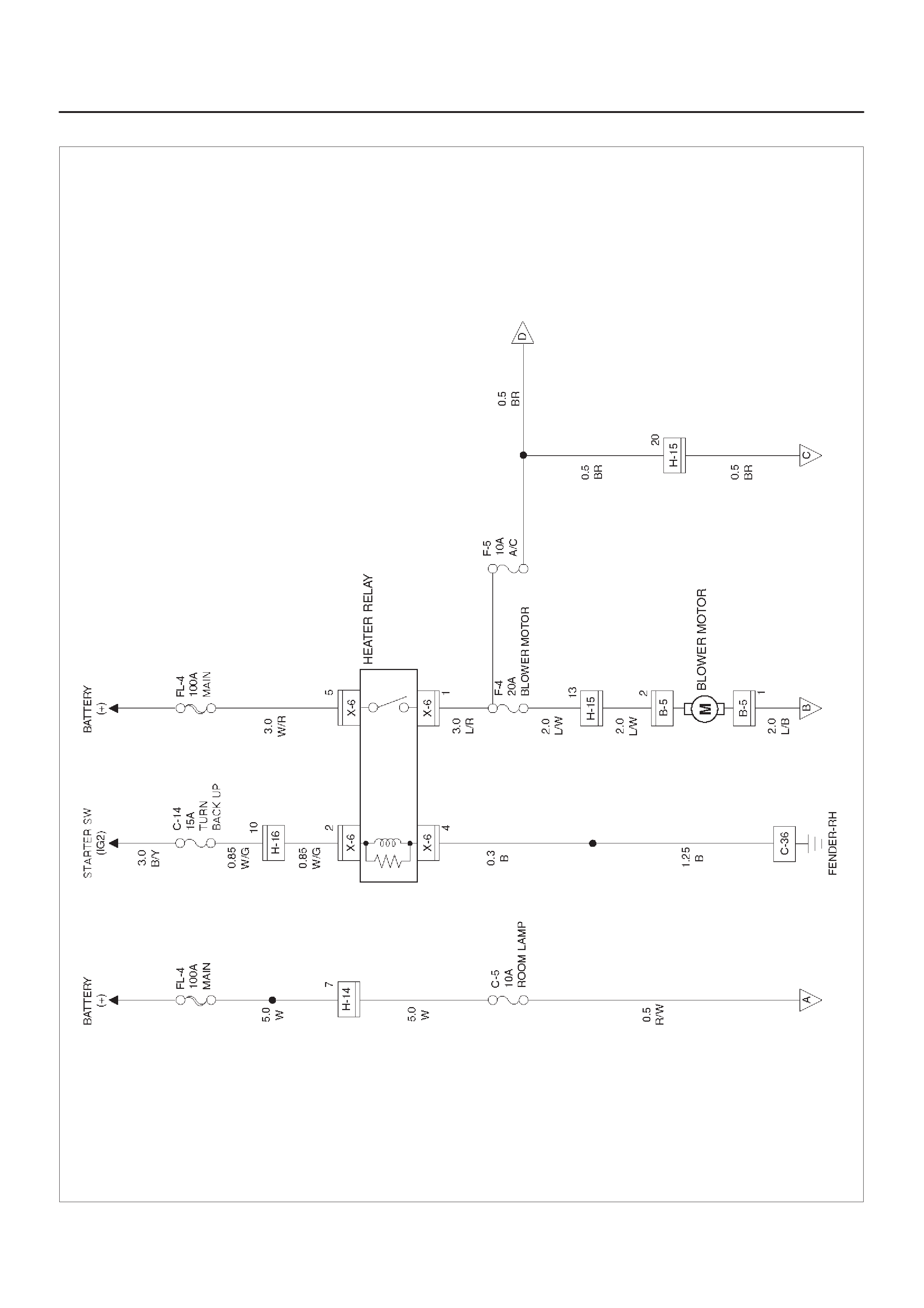
Circuit Diagram–1
D08RX145
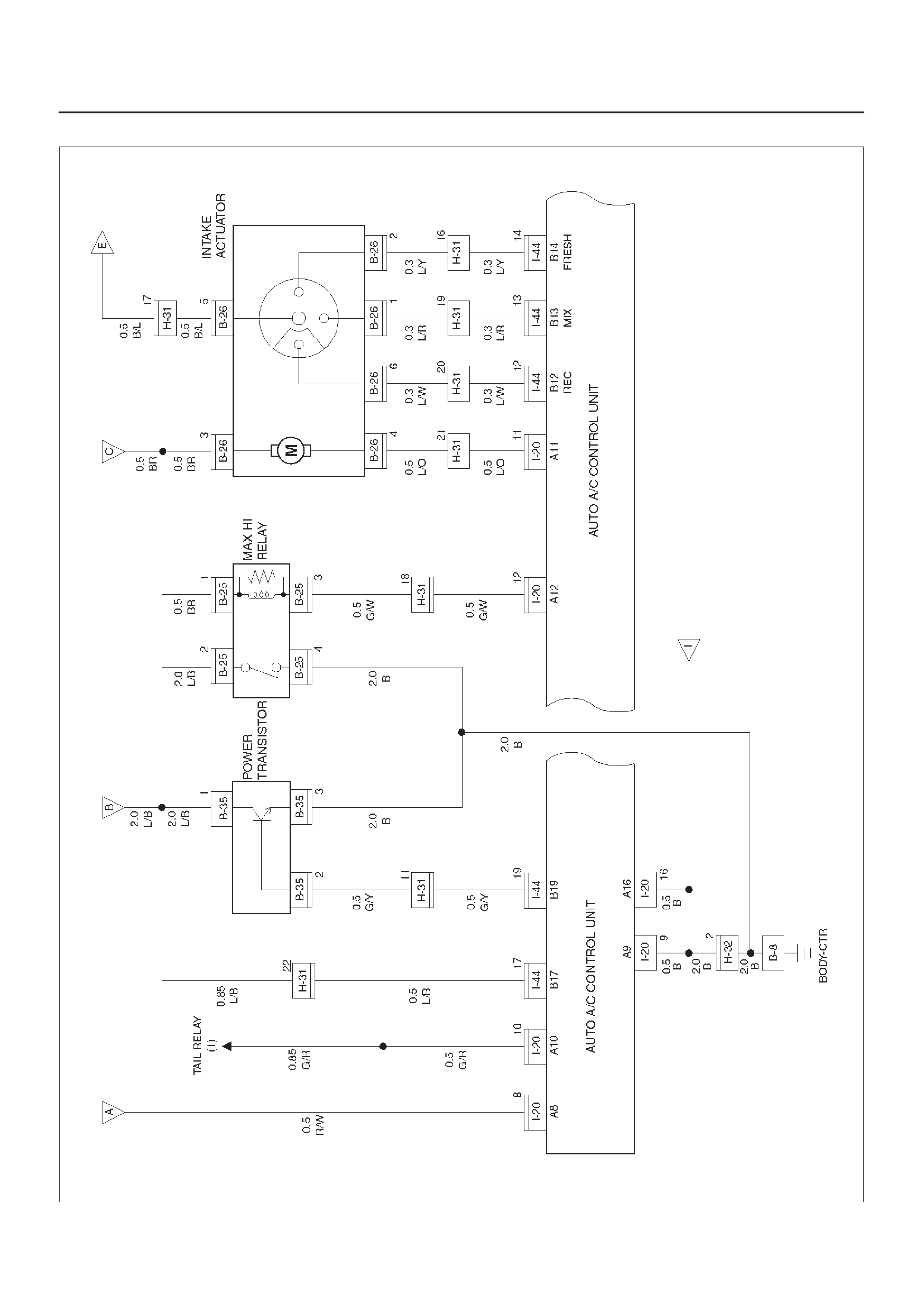
Circuit Diagram–2
D08RX146
Circuit Diagram–3
D08RX147
Circuit Diagram–4
D08RX148
Circuit Diagram–5
D08RX144
Circuit Diagram–6
D08RX143
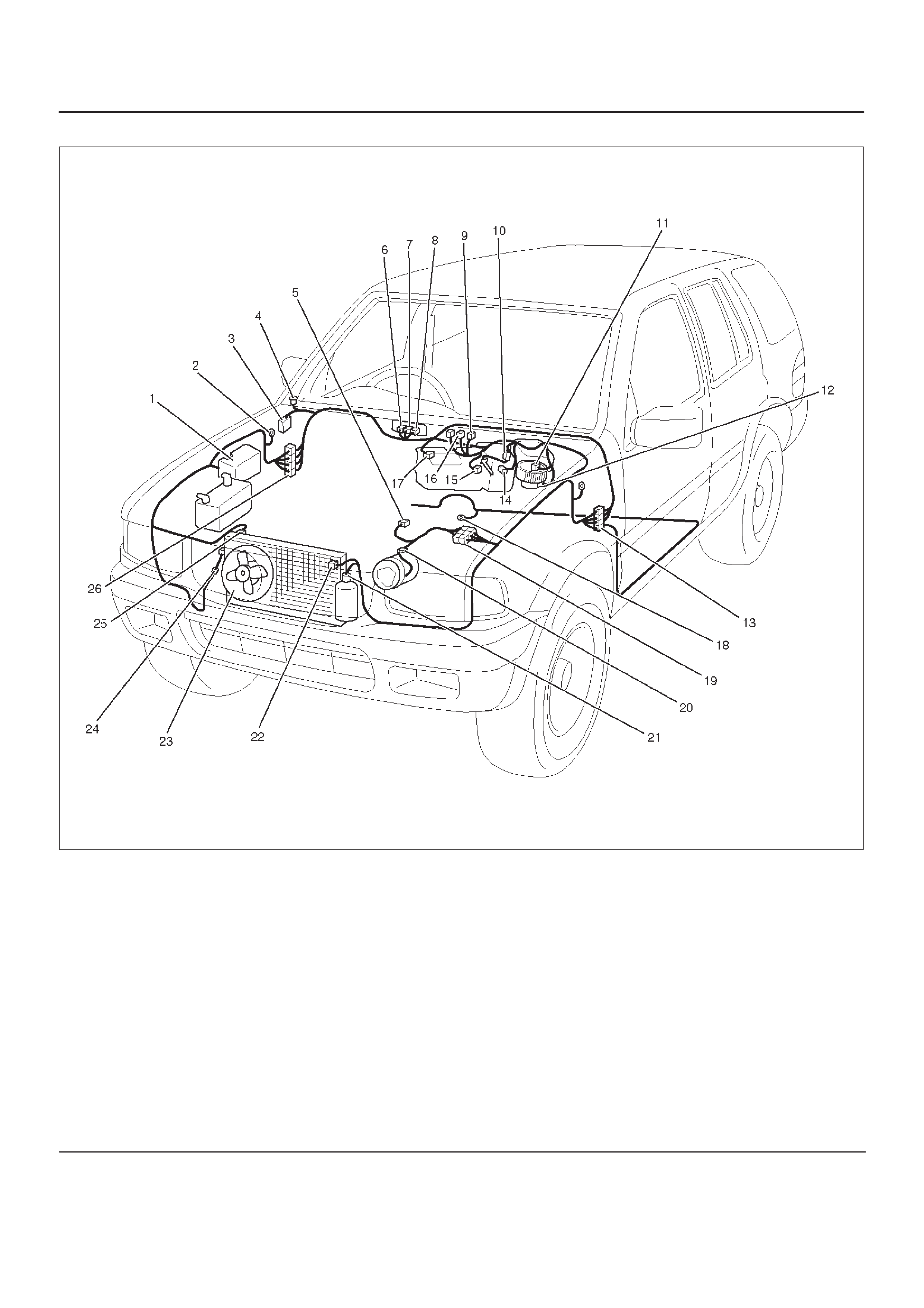
Parts Location
D08RX270
Legend
(1) Relay & Fuse Box (Engine Room)
(2) C–36
(3) Relay & Fuse Box (Instrument Panel)
(4) I–6
(5) E–19
(6) I–40
(7) I–20
(8) I–4
(9) C–45
(10) B–26
(11) B–25
(12) B–5
(13) H–15, H–16, H–17, H–31
(14) B–27
(15) B–18
(16) C–45
(17) C–48
(18) B–8
(19) H–6
(20) E–3
(21) C–11
(22) C–8
(23) Condenser Fan
(24) C–24
(25) C–7
(26) H–14, H–32

Sunroof
General Description
The circuit consists of the starter switch, sunroof switch,
sunroof control unit, limit switch, and sunroof motor.
When the sunroof switch is turned on, the battery voltage
is applied to the sunroof control unit through the circuit
breaker and the power window relay on the circuit.
Accordingly, when the sunroof switch is set to “Open” or
“Close” position, the open or close relay incorporated into
the control unit is activated to change the rotational
direction of the sunroof motor to open or close the
sunroof.
Also, the operational process (full close → limit stop → full
open → safety stop → full close) of the sunroof is
controlled by the control unit in accordance with signals
received from the sunroof switch and limit switch.
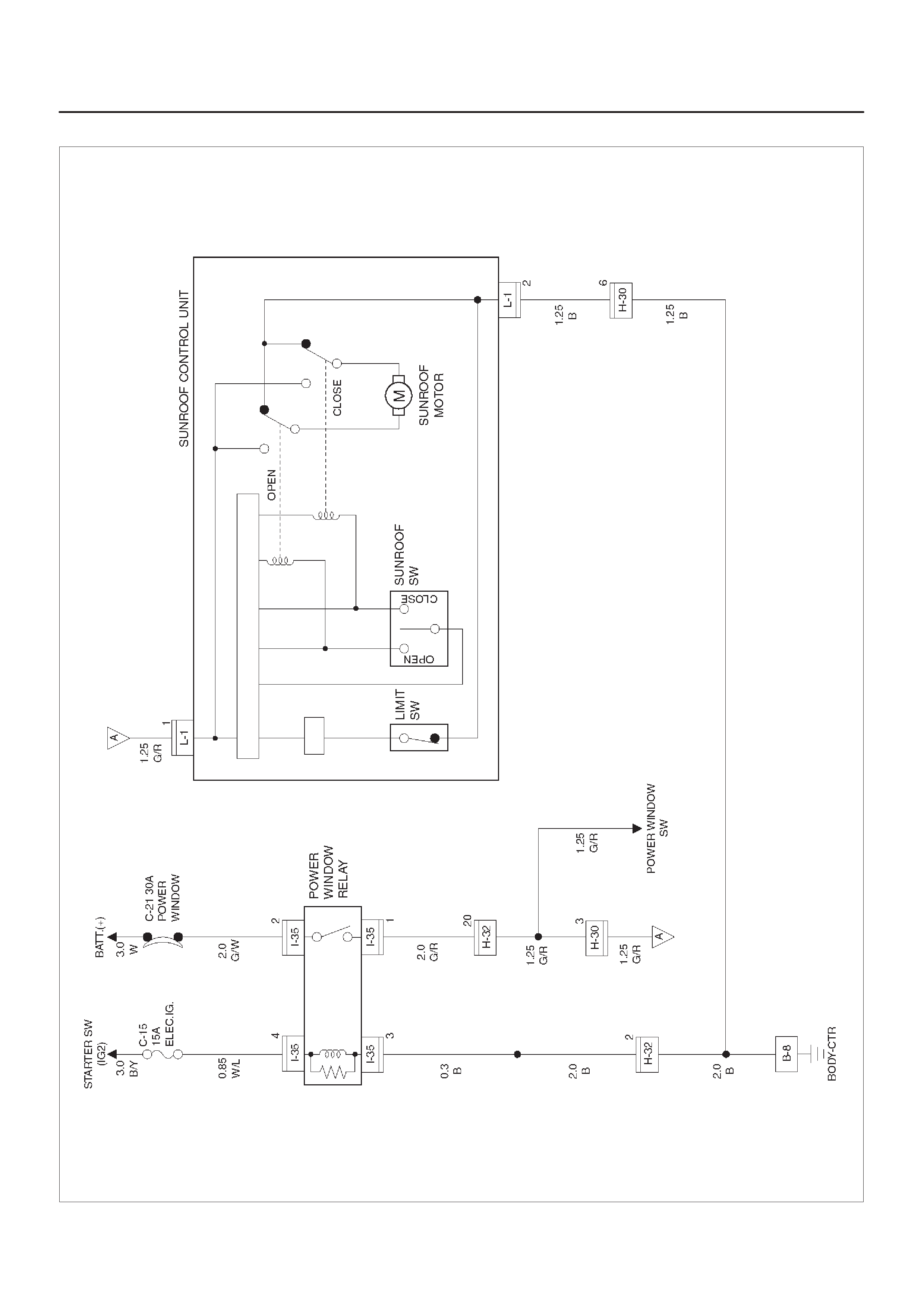
Circuit Diagram–1
D08RX269
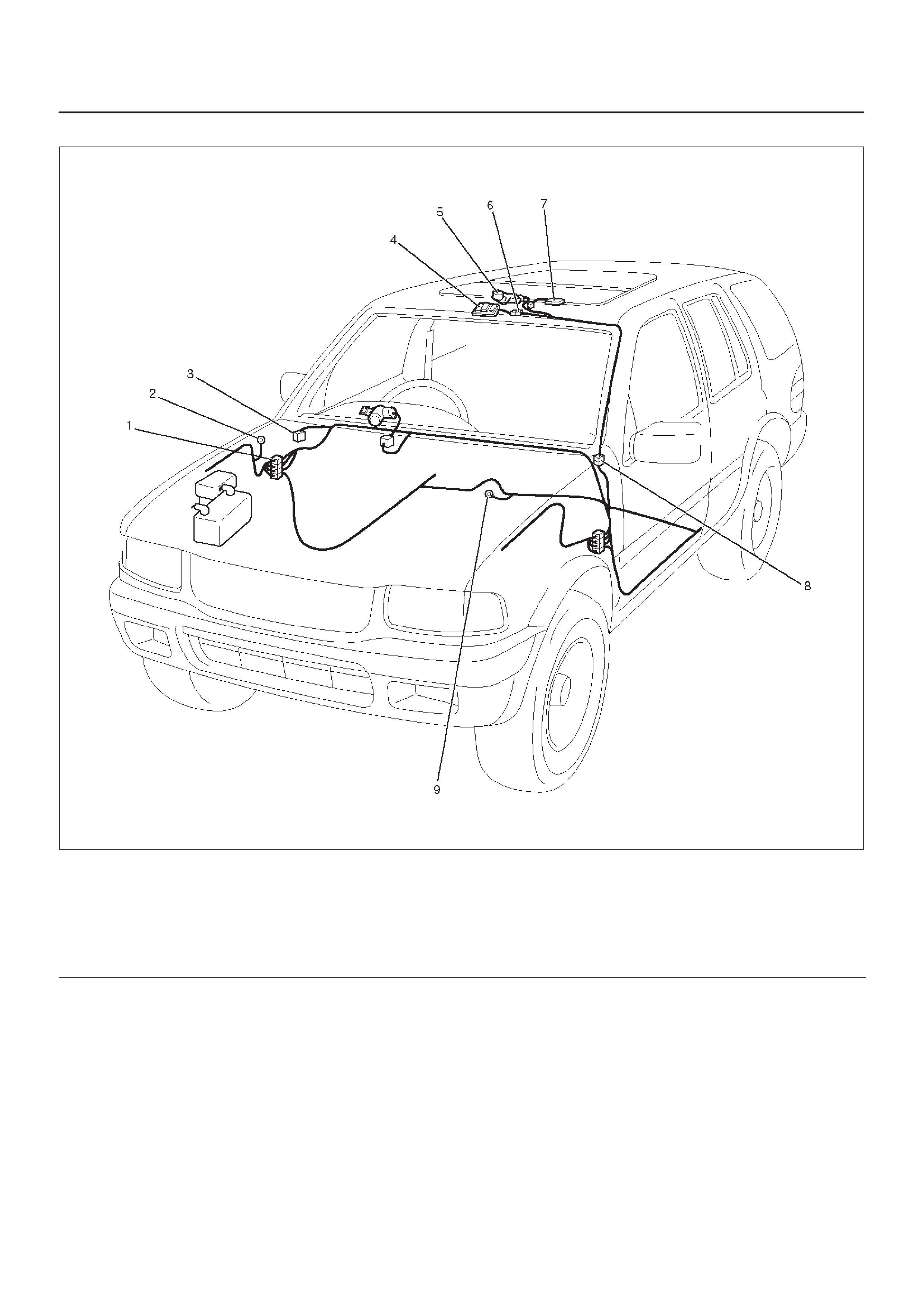
Parts Location
D08RWD23–1
Legend
(1) H–32
(2) C–36
(3) Relay & Fuse Box (Instrument Panel)
(4) Sunroof Switch
(5) Sunroof Motor
(6) L–1
(7) Sunroof Control Unit
(8) H–30
(9) B–8
Diagnosis
Sunroof Inoperative
Step Action Value(s) Yes No
11. Disconnect the sunroof connector L–1.
2. Turn the starter switch on.
Is the battery voltage applied between the harness side
connector L–1 terminal 1 and the ground? Approx. 12V Go to Step 3 Go to Step 2
2Repair an open circuit between the power widow relay
and the sunroof control unit.
Is the action complete? — Verify reapir —
3Replace the sunroof control unit.
Is the action complete? — Verify repair —
Safety Stop Mechanism Inoperative
Step Action Value(s) Yes No
1Replace the sunroof control unit.
Is the action complete? — Verify repair —

Supplemental Restraint System (SRS) – Air Bag
General Description
The circuit consists of Sensing and Diagnostic Module
(SDM), driver’s air bag assembly, SRS coil assembly,
passenger’s air bag assembly, and “AIR BAG” warning
light. SDM, SRS coil assembly (driver side only), driver air
bag assembly, passenger air bag assembly and
connector wire make up the deployment loops. The
function of the deployment loops is to supply current
through air bag assembly, which will cause deployment of
the air bags in the event of a frontal crash of sufficient
force, up to 30 degrees off the center line of the vehicle.
The air bag assemblies are only supplied enough current
to deploy when the SDM detects vehicle velocity changes
severe enough to warrant deployment.
The SDM contains a sensing device which converts
vehicle velocity changes to an electrical signal.
The electrical signal generated is processed by the SDM
and then compared to a value stored in memory. When
the generated signal exceeds the stored value, the SDM
will cause current to flow through the air bag assembly
deploying the air bags.
Refer to Supplemental Restraint System (SRS) and
Restraint Control System in Restraints.
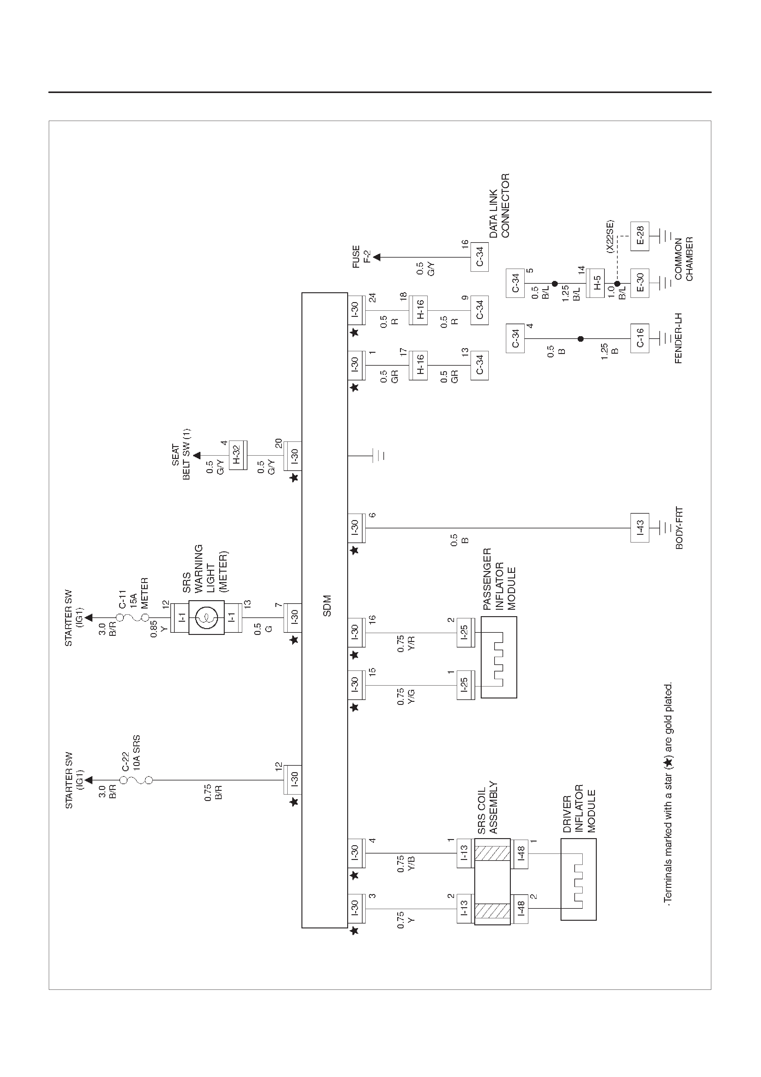
Circuit Diagram
D08RX268
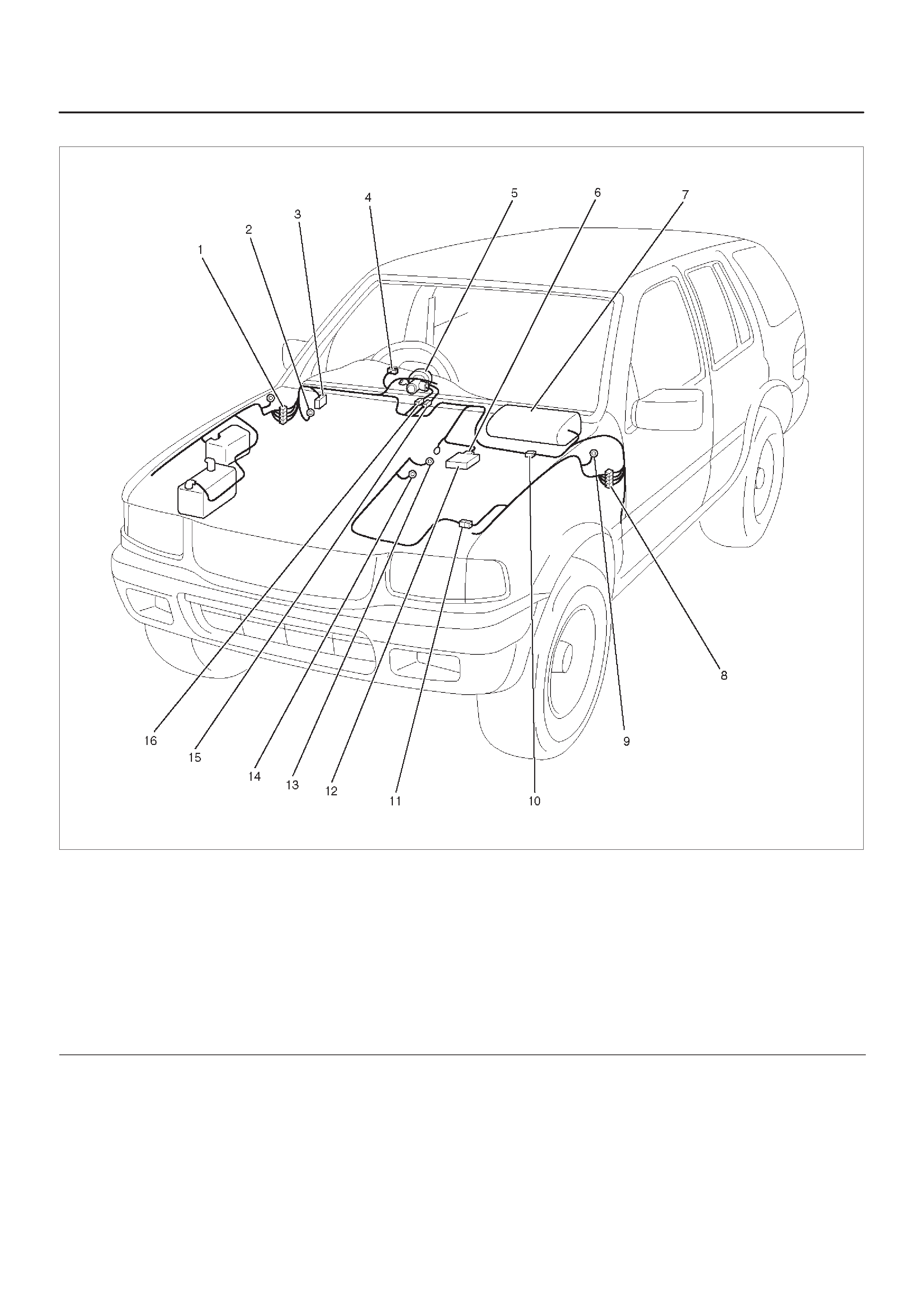
Parts Location
D08RX267
Legend
(1) H–32
(2) I–43
(3) C–34
(4) I–1
(5) SRS Coil Assembly
(6) I–30
(7) Passenger Air Bag Assembly
(8) H–16
(9) C–16
(10) I–25
(11) H–5
(12) SDM
(13) E–28 (X22SE)
(14) E–30 (6VD1)
(15) I–32
(16) I–49

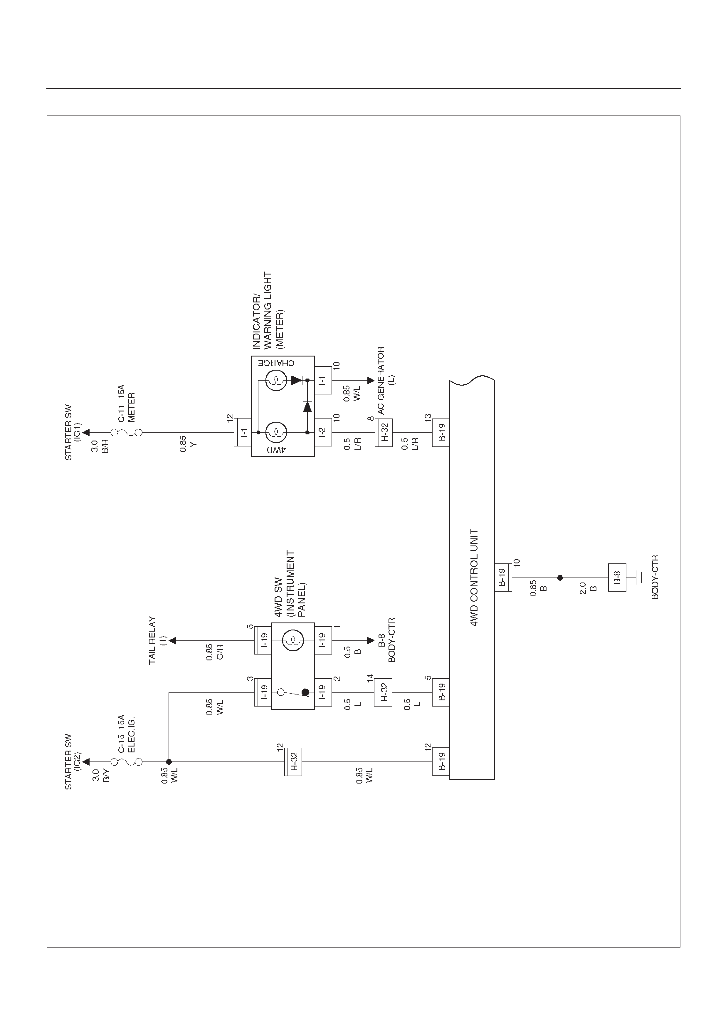
Circuit Diagram–1
D08RX272
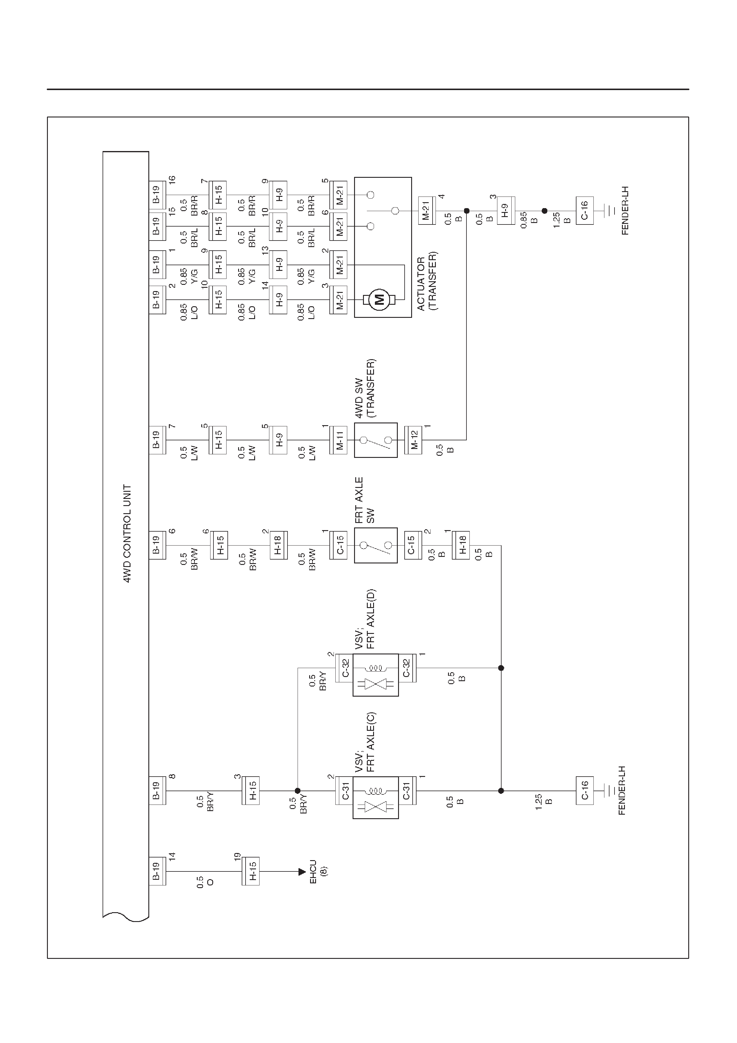
Circuit Diagram–2 (6VD1)
D08RX274
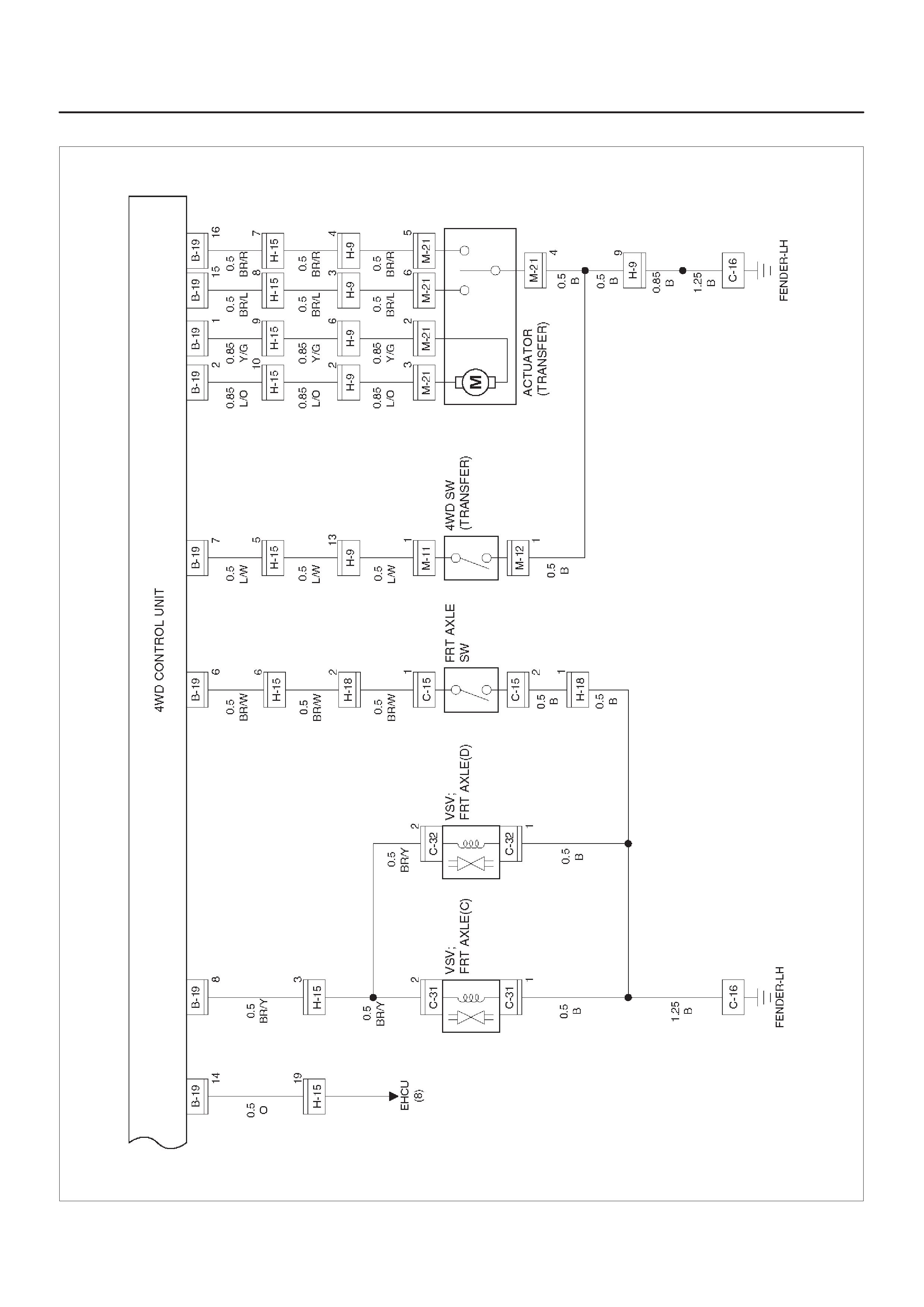
Circuit Diagram–2 (X22SE)
D08RX273
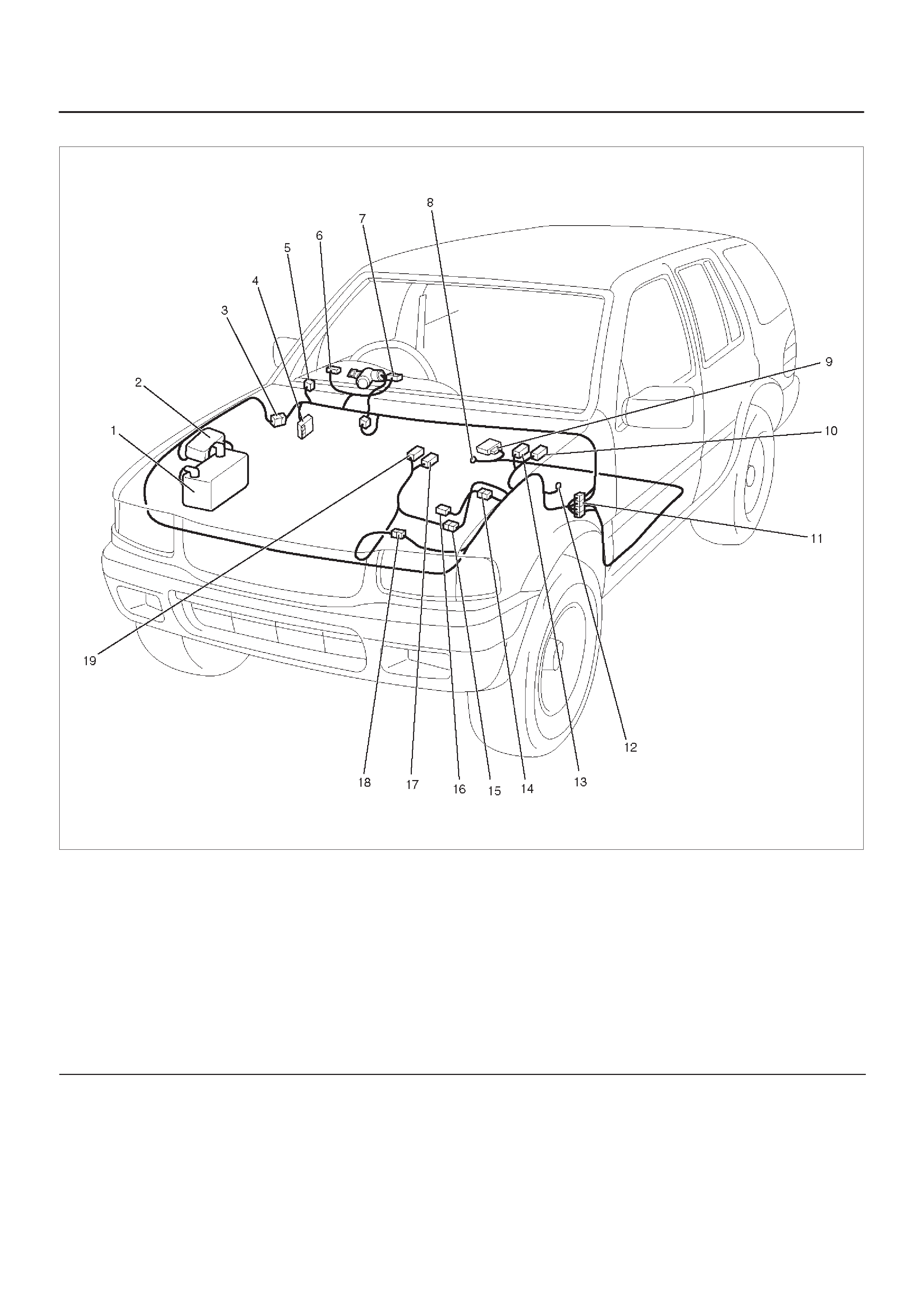
Parts Location
D08RX290
Legend
(1) Battery
(2) Relay & Fuse Box (Engine Room)
(3) H–32
(4) Relay & Fuse Box (Instrument Panel)
(5) I–19
(6) I–1
(7) I–2
(8) B–8
(9) B–19
(10) C–32
(11) H–15
(12) C–16
(13) C–31
(14) H–18
(15) H–9 (X22SE)
(16) C–15
(17) M–21
(18) H–9 (6VD1), H–10
(19) M–11, M–12
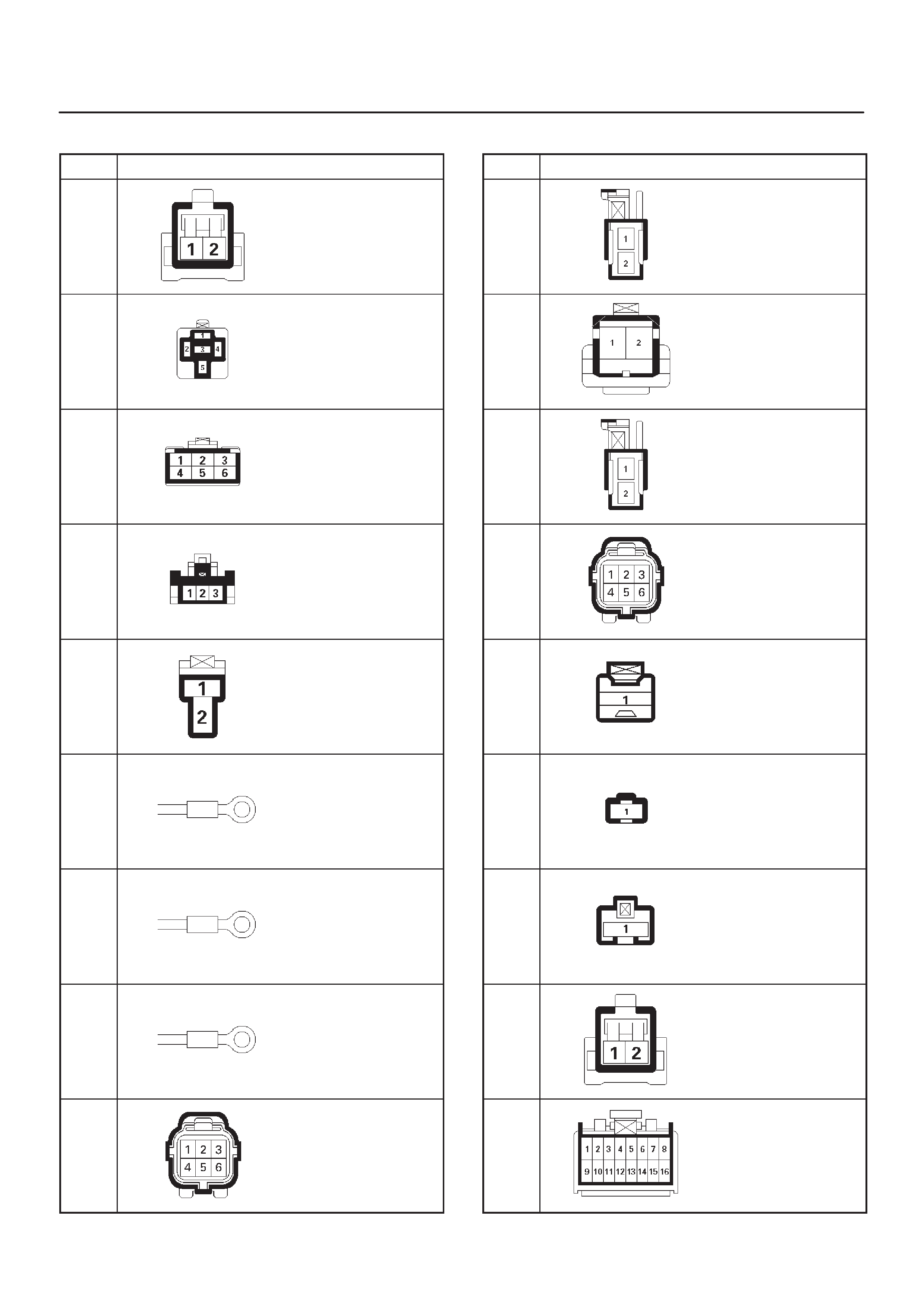
Harness Connector Faces
No. Connector face
B-1
B-2
B-3
B-4
B-5
B-6
B-7
B-8
B-9
No. Connector face
B-10
B-11
B-12
B-13
B-14
B-15
B-16
B-17
B-18
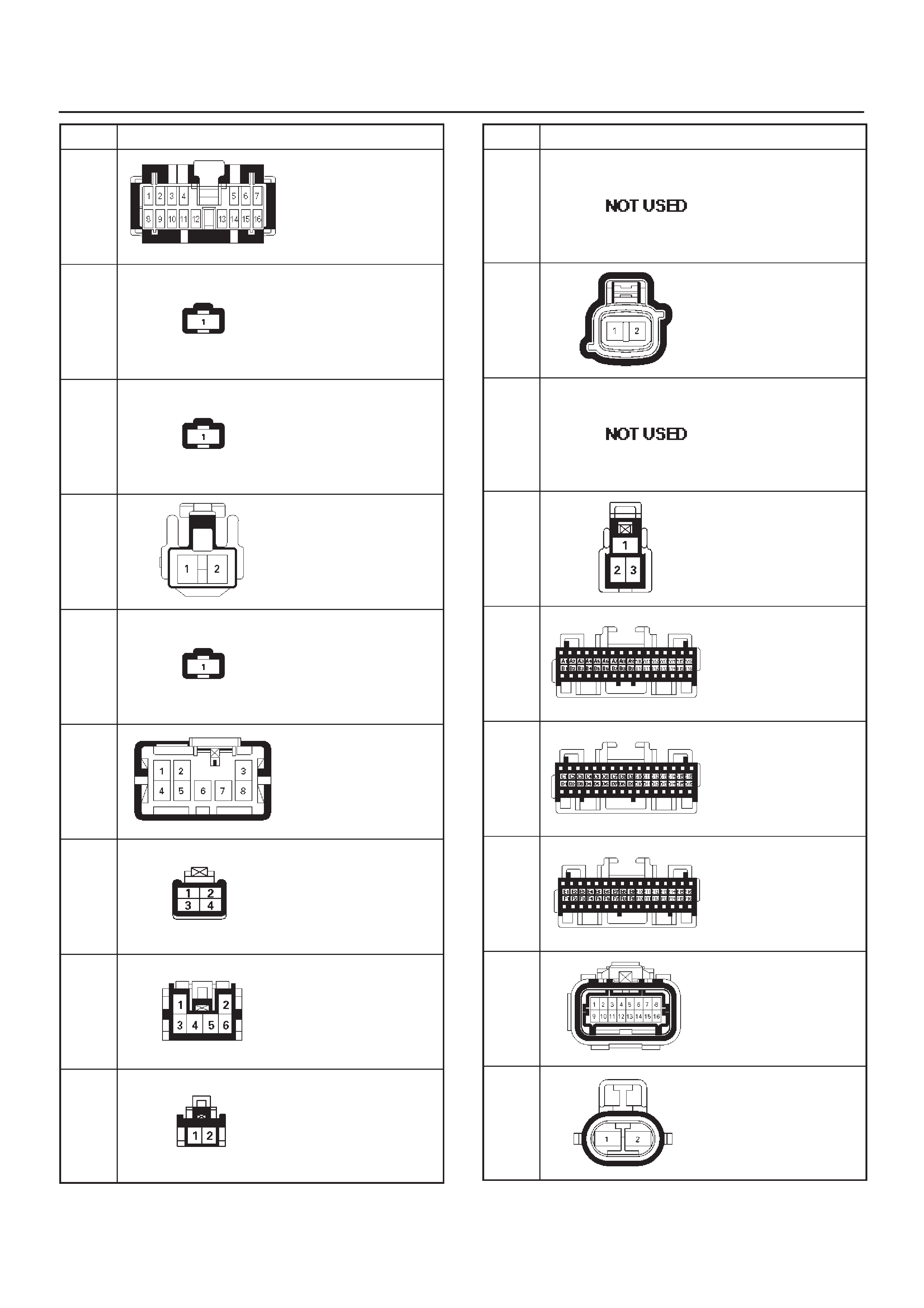
No. Connector face
B-19
B-20
B-21
B-22
B-23
B-24
B-25
B-26
B-27
No. Connector face
B-28
∼
B-29
B-30
B-31
∼
B-34
B-35
C-1
C-2
C-3
C-4
C-5
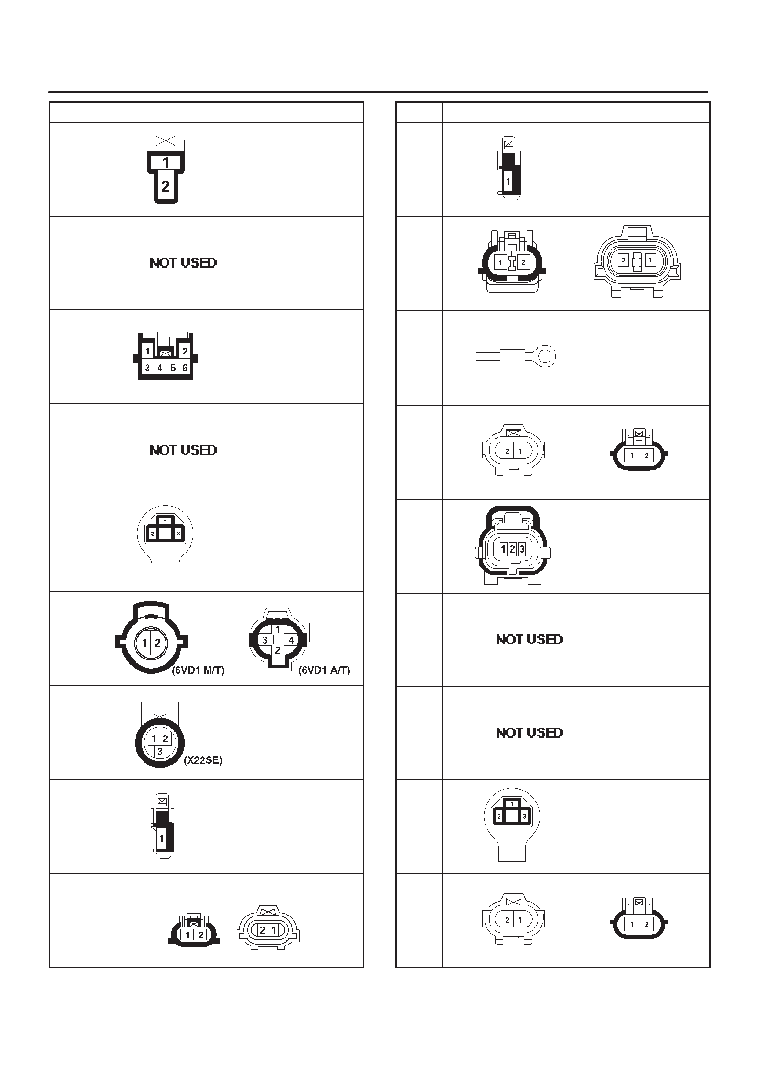
No. Connector face
C-6
C-7
C-8
C-9
C-10
C-11
C-11
C-12
C-13
No. Connector face
C-14
C-15
C-16
C-17
C-18
C-19
C-20
C-21
C-22
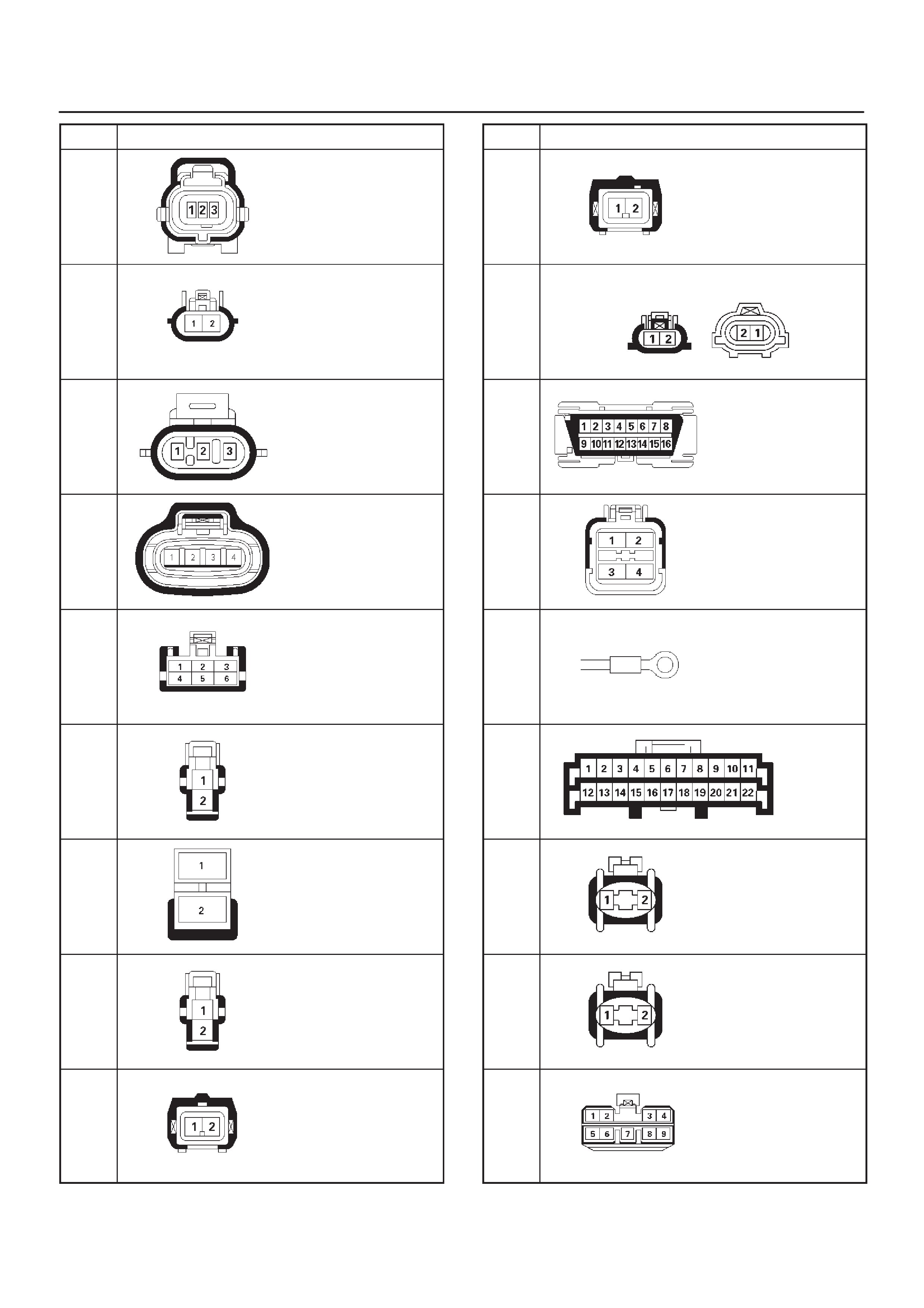
No. Connector face
C-23
C-24
C-25
C-26
C-27
C-28
C-29
C-30
C-31
No. Connector face
C-32
C-33
C-34
C-35
C-36
C-37
C-40
C-43
C-45
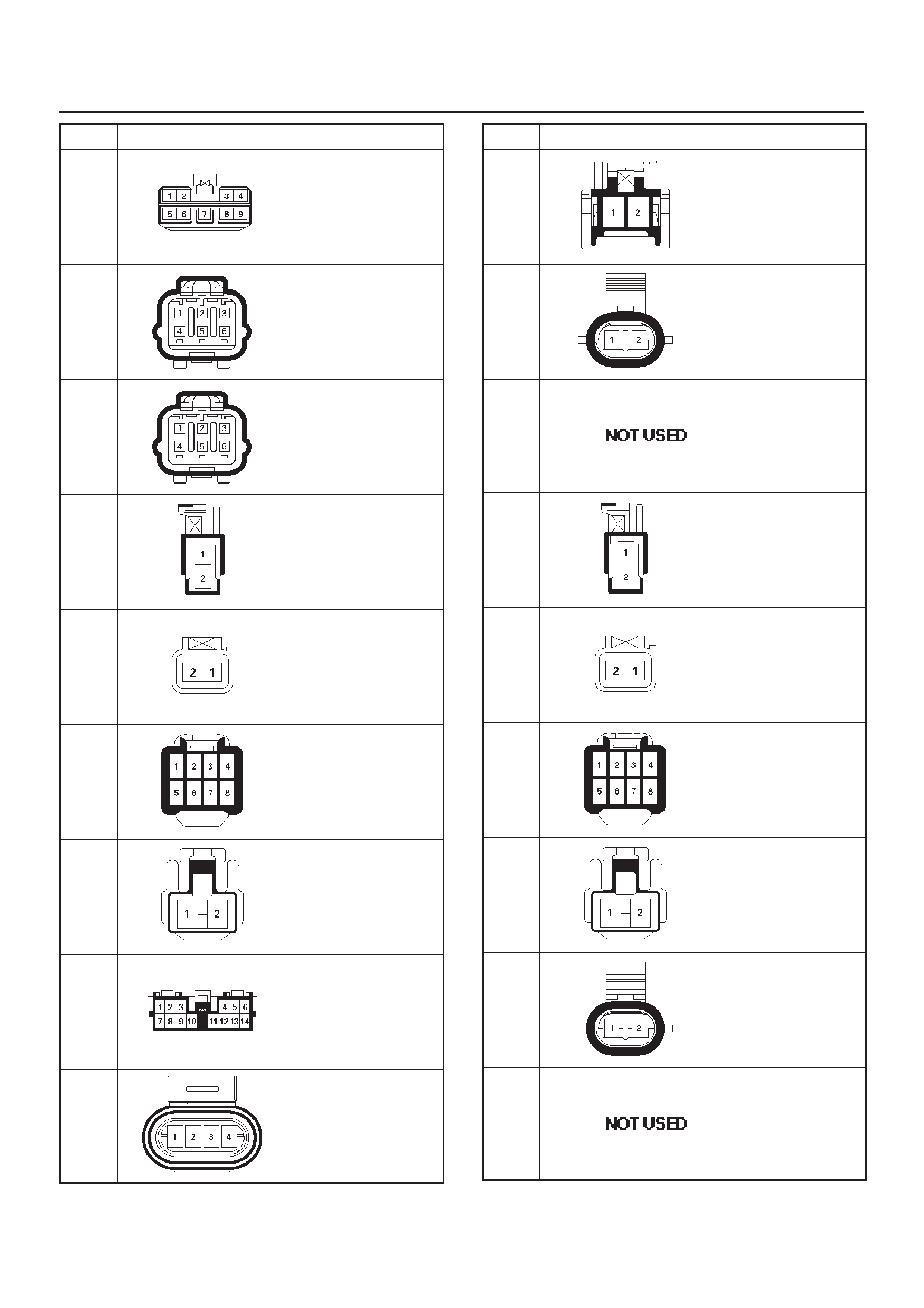
No. Connector face
C-48
C-49
C-50
D-1
D-2
D-3
D-4
D-5
D-6
No. Connector face
D-7
D-8
D-9
D-10
D-11
D-12
D-13
D-14
D-15
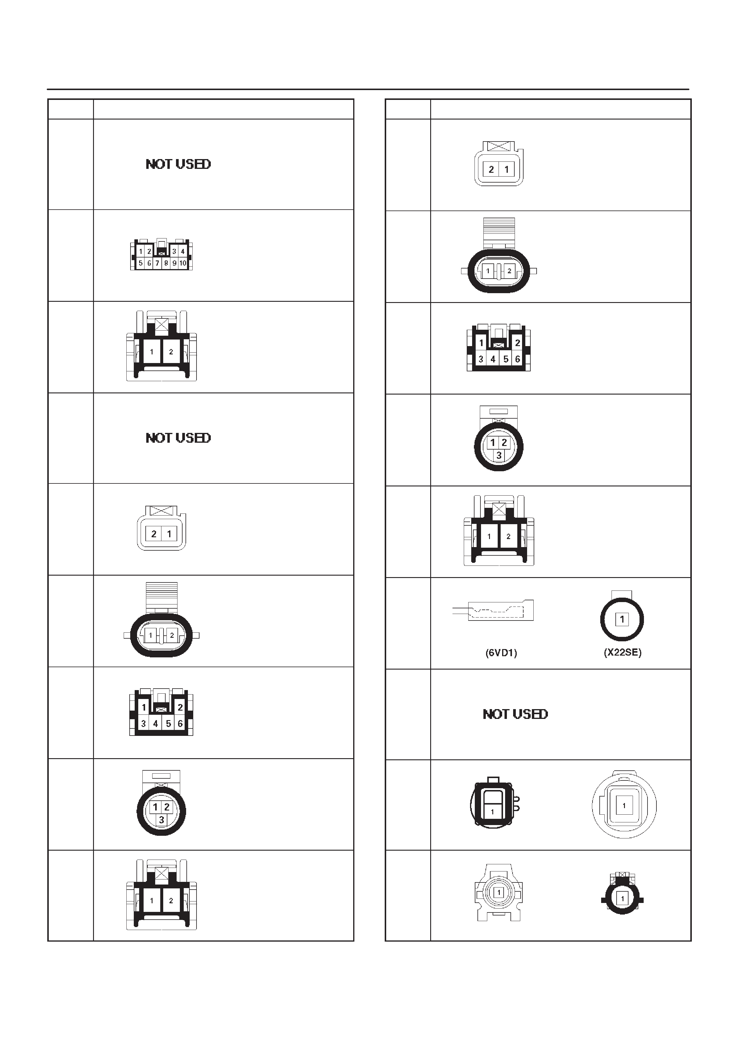
No. Connector face
D-16
D-17
D-18
D-19
D-20
D-21
D-22
D-23
D-24
No. Connector face
D-25
D-26
D-27
D-28
D-29
E-1
E-2
E-3
E-4
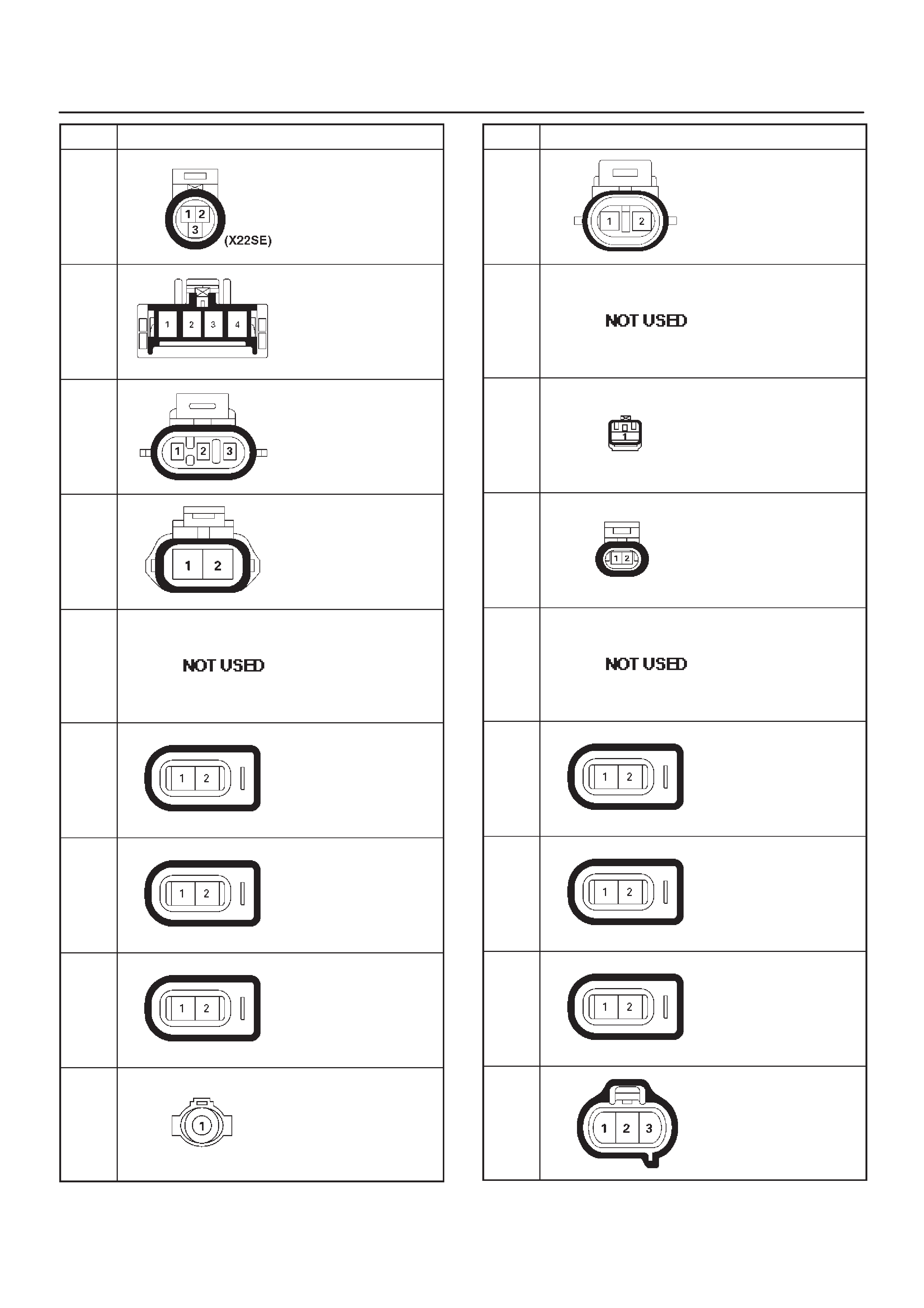
No. Connector face
E-5
E-6
E-7
E-8
E-9 ∼
E-10
E-11
E-12
E-13
E-14
No. Connector face
E-14
E-15
∼
E-18
E-19
E-20
E-21
∼
E-23
E-24
E-25
E-26
E-27
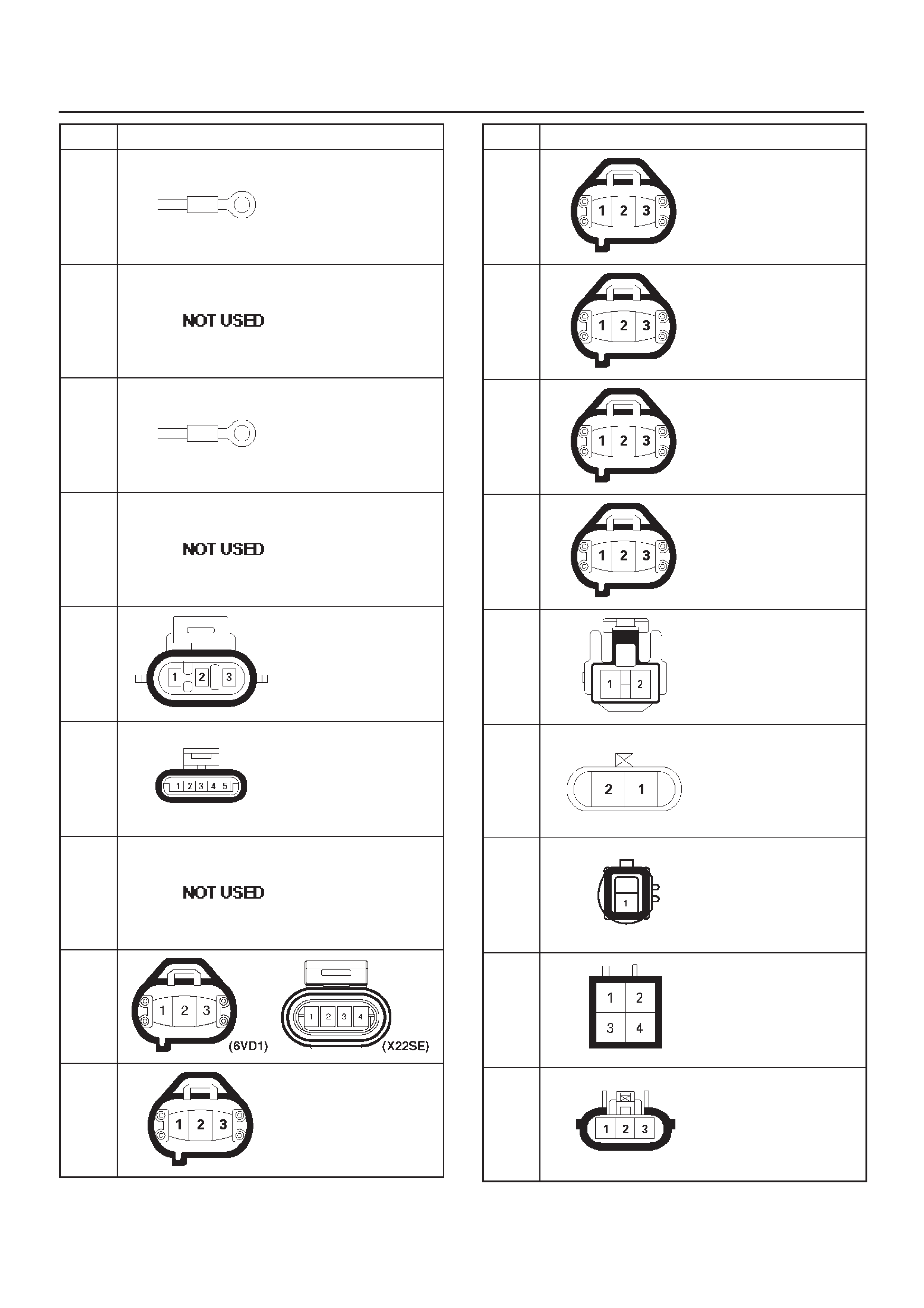
No. Connector face
E-28
E-29
E-30
E-31
E-32
E-33
E-34
∼
E-36
E-37
E-38
No. Connector face
E-39
E-40
E-41
E-42
E-43
E-44
E-45
F-1
F-2
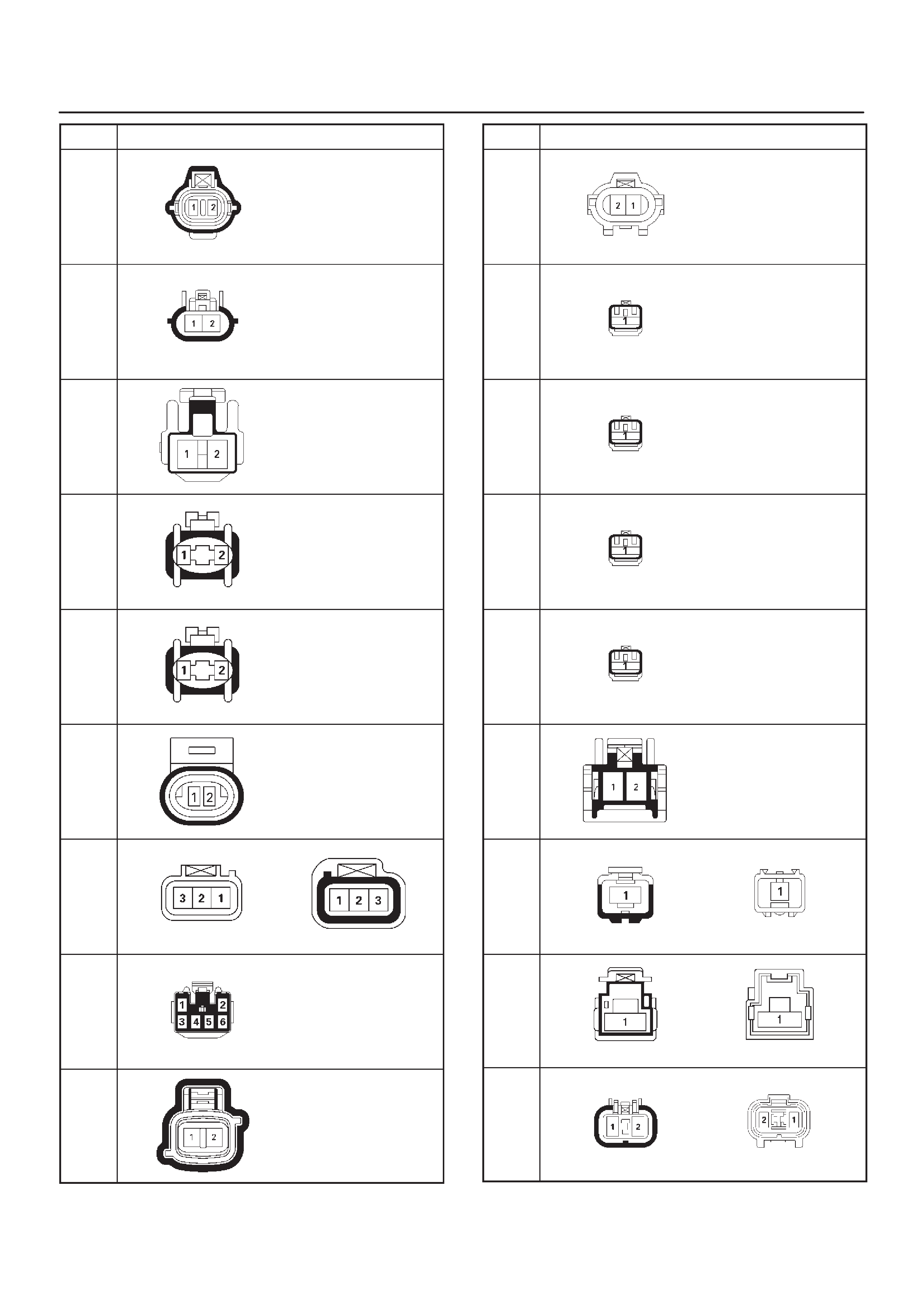
No. Connector face
F-3
F-4
G-1
G-2
G-3
G-4
G-5
G-6
G-7
No. Connector face
G-8
G-9
G-10
G-11
G-12
G-13
H-1
H-2
(X22
SE)
H-2
(6VD
1)
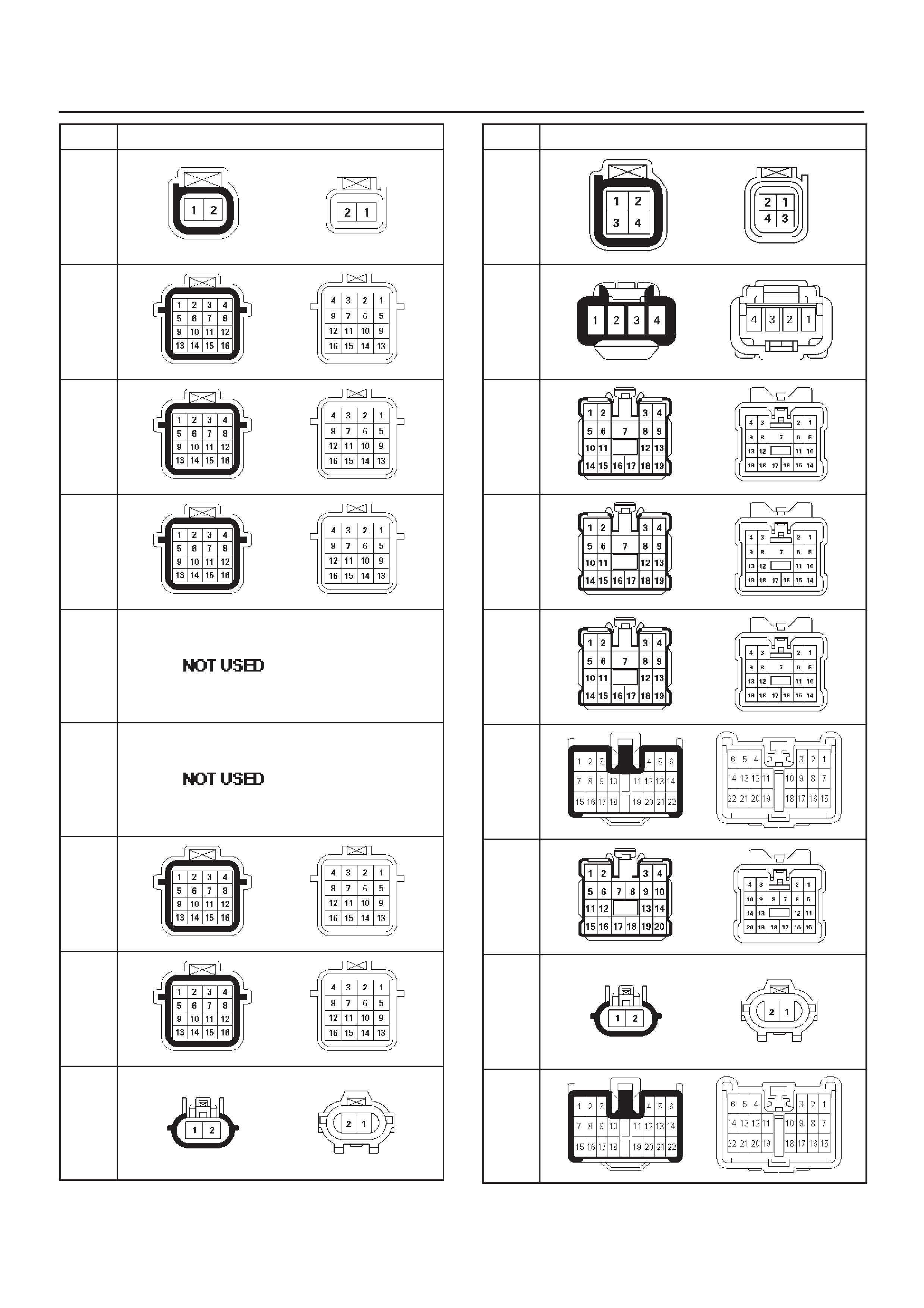
No. Connector face
H-3
H-4
H-5
H-6
H-7
H-8
H-9
H-10
(A/T)
H-10
(M/T)
No. Connector face
H-11
H-12
H-13
H-14
H-15
H-16
H-17
H-18
H-19
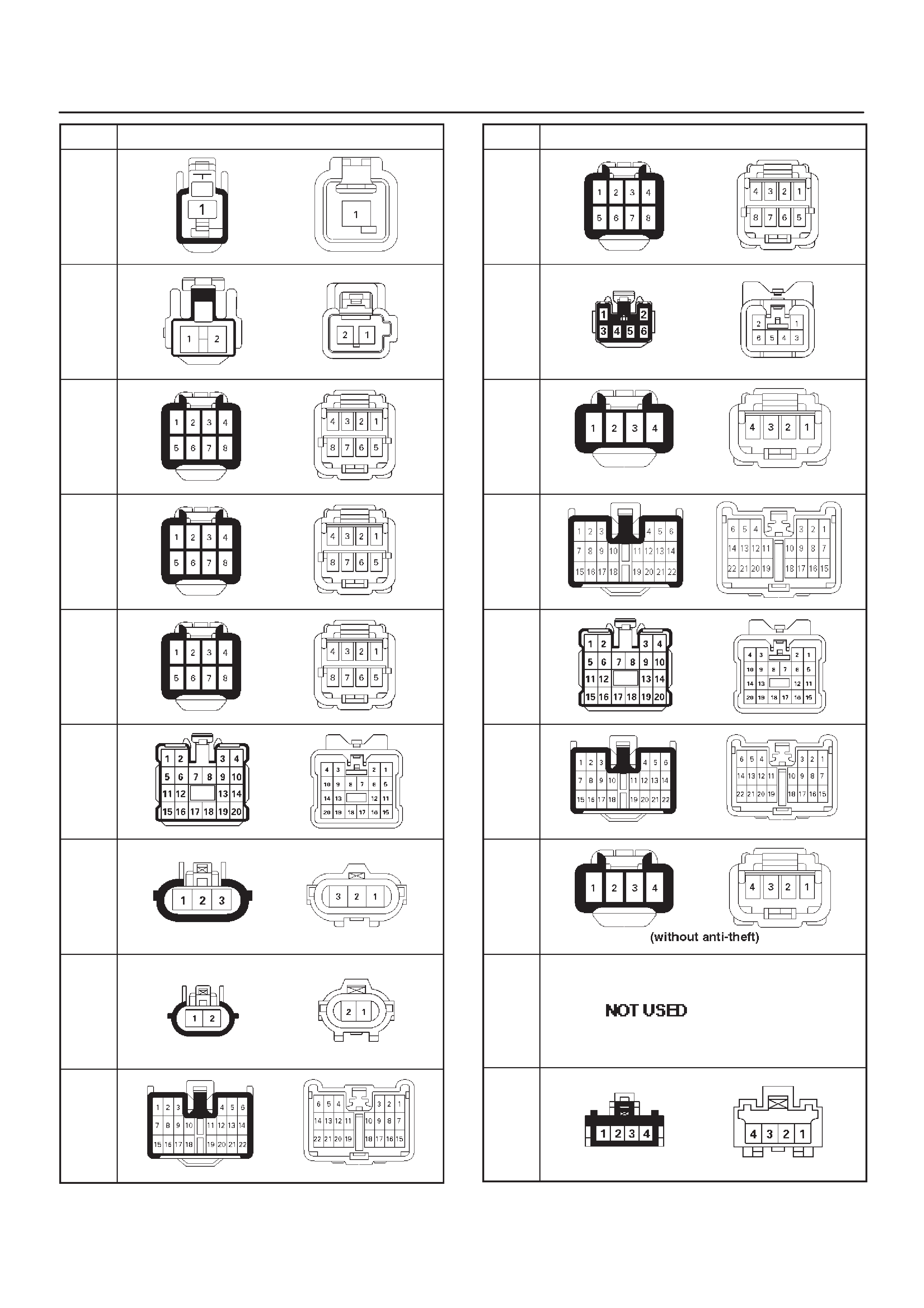
No. Connector face
H-20
H-21
H-22
H-23
H-24
H-25
H-26
H-27
H-28
No. Connector face
H-29
H-30
(4Do
or)
H-30
(2Do
or)
H-31
H-32
H-33
H-34
H-35
∼
H-36
H-37
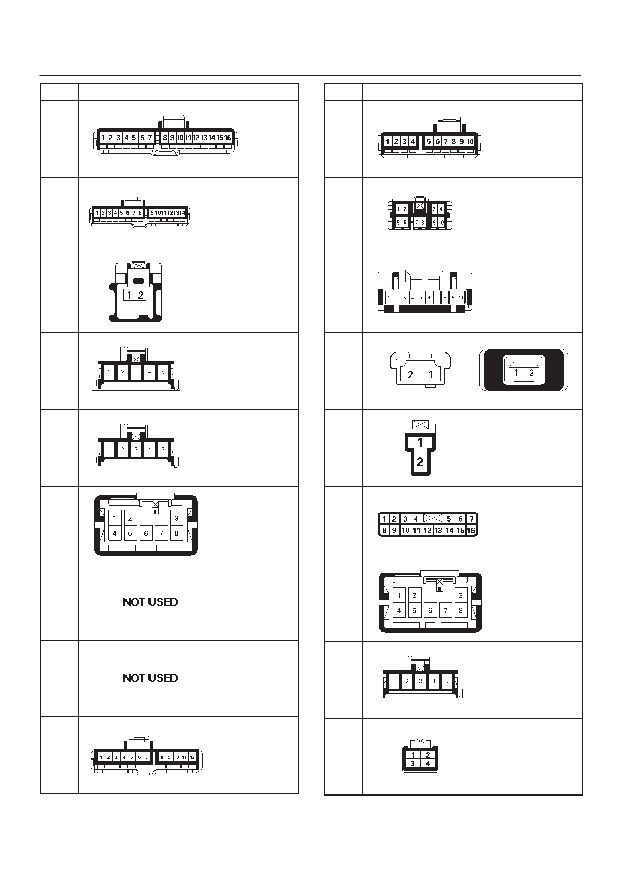
No. Connector face
I-1
I-2
I-3
I-4
I-5
I-6
I-7
I-8
I-9
No. Connector face
I-10
I-11
I-12
I-13
I-14
I-15
I-16
I-17
I-18
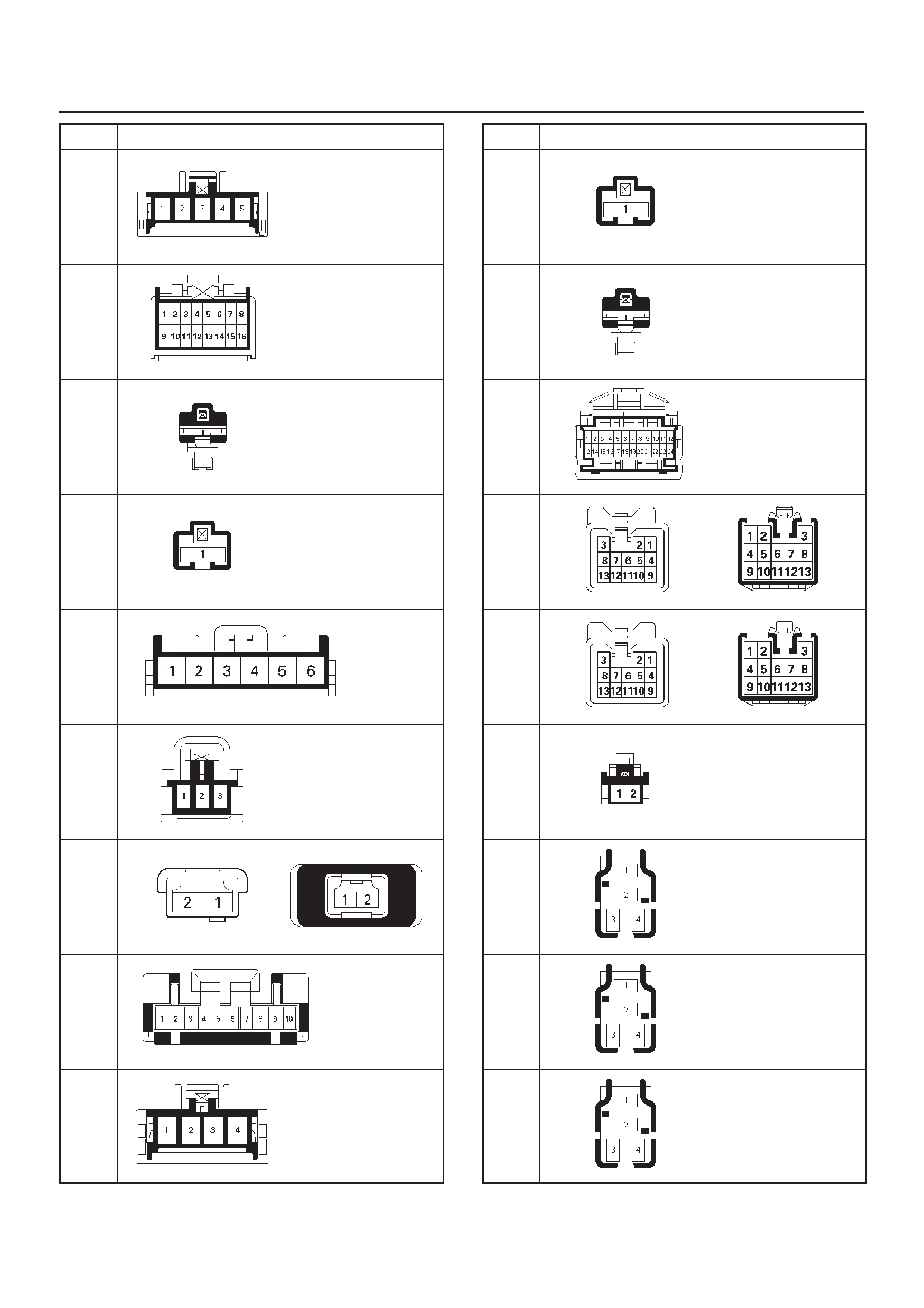
No. Connector face
I-19
I-20
I-21
I-22
I-23
I-24
I-25
I-26
I-27
No. Connector face
I-28
I-29
I-30
I-31
I-32
I-33
I-34
I-35
I-36
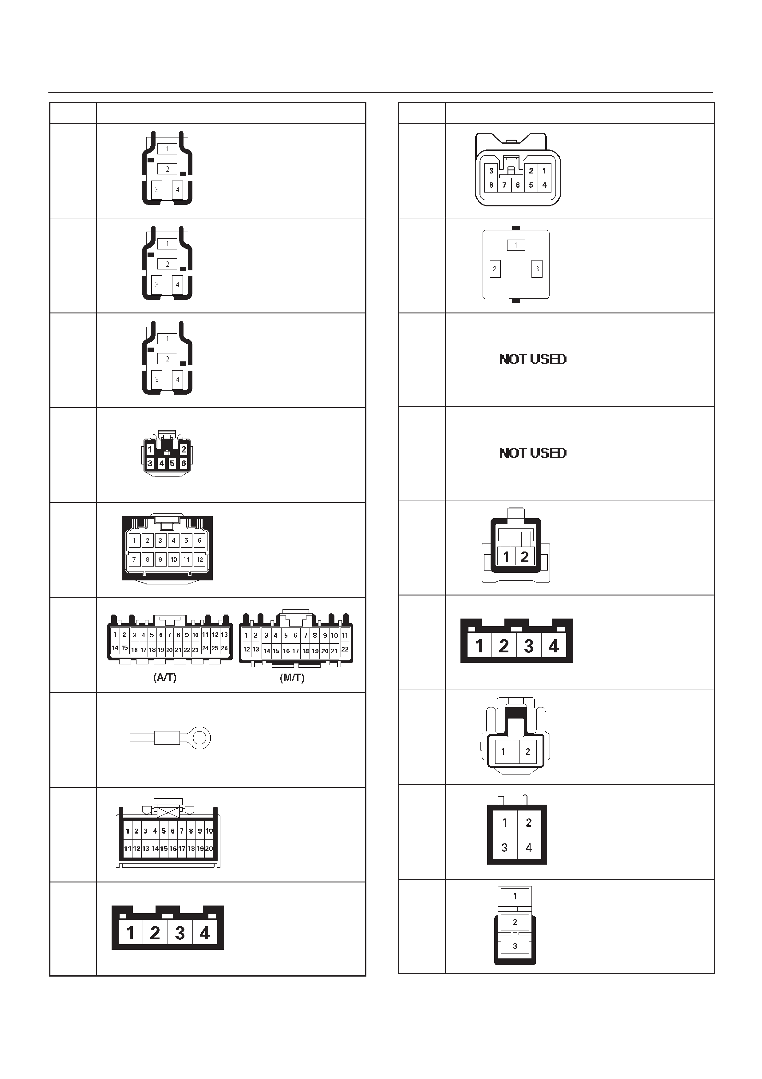
No. Connector face
I-37
I-38
I-39
I-40
I-41
I-42
I-43
I-44
I-45
No. Connector face
I-46
I-47
I-48
I-49
I-50
I-51
L-1
L-2
L-3
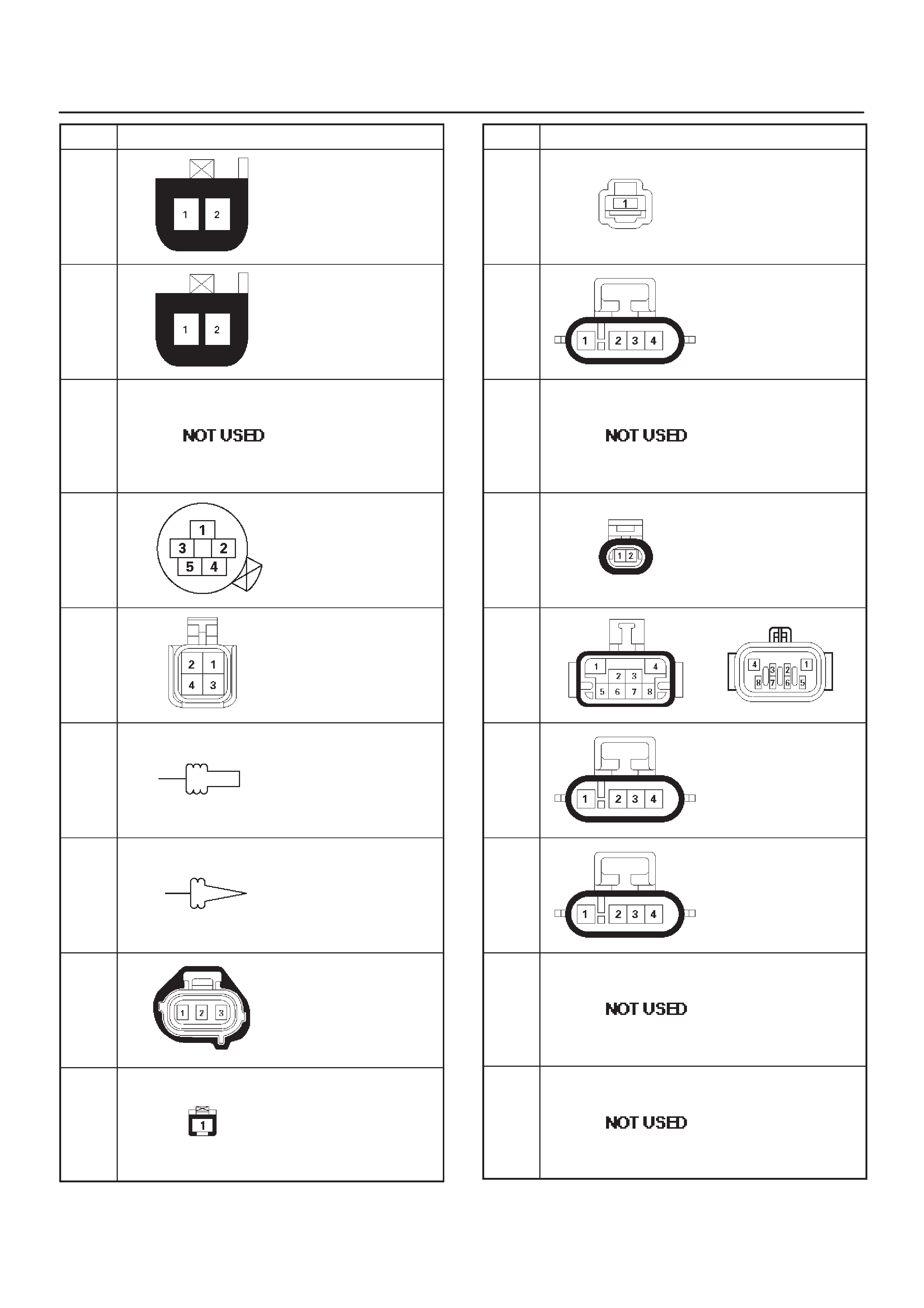
No. Connector face
L-4
L-5
M-1
∼
M-5
M-6
M-7
M-8
M-9
M-10
M-11
No. Connector face
M-12
M-13
M-14
M-15
M-16
M-17
M-18
M-19
M-20
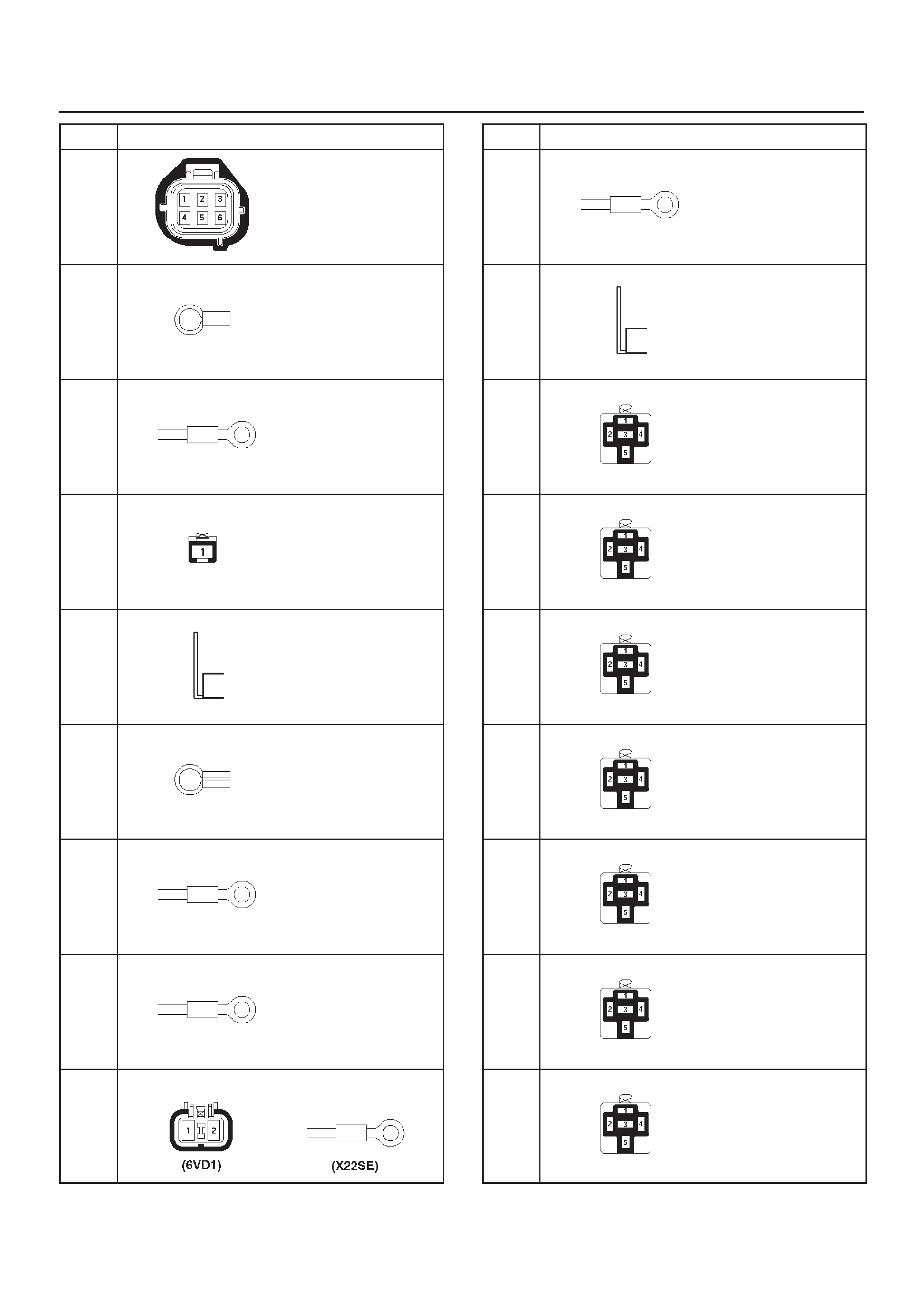
No. Connector face
M-21
P-1
P-2
P-3
P-4
P-5
P-6
P-7
P-8
No. Connector face
P-9
P-10
X-1
X-2
X-3
X-4
X-5
X-6
X-7
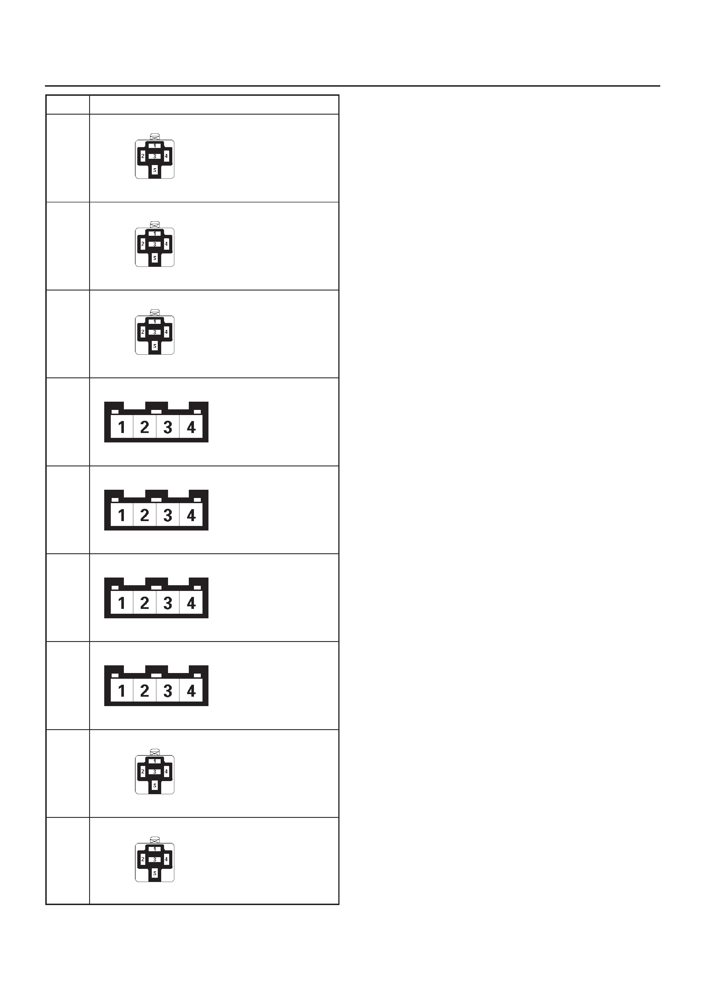
No. Connector face
X-8
X-9
X-10
X-11
X-12
X-13
X-14
X-15
X-16