
SECTION 8E - METER AND GAUGE
Service Precaution
Meter Assembly
General Description
Layout for Meters/Gauges, Warning Lights,
Indicator Lights and Illumination
Lights
Table for Meter/Gauge Connector
Terminal Connections
Removal
Installation
Warning Light Bulb, Indicator Light Bulb,
Illumination Light Bulb, A/T Shift Indicator
Light Bulb
Removal
Installation
Vehicle Speed Sensor
Removal
Installation
Fuel Tank Unit
Removal
Installation
Main Data and Specification
Service Precaution
WARNING: THIS VEHICLE HAS A SUPPLEMENTAL
RESTRAINT SYSTEM (SRS). REFER TO THE SRS
COMPONENT AND WIRING LOCATION VIEW IN
ORDER TO DETERMINE WHETHER YOU ARE
PERFORMING SERVICE ON OR NEAR THE SRS
COMPONENTS OR THE SRS WIRING. WHEN YOU
ARE PERFORMING SERVICE ON OR NEAR THE
SRS COMPONENTS OR THE SRS WIRING, REFER
TO THE SRS SERVICE INFORMATION. FAILURE TO
FOLLOW WARNINGS COULD RESULT IN POSSIBLE
AIR BAG DEPLOYMENT, PERSONAL INJURY, OR
OTHERWISE UNNEEDED SRS SYSTEM REPAIRS.
CAUTION: Always use the correct fastener in the
proper location. When you replace a fastener, use
ONLY the exact part number for that application.
ISUZU will call out those fasteners that require a
replacement after removal. ISUZU will also call out
the fasteners that require thread lockers or thread
sealant. UNLESS OTHERWISE SPECIFIED, do not
use supplemental coatings (Paints, greases, or
other corr osion inhibitor s) o n threaded fastener s o r
fastener joint interfaces. Generally, such coatings
adversely affect the fastener torque and the joint
clamping force, and may damage the fastener.
When you install fasteners, use the correct
tightening sequence and specifications. Following
these instructions can help you avoid damage to
parts and systems.
Meter Assembly
General Description
The meter assembly has the speedometer, tachometer,
engine coolant temperature gauge, fuel gauge and
warning/indicator lights. These gauges and warning/
indicator lights can be removed and installed from the
back side of meter assembly.
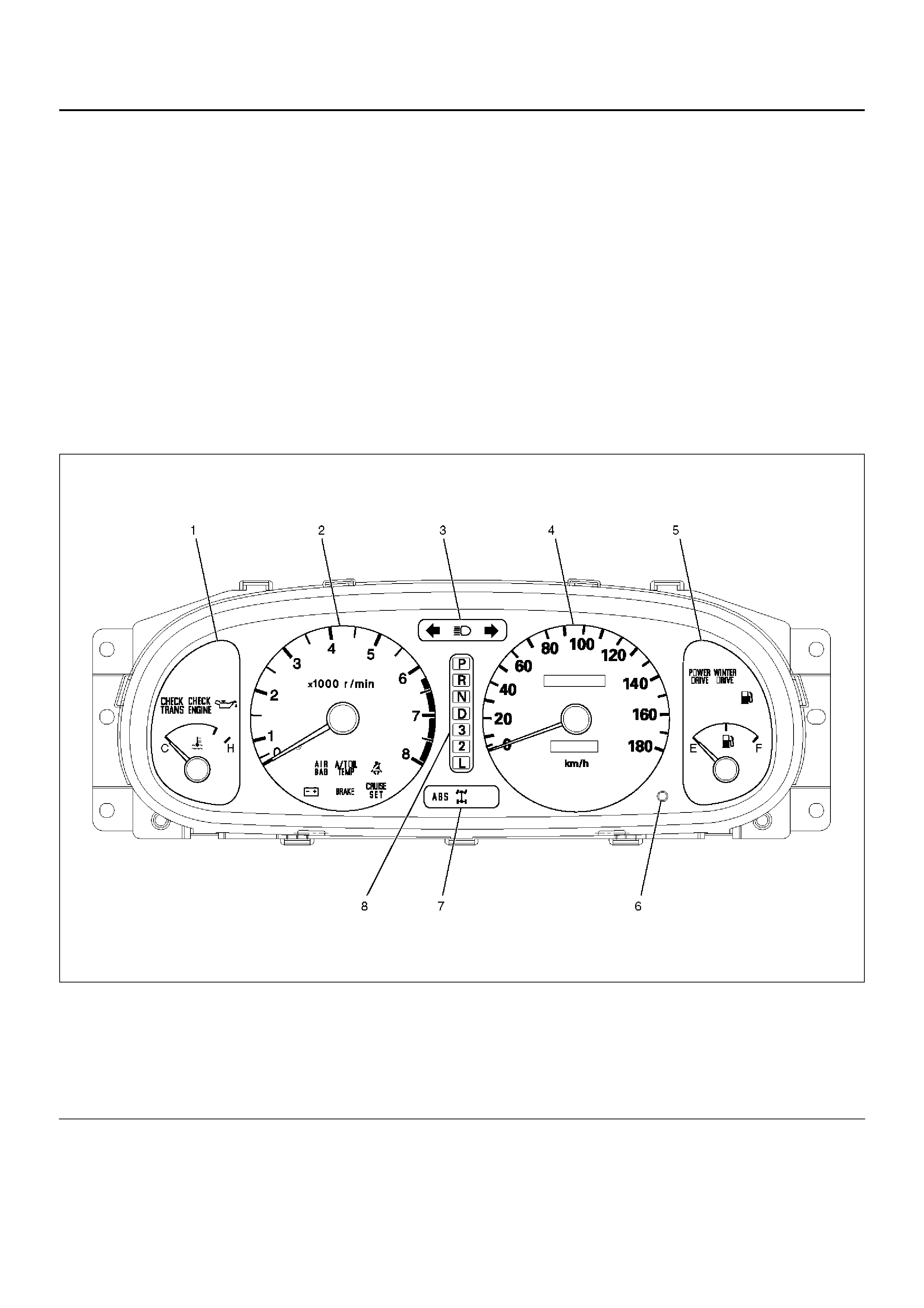
Layout for Meters/Gauges, Warning
Lights, Indicator Lights and
Illumination Lights
Meter Assembly W/A/T (Front View)
825RX038
Legend
EndOFCallout
(1) Engine Coolant Temperature Gauge
(2) Tachometer
(3) Warning Light Lens
(4) Speedometer
(5) Fuel Gauge
(6) Reset Knob
(7) W arning Light Lens
(8) A/T Shift Indicator
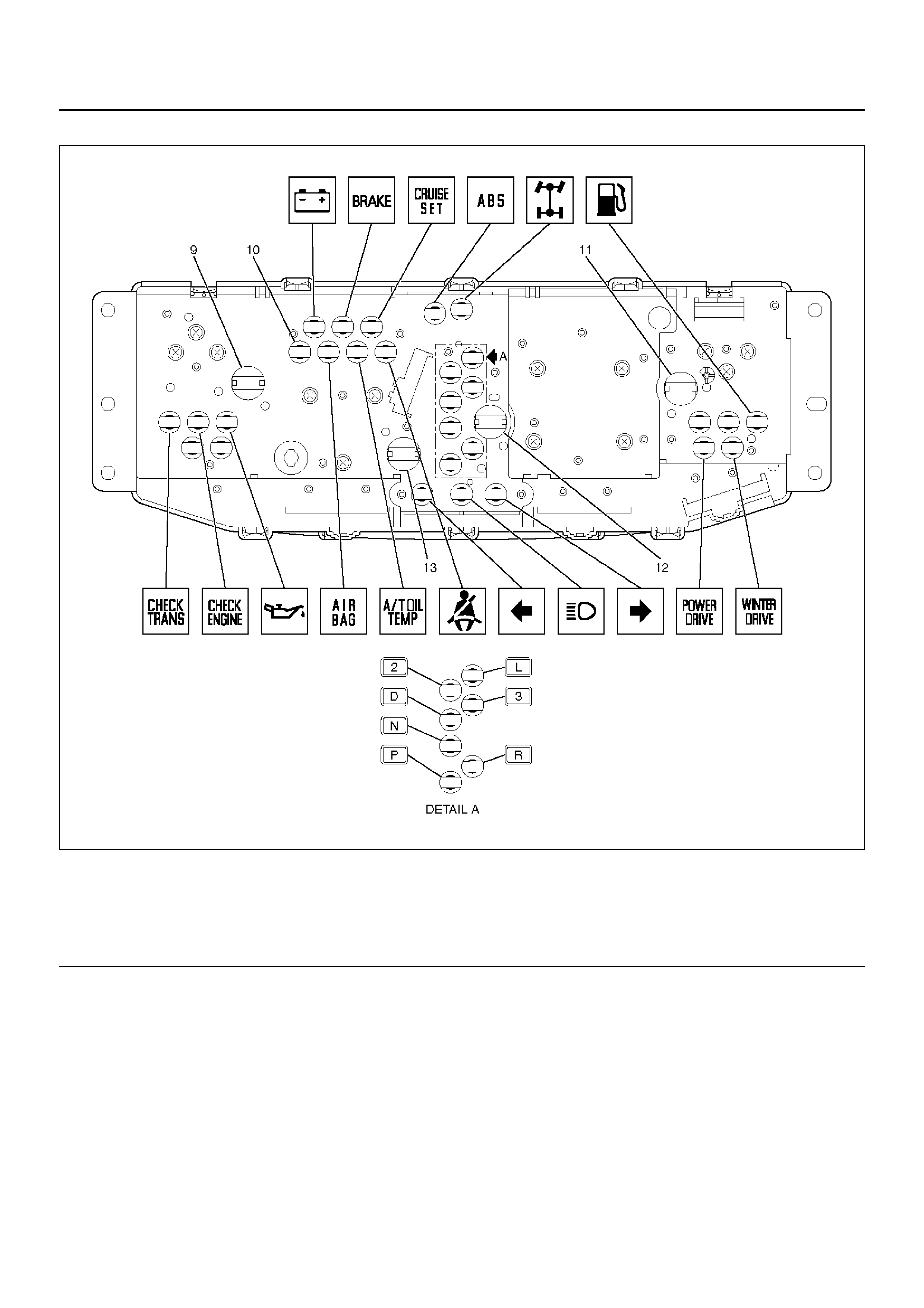
Meter Assembly W/A/T (Rear View )
825RX039
Legend
EndOFCallout
(9) Illumi nati on Lig ht
(10) LCD Light
(11) Illu mi nati on Lig ht
(12) Illuminati on Light
(13) Illuminati on Light
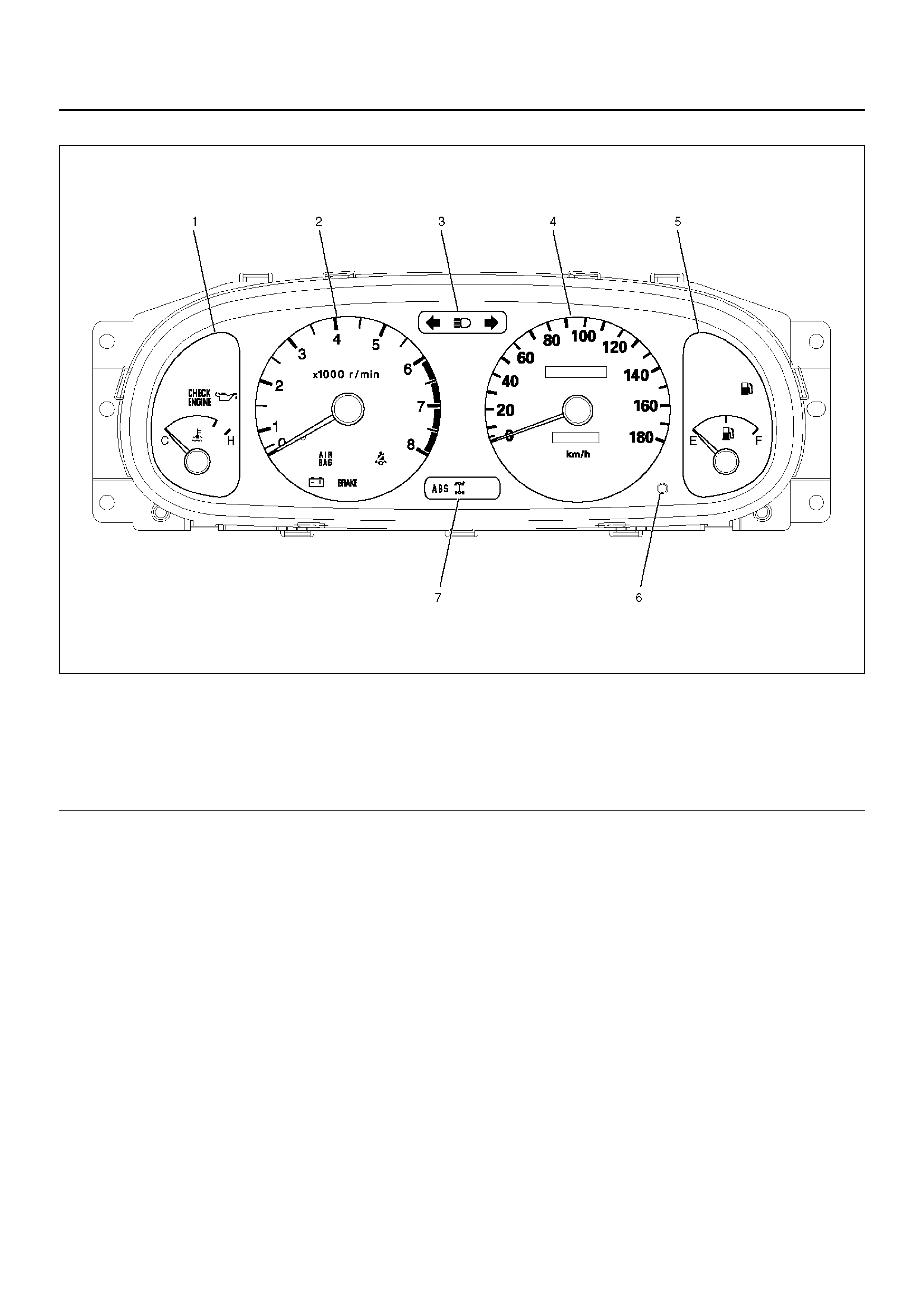
Meter Assembly W/M/T (Front View)
825RX036
Legend
EndOFCallout
(1) Engine Coolant Temperature Gauge
(2) Tachometer
(3) Warning Light Lens
(4) Speedometer
(5) Fuel Gauge
(6) Reset Knob
(7) W arning Light Lens
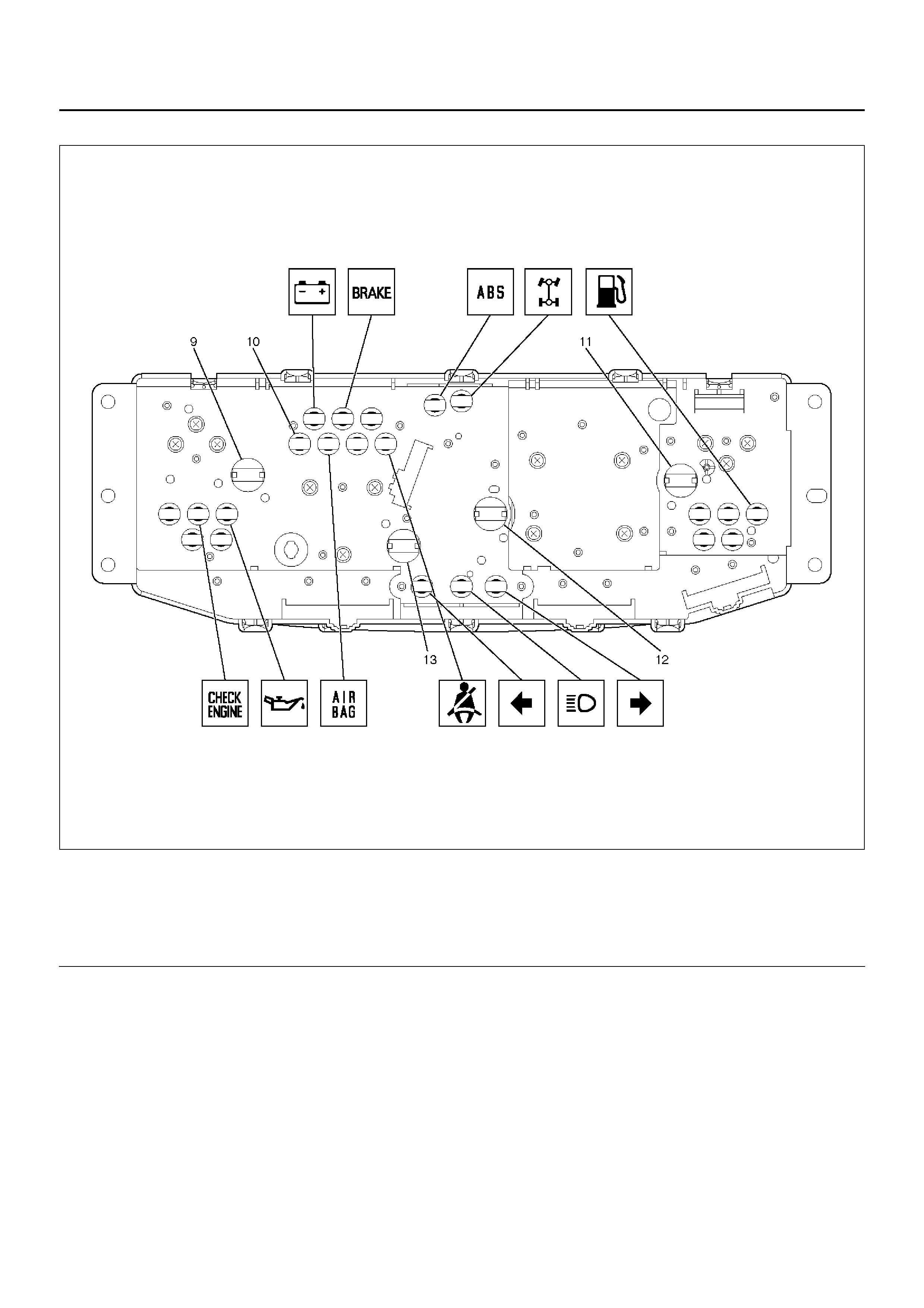
Meter Assembly W/M/T (Rear View)
825RX037
Legend
EndOFCallout
(9) Illumi nati on Lig ht
(10) LCD Light
(11) Illu mi nati on Lig ht
(12) Illuminati on Light
(13) Illuminati on Light
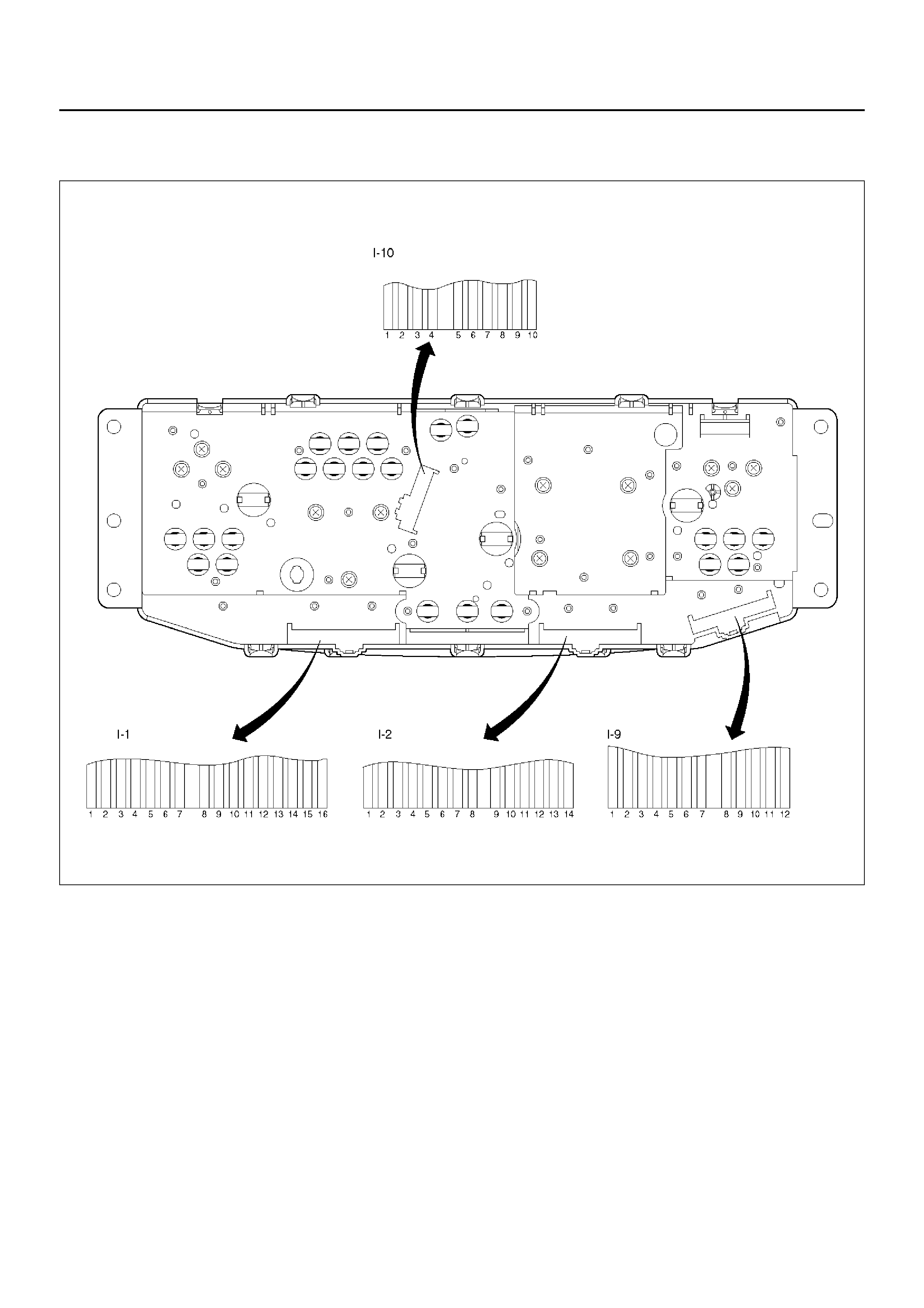
Table for Meter/Gauge Connector Terminal Connections
Meter Assembly W/M/T
825RX014

Connector No. I–1
Terminal Function
1—
2—
3—
4 Oil pressure warning light
5 Check engine warning light
6—
7 Engine coolant temperature gauge
8 Brake warning light
9 Ground (Gauge)
10 Charge warning light
11 —
12 Starter switch
13 Air bag warning light
14 —
15 Seat belt warning light
16 Illumination (+)
Connector No. I–2
Terminal Function
1 Turn sig nal indicator light (Left)
2 Turn signal indicator light (Right)
3Ground
4—
5 Illumination (−)
6 Tachometer
7—
8—
9 ABS indicator light
10 4WD indicator light
11 —
12 Speedometer
13 Ground
14 Fuel gauge
Connector No. I–9
Terminal Function
1 Illumi nation (−)
2 Illumi nation (+ )
3—
4—
5—
6—
7—
8—
9—
10 —
11 Battery (+)
12 —
Connector No. I–10
Terminal Function
1—
2—
3—
4—
5—
6—
7—
8—
9 High–beam indicator light (−)
10 High–beam indicator light (+)
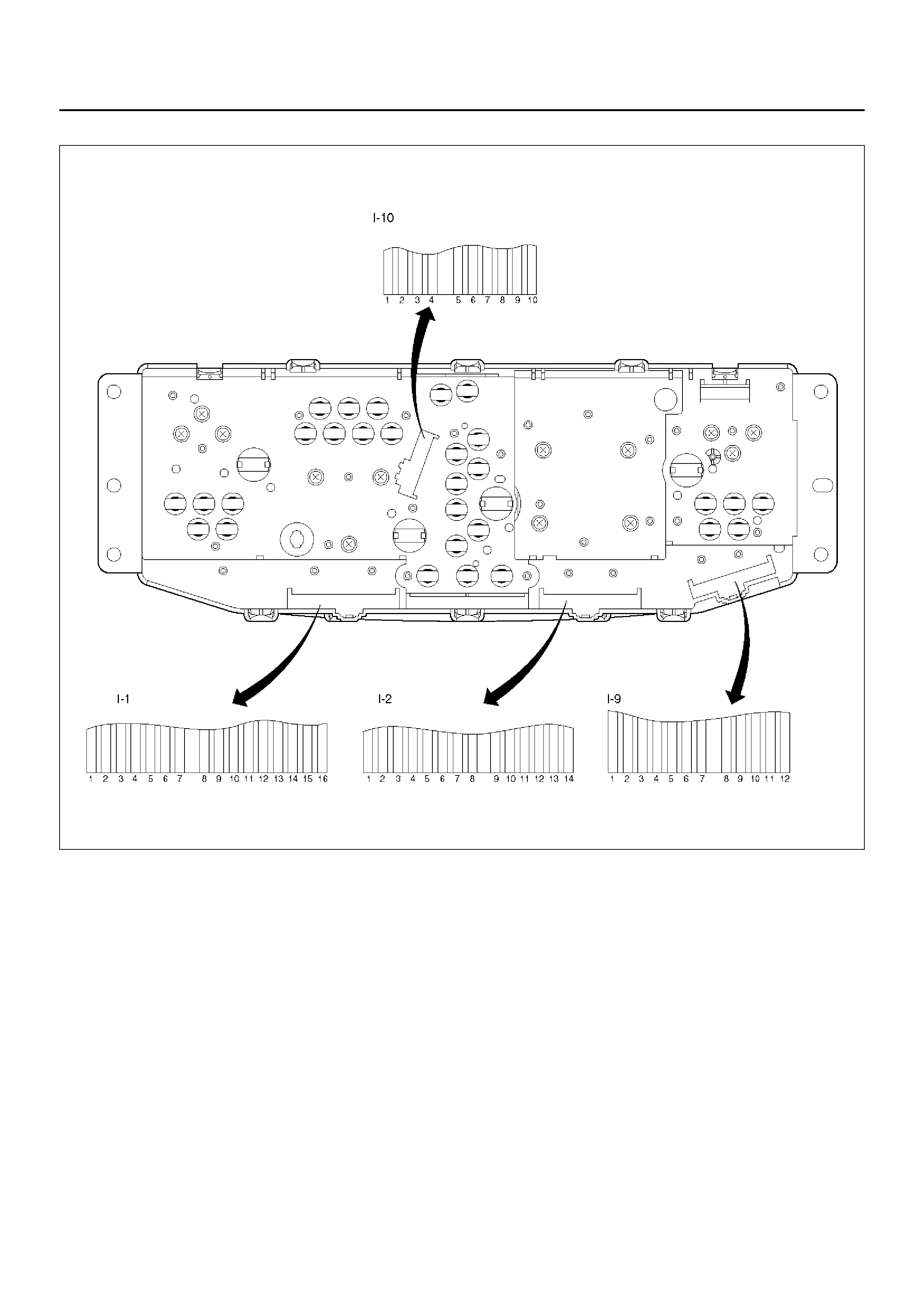
Meter Assembly W/A/T
825RX013
Connector No. I–1
Terminal Function
1—
2—
3—
4 Oil pressure warning light
5 Check engine warning light
6 Check trans warning light
7 Engine coolant temperature gauge
8 Brake warning light
9 Ground (Gauge)
10 Charge warning light
11 —
12 Starter switch
13 Air bag warning light
14 A/T oil temp warning light
15 Seat belt warning light
16 Illumination (+)
Connector No. I–2
Terminal Function
1 Turn sig nal indicator light (Left)
2 Turn signal indicator light (Right)
3Ground
4—
5 Illumination (−)
6 Tachometer
7—
8Cruise set
9 ABS indicator light
10 4WD indicator light
11 —
12 Speedometer
13 Gnd
14 Fuel gauge
Connector No. I–9
Terminal Function
1 Illumi nation (−)
2 Illumi nation (+ )
3—
4—
5—
6—
7 Power drive indicator light
8 Winter drive indicator light
9—
10 —
11 Battery (+)
12 —
Connector No. I–10
Terminal Function
1 L position (A/T)
2 2 position (A/T)
3 3 position (A/T)
4 D position (A/T)
5 N position (A/T)
6 R position (A/T)
7 P position (A/T)
8 A/T shift indicator light
9 High–beam indicator light (−)
10 High–beam indicator light (+)
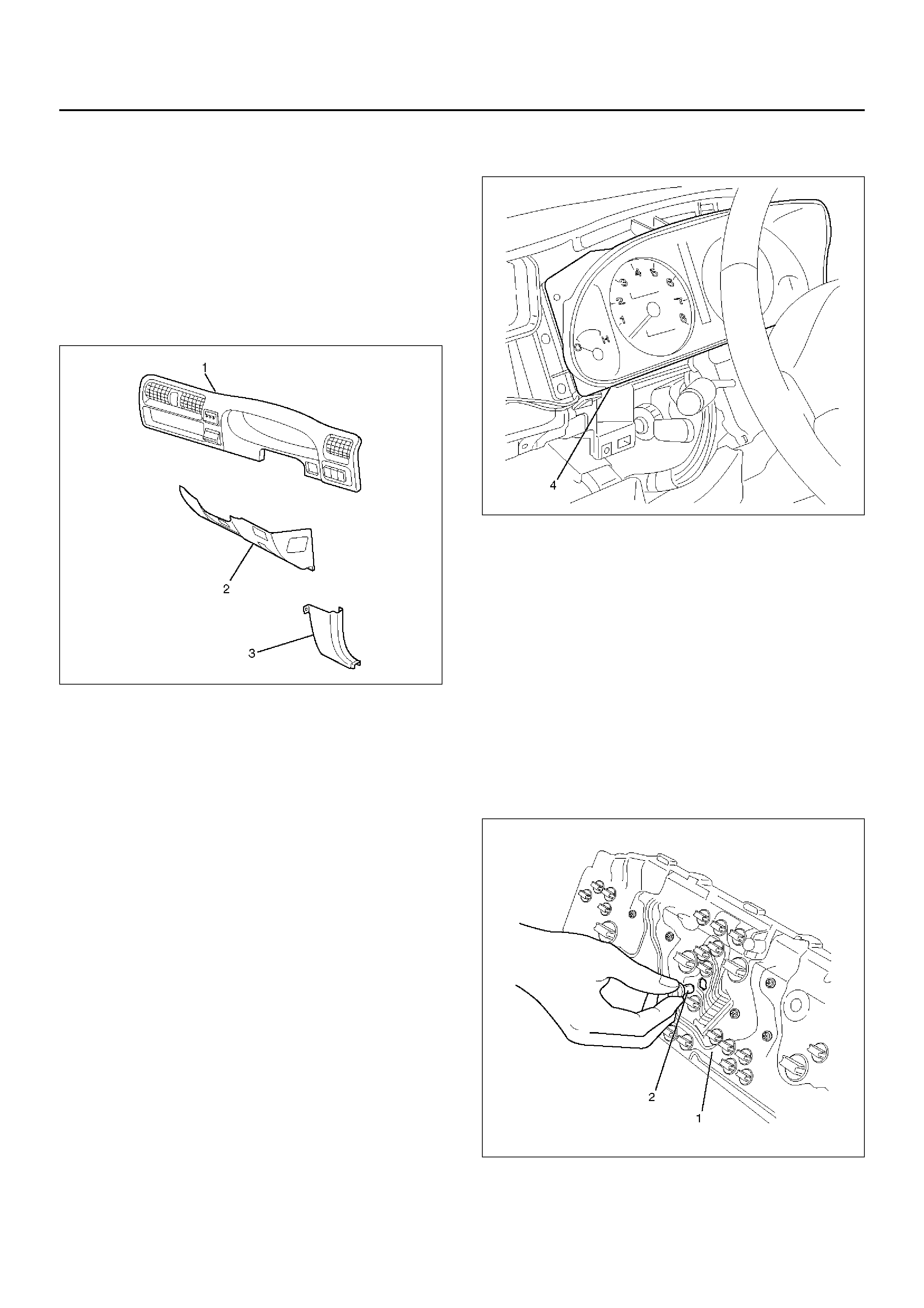
Removal
1.Disconnect the battery ground cable.
2.Remove the Dash Side Trim Panel –RH (3).
3.Remove the lower cover Assembly(2).
•Refer to the Instrument Panel Assembly in Body
Structure section.
4.Remove the meter cluster Assembly(1).
•Refer to the Instrument Panel Assembly in Body
Structure section.
821RW292-1
5.Remove four fixing screws and disconnect the meter
connectors to remove the meter assembly(4).
825RW284
CAUTION: The removed meter assembly should be
placed upright or with its face side up.
Installation
To install, follow the removal steps in the reverse order.
Warning Light Bulb, Indicator Light Bulb, Illumination Light Bulb,
A/T Shift Indicator Light Bulb
Removal
1.Disconnect the battery ground cable.
2.Remove the meter assembly(1).
•Refer to the Meter Assembly removal steps in
Meter and Gauge section.
3. Hold the bulb socket by hand and rotate it
counterclockwise to remove the socket & bulb(2)
from the meter body.
825RW059
Installation
To install, follow the re moval steps in the reverse order.
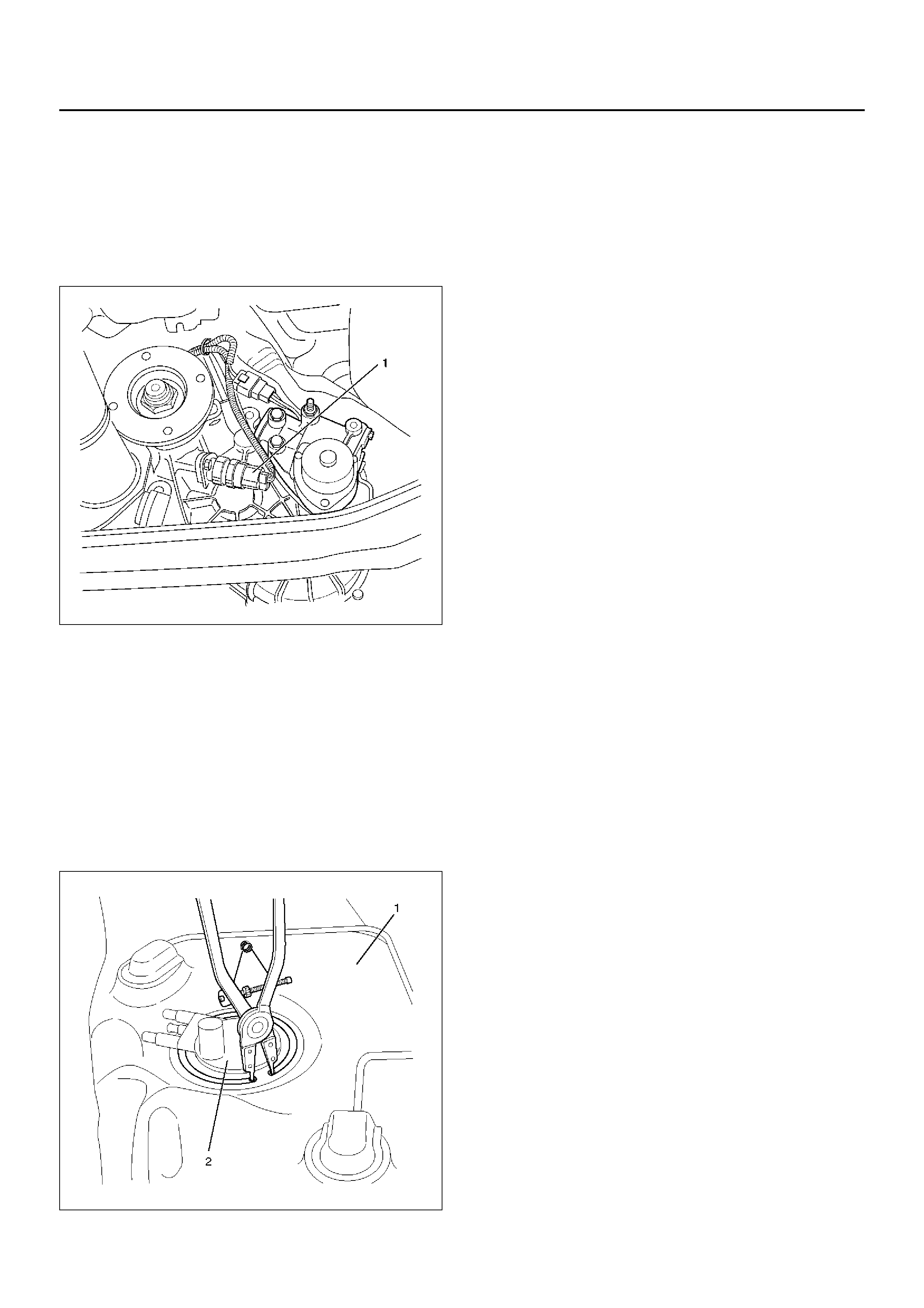
Vehicle Speed Sensor
Removal
1.Disconnect the battery ground cable.
2.Disconnect the connector, remove the vehicle speed
sensor (1) by rotating it.
220RX003
Installation
To install, follow the removal steps in the reverse order,
noting the following points.
1.Tighten the vehicle speed sensor to the specified
torque.
Torque: 27N·m (2.8kg·m/20lbft)
Fuel Tank Unit
Removal
1.Disconnect the battery ground cable.
2.Remove the fuel tank(1).
•Refer to the Fuel Tank in Engine Fuel section
3. Disconnect the connectors, remove five screws and
then remove the fuel tank unit(2).
825RW060
Installation
To install, follow the re moval steps in the reverse order.

Main Data and Specifications
Torque Specifications
Application N·m kg·m LbFt LbIn
Veh icle Spe ed Sen so r Fixing 27 2.8 20 —