
SECTION 8G - SEATS
Service Precaution
Front Seat Assembly
Front Seat Assembly and Associated
Parts
Removal
Installation
Rear Seat Assembly (LWB)
Rear Seat Cushion Assembly and
Associated Parts
Removal
Installation
Rear Seat Back Assembly and
Associated Parts
Removal
Installation
Rear Seat Assembly (SWB)
Rear Seat Assembly and Associated
Parts
Removal
Installation
Main Data and Specifications
Torque Specifications
Service Precaution
WARNING: THIS VEHICLE HAS A SUPPLEMENTAL
RESTRAINT SYSTEM (SRS). REFER TO THE SRS
COMPONENT AND WIRING LOCATION VIEW IN
ORDER TO DETERMINE WHETHER YOU ARE
PERFORMING SERVICE ON OR NEAR THE SRS
COMPONENTS OR THE SRS WIRING. WHEN YOU
ARE PERFORMING SERVICE ON OR NEAR THE
SRS COMPONENTS OR THE SRS WIRING, REFER
TO THE SRS SERVICE INFORMATION. FAILURE TO
FOLLOW WARNINGS COULD RESULT IN POSSIBLE
AIR BAG DEPLOYMENT, PERSONAL INJURY, OR
OTHERWISE UNNEEDED SRS SYSTEM REPAIRS.
CAUTION: Always use the correct fastener in the
proper location. When you replace a fastener, use
ONLY the exact part number for that application.
ISUZU will call out those fasteners that require a
replacement after removal. ISUZU will also call out
the fasteners that require thread lockers or thread
sealant. UNLESS OTHERWISE SPECIFIED, do not
use supplemental coatings (Paints, greases, or
other corrosion inhibito r s) on thr eaded fastener s or
fastener joint interfaces. Generally, such coatings
adversely affect the fastener torque and the joint
clamping force, and may damage the fastener.
When you install fasteners, use the correct
tightening sequence and specifications. Following
these instructions can help you avoid damage to
parts and systems.
Front Seat Assembly
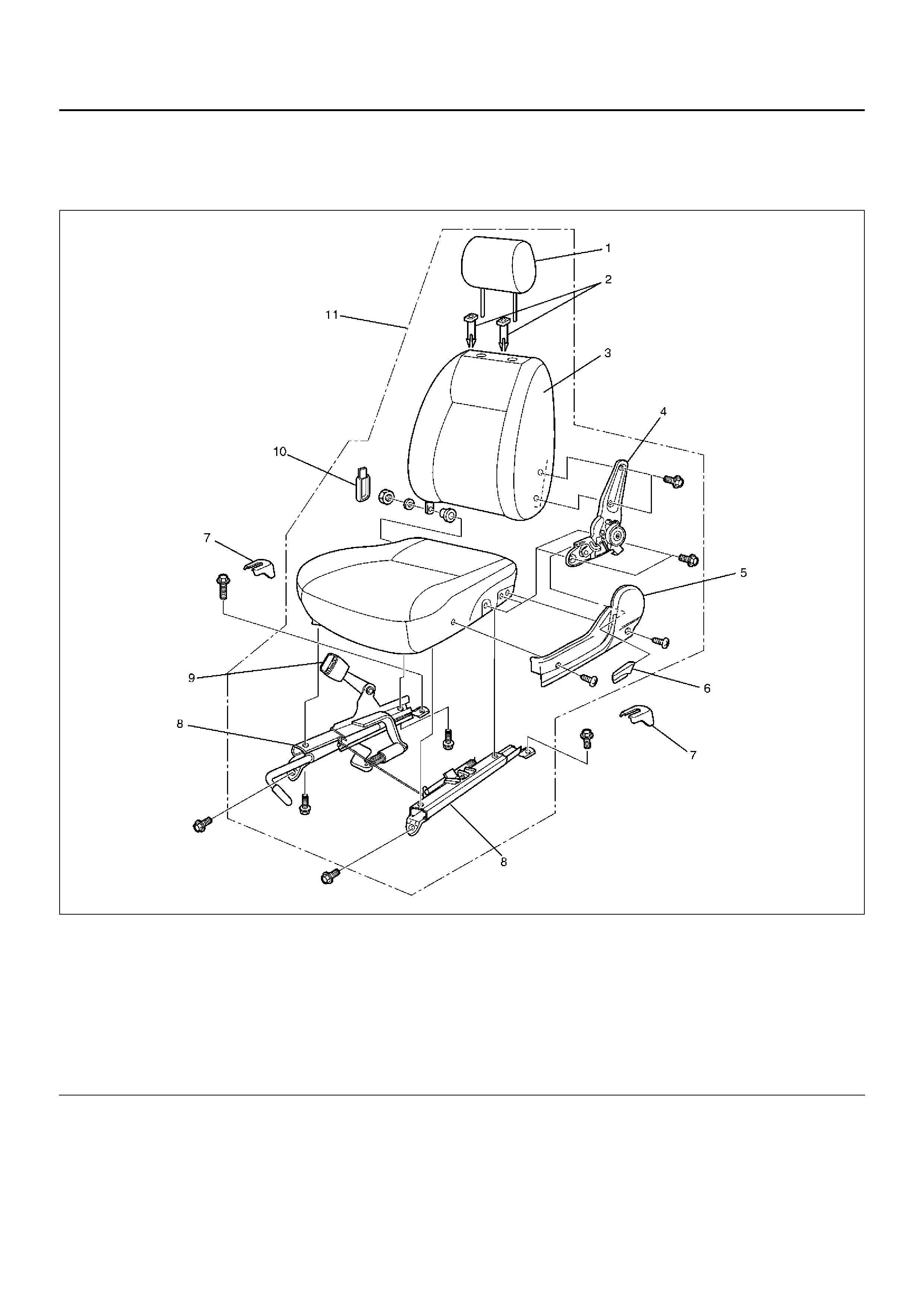
Front Seat Assembly and Associated Parts
750RY00279
Legend
EndOFCallout
Removal
1. Disconnect the battery ground cable.
2. Remove the rear covers.
3. Remove the front seat assembly.
• Remove the four fixing bolts.
• Disconnect the seat belt warning connector
(Driver’s side only).
(1) Headrest
(2) Gui de Holder
(3) Seat Back Assembly
(4) R eclining Device
(5) Side Cover
(6) Reclining Knob
(7) Rear Cover
(8) S eat Adj us ter
(9) Front Seat Belt Buckle Assembly
(10) Hinge Cover
(11) Fr ont Seat Assembly
4. Pull out the reclining knob.
5. Remove the side cover.
• Remove the two scre ws .
6. Remove the headrest.
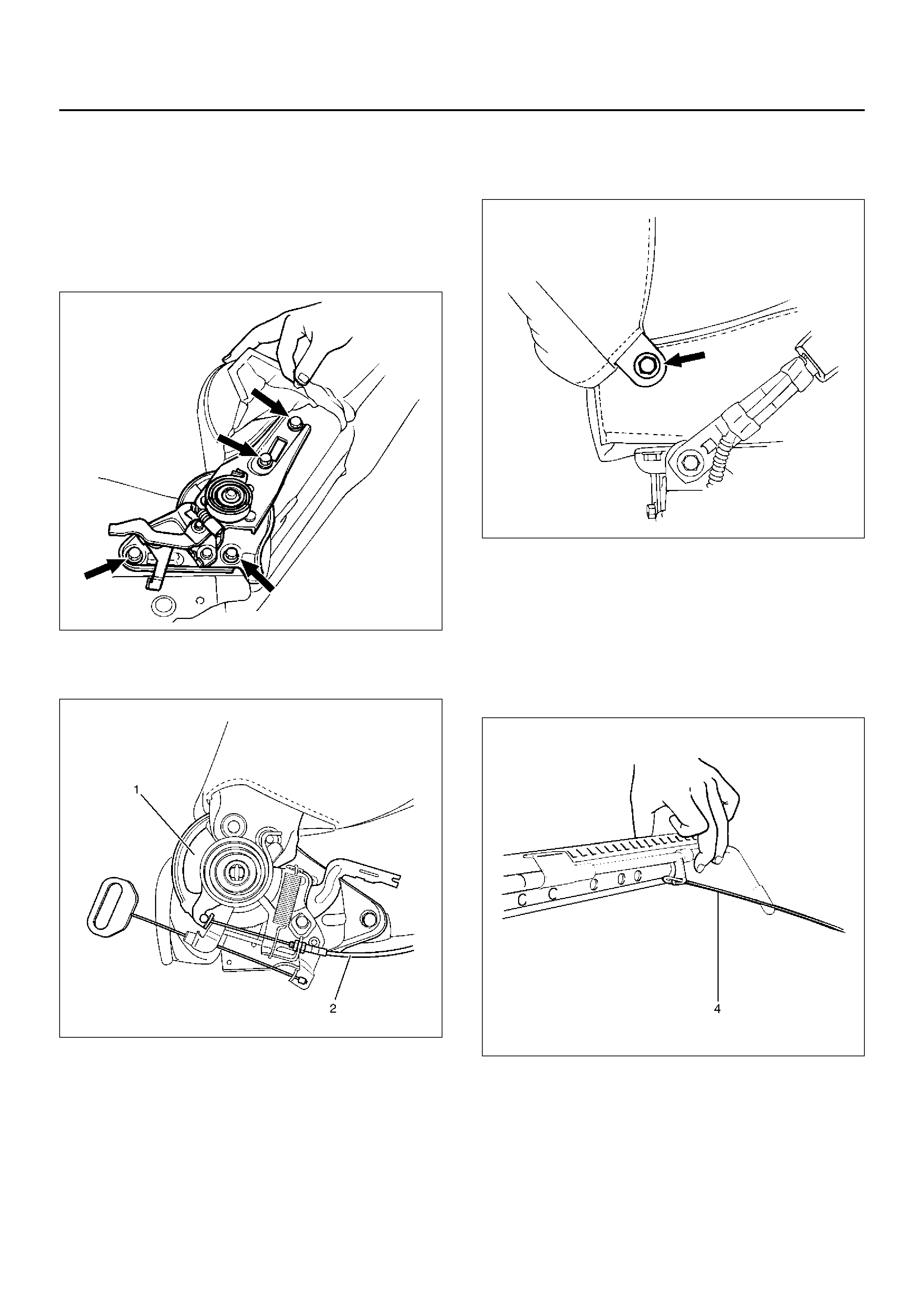
7. Remove the reclining device.
• Turn up the seat back trim cover in order to
remove the reclining device fixing bolts (LWB).
750RS006
• Remove the of device (1) and disconnect the
walk-in cable (2) (SWB).
750RY00276
8. Remove the seat back assembly.
• Remove the seat back assembly fixing nut on the
opposite side of the reclining device.
750RS007
9. Remove the trim cover (Seat back side).
10. Remove the guide hol der.
• Pull the guide holder out by holding the bottom
end of it from the seat back assembly.
11. Remove the se at adju ste r.
• Disconnect the release wire (4) and remove the
fixing bolts.
750RW006
12. Remove the se at belt buckle assembly.
13. Remove the trim cover (Seat cushion side).

Installation
To install, follow the removal steps in the reverse order,
noting the following points:
1. Tighten the reclining device fixing bolts to the
specified torque.
Torque: 46 N·m (4.7 kg·m/34 lbft)
2. Tighten the front seat assembly fixing bolts to the
specified torque.
Torque: 39 N·m (4.0 kg·m/29 lbft)
Rear Seat Assembly (LWB)
Rear Seat Cushion Assembly and Associated Parts
755RY00009
Legend
EndOFCallout
Removal
1. Remove the hinge covers.
2. Remove the seat cushion fixing bolts.
3. Remove the seat cushion assembly.
• Pull on the strap of the rear seat lock assembly to
release the seat lock.
4. Remove the seat cushion hinges.
(1) Rear Seat Lock Striker
(2) Rear Seat Lock Assembly
(3) Rear Seat Belt Buckle Assembly
(4) Seat Cushion Hinge
(5) Hinge Cover
(6) S eat Cus hio n Fixi ng Bolt
(7) Rear Seat Cushion Assembly
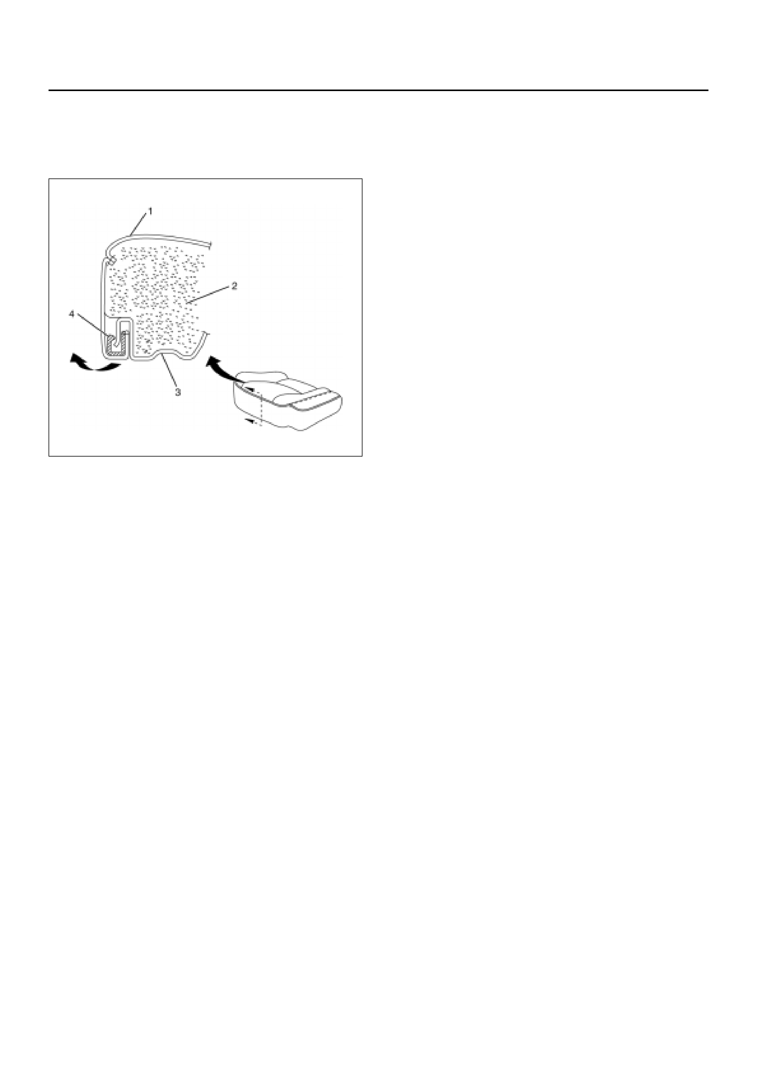
5. Remove the rear cushion trim cov er (1) and rear
seat cushion pad (2).
• Remove cushion trim cover from rear cushion
frame (3) with prying the plastic retainers (4).
755RX028
6. Remove the rear seat lock assembly and rear seat
belt buckle assembly.
7. Remove the rear seat lock strikers.
• Remove the four bolts at each striker.
Installation
To install, follow the removal steps in the reverse or der,
noting the following points:
1. Tighten the rear seat lock assembly and rear seat
belt buckle assembly fixing bolts to the specified
torque.
Torque: 39 N·m (4.0 kg·m/29 lbft)
2. Tighten the rear seat lock striker fixing bolts to the
specified torque.
Torque: 39 N·m (4.0 kg·m/29 lbft)
3. Tighten the seat cushion hinge fixing bolts to the
specified torque.
Torque: 39 N·m (4.0 kg·m/29 lbft)
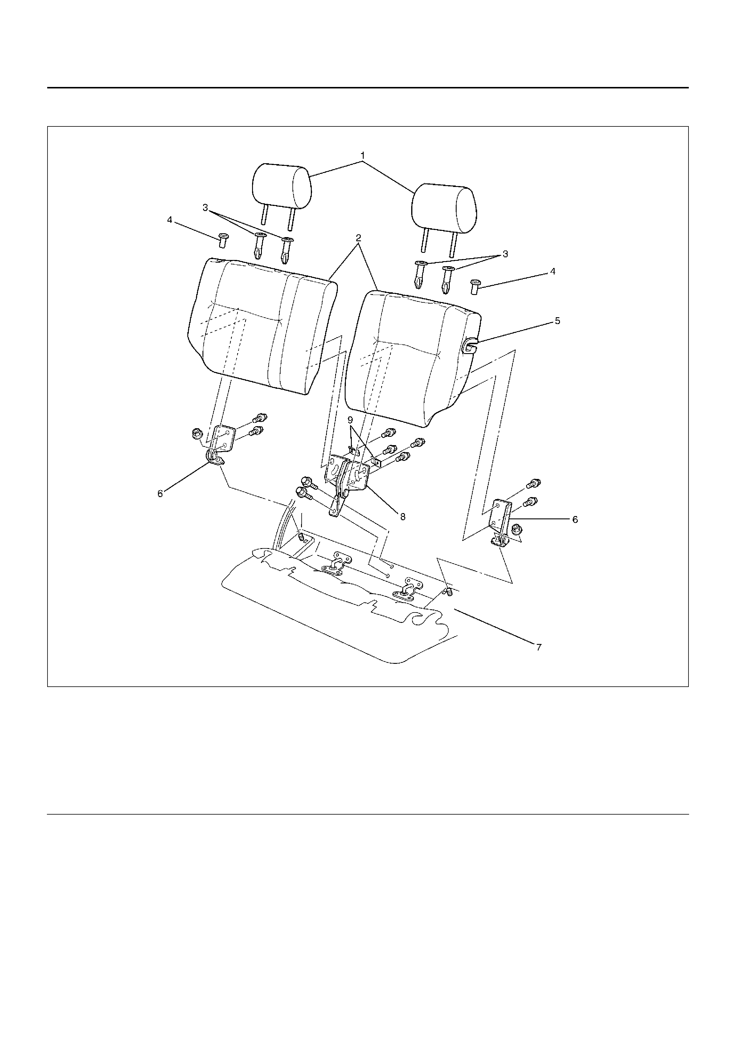
Rear Seat Back Assembly and Associated Parts
755RY00020
Legend
EndOFCallout
Removal
1. Pull on the release knob and fold the seat back
asse mbly forward.
2. Remove the luggage floor carpets.
• Remove the carpet fixing nine clips at each from
the backside of the seat back assembly.
3. Remove the seat back assembly.
• Remove the four fixing bolts at each seat back.
4. Remove the seat lock covers.
5. Remove the head rests.
6. Remove the relea se knobs.
• Turn the knob counterclockwise to remove it.
7. Remove the trim covers.
8. Remove the guide hol der s.
(1) Headrest
(2) Seat Back Assembly
(3) Gui de Hol der
(4) Release Knob
(5) Seat Lock Cover
(6) Side Hinge
(7) Body Floor Panel
(8) Center Hinge
(9) Bracket

9. Remove the side hinges.
• Remove the one fixing nut at each side hinge.
10. Remove the center hinge.
• Remove the two fixing bolts.
Installation
To install, follow the removal steps in the reverse order,
noting the following points:
1. Tighten the center hinge fiixng bolts to the specified
torque.
Torque: 39 N·m (4.0 kg·m/29 lbft)
2. Tighten the side hinge fixing nuts to the specified
torque.
Torque: 29 N·m (3.0 kg·m/22 lbft)
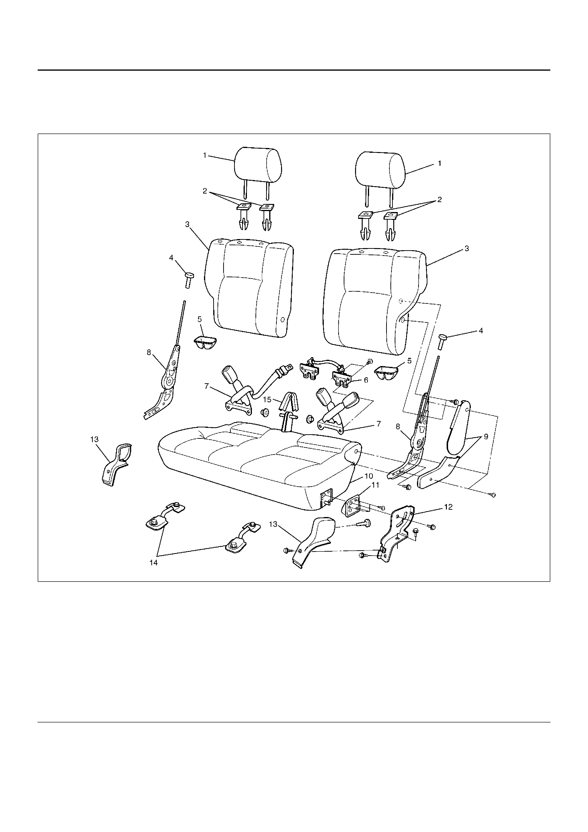
Rear Seat Assembly (SWB)
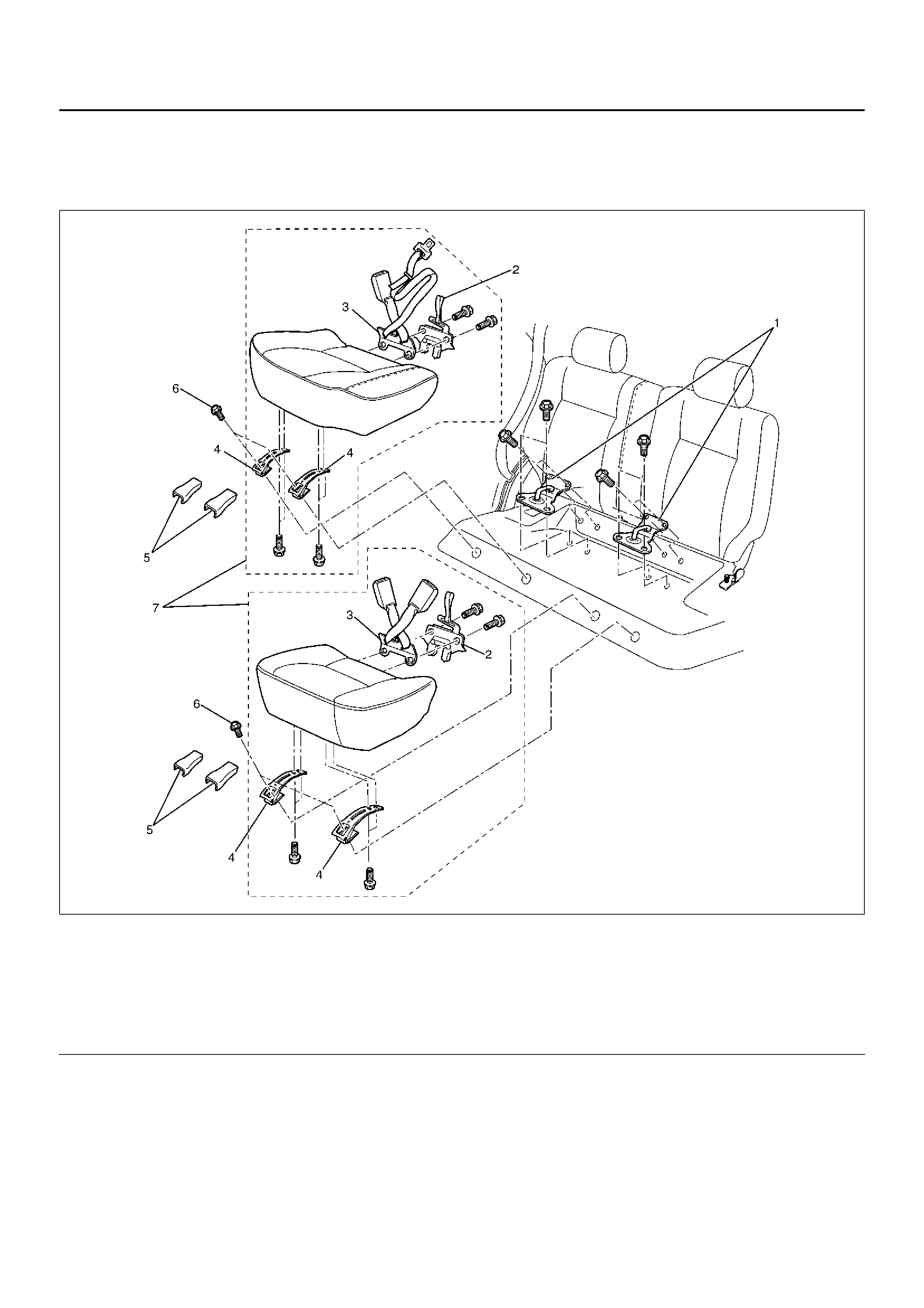
Rear Seat Assembly and Associated Parts
755RY00010
Legend
EndOFCallout
(1) Headrest
(2) Gui de Holder
(3) Rear Seat Back Assembly
(4) Release Knob
(5) Seat Lock Cover
(6) Seat Lock Assembly
(7) Rear Seat Belt Buckle Assembly
(8) R eclining Device
(9) Device Cover
(10) Rear Seat Cushi on Assembly
(11) Support Cover
(12) Rear Seat Leg
(13) Rear Seat Leg Cover
(14) Rear Floor Lock Striker
(15) Free Hinge Cover

Removal
1. Fold the rear seat backs forward.
• Pull up on the left and right release knobs.
2. Remove the rear seat leg covers.
• Remove the one screw and clip from each.
3. Remove the rear seat assembly.
• Remove the two sets of two fixing bolts from left
and right sides, then pull on the seat lock strap to
release the seat lock.
4. Remove the device covers.
• Remove the three screws from each.
5. Remove the release knobs.
6. Remove the rear seat back assembly.
• Remove the two sets of two reclining device fixing
bolts from the sides of the seat backs.
7. Remove the headrests.
8. Remove the trim covers.
9. Remove the guide holders.
10. Remove the reclining devices.
• Remove the two sets of two fixing bolts from the
sides of the seat cushions.
11. Remove the rear seat legs.
12. Remove the support covers.
• Remove the three screws from each.
13. Remove the seat lock covers.
14. Remove the seat lock assembly and the rear seat
belt buckle assembly.
• Remove the two sets of two fixing bolts.
15. Remove the free hinge cover.
Installation
To install, follow the removal steps in the reverse order,
noting the following points:
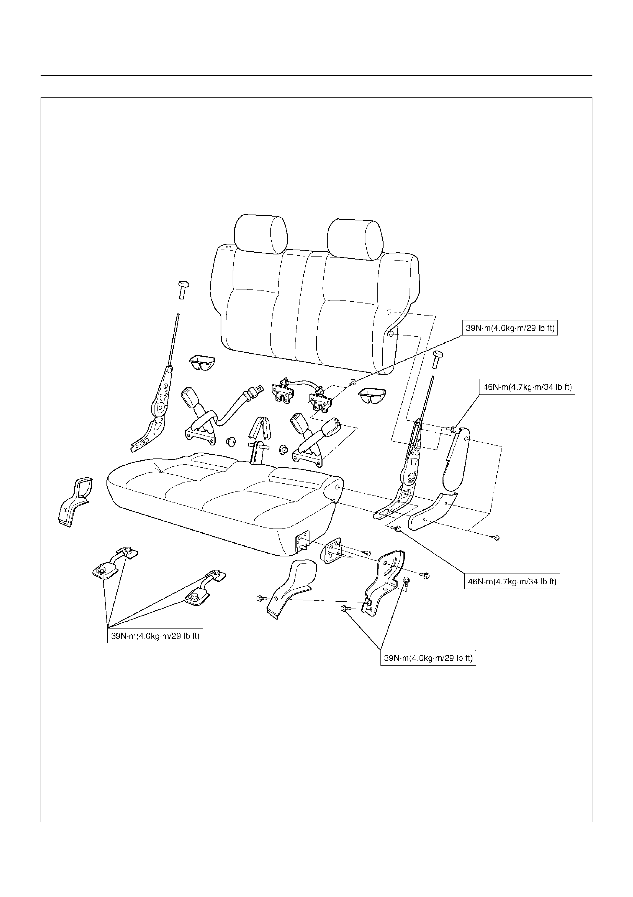
1. Tighten the seat lock assemblies and the rear
seatbelt buckle assemblies to the specified torque.
Torque: 39 N·m (4.0 kg·m/29 lbft)
2. Tighten the reclining devices to the specified torque.
Torque: 46 N·m (4.7 kg·m/34 lbft)
3. Tighten the rear seat assembly fixing bolts to the
specified torque.
Torque: 39 N·m (4.0 kg·m/29 lbft)
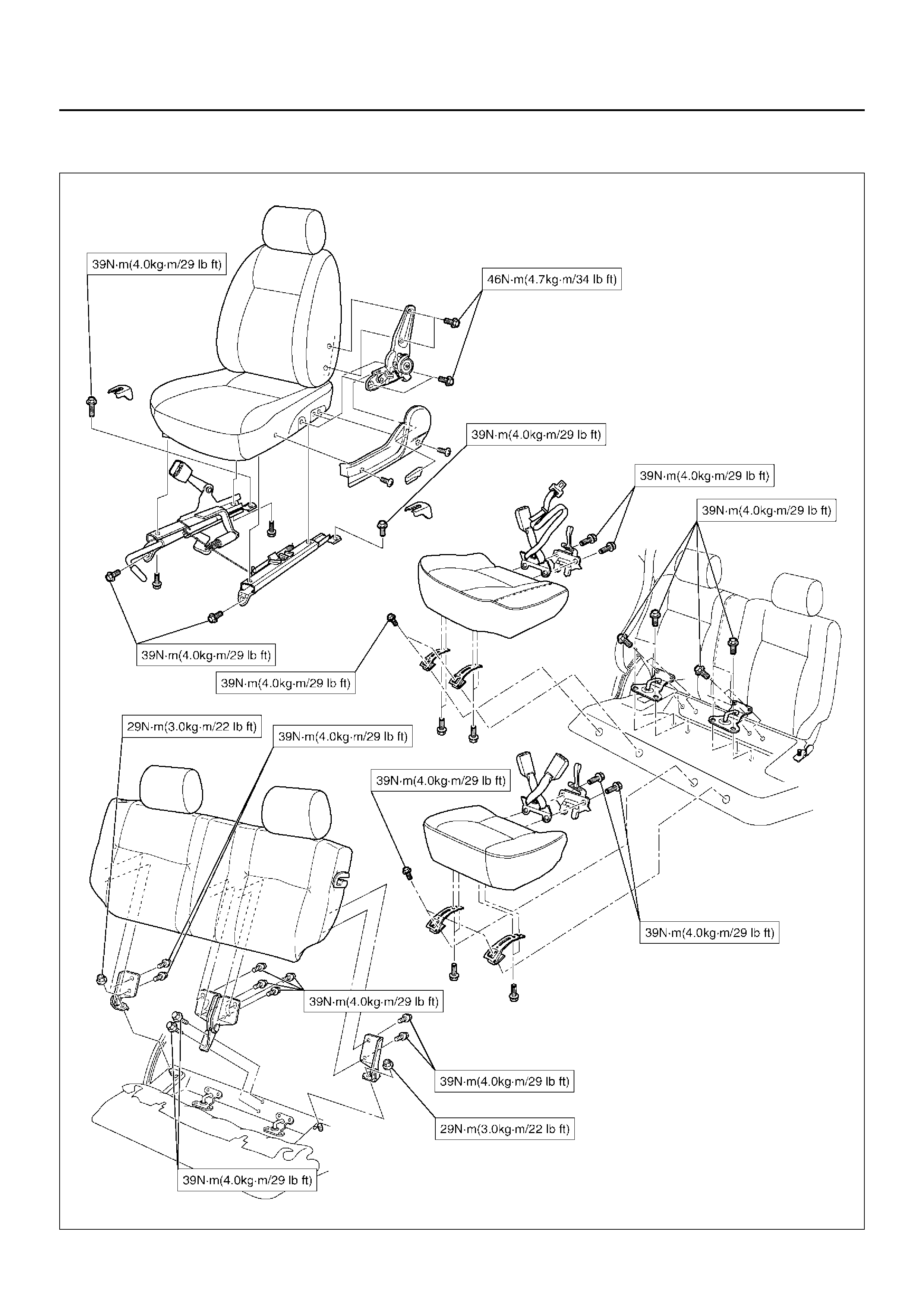
Main Data and Specifications
Torque Specifications
750RY00282
755RY00018