
SECTION 8H - SECURITY AND LOCKS
Service Precaution
Front Door Lock Assembly
Front Door Lock Assembly and
Associated Parts
Removal
Installation
Front Outside Handle
Front Outside Handle and
Associated Parts
Removal
Installation
Rear Door Lock Assembly
Rear Door Lock Assembly and
Associated Parts
Removal
Installation
Rear Outside Handle
Rear Outside Handle and
Associated Parts
Removal
Installation
Tailgate Lock and Hatchgate Lock (LWB)
Tailgate Lock, Hatchgate Lock and
Associated Parts
Removal
Installation
Tailgate Lock (SWB)
Tailgate Lock and Associated Parts
Removal
Installation
Fuel Filler Door Lock
Fuel Filler Door Lock and
Associated Parts
Removal
Installation
Key
Key Coding
Key Styles
Power Door Lock System
General Description
Door Lock Key Switch
Front Door Lock Actuator
Rear Door Lock Actuator
Tailgate Lock Actuator
Fuel Filler Door Lock Actuator
Keyless Entry System
General Description
Keyless Entry Control Unit
Keyless Entry Control Unit/Transmitter
Replacement
Main Data and Specifications
Service Precaution
WARNING: THIS VEHICLE HAS A SUPPLEMENTAL
RESTRAINT SYSTEM (SRS). REFER TO THE SRS
COMPONENT AND WIRING LOCATION VIEW IN
ORDER TO DETERMINE WHETHER YOU ARE
PERFORMING SERVICE ON OR NEAR THE SRS
COMPONENTS OR THE SRS WIRING. WHEN YOU
ARE PERFORMING SERVICE ON OR NEAR THE
SRS COMPONENTS OR THE SRS WIRING, REFER
TO THE SRS SERVICE INFORMATION. FAILURE TOFOLLOW WARNINGS COULD RESULT IN POSSIBLEAIR BAG DEPLOYMENT, PERSONAL INJURY, OROTHERWISE UNNEEDED SRS SYSTEM REPAIRS.
CAUTION: Always use the correct fastener in the
proper location. When you replace a fastener, use
ONLY the exact part number for that application.
ISUZU will call out those fasteners that require a
replacement after removal. ISUZU will also call out
the fasteners that require thread lockers or thread
sealant. UNLESS OTHERWISE SPECIFIED, do not
use supplemental coatings (Paints, greases, or
other corrosion inhibitors) on threade d fasteners or
fasteners joint interfaces. Generally, such coatings
adversely affect the fastener torque and the joint
clamping force, and may damage the fasteners.
When you install fasteners, use the correct
tightening sequence and specifications. Following
these instructions can help you avoid damage to
parts and systems.
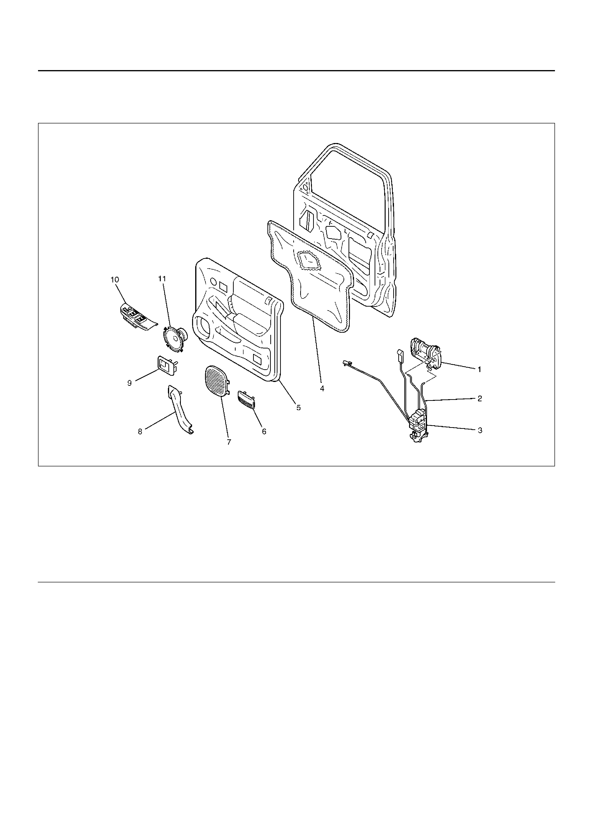
Front Door Lock Assembly
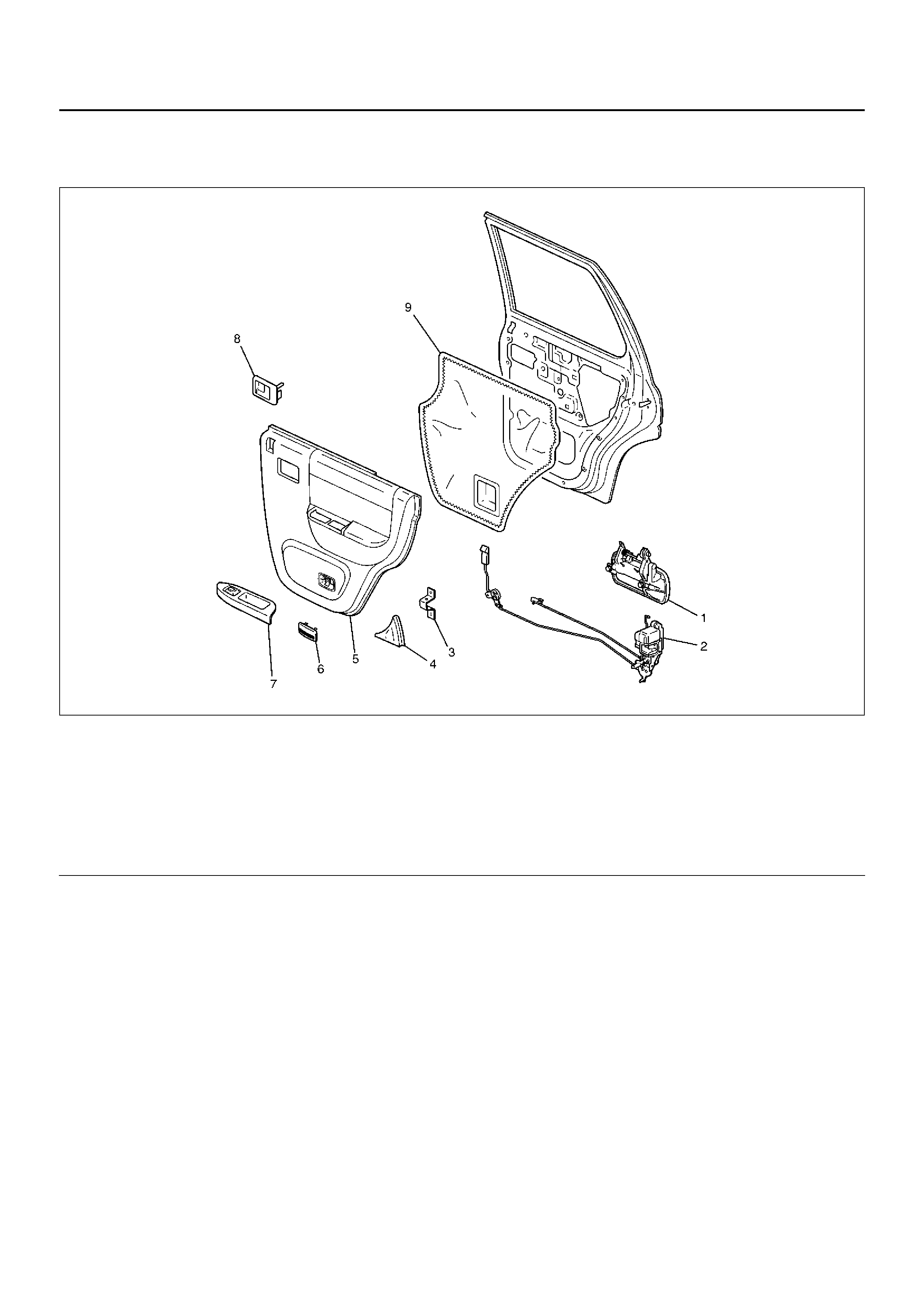
Front Door Lock Assembly and Associated Parts
635RY00005
Legend
EndOFCallout
(1) Outside Handle
(2) Door Locking Link
(3) Door Lock Assembly
(4) Waterproof Sheet
(5) Door Trim P anel
(6) Courtesy Light Lens
(7) Speaker Grille
(8) Grip Cover
(9) Inside Handle
(10) Power Window Switch
(11) Speaker Assembly
Removal
1. Disconnect the battery ground cable.
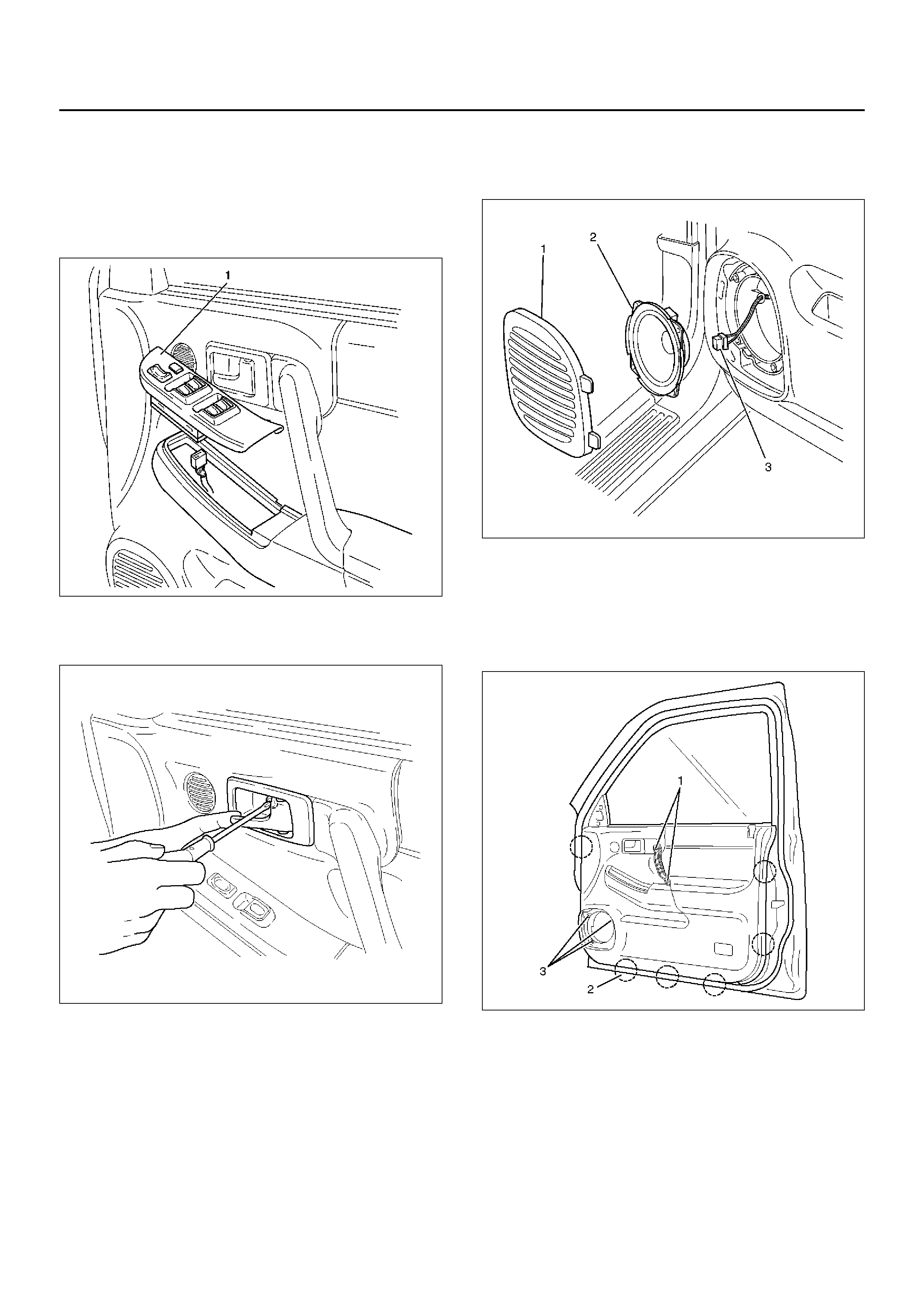
2. Remove the power window switch (1).
• Pry out the power window switch and remov e the
connectors.
635RW016
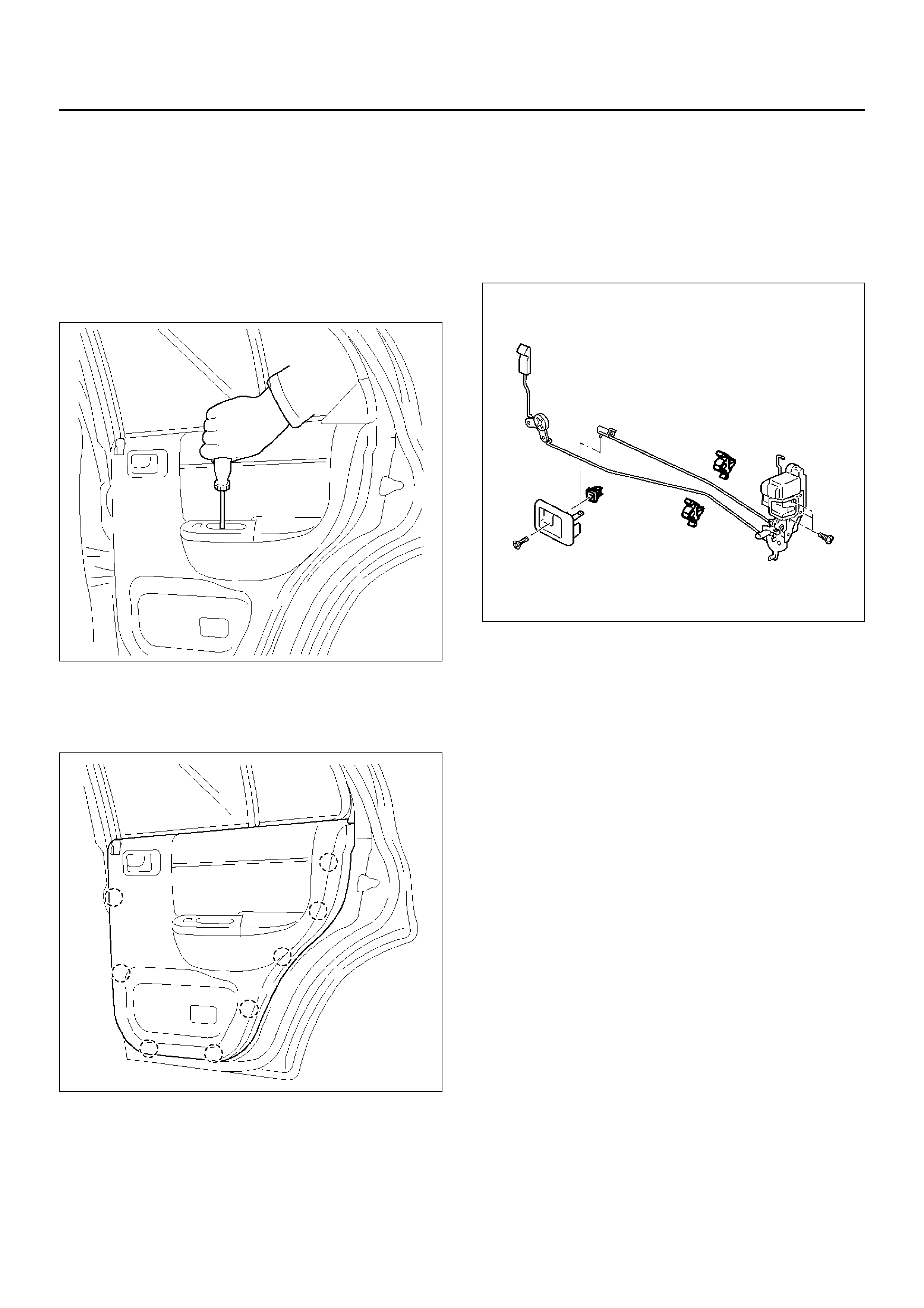
3. Remove the screw while pulling the inside lever
toward you and then remove the inside handle.
632RW003
4. Remove the speaker grille (1).
• Pull out the front side of the grille.
5. Remove the speaker assembly (2).
• Remov e four screws and disconnect the speaker
harness connector (3).
890RX012
6. Remove the courtesy light lens.
7. Remov e the fiv e screws (1), (3) and pull out the door
trim panel at the six clip positions (2).
• Disconnect the tweeter connector and courtesy
light connec to r.
635RW007
8. Remove the waterproof sheet.
• Taking notice of the door harness, peel the
waterproof sheet off the door panel carefully.
9. Raise the glass up to the uppermost position, and
then remove the rear guide rail.
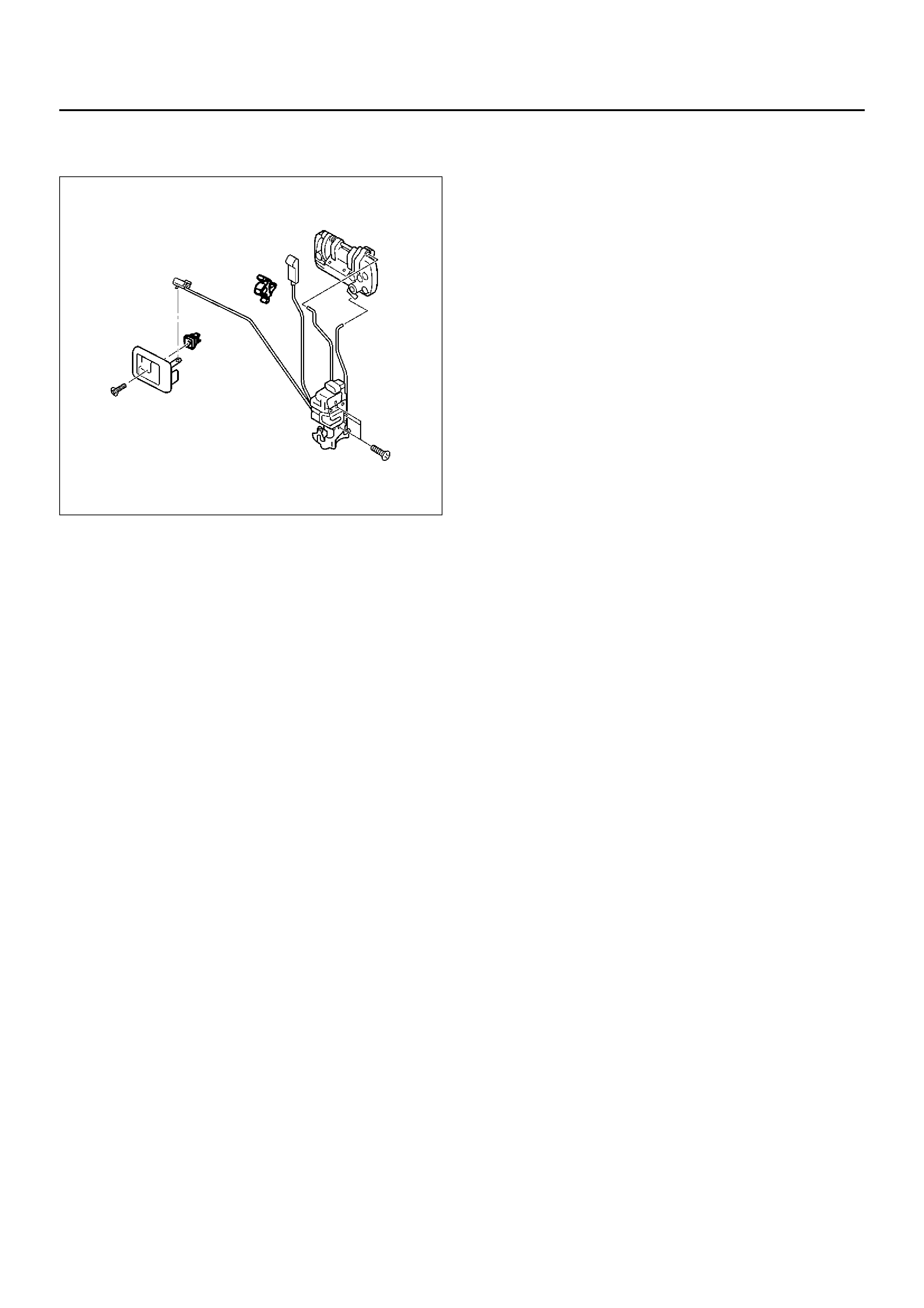
10. Disconnect the locking links then remove the door
lock assembly fixing screws and door lock assembly.
632RY00005
Installation
To install, follo w the removal steps in the reverse order,
noting the following points:
1. Apply chassis grease to the lock assembly and
striker moving surface .
2. Tighten the door lock assembly fixing screws to the
specified torque.
Tor que 7 N·m (0.7kg·m/61lbin)
3. Check that the door lock operates smoothly.
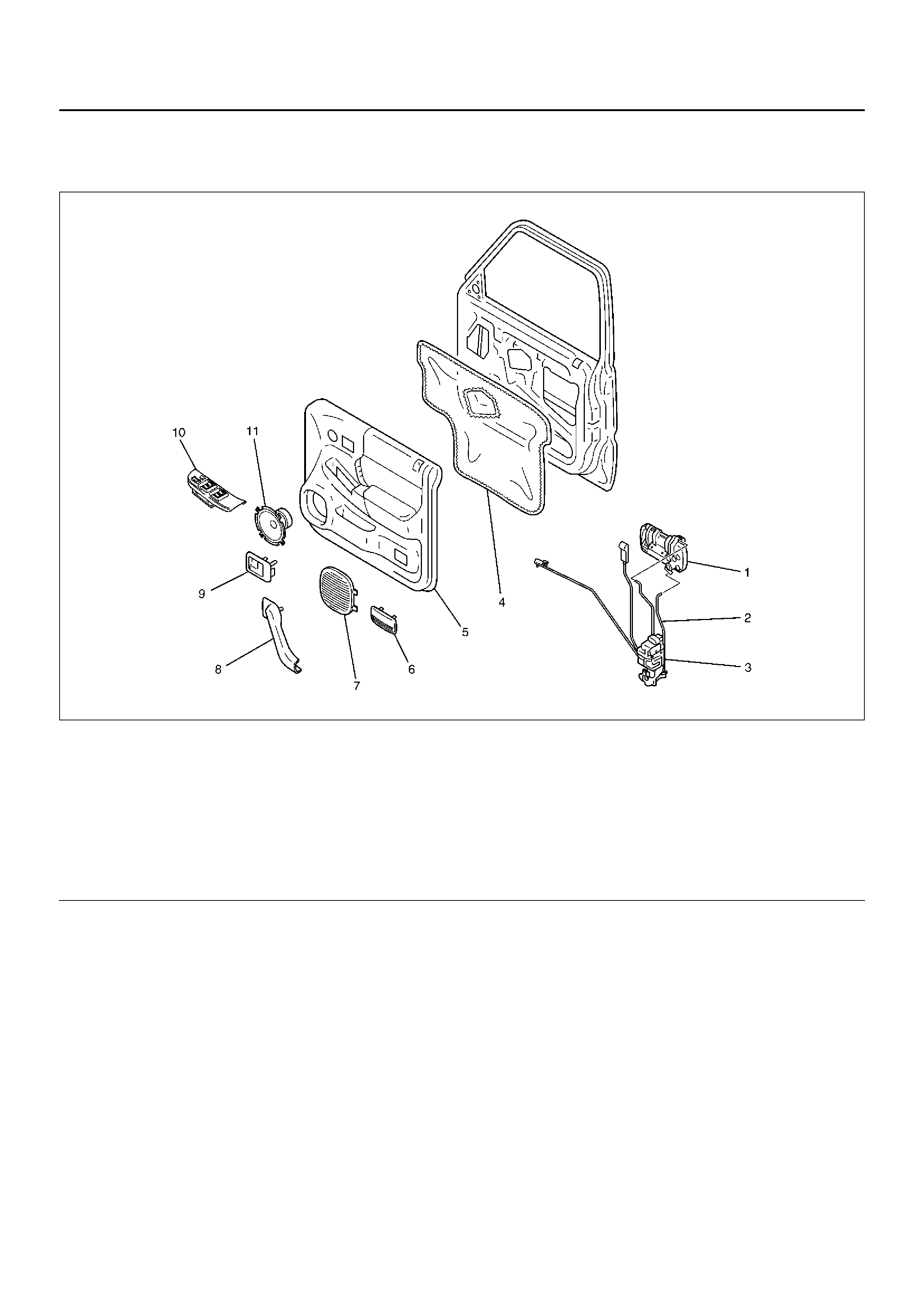
Front Outside Handle
Front Outside Handle and Associated Parts
635RY00005
Legend
EndOFCallout
Removal
1.Disconnect the battery ground cable.
2.Remove the door trim panel.
•Refer to Front Door Lock Assembly in this
section.
3. Remove the waterproof sheet.
• Taking notice of the door harness, peel the
waterproof sheet off the door panel carefully.
4. Disconnect the locking links and remove the outside
handle.
5. Remove the fixing clip to remove the door lock
cylinder.
Installation
To install, follo w the removal steps in the reverse order,
noting the following points:
1. Be sure to install the door lock cylinder at a right
angle to the outside handle.
2. Check f or smooth outside handle and lock cylinder
operation.
3. Tighten the outside handle fixing bolts to the
specified torque.
Tor que 9N·m (0.9kg·m/78lbin)
(1) Outside Handle
(2) Door Locking Link
(3) Door Lock Assembly
(4) Waterproof Sheet
(5) Door Trim P anel
(6) Courtesy Light Lens
(7) Speaker Grille
(8) Grip Cover
(9) Inside Handle
(10) Power Window Switch
(11) Speaker Assembly
Rear Door Lock Assembly
Rear Door Lock Assembly and Associated Parts
655RW012
Legend
EndOFCallout
(1) Outside Handle
(2) Door Lock Assembly
(3) Bracket
(4) Rear Corner Garnish
(5) Door Trim P anel
(6) Courtesy Light Lens
(7) Power Window Switch
(8) Inside Handle
(9) Waterproof Sheet
Removal
1. Disconnect the battery ground cable.
2. Remove rear corner garnish.
3. Remove courtesy light lens.
4. Remove the screw while pulling the inside lever
toward you and then remove the inside handle.
5. Remove the two screws at the pull case and
courtesy light.
655RW003
6. Pull out the trim panel at the eight clip positions.
• Disconnect the power window switch connector
and courtesy light connector.
655RW002
7. Remove the bracket.
8. Remove the waterproof sheet.
• Taking notice of the door harness, peel the
waterproof sheet off the door panel carefully.
9. Disconnect the locking links and remove the door
lock assembly fixing screws to remove the door lock
assembly.
652RW002
Installation
To install, follo w the removal steps in the reverse order,
noting the following points.
1. Apply chassis grease to the lock assembly and
striker moving surface .
2. Tighten the door lock assembly fixing screws to the
specified torque.
Tor que 7N·m (0.7kg·m/61lbin)
3. Check that the door lock operates smoothly.

Rear Outside Handle
Rear Outside Handle and Associated Parts
655RW012
Legend
EndOFCallout
Removal
1.Disconnect the battery ground cable.
2.Remove the door trim panel.
•Refer to Rear Door Lock Assembly in this section.
3. Remove the waterproof sheet.
• Taking notice of the door harness, peel the
waterproof sheet off the door panel carefully.
4. Disconnect the locking link and remove fixing bolts
to remove the outside handle.
Installation
To install, follo w the removal steps in the reverse order,
noting the following point:
1. Check that the outside handle operates smoothly.
2. Tighten the outside handle fixing bolts to the
specified torque.
Tor que 9N·m (0.9kg·m/78lbin)
(1) Outside Handle
(2) Door Lock Assembly
(3) Bracket
(4) Rear Corner Garnish
(5) Door Trim P anel
(6) Courtesy Light Lens
(7) Power Window Switch
(8) Inside Handle
(9) Waterproof Sheet
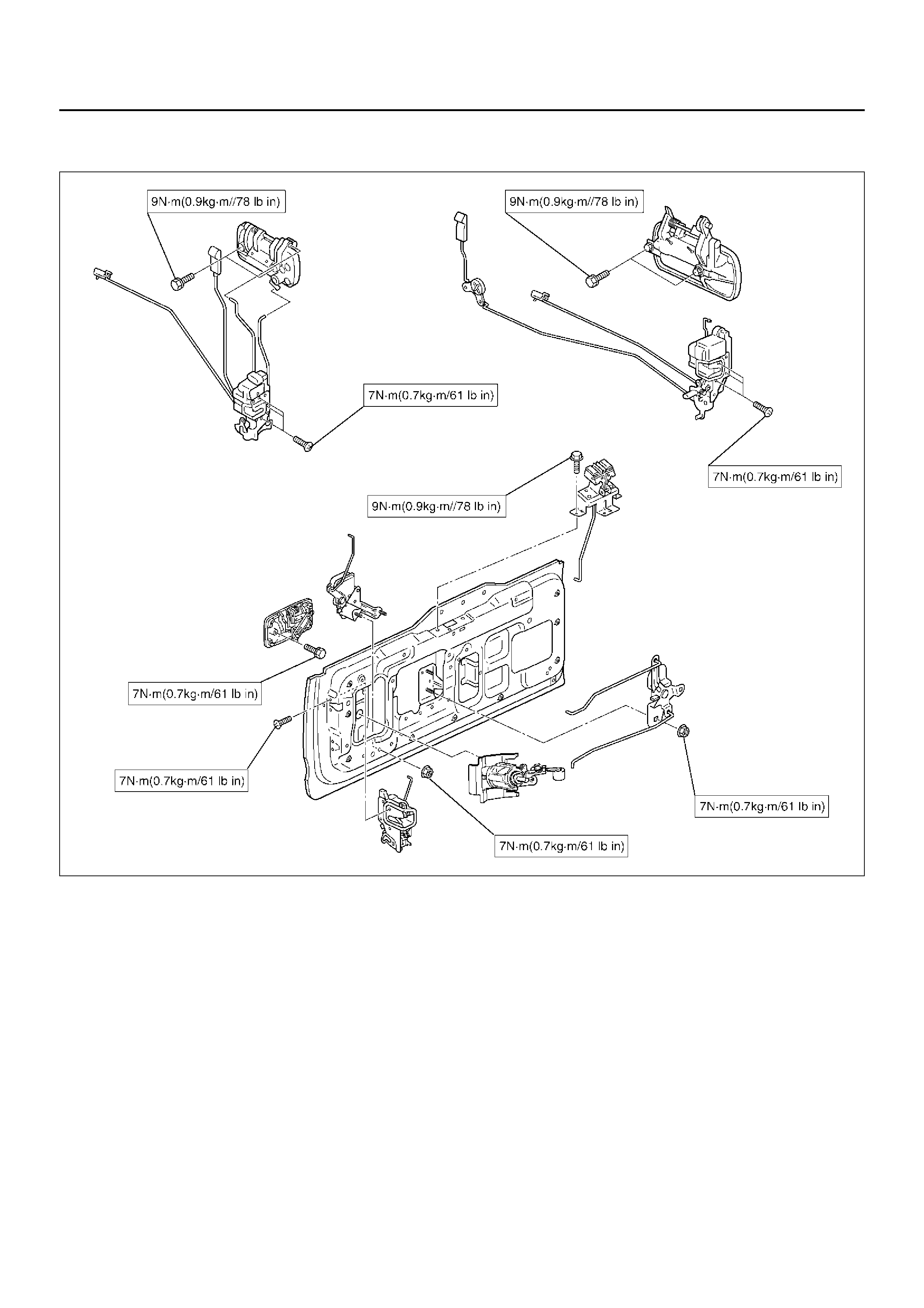
Tailgate Lock and Hatchgate Lock (LWB)
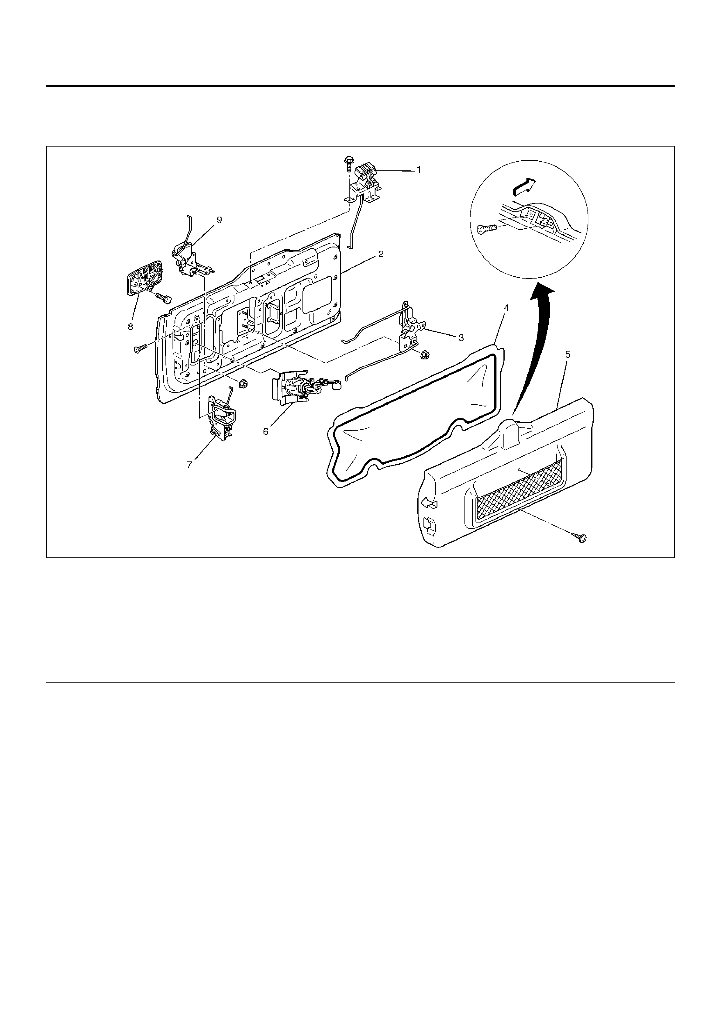
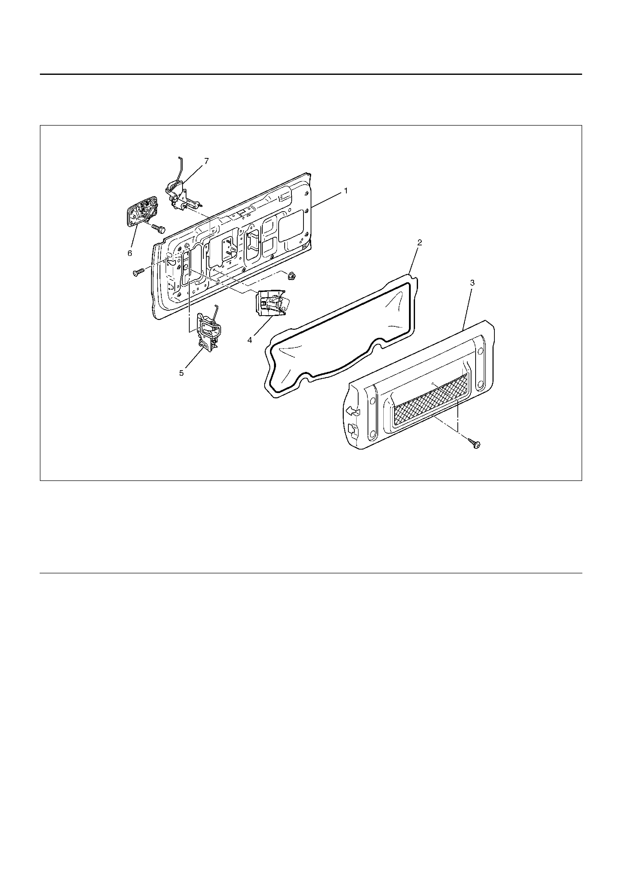
Tailgate Lock, Hatchgate Lock and Associated Parts
681RW015
Legend
EndOFCallout
(1) Hatchgate Lock Assembly
(2) Tailgate Assembly
(3) Tailgate Lock Relay Lever
(4) Waterproof Sheet
(5) Trim Cover Assembly
(6) K ey Cylinder
(7) Tailgate Lock Assembly
(8) Outside Handle
(9) Hatchgate Lock Actuator Assembly
Removal
1. Disconnect the battery ground cable.
2. Remove the tailgate trim cover assembly (3).
• Remov e the two screws (2) holding the hatchgate
lock assembly (1) first and the two screws fixing
the trim cover assembly. Pull up the trim cover
while detaching the clips from tailgate panel.
683RW001
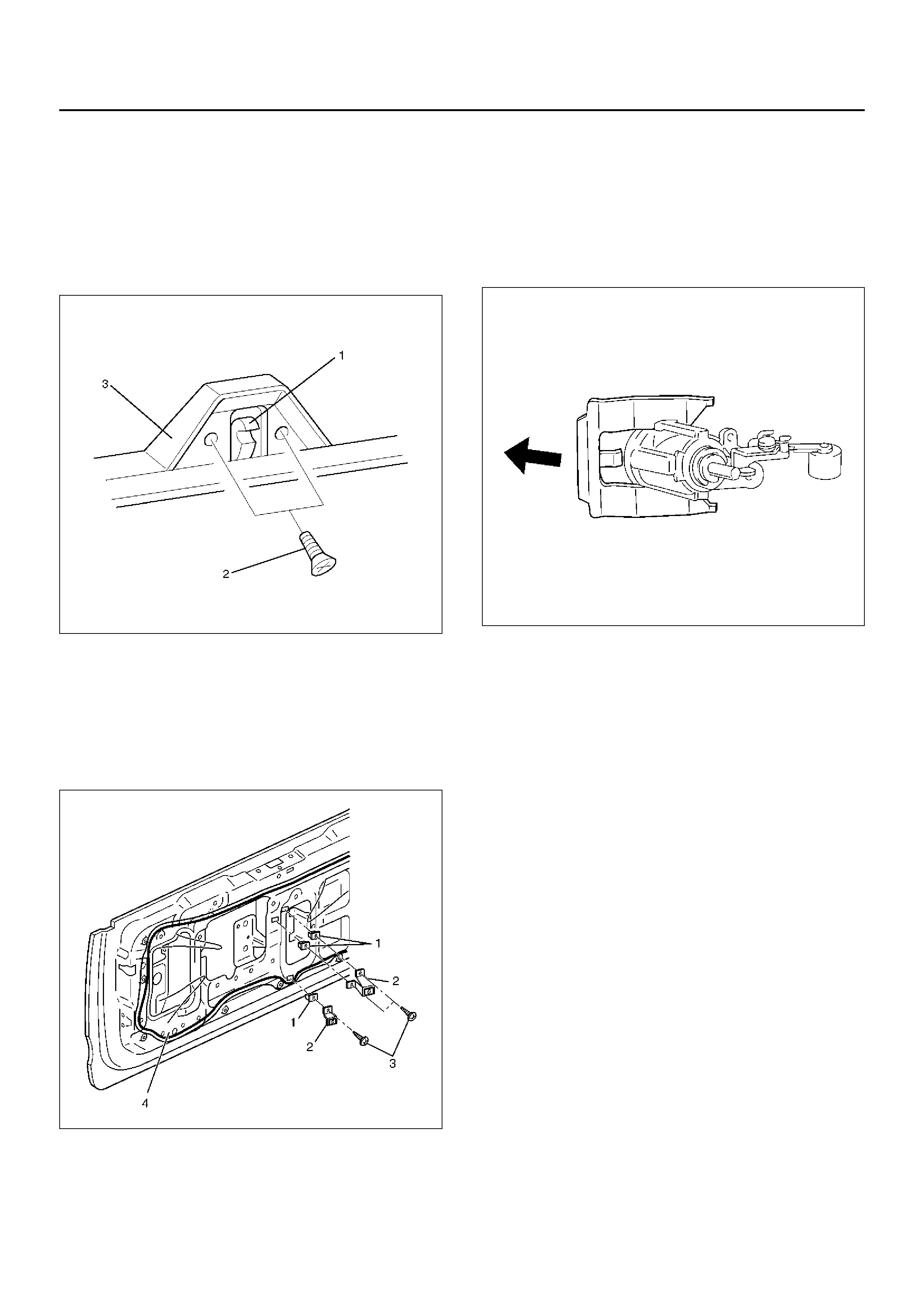
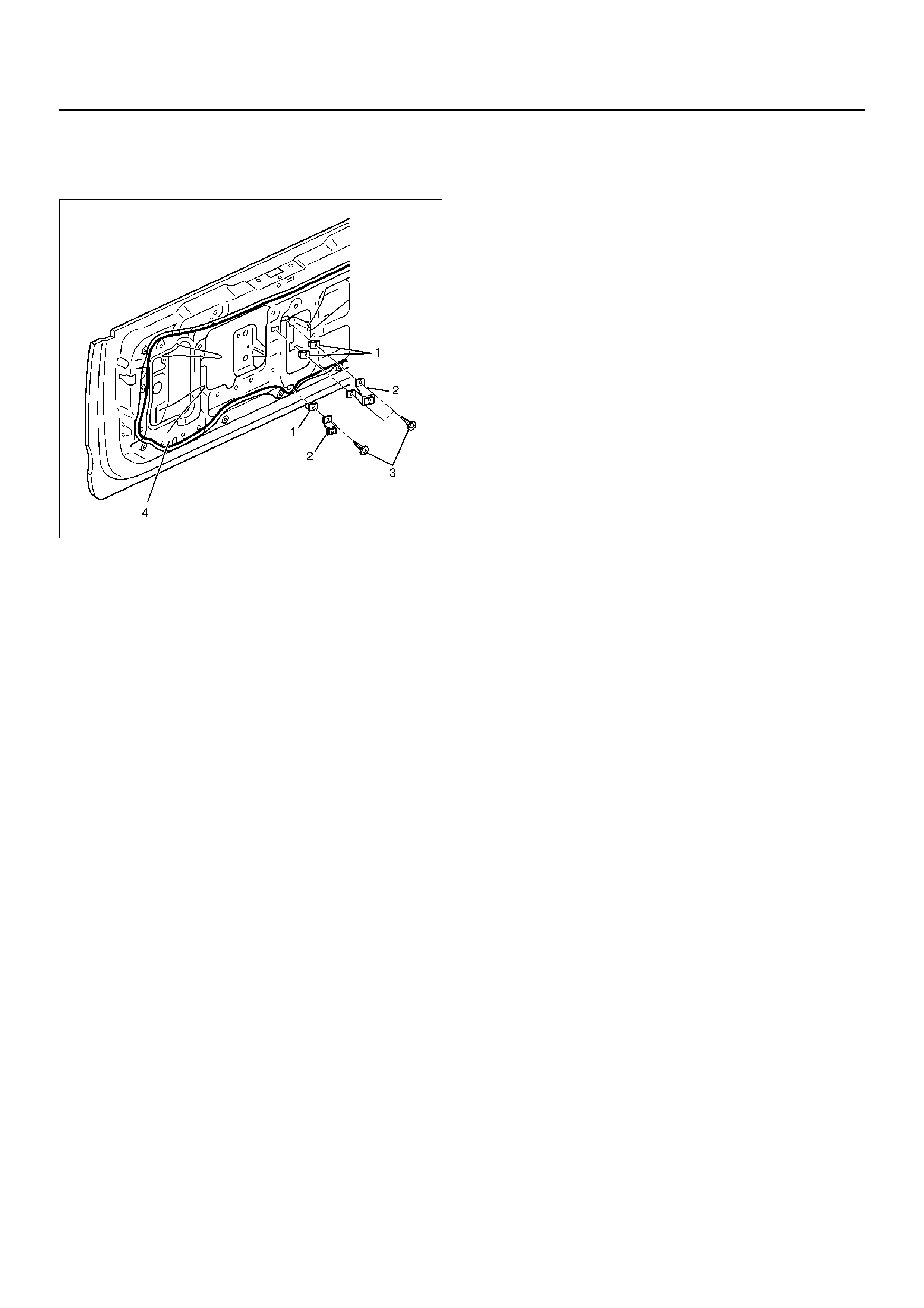
3. Remove the tailgate trim brackets (2).
• Remov e the three screws (3) and screw
grommets (1).
4. Remove the waterproof sheet (4).
• Remov e the waterproof sheet, taking special care
so as not to break it.
681RW014
5. Remove the hatchgate lock.
• Disconnect the lock link and connector and
remove the three fixing bolts.
6. Remove the key cy linde r.
• Disconnect the lock links.
• Remov e the key cylinder retaining clip with screw
driver to remove the key cylinder.
683RW025
7. Remove the hatchgate lock actuator assembly.
• Disconnect the actuator harness connector.
• Remov e the two nuts holding hatchgate lock
actuator assembly from inside.
8. Remove the outside handl e.
• Disconnect the lock links.
• Remov e the two bolts holding the outside handle
from inside.
9. Remove tailgate lock assembly.
• Remov e the three screws holding the lock
assembly.
Installation
To install, follow the removal steps in the reverse order,
noting the following points:
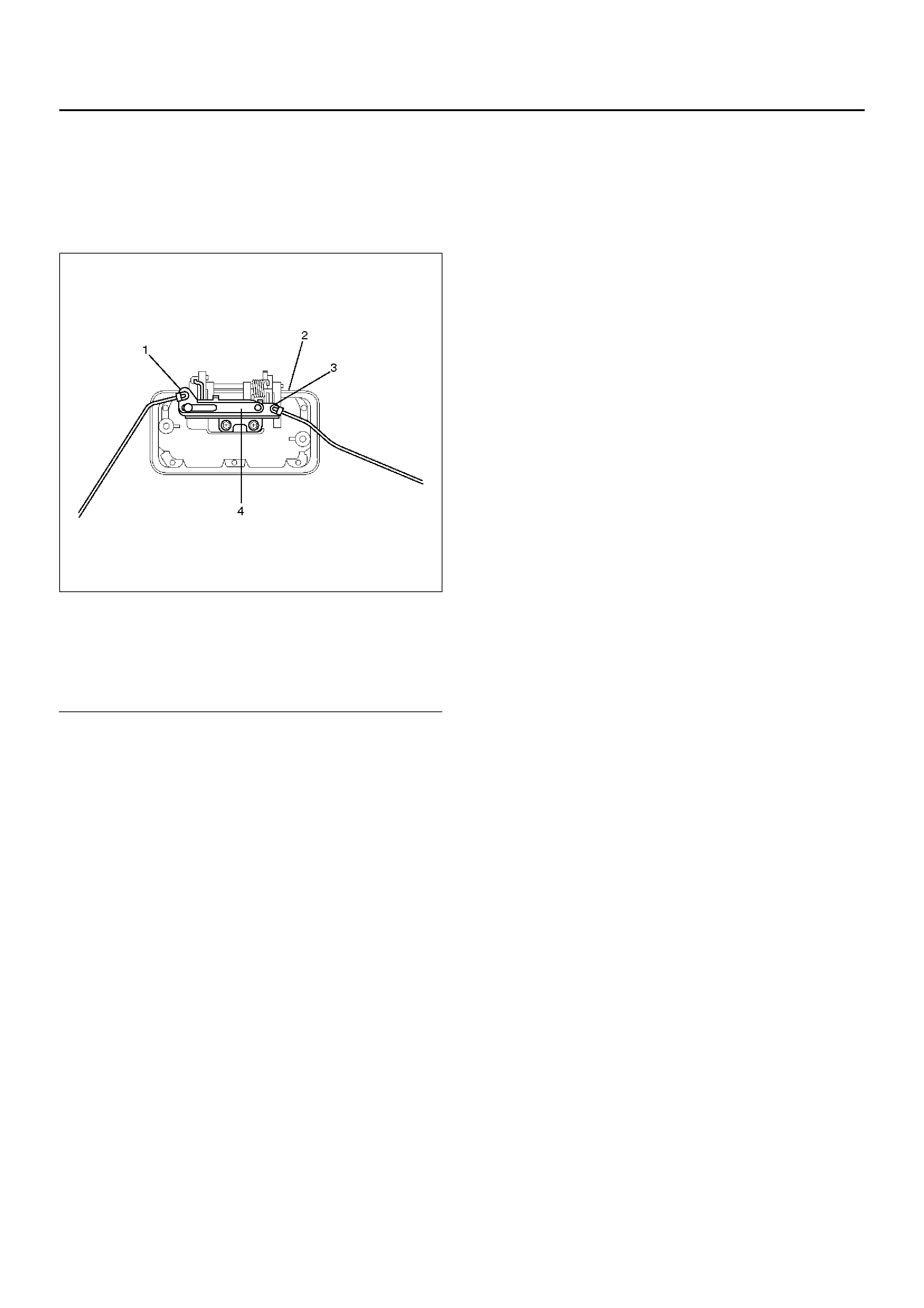
1. When setting up links, pay attention to the position
and direction of the links.
683RW003
Legend
EndOFCallout
2. Apply chassis grease to the lock assembly and
striker moving surface.
3. Check that the tailgate lock operates correctly after
instal li ng it.
4. Tighten the hatchhgate lock assembly fixing bolts to
the specified torque.
Tor que 9N·m (0.9kg·m/78lbin)
5. Tighten the tailgate lock assembly fixing screws to
the specified torque.
Tor que 7N·m (0.7kg·m/61lbin)
(1) Tailgate Lock Link
(2) Outside Handle
(3) Key Cylinder Link
(4) Canc el Mec ha nis m
Tailgate Lock (SWB)
Tailgate Lock and Associated Parts
681RW013
Legend
EndOFCallout
Removal
1.Disconnect the battery ground cable.
2.Remove the tailgate glass assembly and tailgate
glass stay.
•Refer to Tailgate Glass (SWB) in Body Structure
section.
3. Remove the tailgate trim cover assembly.
• Remove the two screws fixing the trim cover
assembly and pull up the trim cover after
detaching the clips from tailgate panel.
4. Remove the tailgate trim brackets (2).
• Remov e the three fixing screws (3) and screw
grommets (1).
(1) Tailgate Assembly
(2) Waterproof sheet
(3) Trim Cover Assembly
(4) Key Cylinder
(5) Tailgate Lock Assembly
(6) Outside Handle
(7) Hatchgate Lock Actuator Assembly
5. Remove the waterproof sheet (4).
• Remov e the waterproof sheet, taking special care
so as not to break it.
681RW014
6. Remove the key cylinder.
• Disconnect the lock links.
• Remov e the key cylinder retaining clip with screw
driv er to remove the key cylinder.
7. Remove the hatchgate lock actuator assembly.
• Disconnect the actuator harness connector.
• Remov e the two nuts holding hatchgate lock
actuator assembly from inside.
8. Remove the outside handle.
• Disconnect the lock link.
• Remov e the two bolts holding the outside handle
from inside.
9. Remove tailgate lock assembly.
• Remov e the three screws holding the lock
assembly.
Installation
To install, follo w the removal steps in the reverse order,
noting the following points:
1. Apply chassis grease to the lock assembly and
striker moving surface .
2. Tighten the tailgate lock assembly fixing screws to
the specified torque.
Tor que 7N·m (0.7kg·m/61lbin)
3. Check that the tailgate lock operates correctl y afte r
installing it.
Fuel Filler Door Lock
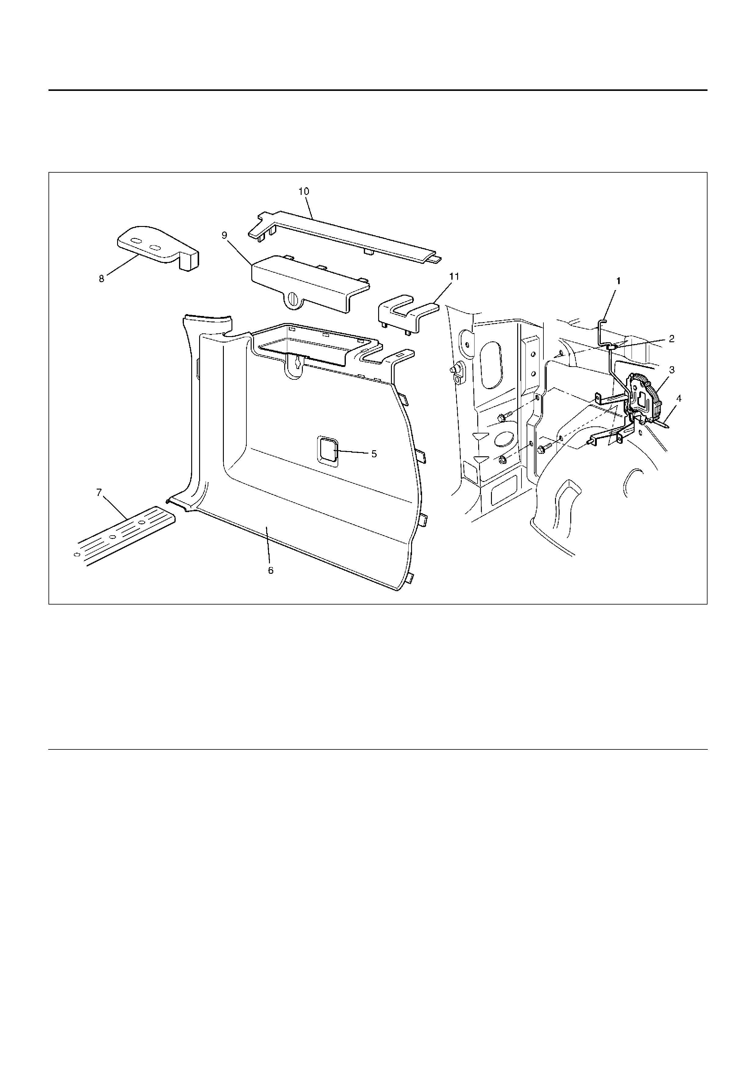
Fuel Filler Door Lock and Associated Parts
This illustration is based on the SWB model.
686RW014
Legend
EndOFCallout
Removal
1.Disconnect the battery ground cable.
2.Unlock the fuel filler door.
3.Remove the luggage trim cover on the left side.
•Remove the two clips, then canopy cover.
•Remove the luggage side lid assembly.
•Remove the luggage side upper cover.
•Remove the luggage side front cover.
•Remove the one fixing screw on the front upper
side of the luggage trim cover.
•Remove the rear and floor trim cover.
•Disconnect the accessory socket connector.
4.Remove the quarter trim cover (LWB).
•Refer to Interior Trim Panel (LWB) in Exterior/
Interior section.
5. Remove the fuel filler door lock actuator assembly.
• Remov e the two fixing bolts and one fixing nut.
(For LWB, one bolt and two nuts.)
6. Remove the fixing clip of the link.
(1) Link (SWB only)
(2) Clip (SWB only)
(3) Fuel Filler Door Lock Actuator Assembly
(4) Rod
(5) Accessory Socket
(6) Luggage Trim Cove r
(7) Rear End Floor Trim Cover
(8) Canopy Cover
(9) Luggage Side Lid Assembly
(10) Luggage Side Upper Cover
(11) Luggage Side Front Cover
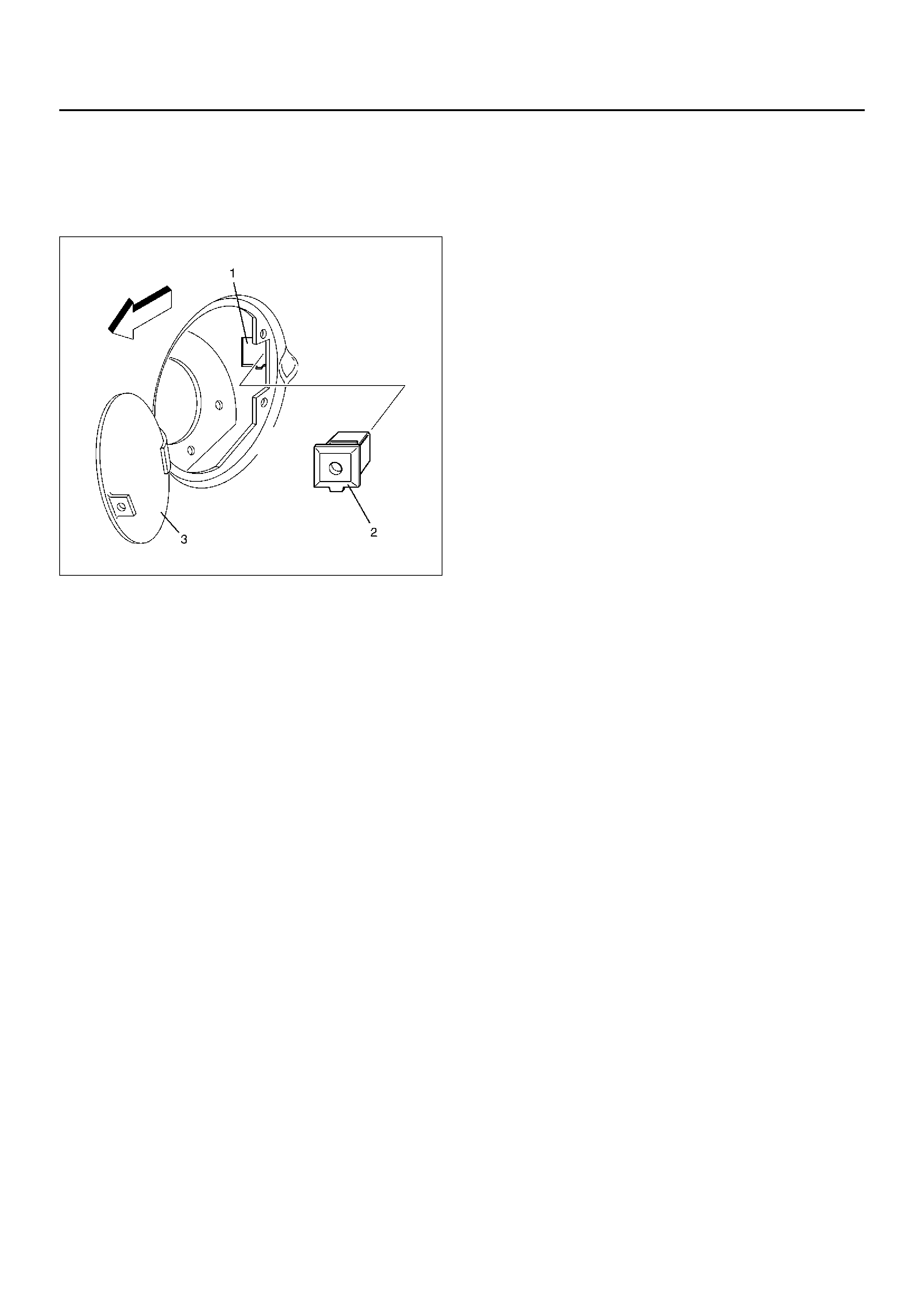
7. Remove the fuel filler door lock cap (2).
• While pressing the two lock portions of the cap
from inside of the vehicle, push the cap into the
hole. Open the fuel filler door (3) and remove the
cap out of the installation hole (1).
686RW013
8. Remove the fuel filler door lock actuator assembly.
• Disconnect the body harness connector.
Installation
To install, follo w the removal steps in the reverse order,
noting the following points:
1. Install the cap by using the actuator assembly rod
as a guide.
2. Take care not to pinch the drain hose and the
harness while tightening the actuator fixing bolts
and nut.
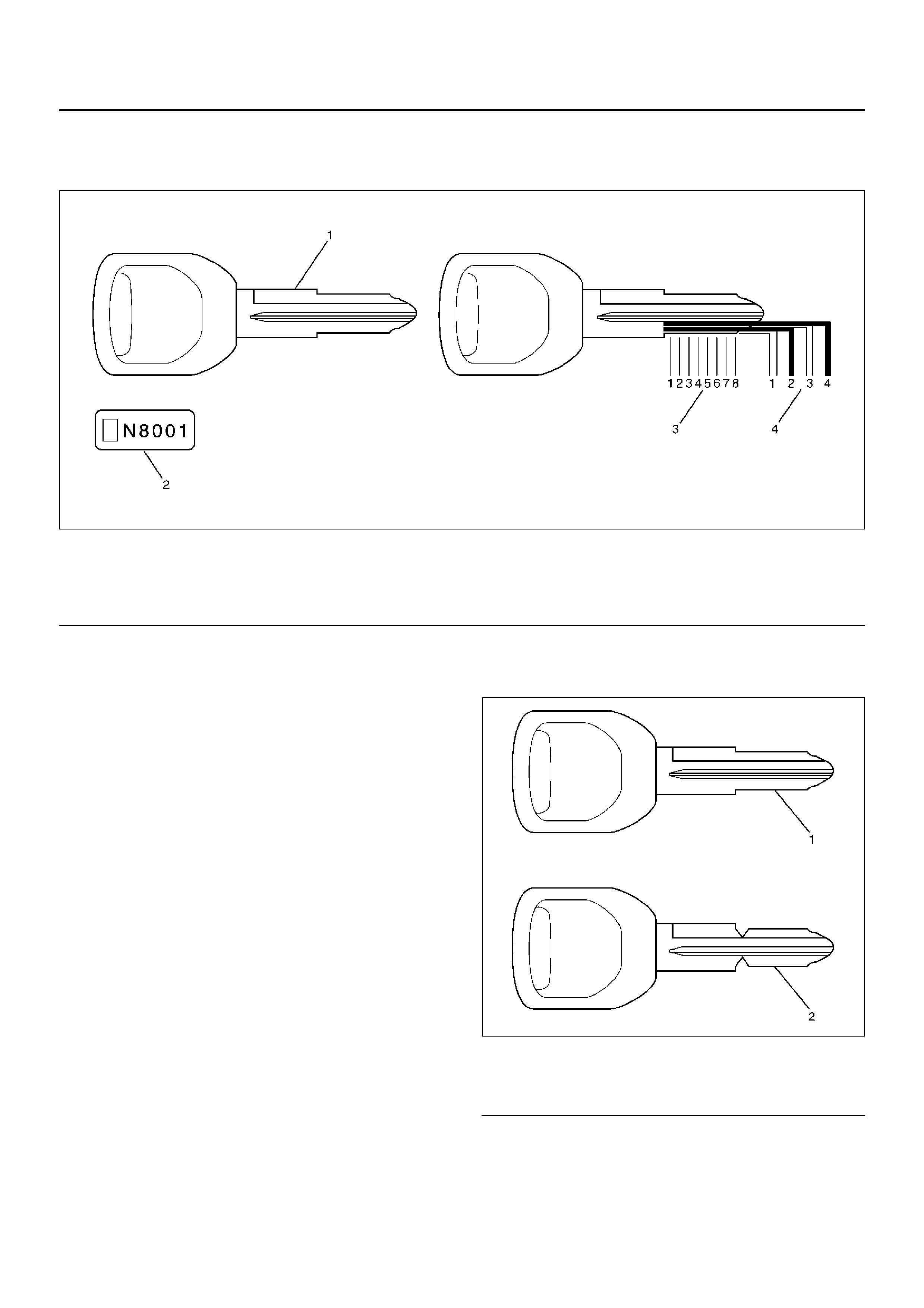
Key
Key Coding
730RX001
Legend
EndOFCallout
One key is used for the ignition, door, and tailgate lock
cylinders. The ke ys are cut on both edges to make them
reversible.
Key identification is obtained from the five character ke y
code stamped on the key code tag. From this key code,
the ke y code cutting combination can be determined
from a code list (available to owners of key cutting
equipment from suppliers).
If key codes are not available from records or tags, the
key code can be obtained from the right hand door lock
cylinder (if lock has not been replaced). Lock cylinders
supplied by the factory as service parts are unmarked.
If the original key is availab l e, the key code cutting
combination can be determined by la ying the ke y on the
diagram shown in the figure.
Key Styles
730RX002
Legend
EndOFCallout
The keys come in styles A or B depending on the key
code cutting combination. When the first position in the
combination is a 1, 2 or 3, Style A is used. When the
first position is a 4, Style B (factory pre-cut key) is us ed.
(1) K ey (Actual size)
(2) Key Code Tag (3) Position
(4) Level
(1) Blank Key Style “A "
(2) Blank Key Style “B "

Power Door Lock System
General Description
The circuit consists of the door lock (& power window)
switch, door lock actuator for the front and rear door,
tailgate lock actuator, fuel filler door lock actuator and
the door lock key switch.
The front door lock switch–LH is always provided with
the battery voltage.
The key or the inside lock button on the both driver's
and the front passenger's door can activate the lock
mechanism of all the doors (including the tailgate).
When the driver's door lock switch or the front
passenger's door lock switch is turned on, current flows
for about one second to the door lock actuator of each
door connected in parallel with the front door lock (&
power window) switch–LH to activate the actuator to
lock and unlock the doors.
Door Lock Key Switch
Removal and Installation
•Refer to Front Door Lock Assembly in this section.
Front Door Lock Actuator
Removal and Installation
•Refer to Front Door Lock Assembly in this section.
Rear Door Lock Actuator
Removal and Installation
•Refer to Rear Door Lock Assembly in this section.
Tailgate Lock Actuator
Removal and Installation
•Refer to Tailgate Lock Assembly in this section.
Fuel Filler Door Lock Actuator
Removal and Installation
•Refer to Fuel Filler Door Lock in this section.
Keyless Entry System
General Description
This circuit consists of the keyless entry control unit, the
front door lock & power window switch (RH), the starter
switch, the dome light, the door switch and the tail gate
switch and possible to be locked/unlocked each door by
operation of transmitter. Basic function of system is as
follows.
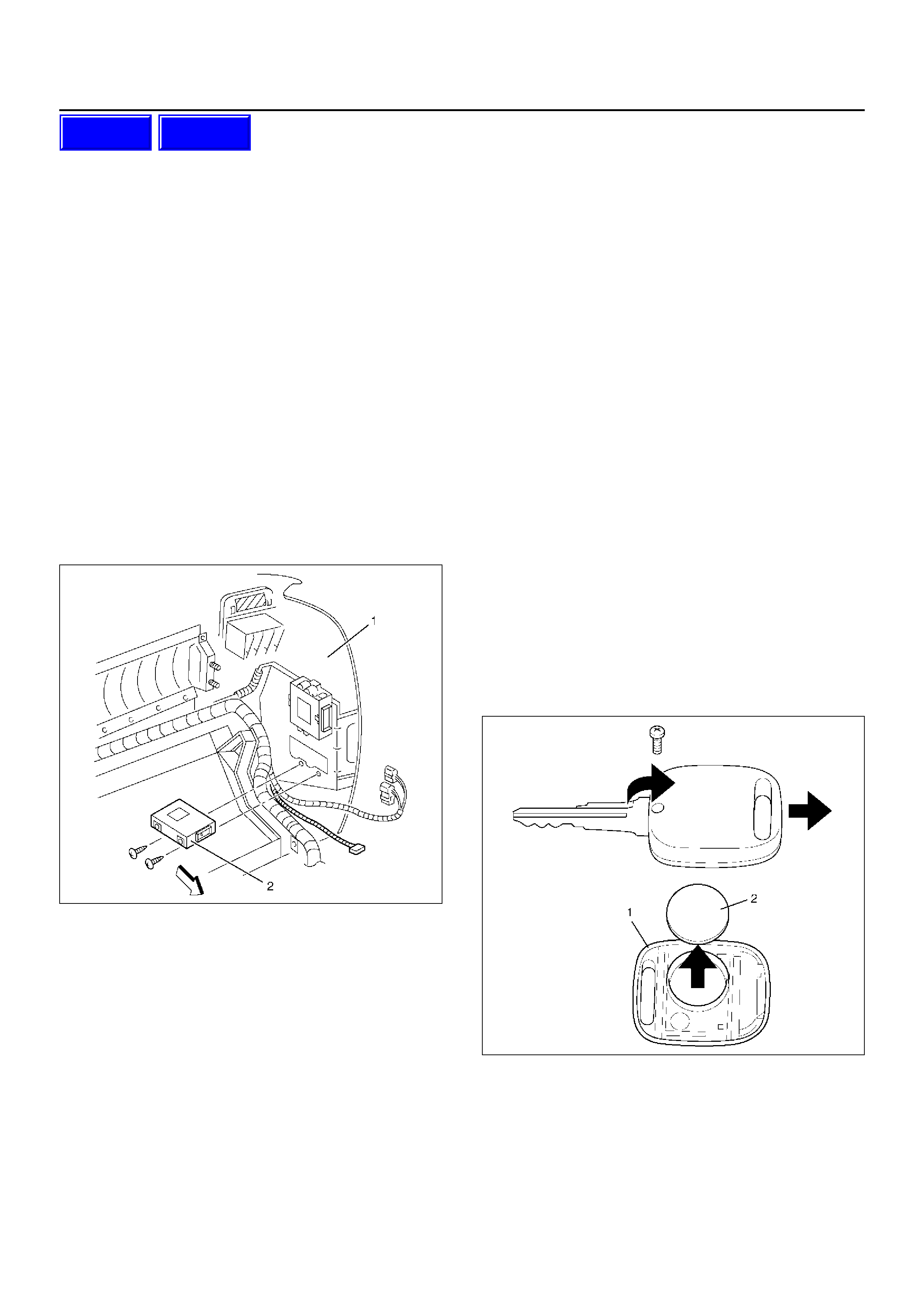
Keyless Entry Control Unit
Removal
1.Disconnect the battery ground cable.
2.Remove the instrument panel assembly (1).
•Refer to the Instrument Panel Assembly in Body
Structure section.
3.Remove the keyless entry control unit (2).
•Disconnect the connector.
•Remove two fixing screws.
826RY00033
Installation
To install, follow the removal steps in the reverse order.
Keyless Entry Control Unit/
Transmitter Replacement
Keyless Entry Control Unit Replacement
1.Remove and install the control unit.
•Refer to Keyless Entry Control Unit in this section.
2. Register ID code.
•Refer to ID Code Registration in Wiring System
section.
3. Check that the keyless entry system works normally.
Transmi tter Replacement
1. Prepare a new transmitter.
2. Regiter ID code.
•Refer to ID Code Registration in Wiring System
section.
3. Check that the keyless entry system works normally.
Transmi tter Bat t ery Replacement
1. Remove a screw to remove the cover (1).
2. Remove the battery (2).
3. Set the new battery into the transmitter.
4. Install the cover to the transmitter.
5. Check that the keyless entry system works normally.
730RY00002
Techline
Techline
Main Data and Specifications
Torque Specifications
635RY00008