
SECTION 8I - SUNROOF/CONVERTIBLE TOP
Service Precaution
Sunroof Glass (LWB)
Sunroof Glass and Associated Parts
Removal
Installation
Sunroof Glass (SWB)
Sunroof Glass and Associated Parts
Removal
Installation
Sunroof Deflector (LWB)
Removal
Installation
Sunroof Deflector (SWB)
Parts Location
Removal
Installation
Sunshade (LWB)
Disassembled View
Removal
Installation
Sunroof Frame Complete Assembly (LWB)
Sunroof Frame Complete Assembly
and Associated Parts
Removal
Installation
Sunroof Switch
Removal
Installation
Sunroof Control Unit
Removal
Installation
Safety Stop Switch
Removal
Installation
Limit Switch
Removal
Installation
Sunroof Motor
Removal
Installation
Resin Top Assembly
Resin Top Assembly and Associated Parts
Removal
Installation
Seat Belt Cross Bar Assembly
Seat Belt Cross Bar Assembly
and Associated Parts
Removal
Installation
Main Data and Specifications
Service Precaution
WARNING: THIS VEHICLE HAS A SUPPLEMENTAL
RESTRAINT SYSTEM (SRS). REFER TO THE SRS
COMPONENT AND WIRING LOCATION VIEW IN
ORDER TO DETERMINE WHETHER YOU ARE
PERFORMING SERVICE ON OR NEAR THE SRS
COMPONENTS OR THE SRS WIRING. WHEN YOU
ARE PERFORMING SERVICE ON OR NEAR THE
SRS COMPONENTS OR THE SRS WIRING, REFER
TO THE SRS SERVICE INFORMATION. FAILURE TO
FOLLOW WARNINGS COULD RESULT IN POSSIBLE
AIR BAG DEPLOYMENT, PERSONAL INJURY, OR
OTHERWISE UNNEEDED SRS SYSTEM REPAIRS.
CAUTION: Always use the correct fastener in the
proper location. When you replace a fastener, use
ONLY the exact part number for that application.
ISUZU will call out those fasteners that require a
replacement after removal. ISUZU will also call out
the fasteners that require thread lockers or thread
sealant. UNLESS OTHERWISE SPECIFIED, do not
use supplemental coatings (Paints, greases, or
other corrosion inhibito r s) on thr eaded fastener s or
fastener joint interfaces. Generally, such coatings
adversely affect the fastener torque and the joint
clamping force, and may damage the fastener.
When you install fasteners, use the correct
tightening sequence and specifications. Following
these instructions can help you avoid damage to
parts and systems.
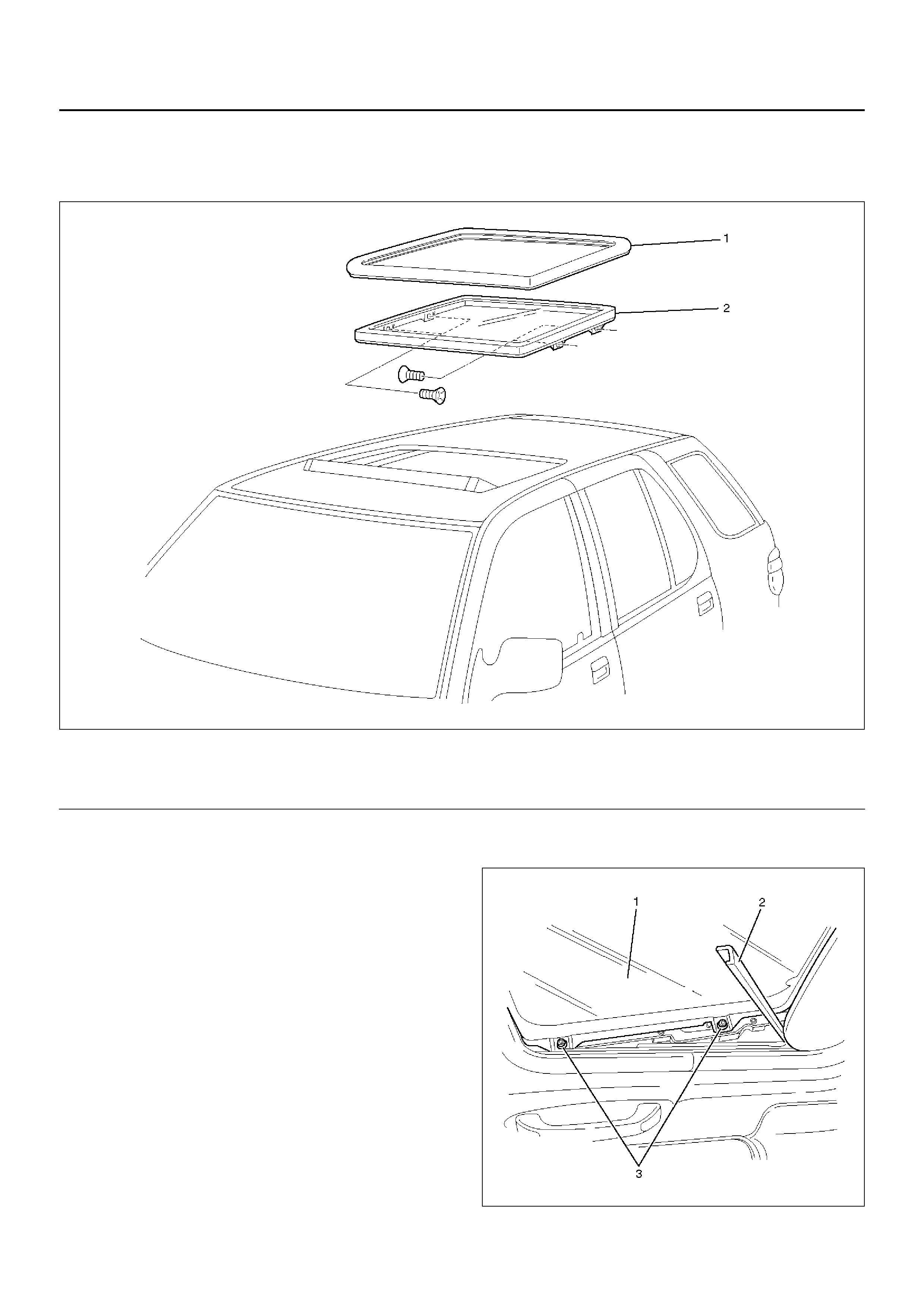
Sunroof Glass (LWB)
Sunroof Glass and Associated Parts
665RW004
Legend
EndOFCallout
Removal
1. Tilt the sunr oof and open the sunshade.
2. Disconnect the battery ground cable.
3. Pull out the front of sight shield (2).
4. Remove four sunroof glass fixing Torx scre ws (3) to
remove the sunroof glass (1).
665RW011
(1) Sunroof Weatherstrip
(2) Sunroof Glass
Installation
1. Be sure to install the sunroof weatherstrip so that
the joint of the weatherstrip is on the rear side of the
vehicle.
2. Temporary install the glass to the sunroof frame.
3. Open and shut the sunroof four to five times to
position correctly the sunroof weatherstrip and the
glass in the longitudinal and lat itudinal setting
positions.
4. Adjust the setting position to flush the surface
between the roof panel and weatherstrip of sunroof
glass.
5. Tighten the sunroof glass fixing screws to the
specified torque.
Torque: 4N·m (0.4 kg·m/35lbin)
6. After the sunroof glass is installed, recheck the roof
panel and sunroof glass for vertical install position.
If out of standard, adjust with fixing screws.
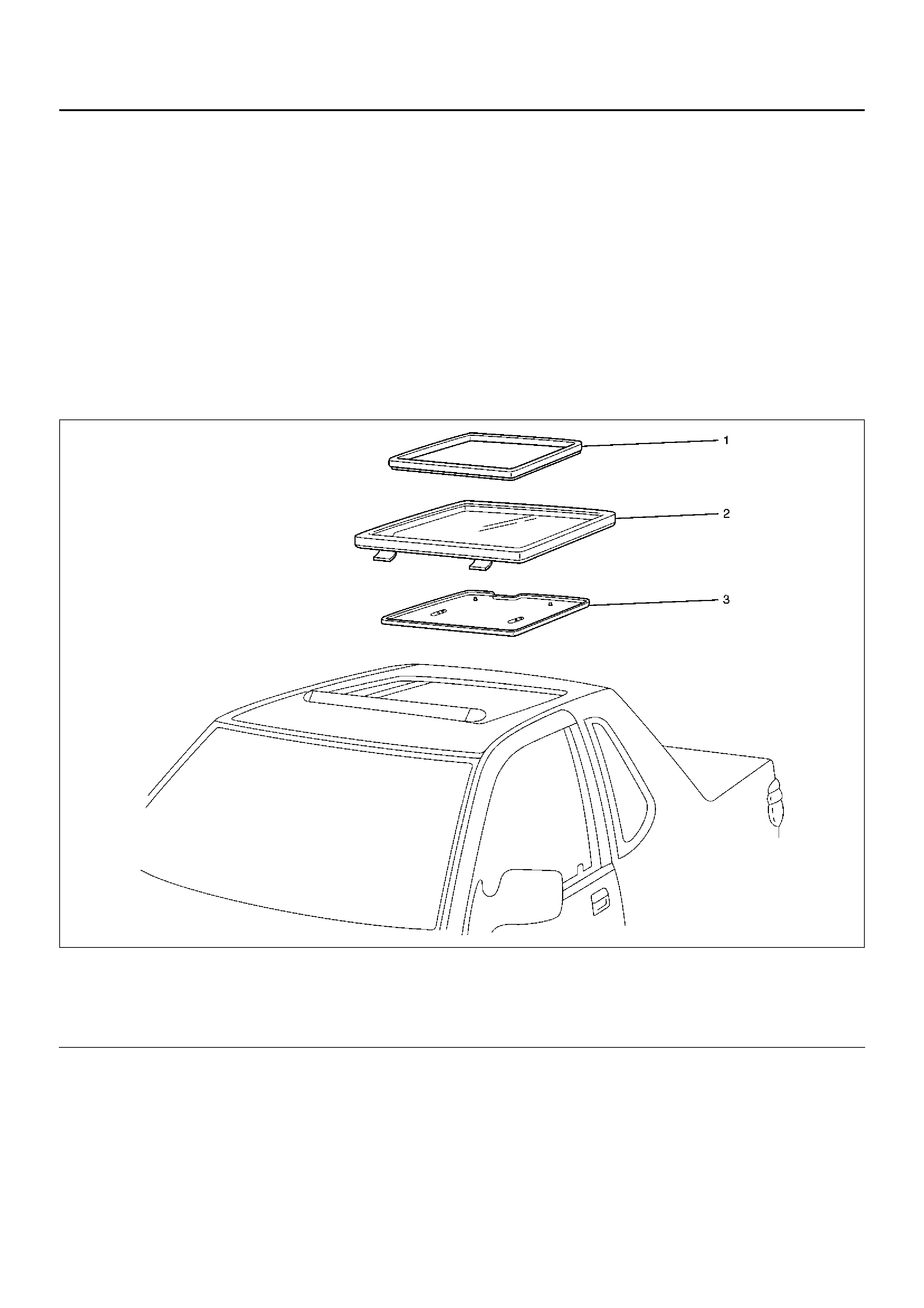
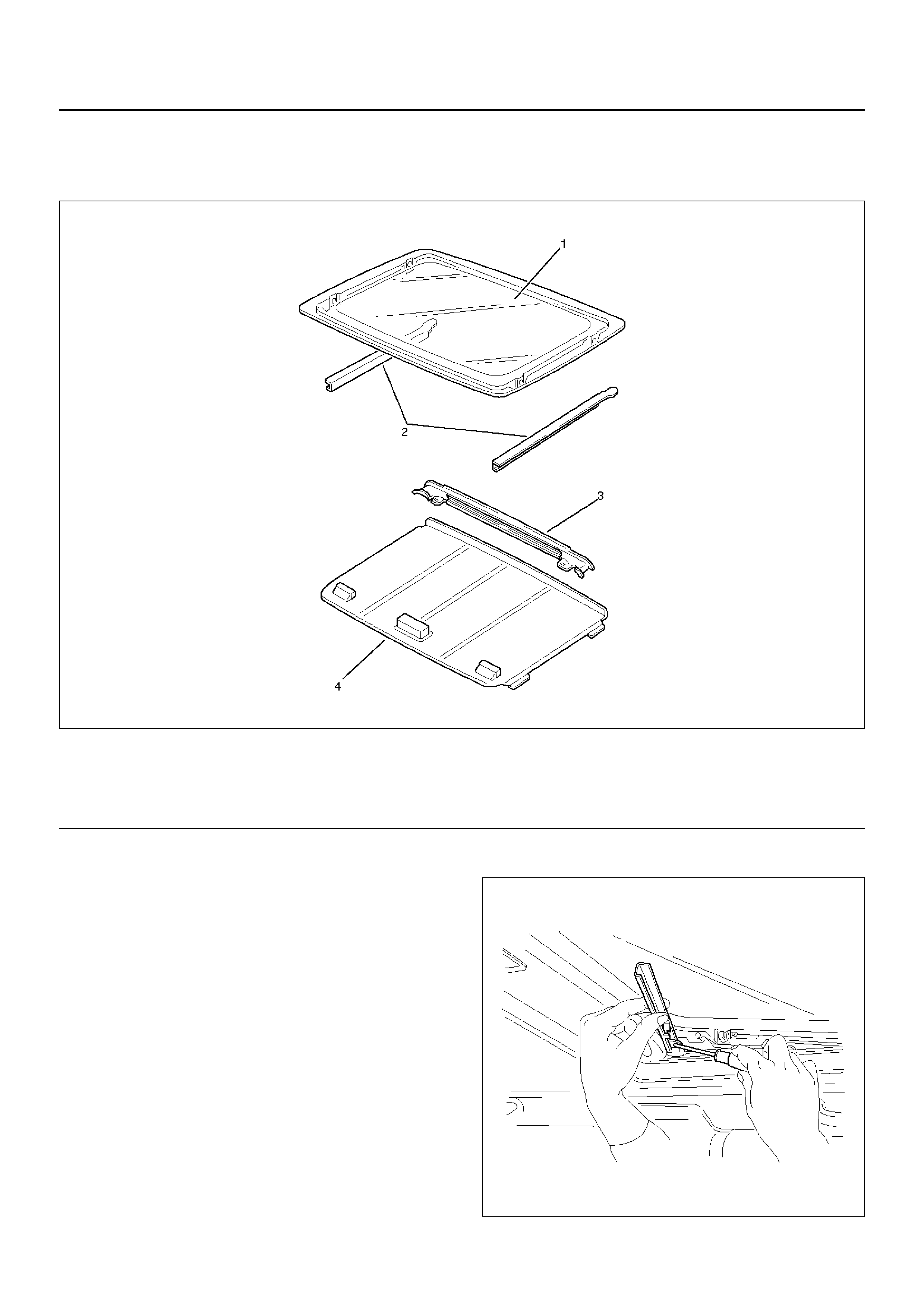
Sunroof Glass (SWB)
Sunroof Glass and Associated Parts
665RW028
Legend
EndOFCallout
(1) Sunroof Weather Strip
(2) Sunroof Glass Assembly (3) Sunshade Assembly
Removal
1. Disconnect the battery ground cable.
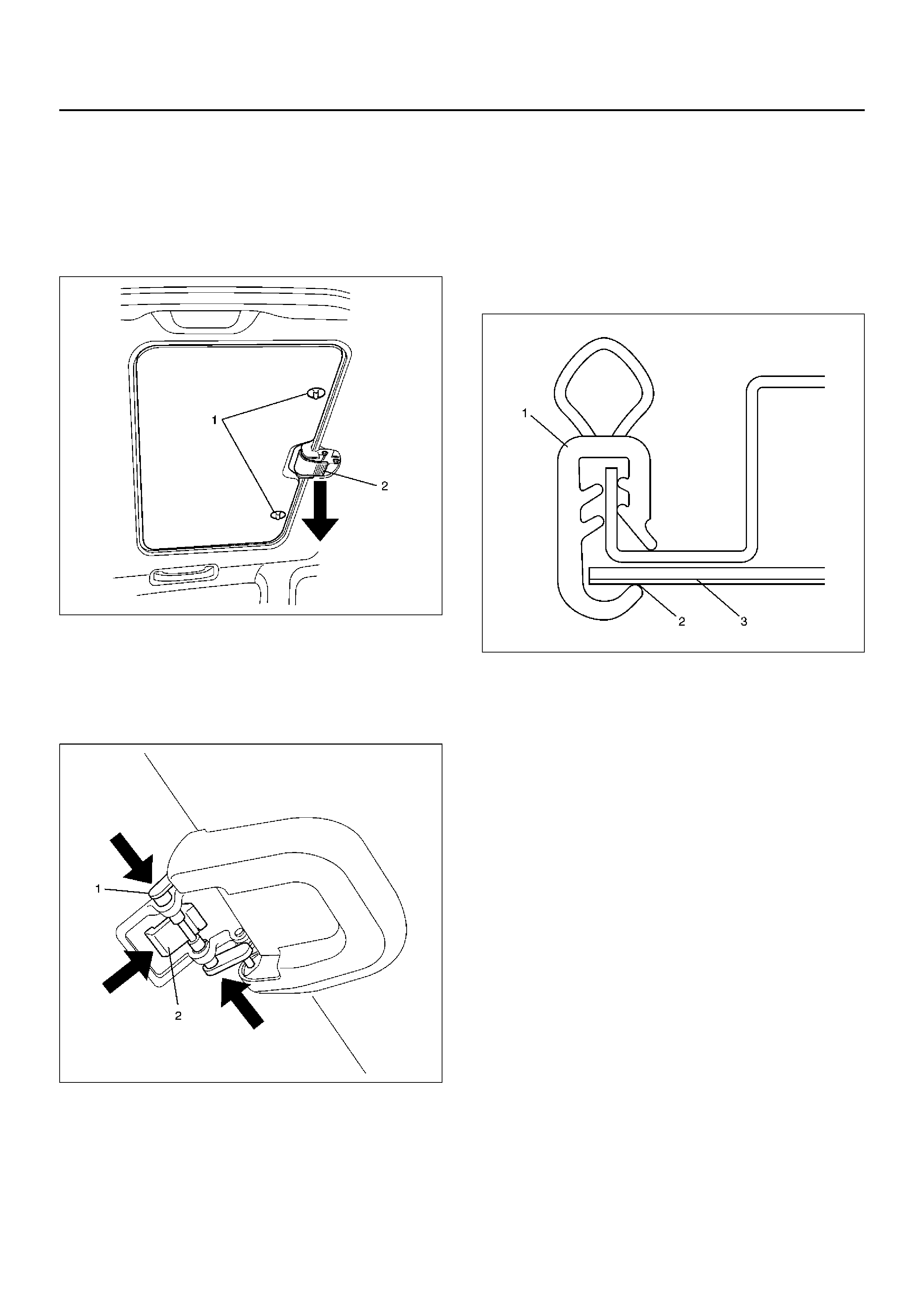
2. Remove the sunshade assembly.
• Turn the knobs (1) 90 degrees and pull it out at
angle. Then pull the sunroof handle (2) to
disengage the lock.
665RW025
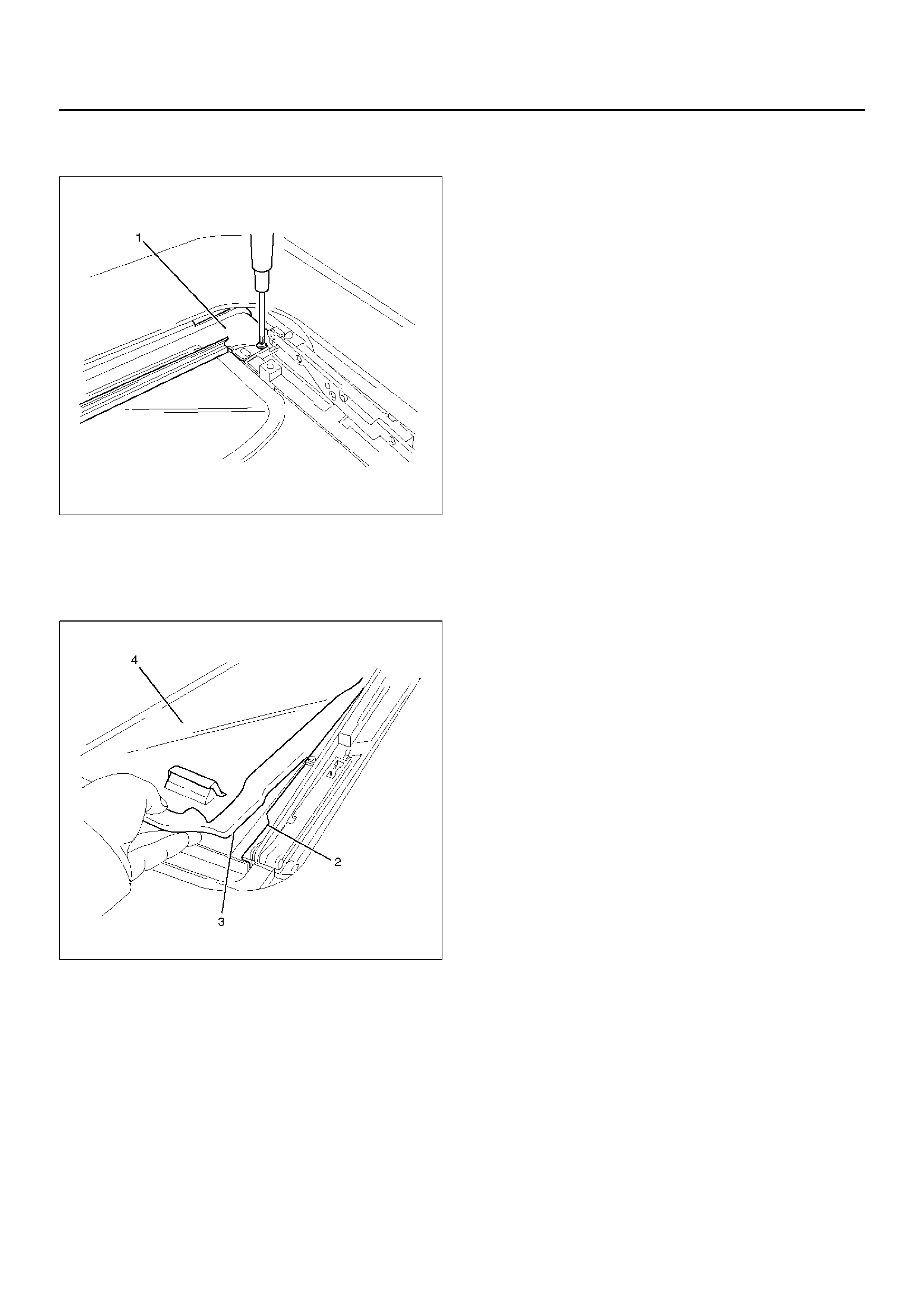
3. Remove the sunroof glass assembly.
• Push the safety lever (2) behind the handle and
push in on the hinge pins (1) from the left and
right to disengage them. Raise the rear end of the
sunroof glass assembly at an angle pull it free.
665RW026
4. Remove the sunroof handle cover and sunroof
hand le pla te.
• Remove the screw form the cover and the three
fixing nuts form the plate.
5. Remove the weather strip.
Installation
To install, follow the removal steps in the reverse or der,
nothing the following points.
1. When attaching the sunroof weather strip (1), make
sure that the lip (2) securely ov erlaps the headlining
(3).
• Assemble with the positioning marks centered
toward the rear of the vehicle.
666RW007
2. Tighten the sunroof handle plate fixing nuts to the
specified torque.
Torque: 8 N·m (0.8 kg·m/69 Ib in)
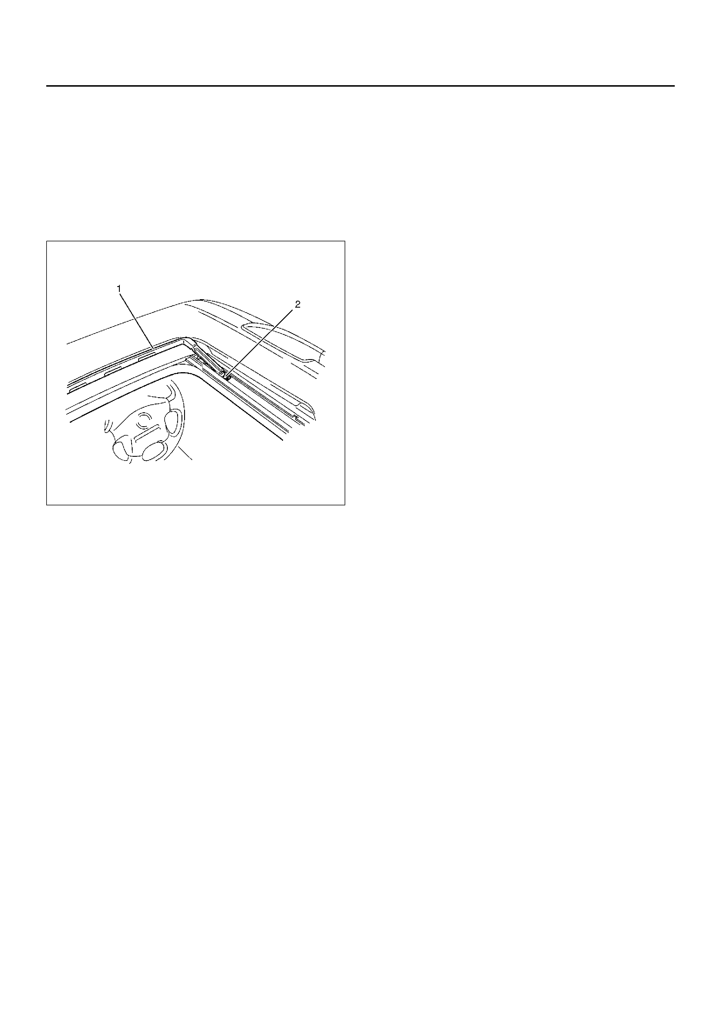
Sunroof Deflector (LWB)
Removal
1. Open the sunroof.
• Let a 5 mm drill go through two blind rivets (2) to
disengage riveted portions.
2. Remove the sunroof deflector (1).
665RW027
Installation
To install, follow the removal steps in the reverse or der.
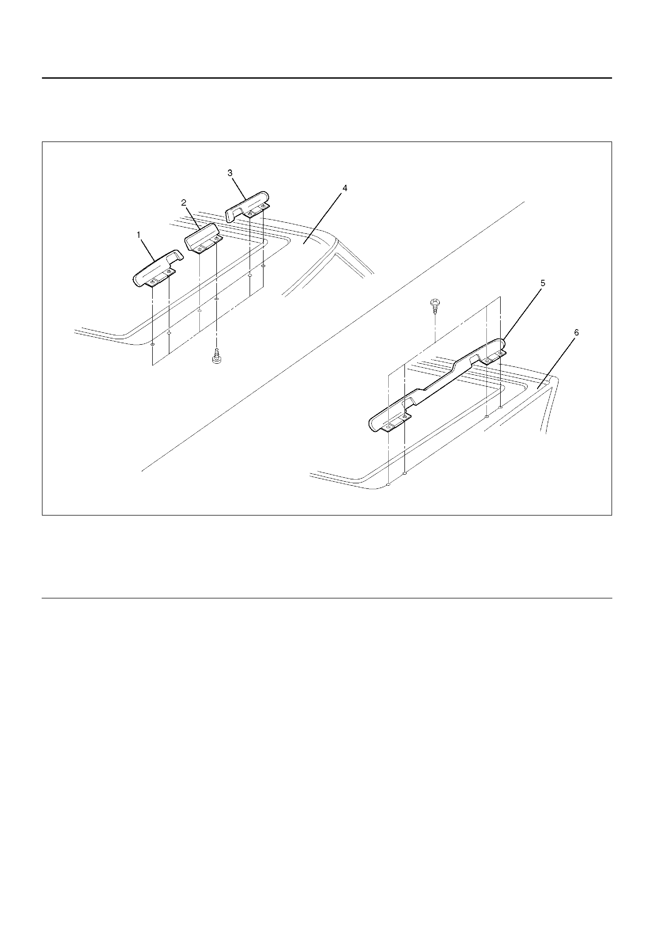
Sunroof Deflector (SWB)
Parts Location
665RX001
Legend
EndOFCallout
Removal
1.Disconnect the battery ground cable.
2.Remove the sunroof glass.
•Refer to Sunroof Glass (SWB) in this section.
3. Remove the headlining (Front roof side).
•Refer to Headlining (SWB) in Exterior/Interior
Trim sectio n.
4. Remove the sunroof deflector.
• Remove the fixing screws.
Installation
To install, follow the removal steps in the reverse or der.
(1) Side Deflector Assembly (RH)
(2) Center Deflector Assembly
(3) Side Deflector Assembly (LH)
(4) Roof Panel (Front side)
(5) Rear Sunroof Deflector Assembly
(6) Roof Panel (Resin Top side)
Sunshade (LWB)
Disassembled View
665RW012
Legend
EndOFCallout
Removal
1.Tilt the sunroof.
2.Disconnect the battery ground cable.
3.Remove the sunroof glass.
•Refer to Sunroof Glass (LWB) in this section.
4. Pull the sight shield upward using screwdriver.
665RW006
(1) Sunroof Glass
(2) Sight Shield (3) Sunshade Stopper
(4) Sunshade
5. Remove 2 sunshade stopper fixing screws and
remove sunshade stopper (1).
665RW007
6. Pull out the sunshade (4) up to the guide rail edge.
Lift the front of sunshade and clear the projection (3)
of sunshade through the notch (2) of guide rail edge,
then draw the sunshade out of the roof.
665RW009
Installation
To install, follow the removal steps in the reverse order.
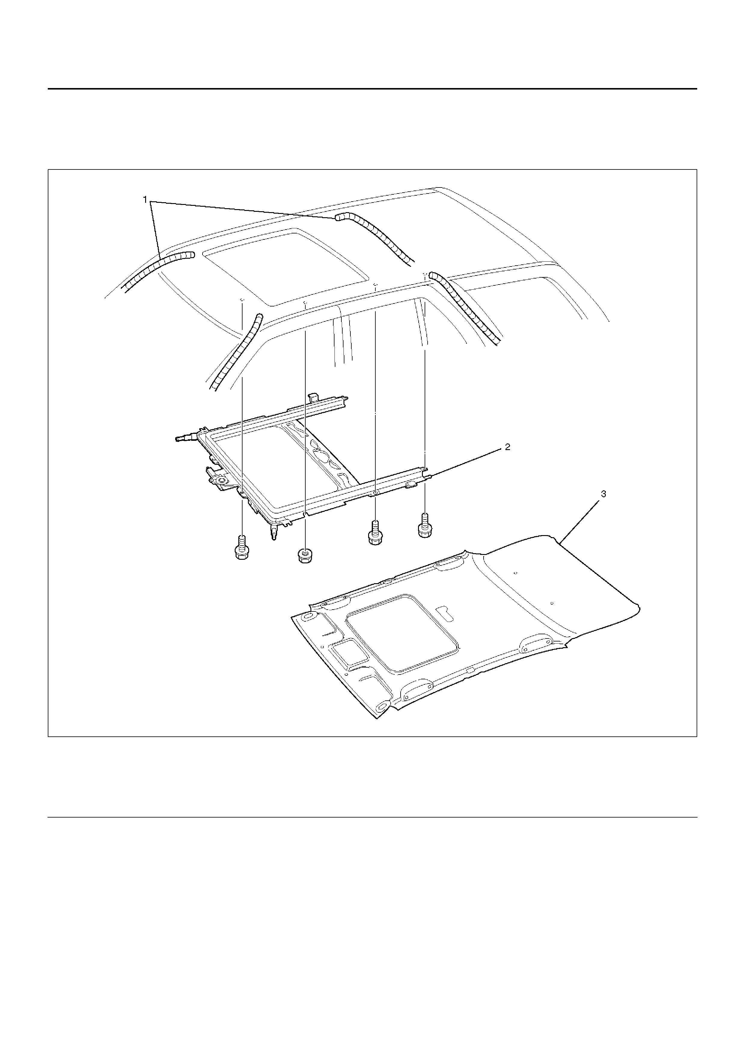
Sunroof Frame Complete Assembly (LWB)
Sunroof Frame Complete Assembly and Associated Parts
665RW005
Legend
EndOFCallout
Removal
1.Disconnect the battery ground cable.
2.Remove the headlining.
•Refer to Headlining (LWB) in Exterior/Interior Trim
section.
(1) Sunroof Drain Hose
(2) Sunroof Frame Complete Assembly (3) Headlining
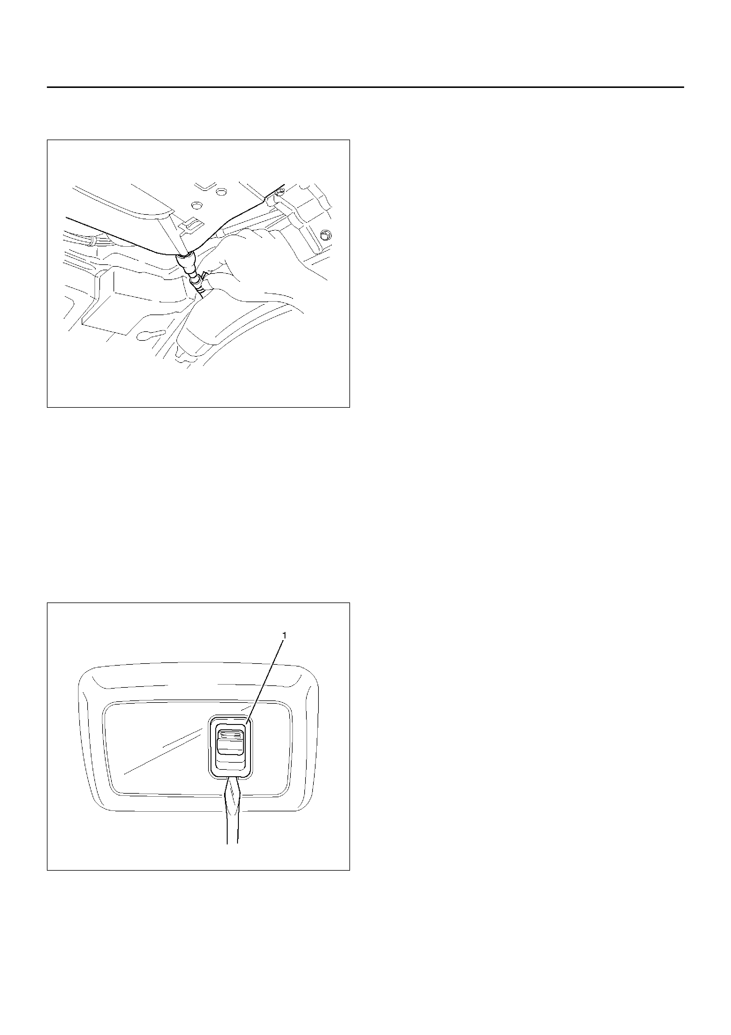
3.Disconnect the sunroof drain hose at the sunroof
frame side as shown in the figure.
665RW010
4.Disconnect the sunroof harness connection.
5.Remove two sunroof frame complete assembly
fixing nuts (front side) and six fixing bolts from the
frame complete assembly, and then remove the
sunroof frame complete assembly.
NOTE: Be sure to remove the frame complete
assembly while supporting it.
Installation
1.Install the sunroof frame complete assembly.
2.After installing the frame complete assembly, loosen
the sunroof glass fixing nuts and adjust the sunroof
glass setting position.
•Refer to Sunroof Glass in this section.
3. Install the sunroof drain hose.
4. Install the headlining.
•Refer to Headlining in Exterior/Interior Trim
section.
Sunroof Switch
Removal
1. Disconnect the battery ground cable.
2. Remove the sunroof switch (1).
• Remov e the s witch b y pushing the spring with the
tip of a screwdriver.
• Disconnect the switch connector.
825RW091
Installation
To install, follow the removal steps in the reverse or der.
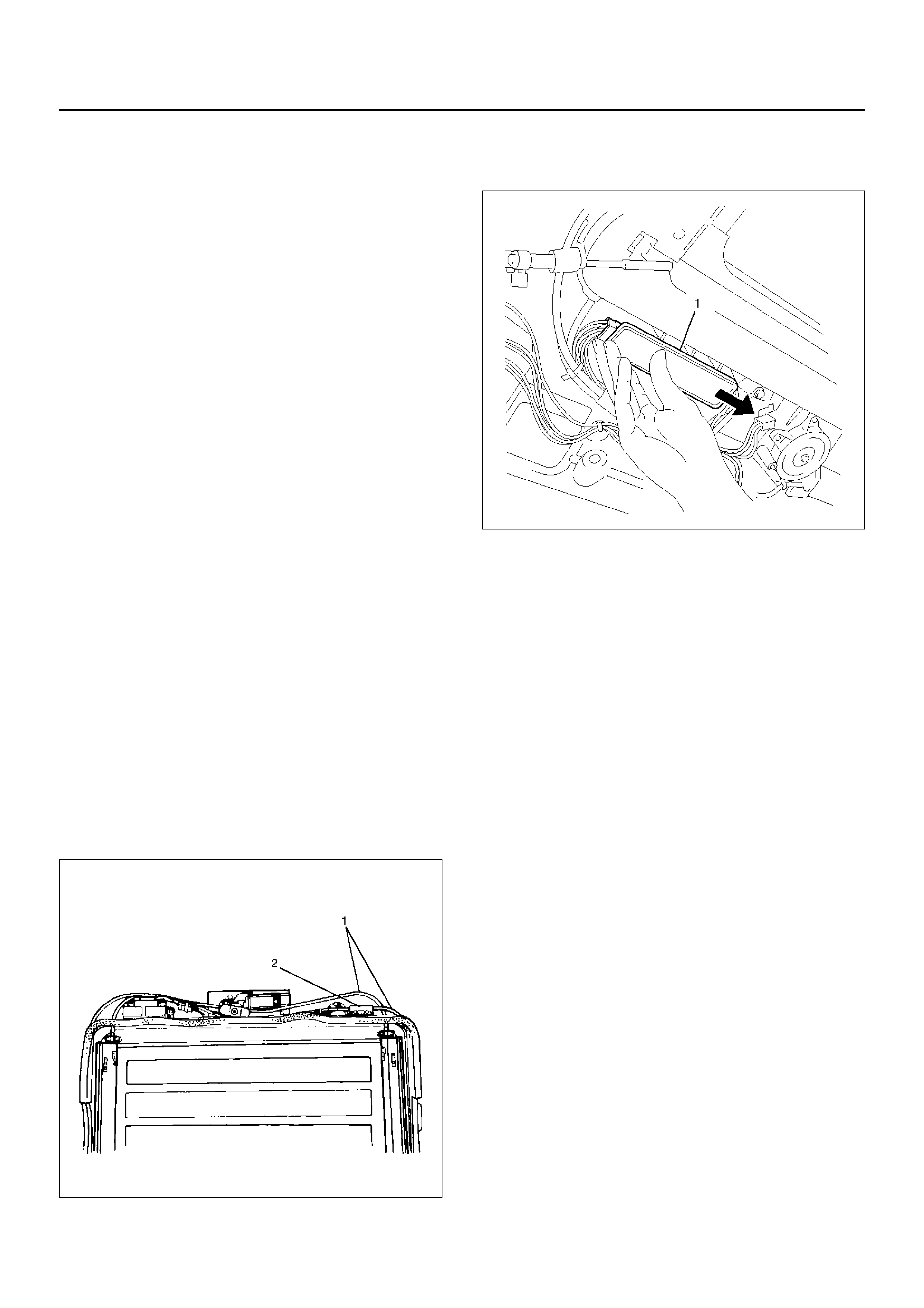
Sunroof Control Unit
Removal
1.Disconnect the battery ground cable.
2.Remove the headlining (2).
•Refer to Headlining (LWB) in Exterior/Interior Trim
section.
3.Remove the sunroof control unit (1).
•Disconnect two connectors.
•Remove two screws.
665RW013
Installation
To install, follow the removal steps in the reverse order.
Safety Stop Switch
Removal
1.Disconnect the battery ground cable.
2.Remove the sunroof frame complete assembly.
•Refer to Sunroof Frame Complete Assembly
(LWB) in this section.
3. Remove the sunroof drive unit assembly (1) to
remove the safety stop switch (2).
665RS022
Installation
To install, follow the removal steps in the reverse or der.
Limit Switch
Removal
1.Disconnect the battery ground cable.
2.Remove the sunroof frame complete assembly.
•Refer to Sunroof Frame Complete Assembly
(LWB) in this section.
3.Remove the sunroof drive unit assembly (1) to
remove the limit switch (2).
665RS025
Installation
To install, follow the removal steps in the reverse order.
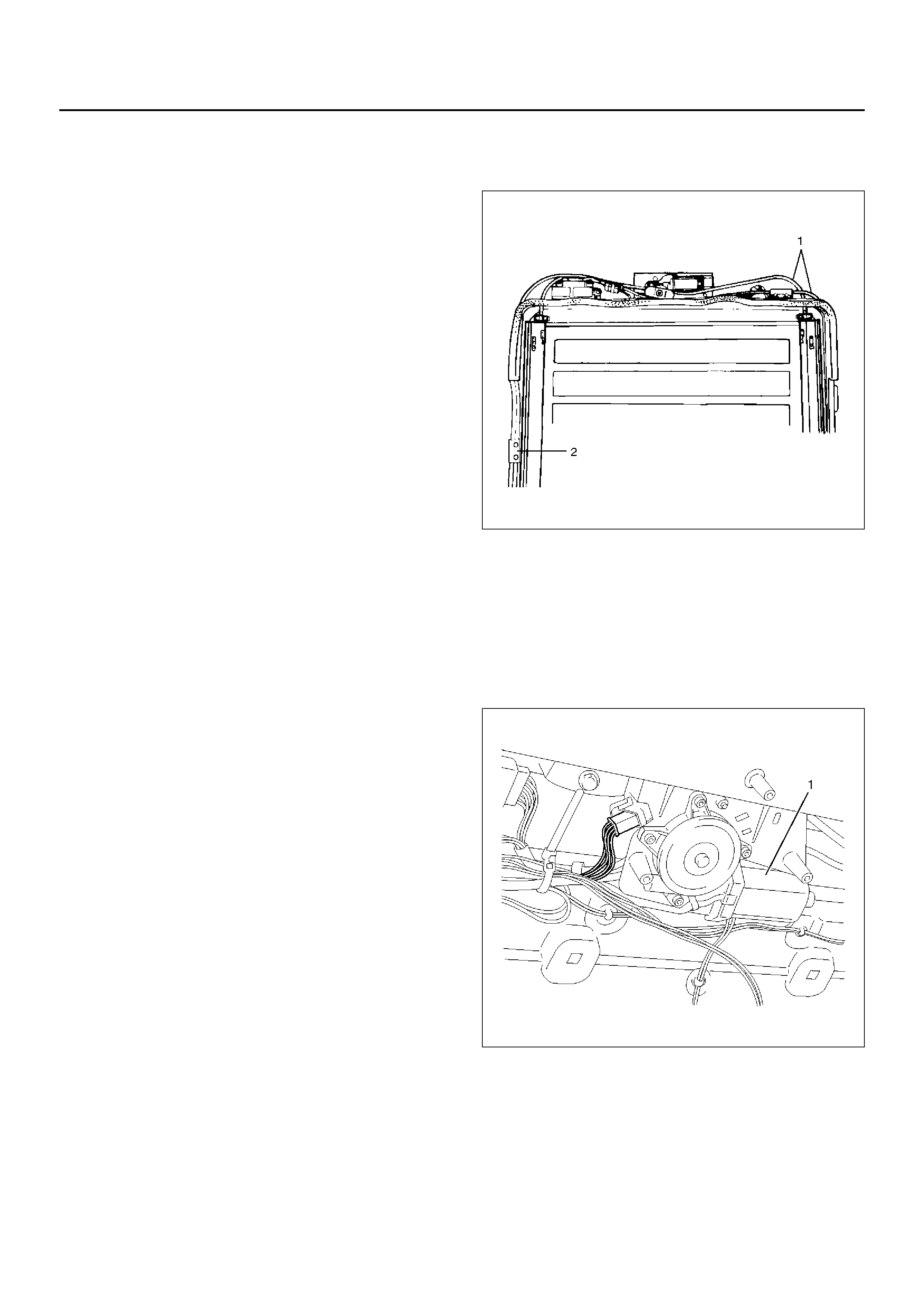
Sunroof Motor
Removal
1.Disconnect the battery ground cable.
2.Remove the headlining (2).
•Refer to Headlining (LWB) in Exterior/Interior Trim
section.
3. Remove the sunroof motor (1).
• Disconnect the connector.
• Remove three nuts and two screws.
665RW014
Installation
To install, follow the removal steps in the reverse or der.
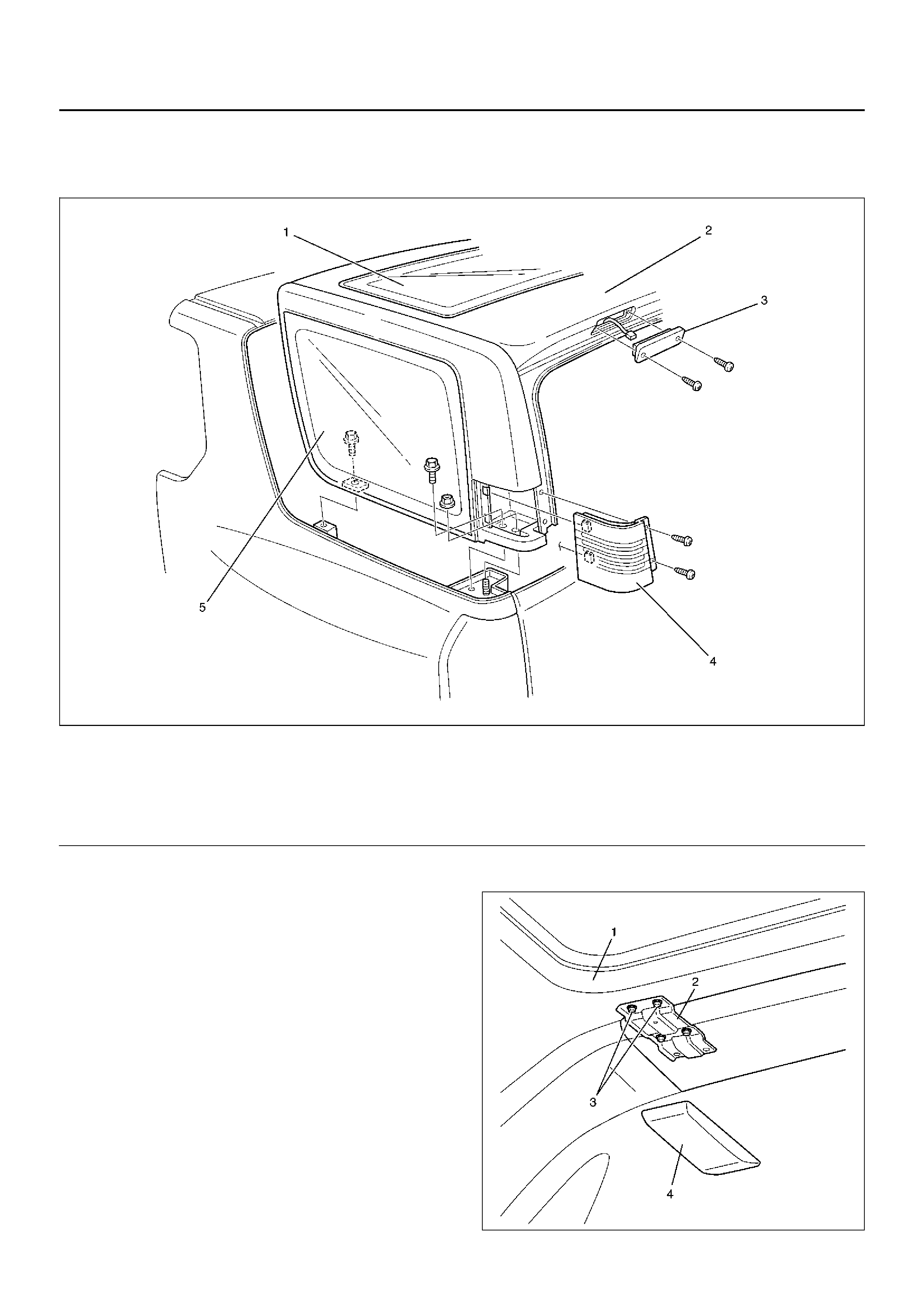
Resin Top Assembly
Resin Top Assembly and Associated Parts
688RW006
Legend
EndOFCallout
Removal
1.Disconnect the battery ground cable.
2.Remove the rear sunroof glass.
•Refer to Sunroof Glass (SWB) in this section.
3. Remove the sunroof deflector.
• Remove the four fixing screws.
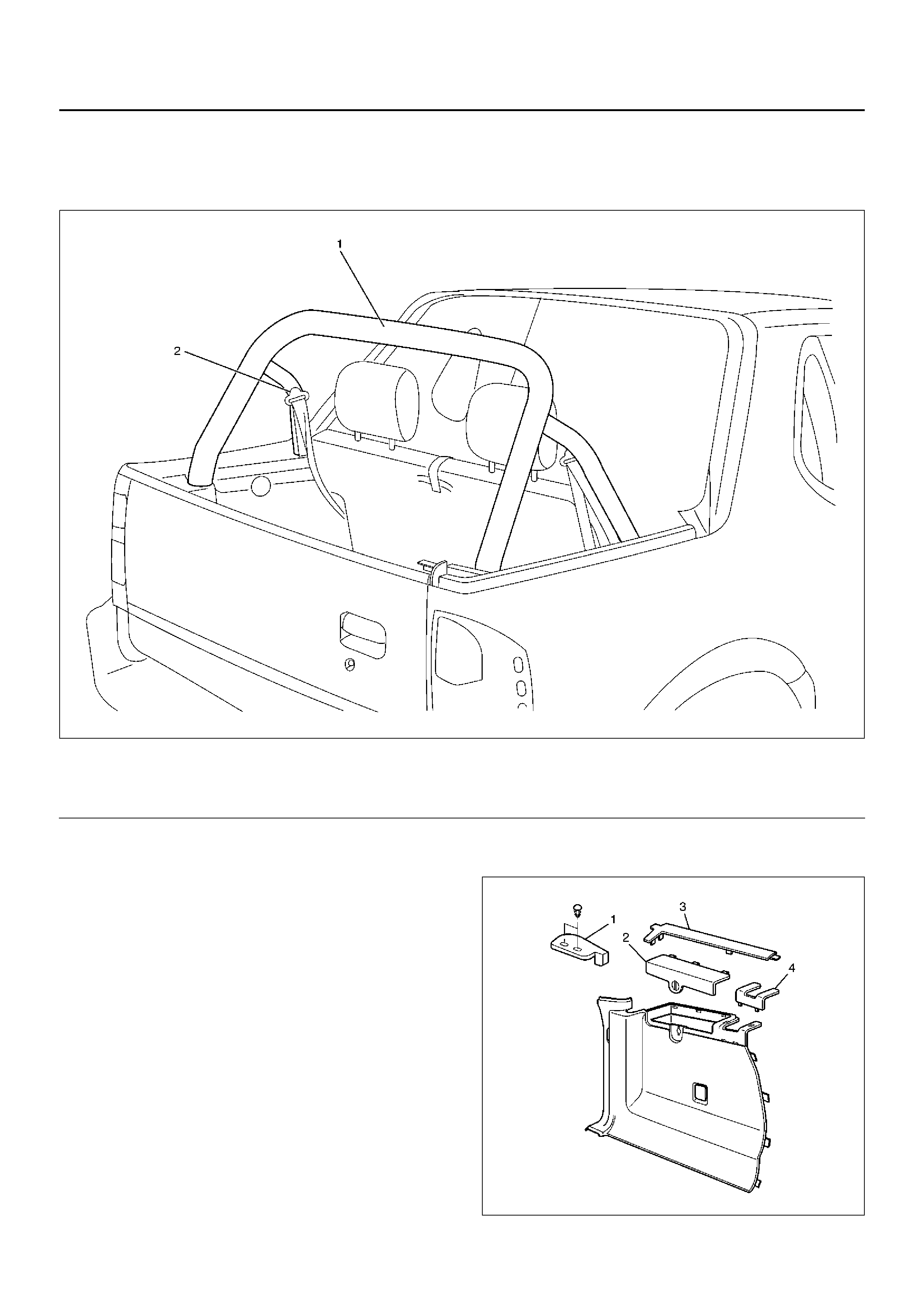
4. Remove the rear roof brack et covers (4) and remov e
the both sets of two bolts (3) on the resin top sides
of the rear roof brackets (2).
666RW010
(1) Rear Sunroof Assembly
(2) Resin Top Assembly
(3) High Mount Stoplight
(4) Ai r Outlet Grille Assembly
(5) Rear Quarter Glass
5. Remove the air outlet grille assembly (LH & RH).
• Remove the two screws and pull the grille
assemblies off toward the rear.
6. Remove the luggage light assembly and disconnect
the connector.
7. Remove the high mount stoplight assembly and
disconnect the connector.
8. Disconnect the rear washer hose (Right side, inside
air outlet grille assembly).
688RW007
9. Disconnect the harness connector for the resin top
(Left side, behind the luggage side trim).
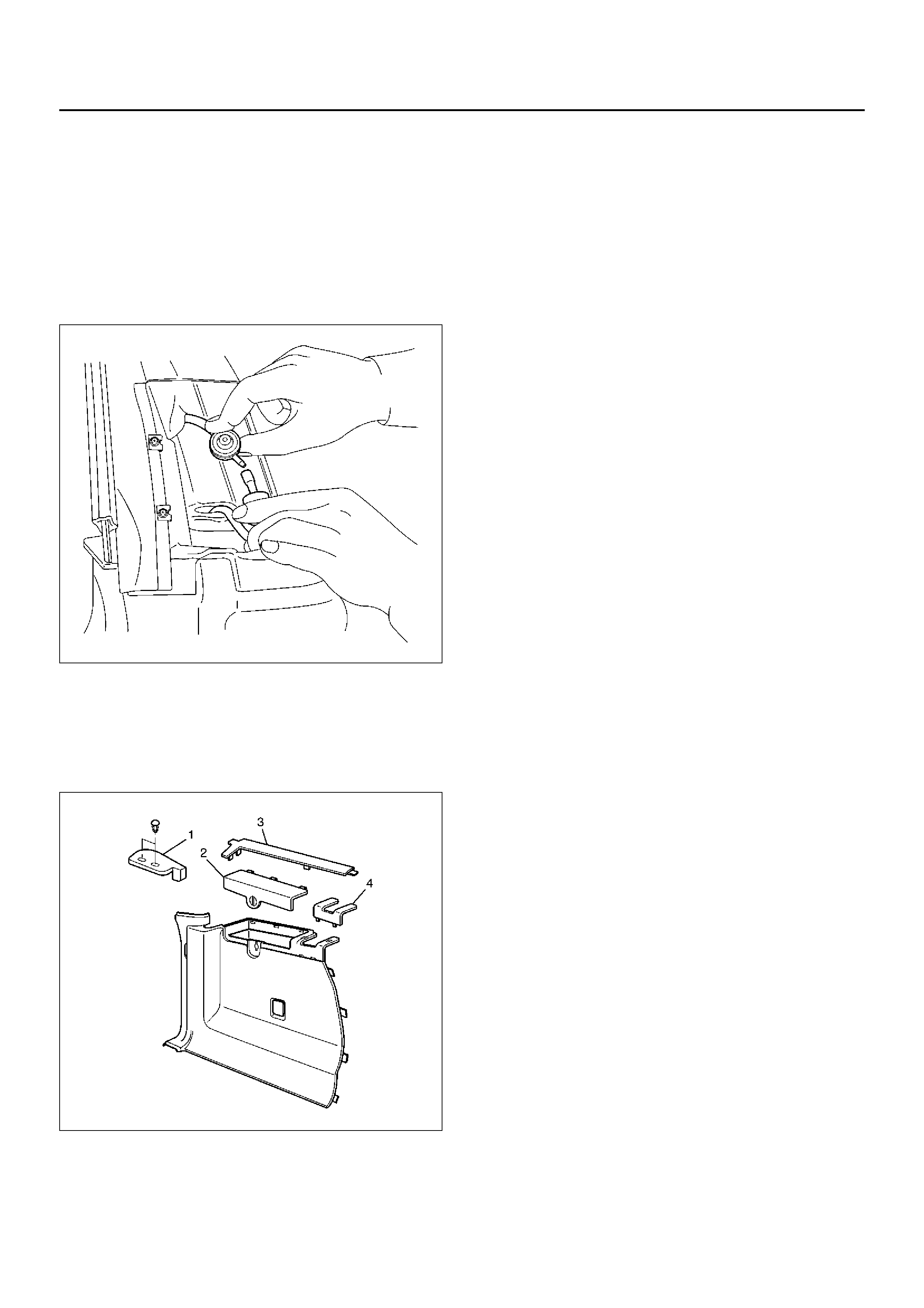
• Remove the canop y cover (1), the luggage side
lid (2) and luggage side upper cover (3). Then pull
out the harness and disconnect the connector.
686RX001
10. Remove the resin top assembly.
• Remove the two fixing bolts each and nut each
from the left and right sides, then lift the resin top
up and off.
Installation
To install, follow the removal steps in the reverse or der,
noting the following points.
1. Removing and mounting the resin top should always
be performed by two persons.
2. Tighten the resin top fixing bolts and nuts to the
specified torque.
Torque: 15 N·m (1.5 kg·m/11 Ib ft)
Seat Belt Cross Bar Assembly
Seat Belt Cross Bar Assembly and Associated Parts
688RY00001
Legend
EndOFCallout
Removal
1. Disconnect the battery ground cable.
2. Remove the resin top Assembly.
•Refer to Resin Top Assembly in this section.
3. Remove the canopy cover (1).
• Remove the two fixing clips.
4. Remove the luggage side lid (2).
5. Remove the luggage side upper cover (3).
6. Remove the luggage side front cover (4).
686RX001
(1) Seat Belt Cross Bar Assembly
(2) Rea r Seat Belt Assembly
7.Remove the weather strip.
8.Remove the rear end floor trim cover.
•Remove the five fixing screws.
9.Remove the right luggage side trim cover.
•Remove the jack & tool lid and take out the tools.
Then remove the fixing screw and pull the clips
out from the body panel.
687RW005
•To remove the left luggage side trim cover,
disconnect the accessory socket connector.
10.Remove the rear seat belt assembly.
•Refer to Rear Seat Belt (SWB) in Restraints
section.
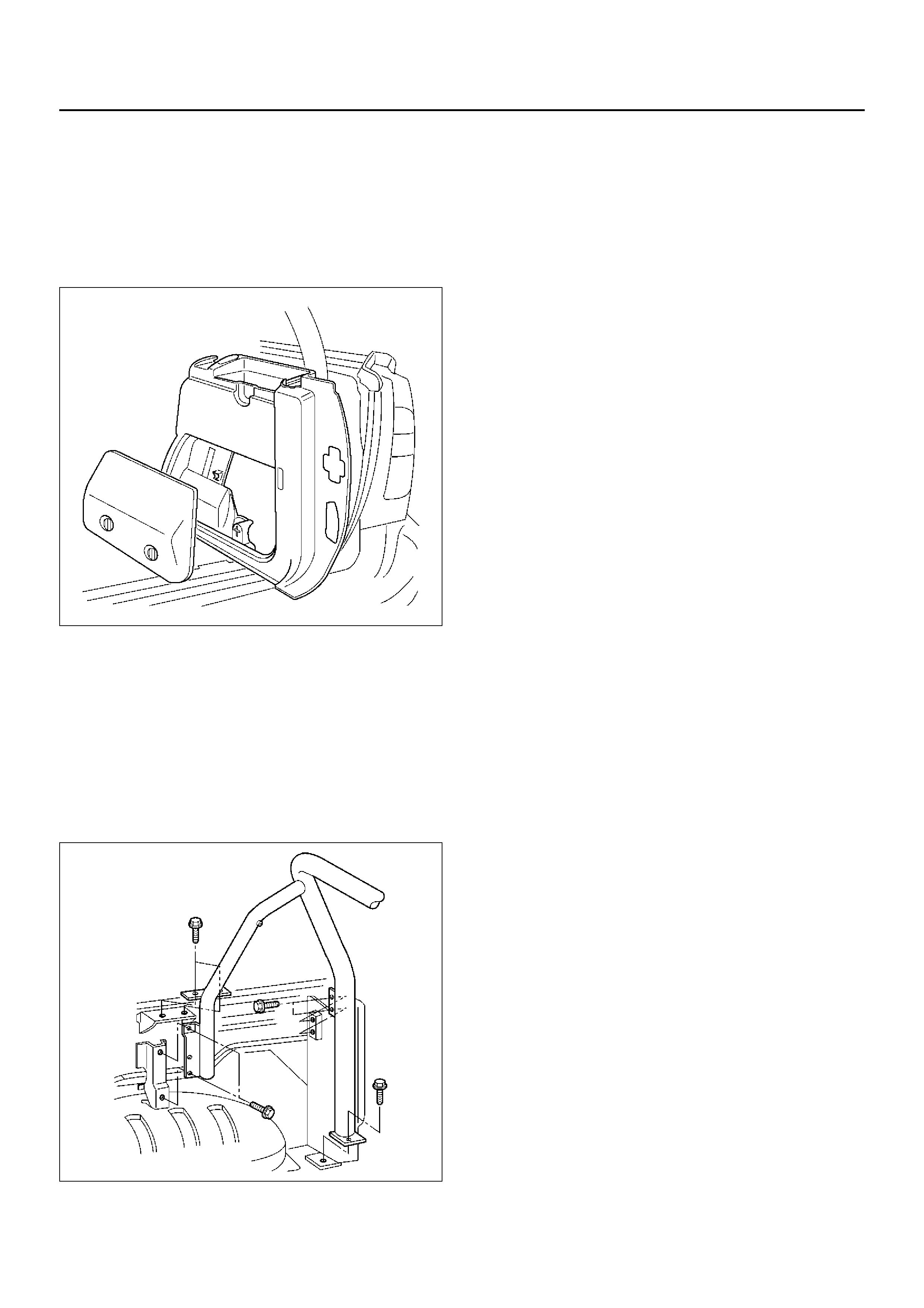
11. Remove the seat belt cross bar assembly.
• Remove the two sets of seven fixing bolts on the
left and right sides. One set of the fixing bolts are
also used to secure the resin top in place.
688RW009
Installation
To install, follow the removal steps in the reverse or der,
noting the following points.
1. Tighten the rear seat belt anchor bolts to the
specified torque.
Torque: 39 N·m (4.0 kg·m/29 Ib ft)
2. Tighten the seat belt cross bar assemb ly fixing bolts
to the specified torque.
Torque: 19 N·m (1.9 kg·m/14 Ib ft)

Main Data and Specifications
Torque Specification
Application N·m kg·m lb ft lb in
Sunroof Glass Fixing Screws (LWB) 4 0.4 — 35
Sunroof Handle Plate Fixing Nuts (SWB) 8 0.8 — 69
Resin Top Assemb ly Fixing Bolts and Nuts 15 1.5 11 —
Rear Seat Belt Anchor Bolts 39 4.0 29 —
Seat Belt Cross Bar Assembly Fixing Bolts 19 1.9 14 —