
SECTION 9A - SEAT BELT SYSTEM
Service Precaution
Front Seat Belt (LWB)
Front Seat Belt and Associated Parts
Removal
Inspection
Installation
Front Seat Belt (SWB)
Front Seat Belt and Associated Parts
Removal
Inspection
Installation
Rear Seat Belt (LWB)
Rear Seat Belt and Associated Parts
Removal
Inspection
Installation
Rear Seat Belt (SWB)
Rear Seat Belt and Associated Parts
Removal
Inspection
Installation
Front Seat Buckle Assembly
Removal
Installation
Rear Center Seat Belt / Buckle Assembly
Rear Center Seat Belt / Buckle Assembly
and Associated Parts
Removal
Installation
Child Seat Tether Anchor Bracket
(Child Restraint)
General Description
Child Seat Tether Anchor Bracket
and Associated Parts
Installation
Main Data and Specification
Service Precaution
WARNING: THIS VEHICLE HAS A SUPPLEMENTAL
RESTRAINT SYSTEM (SRS). REFER TO THE SRS
COMPONENT AND WIRING LOCATION VIEW IN
ORDER TO DETERMINE WHETHER YOU ARE
PERFORMING SERVICE ON OR NEAR THE SRS
COMPONENTS OR THE SRS WIRING. WHEN YOU
ARE PERFORMING SERVICE ON OR NEAR THE
SRS COMPONENTS OR THE SRS WIRING, REFER
TO THE SRS SERVICE INFORMATION. FAILURE TO
FOLLOW WARNINGS COULD RESULT IN POSSIBLE
AIR BAG DEPLOYMENT, PERSONAL INJURY, OR
OTHERWISE UNNEEDED SRS SYSTEM REPAIRS.
CAUTION: Always use the correct fastener in the
proper location. When you replace a fastener, use
ONLY the exact part number for that application.
ISUZU will call out those fasteners that require a
replacement after removal. ISUZU will also call out
the fasteners that require thread lockers or thread
sealant. UNLESS OTHERWISE SPECIFIED, do not
use supplemental coatings (Paints, greases, or
other corrosion inhibito r s) on thr eaded fastener s or
fastener joint interfaces. Generally, such coatings
adversely affect the fastener torque and the joint
clamping force, and may damage the fastener.
When you install fasteners, use the correct
tightening sequence and specifications. Following
these instructions can help you avoid damage to
parts and systems.
Techline
Techline
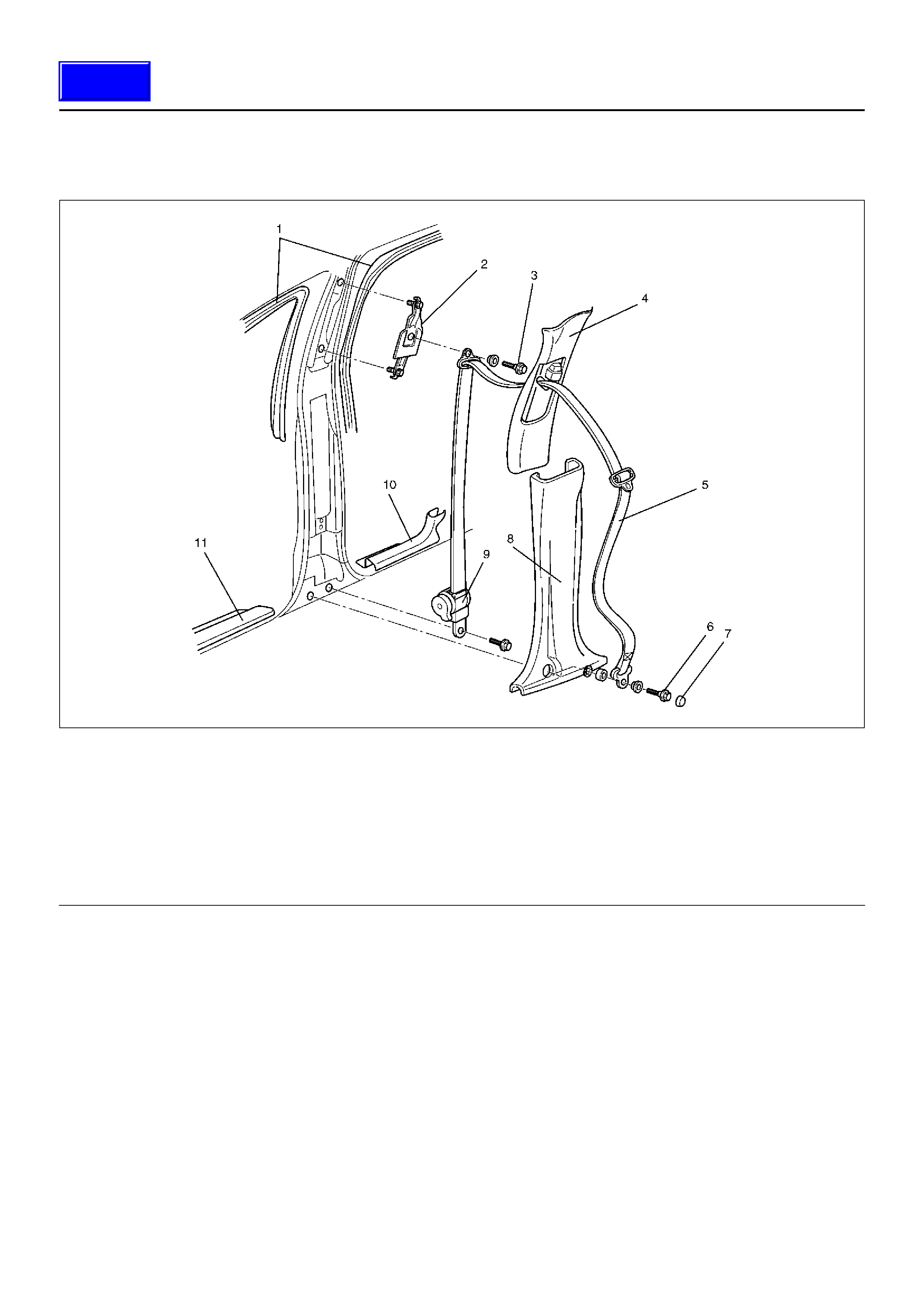
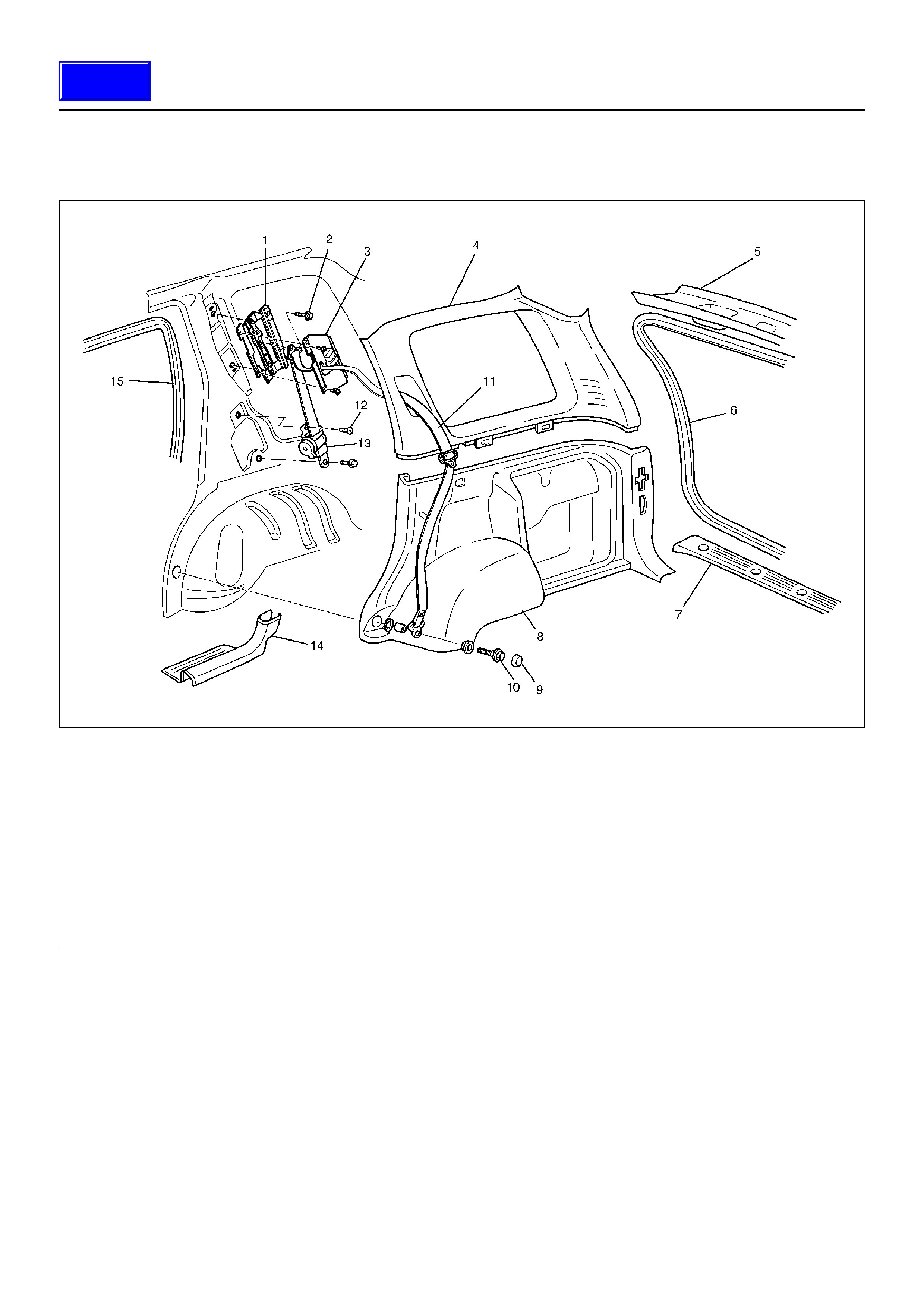
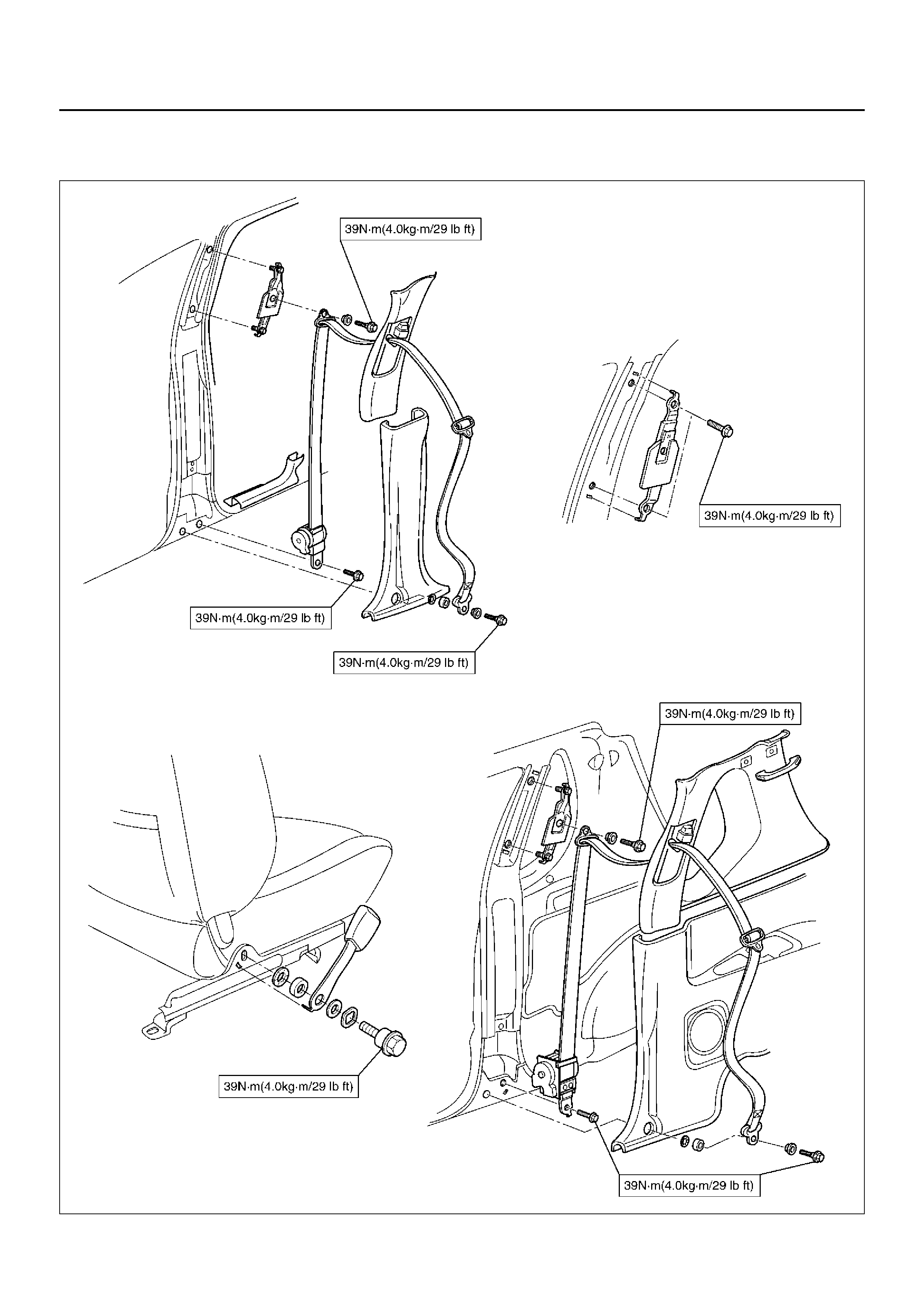
Front Seat Belt (LWB)
Front Seat Belt and Associated Parts
760RY00015
Legend
EndOFCallout
Removal
1. Disconnect the battery ground cable.
2. Remove the sill plate (Front & Rear).
3. Remove the cap and seat belt lower anchor bolt.
4. Remove the lower center pillar trim cover.
5. Remove the door seal finisher (Front & Rear).
6. Remove the upper center pillar trim cover.
7. Remove the seat belt upper anchor bolt.
8. Remove the retractor fixing bolt.
9. Remove the seat belt assembly.
10. Remove the adjustable shoulder anchor assembly.
• Remove the two fixing bolts.
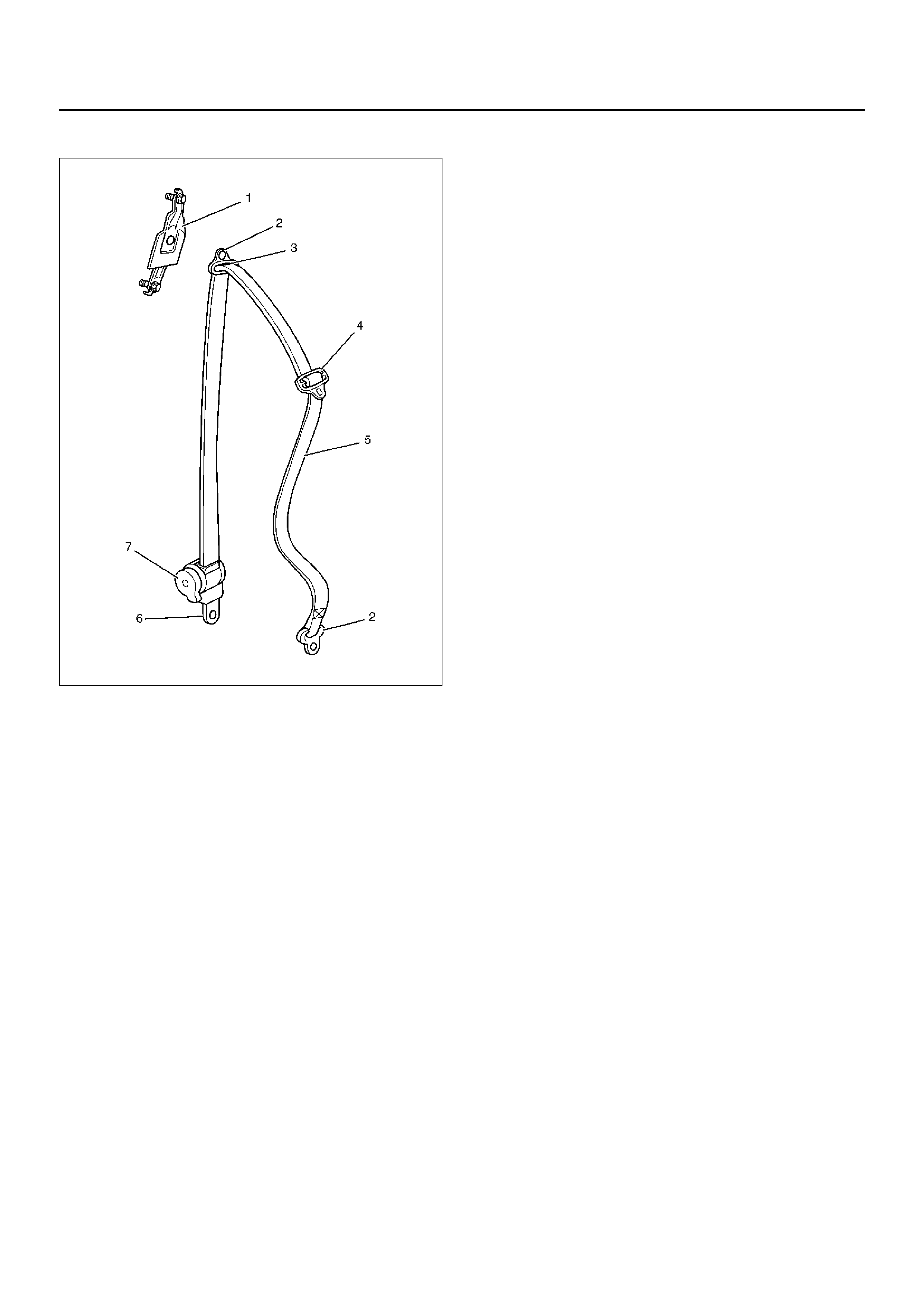
Inspection
If any of the following abnormalities is found, replace on
an as sembly bas is.
• Deform and malfunction of adjustable shoulder
anchor (1).
• No smooth move of upper/lower anchors (2) in the
circumferential direction.
• Damaged and/or deformed through ring (3).
• Damaged and/or deformed tongue (4).
• Damaged and/or frayed of webbing (5).
• Deformed retractor bracket (6).
• Seat belt not rewound up (7).
• Resistance or abnormal sound when seat belt is
wound out and rewound (7).
(1) Door Seal Finisher (Front & Rear)
(2) Adjustable Shoulder Anchor Assembly
(3) Seat Belt Upper Anchor Bolt
(4) Upper Center Pillar Trim Cover
(5) Front Seat Belt Assembly
(6) Seat Belt Lower Anchor Bolt
(7) Cap
(8) Lower Center Pillar Trim Cover
(9) Retractor
(10) Rear Sill Plate
(11) Front Sill Plate
Techline
•Retractor (7) abnormality.
760RY00021
Inspection of retractor
1.ELR (Emergency Locking Retractor) lock inclining
angle check.
•When the retractor is moved gently from its
installing position, make sure it is not locked
within 15° in any directions, and it remains locked
at 45° or larger.
2.ELR lock check.
•When the seat belt is drawn slowly with the
retractor installed, make sure it is not locked. And
when it is drawn quickly, make sure it is locked.
CAUTION: Do not disassemble the retractor.
Installation
To install, follow the removal steps in the reverse or der,
noting the following points.
1. Tighten the adjustable shoulder anchor assembly
fixing bolts to the specified torque.
Torque: 39N·m (4.0kg·m/29lbft)
2. Tighten the seat belt anchor bolts (Upper & Lower)
and the retractor fixing bolts to the specified torque.
Torque: 39N·m (4.0kg·m/29lbft)
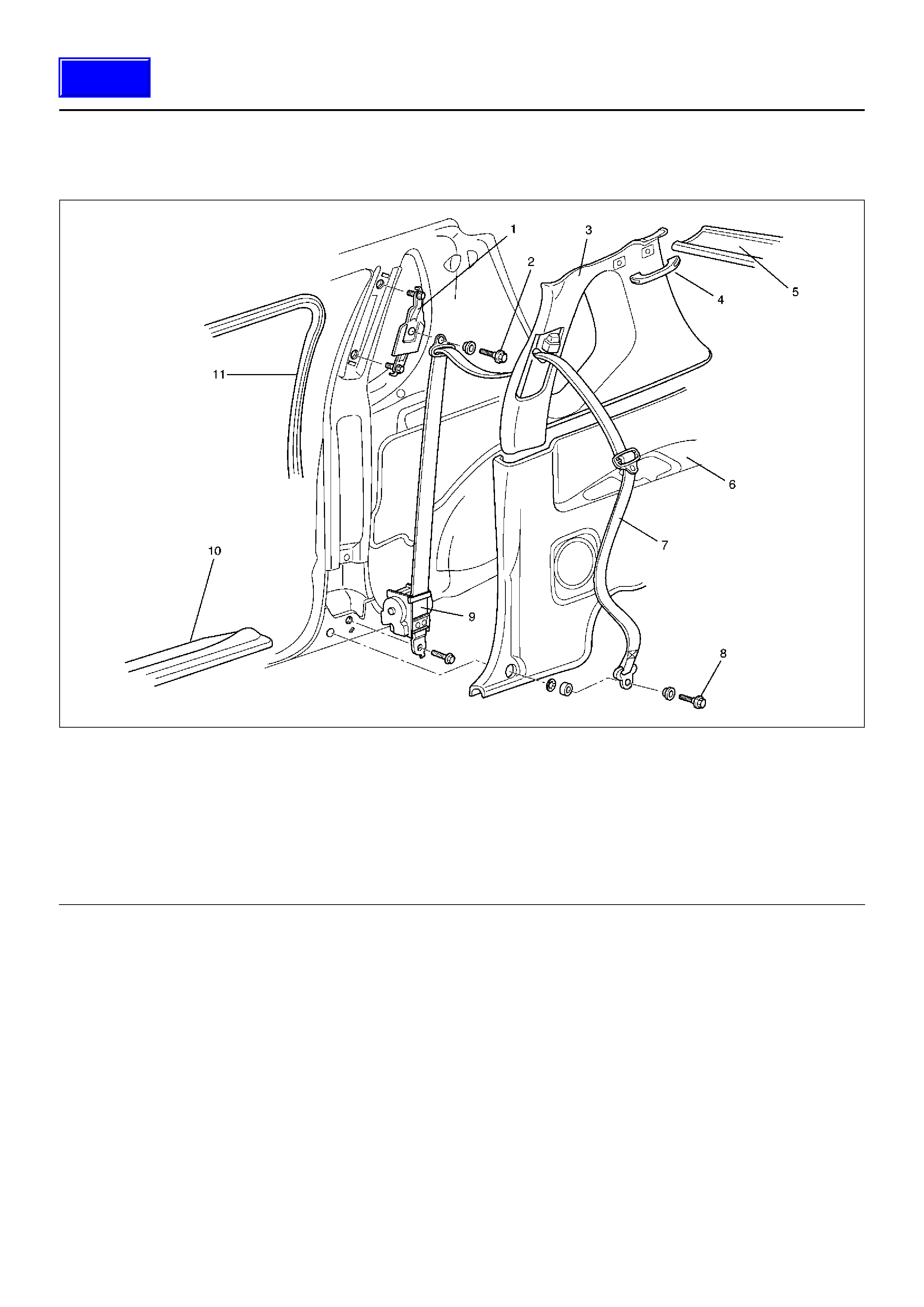
Front Seat Belt (SWB)
Front Seat Belt and Associated Parts
760RW041
Legend
EndOFCallout
Removal
1.Disconnect the battery ground cable.
2.Remove the rear seat assembly.
•Refer to Rear Seat Assembly in Seats section.
3. Remove the resin top assembly.
•Refer to Resin Top Assembly in Sunroof/
Convertible Top section.
4. Remove the luggage side trim cover.
•Refer to Rear Seat Belt (SWB) in this section.
5. Remove the sill plate.
6. Remove the seat belt lower anchor bolt (Front &
Rear).
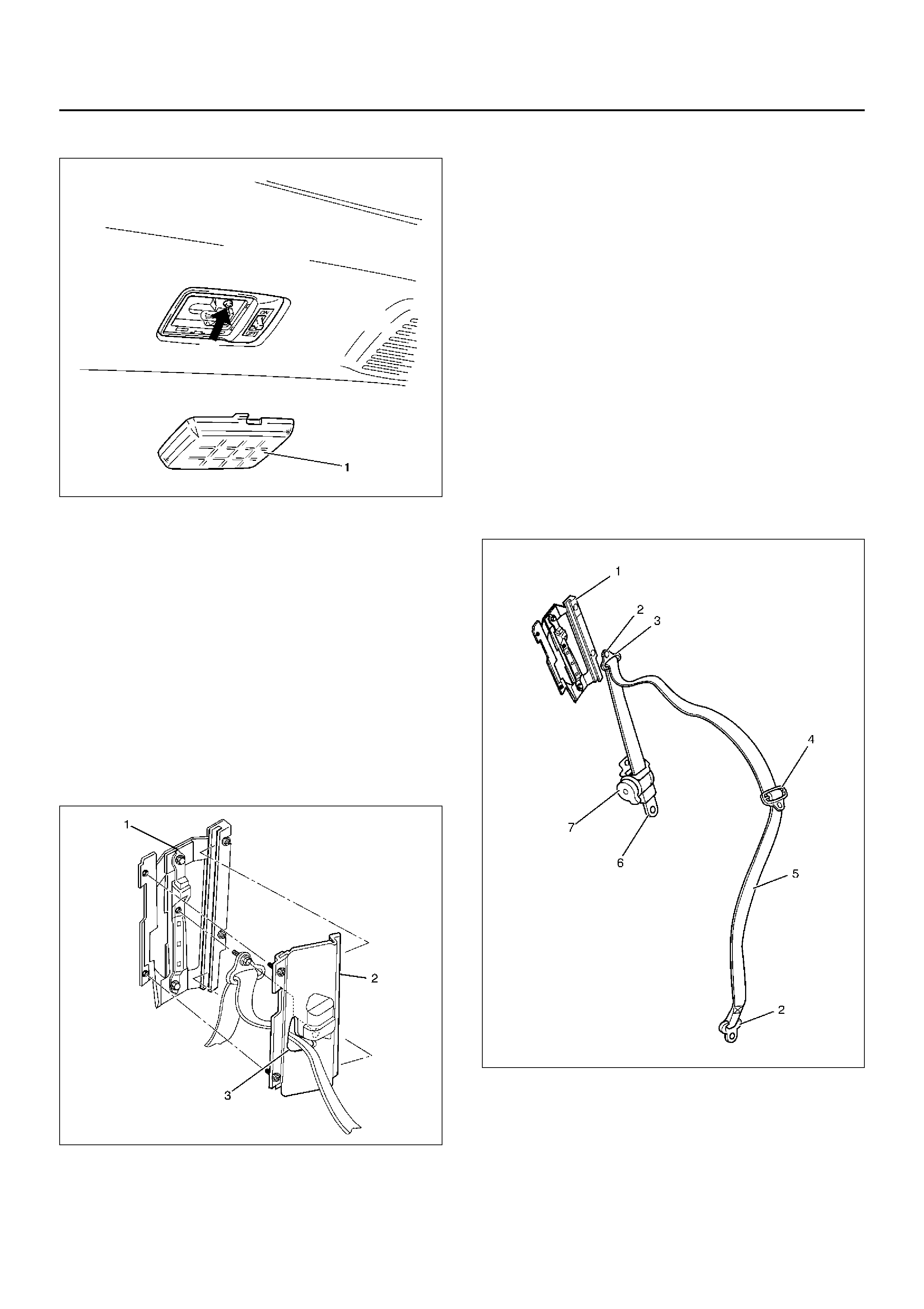
(1) Adjustable Shoulder Anchor Assembly
(2) Seat Belt Upper Anchor Bolt
(3) Upper Quarter Trim Cover
(4) Assist Grip
(5) Rear Roof Trim Cover
(6) Lower Quarter Trim Cover
(7) Front Seat Belt Assembly
(8) Seat Belt Lower Anchor Belt
(9) Retractor
(10) Sill Plate
(11) Door Seal Finisher
Techline
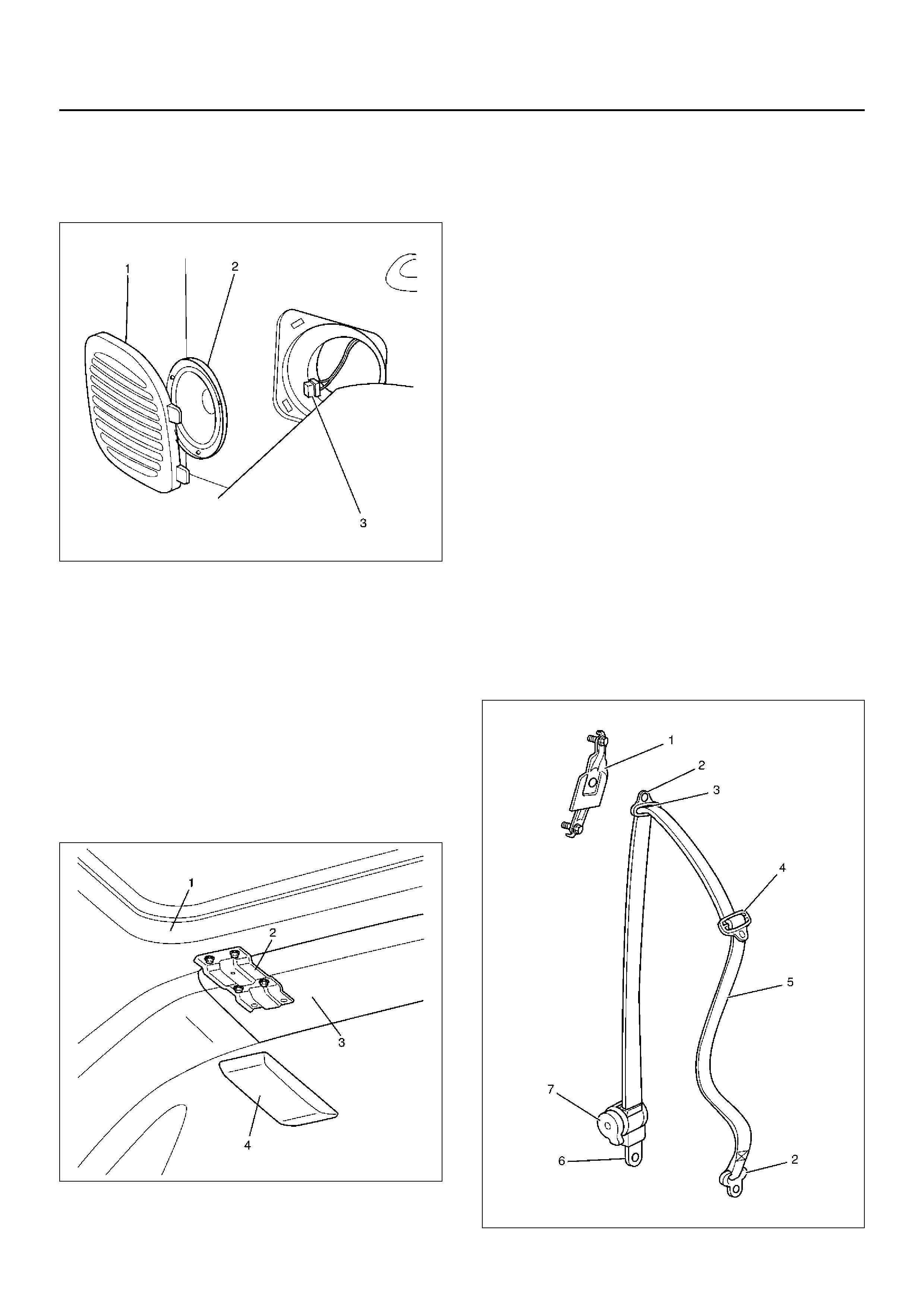
7. Remove the rear speaker (2).
• Remove the speaker grille (1) and remove the
speaker fixing screws.
• Disconnect the connector (3).
890RW048-1
8. Remove the lower quarter trim cover.
• Pry the trim cover retainers free from the body
panel.
9. Remove the dome light.
• Remove the dome light len s and the fixin g
screws.
• Disconnect the dome light connector.
10. Remove the rear roof bracket (2).
• Remove the rear roof bracket cover (4) and
remove rear roof bracket connecting with resin
top (1) and rear roof trim co ver (3) b y removing
four fixing bolts.
666RW006
11. Remove the rear roof trim cover.
12. Remove the assi st gr i p.
13. Remove the door sea l finish er.
14. Remove the uppe r quarter trim cover.
15. Remove the se at belt uppe r ancho r bolt.
16. Remove the retractor fixing bolt.
17. Remove the se at belt assembly.
18. Remove the adjustable shoulder anchor assembly.
• Remove two bolts.
Inspection
If any of the following abnormalities is found, replace on
an as sembly bas is.
• Deform and malfunction of adjustable shoulder
anchor (1).
• No smooth move of upper/lower anchors (2) in the
circumferential direction.
• Damaged and/or deformed through ring (3).
• Damaged and/or deformed tongue (4).
• Damaged and/or frayed of webbing (5).
• Deformed retractor bracket (6).
• Seat belt not rewound up (7).
• Resistance or abnormal sound when seat belt is
wound out and rewound (7).
• Retractor (7) abno rma lity.
760RY00021

Inspection of retractor
1.ELR (Emergency Locking Retractor) lock inclining
angle check.
•When the retractor is moved gently from its
installing position, make sure it is not locked
within 15° in any directions, and it remains locked
at 45° or larger.
2.ELR lock check.
•When the seat belt is drawn slowly with the
retractor installed, make sure it is not locked. And
when it is drawn quickly, make sure it is locked.
CAUTION: Do not disassemble the retractor.
Installation
To install, follow the removal steps in the reverse order,
noting the following points.
1. Tighten the adjustable shoulder anchor assembly
and retractor fixing bolts to the specified torque.
Torque: 39N·m (4.0kg·m/29lbft)
2. Tighten the seat belt anchor bolts to the specified
torque.
Torque: 39N·m (4.0kg·m/29lbft)
Rear Seat Belt (LWB)
Rear Seat Belt and Associated Parts
755RY00014
Legend
EndOFCallout
Removal
1. Disconnect the battery ground cable.
2. Remove the tailgate weather strip.
3. Remove the rear end floor trim cover.
4. Remove the luggage room light.
• Remove the luggage room light lens (1) and the
fixing screw.
(1) Adjustable Shoulder Anchor Assembly
(2) Seat Belt Upper Anchor Bolt
(3) Slider Plate Trim Assembly
(4) Upper Quarter Trim Cover
(5) Rear Roof Trim Cover
(6) Tailgate Weather Strip
(7) Rear End Floor Trim Cover
(8) Lower Quater Trim Cover
(9) Cap
(10) Seat Belt Lower Anchor Bolt
(11) Rear Seat Belt Assembly
(12) Screw
(13) Retractor
(14) Rear Sill Plate
(15) Rear Door Seal Fi nisher
Techline
•Disconnect the luggage room light connector.
825RW100
5.Remove the rear roof trim cover.
•Pry the trim cover clips free from the body panel.
6.Remove the rear sill plate.
7.Remove the rear seat belt lower anchor bolt cap and
the lower anchor bolt.
8.Remove the upper and lower quarter trim cover.
•Refer to Interior Trim Panel (LWB) in Exterior/
Interior Trim section.
9. Remove the slider plate trim assembly (2).
• Remove the two fixing screws from the adjustable
shoulder anchor (1).
• Pull out the seat belt through the hole (3) on the
slider plate trim.
755RW069
10. Remove the seat belt upper anchor bolt.
11. Remove the retractor.
12. Remove the rear seat belt assembly.
13. Remove the adjustable shoulder anchor assembly.
• Remove the two fixing bolts.
Inspection
If any of the following abnormalities is found, replace on
an as sembly bas is.
• Deform and malfunction of adjustable shoulder
anchor (1).
• No smooth move of upper/lower anchors (2) in the
circumferential direction.
• Damaged and/or deformed through ring (3).
• Damaged and/or deformed tongue (4).
• Damaged and/or frayed of webbing (5).
• Deformed retractor bracket (6).
• Seat belt not rewound up (7).
• Resistance or abnormal sound when seat belt is
wound out and rewound (7).
• Retractor (7) abno rma lity.
755RY00021

Inspection of retractor
1.ELR (Emergency Locking Retractor) lock inclining
angle check.
•When the retractor is moved gently from its
installing position, make sure it is not locked
within 15° in any directions, and it remains locked
at 45° or larger.
2.ELR lock check.
•When the seat belt is drawn slowly with the
retractor installed, make sure it is not locked. And
when it is drawn quickly, make sure it is locked.
CAUTION: Do not disassemble the retractor.
Installation
To install, follow the removal steps in the reverse order,
noting the following point.
1. Tighten the adjustable shoulder anchor assembly
fixing bolts to the speci fi ed tor que.
Torque: 39N·m (4.0kg·m/29lbft)
2. Tighten the seat belt anchor bolts (Upper & Lower)
and the retractor fixing bolts to the specified torque.
Torque: 39N·m (4.0kg·m/29lbft)
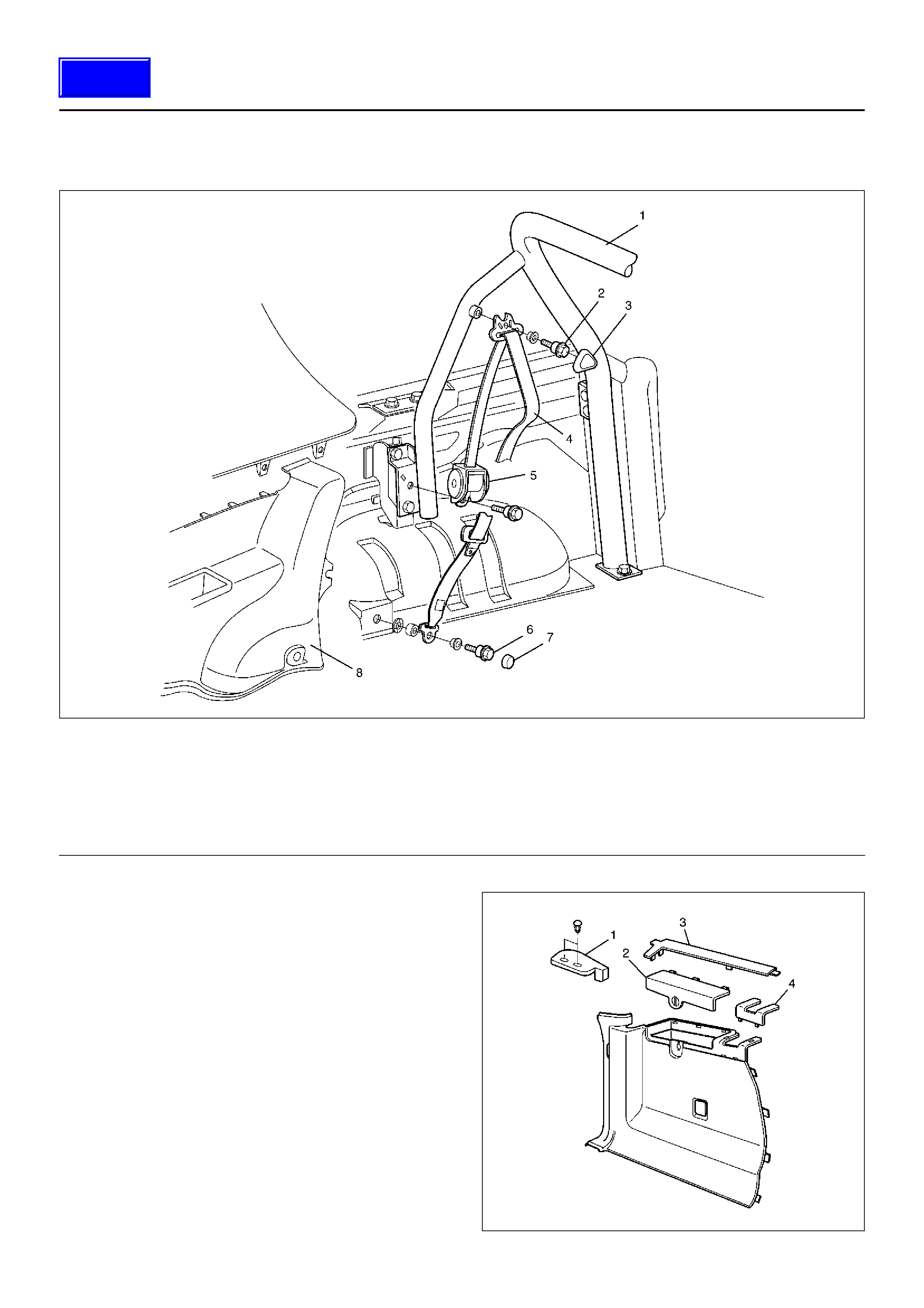
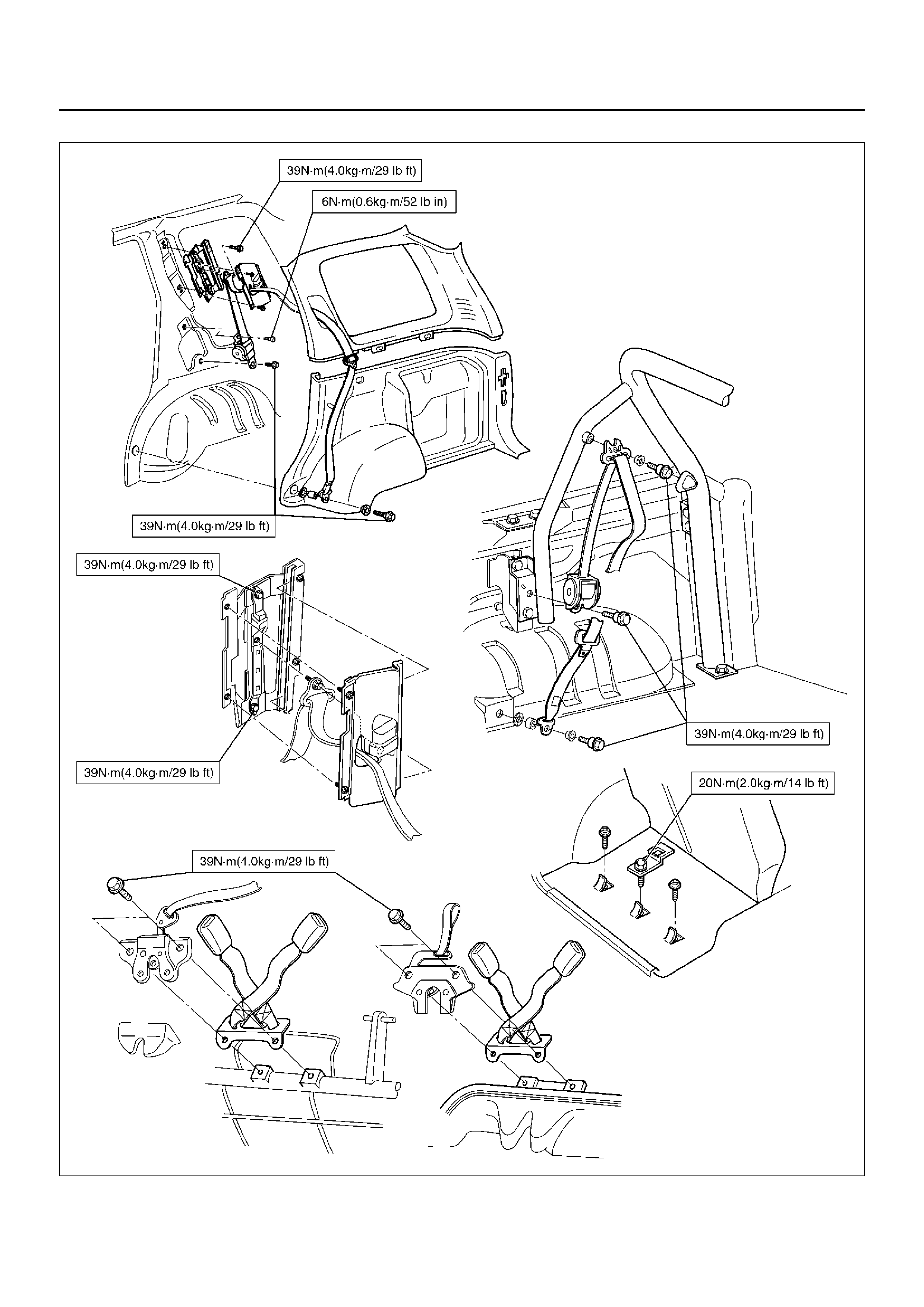
Rear Seat Belt (SWB)
Rear Seat Belt and Associated Parts
755RY00015
Legend
EndOFCallout
Removal
1. Disconnect the battery ground cable.
2. Remove the canopy cover (1).
• Remove two fixing clips.
3. Remove the luggage side lid (2).
4. Remove the luggage side front cover (4).
5. Remove the luggage side upper cover (3).
686RX001
(1) Seat Belt Cross Bar Assembly
(2) Seat Belt Upper Anchor Bolt
(3) Shoulder Anchor Cover
(4) Rear Sea t Belt Assembly
(5) Retractor
(6) Seat Belt Lower Anchor Bolt
(7) Cap
(8) Lower Quarter Trim Cover
Techline
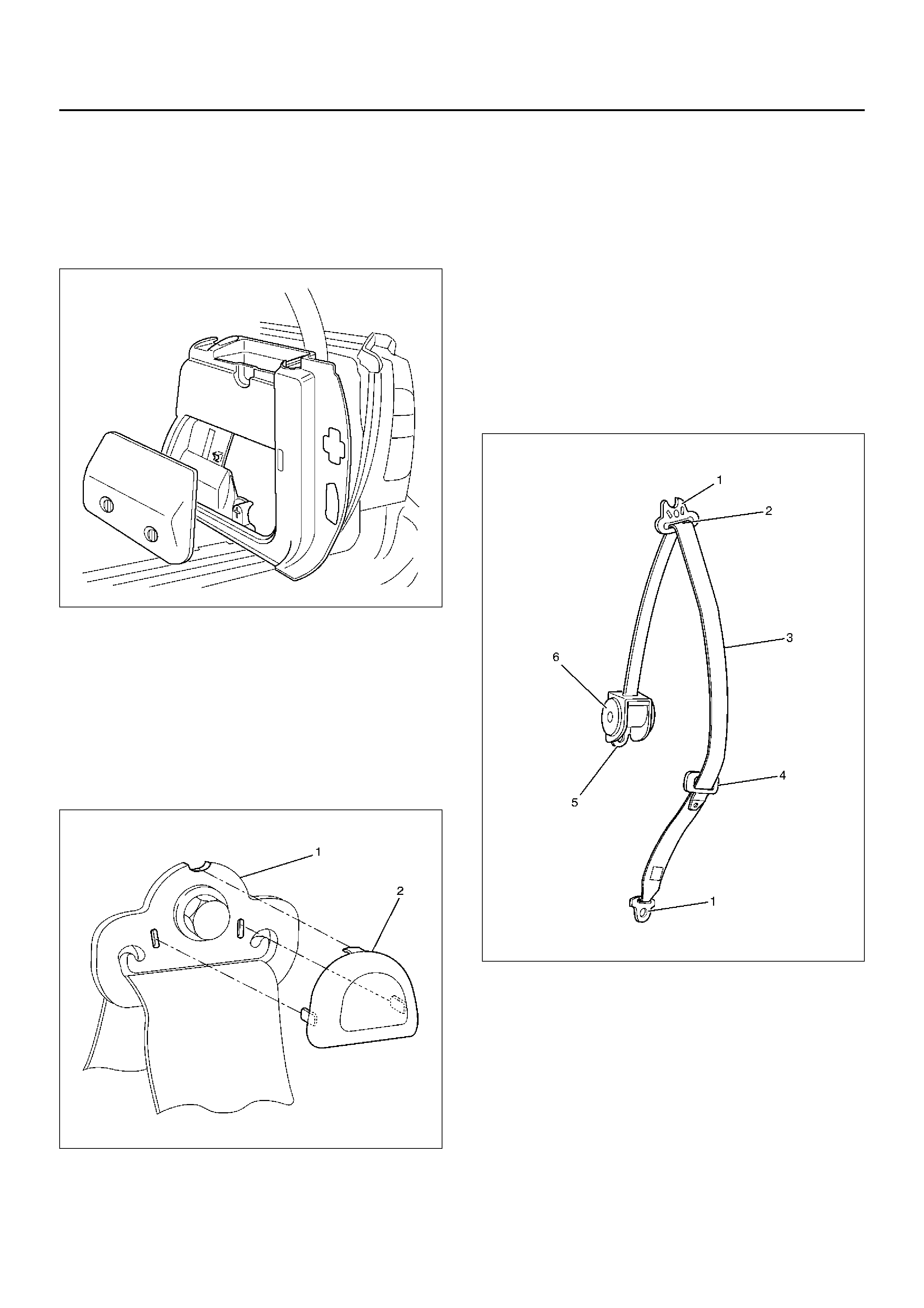
6. Remove the tailgate weather strip.
7. Remove the rear end floor trim cover.
8. Remove the luggage side trim cover (RH).
• Remove the jack & tool lid and remove the tool.
• Remove fixing screw and pry the trim cover
retainers free from the body panel.
687RW005
9. Remove the luggage side trim cover (LH).
• Remove fixing screw and pry the trim cover
retainers free from the body panel.
• Disconnect the accessory socket connectors.
10. Remove the cap and seat belt lower anchor bolt.
11. Remove the shoulder anchor cover (2).
• Release the hooked portion of cover from the
shoulder anchor (1).
755RW070
12. Remove the seat belt upper anchor bolt.
13. Remove the retractor.
14. Remove the rear seat belt assembly.
Inspection
If any of the following abnormalities is found, replace on
an as sembly bas is.
• No smooth move of upper/lower anchors (1) in the
circumferential direction.
• Damaged and/or deformed through ring (2).
• Damaged and/or deformed tongue (4).
• Damaged and/or frayed of webbing (3).
• Deformed retractor bracket (5).
• Seat belt not rewound up (6).
• Resistance or abnormal sound when seat belt is
wound out and rewound (6).
• Retractor (6) abno rma lity.
755RY00022

Inspection of retractor
1.ELR (Emergency Locking Retractor) lock inclining
angle check.
•When the retractor is moved gently from its
installing position, make sure it is not locked
within 15° in any directions, and it remains locked
at 45° or larger.
2.ELR lock check.
•When the seat belt is drawn slowly with the
retractor installed, make sure it is not locked. And
when it is drawn quickly, make sure it is locked.
CAUTION: Do not disassemble the retractor.
Installation
To install, follow the removal steps in the reverse order,
noting the following points.
1. Align the projection of the retractor to the square
hole of the seat belt cross bar assembly bracket.
2. Tighten the retractor fixing bolts to the specified
torque.
Torque: 39N·m (4.0kg·m/29lbft)
3. Tighten the seat belt anchor bolt to the specified
torque.
Torque: 39N·m (4.0kg·m/29lbft)
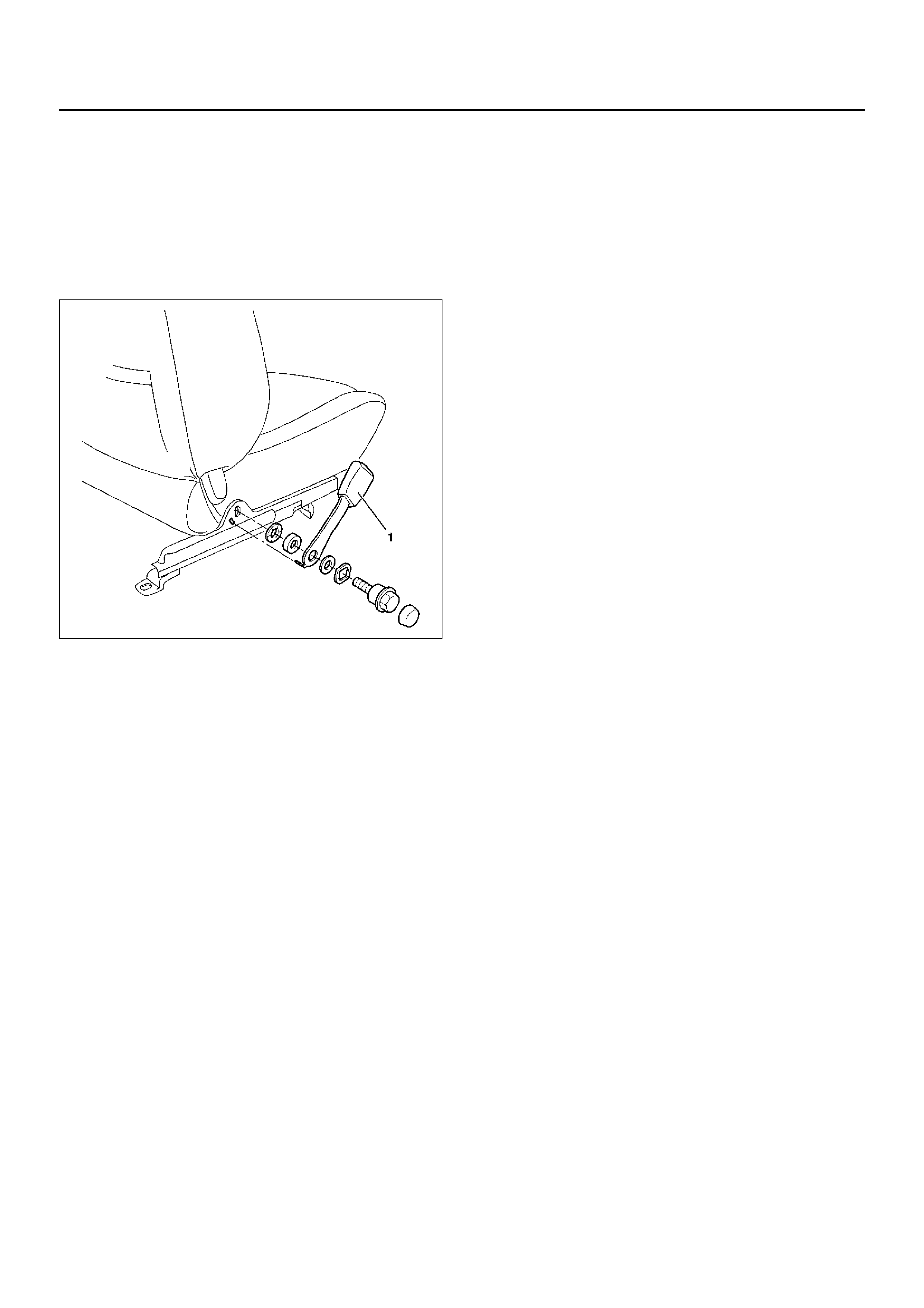
Front Seat Buckle Assembly
Removal
1. Disconnect the battery ground cable.
2. Disconnect the seat belt warning connector (driv er's
side) and remove a clip.
3. Remove the front seat buckle assembly (1).
760RY00016
Installation
To install, follow the removal steps in the reverse or der,
noting the following point.
1. Tighten the buckle anchor bolt to the specified
torque.
Torque: 39N·m (4.0kg·m/29lbft)
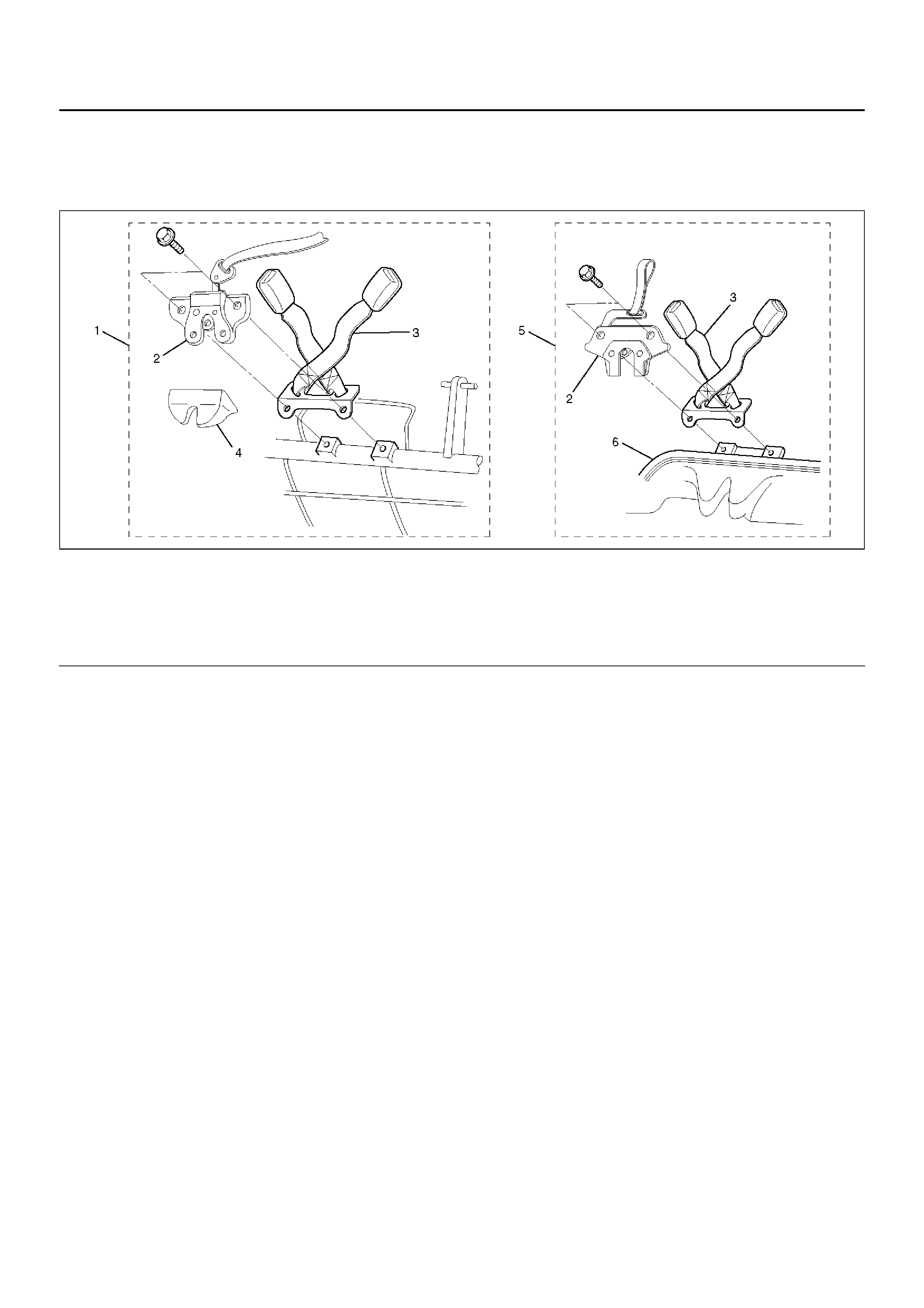
Rear Center Seat Belt / Buckle Assembly
Rear Center Seat Belt / Buckle Assembly and Associated Parts
755RX029
Legend
EndOFCallout
Removal
1.Remove the seat lock cover (SWB).
2.Remove the rear cushion frame assembly (LWB).
•Refer to Rear Seat Assembly in Seats section.
3. Remove the rear seat lock assembly and rear seat
belt buckle assembly.
Installation
To install, follow the removal steps in the reverse or der,
noting the following point.
1. Tighten the rear seat lock assembly and rear seat
belt buckle assembly fixing bolts to the specified
torque.
Torque: 39N·m (4.0kg·m/29lbft)
NO TE: Removal and installation procedure of rear
center seat belt assembly same as rear seat belt buckle
asse mbly procedures.
(1) SWB
(2) Rear Seat Lock Assembly
(3) Rear Seat Belt Buckle Assembly
(4) S eat Lock Cover
(5) LWB
(6) Rear Cushion Frame Assembly
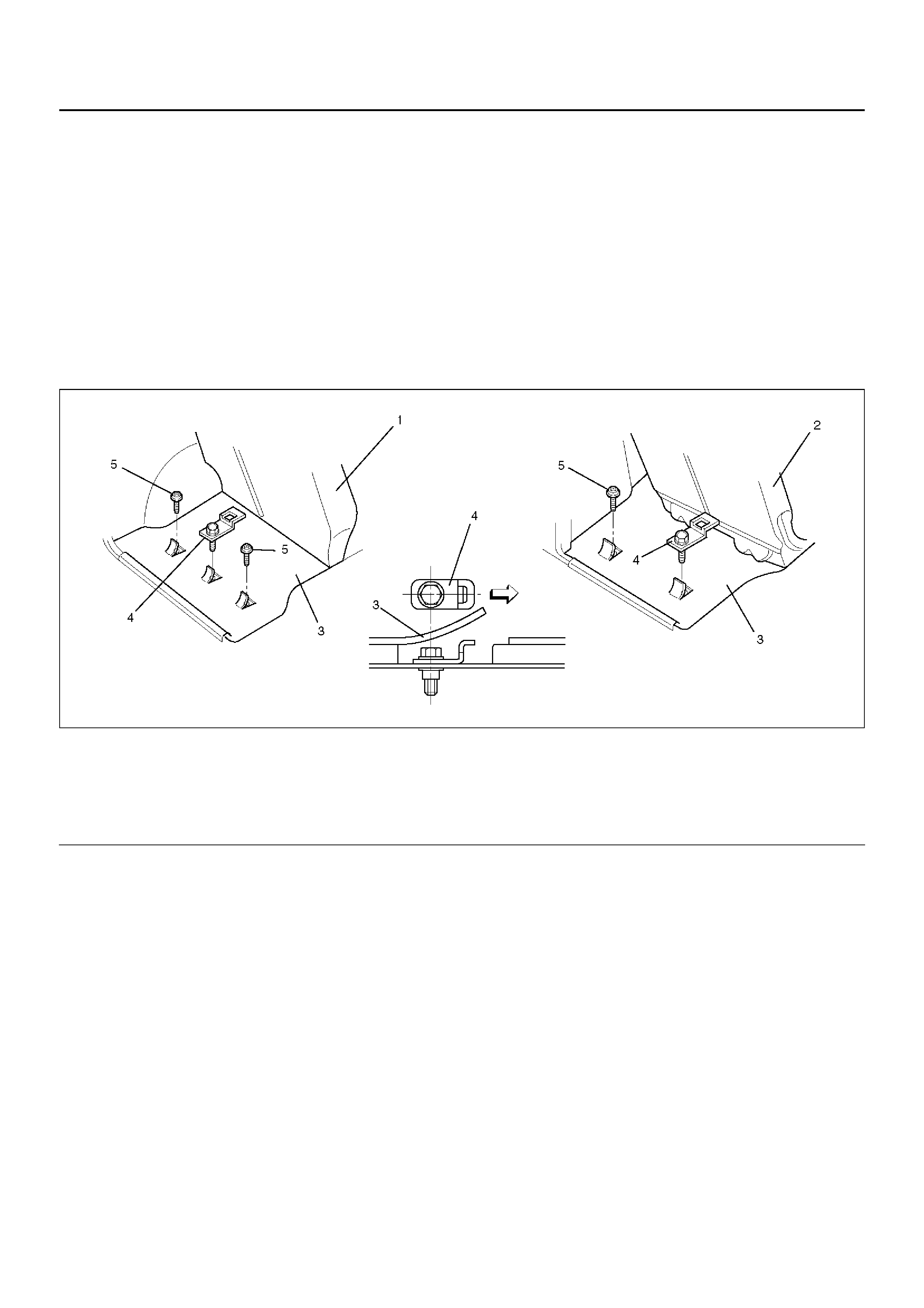
Child Seat Tether Anchor Bracket (Child Restraint)
General Description
Plastic plug is provided at two or three places on the
luggage floor panel.
LWB
Remove the center plug fom the floor panel.
SWB
Remove the right plug from the floor panel.
Install the bracket to the hole where the plug is
removed.
Alternatively, the bracket may be installed in the
right-hand or left-hand plug hole.
Child Seat Tether Anchor Bracket and Associated Parts
760RX019
Legend
EndOFCallout
Installation
1. Turn the plug counterclockwise to remove it.
2. Install the bracket such that its tether belt hook hole
is facing toward the front of the vehicle.
3. Tighten the fixing bolt to the specified torque.
Torque: 20N·m (2.0kg·m/14lbft)
(1) Rear Seat (LWB)
(2) Rear seat (SWB)
(3) Lugga ge Fl oo r carpe t
(4) Child Seat Tether Anchor Bracket
(5) Tether Anchor Plug
Main Data and Specifications
Torque Specifications
760RY00020
755RY00019