
SECTION 9J - SUPPLEMENTAL RESTRAINT SYSTEM
Service Precaution
General Description
SRS Component and Wiring Location View
Component Description
Definition
Diagnosis
SRS Connector Body Face Views
Repairs and Inspections Required After
an Accident
On–Vehicle Service
Air Bag Assembly Handling / Shipping /
Scrapping
Special Tools
Service Precaution
Sensing and Diagnostic Module (SDM)
Service Precautions
Removal
Installation
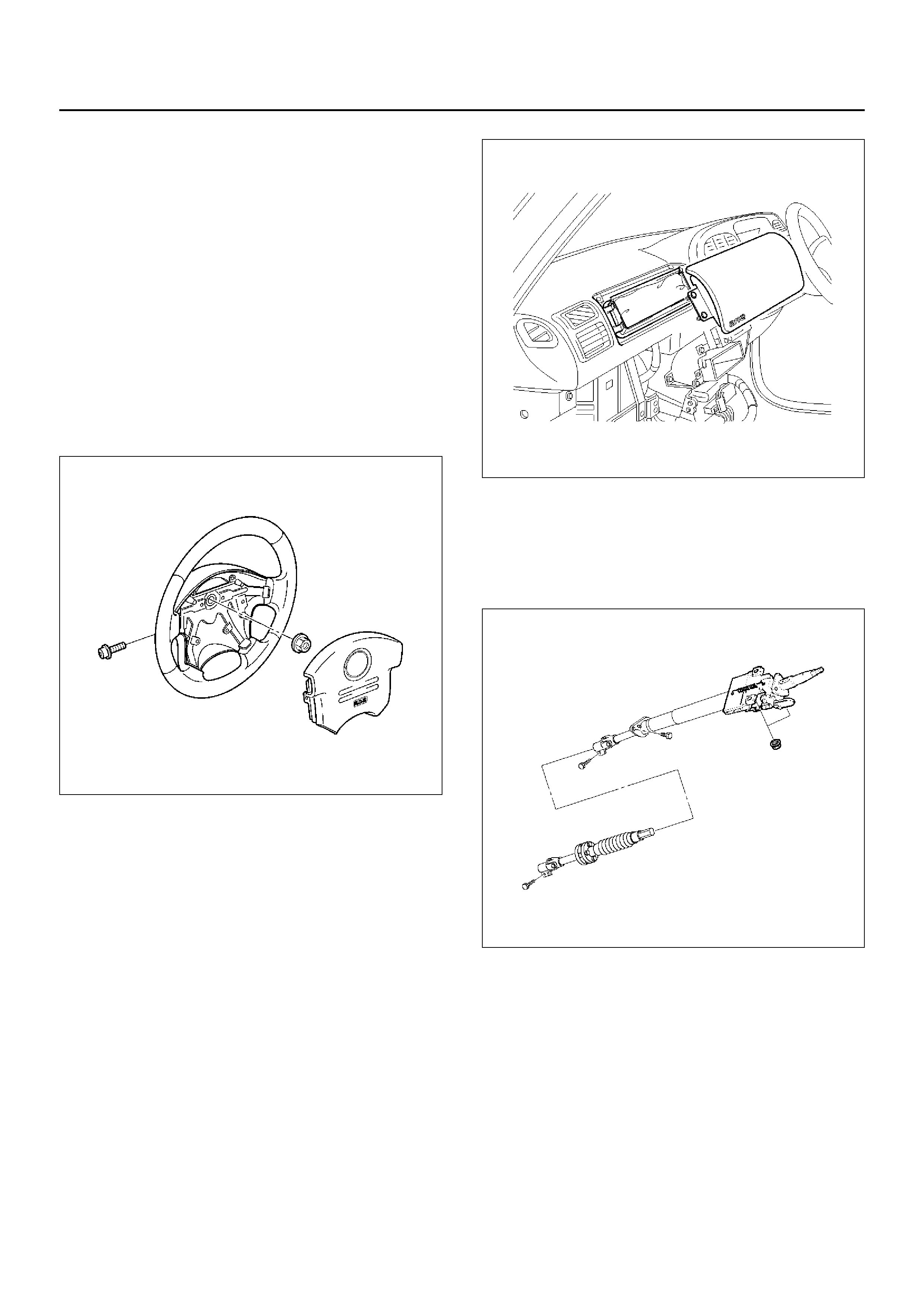
Driver Air Bag Assembly
Service Precautions
Removal
Installation
Steering Wheel
Service Precautions
Removal
Installation
SRS Coil Assembly
Service Precaution
Removal
How to Disconnect the horn terminal
How to Connect Horn Terminal
Installation
Steering Column
Service Precaution
Removal
Installation
Passenger Air Bag Assembly
Service Precaution
Removal
Installation
Main Data and Specifications
SRS Air Bag System Inspection Standards
For Repair
Service Precaution
WARNING: THIS VEHICLE HAS A SUPPLEMENTAL
RESTRAINT SYSTEM (SRS). REFER TO THE SRS
COMPONENT AND WIRING LOCATION VIEW INORDER TO DETERMINE WHETHER YOU AREPERFORMING SERVICE ON OR NEAR THE SRSCOMPONENTS OR THE SRS WIRING. WHEN YOUARE PERFORMING SERVICE ON OR NEAR THESRS COMPONENTS OR THE SRS WIRING, REFER
TO THE SRS SERVICE INFORMATION. FAILURE TOFOLLOW WARNINGS COULD RESULT IN POSSIBLEAIR BAG DEPLOYMENT, PERSONAL INJURY, OROTHERWISE UNNEEDED SRS SYSTEM REPAIRS.
CAUTION: Always use the correct fastener in the
proper location. When you replace a fastener, use
ONLY the exact part number for that application.
ISUZU will call out those fasteners that require a
replacement after removal. ISUZU will also call out
the fasteners that require thread lockers or thread
sealant. UNLESS OTHERWISE SPECIFIED, do not
use supplemental coatings (Paints, greases, or
other corrosion inhibito r s) on thr eaded fastener s or
fastener joint interfaces. Generally, such coatings
adversely affect the fastener torque and the joint
clamping force, and may damage the fastener.
When you install fasteners, use the correct
tightening sequence and specifications. Following
these instructions can help you avoid damage to
parts and systems.
General Description
CAUTION: When fasteners are removed, always
reinstall them at the same location from which they
were removed. If a fastener needs to be replaced,
use the correct part number fastener for that
application. If the correct part number fastener is
not available, a fastener of equal size and strength
(or stronger) may be used. fasteners that are not
reused, and those requiring thread locking
compound will be called out. The correct torque
v alue must be used when installing fasteners that
require it. If the above conditions are not followed,
parts or system damage could result.
Restrain t Devices
827RX044
Legend
EndOFCallout
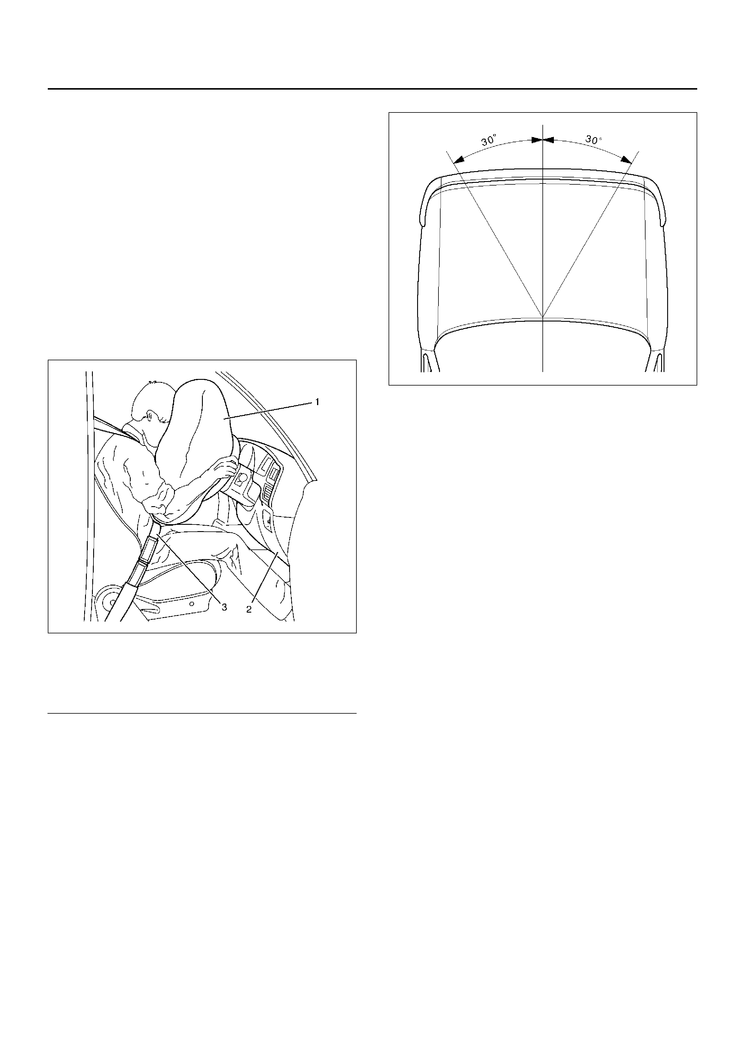
The Supplemental Restraint System (SRS) helps
supplement the protection offered by the driver and front
passenger seat belts by deploying an air bag from the
center of the steering wheel and from the top of the right
side of the instrument panel.
The air bag deploys when the vehicle is involved in a
frontal crash of sufficient force up to 30 degrees off the
centerline of the vehicle. To further absorb the crash
energy there is a knee bolster located beneath the
instrument panel for both the driver and passenger, and
the steering column is collapsible.
827RX050
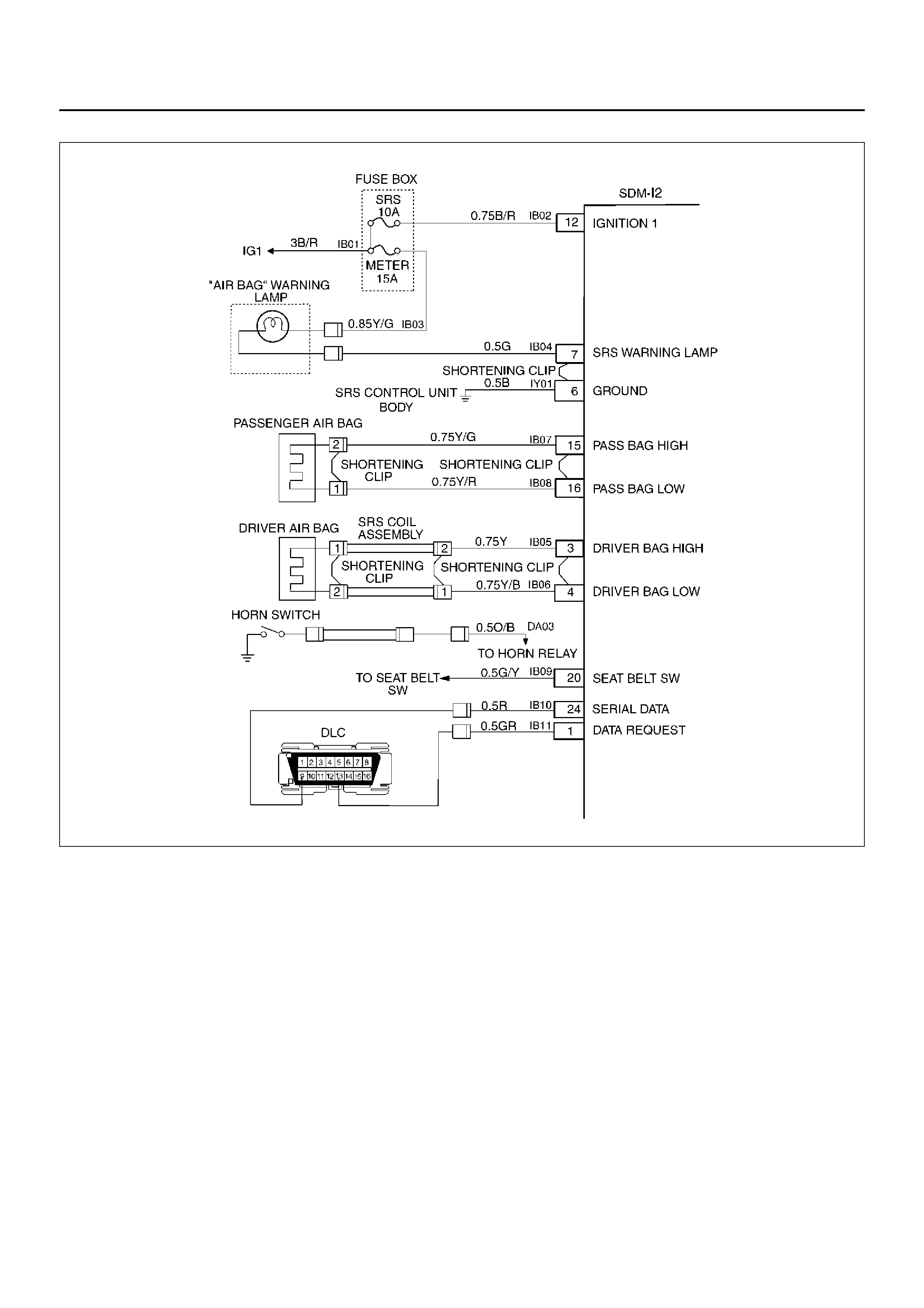
System De script ion
The SRS consists of the Sensing and Diagnostic
Module (SDM), the driver air bag assembly, the SRS coil
assembly, the passenger air bag assembly, and the “AIR
BAG“ warning lamp in the instrument cluster. The
SDM, SRS coil assembly (driver side only), driver air
bag assembly, passenger air bag assembly and
connector wire make up the deployment loops. The
function of the deployment loops is to supply current
through air bag assembly, which will cause deployment
of the air bags in the e vent of a frontal crash of sufficient
force , up to 30 degrees off the centerline of the vehicle.
The air bag assemblies are only supplied enough
current to deploy when the SDM detects vehicle velocity
changes severe enough to warrant deployment.
The SDM contains a sensing device which converts
vehicle velocity change to an electrical signal. The
electrical signal generated is processed by the SDM
and then compared to a v alue stored in memory. When
the generated signal exceeds the stored value, the SDM
will cause current to flow through the air bag assembly
deploying the air bags.
(1) Deployed Air Bag
(2) Knee Bolster
(3) Seat Belt
D09RX002
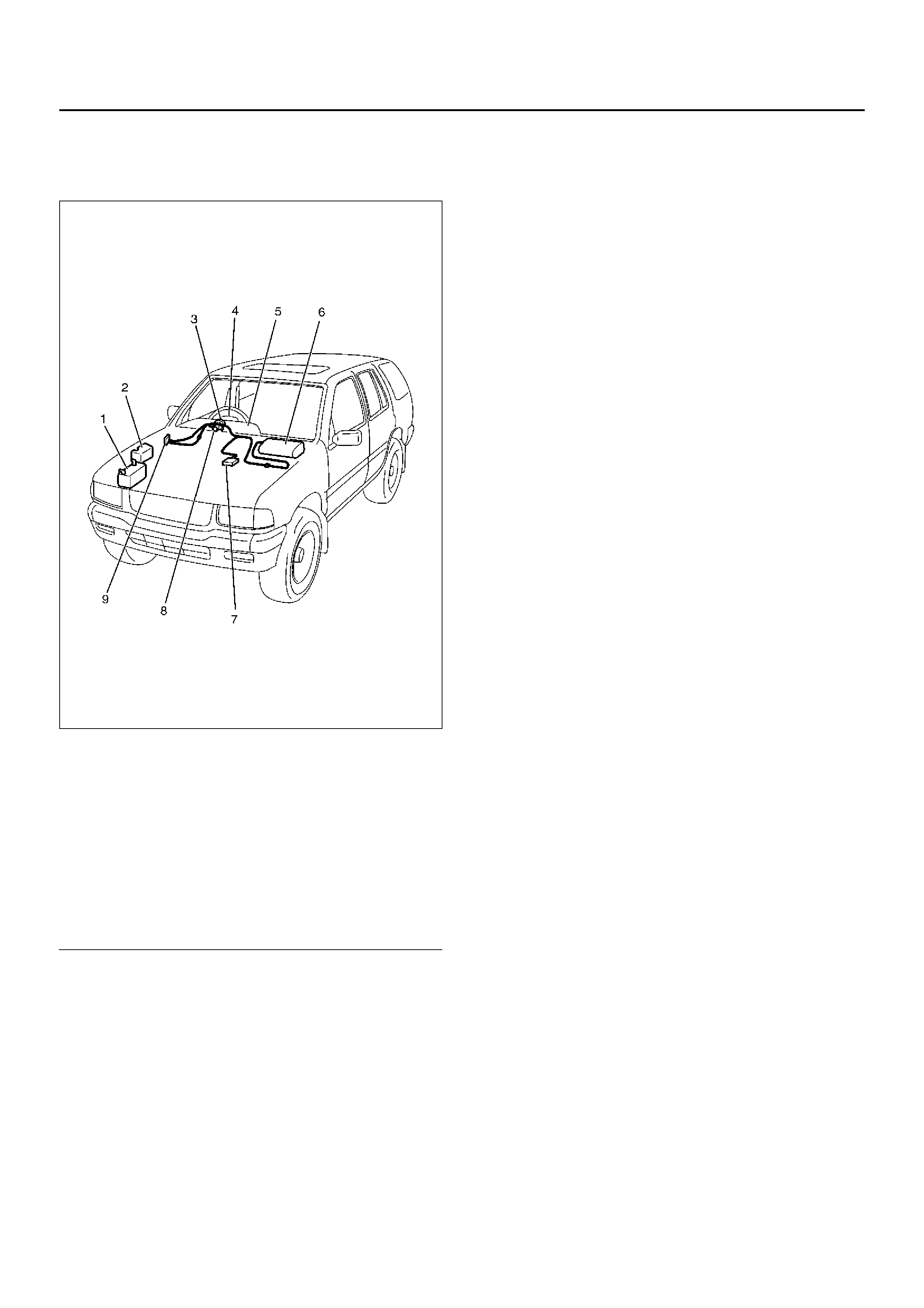
SRS Component and Wiring
Location View
810RX015
Legend
EndOFCallout
Component Description
SDM (Sensing and Diagnostic Module)
WARNING: DURING SERVICE PROCEDURES, BE
VERY CAREFUL WHEN HANDLING A SDM. NEVER
STRIKE OR JAR THE SDM. NEVER PO WER UP THE
SRS WHEN THE SDM IS NOT RIGIDLY ATTACHED
TO THE VEHICLE. ALL SDM AND MOUNTING
BRACKET FASTENERS MUST BE CAREFULLY
TORQUED AND THE ARROW MUST BE POINTED
TOWARD THE FRONT OF THE VEHICLE TO
ENSURE PROPER OPERATION OF THE SRS. THE
SDM COULD BE ACTIVATED WHEN POWERED
WHILE NOT RIGID LY ATTACHED TO THE VEHICLE
WHICH COULD CA USE DEPLOYMENT AND RESULT
IN PERSONAL INJURY.
The SDM is designed to perform the follo wing functions
in the Supplemental Restraint System (SRS):
1. Energy Reserve — The SDM maintains 24–Volt
Loop Reserve (24VLR) energy supply to provide
deployment energy when ignition voltage is lost in a
frontal crash.
2. Frontal Crash Detection — The SDM monitors
vehicle velocity changes to detect frontal crashes
which are severe enough to warrant deployment.
3. Air Bag Deployment — When a frontal crash of
sufficient f orce is detected, the SDM will cause
enough current to flow through the air bag assembly
to deploy the air bag.
4. Malfunction Detection — The SDM performs
diagnostic monitoring of SRS electrical components
and sets a diagnostic trouble code when a
malfunction is detected.
5. Frontal Crash Recording — The SDM records
inf ormation regarding SRS status during frontal
crash.
6. Malfunction Diagnosis — The SDM displays SRS
diagnostic trouble codes and system status
inf ormation through the use of a scan tool.
7. Driver Notification — The SDM warns the vehicle
driver of SRS malfunctions by controlling the “Air
Bag" warning lamp.
The SDM is connected to the SRS wiring harness by a
24–pin connector. This harness connector uses a
shorting clip across certain terminals in the contact
area. This shorting clip connects the “AIR BAG"
warning lamp to ground when the SDM harness
connector is disconnected or Connector Position
Assurance (CPA) is not inserted even if completely
connected. This will cause the “AIR BAG" warning
lamp to come “ON" steady whenever the ignition switch
is at the ON or START positions with the SDM
disconnected.
(1) Battery
(2) Relay & Fuse Box
(3) SRS Coi l Assembly
(4) Driver Air Bag Assembly
(5) Meter Assembly
(6) Passenger Air Bag Assembly
(7) SDM
(8) Starter Switch
(9) Fuse Box, SRS, METER
827RW067
Legend
EndOFCallout
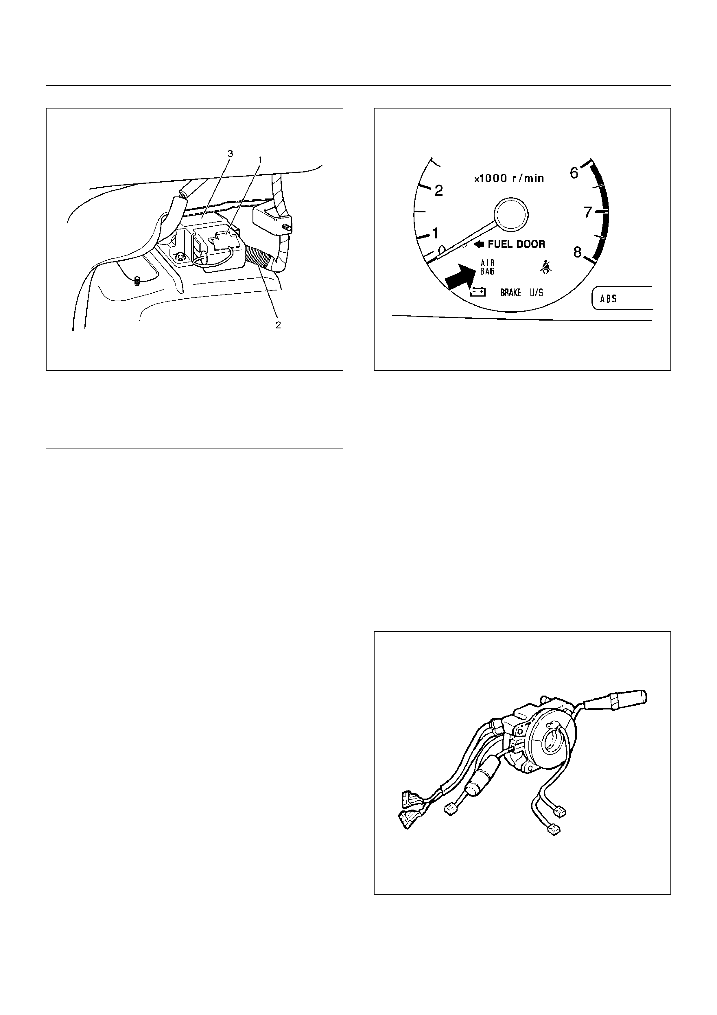
“Air Bag" Warning Lamp
Ignition voltage is applied to the “AIR BAG" warning
lamp when the ignition switch is at the ON or START
positions. The SDM controls the lamp by providing
ground with a lamp driver. The “AIR BAG" warning lamp
is used in the SRS to do the following:
1.Verify lamp and SDM operation by flashing SEVEN
(7) times when the ignition switch is first turned
“ON".
2.Warn the vehicle driver of SRS electrical system
malfunctions which could potentially affect the
operation of the SRS. These malfunctions could
result in nondeployment in case of a frontal crash or
deployment for conditions less severe than
intended.
The “AIR BAG" warning lamp is the key to driver
notification of SRS malfunctions. For proper lamp
operation, refer to the “SRS Diagnostic System Check"
in th is section.
821RW116
SRS Coil Assembly
The SRS coil assembly consists of two current carrying
coils. This is attached to the steering column and allow
rotation of the steering wheel while maintaining
continuous contact of the driver deployment loop to the
dr iver air bag asse mbly.
There is a shorting clip on the yellow 2–pin connector
near the base of steering column which connects the
SRS coil to the SRS wiring harness.
The shorting clip shorts to the SRS coil and driver air
bag assembly when the yellow 2–pin connector is
disconnected. The circuit to the driver air bag
assembly is shorted in this way to help pre vent
unwanted deploy ment of the air bag when servicing the
steering column or other SRS components.
825RS071
Air Bag Assemblies
The air bag assembly consist of an inflatable air bag
(1) Connector Position Assurance (CPA)
(2) Supplemental Restraint System (SRS) Harness
(3) Sensing and Diagnostic Module (SDM)
assembly and an inflator (a canister of gas–generating
material and an initiating device). When the vehicle is
in a frontal crash of sufficient force.
The SDM causes current flow through the deployment
loops. Current passing through the inflator ignites the
material in the air bag assembly. The gas produced
from this reaction rapidly inflates the air bag assembly.
There is a shorting clip on the driver air bag assembly
connector which connects the SRS coil assembly. The
shorting clip shorts across the driver air bag assembly
circuits when driver air bag assembly connector is
disconnected.
The circuit to the driver air bag assembly is shorted in
this way to help pre v ent unw anted deployment of the air
bag when servicing the driver air bag assembly, the
steering column or other Supplemental Restraint
System (S RS) com pon ents.
827RX038
There is a shorting clip on the passenger air bag
assembly conne cto r which connects to the SRS
harness. The shorting clip shorts across the
passenger air bag assembly circuit when the passenger
air bag assembly connector is disconnected. The
circuit to the passenger air bag assembly is shorted in
this way to help pre v ent unw anted deployment of the air
bag when servicing the passenger air bag assembly, the
instrument panel or other SRS components.
827RX051
Steering Column
The steering column absorbs energy and is designed to
compress in a frontal crash to decrease the chance of
injury to the driver.
431RX014
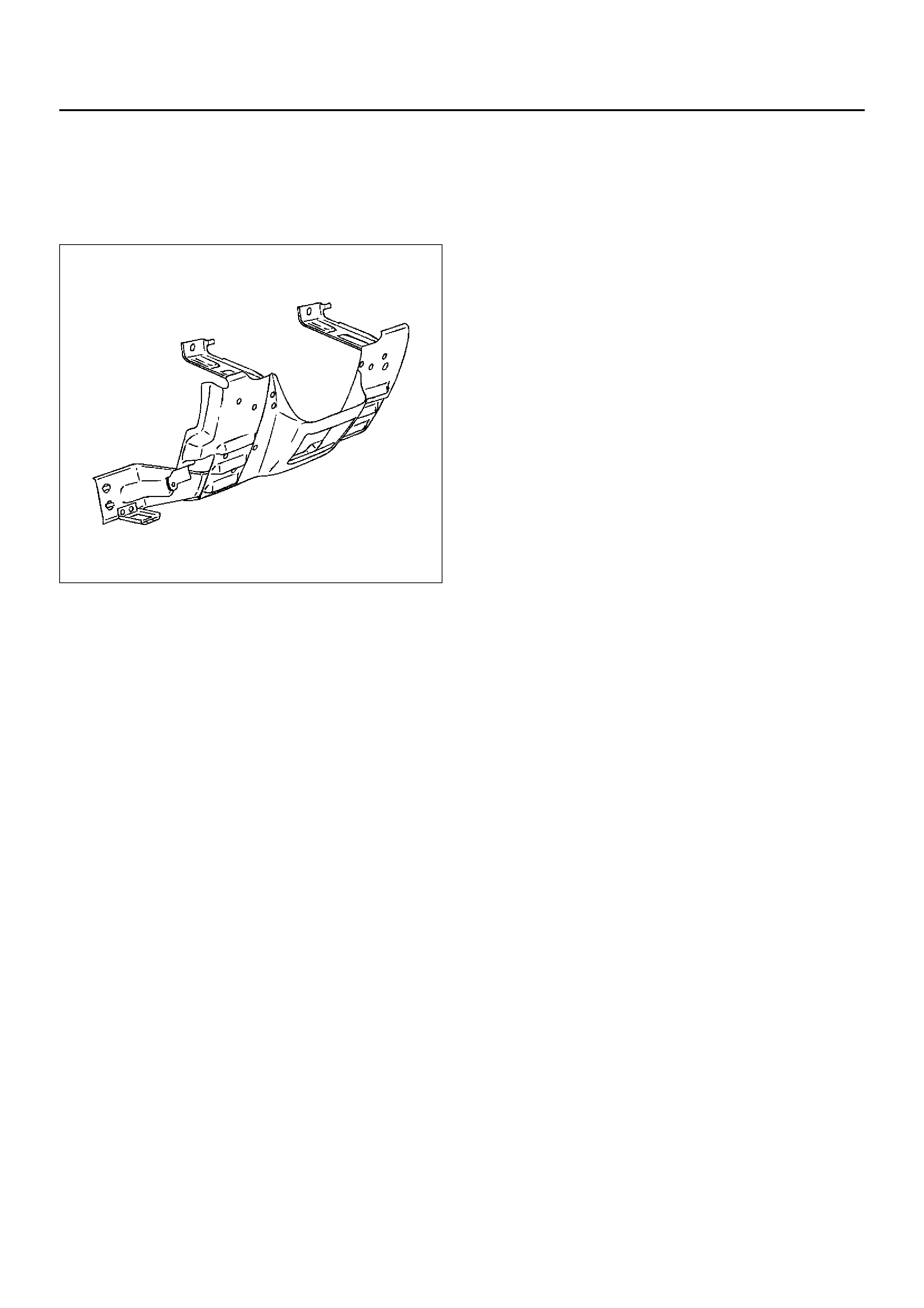
Knee Bolster
The knee bolsters are used to absorb energy to protec
knees and control the forw ard mov ement of the vehicle's
front seat occupants during a frontal crash, by limiting
leg movement.
740RS021
Definition
Air Bag
An inflatable cloth cushion designed to deploy in certain
frontal crashes. It supplements the protection offered b y
the seat belts by distributing the impact load more
evenly over the vehicle occupant's head and torso.
(B+)
Battery voltage, (B+) The voltage available at the
battery at the time of the indicated measurement. With
the key “ON" and the engine not running, the system
voltage will likely be between 12 and 12.5 volts. At idle
the v oltage ma y be 14 to 16 v olts . The v oltage could be
as low as 10 volts during engine cranking.
Bulb Check
The Sensing and Diagnostic Module (SDM) will cause
the “AIR BA G" w arning lamp to flash seven times and
then go “OFF" whenever the ignition switch transitions
to the ON position from any other ignition s witch position
and no malfunctions are detected.
“CONTINUOUS MONITORING"
Tests performed by the SDM on the SRS every 100
milliseconds while “Ignition 1" voltage is in the normal
operating voltage range at the SDM.
Data Link Connector (DLC)
Formerly “DLC" a connector which allows
communication with an external computer, such as a
scan tool.
Deploy
To inflate the air bag.
Deployment Loops
The circuits which supply current to the air bag
assemblies to deploy the air bag.
Diagnostic Trouble Code (DTC)
Formerly “Code", a numerical designator used by the
SDM to indicate specific SRS malfunctions.
Driver Current Source
An output of the SDM which applies current into the
driver air bag assembly circuit during the “Initiator
Assembly Resistance Test".
Driver Air Bag Assembly
An assembly located in the steering wheel hub
consisting of an inflatable bag, an inflator and an
initiator.
EEPROM
Electronically Erasable Programmable Read Only
Memory. Memory which retains its contents when
power is removed from the SDM.
Ignition Cycle
The voltage at the SDM “Ignition 1" inputs, with ignition
switch “ON", is within the normal operating voltage
range for at least ten seconds before turning ignition
switch “OFF".
Ignition 1
A battery voltage (B+) circuit which is only powered with
the ignition switch in the ON, or START positions.
Initiator
The electrical component inside the air bag assembly
which, when sufficient current flows, sets off the
chemical reaction that inflates the air bag.
“Initiator Assembly Resistance Test"
Tests performed once each ignition cycle when no
malfunctions are detected during “Turn–ON" or
“Continuous Monitoring." This test checks for the
correct SDM configuration for the vehicle, shorts to
“Ignition 1" in the deployment loops, high resistance or
opens in the “Driver Side High", “Driver Side Low",
“Passenger Side High" and “Passenger Side Low"
circuits and measures the resistance of the inflator
assembly consisting of: 1) Initiators, 2) SRS coil
assembly (driver side only), 3) Connectors and
associated wiring.
Normal Operating Voltage Range
The voltage measured between the SDM “Ignition 1"
terminals and “Ground" terminals is between 9 and 16
volts.
Passenger Current Source
An output of the SDM which applies current into the
passenger air bag assembly circuit during the “Initiator
Assembly Resistance Test".
Passenger Air Bag Assembly
An assembly located in the left side of the instrument
panel consisting of an inflatable bag, an inflator and an
initiator.

Scan Tool
An external computer used to read diagnostic
information from onboard computers via the data link
connector.
SDM
Sensing and Diagnostic Module which provides reserve
energy to the deployment loops, deploys the air bags
when required and performs diagnostic monitoring of all
SRS components.
Serial Data
Information representing the status of the SRS.
SRS
Supplemental Restraint System.
SRS Coil Assembly
An assembly of two current–carrying coils in the driver
deployment loop that allows the rotation of the steering
wheel while maintaining the continuous contact of the
driver deployment loop to the driver air bag assembly.
SRS Wiring Harness
The wires and connectors that electrically connect the
components in the Supplemental Restraint System
(SRS).
“Turn–ON"
Test which the Sensing and Diagnostic Module (SDM)
performs on the SRS once during each ignition cycle
immediately after “Ignition 1" voltage is applied to the
SDM and before “Continuous Monitoring".
Diagnosis
WARNING: TO AVOID DEPLOYMENT WHEN
TROUBLESHOOTING THE SRS, DO NOT USE
ELECTRICAL TEST EQUIPMENT SUCH AS A
BATTERY–POWERED OR AC–POWERED
VOLTMETER, OHMMETER, ETC., OR ANY TYPE OF
ELECTRICAL EQUIPMENT OTHER THAN THAT
SPECIFIED IN THIS MANUAL. DO NOT USE A NON–
POWERED PROVE–TYPE TESTER. INSTRUCTIONS
IN THIS MANUAL MUST BE FOLLOWED
CAREFULLY, OTHERWISE PERSONAL INJURY MAY
RESULT.
Diagnostic Trouble Codes
The “SRS Diagnostic System Check" must always be
the starting point of any SRS diagnosis. The “SRS
Diagnostic System Check" checks for proper “AIR BAG"
warning lamp operation and checks for SRS diagnostic
trouble codes using the scan tool.
1.Current diagnostic trouble codes – Malfunctions that
are presently being detected. Current diagnostic
trouble codes are stored in Random Access
Memory (RAM).
2.History diagnostic trouble codes – All malfunctions
detected since the last time the history memory was
cleared. History diagnostic trouble codes are
stored in Electronically Erasable Programmable
Read Only Memory (EEPROM).
Scan Tool Diagnostics
A scan tool is used to read current and history
diagnostic trouble codes and to clear all diagnostic
trouble codes after a repair is completed. The scan tool
must be updated to communicate with the SRS through
a replaceable cartridge before it can be used for SRS
diagnostics. To use the scan tool, connect it to the data
link connector and turn the ignition switch “ON". The
scan tool reads serial data from the SDM “Serial Data"
line terminal “24" to the data link connector terminal “9".
Use of Special Tools
WARNING: TO AVOID DEPLOYMENT WHEN
TR OUBLESHOOTING THE SRS, DO NOT USE
ELECTRICAL TEST EQUIPMENT SUCH AS A
BATTERY–POWERED OR AC–POWERED
VO LTME TER, OHMMET ER, ETC, OR ANY TYPE OF
ELECTRICAL EQUIPMENT OTHER THAN THAT
SPECIFIED IN THIS MANUAL. DO NOT USE A NON
POWERED PROVE–TYPE TESTER. INSTRUCTIONS
IN THIS MANUAL MUST BE FOLLOWED
CAREFULLY, OTHERWISE PERSONAL INJURY MAY
RESULT. YOU SHOULD BE FAMILIAR WITH THE
TOOLS LISTED IN THIS SECTION UNDER THE
HANDLING SRS SPECIAL TOOLS.
You should be able to measure voltage and resistance.
You should be familiar with proper use of a scan tool
such as the Tech 2 Diagnostic Computer, SRS Driver/
Passenger Load Tool 5–8840–2421–0, Connector Test
Adapter Kit 5–8840–0385–0, and the DVM (Digital
Multimeter) 5–8840–0285–0.
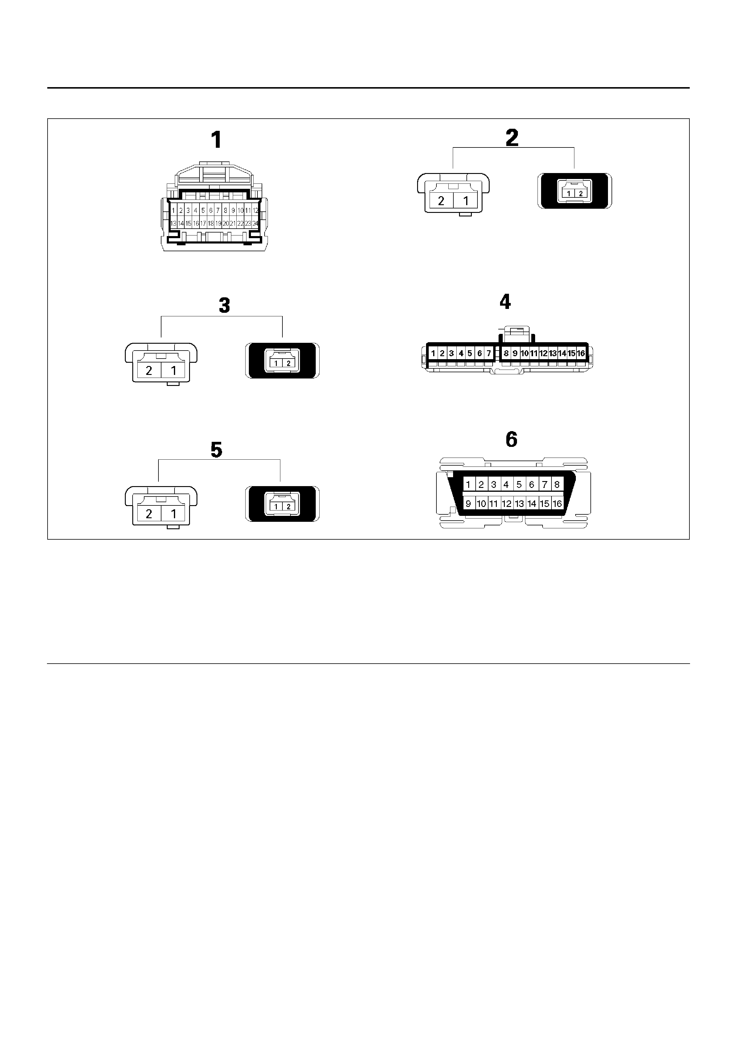
SRS Connector Body Face Views
D09RW003
Legend
EndOFCallout
Repairs and Inspections Required
After an Accident
NOTE: If any SRS components are damaged, they
must be replaced. If SRS component mounting points
are damaged, they must be replaced.
•Never use SRS parts from another vehicle. This
does not include remanufactured parts purchased
from an authorized dealer; they may be used for SRS
repairs.
•Do not attempt to service the SDM, the SRS coil
assembly, or the air bag assembly. Service of these
items is by replacement only.
•Verify the part number of replacement air bag
assembly.
CAUTION: Never use the air bag assembly from
another vehicle.
Use only the air bag assembly for UE models.
CAUTION: Proper operation of the sensors and
Supplemental Restraint System (SRS) requires that
any repairs to the vehicle structure return it to the
original production configuration. Deployment
requires, at a minimum, replacement of the SDM, air
bag assembly and dimensional inspection of the
steering column. Any visible damage to the SDM
mounting bracket (s) requires replacement, and the
steering column must be dimensionally inspected,
whether deployment occurred or not.
Accident With Deployment – Component
Replacement and Inspections
Certain SRS components must be replaced or
inspected for damage after a frontal crash involving air
bag deployment. Those components are:
•Air bag assembly
•SDM
CAUTION: Refer to “SDM Replacement Guidelines"
below for important information on Sensing and
(1) Sensing and Diagnostic Module (SDM)
(2) Driver Air Bag Assembly
(3) Passenger Air Bag Assembly
(4) “Air Bag" Warning Lamp
(5) Supplemental Restraint System (SRS) Coil
Assembly
(6) Data Link Connector (DLC)

Diagnostic Module (SDM) replacement in both
deployment and non deployment crashes.
•Supplemental Restraint System (SRS) coil
assembly—Inspect wiring and connector for any
signs of scorching, melting, or damage due to
excessive heat. Replace if damaged. Refer to SRS
coil assembly in this section.
Accident With or Without Deployment—
Component Inspection
Certain SRS and restraint system components must be
inspected after any crash, whether the air bag deployed
or not. Those components are:
•Steering column—Dimensionally inspect per
“Checking Steering Column for Accident Damage" in
3 of this workshop manual.
•Knee bolsters and mounting points— Inspect for any
distortion, bending, cracking, or other damage.
•Instrument panel steering column reinforcement
plate— Inspect for any distortion, bending, cracking,
or other damage.
•Instrument panel braces—Inspect for any distortion,
bending, cracking, or other damage.
•Seat belts and mounting points—Refer to “Seat
Belts" in 10 of this workshop manual.
SDM Replacement Guidelines
SDM replacement policy requires replacement of SDM,
after crash involving air bag deployment when “SRS
Warning Lamp" turn “ON", “SRS Diagnosis" should be
done according to “Section".
Wiring Damage
If any SRS wire harness is damaged, it should be
replaced. Don't repair SRS. It is replace only.
SRS Connector (Plastic Body And Terminal
Metal Pin) Damage
If any connector or terminal in the SRS wire harness
(except pigtails) is damaged, it should be replaced.
SRS Wire Pigtail Damage
If the wiring pigtail (a wire or wires attached directly to
the device, not by a connector) is damaged, the entire
component (with pigtail) must be replaced. Examples of
“pigtail" components are the driver air bag assembly, the
passenger air bag assembly, and the SRS coil
assembly.
On–Vehicle Service
Service Precautions
WARNING: WHEN PERFORMING SERVICE ON OR
AROUND SRS COMPONENTS OR SRS WIRING,
FOLLOW THE PROCEDURES LISTED BELOW TO
TEMPORARILY DISABLE THE SRS. FAILURE TO
FOLLOW PROCEDURES COULD RESULT IN
POSSIBLE AIR BAG DEPLOYMENT, PERSONAL
INJURY OR OTHERWISE UNNEEDED SRS REPAIRS.
The SDM in Driver—Passenger SRS can maintain
sufficient voltage to cause a deployment for up to 15
seconds after the ignition switch is turned “OFF", the
battery is disconnected, or the fuse powering the SDM
is removed.
Many of the service procedures require removal of the
“SRS" fuse, and disconnection of the air bag assembly
from the deployment loop to avoid an accidental
deployment. If the air bag assembly is disconnected
from the deployment loop as noted in the “Disabling the
SRS" procedure that follows, service can begin
immediately without waiting for the 15 second time
period to expire.
Disabling The SRS
Removal
Turn the ignition switch to “lock" and remove key.
1.Remove SRS fuse “METER” and “SRS”, from left
dash side lower fuse block or disconnect battery.
2.Disconnect yellow 2–pin connector at the base of
steering column.
3.Remove glove box assembly, Refer to “Passenger
Air Bag Assembly Replacement" in section.
4.Disconnect yellow 2–pin connector behind the glove
box assembly.
CAUTION: With the “SRS" fuse removed and
ignition switch “ON", “AIR BAG" warning lamp will
be “ON". This is normal operation and does not
indicate an SRS malfunction.
Enabling The SRS
Installation
CAUTION: Never use the air bag assembly from
another vehicle. Use only the air bag assembly for
UE models.
Turn ignition switch to “LOCK" and remove key.
1.Connect yellow 2–pin connector passenger air bag
assembly.
2.Install glove box assembly, refer to “Passenger Air
Bag Assembly Replacement" in section.
3. Connect yellow 2–pin connector at the base of
steering column.
4. Install “AIR BAG" fuse “METE R” and “SRS” to left
dash side lower fuse block or connect battery.
Turn ignition switch to “ON" and verify that the “AIR
BAG" warning lamp flashes seven times and then turns
“OFF" If it does not operate as described, perform the
“Supplemental Restraint System (SRS) Diagnostic
System Check" in section.
Handling / Installation / Diagnosis
1.Air bag assembly should not be subjected to
temperatures above 93°C (200°F).
2.Air bag assembly, and Sensing and Diagnostic
Module (SDM) should not be used if they have been
dropped from a height of 100 centimeters (3.28
feet).
3.When a SDM is replaced, it must be oriented with
the arrow on the sensor pointing toward the front of
the vehicle. It is very important for the SDM to be
located flat on the mounting surface, parallel to the
vehicle datum line. It is important that the SDM
mounting surface is free of any dirt or other foreign
material.
4.Do not apply power to the SRS unless all
components are connected or a diagnostic chart
requests it, as this will set a diagnostic trouble code.
5.The “SRS Diagnostic System Check" must be the
starting point of any SRS diagnostics. The “SRS
Diagnostic System Check" will verify proper “AIR
BAG" warning lamp operation and will lead you to
the correct chart to diagnose any SRS malfunctions.
Bypassing these procedures may result in extended
diagnostic time, incorrect diagnosis, and incorrect
parts replacement.
Air Bag Assembly Handling /
Shipping / Scrapping
Live (Undeployed) Air Bag Assembly
Special care is necessary when handling and storing a
live (undeployed) air bag assembly. The rapid gas
generation produced during deployment of the air bag
could cause the air bag assembly, or an object in front of
the air bag assembly, to be thrown through the air in the
unlikely event of an accidental deployment.
827RX037
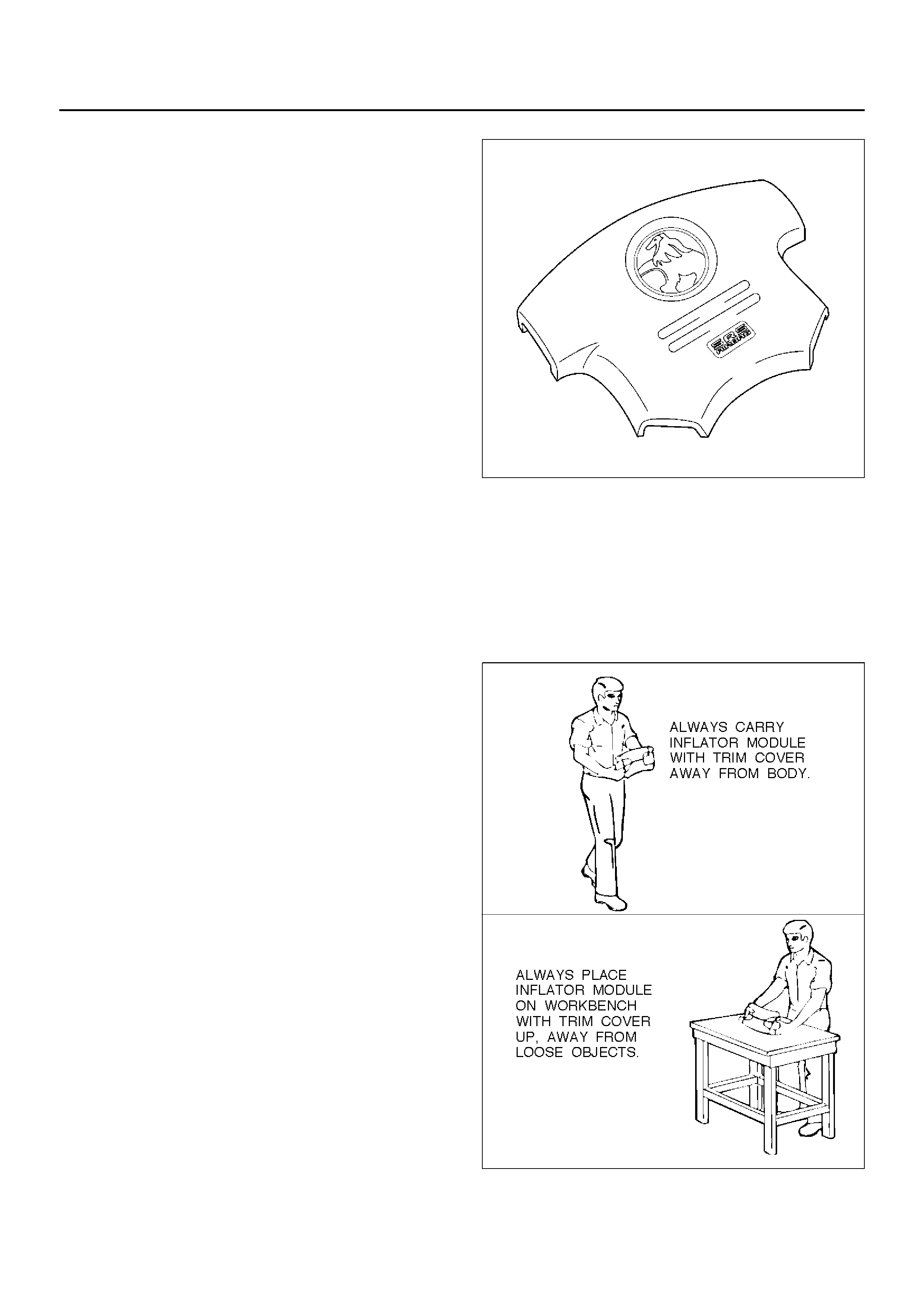
WARNING: WHEN CARRYING A LIVE AIR BAG
ASSEMBLY, MAKE SURE THE BAG OPENING IS
POINTED AWAY FROM YOU . IN CASE OF AN
ACCIDENTAL DEPLOYMENT, THE BAG WILL THEN
DEPLOY WITH MINIMAL CHANCE OF INJURY.
NEVER CARRY THE AIR BAG ASSEMBLY BY THE
WIRES OR CONNECTOR ON THE UNDERSIDE OF
THE MODULE.
827RS044

Air Bag Assembly Shipping Procedure For
Live (Undeployed) Air Bag Assemblies
Service personnel should refer to the latest Service
Bulletins for proper Supplemental Restraint System
(SRS) air bag assembly shipping procedures.
Deployed Air Bag Assembly
“You should wear gloves and glasses. After the air bag
assembly has been deployed, the surface of the air bag
may contain solid particulate. This solid particulate
consists primarily of by products of the chemical
reaction, Potassium Chloride and copper metal dust.
Compounds of Potassium Borate, Strontium Chloride,
Copper Chloride, and Ammounium Chloride may be
found in amounts of about 1% (each) of the total
particulate.”
Air Bag Assembly Scrapping Procedure
During the course of a vehicle's useful life, certain
situations may arise which will necessitate the disposal
of a live (undeployed) air bag assembly. This
information covers proper procedures for disposing of a
live air bag assembly.
Before a live air bag assembly can be disposed of, it
must be deployed. Alive air bag assembly must not be
disposed of through normal refuse channels.
WARNING: FAILURE TO FOLLOW PROPER SRS
AIR BAG ASSEMBLY DISPOSAL PROCEDURES
CAN RESULT IN AIR BAG DEPLOYMENT WHICH
MAY CAUSE PERSONAL INJURY. AN UNDPLOYED
AIR BAG ASSEMBLY MUST NOT BE DISPOSED OF
THROUGH NORMAL REFUSE CHANNELS. THE
UNDEPLOYED AIR BAG ASSEMBLY CONTAINS
SUBSTANCES THAT CAN CAUSE SEVERE ILLNESS
OR PERSONAL INJURY IF THE SEALED
CONTAINER IS DAMAGED DURING DISPOSAL.
DISPOSAL IN ANY MANNER INCONSISTENT WITH
PROPER PROCEDURES MAY BE A VIOLATION OF
FEDERAL, STATE, AND / OR LOCAL LAW.
In situations which require deployment of a live air bag
assembly module, deployment may be accomplished
inside or outside the vehicle. The method employed
depends upon the final disposition of the particular
vehicle, as noted in “Deployment Outside Vehicle" and
“Deployment Inside Vehicle" in this section.
Cautions About Air Bag Deployment And
Disposal
Failure to follow proper procedures could result in
erroneous air bag deployment which may cause
personal injury be sure to follow proper procedures.
1.Turn off (Lock) the ignition switch and disconnect the
minus terminal of the battery, then start the work 15
or more sec later. (Air bag is designed to work by
the back-up power source even if the battery power
source is cut off at vehicle collision).
2.Be sure not to disassemble the air bag.
3.Do not give an impact to the air bag and bring the air
bag close to magnet. (The air bag could deploy
unexpectedly).
4.Place the air bag with its trim cover up.
5.Do not let the air bag deploy directly on the floor.
(The air bag may be blown off 20 ∼ 30 cm (6.5 or 10
feet)).
6.Be sure to install the air bag firmly to a deployment
tool (fixing tool).
7.Set a battery 10 m (33 feet) or more away from the
air bag.
8.Before disconnecting air bag harness, ground the
worker by touching the vehicle outer panel with bare
hand.
9.When connecting or disconnecting the harness, do
not work just in front of the air bag.
10.As deployment gives rise to big sound, warn the
people around against it. Further, try to reduce the
sound by covering the steering wheel or tyres, and
shut the vehicle windows in case of deployment
inside the vehicle.
11. As deployment generates smoke, select a well
ventilated place. (In case of deployment indoors,
avoid deployment just under a fire alarm, smoke
sensor, and fluorescent lamps).
12. Be careful not to inhale the smoke after deployment.
13. If part of the vehicle glass is damaged, cover the
vehicle with a car cover to prevent the glass from
braking at the time of deployment.
14. Do not touch the air bag immediately after
deployment, since it remains hot for 30 minutes.
15. Do not water the air bag immediately after
deployment.
16. W ear safety glasses and glov es throughout the work
and wash the glasses and gloves after the work.
17. Do not reuse the removed air bag for another
vehicle. (Deployment characteristic is different with
vehicle types).
Deployment Outside Vehicle (Driver Air
Bag Assembly)
Deployment outside the vehicle is proper when the
vehicle is to be returned to service. This includes, for
example, situations in which the vehicle will be returned
to useful service after a functionally or cosmetically
deficient air bag assembly is replaced. Deployment and
disposal of a malfunctioning air bag assembly is, of
course, subject to any required retention period.
For deployment of a live (undeployed) air bag assembly
outside the vehicle, the deployment procedure must be
follow ed exactly. Alwa ys wear safety glasses during this
deployment procedure until a deployed air bag
assembly is scrapped or until an undeployed air bag
asse mbly is sh ippe d. Before pe rf orming t he pr ocedu res
you should be familiar with servicing the SRS and with
proper handling of the air bag assembly. Procedures
should be read fully before they are performed.
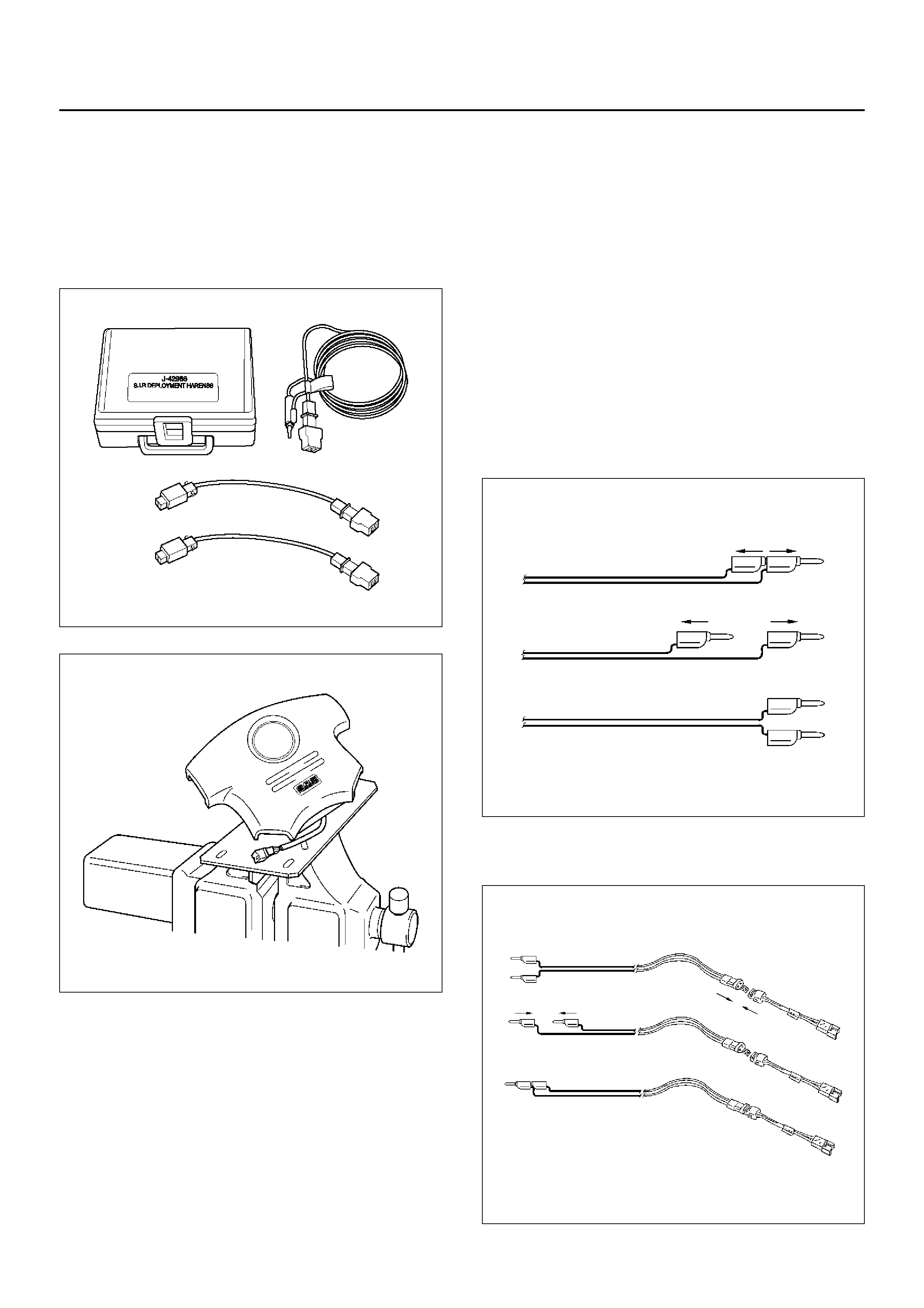
The following procedure requires use of 5–8840–2468–
0 Supplemental Restraint System (SRS) Deployment
Harness with the appropriate pigtail adapter. The
procedure also requires the use of 5–8840–2420–0
Driver Side SRS Deployment Fixture. Do not attempt
this procedure without 5–8840–2468–0 and fixture 5–
8840–2420–0.
901RX046
901RX062
WARNING: FAILURE TO FOLLOW PROCEDURES IN
THE ORDER LISTED MAY RESULT IN PERSONAL
INJURY. NEVER CONNECT DEPLOYMENT
HARNESS TO ANY POWER SOURCE BEFORE
CONNECTING DEPLOYMENT HARNESS TO THE
DRIVER AIR BAG ASSEMBLY. DEPLOYMENT
HARNESS SHALL REMAIN SHORTED AND NOT BE
CONNECTED TO A POWER SOURCE UNTIL THE
AIR BAG IS TO BE DEPLOYED. THE AIR BAG
ASSEMBLY WILL IMMEDIATELY DEPLOY THE AIR
BAG WHEN A POWER SOURCE IS CONNECTED TO
IT. WEAR SAFETY GLASSES THROUGHOUT THIS
ENTIRE DEPLOYMENT AND DISPOSAL
PROCEDURE.
NOTE: This information applies only to driver air bag
assembly . Refer to “Deployment Outside Vehicle
(Passenger Air Bag Assembly)" in this section for
information on passenger air bag assembly scrapping.
18. Turn ignition switch to “LOCK", remov e key and put
on safety glasses.
19. Inspect 5–8840–2419–0 SRS Deployment Harness
and appropriate pigtail adapter for damage. If
harness or pigtail adapter is damaged, discard and
obtain a replacement.
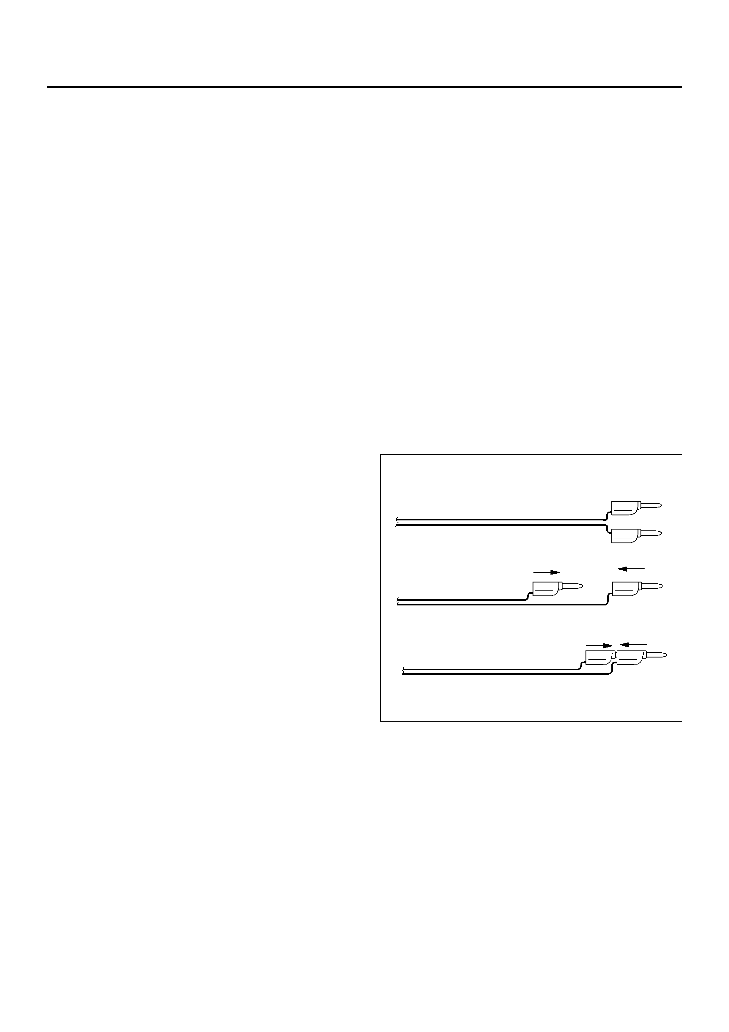
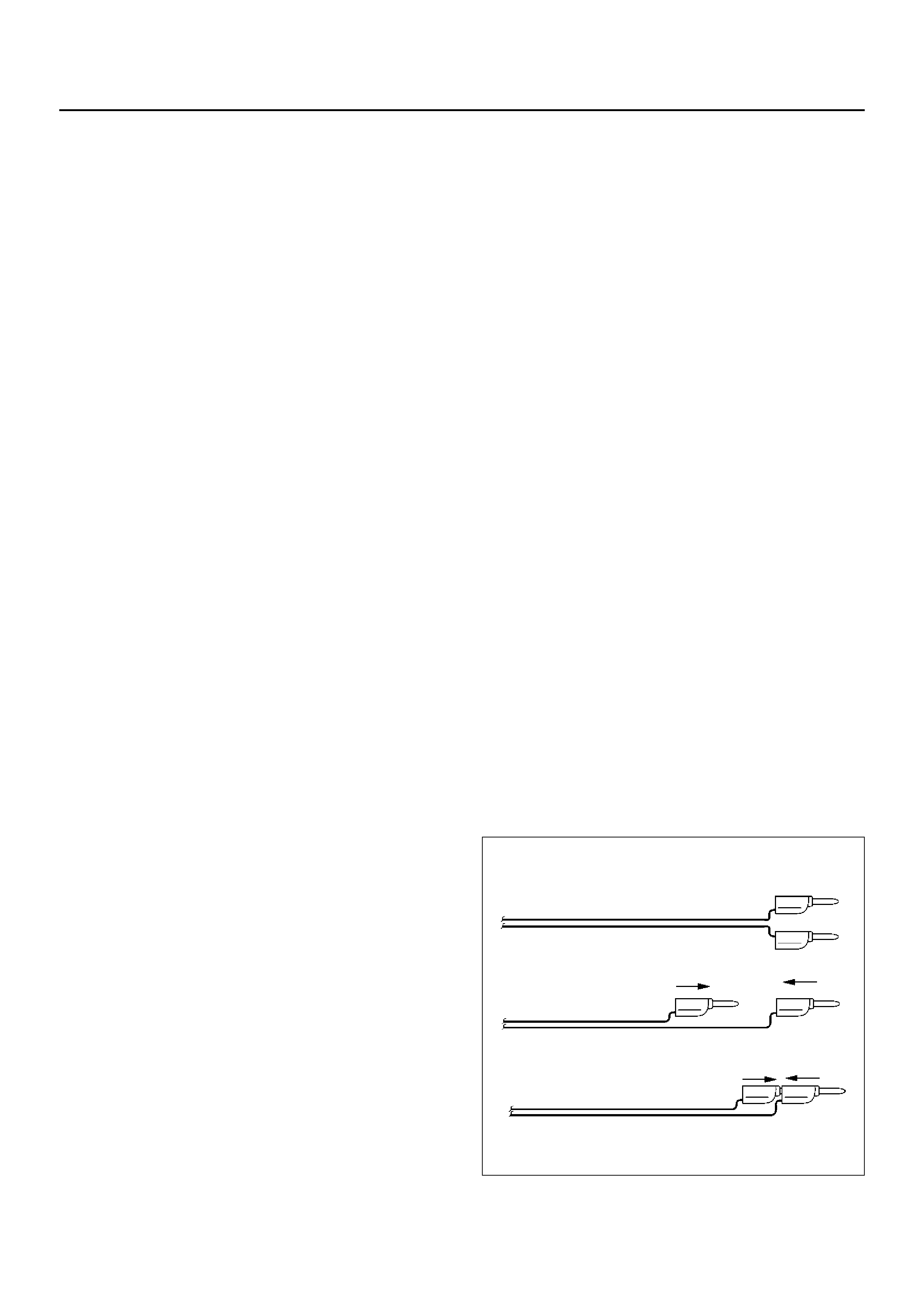
20. Short the two SRS deployment harness leads
together by fully seating one banana plug into the
other. SRS deployment harness shall remain
shorted and not be connected to a power source
until the air bag is to be deployed.
827RS003
21. Connect the appropriate pigtail adapter to the SRS
deployment harness.
827RS004
1.Remove the driver air bag assembly from vehicle.
Refer to driver air bag assembly Removal in this
Section.
WARNING: WHEN STORING A LIVE AIR BAG
ASSEMBLY OR WHEN LEAVING A LIVE AIR BAG
ASSEMBLY UNATTENDED ON A BENCH OR OTHER
SURFACE, ALWAYS FACE THE AIR BAG AND TRIM
COVER UP AND AWAY FROM THE SURFACE. THIS
IS NECESSARY SO THAT A FREE SPACE IS
PROVIDED TO ALLOW THE AIR BAG TO EXPAND IN
THE UNLIKELY EVENT OF ACCIDENTAL
DEPLOYMENT. FAILURE TO FOLLOW
PROCEDURES MAY RESULT IN PERSONAL INJURY.
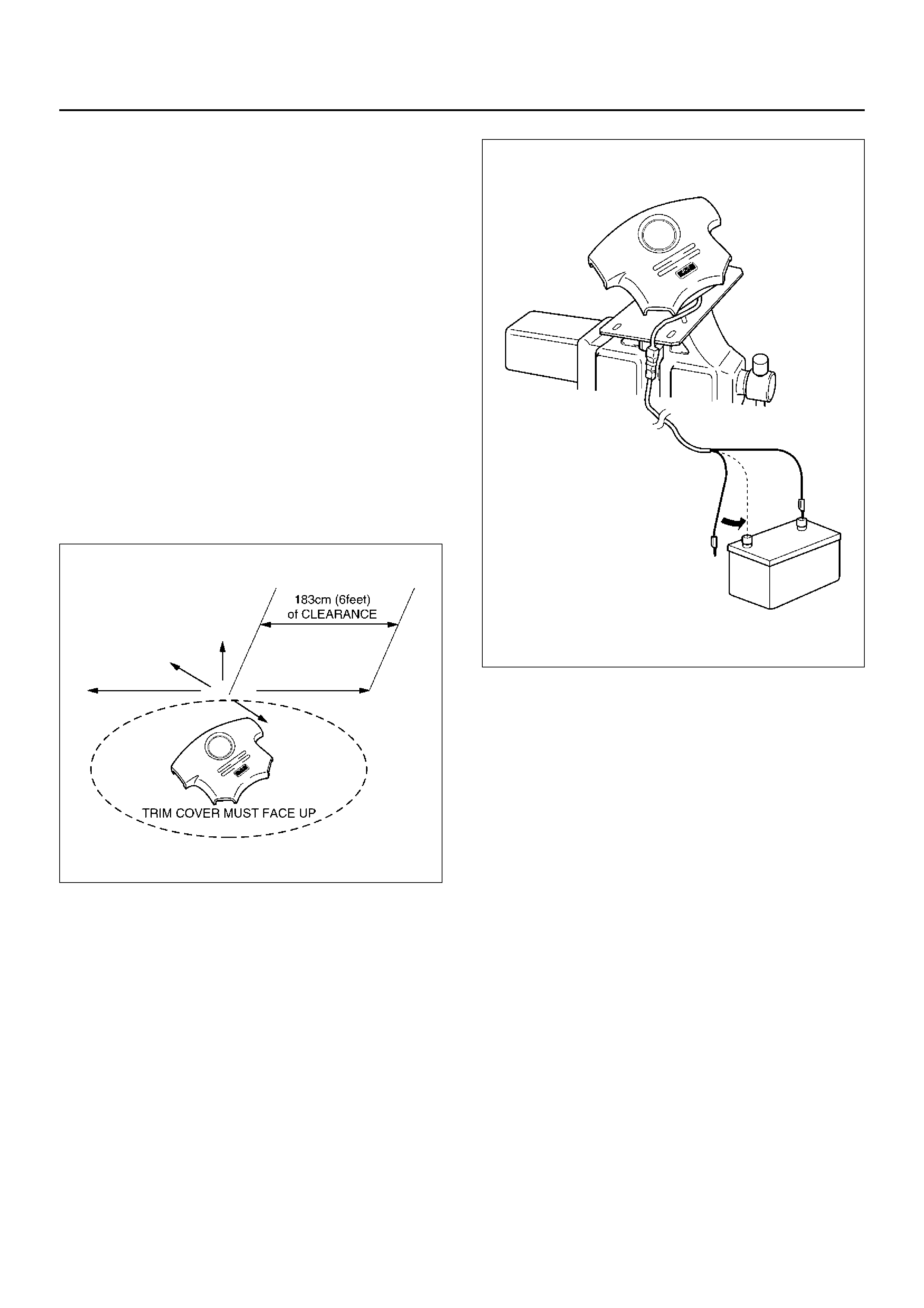
22.Clear a space on the ground about 183 cm (6 feet)
in clearance where the driver air bag assembly is to
be deployed. A paved, outdoor location where there
is no activity is preferred. If an outdoor location is
not av ailable , a space on the shop floor where there
is no activity and sufficient ventilation is
recommended. Ensure no loose or flammable
objects are within the deployment area.
827RX039
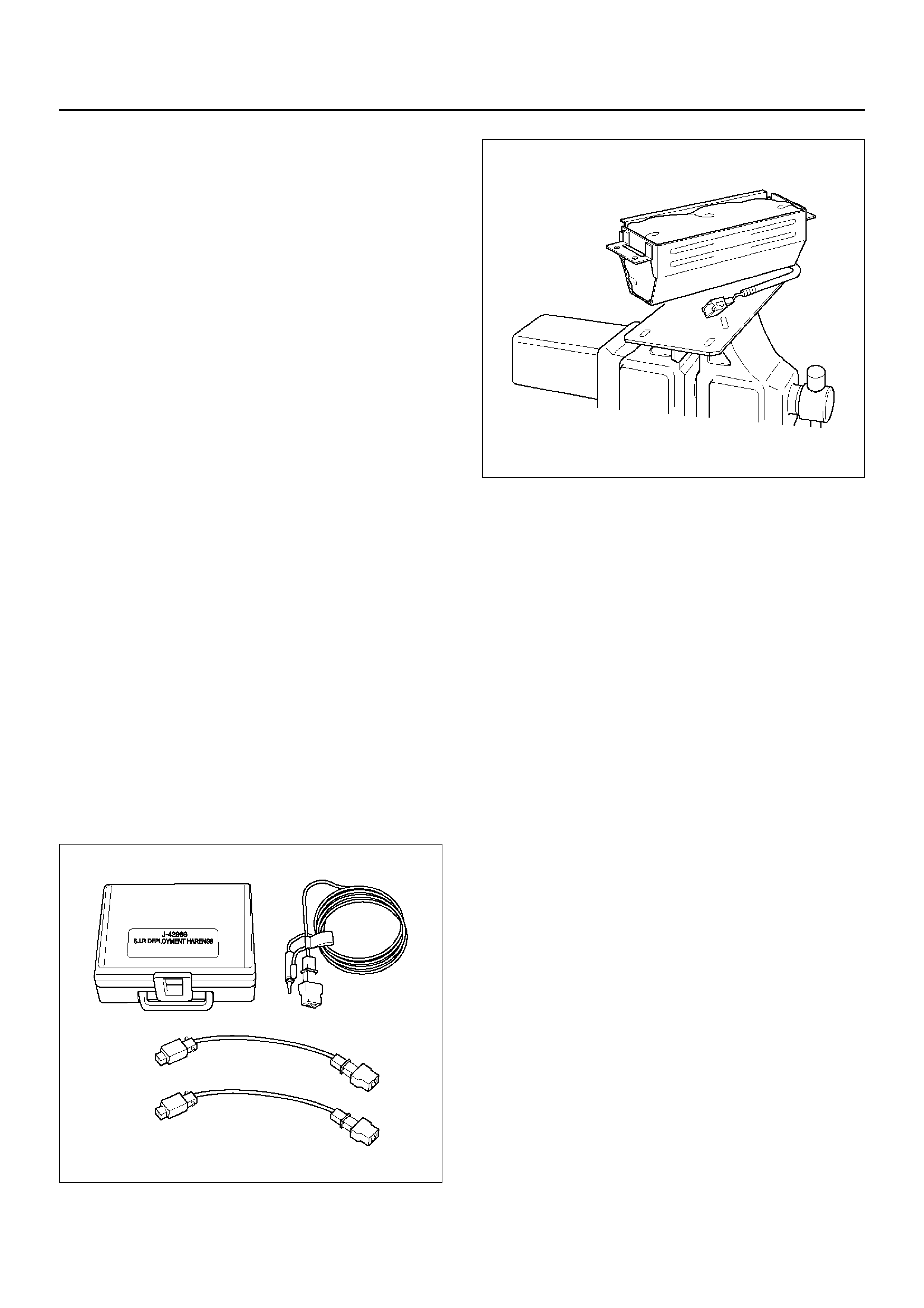
23. Place the J–41497 on the bench vice. This is
necessary to provide sufficient stabilization of the
fixture during deployment.
24. Attach the Dr iver air bag assembly in the J–41497.
Air bag assembly must be mounted such that the
bag will deploy upward. SECURELY HAND–
TIGHTEN ALL FASTENERS PRIOR TO
DEPLOYMENT.
25. Extent double pole extension cord to a position for
away 10 m (33 feet) from the air bag assembly.
26. Place a power source near the shorted end of the
SRS deployment harness. Recommended
application: 12 volts minimum, 2 amps minimum. A
vehicle battery is suggested.
827RX042
27. Connect the driver air bag assembly to the pigtail
adapter on the Supplemental Restraint System
(SRS) deployment harness. Deployment harness
shall remain shorted and not be connected to a
power source until the air bag is to be deployed.
The driver air bag assembly will immediately deploy
the air bag when a power source is connected to it.
NO TE: Ensure that the pigtail adapter is firmly seated
into the driver air bag assembly connector. Failure to
fully seat the connectors may leave the shorting bar
located in the driver air bag assembly connector
functioning (shorted) and may result in non deployment
of the driver air bag assembly.
28. Verify that the area around the driver air bag
assembly is clear of all people and loose or
flammable objec ts.
29. Verify that the driver air bag assembly is firmly and
proper l y in 5–8 840– 242 0–0.
30. Notify all people in the immediate area that you
intend to deploy the driver air bag. The deployment
will be accompanied by a substantial noise which
may star t le the uni nfor med .
31. Separate the two banana plugs on the SRS
deployment harness.
NO TE: When the air bag deploys, the rapid gas
expansion will create a substantial noise. Notify all
people in the immediate area that you intend to deploy
the driver air bag.
WARNING: DEPLOYMENT HARNESS SHALL
REMAIN SHORTED AND NOT BE CONNECTED TO A
POWER SOURCE UNTIL THE AIR BAG IS TO BE
DEPLOYED. THE AIR BAG ASSEMBLY WILL
IMMEDIATELY DEPLOY THE AIR BAG WHEN A
POWER SOURCE IS CONNECTED TO IT.
CONNECTING THE DEPLOYMENT HARNESS TO
THE POWER SOURCE SHOULD ALWAYS BE THE
LAST STEP IN THE AIR BAG ASSEMBLY
DEPLOYMENT PROCEDURE. FAILURE TO FOLLOW
PROCEDURES IN THE ORDER LISTED MAY
RESULT IN PERSONAL INJURY.
32.Connect the Supplemental Restraint System (SRS)
deployment harness wires to the power source to
immediately deploy the driver air bag.
Recommended application: 12 volts minimum, 2
amps minimum. A vehicle battery is suggested.
33.Disconnect the SRS deployment harness from the
power source.
34.Short the two SRS deployment harness leads
together by fully seating one banana plug into the
other.
35.In the unlikely event that the driver air bag assembly
did not deploy after following these procedures,
proceed immediately with Steps 24 through 26. If
the driver air bag assembly did deploy, proceed with
Steps 20 through 23.
36.Put on a pair of shop gloves and safety glasses to
protect your hands and eyes from possible irritation
and heat when handling the deployed driver air bag
assembly. After the air bag assembly has been
deployed, the surface of the air bag may contain
solid particulate. This solid particulate consists
primarily of by products of the chemical reaction,
Potassium Chloride and copper metal dust.
Compounds of Potassium Borate, Strontium
Chloride, Copper Chloride, and Ammonium
Chloride may be found in amounts of about 1%
(each) of the total particulate.
WARNING: SAFETY PRECAUTIONS MUST BE
OBSERVED WHEN HANDING A DEPLOYED AIR
BAG ASSEMBLY. AFTER DEPLOYMENT, THE
METAL SURFACES OF THE AIR BAG ASSEMBLY
WILL BE VERY HOT. ALLOW THE INFLATOR
MODULE TO COOL BEFORE HANDLING ANY
METAL PORTION OF IT. DO NOT PLACE THE
DEPLOYED AIR BAG ASSEMBLY NEAR ANY
FLAMMABLE OBJECTS. FAILURE TO FOLLOW
PROCEDURES MAY RESULT IN FIRE OR
PERSONAL INJURY.
AFTER A DRIVER AIR BAG ASSEMBLY HAS BEEN
DEPLOYED, THE METAL CANISTER AND
SURROUNDING AREAS OF THE DRIVER AIR BAG
ASSEMBLY WILL BE VERY HOT. DO NOT TOUCH
THE METAL AREAS OF THE DRIVER AIR BAG
ASSEMBLY FOR ABOUT TEN MINUTES AFTER
DEPLOYMENT. IF THE DEPLOYED DRIVER AIR BAG
ASSEMBLY MUST BE MOVED BEFORE IT IS COOL,
WEAR GLOVES AND HANDLE BY THE AIR BAG OR
TRIM COVER.
37.Disconnect the pigtail adapter from the driver air
bag assembly as soon after deployment as possible.
This will prevent damage to the pigtail adapter or
SRS deployment harness due to possible contact
with the hot driver air bag assembly canister. The
pigtail adapter can be reused. They should,
however, be inspected for damage after each
deployment and replaced if necessary.
38.Dispose of the deployed driver air bag assembly
through normal refuse channels after it has cooled
for at least 30 minutes.
39.Wash your hands with mild soap and water
afterward.
NOTE: The remaining steps are to be followed in the
unlikely event that the driver air bag assembly did not
deploy after following these procedures.
40.Ensure that the SRS deployment harness has been
disconnected from the power source and that its two
banana plugs have been shorted together by fully
seating one banana plug into the other.
827RW055
41.Disconnect the pigtail adapter from the driver air
bag assembly.
WARNING: WHEN STORING A LIVE AIR BAG
ASSEMBLY OR WHEN LEAVING A LIVE INFLATOR
MODULE UNATTENDED ON A BENCH OR OTHER
SURFACE, ALWAYS FACE THE BAG AND TRIM
COVER UP AND AWAY FROM THE SURFACE. THIS
IS NECESSARY SO THAT A FREE SPACE IS
PROVIDED TO ALLOW THE AIR B AG TO EXPAND IN
THE UNLIKELY EVENT OF ACCIDE NTAL
DEPLOYMENT. FAILURE TO FOLLOW
PROCEDURES MAY RESULT IN PERSONAL INJURY.
42. Temporarily store the driver air bag assembly with
its trim cover facing up, away from the surface upon
which it rests.
Deployment Outside Vehicle (Passenger
Air Bag Assembly)
WARNING: FAILURE TO FOLLOW PROPER SRS
AIR BAG ASSEMBLY DISPOSAL PROCEDURES
CAN RESULT IN AIR BAG DEPLOYMENT WHICH
MAY CAUSE PERSONAL INJURY. UNDEPLOYED
AIR BAG ASSEMBLIES MUST NOT BE DISPOSED
OF THROUGH NORMAL REFUSE CHANNELS. THE
UNDEPLOYED AIR BAG ASSEMBLY CONTAINS
SUBSTANCES THAT CAN CAUSE SEVERE ILLNESS
OR PERSONAL INJURY IF THE SEALED
CONTAINER IS DAMAGED DURING DISPOSAL.
DISPOSAL IN ANY MANNER INCONSISTENT WITH
PROPER PROCEDURES MAY BE A VIOLATION OF
FEDERAL, STATE AND/OR LOCAL LAWS.
Deployment out of the vehicle is proper when the
vehicle is to be returned to service. This includes, for
example, situations in which a functionally or
cosmetically deficient air bag assembly is replaced.
Deployment and disposal of an air bag assembly is, of
course, subject to any required retention period.
For deployment of a live air bag assembly out of the
vehicle, the deployment procedure must be followed
exactly. Always wear safety glasses during this
deployment procedure until the deployed air bag
assembly is scrapped. Before performing the
procedures, you should be familiar with servicing the
SRS system and with proper handling of the air bag
assembly. Procedures should be read fully before they
are performed.
The following procedure requires use of 5–8840–2468–
0 SRS Deployment Harness with the appropriate pigtail
adapter. The procedure also requires the use of 5–
8840–2420–0 Passenger Side Supplemental Restraint
System (SRS) Deployment Fixture. Do not attempt this
procedure without 5–8840–2468–0 and fixture 5–8840–
2420–0.
901RX046
901RW088
WARNING: FAILURE TO FOLLOW PROCEDURES IN
THE ORDER LISTED MAY RESULT IN PERSONAL
INJURY. NEVER CONNECT DEPLOYME NT
HARNESS TO ANY POWER SOURCE BEFORE
CONNECTIN G DEPL OYMENT HARNES S TO THE
AIR BAG ASSEMBLY. DEPLOYMENT HARNESS
SHALL REMAIN SHORTED AND NOT BE
CONNECTED TO A POWER SOURCE UNTIL THE
AIR B AG IS TO BE DEPLOYED. THE AIR BAG
ASSEMBLY WILL IMMEDIATELY DEPLOY THE AIR
BAG WHEN A POWER SOURCE IS CONNECTED TO
IT. WEAR SAFETY GLASSES THROUGHOUT THIS
ENTIRE DEPLOYMENT AND DISPOSAL
PROCEDURE.
NOTE: This information applies only to passenger air
bag assembly. Information for disposing of a live driver
air bag assembly can be found in “Deployment Outside
Vehicle" (Driver Air Bag Assembly) in this section.
43. Turn ignition switch to “LOCK" remov e key, and put
on safety glasses.
44. Inspect 5–8840–2419–0 SRS Deployment Harness
and appropriate pigtail adapter for damage. If
harness or pigtail is damaged, discard and obtain a
replacement.
45. Short the two SRS Deployment Harness leads
together by fully seating one banana plug into the
other. The SRS Deployment Harness shall remain
shorted and not be connected to a power source
until the air bag is to be deployed.
827RS003
46.Connect the appropriate pigtail adapter to the
Supplemental Restraint System (SRS) Deployment
Harness
827RS004
47.Remove passenger air bag assembly from vehicle.
Refer to “Passenger Air Bag Assembly Removal " in
this Section.
48. Clear a space on the ground approximately 183 cm
(6 feet) in clearance where the fixture with attached
air bag assembly is to be placed for deployment. A
paved outdoor location where there is no a ctivity is
preferred. If an outdoor location is not available, a
space on the shop floor where is no activity and
sufficient ventilation is recommended. Ensure that
no loose or flammable objects are within the
deployment area.
49. Place the 5–8840–2420–0 on the bench vice. This
is necessary to provide sufficient stabilization of the
fixture during deployment.
50. Attach the passenger air bag assembly in the 5–
8840–2420–0. Air bag assembly must be mounted
such that the bag will deploy upward. SECURELY
HAND–TIGHTEN ALL FASTENERS PRIOR TO
DEPLOYMENT.
51. Extend double pole extension cord to a position for
away 10 m (33 feet) from the air bag assembly.
52. Place a power source near the shorted end of the
SRS deployment harness. (Recommended
application: 12 volts minimum, 2 amps minimum. A
vehicle battery is suggested.)
827RX043
53. Connect the air bag assembly to the pigtail adapter
on the SRS deployment harness. The SRS
Deployment Harness shall remain shorted and not
be connected to a power source until the air bag is
to be deplo yed. The air bag assembly will
immediately deploy the air bag when a power
source is connected to it.
NO TE: Ensure that the pigtail adapter is firmly seated
into the air bag assembly connector . Failure to fully seat
the connectors ma y leav e the shorting bar located in the
air bag assembly connector functioning (shorting the
deployment circuit) and may result in non deployment of
the air bag assembly.
54. Verify that the area around the passenger air bag
assembly is clear of all people and loose or
flammable objec ts.
55. Verify that the passenger air bag assembly is firmly
and properly in 5–8840–2420–0.
56.Notify all people in the immediate area of your
intention to deploy the passenger air bag assembly.
The deployment will be accompanied by a
substantial noise which may startle the uninformed.
57.Separate the two banana plugs on the
Supplemental Restraint System (SRS) deployment
harness.
NOTE: When air bag deploys, the rapid gas expansion
will create a substantial noise. Notify all people in the
immediate area that you intend to deploy the air bag
assembly.
WARNING: DEPLOYMENT HARNESS SHALL
REMAIN SHORTED AND NOT BE CONNECTED TO A
POWER SOURCE UNTIL THE AIR BAG IS TO BE
DEPLOYED. THE AIR BAG ASSEMBLY WILL
IMMEDIATELY DEPLOY THE AIR BAG WHEN A
POWER SOURCE IS CONNECTED TO IT.
CONNECTING THE DEPLOYMENT HARNESS TO
THE POWER SOURCE SHOULD ALWAYS BE THE
LAST STEP IN THE AIR BAG ASSEMBLY
DEPLOYMENT PROCEDURE. FAILURE TO FOLLOW
PROCEDURES IN THE ORDER LISTED MAY
RESULT IN PERSONAL INJURY.
58.Connect the SRS deployment harness wires to the
power source to immediately deploy the air bag
assembly. Recommended application : 12 volts
minimum, 2 amps minimum. A vehicle battery is
suggested.
59.Disconnect the SRS deployment harness from the
power source.
60.Short the two SRS deployment harness leads
together by fully seating one banana plug into the
other.
61.In the unlikely event that the passenger air bag
assembly did not deploy after following these
procedures, proceed immediately with Steps 24
through 26. If the passenger air bag assembly
deployed as intended, proceed with Steps 20
through 23.
62.Put on a pair of shop gloves and safety glasses to
protect your hands and eyes from possible irritation
and heat when handling the deployed air bag
assembly. After the air bag assembly has been
deployed, the surface of the air bag may contain a
powdery residue. This powder consists primarily of
cornstarch (used to lubricate the bag as it inflates)
and by products of the chemical reaction. Sodium
hydroxide dust (similar to lye soap) is produced as a
by product of the deployment reaction. The sodium
hydroxide quickly reacts with the atmospheric
moisture and is converted to sodium carbonate and
sodium bicarbonate (baking soda). Therefore, it is
unlikely that sodium hydroxide will be present for
very long after deployment.
WARNING: SAFETY PRECAUTIONS MUST BE
OBSERVED WHEN HANDLING A DEPLOYED AIR
BAG ASSEMBLY. AFTER DEPLOYMENT, THE
METAL SURFACES OF THE AIR BAG ASSEMBLY
WILL BE HO T. ALLO W THE AIR B A G ASSEMBLY T O
COOL BEFORE HANDLING ANY METAL PORTION
OF IT. DO NO T PL ACE THE DEPLOYED INFLATOR
MODULE NEAR ANY FLAMMAB LE OBJECTS.
FAILURE TO FOLLOW PROCEDURES MAY RESULT
IN FIRE OR PERSONAL INJURY. AFTER AN AIR
BAG ASSEMBLY HAS BEEN DEPLOYED, THE
METAL CANISTER AND SURROUNDING AREAS OF
THE AIR BAG ASSEMBLY WILL BE HOT. DO NOT
TOUCH THE METAL AREAS OF THE AIR BAG
ASSEMBLY FOR ABOUT THIR TY MINUTES AFTER
DEPLOYMENT. IF THE DEPLOYED AIR BAG
ASSEMBLY MUST BE MOVED BEFORE IT IS COOL,
WEAR GLOVES AND HANDLE BY THE AIR BAG
ITSELF.
63. Disconnect the pigtail adapter from the air bag
assembly as soon after deployment as possible to
avoid damage to the pigtail adapter or SRS
deployment harness from contacting the hot air bag
assembly canister. The pigtail adapter and SRS
deployment harness are designed to be reused.
They should, however, be inspected for damage
after each deployment and replaced if necessary.
64. Dispose of the deployed air bag assembly through
normal refuse channels after it has cooled for at
least 30 minutes.
65. Wash your hands with mild soap and water
afterward.
NO TE: The remaining steps are to be followed in the
unlikely event that the air bag assembly did not deploy
after following the above procedures.
66. Ensure that the SRS deployment harness has been
disconnected from the the power source and that its
two banana plugs have been shorted together by
fully seating one banana plug into the other.
827RW055
67. Disconnect the pigtail adapter from the air bag
assembly.
WARNING: WHEN STORING A LIVE AIR BAG
ASSEMBLY OR WHEN LEAVING A LIVE AIR BAG
ASSEMBLY UNATTENDED ON A BENCH OR OTHER
SURFACE, ALWAYS FACE THE BAG UP AND AWAY
FROM THE SURFACE. THIS IS NECESSARY SO
THAT A FREE SPACE IS PROVIDED TO ALLOW THE
AIR BAG TO EXPAND IN THE UNLIKELY EVENT OF
ACCIDENTAL DEPLOYMENT. FAILURE TO FOLLOW
PROCEDURES MAY RESULT IN PERSONAL INJURY.
68.Temporarily store the air bag assembly with the bag
facing up, away from the surface upon which it rests.
Deployment Outside Vehicle (Fixing Air
Bag on Tyre)
Read and understand the items of “CAUTIONS ABOUT
AIR BAG DEPLOYMENT AND DISPOSAL
PROCEDURES” and “Usage of Deployment Tool” for
safe deployment of air bag.
1.Remove air bag assembly from vehicle. Refer to air
bag assembly Removal “in this section”.
2.Inspect 5–8840–2419–0 Supplemental Restraint
System (SRS) Deployment Harness and
appropriate pigtail adapter for damage. If harness or
pigtail is damaged, discard and obtain a
replacement.
3.Extend double pole extension cord to a position far
away 10 m (33 feet) from the air bag assembly.
4.Place a power source near the extended end of
SRS air bag deployment harness. (Use of 12V
battery is recommended).
827RX040
Legend
EndOFCallout
5.Insert one of the banana plugs into the other
banana plug to short the two SRS air bag
deployment harness. Do not the harness to a power
source until deployment.
827RW055
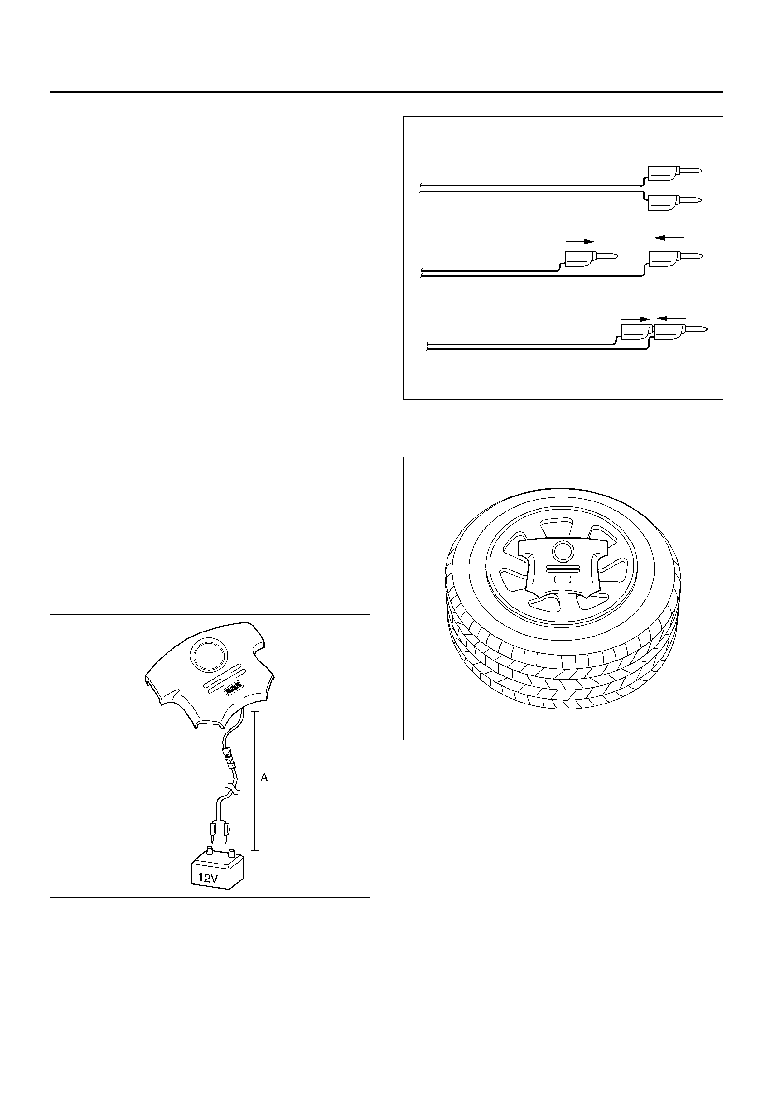
6.Prepare four 15 inch or larger tyres without wheel
and two same size tyres with wheels.
827RX041
7.How to fix Driver air bag.
1.Fix the air bag with its trim cover up on a tyre
with a wheel using an automobile use wire
harness, (core size: 1.3 mm2 (0.05 inch)) or a
wire trebly at two or more points.
2. Connect SRS air bag assembly to the double
pole extension cord of the air bag deployment
harness.
Do not connect the deployment harness to a
power source until air bag deployment.
(If connected the SRS air bag assembly deploys
immediately)
NO TE: Ensure that the pigtail adapter is firmly seated
into the air bag assembly connector . F ailure to fully seat
the connectors ma y leav e the shorting bar located in the
air bag assembly connector functioning (shorting the
deployment circuit) and may result in non deployment of
(A) 10 m (33 feet) or more
the air bag assembly.
827RW054
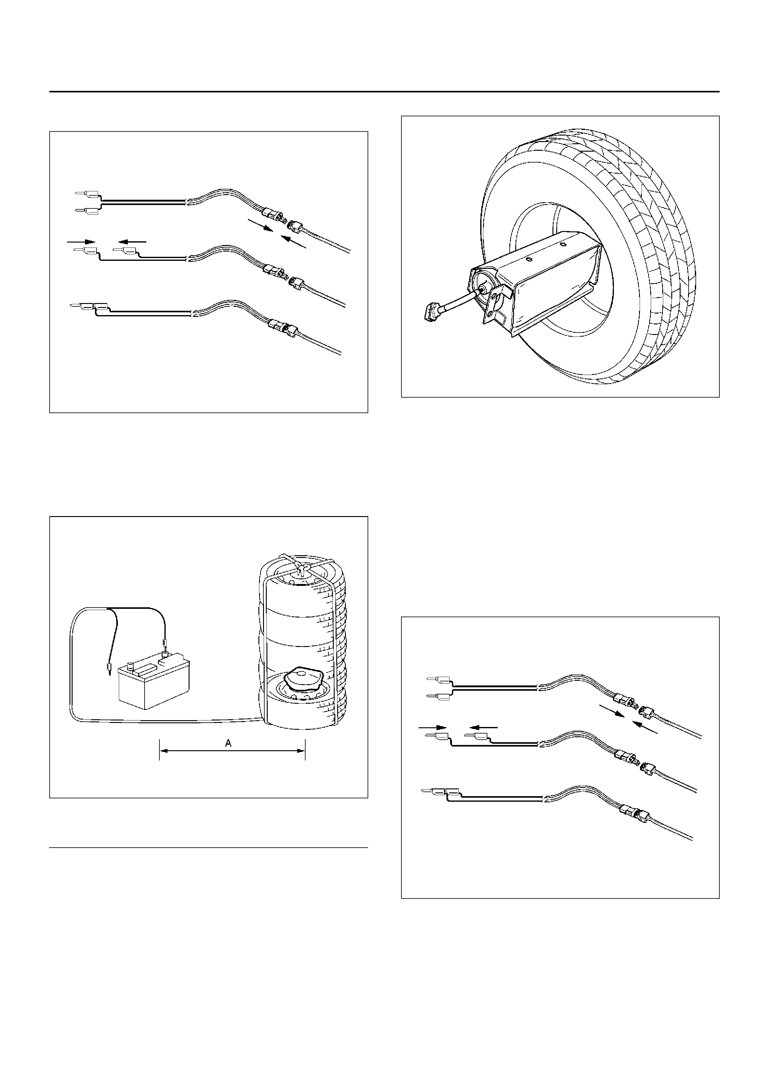
3.Place three tyres without wheel on the tyre on
which air bag is fixed and a tyre with a wheel on
top.
Bind the five tyres with a rope so that the tyres
may not collapse.
827RW053
Legend
EndOFCallout
8.How to fix Passenger air bag.
1.Fix the air bag with its trim cover side fixing the
center of a tyre without a wheel using an
automobile use wire harness, (core size: 1.3
mm (0.05 inch)) or a wire trebly at two or more
points.
827RW058
2.Connect Supplemental Restraint System (SRS)
air bag assembly to the deployment harness
double pole extension cord end. Be sure not to
connect the deployment harness to a power
source. (If connected the SRS air bag assembly
deploys immediately).
NOTE: Ensure that the pigtail adapter is firmly seated
into the air bag assembly connector. Failure to fully seat
the connectors may leave the shorting bar located in the
air bag assembly connector functioning (shorting the
deployment circuit) and may result in non deployment of
the air bag assembly.
827RW054
3.Put a tyre without wheel on another, put the tyre
on which the air bag is fixing, put a tyre without a
wheel, and finally put a tyre with a wheel on top.
Bind the tyres with a rope so that the tyres pile
may not collapse.
(A) 10 m (33 feet) or more
827RW050
Legend
EndOFCallout
9.Notify all people in the immediate area of your
intention to deploy the passenger air bag assembly.
The deployment will be accompanied by a
substantial noise which may startle the uninformed.
WARNING: DEPLOYED HARNESS SHALL REMAIN
SHORTED AND NOT BE CONNECTED TO A POWER
SOURCE UNTIL THE AIR BAG IS TO BE DEPLOYED.
THE AIR BAG ASSEMBLY WILL IMMEDIATELY
DEPLOY THE AIR BAG WHEN A CONNECTING THE
DEPLOYMENT HARNESS TO THE POWER SOURCE
SHOULD ALWAYS BE THE LAST STEP IN THE AIR
BAG ASSEMBLY DEPLOYMENT PROCEDURE.
FAILURE TO FOLLOW PROCEDURES IN THE
ORDER LISTED MAY RESULT IN PERSONAL
INJURY.
10.Connect the Supplemental Restraint System (SRS)
deployment harness wires to the power source to
immediately deploy the air bag assembly.
Recommended application : 12 volts minimum, 2
amps minimum. A vehicle battery is suggested.
827LW011
WARNING: SAFETY PRECAUTIONS MUST BE
OBSERVED WHEN HANDING A DEPLOYED AIR
BA G ASSEMBLY. AFTER DEPLO YMENT , THE MET AL
SURFACES OF THE AIR BAG ASSEMBLY WILL BE
VERY HOT. ALLOW THE AIR BAG ASSEMBLY TO
COOL BEFORE HANDLING ANY METAL PORTION
OF IT. DO NOT PLACE THE DEPLOYED INFLATOR
MODULE NEAR ANY FLAMMAB LE OBJECTS.
FAILURE TO FOLLOW PROCEDURES MAY RESULT
IN FIRE OR PERSONAL INJURY. AFTER AN AIR
BAG ASSEMBLY HAS BEEN DEPLOYED, THE
METAL CANISTER AND SURROUNDING AREAS OF
THE AIR BAG ASSEMBLY WILL BE HOT. DO NOT
TOUCH THE METAL AREAS OF THE AIR BAG
ASSEMBLY FOR ABOUT THIR TY MINUTES AFTER
DEPLOYMENT. IF THE DEPLOYED AIR BAG
ASSEMBLY MUST BE MOVED BEFORE IT IS COOL,
WEAR GLOVES AND HANDLE BY THE AIR BAG IT
SELF.
11. Disconnect the pigtail adapter from the air bag
assembly as soon after deployment as possible to
avoid damage to the pigtail adapter or SRS
deployment harness from contacting the hot air bag
assembly canister. The pigtail adapter and SRS
deployment harness are designed to be reused.
They should, however, be inspected for damage
after each deployment and replaced if necessary.
12. Dispose of the deployed air bag assembly through
normal refuse channels after it has cooled for at
least 30 minutes.
13. Wash your hands with mild soap and water
afterward.
NO TE: The remaining steps are to be followed in the
unlikely event that the air bag assembly did not deploy
after following the above procedures.
14. Ensure that the SRS deployment harness has been
disconnected from the power source and that its two
banana plugs have been shorted together by fully
(A) 10 m (33 feet) or more
seating one banana plug into the other.
827RW055
2.Disconnect the pigtail adapter from the air bag
assembly.
WARNING: WHEN STORING A LIVE AIR BAG
ASSEMBLY OR WHEN LEAVING A LIVE AIR BAG
ASSEMBLY UNATTENDED ON A BENCH OR OTHER
SURFACE, ALWAYS FACE THE BAG UP AND AWAY
FROM THE SURFACE. THIS IS NECESSARY SO
THAT A FREE SPACE IS PROVIDED TO ALLOW THE
AIR BAG TO EXPAND IN THE UNLIKELY EVENT OF
ACCIDENTAL DEPLOYMENT. FAILURE TO FOLLOW
PROCEDURES MAY RESULT IN PERSONAL INJURY.
3.Temporarily store the air bag assembly with the bag
facing up, away from the surface upon which it rests.
066RW030
Deployment Inside Vehicle (Vehicle
Scrapping Procedure)
Deployment inside vehicle is proper when the vehicle is
to be destroyed or salvaged for component parts. This
includes, but is not limited to, the following situations:
1.The vehicle has completed its useful life.
2.The vehicle has been damaged beyond repair in a
non deployment type accident.
3.The vehicle has been stripped or damaged beyond
repair in a theft.
4.The vehicle will be salvaged for component parts to
be used on a vehicle with a different Vehicle
Identification Number (VIN) as opposed to being
rebuilt as same VIN. Never use SRS components
from another vehicle.
WARNING: FAILURE TO FOLLOW PROPER SRS
AIR BAG ASSEMBLY DISPOSAL PROCEDURES
CAN RESULT IN AIR BAG DEPLOYMENT WHICH
MAY CAUSE PERSONAL INJURY. UNDEPLOYED
AIR B AG ASSEMBLIES MUST NOT BE DISPOSED
OF THROUGH NORMAL REFUSE CHANNELS. THE
UNDEPLOYED AIR BAG ASSEMBLY CONTAINS
SUBSTANCES THAT CAN CA USE SEVERE ILLNESS
OR PERSONAL INJURY IF THE SEALED
CONTAINER IS DAMAGED DURING DISPOSAL.
DISPOSAL IN ANY MANNER INCONSISTENT WITH
PROPER PROCEDURES MAY BE A VIOLATION OF
FEDERAL, STATE AND/OR LOCAL LAWS.
15. Turn ignition switch to “LOCK", remov e key and put
on safety glasses.
16. Remove all loose objects from front seats.
17. Disconnect Supplemental Restraint System (SRS)
coil assembly, yellow 2–pin connector located at the
base of the steering column.
18. Cut the SRS coil assembly yellow 2–pin harness
connector from the vehicle leaving at least 16 cm
(six inches) of wire at the connector.
19. Strip 13 mm (1/2 inch) of insulation from yellow–
green and yellow–black wire lead of the connector.
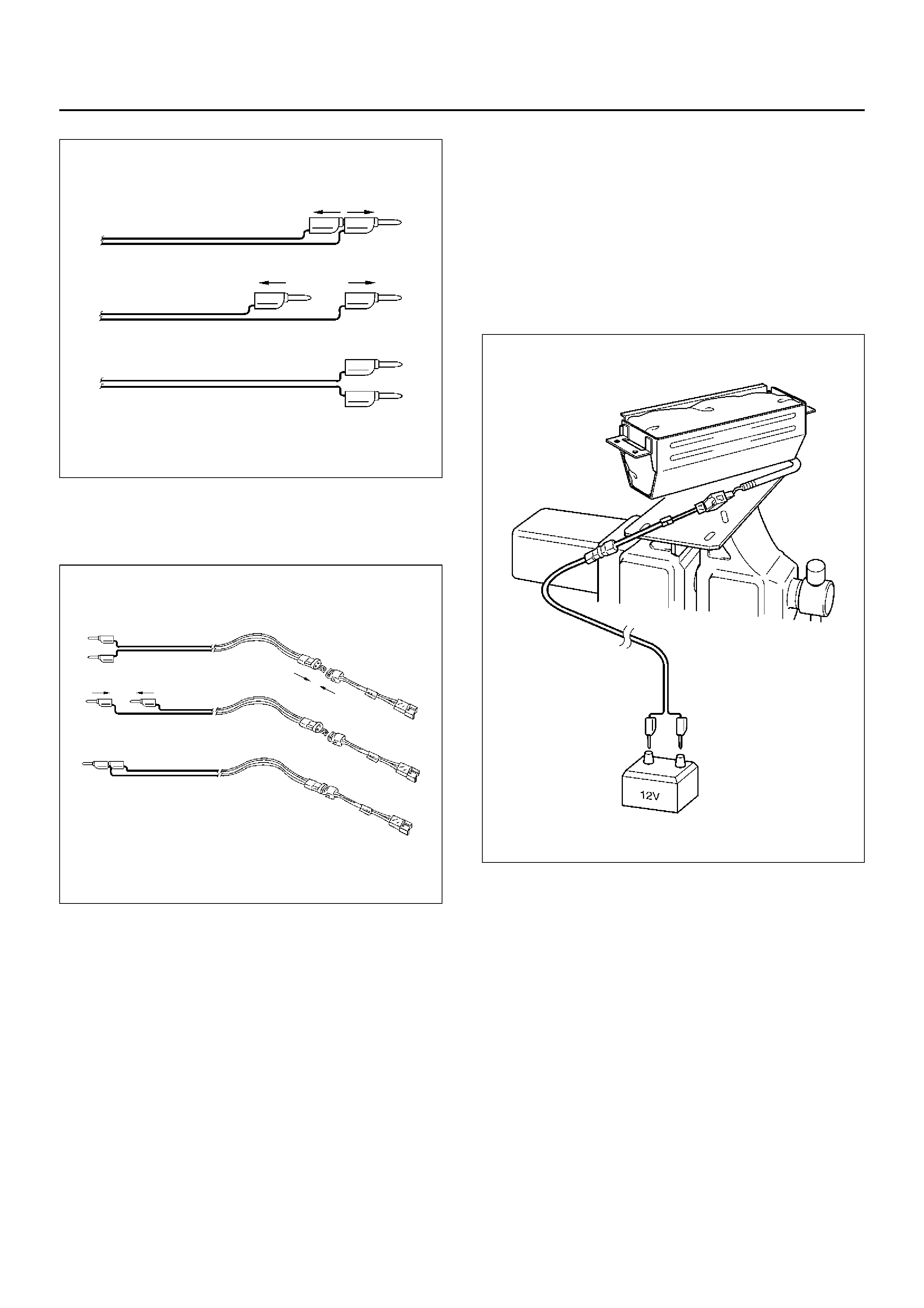
20. Cut two 900 cm (30 feet) deployment wires from 0.8
mm2 (18 gauge) or thick er multi–strand wire. These
wires will be used to f abricate the driver deplo yment
harness.
21. Strip 13 mm (1/2 inch) of insulation from both ends
of the wires cut in the previous step.
4.Short the wires by twisting together one end from
each. Deployment wires shall remain shorted and
not be connected to a power source until the air bag
is to be deployed.
F09RX001
WARNING: FAILURE TO FOLLOW PROCEDURES IN
THE ORDER LISTED COULD RESULT IN PERSONAL
INJURY. NEVER CONNECT DEPLOYMENT WIRES
TO ANY POWER SOURCE BEFORE CONNECTING
DEPLOYMENT WIRES TO THE AIR BAG ASSEMBLY
LEADS. DEPLOYMENT WIRES SHALL REMAIN
SHORTED AND NOT BE CONNECTED TO A POWER
SOURCE UNTIL THE AIR BAG IS TO BE DEPLOYED.
THE AIR BAG ASSEMBLY WILL IMMEDIATELY
DEPLOY THE AIR BAG WHEN A POWER SOURCE IS
CONNECTED TO IT. WEAR SAFETY GLASSES
THROUGHOUT THIS ENTIRE DEPLOYMENT AND
DISPOSAL PROCEDURE.
22.Twist together one connector wire lead to one
deployment wire. The connection should be
mechanically secure.
5.Bend twisted connection made in the previous step
flat and wrap tightly with electrical tape to insulate
and secure.
F09HV009
23.Twist together, bend and tape the remaining
connector wire lead to the remaining deployment
wire.
24.Connect the deployment harness to the driver air
bag assembly, yellow 2–pin connector at the base of
the steering column. Route deployment harness
out the driver side of the vehicle.
WARNING: DEPLOYMENT WIRES SHALL REMAIN
SHORTED AND NO T BE CONNECTED TO A POWER
SOURCE UNTIL THE AIR BAG IS TO BE DEPLOYED.
THE AIR BAG ASSEMBLY WILL IMMEDIATELY
DEPLOY THE AI R B A G WHEN A POWER SOURCE IS
CONNECTED TO IT.
Connecting the deployment wires to the power
sour c e sh ou ld always b e t he f inal ste p in th e air ba g
assembly deployment procedure.
Failure to follow procedures in the order listed could
result in personal injury.
25. Disconnect passenger air bag assembly, yellow 2–
pin connector located behind glove box assembly.
26. Cut the passenger air bag assembly harness
connector from the vehicle leaving at least 16 cm
(six inches) of wire at the connector.
27. Strip 13 mm (1/2 inch) of insulation from yellow–
green and yellow–red wire lead of the connector.
28. Cut two 900 cm (30 feet) deployment wires from 0.8
mm2 (18 gauge) or thick er multi–strand wire. These
wires will be used to fabricate the passenger
deployment harness.
29. Strip 13 mm (1/2 inch) of insulation from both ends
of the wires cut in the previous step.

6.Short the wires by twisting together one end from
each. Deployment wires shall remain shorted and
not be connected to a power source until the air bag
is to be deployed.
F09RX001
WARNING: FAILURE TO FOLLOW PROCEDURES IN
THE ORDER LISTED COULD RESULT IN PERSONAL
INJURY. NEVER CONNECT DEPLOYMENT WIRES
TO ANY POWER SOURCE BEFORE CONNECTING
DEPLOYMENT WIRES TO THE AIR BAG ASSEMBLY
LEADS. DEPLOYMENT WIRES SHALL REMAIN
SHORTED AND NOT BE CONNECTED TO A POWER
SOURCE UNTIL THE AIR BAG IS TO BE DEPLOYED.
THE AIR BAG ASSEMBLY WILL IMMEDIATELY
DEPLOY THE AIR BAG WHEN SAFETY GLASSES
THROUGHOUT THIS ENTIRE DEPLOYMENT AND
DISPOSAL PROCEDURE.
30.Twist together one connector wire lead to one
deployment wire. The connection should be
mechanically secure.
7.Bend twisted connection made in the previous step
flat and wrap tightly with electrical tape to insulate
and secure.
F09HV009
31.Twist together, bend and tape the remaining
connector wire lead to the remaining deployment
wire.
32.Connect the deployment harness to the passenger
air bag assembly, yellow 2–pin connector located
behind the glove box assembly. Route deployment
harness out the passenger side of the vehicle.
WARNING: DEPLOYMENT WIRES SHALL REMAIN
SHORTED AND NO T BE CONNECTED TO A POWER
SOURCE UNTIL THE AIR B A G IS T O BE DEPLO YED .
THE AIR BAG ASSEMBLY WILL IMMEDIATELY
DEPLOY THE AI R B A G WHEN A POWER SOURCE IS
CONNECTED TO IT. CONNECTING THE
DEPLOYMENT WIRES SHOULD ALWAYS BE THE
FINAL STEP IN THE AIR BAG ASSEMBLY
DEPLO YMENT PROCEDURE. F AILURE T O FOLLO W
PROCEDURES IN THE ORDER LISTED COULD
RESULT IN PERSONAL INJURY.
33. Verify that the inside of the vehicle and the area
surrounding the vehicle are clear of all people and
loose or flammable objects.
34. Stretch the driver and passenger deplo yment
harness to their full length.
35. Completely cover windshield area and front door
window openings with a drop cloth, blanket or
similar item. This reduces the possibility of injury
due to possible fragmentation of the vehicle's glass
or interior.
36. Notify all people in the immediate area that you
intend to deploy the air bags. The deployment will
be accompanied by a substantial noise which may
startle the uninformed.
37. Separate the two ends of the driver deployment
harness w ires .

WARNING: DEPLOYMENT WIRES SHALL REMAIN
SHORTED AND NOT BE CONNECTED TO A POWER
SOURCE UNTIL THE AIR BAG IS TO A POWER
SOURCE UNTIL THE AIR BAG IS TO BE DEPLOYED.
THE AIR BAG ASSEMBLY WILL IMMEDIATELY
DEPLOY THE AIR BAG WHEN A POWER SOURCE IS
CONNECTED TO IT. CONNECTING THE
DEPLOYMENT WIRES TO THE POWER SOURCE
SHOULD ALWAYS BE THE FINAL STEP IN THE AIR
BAG ASSEMBLY DEPLOYMENT PROCEDURE.
FAILURE TO FOLLOW PROCEDURES IN THE
ORDER LISTED COULD RESULT IN PERSONAL
INJURY.
NOTE: When the air bag deploys, the rapid gas
expansion will create a substantial noise. Notify all
people in the immediate area that you intend to deploy
the air bags.
38.Connect the driver deployment harness wires to a
power source to immediately deploy the driver air
bag assembly. Recommended application: 12 volts
minimum, 2 amps minimum. A vehicle battery is
suggested.
39.Separate the two ends of the passenger deployment
harness wires.
WARNING: DEPLOYMENT WIRES SHALL REMAIN
SHORTED AND NOT BE CONNECTED TO A POWER
SOURCE UNTIL THE AIR BAG IS TO A POWER
SOURCE UNTIL THE AIR BAG IS TO BE DEPLOYED.
THE AIR BAG ASSEMBLY WILL IMMEDIATELY
DEPLOY THE AIR BAG WHEN A POWER SOURCE IS
CONNECTED TO IT. CONNECTING THE
DEPLOYMENT WIRES TO THE POWER SOURCE
SHOULD ALWAYS BE THE FINAL STEP IN THE AIR
BAG ASSEMBLY DEPLOYMENT PROCEDURE.
FAILURE TO FOLLOW PROCEDURES IN THE
ORDER LISTED COULD RESULT IN PERSONAL
INJURY.
40.Connect the passenger deployment harness wires
to a power source to immediately deploy the
passenger air bag assembly. Recommended
application: 12 volts minimum, 2 amps minimum. A
vehicle battery is suggested. (Driver air bag
assembly) Put on a pair of shop gloves and safety
gasses to protect your hands and eyes from
possible irritation and heat when handling the
deployed air bag assembly. After the air bag
assembly has been deployed, the surface of the air
bag may contain solid particulate. This solid
particulate consists primarily of by products of the
chemical reaction, Potassium Chloride and copper
metal dust. Compounds of Potassium Borate,
Strontium Chloride, Copper Chloride, and
Ammonium Chloride may be found in amounts of
about 1% (each) of the total particulate.
(Passenger air bag assembly)
Put on a pair of shop gloves and safety glasses to
protect your hands and eyes from possible irritation
and heat when handling the deployed air bag
assembly.
After the air bag assembly has been deployed, the
surface of the air bag may contain a powdery
residue. This powder consists primarily of
cornstarch (used to lubricate the bag as it inflates)
and by products of the chemical reaction. Sodium
hydroxide dust (similar to lye soap) is produced as a
by product of the deployment reaction. The sodium
hydroxide then quickly reacts with atmospheric
moisture and is converted to sodium carbonate and
sodium bicarbonate (baking soda). Therefore, it is
unlikely that sodium hydroxide will be present after
deployment.
WARNING: SAFETY PRECAUTIONS MUST BE
OBSERVED WHEN HANDLING A DEPLOYED AIR
BAG ASSEMBLY. AFTER DEPLOYMENT, THE
METAL SURFACES OF THE AIR BAG ASSEMBLY
WILL BE VERY HOT. ALLOW THE AIR BAG
ASSEMBLY TO COOL BEFORE HANDLING ANY
METAL PORTION OF IT. DO NOT PLACE THE HOT
DEPLOYED AIR BAG ASSEMBLY NEAR ANY
FLAMMABLE OBJECTS. FAILURE TO FOLLOW
PROCEDURES COULD RESULT IN FIRE OR
PERSONAL INJURY.
After an air bag assembly has been deployed, the
metal canister and surrounding areas of the air bag
assembly will be very hot. Do not touch the metal
areas of the air bag assembly for about 30 minutes
after deployment. If the deployed air bag assembly
must be moved before it is cool, wear gloves and
handle by the air bag or trim cover.
41.Short the driver deployment harness wires by
twisting together one end from each. Repeat this
procedure for the passenger deployment harness.
42.Carefully remove drop cloth from vehicle and clean
off any fragments or discard drop cloth entirely.
43.Disconnect driver deployment harness and
passenger deployment harness from vehicle and
discard.
44.In the unlikely event that either or both of the air bag
assemblies did not deploy after following these
procedures, proceed immediately with Steps 36
through 37. If the air bag assembly deployed,
proceed to step 35.
45.With both air bags deployed, the vehicle may be
scrapped in the same manner as a non–SRS
equipped vehicle.
NOTE: The remaining steps are to be followed in the
unlikely event that the air bag assembly did not deploy
after following these procedures.
46.Remove the undeployed air bag assembly (s) from
the vehicle. For driver air bag assembly refer to in
the “Passenger Air Bag Assembly Removal" in this
section.

WARNING: WHEN STORING A LIVE AIR BAG
ASSEMBLY OR WHEN LEAVING A LIVE AIR B AG
ASSEMBLY UNATTENDED ON A BENCH OR OTHER
SURFA CE, ALWAYS FA CE THE BAG AND TRIM
COVER UP, AWAY FROM THE SURFACE. THIS IS
NECESSAR Y SO THAT A FREE SPACE IS PRO VIDED
TO ALLOW THE AIR BAG TO EXPAND IN THE
UNLIKELY EVENT OF ACCIDENTAL DEPLOYMENT.
FAILURE TO FOLLOW PROCEDURES COULD
RESULT IN PERSONAL INJURY.
47. Temporarily store the air bag assembly with the air
bag opening facing up, away from the surface upon
which it rests.
Deployed Air Bag Assembly Handling
Put on a pair of shop gloves and safety glasses to
protect your hands and eyes from possible irritation and
heat when handling the deployed air bag assembly.
After the air bag assembly has been deployed, the
surface of the air bag may contain solid particulate. This
solid particulate consists primarily of by products of the
chemical reaction, Potassium Chloride and copper
metal dust. Compounds of P otassium Borate, Strontium
Chloride, Copper Chloride, and Ammonium Chloride
ma y be found in amounts of about 1% (each) of the total
particulate.
(Passeng er air bag asse mbly)
Put on a pair of shop gloves and safety glasses to
protect your hands and eyes from possible irritation and
heat when handling the deployed air bag assembly.
After the air bag assembly has been deployed, the
surface of the air bag may contain a powdery residue.
This powder consists primarily of cornstarch (used to
lubricate the bag as it inflates) and by products of the
chemical reaction. Sodium h ydroxide dust (similar to lye
soap) is produced as a by product of the deployment
reaction. The sodium hydroxid e then quickly reacts with
atmospheric moisture and is converted to sodium
carbonate and sodium bicarbonate (baking soda).
Therefore, it is unlikely that sodium hydroxide will be
present after deployment.
Special Tools
WARNING: TO AVOID DEPLOYMENT WHEN
TROUBLESHOOTING THE SRS, DO NOT USE
ELECTRICAL TEST EQUIPMENT SUCH AS A
BATTERY–POWERED OR AC–POWERED
VOLTMETER, OHMMETER, ETC., OR ANY TYPE OF
ELECTRICAL EQUIPMENT OTHER THAN THAT
SPECIFIED IN THIS MANUAL. DO NOT USE A NON
POWERED PROBE–TYPE TESTER.
INSTRUCTIONS IN THIS MANUAL MUST BE
FOLLOWED CAREFULLY, OTHERWISE PERSONAL
INJURY MAY RESULT.
5–8840–2421–0 (J–41433) SRS Driver/
Passenger Load Tool
The Supplemental Restraint System (SRS) Driver/
Passenger Load Tool 5–8840–2421–0 is used only
when called for in this section. It is used as a
diagnostic aid and safety device to prevent inadvertent
air bag assembly deployment.
The load tool has four yellow connectors attached to its
case.
The three small connectors are electrically functional
and serve as resistive load substitutions.
No more than two connectors are used at any time.
One of the small connectors is used to substitute f or the
lo ad of t h e dri ver ai r b a g as se mbly when i t i s c on n ec te d
at the top of the column to the SRS coil assembly.
Another small connector is used to substitute for the
load of the driver air bag assembly and the SRS coil
assembly when it is connected at the base of the
column to the SRS wiring harness. The third small
connector is used to substitute for the load of the
passenger air bag assembly when connected to the
passenger air bag assembly harness connector.
By substituting the resistance of the load tool when
called for, a determination can be made as to whether
an inflator circuit component is causing system
malfunction and which component is causing the
malfunction. The load tool should be used only when
specifically called for in the diagnostic procedures.
901RS146
5–8840–0285–0 (J–39200) DVM
The 5–8840–0285–0 Digital Multimeter (DVM) is the
preferred DVM for use in SRS diagnosis and repair.
However, 5–8840–0366–0 may be used if 5–8840–
0285–0 is not available. No other DVMs are approved
for SRS diagnosis and repair.
901RS153
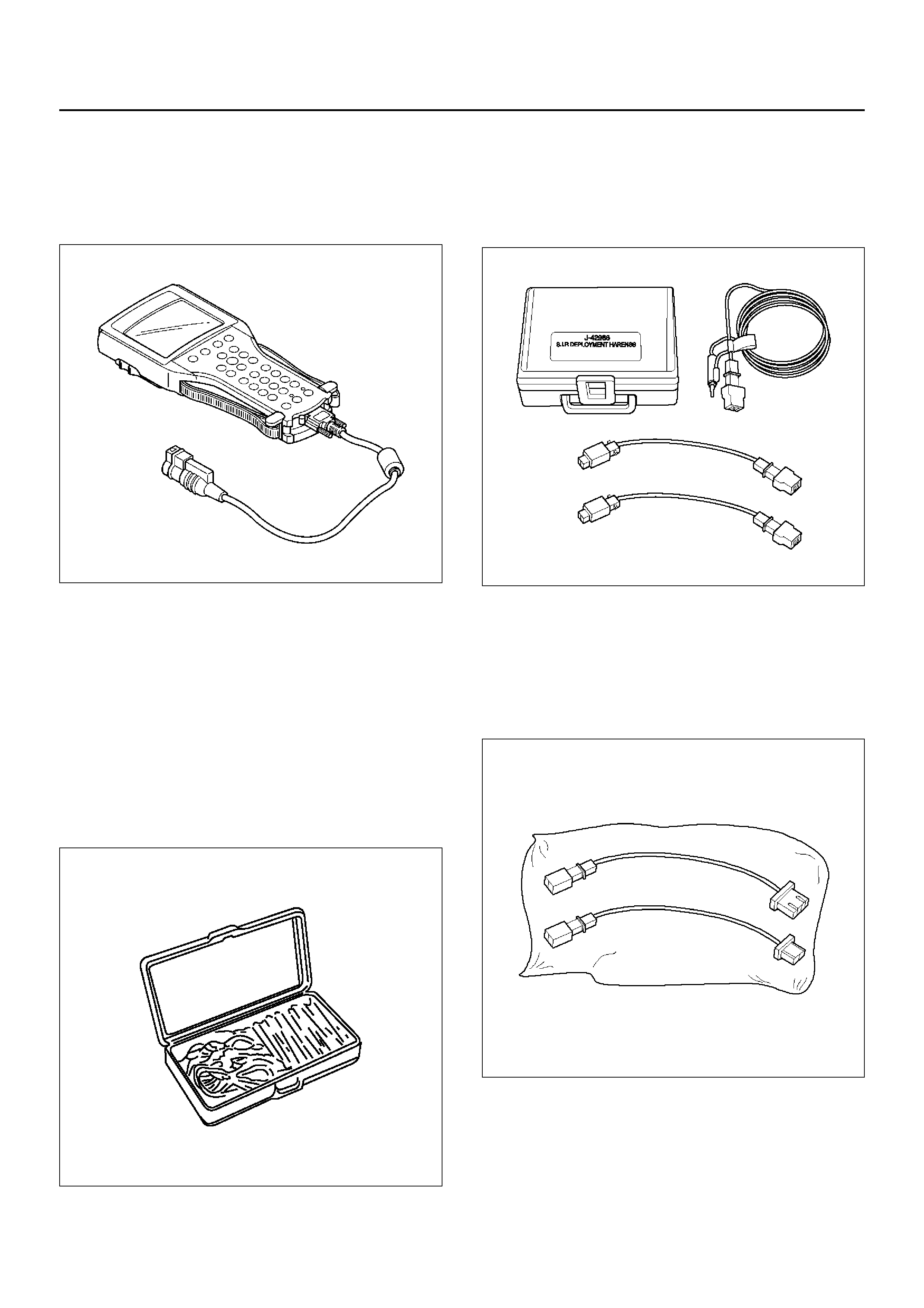
Scan Tool
The Tech 2 is used to read and clear SRS Diagnostic
Trouble Codes (DTCs). Refer to the Tech 2 Operator's
Manual f or specific information on how to use the Tech
2.
901RW176
5–8840–0385–0 (J–35616–A) Connector
Test Adapter Kit
The 5–8840–0385–0 Connector Test Adapter Kit must
be used whenever a diagnostic procedure requests
checking or probing a terminal. Using the appropriate
adapter will ensure that no damage to the terminal will
occur from the Digital Multimeter (DVM) prove, such as
spreading or bending. The adapter will also give an
idea of whether contact tension is sufficient, helping to
find an open or intermittent open due to poor terminal
contact.
901RS151
5–8840– 2468– 0 (J –4298 6) S RS De plo y ment
Tool
The 5–8840–2468–0 Supplemental Restraint System
(SRS) Deployment Tool must be used for deployment of
the undeployed air bag.
901RX046
5–8840– 242 9–0 (J–4298 7) S RS Ad apt er For
Load Tool
The J–42987 SRS Adapter be used f or connect
previous load tool to new SRS system when inspect
SRS system harness.
901RW107
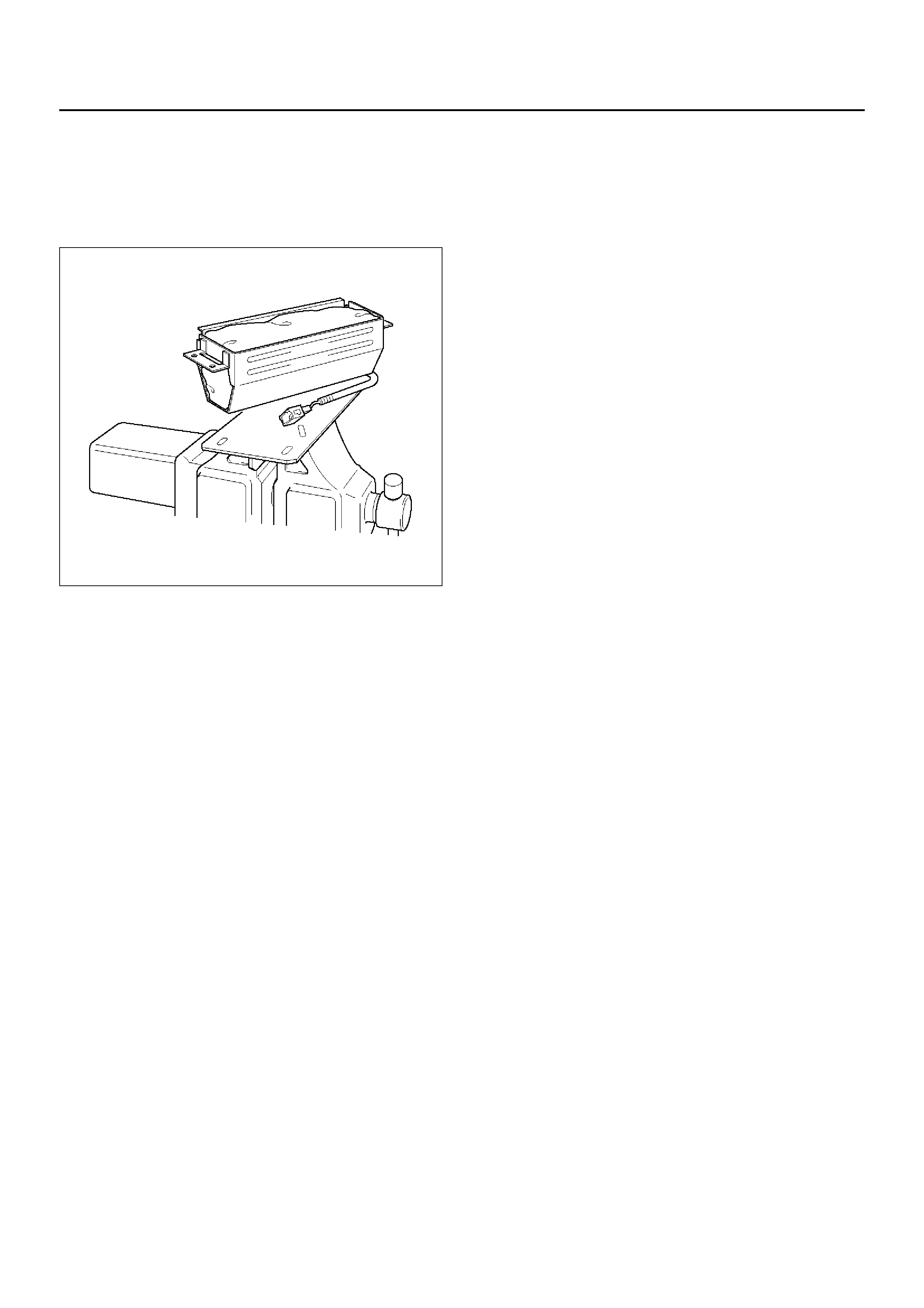
5–8840 –2 420–0 (J –4149 7) S RS De pl o ym ent
Fixture
The 5–8840–2420–0 SRS Deployment Fixture must be
used for deployment of the undeployed passenger side
air bag.
901RW088
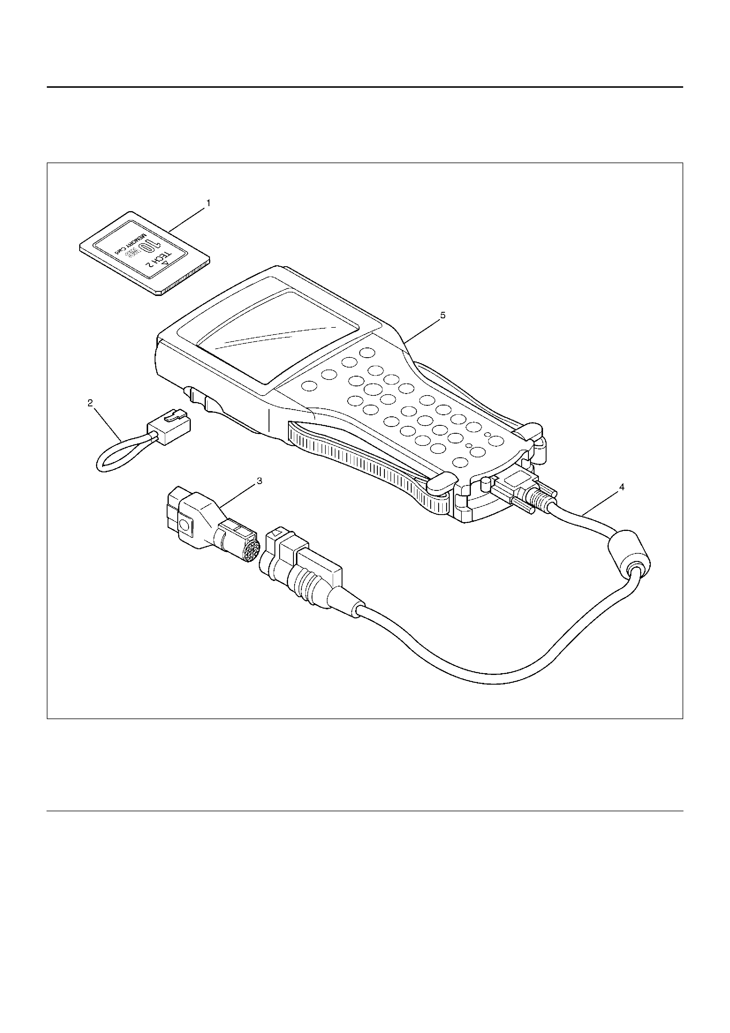
Tech 2 Scan Tool
From 1999 Vehi CROSS (VX), dealer service
departments are recommended to use Tech 2. Please
refer to Tech 2 scan tool user guide.
901RW180
Legend
EndOFCallout
Getting Started
• Before operating the Isuzu PCMCIA card with the
Tech 2, the following steps must be performed:
1. The Isuzu 98 System PCMCIA card (1) inserts into
the Tech 2 (5).
2. Connect the SAE 16/19 adapter (3) to the DLC
cable (4).
1. Connect the DLC cable to the Tech 2 (5)
3. Mark sure the vehi cle ignition is off.
(1) PCMCIA Card
(2) RS 232 Loop Back Connector
(3) SAE 16/19 Adaptor
(4) Data Link Connector (DLC) Cable
(5) Tech–2
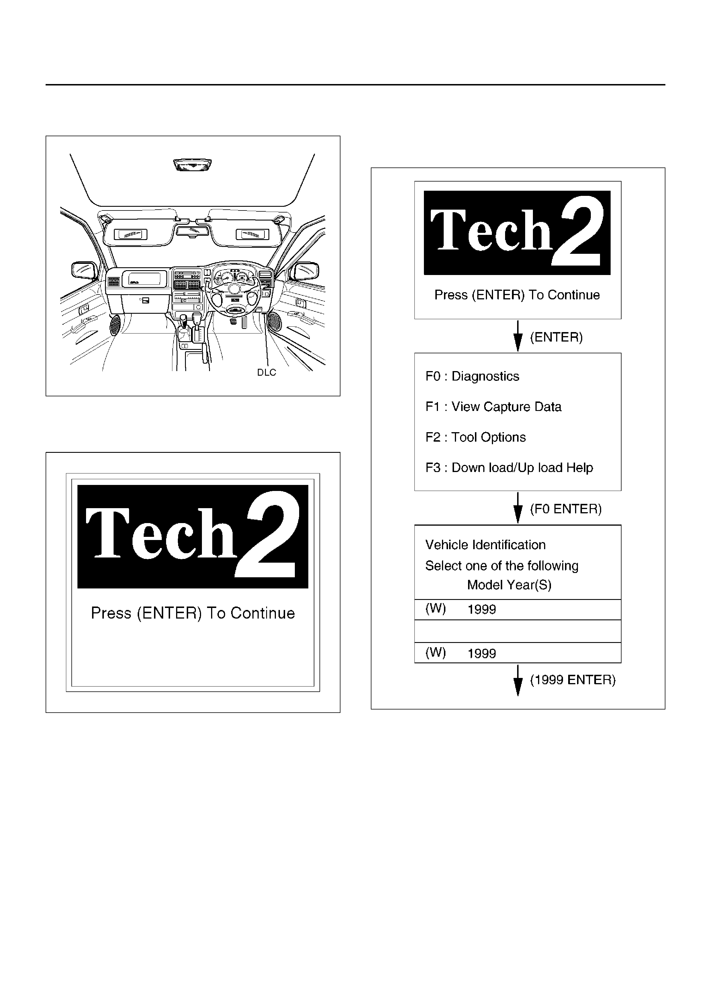
2. Connect the Tech 2 SAE 16/19 adapter to the
vehicle Data Link Connector (DLC).
740RX068
4. The vehicle ignition turns on.
5. Verify the Tech 2 power up display.
060RW009
NOTE: The RS232 loop back connector is only to use
for diagnosis of Tech 2 and refer to user guide of the
Tech 2.
Operating Procedure
The power up screen is displayed when you power up
the tester with the Isuzu systems PCMCIA card. Follow
the operating procedure below.
060RX001
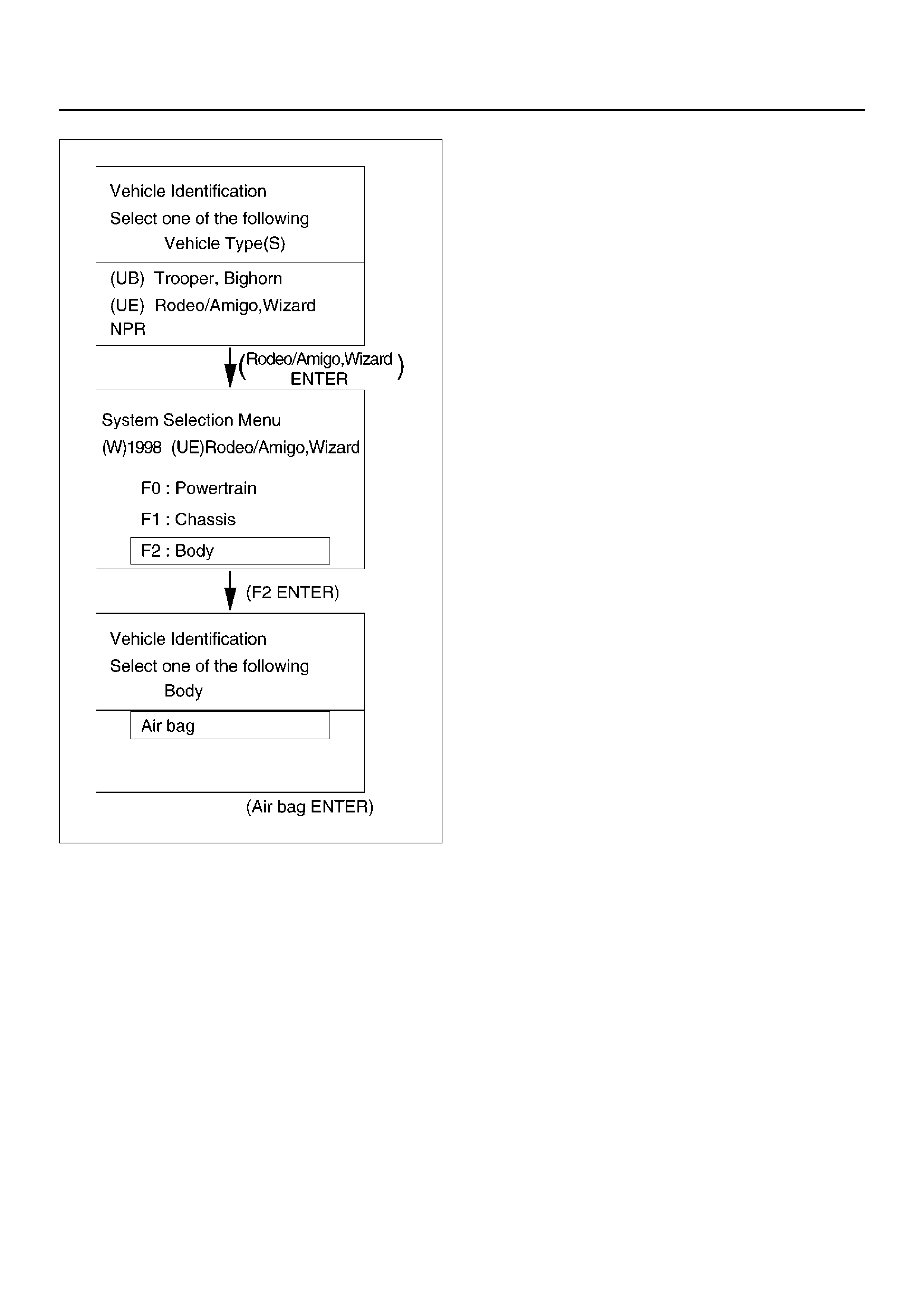
060RW013

Service Precaution
CAUTION: When fasteners are removed, always
reinstall them at the same location from which they
were removed. If a fastener needs to be replaced,
use the correct part number fastener for that
application. If the correct part number fastener is
not available, a fastener of equal size and strength
(or stronger) may be used. Fasteners that are not
reused, and those requiring thread locking
compound will be called out. The correct torque
value must be used when installing fasteners that
require it. if the above conditions are not followed,
parts or system damage could result.
WARNING: WHEN PERFORMING SERVICE ON OR
AROUND SUPPLEMENTAL RESTRAINT SYSTEM
(SRS) COMPONENTS OR SRS WIRING, FOLLOW
THE PROCEDURES LISTED BELOW TO
TEMPORARILY DISABLE THE SRS. FAILURE TO
FOLLOW PROCEDURES COULD RESULT IN
POSSIBLE AIR BAG DEPLOYMENT, PERSONAL
INJURY OR OTHERWISE UNNEEDED SRS REPAIRS.
The Sensing and Diagnostic Module (SDM) in Driver–
Passenger SRS can maintain sufficient voltage to cause
a deployment for up to 15 seconds after the ignition
switch is turned “OFF," the battery is disconnected, or
the fuse powering the SDM is removed.
Many of the service procedures require removal of the
“SRS–1" fuse, and disconnection of the air bag
assembly from the deployment loop to avoid an
accidental deployment. If the air bag assembly is
disconnected from the deployment loop as noted in the
“Disabling the SRS" procedure that follows, service can
begin immediately without waiting for the 15 second
time period to expire.
Disabling The SRS
Removal
Turn the ignition switch to “OFF" and turn the steering
wheel so that the vehicle's wheels are pointing straight
ahead.
6.Remove SRS fuse METER and SRS, from left dash
side lower fuse block or disconnect battery.
7.Disconnect yellow 2–pin connector at the base of
steering column.
8.Remove glove box assembly; Refer to “Passenger
Air Bag Assembly Replacement" in this section.
9.Disconnect passenger air bag assembly yellow 2–
pin connector behind the glove box assembly.
CAUTION: With the “SRS" fuse removed and
ignition switch “ON," the “AIR BAG" warning lamp
will be “ON." This is normal operation and does not
indicate an SRS malfunction.
Enabling The SRS
Installation
Turn ignition switch to “LOCK" and remove key.
1.Connect yellow 2–pin connector passenger air bag
assembly.
2.Install glove box assembly, Refer to “Passenger Air
Bag Assembly Replacement" in this section.
3.Connect yellow 2–pin connector at the base of the steering column.4.Install “AIR BAG" fuse METER and SRS to left dash side lower fuse block or connect battery.Turn ignition switch to “ON" and verify that the “AIR BAG" warning lamp flashes seven times and then turns “OFF" If it does not operate as described, perform the “SRS Diagnostic System Check" in section.
Handling / Installation / Diagnosis5.Air bag assembly should not be subjected to temperatures above 93°C (200°F).6.Air bag assembly, and SDM should not be used if they have been dropped from a height of 100 cm (3.3 feet) or more.7.When a SDM is replaced, it must be oriented with the arrow on the SDM pointing toward the front of the vehicle. It is very important for the SDM to be located flat on the mounting surface, parallel to the vehicle datum line. It is important that the SDM mounting surface is free of any dirt or other foreign material.8.Do not apply power to the SRS unless all components are connected or a diagnostic chart requests it, as this will set a diagnostic trouble code.9.The “SRS Diagnostic System Check" must be the starting point of any SRS diagnostics. The “SRS Diagnostic System Check" will verify proper “AIR BAG" warning lamp operation and will lead you to the correct chart to diagnose any SRS malfunctions.
Bypassing these procedures may result in extended
diagnostic time, incorrect diagnosis, and incorrect
parts replaceme nts.
Inspections Required After An Accident
CAUTION: Certain SRS components must be
replaced after a frontal crash involving air bag
deployment.
In all types of accidents regardless of “Air Bag"
deployment, visually inspect all of the following
components and replace as required:
– Driver air bag assembly
– Passenger air bag assembly
– Steering wheel
– SRS coil assembly
– Steering column
– Knee bolster and instrument panel mounting
attachments
– Driver seat and belt
– Passenger seat and belt
–SDM

Be sure to replace Sensing and Diagnostic Module
(SDM) in accordance with “SDM Replacement
Guidelines”. In cases of collision without causing air bag
deployment, SDM could be used unless this manual
instructs to replace.
CAUTION: Refer to SDM replacement Guidelines
below for important information on SDM
replacement in both deployment and non–
deployment crashes.
SDM Replacement Guidelines
1.In case that the air bag has been deployed, replace
the SDM.
2.When DTC 51, 53 and 71 are set.
3.When SDM fell down from a 100 cm (3.3 feet)
height.
All above is SDM replacement Guideline.
Inspection is needed also on the following.
Inspect Supplemental Restraint System (SRS) coil
assembly wiring and steering wheel for any signs of
scorching meting or damage due to excessive heat. If
coil assembly wire or steering wheel is damaged
replace them. The steering column and wheel must be
dimensionally checked to determine if they are
damaged. Refer to in this Section of this manual.
Never use SRS parts from another vehicle. This does
not include remanufactured parts purchased from an
authorized Retailer they may be used for SRS repairs.
Do not attempt to repair the SDM, the SRS harness, the
SRS coil assembly, the air bag assembly, the steering
wheel, or the steering column. Service of these items is
replacement only.
Verify replacement part numbers.
CAUTION: Proper operation of the SDM and
Supplemental Restraint System (SRS) requires that
any repair s to the vehicle structure return it to its
original pr oduction configuration.

Sensing and Diagnostic Module (SDM)
Service Precautions
WARNING: DURING SERVICE PROCEDURES, BE
VERY CAREFUL WHEN HANDLING SDM. NEVER
STRIKE OR JAR SDM. UNDER SOME
CIRCUMSTANCES, IT COULD CAUSE
DEPLOYMENT AND RESULT IN PERSONAL INJURY
OR IMPROPER OPERATION OF THE
SUPPLEMENTAL RESTRAINT SYSTEM (SRS). SDM
MOUNTING BRACKET BOLTS MUST BE
CAREFULLY TORQUED TO ASSURE PROPER
OPERATION. NEVER POWER UP THE SRS WHEN
SDM IS NOT RIGIDLY ATTACHED TO THE VEHICLE.
THE SDM COULD BE ACTIVATED WHEN POWERED
WHILE NOT RIGIDLY ATTACHED TO THE VEHICLE
WHICH COULD CAUSE DEPLOYMENT AND RESULT
IN PERSONAL INJURY.
WARNING: PROPER OPERATION OF THE SENSING
AND DIAGNOSTIC MODULE (SDM) REQUIRES THE
SDM TO BE RIGIDLY ATTACHED TO THE VEHICLE
STRUCTURE AND THAT THE ARROW ON THE
SENSOR BE POINTING TOWARD THE FRONT OF
THE VEHICLE.
SDM is specifically calibrated and is keyed to the SDM
location SRS wiring harness. Caution should be used to
ensure proper location of the SDM. The keying of the
SDM to its location and wiring harness connectors
should never be modified in the field.
Removal
1.Disable the SRS. (Refer to “Disable the SRS" in this
manual)
2. Remove dressing panel around the radio and
disconnect cigar lighter harness.
3. Remove the transfer sift lever knob.
4. Remove the center console.
5. Remove three connector from Powertrain Control
Module (PCM).
6. Remove PCM with bracket.(Fixed four bolts)
7. Remove right side stay between instrument panel
and floor.
8. Remove driver and passenger seat.
9. Turn over carpet to rear side.
1. Remove air conditioning duct for rear seat.
(Transform the duct during removing it)
827RW023
10. Pull CPA (3) (Connector Position Assurance–red
color) out and push con nec tor lock down to
disconnect the SDM harness connector (2).
11. Remove the three SDM fixing bolts and remove
SDM (1).
827RW044
Installation
1. Install the SDM (1) on bracket and fixing bolts and
tighten the fixing bolts to the specified torque.
Torque: 10 ±
±±
± 3 N·m (1.0 ±
± ±
± 0.3 kg·m/
//
/87 ±
±±
± 26 lbin)
1. Connect the SDM harness connector (2) and after
that, put CPA into connector (3).

2.Install air conditioning duct for rear seat to normal
position.
2.Return carpet normal position.
3.Install right side stay between instrument panel and
floor, tighten to the specified torque.
Torque: 10 ±±±± 3 N·m (1.0 ±±±± 0.3 kg·m/87 ±±±± 26 lbin)
4.Install PCM with bracket and tighten to the specified
torque.
Torque: 10 ±±±± 3 N·m (1.0 ±±±± 0.3 kg·m/87 ±±±± 26 lbin)
5.Reconnect three connector to Powertrain Control
Module (PCM).
6.Install the center console.
7.Install the transfer shift lever knob.
8.Install the dressing panel around the radio and
reconnect cigar lighter harness.
9.Enable the SRS. (Refer to “Enabling the SRS" in this
manual)
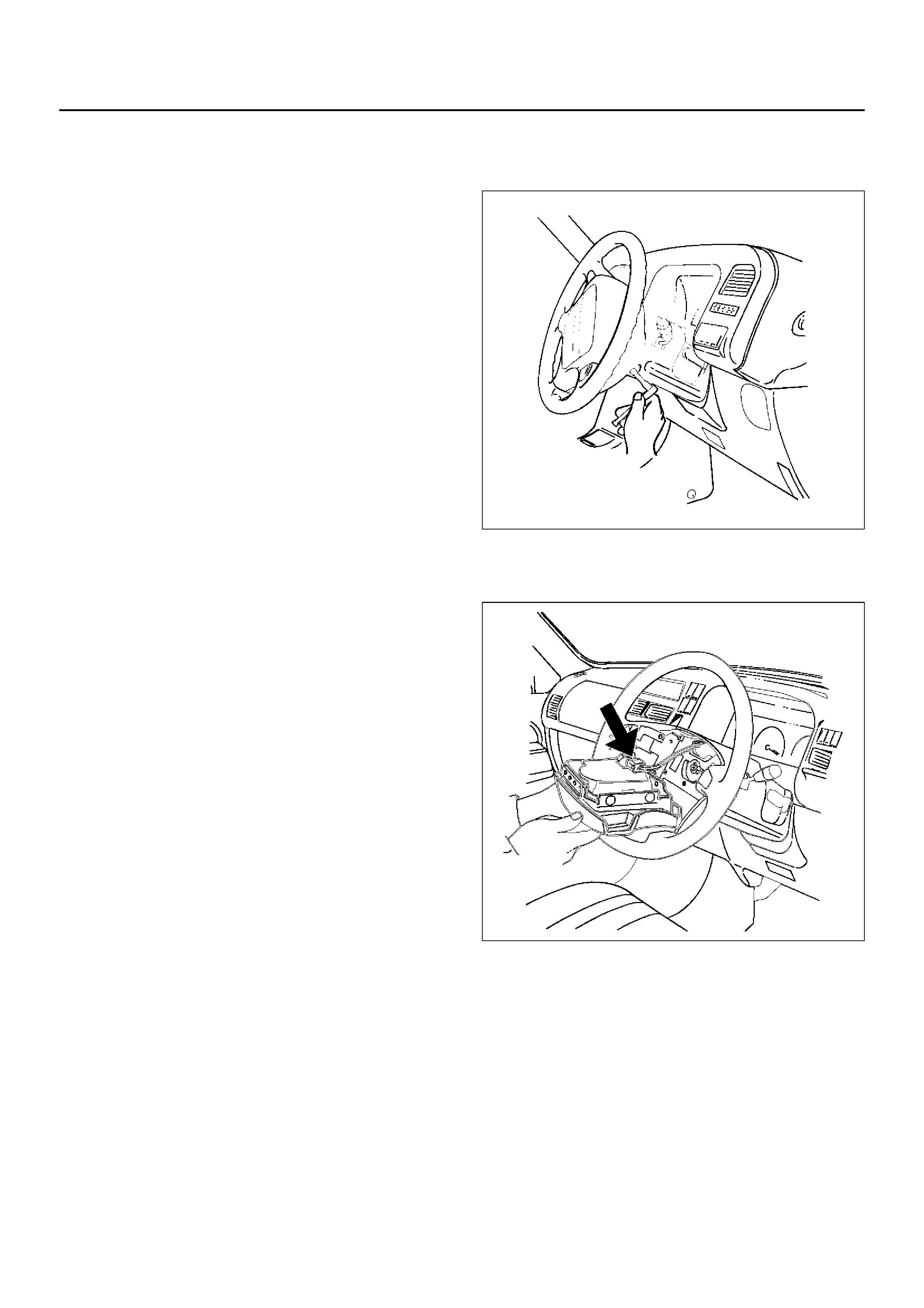
Driver Air Bag Assembly
Service Precautions
WARNING: SAFETY PRECAUTIONS MUST BE
FOLLOWED WHEN HANDLING A DEPLOYED AIR
BAG ASSEMBLY. AFTER DEPLOYMENT, THE AIR
BAG ASSEMBLY SURFACE MAY CONTAIN A SMALL
AMOUNT OF SODIUM HYDROXIDE, A BY-PRODUCT
OF THE DEPLOYMENT REACTION, THAT IS
IRRITATING TO THE SKIN AND EYES. MOST OF THE
POWDER ON THE AIR BAG ASSEMBLY IS
HARMLESS. AS A PRECAUTION, WEAR GLOVES
AND SAFETY GLASSES WHEN HANDLING A
DEPLOYED AIR BAG ASSEMBLY, AND WASH YOUR
HANDS WITH MILD SOAP AND WATER
AFTERWARDS.
WARNING: WHEN CARRYING A LIVE AIR BAG
ASSEMBLY, MAKE SURE THE BAG AND TRIM
COVER ARE POINTED AWAY FROM YOU. NEVER
CARRY AIR BAG ASSEMBLY BY THE WIRES OR
CONNECTOR ON THE UNDERSIDE OF MODULE. IN
THE CASE OF AN ACCIDENTAL DEPLOYMENT, THE
BAG WILL THEN DEPLOY WITH MINIMAL CHANCE
OF INJURY. WHEN PLACING A LIVE AIR BAG
ASSEMBLY ON A BENCH OR OTHER SURFACE,
ALWAYS FACE BAG AND TRIM COVER UP, AWAY
FROM THE SURFACE. NEVER REST A STEERING
COLUMN ASSEMBLY ON THE STEERING WHEEL
WITH THE AIR BAG ASSEMBLY FACE DOWN AND
COLUMN VERTICAL. THIS IS NECESSARY SO THAT
A FREE SPACE IS PROVIDED TO ALLOW THE AIR
BAG ASSEMBLY TO EXPAND IN THE UNLIKELY
EVENT OF ACCIDENTAL DEPLOYMENT.
OTHERWISE, PERSONAL INJURY COULD RESULT.
NOTE: In the event deployment has occurred, inspect
coil assembly wire for any signs of scorching, melting or
any other damage due to excessive heat. If the coil has
been damaged, replace it.
Removal
1.Disable the Supplemental Restraint System (SRS).
(Refer to “Disabling the SRS" in this section.)
2.Remove air bag assembly from steering wheel by
removing two bolts. Lift air bag assembly out of
steering wheel.
827RX036
3.Disconnect connector and remove air bag assembly.
4.Disconnect horn lead.
827RX035
Installation
1.Connect air bag to wiring harness connector.
NOTE: Pass the lead wire through the tabs on the
plastic cover (wire protector) of air bag to prevent lead
wire from being pinched.
2.Connect horn lead.
3.Install air bag into steering wheel and tighten bolts
to specified sequence as shown in figure.
Torque: 8.8 N·m (0.9 kg·m/78 lbin)
CAUTION: Never use the air bag assembly from
another vehicle.
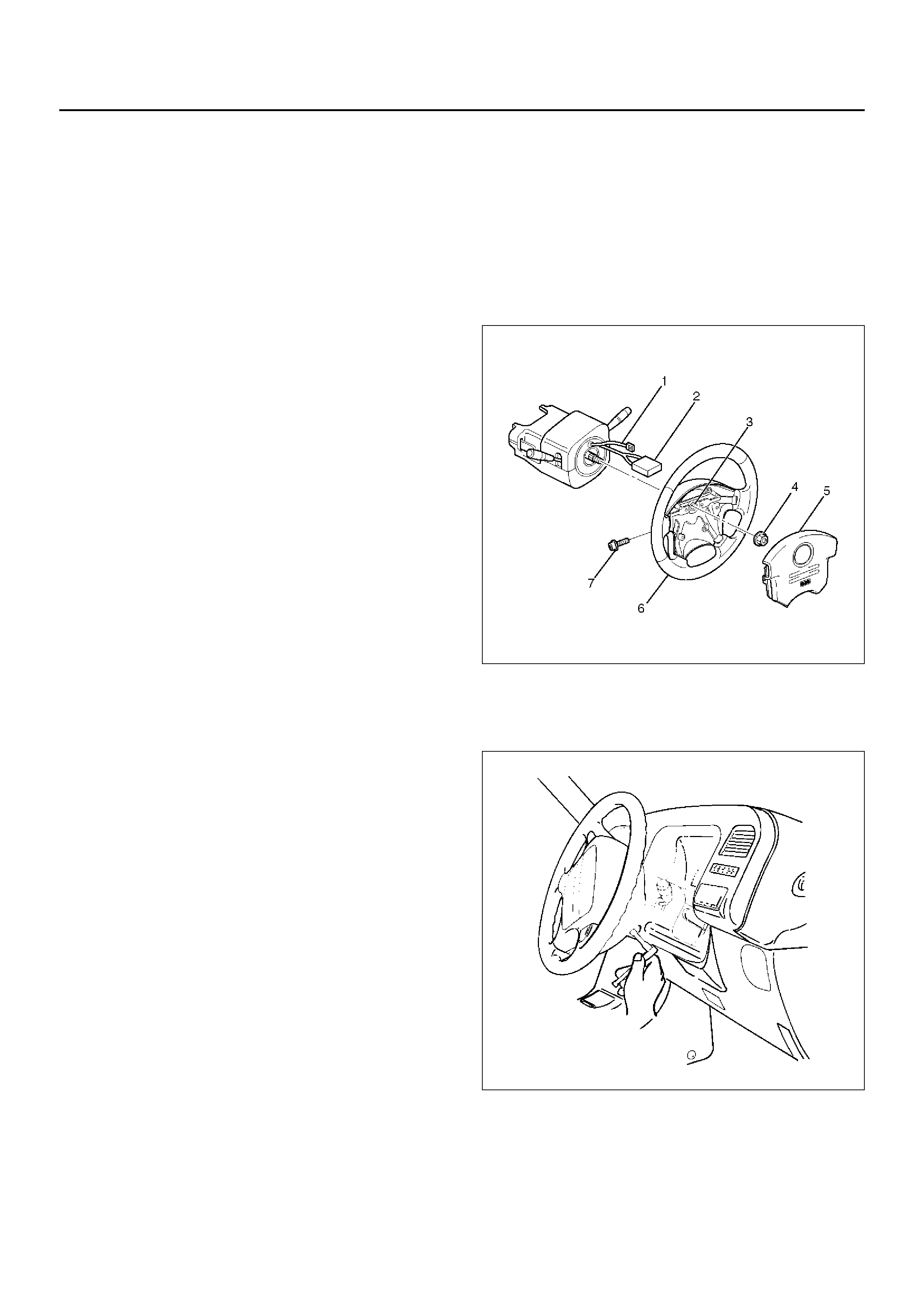
Use only the air bag assembly for UE.4.Enable the Supplemental Restraint System (SRS).
(Refer to “Enabling the SRS" in this section.)
Steering Wheel
Service Precautions
WARNING: SAFETY PRECAUTIONS MUST BE
FOLLOWED WHEN HANDLING A DEPLOYED AIR
BAG ASSEMBLY. AFTER DEPLOYMENT, THE AIR
BAG ASSEMBLY SURFACE MAY CONTAIN A SMALL
AMOUNT OF SODIUM HYDROXIDE, A BY-PRODUCT
OF THE DEPLOYMENT REACTION, THAT IS
IRRITATING TO THE SKIN AND EYES. MOST OF THE
POWDER ON THE AIR BAG ASSEMBLY IS
HARMLESS. AS A PRECAUTION, WEAR GLOVES
AND SAFETY GLASSES WHEN HANDLING A
DEPLOYED AIR BAG ASSEMBLY, AND WASH YOUR
HANDS WITH MILD SOAP AND WATER
AFTERWARDS.
WARNING: WHEN CARRYING A LIVE AIR BAG
ASSEMBLY, MAKE SURE THE BAG AND TRIM
COVER ARE POINTED AWAY FROM YOU. NEVER
CARRY AIR BAG ASSEMBLY BY THE WIRES OR
CONNECTOR ON THE UNDERSIDE OF MODULE. IN
THE CASE OF AN ACCIDENTAL DEPLOYMENT, THE
BAG WILL THEN DEPLOY WITH MINIMAL CHANCE
OF INJURY. WHEN PLACING A LIVE AIR BAG
ASSEMBLY ON A BENCH OR OTHER SURFACE,
ALWAYS FACE BAG AND TRIM COVER UP, AWAY
FROM THE SURFACE. NEVER REST A STEERING
COLUMN ASSEMBLY ON THE STEERING WHEEL
WITH THE AIR BAG ASSEMBLY FACE DOWN AND
COLUMN VERTICAL. THIS IS NECESSARY SO THAT
A FREE SPACE IS PROVIDED TO ALLOW THE AIR
BAG ASSEMBLY TO EXPAND IN THE UNLIKELY
EVENT OF ACCIDENTAL DEPLOYMENT.
OTHERWISE, PERSONAL INJURY COULD RESULT.
NOTE: In the event deployment has occurred, inspect
coil assembly wire for any signs of scorching, melting or
any other damage due to excessive heat. If the coil has
been damaged, replace it.
Removal
1.Disable the SRS. (Refer to “Disabling the SRS" in
this section.)
827RX034
2. Remove the air bag assembly (5) from steering
wheel (6) by removing two bolts (7). Lift air bag
assembly out of steering wheel.
827RX036
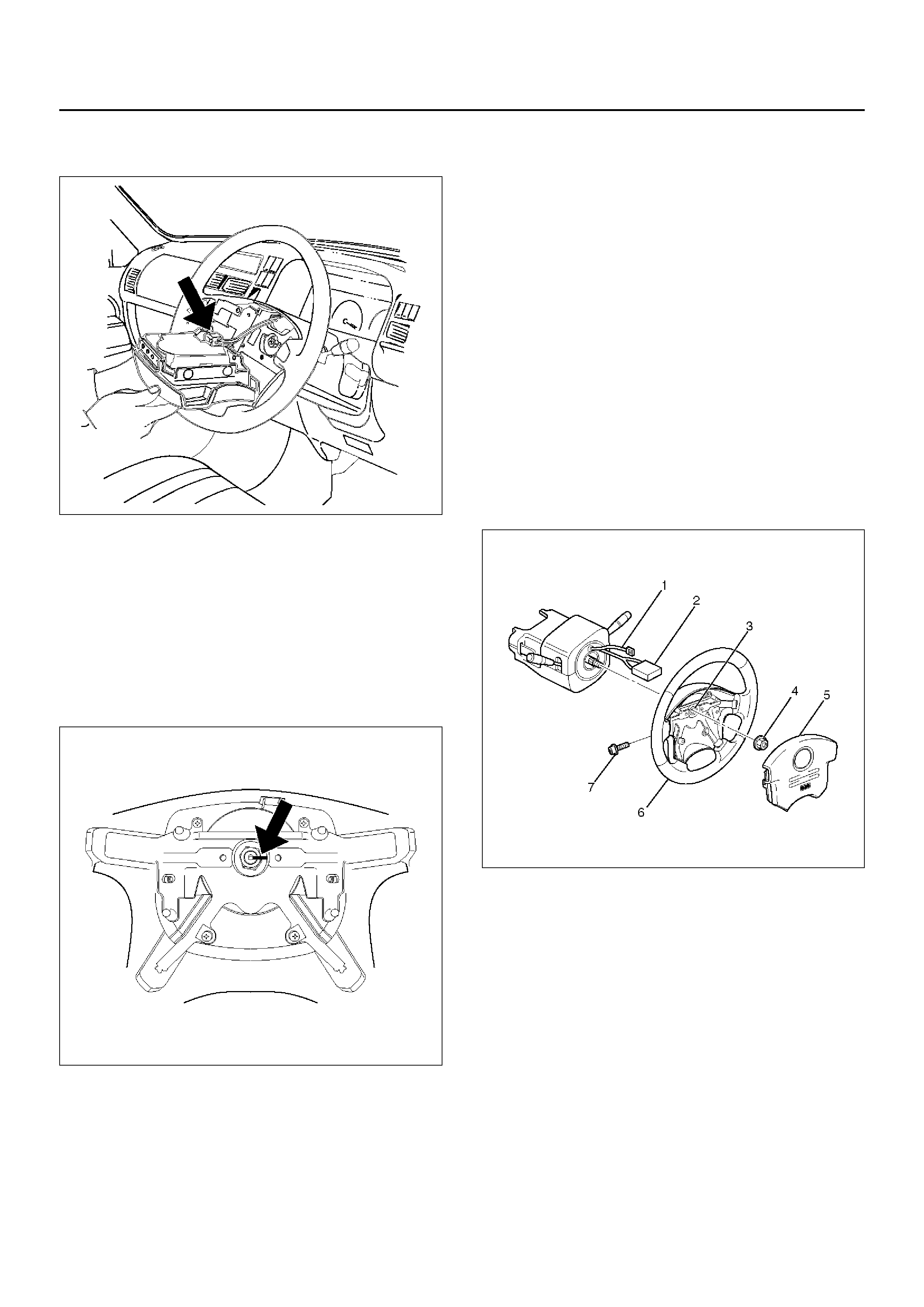
3.Disconnect connector (2) and remove air bag
assembly.
827RX035
3.Disconnect horn lead (1)
4.Remove steering wheel attachment nut (4).
5.Move the tyres to the straight ahead position before
removing the steering wheel. Install steering wheel
puller onto steering wheel and remove steering
wheel with 5–8521–0016–0.
6.Apply a setting mark (3) across the steering wheel
and shaft so parts can be reassembled in their
original position.
827RW063
7.Feed wiring through the wheel and remove wheel.
CAUTION: Never apply force to the steering wheel
in direction of the shaft by using a hammer or other
impact tools in an attempt to remove the steering
wheel. The steering shaft is designed as an energy
absorbing unit.
Installation
1.Install the steering wheel and align the setting
marks (3).
2.Tighten the steering wheel fixing nut (4) to the
specified torque.
Torque: 34 N·m (3.5 kg·m/25 lbft)
3.Connect horn lead (1).
4.Connect air bag to wiring harness connector (2).
NOTE: Pass the lead wire through the tabs on the
plastic cover (wire protector) of air bag to prevent lead
wire from being pinched.
5.Install air bag into steering wheel and tighten bolts
(7) to specified sequence as show in figure.
Torque: 8.8 N·m (0.9 kg·m/78 lbin)
CAUTION: Never use the air bag assembly from
another vehicle. Use only the air bag assembly for
UE.
827RX034
6.Enable the Supplemental Restraint System (SRS).
(Refer to “Enabling The SRS" in this section.)
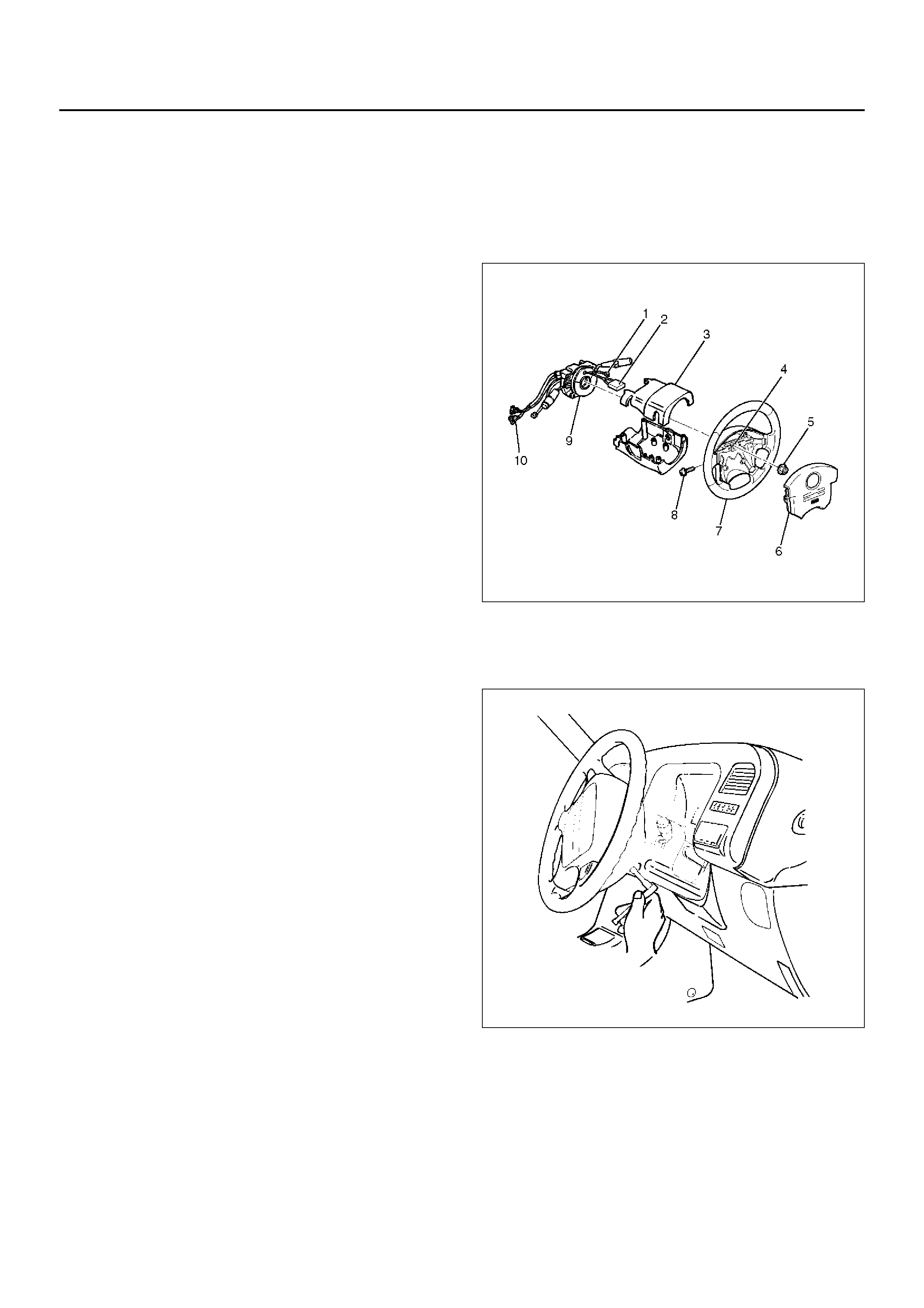
SRS Coil Assembly
Service Precaution
WARNING: SAFETY PRECAUTIONS MUST BE
FOLLOWED WHEN HANDLING A DEPLOYED AIR
BAG ASSEMBLY. AFTER DEPLOYMENT, THE AIR
BAG ASSEMBLY SURFACE MAY CONTAIN A SMALL
AMOUNT OF SODIUM HYDROXIDE, A BY-PRODUCT
OF THE DEPLOYMENT REACTION, THAT IS
IRRITATING TO THE SKIN AND EYES. MOST OF THE
POWDER ON THE AIR BAG ASSEMBLY IS
HARMLESS. AS A PRECAUTION, WEAR GLOVES
AND SAFETY GLASSES WHEN HANDLING A
DEPLOYED AIR BAG ASSEMBLY, AND WASH YOUR
HANDS WITH MILD SOAP AND WATER
AFTERWARDS.
WARNING: WHEN CARRYING A LIVE AIR BAG
ASSEMBLY, MAKE SURE THE BAG AND TRIM
COVER ARE POINTED AWAY FROM YOU. NEVER
CARRY AIR BAG ASSEMBLY BY THE WIRES OR
CONNECTOR ON THE UNDERSIDE OF MODULE. IN
THE CASE OF AN ACCIDENTAL DEPLOYMENT, THE
BAG WILL THEN DEPLOY WITH MINIMAL CHANCE
OF INJURY. WHEN PLACING A LIVE AIR BAG
ASSEMBLY ON A BENCH OR OTHER SURFACE,
ALWAYS FACE BAG AND TRIM COVER UP, AWAY
FROM THE SURFACE. NEVER REST A STEERING
COLUMN ASSEMBLY ON THE STEERING WHEEL
WITH THE AIR BAG ASSEMBLY FACE DOWN AND
COLUMN VERTICAL. THIS IS NECESSARY SO THAT
A FREE SPACE IS PROVIDED TO ALLOW THE AIR
BAG ASSEMBLY TO EXPAND IN THE UNLIKELY
EVENT OF ACCIDENTAL DEPLOYMENT.
OTHERWISE, PERSONAL INJURY COULD RESULT.
NOTE: In the event deployment has occurred, inspect
coil assembly wire for any signs of scorching, melting or
any other damage due to excessive heat. If the coil has
been damaged, replace it.
Removal
1.Disable the SRS. (Refer to "Disabling the SRS" in
this section.)
825RX047
2. Remove the air bag assembly (6) from steering
wheel (7) by removing two bolts (8). Lift air bag
assembly out of steering wheel.
827RX036
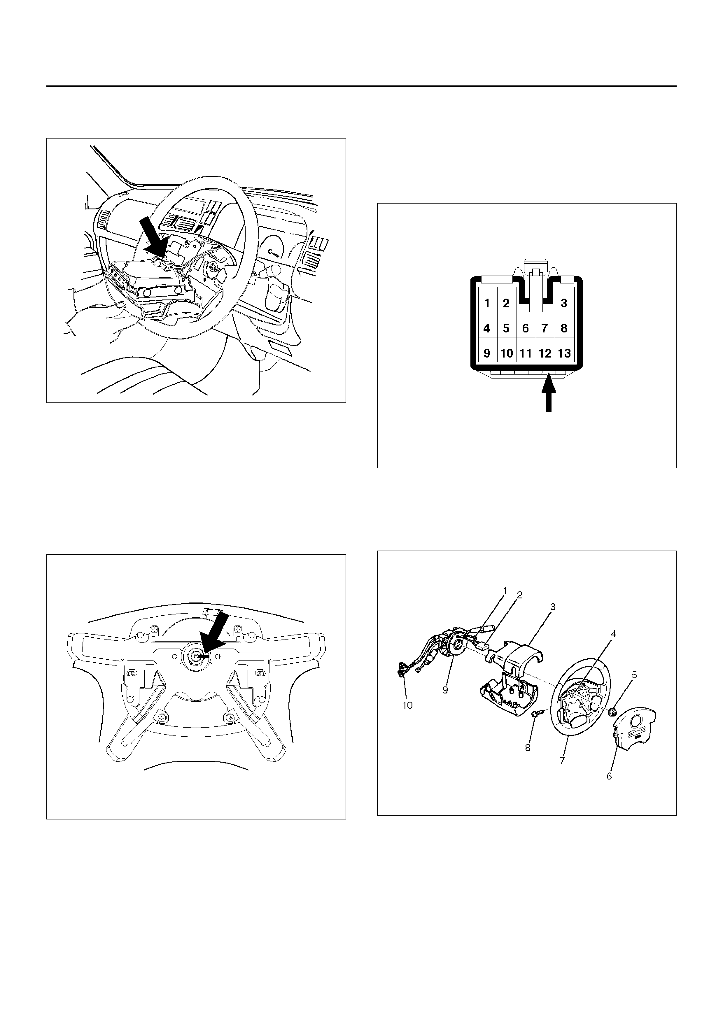
4.Disconnect the 2–pin yellow connector (2) and
remove air bag assembly.
827RX035
3.Disconnect horn lead connector (1).
4.Remove the steering wheel attachment nut (5).
5.Move the tyres to the straight ahead position before
removing the steering wheel and remove wheel with
5–8521–0016–0.
6.Apply a setting mark (4) across the steering wheel
and shaft so parts can be reassembled in their
original position.
827RW063
7.Feed wiring though the wheel and remove wheel.
CAUTION: Never apply force to the steering wheel
in the direction of the shaft by using a hammer or
other impact tools in an attempt to remove the
steering wheel. The steering shaft is designed as an
energy absorbing unit.
8.Remove the steering lower cover.
9.Remove the driver knee bolster assembly.
10.Remove the steering column cover (3).
11.Disconnect the wiring harness connectors (10)
located at the base of steering column.
12.Disconnect the horn terminal NO.2 from connector
and remove the tape binding harness. (Refer to How
to Disconnect the horn terminal in this section.)
827RX029
13. Remove four bolts of combination switch assembly
(9) attached to steering lock and remove the
combination switch assembly (with SRS coil) from
steering shaft.
825RX047
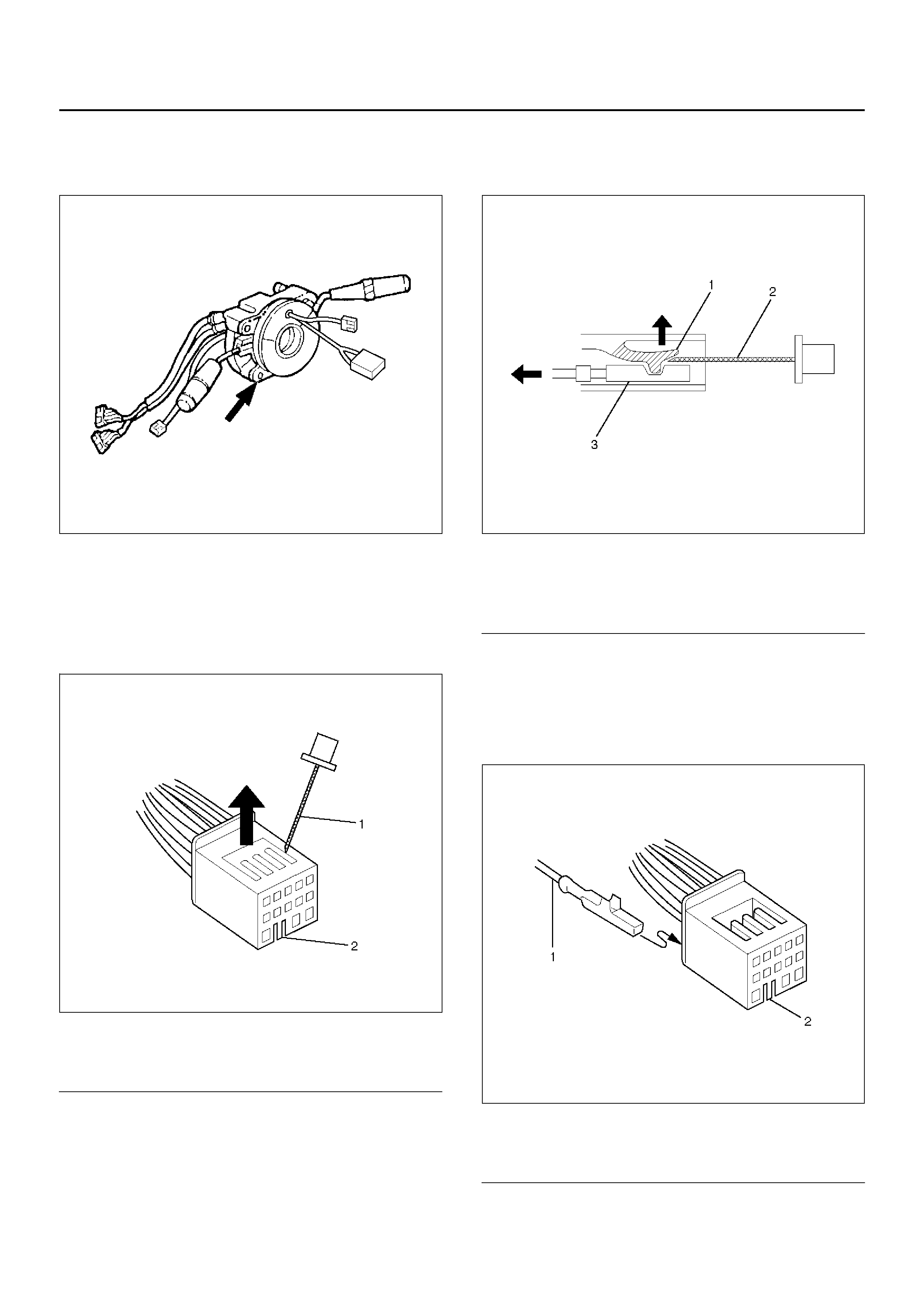
5. Remove four bolts of SRS coil assembly and
remo ve the S RS coil assemb ly fr om the c ombina tion
switch.
825RX033
How to Disconnect the horn terminal
1. Lift the white part of black connector with a
minitenes screw driver (-) and release connector
terminal lock.
827RX045
Legend
EndOFCallout
6. Pull out the terminal of lead wire coming to black
connector NO.12 while lifting the lock part with a
minitenes screw driver (-) .
827RX046
Legend
EndOFCallout
How to Connect Horn Terminal
1. Insert horn terminal from behind black connector
NO.12 until connector lock works.
827RX047
Legend
EndOFCallout
(1) Minitenes screw driver (-)
(2) Connecto r lock knob
(1) Lock
(2) Minitenes screw driver (-)
(3) Terminal
(1) Terminal
(2) Connector lock knob
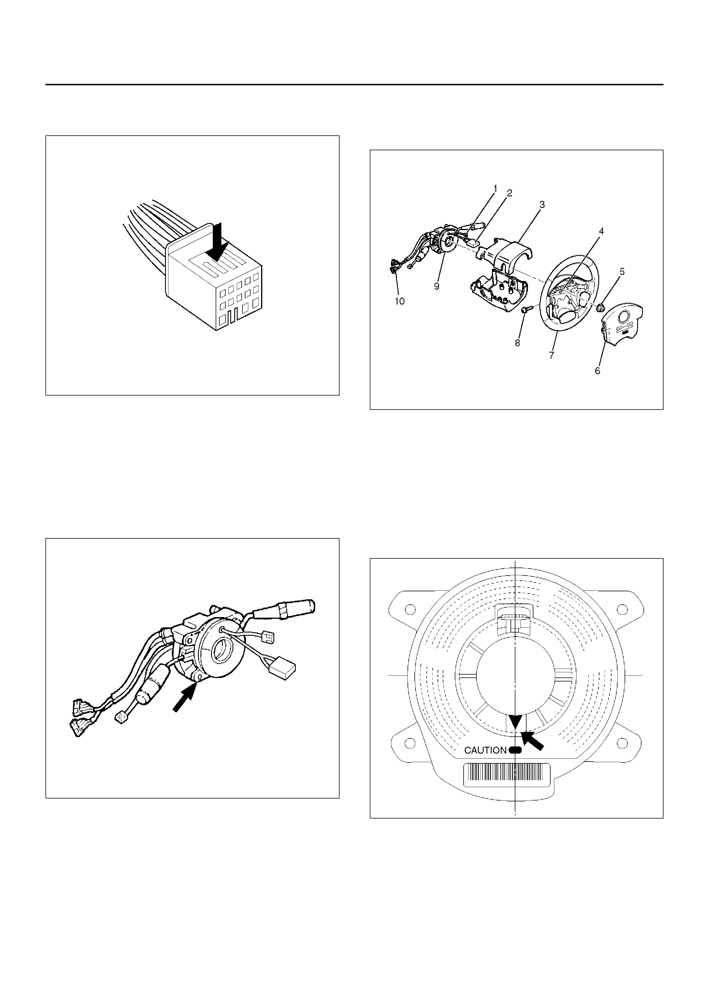
7.Push white connector into the black connector for a
double lock.
827RX048
Installation
1.Set cancel cam and SRS coil in position and install
the SRS coil to combination switch by tightening the
four bolts to a specified tightening torque with four
bolts.
Torque: 0.5 N·m (0.05 kg·m/0.4 lb ft)
825RX033
2.Insert the horn terminal into the connector NO.12
and bind the combination switch harness and SRS
coil harness with a tape.(Refer to How to Connect
the horn terminal in this section.)
8. Install the combination switch assembly (with SRS
coil) to steering lock of steering shaft and tighten the
four bolts to a specified tightening torque.
825RX047
3. Connect the wiring harness connectors (10) located
at the base of steering column.
4. Turn the SRS coil clockwise to full, return about 3
turns and align the neutral mark.
NO TE: Whenev er installing the new combination switch
with SRS coil, be sure to tear off the lock pin for aligning
the neutral position before it is installed to the base of
steering column.
825RX032
CAUTION: When turning the SRS coil clockwise to
full, stop turning if resistance is felt. For ced further
turning may damage the cable in the SRS coil.
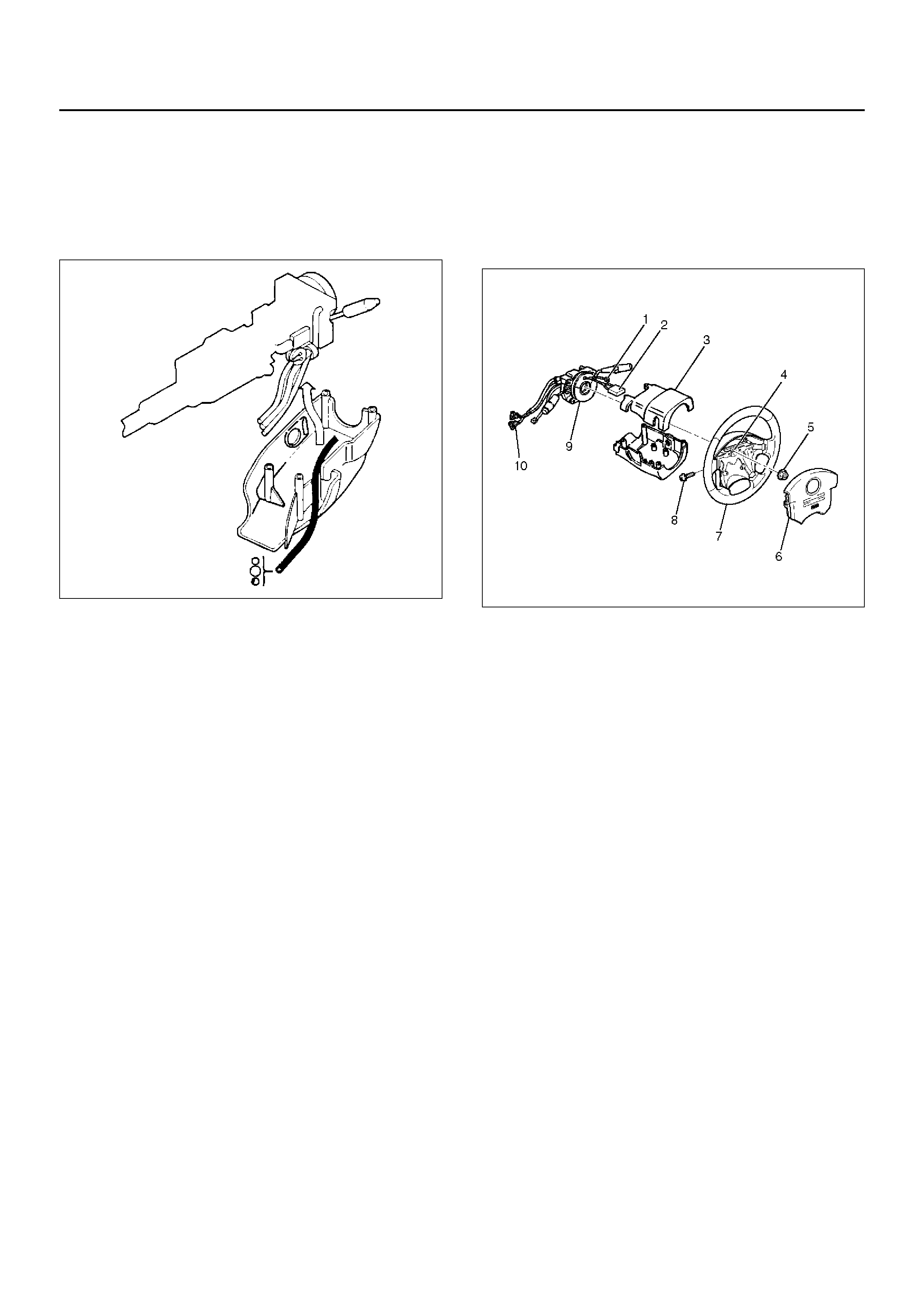
9.Install the steering column cover (3).
CAUTION: When installing the steering column
cover, be sure to through each harness as
illustrated so that the harnesses starter switch,
combination switch and SRS coil may not catch
wiring.
825RS048
5.Install the driver knee bloster assembly.
6.Install the steering lower cover.
7.Install the steering wheel and align the setting
marks (4).
8.Tighten the steering wheel fixing nut (5) to the
specified torque.
Torque: 34 N·m (3.5 kg·m/25 lb ft)
9.Connect horn lead (1).
10.Connect air bag to wiring harness connector (2).
NOTE: Pass the lead wire through the tabs on the
plastic cover (wire protector) of air bag to prevent lead
wire from being pinched.
10.Install Air Bag (6) into steering wheel and tighten
bolts (8) to specified sequence as figure.
Torque: 8.8 N·m (0.9 kg·m/78 lb in)
CAUTION: Never use the air bag assembly from
another vehicle. Use only the air bag assembly for
“UE”.
825RX047
11.Enable the SRS. (Refer to “Enabling The SRS” in
this section.)
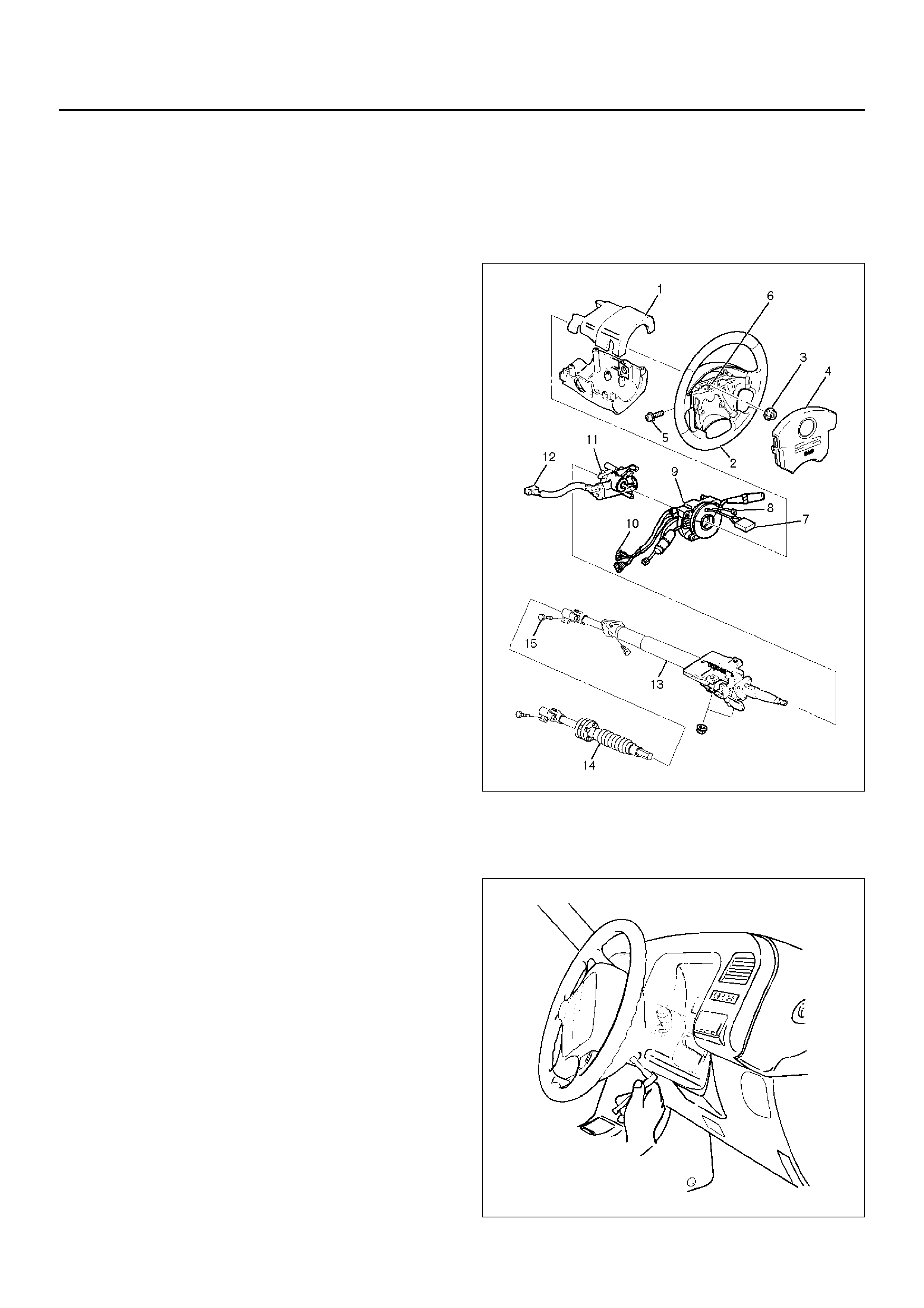
Steering Column
Service Precaution
WARNING: SAFETY PRECAUTIONS MUST BE
FOLLOWED WHEN HANDLING A DEPLOYED AIR
BAG ASSEMBLY. AFTER DEPLOYMENT, THE AIR
BAG ASSEMBLY SURFACE MAY CONTAIN A SMALL
AMOUNT OF SODIUM HYDROXIDE, A BY-PRODUCT
OF THE DEPLOYMENT REACTION, THAT IS
IRRITATING TO THE SKIN AND EYES. MOST OF THE
POWDER ON THE AIR BAG ASSEMBLY IS
HARMLESS. AS A PRECAUTION, WEAR GLOVES
AND SAFETY GLASSES WHEN HANDLING A
DEPLOYED AIR BAG ASSEMBLY, AND WASH YOUR
HANDS WITH MILD SOAP AND WATER
AFTERWARDS.
WARNING: WHEN CARRYING A LIVE AIR BAG
ASSEMBLY, MAKE SURE THE BAG AND TRIM
COVER ARE POINTED AWAY FROM YOU. NEVER
CARRY AIR BAG ASSEMBLY BY THE WIRES OR
CONNECTOR ON THE UNDERSIDE OF MODULE. IN
THE CASE OF AN ACCIDENTAL DEPLOYMENT, THE
BAG WILL THEN DEPLOY WITH MINIMAL CHANCE
OF INJURY. WHEN PLACING A LIVE AIR BAG
ASSEMBLY ON A BENCH OR OTHER SURFACE,
ALWAYS FACE BAG AND TRIM COVER UP, AWAY
FROM THE SURFACE. NEVER REST A STEERING
COLUMN ASSEMBLY ON THE STEERING WHEEL
WITH THE AIR BAG ASSEMBLY FACE DOWN AND
COLUMN VERTICAL. THIS IS NECESSARY SO THAT
A FREE SPACE IS PROVIDED TO ALLOW THE AIR
BAG ASSEMBLY TO EXPAND IN THE UNLIKELY
EVENT OF ACCIDENTAL DEPLOYMENT.
OTHERWISE, PERSONAL INJURY COULD RESULT.
NOTE: In the event deployment has occurred, inspect
coil assembly wire for any signs of scorching, melting or
any other damage due to excessive heat. If the coil has
been damaged, replace it.
Removal
1.Disable the Supplemental Restraint System (SRS).
(Refer to “Disabling The SRS" in this section.)
431RX012
2. Remove the air bag assembly (4) from steering
wheel (2) by removing two bolts (5). Lift air bag
assembly out of steering wheel.
827RX036
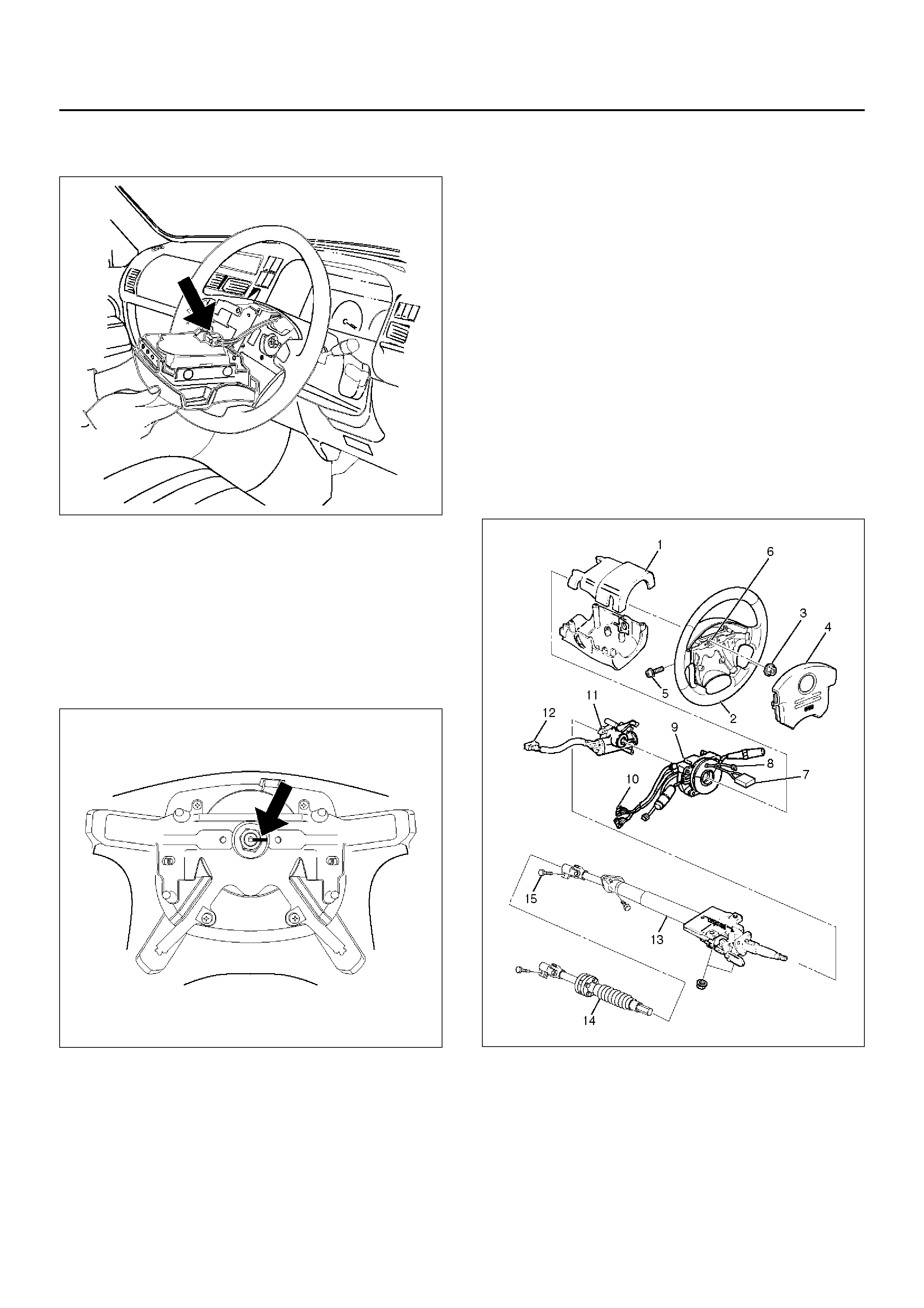
3.Disconnect the 2–pin yellow connector (7) and
remove air bag assembly.
827RX035
4.Disconnect horn lead connector (8).
5.Remove the steering wheel attachment nut (3).
6.Move the tyres to the straight ahead position before
removing the steering wheel and removing wheel
with 5–8521–0016–0.
7.Apply a setting mark (6) across the steering wheel
and shaft so parts can be reassembled in their
original position.
827RW063
8.Feed wiring though the wheel and remove wheel.
9.Remove the steering lower cover.
10.Remove the driver knee bolster assembly.
11.Remove the steering column cover (1).
12.Disconnect the wiring harness connectors (10)
located at the base of steering column.
CAUTION: Never apply force to the steering wheel
in direction of the shaft by using a hammer or other
impact tools in an attempt to remove the steering
wheel. The steering shaft is designed as an energy
absorbing unit.
13. Remove the combination switch assembly with
Supplemental Restraint System (SRS) coil (9).
NOTE: SRS coil is a part of combination switch
assembly, which cannot be replaced separately.
Therefore, be sure not to remove the SRS coil from the
combination switch assembly.
14. Remove the sn ap ri ng .
15. Remove the cu shi on rubber.
16. Disconnect shift lock cable.
17. Disconnect the starter switch harness connector
(12) located base of steering column.
18. Remove steering lock cylinder assembly (11).
19. Remove the 2nd sh aft (14) from the col umn shaft
assembly (13) by removing bolt (15).
20. Remove steering column assembly (13).
431RX012
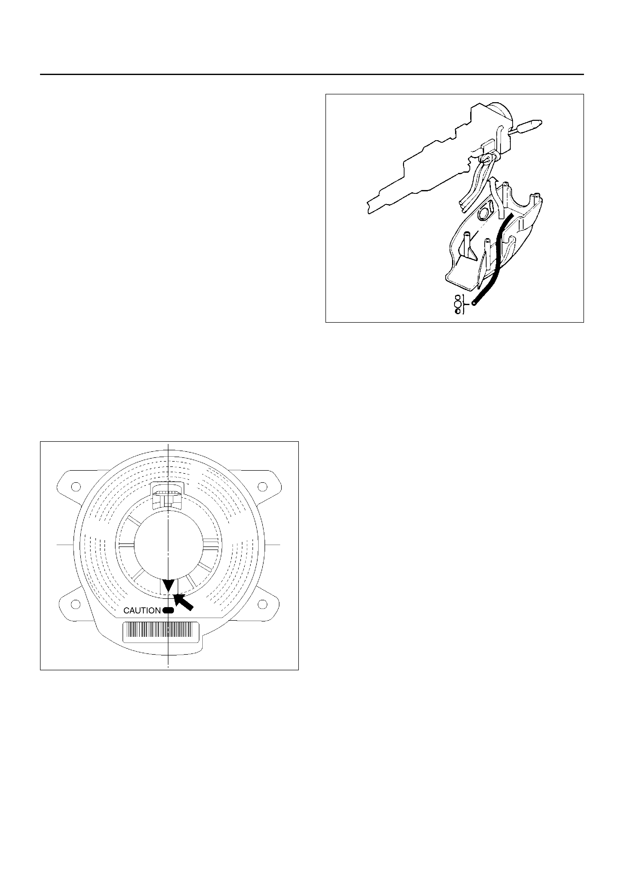
Installation
1.Install the 2nd shaft (14) to the column shaft
assembly (13).
2.Install the steering column assembly (13).
3.Tighten the steering column fixing bolts (dash panel
side) to the specified torque.
Torque: 20 N·m (2.0 kg·m/15 lbft)
4.Tighten the steering column fixing nuts (Cross
beam) to the specified torque.
Torque: 17 N·m (1.7 kg·m/13 lbft)
5.Tighten the universal joint to the specified torque.
Torque: 31 N·m (3.2 kg·m/23 lbft)
6.Install steering lock cylinder assembly (11).
7.Connect shift lock cable.
8.Install cushion rubber.
9.Install snap ring.
10.Install the combination switch assembly with
Supplemental Restraint System (SRS) coil (9).
11.Connect the wiring harness connector (10) located
on the base of steering column.
12.Turn the SRS coil clockwise to full, return about 3
turns and align the neutral mark.
825RX032
CAUTION: When turning the SRS coil clockwise to
full, stop turning if resistance is felt. Further forced
turning may damage the cable in the SRS coil.
13.Install steering column cover (1).
825RS048
CAUTION: When installing the steering column
cover, be sure to wire (through each harness) as
illustrated so that the harnesses starter switch,
combination switch and SRS coil may not catch
wiring.
14. Install the steering wheel (2) and align the setting
marks (6).
15. Tighten the steering wheel fixing nut (3) to the
specified torque.
Torque: 34 N·m (3.5 kg·m/25 lbft)
16. Connect horn lead (8).
17. Connect air Bag wiring harness connector (7).
NO TE: Pass the lead wire through the tabs on the
plastic cover (wire protector) of air bag to prevent lead
wire from being pinched.

18.Install air bag into steering wheel and tighten bolts
(5) to specified sequence as shown in figure.
Torque: 8.8 N·m (9.0 kg·m/78 lbin)
CAUTION: Never use the air bag assembly from
another vehicle.
Use only the air bag assembly for UE.
431RX012
19.Enable the Supplemental Restraint System (SRS)
(Refer to “Enabling The SRS" in this section.)
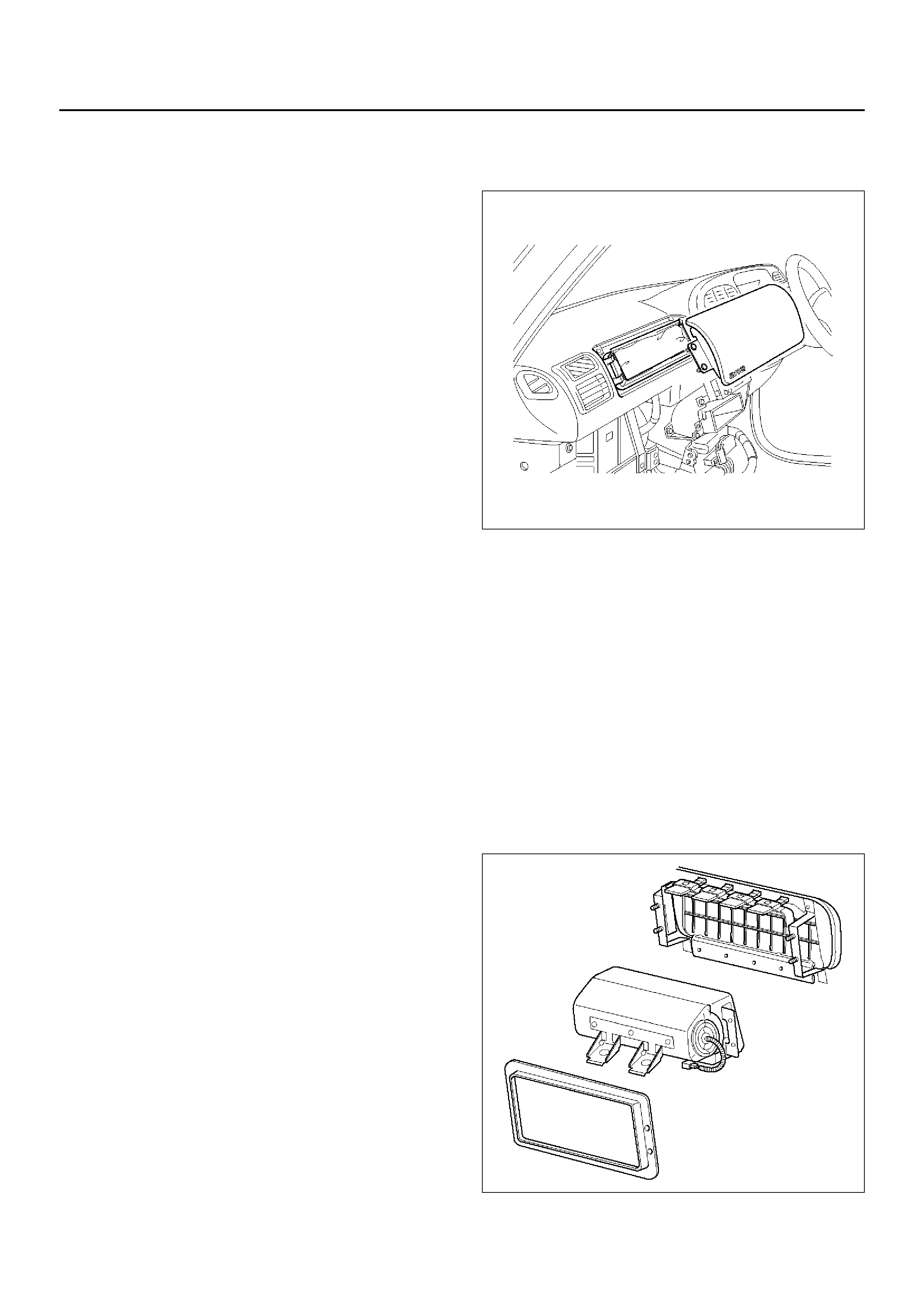
Passenger Air Bag Assembly
Service Precaution
WARNING: SAFETY PRECAUTIONS MUST BE
FOLLOWED WHEN HANDLING A DEPLOYED AIR
BAG ASSEMBLY. AFTER DEPLOYMENT, THE AIR
BAG ASSEMBLY SURFACE MAY CONTAIN A SMALL
AMOUNT OF SODIUM HYDROXIDE, A BY-PRODUCT
OF THE DEPLOYMENT REACTION, THAT IS
IRRITATING TO THE SKIN AND EYES. MOST OF THE
POWDER ON THE AIR BAG ASSEMBLY IS
HARMLESS. AS A PRECAUTION, WEAR GLOVES
AND SAFETY GLASSES WHEN HANDLING A
DEPLOYED AIR BAG ASSEMBLY, AND WASH YOUR
HANDS WITH MILD SOAP AND WATER
AFTERWARDS.
WARNING: WHEN CARRYING A LIVE AIR BAG
ASSEMBLY, MAKE SURE THE BAG AND TRIM
COVER ARE POINTED AWAY FROM YOU. NEVER
CARRY AIR BAG ASSEMBLY BY THE WIRES OR
CONNECTOR ON THE UNDERSIDE OF MODULE. IN
THE CASE OF AN ACCIDENTAL DEPLOYMENT, THE
BAG WILL THEN DEPLOY WITH MINIMAL CHANCE
OF INJURY. WHEN PLACING A LIVE AIR BAG
ASSEMBLY ON A BENCH OR OTHER SURFACE,
ALWAYS FACE BAG AND TRIM COVER UP, AWAY
FROM THE SURFACE. NEVER REST A STEERING
COLUMN ASSEMBLY ON THE STEERING WHEEL
WITH THE AIR BAG ASSEMBLY FACE DOWN AND
COLUMN VERTICAL. THIS IS NECESSARY SO THAT
A FREE SPACE IS PROVIDED TO ALLOW THE AIR
BAG ASSEMBLY TO EXPAND IN THE UNLIKELY
EVENT OF ACCIDENTAL DEPLOYMENT.
OTHERWISE, PERSONAL INJURY COULD RESULT.
In the event deployment has occurred, inspect coil
assembly wire for any signs of scorching, melting or any
other damage due to excessive heat. If the coil has
been damaged, replace it.
Removal
1.Disable the SRS. (Refer to “Disabling the SRS" in
this section.)
2.Remove glove box assembly.
3.Disconnect passenger air bag assembly harness
connector.
4.Remove air bag assembly fixing bolts and nuts.
5.Remove reinforcement.
6.Remove passenger air bag assembly from glove
box opening of instrument panel.
827RX051
Installation
1.Install passenger air bag assembly from glove box
opening of instrument panel.
2.Install reinforcement from glove box opening of
instrument panel.
3.Install air bag assembly fixing nuts and bolts, and
tighten to specified torque.
Torque: 7.8 N·m (69 lbin)
4.Connect air bag assembly harness connector.
5.Install glove box assembly.
6.Enable the SRS (Refer to “Enabling the SRS" in this
section.)
827RW062

Main Data and Specifications
Fastener Tightening Specification
Application N·m kg·m Ib Ft Ib In
SDM 10 1.0 — 87
Driver air bag fixing bolt 8.8 0.9 — 78
Steering wheel fixing bolt 34 3.5 25 —
Steering column (dash panel side fi xing bolts) 20 2.0 15 —
Steering column (Cross beam side fixing nuts) 17 1.7 13 —
Steering column (Universal joint fixing bolt) 31 3.2 23 —
Passenger Air Bag fixing bolts and nuts 6 0.6 — 52

SRS Air Bag System Inspection Standards For Repair
Inspection Standards
In cases of collision: When any type of collision has occurred regardless of air bag deployment.
In cases of trouble code: When trouble code has been detected by TECH 2 in case of the AIR BA G WARNING LIGHT
failing to work or remaining lighted.
Pa rts Name Inspection Standard Part Replacement Standard
Collision Trouble
Driver Air bag
Assembly 1. Air bag has deployed due to collision.
2. Pad surface has crack or scratch.
3. Connector has cracks.
4. Harness is disconnected or scratched.
5. Air bag is soaked in water, oil etc.
6. Air bag has fallen from a height of about 10 cm (3.3) feet.
7. Trouble diagnosis in Workshop Manual resulted in part
replacement.
Passenger Air bag
Assembly
Sensing and
Diagnostic Module
(SDM)
1. Air bag has deployed due to collision.
2. SDM is crack or deformed.
3. Connector has cracks.
4. SDM has fallen from a height of about 100 cm (3.3 feet).
5. Trouble diagnosis in Workshop Manual resulted in part
replacement.
SRS Coil Assembly
1. Burn or melt due to ov erheat.
2. Case is cracked or deformed.
3. Trouble diagnosis in Workshop Manual resulted in part
replacement.
SRS Harness
1. Air bag circuit wire harness is disconnected or damaged.
2. Connector has cracks.
3. Trouble diagnosis in Workshop Manual resulted in part
replacement.
Steering Wheel
1. Bracket is deformed.
2. A new air bag cannot be installed with ease.
3. When a new air bag is installed, pad interferes with the steering
wheel, and clearance is uneven.
Steering Column 1. Capsule is broken.
2. The fitting of column collapses.
3. Bellows pipe is deformed.
Instrument Panel &
Knee bolst er &
Cover Glove box.
Seat Seat Belt
Wood shield Glass
1. Dent, bend, cracks, and deform.
Mounts 1. Repair or replace if dent, bend, cracks, and deform are found.
2. Retighten to specified torque if loose.