
SECTION 11A - TT ZAFIRA BODY STYLING KIT
1. GENERAL DESCRIPTION
2. SERVICE OPERATIONS
2.1 FRONT SPOILER
REMOVE
REINSTALL
2.2 ROCKER PANEL SKIRT
REMOVE
REINSTALL
2.3 REAR SIDE EXTENSION
REMOVE
REINSTALL
2.4 REAR SPOILER
REMOVE
REINSTALL
2.5 IDENTIFICATION PLATE, LABELS & BADGE
IDENTIFICATION PLATE
REAR DOOR LABELS
LIFTGATE BADGE

1. GENERAL DESCRIPTION
This Service Manual Supplement describes the service procedures for the Holden By Design body styling kit
available for TT Zafira vehicles. The body kit consists of the following major components, which are painted the
vehicle’s body colour.
• Front spoiler, attached to the front bumper fascia,
• Rocker panel skirts, fitted along each side of the vehicle,
• Rear side extensions, fitted to each side of the rear bumper fascia, and
• Rear spoiler, attached to the liftgate.
All of the com ponents are attached to the vehic le with urethane adhesive. In addition, the fr ont spoiler, r ock er panel
skirts and rear side extensions are also secured to the vehicle with several retainers and/or screws. The front and
rear spoilers are also attached with pressure sensitive double-sided tape.
Replacement body kit com ponents are supplied in a kit that also includes the attaching parts, adhesive and where
required, double-sided tape. Both the left-hand and right-hand rear side extensions are supplied in the one kit. Refer
to Figure 11A-1 for the contents of each kit.
The front spoiler, rocker panel skirts and rear side extensions are made from polyurethane (PUR), while the rear
spoiler is made from ABS plastic. Replacement parts are supplied primed and will require final finishing before
painting. Many different types and brands of paint are available for refinishing the body kit components and while
the painting procedures are relatively straight forward, the correct steps must be followed. Refer to your paint
manufacturer or supplier for further information if required.
The HBD Zafira Body Styling Kit also includes unique alloy wheels. A HBD identification plate and HBD labels are
also included.
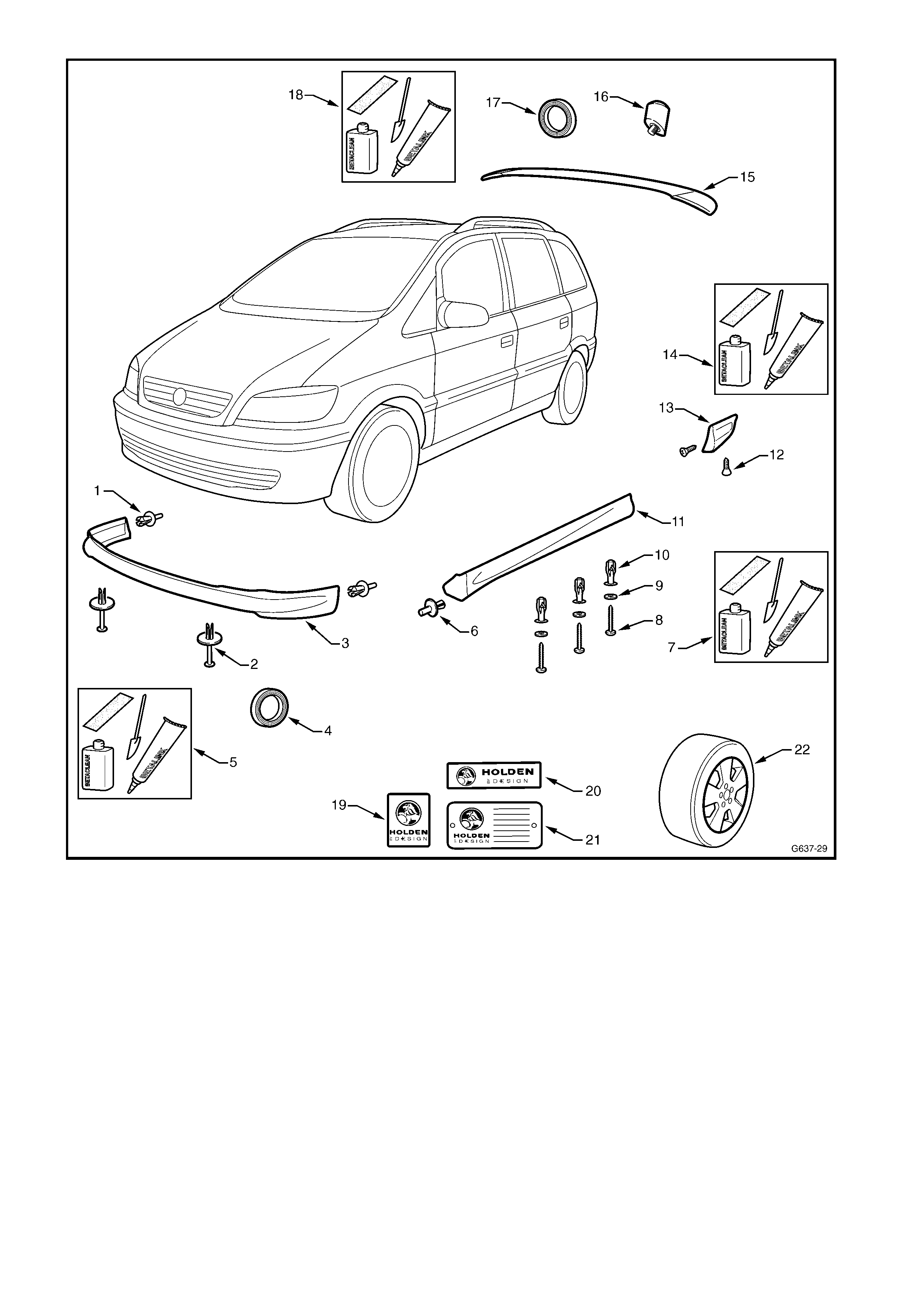
Figure 11A-1
Legend
1. Front Spoiler Side Retainer (x 2) 12. Rear Side Extension Retaining Screw (x 2)
2. Front Spoiler Lower Retainer (x 2) 13. Rear Side Extension
3. Front Spoiler 14. Rear Side Extension Urethane Adhesive Kit
4. Front Spoiler Pressure Sensitive Double Side Tape 15. Rear Spoiler
5. Front Spoiler Urethane Adhesive Kit 16. Antenna Boss (x 2)
6. Rocker Panel Skirt Front Retainer 17. Rear Spoiler Pressure Sensitive Double Side Tape
7. Rocker Panel Skirt Urethane Adhesive Kit 18. Rear Spoiler Urethane Adhesive Kit
8. Rocker Panel Skirt Retaining Screw (x 3) 19. Rear Door Holden By Design Label (x 2)
9. Rocker Panel Skirt Retaining Screw Washer (x 3) 20. Liftgate Holden By Design Badge
10. Rocker Panel Skirt Retainer (x 3) 21. Holden By Design Identification Plate
11. Rocker Panel Skirt 22. Alloy Wheel (x 4)
NOTE: Replacement kits containing the parts shown are available for the front spoiler, left-hand or right-hand rocker panel
skirt (one kit each), both left-hand and right-hand rear side extensions (together in one kit) and the rear spoiler.

2. SERVICE OPERATIONS
2.1 FRONT SPOILER
REMOVE
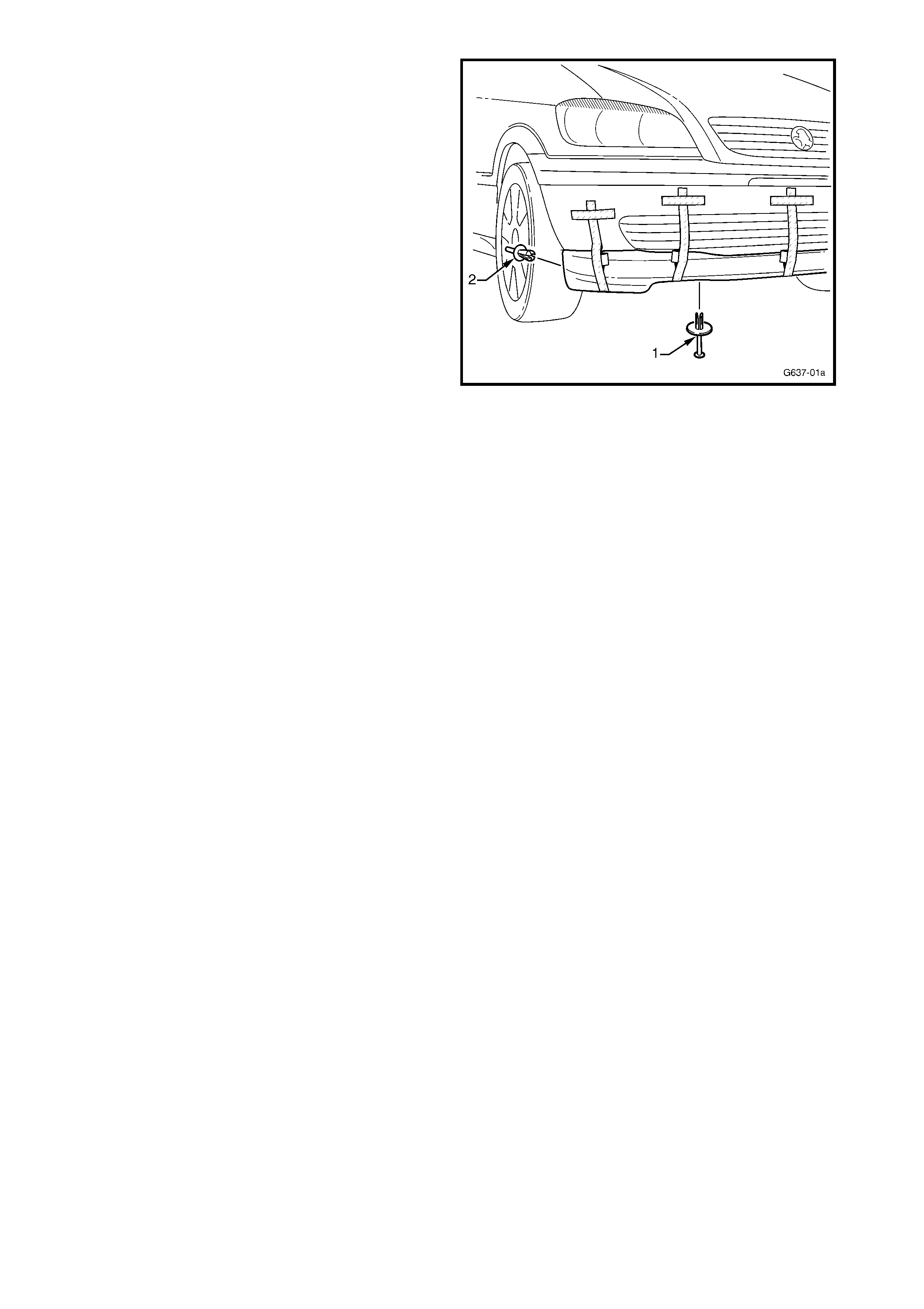
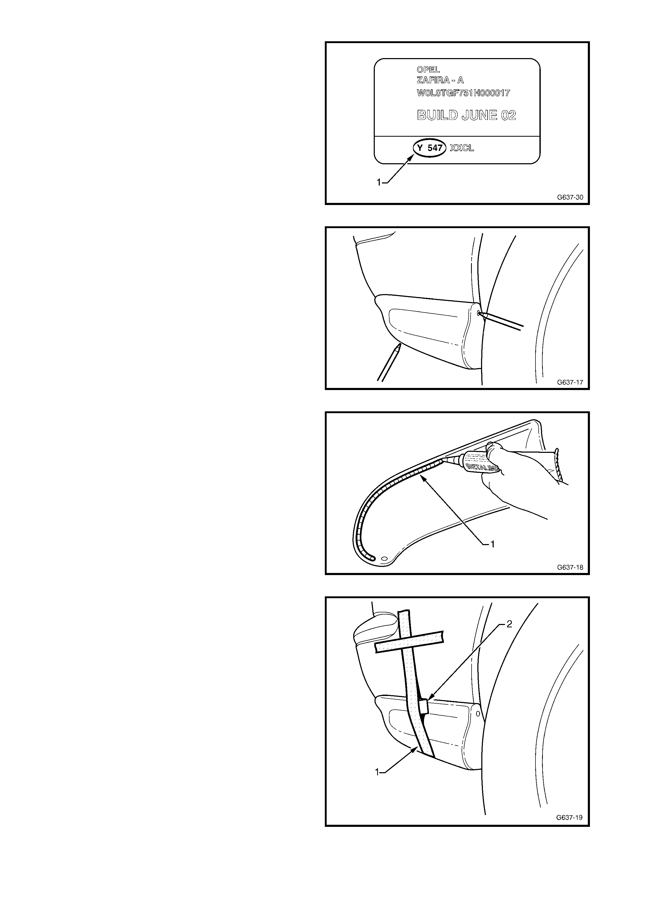
1. From underneath each side of the front bumper
fascia, remove the retainer (1) attaching the front
spoiler to the fascia.
2. From eac h s ide of the f ront bumper fasc ia, rem ove
the retainer (2) attaching the front spoiler to the
fascia.
Figure 11A-2
3. Beginning at one end of the spoiler and using a
sharp knife, cut the urethane adhesive bead and
double- sided tape (1) between the spoiler and
bumper fascia in the area shown, work ing towards
the centre.
NOTE: Hold outward pressure on the spoiler to assist
breaking the bead.
NOTE: Piano wire may be a useful alternative to a
knife.
4. Repeat for the opposite side and remove the
spoiler.
5. If the spoiler and / or bumper fascia are to be
reused, remove the double-sided tape and any
residual tape adhesive. Also remove most of the
urethane bead with a knife to provide a smooth,
sound surface. It is not necessary to completely
remove it.
Figure 11A-3
REINSTALL
The front spoiler is supplied primed and is to be
painted in the vehicle’s body colour.
IMPORTANT: The adhesive track (1 and 2) must be
masked prior to the application of primer or topcoat,
refer to Figure 11A-4.
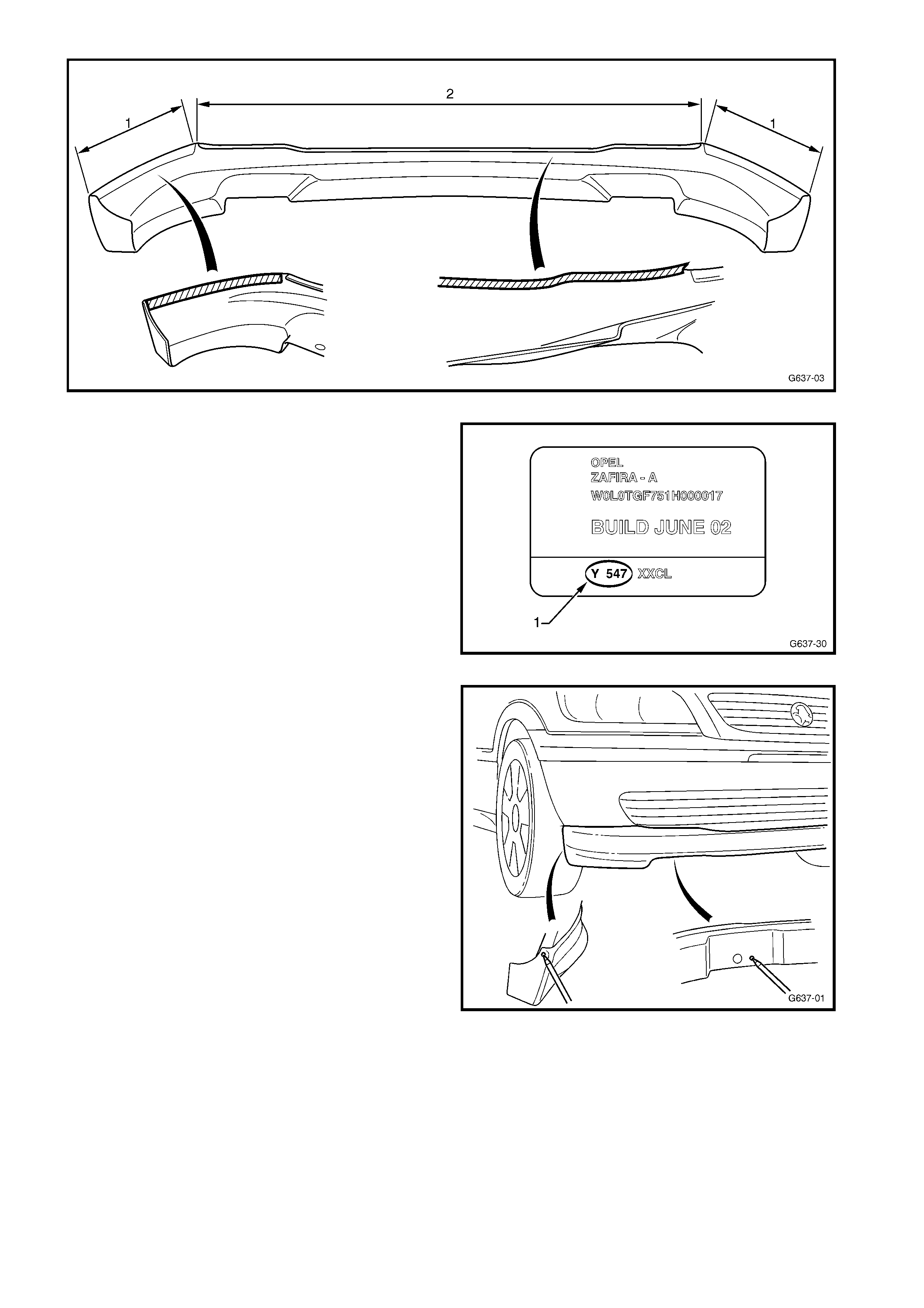
Figure 11A-4
The vehicle paint colour code (1) can be found on the
identification label which is attached to the right-hand
centre pillar.
While the painting procedures are relatively straight
forward, the correct steps must be followed for
refinishing PUR (polyurethane). Refer to your paint
manufacturer for further information as required.
1. Remove the m ask ing tape f rom the adhesive tr ack
on the rear of the spoiler.
2. If required, remove any residual paint from the
adhesive track with 80# sandpaper.
Figure 11A-5
3. If a new bumper fascia has been fitted, seat the
spoiler in position with the aid of an assistant and
mark the two lower and two side retainer holes.
4. Remove the spoiler and drill two 6 mm holes in the
bumper fascia for the lower retainers.
5. Drill a 5 mm hole for each side retainer hole.
6. Clean the bonding surfaces of the bumper fascia
and spoiler with Prepsol or equivalent and dry
thoroughly with a clean, dry cloth to remove any
residue.
7. Apply five lengths of the 3M Pressure Sensitive
Tape supplied with the package, or equivalent, to
the rear of the spoiler in the pos itions shown (1) to
the lower part of the adhesive track and (2) to the
underside of the upper lip, refer to Figure 11A-7.
NOTE: When applying the tape to the glue track (1),
allow enough space for a bead of urethane to be
applied above.
Figure 11A-6
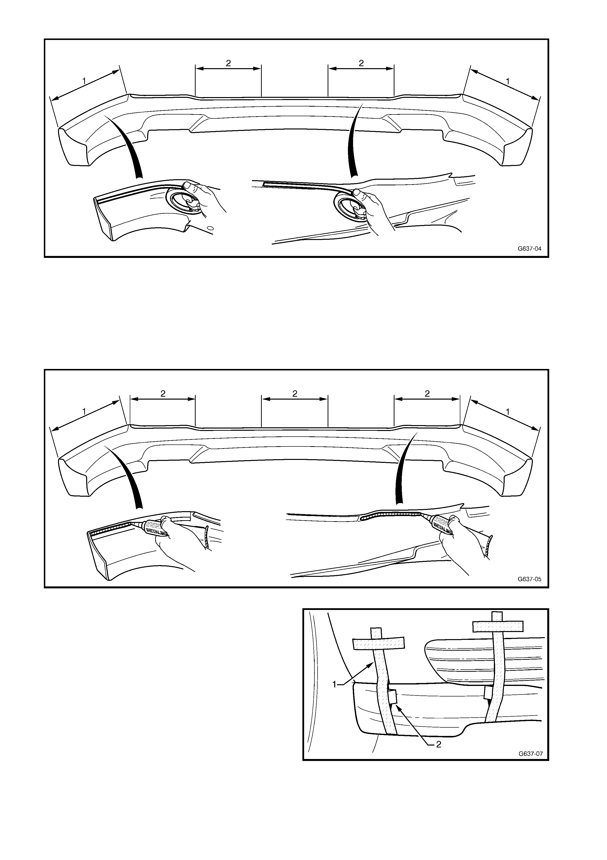
Figure 11A-7
8. Immediately before applying the urethane adhesive, clean the surfaces with Betaclean 3350 supplied with
the replacement kit, or equivalent.
IMPORTANT: T he following steps m ust be completed within 15 m inutes. Carefully read the directions provided
with the urethane adhesive prior to opening the package.
9. Using a circ ular motion, apply a bead of Betalink K1 urethane adhesive (1) supplied with the replacement k it,
or equivalent, into the glue track (1) above the double sided tape, and along the along the underside of the
upper lip (2), in three places, refer to Figure 11A-8.
Figure 11A-8
10. W ith the aid of an assistant, f it the spoiler caref ully
onto the bumper facia.
11. Press the spoiler onto the fascia and apply
masking tape (1) as required across the spoiler
and fascia to temporarily fix the spoiler in position.
NOTE: The use of foam blocks or cardboard packing
(2) will greatly assist in secur ing edges of the s poiler in
position against the fascia until the urethane cures.
Figure 11A-9
12. Reinstall the lower (1) and side (2) retainers, one
place each side.
13. Immediately clean of any excess adhesive as
required using a spatula and the Betaclean 3350
supplied with the replacement kit, or equivalent.
14. Allow a m inim um of over night curing or as directed
on the instructions provided with the urethane
adhesive.
15. Once cured, remove the tape and packing.
Figure 11A-10
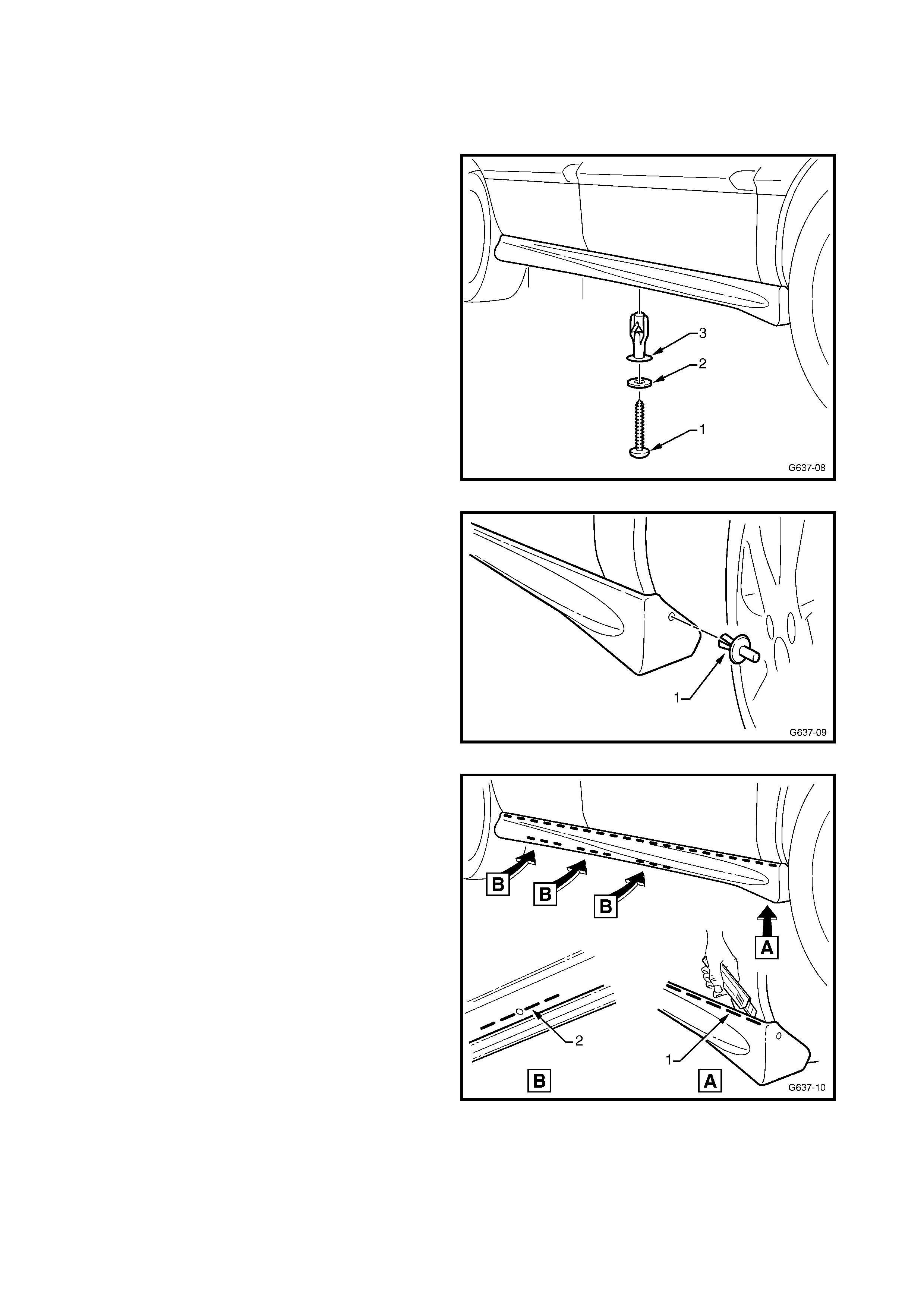
2.2 ROCKER P ANEL SKIRT
REMOVE
1. Open the doors and remove the lower door seal.
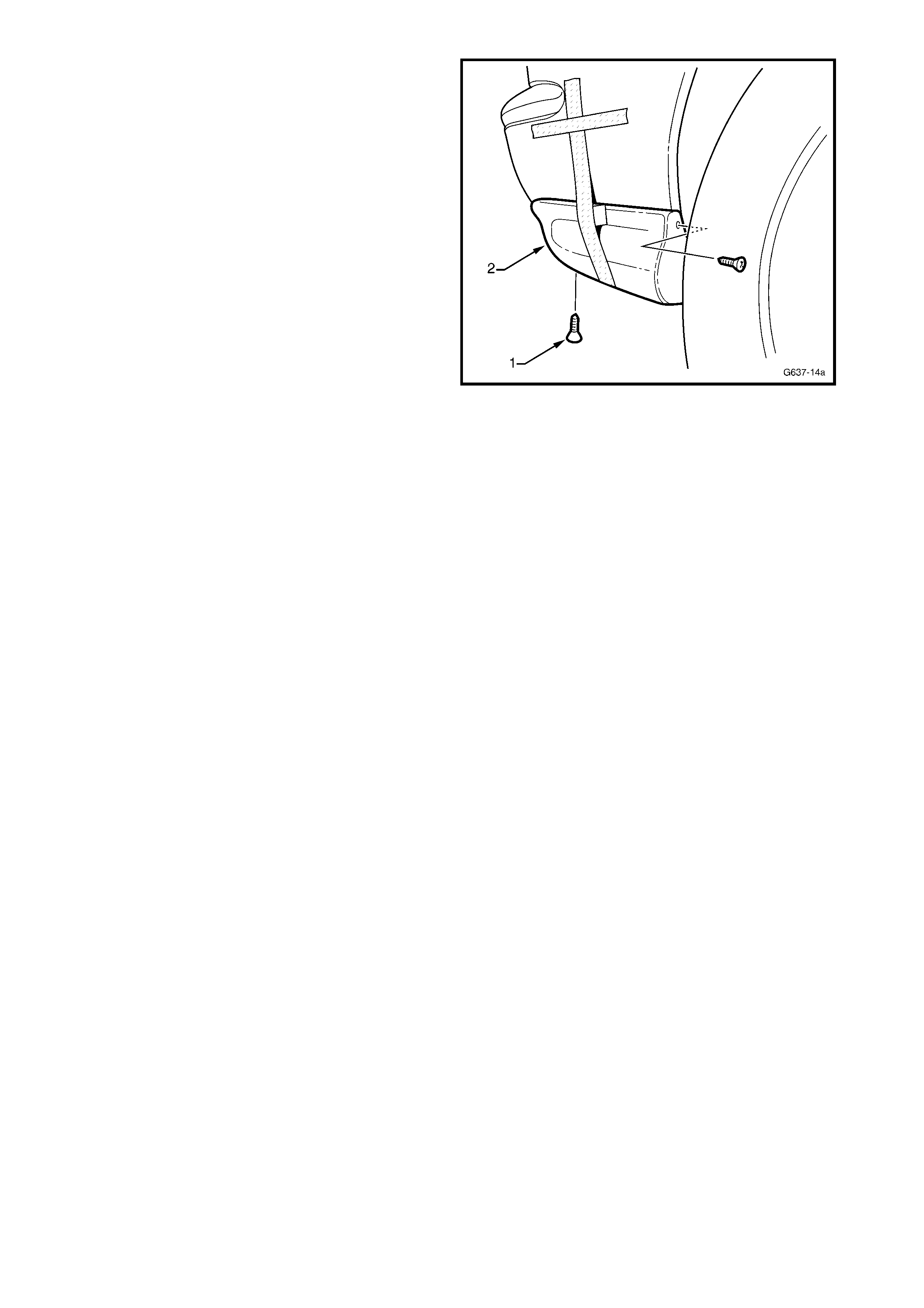
2. Remove the screw (1) and washer (2) and prise
the retainer (3) from the underside of the rocker
panel skirt, three places.
Figure 11A-11
3. Remove the retainer (1) attaching the front of the
skirt to the fender liner.
Figure 11A-12
4. Begin at the front of the skirt and using a sharp
knif e, cut the urethane adhesive bead ( 1) between
the skirt and body.
NOTE: Hold outward pressure on the skirt to assist
breaking the bead.
5. Continue cutting along the entire length of the skirt.
6. Cut the adhesive from the areas adjacent to each
retainer hole (2).
7. Remove the skirt from the vehicle.
8. If the skirt is to be reused, remove most of the
urethane bead with a knife to provide a smooth,
sound surface. It is not necessary to completely
remove it.
Figure 11A-13
REINSTALL
The rocker panel skirt is supplied primed and is to be painted in the vehicle’s body colour.
IMPORTANT: The adhesive track (1) and areas around the three m ounting holes (2) must be masked prior to
the application of primer or topcoat, refer to Figure 11A-14.
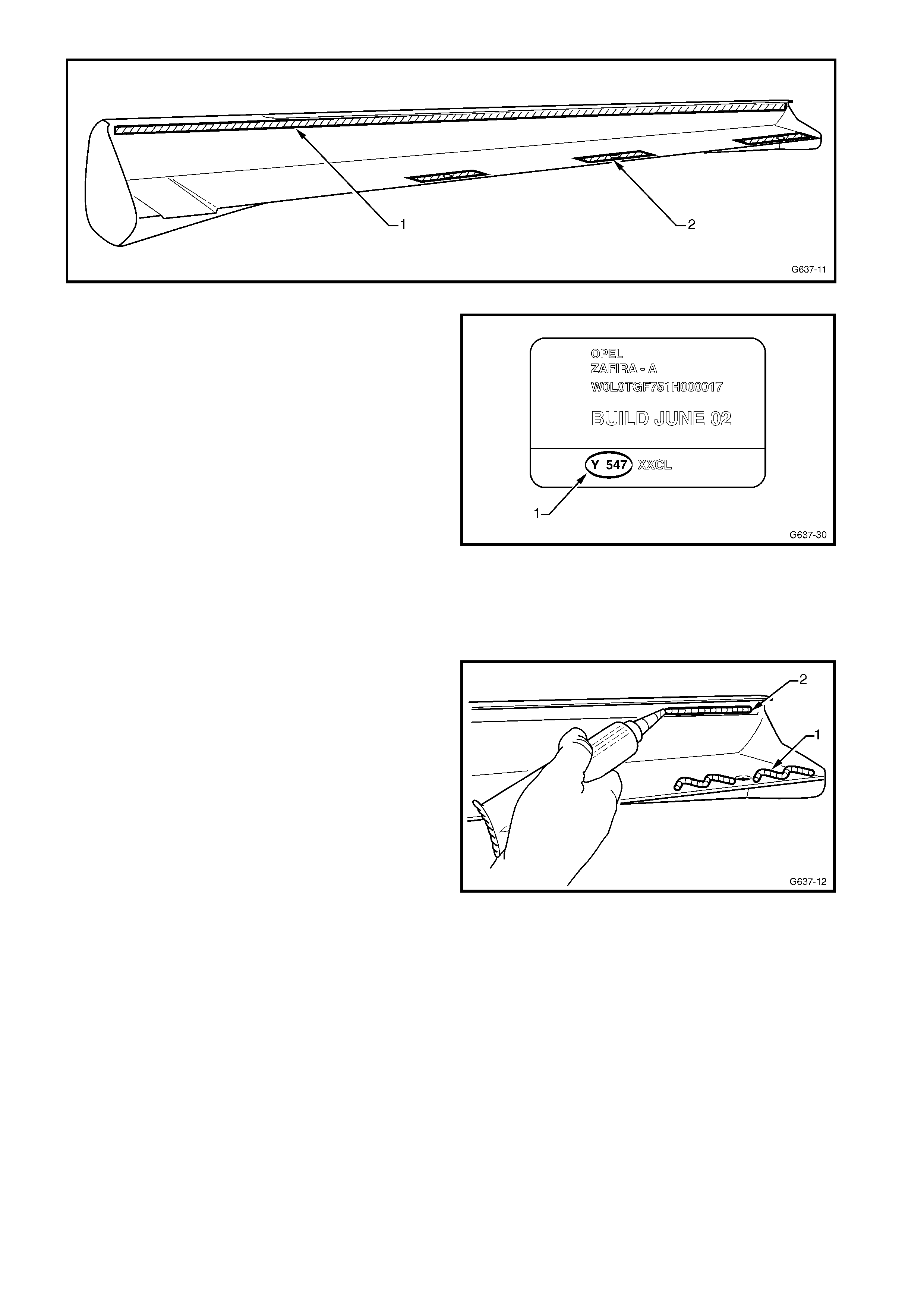
Figure 11A-14
The vehicle paint colour code (1) can be found on the
identification label which is attached to the right-hand
centre pillar.
While the painting procedures are relatively straight
forward, the correct steps must be followed for
refinishing PUR (polyurethane). Refer to your paint
manufacturer for further information as required.
1. Remove the m ask ing tape f rom the adhesive tr ack
on the rear of the skirt.
2. If required, remove any residual paint from the
adhesive track with 80# sandpaper.
3. Clean the bonding surfaces of the rocker panel
and skirt with Prepsol or equivalent and dry
thoroughly with a clean, dry cloth to remove any
residue.
4. Immediately before applying the adhesive, clean
the surf aces with the Betaclean 3350 supplied with
the replacement kit, or equivalent.
Figure 11A-15
IMPORTANT: The following steps must be completed
within 15 minutes. Carefully read the directions
provided with the urethane adhesive prior to opening
the package.
5. Using a circular motion, apply a bead of Betalink
K1 urethane adhesive supplied with the
replacement kit, or equivalent, each side of the
three retainer holes (1) and along the glue track
(2).
Figure 11A-16
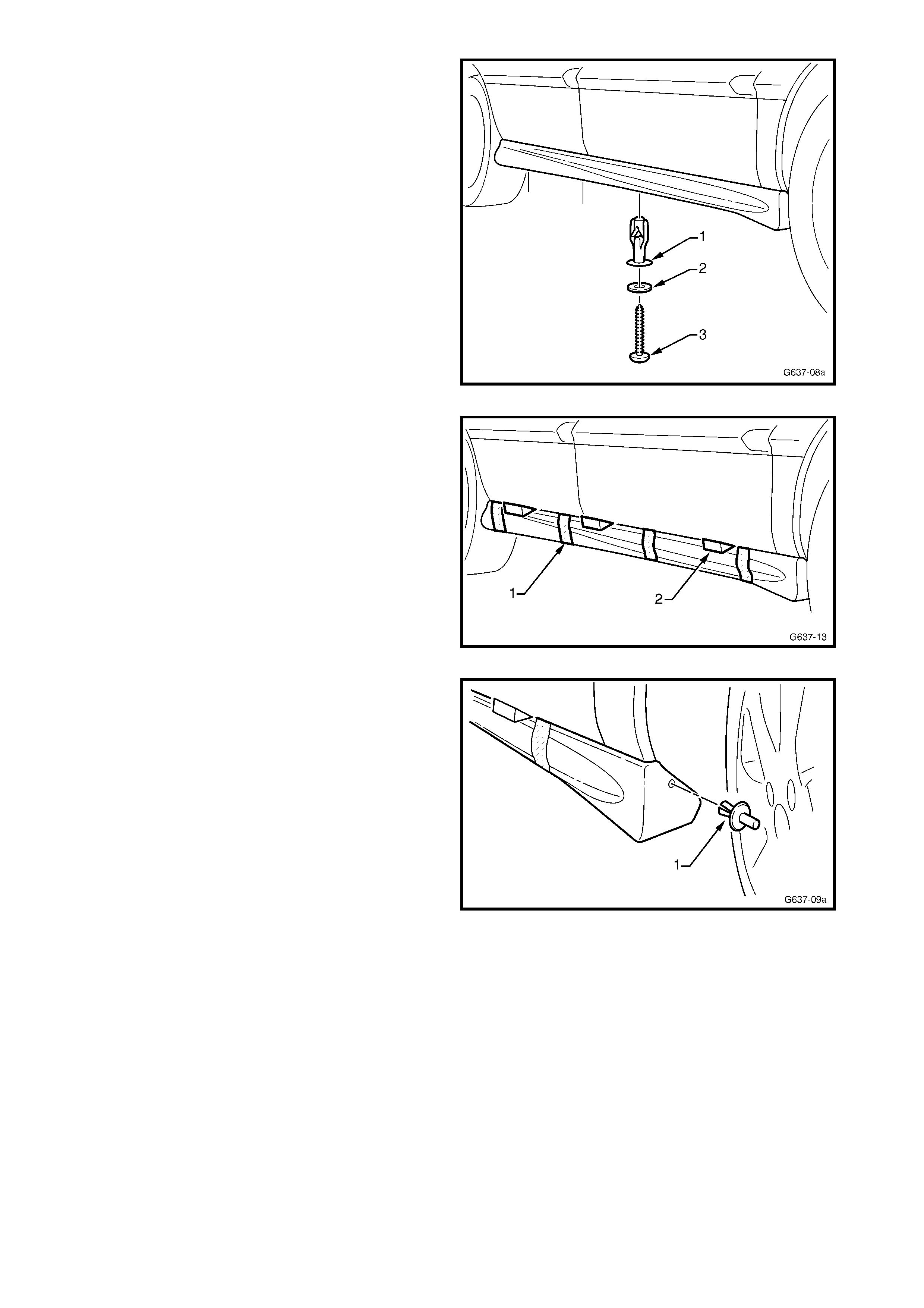
6. With the aid of an assistant, fit the skirt carefully
onto the vehicle.
7. Reinstall the retainer (1) into the hole on the
underside of the skirt, three places.
8. Install the screw (2) and washer (3) into each
retainer and tighten the screw securely.
Figure 11A-17
9. Open the doors and press the upper edge of the
sk irt onto the r ock er panel and apply mask ing tape
(1) across the skirt and sill to temporarily fix it in
position.
10. Wedge foam blocks or cardboard packing (2)
between the doors and sk irt to maintain downward
pressure on the skirt while the urethane adhesive
cures.
Figure 11A-18
11. If required, drill a 5 m m hole through the front skir t
hole into the fender liner.
12. Insert the retainer (1).
13. Clean of any excess adhesive as required using a
spatula and Betaclean 3350 supplied with the
replacement kit, or equivalent.
14. Allow a m inim um of over night curing or as directed
on the instructions provided with the urethane
adhesive.
15. Once cured, remove the tape and reinstall the
lower door seal.
Figure 11A-19
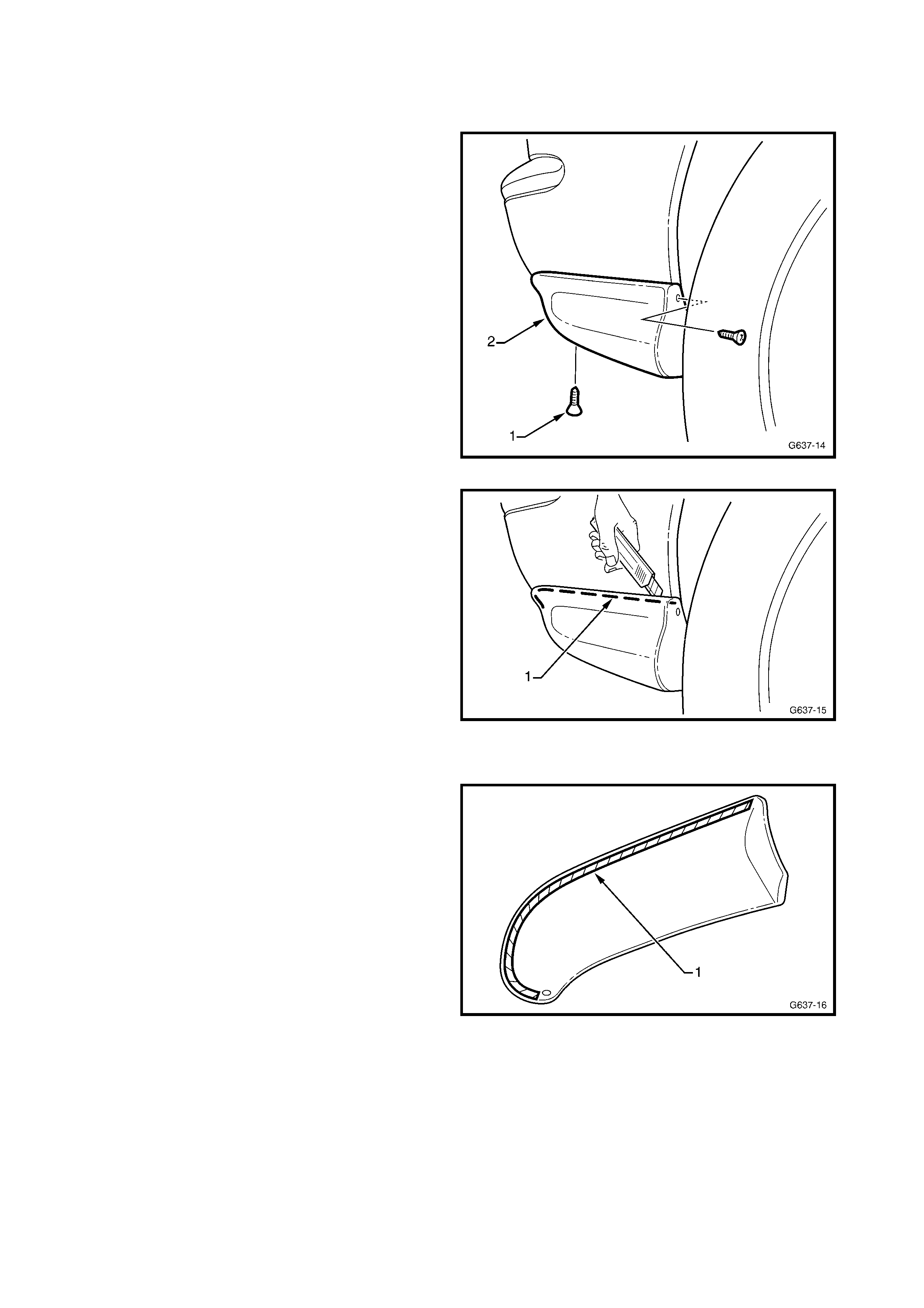
2.3 REAR SIDE EXTENSION
REMOVE
1. Remove the two screws (1) attac hing the rear side
extension (2) to the rear bumper fascia.
Figure 11A-20
2. Begin at the lower rear of the side extension and
using a sharp knife, cut the urethane adhesive
bead (1) between the side extension and bumper
fascia.
NOTE: Hold outward press ure on the s ide extens ion to
assist breaking the bead.
3. Remove the side extension from the vehicle.
4. If the side extension is to be r eused, remove m ost
of the urethane bead with a knife to provide a
smooth, sound surface. It is not necessary to
completely remove it.
Figure 11A-21
REINSTALL
The r ear s ide extens ion is s upplied primed and is to be
painted in the vehicle’s body colour.
IMPORTANT: T he adhesive trac k ( 1) m ust be mask ed
prior to the application of primer or topcoat.
Figure 11A-22
The vehicle paint colour code (1) can be found on the
identification label which is attached to the right-hand
centre pillar.
NOTE: While the painting procedures are relatively
straight f orward, the correc t steps m ust be followed for
refinishing PUR (polyurethane). Refer to your paint
manufacturer for further information as required.
1. Rem o ve the m ask ing tape fr om the adhesive trac k
on the rear of the side extension.
2. If required, remove any residual paint from the
adhesive track with 80# sandpaper.
Figure 11A-23
3. If the rear bumper fascia has been replaced,
temporarily fit the rear side extension in position
and mar k the two attaching scr ew holes in the rear
bumper fascia.
4. Remove the side extension and drill a 3 mm hole
at each mark.
5. Clean the bonding surfaces of the rear bumper
fascia and side extension with Prepsol or
equivalent and dry thoroughly with a clean, dry
cloth to remove any residue.
6. Immediately before applying the adhesive, clean
the surf aces with the Betaclean 3350 supplied with
the replacement kit, or equivalent.
Figure 11A-24
IMPORTANT: The following steps must be completed
within 15 minutes. Carefully read the directions
provided with the urethane adhesive prior to opening
the package.
7. Using a circular motion, apply a bead of Betalink
K1 urethane adhesive (1) supplied with the
replacement kit, or equivalent, along the track on
the back of the side extension as shown.
Figure 11A-25
8. Fit the side extension carefully onto the vehicle.
9. Press the upper edge of the side extension onto
the rear bum per f asc ia and apply mas k ing tape (1)
across the side extension to temporarily fix it in
position.
NOTE: The use of foam blocks or cardboard packing
(2) will greatly assist in securing edges of the
extension in position against the fascia until the
urethane cures.
Figure 11A-26
10. Install the two screws (1) attaching the side
extension (2) to the bumper fascia and tighten
securely.
11. Clean of any excess adhesive as required using a
spatula and Betaclean 3350 supplied with the
replacement kit, or equivalent.
12. Allow a m inim um of over night curing or as directed
on the instructions provided with the urethane
adhesive.
13. Once cured, remove the tape.
Figure 11A-27
2.4 REAR SPOILER
REMOVE
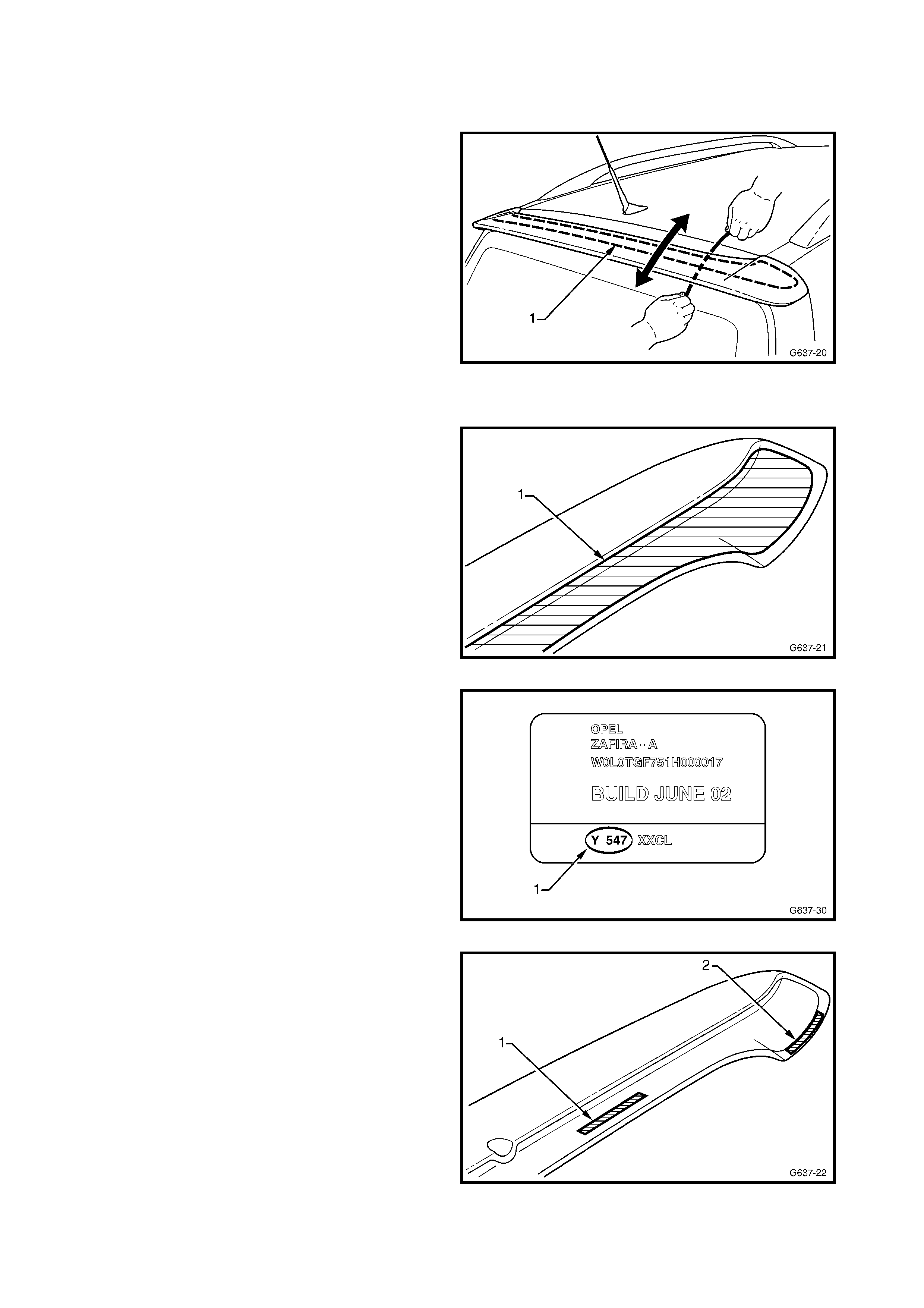
1. Beginning at one end of the spoiler, use a length of
piano wire to carefully cut the urethane adhesive
and double-sided tape from the perimeter of the
spoiler attaching surface. Move the wire in a
cutting motion back and forth as shown.
2. Remove the spoiler.
3. If the spoiler is to be reused, remove the double-
sided tape and clean off any remaining adhesive.
Also remove most of the urethane bead with a
knife to provide a smooth, sound surface. It is not
necessary to completely remove it.
Figure 11A-28
REINSTALL
The rear spoiler is supplied primed and is to be painted
in the vehicle’s body colour.
IMPORTANT: T he adhesive area (1) m ust be mask ed
prior to the application of primer or topcoat.
Figure 11A-29
The vehicle paint colour code (1) can be found on the
identification label which is attached to the right-hand
centre pillar.
While the painting procedures are relatively straight
forward, the correct steps must be followed for
refinishing ABS plastic. Refer to your paint
manufacturer for further information as required.
1. Clean the bonding surfaces of the liftgate and
spoiler with Prepsol or equivalent and dry
thoroughly with a clean, dry cloth to remove and
residue.
Figure 11A-30
2. Apply two lengths of the 3M Pressure Sensitive
Tape (1 & 2) supplied with the replacement kit, or
equivalent, onto each side of the spoiler.
3. Immediately before applying the adhesive, clean
the surf aces with the Betaclean 3350 supplied with
the replacement kit, or equivalent.
Figure 11A-31

IMPORTANT: The following steps must be completed
within 15 minutes. Carefully read the directions
provided with the urethane adhesive prior to opening
the package.
4. Using a circular motion, apply a bead of Betalink
K1 urethane adhesive (1) supplied with the
replacement kit, or equivalent, along the area
shown.
5. Remove the backing paper from the double-sided
tape and with the aid of an assistant, fit the spoiler
carefully onto the liftgate.
Figure 11A-32
6. Press the spoiler firmly into position to ensure a
positive bond of the double-sided tape.
7. Apply masking tape across the spoiler to
temporarily fix it in position.
NOTE: The use of foam blocks or cardboard packing
will greatly assist in s ec ur ing the edges of the spoiler in
position until the urethane cures.
8. Clean of any excess adhesive as required using a
spatula and Betaclean 3350 supplied with the
replacement kit, or equivalent.
9. Allow a m inim um of overnight curing or as directed
on the instructions provided with the urethane
adhesive.
10. Once cured, remove the tape.
11. Carefully open the liftgate and ensure the spoiler
clears the radio antenna.
12. If required, install the antenna boss (1), between
the antenna mast and base. Ensure the boss is
seated correctly and tightened securely, refer to
Figure 11A-34.
NOTE: T wo different sized bosses ar e supplied, fit the
correct one.
Figure 11A-33
Figure 11A-34
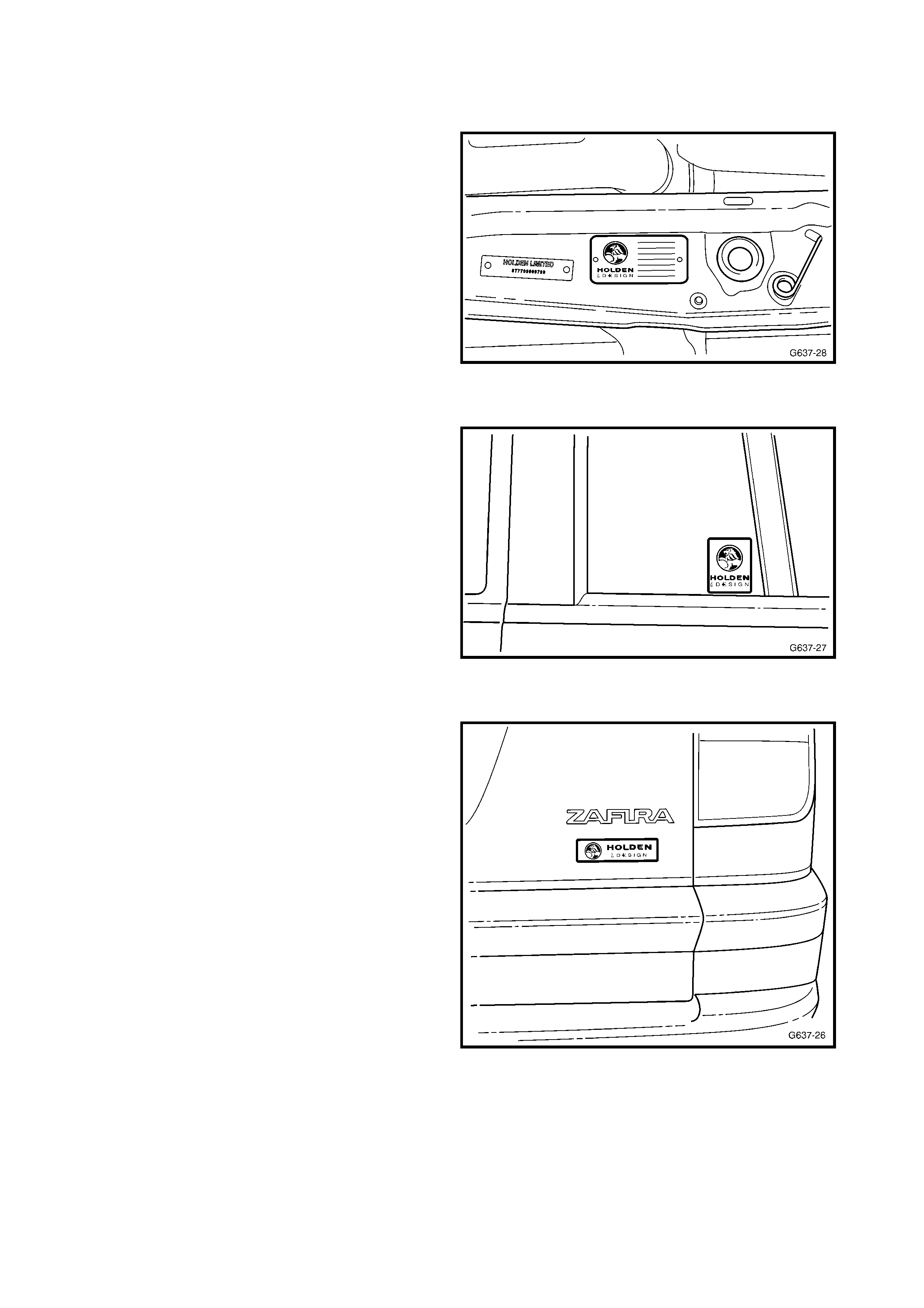
2.5 IDENTIFICATION PLATE, LABELS & BADGE
IDENTIFICATION PLATE
A Holden By Design identification plate is attached to
the front upper panel within the engine compartment.
Figure 11A-35
REAR DOOR LABELS
A Holden By Design label is affixed to the left-hand
and right-hand rear door quarter window.
Figure 11A-36
LIFTGATE BADGE
A Holden By Design label is affixed to the right-hand
side of the liftgate. It is aligned vertically central with
the Zafira emblem, and horizontally central between
the emblem and style line.
Figure 11A-37